AVENTICS Bus Coupler AES/Valve Driver AV CANopen Manual de usuario
- Tipo
- Manual de usuario

Systembeschreibung | System Description | Description système |
Descrizione del sistema | Descripción de sistema | Systembeskrivning
R412018137/2016-08, Replaces: 01.2015, DE/EN/FR/IT/ES/SV
Buskoppler AES/Ventiltreiber AV
Bus Coupler AES/Valve Driver AV
Coupleur de bus AES / Pilote de distributeur AV
Accoppiatore bus AES/driver valvole AV
Acoplador de bus AES/controladores de válvula AV
Bussomkopplare AES/ventildrivenhet AV
CANopen
DeutschEnglishFrançaisItalianoEspañolSvenska


Deutsch
AVENTICS | Buskoppler AES/Ventiltreiber AV, CANopen | R412018137–BAL–001–AE 3
Inhalt
1 Zu dieser Dokumentation ......................................................................................................... 5
1.1 Gültigkeit der Dokumentation .................................................................................................................. 5
1.2 Erforderliche und ergänzende Dokumentationen und Software-Tools ...................................... 5
1.3 Darstellung von Informationen ................................................................................................................ 5
1.3.1 Sicherheitshinweise .................................................................................................................................... 5
1.3.2 Symbole .......................................................................................................................................................... 6
1.3.3 Bezeichnungen .............................................................................................................................................. 7
1.3.4 Abkürzungen ................................................................................................................................................. 7
2 Sicherheitshinweise .................................................................................................................. 8
2.1 Zu diesem Kapitel ........................................................................................................................................ 8
2.2 Bestimmungsgemäße Verwendung ....................................................................................................... 8
2.2.1 Einsatz in explosionsfähiger Atmosphäre ............................................................................................ 9
2.3 Nicht bestimmungsgemäße Verwendung ............................................................................................ 9
2.4 Qualifikation des Personals ...................................................................................................................... 9
2.5 Allgemeine Sicherheitshinweise ........................................................................................................... 10
2.6 Produkt- und technologieabhängige Sicherheitshinweise ............................................................ 10
2.7 Pflichten des Betreibers ........................................................................................................................... 11
3 Allgemeine Hinweise zu Sachschäden und Produktschäden ............................................. 12
4 Zu diesem Produkt .................................................................................................................. 13
4.1 Buskoppler ................................................................................................................................................... 13
4.1.1 Elektrische Anschlüsse ............................................................................................................................ 14
4.1.2 LED ................................................................................................................................................................. 16
4.1.3 Adress- und Baudratenschalter ............................................................................................................ 17
4.1.4 Adressierung ............................................................................................................................................... 17
4.1.5 Baudrate ....................................................................................................................................................... 17
4.2 Ventiltreiber ................................................................................................................................................. 17
5 SPS-Konfiguration des Ventilsystems AV ............................................................................ 18
5.1 SPS-Konfigurationsschlüssel bereitlegen ......................................................................................... 18
5.2 Gerätestammdaten laden ........................................................................................................................ 19
5.3 Buskoppler im Feldbussystem konfigurieren ................................................................................... 19
5.4 Ventilsystem konfigurieren ..................................................................................................................... 19
5.4.1 Reihenfolge der Module ........................................................................................................................... 19
5.5 Parameter des Buskopplers einstellen ............................................................................................... 21
5.5.1 Parameter für Diagnosemeldungen ..................................................................................................... 21
5.5.2 Parameter für das Verhalten im Fehlerfall ........................................................................................ 21
5.6 Konfiguration zur Steuerung übertragen ........................................................................................... 22
6 Aufbau der Daten der Ventiltreiber ....................................................................................... 23
6.1 Prozessdaten ............................................................................................................................................... 23
6.2 Diagnosedaten ............................................................................................................................................ 24
6.3 Parameterdaten ......................................................................................................................................... 24
7 Aufbau der Daten der elektrischen Einspeiseplatte ............................................................ 25
7.1 Prozessdaten ............................................................................................................................................... 25
7.2 Diagnosedaten ............................................................................................................................................ 25
7.3 Parameterdaten ......................................................................................................................................... 25
8 Aufbau der Daten der pneumatischen Einspeiseplatte mit
UA-OFF-Überwachungsplatine .............................................................................................. 26
8.1 Prozessdaten ............................................................................................................................................... 26
8.2 Diagnosedaten ............................................................................................................................................ 26
8.3 Parameterdaten .............................................................................................................
............................ 26
9
V
oreinstellungen am Buskoppler .......................................................................................... 27
9.1 Sichtfenster öffnen und schließen ........................................................................................................ 27
9.2 Adresse am Buskoppler einstellen ....................................................................................................... 27
9.3 Adresse ändern .......................................................................................................................................... 28
9.4 Baudrate ändern ........................................................................................................................................ 29
9.5 Busabschluss herstellen ......................................................................................................................... 30

4 AVENTICS | Buskoppler AES/Ventiltreiber AV, CANopen | R412018137–BAL–001–AE
10 Ventilsystem mit CANopen in Betrieb nehmen .................................................................... 31
11 LED-Diagnose am Buskoppler ............................................................................................... 33
12 Umbau des Ventilsystems ...................................................................................................... 35
12.1 Ventilsystem ................................................................................................................................................ 35
12.2 Ventilbereich ................................................................................................................................................ 36
12.2.1 Grundplatten ................................................................................................................................................ 36
12.2.2 Adapterplatte ............................................................................................................................................... 37
12.2.3 Pneumatische Einspeiseplatte ............................................................................................................... 37
12.2.4 Elektrische Einspeiseplatte ..................................................................................................................... 38
12.2.5 Ventiltreiberplatinen ................................................................................................................................. 38
12.2.6 Druckregelventile ....................................................................................................................................... 39
12.2.7 Überbrückungsplatinen ........................................................................................................................... 41
12.2.8 UA-OFF-Überwachungsplatine .............................................................................................................. 41
12.2.9 Mögliche Kombinationen von Grundplatten und Platinen ............................................................. 41
12.3 Identifikation der Module ......................................................................................................................... 42
12.3.1 Materialnummer des Buskopplers ....................................................................................................... 42
12.3.2 Materialnummer des Ventilsystems .................................................................................................... 42
12.3.3 Identifikationsschlüssel des Buskopplers .......................................................................................... 42
12.3.4 Betriebsmittelkennzeichnung des Buskopplers ............................................................................... 43
12.3.5 Typenschild des Buskopplers ................................................................................................................ 44
12.4 SPS-Konfigurationsschlüssel ................................................................................................................. 44
12.4.1 SPS-Konfigurationsschlüssel des Ventilbereichs ............................................................................ 44
12.4.2 SPS-Konfigurationsschlüssel des E/A-Bereichs .............................................................................. 45
12.5 Umbau des Ventilbereichs ...................................................................................................................... 46
12.5.1 Sektionen ...................................................................................................................................................... 47
12.5.2 Zulässige Konfigurationen ...................................................................................................................... 48
12.5.3 Nicht zulässige Konfigurationen ............................................................................................................ 48
12.5.4 Umbau des Ventilbereichs überprüfen ............................................................................................... 50
12.5.5 Dokumentation des Umbaus .................................................................................................................. 51
12.6 Umbau des E/A-Bereichs ........................................................................................................................ 51
12.6.1 Zulässige Konfigurationen ...................................................................................................................... 51
12.6.2 Positionierung der Prozessdaten für digitale und analoge E/A-Module ................................... 51
12.6.3 Positionierung der Status- und Parameterdaten für digitale und analoge E/A-Module ...... 51
12.6.4 Dokumentation des Umbaus .................................................................................................................. 51
12.7 Erneute SPS-Konfiguration des Ventilsystems ................................................................................ 52
13 Fehlersuche und Fehlerbehebung ........................................................................................ 53
13.1 So gehen Sie bei der Fehlersuche vor ................................................................................................. 53
13.2 Störungstabelle .......................................................................................................................................... 53
14 Technische Daten .................................................................................................................... 56
15 Anhang ...................................................................................................................................... 57
15.1 Zubehör ......................................................................................................................................................... 57
15.2 Unterstützte CANopen-Features ........................................................................................................... 57
15.3 Objektverzeichnis ....................................................................................................................................... 58
15.3.1 COB-ID ........................................................................................................................................................... 67
15.3.2 Bedeutung des Objekts MCR (Objekt 0x2000) ................................................................................... 69
15.3.3 Bedeutung des Objektes Global Diagnostic Flag (Objekt 0x2010) ............................................... 69
15.4 EMCY Error Codes ...........................................................................................................
........................... 70
15.5 Diagnosedaten ............................................................................................................................................ 70
15.5.1 Spannungsdiagnose .................................................................................................................................. 70
15.5.2 Falsche Adresse ......................................................................................................................................... 71
15.5.3 Meldungen bei einer Störung der Backplane .................................................................................... 71
15.5.4 Keine Teilnehmer vorhanden ................................................................................................................. 71
16 Stichwortverzeichnis .............................................................................................................. 72

AVENTICS | Buskoppler AES/Ventiltreiber AV, CANopen | R412018137–BAL–001–AE 5
Zu dieser Dokumentation
Deutsch
1 Zu dieser Dokumentation
1.1 Gültigkeit der Dokumentation
Diese Dokumentation gilt für den Buskoppler der Serie AES für CANopen mit der Materialnummer
R412018220. Diese Dokumentation richtet sich an Programmierer, Elektroplaner, Servicepersonal
und Anlagenbetreiber.
Diese Dokumentation enthält wichtige Informationen, um das Produkt sicher und sachgerecht in
Betrieb zu nehmen, zu bedienen und einfache Störungen selbst zu beseitigen. Neben der
Beschreibung des Buskopplers enthält sie außerdem Informationen zur SPS-Konfiguration des
Buskopplers, der Ventiltreiber und der E/A-Module.
1.2 Erforderliche und ergänzende Dokumentationen und Software-Tools
O Nehmen Sie das Produkt erst in Betrieb, wenn Ihnen folgende Dokumentationen vorliegen und
Sie diese beachtet und verstanden haben.
Alle Montageanleitungen und Systembeschreibungen der Serien AES und AV sowie das
Software-Tool „AES CANopen EDS Creator“ finden Sie auf der CD R412018133.
1.3 Darstellung von Informationen
Damit Sie mit dieser Dokumentation schnell und sicher mit Ihrem Produkt arbeiten können, werden
einheitliche Sicherheitshinweise, Symbole, Begriffe und Abkürzungen verwendet. Zum besseren
Verständnis sind diese in den folgenden Abschnitten erklärt.
1.3.1 Sicherheitshinweise
In dieser Dokumentation stehen Sicherheitshinweise vor einer Handlungsabfolge, bei der die Gefahr
von Personen- oder Sachschäden besteht. Die beschriebenen Maßnahmen zur Gefahrenabwehr
müssen eingehalten werden.
Tabelle 1: Erforderliche und ergänzende Dokumentationen und Software-Tools
Dokumentation/Software-Tool Dokumentart Bemerkung
Anlagendokumentation Betriebsanleitung wird vom Anlagenbetreiber erstellt
Dokumentation des
SPS-Konfigurationsprogramms
Softwareanleitung Bestandteil der Software
Montageanleitungen aller vorhandenen
Komponenten und des gesamten
Ventilsystems AV
Montageanleitung Papierdokumentation
Systembeschreibungen zum elektrischen
Anschließen der E/A-Module und der
Buskoppler
Systembeschreibung pdf-Datei auf CD
Betriebsanleitung der
AV-EP-Druckregelventile
Betriebsanleitung pdf-Datei auf CD
Software-Tool „AES CANopen EDS Creator“ – Windows-Programm auf CD,
zur Erstellung von EDS-Dateien für den
Buskoppler AES, CANopen

6 AVENTICS | Buskoppler AES/Ventiltreiber AV, CANopen | R412018137–BAL–001–AE
Zu dieser Dokumentation
Sicherheitshinweise sind wie folgt aufgebaut:
W Warnzeichen: macht auf die Gefahr aufmerksam
W Signalwort: gibt die Schwere der Gefahr an
W Art und Quelle der Gefahr: benennt die Art und Quelle der Gefahr
W Folgen: beschreibt die Folgen bei Nichtbeachtung
W Abwehr: gibt an, wie man die Gefahr umgehen kann
1.3.2 Symbole
Die folgenden Symbole kennzeichnen Hinweise, die nicht sicherheitsrelevant sind, jedoch die
Verständlichkeit der Dokumentation erhöhen.
SIGNALWORT
Art und Quelle der Gefahr
Folgen bei Nichtbeachtung
O Maßnahme zur Gefahrenabwehr
O <Aufzählung>
Tabelle 2: Gefahrenklassen nach ANSI Z535.6-2006
Warnzeichen, Signalwort Bedeutung
GEFAHR
kennzeichnet eine gefährliche Situation, in der Tod oder schwere
Körperverletzung eintreten werden, wenn sie nicht vermieden wird
WARNUNG
kennzeichnet eine gefährliche Situation, in der Tod oder schwere
Körperverletzung eintreten können, wenn sie nicht vermieden wird
VORSICHT
kennzeichnet eine gefährliche Situation, in der leichte bis mittelschwere
Körperverletzungen eintreten können, wenn sie nicht vermieden wird
ACHTUNG
Sachschäden: Das Produkt oder die Umgebung können beschädigt
werden.
Tabelle 3: Bedeutung der Symbole
Symbol Bedeutung
Wenn diese Information nicht beachtet wird, kann das Produkt nicht optimal genutzt bzw.
betrieben werden.
O
einzelner, unabhängiger Handlungsschritt
1.
2.
3.
nummerierte Handlungsanweisung:
Die Ziffern geben an, dass die Handlungsschritte aufeinander folgen.

AVENTICS | Buskoppler AES/Ventiltreiber AV, CANopen | R412018137–BAL–001–AE 7
Zu dieser Dokumentation
Deutsch
1.3.3 Bezeichnungen
In dieser Dokumentation werden folgende Bezeichnungen verwendet:
1.3.4 Abkürzungen
In dieser Dokumentation werden folgende Abkürzungen verwendet:
Tabelle 4: Bezeichnungen
Bezeichnung Bedeutung
Backplane interne elektrische Verbindung vom Buskoppler zu den Ventiltreibern und den
E/A-Modulen
linke Seite E/A-Bereich, links vom Buskoppler, wenn man auf dessen elektrische
Anschlüsse schaut
Modul Ventiltreiber oder E/A-Modul
rechte Seite Ventilbereich, rechts vom Buskoppler, wenn man auf dessen elektrische
Anschlüsse schaut
Stand-alone-System Buskoppler und E/A-Module ohne Ventilbereich
Ventiltreiber elektrischer Teil der Ventilansteuerung, der das Signal aus der Backplane in
den Strom für die Magnetspule umsetzt.
Tabelle 5: Abkürzungen
Abkürzung Bedeutung
AES Advanced Electronic System
AV Advanced Valve
CANopen Controller Area Network open
E/A-Modul Eingangs-/Ausgangsmodul
EDS Electronic Data Sheet
FE Funktionserde (Functional Earth)
nc not connected (nicht belegt)
MCR Module Control Register
NMT Network Management
PDO Process Data Object
SDO Service Data Object
SPS Speicherprogrammierbare Steuerung oder PC, der Steuerungsfunktionen
übernimmt
UA Aktorspannung (Spannungsversorgung der Ventile und Ausgänge)
UA-ON Spannung, bei der die AV-Ventile immer eingeschaltet werden können
UA-OFF Spannung, bei der die AV-Ventile immer ausgeschaltet sind
UL Logikspannung (Spannungsversorgung der Elektronik und Sensoren)

8 AVENTICS | Buskoppler AES/Ventiltreiber AV, CANopen | R412018137–BAL–001–AE
Sicherheitshinweise
2 Sicherheitshinweise
2.1 Zu diesem Kapitel
Das Produkt wurde gemäß den allgemein anerkannten Regeln der Technik hergestellt. Trotzdem
besteht die Gefahr von Personen- und Sachschäden, wenn Sie dieses Kapitel und die
Sicherheitshinweise in dieser Dokumentation nicht beachten.
O Lesen Sie diese Dokumentation gründlich und vollständig, bevor Sie mit dem Produkt arbeiten.
O Bewahren Sie die Dokumentation so auf, dass sie jederzeit für alle Benutzer zugänglich ist.
O Geben Sie das Produkt an Dritte stets zusammen mit den erforderlichen Dokumentationen
weiter.
2.2 Bestimmungsgemäße Verwendung
Der Buskoppler der Serie AES und die Ventiltreiber der Serie AV sind Elektronikkomponenten und
wurden für den Einsatz in der Industrie für den Bereich Automatisierungstechnik entwickelt.
Der Buskoppler dient zum Anschluss von E/A-Modulen und Ventilen an das Feldbussystem
CANopen. Der Buskoppler darf ausschließlich an Ventiltreiber der Firma AVENTICS sowie an
E/A-Module der Serie AES angeschlossen werden. Das Ventilsystem darf auch ohne pneumatische
Komponenten als Stand-alone-System eingesetzt werden.
Der Buskoppler darf ausschließlich über eine speicherprogrammierbare Steuerung (SPS), eine
numerische Steuerung, einen Industrie-PC oder vergleichbare Steuerungen in Verbindung mit einer
Busmasteranschaltung mit dem Feldbusprotokoll CANopen angesteuert werden.
Ventiltreiber der Serie AV sind das Verbindungsglied zwischen dem Buskoppler und den Ventilen.
Die Ventiltreiber erhalten vom Buskoppler elektrische Informationen, die sie als Spannung an die
Ventile zur Ansteuerung weitergeben.
Buskoppler und Ventiltreiber sind für den professionellen Gebrauch und nicht für die private
Verwendung bestimmt. Sie dürfen Buskoppler und Ventiltreiber nur im industriellen Bereich
einsetzen (Klasse A). Für den Einsatz im Wohnbereich (Wohn-, Geschäfts- und Gewerbebereich) ist
eine Einzelgenehmigung bei einer Behörde oder Prüfstelle einzuholen. In Deutschland werden
solche Einzelgenehmigungen von der Regulierungsbehörde für Telekommunikation und Post
(RegTP) erteilt.
Buskoppler und Ventiltreiber dürfen in sicherheitsgerichteten Steuerungsketten verwendet werden,
wenn die Gesamtanlage darauf ausgerichtet ist.
O Beachten Sie die Dokumentation R412018148, wenn Sie das Ventilsystem in
sicherheitsgerichteten Steuerungsketten einsetzen.

AVENTICS | Buskoppler AES/Ventiltreiber AV, CANopen | R412018137–BAL–001–AE 9
Sicherheitshinweise
Deutsch
2.2.1 Einsatz in explosionsfähiger Atmosphäre
Weder Buskoppler noch Ventiltreiber sind ATEX-zertifiziert. Nur ganze Ventilsysteme können
ATEX-zertifiziert sein. Ventilsysteme dürfen nur dann in Bereichen in explosionsfähiger
Atmosphäre eingesetzt werden, wenn das Ventilsystem eine ATEX-Kennzeichnung trägt!
O Beachten Sie stets die technischen Daten und die auf dem Typenschild der gesamten Einheit
angegebenen Grenzwerte, insbesondere die Daten aus der ATEX-Kennzeichnung.
Der Umbau des Ventilsystems beim Einsatz in explosionsfähiger Atmosphäre ist in dem Umfang
zulässig, wie er in den folgenden Dokumenten beschrieben ist:
W Montageanleitung der Buskoppler und der E/A-Module
W Montageanleitung des Ventilsystems AV
W Montageanleitungen der pneumatischen Komponenten
2.3 Nicht bestimmungsgemäße Verwendung
Jeder andere Gebrauch als in der bestimmungsgemäßen Verwendung beschrieben ist nicht
bestimmungsgemäß und deshalb unzulässig.
Zur nicht bestimmungsgemäßen Verwendung des Buskopplers und der Ventiltreiber gehört:
W der Einsatz als Sicherheitsbauteil
W der Einsatz in explosionsgefährdeten Bereichen in einem Ventilsystem ohne ATEX-Zertifikat
Wenn ungeeignete Produkte in sicherheitsrelevanten Anwendungen eingebaut oder verwendet
werden, können unbeabsichtigte Betriebszustände in der Anwendung auftreten, die Personen-
und/oder Sachschäden verursachen können. Setzen Sie daher ein Produkt nur dann in
sicherheitsrelevanten Anwendungen ein, wenn diese Verwendung ausdrücklich in der
Dokumentation des Produkts spezifiziert und erlaubt ist. Beispielsweise in Ex-Schutz-Bereichen
oder in sicherheitsbezogenen Teilen einer Steuerung (funktionale Sicherheit).
Für Schäden bei nicht bestimmungsgemäßer Verwendung übernimmt die AVENTICS GmbH keine
Haftung. Die Risiken bei nicht bestimmungsgemäßer Verwendung liegen allein beim Benutzer.
2.4 Qualifikation des Personals
Die in dieser Dokumentation beschriebenen Tätigkeiten erfordern grundlegende Kenntnisse der
Elektrik und Pneumatik sowie Kenntnisse der zugehörigen Fachbegriffe. Um die sichere
Verwendung zu gewährleisten, dürfen diese Tätigkeiten daher nur von einer entsprechenden
Fachkraft oder einer unterwiesenen Person unter Leitung einer Fachkraft durchgeführt werden.
Eine Fachkraft ist, wer aufgrund seiner fachlichen Ausbildung, seiner Kenntnisse und Erfahrungen
sowie seiner Kenntnisse der einschlägigen Bestimmungen die ihm übertragenen Arbeiten
beurteilen, mögliche Gefahren erkennen und geeignete Sicherheitsmaßnahmen treffen kann. Eine
Fachkraft muss die einschlägigen fachspezifischen Regeln einhalten.

10 AVENTICS | Buskoppler AES/Ventiltreiber AV, CANopen | R412018137–BAL–001–AE
Sicherheitshinweise
2.5 Allgemeine Sicherheitshinweise
W Beachten Sie die gültigen Vorschriften zur Unfallverhütung und zum Umweltschutz.
W Berücksichtigen Sie die Bestimmungen für explosionsgefährdete Bereiche im Anwenderland.
W Beachten Sie die Sicherheitsvorschriften und -bestimmungen des Landes, in dem das Produkt
eingesetzt/angewendet wird.
W Verwenden Sie Produkte von AVENTICS nur in technisch einwandfreiem Zustand.
W Beachten Sie alle Hinweise auf dem Produkt.
W Personen, die Produkte von AVENTICS montieren, bedienen, demontieren oder warten dürfen
nicht unter dem Einfluss von Alkohol, sonstigen Drogen oder Medikamenten, die die
Reaktionsfähigkeit beeinflussen, stehen.
W Verwenden Sie nur vom Hersteller zugelassene Zubehör- und Ersatzteile, um
Personengefährdungen wegen nicht geeigneter Ersatzteile auszuschließen.
W Halten Sie die in der Produktdokumentation angegebenen technischen Daten und
Umgebungsbedingungen ein.
W Sie dürfen das Produkt erst dann in Betrieb nehmen, wenn festgestellt wurde, dass das
Endprodukt (beispielsweise eine Maschine oder Anlage), in das die Produkte von AVENTICS
eingebaut sind, den länderspezifischen Bestimmungen, Sicherheitsvorschriften und Normen
der Anwendung entspricht.
2.6 Produkt- und technologieabhängige Sicherheitshinweise
GEFAHR
Explosionsgefahr beim Einsatz falscher Geräte!
Wenn Sie in explosionsfähiger Atmosphäre Ventilsysteme einsetzen, die keine
ATEX-Kennzeichnung haben, besteht Explosionsgefahr.
O Setzen Sie in explosionsfähiger Atmosphäre ausschließlich Ventilsysteme ein, die auf dem
Typenschild eine ATEX-Kennzeichnung tragen.
Explosionsgefahr durch Trennen von elektrischen Anschlüssen in explosionsfähiger
Atmosphäre!
Trennen von elektrischen Anschlüssen unter Spannung führt zu großen Potenzialunterschieden.
O Trennen Sie niemals elektrische Anschlüsse in explosionsfähiger Atmosphäre.
O Arbeiten Sie am Ventilsystem nur bei nicht explosionsfähiger Atmosphäre.
Explosionsgefahr durch fehlerhaftes Ventilsystem in explosionsfähiger Atmosphäre!
Nach einer Konfiguration oder einem Umbau des Ventilsystems sind Fehlfunktionen möglich.
O Führen Sie nach einer Konfiguration oder einem Umbau immer vor der
Wiederinbetriebnahme eine Funktionsprüfung in nicht explosionsfähiger Atmosphäre durch.
VORSICHT
Unkontrollierte Bewegungen beim Einschalten!
Es besteht Verletzungsgefahr, wenn sich das System in einem undefinierten Zustand befindet.
O Bringen Sie das System in einen sicheren Zustand, bevor Sie es einschalten.
O Stellen Sie sicher, dass sich keine Person innerhalb des Gefahrenbereichs befindet, wenn Sie
das Ventilsystem einschalten.
Verbrennungsgefahr durch heiße Oberflächen!
Berühren der Oberflächen der Einheit und der benachbarten Teile im laufenden Betrieb kann zu
Verbrennungen führen.
O Lassen Sie den relevanten Anlagenteil abkühlen, bevor Sie an der Einheit arbeiten.
O Berühren Sie den relevanten Anlagenteil nicht im laufenden Betrieb.

AVENTICS | Buskoppler AES/Ventiltreiber AV, CANopen | R412018137–BAL–001–AE 11
Sicherheitshinweise
Deutsch
2.7 Pflichten des Betreibers
Als Betreiber der Anlage, die mit einem Ventilsystem der Serie AV ausgestattet werden soll, sind Sie
dafür verantwortlich,
W dass die bestimmungsgemäße Verwendung sichergestellt ist,
W dass das Bedienpersonal regelmäßig unterwiesen wird,
W dass die Einsatzbedingungen den Anforderungen an die sichere Verwendung des Produktes
entsprechen,
W dass Reinigungsintervalle gemäß den Umweltbeanspruchungen am Einsatzort festgelegt und
eingehalten werden,
W dass beim Vorhandensein von explosionsfähiger Atmosphäre Zündgefahren berücksichtigt
werden, die durch den Einbau von Betriebsmitteln in Ihrer Anlage entstehen,
W dass bei einem aufgetretenen Defekt keine eigenmächtigen Reparaturversuche unternommen
werden.

12 AVENTICS | Buskoppler AES/Ventiltreiber AV, CANopen | R412018137–BAL–001–AE
Allgemeine Hinweise zu Sachschäden und Produktschäden
3 Allgemeine Hinweise zu Sachschäden und
Produktschäden
ACHTUNG
Trennen von Anschlüssen unter Spannung zerstört die elektronischen Komponenten des
Ventilsystems!
Beim Trennen von Anschlüssen unter Spannung entstehen große Potenzialunterschiede, die das
Ventilsystem zerstören können.
O Schalten Sie den relevanten Anlagenteil spannungsfrei, bevor Sie das Ventilsystem
montieren bzw. elektrisch anschließen oder trennen.
Eine Änderung der Adresse und der Baudrate im laufenden Betrieb wird nicht übernommen!
Der Buskoppler arbeitet weiterhin sowohl mit der alten Adresse als auch mit der alten Baudrate.
O Ändern Sie weder die Adresse noch die Baudrate im laufenden Betrieb.
O Trennen Sie den Buskoppler von der Spannungsversorgung UL, bevor Sie die Stellungen an
den Schaltern S1, S2 und S3 ändern.
Störungen der Feldbuskommunikation durch falsche oder ungenügende Erdung!
Angeschlossene Komponenten erhalten falsche oder keine Signale. Stellen Sie sicher, dass die
Erdungen aller Komponenten des Ventilsystems
– miteinander
– und mit der Erde
gut elektrisch leitend verbunden sind.
O Stellen Sie den einwandfreien Kontakt zwischen dem Ventilsystem und der Erde sicher.
Störungen der Feldbuskommunikation durch falsch verlegte Kommunikationsleitungen!
Angeschlossene Komponenten erhalten falsche oder keine Signale.
O Verlegen Sie die Kommunikationsleitungen innerhalb von Gebäuden. Wenn Sie die
Kommunikationsleitungen außerhalb von Gebäuden verlegen, darf die außen verlegte Länge
nicht mehr als 42 m betragen.
Das Ventilsystem enthält elektronische Bauteile, die gegenüber elektrostatischer Entladung
(ESD) empfindlich sind!
Berühren der elektrischen Bauteile durch Personen oder Gegenstände kann zu einer
elektrostatischen Entladung führen, die die Komponenten des Ventilsystems beschädigen oder
zerstören.
O Erden Sie die Komponenten, um eine elektrostatische Aufladung des Ventilsystems zu
vermeiden.
O Verwenden Sie ggf. Handgelenk- und Schuherdungen, wenn Sie am Ventilsystem arbeiten.

AVENTICS | Buskoppler AES/Ventiltreiber AV, CANopen | R412018137–BAL–001–AE 13
Zu diesem Produkt
Deutsch
4 Zu diesem Produkt
4.1 Buskoppler
Der Buskoppler der Serie AES für CANopen stellt die Kommunikation zwischen der übergeordneten
Steuerung und den angeschlossenen Ventilen und E/A-Modulen her. Er ist ausschließlich für den
Betrieb als Slave an einem Bussystem CANopen nach EN 50325-4 bestimmt. Der Buskoppler muss
daher eine eigene Adresse erhalten und konfiguriert werden. Für die Erstellung der EDS-Datei, die
Sie zur Konfiguration benötigen, befindet sich das Software-Tool „AES CANopen EDS Creator“ auf
der mitgelieferten CD R412018133 (siehe Kapitel 5.2 „Gerätestammdaten laden“ auf Seite 19).
Der Buskoppler kann bei der zyklischen Datenübertragung bis zu 512 Bits Eingangsdaten an die
Steuerung senden und bis zu 512 Bits Ausgangsdaten von der Steuerung empfangen. Um mit den
Ventilen zu kommunizieren, befindet sich auf der rechten Seite des Buskopplers eine elektronische
Schnittstelle für den Anschluss der Ventiltreiber. Auf der linken Seite befindet sich eine elektroni-
sche Schnittstelle, die die Kommunikation mit den E/A-Modulen herstellt. Beide Schnittstellen sind
voneinander unabhängig.
Der Buskoppler kann max. 64 einseitig oder beidseitig betätigte Ventile (128 Magnetspulen) und bis
zu zehn E/A-Module ansteuern. Er unterstützt Baudraten bis 1 MBaud.
Alle elektrischen Anschlüsse befinden sich auf der Vorderseite, alle Statusanzeigen auf der
Oberseite.
Abb. 1: Buskoppler CANopen
UL
UA
IO/DIAG
RUN
ERROR
R
4
1
2
0
1
8
2
2
0
A
E
S
-
D
-
B
C
-
C
A
N
1
12
2
3
4
6
10
7
8
9
11
10
10
9
13
5
1 Identifikationsschlüssel
2 LEDs
3 Sichtfenster
4 Feld für Betriebsmittelkennzeichnung
5 Anschluss Feldbus X7C2
6 Anschluss Feldbus X7C1
7 Anschluss Spannungsversorgung X1S
8 Funktionserde
9 Steg für Montage des Federklemmelements
10 Befestigungsschrauben zur Befestigung an
der Adapterplatte
11 elektrischer Anschluss für AES-Module
12 Typenschild
13 elektrischer Anschluss für AV-Module

14 AVENTICS | Buskoppler AES/Ventiltreiber AV, CANopen | R412018137–BAL–001–AE
Zu diesem Produkt
4.1.1 Elektrische Anschlüsse
Der Buskoppler hat folgende elektrische Anschlüsse:
W Stecker X7C2 (5): Feldbuseingang
W Buchse X7C1 (6): Feldbusausgang
W Stecker X1S (7): Spannungsversorgung des Buskopplers mit 24 V DC
W Erdungsschraube (8): Funktionserde
Das Anzugsmoment der Anschlussstecker und -buchsen beträgt 1,5 Nm +0,5.
Das Anzugsmoment der Mutter M4x0,7 (SW7) an der Erdungsschraube beträgt 1,25 Nm +0,25.
Feldbusanschluss Der Feldbuseingang X7C2 (5) ist ein M12-Stecker, male, 5-polig, A-codiert.
Der Feldbusausgang X7C1 (6) ist eine M12-Buchse, female, 5-polig, A-codiert.
O Entnehmen Sie die Pinbelegung des Feldbusanschlusses der Tabelle 6. Dargestellt ist die Sicht
auf die Anschlüsse des Geräts.
Feldbuskabel
ACHTUNG
Nicht angeschlossene Stecker erreichen nicht die Schutzart IP65!
Wasser kann in das Gerät dringen.
O Montieren Sie auf alle nicht angeschlossen Stecker Blindstopfen, damit die Schutzart IP65
erhalten bleibt.
X7C2
X7C1
X1S
6
8
7
5
X7C2
21
345
X7C1
12
435
6
5
Tabelle 6: Pinbelegung der Feldbusanschlüsse
Pin Stecker X7C2 (5) und Buchse X7C1 (6)
1 Funktionserde (Schirm ist intern über ein RC-Glied mit Funktionserde verbunden)
2optional
1)
1)
Alle Leitungen sind durchgeschleift. Pin 2 wird nicht von der Steuerung überwacht. Maximale Spannung: 24 V gegen Pin 3
3CAN_GND
4CAN_H
5CAN_L
Gehäuse Schirm bzw. Funktionserde
ACHTUNG
Gefahr durch falsch konfektionierte oder beschädigte Kabel!
Der Buskoppler kann beschädigt werden.
O Verwenden Sie ausschließlich geschirmte und geprüfte Kabel.
Falsche Verkabelung!
Eine falsche oder fehlerhafte Verkabelung führt zu Fehlfunktionen und zur Beschädigung des
Netzwerks.
O Halten Sie die CANopen-Spezifikationen ein.
O Verwenden Sie nur Kabel, die den Spezifikationen des Feldbusses sowie den Anforderungen
bzgl. Geschwindigkeit und Länge der Verbindung entsprechen.
O Montieren Sie Kabel und Stecker fachgerecht entsprechend der Montageanweisung, damit
Schutzart und Zugentlastung gewährleistet sind.

AVENTICS | Buskoppler AES/Ventiltreiber AV, CANopen | R412018137–BAL–001–AE 15
Zu diesem Produkt
Deutsch
Wenn Sie ein Kabel mit Beilauflitze verwenden, können Sie diese zusätzlich am Pin 1 der
Busstecker (X7C1/X7C2) anschließen.
Buskoppler als Zwischenstation
anschließen
1. Stellen Sie die korrekte Pin-Belegung (siehe Tabelle 6 auf Seite 14) Ihrer elektrischen
Anschlüsse her, wenn Sie keine konfektionierte Leitung verwenden.
2. Schließen Sie die ankommende Busleitung am Feldbus-Eingang X7C2 (5) an.
3. Verbinden Sie die abgehende Busleitung über den Feldbus-Ausgang X7C1 (6) mit dem nächsten
Modul.
4. Stellen Sie sicher, dass das Steckergehäuse fest mit dem Gehäuse des Buskopplers verbunden
ist.
Spannungsversorgung
Der Anschluss für die Spannungsversorgung X1S (7) ist ein M12-Stecker, male, 4-polig, A-codiert.
O Entnehmen Sie die Pinbelegung der Spannungsversorgung der Tabelle 7. Dargestellt ist die
Sicht auf die Anschlüsse des Geräts.
W Die Spannungstoleranz für die Elektronikspannung beträgt 24 V DC ±25%.
W Die Spannungstoleranz für die Aktorspannung beträgt 24 V DC ±10%.
W Der maximale Strom beträgt für beide Spannungen 4 A.
W Die Spannungen sind intern galvanisch getrennt.
X7C2
X7C1
X1S
6
5
GEFAHR
Stromschlag durch falsches Netzteil!
Verletzungsgefahr!
O Verwenden Sie für die Buskoppler ausschließlich die folgenden Spannungsversorgungen:
– 24-V-DC-SELV- oder PELV-Stromkreise, jeweils mit einer DC-Sicherung, die einen Strom
von 6,67 A innerhalb von max. 120 s unterbrechen kann, oder
– 24-V-DC-Stromkreise entsprechend den Anforderungen an energiebegrenzte
Stromkreise gemäß Abschnitt 9.4 der UL-Norm UL 61010-1, dritte Ausgabe, oder
– 24-V-DC-Stromkreise entsprechend den Anforderungen an leistungsbegrenzte
Stromquellen gemäß Abschnitt 2.5 der UL-Norm UL 60950-1, zweite Ausgabe, oder
– 24-V-DC-Stromkreise entsprechend den Anforderungen der NEC Class II gemäß der
UL-Norm UL 1310.
O Stellen Sie sicher, dass die Spannungsversorgung des Netzteils immer kleiner als 300 V AC
(Außenleiter - Neutralleiter) ist.
1
X1S
2
34
7
Tabelle 7: Pinbelegung der Spannungsversorgung
Pin Stecker X1S
Pin 1 24-V-DC-Spannungsversorgung Sensoren/Elektronik (UL)
Pin 2 24-V-DC-Aktorspannung (UA)
Pin 3 0-V-DC-Spannungsversorgung Sensoren/Elektronik (UL)
Pin 4 0-V-DC-Aktorspannung (UA)

16 AVENTICS | Buskoppler AES/Ventiltreiber AV, CANopen | R412018137–BAL–001–AE
Zu diesem Produkt
Anschluss Funktionserde O Verbinden Sie zur Ableitung von EMV-Störungen den FE-Anschluss (8) am Buskoppler über eine
niederimpedante Leitung mit der Funktionserde.
Der Leitungsquerschnitt muss der Anwendung entsprechend ausgelegt sein.
Um Ausgleichsströme über den Schirm des Buskopplers zu vermeiden, ist zwischen den
Geräten eine ausreichende Potenzialausgleichsleitung erforderlich.
4.1.2 LED
Der Buskoppler verfügt über 6 LEDs. Davon sind die ersten fünf mit einer Funktion belegt, die
sechste ist ohne Funktion.
Die Funktionen der LEDs sind in der nachfolgenden Tabelle beschrieben. Eine ausführliche
Beschreibung der LEDs finden Sie in Kapitel 11 „LED-Diagnose am Buskoppler“ auf Seite 33.
X7C2
X7C1
X1S
8
UL
UA
IO/DIAG
RUN
ERROR
14
15
16
17
18
19
Tabelle 8: Bedeutung der LEDs im Normalbetrieb
Bezeichnung Funktion Zustand im Normalbetrieb
UL (14) Überwachung der Spannungsversorgung der
Elektronik
leuchtet grün
UA (15) Überwachung der Aktorspannung leuchtet grün
IO/DIAG (16) Überwachung der Diagnosemeldungen aller
Module
leuchtet grün
RUN (17) Überwachung des Betriebszustands nach
CANopen DSP 303
leuchtet grün
ERROR (18) Überwachung der Buskommunikation nach
CANopen DSP 303
aus
– (19)keine –

AVENTICS | Buskoppler AES/Ventiltreiber AV, CANopen | R412018137–BAL–001–AE 17
Zu diesem Produkt
Deutsch
4.1.3 Adress- und Baudratenschalter
Abb. 2: Lage der Adressschalter S2 und S3 und des Baudratenschalters S1
Der DIP-Schalter S1 für die Baudrate sowie die beiden Drehschalter S2 und S3 für die
Stationsadresse des Ventilsystems im CANopen befinden sich unter dem Sichtfenster (3).
W Schalter S1: Am DIP-Schalter S1 wird die Baudrate an den ersten drei Schaltern eingestellt. Der
vierte Schalter ist nicht belegt.
W Schalter S2: Am Schalter S2 wird die Zehnerstelle der Adresse eingestellt. Der Schalter S2 ist
im Dezimalsystem von 0 bis 9 beschriftet.
W Schalter S3: Am Schalter S3 wird die Einerstelle der Adresse eingestellt. Der Schalter S3 ist im
Dezimalsystem von 0 bis 9 beschriftet.
4.1.4 Adressierung
Eine ausführliche Beschreibung der Adressierung finden Sie in Kapitel 9 „Voreinstellungen am
Buskoppler“ auf Seite 27.
4.1.5 Baudrate
Die Baudrate ist auf 1 MBit/s voreingestellt. Wie Sie die Baudrate ändern, ist im Kapitel 9.4 „Baudrate
ändern“ auf Seite 29 beschrieben.
4.2 Ventiltreiber
Die Beschreibung der Ventiltreiber finden Sie im Kapitel 12.2 „Ventilbereich“ auf Seite 36.
S1
S3
S2
S2
S3
S1
3
S1
S3
S2

18 AVENTICS | Buskoppler AES/Ventiltreiber AV, CANopen | R412018137–BAL–001–AE
SPS-Konfiguration des Ventilsystems AV
5 SPS-Konfiguration des Ventilsystems AV
In diesem Kapitel wird vorausgesetzt, dass Sie die Adresse und die Baudrate des Buskopplers
richtig eingestellt haben und der Busabschluss mit einem Datenendstecker hergestellt ist. Eine
detaillierte Beschreibung dazu finden Sie in Kapitel 9 „Voreinstellungen am Buskoppler“ auf
Seite 27.
Damit der Buskoppler die Daten des modularen Ventilsystems korrekt mit der SPS austauschen
kann, ist es notwendig, dass die SPS den Aufbau des Ventilsystems kennt. Dazu müssen Sie mit Hilfe
der Konfigurationssoftware des SPS-Programmiersystems die reale Anordnung der elektrischen
Komponenten innerhalb eines Ventilsystems in der SPS abbilden. Dieser Vorgang wird als
SPS-Konfiguration bezeichnet.
Sie können das Ventilsystem an Ihrem Rechner konfigurieren, ohne dass die Einheit
angeschlossen ist. Die Daten können Sie dann später vor Ort in das System einspielen.
5.1 SPS-Konfigurationsschlüssel bereitlegen
Da im Bereich der Ventile die elektrischen Komponenten in der Grundplatte liegen und nicht direkt
identifiziert werden können, benötigt der Ersteller der Konfiguration die
SPS-Konfigurationsschlüssel des Ventilbereichs und des E/A-Bereichs.
Sie benötigen den SPS-Konfigurationsschlüssel ebenfalls, wenn Sie die Konfiguration örtlich
getrennt vom Ventilsystem vornehmen.
O Notieren Sie sich den SPS-Konfigurationsschlüssel der einzelnen Komponenten in folgender
Reihenfolge:
– Ventilseite: Der SPS-Konfigurationsschlüssel ist auf dem Typenschild auf der rechten Seite
des Ventilsystems aufgedruckt.
– E/A-Module: Der SPS-Konfigurationsschlüssel ist auf der Oberseite der Module aufgedruckt.
Eine ausführliche Beschreibung des SPS-Konfigurationsschlüssels finden Sie in Kapitel 12.4
„SPS-Konfigurationsschlüssel“ auf Seite 44.
ACHTUNG
Konfigurationsfehler!
Ein fehlerhaft konfiguriertes Ventilsystem kann zu Fehlfunktionen im Gesamtsystem führen und
dieses beschädigen.
O Die Konfiguration darf daher nur von einer Fachkraft durchgeführt werden (siehe Kapitel 2.4
„Qualifikation des Personals“ auf Seite 9).
O Beachten Sie die Vorgaben des Anlagenbetreibers sowie ggf. Einschränkungen, die sich aus
dem Gesamtsystem ergeben.
O Beachten Sie die Dokumentation Ihres Konfigurationsprogramms.

AVENTICS | Buskoppler AES/Ventiltreiber AV, CANopen | R412018137–BAL–001–AE 19
SPS-Konfiguration des Ventilsystems AV
Deutsch
5.2 Gerätestammdaten laden
Die EDS-Dateien mit englischen Texten für den Buskoppler, Serie AES für CANopen müssen Sie
mit dem Software-Tool „AES CANopen EDS Creator“ erstellen. Das Software-Tool befindet sich
auf der mitgelieferten CD R412018133. Sie können es auch über das Internet im Media Centre
von AVENTICS herunterladen. Der Dateiname der EDS-Datei ist frei wählbar.
Jedes Ventilsystem ist gemäß Ihrer Bestellung mit einem Buskoppler und ggf. mit Ventilen bzw. mit
E/A-Modulen bestückt. Die EDS-Datei enthält die Daten aller Module, die am Buskoppler
angeschlossen sind. Dazu wird die EDS-Datei mit den Parameterdaten der Module in ein
Konfigurationsprogramm geladen, so dass der Anwender die Daten der einzelnen Module
komfortabel zuordnen und die Parameter einstellen kann.
W Erstellen Sie die EDS-Dateien mit dem Software-Tool „AES CANopen EDS Creator“ auf dem
Rechner, auf dem sich das SPS-Konfigurationsprogramm befindet.
– Fügen Sie dazu die verbauten elektrischen und pneumatischen Module jeweils auf der
entsprechenden Seite in der richtigen Reihenfolge ein.
– Geben Sie vor dem Speichern ggf. noch einen Produktnamen an, unter dem das Gerät
identifiziert werden kann. Falls das Feld leer bleibt, wird der Standardname „AES-D-BC-CAN“
verwendet.
Zur SPS-Konfiguration können Sie Konfigurationsprogramme verschiedener Hersteller einsetzen.
Daher wird in den folgenden Abschnitten nur das prinzipielle Vorgehen bei der SPS-Konfiguration
beschrieben.
5.3 Buskoppler im Feldbussystem konfigurieren
Bevor Sie die einzelnen Komponenten des Ventilsystems konfigurieren können, müssen Sie in Ihrem
SPS-Konfigurationsprogramm den Buskoppler im Feldbussystem als Slave konfigurieren.
1. Stellen Sie sicher, dass dem Buskoppler eine gültige Adresse zugewiesen ist (siehe Kapitel 9.2
„Adresse am Buskoppler einstellen“ auf Seite 27).
2. Konfigurieren Sie den Buskoppler als Slavemodul.
5.4 Ventilsystem konfigurieren
5.4.1 Reihenfolge der Module
Die in der Einheit verbauten Komponenten werden über das Objektverzeichnis im Buskoppler
angesprochen, das sich nach dem Einschalten anhand der verbauten Komponenten generiert hat
(siehe Kapitel 15.3 „Objektverzeichnis“ auf Seite 58). Es werden die entsprechenden PDOs nach dem
Kommunikationsprofil CiA DS-401 V3.0.0 vorbereitet. Alle PDOs darüber hinaus (max. 22 PDOs je
Senderichtung) müssen Sie dann manuell per SDO aktivieren (siehe
CANopen-Kommunikationsprofil CiA DS-301 V4.2.0).
Wenn das RPDO 5 aktiviert wird, muss das RPDO 1 deaktiviert werden, da RPDO 1 und RPDO 5
gespiegelt sind. Dies gilt nur für das Default-Mapping. Falls das TPDO5 aktiviert wird, stellen
TPDO1 und TPDO5 dieselben Eingangsdaten dar.

20 AVENTICS | Buskoppler AES/Ventiltreiber AV, CANopen | R412018137–BAL–001–AE
SPS-Konfiguration des Ventilsystems AV
Abb. 3: Nummerierung der Module in einem Ventilsystem mit E/A-Modulen
Die Symboldarstellung der Komponenten des Ventilbereichs ist in Kapitel 12.2 „Ventilbereich“
auf Seite 36 erklärt.
Beispiel In Abb. 3 ist ein Ventilsystem mit folgenden Eigenschaften dargestellt:
W Buskoppler
W Sektion 1 (S1) mit 9 Ventilen
– 4-fach-Ventiltreiberplatine
– 2-fach-Ventiltreiberplatine
– 3-fach-Ventiltreiberplatine
W Sektion 2 (S2) mit 8 Ventilen
– 4-fach-Ventiltreiberplatine
– Druckregelventil
– 4-fach-Ventiltreiberplatine
W Sektion 3 (S3) mit 7 Ventilen
– Einspeiseplatine
– 4-fach-Ventiltreiberplatine
– 3-fach-Ventiltreiberplatine
W Eingangsmodul
W Eingangsmodul
W Ausgangsmodul
Der SPS-Konfigurationsschlüssel der gesamten Einheit lautet dann:
423–4M4U43
8DI8M8
8DI8M8
8DO8M8
Diesen SPS-Konfigurationsschlüssel benötigen Sie, um mit dem Software-Tool „AES CANopen
EDS Creator“ die EDS-Datei zu erstellen.
M 1 M 2 M 3 M 4 M 6 M 8M 7 M 9M 10M 11M 12
8DI8M88DI8M88DO8M8
AES-
D-BC-
CAN
P P UA
S1 S2 S3
UA
M 5
A
AV-EP
(M)
S1 Sektion 1
S2 Sektion 2
S3 Sektion 3
P Druckeinspeisung
UA Spannungseinspeisung
A Arbeitsanschluss des Einzeldruckreglers
AV-EP Druckregelventil
M Modul

AVENTICS | Buskoppler AES/Ventiltreiber AV, CANopen | R412018137–BAL–001–AE 21
SPS-Konfiguration des Ventilsystems AV
Deutsch
5.5 Parameter des Buskopplers einstellen
Die Eigenschaften des Ventilsystems werden über verschiedene Parameter, die Sie in der
Steuerung einstellen, beeinflusst. Mit den Parametern können Sie das Verhalten des Buskopplers
sowie der E/A-Module festlegen.
In diesem Kapitel werden nur die Parameter für den Buskoppler beschrieben. Die Parameter des
E/A-Bereichs und der Druckregelventile sind in der Systembeschreibung der jeweiligen E/A-Module
bzw. in der Betriebsanleitung der AV-EP-Druckregelventile erläutert. Die Parameter für die
Ventiltreiberplatinen sind in der Systembeschreibung des Buskopplers erläutert.
Folgende Parameter können Sie für den Buskoppler einstellen:
W über das Objekt MCR (Objekt 0x2000)
– Verhalten der Fehlernachrichten
– Verhalten der Ausgänge im Fehlerfall
– Verhalten bei Störung der Backplane
W über das Objekt Error Behavior (Objekt 0x1029)
– Verhalten bei einer Unterbrechung der CANopen-Kommunikation
O Setzen Sie die entsprechenden Parameter über SDO-Telegramme.
Die Parameter und Konfigurationsdaten werden nicht vom Buskoppler lokal gespeichert. Diese
werden beim Hochlauf aus der SPS an den Buskoppler und an die verbauten Module gesendet.
5.5.1 Parameter für Diagnosemeldungen
Mit den Einstellungen in Bit 3 des Objekts MCR (Objekt 0x2000) stellen Sie an der Steuerung ein, ob
der Buskoppler Diagnosedaten senden soll (siehe Kapitel 15.4 „EMCY Error Codes“ auf Seite 70).
Die Beschreibung der Diagnosedaten für den Ventilbereich finden Sie in Kapitel 6 „Aufbau der
Daten der Ventiltreiber“ auf Seite 23. Die Beschreibung der Diagnosedaten der
AV-EP-Druckregelventile finden Sie in der Betriebsanleitung für AV-EP-Druckregelventile. Die
Beschreibung der Diagnosedaten des E/A-Bereichs sind in den Systembeschreibungen der
jeweiligen E/A-Module erläutert.
5.5.2 Parameter für das Verhalten im Fehlerfall
Verhalten der Fehlernachrichten
und der Ausgänge
Dieser Parameter beschreibt die Reaktion des Buskopplers, wenn keine CANopen-Kommunikation
mehr vorhanden ist. Folgendes Verhalten können Sie im Objekt Module Control Register (MCR)
(Objekt 0x2000) einstellen:
Tabelle 9: Einstellungen im Objekt MCR (Objekt 2000h)
Verhalten der Ausgänge
Bit 8 (0x0100)
0
Ausgänge auf 0 setzen (Voreinstellung)
1
Ausgänge beibehalten
Tabelle 10: Einstellungen im Objekt MCR (Objekt 2000h)
Verhalten der Fehlernachrichten (EMCY)
Bit 10 (0x0400)
0
Fehlernachrichten werden nicht gesendet (Voreinstellung)
1
Fehlernachrichten werden gesendet

22 AVENTICS | Buskoppler AES/Ventiltreiber AV, CANopen | R412018137–BAL–001–AE
SPS-Konfiguration des Ventilsystems AV
Verhalten bei Störung der
Backplane
Dieser Parameter beschreibt die Reaktion des Buskopplers bei einer Störung der Backplane.
Folgendes Verhalten können Sie im Objekt MCR (Objekt 0x2000) einstellen:
Option 1 (Voreinstellung):
W Bei einer kurzzeitigen Störung der Backplane (die z. B. durch einen Impuls auf der
Spannungsversorgung ausgelöst wird) blinkt die LED IO/DIAG rot und der Buskoppler sendet
eine Warnung an die Steuerung. Sobald die Kommunikation über die Backplane wieder
funktioniert, geht der Buskoppler wieder in den normalen Betrieb und die Warnungen werden
zurückgenommen.
W Bei einer länger anhaltenden Störung der Backplane (z. B. durch Entfernen einer Endplatte)
blinkt die LED IO/DIAG rot und der Buskoppler sendet eine Fehlermeldung an die Steuerung.
Gleichzeitig setzt der Buskoppler alle Ventile und Ausgänge zurück. Der Buskoppler versucht,
das System neu zu initialisieren. Ist die Initialisierung erfolgreich, nimmt der Buskoppler seinen
normalen Betrieb wieder auf. Die Fehlermeldung wird zurückgenommen und die LED IO/DIAG
leuchtet grün.
Option 2
W Bei einer kurzzeitigen Störung der Backplane ist die Reaktion identisch zu Option 1.
W Bei einer länger anhaltenden Störung der Backplane sendet der Buskoppler eine Fehlermeldung
an die Steuerung und die LED IO/DIAG blinkt rot. Gleichzeitig setzt der Buskoppler alle Ventile
und Ausgänge zurück. Es wird keine Initialisierung des Systems gestartet. Der Buskoppler
muss von Hand neu gestartet werden (Power Reset), um in den Normalbetrieb zurückgesetzt zu
werden.
Die Warnungen und Fehlermeldungen werden nur gesendet, wenn dies im Objekt MCR auch
aktiviert ist.
Verhalten bei einer Unterbrechung
der CANopen-Kommunikation
Bei einer Unterbrechung der CANopen-Kommunikation geht der Buskoppler standardmäßig in den
PRE-OPERATIONAL-Zustand (Voreinstellung). Über das Objekt 1029 lässt er sich aber auch so
konfigurieren, das der Buskoppler im OPERATIONAL-Zustand bleibt.
5.6 Konfiguration zur Steuerung übertragen
Wenn das Ventilsystem vollständig und richtig konfiguriert ist, können Sie die Daten zur Steuerung
übertragen.
1. Überprüfen Sie, ob die Parametereinstellungen der Steuerung mit denen des Ventilsystems
kompatibel sind.
2. Stellen Sie eine Verbindung zur Steuerung her.
3. Übertragen Sie die Daten des Ventilsystems zur Steuerung. Das genaue Vorgehen hängt vom
SPS-Konfigurationsprogramm ab. Beachten Sie dessen Dokumentation.
Tabelle 11: Einstellungen im Objekt MCR (Objekt 2000h)
Verhalten bei Überschreitung von Fehlergrenzen bei internen Störungen
Bit 2 (0x0004)
0
Anlauf bei Unterschreitung der Fehlergrenzen (Option 1, Voreinstellung)
1
Anlauf über Spannungsreset (Option 2)

AVENTICS | Buskoppler AES/Ventiltreiber AV, CANopen | R412018137–BAL–001–AE 23
Aufbau der Daten der Ventiltreiber
Deutsch
6 Aufbau der Daten der Ventiltreiber
6.1 Prozessdaten
Die Ventiltreiberplatine erhält von der Steuerung Ausgangsdaten mit Sollwerten für die Stellung der
Magnetspulen der Ventile. Der Ventiltreiber übersetzt diese Daten in die Spannung, die zur
Ansteuerung der Ventile benötigt wird. Die Länge der Ausgangsdaten beträgt acht Bit. Davon werden
bei einer 2-fach-Ventiltreiberplatine vier Bit, bei einer 3-fach-Ventiltreiberplatine sechs Bit und bei
einer 4-fach-Ventiltreiberplatine acht Bit verwendet.
In Abb. 4 ist dargestellt, wie die Ventilplätze einer 2-fach-, 3-fach- und 4-fach-Ventiltreiberplatine
zugeordnet sind:
Abb. 4: Anordnung der Ventilplätze
Die Symboldarstellung der Komponenten des Ventilbereichs ist in Kapitel 12.2 „Ventilbereich“
auf Seite 36 erklärt.
WARNUNG
Falsche Datenzuordnung!
Gefahr durch unkontrolliertes Verhalten der Anlage.
O Setzen Sie nicht verwendete Bits immer auf den Wert „0“.
Ventilplatz 1
Ventilplatz 2
Ventilplatz 3
Ventilplatz 4
20 2-fach-Grundplatte
21 3-fach-Grundplatte
22 2-fach-Ventiltreiberplatine
23 3-fach-Ventiltreiberplatine
24 4-fach-Ventiltreiberplatine
n o n o p n op q
22 23 24
202120

24 AVENTICS | Buskoppler AES/Ventiltreiber AV, CANopen | R412018137–BAL–001–AE
Aufbau der Daten der Ventiltreiber
Die Zuordnung der Magnetspulen der Ventile zu den Bits ist wie folgt:
Die Tabellen 12–14 zeigen beidseitig betätigte Ventile. Bei einem einseitig betätigten Ventil wird
nur die Spule 14 verwendet (Bit 0, 2, 4 und 6).
Positionierung der Prozessdaten
für die Module der Ventilseite
Prozessdaten (Ausgangsdaten zur Ansteuerung der Spulen) der Module der Ventilseite werden im
Objekt Standardized Profile Area (ab Objekt 0x6000) (entspricht digitalen Ausgängen, Objekt 0x6200)
und zusätzlich auch im Objekt Manufacturer-specific Profile Area (ab Objekt 0x2000) abgelegt.
Datentypen für Prozessdaten Digitale Daten werden in 8-Bit Datentypen (UNSIGNED8) abgelegt. Analoge Daten werden in
16-Bit-Datentypen (INTEGER16) abgelegt.
6.2 Diagnosedaten
Der Ventiltreiber sendet die Diagnosemeldung als Emergency-Telegramme an den Buskoppler. Sie
zeigt die Nummer des Moduls, bei dem der Fehler aufgetreten ist. Die Diagnosemeldung besteht aus
einem Diagnosebit, das bei Kurzschluss eines Ausgangs gesetzt wird (Sammeldiagnose).
Die Bedeutung des Diagnosebits ist:
W Bit = 1: Es liegt ein Fehler vor
W Bit = 0: Es liegt kein Fehler vor
6.3 Parameterdaten
Die Ventiltreiberplatine hat keine Parameter.
Positionierung der Status- und
Parameterdaten für Module der
Ventilseite
Status- und Parameterdaten der Module der Ventilseite werden im Objekt Manufacturer-specific
Profile Area (ab Objekt 0x2000) abgelegt. Module der Ventilseite haben keinen Parameter „Polarität“.
Tabelle 12: 2-fach-Ventiltreiberplatine
1)
Ausgangsbyte Bit 7 Bit 6 Bit 5 Bit 4 Bit 3 Bit 2 Bit 1 Bit 0
Ventilbezeichnung––––Ventil 2Ventil 2Ventil 1Ventil 1
Spulenbezeichnung––––Spule 12Spule 14Spule 12Spule 14
1)
Bits, die mit „–“ markiert sind, dürfen nicht verwendet werden und erhalten den Wert „0“.
Tabelle 13: 3-fach-Ventiltreiberplatine
1)
Ausgangsbyte Bit 7 Bit 6 Bit 5 Bit 4 Bit 3 Bit 2 Bit 1 Bit 0
Ventilbezeichnung – – Ventil 3 Ventil 3 Ventil 2 Ventil 2 Ventil 1 Ventil 1
Spulenbezeichnung – – Spule 12 Spule 14 Spule 12 Spule 14 Spule 12 Spule 14
1)
Bits, die mit „–“ markiert sind, dürfen nicht verwendet werden und erhalten den Wert „0“.
Tabelle 14: 4-fach-Ventiltreiberplatine
Ausgangsbyte Bit 7 Bit 6 Bit 5 Bit 4 Bit 3 Bit 2 Bit 1 Bit 0
Ventilbezeichnung Ventil 4 Ventil 4 Ventil 3 Ventil 3 Ventil 2 Ventil 2 Ventil 1 Ventil 1
Spulenbezeichnung Spule 12 Spule 14 Spule 12 Spule 14 Spule 12 Spule 14 Spule 12 Spule 14

AVENTICS | Buskoppler AES/Ventiltreiber AV, CANopen | R412018137–BAL–001–AE 25
Aufbau der Daten der elektrischen Einspeiseplatte
Deutsch
7 Aufbau der Daten der elektrischen
Einspeiseplatte
Die elektrische Einspeiseplatte unterbricht die von links kommende Spannung UA, und leitet die
Spannung, die über den zusätzlichen M12-Stecker eingespeist wird, nach rechts weiter. Alle
anderen Signale werden direkt weitergeleitet.
7.1 Prozessdaten
Die elektrische Einspeiseplatte hat keine Prozessdaten.
7.2 Diagnosedaten
Die elektrische Einspeiseplatte sendet die Diagnosemeldung als Emergency-Telegramme an den
Buskoppler. Sie zeigt die Nummer des Moduls an, an dem der Fehler aufgetreten ist. Die
Diagnosemeldung besteht aus einem Diagnosebit, das gesetzt wird, wenn die Aktorspannung unter
21,6 V (24 V DC -10% = UA-ON) fällt.
Die Bedeutung des Diagnosebits ist:
W Bit = 1: Es liegt ein Fehler vor (UA < UA-ON)
W Bit = 0: Es liegt kein Fehler vor (UA > UA-ON)
7.3 Parameterdaten
Die elektrische Einspeiseplatte hat keine Parameter.

26 AVENTICS | Buskoppler AES/Ventiltreiber AV, CANopen | R412018137–BAL–001–AE
Aufbau der Daten der pneumatischen Einspeiseplatte mit UA-OFF-Überwachungsplatine
8 Aufbau der Daten der pneumatischen
Einspeiseplatte mit
UA-OFF-Überwachungsplatine
Die elektrische UA-OFF-Überwachungsplatine leitet alle Signale einschließlich der
Versorgungsspannungen weiter. Die UA-OFF-Überwachungsplatine erkennt, ob die Spannung UA
den Wert UA-OFF unterschreitet.
8.1 Prozessdaten
Die elektrische UA-OFF-Überwachungsplatine hat keine Prozessdaten.
8.2 Diagnosedaten
Die UA-OFF-Überwachungsplatine sendet die Diagnosemeldung als Emergency-Telegramme an
den Buskoppler, die die Unterschreitung der Aktorspannung (UA) signalisiert (UA < UA-OFF). Sie
zeigt die Nummer des Moduls, bei dem der Fehler aufgetreten ist. Die Diagnosemeldung besteht aus
einem Diagnosebit.
Die Bedeutung des Diagnosebits ist:
W Bit = 1: Es liegt ein Fehler vor (UA < UA-OFF)
W Bit = 0: Es liegt kein Fehler vor (UA > UA-OFF)
8.3 Parameterdaten
Die elektrische UA-OFF-Überwachungsplatine hat keine Parameter.

AVENTICS | Buskoppler AES/Ventiltreiber AV, CANopen | R412018137–BAL–001–AE 27
Voreinstellungen am Buskoppler
Deutsch
9 Voreinstellungen am Buskoppler
Folgende Voreinstellungen müssen Sie durchführen:
W Adresse am Buskoppler einstellen (siehe Kapitel 9.2 „Adresse am Buskoppler einstellen“ auf
Seite 27)
W Baudrate einstellen (siehe Kapitel 9.4 „Baudrate ändern“ auf Seite 29)
W Diagnosemeldungen einstellen (siehe Kapitel 5.5 „Parameter des Buskopplers einstellen“ auf
Seite 21)
Die Adresse wird über die beiden Schalter S2 und S3 unter dem Sichtfenster eingestellt.
Die Baudrate wird über den DIP-Schalter S1 unter dem Sichtfenster eingestellt.
Das Melden der Diagnosedaten wird mit Parametern an- und ausgeschaltet (siehe Kapitel 5.5
„Parameter des Buskopplers einstellen“ auf Seite 21).
9.1 Sichtfenster öffnen und schließen
1. Lösen Sie die Schraube (25) am Sichtfenster (3).
2. Klappen Sie das Sichtfenster auf.
3. Nehmen Sie die entsprechenden Einstellungen wie in den nächsten Abschnitten beschrieben
vor.
4. Schließen Sie das Sichtfenster wieder. Achten Sie hierbei auf den korrekten Sitz der Dichtung.
5. Ziehen Sie die Schraube wieder fest.
Anzugsmoment: 0,2 Nm
9.2 Adresse am Buskoppler einstellen
Da der Buskoppler ausschließlich als Slave-Modul arbeitet, müssen Sie ihm eine Adresse im
Feldbussystem zuweisen.
Am Buskoppler dürfen Adressen von 1–99 eingestellt werden. Wenn die Adresse 0 eingestellt wird,
stellt der Buskoppler die Adresse automatisch auf 2 ein und die LED IO/DIAG blinkt grün. Zusätzlich
sendet der Buskoppler folgende Fehlernachricht (EMCY) (siehe Kapitel 15.4 „EMCY Error Codes“ auf
Seite 70):
Jede Adresse darf im Netzwerk nur einmal vorkommen. Doppelbelegungen sind innerhalb eines
CANopen-Systems nicht zulässig.
R412018220
AES-D-BC-CAN
UL
UA
IO/DIAG
RUN
ERROR
25
3
ACHTUNG
Defekte oder falsch sitzende Dichtung!
Wasser kann in das Gerät dringen. Die Schutzart IP65 ist nicht mehr gewährleistet.
O Stellen Sie sicher, dass die Dichtung unter dem Sichtfenster (3) intakt ist und korrekt sitzt.
O Stellen Sie sicher, dass die Schraube (25) mit dem richtigen Anzugsmoment (0,2 Nm)
befestigt wurde.
Tabelle 15: Codierung des EMCY-Telegramms
Byte 7 6 5 4 3 2 1 0
0x00 0x00 0x00 0x00 0x00 0x80
1)
1)
Diese Meldung sendet der Buskoppler auch wenn die Diagnosemeldungen deaktiviert sind.
0xFF 0xFF

28 AVENTICS | Buskoppler AES/Ventiltreiber AV, CANopen | R412018137–BAL–001–AE
Voreinstellungen am Buskoppler
Abb. 5: Adressschalter S2 und S3 am Buskoppler
Die beiden Drehschalter S2 und S3 für die Stationsadresse des Ventilsystems im CANopen befinden
sich unter dem Sichtfenster (3).
W Schalter S2: Am Schalter S2 wird die Zehnerstelle der Adresse eingestellt. Der Schalter S2 ist
im Dezimalsystem von 0 bis 9 beschriftet.
W Schalter S3: Am Schalter S3 wird die Einerstelle der Adresse eingestellt. Der Schalter S3 ist im
Dezimalsystem von 0 bis 9 beschriftet.
Gehen Sie bei der Adressierung wie folgt vor:
1. Trennen Sie den Buskoppler von der Spannungsversorgung UL.
2. Stellen Sie an den Schaltern S2 und S3 (siehe Abb. 5) die Stationsadresse ein:
– S2: Zehnerstelle von 0 bis 9
– S3: Einerstelle von 0 bis 9
3. Schalten Sie die Spannungsversorgung UL wieder ein. Das System wird initialisiert und die
Adresse am Buskoppler wird übernommen.
9.3 Adresse ändern
S1
S3
S2
S2
S3
3
S3
S2
ACHTUNG
Eine Änderung der Adresse im laufenden Betrieb wird nicht übernommen!
Der Buskoppler arbeitet weiterhin mit der alten Adresse.
O Ändern Sie die Adresse niemals im laufenden Betrieb.
O Trennen Sie den Buskoppler von der Spannungsversorgung UL, bevor Sie die Stellungen an
den Schaltern S2 und S3 ändern.

AVENTICS | Buskoppler AES/Ventiltreiber AV, CANopen | R412018137–BAL–001–AE 29
Voreinstellungen am Buskoppler
Deutsch
9.4 Baudrate ändern
Abb. 6: Baudratenschalter S1 am Buskoppler
Der DIP-Schalter S1 für die Baudrate befindet sich unter dem Sichtfenster (3).
W Schalter S1: Am DIP-Schalter S1 wird die Baudrate an den ersten drei Schaltern eingestellt.
Am DIP-Schalter S1 sind zwei Schalterstellungen möglich, nämlich die Schalterstellung „OPEN“ und
die Schalterstellung „ON“.
Je nach Bauart des DIP-Schalters ist die Stellung „OPEN“ oder „ON“ beschriftet. Die nebenstehende
Abbildung zeigt einen DIP-Schalter, bei dem die Schalterstellung „OPEN“ beschriftet ist.
O Achten Sie auf die Beschriftung des DIP-Schalters S1.
O Stellen Sie die Baudrate wie in Tabelle 16 dargestellt ein.
ACHTUNG
Eine Änderung der Baudrate im laufenden Betrieb wird nicht übernommen!
Der Buskoppler arbeitet weiterhin mit der alten Baudrate.
O Ändern Sie die Baudrate niemals im laufenden Betrieb.
O Trennen Sie den Buskoppler von der Spannungsversorgung UL, bevor Sie die Stellungen am
Schalter S1 ändern.
S1
S3
S2
S1
3
S1
OPEN
ON
Tabelle 16: Schalterbelegung zur Baudrateneinstellung
Baudrate max. Leitungslänge Schalter 1 Schalter 2 Schalter 3
1 Mbit/s
(Voreinstellung)
25 m ON ON ON
reserviert – OPEN ON ON
500 kbit/s 100 m ON OPEN ON
250 kbit/s 250 m OPEN OPEN ON

30 AVENTICS | Buskoppler AES/Ventiltreiber AV, CANopen | R412018137–BAL–001–AE
Voreinstellungen am Buskoppler
Schalter 4 ist reserviert und muss auf OPEN bleiben.
9.5 Busabschluss herstellen
Wenn das Gerät der letzte Teilnehmer im CANopen-Strang ist, müssen Sie einen Datenendstecker
Serie CN2, male, M12x1, 5-polig, A-codiert anschließen. Die Materialnummer lautet 8941054264.
Der Datenendstecker stellt einen definierten Leitungsabschluss her und verhindert
Leitungsreflexionen. Außerdem stellt er sicher, dass die Schutzart IP65 erfüllt ist.
Die Montage des Datenendstecker ist in der Montageanleitung der kompletten Einheit
beschrieben.
125 kbit/s 500 m ON ON OPEN
50 kbit/s 1 km OPEN ON OPEN
20 kbit/s 2,5 km ON OPEN OPEN
10 kbit/s 5 km OPEN OPEN OPEN
Tabelle 16: Schalterbelegung zur Baudrateneinstellung
Baudrate max. Leitungslänge Schalter 1 Schalter 2 Schalter 3

AVENTICS | Buskoppler AES/Ventiltreiber AV, CANopen | R412018137–BAL–001–AE 31
Ventilsystem mit CANopen in Betrieb nehmen
Deutsch
10 Ventilsystem mit CANopen in Betrieb
nehmen
Bevor Sie das System in Betrieb nehmen, müssen Sie folgende Arbeiten durchgeführt und
abgeschlossen haben:
W Sie haben das Ventilsystem mit Buskoppler montiert (siehe Montageanleitung der Buskoppler
und der E/A-Module und Montageanleitung des Ventilsystems).
W Sie haben die Voreinstellungen und die Konfiguration durchgeführt (siehe Kapitel 9
„Voreinstellungen am Buskoppler“ auf Seite 27 und Kapitel 5 „SPS-Konfiguration des
Ventilsystems AV“ auf Seite 18).
W Sie haben den Buskoppler an die Steuerung angeschlossen (siehe Montageanleitung für das
Ventilsystem AV).
W Sie haben die Steuerung so konfiguriert, dass die Ventile und die E/A-Module richtig angesteuert
werden.
Die Inbetriebnahme und Bedienung darf nur von einer Elektro- oder Pneumatikfachkraft oder
von einer unterwiesenen Person unter der Leitung und Aufsicht einer Fachkraft erfolgen (siehe
Kapitel 2.4 „Qualifikation des Personals“ auf Seite 9).
GEFAHR
Explosionsgefahr bei fehlendem Schlagschutz!
Mechanische Beschädigungen, z. B. durch Belastung der pneumatischen oder elektrischen
Anschlüsse, führen zum Verlust der Schutzart IP65.
O Stellen Sie sicher, dass das Betriebsmittel in explosionsgefährdeten Bereichen gegen
jegliche mechanische Beschädigung geschützt eingebaut wird.
Explosionsgefahr durch beschädigte Gehäuse!
In explosionsgefährdeten Bereichen können beschädigte Gehäuse zur Explosion führen.
O Stellen Sie sicher, dass die Komponenten des Ventilsystems nur mit vollständig montiertem
und unversehrtem Gehäuse betrieben werden.
Explosionsgefahr durch fehlende Dichtungen und Verschlüsse!
Flüssigkeiten und Fremdkörper können in das Gerät eindringen und das Gerät zerstören.
O Stellen Sie sicher, dass die Dichtungen im Stecker vorhanden sind und dass sie nicht
beschädigt sind.
O Stellen Sie vor der Inbetriebnahme sicher, dass alle Stecker montiert sind.
VORSICHT
Unkontrollierte Bewegungen beim Einschalten!
Es besteht Verletzungsgefahr, wenn sich das System in einem undefinierten Zustand befindet.
O Bringen Sie das System in einen sicheren Zustand, bevor Sie es einschalten.
O Stellen Sie sicher, dass sich keine Person innerhalb des Gefahrenbereichs befindet, wenn Sie
die Druckluftversorgung einschalten.

32 AVENTICS | Buskoppler AES/Ventiltreiber AV, CANopen | R412018137–BAL–001–AE
Ventilsystem mit CANopen in Betrieb nehmen
1. Schalten Sie die Betriebsspannung ein.
Die Steuerung sendet beim Hochlauf Parameter und Konfigurationsdaten an den Buskoppler,
die Elektronik im Ventilbereich und an die E/A-Module.
Beim Einschalten oder nach einem Hardware-Reset werden die angeschlossenen Module der
Ventilseite und digitalen und analogen E/A-Module gescannt und danach die Struktur für die
veränderlichen Objektverzeichniseinträge des Objektverzeichnisses festgelegt. Diese Struktur
bleibt bis zu einem erneuten Einschalten oder Hardware-Reset unverändert erhalten.
2. Überprüfen Sie nach der Initialisierungsphase die LED-Anzeigen an allen Modulen (siehe
Kapitel 11 „LED-Diagnose am Buskoppler“ auf Seite 33 und Systembeschreibung der
E/A-Module).
Die Diagnose-LEDs dürfen vor dem Einschalten des Betriebsdrucks ausschließlich wie in Tabelle 17
beschrieben leuchten.
Wenn die Diagnose erfolgreich verlaufen ist, dürfen Sie das Ventilsystem in Betrieb nehmen.
Andernfalls müssen Sie den Fehler beheben (siehe Kapitel 13 „Fehlersuche und Fehlerbehebung“
auf Seite 53).
3. Schalten Sie die Druckluftversorgung ein.
UL
UA
IO/DIAG
RUN
ERROR
14
15
16
17
18
Tabelle 17: Zustände der LEDs bei der Inbetriebnahme
Bezeichnung Farbe Zustand Bedeutung
UL (14) grün leuchtet Die Spannungsversorgung der Elektronik ist größer als die
untere Toleranzgrenze (18 V DC).
UA (15) grün leuchtet Die Aktorspannung ist größer als die untere
Toleranzgrenze (21,6 V DC).
IO/DIAG (16) grün leuchtet Die Konfiguration ist in Ordnung und die Backplane arbeitet
fehlerfrei
RUN (17) grün leuchtet Betriebsanzeige nach dem Hochlauf, Modul befindet sich
im OPERATIONAL-Zustand
ERROR (18) rot aus kein Busfehler erkannt

AVENTICS | Buskoppler AES/Ventiltreiber AV, CANopen | R412018137–BAL–001–AE 33
LED-Diagnose am Buskoppler
Deutsch
11 LED-Diagnose am Buskoppler
Der Buskoppler überwacht die Spannungsversorgungen für die Elektronik und die
Aktoransteuerung. Wenn die eingestellte Schwelle unter- oder überschritten wird, wird ein
Fehlersignal erzeugt und an die Steuerung gemeldet. Zusätzlich zeigen die Diagnose-LEDs den
Zustand an.
Diagnoseanzeige am Buskoppler
ablesen
Die LEDs auf der Oberseite des Buskopplers geben die in Tabelle 18 aufgeführten Meldungen
wieder.
O Überprüfen Sie vor Inbetriebnahme und während des Betriebs regelmäßig die
Buskopplerfunktionen durch Ablesen der LEDs.
UL
UA
IO/DIAG
RUN
ERROR
14
15
16
17
18
19
Tabelle 18: Bedeutung der LED-Diagnose
Bezeichnung Farbe Zustand Bedeutung
UL (14) grün leuchtet Die Spannungsversorgung der Elektronik ist größer als die
untere Toleranzgrenze (18 V DC).
rot blinkt Die Spannungsversorgung der Elektronik ist kleiner als die
untere Toleranzgrenze (18 V DC) und größer als 10 V DC.
rot leuchtet Die Spannungsversorgung der Elektronik ist kleiner als
10 V DC.
grün/rot aus Die Spannungsversorgung der Elektronik ist deutlich
kleiner als 10 V DC (Schwelle nicht definiert).
UA (15) grün leuchtet Die Aktorspannung ist größer als die untere
Toleranzgrenze (21,6 V DC).
rot blinkt Die Aktorspannung ist kleiner als die untere
Toleranzgrenze (21,6 V DC) und größer als UA-OFF
rot leuchtet Die Aktorspannung ist kleiner als UA-OFF
IO/DIAG (16) grün leuchtet Die Konfiguration ist in Ordnung und die Backplane arbeitet
fehlerfrei
grün blinkt CANopen-Adresse wurde falsch eingestellt (Adresse = 0).
rot leuchtet Diagnosemeldung eines Moduls liegt vor.
rot blinkt Fehler der Konfiguration oder der Funktion der Backplane
RUN (17) grün leuchtet Betriebsanzeige, Modul befindet sich im
OPERATIONAL-Zustand
grün blinkt
langsam
(2,5 Hz)
Modul befindet sich im PRE-OPERATIONAL-Zustand
(SLAVE wartet auf NMT-START-Telegramm vom
CAN-Master)
grün blinkt
(jeweils 1
Blitz)
Modul befindet sich im STOPPED-Zustand
grün aus Modul befindet sich im INITIALIZING-Zustand

34 AVENTICS | Buskoppler AES/Ventiltreiber AV, CANopen | R412018137–BAL–001–AE
LED-Diagnose am Buskoppler
ERROR (18) rot leuchtet Modul befindet sich im BUS-OFF-Zustand (nicht am
CANopen-Bus aktiv)
rot blinkt
(jeweils 1
Blitz)
Modul befindet sich im ERROR PASSIVE-Zustand
(mindestens ein Fehlerzähler hat den Maximalwert
erreicht oder überschritten)
rot blinkt
(jeweils 2
Blitze)
Modul befindet sich im ERROR CONTROL EVENT-Zustand,
ein Heartbeat-/Überwachungs-Fehler ist aufgetreten
Bedingung: Objekt 1006 wird unterstützt
rot blinkt
(jeweils 3
Blitze)
Modul befindet sich im SYNC ERROR-Zustand.
Das Objekt SYNC wurde nicht innerhalb der konfigurierten
Zeit gesendet.
rot aus kein Busfehler erkannt
keine (19)– – nicht belegt
Tabelle 18: Bedeutung der LED-Diagnose
Bezeichnung Farbe Zustand Bedeutung

AVENTICS | Buskoppler AES/Ventiltreiber AV, CANopen | R412018137–BAL–001–AE 35
Umbau des Ventilsystems
Deutsch
12 Umbau des Ventilsystems
Dieses Kapitel beschreibt den Aufbau des kompletten Ventilsystems, die Regeln, nach denen Sie das
Ventilsystem umbauen dürfen, die Dokumentation des Umbaus sowie die erneute Konfiguration des
Ventilsystems.
Die Montage der Komponenten und der kompletten Einheit ist in den jeweiligen
Montageanleitungen beschrieben. Alle notwendigen Montageanleitungen werden als
Papierdokumentation mitgeliefert und befinden sich zusätzlich auf der CD R412018133.
12.1 Ventilsystem
Das Ventilsystem der Serie AV besteht aus einem zentralen Buskoppler, der nach rechts auf bis zu
64 Ventile und auf bis zu 32 dazugehörende elektrische Komponenten (siehe Kapitel 12.5.3 „Nicht
zulässige Konfigurationen“ auf Seite 48) erweitert werden kann. Auf der linken Seite können bis zu
zehn Eingangs- und Ausgangsmodule angeschlossen werden. Die Einheit kann auch ohne
pneumatische Komponenten, also nur mit Buskoppler und E/A-Modulen, als Stand-alone-System
betrieben werden.
In Abb. 7 ist eine Beispielkonfiguration mit Ventilen und E/A-Modulen dargestellt. Je nach
Konfiguration können in Ihrem Ventilsystem weitere Komponenten, wie pneumatische
Einspeiseplatten, elektrische Einspeiseplatten oder Druckregelventile vorhanden sein (siehe
Kapitel 12.2 „Ventilbereich“ auf Seite 36).
GEFAHR
Explosionsgefahr durch fehlerhaftes Ventilsystem in explosionsfähiger Atmosphäre!
Nach einer Konfiguration oder einem Umbau des Ventilsystems sind Fehlfunktionen möglich.
O Führen Sie nach einer Konfiguration oder einem Umbau immer vor der
Wiederinbetriebnahme eine Funktionsprüfung in nicht explosionsfähiger Atmosphäre durch.

36 AVENTICS | Buskoppler AES/Ventiltreiber AV, CANopen | R412018137–BAL–001–AE
Umbau des Ventilsystems
Abb. 7: Beispielkonfiguration: Einheit aus Buskoppler und E/A-Modulen der Serie AES und Ventilen der Serie AV
12.2 Ventilbereich
In den folgenden Abbildungen sind die Komponenten als Illustration und als Symbol dargestellt.
Die Symboldarstellung wird im Kapitel 12.5 „Umbau des Ventilbereichs“ auf Seite 46 verwendet.
12.2.1 Grundplatten
Ventile der Serie AV werden immer auf Grundplatten montiert, die miteinander verblockt werden,
so dass der Versorgungsdruck an allen Ventilen anliegt.
Die Grundplatten sind immer als 2-fach- oder 3-fach-Grundplatten für zwei bzw. drei einseitig oder
beidseitig betätigte Ventile ausgeführt.
R412018220
AES-D-BC-CAN
UL
UA
IO/DIAG
RUN
ERROR
26
27
28
29
30
33
31
32
34
26 linke Endplatte
27 E/A-Module
28 Buskoppler
29 Adapterplatte
30 pneumatische Einspeiseplatte
31 Ventiltreiber (nicht sichtbar)
32 rechte Endplatte
33 pneumatische Einheit der Serie AV
34 elektrische Einheit der Serie AES

AVENTICS | Buskoppler AES/Ventiltreiber AV, CANopen | R412018137–BAL–001–AE 37
Umbau des Ventilsystems
Deutsch
Abb. 8: 2-fach- und 3-fach-Grundplatten
12.2.2 Adapterplatte
Die Adapterplatte (29) hat ausschließlich die Funktion, den Ventilbereich mit dem Buskoppler
mechanisch zu verbinden. Sie befindet sich immer zwischen dem Buskoppler und der ersten
pneumatischen Einspeiseplatte.
Abb. 9: Adapterplatte
12.2.3 Pneumatische Einspeiseplatte
Mit pneumatischen Einspeiseplatten (30) können Sie das Ventilsystem in Sektionen mit
verschiedenen Druckzonen aufteilen (siehe Kapitel 12.5 „Umbau des Ventilbereichs“ auf Seite 46).
Abb. 10: Pneumatische Einspeiseplatte
n
n
o
o
n
o
nop
p
20
20
21
21
Ventilplatz 1
Ventilplatz 2
Ventilplatz 3
20 2-fach-Grundplatte
21 3-fach-Grundplatte
29
29
P
30 30

38 AVENTICS | Buskoppler AES/Ventiltreiber AV, CANopen | R412018137–BAL–001–AE
Umbau des Ventilsystems
12.2.4 Elektrische Einspeiseplatte
Die elektrische Einspeiseplatte (35) ist mit einer Einspeiseplatine verbunden. Sie kann über einen
eigenen 4-poligen M12-Anschluss eine zusätzliche 24-V-Spannungsversorgung für alle Ventile, die
rechts von der elektrischen Einspeiseplatte liegen, einspeisen. Die elektrische Einspeiseplatte
überwacht diese zusätzliche Spannung (UA) auf Unterspannung (24 V DC -10%).
Abb. 11: Elektrische Einspeiseplatte
Das Anzugsmoment der Erdungsschraube M4x0,7 (SW7) beträgt 1,25 Nm +0,25.
Pinbelegung des M12-Steckers Der Anschluss für die Aktorspannung ist ein M12-Stecker, male, 4-polig, A-codiert.
O Entnehmen Sie die Pinbelegung des M12-Steckers der elektrischen Einspeiseplatte der
Tabelle 19.
W Die Spannungstoleranz für die Aktorspannung beträgt 24 V DC ±10%.
W Der maximale Strom beträgt 2 A.
W Die Spannung ist intern galvanisch von UL getrennt.
12.2.5 Ventiltreiberplatinen
In den Grundplatten sind unten an der Rückseite Ventiltreiber eingebaut, die die Ventile elektrisch
mit dem Buskoppler verbinden.
Durch die Verblockung der Grundplatten werden auch die Ventiltreiberplatinen über Stecker
elektrisch verbunden und bilden zusammen die sogenannte Backplane, über die der Buskoppler die
Ventile ansteuert.
UA
35
35
24 V DC -10%
X1S
1
X1S
2
34
Tabelle 19: Pinbelegung des M12-Steckers der elektrischen Einspeiseplatte
Pin Stecker X1S
Pin 1 nc (nicht belegt)
Pin 2 24-V-DC-Aktorspannung (UA)
Pin 3 nc (nicht belegt)
Pin 4 0-V-DC-Aktorspannung (UA)

AVENTICS | Buskoppler AES/Ventiltreiber AV, CANopen | R412018137–BAL–001–AE 39
Umbau des Ventilsystems
Deutsch
Abb. 12: Verblockung von Grundplatten und Ventiltreiberplatinen
Ventiltreiber- und Einspeiseplatinen gibt es in folgenden Ausführungen:
Abb. 13: Übersicht der Ventiltreiber- und Einspeiseplatinen
Mit elektrischen Einspeiseplatten kann das Ventilsystem in Sektionen mit verschiedenen
Spannungszonen aufgeteilt werden. Dazu unterbricht die Einspeiseplatine die 24-V- und die
0-V-Leitung der Spannung UA in der Backplane. Maximal zehn Spannungszonen sind zulässig.
Die Einspeisung der Spannung an der elektrischen Einspeiseplatte muss bei der
SPS-Konfiguration berücksichtigt werden.
12.2.6 Druckregelventile
Elektronisch angesteuerte Druckregelventile können Sie abhängig von der gewählten Grundplatte
als Druckzonen- oder als Einzeldruckregler einsetzen.
n
o
p
q
no pq
20
37
36
22
2237 36
20
Ventilplatz 1
Ventilplatz 2
Ventilplatz 3
Ventilplatz 4
20 2-fach-Grundplatte
22 2-fach-Ventiltreiberplatine
36 Stecker rechts
37 Stecker links
22 2-fach-Ventiltreiberplatine
23 3-fach-Ventiltreiberplatine
24 4-fach-Ventiltreiberplatine
35 elektrische Einspeiseplatte
38 Einspeiseplatine
UA
22 23 24 38
35

40 AVENTICS | Buskoppler AES/Ventiltreiber AV, CANopen | R412018137–BAL–001–AE
Umbau des Ventilsystems
Abb. 14: Grundplatten für Druckregelventile zur Druckzonenregelung (links) und Einzeldruckregelung (rechts)
Druckregelventile zur Druckzonenregelung und zur Einzeldruckregelung unterscheiden sich
von der elektronischen Ansteuerung nicht. Aus diesem Grund wird auf die Unterschiede der
beiden AV-EP-Druckregelventile hier nicht weiter eingegangen. Die pneumatischen Funktionen
werden in der Betriebsanleitung der AV-EP-Druckregelventile beschrieben. Diese finden Sie auf
der CD R412018133.
39 AV-EP-Grundplatte zur Druckzonenregelung
40 AV-EP-Grundplatte zur Einzeldruckregelung
41 Integrierte AV-EP-Leiterplatte
42 Ventilplatz für Druckregelventil
A
39 40
41
42
41
42

AVENTICS | Buskoppler AES/Ventiltreiber AV, CANopen | R412018137–BAL–001–AE 41
Umbau des Ventilsystems
Deutsch
12.2.7 Überbrückungsplatinen
Abb. 15: Überbrückungsplatinen und UA-OFF-Überwachungsplatine
Überbrückungsplatinen überbrücken die Bereiche der Druckeinspeisung und haben keine weitere
Funktion. Sie werden daher bei der SPS-Konfiguration nicht berücksichtigt.
Überbrückungsplatinen gibt es in langer und kurzer Ausführung:
Die lange Überbrückungsplatine befindet sich immer direkt am Buskoppler. Sie überbrückt die
Adapterplatte und die erste pneumatische Einspeiseplatte.
Die kurze Überbrückungsplatine wird verwendet, um weitere pneumatische Einspeiseplatten zu
überbrücken.
12.2.8 UA-OFF-Überwachungsplatine
Die UA-OFF-Überwachungsplatine ist die Alternative zur kurzen Überbrückungsplatine in der
pneumatische Einspeiseplatte (siehe Abb. 15 auf Seite 41).
Die elektrische UA-OFF-Überwachungsplatine überwacht die Aktorspannung UA auf den Zustand
UA < UA-OFF. Alle Spannungen werden direkt durchgeleitet. Daher muss die
UA-OFF-Überwachungsplatine immer nach einer zu überwachenden elektrischen Einspeiseplatte
eingebaut werden.
Im Gegensatz zur Überbrückungsplatine muss die UA-OFF-Überwachungsplatine bei der
Konfiguration der Steuerung berücksichtigt werden.
12.2.9 Mögliche Kombinationen von Grundplatten und Platinen
4-fach-Ventiltreiberplatinen werden immer mit zwei 2-fach-Grundplatten kombiniert.
In Tabelle 20 ist dargestellt, wie die Grundplatten, pneumatische Einspeiseplatten, elektrische
Einspeiseplatten und Adapterplatten mit verschiedenen Ventiltreiber-, Überbrückungs- und
Einspeiseplatinen kombiniert werden können.
28 Buskoppler
29 Adapterplatte
30 pneumatische Einspeiseplatte
35 elektrische Einspeiseplatte
38 Einspeiseplatine
43 lange Überbrückungsplatine
44 kurze Überbrückungsplatine
45 UA-OFF-Überwachungsplatine
Tabelle 20: Mögliche Kombinationen von Platten und Platinen
Grundplatte Platinen
2-fach-Grundplatte 2-fach-Ventiltreiberplatine
3-fach-Grundplatte 3-fach-Ventiltreiberplatine
2x2-fach-Grundplatte 4-fach-Ventiltreiberplatine
1)
pneumatische Einspeiseplatte kurze Überbrückungsplatine oder
UA-OFF-Überwachungsplatine
AES-
D-BC-
CAN
P PUA UA P
28
43 44
29 30
38 45
35 30

42 AVENTICS | Buskoppler AES/Ventiltreiber AV, CANopen | R412018137–BAL–001–AE
Umbau des Ventilsystems
Die Platinen in den AV-EP-Grundplatten sind fest eingebaut und können daher nicht mit anderen
Grundplatten kombiniert werden.
12.3 Identifikation der Module
12.3.1 Materialnummer des Buskopplers
Anhand der Materialnummer können Sie den Buskoppler eindeutig identifizieren. Wenn Sie den
Buskoppler austauschen, können Sie mithilfe der Materialnummer das gleiche Gerät nachbestellen.
Die Materialnummer ist auf der Rückseite des Geräts auf dem Typenschild (12) und auf der
Oberseite unter dem Identifikationsschlüssel aufgedruckt. Für den Buskoppler Serie AES für
CANopen lautet die Materialnummer R412018220.
12.3.2 Materialnummer des Ventilsystems
Die Materialnummer des kompletten Ventilsystems (46) ist auf der rechten Endplatte aufgedruckt.
Mit dieser Materialnummer können Sie ein identisch konfiguriertes Ventilsystem nachbestellen.
O Beachten Sie, dass sich die Materialnummer nach einem Umbau des Ventilsystems immer noch
auf die Ursprungskonfiguration bezieht (siehe Kapitel 12.5.5 „Dokumentation des Umbaus“ auf
Seite 51).
12.3.3 Identifikationsschlüssel des Buskopplers
Der Identifikationsschlüssel (1) auf der Oberseite des Buskopplers der Serie AES für CANopen lautet
AES-D-BC-CAN und beschreibt dessen wesentlichen Eigenschaften:
Adapterplatte und pneumatische Einspeiseplatte lange Überbrückungsplatine
elektrische Einspeiseplatte Einspeiseplatine
1)
Zwei Grundplatten werden mit einer Ventiltreiberplatine verknüpft.
Tabelle 20: Mögliche Kombinationen von Platten und Platinen
Grundplatte Platinen
R412018220
AES-D-BC-CAN
UL
UA
IO/DIAG
RUN
ERROR
12
46
R412018220
AES-D-BC-CAN
UL
UA
IO/DIAG
RUN
ERROR
1
Tabelle 21: Bedeutung des Identifikationsschlüssels
Bezeichnung Bedeutung
AES Modul der Serie AES
D D-Design
BC Bus Coupler
CAN für Feldbusprotokoll CANopen

AVENTICS | Buskoppler AES/Ventiltreiber AV, CANopen | R412018137–BAL–001–AE 43
Umbau des Ventilsystems
Deutsch
12.3.4 Betriebsmittelkennzeichnung des Buskopplers
Um den Buskoppler eindeutig in der Anlage identifizieren zu können, müssen Sie ihm eine
eindeutige Kennzeichnung zuweisen. Hierfür stehen die beiden Felder für die
Betriebsmittelkennzeichnung (4) auf der Oberseite und auf der Front des Buskopplers zur
Verfügung.
O Beschriften Sie die beiden Felder wie in Ihrem Anlagenplan vorgesehen.
R412018220
AES-D-BC-CAN
UL
UA
IO/DIAG
RUN
ERROR
4

44 AVENTICS | Buskoppler AES/Ventiltreiber AV, CANopen | R412018137–BAL–001–AE
Umbau des Ventilsystems
12.3.5 Typenschild des Buskopplers
Das Typenschild befindet sich auf der Rückseite des Buskopplers. Es enthält folgende Angaben:
Abb. 16: Typenschild des Buskopplers
12.4 SPS-Konfigurationsschlüssel
12.4.1 SPS-Konfigurationsschlüssel des Ventilbereichs
Der SPS-Konfigurationsschlüssel für den Ventilbereich (58) ist auf der rechten Endplatte
aufgedruckt.
Der SPS-Konfigurationsschlüssel gibt die Reihenfolge und den Typ der elektrischen Komponenten
anhand eines Ziffern- und Buchstabencodes wieder. Der SPS-Konfigurationsschlüssel hat nur
Ziffern, Buchstaben und Bindestriche. Zwischen den Zeichen wird kein Leerzeichen verwendet.
Allgemein gilt:
W Ziffern und Buchstaben geben die elektrischen Komponenten wieder
W Jede Ziffer entspricht einer Ventiltreiberplatine. Der Wert der Ziffer gibt die Anzahl der
Ventilplätze für eine Ventiltreiberplatine wieder
W Buchstaben geben Sondermodule wieder, die für die SPS-Konfiguration relevant sind
W „–“ visualisiert eine pneumatische Einspeiseplatte ohne UA-OFF-Überwachungsplatine; nicht
relevant für die SPS-Konfiguration
47 Logo
48 Serie
49 Materialnummer
50 Spannungsversorgung
51 Fertigungsdatum in der Form FD:
<YY>W<WW>
52 Seriennummer
53 Adresse des Herstellers
54 Herstellerland
55 Datamatrix-Code
56 CE-Kennzeichen
57 interne Werksbezeichnung
47
48
49
50
51
52
54
55
5657
53
58

AVENTICS | Buskoppler AES/Ventiltreiber AV, CANopen | R412018137–BAL–001–AE 45
Umbau des Ventilsystems
Deutsch
Die Reihenfolge beginnt an der rechten Seite des Buskopplers und endet am rechten Ende des
Ventilsystems.
Die Elemente, die im SPS-Konfigurationsschlüssel dargestellt werden können, sind in Tabelle 22
dargestellt.
Beispiel eines SPS-Konfigurationsschlüssels: 423–4M4U43.
Die Adapterplatte und die pneumatische Einspeiseplatte am Beginn des Ventilsystems sowie
die rechte Endplatte werden im SPS-Konfigurationsschlüssel nicht berücksichtigt.
12.4.2 SPS-Konfigurationsschlüssel des E/A-Bereichs
Der SPS-Konfigurationsschlüssel des E/A-Bereichs (59) ist modulbezogen. Er ist jeweils auf der
Oberseite des Geräts aufgedruckt.
Die Reihenfolge der E/A-Module beginnt am Buskoppler auf der linken Seite und endet am linken
Ende des E/A-Bereichs.
Im SPS-Konfigurationsschlüssel sind folgende Daten codiert:
W Anzahl der Kanäle
W Funktion
W Steckertyp
Tabelle 22: Elemente des SPS-Konfigurationsschlüssels für den Ventilbereich
Abkürzung Bedeutung
2 2-fach-Ventiltreiberplatine
3 3-fach-Ventiltreiberplatine
4 4-fach-Ventiltreiberplatine
– pneumatische Einspeiseplatte
K Druckregelventil 8 Bit, parametrierbar
L Druckregelventil 8 Bit,
M Druckregelventil 16 Bit, parametrierbar
N Druckregelventil 16 Bit
U elektrische Einspeiseplatte
W UA-OFF-Überwachungsplatine
R412018233
8DI8M8
59
Tabelle 23: Abkürzungen für den SPS-Konfigurationsschlüssel im E/A-Bereich
Abkürzung Bedeutung
8 Anzahl der Kanäle oder Anzahl der Stecker, die Ziffer
wird dem Element immer vorangestellt
16
24
DI digitaler Eingangskanal (digital input)
DO digitaler Ausgangskanal (digital output)
AI analoger Eingangskanal (analog input)
AO analoger Ausgangskanal (analog output)
M8 M8-Anschluss
M12 M12-Anschluss
DSUB25 DSUB-Anschluss, 25-polig
SC Anschluss mit Federzugklemme (spring clamp)
A zusätzlicher Anschluss für Aktorspannung
L zusätzlicher Anschluss für Logikspannung
E erweiterte Funktionen (enhanced)

46 AVENTICS | Buskoppler AES/Ventiltreiber AV, CANopen | R412018137–BAL–001–AE
Umbau des Ventilsystems
Beispiel:
Der E/A-Bereich besteht aus drei verschiedenen Modulen mit folgenden
SPS-Konfigurationsschlüsseln:
Die linke Endplatte wird im SPS-Konfigurationsschlüssel nicht berücksichtigt.
12.5 Umbau des Ventilbereichs
Die Symboldarstellung der Komponenten des Ventilbereichs ist in Kapitel „12.2 Ventilbereich“
auf Seite 36 erklärt.
Zur Erweiterung oder zum Umbau dürfen Sie folgende Komponenten einsetzen:
W Ventiltreiber mit Grundplatten
W Druckregelventile mit Grundplatten
W pneumatische Einspeiseplatten mit Überbrückungsplatine
W elektrische Einspeiseplatten mit Einspeiseplatine
W pneumatische Einspeiseplatten mit UA-OFF-Überwachungsplatine
Bei Ventiltreibern sind Kombinationen aus mehreren der folgenden Komponenten möglich (siehe
Abb. 17 auf Seite 47):
W 4-fach-Ventiltreiber mit zwei 2-fach-Grundplatten
W 3-fach-Ventiltreiber mit einer 3-fach-Grundplatte
W 2-fach-Ventiltreiber mit einer 2-fach-Grundplatte
Wenn Sie das Ventilsystem als Stand-alone-System betreiben wollen, benötigen Sie eine
spezielle rechte Endplatte (siehe Kapitel 15.1 „Zubehör“ auf Seite 57).
Tabelle 24: Beispiel eines SPS-Konfigurationsschlüssels im E/A-Bereich
SPS-Konfigurationsschlüssel
des E/A-Moduls
Eigenschaften des E/A-Moduls
8DI8M8 W 8 x digitale Eingangskanäle
W 8 x M8-Anschlüsse
24DODSUB25 W 24 x digitale Ausgangskanäle
W 1 x DSUB-Stecker, 25-polig
2AO2AI2M12A W 2 x analoge Ausgangskanäle
W 2 x analoge Eingangskanäle
W 2 x M12-Anschlüsse
W zusätzlicher Anschluss für Aktorspannung
ACHTUNG
Unzulässige, nicht regelkonforme Erweiterung!
Erweiterungen oder Verkürzungen, die nicht in dieser Anleitung beschrieben sind, stören die
Basis-Konfigurationseinstellungen. Das System kann nicht zuverlässig konfiguriert werden.
O Beachten Sie die Regeln zur Erweiterung des Ventilbereichs.
O Beachten Sie die Vorgaben des Anlagenbetreibers sowie ggf. Einschränkungen, die sich aus
dem Gesamtsystem ergeben.

AVENTICS | Buskoppler AES/Ventiltreiber AV, CANopen | R412018137–BAL–001–AE 47
Umbau des Ventilsystems
Deutsch
12.5.1 Sektionen
Der Ventilbereich eines Ventilsystems kann aus mehreren Sektionen bestehen. Eine Sektion beginnt
immer mit einer Einspeiseplatte, die den Anfang eines neuen Druckbereichs oder eines neuen
Spannungsbereichs markiert.
Eine UA-OFF-Überwachungsplatine sollte nur nach einer elektrischen Einspeiseplatte
eingebaut werden, da sonst die Aktorspannung UA vor der Einspeisung überwacht wird.
Abb. 17: Bildung von Sektionen mit zwei pneumatischen Einspeiseplatten und einer elektrischen Einspeiseplatte
Das Ventilsystem in Abb. 17 besteht aus drei Sektionen:
AES-
D-BC-
CAN
P P UA
S1 S2 S3
UA
AV-EP
(M)
A
28 29 30 43 20 24 22 23 30 44 41 35 38 6042
28 Buskoppler
29 Adapterplatte
30 pneumatische Einspeiseplatte
43 lange Überbrückungsplatine
20 2-fach-Grundplatte
21 3-fach-Grundplatte
24 4-fach-Ventiltreiberplatine
22 2-fach-Ventiltreiberplatine
23 3-fach-Ventiltreiberplatine
44 kurze Überbrückungsplatine
42 Ventilplatz für Druckregelventil
41 Integrierte AV-EP-Leiterplatte
35 elektrische Einspeiseplatte
38 Einspeiseplatine
60 Ventil
S1 Sektion 1
S2 Sektion 2
S3 Sektion 3
P Druckeinspeisung
A Arbeitsanschluss des Einzeldruckreglers
UA Spannungseinspeisung
Tabelle 25: Beispiel eines Ventilsystems, bestehend aus drei Sektionen
Sektion Komponenten
1. Sektion W pneumatische Einspeiseplatte (30)
W drei 2-fach-Grundplatten (20) und eine 3-fach-Grundplatte (21)
W 4-fach- (24), 2-fach- (22) und 3-fach-Ventiltreiberplatine (23)
W 9 Ventile (60)

48 AVENTICS | Buskoppler AES/Ventiltreiber AV, CANopen | R412018137–BAL–001–AE
Umbau des Ventilsystems
12.5.2 Zulässige Konfigurationen
Abb. 18: Zulässige Konfigurationen
An allen mit einem Pfeil gekennzeichneten Punkten können Sie das Ventilsystem erweitern:
W nach einer pneumatischen Einspeiseplatte (A)
W nach einer Ventiltreiberplatine (B)
W am Ende einer Sektion (C)
W am Ende des Ventilsystems (D)
Um die Dokumentation und die Konfiguration einfach zu halten, empfehlen wir, das
Ventilsystem am rechten Ende (D) zu erweitern.
12.5.3 Nicht zulässige Konfigurationen
In Abbildung 19 ist dargestellt, welche Konfigurationen nicht zulässig sind. Sie dürfen nicht:
W innerhalb einer 4-fach- oder 3-fach-Ventiltreiberplatine trennen (A)
W nach dem Buskoppler weniger als vier Ventilplätze montieren (B)
W mehr als 64 Ventile (128 Magnetspulen) montieren
W mehr als 8 AV-EPs verbauen
W mehr als 32 elektrische Komponenten einsetzen.
Einige konfigurierte Komponenten haben mehrere Funktionen und zählen daher wie mehrere
elektrische Komponenten.
2. Sektion W pneumatische Einspeiseplatte (30)
W vier 2-fach-Grundplatten (20)
W zwei 4-fach-Ventiltreiberplatinen (24)
W 8 Ventile (60)
W AV-EP-Grundplatte für Einzeldruckregelung
W AV-EP-Druckregelventil
3. Sektion W elektrische Einspeiseplatte (35)
W zwei 2-fach-Grundplatten (20) und eine 3-fach-Grundplatte (21)
W Einspeiseplatine (38), 4-fach-Ventiltreiberplatine (24) und
3-fach-Ventiltreiberplatine (23)
W 7 Ventile (60)
Tabelle 25: Beispiel eines Ventilsystems, bestehend aus drei Sektionen
Sektion Komponenten
BABCABC BD
AES-
D-BC-
CAN
P P UAUA

AVENTICS | Buskoppler AES/Ventiltreiber AV, CANopen | R412018137–BAL–001–AE 49
Umbau des Ventilsystems
Deutsch
Tabelle 26: Anzahl elektrischer Komponenten pro Bauteil
Konfigurierte Komponente Anzahl elektrischer Komponenten
2-fach-Ventiltreiberplatinen 1
3-fach-Ventiltreiberplatinen 1
4-fach-Ventiltreiberplatinen 1
Druckregelventile 3
elektrische Einspeiseplatte 1
UA-OFF-Überwachungsplatine 1

50 AVENTICS | Buskoppler AES/Ventiltreiber AV, CANopen | R412018137–BAL–001–AE
Umbau des Ventilsystems
Abb. 19: Beispiele für nicht zulässige Konfigurationen
12.5.4 Umbau des Ventilbereichs überprüfen
O Überprüfen Sie nach dem Umbau der Ventileinheit anhand der folgenden Checkliste, ob Sie alle
Regeln eingehalten haben.
Haben Sie mindestens 4 Ventilplätze nach der ersten pneumatischen Einspeiseplatte montiert?
Haben Sie höchstens 64 Ventilplätze montiert?
Haben Sie nicht mehr als 32 elektrische Komponenten verwendet? Beachten Sie, dass ein
AV-EP-Druckregelventil drei elektrischen Komponenten entspricht.
Haben Sie nach einer pneumatischen oder elektrischen Einspeiseplatte, die eine neue Sektion
bildet, mindestens zwei Ventile montiert?
Haben Sie die Ventiltreiberplatinen immer passend zu den Grundplattengrenzen verbaut, d. h.
– eine 2-fach-Grundplatte wurde mit einer 2-fach-Ventiltreiberplatine verbaut,
– zwei 2-fach-Grundplatten wurden mit einer 4-fach-Ventiltreiberplatine verbaut,
– eine 3-fach-Grundplatte wurde mit einer 3-fach-Ventiltreiberplatine verbaut?
Haben Sie nicht mehr als 8 AV-EPs verbaut?
Wenn Sie alle Fragen mit „Ja“ beantwortet haben, können Sie mit der Dokumentation und
Konfiguration des Ventilsystems fortfahren.
AES-
D-BC-
CAN
P P UAUAUA
AES-
D-BC-
CAN
P UAUA
AES-
D-BC-
CAN
PUA
AES-
D-BC-
CAN
P
UA
AA
BB B

AVENTICS | Buskoppler AES/Ventiltreiber AV, CANopen | R412018137–BAL–001–AE 51
Umbau des Ventilsystems
Deutsch
12.5.5 Dokumentation des Umbaus
SPS-Konfigurationsschlüssel Nach einem Umbau ist der auf der rechten Endplatte aufgedruckte SPS-Konfigurationsschlüssel
nicht mehr gültig.
O Ergänzen Sie den SPS-Konfigurationsschlüssel oder überkleben Sie den
SPS-Konfigurationsschlüssel und beschriften Sie die Endplatte neu.
O Dokumentieren Sie stets alle Änderungen an Ihrer Konfiguration.
Materialnummer Nach einem Umbau ist die auf der rechten Endplatte angebrachte Materialnummer (MNR) nicht
mehr gültig.
O Markieren Sie die Materialnummer, so dass ersichtlich wird, dass die Einheit nicht mehr dem
ursprünglichen Auslieferungszustand entspricht.
12.6 Umbau des E/A-Bereichs
12.6.1 Zulässige Konfigurationen
Am Buskoppler dürfen maximal zehn E/A-Module angeschlossen werden.
Weitere Informationen zum Umbau des E/A-Bereichs finden Sie in den Systembeschreibungen der
jeweiligen E/A-Module.
Wir empfehlen Ihnen, die E/A-Module am linken Ende des Ventilsystems zu erweitern.
12.6.2 Positionierung der Prozessdaten für digitale und analoge E/A-Module
Prozessdaten (Ein- und Ausgangsdaten) der digitalen und analogen E/A-Module werden im Objekt
Manufacturer-specific Profile Area (ab Objekt 0x2000) abgelegt. Prozessdaten der digitalen
Eingänge werden zusätzlich im Geräteprofil-spezifischen Bereich (Objekt 0x6000) abgelegt.
12.6.3 Positionierung der Status- und Parameterdaten für digitale und analoge
E/A-Module
Status- und Parameterdaten der digitalen und analogen E/A-Module werden im Objekt
Manufacturer-specific Profile Area (ab Objekt 0x2000) abgelegt. Digitale Eingänge besitzen keine
Parameter wie „Interrupt-Maske“ oder „Polarität“.
12.6.4 Dokumentation des Umbaus
Der SPS-Konfigurationsschlüssel ist auf der Oberseite der E/A-Module aufgedruckt.
O Dokumentieren Sie stets alle Änderungen an Ihrer Konfiguration.

52 AVENTICS | Buskoppler AES/Ventiltreiber AV, CANopen | R412018137–BAL–001–AE
Umbau des Ventilsystems
12.7 Erneute SPS-Konfiguration des Ventilsystems
Nach dem Umbau des Ventilsystems müssen Sie die neu hinzugekommenen Komponenten
konfigurieren. Dazu müssen sie eine neue EDS-Datei erzeugen, die dem jetzt vorhandenen
Ventilsystem entspricht.
Wenn Sie Komponenten ausgetauscht haben, ohne deren Reihenfolge zu verändern, muss das
Ventilsystem nicht neu konfiguriert werden. Alle Komponenten werden dann von der Steuerung
erkannt.
O Gehen Sie bei der SPS-Konfiguration vor, wie in Kapitel 5 „SPS-Konfiguration des Ventilsystems
AV“ auf Seite 18 beschrieben.
ACHTUNG
Konfigurationsfehler!
Ein fehlerhaft konfiguriertes Ventilsystem kann zu Fehlfunktionen im Gesamtsystem führen und
dieses beschädigen.
O Die Konfiguration darf daher nur von einer Elektrofachkraft durchgeführt werden!
O Beachten Sie die Vorgaben des Anlagenbetreibers sowie ggf. Einschränkungen, die sich aus
dem Gesamtsystem ergeben.
O Beachten Sie die Dokumentation Ihres Konfigurationsprogramms.

AVENTICS | Buskoppler AES/Ventiltreiber AV, CANopen | R412018137–BAL–001–AE 53
Fehlersuche und Fehlerbehebung
Deutsch
13 Fehlersuche und Fehlerbehebung
13.1 So gehen Sie bei der Fehlersuche vor
O Gehen Sie auch unter Zeitdruck systematisch und gezielt vor.
O Wahlloses, unüberlegtes Demontieren und Verstellen von Einstellwerten können
schlimmstenfalls dazu führen, dass die ursprüngliche Fehlerursache nicht mehr ermittelt
werden kann.
O Verschaffen Sie sich einen Überblick über die Funktion des Produkts im Zusammenhang mit der
Gesamtanlage.
O Versuchen Sie zu klären, ob das Produkt vor Auftreten des Fehlers die geforderte Funktion in
der Gesamtanlage erbracht hat.
O Versuchen Sie, Veränderungen der Gesamtanlage, in welche das Produkt eingebaut ist, zu
erfassen:
– Wurden die Einsatzbedingungen oder der Einsatzbereich des Produkts verändert?
– Wurden Veränderungen (z. B. Umrüstungen) oder Reparaturen am Gesamtsystem
(Maschine/Anlage, Elektrik, Steuerung) oder am Produkt ausgeführt? Wenn ja: Welche?
– Wurde das Produkt bzw. die Maschine bestimmungsgemäß betrieben?
– Wie zeigt sich die Störung?
O Bilden Sie sich eine klare Vorstellung über die Fehlerursache. Befragen Sie ggf. den
unmittelbaren Bediener oder Maschinenführer.
13.2 Störungstabelle
In Tabelle 27 finden Sie eine Übersicht über Störungen, mögliche Ursachen und deren Abhilfe.
Falls Sie den aufgetretenen Fehler nicht beheben konnten, wenden Sie sich an die AVENTICS
GmbH. Die Adresse finden Sie auf der Rückseite der Anleitung.
Tabelle 27: Störungstabelle
Störung mögliche Ursache Abhilfe
kein Ausgangsdruck an den Ventilen
vorhanden
keine Spannungsversorgung am
Buskoppler bzw. an der
elektrischen Einspeiseplatte
(siehe auch Verhalten der
einzelnen LEDs am Ende der
Tabelle)
Spannungsversorgung am Stecker
X1S am Buskoppler und an der
elektrischen Einspeiseplatte
anschließen
Polung der Spannungsversorgung
am Buskoppler und an der
elektrischen Einspeiseplatte
prüfen
Anlagenteil einschalten
kein Sollwert vorgegeben Sollwert vorgeben
kein Versorgungsdruck vorhanden Versorgungsdruck anschließen
Ausgangsdruck zu niedrig Versorgungsdruck zu niedrig Versorgungsdruck erhöhen
keine ausreichende
Spannungsversorgung des
Geräts
LED UA und UL am Buskoppler
und an der elektrischen
Einspeiseplatte überprüfen und
ggf. Geräte mit der richtigen
(ausreichenden) Spannung
versorgen

54 AVENTICS | Buskoppler AES/Ventiltreiber AV, CANopen | R412018137–BAL–001–AE
Fehlersuche und Fehlerbehebung
Luft entweicht hörbar Undichtigkeit zwischen
Ventilsystem und angeschlossener
Druckleitung
Anschlüsse der Druckleitungen
prüfen und ggf. nachziehen
pneumatische Anschlüsse
vertauscht
Druckleitungen pneumatisch
richtig anschließen
LED UL blinkt rot Die Spannungsversorgung der
Elektronik ist kleiner als die untere
Toleranzgrenze (18 V DC) und
größer als 10 V DC.
Die Spannungsversorgung am
Stecker X1S prüfen
LED UL leuchtet rot Die Spannungsversorgung der
Elektronik ist kleiner als 10 V DC.
LED UL ist aus Die Spannungsversorgung der
Elektronik ist deutlich kleiner als
10 V DC.
LED UA blinkt rot Die Aktorspannung ist kleiner als
die untere Toleranzgrenze
(21,6 V DC) und größer als UA-OFF.
LED UA leuchtet rot Die Aktorspannung ist kleiner als
UA-OFF.
LED IO/DIAG blinkt grün Ungültige Adresse (Adresse = 0 ist
nicht erlaubt)/Die Adresse 2 wird
vom Buskoppler automatisch
eingestellt
Adresse richtig einstellen (siehe
9.2 „Adresse am Buskoppler
einstellen“ auf Seite 27)
LED IO/DIAG leuchtet rot Diagnosemeldung eines Moduls
liegt vor
Module überprüfen
LED IO/DIAG blinkt rot Es ist kein Modul an den
Buskoppler angeschlossen.
Ein Modul anschließen
Es ist keine Endplatte vorhanden. Endplatte anschließen
Auf der Ventilseite sind mehr als
32 elektrische Komponenten
angeschlossen (siehe 12.5.3 „Nicht
zulässige Konfigurationen“ auf
Seite 48)
Anzahl der elektrischen
Komponenten auf der Ventilseite
auf 32 reduzieren
Im E/A-Bereich sind mehr als zehn
Module angeschlossen.
Die Modulanzahl im E/A-Bereich
auf zehn reduzieren
Die Leiterplatten der Module sind
nicht richtig zusammengesteckt.
Steckkontakte aller Module
überprüfen (E/A-Module,
Buskoppler, Ventiltreiber und
Endplatten)
Die Leiterplatte eines Moduls ist
defekt.
Defektes Modul austauschen
Der Buskoppler ist defekt Buskoppler austauschen
Neues Modul ist unbekannt Wenden Sie sich an die AVENTICS
GmbH (Adresse siehe Rückseite)
LED ERROR leuchtet rot Modul befindet sich im
BUS-OFF-Zustand (nicht am
CANopen-Bus aktiv)
CANopen-Kommunikation
kontrollieren (andere Teilnehmer,
Baudrate, Abschlusswiderstand,
Busverbindungen etc.)
LED ERROR blinkt rot (jeweils 1
Blitz)
Modul befindet sich im ERROR
PASSIVE-Zustand (mindestens ein
Fehlerzähler hat den Maximalwert
erreicht oder überschritten)
CANopen-Kommunikation
kontrollieren (andere Teilnehmer,
Baudrate, Abschlusswiderstand,
Busverbindungen etc.)
Tabelle 27: Störungstabelle
Störung mögliche Ursache Abhilfe

AVENTICS | Buskoppler AES/Ventiltreiber AV, CANopen | R412018137–BAL–001–AE 55
Fehlersuche und Fehlerbehebung
Deutsch
LED ERROR blinkt rot (jeweils 2
Blitze)
Modul befindet sich im ERROR
CONTROL EVENT-Zustand, ein
Heartbeat- /
Überwachungs-Fehler ist
aufgetreten
Bedingung: Object 1006 wird
unterstützt
CANopen-Kommunikation
kontrollieren (andere Teilnehmer,
Baudrate, Abschlusswiderstand,
Busverbindungen etc.)
LED ERROR blinkt rot (jeweils 3
Blitze)
Modul befindet sich im SYNC
ERROR-Zustand.
Die SYNC-Message wurde nicht
innerhalb der konfigurierten Zeit
gesendet.
CANopen-Kommunikation
kontrollieren (andere Teilnehmer,
Baudrate, Abschlusswiderstand,
Busverbindungen etc.)
Tabelle 27: Störungstabelle
Störung mögliche Ursache Abhilfe

56 AVENTICS | Buskoppler AES/Ventiltreiber AV, CANopen | R412018137–BAL–001–AE
Technische Daten
14 Technische Daten
Tabelle 28: Technische Daten
Allgemeine Daten
Abmessungen 37,5 mm x 52 mm x 102 mm
Gewicht 0,16 kg
Temperaturbereich Anwendung -10 °C bis 60 °C
Temperaturbereich Lagerung -25 °C bis 80 °C
Betriebsumgebungsbedingungen max. Höhe über N.N. 2000 m
Schwingfestigkeit Wandmontage EN 60068-2-6:
• ±0,35 mm Weg bei 10 Hz–60 Hz,
• 5 g Beschleunigung bei 60 Hz–150 Hz
Schockfestigkeit Wandmontage EN 60068-2-27:
• 30 g bei 18 ms Dauer,
• 3 Schocks je Richtung
Schutzart nach EN60529/IEC60529 IP65 bei montierten Anschlüssen
relative Luftfeuchtigkeit 95%, nicht kondensierend
Verschmutzungsgrad 2
Verwendung nur in geschlossenen Räumen
Elektronik
Spannungsversorgung der Elektronik 24 V DC ±25%
Aktorspannung 24 V DC ±10%
Einschaltstrom der Ventile 50 mA
Bemessungsstrom für beide
24-V-Spannungsversorgungen
4A
Anschlüsse Spannungsversorgung des Buskopplers X1S:
• Stecker, male, M12, 4-polig, A-codiert
Funktionserde (FE, Funktionspotenzialausgleich)
• Anschluss nach DIN EN 60204-1/IEC60204-1
Bus
Busprotokoll CANopen
Anschlüsse Feldbuseingang X7C2:
• Stecker, male, M12, 5-polig, A-codiert
Feldbusausgang X7C1:
•Buchse, female, M12, 5-polig, A-codiert
Anzahl Ausgangsdaten max. 512 bit
Anzahl Eingangsdaten max. 512 bit
Normen und Richtlinien
DIN EN 61000-6-2 „Elektromagnetische Verträglichkeit“ (Störfestigkeit Industriebereich)
DIN EN 61000-6-4 „Elektromagnetische Verträglichkeit“ (Störaussendung Industriebereich)
DIN EN 60204-1 „Sicherheit von Maschinen - Elektrische Ausrüstung von Maschinen - Teil 1: Allgemeine
Anforderungen“

AVENTICS | Buskoppler AES/Ventiltreiber AV, CANopen | R412018137–BAL–001–AE 57
Anhang
Deutsch
15 Anhang
15.1 Zubehör
15.2 Unterstützte CANopen-Features
W CANopen Slave Funktionalität
W 1 Server SDO (expedited, non-expedited, block transfer)
W 22 TPDOs, Mapping abhängig von angeschlossenen Modulen
W 22 RPDOs, Mapping abhängig von angeschlossenen Modulen
W Event- und time-triggered TPDOs
W Dynamisches PDO-Mapping
W Emergency message (producer)
W Heartbeat producer und consumer
W NMT-Slave
W Synchronized operations (SYNC consumer)
W Node guarding
Tabelle 29: Zubehör
Beschreibung Materialnummer
Datenendstecker für CANopen/DeviceNet, Serie CN2 Stecker, M12x1, 5-polig, A-codiert 8941054264
Stecker, Serie CN2, male, M12x1, 5-polig, A-codiert, geschirmt, für Feldbusanschluss
X7C2
• max. anschließbarer Leiter: 0,75 mm
2
(AWG19)
• Umgebungstemperatur: -25 °C – 90 °C
• Nennspannung: 48 V
8942051612
Buchse, Serie CN2, female, M12x1, 5-polig, A-codiert, geschirmt, für Feldbusanschluss
X7C1
• max. anschließbarer Leiter: 0,75 mm
2
(AWG19)
• Umgebungstemperatur: -25 °C – 90 °C
• Nennspannung: 48 V
8942051602
Buchse, Serie CN2, female, M12x1, 4-polig, A-codiert, Kabelabgang gerade 180°, für
Anschluss der Spannungsversorgung
X1S
• max. anschließbarer Leiter: 0,75 mm
2
(AWG19)
• Umgebungstemperatur: -25 °C – 90 °C
• Nennspannung: 48 V
8941054324
Buchse, Serie CN2, female, M12x1, 4-polig, A-codiert, Kabelabgang gewinkelt 90°, für
Anschluss der Spannungsversorgung
X1S
• max. anschließbarer Leiter: 0,75 mm
2
(AWG19)
• Umgebungstemperatur: -25 °C – 90 °C
• Nennspannung: 48 V
8941054424
Schutzkappe M12x1 1823312001
Haltewinkel, 10 Stück R412018339
Federklemmelement, 10 Stück inkl. Montageanleitung R412015400
Endplatte links R412015398
Endplatte rechts für Stand-alone-Variante R412015741

58 AVENTICS | Buskoppler AES/Ventiltreiber AV, CANopen | R412018137–BAL–001–AE
Anhang
15.3 Objektverzeichnis
Tabelle 30: Objektverzeichnis
Index
hex
Sub-Index
hex
Name (Referenz) Attribut mapbar Objekttyp Datentyp
Default-Wert,
Gültigkeitsbereich (1)
1000 00 Device type ro n VAR UNSIGNED32 0002 0191
h
oder
000E 0191
h
1001 00 Error register ro y VAR UNSIGNED8 0x00
1003 Pre-defined error field ARRAY UNSIGNED32
00 Number of errors rw n UNSIGNED8 00
h
01 Standard error field ro n UNSIGNED32 0000 0000
h
02 Standard error field ro n UNSIGNED32 0000 0000
h
03 Standard error field ro n UNSIGNED32 0000 0000
h
04 Standard error field ro n UNSIGNED32 0000 0000
h
1005 00 COB-ID SYNC message rw n VAR UNSIGNED32 0000 0080
h
1008 00 Manufacturer device name ro n VAR VISIBLE_STRING “VendorName AES
CANopen”
1009 00 Manufacturer hardware
version
ro n VAR VISIBLE_STRING hardware version string,
e.g. “V01.00”
100A 00 Manufacturer software
version
ro n VAR VISIBLE_STRING software version string, e.g.
“V01.00”
100C 00 Guard time rw n VAR UNSIGNED16 0000
h
100D 00 Life time factor rw n VAR UNSIGNED8 00
h
1014 00 COB-ID Emergency message rw n VAR UNSIGNED32 80
h
+ Node-ID
1016 Consumer heartbeat time ARRAY
01 Consumer heartbeat time rw n UNSIGNED32 0000 0000
h
02 Consumer heartbeat time rw n UNSIGNED32 0000 0000
h
03 Consumer heartbeat time rw n UNSIGNED32 0000 0000
h
1017 00 Producer heartbeat time rw n VAR UNSIGNED16 0000
h
1018 Identity object RECORD IDENTITY
01 Vendor-ID ro n UNSIGNED32 0000 01B2
h
02 Product code ro n UNSIGNED32 0000 0000
h
03 Revision number ro n UNSIGNED32 0000 0000
h
04 Serial number ro n UNSIGNED32 FFFF FFFFh
(oder evtl.
HW-Seriennummer)
1027 Module list ARRAY
00 Number of connected
modules
ro n UNSIGNED8 Anzahl angeschlossener
Module
01 Module 1 ro n UNSIGNED16 ID Modul 1 (oder 00
h
)
.. .. .. .. .. ..
2a Module 42 ro n UNSIGNED16 ID Modul 42 (oder 00
h
)
1029 Error_behaviour ARRAY
01 Communication error rw n UNSIGNED8 00
1200 SDO server 1 parameter RECORD SDO_PARAMETER
01 COB-ID client -> server (rx) ro n UNSIGNED32 0000 0600
h
+ Node-ID
02 COB-ID server -> client (tx) ro n UNSIGNED32 0000 0580
h
+ Node-ID
14xx RPDO x comm. parameter RECORD PDO_COMMUNICATION_PARA
METER
00 Highest sub-index supported ro n UNSIGNED8 02
h

AVENTICS | Buskoppler AES/Ventiltreiber AV, CANopen | R412018137–BAL–001–AE 59
Anhang
Deutsch
01 COB-ID used by RPDO rw n UNSIGNED32 siehe unten Tabelle 14xx
02 Transmission type rw n UNSIGNED8 FF
h
1600 RPDO 1 mapping parameter RECORD PDO_MAPPING
00 Number of mapped
application objects in RPDO
rw n UNSIGNED8 Anzahl gemappter Objekte
(digital outputs)
01 1
st
application object rw n UNSIGNED32 6200 01 08
h
02 2
nd
application object rw n UNSIGNED32 6200 02 08
h
03 3
rd
application object rw n UNSIGNED32 6200 03 08
h
04 4
th
application object rw n UNSIGNED32 6200 04 08
h
05 5
th
application object rw n UNSIGNED32 6200 05 08
h
06 6
th
application object rw n UNSIGNED32 6200 06 08
h
07 7
th
application object rw n UNSIGNED32 6200 07 08
h
08 8
th
application object rw n UNSIGNED32 6200 08 08
h
1601 RPDO 2 mapping parameter RECORD PDO_MAPPING
00 Number of mapped
application objects in RPDO
ro n UNSIGNED8 Anzahl gemappter Objekte
(analogue outputs)
01 1
st
application object ro n UNSIGNED32 6411 01 10
h
02 2
nd
application object ro n UNSIGNED32 6411 02 10
h
03 3
rd
application object ro n UNSIGNED32 6411 03 10
h
04 4
th
application object ro n UNSIGNED32 6411 04 10
h
05 5
th
application object ro n UNSIGNED32 0000 00 00
h
06 6
th
application object ro n UNSIGNED32 0000 00 00
h
07 7
th
application object ro n UNSIGNED32 0000 00 00
h
08 8
th
application object ro n UNSIGNED32 0000 00 00
h
1602 RPDO 3 mapping parameter RECORD PDO_MAPPING
00 Number of mapped
application objects in RPDO
ro n UNSIGNED8 Anzahl gemappter Objekte
(additional analogue
outputs)
01 1
st
application object ro n UNSIGNED32 6411 05 10
h
02 2
nd
application object ro n UNSIGNED32 6411 06 10
h
03 3
rd
application object ro n UNSIGNED32 6411 07 10
h
04 4
th
application object ro n UNSIGNED32 6411 08 10
h
05 5
th
application object ro n UNSIGNED32 0000 00 00
h
06 6
th
application object ro n UNSIGNED32 0000 00 00
h
07 7
th
application object ro n UNSIGNED32 0000 00 00
h
08 8
th
application object ro n UNSIGNED32 0000 00 00
h
1603 RPDO 4 mapping parameter RECORD PDO_MAPPING
00 Number of mapped
application objects in RPDO
ro n UNSIGNED8 Anzahl gemappter Objekte
(additional analogue
outputs)
01 1
st
application object ro n UNSIGNED32 6411 09 10
h
02 2
nd
application object ro n UNSIGNED32 6411 0A 10
h
03 3
rd
application object ro n UNSIGNED32 0000 00 00
h
04 4
th
application object ro n UNSIGNED32 0000 00 00
h
05 5
th
application object ro n UNSIGNED32 0000 00 00
h
06 6
th
application object ro n UNSIGNED32 0000 00 00
h
07 7
th
application object ro n UNSIGNED32 0000 00 00
h
08 8
th
application object ro n UNSIGNED32 0000 00 00
h
1604 RPDO 5 mapping parameter RECORD PDO_MAPPING
Tabelle 30: Objektverzeichnis
Index
hex
Sub-Index
hex
Name (Referenz) Attribut mapbar Objekttyp Datentyp
Default-Wert,
Gültigkeitsbereich (1)

60 AVENTICS | Buskoppler AES/Ventiltreiber AV, CANopen | R412018137–BAL–001–AE
Anhang
00 Number of mapped
application objects in RPDO
ro n UNSIGNED8 00
h
Anzahl gemappter Objekte
01 1
st
application object ro n UNSIGNED32 (q)
02 2
nd
application object ro n UNSIGNED32 (q)
03 3
rd
application object ro n UNSIGNED32 (q)
04 4
th
application object ro n UNSIGNED32 (q)
05 5
th
application object ro n UNSIGNED32 (q)
06 6
th
application object ro n UNSIGNED32 (q)
07 7
th
application object ro n UNSIGNED32 (q)
08 8
th
application object ro n UNSIGNED32 (q)
... ... ... ... ... ... ... ...
1615 RPDO 22 mapping parameter RECORD PDO_MAPPING
00 Number of mapped
application objects in RPDO
ro n UNSIGNED8 00
h
Anzahl gemappter Objekte
01 1
st
application object ro n UNSIGNED32 (q)
02 2
nd
application object ro n UNSIGNED32 (q)
03 3
rd
application object ro n UNSIGNED32 (q)
04 4
th
application object ro n UNSIGNED32 (q)
05 5
th
application object ro n UNSIGNED32 (q)
06 6
th
application object ro n UNSIGNED32 (q)
07 7
th
application object ro n UNSIGNED32 (q)
08 8
th
application object ro n UNSIGNED32 (q)
18xx TPDO x comm. parameter RECORD PDO_COMMUNICATION_PARA
METER
00 Highest sub-index supported ro n UNSIGNED8 05
h
01 COB-ID used by TPDO rw n UNSIGNED32 0000 0180
h
+ Node-ID
02 Transmission type rw n UNSIGNED8 FF
h
03 Inhibit time rw n UNSIGNED16 0000
h
05 Event timer rw n UNSIGNED16 0000
h
1A00 TPDO 1 mapping parameter RECORD PDO_MAPPING
00 Number of mapped
application objects in TPDO
ro n UNSIGNED8 Anzahl gemappter Objekte
(digital inputs)
01 1
st
application object ro n UNSIGNED32 6000 01 08
h
02 2
nd
application object ro n UNSIGNED32 6000 02 08
h
03 3
rd
application object ro n UNSIGNED32 6000 03 08
h
04 4
th
application object ro n UNSIGNED32 6000 04 08
h
05 5
th
application object ro n UNSIGNED32 6000 05 08
h
06 6
th
application object ro n UNSIGNED32 6000 06 08
h
07 7
th
application object ro n UNSIGNED32 6000 07 08
h
08 8
th
application object ro n UNSIGNED32 6000 08 08
h
1A01 TPDO 2 mapping parameter RECORD PDO_MAPPING
00 Number of mapped
application objects in TPDO
ro n UNSIGNED8 Anzahl gemappter Objekte
(analogue inputs)
01 1
st
application object ro n UNSIGNED32 6401 01 10
h
02 2
nd
application object ro n UNSIGNED32 6401 02 10
h
03 3
rd
application object ro n UNSIGNED32 6401 03 10
h
04 4
th
application object ro n UNSIGNED32 6401 04 10
h
05 5
th
application object ro n UNSIGNED32 0000 00 00
h
06 6
th
application object ro n UNSIGNED32 0000 00 00
h
Tabelle 30: Objektverzeichnis
Index
hex
Sub-Index
hex
Name (Referenz) Attribut mapbar Objekttyp Datentyp
Default-Wert,
Gültigkeitsbereich (1)

AVENTICS | Buskoppler AES/Ventiltreiber AV, CANopen | R412018137–BAL–001–AE 61
Anhang
Deutsch
07 7
th
application object ro n UNSIGNED32 0000 00 00
h
08 8
th
application object ro n UNSIGNED32 0000 00 00
h
1A02 TPDO 3 mapping parameter RECORD PDO_MAPPING
00 Number of mapped
application objects in TPDO
ro n UNSIGNED8 Anzahl gemappter Objekte
(additional analogue inputs)
01 1
st
application object ro n UNSIGNED32 6401 05 10
h
02 2
nd
application object ro n UNSIGNED32 6401 06 10
h
03 3
rd
application object ro n UNSIGNED32 6401 07 10
h
04 4
th
application object ro n UNSIGNED32 6401 08 10
h
05 5
th
application object ro n UNSIGNED32 0000 00 00
h
06 6
th
application object ro n UNSIGNED32 0000 00 00
h
07 7
th
application object ro n UNSIGNED32 0000 00 00
h
08 8
th
application object ro n UNSIGNED32 0000 00 00
h
1A03 TPDO 4 mapping parameter RECORD PDO_MAPPING
00 Number of mapped
application objects in TPDO
ro n UNSIGNED8 Anzahl gemappter Objekte
(additional analogue inputs)
01 1
st
application object ro n UNSIGNED32 6401 09 10
h
02 2
nd
application object ro n UNSIGNED32 6401 0A 10
h
03 3
rd
application object ro n UNSIGNED32 0000 00 00
h
04 4
th
application object ro n UNSIGNED32 0000 00 00
h
05 5
th
application object ro n UNSIGNED32 0000 00 00
h
06 6
th
application object ro n UNSIGNED32 0000 00 00
h
07 7
th
application object ro n UNSIGNED32 0000 00 00
h
08 8
th
application object ro n UNSIGNED32 0000 00 00
h
1A04 TPDO 5 mapping parameter RECORD PDO_MAPPING
00 Number of mapped
application objects in TPDO
ro n UNSIGNED8 00
h
Anzahl gemappter Objekte
01 1
st
application object ro n UNSIGNED32 (q)
02 2
nd
application object ro n UNSIGNED32 (q)
03 3
rd
application object ro n UNSIGNED32 (q)
04 4
th
application object ro n UNSIGNED32 (q)
05 5
th
application object ro n UNSIGNED32 (q)
06 6
th
application object ro n UNSIGNED32 (q)
07 7
th
application object ro n UNSIGNED32 (q)
08 8
th
application object ro n UNSIGNED32 (q)
... ... ... ... ... ... ... ...
1A15 TPDO 22 mapping parameter RECORD PDO_MAPPING
00 number of mapped
application objects in TPDO
ro n UNSIGNED8 00
h
Anzahl gemappter Objekte
01 1
st
application object ro n UNSIGNED32 (q)
02 2
nd
application object ro n UNSIGNED32 (q)
03 3
rd
application object ro n UNSIGNED32 (q)
04 4
th
application object ro n UNSIGNED32 (q)
05 5
th
application object ro n UNSIGNED32 (q)
06 6
th
application object ro n UNSIGNED32 (q)
07 7
th
application object ro n UNSIGNED32 (q)
08 8
th
application object ro n UNSIGNED32 (q)
2000 00 Module control register (MCR) rw j VAR UNSIGNED16 0000
h
Tabelle 30: Objektverzeichnis
Index
hex
Sub-Index
hex
Name (Referenz) Attribut mapbar Objekttyp Datentyp
Default-Wert,
Gültigkeitsbereich (1)

62 AVENTICS | Buskoppler AES/Ventiltreiber AV, CANopen | R412018137–BAL–001–AE
Anhang
2010 00 Global diagnostic flag ro j VAR UNSIGNED8 00
h
2011 Module diagnostic ARRAY
01 Status pneumatic modules 1
to 32
ro j UNSIGNED32 0000 0000
h
02 Enable pneumatic modules 1
to 32
rw j UNSIGNED32 FFFF FFFF
h
03 Status electric modules 1 to
10 and Bus module 0
ro j UNSIGNED32 0000 0000
h
04 Enable electric modules 1 to
10 and Bus module 0
rw j UNSIGNED32 8000 03FF
h
2012 Voltage diagnostic ARRAY
01 Voltage diagnostic status ro j UNSIGNED16 0000
h
02 Voltage diagnostic enable rw j UNSIGNED16 FFFF
h
2013 SLS diagnostic RECORD
01 Error counter since restart ro n UNSIGNED32 no
02 Error counter current ro n UNSIGNED32 no
03 Number of IO modules ro n UNSIGNED8 no
04 Number of pneumatic
modules
ro n UNSIGNED8 no
2101 Read digital input 8-bit
pneumatic module 1
ARRAY
00 Highest sub-index supported ro n UNSIGNED8 Anzahl digitaler
pneumatischer 8-bit Inputs,
Modul 1
01 Read digital input
01
h
to 08
h
ro j UNSIGNED8 no
02 Read digital input
09
h
to 10
h
ro j UNSIGNED8 no
03 Read digital input
11
h
to 18
h
ro j UNSIGNED8 no
04 Read digital input
19
h
to 20
h
ro j UNSIGNED8 no
... ... ... ... ... ... ... ...
2120 Read digital input 8-bit
pneumatic module 32
ARRAY
00 Highest subindex supported ro n UNSIGNED8 Anzahl pneumatischer
digitaler 8-bit Inputs, Modul
32
01 Read digital input 01
h
to 08
h
ro j UNSIGNED8 no
02 Read digital input 09
h
to 10
h
ro j UNSIGNED8 no
03 Read digital input
11
h
to 18
h
ro j UNSIGNED8 no
04 Read digital input
19
h
to 20
h
ro j UNSIGNED8 no
2201 Write digital output 8-bit
pneumatic module 1
ARRAY
00 Highest subindex supported ro n UNSIGNED8 Anzahl digitaler
pneumatischer 8-bit
Outputs, Modul 1
Tabelle 30: Objektverzeichnis
Index
hex
Sub-Index
hex
Name (Referenz) Attribut mapbar Objekttyp Datentyp
Default-Wert,
Gültigkeitsbereich (1)

AVENTICS | Buskoppler AES/Ventiltreiber AV, CANopen | R412018137–BAL–001–AE 63
Anhang
Deutsch
01 Write digital output
01
h
to 08
h
rw j UNSIGNED8 00
h
02 Write digital output
09
h
to 10
h
rw j UNSIGNED8 00
h
03 Write digital output
11
h
to 18
h
rw j UNSIGNED8 00
h
04 Write digital output
19
h
to 20
h
rw j UNSIGNED8 00
h
... ... ... ... ... ... ... ...
2220 Write digital output 8-bit
pneumatic module 32
ARRAY
00 Highest subindex supported ro n UNSIGNED8 Anzahl pneumatischer
digitaler 8-bit Outputs,
Modul 32
01 Write digital output
01
h
to 08
h
rw j UNSIGNED8 00
h
02 Write digital output
09
h
to 10
h
rw j UNSIGNED8 00
h
03 Write digital output
11
h
to 18
h
rw j UNSIGNED8 00
h
04 Write digital output
19
h
to 20
h
rw j UNSIGNED8 00
h
2301 Read analogue input 16-bit
pneumatic module 1
ARRAY
00 Highest sub-index supported ro n UNSIGNED8 Anzahl pneumatischer
analoger 16-bit Inputs,
Modul 1
01 Read analogue input 01
h
ro j INTEGER16 no
02 Read analogue input 02
h
ro j INTEGER16 no
... ... ... ... ... ... ... ...
2320 Read analogue input 16-bit
pneumatic module 32
ARRAY
00 Highest subindex supported ro n UNSIGNED8 Anzahl pneumatischer
analoger 16-bit Inputs,
Modul 32
01 Read analogue input 01
h
ro j INTEGER16 no
02 Read analogue input 02
h
ro j INTEGER16 no
2401 Write analogue output 16-bit
pneumatic module 1
ARRAY
00 Highest subindex supported ro n UNSIGNED8 Anzahl analoger
pneumatischer 16-bit
Outputs, Modul 1
01 Write analogue output 01
h
rw j INTEGER16 00
h
02 Write analogue output 02
h
rw j INTEGER16 00
h
... ... ... ... ... ... ... ...
2420 Write analogue output 16-bit
pneumatic module 32
ARRAY
00 Highest subindex supported ro n UNSIGNED8 Anzahl pneumtischer
analoger 16-bit Outputs,
Modul 32
Tabelle 30: Objektverzeichnis
Index
hex
Sub-Index
hex
Name (Referenz) Attribut mapbar Objekttyp Datentyp
Default-Wert,
Gültigkeitsbereich (1)

64 AVENTICS | Buskoppler AES/Ventiltreiber AV, CANopen | R412018137–BAL–001–AE
Anhang
01 Write analogue output 01
h
rw j INTEGER16 00
h
02 Write analogue output 02
h
rw j INTEGER16 00
h
2501 Channel diagnostic pneumatic
module 1
ARRAY
00 Highest subindex supported ro n UNSIGNED8 00
h
01 Chdiag 01
h
to 08
h
ro j UNSIGNED8 00
h
02 Chdiag 09
h
to 10
h
ro j UNSIGNED8 00
h
03 Chdiag 11
h
to 18
h
ro j UNSIGNED8 00
h
04 Chdiag 19
h
to 20
h
ro j UNSIGNED8 00
h
... ... ... ... ... ... ... ...
2520 Channel diagnostic pneumatic
module 32
ARRAY
00 Highest subindex supported ro n UNSIGNED8 00
h
01 Chdiag 01
h
to 08
h
ro j UNSIGNED8 00
h
02 Chdiag 09
h
to 10
h
ro j UNSIGNED8 00
h
03 Chdiag 11
h
to 18
h
ro j UNSIGNED8 00
h
04 Chdiag 19
h
to 20
h
ro j UNSIGNED8 00
h
2601 00 Parameter pneumatic module
1
rw n VAR DOMAIN
... ... ... ... ... ... ... ...
2620 00 Parameter pneumatic module
32
rw n VAR DOMAIN
2701 00 Info pneumatic module 1 ro n VAR DOMAIN
... ... ... ... ... ... ... ...
2720 00 Info pneumatic module 32 ro n VAR DOMAIN
3101 Read digital input 8-bit
electric module 1
ARRAY
00 Highest sub-index supported ro n UNSIGNED8 Anzahl digitaler
elektrischer 8-bit Inputs,
Modul 1
01 Read digital input
01
h
to 08
h
ro j UNSIGNED8 no
02 Read digital input
09
h
to 10
h
ro j UNSIGNED8 no
03 Read digital input
11
h
to 18
h
ro j UNSIGNED8 no
04 Read digital input
19
h
to 20
h
ro j UNSIGNED8 no
... ... ... ... ... ... ... ...
310A Read digital input 8-bit
electric module 10
ARRAY
00 Highest subindex supported ro n UNSIGNED8 Anzahl elektrischer
digitaler 8-bit Inputs, Modul
10
01 Read digital input
01
h
to 08
h
ro j UNSIGNED8 no
02 Read digital input
09
h
to 10
h
ro j UNSIGNED8 no
03 Read digital input
11
h
to 18
h
ro j UNSIGNED8 no
Tabelle 30: Objektverzeichnis
Index
hex
Sub-Index
hex
Name (Referenz) Attribut mapbar Objekttyp Datentyp
Default-Wert,
Gültigkeitsbereich (1)

AVENTICS | Buskoppler AES/Ventiltreiber AV, CANopen | R412018137–BAL–001–AE 65
Anhang
Deutsch
04 Read digital input
19
h
to 20
h
ro j UNSIGNED8 no
3201 Write digital output 8-bit
electric module 1
ARRAY
00 Highest subindex supported ro n UNSIGNED8 Anzahl elektrischer
digitaler 8-bit Outputs,
Modul 1
01 Write digital output
01
h
to 08
h
rw j UNSIGNED8 00
h
02 Write digital output
09
h
to 10
h
rw j UNSIGNED8 00
h
03 Write digital output
11
h
to 18
h
rw j UNSIGNED8 00
h
04 Write digital output
19
h
to 20
h
rw j UNSIGNED8 00
h
... ... ... ... ... ... ... ...
320A Write digital output 8-bit
electric module 10
ARRAY
00 Highest subindex supported ro n UNSIGNED8 Anzahl elektrischer
digitaler 8-bit Outputs,
Modul 10
01 Write digital output
01
h
to 08
h
rw j UNSIGNED8 00
h
02 Write digital output
09
h
to 10
h
rw j UNSIGNED8 00
h
03 Write digital output
11
h
to 18
h
rw j UNSIGNED8 00
h
04 Write digital output
19
h
to 20
h
rw j UNSIGNED8 00
h
3301 Read analogue input 16-bit
electric module 1
ARRAY
00 Highest sub-index supported ro n UNSIGNED8 Anzahl elektrischer
analoger 16-bit Inputs
Modul 1
01 Read analogue input 01
h
ro j INTEGER16 no
02 Read analogue input 02
h
ro j INTEGER16 no
... ... ... ... ... ... ... ...
330A Read analogue input 16-bit
electric module 10
ARRAY
00 Highest subindex supported ro n UNSIGNED8 Anzahl elektrischer
analoger 16-bit Inputs,
Modul 10
01 Read analogue input 01
h
ro j INTEGER16 no
02 Read analogue input 02
h
ro j INTEGER16 no
3401 Write analogue output 16-bit
electric module 1
ARRAY
00 Highest subindex supported ro n UNSIGNED8 Anzahl elektrischer
analoger 16-bit Outputs,
Modul 1
01 Write analogue output 01
h
rw j INTEGER16 00
h
02 Write analogue output 02
h
rw j INTEGER16 00
h
Tabelle 30: Objektverzeichnis
Index
hex
Sub-Index
hex
Name (Referenz) Attribut mapbar Objekttyp Datentyp
Default-Wert,
Gültigkeitsbereich (1)

66 AVENTICS | Buskoppler AES/Ventiltreiber AV, CANopen | R412018137–BAL–001–AE
Anhang
... ... ... ... ... ... ... ...
340A Write analogue output 16-bit
electric module 10
ARRAY
00 Highest subindex supported ro n UNSIGNED8 Anzahl elektrischer
analoger 16-bit Outputs,
Modul 10
01 Write analogue output 01
h
rw j INTEGER16 00
h
02 Write analogue output 02
h
rw j INTEGER16 00
h
3501 Channel diagnostic electric
module 1
ARRAY
00 Highest subindex supported ro n UNSIGNED8 00h
01 Chdiag 01
h
to 08
h
ro j UNSIGNED8 00
h
02 Chdiag 09
h
to 10
h
ro j UNSIGNED8 00
h
03 Chdiag 11
h
to 18
h
ro j UNSIGNED8 00
h
04 Chdiag 19
h
to 20
h
ro j UNSIGNED8 00
h
... ... ... ... ... ... ... ...
350A Channel diagnostic electric
module 10
ARRAY
00 Highest subindex supported ro n UNSIGNED8 00
h
01 Chdiag 01
h
to 08
h
ro j UNSIGNED8 00
h
02 Chdiag 09
h
to 10
h
ro j UNSIGNED8 00
h
03 Chdiag 11
h
to 18
h
ro j UNSIGNED8 00
h
04 Chdiag 19
h
to 20
h
ro j UNSIGNED8 00
h
3601 00 Parameter electric module 1 rw n VAR DOMAIN 00
h
.. 00
h
... ... ... ... ... ... ... ...
360A 00 Parameter electric module 10 rw n VAR DOMAIN 00
h
.. 00
h
3701 00 Info electric module 1 ro n VAR DOMAIN
... ... ... ... ... ... ... ...
370A 00 Info electric module 10 ro n VAR DOMAIN
6000 Read input 8-bit ARRAY (bis 10 digitale E/A-Module
bis 4 Byte)
00 Number of inputs 8-bit ro n UNSIGNED8 Anzahl digitaler
Eingangsbytes der digitalen
E/A-Module
01 Read input 01
h
to 08
h
ro j UNSIGNED8 no
... ... ... ... ... ... ...
28 Read input 138
h
to 140
h
ro j UNSIGNED8 no
6200 Write output 8-bit ARRAY (bis 32 Module der
Ventilseite)
00 Number of outputs 8-bit Ro n UNSIGNED8 00
h
01 Write output 01
h
to 08
h
rw j UNSIGNED8 00
h
... ... ... ... ... ... ...
20 Write output F9
h
to 100
h
rw j UNSIGNED8 00
h
6401 Read analogue input 16-bit ARRAY (bis 10 Druckregelmodule)
00 Number of analogue inputs
16-bit
ro n UNSIGNED8 Anzahl Druckregelmodule
01 Analogue input 01
h
ro j Integer16 no
... ... ... ... ... ...
0A Analogue input 0A
h
ro j INTEGER16 no
Tabelle 30: Objektverzeichnis
Index
hex
Sub-Index
hex
Name (Referenz) Attribut mapbar Objekttyp Datentyp
Default-Wert,
Gültigkeitsbereich (1)

AVENTICS | Buskoppler AES/Ventiltreiber AV, CANopen | R412018137–BAL–001–AE 67
Anhang
Deutsch
15.3.1 COB-ID
15.3.1.1 Sub 01: COB-ID used by RPDO
6411 Write analogue output 16-bit ARRAY (bis 10 Druckregelmodule)
00 Number of analogue outputs
16-bit
ro n UNSIGNED8 Anzahl Druckregelmodule
01 Analogue output 01
h
rw j INTEGER16 0000
h
... ... ... ... ... ...
0A Analogue output 0A
h
rw j INTEGER16 0000
h
Tabelle 30: Objektverzeichnis
Index
hex
Sub-Index
hex
Name (Referenz) Attribut mapbar Objekttyp Datentyp
Default-Wert,
Gültigkeitsbereich (1)
Tabelle 31:
Bit number Value Meaning
31(MSB) 0 PDO exists / is valid
1 PDO does not exist / is not valid
30 0 RTR allowed on this PDO
1 no RTR allowed on this PDO
29 0 11bit ID
29 1 bit ID (nicht unterstützt)
28 - 11 0 if bit29=0
x if bit29=1 : bits 28-11 of 29-bit-CO-ID
10-0 (LSB) x bits 10-0 of COB-ID
Tabelle 32:
14xx RPDO x comm. parameter RECORD PDO_COMMUNICATION_PARAMETER
00 Highest sub-index supported UNSIGNED8 02h
01 COB-ID used by RPDO UNSIGNED32 siehe unten
02 Transmission type UNSIGNED8 FFh
Tabelle 33:
Object PDOx Meaning Default value
1400 PDO1
1)
Ventile digital out 0200 + Node ID
1401 PDO2 Ventile analog out 0300 + Node ID
1402 PDO3 Ventile analog out 0400 + Node ID
1403 PDO4 Ventile analog out 0500 + Node ID
1404 PDO5
1)
Ventile digital out 8000
1405 PDO6 Ventile digital out 8000
1406 PDO7 Ventile digital out 8000
1407 PDO8 Ventile digital out 8000
1408 PDO9 Ventile analog out 8000
1409 PDO10 Ventile analog out 8000
140A PDO11 Ventile analog out 8000
140B PDO12 IO digital out 8000
140C PDO13 IO digital out 8000
140D PDO14 IO digital out 8000
140E PDO15 IO digital out 8000

68 AVENTICS | Buskoppler AES/Ventiltreiber AV, CANopen | R412018137–BAL–001–AE
Anhang
15.3.1.2 Sub 01: COB-ID used byTPDO
140F PDO16 IO digital out 8000
1410 PDO17 IO analog out 8000
1411 PDO18 IO analog out 8000
1412 PDO19 IO analog out 8000
1413 PDO20 IO analog out 8000
1414 PDO21 IO analog out 8000
1)
PDOs manage the same data, only one is allowed to be valid
Tabelle 34:
18xx TPDO x comm. parameter RECORD PDO_COMMUNICATION_PARAMETER
00 Highest sub-index supported UNSIGNED8 05h
01 COB-ID used by TPDO UNSIGNED32 siehe unten
02 Transmission type UNSIGNED8 FFh
03 Inhibit time UNSIGNED16 0000h
05 Event timer UNSIGNED16 0000h
Tabelle 35:
Object PDOx Meaning Default value
1800 PDO1
1)
1)
PDOs manage the same data, use only one
IO digital in 0180 + Node ID
1801 PDO2 Ventile analog in 0280 + Node ID
1802 PDO3 Ventile analog in 0380 + Node ID
1803 PDO4 Ventile analog in 0480 + Node ID
1804 PDO5 Ventile digital in 8000
1805 PDO6 Ventile digital in 8000
1806 PDO7 Ventile digital in 8000
1807 PDO8 Ventile digital in 8000
1808 PDO9 Ventile analog in 8000
1809 PDO10 Ventile analog in 8000
180A PDO11 Ventile analog in 8000
180B PDO12
1)
IO digital in 8000
180C PDO13 IO digital in 8000
180D PDO14 IO digital in 8000
180E PDO15 IO digital in 8000
180F PDO16 IO digital in 8000
1810 PDO17 IO analog in 8000
1811 PDO18 IO analog in 8000
1812 PDO19 IO analog in 8000
1813 PDO20 IO analog in 8000
1814 PDO21 IO analog in 8000
Tabelle 33:
Object PDOx Meaning Default value

AVENTICS | Buskoppler AES/Ventiltreiber AV, CANopen | R412018137–BAL–001–AE 69
Anhang
Deutsch
15.3.2 Bedeutung des Objekts MCR (Objekt 0x2000)
Die einzelnen Bits des Module Control Registers (MCR) haben folgende Bedeutung und
Funktionalität:
15.3.3 Bedeutung des Objektes Global Diagnostic Flag (Objekt 0x2010)
Bit 0 des Objekts Global Diagnostic Flag hat folgende Bedeutung:
Tabelle 36: Einstellungen im Objekt MCR (Objekt 2000h)
Verhalten der Ausgänge
Bit 8 (0x0100)
0
Ausgänge auf 0 setzen (Voreinstellung)
1
Ausgänge beibehalten
Tabelle 37: Einstellungen im Objekt MCR (Objekt 2000h)
Verhalten der Fehlernachrichten (EMCY)
Bit 10 (0x0400)
0
Fehlernachrichten werden nicht gesendet (Voreinstellung)
1
Fehlernachrichten werden gesendet
Tabelle 38: Einstellungen im Objekt MCR (Objekt 2000h)
Verhalten bei Überschreitung von Fehlergrenzen bei internen Störungen
Bit 2 (0x0004)
0
Anlauf bei Unterschreitung der Fehlergrenzen (Option 1, Voreinstellung)
1
Anlauf über Spannungsreset (Option 2)
Tabelle 39: Einstellungen im Objekt Global Diagnostic Flag
Diagnostic Flags (Sammeldiagnosewerte)
Bit 0
0
Alle Module und auch der Voltage Diagnostic Status (Spannungsdiagnose) haben den Wert 0
1
mindestens einer der genannten Diagnosewerte ist ungleich 0

70 AVENTICS | Buskoppler AES/Ventiltreiber AV, CANopen | R412018137–BAL–001–AE
Anhang
15.4 EMCY Error Codes
Beim Auftreten eines Fehlers sendet der Buskoppler ein Emergency-Telegramm (EMCY). Der Aufbau
des EMCY-Telegramms entspricht den Vorgaben des CANopen-Kommunikationsprofils nach CiA
DS-301.
O Entnehmen Sie die Codierung der einzelnen Fehlerzustände der Tabelle 40:
15.5 Diagnosedaten
15.5.1 Spannungsdiagnose
Der Buskoppler überwacht die Spannungen der Elektronik und die Aktorspannung. Wenn ein Fehler
vorliegt, sendet der Buskoppler folgende Meldung
Wenn ein Fehler in der Spannungsversorgung vorliegt, wird ein entsprechendes Bit in Byte 4 auf den
Wert 1 gesetzt.
Die Bits 0 bis 3 in Byte 4 haben in der Set-Meldung folgende Bedeutung:
Tabelle 40: Codierung des EMCY-Telegramms
Manufacturer-specific Error Field
ErrorReg
1001h
EMCY Error Code
Byte 7 6 5 4 3 2 1 0
Error Reset 0x00 0x00 0x00 0x00 0x00 0x00 0x00 0x00
Recieved invalid PDO 0x00 0x00 0x00 0x00 0x00 ErrorReg 0x82 0x10
Guarding Failure 0x00 0x00 0x00 0x00 0x00 ErrorReg 0x81 0x30
BUSOFF 0x00 0x00 0x00 0x00 0x00 ErrorReg 0x81 0x00
Comm. Error 0x00 0x00 0x00 0x00 0x00 ErrorReg 0x81 0x00
Queue Overrun 0x00 0x00 0x00 0x00 0x00 ErrorReg 0x81 0x10
CAN ES SET 0x00 0x00 0x00 0x00 0x00 ErrorReg 0x81 0x20
CAN ES RESET 0x00 0x00 0x00 0x00 0x00 ErrorReg 0x81 0x20
Additional Modules
(Kanaldiagnose der
Module)
Bitposition der defekten Kanäle im Modul Modul-
nummer
nach Objekt
0x1027
0x80 0x70
Additional
Module
0x00
Additional Modules
(Sammeldiagnose der
Module)
0xFF 0xFF 0xFF 0xFF Modul-
nummer
nach Objekt
0x1027
0x80 0x70
Additional
Module
0x00
Tabelle 41: Spannungsdiagnose
Byte 7 Byte 6 Byte 5 Byte 4 Byte 3 Byte 2 Byte 1 Byte 0
Set0x000x000x00SD
1)
0xBB 0x80 0xFF 0xFF
Reset 0x00 0x00 0x00 0x00 0xBB 0x80 0xFF 0xFF
1)
SD = Spannungsdiagnose (siehe Tabelle 42)
Tabelle 42: Meldung der Spannungsdiagnose in Byte 4
Byte 4 Bit 3 Bit 2 Bit 1 Bit 0
Set1111
UL < 10 V UL < 18 V UA < UA-OFF UA < 21,6

AVENTICS | Buskoppler AES/Ventiltreiber AV, CANopen | R412018137–BAL–001–AE 71
Anhang
Deutsch
15.5.2 Falsche Adresse
Die folgende Meldung sendet der Buskoppler an die Steuerung, wenn eine falsche Adresse
eingestellt wurde (siehe Kapitel 9.2 „Adresse am Buskoppler einstellen“ auf Seite 27).
15.5.3 Meldungen bei einer Störung der Backplane
Die folgende Meldung sendet der Buskoppler bei einer Störung der Backplane an die Steuerung
(siehe „Verhalten bei Störung der Backplane“ auf Seite 22).
Bedeutung der Set-Meldung in Byte 4 (XX)
W 0x10: Warnung: kurzzeitige Störung in der Backplane des E/A-Bereichs
W 0x20: Fehlermeldung: Backplane-Initialisierungsproblem im E/A-Bereich
W 0x40: Meldung: Busmodul versucht sich zu reinitialisieren (Option 1)
W 0x01: Warnung: kurzzeitige Störung in der Backplane des Ventilbereichs
W 0x02: Fehlermeldung: Backplane-Initialisierungsproblem im Ventilbereich
W 0x04: Meldung: Busmodul versucht sich zu reinitialisieren (Option 1)
15.5.4 Keine Teilnehmer vorhanden
Die folgende Meldung sendet der Buskoppler an die Steuerung, wenn Teilnehmer nicht gefunden
werden können. Diese Meldungen kommen auch, wenn die Emergency Telegramme im Objekt MCR
deaktiviert sind.
Tabelle 43: Falsche Adresse
Byte 7 Byte 6 Byte 5 Byte 4 Byte 3 Byte 2 Byte 1 Byte 0
Set 0x00 0x00 0x00 0x00 0x00 0x80 0xFF 0xFF
Tabelle 44: Warnung bei einer Störung der Backplane
Byte 7 Byte 6 Byte 5 Byte 4 Byte 3 Byte 2 Byte 1 Byte 0
Set 0x00 0x00 0x00 XX 0xCC 0x80 0xFF 0xFF
Reset 0x00 0x00 0x00 0x00 0xCC 0x80 0xFF 0xFF
Tabelle 45: Keine Teilnehmer vorhanden (Ventile und E/A-Module)
Byte 7 Byte 6 Byte 5 Byte 4 Byte 3 Byte 2 Byte 1 Byte 0
Set 0xFF 0xFF 0xFF 0xFF 0xFF 0x80 0xFF 0xFF
Tabelle 46: Keine Ventile vorhanden
Byte 7 Byte 6 Byte 5 Byte 4 Byte 3 Byte 2 Byte 1 Byte 0
Set0xFF0xFF0xFF0xFF0xEE0x800xFF0xFF
Reset 0x00 0x00 0x00 0x00 0xEE 0x80 0xFF 0xFF
Tabelle 47: Keine E/A-Module vorhanden
Byte 7 Byte 6 Byte 5 Byte 4 Byte 3 Byte 2 Byte 1 Byte 0
Set 0xFF 0xFF 0xFF 0xFF 0xDD 0x80 0xFF 0xFF
Reset 0x00 0x00 0x00 0x00 0xDD 0x80 0xFF 0xFF

72 AVENTICS | Buskoppler AES/Ventiltreiber AV, CANopen | R412018137–BAL–001–AE
Stichwortverzeichnis
16 Stichwortverzeichnis
W A
Abkürzungen 7
Adapterplatte 37
Adresse
am Buskoppler einstellen 27
ändern 28
Adressschalter 17
Anschluss
Feldbus 14
Funktionserde 16
Spannungsversorgung 15
ATEX-Kennzeichnung 9
Aufbau der Daten
elektrische Einspeiseplatte 25
pneumatische Einspeiseplatte mit UA-OFF-
Überwachungsplatine 26
Ventiltreiber 23
W B
Backplane 7, 38
Störung 22
Baudrate 29
ändern 29
Voreinstellung 17
Bestimmungsgemäße Verwendung 8
Betriebsmittelkennzeichnung des Buskopplers 43
Bezeichnungen 7
Busabschluss herstellen 30
Buskoppler
Adresse einstellen 27
Betriebsmittelkennzeichnung 43
Gerätebeschreibung 13
Identifikationsschlüssel 42
konfigurieren 19
Materialnummer 42
Parameter 21
Typenschild 44
Voreinstellungen 27
W C
Checkliste für den Umbau des Ventilbereichs 50
W D
Datenendstecker 30
Diagnoseanzeige ablesen 33
Diagnosedaten
elektrische Einspeiseplatte 25
pneumatische Einspeiseplatte mit UA-OFF-
Überwachungsplatte 26
Ventiltreiber 24
Diagnosemeldungen, Parameter 21
Dokumentation
erforderliche und ergänzende 5
Gültigkeit 5
Umbau des E/A-Bereichs 51
Umbau des Ventilbereichs 51
W E
E/A-Bereich
Dokumentation des Umbaus 51
SPS-Konfigurationsschlüssel 45
Umbau 51
zulässige Konfigurationen 51
Elektrische Anschlüsse 14
Elektrische Einspeiseplatte 38
Diagnosedaten 25
Parameterdaten 25
Pinbelegung des M12-Steckers 38
Prozessdaten 25
Elektrische Komponenten 48
explosionsfähige Atmosphäre, Einsatzbereich 9
W F
Fehlersuche und Fehlerbehebung 53
Feldbusanschluss 14
W G
Gerätebeschreibung
Buskoppler 13
Ventilsystem 35
Ventiltreiber 17
Gerätestammdaten laden 19
Grundplatten 36
W I
Identifikation der Module 42
Identifikationsschlüssel des Buskopplers 42
Inbetriebnahme des Ventilsystems 31
W K
Kombinationen von Platten und Platinen 41
Konfiguration
des Buskopplers 19
des Ventilsystems 18, 19
nicht zulässige im Ventilbereich 48
zulässige im E/A-Bereich 51
zulässige im Ventilbereich 48
zur Steuerung übertragen 22
W L
LED
Bedeutung der LED-Diagnose 33
Bedeutung im Normalbetrieb 16
Zustände bei der Inbetriebnahme 32
W M
Materialnummer des Buskopplers 42
Module
Reihenfolge 19
W N
Nicht bestimmungsgemäße Verwendung 9
Nicht zulässige Konfigurationen im Ventilbereich 48

Deutsch
AVENTICS | Buskoppler AES/Ventiltreiber AV, CANopen | R412018137–BAL–001–AE 73
Stichwortverzeichnis
W P
Parameter
des Buskopplers 21
für das Verhalten im Fehlerfall 21
für Diagnosemeldungen 21
Parameterdaten
elektrische Einspeiseplatte 25
pneumatische Einspeiseplatte mit UA-OFF-
Überwachungsplatte 26
Ventiltreiber 24
Pflichten des Betreibers 11
Pinbelegung
des M12-Steckers der Einspeiseplatte 38
Feldbusanschlüsse 14
Spannungsversorgung 15
Pneumatische Einspeiseplatte 37
Pneumatische Einspeiseplatte mit UA-OFF-Überwachungsplatte
Diagnosedaten 26
Prozessdaten 26
pneumatische Einspeiseplatte mit UA-OFF-
Überwachungsplatte 26
Produktschäden 12
Prozessdaten
elektrische Einspeiseplatte 25
pneumatische Einspeiseplatte mit UA-OFF-
Überwachungsplatte 26
Ventiltreiber 23
W Q
Qualifikation des Personals 9
W R
Reihenfolge der Module 19
W S
Sachschäden 12
Sektionen 47
Sicherheitshinweise 8
allgemeine 10
Darstellung 5
produkt- und technologieabhängige 10
Sichtfenster öffnen und schließen 27
Spannungsversorgung 15
SPS-Konfigurationsschlüssel 44
E/A-Bereich 45
Ventilbereich 44
Stand-alone-System 35
Störungstabelle 53
Symbole 6
W T
Technische Daten 56
Typenschild des Buskopplers 44
W U
UA-OFF-Überwachungsplatine 41
Überbrückungsplatinen 41
Umbau
des E/A-Bereichs 51
des Ventilbereichs 46
des Ventilsystems 35
Unterbrechung der CANopen-Kommunikation 22
W V
Ventilbereich 36
Adapterplatte 37
Checkliste für Umbau 50
Dokumentation des Umbaus 51
elektrische Einspeiseplatte 38
elektrische Komponenten 48
Grundplatten 36
nicht zulässige Konfigurationen 48
pneumatische Einspeiseplatte 37
Sektionen 47
SPS-Konfigurationsschlüssel 44
Überbrückungsplatinen 41
Umbau 46
Ventiltreiberplatinen 38
zulässige Konfigurationen 48
Ventilsystem
Gerätebeschreibung 35
in Betrieb nehmen 31
konfigurieren 19
Umbau 35
Ventiltreiber
Diagnosedaten 24
Gerätebeschreibung 17
Parameterdaten 24
Prozessdaten 23
Ventiltreiberplatinen 38
Verblockung der Grundplatten 38
Voreinstellungen am Buskoppler 27
W Z
Zubehör 57
Zulässige Konfigurationen
im E/A-Bereich 51
im Ventilbereich 48


AVENTICS | Bus Coupler AES/Valve Driver AV, CANopen | R412018137–BAL–001–AE 75
English
Contents
1 About This Documentation ..................................................................................................... 77
1.1 Documentation validity ............................................................................................................................. 77
1.2 Required and supplementary documentation and software tools ............................................. 77
1.3 Presentation of information .................................................................................................................... 77
1.3.1 Safety instructions ..................................................................................................................................... 77
1.3.2 Symbols ........................................................................................................................................................ 78
1.3.3 Designations ................................................................................................................................................ 79
1.3.4 Abbreviations .............................................................................................................................................. 79
2 Notes on Safety ........................................................................................................................ 80
2.1 About this chapter ...................................................................................................................................... 80
2.2 Intended use ................................................................................................................................................ 80
2.2.1 Use in explosive atmospheres ............................................................................................................... 81
2.3 Improper use ............................................................................................................................................... 81
2.4 Personnel qualifications .......................................................................................................................... 81
2.5 General safety instructions ..................................................................................................................... 82
2.6 Safety instructions related to the product and technology ........................................................... 82
2.7 Responsibilities of the system owner .................................................................................................. 83
3 General Instructions on Equipment and Product Damage .................................................. 84
4 About This Product .................................................................................................................. 85
4.1 Bus coupler .................................................................................................................................................. 85
4.1.1 Electrical connections ............................................................................................................................... 86
4.1.2 LED ................................................................................................................................................................. 88
4.1.3 Address and baud rate switch ............................................................................................................... 89
4.1.4 Addressing ................................................................................................................................................... 89
4.1.5 Baud rate ...................................................................................................................................................... 89
4.2 Valve driver .................................................................................................................................................. 89
5 PLC Configuration of the Valve System ................................................................................. 90
5.1 Readying the PLC configuration keys .................................................................................................. 90
5.2 Loading general station description ..................................................................................................... 91
5.3 Configuring the bus coupler in the fieldbus system ........................................................................ 91
5.4 Configuring the valve system ................................................................................................................. 91
5.4.1 Module sequence ....................................................................................................................................... 91
5.5 Setting the bus coupler parameters .................................................................................................... 93
5.5.1 Parameters for diagnostic messages .................................................................................................. 93
5.5.2 Error-response parameters ................................................................................................................... 93
5.6 Transferring the configuration to the controller .............................................................................. 94
6 Structure of the Valve Driver Data ......................................................................................... 95
6.1 Process data ................................................................................................................................................ 95
6.2 Diagnostic data ........................................................................................................................................... 96
6.3 Parameter data ........................................................................................................................................... 96
7 Data Structure of the Electrical Supply Plate ....................................................................... 97
7.1 Process data ................................................................................................................................................ 97
7.2 Diagnostic data ........................................................................................................................................... 97
7.3 Parameter data ........................................................................................................................................... 97
8 Structure of Pneumatic Supply Plate Data with UA-OFF Monitoring Board ..................... 98
8.1 Process data ................................................................................................................................................ 98
8.2 Diagnostic data ........................................................................................................................................... 98
8.3 Parameter data ........................................................................................................................................... 98
9 Presettings on the Bus Coupler ............................................................................................. 99
9.1 Opening and closing the window ........................................................................................................... 99
9.2 Setting the address on the bus coupler .....................................................................................
......... 99
9
.3
Changing the address ............................................................................................................................ 100
9.4 Changing the baud rate ......................................................................................................................... 101
9.5 Terminating the bus ............................................................................................................................... 102
10 Commissioning the Valve System with CANopen .............................................................. 103
11 LED Diagnosis on the Bus Coupler ...................................................................................... 105

76 AVENTICS | Bus Coupler AES/Valve Driver AV, CANopen | R412018137–BAL–001–AE
12 Conversion of the Valve System .......................................................................................... 106
12.1 Valve system ............................................................................................................................................ 106
12.2 Valve zone ................................................................................................................................................. 107
12.2.1 Base plates ................................................................................................................................................ 107
12.2.2 Transition plate ........................................................................................................................................ 108
12.2.3 Pneumatic supply plate ......................................................................................................................... 108
12.2.4 Power supply unit ................................................................................................................................... 109
12.2.5 Valve driver boards ................................................................................................................................ 109
12.2.6 Pressure regulators ............................................................................................................................... 111
12.2.7 Bridge cards ............................................................................................................................................. 112
12.2.8 UA-OFF monitoring board .................................................................................................................... 112
12.2.9 Possible combinations of base plates and cards .......................................................................... 112
12.3 Identifying the modules ......................................................................................................................... 113
12.3.1 Material number for bus coupler ....................................................................................................... 113
12.3.2 Material number for valve system ..................................................................................................... 113
12.3.3 Identification key for bus coupler ....................................................................................................... 113
12.3.4 Equipment identification for bus coupler ........................................................................................ 113
12.3.5 Rating plate on bus coupler ................................................................................................................. 114
12.4 PLC configuration key ............................................................................................................................ 114
12.4.1 PLC configuration key for the valve zone ........................................................................................ 114
12.4.2 PLC configuration key for the I/O zone ............................................................................................. 115
12.5 Conversion of the valve zone ............................................................................................................... 116
12.5.1 Sections ...................................................................................................................................................... 117
12.5.2 Permissible configurations .................................................................................................................. 118
12.5.3 Impermissible configurations ............................................................................................................. 118
12.5.4 Reviewing the valve zone conversion ............................................................................................... 119
12.5.5 Conversion documentation .................................................................................................................. 120
12.6 Conversion of the I/O zone ................................................................................................................... 120
12.6.1 Permissible configurations .................................................................................................................. 120
12.6.2 Positioning the process data for digital and analog I/O modules ............................................ 120
12.6.3 Positioning the status and parameter data for digital and analog I/O modules ................. 120
12.6.4 Conversion documentation .................................................................................................................. 120
12.7 New PLC configuration for the valve system .................................................................................. 121
13 Troubleshooting .................................................................................................................... 122
13.1 Proceed as follows for troubleshooting ........................................................................................... 122
13.2 Table of malfunctions ............................................................................................................................ 122
14 Technical Data ....................................................................................................................... 125
15 Appendix ................................................................................................................................. 126
15.1 Accessories ............................................................................................................................................... 126
15.2 Supported CANopen features .............................................................................................................. 126
15.3 Object directory ....................................................................................................................................... 127
15.3.1 COB-ID ........................................................................................................................................................ 136
15.3.2 Meaning of the MCR object (object 0x2000) .................................................................................... 138
15.3.3 Meaning of the Global Diagnostic Flag object (object 0x2010) .................................................. 138
15.4 EMCY error codes .................................................................................................................................... 139
15.5 Diagnostic data ........................................................................................................................................ 139
15.5.1 Voltage diagnosis ............................................................................................................
........................ 139
15.5.2 Wrong address ......................................................................................................................................... 140
15.5.3 Backplane malfunction messages ..................................................................................................... 140
15.5.4 No participants ......................................................................................................................................... 140
16 Index ....................................................................................................................................... 141

AVENTICS | Bus Coupler AES/Valve Driver AV, CANopen | R412018137–BAL–001–AE 77
About This Documentation
English
1 About This Documentation
1.1 Documentation validity
This documentation is valid for the AES series bus coupler for CANopen, with material number
R412018220. The documentation is geared toward programmers, electrical engineers, service
personnel, and system owners.
This documentation contains important information on the safe and proper commissioning and
operation of the product and how to remedy simple malfunctions yourself. In addition to a
description of the bus coupler, it also contains information on the PLC configuration of the bus
coupler, valve drivers, and I/O modules.
1.2 Required and supplementary documentation and software tools
O Only commission the product once you have obtained the following documentation and
understood and complied with its contents.
All assembly instructions and system descriptions for the AES and AV series, as well as the
“AES CANopen EDS Creator” software tool, can be found on the CD R412018133.
1.3 Presentation of information
To allow you to begin working with the product quickly and safely, uniform safety instructions,
symbols, terms, and abbreviations are used in this documentation. For better understanding,
these are explained in the following sections.
1.3.1 Safety instructions
In this documentation, there are safety instructions before the steps whenever there is a risk
of personal injury or damage to equipment. The measures described to avoid these hazards must
be followed.
Table 1: Required and supplementary documentation and software tools
Documentation/software tool Document type Comment
System documentation Operating instructions To be created by system owner
Documentation of the PLC configuration program Software manual Included with software
Assembly instructions for all current components
and the entire AV valve system
Assembly instructions Printed documentation
System descriptions for connecting
the I/O modules and bus couplers electrically
System description PDF file on CD
Operating instructions for AV-EP pressure
regulators
Operating instructions PDF file on CD
“AES CANopen EDS Creator” software tool – Windows program on CD,
for the creation of EDS files for
the AES bus coupler, CANopen

78 AVENTICS | Bus Coupler AES/Valve Driver AV, CANopen | R412018137–BAL–001–AE
About This Documentation
Safety instructions are set out as follows:
W Safety sign: draws attention to the risk
W Signal word: identifies the degree of hazard
W Hazard type and source: identifies the hazard type and source
W Consequences: describes what occurs when the safety instructions are not complied with
W Precautions: states how the hazard can be avoided
1.3.2 Symbols
The following symbols indicate information that is not relevant for safety but that helps in
comprehending the documentation.
SIGNAL WORD
Hazard type and source
Consequences
O Precautions
O <List>
Table 2: Hazard classes according to ANSI Z 535.6-2006
Safety sign, signal word Meaning
DANGER
Indicates a hazardous situation which, if not avoided, will certainly
result in death or serious injury.
WARNING
Indicates a hazardous situation which, if not avoided, could result in
death or serious injury.
CAUTION
Indicates a hazardous situation which, if not avoided, could result in
minor or moderate injury.
NOTICE
Indicates that damage may be inflicted on the product or the
environment.
Table 3: Meaning of the symbols
Symbol Meaning
If this information is disregarded, the product cannot be used or operated optimally.
O
Individual, independent action
1.
2.
3.
Numbered steps:
The numbers indicate sequential steps.

AVENTICS | Bus Coupler AES/Valve Driver AV, CANopen | R412018137–BAL–001–AE 79
About This Documentation
English
1.3.3 Designations
The following designations are used in this documentation:
1.3.4 Abbreviations
This documentation uses the following abbreviations:
Table 4: Designations
Designation Meaning
Backplane Internal electrical connection from the bus coupler to the valve drivers and the I/O
modules
Left side I/O zone, located to the left of the bus coupler when facing its electrical connectors
Module Valve driver or I/O module
Right side Valve zone, located to the right of the bus coupler when facing its electrical connectors
Stand-alone system Bus coupler and I/O modules without valve zone
Valve driver Electrical valve actuation component that converts the signal from the backplane into
current for the solenoid coil
Table 5: Abbreviations
Abbreviation Meaning
AES Advanced Electronic System
AV Advanced Valve
CANopen Controller Area Network open
I/O module Input/Output module
EDS Electronic Data Sheet
FE Functional Earth
nc Not connected
MCR Module Control Register
NMT Network Management
PDO Process Data Object
SDO Service Data Object
PLC Programmable Logic Controller, or PC that takes on control functions
UA Actuator voltage (power supply for valves and outputs)
UA-ON Voltage at which the AV valves can always be switched on
UA-OFF Voltage at which the AV valves are always switched off
UL Logic voltage (power supply for electronic components and sensors)

80 AVENTICS | Bus Coupler AES/Valve Driver AV, CANopen | R412018137–BAL–001–AE
Notes on Safety
2 Notes on Safety
2.1 About this chapter
The product has been manufactured according to the accepted rules of current technology. Even so,
there is risk of injury and damage to equipment if the following chapter and safety instructions
of this documentation are not followed.
O Read these instructions completely before working with the product.
O Keep this documentation in a location where it is accessible to all users at all times.
O Always include the documentation when you pass the product on to third parties.
2.2 Intended use
The AES series bus coupler and AV series valve drivers are electronic components developed for
use in the area of industrial automation technology.
The bus coupler connects I/O modules and valves to the CANopen fieldbus system. The bus coupler
may only be connected to valve drivers from AVENTICS and I/O modules from the AES series.
The valve system may also be used without pneumatic components as a stand-alone system.
The bus coupler may only be actuated via a programmable logic controller (PLC), a numerical
controller, an industrial PC, or comparable controllers in conjunction with a bus master interface
with the fieldbus protocol CANopen.
AV series valve drivers are the connecting link between the bus coupler and the valves. The valve
drivers receive electrical information from the bus coupler, which they forward to the valves in the
form of actuation voltage.
Bus couplers and valve drivers are for professional applications and not intended for private use.
Bus couplers and valve drivers may only be used in the industrial sector (class A). An individual
license must be obtained from the authorities or an inspection center for systems that are to be used
in a residential area (residential, business, and commercial areas). In Germany, these individual
licenses are issued by the Regulating Agency for Telecommunications and Post
(Regulierungsbehörde für Telekommunikation und Post, Reg TP).
Bus couplers and valve drivers may be used in safety-related control chains if the entire system
is geared toward this purpose.
O Observe the documentation R412018148 if you use the valve system in safety-related control
chains.

AVENTICS | Bus Coupler AES/Valve Driver AV, CANopen | R412018137–BAL–001–AE 81
Notes on Safety
English
2.2.1 Use in explosive atmospheres
Neither the bus coupler nor the valve drivers are ATEX-certified. ATEX certification can only be
granted to complete valve systems. Valve systems may only be operated in explosive atmospheres
if the valve system has an ATEX identification!
O Always observe the technical data and limits indicated on the rating plate for the complete unit,
particularly the data from the ATEX identification.
Conversion of the valve system for use in explosive atmospheres is permissible within the scope
described in the following documents:
W Assembly instructions for the bus couplers and I/O modules
W Assembly instructions for the AV valve system
W Assembly instructions for pneumatic components
2.3 Improper use
Any use other than that described under Intended use is improper and is not permitted.
Improper use of the bus coupler and the valve drivers includes:
W Use as a safety component
W Use in explosive areas in a valve system without ATEX certification
The installation or use of unsuitable products in safety-relevant applications can result in
unanticipated operating states in the application that can lead to personal injury or damage to
equipment. Therefore, only use a product in safety-relevant applications if such use is specifically
stated and permitted in the product documentation. For example, in areas with explosion protection
or in safety-related components of control systems (functional safety).
AVENTICS GmbH is not liable for any damages resulting from improper use. The user alone bears
the risks of improper use of the product.
2.4 Personnel qualifications
The work described in this documentation requires basic electrical and pneumatic knowledge,
as well as knowledge of the appropriate technical terms. In order to ensure safe use, these activities
may therefore only be carried out by qualified technical personnel or an instructed person under
the direction and supervision of qualified personnel.
Qualified personnel are those who can recognize possible hazards and institute the appropriate
safety measures, due to their professional training, knowledge, and experience, as well as their
understanding of the relevant regulations pertaining to the work to be done. Qualified personnel
must observe the rules relevant to the subject area.

82 AVENTICS | Bus Coupler AES/Valve Driver AV, CANopen | R412018137–BAL–001–AE
Notes on Safety
2.5 General safety instructions
W Observe the regulations for accident prevention and environmental protection.
W Observe the national regulations for explosive areas.
W Observe the safety instructions and regulations of the country in which the product is used or
operated.
W Only use AVENTICS products that are in perfect working order.
W Follow all the instructions on the product.
W Persons who assemble, operate, disassemble, or maintain AVENTICS products must not
consume any alcohol, drugs, or pharmaceuticals that may affect their ability to respond.
W To avoid injuries due to unsuitable spare parts, only use accessories and spare parts approved
by the manufacturer.
W Comply with the technical data and ambient conditions listed in the product documentation.
W You may only commission the product if you have determined that the end product (such as
a machine or system) in which the AVENTICS products are installed meets the country-specific
provisions, safety regulations, and standards for the specific application.
2.6 Safety instructions related to the product and technology
DANGER
Danger of explosion if incorrect devices are used!
There is a danger of explosion if valve systems without ATEX identification are used in an
explosive atmosphere.
O When working in explosive atmospheres, only use valve systems with an ATEX identification
on the rating plate.
Danger of explosion due to disconnection of electrical connections in an explosive atmosphere!
Disconnecting the electrical connections under voltage leads to extreme differences in electrical
potential.
O Never disconnect electrical connections in an explosive atmosphere.
O Only work on the valve system in non-explosive atmospheres.
Danger of explosion caused by defective valve system in an explosive atmosphere!
Malfunctions may occur after the configuration or conversion of the valve system.
O After configuring or converting a system, always perform a function test in a non-explosive
atmosphere before recommissioning.
CAUTION
Risk of uncontrolled movements when switching on the system!
There is a danger of personal injury if the system is in an undefined state.
O Put the system in a safe state before switching it on.
O Make sure that no personnel are within the hazardous zone when the valve system is
switched on.
Danger of burns caused by hot surfaces!
Touching the surfaces of the unit and adjacent components during operation could cause burns.
O Let the relevant system component cool down before working on the unit.
O Do not touch the relevant system component during operation.

AVENTICS | Bus Coupler AES/Valve Driver AV, CANopen | R412018137–BAL–001–AE 83
Notes on Safety
English
2.7 Responsibilities of the system owner
As the owner of a system that will be equipped with an AV series valve system, you are responsible
for
W ensuring intended use,
W ensuring that operating employees receive regular instruction,
W ensuring that the operating conditions are in line with the requirements for the safe use of the
product,
W ensuring that cleaning intervals are determined and complied with according to environmental
stress factors at the operating site,
W ensuring that, in the presence of an explosive atmosphere, ignition hazards that develop due
to the installation of system equipment are observed,
W ensuring that no unauthorized repairs are attempted if there is a malfunction.

84 AVENTICS | Bus Coupler AES/Valve Driver AV, CANopen | R412018137–BAL–001–AE
General Instructions on Equipment and Product Damage
3 General Instructions on Equipment and
Product Damage
NOTICE
Disconnecting connections while under voltage will destroy the electronic components of the
valve system!
Large differences in potential occur when disconnecting connections under voltage, which can
destroy the valve system.
O Make sure the relevant system component is not under voltage before assembling the valve
system or when connecting and disconnecting it electrically.
An address or baud rate change will not be effective during operation!
The bus coupler will continue to work with the previous address and the previous baud rate.
O Never change the address or baud rate during operation.
O Disconnect the bus coupler from the power supply UL before changing the positions of
switches S1, S2, and S3.
Malfunctions in the fieldbus communication due to incorrect or insufficient grounding!
Connected components receive incorrect or no signals. Make sure that the ground connections of
all valve system components are linked
–to each other
– and to ground
with electrically conductive connections.
O Verify proper contact between the valve system and ground.
Malfunctions in the fieldbus communication due improperly laid communication lines!
Connected components receive incorrect or no signals.
O Lay the communication lines within buildings. If you lay the communication lines outside of
buildings, the lines laid outside must not exceed 42 m.
The valve system contains electronic components that are sensitive to electrostatic discharge
(ESD)!
If the electrical components are touched by persons or objects, this may lead to an electrostatic
discharge that could damage or destroy the components of the valve system.
O Ground the components to prevent electrostatic charging of the valve system.
O Use wrist and shoe grounding straps, if necessary, when working on the valve system.

AVENTICS | Bus Coupler AES/Valve Driver AV, CANopen | R412018137–BAL–001–AE 85
About This Product
English
4 About This Product
4.1 Bus coupler
The AES series bus coupler for CANopen establishes communication between the superior
controller and connected valves and I/O modules. It is designed for use as a slave only on a CANopen
bus system in accordance with EN 50325-4. The bus coupler therefore requires a separate address
and configuration. To create the EDS file you need for configuration, the CD R412018133 provided
contains the “AES CANopen EDS Creator” software tool (see section 5.2 “Loading general station
description” on page 91).
During cyclical data transfer, the bus coupler can send up to 512 bits of input data to the controller
and receive up to 512 bits of output data from the controller. To communicate with the valves, an
electronic interface for the valve driver connection is located on the right side of the bus coupler.
The left side of the device contains an electronic interface which establishes communication with
the I/O modules. The two interfaces function independently.
The bus coupler can actuate a maximum of 64 single or double solenoid valves (128 solenoid coils)
and up to ten I/O modules. It supports baud rates up to 1 Mbaud.
All electrical connections are located on the front side, and all status displays on the top.
Fig. 1: CANopen bus coupler
UL
UA
IO/DIAG
RUN
ERROR
R
4
1
2
0
1
8
2
2
0
A
E
S
-
D
-
B
C
-
C
A
N
1
12
2
3
4
6
10
7
8
9
11
10
10
9
13
5
1 Identification key
2 LEDs
3 Window
4 Field for equipment ID
5X7C2 fieldbus connection
6X7C1 fieldbus connection
7X1S power supply connection
8 Ground
9 Base for spring clamp element mounting
10 Mounting screws for mounting on transition
plate
11 Electrical connection for AES modules
12 Rating plate
13 Electrical connection for AV modules

86 AVENTICS | Bus Coupler AES/Valve Driver AV, CANopen | R412018137–BAL–001–AE
About This Product
4.1.1 Electrical connections
The bus coupler has the following electrical connections:
W X7C2 plug (5): fieldbus input
W X7C1 socket (6): fieldbus output
W X1S plug (7): 24 V DC power supply for bus coupler
W Ground screw (8): functional earth
The tightening torque for the connection plugs and sockets is 1.5 Nm +0.5.
The tightening torque for the M4x0.7 nut (SW7) on the ground screw is 1.25 Nm +0.25.
Fieldbus connection The fieldbus input X7C2 (5) is an M12 plug, male, 5-pin, A-coded.
The fieldbus output X7C1 (6) is an M12 socket, female, 5-pin, A-coded.
O See Table 6 for the pin assignments of the fieldbus connection. The view shown displays the
device connections.
Fieldbus cable
If you use a cable with stranded drain wire, you can also connect it to pin 1 on the bus plug
(X7C1/X7C2).
NOTICE
Unconnected plugs do not comply with protection class IP65!
Water may enter the device.
O To maintain the protection class IP65, assemble blanking plugs on all unconnected plugs.
X7C2
X7C1
X1S
6
8
7
5
X7C2
21
345
X7C1
12
435
6
5
Table 6: Pin assignments of the fieldbus connections
Pin Plug X7C2 (5) and socket X7C1 (6)
1 Functional earth (the shield is internally connected to functional earth via an RC circuit)
2Optional
1)
1)
All lines are lopped through. Pin 2 is not monitored by the control. Max. voltage: 24 V to pin 3
3CAN_GND
4CAN_H
5CAN_L
Housing Shield or function grounding
NOTICE
Danger caused by incorrectly assembled or damaged cables!
The bus coupler may be damaged.
O Only use shielded and tested cables.
Faulty wiring!
Faulty wiring can lead to malfunctions as well as damage to the network.
O Comply with the CANopen specifications.
O Only a cable that meets the fieldbus specifications as well as the connection speed and
length requirements should be used.
O In order to assure both the protection class and the required strain relief, the cable and plug
assembly must be done professionally and in accordance with the assembly instructions.

AVENTICS | Bus Coupler AES/Valve Driver AV, CANopen | R412018137–BAL–001–AE 87
About This Product
English
Connecting the bus coupler
as an intermediate station
1. If you are not using an assembled line, correctly assign your the pins for your electrical
connections (see Table 6 on page 86).
2. Connect the incoming bus line to fieldbus input X7C2 (5).
3. Connect the outgoing bus line to the next module via fieldbus output X7C1 (6).
4. Ensure that the plug housing is securely fitted to the bus coupler housing.
Power supply
The X1S power supply connection (7) is an M12 plug, male, 4-pin, A-coded.
O See Table 7 for the pin assignments of the power supply. The view shown displays the device
connections.
W The voltage tolerance for the electronic components is 24 V DC ±25%.
W The voltage tolerance for the actuator voltage is 24 V DC ±10%.
W The maximum current for both power supplies is 4 A.
W The power supplies are equipped with internal electrical isolation.
X7C2
X7C1
X1S
6
5
DANGER
Electric shock due to incorrect power pack!
Danger of injury!
O The units are permitted to be supplied by the following voltages only:
– 24 V DC SELV or PELV circuits, whereby each of the 24 V DC supply circuits must be
provided with a DC-rated fuse which is capable of opening at a current of 6.67 A in 120 s
or less, or
– 24 V DC circuits which fulfill the requirements of limited-energy circuits according
to clause 9.4 of standard UL 61010-1, 3rd edition, or
– 24 V DC circuits which fulfill the requirements of limited power sources according
to clause 2.5 of standard UL 60950-1, 2nd edition, or
– 24 V DC circuits which fulfill the requirements of NEC Class II according to standard
UL 1310.
O Make sure that the power supply of the power pack is always less than 300 V AC
(outer conductor – neutral wire).
1
X1S
2
34
7
Table 7: Power supply pin assignments
Pin X1S plug
Pin 1 24 V DC sensor/electronics power supply (UL)
Pin 2 24 V DC actuator voltage (UA)
Pin 3 0 V DC sensor/electronics power supply (UL)
Pin 4 0 V DC actuator voltage (UA)

88 AVENTICS | Bus Coupler AES/Valve Driver AV, CANopen | R412018137–BAL–001–AE
About This Product
Functional earth connection O To discharge the EMC interferences, connect the FE connection (8) on the bus coupler via
a low-impedance line to functional earth.
The line cross-section must be selected according to the application.
To prevent compensating currents via the bus coupler shield, a sufficient potential
compensating line shall be provided between the devices.
4.1.2 LED
The bus coupler has 6 LEDs. Functions are assigned to the first five; the sixth does not have
afunction.
The table below describes the functions of the LEDs. For a comprehensive description of the LEDs,
see section 11 “LED Diagnosis on the Bus Coupler” on page 105.
X7C2
X7C1
X1S
8
UL
UA
IO/DIAG
RUN
ERROR
14
15
16
17
18
19
Table 8: Meaning of the LEDs in normal mode
Designation Function Status in normal mode
UL (14) Monitors electronics power supply Illuminated green
UA (15) Monitors the actuator voltage Illuminated green
IO/DIAG (16) Monitors diagnostic reporting from all modules Illuminated green
RUN (17) Monitors operational status according to CANopen DSP 303 Illuminated green
ERROR (18) Monitors bus communication according to CANopen DSP 303 Off
– (19)None –

AVENTICS | Bus Coupler AES/Valve Driver AV, CANopen | R412018137–BAL–001–AE 89
About This Product
English
4.1.3 Address and baud rate switch
Fig. 2: Location of address switches S2 and S3 and the baud rate switch S1
The DIP switch S1 for the baud rate and the two rotary switches S2 and S3 for the station address
of the valve system in CANopen are located underneath the window (3).
W Switch S1: On the DIP switch S1, the baud rate is set on the first three switches. The fourth
switch is not assigned.
W Switch S2: The tens digit of the address is set on switch S2. Switch S2 is labeled using the
decimal system from 0 to 9.
W Switch S3: The units digit of the address is set on switch S3. Switch S3 is labeled using the
decimal system from 0 to 9.
4.1.4 Addressing
A comprehensive description of addressing can be found in section 9 “Presettings on the Bus
Coupler” on page 99.
4.1.5 Baud rate
The baud rate is set to 1 MBit/s by default. Section 9.4 “Changing the baud rate” on page 101
contains a description of how you can change the baud rate.
4.2 Valve driver
The valve drivers are described in section 12.2 “Valve zone” on page 107.
S1
S3
S2
S2
S3
S1
3
S1
S3
S2

90 AVENTICS | Bus Coupler AES/Valve Driver AV, CANopen | R412018137–BAL–001–AE
PLC Configuration of the Valve System
5 PLC Configuration of the Valve System
This section requires you to have correctly set the address and baud rate for the bus coupler
and for the bus to be connected to a data termination plug. For a detailed description, see
section 9 “Presettings on the Bus Coupler” on page 99.
For the bus coupler to exchange data from the modular valve system with the PLC, the PLC must be
able to detect the valve system structure. In order to represent the actual configuration of the valve
system’s electrical components in the PLC, you can use the configuration software of the PLC
programming system. This process is known as PLC configuration.
You may configure the valve system on your computer without the need to connect the unit. The
data can be transferred to the system at a later time on site.
5.1 Readying the PLC configuration keys
Because the electrical components in the valve zone are situated in the base plate and cannot be
identified directly, the PLC configuration keys for the valve zone and the I/O zone are required to
carry out the configuration.
You also need the PLC configuration key when the configuration is carried out in a different location
than that of the valve system.
O Note down the PLC configuration key for the individual components in the following order:
– Valve side: The PLC configuration key is printed on the name plate on the right side of the valve
system.
– I/O modules: The PLC configuration key is printed on the top of the modules.
A detailed description of the PLC configuration key can be found in section 12.4 “PLC
configuration key” on page 114.
NOTICE
Configuration error!
An incorrect valve system configuration can cause malfunctions in and damage to the overall
system.
O The configuration may therefore only be carried out by qualified personnel (see section 2.4
“Personnel qualifications” on page 81).
O Observe the specifications of the system owner as well as any restrictions resulting from the
overall system.
O Observe the documentation of your configuration program.

AVENTICS | Bus Coupler AES/Valve Driver AV, CANopen | R412018137–BAL–001–AE 91
PLC Configuration of the Valve System
English
5.2 Loading general station description
You have to create the EDS files with English texts for the AES series bus coupler for CANopen
with the “AES CANopen EDS Creator” software tool. The CD R412018133, included on delivery,
contains the software tool. The files can also be downloaded online from the AVENTICS Media
Center. You can name the EDS file however you would like.
Each valve system is equipped with a bus coupler; some contain valves and/or I/O modules,
depending on your order. The EDS file contains the data of all modules connected to the bus coupler.
The EDS file with the parameter data of the modules is loaded in a configuration program, which
allows the user to conveniently assign data to the individual modules and set the parameters.
W Create the EDS files with the software tool “AES CANopen EDS Creator” on the PC that contains
the PLC configuration program.
– Insert the installed electrical and pneumatic modules in the right order on the corresponding
side.
– Before saving, enter a product name to identify the device. If the field is left empty, the default
name “AES-D-BC-CAN” is used.
You can use configuration software from various manufacturers for the PLC configuration.
The descriptions in the following sections therefore focus on the basic procedure for configuring
the PLC.
5.3 Configuring the bus coupler in the fieldbus system
Before you can configure the individual components of the valve system, you need to configure
the bus coupler as a slave in the fieldbus system using your PLC configuration software.
1. Make sure the bus coupler is assigned a valida address (see section 9.2 ?“Setting the address on
the bus coupler” on page 99).
2. Configure the bus coupler as a slave module.
5.4 Configuring the valve system
5.4.1 Module sequence
The components installed in the unit are addressed via the object directory in the bus coupler that
is generated based on the installed components after startup (see section 15.3 “Object directory” on
page 127). The corresponding PDOs are prepared according to communication profile CiA DS-401
V3.0.0. You have to activate all further PDOs (max. 22 PDOs per transmission direction) manually via
SDO (see CANopen communication profile CiA DS-301 V4.2.0).
If the RPDO 5 is activated, then RPDO 1 must be deactivated, since RPDO 1 and RPDO 5 are
mirrored. This only applies to the default mapping. If TPDO5 is activated, then TPDO1 and
TPDO5 represent the same input data.

92 AVENTICS | Bus Coupler AES/Valve Driver AV, CANopen | R412018137–BAL–001–AE
PLC Configuration of the Valve System
Fig. 3: Numbering of modules in a valve system with I/O modules
The symbols for the valve zone components are explained in section 12.2 “Valve zone” on
page 107.
Example Fig. 3 shows a valve system with the following characteristics:
W Bus coupler
W Section 1 (S1) with 9 valves
– Valve driver board, 4x
– Valve driver board, 2x
– Valve driver board, 3x
W Section 2 (S2) with 8 valves
– Valve driver board, 4x
– Pressure regulator
– Valve driver board, 4x
W Section 3 (S3) with 7 valves
– Supply board
– Valve driver board, 4x
– Valve driver board, 3x
W Input module
W Input module
W Output module
The PLC configuration key for the entire unit is thus:
423–4M4U43
8DI8M8
8DI8M8
8DO8M8
You need this PLC configuration key to create the EDS file with the software tool “AES CANopen
EDS Creator”.
M 1 M 2 M 3 M 4 M 6 M 8M 7 M 9M 10M 11M 12
8DI8M88DI8M88DO8M8
AES-
D-BC-
CAN
P P UA
S1 S2 S3
UA
M 5
A
AV-EP
(M)
S1 Section 1
S2 Section 2
S3 Section 3
P Pressure supply
UA Power supply
A Single pressure control working connection
AV-EP Pressure regulator
M Module

AVENTICS | Bus Coupler AES/Valve Driver AV, CANopen | R412018137–BAL–001–AE 93
PLC Configuration of the Valve System
English
5.5 Setting the bus coupler parameters
The characteristics of the valve system are influenced by the different parameters that you set in
the controller. You can use these parameters to determine the responses of the bus coupler and the
I/O modules.
This section only describes the parameters for the bus coupler. The parameters of the I/O zone and
the pressure regulators are explained in the system description of the individual I/O modules or in
the operating instructions for the AV-EP pressure regulators. The system description of the bus
coupler explains the parameters for the valve driver boards.
The following parameters can be set for the bus coupler:
W via the MCR object (object 0x2000)
– Error message behavior
– Behavior of outputs in case of error
– Response to a backplane malfunction
W via the Error Behavior object (object 0x1029)
– Response to an interruption in CANopen communication
O Enter the corresponding parameters via SDO telegrams.
The parameters and configuration data are not saved locally by the bus coupler. They are sent
from the PLC to the bus coupler and the installed modules on startup.
5.5.1 Parameters for diagnostic messages
With the settings in bit 3 of the MCR object (object 0x2000) you can set on the control whether the
bus coupler is to send diagnostic data (see section 15.4 “EMCY error codes” on page 139).
You can find a description of the diagnostic data for the valve zone in section 6 “Structure of the
Valve Driver Data” on page 95. A description of the diagnostic data for AV-EP pressure
regulators can be found in the operating instructions for AV-EP pressure regulators.
The diagnostic data for the I/O zone is described in the system descriptions of the individual
I/O modules.
5.5.2 Error-response parameters
Error message and output behavior This parameter describes the response of the bus coupler in the absence of CANopen
communication. You can set the following responses in the module control register (MCR) object
(object 0x2000):
Table 9: Settings in the MCR object (object 2000h)
Behavior of the outputs
Bit 8 (0x0100)
0
Set outputs to 0 (default setting)
1
Maintain all outputs
Table 10: Settings in the MCR object (object 2000h)
Error message behavior (EMCY)
Bit 10 (0x0400)
0
Error messages are not transmitted (default setting)
1
Error messages are transmitted

94 AVENTICS | Bus Coupler AES/Valve Driver AV, CANopen | R412018137–BAL–001–AE
PLC Configuration of the Valve System
Response to a backplane
malfunction
This parameter describes the response of the bus coupler in the event of a backplane malfunction.
You can set the following responses in the MCR object (object 0x2000):
Option 1 (default setting):
W If there is a temporary backplane malfunction (triggered, e.g., by a spike in the power supply),
the IO/DIAG LED flashes red and the bus coupler sends a warning to the controller. As soon as
the communication via the backplane is reinstated, the bus coupler returns to normal mode and
the warnings are canceled.
W In the event of a sustained backplane malfunction (e.g. due to the removal of an end plate),
the IO/DIAG LED flashes red and the bus coupler sends an error message to the controller.
The bus coupler simultaneously resets all valves and outputs. The bus coupler tries to
re-initialize the system. If the initialization is successful, the bus coupler resumes its normal
operation. The error message is canceled and the IO/DIAG LED is illuminated in green.
Option 2
W For temporary backplane malfunctions, the response is identical to option 1.
W In the event of a sustained backplane malfunction, the bus coupler sends an error message to
the controller and the IO/DIAG LED flashes red. The bus coupler simultaneously resets all valves
and outputs. An initialization of the system is not started. The bus coupler must be restarted
manually (power reset) in order to return it to normal mode.
The warnings and error messages are only transmitted if this is activated in the MCR object.
Response to an interruption in
CANopen communication
If CANopen communication is interrupted, the bus coupler automatically enters its
PRE-OPERATIONAL state (default setting). However, object 1029 can be configured to keep the bus
coupler in the OPERATIONAL state.
5.6 Transferring the configuration to the controller
Data may be transferred to the controller once the system is completely and correctly configured.
1. Make sure that the controller parameter settings are compatible with those of the valve system.
2. Establish a connection to the controller.
3. Transfer the valve system data to the controller. The precise process depends on the PLC
configuration program. Observe the respective documentation.
Table 11: Settings in the MCR object (object 2000h)
Behavior in case error limits are exceeded by internal errors:
Bit 2 (0x0004)
0
Startup if error limits not exceeded (option 1, default setting)
1
Startup via power reset (option 2)

AVENTICS | Bus Coupler AES/Valve Driver AV, CANopen | R412018137–BAL–001–AE 95
Structure of the Valve Driver Data
English
6 Structure of the Valve Driver Data
6.1 Process data
The valve driver board receives output data from the controller with nominal values for the position
of the valve solenoid coils. The valve driver translates this data into the voltage required to actuate
the valves. The length of the output data is 8 bits. Of these, 4 bits are used with a 2x valve driver
board, 6 bits with a 3x valve driver board, and 8 bits with a 4x valve driver board.
Fig. 4 shows how valve positions are assigned on 2x, 3x, and 4x valve driver boards:
Fig. 4: Valve position assignment
The symbols for the valve zone components are explained in section 12.2 “Valve zone” on
page 107.
WARNING
Incorrect data assignment!
Danger caused by uncontrolled movement of the system.
O Always set the unused bits to the value “0”.
Valve position 1
Valve position 2
Valve position 3
Valve position 4
20 Base plate, 2x
21 Base plate, 3x
22 Valve driver board, 2x
23 Valve driver board, 3x
24 Valve driver board, 4x
n o n o p n op q
22 23 24
202120

96 AVENTICS | Bus Coupler AES/Valve Driver AV, CANopen | R412018137–BAL–001–AE
Structure of the Valve Driver Data
The assignment of valve solenoid coils to bits is as follows:
Tables 12–14 refer to double solenoid valves. With a single solenoid valve, only solenoid 14 is
used (bits 0, 2, 4, and 6).
Positioning the process data for the
modules on the valve side
Process data (output data for controlling the coils) of the modules on the valve side is stored in
Standardized Profile Area object (from object 0x6000) (corresponds to digital outputs,
object 0x6200) as well as in the Manufacturer-specific Profile Area (from object 0x2000).
Data types for process data Digital data is stored in 8-bit data types (UNSIGNED8). Analog data is stored in 16-bit data types
(INTEGER16).
6.2 Diagnostic data
The valve driver sends the diagnostic message as emergency telegrams to the bus coupler. It shows
the number of the module where the error occurred. The diagnostic message consists of
a diagnostic bit, which is set in the event of a short circuit of an output (group diagnostics).
The diagnostic bit can be read as follows:
W Bit = 1: An error has occurred.
W Bit = 0: No error has occurred.
6.3 Parameter data
The valve driver board does not contain any parameters.
Positioning the status
and parameter data
for modules on the valve side
The status and parameter data of the modules on the valve side is stored in the
Manufacturer-Specific Profile Area object (from object 0x2000). Modules on the valve side do not
have the parameter “Polarity.”
Table 12: Valve driver board, 2x
1)
Output byte Bit 7 Bit 6 Bit 5 Bit 4 Bit 3 Bit 2 Bit 1 Bit 0
Valve designation––––Valve 2Valve 2Valve 1Valve 1
Solenoid designation––––Sol. 12Sol. 14Sol. 12Sol. 14
1)
Bits that are marked with a “–” may not be used and are assigned the value “0”.
Table 13: Valve driver board, 3x
1)
Output byte Bit 7 Bit 6 Bit 5 Bit 4 Bit 3 Bit 2 Bit 1 Bit 0
Valve designation – – Valve 3 Valve 3 Valve 2 Valve 2 Valve 1 Valve 1
Solenoid designation – – Sol. 12 Sol. 14 Sol. 12 Sol. 14 Sol. 12 Sol. 14
1)
Bits that are marked with a “–” may not be used and are assigned the value “0”.
Table 14: Valve driver board, 4x
Output byte Bit 7 Bit 6 Bit 5 Bit 4 Bit 3 Bit 2 Bit 1 Bit 0
Valve designation Valve 4 Valve 4 Valve 3 Valve 3 Valve 2 Valve 2 Valve 1 Valve 1
Solenoid designation Sol. 12 Sol. 14 Sol. 12 Sol. 14 Sol. 12 Sol. 14 Sol. 12 Sol. 14

AVENTICS | Bus Coupler AES/Valve Driver AV, CANopen | R412018137–BAL–001–AE 97
Data Structure of the Electrical Supply Plate
English
7 Data Structure of the Electrical Supply Plate
The electrical supply plate interrupts the UA voltage coming from the left and transfers the voltage
supplied by the additional M12 plug to the right. All other signals are directly passed on.
7.1 Process data
The electrical supply plate does not have any process data.
7.2 Diagnostic data
The electrical supply plate sends the diagnostic message as emergency telegrams to the bus
coupler. It shows the number of the module where the error occurred. The diagnostic message
consists of a diagnostic bit that is set when the actuator voltage falls below 21.6 V (24 V DC -10% =
UA-ON).
The diagnostic bit can be read as follows:
W Bit = 1: An error has occurred (UA < UA-ON).
W Bit = 0: No error has occurred (UA > UA-ON).
7.3 Parameter data
The electrical supply plate does not have any parameters.

98 AVENTICS | Bus Coupler AES/Valve Driver AV, CANopen | R412018137–BAL–001–AE
Structure of Pneumatic Supply Plate Data with UA-OFF Monitoring Board
8 Structure of Pneumatic Supply Plate Data
with UA-OFF Monitoring Board
The electrical UA-OFF monitoring board transfers all signals including the supply voltages.
The UA-OFF monitoring board recognizes whether the UA voltage falls below the UA-OFF value.
8.1 Process data
The electrical UA-OFF monitoring board does not have process data.
8.2 Diagnostic data
The UA-OFF monitoring board sends the diagnostic message as an emergency telegram to the bus
coupler, which signalizes that the actuator voltage (UA) has fallen below the minimum (UA <
UA-OFF). It shows the number of the module where the error occurred. The diagnostic message
consists of one diagnostic bit.
The diagnostic bit can be read as follows:
W Bit = 1: An error has occurred (UA < UA-OFF).
W Bit = 0: No error has occurred (UA > UA-OFF).
8.3 Parameter data
The electrical UA-OFF monitoring board does not have parameters.

AVENTICS | Bus Coupler AES/Valve Driver AV, CANopen | R412018137–BAL–001–AE 99
Presettings on the Bus Coupler
English
9 Presettings on the Bus Coupler
The following presettings have to be made:
W Setting the address on the bus coupler (see section 9.2 “Setting the address on the bus coupler”
on page 99)
W Setting the baud rate (see section 9.4 “Changing the baud rate” on page 101)
W Setting diagnosis messages (see section 5.5 “Setting the bus coupler parameters” on page 93)
The address is set via the switches S2 and S3 below the window.
The baud rate is set via the DIP switch S1 below the window.
Diagnostic data reports are activated and deactivated with parameters (see section 5.5 “Setting the
bus coupler parameters” on page 93).
9.1 Opening and closing the window
1. Loosen the screw (25) on the window (3).
2. Lift up the window.
3. Carry out the settings as described in the next steps.
4. Close the window. Ensure that the seal is positioned correctly.
5. Tighten the screw.
Tightening torque: 0.2 Nm
9.2 Setting the address on the bus coupler
Because the bus coupler operates exclusively as a slave module, it must be assigned an address in
the fieldbus system.
Addresses from 1-99 can be set on the bus coupler. If the address is set to 0, the bus coupler
automatically sets the address to 2 and the LED IO/DIAG flashes in green. In addition, the bus
coupler sends the following error message (EMCY) (see section 15.4 “EMCY error codes” on
page 139):
Each address must be unique within the network. It is not possible to assign addresses twice within
the CANopen system.
R412018220
AES-D-BC-CAN
UL
UA
IO/DIAG
RUN
ERROR
25
3
NOTICE
Defective or improperly positioned seal!
Water may enter the device. The protection class IP65 is no longer guaranteed.
O Make sure that the seal below the window (3) is intact and properly positioned.
O Make sure that the screw (25) has been securely tightened with the correct torque (0.2 Nm).
Table 15: Coding of the EMCY telegram
Byte 7 6 5 4 3 2 1 0
0x00 0x00 0x00 0x00 0x00 0x80
1)
1)
The bus coupler also sends this message if the diagnosis messages are deactivated.
0xFF 0xFF

100 AVENTICS | Bus Coupler AES/Valve Driver AV, CANopen | R412018137–BAL–001–AE
Presettings on the Bus Coupler
Fig. 5: Address switches S2 and S3 on the bus coupler
The two rotary switches S2 and S3 for the station address of the valve system in CANopen are
located underneath the window (3).
W Switch S2: The tens digit of the address is set on switch S2. Switch S2 is labeled using the
decimal system from 0 to 9.
W Switch S3: The units digit of the address is set at switch S3. Switch S3 is labeled using the
decimal system from 0 to 9.
Proceed as follows during addressing.
1. Disconnect the bus coupler from the power supply UL.
2. Set the station address at the switches S2 and S3 (see Fig. 5):
– S2: tens digit from 0 to 9
– S3: units digit from 0 to 9
3. Reconnect the power supply UL. The system will be initialized using the address defined on the
bus coupler.
9.3 Changing the address
S1
S3
S2
S2
S3
3
S3
S2
NOTICE
An address change will not be effective during operation!
The bus coupler will continue to work with the previous address.
O Never change the address during operation.
O Disconnect the bus coupler from the power supply UL before changing the positions of
switches S2 and S3.

AVENTICS | Bus Coupler AES/Valve Driver AV, CANopen | R412018137–BAL–001–AE 101
Presettings on the Bus Coupler
English
9.4 Changing the baud rate
Fig. 6: Baud rate switch S1 on the bus coupler
The DIP switch S1 for the baud rate is located below the window (3).
W Switch S1: On the DIP switch S1, the baud rate is set on the first three switches.
Two switch positions are possible on DIP switch S1: the switch position “OPEN” and the switch
position “ON”.
Depending on the design of the DIP switch, the “OPEN” or “ON” position is labeled. The adjacent figure
shows a DIP switch with a labeled “OPEN” switch position.
O Pay attention to the labeling of the S1 DIP switch.
O Set the baud rate as shown in Table 16.
NOTICE
A baud rate change will not be effective during operation!
The bus coupler will continue to work with the previous baud rate.
O Never change the baud rate during operation.
O Disconnect the bus coupler from the power supply UL before changing the positions
of switch S1.
S1
S3
S2
S1
3
S1
OPEN
ON

102 AVENTICS | Bus Coupler AES/Valve Driver AV, CANopen | R412018137–BAL–001–AE
Presettings on the Bus Coupler
Switch 4 is reserved and has to stay on OPEN.
9.5 Terminating the bus
If the device is the last participant in the CANopen chain, you must connect a CN2 series data
termination plug (male, M12x1, 5-pin, A-coded). The material number is 8941054264.
The data termination plug creates a defined line termination and prevents line reflections.
It also ensures compliance with the protection class IP65.
The assembly instructions for the complete unit describe how to fit the data termination plug.
Table 16: Switch assignments for baud rate setting
Baud rate Max. line length Switch 1 Switch 2 Switch 3
1 Mbit/s (default setting) 25 m ON ON ON
Reserved – OPEN ON ON
500 kbit/s 100 m ON OPEN ON
250 kbit/s 250 m OPEN OPEN ON
125 kbit/s 500 m ON ON OPEN
50 kbit/s 1 km OPEN ON OPEN
20 kbit/s 2.5 km ON OPEN OPEN
10 kbit/s 5 km OPEN OPEN OPEN

AVENTICS | Bus Coupler AES/Valve Driver AV, CANopen | R412018137–BAL–001–AE 103
Commissioning the Valve System with CANopen
English
10 Commissioning the Valve System with
CANopen
Before commissioning the system, the following steps must have been carried out and be complete:
W You have assembled the valve system with bus coupler (see the assembly instructions for the
bus couplers and I/O modules, as well as the valve system).
W You have made the presettings and configured the system (see section 9 “Presettings on the Bus
Coupler” on page 99 and section “5 “PLC Configuration of the Valve System” on page 90).
W You have connected the bus coupler to the controller (see AV valve system assembly
instructions).
W You have configured the controller so that it actuates the valves and the I/O modules correctly.
Commissioning and operation may only be carried out by qualified electrical or pneumatics
personnel or an instructed person under the direction and supervision of qualified personnel
(see section 2.4 “Personnel qualifications” on page 81).
DANGER
Danger of explosion with no impact protection!
Mechanical damage, e.g. strain on the pneumatic or electrical connectors, will lead to
non-compliance with the IP65 protection class.
O In explosive environments, make sure that the equipment is installed in a manner that
protects it from all types of mechanical damage.
Danger of explosion due to damaged housings!
Damaged housings can lead to an explosion in explosive areas.
O Make sure that the valve system components are only operated with completely assembled
and intact housing.
Danger of explosion due to missing seals and plugs!
Liquids and foreign objects could penetrate and destroy the device.
O Make sure that the seals are integrated in the plug and not damaged.
O Make sure that all plugs are mounted before starting the system.
CAUTION
Risk of uncontrolled movements when switching on the system!
There is a danger of personal injury if the system is in an undefined state.
O Put the system in a safe state before switching it on.
O Make sure that no personnel are within the hazardous zone when the compressed air supply
is switched on.

104 AVENTICS | Bus Coupler AES/Valve Driver AV, CANopen | R412018137–BAL–001–AE
Commissioning the Valve System with CANopen
1. Switch on the operating voltage.
The controller sends parameters and configuration data to the bus coupler, electronic
components in the valve zone, and I/O modules during startup.
On startup or after a hardware reset, the connected modules on the valve side and the digital
and analog I/O modules are scanned and the structure for the variable object directory entries
of the object directory are then defined. This structure remains unchanged until a restart or
hardware reset.
2. After the initialization phase, check the LED statuses on all modules (see section 11 “LED
Diagnosis on the Bus Coupler” on page 105 as well as the system description of the I/O modules).
Before applying the working pressure, the diagnostic LEDs may only be illuminated as described in
Table 17:
If the diagnostic run is successful, you may commission the valve system. Otherwise, the errors
must be remedied (see section 13 “Troubleshooting” on page 122).
3. Switch on the compressed air supply.
UL
UA
IO/DIAG
RUN
ERROR
14
15
16
17
18
Table 17: Status of the LEDs on commissioning
Designation Color State Meaning
UL (14) Green Illuminated The electronics supply voltage is greater than the lower
tolerance limit (18 V DC).
UA (15) Green Illuminated Actuator voltage exceeds the lower tolerance limit
(21.6 V DC).
IO/DIAG (16) Green Illuminated The configuration is OK and the backplane is working
perfectly.
RUN (17) Green Illuminated Operation display after startup, module is in the
OPERATIONAL state
ERROR (18) Red Off No bus error detected

AVENTICS | Bus Coupler AES/Valve Driver AV, CANopen | R412018137–BAL–001–AE 105
LED Diagnosis on the Bus Coupler
English
11 LED Diagnosis on the Bus Coupler
The bus coupler monitors the power supplies for the electronic components and actuator control.
If they exceed or fall below a set threshold, an error signal will be generated and reported
to the controller. In addition, the status is displayed by the diagnostic LEDs.
Reading the diagnostic display
on the bus coupler
The LEDs on the top of the bus coupler report the messages listed in Table 18.
O Before commissioning and during operation, regularly check the bus coupler functions
by reading the LEDs.
UL
UA
IO/DIAG
RUN
ERROR
14
15
16
17
18
19
Table 18: Meaning of the diagnostic LEDs
Designation Color State Meaning
UL (14) Green Illuminated The electronics supply voltage is greater than the lower
tolerance limit (18 V DC).
Red Flashes The electronics supply voltage is less than the lower
tolerance limit (18 V DC) and greater than 10 V DC.
Red Illuminated The electronics supply voltage is less than 10 V DC.
Green/red Off The electronics supply voltage is significantly less than
10 V DC (limit not defined).
UA (15) Green Illuminated Actuator voltage exceeds the lower tolerance limit
(21.6 V DC).
Red Flashes The actuator voltage is less than the lower tolerance limit
(21.6 V DC) and greater than UA-OFF.
Red Illuminated The actuator voltage is less than UA-OFF.
IO/DIAG (16) Green Illuminated The configuration is OK and the backplane is working
perfectly.
Green Flashes CANopen address was set incorrectly (address = 0).
Red Illuminated Diagnostic message from module present
Red Flashes Error in configuration or the function of the backplane
RUN (17) Green Illuminated Operation display, module is in the OPERATIONAL state.
Green Flashes
slowly
(2.5 Hz)
Module is in the PRE-OPERATIONAL state
(SLAVE is waiting for the NMT-START telegram from
the CAN master.)
Green Flashes
(once each
time)
Module is in the "STOPPED" state
Green Off Module is in the INITIALIZING state.
ERROR (18) Red Illuminated Module is in the BUS OFF state (not active in CANopen bus).
Red Flashes
(once each
time)
Module is in the ERROR PASSIVE state (at least one error
counter has reached or exceeded the maximum value)
Red Flashes
(twice each
time)
Module is in the ERROR CONTROL EVENT state;
a heartbeat/monitoring error has occurred
Prerequisite: object 1006 is supported
Red Flashes (99
flashes each
time)
Module is in the SYNC ERROR state.
The SYNC object was not transmitted within the configured
time.
Red Off No bus error detected
None (19) – – not assigned

106 AVENTICS | Bus Coupler AES/Valve Driver AV, CANopen | R412018137–BAL–001–AE
Conversion of the Valve System
12 Conversion of the Valve System
This chapter describes the structure of the complete valve system, the rules for converting the valve
system, the documentation of the conversion, as well as the re-configuration of the valve system.
The assembly of the components and the complete unit is described in the respective assembly
instructions. All necessary assembly instructions are included as printed documentation on
delivery and can also be found on the CD R412018133.
12.1 Valve system
The AV series valve system consists of a central bus coupler that can be extended towards the right
to up to 64 valves and up to 32 associated electrical components (see section 12.5.3 “Impermissible
configurations” on page 118). Up to 10 input and output modules can be connected on the left side.
The unit can also be operated without pneumatic components, i.e. with only a bus coupler and
I/O modules, as a stand-alone system.
Fig. 7 shows an example configuration with valves and I/O modules. Depending on the configuration,
your valve system may contain additional components, such as pneumatic supply plates, electrical
supply plates, or pressure regulators (see section 12.2 “Valve zone” on page 107).
DANGER
Danger of explosion caused by defective valve system in an explosive atmosphere!
Malfunctions may occur after the configuration or conversion of the valve system.
O After configuring or converting a system, always perform a function test in a non-explosive
atmosphere before recommissioning.

AVENTICS | Bus Coupler AES/Valve Driver AV, CANopen | R412018137–BAL–001–AE 107
Conversion of the Valve System
English
Fig. 7: Example configuration: unit consisting of AES series bus coupler and I/O modules, and AV series valves
12.2 Valve zone
The following figures show the components as illustrations and symbols. The symbol
representations are used in section 12.5 “Conversion of the valve zone” on page 116.
12.2.1 Base plates
The valves from the AV series are always mounted on base plates that are assembled into blocks
so that the supply pressure is applied to all valves.
The base plates are always 2x or 3x base plates for two or three single or double solenoid valves.
R412018220
AES-D-BC-CAN
UL
UA
IO/DIAG
RUN
ERROR
26
27
28
29
30
33
31
32
34
26 Left end plate
27 I/O modules
28 Bus coupler
29 Transition plate
30 Pneumatic supply plate
31 Valve driver (concealed)
32 Right end plate
33 Pneumatic unit, AV series
34 Electrical unit, AES series

108 AVENTICS | Bus Coupler AES/Valve Driver AV, CANopen | R412018137–BAL–001–AE
Conversion of the Valve System
Fig. 8: Base plates, 2x and 3x
12.2.2 Transition plate
The transition plate (29) has the sole function of mechanically connecting the bus coupler to the
valve zone. It is always located between the bus coupler and the first pneumatic supply plate.
Fig. 9: Transition plate
12.2.3 Pneumatic supply plate
Pneumatic supply plates (30) can be used to divide the valve system into sections with different
pressure zones (see section 12.5 “Conversion of the valve zone” on page 116).
Fig. 10: Pneumatic supply plate
n
n
o
o
n
o
nop
p
20
20
21
21
Valve position 1
Valve position 2
Valve position 3
20 Base plate, 2x
21 Base plate, 3x
29
29
P
30 30

AVENTICS | Bus Coupler AES/Valve Driver AV, CANopen | R412018137–BAL–001–AE 109
Conversion of the Valve System
English
12.2.4 Power supply unit
The electrical supply plate (35) is connected to a supply board. It can feed in an extra 24 V power
supply for all valves located to the right of the electrical supply plate via an integrated 4-pin
M12 connection. The electrical supply plate monitors the additional power supply (UA) for low
voltage (24 V DC -10%).
Fig. 11: Electrical supply plate
The tightening torque of the M4x0.7 ground screw (WS 7) is 1.25 Nm +0.25.
Pin assignments of the M12 plug The connection for the actuator voltage is an M12 plug, male, 4-pin, A-coded.
O Please see Table 19 for the pin assignments of the M12 plug on the electrical supply plate.
W The voltage tolerance for the actuator voltage is 24 V DC ±10%.
W The maximum current is 2 A.
W The voltage is internally isolated from UL.
12.2.5 Valve driver boards
Valve drivers, which establish an electrical connection between the valves and the bus coupler,
are built into the bottom reverse side of the base plates.
The base plates’ block assembly also ensures that the valve driver boards are connected via
electrical plug connections. They come together to form the “backplane”, which the bus coupler uses
to control the valves.
UA
35
35
24 V DC -10%
X1S
1
X1S
2
34
Table 19: Pin assignments of M12 plug on electrical supply plate
Pin X1S plug
Pin 1 nc (not connected)
Pin 2 24 V DC actuator voltage (UA)
Pin 3 nc (not connected)
Pin 4 0 V DC actuator voltage (UA)

110 AVENTICS | Bus Coupler AES/Valve Driver AV, CANopen | R412018137–BAL–001–AE
Conversion of the Valve System
Fig. 12: Blocking of base plates and valve driver boards
The following valve driver and supply boards are present:
Fig. 13: Overview of the valve driver and supply boards
Electrical supply plates can be used to separate the valve system into sections with different voltage
zones. For this purpose, the supply board interrupts the 24 V and the 0 V lines from UA voltage in the
backplane. A maximum of ten voltage zones are permitted.
The power supply to the electrical supply plate must be taken into account during PLC
configuration.
n
o
p
q
no pq
20
37
36
22
2237 36
20
Valve position 1
Valve position 2
Valve position 3
Valve position 4
20 Base plate, 2x
22 Valve driver board, 2x
36 Right plug
37 Left plug
22 Valve driver board, 2x
23 Valve driver board, 3x
24 Valve driver board, 4x
35 Electrical supply plate
38 Electrical supply board
UA
22 23 24 38
35

AVENTICS | Bus Coupler AES/Valve Driver AV, CANopen | R412018137–BAL–001–AE 111
Conversion of the Valve System
English
12.2.6 Pressure regulators
You can use electronically operated pressure regulators as a pressure zone control or single
pressure control depending on the selected base plate.
Fig. 14: Base plate for pressure regulators for pressure zone control (left) and single pressure control (right)
Pressure regulators for pressure zone control and single pressure control do not differ in terms
of electronic control. This is why the differences between the two AV-EP pressure regulators are
not discussed in further detail here. The pneumatic functions are described in the operating
instructions for AV-EP pressure regulators, which can be found on CD R 412018133.
39 AV-EP base plate for pressure zone control
40 AV-EP base plate for single pressure control
41 Integrated AV-EP circuit board
42 Valve position for pressure regulator
A
39 40
41
42
41
42

112 AVENTICS | Bus Coupler AES/Valve Driver AV, CANopen | R412018137–BAL–001–AE
Conversion of the Valve System
12.2.7 Bridge cards
Fig. 15: Bridge cards and UA-OFF monitoring board
Bridge cards have the sole function of bridging the pressure supply areas. They are therefore not
taken into account during PLC configuration.
Bridge cards are available in long and short versions:
The long bridge card is always located directly on the bus coupler. It bridges the transition plate and
the first pneumatic supply plate.
The short bridge card is used to bridge additional pneumatic supply plates.
12.2.8 UA-OFF monitoring board
The UA-OFF monitoring board is an alternative to the short bridge card in the pneumatic supply plate
(see Fig. 15 on page 112).
The electrical UA-OFF monitoring board monitors the actuator voltage UA for status UA < UA-OFF.
All voltages are directly passed through. The UA-OFF monitoring board must therefore always be
installed after an electrical supply plate to be monitored.
In contrast to the bridge card, the UA-OFF monitoring board has to be taken into account when
configuring the control.
12.2.9 Possible combinations of base plates and cards
Valve driver boards, 4x, are always combined with two 2x base plates. Table 20 shows the possible
combinations of base plates, pneumatic supply plates, electrical supply plates, and transition plates
with various valve driver boards, bridge cards, and supply boards.
28 Bus coupler
29 Transition plate
30 Pneumatic supply plate
35 Electrical supply plate
38 Electrical supply board
43 Long bridge card
44 Short bridge card
45 UA-OFF monitoring board
Table 20: Possible combinations of plates and cards
Base plate Circuit boards
Base plate, 2x Valve driver board, 2x
Base plate, 3x Valve driver board, 3x
Two base plates, 2x Valve driver board, 4x
1)
1)
Two base plates are linked with a valve driver board.
Pneumatic supply plate Short bridge card or UA-OFF monitoring board
Transition plate and pneumatic supply plate Long bridge card
Electrical supply plate Supply board
AES-
D-BC-
CAN
P PUA UA P
28
43 44
29 30
38 45
35 30

AVENTICS | Bus Coupler AES/Valve Driver AV, CANopen | R412018137–BAL–001–AE 113
Conversion of the Valve System
English
The boards in the AV-EP base plates are installed permanently and can therefore not be
combined with other base plates.
12.3 Identifying the modules
12.3.1 Material number for bus coupler
The bus coupler can be clearly identified using its material number. When exchanging the bus
coupler, you can use the material number to reorder the same unit.
The material number is printed on the rating plate (12) on the back of the device and on the top below
the identification key. The material number for the AES series bus coupler for CANopen
is R412018220.
12.3.2 Material number for valve system
The material number for the complete valve system (46) is printed on the right end plate. You can
use this material number to reorder an identically configured valve system.
O Note that, after a valve system conversion, the material number still refers to the original
configuration (see section 12.5.5 “Conversion documentation” on page 120).
12.3.3 Identification key for bus coupler
The identification key (1) on the top of the AES series bus coupler for CANopen is “AES-D-BC-CAN”
and describes the unit’s main characteristics:
12.3.4 Equipment identification for bus coupler
The bus coupler requires a unique ID to enable the clear identification of the unit within the system.
The two equipment identification fields (4) on the top and front of the bus coupler are available
for this purpose.
O Label the two fields as shown in your system diagram.
R412018220
AES-D-BC-CAN
UL
UA
IO/DIAG
RUN
ERROR
12
46
R412018220
AES-D-BC-CAN
UL
UA
IO/DIAG
RUN
ERROR
1
Table 21: Meaning of the identification key
Designation Meaning
AES Module from the AES series
D D design
BC Bus Coupler
CAN For CANopen fieldbus protocol
R412018220
AES-D-BC-CAN
UL
UA
IO/DIAG
RUN
ERROR
4

114 AVENTICS | Bus Coupler AES/Valve Driver AV, CANopen | R412018137–BAL–001–AE
Conversion of the Valve System
12.3.5 Rating plate on bus coupler
The rating plate is located on the back of the bus coupler. It contains the following information:
Fig. 16: Bus coupler rating plate
12.4 PLC configuration key
12.4.1 PLC configuration key for the valve zone
The PLC configuration key for the valve zone (58) is printed on the right end plate.
The PLC configuration key specifies the sequence and type of electrical components based on
a numerical/alphabetical code. The PLC configuration key consists solely of numbers, letters,
and dashes. There are no spaces between the values.
In general:
W Numbers and letters refer to the electrical components.
W Each digit corresponds to one valve driver board. The number’s value refers to the number
of valve positions for a valve driver board.
W Letters refer to special modules that are relevant to the PLC configuration.
W “–” visualizes a pneumatic supply plate without UA-OFF monitoring board; not relevant
to the PLC configuration
47 Logo
48 Series
49 Mat. no.
50 Power supply
51 Manufacture date (FD) with format “FD:
<YY>W<WW>”
52 Serial number
53 Manufacturer's address
54 Country of manufacture
55 Data Matrix code
56 CE mark
57 Internal plant ID
47
48
49
50
51
52
54
55
5657
53
58

AVENTICS | Bus Coupler AES/Valve Driver AV, CANopen | R412018137–BAL–001–AE 115
Conversion of the Valve System
English
The sequence begins on the right side of the bus coupler and ends at the right end of the valve
system.
The elements that can be represented in a PLC configuration key are shown in Table 22.
Example of a PLC configuration key: 423–4M4U43.
The transition plate and the pneumatic supply plate at the start of the valve system, as well as
the right end plate, are not included in the PLC configuration key.
12.4.2 PLC configuration key for the I/O zone
The PLC configuration key for the I/O zone (59) is module-related. It is printed on the top
of the device.
The sequence of I/O modules starts on the left side of the bus coupler and ends at the left end
of the I/O zone.
The PLC configuration key encodes the following data:
W Number of channels
W Function
W Connector
Table 22: Elements of the PLC configuration key for the valve zone
Abbreviation Meaning
2 Valve driver board, 2x
3 Valve driver board, 3x
4 Valve driver board, 4x
– Pneumatic supply plate
K Pressure regulator, 8 bit, configurable
L Pressure regulator, 8 bit
M Pressure regulator, 16 bit, configurable
N Pressure regulator, 16 bit
U Electrical supply plate
W UA-OFF monitoring board
R412018233
8DI8M8
59
Table 23: Abbreviations for the PLC configuration key in the I/O zone
Abbreviation Meaning
8 Number of channels or number of plugs; the number
always precedes the element
16
24
DI Digital input channel
DO Digital output channel
AI Analog input channel
AO Analog output channel
M8 M8 connection
M12 M12 connection
DSUB25 DSUB connection, 25-pin
SC Spring clamp connection
A Additional actuator voltage connection
L Additional logic voltage connection
E Enhanced functions

116 AVENTICS | Bus Coupler AES/Valve Driver AV, CANopen | R412018137–BAL–001–AE
Conversion of the Valve System
Example:
The I/O zone consists of three different modules with the following PLC configuration keys:
The left end plate is not reflected in the PLC configuration key.
12.5 Conversion of the valve zone
The symbols for the valve zone components are explained in “12.2 Valve zone” on page 107.
You may use the following components for the expansion or conversion of the system:
W Valve driver with base plates
W Pressure regulators with base plates
W Pneumatic supply plates with bridge card
W Electrical supply plates with supply board
W Pneumatic supply plates with UA-OFF monitoring board
With valve drivers, combinations of several of the following components are possible (see Fig. 17
on page 117):
W Valve driver, 4x, with two base plates, 2x
W Valve driver, 3x, with one base plate, 3x
W Valve driver, 2x, with one base plate, 2x
If you would like to operate the valve system as a stand-alone system, a special right end plate
is required (see section 15.1 “Accessories” on page 126).
Table 24: Example of a PLC configuration key for the I/O zone
PLC configuration key for the I/O module Characteristics of the I/O module
8DI8M8 W 8x digital input channels
W 8x M8 connections
24DODSUB25 W 24x digital output channels
W 1x DSUB plug, 25-pin
2AO2AI2M12A W 2x analog output channels
W 2x analog input channels
W 2x M12 connections
W Additional actuator voltage connection
NOTICE
Impermissible, non-compliant expansion!
Any expansions or reductions not described in these instructions interfere with the basic
configuration settings. This will prevent a reliable system configuration.
O Observe the rules for the expansion of the valve zone.
O Observe the specifications of the system owner as well as any restrictions resulting from the
overall system.

AVENTICS | Bus Coupler AES/Valve Driver AV, CANopen | R412018137–BAL–001–AE 117
Conversion of the Valve System
English
12.5.1 Sections
The valve zone of a valve system can consist of multiple sections. A section always starts with
a supply plate that marks the beginning of a new pressure or voltage zone.
An UA-OFF monitoring board should only be installed after an electrical supply plate, otherwise
the actuator voltage UA is monitored before supply.
Fig. 17: Creating sections with two pneumatic supply plates and one electrical supply plate
The valve system in Fig. 17 consists of three sections:
AES-
D-BC-
CAN
P P UA
S1 S2 S3
UA
AV-EP
(M)
A
28 29 30 43 20 24 22 23 30 44 41 35 38 6042
28 Bus coupler
29 Transition plate
30 Pneumatic supply plate
43 Long bridge card
20 Base plate, 2x
21 Base plate, 3x
24 Valve driver board, 4x
22 Valve driver board, 2x
23 Valve driver board, 3x
44 Short bridge card
42 Valve position for pressure regulator
41 Integrated AV-EP circuit board
35 Electrical supply plate
38 Electrical supply board
60 Valve
S1 Section 1
S2 Section 2
S3 Section 3
P Pressure supply
A Single pressure control working connection
UA Power supply
Table 25: Example valve system, consisting of three sections
Section Components
Section 1 W Pneumatic supply plate (30)
W Three base plates, 2x (20), and one base plate, 3x (21)
W Valve driver boards, 4x (24), 2x (22), and 3x (23)
W 9 valves (60)
Section 2 W Pneumatic supply plate (30)
W Four base plates, 2x (20)
W Two valve driver boards, 4x (24)
W 8 valves (60)
W AV-EP base plate for single pressure control
W AV-EP pressure regulator
Section 3 W Electrical supply plate (35)
W Two base plates, 2x (20), and one base plate, 3x (21)
W Supply plate (38), 4x valve driver board (24) and 3x valve driver board (23)
W 7 valves (60)

118 AVENTICS | Bus Coupler AES/Valve Driver AV, CANopen | R412018137–BAL–001–AE
Conversion of the Valve System
12.5.2 Permissible configurations
Fig. 18: Permissible configurations
You can expand the valve system at all points designated with an arrow:
W After a pneumatic supply plate (A)
W After a valve driver board (B)
W At the end of a section (C)
W At the end of the valve system (D)
To simplify your documentation and configuration, we recommend that you expand the valve
system on the right end (D).
12.5.3 Impermissible configurations
Figure 19 displays the configurations that are not permissible. You may not:
W Split a 4x or 3x valve driver board (A)
W Mount fewer than four valve positions after the bus coupler (B)
W Mount more than 64 valves (128 solenoid coils)
W Integrate more than 8 AV-EPs
W Integrate more than 32 electrical components.
Some configured components have multiple functions and therefore count as multiple electrical
components.
BABCABC BD
AES-
D-BC-
CAN
P P UAUA
Table 26: Number of electrical components per component
Configured component Number of electrical components
Valve driver boards, 2x 1
Valve driver boards, 3x 1
Valve driver boards, 4x 1
Pressure regulators 3
Electrical supply plate 1
UA-OFF monitoring board 1

AVENTICS | Bus Coupler AES/Valve Driver AV, CANopen | R412018137–BAL–001–AE 119
Conversion of the Valve System
English
Fig. 19: Examples for impermissible configurations
12.5.4 Reviewing the valve zone conversion
O Following the conversion of the valve zone, use the following checklist to determine whether you
have complied with all rules.
Have you mounted at least 4 valve positions after the first pneumatic supply plate?
Have you mounted a maximum of 64 valve positions?
Have you integrated no more than 32 electrical components? Note that an AV-EP pressure
regulator corresponds to three electrical components.
Have you mounted at least two valves after every pneumatic or electrical supply plate that marks
the start of a new section?
Have you always installed the valve driver boards to be in line with the base plate limits, i.e.
– One base plate, 2x, is installed with one valve driver board, 2x,
– Two base plates, 2x, are installed with one valve driver board, 4x,
– One base plate, 3x, is installed with one valve driver board, 3x,
Have you integrated no more than 8 AV-EPs?
If you have answered “Yes” to all these questions, you may proceed with the documentation and
configuration of the valve system.
AES-
D-BC-
CAN
P P UAUAUA
AES-
D-BC-
CAN
P UAUA
AES-
D-BC-
CAN
PUA
AES-
D-BC-
CAN
P
UA
AA
BB B

120 AVENTICS | Bus Coupler AES/Valve Driver AV, CANopen | R412018137–BAL–001–AE
Conversion of the Valve System
12.5.5 Conversion documentation
PLC configuration key After a conversion, the PLC configuration key printed on the right end plate is no longer valid.
O Correct the PLC configuration key or cover it with a new label and write the new PLC
configuration key on the end plate.
O Always document all changes to your configuration.
Mat. no. After a conversion, the material number (MNR) on the right end plate is no longer valid.
O Mark the material number so that it is clearly visible that the unit no longer corresponds to its
original condition on delivery.
12.6 Conversion of the I/O zone
12.6.1 Permissible configurations
No more than ten I/O modules may be connected to the bus coupler.
For further information on converting the I/O zone, see the system descriptions of the individual
I/O modules.
We recommend an expansion of the I/O modules starting from the left end of the valve system.
12.6.2 Positioning the process data for digital and analog I/O modules
Process data (input an output data) of the digital and analog I/O modules is stored in the
Manufacturer-Specific Profile Area object (from object 0x2000). Process data of the digital inputs
is also stored in the device-specific profile area (object 0x6000).
12.6.3 Positioning the status and parameter data for digital and analog I/O modules
The status and parameter data of the digital and analog I/O modules is stored in the
Manufacturer-Specific Profile Area object (from object 0x2000). Digital inputs do not have
parameters such as “Interrupt mask” or “polarity”.
12.6.4 Conversion documentation
The PLC configuration key is printed on the top of the I/O modules.
O Always document all changes to your configuration.

AVENTICS | Bus Coupler AES/Valve Driver AV, CANopen | R412018137–BAL–001–AE 121
Conversion of the Valve System
English
12.7 New PLC configuration for the valve system
After converting the valve system, you need to configure the newly added components. To do so,
you have to generate a new EDS file corresponding to the present valve system.
If you have exchanged components without changing their order, you do not need to reconfigure
the valve system. All components will be recognized by the controller.
O For the PLC configuration, proceed as described in section 5 “PLC Configuration of the Valve
System” on page 90.
NOTICE
Configuration error!
An incorrect valve system configuration can cause malfunctions in and damage to the overall
system.
O The configuration may therefore only be carried out by an electrical specialist!
O Observe the specifications of the system owner as well as any restrictions resulting from the
overall system.
O Observe the documentation of your configuration program.

122 AVENTICS | Bus Coupler AES/Valve Driver AV, CANopen | R412018137–BAL–001–AE
Troubleshooting
13 Troubleshooting
13.1 Proceed as follows for troubleshooting
O Even if you are in a rush, proceed systematically and in a targeted manner.
O In the worst case, arbitrary, indiscriminate disassembly and modifications to the settings may
mean that you are no longer able to determine the original cause of the error.
O Get an overview of the function of the product as related to the overall system.
O Try to clarify whether the product fulfilled the required function in the overall system before the
error occurred.
O Try to detect all changes to the overall system in which the product is installed:
– Have the conditions or application for the product changed?
– Have changes (e.g. conversions) or repairs been made to the overall system (machine/system,
electrical, controller) or the product? If yes, which ones?
– Has the product or machine been operated as intended?
– What kind of malfunction has occurred?
O Try to get a clear picture of the cause of the error. If necessary, ask the immediate machine
operator or foreman.
13.2 Table of malfunctions
Table 27 contains an overview of malfunctions, possible causes, and remedies.
If you cannot remedy a malfunction, please contact AVENTICS GmbH. The address is printed on
the back cover of these instructions.
Table 27: Table of malfunctions
Malfunction Possible cause Remedy
No outlet pressure at the valves No power supply on the bus
coupler or the electrical supply
plate
(see also the behavior of the
individual LEDs at the end
of the table)
Connect the power supply at plug
X1S on the bus coupler and
to the electrical supply plate.
Check the polarization of the
power supply on the bus coupler
and the electrical supply plate.
Switch on system component.
No set point stipulated Stipulate a set point.
No supply pressure available Connect the supply pressure.
Outlet pressure too low Supply pressure too low Increase the supply pressure.
Insufficient power supply
for the device
Check LEDs UA and UL on the bus
coupler and the electrical supply
plate and supply the devices with
the correct (adequate) voltage.
Air is audibly escaping Leaks between the valve system
and connected pressure line
Check the pressure line
connections and tighten,
if necessary.
Pneumatic connections confused Connect the pneumatics for
the pressure lines correctly.

AVENTICS | Bus Coupler AES/Valve Driver AV, CANopen | R412018137–BAL–001–AE 123
Troubleshooting
English
UL LED flashes red The electronics supply voltage is
less than the lower tolerance limit
(18 V DC) and greater than
10 V DC.
Check the power supply at plug
X1S.
UL LED illuminated red The electronics supply voltage
is less than 10 V DC.
UL LED is off The electronics supply voltage
is significantly less than 10 V DC.
UA LED flashes red The actuator voltage is less than
the lower tolerance limit
(21.6 V DC) and greater than
UA-OFF.
UA LED illuminated red The actuator voltage is less than
UA-OFF.
I/O/DIAG LED flashes green Invalid address (address = 0 is not
permitted)/Address = 2 is set
automatically the bus coupler
Set correct address (see “9.2
Setting the address on the bus
coupler” on page 99)
IO/DIAG LED illuminated red Diagnostic message from module
present
Check modules.
IO/DIAG LED flashes red There is no module connected
to the bus coupler.
Connect a module.
There is no end plate present. Connect an end plate.
More than 32 electrical
components are connected on the
valve side (see section 12.5.3
“Impermissible configurations”
on page 118).
Reduce the number of electrical
components on the valve side
to 32.
Over ten modules are connected
in the I/O zone.
Reduce the number of modules
in the I/O zone to ten.
The module circuit boards are not
plugged together correctly.
Check the plug contacts
of all modules (I/O modules,
bus coupler, valve drivers,
and end plates).
A module circuit board is defective. Exchange the defective module.
The bus coupler is defective. Exchange the bus coupler
The new module is not recognized. Contact AVENTICS GmbH
(see back cover for address)
ERROR LED illuminated red Module is in the BUS OFF state
(not active in CANopen bus).
Check CANopen communication
(other participants, baud rate,
termination resistance, bus
connections, etc.)
ERROR LED flashes red
(once each time)
Module is in the ERROR PASSIVE
state (at least one error counter
has reached or exceeded the
maximum value)
Check CANopen communication
(other participants, baud rate,
termination resistance,
bus connections, etc.)
Table 27: Table of malfunctions
Malfunction Possible cause Remedy

124 AVENTICS | Bus Coupler AES/Valve Driver AV, CANopen | R412018137–BAL–001–AE
Troubleshooting
ERROR LED flashes red
(twice each time)
Module is in the ERROR CONTROL
EVENT state; a heartbeat/
monitoring error has occurred
Prerequisite: object 1006 is
supported
Check CANopen communication
(other participants, baud rate,
termination resistance, bus
connections, etc.)
ERROR LED flashes red
(3 flashes each time)
Module is in the SYNC ERROR
state.
The SYNC message was not
transmitted within the configured
time.
Check CANopen communication
(other participants, baud rate,
termination resistance, bus
connections, etc.)
Table 27: Table of malfunctions
Malfunction Possible cause Remedy

AVENTICS | Bus Coupler AES/Valve Driver AV, CANopen | R412018137–BAL–001–AE 125
Technical Data
English
14 Technical Data
Table 28: Technical data
General data
Dimensions 37.5 mm x 52 mm x 102 mm
Weight 0.16 kg
Operating temperature range -10°C to 60°C
Storage temperature range -25°C to 80°C
Ambient operating conditions Max. height above sea level: 2000 m
Vibration resistance Wall mounting EN 60068-2-6:
• ±0.35 mm displacement at 10 Hz to 60 Hz,
• 5 g acceleration at 60 Hz to 150 Hz
Shock resistance Wall mounting EN 60068-2-27:
• 30 g with 18 ms duration,
• 3 shocks each direction
Protection class according to
EN 60529/IEC 60529
IP65 with assembled connections
Relative humidity 95%, non condensing
Degree of contamination 2
Use Only in closed rooms
Electronics
Electronics power supply 24 V DC ±25%
Actuator voltage 24 V DC ±10%
Valve inrush current 50 mA
Rated current for both 24 V power supplies 4 A
Ports Power supply for bus coupler X1S:
• Plug, male, M12, 4-pin, A-coded
Functional earth (FE)
• Connection according to DIN EN 60204-1/IEC60204-1
BUS
Bus protocol CANopen
Ports Fieldbus input X7C2:
• Plug, male, M12, 5-pin, A-coded
Fieldbus output X7C1:
•Socket, female, M12, 5-pin, A-coded
Output data quantity Max. 512 bits
Input data quantity Max. 512 bits
Standards and directives
DIN EN 61000-6-2 “Electromagnetic compatibility” (Immunity for industrial environments)
DIN EN 61000-6-4 “Electromagnetic compatibility” (Emission standard for industrial environments)
DIN EN 60204-1 “Safety of machinery – Electrical equipment of machines – Part 1: General requirements”

126 AVENTICS | Bus Coupler AES/Valve Driver AV, CANopen | R412018137–BAL–001–AE
Appendix
15 Appendix
15.1 Accessories
15.2 Supported CANopen features
W CANopen slave functionality
W 1 SDO server (expedited, non-expedited, block transfer)
W 22 TPDOs, mapping dependent on the connected modules
W 22 RPDOs, mapping dependent on the connected modules
W Event- and time-triggered TPDOs
W Dynamic PDO mapping
W Emergency message (producer)
W Heartbeat producer and consumer
W NMT slave
W Synchronized operations (SYNC consumer)
W Node guarding
Table 29: Accessories
Description Mat. no.
Data termination plug for CANopen/DeviceNet, CN2 series plug, M12x1, 5-pin, A-coded 8941054264
Plug, CN2 series, male, M12x1, 5-pin, A-coded, shielded, for fieldbus connection X7C2
• Max. line that can be connected: 0.75 mm
2
(AWG19)
• Ambient temperature: -25°C to 90°C
• Nominal voltage: 48 V
8942051612
Socket, CN2 series, female, M12x1, 5-pin, A-coded, shielded, for fieldbus
connection X7C1
• Max. line that can be connected: 0.75 mm
2
(AWG19)
• Ambient temperature: -25°C to 90°C
• Nominal voltage: 48 V
8942051602
Socket, CN2 series, female, M12x1, 4-pin, A-coded, 180° straight cable exit, for power
supply connection X1S
• Max. line that can be connected: 0.75 mm
2
(AWG19)
• Ambient temperature: -25°C to 90°C
• Nominal voltage: 48 V
8941054324
Socket, CN2 series, female, M12x1, 4-pin, A-coded, 90° angled cable exit,
for power supply connection X1S
• Max. line that can be connected: 0.75 mm
2
(AWG19)
• Ambient temperature: -25°C to 90°C
• Nominal voltage: 48 V
8941054424
Protective cap M12x1 1823312001
Retaining bracket, 10x R412018339
Spring clamp element, 10x, including assembly instructions R412015400
Left end plate R412015398
Right end plate for stand-alone variant R412015741

AVENTICS | Bus Coupler AES/Valve Driver AV, CANopen | R412018137–BAL–001–AE 127
Appendix
English
15.3 Object directory
Table 30: Object directory
Index in
hex
Sub-index
in hex
Name (Reference) Attribute Mappable Object type Data type
Default value,
Validity range (1)
1000 00 Device type ro n var UNSIGNED32 0002 0191h
or
000E 0191h
1001 00 Error register ro y var UNSIGNED8 0x00
1003 Pre-defined error field ARRAY UNSIGNED32
00 Number of errors rw n UNSIGNED8 00h
01 Standard error field ro n UNSIGNED32 0000 0000h
02 Standard error field ro n UNSIGNED32 0000 0000h
03 Standard error field ro n UNSIGNED32 0000 0000h
04 Standard error field ro n UNSIGNED32 0000 0000h
1005 00 COB-ID SYNC message rw n var UNSIGNED32 0000 0080h
1008 00 Manufacturer device name ro n var VISIBLE_STRING “VendorName AES
CANopen”
1009 00 Manufacturer hardware
version
ro n var VISIBLE_STRING hardware version string,
e.g. “V01.00”
100A 00 Manufacturer software
version
ro n var VISIBLE_STRING software version string,
e.g. “V01.00”
100C 00 Guard time rw n var UNSIGNED16 0000h
100D 00 Life time factor rw n var UNSIGNED8 00h
1014 00 COB-ID emergency message rw n var UNSIGNED32 80h + node ID
1016 Consumer heartbeat time ARRAY
01 Consumer heartbeat time rw n UNSIGNED32 0000 0000h
02 Consumer heartbeat time rw n UNSIGNED32 0000 0000h
03 Consumer heartbeat time rw n UNSIGNED32 0000 0000h
1017 00 Producer heartbeat time rw n var UNSIGNED16 0000h
1018 Identity object Record IDENTITY
01 Vendor ID ro n UNSIGNED32 0000 01B2h
02 Product code ro n UNSIGNED32 0000 0000h
03 Revision number ro n UNSIGNED32 0000 0000h
04 Serial number ro n UNSIGNED32 FFFF FFFFh
(or possibly HW serial
number)
1027 Module list ARRAY
00 Number of connected
modules
ro n UNSIGNED8 Number of connected
modules
01 Module 1 ro n UNSIGNED16 ID module 1 (or 00h)
.. .. .. .. .. ..
2a Module 42 ro n UNSIGNED16 ID module 42 (or 00h)
1029 Error_behavior ARRAY
01 Communication error rw n UNSIGNED8 00
1200 SDO server 1 parameter Record SDO_PARAMETER
01 COB-ID client -> server (rx) ro n UNSIGNED32 0000 0600h + node ID
02 COB-ID server -> client (tx) ro n UNSIGNED32 0000 0580h + node ID
14xx RPDO x comm. parameter Record PDO_COMMUNICATION_PARA
METER
00 Highest sub-index supported ro n UNSIGNED8 02h

128 AVENTICS | Bus Coupler AES/Valve Driver AV, CANopen | R412018137–BAL–001–AE
Appendix
01 COB-ID used by RPDO rw n UNSIGNED32 siehe unten Tabelle 14xx
02 Transmission type rw n UNSIGNED8 FFh
1600 RPDO 1 mapping parameter Record PDO_MAPPING
00 Number of mapped
application objects in RPDO
rw n UNSIGNED8 Number of mapped objects
(digital outputs)
01 1st application object rw n UNSIGNED32 6200 01 08h
02 2nd application object rw n UNSIGNED32 6200 02 08h
03 3rd application object rw n UNSIGNED32 6200 03 08h
04 4th application object rw n UNSIGNED32 6200 04 08h
05 5th application object rw n UNSIGNED32 6200 05 08h
06 6th application object rw n UNSIGNED32 6200 06 08h
07 7th application object rw n UNSIGNED32 6200 07 08h
08 8th application object rw n UNSIGNED32 6200 08 08h
1601 RPDO 2 mapping parameter Record PDO_MAPPING
00 Number of mapped
application objects in RPDO
ro n UNSIGNED8 Number of mapped objects
(analog outputs)
01 1st application object ro n UNSIGNED32 6411 01 10h
02 2nd application object ro n UNSIGNED32 6411 02 10h
03 3rd application object ro n UNSIGNED32 6411 03 10h
04 4th application object ro n UNSIGNED32 6411 04 10h
05 5th application object ro n UNSIGNED32 0000 00 00h
06 6th application object ro n UNSIGNED32 0000 00 00h
07 7th application object ro n UNSIGNED32 0000 00 00h
08 8th application object ro n UNSIGNED32 0000 00 00h
1602 RPDO 3 mapping parameter Record PDO_MAPPING
00 Number of mapped
application objects in RPDO
ro n UNSIGNED8 Number of mapped objects
(additional analog outputs)
01 1st application object ro n UNSIGNED32 6411 05 10h
02 2nd application object ro n UNSIGNED32 6411 06 10h
03 3rd application object ro n UNSIGNED32 6411 07 10h
04 4th application object ro n UNSIGNED32 6411 08 10h
05 5th application object ro n UNSIGNED32 0000 00 00h
06 6th application object ro n UNSIGNED32 0000 00 00h
07 7th application object ro n UNSIGNED32 0000 00 00h
08 8th application object ro n UNSIGNED32 0000 00 00h
1603 RPDO 4 mapping parameter Record PDO_MAPPING
00 Number of mapped
application objects in RPDO
ro n UNSIGNED8 Number of mapped objects
(additional analog outputs)
01 1st application object ro n UNSIGNED32 6411 09 10h
02 2nd application object ro n UNSIGNED32 6411 0A 10h
03 3rd application object ro n UNSIGNED32 0000 00 00h
04 4th application object ro n UNSIGNED32 0000 00 00h
05 5th application object ro n UNSIGNED32 0000 00 00h
06 6th application object ro n UNSIGNED32 0000 00 00h
07 7th application object ro n UNSIGNED32 0000 00 00h
08 8th application object ro n UNSIGNED32 0000 00 00h
1604 RPDO 5 mapping parameter Record PDO_MAPPING
00 Number of mapped
application objects in RPDO
ro n UNSIGNED8 00h
Number of mapped objects
Table 30: Object directory
Index in
hex
Sub-index
in hex
Name (Reference) Attribute Mappable Object type Data type
Default value,
Validity range (1)

AVENTICS | Bus Coupler AES/Valve Driver AV, CANopen | R412018137–BAL–001–AE 129
Appendix
English
01 1st application object ro n UNSIGNED32 (q)
02 2nd application object ro n UNSIGNED32 (q)
03 3rd application object ro n UNSIGNED32 (q)
04 4th application object ro n UNSIGNED32 (q)
05 5th application object ro n UNSIGNED32 (q)
06 6th application object ro n UNSIGNED32 (q)
07 7th application object ro n UNSIGNED32 (q)
08 8th application object ro n UNSIGNED32 (q)
... ... ... ... ... ... ... ...
1615 RPDO 22 mapping
parameter
Record PDO_MAPPING
00 Number of mapped
application objects in RPDO
ro n UNSIGNED8 00h
Number of mapped objects
01 1st application object ro n UNSIGNED32 (q)
02 2nd application object ro n UNSIGNED32 (q)
03 3rd application object ro n UNSIGNED32 (q)
04 4th application object ro n UNSIGNED32 (q)
05 5th application object ro n UNSIGNED32 (q)
06 6th application object ro n UNSIGNED32 (q)
07 7th application object ro n UNSIGNED32 (q)
08 8th application object ro n UNSIGNED32 (q)
18xx TPDO x comm. parameter Record PDO_COMMUNICATION_PARA
METER
00 Highest sub-index supported ro n UNSIGNED8 05h
01 COB-ID used by TPDO rw n UNSIGNED32 0000 0180h + node ID
02 Transmission type rw n UNSIGNED8 FFh
03 Inhibit time rw n UNSIGNED16 0000h
05 Event timer rw n UNSIGNED16 0000h
1A00 TPDO 1 mapping parameter Record PDO_MAPPING
00 Number of mapped
application objects in TPDO
ro n UNSIGNED8 Number of mapped objects
(digital inputs)
01 1st application object ro n UNSIGNED32 6000 01 08h
02 2nd application object ro n UNSIGNED32 6000 02 08h
03 3rd application object ro n UNSIGNED32 6000 03 08h
04 4th application object ro n UNSIGNED32 6000 04 08h
05 5th application object ro n UNSIGNED32 6000 05 08h
06 6th application object ro n UNSIGNED32 6000 06 08h
07 7th application object ro n UNSIGNED32 6000 07 08h
08 8th application object ro n UNSIGNED32 6000 08 08h
1A01 TPDO 2 mapping parameter Record PDO_MAPPING
00 Number of mapped
application objects in TPDO
ro n UNSIGNED8 Number of mapped objects
(analog inputs)
01 1st application object ro n UNSIGNED32 6401 01 10h
02 2nd application object ro n UNSIGNED32 6401 02 10h
03 3rd application object ro n UNSIGNED32 6401 03 10h
04 4th application object ro n UNSIGNED32 6401 04 10h
05 5th application object ro n UNSIGNED32 0000 00 00h
06 6th application object ro n UNSIGNED32 0000 00 00h
07 7th application object ro n UNSIGNED32 0000 00 00h
Table 30: Object directory
Index in
hex
Sub-index
in hex
Name (Reference) Attribute Mappable Object type Data type
Default value,
Validity range (1)

130 AVENTICS | Bus Coupler AES/Valve Driver AV, CANopen | R412018137–BAL–001–AE
Appendix
08 8th application object ro n UNSIGNED32 0000 00 00h
1A02 TPDO 3 mapping parameter Record PDO_MAPPING
00 Number of mapped
application objects in TPDO
ro n UNSIGNED8 Number of mapped objects
(additional analog inputs)
01 1st application object ro n UNSIGNED32 6401 05 10h
02 2nd application object ro n UNSIGNED32 6401 06 10h
03 3rd application object ro n UNSIGNED32 6401 07 10h
04 4th application object ro n UNSIGNED32 6401 08 10h
05 5th application object ro n UNSIGNED32 0000 00 00h
06 6th application object ro n UNSIGNED32 0000 00 00h
07 7th application object ro n UNSIGNED32 0000 00 00h
08 8th application object ro n UNSIGNED32 0000 00 00h
1A03 TPDO 4 mapping parameter Record PDO_MAPPING
00 Number of mapped
application objects in TPDO
ro n UNSIGNED8 Number of mapped objects
(additional analog inputs)
01 1st application object ro n UNSIGNED32 6401 09 10h
02 2nd application object ro n UNSIGNED32 6401 0A 10h
03 3rd application object ro n UNSIGNED32 0000 00 00h
04 4th application object ro n UNSIGNED32 0000 00 00h
05 5th application object ro n UNSIGNED32 0000 00 00h
06 6th application object ro n UNSIGNED32 0000 00 00h
07 7th application object ro n UNSIGNED32 0000 00 00h
08 8th application object ro n UNSIGNED32 0000 00 00h
1A04 TPDO 5 mapping parameter Record PDO_MAPPING
00 Number of mapped
application objects in TPDO
ro n UNSIGNED8 00h
Number of mapped objects
01 1st application object ro n UNSIGNED32 (q)
02 2nd application object ro n UNSIGNED32 (q)
03 3rd application object ro n UNSIGNED32 (q)
04 4th application object ro n UNSIGNED32 (q)
05 5th application object ro n UNSIGNED32 (q)
06 6th application object ro n UNSIGNED32 (q)
07 7th application object ro n UNSIGNED32 (q)
08 8th application object ro n UNSIGNED32 (q)
... ... ... ... ... ... ... ...
1A15 TPDO 22 mapping
parameter
Record PDO_MAPPING
00 number of mapped
application objects in TPDO
ro n UNSIGNED8 00h
Number of mapped objects
01 1st application object ro n UNSIGNED32 (q)
02 2nd application object ro n UNSIGNED32 (q)
03 3rd application object ro n UNSIGNED32 (q)
04 4th application object ro n UNSIGNED32 (q)
05 5th application object ro n UNSIGNED32 (q)
06 6th application object ro n UNSIGNED32 (q)
07 7th application object ro n UNSIGNED32 (q)
08 8th application object ro n UNSIGNED32 (q)
Table 30: Object directory
Index in
hex
Sub-index
in hex
Name (Reference) Attribute Mappable Object type Data type
Default value,
Validity range (1)

AVENTICS | Bus Coupler AES/Valve Driver AV, CANopen | R412018137–BAL–001–AE 131
Appendix
English
2000 00 Module control register
(MCR)
rw J var UNSIGNED16 0000h
2010 00 Global diagnostic flag ro J var UNSIGNED8 00h
2011 Module diagnostic ARRAY
01 Status pneumatic modules 1
to 32
ro J UNSIGNED32 0000 0000h
02 Enable pneumatic modules
1 to 32
rw J UNSIGNED32 FFFF FFFFh
03 Status electric modules 1 to
10 and Bus module 0
ro J UNSIGNED32 0000 0000h
04 Enable electric modules 1 to
10 and Bus module 0
rw J UNSIGNED32 8000 03FFh
2012 Voltage diagnostic ARRAY
01 Voltage diagnostic status ro J UNSIGNED16 0000h
02 Voltage diagnostic enable rw J UNSIGNED16 FFFFh
2013 SLS diagnostic Record
01 Error counter since restart ro n UNSIGNED32 no
02 Error counter current ro n UNSIGNED32 no
03 Number of IO modules ro n UNSIGNED8 no
04 Number of pneumatic
modules
ro n UNSIGNED8 no
2101 Read digital input 8-bit
pneumatic module 1
ARRAY
00 Highest sub-index supported ro n UNSIGNED8 Number of digital
pneumatic 8-bit inputs,
module 1
01 Read digital input
01h to 08h
ro J UNSIGNED8 no
02 Read digital input
09h to 10h
ro J UNSIGNED8 no
03 Read digital input
11h to 18h
ro J UNSIGNED8 no
04 Read digital input
19h to 20h
ro J UNSIGNED8 no
... ... ... ... ... ... ... ...
2120 Read digital input 8-bit
pneumatic module 32
ARRAY
00 Highest subindex supported ro n UNSIGNED8 Number of digital
pneumatic 8-bit inputs,
module 32
01 Read digital input 01h to 08h ro J UNSIGNED8 no
02 Read digital input 09h to 10h ro J UNSIGNED8 no
03 Read digital input
11h to 18h
ro J UNSIGNED8 no
04 Read digital input
19h to 20h
ro J UNSIGNED8 no
2201 Write digital output 8-bit
pneumatic module 1
ARRAY
Table 30: Object directory
Index in
hex
Sub-index
in hex
Name (Reference) Attribute Mappable Object type Data type
Default value,
Validity range (1)

132 AVENTICS | Bus Coupler AES/Valve Driver AV, CANopen | R412018137–BAL–001–AE
Appendix
00 Highest subindex supported ro n UNSIGNED8 Number of digital
pneumatic 8-bit outputs,
module 1
01 Write digital output
01h to 08h
rw J UNSIGNED8 00h
02 Write digital output
09h to 10h
rw J UNSIGNED8 00h
03 Write digital output
11h to 18h
rw J UNSIGNED8 00h
04 Write digital output
19h to 20h
rw J UNSIGNED8 00h
... ... ... ... ... ... ... ...
2220 Write digital output 8-bit
pneumatic module 32
ARRAY
00 Highest subindex supported ro n UNSIGNED8 Number of digital
pneumatic 8-bit outputs,
module 32
01 Write digital output
01h to 08h
rw J UNSIGNED8 00h
02 Write digital output
09h to 10h
rw J UNSIGNED8 00h
03 Write digital output
11h to 18h
rw J UNSIGNED8 00h
04 Write digital output
19h to 20h
rw J UNSIGNED8 00h
2301 Read analogue input 16-bit
pneumatic module 1
ARRAY
00 Highest sub-index supported ro n UNSIGNED8 Number of analog
pneumatic 16-bit inputs,
module 1
01 Read analog input 01h ro J INTEGER16 no
02 Read analog input 02h ro J INTEGER16 no
... ... ... ... ... ... ... ...
2320 Read analogue input 16-bit
pneumatic module 32
ARRAY
00 Highest subindex supported ro n UNSIGNED8 Number of analog
pneumatic 16-bit inputs,
module 32
01 Read analog input 01h ro J INTEGER16 no
02 Read analog input 02h ro J INTEGER16 no
2401 Write analogue output 16-bit
pneumatic module 1
ARRAY
00 Highest subindex supported ro n UNSIGNED8 Number of analog
pneumatic 16-bit outputs,
module 1
01 Write analog output 01h rw J INTEGER16 00h
02 Write analog output 02h rw J INTEGER16 00h
... ... ... ... ... ... ... ...
2420 Write analogue output 16-bit
pneumatic module 32
ARRAY
Table 30: Object directory
Index in
hex
Sub-index
in hex
Name (Reference) Attribute Mappable Object type Data type
Default value,
Validity range (1)

AVENTICS | Bus Coupler AES/Valve Driver AV, CANopen | R412018137–BAL–001–AE 133
Appendix
English
00 Highest subindex supported ro n UNSIGNED8 Number of analog
pneumatic 16 bit outputs,
module 32
01 Write analog output 01h rw J INTEGER16 00h
02 Write analog output 02h rw J INTEGER16 00h
2501 Channel diagnostic
pneumatic module 1
ARRAY
00 Highest subindex supported ro n UNSIGNED8 00h
01 Chdiag 01h to 08h ro J UNSIGNED8 00h
02 Chdiag 09h to 10h ro J UNSIGNED8 00h
03 Chdiag 11h to 18h ro J UNSIGNED8 00h
04 Chdiag 19h to 20h ro J UNSIGNED8 00h
... ... ... ... ... ... ... ...
2520 Channel diagnostic
pneumatic module 32
ARRAY
00 Highest subindex supported ro n UNSIGNED8 00h
01 Chdiag 01h to 08h ro J UNSIGNED8 00h
02 Chdiag 09h to 10h ro J UNSIGNED8 00h
03 Chdiag 11h to 18h ro J UNSIGNED8 00h
04 Chdiag 19h to 20h ro J UNSIGNED8 00h
2601 00 Parameter pneumatic
module 1
rw n var DOMAIN
... ... ... ... ... ... ... ...
2620 00 Parameter pneumatic
module 32
rw n var DOMAIN
2701 00 Info pneumatic module 1 ro n var DOMAIN
... ... ... ... ... ... ... ...
2720 00 Info pneumatic module 32 ro n var DOMAIN
3101 Read digital input 8-bit
electric module 1
ARRAY
00 Highest sub-index supported ro n UNSIGNED8 Number of digital electrical
8-bit inputs, module 1
01 Read digital input
01h to 08h
ro J UNSIGNED8 no
02 Read digital input
09h to 10h
ro J UNSIGNED8 no
03 Read digital input
11h to 18h
ro J UNSIGNED8 no
04 Read digital input
19h to 20h
ro J UNSIGNED8 no
... ... ... ... ... ... ... ...
310A Read digital input 8-bit
electric module 10
ARRAY
00 Highest subindex supported ro n UNSIGNED8 Number of digital electrical
8-bit inputs, module 10
01 Read digital input
01h to 08h
ro J UNSIGNED8 no
02 Read digital input
09h to 10h
ro J UNSIGNED8 no
Table 30: Object directory
Index in
hex
Sub-index
in hex
Name (Reference) Attribute Mappable Object type Data type
Default value,
Validity range (1)

134 AVENTICS | Bus Coupler AES/Valve Driver AV, CANopen | R412018137–BAL–001–AE
Appendix
03 Read digital input
11h to 18h
ro J UNSIGNED8 no
04 Read digital input
19h to 20h
ro J UNSIGNED8 no
3201 Write digital output 8-bit
electric module 1
ARRAY
00 Highest subindex supported ro n UNSIGNED8 Number of digital electrical
8-bit outputs, module 1
01 Write digital output
01h to 08h
rw J UNSIGNED8 00h
02 Write digital output
09h to 10h
rw J UNSIGNED8 00h
03 Write digital output
11h to 18h
rw J UNSIGNED8 00h
04 Write digital output
19h to 20h
rw J UNSIGNED8 00h
... ... ... ... ... ... ... ...
320A Write digital output 8-bit
electric module 10
ARRAY
00 Highest subindex supported ro n UNSIGNED8 Number of digital electrical
8-bit outputs, module 10
01 Write digital output
01h to 08h
rw J UNSIGNED8 00h
02 Write digital output
09h to 10h
rw J UNSIGNED8 00h
03 Write digital output
11h to 18h
rw J UNSIGNED8 00h
04 Write digital output
19h to 20h
rw J UNSIGNED8 00h
3301 Read analogue input 16-bit
electric module 1
ARRAY
00 Highest sub-index supported ro n UNSIGNED8 Number of analog electrical
16 bit inputs, module 1
01 Read analog input 01h ro J INTEGER16 no
02 Read analog input 02h ro J INTEGER16 no
... ... ... ... ... ... ... ...
330A Read analogue input 16-bit
electric module 10
ARRAY
00 Highest subindex supported ro n UNSIGNED8 Number of analog electrical
16 bit inputs, module 10
01 Read analog input 01h ro J INTEGER16 no
02 Read analog input 02h ro J INTEGER16 no
3401 Write analogue output 16-bit
electric module 1
ARRAY
00 Highest subindex supported ro n UNSIGNED8 Number of analog electrical
16 bit outputs, module 1
01 Write analog output 01h rw J INTEGER16 00h
02 Write analog output 02h rw J INTEGER16 00h
... ... ... ... ... ... ... ...
Table 30: Object directory
Index in
hex
Sub-index
in hex
Name (Reference) Attribute Mappable Object type Data type
Default value,
Validity range (1)

AVENTICS | Bus Coupler AES/Valve Driver AV, CANopen | R412018137–BAL–001–AE 135
Appendix
English
340A Write analogue output 16-bit
electric module 10
ARRAY
00 Highest subindex supported ro n UNSIGNED8 Number of analog electrical
16 bit outputs, module 10
01 Write analog output 01h rw J INTEGER16 00h
02 Write analog output 02h rw J INTEGER16 00h
3501 Channel diagnostic electric
module 1
ARRAY
00 Highest subindex supported ro n UNSIGNED8 00h
01 Chdiag 01h to 08h ro J UNSIGNED8 00h
02 Chdiag 09h to 10h ro J UNSIGNED8 00h
03 Chdiag 11h to 18h ro J UNSIGNED8 00h
04 Chdiag 19h to 20h ro J UNSIGNED8 00h
... ... ... ... ... ... ... ...
350A Channel diagnostic electric
module 10
ARRAY
00 Highest subindex supported ro n UNSIGNED8 00h
01 Chdiag 01h to 08h ro J UNSIGNED8 00h
02 Chdiag 09h to 10h ro J UNSIGNED8 00h
03 Chdiag 11h to 18h ro J UNSIGNED8 00h
04 Chdiag 19h to 20h ro J UNSIGNED8 00h
3601 00 Parameter electric module 1 rw n var DOMAIN 00h .. 00h
... ... ... ... ... ... ... ...
360A 00 Parameter electric module
10
rw n var DOMAIN 00h .. 00h
3701 00 Info electric module 1 ro n var DOMAIN
... ... ... ... ... ... ... ...
370A 00 Info electric module 10 ro n var DOMAIN
6000 Read input 8 bit ARRAY (up to 10 digital I/O
modules, up to 4 bytes)
00 Number of inputs 8 bit ro n UNSIGNED8 Number of digital input
bytes of the digital I/O
modules
01 Read input 01h to 08h ro J UNSIGNED8 no
... ... ... ... ... ... ...
28 Read input 138h to 140h ro J UNSIGNED8 no
6200 Write output 8 bit ARRAY (Up to 32 modules on the
valve side)
00 Number of outputs 8 bit Ro n UNSIGNED8 00h
01 Write output 01h to 08h rw J UNSIGNED8 00h
... ... ... ... ... ... ...
20 Write output F9h to 100h rw J UNSIGNED8 00h
6401 Read analog input 16 bit ARRAY (up to 10 pressure
regulator modules)
00 Number of analog inputs 16
bit
ro n UNSIGNED8 Number of pressure
regulator modules
01 Analog input 01h ro J Integer16 no
... ... ... ... ... ...
0A Analog input 0Ah ro J INTEGER16 no
Table 30: Object directory
Index in
hex
Sub-index
in hex
Name (Reference) Attribute Mappable Object type Data type
Default value,
Validity range (1)

136 AVENTICS | Bus Coupler AES/Valve Driver AV, CANopen | R412018137–BAL–001–AE
Appendix
15.3.1 COB-ID
15.3.1.1 Sub 01: COB-ID used by RPDO
6411 Write analog output 16 bit ARRAY (up to 10 pressure
regulator modules)
00 Number of analog outputs
16 bit
ro n UNSIGNED8 Number of pressure
regulator modules
01 Analog output 01h rw J INTEGER16 0000h
... ... ... ... ... ...
0A Analog output 0Ah rw J INTEGER16 0000h
Table 30: Object directory
Index in
hex
Sub-index
in hex
Name (Reference) Attribute Mappable Object type Data type
Default value,
Validity range (1)
Table 31:
Bit number Value Meaning
31(MSB) 0 PDO exists / is valid
1 PDO does not exist / is not valid
30 0 RTR allowed on this PDO
1 No RTR allowed on this PDO
29 0 11 bit ID
29 1 Bit ID (not supported)
28 - 11 0 If bit29=0
x if bit29=1 : bits 28-11 of 29-bit-CO-ID
10-0 (LSB) X Bits 10-0 of COB-ID
Table 32:
14xx RPDO x comm. parameter RECORD PDO_COMMUNICATION_PARAMETER
00 Highest sub-index supported UNSIGNED8 02h
01 COB-ID used by RPDO UNSIGNED32 see below
02 Transmission type UNSIGNED8 FFh
Table 33:
Object PDOx Meaning Default value
1400 PDO1
1)
Valves digital out 0200 + node ID
1401 PDO2 Valves analog out 0300 + node ID
1402 PDO3 Valves analog out 0400 + node ID
1403 PDO4 Valves analog out 0500 + node ID
1404 PDO5
1)
Valves digital out 8000
1405 PDO6 Valves digital out 8000
1406 PDO7 Valves digital out 8000
1407 PDO8 Valves digital out 8000
1408 PDO9 Valves analog out 8000
1409 PDO10 Valves analog out 8000
140A PDO11 Valves analog out 8000
140B PDO12 IO digital out 8000
140C PDO13 IO digital out 8000
140D PDO14 IO digital out 8000

AVENTICS | Bus Coupler AES/Valve Driver AV, CANopen | R412018137–BAL–001–AE 137
Appendix
English
15.3.1.2 Sub 01: COB-ID used by TPDO
140E PDO15 IO digital out 8000
140F PDO16 IO digital out 8000
1410 PDO17 IO analog out 8000
1411 PDO18 IO analog out 8000
1412 PDO19 IO analog out 8000
1413 PDO20 IO analog out 8000
1414 PDO21 IO analog out 8000
1)
PDOs manage the same data, only one is allowed to be valid
Table 34:
18xx TPDO x comm. parameter RECORD PDO_COMMUNICATION_PARAMETER
00 Highest sub-index supported UNSIGNED8 05h
01 COB-ID used by TPDO UNSIGNED32 see below
02 Transmission type UNSIGNED8 FFh
03 Inhibit time UNSIGNED16 0000h
05 Event timer UNSIGNED16 0000h
Table 35:
Object PDOx Meaning Default value
1800 PDO1
1)
1)
PDOs manage the same data, use only one
IO digital in 0180 + node ID
1801 PDO2 Valves analog in 0280 + node ID
1802 PDO3 Valves analog in 0380 + node ID
1803 PDO4 Ventile analog in 0480 + node ID
1804 PDO5 Valves digital in 8000
1805 PDO6 Valves digital in 8000
1806 PDO7 Valves digital in 8000
1807 PDO8 Valves digital in 8000
1808 PDO9 Valves analog in 8000
1809 PDO10 Valves analog in 8000
180A PDO11 Valves analog in 8000
180B PDO12
1)
IO digital in 8000
180C PDO13 IO digital in 8000
180D PDO14 IO digital in 8000
180E PDO15 IO digital in 8000
180F PDO16 IO digital in 8000
1810 PDO17 IO analog in 8000
1811 PDO18 IO analog in 8000
1812 PDO19 IO analog in 8000
1813 PDO20 IO analog in 8000
1814 PDO21 IO analog in 8000
Table 33:
Object PDOx Meaning Default value

138 AVENTICS | Bus Coupler AES/Valve Driver AV, CANopen | R412018137–BAL–001–AE
Appendix
15.3.2 Meaning of the MCR object (object 0x2000)
The individual bits of the module control register (MCR) have the following meaning and function:
15.3.3 Meaning of the Global Diagnostic Flag object (object 0x2010)
Bit 0 of the Global Diagnostic Flag object has the following meaning:
Table 36: Settings in the MCR object (object 2000h)
Behavior of the outputs
Bit 8 (0x0100)
0
Set outputs to 0 (default setting)
1
Maintain all outputs
Table 37: Settings in the MCR object (object 2000h)
Error message behavior (EMCY)
Bit 10 (0x0400)
0
Error messages are not transmitted (default setting)
1
Error messages are transmitted
Table 38: Settings in the MCR object (object 2000h)
Behavior in case error limits are exceeded by internal errors:
Bit 2 (0x0004)
0
Startup if error limits not exceeded (option 1, default setting)
1
Startup via power reset (option 2)
Table 39: Settings in the Global Diagnostic Flag object
Diagnostic flags (group diagnosis values)
Bit 0
0
All modules and the voltage diagnostic status have a value of 0
1
At least one of the stated diagnosis values is not 0

AVENTICS | Bus Coupler AES/Valve Driver AV, CANopen | R412018137–BAL–001–AE 139
Appendix
English
15.4 EMCY error codes
The bus coupler transmits an emergency telegram (EMCY) when there is an error. The structure of
the EMCY telegram is consistent with the definitions of the CANopen communication profile
according to CiA DS-301.
O Refer to Table 40 for the coding of the individual error states:
15.5 Diagnostic data
15.5.1 Voltage diagnosis
The bus coupler monitors the voltage of the electronics and the actuator. In the event of an error,
the bus coupler sends the following message
If there is a malfunction in the power supply, a corresponding bit in byte 4 is set to 1.
Bits 0 to 3 in byte 4 have the following meaning in the Set message:
Table 40: Coding of the EMCY telegram
Manufacturer-specific error field
ErrorReg
1001h
EMCY error code
Byte 7 6 5 4 3 2 1 0
Error reset 0x00 0x00 0x00 0x00 0x00 0x00 0x00 0x00
Received invalid PDO 0x00 0x00 0x00 0x00 0x00 ErrorReg 0x82 0x10
Guarding failure 0x00 0x00 0x00 0x00 0x00 ErrorReg 0x81 0x30
BUSOFF 0x00 0x00 0x00 0x00 0x00 ErrorReg 0x81 0x00
Comm. Error 0x00 0x00 0x00 0x00 0x00 ErrorReg 0x81 0x00
Queue overrun 0x00 0x00 0x00 0x00 0x00 ErrorReg 0x81 0x10
CAN ES SET 0x00 0x00 0x00 0x00 0x00 ErrorReg 0x81 0x20
CAN ES RESET 0x00 0x00 0x00 0x00 0x00 ErrorReg 0x81 0x20
Additional modules
(channel diagnosis
of the modules)
Bit positions of the defective channels in the module Module
number after
object 0x1027
0x80 0x70
Additional
module
0x00
Additional modules
(group diagnosis
of modules)
0xFF 0xFF 0xFF 0xFF Module
number after
object 0x1027
0x80 0x70
Additional
module
0x00
Table 41: Voltage diagnosis
Byte 7 Byte 6 Byte 5 Byte 4 Byte 3 Byte 2 Byte 1 Byte 0
Set0x000x000x00SD
1)
0xBB 0x80 0xFF 0xFF
Reset 0x00 0x00 0x00 0x00 0xBB 0x80 0xFF 0xFF
1)
SD = Voltage diagnosis (see Table 42)
Table 42: Voltage diagnosis message in byte 4
Byte 4 Bit 3 Bit 2 Bit 1 Bit 0
Set1111
UL < 10 V UL < 18 V UA < UA-OFF UA < 21.6

140 AVENTICS | Bus Coupler AES/Valve Driver AV, CANopen | R412018137–BAL–001–AE
Appendix
15.5.2 Wrong address
The bus coupler sends the following message to the control if an incorrect status was set (see
section 9.2 “Setting the address on the bus coupler” on page 99).
15.5.3 Backplane malfunction messages
The bus coupler transmits the following message to the controller if there is a backplane
malfunction (see “Response to a backplane malfunction” on page 94).
Meaning of the Set message in byte 4 (XX)
W 0x10: Warning: Short-term malfunction in the backplane of the I/O zone
W 0x20: Error message: Backplane initialization problem in the I/O zone
W 0x40: message: Bus module attempting to reinitialize (option 1)
W 0x01: Warning: Short-term malfunction in the backplane of the valve zone
W 0x02: Error message: Backplane initialization problem in the valve zone
W 0x04: message: Bus module attempting to reinitialize (option 1)
15.5.4 No participants
The bus coupler transmits the following message to the controller if no participants are found. These
messages are also transmitted if the emergency telegrams in the MCR object are deactivated.
Table 43: Wrong address
Byte 7 Byte 6 Byte 5 Byte 4 Byte 3 Byte 2 Byte 1 Byte 0
Set 0x00 0x00 0x00 0x00 0x00 0x80 0xFF 0xFF
Table 44: Backplane malfunction warning
Byte 7 Byte 6 Byte 5 Byte 4 Byte 3 Byte 2 Byte 1 Byte 0
Set 0x00 0x00 0x00 XX 0xCC 0x80 0xFF 0xFF
Reset 0x00 0x00 0x00 0x00 0xCC 0x80 0xFF 0xFF
Table 45: No participants (valves and I/O modules)
Byte 7 Byte 6 Byte 5 Byte 4 Byte 3 Byte 2 Byte 1 Byte 0
Set 0xFF 0xFF 0xFF 0xFF 0xFF 0x80 0xFF 0xFF
Table 46: No valves
Byte 7 Byte 6 Byte 5 Byte 4 Byte 3 Byte 2 Byte 1 Byte 0
Set0xFF0xFF0xFF0xFF0xEE0x800xFF0xFF
Reset 0x00 0x00 0x00 0x00 0xEE 0x80 0xFF 0xFF
Table 47: No I/O modules
Byte 7 Byte 6 Byte 5 Byte 4 Byte 3 Byte 2 Byte 1 Byte 0
Set 0xFF 0xFF 0xFF 0xFF 0xDD 0x80 0xFF 0xFF
Reset 0x00 0x00 0x00 0x00 0xDD 0x80 0xFF 0xFF

AVENTICS | Bus Coupler AES/Valve Driver AV, CANopen | R412018137–BAL–001–AE 141
Index
English
16 Index
W A
Abbreviations 79
Accessories 126
Address
Change 100
Setting on bus coupler 99
Address switch 89
ATEX identification 81
W B
Backplane 79, 109
Malfunction 94
Base plates 107
Baud rate 101
Changing 101
Presetting 89
Blocking of base plates 109
Bridge cards 112
Bus coupler
Configuration 91
Device description 85
Equipment identification 113
Identification key 113
Material number 113
Parameters 93
Presettings 99
Rating plate 114
Setting address 99
W C
Checklist for valve zone conversion 119
Combinations of plates and cards 112
Commissioning the valve system 103
Configuration
Bus coupler 91
Impermissible in valve zone 118
Permissible in I/O zone 120
Permissible in valve zone 118
Transfer to controller 94
Valve system 90, 91
Connection
Fieldbus 86
Functional earth 88
Power supply 87
Conversion
Of I/O zone 120
Valve system 106
Valve zone 116
W D
Data structure
Electrical supply plate 97
Valve driver 95
Data termination plug 102
Designations 79
Device description
Bus coupler 85
Valve driver 89
Valve system 106
Diagnostic data
Electrical supply plate 97
Pneumatic supply plate with UA-OFF monitoring board 98
Valve driver 96
Diagnostic messages, parameters 93
Documentation
Conversion of I/O zone 120
Conversion of valve zone 120
Required and supplementary 77
Validity 77
W E
Electrical components 118
Electrical connections 86
Electrical supply plate 109
Diagnostic data 97
Parameter data 97
Pin assignments of M12 plug 109
Process data 97
Equipment damage 84
Equipment identification of bus coupler 113
Explosive atmosphere, application 81
W F
Fieldbus connection 86
W I
I/O zone
Conversion 120
Conversion documentation 120
Permissible configurations 120
PLC configuration key 115
Identification key of bus coupler 113
Identifying the modules 113
Impermissible configurations in valve zone 118
Improper use 81
Intended use 80
Interruption in CANopen communication 94

142 AVENTICS | Bus Coupler AES/Valve Driver AV, CANopen | R412018137–BAL–001–AE
Index
W L
LEDs
Meaning in normal mode 88
Meaning of LED diagnosis 105
Statuses during commissioning 104
Loading device master data 91
W M
Material number of bus coupler 113
Modules
Sequence 91
W O
Obligations of the system owner 83
Opening and closing the window 99
W P
Parameter data
Electrical supply plate 97
Pneumatic supply plate with UA-OFF monitoring board 98
Valve driver 96
Parameters
Bus coupler 93
Diagnostic messages 93
Error-response 93
Permissible configurations
I/O zone 120
Valve zone 118
Personnel qualifications 81
Pin assignments
Fieldbus connections 86
Of M12 plug on supply plate 109
Power supply 87
PLC configuration key 114
I/O zone 115
Valve zone 114
Pneumatic supply plate 108
Pneumatic supply plate with UA-OFF monitoring board 98
Diagnostic data 98
Process data 98
Power supply 87
Presettings on bus coupler 99
Process data
Electrical supply plate 97
Pneumatic supply plate with UA-OFF monitoring board 98
Valve driver 95
Product damage 84
W R
Rating plate on bus coupler 114
Reading the diagnostic display 105
W S
Safety instructions 80
General 82
Presentation 77
Product and technology-dependent 82
Sections 117
Sequence of modules 91
Stand-alone system 106
Structure of data
Pneumatic supply plate with UA-OFF monitoring board 98
Symbols 78
W T
Table of malfunctions 122
Technical data 125
Terminating the bus 102
Transition plate 108
Troubleshooting 122
W U
UA-OFF monitoring board 112
W V
Valve driver
Device description 89
Diagnostic data 96
Parameter data 96
Process data 95
Valve driver boards 109
Valve system
Commissioning 103
Configuration 91
Conversion 106
Device description 106
Valve zone 107
Base plates 107
Bridge cards 112
Conversion 116
Conversion checklist 119
Conversion documentation 120
Electrical components 118
Electrical supply plate 109
Impermissible configurations 118
Permissible configurations 118
PLC configuration key 114
Pneumatic supply plate 108
Sections 117
Transition plate 108
Valve driver boards 109

Français
AVENTICS | Coupleur de bus AES / Pilote de distributeurs AV, CANopen | R412018137–BAL–001–AE 143
Sommaire
1 A propos de cette documentation ........................................................................................ 145
1.1 Validité de la documentation ............................................................................................................... 145
1.2 Documentations et outils logiciels nécessaires et complémentaires .................................... 145
1.3 Présentation des informations ........................................................................................................... 145
1.3.1 Consignes de sécurité ............................................................................................................................ 145
1.3.2 Symboles ................................................................................................................................................... 146
1.3.3 Désignations ............................................................................................................................................. 147
1.3.4 Abréviations .............................................................................................................................................. 147
2 Consignes de sécurité ........................................................................................................... 148
2.1 A propos de ce chapitre ........................................................................................................................ 148
2.2 Utilisation conforme ............................................................................................................................... 148
2.2.1 Utilisation en atmosphère explosible ................................................................................................ 149
2.3 Utilisation non conforme ....................................................................................................................... 149
2.4 Qualification du personnel ................................................................................................................... 149
2.5 Consignes générales de sécurité ....................................................................................................... 150
2.6 Consignes de sécurité selon le produit et la technique ............................................................... 150
2.7 Obligations de l’exploitant .................................................................................................................... 151
3 Consignes générales concernant les dégâts matériels et les endommagements
du produit ............................................................................................................................... 152
4 A propos de ce produit .......................................................................................................... 153
4.1 Coupleur de bus ....................................................................................................................................... 153
4.1.1 Raccords électriques ............................................................................................................................. 154
4.1.2 LED .............................................................................................................................................................. 156
4.1.3 Commutateurs d’adresse et de débit en bauds ............................................................................. 157
4.1.4 Adressage .................................................................................................................................................. 157
4.1.5 Débit en bauds ......................................................................................................................................... 157
4.2 Pilote de distributeurs ........................................................................................................................... 157
5 Configuration API de l’îlot de distribution AV ..................................................................... 158
5.1 Préparation du code de configuration API ....................................................................................... 158
5.2 Chargement des données de base de l’appareil ........................................................................... 159
5.3 Configuration du coupleur de bus dans le système bus ............................................................. 159
5.4 Configuration de l’îlot de distribution ................................................................................................ 159
5.4.1 Ordre des modules ................................................................................................................................. 159
5.5 Réglage des paramètres du coupleur de bus ................................................................................ 161
5.5.1 Paramètres pour messages de diagnostic ..................................................................................... 161
5.5.2 Paramètres pour le comportement en cas d’erreur .................................................................... 161
5.6 Transmission de la configuration à la commande ....................................................................... 162
6 Structure des données des pilotes de distributeurs ......................................................... 163
6.1 Données de processus .......................................................................................................................... 163
6.2 Données de diagnostic .......................................................................................................................... 164
6.3 Données de paramètre .......................................................................................................................... 164
7 Structure des données de la plaque d’alimentation électrique ....................................... 165
7.1 Données de processus .......................................................................................................................... 165
7.2 Données de diagnostic .......................................................................................................................... 165
7.3 Données de paramètre .......................................................................................................................... 165
8 Structure des données de la plaque d’alimentation pneumatique avec platine
de surveillance UA-OFF ........................................................................................................ 166
8.1 Données de processus .......................................................................................................................... 166
8.2 Données de diagnostic .......................................................................................................................... 166
8.3 Données de paramètre .......................................................................................................................... 166
9 Préréglages du coupleur de bus ......................................................................................... 167
9.1 Ouverture et fermeture de la fenêtre ................................................................................................ 167
9.2 Réglage de l’adresse sur le coupleur de bus .................................................................................
167
9
.3 Modification de l’adresse ...................................................................................................................... 168
9.4 Modification du débit en bauds ........................................................................................................... 169
9.5 Etablissement du raccordement bus ................................................................................................ 170
10 Mise en service de l’îlot de distribution avec CANopen ..................................................... 171
11 Diagnostic par LED du coupleur de bus .............................................................................. 173

144 AVENTICS | Coupleur de bus AES / Pilote de distributeurs AV, CANopen | R412018137–BAL–001–AE
12 Transformation de l’îlot de distribution .............................................................................. 175
12.1 Ilot de distribution ................................................................................................................................... 175
12.2 Plage de distributeurs ........................................................................................................................... 176
12.2.1 Embases .................................................................................................................................................... 176
12.2.2 Plaque d’adaptation ................................................................................................................................ 177
12.2.3 Plaque d’alimentation pneumatique ................................................................................................. 177
12.2.4 Plaque d’alimentation électrique ....................................................................................................... 178
12.2.5 Platines pilotes de distributeurs ........................................................................................................ 178
12.2.6 Régulateurs de pression ....................................................................................................................... 180
12.2.7 Platines de pontage ................................................................................................................................ 181
12.2.8 Platine de surveillance UA-OFF .......................................................................................................... 181
12.2.9 Combinaisons d’embases et de platines possibles ...................................................................... 181
12.3 Identification des modules ................................................................................................................... 182
12.3.1 Référence du coupleur de bus ............................................................................................................ 182
12.3.2 Référence de l’îlot de distribution ...................................................................................................... 182
12.3.3 Code d’identification du coupleur de bus ......................................................................................... 182
12.3.4 Identification du moyen d’exploitation du coupleur de bus ........................................................ 183
12.3.5 Plaque signalétique du coupleur de bus .......................................................................................... 183
12.4 Code de configuration API .................................................................................................................... 183
12.4.1 Code de configuration API de la plage de distributeurs .............................................................. 183
12.4.2 Code de configuration API de la plage E/S ...................................................................................... 184
12.5 Transformation de la plage de distributeurs .................................................................................. 185
12.5.1 Sections ...................................................................................................................................................... 186
12.5.2 Configurations autorisées .................................................................................................................... 187
12.5.3 Configurations non autorisées ............................................................................................................ 187
12.5.4 Vérification de la transformation de la plage de distributeurs ................................................. 189
12.5.5 Documentation de la transformation ................................................................................................ 190
12.6 Transformation de la plage E/S ......................................................................................................... 190
12.6.1 Configurations autorisées .................................................................................................................... 190
12.6.2 Positionnement des données de processus pour les modules E/S numériques
et analogiques .......................................................................................................................................... 190
12.6.3 Positionnement des données de statut et de paramètre pour les modules E/S
numériques et analogiques ................................................................................................................. 190
12.6.4 Documentation de la transformation ................................................................................................ 190
12.7 Nouvelle configuration API de l’îlot de distribution ....................................................................... 191
13 Recherche et élimination de défauts ................................................................................... 192
13.1 Pour procéder à la recherche de défauts ........................................................................................ 192
13.2 Tableau des défauts ............................................................................................................................... 192
14 Données techniques .............................................................................................................. 195
15 Annexe .................................................................................................................................... 196
15.1 Accessoires ............................................................................................................................................... 196
15.2 Caractéristiques CANopen supportées ............................................................................................. 196
15.3 Dossier d’objets ....................................................................................................................................... 197
15.3.1 COB-ID ........................................................................................................................................................ 206
15.3.2 Signification de l’objet MCR (objet 0x2000) ..................................................................................... 208
15.3.3 Signification de l’objet Global Diagnostic Flag (objet 0x2010) ................................................... 209
15.4 Codes d’erreur EMCY .......................................................................................................
...................... 209
1
5.5 Données de diagnostic .......................................................................................................................... 210
15.5.1 Diagnostic de tension ............................................................................................................................. 210
15.5.2 Adresse incorrecte ................................................................................................................................. 210
15.5.3 Messages en cas de dysfonctionnement de la platine bus ........................................................ 210
15.5.4 Absence de participants ........................................................................................................................ 211
16 Index ....................................................................................................................................... 212

AVENTICS | Coupleur de bus AES / Pilote de distributeurs AV, CANopen | R412018137–BAL–001–AE 145
A propos de cette documentation
Français
1 A propos de cette documentation
1.1 Validité de la documentation
Cette documentation s’applique au coupleur de bus de la série AES pour CANopen avec la référence
R412018220. Cette documentation s’adresse aux programmateurs, aux planificateurs-électriciens,
au personnel de maintenance et aux exploitants de l’installation.
Cette documentation contient des informations importantes pour mettre en service et utiliser le
produit de manière sûre et conforme, ainsi que pour pouvoir éliminer soi-même de simples
interférences. Outre la description du coupleur de bus, elle contient des informations sur la
configuration API du coupleur de bus, des pilotes de distributeurs et des modules E/S.
1.2 Documentations et outils logiciels nécessaires et complémentaires
O Ne mettre le produit en service qu’en possession des documentations suivantes et qu’après les
avoir comprises et observées.
Toutes les instructions de montage et descriptions système des séries AES et AV, ainsi que
l’outil logiciel « AES CANopen EDS Creator » sont disponibles sur le CD R412018133.
1.3 Présentation des informations
Afin de pouvoir travailler rapidement et en toute sécurité avec ce produit, cette documentation
contient des consignes de sécurité, symboles, termes et abréviations standardisés. Ces derniers
sont expliqués dans les paragraphes suivants.
1.3.1 Consignes de sécurité
Dans la présente documentation, des consignes de sécurité figurent devant les instructions dont
l’exécution recèle un risque de dommages corporels ou matériels. Les mesures décrites pour éviter
des dangers doivent être respectées.
Tableau 1 : Documentations et outils logiciels nécessaires et complémentaires
Documentation / Outil logiciel Type de document Remarque
Documentation de l’installation Notice d’instruction Créée par l’exploitant de l’installation
Documentation du programme
de configuration API
Notice du logiciel Composant du logiciel
Instructions de montage de tous
les composants et de l’îlot de
distribution AV complet
Instructions de montage Documentation imprimée
Descriptions système pour
le raccordement électrique des
modules E/S et des coupleurs de bus
Description du système Fichier PDF sur CD
Manuel d’utilisation des régulateurs
de pression AV-EP
Notice d’instruction Fichier PDF sur CD
Outil logiciel « AES CANopen EDS
Creator »
– Programme Windows sur CD pour la
création de fichiers EDS pour le coupleur
de bus AES, CANopen

146 AVENTICS | Coupleur de bus AES / Pilote de distributeurs AV, CANopen | R412018137–BAL–001–AE
A propos de cette documentation
Les consignes de sécurité sont structurées comme suit :
W Signal de danger : attire l’attention sur un danger
W Mot-clé : précise la gravité du danger
W Type et source de danger : désigne le type et la source du danger
W Conséquences : décrit les conséquences en cas de non-respect
W Remède : indique comment contourner le danger
1.3.2 Symboles
Les symboles suivants signalent des consignes qui ne relèvent pas de la sécurité mais améliorent
néanmoins l’intelligibilité de la documentation.
MOT-CLE
Type et source de danger
Conséquences en cas de non-respect
O Mesure préventive contre le danger
O <Enumération>
Tableau 2 : Classes de dangers selon la norme ANSI Z535.6-2006
Signal de danger, mot-clé Signification
DANGER
Signale une situation dangereuse entraînant à coup sûr des
blessures graves ou mortelles si le danger n’est pas évité.
AVERTISSEMENT
Signale une situation dangereuse susceptible d’entraîner des
blessures graves ou mortelles si le danger n’est pas évité.
ATTENTION
Signale une situation dangereuse susceptible d’entraîner des
blessures légères à modérées si le danger n’est pas évité.
ATTENTION
Dommages matériels : le produit ou son environnement
peuvent être endommagés.
Tableau 3 : Signification des symboles
Symbole Signification
En cas de non-respect de cette information, le produit ne livrera pas sa performance optimale.
O
Action isolée et indépendante
1.
2.
3.
Consignes numérotées :
Les chiffres indiquent l’ordre des différentes actions.

AVENTICS | Coupleur de bus AES / Pilote de distributeurs AV, CANopen | R412018137–BAL–001–AE 147
A propos de cette documentation
Français
1.3.3 Désignations
Cette documentation emploie les désignations suivantes :
1.3.4 Abréviations
Cette documentation emploie les abréviations suivantes :
Tableau 4 : Désignations
Désignation Signification
Backplane (platine bus) Liaison électrique interne entre le coupleur de bus et les pilotes de
distributeurs et les modules E/S
Côté gauche Plage E/S, à gauche du coupleur de bus, avec vue sur ses raccords électriques
Module Pilote de distributeurs ou module E/S
Côté droit Plage de distributeurs, à droite du coupleur de bus, avec vue sur ses raccords
électriques
Système Stand Alone Coupleur de bus et modules E/S sans plage de distributeurs
Pilote de distributeurs Partie électrique de la commande de distributeur qui convertit le signal venant
de la platine bus en courant pour la bobine électromagnétique
Tableau 5 : Abréviations
Abréviation Signification
AES Advanced Electronic System (système électronique avancé)
AV Advanced Valve (distributeur avancé)
CANopen Controller Area Network open
Module E/S Module d’entrée / de sortie
EDS Electronic Data Sheet
FE Functional Earth (mise à la terre)
nc not connected (non affecté)
MCR Module Control Register
NMT Network Management
PDO Process Data Object
SDO Service Data Object
API Commande ou PC à automate programmable industriel prenant en charge
les fonctions de commande
UA Tension de l’actionneur (alimentation électrique des distributeurs et sorties)
UA-ON Tension à laquelle les distributeurs AV peuvent toujours être activés
UA-OFF Tension à laquelle les distributeurs AV sont toujours désactivés
UL Tension logique (alimentation électrique du système électronique et capteurs)

148 AVENTICS | Coupleur de bus AES / Pilote de distributeurs AV, CANopen | R412018137–BAL–001–AE
Consignes de sécurité
2 Consignes de sécurité
2.1 A propos de ce chapitre
Le produit a été fabriqué selon les règles techniques généralement reconnues. Des dommages
matériels et corporels peuvent néanmoins survenir si ce chapitre de même que les consignes de
sécurité ne sont pas respectés.
O Lire la présente documentation attentivement et complètement avant d’utiliser le produit.
O Conserver cette documentation de sorte que tous les utilisateurs puissent y accéder à tout
moment.
O Toujours transmettre le produit à de tierces personnes accompagné des documentations
nécessaires.
2.2 Utilisation conforme
Le coupleur de bus de la série AES et les pilotes de distributeurs de la série AV sont des composants
électroniques conçus pour être utilisés dans la technique d’automatisation industrielle.
Le coupleur de bus permet le raccordement de modules E/S et de distributeurs au système bus
CANopen. Le coupleur de bus doit exclusivement être raccordé à des pilotes de distributeurs de la
société AVENTICS et à des modules E/S de la série AES. L’îlot de distribution peut également être
utilisé sans composant pneumatique en tant que système Stand Alone.
Le coupleur de bus ne peut être commandé que par un automate programmable industriel (API),
une commande numérique, un PC industriel ou des commandes comparables en liaison avec une
connexion bus maître avec le protocole bus de terrain CANopen.
Les pilotes de distributeurs de la série AV relient le coupleur de bus et les distributeurs. Les pilotes
de distributeurs reçoivent du coupleur de bus des informations électriques qu’ils transmettent sous
forme de tension aux distributeurs pour la commande.
Les coupleurs de bus et pilotes de distributeurs sont destinés à un usage professionnel et non privé.
Utiliser les coupleurs de bus et pilotes de distributeurs uniquement dans le domaine industriel
(classe A). Pour les installations devant être utilisées dans les espaces de séjour (habitations,
bureaux et sites de production), demander une autorisation individuelle auprès d’une administration
ou d’un office de contrôle. En Allemagne, de telles régulations sont délivrées par la
Regulierungsbehörde für Telekommunikation und Post (administration de régulation des Postes et
Télécommunications, RegTP).
Les coupleurs de bus et pilotes de distributeurs ne doivent être utilisés dans des chaînes de
commande destinées à la sécurité que si l’installation complète est conçue à cet effet.
O Si l’îlot de distribution est utilisé dans des chaînes de commande destinées à la sécurité,
respecter la documentation R412018148.

AVENTICS | Coupleur de bus AES / Pilote de distributeurs AV, CANopen | R412018137–BAL–001–AE 149
Consignes de sécurité
Français
2.2.1 Utilisation en atmosphère explosible
Ni les coupleurs de bus, ni les pilotes de distributeurs ne sont certifiés ATEX. Seuls des îlots de
distribution complets peuvent être certifiés ATEX. Les îlots de distribution ne peuvent être utilisés
dans une atmosphère explosible que s’ils possèdent un marquage ATEX !
O Toujours tenir compte des données techniques et respecter les valeurs limites figurant sur la
plaque signalétique de l’unité complète, notamment les données résultant du marquage ATEX.
La transformation de l’îlot de distribution en cas d’utilisation en atmosphère explosible est autorisée
telle que décrite dans les documents suivants :
W Instructions de montage des coupleurs de bus et des modules E/S
W Instructions de montage de l’îlot de distribution AV
W Instructions de montage des composants pneumatiques
2.3 Utilisation non conforme
Toute autre utilisation que celle décrite au chapitre « Utilisation conforme » est non conforme et par
conséquent interdite.
Comptent parmi les utilisations non conformes du coupleur de bus et des pilotes de distributeurs :
W L’utilisation en tant que composant de sécurité
W L’utilisation dans un îlot de distribution sans certification ATEX dans des zones à risque
d’explosion
En cas de pose ou d’utilisation de produits inadaptés dans des applications qui relèvent de la
sécurité, des états d’exploitation incontrôlés peuvent survenir dans ces applications et entraîner des
dommages corporels et/ou matériels. Par conséquent, utiliser des produits dans des applications
qui relèvent de la sécurité uniquement lorsque ces applications sont expressément spécifiées et
autorisées dans la documentation. Par exemple, dans les zones de protection contre les explosions
ou dans les pièces de sécurité d’une commande (sécurité fonctionnelle).
AVENTICS GmbH décline toute responsabilité en cas de dommages résultant d’une utilisation non
conforme. Toute utilisation non conforme est aux risques et périls de l’utilisateur.
2.4 Qualification du personnel
Les opérations décrites dans cette documentation exigent des connaissances électriques et
pneumatiques de base, ainsi que la connaissance des termes techniques qui y sont liés.
Afin d’assurer une utilisation en toute sécurité, ces travaux ne doivent par conséquent être effectués
que par des professionnels spécialement formés ou par une personne instruite et sous la direction
d’un spécialiste.
Une personne spécialisée est capable de juger des travaux qui lui sont confiés, de reconnaître
d’éventuels dangers et de prendre les mesures de sécurité adéquates grâce à sa formation
spécialisée, ses connaissances et expériences, ainsi qu’à ses connaissances des directives
correspondantes. Elle doit respecter les règles spécifiques correspondantes.

150 AVENTICS | Coupleur de bus AES / Pilote de distributeurs AV, CANopen | R412018137–BAL–001–AE
Consignes de sécurité
2.5 Consignes générales de sécurité
W Respecter les consignes de prévention d’accidents et de protection de l’environnement
applicables.
W Observer la réglementation en vigueur pour les zones à risque d’explosion dans le pays
d’utilisation.
W Respecter les prescriptions et dispositions de sécurité en vigueur dans le pays
d’utilisation / d’application du produit.
W Utiliser les produits AVENTICS exclusivement lorsque leur état technique est irréprochable.
W Respecter toutes les consignes concernant le produit.
W Les personnes montant, commandant, démontant ou entretenant des produits AVENTICS,
ne doivent pas être sous l’emprise d’alcool, de drogues ou de médicaments divers pouvant
altérer leur temps de réaction.
W Utiliser exclusivement les accessoires et pièces de rechange agréés par le constructeur afin de
ne pas mettre en danger les personnes du fait de pièces de rechange non appropriées.
W Respecter les données techniques ainsi que les conditions ambiantes spécifiées dans la
documentation du produit.
W Il n’est admis de mettre le produit en service que lorsqu’il a été constaté que le produit final
(par exemple une machine ou une installation) dans lequel les produits AVENTICS sont utilisés
satisfait bien aux dispositions du pays d’utilisation, prescriptions de sécurité et normes de
l’application.
2.6 Consignes de sécurité selon le produit et la technique
DANGER
Risque d’explosion dû à l’utilisation d’appareils inadéquats !
L’utilisation d’îlots de distribution non certifiés ATEX en atmosphère explosible engendre un
risque d’explosion.
O En atmosphère explosible, utiliser exclusivement des îlots de distribution possédant un
marquage ATEX sur leur plaque signalétique.
Risque d’explosion dû au débranchement de raccords électriques dans une atmosphère
explosible !
Le débranchement de raccords électriques sous tension provoque d’importantes différences de
potentiel.
O Ne jamais débrancher des raccords électriques dans une atmosphère explosible.
O Travailler sur l’îlot de distribution exclusivement dans une atmosphère non explosible.
Risque d’explosion dû à un îlot de distribution défaillant en atmosphère explosible !
Des dysfonctionnements peuvent survenir suite à une configuration ou une transformation de
l’îlot de distribution.
O Après chaque configuration ou transformation, toujours effectuer un test de fonctionnement
hors zone explosible avant toute remise en service de l’appareil.

AVENTICS | Coupleur de bus AES / Pilote de distributeurs AV, CANopen | R412018137–BAL–001–AE 151
Consignes de sécurité
Français
2.7 Obligations de l’exploitant
En tant qu’exploitant de l’installation devant être équipée d’un îlot de distribution de série AV, il faut :
W Garantir une utilisation conforme
W Assurer l’initiation technique régulière du personnel
W Faire en sorte que les conditions d’utilisation satisfassent aux exigences réglementant une
utilisation sûre du produit
W Fixer et respecter les intervalles de nettoyage conformément aux conditions environnementales
sur place
W Tenir compte des risques d’inflammation survenant en raison du montage de moyens
d’exploitation sur l’installation dans une atmosphère explosible
W Veiller à ce qu’aucune tentative de réparation ne soit faite par le personnel en cas de
dysfonctionnement
ATTENTION
Mouvements incontrôlés lors de la mise en marche !
Un risque de blessure est présent si le système se trouve dans un état indéfini.
O Mettre le système dans un état sécurisé avant de le mettre en marche.
O S’assurer que personne ne se trouve dans la zone de danger lors de la mise sous tension de
l’îlot de distribution.
Risque de brûlure dû à des surfaces chaudes !
Tout contact avec les surfaces de l’unité et des pièces avoisinantes en cours de fonctionnement
peut provoquer des brûlures.
O Laisser la partie de l’installation concernée refroidir avant de travailler sur l’unité.
O Eviter tout contact avec la partie de l’installation concernée pendant son fonctionnement.

152 AVENTICS | Coupleur de bus AES / Pilote de distributeurs AV, CANopen | R412018137–BAL–001–AE
Consignes générales concernant les dégâts matériels et les endommagements du produit
3 Consignes générales concernant les dégâts
matériels et les endommagements du
produit
ATTENTION
Débranchement de raccords sous tension susceptible de détruire les composants
électroniques de l’îlot de distribution !
Le débranchement de raccords sous tension engendre d’importantes différences de potentiel
susceptibles de détruire l’îlot de distribution.
O Toujours mettre la partie concernée de l’installation hors tension avant de procéder au
montage ou au raccordement électrique / débranchement de l’îlot de distribution.
Aucune modification d’adresse et du débit en bauds n’est appliquée en cours de
fonctionnement !
Le coupleur de bus continue de fonctionner aussi bien avec l’ancienne adresse qu’avec l’ancien
débit en bauds.
O Ne jamais changer l’adresse ou le débit en bauds en cours de fonctionnement.
O Séparer le coupleur de bus de l’alimentation électrique UL avant de modifier la position des
commutateurs S1, S2 et S3.
Perturbations de la communication du bus par une mise à la terre erronée ou insuffisante !
Certains composants raccordés reçoivent des signaux erronés ou n’en reçoivent aucun.
S’assurer que les mises à la terre de tous les composants de l’îlot de distribution
– soient bien reliées entre elles
– et mises à la terre
de manière correcte.
O Assurer un contact sans défaut entre l’îlot de distribution et la terre.
Dysfonctionnement de la communication du bus de terrain dû à des câbles de communication
posés de manière incorrecte !
Certains composants raccordés reçoivent des signaux erronés ou n’en reçoivent aucun.
O Poser les câbles de communication à l’intérieur des bâtiments. En cas de pose des câbles de
communication en dehors des bâtiments, la longueur posée à l’extérieur ne doit pas
dépasser 42 m.
L’îlot de distribution contient des composants électroniques sensibles aux décharges
électrostatiques (ESD) !
Tout contact avec les composants électriques par des personnes ou des objets peut provoquer
une décharge électrostatique endommageant ou détruisant les composants de l’îlot de
distribution.
O Eviter toute charge électrostatique de l’îlot de distribution en raccordant les composants
à la terre.
O Le cas échéant, utiliser un appareil de mise à la terre pour poignets et chaussures.

AVENTICS | Coupleur de bus AES / Pilote de distributeurs AV, CANopen | R412018137–BAL–001–AE 153
A propos de ce produit
Français
4 A propos de ce produit
4.1 Coupleur de bus
Le coupleur de bus de la série AES pour CANopen établit la communication entre la commande
maître et les distributeurs et modules E/S raccordés. Il est exclusivement destiné à fonctionner en
tant qu’esclave dans un système bus CANopen selon la norme EN 50325-4. Le coupleur de bus doit
par conséquent avoir sa propre adresse et être configuré. Pour créer le fichier EDS nécessaire à la
configuration, l’outil logiciel « AES CANopen EDS Creator » figure sur le CD fourni R412018133
(voir chapitre 5.2 « Chargement des données de base de l’appareil », page 159).
Lors du transfert cyclique de données, le coupleur de bus peut envoyer jusqu’à 512 bits de données
d’entrée à la commande et recevoir jusqu’à 512 bits de données de sortie de la commande.
Pour communiquer avec les distributeurs, une interface électronique est installée à droite du
coupleur de bus pour le raccordement des pilotes de distributeurs. Sur le côté gauche, une interface
électronique permet d’établir la communication avec les modules E/S. Les deux interfaces sont
indépendantes l’une de l’autre.
Le coupleur de bus peut commander max. 64 distributeurs monostables ou bistables (128 bobines
magnétiques) et jusqu’à dix modules E/S. Il supporte des débits allant jusqu’à 1 Mbauds.
Tous les raccords électriques sont situés à l’avant de l’appareil, tandis que tous les statuts
s’affichent sur la partie supérieure.
Fig. 1: Coupleur de bus CANopen
UL
UA
IO/DIAG
RUN
ERROR
R
4
1
2
0
1
8
2
2
0
A
E
S
-
D
-
B
C
-
C
A
N
1
12
2
3
4
6
10
7
8
9
11
10
10
9
13
5
1 Code d’identification
2 LED
3 Fenêtre
4 Champ pour marquage du moyen
d’exploitation
5 Raccordement bus de terrain X7C2
6 Raccordement bus de terrain X7C1
7 Raccord de l’alimentation électrique X1S
8 Mise à la terre
9 Barrette pour montage de l’élément
de serrage élastique
10 Vis de fixation pour fixation
à la plaque d’adaptation
11 Raccordement électrique pour modules AES
12 Plaque signalétique
13 Raccordement électrique pour modules AV

154 AVENTICS | Coupleur de bus AES / Pilote de distributeurs AV, CANopen | R412018137–BAL–001–AE
A propos de ce produit
4.1.1 Raccords électriques
Le coupleur de bus dispose des raccordements électriques suivants :
W Connecteur X7C2 (5) : entrée du bus de terrain
W Douille X7C1 (6) : sortie du bus de terrain
W Connecteur X1S (7) : alimentation électrique du coupleur de bus avec 24 V CC
W Vis de mise à la terre (8): mise à la terre
Le couple de serrage des connecteurs et douilles de raccordement s’élève à 1,5 Nm +0,5.
Le couple de serrage de l’écrou M4x0,7 (ouverture de clé 7) sur la vis de mise à la terre s’élève à
1,25 Nm +0,25.
Raccordement bus de terrain L’entrée du bus de terrain X7C2 (5) est un connecteur M12, mâle, à 5 pôles, codage A.
La sortie du bus de terrain X7C1 (6) est une douille M12, femelle, à 5 pôles, codage A.
O L’affectation des broches pour le raccordement bus de terrain est disponible dans le tableau 6.
Il présente la vue sur les raccords de l’appareil.
Câble bus de terrain
ATTENTION
Perte de l’indice de protection IP65 due à des connecteurs non raccordés !
De l’eau est susceptible de pénétrer dans l’appareil.
O Afin de conserver l’indice de protection IP65, poser des bouchons d’obturation sur tous les
connecteurs non raccordés.
X7C2
X7C1
X1S
6
8
7
5
X7C2
21
345
X7C1
12
435
6
5
Tableau 6 : Affectation des broches pour les raccords bus de terrain
Broche Connecteur X7C2 (5) et douille X7C1 (6)
1 Mise à la terre (le blindage dispose d’un raccordement interne avec la mise à la terre
par un circuit RC)
2en option
1)
1)
Toutes les conduites sont bouclées. La broche 2 n'est pas surveillée par la commande. Tension maximale : 24 V sur la broche 3
3CAN_GND
4CAN_H
5CAN_L
Boîtier Blindage ou mise à la terre
ATTENTION
Danger dû à des câbles mal confectionnés ou endommagés !
Le coupleur de bus peut être endommagé.
O Utiliser uniquement des câbles blindés et contrôlés.
Câblage erroné !
Un câblage erroné ou défectueux provoque des dysfonctionnements ou des dommages au
réseau.
O Respecter les spécifications CANopen.
O Veiller à utiliser uniquement des câbles correspondant aux spécifications bus et répondant
aux exigences de vitesse et de longueur de la connexion.
O Monter les câbles et connecteurs selon les instructions de montage, afin d’assurer l’indice de
protection et la décharge de traction.

AVENTICS | Coupleur de bus AES / Pilote de distributeurs AV, CANopen | R412018137–BAL–001–AE 155
A propos de ce produit
Français
En cas d’utilisation d’un câble avec un conducteur de repère, celui-ci peut aussi être raccordé à
la broche 1 du connecteur bus (X7C1 / X7C2).
Raccordement du coupleur bus en
tant que station intermédiaire
1. En cas de non-utilisation de câbles confectionnés, effectuer l’affectation correcte des broches
(voir tableau 6 à la page 154) des raccords électriques.
2. Raccorder le câble bus entrant à l’entrée du bus de terrain X7C2 (5).
3. Relier au module suivant le câble bus sortant via la sortie du bus de terrain X7C1 (6).
4. S’assurer que le boîtier du connecteur est solidement connecté au boîtier du coupleur de bus.
Alimentation électrique
Le raccordement pour l’alimentation électrique X1S (7) est un connecteur M12, mâle, à 4 pôles,
codage A.
O Pour l’affectation des broches de l’alimentation électrique, consulter le tableau 7. Il présente la
vue sur les raccords de l’appareil.
W La tension tolérée pour la tension électronique est de 24 V CC ± 25 %.
W La tolérance de tension pour la tension de l’actionneur est de 24 V CC ± 10 %.
W L’intensité maximale pour les deux tensions s’élève à 4 A.
W Les tensions disposent d’une séparation galvanique interne.
X7C2
X7C1
X1S
6
5
DANGER
Risque d’électrocution dû à une alimentation électrique du réseau non conforme !
Risque de blessure !
O Pour les coupleurs de bus, utiliser exclusivement les alimentations électriques suivantes :
– Circuits électriques 24 V CC SELV ou PELV, chacun avec un fusible CC, pouvant
interrompre un courant de 6,67 A en l’espace de max. 120 s, ou
– Circuits électriques 24 V CC correspondant aux exigences posées aux circuits électriques
limités en énergie conformément au paragraphe 9.4 de la norme UL 61010-1, troisième
édition, ou
– Circuits électriques 24 V CC conformément aux exigences posées aux sources électriques
limitées en puissance conformément au paragraphe 2.5 de la norme UL 60950-1,
deuxième édition, ou
– Circuits électriques 24 V CC conformément aux exigences de la classe II de la NEC selon la
norme UL 1310.
O S’assurer que l’alimentation électrique du bloc d’alimentation est toujours inférieure à
300 V CA (conducteur extérieur – conducteur neutre).
1
X1S
2
34
7
Tableau 7 : Affectation des broches de l’alimentation électrique
Broche Connecteur X1S
Broche 1 Alimentation électrique 24 V CC capteurs / système électronique (UL)
Broche 2 Tension de l’actionneur 24 V CC (UA)
Broche 3 Alimentation électrique 0 V CC capteurs / système électronique (UL)
Broche 4 Tension de l’actionneur 0 V CC (UA)

156 AVENTICS | Coupleur de bus AES / Pilote de distributeurs AV, CANopen | R412018137–BAL–001–AE
A propos de ce produit
Raccordement de mise à la terre O Pour dissiper les interférences CEM, relier le raccord FE (8) du coupleur de bus à la mise à la
terre à l’aide d’un câble à basse impédance.
La section de câble doit être conçue conformément à l’application.
Pour éviter que des courants compensateurs passent via le coupleur de bus, un câble de
compensation des potentiels suffisant est nécessaire.
4.1.2 LED
Le coupleur de bus dispose de 6 LED. Les cinq premières LED ont une fonction, la sixième n’en a pas.
La fonction des LED est décrite dans le tableau suivant. La description des LED est détaillée au
chapitre 11 « Diagnostic par LED du coupleur de bus », page 173.
X7C2
X7C1
X1S
8
UL
UA
IO/DIAG
RUN
ERROR
14
15
16
17
18
19
Tableau 8 : Signification de la LED en service normal
Désignation Fonction Etat en service normal
UL (14) Surveillance de l’alimentation électrique du
système électronique
Allumée en vert
UA (15) Surveillance de la tension de l’actionneur Allumée en vert
IO / DIAG (16) Surveillance des messages de diagnostic de tous
les modules
Allumée en vert
RUN (17) Surveillance des conditions de fonctionnement
après CANopen DSP 303
Allumée en vert
ERROR (18) Surveillance de la communication bus après
CANopen DSP 303
Eteinte
– (19) Aucune –

AVENTICS | Coupleur de bus AES / Pilote de distributeurs AV, CANopen | R412018137–BAL–001–AE 157
A propos de ce produit
Français
4.1.3 Commutateurs d’adresse et de débit en bauds
Fig. 2: Position des commutateurs d’adresse S2 et S3 et du commutateur de débit en bauds S1
Le commutateur DIP S1 pour le débit en bauds ainsi que les deux commutateurs rotatifs S2 et S3
pour l’adresse de station du système de distributeurs dans CANopen se trouvent sous la fenêtre (3).
W Commutateur S1 : le commutateur DIP S1 permet de régler le débit en bauds des trois premiers
commutateurs. Le quatrième commutateur n’est pas occupé.
W Commutateur S2 : le commutateur S2 permet de régler la dizaine de l’adresse.
Le commutateur S2 contient une numérotation décimale de 0 à 9.
W Commutateur S3 : le commutateur S3 permet de régler l’unité de l’adresse.
Le commutateur S3 contient une numérotation décimale de 0 à 9.
4.1.4 Adressage
Pour une description détaillée de l’adressage, se reporter au chapitre 9 « Préréglages du coupleur
de bus », page 167.
4.1.5 Débit en bauds
Le débit en bauds est préréglé à 1 Mbit/s. Pour savoir comment modifier le débit en bauds,
se reporter au chapitre « 9.4 Modification du débit en bauds », page 169.
4.2 Pilote de distributeurs
Pour la description des pilotes de distributeurs, se reporter au chapitre 12.2 « Plage de
distributeurs », page 176.
S1
S3
S2
S2
S3
S1
3
S1
S3
S2

158 AVENTICS | Coupleur de bus AES / Pilote de distributeurs AV, CANopen | R412018137–BAL–001–AE
Configuration API de l’îlot de distribution AV
5 Configuration API de l’îlot de distribution AV
Ce chapitre présuppose un réglage correct de l’adresse et du débit en bauds du coupleur de bus
ainsi que l’établissement de la terminaison du bus par un connecteur terminal de données.
Pour une description détaillée à ce sujet, se reporter au chapitre 9 « Préréglages du coupleur de
bus », page 167.
Afin que le coupleur de bus transfère correctement les données de l’îlot de distribution modulaire à
la commande API, cette dernière doit connaître la structure de l’îlot de distribution. Pour cela, il est
impératif de représenter la disposition réelle des composants électriques au sein de l’îlot de
distribution dans la commande API à l’aide du logiciel de configuration du système de
programmation API. Cette procédure est appelée configuration API.
L’îlot de distribution peut être configuré sur ordinateur sans que l’unité ne soit raccordée. Les
données peuvent ensuite être saisies sur place dans le système.
5.1 Préparation du code de configuration API
Les composants électriques dans la plage de distributeurs étant situés dans l’embase et ne pouvant
être identifiés directement, le programmateur de la configuration nécessite le code de
configuration API de la plage de distributeurs et de la plage E/S.
Le code de configuration API est également nécessaire en cas de programmation sur un lieu
différent de l’îlot de distribution.
O Noter le code de configuration API de chaque composant dans l’ordre suivant :
– Face distributeur : le code de configuration API figure sur la plaque signalétique sur le côté de
l'îlot de distribution.
– Modules E/S : le code de configuration API figure sur la partie supérieure des modules.
Pour une description détaillée du code de configuration API, se reporter au chapitre 12.4 « Code
de configuration API », page 183.
ATTENTION
Erreur de configuration !
Une configuration erronée de l’îlot de distribution peut entraîner des dysfonctionnements dans le
système complet et l’endommager.
O C’est pourquoi la configuration doit exclusivement être réalisée par un professionnel (voir
chapitre 2.4 « Qualification du personnel », page 149).
O Respecter les spécifications de l’exploitant de l’installation et, le cas échéant, les restrictions
imposées par le système complet.
O Respecter la documentation du programme de configuration.

AVENTICS | Coupleur de bus AES / Pilote de distributeurs AV, CANopen | R412018137–BAL–001–AE 159
Configuration API de l’îlot de distribution AV
Français
5.2 Chargement des données de base de l’appareil
Les fichiers EDS en anglais pour le coupleur de bus, série AES pour CANopen, doivent être
créés à l’aide de l’outil logiciel « AES CANopen EDS Creator ». L’outil logiciel figure sur le CD
fourni R412018133. Il peut aussi être téléchargé via Internet, dans le Media Centre d'AVENTICS.
Le nom du fichier EDS peut être choisi librement.
Chaque îlot de distribution est équipé, selon la commande, d’un coupleur de bus et, le cas échéant,
de distributeurs ou de modules E/S. Le fichier EDS contient les données de tous les modules
raccordés au coupleur de bus. Pour cela, le fichier EDS contenant les paramètres des modules doit
être chargé dans un programme de configuration, de sorte que l’utilisateur puisse aisément affecter
les données de chaque module et régler les paramètres.
W Créer les fichiers EDS à l’aide de l’outil logiciel « AES CANopen EDS Creator » sur l’ordinateur
contenant le programme de configuration.
– Pour cela, ajouter les modules électriques et pneumatiques montés sur la page
correspondante dans l'ordre approprié.
– Avant d'enregistrer, définir un nom de produit permettant d'identifier le dispositif. Si ce champ
n'est pas renseigné, le nom standard « AES-D-BC-CAN » est utilisé.
Pour la configuration API, les programmes de configuration de différents fabricants peuvent être
utilisés. Par conséquent, les chapitres suivants décrivent uniquement la procédure de principe
concernant la configuration API.
5.3 Configuration du coupleur de bus dans le système bus
Avant de configurer les différents composants de l’îlot de distribution, le coupleur de bus doit être
configuré dans le programme de configuration API en tant qu’esclave dans le système bus.
1. S’assurer que le coupleur de bus est affecté à une adresse valide (voir chapitre 9.2 « Réglage de
l’adresse sur le coupleur de bus », page 167).
2. Configurer le coupleur de bus en tant que module esclave.
5.4 Configuration de l’îlot de distribution
5.4.1 Ordre des modules
Les composants installés dans cette unité sont sollicités à partir du dossier d’objets dans le coupleur
de bus, qui s’est créé après la mise en marche à partir des composants installés (voir chapitre 15.3
« Dossier d’objets », page 197). Les PDO correspondants sont préparés selon le profil de
communication CiA DS-401 V3.0.0. Tous les PDO supplémentaires (max. 22 PDO par sens
d’émission) doivent alors être activés manuellement par SDO (voir profil de communication
CANopen CiA DS-301 V4.2.0).
Lors de l’activation du RPDO 5, le RPDO 1 doit être désactivé étant donné que RPDO 1 et RPDO 5
sont des miroirs. Cela est uniquement valable pour la mise en correspondance par défaut.
En cas d’activation du TPDO5, TPDO1 et TPDO5 constituent les mêmes données d’entrée.

160 AVENTICS | Coupleur de bus AES / Pilote de distributeurs AV, CANopen | R412018137–BAL–001–AE
Configuration API de l’îlot de distribution AV
Fig. 3: Numérotation des modules dans un îlot de distribution avec modules E/S
L’illustration schématique des composants de la plage de distributeurs est expliquée au
chapitre 12.2 « Plage de distributeurs », page 176.
Exemple La fig. 3 présente un îlot de distribution doté des propriétés suivantes :
W Coupleur de bus
W Section 1 (S1) avec 9 distributeurs
– Quadruple platine pilote de distributeurs
– Double platine pilote de distributeurs
– Triple platine pilote de distributeurs
W Section 2 (S2) avec 8 distributeurs
– Quadruple platine pilote de distributeurs
– Régulateur de pression
– Quadruple platine pilote de distributeurs
W Section 3 (S3) avec 7 distributeurs
– Platine d’alimentation
– Quadruple platine pilote de distributeurs
– Triple platine pilote de distributeurs
W Module d’entrée
W Module d’entrée
W Module de sortie
Le code de configuration API de l’unité complète s’intitule alors :
423–4M4U43
8DI8M8
8DI8M8
8DO8M8
Ce code de configuration API est nécessaire pour créer le fichier EDS avec l’outil logiciel
« AES CANopen EDS Creator ».
M 1 M 2 M 3 M 4 M 6 M 8M 7 M 9M 10M 11M 12
8DI8M88DI8M88DO8M8
AES-
D-BC-
CAN
P P UA
S1 S2 S3
UA
M 5
A
AV-EP
(M)
S1 Section 1
S2 Section 2
S3 Section 3
P Alimentation en pression
UA Alimentation en tension
A Raccord de service du régulateur
de pression individuelle
AV-EP Régulateur de pression
M Module

AVENTICS | Coupleur de bus AES / Pilote de distributeurs AV, CANopen | R412018137–BAL–001–AE 161
Configuration API de l’îlot de distribution AV
Français
5.5 Réglage des paramètres du coupleur de bus
Les propriétés de l’îlot de distribution dépendent de différents paramètres réglables dans la
commande. Ces paramètres permettent de définir le comportement du coupleur de bus et des
modules E/S.
Ce chapitre ne décrit que les paramètres réservés au coupleur de bus. Les paramètres de la plage
E/S et des régulateurs de pression sont expliqués dans la description système des modules E/S
respectifs et/ou dans la notice d’instruction des régulateurs de pression AV-EP. Les paramètres pour
platines pilotes de distributeurs sont expliqués dans la description système du coupleur de bus.
Pour le coupleur de bus, les paramètres suivants peuvent être réglés :
W A partir de l’objet MCR (objet 0x2000)
– Comportement des messages d’erreur
– Comportement des sorties en cas d’erreur
– Comportement en cas de dysfonctionnement de la platine bus
W A partir de l’objet Error Behavior (objet 0x1029)
– Comportement en cas d’interruption de la communication CANopen
O Régler les paramètres correspondants à l’aide de télégrammes SDO.
Les paramètres et données de configuration ne sont pas enregistrés localement par le coupleur
de bus. Ils sont envoyés au coupleur de bus et aux modules installés au démarrage de l’API.
5.5.1 Paramètres pour messages de diagnostic
Les réglages dans le bit 3 de l’objet MCR (objet 0x2000) permettent de régler au niveau de la
commande si le coupleur de bus doit émettre des données de diagnostic (voir chapitre 15.4 « Codes
d’erreur EMCY », page 209).
Pour une description détaillée des données de diagnostic pour la plage de distributeurs,
se reporter au chapitre 6 « Structure des données des pilotes de distributeurs », page 163.
La description des données de diagnostic des régulateurs de pression AV-EP est disponible dans la
notice d’instruction des régulateurs de pression AV-EP. La description des données de diagnostic
de la plage E/S est expliquée dans les descriptions système des modules E/S concernés.
5.5.2 Paramètres pour le comportement en cas d’erreur
Comportement des messages
d’erreur et des sorties
Ce paramètre décrit la réaction du coupleur de bus en l’absence de communication CANopen.
Les comportements suivants peuvent être réglés dans l’objet Module Control Register (MCR)
(objet 0x2000) :
Tableau 9 : Réglages dans l’objet MCR (objet 2000h)
Comportement des sorties
Bit 8 (0x0100)
0
Réglage des sorties sur 0 (préréglage)
1
Sorties conservées
Tableau 10 :Réglages dans l’objet MCR (objet 2000h)
Comportement des messages d’erreur (EMCY)
Bit 10 (0x0400)
0
Aucun message d’erreur n’est envoyé (préréglage)
1
Les messages d’erreur sont envoyés

162 AVENTICS | Coupleur de bus AES / Pilote de distributeurs AV, CANopen | R412018137–BAL–001–AE
Configuration API de l’îlot de distribution AV
Comportement en cas
de dysfonctionnement
de la platine bus
Ce paramètre décrit la réaction du coupleur de bus en cas de dysfonctionnement de la platine bus.
Les comportements suivants peuvent être réglés dans l’objet MCR (objet 0x2000) :
Option 1 (préréglage) :
W En cas de bref dysfonctionnement de la platine bus (déclenché par exemple par une impulsion
sur l’alimentation électrique), la LED IO / DIAG clignote au rouge et le coupleur de bus envoie un
avertissement à la commande. Dès que la communication est restaurée via la platine bus,
le coupleur de bus reprend un fonctionnement normal et les avertissements disparaissent.
W En cas de dysfonctionnement prolongé de la platine bus (par le retrait d’une embase terminale
par exemple), la LED IO / DIAG clignote au rouge et le coupleur de bus envoie un message
d’erreur à la commande. Parallèlement, le coupleur de bus réinitialise tous les distributeurs
et toutes les sorties. Le coupleur de bus tente alors de réinitialiser le système. Si la
réinitialisation réussit, le coupleur de bus reprend un fonctionnement normal. Le message
d’erreur disparaît et la LED IO / DIAG s’allume en vert.
Option 2
W En cas de bref dysfonctionnement de la platine bus, la réaction est identique à l’option 1.
W En cas de dysfonctionnement prolongé de la platine bus, le coupleur de bus envoie un message
d’erreur à la commande et la LED IO / DIAG clignote au rouge. Parallèlement, le coupleur de bus
réinitialise tous les distributeurs et toutes les sorties. Aucune réinitialisation du système n’est
lancée. Pour reprendre un fonctionnement normal, le coupleur de bus doit être redémarré
manuellement (Power Reset).
Les avertissements et les messages d’erreur sont uniquement émis lorsque ceci est également
activé dans l’objet MCR.
Comportement en cas
d’interruption
de la communication CANopen
En cas d’interruption de la communication CANopen, le coupleur de bus se met par défaut à l’état
PRE-OPERATIONAL (préréglage). A partir de l’objet 1029, il est également possible de le configurer
de façon à ce que le coupleur de bus reste à l’état OPERATIONAL.
5.6 Transmission de la configuration à la commande
Lorsque l’îlot de distribution est entièrement et correctement configuré, les données peuvent être
transférées à la commande.
1. Vérifier que les paramètres réglés pour la commande sont compatibles avec ceux de l’îlot de
distribution.
2. Etablir la connexion à la commande.
3. Transférer les données de l’îlot de distribution vers la commande. La procédure exacte dépend
du programme de configuration API. Respecter les consignes de la documentation
correspondante.
Tableau 11 :Réglages dans l’objet MCR (objet 2000h)
Comportement en cas de dépassement des limites d’erreur lors de dysfonctionnements internes
Bit 2 (0x0004)
0
Démarrage en cas de valeurs inférieures aux limites d’erreur (option 1, préréglage)
1
Démarrage par réinitialisation de la tension (option 2)

AVENTICS | Coupleur de bus AES / Pilote de distributeurs AV, CANopen | R412018137–BAL–001–AE 163
Structure des données des pilotes de distributeurs
Français
6 Structure des données des pilotes de
distributeurs
6.1 Données de processus
La platine pilote de distributeurs reçoit de la commande des données de sortie avec valeurs
consigne pour la position des bobines magnétiques des distributeurs. Le pilote de distributeurs
convertit ces données dans la tension requise pour le pilotage des distributeurs. La longueur des
données de sortie est de huit bits. Quatre d’entre eux seront utilisés pour une double platine pilote
de distributeurs, six bits pour une triple platine pilote de distributeurs et huit bits pour une quadruple
platine pilote de distributeurs.
La fig. 4 illustre la disposition des emplacements de distributeurs d’une platine pilote de
distributeurs double, triple et quadruple :
Fig. 4: Disposition des emplacements de distributeurs
L’illustration schématique des composants de la plage de distributeurs est expliquée au
chapitre 12.2 « Plage de distributeurs », page 176.
AVERTISSEMENT
Affectation incorrecte des données !
Danger dû à un comportement incontrôlé de l’installation.
O Toujours paramétrer la valeur 0 pour les bits non utilisés.
Emplacement de distributeur 1
Emplacement de distributeur 2
Emplacement de distributeur 3
Emplacement de distributeur 4
20 Double embase
21 Triple embase
22 Double platine pilote de distributeurs
23 Triple platine pilote de distributeurs
24 Quadruple platine pilote de distributeurs
n o n o p n op q
22 23 24
202120

164 AVENTICS | Coupleur de bus AES / Pilote de distributeurs AV, CANopen | R412018137–BAL–001–AE
Structure des données des pilotes de distributeurs
L’affectation des bobines magnétiques des distributeurs aux bits est la suivante :
Les tableaux 12 – 14 présentent des distributeurs bistables. En cas de distributeur monostable,
seule la bobine 14 est utilisée (bits 0, 2, 4 et 6).
Positionnement des données
de processus pour les modules
de la face distributeur
Les données de processus (données de sortie pour la commande des bobines) des modules
de la face distributeur sont stockées dans l’objet Standardized Profile Area (à partir de l’objet
0x6000) (correspondant aux sorties numériques, objet 0x6200) et aussi également dans l’objet
Manufacturer-specific Profile Area (à partir de l’objet 0x2000).
Types de données
pour les données de processus
Les données numériques sont stockées aux types de données 8 bits (UNSIGNED8). Les données
analogiques sont stockées aux types de données 16 bits (INTEGER16).
6.2 Données de diagnostic
Le pilote de distributeurs envoie le message de diagnostic au coupleur de bus en tant que
télégramme d’urgence. Il affiche le numéro du module où est survenue l’erreur. Le message
de diagnostic est composé d’un bit de diagnostic s’activant en cas de court-circuit d’une sortie
(diagnostic de concentration).
La signification du bit de diagnostic est la suivante :
W Bit = 1 : présence d’une erreur
W Bit = 0 : absence d’erreur
6.3 Données de paramètre
La platine pilote de distributeurs n’a aucun paramètre.
Positionnement des données
de statut et de paramètre pour
les modules de la face distributeur
Les données de statut et de paramètre des modules de la face distributeur sont stockées dans l’objet
Manufacturer-specific Profile Area (à partir de l’objet 0x2000). Les modules de la face distributeur
n'ont pas de paramètres « Polarité ».
Tableau 12 :Double platine pilote de distributeurs
1)
Octet de sortie Bit 7 Bit 6 Bit 5 Bit 4 Bit 3 Bit 2 Bit 1 Bit 0
Désignation du distributeur – – – – Distr. 2 Distr. 2 Distr. 1 Distr. 1
Désignation des bobines – – – – Bobine 12 Bobine 14 Bobine 12 Bobine 14
1)
Les bits signalés par un « – » ne peuvent pas être utilisés et reçoivent la valeur 0.
Tableau 13 :Triple platine pilote de distributeurs
1)
Octet de sortie Bit 7 Bit 6 Bit 5 Bit 4 Bit 3 Bit 2 Bit 1 Bit 0
Désignation du distributeur – – Distr. 3 Distr. 3 Distr. 2 Distr. 2 Distr. 1 Distr. 1
Désignation des bobines – – Bobine 12 Bobine 14 Bobine 12 Bobine 14 Bobine 12 Bobine 14
1)
Les bits signalés par un « – » ne peuvent pas être utilisés et reçoivent la valeur 0.
Tableau 14 :Quadruple platine pilote de distributeurs
Octet de sortie Bit 7 Bit 6 Bit 5 Bit 4 Bit 3 Bit 2 Bit 1 Bit 0
Désignation du distributeur Distr. 4 Distr. 4 Distr. 3 Distr. 3 Distr. 2 Distr. 2 Distr. 1 Distr. 1
Désignation des bobines Bobine 12 Bobine 14 Bobine 12 Bobine 14 Bobine 12 Bobine 14 Bobine 12 Bobine 14

AVENTICS | Coupleur de bus AES / Pilote de distributeurs AV, CANopen | R412018137–BAL–001–AE 165
Structure des données de la plaque d’alimentation électrique
Français
7 Structure des données de la plaque
d’alimentation électrique
La plaque d’alimentation électrique interrompt la tension UA provenant de gauche et transmet
la tension alimentée par le connecteur M12 supplémentaire vers la droite. Tous les autres signaux
sont directement transmis.
7.1 Données de processus
La plaque d’alimentation électrique n’a aucune donnée de processus.
7.2 Données de diagnostic
La plaque d’alimentation électrique envoie le message de diagnostic au coupleur de bus en tant que
télégramme d’urgence. Elle affiche le numéro du module sur lequel est survenue l’erreur.
Le message de diagnostic est composé d’un bit de diagnostic s’activant lorsque la tension de
l’actionneur chute en dessous de 21,6 V (24 V CC -10 % = UA-ON).
La signification du bit de diagnostic est la suivante :
W Bit = 1 : présence d’une erreur (UA < UA-ON)
W Bit = 0 : absence d’erreur (UA > UA-ON)
7.3 Données de paramètre
La plaque d’alimentation électrique n’a aucun paramètre.

166 AVENTICS | Coupleur de bus AES / Pilote de distributeurs AV, CANopen | R412018137–BAL–001–AE
Structure des données de la plaque d’alimentation pneumatique avec platine de surveillance UA-OFF
8 Structure des données de la plaque
d’alimentation pneumatique avec platine
de surveillance UA-OFF
La platine de surveillance UA-OFF électrique transfère tous les signaux, y compris ceux des tensions
d’alimentation. La platine de surveillance UA-OFF détecte si la tension UA est inférieure à la valeur
UA-OFF limite.
8.1 Données de processus
La platine de surveillance UA-OFF électrique ne dispose d’aucune donnée de processus.
8.2 Données de diagnostic
La platine de surveillance UA-OFF électrique envoie un message de diagnostic en tant que
télégramme d'urgence au coupleur de bus, signalant le passage sous la limite inférieure de la
tension d’actionneur (UA) (UA < UA-OFF). Il affiche le numéro du module où est survenue l’erreur.
Le message de diagnostic est composé d’un bit de diagnostic.
La signification du bit de diagnostic est la suivante :
W Bit = 1 : présence d’une erreur (UA < UA-OFF)
W Bit = 0 : absence d’erreur (UA > UA-OFF)
8.3 Données de paramètre
La platine de surveillance UA-OFF électrique ne dispose d’aucun paramètre.

AVENTICS | Coupleur de bus AES / Pilote de distributeurs AV, CANopen | R412018137–BAL–001–AE 167
Préréglages du coupleur de bus
Français
9 Préréglages du coupleur de bus
Effectuer les paramétrages préalables suivants :
W Réglage de l’adresse sur le coupleur de bus (voir chapitre 9.2 « Réglage de l’adresse sur le
coupleur de bus », page 167)
W Réglage du débit en bauds (voir chapitre 9.4 « Modification du débit en bauds », page 169)
W Réglage des messages de diagnostic (voir chapitre 5.5 « Réglage des paramètres du coupleur
de bus », page 161)
L’adresse se règle à l’aide des commutateurs S2 et S3 situés sous la fenêtre.
Le débit en bauds se règle à l’aide du commutateur DIP S1 situé sous la fenêtre.
La signalisation des données de diagnostic s’active et se désactive à l’aide des paramètres (voir
chapitre 5.5 « Réglage des paramètres du coupleur de bus », page 161).
9.1 Ouverture et fermeture de la fenêtre
1. Desserrer la vis (25) de la fenêtre (3).
2. Ouvrir la fenêtre.
3. Procéder aux réglages comme décrit dans les prochaines sections.
4. Refermer la fenêtre. Veiller ce faisant au bon positionnement du joint.
5. Resserrer la vis.
Couple de serrage : 0,2 Nm
9.2 Réglage de l’adresse sur le coupleur de bus
Comme le coupleur de bus fonctionne exclusivement en tant que module esclave, une adresse doit
lui être attribuée dans le système bus.
Les adresses 1 à 99 peuvent être réglées sur le coupleur de bus. Si une adresse 0 est réglée,
le coupleur de bus règle automatiquement l’adresse sur 2 et la LED IO / DIAG clignote au vert.
De plus, le coupleur de bus émet le message d’erreur suivant (EMCY) (voir chapitre 15.4 « Codes
d’erreur EMCY », page 209) :
Chaque adresse ne doit être utilisée qu’une seule fois dans le réseau. Les affectations doubles ne
sont pas autorisées à l’intérieur d’un système CANopen.
R412018220
AES-D-BC-CAN
UL
UA
IO/DIAG
RUN
ERROR
25
3
ATTENTION
Joint défectueux ou mal positionné !
De l’eau est susceptible de pénétrer dans l’appareil. L’indice de protection IP65 n’est plus garanti.
O S’assurer que le joint situé sous la fenêtre (3) est intact et correctement positionné.
O S’assurer que la vis (25) est fixée à l’aide du couple de serrage correct (0,2 Nm).
Tableau 15 :Codage du télégramme EMCY
Bit 7 6 5 4 3 2 1 0
0x00 0x00 0x00 0x00 0x00 0x80
1)
1)
Ce message est émis par le coupleur de bus également lorsque les notifications de diagnostic sont désactivées.
0xFF 0xFF

168 AVENTICS | Coupleur de bus AES / Pilote de distributeurs AV, CANopen | R412018137–BAL–001–AE
Préréglages du coupleur de bus
Fig. 5: Commutateurs d’adresse S2 et S3 du coupleur de bus
Les deux commutateurs rotatifs S2 et S3 pour l’adresse de station du système de distributeurs dans
le CANopen se trouvent sous la fenêtre (3).
W Commutateur S2 : le commutateur S2 permet de régler la dizaine de l’adresse.
Le commutateur S2 contient une numérotation décimale de 0 à 9.
W Commutateur S3 : le commutateur S3 permet de régler l’unité de l’adresse.
Le commutateur S3 contient une numérotation décimale de 0 à 9.
Pour l’adressage, procéder comme suit :
1. Séparer le coupleur de bus de l’alimentation électrique UL.
2. Régler l’adresse de station sur les commutateurs S2 et S3 (voir fig. 5) :
– S2 : dizaine de 0 à 9
– S3 : unité de 0 à 9
3. Rallumer l’alimentation électrique UL. Le système s’initialise et l’adresse du coupleur de bus est
appliquée.
9.3 Modification de l’adresse
S1
S3
S2
S2
S3
3
S3
S2
ATTENTION
Aucune modification d’adresse n’est appliquée en cours de fonctionnement !
Le coupleur de bus continue de fonctionner avec l’ancienne adresse.
O Ne jamais changer l’adresse en cours de fonctionnement.
O Séparer le coupleur de bus de l’alimentation électrique UL avant de modifier la position des
commutateurs S2 et S3.

AVENTICS | Coupleur de bus AES / Pilote de distributeurs AV, CANopen | R412018137–BAL–001–AE 169
Préréglages du coupleur de bus
Français
9.4 Modification du débit en bauds
Fig. 6: Commutateur de débit en bauds S1 au coupleur de bus
Le commutateur DIP S1 pour le débit en bauds est situé sous la fenêtre (3).
W Commutateur S1 : le commutateur DIP S1 permet de régler le débit en bauds des trois premiers
commutateurs.
Sur le commutateur DIP S1, deux positions sont possibles, d’une part la position « OPEN » et d’autre
part la position « ON ».
En fonction de la construction du commutateur DIP, la position « OPEN » ou « ON » est inscrite.
La figure ci-contre illustre un commutateur DIP sur lequel la position « OPEN » est inscrite.
O Veiller à l’inscription du commutateur DIP S1.
O Régler le débit en bauds comme illustré dans le tableau 16.
ATTENTION
Aucune modification du débit en bauds n’est appliquée en cours de fonctionnement !
Le coupleur de bus continue de fonctionner avec l’ancien débit en bauds.
O Ne jamais changer le débit en bauds en cours de fonctionnement.
O Séparer le coupleur de bus de l’alimentation électrique UL avant de modifier la position du
commutateur S1.
S1
S3
S2
S1
3
S1
OPEN
ON
Tableau 16 :Affectation des commutateurs pour le paramétrage du débit en bauds
Débit en bauds Longueur max. Commutateur 1 Commutateur 2 Commutateur 3
1 Mbit/s (préréglage) 25 m ON ON ON
Réservé – OPEN ON ON
500 kbit/s 100 m ON OPEN ON
250 kbit/s 250 m OPEN OPEN ON

170 AVENTICS | Coupleur de bus AES / Pilote de distributeurs AV, CANopen | R412018137–BAL–001–AE
Préréglages du coupleur de bus
Le commutateur 4 est réservé et doit rester sur OPEN.
9.5 Etablissement du raccordement bus
Si l’appareil constitue le dernier participant dans la séquence CANopen, un connecteur terminal de
données de série CN2, mâle, M12x1, à 5 pôles, codage A, doit être raccordé. La référence est
8941054264.
Le connecteur terminal de données établit une terminaison de ligne définie et empêche toute
réflexion de ligne. De plus, il garantit que l’indice de protection IP 65 soit satisfait.
Le montage du connecteur terminal de données est décrit dans les instructions de montage de
l’unité complète.
125 kbit/s 500 m ON ON OPEN
50 kbit/s 1 km OPEN ON OPEN
20 kbit/s 2,5 km ON OPEN OPEN
10 kbit/s 5 km OPEN OPEN OPEN
Tableau 16 :Affectation des commutateurs pour le paramétrage du débit en bauds
Débit en bauds Longueur max. Commutateur 1 Commutateur 2 Commutateur 3

AVENTICS | Coupleur de bus AES / Pilote de distributeurs AV, CANopen | R412018137–BAL–001–AE 171
Mise en service de l’îlot de distribution avec CANopen
Français
10 Mise en service de l’îlot de distribution avec
CANopen
Avant de mettre le système en service, effectuer et clôturer les travaux suivants :
W L’îlot de distribution avec coupleur de bus (voir instructions de montage des coupleurs de bus et
modules E/S et instructions de montage de l’îlot de distribution) a été monté.
W Les préréglages et la configuration (voir chapitre 9 « Préréglages du coupleur de bus »,
page 167 et chapitre 5 « Configuration API de l’îlot de distribution AV », page 158) ont été
effectués.
W Le coupleur de bus a été raccordé à la commande (voir instructions de montage de l’îlot de
distribution AV).
W La commande a été configurée de sorte que les distributeurs et les modules E/S soient
correctement pilotés.
La mise en service et l’utilisation ne peuvent être effectuées que par un personnel spécialisé en
électronique ou pneumatique ou par une personne instruite et sous la direction et surveillance
d’une personne qualifiée (voir chapitre 2.4 « Qualification du personnel », page 149).
DANGER
Risque d’explosion en cas de protection antichoc manquante !
Les dégâts mécaniques, par exemple occasionnés par une charge des raccordements
pneumatiques ou électriques, entraînent la perte de l’indice de protection IP65.
O S’assurer que le moyen d’exploitation, lorsque posé dans une atmosphère explosible, est
protégé de tout endommagement mécanique.
Risque d’explosion dû à des boîtiers endommagés !
Dans les zones à risque d’explosion, les boîtiers endommagés peuvent provoquer une explosion.
O Veiller à ce que les composants de l’îlot de distribution soient uniquement exploités lorsque
leurs boîtiers sont entièrement montés et dans un état irréprochable.
Risque d’explosion dû à des joints et verrouillages manquants !
Des liquides et corps étrangers peuvent s’infiltrer dans l’appareil et le détruire.
O S’assurer que les joints sont présents dans le connecteur et qu’ils ne sont pas endommagés.
O Avant la mise en service, s’assurer que tous les connecteurs sont montés.
ATTENTION
Mouvements incontrôlés lors de la mise en marche !
Un risque de blessure est présent si le système se trouve dans un état indéfini.
O Mettre le système dans un état sécurisé avant de le mettre en marche.
O S’assurer que personne ne se trouve dans la zone à risques lors de la mise en marche de
l’alimentation en air comprimé.

172 AVENTICS | Coupleur de bus AES / Pilote de distributeurs AV, CANopen | R412018137–BAL–001–AE
Mise en service de l’îlot de distribution avec CANopen
1. Brancher la tension de service.
Au démarrage, la commande envoie les paramètres et données de configuration au coupleur de
bus, au système électronique de la plage de distributeurs et aux modules E/S.
Lors de la mise en marche ou après une réinitialisation du matériel informatique, les modules
de la face distributeur connectés et les modules E/S numériques et analogiques sont scannés,
puis la structure pour les entrées modifiables du dossier d’objets est fixée. Cette structure reste
inchangée jusqu’à une nouvelle mise en marche ou une réinitialisation du matériel
informatique.
2. Après la phase d’initialisation, vérifier les affichages par LED sur tous les modules (voir
chapitre 11 « Diagnostic par LED du coupleur de bus », page 173 ainsi que la description
système des modules E/S).
Avant d’enclencher la pression de service, les LED de diagnostic doivent exclusivement être
allumées comme décrit au tableau 17.
Si le diagnostic s’est déroulé avec succès, l’îlot de distribution peut être mis en service. Dans le cas
contraire, l’erreur doit être corrigée (voir chapitre 13 « Recherche et élimination de défauts »,
page 192).
3. Mettre l’alimentation en air comprimé en marche.
UL
UA
IO/DIAG
RUN
ERROR
14
15
16
17
18
Tableau 17 :Etats de la LED lors de la mise en service
Désignation Couleur Statut Signification
UL (14) Verte Allumée L’alimentation électrique du système électronique est
supérieure à la limite inférieure tolérée (18 V CC).
UA (15) Verte Allumée La tension de l’actionneur est supérieure à la limite
inférieure tolérée (21,6 V CC)
IO / DIAG (16) Verte Allumée La configuration est correcte et la platine bus fonctionne
normalement.
RUN (17) Verte Allumée Affichage de fonctionnement après le démarrage,
le module se trouve à l’état OPERATIONAL
ERROR (18) Rouge Eteinte Aucune erreur bus détectée

AVENTICS | Coupleur de bus AES / Pilote de distributeurs AV, CANopen | R412018137–BAL–001–AE 173
Diagnostic par LED du coupleur de bus
Français
11 Diagnostic par LED du coupleur de bus
Le coupleur de bus surveille les alimentations en tension pour le système électronique et la
commande de l’actionneur. Si le seuil dépasse la limite supérieure ou inférieure, un signal d’erreur
est généré puis envoyé à la commande. Par ailleurs, les LED de diagnostic affichent l’état en cours.
Lecture de l’affichage de diagnostic
sur le coupleur de bus
Les LED placées sur la partie supérieure du coupleur de bus restituent les messages indiqués dans
le tableau 18.
O Avant la mise en service et en cours de fonctionnement, vérifier régulièrement les fonctions du
coupleur de bus en lisant les LED.
UL
UA
IO/DIAG
RUN
ERROR
14
15
16
17
18
19
Tableau 18 :Signification du diagnostic par LED
Désignation Couleur Statut Signification
UL (14) Verte Allumée L’alimentation électrique du système électronique est
supérieure à la limite inférieure tolérée (18 V CC).
Rouge Clignotante L’alimentation électrique du système électronique est
inférieure à la limite inférieure tolérée (18 V CC) et
supérieure à 10 V CC.
Rouge Allumée Alimentation électrique du système électronique inférieure
à 10 V CC
Verte / Rouge Eteinte L’alimentation électrique du système électronique est
nettement inférieure à 10 V CC (seuil non défini).
UA (15) Verte Allumée La tension de l’actionneur est supérieure à la limite
inférieure tolérée (21,6 V CC)
Rouge Clignotante Tension de l’actionneur inférieure à la limite inférieure
tolérée (21,6 V CC) et supérieure à UA-OFF
Rouge Allumée Tension de l’actionneur inférieure à UA-OFF
IO / DIAG (16) Verte Allumée La configuration est correcte et la platine bus fonctionne
normalement.
Verte Clignotante L’adresse CANopen a mal été réglée (adresse = 0).
Rouge Allumée Présence d’un message de diagnostic pour un module
Rouge Clignotante Erreur de configuration ou de fonction pour la platine bus.
RUN (17) Verte Allumée Affichage de fonctionnement, le module se trouve à l’état
OPERATIONAL
Verte Clignote
lentement
(2,5 Hz)
Le module se trouve à l’état PRE-OPERATIONAL
(l’esclave attend le télégramme NMT-START
du maître CAN).
Verte Clignote
(1 clignotem
ent chaque
fois)
Le module se trouve à l’état STOPPED.
Verte Eteinte Le module se trouve à l’état INITIALIZING.

174 AVENTICS | Coupleur de bus AES / Pilote de distributeurs AV, CANopen | R412018137–BAL–001–AE
Diagnostic par LED du coupleur de bus
ERROR (18) Rouge Allumée Le module se trouve à l’état BUS OFF (non actif sur le bus
CANopen)
Rouge Clignote
(1 clignotem
ent chaque
fois)
Module se trouve à l’état ERROR PASSIVE (au moins
un compteur d’erreurs a atteint ou dépassé la valeur
maximale)
Rouge Clignote
(2 clignotem
ents chaque
fois)
Le module se trouve à l’état ERROR CONTROL EVENT,
une erreur Heartbeat / de surveillance est survenue.
Condition : objet 1006 supporté
Rouge Clignote
(3 clignotem
ents chaque
fois)
Le module se trouve à l’état SYNC ERROR.
L’objet SYNC n’a pas été envoyé pendant le temps
configuré.
Rouge Eteinte Aucune erreur bus détectée
Aucune (19)– – Non affecté
Tableau 18 :Signification du diagnostic par LED
Désignation Couleur Statut Signification

AVENTICS | Coupleur de bus AES / Pilote de distributeurs AV, CANopen | R412018137–BAL–001–AE 175
Transformation de l’îlot de distribution
Français
12 Transformation de l’îlot de distribution
Ce chapitre décrit la structure de l’îlot de distribution complet, les règles à respecter pour
transformer l’îlot de distribution, la documentation concernant la transformation et la nouvelle
configuration de l’îlot de distribution.
Le montage des composants et de l’unité complète est décrit dans les instructions de montage
correspondantes. Toutes les instructions de montage requises sont fournies sur support papier
ainsi que sur le CD R412018133.
12.1 Ilot de distribution
L’îlot de distribution de la série AV est composé d’un coupleur de bus central extensible à droite de
64 distributeurs maximum et de 32 composants électriques correspondants maximum
(voir chapitre 12.5.3 « Configurations non autorisées », page 187). Sur le côté gauche, jusqu’à dix
modules d’entrée et de sortie peuvent être raccordés. L’unité peut également être exploitée sans
composant pneumatique, c’est-à-dire seulement avec coupleur de bus et modules E/S en tant que
système Stand Alone.
La fig. 7 représente un exemple de configuration avec distributeurs et modules E/S. En fonction de
la configuration, l’îlot de distribution peut contenir d’autres composants tels que des plaques
d’alimentation pneumatiques, des plaques d’alimentation électriques ou des régulateurs de
pression (voir chapitre 12.2 « Plage de distributeurs », page 176).
DANGER
Risque d’explosion dû à un îlot de distribution défaillant en atmosphère explosible !
Des dysfonctionnements peuvent survenir suite à une configuration ou une transformation de
l’îlot de distribution.
O Après chaque configuration ou transformation, toujours effectuer un test de fonctionnement
hors zone explosible avant toute remise en service de l’appareil.

176 AVENTICS | Coupleur de bus AES / Pilote de distributeurs AV, CANopen | R412018137–BAL–001–AE
Transformation de l’îlot de distribution
Fig. 7: Exemple de configuration : unité composée d’un coupleur de bus et de modules E/S de série AES et de distributeurs de série AV
12.2 Plage de distributeurs
Les figures suivantes décrivent les composants en tant qu’illustrations et pictogrammes.
L’illustration schématique est utilisée au chapitre 12.5 « Transformation de la plage de
distributeurs », page 185.
12.2.1 Embases
Les distributeurs de série AV doivent toujours être montés sur des embases montées en batterie
afin que la pression d’alimentation soit présente sur tous les distributeurs.
Les embases sont toujours exécutées en version à doubles ou triples embases pour deux ou trois
distributeurs monostables ou bistables.
R412018220
AES-D-BC-CAN
UL
UA
IO/DIAG
RUN
ERROR
26
27
28
29
30
33
31
32
34
26 Embase terminale gauche
27 Module E/S
28 Coupleur de bus
29 Plaque d’adaptation
30 Plaque d’alimentation pneumatique
31 Pilote de distributeurs (non visible)
32 Embase terminale droite
33 Unité pneumatique de série AV
34 Unité électrique de série AES

AVENTICS | Coupleur de bus AES / Pilote de distributeurs AV, CANopen | R412018137–BAL–001–AE 177
Transformation de l’îlot de distribution
Français
Fig. 8: Doubles et triples embases
12.2.2 Plaque d’adaptation
La plaque d’adaptation (29) a exclusivement pour fonction de relier mécaniquement la plage de
distributeurs au coupleur de bus. Elle est toujours située entre le coupleur de bus et la première
plaque d’alimentation pneumatique.
Fig. 9: Plaque d’adaptation
12.2.3 Plaque d’alimentation pneumatique
Les plaques d’alimentation pneumatiques (30) permettent de diviser l’îlot de distribution en sections
dotées de différentes zones de pression (voir chapitre 12.5 « Transformation de la plage de
distributeurs », page 185).
Fig. 10: Plaque d’alimentation pneumatique
n
n
o
o
n
o
nop
p
20
20
21
21
Emplacement de distributeur 1
Emplacement de distributeur 2
Emplacement de distributeur 3
20 Double embase
21 Triple embase
29
29
P
30 30

178 AVENTICS | Coupleur de bus AES / Pilote de distributeurs AV, CANopen | R412018137–BAL–001–AE
Transformation de l’îlot de distribution
12.2.4 Plaque d’alimentation électrique
La plaque d’alimentation électrique (35) est reliée à une platine d’alimentation. Par son propre
connecteur M12 à 4 pôles, elle peut fournir une alimentation électrique complémentaire de 24 V
pour tous les distributeurs placés à droite de la plaque d’alimentation électrique. La plaque
d’alimentation électrique surveille cette tension supplémentaire (UA) quant aux sous-tensions
(24 V CC -10 %).
Fig. 11: Plaque d’alimentation électrique
Le couple de serrage de la vis de mise à la terre M4x0,7 (ouverture de clé 7) s’élève à 1,25 Nm +0,25.
Affectation des broches
du connecteur M12
Le raccordement pour la tension de l’actionneur est un connecteur M12, mâle, à 4 pôles, codage A.
O Pour l’affectation des broches du connecteur M12 de la plaque d’alimentation électrique,
consulter le tableau 19.
W La tolérance de tension pour la tension de l’actionneur est de 24 V CC ± 10 %.
W Le courant maximum s’élève à 2 A.
W La tension dispose d’une séparation de UL galvanique interne.
12.2.5 Platines pilotes de distributeurs
Des pilotes de distributeurs reliant de manière électrique les distributeurs au coupleur de bus sont
montés en bas au dos des embases.
Par le blocage des embases, les platines pilotes de distributeurs sont également reliées de manière
électrique par des connecteurs, formant ensemble la platine bus permettant au coupleur de bus de
piloter les distributeurs.
UA
35
35
24 V CC -10 %
X1S
1
X1S
2
34
Tableau 19 :Affectation des broches du connecteur M12 de la plaque d’alimentation électrique
Broche Connecteur X1S
Broche 1 nc (non affectée)
Broche 2 Tension de l’actionneur 24 V CC (UA)
Broche 3 nc (non affectée)
Broche 4 Tension de l’actionneur 0 V CC (UA)

AVENTICS | Coupleur de bus AES / Pilote de distributeurs AV, CANopen | R412018137–BAL–001–AE 179
Transformation de l’îlot de distribution
Français
Fig. 12: Blocage des embases et platines pilotes de distributeurs
Les platines pilotes de distributeurs et platines d’alimentation sont disponibles dans les versions
suivantes :
Fig. 13: Vue d’ensemble des platines pilotes de distributeurs et des platines d’alimentation
Les plaques d’alimentation électriques permettent de diviser l’îlot de distribution en sections dotées
de différentes zones de tension. Pour cela, la platine d’alimentation interrompt les câbles 24 V et 0 V
de la tension UA dans la platine bus. Dix zones de tension maximum sont autorisées.
L’alimentation en tension de la plaque d’alimentation électrique doit être prise en compte lors
de la configuration API.
n
o
p
q
no pq
20
37
36
22
2237 36
20
Emplacement de distributeur 1
Emplacement de distributeur 2
Emplacement de distributeur 3
Emplacement de distributeur 4
20 Double embase
22 Double platine pilote de distributeurs
36 Connecteur droit
37 Connecteur gauche
22 Double platine pilote de distributeurs
23 Triple platine pilote de distributeurs
24 Quadruple platine pilote de distributeurs
35 Plaque d’alimentation électrique
38 Platine d’alimentation
UA
22 23 24 38
35

180 AVENTICS | Coupleur de bus AES / Pilote de distributeurs AV, CANopen | R412018137–BAL–001–AE
Transformation de l’îlot de distribution
12.2.6 Régulateurs de pression
Les régulateurs de pression à pilotage électronique peuvent être utilisés en fonction de l’embase
choisie en tant que régulateur de zones de pression ou régulateur de pression individuelle.
Fig. 14: Les embases pour régulateurs de pression en vue de la régulation des zones de pression (à gauche) et
de la régulation de pression individuelle (à droite)
Les régulateurs de pression pour la régulation des zones de pression et ceux pour la régulation
de pression individuelle sont similaires du point de vue du pilotage électronique. C’est pourquoi
les différences entre les deux régulateurs de pression AV-EP ne sont pas plus développées dans
cette section. Les fonctions pneumatiques sont décrites dans le manuel d’utilisation des
régulateurs de pression AV-EP disponible sur le CD R412018133.
39 Embase AV-EP pour régulation des zones
de pression
40 Embase AV-EP pour régulation
de pression individuelle
41 Circuit imprimé AV-EP intégré
42 Emplacement de distributeur pour régulateur
de pression
A
39 40
41
42
41
42

AVENTICS | Coupleur de bus AES / Pilote de distributeurs AV, CANopen | R412018137–BAL–001–AE 181
Transformation de l’îlot de distribution
Français
12.2.7 Platines de pontage
Fig. 15: Platines de pontage et platine de surveillance UA-OFF
Des platines de pontage pontent les secteurs de l’alimentation en pression et n’ont pas d’autre
fonction. C’est pourquoi elles ne sont pas prises en compte lors de la configuration API.
Les platines de pontage sont disponibles en versions courte et longue :
La platine de pontage longue est toujours située directement sur le coupleur de bus. Elle ponte la
plaque d’adaptation et la première plaque d’alimentation pneumatique.
La platine de pontage courte est utilisée afin de ponter d’autres plaques d’alimentation
pneumatiques.
12.2.8 Platine de surveillance UA-OFF
La platine de surveillance UA-OFF constitue une alternative à la platine de pontage courte dans la
plaque d’alimentation pneumatique (voir fig. 15, page 181).
La platine de surveillance UA-OFF électrique surveille la tension d’actionneur UA à l’état
UA < UA-OFF. Toutes les tensions sont automatiquement conduites. Par conséquent, la platine de
surveillance UA-OFF doit toujours être montée après une plaque d’alimentation électrique
à surveiller.
A l’inverse de la platine de pontage, la platine de surveillance UA-OFF doit être prise en compte lors
de la configuration de la commande.
12.2.9 Combinaisons d’embases et de platines possibles
Les quadruples platines pilotes de distributeurs sont toujours combinées à deux doubles embases.
Le tableau 20 montre comment combiner les embases, plaques d’alimentation pneumatiques,
plaques d’alimentation électriques et plaques d’adaptation à différentes platines pilotes de
distributeurs, de pontage et d’alimentation.
28 Coupleur de bus
29 Plaque d’adaptation
30 Plaque d’alimentation pneumatique
35 Plaque d’alimentation électrique
38 Platine d’alimentation
43 Platine de pontage longue
44 Platine de pontage courte
45 Platine de surveillance UA-OFF
AES-
D-BC-
CAN
P PUA UA P
28
43 44
29 30
38 45
35 30

182 AVENTICS | Coupleur de bus AES / Pilote de distributeurs AV, CANopen | R412018137–BAL–001–AE
Transformation de l’îlot de distribution
Les platines comprises dans les embases AV-EP sont montées de manière fixe et ne peuvent
par conséquent pas être combinées à d’autres embases.
12.3 Identification des modules
12.3.1 Référence du coupleur de bus
La référence permet d’identifier le coupleur de bus sans ambiguïté. Pour remplacer le coupleur de
bus, utiliser la référence pour commander le même appareil.
La référence est disposée au dos de l’appareil, sur la plaque signalétique (12) et sur la partie
supérieure, sous le code d’identification. Pour le coupleur de bus de série AES pour CANopen,
la référence est R412018220.
12.3.2 Référence de l’îlot de distribution
La référence de l’îlot de distribution complet (46) est imprimée sur l’embase terminale de droite.
Cette référence permet de commander un système de distributeurs configuré à l’identique.
O Après une transformation de l’îlot de distribution, noter que la référence se rapporte toujours
à la configuration d’origine (voir chapitre 12.5.5 « Documentation de la transformation »,
page 190).
12.3.3 Code d’identification du coupleur de bus
Le code d’identification (1) situé sur la partie supérieure du coupleur de bus de série AES pour
CANopen est AES-D-BC-CAN et décrit ses principales propriétés :
Tableau 20 :Combinaisons de plaques et de platines possibles
Embase Platine
Double embase Double platine pilote de distributeurs
Triple embase Triple platine pilote de distributeurs
2 doubles embases Quadruple platine pilote de distributeurs
1)
1)
Deux embases sont associées à une platine pilote de distributeurs.
Plaque d’alimentation pneumatique Platine de pontage courte ou platine de
surveillance UA-OFF
Plaque d’adaptation et plaque d’alimentation pneumatique Platine de pontage longue
Plaque d’alimentation électrique Platine d’alimentation
R412018220
AES-D-BC-CAN
UL
UA
IO/DIAG
RUN
ERROR
12
46
R412018220
AES-D-BC-CAN
UL
UA
IO/DIAG
RUN
ERROR
1
Tableau 21 :Signification du code d’identification
Désignation Signification
AES Module de série AES
DDesign D
BC Bus Coupler (coupleur de bus)
CAN Pour protocole bus de terrain CANopen

AVENTICS | Coupleur de bus AES / Pilote de distributeurs AV, CANopen | R412018137–BAL–001–AE 183
Transformation de l’îlot de distribution
Français
12.3.4 Identification du moyen d’exploitation du coupleur de bus
Pour identifier le coupleur de bus sans ambiguïté dans l’installation, une identification univoque doit
lui être attribuée. Pour cela, des deux champs réservés à l’identification du moyen d’exploitation (4),
placés respectivement sur la partie supérieure et à l’avant du coupleur de bus, sont disponibles.
O Inscrire les données dans les deux champs comme prévu dans le schéma de l’installation.
12.3.5 Plaque signalétique du coupleur de bus
La plaque signalétique est située à l’arrière du coupleur de bus. Elle contient les indications
suivantes :
Fig. 16: Plaque signalétique du coupleur de bus
12.4 Code de configuration API
12.4.1 Code de configuration API de la plage de distributeurs
Le code de configuration API pour la plage de distributeurs (58) est imprimé sur l’embase terminale
de droite.
Le code de configuration API indique l’ordre et le type de composants électriques à l’aide d’un code
à base de chiffres et de lettres. Le code de configuration API ne contient que des chiffres, lettres et
tirets. Aucune espace n’est utilisée entre les caractères.
De manière générale :
W Les chiffres et lettres indiquent les composants électriques
W Chaque chiffre correspond à une platine pilote de distributeurs. La valeur des chiffres
correspond au nombre d’emplacements distributeurs pour une platine pilote de distributeurs
W Les lettres correspondent aux modules spéciaux importants pour la configuration API
W Un « – » indique une plaque d’alimentation pneumatique sans platine de surveillance UA-OFF ;
peu importante pour la configuration API
R412018220
AES-D-BC-CAN
UL
UA
IO/DIAG
RUN
ERROR
4
47 Logo
48 Série
49 Référence
50 Alimentation électrique
51 Date de fabrication au format FD :
<YY>W<WW>
52 Numéro de série
53 Adresse du fabricant
54 Pays de fabrication
55 Code de matrice données
56 Marquage CE
57 Référence interne de l’usine
47
48
49
50
51
52
54
55
5657
53
58

184 AVENTICS | Coupleur de bus AES / Pilote de distributeurs AV, CANopen | R412018137–BAL–001–AE
Transformation de l’îlot de distribution
L’ordre commence sur le côté droit du coupleur de bus et finit à l’extrémité droite de l’îlot de
distribution.
Les éléments pouvant être représentés dans le code de configuration API sont illustrés dans le
tableau 22.
Exemple de code de configuration API : 423–4M4U43.
La plaque d’adaptation et la plaque d’alimentation pneumatique situées au début de l’îlot
de distribution, ainsi que l’embase terminale droite, ne sont pas prises en compte dans le code
de configuration API.
12.4.2 Code de configuration API de la plage E/S
Le code de configuration API de la plage E/S (59) dépend du module. Il est imprimé sur la partie
supérieure de l’appareil.
L’ordre des modules E/S commence sur le coupleur de bus côté gauche et se termine à l’extrémité
gauche de la plage E/S.
Le code de configuration API contient les données codées suivantes :
W Nombre de canaux
W Fonction
W Type de connecteur
Tableau 22 :Eléments du code de configuration API pour la plage de distributeurs
Abréviation Signification
2 Double platine pilote de distributeurs
3 Triple platine pilote de distributeurs
4 Quadruple platine pilote de distributeurs
– Plaque d’alimentation pneumatique
K Régulateur de pression 8 Bit, paramétrable
L Régulateur de pression 8 Bit
M Régulateur de pression 16 Bit, paramétrable
N Régulateur de pression 16 Bit
U Plaque d’alimentation électrique
W Platine de surveillance UA-OFF
R412018233
8DI8M8
59
Tableau 23 :Abréviations pour le code de configuration API dans la plage E/S
Abréviation Signification
8 Nombre de canaux ou de connecteurs ; le nombre précède
toujours l’élément
16
24
DI Canal d’entrée numérique (digital input)
DO Canal de sortie numérique (digital output)
AI Canal d’entrée analogique (analog input)
AO Canal de sortie analogique (analog output)
M8 Connecteur M8
M12 Connecteur M12
DSUB25 Connecteur D-SUB, à 25 pôles
SC Raccordement à l’élément de serrage élastique (spring clamp)
A Raccordement supplémentaire pour tension de l’actionneur
L Raccordement supplémentaire pour tension de logique
E Fonctions étendues (enhanced)

AVENTICS | Coupleur de bus AES / Pilote de distributeurs AV, CANopen | R412018137–BAL–001–AE 185
Transformation de l’îlot de distribution
Français
Exemple :
La plage E/S est composée de trois modules différents avec les codes de configuration API
suivants :
L’embase terminale gauche n’est pas prise en compte dans le code de configuration API.
12.5 Transformation de la plage de distributeurs
L’illustration schématique des composants de la plage de distributeurs est expliquée au
chapitre « 12.2 Plage de distributeurs », page 176.
Pour l’extension ou la transformation, les composants ci-après peuvent être utilisés :
W Pilotes de distributeurs avec embases
W Régulateurs de pression avec embases
W Plaques d’alimentation pneumatiques avec platine de pontage
W Plaques d’alimentation électriques avec platine d’alimentation
W Plaques d’alimentation pneumatiques avec platine de surveillance UA-OFF
Pour les pilotes de distributeurs, plusieurs composants peuvent être utilisés parmi les suivants
(voir fig. 17, page 186) :
W Quadruple pilote de distributeurs avec deux doubles embases
W Triple pilote de distributeurs avec une triple embase
W Double pilote de distributeurs avec une double embase
Pour utiliser l’îlot de distribution en tant que système Stand Alone, une plaque terminale
spéciale est nécessaire à droite (voir chapitre 15.1 « Accessoires », page 196).
Tableau 24 :Exemple de code de configuration API dans la plage E/S
Code de configuration API du module E/S Caractéristiques du module E/S
8DI8M8 W 8 x canal d’entrée numérique
W 8x connecteur M8
24DODSUB25 W 24 x canal de sortie numérique
W 1x connecteur D-SUB, à 25pôles
2AO2AI2M12A W 2 x canal de sortie analogique
W 2 x canal d’entrée analogique
W 2x connecteur M12
W Raccordement supplémentaire pour tension de l’actionneur
ATTENTION
Extension non autorisée et non conforme aux règles !
Les extensions ou réductions non décrites dans cette notice altèrent les réglages de la
configuration de base. Le système ne peut pas être configuré avec fiabilité.
O Respecter les règles d’extension de la plage de distributeurs.
O Respecter les spécifications de l’exploitant de l’installation et, le cas échéant, les restrictions
imposées par le système complet.

186 AVENTICS | Coupleur de bus AES / Pilote de distributeurs AV, CANopen | R412018137–BAL–001–AE
Transformation de l’îlot de distribution
12.5.1 Sections
La plage de distributeurs d’un îlot de distribution peut se composer de plusieurs sections.
Une section commence toujours avec une plaque d’alimentation marquant le début d’une nouvelle
plage de pression ou de tension.
Une platine de surveillance UA-OFF ne doit être montée qu’après une plaque d’alimentation
électrique. Dans le cas contraire, la tension d’actionneur UA sera surveillée avant l’alimentation.
Fig. 17: Formation de sections avec deux plaques d’alimentation pneumatiques et une plaque d’alimentation électrique
L’îlot de distribution illustré à la fig. 17 est composé de trois sections :
AES-
D-BC-
CAN
P P UA
S1 S2 S3
UA
AV-EP
(M)
A
28 29 30 43 20 24 22 23 30 44 41 35 38 6042
28 Coupleur de bus
29 Plaque d’adaptation
30 Plaque d’alimentation pneumatique
43 Platine de pontage longue
20 Double embase
21 Triple embase
24 Quadruple platine pilote de distributeurs
22 Double platine pilote de distributeurs
23 Triple platine pilote de distributeurs
44 Platine de pontage courte
42 Emplacement de distributeur pour régulateur
de pression
41 Circuit imprimé AV-EP intégré
35 Plaque d’alimentation électrique
38 Platine d’alimentation
60 Distributeur
S1 Section 1
S2 Section 2
S3 Section 3
P Alimentation en pression
A Raccord de service du régulateur
de pression individuelle
UA Alimentation en tension
Tableau 25 :Exemple d’îlot de distribution composé de trois sections
Section Composants
Section 1 W Plaque d’alimentation pneumatique (30)
W Trois doubles embases (20) et une triple embase (21)
W Quadruple (24), double (22) et triple platine pilote de distributeurs (23)
W 9 distributeurs (60)

AVENTICS | Coupleur de bus AES / Pilote de distributeurs AV, CANopen | R412018137–BAL–001–AE 187
Transformation de l’îlot de distribution
Français
12.5.2 Configurations autorisées
Fig. 18: Configurations autorisées
L’îlot de distribution peut être étendu à chaque point désigné par une flèche :
W Après une plaque d’alimentation pneumatique (A)
W Après une platine pilote de distributeurs (B)
W A la fin d’une section (C)
W A la fin de l’îlot de distribution (D)
Pour simplifier la documentation et la configuration, nous recommandons l’extension de l’îlot de
distribution vers l’extrémité droite (D).
12.5.3 Configurations non autorisées
La figure 19 illustre les configurations non autorisées. Il est interdit de :
W Séparer une quadruple ou triple platine pilote de distributeurs (A)
W Monter moins de quatre emplacements distributeurs après le coupleur de bus (B)
W Monter plus de 64 distributeurs (128 bobines magnétiques)
W Poser plus de 8 AV-EP
W Utiliser plus de 32 composants électriques.
Quelques composants configurés ont plusieurs fonctions et sont par conséquent considérés comme
plusieurs composants électriques.
Section 2 W Plaque d’alimentation pneumatique (30)
W Quatre doubles embases (20)
W Deux quadruples platines pilotes de distributeurs (24)
W 8 distributeurs (60)
W Embase AV-EP pour régulation de pression individuelle
W Régulateur de pression AV-EP
Section 3 W Plaque d’alimentation électrique (35)
W Deux doubles embases (20) et une triple embase (21)
W Platine d’alimentation (38), quadruple platine pilote de distributeurs (24) et triple
platine pilote de distributeurs (23)
W 7 distributeurs (60)
Tableau 25 :Exemple d’îlot de distribution composé de trois sections
Section Composants
BABCABC BD
AES-
D-BC-
CAN
P P UAUA

188 AVENTICS | Coupleur de bus AES / Pilote de distributeurs AV, CANopen | R412018137–BAL–001–AE
Transformation de l’îlot de distribution
Tableau 26 :Nombre de composants électriques par composant
Composant configuré Nombre de composants électriques
Doubles platines pilotes de distributeurs 1
Triples platines pilotes de distributeurs 1
Quadruples platines pilotes de distributeurs 1
Régulateurs de pression 3
Plaque d’alimentation électrique 1
Platine de surveillance UA-OFF 1

AVENTICS | Coupleur de bus AES / Pilote de distributeurs AV, CANopen | R412018137–BAL–001–AE 189
Transformation de l’îlot de distribution
Français
Fig. 19: Exemples de configurations non autorisées
12.5.4 Vérification de la transformation de la plage de distributeurs
O Après transformation de l’unité distributeur, vérifier que toutes les règles ont été observées
à l’aide de la liste de contrôle suivante.
Les 4 emplacements distributeurs minimum ont-ils été montés après la première plaque
d’alimentation pneumatique ?
Un maximum de 64 emplacements distributeurs a-t-il été respecté ?
Un maximum de 32 composants électriques a-t-il été respecté ? Noter qu’un régulateur de
pression AV-EP correspond à trois composants électriques.
Un minimum de deux distributeurs a-t-il été monté après une plaque d’alimentation
pneumatique ou électrique formant une nouvelle section ?
Des platines pilotes de distributeurs ne dépassant jamais le nombre limite d’embases ont-elles
été montées, c’est-à-dire :
– Une double embase a-t-elle été montée avec une double platine pilote de distributeurs,
– Deux doubles embases ont-elles été montées avec une quadruple platine pilote de
distributeurs,
– Une triple embase a-t-elle été montée avec une triple platine pilote de distributeurs ?
Plus de 8 AV-EP ont-ils été montés ?
Si toutes les questions ont été cochées, il est à présent possible de poursuivre avec la
documentation et configuration de l’îlot de distribution.
AES-
D-BC-
CAN
P P UAUAUA
AES-
D-BC-
CAN
P UAUA
AES-
D-BC-
CAN
PUA
AES-
D-BC-
CAN
P
UA
AA
BB B

190 AVENTICS | Coupleur de bus AES / Pilote de distributeurs AV, CANopen | R412018137–BAL–001–AE
Transformation de l’îlot de distribution
12.5.5 Documentation de la transformation
Code de configuration API Après une transformation, le code de configuration API imprimé sur l’embase terminale de droite
n’est plus valable.
O Compléter le code de configuration API ou recouvrir ce dernier d’une étiquette et y inscrire le
nouveau code sur l’embase terminale.
O Toujours consigner toute modification réalisée sur la configuration.
Référence Après une transformation, la référence située sur l’embase terminale de droite n’est plus valable.
O Marquer la référence de sorte à signaler que l’unité ne correspond plus à l’état de livraison
initial.
12.6 Transformation de la plage E/S
12.6.1 Configurations autorisées
Un nombre maximal de dix modules E/S peut être raccordé au coupleur de bus.
Pour de plus amples informations sur la transformation de la plage E/S, se reporter aux
descriptions système des modules E/S correspondants.
Nous recommandons l’extension des modules E/S vers l’extrémité gauche de l’îlot de
distribution.
12.6.2 Positionnement des données de processus pour les modules E/S numériques
et analogiques
Les données de processus (données d’entrée et de sortie) des modules E/S numériques et
analogiques sont stockées dans l’objet Manufacturer-specific Profile Area (à partir de l’objet
0x2000). Les données de processus des entrées numériques sont en plus stockées dans la plage
spécifique au profil de l’appareil (objet 0x6000).
12.6.3 Positionnement des données de statut et de paramètre pour les modules E/S
numériques et analogiques
Les données de statut et de paramètre des modules E/S numériques et analogiques sont stockées
dans l’objet Manufacturer-specific Profile Area (à partir de l’objet 0x2000). Les entrées numériques
n’ont pas de paramètres tels que « Masque d’interruption » ou « Polarité ».
12.6.4 Documentation de la transformation
Le code de configuration API est apposé sur la partie supérieure du module E/S.
O Toujours consigner toute modification réalisée sur la configuration.

AVENTICS | Coupleur de bus AES / Pilote de distributeurs AV, CANopen | R412018137–BAL–001–AE 191
Transformation de l’îlot de distribution
Français
12.7 Nouvelle configuration API de l’îlot de distribution
Après transformation de l’îlot de distribution, les composants ajoutés doivent être configurés.
Pour cela, créer un nouveau fichier EDS correspondant à l'îlot de distribution désormais disponible.
Si des composants ont été remplacés sans modification de leur ordre, il n’est pas nécessaire de
reconfigurer l’îlot de distribution. Les composants seront tous reconnus par la commande.
O Pour la configuration API, procéder comme décrit au chapitre 5 « Configuration API de l’îlot de
distribution AV », page 158.
ATTENTION
Erreur de configuration !
Une configuration erronée de l’îlot de distribution peut entraîner des dysfonctionnements dans
le système complet et l’endommager.
O La configuration ne doit par conséquent être réalisée que par un personnel spécialisé en
électronique !
O Respecter les spécifications de l’exploitant de l’installation et, le cas échéant, les restrictions
imposées par le système complet.
O Respecter la documentation du programme de configuration.

192 AVENTICS | Coupleur de bus AES / Pilote de distributeurs AV, CANopen | R412018137–BAL–001–AE
Recherche et élimination de défauts
13 Recherche et élimination de défauts
13.1 Pour procéder à la recherche de défauts
O Même dans l’urgence, procéder de manière systématique et ciblée.
O Procéder à des démontages irréfléchis et arbitraires ainsi qu’à des modifications de valeurs de
réglage peut, dans le pire des cas, empêcher la détermination de la cause initiale du défaut.
O Se faire une idée d’ensemble du fonctionnement du produit par rapport à l’installation complète.
O Tenter de déterminer si le produit remplissait la fonction attendue dans l’installation complète
avant le défaut.
O Tenter de déterminer si des modifications de l’installation complète, dans laquelle le produit est
intégré, ont eu lieu :
– Les conditions d’utilisation ou le domaine d’application du produit ont-ils été modifiés ?
– Des transformations (par exemple adaptations) ou réparations sur le système complet
(machine / installation, électricité, commande) ou sur le produit ont-elles été effectuées ?
Si oui, lesquelles ?
– Le produit ou la machine ont-ils été utilisés conformément aux directives ?
– Quels sont les symptômes du dysfonctionnement ?
O Se faire une idée précise de la cause du dysfonctionnement. Le cas échéant, interroger
l’opérateur ou le machiniste directement concerné.
13.2 Tableau des défauts
Le tableau 27 propose un récapitulatif des défauts, des causes possibles et des remèdes.
Au cas où le défaut survenu s’avérerait insoluble, s’adresser à AVENTICS GmbH. L’adresse est
indiquée au dos de ce mode d’emploi.
Tableau 27 :Tableau des défauts
Défaillance Cause possible Remède
Aucune pression de sortie aux
distributeurs
Aucune alimentation électrique au
coupleur de bus et/ou à la plaque
d’alimentation électrique
(voir également le comportement
des différentes LED à la fin du
tableau)
Raccorder l’alimentation
électrique au connecteur X1S du
coupleur de bus et à la plaque
d’alimentation électrique
Vérifier la polarité de
l’alimentation électrique du
coupleur de bus et de la plaque
d’alimentation électrique
Mettre le système sous tension
Absence de valeur consigne Indiquer une valeur consigne
Absence de pression
d’alimentation
Raccorder la pression
d’alimentation
Pression de sortie trop faible Pression d’alimentation trop faible Augmenter la pression
d’alimentation
Alimentation électrique de
l’appareil insuffisante
Vérifier les LED UA et UL du
coupleur de bus et de la plaque
d’alimentation électrique et, le cas
échéant, alimenter les appareils
avec la bonne tension
(suffisamment)

AVENTICS | Coupleur de bus AES / Pilote de distributeurs AV, CANopen | R412018137–BAL–001–AE 193
Recherche et élimination de défauts
Français
Echappement d’air audible Fuite entre l’îlot de distribution et
la conduite de pression raccordée
Vérifier et éventuellement
resserrer les raccords des
conduites de pression
Permutation des raccords
pneumatiques
Réaliser le raccordement
pneumatique correct des
conduites de pression
La LED UL clignote au rouge L’alimentation électrique du
système électronique est
inférieure à la limite inférieure
tolérée (18 V CC) et supérieure
à 10 V CC.
Vérifier l’alimentation électrique
du connecteur X1S
La LED UL est allumée en rouge Alimentation électrique du
système électronique inférieure
à10VCC
La LED UL est éteinte Alimentation électrique du
système électronique nettement
inférieure à 10 V CC
La LED UA clignote au rouge Tension de l’actionneur inférieure
à la limite inférieure tolérée
(21,6 V CC) et supérieure à UA-OFF
La LED UA est allumée en rouge Tension de l’actionneur inférieure
à UA-OFF
La LED IO / DIAG clignote au vert Adresse non valide (adresse = 0
n’est pas autorisé) / L’adresse 2
est automatiquement réglée par le
coupleur de bus
Régler l’adresse correctement
(voir 9.2 « Réglage de l’adresse
sur le coupleur de bus », page 167)
La LED IO / DIAG est allumée en
rouge
Présence d’un message de
diagnostic pour un module
Vérifier les modules
La LED IO / DIAG clignote au rouge Aucun module raccordé au
coupleur de bus
Raccorder un module
Aucune embase terminale
disponible
Raccorder une embase terminale
Côté distributeur, plus de
32 composants électriques sont
raccordés (voir chapitre 12.5.3
« Configurations non autorisées »,
page 187)
Réduire à 32 le nombre de
composants électriques côté
distributeur
Dans la plage E/S, plus de dix
modules sont raccordés
Réduire à dix le nombre de
modules dans la plage E/S
Circuits imprimés des modules
enfichés de manière incorrecte
Vérifier les fiches mâles de tous
les modules (modules E/S,
coupleurs de bus, pilotes de
distributeurs et embases
terminales)
Circuit imprimé d’un module
défectueux
Remplacer le module défectueux
Coupleur de bus défectueux Remplacement du coupleur de bus
Nouveau module inconnu S’adresser à AVENTICS GmbH
(pour l’adresse, voir au dos)
Tableau 27 :Tableau des défauts
Défaillance Cause possible Remède

194 AVENTICS | Coupleur de bus AES / Pilote de distributeurs AV, CANopen | R412018137–BAL–001–AE
Recherche et élimination de défauts
La LED ERROR est allumée en rouge Le module se trouve à l’état BUS
OFF (non actif sur le bus CANopen)
Contrôler la communication
CANopen (autres participants,
débit en bauds, résistance
terminale, connexions bus, etc.)
La LED ERROR clignote au rouge
(1 clignotement chaque fois)
Module se trouve à l’état ERROR
PASSIVE (au moins un compteur
d’erreurs a atteint ou dépassé la
valeur maximale)
Contrôler la communication
CANopen (autres participants,
débit en bauds, résistance
terminale, connexions bus, etc.)
La LED ERROR clignote au rouge
(2 clignotements chaque fois)
Le module se trouve à l’état
ERROR CONTROL EVENT, une
erreur Heartbeat / de surveillance
est survenue.
Condition : objet 1006 supporté
Contrôler la communication
CANopen (autres participants,
débit en bauds, résistance
terminale, connexions bus, etc.)
La LED ERROR clignote au rouge
(3 clignotements chaque fois)
Le module se trouve à l’état SYNC
ERROR.
Le message SYNC n’a pas été
envoyé pendant le temps
configuré.
Contrôler la communication
CANopen (autres participants,
débit en bauds, résistance
terminale, connexions bus, etc.)
Tableau 27 :Tableau des défauts
Défaillance Cause possible Remède

AVENTICS | Coupleur de bus AES / Pilote de distributeurs AV, CANopen | R412018137–BAL–001–AE 195
Données techniques
Français
14 Données techniques
Tableau 28 :Données techniques
Données générales
Dimensions 37,5 mm x 52 mm x 102 mm
Poids 0,16 kg
Plage de température, application De -10 °C à 60 °C
Plage de température, stockage De -25 °C à 80 °C
Conditions ambiantes de fonctionnement Hauteur max. ASL : 2000 m
Résistance aux efforts alternés Montage mural EN 60068-2-6 :
• Course ±0,35 mm pour 10 Hz–60 Hz,
• accélération 5 g pour 60 Hz–150 Hz
Tenue aux chocs Montage mural EN 60068-2-27 :
• 30 g pour une durée de 18 ms,
• 3 chocs par direction
Indice de protection selon
EN 60529/CEI 60529
IP65 (avec raccords montés)
Humidité de l’air relative 95 %, sans condensation
Niveau de contamination 2
Utilisation Uniquement dans des locaux fermés
Electronique
Alimentation électrique de l’électronique 24 V DC ±25%
Tension de l’actionneur 24 V DC ±10%
Courant de mise en marche
des distributeurs
50 mA
Courant nominal pour les deux
alimentations électriques 24 V
4A
Raccordements Alimentation électrique du coupleur de bus X1S :
• Connecteur mâle M12 à 4 pôles, codage A
Mise à la terre (FE, fonction de liaison équipotentielle)
• Raccordement selon DIN EN 60204-1 / CEI 60204-1
Bus
Protocole bus CANopen
Orifices Entrée du bus de terrain X7C2 :
• Connecteur mâle M12 à 5 pôles, codage A
Sortie du bus de terrain X7C1 :
• Douille femelle M12, à 5 pôles, codage A
Quantité de données de sortie Max. 512 bits
Quantité de données d’entrée Max. 512 bits
Normes et directives
DIN EN 61000-6-2 « Compatibilité électromagnétique » (résistance aux parasites en zone industrielle)
DIN EN 61000-6-4 « Compatibilité électromagnétique » (émission parasite en zone industrielle)
DIN EN 60204-1 « Sécurité des machines – Equipement électrique des machines – Partie 1 : Règles
générales »

196 AVENTICS | Coupleur de bus AES / Pilote de distributeurs AV, CANopen | R412018137–BAL–001–AE
Annexe
15 Annexe
15.1 Accessoires
15.2 Caractéristiques CANopen supportées
W Fonctionnalité esclave CANopen
W 1 serveur SDO (expedited, non-expedited, block transfer)
W 22 TPDO, mise en correspondance en fonction des modules raccordés
W 22 RPDO, mise en correspondance en fonction des modules raccordés
W TPDO, event-triggered et time-triggered
W PDO Mapping dynamique
W Emergency message (producer)
W Heartbeat producer et consumer
W Esclave NMT
W Synchronized operations (SYNC consumer)
W Node guarding
Tableau 29 :Accessoires
Description Référence
Connecteur terminal de données pour CANopen/DeviceNet, série CN, 2 connecteurs,
M12x1, à 5 pôles, codage A
8941054264
Connecteur, série CN2, mâle, M12x1, à 5 pôles, codage A, blindé, pour connecteur bus de
terrain X7C2
• Conducteur raccordable max. : 0,75 mm
2
(AWG19)
• Température ambiante : -25 °C – 90 °C
• Tension nominale : 48 V
8942051612
Douille, série CN2, femelle, M12x1, à 5 pôles, codage A, blindé, pour connecteur bus de
terrain X7C1
• Conducteur raccordable max. : 0,75 mm
2
(AWG19)
• Température ambiante : -25 °C – 90 °C
• Tension nominale : 48 V
8942051602
Douille, série CN2, femelle, M12x1, à 4 pôles, codage A, sortie de câble droite à 180°, pour
raccordement de l’alimentation électrique X1S
• Conducteur raccordable max. : 0,75 mm
2
(AWG19)
• Température ambiante : -25 °C – 90 °C
• Tension nominale : 48 V
8941054324
Douille, série CN2, femelle, M12x1, à 4 pôles, codage A, sortie de câble coudée à 90°,
pour raccordement de l’alimentation électrique X1S
• Conducteur raccordable max. : 0,75 mm
2
(AWG19)
• Température ambiante : -25 °C – 90 °C
• Tension nominale : 48 V
8941054424
Capuchon de protection M12x1 1823312001
Equerre de fixation, 10 pièces R412018339
Elément de serrage élastique, 10 pièces, instructions de montage incluses R412015400
Plaque terminale à gauche R412015398
Embase terminale à droite pour la variante Stand Alone R412015741

AVENTICS | Coupleur de bus AES / Pilote de distributeurs AV, CANopen | R412018137–BAL–001–AE 197
Annexe
Français
15.3 Dossier d’objets
Tableau 30 :Dossier d’objets
Index
Hex
Sous-index
Hex
Nom (référence) Attribut mapbar Type d’objet Type de données
Valeur par défaut,
domaine de validité (1)
1000 00 Device type ro n VAR UNSIGNED32 0002 0191h
ou
000E 0191h
1001 00 Error register ro y VAR UNSIGNED8 0x00
1003 Pre-defined error field ARRAY UNSIGNED32
00 Number of errors rw n UNSIGNED8 00h
01 Standard error field ro n UNSIGNED32 0000 0000h
02 Standard error field ro n UNSIGNED32 0000 0000h
03 Standard error field ro n UNSIGNED32 0000 0000h
04 Standard error field ro n UNSIGNED32 0000 0000h
1005 00 COB-ID SYNC message rw n VAR UNSIGNED32 0000 0080h
1008 00 Manufacturer device name ro n VAR VISIBLE_STRING “VendorName AES
CANopen”
1009 00 Manufacturer hardware version ro n VAR VISIBLE_STRING hardware version string,
e.g. « V01.00 »
100a 00 Manufacturer software version ro n VAR VISIBLE_STRING software version string,
e.g. « V01.00 »
100 C 00 Guard time rw n VAR UNSIGNED16 0000h
100D 00 Life time factor rw n VAR UNSIGNED8 00h
1014 00 COB-ID Emergency message rw n VAR UNSIGNED32 80h + Node-ID
1016 Consumer heartbeat time ARRAY
01 Consumer heartbeat time rw n UNSIGNED32 0000 0000h
02 Consumer heartbeat time rw n UNSIGNED32 0000 0000h
03 Consumer heartbeat time rw n UNSIGNED32 0000 0000h
1017 00 Producer heartbeat time rw n VAR UNSIGNED16 0000h
1018 Identity object Record IDENTITY
01 Vendor-ID ro n UNSIGNED32 0000 01B2h
02 Product code ro n UNSIGNED32 0000 0000h
03 Revision number ro n UNSIGNED32 0000 0000h
04 Serial number ro n UNSIGNED32 FFFF FFFFh
(ou éventuellement
le numéro de série du
matériel informatique)
1027 Module list ARRAY
00 Number of connected modules ro n UNSIGNED8 Nombre de modules
raccordés
01 Module 1 ro n UNSIGNED16 Module ID 1 (ou 00h)
.. .. .. .. .. ..
2a Module 42 ro n UNSIGNED16 Module ID 42 (ou 00h)
1029 Error_behaviour ARRAY
01 Communication error rw n UNSIGNED8 00
1200 SDO server 1 parameter Record SDO_PARAMETER
01 COB-ID client -> server (rx) ro n UNSIGNED32 0000 0600h + Node-ID
02 COB-ID server -> client (tx) ro n UNSIGNED32 0000 0580h + Node-ID
14xx RPDO x comm. parameter Record PDO_COMMUNICATION_
PARAMETER

198 AVENTICS | Coupleur de bus AES / Pilote de distributeurs AV, CANopen | R412018137–BAL–001–AE
Annexe
00 Highest sub-index supported ro n UNSIGNED8 02h
01 COB-ID used by RPDO rw n UNSIGNED32 Voir tableau 14xx
ci-dessous
02 Transmission type rw n UNSIGNED8 FFh
1600 RPDO 1 mapping parameter Record PDO_MAPPING
00 Number of mapped application
objects in RPDO
rw n UNSIGNED8 Nombre d’objets mis
en correspondance
(digital outputs)
01 1st application object rw n UNSIGNED32 6200 01 08h
02 2nd application object rw n UNSIGNED32 6200 02 08h
03 3rd application object rw n UNSIGNED32 6200 03 08h
04 4th application object rw n UNSIGNED32 6200 04 08h
05 5th application object rw n UNSIGNED32 6200 05 08h
06 6th application object rw n UNSIGNED32 6200 06 08h
07 7th application object rw n UNSIGNED32 6200 07 08h
08 8th application object rw n UNSIGNED32 6200 08 08h
1601 RPDO 2 mapping parameter Record PDO_MAPPING
00 Number of mapped application
objects in RPDO
ro n UNSIGNED8 Nombre d’objets mis
en correspondance
(analogue outputs)
01 1st application object ro n UNSIGNED32 6411 01 10h
02 2nd application object ro n UNSIGNED32 6411 02 10h
03 3rd application object ro n UNSIGNED32 6411 03 10h
04 4th application object ro n UNSIGNED32 6411 04 10h
05 5th application object ro n UNSIGNED32 0000 00 00h
06 6th application object ro n UNSIGNED32 0000 00 00h
07 7th application object ro n UNSIGNED32 0000 00 00h
08 8th application object ro n UNSIGNED32 0000 00 00h
1602 RPDO 3 mapping parameter Record PDO_MAPPING
00 Number of mapped application
objects in RPDO
ro n UNSIGNED8 Nombre d’objets mis
en correspondance
(additional analogue
outputs)
01 1st application object ro n UNSIGNED32 6411 05 10h
02 2nd application object ro n UNSIGNED32 6411 06 10h
03 3rd application object ro n UNSIGNED32 6411 07 10h
04 4th application object ro n UNSIGNED32 6411 08 10h
05 5th application object ro n UNSIGNED32 0000 00 00h
06 6th application object ro n UNSIGNED32 0000 00 00h
07 7th application object ro n UNSIGNED32 0000 00 00h
08 8th application object ro n UNSIGNED32 0000 00 00h
1603 RPDO 4 mapping parameter Record PDO_MAPPING
00 Number of mapped application
objects in RPDO
ro n UNSIGNED8 Nombre d’objets mis
en correspondance
(additional analogue
outputs)
01 1st application object ro n UNSIGNED32 6411 09 10h
02 2nd application object ro n UNSIGNED32 6411 0A 10h
03 3rd application object ro n UNSIGNED32 0000 00 00h
04 4th application object ro n UNSIGNED32 0000 00 00h
Tableau 30 :Dossier d’objets
Index
Hex
Sous-index
Hex
Nom (référence) Attribut mapbar Type d’objet Type de données
Valeur par défaut,
domaine de validité (1)

AVENTICS | Coupleur de bus AES / Pilote de distributeurs AV, CANopen | R412018137–BAL–001–AE 199
Annexe
Français
05 5th application object ro n UNSIGNED32 0000 00 00h
06 6th application object ro n UNSIGNED32 0000 00 00h
07 7th application object ro n UNSIGNED32 0000 00 00h
08 8th application object ro n UNSIGNED32 0000 00 00h
1604 RPDO 5 mapping parameter Record PDO_MAPPING
00 Number of mapped application
objects in RPDO
ro n UNSIGNED8 00h
Nombre d’objets mis
en correspondance
01 1st application object ro n UNSIGNED32 (q)
02 2nd application object ro n UNSIGNED32 (q)
03 3rd application object ro n UNSIGNED32 (q)
04 4th application object ro n UNSIGNED32 (q)
05 5th application object ro n UNSIGNED32 (q)
06 6th application object ro n UNSIGNED32 (q)
07 7th application object ro n UNSIGNED32 (q)
08 8th application object ro n UNSIGNED32 (q)
... ... ... ... ... ... ... ...
1615 RPDO 22 mapping parameter Record PDO_MAPPING
00 Number of mapped application
objects in RPDO
ro n UNSIGNED8 00h
Nombre d’objets mis
en correspondance
01 1st application object ro n UNSIGNED32 (q)
02 2nd application object ro n UNSIGNED32 (q)
03 3rd application object ro n UNSIGNED32 (q)
04 4th application object ro n UNSIGNED32 (q)
05 5th application object ro n UNSIGNED32 (q)
06 6th application object ro n UNSIGNED32 (q)
07 7th application object ro n UNSIGNED32 (q)
08 8th application object ro n UNSIGNED32 (q)
18xx TPDO x comm. parameter Record PDO_COMMUNICATION_PAR
AMETER
00 Highest sub-index supported ro n UNSIGNED8 05h
01 COB-ID used by TPDO rw n UNSIGNED32 0000 0180h + Node-ID
02 Transmission type rw n UNSIGNED8 FFh
03 Inhibit time rw n UNSIGNED16 0000h
05 Event timer rw n UNSIGNED16 0000h
1A00 TPDO 1 mapping parameter Record PDO_MAPPING
00 Number of mapped application
objects in TPDO
ro n UNSIGNED8 Nombre d’objets mis
en correspondance
(digital inputs)
01 1st application object ro n UNSIGNED32 6000 01 08h
02 2nd application object ro n UNSIGNED32 6000 02 08h
03 3rd application object ro n UNSIGNED32 6000 03 08h
04 4th application object ro n UNSIGNED32 6000 04 08h
05 5th application object ro n UNSIGNED32 6000 05 08h
06 6th application object ro n UNSIGNED32 6000 06 08h
07 7th application object ro n UNSIGNED32 6000 07 08h
08 8th application object ro n UNSIGNED32 6000 08 08h
1A01 TPDO 2 mapping parameter Record PDO_MAPPING
Tableau 30 :Dossier d’objets
Index
Hex
Sous-index
Hex
Nom (référence) Attribut mapbar Type d’objet Type de données
Valeur par défaut,
domaine de validité (1)

200 AVENTICS | Coupleur de bus AES / Pilote de distributeurs AV, CANopen | R412018137–BAL–001–AE
Annexe
00 Number of mapped application
objects in TPDO
ro n UNSIGNED8 Nombre d’objets mis
en correspondance
(analogue inputs)
01 1st application object ro n UNSIGNED32 6401 01 10h
02 2nd application object ro n UNSIGNED32 6401 02 10h
03 3rd application object ro n UNSIGNED32 6401 03 10h
04 4th application object ro n UNSIGNED32 6401 04 10h
05 5th application object ro n UNSIGNED32 0000 00 00h
06 6th application object ro n UNSIGNED32 0000 00 00h
07 7th application object ro n UNSIGNED32 0000 00 00h
08 8th application object ro n UNSIGNED32 0000 00 00h
1A02 TPDO 3 mapping parameter Record PDO_MAPPING
00 Number of mapped application
objects in TPDO
ro n UNSIGNED8 Nombre d’objets mis
en correspondance
(additional analogue
inputs)
01 1st application object ro n UNSIGNED32 6401 05 10h
02 2nd application object ro n UNSIGNED32 6401 06 10h
03 3rd application object ro n UNSIGNED32 6401 07 10h
04 4th application object ro n UNSIGNED32 6401 08 10h
05 5th application object ro n UNSIGNED32 0000 00 00h
06 6th application object ro n UNSIGNED32 0000 00 00h
07 7th application object ro n UNSIGNED32 0000 00 00h
08 8th application object ro n UNSIGNED32 0000 00 00h
1A03 TPDO 4 mapping parameter Record PDO_MAPPING
00 Number of mapped application
objects in TPDO
ro n UNSIGNED8 Nombre d’objets mis
en correspondance
(additional analogue
inputs)
01 1st application object ro n UNSIGNED32 6401 09 10h
02 2nd application object ro n UNSIGNED32 6401 0A 10h
03 3rd application object ro n UNSIGNED32 0000 00 00h
04 4th application object ro n UNSIGNED32 0000 00 00h
05 5th application object ro n UNSIGNED32 0000 00 00h
06 6th application object ro n UNSIGNED32 0000 00 00h
07 7th application object ro n UNSIGNED32 0000 00 00h
08 8th application object ro n UNSIGNED32 0000 00 00h
1A04 TPDO 5 mapping parameter Record PDO_MAPPING
00 Number of mapped application
objects in TPDO
ro n UNSIGNED8 00h
Nombre d’objets mis
en correspondance
01 1st application object ro n UNSIGNED32 (q)
02 2nd application object ro n UNSIGNED32 (q)
03 3rd application object ro n UNSIGNED32 (q)
04 4th application object ro n UNSIGNED32 (q)
05 5th application object ro n UNSIGNED32 (q)
06 6th application object ro n UNSIGNED32 (q)
07 7th application object ro n UNSIGNED32 (q)
08 8th application object ro n UNSIGNED32 (q)
... ... ... ... ... ... ... ...
Tableau 30 :Dossier d’objets
Index
Hex
Sous-index
Hex
Nom (référence) Attribut mapbar Type d’objet Type de données
Valeur par défaut,
domaine de validité (1)

AVENTICS | Coupleur de bus AES / Pilote de distributeurs AV, CANopen | R412018137–BAL–001–AE 201
Annexe
Français
1A15 TPDO 22 mapping parameter Record PDO_MAPPING
00 number of mapped application
objects in TPDO
ro n UNSIGNED8 00h
Nombre d’objets mis
en correspondance
01 1st application object ro n UNSIGNED32 (q)
02 2nd application object ro n UNSIGNED32 (q)
03 3rd application object ro n UNSIGNED32 (q)
04 4th application object ro n UNSIGNED32 (q)
05 5th application object ro n UNSIGNED32 (q)
06 6th application object ro n UNSIGNED32 (q)
07 7th application object ro n UNSIGNED32 (q)
08 8th application object ro n UNSIGNED32 (q)
2000 00 Module control register (MCR) rw j VAR UNSIGNED16 0000h
2010 00 Global diagnostic flag ro j VAR UNSIGNED8 00h
2011 Module diagnostic ARRAY
01 Status pneumatic modules 1 to 32 ro j UNSIGNED32 0000 0000h
02 Enable pneumatic modules 1 to 32 rw j UNSIGNED32 FFFF FFFFh
03 Status electric modules 1 to 10
and Bus module 0
ro j UNSIGNED32 0000 0000h
04 Enable electric modules 1 to 10
and Bus module 0
rw j UNSIGNED32 8000 03FFh
2012 Voltage diagnostic ARRAY
01 Voltage diagnostic status ro j UNSIGNED16 0000h
02 Voltage diagnostic enable rw j UNSIGNED16 FFFFh
2013 SLS diagnostic Record
01 Error counter since restart ro n UNSIGNED32 no
02 Error counter current ro n UNSIGNED32 no
03 Number of IO modules ro n UNSIGNED8 no
04 Number of pneumatic modules ro n UNSIGNED8 no
2101 Read digital input 8-bit pneumatic
module 1
ARRAY
00 Highest sub-index supported ro n UNSIGNED8 Nombre d’entrées 8 bits
pneumatiques
numériques, module 1
01 Read digital input
01h to 08h
ro j UNSIGNED8 no
02 Read digital input
09h to 10h
ro j UNSIGNED8 no
03 Read digital input
11h to 18h
ro j UNSIGNED8 no
04 Read digital input
19h to 20h
ro j UNSIGNED8 no
... ... ... ... ... ... ... ...
2120 Read digital input 8-bit pneumatic
module 32
ARRAY
00 Highest subindex supported ro n UNSIGNED8 Nombre d’entrées 8 bits
pneumatiques
numériques, module 32
01 Read digital input 01h to 08h ro j UNSIGNED8 no
Tableau 30 :Dossier d’objets
Index
Hex
Sous-index
Hex
Nom (référence) Attribut mapbar Type d’objet Type de données
Valeur par défaut,
domaine de validité (1)

202 AVENTICS | Coupleur de bus AES / Pilote de distributeurs AV, CANopen | R412018137–BAL–001–AE
Annexe
02 Read digital input 09h to 10h ro j UNSIGNED8 no
03 Read digital input
11h to 18h
ro j UNSIGNED8 no
04 Read digital input
19h to 20h
ro j UNSIGNED8 no
2201 Write digital output 8-bit
pneumatic module 1
ARRAY
00 Highest subindex supported ro n UNSIGNED8 Nombre de sorties 8 bits
pneumatiques
numériques, module 1
01 Write digital output
01h to 08h
rw j UNSIGNED8 00h
02 Write digital output
09h to 10h
rw j UNSIGNED8 00h
03 Write digital output
11h to 18h
rw j UNSIGNED8 00h
04 Write digital output
19h to 20h
rw j UNSIGNED8 00h
... ... ... ... ... ... ... ...
2220 Write digital output 8-bit
pneumatic module 32
ARRAY
00 Highest subindex supported ro n UNSIGNED8 Nombre de sorties 8 bits
pneumatiques
numériques, module 32
01 Write digital output
01h to 08h
rw j UNSIGNED8 00h
02 Write digital output
09h to 10h
rw j UNSIGNED8 00h
03 Write digital output
11h to 18h
rw j UNSIGNED8 00h
04 Write digital output
19h to 20h
rw j UNSIGNED8 00h
2301 Read analogue input 16-bit
pneumatic module 1
ARRAY
00 Highest sub-index supported ro n UNSIGNED8 Nombre d’entrées 16 bits
pneumatiques
analogiques, module 1
01 Read analogue input 01h ro j INTEGER16 no
02 Read analogue input 02h ro j INTEGER16 no
... ... ... ... ... ... ... ...
2320 Read analogue input 16-bit
pneumatic module 32
ARRAY
00 Highest subindex supported ro n UNSIGNED8 Nombre d’entrées 16 bits
pneumatiques
analogiques, module 32
01 Read analogue input 01h ro j INTEGER16 no
02 Read analogue input 02h ro j INTEGER16 no
2401 Write analogue output 16-bit
pneumatic module 1
ARRAY
Tableau 30 :Dossier d’objets
Index
Hex
Sous-index
Hex
Nom (référence) Attribut mapbar Type d’objet Type de données
Valeur par défaut,
domaine de validité (1)

AVENTICS | Coupleur de bus AES / Pilote de distributeurs AV, CANopen | R412018137–BAL–001–AE 203
Annexe
Français
00 Highest subindex supported ro n UNSIGNED8 Nombre de sorties 16 bits
pneumatiques
analogiques, module 1
01 Write analogue output 01h rw j INTEGER16 00h
02 Write analogue output 02h rw j INTEGER16 00h
... ... ... ... ... ... ... ...
2420 Write analogue output 16-bit
pneumatic module 32
ARRAY
00 Highest subindex supported ro n UNSIGNED8 Nombre de sorties 16 bits
pneumatiques
analogiques, module 32
01 Write analogue output 01h rw j INTEGER16 00h
02 Write analogue output 02h rw j INTEGER16 00h
2501 Channel diagnostic pneumatic
module 1
ARRAY
00 Highest subindex supported ro n UNSIGNED8 00h
01 Chdiag 01h to 08h ro j UNSIGNED8 00h
02 Chdiag 09h to 10h ro j UNSIGNED8 00h
03 Chdiag 11h to 18h ro j UNSIGNED8 00h
04 Chdiag 19h to 20h ro j UNSIGNED8 00h
... ... ... ... ... ... ... ...
2520 Channel diagnostic pneumatic
module 32
ARRAY
00 Highest subindex supported ro n UNSIGNED8 00h
01 Chdiag 01h to 08h ro j UNSIGNED8 00h
02 Chdiag 09h to 10h ro j UNSIGNED8 00h
03 Chdiag 11h to 18h ro j UNSIGNED8 00h
04 Chdiag 19h to 20h ro j UNSIGNED8 00h
2601 00 Parameter pneumatic module 1 rw n VAR DOMAIN
... ... ... ... ... ... ... ...
2620 00 Parameter pneumatic module 32 rw n VAR DOMAIN
2701 00 Info pneumatic module 1 ro n VAR DOMAIN
... ... ... ... ... ... ... ...
2720 00 Info pneumatic module 32 ro n VAR DOMAIN
3101 Read digital input 8-bit electric
module 1
ARRAY
00 Highest sub-index supported ro n UNSIGNED8 Nombre d’entrées 8 bits
électriques numériques,
module 1
01 Read digital input
01h to 08h
ro j UNSIGNED8 no
02 Read digital input
09h to 10h
ro j UNSIGNED8 no
03 Read digital input
11h to 18h
ro j UNSIGNED8 no
04 Read digital input
19h to 20h
ro j UNSIGNED8 no
... ... ... ... ... ... ... ...
310a Read digital input 8-bit electric
module 10
ARRAY
Tableau 30 :Dossier d’objets
Index
Hex
Sous-index
Hex
Nom (référence) Attribut mapbar Type d’objet Type de données
Valeur par défaut,
domaine de validité (1)

204 AVENTICS | Coupleur de bus AES / Pilote de distributeurs AV, CANopen | R412018137–BAL–001–AE
Annexe
00 Highest subindex supported ro n UNSIGNED8 Nombre d’entrées 8 bits
électriques numériques,
module 10
01 Read digital input
01h to 08h
ro j UNSIGNED8 no
02 Read digital input
09h to 10h
ro j UNSIGNED8 no
03 Read digital input
11h to 18h
ro j UNSIGNED8 no
04 Read digital input
19h to 20h
ro j UNSIGNED8 no
3201 Write digital output 8-bit electric
module 1
ARRAY
00 Highest subindex supported ro n UNSIGNED8 Nombre de sorties 8 bits
électriques numériques,
module 1
01 Write digital output
01h to 08h
rw j UNSIGNED8 00h
02 Write digital output
09h to 10h
rw j UNSIGNED8 00h
03 Write digital output
11h to 18h
rw j UNSIGNED8 00h
04 Write digital output
19h to 20h
rw j UNSIGNED8 00h
... ... ... ... ... ... ... ...
320a Write digital output 8-bit electric
module 10
ARRAY
00 Highest subindex supported ro n UNSIGNED8 Nombre de sorties 8 bits
électriques numériques,
module 10
01 Write digital output
01h to 08h
rw j UNSIGNED8 00h
02 Write digital output
09h to 10h
rw j UNSIGNED8 00h
03 Write digital output
11h to 18h
rw j UNSIGNED8 00h
04 Write digital output
19h to 20h
rw j UNSIGNED8 00h
3301 Read analogue input 16-bit electric
module 1
ARRAY
00 Highest sub-index supported ro n UNSIGNED8 Nombre d’entrées 16 bits
électriques analogiques,
module 1
01 Read analogue input 01h ro j INTEGER16 no
02 Read analogue input 02h ro j INTEGER16 no
... ... ... ... ... ... ... ...
330a Read analogue input 16-bit electric
module 10
ARRAY
00 Highest subindex supported ro n UNSIGNED8 Nombre d’entrées 16 bits
électriques analogiques,
module 10
Tableau 30 :Dossier d’objets
Index
Hex
Sous-index
Hex
Nom (référence) Attribut mapbar Type d’objet Type de données
Valeur par défaut,
domaine de validité (1)

AVENTICS | Coupleur de bus AES / Pilote de distributeurs AV, CANopen | R412018137–BAL–001–AE 205
Annexe
Français
01 Read analogue input 01h ro j INTEGER16 no
02 Read analogue input 02h ro j INTEGER16 no
3401 Write analogue output 16-bit
electric module 1
ARRAY
00 Highest subindex supported ro n UNSIGNED8 Nombre de sorties 16 bits
électriques analogiques,
module 1
01 Write analogue output 01h rw j INTEGER16 00h
02 Write analogue output 02h rw j INTEGER16 00h
... ... ... ... ... ... ... ...
340a Write analogue output 16-bit
electric module 10
ARRAY
00 Highest subindex supported ro n UNSIGNED8 Nombre de sorties 16 bits
électriques analogiques,
module 10
01 Write analogue output 01h rw j INTEGER16 00h
02 Write analogue output 02h rw j INTEGER16 00h
3501 Channel diagnostic electric
module 1
ARRAY
00 Highest subindex supported ro n UNSIGNED8 00h
01 Chdiag 01h to 08h ro j UNSIGNED8 00h
02 Chdiag 09h to 10h ro j UNSIGNED8 00h
03 Chdiag 11h to 18h ro j UNSIGNED8 00h
04 Chdiag 19h to 20h ro j UNSIGNED8 00h
... ... ... ... ... ... ... ...
350a Channel diagnostic electric
module 10
ARRAY
00 Highest subindex supported ro n UNSIGNED8 00h
01 Chdiag 01h to 08h ro j UNSIGNED8 00h
02 Chdiag 09h to 10h ro j UNSIGNED8 00h
03 Chdiag 11h to 18h ro j UNSIGNED8 00h
04 Chdiag 19h to 20h ro j UNSIGNED8 00h
3601 00 Parameter electric module 1 rw n VAR DOMAIN 00h .. 00h
... ... ... ... ... ... ... ...
360a 00 Parameter electric module 10 rw n VAR DOMAIN 00h .. 00h
3701 00 Info electric module 1 ro n VAR DOMAIN
... ... ... ... ... ... ... ...
370a 00 Info electric module 10 ro n VAR DOMAIN
6000 Read input 8-bit ARRAY (jusqu’à 10 modules E/S
numériques jusqu’à
4octets)
00 Number of inputs 8-bit ro n UNSIGNED8 Nombre d’octets d’entrée
numériques des modules
E/S numériques
01 Read input 01h to 08h ro j UNSIGNED8 no
... ... ... ... ... ... ...
28 Read input 138h to 140h ro j UNSIGNED8 no
6200 Write output 8-bit ARRAY (jusqu'à 32 modules
de la face distributeur)
Tableau 30 :Dossier d’objets
Index
Hex
Sous-index
Hex
Nom (référence) Attribut mapbar Type d’objet Type de données
Valeur par défaut,
domaine de validité (1)

206 AVENTICS | Coupleur de bus AES / Pilote de distributeurs AV, CANopen | R412018137–BAL–001–AE
Annexe
15.3.1 COB-ID
15.3.1.1 Sub 01: COB-ID used by RPDO
00 Number of outputs 8-bit Ro n UNSIGNED8 00h
01 Write output 01h to 08h rw j UNSIGNED8 00h
... ... ... ... ... ... ...
20 Write output F9h to 100h rw j UNSIGNED8 00h
6401 Read analogue input 16-bit ARRAY (jusqu’à 10 modules de
régulation de pression)
00 Number of analogue inputs 16-bit ro n UNSIGNED8 Nombre de modules de
régulation de pression
01 Analogue input 01h ro j Integer16 no
... ... ... ... ... ...
0a Analogue input 0Ah ro j INTEGER16 no
6411 Write analogue output 16-bit ARRAY (jusqu’à 10 modules de
régulation de pression)
00 Number of analogue outputs 16-bit ro n UNSIGNED8 Nombre de modules de
régulation de pression
01 Analogue output 01h rw j INTEGER16 0000h
... ... ... ... ... ...
0a Analogue output 0Ah rw j INTEGER16 0000h
Tableau 30 :Dossier d’objets
Index
Hex
Sous-index
Hex
Nom (référence) Attribut mapbar Type d’objet Type de données
Valeur par défaut,
domaine de validité (1)
Tableau 31 :
Bit number Value Meaning
31(MSB) 0 PDO exists / is valid
1 PDO does not exist / is not valid
30 0 RTR allowed on this PDO
1 no RTR allowed on this PDO
29 0 11bit ID
29 1 ID bit (non reconnu)
28 - 11 0 if bit29=0
x if bit29=1 : bits 28-11 of 29-bit-CO-ID
10-0 (LSB) X bits 10-0 of COB-ID
Tableau 32 :
14xx RPDO x comm. parameter RECORD PDO_COMMUNICATION_PARAMETER
00 Highest sub-index supported UNSIGNED8 02h
01 COB-ID used by RPDO UNSIGNED32, voir ci-dessous
02 Transmission type UNSIGNED8 FFh

AVENTICS | Coupleur de bus AES / Pilote de distributeurs AV, CANopen | R412018137–BAL–001–AE 207
Annexe
Français
15.3.1.2 Sub 01: COB-ID used byTPDO
Tableau 33 :
Objets PDOx Meaning Default value
1400 PDO1
1)
1)
PDOs manage the same data, only one is allowed to be valid
Ventile digital out 0200 + Node ID
1401 PDO2 Ventile analog out 0300 + Node ID
1402 PDO3 Ventile analog out 0400 + Node ID
1403 PDO4 Ventile analog out 0500 + Node ID
1404 PDO5
1)
Ventile digital out 8000
1405 PDO6 Ventile digital out 8000
1406 PDO7 Ventile digital out 8000
1407 PDO8 Ventile digital out 8000
1408 PDO9 Ventile analog out 8000
1409 PDO10 Ventile analog out 8000
140a PDO11 Ventile analog out 8000
140B PDO12 IO digital out 8000
140 C PDO13 IO digital out 8000
140D PDO14 IO digital out 8000
140E PDO15 IO digital out 8000
140F PDO16 IO digital out 8000
1410 PDO17 IO analog out 8000
1411 PDO18 IO analog out 8000
1412 PDO19 IO analog out 8000
1413 PDO20 IO analog out 8000
1414 PDO21 IO analog out 8000
Tableau 34 :
18xx TPDO x comm. parameter RECORD PDO_COMMUNICATION_PARAMETER
00 Highest sub-index supported UNSIGNED8 05h
01 COB-ID used by TPDO UNSIGNED32, voir ci-dessous
02 Transmission type UNSIGNED8 FFh
03 Inhibit time UNSIGNED16 0000h
05 Event timer UNSIGNED16 0000h
Tableau 35 :
Objets PDOx Meaning Default value
1800 PDO1
1)
IO digital in 0180 + Node ID
1801 PDO2 Ventile analog in 0280 + Node ID
1802 PDO3 Ventile analog in 0380 + Node ID
1803 PDO4 Ventile analog in 0480 + Node ID
1804 PDO5 Ventile digital in 8000
1805 PDO6 Ventile digital in 8000
1806 PDO7 Ventile digital in 8000
1807 PDO8 Ventile digital in 8000
1808 PDO9 Ventile analog in 8000
1809 PDO10 Ventile analog in 8000
180a PDO11 Ventile analog in 8000
180B PDO12
1)
IO digital in 8000

208 AVENTICS | Coupleur de bus AES / Pilote de distributeurs AV, CANopen | R412018137–BAL–001–AE
Annexe
15.3.2 Signification de l’objet MCR (objet 0x2000)
Les différents bits du Module Control Registers (MCR) ont les significations et fonctionnalités
suivantes :
180 C PDO13 IO digital in 8000
180D PDO14 IO digital in 8000
180E PDO15 IO digital in 8000
180F PDO16 IO digital in 8000
1810 PDO17 IO analog in 8000
1811 PDO18 IO analog in 8000
1812 PDO19 IO analog in 8000
1813 PDO20 IO analog in 8000
1814 PDO21 IO analog in 8000
1)
PDOs manage the same data, use only one
Tableau 36 :Réglages dans l’objet MCR (objet 2000h)
Comportement des sorties
Bit 8 (0x0100)
0
Réglage des sorties sur 0 (préréglage)
1
Sorties conservées
Tableau 37 :Réglages dans l’objet MCR (objet 2000h)
Comportement des messages d’erreur (EMCY)
Bit 10 (0x0400)
0
Aucun message d’erreur n’est envoyé (préréglage)
1
Les messages d’erreur sont envoyés
Tableau 38 :Réglages dans l’objet MCR (objet 2000h)
Comportement en cas de dépassement des limites d’erreur lors de dysfonctionnements internes
Bit 2 (0x0004)
0
Démarrage en cas de valeurs inférieures aux limites d’erreur (option 1, préréglage)
1
Démarrage par réinitialisation de la tension (option 2)
Tableau 35 :
Objets PDOx Meaning Default value

AVENTICS | Coupleur de bus AES / Pilote de distributeurs AV, CANopen | R412018137–BAL–001–AE 209
Annexe
Français
15.3.3 Signification de l’objet Global Diagnostic Flag (objet 0x2010)
Le bit 0 de l’objet Global Diagnostic Flag a la signification suivante :
15.4 Codes d’erreur EMCY
En cas d’erreur, le coupleur de bus envoie un télégramme d’urgence (EMCY). La structure du
télégramme EMCY correspond aux indications du profil de communication CANopen selon CiA DS-301.
O Le codage de chaque état d’erreur apparaît dans le tableau 40 :
Tableau 39 :Réglages dans l’objet Global Diagnostic Flag
Diagnostic Flags (valeurs de diagnostic de concentration)
Bit 0
0
Tous les modules ainsi que l’état Voltage Diagnostic (diagnostic de tension) ont la valeur 0
1
Au moins une des valeurs de diagnostic nommées est différente de 0
Tableau 40 :Codage du télégramme EMCY
Manufacturer-specific Error Field
ErrorReg
1001h
EMCY Error Code
Bit 7 6 5 4 3 2 1 0
Error Reset 0x00 0x00 0x00 0x00 0x00 0x00 0x00 0x00
Recieved invalid PDO 0x00 0x00 0x00 0x00 0x00 ErrorReg 0x82 0x10
Guarding Failure 0x00 0x00 0x00 0x00 0x00 ErrorReg 0x81 0x30
BUSOFF 0x00 0x00 0x00 0x00 0x00 ErrorReg 0x81 0x00
Comm. Error 0x00 0x00 0x00 0x00 0x00 ErrorReg 0x81 0x00
Queue Overrun 0x00 0x00 0x00 0x00 0x00 ErrorReg 0x81 0x10
CAN ES SET 0x00 0x00 0x00 0x00 0x00 ErrorReg 0x81 0x20
CAN ES RESET 0x00 0x00 0x00 0x00 0x00 ErrorReg 0x81 0x20
Modules additionnels
(diagnostic de canal
des modules)
Position du bit des canaux défectueux dans le module Numéro de
module selon
objet 0x1027
0x80 0x70 module
additionnel
0x00
Modules additionnels
(diagnostic
de concentration
des modules)
0xFF 0xFF 0xFF 0xFF Numéro de
module selon
objet 0x1027
0x80 0x70 module
additionnel
0x00

210 AVENTICS | Coupleur de bus AES / Pilote de distributeurs AV, CANopen | R412018137–BAL–001–AE
Annexe
15.5 Données de diagnostic
15.5.1 Diagnostic de tension
Le coupleur de bus surveille les tensions de l’électronique et la tension de l'actionneur. En présence
d’une erreur, le coupleur de bus émet le message suivant.
En présence d’une erreur au niveau de l’alimentation électrique, un bit correspondant dans l’octet 4
est réglé sur la valeur 1.
Dans le message de set, les bits 0 à 3 dans l’octet 4 ont la significations suivante :
15.5.2 Adresse incorrecte
Le coupleur de bus envoie le message suivant à la commande lorsqu’une adresse incorrecte a été
réglée (voir chapitre 9.2 « Réglage de l’adresse sur le coupleur de bus », page 167).
15.5.3 Messages en cas de dysfonctionnement de la platine bus
Le coupleur de bus envoie le message suivant à la commande en cas de dysfonctionnement de la
platine bus (voir « Comportement en cas de dysfonctionnement de la platine bus », page 162).
Signification du message de set dans l’octet 4 (XX)
W
0x10 : Avertissement : bref dysfonctionnement dans la platine bus de la plage E/S
W
0x20 : Message d’erreur : problème d’initialisation de la platine bus dans la plage E/S
W
0x40 : Message : le module de bus essaie de se réinitialiser (option 1)
W
0x01 : Avertissement : bref dysfonctionnement dans la platine bus de la plage de distributeurs
W
0x02 : Message d’erreur : problème d’initialisation de la platine bus dans la plage de distributeurs
W
0x04 : Message : le module de bus essaie de se réinitialiser (option 1)
Tableau 41 :Diagnostic de tension
Octet 7 Octet 6 Octet 5 Octet 4 Octet 3 Octet 2 Octet 1 Octet 0
Set0x000x000x00SD
1)
0xBB 0x80 0xFF 0xFF
RESET 0x00 0x00 0x00 0x00 0xBB 0x80 0xFF 0xFF
1)
SD = diagnostic de tension (voir le tableau 42)
Tableau 42 :Message du diagnostic de tension dans l’octet 4
Octet 4 Bit 3 Bit 2 Bit 1 Bit 0
Set1111
UL < 10 V UL < 18 V UA < UA-OFF UA < 21,6
Tableau 43 :Adresse incorrecte
Octet 7 Octet 6 Octet 5 Octet 4 Octet 3 Octet 2 Octet 1 Octet 0
Set 0x00 0x00 0x00 0x00 0x00 0x80 0xFF 0xFF
Tableau 44 :Avertissement en cas de dysfonctionnement de la platine bus
Octet 7 Octet 6 Octet 5 Octet 4 Octet 3 Octet 2 Octet 1 Octet 0
Set 0x00 0x00 0x00 xx 0xCC 0x80 0xFF 0xFF
RESET 0x00 0x00 0x00 0x00 0xCC 0x80 0xFF 0xFF

AVENTICS | Coupleur de bus AES / Pilote de distributeurs AV, CANopen | R412018137–BAL–001–AE 211
Annexe
Français
15.5.4 Absence de participants
Le coupleur de bus envoie le message suivant à la commande lorsque des participants ne peuvent
pas être détectés. Ces messages apparaissent également lorsque les télégrammes d’urgence sont
désactivés dans l’objet MCR.
Tableau 45 :Absence de participants (distributeurs et modules E/S)
Octet 7 Octet 6 Octet 5 Octet 4 Octet 3 Octet 2 Octet 1 Octet 0
Set 0xFF 0xFF 0xFF 0xFF 0xFF 0x80 0xFF 0xFF
Tableau 46 :Absence de distributeurs
Octet 7 Octet 6 Octet 5 Octet 4 Octet 3 Octet 2 Octet 1 Octet 0
Set0xFF0xFF0xFF0xFF0xEE0x800xFF0xFF
RESET 0x00 0x00 0x00 0x00 0xEE 0x80 0xFF 0xFF
Tableau 47 :Absence de modules E/S
Octet 7 Octet 6 Octet 5 Octet 4 Octet 3 Octet 2 Octet 1 Octet 0
Set 0xFF 0xFF 0xFF 0xFF 0xDD 0x80 0xFF 0xFF
RESET 0x00 0x00 0x00 0x00 0xDD 0x80 0xFF 0xFF

212 AVENTICS | Coupleur de bus AES / Pilote de distributeurs AV, CANopen | R412018137–BAL–001–AE
Index
16 Index
W A
Abréviations 147
Accessoires 196
Adresse
Modifier 168
Réglage sur le coupleur de bus 167
Affectation des broches
Alimentation électrique 155
Connecteurs bus de terrain 154
Du connecteur M12 de la plaque d’alimentation 178
Alimentation électrique 155
Atmosphère explosible, domaine d’utilisation 149
W B
Blocage des embases 178
W C
Chargement des données de base de l’appareil 159
Code d’identification du coupleur de bus 182
Code de configuration API 183
Plage de distributeurs 183
Plage E/S 184
Combinaisons de plaques et de platines 181
Commutateurs d’adresse 157
Composants électriques 187
Configuration
Autorisée dans la plage de distributeurs 187
Autorisée dans la plage E/S 190
De l’îlot de distribution 158, 159
Du coupleur de bus 159
Non autorisée dans la plage de distributeurs 187
Transmission à la commande 162
Configurations autorisées
Dans la plage de distributeurs 187
Dans la plage E/S 190
Configurations non autorisées dans la plage de
distributeurs 187
Connecteur bus de terrain 154
Connecteur terminal de données 170
Consignes de sécurité 148
Générales 150
Présentation 145
Selon le produit et la technique 150
Coupleur de bus
Code d’identification 182
Configurer 159
Description de l’appareil 153
Identification du moyen d’exploitation 183
Paramètres 161
Plaque signalétique 183
préréglages 167
Référence 182
Réglage de l’adresse 167
W D
Débit en bauds 169
Modification 169
Préréglages 157
Dégâts matériels 152
Description de l’appareil
Coupleur de bus 153
Ilot de distribution 175
Pilote de distributeurs 157
Désignations 147
Documentation
Nécessaire et complémentaire 145
Transformation de la plage de distributeurs 190
Transformation de la plage E/S 190
Validité 145
Données de diagnostic
Pilote de distributeurs 164
Plaque d’alimentation électrique 165
Plaque d’alimentation pneumatique avec plaque de
surveillance UA-OFF 166
Données de paramètre
Pilote de distributeurs 164
Plaque d’alimentation électrique 165
Données de paramètres
Plaque d’alimentation pneumatique avec plaque de
surveillance UA-OFF 166
Données de processus
Pilote de distributeurs 163
Plaque d’alimentation électrique 165
Plaque d’alimentation pneumatique avec plaque de
surveillance UA-OFF 166
Données techniques 195
W E
Embases 176
Endommagements du produit 152
Etablissement du raccordement bus 170
W I
Identification des modules 182
Identification du moyen d’exploitation du coupleur de bus 183
Ilot de distribution
Description de l’appareil 175
Mise en service 171
Transformation 175
Interruption de la communication CANopen 162
W L
Lecture de l’affichage de diagnostic 173
LED
Etat lors de la mise en service 172
Signification du diagnostic par LED 173
Signification en service normal 156

Français
AVENTICS | Coupleur de bus AES / Pilote de distributeurs AV, CANopen | R412018137–BAL–001–AE 213
Index
lIlot de distribution
Configurer 159
Liste de contrôle pour la transformation de la plage de
distributeurs 189
W M
Marquage ATEX 149
Messages de diagnostic, paramètres 161
Mise en service
Ilot de distribution 171
Modules
Ordre 159
W O
Obligations de l’exploitant 151
Ordre des modules 159
Ouverture et fermeture de la fenêtre 167
W P
Paramètres
Du coupleur de bus 161
Pour le comportement en cas d’erreur 161
Pour messages de diagnostic 161
Pilote de distributeurs
Description de l’appareil 157
Données de diagnostic 164
Données de paramètre 164
Pilotes de distributeurs
Données de processus 163
Plage de distributeurs 176
Code de configuration API 183
Composants électriques 187
Configurations autorisées 187
Configurations non autorisées 187
Documentation de la transformation 190
Embases 176
Liste de contrôle pour transformation 189
Plaque d’adaptation 177
Plaque d’alimentation électrique 178
Plaque d’alimentation pneumatique 177
Platines de pontage 181
Platines pilotes de distributeurs 178
Sections 186
Transformation 185
Plage E/S
Code de configuration API 184
Configurations autorisées 190
Documentation de la transformation 190
Transformation 190
Plaque d’adaptation 177
Plaque d’alimentation électrique 178
Affectation des broches du connecteur M12 178
Données de diagnostic 165
Données de paramètre 165
Données de processus 165
Plaque d’alimentation pneumatique 177
Plaque d’alimentation pneumatique avec plaque de surveillance
UA-OFF 166
Données de diagnostic 166
Données de processus 166
Plaque signalétique du coupleur de bus 183
Platine bus 147, 178
Dysfonctionnement 162
Platine de surveillance UA-OFF 181
Platines de pontage 181
Platines pilotes de distributeurs 178
Préréglages du coupleur de bus 167
W Q
Qualification du personnel 149
W R
Raccord
Alimentation électrique 155
Raccordement
Bus de terrain 154
Mise à la terre 156
Raccordements électriques 154
Recherche et élimination de défauts 192
Référence du coupleur de bus 182
W S
Sections 186
Structure des données
Pilote de distributeurs 163
Plaque d’alimentation électrique 165
plaque d’alimentation pneumatique avec platine de
surveillance UA-OFF 166
Symboles 146
Système Stand Alone 175
W T
Tableau des défauts 192
Transformation
De l’îlot de distribution 175
Plage de distributeurs 185
Plage E/S 190
W U
Utilisation conforme 148
Utilisation non conforme 149


Italiano
AVENTICS | Accoppiatore bus AES/driver valvole AV, CANopen | R412018137–BAL–001–AE 215
Indice
1 Sulla presente documentazione .......................................................................................... 217
1.1 Validità della documentazione ............................................................................................................ 217
1.2 Documentazione necessaria e complementare e tool software .............................................. 217
1.3 Presentazione delle informazioni ...................................................................................................... 217
1.3.1 Indicazioni di sicurezza ......................................................................................................................... 217
1.3.2 Simboli ....................................................................................................................................................... 218
1.3.3 Denominazioni ......................................................................................................................................... 219
1.3.4 Abbreviazioni ............................................................................................................................................ 219
2 Avvertenze di sicurezza ....................................................................................................... 220
2.1 Sul presente capitolo ............................................................................................................................. 220
2.2 Uso a norma ............................................................................................................................................. 220
2.2.1 Impiego in un’atmosfera a rischio di esplosione ........................................................................... 221
2.3 Utilizzo non a norma .............................................................................................................................. 221
2.4 Qualifica del personale .......................................................................................................................... 221
2.5 Avvertenze di sicurezza generali ....................................................................................................... 222
2.6 Avvertenze di sicurezza sul prodotto e sulla tecnologia ............................................................. 222
2.7 Obblighi del gestore ............................................................................................................................... 223
3 Avvertenze generali sui danni materiali
e al prodotto ........................................................................................................................... 224
4 Descrizione del prodotto ...................................................................................................... 225
4.1 Accoppiatore bus ..................................................................................................................................... 225
4.1.1 Attacchi elettrici ....................................................................................................................................... 226
4.1.2 LED .............................................................................................................................................................. 228
4.1.3 Selettori indirizzo e baudrate .............................................................................................................. 229
4.1.4 Indirizzamento ......................................................................................................................................... 229
4.1.5 Baudrate .................................................................................................................................................... 229
4.2 Valvola pilota ............................................................................................................................................ 229
5 Configurazione PLC del sistema valvole AV ....................................................................... 230
5.1 Preparazione della chiave di configurazione PLC ......................................................................... 230
5.2 Caricamento del master data dell’apparecchiatura ..................................................................... 231
5.3 Configurazione dell’accoppiatore bus nel sistema bus di campo ............................................ 231
5.4 Configurazione del sistema valvole ................................................................................................... 231
5.4.1 Sequenza dei moduli .............................................................................................................................. 231
5.5 Impostazione dei parametri dell’accoppiatore bus ...................................................................... 233
5.5.1 Parametri per segnalazioni diagnostiche ........................................................................................ 233
5.5.2 Parametri per il comportamento in caso di errori ........................................................................ 233
5.6 Trasmissione della configurazione al comando ............................................................................ 234
6 Struttura dati del driver valvole .......................................................................................... 235
6.1 Dati di processo ....................................................................................................................................... 235
6.2 Dati di diagnosi ........................................................................................................................................ 236
6.3 Dati di parametro .................................................................................................................................... 236
7 Struttura dati della piastra di alimentazione elettrica ...................................................... 237
7.1 Dati di processo ....................................................................................................................................... 237
7.2 Dati di diagnosi ........................................................................................................................................ 237
7.3 Dati di parametro .................................................................................................................................... 237
8 Struttura dei dati della piastra di alimentazione con scheda di monitoraggio
UA-OFF ................................................................................................................................... 238
8.1 Dati di processo ....................................................................................................................................... 238
8.2 Dati di diagnosi ........................................................................................................................................ 238
8.3 Dati di parametro .................................................................................................................................... 238
9 Preimpostazioni sull’accoppiatore bus ............................................................................... 239
9.1 Chiusura e apertura della finestrella di controllo ......................................................................... 239
9.2 Impostazione dell’indirizzo sull’accoppiatore bus ........................................................................ 239
9.3 Modifica dell’indirizzo .........................................................................................................
.....
.............. 240
9.4 Modifica del baudrate ............................................................................................................................ 241
9.5 Creazione terminazione bus ................................................................................................................ 242
10 Messa in funzione del sistema valvole con CANopen ........................................................ 243
11 Diagnosi LED sull’accoppiatore bus .................................................................................... 245

216 AVENTICS | Accoppiatore bus AES/driver valvole AV, CANopen | R412018137–BAL–001–AE
12 Trasformazione del sistema valvole ................................................................................... 246
12.1 Sistema di valvole ................................................................................................................................... 246
12.2 Campo valvole .......................................................................................................................................... 247
12.2.1 Piastre base .............................................................................................................................................. 247
12.2.2 Piastra di adattamento .......................................................................................................................... 248
12.2.3 Piastra di alimentazione pneumatica ............................................................................................... 248
12.2.4 Piastra di alimentazione elettrica ...................................................................................................... 249
12.2.5 Schede driver valvole ............................................................................................................................ 249
12.2.6 Valvole riduttrici di pressione ............................................................................................................. 250
12.2.7 Schede per collegamento a ponte ..................................................................................................... 252
12.2.8 Scheda di monitoraggio UA-OFF ........................................................................................................ 252
12.2.9 Combinazioni possibili di piastre base e schede ........................................................................... 253
12.3 Identificazione dei moduli ..................................................................................................................... 253
12.3.1 Numero di materiale dell’accoppiatore bus .................................................................................... 253
12.3.2 Numero di materiale del sistema valvole ........................................................................................ 253
12.3.3 Chiave di identificazione dell’accoppiatore bus ............................................................................. 254
12.3.4 Identificazione dei mezzi di servizio dell’accoppiatore bus ....................................................... 254
12.3.5 Targhetta dati dell’accoppiatore bus ................................................................................................ 255
12.4 Chiave di configurazione PLC .............................................................................................................. 255
12.4.1 Chiave di configurazione PLC del campo valvole .......................................................................... 255
12.4.2 Chiave di configurazione PLC del campo I/O .................................................................................. 256
12.5 Trasformazione del campo valvole ................................................................................................... 257
12.5.1 Sezioni ........................................................................................................................................................ 258
12.5.2 Configurazioni consentite ..................................................................................................................... 259
12.5.3 Configurazioni non consentite ............................................................................................................. 259
12.5.4 Controllo della trasformazione del campo valvole ....................................................................... 261
12.5.5 Documentazione della trasformazione ............................................................................................ 262
12.6 Trasformazione del campo I/O ........................................................................................................... 262
12.6.1 Configurazioni consentite ..................................................................................................................... 262
12.6.2 Posizionamento dei dati di processo per i moduli I/O digitali e analogici ............................. 262
12.6.3 Posizionamento dei dati di stato e di parametro per moduli I/O digitali e analogici ......... 262
12.6.4 Documentazione della trasformazione ............................................................................................ 262
12.7 Nuova configurazione PLC del sistema valvole ............................................................................. 263
13 Ricerca e risoluzione errori ................................................................................................. 264
13.1 Per la ricerca degli errori procedere come di seguito ................................................................. 264
13.2 Tabella dei disturbi ................................................................................................................................. 264
14 Dati tecnici .............................................................................................................................. 267
15 Appendice ............................................................................................................................... 268
15.1 Accessori ................................................................................................................................................... 268
15.2 Caratteristiche CANopen supportate ................................................................................................ 268
15.3 Dizionario degli Oggetti ......................................................................................................................... 269
15.3.1 COB-ID ........................................................................................................................................................ 278
15.3.2 Significato dell’oggetto MCR (oggetto 0x2000) ............................................................................... 280
15.3.3 Significato dell’oggetto Global Diagnostic Flag (oggetto 0x2010) ............................................ 280
15.4 Codici di errore EMCY .....................................................................................................
........................ 281
1
5.5
Dati di diagnosi ........................................................................................................................................ 281
15.5.1 Diagnosi della tensione ......................................................................................................................... 281
15.5.2 Indirizzo errato ........................................................................................................................................ 282
15.5.3 Messaggi in caso di guasto del backplane ...................................................................................... 282
15.5.4 Nessun partecipante presente ............................................................................................................ 282
16 Indice analitico ....................................................................................................................... 283

AVENTICS | Accoppiatore bus AES/driver valvole AV, CANopen | R412018137–BAL–001–AE 217
Sulla presente documentazione
Italiano
1 Sulla presente documentazione
1.1 Validità della documentazione
Questa documentazione vale per l’accoppiatore bus della serie AES per CANopen con il numero di
materiale R412018220. Questa documentazione è indirizzata a programmatori, progettisti
elettrotecnici, personale del Servizio Assistenza e gestori di impianti.
La presente documentazione contiene importanti informazioni per mettere in funzione ed azionare
il prodotto, nel rispetto delle norme e della sicurezza. Oltre alla descrizione dell’accoppiatore,
contiene informazioni per la configurazione PLC dell’accoppiatore bus, del driver valvole e dei
moduli I/O.
1.2 Documentazione necessaria e complementare e tool software
O Mettere in funzione il prodotto soltanto se si dispone della seguente documentazione e dopo aver
compreso e seguito le indicazioni.
Tutte le istruzioni di montaggio, le descrizioni del sistema delle serie AES e AV e il tool software
“AES CANopen EDS Creator” si trovano nel CD R412018133.
1.3 Presentazione delle informazioni
Per consentire un impiego rapido e sicuro del prodotto, all'interno della presente documentazione
vengono utilizzati avvertenze di sicurezza, simboli, termini e abbreviazioni unitari. Per una migliore
comprensione questi sono illustrati nei seguenti paragrafi.
1.3.1 Indicazioni di sicurezza
Nella presente documentazione determinate sequenze operative sono contrassegnate da
avvertenze di sicurezza, indicanti un rischio di lesioni a persone o danni a cose. Le misure descritte
per la prevenzione di pericoli devono essere rispettate.
Tabella 1: Documentazione necessaria e complementare e tool software
Documentazione/tool software Tipo di documentazione Nota
Documentazione dell'impianto Istruzioni di montaggio Viene redatta dal gestore dell’impianto
Documentazione del programma
di configurazione PLC
Istruzioni software Parte integrante del software
Istruzioni per il montaggio di tutti
i componenti presenti e dell’intero
sistema valvole AV
Istruzioni di montaggio Documentazione cartacea
Descrizioni del sistema per il
collegamento elettrico dei moduli I/O
e degli accoppiatori bus
Descrizione del sistema File PDF su CD
Istruzioni di montaggio delle valvole
riduttrici di pressione AV-EP
Istruzioni di montaggio File PDF su CD
Tool software “AES CANopen EDS
Creator”
– Programma Windows su CD, per creare
file EDS per l'accoppiatore bus AES,
CANopen

218 AVENTICS | Accoppiatore bus AES/driver valvole AV, CANopen | R412018137–BAL–001–AE
Sulla presente documentazione
Le avvertenze di sicurezza sono strutturate come segue:
W Simbolo di avvertenza: richiama l’attenzione sul pericolo
W Parola di segnalazione: indica la gravità del pericolo
W Tipo e fonte del pericolo: indica il tipo e la fonte di pericolo
W Conseguenze: descrive le conseguenze della non osservanza
W Protezione: indica come evitare il pericolo
1.3.2 Simboli
I seguenti simboli indicano note non rilevanti per la sicurezza, ma che aumentano comunque
la comprensione della documentazione.
PAROLA DI SEGNALAZIONE
Natura e fonte del pericolo
Conseguenze della non osservanza
O Misure di prevenzione dei pericoli
O <Elenco>
Tabella 2: Classi di pericolo secondo ANSI Z535.6–2006
Segnale di avvertimento,
parola di segnalazione
Significato
PERICOLO
Indica una situazione pericolosa che, se non evitata, provoca lesioni
gravi o addirittura la morte
AVVERTENZA
Indica una situazione pericolosa che, se non evitata, può provocare
lesioni gravi o addirittura la morte
ATTENZIONE
Indica una situazione pericolosa che, se non evitata, può provocare
lesioni medie o leggere
ATTENZIONE
Danni materiali: il prodotto o l’ambiente circostante possono essere
danneggiati.
Tabella 3: Significato dei simboli
Simbolo Significato
In caso di inosservanza di questa informazione il prodotto non può essere utilizzato in modo
ottimale.
O
Fase operativa unica, indipendente
1.
2.
3.
Sequenza numerata:
Le cifre indicano che le fasi si susseguono in sequenza.

AVENTICS | Accoppiatore bus AES/driver valvole AV, CANopen | R412018137–BAL–001–AE 219
Sulla presente documentazione
Italiano
1.3.3 Denominazioni
In questa documentazione vengono utilizzate le seguenti denominazioni:
1.3.4 Abbreviazioni
In questa documentazione vengono utilizzate le seguenti abbreviazioni:
Tabella 4: Denominazioni
Definizione Significato
Backplane Collegamento elettrico interno dell’accoppiatore bus ai driver valvole e ai moduli I/O
Lato sinistro Campo I/O, a sinistra dell’accoppiatore bus, guardando i suoi attacchi elettrici
Modulo Driver valvole o modulo I/O
Lato destro Campo valvole, a destra dell’accoppiatore bus, guardando i suoi attacchi elettrici
Sistema stand-alone Accoppiatore bus e moduli I/O senza campo valvole
Valvola pilota Parte elettrica del pilotaggio valvole che trasforma il segnale proveniente dal
backplane in corrente per la bobina magnetica.
Tabella 5: Abbreviazioni
Abbreviazione Significato
AES Advanced Electronic System
AV Advanced Valve
CANopen Controller Area Network open
Modulo I/O Modulo d’ingresso/di uscita
EDS Electronic Data Sheet
FE Messa a terra funzionale (Functional Earth)
nc not connected (non collegato)
MCR Module Control Register
NMT Network Management
PDO Process Data Object
SDO Service Data Object
PLC Programmable Logic Controller o PC che assume le funzioni di comando
UA Tensione attuatori (alimentazione di tensione delle valvole e delle uscite)
UA-ON Tensione a cui le valvole AV possono essere sempre inserite
UA-OFF Tensione a cui le valvole AV sono sempre disinserite
UL Tensione logica (alimentazione di tensione dell’elettronica e dei sensori)

220 AVENTICS | Accoppiatore bus AES/driver valvole AV, CANopen | R412018137–BAL–001–AE
Avvertenze di sicurezza
2 Avvertenze di sicurezza
2.1 Sul presente capitolo
Il prodotto è stato realizzato in base alle regole della tecnica generalmente riconosciute.
Ciononostante sussiste il pericolo di lesioni personali e danni materiali, qualora non vengano
rispettate le indicazioni di questo capitolo e le indicazioni di sicurezza contenute nella presente
documentazione.
O Leggere la presente documentazione attentamente e completamente prima di utilizzare il
prodotto.
O Conservare la documentazione in modo che sia sempre accessibile a tutti gli utenti.
O Cedere il prodotto a terzi sempre unitamente alle documentazioni necessarie.
2.2 Uso a norma
L’accoppiatore bus della serie AES e i driver valvole della serie AV sono componenti elettronici
sviluppati per l’impiego industriale nel settore della tecnica di automazione.
L’accoppiatore bus serve a collegare moduli I/O e valvole al sistema bus di campo CANopen.
L’accoppiatore bus deve essere collegato esclusivamente a driver valvole AVENTICS e a moduli I/O
della serie AES. Il sistema valvole può essere utilizzato come sistema stand-alone anche senza
componenti pneumatici.
L’accoppiatore bus deve essere pilotato esclusivamente tramite un controllore logico
programmabile (PLC), un comando numerico, un PC industriale o comandi simili con bus mastering
collegato al protocollo bus di campo CANopen.
I driver valvole della serie AV sono l’elemento di collegamento tra l’accoppiatore bus e le valvole.
I driver valvole ricevono informazioni elettriche dall’accoppiatore bus, che trasmettono alle valvole
come tensione per il pilotaggio.
Accoppiatore bus e driver valvole sono studiati per un uso professionale e non per un uso privato.
Impiegare l’accoppiatore e i driver esclusivamente in ambiente industriale (classe A). Per l’impiego
in zone residenziali (abitazioni, negozi e uffici), è necessario richiedere un permesso individuale
presso un’autorità od un ente di sorveglianza tecnica. In Germania questo tipo di permesso
individuale viene rilasciato dall’autorità di regolamentazione per telecomunicazioni e posta (RegTP).
Accoppiatore bus e driver valvole possono essere utilizzati in catene di comandi orientate alla
sicurezza, se l’intero impianto è predisposto di conseguenza.
O Osservare la documentazione R412018148, se il sistema valvole viene impiegato in catene di
comandi orientate alla sicurezza.

AVENTICS | Accoppiatore bus AES/driver valvole AV, CANopen | R412018137–BAL–001–AE 221
Avvertenze di sicurezza
Italiano
2.2.1 Impiego in un’atmosfera a rischio di esplosione
Né l’accoppiatore bus, né i driver valvole sono certificati ATEX. Solo sistemi valvole completi possono
avere la certificazione ATEX. I sistemi valvole possono quindi essere impiegati in settori con
atmosfera a rischio di esplosione, solo se riportano la marcatura ATEX!
O Rispettare sempre i dati tecnici ed i valori limite riportati sulla targhetta dati dell’intera unità,
in particolare le indicazioni che derivano dalla marcatura ATEX.
La trasformazione del sistema valvole per l’impiego in atmosfera a rischio di esplosione è consentita
nella misura descritta nei seguenti documenti:
W Istruzioni di montaggio degli accoppiatori bus e dei moduli I/O
W Istruzioni di montaggio del sistema valvole AV
W Istruzioni di montaggio dei componenti pneumatici
2.3 Utilizzo non a norma
Non è consentito ogni altro uso diverso dall’uso a norma descritto.
Per uso non a norma dell’accoppiatore bus e dei driver valvole si intende:
W l’impiego come componente di sicurezza
W l’impiego in un sistema di valvole senza certificato ATEX in zone a rischio di esplosione
Se nelle applicazioni rilevanti per la sicurezza vengono installati o impiegati prodotti non adatti,
possono attivarsi stati d’esercizio involontari che possono provocare danni a persone e/o cose.
Attivare un prodotto rilevante per la sicurezza solo se questo impiego è specificato e autorizzato
espressamente nella documentazione del prodotto. Per esempio nelle zone a protezione
antideflagrante o nelle parti correlate alla sicurezza di una centralina di comando (sicurezza
funzionale).
In caso di danni per utilizzo non a norma decade qualsiasi responsabilità di AVENTICS GmbH.
I rischi in caso di utilizzo non a norma sono interamente a carico dell’utente.
2.4 Qualifica del personale
Le attività descritte nella presente documentazione richiedono conoscenze di base in ambito
elettrico e pneumatico e conoscenze dei termini specifici appartenenti a questi campi. Per garantire
la sicurezza operativa, queste attività devono essere eseguite esclusivamente da personale
specializzato o da persone istruite sotto la guida di personale specializzato.
Per personale specializzato si intendono coloro i quali, grazie alla propria formazione professionale,
alle proprie conoscenze ed esperienze e alle conoscenze delle disposizioni vigenti, sono in grado
di valutare i lavori commissionati, individuare i possibili pericoli e adottare le misure di sicurezza
adeguate. Il personale specializzato deve rispettare le norme in vigore specifiche del settore.

222 AVENTICS | Accoppiatore bus AES/driver valvole AV, CANopen | R412018137–BAL–001–AE
Avvertenze di sicurezza
2.5 Avvertenze di sicurezza generali
W Osservare le prescrizioni antinfortunistiche e di protezione ambientale in vigore.
W Osservare le norme vigenti nel paese di utilizzo relative alle zone a rischio di esplosione.
W Osservare le disposizioni e prescrizioni di sicurezza del paese in cui viene utilizzato il prodotto.
W Utilizzare i prodotti AVENTICS esclusivamente in condizioni tecniche perfette.
W Osservare tutte le note sul prodotto.
W Le persone che si occupano del montaggio, del funzionamento, dello smontaggio o della
manutenzione dei prodotti AVENTICS non devono essere sotto effetto di alcool, droga o farmaci
che alterano la capacità di reazione.
W Utilizzare solo accessori e ricambi autorizzati dal produttore per escludere pericoli per le
persone derivanti dall’impiego di ricambi non adatti.
W Rispettare i dati tecnici e le condizioni ambientali riportati nella documentazione del prodotto.
W Mettere in funzione il prodotto solo dopo aver stabilito che il prodotto finale (per esempio una
macchina o un impianto) in cui i prodotti AVENTICS sono installati corrisponde alle disposizioni
nazionali vigenti, alle disposizioni sulla sicurezza e alle norme dell’applicazione.
2.6 Avvertenze di sicurezza sul prodotto e sulla tecnologia
PERICOLO
Pericolo di esplosione con l’impiego di apparecchi errati!
Se in un’atmosfera potenzialmente esplosiva vengono impiegati sistemi valvole che non hanno
una marcatura ATEX, esiste il rischio di esplosione.
O In atmosfera a rischio di esplosione impiegare esclusivamente sistemi valvola che riportano
sulla targhetta di identificazione il contrassegno ATEX.
Pericolo di esplosione dovuto alla separazione di collegamenti elettrici in un'atmosfera a
rischio di esplosione!
La separazione di collegamenti elettrici sotto tensione porta a grosse differenze di potenziale.
O Non separare mai collegamenti elettrici in un'atmosfera a rischio di esplosione.
O Utilizzare il sistema valvole esclusivamente in un'atmosfera non a rischio di esplosione.
Pericolo di esplosione dovuto a sistema di valvole difettoso in atmosfera a rischio di
esplosione!
Dopo una configurazione o una trasformazione del sistema di valvole possono verificarsi
malfunzionamenti.
O Dopo una configurazione o una trasformazione eseguire sempre un controllo delle funzioni in
atmosfera non a rischio di esplosione prima di rimettere in funzione l’apparecchio.
CAUTELA
Movimenti incontrollati all’azionamento!
Se il sistema si trova in uno stato non definito esiste pericolo di lesioni.
O Prima di azionare il sistema portarlo in uno stato sicuro!
O Assicurarsi che nessuno si trovi nella zona di pericolo al momento del collegamento del
sistema di valvole.
Pericolo di ustioni dovuto a superfici surriscaldate!
Toccando le superfici dell’unità e delle parti adiacenti durante il funzionamento si rischiano
ustioni.
O Lasciare raffreddare la parte rilevante dell’impianto prima di lavorare all’unità.
O Non toccare la parte rilevante dell’impianto durante il funzionamento.

AVENTICS | Accoppiatore bus AES/driver valvole AV, CANopen | R412018137–BAL–001–AE 223
Avvertenze di sicurezza
Italiano
2.7 Obblighi del gestore
È responsabilità del gestore dell’impianto nel quale viene utilizzato un sistema di valvole della
serie AV:
W assicurare l’utilizzo a norma,
W addestrare regolarmente il personale di servizio,
W assicurare che le condizioni d’utilizzo rispettino i requisiti per un uso sicuro del prodotto,
W stabilire e rispettare gli intervalli di pulizia in funzione delle sollecitazioni ambientali presenti nel
luogo di utilizzo,
W in presenza di atmosfera a rischio di esplosione, tenere conto dei pericoli di accensione derivanti
dall’installazione di mezzi di servizio nell’impianto,
W impedire tentativi di riparazione da parte di personale non qualificato in caso di anomalia.

224 AVENTICS | Accoppiatore bus AES/driver valvole AV, CANopen | R412018137–BAL–001–AE
Avvertenze generali sui danni materiali e al prodotto
3 Avvertenze generali sui danni materiali
e al prodotto
ATTENZIONE
Separando i collegamenti sotto tensione si distruggono i componenti elettronici del sistema
valvole!
Separando i collegamenti sotto tensione si verificano grandi differenze di potenziale che possono
distruggere il sistema valvole.
O Togliere l’alimentazione elettrica della parte rilevante dell’impianto prima di montare
il sistema valvole oppure di collegarlo o scollegarlo elettricamente.
Una modifica di indirizzo e di baudrate durante il funzionamento non viene applicata!
L’accoppiatore bus continua a lavorare con il vecchio indirizzo e con il vecchio baudrate.
O Non modificare mai l’indirizzo o il baudrate durante il funzionamento.
O Separare l’accoppiatore bus dall’alimentazione di tensione UL prima di modificare
le impostazioni sugli interruttori S1, S2 e S3.
Disturbi della comunicazione bus di campo dovuti a messa a terra errata o insufficiente!
I componenti collegati non ricevono alcun segnale o solo segnali errati. Assicurarsi che le messe
a terra di tutti i componenti del sistema di valvole siano ben collegate elettricamente
– gli uni con gli altri
– e con la massa
in modo conduttivo.
O Assicurarsi che il contatto tra il sistema valvole e la massa sia in perfetto ordine.
Disturbi della comunicazione del bus di campo dovuti a linee di comunicazione non posate
correttamente!
I componenti collegati non ricevono alcun segnale o solo segnali errati.
O Posare le linee di comunicazione all'interno di edifici. Se si posano all'esterno, la lunghezza
fuori dagli edifici non deve superare i 42 m.
Il sistema valvole contiene componenti elettronici sensibili alle scariche elettrostatiche (ESD)!
Dal contatto di persone o cose con componenti elettrici può scaturire una scarica elettrostatica
che può danneggiare o distruggere i componenti del sistema valvole.
O Mettere a terra i componenti per evitare una scarica elettrostatica del sistema valvole.
O Utilizzare eventualmente polsini antistatici e calzature di sicurezza quando si lavora al
sistema valvole.

AVENTICS | Accoppiatore bus AES/driver valvole AV, CANopen | R412018137–BAL–001–AE 225
Descrizione del prodotto
Italiano
4 Descrizione del prodotto
4.1 Accoppiatore bus
L’accoppiatore bus della serie AES per CANopen crea la comunicazione tra il comando
sovraordinato, le valvole collegate e i moduli I/O. È indicato esclusivamente per il funzionamento
come slave in un sistema bus CANopen, secondo la norma EN 50325-4. L’accoppiatore bus deve
quindi ottenere un indirizzo proprio ed essere configurato. Il tool software “AES CANopen EDS
Creator” per la creazione del file EDS necessario per la configurazione si trova sul CD in dotazione
R412018133 (ved. capitolo 5.2 “Caricamento del master data dell’apparecchiatura” a pagina 231).
Nella trasmissione dati ciclica fino a 512 bit, l’accoppiatore bus può inviare e ricevere dal comando
rispettivamente fino a 512 bit. Per comunicare con le valvole, sul lato destro dell’accoppiatore bus
si trova un’interfaccia elettronica per il collegamento al driver valvole. Sul lato sinistro si trova
un’interfaccia elettronica che stabilisce la comunicazione con i moduli I/O. Entrambe le interfacce
sono indipendenti l’una dall’altra.
L’accoppiatore bus può pilotare max. 64 valvole monostabili o bistabili (128 bobine magnetiche) e
fino a dieci moduli I/O. Supporta baudrate fino a 1 MBaud.
Tutti gli attacchi elettrici si trovano sul lato anteriore, tutti gli indicatori di stato sul lato superiore.
Fig. 1: Accoppiatore bus CANopen
UL
UA
IO/DIAG
RUN
ERROR
R
4
1
2
0
1
8
2
2
0
A
E
S
-
D
-
B
C
-
C
A
N
1
12
2
3
4
6
10
7
8
9
11
10
10
9
13
5
1 Chiave di identificazione
2 LED
3 Finestrella di controllo
4 Campo per identificazione apparecchiatura
5 Attacco bus di campo X7C2
6 Attacco bus di campo X7C1
7 Attacco alimentazione di tensione X1S
8 Messa a terra
9 Staffa per montaggio dell’elemento di
fissaggio a molla
10 Viti di fissaggio per il fissaggio alla piastra di
adattamento
11 Attacco elettrico per moduli AES
12 Targhetta dati
13 Attacco elettrico per moduli AV

226 AVENTICS | Accoppiatore bus AES/driver valvole AV, CANopen | R412018137–BAL–001–AE
Descrizione del prodotto
4.1.1 Attacchi elettrici
L’accoppiatore bus presenta le seguenti connessioni elettriche:
W Connettore X7C2 (5): ingresso bus di campo
W Presa X7C1 (6): uscita bus di campo
W Connettore X1S (7): alimentazione di tensione dell’accoppiatore bus con 24 V DC
W Vite di messa a terra (8): messa a terra funzionale
La coppia di serraggio dei connettori a spina e delle prese è di 1,5 Nm +0,5.
La coppia di serraggio dei dadi M4x0,7 (apertura 7) sulla vite di messa a terra corrisponde a 1,25 Nm
+0,25.
Attacco bus di campo L’ingresso bus di campo X7C2 (5) è un connettore M12, maschio, a 5 poli, codifica A.
L’uscita bus di campo X7C1 (6) è una presa M12, femmina, a 5 poli, codifica A.
O Per l’occupazione pin dell’attacco bus di campo consultare la tabella 6. In figura è rappresentata
la vista degli attacchi dell’apparecchio.
Cavo bus di campo
Se si utilizza un cavo con cavetto parallelo, è possibile collegare quest’ultimo anche al Pin 1 del
connettore bus (X7C1/X7C2).
ATTENZIONE
I connettori non collegati non raggiungono il tipo di protezione IP65!
L’acqua può penetrare nell’apparecchio.
O Montare tappi ciechi su tutti i connettori non collegati per poter mantenere il tipo di
protezione IP65.
X7C2
X7C1
X1S
6
8
7
5
X7C2
21
345
X7C1
12
435
6
5
Tabella 6: Occupazione pin degli attacchi bus di campo
Pin Connettore X7C2 (5) e presa X7C1 (6)
1 Messa a terra funzionale (la schermatura è collegata all’interno con la messa a terra
funzionale tramite un elemento RC)
2Opzionale
1)
1)
Tutti i cavi sono collegati internamente. Il pin 2 non viene sorvegliato dal comando. Tensione max.: 24 V contro il pin 3
3CAN_GND
4CAN_H
5CAN_L
Corpo Schermatura o messa a terra funzionale
ATTENZIONE
Pericolo dovuto a cavi non correttamente confezioni o danneggiati!
L’accoppiatore bus può venire danneggiato.
O Utilizzare esclusivamente cavi schermati e omologati.
Cablaggio errato!
Un cablaggio errato o incorretto provoca malfunzionamento o danni alla rete.
O Attenersi alle specifiche CANopen.
O Utilizzare solo cavi conformi alle specifiche del bus di campo nonché ai requisiti in materia di
velocità e lunghezza del collegamento.
O Montare i cavi e i connettori in rispetto delle istruzioni di montaggio, per garantire
l’osservanza del tipo di protezione e dello scarico della trazione.

AVENTICS | Accoppiatore bus AES/driver valvole AV, CANopen | R412018137–BAL–001–AE 227
Descrizione del prodotto
Italiano
Collegamento dell’accoppiatore
bus come stazione intermedia
1. Impostare l’occupazione corretta dei pin degli attacchi elettrici (ved. tabella 6 a pagina 226) se
non si utilizzano cavi confezionati.
2. Collegare il cavo bus in entrata all’ingresso del bus di campo X7C2 (5).
3. Collegare il cavo bus in uscita al modulo successivo tramite l’uscita del bus di campo X7C1 (6).
4. Assicurarsi che il corpo del connettore sia collegato in modo fisso a quello dell’accoppiatore bus.
Alimentazione di tensione
L’attacco per l’alimentazione di tensione X1S (7) è un connettore M12, maschio, a 4 poli, codifica A.
O Per l’occupazione pin dell’alimentazione di tensione consultare la tabella 7. In figura
è rappresentata la vista degli attacchi dell’apparecchio.
W La tolleranza di tensione per dell’elettronica è di 24 V DC ±25%.
W La tolleranza per la tensione degli attuatori è di 24 V DC ±10%.
W La corrente massima per le due tensioni è di 4 A.
W Le tensioni sono separate galvanicamente all’interno.
X7C2
X7C1
X1S
6
5
PERICOLO
Folgorazione in seguito ad alimentatore errato!
Pericolo di ferimento!
O Per l'accoppiatore bus utilizzare esclusivamente le seguenti alimentazioni di tensione:
– Circuiti elettrici SELV o PELV a 24 V DC, rispettivamente con un fusibile DC in grado di
interrompere una corrente di 6,67 A entro max. 120 s o
– Circuiti elettrici a 24 V DC rispondenti ai requisiti richiesti ai circuiti a corrente limitata in
base al paragrafo 9.4 della norma UL 61010-1, terza edizione, o
– Circuiti elettrici a 24 V DC rispondenti ai requisiti richiesti a fonti di energia elettrica
a potenza limitata in base al paragrafo 2.5 della norma UL 60950-1, seconda edizione
oppure
– Circuiti elettrici a 24 V DC in conformità a NEC Class II secondo la norma UL 1310.
O Assicurarsi che la tensione dell'alimentatore sia sempre inferiore a 300 V AC (conduttore
esterno - conduttore neutro).
1
X1S
2
34
7
Tabella 7: Occupazione pin dell’alimentazione di tensione
Pin Connettore X1S
Pin 1 Alimentazione di tensione da 24 V DC sensori/elettronica (UL)
Pin 2 Tensione attuatori da 24 V DC (UA)
Pin 3 Alimentazione di tensione da 0 V DC sensori/elettronica (UL)
Pin 4 Tensione attuatori da 0 V DC (UA)

228 AVENTICS | Accoppiatore bus AES/driver valvole AV, CANopen | R412018137–BAL–001–AE
Descrizione del prodotto
Attacco messa a terra funzionale O Per disperdere disturbi EMC, collegare l’attacco FE (8) sull’accoppiatore bus ad una messa
a terra funzionale tramite una conduttura a bassa impedenza.
La sezione cavo deve essere posata in base all'applicazione.
Per evitare correnti di compensazione attraverso lo schermo dell'accoppiatore bus,
è necessario predisporre un cavo equipotenziale di dimensioni sufficienti tra gli apparecchi.
4.1.2 LED
L'accoppiatore bus dispone di 6 LED. I primi cinque sono occupati da una funzione, il sesto non
ha funzione.
Le funzioni dei LED sono descritte nella tabella seguente. Una descrizione dettagliata dei LED
è riportata al capitolo 11 "Diagnosi LED sull’accoppiatore bus” a pagina 245.
X7C2
X7C1
X1S
8
UL
UA
IO/DIAG
RUN
ERROR
14
15
16
17
18
19
Tabella 8: Significato dei LED nel funzionamento normale
Definizione Funzione Stato in funzionamento normale
UL (14) Sorveglianza dell’alimentazione di tensione
dell’elettronica
Si illumina in verde
UA (15) Sorveglianza della tensione attuatori Si illumina in verde
IO/DIAG (16) Sorveglianza delle segnalazioni diagnostiche
di tutti i moduli
Si illumina in verde
RUN (17) Sorveglianza dello stato di esercizio secondo
CANopen DSP 303
Si illumina in verde
ERROR (18) Sorveglianza della comunicazione bus secondo
CANopen DSP 303
Spento
– (19) nessuno –

AVENTICS | Accoppiatore bus AES/driver valvole AV, CANopen | R412018137–BAL–001–AE 229
Descrizione del prodotto
Italiano
4.1.3 Selettori indirizzo e baudrate
Fig. 2: Posizione dei selettori indirizzo S2 e S3 e del selettore baudrate S1
Il selettore DIP S1 per il baudrate e i due selettori S2 e S3 per l’indirizzo della stazione del sistema
valvole nel CANopen si trovano sotto la finestrella di controllo (3).
W Selettore S1: sul selettore DIP S1 viene impostato il baudrate sui primi tre selettori. Il quarto non
è occupato.
W Selettore S2: sul selettore S2 vengono impostate le decine dell’indirizzo. Il selettore S2 riporta
la dicitura da 0 a 9 nel sistema decimale.
W Selettore S3: sul selettore S3 vengono impostate le unità dell’indirizzo. Il selettore S3 riporta la
dicitura da 0 a 9 nel sistema decimale.
4.1.4 Indirizzamento
Una descrizione dettagliata dell’indirizzamento è riportata al capitolo 9 “Preimpostazioni
sull’accoppiatore bus” a pagina 239.
4.1.5 Baudrate
Il baudrate è preimpostato a 1 MBit/s. Per modificare il baudrate, consultare il capitolo 9.4 “Modifica
del baudrate” a pagina 241.
4.2 Valvola pilota
La descrizione dei driver valvole è riportata al capitolo 12.2 “Campo valvole” a pagina 247.
S1
S3
S2
S2
S3
S1
3
S1
S3
S2

230 AVENTICS | Accoppiatore bus AES/driver valvole AV, CANopen | R412018137–BAL–001–AE
Configurazione PLC del sistema valvole AV
5 Configurazione PLC del sistema valvole AV
In questo capitolo si parte dal presupposto che l’indirizzo e il baudrate dell’accoppiatore bus
siano impostati correttamente e che l’attacco bus sia stato eseguito con un connettore dati. Una
descrizione dettagliata in proposito è riportata al capitolo 9 “Preimpostazioni sull’accoppiatore
bus” a pagina 239.
Affinché l’accoppiatore bus possa scambiare correttamente i dati del sistema valvole modulare con
il PLC, è necessario che il PLC conosca la struttura del sistema valvole. Con l’ausilio del software di
configurazione del sistema di programmazione PLC è quindi necessario riprodurre nel PLC la
disposizione reale dei componenti elettrici all’interno di un sistema valvole. Questo procedimento
viene definito configurazione PLC.
Il sistema di valvole può essere configurato sul proprio computer, senza collegare l’unità. I dati
possono essere inseriti in un secondo momento nel sistema, direttamente sul posto.
5.1 Preparazione della chiave di configurazione PLC
Dato che nel campo valvole i componenti elettrici si trovano nella piastra base e non possono essere
identificati direttamente, il creatore della configurazione necessita della chiave di configurazione
PLC del campo valvole e del campo I/O.
La chiave di configurazione PLC è necessaria anche quando la configurazione viene effettuata
localmente, separatamente dal sistema valvole.
O Annotare la chiave di configurazione PLC dei singoli componenti nella seguente sequenza:
– Lato valvola: la chiave di configurazione PLC è stampata sulla targhetta di identificazione sul
lato destro del sistema valvole.
– Moduli I/O: la chiave di configurazione PLC è stampata sul lato superiore del modulo.
Una descrizione dettagliata della chiave di configurazione PLC è riportata al capitolo 12.4
“Chiave di configurazione PLC” a pagina 255.
ATTENZIONE
Errore di configurazione
Un sistema valvole configurato in modo errato può provocare malfunzionamenti nell’intero
sistema e danneggiarlo.
O Perciò la configurazione deve essere eseguita esclusivamente da personale qualificato
(ved. capitolo 2.4 “Qualifica del personale” a pagina 221).
O Osservare le disposizioni del gestore dell’impianto ed eventualmente le limitazioni risultanti
dall’intero sistema.
O Rispettare la documentazione del proprio programma di configurazione.

AVENTICS | Accoppiatore bus AES/driver valvole AV, CANopen | R412018137–BAL–001–AE 231
Configurazione PLC del sistema valvole AV
Italiano
5.2 Caricamento del master data dell’apparecchiatura
I file EDS con i testi in inglese per l'accoppiatore bus, serie AES per CANopen devono essere
creati con il tool software “AES CANopen EDS Creator”. Il tool si trova sul CD R412018133 in
dotazione. Il file si può anche scaricare dal Media Centre AVENTICS in Internet. Il nome del file
EDS può essere scelto a piacere.
Ogni sistema valvole è dotato di un accoppiatore bus ed eventualmente di valvole o moduli I/O,
in base all’ordinazione. Il file EDS contiene i dati di tutti i moduli collegati all’accoppiatore bus.
A questo proposito il file EDS con i dati di parametro dei moduli viene caricato in un programma
di configurazione, cosicché l’utente possa assegnare in modo confortevole i dati dei singoli moduli
ed impostare i parametri.
W I file EDS devono essere creati con il tool software “AES CANopen EDS Creator” sul computer su
cui si trova il programma di configurazione PLC.
– Inserire i moduli elettrici e pneumatici installati sul lato di volta in volta opportuno e seguendo
l'ordine corretto.
– Prima di salvare, inserire eventualmente un nome di prodotto che consenta di identificare
l'apparecchio. Se il campo rimane vuoto, verrà utilizzato il nome standard “AES-D-BC-CAN”.
Per la configurazione PLC possono essere impiegati programmi di configurazione di diversi
produttori. Nei paragrafi seguenti viene quindi descritta solo la procedura principale per la
configurazione PLC.
5.3 Configurazione dell’accoppiatore bus nel sistema bus di campo
Prima di poter configurare i singoli componenti del sistema valvole, è necessario configurare
l’accoppiatore bus come slave nel sistema bus di campo, servendosi del proprio programma di
configurazione PLC.
1. Assicurarsi che all’accoppiatore bus sia stato assegnato un indirizzo valido (ved. capitolo 9.2
“Impostazione dell’indirizzo sull’accoppiatore bus” a pagina 239).
2. Configurare l’accoppiatore bus come modulo slave.
5.4 Configurazione del sistema valvole
5.4.1 Sequenza dei moduli
I componenti montati nell’unità vengono interrogati dal Dizionario degli Oggetti presente
nell’accoppiatore bus, generatosi dopo l’azionamento sulla base dei componenti montati
(ved. capitolo “15.3 Dizionario degli Oggetti” a pagina 269). Vengono preparati i rispettivi PDO in
funzione del profilo di comunicazione CiA DS-401 V3.0.0. Tutti i PDO inoltre (max. 22 PDO per ogni
direzione di invio) devono essere attivati manualmente tramite SDO (vedere il profilo di
comunicazione CANopen CiA DS-301 V4.2.0).
Se è attivato il RPDO 5 deve essere disattivato RPDO 1, dato che RPDO 1 e RPDO 5 sono
speculari. Questo vale solo per il default mapping. Se è attivato TPDO5, TPDO1 e TPDO5
rappresentano gli stessi dati d'ingresso.

232 AVENTICS | Accoppiatore bus AES/driver valvole AV, CANopen | R412018137–BAL–001–AE
Configurazione PLC del sistema valvole AV
Fig. 3: Numerazione dei moduli in un sistema valvole con moduli I/O
La rappresentazione simbolica dei componenti del campo valvole è spiegata nel capitolo 12.2
“Campo valvole” a pagina 247.
Esempio Nella Fig. 3 è rappresentato un sistema valvole con le seguenti caratteristiche:
W Accoppiatore bus
W Sezione 1 (S1) con 9 valvole
– Scheda driver per 4 valvole
– Scheda driver per 2 valvole
– Scheda driver per 3 valvole
W Sezione 2 (S2) con 8 valvole
– Scheda driver per 4 valvole
– Valvola riduttrice di pressione
– Scheda driver per 4 valvole
W Sezione 3 (S3) con 7 valvole
– Scheda di alimentazione
– Scheda driver per 4 valvole
– Scheda driver per 3 valvole
W modulo d’ingresso
W modulo d’ingresso
W Modulo di uscita
La chiave di configurazione PLC dell’intera unità è quindi:
423–4M4U43
8DI8M8
8DI8M8
8DO8M8
Questa chiave di configurazione PLC è necessaria per creare il file EDS con il tool software “AES
CANopen EDS Creator”.
M 1 M 2 M 3 M 4 M 6 M 8M 7 M 9M 10M 11M 12
8DI8M88DI8M88DO8M8
AES-
D-BC-
CAN
P P UA
S1 S2 S3
UA
M 5
A
AV-EP
(M)
S1 Sezione 1
S2 Sezione 2
S3 Sezione 3
P Alimentazione di pressione
UA Alimentazione di tensione
A Attacco di utilizzo del regolatore di
pressioni singole
AV-EP Valvola riduttrice di pressione
M Modulo

AVENTICS | Accoppiatore bus AES/driver valvole AV, CANopen | R412018137–BAL–001–AE 233
Configurazione PLC del sistema valvole AV
Italiano
5.5 Impostazione dei parametri dell’accoppiatore bus
Le caratteristiche del sistema valvole vengono influenzate da diversi parametri impostati nel
comando. Con i parametri è possibile definire il comportamento dell’accoppiatore bus e dei
moduli I/O.
In questo capitolo vengono descritti solo i parametri per l’accoppiatore bus. I parametri del campo
I/O e delle valvole riduttrici di pressione sono spiegati nella descrizione del sistema dei rispettivi
moduli I/O o nelle istruzioni di montaggio delle valvole AV-EP. I parametri per le schede driver
valvole sono spiegati nella descrizione del sistema dell’accoppiatore bus.
Per l’accoppiatore bus possono essere impostati i seguenti parametri:
W tramite l’oggetto MCR (oggetto 0x2000)
– comportamento dei messaggi d’errore
– comportamento delle uscite in caso di errore
– comportamento in caso di guasto del backplane
W tramite l’oggetto Error Behavior (oggetto 0x1029)
– comportamento in caso di interruzione della comunicazione CANopen
O Impostare i parametri corrispondenti tramite i telegrammi SDO.
I parametri e i dati di configurazione non vengono salvati localmente dall’accoppiatore bus,
bensì inviati a quest’ultimo e ai moduli installati all’a vvio del PLC.
5.5.1 Parametri per segnalazioni diagnostiche
Con le impostazioni nel bit 3 dell'oggetto MCR (oggetto 0x2000) è possibile impostare nel comando
se l'accoppiatore bus debba inviare dati di diagnosi (ved. capitolo 15.4 “Codici di errore EMCY“
a pagina 281).
La descrizione dei dati di diagnosi per il campo valvole è riportata al capitolo 6 “Struttura dati
del driver valvole” a pagina 235. La descrizione dei dati di diagnosi delle valvole riduttrici di
pressione AV-EP è riportata nelle rispettive istruzioni di montaggio. I dati di diagnosi del
campo I/O sono spiegati nelle descrizioni del sistema dei rispettivi moduli I/O.
5.5.2 Parametri per il comportamento in caso di errori
Comportamento dei messaggi
d’errore e delle uscite
Questo parametro descrive la reazione dell’accoppiatore bus, quando non è più disponibile una
comunicazione CANopen. È possibile impostare il seguente comportamento nell’oggetto Module
Control Register (MCR) (oggetto 0x2000):
Tabella 9: Impostazioni nell’oggetto MCR (oggetto 2000h)
Comportamento delle uscite
Bit 8 (0x0100)
0
Impostare le uscite su 0 (preimpostazione)
1
Mantenere le uscite
Tabella 10: Impostazioni nell’oggetto MCR (oggetto 2000h)
Comportamento dei messaggi d’errore (EMCY)
Bit 10 (0x0400)
0
I messaggi d’errore non vengono inviati (preimpostazione)
1
I messaggi d’errore vengono inviati

234 AVENTICS | Accoppiatore bus AES/driver valvole AV, CANopen | R412018137–BAL–001–AE
Configurazione PLC del sistema valvole AV
Comportamento in caso
di guasto del backplane
Questo parametro descrive la reazione dell’accoppiatore bus in caso di guasto del backplane.
È possibile impostare il seguente comportamento nell’oggetto MCR (oggetto 0x2000):
Opzione 1 (preimpostazione):
W In caso di guasto breve al backplane (dovuto p. es. ad un impulso nell'alimentazione di tensione)
il LED IO/DIAG lampeggia di rosso e l'accoppiatore bus invia un avviso al comando. Non appena
la comunicazione tramite backplane funziona di nuovo, l’accoppiatore bus ritorna al
funzionamento normale e gli avvisi vengono ritirati.
W In caso di guasto al backplane più prolungato (dovuto p. es. alla rimozione di una piastra
terminale) il LED IO/DIAG lampeggia di rosso e l'accoppiatore bus invia un segnale di errore
al comando. Contemporaneamente l’accoppiatore bus resetta tutte le valvole e le uscite.
L’accoppiatore bus cerca di reinizializzare il sistema. Se l’inizializzazione è conclusa,
l’accoppiatore bus riprende il suo funzionamento normale. Il messaggio di errore viene ritirato
ed il LED IO/DIAG si illumina di verde.
Opzione 2
W In caso di guasto breve al backplane la reazione è identica all'opzione 1.
W In caso di guasto al backplane più prolungato, l’accoppiatore bus invia un segnale di errore al
comando ed il LED IO/DIAG lampeggia di rosso. Contemporaneamente l’accoppiatore bus
resetta tutte le valvole e le uscite. Non viene avviata nessuna inizializzazione del sistema.
L’accoppiatore bus deve essere riavviato manualmente (Power Reset) per poter ritornare al
funzionamento normale.
Gli avvisi e i messaggi d’errore vengono inviati solo se sono attivati anche nell’oggetto MCR.
Comportamento in caso
di interruzione della
comunicazione CANopen
In caso di interruzione della comunicazione CANopen l’accoppiatore bus passa di default allo stato
PRE-OPERATIONAL (preimpostazione). Tramite l’oggetto 1029 è tuttavia possibile configurare
l’accoppiatore bus in modo tale che rimanga nello stato OPERATIONAL.
5.6 Trasmissione della configurazione al comando
Se il sistema valvole è configurato completamente ed esattamente, è possibile inviare i dati al
comando.
1. Controllare se le impostazioni dei parametri del comando sono compatibili con quelle del
sistema valvole.
2. Creare un collegamento al comando.
3. Trasmettere i dati del sistema valvole al comando. La procedura adatta dipende dal programma
di configurazione PLC. Osservare la relativa documentazione.
Tabella 11: Impostazioni nell’oggetto MCR (oggetto 2000h)
Comportamento in caso di superamento del limite di errori per guasti interni
Bit 2 (0x0004)
0
Avviamento se non vengono superati i limiti di errore (opzione 1, preimpostazione)
1
Avviamento mediante ripristino della tensione (opzione 2)

AVENTICS | Accoppiatore bus AES/driver valvole AV, CANopen | R412018137–BAL–001–AE 235
Struttura dati del driver valvole
Italiano
6 Struttura dati del driver valvole
6.1 Dati di processo
La scheda driver valvole riceve dal comando dati in uscita con valori nominali per il posizionamento
delle bobine magnetiche delle valvole. Il driver valvole traduce questi dati in tensione, che è
necessaria per il pilotaggio delle valvole. La lunghezza dei dati in uscita è di otto bit. Per una scheda
driver per 2 valvole vengono utilizzati quattro bit, per una scheda driver per 3 valvole sei bit e per
una scheda driver per 4 valvole otto bit.
Nella Fig. 4 è rappresentata l’assegnazione dei posti valvola in una scheda driver per 2, 3 e 4 valvole:
Fig. 4: Assegnazione dei posti valvola
La rappresentazione simbolica dei componenti del campo valvole è spiegata nel capitolo 12.2
“Campo valvole” a pagina 247.
AVVISO
Assegnazione errata dei dati!
Pericolo dovuto ad un comportamento incontrollato dell’impianto.
O Impostare sempre i bit non utilizzati sul valore “0”.
Posto valvola 1
Posto valvola 2
Posto valvola 3
Posto valvola 4
20 Piastra base a 2 vie
21 Piastra base a 3 vie
22 Scheda driver per 2 valvole
23 Scheda driver per 3 valvole
24 Scheda driver per 4 valvole
n o n o p n op q
22 23 24
202120

236 AVENTICS | Accoppiatore bus AES/driver valvole AV, CANopen | R412018137–BAL–001–AE
Struttura dati del driver valvole
L’assegnazione delle bobine magnetiche delle valvole ai bit è la seguente:
Le tabelle 12–14 mostrano valvole bistabili. Per una valvola monostabile viene utilizzata solo la
bobina 14 (bit 0, 2, 4 e 6).
Posizionamento dei dati
di processo per i moduli
del lato valvole
I dati di processo (dati di uscita per il pilotaggio delle bobine) dei moduli sul lato valvola vengono
salvati nell'oggetto Standardized Profile Area (a partire dall'oggetto 0x6000) (corrisponde a uscite
digitali, oggetto 0x6200) e in aggiunta anche nell'oggetto Manufacturer-specific Profile Area
(a partire dall'oggetto 0x2000).
Tipi di dati per i dati di processo I dati digitali vengono archiviati in tipi di dati a 8 bit (UNSIGNED8). I dati analogici in tipi di dati a 16 bit
(INTEGER16).
6.2 Dati di diagnosi
Il driver valvole invia la segnalazione diagnostica all’accoppiatore bus in forma di telegramma di
emergenza. Questa mostra il numero del modulo nel quale si è presentato l’errore. La segnalazione
diagnostica è composta da un bit di diagnosi che viene applicato in caso di cortocircuito di un’uscita
(diagnosi collettiva).
Il significato del bit di diagnosi è il seguente:
W Bit = 1: è presente un errore
W Bit = 0: non è presente alcun errore
6.3 Dati di parametro
La scheda driver valvole non ha alcun parametro.
Posizionamento dei dati di stato
e di parametro per i moduli
sul lato valvola
I dati di stato e di parametro dei moduli sul lato valvola vengono archiviati nell’oggetto
Manufacturer-specific Profile Area (a partire dall’oggetto 0x2000). I moduli sul lato valvola non
hanno il parametro “polarità”.
Tabella 12: Scheda driver per 2 valvole
1)
Byte in uscita Bit 7 Bit 6 Bit 5 Bit 4 Bit 3 Bit 2 Bit 1 Bit 0
Identificazione valvola – – – – Valvola 2 Valvola 2 Valvola 1 Valvola 1
Identificazione bobina – – – – Bobina 12 Bobina 14 Bobina 12 Bobina 14
1)
I bit marcati con un “–” non devono essere utilizzati e ottengono il valore “0”.
Tabella 13: Scheda driver per 3 valvole
1)
Byte in uscita Bit 7 Bit 6 Bit 5 Bit 4 Bit 3 Bit 2 Bit 1 Bit 0
Identificazione valvola – – Valvola 3 Valvola 3 Valvola 2 Valvola 2 Valvola 1 Valvola 1
Identificazione bobina – – Bobina 12 Bobina 14 Bobina 12 Bobina 14 Bobina 12 Bobina 14
1)
I bit marcati con un “–” non devono essere utilizzati e ottengono il valore “0”.
Tabella 14: Scheda driver per 4 valvole
Byte in uscita Bit 7 Bit 6 Bit 5 Bit 4 Bit 3 Bit 2 Bit 1 Bit 0
Identificazione valvola Valvola 4 Valvola 4 Valvola 3 Valvola 3 Valvola 2 Valvola 2 Valvola 1 Valvola 1
Identificazione bobina Bobina 12 Bobina 14 Bobina 12 Bobina 14 Bobina 12 Bobina 14 Bobina 12 Bobina 14

AVENTICS | Accoppiatore bus AES/driver valvole AV, CANopen | R412018137–BAL–001–AE 237
Struttura dati della piastra di alimentazione elettrica
Italiano
7 Struttura dati della piastra di alimentazione
elettrica
La piastra di alimentazione elettrica interrompe la tensione UA proveniente da sinistra e inoltra
a destra la tensione che viene alimentata dal connettore supplementare M12. Tutti gli altri segnali
vengono inoltrati direttamente.
7.1 Dati di processo
La piastra di alimentazione elettrica non ha dati di processo.
7.2 Dati di diagnosi
La piastra di alimentazione elettrica invia la segnalazione diagnostica all’accoppiatore bus in forma
di telegramma di emergenza. Questa mostra il numero del modulo nel quale si è presentato l’errore.
La segnalazione diagnostica è composta da un bit di diagnosi che viene impostato se la tensione
degli attuatori scende sotto i 21,6 V (24 V DC -10% = UA-ON).
Il significato del bit di diagnosi è il seguente:
W Bit = 1: è presente un errore (UA < UA-ON)
W Bit = 0: non sono presenti errori (UA > UA-ON)
7.3 Dati di parametro
La piastra di alimentazione elettrica non ha nessun parametro.

238 AVENTICS | Accoppiatore bus AES/driver valvole AV, CANopen | R412018137–BAL–001–AE
Struttura dei dati della piastra di alimentazione con scheda di monitoraggio UA-OFF
8 Struttura dei dati della piastra
di alimentazione con scheda
di monitoraggio UA-OFF
La scheda elettrica di monitoraggio UA-OFF inoltra tutti i segnali incluse le tensioni di alimentazione.
La scheda di monitoraggio UA-OFF riconosce se la tensione UA non raggiunge il valore UA-OFF.
8.1 Dati di processo
La scheda elettrica di monitoraggio UA-OFF non ha dati di processo.
8.2 Dati di diagnosi
La scheda di monitoraggio UA-OFF invia la segnalazione diagnostica in forma di telegrammi di tipo
Emergency all’accoppiatore bus, che segnala il mancato raggiungimento della tensione degli
attuatori (UA) (UA < UA-OFF). Questa mostra il numero del modulo nel quale si è presentato l’errore.
La segnalazione diagnostica è composta da un bit di diagnosi.
Il significato del bit di diagnosi è il seguente:
W Bit = 1: è presente un errore (UA < UA-OFF)
W Bit = 0: non sono presenti errori (UA > UA-OFF)
8.3 Dati di parametro
La scheda elettrica di monitoraggio UA-OFF non ha parametri.

AVENTICS | Accoppiatore bus AES/driver valvole AV, CANopen | R412018137–BAL–001–AE 239
Preimpostazioni sull’accoppiatore bus
Italiano
9 Preimpostazioni sull’accoppiatore bus
Eseguire le seguenti preimpostazioni:
W Impostare l’indirizzo sull’accoppiatore bus (ved. capitolo 9.2 “Impostazione dell’indirizzo
sull’accoppiatore bus” a pagina 239)
W Impostare il baudrate (ved. capitolo 9.4 “Modifica del baudrate” a pagina 241)
W Impostare le segnalazioni diagnostiche (ved. capitolo 5.5 “Impostazione dei parametri
dell’accoppiatore bus” a pagina 233)
L’indirizzo viene impostato tramite i due selettori S2 e S3 sotto la finestrella di controllo.
Il baudrate viene impostato tramite il selettore DIP S1 sotto la finestrella di controllo.
La segnalazione dei dati di diagnosi viene attivata e disattivata con i parametri (ved. capitolo 5.5
“Impostazione dei parametri dell’accoppiatore bus” a pagina 233).
9.1 Chiusura e apertura della finestrella di controllo
1. Svitare la vite (25) sulla finestrella di controllo (3).
2. Ribaltare la finestrella di controllo.
3. Eseguire le relative impostazioni come descritto nei paragrafi seguenti.
4. Chiudere di nuovo la finestrella di controllo. Accertarsi che la guarnizione sia posizionata
correttamente.
5. Avvitare di nuovo saldamente la vite.
Coppia di serraggio: 0,2 Nm
9.2 Impostazione dell’indirizzo sull’accoppiatore bus
Dato che l’accoppiatore bus lavora esclusivamente come modulo slave, è necessario assegnargli un
indirizzo nel sistema bus di campo.
Sull’accoppiatore bus possono essere impostati indirizzi da 1a 99. Se l’indirizzo è impostato su 0,
l’accoppiatore bus imposta automaticamente l’indirizzo su 2 ed il LED IO/DIAG lampeggia di verde.
Inoltre l'accoppiatore bus invia il seguente messaggio di errore (EMCY) (ved. capitolo 15.4 “Codici di
errore EMCY” a pagina 281):
Ogni indirizzo deve essere presente in rete solo una volta. Nell’ambito di un sistema CANopen non
sono consentite occupazioni doppie.
R412018220
AES-D-BC-CAN
UL
UA
IO/DIAG
RUN
ERROR
25
3
ATTENZIONE
Guarnizione difettosa o mal posizionata!
L’acqua può penetrare nell’apparecchio. Il tipo di protezione IP65 non è più garantito.
O Assicurarsi che la guarnizione sotto la finestrella di controllo (3) sia intatta e posizionata
correttamente.
O Assicurarsi che la vite (25) sia stata fissata con la coppia di serraggio (0,2 Nm) corretta.
Tabella 15: Codifica del telegramma EMCY
Byte 7 6 5 4 3 2 1 0
0x00 0x00 0x00 0x00 0x00 0x80
1)
1)
L’accoppiatore bus invia questo messaggio anche se le segnalazioni diagnostiche sono disattivate.
0xFF 0xFF

240 AVENTICS | Accoppiatore bus AES/driver valvole AV, CANopen | R412018137–BAL–001–AE
Preimpostazioni sull’accoppiatore bus
Fig. 5: Selettori indirizzo S2 e S3 sull'accoppiatore bus
I due selettori S2 e S3 per l’indirizzo della stazione del sistema valvole nel CANopen si trovano sotto
la finestrella di controllo (3).
W Selettore S2: sul selettore S2 vengono impostate le decine dell’indirizzo. Il selettore S2 riporta
la dicitura da 0 a 9 nel sistema decimale.
W Selettore S3: sul selettore S3 vengono impostate le unità dell’indirizzo. Il selettore S3 riporta la
dicitura da 0 a 9 nel sistema decimale.
Durante l’indirizzamento procedere nel modo seguente:
1. Staccare l’accoppiatore bus dall’alimentazione di tensione UL.
2. Impostare nei selettori S2 e S3 (vedere Fig. 5) l'indirizzo della stazione:
– S2: decine da 0 a 9
– S3: unità da 0 a 9
3. Ricollegare l’alimentazione di tensione UL. Il sistema viene inizializzato e l’indirizzo applicato
all’accoppiatore bus.
9.3 Modifica dell’indirizzo
S1
S3
S2
S2
S3
3
S3
S2
ATTENZIONE
Una modifica di indirizzo durante il funzionamento non viene applicata!
L’accoppiatore bus continua a lavorare con il vecchio indirizzo.
O Non modificare mai l’indirizzo durante il funzionamento.
O Separare l'accoppiatore bus dall'alimentazione di tensione UL, prima di modificare le
impostazioni sugli interruttori S2 e S3.

AVENTICS | Accoppiatore bus AES/driver valvole AV, CANopen | R412018137–BAL–001–AE 241
Preimpostazioni sull’accoppiatore bus
Italiano
9.4 Modifica del baudrate
Fig. 6: Selettore baudrate S1 sull’accoppiatore bus
Il selettore DIP S1 per il baudrate si trova sotto la finestrella di controllo (3).
W Selettore S1: sul selettore DIP S1 viene impostato il baudrate sui primi tre selettori.
Sul selettore DIP S1 sono possibili due posizioni: “OPEN” e “ON”.
In base al tipo di selettore DIP è riportata la dicitura “OPEN” o “ON”. La figura qui a fianco mostra un
selettore DIP su cui è riportata la dicitura “OPEN”.
O Prestare attenzione alla dicitura del selettore DIP S1.
O Impostare il baudrate come indicato nella tabella 16.
ATTENZIONE
Una modifica del baudrate durante il funzionamento non viene applicata!
L’accoppiatore bus continua a lavorare con il vecchio baudrate.
O Non modificare mai il baudrate durante il funzionamento.
O Separare l’accoppiatore bus dall’alimentazione di tensione UL prima di modificare le
impostazioni sul selettore S1.
S1
S3
S2
S1
3
S1
OPEN
ON
Tabella 16: Occupazione selettori per l’impostazione del baudrate
Baudrate
Lunghezza cavo
max.
Selettore 1 Selettore 2 Selettore 3
1 Mbit/s
(preimpostazione)
25 m ON ON ON
riservato – OPEN ON ON
500 kbit/s 100 m ON OPEN ON
250 kbit/s 250 m OPEN OPEN ON

242 AVENTICS | Accoppiatore bus AES/driver valvole AV, CANopen | R412018137–BAL–001–AE
Preimpostazioni sull’accoppiatore bus
L'interruttore 4 è riservato e deve restare su OPEN.
9.5 Creazione terminazione bus
Se l’apparecchio è l’ultimo partecipante della linea CANopen, è necessario collegare un connettore
terminale dati della serie CN2, maschio, M12x1, a 5 poli, codifica A. Il numero di materiale
è 8941054264.
Il connettore terminale dati crea una terminazione di linea definita ed evita riflessioni di linea.
Inoltre assicura l’adempimento del tipo di protezione IP65.
Il montaggio del connettore terminale dati è descritto nelle istruzioni di montaggio dell’unità
completa.
125 kbit/s 500 m ON ON OPEN
50 kbit/s 1 km OPEN ON OPEN
20 kbit/s 2,5 km ON OPEN OPEN
10 kbit/s 5 km OPEN OPEN OPEN
Tabella 16: Occupazione selettori per l’impostazione del baudrate
Baudrate
Lunghezza cavo
max.
Selettore 1 Selettore 2 Selettore 3

AVENTICS | Accoppiatore bus AES/driver valvole AV, CANopen | R412018137–BAL–001–AE 243
Messa in funzione del sistema valvole con CANopen
Italiano
10 Messa in funzione del sistema valvole con
CANopen
Prima di mettere in funzione il sistema, intraprendere e portare a termine i seguenti lavori:
W Montaggio del sistema valvole con l’accoppiatore bus (ved. le istruzioni di montaggio degli
accoppiatori bus e dei moduli I/O e quelle del sistema valvole).
W Definizione delle preimpostazioni e della configurazione (ved. capitolo 9 “Preimpostazioni
sull’accoppiatore bus” a pagina 239 e capitolo 5 “Configurazione PLC del sistema valvole AV”
apagina230).
W Collegamento dell’accoppiatore bus al comando (ved. le istruzioni di montaggio per il sistema
valvole AV).
W Configurazione del comando tale da poter pilotare correttamente le valvole e i moduli I/O.
La messa in funzione e il comando devono essere eseguiti solo da parte di personale
specializzato in materia elettrica e pneumatica o da una persona istruita sotto la guida e la
sorveglianza di personale qualificato (ved. capitolo 2.4 “Qualifica del personale” a pagina 221).
PERICOLO
Pericolo di esplosione per mancanza di protezione antiurto!
Danni meccanici, dovuti ad es. al carico dei collegamenti pneumatici o elettrici, portano alla
perdita del tipo di protezione IP65.
O Assicurarsi che il mezzo di servizio sia montato protetto da ogni danneggiamento meccanico
nelle zone a rischio di esplosione.
Pericolo di esplosione dovuto ad alloggiamento danneggiato!
In zone a rischio di esplosione alloggiamenti danneggiati possono provocare esplosione.
O Assicurarsi che i componenti del sistema di valvole vengano azionati solo con alloggiamenti
completamente montati e intatti.
Pericolo di esplosione dovuto a guarnizioni e tappi mancanti!
Fluidi e corpi estranei potrebbero penetrare nell’apparecchio distruggendolo.
O Assicurarsi che nel connettore siano presenti le guarnizioni e che non siano danneggiate.
O Prima della messa in funzione assicurarsi che tutti i connettori siano montati.
CAUTELA
Movimenti incontrollati all’azionamento!
Se il sistema si trova in uno stato non definito esiste pericolo di lesioni.
O Prima di azionare il sistema portarlo in uno stato sicuro!
O Assicurarsi che nessuna persona si trovi nell’area di pericolo quando si accende
l’alimentazione pneumatica!

244 AVENTICS | Accoppiatore bus AES/driver valvole AV, CANopen | R412018137–BAL–001–AE
Messa in funzione del sistema valvole con CANopen
1. Collegare la tensione di esercizio.
Al suo avvio, il comando invia parametri e dati di configurazione all’accoppiatore bus,
all’elettronica nel campo valvole e ai moduli I/O.
All’attivazione oppure dopo il reset dell’hardware i moduli sul lato valvole collegati e i moduli I/O
digitali e analogici vengono scansionati e successivamente viene stabilita la struttura delle
registrazioni variabili del Dizionario degli Oggetti. Questa struttura rimane invariata fino al
successivo azionamento o reset dell’hardware.
2. Dopo la fase di inizializzazione controllare gli indicatori LED su tutti i moduli (ved. capitolo 11
“Diagnosi LED sull’accoppiatore bus” a pagina 245 e la descrizione del sistema dei moduli I/O).
Prima dell’attivazione della pressione d’esercizio, i LED di diagnosi devono illuminarsi
esclusivamente, come descritto nella tabella 17:
Se la diagnosi è conclusa con successo, il sistema valvole può essere messo in funzione. In caso
contrario è necessario eliminare l’errore (ved. capitolo 13 “Ricerca e risoluzione errori” a
pagina 264).
3. Collegare l’alimentazione pneumatica.
UL
UA
IO/DIAG
RUN
ERROR
14
15
16
17
18
Tabella 17: Stati dei LED alla messa in funzione
Definizione Colore Stato Significato
UL (14) Verde Si illumina L’alimentazione di tensione dell’elettronica è maggiore del
limite di tolleranza inferiore (18 V DC).
UA (15) Verde Si illumina La tensione attuatori è maggiore del limite di tolleranza
inferiore (21,6 V DC).
IO/DIAG (16) Verde Si illumina La configurazione è in ordine ed il backplane lavora
correttamente
RUN (17) verde Si illumina Indicatore di funzionamento dopo l'avvio, il modulo si trova
nello stato OPERATIONAL
ERROR (18) rosso Spento Nessun errore del bus riconosciuto

AVENTICS | Accoppiatore bus AES/driver valvole AV, CANopen | R412018137–BAL–001–AE 245
Diagnosi LED sull’accoppiatore bus
Italiano
11 Diagnosi LED sull’accoppiatore bus
L’accoppiatore bus sorveglia le alimentazioni di tensione per l’elettronica e il comando degli
attuatori. Se la soglia impostata non viene raggiunta o viene superata, viene generato un segnale di
errore e inviato al comando. Inoltre i LED di diagnosi mostrano lo stato.
Lettura dell’indicatore di diagnosi
sull’accoppiatore bus
I LED sulla parte superiore dell’accoppiatore bus riproducono le segnalazioni riportate nella tabella
18.
O Prima della messa in funzione e durante il funzionamento, controllare ad intervalli regolari le
funzioni dell’accoppiatore bus, leggendo i LED di diagnosi.
UL
UA
IO/DIAG
RUN
ERROR
14
15
16
17
18
19
Tabella 18: Significato della diagnosi LED
Definizione Colore Stato Significato
UL (14) Verde Si illumina L’alimentazione di tensione dell’elettronica è maggiore del
limite di tolleranza inferiore (18 V DC).
Rosso Lampeggia L’alimentazione di tensione dell’elettronica è più bassa del
limite di tolleranza inferiore (18 V DC) e maggiore di
10 V DC.
Rosso Si illumina L’alimentazione di tensione dell’elettronica è inferiore
a10VDC.
Verde/Rosso Spento L’alimentazione di tensione dell’elettronica è decisamente
inferiore a 10 V DC (soglia non definita).
UA (15) Verde Si illumina La tensione attuatori è maggiore del limite di tolleranza
inferiore (21,6 V DC).
Rosso Lampeggia La tensione attuatori è minore del limite di tolleranza
inferiore (21,6 V DC) e maggiore di UA-OFF.
Rosso Si illumina La tensione attuatori è minore di UA-OFF
IO/DIAG (16) Verde Si illumina La configurazione è in ordine ed il backplane lavora
correttamente
Verde Lampeggia L’indirizzo CANopen è stato impostato in maniera errata
(indirizzo = 0).
rosso Si illumina Segnalazione diagnostica di un modulo presente
Rosso Lampeggia Errore di configurazione o di funzione del backplane
RUN (17) Verde Si illumina Indicatore operativo, modulo in stato OPERATIONAL
Verde lampeggia
lentamente
(2,5 Hz)
Modulo in stato PRE-OPERATIONAL
(lo slave attende il telegramma NMT-START
del master CAN)
Verde lampeggia
(1 lampeggi
o)
Modulo in stato STOPPED
Verde Spento Modulo in stato INITIALIZING
ERROR (18) Rosso Si illumina Modulo in stato BUS-OFF (non attivo sul bus CANopen)
Rosso Lampeggia
(1 lampeggi
o)
Modulo in stato ERROR PASSIVE (almeno uno dei contatori
errori ha raggiunto o superato il valore massimo).
Rosso Lampeggia
(2 lampeggi)
Modulo in stato ERROR CONTROL EVENT, si è verificato un
errore heartbeat/di sorveglianza
Condizione: l’oggetto 1006 è supportato
Rosso Lampeggia
(3 lampeggi)
Modulo in stato SYNC ERROR.
L’oggetto SYNC non è stato inviato entro il tempo
configurato.
Rosso Spento Nessun errore del bus riconosciuto
Nessuna (19) – – Non occupato

246 AVENTICS | Accoppiatore bus AES/driver valvole AV, CANopen | R412018137–BAL–001–AE
Trasformazione del sistema valvole
12 Trasformazione del sistema valvole
Questo capitolo descrive il montaggio del sistema di valvole completo, le regole in base alle quali
è possibile trasformare il sistema di valvole, la documentazione della sua trasformazione e la nuova
configurazione.
Il montaggio dei componenti e dell’unità completa è descritto nelle rispettive istruzioni di
montaggio. Tutte le istruzioni di montaggio necessarie sono allegate in forma cartacea alla
fornitura e si trovano inoltre nel CD R412018133.
12.1 Sistema di valvole
Il sistema valvole della serie AV è composto da un accoppiatore bus centrale, che può essere
ampliato verso destra fino a 64 valvole e 32 relativi componenti elettrici (ved. capitolo 12.5.3
“Configurazioni non consentite” a pagina 259). Sul lato sinistro possono essere collegati fino a dieci
moduli d’ingresso e di uscita. L’unità può essere azionata anche come sistema stand-alone, ossia
senza componenti pneumatici, solo con accoppiatore bus e moduli I/O.
La Fig. 7 rappresenta un esempio di configurazione con valvole e moduli I/O. In base alla
configurazione possono essere presenti nel sistema valvole altri componenti, come piastre di
alimentazione pneumatiche ed elettriche o valvole riduttrici di pressione (ved. capitolo 12.2 “Campo
valvole” a pagina 247).
PERICOLO
Pericolo di esplosione dovuto a sistema di valvole difettoso in atmosfera a rischio di
esplosione!
Dopo una configurazione o una trasformazione del sistema di valvole possono verificarsi
malfunzionamenti.
O Dopo una configurazione o una trasformazione eseguire sempre un controllo delle funzioni in
atmosfera non a rischio di esplosione prima di rimettere in funzione l’apparecchio.

AVENTICS | Accoppiatore bus AES/driver valvole AV, CANopen | R412018137–BAL–001–AE 247
Trasformazione del sistema valvole
Italiano
Fig. 7: Esempio di configurazione: unità composta da accoppiatore bus e moduli I/O della serie AES e valvole della serie AV
12.2 Campo valvole
Nelle seguenti figure i componenti sono rappresentati sia come illustrazione che come simbolo.
La rappresentazione dei simboli viene utilizzata nel capitolo 12.5 “Trasformazione del campo
valvole” a pagina 257.
12.2.1 Piastre base
Le valvole della serie AV vengono montate sempre su piastre base collegate in batteria, in modo tale
che la pressione di alimentazione sia inviata a tutte le valvole.
Le piastre base sono sempre a 2 o a 3 vie per due o tre valvole monostabili o bistabili.
R412018220
AES-D-BC-CAN
UL
UA
IO/DIAG
RUN
ERROR
26
27
28
29
30
33
31
32
34
26 Piastra terminale sinistra
27 Moduli I/O
28 Accoppiatore bus
29 Piastra di adattamento
30 Piastra di alimentazione pneumatica
31 Driver valvole (non visibile)
32 Piastra terminale destra
33 Unità pneumatica della serie AV
34 Unità elettrica della serie AES

248 AVENTICS | Accoppiatore bus AES/driver valvole AV, CANopen | R412018137–BAL–001–AE
Trasformazione del sistema valvole
Fig. 8: Piastre base a 2 e 3 vie
12.2.2 Piastra di adattamento
La piastra di adattamento (29) ha esclusivamente la funzione di collegare meccanicamente il campo
valvole con l’accoppiatore bus. Si trova sempre tra l’accoppiatore bus e la prima piastra di
alimentazione pneumatica.
Fig. 9: Piastra di adattamento
12.2.3 Piastra di alimentazione pneumatica
Con le piastre di alimentazione pneumatiche (30) si può suddividere il sistema di valvole in sezioni
con diverse zone di pressione (ved. capitolo 12.5 “Trasformazione del campo valvole” a pagina 257).
Fig. 10: Piastra di alimentazione pneumatica
n
n
o
o
n
o
nop
p
20
20
21
21
Posto valvola 1
Posto valvola 2
Posto valvola 3
20 Piastra base a 2 vie
21 Piastra base a 3 vie
29
29
P
30 30

AVENTICS | Accoppiatore bus AES/driver valvole AV, CANopen | R412018137–BAL–001–AE 249
Trasformazione del sistema valvole
Italiano
12.2.4 Piastra di alimentazione elettrica
La piastra di alimentazione elettrica (35) è collegata con una scheda di alimentazione. Con un
proprio collegamento M12 a 4 poli può fornire un’ulteriore alimentazione di tensione da 24 V a tutte
le valvole che si trovano a destra della piastra di alimentazione. La piastra di alimentazione elettrica
sorveglia questa tensione supplementare (UA) per rilevare la presenza di sottotensione (24 V DC
-10%).
Fig. 11: Piastra di alimentazione elettrica
La coppia di serraggio della vite di messa a terra M4x0,7 (apertura 7) corrisponde a 1,25 Nm +0,25.
Occupazione pin
del connettore M12
L'attacco per la tensione degli attuatori è un attacco M12, maschio, a 4 poli, codifica A.
O Per l’occupazione pin del connettore M12 della piastra di alimentazione elettrica vedere la
tabella 19.
W La tolleranza per la tensione degli attuatori è di 24 V DC ±10%.
W La corrente massima ammonta a 2 A.
W La tensione è separata galvanicamente da UL al suo interno.
12.2.5 Schede driver valvole
Sul lato posteriore delle piastre base, sono montati driver valvole che collegano elettricamente le
valvole con l’accoppiatore bus.
Grazie al montaggio in batteria delle piastre base, anche le schede driver valvole vengono collegate
elettricamente tramite connettori e formano assieme il cosiddetto backplane, tramite il quale
l’accoppiatore bus pilota le valvole.
UA
35
35
24 V DC -10%
X1S
1
X1S
2
34
Tabella 19: Occupazione pin del connettore M12 della piastra di alimentazione elettrica
Pin Connettore X1S
Pin 1 nc (non occupato)
Pin 2 Tensione attuatori da 24 V DC (UA)
Pin 3 nc (non occupato)
Pin 4 Tensione attuatori da 0 V DC (UA)

250 AVENTICS | Accoppiatore bus AES/driver valvole AV, CANopen | R412018137–BAL–001–AE
Trasformazione del sistema valvole
Fig. 12: Montaggio in batteria delle piastre base e delle schede driver valvole
Le schede driver valvole e le schede di alimentazione sono disponibili nelle seguenti esecuzioni:
Fig. 13: Panoramica delle schede driver valvole e delle schede di alimentazione
Con le piastre di alimentazione elettrica il sistema valvole può essere suddiviso in sezioni con
diverse zone di tensione. La scheda driver valvole interrompe la linea da 24 V e da 0 V della
tensione UA nel backplane. Sono consentite massimo dieci zone di tensione.
L’alimentazione della tensione alla piastra di alimentazione elettrica deve essere tenuta
in considerazione per la configurazione PLC.
12.2.6 Valvole riduttrici di pressione
Le valvole riduttrici di pressione ad azionamento elettrico possono essere impiegate per regolare
zone di pressione o pressioni singole, in base alla piastra base selezionata.
n
o
p
q
no pq
20
37
36
22
2237 36
20
Posto valvola 1
Posto valvola 2
Posto valvola 3
Posto valvola 4
20 Piastra base a 2 vie
22 Scheda driver per 2 valvole
36 Connettore a destra
37 Connettore a sinistra
22 Scheda driver per 2 valvole
23 Scheda driver per 3 valvole
24 Scheda driver per 4 valvole
35 Piastra di alimentazione elettrica
38 Scheda di alimentazione
UA
22 23 24 38
35

AVENTICS | Accoppiatore bus AES/driver valvole AV, CANopen | R412018137–BAL–001–AE 251
Trasformazione del sistema valvole
Italiano
Fig. 14: Piastre base per valvole riduttrici di pressione per la regolazione di zone di pressione (a sinistra)
e di pressioni singole (a destra)
Le valvole riduttrici di pressione per la regolazione di zone di pressione e di pressioni singole
non si differenziano dal comando elettronico. Per questo motivo il capitolo non si occupa delle
differenze delle due valvole riduttrici AV-EP. Le funzioni pneumatiche sono descritte nelle
istruzioni di montaggio delle valvole riduttrici di pressione AV-EP. Queste ultime si trovano sul
CD R412018133.
39 Piastra base AV-EP per la regolazione di zone
di pressione
40 Piastra base AV-EP per regolazione di singole
pressioni
41 Scheda di circuito stampato AV-EP integrata
42 Posto valvola per valvola riduttrice di
pressione
A
39 40
41
42
41
42

252 AVENTICS | Accoppiatore bus AES/driver valvole AV, CANopen | R412018137–BAL–001–AE
Trasformazione del sistema valvole
12.2.7 Schede per collegamento a ponte
Fig. 15: Schede di collegamento a ponte e scheda di collegamento a ponte UA-OFF
Le schede per collegamento a ponte collegano le zone di alimentazione della pressione e non hanno
alcuna funzione. Non vengono quindi prese in considerazione per la configurazione PLC.
Le schede per collegamento a ponte sono disponibili in esecuzione lunga e corta:
La scheda di collegamento a ponte lunga si trova sempre direttamente sull’accoppiatore bus.
Essa collega la piastra di adattamento e la prima piastra di alimentazione pneumatica.
La scheda di collegamento a ponte corta viene utilizzata per collegare ulteriori piastre di
alimentazione pneumatica.
12.2.8 Scheda di monitoraggio UA-OFF
La scheda di monitoraggio UA-OFF è l'alternativa alla scheda di collegamento a ponte corta nella
piastra di alimentazione pneumatica (ved. Fig. 15 a pagina 252).
La scheda di monitoraggio elettrica UA-OFF sorveglia lo stato UA < UA-OFF della tensione degli
attuatori UA. Tutte le tensioni vengono trasmesse direttamente. Perciò la scheda di monitoraggio
UA-OFF deve sempre essere installata a valle della piastra di alimentazione elettrica da sorvegliare.
A differenza della scheda di collegamento a ponte, la scheda di monitoraggio UA-OFF deve essere
tenuta in considerazione nella configurazione del comando.
28 Accoppiatore bus
29 Piastra di adattamento
30 Piastra di alimentazione pneumatica
35 Piastra di alimentazione elettrica
38 Scheda di alimentazione
43 Scheda per collegamento a ponte lunga
44 Scheda per collegamento a ponte corta
45 Scheda di monitoraggio UA-OFF
AES-
D-BC-
CAN
P PUA UA P
28
43 44
29 30
38 45
35 30

AVENTICS | Accoppiatore bus AES/driver valvole AV, CANopen | R412018137–BAL–001–AE 253
Trasformazione del sistema valvole
Italiano
12.2.9 Combinazioni possibili di piastre base e schede
Schede driver per 4 valvole vengono combinate sempre con piastre base a 2 vie.
La tabella20 mostra come possono essere combinate piastre base, piastre di alimentazione
pneumatica ed elettrica e piastre di adattamento con diverse schede valvole pilota, di collegamento
a ponte e schede di alimentazione.
Le schede nelle piastre base AV-EP sono fisse e non possono quindi essere combinate con altre
piastre base.
12.3 Identificazione dei moduli
12.3.1 Numero di materiale dell’accoppiatore bus
In base al numero di materiale è possibile identificare in modo chiaro l’accoppiatore bus. Se si
sostituisce l’accoppiatore bus, è possibile riordinare lo stesso apparecchio con l’ausilio del numero
di materiale.
Il numero di materiale è riportato sulla targhetta dati, sul lato posteriore dell’apparecchio (12)
e stampato sul lato superiore, sotto la chiave di identificazione. Per l’accoppiatore bus della
serie AES per CANopen il numero di materiale è R412018220.
12.3.2 Numero di materiale del sistema valvole
Il numero di materiale del sistema valvole completo (46) è stampato sul lato destro della piastra
terminale. Con questo numero di materiale è possibile riordinare un sistema di valvole configurato
in modo identico.
O Osservare che il numero di materiale dopo una trasformazione del sistema valvole si riferisce
sempre alla configurazione di origine (ved. capitolo 12.5.5 “Documentazione della
trasformazione” a pagina 262).
Tabella 20: Combinazioni possibili di piastre e schede
Piastra base Schede
Piastra base a 2 vie Scheda driver per 2 valvole
Piastra base a 3 vie Scheda driver per 3 valvole
Piastra base 2x2 vie Scheda driver per 4 valvole
1)
1)
Due piastre base vengono collegate con una scheda driver valvole.
Piastra di alimentazione pneumatica Scheda di collegamento a ponte corta
oscheda di monitoraggio UA-OFF
Piastra di adattamento e piastra di alimentazione pneumatica Scheda per collegamento a ponte lunga
Piastra di alimentazione elettrica Scheda di alimentazione
R412018220
AES-D-BC-CAN
UL
UA
IO/DIAG
RUN
ERROR
12
46

254 AVENTICS | Accoppiatore bus AES/driver valvole AV, CANopen | R412018137–BAL–001–AE
Trasformazione del sistema valvole
12.3.3 Chiave di identificazione dell’accoppiatore bus
La chiave di identificazione (1) sulla parte superiore dell’accoppiatore bus della serie AES per
CANopen è AES-D-BC-CAN e ne descrive le caratteristiche essenziali:
12.3.4 Identificazione dei mezzi di servizio dell’accoppiatore bus
Per poter identificare chiaramente l’accoppiatore bus nell’impianto, è necessario assegnargli una
chiara marcatura. A questo proposito sono a disposizione i due campi per l’identificazione dei mezzi
di servizio (4) sul lato superiore e sul fronte dell’accoppiatore bus.
O Riportare la dicitura in entrambi i campi come previsto dal progetto dell’impianto.
R412018220
AES-D-BC-CAN
UL
UA
IO/DIAG
RUN
ERROR
1
Tabella 21: Significato della chiave di identificazione
Definizione Significato
AES Modulo della serie AES
DDesign D
BC Bus Coupler
CAN Per protocollo bus di campo CANopen
R412018220
AES-D-BC-CAN
UL
UA
IO/DIAG
RUN
ERROR
4

AVENTICS | Accoppiatore bus AES/driver valvole AV, CANopen | R412018137–BAL–001–AE 255
Trasformazione del sistema valvole
Italiano
12.3.5 Targhetta dati dell’accoppiatore bus
La targhetta dati si trova sul lato posteriore dell’accoppiatore bus e contiene i seguenti dati:
Fig. 16: Targhetta dati dell’accoppiatore bus
12.4 Chiave di configurazione PLC
12.4.1 Chiave di configurazione PLC del campo valvole
La chiave di configurazione PLC per il campo valvole (58) è stampata sulla piastra terminale destra.
La chiave di configurazione PLC riporta la sequenza ed il tipo di componenti elettrici in base ad un
codice numerico e alfabetico ed è composta solo da cifre, lettere e trattini. Tra i caratteri non
vengono utilizzati spazi. Tra i caratteri non vengono utilizzati spazi.
Validità generale:
W Cifre e lettere rappresentano i componenti elettrici
W Ogni cifra corrisponde ad una scheda driver valvole. Il valore delle cifre rappresenta il numero
di posti valvola per una scheda driver valvole
W Le lettere rappresentano i moduli speciali, rilevanti per la configurazione PLC
W “–” indica una piastra di alimentazione pneumatica senza scheda di monitoraggio UA-OFF; non
rilevante per la configurazione PLC
47 Logo
48 Serie
49 Codice
50 Alimentazione di tensione
51 Data di produzione in formato FD:
<YY>W<WW>
52 Numero di serie
53 Indirizzo del produttore
54 Paese del produttore
55 Codice matrice dati
56 Marchio CE
57 Denominazione di fabbrica interna
47
48
49
50
51
52
54
55
5657
53
58

256 AVENTICS | Accoppiatore bus AES/driver valvole AV, CANopen | R412018137–BAL–001–AE
Trasformazione del sistema valvole
La sequenza comincia dal lato destro dell’accoppiatore bus e finisce all’estremità destra del sistema
valvole.
Gli elementi che possono essere rappresentati nella chiave di configurazione PLC sono mostrati
nella tabella 22.
Esempio di una chiave di configurazione PLC: 423–4M4U43.
La piastra di adattamento e la piastra di alimentazione pneumatica all’inizio del sistema valvole
nonché la piastra terminale destra non vengono tenute in considerazione nella chiave di
identificazione PLC.
12.4.2 Chiave di configurazione PLC del campo I/O
La chiave di configurazione PLC del campo I/O (59) si riferisce al modulo. È stampata
rispettivamente sul lato superiore dell'apparecchio.
La sequenza dei moduli I/O inizia dal lato sinistro dell’accoppiatore bus e termina all’estremità
sinistra del campo I/O.
Nella chiave di configurazione PLC sono codificati i seguenti dati:
W Numero di canali
W Funzione
W Tipo di connettore
Tabella 22: Elementi della chiave di configurazione PLC per il campo valvole
Abbreviazione Significato
2 Scheda driver per 2 valvole
3 Scheda driver per 3 valvole
4 Scheda driver per 4 valvole
– Piastra di alimentazione pneumatica
K Valvola riduttrice di pressione 8 bit, parametrizzabile
L Valvola riduttrice di pressione 8 bit,
M Valvola riduttrice di pressione 16 bit, parametrizzabile
N Valvola riduttrice di pressione 16 bit
U Piastra di alimentazione elettrica
WScheda di monitoraggio UA-OFF
R412018233
8DI8M8
59
Tabella 23: Abbreviazioni per la chiave di configurazione PLC nel campo I/O
Abbreviazione Significato
8 Numero di canali o di connettori; la cifra precede
sempre l’elemento
16
24
DI Canale d’ingresso digitale (digital input)
DO Canale di uscita digitale (digital output)
AI Canale d’ingresso analogico (analog input)
AO Canale di uscita analogico (analog output)
M8 Attacco M8
M12 Attacco M12
DSUB25 Attacco DSUB, a 25 poli
SC Attacco con morsetto a molla (spring clamp)
A Attacco supplementare per tensione attuatori
L Attacco supplementare per tensione logica
E Funzioni avanzate (enhanced)

AVENTICS | Accoppiatore bus AES/driver valvole AV, CANopen | R412018137–BAL–001–AE 257
Trasformazione del sistema valvole
Italiano
Esempio:
Il campo I/O è composto da tre moduli diversi con le seguenti chiavi di configurazione PLC:
La piastra terminale sinistra non viene tenuta in considerazione nella chiave di
configurazione PLC.
12.5 Trasformazione del campo valvole
La rappresentazione simbolica dei componenti del campo valvole è spiegata nel capitolo
“12.2 Campo valvole” a pagina 247.
Per l’ampliamento o la trasformazione possono essere impiegati i seguenti componenti:
W Driver valvole con piastre base
W Valvole riduttrici di pressione con piastre base
W Piastre di alimentazione pneumatica con scheda di collegamento a ponte
W Piastre di alimentazione elettrica con scheda di alimentazione
W Piastre di alimentazione con scheda di monitoraggio UA-OFF
Con i driver valvole sono possibili combinazioni di più dei seguenti componenti (ved. Fig. 17 a
pagina 258):
W Driver per 4 valvole con piastre base a 2 vie
W Driver per 3 valvole con piastre base a 3 vie
W Driver per 2 valvole con piastre base a 2 vie
Se si desidera azionare il sistema valvole come sistema stand-alone è necessaria una piastra
terminale destra speciale (ved. capitolo 15.1 “Accessori” a pagina 268).
Tabella 24: Esempio di una chiave di configurazione PLC nel campo I/O
Chiave di configurazione PLC del modulo I/O Caratteristiche del modulo I/O
8DI8M8 W 8 x canali d’ingresso digitali
W 8 x attacchi M8
24DODSUB25 W 24 x canali di uscita digitali
W 1 x connettore DSUB, a 25 poli
2AO2AI2M12A W 2 x canali di uscita analogici
W 2 x canali d’ingresso analogici
W 2 x attacchi M12
W Attacco supplementare per tensione attuatori
ATTENZIONE
Ampliamento non consentito e non conforme alle regole!
Ampliamenti o accorciamenti non descritti in queste istruzioni disturbano le impostazioni di
configurazione base ed il sistema non può quindi essere configurato in modo affidabile.
O Osservare le regole per l’ampliamento del campo valvole.
O Osservare le disposizioni del gestore dell’impianto ed eventualmente le limitazioni risultanti
dall’intero sistema.

258 AVENTICS | Accoppiatore bus AES/driver valvole AV, CANopen | R412018137–BAL–001–AE
Trasformazione del sistema valvole
12.5.1 Sezioni
Il campo valvole di un sistema valvole può essere composto da più sezioni. Una sezione comincia
sempre con una piastra di alimentazione che contrassegna l’inizio di un nuovo campo di pressione
o di tensione.
Una scheda di monitoraggio UA-OFF andrebbe montata soltanto a valle di una piastra di
alimentazione poiché altrimenti la tensione degli attuatori UA viene sorvegliata prima
dell'alimentazione.
Fig. 17: Formazione di sezioni con due piastre di alimentazione pneumatica e una piastra di alimentazione elettrica
AES-
D-BC-
CAN
P P UA
S1 S2 S3
UA
AV-EP
(M)
A
28 29 30 43 20 24 22 23 30 44 41 35 38 6042
28 Accoppiatore bus
29 Piastra di adattamento
30 Piastra di alimentazione pneumatica
43 Scheda per collegamento a ponte lunga
20 Piastra base a 2 vie
21 Piastra base a 3 vie
24 Scheda driver per 4 valvole
22 Scheda driver per 2 valvole
23 Scheda driver per 3 valvole
44 Scheda per collegamento a ponte corta
42 Posto valvola per valvola riduttrice di
pressione
41 Scheda di circuito stampato AV-EP integrata
35 Piastra di alimentazione elettrica
38 Scheda di alimentazione
60 Valvola
S1 Sezione 1
S2 Sezione 2
S3 Sezione 3
P Alimentazione di pressione
A Attacco di utilizzo del regolatore di pressioni
singole
UA Alimentazione di tensione

AVENTICS | Accoppiatore bus AES/driver valvole AV, CANopen | R412018137–BAL–001–AE 259
Trasformazione del sistema valvole
Italiano
Il sistema di valvole in Fig. 17 è composto da tre sezioni:
12.5.2 Configurazioni consentite
Fig. 18: Configurazioni consentite
Il sistema valvole può essere ampliato in tutti i punti segnalati da una freccia:
W Dopo una piastra di alimentazione pneumatica (A)
W Dopo una scheda driver valvole (B)
W Alla fine di una sezione (C)
W Alla fine del sistema valvole (D)
Per semplificare la documentazione e la configurazione, consigliamo di ampliare il sistema
valvole all’estremità destra (D).
12.5.3 Configurazioni non consentite
Nella Fig. 19 sono rappresentate le configurazioni non consentite. Non è consentito:
W Separare all’interno di una scheda driver per 4 valvole o per 3 valvole (A)
W Montare meno di quattro posti valvola dopo l’accoppiatore bus (B)
W Montare più di 64 valvole (128 bobine magnetiche)
W Montare più di 8 AV-EP
W Impiegare più di 32 componenti elettrici.
Tabella 25: Esempio di un sistema di valvole, composto da tre sezioni
Sezione Componenti
Sezione 1 W Piastra di alimentazione pneumatica (30)
W Tre piastre base a 2 vie (20) ed una piastra base a 3 vie (21)
W Scheda driver per 4 valvole (24), 2 valvole (22) e 3 valvole (23)
W 9 valvole (60)
Sezione 2 W Piastra di alimentazione pneumatica (30)
W Quattro piastre base a 2 vie (20)
W Due schede driver per 4 valvole (24)
W 8 valvole (60)
W Piastra base AV-EP per regolazione di singole pressioni
W Valvola riduttrice di pressione AV-EP
Sezione 3 W Piastra di alimentazione elettrica (35)
W Due piastre base a 2 vie (20) ed una piastra base a 3 vie (21)
W Scheda di alimentazione (38), scheda driver per 4 valvole (24) e scheda driver
per 3 valvole (23)
W 7 valvole (60)
BABCABC BD
AES-
D-BC-
CAN
P P UAUA

260 AVENTICS | Accoppiatore bus AES/driver valvole AV, CANopen | R412018137–BAL–001–AE
Trasformazione del sistema valvole
Alcuni componenti configurati hanno diverse funzioni e contano quindi come più componenti
elettrici.
Tabella 26: Numero di componenti elettrici per modulo
Componenti configurati Numero di componenti elettrici
Schede driver per 2 valvole 1
Schede driver per 3 valvole 1
Schede driver per 4 valvole 1
Valvole riduttrici di pressione 3
Piastra di alimentazione elettrica 1
Scheda di monitoraggio UA-OFF 1

AVENTICS | Accoppiatore bus AES/driver valvole AV, CANopen | R412018137–BAL–001–AE 261
Trasformazione del sistema valvole
Italiano
Fig. 19: Esempi di configurazioni non consentite
12.5.4 Controllo della trasformazione del campo valvole
O Dopo la trasformazione dell’unità valvole controllare se sono state rispettate tutte le regole,
utilizzando la seguente check list.
Sono stati montati almeno 4 posti valvola dopo la prima piastra di alimentazione pneumatica?
Sono stati montati al massimo 64 posti valvola?
Non sono stati utilizzati più di 32 componenti elettrici? Osservare che una valvola riduttrice di
pressione AV-EP corrisponde a tre componenti elettrici.
Sono state montate minimo due valvole dopo una piastra di alimentazione pneumatica ed
elettrica che forma una nuova sezione?
Le schede driver valvole sono state montate sempre nel rispetto dei limiti delle piastre base,
ossia
– su una piastra base a 2 vie è stata montata una scheda driver per 2 valvole,
– su due piastre base a 2 vie è stata montata una scheda driver per 4 valvole,
– su una piastra base a 3 vie è stata montata una scheda driver per 3 valvole?
Non sono state montate più di 8 piastre AV-EP?
Se la risposta a tutte le domande è ”Sì” si può proseguire con la documentazione e la configurazione
del sistema valvole.
AES-
D-BC-
CAN
P P UAUAUA
AES-
D-BC-
CAN
P UAUA
AES-
D-BC-
CAN
PUA
AES-
D-BC-
CAN
P
UA
AA
BB B

262 AVENTICS | Accoppiatore bus AES/driver valvole AV, CANopen | R412018137–BAL–001–AE
Trasformazione del sistema valvole
12.5.5 Documentazione della trasformazione
Chiave di configurazione PLC Dopo una trasformazione la chiave di configurazione PLC stampata sulla piastra terminale destra
non è più valida.
O Completare la chiave di configurazione PLC oppure incollare un’etichetta sopra la chiave ed
aggiungere la nuova dicitura sulla piastra terminale.
O Documentare sempre tutte le modifiche alla configurazione.
Codice Dopo una trasformazione il numero di materiale (MNR) applicato sulla piastra terminale destra non
è più valido.
O Evidenziare il numero di materiale per sottolineare che l’unità non corrisponde più allo stato di
consegna originario.
12.6 Trasformazione del campo I/O
12.6.1 Configurazioni consentite
All’accoppiatore bus possono essere collegati massimo dieci moduli I/O.
Ulteriori informazioni per la trasformazione del campo I/O sono riportate nelle descrizioni del
sistema dei rispettivi moduli I/O.
Si consiglia di ampliare i moduli I/O all’estremità sinistra del sistema valvole.
12.6.2 Posizionamento dei dati di processo per i moduli I/O digitali e analogici
I dati di processo (dati d'ingresso e di uscita) dei moduli I/O digitali e analogici vengono salvati
nell'oggetto Manufacturer-specific Profile Area (a partire dall'oggetto 0x2000). I dati di processo
degli ingressi digitali vengono inoltre salvati nell'area specifica del profilo apparecchio (oggetto
0x6000).
12.6.3 Posizionamento dei dati di stato e di parametro per moduli I/O digitali
e analogici
I dati di stato e dei parametri dei moduli I/O digitali e analogici vengono salvati nell'oggetto
Manufacturer-specific Profile Area (a partire dall'oggetto 0x2000). Gli ingressi digitali non
possiedono nessun parametro del tipo “maschera di interruzione” o “polarità”.
12.6.4 Documentazione della trasformazione
La chiave di configurazione PLC è stampata sul lato superiore dei moduli I/O.
O Documentare sempre tutte le modifiche alla configurazione.

AVENTICS | Accoppiatore bus AES/driver valvole AV, CANopen | R412018137–BAL–001–AE 263
Trasformazione del sistema valvole
Italiano
12.7 Nuova configurazione PLC del sistema valvole
Dopo la trasformazione del sistema valvole devono essere configurati i componenti aggiunti.
Generare un nuovo file EDS che corrisponda al sistema valvole ora presente.
Se sono stati sostituiti componenti senza cambiarne la sequenza, non è necessario configurare
nuovamente il sistema valvole. Tutti i componenti vengono quindi riconosciuti dal comando.
O Per la configurazione PLC procedere come descritto nel capitolo 5 “Configurazione PLC del
sistema valvole AV” a pagina 230.
ATTENZIONE
Errore di configurazione
Un sistema valvole configurato in modo errato può provocare malfunzionamenti nell’intero
sistema e danneggiarlo.
O Perciò la configurazione deve essere eseguita esclusivamente da un elettricista
specializzato!
O Osservare le disposizioni del gestore dell’impianto ed eventualmente le limitazioni risultanti
dall’intero sistema.
O Rispettare la documentazione del proprio programma di configurazione.

264 AVENTICS | Accoppiatore bus AES/driver valvole AV, CANopen | R412018137–BAL–001–AE
Ricerca e risoluzione errori
13 Ricerca e risoluzione errori
13.1 Per la ricerca degli errori procedere come di seguito
O Anche se il tempo stringe procedere in modo sistematico e mirato.
O Uno smontaggio e una modifica dei valori di regolazione indiscriminati ed arbitrari possono
portare nel peggiore dei casi all’impossibilità di individuare la causa originaria del guasto.
O Orientarsi tra le funzioni dei prodotti in relazione all’intero impianto.
O Cercare di chiarire se il prodotto garantiva la funzione richiesta nell’intero impianto prima del
presentarsi dell’errore.
O Cercare di riassumere le modifiche apportate all’intero impianto nel quale è montato il prodotto:
– Sono state modificate le condizioni o il campo d’impiego del prodotto?
– Sono state apportate modifiche (p. es. riequipaggiamenti) o riparazioni all’intero sistema
(macchina/impianto, componenti elettrici, comando) o al prodotto? Se sì: quali?
– Il prodotto o il macchinario è stato azionato a norma?
– Come appare il disturbo?
O Farsi un’idea chiara sulla causa dell’errore. Consultare eventualmente l’operatore o il
macchinista nelle immediate vicinanze.
13.2 Tabella dei disturbi
Nella tabella 27 è riportata una panoramica dei disturbi, le possibili cause e le soluzioni.
Se non è possibile eliminare l’errore verificatosi rivolgersi ad AVENTICS GmbH. L’indirizzo
è riportato sul retro delle istruzioni.
Tabella 27: Tabella dei disturbi
Disturbo Causa possibile Soluzione
Nessuna pressione in uscita
presente sulle valvole
Nessuna polarità
dell’alimentazione di tensione
o alla piastra di alimentazione
elettrica
(vedere anche il comportamento
dei singoli LED alla fine della
tabella)
Collegare l’alimentazione di
tensione del connettore X1S
all’accoppiatore bus e alla piastra
di alimentazione elettrica
Controllare la polarità
dell’alimentazione di tensione
all’accoppiatore bus e alla piastra
di alimentazione elettrica
Azionare la parte dell’impianto
Non è stato definito un valore
nominale
Definire il valore nominale
La pressione di alimentazione non
è presente
Collegare la pressione di
alimentazione
Pressione in uscita troppo bassa Pressione di alimentazione troppo
bassa
Aumentare la pressione di
alimentazione
Alimentazione di tensione
dell’apparecchio insufficiente
Controllare i LED UA e UL
sull’accoppiatore bus e sulla
piastra di alimentazione elettrica
e provvedere eventualmente alla
giusta (sufficiente) tensione degli
apparecchi

AVENTICS | Accoppiatore bus AES/driver valvole AV, CANopen | R412018137–BAL–001–AE 265
Ricerca e risoluzione errori
Italiano
L’aria fuoriesce rumorosamente Mancanza di tenuta tra sistema di
valvole e cavo di pressione
collegato
Controllare gli attacchi dei cavi di
pressione ed eventualmente
stringerli
Attacchi pneumatici scambiati Collegare pneumaticamente i cavi
della pressione nel modo corretto
Il LED UL lampeggia in rosso L’alimentazione di tensione
dell’elettronica è più bassa del
limite di tolleranza inferiore
(18 V DC) e maggiore di 10 V DC.
Verificare l’alimentazione di
tensione sul connettore X1S
Il LED UL si illumina in rosso L’alimentazione di tensione
dell’elettronica è inferiore
a10VDC.
Il LED UL è spento L’alimentazione di tensione
dell’elettronica è decisamente
inferiore a 10 V DC.
Il LED UA lampeggia in rosso La tensione attuatori è minore del
limite di tolleranza inferiore
(21,6 V DC) e maggiore di UA-OFF.
Il LED UA si illumina in rosso La tensione attuatori è minore di
UA-OFF.
Il LED IO/DIAG lampeggia in verde Indirizzo non valido (l’indirizzo = 0
non è consentito)/L’indirizzo 2
viene impostato automaticamente
dall’accoppiatore bus
Impostare correttamente
l’indirizzo (vedere “9.2
Impostazione dell’indirizzo
sull’accoppiatore bus” a
pagina 239)
Il LED IO/DIAG si illumina in rosso Segnalazione diagnostica di un
modulo presente
Controllare i moduli
Il LED IO/DIAG lampeggia in rosso Non è collegato nessun modulo
all’accoppiatore bus.
Collegare un modulo
Non è presente alcuna piastra
terminale.
Collegare una piastra terminale
Sul lato valvole sono collegati più
di 32 componenti elettrici
(ved. 12.5.3 “Configurazioni non
consentite” a pagina 259)
Ridurre il numero di componenti
elettrici sul lato valvole a 32
Nel campo I/O sono collegati più
di dieci moduli.
Ridurre il numero di moduli nel
campo I/O
Le schede di circuito del modulo
non sono innestate correttamente.
Controllare i contatti ad innesto
di tutti i moduli (moduli I/O,
accoppiatore bus, driver valvole
e piastre terminali)
La scheda di circuito di un modulo
è guasta.
Sostituire il modulo guasto
L’accoppiatore bus è guasto Sostituire l’accoppiatore bus
Il nuovo modulo è sconosciuto Rivolgersi ad AVENTICS GmbH
(indirizzo sul retro)
Il LED ERROR si illumina in rosso Modulo in stato BUS-OFF
(non attivo sul bus CANopen)
Controllare la comunicazione
CANopen (altri partecipanti,
baudrate, resistenza terminale,
collegamenti bus, ecc.)
Tabella 27: Tabella dei disturbi
Disturbo Causa possibile Soluzione

266 AVENTICS | Accoppiatore bus AES/driver valvole AV, CANopen | R412018137–BAL–001–AE
Ricerca e risoluzione errori
Il LED ERROR lampeggia di rosso
(1 lampeggio)
Modulo in stato ERROR PASSIVE
(almeno uno dei contatori errori
ha raggiunto o superato il valore
massimo).
Controllare la comunicazione
CANopen (altri partecipanti,
baudrate, resistenza terminale,
collegamenti bus, ecc.)
Il LED ERROR lampeggia di rosso
(2 lampeggi)
Modulo in stato ERROR CONTROL
EVENT, si è verificato un errore
heartbeat/di sorveglianza
Condizione: l’oggetto 1006
èsupportato
Controllare la comunicazione
CANopen (altri partecipanti,
baudrate, resistenza terminale,
collegamenti bus, ecc.)
Il LED ERROR lampeggia di rosso
(3 lampeggi)
Modulo in stato SYNC ERROR.
Il messaggio SYNC non è stato
inviato entro il tempo configurato.
Controllare la comunicazione
CANopen (altri partecipanti,
baudrate, resistenza terminale,
collegamenti bus, ecc.)
Tabella 27: Tabella dei disturbi
Disturbo Causa possibile Soluzione

AVENTICS | Accoppiatore bus AES/driver valvole AV, CANopen | R412018137–BAL–001–AE 267
Dati tecnici
Italiano
14 Dati tecnici
Tabella 28: Dati tecnici
Dati generali
Dimensioni 37,5 mm x 52 mm x 102 mm
Peso 0,16 kg
Campo temperatura applicazione da -10 °C a 60 °C
Campo temperatura magazzinaggio da -25 °C a 80 °C
Condizioni dell'ambiente operativo Altezza max. sopra il livello del mare 2000 m
Resistenza a fatica Montaggio a parete EN 60068-2-6:
• corsa ±0,35 mm a 10 Hz–60 Hz,
• accelerazione di 5 g a 60 Hz–150 Hz
Resistenza all’urto Montaggio a parete EN 60068-2-27:
• 30 g con durata di 18 ms,
• 3 urti per direzione
Tipo di protezione secondo
EN 60529/IEC 60529
IP65 con attacchi montati
Umidità relativa dell'aria 95%, senza condensa
Grado di inquinamento 2
Applicazione Solo in ambienti chiusi
Elettronica
Alimentazione di tensione dell’elettronica 24 V DC ±25%
Tensione attuatori 24 V DC ±10%
Corrente di apertura delle valvole 50 mA
Corrente nominale per entrambi le
alimentazioni di tensione da 24 V
4A
Raccordi Alimentazione di tensione dell’accoppiatore bus X1S:
• Connettore, maschio, M12, a 4 poli, codifica A
Messa a terra funzionale (FE, collegamento equipotenziale
funzionale)
• Attacco a norma DIN EN 60204-1/IEC60204-1
Bus
Protocollo bus CANopen
Raccordi Ingresso bus di campo X7C2:
• Connettore, maschio, M12, a 5 poli, codifica A
Uscita bus di campo X7C1:
•Presa, femmina, M12, a 5 poli, codifica A
Numero dati in uscita max. 512 bit
Numero dati in ingresso max. 512 bit
Norme e direttive
DIN EN 61000-6-2 “Compatibilità elettromagnetica” (resistenza al disturbo per ambienti industriali)
DIN EN 61000-6-4 “Compatibilità elettromagnetica” (emissione di disturbo per ambienti industriali)
DIN EN 60204-1 “Sicurezza del macchinario. Equipaggiamento elettrico delle macchine. Parte 1: Regole
generali”

268 AVENTICS | Accoppiatore bus AES/driver valvole AV, CANopen | R412018137–BAL–001–AE
Appendice
15 Appendice
15.1 Accessori
15.2 Caratteristiche CANopen supportate
W Funzionalità Slave CANopen
W 1 server SDO (expedited, non-expedited, block transfer)
W 22 TPDO, mapping in funzione dei moduli collegati
W 22 RPDO, mapping in funzione dei moduli collegati
W TPDO event e time-triggered
W Mapping PDO dinamico
W Emergency message (producer)
W Heartbeat producer e consumer
W NMT-Slave
W Synchronized operations (SYNC consumer)
W Node guarding
Tabella 29: Accessori
Descrizione Codice
Connettore terminale dati per CANopen/DeviceNet, serie CN2, M12x1, a 5 poli, codifica A 8941054264
Connettore, serie CN2, maschio, M12x1, 5 poli, codifica A, schermato, per attacco bus
di campo X7C2
• Conduttore max. collegabile: 0,75 mm
2
(AWG19)
• Temperatura ambiente: -25 °C – 90 °C
• Tensione nominale: 48 V
8942051612
Presa, serie CN2, femmina, M12x1, 5 poli, codifica A, schermata, per attacco bus
di campo X7C1
• Conduttore max. collegabile: 0,75 mm
2
(AWG19)
• Temperatura ambiente: -25 °C – 90 °C
• Tensione nominale: 48 V
8942051602
Presa, serie CN2, femmina, M12x1, 4 poli, codifica A, uscita cavo diritta 180°, per attacco
dell’alimentazione di tensione X1S
• Conduttore max. collegabile: 0,75 mm
2
(AWG19)
• Temperatura ambiente: -25 °C – 90 °C
• Tensione nominale: 48 V
8941054324
Presa, serie CN2, femmina, M12x1, 4 poli, codifica A, uscita cavo angolare 90°,
per attacco dell’alimentazione di tensione X1S
• Conduttore max. collegabile: 0,75 mm
2
(AWG19)
• Temperatura ambiente: -25 °C – 90 °C
• Tensione nominale: 48 V
8941054424
Tappo di protezione M12x1 1823312001
Angolare di sostegno, 10 pezzi R412018339
Elemento di fissaggio a molla, 10 pezzi con istruzioni di montaggio R412015400
Piastra terminale sinistra R412015398
Piastra terminale destra per variante stand-alone R412015741

AVENTICS | Accoppiatore bus AES/driver valvole AV, CANopen | R412018137–BAL–001–AE 269
Appendice
Italiano
15.3 Dizionario degli Oggetti
Tabella 30: Dizionario degli Oggetti
Index in
Hex
Sub-Index
in Hex
Nome (riferimento) Attributo mappabile Tipo di oggetto Tipo dati
Valore di default,
campo di validità (1)
1000 00 Device type ro N VAR UNSIGNED32 0002 0191h
oppure
000E 0191h
1001 00 Error register ro y VAR UNSIGNED8 0x00
1003 Pre-defined error field ARRAY UNSIGNED32
00 Number of errors rw N UNSIGNED8 00h
01 Standard error field ro N UNSIGNED32 0000 0000h
02 Standard error field ro N UNSIGNED32 0000 0000h
03 Standard error field ro N UNSIGNED32 0000 0000h
04 Standard error field ro N UNSIGNED32 0000 0000h
1005 00 COB-ID SYNC message rw N VAR UNSIGNED32 0000 0080h
1008 00 Manufacturer device name ro N VAR VISIBLE_STRING “VendorName AES
CANopen”
1009 00 Manufacturer hardware
version
ro N VAR VISIBLE_STRING hardware version string, ad
es. “V01.00”
100A 00 Manufacturer software
version
ro N VAR VISIBLE_STRING software version string, ad
es. “V01.00”
100C 00 Guard time rw N VAR UNSIGNED16 0000h
100D 00 Life time factor rw N VAR UNSIGNED8 00h
1014 00 COB-ID Emergency message rw N VAR UNSIGNED32 80h + ID nodo
1016 Consumer heartbeat time ARRAY
01 Consumer heartbeat time rw N UNSIGNED32 0000 0000h
02 Consumer heartbeat time rw N UNSIGNED32 0000 0000h
03 Consumer heartbeat time rw N UNSIGNED32 0000 0000h
1017 00 Producer heartbeat time rw N VAR UNSIGNED16 0000h
1018 Identity object RECORD IDENTITY
01 Vendor-ID ro N UNSIGNED32 0000 01B2h
02 Product code ro N UNSIGNED32 0000 0000h
03 Revision number ro N UNSIGNED32 0000 0000h
04 Serial number ro N UNSIGNED32 FFFF FFFFh
(o event. numero di serie
HW)
1027 Module list ARRAY
00 Number of connected
modules
ro N UNSIGNED8 Numero di moduli collegati
01 Module 1 ro N UNSIGNED16 ID modulo 1 (o 00h)
.. .. .. .. .. ..
2a Module 42 ro N UNSIGNED16 ID modulo 42 (o 00h)
1029 Error_behaviour ARRAY
01 Communication error rw N UNSIGNED8 00
1200 SDO server 1 parameter RECORD SDO_PARAMETER
01 COB-ID client -> server (rx) ro N UNSIGNED32 0000 0600h + ID nodo
02 COB-ID server -> client (tx) ro N UNSIGNED32 0000 0580h + ID nodo
14xx RPDO x comm. parameter RECORD PDO_COMMUNICATION_PARA
METER
00 Highest sub-index supported ro N UNSIGNED8 02h

270 AVENTICS | Accoppiatore bus AES/driver valvole AV, CANopen | R412018137–BAL–001–AE
Appendice
01 COB-ID used by RPDO rw N UNSIGNED32 Vedere tabella sottostante
14xx
02 Transmission type rw N UNSIGNED8 FFh
1600 RPDO 1 mapping parameter RECORD PDO_MAPPING
00 Number of mapped
application objects in RPDO
rw N UNSIGNED8 Numero di oggetti mappati
(output digitali)
01 1st application object rw N UNSIGNED32 6200 01 08h
02 2nd application object rw N UNSIGNED32 6200 02 08h
03 3rd application object rw N UNSIGNED32 6200 03 08h
04 4th application object rw N UNSIGNED32 6200 04 08h
05 5th application object rw N UNSIGNED32 6200 05 08h
06 6th application object rw N UNSIGNED32 6200 06 08h
07 7th application object rw N UNSIGNED32 6200 07 08h
08 8th application object rw N UNSIGNED32 6200 08 08h
1601 RPDO 2 mapping parameter RECORD PDO_MAPPING
00 Number of mapped
application objects in RPDO
ro N UNSIGNED8 Numero di oggetti mappati
(output analogici)
01 1st application object ro N UNSIGNED32 6411 01 10h
02 2nd application object ro N UNSIGNED32 6411 02 10h
03 3rd application object ro N UNSIGNED32 6411 03 10h
04 4th application object ro N UNSIGNED32 6411 04 10h
05 5th application object ro N UNSIGNED32 0000 00 00h
06 6th application object ro N UNSIGNED32 0000 00 00h
07 7th application object ro N UNSIGNED32 0000 00 00h
08 8th application object ro N UNSIGNED32 0000 00 00h
1602 RPDO 3 mapping parameter RECORD PDO_MAPPING
00 Number of mapped
application objects in RPDO
ro N UNSIGNED8 Numero di oggetti mappati
(output analogici
addizionali)
01 1st application object ro N UNSIGNED32 6411 05 10h
02 2nd application object ro N UNSIGNED32 6411 06 10h
03 3rd application object ro N UNSIGNED32 6411 07 10h
04 4th application object ro N UNSIGNED32 6411 08 10h
05 5th application object ro N UNSIGNED32 0000 00 00h
06 6th application object ro N UNSIGNED32 0000 00 00h
07 7th application object ro N UNSIGNED32 0000 00 00h
08 8th application object ro N UNSIGNED32 0000 00 00h
1603 RPDO 4 mapping parameter RECORD PDO_MAPPING
00 Number of mapped
application objects in RPDO
ro N UNSIGNED8 Numero di oggetti mappati
(output analogici
addizionali)
01 1st application object ro N UNSIGNED32 6411 09 10h
02 2nd application object ro N UNSIGNED32 6411 0A 10h
03 3rd application object ro N UNSIGNED32 0000 00 00h
04 4th application object ro N UNSIGNED32 0000 00 00h
05 5th application object ro N UNSIGNED32 0000 00 00h
06 6th application object ro N UNSIGNED32 0000 00 00h
07 7th application object ro N UNSIGNED32 0000 00 00h
08 8th application object ro N UNSIGNED32 0000 00 00h
Tabella 30: Dizionario degli Oggetti
Index in
Hex
Sub-Index
in Hex
Nome (riferimento) Attributo mappabile Tipo di oggetto Tipo dati
Valore di default,
campo di validità (1)

AVENTICS | Accoppiatore bus AES/driver valvole AV, CANopen | R412018137–BAL–001–AE 271
Appendice
Italiano
1604 RPDO 5 mapping parameter RECORD PDO_MAPPING
00 Number of mapped
application objects in RPDO
ro N UNSIGNED8 00h
Numero di oggetti mappati
01 1st application object ro N UNSIGNED32 (q)
02 2nd application object ro N UNSIGNED32 (q)
03 3rd application object ro N UNSIGNED32 (q)
04 4th application object ro N UNSIGNED32 (q)
05 5th application object ro N UNSIGNED32 (q)
06 6th application object ro N UNSIGNED32 (q)
07 7th application object ro N UNSIGNED32 (q)
08 8th application object ro N UNSIGNED32 (q)
... ... ... ... ... ... ... ...
1615 RPDO 22 mapping parameter RECORD PDO_MAPPING
00 Number of mapped
application objects in RPDO
ro N UNSIGNED8 00h
Numero di oggetti mappati
01 1st application object ro N UNSIGNED32 (q)
02 2nd application object ro N UNSIGNED32 (q)
03 3rd application object ro N UNSIGNED32 (q)
04 4th application object ro N UNSIGNED32 (q)
05 5th application object ro N UNSIGNED32 (q)
06 6th application object ro N UNSIGNED32 (q)
07 7th application object ro N UNSIGNED32 (q)
08 8th application object ro N UNSIGNED32 (q)
18xx TPDO x comm. parameter RECORD PDO_COMMUNICATION_PARA
METER
00 Highest sub-index supported ro N UNSIGNED8 05h
01 COB-ID used by TPDO rw N UNSIGNED32 0000 0180h + ID nodo
02 Transmission type rw N UNSIGNED8 FFh
03 Inhibit time rw N UNSIGNED16 0000h
05 Event timer rw N UNSIGNED16 0000h
1A00 TPDO 1 mapping parameter RECORD PDO_MAPPING
00 Number of mapped
application objects in TPDO
ro N UNSIGNED8 Numero di oggetti mappati
(digital inputs)
01 1st application object ro N UNSIGNED32 6000 01 08h
02 2nd application object ro N UNSIGNED32 6000 02 08h
03 3rd application object ro N UNSIGNED32 6000 03 08h
04 4th application object ro N UNSIGNED32 6000 04 08h
05 5th application object ro N UNSIGNED32 6000 05 08h
06 6th application object ro N UNSIGNED32 6000 06 08h
07 7th application object ro N UNSIGNED32 6000 07 08h
08 8th application object ro N UNSIGNED32 6000 08 08h
1A01 TPDO 2 mapping parameter RECORD PDO_MAPPING
00 Number of mapped
application objects in TPDO
ro N UNSIGNED8 Numero di oggetti mappati
(analogue inputs)
01 1st application object ro N UNSIGNED32 6401 01 10h
02 2nd application object ro N UNSIGNED32 6401 02 10h
03 3rd application object ro N UNSIGNED32 6401 03 10h
04 4th application object ro N UNSIGNED32 6401 04 10h
05 5th application object ro N UNSIGNED32 0000 00 00h
Tabella 30: Dizionario degli Oggetti
Index in
Hex
Sub-Index
in Hex
Nome (riferimento) Attributo mappabile Tipo di oggetto Tipo dati
Valore di default,
campo di validità (1)

272 AVENTICS | Accoppiatore bus AES/driver valvole AV, CANopen | R412018137–BAL–001–AE
Appendice
06 6th application object ro N UNSIGNED32 0000 00 00h
07 7th application object ro N UNSIGNED32 0000 00 00h
08 8th application object ro N UNSIGNED32 0000 00 00h
1A02 TPDO 3 mapping parameter RECORD PDO_MAPPING
00 Number of mapped
application objects in TPDO
ro N UNSIGNED8 Numero di oggetti mappati
(additional analogue inputs)
01 1st application object ro N UNSIGNED32 6401 05 10h
02 2nd application object ro N UNSIGNED32 6401 06 10h
03 3rd application object ro N UNSIGNED32 6401 07 10h
04 4th application object ro N UNSIGNED32 6401 08 10h
05 5th application object ro N UNSIGNED32 0000 00 00h
06 6th application object ro N UNSIGNED32 0000 00 00h
07 7th application object ro N UNSIGNED32 0000 00 00h
08 8th application object ro N UNSIGNED32 0000 00 00h
1A03 TPDO 4 mapping parameter RECORD PDO_MAPPING
00 Number of mapped
application objects in TPDO
ro N UNSIGNED8 Numero di oggetti mappati
(additional analogue inputs)
01 1st application object ro N UNSIGNED32 6401 09 10h
02 2nd application object ro N UNSIGNED32 6401 0A 10h
03 3rd application object ro N UNSIGNED32 0000 00 00h
04 4th application object ro N UNSIGNED32 0000 00 00h
05 5th application object ro N UNSIGNED32 0000 00 00h
06 6th application object ro N UNSIGNED32 0000 00 00h
07 7th application object ro N UNSIGNED32 0000 00 00h
08 8th application object ro N UNSIGNED32 0000 00 00h
1A04 TPDO 5 mapping parameter RECORD PDO_MAPPING
00 Number of mapped
application objects in TPDO
ro N UNSIGNED8 00h
Numero di oggetti mappati
01 1st application object ro N UNSIGNED32 (q)
02 2nd application object ro N UNSIGNED32 (q)
03 3rd application object ro N UNSIGNED32 (q)
04 4th application object ro N UNSIGNED32 (q)
05 5th application object ro N UNSIGNED32 (q)
06 6th application object ro N UNSIGNED32 (q)
07 7th application object ro N UNSIGNED32 (q)
08 8th application object ro N UNSIGNED32 (q)
... ... ... ... ... ... ... ...
1A15 TPDO 22 mapping parameter RECORD PDO_MAPPING
00 number of mapped
application objects in TPDO
ro N UNSIGNED8 00h
Numero di oggetti mappati
01 1st application object ro N UNSIGNED32 (q)
02 2nd application object ro N UNSIGNED32 (q)
03 3rd application object ro N UNSIGNED32 (q)
04 4th application object ro N UNSIGNED32 (q)
05 5th application object ro N UNSIGNED32 (q)
06 6th application object ro N UNSIGNED32 (q)
07 7th application object ro N UNSIGNED32 (q)
08 8th application object ro N UNSIGNED32 (q)
Tabella 30: Dizionario degli Oggetti
Index in
Hex
Sub-Index
in Hex
Nome (riferimento) Attributo mappabile Tipo di oggetto Tipo dati
Valore di default,
campo di validità (1)

AVENTICS | Accoppiatore bus AES/driver valvole AV, CANopen | R412018137–BAL–001–AE 273
Appendice
Italiano
2000 00 Module control register
(MCR)
rw j VAR UNSIGNED16 0000h
2010 00 Global diagnostic flag ro j VAR UNSIGNED8 00h
2011 Module diagnostic ARRAY
01 Status pneumatic modules 1
to 32
ro j UNSIGNED32 0000 0000h
02 Enable pneumatic modules 1
to 32
rw j UNSIGNED32 FFFF FFFFh
03 Status electric modules 1 to
10 and Bus module 0
ro j UNSIGNED32 0000 0000h
04 Enable electric modules 1 to
10 and Bus module 0
rw j UNSIGNED32 8000 03FFh
2012 Voltage diagnostic ARRAY
01 Voltage diagnostic status ro j UNSIGNED16 0000h
02 Voltage diagnostic enable rw j UNSIGNED16 FFFFh
2013 SLS diagnostic RECORD
01 Error counter since restart ro N UNSIGNED32 no
02 Error counter current ro N UNSIGNED32 no
03 Number of IO modules ro N UNSIGNED8 no
04 Number of pneumatic
modules
ro N UNSIGNED8 no
2101 Read digital input 8-bit
pneumatic module 1
ARRAY
00 Highest sub-index supported ro N UNSIGNED8 Numero di input digitali
pneumatici da 8 bit, modulo
1
01 Read digital input
01h to 08h
ro j UNSIGNED8 no
02 Read digital input
09h to 10h
ro j UNSIGNED8 no
03 Read digital input
11h to 18h
ro j UNSIGNED8 no
04 Read digital input
19h to 20h
ro j UNSIGNED8 no
... ... ... ... ... ... ... ...
2120 Read digital input 8-bit
pneumatic module 32
ARRAY
00 Highest subindex supported ro N UNSIGNED8 Numero di input digitali
pneumatici da 8 bit, modulo
32
01 Read digital input 01h to 08h ro j UNSIGNED8 no
02 Read digital input 09h to 10h ro j UNSIGNED8 no
03 Read digital input
11h to 18h
ro j UNSIGNED8 no
04 Read digital input
19h to 20h
ro j UNSIGNED8 no
2201 Write digital output 8-bit
pneumatic module 1
ARRAY
Tabella 30: Dizionario degli Oggetti
Index in
Hex
Sub-Index
in Hex
Nome (riferimento) Attributo mappabile Tipo di oggetto Tipo dati
Valore di default,
campo di validità (1)

274 AVENTICS | Accoppiatore bus AES/driver valvole AV, CANopen | R412018137–BAL–001–AE
Appendice
00 Highest subindex supported ro N UNSIGNED8 Numero di output digitali
pneumatici da 8 bit, modulo
1
01 Write digital output
01h to 08h
rw j UNSIGNED8 00h
02 Write digital output
09h to 10h
rw j UNSIGNED8 00h
03 Write digital output
11h to 18h
rw j UNSIGNED8 00h
04 Write digital output
19h to 20h
rw j UNSIGNED8 00h
... ... ... ... ... ... ... ...
2220 Write digital output 8-bit
pneumatic module 32
ARRAY
00 Highest subindex supported ro N UNSIGNED8 Numero di output digitali
pneumatici da 8 bit, modulo
32
01 Write digital output
01h to 08h
rw j UNSIGNED8 00h
02 Write digital output
09h to 10h
rw j UNSIGNED8 00h
03 Write digital output
11h to 18h
rw j UNSIGNED8 00h
04 Write digital output
19h to 20h
rw j UNSIGNED8 00h
2301 Read analogue input 16-bit
pneumatic module 1
ARRAY
00 Highest sub-index supported ro N UNSIGNED8 Numero di input analogici
pneumatici da 16 bit,
modulo 1
01 Read analogue input 01h ro j INTEGER16 no
02 Read analogue input 02h ro j INTEGER16 no
... ... ... ... ... ... ... ...
2320 Read analogue input 16-bit
pneumatic module 32
ARRAY
00 Highest subindex supported ro N UNSIGNED8 Numero di input analogici
pneumatici da 16 bit,
modulo 32
01 Read analogue input 01h ro j INTEGER16 no
02 Read analogue input 02h ro j INTEGER16 no
2401 Write analogue output 16-bit
pneumatic module 1
ARRAY
00 Highest subindex supported ro N UNSIGNED8 Numero di output analogici
pneumatici da 16 bit,
modulo 1
01 Write analogue output 01h rw j INTEGER16 00h
02 Write analogue output 02h rw j INTEGER16 00h
... ... ... ... ... ... ... ...
2420 Write analogue output 16-bit
pneumatic module 32
ARRAY
Tabella 30: Dizionario degli Oggetti
Index in
Hex
Sub-Index
in Hex
Nome (riferimento) Attributo mappabile Tipo di oggetto Tipo dati
Valore di default,
campo di validità (1)

AVENTICS | Accoppiatore bus AES/driver valvole AV, CANopen | R412018137–BAL–001–AE 275
Appendice
Italiano
00 Highest subindex supported ro N UNSIGNED8 Numero di output analogici
pneumatici da 16 bit,
modulo 32
01 Write analogue output 01h rw j INTEGER16 00h
02 Write analogue output 02h rw j INTEGER16 00h
2501 Channel diagnostic
pneumatic module 1
ARRAY
00 Highest subindex supported ro N UNSIGNED8 00h
01 Chdiag 01h to 08h ro j UNSIGNED8 00h
02 Chdiag 09h to 10h ro j UNSIGNED8 00h
03 Chdiag 11h to 18h ro j UNSIGNED8 00h
04 Chdiag 19h to 20h ro j UNSIGNED8 00h
... ... ... ... ... ... ... ...
2520 Channel diagnostic
pneumatic module 32
ARRAY
00 Highest subindex supported ro N UNSIGNED8 00h
01 Chdiag 01h to 08h ro j UNSIGNED8 00h
02 Chdiag 09h to 10h ro j UNSIGNED8 00h
03 Chdiag 11h to 18h ro j UNSIGNED8 00h
04 Chdiag 19h to 20h ro j UNSIGNED8 00h
2601 00 Parameter pneumatic
module 1
rw N VAR DOMAIN
... ... ... ... ... ... ... ...
2620 00 Parameter pneumatic
module 32
rw N VAR DOMAIN
2701 00 Info pneumatic module 1 ro N VAR DOMAIN
... ... ... ... ... ... ... ...
2720 00 Info pneumatic module 32 ro N VAR DOMAIN
3101 Read digital input 8-bit
electric module 1
ARRAY
00 Highest sub-index supported ro N UNSIGNED8 Numero di input digitali
elettrici da 8 bit, modulo 1
01 Read digital input
01h to 08h
ro j UNSIGNED8 no
02 Read digital input
09h to 10h
ro j UNSIGNED8 no
03 Read digital input
11h to 18h
ro j UNSIGNED8 no
04 Read digital input
19h to 20h
ro j UNSIGNED8 no
... ... ... ... ... ... ... ...
310A Read digital input 8-bit
electric module 10
ARRAY
00 Highest subindex supported ro N UNSIGNED8 Numero di input digitali
elettrici da 8 bit, modulo 10
01 Read digital input
01h to 08h
ro j UNSIGNED8 no
02 Read digital input
09h to 10h
ro j UNSIGNED8 no
Tabella 30: Dizionario degli Oggetti
Index in
Hex
Sub-Index
in Hex
Nome (riferimento) Attributo mappabile Tipo di oggetto Tipo dati
Valore di default,
campo di validità (1)

276 AVENTICS | Accoppiatore bus AES/driver valvole AV, CANopen | R412018137–BAL–001–AE
Appendice
03 Read digital input
11h to 18h
ro j UNSIGNED8 no
04 Read digital input
19h to 20h
ro j UNSIGNED8 no
3201 Write digital output 8-bit
electric module 1
ARRAY
00 Highest subindex supported ro N UNSIGNED8 Numero di output digitali
elettrici da 8 bit, modulo 1
01 Write digital output
01h to 08h
rw j UNSIGNED8 00h
02 Write digital output
09h to 10h
rw j UNSIGNED8 00h
03 Write digital output
11h to 18h
rw j UNSIGNED8 00h
04 Write digital output
19h to 20h
rw j UNSIGNED8 00h
... ... ... ... ... ... ... ...
320A Write digital output 8-bit
electric module 10
ARRAY
00 Highest subindex supported ro N UNSIGNED8 Numero di output digitali
elettrici da 8 bit, modulo 10
01 Write digital output
01h to 08h
rw j UNSIGNED8 00h
02 Write digital output
09h to 10h
rw j UNSIGNED8 00h
03 Write digital output
11h to 18h
rw j UNSIGNED8 00h
04 Write digital output
19h to 20h
rw j UNSIGNED8 00h
3301 Read analogue input 16-bit
electric module 1
ARRAY
00 Highest sub-index supported ro N UNSIGNED8 Numero di input analogici
elettrici da 16 bit, modulo 1
01 Read analogue input 01h ro j INTEGER16 no
02 Read analogue input 02h ro j INTEGER16 no
... ... ... ... ... ... ... ...
330A Read analogue input 16-bit
electric module 10
ARRAY
00 Highest subindex supported ro N UNSIGNED8 Numero di input analogici
elettrici da 16 bit, modulo
10
01 Read analogue input 01h ro j INTEGER16 no
02 Read analogue input 02h ro j INTEGER16 no
3401 Write analogue output 16-bit
electric module 1
ARRAY
00 Highest subindex supported ro N UNSIGNED8 Numero di output analogici
elettrici da 16 bit, modulo 1
01 Write analogue output 01h rw j INTEGER16 00h
02 Write analogue output 02h rw j INTEGER16 00h
... ... ... ... ... ... ... ...
Tabella 30: Dizionario degli Oggetti
Index in
Hex
Sub-Index
in Hex
Nome (riferimento) Attributo mappabile Tipo di oggetto Tipo dati
Valore di default,
campo di validità (1)

AVENTICS | Accoppiatore bus AES/driver valvole AV, CANopen | R412018137–BAL–001–AE 277
Appendice
Italiano
340A Write analogue output 16-bit
electric module 10
ARRAY
00 Highest subindex supported ro N UNSIGNED8 Numero di output analogici
elettrici da 16 bit, modulo
10
01 Write analogue output 01h rw j INTEGER16 00h
02 Write analogue output 02h rw j INTEGER16 00h
3501 Channel diagnostic electric
module 1
ARRAY
00 Highest subindex supported ro N UNSIGNED8 00h
01 Chdiag 01h to 08h ro j UNSIGNED8 00h
02 Chdiag 09h to 10h ro j UNSIGNED8 00h
03 Chdiag 11h to 18h ro j UNSIGNED8 00h
04 Chdiag 19h to 20h ro j UNSIGNED8 00h
... ... ... ... ... ... ... ...
350A Channel diagnostic electric
module 10
ARRAY
00 Highest subindex supported ro N UNSIGNED8 00h
01 Chdiag 01h to 08h ro j UNSIGNED8 00h
02 Chdiag 09h to 10h ro j UNSIGNED8 00h
03 Chdiag 11h to 18h ro j UNSIGNED8 00h
04 Chdiag 19h to 20h ro j UNSIGNED8 00h
3601 00 Parameter electric module 1 rw N VAR DOMAIN 00h .. 00h
... ... ... ... ... ... ... ...
360A 00 Parameter electric module
10
rw N VAR DOMAIN 00h .. 00h
3701 00 Info electric module 1 ro N VAR DOMAIN
... ... ... ... ... ... ... ...
370A 00 Info electric module 10 ro N VAR DOMAIN
6000 Read input 8-bit ARRAY (fino a 10 moduli I/O digitali
fino a 4 byte)
00 Number of inputs 8-bit ro N UNSIGNED8 Numero di byte di ingresso
digitali dei moduli I/O
digitali
01 Read input 01h to 08h ro j UNSIGNED8 no
... ... ... ... ... ... ...
28 Read input 138h to 140h ro j UNSIGNED8 no
6200 Write output 8-bit ARRAY (fino a 32 moduli del lato
valvole)
00 Number of outputs 8-bit Ro N UNSIGNED8 00h
01 Write output 01h to 08h rw j UNSIGNED8 00h
... ... ... ... ... ... ...
20 Write output F9h to 100h rw j UNSIGNED8 00h
6401 Read analogue input 16-bit ARRAY (fino a 10 moduli di
regolazione della
pressione)
00 Number of analogue inputs
16-bit
ro N UNSIGNED8 Numero di moduli di
regolazione della pressione
01 Analogue input 01h ro j Integer16 no
Tabella 30: Dizionario degli Oggetti
Index in
Hex
Sub-Index
in Hex
Nome (riferimento) Attributo mappabile Tipo di oggetto Tipo dati
Valore di default,
campo di validità (1)

278 AVENTICS | Accoppiatore bus AES/driver valvole AV, CANopen | R412018137–BAL–001–AE
Appendice
15.3.1 COB-ID
15.3.1.1 Sub 01: COB-ID used by RPDO
... ... ... ... ... ...
0A Analogue input 0Ah ro j INTEGER16 no
6411 Write analogue output 16-bit ARRAY (fino a 10 moduli di
regolazione della
pressione)
00 Number of analogue outputs
16-bit
ro N UNSIGNED8 Numero di moduli di
regolazione della pressione
01 Analogue output 01h rw j INTEGER16 0000h
... ... ... ... ... ...
0A Analogue output 0Ah rw j INTEGER16 0000h
Tabella 30: Dizionario degli Oggetti
Index in
Hex
Sub-Index
in Hex
Nome (riferimento) Attributo mappabile Tipo di oggetto Tipo dati
Valore di default,
campo di validità (1)
Tabella 31:
Bit number Value Meaning
31(MSB) 0 PDO exists / is valid
1 PDO does not exist / is not valid
30 0 RTR allowed on this PDO
1 no RTR allowed on this PDO
29 0 11bit ID
29 1 bit ID (non supportato)
28 - 11 0 if bit29=0
x if bit29=1 : bits 28-11 of 29-bit-CO-ID
10-0 (LSB) X bits 10-0 of COB-ID
Tabella 32:
14xx RPDO x comm. parameter RECORD PDO_COMMUNICATION_PARAMETER
00 Highest sub-index supported UNSIGNED8 02h
01 COB-ID used by RPDO UNSIGNED32 vedi sotto
02 Transmission type UNSIGNED8 FFh
Tabella 33:
Oggetto PDOx Meaning Default value
1400 PDO1
1)
Ventile digital out 0200 + Node ID
1401 PDO2 Ventile analog out 0300 + Node ID
1402 PDO3 Ventile analog out 0400 + Node ID
1403 PDO4 Ventile analog out 0500 + Node ID
1404 PDO5
1)
Ventile digital out 8000
1405 PDO6 Ventile digital out 8000
1406 PDO7 Ventile digital out 8000
1407 PDO8 Ventile digital out 8000
1408 PDO9 Ventile analog out 8000
1409 PDO10 Ventile analog out 8000
140A PDO11 Ventile analog out 8000

AVENTICS | Accoppiatore bus AES/driver valvole AV, CANopen | R412018137–BAL–001–AE 279
Appendice
Italiano
15.3.1.2 Sub 01: COB-ID used byTPDO
140B PDO12 IO digital out 8000
140C PDO13 IO digital out 8000
140D PDO14 IO digital out 8000
140E PDO15 IO digital out 8000
140F PDO16 IO digital out 8000
1410 PDO17 IO analog out 8000
1411 PDO18 IO analog out 8000
1412 PDO19 IO analog out 8000
1413 PDO20 IO analog out 8000
1414 PDO21 IO analog out 8000
1)
PDOs manage the same data, only one is allowed to be valid
Tabella 34:
18xx TPDO x comm. parameter RECORD PDO_COMMUNICATION_PARAMETER
00 Highest sub-index supported UNSIGNED8 05h
01 COB-ID used by TPDO UNSIGNED32 vedi sotto
02 Transmission type UNSIGNED8 FFh
03 Inhibit time UNSIGNED16 0000h
05 Event timer UNSIGNED16 0000h
Tabella 35:
Oggetto PDOx Meaning Default value
1800 PDO1
1)
1)
PDOs manage the same data, use only one
IO digital in 0180 + Node ID
1801 PDO2 Ventile analog in 0280 + Node ID
1802 PDO3 Ventile analog in 0380 + Node ID
1803 PDO4 Ventile analog in 0480 + Node ID
1804 PDO5 Ventile digital in 8000
1805 PDO6 Ventile digital in 8000
1806 PDO7 Ventile digital in 8000
1807 PDO8 Ventile digital in 8000
1808 PDO9 Ventile analog in 8000
1809 PDO10 Ventile analog in 8000
180A PDO11 Ventile analog in 8000
180B PDO12
1)
IO digital in 8000
180C PDO13 IO digital in 8000
180D PDO14 IO digital in 8000
180E PDO15 IO digital in 8000
180F PDO16 IO digital in 8000
1810 PDO17 IO analog in 8000
1811 PDO18 IO analog in 8000
1812 PDO19 IO analog in 8000
1813 PDO20 IO analog in 8000
1814 PDO21 IO analog in 8000
Tabella 33:
Oggetto PDOx Meaning Default value

280 AVENTICS | Accoppiatore bus AES/driver valvole AV, CANopen | R412018137–BAL–001–AE
Appendice
15.3.2 Significato dell’oggetto MCR (oggetto 0x2000)
I singoli bit del Module Control Register (MCR) hanno il seguente significato e le seguenti funzioni:
15.3.3 Significato dell’oggetto Global Diagnostic Flag (oggetto 0x2010)
Il bit 0 dell'oggetto Global Diagnostic Flag ha il seguente significato:
Tabella 36: Impostazioni nell’oggetto MCR (oggetto 2000h)
Comportamento delle uscite
Bit 8 (0x0100)
0
Impostare le uscite su 0 (preimpostazione)
1
Mantenere le uscite
Tabella 37: Impostazioni nell’oggetto MCR (oggetto 2000h)
Comportamento dei messaggi d’errore (EMCY)
Bit 10 (0x0400)
0
I messaggi d’errore non vengono inviati (preimpostazione)
1
I messaggi d’errore vengono inviati
Tabella 38: Impostazioni nell’oggetto MCR (oggetto 2000h)
Comportamento in caso di superamento del limite di errori per guasti interni
Bit 2 (0x0004)
0
Avviamento se non vengono superati i limiti di errore (opzione 1, preimpostazione)
1
Avviamento mediante ripristino della tensione (opzione 2)
Tabella 39: Impostazioni nell’oggetto Global Diagnostic Flag
Diagnostic Flags (valori di diagnosi collettiva)
Bit 0
0
Tutti i moduli e lo stato Voltage Diagnostic (diagnosi della tensione) hanno il valore 0
1
almeno uno dei valori di diagnosi è diverso da 0

AVENTICS | Accoppiatore bus AES/driver valvole AV, CANopen | R412018137–BAL–001–AE 281
Appendice
Italiano
15.4 Codici di errore EMCY
Se viene riscontrato un errore, l’accoppiatore bus invia un telegramma di emergenza (EMCY).
La struttura del telegramma EMCY risponde alle norme del profilo di comunicazione CANopen
secondo lo standard CiA DS-301.
O La codifica dei singoli stati di errore è riportata nella tabella 40:
15.5 Dati di diagnosi
15.5.1 Diagnosi della tensione
L’accoppiatore bus sorveglia le tensioni dell’elettronica e degli attuatori. Se si verifica un guasto,
l’accoppiatore bus invia il seguente messaggio
Se si verifica un guasto nell’alimentazione di tensione, il bit corrispondente nel byte 4 viene
impostato sul valore 1.
I bit da 0 a 3 nel byte 4 nel messaggio set hanno il seguente significato:
Tabella 40: Codifica del telegramma EMCY
Manufacturer specific Error Field
ErrorReg
1001h
EMCY Error Code
Byte 7 6 5 4 3 2 1 0
Error Reset 0x00 0x00 0x00 0x00 0x00 0x00 0x00 0x00
Recieved invalid PDO 0x00 0x00 0x00 0x00 0x00 ErrorReg 0x82 0x10
Guarding Failure 0x00 0x00 0x00 0x00 0x00 ErrorReg 0x81 0x30
BUSOFF 0x00 0x00 0x00 0x00 0x00 ErrorReg 0x81 0x00
Comm. Error 0x00 0x00 0x00 0x00 0x00 ErrorReg 0x81 0x00
Queue Overrung 0x00 0x00 0x00 0x00 0x00 ErrorReg 0x81 0x10
CAN ES SET 0x00 0x00 0x00 0x00 0x00 ErrorReg 0x81 0x20
CAN ES RESET 0x00 0x00 0x00 0x00 0x00 ErrorReg 0x81 0x20
Additional Modules
(diagnosi dei canali
dei moduli)
Posizione del bit dei canali guasti del modulo Numero di
modulo dopo
l'oggetto
0x1027
0x80 0x70
Additional
Module
0x00
Additional Modules
(diagnosi collettiva
dei moduli)
0xFF 0xFF 0xFF 0xFF Numero di
modulo dopo
l'oggetto
0x1027
0x80 0x70
Additional
Module
0x00
Tabella 41: Diagnosi della tensione
Byte 7 Byte 6 Byte 5 Byte 4 Byte 3 Byte 2 Byte 1 Byte 0
Set0x000x000x00 DT
1)
0xBB 0x80 0xFF 0xFF
reset 0x00 0x00 0x00 0x00 0xBB 0x80 0xFF 0xFF
1)
SD = diagnosi della tensione (ved. tabella 42)
Tabella 42: Messaggio della diagnosi della tensione nel byte 4
Byte 4 Bit 3 Bit 2 Bit 1 Bit 0
Set1111
UL < 10 V UL < 18 V UA < UA-OFF UA < 21,6

282 AVENTICS | Accoppiatore bus AES/driver valvole AV, CANopen | R412018137–BAL–001–AE
Appendice
15.5.2 Indirizzo errato
L’accoppiatore bus invia il seguente messaggio al controllo se è stato impostato un indirizzo errato
(ved. capitolo 9.2 “Impostazione dell’indirizzo sull’accoppiatore bus” a pagina 239).
15.5.3 Messaggi in caso di guasto del backplane
L’accoppiatore bus invia il seguente messaggio al comando in caso di guasto del backplane
(vedere “Comportamento in caso di guasto del backplane” a pagina 234).
Significato del messaggio di impostazione nel byte 4 (XX)
W 0x10: avviso: guasto temporaneo nel backplane campo I/O
W 0x20: messaggio d’errore: problema di inizializzazione del backplane nel campo I/O
W 0x40: messaggio: modulo bus cerca di reinizializzarsi (opzione 1)
W 0x01: avviso: guasto temporaneo nel backplane campo I/O
W 0x02: messaggio d’errore: problema di inizializzazione del backplane nel campo I/O
W 0x04: messaggio: modulo bus cerca di reinizializzarsi (opzione 1)
15.5.4 Nessun partecipante presente
I seguenti messaggi vengono inviati dall'accoppiatore bus al comando quando non è possibile
trovare i partecipanti. Questi messaggi compaiono anche se i telegrammi Emergency sono
disattivati nell'oggetto MCR.
Tabella 43: Indirizzo errato
Byte 7 Byte 6 Byte 5 Byte 4 Byte 3 Byte 2 Byte 1 Byte 0
Set 0x00 0x00 0x00 0x00 0x00 0x80 0xFF 0xFF
Tabella 44: Avviso in caso di guasto del backplane
Byte 7 Byte 6 Byte 5 Byte 4 Byte 3 Byte 2 Byte 1 Byte 0
Set 0x00 0x00 0x00 xx 0xCC 0x80 0xFF 0xFF
reset 0x00 0x00 0x00 0x00 0xCC 0x80 0xFF 0xFF
Tabella 45: Nessun partecipante presente (valvole e moduli I/O)
Byte 7 Byte 6 Byte 5 Byte 4 Byte 3 Byte 2 Byte 1 Byte 0
Set 0xFF 0xFF 0xFF 0xFF 0xFF 0x80 0xFF 0xFF
Tabella 46: Nessuna valvola presente
Byte 7 Byte 6 Byte 5 Byte 4 Byte 3 Byte 2 Byte 1 Byte 0
Set0xFF0xFF0xFF0xFF0xEE0x800xFF0xFF
reset 0x00 0x00 0x00 0x00 0xEE 0x80 0xFF 0xFF
Tabella 47: Nessun modulo I/O presente
Byte 7 Byte 6 Byte 5 Byte 4 Byte 3 Byte 2 Byte 1 Byte 0
Set 0xFF 0xFF 0xFF 0xFF 0xDD 0x80 0xFF 0xFF
reset 0x00 0x00 0x00 0x00 0xDD 0x80 0xFF 0xFF

Italiano
AVENTICS | Accoppiatore bus AES/driver valvole AV, CANopen | R412018137–BAL–001–AE 283
Indice analitico
16 Indice analitico
W A
Abbreviazioni 219
Accessori 268
Accoppiatore bus
Chiave di identificazione 254
Configurare 231
Descrizione dell’apparecchio 225
Identificazione mezzi di servizio 254
Impostazione indirizzo 239
Numero di materiale 253
Parametri 233
Preimpostazioni 239
Targhetta dati 255
Alimentazione di tensione 227
Atmosfera a rischio di esplosione, campo d’impiego 221
Attacco
Alimentazione di tensione 227
Bus di campo 226
Messa a terra funzionale 228
Attacco bus di campo 226
Avvertenze di sicurezza
Generali 222
Illustrazione 217
Specifiche per il prodotto e la tecnologia 222
W B
Backplane 219, 249
Guasto 234
Baudrate 241
Modifica 241
Preimpostazioni 229
W C
Campo I/O
Chiave di configurazione PLC 256
Configurazioni consentite 262
Documentazione della trasformazione 262
Trasformazione 262
Campo valvole 247
Check list per trasformazione 261
Chiave di configurazione PLC 255
Componenti elettrici 260
Configurazioni consentite 259
Configurazioni non consentite 259
Documentazione della trasformazione 262
Piastra di adattamento 248
Piastra di alimentazione elettrica 249
Piastra di alimentazione pneumatica 248
Piastre base 247
Schede driver valvole 249
Schede per collegamento a ponte 252
Sezioni 258
Trasformazione 257
Caricamento del master data dell’apparecchiatura 231
Check list per la trasformazione del campo valvole 261
Chiave di configurazione PLC 255
campo I/O 256
Campo valvole 255
Chiave di identificazione dell’accoppiatore bus 254
Chiusura e apertura della finestrella di controllo 239
Combinazioni di piastre e schede 253
Componenti elettrici 260
Configurazione
Consentita nel campo I/O 262
Consentita nel campo valvole 259
Del sistema valvole 230, 231
Dell’accoppiatore bus 231
Non consentita nel campo valvole 259
Trasmissione al comando 234
Configurazioni consentite
Nel campo I/O 262
nel campo valvole 259
Configurazioni non consentite
nel campo valvole 259
Connessioni elettriche 226
Connettore terminale dati 242
Creazione terminazione bus 242
W D
Danni al prodotto 224
Danni materiali 224
Dati di diagnosi
Driver valvole 236
Piastra di alimentazione elettrica 237
Piastra di alimentazione pneumatica con scheda di
monitoraggio UA-OFF 238
Dati di parametri
Piastra di alimentazione pneumatica con scheda di
monitoraggio UA-OFF 238
Dati di parametro
Driver valvole 236
Piastra di alimentazione elettrica 237
Dati di processo
Driver valvole 235
Piastra di alimentazione elettrica 237
Piastra di alimentazione pneumatica con scheda di
monitoraggio UA-OFF 238
Dati tecnici 267
Denominazioni 219

284 AVENTICS | Accoppiatore bus AES/driver valvole AV, CANopen | R412018137–BAL–001–AE
Indice analitico
Descrizione dell’apparecchio
Accoppiatore bus 225
Driver valvole 229
Sistema valvole 246
Documentazione
Necessaria e complementare 217
Trasformazione del campo I/O 262
Trasformazione del campo valvole 262
Validità 217
Driver valvole
Dati di diagnosi 236
Dati di parametro 236
Dati di processo 235
Descrizione dell’apparecchio 229
W I
Identificazione dei moduli 253
Identificazione mezzi di servizio dell’accoppiatore bus 254
Indicazioni di sicurezza 220
Indirizzo
Impostazione sull’accoppiatore bus 239
Modifica 240
Interruzione della comunicazione CANopen 234
W L
LED
Significato della diagnosi LED 245
Significato nel funzionamento normale 228
Stati nella messa in funzione 244
Lettura dell’indicatore di diagnosi 245
W M
Marcatura ATEX 221
Messa in funzione del sistema valvole 243
Moduli
sequenza 231
Montaggio in batteria delle piastre base 249
W N
Numero di materiale dell’accoppiatore bus 253
W O
Obblighi del gestore 223
Occupazione pin
Alimentazione di tensione 227
attacchi bus di campo 226
Occupazione pin del connettore M12 della piastra di
alimentazione 249
W P
Parametri
Dell’accoppiatore bus 233
Per il comportamento in caso di errori 233
Per segnalazioni diagnostiche 233
Piastra di adattamento 248
Piastra di alimentazione elettrica 249
Dati di diagnosi 237
dati di parametro 237
Dati di processo 237
Occupazione pin del connettore M12 249
Piastra di alimentazione pneumatica 248
Piastra di alimentazione pneumatica con scheda di monitoraggio
UA-OFF 238
Dati di diagnosi 238
Dati di processo 238
Piastre base 247
Preimpostazioni sull’accoppiatore bus 239
W Q
Qualifica del personale 221
W R
Ricerca e risoluzione errori 264
W S
Scheda di monitoraggio UA-OFF 252
Schede driver valvole 249
Schede per collegamento a ponte 252
Segnalazioni diagnostiche, Parametri 233
Selettori indirizzo 229
Sequenza dei moduli 231
Sezioni 258
Simboli 218
Sistema di valvole
Trasformazione 246
Sistema stand-alone 246
Sistema valvole
Configurare 231
Descrizione dell’apparecchio 246
Messa in funzione 243
Struttura dei dati
Driver valvole 235
piastra di alimentazione con scheda di monitoraggio UA-
OFF 238
Piastra di alimentazione elettrica 237
W T
Tabella dei disturbi 264
Targhetta dati dell’accoppiatore bus 255
Trasformazione
Del campo I/O 262
del campo valvole 257
Del sistema di valvole 246
W U
Uso a norma 220
Utilizzo non a norma 221

Español
AVENTICS | Acoplador de bus AES/controladores de válvula AV, CANopen | R412018137–BAL–001–AE 285
Índice
1 Acerca de esta documentación ............................................................................................ 287
1.1 Validez de la documentación ............................................................................................................... 287
1.2 Software y documentación necesaria y complementaria .......................................................... 287
1.3 Presentación de la información .......................................................................................................... 287
1.3.1 Indicaciones de seguridad .................................................................................................................... 287
1.3.2 Símbolos .................................................................................................................................................... 288
1.3.3 Denominaciones ...................................................................................................................................... 289
1.3.4 Abreviaturas ............................................................................................................................................. 289
2 Indicaciones de seguridad .................................................................................................... 290
2.1 Acerca de este capítulo ......................................................................................................................... 290
2.2 Utilización conforme a las especificaciones ................................................................................... 290
2.2.1 Uso en atmósferas con peligro de explosión ................................................................................. 291
2.3 Utilización no conforme a las especificaciones ............................................................................. 291
2.4 Cualificación del personal .................................................................................................................... 291
2.5 Indicaciones de seguridad generales ............................................................................................... 292
2.6 Indicaciones de seguridad según producto y tecnología ............................................................ 292
2.7 Obligaciones del explotador ................................................................................................................. 293
3 Indicaciones generales sobre daños materiales y en el producto .................................. 294
4 Sobre este producto .............................................................................................................. 295
4.1 Acoplador de bus .................................................................................................................................... 295
4.1.1 Conexiones eléctricas ............................................................................................................................ 296
4.1.2 LED .............................................................................................................................................................. 298
4.1.3 Conmutadores de dirección y de velocidad en baudios .............................................................. 299
4.1.4 Direccionamiento .................................................................................................................................... 299
4.1.5 Velocidad en baudios ............................................................................................................................. 299
4.2 Controlador de válvula .......................................................................................................................... 299
5 Configuración PLC del sistema de válvulas AV .................................................................. 300
5.1 Anotación de los códigos de configuración PLC ............................................................................ 300
5.2 Carga de la base de datos del aparato ............................................................................................. 301
5.3 Configuración del acoplador de bus en el sistema de bus de campo ..................................... 301
5.4 Configuración del sistema de válvulas ............................................................................................. 301
5.4.1 Orden de los módulos ............................................................................................................................ 301
5.5 Ajuste de los parámetros del acoplador de bus ............................................................................ 303
5.5.1 Parámetros para avisos de diagnóstico .......................................................................................... 303
5.5.2 Parámetros para comportamiento en caso de fallo .................................................................... 303
5.6 Transferencia de la configuración al control .................................................................................. 304
6 Estructura de los datos de los controladores de válvula ................................................. 305
6.1 Datos de proceso ..................................................................................................................................... 305
6.2 Datos de diagnóstico .............................................................................................................................. 306
6.3 Datos de parámetros ............................................................................................................................. 306
7 Estructura de los datos de la placa de alimentación eléctrica ........................................ 307
7.1 Datos de proceso ..................................................................................................................................... 307
7.2 Datos de diagnóstico .............................................................................................................................. 307
7.3 Datos de parámetros ............................................................................................................................. 307
8 Estructura de los datos de la placa de alimentación neumática con placa
de supervisión UA-OFF ......................................................................................................... 308
8.1 Datos de proceso ..................................................................................................................................... 308
8.2 Datos de diagnóstico .............................................................................................................................. 308
8.3 Datos de parámetros ............................................................................................................................. 308
9 Ajustes previos en el acoplador de bus .............................................................................. 309
9.1 Apertura y cierre de la mirilla ...............................................................................................
.....
......... 309
9.2 Configuración de la dirección en el acoplador de bus ................................................................. 309
9.3 Modificación de la dirección ................................................................................................................ 310
9.4 Modificación de la velocidad en baudios .......................................................................................... 311
9.5 Establecimiento del terminador de bus ........................................................................................... 312
10 Puesta en servicio del sistema de válvulas con CANopen ................................................ 313
11 LED de diagnóstico del acoplador de bus ........................................................................... 315

286 AVENTICS | Acoplador de bus AES/controladores de válvula AV, CANopen | R412018137–BAL–001–AE
12 Modificación del sistema de válvulas .................................................................................. 317
12.1 Sistema de válvulas ............................................................................................................................... 317
12.2 Zona de válvulas ...................................................................................................................................... 318
12.2.1 Placas base ............................................................................................................................................... 318
12.2.2 Placa adaptadora .................................................................................................................................... 319
12.2.3 Placa de alimentación neumática ...................................................................................................... 319
12.2.4 Placa de alimentación eléctrica .......................................................................................................... 320
12.2.5 Placas de controlador de válvula ....................................................................................................... 320
12.2.6 Válvulas reguladoras de presión ........................................................................................................ 322
12.2.7 Placas de puenteo ................................................................................................................................... 323
12.2.8 Placa de supervisión UA-OFF .............................................................................................................. 323
12.2.9 Combinaciones posibles de placas base y otras placas ............................................................. 323
12.3 Identificación de los módulos .............................................................................................................. 324
12.3.1 Número de material del acoplador de bus ...................................................................................... 324
12.3.2 Número de material del sistema de válvulas ................................................................................. 324
12.3.3 Código de identificación del acoplador de bus ............................................................................... 324
12.3.4 Identificación de componente del acoplador de bus .................................................................... 324
12.3.5 Placa de características del acoplador de bus .............................................................................. 325
12.4 Código de configuración PLC ............................................................................................................... 325
12.4.1 Código de configuración PLC de la zona de válvulas ................................................................... 325
12.4.2 Código de configuración PLC de la zona E/S .................................................................................. 326
12.5 Modificación de la zona de válvulas .................................................................................................. 327
12.5.1 Secciones ................................................................................................................................................... 328
12.5.2 Configuraciones admisibles ................................................................................................................. 329
12.5.3 Configuraciones no admisibles ........................................................................................................... 329
12.5.4 Comprobación de la modificación de la zona de válvulas .......................................................... 331
12.5.5 Documentación de la modificación .................................................................................................... 332
12.6 Modificación de la zona E/S ................................................................................................................. 332
12.6.1 Configuraciones admisibles ................................................................................................................. 332
12.6.2 Posicionamiento de los datos de proceso para los módulos E/S digitales
y analógicos .............................................................................................................................................. 332
12.6.3 Posicionamiento de los datos de estado y parámetros para los módulos E/S
digitales y analógicos ............................................................................................................................. 332
12.6.4 Documentación de la modificación .................................................................................................... 332
12.7 Configuración PLC nueva del sistema de válvulas ....................................................................... 333
13 Localización de fallos y su eliminación ............................................................................... 334
13.1 Localización de fallos: ............................................................................................................................ 334
13.2 Tabla de averías ...................................................................................................................................... 334
14 Datos técnicos ........................................................................................................................ 337
15 Anexo ...................................................................................................................................... 338
15.1 Accesorios ................................................................................................................................................. 338
15.2 Funciones CANopen admitidas ........................................................................................................... 338
15.3 Directorio de objetos .............................................................................................................................. 339
15.3.1 COB-ID ........................................................................................................................................................ 348
15.3.2 Significado del objeto MCR (objeto 0x2000) .................................................................................... 351
15.3.3 Significado del objeto Global Diagnostic Flag (objeto 0x2010) ................................................. 351
15.4 EMCY Error Codes ...........................................................................................................
........................ 352
15.5 Datos de diagnóstico .............................................................................................................................. 352
15.5.1 Diagnóstico de tensión .......................................................................................................................... 352
15.5.2 Dirección incorrecta ............................................................................................................................... 353
15.5.3 Avisos en caso de fallo de bus backplane ....................................................................................... 353
15.5.4 Ningún usuario disponible .................................................................................................................... 353
16 Índice temático ...................................................................................................................... 354

AVENTICS | Acoplador de bus AES/controladores de válvula AV, CANopen | R412018137–BAL–001–AE 287
Acerca de esta documentación
Español
1 Acerca de esta documentación
1.1 Validez de la documentación
Esta documentación es válida para el acoplador de bus de la serie AES para CANopen con el número
de material R412018220. Esta documentación va dirigida a programadores, planificadores de
instalaciones eléctricas y personal de servicio, así como al explotador de la instalación.
Esta documentación contiene información importante para poner en servicio, utilizar y eliminar
averías sencillas del producto de un modo seguro y apropiado. Además de la descripción del
acoplador de bus, contiene información sobre la configuración PLC del acoplador de bus, de los
controladores de válvula y de los módulos E/S.
1.2 Software y documentación necesaria y complementaria
O No ponga el producto en funcionamiento mientras no disponga de la siguiente documentación
y haya entendido su contenido.
Todas las instrucciones de montaje y descripciones de sistema de las series AES y AV, así como
el software “AES CANopen EDS Creator” se encuentran en el CD R412018133.
1.3 Presentación de la información
Para poder trabajar con su producto de forma rápida y segura gracias a esta documentación, en ella
se emplean de forma coherente las indicaciones de seguridad, símbolos, términos y abreviaturas.
Para facilitar su comprensión, estos se explican en las secciones siguientes.
1.3.1 Indicaciones de seguridad
En esta documentación se emplean instrucciones de seguridad antes de una secuencia de acciones
en la que existe riesgo de daños materiales y personales. Se deben respetar las medidas descritas
de protección ante peligros.
Tabla 1: Software y documentación necesaria y complementaria
Documentación/herramientas de
software
Tipo de documento Observación
Documentación de la instalación Instrucciones de servicio Elaboradas por el explotador
de la instalación
Documentación del programa de
configuración PLC
Instrucciones del software Incluidas con el software
Instrucciones de montaje de todos los
componentes disponibles y del sistema
de válvulas AV completo
Instrucciones de montaje Documentación en papel
Descripciones de sistema para la
conexión eléctrica de los módulos E/S
y los acopladores de bus
Descripción de sistema Archivo PDF en CD
Instrucciones de servicio de las
válvulas reguladoras de presión AV-EP
Instrucciones de servicio Archivo PDF en CD
Software “AES CANopen EDS Creator” – Programa Windows en CD para crear
archivos EDS para el acoplador de bus
AES, CANopen

288 AVENTICS | Acoplador de bus AES/controladores de válvula AV, CANopen | R412018137–BAL–001–AE
Acerca de esta documentación
Las indicaciones de seguridad tienen la estructura siguiente:
W Símbolo de advertencia: alerta sobre el peligro
W Palabra de advertencia: indica la gravedad del peligro
W Clase y fuente de peligro: determina el tipo y la fuente de peligro.
W Consecuencias: describe las consecuencias si no se sigue la indicación
W Protección: indica cómo evitar el peligro.
1.3.2 Símbolos
Los símbolos siguientes identifican indicaciones que no son relevantes para la seguridad, pero que
ayudan a comprender mejor la documentación.
PALABRA DE ADVERTENCIA
Tipo y fuente de peligro
Consecuencias si no se sigue la indicación
O Medidas de protección ante peligros
O <Enumeración>
Tabla 2: Clases de peligros según ANSI Z535.6-2006
Símbolo de advertencia,
palabra de advertencia
Significado
PELIGRO
Identifica una situación de peligro con lesiones graves, incluso
mortales, en caso de que no se evite.
ADVERTENCIA
Identifica una situación de peligro con riesgo de lesiones
graves, incluso mortales, en caso de que no se evite.
PRECAUCIÓN
identifica una situación de peligro en la que puede existir riesgo
de lesiones de carácter leve o leve-medio.
ATENCIÓN
Daños materiales: el entorno o el producto pueden sufrir daños.
Tabla 3: Significado de los símbolos
Símbolo Significado
Si no se tiene en cuenta esta información, no se puede utilizar el producto de forma óptima.
O
Instrucción única, independiente
1.
2.
3.
Sucesión numerada de actuaciones:
Las cifras indican la secuencia de ejecución.

AVENTICS | Acoplador de bus AES/controladores de válvula AV, CANopen | R412018137–BAL–001–AE 289
Acerca de esta documentación
Español
1.3.3 Denominaciones
En esta documentación se utilizan las siguientes denominaciones:
1.3.4 Abreviaturas
En esta documentación se utilizan las siguientes abreviaturas:
Tabla 4: Denominaciones
Denominación Significado
Bus backplane Unión eléctrica interna del acoplador de bus con los controladores de válvula y
los módulos E/S
Lado izquierdo Zona E/S, a la izquierda del acoplador de bus mirando a sus conexiones
eléctricas
Módulo Controlador de válvula o módulo E/S
lado derecho Zona de válvulas, a la derecha del acoplador de bus mirando a sus conexiones
eléctricas
Sistema Stand-Alone Acoplador de bus y módulos E/S sin zona de válvulas
Controlador de válvula Componente eléctrico del pilotaje de válvulas que transforma la señal
procedente del bus backplane en corriente para la bobina magnética
Tabla 5: Abreviaturas
Abreviatura Significado
AES Advanced Electronic System (sistema electrónico avanzado)
AV Advanced Valve (válvula avanzada)
CANopen Controller Area Network open
Módulo E/S Módulo de entrada/salida
EDS Hoja de datos electrónicos (Electronic Data Sheet)
FE Puesta a tierra (Functional Earth)
nc not connected (no ocupado)
MCR Module Control Register (registro de control de módulos)
NMT Network Management (gestión de redes)
PDO Process Data Object (objeto de datos de proceso)
SDO Service Data Object (objeto de datos de servicio)
PLC Controlador lógico programable (“Programmable Logic Controller”) o PC que
asume las funciones de control
UA Tensión de actuadores (alimentación de tensión de las válvulas y las salidas)
UA-ON Tensión a la que siempre se pueden conectar las válvulas AV
UA-OFF Tensión a la que las válvulas AV siempre están desconectadas
UL Tensión lógica (alimentación de tensión de la electrónica y los sensores)

290 AVENTICS | Acoplador de bus AES/controladores de válvula AV, CANopen | R412018137–BAL–001–AE
Indicaciones de seguridad
2 Indicaciones de seguridad
2.1 Acerca de este capítulo
Este producto ha sido fabricado conforme a las reglas de la técnica generalmente conocidas.
No obstante, existe riesgo de sufrir daños personales y materiales si no se tienen en cuenta este
capítulo ni las indicaciones de seguridad contenidas en la documentación.
O Lea esta documentación con detenimiento y por completo antes de trabajar con el producto.
O Guarde esta documentación en un lugar al que siempre puedan acceder fácilmente todos los
usuarios.
O Entregue el producto a terceros siempre junto con la documentación necesaria.
2.2 Utilización conforme a las especificaciones
El acoplador de bus de la serie AES y los controladores de válvula de la serie AV son componentes
electrónicos y han sido diseñados específicamente para uso industrial en el ámbito de la técnica de
automatización.
El acoplador de bus sirve para conectar módulos E/S y válvulas al sistema de bus de campo
CANopen. El acoplador de bus únicamente se puede conectar a controladores de válvula de la marca
AVENTICS y módulos E/S de la serie AES. El sistema de válvulas también se puede utilizar sin
componentes neumáticos como sistema Stand-Alone.
El acoplador de bus únicamente se debe controlar mediante un controlador lógico programable
(PLC), un control numérico, un PC industrial o un control comparable en combinación con una
conexión máster de bus con el protocolo de bus de campo CANopen.
Los controladores de válvula de la serie AV constituyen los elementos de unión entre el acoplador
de bus y las válvulas. Los controladores reciben del acoplador de bus información eléctrica que
transmiten a las válvulas en forma de tensión para su pilotaje.
Los acopladores de bus y los controladores de válvula están diseñados para uso profesional y no
para uso privado. Solo se pueden utilizar en el ámbito industrial (clase A). Para su utilización en
zonas urbanas (viviendas, comercios e industrias) se necesita un permiso particular por parte de las
autoridades. En Alemania, este permiso particular es concedido por la autoridad reguladora de
telecomunicaciones y correos (Regulierungsbehörde für Telekommunikation und Post, RegTP).
Los acopladores de bus y los controladores de válvula se pueden utilizar en cadenas de control con
función de seguridad si el conjunto de la instalación está diseñado para ello.
O Tenga en cuenta la documentación R412018148 si va a utilizar el sistema de válvulas en
cadenas de control con función de seguridad.

AVENTICS | Acoplador de bus AES/controladores de válvula AV, CANopen | R412018137–BAL–001–AE 291
Indicaciones de seguridad
Español
2.2.1 Uso en atmósferas con peligro de explosión
Ni los acopladores de bus ni los controladores de válvula cuentan con certificación ATEX. Esta
certificación solo se puede otorgar a sistemas de válvulas completos. En este caso, los sistemas de
válvulas se pueden utilizar en atmósferas con peligro de explosión si el sistema de válvulas
cuenta con la identificación ATEX.
O Observe siempre los datos técnicos y los valores límite indicados en la placa de características
de la unidad completa, especialmente los datos de la identificación ATEX.
La modificación del sistema de válvulas para su uso en una atmósfera con peligro de explosión solo
está permitida conforme a las especificaciones que se recogen al respecto en los documentos
siguientes:
W Instrucciones de montaje de los acopladores de bus y de los módulos E/S
W Instrucciones de montaje del sistema de válvulas AV
W Instrucciones de montaje de los componentes neumáticos
2.3 Utilización no conforme a las especificaciones
Cualquier otro uso distinto del descrito en la utilización conforme a las especificaciones se considera
un uso no conforme y, por lo tanto, no está autorizado.
Dentro de la utilización no conforme a las especificaciones del acoplador de bus y los controladores
de válvula se incluye:
W su uso como componentes de seguridad,
W su uso en zonas con peligro de explosión en un sistema de válvulas sin certificación ATEX.
Si se montan o utilizan en aplicaciones relevantes para la seguridad productos inadecuados, pueden
producirse estados de servicio no previstos que podrían derivar en daños personales o materiales.
Por tanto, utilice un producto en una aplicación relevante para la seguridad solo si dicha utilización
viene especificada y autorizada de forma expresa en la documentación del producto, por ejemplo,
en zonas con protección contra explosión o en componentes de un control relacionados con la
seguridad (seguridad funcional).
AVENTICS GmbH no asume responsabilidad alguna por daños debidos a una utilización no conforme
a las especificaciones. Los riesgos derivados de una utilización no conforme a las especificaciones
son responsabilidad exclusiva del usuario.
2.4 Cualificación del personal
Las actividades descritas en esta documentación requieren disponer de conocimientos básicos de
electrónica y neumática, así como de la terminología correspondiente. Para garantizar un uso
seguro, solamente personal cualificado o bien otra persona supervisada por una persona
cualificada podrá realizar estas actividades.
Un especialista es aquella persona que por su formación especializada, conocimientos y
experiencia, así como por el conocimiento de las disposiciones pertinentes, puede juzgar los
trabajos a él encargados, reconocer los posibles peligros y adoptar las medidas de seguridad
adecuadas. Un especialista debe cumplir las reglas pertinentes específicas del ramo.

292 AVENTICS | Acoplador de bus AES/controladores de válvula AV, CANopen | R412018137–BAL–001–AE
Indicaciones de seguridad
2.5 Indicaciones de seguridad generales
W Observe la normativa vigente sobre prevención de accidentes y protección del medio ambiente.
W Tenga en cuenta las especificaciones vigentes en el país de utilización relativas a las zonas con
peligro de explosión.
W Tenga en cuenta las normativas y disposiciones de seguridad vigentes en el país de utilización
del producto.
W Utilice los productos de AVENTICS solo si no presentan problemas técnicos.
W Tenga en cuenta todas las indicaciones que figuran en el producto.
W Las personas que montan, manejan y desmontan productos de AVENTICS o realizan su
mantenimiento no deben encontrarse bajo la influencia del alcohol, drogas o medicamentos que
pudieran afectar a la capacidad de reacción.
W Utilice solo los accesorios y piezas de repuesto autorizados por el fabricante para evitar riesgos
para las personas por uso de piezas de repuesto no adecuadas.
W Respete los datos técnicos y condiciones ambientales que se especifican en la documentación
del producto.
W El producto no se puede poner en funcionamiento mientras no se haya verificado que el producto
final (por ejemplo, una máquina o instalación) en la que están integrados los productos de
AVENTICS cumple las disposiciones, normativas de seguridad y normas de utilización vigentes
en el país de explotación.
2.6 Indicaciones de seguridad según producto y tecnología
PELIGRO
Peligro de explosión por uso de aparatos incorrectos
Si utiliza en una atmósfera con peligro de explosión sistemas de válvulas que no cuentan con
identificación ATEX, existe el riesgo de que se produzcan explosiones.
O Utilice en atmósferas con peligro de explosión solo sistemas de válvulas en cuya placa de
características figure expresamente la identificación ATEX.
Peligro de explosión por desconexión de conexiones eléctricas en atmósferas potencialmente
explosivas
Desconectar las conexiones eléctricas bajo tensión genera grandes diferencias de potencial.
O No desconecte nunca las conexiones eléctricas en atmósferas potencialmente explosivas.
O Trabaje en el sistema de válvulas solo en atmósferas que no sean potencialmente explosivas.
Peligro de explosión por sistema de válvulas defectuoso en atmósfera potencialmente
explosiva
Después de haber configurado o modificado el sistema de válvulas es posible que se produzcan
fallos de funcionamiento.
O Después de configurar o modificar el equipamiento, realice siempre una comprobación del
funcionamiento en una atmósfera sin peligro de explosión antes de volver a poner en servicio
el aparato.

AVENTICS | Acoplador de bus AES/controladores de válvula AV, CANopen | R412018137–BAL–001–AE 293
Indicaciones de seguridad
Español
2.7 Obligaciones del explotador
Como explotador de la instalación equipada con un sistema de válvulas de la serie AV es
responsable de que:
W el producto se utilice conforme a las especificaciones.
W el personal de manejo reciba formación con regularidad.
W las condiciones de utilización respondan a los requisitos para un uso seguro del producto.
W los intervalos de limpieza se determinen y se respeten en función del impacto medioambiental
en el lugar de aplicación.
W en caso de encontrarse en una atmósfera con peligro de explosión, se tengan en cuenta los
peligros de incendio generados por el montaje de medios de producción en su instalación.
W no se intente reparar por cuenta propia el producto en caso de que se produzca una avería.
PRECAUCIÓN
Movimientos descontrolados al conectar el sistema
Si el sistema se encuentra en un estado indefinido, existe peligro de lesiones.
O Antes de conectar el sistema, asegúrese de que este se encuentra en un estado seguro.
O Asegúrese de que no se encuentra ninguna persona dentro de la zona de peligro cuando
conecte el sistema de válvulas.
Peligro de quemaduras debido a superficies calientes
Entrar en contacto con las superficies de la unidad y contiguas durante el funcionamiento puede
originar quemaduras.
O Espere a que la pieza relevante de la instalación se haya enfriado antes de trabajar
en la unidad.
O No toque la pieza relevante de la instalación durante el funcionamiento.

294 AVENTICS | Acoplador de bus AES/controladores de válvula AV, CANopen | R412018137–BAL–001–AE
Indicaciones generales sobre daños materiales y en el producto
3 Indicaciones generales sobre daños
materiales y en el producto
ATENCIÓN
Desconectar las conexiones bajo tensión provoca daños en los componentes electrónicos del
sistema de válvulas.
Al desconectar las conexiones bajo tensión se producen grandes diferencias de potencial que
pueden dañar el sistema de válvulas.
O Desconecte la tensión de la pieza relevante de la instalación antes de montar/conectar
eléctricamente el sistema de válvulas o desenchufarlo.
No se guarda ninguna modificación de la dirección ni de la velocidad en baudios realizada
durante el funcionamiento.
El acoplador de bus sigue trabajando con los datos antiguos de dirección y velocidad en baudios.
O No modifique nunca la dirección ni la velocidad en baudios durante el funcionamiento.
O Desconecte el acoplador de bus de la alimentación de tensión UL antes de modificar las
posiciones de los conmutadores S1, S2 y S3.
Averías en la comunicación de bus de campo debido a una puesta a tierra incorrecta
o insuficiente
Los componentes conectados no reciben ninguna señal o reciben señales erróneas. Compruebe
que las puestas a tierra de todos los componentes del sistema de válvulas
– entre ellos
– y con la puesta a tierra
están bien conectadas con conducción eléctrica.
O Asegúrese de que el contacto entre el sistema de válvulas y la tierra es correcto.
Interferencias en la comunicación de bus de campo debido a un tendido incorrecto de las
líneas de comunicación
Los componentes conectados no reciben ninguna señal o reciben señales erróneas.
O Tienda las líneas de comunicación dentro de edificios. Si las tiende por el exterior de los
edificios, la longitud del tramo exterior no debe ser superior a 42 m.
El sistema de válvulas contiene componentes electrónicos que son sensibles a las descargas
electrostáticas.
Si los componentes eléctricos entran en contacto con personas u objetos, puede generarse una
descarga electroestática que dañe o destruya los componentes del sistema de válvulas.
O Conecte a tierra todos los componentes para evitar una descarga electrostática en el sistema
de válvulas.
O En caso necesario, utilice sistemas de puesta a tierra en las muñecas y el calzado al trabajar
en el sistema de válvulas.

AVENTICS | Acoplador de bus AES/controladores de válvula AV, CANopen | R412018137–BAL–001–AE 295
Sobre este producto
Español
4 Sobre este producto
4.1 Acoplador de bus
El acoplador de bus de la serie AES para CANopen establece la comunicación entre el control
superior y las válvulas y módulos E/S conectados. Se puede utilizar única y exclusivamente como
slave en un sistema de bus CANopen según EN 50325-4. Por este motivo, el acoplador de bus debe
configurarse y contar con una dirección propia. Para crear el archivo EDS necesario para la
configuración dispone del software “AES CANopen EDS Creator” en el CD R412018133 suministrado
(véase el capítulo 5.2 “Carga de la base de datos del aparato” en la página 301).
En la transferencia de datos cíclica, el acoplador de bus puede enviar al control hasta 512 bits de
datos de entrada y recibir del control hasta 512 bits de datos de salida. Para la comunicación con
las válvulas, cuenta en el lado derecho con una interfaz electrónica a la que se conectan los
controladores de válvula. En el lado izquierdo dispone de otra interfaz electrónica mediante la que
se establece la comunicación con los módulos E/S. Ambas interfaces son independientes entre sí.
El acoplador de bus puede pilotar como máximo 64 válvulas monoestables o biestables
(128 bobinas magnéticas) y hasta diez módulos E/S. Admite velocidades de hasta 1 Mbaudio.
Todas las conexiones eléctricas se encuentran en el frontal; los indicadores de estado, en la parte
superior.
Fig. 1: Acoplador de bus CANopen
UL
UA
IO/DIAG
RUN
ERROR
R
4
1
2
0
1
8
2
2
0
A
E
S
-
D
-
B
C
-
C
A
N
1
12
2
3
4
6
10
7
8
9
11
10
10
9
13
5
1 Código de identificación
2 LED
3 Mirilla
4 Campo para identificación de componente
5 Conexión de bus de campo X7C2
6 Conexión de bus de campo X7C1
7 Conexión de alimentación de tensión X1S
8 Puesta a tierra
9 Ranura para montaje del elemento de fijación
de resorte
10 Tornillos para fijación a la placa adaptadora
11 Conexión eléctrica para módulos AES
12 Placa de características
13 Conexión eléctrica para módulos AV

296 AVENTICS | Acoplador de bus AES/controladores de válvula AV, CANopen | R412018137–BAL–001–AE
Sobre este producto
4.1.1 Conexiones eléctricas
El acoplador de bus cuenta con las siguientes conexiones eléctricas:
W Conector X7C2 (5): entrada de bus de campo
W Conector X7C1 (6): salida de bus de campo
W Conector X1S (7): tensión de alimentación del acoplador de bus con 24 V DC
W Tornillo de puesta a tierra (8): puesta a tierra
El par de apriete de las conexiones macho y hembra es de 1,5 Nm +0,5.
El par de apriete de la tuerca M4x0,7 (ancho de llave 7) del tornillo de puesta a tierra
es de 1,25 Nm +0,25.
Conexión de bus de campo La entrada de bus de campo X7C2 (5) es un conector M12, macho, de 5 pines, codificado A.
La salida de bus de campo X7C1 (6) es un conector M12, hembra, de 5 pines, codificado A.
O Puede consultar la ocupación de pines de la conexión de bus de campo en la tabla 6. Se muestra
la vista a las conexiones del aparato.
Cables de bus de campo
Si utiliza un cable con conductor apantallado, puede conectarlo adicionalmente al pin 1 de los
conectores de bus (X7C1/X7C2).
ATENCIÓN
Los conectores no enchufados no alcanzan el tipo de protección IP65.
Puede entrar agua en el aparato.
O Monte tapones ciegos en todos los conectores no enchufados para conservar el tipo de
protección IP65.
X7C2
X7C1
X1S
6
8
7
5
X7C2
21
345
X7C1
12
435
6
5
Tabla 6: Ocupación de pines de las conexiones de bus de campo
Pin Conector macho X7C2 (5) y conector hembra X7C1 (6)
1 Puesta a tierra (el blindaje está conectado a la puesta a tierra de forma interna mediante
un elemento RC)
2Opcional
1)
1)
Todos los cables se hacen pasar por derivación. El pin 2 no es supervisado por el control. Tensión máxima: 24 V en pin 3
3CAN_GND
4CAN_H
5CAN_L
Carcasa Blindaje o puesta a tierra
ATENCIÓN
Peligro por cables confeccionados incorrectamente o dañados
El acoplador de bus puede resultar dañado.
O Utilice exclusivamente cables apantallados y controlados.
Cableado incorrecto
Un cableado incorrecto o erróneo provoca funciones erróneas y daños en la red.
O Respete las especificaciones CANOpen.
O Emplee solamente cables que correspondan a las especificaciones del bus de campo
y a los requisitos concernientes a la velocidad y la longitud de la conexión.
O Monte los cables y conectores conforme a las instrucciones de montaje a fin de garantizar
el tipo de protección y la descarga de tracción.

AVENTICS | Acoplador de bus AES/controladores de válvula AV, CANopen | R412018137–BAL–001–AE 297
Sobre este producto
Español
Conexión del acoplador de bus
como estación intermedia
1. Si no utiliza un cable confeccionado, establezca la ocupación de pines correcta (véase la tabla 6
en la página 296) de sus conexiones eléctricas.
2. Conecte el cable de bus de llegada a la entrada de bus de campo X7C2 (5).
3. Conecte el cable de bus de salida mediante la salida de bus de campo X7C1 (6) al módulo
siguiente.
4. Asegúrese de que la carcasa del conector esté conectada de forma fija a la carcasa del
acoplador de bus.
Alimentación de tensión
La conexión para la alimentación de tensión X1S (7) es un conector M12, macho, de 4 pines,
codificado A.
O Puede consultar la ocupación de pines de la alimentación de tensión en la tabla 7. Se muestra
la vista a las conexiones del aparato.
W La tolerancia de tensión para la tensión de la electrónica es de 24 V DC ±25 %.
W La tolerancia de tensión para la tensión de actuadores es de 24 V DC ±10 %.
W La corriente máxima para ambas tensiones es de 4 A.
W Las tensiones están separadas entre sí galvánicamente.
X7C2
X7C1
X1S
6
5
PELIGRO
Descarga de corriente por uso de bloque de alimentación erróneo
Peligro de lesiones
O Utilice para el acoplador de bus únicamente las alimentaciones de tensión siguientes:
– circuitos eléctricos SELV o PELV de 24 V DC, cada uno con un fusible DC capaz de
interrumpir una corriente de 6,67 A en máx. 120 s, o bien
– circuitos eléctricos de 24 V DC acordes con los requisitos para circuitos con limitación de
energía conforme a la sección 9.4 de la norma UL 61010-1, tercera edición, o bien
– circuitos eléctricos de 24 V DC acordes con los requisitos para fuentes de corriente con
limitación de potencia conforme a la sección 2.5 de la norma UL 60950-1, segunda edición,
o bien
– circuitos eléctricos de 24 V DC acordes con los requisitos de NEC clase II conforme con la
norma UL 1310.
O Asegúrese de que la alimentación de tensión del bloque de alimentación siempre sea inferior
a 300 V AC (conductor exterior - conductor neutro).
1
X1S
2
34
7
Tabla 7: Ocupación de pines de la alimentación de tensión
Pin Conector X1S
Pin 1 Alimentación de tensión de 24 V DC de los sensores/electrónica (UL)
Pin 2 Tensión de actuadores 24 V DC (UA)
Pin 3 Alimentación de tensión de 0 V DC de los sensores/electrónica (UL)
Pin 4 Tensión de actuadores 0 V DC (UA)

298 AVENTICS | Acoplador de bus AES/controladores de válvula AV, CANopen | R412018137–BAL–001–AE
Sobre este producto
Conexión de puesta a tierra O Para descargar averías CEM, conecte a masa la conexión FE (8) del acoplador de bus mediante
un cable de baja impedancia.
La sección de cable debe ser adecuada a la aplicación.
Para evitar corrientes de compensación a través de la pantalla del acoplador de bus,
se requiere una línea de compensación de potencial suficiente entre los aparatos.
4.1.2 LED
El acoplador de bus dispone de 6 LED. Los cinco primeros tienen asignada una función; el sexto no
tiene función.
En la tabla siguiente se explican las funciones de los LED. Puede consultar una descripción más
detallada de los LED en el capítulo 11 “LED de diagnóstico del acoplador de bus” en la página 315.
X7C2
X7C1
X1S
8
UL
UA
IO/DIAG
RUN
ERROR
14
15
16
17
18
19
Tabla 8: Significado de los LED en modo normal
Denominación Función Estado en modo normal
UL (14) Supervisión de la alimentación de tensión
de la electrónica
iluminado en verde
UA (15) Supervisión de la tensión de actuadores iluminado en verde
IO/DIAG (16) Supervisión de los avisos de diagnóstico de todos
los módulos
iluminado en verde
RUN (17) Supervisión del estado de servicio según CANopen
DSP 303
iluminado en verde
ERROR (18) Supervisión de la comunicación de bus según
CANopen DSP 303
apagado
– (19)Ninguna –

AVENTICS | Acoplador de bus AES/controladores de válvula AV, CANopen | R412018137–BAL–001–AE 299
Sobre este producto
Español
4.1.3 Conmutadores de dirección y de velocidad en baudios
Fig. 2: Posición de los conmutadores de dirección S2 y S3 y del interruptor de velocidad en baudios S1
Debajo de la mirilla se encuentran el interruptor DIP S1 para la velocidad en baudios, así como los
dos conmutadores giratorios S2 y S3 para la dirección de estación del sistema de válvulas del
CANopen (3).
W Interruptor S1: en el interruptor DIP S1 se ajusta la velocidad en baudios en los tres primeros
conmutadores. El cuarto no está ocupado.
W Conmutador S2: en el conmutador S2 se ajusta la posición de decena de la dirección.
El conmutador S2 está rotulado con sistema decimal de 0 a 9.
W Conmutador S3: en el conmutador S3 se ajusta la posición de la unidad de la dirección.
El conmutador S3 está rotulado con sistema decimal de 0 a 9.
4.1.4 Direccionamiento
Puede consultar una descripción detallada del sistema de asignación de direcciones en el capítulo 9
“Ajustes previos en el acoplador de bus” en la página 309.
4.1.5 Velocidad en baudios
La velocidad en baudios está preajustada a 1 MBit/s. En el capítulo 9.4 “Modificación de la velocidad
en baudios” en la página 311 se explica cómo cambiar la velocidad en baudios.
4.2 Controlador de válvula
En el capítulo 12.2 “Zona de válvulas” en la página 318 se describen los controladores de
válvula.
S1
S3
S2
S2
S3
S1
3
S1
S3
S2

300 AVENTICS | Acoplador de bus AES/controladores de válvula AV, CANopen | R412018137–BAL–001–AE
Configuración PLC del sistema de válvulas AV
5 Configuración PLC del sistema de
válvulas AV
En este capítulo se parte de que la dirección y la velocidad en baudios del acoplador de bus
están correctamente configuradas y de que para el terminador del bus se ha utilizado un
enchufe terminal de datos. Encontrará una descripción detallada en el capítulo 9 “Ajustes
previos en el acoplador de bus” en la página 309.
Para que el acoplador de bus pueda intercambiar correctamente los datos del sistema de válvulas
modular con el PLC, es necesario que el PLC conozca la configuración del sistema de válvulas.
Para ello deberá reproducir en el PLC la disposición real de los componentes eléctricos del sistema
de válvulas usando el software de configuración del sistema de programación PLC.
Este procedimiento se denomina configuración PLC.
Puede configurar el sistema de válvulas en el ordenador sin necesidad de que la unidad esté
conectada. Los datos se podrán transferir más tarde al sistema in situ.
5.1 Anotación de los códigos de configuración PLC
Dado que, en la zona de las válvulas, los componentes eléctricos se encuentran en la placa base
y no se pueden identificar directamente, para elaborar la configuración se necesitan los códigos
de configuración PLC de la zona de válvulas y de la zona E/S.
También necesita los códigos de configuración PLC si la va a realizar separada del sistema
de válvulas.
O Anote los códigos de configuración PLC de los distintos componentes en el orden siguiente:
– Lado de válvula: el código de configuración PLC se encuentra impreso en la placa de
características, en el lado derecho del sistema de válvulas.
– Módulos E/S: el código de configuración PLC se encuentra impreso en la parte superior
de los módulos.
Puede consultar una descripción detallada del código de configuración PLC en el capítulo 12.4
“Código de configuración PLC” en la página 325.
ATENCIÓN
Error de configuración
Un sistema de válvulas mal configurado puede causar fallos de funcionamiento en el conjunto del
sistema e incluso dañarlo.
O Por este motivo, solamente personal cualificado podrá llevar a cabo la configuración
(véase el capítulo 2.4 “Cualificación del personal” en la página 291).
O Tenga en cuenta las especificaciones del explotador de la instalación, así como cualquier
posible restricción derivada del sistema en conjunto.
O Tenga en cuenta la documentación del programa de configuración.

AVENTICS | Acoplador de bus AES/controladores de válvula AV, CANopen | R412018137–BAL–001–AE 301
Configuración PLC del sistema de válvulas AV
Español
5.2 Carga de la base de datos del aparato
Los archivos EDS con textos en inglés para el acoplador de bus, serie AES para CANopen, deben
crearse con la herramienta de software “AES CANopen EDS Creator”. Esta se encuentra en el
CD R412018133 suministrado. También se puede descargar desde Internet en el Media Centre
de AVENTICS. Se puede asignar libremente un nombre al archivo EDS.
Cada sistema de válvulas está equipado con un acoplador de bus y, según su pedido, con válvulas
o módulos E/S. El archivo EDS contiene los datos de todos los módulos que están conectados
al acoplador de bus. Para ello, el archivo EDS que contiene los datos de parámetros de los módulos
se carga en un programa de configuración de modo que el usuario pueda asignar cómodamente
los datos de los distintos módulos y configurar los parámetros.
W Cree los archivos EDS con el software “AES CANopen EDS Creator” en el ordenador en el que
tenga instalado el programa de configuración PLC.
– Añada los módulos eléctricos y neumáticos montados en el lado que corresponda en cada
caso y siguiendo la secuencia correcta.
– En caso dado, antes de guardar indique un nombre de producto que sirva para identificar
el equipo. Si deja el campo vacío, se aplicará el nombre por defecto “AES-D-B-CAN”.
Para realizar la configuración PLC puede utilizar programas de configuración de distintos
fabricantes. Por este motivo, en los apartados siguientes solo se explica el procedimiento básico
para la configuración PLC.
5.3 Configuración del acoplador de bus en el sistema de bus de campo
Antes de poder configurar los distintos componentes del sistema de válvulas, debe configurar
primero el acoplador de bus como slave en el sistema de bus de campo mediante el programa de
configuración PLC.
1. Asegúrese de que se ha asignado al acoplador de bus una dirección válida (véase el capítulo 9.2
“Configuración de la dirección en el acoplador de bus” en la página 309).
2. Configure el acoplador de bus como módulo slave.
5.4 Configuración del sistema de válvulas
5.4.1 Orden de los módulos
La comunicación con los componentes montados en la unidad se realiza mediante el directorio de
objetos del acoplador de bus que se genera a partir de los componentes montados una vez realizada
la conexión (véase el capítulo 15.3 “Directorio de objetos” en la página 339). Se preparan los PDO
correspondientes según el perfil de comunicación CiA DS-401 V3.0.0. Todos los PDO adicionales
(máx. 22 PDO por sentido de envío) se deben activar entonces manualmente por SDO (véase el perfil
de comunicación de CANopen CiA DS-301 V4.2.0).
Si se activa el RPDO 5, se debe desactivar el RPDO 1, ya que son reflejo el uno del otro. Esto solo
es aplicable para el mapping por defecto. Si se activa el TPDO5, el TPDO1 y el TPDO5
representan los mismos datos de entrada.

302 AVENTICS | Acoplador de bus AES/controladores de válvula AV, CANopen | R412018137–BAL–001–AE
Configuración PLC del sistema de válvulas AV
Fig. 3: Numeración de los módulos en un sistema de válvulas con módulos E/S
La simbología utilizada para los componentes de la zona de válvulas se explica en el
capítulo 12.2 “Zona de válvulas” en la página 318.
Ejemplo La figura 3 representa un sistema de válvulas con las propiedades siguientes:
W Acoplador de bus
W Sección 1 (S1) con 9 válvulas
– Placa de controlador para 4 válvulas
– Placa de controlador para 2 válvulas
– Placa de controlador para 3 válvulas
W Sección 2 (S2) con 8 válvulas
– Placa de controlador para 4 válvulas
– Válvula reguladora de presión
– Placa de controlador para 4 válvulas
W Sección 3 (S3) con 7 válvulas
– Placa de alimentación
– Placa de controlador para 4 válvulas
– Placa de controlador para 3 válvulas
W Módulo de entrada
W Módulo de entrada
W Módulo de salida
El código de configuración PLC de toda la unidad es en este caso:
423–4M4U43
8DI8M8
8DI8M8
8DO8M8
Necesita este código de configuración PLC para crear el archivo EDS con el software
“AES CANopen EDS Creator”.
M 1 M 2 M 3 M 4 M 6 M 8M 7 M 9M 10M 11M 12
8DI8M88DI8M88DO8M8
AES-
D-BC-
CAN
P P UA
S1 S2 S3
UA
M 5
A
AV-EP
(M)
S1 Sección 1
S2 Sección 2
S3 Sección 3
P Alimentación de presión
UA Alimentación de tensión
A Conexión de trabajo del regulador
de presión única
AV-EP Válvula reguladora de presión
M Módulo

AVENTICS | Acoplador de bus AES/controladores de válvula AV, CANopen | R412018137–BAL–001–AE 303
Configuración PLC del sistema de válvulas AV
Español
5.5 Ajuste de los parámetros del acoplador de bus
Las propiedades del sistema de válvulas se ven influenciadas por diferentes parámetros que se
ajustan en el control. Los parámetros le permiten determinar el comportamiento del acoplador
de bus y de los módulos E/S.
En este capítulo únicamente se describen los parámetros del acoplador de bus. Los parámetros de
la zona E/S y de las válvulas reguladoras de presión se explican, respectivamente, en la descripción
de sistema de los módulos E/S correspondientes y en el manual de instrucciones de las válvulas
reguladoras de presión AV-EP. Por su parte, los parámetros de las placas de los controladores de
válvula se explican en la descripción de sistema del acoplador de bus.
Puede ajustar los parámetros siguientes en el acoplador de bus:
W Mediante el objeto MCR (objeto 0x2000)
– Comportamiento de los avisos de fallo
– Comportamiento de las salidas en caso de error
– Comportamiento en caso de fallo del bus backplane
W Mediante el objeto Error Behavior (objeto 0x1029)
– Comportamiento en caso de que se interrumpa la comunicación CANopen
O Indique los parámetros correspondientes mediante telegramas SDO.
El acoplador de bus no memoriza los parámetros y los datos de configuración de modo local.
Al arrancar desde el PLC, estos son enviados al acoplador de bus y a los módulos montados.
5.5.1 Parámetros para avisos de diagnóstico
Con los ajustes en el bit 3 del objeto MCR (objeto 0x2000) se indica en el control si el acoplador de
bus debe enviar datos de diagnóstico (véase el capítulo 15.4 “EMCY Error Codes” en la página 352).
Los datos de diagnóstico para la zona de válvulas se describen en el capítulo 6 “Estructura de
los datos de los controladores de válvula” en la página 305. Los datos de diagnóstico de las
válvulas reguladoras de presión AV-EP se describen en las instrucciones de servicio para las
válvulas reguladoras de presión AV-EP. Por su parte, la descripción de los datos de diagnóstico
de la zona E/S se recoge en las descripciones de sistema de los módulos E/S correspondientes.
5.5.2 Parámetros para comportamiento en caso de fallo
Comportamiento de los avisos
de fallo y de las salidas
Este parámetro indica cómo debe reaccionar el acoplador de bus en caso de que deje de haber
comunicación CANopen. En el objeto Module Control Register (MCR) (objeto 0x2000) se puede
configurar el comportamiento siguiente:
Tabla 9: Configuración en el objeto MCR (objeto 2000h)
Comportamiento de las salidas
Bit 8 (0x0100)
0
Fijar las salidas a 0 (ajuste por defecto)
1
Mantener las salidas

304 AVENTICS | Acoplador de bus AES/controladores de válvula AV, CANopen | R412018137–BAL–001–AE
Configuración PLC del sistema de válvulas AV
Comportamiento en caso
de fallo del bus backplane
Este parámetro indica cómo debe reaccionar el acoplador de bus en caso de que se produzca un fallo
en el bus backplane. Puede seleccionar el comportamiento siguiente en el objeto MCR (objeto 0x2000):
Opción 1 (ajuste por defecto):
W Si se produce un fallo breve del bus backplane (generado, p. ej., por un impulso en la
alimentación de tensión), el LED IO/DIAG parpadea en rojo y el acoplador de bus envía una
advertencia al control. En cuanto se restablece la comunicación a través del bus backplane,
el acoplador de bus retoma el funcionamiento normal y se anulan las advertencias.
W
Si se produce un fallo de larga duración en el bus backplane (p. ej., al retirar una placa final),
el LED
IO/DIAG
parpadea en rojo y el acoplador de bus envía un aviso de fallo al control. Al mismo
tiempo, el acoplador de bus restablece todas las válvulas y salidas.
El acoplador de bus intenta
reinicializar el sistema
.
Si la inicialización se realiza correctamente, el acoplador de bus retoma
el funcionamiento normal. Se anula el aviso de fallo y el LED
IO/DIAG
se enciende en verde.
Opción 2
W Si se produce un fallo breve del bus backplane, la reacción es idéntica a la opción 1.
W Si se produce un fallo de larga duración en el bus backplane, el acoplador de bus envía un aviso
de fallo al control y el LED IO/DIAG parpadea en rojo. Al mismo tiempo, el acoplador de bus
restablece todas las válvulas y salidas. No se reinicia el sistema. Es necesario reiniciar
manualmente el acoplador de bus (“power reset”) para restablecer su funcionamiento normal.
Las advertencias y avisos de fallo solo se envían si esto está activado en el objeto MCR.
Comportamiento en caso
de que se interrumpa
la comunicación CANopen
En caso de que se interrumpa la comunicación CANopen, el acoplador de bus entra por defecto
en estado PRE-OPERATIONAL (ajuste por defecto). No obstante, también se puede configurar
con el objeto 1029 de modo que permanezca en estado OPERATIONAL.
5.6 Transferencia de la configuración al control
Una vez que el sistema esté configurado total y correctamente, puede transferir los datos al control.
1. Compruebe que los ajustes de parámetros del control son compatibles con los del sistema de
válvulas.
2. Establezca la conexión con el control.
3. Transfiera los datos del sistema de válvulas al control. El procedimiento concreto depende
del programa de configuración PLC usado. Tenga en cuenta la documentación del mismo.
Tabla 10: Configuración en el objeto MCR (objeto 2000h)
Comportamiento de los avisos de fallo (EMCY)
Bit 10 (0x0400)
0
No se envían avisos de fallo (ajuste por defecto)
1
Se envían avisos de fallo
Tabla 11: Configuración en el objeto MCR (objeto 2000h)
Comportamiento en caso de exceder los límites de error en averías internas
Bit 2 (0x0004)
0
Arranque al descender de los límites de error (opción 1, ajuste por defecto)
1
Arranque mediante reset de tensión (opción 2)

AVENTICS | Acoplador de bus AES/controladores de válvula AV, CANopen | R412018137–BAL–001–AE 305
Estructura de los datos de los controladores de válvula
Español
6 Estructura de los datos de los controladores
de válvula
6.1 Datos de proceso
La placa de controlador de válvula recibe del control los datos de salida con valores nominales para
la posición de las bobinas magnéticas de las válvulas. El controlador de válvula convierte estos
datos en la tensión necesaria para pilotar las válvulas. La longitud de los datos de salida es de ocho
bits. De ellos, una placa de controlador para 2 válvulas utiliza cuatro bits; una placa de controlador
para 3 válvulas utiliza seis, y una para 4 válvulas, ocho.
En la figura 4 se muestra cómo están asignados los lugares de válvula en una placa de controlador
para 2, 3 y 4 válvulas:
Fig. 4: Asignación de los lugares de válvula
La simbología utilizada para los componentes de la zona de válvulas se explica en el
capítulo 12.2 “Zona de válvulas” en la página 318.
ADVERTENCIA
Asignación de datos incorrecta
Peligro de comportamiento no controlado de la instalación
O Fije siempre el valor “0” para los bits no utilizados.
Lugar de válvula 1
Lugar de válvula 2
Lugar de válvula 3
Lugar de válvula 4
20 Placa base doble
21 Placa base triple
22 Placa de controlador para 2 válvulas
23 Placa de controlador para 3 válvulas
24 Placa de controlador para 4 válvulas
n o n o p n op q
22 23 24
202120

306 AVENTICS | Acoplador de bus AES/controladores de válvula AV, CANopen | R412018137–BAL–001–AE
Estructura de los datos de los controladores de válvula
La asignación de las bobinas magnéticas a las válvulas es la siguiente:
En las tablas 12–14 se muestran válvulas biestables. En una válvula monoestable solo se utiliza
la bobina 14 (bit 0, 2, 4 y 6).
Posicionamiento de los datos
de proceso para los módulos
del lado de válvulas
Los datos de proceso (datos de salida para el pilotaje de las bobinas) de los módulos del lado
de válvulas se guardan en el objeto Standardized Profile Area (a partir del objeto 0x6000)
(corresponde a las salidas digitales, objeto 0x6200) y, adicionalmente, en el objeto
Manufacturer-specific Profile Area (a partir del objeto 0x2000).
Tipos de datos
para datos de proceso
Los datos digitales se guardan en tipos de datos de 8 bits (UNSIGNED8). Los datos analógicos se
guardan en tipos de datos de 16 bits (INTEGER16).
6.2 Datos de diagnóstico
El controlador de válvula envía el aviso de diagnóstico al acoplador de bus como telegrama de
emergencia. Indica el número del módulo en el que se ha producido el fallo. El aviso de diagnóstico
está formado por un bit de diagnóstico que se genera si se produce un cortocircuito en una salida
(diagnóstico colectivo).
El significado del bit de diagnóstico es:
W Bit = 1: existe un fallo.
W Bit = 0: no existe ningún fallo.
6.3 Datos de parámetros
La placa de controlador de válvula no tiene ningún parámetro.
Posicionamiento de los datos de
estado y parámetros para los
módulos del lado de válvulas
Los datos de estado y parámetros para los módulos del lado de válvulas se guardan en el objeto
Manufacturer-specific Profile Area (a partir del objeto 0x2000). Los módulos del lado de válvulas no
tienen ningún parámetro “polaridad”.
Tabla 12: Placa de controlador para 2 válvulas
1)
Byte de salida Bit 7 Bit 6 Bit 5 Bit 4 Bit 3 Bit 2 Bit 1 Bit 0
Denominación de la válvula – – – – Válvula 2 Válvula 2 Válvula 1 Válvula 1
Denominación de la bobina – – – – bobina 12 bobina 14 bobina 12 bobina 14
1)
Los bits marcados con “–” no se pueden utilizar y reciben el valor “0”.
Tabla 13: Placa de controlador para 3 válvulas
1)
Byte de salida Bit 7 Bit 6 Bit 5 Bit 4 Bit 3 Bit 2 Bit 1 Bit 0
Denominación de la válvula – – Válvula 3 Válvula 3 Válvula 2 Válvula 2 Válvula 1 Válvula 1
Denominación de la bobina – – bobina 12 bobina 14 bobina 12 bobina 14 bobina 12 bobina 14
1)
Los bits marcados con “–” no se pueden utilizar y reciben el valor “0”.
Tabla 14: Placa de controlador para 4 válvulas
Byte de salida Bit 7 Bit 6 Bit 5 Bit 4 Bit 3 Bit 2 Bit 1 Bit 0
Denominación de la válvula Válvula 4 Válvula 4 Válvula 3 Válvula 3 Válvula 2 Válvula 2 Válvula 1 Válvula 1
Denominación de la bobina bobina 12 bobina 14 bobina 12 bobina 14 bobina 12 bobina 14 bobina 12 bobina 14

AVENTICS | Acoplador de bus AES/controladores de válvula AV, CANopen | R412018137–BAL–001–AE 307
Estructura de los datos de la placa de alimentación eléctrica
Español
7 Estructura de los datos de la placa de
alimentación eléctrica
La placa de alimentación eléctrica interrumpe la tensión UA recibida desde la izquierda y transmite
hacia la derecha la tensión alimentada a través del conector M12 adicional. Todas las demás
señales se transfieren directamente.
7.1 Datos de proceso
La placa de alimentación eléctrica no tiene ningún dato de proceso.
7.2 Datos de diagnóstico
La placa de alimentación eléctrica envía el aviso de diagnóstico al acoplador de bus en forma de
telegrama de emergencia. Indica el número del módulo en el que se ha producido el fallo. El aviso
de diagnóstico está formado por un bit de diagnóstico que se genera si la tensión de actuadores
desciende por debajo de 21,6 V (24 V DC –10 % = UA-ON).
El significado del bit de diagnóstico es:
W Bit = 1: existe un fallo (UA < UA-ON)
W Bit = 0: no existe ningún fallo (UA > UA-ON)
7.3 Datos de parámetros
La placa de alimentación eléctrica no tiene ningún dato de parámetro.

308 AVENTICS | Acoplador de bus AES/controladores de válvula AV, CANopen | R412018137–BAL–001–AE
Estructura de los datos de la placa de alimentación neumática con placa de supervisión UA-OFF
8 Estructura de los datos de la placa
de alimentación neumática con placa
de supervisión UA-OFF
La placa de supervisión UA-OFF eléctrica transfiere todas las señales, incluidas las tensiones
de alimentación. La placa de supervisión UA-OFF detecta si la tensión UA se sitúa por debajo
del valor UA-OFF.
8.1 Datos de proceso
La placa de supervisión UA-OFF eléctrica no tiene ningún dato de proceso.
8.2 Datos de diagnóstico
La placa de supervisión UA-OFF envía al acoplador de bus un aviso de diagnóstico en forma de
telegramas de emergencia que indica que no se alcanza la tensión de actuadores (UA < UA-OFF).
Indica el número del módulo en el que se ha producido el fallo. El aviso de diagnóstico está formado
por un bit de diagnóstico.
El significado del bit de diagnóstico es:
W Bit = 1: existe un fallo (UA < UA-OFF)
W Bit = 0: no existe ningún fallo (UA > UA-OFF)
8.3 Datos de parámetros
La placa de supervisión UA-OFF eléctrica no tiene ningún parámetro.

AVENTICS | Acoplador de bus AES/controladores de válvula AV, CANopen | R412018137–BAL–001–AE 309
Ajustes previos en el acoplador de bus
Español
9 Ajustes previos en el acoplador de bus
Debe realizar los siguientes ajustes previos:
W Configurar la dirección en el acoplador de bus (véase el capítulo 9.2 “Configuración de la
dirección en el acoplador de bus” en la página 309)
W Ajustar la velocidad en baudios (véase el capítulo 9.4 “Modificación de la velocidad en baudios”
en la página 311)
W Configurar los avisos de diagnóstico (véase el capítulo 5.5 “Ajuste de los parámetros del
acoplador de bus” en la página 303)
La dirección se configura con los dos conmutadores S2 y S3 situados debajo de la mirilla.
La velocidad en baudios se ajusta mediante el interruptor DIP S1 que se encuentra debajo
de la mirilla.
La transmisión de los datos de diagnóstico se activa y desactiva mediante parámetros
(véase el capítulo 5.5 “Ajuste de los parámetros del acoplador de bus” en la página 303).
9.1 Apertura y cierre de la mirilla
1. Desenrosque el tornillo (25) de la mirilla (3).
2. Abra la mirilla.
3. Realice los ajustes que correspondan conforme se explica en los apartados siguientes.
4. Vuelva a cerrar la mirilla. Al hacerlo, compruebe que la junta quede colocada correctamente.
5. Vuelva a apretar el tornillo.
Par de apriete: 0,2 Nm
9.2 Configuración de la dirección en el acoplador de bus
Dado que el acoplador de bus funciona exclusivamente como módulo slave, deberá asignarle una
dirección en el sistema de bus de campo.
En el acoplador de bus se pueden configurar direcciones de 1 a 99. Si se ajusta la dirección 0,
el acoplador de bus ajusta la dirección automáticamente a 2 y el LED IO/DIAG parpadea en verde.
El acoplador de bus envía adicionalmente un mensaje de error (EMCY) (véase el capítulo 15.4 “EMCY
Error Codes” en la página 352):
Cada dirección solo puede aparecer una vez en la red. Las ocupaciones dobles no están permitidas
en el bus CANopen.
R412018220
AES-D-BC-CAN
UL
UA
IO/DIAG
RUN
ERROR
25
3
ATENCIÓN
Junta defectuosa o mal asentada
Puede entrar agua en el aparato. Ya no queda garantizado el tipo de protección IP65.
O Asegúrese de que la junta de debajo de la mirilla (3) está intacta y ajusta correctamente.
O Asegúrese de que el tornillo (25) está fijado al par de apriete correcto (0,2 Nm).
Tabla 15: Codificación del telegrama EMCY
Byte 7 6 5 4 3 2 1 0
0x00 0x00 0x00 0x00 0x00 0x80
1)
1)
El acoplador de bus también envía este aviso si están desactivados los avisos de diagnóstico.
0xFF 0xFF

310 AVENTICS | Acoplador de bus AES/controladores de válvula AV, CANopen | R412018137–BAL–001–AE
Ajustes previos en el acoplador de bus
Fig. 5: Conmutadores de dirección S2 y S3 del acoplador de bus
Los dos conmutadores giratorios S2 y S3 con los que se asigna la dirección de estación del sistema
de válvulas en el CANopen se encuentran debajo de la mirilla (3).
W Conmutador S2: en el conmutador S2 se ajusta la posición de decena de la dirección.
El conmutador S2 está rotulado con sistema decimal de 0 a 9.
W Conmutador S3: en el conmutador S3 se ajusta la posición de unidad de la dirección.
El conmutador S3 está rotulado con sistema decimal de 0 a 9.
Para asignar la dirección, proceda como se explica a continuación:
1. Desconecte el acoplador de bus de la alimentación de tensión UL.
2. Ajuste en los conmutadores S2 y S3 (véase la figura 5) la dirección de estación:
– S2: decena de 0 a 9
– S3: unidad de 0 a 9
3. Vuelva a conectar la alimentación de tensión UL. El sistema se inicializa y se adopta la dirección
del acoplador de bus.
9.3 Modificación de la dirección
S1
S3
S2
S2
S3
3
S3
S2
ATENCIÓN
No se guarda ninguna modificación de la dirección realizada durante el funcionamiento.
El acoplador de bus sigue trabajando con la dirección antigua.
O No modifique nunca la dirección durante el funcionamiento.
O Desconecte el acoplador de bus de la alimentación de tensión antes de modificar las
posiciones de los conmutadores S2 y S3.

AVENTICS | Acoplador de bus AES/controladores de válvula AV, CANopen | R412018137–BAL–001–AE 311
Ajustes previos en el acoplador de bus
Español
9.4 Modificación de la velocidad en baudios
Fig. 6: Interruptor de velocidad en baudios S1 del acoplador de bus
El interruptor DIP S1 de la velocidad en baudios se encuentra debajo de la mirilla (3).
W Interruptor S1: en el interruptor DIP S1 se ajusta la velocidad en baudios en los tres primeros
conmutadores.
En el interruptor DIP S1 son posibles dos posiciones de conmutador: la posición “OPEN” y la posición
“ON”.
Según el modelo de interruptor DIP estará rotulada la posición “OPEN” u “ON”. En la figura siguiente
se muestra un interruptor DIP en el que está rotulada la posición “OPEN”.
O Preste atención a la rotulación del interruptor DIP S1.
O Ajuste la velocidad en baudios como se muestra en la tabla 16.
ATENCIÓN
No se guarda ninguna modificación de la velocidad en baudios realizada durante el
funcionamiento.
El acoplador de bus sigue trabajando con la velocidad antigua.
O No modifique nunca la velocidad en baudios durante el funcionamiento.
O Desconecte el acoplador de bus de la alimentación de tensión UL antes de modificar las
posiciones del interruptor S1.
S1
S3
S2
S1
3
S1
OPEN
ON

312 AVENTICS | Acoplador de bus AES/controladores de válvula AV, CANopen | R412018137–BAL–001–AE
Ajustes previos en el acoplador de bus
El conmutador 4 está reservado y debe permanecer en OPEN.
9.5 Establecimiento del terminador de bus
Si el aparato es el último usuario en una línea de CANopen, deberá conectar un enchufe terminal
de datos de la serie CN2, macho, M12x1, de 5 pines, codificado A. El número de material es
8941054264.
El enchufe terminal de datos constituye un terminador definido de la línea y evita que se produzcan
reflexiones en esta. Además, garantiza que se respete el tipo de protección IP65.
En las instrucciones de montaje de la unidad completa se explica cómo montar el enchufe
terminal de datos.
Tabla 16: Ocupación de los conmutadores para el ajuste de la velocidad en baudios
Velocidad en
baudios
Longitud máx.
de cable
Conmutador 1 Conmutador 2 Conmutador 3
1Mbit/s
(ajuste por defecto)
25 m ON ON ON
Reservado – OPEN ON ON
500 kbit/s 100 m ON OPEN ON
250 kbit/s 250 m OPEN OPEN ON
125 kbit/s 500 m ON ON OPEN
50 kbit/s 1 km OPEN ON OPEN
20 kbit/s 2,5 km ON OPEN OPEN
10 kbit/s 5 km OPEN OPEN OPEN

AVENTICS | Acoplador de bus AES/controladores de válvula AV, CANopen | R412018137–BAL–001–AE 313
Puesta en servicio del sistema de válvulas con CANopen
Español
10 Puesta en servicio del sistema de válvulas
con CANopen
Antes de poner en servicio el sistema, se deben haber realizado y finalizado los siguientes trabajos:
W Ha montado el sistema de válvulas con el acoplador de bus (véanse las instrucciones de montaje
de los acopladores de bus y los módulos E/S, así como del sistema de válvulas).
W Ha realizado los ajustes previos y la configuración (véase el capítulo 9 “Ajustes previos en el
acoplador de bus” en la página 309 y el capítulo 5 “Configuración PLC del sistema de
válvulas AV” en la página 300).
W Ha conectado el acoplador de bus al control (véanse las instrucciones de montaje del sistema
de válvulas AV).
W Ha configurado el control de tal manera que las válvulas y los módulos E/S se piloten
adecuadamente.
Solamente personal cualificado en electrónica o neumática o bien otra persona supervisada
y controlada por una persona cualificada podrá realizar la puesta en servicio y el manejo
(véase el capítulo 2.4 “Cualificación del personal” en la página 291).
PELIGRO
¡Peligro de explosión por falta de protección contra golpes!
Cualquier daño mecánico debido, p. ej., a una sobrecarga de las conexiones neumáticas
o eléctricas, puede provocar la pérdida del tipo de protección IP65.
O Asegúrese de que, en zonas con peligro de explosión, el equipo se monta protegido contra
cualquier daño mecánico.
¡Peligro de explosión por daños en la carcasa!
En zonas con peligro de explosión, las carcasas que presenten daños pueden provocar una
explosión.
O Asegúrese de que los componentes del sistema de válvulas solo se ponen en funcionamiento
si su carcasa no presenta ningún daño y está correctamente montada.
¡Peligro de explosión por falta de juntas y cierres!
Es posible que líquidos y cuerpos extraños penetren en el aparato y lo destruyan.
O Asegúrese de que las juntas se encuentran disponibles en el conector y de que no están
dañadas.
O Antes de la puesta en servicio, asegúrese de que todos los enchufes están montados.
PRECAUCIÓN
Movimientos descontrolados al conectar el sistema
Si el sistema se encuentra en un estado indefinido, existe peligro de lesiones.
O Antes de conectar el sistema, asegúrese de que este se encuentra en un estado seguro.
O Asegúrese de que no se encuentra ninguna persona dentro de la zona de peligro cuando
conecte la alimentación de aire comprimido.

314 AVENTICS | Acoplador de bus AES/controladores de válvula AV, CANopen | R412018137–BAL–001–AE
Puesta en servicio del sistema de válvulas con CANopen
1. Conecte la tensión de servicio.
Al arrancar, el control envía los parámetros y los datos de configuración al acoplador de bus,
la electrónica de la zona de válvulas y los módulos E/S.
Al encender o después de resetear el hardware, se escanean los módulos del lado de válvulas
conectados y los módulos E/S digitales y analógicos y, a continuación, se determina la
estructura de las entradas del directorio de objetos modificadas. Esta estructura se mantiene
sin cambios hasta que se vuelve a encender o resetear el hardware.
2. Después de la fase de inicialización, compruebe las indicaciones LED en todos los módulos
(véase el capítulo 11 “LED de diagnóstico del acoplador de bus” en la página 315 y la descripción
de sistema de los módulos E/S).
Antes de encender la presión de servicio, los LED de diagnóstico únicamente se deben encender
como se indica en la tabla 17.
Si el diagnóstico se ha efectuado con éxito, puede poner el sistema de válvulas en servicio. En caso
contrario, deberá solucionar el fallo (véase el capítulo 13 “Localización de fallos y su eliminación”
en la página 334).
3. Conecte la alimentación de aire comprimido.
UL
UA
IO/DIAG
RUN
ERROR
14
15
16
17
18
Tabla 17: Estado de los LED durante la puesta en servicio
Denominación Color Estado Significado
UL (14) Verde encendido La alimentación de tensión de la electrónica supera
el límite de tolerancia inferior (18 V DC).
UA (15) Verde encendido La tensión de actuadores supera el límite de tolerancia
inferior (21,6 V DC).
IO/DIAG (16) Verde encendido La configuración es correcta y el backplane funciona sin
problemas.
RUN (17) Verde encendido Indicación de servicio tras el arranque, el módulo está en
estado OPERATIONAL
ERROR (18) Rojo apagado ningún error de bus identificado

AVENTICS | Acoplador de bus AES/controladores de válvula AV, CANopen | R412018137–BAL–001–AE 315
LED de diagnóstico del acoplador de bus
Español
11 LED de diagnóstico del acoplador de bus
El acoplador de bus supervisa las alimentaciones de tensión para la electrónica y el pilotaje de
actuadores. Si se excede o no se alcanza el margen configurado, se emitirá una señal de fallo que
se envía al control. Adicionalmente, los LED de diagnóstico indican el estado.
Lectura de indicaciones de
diagnóstico en el acoplador de bus
Los LED ubicados en la parte superior del acoplador de bus reproducen los avisos recogidos en la
tabla 18.
O Antes de la puesta en servicio y durante el funcionamiento debe controlar periódicamente las
funciones del acoplador de bus mediante la lectura de los LED de diagnóstico.
UL
UA
IO/DIAG
RUN
ERROR
14
15
16
17
18
19
Tabla 18: Significado de los LED de diagnóstico
Denominación Color Estado Significado
UL (14) Verde encendido La alimentación de tensión de la electrónica supera el
límite de tolerancia inferior (18 V DC).
Rojo parpadeo La alimentación de tensión de la electrónica es inferior al
límite de tolerancia inferior (18 V DC) y superior a 10 V DC.
Rojo encendido La alimentación de tensión de la electrónica no alcanza
10 V DC.
Verde/Rojo apagado La alimentación de tensión de la electrónica se encuentra
muy por debajo de 10 V DC (margen no definido).
UA (15) Verde encendido La tensión de actuadores supera el límite de tolerancia
inferior (21,6 V DC).
Rojo parpadeo La tensión de actuadores es inferior al límite de tolerancia
inferior (21,6 V DC) y superior a UA-OFF.
Rojo encendido La tensión de actuadores es inferior a UA-OFF.
IO/DIAG (16) Verde encendido La configuración es correcta y el backplane funciona sin
problemas.
Verde parpadeo Se ha configurado incorrectamente la dirección CANopen
(dirección = 0).
Rojo encendido Existe un aviso de diagnóstico de un módulo.
Rojo parpadeo Fallo de configuración o del funcionamiento del bus
backplane
RUN (17) Verde encendido Indicación de funcionamiento, el módulo se encuentra en
estado OPERATIONAL.
Verde parpadeo
lento
(2,5 Hz)
El módulo se encuentra en estado PRE-OPERATIONAL
(el slave está a la espera del telegrama NMT-START del
máster CAN).
Verde parpadeo (1
de cada vez)
El módulo se encuentra en estado STOPPED.
Verde apagado El módulo se encuentra en estado INITIALIZING.

316 AVENTICS | Acoplador de bus AES/controladores de válvula AV, CANopen | R412018137–BAL–001–AE
LED de diagnóstico del acoplador de bus
ERROR (18) Rojo encendido El módulo se encuentra en estado BUS-OFF (no en el bus
CANopen).
Rojo parpadeo (1
de cada vez)
El módulo se encuentra en estado ERROR PASSIVE (al
menos un contador de errores ha alcanzado o sobrepasado
el valor máximo).
Rojo parpadeo (2
de cada vez)
El módulo se encuentra en estado ERROR CONTROL
EVENT; se ha producido un fallo de impulsos/supervisión.
Condición: se admite el objeto 1006.
Rojo parpadeo (3
de cada vez)
El módulo se encuentra en estado SYNC ERROR.
El objeto SYNC no se ha enviado dentro del tiempo
configurado.
Rojo apagado ningún error de bus identificado
Ninguna (19) – – no ocupado
Tabla 18: Significado de los LED de diagnóstico
Denominación Color Estado Significado

AVENTICS | Acoplador de bus AES/controladores de válvula AV, CANopen | R412018137–BAL–001–AE 317
Modificación del sistema de válvulas
Español
12 Modificación del sistema de válvulas
En este capítulo se describe la estructura del sistema de válvulas completo, las reglas según las
cuales se puede modificar el sistema, la documentación de dicha modificación y la configuración
nueva del sistema.
El montaje de los componentes y de la unidad completa se explica en las correspondientes
instrucciones de montaje. Todas las instrucciones de montaje necesarias se suministran en
formato papel junto con el sistema y se encuentran adicionalmente en el CD R412018133.
12.1 Sistema de válvulas
El sistema de válvulas de la serie AV está formado por un acoplador de bus central que se puede
ampliar hacia la derecha con hasta 64 válvulas y con hasta los 32 componentes eléctricos
correspondientes (véase el capítulo 12.5.3 “Configuraciones no admisibles” en la página 329).
Por el lado izquierdo se pueden conectar hasta diez módulos de entrada y salida. La unidad puede
funcionar también sin componentes neumáticos, es decir, solo con acoplador de bus y módulos E/S,
como sistema Stand-Alone.
En la figura 7 se muestra una configuración de ejemplo con válvulas y módulos E/S. Dependiendo
de la configuración, su sistema de válvulas puede incluir componentes adicionales como,
p. ej., placas de alimentación neumática o eléctrica, o válvulas reguladoras de presión
(véase el capítulo 12.2 “Zona de válvulas” en la página 318).
PELIGRO
Peligro de explosión por sistema de válvulas defectuoso en atmósfera potencialmente
explosiva
Después de haber configurado o modificado el sistema de válvulas es posible que se produzcan
fallos de funcionamiento.
O Después de configurar o modificar el equipamiento, realice siempre una comprobación del
funcionamiento en una atmósfera sin peligro de explosión antes de volver a poner en servicio
el aparato.

318 AVENTICS | Acoplador de bus AES/controladores de válvula AV, CANopen | R412018137–BAL–001–AE
Modificación del sistema de válvulas
Fig. 7: Ejemplo de configuración: unidad formada por acoplador de bus y módulos E/S de la serie AES y válvulas de la serie AV
12.2 Zona de válvulas
En las imágenes siguientes se muestran los componentes en forma ilustrada y simbólica.
La representación simbólica se utiliza en el capítulo 12.5 “Modificación de la zona de válvulas”
en la página 327.
12.2.1 Placas base
Las válvulas de la serie AV se montan siempre en placas base que se unen entre sí formando
un bloque de modo que la presión de alimentación esté presente en todas las válvulas.
Las placas base son siempre de tipo doble o triple para, respectivamente, dos y tres válvulas
monoestables o biestables.
R412018220
AES-D-BC-CAN
UL
UA
IO/DIAG
RUN
ERROR
26
27
28
29
30
33
31
32
34
26 Placa final izquierda
27 Módulos E/S
28 Acoplador de bus
29 Placa adaptadora
30 Placa de alimentación neumática
31 Controlador de válvula (no visible)
32 Placa final derecha
33 Unidad neumática de la serie AV
34 Unidad eléctrica de la serie AES

AVENTICS | Acoplador de bus AES/controladores de válvula AV, CANopen | R412018137–BAL–001–AE 319
Modificación del sistema de válvulas
Español
Fig. 8: Placas base dobles y triples
12.2.2 Placa adaptadora
La placa adaptadora (29) tiene únicamente la función de establecer la unión mecánica entre la zona
de válvulas y el acoplador de bus. Se encuentra siempre entre el acoplador de bus y la primera placa
de alimentación neumática.
Fig. 9: Placa adaptadora
12.2.3 Placa de alimentación neumática
Las placas de alimentación neumáticas (30) le permiten dividir el sistema de válvulas en secciones
de diferentes zonas de presión (véase el capítulo 12.5 “Modificación de la zona de válvulas” en la
página 327).
Fig. 10: Placa de alimentación neumática
n
n
o
o
n
o
nop
p
20
20
21
21
Lugar de válvula 1
Lugar de válvula 2
Lugar de válvula 3
20 Placa base doble
21 Placa base triple
29
29
P
30 30

320 AVENTICS | Acoplador de bus AES/controladores de válvula AV, CANopen | R412018137–BAL–001–AE
Modificación del sistema de válvulas
12.2.4 Placa de alimentación eléctrica
La placa de alimentación eléctrica (35) está conectada a una placa de alimentación. Mediante una
conexión propia M12 de 4 pines puede suministrar una alimentación adicional de tensión de 24 V
a todas las válvulas situadas a la derecha de la placa de alimentación eléctrica. La placa
de alimentación eléctrica controla si en esta tensión adicional (UA) se produce subtensión
(24 V DC –10 %).
Fig. 11: Placa de alimentación eléctrica
El par de apriete del tornillo de puesta a tierra M4x0,7 (ancho de llave 7) es de 1,25 Nm +0,25.
Ocupación de pines
del conector M12
La conexión para la tensión de actuadores es un conector M12, macho, de 4 pines, codificado A.
O Puede consultar la ocupación de pines del conector M12 de la placa de alimentación eléctrica en
la tabla 19.
W La tolerancia de tensión para la tensión de actuadores es de 24 V DC ±10 %.
W La corriente máxima es de 2 A.
W La tensión está separada galvánicamente de UL.
12.2.5 Placas de controlador de válvula
En la parte inferior trasera de las placas base se encuentran controladores de válvula que conectan
eléctricamente las válvulas con el acoplador de bus.
Mediante la unión en bloque de las placas base, también las placas de controlador de válvula quedan
conectadas eléctricamente mediante conectores y conforman el denominado bus backplane
mediante el cual el acoplador de bus pilota las válvulas.
UA
35
35
24 V DC –10 %
X1S
1
X1S
2
34
Tabla 19: Ocupación de pines del conector M12 de la placa de alimentación eléctrica
Pin Conector X1S
Pin 1 nc (no ocupado)
Pin 2 Tensión de actuadores 24 V DC (UA)
Pin 3 nc (no ocupado)
Pin 4 Tensión de actuadores 0 V DC (UA)

AVENTICS | Acoplador de bus AES/controladores de válvula AV, CANopen | R412018137–BAL–001–AE 321
Modificación del sistema de válvulas
Español
Fig. 12: Unión en bloque de placas base y placas de controlador de válvula
Existen las siguientes variantes de placas de controlador de válvula y alimentación:
Fig. 13: Vista general de placas de controlador de válvula y alimentación
Con las placas de alimentación eléctrica se puede dividir el sistema de válvulas en secciones de
diferentes zonas de tensión. Para ello, la placa de alimentación interrumpe la línea de 24 V y la línea
de 0 V de la tensión UA en el bus backplane. Se puede crear un máximo de diez zonas de tensión.
En la configuración PLC se debe tener en cuenta la alimentación de tensión de la placa de
alimentación eléctrica.
n
o
p
q
no pq
20
37
36
22
2237 36
20
Lugar de válvula 1
Lugar de válvula 2
Lugar de válvula 3
Lugar de válvula 4
20 Placa base doble
22 Placa de controlador para 2 válvulas
36 Conector derecho
37 Conector izquierdo
22 Placa de controlador para 2 válvulas
23 Placa de controlador para 3 válvulas
24 Placa de controlador para 4 válvulas
35 Placa de alimentación eléctrica
38 Placa de alimentación
UA
22 23 24 38
35

322 AVENTICS | Acoplador de bus AES/controladores de válvula AV, CANopen | R412018137–BAL–001–AE
Modificación del sistema de válvulas
12.2.6 Válvulas reguladoras de presión
Las válvulas reguladoras de presión de pilotaje electrónico se pueden utilizar, según el tipo de placa
base seleccionado, como reguladoras de zonas de presión o como reguladoras de presión única.
Fig. 14: Placas base para válvulas reguladoras de presión para regulación de zona de presión (izquierda) y para
regulación de presión única (derecha)
Las válvulas reguladoras de presión para regulación de zona de presión y para regulación
de presión única no se diferencian en el pilotaje electrónico. Por ello, no se abordarán aquí en
más detalle las diferencias entre ambos tipos de válvulas reguladoras de presión AV-EP.
Las funciones neumáticas se explican en las instrucciones de servicio de las válvulas
reguladoras de presión AV-EP. Estas se encuentran en el CD R412018133.
39 Placa base AV-EP para regulación
de zona de presión
40 Placa base AV-EP para regulación
de presión única
41 Placa de circuitos AV-EP integrada
42 Lugar de válvula para válvula reguladora
de presión
A
39 40
41
42
41
42

AVENTICS | Acoplador de bus AES/controladores de válvula AV, CANopen | R412018137–BAL–001–AE 323
Modificación del sistema de válvulas
Español
12.2.7 Placas de puenteo
Fig. 15: Placas de puenteo y placa de supervisión UA-OFF
La única función de las placas de puenteo consiste en puentear las zonas de la alimentación
de presión, por lo que no se tienen en cuenta en la configuración PLC.
Existen dos tipos de placas de puenteo: largas y cortas.
La placa de puenteo larga se encuentra siempre directamente en el acoplador de bus.
Puentea la placa adaptadora y la primera placa de alimentación neumática.
La placa de puenteo corta se utiliza para puentear otras placas de alimentación neumáticas.
12.2.8 Placa de supervisión UA-OFF
La placa de supervisión UA-OFF es la alternativa a la placa de puenteo corta en la placa de
alimentación neumática (véase la figura 15 en la página 323).
La placa de supervisión UA-OFF eléctrica supervisa que la tensión de actuadores UA no alcance
el estado UA < UA-OFF. Todas las tensiones son conducidas directamente. Por este motivo, la placa
de supervisión UA-OFF se debe montar siempre después de una placa de alimentación eléctrica que
requiera supervisión.
A diferencia de la placa de puenteo, la placa de supervisión UA-OFF sí se tiene en cuenta
en la configuración del control.
12.2.9 Combinaciones posibles de placas base y otras placas
Las placas de controlador para 4 válvulas se combinan siempre con dos placas base dobles.
En la tabla 20 se muestra cómo se pueden combinar las placas base, las placas de alimentación
neumática y eléctrica, y las placas adaptadoras con diferentes placas de controlador de válvula,
placas de puenteo y placas de alimentación.
28 Acoplador de bus
29 Placa adaptadora
30 Placa de alimentación neumática
35 Placa de alimentación eléctrica
38 Placa de alimentación
43 Placa de puenteo larga
44 Placa de puenteo corto
45 Placa de supervisión UA-OFF
Tabla 20: Combinaciones posibles de placas
Placa base Placas
Placa base doble Placa de controlador para 2 válvulas
Placa base triple Placa de controlador para 3 válvulas
2 placas base dobles Placa de controlador para 4 válvulas
1)
1)
Dos placas base se conectan a una placa de controlador de válvula.
Placa de alimentación neumática Placa de puenteo corta o placa de supervisión UA-OFF
Placa adaptadora y placa de alimentación neumática Placa de puenteo larga
Placa de alimentación eléctrica Placa de alimentación
AES-
D-BC-
CAN
P PUA UA P
28
43 44
29 30
38 45
35 30

324 AVENTICS | Acoplador de bus AES/controladores de válvula AV, CANopen | R412018137–BAL–001–AE
Modificación del sistema de válvulas
Las placas de circuitos de las placas base AV-EP están integradas de forma fija, por lo que no se
pueden combinar con otras placas base.
12.3 Identificación de los módulos
12.3.1 Número de material del acoplador de bus
El número de material permite identificar el acoplador de bus de forma unívoca. Cuando cambie el
acoplador de bus, con este número podrá pedir el mismo aparato.
El número de material se encuentra impreso en la placa de características (12), situada en la parte
posterior del aparato, y debajo del código de identificación en la parte superior. El número de
material del acoplador de bus de la serie AES para CANopen es R412018220.
12.3.2 Número de material del sistema de válvulas
El número de material del sistema de válvulas completo (46) se encuentra impreso en la placa final
derecha. Con este número podrá pedir un sistema de válvulas con exactamente la misma
configuración.
O Si realiza modificaciones en el sistema de válvulas, tenga en cuenta que el número de material
seguirá haciendo referencia a la configuración original (véase el capítulo 12.5.5 “Documentación
de la modificación” en la página 332).
12.3.3 Código de identificación del acoplador de bus
El código de identificación (1) que se encuentra en la parte superior del acoplador de bus de la
serie AES para CANopen es AES-D-BC-CAN e indica sus principales características:
12.3.4 Identificación de componente del acoplador de bus
Para poder identificar de forma inequívoca el acoplador de bus en la instalación debe asignarle una
identificación única. Para ello dispone de los dos campos para identificación del componente (4) en
la parte superior y en el frontal del acoplador de bus.
O Rotule los dos campos como esté previsto en su plano de la instalación.
R412018220
AES-D-BC-CAN
UL
UA
IO/DIAG
RUN
ERROR
12
46
R412018220
AES-D-BC-CAN
UL
UA
IO/DIAG
RUN
ERROR
1
Tabla 21: Significado del código de identificación
Denominación Significado
AES Módulo de la serie AES
DDiseño D
BC Bus Coupler (acoplador de bus)
CAN Para protocolo de bus de campo CANopen
R412018220
AES-D-BC-CAN
UL
UA
IO/DIAG
RUN
ERROR
4

AVENTICS | Acoplador de bus AES/controladores de válvula AV, CANopen | R412018137–BAL–001–AE 325
Modificación del sistema de válvulas
Español
12.3.5 Placa de características del acoplador de bus
La placa de características se encuentra en la parte posterior del acoplador de bus. Contiene los
siguientes datos:
Fig. 16: Placa de características del acoplador de bus
12.4 Código de configuración PLC
12.4.1 Código de configuración PLC de la zona de válvulas
El código de configuración PLC para la zona de válvulas (58) está impresa en la placa final derecha.
El código de configuración PLC reproduce el orden y el tipo de componentes eléctricos mediante un
código formado únicamente por cifras y letras. Se admiten cifras, letras y guiones. Entre los
diferentes caracteres no se utiliza ningún espacio en blanco.
En general se aplican las reglas siguientes:
W Las cifras y las letras indican cuáles son los componentes eléctricos.
W Cada cifra se corresponde con una placa de controlador de válvula. El valor de la cifra indica la
cantidad de lugares de válvula de la placa.
W Las letras representan los módulos especiales que son relevantes para la configuración PLC.
W El guión “–” representa una placa de alimentación neumática sin placa de supervisión UA-OFF;
no es relevante para la configuración PLC.
47 Logotipo
48 Serie
49 N.° de material
50 Alimentación de tensión
51 Fecha de fabricación en formato FD:
<YY>W<WW>
52 Número de serie
53 Dirección del fabricante
54 País del fabricante
55 Código Datamatrix
56 Distintivo CE
57 Denominación interna de fábrica
47
48
49
50
51
52
54
55
5657
53
58

326 AVENTICS | Acoplador de bus AES/controladores de válvula AV, CANopen | R412018137–BAL–001–AE
Modificación del sistema de válvulas
El orden de la secuencia comienza en el lado derecho del acoplador de bus y finaliza en el extremo
derecho del sistema de válvulas.
Los elementos que se pueden representar en el código de configuración PLC se recogen en la
tabla 22.
Ejemplo de un código de configuración PLC: 423–4M4U43.
En el código de configuración PLC no se tienen en cuenta la placa adaptadora ni la placa de
alimentación eléctrica situadas al principio del sistema de válvulas, ni la placa final derecha.
12.4.2 Código de configuración PLC de la zona E/S
El código de configuración PLC de la zona E/S (59) depende del módulo. Se encuentra impreso
en la parte superior de cada aparato.
El orden de los módulos E/S empieza en el acoplador de bus, en el lado izquierdo, y finaliza
en el extremo izquierdo de la zona E/S.
El código de configuración PLC contiene los datos siguientes:
W Cantidad de canales
W Función
W Tipo de conexión
Tabla 22: Elementos del código de configuración PLC para la zona de válvulas
Abreviatura Significado
2 Placa de controlador para 2 válvulas
3 Placa de controlador para 3 válvulas
4 Placa de controlador para 4 válvulas
– Placa de alimentación neumática
K Válvula reguladora de presión 8 bits, parametrizable
L Válvula reguladora de presión 8 bits
M Válvula reguladora de presión 16 bits, parametrizable
N Válvula reguladora de presión 16 bits
U Placa de alimentación eléctrica
W Placa de supervisión UA-OFF
R412018233
8DI8M8
59
Tabla 23: Abreviaciones usadas en el código de configuración PLC en la zona E/S
Abreviatura Significado
8 Cantidad de canales o cantidad de conexiones; la cifra
figura siempre antes del elemento.
16
24
DI Canal de entrada digital (digital input)
DO Canal de salida digital (digital output)
AI Canal de entrada analógico (analog input)
AO Canal de salida analógico (analog output)
M8 Conexión M8
M12 Conexión M12
DSUB25 Conexión D-Sub, 25 pines
SC Conexión con fijación de resorte (spring clamp)
A Conexión adicional para tensión de actuadores
L Conexión adicional para tensión lógica
E Funciones ampliadas (enhanced)

AVENTICS | Acoplador de bus AES/controladores de válvula AV, CANopen | R412018137–BAL–001–AE 327
Modificación del sistema de válvulas
Español
Ejemplo:
La zona E/S está formada por tres módulos distintos que tienen los códigos de configuración PLC
siguientes:
La placa final izquierda no se tiene en cuenta en el código de configuración PLC.
12.5 Modificación de la zona de válvulas
La simbología utilizada para los componentes de la zona de válvulas se explica en el
capítulo “12.2 Zona de válvulas” en la página 318.
Para la ampliación o modificación puede emplear los componentes siguientes:
W Controladores de válvula con placas base
W Válvulas reguladores de presión con placas base
W Placas de alimentación neumáticas con placa de puenteo
W Placas de alimentación eléctrica con placa de alimentación
W Placas de alimentación neumáticas con placa de supervisión UA-OFF
En el caso de los controladores de válvula, se pueden realizar combinaciones de varios de los
componentes siguientes (véase la figura 17 en la página 328):
W Controladores para 4 válvulas con dos placas base dobles
W Controladores para 3 válvulas con una placa base triple
W Controladores para 2 válvulas con una placa base doble
Si desea utilizar el sistema de válvulas como sistema Stand-Alone, necesita una placa final
derecha especial (véase el capítulo 15.1 “Accesorios” en la página 338).
Tabla 24: Ejemplo de un código de configuración PLC en la zona E/S
Código de configuración PLC del módulo E/S Propiedades del módulo E/S
8DI8M8 W 8 canales de entrada digitales
W 8 conexiones M8
24DODSUB25 W 24 canales de salida digitales
W 1 conector D-Sub, 25 pines
2AO2AI2M12A W 2 canales de salida analógicos
W 2 canales de entrada analógicos
W 2 conexiones M12
W Conexión adicional para tensión de actuadores
ATENCIÓN
Ampliación no admisible
Las ampliaciones o reducciones que no se especifican en estas instrucciones afectan a los
ajustes de configuración básicos. En este caso no se podrá configurar el sistema con fiabilidad.
O Tenga en cuenta las reglas aplicables a la ampliación de la zona de válvulas.
O Tenga en cuenta las especificaciones del explotador de la instalación, así como cualquier
posible restricción derivada del sistema en conjunto.

328 AVENTICS | Acoplador de bus AES/controladores de válvula AV, CANopen | R412018137–BAL–001–AE
Modificación del sistema de válvulas
12.5.1 Secciones
La zona de válvulas de un sistema de válvulas puede constar de varias secciones. Una sección
empieza siempre con una placa de alimentación que marca el comienzo de una nueva zona de
presión o de tensión.
La placa de supervisión UA-OFF se debe montar siempre después de una placa de alimentación
eléctrica, ya que de lo contrario se supervisará la tensión de actuadores UA antes de la
alimentación.
Fig. 17: Formación de secciones con dos placas de alimentación neumática y una eléctrica
El sistema de válvulas de la figura 17 consta de tres secciones:
AES-
D-BC-
CAN
P P UA
S1 S2 S3
UA
AV-EP
(M)
A
28 29 30 43 20 24 22 23 30 44 41 35 38 6042
28 Acoplador de bus
29 Placa adaptadora
30 Placa de alimentación neumática
43 Placa de puenteo larga
20 Placa base doble
21 Placa base triple
24 Placa de controlador para 4 válvulas
22 Placa de controlador para 2 válvulas
23 Placa de controlador para 3 válvulas
44 Placa de puenteo corto
42 Lugar de válvula para válvula reguladora
de presión
41 Placa de circuitos AV-EP integrada
35 Placa de alimentación eléctrica
38 Placa de alimentación
60 válvula
S1 Sección 1
S2 Sección 2
S3 Sección 3
P Alimentación de presión
A Conexión de trabajo del regulador
de presión única
UA Alimentación de tensión
Tabla 25: Ejemplo de un sistema de válvulas formado por tres secciones
Sección Componentes
1.ª sección W Placa de alimentación neumática (30)
W Tres placas base dobles (20) y una placa base triple (21)
W Placas de controlador para 4 válvulas (24), para 2 válvulas (22) y para 3 válvulas (23)
W 9 válvulas (60)

AVENTICS | Acoplador de bus AES/controladores de válvula AV, CANopen | R412018137–BAL–001–AE 329
Modificación del sistema de válvulas
Español
12.5.2 Configuraciones admisibles
Fig. 18: Configuraciones admisibles
Puede ampliar el sistema de válvulas en todos los puntos marcados con una flecha:
W Después de una placa de alimentación neumática (A)
W Después de una placa de controlador de válvula (B)
W Al final de una sección (C)
W Al final de un sistema de válvulas (D)
Para que la documentación y la configuración resulten sencillas le recomendamos ampliar
el sistema de válvulas por el extremo derecho (D).
12.5.3 Configuraciones no admisibles
En la figura 19 se muestra qué configuraciones no son admisibles. No puede:
W Establecer una separación dentro de una placa de controlador para 4 o 3 válvulas (A)
W Montar después del acoplador de bus menos de cuatro lugares de válvula (B)
W Montar más de 64 válvulas (128 bobinas magnéticas)
W Montar más de 8 AV-EP
W Utilizar más de 32 componentes eléctricos.
Algunos componentes configurados tienen varias funciones, por lo que cuentan como varios
componentes eléctricos.
2.ª sección W Placa de alimentación neumática (30)
W Cuatro placas base dobles (20)
W Dos placas de controlador para 4 válvulas (24)
W 8 válvulas (60)
W Placa base AV-EP para regulación de presión única
W Válvula reguladora de presión AV-EP
3.ª sección W Placa de alimentación eléctrica (35)
W Dos placas base dobles (20) y una placa base triple (21)
W Placa de alimentación (38), placa de controlador para 4 válvulas (24) y placa de
controlador para 3 válvulas (23)
W 7 válvulas (60)
Tabla 25: Ejemplo de un sistema de válvulas formado por tres secciones
Sección Componentes
BABCABC BD
AES-
D-BC-
CAN
P P UAUA

330 AVENTICS | Acoplador de bus AES/controladores de válvula AV, CANopen | R412018137–BAL–001–AE
Modificación del sistema de válvulas
Tabla 26: Cantidad de componentes eléctricos por módulo
Componente configurado Cantidad de componentes eléctricos
Placas de controlador para 2 válvulas 1
Placas de controlador para 3 válvulas 1
Placas de controlador para 4 válvulas 1
Válvulas reguladoras de presión 3
Placa de alimentación eléctrica 1
Placa de supervisión UA-OFF 1

AVENTICS | Acoplador de bus AES/controladores de válvula AV, CANopen | R412018137–BAL–001–AE 331
Modificación del sistema de válvulas
Español
Fig. 19: Ejemplos de configuraciones no admisibles
12.5.4 Comprobación de la modificación de la zona de válvulas
O Después de modificar la unidad de válvulas, compruebe con la siguiente lista de comprobación
si ha respetado todas las reglas.
¿Ha montado al menos 4 lugares de válvula después de la primera placa de alimentación
neumática?
¿Ha montado como máximo 64 lugares de válvula?
¿Ha utilizado como máximo 32 componentes eléctricos? Tenga en cuenta que una válvula
reguladora de presión AV-EP equivale a tres componentes eléctricos.
¿Ha montado al menos dos válvulas después de una placa de alimentación neumática o eléctrica
que conforma una nueva sección?
¿Ha montado siempre las placas de controlador de válvula atendiendo a los límites de las placas
base conforme a las combinaciones siguientes?
– Una placa base doble con una placa de controlador para 2 válvulas
– Dos placas base dobles con una placa de controlador para 4 válvulas
– Una placa base triple con una placa de controlador para 3 válvulas
¿No ha utilizado más de 8 AV-EP?
Si ha respondido afirmativamente a todas las preguntas, puede continuar con las tareas de
documentación y configuración del sistema de válvulas.
AES-
D-BC-
CAN
P P UAUAUA
AES-
D-BC-
CAN
P UAUA
AES-
D-BC-
CAN
PUA
AES-
D-BC-
CAN
P
UA
AA
BB B

332 AVENTICS | Acoplador de bus AES/controladores de válvula AV, CANopen | R412018137–BAL–001–AE
Modificación del sistema de válvulas
12.5.5 Documentación de la modificación
Código de configuración PLC Después de la modificación, el código de configuración PLC que figura impreso en la placa final
derecha ya no es válido.
O Complete el código de configuración PLC o bien tápelo y escriba por encima el nuevo código.
O Documente siempre por escrito todos los cambios que efectúe en la configuración.
N.º de material Después de la modificación, el número de material que figura en la placa final derecha ya no es
válido.
O Ponga una marca al número de material de modo que quede claro que la unidad ya no responde
al estado de suministro original.
12.6 Modificación de la zona E/S
12.6.1 Configuraciones admisibles
Se pueden conectar hasta diez módulos E/S al acoplador de bus.
Puede consultar información adicional sobre la modificación de la zona E/S en las descripciones de
sistema de los módulos E/S correspondientes.
Le recomendamos ampliar los módulos E/S en el extremo izquierdo del sistema de válvulas.
12.6.2 Posicionamiento de los datos de proceso para los módulos E/S digitales
y analógicos
Los datos de proceso (datos de entrada y salida) de los módulos E/S digitales y analógicos
se guardan en el objeto Manufacturer-specific Profile Area (a partir del objeto 0x2000). Los datos
de proceso de las entradas digitales se guardan adicionalmente en el área específica de perfil
del aparato (objeto 0x6000).
12.6.3 Posicionamiento de los datos de estado y parámetros para los módulos E/S
digitales y analógicos
Los datos de estado y parámetros de los módulos E/S digitales y analógicos se guardan en el objeto
Manufacturer-specific Profile Area (a partir del objeto 0x2000). Las entradas digitales no contienen
ningún parámetro como “máscara de interrupción” o “polaridad”.
12.6.4 Documentación de la modificación
El código de configuración PLC se encuentra impreso en la parte superior de los módulos E/S.
O Documente siempre por escrito todos los cambios que efectúe en la configuración.

AVENTICS | Acoplador de bus AES/controladores de válvula AV, CANopen | R412018137–BAL–001–AE 333
Modificación del sistema de válvulas
Español
12.7 Configuración PLC nueva del sistema de válvulas
Después de modificar el sistema de válvulas, debe configurar los componentes que se han añadido.
Para ello se debe crear un archivo EDS nuevo que se corresponda con el sistema de válvulas en su
configuración actual.
Si ha sustituido componentes sin modificar el orden que ocupaban, no es necesario volver a
configurar el sistema de válvulas. En este caso, el control reconoce todos los componentes.
O Para la configuración PLC proceda como se explica en el capítulo 5 “Configuración PLC del
sistema de válvulas AV” en la página 300.
ATENCIÓN
Error de configuración
Un sistema de válvulas mal configurado puede causar fallos de funcionamiento en el conjunto
del sistema e incluso dañarlo.
O Por lo tanto, solamente personal cualificado en electrónica podrá llevar a cabo
la configuración.
O Tenga en cuenta las especificaciones del explotador de la instalación, así como cualquier
posible restricción derivada del sistema en conjunto.
O Tenga en cuenta la documentación del programa de configuración.

334 AVENTICS | Acoplador de bus AES/controladores de válvula AV, CANopen | R412018137–BAL–001–AE
Localización de fallos y su eliminación
13 Localización de fallos y su eliminación
13.1 Localización de fallos:
O Proceda siempre de forma sistemática y directa, incluso aunque el tiempo apremie.
O Desmontar componentes y modificar los valores de ajuste sin una razón clara puede, en el peor
de los casos, impedir que se localice la causa original del fallo.
O Tenga claras cuáles son las funciones del producto en relación con la instalación completa.
O Intente determinar si, antes de producirse el fallo, el producto había cumplido la función
requerida en el conjunto de la instalación.
O Intente determinar qué cambios se han producido en la instalación en la que está montado el
producto:
– ¿Se han modificado las condiciones de uso o la zona de utilización del producto?
– ¿Se han realizado cambios (p. ej., cambio de equipamiento) o reparaciones en el conjunto del
sistema (máquina/instalación, sistema eléctrico, control) o en el producto? En caso de que así
sea, ¿cuáles?
– ¿Se ha utilizado el producto/la máquina conforme al uso previsto?
– ¿De qué modo se manifiesta el fallo?
O Fórmese una idea clara de la causa del fallo. A ser posible, consulte al usuario directo
o encargado de la máquina.
13.2 Tabla de averías
En la tabla 27 encontrará una vista general de averías, sus posibles causas y soluciones.
En caso de que no haya podido solucionar el error, póngase en contacto con AVENTICS GmbH.
La dirección figura en la contraportada del manual de instrucciones.
Tabla 27: Tabla de averías
Avería Posible causa Remedio
Sin presión de salida en las válvulas Sin alimentación de tensión en
el acoplador de bus/en la placa
de alimentación eléctrica
(véase también el comportamiento
de los distintos LED al final
de la tabla)
Conectar la alimentación
de tensión al conector X1S
del acoplador de bus y a la placa
de alimentación eléctrica
Comprobar la polaridad de
la alimentación de tensión en
el acoplador de bus/en la placa
de alimentación eléctrica
Conectar la pieza de la instalación
Ningún valor nominal prescrito Prescribir el valor nominal
No existe presión de alimentación Conectar la presión
de alimentación
Presión de salida demasiado baja Presión de alimentación
demasiado baja
Aumentar la presión
de alimentación
Sin alimentación de tensión
suficiente del aparato
Comprobar los LED UA y UL del
acoplador de bus y la placa de
alimentación eléctrica y, en caso
dado, suministrar la tensión
correcta (suficiente) a los aparatos

AVENTICS | Acoplador de bus AES/controladores de válvula AV, CANopen | R412018137–BAL–001–AE 335
Localización de fallos y su eliminación
Español
El aire sale de forma perceptible Existe una fuga entre el sistema
de válvulas y el conducto
de presión conectado.
Comprobar las conexiones de los
conductos de presión y, en caso
necesario, volver a apretar
Conexiones neumáticas
intercambiadas
Establecer las conexiones
neumáticas de los conductos
de presión correctamente
LED UL parpadea en rojo La alimentación de tensión de
la electrónica es inferior al límite
de tolerancia inferior (18 V DC)
ysuperior a 10VDC.
Comprobar la alimentación
de tensión en el conector X1S
LED UL iluminado en rojo La alimentación de tensión de la
electrónica no alcanza 10 V DC.
LED UL apagado La alimentación de tensión de
la electrónica se encuentra muy
por debajo de 10 V DC.
LED UA parpadea en rojo La tensión de actuadores
es inferior al límite de tolerancia
inferior (21,6 V DC) y superior
aUA-OFF.
LED UA iluminado en rojo La tensión de actuadores es
inferior a UA-OFF.
LED IO/DIAG parpadea en verde Dirección no válida (no está
permitido dirección = 0)/
El acoplador de bus ajusta
automáticamente la dirección 2.
Configurar correctamente la
dirección (véase 9.2 “Configuración
de la dirección en el acoplador de
bus” en la página 309)
LED IO/DIAG iluminado en rojo Existe un aviso de diagnóstico de
un módulo.
Comprobar los módulos
LED IO/DIAG parpadea en rojo No hay ningún módulo conectado
al acoplador de bus.
Conectar un módulo
No hay ninguna placa final
disponible.
Conectar la placa final
En el lado de válvulas hay
conectados más de 32
componentes eléctricos
(véase 12.5.3 “Configuraciones no
admisibles” en la página 329).
Reducir a 32 el número de
componentes eléctricos en el lado
de válvulas
En la zona E/S hay conectados
más de diez módulos.
Reducir a diez el número de
módulos en la zona E/S
Las placas de circuito de los
módulos no están correctamente
insertadas.
Comprobar los contactos de todos
los módulos (módulos E/S,
acoplador de bus, controladores
de válvula y placas finales)
La placa de circuito de un módulo
está averiada.
Sustituir el módulo averiado
El acoplador de bus está averiado. Sustituir el acoplador de bus
El módulo nuevo es desconocido. Póngase en contacto con
AVENTICS GmbH (direcciones,
véase contraportada)
LED ERROR iluminado en rojo El módulo se encuentra en estado
BUS-OFF (no en el bus CANopen).
Controlar la comunicación
CANopen (otros usuarios,
velocidad en baudios, resistencia
terminal, conexiones de bus, etc.)
Tabla 27: Tabla de averías
Avería Posible causa Remedio

336 AVENTICS | Acoplador de bus AES/controladores de válvula AV, CANopen | R412018137–BAL–001–AE
Localización de fallos y su eliminación
LED ERROR parpadea en rojo
(1 destello cada vez)
El módulo se encuentra en estado
ERROR PASSIVE (al menos un
contador de errores ha alcanzado
o sobrepasado el valor máximo).
Controlar la comunicación
CANopen (otros usuarios,
velocidad en baudios, resistencia
terminal, conexiones de bus, etc.)
LED ERROR parpadea en rojo
(2 destellos cada vez)
El módulo se encuentra en estado
ERROR CONTROL EVENT;
se ha producido un fallo
de impulsos/supervisión.
Condición: se admite el objeto
1006.
Controlar la comunicación
CANopen (otros usuarios,
velocidad en baudios, resistencia
terminal, conexiones de bus, etc.)
LED ERROR parpadea en rojo
(3 destellos cada vez)
El módulo se encuentra en estado
SYNC ERROR.
El mensaje SYNC no se ha enviado
dentro del tiempo configurado.
Controlar la comunicación
CANopen (otros usuarios,
velocidad en baudios, resistencia
terminal, conexiones de bus, etc.)
Tabla 27: Tabla de averías
Avería Posible causa Remedio

AVENTICS | Acoplador de bus AES/controladores de válvula AV, CANopen | R412018137–BAL–001–AE 337
Datos técnicos
Español
14 Datos técnicos
Tabla 28: Datos técnicos
Generalidades
Dimensiones 37,5 mm x 52 mm x 102 mm
Peso 0,16 kg
Rango de temperatura para la aplicación –10 °C a 60 °C
Rango de temperatura para el
almacenamiento
–25 °C a 80 °C
Condiciones ambiente Altura máx. sobre el nivel del mar: 2000 m
Resistencia a oscilaciones Montaje en pared EN 60068-2-6:
• ±0,35 mm recorrido a 10 Hz–60 Hz,
• 5 g aceleración a 60 Hz–150 Hz
Resistencia a los choques Montaje en pared EN 60068-2-27:
•30g a 18ms duración,
• 3 choques por dirección
Tipo de protección según
EN 60529/IEC 60529
IP65 con conexiones montadas
Humedad relativa 95 %, sin condensación
Grado de suciedad 2
Uso solo en espacios cerrados
Sistema electrónico
Alimentación de tensión de la electrónica 24 V DC ±25 %
Tensión de actuadores 24 V DC ±10 %
Corriente de conexión de las válvulas 50 mA
Corriente de referencia para ambas
alimentaciones de tensión de 24 V
4A
Conexiones Alimentación de tensión del acoplador de bus X1S:
• Conector, macho, M12, 4 pines, codificado A
Puesta a tierra (FE, conexión equipotencial)
• Conexión según DIN EN 60204-1/IEC 60204-1
Bus
Protocolo de bus CANopen
Conexiones Entrada de bus de campo X7C2:
• Conector, macho, M12, 5 pines, codificado A
Salida de bus de campo X7C1:
• Conector, hembra, M12, 5 pines, codificado A
Cantidad de datos de salida Máx. 512 bits
Cantidad de datos de entrada Máx. 512 bits
Normas y directivas
DIN EN 61000-6-2 Compatibilidad electromagnética (resistencia a interferencias en ámbito industrial)
DIN EN 61000-6-4 Compatibilidad electromagnética (emisión de interferencias en ámbito industrial)
DIN EN 60204-1 Seguridad de las máquinas. Equipo eléctrico de las máquinas. Parte 1: Requisitos generales

338 AVENTICS | Acoplador de bus AES/controladores de válvula AV, CANopen | R412018137–BAL–001–AE
Anexo
15 Anexo
15.1 Accesorios
15.2 Funciones CANopen admitidas
W Funcionalidad CANopen slave
W 1 servidor SDO (expedited, non-expedited, block transfer)
W 22 TPDO, mapping en función de los módulos conectados
W 22 RPDO, mapping en función de los módulos conectados
W TPDO por evento y tiempo
W Mapping de PDO dinámico
W Emergency message (producer) (mensaje de emergencia (productor))
W Heartbeat producer und consumer (productor y consumidor de impulsos)
W Slave NMT
W Synchronized operations (SYNC consumer) (operaciones sincronizadas (consumidor SYNC))
W Node guarding (protección de nodo)
Tabla 29: Accesorios
Descripción N.º de material
Enchufe terminal de datos para CANopen/DeviceNet, serie CN2, conector macho, M12x1,
5 pines, codificado A
8941054264
Conector macho, serie CN2, M12x1, 5 pines, codificado A, blindado, para conexión de bus
de campo X7C2
• Conductor máx. conectable: 0,75 mm
2
(AWG19)
• Temperatura ambiente: –25 °C a +90 °C
• Tensión nominal: 48 V
8942051612
Conector hembra, serie CN2, M12x1, 5 pines, codificado A, blindado, para conexión de
bus de campo X7C1
• Conductor máx. conectable: 0,75 mm
2
(AWG19)
• Temperatura ambiente: –25 °C a +90 °C
• Tensión nominal: 48 V
8942051602
Conector, serie CN2, hembra, M12x1, 4 pines, codificado A, salida de cable recta 180°,
para conexión de alimentación de tensión X1S
• Conductor máx. conectable: 0,75 mm
2
(AWG19)
• Temperatura ambiente: –25 °C a +90 °C
• Tensión nominal: 48 V
8941054324
Conector hembra, serie CN2, M12x1, 4 pines, codificado A, salida de cable acodada 90°,
para conexión de alimentación de tensión X1S
• Conductor máx. conectable: 0,75 mm
2
(AWG19)
• Temperatura ambiente: –25 °C a +90 °C
• Tensión nominal: 48 V
8941054424
Caperuza protectora M12x1 1823312001
Ángulo de fijación, 10 unidades R412018339
Elemento de fijación de resorte, 10 unidades, incl. instrucciones de montaje R412015400
Placa final izquierda R412015398
Placa final derecha para variante Stand-Alone R412015741

AVENTICS | Acoplador de bus AES/controladores de válvula AV, CANopen | R412018137–BAL–001–AE 339
Anexo
Español
15.3 Directorio de objetos
Tabla 30: Directorio de objetos
Índice
en hex.
Subíndice
en hex.
Nombre (referencia) Atributo Mapa Tipo de objeto Tipo de datos
Valor por defecto,
área de validez (1)
1000 00 Device type ro n VAR UNSIGNED32 0002 0191h
o bien
000E 0191h
1001 00 Error register ro y VAR UNSIGNED8 0x00
1003 Pre-defined error field ARRAY UNSIGNED32
00 Number of errors rw n UNSIGNED8 00h
01 Standard error field ro n UNSIGNED32 0000 0000h
02 Standard error field ro n UNSIGNED32 0000 0000h
03 Standard error field ro n UNSIGNED32 0000 0000h
04 Standard error field ro n UNSIGNED32 0000 0000h
1005 00 COB-ID SYNC message rw n VAR UNSIGNED32 0000 0080h
1008 00 Manufacturer device name ro n VAR VISIBLE_STRING “VendorName AES
CANopen”
1009 00 Manufacturer hardware version ro n VAR VISIBLE_STRING Cadena de versión de
hardware, p. ej., “V01.00”
100a 00 Manufacturer software version ro n VAR VISIBLE_STRING Cadena de versión de
software, p. ej., “V01.00”
100C 00 Guard time rw n VAR UNSIGNED16 0000h
100D 00 Life time factor rw n VAR UNSIGNED8 00h
1014 00 COB-ID Emergency message rw n VAR UNSIGNED32 80h + ID nodo
1016 Consumer heartbeat time ARRAY
01 Consumer heartbeat time rw n UNSIGNED32 0000 0000h
02 Consumer heartbeat time rw n UNSIGNED32 0000 0000h
03 Consumer heartbeat time rw n UNSIGNED32 0000 0000h
1017 00 Producer heartbeat time rw n VAR UNSIGNED16 0000h
1018 Identity object Record IDENTITY
01 Vendor-ID ro n UNSIGNED32 0000 01B2h
02 Product code ro n UNSIGNED32 0000 0000h
03 Revision number ro n UNSIGNED32 0000 0000h
04 Serial number ro n UNSIGNED32 FFFF FFFFh
(o, en caso dado, número de
serie de hardware)
1027 Module list ARRAY
00 Number of connected modules ro n UNSIGNED8 Cantidad de módulos
conectados
01 Module 1 ro n UNSIGNED16 ID de módulo 1 (o bien 00h)
.. .. .. .. .. ..
2a Module 42 ro n UNSIGNED16 ID de módulo 42 (o bien 00h)
1029 Error_behaviour ARRAY
01 Communication error rw n UNSIGNED8 00
1200 SDO server 1 parameter Record SDO_PARAMETER
01 COB-ID client -> server (rx) ro n UNSIGNED32 0000 0600h + ID nodo
02 COB-ID server -> client (tx) ro n UNSIGNED32 0000 0580h + ID nodo
14xx RPDO x comm. parameter Record PDO_COMMUNICATION_PAR
AMETER
00 Highest sub-index supported ro n UNSIGNED8 02h

340 AVENTICS | Acoplador de bus AES/controladores de válvula AV, CANopen | R412018137–BAL–001–AE
Anexo
01 COB-ID used by RPDO rw n UNSIGNED32 véase más abajo tabla 14xx
02 Transmission type rw n UNSIGNED8 FFh
1600 RPDO 1 mapping parameter Record PDO_MAPPING
00 Number of mapped application
objects in RPDO
rw n UNSIGNED8 Cantidad de objetos
mapeados
(salidas digitales)
01 1st application object rw n UNSIGNED32 6200 01 08h
02 2nd application object rw n UNSIGNED32 6200 02 08h
03 3rd application object rw n UNSIGNED32 6200 03 08h
04 4th application object rw n UNSIGNED32 6200 04 08h
05 5th application object rw n UNSIGNED32 6200 05 08h
06 6th application object rw n UNSIGNED32 6200 06 08h
07 7th application object rw n UNSIGNED32 6200 07 08h
08 8th application object rw n UNSIGNED32 6200 08 08h
1601 RPDO 2 mapping parameter Record PDO_MAPPING
00 Number of mapped application
objects in RPDO
ro n UNSIGNED8 Cantidad de objetos
mapeados
(salidas analógicas)
01 1st application object ro n UNSIGNED32 6411 01 10h
02 2nd application object ro n UNSIGNED32 6411 02 10h
03 3rd application object ro n UNSIGNED32 6411 03 10h
04 4th application object ro n UNSIGNED32 6411 04 10h
05 5th application object ro n UNSIGNED32 0000 00 00h
06 6th application object ro n UNSIGNED32 0000 00 00h
07 7th application object ro n UNSIGNED32 0000 00 00h
08 8th application object ro n UNSIGNED32 0000 00 00h
1602 RPDO 3 mapping parameter Record PDO_MAPPING
00 Number of mapped application
objects in RPDO
ro n UNSIGNED8 Cantidad de objetos
mapeados
(salidas analógicas
adicionales)
01 1st application object ro n UNSIGNED32 6411 05 10h
02 2nd application object ro n UNSIGNED32 6411 06 10h
03 3rd application object ro n UNSIGNED32 6411 07 10h
04 4th application object ro n UNSIGNED32 6411 08 10h
05 5th application object ro n UNSIGNED32 0000 00 00h
06 6th application object ro n UNSIGNED32 0000 00 00h
07 7th application object ro n UNSIGNED32 0000 00 00h
08 8th application object ro n UNSIGNED32 0000 00 00h
1603 RPDO 4 mapping parameter Record PDO_MAPPING
00 Number of mapped application
objects in RPDO
ro n UNSIGNED8 Cantidad de objetos
mapeados
(salidas analógicas
adicionales)
01 1st application object ro n UNSIGNED32 6411 09 10h
02 2nd application object ro n UNSIGNED32 6411 0A 10h
03 3rd application object ro n UNSIGNED32 0000 00 00h
04 4th application object ro n UNSIGNED32 0000 00 00h
05 5th application object ro n UNSIGNED32 0000 00 00h
06 6th application object ro n UNSIGNED32 0000 00 00h
Tabla 30: Directorio de objetos
Índice
en hex.
Subíndice
en hex.
Nombre (referencia) Atributo Mapa Tipo de objeto Tipo de datos
Valor por defecto,
área de validez (1)

AVENTICS | Acoplador de bus AES/controladores de válvula AV, CANopen | R412018137–BAL–001–AE 341
Anexo
Español
07 7th application object ro n UNSIGNED32 0000 00 00h
08 8th application object ro n UNSIGNED32 0000 00 00h
1604 RPDO 5 mapping parameter Record PDO_MAPPING
00 Number of mapped application
objects in RPDO
ro n UNSIGNED8 00h
Cantidad de objetos
mapeados
01 1st application object ro n UNSIGNED32 (q)
02 2nd application object ro n UNSIGNED32 (q)
03 3rd application object ro n UNSIGNED32 (q)
04 4th application object ro n UNSIGNED32 (q)
05 5th application object ro n UNSIGNED32 (q)
06 6th application object ro n UNSIGNED32 (q)
07 7th application object ro n UNSIGNED32 (q)
08 8th application object ro n UNSIGNED32 (q)
... ... ... ... ... ... ... ...
1615 RPDO 22 mapping parameter Record PDO_MAPPING
00 Number of mapped application
objects in RPDO
ro n UNSIGNED8 00h
Cantidad de objetos
mapeados
01 1st application object ro n UNSIGNED32 (q)
02 2nd application object ro n UNSIGNED32 (q)
03 3rd application object ro n UNSIGNED32 (q)
04 4th application object ro n UNSIGNED32 (q)
05 5th application object ro n UNSIGNED32 (q)
06 6th application object ro n UNSIGNED32 (q)
07 7th application object ro n UNSIGNED32 (q)
08 8th application object ro n UNSIGNED32 (q)
18xx TPDO x comm. parameter Record PDO_COMMUNICATION_PAR
AMETER
00 Highest sub-index supported ro n UNSIGNED8 05h
01 COB-ID used by TPDO rw n UNSIGNED32 0000 0180h + ID nodo
02 Transmission type rw n UNSIGNED8 FFh
03 Inhibit time rw n UNSIGNED16 0000h
05 Event timer rw n UNSIGNED16 0000h
1A00 TPDO 1 mapping parameter Record PDO_MAPPING
00 Number of mapped application
objects in TPDO
ro n UNSIGNED8 Cantidad de objetos
mapeados
(digital inputs)
01 1st application object ro n UNSIGNED32 6000 01 08h
02 2nd application object ro n UNSIGNED32 6000 02 08h
03 3rd application object ro n UNSIGNED32 6000 03 08h
04 4th application object ro n UNSIGNED32 6000 04 08h
05 5th application object ro n UNSIGNED32 6000 05 08h
06 6th application object ro n UNSIGNED32 6000 06 08h
07 7th application object ro n UNSIGNED32 6000 07 08h
08 8th application object ro n UNSIGNED32 6000 08 08h
1A01 TPDO 2 mapping parameter Record PDO_MAPPING
Tabla 30: Directorio de objetos
Índice
en hex.
Subíndice
en hex.
Nombre (referencia) Atributo Mapa Tipo de objeto Tipo de datos
Valor por defecto,
área de validez (1)

342 AVENTICS | Acoplador de bus AES/controladores de válvula AV, CANopen | R412018137–BAL–001–AE
Anexo
00 Number of mapped application
objects in TPDO
ro n UNSIGNED8 Cantidad de objetos
mapeados
(analogue inputs)
01 1st application object ro n UNSIGNED32 6401 01 10h
02 2nd application object ro n UNSIGNED32 6401 02 10h
03 3rd application object ro n UNSIGNED32 6401 03 10h
04 4th application object ro n UNSIGNED32 6401 04 10h
05 5th application object ro n UNSIGNED32 0000 00 00h
06 6th application object ro n UNSIGNED32 0000 00 00h
07 7th application object ro n UNSIGNED32 0000 00 00h
08 8th application object ro n UNSIGNED32 0000 00 00h
1A02 TPDO 3 mapping parameter Record PDO_MAPPING
00 Number of mapped application
objects in TPDO
ro n UNSIGNED8 Cantidad de objetos
mapeados
(additional analogue inputs)
01 1st application object ro n UNSIGNED32 6401 05 10h
02 2nd application object ro n UNSIGNED32 6401 06 10h
03 3rd application object ro n UNSIGNED32 6401 07 10h
04 4th application object ro n UNSIGNED32 6401 08 10h
05 5th application object ro n UNSIGNED32 0000 00 00h
06 6th application object ro n UNSIGNED32 0000 00 00h
07 7th application object ro n UNSIGNED32 0000 00 00h
08 8th application object ro n UNSIGNED32 0000 00 00h
1A03 TPDO 4 mapping parameter Record PDO_MAPPING
00 Number of mapped application
objects in TPDO
ro n UNSIGNED8 Cantidad de objetos
mapeados
(additional analogue inputs)
01 1st application object ro n UNSIGNED32 6401 09 10h
02 2nd application object ro n UNSIGNED32 6401 0A 10h
03 3rd application object ro n UNSIGNED32 0000 00 00h
04 4th application object ro n UNSIGNED32 0000 00 00h
05 5th application object ro n UNSIGNED32 0000 00 00h
06 6th application object ro n UNSIGNED32 0000 00 00h
07 7th application object ro n UNSIGNED32 0000 00 00h
08 8th application object ro n UNSIGNED32 0000 00 00h
1A04 TPDO 5 mapping parameter Record PDO_MAPPING
00 Number of mapped application
objects in TPDO
ro n UNSIGNED8 00h
Cantidad de objetos
mapeados
01 1st application object ro n UNSIGNED32 (q)
02 2nd application object ro n UNSIGNED32 (q)
03 3rd application object ro n UNSIGNED32 (q)
04 4th application object ro n UNSIGNED32 (q)
05 5th application object ro n UNSIGNED32 (q)
06 6th application object ro n UNSIGNED32 (q)
07 7th application object ro n UNSIGNED32 (q)
08 8th application object ro n UNSIGNED32 (q)
... ... ... ... ... ... ... ...
1A15 TPDO 22 mapping parameter Record PDO_MAPPING
Tabla 30: Directorio de objetos
Índice
en hex.
Subíndice
en hex.
Nombre (referencia) Atributo Mapa Tipo de objeto Tipo de datos
Valor por defecto,
área de validez (1)

AVENTICS | Acoplador de bus AES/controladores de válvula AV, CANopen | R412018137–BAL–001–AE 343
Anexo
Español
00 Number of mapped application
objects in TPDO
ro n UNSIGNED8 00h
Cantidad de objetos
mapeados
01 1st application object ro n UNSIGNED32 (q)
02 2nd application object ro n UNSIGNED32 (q)
03 3rd application object ro n UNSIGNED32 (q)
04 4th application object ro n UNSIGNED32 (q)
05 5th application object ro n UNSIGNED32 (q)
06 6th application object ro n UNSIGNED32 (q)
07 7th application object ro n UNSIGNED32 (q)
08 8th application object ro n UNSIGNED32 (q)
2000 00 Module control register (MCR) rw y VAR UNSIGNED16 0000h
2010 00 Global diagnostic flag ro y VAR UNSIGNED8 00h
2011 Module diagnostic ARRAY
01 Status pneumatic modules
1to32
ro y UNSIGNED32 0000 0000h
02 Enable pneumatic modules
1 to 32
rw y UNSIGNED32 FFFF FFFFh
03 Status electric modules 1 to 10
and Bus module 0
ro y UNSIGNED32 0000 0000h
04 Enable electric modules 1 to 10
and Bus module 0
rw y UNSIGNED32 8000 03FFh
2012 Voltage diagnostic ARRAY
01 Voltage diagnostic status ro y UNSIGNED16 0000h
02 Voltage diagnostic enable rw y UNSIGNED16 FFFFh
2013 SLS diagnostic Record
01 Error counter since restart ro n UNSIGNED32 no
02 Error counter current ro n UNSIGNED32 no
03 Number of IO modules ro n UNSIGNED8 no
04 Number of pneumatic modules ro n UNSIGNED8 no
2101 Read digital input 8-bit
pneumatic module 1
ARRAY
00 Highest sub-index supported ro n UNSIGNED8 Número de entradas
neumáticas digitales
de 8 bits, módulo 1
01 Read digital input
01h to 08h
ro y UNSIGNED8 no
02 Read digital input
09h to 10h
ro y UNSIGNED8 no
03 Read digital input
11h to 18h
ro y UNSIGNED8 no
04 Read digital input
19h to 20h
ro y UNSIGNED8 no
... ... ... ... ... ... ... ...
2120 Read digital input 8-bit
pneumatic module 32
ARRAY
00 Highest subindex supported ro n UNSIGNED8 Número de entradas
neumáticas digitales de
8bits, módulo32
Tabla 30: Directorio de objetos
Índice
en hex.
Subíndice
en hex.
Nombre (referencia) Atributo Mapa Tipo de objeto Tipo de datos
Valor por defecto,
área de validez (1)

344 AVENTICS | Acoplador de bus AES/controladores de válvula AV, CANopen | R412018137–BAL–001–AE
Anexo
01 Read digital input 01h to 08h ro y UNSIGNED8 no
02 Read digital input 09h to 10h ro y UNSIGNED8 no
03 Read digital input
11h to 18h
ro y UNSIGNED8 no
04 Read digital input
19h to 20h
ro y UNSIGNED8 no
2201 Write digital output 8-bit
pneumatic module 1
ARRAY
00 Highest subindex supported ro n UNSIGNED8 Número de salidas
neumáticas digitales
de 8 bits, módulo 1
01 Write digital output
01h to 08h
rw y UNSIGNED8 00h
02 Write digital output
09h to 10h
rw y UNSIGNED8 00h
03 Write digital output
11h to 18h
rw y UNSIGNED8 00h
04 Write digital output
19h to 20h
rw y UNSIGNED8 00h
... ... ... ... ... ... ... ...
2220 Write digital output 8-bit
pneumatic module 32
ARRAY
00 Highest subindex supported ro n UNSIGNED8 Número de salidas
neumáticas digitales de
8bits, módulo32
01 Write digital output
01h to 08h
rw y UNSIGNED8 00h
02 Write digital output
09h to 10h
rw y UNSIGNED8 00h
03 Write digital output
11h to 18h
rw y UNSIGNED8 00h
04 Write digital output
19h to 20h
rw y UNSIGNED8 00h
2301 Read analogue input 16-bit
pneumatic module 1
ARRAY
00 Highest sub-index supported ro n UNSIGNED8 Número de entradas
neumáticas analógicas de
16 bits, módulo 1
01 Read analogue input 01h ro y INTEGER16 no
02 Read analogue input 02h ro y INTEGER16 no
... ... ... ... ... ... ... ...
2320 Read analogue input 16-bit
pneumatic module 32
ARRAY
00 Highest subindex supported ro n UNSIGNED8 Número de entradas
neumáticas analógicas de
16 bits, módulo 32
01 Read analogue input 01h ro y INTEGER16 no
02 Read analogue input 02h ro y INTEGER16 no
2401 Write analogue output 16-bit
pneumatic module 1
ARRAY
Tabla 30: Directorio de objetos
Índice
en hex.
Subíndice
en hex.
Nombre (referencia) Atributo Mapa Tipo de objeto Tipo de datos
Valor por defecto,
área de validez (1)

AVENTICS | Acoplador de bus AES/controladores de válvula AV, CANopen | R412018137–BAL–001–AE 345
Anexo
Español
00 Highest subindex supported ro n UNSIGNED8 Número de salidas
neumáticas analógicas de
16 bits, módulo 1
01 Write analogue output 01h rw y INTEGER16 00h
02 Write analogue output 02h rw y INTEGER16 00h
... ... ... ... ... ... ... ...
2420 Write analogue output 16-bit
pneumatic module 32
ARRAY
00 Highest subindex supported ro n UNSIGNED8 Número de salidas
neumáticas analógicas de
16 bits, módulo 32
01 Write analogue output 01h rw y INTEGER16 00h
02 Write analogue output 02h rw y INTEGER16 00h
2501 Channel diagnostic pneumatic
module 1
ARRAY
00 Highest subindex supported ro n UNSIGNED8 00h
01 Chdiag 01h to 08h ro y UNSIGNED8 00h
02 Chdiag 09h to 10h ro y UNSIGNED8 00h
03 Chdiag 11h to 18h ro y UNSIGNED8 00h
04 Chdiag 19h to 20h ro y UNSIGNED8 00h
... ... ... ... ... ... ... ...
2520 Channel diagnostic pneumatic
module 32
ARRAY
00 Highest subindex supported ro n UNSIGNED8 00h
01 Chdiag 01h to 08h ro y UNSIGNED8 00h
02 Chdiag 09h to 10h ro y UNSIGNED8 00h
03 Chdiag 11h to 18h ro y UNSIGNED8 00h
04 Chdiag 19h to 20h ro y UNSIGNED8 00h
2601 00 Parameter pneumatic module 1 rw n VAR DOMAIN
... ... ... ... ... ... ... ...
2620 00 Parameter pneumatic
module 32
rw n VAR DOMAIN
2701 00 Info pneumatic module 1 ro n VAR DOMAIN
... ... ... ... ... ... ... ...
2720 00 Info pneumatic module 32 ro n VAR DOMAIN
3101 Read digital input 8-bit electric
module 1
ARRAY
00 Highest sub-index supported ro n UNSIGNED8 Número de entradas
eléctricas digitales de 8 bits,
módulo 1
01 Read digital input
01h to 08h
ro y UNSIGNED8 no
02 Read digital input
09h to 10h
ro y UNSIGNED8 no
03 Read digital input
11h to 18h
ro y UNSIGNED8 no
04 Read digital input
19h to 20h
ro y UNSIGNED8 no
... ... ... ... ... ... ... ...
Tabla 30: Directorio de objetos
Índice
en hex.
Subíndice
en hex.
Nombre (referencia) Atributo Mapa Tipo de objeto Tipo de datos
Valor por defecto,
área de validez (1)

346 AVENTICS | Acoplador de bus AES/controladores de válvula AV, CANopen | R412018137–BAL–001–AE
Anexo
310a Read digital input 8-bit electric
module 10
ARRAY
00 Highest subindex supported ro n UNSIGNED8 Número de entradas
eléctricas digitales de 8 bits,
módulo 10
01 Read digital input
01h to 08h
ro y UNSIGNED8 no
02 Read digital input
09h to 10h
ro y UNSIGNED8 no
03 Read digital input
11h to 18h
ro y UNSIGNED8 no
04 Read digital input
19h to 20h
ro y UNSIGNED8 no
3201 Write digital output 8-bit
electric module 1
ARRAY
00 Highest subindex supported ro n UNSIGNED8 Número de salidas
eléctricas digitales de 8 bits,
módulo 1
01 Write digital output
01h to 08h
rw y UNSIGNED8 00h
02 Write digital output
09h to 10h
rw y UNSIGNED8 00h
03 Write digital output
11h to 18h
rw y UNSIGNED8 00h
04 Write digital output
19h to 20h
rw y UNSIGNED8 00h
... ... ... ... ... ... ... ...
320a Write digital output 8-bit
electric module 10
ARRAY
00 Highest subindex supported ro n UNSIGNED8 Número de salidas
eléctricas digitales de 8 bits,
módulo 10
01 Write digital output
01h to 08h
rw y UNSIGNED8 00h
02 Write digital output
09h to 10h
rw y UNSIGNED8 00h
03 Write digital output
11h to 18h
rw y UNSIGNED8 00h
04 Write digital output
19h to 20h
rw y UNSIGNED8 00h
3301 Read analogue input 16-bit
electric module 1
ARRAY
00 Highest sub-index supported ro n UNSIGNED8 Número de entradas
eléctricas analógicas de
16 bits, módulo 1
01 Read analogue input 01h ro y INTEGER16 no
02 Read analogue input 02h ro y INTEGER16 no
... ... ... ... ... ... ... ...
330a Read analogue input 16-bit
electric module 10
ARRAY
Tabla 30: Directorio de objetos
Índice
en hex.
Subíndice
en hex.
Nombre (referencia) Atributo Mapa Tipo de objeto Tipo de datos
Valor por defecto,
área de validez (1)

AVENTICS | Acoplador de bus AES/controladores de válvula AV, CANopen | R412018137–BAL–001–AE 347
Anexo
Español
00 Highest subindex supported ro n UNSIGNED8 Número de entradas
eléctricas analógicas de
16 bits, módulo 10
01 Read analogue input 01h ro y INTEGER16 no
02 Read analogue input 02h ro y INTEGER16 no
3401 Write analogue output 16-bit
electric module 1
ARRAY
00 Highest subindex supported ro n UNSIGNED8 Número de salidas
eléctricas analógicas de
16 bits, módulo 1
01 Write analogue output 01h rw y INTEGER16 00h
02 Write analogue output 02h rw y INTEGER16 00h
... ... ... ... ... ... ... ...
340a Write analogue output 16-bit
electric module 10
ARRAY
00 Highest subindex supported ro n UNSIGNED8 Número de salidas
eléctricas analógicas de
16 bits, módulo 10
01 Write analogue output 01h rw y INTEGER16 00h
02 Write analogue output 02h rw y INTEGER16 00h
3501 Channel diagnostic electric
module 1
ARRAY
00 Highest subindex supported ro n UNSIGNED8 00h
01 Chdiag 01h to 08h ro y UNSIGNED8 00h
02 Chdiag 09h to 10h ro y UNSIGNED8 00h
03 Chdiag 11h to 18h ro y UNSIGNED8 00h
04 Chdiag 19h to 20h ro y UNSIGNED8 00h
... ... ... ... ... ... ... ...
350a Channel diagnostic electric
module 10
ARRAY
00 Highest subindex supported ro n UNSIGNED8 00h
01 Chdiag 01h to 08h ro y UNSIGNED8 00h
02 Chdiag 09h to 10h ro y UNSIGNED8 00h
03 Chdiag 11h to 18h ro y UNSIGNED8 00h
04 Chdiag 19h to 20h ro y UNSIGNED8 00h
3601 00 Parameter electric module 1 rw n VAR DOMAIN 00h .. 00h
... ... ... ... ... ... ... ...
360a 00 Parameter electric module 10 rw n VAR DOMAIN 00h .. 00h
3701 00 Info electric module 1 ro n VAR DOMAIN
... ... ... ... ... ... ... ...
370a 00 Info electric module 10 ro n VAR DOMAIN
6000 Read input 8-bit ARRAY (hasta 10 módulos E/S
digitales hasta 4 bytes)
00 Number of inputs 8-bit ro n UNSIGNED8 Cantidad de bytes de
entrada digitales de los
módulos E/S digitales
01 Read input 01h to 08h ro y UNSIGNED8 no
... ... ... ... ... ... ...
28 Read input 138h to 140h ro y UNSIGNED8 no
Tabla 30: Directorio de objetos
Índice
en hex.
Subíndice
en hex.
Nombre (referencia) Atributo Mapa Tipo de objeto Tipo de datos
Valor por defecto,
área de validez (1)

348 AVENTICS | Acoplador de bus AES/controladores de válvula AV, CANopen | R412018137–BAL–001–AE
Anexo
15.3.1 COB-ID
15.3.1.1 Sub 01: COB-ID used by RPDO
6200 Write output 8-bit ARRAY (hasta 32 módulos del lado
de válvulas)
00 Number of outputs 8-bit ro n UNSIGNED8 00h
01 Write output 01h to 08h rw y UNSIGNED8 00h
... ... ... ... ... ... ...
20 Write output F9h to 100h rw y UNSIGNED8 00h
6401 Read analogue input 16-bit ARRAY (hasta 10 módulos
reguladores de presión)
00 Number of analogue inputs
16-bit
ro n UNSIGNED8 Cantidad de módulos
reguladores de presión
01 Analogue input 01h ro y Integer16 no
... ... ... ... ... ...
0a Analogue input 0Ah ro y INTEGER16 no
6411 Write analogue output 16-bit ARRAY (hasta 10 módulos
reguladores de presión)
00 Number of analogue outputs
16-bit
ro n UNSIGNED8 Cantidad de módulos
reguladores de presión
01 Analogue output 01h rw y INTEGER16 0000h
... ... ... ... ... ...
0a Analogue output 0Ah rw y INTEGER16 0000h
Tabla 30: Directorio de objetos
Índice
en hex.
Subíndice
en hex.
Nombre (referencia) Atributo Mapa Tipo de objeto Tipo de datos
Valor por defecto,
área de validez (1)
Tabla 31:
Bit number Value Meaning
31(MSB) 0 PDO exists / is valid
1 PDO does not exist / is not valid
30 0 RTR allowed on this PDO
1 no RTR allowed on this PDO
29 0 11bit ID
29 1 bit ID (no compatible)
28 - 11 0 if bit29=0
X if bit29=1 : bits 28-11 of 29-bit-CO-ID
10-0 (LSB) x bits 10-0 of COB-ID
Tabla 32:
14xx RPDO x comm. parameter RECORD PDO_COMMUNICATION_PARAMETER
00 Highest sub-index supported UNSIGNED8 02h
01 COB-ID used by RPDO UNSIGNED32, véase abajo
02 Transmission type UNSIGNED8 FFh

AVENTICS | Acoplador de bus AES/controladores de válvula AV, CANopen | R412018137–BAL–001–AE 349
Anexo
Español
15.3.1.2 Sub 01: COB-ID used by TPDO
Tabla 33:
Objeto PDOx Meaning Default value
1400 PDO1
1)
1)
PDOs manage the same data, only one is allowed to be valid
Ventile digital out 0200 + Node ID
1401 PDO2 Ventile analog out 0300 + Node ID
1402 PDO3 Ventile analog out 0400 + Node ID
1403 PDO4 Ventile analog out 0500 + Node ID
1404 PDO5
1)
Ventile digital out 8000
1405 PDO6 Ventile digital out 8000
1406 PDO7 Ventile digital out 8000
1407 PDO8 Ventile digital out 8000
1408 PDO9 Ventile analog out 8000
1409 PDO10 Ventile analog out 8000
140a PDO11 Ventile analog out 8000
140B PDO12 IO digital out 8000
140C PDO13 IO digital out 8000
140D PDO14 IO digital out 8000
140E PDO15 IO digital out 8000
140F PDO16 IO digital out 8000
1410 PDO17 IO analog out 8000
1411 PDO18 IO analog out 8000
1412 PDO19 IO analog out 8000
1413 PDO20 IO analog out 8000
1414 PDO21 IO analog out 8000
Tabla 34:
18xx TPDO x comm. parameter RECORD PDO_COMMUNICATION_PARAMETER
00 Highest sub-index supported UNSIGNED8 05h
01 COB-ID used by TPDO UNSIGNED32, véase abajo
02 Transmission type UNSIGNED8 FFh
03 Inhibit time UNSIGNED16 0000h
05 Event timer UNSIGNED16 0000h
Tabla 35:
Objeto PDOx Meaning Default value
1800 PDO1
1)
IO digital in 0180 + Node ID
1801 PDO2 Ventile analog in 0280 + Node ID
1802 PDO3 Ventile analog in 0380 + Node ID
1803 PDO4 Ventile analog in 0480 + Node ID
1804 PDO5 Ventile digital in 8000
1805 PDO6 Ventile digital in 8000
1806 PDO7 Ventile digital in 8000
1807 PDO8 Ventile digital in 8000
1808 PDO9 Ventile analog in 8000
1809 PDO10 Ventile analog in 8000
180a PDO11 Ventile analog in 8000
180B PDO12
1)
IO digital in 8000

350 AVENTICS | Acoplador de bus AES/controladores de válvula AV, CANopen | R412018137–BAL–001–AE
Anexo
180C PDO13 IO digital in 8000
180D PDO14 IO digital in 8000
180E PDO15 IO digital in 8000
180F PDO16 IO digital in 8000
1810 PDO17 IO analog in 8000
1811 PDO18 IO analog in 8000
1812 PDO19 IO analog in 8000
1813 PDO20 IO analog in 8000
1814 PDO21 IO analog in 8000
1)
PDOs manage the same data, use only one
Tabla 35:
Objeto PDOx Meaning Default value

AVENTICS | Acoplador de bus AES/controladores de válvula AV, CANopen | R412018137–BAL–001–AE 351
Anexo
Español
15.3.2 Significado del objeto MCR (objeto 0x2000)
Los distintos bits del Module Control Register (MCR) tienen el significado y funciones siguientes:
15.3.3 Significado del objeto Global Diagnostic Flag (objeto 0x2010)
El bit 0 del objeto Global Diagnostic Flag tiene el significado siguiente:
Tabla 36: Configuración en el objeto MCR (objeto 2000h)
Comportamiento de las salidas
Bit 8 (0x0100)
0
Fijar las salidas a 0 (ajuste por defecto)
1
Mantener las salidas
Tabla 37: Configuración en el objeto MCR (objeto 2000h)
Comportamiento de los avisos de fallo (EMCY)
Bit 10 (0x0400)
0
No se envían avisos de fallo (ajuste por defecto)
1
Se envían avisos de fallo
Tabla 38: Configuración en el objeto MCR (objeto 2000h)
Comportamiento en caso de exceder los límites de error en averías internas
Bit 2 (0x0004)
0
Arranque al descender de los límites de error (opción 1, ajuste por defecto)
1
Arranque mediante reset de tensión (opción 2)
Tabla 39: Configuración en el objeto Global Diagnostic Flag
Diagnostic flags (valores de diagnóstico colectivo)
Bit 0
0
Todos los módulos y el Voltage Diagnostic Status (diagnóstico de tensión) tienen el valor 0.
1
al menos uno de los valores de diagnóstico mencionados es distinto de 0

352 AVENTICS | Acoplador de bus AES/controladores de válvula AV, CANopen | R412018137–BAL–001–AE
Anexo
15.4 EMCY Error Codes
Al producirse un error, el acoplador de bus envía un telegrama de emergencia (EMCY). La estructura
del telegrama EMCY corresponde a las especificaciones del perfil de comunicación CANopen según
CiA DS-301.
O Puede consultar la codificación de cada uno de los estados de error en la tabla 40:
15.5 Datos de diagnóstico
15.5.1 Diagnóstico de tensión
El acoplador de bus supervisa las tensiones de la electrónica y de los actuadores. Si se produce un
fallo, el acoplador envía el aviso siguiente:
Si se produce un fallo en la alimentación de tensión, en el byte 4 se asigna el valor 1 al bit
correspondiente.
Los bits 0 a 3 del byte 4 tienen el significado siguiente en el aviso Set:
Tabla 40: Codificación del telegrama EMCY
Manufacturer-specific Error Field
ErrorReg
1001h
EMCY Error Code
Byte 7 6 5 4 3 2 1 0
Error Reset 0x00 0x00 0x00 0x00 0x00 0x00 0x00 0x00
Received invalid PDO 0x00 0x00 0x00 0x00 0x00 ErrorReg 0x82 0x10
Guarding Failure 0x00 0x00 0x00 0x00 0x00 ErrorReg 0x81 0x30
BUSOFF 0x00 0x00 0x00 0x00 0x00 ErrorReg 0x81 0x00
Comm. Error 0x00 0x00 0x00 0x00 0x00 ErrorReg 0x81 0x00
Queue Overrun 0x00 0x00 0x00 0x00 0x00 ErrorReg 0x81 0x10
CAN ES SET 0x00 0x00 0x00 0x00 0x00 ErrorReg 0x81 0x20
CAN ES RESET 0x00 0x00 0x00 0x00 0x00 ErrorReg 0x81 0x20
Additional modules
(diagnóstico de canal
de los módulos)
posición de bit de los canales con fallo en el módulo Número de
módulo tras
objeto
0x1027
0x80 0x70
Additional
module
0x00
Additional modules
(diagnóstico colectivo
de los módulos)
0xFF 0xFF 0xFF 0xFF Número de
módulo tras
objeto
0x1027
0x80 0x70
Additional
module
0x00
Tabla 41: Diagnóstico de tensión
Byte 7 Byte 6 Byte 5 Byte 4 Byte 3 Byte 2 Byte 1 Byte 0
Set0x000x000x00SD
1)
0xBB 0x80 0xFF 0xFF
Reinicialización 0x00 0x00 0x00 0x00 0xBB 0x80 0xFF 0xFF
1)
SD = diagnóstico de tensión (véase la tabla 42)
Tabla 42: Aviso del diagnóstico de tensión en el byte 4
Byte 4 Bit 3 Bit 2 Bit 1 Bit 0
Set1111
UL < 10 V UL < 18 V UA < UA-OFF UA < 21,6

AVENTICS | Acoplador de bus AES/controladores de válvula AV, CANopen | R412018137–BAL–001–AE 353
Anexo
Español
15.5.2 Dirección incorrecta
El acoplador de bus envía el aviso siguiente al control si se ha configurado una dirección incorrecta
(véase el capítulo 9.2 “Configuración de la dirección en el acoplador de bus” en la página 309).
15.5.3 Avisos en caso de fallo de bus backplane
El acoplador de bus envía el aviso siguiente al control en caso de que se produzca un fallo del bus
backplane (véase “Comportamiento en caso de fallo del bus backplane” en la página 304).
Significado del aviso Set en byte 4 (XX)
W 0x10: advertencia: fallo breve en el bus backplane de la zona E/S
W 0x20: aviso de fallo: problema de inicialización del bus backplane en la zona E/S
W 0x40: aviso: el módulo de bus intenta reinicializar (opción 1)
W 0x01: advertencia: fallo breve en el bus backplane de la zona de válvulas
W 0x02: aviso de fallo: problema de inicialización del bus backplane en la zona de válvulas
W 0x04: aviso: el módulo de bus intenta reinicializar (opción 1)
15.5.4 Ningún usuario disponible
El acoplador de bus envía el aviso siguiente al control si no se encuentran usuarios. Estos avisos
se producen también si están desactivados los telegramas de emergencia en el objeto MCR.
Tabla 43: Dirección incorrecta
Byte 7 Byte 6 Byte 5 Byte 4 Byte 3 Byte 2 Byte 1 Byte 0
Set 0x00 0x00 0x00 0x00 0x00 0x80 0xFF 0xFF
Tabla 44: Advertencia en caso de fallo de bus backplane
Byte 7 Byte 6 Byte 5 Byte 4 Byte 3 Byte 2 Byte 1 Byte 0
Set 0x00 0x00 0x00 xx 0xCC 0x80 0xFF 0xFF
Reinicialización 0x00 0x00 0x00 0x00 0xCC 0x80 0xFF 0xFF
Tabla 45: Ningún usuario disponible (válvulas y módulos E/S)
Byte 7 Byte 6 Byte 5 Byte 4 Byte 3 Byte 2 Byte 1 Byte 0
Set 0xFF 0xFF 0xFF 0xFF 0xFF 0x80 0xFF 0xFF
Tabla 46: Ninguna válvula disponible
Byte 7 Byte 6 Byte 5 Byte 4 Byte 3 Byte 2 Byte 1 Byte 0
Set0xFF0xFF0xFF0xFF0xEE0x800xFF0xFF
Reinicialización 0x00 0x00 0x00 0x00 0xEE 0x80 0xFF 0xFF
Tabla 47: Ningún módulo E/S disponible
Byte 7 Byte 6 Byte 5 Byte 4 Byte 3 Byte 2 Byte 1 Byte 0
Set 0xFF 0xFF 0xFF 0xFF 0xDD 0x80 0xFF 0xFF
Reinicialización 0x00 0x00 0x00 0x00 0xDD 0x80 0xFF 0xFF

354 AVENTICS | Acoplador de bus AES/controladores de válvula AV, CANopen | R412018137–BAL–001–AE
Índice temático
16 Índice temático
W A
Abreviaturas 289
Accesorios 338
Acoplador de bus
Ajustes previos 309
Código de identificación 324
Configuración de la dirección 309
Configurar 301
Descripción del aparato 295
Identificación del componente 324
Número de material 324
Parámetros 303
Placa de características 325
Ajustes previos en acoplador de bus 309
Alimentación de tensión 297
Atmósfera con peligro de explosión, zona de utilización 291
Avisos de diagnóstico, parámetros 303
W B
Bus backplane 289, 320
Avería 304
W C
Carga de la base de datos del aparato 301
Código de configuración PLC 325
Zona de válvulas 325
Zona E/S 326
Código de identificación del acoplador de bus 324
Combinaciones de placas 323
Componentes eléctricos 329
Conexión
Alimentación de tensión 297
Bus de campo 296
Puesta a tierra 298
Conexión de bus de campo 296
Conexiones eléctricas 296
Configuración
Acoplador de bus 301
Admisible en la zona E/S 332
Admisible en zona de válvulas 329
No admisible en zona de válvulas 329
Sistema de válvulas 300, 301
Transferencia al control 304
Configuraciones admisibles
Zona de válvulas 329
Zona E/S 332
Configuraciones no admisibles
Zona de válvulas 329
Conmutadores de dirección 299
Controlador de válvula
Datos de diagnóstico 306
Datos de parámetros 306
Datos de proceso 305
Descripción del aparato 299
Cualificación del personal 291
W D
Daños en el producto 294
Daños materiales 294
Datos de diagnóstico
Controlador de válvula 306
Placa de alimentación eléctrica 307
Placa de alimentación neumática con placa de supervisión UA-
OFF 308
Datos de parámetros
Controlador de válvula 306
Placa de alimentación eléctrica 307
Placa de alimentación neumática con placa de supervisión UA-
OFF 308
Datos de proceso
Controlador de válvula 305
Placa de alimentación eléctrica 307
Placa de alimentación neumática con placa de supervisión UA-
OFF 308
Datos técnicos 337
Denominaciones 289
Descripción del aparato
Acoplador de bus 295
Controlador de válvula 299
Sistema de válvulas 317
Diagnóstico
Lectura de indicaciones de diagnóstico 315
Dirección
Configuración en el acoplador de bus 309
Modificar 310
Documentación
Modificación de la zona de válvulas 332
Modificación de la zona E/S 332
Necesaria y complementaria 287
Validez 287
W E
Enchufe terminal de datos 312
Establecimiento del terminador de bus 312
Estructura de los datos
Controlador de válvula 305
Placa de alimentación eléctrica 307
Placa de alimentación neumática con placa de supervisión UA-
OFF 308

Español
AVENTICS | Acoplador de bus AES/controladores de válvula AV, CANopen | R412018137–BAL–001–AE 355
Índice temático
W I
Identificación ATEX 291
Identificación de componente del acoplador de bus 324
Identificación de los módulos 324
Indicaciones de seguridad 290
Generales 292
Presentación 287
Según producto y tecnología 292
Interrupción de la comunicación CANopen 304
W L
LED
Estados durante puesta en servicio 314
Significado de los LED de diagnóstico 315
Significado en modo normal 298
Lista de comprobación para modificación de la zona de
válvulas 331
Localización de fallos y su eliminación 334
W M
Mirilla
Apertura y cierre 309
Modificación
Sistema de válvulas 317
Zona de válvulas 327
Zona E/S 332
Módulos
Orden 301
W N
Número de material del acoplador de bus 324
W O
Obligaciones del explotador 293
Ocupación de pines
Alimentación de tensión 297
Conector M12 de la placa de alimentación 320
Conexiones de bus de campo 296
Orden de los módulos 301
W P
Parámetros
Avisos de diagnóstico 303
Comportamiento en caso de fallo 303
Parámetros del acoplador de bus 303
Placa adaptadora 319
Placa de alimentación eléctrica 320
Datos de diagnóstico 307
Datos de parámetros 307
Datos de proceso 307
Ocupación de pines del conector M12 320
Placa de alimentación neumática 319
Placa de alimentación neumática con placa de supervisión UA-
OFF
Datos de diagnóstico 308
Datos de parámetros 308
Datos de proceso 308
Placa de características del acoplador de bus 325
Placa de supervisión UA-OFF 323
Placas base 318
Placas de controlador de válvula 320
Placas de puenteo 323
Puesta en servicio del sistema de válvulas 313
W S
Secciones 328
Símbolos 288
Sistema de válvulas
Configurar 301
Descripción del aparato 317
Modificación 317
Puesta en servicio 313
Sistema Stand-Alone 317
W T
Tabla de averías 334
W U
Unión en bloque de placas base 320
Utilización conforme a las especificaciones 290
Utilización no conforme a las especificaciones 291
W V
Velocidad en baudios 311
Ajuste previo 299
Modificación 311
W Z
Zona de válvulas 318
Código de configuración PLC 325
Componentes eléctricos 329
Configuraciones admisibles 329
Configuraciones no admisibles 329
Documentación de la modificación 332
Lista de comprobación para modificación 331
Modificación 327
Placa adaptadora 319
Placa de alimentación eléctrica 320
Placa de alimentación neumática 319
Placas base 318
Placas de controlador de válvula 320
Placas de puenteo 323
Secciones 328
Zona E/S
Código de configuración PLC 326
Configuraciones admisibles 332
Documentación de la modificación 332
Modificación 332


Svenska
AVENTICS | Fältbussnod AES/Ventildrivenhet AV CANopen | R412018137–BAL–001–AE 357
Innehåll
1 Om denna dokumentation ..................................................................................................... 359
1.1 Dokumentationens giltighet ................................................................................................................. 359
1.2 Nödvändig och kompletterande dokumentation samt programverktyg ................................ 359
1.3 Beskrivning av hur informationen presenteras ............................................................................. 359
1.3.1 Säkerhetsföreskrifter ............................................................................................................................ 359
1.3.2 Symboler ................................................................................................................................................... 360
1.3.3 Beteckningar ............................................................................................................................................ 361
1.3.4 Förkortningar ........................................................................................................................................... 361
2 Säkerhetsföreskrifter ........................................................................................................... 362
2.1 Om detta kapitel ...................................................................................................................................... 362
2.2 Avsedd användning ................................................................................................................................ 362
2.2.1 Användning i explosiv atmosfär ......................................................................................................... 363
2.3 Ej avsedd användning ............................................................................................................................ 363
2.4 Förkunskapskrav .................................................................................................................................... 363
2.5 Allmänna säkerhetsanvisningar ........................................................................................................ 364
2.6 Produkt- och teknikrelaterade säkerhetsanvisningar ................................................................. 364
2.7 Skyldigheter hos den driftsansvarige ............................................................................................... 365
3 Allmänna anvisningar för material- och produktskador .................................................. 366
4 Om denna produkt ................................................................................................................. 367
4.1 Fältbussnod .............................................................................................................................................. 367
4.1.1 Elanslutningar .......................................................................................................................................... 368
4.1.2 LED .............................................................................................................................................................. 370
4.1.3 Omkopplare för adress och datahastighet ...................................................................................... 371
4.1.4 Adressering ............................................................................................................................................... 371
4.1.5 Datahastighet ........................................................................................................................................... 371
4.2 Ventildrivenheter ..................................................................................................................................... 371
5 PLC-konfigurering av ventilsystemet AV ............................................................................ 372
5.1 Förbereda PLC-konfigurationsnyckel ............................................................................................... 372
5.2 Ladda enhetens stamdata .................................................................................................................... 373
5.3 Konfigurera fältbussnod i fältbussystem ........................................................................................ 373
5.4 Konfigurera ventilsystem ..................................................................................................................... 373
5.4.1 Modulernas ordningsföljd ..................................................................................................................... 373
5.5 Ställa in parametrar för fältbussnod ................................................................................................ 375
5.5.1 Parametrar för diagnosmeddelanden .............................................................................................. 375
5.5.2 Parametrar för åtgärder i händelse av fel ...................................................................................... 375
5.6 Överföra konfiguration till styrningen .............................................................................................. 376
6 Uppbyggnad av ventildrivenheternas data ......................................................................... 377
6.1 Processdata .............................................................................................................................................. 377
6.2 Diagnosdata .............................................................................................................................................. 378
6.3 Parameterdata ......................................................................................................................................... 378
7 Uppbyggnad av data för matningsplatta med separat elektrisk spänningsmatning ..... 379
7.1 Processdata .............................................................................................................................................. 379
7.2 Diagnosdata .............................................................................................................................................. 379
7.3 Parameterdata ......................................................................................................................................... 379
8 Datauppbyggnad för matningsplatta med separat elektrisk spänningsmatning med UA-
OFF-övervakningskretskort ................................................................................................. 380
8.1 Processdata .............................................................................................................................................. 380
8.2 Diagnosdata .............................................................................................................................................. 380
8.3 Parameterdata ......................................................................................................................................... 380
9 Förinställningar i fältbussnoden ......................................................................................... 381
9.1 Öppna och stänga det genomskinliga locket .................................................................................. 381
9.2 Ställa in adressen i fältbussnoden .........................................................................................
........... 381
9
.3 Ändra adressen ....................................................................................................................................... 382
9.4 Ändra datahastighet ............................................................................................................................... 383
9.5 Upprätta bussanslutning ...................................................................................................................... 384
10 Driftstart av ventilsystem med CANopen ........................................................................... 385
11 Diagnosindikering på fältbussnod ....................................................................................... 387

358 AVENTICS | Fältbussnod AES/Ventildrivenhet AV CANopen | R412018137–BAL–001–AE
12 Bygga om ventilsystemet ..................................................................................................... 388
12.1 Ventilsystem ............................................................................................................................................. 388
12.2 Ventilområde ............................................................................................................................................ 389
12.2.1 Basplattor .................................................................................................................................................. 389
12.2.2 Adapterplatta ............................................................................................................................................ 390
12.2.3 Pneumatisk matningsplatta ................................................................................................................. 390
12.2.4 Elektrisk matningsplatta ....................................................................................................................... 391
12.2.5 Kretskort för ventildrivenheter ........................................................................................................... 391
12.2.6 E/P-omvandlare ...................................................................................................................................... 393
12.2.7 Förbikopplingskretskort ....................................................................................................................... 394
12.2.8 UA-OFF-övervakningskretskort .......................................................................................................... 394
12.2.9 Möjliga kombinationer av basplattor och kretskort ..................................................................... 394
12.3 Identifiering av modulerna ................................................................................................................... 395
12.3.1 Materialnummer för fältbussnoden .................................................................................................. 395
12.3.2 Ventilsystemets materialnummer ..................................................................................................... 395
12.3.3 Fältbussnodens identifikationskod .................................................................................................... 395
12.3.4 Fältbussnodens anläggningsmärkning ............................................................................................ 396
12.3.5 Fältbussnodens typskylt ....................................................................................................................... 396
12.4 PLC-konfigurationsnyckel .................................................................................................................... 396
12.4.1 PLC-konfigurationsnyckel för ventilområdet ................................................................................. 396
12.4.2 PLC-konfigurationsnyckel för I/O-området ..................................................................................... 397
12.5 Ombyggnad av ventilområdet ............................................................................................................. 398
12.5.1 Sektioner .................................................................................................................................................... 399
12.5.2 Tillåtna konfigurationer ......................................................................................................................... 400
12.5.3 Ej tillåtna konfigurationer ..................................................................................................................... 400
12.5.4 Kontrollera ombyggnaden av ventilområdet .................................................................................. 402
12.5.5 Dokumentera ombyggnaden ............................................................................................................... 403
12.6 Ombyggnad av I/O-området ................................................................................................................ 403
12.6.1 Tillåtna konfigurationer ......................................................................................................................... 403
12.6.2 Positionering av processdata för digitala och analoga I/O-moduler ...................................... 403
12.6.3 Positionering av status- och parameterdata för digitala och analoga I/O-moduler .......... 403
12.6.4 Dokumentera ombyggnaden ............................................................................................................... 403
12.7 Ny PLC-konfigurering av ventilsystemet ......................................................................................... 404
13 Felsökning och åtgärder ....................................................................................................... 405
13.1 Tillvägagångssätt vid felsökning ........................................................................................................ 405
13.2 Feltabell ..................................................................................................................................................... 405
14 Tekniska data ......................................................................................................................... 408
15 Bilaga ...................................................................................................................................... 409
15.1 Tillbehör ..................................................................................................................................................... 409
15.2 CANopen-egenskaper som stöds ....................................................................................................... 409
15.3 Objektlista .................................................................................................................................................. 409
15.3.1 COB-ID ........................................................................................................................................................ 419
15.3.2 Betydelse för objektet MCR (objekt 0x2000) ..............................................................................
..... 421
1
5
.3.3 Betydelse för objektet Global Diagnostic Flag (objekt 0x2010) ................................................. 421
15.4 EMCY Error Codes ................................................................................................................................... 422
15.5 Diagnosdata .............................................................................................................................................. 422
15.5.1 Spänningsdiagnos .................................................................................................................................. 422
15.5.2 Fel adress .................................................................................................................................................. 423
15.5.3 Meddelanden vid en störning i backplane ....................................................................................... 423
15.5.4 Inga deltagare .......................................................................................................................................... 423
16 Nyckelordsregister ............................................................................................................... 424

AVENTICS | Fältbussnod AES/Ventildrivenhet AV CANopen | R412018137–BAL–001–AE 359
Om denna dokumentation
Svenska
1 Om denna dokumentation
1.1 Dokumentationens giltighet
Denna dokumentation avser fältbussnoder i serie AES för CANopen med materialnummer
R412018220. Denna dokumentation riktar sig till programmerare, elplanerare, servicepersonal och
driftansvariga.
Denna dokumentation innehåller viktig information för att driftsätta och använda produkten på ett
säkert och fackmannamässigt sätt. Den innehåller även information om skötsel och underhåll samt
enkel felsökning. Förutom beskrivningen av fältbussnoden innehåller den dessutom information för
PLC-konfiguration av fältbussnoden, ventildrivenheter och I/O-moduler.
1.2 Nödvändig och kompletterande dokumentation samt programverktyg
O Ta inte produkten i drift innan du har läst och förstått informationen i följande dokumentation.
Alla monteringsanvisningar och systembeskrivningar i serie AES och AV samt
programvaruverktyget ”AES CANopen EDS Creator” finns på CDn R412018133.
1.3 Beskrivning av hur informationen presenteras
I bruksanvisningen används enhetliga säkerhetsanvisningar, symboler, begrepp och förkortningar
för att du ska kunna arbeta snabbt och säkert med produkten. Dessa förklaras i nedanstående
avsnitt.
1.3.1 Säkerhetsföreskrifter
I denna dokumentation står säkerhetsinformation före en handlingsföljd där det finns risk för
person- eller materialskador. De åtgärder som beskrivs för att avvärja faror måste följas.
Tabell 1: Nödvändig och kompletterande dokumentation samt programverktyg
Dokumentation/programverktyg Dokumenttyp Kommentar
Systemdokumentation Bruksanvisning Tas fram av driftsansvarig
Dokumentation till
PLC-konfigurationsprogrammet
Programvaruanvisning Programvarukomponent
Monteringsanvisningar för alla befintliga
komponenter och hela ventilsystemet AV
Monteringsanvisning Pappersdokumentation
Systembeskrivningar för elanslutning av
I/O-modul och fältbussnod
Systembeskrivning Pdf-fil på CD
Bruksanvisning till AV-EP, E/P-omvandlare Bruksanvisning Pdf-fil på CD
Programvaruverktyg ”AES CANopen EDS
Creator”
– Windowsprogram på CD för att skapa
EDS-filer för fältbussnoden AES,
CANopen

360 AVENTICS | Fältbussnod AES/Ventildrivenhet AV CANopen | R412018137–BAL–001–AE
Om denna dokumentation
Säkerhetsanvisningar är uppställda enligt följande:
W Varningssymbol: uppmärksammar faran
W Signalord: visar hur stor faran är
W Typ av fara och orsak till faran: anger typ av fara eller orsak till faran
W Följder: beskriver följderna om faran inte beaktas
W Avvärjning: anger hur man kan kringgå faran
1.3.2 Symboler
Följande symboler markerar anvisningar som inte är säkerhetsrelevanta, men som underlättar
förståelsen av denna bruksanvisning.
SIGNALORD
Typ av fara eller riskkälla
Följder om faran inte beaktas
O Åtgärd för att avvärja faran
O <Uppräkning>
Tabell 2: Riskklasser enligt ANSI Z535.6–2006
Varningssymbol, signalord Betydelse
FARA
markerar en farlig situation som med säkerhet leder till svåra skador
eller till och med dödsfall om den inte avvärjes
VARNING
markerar en farlig situation som kan leda till svåra skador eller till och
med dödsfall om den inte avvärjes
SE UPP!
Markerar en farlig situation som kan orsaka lätta till medelsvåra
personskador om den inte avvärjs.
OBS!
Materialskador: produkten eller omgivningen kan skadas.
Tabell 3: Symbolernas betydelse
Symbol Betydelse
Om denna information inte beaktas, kan produkten inte användas på optimalt sätt.
O
enskilt, oberoende arbetsmoment
1.
2.
3.
numrerad arbetsanvisning
Siffrorna anger på varandra följande steg.

AVENTICS | Fältbussnod AES/Ventildrivenhet AV CANopen | R412018137–BAL–001–AE 361
Om denna dokumentation
Svenska
1.3.3 Beteckningar
I denna dokumentation används följande beteckningar:
1.3.4 Förkortningar
I denna dokumentation används följande förkortningar:
Tabell 4: Beteckningar
Beteckning Betydelse
Backplane Benämningen på den interna eldragningen mellan fältbussnoden och
elektroniken i ventilplattorna på höger sida resp. I/O-modulerna på vänster sida.
vänster sida I/O-område, till vänster om fältbussnoden, när man tittar rakt mot nodens
elanslutningar
Modul Ventildrivenhet eller I/O-modul
Höger sida Ventilområde, till höger om fältbussnoden, när man tittar rakt mot nodens
elanslutningar
Stand-Alone-system Fältbussnod och I/O-modul(er), utan ventilplatser
Ventildrivenheter Elektronik på kretskort i basplattorna som omvandlar signal från backplane till
ström som aktiverar ventilspole.
Tabell 5: Förkortningar
Förkortning Betydelse
AES Advanced Electronic System
AV Advanced Valve
CANopen Controller Area Network open
I/O-modul Ingångs-/utgångsmodul (In-/Out-modul)
EDS Electronic Data Sheet
FE Funktionsjord (Functional Earth)
nc not connected (ej ansluten)
MCR Module Control Register
NMT Network Management
PDO Process Data Object
SDO Service Data Object
PLC Programmerbart styrsystem eller PC som verkställer styrfunktionerna
UA Utgångsspänning (spänningsförsörjning av ventiler och utgångar)
UA-ON Spänning vid vilken AV-ventilerna alltid kan kopplas in.
UA-OFF Spänning vid vilken AV-ventilerna alltid kan kopplas ur.
UL Logisk spänning (spänningsmatning till elektronik och sensorer)

362 AVENTICS | Fältbussnod AES/Ventildrivenhet AV CANopen | R412018137–BAL–001–AE
Säkerhetsföreskrifter
2 Säkerhetsföreskrifter
2.1 Om detta kapitel
Produkten har tillverkats i enlighet med gällande tekniska föreskrifter. Ändå finns det risk
för person- och materialskador om du inte följer informationen i detta kapitel och
säkerhetsanvisningarna i denna bruksanvisning.
O Läs hela denna instruktionsbok noggrant, innan du börjar arbeta med produkten.
O Förvara denna bruksanvisning så att den alltid är tillgänglig för alla användare.
O Överlämna alltid produkten till tredje person tillsammans med bruksanvisningen.
2.2 Avsedd användning
Fältbussnoden i serien AES och ventildrivenheterna i serien AV är elektroniska komponenter och
har utvecklats för användning i industrin inom området automatiseringsteknik.
Fältbussnoden används för anslutning av I/O-moduler och ventiler till fältbussystemet CANopen.
Fältbussnoden får uteslutande anslutas till ventildrivenheter från företaget AVENTICS samt
I/O-moduler i serie AES. Ventilsystemet får även användas utan pneumatiska komponenter, då som
ett stand-alone-system.
Fältbussnoden får uteslutande styras med programmerbara styrsystem (PLC), numerisk styrning,
industri-PC eller jämförbara styrsystem i kombination med en buss-master-tillkoppling med
fältbussprotokollet CANopen.
Kretskort för ventiler i serie AV är förbindelsedelen mellan fältbussnoden och ventilerna.
Ventildrivenheterna får elektrisk information från fältbussnoden, som de vidarebefordrar som
spänning till ventilerna för styrning.
Fältbussnoden och ventildrivenheten är avsedda för yrkesmässigt bruk, ej för privat användning.
Du får bara använda fältbussnoder och ventildrivenheter i industriell verksamhet (klass A).
För installation i andra lokaler (bostäder, affärs- och hantverkslokaler) krävs ett
specialgodkännande från myndighet eller provningsanstalt. I Tyskland kan ett sådant
specialgodkännande beviljas av myndigheten för post och telekommunikation (RegTP).
Fältbussnoden och ventildrivenheterna får användas i säkerhetsrelaterade styrningar om hela
anläggningen är konstruerad för detta.
O Observera dokumentationen R412018148, om ventilsystemet används i säkerhetsrelaterad
styrkedjor.

AVENTICS | Fältbussnod AES/Ventildrivenhet AV CANopen | R412018137–BAL–001–AE 363
Säkerhetsföreskrifter
Svenska
2.2.1 Användning i explosiv atmosfär
Varken fältbussnoder eller ventildrivenheter är ATEX-certifierade. Endast hela ventilsystem kan ha
ATEX-certifiering. Ventilsystem får endast användas i områden med explosiv atmosfär om de har
ATEX-märkning!
O Beakta alltid tekniska data och gränsvärden som anges på typskylten för hela enheten, framför
allt de uppgifter som framgår av ATEX-märkningen.
Ventilsystemet får byggas om för användning i explosiv atmosfär i den omfattning som beskrivs
i följande dokument:
W Monteringsanvisning för fältbussnod och I/O-modul
W Monteringsanvisning för ventilsystemet AV
W Monteringsanvisningar för de pneumatiska komponenterna
2.3 Ej avsedd användning
All annan användning än den som beskrivs under avsedd användning räknas som ej avsedd
användning och är därmed förbjuden.
Nedanstående räknas som ej avsedd användning av fältbussnoden och ventildrivenheterna:
W användning som säkerhetskomponent
W användning i områden med explosionsrisk i ventilsystem utan ATEX-certifiering
Om olämpliga produkter monteras eller används i säkerhetsrelevanta system, kan oavsiktliga
drifttillstånd uppstå med risk för person- eller materialskador. Produkten får därför endast
användas i säkerhetsrelevanta system om uttrycklig specifikation och tillstånd för detta ges
i produktdokumentationen. Exempelvis i explosionsskyddsområden eller i säkerhetsrelaterade
delar av ett styrsystem (funktionell säkerhet).
AVENTICS GmbH påtar sig inget ansvar för skador som uppstår till följd av ej tillåten användning.
Användaren ansvarar ensam för risker vid icke ändamålsenlig användning.
2.4 Förkunskapskrav
Hantering av produkten som beskrivs i denna bruksanvisning kräver grundläggande kunskaper om
elteknik och pneumatik liksom kunskap om de tillämpliga facktermerna. För att garantera
driftsäkerheten får sådana arbeten endast utföras av motsvarande fackman eller instruerad person
under ledning av fackman.
Med fackman avses en person som till följd av sin yrkesutbildning, sina kunskaper och erfarenheter
liksom sin kännedom om tillämpliga bestämmelser kan bedöma anförtrott arbete, upptäcka möjliga
faror och vidta nödvändiga säkerhetsåtgärder. Fackmannen måste iaktta tillämpliga yrkesmässiga
regler.

364 AVENTICS | Fältbussnod AES/Ventildrivenhet AV CANopen | R412018137–BAL–001–AE
Säkerhetsföreskrifter
2.5 Allmänna säkerhetsanvisningar
W Följ gällande föreskrifter för att undvika olycka och för att skydda miljön i användarlandet och
på arbetsplatsen.
W Beakta de gällande bestämmelserna för områden med explosionsrisk i användarlandet.
W Följ de säkerhetsföreskrifter och -bestämmelser som gäller i användarlandet.
W Produkter från AVENTICS får bara användas om de är i ett tekniskt felfritt skick.
W Följ alla anvisningar som står på produkten.
W Personer som monterar, använder, demonterar eller underhåller produkter från AVENTICS får
inte vara under påverkan av alkohol, övriga droger eller mediciner som kan försämra
reaktionsförmågan.
W För att undvika risk för personskador får endast sådana tillbehör och reservdelar användas som
är tillåtna enligt tillverkaren.
W Se till att produkten används i enlighet med de tekniska data och omgivningsvillkor som anges
i produktdokumentationen.
W Produkten får tas i drift först när det har fastställts att den slutprodukt (exempelvis en maskin
eller anläggning) där produkterna från AVENTICS har monterats, uppfyller landsspecifika
bestämmelser, säkerhetsföreskrifter och användningsnormer.
2.6 Produkt- och teknikrelaterade säkerhetsanvisningar
FARA
Explosionsrisk om fel utrustning används!
Om man använder ventilsystem utan ATEX-märkning i explosiva atmosfärer finns risk för
explosion.
O Endast ventilsystem med ATEX-märkning på typskylten får användas i explosiva atmosfärer.
Explosionsrisk om elektriska anslutningar kopplas från i explosionsfarliga atmosfärer!
Om elektriska anslutningar som står under spänning kopplas från leder det till stora
potentialskillnader.
O Koppla aldrig från elektriska anslutningar i explosionsfarliga atmosfärer.
O Utför endast arbeten i ventilsystem i icke explosionsfarliga atmosfärer.
Explosionsrisk på grund av felaktigt ventilsystem i explosiv atmosfär!
Om ventilsystemet konfigurerats eller byggts om kan felfunktioner uppstå.
O Testa alltid att en konfigurerad eller ombyggd enhet fungerar utanför den explosionsfarliga
atmosfären innan enheten tas i drift igen.
SE UPP!
Risk för okontrollerade rörelser vid tillkoppling!
Om systemet befinner sig i ett ej definierat tillstånd, kan detta leda till personskador.
O Sätt systemet i ett säkert tillstånd innan det kopplas till!
O Kontrollera noga att ingen befinner sig inom riskområdet när ventilsystemet kopplas till.
Risk för brännskador till följd av heta ytor!
Beröring av enheten och intilliggande anläggningsdelar under pågående drift kan leda till
brännskador.
O Låt heta delar av anläggningen svalna innan du utför arbeten på enheten.
O Vidrör inte relevanta delar av anläggningen under drift.

AVENTICS | Fältbussnod AES/Ventildrivenhet AV CANopen | R412018137–BAL–001–AE 365
Säkerhetsföreskrifter
Svenska
2.7 Skyldigheter hos den driftsansvarige
Som driftsansvarig för en anläggning som ska utrustas med ett ventilsystem i serie AV är du
ansvarig för följande:
W att ändamålsenlig användning säkerställs
W att manövreringspersonalen regelbundet undervisas,
W att användningsvillkoren motsvarar kraven för säker användning av produkten
W att rengöringsintervall fastställs och följs enligt de lokala miljökraven
W att man om det finns explosiva atmosfärer måste ta hänsyn till tändningsrisken som uppstår
genom att hjälpmedel monteras in i anläggningen
W att om det uppstår en defekt inga egenmäktiga reparationsförsök görs

366 AVENTICS | Fältbussnod AES/Ventildrivenhet AV CANopen | R412018137–BAL–001–AE
Allmänna anvisningar för material- och produktskador
3 Allmänna anvisningar för material- och
produktskador
OBS!
Om anslutningar under spänning kopplas bort förstörs elektroniska komponenter
i ventilsystemet!
Om anslutningar under spänning kopplas bort uppstår det stora potentialskillnader som kan
förstöra ventilsystemet.
O Koppla relevant anläggningsdel spänningsfri innan ventilsystemet monteras eller ansluts
eller kopplas från elektriskt.
En ändring av adress eller datahastighet som görs under drift överförs inte!
Fältbussnoden fortsätter arbeta med den gamla adressen eller datahastigheten.
O Ändra aldrig adressen eller datahastigheten under drift.
O Koppla loss fältbussnoden från spänningen UL innan du ändrar läge på omkopplare S1, S2
och S3.
Störningar i fältbusskommunikationen på grund av felaktig eller otillräcklig jordning!
Anslutna komponenter får felaktiga eller inga signaler alls. Kontrollera att jordningen av alla
ventilsystemets komponenter
–med varandra
–med jord
har tillräcklig god elektrisk ledning.
O Säkerställ felfri kontakt mellan ventilsystemet och jorden.
Störningar i fältbusskommunikationen på grund av felaktigt dragna
kommunikationsledningar!
Anslutna komponenter får felaktiga eller inga signaler alls.
O Drag kommunikationsledningar inuti byggnader. Om kommunikationsledningarna dras
utanför byggnader, får längden inte överskrida 42 m.
Ventilsystemet innehåller elektroniska komponenter som är känsliga för elektrostatiska
urladdningar (ESD)!
Om elektriska komponenter kommer i beröring med personer eller föremål kan det uppstå en
elektrostatisk urladdning som skadar eller förstör komponenterna i ventilsystemet.
O Jorda komponenterna för att undvika att ventilsystemet laddas upp elektrostatiskt.
O Använd jordningar på handleder och skor när du arbetar med ventilsystemet.

AVENTICS | Fältbussnod AES/Ventildrivenhet AV CANopen | R412018137–BAL–001–AE 367
Om denna produkt
Svenska
4 Om denna produkt
4.1 Fältbussnod
Fältbussnoden i serie AES för CANopen står för kommunikationen mellan det överordnade
styrsystemet och anslutna ventiler och I/O-moduler. Den är uteslutande avsedd för drift som slav
i ett CANopen-bussystem enligt EN 50325-4. Fältbussnoden måste därför ha en egen adress och
konfigureras. För att skapa den EDS-fil som krävs för konfigureringen finns programvaruverktyget
”AES CANopen EDS Creator” på den medföljande CD:n R412018133 (se 5.2 Ladda enhetens
stamdata på sidan 373).
Fältbussnoden kan sända upp till 512 bit ingångsdata till styrsystemet och ta emot upp till 512 bit
utgångsdata vid cyklisk dataöverföring. För kommunikationen med ventilerna finns ett elektroniskt
gränssnitt för anslutning av ventildrivenheter på höger sida av fältbussnoden. På vänster sida finns
ett elektroniskt gränssnitt för kommunikationen med I/O-modulerna. Gränssnitten är oberoende av
varandra.
Fältbussnoden kan styra maximalt 64 ensidigt eller dubbelsidigt aktiverade ventiler
(128 magnetspolar) och upp till 10 I/O-moduler. Den stöder datahastigheter upp till 1 MBaud.
Alla elanslutningar är monterade på framsidan, alla statusvisningar på ovansidan.
Fig 1: Fältbussnod CANopen
UL
UA
IO/DIAG
RUN
ERROR
R
4
1
2
0
1
8
2
2
0
A
E
S
-
D
-
B
C
-
C
A
N
1
12
2
3
4
6
10
7
8
9
11
10
10
9
13
5
1 Identifikationskod
2 LEDer
3 Adresseringsfönster
4 Fält för märkning av modulen
5 Anslutningskontakt fältbuss X7C2
6 Anslutningskontakt fältbuss X7C1
7 Anslutningskontakt spänningsmatning X1S
8 Jord
9 Stag för montering av fjäderklämman
10 Fästskruvar för infästning på adapterplattan
11 Elanslutning för AES-moduler
12 Typskylt
13 Elanslutning för AV-moduler

368 AVENTICS | Fältbussnod AES/Ventildrivenhet AV CANopen | R412018137–BAL–001–AE
Om denna produkt
4.1.1 Elanslutningar
Fältbussnoden har följande elanslutningar:
W Kontakt X7C2, hane (5): Fältbussingång
W Kontakt X7C1, hona (6): Fältbussutgång
W Kontakt X1S, hane (7): Spänningsmatning 24 V DC till fältbussnoden
W Jordskruv (8): Funktionsjord
Åtdragningsmomentet för anslutningskontakterna är 1,5 Nm +0,5.
Åtdragningsmomentet för muttern M4x0,7 (nyckelvidd 7) på jordskruven är 1,25 Nm +0,25.
Fältbussanslutning Fältbussingången X7C2 (5) är en M12-kontakt, hane, 5-polig, A-kodad.
Fältbussutgången X7C1 (6) är en M12-kontakt, hona, 5-polig, A-kodad.
O Fältbussanslutningens stiftskonfiguration framgår av tabell 6. Här visas enhetens anslutningar.
Fältbusskabel
Om en kabel med kabelskärmsledning används, kan denna anslutas även till stift 1 på
fältbussnoden (X7C1/X7C2).
OBS!
Ej anslutna kontakter uppfyller inte skyddsklass IP65!
Vatten kan tränga in i enheten.
O Montera blindpluggar på alla kontakter som inte är anslutna, så att skyddsklass IP65
bibehålls.
X7C2
X7C1
X1S
6
8
7
5
X7C2
21
345
X7C1
12
435
6
5
Tabell 6: Stiftskonfiguration för fältbussanslutningar
Stift Kontakt X7C2 (5) och X7C1 (6)
1 Funktionsjord (skärmen är internt ansluten till funktionsjord via en RC-del)
2Valfritt:
1)
1)
Alla kablar är genomdragna. Stift 2 övervakas inte av styrningen. Maximal spänning: 24 V mot stift 3
3CAN_GND
4CAN_H
5CAN_L
Hus Skärm resp. funktionsjord
OBS!
Fara på grund av feltillverkade eller skadade kablar!
Fältbussnoden kan skadas.
O Använd uteslutande skärmade och kontrollerade kablar.
Felaktig kabeldragning!
En felaktig eller bristfällig kabeldragning leder till felfunktion och skador på nätverket.
O Följ specifikationerna för CANopen.
O Använd endast kablar som motsvarar specifikationerna för fältbussen och ligger inom
gränserna för hastighet och längd på anslutningarna.
O Montera kablar och stickkontakter enligt monteringsanvisningen, för att säkerställa
skyddsklass och dragavlastning.

AVENTICS | Fältbussnod AES/Ventildrivenhet AV CANopen | R412018137–BAL–001–AE 369
Om denna produkt
Svenska
Ansluta fältbussnod som
mellanstation
1. Kontrollera att stifttilldelningen för kontaktanslutningarna är korrekt (se 6 på sidan368), om inte
färdigmonterade kablar används.
2. Anslut den inkommande busskabeln till ingång X7C2 (5).
3. Anslut den utgående busskabeln via fältbussutgång X7C1 (6) till nästa modul.
4. Kontrollera att kontakthuset är ordentligt anslutet till fältbussnodens hus.
Spänningsmatning
Anslutningen för spänningsmatningen X1S (7) är en M12-kontakt, hane, 4-polig, A-kodad.
O Stiftskonfigurationen för spänningsmatningen framgår av tabell 7. Här visas enhetens
anslutningar.
W Spänningstoleransen för elektronikspänning är 24 V DC ±25%.
W Spänningstoleransen för utgångsspänningen är 24 V DC +/- 10 %.
W Maximal ström för båda spänningar är 4 A.
W Spänningarna är galvaniskt skilda från varandra.
X7C2
X7C1
X1S
6
5
FARA
Elchock på grund av felaktig nätdel!
Risk för personskador!
O Använd endast denna spänningsmatning för fältbussnoden:
– 24-V-DC-SELV- eller PELV-strömkrets, båda med en DC-säkring, som kan bryta en ström
på 6,67 A inom max. 120 s, eller
– 24-V-DC-strömkrets motsvarande kraven på strömkrets med egensäkra kretsar enligt
avsnitt 9.4 i UL-standard UL 61010-1, tredje utgåvan, eller
– 24-V-DC-strömkrets motsvarande kraven på effektbegränsade strömkällor enligt
avsnitt 2.5 i UL-standard UL 60950-1, andra utgåvan, eller
– 24-V-DC-strömkrets motsvarande kraven i NEC Class II enligt UL-standard UL 1310.
O Kontrollera, att nätdelens spänningsmatning alltid är mindre än 300 V AC
(fasledare - 0V-ledare).
1
X1S
2
34
7
Tabell 7: Stiftskonfiguration för spänningsmatning
Stift Kontakt X1S
Stift 1 Spänningsmatning 24 V DC sensorer/elektronik (UL)
Stift 2 24 V DC utgångsspänning (UA)
Stift 3 Spänningsmatning 0 V DC sensorer/elektronik (UL)
Stift 4 0 V DC utgångsspänning (UA)

370 AVENTICS | Fältbussnod AES/Ventildrivenhet AV CANopen | R412018137–BAL–001–AE
Om denna produkt
Anslutning funktionsjord O För att avleda EMC-störningar, anslut FE-anslutningen (8) på fältbussnoden till funktionsjord via
en ledning med låg impedans.
Kabelomkretsen måste anpassas till användningen.
För att undvika utjämningsströmmar via fältbussnodens skärm krävs en
potentalutjämningskabel tillräklig för användningen.
4.1.2 LED
Fältbussnoden har 6 LEDer. De fem första har tilldelats en funktion, den sjätte saknar funktion.
LEDernas funktioner beskrivs i nedanstående tabeller. En utförlig beskrivning av LEDerna finns
i kapitel ”11” Diagnosindikering på fältbussnod på sidan 387.
X7C2
X7C1
X1S
8
UL
UA
IO/DIAG
RUN
ERROR
14
15
16
17
18
19
Tabell 8: LEDernas betydelse i normaldrift
Beteckning Funktion Status i normaldrift
UL (14) Övervakning av elektronikens spänningsmatning lyser grön
UA (15) Övervakning av utgångsspänning lyser grön
IO/DIAG (16) Övervakning av diagnosmeddelanden för alla moduler lyser grön
RUN (17) Övervakning av driftstatus efter CANopen DSP 303 lyser grön
ERROR (18) Övervakning av busskommunikation efter CANopen DSP 303 av
– (19)Ingen –

AVENTICS | Fältbussnod AES/Ventildrivenhet AV CANopen | R412018137–BAL–001–AE 371
Om denna produkt
Svenska
4.1.3 Omkopplare för adress och datahastighet
Fig 2: Placering av omkopplare för inställning av adress S2 och S3 samt datahastighet S1
DIP-omkopplare S1 för datahastighet och de båda vridomkopplarna S2 och S3 för ventilsystemets
stationsadress i CANopen sitter under det genomskinliga locket (3).
W Omkopplare S1: På DIP-omkopplare S1 ställs datahastigheten för de tre första kontakterna in.
Den fjärde är inte belagd.
W Omkopplare S2: Med omkopplaren S2 ställs adressens tiotal in. Omkopplare S2 är märkt med
decimalsystemet från 0 till 9.
W Omkopplare S3: På omkopplare S3 ställs adressens entalssiffra in. Omkopplare S3 är märkt
enligt decimalsystemet från 0 till 9.
4.1.4 Adressering
En utförlig beskrivning av adresseringen finns i kapitel ”9 Förinställningar i fältbussnoden” på
sidan 381.
4.1.5 Datahastighet
Datahastigheten är förinställd på 1 MBit/s. Hur man ändrar datahastigheten beskrivs i kapitel 9.4
”Ändra datahastighet” på sidan 383.
4.2 Ventildrivenheter
En beskrivning av ventildrivenheten finns i kapitel ”12.2 Ventilområde” på sidan 389.
S1
S3
S2
S2
S3
S1
3
S1
S3
S2

372 AVENTICS | Fältbussnod AES/Ventildrivenhet AV CANopen | R412018137–BAL–001–AE
PLC-konfigurering av ventilsystemet AV
5 PLC-konfigurering av ventilsystemet AV
I detta kapitel förutsätts att adressen och datahastigheten för fältbussnoden är korrekt inställda
och att bussavslutningen är upprättad med en datatermineringsplugg. En detaljerad
beskrivning av detta finns i kapitel ”9 Förinställningar i fältbussnoden” på sidan 381.
För att fältbussnoden ska kunna sköta datautbytet mellan det modulära ventilsystemet och
PLC-styrsystemet korrekt, måste PLC:n känna till ventilsystemets uppbyggnad
(modulinnehåll/inbördes placering). För att beskriva detta i PLC:n använder du
konfigureringsprogrammet i PLC:ns programmeringsmjukvara. Detta kallas PLC-konfigurering.
Du kan konfigurera ventilsystemet i din dator utan att själva enheten är ansluten. Sedan kan
informationen överföras till systemet på plats i efterhand.
5.1 Förbereda PLC-konfigurationsnyckel
Eftersom de elektriska komponenterna i basplattan ligger i ventilområdet och inte kan identifieras
direkt, behöver den som skapar konfigurationen PLC-konfigurationsnycklar för ventilområdet och
I/O-området.
Du behöver även en PLC-konfigurationsnyckel om du gör konfigurationen på annan plats än där
ventilsystemet finns.
O Anteckna PLC-konfigurationsnyckeln för de enskilda komponenterna i denna ordning:
– Kortsida: PLC-konfigurationsnyckeln är tryckt på typskylten på höger sida av ventilsystemet.
– I/O-moduler: PLC-konfigurationsnyckeln står tryckt på modulens ovansida.
En utförlig beskrivning av PLC-konfigurationsnyckeln finns i kapitel ”12.4
PLC-konfigurationsnyckel” på sidan 396.
OBS!
Konfigurationsfel
Ett felaktigt konfigurerat ventilsystem kan leda till felfunktioner i hela systemet och skada det.
O Därför får konfigurationen endast genomföras av en fackman (se ”2.4 Förkunskapskrav” på
sidan 363).
O Beakta anvisningarna från den eventuella begränsningar som beror på hela systemet.
O Beakta även dokumentationen för PLC-konfigurationsprogrammet.

AVENTICS | Fältbussnod AES/Ventildrivenhet AV CANopen | R412018137–BAL–001–AE 373
PLC-konfigurering av ventilsystemet AV
Svenska
5.2 Ladda enhetens stamdata
EDS-filer med engelsk text för fältbussnod, serie AES för CANopen måste skapas med
programvaruverktyget "AES CANopen EDS Creator". Programvaruverktyget finns på
medföljande CD R412018133. Filerna kan även laddas ner från AVENTICS mediebibliotek på
internet. EDS-filens namn kan väljas fritt.
Varje ventilsystem har en fältbussnod men antal/typ av ventiler resp. I/O-moduler kan variera och
bestäms av innehållet i det beställda ventilsystemet. EDS-filerna innehåller data för alla moduler
som är anslutna till fältbussnoden. Därför laddas EDS-filen med modulernas parameterdata i ett
konfigurationsprogram, så att användaren enkelt kan tilldela data för de enskilda modulerna och
ställa in parametrarna.
W EDS-filerna tas fram med programvaruverktyget ”AES CANopen EDS Creator” på den dator där
PLC-konfigurationsprogrammet finns.
– För dessutom in de monterade elektriska och pneumatiska modulerna på rätt sida och i rätt
ordningsföljd.
– Ange eventuellt även ytterligare ett produktnamn som kan identifiera enheten. Om fältet är
tomt, används standardnamnet AES-D-BC-CAN.
Man kan använda konfigurationsprogram från olika tillverkare vid PLC-konfigureringen. Därför
beskrivs bara själva principen för PLC-konfigureringen i följande avsnitt.
5.3 Konfigurera fältbussnod i fältbussystem
Innan du kan konfigurera de enskilda komponenterna i ventilsystemet, måste du konfigurera
fältbussnoden som slav i fältbussystemet i ditt PLC-konfigurationsprogram.
1. Kontrollera att fältbussnoden har tilldelats en giltig adress (se ”9.2 Ställa in adressen i
fältbussnoden” på sidan 381).
2. Konfigurera fältbussnoden som slavmodul.
5.4 Konfigurera ventilsystem
5.4.1 Modulernas ordningsföljd
Komponenterna i enheten aktiveras via objektförteckningen i fältbussnoden, vilken efter
inkopplingen har skapats enligt de monterade komponenterna (se 15.3 Objektlista 409).
Motsvarande PDO:s enligt kommunikationsprofil CiA DS-401 V3.0.0 förbereds. Alla PDO:s utöver
dessa (max 22 PDO per sändningsriktning) måste aktiveras manuellt (se CANopen
kommunikationsprofil CiA DS-301 V4.2.0).
Om RPDO 5 aktiveras måste RPDO 1 deaktiveras, eftersom RPDO 1 och RPDO 5 avspeglas.
Detta gäller endast för Default-Mapping. Om TPDO5 aktiveras, får TPDO1 och TPDO5 samma
ingångsdata.

374 AVENTICS | Fältbussnod AES/Ventildrivenhet AV CANopen | R412018137–BAL–001–AE
PLC-konfigurering av ventilsystemet AV
Fig 3: Numrering av moduler i ett ventilsystem med I/O-moduler
Symbolerna för komponenterna i ventilområdet förklaras i kapitel ”12.2” Ventilområdepå
sidan 389.
Exempel I Fig. 3 visas ett ventilsystem med följande egenskaper:
W Fältbussnod
W Sektion 1 (S1) med 9 ventiler
– Kretskort för 4 ventiler
– Kretskort med drivenheter för 2 ventilplatser
– Kretskort med drivenheter för 3 ventilplatser
W Sektion 2 (S2) med 8 ventiler
– Kretskort för ventildrivenheter för 4 ventilplatser
–E/P-omvandlare
– Kretskort för ventildrivenheter för 4 ventilplatser
W Sektion 3 (S3) med 7 ventilplatser
– Kretskort för separat spänningsmatning
– Kretskort för ventildrivenheter för 4 ventilplatser
– Kretskort med ventildrivenheter med 3 ventilplatser
W Ingångsmodul
W Ingångsmodul
W Utgångsmodul
PLC-konfigurationsnyckeln för hela enheten blir då:
423–4M4U43
8DI8M8
8DI8M8
8DO8M8
Denna PLC-konfigurationsnyckel behövs för att du ska kunna ta fram en EDS-fil med
programvaruverktyget ”AES CANopen EDS Creator”.
M 1 M 2 M 3 M 4 M 6 M 8M 7 M 9M 10M 11M 12
8DI8M88DI8M88DO8M8
AES-
D-BC-
CAN
P P UA
S1 S2 S3
UA
M 5
A
AV-EP
(M)
S1 Sektion 1
S2 Sektion 2
S3 Sektion 3
P Matningstryck till ventilerna
UA Separat spänningsmatning
A Arbetsanslutning för stand-alone
E/P-omvandlare
AV-EP E/P-omvandlare
M Modul

AVENTICS | Fältbussnod AES/Ventildrivenhet AV CANopen | R412018137–BAL–001–AE 375
PLC-konfigurering av ventilsystemet AV
Svenska
5.5 Ställa in parametrar för fältbussnod
Ventilsystemets egenskaper påverkas av olika parametrar som du ställer in i styrsystemet.
Med dessa parametrar kan du bestämma hur fältbussnoden och I/O-modulerna agerar.
I detta kapitel beskrivs bara parametrarna för fältbussnoden. Parametrarna för I/O-området och
E/P-omvandlaren finns i systembeskrivningen för respektive I/O-modul resp. i bruksanvisningen för
AV-EP, E/P-omvandlaren. Parametrarna för ventildrivenheternas kretskort finns i
systembeskrivningen för fältbussnoden.
Du kan ställa in följande parametrar för fältbussnoden:
W Via objektet MCR (objekt 0x2000)
– Reaktion vid felmeddelanden
– Reaktion för utgångar vid fel
– Åtgärd vid störning i backplane (backplane är den elektriska sammankopplingen mellan de
olika kretskorten i modulerna och i anslutningsplattorna i systemet)
W Via objektet Error Behavior (objekt 0x1029)
– Reaktion vid avbrott i CANopen-kommunikationen
O Ställ in motsvarande parametrar via SDO-telegrammen.
Parametrarna och konfigurationsdata sparas inte lokalt av fältbussnoden. De skickas från PLC
till fältbussnoden och de monterade modulerna när systemet startas.
5.5.1 Parametrar för diagnosmeddelanden
Med inställningarna i bit 3 för MCR-objektet (objekt 0x2000) ställs på styrningen in,
om fältbussnoden skall sända diagnosdata (se 15.4 „EMCY Error Codes“ på sida 422).
Beskrivningen av aktuella diagnosdata för ventilområdet finns i kapitlet ”6 Uppbyggnad av
ventildrivenheternas data” på sidan 377. Beskrivning av diagnosdata för AV-EP,
E/P-omvandlaren finns i bruksanvisningen för AV-EP, E/P-omvandlaren. Beskrivningen av
diagnosdata för I/O-området finns i systembeskrivningarna för respektive I/O-modul.
5.5.2 Parametrar för åtgärder i händelse av fel
Reaktion vid felmeddelanden
och för utgångar
Denna parameter beskriver fältbussnodens reaktion, om det inte föreligger någon
CANopen-kommunikation. Följande reaktion kan ställas in i objektet Module Control Register (MCR)
(objekt 0x2000):
Tabell 9: Inställningar i objektet MCR (objekt 2000h)
Reaktion för utgångar
Bit 8 (0x0100)
0
Ställ in utgångarna på 0 (förinställning)
1
Bibehåll utgångarna
Tabell 10: Inställningar i objektet MCR (objekt 2000h)
Reaktion vid felmeddelanden (EMCY)
Bit 10 (0x0400)
0
Inga felmeddelanden sänds (förinställt)
1
Felmeddelanden sänds

376 AVENTICS | Fältbussnod AES/Ventildrivenhet AV CANopen | R412018137–BAL–001–AE
PLC-konfigurering av ventilsystemet AV
Åtgärd vid störning i backplane Denna parameter beskriver fältbussnodens reaktion vid en backplane-störning. Du kan ställa in
denna reaktion i objektet MCR (objekt 0x2000):
Alternativ 1 (förinställt):
W Vid en kortvarig backplane-störning (som t.ex. utlöses genom en transient i
spänningsmatningen) blinkar LEDn IO/DIAG röd och fältbussnoden sänder en varning till
styrningen. Så snart som kommunikationen via backplane fungerar igen, återgår fältbussnoden
till normal drift och varningarna raderas.
W Vid en backplane-störning som varar en längre tid (t.ex. på grund av att en ändplatta tagits bort)
blinkar LEDn IO/DIAG röd och fältbussnoden sänder ett felmeddelande till styrningen. Samtidigt
slår fältbussnoden ifrån alla ventilspolar och utgångar. Fältbussnoden försöker initiera
systemet på nytt. Lyckades initieringen, så återgår fältbussnoden till normal drift.
Felmeddelandet raderas och LEDn IO/DIAG lyser grön.
Alternativ 2
W Vid en kortvarig backplane-störning är reaktionen identisk med alternativ 1.
W Vid en ihållande störning i backplane skickar fältbussnoden ett felmeddelande till styrningen och
LED IO/DIAG blinkar röd. Samtidigt slår fältbussnoden ifrån alla ventilspolar och utgångar. Ingen
initiering av styrningen startas. Fältbussnoden måste startas om för hand (Power Reset), för att
kunna återställas till normal drift.
Varningar och felmeddelanden sänds endast om detta även är aktiverat i objektet MCR.
Reaktion vid avbrott
i CANopen-kommunikationen
Vid ett avbrott i CANopen-kommunikationen går fältbussnoden som standard till statusen
PRE-OPERATIONAL (förinställt). Via objekt 1029 kan den dock konfigureras så, att den bibehåller
statusen OPERATIONAL.
5.6 Överföra konfiguration till styrningen
Om ventilsystemet har konfigurerats fullständigt och korrekt, kan man överföra datainformationen
till styrsystemet.
1. Kontrollera om styrsystemets parameterinställningar är kompatibla med ventilsystemets
inställningar.
2. Upprätta en förbindelse med styrningen.
3. Överför ventilsystemets data till styrsystemet. Det exakta tillvägagångssättet beror på
PLC-konfigurationsprogrammet. Beakta dokumentationen för programmet.
Tabell 11: Inställningar i objektet MCR (objekt 2000h)
Reaktion om felgränser överskrids vid interna störningar
Bit 2 (0x0004)
0
Start om felgränser underskrids (alt. 1, förinställt)
1
Start via spännings-reset (alt. 2)

AVENTICS | Fältbussnod AES/Ventildrivenhet AV CANopen | R412018137–BAL–001–AE 377
Uppbyggnad av ventildrivenheternas data
Svenska
6 Uppbyggnad av ventildrivenheternas data
6.1 Processdata
Från styrsystemet får ventildrivenheternas kretskort aktuell utgångsdata med börvärde för
magneternas magnetspolläge. Ventildrivenheterna översätter dessa data till rätt spänningsnivå
som krävs för att aktivera ventilerna. Längden för aktuella utgångsdata uppgår till 8 bit. Av dessa
används 4 bit för kretskort för 2 ventiler, 6 bit för kretskort för 3 ventiler och 8 bit för kretskort för
4 ventiler.
I fig. 4 visas hur ventilplatserna för ett kretskort för 2, 3 och 4 ventiler har tilldelats:
Fig 4: Ventilplatsernas placering
Symbolerna för komponenterna i ventilområdet förklaras i kapitel ”12.2” Ventilområdepå
sidan 389.
VARNING
Felaktig datatilldelning!
Fara på grund av okontrollerad reaktion i anläggningen.
O Ställ alltid in ej använda bits på värdet ”0”.
Ventilplats 1
Ventilplats 2
Ventilplats 3
Ventilplats 4
20 Kretskort med 2 ventilplatser
21 Trippelbasplatta
22 Kretskort med ventildrivenhet
för 2 ventilplatser
23 Kretskort med ventildrivenheter
med 3 ventilplatser
24 Kretskort för 4 ventiler
n o n o p n op q
22 23 24
202120

378 AVENTICS | Fältbussnod AES/Ventildrivenhet AV CANopen | R412018137–BAL–001–AE
Uppbyggnad av ventildrivenheternas data
Tilldelningen av ventilernas magnetspolar till bitsen är följande:
Tabellerna 12–14 visar ventiler som aktiverats på båda sidor. Vid en monostabil ventil används
endast spole 14 (bit 0, 2, 4 och 6).
Positionering av ventilmodulernas
processdata
Ventilmodulens processdata (utgångsdata för styrning av spolar) anges i Objekt Standardized
Profile Area (från objekt 0x6000) (motsvarar digitala utgångar, objekt 0x6200) och dessutom även
i Objekt Manufacturer-specific Profile Area (från objekt 0x2000).
Datatyper för processdata Digitala data sparas i 8-bit-datatyper (UNSIGNED8). Analoga data sparas i 16-bit-datatyper
(INTEGER16).
6.2 Diagnosdata
Ventildrivenheterna skickar diagnosmeddelandet i form av ett felmeddelande till fältbussnoden.
Det visar numret för modulen där felet finns. Meddelandet består av diagnos-bit 1, som ställs in vid
kortslutning av en utgång (samlingsdiagnos).
Betydelsen för denna diagnos-bit är:
W Bit = 1: Det föreligger ett fel
W Bit = 0: Det föreligger inget fel
6.3 Parameterdata
Ventildrivenhetens kretskort har inga parametrar.
Positionering av ventilmodulernas
status- och parameterdata
Ventilmodulernas status- och parameterdata sparas i objektet Manufacturer-specific Profile Area
(från objekt 0x2000). Ventilmodulerna har inte parametern ”Polaritet”.
Tabell 12: Kretskort dubbel ventildrivenhet
1)
Utgångsbyte Bit 7 Bit 6 Bit 5 Bit 4 Bit 3 Bit 2 Bit 1 Bit 0
Ventilbeteckning––––Ventil 2Ventil 2Ventil 1Ventil 1
Spolbeteckning––––Spole 12Spole 14Spole 12Spole 14
1)
Bits markerade med ”–” får inte användas och får värdet ”0”.
Tabell 13: Kretskort med ventildrivenheter för 3 ventilplatser
1)
Utgångsbyte Bit 7 Bit 6 Bit 5 Bit 4 Bit 3 Bit 2 Bit 1 Bit 0
Ventilbeteckning – – Ventil 3 Ventil 3 Ventil 2 Ventil 2 Ventil 1 Ventil 1
Spolbeteckning – – Spole 12 Spole 14 Spole 12 Spole 14 Spole 12 Spole 14
1)
Bits markerade med ”–” får inte användas och får värdet ”0”.
Tabell 14: Kretskort med ventildrivenheter för 4 ventilplatser
Utgångsbyte Bit 7 Bit 6 Bit 5 Bit 4 Bit 3 Bit 2 Bit 1 Bit 0
Ventilbeteckning Ventil 4 Ventil 4 Ventil 3 Ventil 3 Ventil 2 Ventil 2 Ventil 1 Ventil 1
Spolbeteckning Spole 12 Spole 14 Spole 12 Spole 14 Spole 12 Spole 14 Spole 12 Spole 14

AVENTICS | Fältbussnod AES/Ventildrivenhet AV CANopen | R412018137–BAL–001–AE 379
Uppbyggnad av data för matningsplatta med separat elektrisk spänningsmatning
Svenska
7 Uppbyggnad av data för matningsplatta med
separat elektrisk spänningsmatning
Den elektriska matningsplattan kopplar bort UA-spänningen som kommer från vänster och leder
spänningsmatningen, som matas via den extra M12-kontakten, vidare åt höger. Alla andra signaler
leds automatiskt vidare.
7.1 Processdata
Den elektriska matningsplattan har inga processdata.
7.2 Diagnosdata
Den elektriska matningsplattan skickar diagnosmeddelandet i form av ett felmeddelande till
fältbussnoden. Det visar numret för modulen där felet finns. Diagnosmeddelandet består av en
diagnosbit som ställs in när utgångsspänningen faller under 21,6 V (24 V DC -10% = UA-ON).
Betydelsen för denna diagnosbit är:
W Bit = 1: Det föreligger ett fel (UA < UA-ON)
W Bit = 0: Det föreligger inget fel (UA > UA-ON)
7.3 Parameterdata
Den elektriska matningsplattan har inga parametrar.

380 AVENTICS | Fältbussnod AES/Ventildrivenhet AV CANopen | R412018137–BAL–001–AE
Datauppbyggnad för matningsplatta med separat elektrisk spänningsmatning med UA-OFF-övervakningskretskort
8 Datauppbyggnad för matningsplatta med
separat elektrisk spänningsmatning med
UA-OFF-övervakningskretskort
Det elektriska UA-OFF-övervakningskretskortet leder vidare alla signaler inkl.
matningsspänningen. UA-OFF-övervakningskretskortet registrerar om UA-spänningen
underskrider UA-OFF-värdet.
8.1 Processdata
Det elektriska UA-OFF-övervakningskretskortet har inga processdata.
8.2 Diagnosdata
Det elektriska UA-OFF-övervakningskretskortet sänder ett tillverkarspecifikt diagnosmeddelande
i form av Emergency-telegram till fältbussnoden, som anger att utgångsspänningen (UA) har
underskridits (UA < UA-OFF). Det visar numret för modulen där felet finns.
Betydelsen för denna diagnosbit är:
W Bit = 1: Det föreligger ett fel (UA < UA-OFF)
W Bit = 0: Det föreligger inget fel (UA > UA-OFF)
8.3 Parameterdata
Det elektriska UA-OFF-övervakningskretskortet har inga parametrar.

AVENTICS | Fältbussnod AES/Ventildrivenhet AV CANopen | R412018137–BAL–001–AE 381
Förinställningar i fältbussnoden
Svenska
9 Förinställningar i fältbussnoden
Följande inställningar måste göras:
W Ställa in adressen i fältbussnoden (se ”9.2 Ställa in adressen i fältbussnoden” på sidan 381)
W Ställa in datahastighet (se 9.4 ”Ändra datahastighet” på sidan 383)
W Ställa in diagnosmeddelanden (se ”5.5 Ställa in parametrar för fältbussnod” på sidan 375)
Adressen ställs in med de båda omkopplarna S2 och S3 under det genomskinliga locket.
Datahastigheten ställs in via DIP-switchen S1 under det genomskinliga locket.
Rapporteringen av diagnosdata kopplas till och från med parametrarna (se 5.5 „Ställa in parametrar
för fältbussnod“ på sidan 375).
9.1 Öppna och stänga det genomskinliga locket
1. Lossa skruven (25) på det genomskinliga locket (3).
2. Fäll upp det genomskinliga locket.
3. Gör de inställningar som beskrivs i följande avsnitt.
4. Stäng det genomskinliga locket igen. Kontrollera att tätningen sitter korrekt.
5. Dra åt skruven igen.
Åtdragningsmoment: 0,2 Nm
9.2 Ställa in adressen i fältbussnoden
Eftersom fältbussnoden uteslutande arbetar som slavmodul, måste man tilldela den en adress
i fältbussystemet.
I fältbussnoden får adresser mellan 1 och 99 ställas in. Om adressen 0 ställs in, så ställer
fältbussnoden automatiskt in adressen på 2 och LEDn IO/DIAG blinkar grön. Dessutom sänder
fältbussnoden följande felmeddelande (EMCY) (se " 15.4 EMCY Error Codes" på sidan 422):
Varje adress får endast förekomma en gång i nätverket. Dubbelbeläggningar är inte tillåtna i ett
CANopen-system.
R412018220
AES-D-BC-CAN
UL
UA
IO/DIAG
RUN
ERROR
25
3
OBS!
Defekt eller felaktigt sittande tätning!
Vatten kan tränga in i enheten. Skyddsklassen IP65 kan då inte längre garanteras.
O Kontrollera att tätningen under det genomskinliga locket (3) är intakt och sitter korrekt.
O Kontrollera att skruven (25) är åtdragen med korrekt moment (0,2 Nm).
Tabell 15: EMCY-telegrammets kodning
Byte 7 6 5 4 3 2 1 0
0x00 0x00 0x00 0x00 0x00 0x80
1)
1)
Detta meddelande skickar fältbussnoden även om diagnosmeddelandena är avaktiverade.
0xFF 0xFF

382 AVENTICS | Fältbussnod AES/Ventildrivenhet AV CANopen | R412018137–BAL–001–AE
Förinställningar i fältbussnoden
Fig 5: Adressomkopplare S2 och S3 på fältbussnoden
De båda vridomkopplarna S2 och S3 för ventilsystemets stationsadress i CANopen sitter under det
genomskinliga locket (3).
W Omkopplare S2: Med omkopplaren S2 ställer man in adressens tiotalssiffra. Omkopplare S2 är
märkt med decimalsystemet från 0 till 9.
W Omkopplare S3: På omkopplare S3 ställs adressens entalssiffra in. Omkopplare S3 är märkt
enligt decimalsystemet från 0 till 9.
Gör så här vid adresseringen:
1. Koppla ifrån fältbussnoden från spänningsmatningen UL.
2. Ställ in stationsadressen med omkopplarna S2 och S3 (se Fig. 5):
– S2: Tiotalssiffra från 0 till 9
– S3: Entalssiffra från 0 till 9
3. Koppla till spänningsmatningen UL igen. Systemet initieras och adressen på fältbussnoden
överförs.
9.3 Ändra adressen
S1
S3
S2
S2
S3
3
S3
S2
OBS!
En adressändring som görs under drift överförs inte!
Fältbussnoden fortsätter arbeta med den gamla adressen.
O Ändra aldrig adressen under drift.
O Koppla loss fältbussnoden från spänningen UL innan du ändrar läge på omkopplare S2
och S3.

AVENTICS | Fältbussnod AES/Ventildrivenhet AV CANopen | R412018137–BAL–001–AE 383
Förinställningar i fältbussnoden
Svenska
9.4 Ändra datahastighet
Fig 6: Omkopplare S1 för datahastighet i fältbussnoden
DIP-brytaren S1 för datahastighet sitter under det genomskinliga locket (3).
W Omkopplare S1: På DIP-omkopplaren S1 ställs datahastigheten för de tre första
omkopplarna in.
DIP-omkopplaren S1 har två lägen: ”OPEN” och ”ON”.
Beroende på DIP-omkopplarens modell är läget ”OPEN” eller ”ON” utmärkt. Figuren bredvid visar en
DIP-omkopplare märkt med ”OPEN”.
O Observera texten på DIP-omkopplaren S1.
O Ställ in datahastigheten enligt tabellen 16.
OBS!
En ändring av datahastighet som görs under drift överförs inte!
Fältbussnoden fortsätter arbeta med den gamla hastigheten.
O Ändra aldrig datahastigheten under drift.
O Koppla loss fältbussnoden från spänningen UL innan du ändrar läge på omkopplaren S1.
S1
S3
S2
S1
3
S1
OPEN
ON

384 AVENTICS | Fältbussnod AES/Ventildrivenhet AV CANopen | R412018137–BAL–001–AE
Förinställningar i fältbussnoden
Omkopplare 4 är reserverad och måste vara på OPEN.
9.5 Upprätta bussanslutning
Om enheten är den sista deltagaren i CANopen-strängen, så måste man ansluta en
datatermineringsplugg i serie CN2, hane, M12x1, 5-polig, A-kodad. Materialnumret är 8941054264.
Datatermineringspluggen utgör en definierad kabelavslutning och förhindrar kabelreflektioner.
Dessutom säkerställer den att skyddsklassen IP65 uppfylls.
Monteringen av datatermineringspluggen beskrivs i monteringsanvisningen för hela enheten.
Tabell 16: Inställning av datahastighet
Datahastighet Max. kabellängd Omkopplare 1 Omkopplare 2 Omkopplare 3
1 Mbit/s (förinställt) 25 m ON ON ON
reserverad – OPEN ON ON
500 kbit/s 100 m ON OPEN ON
250 kbit/s 250 m OPEN OPEN ON
125 kbit/s 500 m ON ON OPEN
50 kbit/s 1 km OPEN ON OPEN
20 kbit/s 2,5 km ON OPEN OPEN
10 kbit/s 5 km OPEN OPEN OPEN

AVENTICS | Fältbussnod AES/Ventildrivenhet AV CANopen | R412018137–BAL–001–AE 385
Driftstart av ventilsystem med CANopen
Svenska
10 Driftstart av ventilsystem med CANopen
Innan systemet tas i drift, måste man ha genomfört och avslutat följande arbeten:
W Du har monterat ventilsystemet med fältbussnoden (se monteringsanvisningen för
fältbussnoden och I/O-modulerna samt monteringsanvisningen för ventilsystemet).
W Du har gjort inställningarna och konfigurationen (se 9 Förinställningar i fältbussnodenpå
sid. 381 och 5 PLC-konfigurering av ventilsystemet AVpå sid. 372).
W Du har anslutit fältbussnoden till styrningen (se monteringsanvisningen för ventilsystem AV).
W Du har konfigurerat styrningen så att ventilerna och I/O-modulerna aktiveras rätt.
Driftstart och hantering får endast utföras av en fackman inom el och pneumatik eller av en
person under ledning och uppsikt av en sådan person (se 2.4 Förkunskapskravpå sidan 363).
FARA
Explosionsrisk om slagskydd saknas!
Mekaniska skador, t. ex. genom belastning av pneumatiska eller elektriska anslutningar, leder till
förlust av skyddsklass IP65.
O I explosiv miljö, säkerställ att utrustningen monteras så att den är skyddad mot alla typer av
mekaniska skador.
Explosionsfara pga. skadat hus!
I explosionsfarliga områden kan skadade hus leda till explosion.
O Säkerställ att komponenterna i ventilsystemet endast drivs med fullständigt monterat och
oskadat hus.
Explosionsrisk på grund av att tätningar och pluggar saknas!
Vätskor och främmande partiklar kan då tränga in i enheten och förstöra den.
O Kontrollera noga att det finns tätningar i stickkontakten och att de inte är skadade.
O Kontrollera före driftstart att alla stickkontakter är monterade.
SE UPP!
Risk för okontrollerade rörelser vid tillkoppling!
Om systemet befinner sig i ett ej definierat tillstånd, kan detta leda till personskador.
O Sätt systemet i ett säkert tillstånd innan det kopplas till!
O Kontrollera noga att ingen befinner sig inom riskområdet när tryckluft kopplas till.

386 AVENTICS | Fältbussnod AES/Ventildrivenhet AV CANopen | R412018137–BAL–001–AE
Driftstart av ventilsystem med CANopen
1. Koppla till driftspänningen.
Vid uppstart skickar styrsystemet parametrar och konfigurationsdata till fältbussnoden,
elektroniken i ventilområdet och I/O-modulerna.
Vid tillkoppling eller efter en hårdvaruåterställning skannas anslutna ventilmoduler och digitala
och analoga I/O-moduler och därefter fastställs strukturen för de objektförteckningsuppgifter
som kan ändras i objektförteckningen. Strukturen förändras inte förrän en ny tillkoppling eller
hårdvaruåterställning görs.
2. Kontrollera LED-indikeringen på alla moduler (se ”11 Diagnosindikering på fältbussnod“ på
sidan 387 och systembeskrivningen för I/O-modulerna) efter initieringsfasen.
Diagnos-LEDerna måste ovillkorligen lysa innan arbetstrycket kopplas till, enligt beskrivningen
i tabell 17:
Om diagnosen är felfri får ventilsystemet startas. I annat fall måste du åtgärda felet (se 13
Felsökning och åtgärder på sidan 405).
3. Koppla till tryckluften.
UL
UA
IO/DIAG
RUN
ERROR
14
15
16
17
18
Tabell 17: Status för LEDerna vid driftstart
Beteckning Färg Status Betydelse
UL (14) grön lyser Elektronikens spänningsmatning är högre än den undre
toleransgränsen (18 V DC)
UA (15) grön lyser Utgångsspänning godkänd. (Ej under nedre toleransgräns
21,6 V DC).
IO/DIAG (16) grön lyser Konfigurationen är OK och backplane fungerar felfritt
RUN (17) grön lyser Driftindikering efter uppstart, modulen befinner sig i
OPERATIONAL-läge
ERROR (18) röd av inget bussfel identifierat

AVENTICS | Fältbussnod AES/Ventildrivenhet AV CANopen | R412018137–BAL–001–AE 387
Diagnosindikering på fältbussnod
Svenska
11 Diagnosindikering på fältbussnod
Fältbussnoden övervakar spänningsförsörjningen för elektroniken och ventilstyrningen. Om den
inställda tröskeln under- eller överskrids genereras en felsignal som rapporteras till styrningen.
Förutom detta visar diagnos-LED-lamporna tillståndet.
Avläsa diagnosindikering på
fältbussnoden
LEDerna på fältbussnodens ovansida visar meddelandena som listas i tabell 18.
O Kontrollera regelbundet fältbussnodens funktioner genom att avläsa diagnosindikeringarna
före driftstart och under drift.
UL
UA
IO/DIAG
RUN
ERROR
14
15
16
17
18
19
Tabell 18: Betydelse för diagnosindikeringar
Beteckning Färg Status Betydelse
UL (14) grön lyser Elektronikens spänningsmatning är högre än den undre
toleransgränsen (18 V DC)
röd blinkar Elektronikens spänningsmatning är lägre än den undre
toleransgränsen (18 V DC) men högre än 10 V DC
röd lyser Elektronikens spänningsmatning är lägre än 10 V DC
grön/röd av Elektronikens spänningsmatning är mycket lägre än
10 V DC (ingen tröskel identifierad)
UA (15) grön lyser Utgångsspänning godkänd. (Ej under nedre toleransgräns
21,6 V DC).
röd blinkar Utgångsspänning är lägre än den nedre toleransgräns
(21,6 V DC) och högre än UA-OFF.
röd lyser Utgångsspänning är lägre än UA-OFF.
IO/DIAG (16) grön lyser Konfigurationen är OK och backplane fungerar felfritt
grön blinkar CANopen-adressen är fel inställd (adress = 0).
röd lyser Det finns diagnosmeddelande för en modul
röd blinkar Fel i konfigurationen eller funktionsfel i backplane
RUN (17) grön lyser Driftindikering, modul i OPERATIONAL-läge.
grön blinkar
långsamt
(2,5 Hz)
Modul i PRE-OPERATIONAL-läge
(SLAVE väntar på NMT-START-telegram från CAN-Master)
grön blinkar
(1 gång)
Modul i STOPPED-läge.
grön av Modul i INITIALIZING-läge
ERROR (18) röd lyser Modul i BUS-OFF-läge (ej aktiv på CANopen-bussen)
röd blinkar
(1 gång)
Modul i ERROR PASSIVE-läge (minst en felräknare har
uppnått eller överskridit maximivärdet)
röd blinkar
(2 ggr)
Modul i ERROR CONTROL EVENT-läge, ett
heartbeat-/övervakningsfel föreligger
Villkor: objekt 1006 stöds
röd blinkar
(3 ggr)
Modul i SYNC ERROR-läge.
Objektet SYNC har inte skickats inom den konfigurerade
tiden.
röd av inget bussfel identifierat
ingen (19)– – Ej använd

388 AVENTICS | Fältbussnod AES/Ventildrivenhet AV CANopen | R412018137–BAL–001–AE
Bygga om ventilsystemet
12 Bygga om ventilsystemet
I detta kapitel beskrivs uppbyggnaden för hela ventilsystemet, reglerna som gäller för
ombyggnaden av ventilsystemet, dokumentationen för ombyggnaden och den nya konfigurationen
för ventilsystemet.
Monteringen av komponenterna och hela enheten beskrivs i respektive monteringsanvisningar.
Alla monteringsanvisningar som behövs medlevereras som pappersdokument och finns
dessutom på CD R412018133.
12.1 Ventilsystem
Ventilsystemet i serie AV består av en central fältbussnod, som kan byggas ut åt höger med upp till
64 ventiler och upp till 32 tillhörande elkomponenter (se ”12.5.3 Ej tillåtna konfigurationer” på
sidan400). På vänster sida kan upp till tio ingångs- och utgångsmoduler anslutas. Enheten kan även
drivas utan pneumatiska komponenter, dvs. endast med fältbussnoder och I/O-moduler, som ett
stand-alone-system.
I bild. 7 visas ett konfigurationsexempel med ventiler och I/O-moduler. Beroende på konfigurationen
för ert ventilsystem kan ytterligare komponenter som t ex pneumatiska matningsplattor, elektriska
matningsplattor eller E/P-omvandlare finnas (se "12.2 Ventilområde" på sidan 389).
FARA
Explosionsrisk på grund av felaktigt ventilsystem i explosiv atmosfär!
Om ventilsystemet konfigurerats eller byggts om kan felfunktioner uppstå.
O Testa alltid att en konfigurerad eller ombyggd enhet fungerar utanför den explosionsfarliga
atmosfären innan enheten tas i drift igen.

AVENTICS | Fältbussnod AES/Ventildrivenhet AV CANopen | R412018137–BAL–001–AE 389
Bygga om ventilsystemet
Svenska
Fig 7: Konfigurationsexempel: Enhet bestående av fältbussnod och I/O-moduler i serie AES och ventiler i serie AV
12.2 Ventilområde
I följande bilder framställs komponenterna som illustration och symbol. Symbolframställningen
används i kapitel "12.5 Ombyggnad av ventilområdet" på sidan 398.
12.2.1 Basplattor
Ventiler i serie AV monteras alltid på basplattor som sitter i block, så att matningstrycket når alla
ventiler.
Basplattorna har alltid 2 eller 3 ventilplatser. Varje ventilplats kan bestyckas med ventil som har 1
eller 2 spolar.
R412018220
AES-D-BC-CAN
UL
UA
IO/DIAG
RUN
ERROR
26
27
28
29
30
33
31
32
34
26 Vänster ändplatta
27 I/O-moduler
28 Fältbussnod
29 Adapterplatta
30 Pneumatisk matningsplatta (med
avloppsmodul)
31 Kretskort (nere i ventilplattorna)
32 Höger ändplatta
33 Pneumatiska ventiler etc. i serie AV
(ventilområde)
34 Elektriska enheter i serie AES

390 AVENTICS | Fältbussnod AES/Ventildrivenhet AV CANopen | R412018137–BAL–001–AE
Bygga om ventilsystemet
Fig 8: Dubbel- och trippelbasplattor
12.2.2 Adapterplatta
Adapterplattans (29) enda funktion är att mekaniskt hålla ihop ventilområdet med fältbussnoden.
Den sitter alltid mellan fältbussnoden och den första pneumatiska matningsplattan.
Fig 9: Adapterplatta
12.2.3 Pneumatisk matningsplatta
Med pneumatiska matningsplattor (30) kan man dela in ventilsystemet i sektioner med olika
tryckzoner (se ”12.5 Ombyggnad av ventilområdet” på sidan 398).
Fig 10: Pneumatisk matningsplatta
n
n
o
o
n
o
nop
p
20
20
21
21
Ventilplats 1
Ventilplats 2
Ventilplats 3
20 Anslutningsplatta med 2 ventilplatser
21 Basplatta med 3 ventilplatser
29
29
P
30 30

AVENTICS | Fältbussnod AES/Ventildrivenhet AV CANopen | R412018137–BAL–001–AE 391
Bygga om ventilsystemet
Svenska
12.2.4 Elektrisk matningsplatta
Den elektriska matningsplattan (35) är ansluten till ett kretskort för separat spänningsmatning.
Via en 4-polig M12-kontakt matas alla ventiler som ligger till höger om matningsplattan med en
separat 24V-spänningsförsörjning. Den elektriska matningsplattan övervakar denna extra spänning
(UA) avseende underspänning (24 V DC -10%).
Fig 11: Elektrisk matningsplatta
Åtdragningsmomentet för jordskruven M4x0,7 (nyckelvidd 7) är 1,25 Nm +0,25.
M12-kontaktens stiftskonfiguration Anslutningen för utgångsspänningen är en M12-kontakt, hane, 4-polig, A-kodad.
O Stiftskonfigurationen för den elektriska matningsplattans M12-kontakt framgår av tabellen 19.
W Spänningstoleransen för utgångsspänningen är 24 V DC +/- 10 %.
W Maximal ström är 2 A.
W Spänningen är galvaniskt skild från UL internt.
12.2.5 Kretskort för ventildrivenheter
Nedtill på basplattornas baksida sitter kretskort med ventildrivenheterna som utgör ventilernas
elanslutning till fältbussnoden.
Eftersom basplattorna sitter modulärt hopbyggda i block, är även kretskorten för
ventildrivenheterna elektriskt hopkopplade via kontakter och bildar tillsammans den så kallade
backplane, via vilken fältbussnoden styr ventilerna.
UA
35
35
24 V DC -10%
X1S
1
X1S
2
34
Tabell 19: Stiftskonfiguration för den elektriska matningsplattans M12-kontakt
Stift Kontakt X1S
Stift 1 nc (ej ansluten)
Stift 2 24 V DC utgångsspänning (UA)
Stift 3 nc (ej ansluten)
Stift 4 0 V DC utgångsspänning (UA)

392 AVENTICS | Fältbussnod AES/Ventildrivenhet AV CANopen | R412018137–BAL–001–AE
Bygga om ventilsystemet
Fig 12: Basplattor och kretskort för ventildrivenheter i block
Ventildrivenhet med drivelektronik för ventilenheter och kretskort för matning finns i dessa
utföranden:
Fig 13: Översikt över ventildrivenheter och kretskort för separat spänningsmatning
Med elektriska matningsplattor kan ventilsystemet delas in i sektioner med olika spänningszoner.
Kretskortet bryter ledningarna för 24 V och 0 V i backplane från vänster. Maximalt tio
spänningszoner är tillåtna.
Man måste ta hänsyn till spänningsmatningen till den elektriska matningsplattan vid
PLC-konfigurationen.
n
o
p
q
no pq
20
37
36
22
2237 36
20
Ventilplats 1
Ventilplats 2
Ventilplats 3
Ventilplats 4
20 Anslutningsplatta med 2 ventilplatser
22 Kretskort med drivenheter för 2 ventiler
36 Kretskortskontakt höger
37 Kretskortskontakt vänster
22 Kretskort med drivenheter för 2 ventiler
23 Kretskort för 3 ventilplatser
24 Kretskort med ventildrivenheter för 4
ventilplatser
35 Elektrisk matningsplatta
38 Kretskort för separat spänningsmatning
UA
22 23 24 38
35

AVENTICS | Fältbussnod AES/Ventildrivenhet AV CANopen | R412018137–BAL–001–AE 393
Bygga om ventilsystemet
Svenska
12.2.6 E/P-omvandlare
Den elektroniskt styrda E/P-omvandlaren kan beroende på vald basplatta användas som
tryckzonsregulator eller som stand-alone-E/P-omvandlare.
Fig 14: Basplattor för E/P-omvandlare för tryckzonsreglering (vänster) och stand-alone-E/P-omvandlare
(höger)
E/P-omvandlare för tryckzonsreglering och stand-alone-tryckreglering skiljer sig inte från
varandra elektriskt. Därför förklaras skillnaden på de båda AV-EP, E/P-omvandlarna inte
ingående här. De pneumatiska funktionerna beskrivs i bruksanvisningen för AV-EP,
E/P-omvandlaren. Denna finns på CDn 412018133.
39 AV-EP-basplatta för tryckzonsreglering
40 AV-EP-basplatta för
stand-alone-tryckreglering
41 Kretskort med elektronik för AV/EP
(integrerad i basplattan)
42 Anslutningsplatta för E/P-omvandlare
A
39 40
41
42
41
42

394 AVENTICS | Fältbussnod AES/Ventildrivenhet AV CANopen | R412018137–BAL–001–AE
Bygga om ventilsystemet
12.2.7 Förbikopplingskretskort
Fig 15: Förbikopplingskretskort och UA-OFF-övervakningskretskort
Förbikopplingskretskortens enda funktion är att överbrygga tryckmatningsområdena. De innehåller
ingen elektronik, och beaktas därför inte vid PLC-konfigurationen.
Förbikopplingskretskorten finns i både i ett långt och ett kort utförande:
Det långa förbikopplingskretskortet sitter alltid direkt mot fältbussnoden. Det överbryggar
adapterplattan och den första pneumatiska matningsplattan.
Det korta förbikopplingskretskortet används för att överbrygga övriga/extra pneumatiska
matningsplattor.
12.2.8 UA-OFF-övervakningskretskort
UA-OFF-övervakningskretskortet är alternativet till det korta övervakningskretskortet i den
pneumatiska matningsplattan (se fig.15 på sidan 394).
Det elektriska UA-OFF-övervakningskretskortet övervakar tillståndet för spänningen UA < UA-OFF.
Alla spänningar leds direkt igenom. Därför måste UA-OFF-övervakningskretskortet alltid monteras
efter den elektriska matningsplatta som ska övervakas.
Till skillnad från förbikopplingskretskort måste UA-OFF-övervakningskretskort beaktas vid
konfigureringen av styrningen.
12.2.9 Möjliga kombinationer av basplattor och kretskort
Kretskorten för ventildrivenheter med 4 ventilplatser kombineras alltid med två basplattor med
2 ventilplatser. Tabell 20 visar hur basplattorna, de pneumatiska och elektriska matningsplattorna
samt adapterplattorna med olika ventildrivenheter kan kombineras med olika
förbikopplingskretskort och kretskort för separat spänningsmatning.
28 Fältbussnod
29 Adapterplatta
30 Pneumatisk matningsplatta (med
avloppsmodul)
35 Elektrisk matningsplatta
38 Kretskort för separat spänningsmatning
43 Långt förbikopplingskretskort
44 Kort förbikopplingskretskort
45 UA-OFF-övervakningskretskort
Tabell 20: Möjliga kombinationer av plattor och kretskort
Basplatta Kretskort
Kretskort med 2 ventilplatser Kretskort med ventildrivenhet för 2 ventilplatser
Basplatta med 3 ventilplaser Kretskort med ventildrivenheter med 3 ventilplatser
2 basplattor med 2 ventilplatser Kretskort med drivenheter för 4 ventilplatser
1)
Pneumatisk inmatningsplatta (med avloppsmodul) Kort förbikopplingskretskort eller
UA-OFF-övervakningskretskort
AES-
D-BC-
CAN
P PUA UA P
28
43 44
29 30
38 45
35 30

AVENTICS | Fältbussnod AES/Ventildrivenhet AV CANopen | R412018137–BAL–001–AE 395
Bygga om ventilsystemet
Svenska
Kretskorten i AV-EP-basplattorna är fast monterade och kan därför inte kombineras med andra
basplattor.
12.3 Identifiering av modulerna
12.3.1 Materialnummer för fältbussnoden
Med hjälp av materialnumret kan man identifiera fältbussnoden entydigt. Om man vill byta ut
fältbussnoden, kan man efterbeställa enheten med hjälp av materialnumret.
Materialnumret finns på baksidan av enheten på typskylten (12) och tryckt på ovansidan under
identifikationsnyckeln. För fältbussnoden, serie AES för CANopen är materialnumret R412018220.
12.3.2 Ventilsystemets materialnummer
Materialnumret för det kompletta ventilsystemet (46) står på den högra ändplattan. Med detta
materialnummer kan man efterbeställa ett likadant ventilsystem.
O Observera att materialnumret efter en ombyggnad av ventilsystemet fortfarande hänför sig till
ursprungskonfigurationen (se ”12.5.5 Dokumentera ombyggnaden” på sidan 403).
12.3.3 Fältbussnodens identifikationskod
Identifikationskoden (1) på ovansidan av fältbussnoden i serie AES för CANopen är AES-D-BC-CAN
och beskriver dess viktigaste egenskaper:
Adapterplatta och inmatningsplatta Långt förbikopplingskretskort
Kretskort för separat spänningsmatning Kretskort för separat spänningsmatning
1)
Basplattor med 2 ventilplatser förbinds med ett kretskort.
Tabell 20: Möjliga kombinationer av plattor och kretskort
Basplatta Kretskort
R412018220
AES-D-BC-CAN
UL
UA
IO/DIAG
RUN
ERROR
12
46
R412018220
AES-D-BC-CAN
UL
UA
IO/DIAG
RUN
ERROR
1
Tabell 21: Identifikationskodens betydelse
Beteckning Betydelse
AES Modul i serien AES
D D-design
BC Bus Coupler
CAN För fältbussprotokoll CANopen

396 AVENTICS | Fältbussnod AES/Ventildrivenhet AV CANopen | R412018137–BAL–001–AE
Bygga om ventilsystemet
12.3.4 Fältbussnodens anläggningsmärkning
För att kunna identifiera fältbussnoden entydigt i anläggningen, måste man tilldela den en entydig
märkning. För detta ändamål står de båda fälten för anläggningsmärkning (4) på ovansidan och på
framsidan av fältbussnoden till förfogande.
O Skriv in fältbussnodens beteckning i båda fälten. Beteckningen ska vara samma som den har
i elschemat.
12.3.5 Fältbussnodens typskylt
Typskylten sitter på fältbussnodens baksida. Den innehåller följande uppgifter:
Fig 16: Fältbussnodens typskylt
12.4 PLC-konfigurationsnyckel
12.4.1 PLC-konfigurationsnyckel för ventilområdet
PLC-konfigurationsnyckeln för ventilområdet (58) står på den högra ändplattan.
PLC-konfigurationsnyckeln återger ordningsföljden och typen av elkomponenter med hjälp av en
siffer- och bokstavskod. PLC-konfigurationskoden har endast siffror, bokstäver och bindestreck.
Inga blanksteg används mellan tecknen.
Allmänt gäller:
W Siffror och bokstäver återger de elektriska komponenterna
W Varje siffra motsvarar ett kretskort med drivelektronik för ventiler. Siffervärdet anger antalet
ventilplatser som kortet kan driva.
W Bokstäver återger specialmoduler som är relevanta för PLC-konfigurationen
W ”–” åskådliggör en pneumatisk matningsplatta utan UA-OFF-övervakningskretskort; inte
relevant för PLC-konfigurationen
R412018220
AES-D-BC-CAN
UL
UA
IO/DIAG
RUN
ERROR
4
47 Logo
48 Serie
49 Materialnummer
50 Spänningsmatning
51 Tillverkningsdatum: <År>W<Vecka>
52 Serienummer
53 Tillverkarens adress
54 Ursprungsland
55 Datamatriskod
56 CE-märkning
57 Intern fabriksbeteckning
47
48
49
50
51
52
54
55
5657
53
58

AVENTICS | Fältbussnod AES/Ventildrivenhet AV CANopen | R412018137–BAL–001–AE 397
Bygga om ventilsystemet
Svenska
Ordningsföljden börjar på första platsen direkt till höger om fältbussnoden och slutar
i ventilsystemets högra ände.
De element som kan återges i PLC-konfigurationsnyckeln visas i tabellen 22.
Exempel på en PLC-konfigurationsnyckel: 423–M4U43.
Adapterplattan och den pneumatiska matningsplattan i början av ventilsystemet och höger
ändplatta behöver man inte ta hänsyn till vid PLC-konfigurationen.
12.4.2 PLC-konfigurationsnyckel för I/O-området
PLC-konfigurationsnyckeln för I/O-området (59) baseras på modulfunktionerna. Den står på
modulens ovansida.
Ordningsföljden för I/O-modulerna börjar direkt på första modulen till vänster om fältbussnoden,
och slutar på sista modulen längst ut till vänster.
PLC-konfigurationsnyckeln innehåller dessa data:
W Antal kanaler
W Funktion
W Kontakttyp
Tabell 22: PLC-konfigurationsnyckelns element för ventilområdet
Förkortning Betydelse
2 Kretskort för 2 ventilplatser
3 Kretskort med ventildrivenhet för 3 ventilplatser
4 Kretskort för 4 ventiler
– Pneumatisk matningsplatta (med avloppsmodul)
K E/P-omvandlare 8 bit, parametrerbar
LE/P-omvandlare 8bit,
M E/P-omvandlare 16 bit, parametrerbar
N E/P-omvandlare 16 bit
U Kretskort för separat spänningsmatning
W UA-OFF-övervakningskretskort
R412018233
8DI8M8
59
Tabell 23: Förkortningar för PLC-konfigurationsnyckeln i I/O-området
Förkortning Betydelse
8 Antal kanaler eller antal kontakter, siffran står alltid
framför beteckning DI, DO, AI etc
16
24
DI Digital ingångskanal (digital input)
DO Digital utgångskanal (digital output)
AI Analog ingångskanal (analog input)
AO Analog utgångskanal (analog output)
M8 M8-anslutning
M12 M12-anslutning
DSUB25 DSUB-anslutning, 25-polig
SC Anslutning med fjäderklämma (spring clamp)
A Anslutning för separat utgångsspänning
L Extra anslutning för logikspänning
E Utökade funktioner (enhanced)

398 AVENTICS | Fältbussnod AES/Ventildrivenhet AV CANopen | R412018137–BAL–001–AE
Bygga om ventilsystemet
Exempel:
Tre olika exempel på PLC-konfigurationskoder, och det innehåll var och en representerar:
Vänster ändplatta behöver man inte ta hänsyn till i konfigurationsnyckeln.
12.5 Ombyggnad av ventilområdet
Symbolerna för komponenterna i ventilområdet förklaras i kapitel 12.2 Ventilområde på
sidan 389.
Följande komponenter får användas för ut- och ombyggnad:
W Anslutningsplattor med ventildrivenheter
W E/P-omvandlare med basplattor
W Pneumatiska matningsplattor med förbikopplingskretskort
W Elektriska matningsplattor med kretskort för separat spänningsmatning.
W pneumatiska matningsplattor med UA-OFF-övervakningskretskort
När det gäller kretskort med drivelektronik för ventiler är kombinationer av flera av följande
komponenter möjliga (se Fig. 17 på sidan 399):
W Ventildrivenhet med 4 ventilplatser med 2 basplattor med 2 ventilplatser
W Ventildrivenhet med 3 ventilplatser med 1 basplatta med 3 ventilplatser
W Ventildrivenhet med 2 ventilplatser med 1 basplatta med 2 ventilplatser
När du ska konstruera ett ”stand-alone-system” behöver du en speciell basplatta till höger
(se 15.1 Tillbehörpå sidan 409).
Tabell 24: Exempel på en PLC-konfigurationsnyckel i I/O-området
I/O-modulens PLC-konfigurationsnyckel I/O-modulens egenskaper
8DI8M8 W 8 st. digitala ingångskanaler
W 8 st. M8-anslutningar
24DODSUB25 W 24 st. digitala utgångskanaler
W 1 st. DSUB-kontakt, 25-polig
2AO2AI2M12A W 2 st. analoga utgångskanaler
W 2 st. analoga ingångskanaler
W 2 st. M12-anslutningar
W Anslutning för separat utgångsspänning
OBS!
Otillåten utbyggnad som inte följer reglerna!
Utbyggnader och förkortningar som inte beskrivs i denna anvisning stör baskonfigurationens
inställningar. Systemet kan inte konfigureras tillförlitligt.
O Följ reglerna för utbyggnad av ventilområdet.
O Beakta anvisningarna från den driftansvarige liksom eventuella begränsningar som beror på
hela systemet.

AVENTICS | Fältbussnod AES/Ventildrivenhet AV CANopen | R412018137–BAL–001–AE 399
Bygga om ventilsystemet
Svenska
12.5.1 Sektioner
Ventilsystemets ventilområde kan bestå av flera sektioner. En sektion börjar alltid med en
matningsplatta, som markerar början på ett nytt tryckområde eller ett nytt spänningsområde.
Ett UA-OFF-övervakningskretskort måste monteras efter den elektriska matningsplattan
annars övervakas spänningsmatningen UA framför matningen.
Fig 17: Skapa sektioner med två pneumatiska matningsplattor och en elektrisk matningsplatta
AES-
D-BC-
CAN
P P UA
S1 S2 S3
UA
AV-EP
(M)
A
28 29 30 43 20 24 22 23 30 44 41 35 38 6042
28 Fältbussnod
29 Adapterplatta
30 Pneumatisk matningsplatta (med
avloppsmodul)
43 Långt förbikopplingskretskort
20 Anslutningsplatta med 2 ventilplatser
21 Basplatta med 3 ventilplatser
24 Kretskort med ventildrivenheter för 4
ventilplatser
22 Kretskort med drivenheter för 2 ventiler
23 Kretskort för 3 ventilplatser
44 Kort förbikopplingskretskort
42 Anslutningsplatta för E/P-omvandlare
41 Kretskort med elektronik för AV/EP
(integrerad i basplattan)
35 Elektrisk matningsplatta
38 Kretskort för separat spänningsmatning
60 Ventil
S1 Sektion 1
S2 Sektion 2
S3 Sektion 3
P Matningstryck till ventilerna
A Elektrisk anslutning för stand-alone
E/P-omvandlare
UA Separat spänningsmatning

400 AVENTICS | Fältbussnod AES/Ventildrivenhet AV CANopen | R412018137–BAL–001–AE
Bygga om ventilsystemet
Ventilsystemet på bild 17 består av tre sektioner:
12.5.2 Tillåtna konfigurationer
Fig 18: Tillåtna konfigurationer
Ventilsystemet kan byggas ut på alla punkter märkta med en pil:
W efter en pneumatisk matningsplatta (A)
W efter ett kretskort med drivelektronik för ventiler (B)
W i slutet av en sektion (C)
W i slutet av ventilsystemet (D)
För att underlätta dokumentationen och konfigurationen rekommenderar vi att ventilsystemet
byggs ut i högra änden (D).
12.5.3 Ej tillåtna konfigurationer
19 visas vilka konfigurationer som inte är tillåtna. Du får inte:
W separera ”inom” ett kretskort med drivelektronik för 4 eller 3 ventiler (A)
W montera färre än fyra ventilplatser direkt efter fältbussnoden (B)
W montera fler än 64 ventiler (128 magnetspolar)
W montera fler än 8 AV-EP
W använda fler än 32 elkomponenter.
Tabell 25: Exempel på ett ventilsystem som består av tre sektioner
Sektion Komponenter
1:a sektionen W pneumatisk matningsplatta med långt förbikopplingskretskort (30)
W tre dubbla basplattor (20) och en trippelbasplatta (21)
W kretskort för 4 ventiler (24), kretskort för 2 ventiler (22) och kretskort för 3 ventiler
(23)
W 9 ventiler (60)
2:a sektionen W pneumatisk matningsplatta med långt förbikopplingskretskort (30)
W fyra dubbla basplattor (20)
W två kretskort för 4 ventiler (24)
W 8 ventiler (60)
W AV-EP-basplatta för stand-alone-tryckreglering
W AV-EP-omvandlare
3:e sektionen W elektrisk matningsplatta (35)
W två dubbla basplattor (20) och en trippelbasplatta (21)
W kretskort för separat spänningsmatning (38), kretskort för 4 ventiler (24) och
kretskort för 3 ventiler (23)
W 7 ventiler (60)
BABCABC BD
AES-
D-BC-
CAN
P P UAUA

AVENTICS | Fältbussnod AES/Ventildrivenhet AV CANopen | R412018137–BAL–001–AE 401
Bygga om ventilsystemet
Svenska
Vissa konfigurerade komponenter har flera funktioner och räknas därför som flera elektriska
komponenter.
Tabell 26: Antal elektriska komponenter per modul
Konfigurerade komponenter Antal elektriska komponenter
Kretskort med drivenhet för 2 ventiler 1
Kretskort med drivelektronik för 3 ventiler 1
Kretskort med drivelektronik för 4 ventiler 1
E/P-omvandlare 3
Kretskort för separat spänningsmatning 1
UA-OFF-övervakningskretskort 1

402 AVENTICS | Fältbussnod AES/Ventildrivenhet AV CANopen | R412018137–BAL–001–AE
Bygga om ventilsystemet
Fig 19: Exempel på ej tillåtna konfigurationer
12.5.4 Kontrollera ombyggnaden av ventilområdet
O Kontrollera med hjälp av checklistan om du följt alla regler vid ombyggnaden av ventilenheten.
Har du monterat minst 4 ventilplatser efter den första pneumatiska matningsplattan?
Har du monterat högst 64 ventilplatser?
Du har monterat 32 eller färre antal elkomponenter? Observera att en AV-EP, E/P-omvandlare
motsvarar tre elektriska komponenter.
Har du monterat minst två ventilplatser efter en pneumatisk eller elektrisk matningsplatta som
bildar en ny sektion?
Har du alltid monterat kretskorten för ventildrivenheterna så att de passar basplattornas
gränser, dvs.
– en dubbel basplatta har monterats med kretskort för 2 ventiler,
– två dubbla basplattor har monterats med kretskort för 4 ventiler,
– en trippelbasplatta har monterats med kretskort för 3 ventiler?
Har du monterat 8 eller färre antal AV-EP?
Om du har svarat ”Ja” på alla frågor kan du gå vidare med att dokumentera och konfigurera
ventilsystemet.
AES-
D-BC-
CAN
P P UAUAUA
AES-
D-BC-
CAN
P UAUA
AES-
D-BC-
CAN
PUA
AES-
D-BC-
CAN
P
UA
AA
BB B

AVENTICS | Fältbussnod AES/Ventildrivenhet AV CANopen | R412018137–BAL–001–AE 403
Bygga om ventilsystemet
Svenska
12.5.5 Dokumentera ombyggnaden
PLC-konfigurationsnyckel Efter en ombyggnad gäller inte längre PLC-konfigurationsnyckeln som står på höger ändplatta.
O Ändra PLC-konfigurationsnyckeln eller klistra över den och skriv en ny på ändplattan.
O Dokumentera alltid alla ändringar i din konfiguration.
Materialnummer Efter en ombyggnad gäller inte längre materialnumret (MNR) som står på höger ändplatta.
O Markera materialnumret så att det syns att enheten inte längre motsvarar den ursprungliga
leveransen.
12.6 Ombyggnad av I/O-området
12.6.1 Tillåtna konfigurationer
Max tio I/O-moduler får anslutas till fältbussnoden.
Mer information om ombyggnad av I/O-området finns i systembeskrivningen för respektive
I/O-modul.
Vi rekommenderar att ventilsystemet byggs ut med I/O-moduler i vänster ände.
12.6.2 Positionering av processdata för digitala och analoga I/O-moduler
I/O-modulens processdata (in- och utgångsdata) anges i Objekt Manufacturer-specific Profile Area
(från objekt 0x2000). Processdata för digitala utgångar anges dessutom i det enhetsspecifika
området (objekt 0x6000).
12.6.3 Positionering av status- och parameterdata för digitala och analoga
I/O-moduler
Status- och parameterdata för de digitala och analoga I/O-modulerna sparas i objektet
Manufacturer-specific Profile Area (från objekt 0x2000). Digitala ingångar har inga parametrar som
”Interrupt-fönster” eller ”Polaritet”.
12.6.4 Dokumentera ombyggnaden
PLC-konfigurationsnyckeln står tryckt på modulens ovansida.
O Dokumentera alltid alla ändringar i din konfiguration.

404 AVENTICS | Fältbussnod AES/Ventildrivenhet AV CANopen | R412018137–BAL–001–AE
Bygga om ventilsystemet
12.7 Ny PLC-konfigurering av ventilsystemet
När ventilsystemet har byggts om måste de nya komponenterna konfigureras i PLC:n. För detta
måste du göra en ny EDS-fil som motsvarar det aktuella ventilsystemet.
Om du har bytt ut komponenter utan att ändra deras ordningsföljd eller innehåll behöver
ventilsystemet inte konfigureras om. Alla komponenter kommer då att identifieras av
styrningen.
O Utför PLC-konfigurationen enligt beskrivningen i kapitel ”5 PLC-konfigurering av ventilsystemet
AV” på sidan 372.
OBS!
Konfigurationsfel
Ett felaktigt konfigurerat ventilsystem kan leda till felfunktioner i hela systemet och skada det.
O Därför får konfigureringen endast genomföras av en fackman i elektronik!
O Beakta anvisningarna från den driftansvarige liksom eventuella begränsningar som beror på
hela systemet.
O Beakta även dokumentationen för PLC-konfigurationsprogrammet.

AVENTICS | Fältbussnod AES/Ventildrivenhet AV CANopen | R412018137–BAL–001–AE 405
Felsökning och åtgärder
Svenska
13 Felsökning och åtgärder
13.1 Tillvägagångssätt vid felsökning
O Arbeta systematiskt och målinriktat även under tidspress.
O En godtycklig, ogenomtänkt demontering och ändring av inställda värden kan i värsta fall leda
till att den ursprungliga orsaken till felet inte kan fastställas.
O Skaffa dig en överblick över hur produkten fungerar i kombination med hela anläggningen.
O Försök att ta reda på om produkten fungerade som det var tänkt i anläggningen innan felet
uppstod.
O Försök att fastställa förändringar i hela anläggningen där produkten ingår:
– Har användningsvillkoren eller användningsområdet för produkten ändrats?
– Har man gjort förändringar (t.ex. modifieringar) eller reparationer i hela anläggningen
(maskin/anläggning, elsystem, styrning) eller i produkten? Om ja, vilka?
– Har produkten resp. maskinen använts korrekt?
– Hur visar sig felet?
O Se till att få en klar bild av orsaken till felet. Fråga användarna eller maskinoperatörerna om så
behövs.
13.2 Feltabell
I tabell 27 finns en översikt över fel, möjliga orsaker och hur man åtgärdar dem.
Om du inte lyckas åtgärda felet, vänd dig till AVENTICS GmbH. Adressen finns på baksidan av
anvisningen
Tabell 27: Feltabell
Fel Möjlig orsak Åtgärd
Det finns inget utgångstryck i
ventilerna
Ingen spänningsmatningen till
fältbussnoden resp. till den
elektriska matningsplattan
(se även visningen av enskilda
LEDer i slutet av tabellen)
Anslut spänningen med kontakt
X1S till fältbussnoden och den
elektriska matningsplattan
Kontrollera att polerna
i spänningsmatningen till
fältbussnoden och den elektriska
matningsplattan är korrekta
koppla till anläggningsdelen
Det finns inget inställt börvärde ställ in ett börvärde
Det finns inget matningstryck anslut matningstrycket
Utgångstrycket för lågt Matningstrycket är för lågt Öka matningstrycket
Spänningsmatningen till enheten
är inte tillräcklig
Kontrollera LED UA och UL vid
fältbussnoden och den elektriska
matningsplattan och försörj ev.
enheterna med rätt (tillräcklig)
spänning
hörbart luftläckage Otäthet mellan ventilsystemet och
ansluten tryckledning
Kontrollera och efterdra
tryckledningarnas anslutningar
om det behövs
Tryckluftsanslutningarna är
förväxlade
Anslut tryckluftsledningarna rätt

406 AVENTICS | Fältbussnod AES/Ventildrivenhet AV CANopen | R412018137–BAL–001–AE
Felsökning och åtgärder
LEDn UL blinkar rött Elektronikens spänningsmatning
är lägre än den undre
toleransgränsen (18 V DC) men
högre än 10 V DC
Kontrollera spänningsmatningen
till kontakt X1S
LEDn UL lyser rött Elektronikens spänningsmatning
är lägre än 10 V DC
LEDn UL är släckt Elektronikens spänningsmatning
är betydligt lägre än 10 V DC
LED UA blinkar rött Utgångsspänning är lägre än den
nedre toleransgräns (21,6 V DC)
och högre än UA-OFF.
LED UA lyser röd Utgångsspänning är lägre
än UA-OFF.
LEDn IO/DIAG blinkar grönt Ogiltig adress (adressen = 0 är inte
tillåten)/Adressen 2 ställs
automatiskt in av fältbussnoden
Ställ in adressen korrekt (se ”9.2
Ställa in adressen i fältbussnoden”
på sidan 381)
LEDn IO/DIAG lyser rött Det finns diagnosmeddelande för
en modul
Kontrollera modulen
LEDn IO/DIAG blinkar rött Ingen modul är ansluten till
fältbussnoden
Anslut en modul
Det finns ingen ändplatta Anslut ändplattan
Fler än 32 elkomponenter har
anslutits på ventilsidan
(se ”12.5.3 Ej tillåtna
konfigurationer” på sidan 400)
Minska antalet elkomponenter på
ventilsidan till 32
Fler än tio moduler har anslutits
iI/O-området
Minska antalet moduler
i I/O-området till tio
Kretskortkkontakterna mellan
enheterna är inte riktigt
ihoptryckta (anslutna till
varandra).
Kontrollera kontakterna till alla
moduler (I/O-moduler,
fältbussnoder,
ventildrivenheternana och
ändplattor)
Kretskortet för en modul är defekt. Byt den defekta modulen
Fältbussnoden är defekt Byt ut fältbussnoden
En ny modul är obekant Kontakta AVENTICS GmbH
(adressen finns på baksidan).
LEDn ERROR lyser rött Modul i BUS-OFF-läge (ej aktiv på
CANopen-bussen)
Kontrollera
CANopen-kommunikationen
(andra deltagare, datahastighet,
avslutningsmotstånd,
bussanslutningar osv.)
LED ERROR blinkar rött (1 gång) Modul i ERROR PASSIVE-läge
(minst en felräknare har uppnått
eller överskridit maximivärdet)
Kontrollera
CANopen-kommunikationen
(andra deltagare, datahastighet,
avslutningsmotstånd,
bussanslutningar osv.)
Tabell 27: Feltabell
Fel Möjlig orsak Åtgärd

AVENTICS | Fältbussnod AES/Ventildrivenhet AV CANopen | R412018137–BAL–001–AE 407
Felsökning och åtgärder
Svenska
LED ERROR blinkar rött (2 gånger) Modul i ERROR CONTROL
EVENT-läge, ett
heartbeat-/övervakningsfel
föreligger
Villkor: objekt 1006 stöds
Kontrollera
CANopen-kommunikationen
(andra deltagare, datahastighet,
avslutningsmotstånd,
bussanslutningar osv.)
LED ERROR blinkar rött (3 gånger) Modul i SYNC ERROR-läge.
SYNC-meddelandet har inte
skickats inom den konfigurerade
tiden.
Kontrollera
CANopen-kommunikationen
(andra deltagare, datahastighet,
avslutningsmotstånd,
bussanslutningar osv.)
Tabell 27: Feltabell
Fel Möjlig orsak Åtgärd

408 AVENTICS | Fältbussnod AES/Ventildrivenhet AV CANopen | R412018137–BAL–001–AE
Tekniska data
14 Tekniska data
Tabell 28: Tekniska data
Allmänna data
Dimensioner 37,5 mm x 52 mm x 102 mm
Vikt 0,16 kg
Temperaturområde vid användning -10 °C till 60 °C
Temperaturområde vid förvaring -25 °C till 80 °C
Driftomgivningsförhållanden max. höjd över n.n.: 2000 m
Vibrationsbeständighet Väggmontering EN 60068-2-6:
• ±0,35 mm väg vid 10 Hz–60 Hz,
• 5 g acceleration vid 60 Hz–150 Hz
Skakhållfasthet Väggmontering EN 60068-2-27:
• 30 g vid 18 ms längd,
• 3 skakningar per riktning
Skyddsklass enligt EN60529/IEC60529 IP65 med monterade anslutningar
Relativ luftfuktighet 95%, inte kondenserad
Nedsmutsningsgrad 2
Användning endast i slutna rum
Elektronik
Elektronikens spänningsmatning 24 V DC ±25%
Utgångsspänning 24 V DC ±10%
Ventilernas tillslagsström 50 mA
Mätström för båda
24-V-spänningsmatningarna
4A
Anslutningar Fältbussnodens spänningsmatning X1S:
• Kontakt, hane, M12, 4-polig, A-kodad
Funktionsjord (FE, funktionell potentialutjämning)
• Anslutning enligt DIN EN 60204-1/IEC60204-1
Buss
Fältbussprotokoll CANopen
Anslutningar Fältbussingång X7C2:
• Kontakt, hane, M12, 5-polig, A-kodad
Fältbussutgång X7C1:
• Uttag, hona, M12, 5-polig, A-kodad
Antal utgångsdata Max. 512 bit
Antal ingångsdata Max. 512 bit
Normer och riktlinjer
DIN EN 61000-6-2 ”Elektromagnetisk kompatibilitet” (störfasthet industriområde)
DIN EN 61000-6-4 ”Elektromagnetisk kompatibilitet” (emission industriområde)
DIN EN 60204-1 Maskinsäkerhet - Maskiners elutrustning - Del 1: Allmänna fordringar

AVENTICS | Fältbussnod AES/Ventildrivenhet AV CANopen | R412018137–BAL–001–AE 409
Bilaga
Svenska
15 Bilaga
15.1 Tillbehör
15.2 CANopen-egenskaper som stöds
W CANopen slav funktionalitet
W 1 server SDO (expedited, non-expedited, block transfer)
W 22 TPDOs, mapping beroende på anslutna moduler
W 22 TPDOs, mapping beroende på anslutna moduler
W Event- och time-triggade TPDO
W Dynamisk PDO-mapping
W Emergency message (producer)
W Heartbeat producer och consumer
W NMT-slav
W Synchronized operations (SYNC consumer)
W Node Guarding
15.3 Objektlista
Tabell 29: Tillbehör
Beskrivning Materialnummer
Datatermineringsplugg för CANopen/DeviceNet, serie CN2 kontakt, M12x1, 5-polig,
A-kodad
8941054264
Kontakt, serie CN2, hane, M12x1, 5-polig, A-kodad, skärmad, för fältbussanslutning X7C2
• max. anslutningsbar kabel: 0,75 mm
2
(AWG19)
• Omgivningstemperatur: -25 °C – 90 °C
• Nominell spänning: 48 V
8942051612
Kontakt, serie CN2, hona, M12x1, 5-polig, A-kodad, skärmad, för fältbussanslutning X7C1
• max. anslutningsbar kabel: 0,75 mm
2
(AWG19)
• Omgivningstemperatur: -25 °C – 90 °C
• Nominell spänning: 48 V
8942051602
Kontakt, serie CN2, hona, M12x1, 4-polig, A-kodad, kabelfäste rakt 180°, för anslutning av
spänningsmatning X1S
• max. anslutningsbar kabel: 0,75 mm
2
(AWG19)
• Omgivningstemperatur: -25 °C – 90 °C
• Nominell spänning: 48 V
8941054324
Kontakt, serie CN2, hona, M12x1, 4-polig, A-kodad, kabelfäste vinklat 90°, för anslutning
av spänningsmatning X1S
• max. anslutningsbar kabel: 0,75 mm
2
(AWG19)
• Omgivningstemperatur: -25 °C – 90 °C
• Nominell spänning: 48 V
8941054424
Skyddshatt M12x1 1823312001
Vinkelfäste, 10 styck R412018339
Fjäderklämma, 10 st. inkl. monteringsanvisning R412015400
Ändplatta vänster R412015398
Ändplatta höger för stand-alone-variant R412015741

410 AVENTICS | Fältbussnod AES/Ventildrivenhet AV CANopen | R412018137–BAL–001–AE
Bilaga
Tabell 30: Objektlista
Index
hex
Sub-Index
hex
Name (referens) Attribut Mapbar Objekttyp Datatyp
Default-Wert,
giltighetsområde (1)
1000 00 Device type ro n VAR UNSIGNED32 0002 0191h
eller
000E 0191h
1001 00 Error register ro y VAR UNSIGNED8 0x00
1003 Pre-defined error field ARRAY UNSIGNED32
00 Number of errors rw n UNSIGNED8 00h
01 Standard error field ro n UNSIGNED32 0000 0000h
02 Standard error field ro n UNSIGNED32 0000 0000h
03 Standard error field ro n UNSIGNED32 0000 0000h
04 Standard error field ro n UNSIGNED32 0000 0000h
1005 00 COB-ID SYNC message rw n VAR UNSIGNED32 0000 0080h
1008 00 Manufacturer device name ro n VAR VISIBLE_STRING “VendorName AES
CANopen”
1009 00 Manufacturer hardware
version
ro n VAR VISIBLE_STRING hardware version string,
e.g. “V01.00”
100A 00 Manufacturer software
version
ro n VAR VISIBLE_STRING software version string, e.g.
“V01.00”
100C 00 Guard time rw n VAR UNSIGNED16 0000h
100D 00 Life time factor rw n VAR UNSIGNED8 00h
1014 00 COB-ID Emergency message rw n VAR UNSIGNED32 80h + nod-ID
1016 Consumer heartbeat time ARRAY
01 Consumer heartbeat time rw n UNSIGNED32 0000 0000h
02 Consumer heartbeat time rw n UNSIGNED32 0000 0000h
03 Consumer heartbeat time rw n UNSIGNED32 0000 0000h
1017 00 Producer heartbeat time rw n VAR UNSIGNED16 0000h
1018 Identity object RECORD IDENTITY
01 Vendor-ID ro n UNSIGNED32 0000 01B2h
02 Product code ro n UNSIGNED32 0000 0000h
03 Revision number ro n UNSIGNED32 0000 0000h
04 Serial number ro n UNSIGNED32 FFFF FFFFh
(eller ev. HW-serienummer)
1027 Module list ARRAY
00 Number of connected
modules
ro n UNSIGNED8 Antal anslutna moduler
01 Modul 1 ro n UNSIGNED16 ID Modul 1 (eller 00h)
.. .. .. .. .. ..
2a Modul 42 ro n UNSIGNED16 ID Modul 42 (eller 00h)
1029 Error_behaviour ARRAY
01 Communication error rw n UNSIGNED8 00
1200 SDO server 1 parameter RECORD SDO_PARAMETER
01 COB-ID client -> server (rx) ro n UNSIGNED32 0000 0600h + nod-ID
02 COB-ID server -> client (tx) ro n UNSIGNED32 0000 0580h + nod-ID
14xx RPDO x comm. parameter RECORD PDO_COMMUNICATION_PARA
METER
00 Highest sub-index supported ro n UNSIGNED8 02h
01 COB-ID used by RPDO rw n UNSIGNED32 se nedan tabell 14xx
02 Transmission type rw n UNSIGNED8 FFh
1600 RPDO 1 mapping parameter RECORD PDO_MAPPING

AVENTICS | Fältbussnod AES/Ventildrivenhet AV CANopen | R412018137–BAL–001–AE 411
Bilaga
Svenska
00 Number of mapped
application objects in RPDO
rw n UNSIGNED8 Antal mappade objekt
(digital outputs)
01 1st application object rw n UNSIGNED32 6200 01 08h
02 2nd application object rw n UNSIGNED32 6200 02 08h
03 3rd application object rw n UNSIGNED32 6200 03 08h
04 4th application object rw n UNSIGNED32 6200 04 08h
05 5th application object rw n UNSIGNED32 6200 05 08h
06 6th application object rw n UNSIGNED32 6200 06 08h
07 7th application object rw n UNSIGNED32 6200 07 08h
08 8th application object rw n UNSIGNED32 6200 08 08h
1601 RPDO 2 mapping parameter RECORD PDO_MAPPING
00 Number of mapped
application objects in RPDO
ro n UNSIGNED8 Antal mappade objekt
(analogue outputs)
01 1st application object ro n UNSIGNED32 6411 01 10h
02 2nd application object ro n UNSIGNED32 6411 02 10h
03 3rd application object ro n UNSIGNED32 6411 03 10h
04 4th application object ro n UNSIGNED32 6411 04 10h
05 5th application object ro n UNSIGNED32 0000 00 00h
06 6th application object ro n UNSIGNED32 0000 00 00h
07 7th application object ro n UNSIGNED32 0000 00 00h
08 8th application object ro n UNSIGNED32 0000 00 00h
1602 RPDO 3 mapping parameter RECORD PDO_MAPPING
00 Number of mapped
application objects in RPDO
ro n UNSIGNED8 Antal mappade objekt
(additional analogue
outputs)
01 1st application object ro n UNSIGNED32 6411 05 10h
02 2nd application object ro n UNSIGNED32 6411 06 10h
03 3rd application object ro n UNSIGNED32 6411 07 10h
04 4th application object ro n UNSIGNED32 6411 08 10h
05 5th application object ro n UNSIGNED32 0000 00 00h
06 6th application object ro n UNSIGNED32 0000 00 00h
07 7th application object ro n UNSIGNED32 0000 00 00h
08 8th application object ro n UNSIGNED32 0000 00 00h
1603 RPDO 4 mapping parameter RECORD PDO_MAPPING
00 Number of mapped
application objects in RPDO
ro n UNSIGNED8 Antal mappade objekt
(additional analogue
outputs)
01 1st application object ro n UNSIGNED32 6411 09 10h
02 2nd application object ro n UNSIGNED32 6411 0A 10h
03 3rd application object ro n UNSIGNED32 0000 00 00h
04 4th application object ro n UNSIGNED32 0000 00 00h
05 5th application object ro n UNSIGNED32 0000 00 00h
06 6th application object ro n UNSIGNED32 0000 00 00h
07 7th application object ro n UNSIGNED32 0000 00 00h
08 8th application object ro n UNSIGNED32 0000 00 00h
1604 RPDO 5 mapping parameter RECORD PDO_MAPPING
00 Number of mapped
application objects in RPDO
ro n UNSIGNED8 00h
Antal mappade objekt
01 1st application object ro n UNSIGNED32 (q)
Tabell 30: Objektlista
Index
hex
Sub-Index
hex
Name (referens) Attribut Mapbar Objekttyp Datatyp
Default-Wert,
giltighetsområde (1)

412 AVENTICS | Fältbussnod AES/Ventildrivenhet AV CANopen | R412018137–BAL–001–AE
Bilaga
02 2nd application object ro n UNSIGNED32 (q)
03 3rd application object ro n UNSIGNED32 (q)
04 4th application object ro n UNSIGNED32 (q)
05 5th application object ro n UNSIGNED32 (q)
06 6th application object ro n UNSIGNED32 (q)
07 7th application object ro n UNSIGNED32 (q)
08 8th application object ro n UNSIGNED32 (q)
... ... ... ... ... ... ... ...
1615 RPDO 22 mapping parameter RECORD PDO_MAPPING
00 Number of mapped
application objects in RPDO
ro n UNSIGNED8 00h
Antal mappade objekt
01 1st application object ro n UNSIGNED32 (q)
02 2nd application object ro n UNSIGNED32 (q)
03 3rd application object ro n UNSIGNED32 (q)
04 4th application object ro n UNSIGNED32 (q)
05 5th application object ro n UNSIGNED32 (q)
06 6th application object ro n UNSIGNED32 (q)
07 7th application object ro n UNSIGNED32 (q)
08 8th application object ro n UNSIGNED32 (q)
18xx TPDO x comm. parameter RECORD PDO_COMMUNICATION_PARA
METER
00 Highest sub-index supported ro n UNSIGNED8 05h
01 COB-ID used by TPDO rw n UNSIGNED32 0000 0180h + nod-ID
02 Transmission type rw n UNSIGNED8 FFh
03 Inhibit time rw n UNSIGNED16 0000h
05 Event timer rw n UNSIGNED16 0000h
1A00 TPDO 1 mapping parameter RECORD PDO_MAPPING
00 Number of mapped
application objects in TPDO
ro n UNSIGNED8 Antal mappade objekt
(digital inputs)
01 1st application object ro n UNSIGNED32 6000 01 08h
02 2nd application object ro n UNSIGNED32 6000 02 08h
03 3rd application object ro n UNSIGNED32 6000 03 08h
04 4th application object ro n UNSIGNED32 6000 04 08h
05 5th application object ro n UNSIGNED32 6000 05 08h
06 6th application object ro n UNSIGNED32 6000 06 08h
07 7th application object ro n UNSIGNED32 6000 07 08h
08 8th application object ro n UNSIGNED32 6000 08 08h
1A01 TPDO 2 mapping parameter RECORD PDO_MAPPING
00 Number of mapped
application objects in TPDO
ro n UNSIGNED8 Antal mappade objekt
(analogue inputs)
01 1st application object ro n UNSIGNED32 6401 01 10h
02 2nd application object ro n UNSIGNED32 6401 02 10h
03 3rd application object ro n UNSIGNED32 6401 03 10h
04 4th application object ro n UNSIGNED32 6401 04 10h
05 5th application object ro n UNSIGNED32 0000 00 00h
06 6th application object ro n UNSIGNED32 0000 00 00h
07 7th application object ro n UNSIGNED32 0000 00 00h
08 8th application object ro n UNSIGNED32 0000 00 00h
1A02 TPDO 3 mapping parameter RECORD PDO_MAPPING
Tabell 30: Objektlista
Index
hex
Sub-Index
hex
Name (referens) Attribut Mapbar Objekttyp Datatyp
Default-Wert,
giltighetsområde (1)

AVENTICS | Fältbussnod AES/Ventildrivenhet AV CANopen | R412018137–BAL–001–AE 413
Bilaga
Svenska
00 Number of mapped
application objects in TPDO
ro n UNSIGNED8 Antal mappade objekt
(additional analogue inputs)
01 1st application object ro n UNSIGNED32 6401 05 10h
02 2nd application object ro n UNSIGNED32 6401 06 10h
03 3rd application object ro n UNSIGNED32 6401 07 10h
04 4th application object ro n UNSIGNED32 6401 08 10h
05 5th application object ro n UNSIGNED32 0000 00 00h
06 6th application object ro n UNSIGNED32 0000 00 00h
07 7th application object ro n UNSIGNED32 0000 00 00h
08 8th application object ro n UNSIGNED32 0000 00 00h
1A03 TPDO 4 mapping parameter RECORD PDO_MAPPING
00 Number of mapped
application objects in TPDO
ro n UNSIGNED8 Antal mappade objekt
(additional analogue inputs)
01 1st application object ro n UNSIGNED32 6401 09 10h
02 2nd application object ro n UNSIGNED32 6401 0A 10h
03 3rd application object ro n UNSIGNED32 0000 00 00h
04 4th application object ro n UNSIGNED32 0000 00 00h
05 5th application object ro n UNSIGNED32 0000 00 00h
06 6th application object ro n UNSIGNED32 0000 00 00h
07 7th application object ro n UNSIGNED32 0000 00 00h
08 8th application object ro n UNSIGNED32 0000 00 00h
1A04 TPDO 5 mapping parameter RECORD PDO_MAPPING
00 Number of mapped
application objects in TPDO
ro n UNSIGNED8 00h
Antal mappade objekt
01 1st application object ro n UNSIGNED32 (q)
02 2nd application object ro n UNSIGNED32 (q)
03 3rd application object ro n UNSIGNED32 (q)
04 4th application object ro n UNSIGNED32 (q)
05 5th application object ro n UNSIGNED32 (q)
06 6th application object ro n UNSIGNED32 (q)
07 7th application object ro n UNSIGNED32 (q)
08 8th application object ro n UNSIGNED32 (q)
... ... ... ... ... ... ... ...
1A15 TPDO 22 mapping parameter RECORD PDO_MAPPING
00 number of mapped
application objects in TPDO
ro n UNSIGNED8 00h
Antal mappade objekt
01 1st application object ro n UNSIGNED32 (q)
02 2nd application object ro n UNSIGNED32 (q)
03 3rd application object ro n UNSIGNED32 (q)
04 4th application object ro n UNSIGNED32 (q)
05 5th application object ro n UNSIGNED32 (q)
06 6th application object ro n UNSIGNED32 (q)
07 7th application object ro n UNSIGNED32 (q)
08 8th application object ro n UNSIGNED32 (q)
2000 00 Module control register (MCR) rw j VAR UNSIGNED16 0000h
2010 00 Global diagnostic flag ro j VAR UNSIGNED8 00h
2011 Module diagnostic ARRAY
Tabell 30: Objektlista
Index
hex
Sub-Index
hex
Name (referens) Attribut Mapbar Objekttyp Datatyp
Default-Wert,
giltighetsområde (1)

414 AVENTICS | Fältbussnod AES/Ventildrivenhet AV CANopen | R412018137–BAL–001–AE
Bilaga
01 Status pneumatic
modules 1 to 32
ro j UNSIGNED32 0000 0000h
02 Enable pneumatic
modules 1 to 32
rw j UNSIGNED32 FFFF FFFFh
03 Status electric modules 1 to
10 and Bus module 0
ro j UNSIGNED32 0000 0000h
04 Enable electric modules 1 to
10 and Bus module 0
rw j UNSIGNED32 8000 03FFh
2012 Voltage diagnostic ARRAY
01 Voltage diagnostic status ro j UNSIGNED16 0000h
02 Voltage diagnostic enable rw j UNSIGNED16 FFFFh
2013 SLS diagnostic RECORD
01 Error counter since restart ro n UNSIGNED32 no
02 Error counter current ro n UNSIGNED32 no
03 Number of IO modules ro n UNSIGNED8 no
04 Number of pneumatic
modules
ro n UNSIGNED8 no
2101 Read digital input 8-bit
pneumatic module 1
ARRAY
00 Highest sub-index supported ro n UNSIGNED8 Anta digitala pneumatiska
8-bit-inputs, modul 1
01 Read digital input
01h to 08h
ro j UNSIGNED8 no
02 Read digital input
09h to 10h
ro j UNSIGNED8 no
03 Read digital input
11h to 18h
ro j UNSIGNED8 no
04 Read digital input
19h to 20h
ro j UNSIGNED8 no
... ... ... ... ... ... ... ...
2120 Read digital input 8-bit
pneumatic module 32
ARRAY
00 Highest subindex supported ro n UNSIGNED8 Antal pneumatiska digitala
8-bit inputs, modul 32
01 Read digital input 01h to 08h ro j UNSIGNED8 no
02 Read digital input 09h to 10h ro j UNSIGNED8 no
03 Read digital input
11h to 18h
ro j UNSIGNED8 no
04 Read digital input
19h to 20h
ro j UNSIGNED8 no
2201 Write digital output 8-bit
pneumatic module 1
ARRAY
00 Highest subindex supported ro n UNSIGNED8 Antal digitala pneumatiska
8-bit outputs, modul 1
01 Write digital output
01h to 08h
rw j UNSIGNED8 00h
02 Write digital output
09h to 10h
rw j UNSIGNED8 00h
03 Write digital output
11h to 18h
rw j UNSIGNED8 00h
Tabell 30: Objektlista
Index
hex
Sub-Index
hex
Name (referens) Attribut Mapbar Objekttyp Datatyp
Default-Wert,
giltighetsområde (1)

AVENTICS | Fältbussnod AES/Ventildrivenhet AV CANopen | R412018137–BAL–001–AE 415
Bilaga
Svenska
04 Write digital output
19h to 20h
rw j UNSIGNED8 00h
... ... ... ... ... ... ... ...
2220 Write digital output 8-bit
pneumatic module 32
ARRAY
00 Highest subindex supported ro n UNSIGNED8 Antal pneumatiska digitala
8-bit outputs, modul 32
01 Write digital output
01h to 08h
rw j UNSIGNED8 00h
02 Write digital output
09h to 10h
rw j UNSIGNED8 00h
03 Write digital output
11h to 18h
rw j UNSIGNED8 00h
04 Write digital output
19h to 20h
rw j UNSIGNED8 00h
2301 Read analogue input 16-bit
pneumatic module 1
ARRAY
00 Highest sub-index supported ro n UNSIGNED8 Antal pneumatiska analoga
16-bit inputs, modul 1
01 Read analogue input 01h ro j INTEGER16 no
02 Read analogue input 02h ro j INTEGER16 no
... ... ... ... ... ... ... ...
2320 Read analogue input 16-bit
pneumatic module 32
ARRAY
00 Highest subindex supported ro n UNSIGNED8 Antal pneumatiska analoga
16-bit inputs, modul 32
01 Read analogue input 01h ro j INTEGER16 no
02 Read analogue input 02h ro j INTEGER16 no
2401 Write analogue output 16-bit
pneumatic module 1
ARRAY
00 Highest subindex supported ro n UNSIGNED8 Antal analoga pneumatiska
16-bit outputs, modul 1
01 Write analogue output 01h rw j INTEGER16 00h
02 Write analogue output 02h rw j INTEGER16 00h
... ... ... ... ... ... ... ...
2420 Write analogue output 16-bit
pneumatic module 32
ARRAY
00 Highest subindex supported ro n UNSIGNED8 Antal pneumatiska analoga
16-bit outputs, modul 32
01 Write analogue output 01h rw j INTEGER16 00h
02 Write analogue output 02h rw j INTEGER16 00h
2501 Channel diagnostic pneumatic
module 1
ARRAY
00 Highest subindex supported ro n UNSIGNED8 00h
01 Chdiag 01h to 08h ro j UNSIGNED8 00h
02 Chdiag 09h to 10h ro j UNSIGNED8 00h
03 Chdiag 11h to 18h ro j UNSIGNED8 00h
04 Chdiag 19h to 20h ro j UNSIGNED8 00h
... ... ... ... ... ... ... ...
Tabell 30: Objektlista
Index
hex
Sub-Index
hex
Name (referens) Attribut Mapbar Objekttyp Datatyp
Default-Wert,
giltighetsområde (1)

416 AVENTICS | Fältbussnod AES/Ventildrivenhet AV CANopen | R412018137–BAL–001–AE
Bilaga
2520 Channel diagnostic pneumatic
module 32
ARRAY
00 Highest subindex supported ro n UNSIGNED8 00h
01 Chdiag 01h to 08h ro j UNSIGNED8 00h
02 Chdiag 09h to 10h ro j UNSIGNED8 00h
03 Chdiag 11h to 18h ro j UNSIGNED8 00h
04 Chdiag 19h to 20h ro j UNSIGNED8 00h
2601 00 Parameter pneumatic module
1
rw n VAR DOMAIN
... ... ... ... ... ... ... ...
2620 00 Parameter pneumatic module
32
rw n VAR DOMAIN
2701 00 Info pneumatic module 1 ro n VAR DOMAIN
... ... ... ... ... ... ... ...
2720 00 Info pneumatic module 32 ro n VAR DOMAIN
3101 Read digital input 8-bit
electric module 1
ARRAY
00 Highest sub-index supported ro n UNSIGNED8 Antal digitala elektriska
8-bit inputs, modul 1
01 Read digital input
01h to 08h
ro j UNSIGNED8 no
02 Read digital input
09h to 10h
ro j UNSIGNED8 no
03 Read digital input
11h to 18h
ro j UNSIGNED8 no
04 Read digital input
19h to 20h
ro j UNSIGNED8 no
... ... ... ... ... ... ... ...
310A Read digital input 8-bit
electric module 10
ARRAY
00 Highest subindex supported ro n UNSIGNED8 Antal elektriska digitala
8-bit inputs, modul 10
01 Read digital input
01h to 08h
ro j UNSIGNED8 no
02 Read digital input
09h to 10h
ro j UNSIGNED8 no
03 Read digital input
11h to 18h
ro j UNSIGNED8 no
04 Read digital input
19h to 20h
ro j UNSIGNED8 no
3201 Write digital output 8-bit
electric module 1
ARRAY
00 Highest subindex supported ro n UNSIGNED8 Antal elektriska digitala
8-bit outputs, modul 1
01 Write digital output
01h to 08h
rw j UNSIGNED8 00h
02 Write digital output
09h to 10h
rw j UNSIGNED8 00h
03 Write digital output
11h to 18h
rw j UNSIGNED8 00h
Tabell 30: Objektlista
Index
hex
Sub-Index
hex
Name (referens) Attribut Mapbar Objekttyp Datatyp
Default-Wert,
giltighetsområde (1)

AVENTICS | Fältbussnod AES/Ventildrivenhet AV CANopen | R412018137–BAL–001–AE 417
Bilaga
Svenska
04 Write digital output
19h to 20h
rw j UNSIGNED8 00h
... ... ... ... ... ... ... ...
320A Write digital output 8-bit
electric module 10
ARRAY
00 Highest subindex supported ro n UNSIGNED8 Antal elektriska digitala
8-bit outputs, modul 10
01 Write digital output
01h to 08h
rw j UNSIGNED8 00h
02 Write digital output
09h to 10h
rw j UNSIGNED8 00h
03 Write digital output
11h to 18h
rw j UNSIGNED8 00h
04 Write digital output
19h to 20h
rw j UNSIGNED8 00h
3301 Read analogue input 16-bit
electric module 1
ARRAY
00 Highest sub-index supported ro n UNSIGNED8 Antal elektriska analoga
16-bit inputs, modul 1
01 Read analogue input 01h ro j INTEGER16 no
02 Read analogue input 02h ro j INTEGER16 no
... ... ... ... ... ... ... ...
330A Read analogue input 16-bit
electric module 10
ARRAY
00 Highest subindex supported ro n UNSIGNED8 Antal elektriska analoga
16-bit inputs, modul 10
01 Read analogue input 01h ro j INTEGER16 no
02 Read analogue input 02h ro j INTEGER16 no
3401 Write analogue output 16-bit
electric module 1
ARRAY
00 Highest subindex supported ro n UNSIGNED8 Antal elektriska analoga
16-bit outputs, modul 1
01 Write analogue output 01h rw j INTEGER16 00h
02 Write analogue output 02h rw j INTEGER16 00h
... ... ... ... ... ... ... ...
340A Write analogue output 16-bit
electric module 10
ARRAY
00 Highest subindex supported ro n UNSIGNED8 Antal elektriska analoga
16-bit outputs, modul 10
01 Write analogue output 01h rw j INTEGER16 00h
02 Write analogue output 02h rw j INTEGER16 00h
3501 Channel diagnostic electric
module 1
ARRAY
00 Highest subindex supported ro n UNSIGNED8 00h
01 Chdiag 01h to 08h ro j UNSIGNED8 00h
02 Chdiag 09h to 10h ro j UNSIGNED8 00h
03 Chdiag 11h to 18h ro j UNSIGNED8 00h
04 Chdiag 19h to 20h ro j UNSIGNED8 00h
... ... ... ... ... ... ... ...
Tabell 30: Objektlista
Index
hex
Sub-Index
hex
Name (referens) Attribut Mapbar Objekttyp Datatyp
Default-Wert,
giltighetsområde (1)

418 AVENTICS | Fältbussnod AES/Ventildrivenhet AV CANopen | R412018137–BAL–001–AE
Bilaga
350A Channel diagnostic electric
module 10
ARRAY
00 Highest subindex supported ro n UNSIGNED8 00h
01 Chdiag 01h to 08h ro j UNSIGNED8 00h
02 Chdiag 09h to 10h ro j UNSIGNED8 00h
03 Chdiag 11h to 18h ro j UNSIGNED8 00h
04 Chdiag 19h to 20h ro j UNSIGNED8 00h
3601 00 Parameter electric module 1 rw n VAR DOMAIN 00h .. 00h
... ... ... ... ... ... ... ...
360A 00 Parameter electric module 10 rw n VAR DOMAIN 00h .. 00h
3701 00 Info electric module 1 ro n VAR DOMAIN
... ... ... ... ... ... ... ...
370A 00 Info electric module 10 ro n VAR DOMAIN
6000 Read input 8-bit ARRAY (upp till 10 digitala
I/O-moduler upp till 4 byte)
00 Number of inputs 8-bit ro n UNSIGNED8 Antal digitala ingångsbytes
för digitala I/O-moduler
01 Read input 01h to 08h ro j UNSIGNED8 no
... ... ... ... ... ... ...
28 Read input 138h to 140h ro j UNSIGNED8 no
6200 Write output 8-bit ARRAY (upp till 32 ventilmoduler)
00 Number of outputs 8-bit Ro n UNSIGNED8 00h
01 Write output 01h to 08h rw j UNSIGNED8 00h
... ... ... ... ... ... ...
20 Write output F9h to 100h rw j UNSIGNED8 00h
6401 Read analogue input 16-bit ARRAY (upp till 10
tryckreglermoduler)
00 Number of analogue inputs
16-bit
ro n UNSIGNED8 Antal tryckreglermoduler
01 Analogue input 01h ro j Integer16 no
... ... ... ... ... ...
0A Analogue input 0Ah ro j INTEGER16 no
6411 Write analogue output 16-bit ARRAY (upp till 10
tryckreglermoduler)
00 Number of analogue outputs
16-bit
ro n UNSIGNED8 Antal tryckreglermoduler
01 Analogue output 01h rw j INTEGER16 0000h
... ... ... ... ... ...
0A Analogue output 0Ah rw j INTEGER16 0000h
Tabell 30: Objektlista
Index
hex
Sub-Index
hex
Name (referens) Attribut Mapbar Objekttyp Datatyp
Default-Wert,
giltighetsområde (1)

AVENTICS | Fältbussnod AES/Ventildrivenhet AV CANopen | R412018137–BAL–001–AE 419
Bilaga
Svenska
15.3.1 COB-ID
15.3.1.1 Sub 01: COB-ID used by RPDO
Tabell 31:
Bit number Value Meaning
31(MSB) 0 PDO exists / is valid
1 PDO does not exist / is not valid
30 0 RTR allowed on this PDO
1 no RTR allowed on this PDO
29 0 11bit ID
29 1 bit ID (stöds ej)
28 - 11 0 if bit29=0
x if bit29=1 : bits 28-11 of 29-bit-CO-ID
10-0 (LSB) x bits 10-0 of COB-ID
Tabell 32:
14xx RPDO x comm. parameter RECORD PDO_COMMUNICATION_PARAMETER
00 Highest sub-index supported UNSIGNED8 02h
01 COB-ID used by RPDO UNSIGNED32 se nedan
02 Transmission type UNSIGNED8 FFh
Tabell 33:
Objektbeskrivning PDOx Meaning Default value
1400 PDO1
1)
1)
PDOs manage the same data, only one is allowed to be valid
Ventiler digital out 0200 + Node ID
1401 PDO2 Ventiler analog out 0300 + Node ID
1402 PDO3 Ventiler analog out 0400 + Node ID
1403 PDO4 Ventiler analog out 0500 + Node ID
1404 PDO5
1)
Ventiler digital out 8000
1405 PDO6 Ventiler digital out 8000
1406 PDO7 Ventiler digital out 8000
1407 PDO8 Ventiler digital out 8000
1408 PDO9 Ventiler analog out 8000
1409 PDO10 Ventiler analog out 8000
140A PDO11 Ventiler analog out 8000
140B PDO12 IO digital out 8000
140C PDO13 IO digital out 8000
140D PDO14 IO digital out 8000
140E PDO15 IO digital out 8000
140F PDO16 IO digital out 8000
1410 PDO17 IO analog out 8000
1411 PDO18 IO analog out 8000
1412 PDO19 IO analog out 8000
1413 PDO20 IO analog out 8000
1414 PDO21 IO analog out 8000

420 AVENTICS | Fältbussnod AES/Ventildrivenhet AV CANopen | R412018137–BAL–001–AE
Bilaga
15.3.1.2 Sub 01: COB-ID used byTPDO
Tabell 34:
18xx TPDO x comm. parameter RECORD PDO_COMMUNICATION_PARAMETER
00 Highest sub-index supported UNSIGNED8 05h
01 COB-ID used by TPDO UNSIGNED32 se nedan
02 Transmission type UNSIGNED8 FFh
03 Inhibit time UNSIGNED16 0000h
05 Event timer UNSIGNED16 0000h
Tabell 35:
Objektbeskrivning PDOx Meaning Default value
1800 PDO1
1)
1)
PDOs manage the same data, use only one
IO digital in 0180 + Node ID
1801 PDO2 Ventiler analog in 0280 + Node ID
1802 PDO3 Ventiler analog in 0380 + Node ID
1803 PDO4 Ventile analog in 0480 + Node ID
1804 PDO5 Ventiler digital in 8000
1805 PDO6 Ventiler digital in 8000
1806 PDO7 Ventiler digital in 8000
1807 PDO8 Ventiler digital in 8000
1808 PDO9 Ventiler analog in 8000
1809 PDO10 Ventiler analog in 8000
180A PDO11 Ventiler analog in 8000
180B PDO12
1)
IO digital in 8000
180C PDO13 IO digital in 8000
180D PDO14 IO digital in 8000
180E PDO15 IO digital in 8000
180F PDO16 IO digital in 8000
1810 PDO17 IO analog in 8000
1811 PDO18 IO analog in 8000
1812 PDO19 IO analog in 8000
1813 PDO20 IO analog in 8000
1814 PDO21 IO analog in 8000

AVENTICS | Fältbussnod AES/Ventildrivenhet AV CANopen | R412018137–BAL–001–AE 421
Bilaga
Svenska
15.3.2 Betydelse för objektet MCR (objekt 0x2000)
Enskilda bits för Module Control Register (MCR) har följande betydelse och funktionalitet:
15.3.3 Betydelse för objektet Global Diagnostic Flag (objekt 0x2010)
Bit 0 för Objekts Global Diagnostic Flag betyder följande:
Tabell 36: Inställningar i objektet MCR (objekt 2000h)
Reaktion för utgångar
Bit 8 (0x0100)
0
Ställ in utgångarna på 0 (förinställning)
1
Bibehåll utgångarna
Tabell 37: Inställningar i objektet MCR (objekt 2000h)
Reaktion vid felmeddelanden (EMCY)
Bit 10 (0x0400)
0
Inga felmeddelanden sänds (förinställt)
1
Felmeddelanden sänds
Tabell 38: Inställningar i objektet MCR (objekt 2000h)
Reaktion om felgränser överskrids vid interna störningar
Bit 2 (0x0004)
0
Start om felgränser underskrids (alt. 1, förinställt)
1
Start via spännings-reset (alt. 2)
Tabell 39: Inställningar i objektet Global Diagnostic Flag
Diagnostic Flags (samlingsdiagnosvärden)
Bit 0
0
Samtliga moduler och Voltage Diagnostic Status (spänningsdiagnos) har värdet 0
1
Minst ett av diagnosvärdena är inte lika med 0

422 AVENTICS | Fältbussnod AES/Ventildrivenhet AV CANopen | R412018137–BAL–001–AE
Bilaga
15.4 EMCY Error Codes
När det inträffar ett fel skickar fältbussnoden ett felmeddelande (EMCY). EMCY-meddelandets
uppbyggnad följer CANopens kommunikationsprofil enligt CiA DS-301.
O Kodningen av de enskilda feltillstånden framgår av tabell 40:
15.5 Diagnosdata
15.5.1 Spänningsdiagnos
Fältbussnoden övervakar spänningarna för elektroniken och utgångsspännngen. Vid fel skickar
fältbussnoden detta meddelande
Vid fel i spänningsmatningen ställs en motsvarande bit i byte 4 in på värdet 1.
Bit 0 till 3 i byte 4 har följande betydelse i set-meddelandet:
Tabell 40: EMCY-telegrammets kodning
Tillverkarspecifikt felfält
ErrorReg
1001h
EMCY Error Code
Byte 7 6 5 4 3 2 1 0
Error Reset 0x00 0x00 0x00 0x00 0x00 0x00 0x00 0x00
Recieved invalid PDO 0x00 0x00 0x00 0x00 0x00 ErrorReg 0x82 0x10
Guarding Failure 0x00 0x00 0x00 0x00 0x00 ErrorReg 0x81 0x30
BUSOFF 0x00 0x00 0x00 0x00 0x00 ErrorReg 0x81 0x00
Comm. Error 0x00 0x00 0x00 0x00 0x00 ErrorReg 0x81 0x00
Datakö överskriden 0x00 0x00 0x00 0x00 0x00 ErrorReg 0x81 0x10
CAN ES SET 0x00 0x00 0x00 0x00 0x00 ErrorReg 0x81 0x20
CAN ES RESET 0x00 0x00 0x00 0x00 0x00 ErrorReg 0x81 0x20
Additional Modules
(modulernas
kanaldiagnos)
Bitposition för defekta kanaler i modulen Mdulnummer
enligt Objekt
0x1027
0x80 0x70
Additional
Module
0x00
Additional Modules
(samlingsdiagnos för
modulerna)
0xFF 0xFF 0xFF 0xFF Mdulnummer
enligt Objekt
0x1027
0x80 0x70
Additional
Module
0x00
Tabell 41: Spänningsdiagnos
Byte 7 Byte 6 Byte 5 Byte 4 Byte 3 Byte 2 Byte 1 Byte 0
Set0x000x000x00SD
1)
0xBB 0x80 0xFF 0xFF
Reset 0x00 0x00 0x00 0x00 0xBB 0x80 0xFF 0xFF
1)
SD = Spänningsdiagnos (se tabell 42)
Tabell 42: Spänningsdiagnosens meddelande i byte 4
Byte 4 Bit 3 Bit 2 Bit 1 Bit 0
Set1111
UL < 10 V UL < 18 V UA < UA-OFF UA < 21,6

AVENTICS | Fältbussnod AES/Ventildrivenhet AV CANopen | R412018137–BAL–001–AE 423
Bilaga
Svenska
15.5.2 Fel adress
Om en adress är felaktigt inställd skickar fältbussen detta meddelande till styrningen (se ”9.2 Ställa
in adressen i fältbussnoden” på sidan 381).
15.5.3 Meddelanden vid en störning i backplane
Vid en störning i backplane skickar fältbussnoden följande meddelande till styrningen (se ”Åtgärd
vid störning i backplane” på sidan 376).
Betydelse för set-meddelande i byte 4 (XX)
W 0x10: Varning: kortvarig störning i backplane för I/O-området
W 0x20: Felmeddelande: problem med backplane-initiering i I/O-området
W 0x40: Meddelande: bussmodulen försöker initiera om sig (alt. 1)
W 0x01: Varning: kortvarig störning i backplane för ventilområdet
W 0x02: Felmeddelande: problem med backplane-initiering i ventilområdet
W 0x04: Meddelande: bussmodulen försöker initiera om sig (alt. 1)
15.5.4 Inga deltagare
Fältbussnoden sänder följande meddelande till styrningen, när deltagare inte kan hittas.
Meddelandet följer också när Emergency Telegramme i object MRC är deaktiverad.
Tabell 43: Fel adress
Byte 7 Byte 6 Byte 5 Byte 4 Byte 3 Byte 2 Byte 1 Byte 0
Set 0x00 0x00 0x00 0x00 0x00 0x80 0xFF 0xFF
Tabell 44: Varning vid en störning i backplane
Byte 7 Byte 6 Byte 5 Byte 4 Byte 3 Byte 2 Byte 1 Byte 0
Set 0x00 0x00 0x00 xx 0xCC 0x80 0xFF 0xFF
Reset 0x00 0x00 0x00 0x00 0xCC 0x80 0xFF 0xFF
Tabell 45: Inga deltagare (ventiler och I/O-moduler)
Byte 7 Byte 6 Byte 5 Byte 4 Byte 3 Byte 2 Byte 1 Byte 0
Set 0xFF 0xFF 0xFF 0xFF 0xFF 0x80 0xFF 0xFF
Tabell 46: Inga deltagare
Byte 7 Byte 6 Byte 5 Byte 4 Byte 3 Byte 2 Byte 1 Byte 0
Set0xFF0xFF0xFF0xFF0xEE0x800xFF0xFF
Reset 0x00 0x00 0x00 0x00 0xEE 0x80 0xFF 0xFF
Tabell 47: Inga I/O-moduler
Byte 7 Byte 6 Byte 5 Byte 4 Byte 3 Byte 2 Byte 1 Byte 0
Set 0xFF 0xFF 0xFF 0xFF 0xDD 0x80 0xFF 0xFF
Reset 0x00 0x00 0x00 0x00 0xDD 0x80 0xFF 0xFF

424 AVENTICS | Fältbussnod AES/Ventildrivenhet AV CANopen | R412018137–BAL–001–AE
Nyckelordsregister
16 Nyckelordsregister
W A
Adapterplatta 390
Adress
Ändra 382
Ställa in på fältbussnod 381
Adressomkopplare 371
Anslutning
Fältbuss 368
Funktionsjord 370
spänningsmatning 369
ATEX-märkning 363
Avbrott i CANopen-kommunikationen 376
Avläsa diagnosindikering 387
W B
Backplane 361, 391
Störning 376
Basplattor 389
Basplattor i block 391
Beteckningar 361
W C
Checklista för ombyggnad av ventilområdet 402
W D
Datahastighet 383
ändra 383
Förinställning 371
Datatermineringsplugg 384
Diagnosdata
Elektrisk matningsplatta 379
pneumatisk matningsplatta med UA/OFF-
övervakningskretskort 380
Ventildrivenheter 378
Diagnosmeddelanden, parametrar 375
Dokumentation
Giltighet 359
Nödvändig och kompletterande 359
Ombyggnad av I/O-område 403
Ombyggnad av ventilområdet
Dokumentation av ombyggnad 403
Driftstart av ventilsystem 385
W E
Ej avsedd användning 363
Ej tillåtna konfigurationer
i ventilområde 400
Elanslutningar 368
Elektrisk matningsplatta 391
Diagnosdata 379
Parameterdata 379
Processdata 379
Stiftskonfiguration för M12-kontakt 391
Elkomponenter 401
Enhetsbeskrivning
Fältbussnod 367
Ventildrivenhet 371
Ventilsystem 388
Explosionsfarlig atmosfär, användningsområde 363
W F
Fältbussanslutning 368
Fältbussnod
Drivkomponent 396
enhetsbeskrivning 367
Förinställningar 381
Identifikationskod 395
Konfigurera 373
Materialnummer 395
Parametrar 375
Ställa in adress 381
Typskylt 396
Fältbussnodens drivkomponent 396
Fältbussnodens identifikationskod 395
Fältbussnodens materialnummer 395
Fältbussnodens typskylt 396
Felsökning och åtgärder 405
Feltabell 405
Förbikopplingskretskort 394
Förinställningar på fältbussnod 381
Förkortningar 361
Förkunskapskrav 363
W I
I/O-område
Dokumentation av ombyggnad 403
Ombyggnad 403
PLC-konfigurationsnyckel 397
Tillåtna konfigurationer 403
Identifiering av modul 395
W K
Kombinationer av plattor och kretskort 394
Konfiguration
av ventilsystemet 372, 373
Ej tillåten i ventilområde 400
Överföra till styrningen 376
Tillåten i I/O-område 403
tillåten i ventilområde 400
Konfigurering
av fältbussnod 373
Kretskort för ventildrivenheter 391
W L
Ladda enhetens stamdata 373

Svenska
AVENTICS | Fältbussnod AES/Ventildrivenhet AV CANopen | R412018137–BAL–001–AE 425
Nyckelordsregister
LED
Betydelse i normaldrift 370
LED-diagnosens betydelse 387
Statusar vid driftstart 386
W M
Materialskador 366
Moduler
Ordningsföljd 373
W O
Ombyggnad
av I/O-område 403
Ventilområde 398
Ventilsystemet 388
Öppna och stänga det genomskinliga locket 381
Ordningsföljd moduler 373
W P
Parameter
för åtgärder i händelse av fel 375
Parameterdata
Elektrisk matningsplatta 379
pneumatisk matningsplatta med UA/OFF-
övervakningskretskort 380
Ventildrivenheter 378
Parametrar
för diagnosmeddelanden 375
för fältbussnod 375
PLC-konfigurationsnyckel 396
I/O-område 397
Ventilområde 396
Pneumatisk matningsplatta 390
pneumatisk matningsplatta med UA/OFF-övervakningskrets-
kort
380
diagnosdata 380
processdata 380
Processdata
Elektrisk matningsplatta 379
pneumatisk matningsplatta med UA/OFF-
övervakningskretskort 380
Ventildrivenheter 377
Produktskador 366
W S
Säkerhetsanvisningar
allmänna 364
produkt- och teknikrelaterade 364
Säkerhetsföreskrifter 362
Säkerhetsinformation
framställning 359
Sektioner 399
Skyldigheter hos den driftsansvarige 365
Spänningsmatning 369
Stand-Alone-system 388
Stiftskonfiguration
den elektriska matningsplattans M12-kontakt 391
Fältbussanslutningar 368
Spänningsmatning 369
Symboler 360
W T
Tekniska data 408
Tillåten användning 362
Tillåtna konfigurationer
i I/O-område 403
i ventilområde 400
Tillbehör 409
W U
UA-OFF-övervakningskretskort 394
Uppbyggnad av data
Elektrisk matningsplatta 379
pneumatisk matningsplatta med UA-OFF-
övervakningskretskort 380
Ventildrivenheter 377
Upprätta bussanslutning 384
W V
Ventildrivenhet
Enhetsbeskrivning 371
Ventildrivenheter
Diagnosdata 378
Parameterdata 378
Processdata 377
Ventilområde 389
Adapterplatta 390
Basplattor 389
Checklista för ombyggnad 402
Ej tillåtna konfigurationer 400
Elektrisk matningsplatta 391
Elkomponenter 401
Förbikopplingskretskort 394
Kretskort för ventildrivenheter 391
Ombyggnad 398
PLC-konfigurationsnyckel 396
Pnneumatisk matningsplatta 390
Sektioner 399
Tillåtna konfigurationer 400
Ventilsystem
Driftstart 385
Enhetsbeskrivning 388
Konfigurera 373
Ombyggnad 388

AVENTICS GmbH
Ulmer Straße 4
30880 Laatzen, GERMANY
Phone +49 (0) 5 11-21 36-0
Fax: +49 (0) 511-21 36-2 69
www.aventics.com
Further addresses:
www.aventics.com/contact
The data specified above only serve to
describe the product. No statements
concerning a certain condition or
suitability for a certain application can be
derived from our information. The given
information does not release the user from
the obligation of own judgement and
verification. It must be remembered that
our products are subject to a natural
process of wear and aging.
An example configuration is depicted on
the title page. The delivered product may
thus vary from that in the illustration.
Translation of the original operating
instructions. The original operating
instructions were created in the German
language.
R412018137–BAL–001–AE/2016-08
Subject to modifications. © All rights
reserved by AVENTICS GmbH, even and
especially in cases of proprietary rights
applications. It may not be reproduced or
given to third parties without its consent.
Transcripción de documentos
Systembeschreibung | System Description | Description système | Descrizione del sistema | Descripción de sistema | Systembeskrivning Buskoppler AES/Ventiltreiber AV Bus Coupler AES/Valve Driver AV Coupleur de bus AES / Pilote de distributeur AV Accoppiatore bus AES/driver valvole AV Acoplador de bus AES/controladores de válvula AV Bussomkopplare AES/ventildrivenhet AV CANopen Svenska Español Italiano Français English Deutsch R412018137/2016-08, Replaces: 01.2015, DE/EN/FR/IT/ES/SV AVENTICS | Buskoppler AES/Ventiltreiber AV, CANopen | R412018137–BAL–001–AE 3 1 1.1 1.2 1.3 1.3.1 1.3.2 1.3.3 1.3.4 2 2.1 2.2 2.2.1 2.3 2.4 2.5 2.6 2.7 3 4 4.1 4.1.1 4.1.2 4.1.3 4.1.4 4.1.5 4.2 5 5.1 5.2 5.3 5.4 5.4.1 5.5 5.5.1 5.5.2 5.6 6 6.1 6.2 6.3 7 7.1 7.2 7.3 8 8.1 8.2 8.3 9 9.1 9.2 9.3 9.4 9.5 Zu dieser Dokumentation ......................................................................................................... 5 Gültigkeit der Dokumentation .................................................................................................................. 5 Erforderliche und ergänzende Dokumentationen und Software-Tools ...................................... 5 Darstellung von Informationen ................................................................................................................ 5 Sicherheitshinweise .................................................................................................................................... 5 Symbole .......................................................................................................................................................... 6 Bezeichnungen .............................................................................................................................................. 7 Abkürzungen ................................................................................................................................................. 7 Sicherheitshinweise .................................................................................................................. 8 Zu diesem Kapitel ........................................................................................................................................ 8 Bestimmungsgemäße Verwendung ....................................................................................................... 8 Einsatz in explosionsfähiger Atmosphäre ............................................................................................ 9 Nicht bestimmungsgemäße Verwendung ............................................................................................ 9 Qualifikation des Personals ...................................................................................................................... 9 Allgemeine Sicherheitshinweise ........................................................................................................... 10 Produkt- und technologieabhängige Sicherheitshinweise ............................................................ 10 Pflichten des Betreibers ........................................................................................................................... 11 Allgemeine Hinweise zu Sachschäden und Produktschäden ............................................. 12 Zu diesem Produkt .................................................................................................................. 13 Buskoppler ................................................................................................................................................... 13 Elektrische Anschlüsse ............................................................................................................................ 14 LED ................................................................................................................................................................. 16 Adress- und Baudratenschalter ............................................................................................................ 17 Adressierung ............................................................................................................................................... 17 Baudrate ....................................................................................................................................................... 17 Ventiltreiber ................................................................................................................................................. 17 SPS-Konfiguration des Ventilsystems AV ............................................................................ 18 SPS-Konfigurationsschlüssel bereitlegen ......................................................................................... 18 Gerätestammdaten laden ........................................................................................................................ 19 Buskoppler im Feldbussystem konfigurieren ................................................................................... 19 Ventilsystem konfigurieren ..................................................................................................................... 19 Reihenfolge der Module ........................................................................................................................... 19 Parameter des Buskopplers einstellen ............................................................................................... 21 Parameter für Diagnosemeldungen ..................................................................................................... 21 Parameter für das Verhalten im Fehlerfall ........................................................................................ 21 Konfiguration zur Steuerung übertragen ........................................................................................... 22 Aufbau der Daten der Ventiltreiber ....................................................................................... 23 Prozessdaten ............................................................................................................................................... 23 Diagnosedaten ............................................................................................................................................ 24 Parameterdaten ......................................................................................................................................... 24 Aufbau der Daten der elektrischen Einspeiseplatte ............................................................ 25 Prozessdaten ............................................................................................................................................... 25 Diagnosedaten ............................................................................................................................................ 25 Parameterdaten ......................................................................................................................................... 25 Aufbau der Daten der pneumatischen Einspeiseplatte mit UA-OFF-Überwachungsplatine .............................................................................................. 26 Prozessdaten ............................................................................................................................................... 26 Diagnosedaten ............................................................................................................................................ 26 Parameterdaten ......................................................................................................................................... 26 Voreinstellungen am Buskoppler .......................................................................................... 27 Sichtfenster öffnen und schließen ........................................................................................................ 27 Adresse am Buskoppler einstellen ....................................................................................................... 27 Adresse ändern .......................................................................................................................................... 28 Baudrate ändern ........................................................................................................................................ 29 Busabschluss herstellen ......................................................................................................................... 30 Deutsch Inhalt 4 AVENTICS | Buskoppler AES/Ventiltreiber AV, CANopen | R412018137–BAL–001–AE 10 11 12 12.1 12.2 12.2.1 12.2.2 12.2.3 12.2.4 12.2.5 12.2.6 12.2.7 12.2.8 12.2.9 12.3 12.3.1 12.3.2 12.3.3 12.3.4 12.3.5 12.4 12.4.1 12.4.2 12.5 12.5.1 12.5.2 12.5.3 12.5.4 12.5.5 12.6 12.6.1 12.6.2 12.6.3 12.6.4 12.7 13 13.1 13.2 14 15 15.1 15.2 15.3 15.3.1 15.3.2 15.3.3 15.4 15.5 15.5.1 15.5.2 15.5.3 15.5.4 16 Ventilsystem mit CANopen in Betrieb nehmen .................................................................... 31 LED-Diagnose am Buskoppler ............................................................................................... 33 Umbau des Ventilsystems ...................................................................................................... 35 Ventilsystem ................................................................................................................................................ 35 Ventilbereich ................................................................................................................................................ 36 Grundplatten ................................................................................................................................................ 36 Adapterplatte ............................................................................................................................................... 37 Pneumatische Einspeiseplatte ............................................................................................................... 37 Elektrische Einspeiseplatte ..................................................................................................................... 38 Ventiltreiberplatinen ................................................................................................................................. 38 Druckregelventile ....................................................................................................................................... 39 Überbrückungsplatinen ........................................................................................................................... 41 UA-OFF-Überwachungsplatine .............................................................................................................. 41 Mögliche Kombinationen von Grundplatten und Platinen ............................................................. 41 Identifikation der Module ......................................................................................................................... 42 Materialnummer des Buskopplers ....................................................................................................... 42 Materialnummer des Ventilsystems .................................................................................................... 42 Identifikationsschlüssel des Buskopplers .......................................................................................... 42 Betriebsmittelkennzeichnung des Buskopplers ............................................................................... 43 Typenschild des Buskopplers ................................................................................................................ 44 SPS-Konfigurationsschlüssel ................................................................................................................. 44 SPS-Konfigurationsschlüssel des Ventilbereichs ............................................................................ 44 SPS-Konfigurationsschlüssel des E/A-Bereichs .............................................................................. 45 Umbau des Ventilbereichs ...................................................................................................................... 46 Sektionen ...................................................................................................................................................... 47 Zulässige Konfigurationen ...................................................................................................................... 48 Nicht zulässige Konfigurationen ............................................................................................................ 48 Umbau des Ventilbereichs überprüfen ............................................................................................... 50 Dokumentation des Umbaus .................................................................................................................. 51 Umbau des E/A-Bereichs ........................................................................................................................ 51 Zulässige Konfigurationen ...................................................................................................................... 51 Positionierung der Prozessdaten für digitale und analoge E/A-Module ................................... 51 Positionierung der Status- und Parameterdaten für digitale und analoge E/A-Module ...... 51 Dokumentation des Umbaus .................................................................................................................. 51 Erneute SPS-Konfiguration des Ventilsystems ................................................................................ 52 Fehlersuche und Fehlerbehebung ........................................................................................ 53 So gehen Sie bei der Fehlersuche vor ................................................................................................. 53 Störungstabelle .......................................................................................................................................... 53 Technische Daten .................................................................................................................... 56 Anhang ...................................................................................................................................... 57 Zubehör ......................................................................................................................................................... 57 Unterstützte CANopen-Features ........................................................................................................... 57 Objektverzeichnis ....................................................................................................................................... 58 COB-ID ........................................................................................................................................................... 67 Bedeutung des Objekts MCR (Objekt 0x2000) ................................................................................... 69 Bedeutung des Objektes Global Diagnostic Flag (Objekt 0x2010) ............................................... 69 EMCY Error Codes ...................................................................................................................................... 70 Diagnosedaten ............................................................................................................................................ 70 Spannungsdiagnose .................................................................................................................................. 70 Falsche Adresse ......................................................................................................................................... 71 Meldungen bei einer Störung der Backplane .................................................................................... 71 Keine Teilnehmer vorhanden ................................................................................................................. 71 Stichwortverzeichnis .............................................................................................................. 72 AVENTICS | Buskoppler AES/Ventiltreiber AV, CANopen | R412018137–BAL–001–AE 5 Zu dieser Dokumentation 1 Zu dieser Dokumentation 1.1 Gültigkeit der Dokumentation Diese Dokumentation gilt für den Buskoppler der Serie AES für CANopen mit der Materialnummer R412018220. Diese Dokumentation richtet sich an Programmierer, Elektroplaner, Servicepersonal und Anlagenbetreiber. Diese Dokumentation enthält wichtige Informationen, um das Produkt sicher und sachgerecht in Betrieb zu nehmen, zu bedienen und einfache Störungen selbst zu beseitigen. Neben der Beschreibung des Buskopplers enthält sie außerdem Informationen zur SPS-Konfiguration des Buskopplers, der Ventiltreiber und der E/A-Module. 1.2 O Erforderliche und ergänzende Dokumentationen und Software-Tools Nehmen Sie das Produkt erst in Betrieb, wenn Ihnen folgende Dokumentationen vorliegen und Sie diese beachtet und verstanden haben. Tabelle 1: Erforderliche und ergänzende Dokumentationen und Software-Tools Dokumentation/Software-Tool Dokumentart Bemerkung Anlagendokumentation Betriebsanleitung wird vom Anlagenbetreiber erstellt Dokumentation des Softwareanleitung Bestandteil der Software Montageanleitung Papierdokumentation Systembeschreibung pdf-Datei auf CD Betriebsanleitung pdf-Datei auf CD – Windows-Programm auf CD, SPS-Konfigurationsprogramms Montageanleitungen aller vorhandenen Komponenten und des gesamten Systembeschreibungen zum elektrischen Anschließen der E/A-Module und der Buskoppler Betriebsanleitung der AV-EP-Druckregelventile Software-Tool „AES CANopen EDS Creator“ zur Erstellung von EDS-Dateien für den Buskoppler AES, CANopen Alle Montageanleitungen und Systembeschreibungen der Serien AES und AV sowie das Software-Tool „AES CANopen EDS Creator“ finden Sie auf der CD R412018133. 1.3 Darstellung von Informationen Damit Sie mit dieser Dokumentation schnell und sicher mit Ihrem Produkt arbeiten können, werden einheitliche Sicherheitshinweise, Symbole, Begriffe und Abkürzungen verwendet. Zum besseren Verständnis sind diese in den folgenden Abschnitten erklärt. 1.3.1 Sicherheitshinweise In dieser Dokumentation stehen Sicherheitshinweise vor einer Handlungsabfolge, bei der die Gefahr von Personen- oder Sachschäden besteht. Die beschriebenen Maßnahmen zur Gefahrenabwehr müssen eingehalten werden. Deutsch Ventilsystems AV 6 AVENTICS | Buskoppler AES/Ventiltreiber AV, CANopen | R412018137–BAL–001–AE Zu dieser Dokumentation Sicherheitshinweise sind wie folgt aufgebaut: SIGNALWORT Art und Quelle der Gefahr Folgen bei Nichtbeachtung O Maßnahme zur Gefahrenabwehr O <Aufzählung> W W W W W Warnzeichen: macht auf die Gefahr aufmerksam Signalwort: gibt die Schwere der Gefahr an Art und Quelle der Gefahr: benennt die Art und Quelle der Gefahr Folgen: beschreibt die Folgen bei Nichtbeachtung Abwehr: gibt an, wie man die Gefahr umgehen kann Tabelle 2: Gefahrenklassen nach ANSI Z535.6-2006 Warnzeichen, Signalwort Bedeutung kennzeichnet eine gefährliche Situation, in der Tod oder schwere GEFAHR WARNUNG VORSICHT ACHTUNG 1.3.2 Körperverletzung eintreten werden, wenn sie nicht vermieden wird kennzeichnet eine gefährliche Situation, in der Tod oder schwere Körperverletzung eintreten können, wenn sie nicht vermieden wird kennzeichnet eine gefährliche Situation, in der leichte bis mittelschwere Körperverletzungen eintreten können, wenn sie nicht vermieden wird Sachschäden: Das Produkt oder die Umgebung können beschädigt werden. Symbole Die folgenden Symbole kennzeichnen Hinweise, die nicht sicherheitsrelevant sind, jedoch die Verständlichkeit der Dokumentation erhöhen. Tabelle 3: Symbol Bedeutung der Symbole Bedeutung Wenn diese Information nicht beachtet wird, kann das Produkt nicht optimal genutzt bzw. betrieben werden. O einzelner, unabhängiger Handlungsschritt 1. 2. 3. nummerierte Handlungsanweisung: Die Ziffern geben an, dass die Handlungsschritte aufeinander folgen. AVENTICS | Buskoppler AES/Ventiltreiber AV, CANopen | R412018137–BAL–001–AE 7 Zu dieser Dokumentation 1.3.3 Bezeichnungen In dieser Dokumentation werden folgende Bezeichnungen verwendet: Tabelle 4: Bezeichnungen Bezeichnung Backplane Bedeutung interne elektrische Verbindung vom Buskoppler zu den Ventiltreibern und den E/A-Modulen linke Seite E/A-Bereich, links vom Buskoppler, wenn man auf dessen elektrische Anschlüsse schaut Modul Ventiltreiber oder E/A-Modul rechte Seite Ventilbereich, rechts vom Buskoppler, wenn man auf dessen elektrische Anschlüsse schaut Stand-alone-System Buskoppler und E/A-Module ohne Ventilbereich Ventiltreiber elektrischer Teil der Ventilansteuerung, der das Signal aus der Backplane in den Strom für die Magnetspule umsetzt. 1.3.4 Abkürzungen In dieser Dokumentation werden folgende Abkürzungen verwendet: Abkürzungen Abkürzung Bedeutung AES Advanced Electronic System AV Advanced Valve CANopen Controller Area Network open E/A-Modul Eingangs-/Ausgangsmodul EDS Electronic Data Sheet FE Funktionserde (Functional Earth) nc not connected (nicht belegt) MCR Module Control Register NMT Network Management PDO Process Data Object SDO Service Data Object SPS Speicherprogrammierbare Steuerung oder PC, der Steuerungsfunktionen übernimmt UA Aktorspannung (Spannungsversorgung der Ventile und Ausgänge) UA-ON Spannung, bei der die AV-Ventile immer eingeschaltet werden können UA-OFF Spannung, bei der die AV-Ventile immer ausgeschaltet sind UL Logikspannung (Spannungsversorgung der Elektronik und Sensoren) Deutsch Tabelle 5: 8 AVENTICS | Buskoppler AES/Ventiltreiber AV, CANopen | R412018137–BAL–001–AE Sicherheitshinweise 2 Sicherheitshinweise 2.1 Zu diesem Kapitel Das Produkt wurde gemäß den allgemein anerkannten Regeln der Technik hergestellt. Trotzdem besteht die Gefahr von Personen- und Sachschäden, wenn Sie dieses Kapitel und die Sicherheitshinweise in dieser Dokumentation nicht beachten. O Lesen Sie diese Dokumentation gründlich und vollständig, bevor Sie mit dem Produkt arbeiten. O Bewahren Sie die Dokumentation so auf, dass sie jederzeit für alle Benutzer zugänglich ist. O Geben Sie das Produkt an Dritte stets zusammen mit den erforderlichen Dokumentationen weiter. 2.2 Bestimmungsgemäße Verwendung Der Buskoppler der Serie AES und die Ventiltreiber der Serie AV sind Elektronikkomponenten und wurden für den Einsatz in der Industrie für den Bereich Automatisierungstechnik entwickelt. Der Buskoppler dient zum Anschluss von E/A-Modulen und Ventilen an das Feldbussystem CANopen. Der Buskoppler darf ausschließlich an Ventiltreiber der Firma AVENTICS sowie an E/A-Module der Serie AES angeschlossen werden. Das Ventilsystem darf auch ohne pneumatische Komponenten als Stand-alone-System eingesetzt werden. Der Buskoppler darf ausschließlich über eine speicherprogrammierbare Steuerung (SPS), eine numerische Steuerung, einen Industrie-PC oder vergleichbare Steuerungen in Verbindung mit einer Busmasteranschaltung mit dem Feldbusprotokoll CANopen angesteuert werden. Ventiltreiber der Serie AV sind das Verbindungsglied zwischen dem Buskoppler und den Ventilen. Die Ventiltreiber erhalten vom Buskoppler elektrische Informationen, die sie als Spannung an die Ventile zur Ansteuerung weitergeben. Buskoppler und Ventiltreiber sind für den professionellen Gebrauch und nicht für die private Verwendung bestimmt. Sie dürfen Buskoppler und Ventiltreiber nur im industriellen Bereich einsetzen (Klasse A). Für den Einsatz im Wohnbereich (Wohn-, Geschäfts- und Gewerbebereich) ist eine Einzelgenehmigung bei einer Behörde oder Prüfstelle einzuholen. In Deutschland werden solche Einzelgenehmigungen von der Regulierungsbehörde für Telekommunikation und Post (RegTP) erteilt. Buskoppler und Ventiltreiber dürfen in sicherheitsgerichteten Steuerungsketten verwendet werden, wenn die Gesamtanlage darauf ausgerichtet ist. O Beachten Sie die Dokumentation R412018148, wenn Sie das Ventilsystem in sicherheitsgerichteten Steuerungsketten einsetzen. AVENTICS | Buskoppler AES/Ventiltreiber AV, CANopen | R412018137–BAL–001–AE 9 Sicherheitshinweise 2.2.1 Einsatz in explosionsfähiger Atmosphäre Weder Buskoppler noch Ventiltreiber sind ATEX-zertifiziert. Nur ganze Ventilsysteme können ATEX-zertifiziert sein. Ventilsysteme dürfen nur dann in Bereichen in explosionsfähiger Atmosphäre eingesetzt werden, wenn das Ventilsystem eine ATEX-Kennzeichnung trägt! O Beachten Sie stets die technischen Daten und die auf dem Typenschild der gesamten Einheit angegebenen Grenzwerte, insbesondere die Daten aus der ATEX-Kennzeichnung. Der Umbau des Ventilsystems beim Einsatz in explosionsfähiger Atmosphäre ist in dem Umfang zulässig, wie er in den folgenden Dokumenten beschrieben ist: W Montageanleitung der Buskoppler und der E/A-Module W Montageanleitung des Ventilsystems AV W Montageanleitungen der pneumatischen Komponenten 2.3 Nicht bestimmungsgemäße Verwendung Wenn ungeeignete Produkte in sicherheitsrelevanten Anwendungen eingebaut oder verwendet werden, können unbeabsichtigte Betriebszustände in der Anwendung auftreten, die Personenund/oder Sachschäden verursachen können. Setzen Sie daher ein Produkt nur dann in sicherheitsrelevanten Anwendungen ein, wenn diese Verwendung ausdrücklich in der Dokumentation des Produkts spezifiziert und erlaubt ist. Beispielsweise in Ex-Schutz-Bereichen oder in sicherheitsbezogenen Teilen einer Steuerung (funktionale Sicherheit). Für Schäden bei nicht bestimmungsgemäßer Verwendung übernimmt die AVENTICS GmbH keine Haftung. Die Risiken bei nicht bestimmungsgemäßer Verwendung liegen allein beim Benutzer. 2.4 Qualifikation des Personals Die in dieser Dokumentation beschriebenen Tätigkeiten erfordern grundlegende Kenntnisse der Elektrik und Pneumatik sowie Kenntnisse der zugehörigen Fachbegriffe. Um die sichere Verwendung zu gewährleisten, dürfen diese Tätigkeiten daher nur von einer entsprechenden Fachkraft oder einer unterwiesenen Person unter Leitung einer Fachkraft durchgeführt werden. Eine Fachkraft ist, wer aufgrund seiner fachlichen Ausbildung, seiner Kenntnisse und Erfahrungen sowie seiner Kenntnisse der einschlägigen Bestimmungen die ihm übertragenen Arbeiten beurteilen, mögliche Gefahren erkennen und geeignete Sicherheitsmaßnahmen treffen kann. Eine Fachkraft muss die einschlägigen fachspezifischen Regeln einhalten. Deutsch Jeder andere Gebrauch als in der bestimmungsgemäßen Verwendung beschrieben ist nicht bestimmungsgemäß und deshalb unzulässig. Zur nicht bestimmungsgemäßen Verwendung des Buskopplers und der Ventiltreiber gehört: W der Einsatz als Sicherheitsbauteil W der Einsatz in explosionsgefährdeten Bereichen in einem Ventilsystem ohne ATEX-Zertifikat 10 AVENTICS | Buskoppler AES/Ventiltreiber AV, CANopen | R412018137–BAL–001–AE Sicherheitshinweise 2.5 Allgemeine Sicherheitshinweise W Beachten Sie die gültigen Vorschriften zur Unfallverhütung und zum Umweltschutz. W Berücksichtigen Sie die Bestimmungen für explosionsgefährdete Bereiche im Anwenderland. W Beachten Sie die Sicherheitsvorschriften und -bestimmungen des Landes, in dem das Produkt eingesetzt/angewendet wird. W Verwenden Sie Produkte von AVENTICS nur in technisch einwandfreiem Zustand. W Beachten Sie alle Hinweise auf dem Produkt. W Personen, die Produkte von AVENTICS montieren, bedienen, demontieren oder warten dürfen nicht unter dem Einfluss von Alkohol, sonstigen Drogen oder Medikamenten, die die Reaktionsfähigkeit beeinflussen, stehen. W Verwenden Sie nur vom Hersteller zugelassene Zubehör- und Ersatzteile, um Personengefährdungen wegen nicht geeigneter Ersatzteile auszuschließen. W Halten Sie die in der Produktdokumentation angegebenen technischen Daten und Umgebungsbedingungen ein. W Sie dürfen das Produkt erst dann in Betrieb nehmen, wenn festgestellt wurde, dass das Endprodukt (beispielsweise eine Maschine oder Anlage), in das die Produkte von AVENTICS eingebaut sind, den länderspezifischen Bestimmungen, Sicherheitsvorschriften und Normen der Anwendung entspricht. 2.6 Produkt- und technologieabhängige Sicherheitshinweise GEFAHR Explosionsgefahr beim Einsatz falscher Geräte! Wenn Sie in explosionsfähiger Atmosphäre Ventilsysteme einsetzen, die keine ATEX-Kennzeichnung haben, besteht Explosionsgefahr. O Setzen Sie in explosionsfähiger Atmosphäre ausschließlich Ventilsysteme ein, die auf dem Typenschild eine ATEX-Kennzeichnung tragen. Explosionsgefahr durch Trennen von elektrischen Anschlüssen in explosionsfähiger Atmosphäre! Trennen von elektrischen Anschlüssen unter Spannung führt zu großen Potenzialunterschieden. O Trennen Sie niemals elektrische Anschlüsse in explosionsfähiger Atmosphäre. O Arbeiten Sie am Ventilsystem nur bei nicht explosionsfähiger Atmosphäre. Explosionsgefahr durch fehlerhaftes Ventilsystem in explosionsfähiger Atmosphäre! Nach einer Konfiguration oder einem Umbau des Ventilsystems sind Fehlfunktionen möglich. O Führen Sie nach einer Konfiguration oder einem Umbau immer vor der Wiederinbetriebnahme eine Funktionsprüfung in nicht explosionsfähiger Atmosphäre durch. VORSICHT Unkontrollierte Bewegungen beim Einschalten! Es besteht Verletzungsgefahr, wenn sich das System in einem undefinierten Zustand befindet. O Bringen Sie das System in einen sicheren Zustand, bevor Sie es einschalten. O Stellen Sie sicher, dass sich keine Person innerhalb des Gefahrenbereichs befindet, wenn Sie das Ventilsystem einschalten. Verbrennungsgefahr durch heiße Oberflächen! Berühren der Oberflächen der Einheit und der benachbarten Teile im laufenden Betrieb kann zu Verbrennungen führen. O Lassen Sie den relevanten Anlagenteil abkühlen, bevor Sie an der Einheit arbeiten. O Berühren Sie den relevanten Anlagenteil nicht im laufenden Betrieb. AVENTICS | Buskoppler AES/Ventiltreiber AV, CANopen | R412018137–BAL–001–AE 11 Sicherheitshinweise 2.7 Pflichten des Betreibers Deutsch Als Betreiber der Anlage, die mit einem Ventilsystem der Serie AV ausgestattet werden soll, sind Sie dafür verantwortlich, W dass die bestimmungsgemäße Verwendung sichergestellt ist, W dass das Bedienpersonal regelmäßig unterwiesen wird, W dass die Einsatzbedingungen den Anforderungen an die sichere Verwendung des Produktes entsprechen, W dass Reinigungsintervalle gemäß den Umweltbeanspruchungen am Einsatzort festgelegt und eingehalten werden, W dass beim Vorhandensein von explosionsfähiger Atmosphäre Zündgefahren berücksichtigt werden, die durch den Einbau von Betriebsmitteln in Ihrer Anlage entstehen, W dass bei einem aufgetretenen Defekt keine eigenmächtigen Reparaturversuche unternommen werden. 12 AVENTICS | Buskoppler AES/Ventiltreiber AV, CANopen | R412018137–BAL–001–AE Allgemeine Hinweise zu Sachschäden und Produktschäden 3 Allgemeine Hinweise zu Sachschäden und Produktschäden ACHTUNG Trennen von Anschlüssen unter Spannung zerstört die elektronischen Komponenten des Ventilsystems! Beim Trennen von Anschlüssen unter Spannung entstehen große Potenzialunterschiede, die das Ventilsystem zerstören können. O Schalten Sie den relevanten Anlagenteil spannungsfrei, bevor Sie das Ventilsystem montieren bzw. elektrisch anschließen oder trennen. Eine Änderung der Adresse und der Baudrate im laufenden Betrieb wird nicht übernommen! Der Buskoppler arbeitet weiterhin sowohl mit der alten Adresse als auch mit der alten Baudrate. O Ändern Sie weder die Adresse noch die Baudrate im laufenden Betrieb. O Trennen Sie den Buskoppler von der Spannungsversorgung UL, bevor Sie die Stellungen an den Schaltern S1, S2 und S3 ändern. Störungen der Feldbuskommunikation durch falsche oder ungenügende Erdung! Angeschlossene Komponenten erhalten falsche oder keine Signale. Stellen Sie sicher, dass die Erdungen aller Komponenten des Ventilsystems – miteinander – und mit der Erde gut elektrisch leitend verbunden sind. O Stellen Sie den einwandfreien Kontakt zwischen dem Ventilsystem und der Erde sicher. Störungen der Feldbuskommunikation durch falsch verlegte Kommunikationsleitungen! Angeschlossene Komponenten erhalten falsche oder keine Signale. O Verlegen Sie die Kommunikationsleitungen innerhalb von Gebäuden. Wenn Sie die Kommunikationsleitungen außerhalb von Gebäuden verlegen, darf die außen verlegte Länge nicht mehr als 42 m betragen. Das Ventilsystem enthält elektronische Bauteile, die gegenüber elektrostatischer Entladung (ESD) empfindlich sind! Berühren der elektrischen Bauteile durch Personen oder Gegenstände kann zu einer elektrostatischen Entladung führen, die die Komponenten des Ventilsystems beschädigen oder zerstören. O Erden Sie die Komponenten, um eine elektrostatische Aufladung des Ventilsystems zu vermeiden. O Verwenden Sie ggf. Handgelenk- und Schuherdungen, wenn Sie am Ventilsystem arbeiten. AVENTICS | Buskoppler AES/Ventiltreiber AV, CANopen | R412018137–BAL–001–AE 13 Zu diesem Produkt 4 Zu diesem Produkt 4.1 Buskoppler Der Buskoppler der Serie AES für CANopen stellt die Kommunikation zwischen der übergeordneten Steuerung und den angeschlossenen Ventilen und E/A-Modulen her. Er ist ausschließlich für den Betrieb als Slave an einem Bussystem CANopen nach EN 50325-4 bestimmt. Der Buskoppler muss daher eine eigene Adresse erhalten und konfiguriert werden. Für die Erstellung der EDS-Datei, die Sie zur Konfiguration benötigen, befindet sich das Software-Tool „AES CANopen EDS Creator“ auf der mitgelieferten CD R412018133 (siehe Kapitel 5.2 „Gerätestammdaten laden“ auf Seite 19). Der Buskoppler kann bei der zyklischen Datenübertragung bis zu 512 Bits Eingangsdaten an die Steuerung senden und bis zu 512 Bits Ausgangsdaten von der Steuerung empfangen. Um mit den Ventilen zu kommunizieren, befindet sich auf der rechten Seite des Buskopplers eine elektronische Schnittstelle für den Anschluss der Ventiltreiber. Auf der linken Seite befindet sich eine elektronische Schnittstelle, die die Kommunikation mit den E/A-Modulen herstellt. Beide Schnittstellen sind voneinander unabhängig. Der Buskoppler kann max. 64 einseitig oder beidseitig betätigte Ventile (128 Magnetspulen) und bis zu zehn E/A-Module ansteuern. Er unterstützt Baudraten bis 1 MBaud. Alle elektrischen Anschlüsse befinden sich auf der Vorderseite, alle Statusanzeigen auf der Oberseite. 12 1 UL 2 UA IAG /D N IO RU R RO ER 13 Deutsch 3 10 20 82 01 N 12 CA R4 -BCS-D AE 4 9 10 11 5 6 10 7 9 8 Abb. 1: Buskoppler CANopen 1 Identifikationsschlüssel 8 Funktionserde 2 LEDs 9 Steg für Montage des Federklemmelements 3 Sichtfenster 4 Feld für Betriebsmittelkennzeichnung 10 Befestigungsschrauben zur Befestigung an der Adapterplatte 5 Anschluss Feldbus X7C2 11 elektrischer Anschluss für AES-Module 6 Anschluss Feldbus X7C1 12 Typenschild 7 Anschluss Spannungsversorgung X1S 13 elektrischer Anschluss für AV-Module 14 AVENTICS | Buskoppler AES/Ventiltreiber AV, CANopen | R412018137–BAL–001–AE Zu diesem Produkt 4.1.1 Elektrische Anschlüsse ACHTUNG Nicht angeschlossene Stecker erreichen nicht die Schutzart IP65! Wasser kann in das Gerät dringen. O Montieren Sie auf alle nicht angeschlossen Stecker Blindstopfen, damit die Schutzart IP65 erhalten bleibt. X7C2 X7C1 5 6 X1S Der Buskoppler hat folgende elektrische Anschlüsse: W Stecker X7C2 (5): Feldbuseingang W Buchse X7C1 (6): Feldbusausgang W Stecker X1S (7): Spannungsversorgung des Buskopplers mit 24 V DC W Erdungsschraube (8): Funktionserde 7 Das Anzugsmoment der Anschlussstecker und -buchsen beträgt 1,5 Nm +0,5. Das Anzugsmoment der Mutter M4x0,7 (SW7) an der Erdungsschraube beträgt 1,25 Nm +0,25. 8 Feldbusanschluss Der Feldbuseingang X7C2 (5) ist ein M12-Stecker, male, 5-polig, A-codiert. Der Feldbusausgang X7C1 (6) ist eine M12-Buchse, female, 5-polig, A-codiert. O Entnehmen Sie die Pinbelegung des Feldbusanschlusses der Tabelle 6. Dargestellt ist die Sicht auf die Anschlüsse des Geräts. Tabelle 6: 5 2 3 5 Pin Stecker X7C2 (5) und Buchse X7C1 (6) 1 1 Funktionserde (Schirm ist intern über ein RC-Glied mit Funktionserde verbunden) 4 2 optional1) 3 CAN_GND 4 CAN_H 5 CAN_L Gehäuse Schirm bzw. Funktionserde X7C2 6 1 2 1) 4 5 Pinbelegung der Feldbusanschlüsse 3 Alle Leitungen sind durchgeschleift. Pin 2 wird nicht von der Steuerung überwacht. Maximale Spannung: 24 V gegen Pin 3 X7C1 Feldbuskabel ACHTUNG Gefahr durch falsch konfektionierte oder beschädigte Kabel! Der Buskoppler kann beschädigt werden. O Verwenden Sie ausschließlich geschirmte und geprüfte Kabel. Falsche Verkabelung! Eine falsche oder fehlerhafte Verkabelung führt zu Fehlfunktionen und zur Beschädigung des Netzwerks. O Halten Sie die CANopen-Spezifikationen ein. O Verwenden Sie nur Kabel, die den Spezifikationen des Feldbusses sowie den Anforderungen bzgl. Geschwindigkeit und Länge der Verbindung entsprechen. O Montieren Sie Kabel und Stecker fachgerecht entsprechend der Montageanweisung, damit Schutzart und Zugentlastung gewährleistet sind. AVENTICS | Buskoppler AES/Ventiltreiber AV, CANopen | R412018137–BAL–001–AE 15 Zu diesem Produkt Wenn Sie ein Kabel mit Beilauflitze verwenden, können Sie diese zusätzlich am Pin 1 der Busstecker (X7C1/X7C2) anschließen. Buskoppler als Zwischenstation anschließen X7C2 X7C1 1. Stellen Sie die korrekte Pin-Belegung (siehe Tabelle 6 auf Seite 14) Ihrer elektrischen Anschlüsse her, wenn Sie keine konfektionierte Leitung verwenden. 2. Schließen Sie die ankommende Busleitung am Feldbus-Eingang X7C2 (5) an. 3. Verbinden Sie die abgehende Busleitung über den Feldbus-Ausgang X7C1 (6) mit dem nächsten Modul. 4. Stellen Sie sicher, dass das Steckergehäuse fest mit dem Gehäuse des Buskopplers verbunden ist. 5 6 X1S Spannungsversorgung Stromschlag durch falsches Netzteil! Verletzungsgefahr! O Verwenden Sie für die Buskoppler ausschließlich die folgenden Spannungsversorgungen: – 24-V-DC-SELV- oder PELV-Stromkreise, jeweils mit einer DC-Sicherung, die einen Strom von 6,67 A innerhalb von max. 120 s unterbrechen kann, oder – 24-V-DC-Stromkreise entsprechend den Anforderungen an energiebegrenzte Stromkreise gemäß Abschnitt 9.4 der UL-Norm UL 61010-1, dritte Ausgabe, oder – 24-V-DC-Stromkreise entsprechend den Anforderungen an leistungsbegrenzte Stromquellen gemäß Abschnitt 2.5 der UL-Norm UL 60950-1, zweite Ausgabe, oder – 24-V-DC-Stromkreise entsprechend den Anforderungen der NEC Class II gemäß der UL-Norm UL 1310. O Stellen Sie sicher, dass die Spannungsversorgung des Netzteils immer kleiner als 300 V AC (Außenleiter - Neutralleiter) ist. Der Anschluss für die Spannungsversorgung X1S (7) ist ein M12-Stecker, male, 4-polig, A-codiert. O Entnehmen Sie die Pinbelegung der Spannungsversorgung der Tabelle 7. Dargestellt ist die Sicht auf die Anschlüsse des Geräts. Tabelle 7: 7 2 1 3 4 X1S Pinbelegung der Spannungsversorgung Pin Stecker X1S Pin 1 24-V-DC-Spannungsversorgung Sensoren/Elektronik (UL) Pin 2 24-V-DC-Aktorspannung (UA) Pin 3 0-V-DC-Spannungsversorgung Sensoren/Elektronik (UL) Pin 4 0-V-DC-Aktorspannung (UA) W W W W Die Spannungstoleranz für die Elektronikspannung beträgt 24 V DC ±25%. Die Spannungstoleranz für die Aktorspannung beträgt 24 V DC ±10%. Der maximale Strom beträgt für beide Spannungen 4 A. Die Spannungen sind intern galvanisch getrennt. Deutsch GEFAHR 16 AVENTICS | Buskoppler AES/Ventiltreiber AV, CANopen | R412018137–BAL–001–AE Zu diesem Produkt Anschluss Funktionserde X7C2 O Verbinden Sie zur Ableitung von EMV-Störungen den FE-Anschluss (8) am Buskoppler über eine niederimpedante Leitung mit der Funktionserde. Der Leitungsquerschnitt muss der Anwendung entsprechend ausgelegt sein. X7C1 X1S 8 Um Ausgleichsströme über den Schirm des Buskopplers zu vermeiden, ist zwischen den Geräten eine ausreichende Potenzialausgleichsleitung erforderlich. 4.1.2 LED Der Buskoppler verfügt über 6 LEDs. Davon sind die ersten fünf mit einer Funktion belegt, die sechste ist ohne Funktion. Die Funktionen der LEDs sind in der nachfolgenden Tabelle beschrieben. Eine ausführliche Beschreibung der LEDs finden Sie in Kapitel 11 „LED-Diagnose am Buskoppler“ auf Seite 33. 14 UL RUN ERROR Bedeutung der LEDs im Normalbetrieb Bezeichnung Funktion Zustand im Normalbetrieb Überwachung der Spannungsversorgung der leuchtet grün 15 UL (14) UA IO/DIAG Tabelle 8: 16 17 Elektronik UA (15) Überwachung der Aktorspannung leuchtet grün IO/DIAG (16) Überwachung der Diagnosemeldungen aller leuchtet grün 18 19 Module RUN (17) Überwachung des Betriebszustands nach leuchtet grün CANopen DSP 303 ERROR (18) Überwachung der Buskommunikation nach aus CANopen DSP 303 – (19) keine – AVENTICS | Buskoppler AES/Ventiltreiber AV, CANopen | R412018137–BAL–001–AE 17 Zu diesem Produkt 4.1.3 Adress- und Baudratenschalter S1 S1 S2 S2 S3 S3 3 S1 S2 S3 Der DIP-Schalter S1 für die Baudrate sowie die beiden Drehschalter S2 und S3 für die Stationsadresse des Ventilsystems im CANopen befinden sich unter dem Sichtfenster (3). W Schalter S1: Am DIP-Schalter S1 wird die Baudrate an den ersten drei Schaltern eingestellt. Der vierte Schalter ist nicht belegt. W Schalter S2: Am Schalter S2 wird die Zehnerstelle der Adresse eingestellt. Der Schalter S2 ist im Dezimalsystem von 0 bis 9 beschriftet. W Schalter S3: Am Schalter S3 wird die Einerstelle der Adresse eingestellt. Der Schalter S3 ist im Dezimalsystem von 0 bis 9 beschriftet. 4.1.4 Adressierung Eine ausführliche Beschreibung der Adressierung finden Sie in Kapitel 9 „Voreinstellungen am Buskoppler“ auf Seite 27. 4.1.5 Baudrate Die Baudrate ist auf 1 MBit/s voreingestellt. Wie Sie die Baudrate ändern, ist im Kapitel 9.4 „Baudrate ändern“ auf Seite 29 beschrieben. 4.2 Ventiltreiber Die Beschreibung der Ventiltreiber finden Sie im Kapitel 12.2 „Ventilbereich“ auf Seite 36. Deutsch Abb. 2: Lage der Adressschalter S2 und S3 und des Baudratenschalters S1 18 AVENTICS | Buskoppler AES/Ventiltreiber AV, CANopen | R412018137–BAL–001–AE SPS-Konfiguration des Ventilsystems AV 5 SPS-Konfiguration des Ventilsystems AV In diesem Kapitel wird vorausgesetzt, dass Sie die Adresse und die Baudrate des Buskopplers richtig eingestellt haben und der Busabschluss mit einem Datenendstecker hergestellt ist. Eine detaillierte Beschreibung dazu finden Sie in Kapitel 9 „Voreinstellungen am Buskoppler“ auf Seite 27. Damit der Buskoppler die Daten des modularen Ventilsystems korrekt mit der SPS austauschen kann, ist es notwendig, dass die SPS den Aufbau des Ventilsystems kennt. Dazu müssen Sie mit Hilfe der Konfigurationssoftware des SPS-Programmiersystems die reale Anordnung der elektrischen Komponenten innerhalb eines Ventilsystems in der SPS abbilden. Dieser Vorgang wird als SPS-Konfiguration bezeichnet. ACHTUNG Konfigurationsfehler! Ein fehlerhaft konfiguriertes Ventilsystem kann zu Fehlfunktionen im Gesamtsystem führen und dieses beschädigen. O Die Konfiguration darf daher nur von einer Fachkraft durchgeführt werden (siehe Kapitel 2.4 „Qualifikation des Personals“ auf Seite 9). O Beachten Sie die Vorgaben des Anlagenbetreibers sowie ggf. Einschränkungen, die sich aus dem Gesamtsystem ergeben. O Beachten Sie die Dokumentation Ihres Konfigurationsprogramms. Sie können das Ventilsystem an Ihrem Rechner konfigurieren, ohne dass die Einheit angeschlossen ist. Die Daten können Sie dann später vor Ort in das System einspielen. 5.1 SPS-Konfigurationsschlüssel bereitlegen Da im Bereich der Ventile die elektrischen Komponenten in der Grundplatte liegen und nicht direkt identifiziert werden können, benötigt der Ersteller der Konfiguration die SPS-Konfigurationsschlüssel des Ventilbereichs und des E/A-Bereichs. Sie benötigen den SPS-Konfigurationsschlüssel ebenfalls, wenn Sie die Konfiguration örtlich getrennt vom Ventilsystem vornehmen. O Notieren Sie sich den SPS-Konfigurationsschlüssel der einzelnen Komponenten in folgender Reihenfolge: – Ventilseite: Der SPS-Konfigurationsschlüssel ist auf dem Typenschild auf der rechten Seite des Ventilsystems aufgedruckt. – E/A-Module: Der SPS-Konfigurationsschlüssel ist auf der Oberseite der Module aufgedruckt. Eine ausführliche Beschreibung des SPS-Konfigurationsschlüssels finden Sie in Kapitel 12.4 „SPS-Konfigurationsschlüssel“ auf Seite 44. AVENTICS | Buskoppler AES/Ventiltreiber AV, CANopen | R412018137–BAL–001–AE 19 SPS-Konfiguration des Ventilsystems AV 5.2 Gerätestammdaten laden Die EDS-Dateien mit englischen Texten für den Buskoppler, Serie AES für CANopen müssen Sie mit dem Software-Tool „AES CANopen EDS Creator“ erstellen. Das Software-Tool befindet sich auf der mitgelieferten CD R412018133. Sie können es auch über das Internet im Media Centre von AVENTICS herunterladen. Der Dateiname der EDS-Datei ist frei wählbar. Jedes Ventilsystem ist gemäß Ihrer Bestellung mit einem Buskoppler und ggf. mit Ventilen bzw. mit E/A-Modulen bestückt. Die EDS-Datei enthält die Daten aller Module, die am Buskoppler angeschlossen sind. Dazu wird die EDS-Datei mit den Parameterdaten der Module in ein Konfigurationsprogramm geladen, so dass der Anwender die Daten der einzelnen Module komfortabel zuordnen und die Parameter einstellen kann. W Erstellen Sie die EDS-Dateien mit dem Software-Tool „AES CANopen EDS Creator“ auf dem Rechner, auf dem sich das SPS-Konfigurationsprogramm befindet. – Fügen Sie dazu die verbauten elektrischen und pneumatischen Module jeweils auf der entsprechenden Seite in der richtigen Reihenfolge ein. – Geben Sie vor dem Speichern ggf. noch einen Produktnamen an, unter dem das Gerät identifiziert werden kann. Falls das Feld leer bleibt, wird der Standardname „AES-D-BC-CAN“ verwendet. Zur SPS-Konfiguration können Sie Konfigurationsprogramme verschiedener Hersteller einsetzen. Daher wird in den folgenden Abschnitten nur das prinzipielle Vorgehen bei der SPS-Konfiguration beschrieben. Buskoppler im Feldbussystem konfigurieren Bevor Sie die einzelnen Komponenten des Ventilsystems konfigurieren können, müssen Sie in Ihrem SPS-Konfigurationsprogramm den Buskoppler im Feldbussystem als Slave konfigurieren. 1. Stellen Sie sicher, dass dem Buskoppler eine gültige Adresse zugewiesen ist (siehe Kapitel 9.2 „Adresse am Buskoppler einstellen“ auf Seite 27). 2. Konfigurieren Sie den Buskoppler als Slavemodul. 5.4 5.4.1 Ventilsystem konfigurieren Reihenfolge der Module Die in der Einheit verbauten Komponenten werden über das Objektverzeichnis im Buskoppler angesprochen, das sich nach dem Einschalten anhand der verbauten Komponenten generiert hat (siehe Kapitel 15.3 „Objektverzeichnis“ auf Seite 58). Es werden die entsprechenden PDOs nach dem Kommunikationsprofil CiA DS-401 V3.0.0 vorbereitet. Alle PDOs darüber hinaus (max. 22 PDOs je Senderichtung) müssen Sie dann manuell per SDO aktivieren (siehe CANopen-Kommunikationsprofil CiA DS-301 V4.2.0). Wenn das RPDO 5 aktiviert wird, muss das RPDO 1 deaktiviert werden, da RPDO 1 und RPDO 5 gespiegelt sind. Dies gilt nur für das Default-Mapping. Falls das TPDO5 aktiviert wird, stellen TPDO1 und TPDO5 dieselben Eingangsdaten dar. Deutsch 5.3 20 AVENTICS | Buskoppler AES/Ventiltreiber AV, CANopen | R412018137–BAL–001–AE SPS-Konfiguration des Ventilsystems AV M 12 M 11 M 10 8DO8M8 8DI8M8 8DI8M8 M1 M2 M3 M4 AESD-BCCAN UA M5 M6 M7 M8 M9 AV-EP (M) P A P S1 UA S2 S3 Abb. 3: Nummerierung der Module in einem Ventilsystem mit E/A-Modulen S1 S2 S3 P Sektion 1 Sektion 2 Sektion 3 Druckeinspeisung UA A AV-EP M Spannungseinspeisung Arbeitsanschluss des Einzeldruckreglers Druckregelventil Modul Die Symboldarstellung der Komponenten des Ventilbereichs ist in Kapitel 12.2 „Ventilbereich“ auf Seite 36 erklärt. Beispiel In Abb. 3 ist ein Ventilsystem mit folgenden Eigenschaften dargestellt: W Buskoppler W Sektion 1 (S1) mit 9 Ventilen – 4-fach-Ventiltreiberplatine – 2-fach-Ventiltreiberplatine – 3-fach-Ventiltreiberplatine W Sektion 2 (S2) mit 8 Ventilen – 4-fach-Ventiltreiberplatine – Druckregelventil – 4-fach-Ventiltreiberplatine W Sektion 3 (S3) mit 7 Ventilen – Einspeiseplatine – 4-fach-Ventiltreiberplatine – 3-fach-Ventiltreiberplatine W Eingangsmodul W Eingangsmodul W Ausgangsmodul Der SPS-Konfigurationsschlüssel der gesamten Einheit lautet dann: 423–4M4U43 8DI8M8 8DI8M8 8DO8M8 Diesen SPS-Konfigurationsschlüssel benötigen Sie, um mit dem Software-Tool „AES CANopen EDS Creator“ die EDS-Datei zu erstellen. AVENTICS | Buskoppler AES/Ventiltreiber AV, CANopen | R412018137–BAL–001–AE 21 SPS-Konfiguration des Ventilsystems AV 5.5 Parameter des Buskopplers einstellen Die Eigenschaften des Ventilsystems werden über verschiedene Parameter, die Sie in der Steuerung einstellen, beeinflusst. Mit den Parametern können Sie das Verhalten des Buskopplers sowie der E/A-Module festlegen. In diesem Kapitel werden nur die Parameter für den Buskoppler beschrieben. Die Parameter des E/A-Bereichs und der Druckregelventile sind in der Systembeschreibung der jeweiligen E/A-Module bzw. in der Betriebsanleitung der AV-EP-Druckregelventile erläutert. Die Parameter für die Ventiltreiberplatinen sind in der Systembeschreibung des Buskopplers erläutert. Folgende Parameter können Sie für den Buskoppler einstellen: W über das Objekt MCR (Objekt 0x2000) – Verhalten der Fehlernachrichten – Verhalten der Ausgänge im Fehlerfall – Verhalten bei Störung der Backplane W über das Objekt Error Behavior (Objekt 0x1029) – Verhalten bei einer Unterbrechung der CANopen-Kommunikation O Setzen Sie die entsprechenden Parameter über SDO-Telegramme. Die Parameter und Konfigurationsdaten werden nicht vom Buskoppler lokal gespeichert. Diese werden beim Hochlauf aus der SPS an den Buskoppler und an die verbauten Module gesendet. 5.5.1 Parameter für Diagnosemeldungen Die Beschreibung der Diagnosedaten für den Ventilbereich finden Sie in Kapitel 6 „Aufbau der Daten der Ventiltreiber“ auf Seite 23. Die Beschreibung der Diagnosedaten der AV-EP-Druckregelventile finden Sie in der Betriebsanleitung für AV-EP-Druckregelventile. Die Beschreibung der Diagnosedaten des E/A-Bereichs sind in den Systembeschreibungen der jeweiligen E/A-Module erläutert. 5.5.2 Verhalten der Fehlernachrichten und der Ausgänge Parameter für das Verhalten im Fehlerfall Dieser Parameter beschreibt die Reaktion des Buskopplers, wenn keine CANopen-Kommunikation mehr vorhanden ist. Folgendes Verhalten können Sie im Objekt Module Control Register (MCR) (Objekt 0x2000) einstellen: Tabelle 9: Einstellungen im Objekt MCR (Objekt 2000h) Verhalten der Ausgänge Bit 8 (0x0100) 0 Ausgänge auf 0 setzen (Voreinstellung) 1 Ausgänge beibehalten Tabelle 10: Einstellungen im Objekt MCR (Objekt 2000h) Verhalten der Fehlernachrichten (EMCY) Bit 10 (0x0400) 0 Fehlernachrichten werden nicht gesendet (Voreinstellung) 1 Fehlernachrichten werden gesendet Deutsch Mit den Einstellungen in Bit 3 des Objekts MCR (Objekt 0x2000) stellen Sie an der Steuerung ein, ob der Buskoppler Diagnosedaten senden soll (siehe Kapitel 15.4 „EMCY Error Codes“ auf Seite 70). 22 AVENTICS | Buskoppler AES/Ventiltreiber AV, CANopen | R412018137–BAL–001–AE SPS-Konfiguration des Ventilsystems AV Verhalten bei Störung der Backplane Dieser Parameter beschreibt die Reaktion des Buskopplers bei einer Störung der Backplane. Folgendes Verhalten können Sie im Objekt MCR (Objekt 0x2000) einstellen: Tabelle 11: Einstellungen im Objekt MCR (Objekt 2000h) Verhalten bei Überschreitung von Fehlergrenzen bei internen Störungen Bit 2 (0x0004) 0 Anlauf bei Unterschreitung der Fehlergrenzen (Option 1, Voreinstellung) 1 Anlauf über Spannungsreset (Option 2) Option 1 (Voreinstellung): W Bei einer kurzzeitigen Störung der Backplane (die z. B. durch einen Impuls auf der Spannungsversorgung ausgelöst wird) blinkt die LED IO/DIAG rot und der Buskoppler sendet eine Warnung an die Steuerung. Sobald die Kommunikation über die Backplane wieder funktioniert, geht der Buskoppler wieder in den normalen Betrieb und die Warnungen werden zurückgenommen. W Bei einer länger anhaltenden Störung der Backplane (z. B. durch Entfernen einer Endplatte) blinkt die LED IO/DIAG rot und der Buskoppler sendet eine Fehlermeldung an die Steuerung. Gleichzeitig setzt der Buskoppler alle Ventile und Ausgänge zurück. Der Buskoppler versucht, das System neu zu initialisieren. Ist die Initialisierung erfolgreich, nimmt der Buskoppler seinen normalen Betrieb wieder auf. Die Fehlermeldung wird zurückgenommen und die LED IO/DIAG leuchtet grün. Option 2 W Bei einer kurzzeitigen Störung der Backplane ist die Reaktion identisch zu Option 1. W Bei einer länger anhaltenden Störung der Backplane sendet der Buskoppler eine Fehlermeldung an die Steuerung und die LED IO/DIAG blinkt rot. Gleichzeitig setzt der Buskoppler alle Ventile und Ausgänge zurück. Es wird keine Initialisierung des Systems gestartet. Der Buskoppler muss von Hand neu gestartet werden (Power Reset), um in den Normalbetrieb zurückgesetzt zu werden. Die Warnungen und Fehlermeldungen werden nur gesendet, wenn dies im Objekt MCR auch aktiviert ist. Verhalten bei einer Unterbrechung der CANopen-Kommunikation Bei einer Unterbrechung der CANopen-Kommunikation geht der Buskoppler standardmäßig in den PRE-OPERATIONAL-Zustand (Voreinstellung). Über das Objekt 1029 lässt er sich aber auch so konfigurieren, das der Buskoppler im OPERATIONAL-Zustand bleibt. 5.6 Konfiguration zur Steuerung übertragen Wenn das Ventilsystem vollständig und richtig konfiguriert ist, können Sie die Daten zur Steuerung übertragen. 1. Überprüfen Sie, ob die Parametereinstellungen der Steuerung mit denen des Ventilsystems kompatibel sind. 2. Stellen Sie eine Verbindung zur Steuerung her. 3. Übertragen Sie die Daten des Ventilsystems zur Steuerung. Das genaue Vorgehen hängt vom SPS-Konfigurationsprogramm ab. Beachten Sie dessen Dokumentation. AVENTICS | Buskoppler AES/Ventiltreiber AV, CANopen | R412018137–BAL–001–AE 23 Aufbau der Daten der Ventiltreiber 6 Aufbau der Daten der Ventiltreiber 6.1 Prozessdaten WARNUNG Falsche Datenzuordnung! Gefahr durch unkontrolliertes Verhalten der Anlage. O Setzen Sie nicht verwendete Bits immer auf den Wert „0“. Die Ventiltreiberplatine erhält von der Steuerung Ausgangsdaten mit Sollwerten für die Stellung der Magnetspulen der Ventile. Der Ventiltreiber übersetzt diese Daten in die Spannung, die zur Ansteuerung der Ventile benötigt wird. Die Länge der Ausgangsdaten beträgt acht Bit. Davon werden bei einer 2-fach-Ventiltreiberplatine vier Bit, bei einer 3-fach-Ventiltreiberplatine sechs Bit und bei einer 4-fach-Ventiltreiberplatine acht Bit verwendet. In Abb. 4 ist dargestellt, wie die Ventilplätze einer 2-fach-, 3-fach- und 4-fach-Ventiltreiberplatine zugeordnet sind: 23 24 20 n o 21 n o p 20 n o p q Abb. 4: Anordnung der Ventilplätze 20 21 Ventilplatz 1 Ventilplatz 2 Ventilplatz 3 Ventilplatz 4 2-fach-Grundplatte 3-fach-Grundplatte 22 2-fach-Ventiltreiberplatine 23 3-fach-Ventiltreiberplatine 24 4-fach-Ventiltreiberplatine Die Symboldarstellung der Komponenten des Ventilbereichs ist in Kapitel 12.2 „Ventilbereich“ auf Seite 36 erklärt. Deutsch 22 24 AVENTICS | Buskoppler AES/Ventiltreiber AV, CANopen | R412018137–BAL–001–AE Aufbau der Daten der Ventiltreiber Die Zuordnung der Magnetspulen der Ventile zu den Bits ist wie folgt: Tabelle 12: 2-fach-Ventiltreiberplatine1) Ausgangsbyte Bit 7 Bit 6 Bit 5 Bit 4 Bit 3 Bit 2 Bit 1 Bit 0 Ventilbezeichnung – – – – Ventil 2 Ventil 2 Ventil 1 Ventil 1 Spulenbezeichnung – – – – Spule 12 Spule 14 Spule 12 Spule 14 1) Bits, die mit „–“ markiert sind, dürfen nicht verwendet werden und erhalten den Wert „0“. Tabelle 13: 3-fach-Ventiltreiberplatine1) Ausgangsbyte Bit 7 Bit 6 Bit 5 Bit 4 Bit 3 Bit 2 Bit 1 Bit 0 Ventilbezeichnung – – Ventil 3 Ventil 3 Ventil 2 Ventil 2 Ventil 1 Ventil 1 Spulenbezeichnung – – Spule 12 Spule 14 Spule 12 Spule 14 Spule 12 Spule 14 1) Bits, die mit „–“ markiert sind, dürfen nicht verwendet werden und erhalten den Wert „0“. Tabelle 14: 4-fach-Ventiltreiberplatine Ausgangsbyte Bit 7 Bit 6 Bit 5 Bit 4 Bit 3 Bit 2 Bit 1 Bit 0 Ventilbezeichnung Ventil 4 Ventil 4 Ventil 3 Ventil 3 Ventil 2 Ventil 2 Ventil 1 Ventil 1 Spulenbezeichnung Spule 12 Spule 14 Spule 12 Spule 14 Spule 12 Spule 14 Spule 12 Spule 14 Die Tabellen 12–14 zeigen beidseitig betätigte Ventile. Bei einem einseitig betätigten Ventil wird nur die Spule 14 verwendet (Bit 0, 2, 4 und 6). Positionierung der Prozessdaten für die Module der Ventilseite Datentypen für Prozessdaten Prozessdaten (Ausgangsdaten zur Ansteuerung der Spulen) der Module der Ventilseite werden im Objekt Standardized Profile Area (ab Objekt 0x6000) (entspricht digitalen Ausgängen, Objekt 0x6200) und zusätzlich auch im Objekt Manufacturer-specific Profile Area (ab Objekt 0x2000) abgelegt. Digitale Daten werden in 8-Bit Datentypen (UNSIGNED8) abgelegt. Analoge Daten werden in 16-Bit-Datentypen (INTEGER16) abgelegt. 6.2 Diagnosedaten Der Ventiltreiber sendet die Diagnosemeldung als Emergency-Telegramme an den Buskoppler. Sie zeigt die Nummer des Moduls, bei dem der Fehler aufgetreten ist. Die Diagnosemeldung besteht aus einem Diagnosebit, das bei Kurzschluss eines Ausgangs gesetzt wird (Sammeldiagnose). Die Bedeutung des Diagnosebits ist: W Bit = 1: Es liegt ein Fehler vor W Bit = 0: Es liegt kein Fehler vor 6.3 Positionierung der Status- und Parameterdaten für Module der Ventilseite Parameterdaten Die Ventiltreiberplatine hat keine Parameter. Status- und Parameterdaten der Module der Ventilseite werden im Objekt Manufacturer-specific Profile Area (ab Objekt 0x2000) abgelegt. Module der Ventilseite haben keinen Parameter „Polarität“. AVENTICS | Buskoppler AES/Ventiltreiber AV, CANopen | R412018137–BAL–001–AE 25 Aufbau der Daten der elektrischen Einspeiseplatte 7 Aufbau der Daten der elektrischen Einspeiseplatte Die elektrische Einspeiseplatte unterbricht die von links kommende Spannung UA, und leitet die Spannung, die über den zusätzlichen M12-Stecker eingespeist wird, nach rechts weiter. Alle anderen Signale werden direkt weitergeleitet. 7.1 Prozessdaten Die elektrische Einspeiseplatte hat keine Prozessdaten. 7.2 Diagnosedaten Die elektrische Einspeiseplatte sendet die Diagnosemeldung als Emergency-Telegramme an den Buskoppler. Sie zeigt die Nummer des Moduls an, an dem der Fehler aufgetreten ist. Die Diagnosemeldung besteht aus einem Diagnosebit, das gesetzt wird, wenn die Aktorspannung unter 21,6 V (24 V DC -10% = UA-ON) fällt. Die Bedeutung des Diagnosebits ist: W Bit = 1: Es liegt ein Fehler vor (UA < UA-ON) W Bit = 0: Es liegt kein Fehler vor (UA > UA-ON) Parameterdaten Die elektrische Einspeiseplatte hat keine Parameter. Deutsch 7.3 26 AVENTICS | Buskoppler AES/Ventiltreiber AV, CANopen | R412018137–BAL–001–AE Aufbau der Daten der pneumatischen Einspeiseplatte mit UA-OFF-Überwachungsplatine 8 Aufbau der Daten der pneumatischen Einspeiseplatte mit UA-OFF-Überwachungsplatine Die elektrische UA-OFF-Überwachungsplatine leitet alle Signale einschließlich der Versorgungsspannungen weiter. Die UA-OFF-Überwachungsplatine erkennt, ob die Spannung UA den Wert UA-OFF unterschreitet. 8.1 Prozessdaten Die elektrische UA-OFF-Überwachungsplatine hat keine Prozessdaten. 8.2 Diagnosedaten Die UA-OFF-Überwachungsplatine sendet die Diagnosemeldung als Emergency-Telegramme an den Buskoppler, die die Unterschreitung der Aktorspannung (UA) signalisiert (UA < UA-OFF). Sie zeigt die Nummer des Moduls, bei dem der Fehler aufgetreten ist. Die Diagnosemeldung besteht aus einem Diagnosebit. Die Bedeutung des Diagnosebits ist: W Bit = 1: Es liegt ein Fehler vor (UA < UA-OFF) W Bit = 0: Es liegt kein Fehler vor (UA > UA-OFF) 8.3 Parameterdaten Die elektrische UA-OFF-Überwachungsplatine hat keine Parameter. AVENTICS | Buskoppler AES/Ventiltreiber AV, CANopen | R412018137–BAL–001–AE 27 Voreinstellungen am Buskoppler 9 Voreinstellungen am Buskoppler Folgende Voreinstellungen müssen Sie durchführen: W Adresse am Buskoppler einstellen (siehe Kapitel 9.2 „Adresse am Buskoppler einstellen“ auf Seite 27) W Baudrate einstellen (siehe Kapitel 9.4 „Baudrate ändern“ auf Seite 29) W Diagnosemeldungen einstellen (siehe Kapitel 5.5 „Parameter des Buskopplers einstellen“ auf Seite 21) Die Adresse wird über die beiden Schalter S2 und S3 unter dem Sichtfenster eingestellt. Die Baudrate wird über den DIP-Schalter S1 unter dem Sichtfenster eingestellt. Das Melden der Diagnosedaten wird mit Parametern an- und ausgeschaltet (siehe Kapitel 5.5 „Parameter des Buskopplers einstellen“ auf Seite 21). 9.1 Sichtfenster öffnen und schließen 3 ACHTUNG 25 UA IO /D IAG RU N ER RO R AE R41 S -D 20 -B 1822 C -C 0 AN Defekte oder falsch sitzende Dichtung! Wasser kann in das Gerät dringen. Die Schutzart IP65 ist nicht mehr gewährleistet. O Stellen Sie sicher, dass die Dichtung unter dem Sichtfenster (3) intakt ist und korrekt sitzt. O Stellen Sie sicher, dass die Schraube (25) mit dem richtigen Anzugsmoment (0,2 Nm) befestigt wurde. 1. Lösen Sie die Schraube (25) am Sichtfenster (3). 2. Klappen Sie das Sichtfenster auf. 3. Nehmen Sie die entsprechenden Einstellungen wie in den nächsten Abschnitten beschrieben vor. 4. Schließen Sie das Sichtfenster wieder. Achten Sie hierbei auf den korrekten Sitz der Dichtung. 5. Ziehen Sie die Schraube wieder fest. Anzugsmoment: 0,2 Nm 9.2 Adresse am Buskoppler einstellen Da der Buskoppler ausschließlich als Slave-Modul arbeitet, müssen Sie ihm eine Adresse im Feldbussystem zuweisen. Am Buskoppler dürfen Adressen von 1–99 eingestellt werden. Wenn die Adresse 0 eingestellt wird, stellt der Buskoppler die Adresse automatisch auf 2 ein und die LED IO/DIAG blinkt grün. Zusätzlich sendet der Buskoppler folgende Fehlernachricht (EMCY) (siehe Kapitel 15.4 „EMCY Error Codes“ auf Seite 70): Tabelle 15: Codierung des EMCY-Telegramms Byte 7 0x00 1) 6 0x00 5 0x00 4 0x00 3 0x00 2 0x80 1) 1 0 0xFF 0xFF Diese Meldung sendet der Buskoppler auch wenn die Diagnosemeldungen deaktiviert sind. Jede Adresse darf im Netzwerk nur einmal vorkommen. Doppelbelegungen sind innerhalb eines CANopen-Systems nicht zulässig. Deutsch UL 28 AVENTICS | Buskoppler AES/Ventiltreiber AV, CANopen | R412018137–BAL–001–AE Voreinstellungen am Buskoppler S1 S2 S2 S3 S3 3 Abb. 5: Adressschalter S2 und S3 am Buskoppler S2 S3 Die beiden Drehschalter S2 und S3 für die Stationsadresse des Ventilsystems im CANopen befinden sich unter dem Sichtfenster (3). W Schalter S2: Am Schalter S2 wird die Zehnerstelle der Adresse eingestellt. Der Schalter S2 ist im Dezimalsystem von 0 bis 9 beschriftet. W Schalter S3: Am Schalter S3 wird die Einerstelle der Adresse eingestellt. Der Schalter S3 ist im Dezimalsystem von 0 bis 9 beschriftet. Gehen Sie bei der Adressierung wie folgt vor: 1. Trennen Sie den Buskoppler von der Spannungsversorgung UL. 2. Stellen Sie an den Schaltern S2 und S3 (siehe Abb. 5) die Stationsadresse ein: – S2: Zehnerstelle von 0 bis 9 – S3: Einerstelle von 0 bis 9 3. Schalten Sie die Spannungsversorgung UL wieder ein. Das System wird initialisiert und die Adresse am Buskoppler wird übernommen. 9.3 Adresse ändern ACHTUNG Eine Änderung der Adresse im laufenden Betrieb wird nicht übernommen! Der Buskoppler arbeitet weiterhin mit der alten Adresse. O Ändern Sie die Adresse niemals im laufenden Betrieb. O Trennen Sie den Buskoppler von der Spannungsversorgung UL, bevor Sie die Stellungen an den Schaltern S2 und S3 ändern. AVENTICS | Buskoppler AES/Ventiltreiber AV, CANopen | R412018137–BAL–001–AE 29 Voreinstellungen am Buskoppler 9.4 Baudrate ändern ACHTUNG Eine Änderung der Baudrate im laufenden Betrieb wird nicht übernommen! Der Buskoppler arbeitet weiterhin mit der alten Baudrate. O Ändern Sie die Baudrate niemals im laufenden Betrieb. O Trennen Sie den Buskoppler von der Spannungsversorgung UL, bevor Sie die Stellungen am Schalter S1 ändern. S1 S1 S2 S3 Deutsch 3 Abb. 6: Baudratenschalter S1 am Buskoppler S1 OPEN ON Der DIP-Schalter S1 für die Baudrate befindet sich unter dem Sichtfenster (3). W Schalter S1: Am DIP-Schalter S1 wird die Baudrate an den ersten drei Schaltern eingestellt. Am DIP-Schalter S1 sind zwei Schalterstellungen möglich, nämlich die Schalterstellung „OPEN“ und die Schalterstellung „ON“. Je nach Bauart des DIP-Schalters ist die Stellung „OPEN“ oder „ON“ beschriftet. Die nebenstehende Abbildung zeigt einen DIP-Schalter, bei dem die Schalterstellung „OPEN“ beschriftet ist. O Achten Sie auf die Beschriftung des DIP-Schalters S1. O Stellen Sie die Baudrate wie in Tabelle 16 dargestellt ein. Tabelle 16: Schalterbelegung zur Baudrateneinstellung Baudrate max. Leitungslänge Schalter 1 Schalter 2 Schalter 3 1 Mbit/s 25 m ON ON ON reserviert – OPEN ON ON 500 kbit/s 100 m ON OPEN ON 250 kbit/s 250 m OPEN OPEN ON (Voreinstellung) 30 AVENTICS | Buskoppler AES/Ventiltreiber AV, CANopen | R412018137–BAL–001–AE Voreinstellungen am Buskoppler Tabelle 16: Schalterbelegung zur Baudrateneinstellung Baudrate max. Leitungslänge Schalter 1 Schalter 2 Schalter 3 125 kbit/s 500 m ON OPEN 50 kbit/s 1 km OPEN ON OPEN 20 kbit/s 2,5 km ON OPEN OPEN 10 kbit/s 5 km OPEN OPEN OPEN ON Schalter 4 ist reserviert und muss auf OPEN bleiben. 9.5 Busabschluss herstellen Wenn das Gerät der letzte Teilnehmer im CANopen-Strang ist, müssen Sie einen Datenendstecker Serie CN2, male, M12x1, 5-polig, A-codiert anschließen. Die Materialnummer lautet 8941054264. Der Datenendstecker stellt einen definierten Leitungsabschluss her und verhindert Leitungsreflexionen. Außerdem stellt er sicher, dass die Schutzart IP65 erfüllt ist. Die Montage des Datenendstecker ist in der Montageanleitung der kompletten Einheit beschrieben. AVENTICS | Buskoppler AES/Ventiltreiber AV, CANopen | R412018137–BAL–001–AE 31 Ventilsystem mit CANopen in Betrieb nehmen 10 Ventilsystem mit CANopen in Betrieb nehmen Bevor Sie das System in Betrieb nehmen, müssen Sie folgende Arbeiten durchgeführt und abgeschlossen haben: W Sie haben das Ventilsystem mit Buskoppler montiert (siehe Montageanleitung der Buskoppler und der E/A-Module und Montageanleitung des Ventilsystems). W Sie haben die Voreinstellungen und die Konfiguration durchgeführt (siehe Kapitel 9 „Voreinstellungen am Buskoppler“ auf Seite 27 und Kapitel 5 „SPS-Konfiguration des Ventilsystems AV“ auf Seite 18). W Sie haben den Buskoppler an die Steuerung angeschlossen (siehe Montageanleitung für das Ventilsystem AV). W Sie haben die Steuerung so konfiguriert, dass die Ventile und die E/A-Module richtig angesteuert werden. Die Inbetriebnahme und Bedienung darf nur von einer Elektro- oder Pneumatikfachkraft oder von einer unterwiesenen Person unter der Leitung und Aufsicht einer Fachkraft erfolgen (siehe Kapitel 2.4 „Qualifikation des Personals“ auf Seite 9). Explosionsgefahr bei fehlendem Schlagschutz! Mechanische Beschädigungen, z. B. durch Belastung der pneumatischen oder elektrischen Anschlüsse, führen zum Verlust der Schutzart IP65. O Stellen Sie sicher, dass das Betriebsmittel in explosionsgefährdeten Bereichen gegen jegliche mechanische Beschädigung geschützt eingebaut wird. Explosionsgefahr durch beschädigte Gehäuse! In explosionsgefährdeten Bereichen können beschädigte Gehäuse zur Explosion führen. O Stellen Sie sicher, dass die Komponenten des Ventilsystems nur mit vollständig montiertem und unversehrtem Gehäuse betrieben werden. Explosionsgefahr durch fehlende Dichtungen und Verschlüsse! Flüssigkeiten und Fremdkörper können in das Gerät eindringen und das Gerät zerstören. O Stellen Sie sicher, dass die Dichtungen im Stecker vorhanden sind und dass sie nicht beschädigt sind. O Stellen Sie vor der Inbetriebnahme sicher, dass alle Stecker montiert sind. VORSICHT Unkontrollierte Bewegungen beim Einschalten! Es besteht Verletzungsgefahr, wenn sich das System in einem undefinierten Zustand befindet. O Bringen Sie das System in einen sicheren Zustand, bevor Sie es einschalten. O Stellen Sie sicher, dass sich keine Person innerhalb des Gefahrenbereichs befindet, wenn Sie die Druckluftversorgung einschalten. Deutsch GEFAHR 32 AVENTICS | Buskoppler AES/Ventiltreiber AV, CANopen | R412018137–BAL–001–AE Ventilsystem mit CANopen in Betrieb nehmen 1. Schalten Sie die Betriebsspannung ein. Die Steuerung sendet beim Hochlauf Parameter und Konfigurationsdaten an den Buskoppler, die Elektronik im Ventilbereich und an die E/A-Module. Beim Einschalten oder nach einem Hardware-Reset werden die angeschlossenen Module der Ventilseite und digitalen und analogen E/A-Module gescannt und danach die Struktur für die veränderlichen Objektverzeichniseinträge des Objektverzeichnisses festgelegt. Diese Struktur bleibt bis zu einem erneuten Einschalten oder Hardware-Reset unverändert erhalten. 2. Überprüfen Sie nach der Initialisierungsphase die LED-Anzeigen an allen Modulen (siehe Kapitel 11 „LED-Diagnose am Buskoppler“ auf Seite 33 und Systembeschreibung der E/A-Module). Die Diagnose-LEDs dürfen vor dem Einschalten des Betriebsdrucks ausschließlich wie in Tabelle 17 beschrieben leuchten. 14 UL RUN ERROR Bezeichnung Farbe Zustand Bedeutung UL (14) grün leuchtet Die Spannungsversorgung der Elektronik ist größer als die 15 UA IO/DIAG Tabelle 17: Zustände der LEDs bei der Inbetriebnahme 16 untere Toleranzgrenze (18 V DC). 17 UA (15) grün leuchtet Die Aktorspannung ist größer als die untere 18 IO/DIAG (16) grün leuchtet Die Konfiguration ist in Ordnung und die Backplane arbeitet RUN (17) grün leuchtet Betriebsanzeige nach dem Hochlauf, Modul befindet sich Toleranzgrenze (21,6 V DC). fehlerfrei im OPERATIONAL-Zustand ERROR (18) rot aus kein Busfehler erkannt Wenn die Diagnose erfolgreich verlaufen ist, dürfen Sie das Ventilsystem in Betrieb nehmen. Andernfalls müssen Sie den Fehler beheben (siehe Kapitel 13 „Fehlersuche und Fehlerbehebung“ auf Seite 53). 3. Schalten Sie die Druckluftversorgung ein. AVENTICS | Buskoppler AES/Ventiltreiber AV, CANopen | R412018137–BAL–001–AE 33 LED-Diagnose am Buskoppler 11 LED-Diagnose am Buskoppler Diagnoseanzeige am Buskoppler ablesen 14 RUN ERROR Bezeichnung Farbe Zustand UL (14) grün leuchtet Bedeutung 15 UA IO/DIAG Tabelle 18: Bedeutung der LED-Diagnose 16 Die Spannungsversorgung der Elektronik ist größer als die untere Toleranzgrenze (18 V DC). rot 17 blinkt Die Spannungsversorgung der Elektronik ist kleiner als die untere Toleranzgrenze (18 V DC) und größer als 10 V DC. 18 rot leuchtet Die Spannungsversorgung der Elektronik ist kleiner als 10 V DC. 19 grün/rot aus Die Spannungsversorgung der Elektronik ist deutlich grün leuchtet Die Aktorspannung ist größer als die untere kleiner als 10 V DC (Schwelle nicht definiert). UA (15) Toleranzgrenze (21,6 V DC). rot blinkt Die Aktorspannung ist kleiner als die untere Toleranzgrenze (21,6 V DC) und größer als UA-OFF IO/DIAG (16) rot leuchtet Die Aktorspannung ist kleiner als UA-OFF grün leuchtet Die Konfiguration ist in Ordnung und die Backplane arbeitet fehlerfrei RUN (17) grün blinkt CANopen-Adresse wurde falsch eingestellt (Adresse = 0). rot leuchtet Diagnosemeldung eines Moduls liegt vor. rot blinkt Fehler der Konfiguration oder der Funktion der Backplane grün leuchtet Betriebsanzeige, Modul befindet sich im grün blinkt Modul befindet sich im PRE-OPERATIONAL-Zustand langsam (SLAVE wartet auf NMT-START-Telegramm vom (2,5 Hz) CAN-Master) blinkt Modul befindet sich im STOPPED-Zustand OPERATIONAL-Zustand grün (jeweils 1 Blitz) grün aus Modul befindet sich im INITIALIZING-Zustand Deutsch UL Der Buskoppler überwacht die Spannungsversorgungen für die Elektronik und die Aktoransteuerung. Wenn die eingestellte Schwelle unter- oder überschritten wird, wird ein Fehlersignal erzeugt und an die Steuerung gemeldet. Zusätzlich zeigen die Diagnose-LEDs den Zustand an. Die LEDs auf der Oberseite des Buskopplers geben die in Tabelle 18 aufgeführten Meldungen wieder. O Überprüfen Sie vor Inbetriebnahme und während des Betriebs regelmäßig die Buskopplerfunktionen durch Ablesen der LEDs. 34 AVENTICS | Buskoppler AES/Ventiltreiber AV, CANopen | R412018137–BAL–001–AE LED-Diagnose am Buskoppler Tabelle 18: Bedeutung der LED-Diagnose Bezeichnung Farbe Zustand Bedeutung ERROR (18) rot leuchtet Modul befindet sich im BUS-OFF-Zustand (nicht am rot blinkt Modul befindet sich im ERROR PASSIVE-Zustand (jeweils 1 (mindestens ein Fehlerzähler hat den Maximalwert Blitz) erreicht oder überschritten) blinkt Modul befindet sich im ERROR CONTROL EVENT-Zustand, (jeweils 2 ein Heartbeat-/Überwachungs-Fehler ist aufgetreten Blitze) Bedingung: Objekt 1006 wird unterstützt blinkt Modul befindet sich im SYNC ERROR-Zustand. (jeweils 3 Das Objekt SYNC wurde nicht innerhalb der konfigurierten CANopen-Bus aktiv) rot rot keine (19) Blitze) Zeit gesendet. rot aus kein Busfehler erkannt – – nicht belegt AVENTICS | Buskoppler AES/Ventiltreiber AV, CANopen | R412018137–BAL–001–AE 35 Umbau des Ventilsystems 12 Umbau des Ventilsystems GEFAHR Explosionsgefahr durch fehlerhaftes Ventilsystem in explosionsfähiger Atmosphäre! Nach einer Konfiguration oder einem Umbau des Ventilsystems sind Fehlfunktionen möglich. O Führen Sie nach einer Konfiguration oder einem Umbau immer vor der Wiederinbetriebnahme eine Funktionsprüfung in nicht explosionsfähiger Atmosphäre durch. Dieses Kapitel beschreibt den Aufbau des kompletten Ventilsystems, die Regeln, nach denen Sie das Ventilsystem umbauen dürfen, die Dokumentation des Umbaus sowie die erneute Konfiguration des Ventilsystems. Die Montage der Komponenten und der kompletten Einheit ist in den jeweiligen Montageanleitungen beschrieben. Alle notwendigen Montageanleitungen werden als Papierdokumentation mitgeliefert und befinden sich zusätzlich auf der CD R412018133. Das Ventilsystem der Serie AV besteht aus einem zentralen Buskoppler, der nach rechts auf bis zu 64 Ventile und auf bis zu 32 dazugehörende elektrische Komponenten (siehe Kapitel 12.5.3 „Nicht zulässige Konfigurationen“ auf Seite 48) erweitert werden kann. Auf der linken Seite können bis zu zehn Eingangs- und Ausgangsmodule angeschlossen werden. Die Einheit kann auch ohne pneumatische Komponenten, also nur mit Buskoppler und E/A-Modulen, als Stand-alone-System betrieben werden. In Abb. 7 ist eine Beispielkonfiguration mit Ventilen und E/A-Modulen dargestellt. Je nach Konfiguration können in Ihrem Ventilsystem weitere Komponenten, wie pneumatische Einspeiseplatten, elektrische Einspeiseplatten oder Druckregelventile vorhanden sein (siehe Kapitel 12.2 „Ventilbereich“ auf Seite 36). Deutsch 12.1 Ventilsystem 36 AVENTICS | Buskoppler AES/Ventiltreiber AV, CANopen | R412018137–BAL–001–AE Umbau des Ventilsystems 32 31 30 29 28 UL UA IO /D IAG RU N ER RO R AE R41 S -D 20 -B 1822 C -C 0 AN 27 33 26 34 Abb. 7: Beispielkonfiguration: Einheit aus Buskoppler und E/A-Modulen der Serie AES und Ventilen der Serie AV 26 linke Endplatte 31 Ventiltreiber (nicht sichtbar) 27 E/A-Module 32 rechte Endplatte 28 Buskoppler 33 pneumatische Einheit der Serie AV 29 Adapterplatte 34 elektrische Einheit der Serie AES 30 pneumatische Einspeiseplatte 12.2 Ventilbereich In den folgenden Abbildungen sind die Komponenten als Illustration und als Symbol dargestellt. Die Symboldarstellung wird im Kapitel 12.5 „Umbau des Ventilbereichs“ auf Seite 46 verwendet. 12.2.1 Grundplatten Ventile der Serie AV werden immer auf Grundplatten montiert, die miteinander verblockt werden, so dass der Versorgungsdruck an allen Ventilen anliegt. Die Grundplatten sind immer als 2-fach- oder 3-fach-Grundplatten für zwei bzw. drei einseitig oder beidseitig betätigte Ventile ausgeführt. AVENTICS | Buskoppler AES/Ventiltreiber AV, CANopen | R412018137–BAL–001–AE 37 Umbau des Ventilsystems n n 20 o o 21 p 20 n 21 o n o p Abb. 8: 2-fach- und 3-fach-Grundplatten Ventilplatz 1 Ventilplatz 2 Ventilplatz 3 12.2.2 20 2-fach-Grundplatte 21 3-fach-Grundplatte Adapterplatte Die Adapterplatte (29) hat ausschließlich die Funktion, den Ventilbereich mit dem Buskoppler mechanisch zu verbinden. Sie befindet sich immer zwischen dem Buskoppler und der ersten pneumatischen Einspeiseplatte. 29 Deutsch 29 Abb. 9: Adapterplatte 12.2.3 Pneumatische Einspeiseplatte Mit pneumatischen Einspeiseplatten (30) können Sie das Ventilsystem in Sektionen mit verschiedenen Druckzonen aufteilen (siehe Kapitel 12.5 „Umbau des Ventilbereichs“ auf Seite 46). 30 30 P Abb. 10: Pneumatische Einspeiseplatte 38 AVENTICS | Buskoppler AES/Ventiltreiber AV, CANopen | R412018137–BAL–001–AE Umbau des Ventilsystems 12.2.4 Elektrische Einspeiseplatte Die elektrische Einspeiseplatte (35) ist mit einer Einspeiseplatine verbunden. Sie kann über einen eigenen 4-poligen M12-Anschluss eine zusätzliche 24-V-Spannungsversorgung für alle Ventile, die rechts von der elektrischen Einspeiseplatte liegen, einspeisen. Die elektrische Einspeiseplatte überwacht diese zusätzliche Spannung (UA) auf Unterspannung (24 V DC -10%). 24 V DC -10% 35 35 UA Abb. 11: Elektrische Einspeiseplatte Pinbelegung des M12-Steckers Das Anzugsmoment der Erdungsschraube M4x0,7 (SW7) beträgt 1,25 Nm +0,25. Der Anschluss für die Aktorspannung ist ein M12-Stecker, male, 4-polig, A-codiert. O Entnehmen Sie die Pinbelegung des M12-Steckers der elektrischen Einspeiseplatte der Tabelle 19. Tabelle 19: Pinbelegung des M12-Steckers der elektrischen Einspeiseplatte 2 1 3 4 X1S Pin Stecker X1S Pin 1 nc (nicht belegt) Pin 2 24-V-DC-Aktorspannung (UA) Pin 3 nc (nicht belegt) Pin 4 0-V-DC-Aktorspannung (UA) W Die Spannungstoleranz für die Aktorspannung beträgt 24 V DC ±10%. W Der maximale Strom beträgt 2 A. W Die Spannung ist intern galvanisch von UL getrennt. 12.2.5 Ventiltreiberplatinen In den Grundplatten sind unten an der Rückseite Ventiltreiber eingebaut, die die Ventile elektrisch mit dem Buskoppler verbinden. Durch die Verblockung der Grundplatten werden auch die Ventiltreiberplatinen über Stecker elektrisch verbunden und bilden zusammen die sogenannte Backplane, über die der Buskoppler die Ventile ansteuert. AVENTICS | Buskoppler AES/Ventiltreiber AV, CANopen | R412018137–BAL–001–AE 39 Umbau des Ventilsystems 37 n 37 22 36 22 o 36 p q 20 20 n o p q Abb. 12: Verblockung von Grundplatten und Ventiltreiberplatinen Ventilplatz 1 Ventilplatz 2 Ventilplatz 3 Ventilplatz 4 20 2-fach-Grundplatte 22 2-fach-Ventiltreiberplatine 36 Stecker rechts 37 Stecker links Ventiltreiber- und Einspeiseplatinen gibt es in folgenden Ausführungen: 22 23 24 38 Deutsch 35 UA Abb. 13: Übersicht der Ventiltreiber- und Einspeiseplatinen 22 2-fach-Ventiltreiberplatine 35 elektrische Einspeiseplatte 23 3-fach-Ventiltreiberplatine 38 Einspeiseplatine 24 4-fach-Ventiltreiberplatine Mit elektrischen Einspeiseplatten kann das Ventilsystem in Sektionen mit verschiedenen Spannungszonen aufgeteilt werden. Dazu unterbricht die Einspeiseplatine die 24-V- und die 0-V-Leitung der Spannung UA in der Backplane. Maximal zehn Spannungszonen sind zulässig. Die Einspeisung der Spannung an der elektrischen Einspeiseplatte muss bei der SPS-Konfiguration berücksichtigt werden. 12.2.6 Druckregelventile Elektronisch angesteuerte Druckregelventile können Sie abhängig von der gewählten Grundplatte als Druckzonen- oder als Einzeldruckregler einsetzen. 40 AVENTICS | Buskoppler AES/Ventiltreiber AV, CANopen | R412018137–BAL–001–AE Umbau des Ventilsystems 39 40 41 42 41 42 A Abb. 14: Grundplatten für Druckregelventile zur Druckzonenregelung (links) und Einzeldruckregelung (rechts) 39 AV-EP-Grundplatte zur Druckzonenregelung 41 Integrierte AV-EP-Leiterplatte 40 AV-EP-Grundplatte zur Einzeldruckregelung 42 Ventilplatz für Druckregelventil Druckregelventile zur Druckzonenregelung und zur Einzeldruckregelung unterscheiden sich von der elektronischen Ansteuerung nicht. Aus diesem Grund wird auf die Unterschiede der beiden AV-EP-Druckregelventile hier nicht weiter eingegangen. Die pneumatischen Funktionen werden in der Betriebsanleitung der AV-EP-Druckregelventile beschrieben. Diese finden Sie auf der CD R412018133. AVENTICS | Buskoppler AES/Ventiltreiber AV, CANopen | R412018137–BAL–001–AE 41 Umbau des Ventilsystems 12.2.7 Überbrückungsplatinen 43 44 38 45 28 AESD-BCCAN UA P 29 P UA P 30 35 30 28 Buskoppler 38 Einspeiseplatine 29 Adapterplatte 43 lange Überbrückungsplatine 30 pneumatische Einspeiseplatte 44 kurze Überbrückungsplatine 35 elektrische Einspeiseplatte 45 UA-OFF-Überwachungsplatine Überbrückungsplatinen überbrücken die Bereiche der Druckeinspeisung und haben keine weitere Funktion. Sie werden daher bei der SPS-Konfiguration nicht berücksichtigt. Überbrückungsplatinen gibt es in langer und kurzer Ausführung: Die lange Überbrückungsplatine befindet sich immer direkt am Buskoppler. Sie überbrückt die Adapterplatte und die erste pneumatische Einspeiseplatte. Die kurze Überbrückungsplatine wird verwendet, um weitere pneumatische Einspeiseplatten zu überbrücken. 12.2.8 UA-OFF-Überwachungsplatine Die UA-OFF-Überwachungsplatine ist die Alternative zur kurzen Überbrückungsplatine in der pneumatische Einspeiseplatte (siehe Abb. 15 auf Seite 41). Die elektrische UA-OFF-Überwachungsplatine überwacht die Aktorspannung UA auf den Zustand UA < UA-OFF. Alle Spannungen werden direkt durchgeleitet. Daher muss die UA-OFF-Überwachungsplatine immer nach einer zu überwachenden elektrischen Einspeiseplatte eingebaut werden. Im Gegensatz zur Überbrückungsplatine muss die UA-OFF-Überwachungsplatine bei der Konfiguration der Steuerung berücksichtigt werden. 12.2.9 Mögliche Kombinationen von Grundplatten und Platinen 4-fach-Ventiltreiberplatinen werden immer mit zwei 2-fach-Grundplatten kombiniert. In Tabelle 20 ist dargestellt, wie die Grundplatten, pneumatische Einspeiseplatten, elektrische Einspeiseplatten und Adapterplatten mit verschiedenen Ventiltreiber-, Überbrückungs- und Einspeiseplatinen kombiniert werden können. Tabelle 20: Mögliche Kombinationen von Platten und Platinen Grundplatte Platinen 2-fach-Grundplatte 2-fach-Ventiltreiberplatine 3-fach-Grundplatte 3-fach-Ventiltreiberplatine 2x2-fach-Grundplatte 4-fach-Ventiltreiberplatine1) pneumatische Einspeiseplatte kurze Überbrückungsplatine oder UA-OFF-Überwachungsplatine Deutsch Abb. 15: Überbrückungsplatinen und UA-OFF-Überwachungsplatine 42 AVENTICS | Buskoppler AES/Ventiltreiber AV, CANopen | R412018137–BAL–001–AE Umbau des Ventilsystems Tabelle 20: Mögliche Kombinationen von Platten und Platinen Grundplatte Platinen Adapterplatte und pneumatische Einspeiseplatte lange Überbrückungsplatine elektrische Einspeiseplatte Einspeiseplatine 1) Zwei Grundplatten werden mit einer Ventiltreiberplatine verknüpft. Die Platinen in den AV-EP-Grundplatten sind fest eingebaut und können daher nicht mit anderen Grundplatten kombiniert werden. 12.3 Identifikation der Module 12.3.1 Materialnummer des Buskopplers Anhand der Materialnummer können Sie den Buskoppler eindeutig identifizieren. Wenn Sie den Buskoppler austauschen, können Sie mithilfe der Materialnummer das gleiche Gerät nachbestellen. Die Materialnummer ist auf der Rückseite des Geräts auf dem Typenschild (12) und auf der Oberseite unter dem Identifikationsschlüssel aufgedruckt. Für den Buskoppler Serie AES für CANopen lautet die Materialnummer R412018220. 12 UL UA IO /D IAG RU N ER RO R AE R41 S -D 20 -B 1822 C -C 0 AN 12.3.2 Materialnummer des Ventilsystems Die Materialnummer des kompletten Ventilsystems (46) ist auf der rechten Endplatte aufgedruckt. Mit dieser Materialnummer können Sie ein identisch konfiguriertes Ventilsystem nachbestellen. O Beachten Sie, dass sich die Materialnummer nach einem Umbau des Ventilsystems immer noch auf die Ursprungskonfiguration bezieht (siehe Kapitel 12.5.5 „Dokumentation des Umbaus“ auf Seite 51). 46 12.3.3 Der Identifikationsschlüssel (1) auf der Oberseite des Buskopplers der Serie AES für CANopen lautet AES-D-BC-CAN und beschreibt dessen wesentlichen Eigenschaften: 1 UL UA IO Identifikationsschlüssel des Buskopplers /D IAG RU N ER RO R AE R41 S -D 20 -B 1822 C -C 0 AN Tabelle 21: Bedeutung des Identifikationsschlüssels Bezeichnung Bedeutung AES Modul der Serie AES D D-Design BC Bus Coupler CAN für Feldbusprotokoll CANopen AVENTICS | Buskoppler AES/Ventiltreiber AV, CANopen | R412018137–BAL–001–AE 43 Umbau des Ventilsystems 12.3.4 UA IO /D IAG RU N ER RO R AE R41 S -D 20 -B 1822 C -C 0 AN 4 Um den Buskoppler eindeutig in der Anlage identifizieren zu können, müssen Sie ihm eine eindeutige Kennzeichnung zuweisen. Hierfür stehen die beiden Felder für die Betriebsmittelkennzeichnung (4) auf der Oberseite und auf der Front des Buskopplers zur Verfügung. O Beschriften Sie die beiden Felder wie in Ihrem Anlagenplan vorgesehen. Deutsch UL Betriebsmittelkennzeichnung des Buskopplers 44 AVENTICS | Buskoppler AES/Ventiltreiber AV, CANopen | R412018137–BAL–001–AE Umbau des Ventilsystems 12.3.5 Typenschild des Buskopplers Das Typenschild befindet sich auf der Rückseite des Buskopplers. Es enthält folgende Angaben: 57 56 47 48 49 50 55 51 52 53 54 Abb. 16: Typenschild des Buskopplers 47 Logo 52 Seriennummer 48 Serie 53 Adresse des Herstellers 49 Materialnummer 54 Herstellerland 50 Spannungsversorgung 55 Datamatrix-Code 51 Fertigungsdatum in der Form FD: <YY>W<WW> 56 CE-Kennzeichen 57 interne Werksbezeichnung 12.4 SPS-Konfigurationsschlüssel 12.4.1 58 SPS-Konfigurationsschlüssel des Ventilbereichs Der SPS-Konfigurationsschlüssel für den Ventilbereich (58) ist auf der rechten Endplatte aufgedruckt. Der SPS-Konfigurationsschlüssel gibt die Reihenfolge und den Typ der elektrischen Komponenten anhand eines Ziffern- und Buchstabencodes wieder. Der SPS-Konfigurationsschlüssel hat nur Ziffern, Buchstaben und Bindestriche. Zwischen den Zeichen wird kein Leerzeichen verwendet. Allgemein gilt: W Ziffern und Buchstaben geben die elektrischen Komponenten wieder W Jede Ziffer entspricht einer Ventiltreiberplatine. Der Wert der Ziffer gibt die Anzahl der Ventilplätze für eine Ventiltreiberplatine wieder W Buchstaben geben Sondermodule wieder, die für die SPS-Konfiguration relevant sind W „–“ visualisiert eine pneumatische Einspeiseplatte ohne UA-OFF-Überwachungsplatine; nicht relevant für die SPS-Konfiguration AVENTICS | Buskoppler AES/Ventiltreiber AV, CANopen | R412018137–BAL–001–AE 45 Umbau des Ventilsystems Die Reihenfolge beginnt an der rechten Seite des Buskopplers und endet am rechten Ende des Ventilsystems. Die Elemente, die im SPS-Konfigurationsschlüssel dargestellt werden können, sind in Tabelle 22 dargestellt. Tabelle 22: Elemente des SPS-Konfigurationsschlüssels für den Ventilbereich Abkürzung Bedeutung 2 2-fach-Ventiltreiberplatine 3 3-fach-Ventiltreiberplatine 4 4-fach-Ventiltreiberplatine – pneumatische Einspeiseplatte K Druckregelventil 8 Bit, parametrierbar L Druckregelventil 8 Bit, M Druckregelventil 16 Bit, parametrierbar N Druckregelventil 16 Bit U elektrische Einspeiseplatte W UA-OFF-Überwachungsplatine Beispiel eines SPS-Konfigurationsschlüssels: 423–4M4U43. Die Adapterplatte und die pneumatische Einspeiseplatte am Beginn des Ventilsystems sowie die rechte Endplatte werden im SPS-Konfigurationsschlüssel nicht berücksichtigt. 59 SPS-Konfigurationsschlüssel des E/A-Bereichs 33 82 01 12 8 R4 I8M 8D Der SPS-Konfigurationsschlüssel des E/A-Bereichs (59) ist modulbezogen. Er ist jeweils auf der Oberseite des Geräts aufgedruckt. Die Reihenfolge der E/A-Module beginnt am Buskoppler auf der linken Seite und endet am linken Ende des E/A-Bereichs. Im SPS-Konfigurationsschlüssel sind folgende Daten codiert: W Anzahl der Kanäle W Funktion W Steckertyp Tabelle 23: Abkürzungen für den SPS-Konfigurationsschlüssel im E/A-Bereich Abkürzung Bedeutung 8 Anzahl der Kanäle oder Anzahl der Stecker, die Ziffer 16 wird dem Element immer vorangestellt 24 DI digitaler Eingangskanal (digital input) DO digitaler Ausgangskanal (digital output) AI analoger Eingangskanal (analog input) AO analoger Ausgangskanal (analog output) M8 M8-Anschluss M12 M12-Anschluss DSUB25 DSUB-Anschluss, 25-polig SC Anschluss mit Federzugklemme (spring clamp) A zusätzlicher Anschluss für Aktorspannung L zusätzlicher Anschluss für Logikspannung E erweiterte Funktionen (enhanced) Deutsch 12.4.2 46 AVENTICS | Buskoppler AES/Ventiltreiber AV, CANopen | R412018137–BAL–001–AE Umbau des Ventilsystems Beispiel: Der E/A-Bereich besteht aus drei verschiedenen Modulen mit folgenden SPS-Konfigurationsschlüsseln: Tabelle 24: Beispiel eines SPS-Konfigurationsschlüssels im E/A-Bereich SPS-Konfigurationsschlüssel Eigenschaften des E/A-Moduls des E/A-Moduls 8DI8M8 24DODSUB25 2AO2AI2M12A W 8 x digitale Eingangskanäle W 8 x M8-Anschlüsse W 24 x digitale Ausgangskanäle W 1 x DSUB-Stecker, 25-polig W 2 x analoge Ausgangskanäle W 2 x analoge Eingangskanäle W 2 x M12-Anschlüsse W zusätzlicher Anschluss für Aktorspannung Die linke Endplatte wird im SPS-Konfigurationsschlüssel nicht berücksichtigt. 12.5 Umbau des Ventilbereichs Die Symboldarstellung der Komponenten des Ventilbereichs ist in Kapitel „12.2 Ventilbereich“ auf Seite 36 erklärt. ACHTUNG Unzulässige, nicht regelkonforme Erweiterung! Erweiterungen oder Verkürzungen, die nicht in dieser Anleitung beschrieben sind, stören die Basis-Konfigurationseinstellungen. Das System kann nicht zuverlässig konfiguriert werden. O Beachten Sie die Regeln zur Erweiterung des Ventilbereichs. O Beachten Sie die Vorgaben des Anlagenbetreibers sowie ggf. Einschränkungen, die sich aus dem Gesamtsystem ergeben. Zur Erweiterung oder zum Umbau dürfen Sie folgende Komponenten einsetzen: W Ventiltreiber mit Grundplatten W Druckregelventile mit Grundplatten W pneumatische Einspeiseplatten mit Überbrückungsplatine W elektrische Einspeiseplatten mit Einspeiseplatine W pneumatische Einspeiseplatten mit UA-OFF-Überwachungsplatine Bei Ventiltreibern sind Kombinationen aus mehreren der folgenden Komponenten möglich (siehe Abb. 17 auf Seite 47): W 4-fach-Ventiltreiber mit zwei 2-fach-Grundplatten W 3-fach-Ventiltreiber mit einer 3-fach-Grundplatte W 2-fach-Ventiltreiber mit einer 2-fach-Grundplatte Wenn Sie das Ventilsystem als Stand-alone-System betreiben wollen, benötigen Sie eine spezielle rechte Endplatte (siehe Kapitel 15.1 „Zubehör“ auf Seite 57). AVENTICS | Buskoppler AES/Ventiltreiber AV, CANopen | R412018137–BAL–001–AE 47 Umbau des Ventilsystems 12.5.1 Sektionen Der Ventilbereich eines Ventilsystems kann aus mehreren Sektionen bestehen. Eine Sektion beginnt immer mit einer Einspeiseplatte, die den Anfang eines neuen Druckbereichs oder eines neuen Spannungsbereichs markiert. Eine UA-OFF-Überwachungsplatine sollte nur nach einer elektrischen Einspeiseplatte eingebaut werden, da sonst die Aktorspannung UA vor der Einspeisung überwacht wird. 28 29 30 43 20 24 22 23 30 44 42 AESD-BCCAN UA 41 35 38 60 AV-EP (M) P P UA A S1 S2 S3 28 Buskoppler 42 Ventilplatz für Druckregelventil 29 Adapterplatte 41 Integrierte AV-EP-Leiterplatte 30 pneumatische Einspeiseplatte 35 elektrische Einspeiseplatte 43 lange Überbrückungsplatine 38 Einspeiseplatine 20 2-fach-Grundplatte 60 Ventil 21 3-fach-Grundplatte S1 S2 S3 P A UA 24 4-fach-Ventiltreiberplatine 22 2-fach-Ventiltreiberplatine 23 3-fach-Ventiltreiberplatine 44 kurze Überbrückungsplatine Sektion 1 Sektion 2 Sektion 3 Druckeinspeisung Arbeitsanschluss des Einzeldruckreglers Spannungseinspeisung Das Ventilsystem in Abb. 17 besteht aus drei Sektionen: Tabelle 25: Beispiel eines Ventilsystems, bestehend aus drei Sektionen Sektion 1. Sektion Komponenten W pneumatische Einspeiseplatte (30) W drei 2-fach-Grundplatten (20) und eine 3-fach-Grundplatte (21) W 4-fach- (24), 2-fach- (22) und 3-fach-Ventiltreiberplatine (23) W 9 Ventile (60) Deutsch Abb. 17: Bildung von Sektionen mit zwei pneumatischen Einspeiseplatten und einer elektrischen Einspeiseplatte 48 AVENTICS | Buskoppler AES/Ventiltreiber AV, CANopen | R412018137–BAL–001–AE Umbau des Ventilsystems Tabelle 25: Beispiel eines Ventilsystems, bestehend aus drei Sektionen Sektion Komponenten 2. Sektion W 3. Sektion pneumatische Einspeiseplatte (30) W vier 2-fach-Grundplatten (20) W zwei 4-fach-Ventiltreiberplatinen (24) W 8 Ventile (60) W AV-EP-Grundplatte für Einzeldruckregelung W AV-EP-Druckregelventil W elektrische Einspeiseplatte (35) W zwei 2-fach-Grundplatten (20) und eine 3-fach-Grundplatte (21) W Einspeiseplatine (38), 4-fach-Ventiltreiberplatine (24) und W 7 Ventile (60) 3-fach-Ventiltreiberplatine (23) 12.5.2 Zulässige Konfigurationen AESD-BCCAN UA P P A B B C UA A B C B D Abb. 18: Zulässige Konfigurationen An allen mit einem Pfeil gekennzeichneten Punkten können Sie das Ventilsystem erweitern: W nach einer pneumatischen Einspeiseplatte (A) W nach einer Ventiltreiberplatine (B) W am Ende einer Sektion (C) W am Ende des Ventilsystems (D) Um die Dokumentation und die Konfiguration einfach zu halten, empfehlen wir, das Ventilsystem am rechten Ende (D) zu erweitern. 12.5.3 Nicht zulässige Konfigurationen In Abbildung 19 ist dargestellt, welche Konfigurationen nicht zulässig sind. Sie dürfen nicht: W innerhalb einer 4-fach- oder 3-fach-Ventiltreiberplatine trennen (A) W nach dem Buskoppler weniger als vier Ventilplätze montieren (B) W mehr als 64 Ventile (128 Magnetspulen) montieren W mehr als 8 AV-EPs verbauen W mehr als 32 elektrische Komponenten einsetzen. Einige konfigurierte Komponenten haben mehrere Funktionen und zählen daher wie mehrere elektrische Komponenten. AVENTICS | Buskoppler AES/Ventiltreiber AV, CANopen | R412018137–BAL–001–AE 49 Umbau des Ventilsystems Tabelle 26: Anzahl elektrischer Komponenten pro Bauteil Anzahl elektrischer Komponenten 2-fach-Ventiltreiberplatinen 1 3-fach-Ventiltreiberplatinen 1 4-fach-Ventiltreiberplatinen 1 Druckregelventile 3 elektrische Einspeiseplatte 1 UA-OFF-Überwachungsplatine 1 Deutsch Konfigurierte Komponente 50 AVENTICS | Buskoppler AES/Ventiltreiber AV, CANopen | R412018137–BAL–001–AE Umbau des Ventilsystems AESD-BCCAN UA P P A B UA A B AESD-BCCAN UA UA B AESD-BCCAN UA P AESD-BCCAN P UA P UA Abb. 19: Beispiele für nicht zulässige Konfigurationen 12.5.4 O Umbau des Ventilbereichs überprüfen Überprüfen Sie nach dem Umbau der Ventileinheit anhand der folgenden Checkliste, ob Sie alle Regeln eingehalten haben. Haben Sie mindestens 4 Ventilplätze nach der ersten pneumatischen Einspeiseplatte montiert? Haben Sie höchstens 64 Ventilplätze montiert? Haben Sie nicht mehr als 32 elektrische Komponenten verwendet? Beachten Sie, dass ein AV-EP-Druckregelventil drei elektrischen Komponenten entspricht. Haben Sie nach einer pneumatischen oder elektrischen Einspeiseplatte, die eine neue Sektion bildet, mindestens zwei Ventile montiert? Haben Sie die Ventiltreiberplatinen immer passend zu den Grundplattengrenzen verbaut, d. h. – eine 2-fach-Grundplatte wurde mit einer 2-fach-Ventiltreiberplatine verbaut, – zwei 2-fach-Grundplatten wurden mit einer 4-fach-Ventiltreiberplatine verbaut, – eine 3-fach-Grundplatte wurde mit einer 3-fach-Ventiltreiberplatine verbaut? Haben Sie nicht mehr als 8 AV-EPs verbaut? Wenn Sie alle Fragen mit „Ja“ beantwortet haben, können Sie mit der Dokumentation und Konfiguration des Ventilsystems fortfahren. AVENTICS | Buskoppler AES/Ventiltreiber AV, CANopen | R412018137–BAL–001–AE 51 Umbau des Ventilsystems 12.5.5 Materialnummer Nach einem Umbau ist der auf der rechten Endplatte aufgedruckte SPS-Konfigurationsschlüssel nicht mehr gültig. O Ergänzen Sie den SPS-Konfigurationsschlüssel oder überkleben Sie den SPS-Konfigurationsschlüssel und beschriften Sie die Endplatte neu. O Dokumentieren Sie stets alle Änderungen an Ihrer Konfiguration. Nach einem Umbau ist die auf der rechten Endplatte angebrachte Materialnummer (MNR) nicht mehr gültig. O Markieren Sie die Materialnummer, so dass ersichtlich wird, dass die Einheit nicht mehr dem ursprünglichen Auslieferungszustand entspricht. 12.6 Umbau des E/A-Bereichs 12.6.1 Zulässige Konfigurationen Am Buskoppler dürfen maximal zehn E/A-Module angeschlossen werden. Weitere Informationen zum Umbau des E/A-Bereichs finden Sie in den Systembeschreibungen der jeweiligen E/A-Module. Wir empfehlen Ihnen, die E/A-Module am linken Ende des Ventilsystems zu erweitern. 12.6.2 Positionierung der Prozessdaten für digitale und analoge E/A-Module Prozessdaten (Ein- und Ausgangsdaten) der digitalen und analogen E/A-Module werden im Objekt Manufacturer-specific Profile Area (ab Objekt 0x2000) abgelegt. Prozessdaten der digitalen Eingänge werden zusätzlich im Geräteprofil-spezifischen Bereich (Objekt 0x6000) abgelegt. 12.6.3 Positionierung der Status- und Parameterdaten für digitale und analoge E/A-Module Status- und Parameterdaten der digitalen und analogen E/A-Module werden im Objekt Manufacturer-specific Profile Area (ab Objekt 0x2000) abgelegt. Digitale Eingänge besitzen keine Parameter wie „Interrupt-Maske“ oder „Polarität“. 12.6.4 Dokumentation des Umbaus Der SPS-Konfigurationsschlüssel ist auf der Oberseite der E/A-Module aufgedruckt. O Dokumentieren Sie stets alle Änderungen an Ihrer Konfiguration. Deutsch SPS-Konfigurationsschlüssel Dokumentation des Umbaus 52 AVENTICS | Buskoppler AES/Ventiltreiber AV, CANopen | R412018137–BAL–001–AE Umbau des Ventilsystems 12.7 Erneute SPS-Konfiguration des Ventilsystems ACHTUNG Konfigurationsfehler! Ein fehlerhaft konfiguriertes Ventilsystem kann zu Fehlfunktionen im Gesamtsystem führen und dieses beschädigen. O Die Konfiguration darf daher nur von einer Elektrofachkraft durchgeführt werden! O Beachten Sie die Vorgaben des Anlagenbetreibers sowie ggf. Einschränkungen, die sich aus dem Gesamtsystem ergeben. O Beachten Sie die Dokumentation Ihres Konfigurationsprogramms. Nach dem Umbau des Ventilsystems müssen Sie die neu hinzugekommenen Komponenten konfigurieren. Dazu müssen sie eine neue EDS-Datei erzeugen, die dem jetzt vorhandenen Ventilsystem entspricht. Wenn Sie Komponenten ausgetauscht haben, ohne deren Reihenfolge zu verändern, muss das Ventilsystem nicht neu konfiguriert werden. Alle Komponenten werden dann von der Steuerung erkannt. O Gehen Sie bei der SPS-Konfiguration vor, wie in Kapitel 5 „SPS-Konfiguration des Ventilsystems AV“ auf Seite 18 beschrieben. AVENTICS | Buskoppler AES/Ventiltreiber AV, CANopen | R412018137–BAL–001–AE 53 Fehlersuche und Fehlerbehebung 13 Fehlersuche und Fehlerbehebung 13.1 So gehen Sie bei der Fehlersuche vor O O O O O Gehen Sie auch unter Zeitdruck systematisch und gezielt vor. Wahlloses, unüberlegtes Demontieren und Verstellen von Einstellwerten können schlimmstenfalls dazu führen, dass die ursprüngliche Fehlerursache nicht mehr ermittelt werden kann. Verschaffen Sie sich einen Überblick über die Funktion des Produkts im Zusammenhang mit der Gesamtanlage. Versuchen Sie zu klären, ob das Produkt vor Auftreten des Fehlers die geforderte Funktion in der Gesamtanlage erbracht hat. Versuchen Sie, Veränderungen der Gesamtanlage, in welche das Produkt eingebaut ist, zu erfassen: – Wurden die Einsatzbedingungen oder der Einsatzbereich des Produkts verändert? – Wurden Veränderungen (z. B. Umrüstungen) oder Reparaturen am Gesamtsystem (Maschine/Anlage, Elektrik, Steuerung) oder am Produkt ausgeführt? Wenn ja: Welche? – Wurde das Produkt bzw. die Maschine bestimmungsgemäß betrieben? O – Wie zeigt sich die Störung? Bilden Sie sich eine klare Vorstellung über die Fehlerursache. Befragen Sie ggf. den unmittelbaren Bediener oder Maschinenführer. 13.2 Störungstabelle Falls Sie den aufgetretenen Fehler nicht beheben konnten, wenden Sie sich an die AVENTICS GmbH. Die Adresse finden Sie auf der Rückseite der Anleitung. Tabelle 27: Störungstabelle Störung mögliche Ursache Abhilfe kein Ausgangsdruck an den Ventilen keine Spannungsversorgung am Spannungsversorgung am Stecker vorhanden Buskoppler bzw. an der X1S am Buskoppler und an der elektrischen Einspeiseplatte elektrischen Einspeiseplatte (siehe auch Verhalten der anschließen einzelnen LEDs am Ende der Polung der Spannungsversorgung Tabelle) am Buskoppler und an der elektrischen Einspeiseplatte prüfen Anlagenteil einschalten kein Sollwert vorgegeben Sollwert vorgeben kein Versorgungsdruck vorhanden Versorgungsdruck anschließen Ausgangsdruck zu niedrig Versorgungsdruck zu niedrig Versorgungsdruck erhöhen keine ausreichende LED UA und UL am Buskoppler Spannungsversorgung des und an der elektrischen Geräts Einspeiseplatte überprüfen und ggf. Geräte mit der richtigen (ausreichenden) Spannung versorgen Deutsch In Tabelle 27 finden Sie eine Übersicht über Störungen, mögliche Ursachen und deren Abhilfe. 54 AVENTICS | Buskoppler AES/Ventiltreiber AV, CANopen | R412018137–BAL–001–AE Fehlersuche und Fehlerbehebung Tabelle 27: Störungstabelle Störung mögliche Ursache Abhilfe Luft entweicht hörbar Undichtigkeit zwischen Anschlüsse der Druckleitungen Ventilsystem und angeschlossener prüfen und ggf. nachziehen Druckleitung pneumatische Anschlüsse LED UL blinkt rot Druckleitungen pneumatisch vertauscht richtig anschließen Die Spannungsversorgung der Die Spannungsversorgung am Elektronik ist kleiner als die untere Stecker X1S prüfen Toleranzgrenze (18 V DC) und größer als 10 V DC. LED UL leuchtet rot Die Spannungsversorgung der Elektronik ist kleiner als 10 V DC. LED UL ist aus Die Spannungsversorgung der Elektronik ist deutlich kleiner als 10 V DC. LED UA blinkt rot Die Aktorspannung ist kleiner als die untere Toleranzgrenze (21,6 V DC) und größer als UA-OFF. LED UA leuchtet rot Die Aktorspannung ist kleiner als UA-OFF. LED IO/DIAG blinkt grün Ungültige Adresse (Adresse = 0 ist Adresse richtig einstellen (siehe nicht erlaubt)/Die Adresse 2 wird 9.2 „Adresse am Buskoppler vom Buskoppler automatisch einstellen“ auf Seite 27) eingestellt LED IO/DIAG leuchtet rot Diagnosemeldung eines Moduls Module überprüfen liegt vor LED IO/DIAG blinkt rot Es ist kein Modul an den Ein Modul anschließen Buskoppler angeschlossen. Es ist keine Endplatte vorhanden. Endplatte anschließen Auf der Ventilseite sind mehr als Anzahl der elektrischen 32 elektrische Komponenten Komponenten auf der Ventilseite angeschlossen (siehe 12.5.3 „Nicht auf 32 reduzieren zulässige Konfigurationen“ auf Seite 48) Im E/A-Bereich sind mehr als zehn Die Modulanzahl im E/A-Bereich Module angeschlossen. auf zehn reduzieren Die Leiterplatten der Module sind Steckkontakte aller Module nicht richtig zusammengesteckt. überprüfen (E/A-Module, Buskoppler, Ventiltreiber und Endplatten) Die Leiterplatte eines Moduls ist Defektes Modul austauschen defekt. Der Buskoppler ist defekt Neues Modul ist unbekannt Buskoppler austauschen Wenden Sie sich an die AVENTICS GmbH (Adresse siehe Rückseite) LED ERROR leuchtet rot Modul befindet sich im CANopen-Kommunikation BUS-OFF-Zustand (nicht am kontrollieren (andere Teilnehmer, CANopen-Bus aktiv) Baudrate, Abschlusswiderstand, Busverbindungen etc.) LED ERROR blinkt rot (jeweils 1 Modul befindet sich im ERROR CANopen-Kommunikation Blitz) PASSIVE-Zustand (mindestens ein kontrollieren (andere Teilnehmer, Fehlerzähler hat den Maximalwert Baudrate, Abschlusswiderstand, erreicht oder überschritten) Busverbindungen etc.) AVENTICS | Buskoppler AES/Ventiltreiber AV, CANopen | R412018137–BAL–001–AE 55 Fehlersuche und Fehlerbehebung Tabelle 27: Störungstabelle Störung mögliche Ursache Abhilfe LED ERROR blinkt rot (jeweils 2 Modul befindet sich im ERROR CANopen-Kommunikation Blitze) CONTROL EVENT-Zustand, ein kontrollieren (andere Teilnehmer, Heartbeat- / Baudrate, Abschlusswiderstand, Überwachungs-Fehler ist Busverbindungen etc.) aufgetreten Bedingung: Object 1006 wird unterstützt LED ERROR blinkt rot (jeweils 3 Modul befindet sich im SYNC CANopen-Kommunikation Blitze) ERROR-Zustand. kontrollieren (andere Teilnehmer, Die SYNC-Message wurde nicht Baudrate, Abschlusswiderstand, innerhalb der konfigurierten Zeit Busverbindungen etc.) Deutsch gesendet. 56 AVENTICS | Buskoppler AES/Ventiltreiber AV, CANopen | R412018137–BAL–001–AE Technische Daten 14 Technische Daten Tabelle 28: Technische Daten Allgemeine Daten Abmessungen 37,5 mm x 52 mm x 102 mm Gewicht 0,16 kg Temperaturbereich Anwendung -10 °C bis 60 °C Temperaturbereich Lagerung -25 °C bis 80 °C Betriebsumgebungsbedingungen max. Höhe über N.N. 2000 m Schwingfestigkeit Wandmontage EN 60068-2-6: • ±0,35 mm Weg bei 10 Hz–60 Hz, • 5 g Beschleunigung bei 60 Hz–150 Hz Schockfestigkeit Wandmontage EN 60068-2-27: • 30 g bei 18 ms Dauer, • 3 Schocks je Richtung Schutzart nach EN60529/IEC60529 IP65 bei montierten Anschlüssen relative Luftfeuchtigkeit 95%, nicht kondensierend Verschmutzungsgrad 2 Verwendung nur in geschlossenen Räumen Elektronik Spannungsversorgung der Elektronik 24 V DC ±25% Aktorspannung 24 V DC ±10% Einschaltstrom der Ventile 50 mA Bemessungsstrom für beide 4A 24-V-Spannungsversorgungen Anschlüsse Spannungsversorgung des Buskopplers X1S: • Stecker, male, M12, 4-polig, A-codiert Funktionserde (FE, Funktionspotenzialausgleich) • Anschluss nach DIN EN 60204-1/IEC60204-1 Bus Busprotokoll Anschlüsse CANopen Feldbuseingang X7C2: • Stecker, male, M12, 5-polig, A-codiert Feldbusausgang X7C1: • Buchse, female, M12, 5-polig, A-codiert Anzahl Ausgangsdaten max. 512 bit Anzahl Eingangsdaten max. 512 bit Normen und Richtlinien DIN EN 61000-6-2 „Elektromagnetische Verträglichkeit“ (Störfestigkeit Industriebereich) DIN EN 61000-6-4 „Elektromagnetische Verträglichkeit“ (Störaussendung Industriebereich) DIN EN 60204-1 „Sicherheit von Maschinen - Elektrische Ausrüstung von Maschinen - Teil 1: Allgemeine Anforderungen“ AVENTICS | Buskoppler AES/Ventiltreiber AV, CANopen | R412018137–BAL–001–AE 57 Anhang 15 Anhang 15.1 Zubehör Tabelle 29: Zubehör Beschreibung Materialnummer Datenendstecker für CANopen/DeviceNet, Serie CN2 Stecker, M12x1, 5-polig, A-codiert 8941054264 Stecker, Serie CN2, male, M12x1, 5-polig, A-codiert, geschirmt, für Feldbusanschluss 8942051612 X7C2 • max. anschließbarer Leiter: 0,75 mm2 (AWG19) • Umgebungstemperatur: -25 °C – 90 °C • Nennspannung: 48 V Buchse, Serie CN2, female, M12x1, 5-polig, A-codiert, geschirmt, für Feldbusanschluss 8942051602 X7C1 • max. anschließbarer Leiter: 0,75 mm2 (AWG19) • Umgebungstemperatur: -25 °C – 90 °C • Nennspannung: 48 V Buchse, Serie CN2, female, M12x1, 4-polig, A-codiert, Kabelabgang gerade 180°, für 8941054324 Anschluss der Spannungsversorgung X1S • max. anschließbarer Leiter: 0,75 mm2 (AWG19) • Umgebungstemperatur: -25 °C – 90 °C • Nennspannung: 48 V Buchse, Serie CN2, female, M12x1, 4-polig, A-codiert, Kabelabgang gewinkelt 90°, für 8941054424 • max. anschließbarer Leiter: 0,75 mm2 (AWG19) • Umgebungstemperatur: -25 °C – 90 °C • Nennspannung: 48 V Schutzkappe M12x1 1823312001 Haltewinkel, 10 Stück R412018339 Federklemmelement, 10 Stück inkl. Montageanleitung R412015400 Endplatte links R412015398 Endplatte rechts für Stand-alone-Variante R412015741 15.2 Unterstützte CANopen-Features W W W W W W W W W W W CANopen Slave Funktionalität 1 Server SDO (expedited, non-expedited, block transfer) 22 TPDOs, Mapping abhängig von angeschlossenen Modulen 22 RPDOs, Mapping abhängig von angeschlossenen Modulen Event- und time-triggered TPDOs Dynamisches PDO-Mapping Emergency message (producer) Heartbeat producer und consumer NMT-Slave Synchronized operations (SYNC consumer) Node guarding Deutsch Anschluss der Spannungsversorgung X1S 58 AVENTICS | Buskoppler AES/Ventiltreiber AV, CANopen | R412018137–BAL–001–AE Anhang 15.3 Objektverzeichnis Tabelle 30: Objektverzeichnis Index Sub-Index hex hex 1000 00 Name (Referenz) Attribut mapbar Objekttyp Datentyp Device type ro n VAR UNSIGNED32 Default-Wert, Gültigkeitsbereich (1) 0002 0191h oder 000E 0191h 1001 00 1003 Error register ro y Pre-defined error field VAR UNSIGNED8 ARRAY UNSIGNED32 0x00 00 Number of errors rw n UNSIGNED8 00h 01 Standard error field ro n UNSIGNED32 0000 0000h 02 Standard error field ro n UNSIGNED32 0000 0000h 03 Standard error field ro n UNSIGNED32 0000 0000h 04 Standard error field ro n UNSIGNED32 0000 0000h 1005 00 COB-ID SYNC message rw n VAR UNSIGNED32 0000 0080h 1008 00 Manufacturer device name ro n VAR VISIBLE_STRING “VendorName AES CANopen” 1009 00 Manufacturer hardware ro n VAR VISIBLE_STRING hardware version string, ro n VAR VISIBLE_STRING software version string, e.g. rw n VAR UNSIGNED16 version Manufacturer software e.g. “V01.00” 100A 00 100C 00 Guard time 100D 00 Life time factor rw n VAR UNSIGNED8 00h 1014 00 COB-ID Emergency message rw n VAR UNSIGNED32 80h + Node-ID version 1016 1017 “V01.00” Consumer heartbeat time 0000h ARRAY 01 Consumer heartbeat time rw n UNSIGNED32 0000 0000h 02 Consumer heartbeat time rw n UNSIGNED32 0000 0000h 03 Consumer heartbeat time rw n UNSIGNED32 0000 0000h Producer heartbeat time rw n VAR UNSIGNED16 0000h RECORD IDENTITY 00 1018 Identity object 01 Vendor-ID ro n UNSIGNED32 0000 01B2h 02 Product code ro n UNSIGNED32 0000 0000h 03 Revision number ro n UNSIGNED32 0000 0000h 04 Serial number ro n UNSIGNED32 FFFF FFFFh (oder evtl. HW-Seriennummer) 1027 Module list 00 Number of connected ARRAY ro n UNSIGNED8 modules Anzahl angeschlossener Module 01 Module 1 ro n UNSIGNED16 ID Modul 1 (oder 00h) .. .. .. .. .. .. Module 42 ro n UNSIGNED16 ID Modul 42 (oder 00h) UNSIGNED8 00 2a 1029 Error_behaviour 01 1200 Communication error ARRAY rw n SDO server 1 parameter RECORD SDO_PARAMETER 01 COB-ID client -> server (rx) ro n UNSIGNED32 0000 0600h + Node-ID 02 COB-ID server -> client (tx) ro n UNSIGNED32 0000 0580h + Node-ID 14xx RPDO x comm. parameter RECORD PDO_COMMUNICATION_PARA METER 00 Highest sub-index supported ro n UNSIGNED8 02h AVENTICS | Buskoppler AES/Ventiltreiber AV, CANopen | R412018137–BAL–001–AE 59 Anhang Tabelle 30: Objektverzeichnis Sub-Index hex hex Attribut mapbar 01 COB-ID used by RPDO rw n UNSIGNED32 siehe unten Tabelle 14xx 02 Transmission type rw n UNSIGNED8 FFh rw n 1600 RPDO 1 mapping parameter 00 Number of mapped Objekttyp RECORD Datentyp Default-Wert, Name (Referenz) PDO_MAPPING UNSIGNED8 application objects in RPDO st Gültigkeitsbereich (1) Anzahl gemappter Objekte (digital outputs) 01 1 application object rw n UNSIGNED32 6200 01 08h 02 2nd application object rw n UNSIGNED32 6200 02 08h 03 3rd application object rw n UNSIGNED32 6200 03 08h 04 4th application object rw n UNSIGNED32 6200 04 08h 05 5th application object rw n UNSIGNED32 6200 05 08h 06 6th application object rw n UNSIGNED32 6200 06 08h th 07 7 application object rw n UNSIGNED32 6200 07 08h 08 8th application object rw n UNSIGNED32 6200 08 08h ro n UNSIGNED8 1601 RPDO 2 mapping parameter RECORD PDO_MAPPING 00 Number of mapped 01 1st application object ro n UNSIGNED32 6411 01 10h 02 2nd application object ro n UNSIGNED32 6411 02 10h 03 3rd application object ro n UNSIGNED32 6411 03 10h application objects in RPDO th Anzahl gemappter Objekte (analogue outputs) 04 4 application object ro n UNSIGNED32 6411 04 10h 05 5th application object ro n UNSIGNED32 0000 00 00h 06 6th application object ro n UNSIGNED32 0000 00 00h 07 7th application object ro n UNSIGNED32 0000 00 00h 08 8th ro n UNSIGNED32 0000 00 00h 1602 application object RPDO 3 mapping parameter 00 Number of mapped RECORD ro n PDO_MAPPING UNSIGNED8 application objects in RPDO Anzahl gemappter Objekte (additional analogue outputs) st 01 1 application object ro n UNSIGNED32 6411 05 10h 02 2nd application object ro n UNSIGNED32 6411 06 10h 03 3rd application object ro n UNSIGNED32 6411 07 10h 04 4th application object ro n UNSIGNED32 6411 08 10h 05 5th application object ro n UNSIGNED32 0000 00 00h 06 6th application object ro n UNSIGNED32 0000 00 00h th 07 7 application object ro n UNSIGNED32 0000 00 00h 08 8th application object ro n UNSIGNED32 0000 00 00h ro n 1603 RPDO 4 mapping parameter 00 Number of mapped RECORD PDO_MAPPING UNSIGNED8 application objects in RPDO Anzahl gemappter Objekte (additional analogue outputs) 01 nd ro n UNSIGNED32 6411 09 10h 02 2 application object ro n UNSIGNED32 6411 0A 10h 03 3rd application object ro n UNSIGNED32 0000 00 00h th 04 4 application object ro n UNSIGNED32 0000 00 00h 05 5th application object ro n UNSIGNED32 0000 00 00h 06 6th application object ro n UNSIGNED32 0000 00 00h 07 7th application object ro n UNSIGNED32 0000 00 00h ro n UNSIGNED32 0000 00 00h 08 1604 1st application object th 8 application object RPDO 5 mapping parameter RECORD PDO_MAPPING Deutsch Index 60 AVENTICS | Buskoppler AES/Ventiltreiber AV, CANopen | R412018137–BAL–001–AE Anhang Tabelle 30: Objektverzeichnis Index Sub-Index hex hex 00 Name (Referenz) Attribut mapbar Number of mapped ro n Objekttyp Datentyp UNSIGNED8 application objects in RPDO 01 ... 1st application object nd Default-Wert, Gültigkeitsbereich (1) 00h Anzahl gemappter Objekte ro n UNSIGNED32 (q) 02 2 application object ro n UNSIGNED32 (q) 03 3rd application object ro n UNSIGNED32 (q) th 04 4 application object ro n UNSIGNED32 (q) 05 5th application object ro n UNSIGNED32 (q) th 06 6 application object ro n UNSIGNED32 (q) 07 7th application object ro n UNSIGNED32 (q) th 08 8 application object ro n ... ... ... ... ro n UNSIGNED8 ro n UNSIGNED32 (q) 1615 RPDO 22 mapping parameter 00 Number of mapped ... RECORD UNSIGNED32 (q) ... ... PDO_MAPPING Anzahl gemappter Objekte application objects in RPDO 01 1st application object nd 00h 02 2 application object ro n UNSIGNED32 (q) 03 3rd application object ro n UNSIGNED32 (q) th 04 4 application object ro n UNSIGNED32 (q) 05 5th application object ro n UNSIGNED32 (q) th 06 6 application object ro n UNSIGNED32 (q) 07 7th application object ro n UNSIGNED32 (q) ro n UNSIGNED32 (q) 08 18xx th 8 application object TPDO x comm. parameter RECORD PDO_COMMUNICATION_PARA METER 00 Highest sub-index supported ro n UNSIGNED8 05h 01 COB-ID used by TPDO rw n UNSIGNED32 0000 0180h + Node-ID 02 Transmission type rw n UNSIGNED8 FFh 03 Inhibit time rw n UNSIGNED16 0000h 05 Event timer rw n UNSIGNED16 0000h 1A00 TPDO 1 mapping parameter 00 Number of mapped RECORD ro n PDO_MAPPING UNSIGNED8 application objects in TPDO Anzahl gemappter Objekte (digital inputs) 01 1st application object ro n UNSIGNED32 6000 01 08h 02 2nd application object ro n UNSIGNED32 6000 02 08h 03 3rd application object ro n UNSIGNED32 6000 03 08h 04 4th application object ro n UNSIGNED32 6000 04 08h 05 5th application object ro n UNSIGNED32 6000 05 08h 06 6th application object ro n UNSIGNED32 6000 06 08h th 07 7 application object ro n UNSIGNED32 6000 07 08h 08 8th application object ro n UNSIGNED32 6000 08 08h 00 Number of mapped ro n 1A01 TPDO 2 mapping parameter RECORD PDO_MAPPING UNSIGNED8 application objects in TPDO Anzahl gemappter Objekte (analogue inputs) 01 1st application object ro n UNSIGNED32 6401 01 10h 02 2nd application object ro n UNSIGNED32 6401 02 10h 03 3rd application object ro n UNSIGNED32 6401 03 10h 04 4th application object ro n UNSIGNED32 6401 04 10h 05 5th application object ro n UNSIGNED32 0000 00 00h 06 6th application object ro n UNSIGNED32 0000 00 00h AVENTICS | Buskoppler AES/Ventiltreiber AV, CANopen | R412018137–BAL–001–AE 61 Anhang Tabelle 30: Objektverzeichnis Sub-Index hex hex Name (Referenz) th Attribut mapbar Objekttyp Datentyp 7 application object ro n UNSIGNED32 0000 00 00h 08 8th application object ro n UNSIGNED32 0000 00 00h 00 Number of mapped ro n TPDO 3 mapping parameter RECORD PDO_MAPPING UNSIGNED8 application objects in TPDO Anzahl gemappter Objekte (additional analogue inputs) 01 1st application object ro n UNSIGNED32 6401 05 10h 02 2nd application object ro n UNSIGNED32 6401 06 10h 03 3rd application object ro n UNSIGNED32 6401 07 10h 04 4th application object ro n UNSIGNED32 6401 08 10h 05 5th application object ro n UNSIGNED32 0000 00 00h 06 6th application object ro n UNSIGNED32 0000 00 00h th 07 7 application object ro n UNSIGNED32 0000 00 00h 08 8th application object ro n UNSIGNED32 0000 00 00h 00 Number of mapped ro n UNSIGNED8 01 1st application object ro n UNSIGNED32 6401 09 10h 02 2nd application object ro n UNSIGNED32 6401 0A 10h 03 3rd application object ro n UNSIGNED32 0000 00 00h 1A03 TPDO 4 mapping parameter RECORD PDO_MAPPING application objects in TPDO th Anzahl gemappter Objekte (additional analogue inputs) 04 4 application object ro n UNSIGNED32 0000 00 00h 05 5th application object ro n UNSIGNED32 0000 00 00h 06 6th application object ro n UNSIGNED32 0000 00 00h 07 7th application object ro n UNSIGNED32 0000 00 00h 08 8th ro n UNSIGNED32 0000 00 00h 1A04 application object TPDO 5 mapping parameter 00 Number of mapped RECORD PDO_MAPPING ro n UNSIGNED8 ro n UNSIGNED32 (q) application objects in TPDO 01 1st application object nd 00h Anzahl gemappter Objekte 02 2 application object ro n UNSIGNED32 (q) 03 3rd application object ro n UNSIGNED32 (q) th 04 4 application object ro n UNSIGNED32 (q) 05 5th application object ro n UNSIGNED32 (q) th 06 6 application object ro n UNSIGNED32 (q) 07 7th application object ro n UNSIGNED32 (q) th 08 8 application object ro n ... ... ... ... 00 number of mapped ro n UNSIGNED8 ro n UNSIGNED32 (q) 1A15 TPDO 22 mapping parameter ... RECORD UNSIGNED32 (q) ... ... PDO_MAPPING 1st application object nd 00h Anzahl gemappter Objekte application objects in TPDO 01 2000 Gültigkeitsbereich (1) 07 1A02 ... Default-Wert, 02 2 application object ro n UNSIGNED32 (q) 03 3rd application object ro n UNSIGNED32 (q) th 04 4 application object ro n UNSIGNED32 (q) 05 5th application object ro n UNSIGNED32 (q) th 06 6 application object ro n UNSIGNED32 (q) 07 7th application object ro n UNSIGNED32 (q) UNSIGNED32 (q) UNSIGNED16 0000h th 08 8 application object ro n 00 Module control register (MCR) rw j VAR Deutsch Index 62 AVENTICS | Buskoppler AES/Ventiltreiber AV, CANopen | R412018137–BAL–001–AE Anhang Tabelle 30: Objektverzeichnis Index Sub-Index hex hex 2010 00 2011 Name (Referenz) Attribut mapbar Global diagnostic flag ro j Module diagnostic 01 Status pneumatic modules 1 Default-Wert, Objekttyp Datentyp VAR UNSIGNED8 00h Gültigkeitsbereich (1) ARRAY ro j UNSIGNED32 0000 0000h rw j UNSIGNED32 FFFF FFFFh ro j UNSIGNED32 0000 0000h rw j UNSIGNED32 8000 03FFh UNSIGNED16 0000h UNSIGNED16 FFFFh to 32 02 Enable pneumatic modules 1 03 Status electric modules 1 to to 32 10 and Bus module 0 04 Enable electric modules 1 to 10 and Bus module 0 2012 Voltage diagnostic ARRAY 01 Voltage diagnostic status ro j 02 Voltage diagnostic enable rw j 2013 SLS diagnostic RECORD 01 Error counter since restart ro n UNSIGNED32 no 02 Error counter current ro n UNSIGNED32 no 03 Number of IO modules ro n UNSIGNED8 no 04 Number of pneumatic ro n UNSIGNED8 no UNSIGNED8 Anzahl digitaler modules 2101 Read digital input 8-bit ARRAY pneumatic module 1 00 Highest sub-index supported ro n pneumatischer 8-bit Inputs, Modul 1 01 Read digital input ro j UNSIGNED8 no ro j UNSIGNED8 no ro j UNSIGNED8 no ro j UNSIGNED8 no ... ... ... ... UNSIGNED8 Anzahl pneumatischer 01h to 08h 02 Read digital input 03 Read digital input 09h to 10h 11h to 18h 04 Read digital input 19h to 20h ... ... 2120 ... Read digital input 8-bit ... ARRAY pneumatic module 32 00 Highest subindex supported ro n digitaler 8-bit Inputs, Modul 32 01 Read digital input 01h to 08h ro j UNSIGNED8 no 02 Read digital input 09h to 10h ro j UNSIGNED8 no Read digital input ro j UNSIGNED8 no ro j UNSIGNED8 no 03 11h to 18h 04 Read digital input 19h to 20h 2201 Write digital output 8-bit ARRAY pneumatic module 1 00 Highest subindex supported ro n UNSIGNED8 Anzahl digitaler pneumatischer 8-bit Outputs, Modul 1 AVENTICS | Buskoppler AES/Ventiltreiber AV, CANopen | R412018137–BAL–001–AE 63 Anhang Tabelle 30: Objektverzeichnis Index Sub-Index hex hex 01 Objekttyp Datentyp Default-Wert, Name (Referenz) Attribut mapbar Write digital output rw j UNSIGNED8 00h rw j UNSIGNED8 00h rw j UNSIGNED8 00h rw j UNSIGNED8 00h ... ... ... ... UNSIGNED8 Anzahl pneumatischer Gültigkeitsbereich (1) 01h to 08h 02 Write digital output 09h to 10h 03 Write digital output 11h to 18h 04 Write digital output 19h to 20h ... ... 2220 ... Write digital output 8-bit ... ARRAY pneumatic module 32 00 Highest subindex supported ro n digitaler 8-bit Outputs, Modul 32 01 Write digital output rw j UNSIGNED8 00h rw j UNSIGNED8 00h rw j UNSIGNED8 00h rw j UNSIGNED8 00h UNSIGNED8 Anzahl pneumatischer 01h to 08h 02 Write digital output 09h to 10h 03 Write digital output 11h to 18h 04 Write digital output 19h to 20h 2301 Read analogue input 16-bit ARRAY 00 Highest sub-index supported ro n analoger 16-bit Inputs, Modul 1 ... 01 Read analogue input 01h ro j INTEGER16 no 02 Read analogue input 02h ro j INTEGER16 no ... ... ... ... ... UNSIGNED8 Anzahl pneumatischer ... 2320 Read analogue input 16-bit ... ARRAY pneumatic module 32 00 Highest subindex supported ro n analoger 16-bit Inputs, Modul 32 01 Read analogue input 01h ro j INTEGER16 no 02 Read analogue input 02h ro j INTEGER16 no UNSIGNED8 Anzahl analoger 2401 Write analogue output 16-bit ARRAY pneumatic module 1 00 Highest subindex supported ro n pneumatischer 16-bit Outputs, Modul 1 ... 01 Write analogue output 01h rw j INTEGER16 00h 02 Write analogue output 02h rw j INTEGER16 00h ... ... ... ... ... ... 2420 Write analogue output 16-bit ... ARRAY pneumatic module 32 00 Highest subindex supported ro n UNSIGNED8 Anzahl pneumtischer analoger 16-bit Outputs, Modul 32 Deutsch pneumatic module 1 64 AVENTICS | Buskoppler AES/Ventiltreiber AV, CANopen | R412018137–BAL–001–AE Anhang Tabelle 30: Objektverzeichnis Index Sub-Index hex hex Attribut mapbar 01 Write analogue output 01h rw j INTEGER16 00h 02 Write analogue output 02h rw j INTEGER16 00h n UNSIGNED8 00h 2501 Channel diagnostic pneumatic Objekttyp Datentyp Default-Wert, Name (Referenz) Gültigkeitsbereich (1) ARRAY module 1 ... 00 Highest subindex supported 01 Chdiag 01h to 08h ro j UNSIGNED8 00h 02 Chdiag 09h to 10h ro j UNSIGNED8 00h 03 Chdiag 11h to 18h ro j UNSIGNED8 00h 04 Chdiag 19h to 20h ro j UNSIGNED8 00h ... ... ... ... ... ... n UNSIGNED8 00h 2520 ro Channel diagnostic pneumatic ... ARRAY module 32 2601 00 Highest subindex supported ro 01 Chdiag 01h to 08h ro j UNSIGNED8 00h 02 Chdiag 09h to 10h ro j UNSIGNED8 00h 03 Chdiag 11h to 18h ro j UNSIGNED8 00h 04 Chdiag 19h to 20h ro j UNSIGNED8 00h 00 Parameter pneumatic module rw n VAR DOMAIN ... ... ... n VAR DOMAIN 1 ... ... ... ... 2620 00 Parameter pneumatic module rw ... 32 2701 00 Info pneumatic module 1 ro n VAR DOMAIN ... ... ... ... ... ... ... 2720 00 Info pneumatic module 32 ro n VAR DOMAIN 3101 Read digital input 8-bit ... ARRAY electric module 1 00 Highest sub-index supported ro n UNSIGNED8 Anzahl digitaler elektrischer 8-bit Inputs, Modul 1 01 Read digital input ro j UNSIGNED8 no ro j UNSIGNED8 no ro j UNSIGNED8 no ro j UNSIGNED8 no ... ... ... ... 01h to 08h 02 Read digital input 09h to 10h 03 Read digital input 11h to 18h 04 Read digital input 19h to 20h ... ... 310A ... Read digital input 8-bit ... ARRAY electric module 10 00 Highest subindex supported ro n UNSIGNED8 Anzahl elektrischer digitaler 8-bit Inputs, Modul 10 01 Read digital input ro j UNSIGNED8 no ro j UNSIGNED8 no ro j UNSIGNED8 no 01h to 08h 02 Read digital input 09h to 10h 03 Read digital input 11h to 18h AVENTICS | Buskoppler AES/Ventiltreiber AV, CANopen | R412018137–BAL–001–AE 65 Anhang Tabelle 30: Objektverzeichnis Index Sub-Index hex hex 04 Name (Referenz) Attribut mapbar Read digital input ro j Objekttyp Datentyp UNSIGNED8 Default-Wert, Gültigkeitsbereich (1) no 19h to 20h 3201 Write digital output 8-bit ARRAY electric module 1 00 Highest subindex supported ro n UNSIGNED8 Anzahl elektrischer digitaler 8-bit Outputs, Modul 1 01 Write digital output rw j UNSIGNED8 00h rw j UNSIGNED8 00h rw j UNSIGNED8 00h rw j UNSIGNED8 00h ... ... ... ... UNSIGNED8 Anzahl elektrischer 01h to 08h 02 Write digital output 09h to 10h 03 Write digital output 11h to 18h 04 Write digital output 19h to 20h ... ... 320A ... Write digital output 8-bit ... ARRAY electric module 10 00 Highest subindex supported ro n digitaler 8-bit Outputs, Modul 10 01 Write digital output rw j UNSIGNED8 00h rw j UNSIGNED8 00h rw j UNSIGNED8 00h rw j UNSIGNED8 00h UNSIGNED8 Anzahl elektrischer 01h to 08h 02 Write digital output 03 Write digital output 11h to 18h 04 Write digital output 19h to 20h 3301 Read analogue input 16-bit ARRAY electric module 1 00 Highest sub-index supported ro n analoger 16-bit Inputs Modul 1 ... ro j 01 Read analogue input 01h 02 Read analogue input 02h ro j ... ... ... ... 330A Read analogue input 16-bit ... INTEGER16 no INTEGER16 no ... ... UNSIGNED8 Anzahl elektrischer ARRAY electric module 10 00 Highest subindex supported ro n analoger 16-bit Inputs, Modul 10 01 Read analogue input 01h ro j 02 Read analogue input 02h ro j 3401 Write analogue output 16-bit INTEGER16 no INTEGER16 no ARRAY electric module 1 00 Highest subindex supported ro n UNSIGNED8 Anzahl elektrischer analoger 16-bit Outputs, Modul 1 01 Write analogue output 01h rw j INTEGER16 00h 02 Write analogue output 02h rw j INTEGER16 00h Deutsch 09h to 10h 66 AVENTICS | Buskoppler AES/Ventiltreiber AV, CANopen | R412018137–BAL–001–AE Anhang Tabelle 30: Objektverzeichnis Index Sub-Index hex hex ... ... 340A Name (Referenz) Attribut mapbar ... ... ... Write analogue output 16-bit Objekttyp Datentyp ... ... Default-Wert, Gültigkeitsbereich (1) ... ARRAY electric module 10 00 Highest subindex supported ro n UNSIGNED8 Anzahl elektrischer analoger 16-bit Outputs, Modul 10 01 Write analogue output 01h rw j INTEGER16 00h 02 Write analogue output 02h rw j INTEGER16 00h 3501 Channel diagnostic electric ARRAY module 1 ... 00 Highest subindex supported ro n UNSIGNED8 00h 01 Chdiag 01h to 08h ro j UNSIGNED8 00h 02 Chdiag 09h to 10h ro j UNSIGNED8 00h 03 Chdiag 11h to 18h ro j UNSIGNED8 00h 04 Chdiag 19h to 20h ro j ... ... ... ... 350A UNSIGNED8 00h ... ... n UNSIGNED8 00h Channel diagnostic electric ... ARRAY module 10 00 Highest subindex supported ro 01 Chdiag 01h to 08h ro j UNSIGNED8 00h 02 Chdiag 09h to 10h ro j UNSIGNED8 00h 03 Chdiag 11h to 18h ro j UNSIGNED8 00h 04 Chdiag 19h to 20h ro j UNSIGNED8 00h 3601 00 Parameter electric module 1 rw n VAR DOMAIN 00h .. 00h ... ... ... ... ... ... ... ... 00h .. 00h 360A 00 Parameter electric module 10 rw n VAR DOMAIN 3701 00 Info electric module 1 ro n VAR DOMAIN ... ... ... ... ... ... ... 370A 00 Info electric module 10 ro n VAR DOMAIN 6000 Read input 8-bit ARRAY ... (bis 10 digitale E/A-Module bis 4 Byte) 00 Number of inputs 8-bit ro n UNSIGNED8 Anzahl digitaler Eingangsbytes der digitalen E/A-Module 01 Read input 01h to 08h ro j ... ... ... ... 28 Read input 138h to 140h ro j 6200 Write output 8-bit UNSIGNED8 ... no ... ... UNSIGNED8 no ARRAY (bis 32 Module der Ventilseite) 00 Number of outputs 8-bit Ro n 01 Write output 01h to 08h rw j ... ... ... ... Write output F9h to 100h rw j 20 6401 Read analogue input 16-bit 00 Number of analogue inputs UNSIGNED8 ... UNSIGNED8 00h ... ... UNSIGNED8 00h ARRAY ro 00h (bis 10 Druckregelmodule) n UNSIGNED8 Anzahl Druckregelmodule 16-bit 01 Analogue input 01h ro j Integer16 no ... ... ... ... ... ... 0A Analogue input 0Ah ro j INTEGER16 no AVENTICS | Buskoppler AES/Ventiltreiber AV, CANopen | R412018137–BAL–001–AE 67 Anhang Tabelle 30: Objektverzeichnis Index Sub-Index hex hex 6411 Name (Referenz) mapbar ro n UNSIGNED8 Write analogue output 16-bit 00 Number of analogue outputs Objekttyp Default-Wert, Attribut Datentyp Gültigkeitsbereich (1) ARRAY (bis 10 Druckregelmodule) Anzahl Druckregelmodule 16-bit 01 Analogue output 01h rw j INTEGER16 0000h ... ... ... ... ... ... 0A Analogue output 0Ah rw j INTEGER16 0000h 15.3.1 COB-ID Tabelle 31: Bit number Value Meaning 31(MSB) 0 PDO exists / is valid 1 PDO does not exist / is not valid 30 0 RTR allowed on this PDO 1 no RTR allowed on this PDO 29 0 11bit ID 29 1 bit ID (nicht unterstützt) 28 - 11 0 if bit29=0 x if bit29=1 : bits 28-11 of 29-bit-CO-ID 10-0 (LSB) x bits 10-0 of COB-ID Deutsch 15.3.1.1 Sub 01: COB-ID used by RPDO Tabelle 32: 14xx RPDO x comm. parameter RECORD PDO_COMMUNICATION_PARAMETER 00 Highest sub-index supported UNSIGNED8 02h 01 COB-ID used by RPDO UNSIGNED32 siehe unten 02 Transmission type UNSIGNED8 FFh Tabelle 33: Object PDOx Meaning Default value 1400 PDO11) Ventile digital out 0200 + Node ID 1401 PDO2 Ventile analog out 0300 + Node ID 1402 PDO3 Ventile analog out 0400 + Node ID 1403 PDO4 Ventile analog out 0500 + Node ID 1404 PDO51) Ventile digital out 8000 1405 PDO6 Ventile digital out 8000 1406 PDO7 Ventile digital out 8000 1407 PDO8 Ventile digital out 8000 1408 PDO9 Ventile analog out 8000 1409 PDO10 Ventile analog out 8000 140A PDO11 Ventile analog out 8000 140B PDO12 IO digital out 8000 140C PDO13 IO digital out 8000 140D PDO14 IO digital out 8000 140E PDO15 IO digital out 8000 68 AVENTICS | Buskoppler AES/Ventiltreiber AV, CANopen | R412018137–BAL–001–AE Anhang Tabelle 33: Object PDOx Meaning Default value 140F PDO16 IO digital out 8000 1410 PDO17 IO analog out 8000 1411 PDO18 IO analog out 8000 1412 PDO19 IO analog out 8000 1413 PDO20 IO analog out 8000 1414 PDO21 IO analog out 8000 1) PDOs manage the same data, only one is allowed to be valid 15.3.1.2 Sub 01: COB-ID used byTPDO Tabelle 34: 18xx TPDO x comm. parameter RECORD PDO_COMMUNICATION_PARAMETER 00 Highest sub-index supported UNSIGNED8 05h 01 COB-ID used by TPDO UNSIGNED32 siehe unten 02 Transmission type UNSIGNED8 FFh 03 Inhibit time UNSIGNED16 0000h 05 Event timer UNSIGNED16 0000h Tabelle 35: Object PDOx 1) Meaning Default value 1800 PDO1 IO digital in 0180 + Node ID 1801 PDO2 Ventile analog in 0280 + Node ID 1802 PDO3 Ventile analog in 0380 + Node ID 1803 PDO4 Ventile analog in 0480 + Node ID 1804 PDO5 Ventile digital in 8000 1805 PDO6 Ventile digital in 8000 1806 PDO7 Ventile digital in 8000 1807 PDO8 Ventile digital in 8000 1808 PDO9 Ventile analog in 8000 1809 PDO10 Ventile analog in 8000 180A PDO11 Ventile analog in 8000 180B PDO121) IO digital in 8000 180C PDO13 IO digital in 8000 180D PDO14 IO digital in 8000 180E PDO15 IO digital in 8000 180F PDO16 IO digital in 8000 1810 PDO17 IO analog in 8000 1811 PDO18 IO analog in 8000 1812 PDO19 IO analog in 8000 1813 PDO20 IO analog in 8000 1814 PDO21 IO analog in 8000 1) PDOs manage the same data, use only one AVENTICS | Buskoppler AES/Ventiltreiber AV, CANopen | R412018137–BAL–001–AE 69 Anhang 15.3.2 Bedeutung des Objekts MCR (Objekt 0x2000) Die einzelnen Bits des Module Control Registers (MCR) haben folgende Bedeutung und Funktionalität: Tabelle 36: Einstellungen im Objekt MCR (Objekt 2000h) Verhalten der Ausgänge Bit 8 (0x0100) 0 Ausgänge auf 0 setzen (Voreinstellung) 1 Ausgänge beibehalten Tabelle 37: Einstellungen im Objekt MCR (Objekt 2000h) Verhalten der Fehlernachrichten (EMCY) Bit 10 (0x0400) 0 Fehlernachrichten werden nicht gesendet (Voreinstellung) 1 Fehlernachrichten werden gesendet Tabelle 38: Einstellungen im Objekt MCR (Objekt 2000h) Verhalten bei Überschreitung von Fehlergrenzen bei internen Störungen 0 Anlauf bei Unterschreitung der Fehlergrenzen (Option 1, Voreinstellung) 1 Anlauf über Spannungsreset (Option 2) 15.3.3 Bedeutung des Objektes Global Diagnostic Flag (Objekt 0x2010) Bit 0 des Objekts Global Diagnostic Flag hat folgende Bedeutung: Tabelle 39: Einstellungen im Objekt Global Diagnostic Flag Diagnostic Flags (Sammeldiagnosewerte) Bit 0 0 Alle Module und auch der Voltage Diagnostic Status (Spannungsdiagnose) haben den Wert 0 1 mindestens einer der genannten Diagnosewerte ist ungleich 0 Deutsch Bit 2 (0x0004) 70 AVENTICS | Buskoppler AES/Ventiltreiber AV, CANopen | R412018137–BAL–001–AE Anhang 15.4 EMCY Error Codes Beim Auftreten eines Fehlers sendet der Buskoppler ein Emergency-Telegramm (EMCY). Der Aufbau des EMCY-Telegramms entspricht den Vorgaben des CANopen-Kommunikationsprofils nach CiA DS-301. O Entnehmen Sie die Codierung der einzelnen Fehlerzustände der Tabelle 40: Tabelle 40: Codierung des EMCY-Telegramms ErrorReg Manufacturer-specific Error Field Byte 7 6 5 EMCY Error Code 1001h 4 3 2 1 0 Error Reset 0x00 0x00 0x00 0x00 0x00 0x00 0x00 0x00 Recieved invalid PDO 0x00 0x00 0x00 0x00 0x00 ErrorReg 0x82 0x10 Guarding Failure 0x00 0x00 0x00 0x00 0x00 ErrorReg 0x81 0x30 BUSOFF 0x00 0x00 0x00 0x00 0x00 ErrorReg 0x81 0x00 Comm. Error 0x00 0x00 0x00 0x00 0x00 ErrorReg 0x81 0x00 Queue Overrun 0x00 0x00 0x00 0x00 0x00 ErrorReg 0x81 0x10 CAN ES SET 0x00 0x00 0x00 0x00 0x00 ErrorReg 0x81 0x20 CAN ES RESET 0x00 0x00 0x00 0x00 Additional Modules Bitposition der defekten Kanäle im Modul 0x00 ErrorReg 0x81 0x20 Modul- 0x80 0x70 0x00 (Kanaldiagnose der nummer Additional Module) nach Objekt Module 0x1027 Additional Modules 0xFF 0xFF 0xFF 0xFF Modul- 0x80 0x70 (Sammeldiagnose der nummer Additional Module) nach Objekt Module 0x00 0x1027 15.5 Diagnosedaten 15.5.1 Spannungsdiagnose Der Buskoppler überwacht die Spannungen der Elektronik und die Aktorspannung. Wenn ein Fehler vorliegt, sendet der Buskoppler folgende Meldung Tabelle 41: Spannungsdiagnose Byte 7 1) Byte 6 Byte 5 Byte 4 Byte 3 Byte 2 Byte 1 0xBB 0x80 0xFF 0xFF 0xBB 0x80 0xFF 0xFF Set 0x00 0x00 0x00 SD1) Reset 0x00 0x00 0x00 0x00 Byte 0 SD = Spannungsdiagnose (siehe Tabelle 42) Wenn ein Fehler in der Spannungsversorgung vorliegt, wird ein entsprechendes Bit in Byte 4 auf den Wert 1 gesetzt. Die Bits 0 bis 3 in Byte 4 haben in der Set-Meldung folgende Bedeutung: Tabelle 42: Meldung der Spannungsdiagnose in Byte 4 Byte 4 Bit 3 Bit 2 Bit 1 Bit 0 Set 1 1 1 1 UL < 10 V UL < 18 V UA < UA-OFF UA < 21,6 AVENTICS | Buskoppler AES/Ventiltreiber AV, CANopen | R412018137–BAL–001–AE 71 Anhang 15.5.2 Falsche Adresse Die folgende Meldung sendet der Buskoppler an die Steuerung, wenn eine falsche Adresse eingestellt wurde (siehe Kapitel 9.2 „Adresse am Buskoppler einstellen“ auf Seite 27). Tabelle 43: Falsche Adresse Set 15.5.3 Byte 7 Byte 6 Byte 5 Byte 4 Byte 3 Byte 2 Byte 1 Byte 0 0x00 0x00 0x00 0x00 0x00 0x80 0xFF 0xFF Meldungen bei einer Störung der Backplane Die folgende Meldung sendet der Buskoppler bei einer Störung der Backplane an die Steuerung (siehe „Verhalten bei Störung der Backplane“ auf Seite 22). Tabelle 44: Warnung bei einer Störung der Backplane Byte 7 Byte 6 Byte 5 Byte 4 Byte 3 Byte 2 Byte 1 Byte 0 Set 0x00 0x00 0x00 XX 0xCC 0x80 0xFF 0xFF Reset 0x00 0x00 0x00 0x00 0xCC 0x80 0xFF 0xFF Bedeutung der Set-Meldung in Byte 4 (XX) W 0x10: Warnung: kurzzeitige Störung in der Backplane des E/A-Bereichs W 0x20: Fehlermeldung: Backplane-Initialisierungsproblem im E/A-Bereich W 0x40: Meldung: Busmodul versucht sich zu reinitialisieren (Option 1) W 0x01: Warnung: kurzzeitige Störung in der Backplane des Ventilbereichs W 0x02: Fehlermeldung: Backplane-Initialisierungsproblem im Ventilbereich W 0x04: Meldung: Busmodul versucht sich zu reinitialisieren (Option 1) Keine Teilnehmer vorhanden Die folgende Meldung sendet der Buskoppler an die Steuerung, wenn Teilnehmer nicht gefunden werden können. Diese Meldungen kommen auch, wenn die Emergency Telegramme im Objekt MCR deaktiviert sind. Tabelle 45: Keine Teilnehmer vorhanden (Ventile und E/A-Module) Byte 7 Byte 6 Byte 5 Byte 4 Byte 3 Byte 2 Byte 1 Byte 0 0xFF 0xFF 0xFF 0xFF 0xFF 0x80 0xFF 0xFF Byte 7 Byte 6 Byte 5 Byte 4 Byte 3 Byte 2 Byte 1 Byte 0 Set 0xFF 0xFF 0xFF 0xFF 0xEE 0x80 0xFF 0xFF Reset 0x00 0x00 0x00 0x00 0xEE 0x80 0xFF 0xFF Byte 7 Byte 6 Byte 5 Byte 4 Byte 3 Byte 2 Byte 1 Byte 0 Set 0xFF 0xFF 0xFF 0xFF 0xDD 0x80 0xFF 0xFF Reset 0x00 0x00 0x00 0x00 0xDD 0x80 0xFF 0xFF Set Tabelle 46: Keine Ventile vorhanden Tabelle 47: Keine E/A-Module vorhanden Deutsch 15.5.4 72 AVENTICS | Buskoppler AES/Ventiltreiber AV, CANopen | R412018137–BAL–001–AE Stichwortverzeichnis 16 Stichwortverzeichnis W A Abkürzungen 7 Adapterplatte 37 Adresse am Buskoppler einstellen 27 ändern 28 Adressschalter 17 Anschluss Feldbus 14 Funktionserde 16 Spannungsversorgung 15 ATEX-Kennzeichnung 9 Aufbau der Daten elektrische Einspeiseplatte 25 pneumatische Einspeiseplatte mit UA-OFFÜberwachungsplatine 26 Ventiltreiber 23 W B Backplane 7, 38 Störung 22 Baudrate 29 ändern 29 Voreinstellung 17 Bestimmungsgemäße Verwendung 8 Betriebsmittelkennzeichnung des Buskopplers 43 Bezeichnungen 7 Busabschluss herstellen 30 Buskoppler Adresse einstellen 27 Betriebsmittelkennzeichnung 43 Gerätebeschreibung 13 Identifikationsschlüssel 42 konfigurieren 19 Materialnummer 42 Parameter 21 Typenschild 44 Voreinstellungen 27 W C Checkliste für den Umbau des Ventilbereichs 50 W D Datenendstecker 30 Diagnoseanzeige ablesen 33 Diagnosedaten elektrische Einspeiseplatte 25 pneumatische Einspeiseplatte mit UA-OFFÜberwachungsplatte 26 Ventiltreiber 24 Diagnosemeldungen, Parameter 21 Dokumentation erforderliche und ergänzende 5 Gültigkeit 5 Umbau des E/A-Bereichs 51 Umbau des Ventilbereichs 51 W E E/A-Bereich Dokumentation des Umbaus 51 SPS-Konfigurationsschlüssel 45 Umbau 51 zulässige Konfigurationen 51 Elektrische Anschlüsse 14 Elektrische Einspeiseplatte 38 Diagnosedaten 25 Parameterdaten 25 Pinbelegung des M12-Steckers 38 Prozessdaten 25 Elektrische Komponenten 48 explosionsfähige Atmosphäre, Einsatzbereich 9 W F Fehlersuche und Fehlerbehebung 53 Feldbusanschluss 14 W G Gerätebeschreibung Buskoppler 13 Ventilsystem 35 Ventiltreiber 17 Gerätestammdaten laden 19 Grundplatten 36 W I Identifikation der Module 42 Identifikationsschlüssel des Buskopplers 42 Inbetriebnahme des Ventilsystems 31 W K Kombinationen von Platten und Platinen 41 Konfiguration des Buskopplers 19 des Ventilsystems 18, 19 nicht zulässige im Ventilbereich 48 zulässige im E/A-Bereich 51 zulässige im Ventilbereich 48 zur Steuerung übertragen 22 W L LED Bedeutung der LED-Diagnose 33 Bedeutung im Normalbetrieb 16 Zustände bei der Inbetriebnahme 32 W M Materialnummer des Buskopplers 42 Module Reihenfolge 19 W N Nicht bestimmungsgemäße Verwendung 9 Nicht zulässige Konfigurationen im Ventilbereich 48 AVENTICS | Buskoppler AES/Ventiltreiber AV, CANopen | R412018137–BAL–001–AE 73 Stichwortverzeichnis W Q Qualifikation des Personals 9 W R Reihenfolge der Module 19 W S Sachschäden 12 Sektionen 47 Sicherheitshinweise 8 allgemeine 10 Darstellung 5 produkt- und technologieabhängige 10 Sichtfenster öffnen und schließen 27 Spannungsversorgung 15 SPS-Konfigurationsschlüssel 44 E/A-Bereich 45 Ventilbereich 44 Stand-alone-System 35 Störungstabelle 53 Symbole 6 W T Technische Daten 56 Typenschild des Buskopplers 44 W U UA-OFF-Überwachungsplatine 41 Überbrückungsplatinen 41 Umbau des E/A-Bereichs 51 des Ventilbereichs 46 des Ventilsystems 35 Unterbrechung der CANopen-Kommunikation 22 W V Ventilbereich 36 Adapterplatte 37 Checkliste für Umbau 50 Dokumentation des Umbaus 51 elektrische Einspeiseplatte 38 elektrische Komponenten 48 Grundplatten 36 nicht zulässige Konfigurationen 48 pneumatische Einspeiseplatte 37 Sektionen 47 SPS-Konfigurationsschlüssel 44 Überbrückungsplatinen 41 Umbau 46 Ventiltreiberplatinen 38 zulässige Konfigurationen 48 Ventilsystem Gerätebeschreibung 35 in Betrieb nehmen 31 konfigurieren 19 Umbau 35 Ventiltreiber Diagnosedaten 24 Gerätebeschreibung 17 Parameterdaten 24 Prozessdaten 23 Ventiltreiberplatinen 38 Verblockung der Grundplatten 38 Voreinstellungen am Buskoppler 27 W Z Zubehör 57 Zulässige Konfigurationen im E/A-Bereich 51 im Ventilbereich 48 Deutsch W P Parameter des Buskopplers 21 für das Verhalten im Fehlerfall 21 für Diagnosemeldungen 21 Parameterdaten elektrische Einspeiseplatte 25 pneumatische Einspeiseplatte mit UA-OFFÜberwachungsplatte 26 Ventiltreiber 24 Pflichten des Betreibers 11 Pinbelegung des M12-Steckers der Einspeiseplatte 38 Feldbusanschlüsse 14 Spannungsversorgung 15 Pneumatische Einspeiseplatte 37 Pneumatische Einspeiseplatte mit UA-OFF-Überwachungsplatte Diagnosedaten 26 Prozessdaten 26 pneumatische Einspeiseplatte mit UA-OFFÜberwachungsplatte 26 Produktschäden 12 Prozessdaten elektrische Einspeiseplatte 25 pneumatische Einspeiseplatte mit UA-OFFÜberwachungsplatte 26 Ventiltreiber 23 AVENTICS | Bus Coupler AES/Valve Driver AV, CANopen | R412018137–BAL–001–AE 75 1 1.1 1.2 1.3 1.3.1 1.3.2 1.3.3 1.3.4 2 2.1 2.2 2.2.1 2.3 2.4 2.5 2.6 2.7 3 4 4.1 4.1.1 4.1.2 4.1.3 4.1.4 4.1.5 4.2 5 5.1 5.2 5.3 5.4 5.4.1 5.5 5.5.1 5.5.2 5.6 6 6.1 6.2 6.3 7 7.1 7.2 7.3 8 8.1 8.2 8.3 9 9.1 9.2 9.3 9.4 9.5 10 11 About This Documentation ..................................................................................................... 77 Documentation validity ............................................................................................................................. 77 Required and supplementary documentation and software tools ............................................. 77 Presentation of information .................................................................................................................... 77 Safety instructions ..................................................................................................................................... 77 Symbols ........................................................................................................................................................ 78 Designations ................................................................................................................................................ 79 Abbreviations .............................................................................................................................................. 79 Notes on Safety ........................................................................................................................ 80 About this chapter ...................................................................................................................................... 80 Intended use ................................................................................................................................................ 80 Use in explosive atmospheres ............................................................................................................... 81 Improper use ............................................................................................................................................... 81 Personnel qualifications .......................................................................................................................... 81 General safety instructions ..................................................................................................................... 82 Safety instructions related to the product and technology ........................................................... 82 Responsibilities of the system owner .................................................................................................. 83 General Instructions on Equipment and Product Damage .................................................. 84 About This Product .................................................................................................................. 85 Bus coupler .................................................................................................................................................. 85 Electrical connections ............................................................................................................................... 86 LED ................................................................................................................................................................. 88 Address and baud rate switch ............................................................................................................... 89 Addressing ................................................................................................................................................... 89 Baud rate ...................................................................................................................................................... 89 Valve driver .................................................................................................................................................. 89 PLC Configuration of the Valve System ................................................................................. 90 Readying the PLC configuration keys .................................................................................................. 90 Loading general station description ..................................................................................................... 91 Configuring the bus coupler in the fieldbus system ........................................................................ 91 Configuring the valve system ................................................................................................................. 91 Module sequence ....................................................................................................................................... 91 Setting the bus coupler parameters .................................................................................................... 93 Parameters for diagnostic messages .................................................................................................. 93 Error-response parameters ................................................................................................................... 93 Transferring the configuration to the controller .............................................................................. 94 Structure of the Valve Driver Data ......................................................................................... 95 Process data ................................................................................................................................................ 95 Diagnostic data ........................................................................................................................................... 96 Parameter data ........................................................................................................................................... 96 Data Structure of the Electrical Supply Plate ....................................................................... 97 Process data ................................................................................................................................................ 97 Diagnostic data ........................................................................................................................................... 97 Parameter data ........................................................................................................................................... 97 Structure of Pneumatic Supply Plate Data with UA-OFF Monitoring Board ..................... 98 Process data ................................................................................................................................................ 98 Diagnostic data ........................................................................................................................................... 98 Parameter data ........................................................................................................................................... 98 Presettings on the Bus Coupler ............................................................................................. 99 Opening and closing the window ........................................................................................................... 99 Setting the address on the bus coupler .............................................................................................. 99 Changing the address ............................................................................................................................ 100 Changing the baud rate ......................................................................................................................... 101 Terminating the bus ............................................................................................................................... 102 Commissioning the Valve System with CANopen .............................................................. 103 LED Diagnosis on the Bus Coupler ...................................................................................... 105 English Contents 76 AVENTICS | Bus Coupler AES/Valve Driver AV, CANopen | R412018137–BAL–001–AE 12 12.1 12.2 12.2.1 12.2.2 12.2.3 12.2.4 12.2.5 12.2.6 12.2.7 12.2.8 12.2.9 12.3 12.3.1 12.3.2 12.3.3 12.3.4 12.3.5 12.4 12.4.1 12.4.2 12.5 12.5.1 12.5.2 12.5.3 12.5.4 12.5.5 12.6 12.6.1 12.6.2 12.6.3 12.6.4 12.7 13 13.1 13.2 14 15 15.1 15.2 15.3 15.3.1 15.3.2 15.3.3 15.4 15.5 15.5.1 15.5.2 15.5.3 15.5.4 16 Conversion of the Valve System .......................................................................................... 106 Valve system ............................................................................................................................................ 106 Valve zone ................................................................................................................................................. 107 Base plates ................................................................................................................................................ 107 Transition plate ........................................................................................................................................ 108 Pneumatic supply plate ......................................................................................................................... 108 Power supply unit ................................................................................................................................... 109 Valve driver boards ................................................................................................................................ 109 Pressure regulators ............................................................................................................................... 111 Bridge cards ............................................................................................................................................. 112 UA-OFF monitoring board .................................................................................................................... 112 Possible combinations of base plates and cards .......................................................................... 112 Identifying the modules ......................................................................................................................... 113 Material number for bus coupler ....................................................................................................... 113 Material number for valve system ..................................................................................................... 113 Identification key for bus coupler ....................................................................................................... 113 Equipment identification for bus coupler ........................................................................................ 113 Rating plate on bus coupler ................................................................................................................. 114 PLC configuration key ............................................................................................................................ 114 PLC configuration key for the valve zone ........................................................................................ 114 PLC configuration key for the I/O zone ............................................................................................. 115 Conversion of the valve zone ............................................................................................................... 116 Sections ...................................................................................................................................................... 117 Permissible configurations .................................................................................................................. 118 Impermissible configurations ............................................................................................................. 118 Reviewing the valve zone conversion ............................................................................................... 119 Conversion documentation .................................................................................................................. 120 Conversion of the I/O zone ................................................................................................................... 120 Permissible configurations .................................................................................................................. 120 Positioning the process data for digital and analog I/O modules ............................................ 120 Positioning the status and parameter data for digital and analog I/O modules ................. 120 Conversion documentation .................................................................................................................. 120 New PLC configuration for the valve system .................................................................................. 121 Troubleshooting .................................................................................................................... 122 Proceed as follows for troubleshooting ........................................................................................... 122 Table of malfunctions ............................................................................................................................ 122 Technical Data ....................................................................................................................... 125 Appendix ................................................................................................................................. 126 Accessories ............................................................................................................................................... 126 Supported CANopen features .............................................................................................................. 126 Object directory ....................................................................................................................................... 127 COB-ID ........................................................................................................................................................ 136 Meaning of the MCR object (object 0x2000) .................................................................................... 138 Meaning of the Global Diagnostic Flag object (object 0x2010) .................................................. 138 EMCY error codes .................................................................................................................................... 139 Diagnostic data ........................................................................................................................................ 139 Voltage diagnosis .................................................................................................................................... 139 Wrong address ......................................................................................................................................... 140 Backplane malfunction messages ..................................................................................................... 140 No participants ......................................................................................................................................... 140 Index ....................................................................................................................................... 141 AVENTICS | Bus Coupler AES/Valve Driver AV, CANopen | R412018137–BAL–001–AE 77 About This Documentation 1 About This Documentation 1.1 Documentation validity This documentation is valid for the AES series bus coupler for CANopen, with material number R412018220. The documentation is geared toward programmers, electrical engineers, service personnel, and system owners. This documentation contains important information on the safe and proper commissioning and operation of the product and how to remedy simple malfunctions yourself. In addition to a description of the bus coupler, it also contains information on the PLC configuration of the bus coupler, valve drivers, and I/O modules. 1.2 O Required and supplementary documentation and software tools Only commission the product once you have obtained the following documentation and understood and complied with its contents. Table 1: Required and supplementary documentation and software tools Documentation/software tool Document type Comment System documentation Operating instructions To be created by system owner Documentation of the PLC configuration program Software manual Included with software Assembly instructions for all current components Assembly instructions Printed documentation and the entire AV valve system System descriptions for connecting System description PDF file on CD the I/O modules and bus couplers electrically Operating instructions for AV-EP pressure Operating instructions PDF file on CD regulators “AES CANopen EDS Creator” software tool – Windows program on CD, the AES bus coupler, CANopen All assembly instructions and system descriptions for the AES and AV series, as well as the “AES CANopen EDS Creator” software tool, can be found on the CD R412018133. 1.3 Presentation of information To allow you to begin working with the product quickly and safely, uniform safety instructions, symbols, terms, and abbreviations are used in this documentation. For better understanding, these are explained in the following sections. 1.3.1 Safety instructions In this documentation, there are safety instructions before the steps whenever there is a risk of personal injury or damage to equipment. The measures described to avoid these hazards must be followed. English for the creation of EDS files for 78 AVENTICS | Bus Coupler AES/Valve Driver AV, CANopen | R412018137–BAL–001–AE About This Documentation Safety instructions are set out as follows: SIGNAL WORD Hazard type and source Consequences O Precautions O <List> W W W W W Safety sign: draws attention to the risk Signal word: identifies the degree of hazard Hazard type and source: identifies the hazard type and source Consequences: describes what occurs when the safety instructions are not complied with Precautions: states how the hazard can be avoided Table 2: Hazard classes according to ANSI Z 535.6-2006 Safety sign, signal word Meaning Indicates a hazardous situation which, if not avoided, will certainly DANGER WARNING CAUTION NOTICE 1.3.2 result in death or serious injury. Indicates a hazardous situation which, if not avoided, could result in death or serious injury. Indicates a hazardous situation which, if not avoided, could result in minor or moderate injury. Indicates that damage may be inflicted on the product or the environment. Symbols The following symbols indicate information that is not relevant for safety but that helps in comprehending the documentation. Table 3: Symbol Meaning of the symbols Meaning If this information is disregarded, the product cannot be used or operated optimally. O Individual, independent action 1. 2. 3. Numbered steps: The numbers indicate sequential steps. AVENTICS | Bus Coupler AES/Valve Driver AV, CANopen | R412018137–BAL–001–AE 79 About This Documentation 1.3.3 Designations The following designations are used in this documentation: Table 4: Designations Designation Backplane Meaning Internal electrical connection from the bus coupler to the valve drivers and the I/O modules Left side I/O zone, located to the left of the bus coupler when facing its electrical connectors Module Valve driver or I/O module Right side Valve zone, located to the right of the bus coupler when facing its electrical connectors Stand-alone system Bus coupler and I/O modules without valve zone Valve driver Electrical valve actuation component that converts the signal from the backplane into current for the solenoid coil 1.3.4 Abbreviations This documentation uses the following abbreviations: Abbreviations Abbreviation Meaning AES Advanced Electronic System AV Advanced Valve CANopen Controller Area Network open I/O module Input/Output module EDS Electronic Data Sheet FE Functional Earth nc Not connected MCR Module Control Register NMT Network Management PDO Process Data Object SDO Service Data Object PLC Programmable Logic Controller, or PC that takes on control functions UA Actuator voltage (power supply for valves and outputs) UA-ON Voltage at which the AV valves can always be switched on UA-OFF Voltage at which the AV valves are always switched off UL Logic voltage (power supply for electronic components and sensors) English Table 5: 80 AVENTICS | Bus Coupler AES/Valve Driver AV, CANopen | R412018137–BAL–001–AE Notes on Safety 2 Notes on Safety 2.1 About this chapter The product has been manufactured according to the accepted rules of current technology. Even so, there is risk of injury and damage to equipment if the following chapter and safety instructions of this documentation are not followed. O Read these instructions completely before working with the product. O Keep this documentation in a location where it is accessible to all users at all times. O Always include the documentation when you pass the product on to third parties. 2.2 Intended use The AES series bus coupler and AV series valve drivers are electronic components developed for use in the area of industrial automation technology. The bus coupler connects I/O modules and valves to the CANopen fieldbus system. The bus coupler may only be connected to valve drivers from AVENTICS and I/O modules from the AES series. The valve system may also be used without pneumatic components as a stand-alone system. The bus coupler may only be actuated via a programmable logic controller (PLC), a numerical controller, an industrial PC, or comparable controllers in conjunction with a bus master interface with the fieldbus protocol CANopen. AV series valve drivers are the connecting link between the bus coupler and the valves. The valve drivers receive electrical information from the bus coupler, which they forward to the valves in the form of actuation voltage. Bus couplers and valve drivers are for professional applications and not intended for private use. Bus couplers and valve drivers may only be used in the industrial sector (class A). An individual license must be obtained from the authorities or an inspection center for systems that are to be used in a residential area (residential, business, and commercial areas). In Germany, these individual licenses are issued by the Regulating Agency for Telecommunications and Post (Regulierungsbehörde für Telekommunikation und Post, Reg TP). Bus couplers and valve drivers may be used in safety-related control chains if the entire system is geared toward this purpose. O Observe the documentation R412018148 if you use the valve system in safety-related control chains. AVENTICS | Bus Coupler AES/Valve Driver AV, CANopen | R412018137–BAL–001–AE 81 Notes on Safety 2.2.1 Use in explosive atmospheres Neither the bus coupler nor the valve drivers are ATEX-certified. ATEX certification can only be granted to complete valve systems. Valve systems may only be operated in explosive atmospheres if the valve system has an ATEX identification! O Always observe the technical data and limits indicated on the rating plate for the complete unit, particularly the data from the ATEX identification. Conversion of the valve system for use in explosive atmospheres is permissible within the scope described in the following documents: W Assembly instructions for the bus couplers and I/O modules W Assembly instructions for the AV valve system W Assembly instructions for pneumatic components 2.3 Improper use Any use other than that described under Intended use is improper and is not permitted. Improper use of the bus coupler and the valve drivers includes: W Use as a safety component W Use in explosive areas in a valve system without ATEX certification The installation or use of unsuitable products in safety-relevant applications can result in unanticipated operating states in the application that can lead to personal injury or damage to equipment. Therefore, only use a product in safety-relevant applications if such use is specifically stated and permitted in the product documentation. For example, in areas with explosion protection or in safety-related components of control systems (functional safety). AVENTICS GmbH is not liable for any damages resulting from improper use. The user alone bears the risks of improper use of the product. Personnel qualifications The work described in this documentation requires basic electrical and pneumatic knowledge, as well as knowledge of the appropriate technical terms. In order to ensure safe use, these activities may therefore only be carried out by qualified technical personnel or an instructed person under the direction and supervision of qualified personnel. Qualified personnel are those who can recognize possible hazards and institute the appropriate safety measures, due to their professional training, knowledge, and experience, as well as their understanding of the relevant regulations pertaining to the work to be done. Qualified personnel must observe the rules relevant to the subject area. English 2.4 82 AVENTICS | Bus Coupler AES/Valve Driver AV, CANopen | R412018137–BAL–001–AE Notes on Safety 2.5 General safety instructions W Observe the regulations for accident prevention and environmental protection. W Observe the national regulations for explosive areas. W Observe the safety instructions and regulations of the country in which the product is used or operated. W Only use AVENTICS products that are in perfect working order. W Follow all the instructions on the product. W Persons who assemble, operate, disassemble, or maintain AVENTICS products must not consume any alcohol, drugs, or pharmaceuticals that may affect their ability to respond. W To avoid injuries due to unsuitable spare parts, only use accessories and spare parts approved by the manufacturer. W Comply with the technical data and ambient conditions listed in the product documentation. W You may only commission the product if you have determined that the end product (such as a machine or system) in which the AVENTICS products are installed meets the country-specific provisions, safety regulations, and standards for the specific application. 2.6 Safety instructions related to the product and technology DANGER Danger of explosion if incorrect devices are used! There is a danger of explosion if valve systems without ATEX identification are used in an explosive atmosphere. O When working in explosive atmospheres, only use valve systems with an ATEX identification on the rating plate. Danger of explosion due to disconnection of electrical connections in an explosive atmosphere! Disconnecting the electrical connections under voltage leads to extreme differences in electrical potential. O Never disconnect electrical connections in an explosive atmosphere. O Only work on the valve system in non-explosive atmospheres. Danger of explosion caused by defective valve system in an explosive atmosphere! Malfunctions may occur after the configuration or conversion of the valve system. O After configuring or converting a system, always perform a function test in a non-explosive atmosphere before recommissioning. CAUTION Risk of uncontrolled movements when switching on the system! There is a danger of personal injury if the system is in an undefined state. O Put the system in a safe state before switching it on. O Make sure that no personnel are within the hazardous zone when the valve system is switched on. Danger of burns caused by hot surfaces! Touching the surfaces of the unit and adjacent components during operation could cause burns. O Let the relevant system component cool down before working on the unit. O Do not touch the relevant system component during operation. AVENTICS | Bus Coupler AES/Valve Driver AV, CANopen | R412018137–BAL–001–AE 83 Notes on Safety 2.7 Responsibilities of the system owner English As the owner of a system that will be equipped with an AV series valve system, you are responsible for W ensuring intended use, W ensuring that operating employees receive regular instruction, W ensuring that the operating conditions are in line with the requirements for the safe use of the product, W ensuring that cleaning intervals are determined and complied with according to environmental stress factors at the operating site, W ensuring that, in the presence of an explosive atmosphere, ignition hazards that develop due to the installation of system equipment are observed, W ensuring that no unauthorized repairs are attempted if there is a malfunction. 84 AVENTICS | Bus Coupler AES/Valve Driver AV, CANopen | R412018137–BAL–001–AE General Instructions on Equipment and Product Damage 3 General Instructions on Equipment and Product Damage NOTICE Disconnecting connections while under voltage will destroy the electronic components of the valve system! Large differences in potential occur when disconnecting connections under voltage, which can destroy the valve system. O Make sure the relevant system component is not under voltage before assembling the valve system or when connecting and disconnecting it electrically. An address or baud rate change will not be effective during operation! The bus coupler will continue to work with the previous address and the previous baud rate. O Never change the address or baud rate during operation. O Disconnect the bus coupler from the power supply UL before changing the positions of switches S1, S2, and S3. Malfunctions in the fieldbus communication due to incorrect or insufficient grounding! Connected components receive incorrect or no signals. Make sure that the ground connections of all valve system components are linked – to each other – and to ground with electrically conductive connections. O Verify proper contact between the valve system and ground. Malfunctions in the fieldbus communication due improperly laid communication lines! Connected components receive incorrect or no signals. O Lay the communication lines within buildings. If you lay the communication lines outside of buildings, the lines laid outside must not exceed 42 m. The valve system contains electronic components that are sensitive to electrostatic discharge (ESD)! If the electrical components are touched by persons or objects, this may lead to an electrostatic discharge that could damage or destroy the components of the valve system. O Ground the components to prevent electrostatic charging of the valve system. O Use wrist and shoe grounding straps, if necessary, when working on the valve system. AVENTICS | Bus Coupler AES/Valve Driver AV, CANopen | R412018137–BAL–001–AE 85 About This Product 4 About This Product 4.1 Bus coupler The AES series bus coupler for CANopen establishes communication between the superior controller and connected valves and I/O modules. It is designed for use as a slave only on a CANopen bus system in accordance with EN 50325-4. The bus coupler therefore requires a separate address and configuration. To create the EDS file you need for configuration, the CD R412018133 provided contains the “AES CANopen EDS Creator” software tool (see section 5.2 “Loading general station description” on page 91). During cyclical data transfer, the bus coupler can send up to 512 bits of input data to the controller and receive up to 512 bits of output data from the controller. To communicate with the valves, an electronic interface for the valve driver connection is located on the right side of the bus coupler. The left side of the device contains an electronic interface which establishes communication with the I/O modules. The two interfaces function independently. The bus coupler can actuate a maximum of 64 single or double solenoid valves (128 solenoid coils) and up to ten I/O modules. It supports baud rates up to 1 Mbaud. All electrical connections are located on the front side, and all status displays on the top. 12 1 UL 2 UA IAG /D N IO RU R RO ER 13 3 10 20 82 01 N 12 CA R4 -BCS-D AE 4 9 English 10 11 5 6 10 7 9 8 Fig. 1: CANopen bus coupler 1 Identification key 8 Ground 2 LEDs 9 Base for spring clamp element mounting 3 Window 4 Field for equipment ID 10 Mounting screws for mounting on transition plate 5 X7C2 fieldbus connection 11 Electrical connection for AES modules 6 X7C1 fieldbus connection 12 Rating plate 7 X1S power supply connection 13 Electrical connection for AV modules 86 AVENTICS | Bus Coupler AES/Valve Driver AV, CANopen | R412018137–BAL–001–AE About This Product 4.1.1 Electrical connections NOTICE Unconnected plugs do not comply with protection class IP65! Water may enter the device. O To maintain the protection class IP65, assemble blanking plugs on all unconnected plugs. X7C2 X7C1 5 6 X1S The bus coupler has the following electrical connections: W X7C2 plug (5): fieldbus input W X7C1 socket (6): fieldbus output W X1S plug (7): 24 V DC power supply for bus coupler W Ground screw (8): functional earth 7 The tightening torque for the connection plugs and sockets is 1.5 Nm +0.5. The tightening torque for the M4x0.7 nut (SW7) on the ground screw is 1.25 Nm +0.25. 8 Fieldbus connection The fieldbus input X7C2 (5) is an M12 plug, male, 5-pin, A-coded. The fieldbus output X7C1 (6) is an M12 socket, female, 5-pin, A-coded. O See Table 6 for the pin assignments of the fieldbus connection. The view shown displays the device connections. Table 6: 5 2 3 5 Pin Plug X7C2 (5) and socket X7C1 (6) 1 1 Functional earth (the shield is internally connected to functional earth via an RC circuit) 4 2 Optional1) 3 CAN_GND 4 CAN_H 5 CAN_L Housing Shield or function grounding X7C2 6 1 2 1) 4 5 Pin assignments of the fieldbus connections 3 All lines are lopped through. Pin 2 is not monitored by the control. Max. voltage: 24 V to pin 3 X7C1 Fieldbus cable NOTICE Danger caused by incorrectly assembled or damaged cables! The bus coupler may be damaged. O Only use shielded and tested cables. Faulty wiring! Faulty wiring can lead to malfunctions as well as damage to the network. O Comply with the CANopen specifications. O Only a cable that meets the fieldbus specifications as well as the connection speed and length requirements should be used. O In order to assure both the protection class and the required strain relief, the cable and plug assembly must be done professionally and in accordance with the assembly instructions. If you use a cable with stranded drain wire, you can also connect it to pin 1 on the bus plug (X7C1/X7C2). AVENTICS | Bus Coupler AES/Valve Driver AV, CANopen | R412018137–BAL–001–AE 87 About This Product Connecting the bus coupler as an intermediate station 1. If you are not using an assembled line, correctly assign your the pins for your electrical connections (see Table 6 on page 86). 2. Connect the incoming bus line to fieldbus input X7C2 (5). 3. Connect the outgoing bus line to the next module via fieldbus output X7C1 (6). 4. Ensure that the plug housing is securely fitted to the bus coupler housing. X7C2 X7C1 5 6 X1S Power supply DANGER The X1S power supply connection (7) is an M12 plug, male, 4-pin, A-coded. O See Table 7 for the pin assignments of the power supply. The view shown displays the device connections. Table 7: 7 Pin 2 1 3 4 X1S Power supply pin assignments X1S plug Pin 1 24 V DC sensor/electronics power supply (UL) Pin 2 24 V DC actuator voltage (UA) Pin 3 0 V DC sensor/electronics power supply (UL) Pin 4 0 V DC actuator voltage (UA) W W W W The voltage tolerance for the electronic components is 24 V DC ±25%. The voltage tolerance for the actuator voltage is 24 V DC ±10%. The maximum current for both power supplies is 4 A. The power supplies are equipped with internal electrical isolation. English Electric shock due to incorrect power pack! Danger of injury! O The units are permitted to be supplied by the following voltages only: – 24 V DC SELV or PELV circuits, whereby each of the 24 V DC supply circuits must be provided with a DC-rated fuse which is capable of opening at a current of 6.67 A in 120 s or less, or – 24 V DC circuits which fulfill the requirements of limited-energy circuits according to clause 9.4 of standard UL 61010-1, 3rd edition, or – 24 V DC circuits which fulfill the requirements of limited power sources according to clause 2.5 of standard UL 60950-1, 2nd edition, or – 24 V DC circuits which fulfill the requirements of NEC Class II according to standard UL 1310. O Make sure that the power supply of the power pack is always less than 300 V AC (outer conductor – neutral wire). 88 AVENTICS | Bus Coupler AES/Valve Driver AV, CANopen | R412018137–BAL–001–AE About This Product Functional earth connection X7C2 O To discharge the EMC interferences, connect the FE connection (8) on the bus coupler via a low-impedance line to functional earth. The line cross-section must be selected according to the application. X7C1 X1S 8 To prevent compensating currents via the bus coupler shield, a sufficient potential compensating line shall be provided between the devices. 4.1.2 LED The bus coupler has 6 LEDs. Functions are assigned to the first five; the sixth does not have a function. The table below describes the functions of the LEDs. For a comprehensive description of the LEDs, see section 11 “LED Diagnosis on the Bus Coupler” on page 105. 14 UL RUN ERROR Meaning of the LEDs in normal mode Designation Function Status in normal mode UL (14) Monitors electronics power supply Illuminated green UA (15) Monitors the actuator voltage Illuminated green IO/DIAG (16) Monitors diagnostic reporting from all modules Illuminated green 15 UA IO/DIAG Table 8: 16 17 18 19 RUN (17) Monitors operational status according to CANopen DSP 303 Illuminated green ERROR (18) Monitors bus communication according to CANopen DSP 303 Off – (19) None – AVENTICS | Bus Coupler AES/Valve Driver AV, CANopen | R412018137–BAL–001–AE 89 About This Product 4.1.3 Address and baud rate switch S1 S1 S2 S2 S3 S3 3 Fig. 2: S2 S3 The DIP switch S1 for the baud rate and the two rotary switches S2 and S3 for the station address of the valve system in CANopen are located underneath the window (3). W Switch S1: On the DIP switch S1, the baud rate is set on the first three switches. The fourth switch is not assigned. W Switch S2: The tens digit of the address is set on switch S2. Switch S2 is labeled using the decimal system from 0 to 9. W Switch S3: The units digit of the address is set on switch S3. Switch S3 is labeled using the decimal system from 0 to 9. 4.1.4 Addressing A comprehensive description of addressing can be found in section 9 “Presettings on the Bus Coupler” on page 99. 4.1.5 Baud rate The baud rate is set to 1 MBit/s by default. Section 9.4 “Changing the baud rate” on page 101 contains a description of how you can change the baud rate. 4.2 Valve driver The valve drivers are described in section 12.2 “Valve zone” on page 107. English S1 Location of address switches S2 and S3 and the baud rate switch S1 90 AVENTICS | Bus Coupler AES/Valve Driver AV, CANopen | R412018137–BAL–001–AE PLC Configuration of the Valve System 5 PLC Configuration of the Valve System This section requires you to have correctly set the address and baud rate for the bus coupler and for the bus to be connected to a data termination plug. For a detailed description, see section 9 “Presettings on the Bus Coupler” on page 99. For the bus coupler to exchange data from the modular valve system with the PLC, the PLC must be able to detect the valve system structure. In order to represent the actual configuration of the valve system’s electrical components in the PLC, you can use the configuration software of the PLC programming system. This process is known as PLC configuration. NOTICE Configuration error! An incorrect valve system configuration can cause malfunctions in and damage to the overall system. O The configuration may therefore only be carried out by qualified personnel (see section 2.4 “Personnel qualifications” on page 81). O Observe the specifications of the system owner as well as any restrictions resulting from the overall system. O Observe the documentation of your configuration program. You may configure the valve system on your computer without the need to connect the unit. The data can be transferred to the system at a later time on site. 5.1 Readying the PLC configuration keys Because the electrical components in the valve zone are situated in the base plate and cannot be identified directly, the PLC configuration keys for the valve zone and the I/O zone are required to carry out the configuration. You also need the PLC configuration key when the configuration is carried out in a different location than that of the valve system. O Note down the PLC configuration key for the individual components in the following order: – Valve side: The PLC configuration key is printed on the name plate on the right side of the valve system. – I/O modules: The PLC configuration key is printed on the top of the modules. A detailed description of the PLC configuration key can be found in section 12.4 “PLC configuration key” on page 114. AVENTICS | Bus Coupler AES/Valve Driver AV, CANopen | R412018137–BAL–001–AE 91 PLC Configuration of the Valve System 5.2 Loading general station description You have to create the EDS files with English texts for the AES series bus coupler for CANopen with the “AES CANopen EDS Creator” software tool. The CD R412018133, included on delivery, contains the software tool. The files can also be downloaded online from the AVENTICS Media Center. You can name the EDS file however you would like. Each valve system is equipped with a bus coupler; some contain valves and/or I/O modules, depending on your order. The EDS file contains the data of all modules connected to the bus coupler. The EDS file with the parameter data of the modules is loaded in a configuration program, which allows the user to conveniently assign data to the individual modules and set the parameters. W Create the EDS files with the software tool “AES CANopen EDS Creator” on the PC that contains the PLC configuration program. – Insert the installed electrical and pneumatic modules in the right order on the corresponding side. – Before saving, enter a product name to identify the device. If the field is left empty, the default name “AES-D-BC-CAN” is used. You can use configuration software from various manufacturers for the PLC configuration. The descriptions in the following sections therefore focus on the basic procedure for configuring the PLC. 5.3 Configuring the bus coupler in the fieldbus system Before you can configure the individual components of the valve system, you need to configure the bus coupler as a slave in the fieldbus system using your PLC configuration software. 1. Make sure the bus coupler is assigned a valida address (see section 9.2 ?“Setting the address on the bus coupler” on page 99). 2. Configure the bus coupler as a slave module. 5.4.1 Configuring the valve system Module sequence The components installed in the unit are addressed via the object directory in the bus coupler that is generated based on the installed components after startup (see section 15.3 “Object directory” on page 127). The corresponding PDOs are prepared according to communication profile CiA DS-401 V3.0.0. You have to activate all further PDOs (max. 22 PDOs per transmission direction) manually via SDO (see CANopen communication profile CiA DS-301 V4.2.0). If the RPDO 5 is activated, then RPDO 1 must be deactivated, since RPDO 1 and RPDO 5 are mirrored. This only applies to the default mapping. If TPDO5 is activated, then TPDO1 and TPDO5 represent the same input data. English 5.4 92 AVENTICS | Bus Coupler AES/Valve Driver AV, CANopen | R412018137–BAL–001–AE PLC Configuration of the Valve System M 12 M 11 M 10 M1 8DO8M8 8DI8M8 8DI8M8 M2 M3 AESD-BCCAN UA M5 M6 M7 M8 M9 AV-EP (M) P A P S1 Fig. 3: M4 UA S2 S3 Numbering of modules in a valve system with I/O modules S1 S2 S3 P Section 1 Section 2 Section 3 Pressure supply UA A AV-EP M Power supply Single pressure control working connection Pressure regulator Module The symbols for the valve zone components are explained in section 12.2 “Valve zone” on page 107. Example Fig. 3 shows a valve system with the following characteristics: W Bus coupler W Section 1 (S1) with 9 valves – Valve driver board, 4x – Valve driver board, 2x – Valve driver board, 3x W Section 2 (S2) with 8 valves – Valve driver board, 4x – Pressure regulator – Valve driver board, 4x W Section 3 (S3) with 7 valves – Supply board – Valve driver board, 4x – Valve driver board, 3x W Input module W Input module W Output module The PLC configuration key for the entire unit is thus: 423–4M4U43 8DI8M8 8DI8M8 8DO8M8 You need this PLC configuration key to create the EDS file with the software tool “AES CANopen EDS Creator”. AVENTICS | Bus Coupler AES/Valve Driver AV, CANopen | R412018137–BAL–001–AE 93 PLC Configuration of the Valve System 5.5 Setting the bus coupler parameters The characteristics of the valve system are influenced by the different parameters that you set in the controller. You can use these parameters to determine the responses of the bus coupler and the I/O modules. This section only describes the parameters for the bus coupler. The parameters of the I/O zone and the pressure regulators are explained in the system description of the individual I/O modules or in the operating instructions for the AV-EP pressure regulators. The system description of the bus coupler explains the parameters for the valve driver boards. The following parameters can be set for the bus coupler: W via the MCR object (object 0x2000) – Error message behavior – Behavior of outputs in case of error – Response to a backplane malfunction W via the Error Behavior object (object 0x1029) – Response to an interruption in CANopen communication O Enter the corresponding parameters via SDO telegrams. The parameters and configuration data are not saved locally by the bus coupler. They are sent from the PLC to the bus coupler and the installed modules on startup. 5.5.1 Parameters for diagnostic messages With the settings in bit 3 of the MCR object (object 0x2000) you can set on the control whether the bus coupler is to send diagnostic data (see section 15.4 “EMCY error codes” on page 139). 5.5.2 Error message and output behavior English You can find a description of the diagnostic data for the valve zone in section 6 “Structure of the Valve Driver Data” on page 95. A description of the diagnostic data for AV-EP pressure regulators can be found in the operating instructions for AV-EP pressure regulators. The diagnostic data for the I/O zone is described in the system descriptions of the individual I/O modules. Error-response parameters This parameter describes the response of the bus coupler in the absence of CANopen communication. You can set the following responses in the module control register (MCR) object (object 0x2000): Table 9: Settings in the MCR object (object 2000h) Behavior of the outputs Bit 8 (0x0100) 0 Set outputs to 0 (default setting) 1 Maintain all outputs Table 10: Settings in the MCR object (object 2000h) Error message behavior (EMCY) Bit 10 (0x0400) 0 Error messages are not transmitted (default setting) 1 Error messages are transmitted 94 AVENTICS | Bus Coupler AES/Valve Driver AV, CANopen | R412018137–BAL–001–AE PLC Configuration of the Valve System Response to a backplane malfunction This parameter describes the response of the bus coupler in the event of a backplane malfunction. You can set the following responses in the MCR object (object 0x2000): Table 11: Settings in the MCR object (object 2000h) Behavior in case error limits are exceeded by internal errors: Bit 2 (0x0004) 0 Startup if error limits not exceeded (option 1, default setting) 1 Startup via power reset (option 2) Option 1 (default setting): W If there is a temporary backplane malfunction (triggered, e.g., by a spike in the power supply), the IO/DIAG LED flashes red and the bus coupler sends a warning to the controller. As soon as the communication via the backplane is reinstated, the bus coupler returns to normal mode and the warnings are canceled. W In the event of a sustained backplane malfunction (e.g. due to the removal of an end plate), the IO/DIAG LED flashes red and the bus coupler sends an error message to the controller. The bus coupler simultaneously resets all valves and outputs. The bus coupler tries to re-initialize the system. If the initialization is successful, the bus coupler resumes its normal operation. The error message is canceled and the IO/DIAG LED is illuminated in green. Option 2 W For temporary backplane malfunctions, the response is identical to option 1. W In the event of a sustained backplane malfunction, the bus coupler sends an error message to the controller and the IO/DIAG LED flashes red. The bus coupler simultaneously resets all valves and outputs. An initialization of the system is not started. The bus coupler must be restarted manually (power reset) in order to return it to normal mode. The warnings and error messages are only transmitted if this is activated in the MCR object. Response to an interruption in CANopen communication If CANopen communication is interrupted, the bus coupler automatically enters its PRE-OPERATIONAL state (default setting). However, object 1029 can be configured to keep the bus coupler in the OPERATIONAL state. 5.6 Transferring the configuration to the controller Data may be transferred to the controller once the system is completely and correctly configured. 1. Make sure that the controller parameter settings are compatible with those of the valve system. 2. Establish a connection to the controller. 3. Transfer the valve system data to the controller. The precise process depends on the PLC configuration program. Observe the respective documentation. AVENTICS | Bus Coupler AES/Valve Driver AV, CANopen | R412018137–BAL–001–AE 95 Structure of the Valve Driver Data 6 Structure of the Valve Driver Data 6.1 Process data WARNING Incorrect data assignment! Danger caused by uncontrolled movement of the system. O Always set the unused bits to the value “0”. The valve driver board receives output data from the controller with nominal values for the position of the valve solenoid coils. The valve driver translates this data into the voltage required to actuate the valves. The length of the output data is 8 bits. Of these, 4 bits are used with a 2x valve driver board, 6 bits with a 3x valve driver board, and 8 bits with a 4x valve driver board. Fig. 4 shows how valve positions are assigned on 2x, 3x, and 4x valve driver boards: 22 23 24 20 n 20 21 n o p 20 n o p q Valve position assignment Valve position 1 Valve position 2 Valve position 3 Valve position 4 Base plate, 2x Base plate, 3x 22 Valve driver board, 2x 23 Valve driver board, 3x 24 Valve driver board, 4x The symbols for the valve zone components are explained in section 12.2 “Valve zone” on page 107. English Fig. 4: o 21 96 AVENTICS | Bus Coupler AES/Valve Driver AV, CANopen | R412018137–BAL–001–AE Structure of the Valve Driver Data The assignment of valve solenoid coils to bits is as follows: Table 12: Valve driver board, 2x1) Output byte Bit 7 Bit 6 Bit 5 Bit 4 Bit 3 Bit 2 Bit 1 Bit 0 Valve designation – – – – Valve 2 Valve 2 Valve 1 Valve 1 Solenoid designation – – – – Sol. 12 Sol. 14 Sol. 12 Sol. 14 1) Bits that are marked with a “–” may not be used and are assigned the value “0”. Table 13: Valve driver board, 3x1) Output byte Bit 7 Bit 6 Bit 5 Bit 4 Bit 3 Bit 2 Bit 1 Bit 0 Valve designation – – Valve 3 Valve 3 Valve 2 Valve 2 Valve 1 Valve 1 Solenoid designation – – Sol. 12 Sol. 14 Sol. 12 Sol. 14 Sol. 12 Sol. 14 1) Bits that are marked with a “–” may not be used and are assigned the value “0”. Table 14: Valve driver board, 4x Output byte Bit 7 Bit 6 Bit 5 Bit 4 Bit 3 Bit 2 Bit 1 Bit 0 Valve designation Valve 4 Valve 4 Valve 3 Valve 3 Valve 2 Valve 2 Valve 1 Valve 1 Solenoid designation Sol. 12 Sol. 14 Sol. 12 Sol. 14 Sol. 12 Sol. 14 Sol. 12 Sol. 14 Tables 12–14 refer to double solenoid valves. With a single solenoid valve, only solenoid 14 is used (bits 0, 2, 4, and 6). Positioning the process data for the modules on the valve side Data types for process data Process data (output data for controlling the coils) of the modules on the valve side is stored in Standardized Profile Area object (from object 0x6000) (corresponds to digital outputs, object 0x6200) as well as in the Manufacturer-specific Profile Area (from object 0x2000). Digital data is stored in 8-bit data types (UNSIGNED8). Analog data is stored in 16-bit data types (INTEGER16). 6.2 Diagnostic data The valve driver sends the diagnostic message as emergency telegrams to the bus coupler. It shows the number of the module where the error occurred. The diagnostic message consists of a diagnostic bit, which is set in the event of a short circuit of an output (group diagnostics). The diagnostic bit can be read as follows: W Bit = 1: An error has occurred. W Bit = 0: No error has occurred. 6.3 Positioning the status and parameter data for modules on the valve side Parameter data The valve driver board does not contain any parameters. The status and parameter data of the modules on the valve side is stored in the Manufacturer-Specific Profile Area object (from object 0x2000). Modules on the valve side do not have the parameter “Polarity.” AVENTICS | Bus Coupler AES/Valve Driver AV, CANopen | R412018137–BAL–001–AE 97 Data Structure of the Electrical Supply Plate 7 Data Structure of the Electrical Supply Plate The electrical supply plate interrupts the UA voltage coming from the left and transfers the voltage supplied by the additional M12 plug to the right. All other signals are directly passed on. 7.1 Process data The electrical supply plate does not have any process data. 7.2 Diagnostic data The electrical supply plate sends the diagnostic message as emergency telegrams to the bus coupler. It shows the number of the module where the error occurred. The diagnostic message consists of a diagnostic bit that is set when the actuator voltage falls below 21.6 V (24 V DC -10% = UA-ON). The diagnostic bit can be read as follows: W Bit = 1: An error has occurred (UA < UA-ON). W Bit = 0: No error has occurred (UA > UA-ON). 7.3 Parameter data English The electrical supply plate does not have any parameters. 98 AVENTICS | Bus Coupler AES/Valve Driver AV, CANopen | R412018137–BAL–001–AE Structure of Pneumatic Supply Plate Data with UA-OFF Monitoring Board 8 Structure of Pneumatic Supply Plate Data with UA-OFF Monitoring Board The electrical UA-OFF monitoring board transfers all signals including the supply voltages. The UA-OFF monitoring board recognizes whether the UA voltage falls below the UA-OFF value. 8.1 Process data The electrical UA-OFF monitoring board does not have process data. 8.2 Diagnostic data The UA-OFF monitoring board sends the diagnostic message as an emergency telegram to the bus coupler, which signalizes that the actuator voltage (UA) has fallen below the minimum (UA < UA-OFF). It shows the number of the module where the error occurred. The diagnostic message consists of one diagnostic bit. The diagnostic bit can be read as follows: W Bit = 1: An error has occurred (UA < UA-OFF). W Bit = 0: No error has occurred (UA > UA-OFF). 8.3 Parameter data The electrical UA-OFF monitoring board does not have parameters. AVENTICS | Bus Coupler AES/Valve Driver AV, CANopen | R412018137–BAL–001–AE 99 Presettings on the Bus Coupler 9 Presettings on the Bus Coupler The following presettings have to be made: W Setting the address on the bus coupler (see section 9.2 “Setting the address on the bus coupler” on page 99) W Setting the baud rate (see section 9.4 “Changing the baud rate” on page 101) W Setting diagnosis messages (see section 5.5 “Setting the bus coupler parameters” on page 93) The address is set via the switches S2 and S3 below the window. The baud rate is set via the DIP switch S1 below the window. Diagnostic data reports are activated and deactivated with parameters (see section 5.5 “Setting the bus coupler parameters” on page 93). 9.1 Opening and closing the window 3 NOTICE 25 UA IO /D IAG RU N ER R OR AE R41 S -D 20 -B 1822 C -C 0 AN Defective or improperly positioned seal! Water may enter the device. The protection class IP65 is no longer guaranteed. O Make sure that the seal below the window (3) is intact and properly positioned. O Make sure that the screw (25) has been securely tightened with the correct torque (0.2 Nm). 1. 2. 3. 4. 5. Loosen the screw (25) on the window (3). Lift up the window. Carry out the settings as described in the next steps. Close the window. Ensure that the seal is positioned correctly. Tighten the screw. Tightening torque: 0.2 Nm 9.2 English UL Setting the address on the bus coupler Because the bus coupler operates exclusively as a slave module, it must be assigned an address in the fieldbus system. Addresses from 1-99 can be set on the bus coupler. If the address is set to 0, the bus coupler automatically sets the address to 2 and the LED IO/DIAG flashes in green. In addition, the bus coupler sends the following error message (EMCY) (see section 15.4 “EMCY error codes” on page 139): Table 15: Byte Coding of the EMCY telegram 7 0x00 1) 6 0x00 5 0x00 4 0x00 3 0x00 2 0x80 1) 1 0 0xFF 0xFF The bus coupler also sends this message if the diagnosis messages are deactivated. Each address must be unique within the network. It is not possible to assign addresses twice within the CANopen system. 100 AVENTICS | Bus Coupler AES/Valve Driver AV, CANopen | R412018137–BAL–001–AE Presettings on the Bus Coupler S1 S2 S2 S3 S3 3 Fig. 5: S2 S3 Address switches S2 and S3 on the bus coupler The two rotary switches S2 and S3 for the station address of the valve system in CANopen are located underneath the window (3). W Switch S2: The tens digit of the address is set on switch S2. Switch S2 is labeled using the decimal system from 0 to 9. W Switch S3: The units digit of the address is set at switch S3. Switch S3 is labeled using the decimal system from 0 to 9. Proceed as follows during addressing. 1. Disconnect the bus coupler from the power supply UL. 2. Set the station address at the switches S2 and S3 (see Fig. 5): – S2: tens digit from 0 to 9 – S3: units digit from 0 to 9 3. Reconnect the power supply UL. The system will be initialized using the address defined on the bus coupler. 9.3 Changing the address NOTICE An address change will not be effective during operation! The bus coupler will continue to work with the previous address. O Never change the address during operation. O Disconnect the bus coupler from the power supply UL before changing the positions of switches S2 and S3. AVENTICS | Bus Coupler AES/Valve Driver AV, CANopen | R412018137–BAL–001–AE 101 Presettings on the Bus Coupler 9.4 Changing the baud rate NOTICE A baud rate change will not be effective during operation! The bus coupler will continue to work with the previous baud rate. O Never change the baud rate during operation. O Disconnect the bus coupler from the power supply UL before changing the positions of switch S1. S1 S1 S2 S3 3 S1 OPEN ON Baud rate switch S1 on the bus coupler The DIP switch S1 for the baud rate is located below the window (3). W Switch S1: On the DIP switch S1, the baud rate is set on the first three switches. Two switch positions are possible on DIP switch S1: the switch position “OPEN” and the switch position “ON”. Depending on the design of the DIP switch, the “OPEN” or “ON” position is labeled. The adjacent figure shows a DIP switch with a labeled “OPEN” switch position. O Pay attention to the labeling of the S1 DIP switch. O Set the baud rate as shown in Table 16. English Fig. 6: 102 AVENTICS | Bus Coupler AES/Valve Driver AV, CANopen | R412018137–BAL–001–AE Presettings on the Bus Coupler Table 16: Switch assignments for baud rate setting Baud rate Max. line length Switch 1 Switch 2 Switch 3 1 Mbit/s (default setting) 25 m ON ON ON Reserved – OPEN ON ON 500 kbit/s 100 m ON OPEN ON 250 kbit/s 250 m OPEN OPEN ON 125 kbit/s 500 m ON ON OPEN 50 kbit/s 1 km OPEN ON OPEN 20 kbit/s 2.5 km ON OPEN OPEN 10 kbit/s 5 km OPEN OPEN OPEN Switch 4 is reserved and has to stay on OPEN. 9.5 Terminating the bus If the device is the last participant in the CANopen chain, you must connect a CN2 series data termination plug (male, M12x1, 5-pin, A-coded). The material number is 8941054264. The data termination plug creates a defined line termination and prevents line reflections. It also ensures compliance with the protection class IP65. The assembly instructions for the complete unit describe how to fit the data termination plug. AVENTICS | Bus Coupler AES/Valve Driver AV, CANopen | R412018137–BAL–001–AE 103 Commissioning the Valve System with CANopen 10 Commissioning the Valve System with CANopen Before commissioning the system, the following steps must have been carried out and be complete: W You have assembled the valve system with bus coupler (see the assembly instructions for the bus couplers and I/O modules, as well as the valve system). W You have made the presettings and configured the system (see section 9 “Presettings on the Bus Coupler” on page 99 and section “5 “PLC Configuration of the Valve System” on page 90). W You have connected the bus coupler to the controller (see AV valve system assembly instructions). W You have configured the controller so that it actuates the valves and the I/O modules correctly. Commissioning and operation may only be carried out by qualified electrical or pneumatics personnel or an instructed person under the direction and supervision of qualified personnel (see section 2.4 “Personnel qualifications” on page 81). DANGER Danger of explosion with no impact protection! Mechanical damage, e.g. strain on the pneumatic or electrical connectors, will lead to non-compliance with the IP65 protection class. O In explosive environments, make sure that the equipment is installed in a manner that protects it from all types of mechanical damage. Danger of explosion due to missing seals and plugs! Liquids and foreign objects could penetrate and destroy the device. O Make sure that the seals are integrated in the plug and not damaged. O Make sure that all plugs are mounted before starting the system. CAUTION Risk of uncontrolled movements when switching on the system! There is a danger of personal injury if the system is in an undefined state. O Put the system in a safe state before switching it on. O Make sure that no personnel are within the hazardous zone when the compressed air supply is switched on. English Danger of explosion due to damaged housings! Damaged housings can lead to an explosion in explosive areas. O Make sure that the valve system components are only operated with completely assembled and intact housing. 104 AVENTICS | Bus Coupler AES/Valve Driver AV, CANopen | R412018137–BAL–001–AE Commissioning the Valve System with CANopen 1. Switch on the operating voltage. The controller sends parameters and configuration data to the bus coupler, electronic components in the valve zone, and I/O modules during startup. On startup or after a hardware reset, the connected modules on the valve side and the digital and analog I/O modules are scanned and the structure for the variable object directory entries of the object directory are then defined. This structure remains unchanged until a restart or hardware reset. 2. After the initialization phase, check the LED statuses on all modules (see section 11 “LED Diagnosis on the Bus Coupler” on page 105 as well as the system description of the I/O modules). Before applying the working pressure, the diagnostic LEDs may only be illuminated as described in Table 17: 14 UL RUN ERROR Status of the LEDs on commissioning Designation Color State Meaning UL (14) Green Illuminated The electronics supply voltage is greater than the lower 17 UA (15) Green Illuminated 18 IO/DIAG (16) Green Illuminated 15 UA IO/DIAG Table 17: 16 tolerance limit (18 V DC). Actuator voltage exceeds the lower tolerance limit (21.6 V DC). The configuration is OK and the backplane is working perfectly. RUN (17) Green Illuminated Operation display after startup, module is in the OPERATIONAL state ERROR (18) Red Off No bus error detected If the diagnostic run is successful, you may commission the valve system. Otherwise, the errors must be remedied (see section 13 “Troubleshooting” on page 122). 3. Switch on the compressed air supply. AVENTICS | Bus Coupler AES/Valve Driver AV, CANopen | R412018137–BAL–001–AE 105 LED Diagnosis on the Bus Coupler 11 LED Diagnosis on the Bus Coupler Reading the diagnostic display on the bus coupler 14 RUN ERROR Meaning of the diagnostic LEDs Designation Color State Meaning UL (14) Green Illuminated The electronics supply voltage is greater than the lower 17 Red Flashes The electronics supply voltage is less than the lower 18 Red Illuminated The electronics supply voltage is less than 10 V DC. 19 Green/red Off 15 UA IO/DIAG Table 18: 16 tolerance limit (18 V DC). tolerance limit (18 V DC) and greater than 10 V DC. The electronics supply voltage is significantly less than 10 V DC (limit not defined). UA (15) Green Illuminated Red Flashes Actuator voltage exceeds the lower tolerance limit (21.6 V DC). The actuator voltage is less than the lower tolerance limit (21.6 V DC) and greater than UA-OFF. IO/DIAG (16) Red Illuminated The actuator voltage is less than UA-OFF. Green Illuminated The configuration is OK and the backplane is working Green Flashes CANopen address was set incorrectly (address = 0). Red Illuminated Diagnostic message from module present Red Flashes Error in configuration or the function of the backplane perfectly. RUN (17) Green Illuminated Operation display, module is in the OPERATIONAL state. Green Flashes Module is in the PRE-OPERATIONAL state slowly (SLAVE is waiting for the NMT-START telegram from (2.5 Hz) the CAN master.) Flashes Module is in the "STOPPED" state Green (once each time) ERROR (18) Green Off Module is in the INITIALIZING state. Red Illuminated Module is in the BUS OFF state (not active in CANopen bus). Red Flashes Module is in the ERROR PASSIVE state (at least one error (once each counter has reached or exceeded the maximum value) time) Red Red Flashes Module is in the ERROR CONTROL EVENT state; (twice each a heartbeat/monitoring error has occurred time) Prerequisite: object 1006 is supported Flashes (99 Module is in the SYNC ERROR state. flashes each The SYNC object was not transmitted within the configured None (19) time) time. Red Off No bus error detected – – not assigned English UL The bus coupler monitors the power supplies for the electronic components and actuator control. If they exceed or fall below a set threshold, an error signal will be generated and reported to the controller. In addition, the status is displayed by the diagnostic LEDs. The LEDs on the top of the bus coupler report the messages listed in Table 18. O Before commissioning and during operation, regularly check the bus coupler functions by reading the LEDs. 106 AVENTICS | Bus Coupler AES/Valve Driver AV, CANopen | R412018137–BAL–001–AE Conversion of the Valve System 12 Conversion of the Valve System DANGER Danger of explosion caused by defective valve system in an explosive atmosphere! Malfunctions may occur after the configuration or conversion of the valve system. O After configuring or converting a system, always perform a function test in a non-explosive atmosphere before recommissioning. This chapter describes the structure of the complete valve system, the rules for converting the valve system, the documentation of the conversion, as well as the re-configuration of the valve system. The assembly of the components and the complete unit is described in the respective assembly instructions. All necessary assembly instructions are included as printed documentation on delivery and can also be found on the CD R412018133. 12.1 Valve system The AV series valve system consists of a central bus coupler that can be extended towards the right to up to 64 valves and up to 32 associated electrical components (see section 12.5.3 “Impermissible configurations” on page 118). Up to 10 input and output modules can be connected on the left side. The unit can also be operated without pneumatic components, i.e. with only a bus coupler and I/O modules, as a stand-alone system. Fig. 7 shows an example configuration with valves and I/O modules. Depending on the configuration, your valve system may contain additional components, such as pneumatic supply plates, electrical supply plates, or pressure regulators (see section 12.2 “Valve zone” on page 107). AVENTICS | Bus Coupler AES/Valve Driver AV, CANopen | R412018137–BAL–001–AE 107 Conversion of the Valve System 32 31 30 29 28 UL UA IO /D IAG RU N ER RO R AE R41 S -D 20 -B 1822 C -C 0 AN 27 33 26 34 Example configuration: unit consisting of AES series bus coupler and I/O modules, and AV series valves 26 Left end plate 31 Valve driver (concealed) 27 I/O modules 32 Right end plate 28 Bus coupler 33 Pneumatic unit, AV series 29 Transition plate 34 Electrical unit, AES series 30 Pneumatic supply plate 12.2 Valve zone The following figures show the components as illustrations and symbols. The symbol representations are used in section 12.5 “Conversion of the valve zone” on page 116. 12.2.1 Base plates The valves from the AV series are always mounted on base plates that are assembled into blocks so that the supply pressure is applied to all valves. The base plates are always 2x or 3x base plates for two or three single or double solenoid valves. English Fig. 7: 108 AVENTICS | Bus Coupler AES/Valve Driver AV, CANopen | R412018137–BAL–001–AE Conversion of the Valve System n n 20 o o 21 p 20 n Fig. 8: 21 o n o p Base plates, 2x and 3x Valve position 1 Valve position 2 Valve position 3 12.2.2 20 Base plate, 2x 21 Base plate, 3x Transition plate The transition plate (29) has the sole function of mechanically connecting the bus coupler to the valve zone. It is always located between the bus coupler and the first pneumatic supply plate. 29 Fig. 9: 12.2.3 29 Transition plate Pneumatic supply plate Pneumatic supply plates (30) can be used to divide the valve system into sections with different pressure zones (see section 12.5 “Conversion of the valve zone” on page 116). 30 30 P Fig. 10: Pneumatic supply plate AVENTICS | Bus Coupler AES/Valve Driver AV, CANopen | R412018137–BAL–001–AE 109 Conversion of the Valve System 12.2.4 Power supply unit The electrical supply plate (35) is connected to a supply board. It can feed in an extra 24 V power supply for all valves located to the right of the electrical supply plate via an integrated 4-pin M12 connection. The electrical supply plate monitors the additional power supply (UA) for low voltage (24 V DC -10%). 24 V DC -10% 35 35 UA Fig. 11: Electrical supply plate Table 19: 2 1 3 4 X1S Pin Pin assignments of M12 plug on electrical supply plate X1S plug Pin 1 nc (not connected) Pin 2 24 V DC actuator voltage (UA) Pin 3 nc (not connected) Pin 4 0 V DC actuator voltage (UA) W The voltage tolerance for the actuator voltage is 24 V DC ±10%. W The maximum current is 2 A. W The voltage is internally isolated from UL. 12.2.5 Valve driver boards Valve drivers, which establish an electrical connection between the valves and the bus coupler, are built into the bottom reverse side of the base plates. The base plates’ block assembly also ensures that the valve driver boards are connected via electrical plug connections. They come together to form the “backplane”, which the bus coupler uses to control the valves. English Pin assignments of the M12 plug The tightening torque of the M4x0.7 ground screw (WS 7) is 1.25 Nm +0.25. The connection for the actuator voltage is an M12 plug, male, 4-pin, A-coded. O Please see Table 19 for the pin assignments of the M12 plug on the electrical supply plate. 110 AVENTICS | Bus Coupler AES/Valve Driver AV, CANopen | R412018137–BAL–001–AE Conversion of the Valve System 37 n 37 22 36 22 o 36 p q 20 20 n o p q Fig. 12: Blocking of base plates and valve driver boards Valve position 1 Valve position 2 Valve position 3 Valve position 4 20 Base plate, 2x 22 Valve driver board, 2x 36 Right plug 37 Left plug The following valve driver and supply boards are present: 22 23 24 38 35 UA Fig. 13: Overview of the valve driver and supply boards 22 Valve driver board, 2x 35 Electrical supply plate 23 Valve driver board, 3x 38 Electrical supply board 24 Valve driver board, 4x Electrical supply plates can be used to separate the valve system into sections with different voltage zones. For this purpose, the supply board interrupts the 24 V and the 0 V lines from UA voltage in the backplane. A maximum of ten voltage zones are permitted. The power supply to the electrical supply plate must be taken into account during PLC configuration. AVENTICS | Bus Coupler AES/Valve Driver AV, CANopen | R412018137–BAL–001–AE 111 Conversion of the Valve System 12.2.6 Pressure regulators You can use electronically operated pressure regulators as a pressure zone control or single pressure control depending on the selected base plate. 39 40 41 42 41 42 A Fig. 14: Base plate for pressure regulators for pressure zone control (left) and single pressure control (right) 39 AV-EP base plate for pressure zone control 41 Integrated AV-EP circuit board Pressure regulators for pressure zone control and single pressure control do not differ in terms of electronic control. This is why the differences between the two AV-EP pressure regulators are not discussed in further detail here. The pneumatic functions are described in the operating instructions for AV-EP pressure regulators, which can be found on CD R 412018133. English 40 AV-EP base plate for single pressure control 42 Valve position for pressure regulator 112 AVENTICS | Bus Coupler AES/Valve Driver AV, CANopen | R412018137–BAL–001–AE Conversion of the Valve System 12.2.7 Bridge cards 43 44 38 45 28 AESD-BCCAN UA P 29 P UA P 30 35 30 Fig. 15: Bridge cards and UA-OFF monitoring board 28 Bus coupler 38 Electrical supply board 29 Transition plate 43 Long bridge card 30 Pneumatic supply plate 44 Short bridge card 35 Electrical supply plate 45 UA-OFF monitoring board Bridge cards have the sole function of bridging the pressure supply areas. They are therefore not taken into account during PLC configuration. Bridge cards are available in long and short versions: The long bridge card is always located directly on the bus coupler. It bridges the transition plate and the first pneumatic supply plate. The short bridge card is used to bridge additional pneumatic supply plates. 12.2.8 UA-OFF monitoring board The UA-OFF monitoring board is an alternative to the short bridge card in the pneumatic supply plate (see Fig. 15 on page 112). The electrical UA-OFF monitoring board monitors the actuator voltage UA for status UA < UA-OFF. All voltages are directly passed through. The UA-OFF monitoring board must therefore always be installed after an electrical supply plate to be monitored. In contrast to the bridge card, the UA-OFF monitoring board has to be taken into account when configuring the control. 12.2.9 Possible combinations of base plates and cards Valve driver boards, 4x, are always combined with two 2x base plates. Table 20 shows the possible combinations of base plates, pneumatic supply plates, electrical supply plates, and transition plates with various valve driver boards, bridge cards, and supply boards. Table 20: Possible combinations of plates and cards Base plate Circuit boards Base plate, 2x Valve driver board, 2x Base plate, 3x Valve driver board, 3x Two base plates, 2x Valve driver board, 4x1) Pneumatic supply plate Short bridge card or UA-OFF monitoring board Transition plate and pneumatic supply plate Long bridge card Electrical supply plate Supply board 1) Two base plates are linked with a valve driver board. AVENTICS | Bus Coupler AES/Valve Driver AV, CANopen | R412018137–BAL–001–AE 113 Conversion of the Valve System The boards in the AV-EP base plates are installed permanently and can therefore not be combined with other base plates. 12.3 Identifying the modules 12.3.1 Material number for bus coupler The bus coupler can be clearly identified using its material number. When exchanging the bus coupler, you can use the material number to reorder the same unit. The material number is printed on the rating plate (12) on the back of the device and on the top below the identification key. The material number for the AES series bus coupler for CANopen is R412018220. 12 UL UA IO /D IAG RU N ER RO R AE R41 S -D 20 -B 1822 C -C 0 AN 12.3.2 Material number for valve system The material number for the complete valve system (46) is printed on the right end plate. You can use this material number to reorder an identically configured valve system. O Note that, after a valve system conversion, the material number still refers to the original configuration (see section 12.5.5 “Conversion documentation” on page 120). 12.3.3 The identification key (1) on the top of the AES series bus coupler for CANopen is “AES-D-BC-CAN” and describes the unit’s main characteristics: 1 UL UA IO /D IAG RU N ER RO R Table 21: AE R41 S -D 20 -B 1822 C -C 0 AN UA IO /D IAG RU N ER RO R AE R41 S -D 20 -B 1822 C -C 0 AN 4 Meaning of the identification key Designation Meaning AES Module from the AES series D D design BC Bus Coupler CAN For CANopen fieldbus protocol 12.3.4 UL Identification key for bus coupler Equipment identification for bus coupler The bus coupler requires a unique ID to enable the clear identification of the unit within the system. The two equipment identification fields (4) on the top and front of the bus coupler are available for this purpose. O Label the two fields as shown in your system diagram. English 46 114 AVENTICS | Bus Coupler AES/Valve Driver AV, CANopen | R412018137–BAL–001–AE Conversion of the Valve System 12.3.5 Rating plate on bus coupler The rating plate is located on the back of the bus coupler. It contains the following information: 57 56 47 48 49 50 55 51 52 53 54 Fig. 16: Bus coupler rating plate 47 Logo 52 Serial number 48 Series 53 Manufacturer's address 49 Mat. no. 54 Country of manufacture 50 Power supply 55 Data Matrix code 51 Manufacture date (FD) with format “FD: <YY>W<WW>” 56 CE mark 57 Internal plant ID 12.4 PLC configuration key 12.4.1 58 PLC configuration key for the valve zone The PLC configuration key for the valve zone (58) is printed on the right end plate. The PLC configuration key specifies the sequence and type of electrical components based on a numerical/alphabetical code. The PLC configuration key consists solely of numbers, letters, and dashes. There are no spaces between the values. In general: W Numbers and letters refer to the electrical components. W Each digit corresponds to one valve driver board. The number’s value refers to the number of valve positions for a valve driver board. W Letters refer to special modules that are relevant to the PLC configuration. W “–” visualizes a pneumatic supply plate without UA-OFF monitoring board; not relevant to the PLC configuration AVENTICS | Bus Coupler AES/Valve Driver AV, CANopen | R412018137–BAL–001–AE 115 Conversion of the Valve System The sequence begins on the right side of the bus coupler and ends at the right end of the valve system. The elements that can be represented in a PLC configuration key are shown in Table 22. Table 22: Elements of the PLC configuration key for the valve zone Abbreviation Meaning 2 Valve driver board, 2x 3 Valve driver board, 3x 4 Valve driver board, 4x – Pneumatic supply plate K Pressure regulator, 8 bit, configurable L Pressure regulator, 8 bit M Pressure regulator, 16 bit, configurable N Pressure regulator, 16 bit U Electrical supply plate W UA-OFF monitoring board Example of a PLC configuration key: 423–4M4U43. The transition plate and the pneumatic supply plate at the start of the valve system, as well as the right end plate, are not included in the PLC configuration key. 59 PLC configuration key for the I/O zone 33 82 01 12 8 R4 I8M 8D The PLC configuration key for the I/O zone (59) is module-related. It is printed on the top of the device. The sequence of I/O modules starts on the left side of the bus coupler and ends at the left end of the I/O zone. The PLC configuration key encodes the following data: W Number of channels W Function W Connector Table 23: Abbreviations for the PLC configuration key in the I/O zone Abbreviation Meaning 8 Number of channels or number of plugs; the number 16 always precedes the element 24 DI Digital input channel DO Digital output channel AI Analog input channel AO Analog output channel M8 M8 connection M12 M12 connection DSUB25 DSUB connection, 25-pin SC Spring clamp connection A Additional actuator voltage connection L Additional logic voltage connection E Enhanced functions English 12.4.2 116 AVENTICS | Bus Coupler AES/Valve Driver AV, CANopen | R412018137–BAL–001–AE Conversion of the Valve System Example: The I/O zone consists of three different modules with the following PLC configuration keys: Table 24: Example of a PLC configuration key for the I/O zone PLC configuration key for the I/O module Characteristics of the I/O module 8DI8M8 W 8x digital input channels W 8x M8 connections W 24x digital output channels W 1x DSUB plug, 25-pin W 2x analog output channels W 2x analog input channels W 2x M12 connections W Additional actuator voltage connection 24DODSUB25 2AO2AI2M12A The left end plate is not reflected in the PLC configuration key. 12.5 Conversion of the valve zone The symbols for the valve zone components are explained in “12.2 Valve zone” on page 107. NOTICE Impermissible, non-compliant expansion! Any expansions or reductions not described in these instructions interfere with the basic configuration settings. This will prevent a reliable system configuration. O Observe the rules for the expansion of the valve zone. O Observe the specifications of the system owner as well as any restrictions resulting from the overall system. You may use the following components for the expansion or conversion of the system: W Valve driver with base plates W Pressure regulators with base plates W Pneumatic supply plates with bridge card W Electrical supply plates with supply board W Pneumatic supply plates with UA-OFF monitoring board With valve drivers, combinations of several of the following components are possible (see Fig. 17 on page 117): W Valve driver, 4x, with two base plates, 2x W Valve driver, 3x, with one base plate, 3x W Valve driver, 2x, with one base plate, 2x If you would like to operate the valve system as a stand-alone system, a special right end plate is required (see section 15.1 “Accessories” on page 126). AVENTICS | Bus Coupler AES/Valve Driver AV, CANopen | R412018137–BAL–001–AE 117 Conversion of the Valve System 12.5.1 Sections The valve zone of a valve system can consist of multiple sections. A section always starts with a supply plate that marks the beginning of a new pressure or voltage zone. An UA-OFF monitoring board should only be installed after an electrical supply plate, otherwise the actuator voltage UA is monitored before supply. 28 29 30 43 20 24 22 23 30 44 42 AESD-BCCAN UA 41 35 38 60 AV-EP (M) P P UA A S1 S2 S3 28 Bus coupler 42 Valve position for pressure regulator 29 Transition plate 41 Integrated AV-EP circuit board 30 Pneumatic supply plate 35 Electrical supply plate 43 Long bridge card 38 Electrical supply board 20 Base plate, 2x 60 Valve 21 Base plate, 3x S1 S2 S3 P A UA 24 Valve driver board, 4x 22 Valve driver board, 2x 23 Valve driver board, 3x 44 Short bridge card Section 1 Section 2 Section 3 Pressure supply Single pressure control working connection Power supply The valve system in Fig. 17 consists of three sections: Table 25: Example valve system, consisting of three sections Section Components Section 1 W Section 2 Section 3 Pneumatic supply plate (30) W Three base plates, 2x (20), and one base plate, 3x (21) W Valve driver boards, 4x (24), 2x (22), and 3x (23) W 9 valves (60) W Pneumatic supply plate (30) W Four base plates, 2x (20) W Two valve driver boards, 4x (24) W 8 valves (60) W AV-EP base plate for single pressure control W AV-EP pressure regulator W Electrical supply plate (35) W Two base plates, 2x (20), and one base plate, 3x (21) W Supply plate (38), 4x valve driver board (24) and 3x valve driver board (23) W 7 valves (60) English Fig. 17: Creating sections with two pneumatic supply plates and one electrical supply plate 118 AVENTICS | Bus Coupler AES/Valve Driver AV, CANopen | R412018137–BAL–001–AE Conversion of the Valve System 12.5.2 Permissible configurations AESD-BCCAN UA P P A B B C UA A B C B D Fig. 18: Permissible configurations You can expand the valve system at all points designated with an arrow: W After a pneumatic supply plate (A) W After a valve driver board (B) W At the end of a section (C) W At the end of the valve system (D) To simplify your documentation and configuration, we recommend that you expand the valve system on the right end (D). 12.5.3 Impermissible configurations Figure 19 displays the configurations that are not permissible. You may not: W Split a 4x or 3x valve driver board (A) W Mount fewer than four valve positions after the bus coupler (B) W Mount more than 64 valves (128 solenoid coils) W Integrate more than 8 AV-EPs W Integrate more than 32 electrical components. Some configured components have multiple functions and therefore count as multiple electrical components. Table 26: Number of electrical components per component Configured component Number of electrical components Valve driver boards, 2x 1 Valve driver boards, 3x 1 Valve driver boards, 4x 1 Pressure regulators 3 Electrical supply plate 1 UA-OFF monitoring board 1 AVENTICS | Bus Coupler AES/Valve Driver AV, CANopen | R412018137–BAL–001–AE 119 Conversion of the Valve System AESD-BCCAN UA P P A B UA A B AESD-BCCAN UA UA B AESD-BCCAN UA P AESD-BCCAN P UA P UA Fig. 19: Examples for impermissible configurations 12.5.4 Following the conversion of the valve zone, use the following checklist to determine whether you have complied with all rules. Have you mounted at least 4 valve positions after the first pneumatic supply plate? Have you mounted a maximum of 64 valve positions? Have you integrated no more than 32 electrical components? Note that an AV-EP pressure regulator corresponds to three electrical components. Have you mounted at least two valves after every pneumatic or electrical supply plate that marks the start of a new section? Have you always installed the valve driver boards to be in line with the base plate limits, i.e. – One base plate, 2x, is installed with one valve driver board, 2x, – Two base plates, 2x, are installed with one valve driver board, 4x, – One base plate, 3x, is installed with one valve driver board, 3x, Have you integrated no more than 8 AV-EPs? If you have answered “Yes” to all these questions, you may proceed with the documentation and configuration of the valve system. English O Reviewing the valve zone conversion 120 AVENTICS | Bus Coupler AES/Valve Driver AV, CANopen | R412018137–BAL–001–AE Conversion of the Valve System 12.5.5 PLC configuration key Mat. no. Conversion documentation After a conversion, the PLC configuration key printed on the right end plate is no longer valid. O Correct the PLC configuration key or cover it with a new label and write the new PLC configuration key on the end plate. O Always document all changes to your configuration. After a conversion, the material number (MNR) on the right end plate is no longer valid. O Mark the material number so that it is clearly visible that the unit no longer corresponds to its original condition on delivery. 12.6 Conversion of the I/O zone 12.6.1 Permissible configurations No more than ten I/O modules may be connected to the bus coupler. For further information on converting the I/O zone, see the system descriptions of the individual I/O modules. We recommend an expansion of the I/O modules starting from the left end of the valve system. 12.6.2 Positioning the process data for digital and analog I/O modules Process data (input an output data) of the digital and analog I/O modules is stored in the Manufacturer-Specific Profile Area object (from object 0x2000). Process data of the digital inputs is also stored in the device-specific profile area (object 0x6000). 12.6.3 Positioning the status and parameter data for digital and analog I/O modules The status and parameter data of the digital and analog I/O modules is stored in the Manufacturer-Specific Profile Area object (from object 0x2000). Digital inputs do not have parameters such as “Interrupt mask” or “polarity”. 12.6.4 Conversion documentation The PLC configuration key is printed on the top of the I/O modules. O Always document all changes to your configuration. AVENTICS | Bus Coupler AES/Valve Driver AV, CANopen | R412018137–BAL–001–AE 121 Conversion of the Valve System 12.7 New PLC configuration for the valve system NOTICE Configuration error! An incorrect valve system configuration can cause malfunctions in and damage to the overall system. O The configuration may therefore only be carried out by an electrical specialist! O Observe the specifications of the system owner as well as any restrictions resulting from the overall system. O Observe the documentation of your configuration program. After converting the valve system, you need to configure the newly added components. To do so, you have to generate a new EDS file corresponding to the present valve system. If you have exchanged components without changing their order, you do not need to reconfigure the valve system. All components will be recognized by the controller. For the PLC configuration, proceed as described in section 5 “PLC Configuration of the Valve System” on page 90. English O 122 AVENTICS | Bus Coupler AES/Valve Driver AV, CANopen | R412018137–BAL–001–AE Troubleshooting 13 Troubleshooting 13.1 Proceed as follows for troubleshooting O O O O O Even if you are in a rush, proceed systematically and in a targeted manner. In the worst case, arbitrary, indiscriminate disassembly and modifications to the settings may mean that you are no longer able to determine the original cause of the error. Get an overview of the function of the product as related to the overall system. Try to clarify whether the product fulfilled the required function in the overall system before the error occurred. Try to detect all changes to the overall system in which the product is installed: – Have the conditions or application for the product changed? – Have changes (e.g. conversions) or repairs been made to the overall system (machine/system, electrical, controller) or the product? If yes, which ones? – Has the product or machine been operated as intended? O – What kind of malfunction has occurred? Try to get a clear picture of the cause of the error. If necessary, ask the immediate machine operator or foreman. 13.2 Table of malfunctions Table 27 contains an overview of malfunctions, possible causes, and remedies. If you cannot remedy a malfunction, please contact AVENTICS GmbH. The address is printed on the back cover of these instructions. Table 27: Table of malfunctions Malfunction No outlet pressure at the valves Possible cause Remedy No power supply on the bus Connect the power supply at plug coupler or the electrical supply X1S on the bus coupler and plate to the electrical supply plate. (see also the behavior of the Check the polarization of the individual LEDs at the end power supply on the bus coupler of the table) and the electrical supply plate. No set point stipulated Stipulate a set point. Switch on system component. Outlet pressure too low No supply pressure available Connect the supply pressure. Supply pressure too low Increase the supply pressure. Insufficient power supply Check LEDs UA and UL on the bus for the device coupler and the electrical supply plate and supply the devices with the correct (adequate) voltage. Air is audibly escaping Leaks between the valve system Check the pressure line and connected pressure line connections and tighten, if necessary. Pneumatic connections confused Connect the pneumatics for the pressure lines correctly. AVENTICS | Bus Coupler AES/Valve Driver AV, CANopen | R412018137–BAL–001–AE 123 Troubleshooting Table 27: Table of malfunctions Malfunction Possible cause Remedy UL LED flashes red The electronics supply voltage is Check the power supply at plug less than the lower tolerance limit X1S. (18 V DC) and greater than 10 V DC. UL LED illuminated red The electronics supply voltage is less than 10 V DC. UL LED is off The electronics supply voltage UA LED flashes red The actuator voltage is less than is significantly less than 10 V DC. the lower tolerance limit (21.6 V DC) and greater than UA-OFF. UA LED illuminated red The actuator voltage is less than I/O/DIAG LED flashes green Invalid address (address = 0 is not Set correct address (see “9.2 permitted)/Address = 2 is set Setting the address on the bus automatically the bus coupler coupler” on page 99) Diagnostic message from module Check modules. UA-OFF. IO/DIAG LED illuminated red present IO/DIAG LED flashes red There is no module connected Connect a module. to the bus coupler. There is no end plate present. Connect an end plate. More than 32 electrical Reduce the number of electrical components are connected on the components on the valve side valve side (see section 12.5.3 to 32. “Impermissible configurations” Over ten modules are connected Reduce the number of modules in the I/O zone. in the I/O zone to ten. The module circuit boards are not Check the plug contacts plugged together correctly. of all modules (I/O modules, bus coupler, valve drivers, and end plates). A module circuit board is defective. Exchange the defective module. The bus coupler is defective. Exchange the bus coupler The new module is not recognized. Contact AVENTICS GmbH (see back cover for address) ERROR LED illuminated red Module is in the BUS OFF state Check CANopen communication (not active in CANopen bus). (other participants, baud rate, termination resistance, bus connections, etc.) ERROR LED flashes red Module is in the ERROR PASSIVE Check CANopen communication (once each time) state (at least one error counter (other participants, baud rate, has reached or exceeded the termination resistance, maximum value) bus connections, etc.) English on page 118). 124 AVENTICS | Bus Coupler AES/Valve Driver AV, CANopen | R412018137–BAL–001–AE Troubleshooting Table 27: Table of malfunctions Malfunction Possible cause Remedy ERROR LED flashes red Module is in the ERROR CONTROL Check CANopen communication (twice each time) EVENT state; a heartbeat/ (other participants, baud rate, monitoring error has occurred termination resistance, bus Prerequisite: object 1006 is connections, etc.) supported ERROR LED flashes red Module is in the SYNC ERROR Check CANopen communication (3 flashes each time) state. (other participants, baud rate, The SYNC message was not termination resistance, bus transmitted within the configured connections, etc.) time. AVENTICS | Bus Coupler AES/Valve Driver AV, CANopen | R412018137–BAL–001–AE 125 Technical Data 14 Technical Data Table 28: Technical data General data Dimensions 37.5 mm x 52 mm x 102 mm Weight 0.16 kg Operating temperature range -10°C to 60°C Storage temperature range -25°C to 80°C Ambient operating conditions Max. height above sea level: 2000 m Vibration resistance Wall mounting EN 60068-2-6: • ±0.35 mm displacement at 10 Hz to 60 Hz, • 5 g acceleration at 60 Hz to 150 Hz Shock resistance Wall mounting EN 60068-2-27: • 30 g with 18 ms duration, • 3 shocks each direction Protection class according to IP65 with assembled connections EN 60529/IEC 60529 Relative humidity 95%, non condensing Degree of contamination 2 Use Only in closed rooms Electronics Electronics power supply 24 V DC ±25% Actuator voltage 24 V DC ±10% Valve inrush current 50 mA Rated current for both 24 V power supplies 4 A Ports Power supply for bus coupler X1S: • Plug, male, M12, 4-pin, A-coded Functional earth (FE) BUS Bus protocol CANopen Ports Fieldbus input X7C2: • Plug, male, M12, 5-pin, A-coded Fieldbus output X7C1: • Socket, female, M12, 5-pin, A-coded Output data quantity Max. 512 bits Input data quantity Max. 512 bits Standards and directives DIN EN 61000-6-2 “Electromagnetic compatibility” (Immunity for industrial environments) DIN EN 61000-6-4 “Electromagnetic compatibility” (Emission standard for industrial environments) DIN EN 60204-1 “Safety of machinery – Electrical equipment of machines – Part 1: General requirements” English • Connection according to DIN EN 60204-1/IEC60204-1 126 AVENTICS | Bus Coupler AES/Valve Driver AV, CANopen | R412018137–BAL–001–AE Appendix 15 Appendix 15.1 Accessories Table 29: Accessories Description Mat. no. Data termination plug for CANopen/DeviceNet, CN2 series plug, M12x1, 5-pin, A-coded 8941054264 Plug, CN2 series, male, M12x1, 5-pin, A-coded, shielded, for fieldbus connection X7C2 8942051612 • Max. line that can be connected: 0.75 mm2 (AWG19) • Ambient temperature: -25°C to 90°C • Nominal voltage: 48 V Socket, CN2 series, female, M12x1, 5-pin, A-coded, shielded, for fieldbus 8942051602 connection X7C1 • Max. line that can be connected: 0.75 mm2 (AWG19) • Ambient temperature: -25°C to 90°C • Nominal voltage: 48 V Socket, CN2 series, female, M12x1, 4-pin, A-coded, 180° straight cable exit, for power 8941054324 supply connection X1S • Max. line that can be connected: 0.75 mm2 (AWG19) • Ambient temperature: -25°C to 90°C • Nominal voltage: 48 V Socket, CN2 series, female, M12x1, 4-pin, A-coded, 90° angled cable exit, 8941054424 for power supply connection X1S • Max. line that can be connected: 0.75 mm2 (AWG19) • Ambient temperature: -25°C to 90°C • Nominal voltage: 48 V Protective cap M12x1 1823312001 Retaining bracket, 10x R412018339 Spring clamp element, 10x, including assembly instructions R412015400 Left end plate R412015398 Right end plate for stand-alone variant R412015741 15.2 Supported CANopen features W W W W W W W W W W W CANopen slave functionality 1 SDO server (expedited, non-expedited, block transfer) 22 TPDOs, mapping dependent on the connected modules 22 RPDOs, mapping dependent on the connected modules Event- and time-triggered TPDOs Dynamic PDO mapping Emergency message (producer) Heartbeat producer and consumer NMT slave Synchronized operations (SYNC consumer) Node guarding AVENTICS | Bus Coupler AES/Valve Driver AV, CANopen | R412018137–BAL–001–AE 127 Appendix 15.3 Object directory Table 30: Object directory Index in Sub-index hex in hex 1000 00 Name (Reference) Attribute Mappable Object type Data type Device type ro n UNSIGNED32 var Default value, Validity range (1) 0002 0191h or 000E 0191h 1001 00 1003 Error register ro y Pre-defined error field var UNSIGNED8 ARRAY UNSIGNED32 0x00 00 Number of errors rw n UNSIGNED8 00h 01 Standard error field ro n UNSIGNED32 0000 0000h 02 Standard error field ro n UNSIGNED32 0000 0000h 03 Standard error field ro n UNSIGNED32 0000 0000h 04 Standard error field ro n UNSIGNED32 0000 0000h 1005 00 COB-ID SYNC message rw n var UNSIGNED32 0000 0080h 1008 00 Manufacturer device name ro n var VISIBLE_STRING “VendorName AES CANopen” 00 Manufacturer hardware ro n var VISIBLE_STRING hardware version string, ro n var VISIBLE_STRING software version string, Guard time rw n var UNSIGNED16 version 100A 00 100C 00 Manufacturer software e.g. “V01.00” version e.g. “V01.00” 0000h 100D 00 Life time factor rw n var UNSIGNED8 00h 1014 00 COB-ID emergency message rw n var UNSIGNED32 80h + node ID 1016 1017 Consumer heartbeat time ARRAY 01 Consumer heartbeat time rw n UNSIGNED32 0000 0000h 02 Consumer heartbeat time rw n UNSIGNED32 0000 0000h 03 Consumer heartbeat time rw n UNSIGNED32 0000 0000h Producer heartbeat time rw n var UNSIGNED16 0000h Record IDENTITY 00 1018 Identity object 01 Vendor ID ro n UNSIGNED32 0000 01B2h 02 Product code ro n UNSIGNED32 0000 0000h 03 Revision number ro n UNSIGNED32 0000 0000h 04 Serial number ro n UNSIGNED32 FFFF FFFFh (or possibly HW serial number) 1027 Module list 00 Number of connected ARRAY ro n UNSIGNED8 modules Number of connected modules 01 Module 1 ro n UNSIGNED16 ID module 1 (or 00h) .. .. .. .. .. .. 2a Module 42 ro n UNSIGNED16 ID module 42 (or 00h) UNSIGNED8 00 1029 Error_behavior 01 1200 Communication error ARRAY rw n SDO server 1 parameter Record SDO_PARAMETER 01 COB-ID client -> server (rx) ro n UNSIGNED32 0000 0600h + node ID 02 COB-ID server -> client (tx) ro n UNSIGNED32 0000 0580h + node ID 14xx RPDO x comm. parameter Record PDO_COMMUNICATION_PARA METER 00 Highest sub-index supported ro n UNSIGNED8 02h English 1009 128 AVENTICS | Bus Coupler AES/Valve Driver AV, CANopen | R412018137–BAL–001–AE Appendix Table 30: Object directory Index in Sub-index hex in hex Default value, Name (Reference) Attribute Mappable Object type Data type 01 COB-ID used by RPDO rw n UNSIGNED32 siehe unten Tabelle 14xx 02 Transmission type rw n UNSIGNED8 FFh rw n 1600 RPDO 1 mapping parameter 00 Number of mapped Record Validity range (1) PDO_MAPPING UNSIGNED8 application objects in RPDO Number of mapped objects (digital outputs) 01 1st application object rw n UNSIGNED32 6200 01 08h 02 2nd application object rw n UNSIGNED32 6200 02 08h 03 3rd application object rw n UNSIGNED32 6200 03 08h 04 4th application object rw n UNSIGNED32 6200 04 08h 05 5th application object rw n UNSIGNED32 6200 05 08h 06 6th application object rw n UNSIGNED32 6200 06 08h 07 7th application object rw n UNSIGNED32 6200 07 08h 08 8th application object rw n UNSIGNED32 6200 08 08h ro n UNSIGNED8 ro n UNSIGNED32 1601 RPDO 2 mapping parameter 00 Number of mapped Record PDO_MAPPING application objects in RPDO 01 1st application object Number of mapped objects (analog outputs) 6411 01 10h 02 2nd application object ro n UNSIGNED32 6411 02 10h 03 3rd application object ro n UNSIGNED32 6411 03 10h 04 4th application object ro n UNSIGNED32 6411 04 10h 05 5th application object ro n UNSIGNED32 0000 00 00h 06 6th application object ro n UNSIGNED32 0000 00 00h 07 7th application object ro n UNSIGNED32 0000 00 00h 08 8th application object ro n UNSIGNED32 0000 00 00h 1602 RPDO 3 mapping parameter 00 Number of mapped Record ro n PDO_MAPPING UNSIGNED8 application objects in RPDO 01 1st application object Number of mapped objects (additional analog outputs) ro n UNSIGNED32 6411 05 10h 02 2nd application object ro n UNSIGNED32 6411 06 10h 03 3rd application object ro n UNSIGNED32 6411 07 10h 04 4th application object ro n UNSIGNED32 6411 08 10h 05 5th application object ro n UNSIGNED32 0000 00 00h 06 6th application object ro n UNSIGNED32 0000 00 00h 07 7th application object ro n UNSIGNED32 0000 00 00h 08 8th application object ro n UNSIGNED32 0000 00 00h 1603 RPDO 4 mapping parameter 00 Number of mapped Record ro n PDO_MAPPING UNSIGNED8 application objects in RPDO Number of mapped objects (additional analog outputs) 01 1st application object ro n UNSIGNED32 6411 09 10h 02 2nd application object ro n UNSIGNED32 6411 0A 10h 03 3rd application object ro n UNSIGNED32 0000 00 00h 04 4th application object ro n UNSIGNED32 0000 00 00h 05 5th application object ro n UNSIGNED32 0000 00 00h 06 6th application object ro n UNSIGNED32 0000 00 00h 07 7th application object ro n UNSIGNED32 0000 00 00h 08 8th application object ro n UNSIGNED32 0000 00 00h ro n 1604 RPDO 5 mapping parameter 00 Number of mapped application objects in RPDO Record PDO_MAPPING UNSIGNED8 00h Number of mapped objects AVENTICS | Bus Coupler AES/Valve Driver AV, CANopen | R412018137–BAL–001–AE 129 Appendix Table 30: Object directory Index in Sub-index hex in hex ... Name (Reference) Attribute Mappable Object type Data type Default value, Validity range (1) 01 1st application object ro n UNSIGNED32 (q) 02 2nd application object ro n UNSIGNED32 (q) 03 3rd application object ro n UNSIGNED32 (q) 04 4th application object ro n UNSIGNED32 (q) 05 5th application object ro n UNSIGNED32 (q) 06 6th application object ro n UNSIGNED32 (q) 07 7th application object ro n UNSIGNED32 (q) 08 8th application object ro n UNSIGNED32 (q) ... ... ... ... ... ... ... Record PDO_MAPPING 1615 RPDO 22 mapping parameter 00 Number of mapped ro n UNSIGNED8 application objects in RPDO 00h Number of mapped objects 01 1st application object ro n UNSIGNED32 (q) 02 2nd application object ro n UNSIGNED32 (q) 03 3rd application object ro n UNSIGNED32 (q) 04 4th application object ro n UNSIGNED32 (q) 05 5th application object ro n UNSIGNED32 (q) 06 6th application object ro n UNSIGNED32 (q) 07 7th application object ro n UNSIGNED32 (q) 08 8th application object ro n UNSIGNED32 (q) 18xx TPDO x comm. parameter Record PDO_COMMUNICATION_PARA Highest sub-index supported ro n UNSIGNED8 05h 01 COB-ID used by TPDO rw n UNSIGNED32 0000 0180h + node ID 02 Transmission type rw n UNSIGNED8 FFh 03 Inhibit time rw n UNSIGNED16 0000h 05 Event timer rw n UNSIGNED16 0000h 00 Number of mapped ro n UNSIGNED8 ro n UNSIGNED32 1A00 TPDO 1 mapping parameter Record PDO_MAPPING application objects in TPDO 01 1st application object Number of mapped objects (digital inputs) 6000 01 08h 02 2nd application object ro n UNSIGNED32 6000 02 08h 03 3rd application object ro n UNSIGNED32 6000 03 08h 04 4th application object ro n UNSIGNED32 6000 04 08h 05 5th application object ro n UNSIGNED32 6000 05 08h 06 6th application object ro n UNSIGNED32 6000 06 08h 07 7th application object ro n UNSIGNED32 6000 07 08h 08 8th application object ro n UNSIGNED32 6000 08 08h 1A01 TPDO 2 mapping parameter 00 Number of mapped Record ro n PDO_MAPPING UNSIGNED8 application objects in TPDO 01 1st application object Number of mapped objects (analog inputs) ro n UNSIGNED32 6401 01 10h 02 2nd application object ro n UNSIGNED32 6401 02 10h 03 3rd application object ro n UNSIGNED32 6401 03 10h 04 4th application object ro n UNSIGNED32 6401 04 10h 05 5th application object ro n UNSIGNED32 0000 00 00h 06 6th application object ro n UNSIGNED32 0000 00 00h 07 7th application object ro n UNSIGNED32 0000 00 00h English METER 00 130 AVENTICS | Bus Coupler AES/Valve Driver AV, CANopen | R412018137–BAL–001–AE Appendix Table 30: Object directory Index in Sub-index hex in hex 08 1A02 Name (Reference) Attribute Mappable Object type Data type 8th application object ro n UNSIGNED32 TPDO 3 mapping parameter 00 Number of mapped Record ro n 1st application object 0000 00 00h UNSIGNED8 Number of mapped objects (additional analog inputs) ro n UNSIGNED32 6401 05 10h 02 2nd application object ro n UNSIGNED32 6401 06 10h 03 3rd application object ro n UNSIGNED32 6401 07 10h 04 4th application object ro n UNSIGNED32 6401 08 10h 05 5th application object ro n UNSIGNED32 0000 00 00h 06 6th application object ro n UNSIGNED32 0000 00 00h 07 7th application object ro n UNSIGNED32 0000 00 00h 08 8th application object ro n UNSIGNED32 0000 00 00h 1A03 TPDO 4 mapping parameter 00 Number of mapped Record ro n PDO_MAPPING UNSIGNED8 application objects in TPDO Number of mapped objects (additional analog inputs) 01 1st application object ro n UNSIGNED32 6401 09 10h 02 2nd application object ro n UNSIGNED32 6401 0A 10h 03 3rd application object ro n UNSIGNED32 0000 00 00h 04 4th application object ro n UNSIGNED32 0000 00 00h 05 5th application object ro n UNSIGNED32 0000 00 00h 06 6th application object ro n UNSIGNED32 0000 00 00h 07 7th application object ro n UNSIGNED32 0000 00 00h 08 8th application object ro n UNSIGNED32 0000 00 00h 00 Number of mapped ro n 1A04 TPDO 5 mapping parameter Record PDO_MAPPING UNSIGNED8 application objects in TPDO ... Validity range (1) PDO_MAPPING application objects in TPDO 01 Default value, 00h Number of mapped objects 01 1st application object ro n UNSIGNED32 (q) 02 2nd application object ro n UNSIGNED32 (q) 03 3rd application object ro n UNSIGNED32 (q) 04 4th application object ro n UNSIGNED32 (q) 05 5th application object ro n UNSIGNED32 (q) 06 6th application object ro n UNSIGNED32 (q) 07 7th application object ro n UNSIGNED32 (q) 08 8th application object ro n UNSIGNED32 (q) ... ... ... ... ... ... ... Record PDO_MAPPING 1A15 TPDO 22 mapping parameter 00 number of mapped ro n UNSIGNED8 application objects in TPDO 00h Number of mapped objects 01 1st application object ro n UNSIGNED32 (q) 02 2nd application object ro n UNSIGNED32 (q) 03 3rd application object ro n UNSIGNED32 (q) 04 4th application object ro n UNSIGNED32 (q) 05 5th application object ro n UNSIGNED32 (q) 06 6th application object ro n UNSIGNED32 (q) 07 7th application object ro n UNSIGNED32 (q) 08 8th application object ro n UNSIGNED32 (q) AVENTICS | Bus Coupler AES/Valve Driver AV, CANopen | R412018137–BAL–001–AE 131 Appendix Table 30: Object directory Index in Sub-index hex in hex 2000 00 Default value, Name (Reference) Attribute Mappable Object type Data type Module control register rw J var UNSIGNED16 0000h var UNSIGNED8 00h Validity range (1) (MCR) 2010 00 Global diagnostic flag ro J 01 Status pneumatic modules 1 ro J UNSIGNED32 0000 0000h 02 Enable pneumatic modules rw J UNSIGNED32 FFFF FFFFh ro J UNSIGNED32 0000 0000h Enable electric modules 1 to rw J UNSIGNED32 8000 03FFh 2011 Module diagnostic ARRAY to 32 1 to 32 03 Status electric modules 1 to 10 and Bus module 0 04 10 and Bus module 0 2012 Voltage diagnostic ARRAY 01 Voltage diagnostic status ro J UNSIGNED16 0000h 02 Voltage diagnostic enable rw J UNSIGNED16 FFFFh 01 Error counter since restart ro n UNSIGNED32 no 02 Error counter current ro n UNSIGNED32 no 03 Number of IO modules ro n UNSIGNED8 no 04 Number of pneumatic ro n UNSIGNED8 no UNSIGNED8 Number of digital 2013 SLS diagnostic Record modules 2101 Read digital input 8-bit ARRAY pneumatic module 1 00 Highest sub-index supported ro n pneumatic 8-bit inputs, module 1 01 Read digital input 02 Read digital input ro J UNSIGNED8 no ro J UNSIGNED8 no ro J UNSIGNED8 no ro J UNSIGNED8 no ... ... ... ... UNSIGNED8 Number of digital 09h to 10h 03 Read digital input 11h to 18h 04 Read digital input 19h to 20h ... ... 2120 ... Read digital input 8-bit ... ARRAY pneumatic module 32 00 Highest subindex supported ro n pneumatic 8-bit inputs, module 32 01 Read digital input 01h to 08h ro J UNSIGNED8 no 02 Read digital input 09h to 10h ro J UNSIGNED8 no 03 Read digital input ro J UNSIGNED8 no ro J UNSIGNED8 no 11h to 18h 04 Read digital input 19h to 20h 2201 Write digital output 8-bit pneumatic module 1 ARRAY English 01h to 08h 132 AVENTICS | Bus Coupler AES/Valve Driver AV, CANopen | R412018137–BAL–001–AE Appendix Table 30: Object directory Index in Sub-index hex in hex 00 Name (Reference) Attribute Mappable Object type Data type Highest subindex supported ro n UNSIGNED8 Default value, Validity range (1) Number of digital pneumatic 8-bit outputs, module 1 01 Write digital output rw J UNSIGNED8 00h rw J UNSIGNED8 00h rw J UNSIGNED8 00h rw J UNSIGNED8 00h ... ... ... ... UNSIGNED8 Number of digital 01h to 08h 02 Write digital output 09h to 10h 03 Write digital output 11h to 18h 04 Write digital output 19h to 20h ... ... 2220 ... Write digital output 8-bit ... ARRAY pneumatic module 32 00 Highest subindex supported ro n pneumatic 8-bit outputs, module 32 01 Write digital output rw J UNSIGNED8 00h rw J UNSIGNED8 00h rw J UNSIGNED8 00h rw J UNSIGNED8 00h UNSIGNED8 Number of analog 01h to 08h 02 Write digital output 09h to 10h 03 Write digital output 11h to 18h 04 Write digital output 19h to 20h 2301 Read analogue input 16-bit ARRAY pneumatic module 1 00 Highest sub-index supported ro n pneumatic 16-bit inputs, module 1 ... 01 Read analog input 01h ro J INTEGER16 no 02 Read analog input 02h ro J INTEGER16 no ... ... ... ... ... ... 2320 Read analogue input 16-bit ... ARRAY pneumatic module 32 00 Highest subindex supported ro n UNSIGNED8 Number of analog pneumatic 16-bit inputs, module 32 01 Read analog input 01h ro J INTEGER16 no 02 Read analog input 02h ro J INTEGER16 no 2401 Write analogue output 16-bit ARRAY pneumatic module 1 00 Highest subindex supported ro n UNSIGNED8 Number of analog pneumatic 16-bit outputs, module 1 ... 2420 01 Write analog output 01h rw J INTEGER16 00h 02 Write analog output 02h rw J INTEGER16 00h ... ... ... ... ... ... Write analogue output 16-bit pneumatic module 32 ... ARRAY AVENTICS | Bus Coupler AES/Valve Driver AV, CANopen | R412018137–BAL–001–AE 133 Appendix Table 30: Object directory Index in Sub-index hex in hex 00 Name (Reference) Attribute Mappable Object type Data type Highest subindex supported ro n UNSIGNED8 Default value, Validity range (1) Number of analog pneumatic 16 bit outputs, module 32 01 Write analog output 01h rw J INTEGER16 00h 02 Write analog output 02h rw J INTEGER16 00h UNSIGNED8 00h 2501 Channel diagnostic ARRAY pneumatic module 1 00 ... Highest subindex supported ro n 01 Chdiag 01h to 08h ro J UNSIGNED8 00h 02 Chdiag 09h to 10h ro J UNSIGNED8 00h 03 Chdiag 11h to 18h ro J UNSIGNED8 00h 04 Chdiag 19h to 20h ro J UNSIGNED8 00h ... ... ... ... ... UNSIGNED8 00h ... 2520 Channel diagnostic ... ARRAY pneumatic module 32 00 2601 Highest subindex supported ro n 01 Chdiag 01h to 08h ro J UNSIGNED8 00h 02 Chdiag 09h to 10h ro J UNSIGNED8 00h 03 Chdiag 11h to 18h ro J UNSIGNED8 00h 04 Chdiag 19h to 20h ro J UNSIGNED8 00h 00 Parameter pneumatic rw n var DOMAIN module 1 ... ... ... ... ... ... ... 2620 00 Parameter pneumatic rw n var DOMAIN ... module 32 00 Info pneumatic module 1 ro n var DOMAIN ... ... ... ... ... ... ... 2720 00 Info pneumatic module 32 ro n var DOMAIN 3101 Read digital input 8-bit ... English 2701 ARRAY electric module 1 00 Highest sub-index supported ro n UNSIGNED8 Number of digital electrical 8-bit inputs, module 1 01 Read digital input ro J UNSIGNED8 no ro J UNSIGNED8 no ro J UNSIGNED8 no ro J UNSIGNED8 no ... ... ... ... 01h to 08h 02 Read digital input 03 Read digital input 09h to 10h 11h to 18h 04 Read digital input 19h to 20h ... ... 310A ... Read digital input 8-bit ... ARRAY electric module 10 00 Highest subindex supported ro n UNSIGNED8 Number of digital electrical 8-bit inputs, module 10 01 Read digital input ro J UNSIGNED8 no ro J UNSIGNED8 no 01h to 08h 02 Read digital input 09h to 10h 134 AVENTICS | Bus Coupler AES/Valve Driver AV, CANopen | R412018137–BAL–001–AE Appendix Table 30: Object directory Index in Sub-index hex in hex 03 Default value, Name (Reference) Attribute Mappable Object type Data type Read digital input ro J UNSIGNED8 no ro J UNSIGNED8 no Validity range (1) 11h to 18h 04 Read digital input 19h to 20h 3201 Write digital output 8-bit ARRAY electric module 1 00 Highest subindex supported ro n UNSIGNED8 Number of digital electrical 8-bit outputs, module 1 01 Write digital output rw J UNSIGNED8 00h rw J UNSIGNED8 00h rw J UNSIGNED8 00h rw J UNSIGNED8 00h ... ... ... ... 01h to 08h 02 Write digital output 09h to 10h 03 Write digital output 11h to 18h 04 Write digital output 19h to 20h ... ... 320A ... Write digital output 8-bit ... ARRAY electric module 10 00 Highest subindex supported ro n UNSIGNED8 Number of digital electrical 8-bit outputs, module 10 01 Write digital output rw J UNSIGNED8 00h rw J UNSIGNED8 00h rw J UNSIGNED8 00h rw J UNSIGNED8 00h 01h to 08h 02 Write digital output 09h to 10h 03 Write digital output 11h to 18h 04 Write digital output 19h to 20h 3301 Read analogue input 16-bit ARRAY electric module 1 00 Highest sub-index supported ro n UNSIGNED8 Number of analog electrical 01 Read analog input 01h ro J INTEGER16 no 02 Read analog input 02h ro J INTEGER16 no ... ... ... ... ... ... 16 bit inputs, module 1 ... 330A Read analogue input 16-bit ... ARRAY electric module 10 00 Highest subindex supported ro n UNSIGNED8 Number of analog electrical 01 Read analog input 01h ro J INTEGER16 no Read analog input 02h ro J INTEGER16 no UNSIGNED8 Number of analog electrical 16 bit inputs, module 10 02 3401 Write analogue output 16-bit ARRAY electric module 1 00 Highest subindex supported ro n 16 bit outputs, module 1 ... 01 Write analog output 01h rw J INTEGER16 00h 02 Write analog output 02h rw J INTEGER16 00h ... ... ... ... ... ... ... AVENTICS | Bus Coupler AES/Valve Driver AV, CANopen | R412018137–BAL–001–AE 135 Appendix Table 30: Object directory Index in Sub-index hex in hex 340A Name (Reference) Attribute Mappable Object type Write analogue output 16-bit Data type Default value, Validity range (1) ARRAY electric module 10 00 Highest subindex supported ro n UNSIGNED8 Number of analog electrical 01 Write analog output 01h rw J INTEGER16 00h Write analog output 02h rw J INTEGER16 00h 16 bit outputs, module 10 02 3501 Channel diagnostic electric ARRAY module 1 ... 00 Highest subindex supported ro n UNSIGNED8 00h 01 Chdiag 01h to 08h ro J UNSIGNED8 00h 02 Chdiag 09h to 10h ro J UNSIGNED8 00h 03 Chdiag 11h to 18h ro J UNSIGNED8 00h 04 Chdiag 19h to 20h ro J ... ... ... ... 350A Channel diagnostic electric ... UNSIGNED8 00h ... ... ARRAY module 10 00 Highest subindex supported ro n UNSIGNED8 00h 01 Chdiag 01h to 08h ro J UNSIGNED8 00h 02 Chdiag 09h to 10h ro J UNSIGNED8 00h 03 Chdiag 11h to 18h ro J UNSIGNED8 00h 04 Chdiag 19h to 20h ro J 00 Parameter electric module 1 rw n var ... ... ... ... ... ... ... ... 360A 00 Parameter electric module rw n var DOMAIN 00h .. 00h 3601 UNSIGNED8 00h DOMAIN 00h .. 00h 10 00 Info electric module 1 ro n var DOMAIN ... ... ... ... ... ... ... 370A 00 Info electric module 10 ro n var DOMAIN ... English 3701 6000 Read input 8 bit ARRAY (up to 10 digital I/O modules, up to 4 bytes) 00 Number of inputs 8 bit ro n UNSIGNED8 Number of digital input bytes of the digital I/O modules 01 Read input 01h to 08h ro J ... ... ... ... Read input 138h to 140h ro J 28 6200 Write output 8 bit ... UNSIGNED8 no ... ... UNSIGNED8 ARRAY no (Up to 32 modules on the valve side) 00 Number of outputs 8 bit Ro n UNSIGNED8 00h 01 Write output 01h to 08h rw J UNSIGNED8 00h ... ... UNSIGNED8 00h ... ... ... ... 20 Write output F9h to 100h rw J 6401 Read analog input 16 bit ... ARRAY (up to 10 pressure regulator modules) 00 Number of analog inputs 16 ro n UNSIGNED8 bit 01 Number of pressure regulator modules Analog input 01h ro J Integer16 no ... ... ... ... ... ... 0A Analog input 0Ah ro J INTEGER16 no 136 AVENTICS | Bus Coupler AES/Valve Driver AV, CANopen | R412018137–BAL–001–AE Appendix Table 30: Object directory Index in Sub-index hex in hex 6411 Name (Reference) Attribute Mappable Object type Write analog output 16 bit Default value, Data type Validity range (1) ARRAY (up to 10 pressure regulator modules) 00 Number of analog outputs ro n UNSIGNED8 01 Analog output 01h rw J INTEGER16 0000h ... ... ... ... ... ... 0A Analog output 0Ah rw J INTEGER16 0000h 16 bit Number of pressure regulator modules 15.3.1 COB-ID Table 31: Bit number Value Meaning 31(MSB) 0 PDO exists / is valid 1 PDO does not exist / is not valid 0 RTR allowed on this PDO 1 No RTR allowed on this PDO 0 11 bit ID 30 29 29 1 Bit ID (not supported) 28 - 11 0 If bit29=0 x if bit29=1 : bits 28-11 of 29-bit-CO-ID 10-0 (LSB) X Bits 10-0 of COB-ID 15.3.1.1 Sub 01: COB-ID used by RPDO Table 32: 14xx RPDO x comm. parameter RECORD PDO_COMMUNICATION_PARAMETER 00 Highest sub-index supported UNSIGNED8 02h 01 COB-ID used by RPDO UNSIGNED32 see below 02 Transmission type UNSIGNED8 FFh Table 33: Object PDOx 1) Meaning Default value 1400 PDO1 Valves digital out 0200 + node ID 1401 PDO2 Valves analog out 0300 + node ID 1402 PDO3 Valves analog out 0400 + node ID 1403 PDO4 Valves analog out 0500 + node ID 1404 PDO51) Valves digital out 8000 1405 PDO6 Valves digital out 8000 1406 PDO7 Valves digital out 8000 1407 PDO8 Valves digital out 8000 1408 PDO9 Valves analog out 8000 1409 PDO10 Valves analog out 8000 140A PDO11 Valves analog out 8000 140B PDO12 IO digital out 8000 140C PDO13 IO digital out 8000 140D PDO14 IO digital out 8000 AVENTICS | Bus Coupler AES/Valve Driver AV, CANopen | R412018137–BAL–001–AE 137 Appendix Table 33: Object PDOx Meaning Default value 140E PDO15 IO digital out 8000 140F PDO16 IO digital out 8000 1410 PDO17 IO analog out 8000 1411 PDO18 IO analog out 8000 1412 PDO19 IO analog out 8000 1413 PDO20 IO analog out 8000 1414 PDO21 IO analog out 8000 1) PDOs manage the same data, only one is allowed to be valid 15.3.1.2 Sub 01: COB-ID used by TPDO Table 34: 18xx TPDO x comm. parameter RECORD PDO_COMMUNICATION_PARAMETER 00 Highest sub-index supported UNSIGNED8 05h 01 COB-ID used by TPDO UNSIGNED32 see below 02 Transmission type UNSIGNED8 FFh 03 Inhibit time UNSIGNED16 0000h 05 Event timer UNSIGNED16 0000h Object 1800 PDOx PDO1 1) Meaning Default value IO digital in 0180 + node ID 1801 PDO2 Valves analog in 0280 + node ID 1802 PDO3 Valves analog in 0380 + node ID 1803 PDO4 Ventile analog in 0480 + node ID 1804 PDO5 Valves digital in 8000 1805 PDO6 Valves digital in 8000 1806 PDO7 Valves digital in 8000 1807 PDO8 Valves digital in 8000 1808 PDO9 Valves analog in 8000 1809 PDO10 Valves analog in 8000 180A PDO11 Valves analog in 8000 1) 180B PDO12 IO digital in 8000 180C PDO13 IO digital in 8000 180D PDO14 IO digital in 8000 180E PDO15 IO digital in 8000 180F PDO16 IO digital in 8000 1810 PDO17 IO analog in 8000 1811 PDO18 IO analog in 8000 1812 PDO19 IO analog in 8000 1813 PDO20 IO analog in 8000 1814 PDO21 IO analog in 8000 1) PDOs manage the same data, use only one English Table 35: 138 AVENTICS | Bus Coupler AES/Valve Driver AV, CANopen | R412018137–BAL–001–AE Appendix 15.3.2 Meaning of the MCR object (object 0x2000) The individual bits of the module control register (MCR) have the following meaning and function: Table 36: Settings in the MCR object (object 2000h) Behavior of the outputs Bit 8 (0x0100) 0 Set outputs to 0 (default setting) 1 Maintain all outputs Table 37: Settings in the MCR object (object 2000h) Error message behavior (EMCY) Bit 10 (0x0400) 0 Error messages are not transmitted (default setting) 1 Error messages are transmitted Table 38: Settings in the MCR object (object 2000h) Behavior in case error limits are exceeded by internal errors: Bit 2 (0x0004) 0 Startup if error limits not exceeded (option 1, default setting) 1 Startup via power reset (option 2) 15.3.3 Meaning of the Global Diagnostic Flag object (object 0x2010) Bit 0 of the Global Diagnostic Flag object has the following meaning: Table 39: Settings in the Global Diagnostic Flag object Diagnostic flags (group diagnosis values) Bit 0 0 All modules and the voltage diagnostic status have a value of 0 1 At least one of the stated diagnosis values is not 0 AVENTICS | Bus Coupler AES/Valve Driver AV, CANopen | R412018137–BAL–001–AE 139 Appendix 15.4 EMCY error codes The bus coupler transmits an emergency telegram (EMCY) when there is an error. The structure of the EMCY telegram is consistent with the definitions of the CANopen communication profile according to CiA DS-301. O Refer to Table 40 for the coding of the individual error states: Table 40: Coding of the EMCY telegram ErrorReg Manufacturer-specific error field Byte 7 6 5 EMCY error code 1001h 4 3 0x00 0x00 2 1 0x00 0x00 0 Error reset 0x00 0x00 0x00 0x00 Received invalid PDO 0x00 0x00 0x00 0x00 0x00 ErrorReg 0x82 0x10 Guarding failure 0x00 0x00 0x00 0x00 0x00 ErrorReg 0x81 0x30 BUSOFF 0x00 0x00 0x00 0x00 0x00 ErrorReg 0x81 0x00 Comm. Error 0x00 0x00 0x00 0x00 0x00 ErrorReg 0x81 0x00 Queue overrun 0x00 0x00 0x00 0x00 0x00 ErrorReg 0x81 0x10 CAN ES SET 0x00 0x00 0x00 0x00 0x00 ErrorReg 0x81 0x20 CAN ES RESET 0x00 0x00 0x00 0x00 Additional modules Bit positions of the defective channels in the module 0x00 ErrorReg 0x81 0x20 Module 0x80 0x70 0x00 (channel diagnosis number after of the modules) object 0x1027 Additional modules 0xFF 0xFF 0xFF 0xFF Module Additional module 0x80 0x70 (group diagnosis number after Additional of modules) object 0x1027 module 0x00 15.5 Diagnostic data Voltage diagnosis The bus coupler monitors the voltage of the electronics and the actuator. In the event of an error, the bus coupler sends the following message Table 41: 1) Voltage diagnosis Byte 7 Byte 6 Byte 5 Byte 4 Byte 3 Byte 2 Byte 1 Byte 0 Set 0x00 0x00 0x00 SD1) 0xBB 0x80 0xFF 0xFF Reset 0x00 0x00 0x00 0x00 0xBB 0x80 0xFF 0xFF SD = Voltage diagnosis (see Table 42) If there is a malfunction in the power supply, a corresponding bit in byte 4 is set to 1. Bits 0 to 3 in byte 4 have the following meaning in the Set message: Table 42: Voltage diagnosis message in byte 4 Byte 4 Set Bit 3 Bit 2 Bit 1 Bit 0 1 1 1 1 UL < 10 V UL < 18 V UA < UA-OFF UA < 21.6 English 15.5.1 140 AVENTICS | Bus Coupler AES/Valve Driver AV, CANopen | R412018137–BAL–001–AE Appendix 15.5.2 Wrong address The bus coupler sends the following message to the control if an incorrect status was set (see section 9.2 “Setting the address on the bus coupler” on page 99). Table 43: Wrong address Set 15.5.3 Byte 7 Byte 6 Byte 5 Byte 4 Byte 3 Byte 2 Byte 1 Byte 0 0x00 0x00 0x00 0x00 0x00 0x80 0xFF 0xFF Backplane malfunction messages The bus coupler transmits the following message to the controller if there is a backplane malfunction (see “Response to a backplane malfunction” on page 94). Table 44: Backplane malfunction warning Byte 7 Byte 6 Byte 5 Byte 4 Byte 3 Byte 2 Byte 1 Byte 0 Set 0x00 0x00 0x00 XX 0xCC 0x80 0xFF 0xFF Reset 0x00 0x00 0x00 0x00 0xCC 0x80 0xFF 0xFF Meaning of the Set message in byte 4 (XX) W 0x10: Warning: Short-term malfunction in the backplane of the I/O zone W 0x20: Error message: Backplane initialization problem in the I/O zone W 0x40: message: Bus module attempting to reinitialize (option 1) W 0x01: Warning: Short-term malfunction in the backplane of the valve zone W 0x02: Error message: Backplane initialization problem in the valve zone W 0x04: message: Bus module attempting to reinitialize (option 1) 15.5.4 No participants The bus coupler transmits the following message to the controller if no participants are found. These messages are also transmitted if the emergency telegrams in the MCR object are deactivated. Table 45: No participants (valves and I/O modules) Byte 7 Byte 6 Byte 5 Byte 4 Byte 3 Byte 2 Byte 1 Byte 0 0xFF 0xFF 0xFF 0xFF 0xFF 0x80 0xFF 0xFF Byte 7 Byte 6 Byte 5 Byte 4 Byte 3 Byte 2 Byte 1 Byte 0 Set 0xFF 0xFF 0xFF 0xFF 0xEE 0x80 0xFF 0xFF Reset 0x00 0x00 0x00 0x00 0xEE 0x80 0xFF 0xFF Byte 7 Byte 6 Byte 5 Byte 4 Byte 3 Byte 2 Byte 1 Byte 0 Set 0xFF 0xFF 0xFF 0xFF 0xDD 0x80 0xFF 0xFF Reset 0x00 0x00 0x00 0x00 0xDD 0x80 0xFF 0xFF Set Table 46: Table 47: No valves No I/O modules AVENTICS | Bus Coupler AES/Valve Driver AV, CANopen | R412018137–BAL–001–AE 141 Index 16 Index W B Backplane 79, 109 Malfunction 94 Base plates 107 Baud rate 101 Changing 101 Presetting 89 Blocking of base plates 109 Bridge cards 112 Bus coupler Configuration 91 Device description 85 Equipment identification 113 Identification key 113 Material number 113 Parameters 93 Presettings 99 Rating plate 114 Setting address 99 W C Checklist for valve zone conversion 119 Combinations of plates and cards 112 Commissioning the valve system 103 Configuration Bus coupler 91 Impermissible in valve zone 118 Permissible in I/O zone 120 Permissible in valve zone 118 Transfer to controller 94 Valve system 90, 91 Connection Fieldbus 86 Functional earth 88 Power supply 87 Conversion Of I/O zone 120 Valve system 106 Valve zone 116 W D Data structure Electrical supply plate 97 Valve driver 95 Data termination plug 102 Designations 79 Device description Bus coupler 85 Valve driver 89 Valve system 106 Diagnostic data Electrical supply plate 97 Pneumatic supply plate with UA-OFF monitoring board 98 Valve driver 96 Diagnostic messages, parameters 93 Documentation Conversion of I/O zone 120 Conversion of valve zone 120 Required and supplementary 77 Validity 77 W E Electrical components 118 Electrical connections 86 Electrical supply plate 109 Diagnostic data 97 Parameter data 97 Pin assignments of M12 plug 109 Process data 97 Equipment damage 84 Equipment identification of bus coupler 113 Explosive atmosphere, application 81 W F Fieldbus connection 86 W I I/O zone Conversion 120 Conversion documentation 120 Permissible configurations 120 PLC configuration key 115 Identification key of bus coupler 113 Identifying the modules 113 Impermissible configurations in valve zone 118 Improper use 81 Intended use 80 Interruption in CANopen communication 94 English W A Abbreviations 79 Accessories 126 Address Change 100 Setting on bus coupler 99 Address switch 89 ATEX identification 81 142 AVENTICS | Bus Coupler AES/Valve Driver AV, CANopen | R412018137–BAL–001–AE Index W L LEDs Meaning in normal mode 88 Meaning of LED diagnosis 105 Statuses during commissioning 104 Loading device master data 91 W M Material number of bus coupler 113 Modules Sequence 91 W O Obligations of the system owner 83 Opening and closing the window 99 W P Parameter data Electrical supply plate 97 Pneumatic supply plate with UA-OFF monitoring board 98 Valve driver 96 Parameters Bus coupler 93 Diagnostic messages 93 Error-response 93 Permissible configurations I/O zone 120 Valve zone 118 Personnel qualifications 81 Pin assignments Fieldbus connections 86 Of M12 plug on supply plate 109 Power supply 87 PLC configuration key 114 I/O zone 115 Valve zone 114 Pneumatic supply plate 108 Pneumatic supply plate with UA-OFF monitoring board 98 Diagnostic data 98 Process data 98 Power supply 87 Presettings on bus coupler 99 Process data Electrical supply plate 97 Pneumatic supply plate with UA-OFF monitoring board 98 Valve driver 95 Product damage 84 W R Rating plate on bus coupler 114 Reading the diagnostic display 105 W S Safety instructions 80 General 82 Presentation 77 Product and technology-dependent 82 Sections 117 Sequence of modules 91 Stand-alone system 106 Structure of data Pneumatic supply plate with UA-OFF monitoring board 98 Symbols 78 W T Table of malfunctions 122 Technical data 125 Terminating the bus 102 Transition plate 108 Troubleshooting 122 W U UA-OFF monitoring board 112 W V Valve driver Device description 89 Diagnostic data 96 Parameter data 96 Process data 95 Valve driver boards 109 Valve system Commissioning 103 Configuration 91 Conversion 106 Device description 106 Valve zone 107 Base plates 107 Bridge cards 112 Conversion 116 Conversion checklist 119 Conversion documentation 120 Electrical components 118 Electrical supply plate 109 Impermissible configurations 118 Permissible configurations 118 PLC configuration key 114 Pneumatic supply plate 108 Sections 117 Transition plate 108 Valve driver boards 109 AVENTICS | Coupleur de bus AES / Pilote de distributeurs AV, CANopen | R412018137–BAL–001–AE 143 1 1.1 1.2 1.3 1.3.1 1.3.2 1.3.3 1.3.4 2 2.1 2.2 2.2.1 2.3 2.4 2.5 2.6 2.7 3 4 4.1 4.1.1 4.1.2 4.1.3 4.1.4 4.1.5 4.2 5 5.1 5.2 5.3 5.4 5.4.1 5.5 5.5.1 5.5.2 5.6 6 6.1 6.2 6.3 7 7.1 7.2 7.3 8 8.1 8.2 8.3 9 9.1 9.2 9.3 9.4 9.5 10 11 A propos de cette documentation ........................................................................................ 145 Validité de la documentation ............................................................................................................... 145 Documentations et outils logiciels nécessaires et complémentaires .................................... 145 Présentation des informations ........................................................................................................... 145 Consignes de sécurité ............................................................................................................................ 145 Symboles ................................................................................................................................................... 146 Désignations ............................................................................................................................................. 147 Abréviations .............................................................................................................................................. 147 Consignes de sécurité ........................................................................................................... 148 A propos de ce chapitre ........................................................................................................................ 148 Utilisation conforme ............................................................................................................................... 148 Utilisation en atmosphère explosible ................................................................................................ 149 Utilisation non conforme ....................................................................................................................... 149 Qualification du personnel ................................................................................................................... 149 Consignes générales de sécurité ....................................................................................................... 150 Consignes de sécurité selon le produit et la technique ............................................................... 150 Obligations de l’exploitant .................................................................................................................... 151 Consignes générales concernant les dégâts matériels et les endommagements du produit ............................................................................................................................... 152 A propos de ce produit .......................................................................................................... 153 Coupleur de bus ....................................................................................................................................... 153 Raccords électriques ............................................................................................................................. 154 LED .............................................................................................................................................................. 156 Commutateurs d’adresse et de débit en bauds ............................................................................. 157 Adressage .................................................................................................................................................. 157 Débit en bauds ......................................................................................................................................... 157 Pilote de distributeurs ........................................................................................................................... 157 Configuration API de l’îlot de distribution AV ..................................................................... 158 Préparation du code de configuration API ....................................................................................... 158 Chargement des données de base de l’appareil ........................................................................... 159 Configuration du coupleur de bus dans le système bus ............................................................. 159 Configuration de l’îlot de distribution ................................................................................................ 159 Ordre des modules ................................................................................................................................. 159 Réglage des paramètres du coupleur de bus ................................................................................ 161 Paramètres pour messages de diagnostic ..................................................................................... 161 Paramètres pour le comportement en cas d’erreur .................................................................... 161 Transmission de la configuration à la commande ....................................................................... 162 Structure des données des pilotes de distributeurs ......................................................... 163 Données de processus .......................................................................................................................... 163 Données de diagnostic .......................................................................................................................... 164 Données de paramètre .......................................................................................................................... 164 Structure des données de la plaque d’alimentation électrique ....................................... 165 Données de processus .......................................................................................................................... 165 Données de diagnostic .......................................................................................................................... 165 Données de paramètre .......................................................................................................................... 165 Structure des données de la plaque d’alimentation pneumatique avec platine de surveillance UA-OFF ........................................................................................................ 166 Données de processus .......................................................................................................................... 166 Données de diagnostic .......................................................................................................................... 166 Données de paramètre .......................................................................................................................... 166 Préréglages du coupleur de bus ......................................................................................... 167 Ouverture et fermeture de la fenêtre ................................................................................................ 167 Réglage de l’adresse sur le coupleur de bus ................................................................................. 167 Modification de l’adresse ...................................................................................................................... 168 Modification du débit en bauds ........................................................................................................... 169 Etablissement du raccordement bus ................................................................................................ 170 Mise en service de l’îlot de distribution avec CANopen ..................................................... 171 Diagnostic par LED du coupleur de bus .............................................................................. 173 Français Sommaire 144 AVENTICS | Coupleur de bus AES / Pilote de distributeurs AV, CANopen | R412018137–BAL–001–AE 12 12.1 12.2 12.2.1 12.2.2 12.2.3 12.2.4 12.2.5 12.2.6 12.2.7 12.2.8 12.2.9 12.3 12.3.1 12.3.2 12.3.3 12.3.4 12.3.5 12.4 12.4.1 12.4.2 12.5 12.5.1 12.5.2 12.5.3 12.5.4 12.5.5 12.6 12.6.1 12.6.2 12.6.3 12.6.4 12.7 13 13.1 13.2 14 15 15.1 15.2 15.3 15.3.1 15.3.2 15.3.3 15.4 15.5 15.5.1 15.5.2 15.5.3 15.5.4 16 Transformation de l’îlot de distribution .............................................................................. 175 Ilot de distribution ................................................................................................................................... 175 Plage de distributeurs ........................................................................................................................... 176 Embases .................................................................................................................................................... 176 Plaque d’adaptation ................................................................................................................................ 177 Plaque d’alimentation pneumatique ................................................................................................. 177 Plaque d’alimentation électrique ....................................................................................................... 178 Platines pilotes de distributeurs ........................................................................................................ 178 Régulateurs de pression ....................................................................................................................... 180 Platines de pontage ................................................................................................................................ 181 Platine de surveillance UA-OFF .......................................................................................................... 181 Combinaisons d’embases et de platines possibles ...................................................................... 181 Identification des modules ................................................................................................................... 182 Référence du coupleur de bus ............................................................................................................ 182 Référence de l’îlot de distribution ...................................................................................................... 182 Code d’identification du coupleur de bus ......................................................................................... 182 Identification du moyen d’exploitation du coupleur de bus ........................................................ 183 Plaque signalétique du coupleur de bus .......................................................................................... 183 Code de configuration API .................................................................................................................... 183 Code de configuration API de la plage de distributeurs .............................................................. 183 Code de configuration API de la plage E/S ...................................................................................... 184 Transformation de la plage de distributeurs .................................................................................. 185 Sections ...................................................................................................................................................... 186 Configurations autorisées .................................................................................................................... 187 Configurations non autorisées ............................................................................................................ 187 Vérification de la transformation de la plage de distributeurs ................................................. 189 Documentation de la transformation ................................................................................................ 190 Transformation de la plage E/S ......................................................................................................... 190 Configurations autorisées .................................................................................................................... 190 Positionnement des données de processus pour les modules E/S numériques et analogiques .......................................................................................................................................... 190 Positionnement des données de statut et de paramètre pour les modules E/S numériques et analogiques ................................................................................................................. 190 Documentation de la transformation ................................................................................................ 190 Nouvelle configuration API de l’îlot de distribution ....................................................................... 191 Recherche et élimination de défauts ................................................................................... 192 Pour procéder à la recherche de défauts ........................................................................................ 192 Tableau des défauts ............................................................................................................................... 192 Données techniques .............................................................................................................. 195 Annexe .................................................................................................................................... 196 Accessoires ............................................................................................................................................... 196 Caractéristiques CANopen supportées ............................................................................................. 196 Dossier d’objets ....................................................................................................................................... 197 COB-ID ........................................................................................................................................................ 206 Signification de l’objet MCR (objet 0x2000) ..................................................................................... 208 Signification de l’objet Global Diagnostic Flag (objet 0x2010) ................................................... 209 Codes d’erreur EMCY ............................................................................................................................. 209 Données de diagnostic .......................................................................................................................... 210 Diagnostic de tension ............................................................................................................................. 210 Adresse incorrecte ................................................................................................................................. 210 Messages en cas de dysfonctionnement de la platine bus ........................................................ 210 Absence de participants ........................................................................................................................ 211 Index ....................................................................................................................................... 212 AVENTICS | Coupleur de bus AES / Pilote de distributeurs AV, CANopen | R412018137–BAL–001–AE 145 A propos de cette documentation 1 A propos de cette documentation 1.1 Validité de la documentation Cette documentation s’applique au coupleur de bus de la série AES pour CANopen avec la référence R412018220. Cette documentation s’adresse aux programmateurs, aux planificateurs-électriciens, au personnel de maintenance et aux exploitants de l’installation. Cette documentation contient des informations importantes pour mettre en service et utiliser le produit de manière sûre et conforme, ainsi que pour pouvoir éliminer soi-même de simples interférences. Outre la description du coupleur de bus, elle contient des informations sur la configuration API du coupleur de bus, des pilotes de distributeurs et des modules E/S. 1.2 O Documentations et outils logiciels nécessaires et complémentaires Ne mettre le produit en service qu’en possession des documentations suivantes et qu’après les avoir comprises et observées. Tableau 1 : Documentations et outils logiciels nécessaires et complémentaires Documentation / Outil logiciel Type de document Remarque Documentation de l’installation Notice d’instruction Créée par l’exploitant de l’installation Documentation du programme Notice du logiciel Composant du logiciel de configuration API Instructions de montage de tous Instructions de montage Documentation imprimée les composants et de l’îlot de distribution AV complet Descriptions système pour Description du système Fichier PDF sur CD Notice d’instruction Fichier PDF sur CD le raccordement électrique des modules E/S et des coupleurs de bus Manuel d’utilisation des régulateurs de pression AV-EP Outil logiciel « AES CANopen EDS – Programme Windows sur CD pour la création de fichiers EDS pour le coupleur de bus AES, CANopen Toutes les instructions de montage et descriptions système des séries AES et AV, ainsi que l’outil logiciel « AES CANopen EDS Creator » sont disponibles sur le CD R412018133. 1.3 Présentation des informations Afin de pouvoir travailler rapidement et en toute sécurité avec ce produit, cette documentation contient des consignes de sécurité, symboles, termes et abréviations standardisés. Ces derniers sont expliqués dans les paragraphes suivants. 1.3.1 Consignes de sécurité Dans la présente documentation, des consignes de sécurité figurent devant les instructions dont l’exécution recèle un risque de dommages corporels ou matériels. Les mesures décrites pour éviter des dangers doivent être respectées. Français Creator » 146 AVENTICS | Coupleur de bus AES / Pilote de distributeurs AV, CANopen | R412018137–BAL–001–AE A propos de cette documentation Les consignes de sécurité sont structurées comme suit : MOT-CLE Type et source de danger Conséquences en cas de non-respect O Mesure préventive contre le danger O <Enumération> W W W W W Signal de danger : attire l’attention sur un danger Mot-clé : précise la gravité du danger Type et source de danger : désigne le type et la source du danger Conséquences : décrit les conséquences en cas de non-respect Remède : indique comment contourner le danger Tableau 2 : Classes de dangers selon la norme ANSI Z535.6-2006 Signal de danger, mot-clé Signification Signale une situation dangereuse entraînant à coup sûr des DANGER AVERTISSEMENT ATTENTION ATTENTION 1.3.2 blessures graves ou mortelles si le danger n’est pas évité. Signale une situation dangereuse susceptible d’entraîner des blessures graves ou mortelles si le danger n’est pas évité. Signale une situation dangereuse susceptible d’entraîner des blessures légères à modérées si le danger n’est pas évité. Dommages matériels : le produit ou son environnement peuvent être endommagés. Symboles Les symboles suivants signalent des consignes qui ne relèvent pas de la sécurité mais améliorent néanmoins l’intelligibilité de la documentation. Tableau 3 : Signification des symboles Symbole Signification En cas de non-respect de cette information, le produit ne livrera pas sa performance optimale. O Action isolée et indépendante 1. 2. 3. Consignes numérotées : Les chiffres indiquent l’ordre des différentes actions. AVENTICS | Coupleur de bus AES / Pilote de distributeurs AV, CANopen | R412018137–BAL–001–AE 147 A propos de cette documentation 1.3.3 Désignations Cette documentation emploie les désignations suivantes : Tableau 4 : Désignations Désignation Backplane (platine bus) Signification Liaison électrique interne entre le coupleur de bus et les pilotes de distributeurs et les modules E/S Côté gauche Plage E/S, à gauche du coupleur de bus, avec vue sur ses raccords électriques Module Pilote de distributeurs ou module E/S Côté droit Plage de distributeurs, à droite du coupleur de bus, avec vue sur ses raccords électriques Système Stand Alone Pilote de distributeurs Coupleur de bus et modules E/S sans plage de distributeurs Partie électrique de la commande de distributeur qui convertit le signal venant de la platine bus en courant pour la bobine électromagnétique 1.3.4 Abréviations Cette documentation emploie les abréviations suivantes : Tableau 5 : Abréviations Signification AES Advanced Electronic System (système électronique avancé) AV Advanced Valve (distributeur avancé) CANopen Controller Area Network open Module E/S Module d’entrée / de sortie EDS Electronic Data Sheet FE Functional Earth (mise à la terre) nc not connected (non affecté) MCR Module Control Register NMT Network Management PDO Process Data Object SDO Service Data Object API Commande ou PC à automate programmable industriel prenant en charge les fonctions de commande UA Tension de l’actionneur (alimentation électrique des distributeurs et sorties) UA-ON Tension à laquelle les distributeurs AV peuvent toujours être activés UA-OFF Tension à laquelle les distributeurs AV sont toujours désactivés UL Tension logique (alimentation électrique du système électronique et capteurs) Français Abréviation 148 AVENTICS | Coupleur de bus AES / Pilote de distributeurs AV, CANopen | R412018137–BAL–001–AE Consignes de sécurité 2 Consignes de sécurité 2.1 A propos de ce chapitre Le produit a été fabriqué selon les règles techniques généralement reconnues. Des dommages matériels et corporels peuvent néanmoins survenir si ce chapitre de même que les consignes de sécurité ne sont pas respectés. O Lire la présente documentation attentivement et complètement avant d’utiliser le produit. O Conserver cette documentation de sorte que tous les utilisateurs puissent y accéder à tout moment. O Toujours transmettre le produit à de tierces personnes accompagné des documentations nécessaires. 2.2 Utilisation conforme Le coupleur de bus de la série AES et les pilotes de distributeurs de la série AV sont des composants électroniques conçus pour être utilisés dans la technique d’automatisation industrielle. Le coupleur de bus permet le raccordement de modules E/S et de distributeurs au système bus CANopen. Le coupleur de bus doit exclusivement être raccordé à des pilotes de distributeurs de la société AVENTICS et à des modules E/S de la série AES. L’îlot de distribution peut également être utilisé sans composant pneumatique en tant que système Stand Alone. Le coupleur de bus ne peut être commandé que par un automate programmable industriel (API), une commande numérique, un PC industriel ou des commandes comparables en liaison avec une connexion bus maître avec le protocole bus de terrain CANopen. Les pilotes de distributeurs de la série AV relient le coupleur de bus et les distributeurs. Les pilotes de distributeurs reçoivent du coupleur de bus des informations électriques qu’ils transmettent sous forme de tension aux distributeurs pour la commande. Les coupleurs de bus et pilotes de distributeurs sont destinés à un usage professionnel et non privé. Utiliser les coupleurs de bus et pilotes de distributeurs uniquement dans le domaine industriel (classe A). Pour les installations devant être utilisées dans les espaces de séjour (habitations, bureaux et sites de production), demander une autorisation individuelle auprès d’une administration ou d’un office de contrôle. En Allemagne, de telles régulations sont délivrées par la Regulierungsbehörde für Telekommunikation und Post (administration de régulation des Postes et Télécommunications, RegTP). Les coupleurs de bus et pilotes de distributeurs ne doivent être utilisés dans des chaînes de commande destinées à la sécurité que si l’installation complète est conçue à cet effet. O Si l’îlot de distribution est utilisé dans des chaînes de commande destinées à la sécurité, respecter la documentation R412018148. AVENTICS | Coupleur de bus AES / Pilote de distributeurs AV, CANopen | R412018137–BAL–001–AE 149 Consignes de sécurité 2.2.1 Utilisation en atmosphère explosible Ni les coupleurs de bus, ni les pilotes de distributeurs ne sont certifiés ATEX. Seuls des îlots de distribution complets peuvent être certifiés ATEX. Les îlots de distribution ne peuvent être utilisés dans une atmosphère explosible que s’ils possèdent un marquage ATEX ! O Toujours tenir compte des données techniques et respecter les valeurs limites figurant sur la plaque signalétique de l’unité complète, notamment les données résultant du marquage ATEX. La transformation de l’îlot de distribution en cas d’utilisation en atmosphère explosible est autorisée telle que décrite dans les documents suivants : W Instructions de montage des coupleurs de bus et des modules E/S W Instructions de montage de l’îlot de distribution AV W Instructions de montage des composants pneumatiques 2.3 Utilisation non conforme Toute autre utilisation que celle décrite au chapitre « Utilisation conforme » est non conforme et par conséquent interdite. Comptent parmi les utilisations non conformes du coupleur de bus et des pilotes de distributeurs : W L’utilisation en tant que composant de sécurité W L’utilisation dans un îlot de distribution sans certification ATEX dans des zones à risque d’explosion En cas de pose ou d’utilisation de produits inadaptés dans des applications qui relèvent de la sécurité, des états d’exploitation incontrôlés peuvent survenir dans ces applications et entraîner des dommages corporels et/ou matériels. Par conséquent, utiliser des produits dans des applications qui relèvent de la sécurité uniquement lorsque ces applications sont expressément spécifiées et autorisées dans la documentation. Par exemple, dans les zones de protection contre les explosions ou dans les pièces de sécurité d’une commande (sécurité fonctionnelle). AVENTICS GmbH décline toute responsabilité en cas de dommages résultant d’une utilisation non conforme. Toute utilisation non conforme est aux risques et périls de l’utilisateur. Qualification du personnel Les opérations décrites dans cette documentation exigent des connaissances électriques et pneumatiques de base, ainsi que la connaissance des termes techniques qui y sont liés. Afin d’assurer une utilisation en toute sécurité, ces travaux ne doivent par conséquent être effectués que par des professionnels spécialement formés ou par une personne instruite et sous la direction d’un spécialiste. Une personne spécialisée est capable de juger des travaux qui lui sont confiés, de reconnaître d’éventuels dangers et de prendre les mesures de sécurité adéquates grâce à sa formation spécialisée, ses connaissances et expériences, ainsi qu’à ses connaissances des directives correspondantes. Elle doit respecter les règles spécifiques correspondantes. Français 2.4 150 AVENTICS | Coupleur de bus AES / Pilote de distributeurs AV, CANopen | R412018137–BAL–001–AE Consignes de sécurité 2.5 Consignes générales de sécurité W Respecter les consignes de prévention d’accidents et de protection de l’environnement applicables. W Observer la réglementation en vigueur pour les zones à risque d’explosion dans le pays d’utilisation. W Respecter les prescriptions et dispositions de sécurité en vigueur dans le pays d’utilisation / d’application du produit. W Utiliser les produits AVENTICS exclusivement lorsque leur état technique est irréprochable. W Respecter toutes les consignes concernant le produit. W Les personnes montant, commandant, démontant ou entretenant des produits AVENTICS, ne doivent pas être sous l’emprise d’alcool, de drogues ou de médicaments divers pouvant altérer leur temps de réaction. W Utiliser exclusivement les accessoires et pièces de rechange agréés par le constructeur afin de ne pas mettre en danger les personnes du fait de pièces de rechange non appropriées. W Respecter les données techniques ainsi que les conditions ambiantes spécifiées dans la documentation du produit. W Il n’est admis de mettre le produit en service que lorsqu’il a été constaté que le produit final (par exemple une machine ou une installation) dans lequel les produits AVENTICS sont utilisés satisfait bien aux dispositions du pays d’utilisation, prescriptions de sécurité et normes de l’application. 2.6 Consignes de sécurité selon le produit et la technique DANGER Risque d’explosion dû à l’utilisation d’appareils inadéquats ! L’utilisation d’îlots de distribution non certifiés ATEX en atmosphère explosible engendre un risque d’explosion. O En atmosphère explosible, utiliser exclusivement des îlots de distribution possédant un marquage ATEX sur leur plaque signalétique. Risque d’explosion dû au débranchement de raccords électriques dans une atmosphère explosible ! Le débranchement de raccords électriques sous tension provoque d’importantes différences de potentiel. O Ne jamais débrancher des raccords électriques dans une atmosphère explosible. O Travailler sur l’îlot de distribution exclusivement dans une atmosphère non explosible. Risque d’explosion dû à un îlot de distribution défaillant en atmosphère explosible ! Des dysfonctionnements peuvent survenir suite à une configuration ou une transformation de l’îlot de distribution. O Après chaque configuration ou transformation, toujours effectuer un test de fonctionnement hors zone explosible avant toute remise en service de l’appareil. AVENTICS | Coupleur de bus AES / Pilote de distributeurs AV, CANopen | R412018137–BAL–001–AE 151 Consignes de sécurité ATTENTION Mouvements incontrôlés lors de la mise en marche ! Un risque de blessure est présent si le système se trouve dans un état indéfini. O Mettre le système dans un état sécurisé avant de le mettre en marche. O S’assurer que personne ne se trouve dans la zone de danger lors de la mise sous tension de l’îlot de distribution. Risque de brûlure dû à des surfaces chaudes ! Tout contact avec les surfaces de l’unité et des pièces avoisinantes en cours de fonctionnement peut provoquer des brûlures. O Laisser la partie de l’installation concernée refroidir avant de travailler sur l’unité. O Eviter tout contact avec la partie de l’installation concernée pendant son fonctionnement. 2.7 Obligations de l’exploitant Français En tant qu’exploitant de l’installation devant être équipée d’un îlot de distribution de série AV, il faut : W Garantir une utilisation conforme W Assurer l’initiation technique régulière du personnel W Faire en sorte que les conditions d’utilisation satisfassent aux exigences réglementant une utilisation sûre du produit W Fixer et respecter les intervalles de nettoyage conformément aux conditions environnementales sur place W Tenir compte des risques d’inflammation survenant en raison du montage de moyens d’exploitation sur l’installation dans une atmosphère explosible W Veiller à ce qu’aucune tentative de réparation ne soit faite par le personnel en cas de dysfonctionnement 152 AVENTICS | Coupleur de bus AES / Pilote de distributeurs AV, CANopen | R412018137–BAL–001–AE Consignes générales concernant les dégâts matériels et les endommagements du produit 3 Consignes générales concernant les dégâts matériels et les endommagements du produit ATTENTION Débranchement de raccords sous tension susceptible de détruire les composants électroniques de l’îlot de distribution ! Le débranchement de raccords sous tension engendre d’importantes différences de potentiel susceptibles de détruire l’îlot de distribution. O Toujours mettre la partie concernée de l’installation hors tension avant de procéder au montage ou au raccordement électrique / débranchement de l’îlot de distribution. Aucune modification d’adresse et du débit en bauds n’est appliquée en cours de fonctionnement ! Le coupleur de bus continue de fonctionner aussi bien avec l’ancienne adresse qu’avec l’ancien débit en bauds. O Ne jamais changer l’adresse ou le débit en bauds en cours de fonctionnement. O Séparer le coupleur de bus de l’alimentation électrique UL avant de modifier la position des commutateurs S1, S2 et S3. Perturbations de la communication du bus par une mise à la terre erronée ou insuffisante ! Certains composants raccordés reçoivent des signaux erronés ou n’en reçoivent aucun. S’assurer que les mises à la terre de tous les composants de l’îlot de distribution – soient bien reliées entre elles – et mises à la terre de manière correcte. O Assurer un contact sans défaut entre l’îlot de distribution et la terre. Dysfonctionnement de la communication du bus de terrain dû à des câbles de communication posés de manière incorrecte ! Certains composants raccordés reçoivent des signaux erronés ou n’en reçoivent aucun. O Poser les câbles de communication à l’intérieur des bâtiments. En cas de pose des câbles de communication en dehors des bâtiments, la longueur posée à l’extérieur ne doit pas dépasser 42 m. L’îlot de distribution contient des composants électroniques sensibles aux décharges électrostatiques (ESD) ! Tout contact avec les composants électriques par des personnes ou des objets peut provoquer une décharge électrostatique endommageant ou détruisant les composants de l’îlot de distribution. O Eviter toute charge électrostatique de l’îlot de distribution en raccordant les composants à la terre. O Le cas échéant, utiliser un appareil de mise à la terre pour poignets et chaussures. AVENTICS | Coupleur de bus AES / Pilote de distributeurs AV, CANopen | R412018137–BAL–001–AE 153 A propos de ce produit 4 A propos de ce produit 4.1 Coupleur de bus Le coupleur de bus de la série AES pour CANopen établit la communication entre la commande maître et les distributeurs et modules E/S raccordés. Il est exclusivement destiné à fonctionner en tant qu’esclave dans un système bus CANopen selon la norme EN 50325-4. Le coupleur de bus doit par conséquent avoir sa propre adresse et être configuré. Pour créer le fichier EDS nécessaire à la configuration, l’outil logiciel « AES CANopen EDS Creator » figure sur le CD fourni R412018133 (voir chapitre 5.2 « Chargement des données de base de l’appareil », page 159). Lors du transfert cyclique de données, le coupleur de bus peut envoyer jusqu’à 512 bits de données d’entrée à la commande et recevoir jusqu’à 512 bits de données de sortie de la commande. Pour communiquer avec les distributeurs, une interface électronique est installée à droite du coupleur de bus pour le raccordement des pilotes de distributeurs. Sur le côté gauche, une interface électronique permet d’établir la communication avec les modules E/S. Les deux interfaces sont indépendantes l’une de l’autre. Le coupleur de bus peut commander max. 64 distributeurs monostables ou bistables (128 bobines magnétiques) et jusqu’à dix modules E/S. Il supporte des débits allant jusqu’à 1 Mbauds. Tous les raccords électriques sont situés à l’avant de l’appareil, tandis que tous les statuts s’affichent sur la partie supérieure. 12 1 UL 2 UA IAG /D N IO RU R RO ER 13 3 10 20 82 01 N 12 CA R4 -BCS-D AE 4 9 10 5 6 10 7 9 8 Fig. 1: Coupleur de bus CANopen 1 Code d’identification 8 Mise à la terre 2 LED 9 3 Fenêtre Barrette pour montage de l’élément de serrage élastique 4 Champ pour marquage du moyen d’exploitation 10 Vis de fixation pour fixation à la plaque d’adaptation 5 Raccordement bus de terrain X7C2 11 Raccordement électrique pour modules AES 6 Raccordement bus de terrain X7C1 12 Plaque signalétique 7 Raccord de l’alimentation électrique X1S 13 Raccordement électrique pour modules AV Français 11 154 AVENTICS | Coupleur de bus AES / Pilote de distributeurs AV, CANopen | R412018137–BAL–001–AE A propos de ce produit 4.1.1 Raccords électriques ATTENTION Perte de l’indice de protection IP65 due à des connecteurs non raccordés ! De l’eau est susceptible de pénétrer dans l’appareil. O Afin de conserver l’indice de protection IP65, poser des bouchons d’obturation sur tous les connecteurs non raccordés. X7C2 X7C1 5 6 X1S Le coupleur de bus dispose des raccordements électriques suivants : W Connecteur X7C2 (5) : entrée du bus de terrain W Douille X7C1 (6) : sortie du bus de terrain W Connecteur X1S (7) : alimentation électrique du coupleur de bus avec 24 V CC W Vis de mise à la terre (8) : mise à la terre 7 8 Raccordement bus de terrain Le couple de serrage des connecteurs et douilles de raccordement s’élève à 1,5 Nm +0,5. Le couple de serrage de l’écrou M4x0,7 (ouverture de clé 7) sur la vis de mise à la terre s’élève à 1,25 Nm +0,25. L’entrée du bus de terrain X7C2 (5) est un connecteur M12, mâle, à 5 pôles, codage A. La sortie du bus de terrain X7C1 (6) est une douille M12, femelle, à 5 pôles, codage A. O L’affectation des broches pour le raccordement bus de terrain est disponible dans le tableau 6. Il présente la vue sur les raccords de l’appareil. Tableau 6 : Affectation des broches pour les raccords bus de terrain 5 2 3 1 5 X7C2 4 2 5 Connecteur X7C2 (5) et douille X7C1 (6) 1 Mise à la terre (le blindage dispose d’un raccordement interne avec la mise à la terre 2 en option1) 3 CAN_GND 4 CAN_H 5 CAN_L Boîtier Blindage ou mise à la terre 4 6 1 Broche 3 par un circuit RC) 1) Toutes les conduites sont bouclées. La broche 2 n'est pas surveillée par la commande. Tension maximale : 24 V sur la broche 3 X7C1 Câble bus de terrain ATTENTION Danger dû à des câbles mal confectionnés ou endommagés ! Le coupleur de bus peut être endommagé. O Utiliser uniquement des câbles blindés et contrôlés. Câblage erroné ! Un câblage erroné ou défectueux provoque des dysfonctionnements ou des dommages au réseau. O Respecter les spécifications CANopen. O Veiller à utiliser uniquement des câbles correspondant aux spécifications bus et répondant aux exigences de vitesse et de longueur de la connexion. O Monter les câbles et connecteurs selon les instructions de montage, afin d’assurer l’indice de protection et la décharge de traction. AVENTICS | Coupleur de bus AES / Pilote de distributeurs AV, CANopen | R412018137–BAL–001–AE 155 A propos de ce produit En cas d’utilisation d’un câble avec un conducteur de repère, celui-ci peut aussi être raccordé à la broche 1 du connecteur bus (X7C1 / X7C2). Raccordement du coupleur bus en tant que station intermédiaire 1. En cas de non-utilisation de câbles confectionnés, effectuer l’affectation correcte des broches (voir tableau 6 à la page 154) des raccords électriques. 2. Raccorder le câble bus entrant à l’entrée du bus de terrain X7C2 (5). 3. Relier au module suivant le câble bus sortant via la sortie du bus de terrain X7C1 (6). 4. S’assurer que le boîtier du connecteur est solidement connecté au boîtier du coupleur de bus. X7C2 X7C1 5 6 X1S Alimentation électrique DANGER Le raccordement pour l’alimentation électrique X1S (7) est un connecteur M12, mâle, à 4 pôles, codage A. O Pour l’affectation des broches de l’alimentation électrique, consulter le tableau 7. Il présente la vue sur les raccords de l’appareil. Tableau 7 : Affectation des broches de l’alimentation électrique 7 Broche 2 1 3 4 X1S Connecteur X1S Broche 1 Alimentation électrique 24 V CC capteurs / système électronique (UL) Broche 2 Tension de l’actionneur 24 V CC (UA) Broche 3 Alimentation électrique 0 V CC capteurs / système électronique (UL) Broche 4 Tension de l’actionneur 0 V CC (UA) W W W W La tension tolérée pour la tension électronique est de 24 V CC ± 25 %. La tolérance de tension pour la tension de l’actionneur est de 24 V CC ± 10 %. L’intensité maximale pour les deux tensions s’élève à 4 A. Les tensions disposent d’une séparation galvanique interne. Français Risque d’électrocution dû à une alimentation électrique du réseau non conforme ! Risque de blessure ! O Pour les coupleurs de bus, utiliser exclusivement les alimentations électriques suivantes : – Circuits électriques 24 V CC SELV ou PELV, chacun avec un fusible CC, pouvant interrompre un courant de 6,67 A en l’espace de max. 120 s, ou – Circuits électriques 24 V CC correspondant aux exigences posées aux circuits électriques limités en énergie conformément au paragraphe 9.4 de la norme UL 61010-1, troisième édition, ou – Circuits électriques 24 V CC conformément aux exigences posées aux sources électriques limitées en puissance conformément au paragraphe 2.5 de la norme UL 60950-1, deuxième édition, ou – Circuits électriques 24 V CC conformément aux exigences de la classe II de la NEC selon la norme UL 1310. O S’assurer que l’alimentation électrique du bloc d’alimentation est toujours inférieure à 300 V CA (conducteur extérieur – conducteur neutre). 156 AVENTICS | Coupleur de bus AES / Pilote de distributeurs AV, CANopen | R412018137–BAL–001–AE A propos de ce produit Raccordement de mise à la terre X7C2 O Pour dissiper les interférences CEM, relier le raccord FE (8) du coupleur de bus à la mise à la terre à l’aide d’un câble à basse impédance. La section de câble doit être conçue conformément à l’application. X7C1 X1S 8 Pour éviter que des courants compensateurs passent via le coupleur de bus, un câble de compensation des potentiels suffisant est nécessaire. 4.1.2 LED Le coupleur de bus dispose de 6 LED. Les cinq premières LED ont une fonction, la sixième n’en a pas. La fonction des LED est décrite dans le tableau suivant. La description des LED est détaillée au chapitre 11 « Diagnostic par LED du coupleur de bus », page 173. 14 UL Désignation RUN ERROR Fonction Etat en service normal Surveillance de l’alimentation électrique du Allumée en vert 15 UL (14) UA IO/DIAG Tableau 8 : Signification de la LED en service normal 16 17 système électronique UA (15) Surveillance de la tension de l’actionneur Allumée en vert IO / DIAG (16) Surveillance des messages de diagnostic de tous Allumée en vert 18 19 les modules RUN (17) Surveillance des conditions de fonctionnement Allumée en vert après CANopen DSP 303 ERROR (18) Surveillance de la communication bus après Eteinte CANopen DSP 303 – (19) Aucune – AVENTICS | Coupleur de bus AES / Pilote de distributeurs AV, CANopen | R412018137–BAL–001–AE 157 A propos de ce produit 4.1.3 Commutateurs d’adresse et de débit en bauds S1 S1 S2 S2 S3 S3 3 Fig. 2: S2 S3 Le commutateur DIP S1 pour le débit en bauds ainsi que les deux commutateurs rotatifs S2 et S3 pour l’adresse de station du système de distributeurs dans CANopen se trouvent sous la fenêtre (3). W Commutateur S1 : le commutateur DIP S1 permet de régler le débit en bauds des trois premiers commutateurs. Le quatrième commutateur n’est pas occupé. W Commutateur S2 : le commutateur S2 permet de régler la dizaine de l’adresse. Le commutateur S2 contient une numérotation décimale de 0 à 9. W Commutateur S3 : le commutateur S3 permet de régler l’unité de l’adresse. Le commutateur S3 contient une numérotation décimale de 0 à 9. 4.1.4 Adressage Pour une description détaillée de l’adressage, se reporter au chapitre 9 « Préréglages du coupleur de bus », page 167. 4.1.5 Débit en bauds Le débit en bauds est préréglé à 1 Mbit/s. Pour savoir comment modifier le débit en bauds, se reporter au chapitre « 9.4 Modification du débit en bauds », page 169. 4.2 Pilote de distributeurs Pour la description des pilotes de distributeurs, se reporter au chapitre 12.2 « Plage de distributeurs », page 176. Français S1 Position des commutateurs d’adresse S2 et S3 et du commutateur de débit en bauds S1 158 AVENTICS | Coupleur de bus AES / Pilote de distributeurs AV, CANopen | R412018137–BAL–001–AE Configuration API de l’îlot de distribution AV 5 Configuration API de l’îlot de distribution AV Ce chapitre présuppose un réglage correct de l’adresse et du débit en bauds du coupleur de bus ainsi que l’établissement de la terminaison du bus par un connecteur terminal de données. Pour une description détaillée à ce sujet, se reporter au chapitre 9 « Préréglages du coupleur de bus », page 167. Afin que le coupleur de bus transfère correctement les données de l’îlot de distribution modulaire à la commande API, cette dernière doit connaître la structure de l’îlot de distribution. Pour cela, il est impératif de représenter la disposition réelle des composants électriques au sein de l’îlot de distribution dans la commande API à l’aide du logiciel de configuration du système de programmation API. Cette procédure est appelée configuration API. ATTENTION Erreur de configuration ! Une configuration erronée de l’îlot de distribution peut entraîner des dysfonctionnements dans le système complet et l’endommager. O C’est pourquoi la configuration doit exclusivement être réalisée par un professionnel (voir chapitre 2.4 « Qualification du personnel », page 149). O Respecter les spécifications de l’exploitant de l’installation et, le cas échéant, les restrictions imposées par le système complet. O Respecter la documentation du programme de configuration. L’îlot de distribution peut être configuré sur ordinateur sans que l’unité ne soit raccordée. Les données peuvent ensuite être saisies sur place dans le système. 5.1 Préparation du code de configuration API Les composants électriques dans la plage de distributeurs étant situés dans l’embase et ne pouvant être identifiés directement, le programmateur de la configuration nécessite le code de configuration API de la plage de distributeurs et de la plage E/S. Le code de configuration API est également nécessaire en cas de programmation sur un lieu différent de l’îlot de distribution. O Noter le code de configuration API de chaque composant dans l’ordre suivant : – Face distributeur : le code de configuration API figure sur la plaque signalétique sur le côté de l'îlot de distribution. – Modules E/S : le code de configuration API figure sur la partie supérieure des modules. Pour une description détaillée du code de configuration API, se reporter au chapitre 12.4 « Code de configuration API », page 183. AVENTICS | Coupleur de bus AES / Pilote de distributeurs AV, CANopen | R412018137–BAL–001–AE 159 Configuration API de l’îlot de distribution AV 5.2 Chargement des données de base de l’appareil Les fichiers EDS en anglais pour le coupleur de bus, série AES pour CANopen, doivent être créés à l’aide de l’outil logiciel « AES CANopen EDS Creator ». L’outil logiciel figure sur le CD fourni R412018133. Il peut aussi être téléchargé via Internet, dans le Media Centre d'AVENTICS. Le nom du fichier EDS peut être choisi librement. Chaque îlot de distribution est équipé, selon la commande, d’un coupleur de bus et, le cas échéant, de distributeurs ou de modules E/S. Le fichier EDS contient les données de tous les modules raccordés au coupleur de bus. Pour cela, le fichier EDS contenant les paramètres des modules doit être chargé dans un programme de configuration, de sorte que l’utilisateur puisse aisément affecter les données de chaque module et régler les paramètres. W Créer les fichiers EDS à l’aide de l’outil logiciel « AES CANopen EDS Creator » sur l’ordinateur contenant le programme de configuration. – Pour cela, ajouter les modules électriques et pneumatiques montés sur la page correspondante dans l'ordre approprié. – Avant d'enregistrer, définir un nom de produit permettant d'identifier le dispositif. Si ce champ n'est pas renseigné, le nom standard « AES-D-BC-CAN » est utilisé. Pour la configuration API, les programmes de configuration de différents fabricants peuvent être utilisés. Par conséquent, les chapitres suivants décrivent uniquement la procédure de principe concernant la configuration API. 5.3 Configuration du coupleur de bus dans le système bus Avant de configurer les différents composants de l’îlot de distribution, le coupleur de bus doit être configuré dans le programme de configuration API en tant qu’esclave dans le système bus. 1. S’assurer que le coupleur de bus est affecté à une adresse valide (voir chapitre 9.2 « Réglage de l’adresse sur le coupleur de bus », page 167). 2. Configurer le coupleur de bus en tant que module esclave. 5.4.1 Configuration de l’îlot de distribution Ordre des modules Les composants installés dans cette unité sont sollicités à partir du dossier d’objets dans le coupleur de bus, qui s’est créé après la mise en marche à partir des composants installés (voir chapitre 15.3 « Dossier d’objets », page 197). Les PDO correspondants sont préparés selon le profil de communication CiA DS-401 V3.0.0. Tous les PDO supplémentaires (max. 22 PDO par sens d’émission) doivent alors être activés manuellement par SDO (voir profil de communication CANopen CiA DS-301 V4.2.0). Lors de l’activation du RPDO 5, le RPDO 1 doit être désactivé étant donné que RPDO 1 et RPDO 5 sont des miroirs. Cela est uniquement valable pour la mise en correspondance par défaut. En cas d’activation du TPDO5, TPDO1 et TPDO5 constituent les mêmes données d’entrée. Français 5.4 160 AVENTICS | Coupleur de bus AES / Pilote de distributeurs AV, CANopen | R412018137–BAL–001–AE Configuration API de l’îlot de distribution AV M 12 M 11 M 10 M1 8DO8M8 8DI8M8 8DI8M8 M2 M3 M4 AESD-BCCAN UA M6 M7 M8 M9 AV-EP (M) P A P S1 Fig. 3: M5 UA S2 S3 Numérotation des modules dans un îlot de distribution avec modules E/S S1 S2 S3 P Section 1 Section 2 Section 3 Alimentation en pression UA A Alimentation en tension Raccord de service du régulateur de pression individuelle AV-EP Régulateur de pression M Module L’illustration schématique des composants de la plage de distributeurs est expliquée au chapitre 12.2 « Plage de distributeurs », page 176. Exemple La fig. 3 présente un îlot de distribution doté des propriétés suivantes : W Coupleur de bus W Section 1 (S1) avec 9 distributeurs – Quadruple platine pilote de distributeurs – Double platine pilote de distributeurs – Triple platine pilote de distributeurs W Section 2 (S2) avec 8 distributeurs – Quadruple platine pilote de distributeurs – Régulateur de pression – Quadruple platine pilote de distributeurs W Section 3 (S3) avec 7 distributeurs – Platine d’alimentation – Quadruple platine pilote de distributeurs – Triple platine pilote de distributeurs W Module d’entrée W Module d’entrée W Module de sortie Le code de configuration API de l’unité complète s’intitule alors : 423–4M4U43 8DI8M8 8DI8M8 8DO8M8 Ce code de configuration API est nécessaire pour créer le fichier EDS avec l’outil logiciel « AES CANopen EDS Creator ». AVENTICS | Coupleur de bus AES / Pilote de distributeurs AV, CANopen | R412018137–BAL–001–AE 161 Configuration API de l’îlot de distribution AV 5.5 Réglage des paramètres du coupleur de bus Les propriétés de l’îlot de distribution dépendent de différents paramètres réglables dans la commande. Ces paramètres permettent de définir le comportement du coupleur de bus et des modules E/S. Ce chapitre ne décrit que les paramètres réservés au coupleur de bus. Les paramètres de la plage E/S et des régulateurs de pression sont expliqués dans la description système des modules E/S respectifs et/ou dans la notice d’instruction des régulateurs de pression AV-EP. Les paramètres pour platines pilotes de distributeurs sont expliqués dans la description système du coupleur de bus. Pour le coupleur de bus, les paramètres suivants peuvent être réglés : W A partir de l’objet MCR (objet 0x2000) – Comportement des messages d’erreur – Comportement des sorties en cas d’erreur – Comportement en cas de dysfonctionnement de la platine bus W A partir de l’objet Error Behavior (objet 0x1029) – Comportement en cas d’interruption de la communication CANopen O Régler les paramètres correspondants à l’aide de télégrammes SDO. Les paramètres et données de configuration ne sont pas enregistrés localement par le coupleur de bus. Ils sont envoyés au coupleur de bus et aux modules installés au démarrage de l’API. 5.5.1 Paramètres pour messages de diagnostic Les réglages dans le bit 3 de l’objet MCR (objet 0x2000) permettent de régler au niveau de la commande si le coupleur de bus doit émettre des données de diagnostic (voir chapitre 15.4 « Codes d’erreur EMCY », page 209). Pour une description détaillée des données de diagnostic pour la plage de distributeurs, se reporter au chapitre 6 « Structure des données des pilotes de distributeurs », page 163. La description des données de diagnostic des régulateurs de pression AV-EP est disponible dans la notice d’instruction des régulateurs de pression AV-EP. La description des données de diagnostic de la plage E/S est expliquée dans les descriptions système des modules E/S concernés. Comportement des messages d’erreur et des sorties Paramètres pour le comportement en cas d’erreur Ce paramètre décrit la réaction du coupleur de bus en l’absence de communication CANopen. Les comportements suivants peuvent être réglés dans l’objet Module Control Register (MCR) (objet 0x2000) : Tableau 9 : Réglages dans l’objet MCR (objet 2000h) Comportement des sorties Bit 8 (0x0100) 0 Réglage des sorties sur 0 (préréglage) 1 Sorties conservées Tableau 10 :Réglages dans l’objet MCR (objet 2000h) Comportement des messages d’erreur (EMCY) Bit 10 (0x0400) 0 Aucun message d’erreur n’est envoyé (préréglage) 1 Les messages d’erreur sont envoyés Français 5.5.2 162 AVENTICS | Coupleur de bus AES / Pilote de distributeurs AV, CANopen | R412018137–BAL–001–AE Configuration API de l’îlot de distribution AV Comportement en cas de dysfonctionnement de la platine bus Ce paramètre décrit la réaction du coupleur de bus en cas de dysfonctionnement de la platine bus. Les comportements suivants peuvent être réglés dans l’objet MCR (objet 0x2000) : Tableau 11 :Réglages dans l’objet MCR (objet 2000h) Comportement en cas de dépassement des limites d’erreur lors de dysfonctionnements internes Bit 2 (0x0004) 0 Démarrage en cas de valeurs inférieures aux limites d’erreur (option 1, préréglage) 1 Démarrage par réinitialisation de la tension (option 2) Option 1 (préréglage) : W En cas de bref dysfonctionnement de la platine bus (déclenché par exemple par une impulsion sur l’alimentation électrique), la LED IO / DIAG clignote au rouge et le coupleur de bus envoie un avertissement à la commande. Dès que la communication est restaurée via la platine bus, le coupleur de bus reprend un fonctionnement normal et les avertissements disparaissent. W En cas de dysfonctionnement prolongé de la platine bus (par le retrait d’une embase terminale par exemple), la LED IO / DIAG clignote au rouge et le coupleur de bus envoie un message d’erreur à la commande. Parallèlement, le coupleur de bus réinitialise tous les distributeurs et toutes les sorties. Le coupleur de bus tente alors de réinitialiser le système. Si la réinitialisation réussit, le coupleur de bus reprend un fonctionnement normal. Le message d’erreur disparaît et la LED IO / DIAG s’allume en vert. Option 2 W En cas de bref dysfonctionnement de la platine bus, la réaction est identique à l’option 1. W En cas de dysfonctionnement prolongé de la platine bus, le coupleur de bus envoie un message d’erreur à la commande et la LED IO / DIAG clignote au rouge. Parallèlement, le coupleur de bus réinitialise tous les distributeurs et toutes les sorties. Aucune réinitialisation du système n’est lancée. Pour reprendre un fonctionnement normal, le coupleur de bus doit être redémarré manuellement (Power Reset). Les avertissements et les messages d’erreur sont uniquement émis lorsque ceci est également activé dans l’objet MCR. Comportement en cas d’interruption de la communication CANopen En cas d’interruption de la communication CANopen, le coupleur de bus se met par défaut à l’état PRE-OPERATIONAL (préréglage). A partir de l’objet 1029, il est également possible de le configurer de façon à ce que le coupleur de bus reste à l’état OPERATIONAL. 5.6 Transmission de la configuration à la commande Lorsque l’îlot de distribution est entièrement et correctement configuré, les données peuvent être transférées à la commande. 1. Vérifier que les paramètres réglés pour la commande sont compatibles avec ceux de l’îlot de distribution. 2. Etablir la connexion à la commande. 3. Transférer les données de l’îlot de distribution vers la commande. La procédure exacte dépend du programme de configuration API. Respecter les consignes de la documentation correspondante. AVENTICS | Coupleur de bus AES / Pilote de distributeurs AV, CANopen | R412018137–BAL–001–AE 163 Structure des données des pilotes de distributeurs 6 Structure des données des pilotes de distributeurs 6.1 Données de processus AVERTISSEMENT Affectation incorrecte des données ! Danger dû à un comportement incontrôlé de l’installation. O Toujours paramétrer la valeur 0 pour les bits non utilisés. La platine pilote de distributeurs reçoit de la commande des données de sortie avec valeurs consigne pour la position des bobines magnétiques des distributeurs. Le pilote de distributeurs convertit ces données dans la tension requise pour le pilotage des distributeurs. La longueur des données de sortie est de huit bits. Quatre d’entre eux seront utilisés pour une double platine pilote de distributeurs, six bits pour une triple platine pilote de distributeurs et huit bits pour une quadruple platine pilote de distributeurs. La fig. 4 illustre la disposition des emplacements de distributeurs d’une platine pilote de distributeurs double, triple et quadruple : 22 23 24 20 n 20 21 n o p 20 n o p q Disposition des emplacements de distributeurs Emplacement de distributeur 1 Emplacement de distributeur 2 Emplacement de distributeur 3 Emplacement de distributeur 4 Double embase Triple embase 22 Double platine pilote de distributeurs 23 Triple platine pilote de distributeurs 24 Quadruple platine pilote de distributeurs L’illustration schématique des composants de la plage de distributeurs est expliquée au chapitre 12.2 « Plage de distributeurs », page 176. Français Fig. 4: o 21 164 AVENTICS | Coupleur de bus AES / Pilote de distributeurs AV, CANopen | R412018137–BAL–001–AE Structure des données des pilotes de distributeurs L’affectation des bobines magnétiques des distributeurs aux bits est la suivante : Tableau 12 :Double platine pilote de distributeurs1) Octet de sortie Bit 7 Bit 6 Bit 5 Bit 4 Bit 3 Bit 2 Bit 1 Bit 0 Désignation du distributeur – – – – Distr. 2 Distr. 2 Distr. 1 Distr. 1 Désignation des bobines – – – – Bobine 12 Bobine 14 Bobine 12 Bobine 14 1) Les bits signalés par un « – » ne peuvent pas être utilisés et reçoivent la valeur 0. Tableau 13 :Triple platine pilote de distributeurs1) Octet de sortie Bit 7 Bit 6 Bit 5 Bit 4 Bit 3 Bit 2 Bit 1 Bit 0 Désignation du distributeur – – Distr. 3 Distr. 3 Distr. 2 Distr. 2 Distr. 1 Distr. 1 Désignation des bobines – – Bobine 12 Bobine 14 Bobine 12 Bobine 14 Bobine 12 Bobine 14 1) Les bits signalés par un « – » ne peuvent pas être utilisés et reçoivent la valeur 0. Tableau 14 :Quadruple platine pilote de distributeurs Octet de sortie Désignation du distributeur Désignation des bobines Bit 7 Bit 6 Bit 5 Bit 4 Bit 3 Bit 2 Bit 1 Bit 0 Distr. 4 Distr. 4 Distr. 3 Distr. 3 Distr. 2 Distr. 2 Distr. 1 Distr. 1 Bobine 12 Bobine 14 Bobine 12 Bobine 14 Bobine 12 Bobine 14 Bobine 12 Bobine 14 Les tableaux 12 – 14 présentent des distributeurs bistables. En cas de distributeur monostable, seule la bobine 14 est utilisée (bits 0, 2, 4 et 6). Positionnement des données de processus pour les modules de la face distributeur Types de données pour les données de processus Les données de processus (données de sortie pour la commande des bobines) des modules de la face distributeur sont stockées dans l’objet Standardized Profile Area (à partir de l’objet 0x6000) (correspondant aux sorties numériques, objet 0x6200) et aussi également dans l’objet Manufacturer-specific Profile Area (à partir de l’objet 0x2000). Les données numériques sont stockées aux types de données 8 bits (UNSIGNED8). Les données analogiques sont stockées aux types de données 16 bits (INTEGER16). 6.2 Données de diagnostic Le pilote de distributeurs envoie le message de diagnostic au coupleur de bus en tant que télégramme d’urgence. Il affiche le numéro du module où est survenue l’erreur. Le message de diagnostic est composé d’un bit de diagnostic s’activant en cas de court-circuit d’une sortie (diagnostic de concentration). La signification du bit de diagnostic est la suivante : W Bit = 1 : présence d’une erreur W Bit = 0 : absence d’erreur 6.3 Positionnement des données de statut et de paramètre pour les modules de la face distributeur Données de paramètre La platine pilote de distributeurs n’a aucun paramètre. Les données de statut et de paramètre des modules de la face distributeur sont stockées dans l’objet Manufacturer-specific Profile Area (à partir de l’objet 0x2000). Les modules de la face distributeur n'ont pas de paramètres « Polarité ». AVENTICS | Coupleur de bus AES / Pilote de distributeurs AV, CANopen | R412018137–BAL–001–AE 165 Structure des données de la plaque d’alimentation électrique 7 Structure des données de la plaque d’alimentation électrique La plaque d’alimentation électrique interrompt la tension UA provenant de gauche et transmet la tension alimentée par le connecteur M12 supplémentaire vers la droite. Tous les autres signaux sont directement transmis. 7.1 Données de processus La plaque d’alimentation électrique n’a aucune donnée de processus. 7.2 Données de diagnostic La plaque d’alimentation électrique envoie le message de diagnostic au coupleur de bus en tant que télégramme d’urgence. Elle affiche le numéro du module sur lequel est survenue l’erreur. Le message de diagnostic est composé d’un bit de diagnostic s’activant lorsque la tension de l’actionneur chute en dessous de 21,6 V (24 V CC -10 % = UA-ON). La signification du bit de diagnostic est la suivante : W Bit = 1 : présence d’une erreur (UA < UA-ON) W Bit = 0 : absence d’erreur (UA > UA-ON) 7.3 Données de paramètre Français La plaque d’alimentation électrique n’a aucun paramètre. 166 AVENTICS | Coupleur de bus AES / Pilote de distributeurs AV, CANopen | R412018137–BAL–001–AE Structure des données de la plaque d’alimentation pneumatique avec platine de surveillance UA-OFF 8 Structure des données de la plaque d’alimentation pneumatique avec platine de surveillance UA-OFF La platine de surveillance UA-OFF électrique transfère tous les signaux, y compris ceux des tensions d’alimentation. La platine de surveillance UA-OFF détecte si la tension UA est inférieure à la valeur UA-OFF limite. 8.1 Données de processus La platine de surveillance UA-OFF électrique ne dispose d’aucune donnée de processus. 8.2 Données de diagnostic La platine de surveillance UA-OFF électrique envoie un message de diagnostic en tant que télégramme d'urgence au coupleur de bus, signalant le passage sous la limite inférieure de la tension d’actionneur (UA) (UA < UA-OFF). Il affiche le numéro du module où est survenue l’erreur. Le message de diagnostic est composé d’un bit de diagnostic. La signification du bit de diagnostic est la suivante : W Bit = 1 : présence d’une erreur (UA < UA-OFF) W Bit = 0 : absence d’erreur (UA > UA-OFF) 8.3 Données de paramètre La platine de surveillance UA-OFF électrique ne dispose d’aucun paramètre. AVENTICS | Coupleur de bus AES / Pilote de distributeurs AV, CANopen | R412018137–BAL–001–AE 167 Préréglages du coupleur de bus 9 Préréglages du coupleur de bus Effectuer les paramétrages préalables suivants : W Réglage de l’adresse sur le coupleur de bus (voir chapitre 9.2 « Réglage de l’adresse sur le coupleur de bus », page 167) W Réglage du débit en bauds (voir chapitre 9.4 « Modification du débit en bauds », page 169) W Réglage des messages de diagnostic (voir chapitre 5.5 « Réglage des paramètres du coupleur de bus », page 161) L’adresse se règle à l’aide des commutateurs S2 et S3 situés sous la fenêtre. Le débit en bauds se règle à l’aide du commutateur DIP S1 situé sous la fenêtre. La signalisation des données de diagnostic s’active et se désactive à l’aide des paramètres (voir chapitre 5.5 « Réglage des paramètres du coupleur de bus », page 161). 9.1 Ouverture et fermeture de la fenêtre 3 ATTENTION 25 UA IO /D IAG RU N ER RO R AE R41 S -D 20 -B 1822 C -C 0 AN Joint défectueux ou mal positionné ! De l’eau est susceptible de pénétrer dans l’appareil. L’indice de protection IP65 n’est plus garanti. O S’assurer que le joint situé sous la fenêtre (3) est intact et correctement positionné. O S’assurer que la vis (25) est fixée à l’aide du couple de serrage correct (0,2 Nm). 1. 2. 3. 4. 5. Desserrer la vis (25) de la fenêtre (3). Ouvrir la fenêtre. Procéder aux réglages comme décrit dans les prochaines sections. Refermer la fenêtre. Veiller ce faisant au bon positionnement du joint. Resserrer la vis. Couple de serrage : 0,2 Nm 9.2 Réglage de l’adresse sur le coupleur de bus Comme le coupleur de bus fonctionne exclusivement en tant que module esclave, une adresse doit lui être attribuée dans le système bus. Les adresses 1 à 99 peuvent être réglées sur le coupleur de bus. Si une adresse 0 est réglée, le coupleur de bus règle automatiquement l’adresse sur 2 et la LED IO / DIAG clignote au vert. De plus, le coupleur de bus émet le message d’erreur suivant (EMCY) (voir chapitre 15.4 « Codes d’erreur EMCY », page 209) : Tableau 15 :Codage du télégramme EMCY Bit 1) 7 6 5 4 3 2 1 0 0x00 0x00 0x00 0x00 0x00 0x801) 0xFF 0xFF Ce message est émis par le coupleur de bus également lorsque les notifications de diagnostic sont désactivées. Chaque adresse ne doit être utilisée qu’une seule fois dans le réseau. Les affectations doubles ne sont pas autorisées à l’intérieur d’un système CANopen. Français UL 168 AVENTICS | Coupleur de bus AES / Pilote de distributeurs AV, CANopen | R412018137–BAL–001–AE Préréglages du coupleur de bus S1 S2 S2 S3 S3 3 Fig. 5: S2 S3 Commutateurs d’adresse S2 et S3 du coupleur de bus Les deux commutateurs rotatifs S2 et S3 pour l’adresse de station du système de distributeurs dans le CANopen se trouvent sous la fenêtre (3). W Commutateur S2 : le commutateur S2 permet de régler la dizaine de l’adresse. Le commutateur S2 contient une numérotation décimale de 0 à 9. W Commutateur S3 : le commutateur S3 permet de régler l’unité de l’adresse. Le commutateur S3 contient une numérotation décimale de 0 à 9. Pour l’adressage, procéder comme suit : 1. Séparer le coupleur de bus de l’alimentation électrique UL. 2. Régler l’adresse de station sur les commutateurs S2 et S3 (voir fig. 5) : – S2 : dizaine de 0 à 9 – S3 : unité de 0 à 9 3. Rallumer l’alimentation électrique UL. Le système s’initialise et l’adresse du coupleur de bus est appliquée. 9.3 Modification de l’adresse ATTENTION Aucune modification d’adresse n’est appliquée en cours de fonctionnement ! Le coupleur de bus continue de fonctionner avec l’ancienne adresse. O Ne jamais changer l’adresse en cours de fonctionnement. O Séparer le coupleur de bus de l’alimentation électrique UL avant de modifier la position des commutateurs S2 et S3. AVENTICS | Coupleur de bus AES / Pilote de distributeurs AV, CANopen | R412018137–BAL–001–AE 169 Préréglages du coupleur de bus 9.4 Modification du débit en bauds ATTENTION Aucune modification du débit en bauds n’est appliquée en cours de fonctionnement ! Le coupleur de bus continue de fonctionner avec l’ancien débit en bauds. O Ne jamais changer le débit en bauds en cours de fonctionnement. O Séparer le coupleur de bus de l’alimentation électrique UL avant de modifier la position du commutateur S1. S1 S1 S2 S3 3 Fig. 6: Le commutateur DIP S1 pour le débit en bauds est situé sous la fenêtre (3). W Commutateur S1 : le commutateur DIP S1 permet de régler le débit en bauds des trois premiers commutateurs. Français S1 Commutateur de débit en bauds S1 au coupleur de bus OPEN ON Sur le commutateur DIP S1, deux positions sont possibles, d’une part la position « OPEN » et d’autre part la position « ON ». En fonction de la construction du commutateur DIP, la position « OPEN » ou « ON » est inscrite. La figure ci-contre illustre un commutateur DIP sur lequel la position « OPEN » est inscrite. O Veiller à l’inscription du commutateur DIP S1. O Régler le débit en bauds comme illustré dans le tableau 16. Tableau 16 :Affectation des commutateurs pour le paramétrage du débit en bauds Débit en bauds Longueur max. Commutateur 1 Commutateur 2 Commutateur 3 1 Mbit/s (préréglage) 25 m ON ON ON Réservé – OPEN ON ON 500 kbit/s 100 m ON OPEN ON 250 kbit/s 250 m OPEN OPEN ON 170 AVENTICS | Coupleur de bus AES / Pilote de distributeurs AV, CANopen | R412018137–BAL–001–AE Préréglages du coupleur de bus Tableau 16 :Affectation des commutateurs pour le paramétrage du débit en bauds Débit en bauds Longueur max. Commutateur 1 Commutateur 2 Commutateur 3 125 kbit/s 500 m ON ON OPEN 50 kbit/s 1 km OPEN ON OPEN 20 kbit/s 2,5 km ON OPEN OPEN 10 kbit/s 5 km OPEN OPEN OPEN Le commutateur 4 est réservé et doit rester sur OPEN. 9.5 Etablissement du raccordement bus Si l’appareil constitue le dernier participant dans la séquence CANopen, un connecteur terminal de données de série CN2, mâle, M12x1, à 5 pôles, codage A, doit être raccordé. La référence est 8941054264. Le connecteur terminal de données établit une terminaison de ligne définie et empêche toute réflexion de ligne. De plus, il garantit que l’indice de protection IP 65 soit satisfait. Le montage du connecteur terminal de données est décrit dans les instructions de montage de l’unité complète. AVENTICS | Coupleur de bus AES / Pilote de distributeurs AV, CANopen | R412018137–BAL–001–AE 171 Mise en service de l’îlot de distribution avec CANopen 10 Mise en service de l’îlot de distribution avec CANopen Avant de mettre le système en service, effectuer et clôturer les travaux suivants : W L’îlot de distribution avec coupleur de bus (voir instructions de montage des coupleurs de bus et modules E/S et instructions de montage de l’îlot de distribution) a été monté. W Les préréglages et la configuration (voir chapitre 9 « Préréglages du coupleur de bus », page 167 et chapitre 5 « Configuration API de l’îlot de distribution AV », page 158) ont été effectués. W Le coupleur de bus a été raccordé à la commande (voir instructions de montage de l’îlot de distribution AV). W La commande a été configurée de sorte que les distributeurs et les modules E/S soient correctement pilotés. La mise en service et l’utilisation ne peuvent être effectuées que par un personnel spécialisé en électronique ou pneumatique ou par une personne instruite et sous la direction et surveillance d’une personne qualifiée (voir chapitre 2.4 « Qualification du personnel », page 149). DANGER Risque d’explosion en cas de protection antichoc manquante ! Les dégâts mécaniques, par exemple occasionnés par une charge des raccordements pneumatiques ou électriques, entraînent la perte de l’indice de protection IP65. O S’assurer que le moyen d’exploitation, lorsque posé dans une atmosphère explosible, est protégé de tout endommagement mécanique. Risque d’explosion dû à des joints et verrouillages manquants ! Des liquides et corps étrangers peuvent s’infiltrer dans l’appareil et le détruire. O S’assurer que les joints sont présents dans le connecteur et qu’ils ne sont pas endommagés. O Avant la mise en service, s’assurer que tous les connecteurs sont montés. ATTENTION Mouvements incontrôlés lors de la mise en marche ! Un risque de blessure est présent si le système se trouve dans un état indéfini. O Mettre le système dans un état sécurisé avant de le mettre en marche. O S’assurer que personne ne se trouve dans la zone à risques lors de la mise en marche de l’alimentation en air comprimé. Français Risque d’explosion dû à des boîtiers endommagés ! Dans les zones à risque d’explosion, les boîtiers endommagés peuvent provoquer une explosion. O Veiller à ce que les composants de l’îlot de distribution soient uniquement exploités lorsque leurs boîtiers sont entièrement montés et dans un état irréprochable. 172 AVENTICS | Coupleur de bus AES / Pilote de distributeurs AV, CANopen | R412018137–BAL–001–AE Mise en service de l’îlot de distribution avec CANopen 1. Brancher la tension de service. Au démarrage, la commande envoie les paramètres et données de configuration au coupleur de bus, au système électronique de la plage de distributeurs et aux modules E/S. Lors de la mise en marche ou après une réinitialisation du matériel informatique, les modules de la face distributeur connectés et les modules E/S numériques et analogiques sont scannés, puis la structure pour les entrées modifiables du dossier d’objets est fixée. Cette structure reste inchangée jusqu’à une nouvelle mise en marche ou une réinitialisation du matériel informatique. 2. Après la phase d’initialisation, vérifier les affichages par LED sur tous les modules (voir chapitre 11 « Diagnostic par LED du coupleur de bus », page 173 ainsi que la description système des modules E/S). Avant d’enclencher la pression de service, les LED de diagnostic doivent exclusivement être allumées comme décrit au tableau 17. 14 UL RUN ERROR Désignation Couleur Statut Signification UL (14) Verte L’alimentation électrique du système électronique est 15 UA IO/DIAG Tableau 17 :Etats de la LED lors de la mise en service Allumée 16 17 supérieure à la limite inférieure tolérée (18 V CC). UA (15) Verte Allumée La tension de l’actionneur est supérieure à la limite inférieure tolérée (21,6 V CC) 18 IO / DIAG (16) Verte Allumée La configuration est correcte et la platine bus fonctionne normalement. RUN (17) Verte Allumée Affichage de fonctionnement après le démarrage, ERROR (18) Rouge Eteinte Aucune erreur bus détectée le module se trouve à l’état OPERATIONAL Si le diagnostic s’est déroulé avec succès, l’îlot de distribution peut être mis en service. Dans le cas contraire, l’erreur doit être corrigée (voir chapitre 13 « Recherche et élimination de défauts », page 192). 3. Mettre l’alimentation en air comprimé en marche. AVENTICS | Coupleur de bus AES / Pilote de distributeurs AV, CANopen | R412018137–BAL–001–AE 173 Diagnostic par LED du coupleur de bus 11 Diagnostic par LED du coupleur de bus Lecture de l’affichage de diagnostic sur le coupleur de bus 14 RUN ERROR Désignation Couleur Statut Signification UL (14) Verte Allumée L’alimentation électrique du système électronique est 15 UA IO/DIAG Tableau 18 :Signification du diagnostic par LED 16 supérieure à la limite inférieure tolérée (18 V CC). Rouge 17 Clignotante L’alimentation électrique du système électronique est inférieure à la limite inférieure tolérée (18 V CC) et 18 supérieure à 10 V CC. Rouge 19 Allumée Alimentation électrique du système électronique inférieure à 10 V CC Verte / Rouge Eteinte Verte Allumée L’alimentation électrique du système électronique est nettement inférieure à 10 V CC (seuil non défini). UA (15) La tension de l’actionneur est supérieure à la limite inférieure tolérée (21,6 V CC) Rouge Clignotante Tension de l’actionneur inférieure à la limite inférieure tolérée (21,6 V CC) et supérieure à UA-OFF IO / DIAG (16) Rouge Allumée Verte Allumée Tension de l’actionneur inférieure à UA-OFF La configuration est correcte et la platine bus fonctionne normalement. RUN (17) Verte Clignotante L’adresse CANopen a mal été réglée (adresse = 0). Rouge Allumée Présence d’un message de diagnostic pour un module Rouge Clignotante Erreur de configuration ou de fonction pour la platine bus. Verte Allumée Affichage de fonctionnement, le module se trouve à l’état Verte Clignote Le module se trouve à l’état PRE-OPERATIONAL lentement (l’esclave attend le télégramme NMT-START (2,5 Hz) du maître CAN). Clignote Le module se trouve à l’état STOPPED. OPERATIONAL Verte (1 clignotem ent chaque fois) Verte Eteinte Le module se trouve à l’état INITIALIZING. Français UL Le coupleur de bus surveille les alimentations en tension pour le système électronique et la commande de l’actionneur. Si le seuil dépasse la limite supérieure ou inférieure, un signal d’erreur est généré puis envoyé à la commande. Par ailleurs, les LED de diagnostic affichent l’état en cours. Les LED placées sur la partie supérieure du coupleur de bus restituent les messages indiqués dans le tableau 18. O Avant la mise en service et en cours de fonctionnement, vérifier régulièrement les fonctions du coupleur de bus en lisant les LED. 174 AVENTICS | Coupleur de bus AES / Pilote de distributeurs AV, CANopen | R412018137–BAL–001–AE Diagnostic par LED du coupleur de bus Tableau 18 :Signification du diagnostic par LED Désignation Couleur Statut Signification ERROR (18) Rouge Allumée Le module se trouve à l’état BUS OFF (non actif sur le bus Rouge Clignote CANopen) Module se trouve à l’état ERROR PASSIVE (au moins (1 clignotem un compteur d’erreurs a atteint ou dépassé la valeur ent chaque maximale) fois) Rouge Clignote Le module se trouve à l’état ERROR CONTROL EVENT, (2 clignotem une erreur Heartbeat / de surveillance est survenue. ents chaque Condition : objet 1006 supporté fois) Rouge Clignote Le module se trouve à l’état SYNC ERROR. (3 clignotem L’objet SYNC n’a pas été envoyé pendant le temps ents chaque configuré. fois) Aucune (19) Rouge Eteinte Aucune erreur bus détectée – – Non affecté AVENTICS | Coupleur de bus AES / Pilote de distributeurs AV, CANopen | R412018137–BAL–001–AE 175 Transformation de l’îlot de distribution 12 Transformation de l’îlot de distribution DANGER Risque d’explosion dû à un îlot de distribution défaillant en atmosphère explosible ! Des dysfonctionnements peuvent survenir suite à une configuration ou une transformation de l’îlot de distribution. O Après chaque configuration ou transformation, toujours effectuer un test de fonctionnement hors zone explosible avant toute remise en service de l’appareil. Ce chapitre décrit la structure de l’îlot de distribution complet, les règles à respecter pour transformer l’îlot de distribution, la documentation concernant la transformation et la nouvelle configuration de l’îlot de distribution. Le montage des composants et de l’unité complète est décrit dans les instructions de montage correspondantes. Toutes les instructions de montage requises sont fournies sur support papier ainsi que sur le CD R412018133. 12.1 Ilot de distribution Français L’îlot de distribution de la série AV est composé d’un coupleur de bus central extensible à droite de 64 distributeurs maximum et de 32 composants électriques correspondants maximum (voir chapitre 12.5.3 « Configurations non autorisées », page 187). Sur le côté gauche, jusqu’à dix modules d’entrée et de sortie peuvent être raccordés. L’unité peut également être exploitée sans composant pneumatique, c’est-à-dire seulement avec coupleur de bus et modules E/S en tant que système Stand Alone. La fig. 7 représente un exemple de configuration avec distributeurs et modules E/S. En fonction de la configuration, l’îlot de distribution peut contenir d’autres composants tels que des plaques d’alimentation pneumatiques, des plaques d’alimentation électriques ou des régulateurs de pression (voir chapitre 12.2 « Plage de distributeurs », page 176). 176 AVENTICS | Coupleur de bus AES / Pilote de distributeurs AV, CANopen | R412018137–BAL–001–AE Transformation de l’îlot de distribution 32 31 30 29 28 UL UA IO /D IAG RU N ER RO R AE R41 S -D 20 -B 1822 C -C 0 AN 27 33 26 34 Fig. 7: Exemple de configuration : unité composée d’un coupleur de bus et de modules E/S de série AES et de distributeurs de série AV 26 Embase terminale gauche 31 Pilote de distributeurs (non visible) 27 Module E/S 32 Embase terminale droite 28 Coupleur de bus 33 Unité pneumatique de série AV 29 Plaque d’adaptation 34 Unité électrique de série AES 30 Plaque d’alimentation pneumatique 12.2 Plage de distributeurs Les figures suivantes décrivent les composants en tant qu’illustrations et pictogrammes. L’illustration schématique est utilisée au chapitre 12.5 « Transformation de la plage de distributeurs », page 185. 12.2.1 Embases Les distributeurs de série AV doivent toujours être montés sur des embases montées en batterie afin que la pression d’alimentation soit présente sur tous les distributeurs. Les embases sont toujours exécutées en version à doubles ou triples embases pour deux ou trois distributeurs monostables ou bistables. AVENTICS | Coupleur de bus AES / Pilote de distributeurs AV, CANopen | R412018137–BAL–001–AE 177 Transformation de l’îlot de distribution n n 20 o o 21 p 20 n o n o p Doubles et triples embases Emplacement de distributeur 1 Emplacement de distributeur 2 Emplacement de distributeur 3 12.2.2 20 Double embase 21 Triple embase Plaque d’adaptation La plaque d’adaptation (29) a exclusivement pour fonction de relier mécaniquement la plage de distributeurs au coupleur de bus. Elle est toujours située entre le coupleur de bus et la première plaque d’alimentation pneumatique. 29 Fig. 9: 12.2.3 29 Plaque d’adaptation Plaque d’alimentation pneumatique Les plaques d’alimentation pneumatiques (30) permettent de diviser l’îlot de distribution en sections dotées de différentes zones de pression (voir chapitre 12.5 « Transformation de la plage de distributeurs », page 185). 30 30 P Fig. 10: Plaque d’alimentation pneumatique Français Fig. 8: 21 178 AVENTICS | Coupleur de bus AES / Pilote de distributeurs AV, CANopen | R412018137–BAL–001–AE Transformation de l’îlot de distribution 12.2.4 Plaque d’alimentation électrique La plaque d’alimentation électrique (35) est reliée à une platine d’alimentation. Par son propre connecteur M12 à 4 pôles, elle peut fournir une alimentation électrique complémentaire de 24 V pour tous les distributeurs placés à droite de la plaque d’alimentation électrique. La plaque d’alimentation électrique surveille cette tension supplémentaire (UA) quant aux sous-tensions (24 V CC -10 %). 24 V CC -10 % 35 35 UA Fig. 11: Plaque d’alimentation électrique Affectation des broches du connecteur M12 Le couple de serrage de la vis de mise à la terre M4x0,7 (ouverture de clé 7) s’élève à 1,25 Nm +0,25. Le raccordement pour la tension de l’actionneur est un connecteur M12, mâle, à 4 pôles, codage A. O Pour l’affectation des broches du connecteur M12 de la plaque d’alimentation électrique, consulter le tableau 19. Tableau 19 :Affectation des broches du connecteur M12 de la plaque d’alimentation électrique 2 1 3 4 X1S Broche Connecteur X1S Broche 1 nc (non affectée) Broche 2 Tension de l’actionneur 24 V CC (UA) Broche 3 nc (non affectée) Broche 4 Tension de l’actionneur 0 V CC (UA) W La tolérance de tension pour la tension de l’actionneur est de 24 V CC ± 10 %. W Le courant maximum s’élève à 2 A. W La tension dispose d’une séparation de UL galvanique interne. 12.2.5 Platines pilotes de distributeurs Des pilotes de distributeurs reliant de manière électrique les distributeurs au coupleur de bus sont montés en bas au dos des embases. Par le blocage des embases, les platines pilotes de distributeurs sont également reliées de manière électrique par des connecteurs, formant ensemble la platine bus permettant au coupleur de bus de piloter les distributeurs. AVENTICS | Coupleur de bus AES / Pilote de distributeurs AV, CANopen | R412018137–BAL–001–AE 179 Transformation de l’îlot de distribution 37 n 37 22 36 22 o 36 p q 20 20 n o p q Fig. 12: Blocage des embases et platines pilotes de distributeurs Emplacement de distributeur 1 Emplacement de distributeur 2 Emplacement de distributeur 3 Emplacement de distributeur 4 20 Double embase 22 Double platine pilote de distributeurs 36 Connecteur droit 37 Connecteur gauche Les platines pilotes de distributeurs et platines d’alimentation sont disponibles dans les versions suivantes : 22 23 24 38 35 UA 22 Double platine pilote de distributeurs 35 Plaque d’alimentation électrique 23 Triple platine pilote de distributeurs 38 Platine d’alimentation 24 Quadruple platine pilote de distributeurs Les plaques d’alimentation électriques permettent de diviser l’îlot de distribution en sections dotées de différentes zones de tension. Pour cela, la platine d’alimentation interrompt les câbles 24 V et 0 V de la tension UA dans la platine bus. Dix zones de tension maximum sont autorisées. L’alimentation en tension de la plaque d’alimentation électrique doit être prise en compte lors de la configuration API. Français Fig. 13: Vue d’ensemble des platines pilotes de distributeurs et des platines d’alimentation 180 AVENTICS | Coupleur de bus AES / Pilote de distributeurs AV, CANopen | R412018137–BAL–001–AE Transformation de l’îlot de distribution 12.2.6 Régulateurs de pression Les régulateurs de pression à pilotage électronique peuvent être utilisés en fonction de l’embase choisie en tant que régulateur de zones de pression ou régulateur de pression individuelle. 39 40 41 41 42 42 A Fig. 14: Les embases pour régulateurs de pression en vue de la régulation des zones de pression (à gauche) et de la régulation de pression individuelle (à droite) 39 Embase AV-EP pour régulation des zones de pression 40 Embase AV-EP pour régulation de pression individuelle 41 Circuit imprimé AV-EP intégré 42 Emplacement de distributeur pour régulateur de pression Les régulateurs de pression pour la régulation des zones de pression et ceux pour la régulation de pression individuelle sont similaires du point de vue du pilotage électronique. C’est pourquoi les différences entre les deux régulateurs de pression AV-EP ne sont pas plus développées dans cette section. Les fonctions pneumatiques sont décrites dans le manuel d’utilisation des régulateurs de pression AV-EP disponible sur le CD R412018133. AVENTICS | Coupleur de bus AES / Pilote de distributeurs AV, CANopen | R412018137–BAL–001–AE 181 Transformation de l’îlot de distribution 12.2.7 Platines de pontage 43 44 38 45 28 AESD-BCCAN UA P 29 P UA P 30 35 30 Fig. 15: Platines de pontage et platine de surveillance UA-OFF 28 Coupleur de bus 38 Platine d’alimentation 29 Plaque d’adaptation 43 Platine de pontage longue 30 Plaque d’alimentation pneumatique 44 Platine de pontage courte 35 Plaque d’alimentation électrique 45 Platine de surveillance UA-OFF Des platines de pontage pontent les secteurs de l’alimentation en pression et n’ont pas d’autre fonction. C’est pourquoi elles ne sont pas prises en compte lors de la configuration API. Les platines de pontage sont disponibles en versions courte et longue : La platine de pontage longue est toujours située directement sur le coupleur de bus. Elle ponte la plaque d’adaptation et la première plaque d’alimentation pneumatique. La platine de pontage courte est utilisée afin de ponter d’autres plaques d’alimentation pneumatiques. Platine de surveillance UA-OFF La platine de surveillance UA-OFF constitue une alternative à la platine de pontage courte dans la plaque d’alimentation pneumatique (voir fig. 15, page 181). La platine de surveillance UA-OFF électrique surveille la tension d’actionneur UA à l’état UA < UA-OFF. Toutes les tensions sont automatiquement conduites. Par conséquent, la platine de surveillance UA-OFF doit toujours être montée après une plaque d’alimentation électrique à surveiller. A l’inverse de la platine de pontage, la platine de surveillance UA-OFF doit être prise en compte lors de la configuration de la commande. 12.2.9 Combinaisons d’embases et de platines possibles Les quadruples platines pilotes de distributeurs sont toujours combinées à deux doubles embases. Le tableau 20 montre comment combiner les embases, plaques d’alimentation pneumatiques, plaques d’alimentation électriques et plaques d’adaptation à différentes platines pilotes de distributeurs, de pontage et d’alimentation. Français 12.2.8 182 AVENTICS | Coupleur de bus AES / Pilote de distributeurs AV, CANopen | R412018137–BAL–001–AE Transformation de l’îlot de distribution Tableau 20 :Combinaisons de plaques et de platines possibles Embase Platine Double embase Double platine pilote de distributeurs Triple embase Triple platine pilote de distributeurs 2 doubles embases Quadruple platine pilote de distributeurs1) Plaque d’alimentation pneumatique Platine de pontage courte ou platine de Plaque d’adaptation et plaque d’alimentation pneumatique Platine de pontage longue Plaque d’alimentation électrique Platine d’alimentation surveillance UA-OFF 1) Deux embases sont associées à une platine pilote de distributeurs. Les platines comprises dans les embases AV-EP sont montées de manière fixe et ne peuvent par conséquent pas être combinées à d’autres embases. 12.3 Identification des modules 12.3.1 Référence du coupleur de bus La référence permet d’identifier le coupleur de bus sans ambiguïté. Pour remplacer le coupleur de bus, utiliser la référence pour commander le même appareil. La référence est disposée au dos de l’appareil, sur la plaque signalétique (12) et sur la partie supérieure, sous le code d’identification. Pour le coupleur de bus de série AES pour CANopen, la référence est R412018220. 12 UL UA IO /D IAG RU N ER RO R AE R41 S -D 20 -B 1822 C -C 0 AN 12.3.2 Référence de l’îlot de distribution La référence de l’îlot de distribution complet (46) est imprimée sur l’embase terminale de droite. Cette référence permet de commander un système de distributeurs configuré à l’identique. O Après une transformation de l’îlot de distribution, noter que la référence se rapporte toujours à la configuration d’origine (voir chapitre 12.5.5 « Documentation de la transformation », page 190). 46 12.3.3 Le code d’identification (1) situé sur la partie supérieure du coupleur de bus de série AES pour CANopen est AES-D-BC-CAN et décrit ses principales propriétés : 1 UL UA IO Code d’identification du coupleur de bus /D IAG RU N ER RO R AE R41 S -D 20 -B 1822 C -C 0 AN Tableau 21 :Signification du code d’identification Désignation Signification AES Module de série AES D Design D BC Bus Coupler (coupleur de bus) CAN Pour protocole bus de terrain CANopen AVENTICS | Coupleur de bus AES / Pilote de distributeurs AV, CANopen | R412018137–BAL–001–AE 183 Transformation de l’îlot de distribution 12.3.4 UA IO /D IAG RU N ER RO R 4 AE R41 S -D 20 -B 1822 C -C 0 AN Pour identifier le coupleur de bus sans ambiguïté dans l’installation, une identification univoque doit lui être attribuée. Pour cela, des deux champs réservés à l’identification du moyen d’exploitation (4), placés respectivement sur la partie supérieure et à l’avant du coupleur de bus, sont disponibles. O Inscrire les données dans les deux champs comme prévu dans le schéma de l’installation. 12.3.5 Plaque signalétique du coupleur de bus La plaque signalétique est située à l’arrière du coupleur de bus. Elle contient les indications suivantes : 57 56 47 48 49 50 55 51 52 53 54 Fig. 16: Plaque signalétique du coupleur de bus 47 Logo 52 Numéro de série 48 Série 53 Adresse du fabricant 49 Référence 54 Pays de fabrication 50 Alimentation électrique 55 Code de matrice données 51 Date de fabrication au format FD : <YY>W<WW> 56 Marquage CE 57 Référence interne de l’usine 12.4 Code de configuration API 12.4.1 58 Code de configuration API de la plage de distributeurs Le code de configuration API pour la plage de distributeurs (58) est imprimé sur l’embase terminale de droite. Le code de configuration API indique l’ordre et le type de composants électriques à l’aide d’un code à base de chiffres et de lettres. Le code de configuration API ne contient que des chiffres, lettres et tirets. Aucune espace n’est utilisée entre les caractères. De manière générale : W Les chiffres et lettres indiquent les composants électriques W Chaque chiffre correspond à une platine pilote de distributeurs. La valeur des chiffres correspond au nombre d’emplacements distributeurs pour une platine pilote de distributeurs W Les lettres correspondent aux modules spéciaux importants pour la configuration API W Un « – » indique une plaque d’alimentation pneumatique sans platine de surveillance UA-OFF ; peu importante pour la configuration API Français UL Identification du moyen d’exploitation du coupleur de bus 184 AVENTICS | Coupleur de bus AES / Pilote de distributeurs AV, CANopen | R412018137–BAL–001–AE Transformation de l’îlot de distribution L’ordre commence sur le côté droit du coupleur de bus et finit à l’extrémité droite de l’îlot de distribution. Les éléments pouvant être représentés dans le code de configuration API sont illustrés dans le tableau 22. Tableau 22 :Eléments du code de configuration API pour la plage de distributeurs Abréviation Signification 2 Double platine pilote de distributeurs 3 Triple platine pilote de distributeurs 4 Quadruple platine pilote de distributeurs – Plaque d’alimentation pneumatique K Régulateur de pression 8 Bit, paramétrable L Régulateur de pression 8 Bit M Régulateur de pression 16 Bit, paramétrable N Régulateur de pression 16 Bit U Plaque d’alimentation électrique W Platine de surveillance UA-OFF Exemple de code de configuration API : 423–4M4U43. La plaque d’adaptation et la plaque d’alimentation pneumatique situées au début de l’îlot de distribution, ainsi que l’embase terminale droite, ne sont pas prises en compte dans le code de configuration API. 12.4.2 59 Code de configuration API de la plage E/S 33 82 01 12 8 R4 I8M 8D Le code de configuration API de la plage E/S (59) dépend du module. Il est imprimé sur la partie supérieure de l’appareil. L’ordre des modules E/S commence sur le coupleur de bus côté gauche et se termine à l’extrémité gauche de la plage E/S. Le code de configuration API contient les données codées suivantes : W Nombre de canaux W Fonction W Type de connecteur Tableau 23 :Abréviations pour le code de configuration API dans la plage E/S Abréviation Signification 8 Nombre de canaux ou de connecteurs ; le nombre précède 16 toujours l’élément 24 DI Canal d’entrée numérique (digital input) DO Canal de sortie numérique (digital output) AI Canal d’entrée analogique (analog input) AO Canal de sortie analogique (analog output) M8 Connecteur M8 M12 Connecteur M12 DSUB25 Connecteur D-SUB, à 25 pôles SC Raccordement à l’élément de serrage élastique (spring clamp) A Raccordement supplémentaire pour tension de l’actionneur L Raccordement supplémentaire pour tension de logique E Fonctions étendues (enhanced) AVENTICS | Coupleur de bus AES / Pilote de distributeurs AV, CANopen | R412018137–BAL–001–AE 185 Transformation de l’îlot de distribution Exemple : La plage E/S est composée de trois modules différents avec les codes de configuration API suivants : Tableau 24 :Exemple de code de configuration API dans la plage E/S Code de configuration API du module E/S Caractéristiques du module E/S 8DI8M8 W 8 x canal d’entrée numérique W 8 x connecteur M8 W 24 x canal de sortie numérique W 1 x connecteur D-SUB, à 25 pôles W 2 x canal de sortie analogique W 2 x canal d’entrée analogique W 2 x connecteur M12 W Raccordement supplémentaire pour tension de l’actionneur 24DODSUB25 2AO2AI2M12A L’embase terminale gauche n’est pas prise en compte dans le code de configuration API. 12.5 Transformation de la plage de distributeurs L’illustration schématique des composants de la plage de distributeurs est expliquée au chapitre « 12.2 Plage de distributeurs », page 176. ATTENTION Pour l’extension ou la transformation, les composants ci-après peuvent être utilisés : W Pilotes de distributeurs avec embases W Régulateurs de pression avec embases W Plaques d’alimentation pneumatiques avec platine de pontage W Plaques d’alimentation électriques avec platine d’alimentation W Plaques d’alimentation pneumatiques avec platine de surveillance UA-OFF Pour les pilotes de distributeurs, plusieurs composants peuvent être utilisés parmi les suivants (voir fig. 17, page 186) : W Quadruple pilote de distributeurs avec deux doubles embases W Triple pilote de distributeurs avec une triple embase W Double pilote de distributeurs avec une double embase Pour utiliser l’îlot de distribution en tant que système Stand Alone, une plaque terminale spéciale est nécessaire à droite (voir chapitre 15.1 « Accessoires », page 196). Français Extension non autorisée et non conforme aux règles ! Les extensions ou réductions non décrites dans cette notice altèrent les réglages de la configuration de base. Le système ne peut pas être configuré avec fiabilité. O Respecter les règles d’extension de la plage de distributeurs. O Respecter les spécifications de l’exploitant de l’installation et, le cas échéant, les restrictions imposées par le système complet. 186 AVENTICS | Coupleur de bus AES / Pilote de distributeurs AV, CANopen | R412018137–BAL–001–AE Transformation de l’îlot de distribution 12.5.1 Sections La plage de distributeurs d’un îlot de distribution peut se composer de plusieurs sections. Une section commence toujours avec une plaque d’alimentation marquant le début d’une nouvelle plage de pression ou de tension. Une platine de surveillance UA-OFF ne doit être montée qu’après une plaque d’alimentation électrique. Dans le cas contraire, la tension d’actionneur UA sera surveillée avant l’alimentation. 28 29 30 43 20 24 22 23 30 44 42 AESD-BCCAN UA 41 35 38 60 AV-EP (M) P P UA A S1 S2 S3 Fig. 17: Formation de sections avec deux plaques d’alimentation pneumatiques et une plaque d’alimentation électrique 29 Plaque d’adaptation 42 Emplacement de distributeur pour régulateur de pression 30 Plaque d’alimentation pneumatique 41 Circuit imprimé AV-EP intégré 43 Platine de pontage longue 35 Plaque d’alimentation électrique 20 Double embase 38 Platine d’alimentation 21 Triple embase 60 Distributeur 24 Quadruple platine pilote de distributeurs S1 S2 S3 P A 28 Coupleur de bus 22 Double platine pilote de distributeurs 23 Triple platine pilote de distributeurs 44 Platine de pontage courte Section 1 Section 2 Section 3 Alimentation en pression Raccord de service du régulateur de pression individuelle UA Alimentation en tension L’îlot de distribution illustré à la fig. 17 est composé de trois sections : Tableau 25 :Exemple d’îlot de distribution composé de trois sections Section Composants Section 1 W Plaque d’alimentation pneumatique (30) W Trois doubles embases (20) et une triple embase (21) W Quadruple (24), double (22) et triple platine pilote de distributeurs (23) W 9 distributeurs (60) AVENTICS | Coupleur de bus AES / Pilote de distributeurs AV, CANopen | R412018137–BAL–001–AE 187 Transformation de l’îlot de distribution Tableau 25 :Exemple d’îlot de distribution composé de trois sections Section Composants Section 2 W Section 3 Plaque d’alimentation pneumatique (30) W Quatre doubles embases (20) W Deux quadruples platines pilotes de distributeurs (24) W 8 distributeurs (60) W Embase AV-EP pour régulation de pression individuelle W Régulateur de pression AV-EP W Plaque d’alimentation électrique (35) W Deux doubles embases (20) et une triple embase (21) W Platine d’alimentation (38), quadruple platine pilote de distributeurs (24) et triple platine pilote de distributeurs (23) W 12.5.2 7 distributeurs (60) Configurations autorisées AESD-BCCAN UA P P A B B C UA A B C B D L’îlot de distribution peut être étendu à chaque point désigné par une flèche : W Après une plaque d’alimentation pneumatique (A) W Après une platine pilote de distributeurs (B) W A la fin d’une section (C) W A la fin de l’îlot de distribution (D) Pour simplifier la documentation et la configuration, nous recommandons l’extension de l’îlot de distribution vers l’extrémité droite (D). 12.5.3 Configurations non autorisées La figure 19 illustre les configurations non autorisées. Il est interdit de : W Séparer une quadruple ou triple platine pilote de distributeurs (A) W Monter moins de quatre emplacements distributeurs après le coupleur de bus (B) W Monter plus de 64 distributeurs (128 bobines magnétiques) W Poser plus de 8 AV-EP W Utiliser plus de 32 composants électriques. Quelques composants configurés ont plusieurs fonctions et sont par conséquent considérés comme plusieurs composants électriques. Français Fig. 18: Configurations autorisées 188 AVENTICS | Coupleur de bus AES / Pilote de distributeurs AV, CANopen | R412018137–BAL–001–AE Transformation de l’îlot de distribution Tableau 26 :Nombre de composants électriques par composant Composant configuré Nombre de composants électriques Doubles platines pilotes de distributeurs 1 Triples platines pilotes de distributeurs 1 Quadruples platines pilotes de distributeurs 1 Régulateurs de pression 3 Plaque d’alimentation électrique 1 Platine de surveillance UA-OFF 1 AVENTICS | Coupleur de bus AES / Pilote de distributeurs AV, CANopen | R412018137–BAL–001–AE 189 Transformation de l’îlot de distribution AESD-BCCAN UA P P A B UA A B AESD-BCCAN UA UA B AESD-BCCAN UA P AESD-BCCAN P UA P UA Fig. 19: Exemples de configurations non autorisées 12.5.4 Après transformation de l’unité distributeur, vérifier que toutes les règles ont été observées à l’aide de la liste de contrôle suivante. Les 4 emplacements distributeurs minimum ont-ils été montés après la première plaque d’alimentation pneumatique ? Un maximum de 64 emplacements distributeurs a-t-il été respecté ? Un maximum de 32 composants électriques a-t-il été respecté ? Noter qu’un régulateur de pression AV-EP correspond à trois composants électriques. Un minimum de deux distributeurs a-t-il été monté après une plaque d’alimentation pneumatique ou électrique formant une nouvelle section ? Des platines pilotes de distributeurs ne dépassant jamais le nombre limite d’embases ont-elles été montées, c’est-à-dire : – Une double embase a-t-elle été montée avec une double platine pilote de distributeurs, – Deux doubles embases ont-elles été montées avec une quadruple platine pilote de distributeurs, – Une triple embase a-t-elle été montée avec une triple platine pilote de distributeurs ? Plus de 8 AV-EP ont-ils été montés ? Si toutes les questions ont été cochées, il est à présent possible de poursuivre avec la documentation et configuration de l’îlot de distribution. Français O Vérification de la transformation de la plage de distributeurs 190 AVENTICS | Coupleur de bus AES / Pilote de distributeurs AV, CANopen | R412018137–BAL–001–AE Transformation de l’îlot de distribution 12.5.5 Code de configuration API Référence Documentation de la transformation Après une transformation, le code de configuration API imprimé sur l’embase terminale de droite n’est plus valable. O Compléter le code de configuration API ou recouvrir ce dernier d’une étiquette et y inscrire le nouveau code sur l’embase terminale. O Toujours consigner toute modification réalisée sur la configuration. Après une transformation, la référence située sur l’embase terminale de droite n’est plus valable. O Marquer la référence de sorte à signaler que l’unité ne correspond plus à l’état de livraison initial. 12.6 Transformation de la plage E/S 12.6.1 Configurations autorisées Un nombre maximal de dix modules E/S peut être raccordé au coupleur de bus. Pour de plus amples informations sur la transformation de la plage E/S, se reporter aux descriptions système des modules E/S correspondants. Nous recommandons l’extension des modules E/S vers l’extrémité gauche de l’îlot de distribution. 12.6.2 Positionnement des données de processus pour les modules E/S numériques et analogiques Les données de processus (données d’entrée et de sortie) des modules E/S numériques et analogiques sont stockées dans l’objet Manufacturer-specific Profile Area (à partir de l’objet 0x2000). Les données de processus des entrées numériques sont en plus stockées dans la plage spécifique au profil de l’appareil (objet 0x6000). 12.6.3 Positionnement des données de statut et de paramètre pour les modules E/S numériques et analogiques Les données de statut et de paramètre des modules E/S numériques et analogiques sont stockées dans l’objet Manufacturer-specific Profile Area (à partir de l’objet 0x2000). Les entrées numériques n’ont pas de paramètres tels que « Masque d’interruption » ou « Polarité ». 12.6.4 Documentation de la transformation Le code de configuration API est apposé sur la partie supérieure du module E/S. O Toujours consigner toute modification réalisée sur la configuration. AVENTICS | Coupleur de bus AES / Pilote de distributeurs AV, CANopen | R412018137–BAL–001–AE 191 Transformation de l’îlot de distribution 12.7 Nouvelle configuration API de l’îlot de distribution ATTENTION Erreur de configuration ! Une configuration erronée de l’îlot de distribution peut entraîner des dysfonctionnements dans le système complet et l’endommager. O La configuration ne doit par conséquent être réalisée que par un personnel spécialisé en électronique ! O Respecter les spécifications de l’exploitant de l’installation et, le cas échéant, les restrictions imposées par le système complet. O Respecter la documentation du programme de configuration. Après transformation de l’îlot de distribution, les composants ajoutés doivent être configurés. Pour cela, créer un nouveau fichier EDS correspondant à l'îlot de distribution désormais disponible. Si des composants ont été remplacés sans modification de leur ordre, il n’est pas nécessaire de reconfigurer l’îlot de distribution. Les composants seront tous reconnus par la commande. Pour la configuration API, procéder comme décrit au chapitre 5 « Configuration API de l’îlot de distribution AV », page 158. Français O 192 AVENTICS | Coupleur de bus AES / Pilote de distributeurs AV, CANopen | R412018137–BAL–001–AE Recherche et élimination de défauts 13 Recherche et élimination de défauts 13.1 Pour procéder à la recherche de défauts O O O O O Même dans l’urgence, procéder de manière systématique et ciblée. Procéder à des démontages irréfléchis et arbitraires ainsi qu’à des modifications de valeurs de réglage peut, dans le pire des cas, empêcher la détermination de la cause initiale du défaut. Se faire une idée d’ensemble du fonctionnement du produit par rapport à l’installation complète. Tenter de déterminer si le produit remplissait la fonction attendue dans l’installation complète avant le défaut. Tenter de déterminer si des modifications de l’installation complète, dans laquelle le produit est intégré, ont eu lieu : – Les conditions d’utilisation ou le domaine d’application du produit ont-ils été modifiés ? – Des transformations (par exemple adaptations) ou réparations sur le système complet (machine / installation, électricité, commande) ou sur le produit ont-elles été effectuées ? Si oui, lesquelles ? – Le produit ou la machine ont-ils été utilisés conformément aux directives ? O – Quels sont les symptômes du dysfonctionnement ? Se faire une idée précise de la cause du dysfonctionnement. Le cas échéant, interroger l’opérateur ou le machiniste directement concerné. 13.2 Tableau des défauts Le tableau 27 propose un récapitulatif des défauts, des causes possibles et des remèdes. Au cas où le défaut survenu s’avérerait insoluble, s’adresser à AVENTICS GmbH. L’adresse est indiquée au dos de ce mode d’emploi. Tableau 27 :Tableau des défauts Défaillance Cause possible Remède Aucune pression de sortie aux Aucune alimentation électrique au Raccorder l’alimentation distributeurs coupleur de bus et/ou à la plaque électrique au connecteur X1S du d’alimentation électrique coupleur de bus et à la plaque (voir également le comportement d’alimentation électrique des différentes LED à la fin du Vérifier la polarité de tableau) l’alimentation électrique du coupleur de bus et de la plaque d’alimentation électrique Mettre le système sous tension Pression de sortie trop faible Absence de valeur consigne Indiquer une valeur consigne Absence de pression Raccorder la pression d’alimentation d’alimentation Pression d’alimentation trop faible Augmenter la pression d’alimentation Alimentation électrique de Vérifier les LED UA et UL du l’appareil insuffisante coupleur de bus et de la plaque d’alimentation électrique et, le cas échéant, alimenter les appareils avec la bonne tension (suffisamment) AVENTICS | Coupleur de bus AES / Pilote de distributeurs AV, CANopen | R412018137–BAL–001–AE 193 Recherche et élimination de défauts Tableau 27 :Tableau des défauts Défaillance Cause possible Remède Echappement d’air audible Fuite entre l’îlot de distribution et Vérifier et éventuellement la conduite de pression raccordée resserrer les raccords des conduites de pression Permutation des raccords Réaliser le raccordement pneumatiques pneumatique correct des conduites de pression La LED UL clignote au rouge L’alimentation électrique du Vérifier l’alimentation électrique système électronique est du connecteur X1S inférieure à la limite inférieure tolérée (18 V CC) et supérieure à 10 V CC. La LED UL est allumée en rouge Alimentation électrique du système électronique inférieure à 10 V CC La LED UL est éteinte Alimentation électrique du système électronique nettement inférieure à 10 V CC La LED UA clignote au rouge Tension de l’actionneur inférieure à la limite inférieure tolérée (21,6 V CC) et supérieure à UA-OFF La LED UA est allumée en rouge Tension de l’actionneur inférieure à UA-OFF La LED IO / DIAG clignote au vert Adresse non valide (adresse = 0 Régler l’adresse correctement n’est pas autorisé) / L’adresse 2 (voir 9.2 « Réglage de l’adresse est automatiquement réglée par le sur le coupleur de bus », page 167) coupleur de bus La LED IO / DIAG est allumée en Présence d’un message de rouge diagnostic pour un module La LED IO / DIAG clignote au rouge Aucun module raccordé au Vérifier les modules Raccorder un module coupleur de bus Aucune embase terminale Raccorder une embase terminale Côté distributeur, plus de Réduire à 32 le nombre de 32 composants électriques sont composants électriques côté raccordés (voir chapitre 12.5.3 distributeur « Configurations non autorisées », page 187) Dans la plage E/S, plus de dix Réduire à dix le nombre de modules sont raccordés modules dans la plage E/S Circuits imprimés des modules Vérifier les fiches mâles de tous enfichés de manière incorrecte les modules (modules E/S, coupleurs de bus, pilotes de distributeurs et embases terminales) Circuit imprimé d’un module Remplacer le module défectueux défectueux Coupleur de bus défectueux Nouveau module inconnu Remplacement du coupleur de bus S’adresser à AVENTICS GmbH (pour l’adresse, voir au dos) Français disponible 194 AVENTICS | Coupleur de bus AES / Pilote de distributeurs AV, CANopen | R412018137–BAL–001–AE Recherche et élimination de défauts Tableau 27 :Tableau des défauts Défaillance Cause possible La LED ERROR est allumée en rouge Le module se trouve à l’état BUS Remède Contrôler la communication OFF (non actif sur le bus CANopen) CANopen (autres participants, débit en bauds, résistance terminale, connexions bus, etc.) La LED ERROR clignote au rouge Module se trouve à l’état ERROR Contrôler la communication (1 clignotement chaque fois) PASSIVE (au moins un compteur CANopen (autres participants, d’erreurs a atteint ou dépassé la débit en bauds, résistance valeur maximale) terminale, connexions bus, etc.) La LED ERROR clignote au rouge Le module se trouve à l’état Contrôler la communication (2 clignotements chaque fois) ERROR CONTROL EVENT, une CANopen (autres participants, erreur Heartbeat / de surveillance débit en bauds, résistance est survenue. terminale, connexions bus, etc.) Condition : objet 1006 supporté La LED ERROR clignote au rouge Le module se trouve à l’état SYNC Contrôler la communication (3 clignotements chaque fois) ERROR. CANopen (autres participants, Le message SYNC n’a pas été débit en bauds, résistance envoyé pendant le temps terminale, connexions bus, etc.) configuré. AVENTICS | Coupleur de bus AES / Pilote de distributeurs AV, CANopen | R412018137–BAL–001–AE 195 Données techniques 14 Données techniques Tableau 28 :Données techniques Données générales Dimensions 37,5 mm x 52 mm x 102 mm Poids 0,16 kg Plage de température, application De -10 °C à 60 °C Plage de température, stockage De -25 °C à 80 °C Conditions ambiantes de fonctionnement Hauteur max. ASL : 2000 m Résistance aux efforts alternés Montage mural EN 60068-2-6 : • Course ±0,35 mm pour 10 Hz–60 Hz, • accélération 5 g pour 60 Hz–150 Hz Tenue aux chocs Montage mural EN 60068-2-27 : • 30 g pour une durée de 18 ms, • 3 chocs par direction Indice de protection selon IP65 (avec raccords montés) EN 60529/CEI 60529 Humidité de l’air relative 95 %, sans condensation Niveau de contamination 2 Utilisation Uniquement dans des locaux fermés Electronique Alimentation électrique de l’électronique 24 V DC ±25% Tension de l’actionneur 24 V DC ±10% Courant de mise en marche 50 mA des distributeurs Courant nominal pour les deux 4A alimentations électriques 24 V Raccordements Alimentation électrique du coupleur de bus X1S : • Connecteur mâle M12 à 4 pôles, codage A Mise à la terre (FE, fonction de liaison équipotentielle) • Raccordement selon DIN EN 60204-1 / CEI 60204-1 Protocole bus CANopen Orifices Entrée du bus de terrain X7C2 : • Connecteur mâle M12 à 5 pôles, codage A Sortie du bus de terrain X7C1 : • Douille femelle M12, à 5 pôles, codage A Quantité de données de sortie Max. 512 bits Quantité de données d’entrée Max. 512 bits Normes et directives DIN EN 61000-6-2 « Compatibilité électromagnétique » (résistance aux parasites en zone industrielle) DIN EN 61000-6-4 « Compatibilité électromagnétique » (émission parasite en zone industrielle) DIN EN 60204-1 « Sécurité des machines – Equipement électrique des machines – Partie 1 : Règles générales » Français Bus 196 AVENTICS | Coupleur de bus AES / Pilote de distributeurs AV, CANopen | R412018137–BAL–001–AE Annexe 15 Annexe 15.1 Accessoires Tableau 29 :Accessoires Description Référence Connecteur terminal de données pour CANopen/DeviceNet, série CN, 2 connecteurs, 8941054264 M12x1, à 5 pôles, codage A Connecteur, série CN2, mâle, M12x1, à 5 pôles, codage A, blindé, pour connecteur bus de 8942051612 terrain X7C2 • Conducteur raccordable max. : 0,75 mm2 (AWG19) • Température ambiante : -25 °C – 90 °C • Tension nominale : 48 V Douille, série CN2, femelle, M12x1, à 5 pôles, codage A, blindé, pour connecteur bus de 8942051602 terrain X7C1 • Conducteur raccordable max. : 0,75 mm2 (AWG19) • Température ambiante : -25 °C – 90 °C • Tension nominale : 48 V Douille, série CN2, femelle, M12x1, à 4 pôles, codage A, sortie de câble droite à 180°, pour 8941054324 raccordement de l’alimentation électrique X1S • Conducteur raccordable max. : 0,75 mm2 (AWG19) • Température ambiante : -25 °C – 90 °C • Tension nominale : 48 V Douille, série CN2, femelle, M12x1, à 4 pôles, codage A, sortie de câble coudée à 90°, 8941054424 pour raccordement de l’alimentation électrique X1S • Conducteur raccordable max. : 0,75 mm2 (AWG19) • Température ambiante : -25 °C – 90 °C • Tension nominale : 48 V Capuchon de protection M12x1 1823312001 Equerre de fixation, 10 pièces R412018339 Elément de serrage élastique, 10 pièces, instructions de montage incluses R412015400 Plaque terminale à gauche R412015398 Embase terminale à droite pour la variante Stand Alone R412015741 15.2 Caractéristiques CANopen supportées W W W W W W W W W W W Fonctionnalité esclave CANopen 1 serveur SDO (expedited, non-expedited, block transfer) 22 TPDO, mise en correspondance en fonction des modules raccordés 22 RPDO, mise en correspondance en fonction des modules raccordés TPDO, event-triggered et time-triggered PDO Mapping dynamique Emergency message (producer) Heartbeat producer et consumer Esclave NMT Synchronized operations (SYNC consumer) Node guarding AVENTICS | Coupleur de bus AES / Pilote de distributeurs AV, CANopen | R412018137–BAL–001–AE 197 Annexe 15.3 Dossier d’objets Tableau 30 :Dossier d’objets Index Sous-index Hex Hex 1000 00 Nom (référence) Attribut mapbar Type d’objet Type de données Device type ro n VAR UNSIGNED32 Valeur par défaut, domaine de validité (1) 0002 0191h ou 000E 0191h 1001 00 1003 Error register ro y Pre-defined error field VAR UNSIGNED8 ARRAY UNSIGNED32 0x00 00 Number of errors rw n UNSIGNED8 00h 01 Standard error field ro n UNSIGNED32 0000 0000h 02 Standard error field ro n UNSIGNED32 0000 0000h 03 Standard error field ro n UNSIGNED32 0000 0000h 04 Standard error field ro n UNSIGNED32 0000 0000h 1005 00 COB-ID SYNC message rw n VAR UNSIGNED32 0000 0080h 1008 00 Manufacturer device name ro n VAR VISIBLE_STRING “VendorName AES CANopen” 1009 00 Manufacturer hardware version ro n VAR VISIBLE_STRING hardware version string, 100a 00 Manufacturer software version ro n VAR VISIBLE_STRING software version string, 100 C 00 Guard time rw n VAR UNSIGNED16 0000h 100D 00 Life time factor rw n VAR UNSIGNED8 00h 1014 00 COB-ID Emergency message rw n VAR UNSIGNED32 80h + Node-ID rw n UNSIGNED32 0000 0000h e.g. « V01.00 » e.g. « V01.00 » Consumer heartbeat time 01 1017 Consumer heartbeat time ARRAY 02 Consumer heartbeat time rw n UNSIGNED32 0000 0000h 03 Consumer heartbeat time rw n UNSIGNED32 0000 0000h 00 Producer heartbeat time rw n VAR UNSIGNED16 0000h Record IDENTITY 1018 Identity object 01 Vendor-ID ro n UNSIGNED32 0000 01B2h 02 Product code ro n UNSIGNED32 0000 0000h 03 Revision number ro n UNSIGNED32 0000 0000h 04 Serial number ro n UNSIGNED32 FFFF FFFFh (ou éventuellement le numéro de série du matériel informatique) 1027 Module list 00 Number of connected modules ARRAY ro n UNSIGNED8 Nombre de modules raccordés 01 Module 1 ro n UNSIGNED16 Module ID 1 (ou 00h) .. .. .. .. .. .. 2a Module 42 ro n UNSIGNED16 Module ID 42 (ou 00h) UNSIGNED8 00 1029 Error_behaviour 01 1200 14xx Communication error ARRAY rw n SDO server 1 parameter Record SDO_PARAMETER 01 COB-ID client -> server (rx) ro n UNSIGNED32 0000 0600h + Node-ID 02 COB-ID server -> client (tx) ro n UNSIGNED32 0000 0580h + Node-ID RPDO x comm. parameter Record PDO_COMMUNICATION_ PARAMETER Français 1016 198 AVENTICS | Coupleur de bus AES / Pilote de distributeurs AV, CANopen | R412018137–BAL–001–AE Annexe Tableau 30 :Dossier d’objets Index Sous-index Hex Hex Nom (référence) Attribut mapbar Type d’objet Type de données 00 Highest sub-index supported ro n UNSIGNED8 01 COB-ID used by RPDO rw n UNSIGNED32 Valeur par défaut, domaine de validité (1) 02h Voir tableau 14xx ci-dessous 02 1600 Transmission type rw n RPDO 1 mapping parameter 00 Number of mapped application UNSIGNED8 Record rw n FFh PDO_MAPPING UNSIGNED8 objects in RPDO Nombre d’objets mis en correspondance (digital outputs) 01 1st application object rw n UNSIGNED32 6200 01 08h 02 2nd application object rw n UNSIGNED32 6200 02 08h 03 3rd application object rw n UNSIGNED32 6200 03 08h 04 4th application object rw n UNSIGNED32 6200 04 08h 05 5th application object rw n UNSIGNED32 6200 05 08h 06 6th application object rw n UNSIGNED32 6200 06 08h 07 7th application object rw n UNSIGNED32 6200 07 08h 08 8th application object rw n UNSIGNED32 6200 08 08h 00 Number of mapped application ro n 1601 RPDO 2 mapping parameter Record PDO_MAPPING UNSIGNED8 objects in RPDO Nombre d’objets mis en correspondance (analogue outputs) 01 1st application object ro n UNSIGNED32 6411 01 10h 02 2nd application object ro n UNSIGNED32 6411 02 10h 03 3rd application object ro n UNSIGNED32 6411 03 10h 04 4th application object ro n UNSIGNED32 6411 04 10h 05 5th application object ro n UNSIGNED32 0000 00 00h 06 6th application object ro n UNSIGNED32 0000 00 00h 07 7th application object ro n UNSIGNED32 0000 00 00h 08 8th application object ro n UNSIGNED32 0000 00 00h 1602 RPDO 3 mapping parameter 00 Number of mapped application Record ro n PDO_MAPPING UNSIGNED8 objects in RPDO Nombre d’objets mis en correspondance (additional analogue outputs) 01 1st application object ro n UNSIGNED32 6411 05 10h 02 2nd application object ro n UNSIGNED32 6411 06 10h 03 3rd application object ro n UNSIGNED32 6411 07 10h 04 4th application object ro n UNSIGNED32 6411 08 10h 05 5th application object ro n UNSIGNED32 0000 00 00h 06 6th application object ro n UNSIGNED32 0000 00 00h 07 7th application object ro n UNSIGNED32 0000 00 00h 08 8th application object ro n UNSIGNED32 0000 00 00h 1603 RPDO 4 mapping parameter 00 Number of mapped application Record ro n PDO_MAPPING UNSIGNED8 objects in RPDO Nombre d’objets mis en correspondance (additional analogue outputs) 01 1st application object ro n UNSIGNED32 6411 09 10h 02 2nd application object ro n UNSIGNED32 6411 0A 10h 03 3rd application object ro n UNSIGNED32 0000 00 00h 04 4th application object ro n UNSIGNED32 0000 00 00h AVENTICS | Coupleur de bus AES / Pilote de distributeurs AV, CANopen | R412018137–BAL–001–AE 199 Annexe Tableau 30 :Dossier d’objets Index Sous-index Hex Hex Nom (référence) Attribut mapbar Type d’objet Type de données Valeur par défaut, domaine de validité (1) 05 5th application object ro n UNSIGNED32 0000 00 00h 06 6th application object ro n UNSIGNED32 0000 00 00h 07 7th application object ro n UNSIGNED32 0000 00 00h 08 8th application object ro n UNSIGNED32 0000 00 00h 00 Number of mapped application ro n 1604 RPDO 5 mapping parameter Record PDO_MAPPING UNSIGNED8 objects in RPDO 00h Nombre d’objets mis en correspondance 01 ... 1st application object ro n UNSIGNED32 (q) 02 2nd application object ro n UNSIGNED32 (q) 03 3rd application object ro n UNSIGNED32 (q) 04 4th application object ro n UNSIGNED32 (q) 05 5th application object ro n UNSIGNED32 (q) 06 6th application object ro n UNSIGNED32 (q) 07 7th application object ro n UNSIGNED32 (q) 08 8th application object ro n ... ... ... ... ro n 1615 RPDO 22 mapping parameter 00 Number of mapped application ... Record UNSIGNED32 (q) ... ... PDO_MAPPING UNSIGNED8 objects in RPDO 00h Nombre d’objets mis en correspondance 01 1st application object ro n UNSIGNED32 (q) 02 2nd application object ro n UNSIGNED32 (q) 03 3rd application object ro n UNSIGNED32 (q) 04 4th application object ro n UNSIGNED32 (q) 05 5th application object ro n UNSIGNED32 (q) 06 6th application object ro n UNSIGNED32 (q) 07 7th application object ro n UNSIGNED32 (q) 8th application object ro n UNSIGNED32 (q) 08 18xx TPDO x comm. parameter Record PDO_COMMUNICATION_PAR 00 Highest sub-index supported ro n UNSIGNED8 05h 01 COB-ID used by TPDO rw n UNSIGNED32 0000 0180h + Node-ID 02 Transmission type rw n UNSIGNED8 FFh 03 Inhibit time rw n UNSIGNED16 0000h 05 Event timer rw n UNSIGNED16 0000h 1A00 TPDO 1 mapping parameter 00 Number of mapped application Record ro n PDO_MAPPING UNSIGNED8 objects in TPDO Nombre d’objets mis en correspondance (digital inputs) 1A01 01 1st application object ro n UNSIGNED32 6000 01 08h 02 2nd application object ro n UNSIGNED32 6000 02 08h 03 3rd application object ro n UNSIGNED32 6000 03 08h 04 4th application object ro n UNSIGNED32 6000 04 08h 05 5th application object ro n UNSIGNED32 6000 05 08h 06 6th application object ro n UNSIGNED32 6000 06 08h 07 7th application object ro n UNSIGNED32 6000 07 08h 08 8th application object ro n UNSIGNED32 6000 08 08h TPDO 2 mapping parameter Record PDO_MAPPING Français AMETER 200 AVENTICS | Coupleur de bus AES / Pilote de distributeurs AV, CANopen | R412018137–BAL–001–AE Annexe Tableau 30 :Dossier d’objets Index Sous-index Hex Hex 00 Nom (référence) Attribut mapbar Number of mapped application ro n Type d’objet Type de données UNSIGNED8 objects in TPDO Valeur par défaut, domaine de validité (1) Nombre d’objets mis en correspondance (analogue inputs) 01 1st application object ro n UNSIGNED32 6401 01 10h 02 2nd application object ro n UNSIGNED32 6401 02 10h 03 3rd application object ro n UNSIGNED32 6401 03 10h 04 4th application object ro n UNSIGNED32 6401 04 10h 05 5th application object ro n UNSIGNED32 0000 00 00h 06 6th application object ro n UNSIGNED32 0000 00 00h 07 7th application object ro n UNSIGNED32 0000 00 00h 08 8th application object ro n UNSIGNED32 0000 00 00h 00 Number of mapped application ro n 1A02 TPDO 3 mapping parameter Record PDO_MAPPING UNSIGNED8 objects in TPDO Nombre d’objets mis en correspondance (additional analogue inputs) 01 1st application object ro n UNSIGNED32 6401 05 10h 02 2nd application object ro n UNSIGNED32 6401 06 10h 03 3rd application object ro n UNSIGNED32 6401 07 10h 04 4th application object ro n UNSIGNED32 6401 08 10h 05 5th application object ro n UNSIGNED32 0000 00 00h 06 6th application object ro n UNSIGNED32 0000 00 00h 07 7th application object ro n UNSIGNED32 0000 00 00h 08 8th application object ro n UNSIGNED32 0000 00 00h 1A03 TPDO 4 mapping parameter 00 Number of mapped application Record ro n PDO_MAPPING UNSIGNED8 objects in TPDO Nombre d’objets mis en correspondance (additional analogue inputs) 01 1st application object ro n UNSIGNED32 6401 09 10h 02 2nd application object ro n UNSIGNED32 6401 0A 10h 03 3rd application object ro n UNSIGNED32 0000 00 00h 04 4th application object ro n UNSIGNED32 0000 00 00h 05 5th application object ro n UNSIGNED32 0000 00 00h 06 6th application object ro n UNSIGNED32 0000 00 00h 07 7th application object ro n UNSIGNED32 0000 00 00h 08 8th application object ro n UNSIGNED32 0000 00 00h 1A04 TPDO 5 mapping parameter 00 Number of mapped application Record ro n PDO_MAPPING UNSIGNED8 objects in TPDO 00h Nombre d’objets mis en correspondance ... 01 1st application object ro n UNSIGNED32 (q) 02 2nd application object ro n UNSIGNED32 (q) 03 3rd application object ro n UNSIGNED32 (q) 04 4th application object ro n UNSIGNED32 (q) 05 5th application object ro n UNSIGNED32 (q) 06 6th application object ro n UNSIGNED32 (q) 07 7th application object ro n UNSIGNED32 (q) 08 8th application object ro n UNSIGNED32 (q) ... ... ... ... ... ... ... AVENTICS | Coupleur de bus AES / Pilote de distributeurs AV, CANopen | R412018137–BAL–001–AE 201 Annexe Tableau 30 :Dossier d’objets Index Sous-index Hex Hex 1A15 Nom (référence) Attribut mapbar ro n TPDO 22 mapping parameter 00 number of mapped application Type d’objet Record Type de données Valeur par défaut, domaine de validité (1) PDO_MAPPING UNSIGNED8 objects in TPDO 00h Nombre d’objets mis en correspondance 01 1st application object ro n UNSIGNED32 (q) 02 2nd application object ro n UNSIGNED32 (q) 03 3rd application object ro n UNSIGNED32 (q) 04 4th application object ro n UNSIGNED32 (q) 05 5th application object ro n UNSIGNED32 (q) 06 6th application object ro n UNSIGNED32 (q) 07 7th application object ro n UNSIGNED32 (q) 08 8th application object ro n UNSIGNED32 (q) 2000 00 Module control register (MCR) rw j VAR UNSIGNED16 0000h 2010 00 Global diagnostic flag ro j VAR UNSIGNED8 00h ro j UNSIGNED32 0000 0000h 2011 Module diagnostic 01 Status pneumatic modules 1 to 32 ARRAY 02 Enable pneumatic modules 1 to 32 rw j UNSIGNED32 FFFF FFFFh 03 Status electric modules 1 to 10 ro j UNSIGNED32 0000 0000h rw j UNSIGNED32 8000 03FFh Voltage diagnostic status ro j UNSIGNED16 0000h Voltage diagnostic enable rw j UNSIGNED16 FFFFh and Bus module 0 04 Enable electric modules 1 to 10 and Bus module 0 Voltage diagnostic 01 02 2013 ARRAY SLS diagnostic Record 01 Error counter since restart ro n UNSIGNED32 no 02 Error counter current ro n UNSIGNED32 no 03 Number of IO modules ro n UNSIGNED8 no 04 Number of pneumatic modules ro n UNSIGNED8 no UNSIGNED8 Nombre d’entrées 8 bits 2101 Read digital input 8-bit pneumatic ARRAY module 1 00 Highest sub-index supported ro n pneumatiques numériques, module 1 01 Read digital input 02 Read digital input ro j UNSIGNED8 no ro j UNSIGNED8 no ro j UNSIGNED8 no ro j UNSIGNED8 no ... ... ... ... 01h to 08h 09h to 10h 03 Read digital input 11h to 18h 04 Read digital input 19h to 20h ... ... 2120 ... Read digital input 8-bit pneumatic ... ARRAY module 32 00 Highest subindex supported ro n UNSIGNED8 Nombre d’entrées 8 bits pneumatiques numériques, module 32 01 Read digital input 01h to 08h ro j UNSIGNED8 no Français 2012 202 AVENTICS | Coupleur de bus AES / Pilote de distributeurs AV, CANopen | R412018137–BAL–001–AE Annexe Tableau 30 :Dossier d’objets Index Sous-index Hex Hex Nom (référence) Attribut mapbar Type d’objet Type de données Valeur par défaut, domaine de validité (1) 02 Read digital input 09h to 10h ro j UNSIGNED8 no 03 Read digital input ro j UNSIGNED8 no ro j UNSIGNED8 no UNSIGNED8 Nombre de sorties 8 bits 11h to 18h 04 Read digital input 19h to 20h 2201 Write digital output 8-bit ARRAY pneumatic module 1 00 Highest subindex supported ro n pneumatiques numériques, module 1 01 Write digital output 02 Write digital output rw j UNSIGNED8 00h rw j UNSIGNED8 00h rw j UNSIGNED8 00h rw j UNSIGNED8 00h ... ... ... ... UNSIGNED8 Nombre de sorties 8 bits 01h to 08h 09h to 10h 03 Write digital output 11h to 18h 04 Write digital output 19h to 20h ... ... 2220 ... Write digital output 8-bit ... ARRAY pneumatic module 32 00 Highest subindex supported ro n pneumatiques numériques, module 32 01 Write digital output rw j UNSIGNED8 00h rw j UNSIGNED8 00h rw j UNSIGNED8 00h rw j UNSIGNED8 00h UNSIGNED8 Nombre d’entrées 16 bits 01h to 08h 02 Write digital output 03 Write digital output 09h to 10h 11h to 18h 04 Write digital output 19h to 20h 2301 Read analogue input 16-bit ARRAY pneumatic module 1 00 Highest sub-index supported ro n pneumatiques analogiques, module 1 ... 01 Read analogue input 01h 02 Read analogue input 02h ro j ... ... ... ... 2320 ro j Read analogue input 16-bit INTEGER16 ... no INTEGER16 no ... ... ARRAY pneumatic module 32 00 Highest subindex supported ro n UNSIGNED8 Nombre d’entrées 16 bits pneumatiques analogiques, module 32 2401 01 Read analogue input 01h ro j INTEGER16 no 02 Read analogue input 02h ro j INTEGER16 no Write analogue output 16-bit pneumatic module 1 ARRAY AVENTICS | Coupleur de bus AES / Pilote de distributeurs AV, CANopen | R412018137–BAL–001–AE 203 Annexe Tableau 30 :Dossier d’objets Index Sous-index Hex Hex 00 Nom (référence) Attribut mapbar Highest subindex supported ro n Type d’objet Type de données UNSIGNED8 Valeur par défaut, domaine de validité (1) Nombre de sorties 16 bits pneumatiques analogiques, module 1 ... 01 Write analogue output 01h rw j INTEGER16 00h 02 Write analogue output 02h rw j INTEGER16 00h ... ... ... ... ... ... UNSIGNED8 Nombre de sorties 16 bits 2420 Write analogue output 16-bit ... ARRAY pneumatic module 32 00 Highest subindex supported ro n pneumatiques analogiques, module 32 01 Write analogue output 01h rw j INTEGER16 00h 02 Write analogue output 02h rw j INTEGER16 00h 2501 Channel diagnostic pneumatic ARRAY module 1 ... 00 Highest subindex supported ro n UNSIGNED8 00h 01 Chdiag 01h to 08h ro j UNSIGNED8 00h 02 Chdiag 09h to 10h ro j UNSIGNED8 00h 03 Chdiag 11h to 18h ro j UNSIGNED8 00h 04 Chdiag 19h to 20h ro j ... ... ... ... 2520 Channel diagnostic pneumatic ... UNSIGNED8 00h ... ... ARRAY module 32 00 Highest subindex supported ro n UNSIGNED8 00h 01 Chdiag 01h to 08h ro j UNSIGNED8 00h 02 Chdiag 09h to 10h ro j UNSIGNED8 00h 03 Chdiag 11h to 18h ro j UNSIGNED8 00h 04 Chdiag 19h to 20h ro j UNSIGNED8 00h 2601 00 Parameter pneumatic module 1 rw n VAR DOMAIN ... ... ... ... ... ... ... 2620 00 Parameter pneumatic module 32 rw n VAR DOMAIN 2701 00 Info pneumatic module 1 ro n VAR DOMAIN ... ... ... ... ... ... 00 Info pneumatic module 32 ro n VAR DOMAIN 3101 Read digital input 8-bit electric ... ARRAY module 1 00 Highest sub-index supported ro n UNSIGNED8 Nombre d’entrées 8 bits électriques numériques, module 1 01 Read digital input ro j UNSIGNED8 no ro j UNSIGNED8 no ro j UNSIGNED8 no ro j UNSIGNED8 no ... ... ... ... 01h to 08h 02 Read digital input 03 Read digital input 09h to 10h 11h to 18h 04 Read digital input 19h to 20h ... 310a ... ... Read digital input 8-bit electric module 10 ... ARRAY Français ... 2720 ... 204 AVENTICS | Coupleur de bus AES / Pilote de distributeurs AV, CANopen | R412018137–BAL–001–AE Annexe Tableau 30 :Dossier d’objets Index Sous-index Hex Hex 00 Nom (référence) Attribut mapbar Highest subindex supported ro n Type d’objet Type de données UNSIGNED8 Valeur par défaut, domaine de validité (1) Nombre d’entrées 8 bits électriques numériques, module 10 01 Read digital input ro j UNSIGNED8 no ro j UNSIGNED8 no ro j UNSIGNED8 no ro j UNSIGNED8 no UNSIGNED8 Nombre de sorties 8 bits 01h to 08h 02 Read digital input 03 Read digital input 09h to 10h 11h to 18h 04 Read digital input 19h to 20h 3201 Write digital output 8-bit electric ARRAY module 1 00 Highest subindex supported ro n électriques numériques, module 1 01 Write digital output 02 Write digital output rw j UNSIGNED8 00h rw j UNSIGNED8 00h rw j UNSIGNED8 00h rw j UNSIGNED8 00h ... ... ... ... UNSIGNED8 Nombre de sorties 8 bits 01h to 08h 09h to 10h 03 Write digital output 11h to 18h 04 Write digital output 19h to 20h ... ... 320a ... Write digital output 8-bit electric ... ARRAY module 10 00 Highest subindex supported ro n électriques numériques, module 10 01 Write digital output rw j UNSIGNED8 00h rw j UNSIGNED8 00h rw j UNSIGNED8 00h rw j UNSIGNED8 00h UNSIGNED8 Nombre d’entrées 16 bits 01h to 08h 02 Write digital output 03 Write digital output 09h to 10h 11h to 18h 04 Write digital output 19h to 20h 3301 Read analogue input 16-bit electric ARRAY module 1 00 Highest sub-index supported ro n électriques analogiques, module 1 ... 01 Read analogue input 01h 02 Read analogue input 02h ro j ... ... ... ... 330a ro j Read analogue input 16-bit electric INTEGER16 ... no INTEGER16 no ... ... ARRAY module 10 00 Highest subindex supported ro n UNSIGNED8 Nombre d’entrées 16 bits électriques analogiques, module 10 AVENTICS | Coupleur de bus AES / Pilote de distributeurs AV, CANopen | R412018137–BAL–001–AE 205 Annexe Tableau 30 :Dossier d’objets Index Sous-index Hex Hex Nom (référence) Attribut mapbar Type d’objet Type de données Valeur par défaut, domaine de validité (1) 01 Read analogue input 01h ro j INTEGER16 no 02 Read analogue input 02h ro j INTEGER16 no UNSIGNED8 Nombre de sorties 16 bits 3401 Write analogue output 16-bit ARRAY electric module 1 00 Highest subindex supported ro n électriques analogiques, module 1 01 ... Write analogue output 01h rw j 02 Write analogue output 02h rw j ... ... ... ... 340a Write analogue output 16-bit INTEGER16 ... 00h INTEGER16 00h ... ... UNSIGNED8 Nombre de sorties 16 bits ARRAY electric module 10 00 Highest subindex supported ro n électriques analogiques, module 10 01 Write analogue output 01h rw j INTEGER16 00h 02 Write analogue output 02h rw j INTEGER16 00h UNSIGNED8 00h 3501 Channel diagnostic electric ARRAY module 1 00 ... Highest subindex supported ro n 01 Chdiag 01h to 08h ro j UNSIGNED8 00h 02 Chdiag 09h to 10h ro j UNSIGNED8 00h 03 Chdiag 11h to 18h ro j UNSIGNED8 00h 04 Chdiag 19h to 20h ro j UNSIGNED8 00h ... ... ... ... ... ... 350a Channel diagnostic electric ... ARRAY Highest subindex supported ro n UNSIGNED8 00h 01 Chdiag 01h to 08h ro j UNSIGNED8 00h 02 Chdiag 09h to 10h ro j UNSIGNED8 00h 03 Chdiag 11h to 18h ro j UNSIGNED8 00h 04 Chdiag 19h to 20h ro j UNSIGNED8 00h 3601 00 Parameter electric module 1 rw n VAR DOMAIN 00h .. 00h ... ... ... ... ... ... ... ... 360a 00 Parameter electric module 10 rw n VAR DOMAIN 00h .. 00h 3701 00 Info electric module 1 ro n VAR DOMAIN ... ... ... ... ... ... ... 370a 00 Info electric module 10 ro n VAR DOMAIN 6000 Read input 8-bit ARRAY ... (jusqu’à 10 modules E/S numériques jusqu’à 4 octets) 00 Number of inputs 8-bit ro n UNSIGNED8 Nombre d’octets d’entrée numériques des modules E/S numériques 01 6200 Read input 01h to 08h ro j ... ... ... ... 28 Read input 138h to 140h ro j Write output 8-bit UNSIGNED8 ... ARRAY no ... ... UNSIGNED8 no (jusqu'à 32 modules de la face distributeur) Français module 10 00 206 AVENTICS | Coupleur de bus AES / Pilote de distributeurs AV, CANopen | R412018137–BAL–001–AE Annexe Tableau 30 :Dossier d’objets Index Sous-index Hex Hex Attribut mapbar 00 Number of outputs 8-bit Ro n UNSIGNED8 00h 01 Write output 01h to 08h rw j UNSIGNED8 00h ... ... ... ... 20 Write output F9h to 100h rw j 6401 Read analogue input 16-bit Type d’objet ... Type de données Valeur par défaut, Nom (référence) domaine de validité (1) ... ... UNSIGNED8 00h ARRAY (jusqu’à 10 modules de régulation de pression) 00 Number of analogue inputs 16-bit ro n UNSIGNED8 Nombre de modules de 01 Analogue input 01h ro j Integer16 no ... ... ... ... ... ... 0a Analogue input 0Ah ro j INTEGER16 no régulation de pression 6411 Write analogue output 16-bit ARRAY (jusqu’à 10 modules de régulation de pression) 00 Number of analogue outputs 16-bit ro n UNSIGNED8 Nombre de modules de 01 Analogue output 01h rw j INTEGER16 0000h ... ... ... ... ... ... 0a Analogue output 0Ah rw j INTEGER16 0000h régulation de pression 15.3.1 COB-ID Tableau 31 : Bit number Value Meaning 31(MSB) 0 PDO exists / is valid 1 PDO does not exist / is not valid 30 0 RTR allowed on this PDO 1 no RTR allowed on this PDO 29 0 11bit ID 29 1 ID bit (non reconnu) 28 - 11 0 if bit29=0 x if bit29=1 : bits 28-11 of 29-bit-CO-ID 10-0 (LSB) X bits 10-0 of COB-ID 15.3.1.1 Sub 01: COB-ID used by RPDO Tableau 32 : 14xx RPDO x comm. parameter RECORD PDO_COMMUNICATION_PARAMETER 00 Highest sub-index supported UNSIGNED8 02h 01 COB-ID used by RPDO UNSIGNED32, voir ci-dessous 02 Transmission type UNSIGNED8 FFh AVENTICS | Coupleur de bus AES / Pilote de distributeurs AV, CANopen | R412018137–BAL–001–AE 207 Annexe Tableau 33 : Objets PDOx Meaning 1) Default value 1400 PDO1 Ventile digital out 0200 + Node ID 1401 PDO2 Ventile analog out 0300 + Node ID 1402 PDO3 Ventile analog out 0400 + Node ID 1403 PDO4 Ventile analog out 0500 + Node ID Ventile digital out 8000 Ventile digital out 8000 1) 1404 PDO5 1405 PDO6 1406 PDO7 Ventile digital out 8000 1407 PDO8 Ventile digital out 8000 1408 PDO9 Ventile analog out 8000 1409 PDO10 Ventile analog out 8000 140a PDO11 Ventile analog out 8000 140B PDO12 IO digital out 8000 140 C PDO13 IO digital out 8000 140D PDO14 IO digital out 8000 140E PDO15 IO digital out 8000 140F PDO16 IO digital out 8000 1410 PDO17 IO analog out 8000 1411 PDO18 IO analog out 8000 1412 PDO19 IO analog out 8000 1413 PDO20 IO analog out 8000 1414 PDO21 IO analog out 8000 1) PDOs manage the same data, only one is allowed to be valid 15.3.1.2 Sub 01: COB-ID used byTPDO Tableau 34 : 18xx TPDO x comm. parameter RECORD PDO_COMMUNICATION_PARAMETER Highest sub-index supported UNSIGNED8 05h 01 COB-ID used by TPDO UNSIGNED32, voir ci-dessous 02 Transmission type UNSIGNED8 FFh 03 Inhibit time UNSIGNED16 0000h 05 Event timer UNSIGNED16 0000h Français 00 Tableau 35 : Objets PDOx 1) Meaning Default value 1800 PDO1 IO digital in 0180 + Node ID 1801 PDO2 Ventile analog in 0280 + Node ID 1802 PDO3 Ventile analog in 0380 + Node ID 1803 PDO4 Ventile analog in 0480 + Node ID 1804 PDO5 Ventile digital in 8000 1805 PDO6 Ventile digital in 8000 1806 PDO7 Ventile digital in 8000 1807 PDO8 Ventile digital in 8000 1808 PDO9 Ventile analog in 8000 1809 PDO10 Ventile analog in 8000 180a PDO11 Ventile analog in 8000 180B PDO121) IO digital in 8000 208 AVENTICS | Coupleur de bus AES / Pilote de distributeurs AV, CANopen | R412018137–BAL–001–AE Annexe Tableau 35 : Objets PDOx Meaning Default value 180 C PDO13 IO digital in 8000 180D PDO14 IO digital in 8000 180E PDO15 IO digital in 8000 180F PDO16 IO digital in 8000 1810 PDO17 IO analog in 8000 1811 PDO18 IO analog in 8000 1812 PDO19 IO analog in 8000 1813 PDO20 IO analog in 8000 1814 PDO21 IO analog in 8000 1) PDOs manage the same data, use only one 15.3.2 Signification de l’objet MCR (objet 0x2000) Les différents bits du Module Control Registers (MCR) ont les significations et fonctionnalités suivantes : Tableau 36 :Réglages dans l’objet MCR (objet 2000h) Comportement des sorties Bit 8 (0x0100) 0 Réglage des sorties sur 0 (préréglage) 1 Sorties conservées Tableau 37 :Réglages dans l’objet MCR (objet 2000h) Comportement des messages d’erreur (EMCY) Bit 10 (0x0400) 0 Aucun message d’erreur n’est envoyé (préréglage) 1 Les messages d’erreur sont envoyés Tableau 38 :Réglages dans l’objet MCR (objet 2000h) Comportement en cas de dépassement des limites d’erreur lors de dysfonctionnements internes Bit 2 (0x0004) 0 Démarrage en cas de valeurs inférieures aux limites d’erreur (option 1, préréglage) 1 Démarrage par réinitialisation de la tension (option 2) AVENTICS | Coupleur de bus AES / Pilote de distributeurs AV, CANopen | R412018137–BAL–001–AE 209 Annexe 15.3.3 Signification de l’objet Global Diagnostic Flag (objet 0x2010) Le bit 0 de l’objet Global Diagnostic Flag a la signification suivante : Tableau 39 :Réglages dans l’objet Global Diagnostic Flag Diagnostic Flags (valeurs de diagnostic de concentration) Bit 0 0 Tous les modules ainsi que l’état Voltage Diagnostic (diagnostic de tension) ont la valeur 0 1 Au moins une des valeurs de diagnostic nommées est différente de 0 15.4 Codes d’erreur EMCY En cas d’erreur, le coupleur de bus envoie un télégramme d’urgence (EMCY). La structure du télégramme EMCY correspond aux indications du profil de communication CANopen selon CiA DS-301. O Le codage de chaque état d’erreur apparaît dans le tableau 40 : Tableau 40 :Codage du télégramme EMCY ErrorReg Bit 7 6 5 EMCY Error Code 1001h 4 3 2 1 0 Error Reset 0x00 0x00 0x00 0x00 0x00 0x00 0x00 0x00 Recieved invalid PDO 0x00 0x00 0x00 0x00 0x00 ErrorReg 0x82 0x10 Guarding Failure 0x00 0x00 0x00 0x00 0x00 ErrorReg 0x81 0x30 BUSOFF 0x00 0x00 0x00 0x00 0x00 ErrorReg 0x81 0x00 Comm. Error 0x00 0x00 0x00 0x00 0x00 ErrorReg 0x81 0x00 Queue Overrun 0x00 0x00 0x00 0x00 0x00 ErrorReg 0x81 0x10 CAN ES SET 0x00 0x00 0x00 0x00 0x00 ErrorReg 0x81 0x20 CAN ES RESET 0x00 0x00 0x00 0x00 0x00 ErrorReg 0x81 0x20 Numéro de 0x80 0x70 module 0x00 Modules additionnels Position du bit des canaux défectueux dans le module (diagnostic de canal module selon des modules) objet 0x1027 Modules additionnels 0xFF 0xFF 0xFF 0xFF Numéro de (diagnostic module selon de concentration objet 0x1027 des modules) additionnel 0x80 0x70 module additionnel 0x00 Français Manufacturer-specific Error Field 210 AVENTICS | Coupleur de bus AES / Pilote de distributeurs AV, CANopen | R412018137–BAL–001–AE Annexe 15.5 Données de diagnostic 15.5.1 Diagnostic de tension Le coupleur de bus surveille les tensions de l’électronique et la tension de l'actionneur. En présence d’une erreur, le coupleur de bus émet le message suivant. Tableau 41 :Diagnostic de tension Octet 7 1) Octet 6 Octet 5 Octet 4 Octet 3 Octet 2 Octet 1 Octet 0 1) 0xBB 0x80 0xFF 0xFF 0xBB 0x80 0xFF 0xFF Set 0x00 0x00 0x00 SD RESET 0x00 0x00 0x00 0x00 SD = diagnostic de tension (voir le tableau 42) En présence d’une erreur au niveau de l’alimentation électrique, un bit correspondant dans l’octet 4 est réglé sur la valeur 1. Dans le message de set, les bits 0 à 3 dans l’octet 4 ont la significations suivante : Tableau 42 :Message du diagnostic de tension dans l’octet 4 Octet 4 Bit 3 Set 15.5.2 Bit 2 Bit 1 Bit 0 1 1 1 1 UL < 10 V UL < 18 V UA < UA-OFF UA < 21,6 Adresse incorrecte Le coupleur de bus envoie le message suivant à la commande lorsqu’une adresse incorrecte a été réglée (voir chapitre 9.2 « Réglage de l’adresse sur le coupleur de bus », page 167). Tableau 43 :Adresse incorrecte Set 15.5.3 Octet 7 Octet 6 Octet 5 Octet 4 Octet 3 Octet 2 Octet 1 Octet 0 0x00 0x00 0x00 0x00 0x00 0x80 0xFF 0xFF Messages en cas de dysfonctionnement de la platine bus Le coupleur de bus envoie le message suivant à la commande en cas de dysfonctionnement de la platine bus (voir « Comportement en cas de dysfonctionnement de la platine bus », page 162). Tableau 44 :Avertissement en cas de dysfonctionnement de la platine bus Octet 7 Octet 6 Octet 5 Octet 4 Octet 3 Octet 2 Octet 1 Octet 0 Set 0x00 0x00 0x00 xx 0xCC 0x80 0xFF 0xFF RESET 0x00 0x00 0x00 0x00 0xCC 0x80 0xFF 0xFF Signification du message de set dans l’octet 4 (XX) W 0x10 : Avertissement : bref dysfonctionnement dans la platine bus de la plage E/S W 0x20 : Message d’erreur : problème d’initialisation de la platine bus dans la plage E/S W 0x40 : Message : le module de bus essaie de se réinitialiser (option 1) W 0x01 : Avertissement : bref dysfonctionnement dans la platine bus de la plage de distributeurs W 0x02 : Message d’erreur : problème d’initialisation de la platine bus dans la plage de distributeurs W 0x04 : Message : le module de bus essaie de se réinitialiser (option 1) AVENTICS | Coupleur de bus AES / Pilote de distributeurs AV, CANopen | R412018137–BAL–001–AE 211 Annexe 15.5.4 Absence de participants Le coupleur de bus envoie le message suivant à la commande lorsque des participants ne peuvent pas être détectés. Ces messages apparaissent également lorsque les télégrammes d’urgence sont désactivés dans l’objet MCR. Tableau 45 :Absence de participants (distributeurs et modules E/S) Octet 7 Octet 6 Octet 5 Octet 4 Octet 3 Octet 2 Octet 1 Octet 0 0xFF 0xFF 0xFF 0xFF 0xFF 0x80 0xFF 0xFF Octet 7 Octet 6 Octet 5 Octet 4 Octet 3 Octet 2 Octet 1 Octet 0 Set 0xFF 0xFF 0xFF 0xFF 0xEE 0x80 0xFF 0xFF RESET 0x00 0x00 0x00 0x00 0xEE 0x80 0xFF 0xFF Octet 7 Octet 6 Octet 5 Octet 4 Octet 3 Octet 2 Octet 1 Octet 0 Set 0xFF 0xFF 0xFF 0xFF 0xDD 0x80 0xFF 0xFF RESET 0x00 0x00 0x00 0x00 0xDD 0x80 0xFF 0xFF Set Tableau 46 :Absence de distributeurs Français Tableau 47 :Absence de modules E/S 212 AVENTICS | Coupleur de bus AES / Pilote de distributeurs AV, CANopen | R412018137–BAL–001–AE Index 16 Index W A Abréviations 147 Accessoires 196 Adresse Modifier 168 Réglage sur le coupleur de bus 167 Affectation des broches Alimentation électrique 155 Connecteurs bus de terrain 154 Du connecteur M12 de la plaque d’alimentation 178 Alimentation électrique 155 Atmosphère explosible, domaine d’utilisation 149 W B Blocage des embases 178 W C Chargement des données de base de l’appareil 159 Code d’identification du coupleur de bus 182 Code de configuration API 183 Plage de distributeurs 183 Plage E/S 184 Combinaisons de plaques et de platines 181 Commutateurs d’adresse 157 Composants électriques 187 Configuration Autorisée dans la plage de distributeurs 187 Autorisée dans la plage E/S 190 De l’îlot de distribution 158, 159 Du coupleur de bus 159 Non autorisée dans la plage de distributeurs 187 Transmission à la commande 162 Configurations autorisées Dans la plage de distributeurs 187 Dans la plage E/S 190 Configurations non autorisées dans la plage de distributeurs 187 Connecteur bus de terrain 154 Connecteur terminal de données 170 Consignes de sécurité 148 Générales 150 Présentation 145 Selon le produit et la technique 150 Coupleur de bus Code d’identification 182 Configurer 159 Description de l’appareil 153 Identification du moyen d’exploitation 183 Paramètres 161 Plaque signalétique 183 préréglages 167 Référence 182 Réglage de l’adresse 167 W D Débit en bauds 169 Modification 169 Préréglages 157 Dégâts matériels 152 Description de l’appareil Coupleur de bus 153 Ilot de distribution 175 Pilote de distributeurs 157 Désignations 147 Documentation Nécessaire et complémentaire 145 Transformation de la plage de distributeurs 190 Transformation de la plage E/S 190 Validité 145 Données de diagnostic Pilote de distributeurs 164 Plaque d’alimentation électrique 165 Plaque d’alimentation pneumatique avec plaque de surveillance UA-OFF 166 Données de paramètre Pilote de distributeurs 164 Plaque d’alimentation électrique 165 Données de paramètres Plaque d’alimentation pneumatique avec plaque de surveillance UA-OFF 166 Données de processus Pilote de distributeurs 163 Plaque d’alimentation électrique 165 Plaque d’alimentation pneumatique avec plaque de surveillance UA-OFF 166 Données techniques 195 W E Embases 176 Endommagements du produit 152 Etablissement du raccordement bus 170 W I Identification des modules 182 Identification du moyen d’exploitation du coupleur de bus 183 Ilot de distribution Description de l’appareil 175 Mise en service 171 Transformation 175 Interruption de la communication CANopen 162 W L Lecture de l’affichage de diagnostic 173 LED Etat lors de la mise en service 172 Signification du diagnostic par LED 173 Signification en service normal 156 AVENTICS | Coupleur de bus AES / Pilote de distributeurs AV, CANopen | R412018137–BAL–001–AE 213 Index W M Marquage ATEX 149 Messages de diagnostic, paramètres 161 Mise en service Ilot de distribution 171 Modules Ordre 159 W O Obligations de l’exploitant 151 Ordre des modules 159 Ouverture et fermeture de la fenêtre 167 W P Paramètres Du coupleur de bus 161 Pour le comportement en cas d’erreur 161 Pour messages de diagnostic 161 Pilote de distributeurs Description de l’appareil 157 Données de diagnostic 164 Données de paramètre 164 Pilotes de distributeurs Données de processus 163 Plage de distributeurs 176 Code de configuration API 183 Composants électriques 187 Configurations autorisées 187 Configurations non autorisées 187 Documentation de la transformation 190 Embases 176 Liste de contrôle pour transformation 189 Plaque d’adaptation 177 Plaque d’alimentation électrique 178 Plaque d’alimentation pneumatique 177 Platines de pontage 181 Platines pilotes de distributeurs 178 Sections 186 Transformation 185 Plage E/S Code de configuration API 184 Configurations autorisées 190 Documentation de la transformation 190 Transformation 190 Plaque d’adaptation 177 Plaque d’alimentation électrique 178 Affectation des broches du connecteur M12 178 Données de diagnostic 165 Données de paramètre 165 Données de processus 165 Plaque d’alimentation pneumatique 177 Plaque d’alimentation pneumatique avec plaque de surveillance UA-OFF 166 Données de diagnostic 166 Données de processus 166 Plaque signalétique du coupleur de bus 183 Platine bus 147, 178 Dysfonctionnement 162 Platine de surveillance UA-OFF 181 Platines de pontage 181 Platines pilotes de distributeurs 178 Préréglages du coupleur de bus 167 W Q Qualification du personnel 149 W R Raccord Alimentation électrique 155 Raccordement Bus de terrain 154 Mise à la terre 156 Raccordements électriques 154 Recherche et élimination de défauts 192 Référence du coupleur de bus 182 W S Sections 186 Structure des données Pilote de distributeurs 163 Plaque d’alimentation électrique 165 plaque d’alimentation pneumatique avec platine de surveillance UA-OFF 166 Symboles 146 Système Stand Alone 175 W T Tableau des défauts 192 Transformation De l’îlot de distribution 175 Plage de distributeurs 185 Plage E/S 190 W U Utilisation conforme 148 Utilisation non conforme 149 Français lIlot de distribution Configurer 159 Liste de contrôle pour la transformation de la plage de distributeurs 189 AVENTICS | Accoppiatore bus AES/driver valvole AV, CANopen | R412018137–BAL–001–AE 215 1 1.1 1.2 1.3 1.3.1 1.3.2 1.3.3 1.3.4 2 2.1 2.2 2.2.1 2.3 2.4 2.5 2.6 2.7 3 4 4.1 4.1.1 4.1.2 4.1.3 4.1.4 4.1.5 4.2 5 5.1 5.2 5.3 5.4 5.4.1 5.5 5.5.1 5.5.2 5.6 6 6.1 6.2 6.3 7 7.1 7.2 7.3 8 8.1 8.2 8.3 9 9.1 9.2 9.3 9.4 9.5 10 11 Sulla presente documentazione .......................................................................................... 217 Validità della documentazione ............................................................................................................ 217 Documentazione necessaria e complementare e tool software .............................................. 217 Presentazione delle informazioni ...................................................................................................... 217 Indicazioni di sicurezza ......................................................................................................................... 217 Simboli ....................................................................................................................................................... 218 Denominazioni ......................................................................................................................................... 219 Abbreviazioni ............................................................................................................................................ 219 Avvertenze di sicurezza ....................................................................................................... 220 Sul presente capitolo ............................................................................................................................. 220 Uso a norma ............................................................................................................................................. 220 Impiego in un’atmosfera a rischio di esplosione ........................................................................... 221 Utilizzo non a norma .............................................................................................................................. 221 Qualifica del personale .......................................................................................................................... 221 Avvertenze di sicurezza generali ....................................................................................................... 222 Avvertenze di sicurezza sul prodotto e sulla tecnologia ............................................................. 222 Obblighi del gestore ............................................................................................................................... 223 Avvertenze generali sui danni materiali e al prodotto ........................................................................................................................... 224 Descrizione del prodotto ...................................................................................................... 225 Accoppiatore bus ..................................................................................................................................... 225 Attacchi elettrici ....................................................................................................................................... 226 LED .............................................................................................................................................................. 228 Selettori indirizzo e baudrate .............................................................................................................. 229 Indirizzamento ......................................................................................................................................... 229 Baudrate .................................................................................................................................................... 229 Valvola pilota ............................................................................................................................................ 229 Configurazione PLC del sistema valvole AV ....................................................................... 230 Preparazione della chiave di configurazione PLC ......................................................................... 230 Caricamento del master data dell’apparecchiatura ..................................................................... 231 Configurazione dell’accoppiatore bus nel sistema bus di campo ............................................ 231 Configurazione del sistema valvole ................................................................................................... 231 Sequenza dei moduli .............................................................................................................................. 231 Impostazione dei parametri dell’accoppiatore bus ...................................................................... 233 Parametri per segnalazioni diagnostiche ........................................................................................ 233 Parametri per il comportamento in caso di errori ........................................................................ 233 Trasmissione della configurazione al comando ............................................................................ 234 Struttura dati del driver valvole .......................................................................................... 235 Dati di processo ....................................................................................................................................... 235 Dati di diagnosi ........................................................................................................................................ 236 Dati di parametro .................................................................................................................................... 236 Struttura dati della piastra di alimentazione elettrica ...................................................... 237 Dati di processo ....................................................................................................................................... 237 Dati di diagnosi ........................................................................................................................................ 237 Dati di parametro .................................................................................................................................... 237 Struttura dei dati della piastra di alimentazione con scheda di monitoraggio UA-OFF ................................................................................................................................... 238 Dati di processo ....................................................................................................................................... 238 Dati di diagnosi ........................................................................................................................................ 238 Dati di parametro .................................................................................................................................... 238 Preimpostazioni sull’accoppiatore bus ............................................................................... 239 Chiusura e apertura della finestrella di controllo ......................................................................... 239 Impostazione dell’indirizzo sull’accoppiatore bus ........................................................................ 239 Modifica dell’indirizzo ............................................................................................................................ 240 Modifica del baudrate ............................................................................................................................ 241 Creazione terminazione bus ................................................................................................................ 242 Messa in funzione del sistema valvole con CANopen ........................................................ 243 Diagnosi LED sull’accoppiatore bus .................................................................................... 245 Italiano Indice 216 AVENTICS | Accoppiatore bus AES/driver valvole AV, CANopen | R412018137–BAL–001–AE 12 12.1 12.2 12.2.1 12.2.2 12.2.3 12.2.4 12.2.5 12.2.6 12.2.7 12.2.8 12.2.9 12.3 12.3.1 12.3.2 12.3.3 12.3.4 12.3.5 12.4 12.4.1 12.4.2 12.5 12.5.1 12.5.2 12.5.3 12.5.4 12.5.5 12.6 12.6.1 12.6.2 12.6.3 12.6.4 12.7 13 13.1 13.2 14 15 15.1 15.2 15.3 15.3.1 15.3.2 15.3.3 15.4 15.5 15.5.1 15.5.2 15.5.3 15.5.4 16 Trasformazione del sistema valvole ................................................................................... 246 Sistema di valvole ................................................................................................................................... 246 Campo valvole .......................................................................................................................................... 247 Piastre base .............................................................................................................................................. 247 Piastra di adattamento .......................................................................................................................... 248 Piastra di alimentazione pneumatica ............................................................................................... 248 Piastra di alimentazione elettrica ...................................................................................................... 249 Schede driver valvole ............................................................................................................................ 249 Valvole riduttrici di pressione ............................................................................................................. 250 Schede per collegamento a ponte ..................................................................................................... 252 Scheda di monitoraggio UA-OFF ........................................................................................................ 252 Combinazioni possibili di piastre base e schede ........................................................................... 253 Identificazione dei moduli ..................................................................................................................... 253 Numero di materiale dell’accoppiatore bus .................................................................................... 253 Numero di materiale del sistema valvole ........................................................................................ 253 Chiave di identificazione dell’accoppiatore bus ............................................................................. 254 Identificazione dei mezzi di servizio dell’accoppiatore bus ....................................................... 254 Targhetta dati dell’accoppiatore bus ................................................................................................ 255 Chiave di configurazione PLC .............................................................................................................. 255 Chiave di configurazione PLC del campo valvole .......................................................................... 255 Chiave di configurazione PLC del campo I/O .................................................................................. 256 Trasformazione del campo valvole ................................................................................................... 257 Sezioni ........................................................................................................................................................ 258 Configurazioni consentite ..................................................................................................................... 259 Configurazioni non consentite ............................................................................................................. 259 Controllo della trasformazione del campo valvole ....................................................................... 261 Documentazione della trasformazione ............................................................................................ 262 Trasformazione del campo I/O ........................................................................................................... 262 Configurazioni consentite ..................................................................................................................... 262 Posizionamento dei dati di processo per i moduli I/O digitali e analogici ............................. 262 Posizionamento dei dati di stato e di parametro per moduli I/O digitali e analogici ......... 262 Documentazione della trasformazione ............................................................................................ 262 Nuova configurazione PLC del sistema valvole ............................................................................. 263 Ricerca e risoluzione errori ................................................................................................. 264 Per la ricerca degli errori procedere come di seguito ................................................................. 264 Tabella dei disturbi ................................................................................................................................. 264 Dati tecnici .............................................................................................................................. 267 Appendice ............................................................................................................................... 268 Accessori ................................................................................................................................................... 268 Caratteristiche CANopen supportate ................................................................................................ 268 Dizionario degli Oggetti ......................................................................................................................... 269 COB-ID ........................................................................................................................................................ 278 Significato dell’oggetto MCR (oggetto 0x2000) ............................................................................... 280 Significato dell’oggetto Global Diagnostic Flag (oggetto 0x2010) ............................................ 280 Codici di errore EMCY ............................................................................................................................. 281 Dati di diagnosi ........................................................................................................................................ 281 Diagnosi della tensione ......................................................................................................................... 281 Indirizzo errato ........................................................................................................................................ 282 Messaggi in caso di guasto del backplane ...................................................................................... 282 Nessun partecipante presente ............................................................................................................ 282 Indice analitico ....................................................................................................................... 283 AVENTICS | Accoppiatore bus AES/driver valvole AV, CANopen | R412018137–BAL–001–AE 217 Sulla presente documentazione 1 Sulla presente documentazione 1.1 Validità della documentazione Questa documentazione vale per l’accoppiatore bus della serie AES per CANopen con il numero di materiale R412018220. Questa documentazione è indirizzata a programmatori, progettisti elettrotecnici, personale del Servizio Assistenza e gestori di impianti. La presente documentazione contiene importanti informazioni per mettere in funzione ed azionare il prodotto, nel rispetto delle norme e della sicurezza. Oltre alla descrizione dell’accoppiatore, contiene informazioni per la configurazione PLC dell’accoppiatore bus, del driver valvole e dei moduli I/O. 1.2 O Documentazione necessaria e complementare e tool software Mettere in funzione il prodotto soltanto se si dispone della seguente documentazione e dopo aver compreso e seguito le indicazioni. Tabella 1: Documentazione necessaria e complementare e tool software Documentazione/tool software Tipo di documentazione Nota Documentazione dell'impianto Istruzioni di montaggio Viene redatta dal gestore dell’impianto Documentazione del programma Istruzioni software Parte integrante del software Istruzioni di montaggio Documentazione cartacea Descrizione del sistema File PDF su CD Istruzioni di montaggio File PDF su CD di configurazione PLC Istruzioni per il montaggio di tutti i componenti presenti e dell’intero sistema valvole AV Descrizioni del sistema per il collegamento elettrico dei moduli I/O e degli accoppiatori bus Istruzioni di montaggio delle valvole riduttrici di pressione AV-EP Tool software “AES CANopen EDS – Creator” Programma Windows su CD, per creare file EDS per l'accoppiatore bus AES, Tutte le istruzioni di montaggio, le descrizioni del sistema delle serie AES e AV e il tool software “AES CANopen EDS Creator” si trovano nel CD R412018133. 1.3 Presentazione delle informazioni Per consentire un impiego rapido e sicuro del prodotto, all'interno della presente documentazione vengono utilizzati avvertenze di sicurezza, simboli, termini e abbreviazioni unitari. Per una migliore comprensione questi sono illustrati nei seguenti paragrafi. 1.3.1 Indicazioni di sicurezza Nella presente documentazione determinate sequenze operative sono contrassegnate da avvertenze di sicurezza, indicanti un rischio di lesioni a persone o danni a cose. Le misure descritte per la prevenzione di pericoli devono essere rispettate. Italiano CANopen 218 AVENTICS | Accoppiatore bus AES/driver valvole AV, CANopen | R412018137–BAL–001–AE Sulla presente documentazione Le avvertenze di sicurezza sono strutturate come segue: PAROLA DI SEGNALAZIONE Natura e fonte del pericolo Conseguenze della non osservanza O Misure di prevenzione dei pericoli O <Elenco> W W W W W Simbolo di avvertenza: richiama l’attenzione sul pericolo Parola di segnalazione: indica la gravità del pericolo Tipo e fonte del pericolo: indica il tipo e la fonte di pericolo Conseguenze: descrive le conseguenze della non osservanza Protezione: indica come evitare il pericolo Tabella 2: Classi di pericolo secondo ANSI Z535.6–2006 Segnale di avvertimento, parola di segnalazione Significato Indica una situazione pericolosa che, se non evitata, provoca lesioni PERICOLO AVVERTENZA ATTENZIONE ATTENZIONE 1.3.2 gravi o addirittura la morte Indica una situazione pericolosa che, se non evitata, può provocare lesioni gravi o addirittura la morte Indica una situazione pericolosa che, se non evitata, può provocare lesioni medie o leggere Danni materiali: il prodotto o l’ambiente circostante possono essere danneggiati. Simboli I seguenti simboli indicano note non rilevanti per la sicurezza, ma che aumentano comunque la comprensione della documentazione. Tabella 3: Simbolo Significato dei simboli Significato In caso di inosservanza di questa informazione il prodotto non può essere utilizzato in modo ottimale. O Fase operativa unica, indipendente 1. 2. 3. Sequenza numerata: Le cifre indicano che le fasi si susseguono in sequenza. AVENTICS | Accoppiatore bus AES/driver valvole AV, CANopen | R412018137–BAL–001–AE 219 Sulla presente documentazione 1.3.3 Denominazioni In questa documentazione vengono utilizzate le seguenti denominazioni: Tabella 4: Denominazioni Definizione Significato Backplane Collegamento elettrico interno dell’accoppiatore bus ai driver valvole e ai moduli I/O Lato sinistro Campo I/O, a sinistra dell’accoppiatore bus, guardando i suoi attacchi elettrici Modulo Driver valvole o modulo I/O Lato destro Campo valvole, a destra dell’accoppiatore bus, guardando i suoi attacchi elettrici Sistema stand-alone Accoppiatore bus e moduli I/O senza campo valvole Valvola pilota Parte elettrica del pilotaggio valvole che trasforma il segnale proveniente dal backplane in corrente per la bobina magnetica. 1.3.4 Abbreviazioni In questa documentazione vengono utilizzate le seguenti abbreviazioni: Abbreviazioni Abbreviazione Significato AES Advanced Electronic System AV Advanced Valve CANopen Controller Area Network open Modulo I/O Modulo d’ingresso/di uscita EDS Electronic Data Sheet FE Messa a terra funzionale (Functional Earth) nc not connected (non collegato) MCR Module Control Register NMT Network Management PDO Process Data Object SDO Service Data Object PLC Programmable Logic Controller o PC che assume le funzioni di comando UA Tensione attuatori (alimentazione di tensione delle valvole e delle uscite) UA-ON Tensione a cui le valvole AV possono essere sempre inserite UA-OFF Tensione a cui le valvole AV sono sempre disinserite UL Tensione logica (alimentazione di tensione dell’elettronica e dei sensori) Italiano Tabella 5: 220 AVENTICS | Accoppiatore bus AES/driver valvole AV, CANopen | R412018137–BAL–001–AE Avvertenze di sicurezza 2 Avvertenze di sicurezza 2.1 Sul presente capitolo Il prodotto è stato realizzato in base alle regole della tecnica generalmente riconosciute. Ciononostante sussiste il pericolo di lesioni personali e danni materiali, qualora non vengano rispettate le indicazioni di questo capitolo e le indicazioni di sicurezza contenute nella presente documentazione. O Leggere la presente documentazione attentamente e completamente prima di utilizzare il prodotto. O Conservare la documentazione in modo che sia sempre accessibile a tutti gli utenti. O Cedere il prodotto a terzi sempre unitamente alle documentazioni necessarie. 2.2 Uso a norma L’accoppiatore bus della serie AES e i driver valvole della serie AV sono componenti elettronici sviluppati per l’impiego industriale nel settore della tecnica di automazione. L’accoppiatore bus serve a collegare moduli I/O e valvole al sistema bus di campo CANopen. L’accoppiatore bus deve essere collegato esclusivamente a driver valvole AVENTICS e a moduli I/O della serie AES. Il sistema valvole può essere utilizzato come sistema stand-alone anche senza componenti pneumatici. L’accoppiatore bus deve essere pilotato esclusivamente tramite un controllore logico programmabile (PLC), un comando numerico, un PC industriale o comandi simili con bus mastering collegato al protocollo bus di campo CANopen. I driver valvole della serie AV sono l’elemento di collegamento tra l’accoppiatore bus e le valvole. I driver valvole ricevono informazioni elettriche dall’accoppiatore bus, che trasmettono alle valvole come tensione per il pilotaggio. Accoppiatore bus e driver valvole sono studiati per un uso professionale e non per un uso privato. Impiegare l’accoppiatore e i driver esclusivamente in ambiente industriale (classe A). Per l’impiego in zone residenziali (abitazioni, negozi e uffici), è necessario richiedere un permesso individuale presso un’autorità od un ente di sorveglianza tecnica. In Germania questo tipo di permesso individuale viene rilasciato dall’autorità di regolamentazione per telecomunicazioni e posta (RegTP). Accoppiatore bus e driver valvole possono essere utilizzati in catene di comandi orientate alla sicurezza, se l’intero impianto è predisposto di conseguenza. O Osservare la documentazione R412018148, se il sistema valvole viene impiegato in catene di comandi orientate alla sicurezza. AVENTICS | Accoppiatore bus AES/driver valvole AV, CANopen | R412018137–BAL–001–AE 221 Avvertenze di sicurezza 2.2.1 Impiego in un’atmosfera a rischio di esplosione Né l’accoppiatore bus, né i driver valvole sono certificati ATEX. Solo sistemi valvole completi possono avere la certificazione ATEX. I sistemi valvole possono quindi essere impiegati in settori con atmosfera a rischio di esplosione, solo se riportano la marcatura ATEX! O Rispettare sempre i dati tecnici ed i valori limite riportati sulla targhetta dati dell’intera unità, in particolare le indicazioni che derivano dalla marcatura ATEX. La trasformazione del sistema valvole per l’impiego in atmosfera a rischio di esplosione è consentita nella misura descritta nei seguenti documenti: W Istruzioni di montaggio degli accoppiatori bus e dei moduli I/O W Istruzioni di montaggio del sistema valvole AV W Istruzioni di montaggio dei componenti pneumatici 2.3 Utilizzo non a norma Non è consentito ogni altro uso diverso dall’uso a norma descritto. Per uso non a norma dell’accoppiatore bus e dei driver valvole si intende: W l’impiego come componente di sicurezza W l’impiego in un sistema di valvole senza certificato ATEX in zone a rischio di esplosione Se nelle applicazioni rilevanti per la sicurezza vengono installati o impiegati prodotti non adatti, possono attivarsi stati d’esercizio involontari che possono provocare danni a persone e/o cose. Attivare un prodotto rilevante per la sicurezza solo se questo impiego è specificato e autorizzato espressamente nella documentazione del prodotto. Per esempio nelle zone a protezione antideflagrante o nelle parti correlate alla sicurezza di una centralina di comando (sicurezza funzionale). In caso di danni per utilizzo non a norma decade qualsiasi responsabilità di AVENTICS GmbH. I rischi in caso di utilizzo non a norma sono interamente a carico dell’utente. Qualifica del personale Le attività descritte nella presente documentazione richiedono conoscenze di base in ambito elettrico e pneumatico e conoscenze dei termini specifici appartenenti a questi campi. Per garantire la sicurezza operativa, queste attività devono essere eseguite esclusivamente da personale specializzato o da persone istruite sotto la guida di personale specializzato. Per personale specializzato si intendono coloro i quali, grazie alla propria formazione professionale, alle proprie conoscenze ed esperienze e alle conoscenze delle disposizioni vigenti, sono in grado di valutare i lavori commissionati, individuare i possibili pericoli e adottare le misure di sicurezza adeguate. Il personale specializzato deve rispettare le norme in vigore specifiche del settore. Italiano 2.4 222 AVENTICS | Accoppiatore bus AES/driver valvole AV, CANopen | R412018137–BAL–001–AE Avvertenze di sicurezza 2.5 Avvertenze di sicurezza generali W W W W W W Osservare le prescrizioni antinfortunistiche e di protezione ambientale in vigore. Osservare le norme vigenti nel paese di utilizzo relative alle zone a rischio di esplosione. Osservare le disposizioni e prescrizioni di sicurezza del paese in cui viene utilizzato il prodotto. Utilizzare i prodotti AVENTICS esclusivamente in condizioni tecniche perfette. Osservare tutte le note sul prodotto. Le persone che si occupano del montaggio, del funzionamento, dello smontaggio o della manutenzione dei prodotti AVENTICS non devono essere sotto effetto di alcool, droga o farmaci che alterano la capacità di reazione. W Utilizzare solo accessori e ricambi autorizzati dal produttore per escludere pericoli per le persone derivanti dall’impiego di ricambi non adatti. W Rispettare i dati tecnici e le condizioni ambientali riportati nella documentazione del prodotto. W Mettere in funzione il prodotto solo dopo aver stabilito che il prodotto finale (per esempio una macchina o un impianto) in cui i prodotti AVENTICS sono installati corrisponde alle disposizioni nazionali vigenti, alle disposizioni sulla sicurezza e alle norme dell’applicazione. 2.6 Avvertenze di sicurezza sul prodotto e sulla tecnologia PERICOLO Pericolo di esplosione con l’impiego di apparecchi errati! Se in un’atmosfera potenzialmente esplosiva vengono impiegati sistemi valvole che non hanno una marcatura ATEX, esiste il rischio di esplosione. O In atmosfera a rischio di esplosione impiegare esclusivamente sistemi valvola che riportano sulla targhetta di identificazione il contrassegno ATEX. Pericolo di esplosione dovuto alla separazione di collegamenti elettrici in un'atmosfera a rischio di esplosione! La separazione di collegamenti elettrici sotto tensione porta a grosse differenze di potenziale. O Non separare mai collegamenti elettrici in un'atmosfera a rischio di esplosione. O Utilizzare il sistema valvole esclusivamente in un'atmosfera non a rischio di esplosione. Pericolo di esplosione dovuto a sistema di valvole difettoso in atmosfera a rischio di esplosione! Dopo una configurazione o una trasformazione del sistema di valvole possono verificarsi malfunzionamenti. O Dopo una configurazione o una trasformazione eseguire sempre un controllo delle funzioni in atmosfera non a rischio di esplosione prima di rimettere in funzione l’apparecchio. CAUTELA Movimenti incontrollati all’azionamento! Se il sistema si trova in uno stato non definito esiste pericolo di lesioni. O Prima di azionare il sistema portarlo in uno stato sicuro! O Assicurarsi che nessuno si trovi nella zona di pericolo al momento del collegamento del sistema di valvole. Pericolo di ustioni dovuto a superfici surriscaldate! Toccando le superfici dell’unità e delle parti adiacenti durante il funzionamento si rischiano ustioni. O Lasciare raffreddare la parte rilevante dell’impianto prima di lavorare all’unità. O Non toccare la parte rilevante dell’impianto durante il funzionamento. AVENTICS | Accoppiatore bus AES/driver valvole AV, CANopen | R412018137–BAL–001–AE 223 Avvertenze di sicurezza 2.7 Obblighi del gestore Italiano È responsabilità del gestore dell’impianto nel quale viene utilizzato un sistema di valvole della serie AV: W assicurare l’utilizzo a norma, W addestrare regolarmente il personale di servizio, W assicurare che le condizioni d’utilizzo rispettino i requisiti per un uso sicuro del prodotto, W stabilire e rispettare gli intervalli di pulizia in funzione delle sollecitazioni ambientali presenti nel luogo di utilizzo, W in presenza di atmosfera a rischio di esplosione, tenere conto dei pericoli di accensione derivanti dall’installazione di mezzi di servizio nell’impianto, W impedire tentativi di riparazione da parte di personale non qualificato in caso di anomalia. 224 AVENTICS | Accoppiatore bus AES/driver valvole AV, CANopen | R412018137–BAL–001–AE Avvertenze generali sui danni materiali e al prodotto 3 Avvertenze generali sui danni materiali e al prodotto ATTENZIONE Separando i collegamenti sotto tensione si distruggono i componenti elettronici del sistema valvole! Separando i collegamenti sotto tensione si verificano grandi differenze di potenziale che possono distruggere il sistema valvole. O Togliere l’alimentazione elettrica della parte rilevante dell’impianto prima di montare il sistema valvole oppure di collegarlo o scollegarlo elettricamente. Una modifica di indirizzo e di baudrate durante il funzionamento non viene applicata! L’accoppiatore bus continua a lavorare con il vecchio indirizzo e con il vecchio baudrate. O Non modificare mai l’indirizzo o il baudrate durante il funzionamento. O Separare l’accoppiatore bus dall’alimentazione di tensione UL prima di modificare le impostazioni sugli interruttori S1, S2 e S3. Disturbi della comunicazione bus di campo dovuti a messa a terra errata o insufficiente! I componenti collegati non ricevono alcun segnale o solo segnali errati. Assicurarsi che le messe a terra di tutti i componenti del sistema di valvole siano ben collegate elettricamente – gli uni con gli altri – e con la massa in modo conduttivo. O Assicurarsi che il contatto tra il sistema valvole e la massa sia in perfetto ordine. Disturbi della comunicazione del bus di campo dovuti a linee di comunicazione non posate correttamente! I componenti collegati non ricevono alcun segnale o solo segnali errati. O Posare le linee di comunicazione all'interno di edifici. Se si posano all'esterno, la lunghezza fuori dagli edifici non deve superare i 42 m. Il sistema valvole contiene componenti elettronici sensibili alle scariche elettrostatiche (ESD)! Dal contatto di persone o cose con componenti elettrici può scaturire una scarica elettrostatica che può danneggiare o distruggere i componenti del sistema valvole. O Mettere a terra i componenti per evitare una scarica elettrostatica del sistema valvole. O Utilizzare eventualmente polsini antistatici e calzature di sicurezza quando si lavora al sistema valvole. AVENTICS | Accoppiatore bus AES/driver valvole AV, CANopen | R412018137–BAL–001–AE 225 Descrizione del prodotto 4 Descrizione del prodotto 4.1 Accoppiatore bus L’accoppiatore bus della serie AES per CANopen crea la comunicazione tra il comando sovraordinato, le valvole collegate e i moduli I/O. È indicato esclusivamente per il funzionamento come slave in un sistema bus CANopen, secondo la norma EN 50325-4. L’accoppiatore bus deve quindi ottenere un indirizzo proprio ed essere configurato. Il tool software “AES CANopen EDS Creator” per la creazione del file EDS necessario per la configurazione si trova sul CD in dotazione R412018133 (ved. capitolo 5.2 “Caricamento del master data dell’apparecchiatura” a pagina 231). Nella trasmissione dati ciclica fino a 512 bit, l’accoppiatore bus può inviare e ricevere dal comando rispettivamente fino a 512 bit. Per comunicare con le valvole, sul lato destro dell’accoppiatore bus si trova un’interfaccia elettronica per il collegamento al driver valvole. Sul lato sinistro si trova un’interfaccia elettronica che stabilisce la comunicazione con i moduli I/O. Entrambe le interfacce sono indipendenti l’una dall’altra. L’accoppiatore bus può pilotare max. 64 valvole monostabili o bistabili (128 bobine magnetiche) e fino a dieci moduli I/O. Supporta baudrate fino a 1 MBaud. Tutti gli attacchi elettrici si trovano sul lato anteriore, tutti gli indicatori di stato sul lato superiore. 12 1 UL 2 UA IAG /D N IO RU R RO ER 13 3 10 20 82 01 N 12 CA R4 -BCS-D AE 4 9 10 11 5 6 7 9 8 Fig. 1: Accoppiatore bus CANopen 1 Chiave di identificazione 8 Messa a terra 2 LED 9 3 Finestrella di controllo Staffa per montaggio dell’elemento di fissaggio a molla 4 Campo per identificazione apparecchiatura 5 Attacco bus di campo X7C2 6 Attacco bus di campo X7C1 7 Attacco alimentazione di tensione X1S 10 Viti di fissaggio per il fissaggio alla piastra di adattamento 11 Attacco elettrico per moduli AES 12 Targhetta dati 13 Attacco elettrico per moduli AV Italiano 10 226 AVENTICS | Accoppiatore bus AES/driver valvole AV, CANopen | R412018137–BAL–001–AE Descrizione del prodotto 4.1.1 Attacchi elettrici ATTENZIONE I connettori non collegati non raggiungono il tipo di protezione IP65! L’acqua può penetrare nell’apparecchio. O Montare tappi ciechi su tutti i connettori non collegati per poter mantenere il tipo di protezione IP65. X7C2 X7C1 5 6 X1S L’accoppiatore bus presenta le seguenti connessioni elettriche: W Connettore X7C2 (5): ingresso bus di campo W Presa X7C1 (6): uscita bus di campo W Connettore X1S (7): alimentazione di tensione dell’accoppiatore bus con 24 V DC W Vite di messa a terra (8): messa a terra funzionale 7 8 Attacco bus di campo La coppia di serraggio dei connettori a spina e delle prese è di 1,5 Nm +0,5. La coppia di serraggio dei dadi M4x0,7 (apertura 7) sulla vite di messa a terra corrisponde a 1,25 Nm +0,25. L’ingresso bus di campo X7C2 (5) è un connettore M12, maschio, a 5 poli, codifica A. L’uscita bus di campo X7C1 (6) è una presa M12, femmina, a 5 poli, codifica A. O Per l’occupazione pin dell’attacco bus di campo consultare la tabella 6. In figura è rappresentata la vista degli attacchi dell’apparecchio. Tabella 6: 5 2 3 1 5 X7C2 1 4 2 5 Pin Connettore X7C2 (5) e presa X7C1 (6) 1 Messa a terra funzionale (la schermatura è collegata all’interno con la messa a terra 2 Opzionale1) 3 CAN_GND 4 CAN_H 4 6 3 Occupazione pin degli attacchi bus di campo funzionale tramite un elemento RC) 5 CAN_L Corpo Schermatura o messa a terra funzionale 1) Tutti i cavi sono collegati internamente. Il pin 2 non viene sorvegliato dal comando. Tensione max.: 24 V contro il pin 3 X7C1 Cavo bus di campo ATTENZIONE Pericolo dovuto a cavi non correttamente confezioni o danneggiati! L’accoppiatore bus può venire danneggiato. O Utilizzare esclusivamente cavi schermati e omologati. Cablaggio errato! Un cablaggio errato o incorretto provoca malfunzionamento o danni alla rete. O Attenersi alle specifiche CANopen. O Utilizzare solo cavi conformi alle specifiche del bus di campo nonché ai requisiti in materia di velocità e lunghezza del collegamento. O Montare i cavi e i connettori in rispetto delle istruzioni di montaggio, per garantire l’osservanza del tipo di protezione e dello scarico della trazione. Se si utilizza un cavo con cavetto parallelo, è possibile collegare quest’ultimo anche al Pin 1 del connettore bus (X7C1/X7C2). AVENTICS | Accoppiatore bus AES/driver valvole AV, CANopen | R412018137–BAL–001–AE 227 Descrizione del prodotto Collegamento dell’accoppiatore bus come stazione intermedia 1. Impostare l’occupazione corretta dei pin degli attacchi elettrici (ved. tabella 6 a pagina 226) se non si utilizzano cavi confezionati. 2. Collegare il cavo bus in entrata all’ingresso del bus di campo X7C2 (5). 3. Collegare il cavo bus in uscita al modulo successivo tramite l’uscita del bus di campo X7C1 (6). 4. Assicurarsi che il corpo del connettore sia collegato in modo fisso a quello dell’accoppiatore bus. X7C2 X7C1 5 6 X1S Alimentazione di tensione PERICOLO Folgorazione in seguito ad alimentatore errato! Pericolo di ferimento! O Per l'accoppiatore bus utilizzare esclusivamente le seguenti alimentazioni di tensione: – Circuiti elettrici SELV o PELV a 24 V DC, rispettivamente con un fusibile DC in grado di interrompere una corrente di 6,67 A entro max. 120 s o – Circuiti elettrici a 24 V DC rispondenti ai requisiti richiesti ai circuiti a corrente limitata in base al paragrafo 9.4 della norma UL 61010-1, terza edizione, o – Circuiti elettrici a 24 V DC rispondenti ai requisiti richiesti a fonti di energia elettrica a potenza limitata in base al paragrafo 2.5 della norma UL 60950-1, seconda edizione oppure – Circuiti elettrici a 24 V DC in conformità a NEC Class II secondo la norma UL 1310. O Assicurarsi che la tensione dell'alimentatore sia sempre inferiore a 300 V AC (conduttore esterno - conduttore neutro). L’attacco per l’alimentazione di tensione X1S (7) è un connettore M12, maschio, a 4 poli, codifica A. O Per l’occupazione pin dell’alimentazione di tensione consultare la tabella 7. In figura è rappresentata la vista degli attacchi dell’apparecchio. 2 1 3 4 X1S Occupazione pin dell’alimentazione di tensione Pin Connettore X1S Pin 1 Alimentazione di tensione da 24 V DC sensori/elettronica (UL) Pin 2 Tensione attuatori da 24 V DC (UA) Pin 3 Alimentazione di tensione da 0 V DC sensori/elettronica (UL) Pin 4 Tensione attuatori da 0 V DC (UA) W W W W La tolleranza di tensione per dell’elettronica è di 24 V DC ±25%. La tolleranza per la tensione degli attuatori è di 24 V DC ±10%. La corrente massima per le due tensioni è di 4 A. Le tensioni sono separate galvanicamente all’interno. Italiano Tabella 7: 7 228 AVENTICS | Accoppiatore bus AES/driver valvole AV, CANopen | R412018137–BAL–001–AE Descrizione del prodotto Attacco messa a terra funzionale X7C2 O Per disperdere disturbi EMC, collegare l’attacco FE (8) sull’accoppiatore bus ad una messa a terra funzionale tramite una conduttura a bassa impedenza. La sezione cavo deve essere posata in base all'applicazione. X7C1 X1S 8 Per evitare correnti di compensazione attraverso lo schermo dell'accoppiatore bus, è necessario predisporre un cavo equipotenziale di dimensioni sufficienti tra gli apparecchi. 4.1.2 LED L'accoppiatore bus dispone di 6 LED. I primi cinque sono occupati da una funzione, il sesto non ha funzione. Le funzioni dei LED sono descritte nella tabella seguente. Una descrizione dettagliata dei LED è riportata al capitolo 11 "Diagnosi LED sull’accoppiatore bus” a pagina 245. 14 UL RUN ERROR Significato dei LED nel funzionamento normale Definizione Funzione Stato in funzionamento normale UL (14) Sorveglianza dell’alimentazione di tensione Si illumina in verde 15 UA IO/DIAG Tabella 8: 16 17 dell’elettronica UA (15) Sorveglianza della tensione attuatori Si illumina in verde IO/DIAG (16) Sorveglianza delle segnalazioni diagnostiche Si illumina in verde 18 19 di tutti i moduli RUN (17) Sorveglianza dello stato di esercizio secondo Si illumina in verde CANopen DSP 303 ERROR (18) Sorveglianza della comunicazione bus secondo Spento CANopen DSP 303 – (19) nessuno – AVENTICS | Accoppiatore bus AES/driver valvole AV, CANopen | R412018137–BAL–001–AE 229 Descrizione del prodotto 4.1.3 Selettori indirizzo e baudrate S1 S1 S2 S2 S3 S3 3 Fig. 2: S2 S3 Il selettore DIP S1 per il baudrate e i due selettori S2 e S3 per l’indirizzo della stazione del sistema valvole nel CANopen si trovano sotto la finestrella di controllo (3). W Selettore S1: sul selettore DIP S1 viene impostato il baudrate sui primi tre selettori. Il quarto non è occupato. W Selettore S2: sul selettore S2 vengono impostate le decine dell’indirizzo. Il selettore S2 riporta la dicitura da 0 a 9 nel sistema decimale. W Selettore S3: sul selettore S3 vengono impostate le unità dell’indirizzo. Il selettore S3 riporta la dicitura da 0 a 9 nel sistema decimale. 4.1.4 Indirizzamento Una descrizione dettagliata dell’indirizzamento è riportata al capitolo 9 “Preimpostazioni sull’accoppiatore bus” a pagina 239. 4.1.5 Baudrate Il baudrate è preimpostato a 1 MBit/s. Per modificare il baudrate, consultare il capitolo 9.4 “Modifica del baudrate” a pagina 241. 4.2 Valvola pilota La descrizione dei driver valvole è riportata al capitolo 12.2 “Campo valvole” a pagina 247. Italiano S1 Posizione dei selettori indirizzo S2 e S3 e del selettore baudrate S1 230 AVENTICS | Accoppiatore bus AES/driver valvole AV, CANopen | R412018137–BAL–001–AE Configurazione PLC del sistema valvole AV 5 Configurazione PLC del sistema valvole AV In questo capitolo si parte dal presupposto che l’indirizzo e il baudrate dell’accoppiatore bus siano impostati correttamente e che l’attacco bus sia stato eseguito con un connettore dati. Una descrizione dettagliata in proposito è riportata al capitolo 9 “Preimpostazioni sull’accoppiatore bus” a pagina 239. Affinché l’accoppiatore bus possa scambiare correttamente i dati del sistema valvole modulare con il PLC, è necessario che il PLC conosca la struttura del sistema valvole. Con l’ausilio del software di configurazione del sistema di programmazione PLC è quindi necessario riprodurre nel PLC la disposizione reale dei componenti elettrici all’interno di un sistema valvole. Questo procedimento viene definito configurazione PLC. ATTENZIONE Errore di configurazione Un sistema valvole configurato in modo errato può provocare malfunzionamenti nell’intero sistema e danneggiarlo. O Perciò la configurazione deve essere eseguita esclusivamente da personale qualificato (ved. capitolo 2.4 “Qualifica del personale” a pagina 221). O Osservare le disposizioni del gestore dell’impianto ed eventualmente le limitazioni risultanti dall’intero sistema. O Rispettare la documentazione del proprio programma di configurazione. Il sistema di valvole può essere configurato sul proprio computer, senza collegare l’unità. I dati possono essere inseriti in un secondo momento nel sistema, direttamente sul posto. 5.1 Preparazione della chiave di configurazione PLC Dato che nel campo valvole i componenti elettrici si trovano nella piastra base e non possono essere identificati direttamente, il creatore della configurazione necessita della chiave di configurazione PLC del campo valvole e del campo I/O. La chiave di configurazione PLC è necessaria anche quando la configurazione viene effettuata localmente, separatamente dal sistema valvole. O Annotare la chiave di configurazione PLC dei singoli componenti nella seguente sequenza: – Lato valvola: la chiave di configurazione PLC è stampata sulla targhetta di identificazione sul lato destro del sistema valvole. – Moduli I/O: la chiave di configurazione PLC è stampata sul lato superiore del modulo. Una descrizione dettagliata della chiave di configurazione PLC è riportata al capitolo 12.4 “Chiave di configurazione PLC” a pagina 255. AVENTICS | Accoppiatore bus AES/driver valvole AV, CANopen | R412018137–BAL–001–AE 231 Configurazione PLC del sistema valvole AV 5.2 Caricamento del master data dell’apparecchiatura I file EDS con i testi in inglese per l'accoppiatore bus, serie AES per CANopen devono essere creati con il tool software “AES CANopen EDS Creator”. Il tool si trova sul CD R412018133 in dotazione. Il file si può anche scaricare dal Media Centre AVENTICS in Internet. Il nome del file EDS può essere scelto a piacere. Ogni sistema valvole è dotato di un accoppiatore bus ed eventualmente di valvole o moduli I/O, in base all’ordinazione. Il file EDS contiene i dati di tutti i moduli collegati all’accoppiatore bus. A questo proposito il file EDS con i dati di parametro dei moduli viene caricato in un programma di configurazione, cosicché l’utente possa assegnare in modo confortevole i dati dei singoli moduli ed impostare i parametri. W I file EDS devono essere creati con il tool software “AES CANopen EDS Creator” sul computer su cui si trova il programma di configurazione PLC. – Inserire i moduli elettrici e pneumatici installati sul lato di volta in volta opportuno e seguendo l'ordine corretto. – Prima di salvare, inserire eventualmente un nome di prodotto che consenta di identificare l'apparecchio. Se il campo rimane vuoto, verrà utilizzato il nome standard “AES-D-BC-CAN”. Per la configurazione PLC possono essere impiegati programmi di configurazione di diversi produttori. Nei paragrafi seguenti viene quindi descritta solo la procedura principale per la configurazione PLC. 5.3 Configurazione dell’accoppiatore bus nel sistema bus di campo Prima di poter configurare i singoli componenti del sistema valvole, è necessario configurare l’accoppiatore bus come slave nel sistema bus di campo, servendosi del proprio programma di configurazione PLC. 1. Assicurarsi che all’accoppiatore bus sia stato assegnato un indirizzo valido (ved. capitolo 9.2 “Impostazione dell’indirizzo sull’accoppiatore bus” a pagina 239). 2. Configurare l’accoppiatore bus come modulo slave. 5.4.1 Configurazione del sistema valvole Sequenza dei moduli I componenti montati nell’unità vengono interrogati dal Dizionario degli Oggetti presente nell’accoppiatore bus, generatosi dopo l’azionamento sulla base dei componenti montati (ved. capitolo “15.3 Dizionario degli Oggetti” a pagina 269). Vengono preparati i rispettivi PDO in funzione del profilo di comunicazione CiA DS-401 V3.0.0. Tutti i PDO inoltre (max. 22 PDO per ogni direzione di invio) devono essere attivati manualmente tramite SDO (vedere il profilo di comunicazione CANopen CiA DS-301 V4.2.0). Se è attivato il RPDO 5 deve essere disattivato RPDO 1, dato che RPDO 1 e RPDO 5 sono speculari. Questo vale solo per il default mapping. Se è attivato TPDO5, TPDO1 e TPDO5 rappresentano gli stessi dati d'ingresso. Italiano 5.4 232 AVENTICS | Accoppiatore bus AES/driver valvole AV, CANopen | R412018137–BAL–001–AE Configurazione PLC del sistema valvole AV M 12 M 11 M 10 M1 8DO8M8 8DI8M8 8DI8M8 M2 M3 M4 AESD-BCCAN UA M6 M7 M8 M9 AV-EP (M) P A P S1 Fig. 3: M5 UA S2 S3 Numerazione dei moduli in un sistema valvole con moduli I/O S1 S2 S3 P Sezione 1 Sezione 2 Sezione 3 Alimentazione di pressione UA A Alimentazione di tensione Attacco di utilizzo del regolatore di pressioni singole AV-EP Valvola riduttrice di pressione M Modulo La rappresentazione simbolica dei componenti del campo valvole è spiegata nel capitolo 12.2 “Campo valvole” a pagina 247. Esempio Nella Fig. 3 è rappresentato un sistema valvole con le seguenti caratteristiche: W Accoppiatore bus W Sezione 1 (S1) con 9 valvole – Scheda driver per 4 valvole – Scheda driver per 2 valvole – Scheda driver per 3 valvole W Sezione 2 (S2) con 8 valvole – Scheda driver per 4 valvole – Valvola riduttrice di pressione – Scheda driver per 4 valvole W Sezione 3 (S3) con 7 valvole – Scheda di alimentazione – Scheda driver per 4 valvole – Scheda driver per 3 valvole W modulo d’ingresso W modulo d’ingresso W Modulo di uscita La chiave di configurazione PLC dell’intera unità è quindi: 423–4M4U43 8DI8M8 8DI8M8 8DO8M8 Questa chiave di configurazione PLC è necessaria per creare il file EDS con il tool software “AES CANopen EDS Creator”. AVENTICS | Accoppiatore bus AES/driver valvole AV, CANopen | R412018137–BAL–001–AE 233 Configurazione PLC del sistema valvole AV 5.5 Impostazione dei parametri dell’accoppiatore bus Le caratteristiche del sistema valvole vengono influenzate da diversi parametri impostati nel comando. Con i parametri è possibile definire il comportamento dell’accoppiatore bus e dei moduli I/O. In questo capitolo vengono descritti solo i parametri per l’accoppiatore bus. I parametri del campo I/O e delle valvole riduttrici di pressione sono spiegati nella descrizione del sistema dei rispettivi moduli I/O o nelle istruzioni di montaggio delle valvole AV-EP. I parametri per le schede driver valvole sono spiegati nella descrizione del sistema dell’accoppiatore bus. Per l’accoppiatore bus possono essere impostati i seguenti parametri: W tramite l’oggetto MCR (oggetto 0x2000) – comportamento dei messaggi d’errore – comportamento delle uscite in caso di errore – comportamento in caso di guasto del backplane W tramite l’oggetto Error Behavior (oggetto 0x1029) – comportamento in caso di interruzione della comunicazione CANopen O Impostare i parametri corrispondenti tramite i telegrammi SDO. I parametri e i dati di configurazione non vengono salvati localmente dall’accoppiatore bus, bensì inviati a quest’ultimo e ai moduli installati all’a vvio del PLC. 5.5.1 Parametri per segnalazioni diagnostiche Con le impostazioni nel bit 3 dell'oggetto MCR (oggetto 0x2000) è possibile impostare nel comando se l'accoppiatore bus debba inviare dati di diagnosi (ved. capitolo 15.4 “Codici di errore EMCY“ a pagina 281). La descrizione dei dati di diagnosi per il campo valvole è riportata al capitolo 6 “Struttura dati del driver valvole” a pagina 235. La descrizione dei dati di diagnosi delle valvole riduttrici di pressione AV-EP è riportata nelle rispettive istruzioni di montaggio. I dati di diagnosi del campo I/O sono spiegati nelle descrizioni del sistema dei rispettivi moduli I/O. 5.5.2 Questo parametro descrive la reazione dell’accoppiatore bus, quando non è più disponibile una comunicazione CANopen. È possibile impostare il seguente comportamento nell’oggetto Module Control Register (MCR) (oggetto 0x2000): Tabella 9: Impostazioni nell’oggetto MCR (oggetto 2000h) Comportamento delle uscite Bit 8 (0x0100) 0 Impostare le uscite su 0 (preimpostazione) 1 Mantenere le uscite Tabella 10: Impostazioni nell’oggetto MCR (oggetto 2000h) Comportamento dei messaggi d’errore (EMCY) Bit 10 (0x0400) 0 I messaggi d’errore non vengono inviati (preimpostazione) 1 I messaggi d’errore vengono inviati Italiano Comportamento dei messaggi d’errore e delle uscite Parametri per il comportamento in caso di errori 234 AVENTICS | Accoppiatore bus AES/driver valvole AV, CANopen | R412018137–BAL–001–AE Configurazione PLC del sistema valvole AV Comportamento in caso di guasto del backplane Questo parametro descrive la reazione dell’accoppiatore bus in caso di guasto del backplane. È possibile impostare il seguente comportamento nell’oggetto MCR (oggetto 0x2000): Tabella 11: Impostazioni nell’oggetto MCR (oggetto 2000h) Comportamento in caso di superamento del limite di errori per guasti interni Bit 2 (0x0004) 0 Avviamento se non vengono superati i limiti di errore (opzione 1, preimpostazione) 1 Avviamento mediante ripristino della tensione (opzione 2) Opzione 1 (preimpostazione): W In caso di guasto breve al backplane (dovuto p. es. ad un impulso nell'alimentazione di tensione) il LED IO/DIAG lampeggia di rosso e l'accoppiatore bus invia un avviso al comando. Non appena la comunicazione tramite backplane funziona di nuovo, l’accoppiatore bus ritorna al funzionamento normale e gli avvisi vengono ritirati. W In caso di guasto al backplane più prolungato (dovuto p. es. alla rimozione di una piastra terminale) il LED IO/DIAG lampeggia di rosso e l'accoppiatore bus invia un segnale di errore al comando. Contemporaneamente l’accoppiatore bus resetta tutte le valvole e le uscite. L’accoppiatore bus cerca di reinizializzare il sistema. Se l’inizializzazione è conclusa, l’accoppiatore bus riprende il suo funzionamento normale. Il messaggio di errore viene ritirato ed il LED IO/DIAG si illumina di verde. Opzione 2 W In caso di guasto breve al backplane la reazione è identica all'opzione 1. W In caso di guasto al backplane più prolungato, l’accoppiatore bus invia un segnale di errore al comando ed il LED IO/DIAG lampeggia di rosso. Contemporaneamente l’accoppiatore bus resetta tutte le valvole e le uscite. Non viene avviata nessuna inizializzazione del sistema. L’accoppiatore bus deve essere riavviato manualmente (Power Reset) per poter ritornare al funzionamento normale. Gli avvisi e i messaggi d’errore vengono inviati solo se sono attivati anche nell’oggetto MCR. Comportamento in caso di interruzione della comunicazione CANopen In caso di interruzione della comunicazione CANopen l’accoppiatore bus passa di default allo stato PRE-OPERATIONAL (preimpostazione). Tramite l’oggetto 1029 è tuttavia possibile configurare l’accoppiatore bus in modo tale che rimanga nello stato OPERATIONAL. 5.6 Trasmissione della configurazione al comando Se il sistema valvole è configurato completamente ed esattamente, è possibile inviare i dati al comando. 1. Controllare se le impostazioni dei parametri del comando sono compatibili con quelle del sistema valvole. 2. Creare un collegamento al comando. 3. Trasmettere i dati del sistema valvole al comando. La procedura adatta dipende dal programma di configurazione PLC. Osservare la relativa documentazione. AVENTICS | Accoppiatore bus AES/driver valvole AV, CANopen | R412018137–BAL–001–AE 235 Struttura dati del driver valvole 6 Struttura dati del driver valvole 6.1 Dati di processo AVVISO Assegnazione errata dei dati! Pericolo dovuto ad un comportamento incontrollato dell’impianto. O Impostare sempre i bit non utilizzati sul valore “0”. La scheda driver valvole riceve dal comando dati in uscita con valori nominali per il posizionamento delle bobine magnetiche delle valvole. Il driver valvole traduce questi dati in tensione, che è necessaria per il pilotaggio delle valvole. La lunghezza dei dati in uscita è di otto bit. Per una scheda driver per 2 valvole vengono utilizzati quattro bit, per una scheda driver per 3 valvole sei bit e per una scheda driver per 4 valvole otto bit. Nella Fig. 4 è rappresentata l’assegnazione dei posti valvola in una scheda driver per 2, 3 e 4 valvole: 22 23 24 20 n 20 21 n o p 20 n o p q Assegnazione dei posti valvola Posto valvola 1 Posto valvola 2 Posto valvola 3 Posto valvola 4 Piastra base a 2 vie Piastra base a 3 vie 22 Scheda driver per 2 valvole 23 Scheda driver per 3 valvole 24 Scheda driver per 4 valvole La rappresentazione simbolica dei componenti del campo valvole è spiegata nel capitolo 12.2 “Campo valvole” a pagina 247. Italiano Fig. 4: o 21 236 AVENTICS | Accoppiatore bus AES/driver valvole AV, CANopen | R412018137–BAL–001–AE Struttura dati del driver valvole L’assegnazione delle bobine magnetiche delle valvole ai bit è la seguente: Tabella 12: Scheda driver per 2 valvole1) Byte in uscita Bit 7 Bit 6 Bit 5 Bit 4 Bit 3 Bit 2 Bit 1 Bit 0 Identificazione valvola – – – – Valvola 2 Valvola 2 Valvola 1 Valvola 1 Identificazione bobina – – – – Bobina 12 Bobina 14 Bobina 12 Bobina 14 1) I bit marcati con un “–” non devono essere utilizzati e ottengono il valore “0”. Tabella 13: Scheda driver per 3 valvole1) Byte in uscita Bit 7 Bit 6 Bit 5 Bit 4 Bit 3 Bit 2 Bit 1 Bit 0 Identificazione valvola – – Valvola 3 Valvola 3 Valvola 2 Valvola 2 Valvola 1 Valvola 1 Identificazione bobina – – Bobina 12 Bobina 14 Bobina 12 Bobina 14 Bobina 12 Bobina 14 1) I bit marcati con un “–” non devono essere utilizzati e ottengono il valore “0”. Tabella 14: Scheda driver per 4 valvole Byte in uscita Bit 7 Bit 6 Bit 5 Bit 4 Bit 3 Bit 2 Bit 1 Bit 0 Identificazione valvola Valvola 4 Valvola 4 Valvola 3 Valvola 3 Valvola 2 Valvola 2 Valvola 1 Valvola 1 Identificazione bobina Bobina 12 Bobina 14 Bobina 12 Bobina 14 Bobina 12 Bobina 14 Bobina 12 Bobina 14 Le tabelle 12–14 mostrano valvole bistabili. Per una valvola monostabile viene utilizzata solo la bobina 14 (bit 0, 2, 4 e 6). Posizionamento dei dati di processo per i moduli del lato valvole Tipi di dati per i dati di processo I dati di processo (dati di uscita per il pilotaggio delle bobine) dei moduli sul lato valvola vengono salvati nell'oggetto Standardized Profile Area (a partire dall'oggetto 0x6000) (corrisponde a uscite digitali, oggetto 0x6200) e in aggiunta anche nell'oggetto Manufacturer-specific Profile Area (a partire dall'oggetto 0x2000). I dati digitali vengono archiviati in tipi di dati a 8 bit (UNSIGNED8). I dati analogici in tipi di dati a 16 bit (INTEGER16). 6.2 Dati di diagnosi Il driver valvole invia la segnalazione diagnostica all’accoppiatore bus in forma di telegramma di emergenza. Questa mostra il numero del modulo nel quale si è presentato l’errore. La segnalazione diagnostica è composta da un bit di diagnosi che viene applicato in caso di cortocircuito di un’uscita (diagnosi collettiva). Il significato del bit di diagnosi è il seguente: W Bit = 1: è presente un errore W Bit = 0: non è presente alcun errore 6.3 Posizionamento dei dati di stato e di parametro per i moduli sul lato valvola Dati di parametro La scheda driver valvole non ha alcun parametro. I dati di stato e di parametro dei moduli sul lato valvola vengono archiviati nell’oggetto Manufacturer-specific Profile Area (a partire dall’oggetto 0x2000). I moduli sul lato valvola non hanno il parametro “polarità”. AVENTICS | Accoppiatore bus AES/driver valvole AV, CANopen | R412018137–BAL–001–AE 237 Struttura dati della piastra di alimentazione elettrica 7 Struttura dati della piastra di alimentazione elettrica La piastra di alimentazione elettrica interrompe la tensione UA proveniente da sinistra e inoltra a destra la tensione che viene alimentata dal connettore supplementare M12. Tutti gli altri segnali vengono inoltrati direttamente. 7.1 Dati di processo La piastra di alimentazione elettrica non ha dati di processo. 7.2 Dati di diagnosi La piastra di alimentazione elettrica invia la segnalazione diagnostica all’accoppiatore bus in forma di telegramma di emergenza. Questa mostra il numero del modulo nel quale si è presentato l’errore. La segnalazione diagnostica è composta da un bit di diagnosi che viene impostato se la tensione degli attuatori scende sotto i 21,6 V (24 V DC -10% = UA-ON). Il significato del bit di diagnosi è il seguente: W Bit = 1: è presente un errore (UA < UA-ON) W Bit = 0: non sono presenti errori (UA > UA-ON) 7.3 Dati di parametro Italiano La piastra di alimentazione elettrica non ha nessun parametro. 238 AVENTICS | Accoppiatore bus AES/driver valvole AV, CANopen | R412018137–BAL–001–AE Struttura dei dati della piastra di alimentazione con scheda di monitoraggio UA-OFF 8 Struttura dei dati della piastra di alimentazione con scheda di monitoraggio UA-OFF La scheda elettrica di monitoraggio UA-OFF inoltra tutti i segnali incluse le tensioni di alimentazione. La scheda di monitoraggio UA-OFF riconosce se la tensione UA non raggiunge il valore UA-OFF. 8.1 Dati di processo La scheda elettrica di monitoraggio UA-OFF non ha dati di processo. 8.2 Dati di diagnosi La scheda di monitoraggio UA-OFF invia la segnalazione diagnostica in forma di telegrammi di tipo Emergency all’accoppiatore bus, che segnala il mancato raggiungimento della tensione degli attuatori (UA) (UA < UA-OFF). Questa mostra il numero del modulo nel quale si è presentato l’errore. La segnalazione diagnostica è composta da un bit di diagnosi. Il significato del bit di diagnosi è il seguente: W Bit = 1: è presente un errore (UA < UA-OFF) W Bit = 0: non sono presenti errori (UA > UA-OFF) 8.3 Dati di parametro La scheda elettrica di monitoraggio UA-OFF non ha parametri. AVENTICS | Accoppiatore bus AES/driver valvole AV, CANopen | R412018137–BAL–001–AE 239 Preimpostazioni sull’accoppiatore bus 9 Preimpostazioni sull’accoppiatore bus Eseguire le seguenti preimpostazioni: W Impostare l’indirizzo sull’accoppiatore bus (ved. capitolo 9.2 “Impostazione dell’indirizzo sull’accoppiatore bus” a pagina 239) W Impostare il baudrate (ved. capitolo 9.4 “Modifica del baudrate” a pagina 241) W Impostare le segnalazioni diagnostiche (ved. capitolo 5.5 “Impostazione dei parametri dell’accoppiatore bus” a pagina 233) L’indirizzo viene impostato tramite i due selettori S2 e S3 sotto la finestrella di controllo. Il baudrate viene impostato tramite il selettore DIP S1 sotto la finestrella di controllo. La segnalazione dei dati di diagnosi viene attivata e disattivata con i parametri (ved. capitolo 5.5 “Impostazione dei parametri dell’accoppiatore bus” a pagina 233). 9.1 Chiusura e apertura della finestrella di controllo 3 ATTENZIONE 25 UA IO /D IAG RU N ER RO R AE R41 S -D 20 -B 1822 C -C 0 AN Guarnizione difettosa o mal posizionata! L’acqua può penetrare nell’apparecchio. Il tipo di protezione IP65 non è più garantito. O Assicurarsi che la guarnizione sotto la finestrella di controllo (3) sia intatta e posizionata correttamente. O Assicurarsi che la vite (25) sia stata fissata con la coppia di serraggio (0,2 Nm) corretta. 1. 2. 3. 4. Svitare la vite (25) sulla finestrella di controllo (3). Ribaltare la finestrella di controllo. Eseguire le relative impostazioni come descritto nei paragrafi seguenti. Chiudere di nuovo la finestrella di controllo. Accertarsi che la guarnizione sia posizionata correttamente. 5. Avvitare di nuovo saldamente la vite. Coppia di serraggio: 0,2 Nm 9.2 Impostazione dell’indirizzo sull’accoppiatore bus Dato che l’accoppiatore bus lavora esclusivamente come modulo slave, è necessario assegnargli un indirizzo nel sistema bus di campo. Sull’accoppiatore bus possono essere impostati indirizzi da 1a 99. Se l’indirizzo è impostato su 0, l’accoppiatore bus imposta automaticamente l’indirizzo su 2 ed il LED IO/DIAG lampeggia di verde. Inoltre l'accoppiatore bus invia il seguente messaggio di errore (EMCY) (ved. capitolo 15.4 “Codici di errore EMCY” a pagina 281): Tabella 15: Codifica del telegramma EMCY Byte 7 0x00 1) 6 0x00 5 0x00 4 0x00 3 0x00 2 0x80 1) 1 0 0xFF 0xFF L’accoppiatore bus invia questo messaggio anche se le segnalazioni diagnostiche sono disattivate. Ogni indirizzo deve essere presente in rete solo una volta. Nell’ambito di un sistema CANopen non sono consentite occupazioni doppie. Italiano UL 240 AVENTICS | Accoppiatore bus AES/driver valvole AV, CANopen | R412018137–BAL–001–AE Preimpostazioni sull’accoppiatore bus S1 S2 S2 S3 S3 3 Fig. 5: S2 S3 Selettori indirizzo S2 e S3 sull'accoppiatore bus I due selettori S2 e S3 per l’indirizzo della stazione del sistema valvole nel CANopen si trovano sotto la finestrella di controllo (3). W Selettore S2: sul selettore S2 vengono impostate le decine dell’indirizzo. Il selettore S2 riporta la dicitura da 0 a 9 nel sistema decimale. W Selettore S3: sul selettore S3 vengono impostate le unità dell’indirizzo. Il selettore S3 riporta la dicitura da 0 a 9 nel sistema decimale. Durante l’indirizzamento procedere nel modo seguente: 1. Staccare l’accoppiatore bus dall’alimentazione di tensione UL. 2. Impostare nei selettori S2 e S3 (vedere Fig. 5) l'indirizzo della stazione: – S2: decine da 0 a 9 – S3: unità da 0 a 9 3. Ricollegare l’alimentazione di tensione UL. Il sistema viene inizializzato e l’indirizzo applicato all’accoppiatore bus. 9.3 Modifica dell’indirizzo ATTENZIONE Una modifica di indirizzo durante il funzionamento non viene applicata! L’accoppiatore bus continua a lavorare con il vecchio indirizzo. O Non modificare mai l’indirizzo durante il funzionamento. O Separare l'accoppiatore bus dall'alimentazione di tensione UL, prima di modificare le impostazioni sugli interruttori S2 e S3. AVENTICS | Accoppiatore bus AES/driver valvole AV, CANopen | R412018137–BAL–001–AE 241 Preimpostazioni sull’accoppiatore bus 9.4 Modifica del baudrate ATTENZIONE Una modifica del baudrate durante il funzionamento non viene applicata! L’accoppiatore bus continua a lavorare con il vecchio baudrate. O Non modificare mai il baudrate durante il funzionamento. O Separare l’accoppiatore bus dall’alimentazione di tensione UL prima di modificare le impostazioni sul selettore S1. S1 S1 S2 S3 3 Fig. 6: OPEN ON Il selettore DIP S1 per il baudrate si trova sotto la finestrella di controllo (3). W Selettore S1: sul selettore DIP S1 viene impostato il baudrate sui primi tre selettori. Sul selettore DIP S1 sono possibili due posizioni: “OPEN” e “ON”. In base al tipo di selettore DIP è riportata la dicitura “OPEN” o “ON”. La figura qui a fianco mostra un selettore DIP su cui è riportata la dicitura “OPEN”. O Prestare attenzione alla dicitura del selettore DIP S1. O Impostare il baudrate come indicato nella tabella 16. Tabella 16: Occupazione selettori per l’impostazione del baudrate Baudrate 1 Mbit/s Lunghezza cavo Selettore 1 Selettore 2 Selettore 3 25 m ON ON ON – OPEN ON ON max. (preimpostazione) riservato 500 kbit/s 100 m ON OPEN ON 250 kbit/s 250 m OPEN OPEN ON Italiano S1 Selettore baudrate S1 sull’accoppiatore bus 242 AVENTICS | Accoppiatore bus AES/driver valvole AV, CANopen | R412018137–BAL–001–AE Preimpostazioni sull’accoppiatore bus Tabella 16: Occupazione selettori per l’impostazione del baudrate Baudrate Lunghezza cavo max. Selettore 1 Selettore 2 Selettore 3 125 kbit/s 500 m ON ON OPEN 50 kbit/s 1 km OPEN ON OPEN 20 kbit/s 2,5 km ON OPEN OPEN 10 kbit/s 5 km OPEN OPEN OPEN L'interruttore 4 è riservato e deve restare su OPEN. 9.5 Creazione terminazione bus Se l’apparecchio è l’ultimo partecipante della linea CANopen, è necessario collegare un connettore terminale dati della serie CN2, maschio, M12x1, a 5 poli, codifica A. Il numero di materiale è 8941054264. Il connettore terminale dati crea una terminazione di linea definita ed evita riflessioni di linea. Inoltre assicura l’adempimento del tipo di protezione IP65. Il montaggio del connettore terminale dati è descritto nelle istruzioni di montaggio dell’unità completa. AVENTICS | Accoppiatore bus AES/driver valvole AV, CANopen | R412018137–BAL–001–AE 243 Messa in funzione del sistema valvole con CANopen 10 Messa in funzione del sistema valvole con CANopen Prima di mettere in funzione il sistema, intraprendere e portare a termine i seguenti lavori: W Montaggio del sistema valvole con l’accoppiatore bus (ved. le istruzioni di montaggio degli accoppiatori bus e dei moduli I/O e quelle del sistema valvole). W Definizione delle preimpostazioni e della configurazione (ved. capitolo 9 “Preimpostazioni sull’accoppiatore bus” a pagina 239 e capitolo 5 “Configurazione PLC del sistema valvole AV” a pagina 230). W Collegamento dell’accoppiatore bus al comando (ved. le istruzioni di montaggio per il sistema valvole AV). W Configurazione del comando tale da poter pilotare correttamente le valvole e i moduli I/O. La messa in funzione e il comando devono essere eseguiti solo da parte di personale specializzato in materia elettrica e pneumatica o da una persona istruita sotto la guida e la sorveglianza di personale qualificato (ved. capitolo 2.4 “Qualifica del personale” a pagina 221). PERICOLO Pericolo di esplosione per mancanza di protezione antiurto! Danni meccanici, dovuti ad es. al carico dei collegamenti pneumatici o elettrici, portano alla perdita del tipo di protezione IP65. O Assicurarsi che il mezzo di servizio sia montato protetto da ogni danneggiamento meccanico nelle zone a rischio di esplosione. Pericolo di esplosione dovuto ad alloggiamento danneggiato! In zone a rischio di esplosione alloggiamenti danneggiati possono provocare esplosione. O Assicurarsi che i componenti del sistema di valvole vengano azionati solo con alloggiamenti completamente montati e intatti. CAUTELA Movimenti incontrollati all’azionamento! Se il sistema si trova in uno stato non definito esiste pericolo di lesioni. O Prima di azionare il sistema portarlo in uno stato sicuro! O Assicurarsi che nessuna persona si trovi nell’area di pericolo quando si accende l’alimentazione pneumatica! Italiano Pericolo di esplosione dovuto a guarnizioni e tappi mancanti! Fluidi e corpi estranei potrebbero penetrare nell’apparecchio distruggendolo. O Assicurarsi che nel connettore siano presenti le guarnizioni e che non siano danneggiate. O Prima della messa in funzione assicurarsi che tutti i connettori siano montati. 244 AVENTICS | Accoppiatore bus AES/driver valvole AV, CANopen | R412018137–BAL–001–AE Messa in funzione del sistema valvole con CANopen 1. Collegare la tensione di esercizio. Al suo avvio, il comando invia parametri e dati di configurazione all’accoppiatore bus, all’elettronica nel campo valvole e ai moduli I/O. All’attivazione oppure dopo il reset dell’hardware i moduli sul lato valvole collegati e i moduli I/O digitali e analogici vengono scansionati e successivamente viene stabilita la struttura delle registrazioni variabili del Dizionario degli Oggetti. Questa struttura rimane invariata fino al successivo azionamento o reset dell’hardware. 2. Dopo la fase di inizializzazione controllare gli indicatori LED su tutti i moduli (ved. capitolo 11 “Diagnosi LED sull’accoppiatore bus” a pagina 245 e la descrizione del sistema dei moduli I/O). Prima dell’attivazione della pressione d’esercizio, i LED di diagnosi devono illuminarsi esclusivamente, come descritto nella tabella 17: 14 UL Definizione Colore Stato Significato UL (14) Verde Si illumina L’alimentazione di tensione dell’elettronica è maggiore del 17 UA (15) Verde Si illumina 18 IO/DIAG (16) Verde Si illumina 15 UA IO/DIAG RUN ERROR Tabella 17: Stati dei LED alla messa in funzione 16 limite di tolleranza inferiore (18 V DC). La tensione attuatori è maggiore del limite di tolleranza inferiore (21,6 V DC). La configurazione è in ordine ed il backplane lavora correttamente RUN (17) verde Si illumina Indicatore di funzionamento dopo l'avvio, il modulo si trova nello stato OPERATIONAL ERROR (18) rosso Spento Nessun errore del bus riconosciuto Se la diagnosi è conclusa con successo, il sistema valvole può essere messo in funzione. In caso contrario è necessario eliminare l’errore (ved. capitolo 13 “Ricerca e risoluzione errori” a pagina 264). 3. Collegare l’alimentazione pneumatica. AVENTICS | Accoppiatore bus AES/driver valvole AV, CANopen | R412018137–BAL–001–AE 245 Diagnosi LED sull’accoppiatore bus 11 Diagnosi LED sull’accoppiatore bus Lettura dell’indicatore di diagnosi sull’accoppiatore bus 14 RUN ERROR Definizione Colore Stato Significato UL (14) Verde Si illumina L’alimentazione di tensione dell’elettronica è maggiore del 15 UA IO/DIAG Tabella 18: Significato della diagnosi LED 16 limite di tolleranza inferiore (18 V DC). Rosso 17 Lampeggia L’alimentazione di tensione dell’elettronica è più bassa del limite di tolleranza inferiore (18 V DC) e maggiore di 18 10 V DC. Rosso 19 Si illumina L’alimentazione di tensione dell’elettronica è inferiore a 10 V DC. Verde/Rosso Spento Verde Si illumina L’alimentazione di tensione dell’elettronica è decisamente inferiore a 10 V DC (soglia non definita). UA (15) La tensione attuatori è maggiore del limite di tolleranza inferiore (21,6 V DC). Rosso Lampeggia La tensione attuatori è minore del limite di tolleranza inferiore (21,6 V DC) e maggiore di UA-OFF. IO/DIAG (16) Rosso Si illumina Verde Si illumina La tensione attuatori è minore di UA-OFF La configurazione è in ordine ed il backplane lavora correttamente Verde Lampeggia L’indirizzo CANopen è stato impostato in maniera errata (indirizzo = 0). RUN (17) rosso Si illumina Segnalazione diagnostica di un modulo presente Rosso Lampeggia Errore di configurazione o di funzione del backplane Verde Si illumina Indicatore operativo, modulo in stato OPERATIONAL Verde lampeggia Modulo in stato PRE-OPERATIONAL lentamente (lo slave attende il telegramma NMT-START (2,5 Hz) del master CAN) lampeggia Modulo in stato STOPPED Verde (1 lampeggi o) Verde ERROR (18) Spento Modulo in stato INITIALIZING Rosso Si illumina Modulo in stato BUS-OFF (non attivo sul bus CANopen) Rosso Lampeggia Modulo in stato ERROR PASSIVE (almeno uno dei contatori (1 lampeggi errori ha raggiunto o superato il valore massimo). o) Rosso Lampeggia Modulo in stato ERROR CONTROL EVENT, si è verificato un (2 lampeggi) errore heartbeat/di sorveglianza Condizione: l’oggetto 1006 è supportato Rosso Lampeggia Modulo in stato SYNC ERROR. (3 lampeggi) L’oggetto SYNC non è stato inviato entro il tempo configurato. Nessuna (19) Rosso Spento Nessun errore del bus riconosciuto – – Non occupato Italiano UL L’accoppiatore bus sorveglia le alimentazioni di tensione per l’elettronica e il comando degli attuatori. Se la soglia impostata non viene raggiunta o viene superata, viene generato un segnale di errore e inviato al comando. Inoltre i LED di diagnosi mostrano lo stato. I LED sulla parte superiore dell’accoppiatore bus riproducono le segnalazioni riportate nella tabella 18. O Prima della messa in funzione e durante il funzionamento, controllare ad intervalli regolari le funzioni dell’accoppiatore bus, leggendo i LED di diagnosi. 246 AVENTICS | Accoppiatore bus AES/driver valvole AV, CANopen | R412018137–BAL–001–AE Trasformazione del sistema valvole 12 Trasformazione del sistema valvole PERICOLO Pericolo di esplosione dovuto a sistema di valvole difettoso in atmosfera a rischio di esplosione! Dopo una configurazione o una trasformazione del sistema di valvole possono verificarsi malfunzionamenti. O Dopo una configurazione o una trasformazione eseguire sempre un controllo delle funzioni in atmosfera non a rischio di esplosione prima di rimettere in funzione l’apparecchio. Questo capitolo descrive il montaggio del sistema di valvole completo, le regole in base alle quali è possibile trasformare il sistema di valvole, la documentazione della sua trasformazione e la nuova configurazione. Il montaggio dei componenti e dell’unità completa è descritto nelle rispettive istruzioni di montaggio. Tutte le istruzioni di montaggio necessarie sono allegate in forma cartacea alla fornitura e si trovano inoltre nel CD R412018133. 12.1 Sistema di valvole Il sistema valvole della serie AV è composto da un accoppiatore bus centrale, che può essere ampliato verso destra fino a 64 valvole e 32 relativi componenti elettrici (ved. capitolo 12.5.3 “Configurazioni non consentite” a pagina 259). Sul lato sinistro possono essere collegati fino a dieci moduli d’ingresso e di uscita. L’unità può essere azionata anche come sistema stand-alone, ossia senza componenti pneumatici, solo con accoppiatore bus e moduli I/O. La Fig. 7 rappresenta un esempio di configurazione con valvole e moduli I/O. In base alla configurazione possono essere presenti nel sistema valvole altri componenti, come piastre di alimentazione pneumatiche ed elettriche o valvole riduttrici di pressione (ved. capitolo 12.2 “Campo valvole” a pagina 247). AVENTICS | Accoppiatore bus AES/driver valvole AV, CANopen | R412018137–BAL–001–AE 247 Trasformazione del sistema valvole 32 31 30 29 28 UL UA IO /D IAG RU N ER RO R AE R41 S -D 20 -B 1822 C -C 0 AN 27 33 26 34 Esempio di configurazione: unità composta da accoppiatore bus e moduli I/O della serie AES e valvole della serie AV 26 Piastra terminale sinistra 31 Driver valvole (non visibile) 27 Moduli I/O 32 Piastra terminale destra 28 Accoppiatore bus 33 Unità pneumatica della serie AV 29 Piastra di adattamento 34 Unità elettrica della serie AES 30 Piastra di alimentazione pneumatica 12.2 Campo valvole Nelle seguenti figure i componenti sono rappresentati sia come illustrazione che come simbolo. La rappresentazione dei simboli viene utilizzata nel capitolo 12.5 “Trasformazione del campo valvole” a pagina 257. 12.2.1 Piastre base Le valvole della serie AV vengono montate sempre su piastre base collegate in batteria, in modo tale che la pressione di alimentazione sia inviata a tutte le valvole. Le piastre base sono sempre a 2 o a 3 vie per due o tre valvole monostabili o bistabili. Italiano Fig. 7: 248 AVENTICS | Accoppiatore bus AES/driver valvole AV, CANopen | R412018137–BAL–001–AE Trasformazione del sistema valvole n n 20 o o 21 p 20 n Fig. 8: 21 o n o p Piastre base a 2 e 3 vie Posto valvola 1 Posto valvola 2 Posto valvola 3 12.2.2 20 Piastra base a 2 vie 21 Piastra base a 3 vie Piastra di adattamento La piastra di adattamento (29) ha esclusivamente la funzione di collegare meccanicamente il campo valvole con l’accoppiatore bus. Si trova sempre tra l’accoppiatore bus e la prima piastra di alimentazione pneumatica. 29 Fig. 9: 12.2.3 29 Piastra di adattamento Piastra di alimentazione pneumatica Con le piastre di alimentazione pneumatiche (30) si può suddividere il sistema di valvole in sezioni con diverse zone di pressione (ved. capitolo 12.5 “Trasformazione del campo valvole” a pagina 257). 30 30 P Fig. 10: Piastra di alimentazione pneumatica AVENTICS | Accoppiatore bus AES/driver valvole AV, CANopen | R412018137–BAL–001–AE 249 Trasformazione del sistema valvole 12.2.4 Piastra di alimentazione elettrica La piastra di alimentazione elettrica (35) è collegata con una scheda di alimentazione. Con un proprio collegamento M12 a 4 poli può fornire un’ulteriore alimentazione di tensione da 24 V a tutte le valvole che si trovano a destra della piastra di alimentazione. La piastra di alimentazione elettrica sorveglia questa tensione supplementare (UA) per rilevare la presenza di sottotensione (24 V DC -10%). 24 V DC -10% 35 35 UA Fig. 11: Piastra di alimentazione elettrica Occupazione pin del connettore M12 La coppia di serraggio della vite di messa a terra M4x0,7 (apertura 7) corrisponde a 1,25 Nm +0,25. L'attacco per la tensione degli attuatori è un attacco M12, maschio, a 4 poli, codifica A. O Per l’occupazione pin del connettore M12 della piastra di alimentazione elettrica vedere la tabella 19. Tabella 19: Occupazione pin del connettore M12 della piastra di alimentazione elettrica 1 3 4 X1S Pin Connettore X1S Pin 1 nc (non occupato) Pin 2 Tensione attuatori da 24 V DC (UA) Pin 3 nc (non occupato) Pin 4 Tensione attuatori da 0 V DC (UA) W La tolleranza per la tensione degli attuatori è di 24 V DC ±10%. W La corrente massima ammonta a 2 A. W La tensione è separata galvanicamente da UL al suo interno. 12.2.5 Schede driver valvole Sul lato posteriore delle piastre base, sono montati driver valvole che collegano elettricamente le valvole con l’accoppiatore bus. Grazie al montaggio in batteria delle piastre base, anche le schede driver valvole vengono collegate elettricamente tramite connettori e formano assieme il cosiddetto backplane, tramite il quale l’accoppiatore bus pilota le valvole. Italiano 2 250 AVENTICS | Accoppiatore bus AES/driver valvole AV, CANopen | R412018137–BAL–001–AE Trasformazione del sistema valvole 37 n 37 22 36 22 o 36 p q 20 20 n o p q Fig. 12: Montaggio in batteria delle piastre base e delle schede driver valvole Posto valvola 1 Posto valvola 2 Posto valvola 3 Posto valvola 4 20 Piastra base a 2 vie 22 Scheda driver per 2 valvole 36 Connettore a destra 37 Connettore a sinistra Le schede driver valvole e le schede di alimentazione sono disponibili nelle seguenti esecuzioni: 22 23 24 38 35 UA Fig. 13: Panoramica delle schede driver valvole e delle schede di alimentazione 22 Scheda driver per 2 valvole 35 Piastra di alimentazione elettrica 23 Scheda driver per 3 valvole 38 Scheda di alimentazione 24 Scheda driver per 4 valvole Con le piastre di alimentazione elettrica il sistema valvole può essere suddiviso in sezioni con diverse zone di tensione. La scheda driver valvole interrompe la linea da 24 V e da 0 V della tensione UA nel backplane. Sono consentite massimo dieci zone di tensione. L’alimentazione della tensione alla piastra di alimentazione elettrica deve essere tenuta in considerazione per la configurazione PLC. 12.2.6 Valvole riduttrici di pressione Le valvole riduttrici di pressione ad azionamento elettrico possono essere impiegate per regolare zone di pressione o pressioni singole, in base alla piastra base selezionata. AVENTICS | Accoppiatore bus AES/driver valvole AV, CANopen | R412018137–BAL–001–AE 251 Trasformazione del sistema valvole 39 40 41 42 41 42 A Fig. 14: Piastre base per valvole riduttrici di pressione per la regolazione di zone di pressione (a sinistra) e di pressioni singole (a destra) 39 Piastra base AV-EP per la regolazione di zone 41 Scheda di circuito stampato AV-EP integrata di pressione 42 Posto valvola per valvola riduttrice di 40 Piastra base AV-EP per regolazione di singole pressione pressioni Italiano Le valvole riduttrici di pressione per la regolazione di zone di pressione e di pressioni singole non si differenziano dal comando elettronico. Per questo motivo il capitolo non si occupa delle differenze delle due valvole riduttrici AV-EP. Le funzioni pneumatiche sono descritte nelle istruzioni di montaggio delle valvole riduttrici di pressione AV-EP. Queste ultime si trovano sul CD R412018133. 252 AVENTICS | Accoppiatore bus AES/driver valvole AV, CANopen | R412018137–BAL–001–AE Trasformazione del sistema valvole 12.2.7 Schede per collegamento a ponte 43 44 38 45 28 AESD-BCCAN UA P 29 P 30 UA P 35 30 Fig. 15: Schede di collegamento a ponte e scheda di collegamento a ponte UA-OFF 28 Accoppiatore bus 38 Scheda di alimentazione 29 Piastra di adattamento 43 Scheda per collegamento a ponte lunga 30 Piastra di alimentazione pneumatica 44 Scheda per collegamento a ponte corta 35 Piastra di alimentazione elettrica 45 Scheda di monitoraggio UA-OFF Le schede per collegamento a ponte collegano le zone di alimentazione della pressione e non hanno alcuna funzione. Non vengono quindi prese in considerazione per la configurazione PLC. Le schede per collegamento a ponte sono disponibili in esecuzione lunga e corta: La scheda di collegamento a ponte lunga si trova sempre direttamente sull’accoppiatore bus. Essa collega la piastra di adattamento e la prima piastra di alimentazione pneumatica. La scheda di collegamento a ponte corta viene utilizzata per collegare ulteriori piastre di alimentazione pneumatica. 12.2.8 Scheda di monitoraggio UA-OFF La scheda di monitoraggio UA-OFF è l'alternativa alla scheda di collegamento a ponte corta nella piastra di alimentazione pneumatica (ved. Fig. 15 a pagina 252). La scheda di monitoraggio elettrica UA-OFF sorveglia lo stato UA < UA-OFF della tensione degli attuatori UA. Tutte le tensioni vengono trasmesse direttamente. Perciò la scheda di monitoraggio UA-OFF deve sempre essere installata a valle della piastra di alimentazione elettrica da sorvegliare. A differenza della scheda di collegamento a ponte, la scheda di monitoraggio UA-OFF deve essere tenuta in considerazione nella configurazione del comando. AVENTICS | Accoppiatore bus AES/driver valvole AV, CANopen | R412018137–BAL–001–AE 253 Trasformazione del sistema valvole 12.2.9 Combinazioni possibili di piastre base e schede Schede driver per 4 valvole vengono combinate sempre con piastre base a 2 vie. La tabella20 mostra come possono essere combinate piastre base, piastre di alimentazione pneumatica ed elettrica e piastre di adattamento con diverse schede valvole pilota, di collegamento a ponte e schede di alimentazione. Tabella 20: Combinazioni possibili di piastre e schede Piastra base Schede Piastra base a 2 vie Scheda driver per 2 valvole Piastra base a 3 vie Scheda driver per 3 valvole Piastra base 2x2 vie Scheda driver per 4 valvole1) Piastra di alimentazione pneumatica Scheda di collegamento a ponte corta o scheda di monitoraggio UA-OFF Piastra di adattamento e piastra di alimentazione pneumatica Scheda per collegamento a ponte lunga Piastra di alimentazione elettrica Scheda di alimentazione 1) Due piastre base vengono collegate con una scheda driver valvole. Le schede nelle piastre base AV-EP sono fisse e non possono quindi essere combinate con altre piastre base. 12.3 Identificazione dei moduli 12.3.1 Numero di materiale dell’accoppiatore bus In base al numero di materiale è possibile identificare in modo chiaro l’accoppiatore bus. Se si sostituisce l’accoppiatore bus, è possibile riordinare lo stesso apparecchio con l’ausilio del numero di materiale. Il numero di materiale è riportato sulla targhetta dati, sul lato posteriore dell’apparecchio (12) e stampato sul lato superiore, sotto la chiave di identificazione. Per l’accoppiatore bus della serie AES per CANopen il numero di materiale è R412018220. 12 UA IO /D IAG RU N ER RO R AE R41 S -D 20 -B 1822 C -C 0 AN 12.3.2 Numero di materiale del sistema valvole Il numero di materiale del sistema valvole completo (46) è stampato sul lato destro della piastra terminale. Con questo numero di materiale è possibile riordinare un sistema di valvole configurato in modo identico. O Osservare che il numero di materiale dopo una trasformazione del sistema valvole si riferisce sempre alla configurazione di origine (ved. capitolo 12.5.5 “Documentazione della trasformazione” a pagina 262). 46 Italiano UL 254 AVENTICS | Accoppiatore bus AES/driver valvole AV, CANopen | R412018137–BAL–001–AE Trasformazione del sistema valvole 12.3.3 La chiave di identificazione (1) sulla parte superiore dell’accoppiatore bus della serie AES per CANopen è AES-D-BC-CAN e ne descrive le caratteristiche essenziali: 1 UL UA IO /D IAG RU N ER RO R Tabella 21: Significato della chiave di identificazione AE R41 S -D 20 -B 1822 C -C 0 AN Definizione UA IO /D IAG RU N ER RO R AE R41 S -D 20 -B 1822 C -C 0 AN 4 Significato AES Modulo della serie AES D Design D BC Bus Coupler CAN Per protocollo bus di campo CANopen 12.3.4 UL Chiave di identificazione dell’accoppiatore bus Identificazione dei mezzi di servizio dell’accoppiatore bus Per poter identificare chiaramente l’accoppiatore bus nell’impianto, è necessario assegnargli una chiara marcatura. A questo proposito sono a disposizione i due campi per l’identificazione dei mezzi di servizio (4) sul lato superiore e sul fronte dell’accoppiatore bus. O Riportare la dicitura in entrambi i campi come previsto dal progetto dell’impianto. AVENTICS | Accoppiatore bus AES/driver valvole AV, CANopen | R412018137–BAL–001–AE 255 Trasformazione del sistema valvole 12.3.5 Targhetta dati dell’accoppiatore bus La targhetta dati si trova sul lato posteriore dell’accoppiatore bus e contiene i seguenti dati: 57 56 47 48 49 50 55 51 52 53 54 Fig. 16: Targhetta dati dell’accoppiatore bus 47 Logo 52 Numero di serie 48 Serie 53 Indirizzo del produttore 49 Codice 54 Paese del produttore 50 Alimentazione di tensione 55 Codice matrice dati 51 Data di produzione in formato FD: <YY>W<WW> 56 Marchio CE 57 Denominazione di fabbrica interna 12.4 Chiave di configurazione PLC 58 Chiave di configurazione PLC del campo valvole La chiave di configurazione PLC per il campo valvole (58) è stampata sulla piastra terminale destra. La chiave di configurazione PLC riporta la sequenza ed il tipo di componenti elettrici in base ad un codice numerico e alfabetico ed è composta solo da cifre, lettere e trattini. Tra i caratteri non vengono utilizzati spazi. Tra i caratteri non vengono utilizzati spazi. Validità generale: W Cifre e lettere rappresentano i componenti elettrici W Ogni cifra corrisponde ad una scheda driver valvole. Il valore delle cifre rappresenta il numero di posti valvola per una scheda driver valvole W Le lettere rappresentano i moduli speciali, rilevanti per la configurazione PLC W “–” indica una piastra di alimentazione pneumatica senza scheda di monitoraggio UA-OFF; non rilevante per la configurazione PLC Italiano 12.4.1 256 AVENTICS | Accoppiatore bus AES/driver valvole AV, CANopen | R412018137–BAL–001–AE Trasformazione del sistema valvole La sequenza comincia dal lato destro dell’accoppiatore bus e finisce all’estremità destra del sistema valvole. Gli elementi che possono essere rappresentati nella chiave di configurazione PLC sono mostrati nella tabella 22. Tabella 22: Elementi della chiave di configurazione PLC per il campo valvole Abbreviazione Significato 2 Scheda driver per 2 valvole 3 Scheda driver per 3 valvole 4 Scheda driver per 4 valvole – Piastra di alimentazione pneumatica K Valvola riduttrice di pressione 8 bit, parametrizzabile L Valvola riduttrice di pressione 8 bit, M Valvola riduttrice di pressione 16 bit, parametrizzabile N Valvola riduttrice di pressione 16 bit U Piastra di alimentazione elettrica W Scheda di monitoraggio UA-OFF Esempio di una chiave di configurazione PLC: 423–4M4U43. La piastra di adattamento e la piastra di alimentazione pneumatica all’inizio del sistema valvole nonché la piastra terminale destra non vengono tenute in considerazione nella chiave di identificazione PLC. 12.4.2 59 Chiave di configurazione PLC del campo I/O 33 82 01 12 8 R4 I8M 8D La chiave di configurazione PLC del campo I/O (59) si riferisce al modulo. È stampata rispettivamente sul lato superiore dell'apparecchio. La sequenza dei moduli I/O inizia dal lato sinistro dell’accoppiatore bus e termina all’estremità sinistra del campo I/O. Nella chiave di configurazione PLC sono codificati i seguenti dati: W Numero di canali W Funzione W Tipo di connettore Tabella 23: Abbreviazioni per la chiave di configurazione PLC nel campo I/O Abbreviazione Significato 8 Numero di canali o di connettori; la cifra precede 16 sempre l’elemento 24 DI Canale d’ingresso digitale (digital input) DO Canale di uscita digitale (digital output) AI Canale d’ingresso analogico (analog input) AO Canale di uscita analogico (analog output) M8 Attacco M8 M12 Attacco M12 DSUB25 Attacco DSUB, a 25 poli SC Attacco con morsetto a molla (spring clamp) A Attacco supplementare per tensione attuatori L Attacco supplementare per tensione logica E Funzioni avanzate (enhanced) AVENTICS | Accoppiatore bus AES/driver valvole AV, CANopen | R412018137–BAL–001–AE 257 Trasformazione del sistema valvole Esempio: Il campo I/O è composto da tre moduli diversi con le seguenti chiavi di configurazione PLC: Tabella 24: Esempio di una chiave di configurazione PLC nel campo I/O Chiave di configurazione PLC del modulo I/O Caratteristiche del modulo I/O 8DI8M8 W 8 x canali d’ingresso digitali W 8 x attacchi M8 W 24 x canali di uscita digitali W 1 x connettore DSUB, a 25 poli W 2 x canali di uscita analogici W 2 x canali d’ingresso analogici W 2 x attacchi M12 W Attacco supplementare per tensione attuatori 24DODSUB25 2AO2AI2M12A La piastra terminale sinistra non viene tenuta in considerazione nella chiave di configurazione PLC. 12.5 Trasformazione del campo valvole La rappresentazione simbolica dei componenti del campo valvole è spiegata nel capitolo “12.2 Campo valvole” a pagina 247. ATTENZIONE Ampliamento non consentito e non conforme alle regole! Ampliamenti o accorciamenti non descritti in queste istruzioni disturbano le impostazioni di configurazione base ed il sistema non può quindi essere configurato in modo affidabile. O Osservare le regole per l’ampliamento del campo valvole. O Osservare le disposizioni del gestore dell’impianto ed eventualmente le limitazioni risultanti dall’intero sistema. Con i driver valvole sono possibili combinazioni di più dei seguenti componenti (ved. Fig. 17 a pagina 258): W Driver per 4 valvole con piastre base a 2 vie W Driver per 3 valvole con piastre base a 3 vie W Driver per 2 valvole con piastre base a 2 vie Se si desidera azionare il sistema valvole come sistema stand-alone è necessaria una piastra terminale destra speciale (ved. capitolo 15.1 “Accessori” a pagina 268). Italiano Per l’ampliamento o la trasformazione possono essere impiegati i seguenti componenti: W Driver valvole con piastre base W Valvole riduttrici di pressione con piastre base W Piastre di alimentazione pneumatica con scheda di collegamento a ponte W Piastre di alimentazione elettrica con scheda di alimentazione W Piastre di alimentazione con scheda di monitoraggio UA-OFF 258 AVENTICS | Accoppiatore bus AES/driver valvole AV, CANopen | R412018137–BAL–001–AE Trasformazione del sistema valvole 12.5.1 Sezioni Il campo valvole di un sistema valvole può essere composto da più sezioni. Una sezione comincia sempre con una piastra di alimentazione che contrassegna l’inizio di un nuovo campo di pressione o di tensione. Una scheda di monitoraggio UA-OFF andrebbe montata soltanto a valle di una piastra di alimentazione poiché altrimenti la tensione degli attuatori UA viene sorvegliata prima dell'alimentazione. 28 29 30 43 20 24 22 23 30 44 AESD-BCCAN UA 42 41 35 38 60 AV-EP (M) P P UA A S1 S2 S3 Fig. 17: Formazione di sezioni con due piastre di alimentazione pneumatica e una piastra di alimentazione elettrica 29 Piastra di adattamento 42 Posto valvola per valvola riduttrice di pressione 30 Piastra di alimentazione pneumatica 41 Scheda di circuito stampato AV-EP integrata 43 Scheda per collegamento a ponte lunga 35 Piastra di alimentazione elettrica 20 Piastra base a 2 vie 38 Scheda di alimentazione 21 Piastra base a 3 vie 60 Valvola 24 Scheda driver per 4 valvole S1 S2 S3 P A 28 Accoppiatore bus 22 Scheda driver per 2 valvole 23 Scheda driver per 3 valvole 44 Scheda per collegamento a ponte corta Sezione 1 Sezione 2 Sezione 3 Alimentazione di pressione Attacco di utilizzo del regolatore di pressioni singole UA Alimentazione di tensione AVENTICS | Accoppiatore bus AES/driver valvole AV, CANopen | R412018137–BAL–001–AE 259 Trasformazione del sistema valvole Il sistema di valvole in Fig. 17 è composto da tre sezioni: Tabella 25: Esempio di un sistema di valvole, composto da tre sezioni Sezione Componenti Sezione 1 W Piastra di alimentazione pneumatica (30) W Tre piastre base a 2 vie (20) ed una piastra base a 3 vie (21) W Scheda driver per 4 valvole (24), 2 valvole (22) e 3 valvole (23) W 9 valvole (60) W Piastra di alimentazione pneumatica (30) W Quattro piastre base a 2 vie (20) W Due schede driver per 4 valvole (24) Sezione 2 Sezione 3 W 8 valvole (60) W Piastra base AV-EP per regolazione di singole pressioni W Valvola riduttrice di pressione AV-EP W Piastra di alimentazione elettrica (35) W Due piastre base a 2 vie (20) ed una piastra base a 3 vie (21) W Scheda di alimentazione (38), scheda driver per 4 valvole (24) e scheda driver per 3 valvole (23) W 12.5.2 7 valvole (60) Configurazioni consentite AESD-BCCAN UA P P A B B C UA A B C B D Il sistema valvole può essere ampliato in tutti i punti segnalati da una freccia: W Dopo una piastra di alimentazione pneumatica (A) W Dopo una scheda driver valvole (B) W Alla fine di una sezione (C) W Alla fine del sistema valvole (D) Per semplificare la documentazione e la configurazione, consigliamo di ampliare il sistema valvole all’estremità destra (D). 12.5.3 Configurazioni non consentite Nella Fig. 19 sono rappresentate le configurazioni non consentite. Non è consentito: W Separare all’interno di una scheda driver per 4 valvole o per 3 valvole (A) W Montare meno di quattro posti valvola dopo l’accoppiatore bus (B) W Montare più di 64 valvole (128 bobine magnetiche) W Montare più di 8 AV-EP W Impiegare più di 32 componenti elettrici. Italiano Fig. 18: Configurazioni consentite 260 AVENTICS | Accoppiatore bus AES/driver valvole AV, CANopen | R412018137–BAL–001–AE Trasformazione del sistema valvole Alcuni componenti configurati hanno diverse funzioni e contano quindi come più componenti elettrici. Tabella 26: Numero di componenti elettrici per modulo Componenti configurati Numero di componenti elettrici Schede driver per 2 valvole 1 Schede driver per 3 valvole 1 Schede driver per 4 valvole 1 Valvole riduttrici di pressione 3 Piastra di alimentazione elettrica 1 Scheda di monitoraggio UA-OFF 1 AVENTICS | Accoppiatore bus AES/driver valvole AV, CANopen | R412018137–BAL–001–AE 261 Trasformazione del sistema valvole AESD-BCCAN UA P P A B UA A B AESD-BCCAN UA UA B AESD-BCCAN UA P AESD-BCCAN P UA P UA Fig. 19: Esempi di configurazioni non consentite 12.5.4 Dopo la trasformazione dell’unità valvole controllare se sono state rispettate tutte le regole, utilizzando la seguente check list. Sono stati montati almeno 4 posti valvola dopo la prima piastra di alimentazione pneumatica? Sono stati montati al massimo 64 posti valvola? Non sono stati utilizzati più di 32 componenti elettrici? Osservare che una valvola riduttrice di pressione AV-EP corrisponde a tre componenti elettrici. Sono state montate minimo due valvole dopo una piastra di alimentazione pneumatica ed elettrica che forma una nuova sezione? Le schede driver valvole sono state montate sempre nel rispetto dei limiti delle piastre base, ossia – su una piastra base a 2 vie è stata montata una scheda driver per 2 valvole, – su due piastre base a 2 vie è stata montata una scheda driver per 4 valvole, – su una piastra base a 3 vie è stata montata una scheda driver per 3 valvole? Non sono state montate più di 8 piastre AV-EP? Se la risposta a tutte le domande è ”Sì” si può proseguire con la documentazione e la configurazione del sistema valvole. Italiano O Controllo della trasformazione del campo valvole 262 AVENTICS | Accoppiatore bus AES/driver valvole AV, CANopen | R412018137–BAL–001–AE Trasformazione del sistema valvole 12.5.5 Chiave di configurazione PLC Codice Documentazione della trasformazione Dopo una trasformazione la chiave di configurazione PLC stampata sulla piastra terminale destra non è più valida. O Completare la chiave di configurazione PLC oppure incollare un’etichetta sopra la chiave ed aggiungere la nuova dicitura sulla piastra terminale. O Documentare sempre tutte le modifiche alla configurazione. Dopo una trasformazione il numero di materiale (MNR) applicato sulla piastra terminale destra non è più valido. O Evidenziare il numero di materiale per sottolineare che l’unità non corrisponde più allo stato di consegna originario. 12.6 Trasformazione del campo I/O 12.6.1 Configurazioni consentite All’accoppiatore bus possono essere collegati massimo dieci moduli I/O. Ulteriori informazioni per la trasformazione del campo I/O sono riportate nelle descrizioni del sistema dei rispettivi moduli I/O. Si consiglia di ampliare i moduli I/O all’estremità sinistra del sistema valvole. 12.6.2 Posizionamento dei dati di processo per i moduli I/O digitali e analogici I dati di processo (dati d'ingresso e di uscita) dei moduli I/O digitali e analogici vengono salvati nell'oggetto Manufacturer-specific Profile Area (a partire dall'oggetto 0x2000). I dati di processo degli ingressi digitali vengono inoltre salvati nell'area specifica del profilo apparecchio (oggetto 0x6000). 12.6.3 Posizionamento dei dati di stato e di parametro per moduli I/O digitali e analogici I dati di stato e dei parametri dei moduli I/O digitali e analogici vengono salvati nell'oggetto Manufacturer-specific Profile Area (a partire dall'oggetto 0x2000). Gli ingressi digitali non possiedono nessun parametro del tipo “maschera di interruzione” o “polarità”. 12.6.4 Documentazione della trasformazione La chiave di configurazione PLC è stampata sul lato superiore dei moduli I/O. O Documentare sempre tutte le modifiche alla configurazione. AVENTICS | Accoppiatore bus AES/driver valvole AV, CANopen | R412018137–BAL–001–AE 263 Trasformazione del sistema valvole 12.7 Nuova configurazione PLC del sistema valvole ATTENZIONE Errore di configurazione Un sistema valvole configurato in modo errato può provocare malfunzionamenti nell’intero sistema e danneggiarlo. O Perciò la configurazione deve essere eseguita esclusivamente da un elettricista specializzato! O Osservare le disposizioni del gestore dell’impianto ed eventualmente le limitazioni risultanti dall’intero sistema. O Rispettare la documentazione del proprio programma di configurazione. Dopo la trasformazione del sistema valvole devono essere configurati i componenti aggiunti. Generare un nuovo file EDS che corrisponda al sistema valvole ora presente. Se sono stati sostituiti componenti senza cambiarne la sequenza, non è necessario configurare nuovamente il sistema valvole. Tutti i componenti vengono quindi riconosciuti dal comando. Per la configurazione PLC procedere come descritto nel capitolo 5 “Configurazione PLC del sistema valvole AV” a pagina 230. Italiano O 264 AVENTICS | Accoppiatore bus AES/driver valvole AV, CANopen | R412018137–BAL–001–AE Ricerca e risoluzione errori 13 Ricerca e risoluzione errori 13.1 Per la ricerca degli errori procedere come di seguito O O O O O Anche se il tempo stringe procedere in modo sistematico e mirato. Uno smontaggio e una modifica dei valori di regolazione indiscriminati ed arbitrari possono portare nel peggiore dei casi all’impossibilità di individuare la causa originaria del guasto. Orientarsi tra le funzioni dei prodotti in relazione all’intero impianto. Cercare di chiarire se il prodotto garantiva la funzione richiesta nell’intero impianto prima del presentarsi dell’errore. Cercare di riassumere le modifiche apportate all’intero impianto nel quale è montato il prodotto: – Sono state modificate le condizioni o il campo d’impiego del prodotto? – Sono state apportate modifiche (p. es. riequipaggiamenti) o riparazioni all’intero sistema (macchina/impianto, componenti elettrici, comando) o al prodotto? Se sì: quali? – Il prodotto o il macchinario è stato azionato a norma? O – Come appare il disturbo? Farsi un’idea chiara sulla causa dell’errore. Consultare eventualmente l’operatore o il macchinista nelle immediate vicinanze. 13.2 Tabella dei disturbi Nella tabella 27 è riportata una panoramica dei disturbi, le possibili cause e le soluzioni. Se non è possibile eliminare l’errore verificatosi rivolgersi ad AVENTICS GmbH. L’indirizzo è riportato sul retro delle istruzioni. Tabella 27: Tabella dei disturbi Disturbo Causa possibile Soluzione Nessuna pressione in uscita Nessuna polarità Collegare l’alimentazione di presente sulle valvole dell’alimentazione di tensione tensione del connettore X1S o alla piastra di alimentazione all’accoppiatore bus e alla piastra elettrica di alimentazione elettrica (vedere anche il comportamento Controllare la polarità dei singoli LED alla fine della dell’alimentazione di tensione tabella) all’accoppiatore bus e alla piastra di alimentazione elettrica Azionare la parte dell’impianto Non è stato definito un valore Definire il valore nominale nominale La pressione di alimentazione non Collegare la pressione di Pressione in uscita troppo bassa è presente alimentazione Pressione di alimentazione troppo Aumentare la pressione di bassa alimentazione Alimentazione di tensione Controllare i LED UA e UL dell’apparecchio insufficiente sull’accoppiatore bus e sulla piastra di alimentazione elettrica e provvedere eventualmente alla giusta (sufficiente) tensione degli apparecchi AVENTICS | Accoppiatore bus AES/driver valvole AV, CANopen | R412018137–BAL–001–AE 265 Ricerca e risoluzione errori Tabella 27: Tabella dei disturbi Disturbo Causa possibile Soluzione L’aria fuoriesce rumorosamente Mancanza di tenuta tra sistema di Controllare gli attacchi dei cavi di valvole e cavo di pressione pressione ed eventualmente collegato stringerli Attacchi pneumatici scambiati Collegare pneumaticamente i cavi della pressione nel modo corretto Il LED UL lampeggia in rosso L’alimentazione di tensione Verificare l’alimentazione di dell’elettronica è più bassa del tensione sul connettore X1S limite di tolleranza inferiore (18 V DC) e maggiore di 10 V DC. Il LED UL si illumina in rosso L’alimentazione di tensione dell’elettronica è inferiore a 10 V DC. Il LED UL è spento L’alimentazione di tensione dell’elettronica è decisamente inferiore a 10 V DC. Il LED UA lampeggia in rosso La tensione attuatori è minore del limite di tolleranza inferiore (21,6 V DC) e maggiore di UA-OFF. Il LED UA si illumina in rosso La tensione attuatori è minore di UA-OFF. Il LED IO/DIAG lampeggia in verde Indirizzo non valido (l’indirizzo = 0 Impostare correttamente non è consentito)/L’indirizzo 2 l’indirizzo (vedere “9.2 viene impostato automaticamente Impostazione dell’indirizzo dall’accoppiatore bus sull’accoppiatore bus” a pagina 239) Il LED IO/DIAG si illumina in rosso Segnalazione diagnostica di un Controllare i moduli modulo presente Il LED IO/DIAG lampeggia in rosso Non è collegato nessun modulo Collegare un modulo all’accoppiatore bus. Non è presente alcuna piastra Collegare una piastra terminale terminale. Sul lato valvole sono collegati più Ridurre il numero di componenti di 32 componenti elettrici elettrici sul lato valvole a 32 (ved. 12.5.3 “Configurazioni non Nel campo I/O sono collegati più Ridurre il numero di moduli nel di dieci moduli. campo I/O Le schede di circuito del modulo Controllare i contatti ad innesto non sono innestate correttamente. di tutti i moduli (moduli I/O, accoppiatore bus, driver valvole e piastre terminali) La scheda di circuito di un modulo Sostituire il modulo guasto è guasta. L’accoppiatore bus è guasto Sostituire l’accoppiatore bus Il nuovo modulo è sconosciuto Rivolgersi ad AVENTICS GmbH Modulo in stato BUS-OFF Controllare la comunicazione (non attivo sul bus CANopen) CANopen (altri partecipanti, (indirizzo sul retro) Il LED ERROR si illumina in rosso baudrate, resistenza terminale, collegamenti bus, ecc.) Italiano consentite” a pagina 259) 266 AVENTICS | Accoppiatore bus AES/driver valvole AV, CANopen | R412018137–BAL–001–AE Ricerca e risoluzione errori Tabella 27: Tabella dei disturbi Disturbo Causa possibile Soluzione Il LED ERROR lampeggia di rosso Modulo in stato ERROR PASSIVE Controllare la comunicazione (1 lampeggio) (almeno uno dei contatori errori CANopen (altri partecipanti, ha raggiunto o superato il valore baudrate, resistenza terminale, massimo). collegamenti bus, ecc.) Il LED ERROR lampeggia di rosso Modulo in stato ERROR CONTROL Controllare la comunicazione (2 lampeggi) EVENT, si è verificato un errore CANopen (altri partecipanti, heartbeat/di sorveglianza baudrate, resistenza terminale, Condizione: l’oggetto 1006 collegamenti bus, ecc.) è supportato Il LED ERROR lampeggia di rosso Modulo in stato SYNC ERROR. Controllare la comunicazione (3 lampeggi) Il messaggio SYNC non è stato CANopen (altri partecipanti, inviato entro il tempo configurato. baudrate, resistenza terminale, collegamenti bus, ecc.) AVENTICS | Accoppiatore bus AES/driver valvole AV, CANopen | R412018137–BAL–001–AE 267 Dati tecnici 14 Dati tecnici Tabella 28: Dati tecnici Dati generali Dimensioni 37,5 mm x 52 mm x 102 mm Peso 0,16 kg Campo temperatura applicazione da -10 °C a 60 °C Campo temperatura magazzinaggio da -25 °C a 80 °C Condizioni dell'ambiente operativo Altezza max. sopra il livello del mare 2000 m Resistenza a fatica Montaggio a parete EN 60068-2-6: • corsa ±0,35 mm a 10 Hz–60 Hz, • accelerazione di 5 g a 60 Hz–150 Hz Resistenza all’urto Montaggio a parete EN 60068-2-27: • 30 g con durata di 18 ms, • 3 urti per direzione Tipo di protezione secondo IP65 con attacchi montati EN 60529/IEC 60529 Umidità relativa dell'aria 95%, senza condensa Grado di inquinamento 2 Applicazione Solo in ambienti chiusi Elettronica Alimentazione di tensione dell’elettronica 24 V DC ±25% Tensione attuatori 24 V DC ±10% Corrente di apertura delle valvole 50 mA Corrente nominale per entrambi le 4A alimentazioni di tensione da 24 V Raccordi Alimentazione di tensione dell’accoppiatore bus X1S: • Connettore, maschio, M12, a 4 poli, codifica A Messa a terra funzionale (FE, collegamento equipotenziale funzionale) • Attacco a norma DIN EN 60204-1/IEC60204-1 Bus Protocollo bus CANopen Raccordi Ingresso bus di campo X7C2: • Presa, femmina, M12, a 5 poli, codifica A Numero dati in uscita max. 512 bit Numero dati in ingresso max. 512 bit Norme e direttive DIN EN 61000-6-2 “Compatibilità elettromagnetica” (resistenza al disturbo per ambienti industriali) DIN EN 61000-6-4 “Compatibilità elettromagnetica” (emissione di disturbo per ambienti industriali) DIN EN 60204-1 “Sicurezza del macchinario. Equipaggiamento elettrico delle macchine. Parte 1: Regole generali” Italiano • Connettore, maschio, M12, a 5 poli, codifica A Uscita bus di campo X7C1: 268 AVENTICS | Accoppiatore bus AES/driver valvole AV, CANopen | R412018137–BAL–001–AE Appendice 15 Appendice 15.1 Accessori Tabella 29: Accessori Descrizione Codice Connettore terminale dati per CANopen/DeviceNet, serie CN2, M12x1, a 5 poli, codifica A 8941054264 Connettore, serie CN2, maschio, M12x1, 5 poli, codifica A, schermato, per attacco bus 8942051612 di campo X7C2 • Conduttore max. collegabile: 0,75 mm2 (AWG19) • Temperatura ambiente: -25 °C – 90 °C • Tensione nominale: 48 V Presa, serie CN2, femmina, M12x1, 5 poli, codifica A, schermata, per attacco bus 8942051602 di campo X7C1 • Conduttore max. collegabile: 0,75 mm2 (AWG19) • Temperatura ambiente: -25 °C – 90 °C • Tensione nominale: 48 V Presa, serie CN2, femmina, M12x1, 4 poli, codifica A, uscita cavo diritta 180°, per attacco 8941054324 dell’alimentazione di tensione X1S • Conduttore max. collegabile: 0,75 mm2 (AWG19) • Temperatura ambiente: -25 °C – 90 °C • Tensione nominale: 48 V Presa, serie CN2, femmina, M12x1, 4 poli, codifica A, uscita cavo angolare 90°, 8941054424 per attacco dell’alimentazione di tensione X1S • Conduttore max. collegabile: 0,75 mm2 (AWG19) • Temperatura ambiente: -25 °C – 90 °C • Tensione nominale: 48 V Tappo di protezione M12x1 1823312001 Angolare di sostegno, 10 pezzi R412018339 Elemento di fissaggio a molla, 10 pezzi con istruzioni di montaggio R412015400 Piastra terminale sinistra R412015398 Piastra terminale destra per variante stand-alone R412015741 15.2 Caratteristiche CANopen supportate W W W W W W W W W W W Funzionalità Slave CANopen 1 server SDO (expedited, non-expedited, block transfer) 22 TPDO, mapping in funzione dei moduli collegati 22 RPDO, mapping in funzione dei moduli collegati TPDO event e time-triggered Mapping PDO dinamico Emergency message (producer) Heartbeat producer e consumer NMT-Slave Synchronized operations (SYNC consumer) Node guarding AVENTICS | Accoppiatore bus AES/driver valvole AV, CANopen | R412018137–BAL–001–AE 269 Appendice 15.3 Dizionario degli Oggetti Tabella 30: Dizionario degli Oggetti Index in Sub-Index Hex in Hex 1000 00 Nome (riferimento) Attributo mappabile Tipo di oggetto Tipo dati Device type ro N VAR UNSIGNED32 Valore di default, campo di validità (1) 0002 0191h oppure 000E 0191h 1001 00 1003 Error register ro y Pre-defined error field VAR UNSIGNED8 ARRAY UNSIGNED32 0x00 00 Number of errors rw N UNSIGNED8 00h 01 Standard error field ro N UNSIGNED32 0000 0000h 02 Standard error field ro N UNSIGNED32 0000 0000h 03 Standard error field ro N UNSIGNED32 0000 0000h 04 Standard error field ro N UNSIGNED32 0000 0000h 1005 00 COB-ID SYNC message rw N VAR UNSIGNED32 0000 0080h 1008 00 Manufacturer device name ro N VAR VISIBLE_STRING “VendorName AES CANopen” 1009 00 Manufacturer hardware ro N VAR VISIBLE_STRING hardware version string, ad ro N VAR VISIBLE_STRING software version string, ad rw N VAR UNSIGNED16 0000h version es. “V01.00” 100A 00 Manufacturer software 100C 00 Guard time 100D 00 Life time factor rw N VAR UNSIGNED8 00h 1014 00 COB-ID Emergency message rw N VAR UNSIGNED32 80h + ID nodo version 1016 1017 es. “V01.00” Consumer heartbeat time ARRAY 01 Consumer heartbeat time rw N UNSIGNED32 0000 0000h 02 Consumer heartbeat time rw N UNSIGNED32 0000 0000h 03 Consumer heartbeat time rw N UNSIGNED32 0000 0000h Producer heartbeat time rw N VAR UNSIGNED16 0000h RECORD IDENTITY 00 1018 Identity object 01 Vendor-ID ro N UNSIGNED32 0000 01B2h 02 Product code ro N UNSIGNED32 0000 0000h 03 Revision number ro N UNSIGNED32 0000 0000h 04 Serial number ro N UNSIGNED32 FFFF FFFFh HW) 1027 Module list 00 Number of connected ARRAY ro N UNSIGNED8 Numero di moduli collegati modules 01 Module 1 ro N UNSIGNED16 ID modulo 1 (o 00h) .. .. .. .. .. .. Module 42 ro N UNSIGNED16 ID modulo 42 (o 00h) UNSIGNED8 00 2a 1029 Error_behaviour 01 1200 Communication error ARRAY rw N SDO server 1 parameter RECORD SDO_PARAMETER 01 COB-ID client -> server (rx) ro N UNSIGNED32 0000 0600h + ID nodo 02 COB-ID server -> client (tx) ro N UNSIGNED32 0000 0580h + ID nodo 14xx RPDO x comm. parameter RECORD PDO_COMMUNICATION_PARA METER 00 Highest sub-index supported ro N UNSIGNED8 02h Italiano (o event. numero di serie 270 AVENTICS | Accoppiatore bus AES/driver valvole AV, CANopen | R412018137–BAL–001–AE Appendice Tabella 30: Dizionario degli Oggetti Index in Sub-Index Hex in Hex 01 Nome (riferimento) Attributo mappabile Tipo di oggetto Tipo dati COB-ID used by RPDO rw N UNSIGNED32 Valore di default, campo di validità (1) Vedere tabella sottostante 14xx 02 1600 Transmission type rw N rw N UNSIGNED8 RPDO 1 mapping parameter 00 Number of mapped UNSIGNED8 RECORD FFh PDO_MAPPING application objects in RPDO Numero di oggetti mappati (output digitali) 01 1st application object rw N UNSIGNED32 6200 01 08h 02 2nd application object rw N UNSIGNED32 6200 02 08h 03 3rd application object rw N UNSIGNED32 6200 03 08h 04 4th application object rw N UNSIGNED32 6200 04 08h 05 5th application object rw N UNSIGNED32 6200 05 08h 06 6th application object rw N UNSIGNED32 6200 06 08h 07 7th application object rw N UNSIGNED32 6200 07 08h 8th application object rw N UNSIGNED32 6200 08 08h 08 1601 RPDO 2 mapping parameter 00 Number of mapped RECORD ro N PDO_MAPPING UNSIGNED8 application objects in RPDO Numero di oggetti mappati (output analogici) 01 1st application object ro N UNSIGNED32 6411 01 10h 02 2nd application object ro N UNSIGNED32 6411 02 10h 03 3rd application object ro N UNSIGNED32 6411 03 10h 04 4th application object ro N UNSIGNED32 6411 04 10h 05 5th application object ro N UNSIGNED32 0000 00 00h 06 6th application object ro N UNSIGNED32 0000 00 00h 07 7th application object ro N UNSIGNED32 0000 00 00h 8th application object ro N UNSIGNED32 0000 00 00h 08 1602 RPDO 3 mapping parameter 00 Number of mapped RECORD ro N PDO_MAPPING UNSIGNED8 application objects in RPDO Numero di oggetti mappati (output analogici addizionali) 01 1st application object ro N UNSIGNED32 6411 05 10h 02 2nd application object ro N UNSIGNED32 6411 06 10h 03 3rd application object ro N UNSIGNED32 6411 07 10h 04 4th application object ro N UNSIGNED32 6411 08 10h 05 5th application object ro N UNSIGNED32 0000 00 00h 06 6th application object ro N UNSIGNED32 0000 00 00h 07 7th application object ro N UNSIGNED32 0000 00 00h 08 8th application object ro N UNSIGNED32 0000 00 00h ro N 1603 RPDO 4 mapping parameter 00 Number of mapped RECORD PDO_MAPPING UNSIGNED8 application objects in RPDO Numero di oggetti mappati (output analogici addizionali) 01 1st application object ro N UNSIGNED32 6411 09 10h 02 2nd application object ro N UNSIGNED32 6411 0A 10h 03 3rd application object ro N UNSIGNED32 0000 00 00h 04 4th application object ro N UNSIGNED32 0000 00 00h 05 5th application object ro N UNSIGNED32 0000 00 00h 06 6th application object ro N UNSIGNED32 0000 00 00h 07 7th application object ro N UNSIGNED32 0000 00 00h 08 8th application object ro N UNSIGNED32 0000 00 00h AVENTICS | Accoppiatore bus AES/driver valvole AV, CANopen | R412018137–BAL–001–AE 271 Appendice Tabella 30: Dizionario degli Oggetti Index in Sub-Index Hex in Hex 1604 Nome (riferimento) Attributo mappabile Tipo di oggetto Tipo dati ro N RPDO 5 mapping parameter 00 Number of mapped RECORD campo di validità (1) PDO_MAPPING UNSIGNED8 application objects in RPDO ... Valore di default, 00h Numero di oggetti mappati 01 1st application object ro N UNSIGNED32 (q) 02 2nd application object ro N UNSIGNED32 (q) 03 3rd application object ro N UNSIGNED32 (q) 04 4th application object ro N UNSIGNED32 (q) 05 5th application object ro N UNSIGNED32 (q) 06 6th application object ro N UNSIGNED32 (q) 07 7th application object ro N UNSIGNED32 (q) 08 8th application object ro N UNSIGNED32 (q) ... ... ... ... ... ... RECORD PDO_MAPPING ... 1615 RPDO 22 mapping parameter 00 Number of mapped ro N UNSIGNED8 application objects in RPDO 00h Numero di oggetti mappati 01 1st application object ro N UNSIGNED32 (q) 02 2nd application object ro N UNSIGNED32 (q) 03 3rd application object ro N UNSIGNED32 (q) 04 4th application object ro N UNSIGNED32 (q) 05 5th application object ro N UNSIGNED32 (q) 06 6th application object ro N UNSIGNED32 (q) 07 7th application object ro N UNSIGNED32 (q) 08 8th application object ro N UNSIGNED32 (q) 18xx TPDO x comm. parameter RECORD PDO_COMMUNICATION_PARA METER 00 Highest sub-index supported ro N UNSIGNED8 05h 01 COB-ID used by TPDO rw N UNSIGNED32 0000 0180h + ID nodo 02 Transmission type rw N UNSIGNED8 FFh 03 Inhibit time rw N UNSIGNED16 0000h 05 Event timer rw N UNSIGNED16 0000h 00 Number of mapped ro N UNSIGNED8 TPDO 1 mapping parameter RECORD PDO_MAPPING application objects in TPDO Numero di oggetti mappati (digital inputs) 01 1st application object ro N UNSIGNED32 6000 01 08h 02 2nd application object ro N UNSIGNED32 6000 02 08h 03 3rd application object ro N UNSIGNED32 6000 03 08h 04 4th application object ro N UNSIGNED32 6000 04 08h 05 5th application object ro N UNSIGNED32 6000 05 08h 06 6th application object ro N UNSIGNED32 6000 06 08h 07 7th application object ro N UNSIGNED32 6000 07 08h 08 8th application object ro N UNSIGNED32 6000 08 08h 1A01 TPDO 2 mapping parameter 00 Number of mapped RECORD ro N PDO_MAPPING UNSIGNED8 application objects in TPDO Numero di oggetti mappati (analogue inputs) 01 1st application object ro N UNSIGNED32 6401 01 10h 02 2nd application object ro N UNSIGNED32 6401 02 10h 03 3rd application object ro N UNSIGNED32 6401 03 10h 04 4th application object ro N UNSIGNED32 6401 04 10h 05 5th application object ro N UNSIGNED32 0000 00 00h Italiano 1A00 272 AVENTICS | Accoppiatore bus AES/driver valvole AV, CANopen | R412018137–BAL–001–AE Appendice Tabella 30: Dizionario degli Oggetti Index in Sub-Index Hex in Hex Nome (riferimento) Attributo mappabile Tipo di oggetto Tipo dati campo di validità (1) 06 6th application object ro N UNSIGNED32 0000 00 00h 07 7th application object ro N UNSIGNED32 0000 00 00h 08 8th application object ro N UNSIGNED32 0000 00 00h 1A02 TPDO 3 mapping parameter 00 Number of mapped RECORD ro N PDO_MAPPING UNSIGNED8 application objects in TPDO Numero di oggetti mappati (additional analogue inputs) 01 1st application object ro N UNSIGNED32 6401 05 10h 02 2nd application object ro N UNSIGNED32 6401 06 10h 03 3rd application object ro N UNSIGNED32 6401 07 10h 04 4th application object ro N UNSIGNED32 6401 08 10h 05 5th application object ro N UNSIGNED32 0000 00 00h 06 6th application object ro N UNSIGNED32 0000 00 00h 07 7th application object ro N UNSIGNED32 0000 00 00h 08 8th application object ro N UNSIGNED32 0000 00 00h 1A03 TPDO 4 mapping parameter 00 Number of mapped RECORD ro N PDO_MAPPING UNSIGNED8 application objects in TPDO Numero di oggetti mappati (additional analogue inputs) 01 1st application object ro N UNSIGNED32 6401 09 10h 02 2nd application object ro N UNSIGNED32 6401 0A 10h 03 3rd application object ro N UNSIGNED32 0000 00 00h 04 4th application object ro N UNSIGNED32 0000 00 00h 05 5th application object ro N UNSIGNED32 0000 00 00h 06 6th application object ro N UNSIGNED32 0000 00 00h 07 7th application object ro N UNSIGNED32 0000 00 00h 08 8th application object ro N UNSIGNED32 0000 00 00h 00 Number of mapped ro N 1A04 TPDO 5 mapping parameter RECORD PDO_MAPPING UNSIGNED8 application objects in TPDO ... Valore di default, 00h Numero di oggetti mappati 01 1st application object ro N UNSIGNED32 (q) 02 2nd application object ro N UNSIGNED32 (q) 03 3rd application object ro N UNSIGNED32 (q) 04 4th application object ro N UNSIGNED32 (q) 05 5th application object ro N UNSIGNED32 (q) 06 6th application object ro N UNSIGNED32 (q) 07 7th application object ro N UNSIGNED32 (q) 08 8th application object ro N UNSIGNED32 (q) ... ... ... ... ... ... ... RECORD PDO_MAPPING 1A15 TPDO 22 mapping parameter 00 number of mapped ro N UNSIGNED8 application objects in TPDO 00h Numero di oggetti mappati 01 1st application object ro N UNSIGNED32 (q) 02 2nd application object ro N UNSIGNED32 (q) 03 3rd application object ro N UNSIGNED32 (q) 04 4th application object ro N UNSIGNED32 (q) 05 5th application object ro N UNSIGNED32 (q) 06 6th application object ro N UNSIGNED32 (q) 07 7th application object ro N UNSIGNED32 (q) 08 8th application object ro N UNSIGNED32 (q) AVENTICS | Accoppiatore bus AES/driver valvole AV, CANopen | R412018137–BAL–001–AE 273 Appendice Tabella 30: Dizionario degli Oggetti Index in Sub-Index Hex in Hex 2000 00 Valore di default, Nome (riferimento) Attributo mappabile Tipo di oggetto Tipo dati Module control register rw j VAR UNSIGNED16 0000h ro j VAR UNSIGNED8 00h ro j UNSIGNED32 0000 0000h Enable pneumatic modules 1 rw j UNSIGNED32 FFFF FFFFh ro j UNSIGNED32 0000 0000h rw j UNSIGNED32 8000 03FFh campo di validità (1) (MCR) 2010 00 Global diagnostic flag 01 Status pneumatic modules 1 2011 Module diagnostic ARRAY to 32 02 to 32 03 Status electric modules 1 to 10 and Bus module 0 04 Enable electric modules 1 to 10 and Bus module 0 2012 Voltage diagnostic ARRAY 01 Voltage diagnostic status ro j UNSIGNED16 0000h 02 Voltage diagnostic enable rw j UNSIGNED16 FFFFh 01 Error counter since restart ro N UNSIGNED32 no 02 Error counter current ro N UNSIGNED32 no 03 Number of IO modules ro N UNSIGNED8 no Number of pneumatic ro N UNSIGNED8 no UNSIGNED8 Numero di input digitali 2013 SLS diagnostic 04 RECORD modules 2101 Read digital input 8-bit ARRAY pneumatic module 1 00 Highest sub-index supported ro N pneumatici da 8 bit, modulo 1 01 Read digital input 02 Read digital input ro j UNSIGNED8 no ro j UNSIGNED8 no ro j UNSIGNED8 no ro j UNSIGNED8 no ... ... ... ... UNSIGNED8 Numero di input digitali 01h to 08h 09h to 10h 03 Read digital input 11h to 18h 04 Read digital input ... ... 2120 ... Read digital input 8-bit ... Italiano 19h to 20h ARRAY pneumatic module 32 00 Highest subindex supported ro N pneumatici da 8 bit, modulo 32 01 Read digital input 01h to 08h ro j UNSIGNED8 no 02 Read digital input 09h to 10h ro j UNSIGNED8 no Read digital input ro j UNSIGNED8 no ro j UNSIGNED8 no 03 11h to 18h 04 Read digital input 19h to 20h 2201 Write digital output 8-bit pneumatic module 1 ARRAY 274 AVENTICS | Accoppiatore bus AES/driver valvole AV, CANopen | R412018137–BAL–001–AE Appendice Tabella 30: Dizionario degli Oggetti Index in Sub-Index Hex in Hex 00 Nome (riferimento) Attributo mappabile Tipo di oggetto Tipo dati Highest subindex supported ro N UNSIGNED8 Valore di default, campo di validità (1) Numero di output digitali pneumatici da 8 bit, modulo 1 01 Write digital output rw j UNSIGNED8 00h rw j UNSIGNED8 00h rw j UNSIGNED8 00h rw j UNSIGNED8 00h ... ... ... ... 01h to 08h 02 Write digital output 09h to 10h 03 Write digital output 11h to 18h 04 Write digital output 19h to 20h ... ... 2220 ... Write digital output 8-bit ... ARRAY pneumatic module 32 00 Highest subindex supported ro N UNSIGNED8 Numero di output digitali pneumatici da 8 bit, modulo 32 01 Write digital output rw j UNSIGNED8 00h rw j UNSIGNED8 00h rw j UNSIGNED8 00h rw j UNSIGNED8 00h UNSIGNED8 Numero di input analogici 01h to 08h 02 Write digital output 09h to 10h 03 Write digital output 11h to 18h 04 Write digital output 19h to 20h 2301 Read analogue input 16-bit ARRAY pneumatic module 1 00 Highest sub-index supported ro N pneumatici da 16 bit, modulo 1 ... 01 Read analogue input 01h ro j INTEGER16 no 02 Read analogue input 02h ro j INTEGER16 no ... ... ... ... ... UNSIGNED8 Numero di input analogici ... 2320 Read analogue input 16-bit ... ARRAY pneumatic module 32 00 Highest subindex supported ro N pneumatici da 16 bit, modulo 32 01 Read analogue input 01h ro j INTEGER16 no 02 Read analogue input 02h ro j INTEGER16 no 2401 Write analogue output 16-bit ARRAY pneumatic module 1 00 Highest subindex supported ro N UNSIGNED8 Numero di output analogici pneumatici da 16 bit, modulo 1 ... 2420 01 Write analogue output 01h rw j INTEGER16 00h 02 Write analogue output 02h rw j INTEGER16 00h ... ... ... ... ... ... Write analogue output 16-bit pneumatic module 32 ... ARRAY AVENTICS | Accoppiatore bus AES/driver valvole AV, CANopen | R412018137–BAL–001–AE 275 Appendice Tabella 30: Dizionario degli Oggetti Index in Sub-Index Hex in Hex 00 Nome (riferimento) Attributo mappabile Tipo di oggetto Tipo dati Highest subindex supported ro N UNSIGNED8 Valore di default, campo di validità (1) Numero di output analogici pneumatici da 16 bit, modulo 32 01 Write analogue output 01h rw j INTEGER16 00h 02 Write analogue output 02h rw j INTEGER16 00h 2501 Channel diagnostic ARRAY pneumatic module 1 ... 00 Highest subindex supported ro N UNSIGNED8 00h 01 Chdiag 01h to 08h ro j UNSIGNED8 00h 02 Chdiag 09h to 10h ro j UNSIGNED8 00h 03 Chdiag 11h to 18h ro j UNSIGNED8 00h 04 Chdiag 19h to 20h ro j UNSIGNED8 00h ... ... ... ... ... ... 2520 Channel diagnostic ... ARRAY pneumatic module 32 2601 00 Highest subindex supported ro N UNSIGNED8 00h 01 Chdiag 01h to 08h ro j UNSIGNED8 00h 02 Chdiag 09h to 10h ro j UNSIGNED8 00h 03 Chdiag 11h to 18h ro j UNSIGNED8 00h 04 Chdiag 19h to 20h ro j UNSIGNED8 00h Parameter pneumatic rw N VAR DOMAIN ... ... ... ... ... Parameter pneumatic rw N VAR DOMAIN 00 module 1 ... ... 2620 00 ... module 32 2701 00 Info pneumatic module 1 ro N VAR DOMAIN ... ... ... ... ... ... ... 2720 00 Info pneumatic module 32 ro N VAR DOMAIN 3101 Read digital input 8-bit ... ARRAY electric module 1 00 Highest sub-index supported ro N UNSIGNED8 Numero di input digitali elettrici da 8 bit, modulo 1 01 Read digital input ro j UNSIGNED8 no ro j UNSIGNED8 no ro j UNSIGNED8 no ro j UNSIGNED8 no ... ... ... ... UNSIGNED8 Numero di input digitali 02 Read digital input 03 Read digital input 09h to 10h 11h to 18h 04 Read digital input 19h to 20h ... ... 310A ... Read digital input 8-bit ... ARRAY electric module 10 00 Highest subindex supported ro N elettrici da 8 bit, modulo 10 01 Read digital input ro j UNSIGNED8 no ro j UNSIGNED8 no 01h to 08h 02 Read digital input 09h to 10h Italiano 01h to 08h 276 AVENTICS | Accoppiatore bus AES/driver valvole AV, CANopen | R412018137–BAL–001–AE Appendice Tabella 30: Dizionario degli Oggetti Index in Sub-Index Hex in Hex 03 Valore di default, Nome (riferimento) Attributo mappabile Tipo di oggetto Tipo dati Read digital input ro j UNSIGNED8 no ro j UNSIGNED8 no campo di validità (1) 11h to 18h 04 Read digital input 19h to 20h 3201 Write digital output 8-bit ARRAY electric module 1 00 Highest subindex supported ro N UNSIGNED8 Numero di output digitali elettrici da 8 bit, modulo 1 01 Write digital output rw j UNSIGNED8 00h rw j UNSIGNED8 00h rw j UNSIGNED8 00h rw j UNSIGNED8 00h ... ... ... ... 01h to 08h 02 Write digital output 09h to 10h 03 Write digital output 11h to 18h 04 Write digital output 19h to 20h ... ... 320A ... Write digital output 8-bit ... ARRAY electric module 10 00 Highest subindex supported ro N UNSIGNED8 Numero di output digitali elettrici da 8 bit, modulo 10 01 Write digital output rw j UNSIGNED8 00h rw j UNSIGNED8 00h rw j UNSIGNED8 00h rw j UNSIGNED8 00h Numero di input analogici 01h to 08h 02 Write digital output 09h to 10h 03 Write digital output 11h to 18h 04 Write digital output 19h to 20h 3301 Read analogue input 16-bit ARRAY electric module 1 00 Highest sub-index supported ro N UNSIGNED8 01 Read analogue input 01h j INTEGER16 02 Read analogue input 02h ro j ... ... ... ... elettrici da 16 bit, modulo 1 ... 330A ro Read analogue input 16-bit ... no INTEGER16 no ... ... UNSIGNED8 Numero di input analogici ARRAY electric module 10 00 Highest subindex supported ro N elettrici da 16 bit, modulo 10 01 02 3401 Read analogue input 01h ro j Read analogue input 02h ro j Write analogue output 16-bit INTEGER16 no INTEGER16 no ARRAY electric module 1 00 Highest subindex supported ro N UNSIGNED8 Numero di output analogici elettrici da 16 bit, modulo 1 ... 01 Write analogue output 01h rw j INTEGER16 00h 02 Write analogue output 02h rw j INTEGER16 00h ... ... ... ... ... ... ... AVENTICS | Accoppiatore bus AES/driver valvole AV, CANopen | R412018137–BAL–001–AE 277 Appendice Tabella 30: Dizionario degli Oggetti Index in Sub-Index Hex in Hex 340A Nome (riferimento) Attributo mappabile Tipo di oggetto Tipo dati Write analogue output 16-bit Valore di default, campo di validità (1) ARRAY electric module 10 00 Highest subindex supported ro N UNSIGNED8 Numero di output analogici elettrici da 16 bit, modulo 10 01 02 3501 Write analogue output 01h rw j Write analogue output 02h rw j Channel diagnostic electric INTEGER16 00h INTEGER16 00h ARRAY module 1 ... 00 Highest subindex supported ro N UNSIGNED8 00h 01 Chdiag 01h to 08h ro j UNSIGNED8 00h 02 Chdiag 09h to 10h ro j UNSIGNED8 00h 03 Chdiag 11h to 18h ro j UNSIGNED8 00h 04 Chdiag 19h to 20h ro j UNSIGNED8 00h ... ... ... ... ... ... 350A Channel diagnostic electric ... ARRAY module 10 3601 00 Highest subindex supported ro N UNSIGNED8 00h 01 Chdiag 01h to 08h ro j UNSIGNED8 00h 02 Chdiag 09h to 10h ro j UNSIGNED8 00h 03 Chdiag 11h to 18h ro j UNSIGNED8 00h 04 Chdiag 19h to 20h ro j 00 Parameter electric module 1 rw N VAR UNSIGNED8 00h DOMAIN 00h .. 00h ... ... ... ... ... ... ... ... 360A 00 Parameter electric module rw N VAR DOMAIN 00h .. 00h 3701 00 Info electric module 1 ro N VAR DOMAIN ... ... ... ... ... ... ... 370A 00 Info electric module 10 ro N VAR DOMAIN 10 6000 Read input 8-bit ARRAY ... (fino a 10 moduli I/O digitali fino a 4 byte) 00 Number of inputs 8-bit ro N UNSIGNED8 Numero di byte di ingresso digitali dei moduli I/O 01 Read input 01h to 08h ro j ... ... ... ... Read input 138h to 140h ro j 28 6200 Write output 8-bit ... UNSIGNED8 no ... ... UNSIGNED8 no ARRAY (fino a 32 moduli del lato valvole) 00 Number of outputs 8-bit 01 Write output 01h to 08h rw j ... ... ... ... Write output F9h to 100h rw j 20 6401 Ro N Read analogue input 16-bit UNSIGNED8 ... 00h UNSIGNED8 00h ... ... UNSIGNED8 00h ARRAY (fino a 10 moduli di regolazione della pressione) 00 Number of analogue inputs ro N UNSIGNED8 16-bit 01 Analogue input 01h Numero di moduli di regolazione della pressione ro j Integer16 no Italiano digitali 278 AVENTICS | Accoppiatore bus AES/driver valvole AV, CANopen | R412018137–BAL–001–AE Appendice Tabella 30: Dizionario degli Oggetti Index in Sub-Index Hex in Hex Valore di default, Nome (riferimento) Attributo mappabile Tipo di oggetto Tipo dati ... ... ... ... ... ... 0A Analogue input 0Ah ro j INTEGER16 no 6411 Write analogue output 16-bit campo di validità (1) ARRAY (fino a 10 moduli di regolazione della pressione) 00 Number of analogue outputs ro N UNSIGNED8 rw j INTEGER16 16-bit 01 Numero di moduli di regolazione della pressione Analogue output 01h 0000h ... ... ... ... ... ... 0A Analogue output 0Ah rw j INTEGER16 0000h 15.3.1 COB-ID Tabella 31: Bit number Value 31(MSB) Meaning 0 PDO exists / is valid 1 PDO does not exist / is not valid 0 RTR allowed on this PDO 1 no RTR allowed on this PDO 29 0 11bit ID 29 1 bit ID (non supportato) 28 - 11 0 if bit29=0 x if bit29=1 : bits 28-11 of 29-bit-CO-ID X bits 10-0 of COB-ID 30 10-0 (LSB) 15.3.1.1 Sub 01: COB-ID used by RPDO Tabella 32: 14xx RPDO x comm. parameter RECORD PDO_COMMUNICATION_PARAMETER 00 Highest sub-index supported UNSIGNED8 02h 01 COB-ID used by RPDO UNSIGNED32 vedi sotto 02 Transmission type UNSIGNED8 FFh Tabella 33: Oggetto PDOx Meaning 1400 PDO11) Ventile digital out 0200 + Node ID 1401 PDO2 Ventile analog out 0300 + Node ID 1402 PDO3 Ventile analog out 0400 + Node ID 1403 PDO4 Ventile analog out 0500 + Node ID Ventile digital out 8000 Ventile digital out 8000 1) Default value 1404 PDO5 1405 PDO6 1406 PDO7 Ventile digital out 8000 1407 PDO8 Ventile digital out 8000 1408 PDO9 Ventile analog out 8000 1409 PDO10 Ventile analog out 8000 140A PDO11 Ventile analog out 8000 AVENTICS | Accoppiatore bus AES/driver valvole AV, CANopen | R412018137–BAL–001–AE 279 Appendice Tabella 33: Oggetto PDOx Meaning Default value 140B PDO12 IO digital out 8000 140C PDO13 IO digital out 8000 140D PDO14 IO digital out 8000 140E PDO15 IO digital out 8000 140F PDO16 IO digital out 8000 1410 PDO17 IO analog out 8000 1411 PDO18 IO analog out 8000 1412 PDO19 IO analog out 8000 1413 PDO20 IO analog out 8000 1414 PDO21 IO analog out 8000 1) PDOs manage the same data, only one is allowed to be valid 15.3.1.2 Sub 01: COB-ID used byTPDO Tabella 34: 18xx TPDO x comm. parameter RECORD PDO_COMMUNICATION_PARAMETER 00 Highest sub-index supported UNSIGNED8 05h 01 COB-ID used by TPDO UNSIGNED32 vedi sotto 02 Transmission type UNSIGNED8 FFh 03 Inhibit time UNSIGNED16 0000h 05 Event timer UNSIGNED16 0000h Oggetto PDOx 1) Meaning Default value 1800 PDO1 IO digital in 0180 + Node ID 1801 PDO2 Ventile analog in 0280 + Node ID 1802 PDO3 Ventile analog in 0380 + Node ID 1803 PDO4 Ventile analog in 0480 + Node ID 1804 PDO5 Ventile digital in 8000 1805 PDO6 Ventile digital in 8000 1806 PDO7 Ventile digital in 8000 1807 PDO8 Ventile digital in 8000 1808 PDO9 Ventile analog in 8000 1809 PDO10 Ventile analog in 8000 180A PDO11 Ventile analog in 8000 180B PDO121) IO digital in 8000 180C PDO13 IO digital in 8000 180D PDO14 IO digital in 8000 180E PDO15 IO digital in 8000 180F PDO16 IO digital in 8000 1810 PDO17 IO analog in 8000 1811 PDO18 IO analog in 8000 1812 PDO19 IO analog in 8000 1813 PDO20 IO analog in 8000 1814 PDO21 IO analog in 8000 1) PDOs manage the same data, use only one Italiano Tabella 35: 280 AVENTICS | Accoppiatore bus AES/driver valvole AV, CANopen | R412018137–BAL–001–AE Appendice 15.3.2 Significato dell’oggetto MCR (oggetto 0x2000) I singoli bit del Module Control Register (MCR) hanno il seguente significato e le seguenti funzioni: Tabella 36: Impostazioni nell’oggetto MCR (oggetto 2000h) Comportamento delle uscite Bit 8 (0x0100) 0 Impostare le uscite su 0 (preimpostazione) 1 Mantenere le uscite Tabella 37: Impostazioni nell’oggetto MCR (oggetto 2000h) Comportamento dei messaggi d’errore (EMCY) Bit 10 (0x0400) 0 I messaggi d’errore non vengono inviati (preimpostazione) 1 I messaggi d’errore vengono inviati Tabella 38: Impostazioni nell’oggetto MCR (oggetto 2000h) Comportamento in caso di superamento del limite di errori per guasti interni Bit 2 (0x0004) 0 Avviamento se non vengono superati i limiti di errore (opzione 1, preimpostazione) 1 Avviamento mediante ripristino della tensione (opzione 2) 15.3.3 Significato dell’oggetto Global Diagnostic Flag (oggetto 0x2010) Il bit 0 dell'oggetto Global Diagnostic Flag ha il seguente significato: Tabella 39: Impostazioni nell’oggetto Global Diagnostic Flag Diagnostic Flags (valori di diagnosi collettiva) Bit 0 0 Tutti i moduli e lo stato Voltage Diagnostic (diagnosi della tensione) hanno il valore 0 1 almeno uno dei valori di diagnosi è diverso da 0 AVENTICS | Accoppiatore bus AES/driver valvole AV, CANopen | R412018137–BAL–001–AE 281 Appendice 15.4 Codici di errore EMCY Se viene riscontrato un errore, l’accoppiatore bus invia un telegramma di emergenza (EMCY). La struttura del telegramma EMCY risponde alle norme del profilo di comunicazione CANopen secondo lo standard CiA DS-301. O La codifica dei singoli stati di errore è riportata nella tabella 40: Tabella 40: Codifica del telegramma EMCY ErrorReg Manufacturer specific Error Field Byte 7 6 5 EMCY Error Code 1001h 4 3 2 1 0 Error Reset 0x00 0x00 0x00 0x00 0x00 0x00 0x00 0x00 Recieved invalid PDO 0x00 0x00 0x00 0x00 0x00 ErrorReg 0x82 0x10 Guarding Failure 0x00 0x00 0x00 0x00 0x00 ErrorReg 0x81 0x30 BUSOFF 0x00 0x00 0x00 0x00 0x00 ErrorReg 0x81 0x00 Comm. Error 0x00 0x00 0x00 0x00 0x00 ErrorReg 0x81 0x00 Queue Overrung 0x00 0x00 0x00 0x00 0x00 ErrorReg 0x81 0x10 CAN ES SET 0x00 0x00 0x00 0x00 0x00 ErrorReg 0x81 0x20 CAN ES RESET 0x00 0x00 0x00 0x00 0x00 ErrorReg 0x81 0x20 Numero di 0x80 0x70 0x00 Additional Modules Posizione del bit dei canali guasti del modulo (diagnosi dei canali modulo dopo Additional dei moduli) l'oggetto Module 0x1027 Additional Modules 0xFF 0xFF 0xFF 0xFF Numero di 0x80 0x70 (diagnosi collettiva modulo dopo Additional dei moduli) l'oggetto Module 0x00 0x1027 15.5 Dati di diagnosi 15.5.1 Diagnosi della tensione L’accoppiatore bus sorveglia le tensioni dell’elettronica e degli attuatori. Se si verifica un guasto, l’accoppiatore bus invia il seguente messaggio Tabella 41: Diagnosi della tensione 1) Byte 6 Byte 5 Byte 4 Byte 3 Byte 2 Byte 1 0xBB 0x80 0xFF 0xFF 0xBB 0x80 0xFF 0xFF Set 0x00 0x00 0x00 DT1) reset 0x00 0x00 0x00 0x00 Byte 0 SD = diagnosi della tensione (ved. tabella 42) Se si verifica un guasto nell’alimentazione di tensione, il bit corrispondente nel byte 4 viene impostato sul valore 1. I bit da 0 a 3 nel byte 4 nel messaggio set hanno il seguente significato: Tabella 42: Messaggio della diagnosi della tensione nel byte 4 Byte 4 Bit 3 Bit 2 Bit 1 Bit 0 Set 1 1 1 1 UL < 10 V UL < 18 V UA < UA-OFF UA < 21,6 Italiano Byte 7 282 AVENTICS | Accoppiatore bus AES/driver valvole AV, CANopen | R412018137–BAL–001–AE Appendice 15.5.2 Indirizzo errato L’accoppiatore bus invia il seguente messaggio al controllo se è stato impostato un indirizzo errato (ved. capitolo 9.2 “Impostazione dell’indirizzo sull’accoppiatore bus” a pagina 239). Tabella 43: Indirizzo errato Set 15.5.3 Byte 7 Byte 6 Byte 5 Byte 4 Byte 3 Byte 2 Byte 1 Byte 0 0x00 0x00 0x00 0x00 0x00 0x80 0xFF 0xFF Messaggi in caso di guasto del backplane L’accoppiatore bus invia il seguente messaggio al comando in caso di guasto del backplane (vedere “Comportamento in caso di guasto del backplane” a pagina 234). Tabella 44: Avviso in caso di guasto del backplane Byte 7 Byte 6 Byte 5 Byte 4 Byte 3 Byte 2 Byte 1 Byte 0 Set 0x00 0x00 0x00 xx 0xCC 0x80 0xFF 0xFF reset 0x00 0x00 0x00 0x00 0xCC 0x80 0xFF 0xFF Significato del messaggio di impostazione nel byte 4 (XX) W 0x10: avviso: guasto temporaneo nel backplane campo I/O W 0x20: messaggio d’errore: problema di inizializzazione del backplane nel campo I/O W 0x40: messaggio: modulo bus cerca di reinizializzarsi (opzione 1) W 0x01: avviso: guasto temporaneo nel backplane campo I/O W 0x02: messaggio d’errore: problema di inizializzazione del backplane nel campo I/O W 0x04: messaggio: modulo bus cerca di reinizializzarsi (opzione 1) 15.5.4 Nessun partecipante presente I seguenti messaggi vengono inviati dall'accoppiatore bus al comando quando non è possibile trovare i partecipanti. Questi messaggi compaiono anche se i telegrammi Emergency sono disattivati nell'oggetto MCR. Tabella 45: Nessun partecipante presente (valvole e moduli I/O) Byte 7 Byte 6 Byte 5 Byte 4 Byte 3 Byte 2 Byte 1 Byte 0 0xFF 0xFF 0xFF 0xFF 0xFF 0x80 0xFF 0xFF Byte 7 Byte 6 Byte 5 Byte 4 Byte 3 Byte 2 Byte 1 Byte 0 Set 0xFF 0xFF 0xFF 0xFF 0xEE 0x80 0xFF 0xFF reset 0x00 0x00 0x00 0x00 0xEE 0x80 0xFF 0xFF Byte 7 Byte 6 Byte 5 Byte 4 Byte 3 Byte 2 Byte 1 Byte 0 Set 0xFF 0xFF 0xFF 0xFF 0xDD 0x80 0xFF 0xFF reset 0x00 0x00 0x00 0x00 0xDD 0x80 0xFF 0xFF Set Tabella 46: Nessuna valvola presente Tabella 47: Nessun modulo I/O presente AVENTICS | Accoppiatore bus AES/driver valvole AV, CANopen | R412018137–BAL–001–AE 283 Indice analitico 16 Indice analitico W B Backplane 219, 249 Guasto 234 Baudrate 241 Modifica 241 Preimpostazioni 229 W C Campo I/O Chiave di configurazione PLC 256 Configurazioni consentite 262 Documentazione della trasformazione 262 Trasformazione 262 Campo valvole 247 Check list per trasformazione 261 Chiave di configurazione PLC 255 Componenti elettrici 260 Configurazioni consentite 259 Configurazioni non consentite 259 Documentazione della trasformazione 262 Piastra di adattamento 248 Piastra di alimentazione elettrica 249 Piastra di alimentazione pneumatica 248 Piastre base 247 Schede driver valvole 249 Schede per collegamento a ponte 252 Sezioni 258 Trasformazione 257 Caricamento del master data dell’apparecchiatura 231 Check list per la trasformazione del campo valvole 261 Chiave di configurazione PLC 255 campo I/O 256 Campo valvole 255 Chiave di identificazione dell’accoppiatore bus 254 Chiusura e apertura della finestrella di controllo 239 Combinazioni di piastre e schede 253 Componenti elettrici 260 Configurazione Consentita nel campo I/O 262 Consentita nel campo valvole 259 Del sistema valvole 230, 231 Dell’accoppiatore bus 231 Non consentita nel campo valvole 259 Trasmissione al comando 234 Configurazioni consentite Nel campo I/O 262 nel campo valvole 259 Configurazioni non consentite nel campo valvole 259 Connessioni elettriche 226 Connettore terminale dati 242 Creazione terminazione bus 242 W D Danni al prodotto 224 Danni materiali 224 Dati di diagnosi Driver valvole 236 Piastra di alimentazione elettrica 237 Piastra di alimentazione pneumatica con scheda di monitoraggio UA-OFF 238 Dati di parametri Piastra di alimentazione pneumatica con scheda di monitoraggio UA-OFF 238 Dati di parametro Driver valvole 236 Piastra di alimentazione elettrica 237 Dati di processo Driver valvole 235 Piastra di alimentazione elettrica 237 Piastra di alimentazione pneumatica con scheda di monitoraggio UA-OFF 238 Dati tecnici 267 Denominazioni 219 Italiano W A Abbreviazioni 219 Accessori 268 Accoppiatore bus Chiave di identificazione 254 Configurare 231 Descrizione dell’apparecchio 225 Identificazione mezzi di servizio 254 Impostazione indirizzo 239 Numero di materiale 253 Parametri 233 Preimpostazioni 239 Targhetta dati 255 Alimentazione di tensione 227 Atmosfera a rischio di esplosione, campo d’impiego 221 Attacco Alimentazione di tensione 227 Bus di campo 226 Messa a terra funzionale 228 Attacco bus di campo 226 Avvertenze di sicurezza Generali 222 Illustrazione 217 Specifiche per il prodotto e la tecnologia 222 284 AVENTICS | Accoppiatore bus AES/driver valvole AV, CANopen | R412018137–BAL–001–AE Indice analitico Descrizione dell’apparecchio Accoppiatore bus 225 Driver valvole 229 Sistema valvole 246 Documentazione Necessaria e complementare 217 Trasformazione del campo I/O 262 Trasformazione del campo valvole 262 Validità 217 Driver valvole Dati di diagnosi 236 Dati di parametro 236 Dati di processo 235 Descrizione dell’apparecchio 229 W I Identificazione dei moduli 253 Identificazione mezzi di servizio dell’accoppiatore bus 254 Indicazioni di sicurezza 220 Indirizzo Impostazione sull’accoppiatore bus 239 Modifica 240 Interruzione della comunicazione CANopen 234 Piastra di alimentazione elettrica 249 Dati di diagnosi 237 dati di parametro 237 Dati di processo 237 Occupazione pin del connettore M12 249 Piastra di alimentazione pneumatica 248 Piastra di alimentazione pneumatica con scheda di monitoraggio UA-OFF 238 Dati di diagnosi 238 Dati di processo 238 Piastre base 247 Preimpostazioni sull’accoppiatore bus 239 W Q Qualifica del personale 221 W R Ricerca e risoluzione errori 264 W N Numero di materiale dell’accoppiatore bus 253 W S Scheda di monitoraggio UA-OFF 252 Schede driver valvole 249 Schede per collegamento a ponte 252 Segnalazioni diagnostiche, Parametri 233 Selettori indirizzo 229 Sequenza dei moduli 231 Sezioni 258 Simboli 218 Sistema di valvole Trasformazione 246 Sistema stand-alone 246 Sistema valvole Configurare 231 Descrizione dell’apparecchio 246 Messa in funzione 243 Struttura dei dati Driver valvole 235 piastra di alimentazione con scheda di monitoraggio UAOFF 238 Piastra di alimentazione elettrica 237 W O Obblighi del gestore 223 Occupazione pin Alimentazione di tensione 227 attacchi bus di campo 226 Occupazione pin del connettore M12 della piastra di alimentazione 249 W T Tabella dei disturbi 264 Targhetta dati dell’accoppiatore bus 255 Trasformazione Del campo I/O 262 del campo valvole 257 Del sistema di valvole 246 W P Parametri Dell’accoppiatore bus 233 Per il comportamento in caso di errori 233 Per segnalazioni diagnostiche 233 Piastra di adattamento 248 W U Uso a norma 220 Utilizzo non a norma 221 W L LED Significato della diagnosi LED 245 Significato nel funzionamento normale 228 Stati nella messa in funzione 244 Lettura dell’indicatore di diagnosi 245 W M Marcatura ATEX 221 Messa in funzione del sistema valvole 243 Moduli sequenza 231 Montaggio in batteria delle piastre base 249 AVENTICS | Acoplador de bus AES/controladores de válvula AV, CANopen | R412018137–BAL–001–AE 285 1 1.1 1.2 1.3 1.3.1 1.3.2 1.3.3 1.3.4 2 2.1 2.2 2.2.1 2.3 2.4 2.5 2.6 2.7 3 4 4.1 4.1.1 4.1.2 4.1.3 4.1.4 4.1.5 4.2 5 5.1 5.2 5.3 5.4 5.4.1 5.5 5.5.1 5.5.2 5.6 6 6.1 6.2 6.3 7 7.1 7.2 7.3 8 8.1 8.2 8.3 9 9.1 9.2 9.3 9.4 9.5 10 11 Acerca de esta documentación ............................................................................................ 287 Validez de la documentación ............................................................................................................... 287 Software y documentación necesaria y complementaria .......................................................... 287 Presentación de la información .......................................................................................................... 287 Indicaciones de seguridad .................................................................................................................... 287 Símbolos .................................................................................................................................................... 288 Denominaciones ...................................................................................................................................... 289 Abreviaturas ............................................................................................................................................. 289 Indicaciones de seguridad .................................................................................................... 290 Acerca de este capítulo ......................................................................................................................... 290 Utilización conforme a las especificaciones ................................................................................... 290 Uso en atmósferas con peligro de explosión ................................................................................. 291 Utilización no conforme a las especificaciones ............................................................................. 291 Cualificación del personal .................................................................................................................... 291 Indicaciones de seguridad generales ............................................................................................... 292 Indicaciones de seguridad según producto y tecnología ............................................................ 292 Obligaciones del explotador ................................................................................................................. 293 Indicaciones generales sobre daños materiales y en el producto .................................. 294 Sobre este producto .............................................................................................................. 295 Acoplador de bus .................................................................................................................................... 295 Conexiones eléctricas ............................................................................................................................ 296 LED .............................................................................................................................................................. 298 Conmutadores de dirección y de velocidad en baudios .............................................................. 299 Direccionamiento .................................................................................................................................... 299 Velocidad en baudios ............................................................................................................................. 299 Controlador de válvula .......................................................................................................................... 299 Configuración PLC del sistema de válvulas AV .................................................................. 300 Anotación de los códigos de configuración PLC ............................................................................ 300 Carga de la base de datos del aparato ............................................................................................. 301 Configuración del acoplador de bus en el sistema de bus de campo ..................................... 301 Configuración del sistema de válvulas ............................................................................................. 301 Orden de los módulos ............................................................................................................................ 301 Ajuste de los parámetros del acoplador de bus ............................................................................ 303 Parámetros para avisos de diagnóstico .......................................................................................... 303 Parámetros para comportamiento en caso de fallo .................................................................... 303 Transferencia de la configuración al control .................................................................................. 304 Estructura de los datos de los controladores de válvula ................................................. 305 Datos de proceso ..................................................................................................................................... 305 Datos de diagnóstico .............................................................................................................................. 306 Datos de parámetros ............................................................................................................................. 306 Estructura de los datos de la placa de alimentación eléctrica ........................................ 307 Datos de proceso ..................................................................................................................................... 307 Datos de diagnóstico .............................................................................................................................. 307 Datos de parámetros ............................................................................................................................. 307 Estructura de los datos de la placa de alimentación neumática con placa de supervisión UA-OFF ......................................................................................................... 308 Datos de proceso ..................................................................................................................................... 308 Datos de diagnóstico .............................................................................................................................. 308 Datos de parámetros ............................................................................................................................. 308 Ajustes previos en el acoplador de bus .............................................................................. 309 Apertura y cierre de la mirilla ............................................................................................................. 309 Configuración de la dirección en el acoplador de bus ................................................................. 309 Modificación de la dirección ................................................................................................................ 310 Modificación de la velocidad en baudios .......................................................................................... 311 Establecimiento del terminador de bus ........................................................................................... 312 Puesta en servicio del sistema de válvulas con CANopen ................................................ 313 LED de diagnóstico del acoplador de bus ........................................................................... 315 Español Índice 286 AVENTICS | Acoplador de bus AES/controladores de válvula AV, CANopen | R412018137–BAL–001–AE 12 12.1 12.2 12.2.1 12.2.2 12.2.3 12.2.4 12.2.5 12.2.6 12.2.7 12.2.8 12.2.9 12.3 12.3.1 12.3.2 12.3.3 12.3.4 12.3.5 12.4 12.4.1 12.4.2 12.5 12.5.1 12.5.2 12.5.3 12.5.4 12.5.5 12.6 12.6.1 12.6.2 12.6.3 12.6.4 12.7 13 13.1 13.2 14 15 15.1 15.2 15.3 15.3.1 15.3.2 15.3.3 15.4 15.5 15.5.1 15.5.2 15.5.3 15.5.4 16 Modificación del sistema de válvulas .................................................................................. 317 Sistema de válvulas ............................................................................................................................... 317 Zona de válvulas ...................................................................................................................................... 318 Placas base ............................................................................................................................................... 318 Placa adaptadora .................................................................................................................................... 319 Placa de alimentación neumática ...................................................................................................... 319 Placa de alimentación eléctrica .......................................................................................................... 320 Placas de controlador de válvula ....................................................................................................... 320 Válvulas reguladoras de presión ........................................................................................................ 322 Placas de puenteo ................................................................................................................................... 323 Placa de supervisión UA-OFF .............................................................................................................. 323 Combinaciones posibles de placas base y otras placas ............................................................. 323 Identificación de los módulos .............................................................................................................. 324 Número de material del acoplador de bus ...................................................................................... 324 Número de material del sistema de válvulas ................................................................................. 324 Código de identificación del acoplador de bus ............................................................................... 324 Identificación de componente del acoplador de bus .................................................................... 324 Placa de características del acoplador de bus .............................................................................. 325 Código de configuración PLC ............................................................................................................... 325 Código de configuración PLC de la zona de válvulas ................................................................... 325 Código de configuración PLC de la zona E/S .................................................................................. 326 Modificación de la zona de válvulas .................................................................................................. 327 Secciones ................................................................................................................................................... 328 Configuraciones admisibles ................................................................................................................. 329 Configuraciones no admisibles ........................................................................................................... 329 Comprobación de la modificación de la zona de válvulas .......................................................... 331 Documentación de la modificación .................................................................................................... 332 Modificación de la zona E/S ................................................................................................................. 332 Configuraciones admisibles ................................................................................................................. 332 Posicionamiento de los datos de proceso para los módulos E/S digitales y analógicos .............................................................................................................................................. 332 Posicionamiento de los datos de estado y parámetros para los módulos E/S digitales y analógicos ............................................................................................................................. 332 Documentación de la modificación .................................................................................................... 332 Configuración PLC nueva del sistema de válvulas ....................................................................... 333 Localización de fallos y su eliminación ............................................................................... 334 Localización de fallos: ............................................................................................................................ 334 Tabla de averías ...................................................................................................................................... 334 Datos técnicos ........................................................................................................................ 337 Anexo ...................................................................................................................................... 338 Accesorios ................................................................................................................................................. 338 Funciones CANopen admitidas ........................................................................................................... 338 Directorio de objetos .............................................................................................................................. 339 COB-ID ........................................................................................................................................................ 348 Significado del objeto MCR (objeto 0x2000) .................................................................................... 351 Significado del objeto Global Diagnostic Flag (objeto 0x2010) ................................................. 351 EMCY Error Codes ................................................................................................................................... 352 Datos de diagnóstico .............................................................................................................................. 352 Diagnóstico de tensión .......................................................................................................................... 352 Dirección incorrecta ............................................................................................................................... 353 Avisos en caso de fallo de bus backplane ....................................................................................... 353 Ningún usuario disponible .................................................................................................................... 353 Índice temático ...................................................................................................................... 354 AVENTICS | Acoplador de bus AES/controladores de válvula AV, CANopen | R412018137–BAL–001–AE 287 Acerca de esta documentación 1 Acerca de esta documentación 1.1 Validez de la documentación Esta documentación es válida para el acoplador de bus de la serie AES para CANopen con el número de material R412018220. Esta documentación va dirigida a programadores, planificadores de instalaciones eléctricas y personal de servicio, así como al explotador de la instalación. Esta documentación contiene información importante para poner en servicio, utilizar y eliminar averías sencillas del producto de un modo seguro y apropiado. Además de la descripción del acoplador de bus, contiene información sobre la configuración PLC del acoplador de bus, de los controladores de válvula y de los módulos E/S. 1.2 O Software y documentación necesaria y complementaria No ponga el producto en funcionamiento mientras no disponga de la siguiente documentación y haya entendido su contenido. Tabla 1: Software y documentación necesaria y complementaria Documentación/herramientas de software Documentación de la instalación Tipo de documento Instrucciones de servicio Observación Elaboradas por el explotador de la instalación Documentación del programa de Instrucciones del software Incluidas con el software configuración PLC Instrucciones de montaje de todos los Instrucciones de montaje Documentación en papel Descripción de sistema Archivo PDF en CD Instrucciones de servicio Archivo PDF en CD – Programa Windows en CD para crear componentes disponibles y del sistema de válvulas AV completo Descripciones de sistema para la conexión eléctrica de los módulos E/S y los acopladores de bus Instrucciones de servicio de las válvulas reguladoras de presión AV-EP Software “AES CANopen EDS Creator” archivos EDS para el acoplador de bus AES, CANopen 1.3 Presentación de la información Para poder trabajar con su producto de forma rápida y segura gracias a esta documentación, en ella se emplean de forma coherente las indicaciones de seguridad, símbolos, términos y abreviaturas. Para facilitar su comprensión, estos se explican en las secciones siguientes. 1.3.1 Indicaciones de seguridad En esta documentación se emplean instrucciones de seguridad antes de una secuencia de acciones en la que existe riesgo de daños materiales y personales. Se deben respetar las medidas descritas de protección ante peligros. Español Todas las instrucciones de montaje y descripciones de sistema de las series AES y AV, así como el software “AES CANopen EDS Creator” se encuentran en el CD R412018133. 288 AVENTICS | Acoplador de bus AES/controladores de válvula AV, CANopen | R412018137–BAL–001–AE Acerca de esta documentación Las indicaciones de seguridad tienen la estructura siguiente: PALABRA DE ADVERTENCIA Tipo y fuente de peligro Consecuencias si no se sigue la indicación O Medidas de protección ante peligros O <Enumeración> W W W W W Símbolo de advertencia: alerta sobre el peligro Palabra de advertencia: indica la gravedad del peligro Clase y fuente de peligro: determina el tipo y la fuente de peligro. Consecuencias: describe las consecuencias si no se sigue la indicación Protección: indica cómo evitar el peligro. Tabla 2: Clases de peligros según ANSI Z535.6-2006 Símbolo de advertencia, palabra de advertencia Significado Identifica una situación de peligro con lesiones graves, incluso PELIGRO ADVERTENCIA PRECAUCIÓN ATENCIÓN 1.3.2 mortales, en caso de que no se evite. Identifica una situación de peligro con riesgo de lesiones graves, incluso mortales, en caso de que no se evite. identifica una situación de peligro en la que puede existir riesgo de lesiones de carácter leve o leve-medio. Daños materiales: el entorno o el producto pueden sufrir daños. Símbolos Los símbolos siguientes identifican indicaciones que no son relevantes para la seguridad, pero que ayudan a comprender mejor la documentación. Tabla 3: Símbolo Significado de los símbolos Significado Si no se tiene en cuenta esta información, no se puede utilizar el producto de forma óptima. O Instrucción única, independiente 1. 2. 3. Sucesión numerada de actuaciones: Las cifras indican la secuencia de ejecución. AVENTICS | Acoplador de bus AES/controladores de válvula AV, CANopen | R412018137–BAL–001–AE 289 Acerca de esta documentación 1.3.3 Denominaciones En esta documentación se utilizan las siguientes denominaciones: Tabla 4: Denominaciones Denominación Bus backplane Significado Unión eléctrica interna del acoplador de bus con los controladores de válvula y los módulos E/S Lado izquierdo Zona E/S, a la izquierda del acoplador de bus mirando a sus conexiones eléctricas Módulo Controlador de válvula o módulo E/S lado derecho Zona de válvulas, a la derecha del acoplador de bus mirando a sus conexiones eléctricas Sistema Stand-Alone Controlador de válvula Acoplador de bus y módulos E/S sin zona de válvulas Componente eléctrico del pilotaje de válvulas que transforma la señal procedente del bus backplane en corriente para la bobina magnética 1.3.4 Abreviaturas En esta documentación se utilizan las siguientes abreviaturas: Tabla 5: Abreviaturas Abreviatura Significado AES Advanced Electronic System (sistema electrónico avanzado) AV Advanced Valve (válvula avanzada) CANopen Controller Area Network open Módulo E/S Módulo de entrada/salida EDS Hoja de datos electrónicos (Electronic Data Sheet) FE Puesta a tierra (Functional Earth) nc not connected (no ocupado) MCR Module Control Register (registro de control de módulos) NMT Network Management (gestión de redes) PDO Process Data Object (objeto de datos de proceso) SDO Service Data Object (objeto de datos de servicio) PLC Controlador lógico programable (“Programmable Logic Controller”) o PC que Tensión de actuadores (alimentación de tensión de las válvulas y las salidas) UA-ON Tensión a la que siempre se pueden conectar las válvulas AV UA-OFF Tensión a la que las válvulas AV siempre están desconectadas UL Tensión lógica (alimentación de tensión de la electrónica y los sensores) Español asume las funciones de control UA 290 AVENTICS | Acoplador de bus AES/controladores de válvula AV, CANopen | R412018137–BAL–001–AE Indicaciones de seguridad 2 Indicaciones de seguridad 2.1 Acerca de este capítulo Este producto ha sido fabricado conforme a las reglas de la técnica generalmente conocidas. No obstante, existe riesgo de sufrir daños personales y materiales si no se tienen en cuenta este capítulo ni las indicaciones de seguridad contenidas en la documentación. O Lea esta documentación con detenimiento y por completo antes de trabajar con el producto. O Guarde esta documentación en un lugar al que siempre puedan acceder fácilmente todos los usuarios. O Entregue el producto a terceros siempre junto con la documentación necesaria. 2.2 Utilización conforme a las especificaciones El acoplador de bus de la serie AES y los controladores de válvula de la serie AV son componentes electrónicos y han sido diseñados específicamente para uso industrial en el ámbito de la técnica de automatización. El acoplador de bus sirve para conectar módulos E/S y válvulas al sistema de bus de campo CANopen. El acoplador de bus únicamente se puede conectar a controladores de válvula de la marca AVENTICS y módulos E/S de la serie AES. El sistema de válvulas también se puede utilizar sin componentes neumáticos como sistema Stand-Alone. El acoplador de bus únicamente se debe controlar mediante un controlador lógico programable (PLC), un control numérico, un PC industrial o un control comparable en combinación con una conexión máster de bus con el protocolo de bus de campo CANopen. Los controladores de válvula de la serie AV constituyen los elementos de unión entre el acoplador de bus y las válvulas. Los controladores reciben del acoplador de bus información eléctrica que transmiten a las válvulas en forma de tensión para su pilotaje. Los acopladores de bus y los controladores de válvula están diseñados para uso profesional y no para uso privado. Solo se pueden utilizar en el ámbito industrial (clase A). Para su utilización en zonas urbanas (viviendas, comercios e industrias) se necesita un permiso particular por parte de las autoridades. En Alemania, este permiso particular es concedido por la autoridad reguladora de telecomunicaciones y correos (Regulierungsbehörde für Telekommunikation und Post, RegTP). Los acopladores de bus y los controladores de válvula se pueden utilizar en cadenas de control con función de seguridad si el conjunto de la instalación está diseñado para ello. O Tenga en cuenta la documentación R412018148 si va a utilizar el sistema de válvulas en cadenas de control con función de seguridad. AVENTICS | Acoplador de bus AES/controladores de válvula AV, CANopen | R412018137–BAL–001–AE 291 Indicaciones de seguridad 2.2.1 Uso en atmósferas con peligro de explosión Ni los acopladores de bus ni los controladores de válvula cuentan con certificación ATEX. Esta certificación solo se puede otorgar a sistemas de válvulas completos. En este caso, los sistemas de válvulas se pueden utilizar en atmósferas con peligro de explosión si el sistema de válvulas cuenta con la identificación ATEX. O Observe siempre los datos técnicos y los valores límite indicados en la placa de características de la unidad completa, especialmente los datos de la identificación ATEX. La modificación del sistema de válvulas para su uso en una atmósfera con peligro de explosión solo está permitida conforme a las especificaciones que se recogen al respecto en los documentos siguientes: W Instrucciones de montaje de los acopladores de bus y de los módulos E/S W Instrucciones de montaje del sistema de válvulas AV W Instrucciones de montaje de los componentes neumáticos 2.3 Utilización no conforme a las especificaciones Cualquier otro uso distinto del descrito en la utilización conforme a las especificaciones se considera un uso no conforme y, por lo tanto, no está autorizado. Dentro de la utilización no conforme a las especificaciones del acoplador de bus y los controladores de válvula se incluye: W su uso como componentes de seguridad, W su uso en zonas con peligro de explosión en un sistema de válvulas sin certificación ATEX. Si se montan o utilizan en aplicaciones relevantes para la seguridad productos inadecuados, pueden producirse estados de servicio no previstos que podrían derivar en daños personales o materiales. Por tanto, utilice un producto en una aplicación relevante para la seguridad solo si dicha utilización viene especificada y autorizada de forma expresa en la documentación del producto, por ejemplo, en zonas con protección contra explosión o en componentes de un control relacionados con la seguridad (seguridad funcional). AVENTICS GmbH no asume responsabilidad alguna por daños debidos a una utilización no conforme a las especificaciones. Los riesgos derivados de una utilización no conforme a las especificaciones son responsabilidad exclusiva del usuario. Cualificación del personal Las actividades descritas en esta documentación requieren disponer de conocimientos básicos de electrónica y neumática, así como de la terminología correspondiente. Para garantizar un uso seguro, solamente personal cualificado o bien otra persona supervisada por una persona cualificada podrá realizar estas actividades. Un especialista es aquella persona que por su formación especializada, conocimientos y experiencia, así como por el conocimiento de las disposiciones pertinentes, puede juzgar los trabajos a él encargados, reconocer los posibles peligros y adoptar las medidas de seguridad adecuadas. Un especialista debe cumplir las reglas pertinentes específicas del ramo. Español 2.4 292 AVENTICS | Acoplador de bus AES/controladores de válvula AV, CANopen | R412018137–BAL–001–AE Indicaciones de seguridad 2.5 Indicaciones de seguridad generales W Observe la normativa vigente sobre prevención de accidentes y protección del medio ambiente. W Tenga en cuenta las especificaciones vigentes en el país de utilización relativas a las zonas con peligro de explosión. W Tenga en cuenta las normativas y disposiciones de seguridad vigentes en el país de utilización del producto. W Utilice los productos de AVENTICS solo si no presentan problemas técnicos. W Tenga en cuenta todas las indicaciones que figuran en el producto. W Las personas que montan, manejan y desmontan productos de AVENTICS o realizan su mantenimiento no deben encontrarse bajo la influencia del alcohol, drogas o medicamentos que pudieran afectar a la capacidad de reacción. W Utilice solo los accesorios y piezas de repuesto autorizados por el fabricante para evitar riesgos para las personas por uso de piezas de repuesto no adecuadas. W Respete los datos técnicos y condiciones ambientales que se especifican en la documentación del producto. W El producto no se puede poner en funcionamiento mientras no se haya verificado que el producto final (por ejemplo, una máquina o instalación) en la que están integrados los productos de AVENTICS cumple las disposiciones, normativas de seguridad y normas de utilización vigentes en el país de explotación. 2.6 Indicaciones de seguridad según producto y tecnología PELIGRO Peligro de explosión por uso de aparatos incorrectos Si utiliza en una atmósfera con peligro de explosión sistemas de válvulas que no cuentan con identificación ATEX, existe el riesgo de que se produzcan explosiones. O Utilice en atmósferas con peligro de explosión solo sistemas de válvulas en cuya placa de características figure expresamente la identificación ATEX. Peligro de explosión por desconexión de conexiones eléctricas en atmósferas potencialmente explosivas Desconectar las conexiones eléctricas bajo tensión genera grandes diferencias de potencial. O No desconecte nunca las conexiones eléctricas en atmósferas potencialmente explosivas. O Trabaje en el sistema de válvulas solo en atmósferas que no sean potencialmente explosivas. Peligro de explosión por sistema de válvulas defectuoso en atmósfera potencialmente explosiva Después de haber configurado o modificado el sistema de válvulas es posible que se produzcan fallos de funcionamiento. O Después de configurar o modificar el equipamiento, realice siempre una comprobación del funcionamiento en una atmósfera sin peligro de explosión antes de volver a poner en servicio el aparato. AVENTICS | Acoplador de bus AES/controladores de válvula AV, CANopen | R412018137–BAL–001–AE 293 Indicaciones de seguridad PRECAUCIÓN Movimientos descontrolados al conectar el sistema Si el sistema se encuentra en un estado indefinido, existe peligro de lesiones. O Antes de conectar el sistema, asegúrese de que este se encuentra en un estado seguro. O Asegúrese de que no se encuentra ninguna persona dentro de la zona de peligro cuando conecte el sistema de válvulas. Peligro de quemaduras debido a superficies calientes Entrar en contacto con las superficies de la unidad y contiguas durante el funcionamiento puede originar quemaduras. O Espere a que la pieza relevante de la instalación se haya enfriado antes de trabajar en la unidad. O No toque la pieza relevante de la instalación durante el funcionamiento. 2.7 Obligaciones del explotador Español Como explotador de la instalación equipada con un sistema de válvulas de la serie AV es responsable de que: W el producto se utilice conforme a las especificaciones. W el personal de manejo reciba formación con regularidad. W las condiciones de utilización respondan a los requisitos para un uso seguro del producto. W los intervalos de limpieza se determinen y se respeten en función del impacto medioambiental en el lugar de aplicación. W en caso de encontrarse en una atmósfera con peligro de explosión, se tengan en cuenta los peligros de incendio generados por el montaje de medios de producción en su instalación. W no se intente reparar por cuenta propia el producto en caso de que se produzca una avería. 294 AVENTICS | Acoplador de bus AES/controladores de válvula AV, CANopen | R412018137–BAL–001–AE Indicaciones generales sobre daños materiales y en el producto 3 Indicaciones generales sobre daños materiales y en el producto ATENCIÓN Desconectar las conexiones bajo tensión provoca daños en los componentes electrónicos del sistema de válvulas. Al desconectar las conexiones bajo tensión se producen grandes diferencias de potencial que pueden dañar el sistema de válvulas. O Desconecte la tensión de la pieza relevante de la instalación antes de montar/conectar eléctricamente el sistema de válvulas o desenchufarlo. No se guarda ninguna modificación de la dirección ni de la velocidad en baudios realizada durante el funcionamiento. El acoplador de bus sigue trabajando con los datos antiguos de dirección y velocidad en baudios. O No modifique nunca la dirección ni la velocidad en baudios durante el funcionamiento. O Desconecte el acoplador de bus de la alimentación de tensión UL antes de modificar las posiciones de los conmutadores S1, S2 y S3. Averías en la comunicación de bus de campo debido a una puesta a tierra incorrecta o insuficiente Los componentes conectados no reciben ninguna señal o reciben señales erróneas. Compruebe que las puestas a tierra de todos los componentes del sistema de válvulas – entre ellos – y con la puesta a tierra están bien conectadas con conducción eléctrica. O Asegúrese de que el contacto entre el sistema de válvulas y la tierra es correcto. Interferencias en la comunicación de bus de campo debido a un tendido incorrecto de las líneas de comunicación Los componentes conectados no reciben ninguna señal o reciben señales erróneas. O Tienda las líneas de comunicación dentro de edificios. Si las tiende por el exterior de los edificios, la longitud del tramo exterior no debe ser superior a 42 m. El sistema de válvulas contiene componentes electrónicos que son sensibles a las descargas electrostáticas. Si los componentes eléctricos entran en contacto con personas u objetos, puede generarse una descarga electroestática que dañe o destruya los componentes del sistema de válvulas. O Conecte a tierra todos los componentes para evitar una descarga electrostática en el sistema de válvulas. O En caso necesario, utilice sistemas de puesta a tierra en las muñecas y el calzado al trabajar en el sistema de válvulas. AVENTICS | Acoplador de bus AES/controladores de válvula AV, CANopen | R412018137–BAL–001–AE 295 Sobre este producto 4 Sobre este producto 4.1 Acoplador de bus El acoplador de bus de la serie AES para CANopen establece la comunicación entre el control superior y las válvulas y módulos E/S conectados. Se puede utilizar única y exclusivamente como slave en un sistema de bus CANopen según EN 50325-4. Por este motivo, el acoplador de bus debe configurarse y contar con una dirección propia. Para crear el archivo EDS necesario para la configuración dispone del software “AES CANopen EDS Creator” en el CD R412018133 suministrado (véase el capítulo 5.2 “Carga de la base de datos del aparato” en la página 301). En la transferencia de datos cíclica, el acoplador de bus puede enviar al control hasta 512 bits de datos de entrada y recibir del control hasta 512 bits de datos de salida. Para la comunicación con las válvulas, cuenta en el lado derecho con una interfaz electrónica a la que se conectan los controladores de válvula. En el lado izquierdo dispone de otra interfaz electrónica mediante la que se establece la comunicación con los módulos E/S. Ambas interfaces son independientes entre sí. El acoplador de bus puede pilotar como máximo 64 válvulas monoestables o biestables (128 bobinas magnéticas) y hasta diez módulos E/S. Admite velocidades de hasta 1 Mbaudio. Todas las conexiones eléctricas se encuentran en el frontal; los indicadores de estado, en la parte superior. 12 1 UL 2 UA IAG /D N IO RU R RO ER 13 3 10 20 82 01 N 12 CA R4 -BCS-D AE 4 9 10 11 5 6 10 7 9 8 Acoplador de bus CANopen Español Fig. 1: 1 Código de identificación 8 Puesta a tierra 2 LED 9 3 Mirilla Ranura para montaje del elemento de fijación de resorte 4 Campo para identificación de componente 10 Tornillos para fijación a la placa adaptadora 5 Conexión de bus de campo X7C2 11 Conexión eléctrica para módulos AES 6 Conexión de bus de campo X7C1 12 Placa de características 7 Conexión de alimentación de tensión X1S 13 Conexión eléctrica para módulos AV 296 AVENTICS | Acoplador de bus AES/controladores de válvula AV, CANopen | R412018137–BAL–001–AE Sobre este producto 4.1.1 Conexiones eléctricas ATENCIÓN Los conectores no enchufados no alcanzan el tipo de protección IP65. Puede entrar agua en el aparato. O Monte tapones ciegos en todos los conectores no enchufados para conservar el tipo de protección IP65. X7C2 X7C1 5 6 X1S El acoplador de bus cuenta con las siguientes conexiones eléctricas: W Conector X7C2 (5): entrada de bus de campo W Conector X7C1 (6): salida de bus de campo W Conector X1S (7): tensión de alimentación del acoplador de bus con 24 V DC W Tornillo de puesta a tierra (8): puesta a tierra 7 8 Conexión de bus de campo El par de apriete de las conexiones macho y hembra es de 1,5 Nm +0,5. El par de apriete de la tuerca M4x0,7 (ancho de llave 7) del tornillo de puesta a tierra es de 1,25 Nm +0,25. La entrada de bus de campo X7C2 (5) es un conector M12, macho, de 5 pines, codificado A. La salida de bus de campo X7C1 (6) es un conector M12, hembra, de 5 pines, codificado A. O Puede consultar la ocupación de pines de la conexión de bus de campo en la tabla 6. Se muestra la vista a las conexiones del aparato. Tabla 6: 5 2 3 1 5 X7C2 1 4 2 5 Pin Conector macho X7C2 (5) y conector hembra X7C1 (6) 1 Puesta a tierra (el blindaje está conectado a la puesta a tierra de forma interna mediante 2 Opcional1) 3 CAN_GND 4 CAN_H 5 CAN_L Carcasa Blindaje o puesta a tierra 4 6 3 Ocupación de pines de las conexiones de bus de campo un elemento RC) 1) Todos los cables se hacen pasar por derivación. El pin 2 no es supervisado por el control. Tensión máxima: 24 V en pin 3 X7C1 Cables de bus de campo ATENCIÓN Peligro por cables confeccionados incorrectamente o dañados El acoplador de bus puede resultar dañado. O Utilice exclusivamente cables apantallados y controlados. Cableado incorrecto Un cableado incorrecto o erróneo provoca funciones erróneas y daños en la red. O Respete las especificaciones CANOpen. O Emplee solamente cables que correspondan a las especificaciones del bus de campo y a los requisitos concernientes a la velocidad y la longitud de la conexión. O Monte los cables y conectores conforme a las instrucciones de montaje a fin de garantizar el tipo de protección y la descarga de tracción. Si utiliza un cable con conductor apantallado, puede conectarlo adicionalmente al pin 1 de los conectores de bus (X7C1/X7C2). AVENTICS | Acoplador de bus AES/controladores de válvula AV, CANopen | R412018137–BAL–001–AE 297 Sobre este producto Conexión del acoplador de bus como estación intermedia X7C2 X7C1 1. Si no utiliza un cable confeccionado, establezca la ocupación de pines correcta (véase la tabla 6 en la página 296) de sus conexiones eléctricas. 2. Conecte el cable de bus de llegada a la entrada de bus de campo X7C2 (5). 3. Conecte el cable de bus de salida mediante la salida de bus de campo X7C1 (6) al módulo siguiente. 4. Asegúrese de que la carcasa del conector esté conectada de forma fija a la carcasa del acoplador de bus. 5 6 X1S Alimentación de tensión PELIGRO Descarga de corriente por uso de bloque de alimentación erróneo Peligro de lesiones O Utilice para el acoplador de bus únicamente las alimentaciones de tensión siguientes: – circuitos eléctricos SELV o PELV de 24 V DC, cada uno con un fusible DC capaz de interrumpir una corriente de 6,67 A en máx. 120 s, o bien – circuitos eléctricos de 24 V DC acordes con los requisitos para circuitos con limitación de energía conforme a la sección 9.4 de la norma UL 61010-1, tercera edición, o bien – circuitos eléctricos de 24 V DC acordes con los requisitos para fuentes de corriente con limitación de potencia conforme a la sección 2.5 de la norma UL 60950-1, segunda edición, o bien – circuitos eléctricos de 24 V DC acordes con los requisitos de NEC clase II conforme con la norma UL 1310. O Asegúrese de que la alimentación de tensión del bloque de alimentación siempre sea inferior a 300 V AC (conductor exterior - conductor neutro). La conexión para la alimentación de tensión X1S (7) es un conector M12, macho, de 4 pines, codificado A. O Puede consultar la ocupación de pines de la alimentación de tensión en la tabla 7. Se muestra la vista a las conexiones del aparato. 2 1 3 4 X1S Ocupación de pines de la alimentación de tensión Pin Conector X1S Pin 1 Alimentación de tensión de 24 V DC de los sensores/electrónica (UL) Pin 2 Tensión de actuadores 24 V DC (UA) Pin 3 Alimentación de tensión de 0 V DC de los sensores/electrónica (UL) Pin 4 Tensión de actuadores 0 V DC (UA) W W W W La tolerancia de tensión para la tensión de la electrónica es de 24 V DC ±25 %. La tolerancia de tensión para la tensión de actuadores es de 24 V DC ±10 %. La corriente máxima para ambas tensiones es de 4 A. Las tensiones están separadas entre sí galvánicamente. Español Tabla 7: 7 298 AVENTICS | Acoplador de bus AES/controladores de válvula AV, CANopen | R412018137–BAL–001–AE Sobre este producto Conexión de puesta a tierra X7C2 O Para descargar averías CEM, conecte a masa la conexión FE (8) del acoplador de bus mediante un cable de baja impedancia. La sección de cable debe ser adecuada a la aplicación. X7C1 X1S 8 Para evitar corrientes de compensación a través de la pantalla del acoplador de bus, se requiere una línea de compensación de potencial suficiente entre los aparatos. 4.1.2 LED El acoplador de bus dispone de 6 LED. Los cinco primeros tienen asignada una función; el sexto no tiene función. En la tabla siguiente se explican las funciones de los LED. Puede consultar una descripción más detallada de los LED en el capítulo 11 “LED de diagnóstico del acoplador de bus” en la página 315. 14 UL RUN ERROR Significado de los LED en modo normal Denominación Función Estado en modo normal Supervisión de la alimentación de tensión iluminado en verde 15 UL (14) UA IO/DIAG Tabla 8: 16 17 de la electrónica UA (15) Supervisión de la tensión de actuadores iluminado en verde IO/DIAG (16) Supervisión de los avisos de diagnóstico de todos iluminado en verde 18 19 los módulos RUN (17) Supervisión del estado de servicio según CANopen iluminado en verde DSP 303 ERROR (18) Supervisión de la comunicación de bus según apagado CANopen DSP 303 – (19) Ninguna – AVENTICS | Acoplador de bus AES/controladores de válvula AV, CANopen | R412018137–BAL–001–AE 299 Sobre este producto 4.1.3 Conmutadores de dirección y de velocidad en baudios S1 S1 S2 S2 S3 S3 3 Fig. 2: S2 S3 Debajo de la mirilla se encuentran el interruptor DIP S1 para la velocidad en baudios, así como los dos conmutadores giratorios S2 y S3 para la dirección de estación del sistema de válvulas del CANopen (3). W Interruptor S1: en el interruptor DIP S1 se ajusta la velocidad en baudios en los tres primeros conmutadores. El cuarto no está ocupado. W Conmutador S2: en el conmutador S2 se ajusta la posición de decena de la dirección. El conmutador S2 está rotulado con sistema decimal de 0 a 9. W Conmutador S3: en el conmutador S3 se ajusta la posición de la unidad de la dirección. El conmutador S3 está rotulado con sistema decimal de 0 a 9. 4.1.4 Direccionamiento Puede consultar una descripción detallada del sistema de asignación de direcciones en el capítulo 9 “Ajustes previos en el acoplador de bus” en la página 309. 4.1.5 Velocidad en baudios La velocidad en baudios está preajustada a 1 MBit/s. En el capítulo 9.4 “Modificación de la velocidad en baudios” en la página 311 se explica cómo cambiar la velocidad en baudios. 4.2 Controlador de válvula En el capítulo 12.2 “Zona de válvulas” en la página 318 se describen los controladores de válvula. Español S1 Posición de los conmutadores de dirección S2 y S3 y del interruptor de velocidad en baudios S1 300 AVENTICS | Acoplador de bus AES/controladores de válvula AV, CANopen | R412018137–BAL–001–AE Configuración PLC del sistema de válvulas AV 5 Configuración PLC del sistema de válvulas AV En este capítulo se parte de que la dirección y la velocidad en baudios del acoplador de bus están correctamente configuradas y de que para el terminador del bus se ha utilizado un enchufe terminal de datos. Encontrará una descripción detallada en el capítulo 9 “Ajustes previos en el acoplador de bus” en la página 309. Para que el acoplador de bus pueda intercambiar correctamente los datos del sistema de válvulas modular con el PLC, es necesario que el PLC conozca la configuración del sistema de válvulas. Para ello deberá reproducir en el PLC la disposición real de los componentes eléctricos del sistema de válvulas usando el software de configuración del sistema de programación PLC. Este procedimiento se denomina configuración PLC. ATENCIÓN Error de configuración Un sistema de válvulas mal configurado puede causar fallos de funcionamiento en el conjunto del sistema e incluso dañarlo. O Por este motivo, solamente personal cualificado podrá llevar a cabo la configuración (véase el capítulo 2.4 “Cualificación del personal” en la página 291). O Tenga en cuenta las especificaciones del explotador de la instalación, así como cualquier posible restricción derivada del sistema en conjunto. O Tenga en cuenta la documentación del programa de configuración. Puede configurar el sistema de válvulas en el ordenador sin necesidad de que la unidad esté conectada. Los datos se podrán transferir más tarde al sistema in situ. 5.1 Anotación de los códigos de configuración PLC Dado que, en la zona de las válvulas, los componentes eléctricos se encuentran en la placa base y no se pueden identificar directamente, para elaborar la configuración se necesitan los códigos de configuración PLC de la zona de válvulas y de la zona E/S. También necesita los códigos de configuración PLC si la va a realizar separada del sistema de válvulas. O Anote los códigos de configuración PLC de los distintos componentes en el orden siguiente: – Lado de válvula: el código de configuración PLC se encuentra impreso en la placa de características, en el lado derecho del sistema de válvulas. – Módulos E/S: el código de configuración PLC se encuentra impreso en la parte superior de los módulos. Puede consultar una descripción detallada del código de configuración PLC en el capítulo 12.4 “Código de configuración PLC” en la página 325. AVENTICS | Acoplador de bus AES/controladores de válvula AV, CANopen | R412018137–BAL–001–AE 301 Configuración PLC del sistema de válvulas AV 5.2 Carga de la base de datos del aparato Los archivos EDS con textos en inglés para el acoplador de bus, serie AES para CANopen, deben crearse con la herramienta de software “AES CANopen EDS Creator”. Esta se encuentra en el CD R412018133 suministrado. También se puede descargar desde Internet en el Media Centre de AVENTICS. Se puede asignar libremente un nombre al archivo EDS. Cada sistema de válvulas está equipado con un acoplador de bus y, según su pedido, con válvulas o módulos E/S. El archivo EDS contiene los datos de todos los módulos que están conectados al acoplador de bus. Para ello, el archivo EDS que contiene los datos de parámetros de los módulos se carga en un programa de configuración de modo que el usuario pueda asignar cómodamente los datos de los distintos módulos y configurar los parámetros. W Cree los archivos EDS con el software “AES CANopen EDS Creator” en el ordenador en el que tenga instalado el programa de configuración PLC. – Añada los módulos eléctricos y neumáticos montados en el lado que corresponda en cada caso y siguiendo la secuencia correcta. – En caso dado, antes de guardar indique un nombre de producto que sirva para identificar el equipo. Si deja el campo vacío, se aplicará el nombre por defecto “AES-D-B-CAN”. Para realizar la configuración PLC puede utilizar programas de configuración de distintos fabricantes. Por este motivo, en los apartados siguientes solo se explica el procedimiento básico para la configuración PLC. 5.3 Configuración del acoplador de bus en el sistema de bus de campo Antes de poder configurar los distintos componentes del sistema de válvulas, debe configurar primero el acoplador de bus como slave en el sistema de bus de campo mediante el programa de configuración PLC. 1. Asegúrese de que se ha asignado al acoplador de bus una dirección válida (véase el capítulo 9.2 “Configuración de la dirección en el acoplador de bus” en la página 309). 2. Configure el acoplador de bus como módulo slave. 5.4.1 Configuración del sistema de válvulas Orden de los módulos La comunicación con los componentes montados en la unidad se realiza mediante el directorio de objetos del acoplador de bus que se genera a partir de los componentes montados una vez realizada la conexión (véase el capítulo 15.3 “Directorio de objetos” en la página 339). Se preparan los PDO correspondientes según el perfil de comunicación CiA DS-401 V3.0.0. Todos los PDO adicionales (máx. 22 PDO por sentido de envío) se deben activar entonces manualmente por SDO (véase el perfil de comunicación de CANopen CiA DS-301 V4.2.0). Si se activa el RPDO 5, se debe desactivar el RPDO 1, ya que son reflejo el uno del otro. Esto solo es aplicable para el mapping por defecto. Si se activa el TPDO5, el TPDO1 y el TPDO5 representan los mismos datos de entrada. Español 5.4 302 AVENTICS | Acoplador de bus AES/controladores de válvula AV, CANopen | R412018137–BAL–001–AE Configuración PLC del sistema de válvulas AV M 12 M 11 M 10 8DO8M8 8DI8M8 8DI8M8 M1 M2 M3 M4 AESD-BCCAN UA M6 M7 M8 M9 AV-EP (M) P A P S1 Fig. 3: M5 UA S2 S3 Numeración de los módulos en un sistema de válvulas con módulos E/S S1 S2 S3 P Sección 1 Sección 2 Sección 3 Alimentación de presión UA A Alimentación de tensión Conexión de trabajo del regulador de presión única AV-EP Válvula reguladora de presión M Módulo La simbología utilizada para los componentes de la zona de válvulas se explica en el capítulo 12.2 “Zona de válvulas” en la página 318. Ejemplo La figura 3 representa un sistema de válvulas con las propiedades siguientes: W Acoplador de bus W Sección 1 (S1) con 9 válvulas – Placa de controlador para 4 válvulas – Placa de controlador para 2 válvulas – Placa de controlador para 3 válvulas W Sección 2 (S2) con 8 válvulas – Placa de controlador para 4 válvulas – Válvula reguladora de presión – Placa de controlador para 4 válvulas W Sección 3 (S3) con 7 válvulas – Placa de alimentación – Placa de controlador para 4 válvulas – Placa de controlador para 3 válvulas W Módulo de entrada W Módulo de entrada W Módulo de salida El código de configuración PLC de toda la unidad es en este caso: 423–4M4U43 8DI8M8 8DI8M8 8DO8M8 Necesita este código de configuración PLC para crear el archivo EDS con el software “AES CANopen EDS Creator”. AVENTICS | Acoplador de bus AES/controladores de válvula AV, CANopen | R412018137–BAL–001–AE 303 Configuración PLC del sistema de válvulas AV 5.5 Ajuste de los parámetros del acoplador de bus Las propiedades del sistema de válvulas se ven influenciadas por diferentes parámetros que se ajustan en el control. Los parámetros le permiten determinar el comportamiento del acoplador de bus y de los módulos E/S. En este capítulo únicamente se describen los parámetros del acoplador de bus. Los parámetros de la zona E/S y de las válvulas reguladoras de presión se explican, respectivamente, en la descripción de sistema de los módulos E/S correspondientes y en el manual de instrucciones de las válvulas reguladoras de presión AV-EP. Por su parte, los parámetros de las placas de los controladores de válvula se explican en la descripción de sistema del acoplador de bus. Puede ajustar los parámetros siguientes en el acoplador de bus: W Mediante el objeto MCR (objeto 0x2000) – Comportamiento de los avisos de fallo – Comportamiento de las salidas en caso de error – Comportamiento en caso de fallo del bus backplane W Mediante el objeto Error Behavior (objeto 0x1029) – Comportamiento en caso de que se interrumpa la comunicación CANopen O Indique los parámetros correspondientes mediante telegramas SDO. El acoplador de bus no memoriza los parámetros y los datos de configuración de modo local. Al arrancar desde el PLC, estos son enviados al acoplador de bus y a los módulos montados. 5.5.1 Parámetros para avisos de diagnóstico Con los ajustes en el bit 3 del objeto MCR (objeto 0x2000) se indica en el control si el acoplador de bus debe enviar datos de diagnóstico (véase el capítulo 15.4 “EMCY Error Codes” en la página 352). Los datos de diagnóstico para la zona de válvulas se describen en el capítulo 6 “Estructura de los datos de los controladores de válvula” en la página 305. Los datos de diagnóstico de las válvulas reguladoras de presión AV-EP se describen en las instrucciones de servicio para las válvulas reguladoras de presión AV-EP. Por su parte, la descripción de los datos de diagnóstico de la zona E/S se recoge en las descripciones de sistema de los módulos E/S correspondientes. 5.5.2 Este parámetro indica cómo debe reaccionar el acoplador de bus en caso de que deje de haber comunicación CANopen. En el objeto Module Control Register (MCR) (objeto 0x2000) se puede configurar el comportamiento siguiente: Tabla 9: Configuración en el objeto MCR (objeto 2000h) Comportamiento de las salidas Bit 8 (0x0100) 0 Fijar las salidas a 0 (ajuste por defecto) 1 Mantener las salidas Español Comportamiento de los avisos de fallo y de las salidas Parámetros para comportamiento en caso de fallo 304 AVENTICS | Acoplador de bus AES/controladores de válvula AV, CANopen | R412018137–BAL–001–AE Configuración PLC del sistema de válvulas AV Tabla 10: Configuración en el objeto MCR (objeto 2000h) Comportamiento de los avisos de fallo (EMCY) Bit 10 (0x0400) 0 No se envían avisos de fallo (ajuste por defecto) 1 Se envían avisos de fallo Comportamiento en caso de fallo del bus backplane Este parámetro indica cómo debe reaccionar el acoplador de bus en caso de que se produzca un fallo en el bus backplane. Puede seleccionar el comportamiento siguiente en el objeto MCR (objeto 0x2000): Tabla 11: Configuración en el objeto MCR (objeto 2000h) Comportamiento en caso de exceder los límites de error en averías internas Bit 2 (0x0004) 0 Arranque al descender de los límites de error (opción 1, ajuste por defecto) 1 Arranque mediante reset de tensión (opción 2) Opción 1 (ajuste por defecto): W Si se produce un fallo breve del bus backplane (generado, p. ej., por un impulso en la alimentación de tensión), el LED IO/DIAG parpadea en rojo y el acoplador de bus envía una advertencia al control. En cuanto se restablece la comunicación a través del bus backplane, el acoplador de bus retoma el funcionamiento normal y se anulan las advertencias. W Si se produce un fallo de larga duración en el bus backplane (p. ej., al retirar una placa final), el LED IO/DIAG parpadea en rojo y el acoplador de bus envía un aviso de fallo al control. Al mismo tiempo, el acoplador de bus restablece todas las válvulas y salidas. El acoplador de bus intenta reinicializar el sistema. Si la inicialización se realiza correctamente, el acoplador de bus retoma el funcionamiento normal. Se anula el aviso de fallo y el LED IO/DIAG se enciende en verde. Opción 2 W Si se produce un fallo breve del bus backplane, la reacción es idéntica a la opción 1. W Si se produce un fallo de larga duración en el bus backplane, el acoplador de bus envía un aviso de fallo al control y el LED IO/DIAG parpadea en rojo. Al mismo tiempo, el acoplador de bus restablece todas las válvulas y salidas. No se reinicia el sistema. Es necesario reiniciar manualmente el acoplador de bus (“power reset”) para restablecer su funcionamiento normal. Las advertencias y avisos de fallo solo se envían si esto está activado en el objeto MCR. Comportamiento en caso de que se interrumpa la comunicación CANopen En caso de que se interrumpa la comunicación CANopen, el acoplador de bus entra por defecto en estado PRE-OPERATIONAL (ajuste por defecto). No obstante, también se puede configurar con el objeto 1029 de modo que permanezca en estado OPERATIONAL. 5.6 Transferencia de la configuración al control Una vez que el sistema esté configurado total y correctamente, puede transferir los datos al control. 1. Compruebe que los ajustes de parámetros del control son compatibles con los del sistema de válvulas. 2. Establezca la conexión con el control. 3. Transfiera los datos del sistema de válvulas al control. El procedimiento concreto depende del programa de configuración PLC usado. Tenga en cuenta la documentación del mismo. AVENTICS | Acoplador de bus AES/controladores de válvula AV, CANopen | R412018137–BAL–001–AE 305 Estructura de los datos de los controladores de válvula 6 Estructura de los datos de los controladores de válvula 6.1 Datos de proceso ADVERTENCIA Asignación de datos incorrecta Peligro de comportamiento no controlado de la instalación O Fije siempre el valor “0” para los bits no utilizados. La placa de controlador de válvula recibe del control los datos de salida con valores nominales para la posición de las bobinas magnéticas de las válvulas. El controlador de válvula convierte estos datos en la tensión necesaria para pilotar las válvulas. La longitud de los datos de salida es de ocho bits. De ellos, una placa de controlador para 2 válvulas utiliza cuatro bits; una placa de controlador para 3 válvulas utiliza seis, y una para 4 válvulas, ocho. En la figura 4 se muestra cómo están asignados los lugares de válvula en una placa de controlador para 2, 3 y 4 válvulas: 22 23 24 20 n 20 21 n o p 20 n o p q Asignación de los lugares de válvula Lugar de válvula 1 Lugar de válvula 2 Lugar de válvula 3 Lugar de válvula 4 Placa base doble Placa base triple 22 Placa de controlador para 2 válvulas 23 Placa de controlador para 3 válvulas 24 Placa de controlador para 4 válvulas La simbología utilizada para los componentes de la zona de válvulas se explica en el capítulo 12.2 “Zona de válvulas” en la página 318. Español Fig. 4: o 21 306 AVENTICS | Acoplador de bus AES/controladores de válvula AV, CANopen | R412018137–BAL–001–AE Estructura de los datos de los controladores de válvula La asignación de las bobinas magnéticas a las válvulas es la siguiente: Tabla 12: Placa de controlador para 2 válvulas1) Byte de salida Bit 7 Bit 6 Bit 5 Bit 4 Bit 3 Bit 2 Bit 1 Bit 0 Denominación de la válvula – – – – Válvula 2 Válvula 2 Válvula 1 Válvula 1 Denominación de la bobina – – – – bobina 12 bobina 14 bobina 12 bobina 14 1) Los bits marcados con “–” no se pueden utilizar y reciben el valor “0”. Tabla 13: Placa de controlador para 3 válvulas1) Byte de salida Bit 7 Bit 6 Bit 5 Bit 4 Bit 3 Bit 2 Bit 1 Bit 0 Denominación de la válvula – – Válvula 3 Válvula 3 Válvula 2 Válvula 2 Válvula 1 Válvula 1 Denominación de la bobina – – bobina 12 bobina 14 bobina 12 bobina 14 bobina 12 bobina 14 1) Los bits marcados con “–” no se pueden utilizar y reciben el valor “0”. Tabla 14: Placa de controlador para 4 válvulas Byte de salida Bit 7 Bit 6 Bit 5 Bit 4 Bit 3 Bit 2 Bit 1 Bit 0 Denominación de la válvula Válvula 4 Válvula 4 Válvula 3 Válvula 3 Válvula 2 Válvula 2 Válvula 1 Válvula 1 Denominación de la bobina bobina 12 bobina 14 bobina 12 bobina 14 bobina 12 bobina 14 bobina 12 bobina 14 En las tablas 12–14 se muestran válvulas biestables. En una válvula monoestable solo se utiliza la bobina 14 (bit 0, 2, 4 y 6). Posicionamiento de los datos de proceso para los módulos del lado de válvulas Tipos de datos para datos de proceso Los datos de proceso (datos de salida para el pilotaje de las bobinas) de los módulos del lado de válvulas se guardan en el objeto Standardized Profile Area (a partir del objeto 0x6000) (corresponde a las salidas digitales, objeto 0x6200) y, adicionalmente, en el objeto Manufacturer-specific Profile Area (a partir del objeto 0x2000). Los datos digitales se guardan en tipos de datos de 8 bits (UNSIGNED8). Los datos analógicos se guardan en tipos de datos de 16 bits (INTEGER16). 6.2 Datos de diagnóstico El controlador de válvula envía el aviso de diagnóstico al acoplador de bus como telegrama de emergencia. Indica el número del módulo en el que se ha producido el fallo. El aviso de diagnóstico está formado por un bit de diagnóstico que se genera si se produce un cortocircuito en una salida (diagnóstico colectivo). El significado del bit de diagnóstico es: W Bit = 1: existe un fallo. W Bit = 0: no existe ningún fallo. 6.3 Posicionamiento de los datos de estado y parámetros para los módulos del lado de válvulas Datos de parámetros La placa de controlador de válvula no tiene ningún parámetro. Los datos de estado y parámetros para los módulos del lado de válvulas se guardan en el objeto Manufacturer-specific Profile Area (a partir del objeto 0x2000). Los módulos del lado de válvulas no tienen ningún parámetro “polaridad”. AVENTICS | Acoplador de bus AES/controladores de válvula AV, CANopen | R412018137–BAL–001–AE 307 Estructura de los datos de la placa de alimentación eléctrica 7 Estructura de los datos de la placa de alimentación eléctrica La placa de alimentación eléctrica interrumpe la tensión UA recibida desde la izquierda y transmite hacia la derecha la tensión alimentada a través del conector M12 adicional. Todas las demás señales se transfieren directamente. 7.1 Datos de proceso La placa de alimentación eléctrica no tiene ningún dato de proceso. 7.2 Datos de diagnóstico La placa de alimentación eléctrica envía el aviso de diagnóstico al acoplador de bus en forma de telegrama de emergencia. Indica el número del módulo en el que se ha producido el fallo. El aviso de diagnóstico está formado por un bit de diagnóstico que se genera si la tensión de actuadores desciende por debajo de 21,6 V (24 V DC –10 % = UA-ON). El significado del bit de diagnóstico es: W Bit = 1: existe un fallo (UA < UA-ON) W Bit = 0: no existe ningún fallo (UA > UA-ON) 7.3 Datos de parámetros Español La placa de alimentación eléctrica no tiene ningún dato de parámetro. 308 AVENTICS | Acoplador de bus AES/controladores de válvula AV, CANopen | R412018137–BAL–001–AE Estructura de los datos de la placa de alimentación neumática con placa de supervisión UA-OFF 8 Estructura de los datos de la placa de alimentación neumática con placa de supervisión UA-OFF La placa de supervisión UA-OFF eléctrica transfiere todas las señales, incluidas las tensiones de alimentación. La placa de supervisión UA-OFF detecta si la tensión UA se sitúa por debajo del valor UA-OFF. 8.1 Datos de proceso La placa de supervisión UA-OFF eléctrica no tiene ningún dato de proceso. 8.2 Datos de diagnóstico La placa de supervisión UA-OFF envía al acoplador de bus un aviso de diagnóstico en forma de telegramas de emergencia que indica que no se alcanza la tensión de actuadores (UA < UA-OFF). Indica el número del módulo en el que se ha producido el fallo. El aviso de diagnóstico está formado por un bit de diagnóstico. El significado del bit de diagnóstico es: W Bit = 1: existe un fallo (UA < UA-OFF) W Bit = 0: no existe ningún fallo (UA > UA-OFF) 8.3 Datos de parámetros La placa de supervisión UA-OFF eléctrica no tiene ningún parámetro. AVENTICS | Acoplador de bus AES/controladores de válvula AV, CANopen | R412018137–BAL–001–AE 309 Ajustes previos en el acoplador de bus 9 Ajustes previos en el acoplador de bus Debe realizar los siguientes ajustes previos: W Configurar la dirección en el acoplador de bus (véase el capítulo 9.2 “Configuración de la dirección en el acoplador de bus” en la página 309) W Ajustar la velocidad en baudios (véase el capítulo 9.4 “Modificación de la velocidad en baudios” en la página 311) W Configurar los avisos de diagnóstico (véase el capítulo 5.5 “Ajuste de los parámetros del acoplador de bus” en la página 303) La dirección se configura con los dos conmutadores S2 y S3 situados debajo de la mirilla. La velocidad en baudios se ajusta mediante el interruptor DIP S1 que se encuentra debajo de la mirilla. La transmisión de los datos de diagnóstico se activa y desactiva mediante parámetros (véase el capítulo 5.5 “Ajuste de los parámetros del acoplador de bus” en la página 303). 9.1 Apertura y cierre de la mirilla 3 ATENCIÓN 25 UA IO /D IAG RU N E O RR R AE R41 S -D 20 -B 1822 C -C 0 AN Junta defectuosa o mal asentada Puede entrar agua en el aparato. Ya no queda garantizado el tipo de protección IP65. O Asegúrese de que la junta de debajo de la mirilla (3) está intacta y ajusta correctamente. O Asegúrese de que el tornillo (25) está fijado al par de apriete correcto (0,2 Nm). 1. 2. 3. 4. 5. Desenrosque el tornillo (25) de la mirilla (3). Abra la mirilla. Realice los ajustes que correspondan conforme se explica en los apartados siguientes. Vuelva a cerrar la mirilla. Al hacerlo, compruebe que la junta quede colocada correctamente. Vuelva a apretar el tornillo. Par de apriete: 0,2 Nm 9.2 Configuración de la dirección en el acoplador de bus Dado que el acoplador de bus funciona exclusivamente como módulo slave, deberá asignarle una dirección en el sistema de bus de campo. En el acoplador de bus se pueden configurar direcciones de 1 a 99. Si se ajusta la dirección 0, el acoplador de bus ajusta la dirección automáticamente a 2 y el LED IO/DIAG parpadea en verde. El acoplador de bus envía adicionalmente un mensaje de error (EMCY) (véase el capítulo 15.4 “EMCY Error Codes” en la página 352): Tabla 15: Byte Codificación del telegrama EMCY 7 0x00 1) 6 0x00 5 0x00 4 0x00 3 0x00 2 0x80 1) 1 0 0xFF 0xFF El acoplador de bus también envía este aviso si están desactivados los avisos de diagnóstico. Cada dirección solo puede aparecer una vez en la red. Las ocupaciones dobles no están permitidas en el bus CANopen. Español UL 310 AVENTICS | Acoplador de bus AES/controladores de válvula AV, CANopen | R412018137–BAL–001–AE Ajustes previos en el acoplador de bus S1 S2 S2 S3 S3 3 Fig. 5: S2 S3 Conmutadores de dirección S2 y S3 del acoplador de bus Los dos conmutadores giratorios S2 y S3 con los que se asigna la dirección de estación del sistema de válvulas en el CANopen se encuentran debajo de la mirilla (3). W Conmutador S2: en el conmutador S2 se ajusta la posición de decena de la dirección. El conmutador S2 está rotulado con sistema decimal de 0 a 9. W Conmutador S3: en el conmutador S3 se ajusta la posición de unidad de la dirección. El conmutador S3 está rotulado con sistema decimal de 0 a 9. Para asignar la dirección, proceda como se explica a continuación: 1. Desconecte el acoplador de bus de la alimentación de tensión UL. 2. Ajuste en los conmutadores S2 y S3 (véase la figura 5) la dirección de estación: – S2: decena de 0 a 9 – S3: unidad de 0 a 9 3. Vuelva a conectar la alimentación de tensión UL. El sistema se inicializa y se adopta la dirección del acoplador de bus. 9.3 Modificación de la dirección ATENCIÓN No se guarda ninguna modificación de la dirección realizada durante el funcionamiento. El acoplador de bus sigue trabajando con la dirección antigua. O No modifique nunca la dirección durante el funcionamiento. O Desconecte el acoplador de bus de la alimentación de tensión antes de modificar las posiciones de los conmutadores S2 y S3. AVENTICS | Acoplador de bus AES/controladores de válvula AV, CANopen | R412018137–BAL–001–AE 311 Ajustes previos en el acoplador de bus 9.4 Modificación de la velocidad en baudios ATENCIÓN No se guarda ninguna modificación de la velocidad en baudios realizada durante el funcionamiento. El acoplador de bus sigue trabajando con la velocidad antigua. O No modifique nunca la velocidad en baudios durante el funcionamiento. O Desconecte el acoplador de bus de la alimentación de tensión UL antes de modificar las posiciones del interruptor S1. S1 S1 S2 S3 3 Fig. 6: OPEN ON El interruptor DIP S1 de la velocidad en baudios se encuentra debajo de la mirilla (3). W Interruptor S1: en el interruptor DIP S1 se ajusta la velocidad en baudios en los tres primeros conmutadores. En el interruptor DIP S1 son posibles dos posiciones de conmutador: la posición “OPEN” y la posición “ON”. Según el modelo de interruptor DIP estará rotulada la posición “OPEN” u “ON”. En la figura siguiente se muestra un interruptor DIP en el que está rotulada la posición “OPEN”. O Preste atención a la rotulación del interruptor DIP S1. O Ajuste la velocidad en baudios como se muestra en la tabla 16. Español S1 Interruptor de velocidad en baudios S1 del acoplador de bus 312 AVENTICS | Acoplador de bus AES/controladores de válvula AV, CANopen | R412018137–BAL–001–AE Ajustes previos en el acoplador de bus Tabla 16: Ocupación de los conmutadores para el ajuste de la velocidad en baudios Velocidad en Longitud máx. baudios de cable 1 Mbit/s Conmutador 1 Conmutador 2 Conmutador 3 25 m ON ON ON Reservado – OPEN ON ON 500 kbit/s 100 m ON OPEN ON (ajuste por defecto) 250 kbit/s 250 m OPEN OPEN ON 125 kbit/s 500 m ON ON OPEN 50 kbit/s 1 km OPEN ON OPEN 20 kbit/s 2,5 km ON OPEN OPEN 10 kbit/s 5 km OPEN OPEN OPEN El conmutador 4 está reservado y debe permanecer en OPEN. 9.5 Establecimiento del terminador de bus Si el aparato es el último usuario en una línea de CANopen, deberá conectar un enchufe terminal de datos de la serie CN2, macho, M12x1, de 5 pines, codificado A. El número de material es 8941054264. El enchufe terminal de datos constituye un terminador definido de la línea y evita que se produzcan reflexiones en esta. Además, garantiza que se respete el tipo de protección IP65. En las instrucciones de montaje de la unidad completa se explica cómo montar el enchufe terminal de datos. AVENTICS | Acoplador de bus AES/controladores de válvula AV, CANopen | R412018137–BAL–001–AE 313 Puesta en servicio del sistema de válvulas con CANopen 10 Puesta en servicio del sistema de válvulas con CANopen Antes de poner en servicio el sistema, se deben haber realizado y finalizado los siguientes trabajos: W Ha montado el sistema de válvulas con el acoplador de bus (véanse las instrucciones de montaje de los acopladores de bus y los módulos E/S, así como del sistema de válvulas). W Ha realizado los ajustes previos y la configuración (véase el capítulo 9 “Ajustes previos en el acoplador de bus” en la página 309 y el capítulo 5 “Configuración PLC del sistema de válvulas AV” en la página 300). W Ha conectado el acoplador de bus al control (véanse las instrucciones de montaje del sistema de válvulas AV). W Ha configurado el control de tal manera que las válvulas y los módulos E/S se piloten adecuadamente. Solamente personal cualificado en electrónica o neumática o bien otra persona supervisada y controlada por una persona cualificada podrá realizar la puesta en servicio y el manejo (véase el capítulo 2.4 “Cualificación del personal” en la página 291). PELIGRO ¡Peligro de explosión por falta de protección contra golpes! Cualquier daño mecánico debido, p. ej., a una sobrecarga de las conexiones neumáticas o eléctricas, puede provocar la pérdida del tipo de protección IP65. O Asegúrese de que, en zonas con peligro de explosión, el equipo se monta protegido contra cualquier daño mecánico. ¡Peligro de explosión por daños en la carcasa! En zonas con peligro de explosión, las carcasas que presenten daños pueden provocar una explosión. O Asegúrese de que los componentes del sistema de válvulas solo se ponen en funcionamiento si su carcasa no presenta ningún daño y está correctamente montada. ¡Peligro de explosión por falta de juntas y cierres! Es posible que líquidos y cuerpos extraños penetren en el aparato y lo destruyan. O Asegúrese de que las juntas se encuentran disponibles en el conector y de que no están dañadas. O Antes de la puesta en servicio, asegúrese de que todos los enchufes están montados. Movimientos descontrolados al conectar el sistema Si el sistema se encuentra en un estado indefinido, existe peligro de lesiones. O Antes de conectar el sistema, asegúrese de que este se encuentra en un estado seguro. O Asegúrese de que no se encuentra ninguna persona dentro de la zona de peligro cuando conecte la alimentación de aire comprimido. Español PRECAUCIÓN 314 AVENTICS | Acoplador de bus AES/controladores de válvula AV, CANopen | R412018137–BAL–001–AE Puesta en servicio del sistema de válvulas con CANopen 1. Conecte la tensión de servicio. Al arrancar, el control envía los parámetros y los datos de configuración al acoplador de bus, la electrónica de la zona de válvulas y los módulos E/S. Al encender o después de resetear el hardware, se escanean los módulos del lado de válvulas conectados y los módulos E/S digitales y analógicos y, a continuación, se determina la estructura de las entradas del directorio de objetos modificadas. Esta estructura se mantiene sin cambios hasta que se vuelve a encender o resetear el hardware. 2. Después de la fase de inicialización, compruebe las indicaciones LED en todos los módulos (véase el capítulo 11 “LED de diagnóstico del acoplador de bus” en la página 315 y la descripción de sistema de los módulos E/S). Antes de encender la presión de servicio, los LED de diagnóstico únicamente se deben encender como se indica en la tabla 17. 14 UL RUN ERROR Estado de los LED durante la puesta en servicio Denominación Color Estado UL (14) Verde encendido Significado 15 UA IO/DIAG Tabla 17: 16 La alimentación de tensión de la electrónica supera el límite de tolerancia inferior (18 V DC). 17 UA (15) Verde encendido La tensión de actuadores supera el límite de tolerancia 18 IO/DIAG (16) Verde encendido La configuración es correcta y el backplane funciona sin RUN (17) Verde encendido Indicación de servicio tras el arranque, el módulo está en inferior (21,6 V DC). problemas. estado OPERATIONAL ERROR (18) Rojo apagado ningún error de bus identificado Si el diagnóstico se ha efectuado con éxito, puede poner el sistema de válvulas en servicio. En caso contrario, deberá solucionar el fallo (véase el capítulo 13 “Localización de fallos y su eliminación” en la página 334). 3. Conecte la alimentación de aire comprimido. AVENTICS | Acoplador de bus AES/controladores de válvula AV, CANopen | R412018137–BAL–001–AE 315 LED de diagnóstico del acoplador de bus 11 LED de diagnóstico del acoplador de bus Lectura de indicaciones de diagnóstico en el acoplador de bus 14 RUN ERROR Significado de los LED de diagnóstico Denominación Color Estado UL (14) Verde encendido Significado 15 UA IO/DIAG Tabla 18: 16 La alimentación de tensión de la electrónica supera el límite de tolerancia inferior (18 V DC). Rojo 17 parpadeo La alimentación de tensión de la electrónica es inferior al límite de tolerancia inferior (18 V DC) y superior a 10 V DC. 18 Rojo encendido La alimentación de tensión de la electrónica no alcanza Verde/Rojo apagado La alimentación de tensión de la electrónica se encuentra 10 V DC. 19 muy por debajo de 10 V DC (margen no definido). UA (15) Verde encendido La tensión de actuadores supera el límite de tolerancia inferior (21,6 V DC). Rojo parpadeo La tensión de actuadores es inferior al límite de tolerancia Rojo encendido La tensión de actuadores es inferior a UA-OFF. Verde encendido La configuración es correcta y el backplane funciona sin inferior (21,6 V DC) y superior a UA-OFF. IO/DIAG (16) problemas. Verde parpadeo Se ha configurado incorrectamente la dirección CANopen (dirección = 0). Rojo encendido Existe un aviso de diagnóstico de un módulo. Rojo parpadeo Fallo de configuración o del funcionamiento del bus backplane RUN (17) Verde encendido Indicación de funcionamiento, el módulo se encuentra en estado OPERATIONAL. Verde Verde parpadeo El módulo se encuentra en estado PRE-OPERATIONAL lento (el slave está a la espera del telegrama NMT-START del (2,5 Hz) máster CAN). parpadeo (1 El módulo se encuentra en estado STOPPED. de cada vez) Verde apagado El módulo se encuentra en estado INITIALIZING. Español UL El acoplador de bus supervisa las alimentaciones de tensión para la electrónica y el pilotaje de actuadores. Si se excede o no se alcanza el margen configurado, se emitirá una señal de fallo que se envía al control. Adicionalmente, los LED de diagnóstico indican el estado. Los LED ubicados en la parte superior del acoplador de bus reproducen los avisos recogidos en la tabla 18. O Antes de la puesta en servicio y durante el funcionamiento debe controlar periódicamente las funciones del acoplador de bus mediante la lectura de los LED de diagnóstico. 316 AVENTICS | Acoplador de bus AES/controladores de válvula AV, CANopen | R412018137–BAL–001–AE LED de diagnóstico del acoplador de bus Tabla 18: Significado de los LED de diagnóstico Denominación Color Estado Significado ERROR (18) Rojo encendido El módulo se encuentra en estado BUS-OFF (no en el bus Rojo parpadeo (1 CANopen). El módulo se encuentra en estado ERROR PASSIVE (al de cada vez) menos un contador de errores ha alcanzado o sobrepasado el valor máximo). Rojo parpadeo (2 El módulo se encuentra en estado ERROR CONTROL de cada vez) EVENT; se ha producido un fallo de impulsos/supervisión. Condición: se admite el objeto 1006. Rojo parpadeo (3 El módulo se encuentra en estado SYNC ERROR. de cada vez) El objeto SYNC no se ha enviado dentro del tiempo configurado. Ninguna (19) Rojo apagado ningún error de bus identificado – – no ocupado AVENTICS | Acoplador de bus AES/controladores de válvula AV, CANopen | R412018137–BAL–001–AE 317 Modificación del sistema de válvulas 12 Modificación del sistema de válvulas PELIGRO Peligro de explosión por sistema de válvulas defectuoso en atmósfera potencialmente explosiva Después de haber configurado o modificado el sistema de válvulas es posible que se produzcan fallos de funcionamiento. O Después de configurar o modificar el equipamiento, realice siempre una comprobación del funcionamiento en una atmósfera sin peligro de explosión antes de volver a poner en servicio el aparato. En este capítulo se describe la estructura del sistema de válvulas completo, las reglas según las cuales se puede modificar el sistema, la documentación de dicha modificación y la configuración nueva del sistema. El montaje de los componentes y de la unidad completa se explica en las correspondientes instrucciones de montaje. Todas las instrucciones de montaje necesarias se suministran en formato papel junto con el sistema y se encuentran adicionalmente en el CD R412018133. 12.1 Sistema de válvulas Español El sistema de válvulas de la serie AV está formado por un acoplador de bus central que se puede ampliar hacia la derecha con hasta 64 válvulas y con hasta los 32 componentes eléctricos correspondientes (véase el capítulo 12.5.3 “Configuraciones no admisibles” en la página 329). Por el lado izquierdo se pueden conectar hasta diez módulos de entrada y salida. La unidad puede funcionar también sin componentes neumáticos, es decir, solo con acoplador de bus y módulos E/S, como sistema Stand-Alone. En la figura 7 se muestra una configuración de ejemplo con válvulas y módulos E/S. Dependiendo de la configuración, su sistema de válvulas puede incluir componentes adicionales como, p. ej., placas de alimentación neumática o eléctrica, o válvulas reguladoras de presión (véase el capítulo 12.2 “Zona de válvulas” en la página 318). 318 AVENTICS | Acoplador de bus AES/controladores de válvula AV, CANopen | R412018137–BAL–001–AE Modificación del sistema de válvulas 32 31 30 29 28 UL UA IO /D IAG RU N ER RO R AE R41 S -D 20 -B 1822 C -C 0 AN 27 33 26 34 Fig. 7: Ejemplo de configuración: unidad formada por acoplador de bus y módulos E/S de la serie AES y válvulas de la serie AV 26 Placa final izquierda 31 Controlador de válvula (no visible) 27 Módulos E/S 32 Placa final derecha 28 Acoplador de bus 33 Unidad neumática de la serie AV 29 Placa adaptadora 34 Unidad eléctrica de la serie AES 30 Placa de alimentación neumática 12.2 Zona de válvulas En las imágenes siguientes se muestran los componentes en forma ilustrada y simbólica. La representación simbólica se utiliza en el capítulo 12.5 “Modificación de la zona de válvulas” en la página 327. 12.2.1 Placas base Las válvulas de la serie AV se montan siempre en placas base que se unen entre sí formando un bloque de modo que la presión de alimentación esté presente en todas las válvulas. Las placas base son siempre de tipo doble o triple para, respectivamente, dos y tres válvulas monoestables o biestables. AVENTICS | Acoplador de bus AES/controladores de válvula AV, CANopen | R412018137–BAL–001–AE 319 Modificación del sistema de válvulas n n 20 o o 21 p 20 n o n o p Placas base dobles y triples Lugar de válvula 1 Lugar de válvula 2 Lugar de válvula 3 12.2.2 20 Placa base doble 21 Placa base triple Placa adaptadora La placa adaptadora (29) tiene únicamente la función de establecer la unión mecánica entre la zona de válvulas y el acoplador de bus. Se encuentra siempre entre el acoplador de bus y la primera placa de alimentación neumática. 29 Fig. 9: 12.2.3 29 Placa adaptadora Placa de alimentación neumática Las placas de alimentación neumáticas (30) le permiten dividir el sistema de válvulas en secciones de diferentes zonas de presión (véase el capítulo 12.5 “Modificación de la zona de válvulas” en la página 327). 30 30 Español Fig. 8: 21 P Fig. 10: Placa de alimentación neumática 320 AVENTICS | Acoplador de bus AES/controladores de válvula AV, CANopen | R412018137–BAL–001–AE Modificación del sistema de válvulas 12.2.4 Placa de alimentación eléctrica La placa de alimentación eléctrica (35) está conectada a una placa de alimentación. Mediante una conexión propia M12 de 4 pines puede suministrar una alimentación adicional de tensión de 24 V a todas las válvulas situadas a la derecha de la placa de alimentación eléctrica. La placa de alimentación eléctrica controla si en esta tensión adicional (UA) se produce subtensión (24 V DC –10 %). 24 V DC –10 % 35 35 UA Fig. 11: Placa de alimentación eléctrica Ocupación de pines del conector M12 El par de apriete del tornillo de puesta a tierra M4x0,7 (ancho de llave 7) es de 1,25 Nm +0,25. La conexión para la tensión de actuadores es un conector M12, macho, de 4 pines, codificado A. O Puede consultar la ocupación de pines del conector M12 de la placa de alimentación eléctrica en la tabla 19. Tabla 19: 2 1 3 4 X1S Ocupación de pines del conector M12 de la placa de alimentación eléctrica Pin Conector X1S Pin 1 nc (no ocupado) Pin 2 Tensión de actuadores 24 V DC (UA) Pin 3 nc (no ocupado) Pin 4 Tensión de actuadores 0 V DC (UA) W La tolerancia de tensión para la tensión de actuadores es de 24 V DC ±10 %. W La corriente máxima es de 2 A. W La tensión está separada galvánicamente de UL. 12.2.5 Placas de controlador de válvula En la parte inferior trasera de las placas base se encuentran controladores de válvula que conectan eléctricamente las válvulas con el acoplador de bus. Mediante la unión en bloque de las placas base, también las placas de controlador de válvula quedan conectadas eléctricamente mediante conectores y conforman el denominado bus backplane mediante el cual el acoplador de bus pilota las válvulas. AVENTICS | Acoplador de bus AES/controladores de válvula AV, CANopen | R412018137–BAL–001–AE 321 Modificación del sistema de válvulas 37 n 37 22 36 22 o 36 p q 20 20 n o p q Fig. 12: Unión en bloque de placas base y placas de controlador de válvula Lugar de válvula 1 Lugar de válvula 2 Lugar de válvula 3 Lugar de válvula 4 20 Placa base doble 22 Placa de controlador para 2 válvulas 36 Conector derecho 37 Conector izquierdo Existen las siguientes variantes de placas de controlador de válvula y alimentación: 22 23 24 38 35 UA Fig. 13: Vista general de placas de controlador de válvula y alimentación 22 Placa de controlador para 2 válvulas 35 Placa de alimentación eléctrica 23 Placa de controlador para 3 válvulas 38 Placa de alimentación Con las placas de alimentación eléctrica se puede dividir el sistema de válvulas en secciones de diferentes zonas de tensión. Para ello, la placa de alimentación interrumpe la línea de 24 V y la línea de 0 V de la tensión UA en el bus backplane. Se puede crear un máximo de diez zonas de tensión. En la configuración PLC se debe tener en cuenta la alimentación de tensión de la placa de alimentación eléctrica. Español 24 Placa de controlador para 4 válvulas 322 AVENTICS | Acoplador de bus AES/controladores de válvula AV, CANopen | R412018137–BAL–001–AE Modificación del sistema de válvulas 12.2.6 Válvulas reguladoras de presión Las válvulas reguladoras de presión de pilotaje electrónico se pueden utilizar, según el tipo de placa base seleccionado, como reguladoras de zonas de presión o como reguladoras de presión única. 39 40 41 42 41 42 A Fig. 14: Placas base para válvulas reguladoras de presión para regulación de zona de presión (izquierda) y para regulación de presión única (derecha) 39 Placa base AV-EP para regulación de zona de presión 40 Placa base AV-EP para regulación de presión única 41 Placa de circuitos AV-EP integrada 42 Lugar de válvula para válvula reguladora de presión Las válvulas reguladoras de presión para regulación de zona de presión y para regulación de presión única no se diferencian en el pilotaje electrónico. Por ello, no se abordarán aquí en más detalle las diferencias entre ambos tipos de válvulas reguladoras de presión AV-EP. Las funciones neumáticas se explican en las instrucciones de servicio de las válvulas reguladoras de presión AV-EP. Estas se encuentran en el CD R412018133. AVENTICS | Acoplador de bus AES/controladores de válvula AV, CANopen | R412018137–BAL–001–AE 323 Modificación del sistema de válvulas 12.2.7 Placas de puenteo 43 44 38 45 28 AESD-BCCAN UA P 29 P UA P 30 35 30 Fig. 15: Placas de puenteo y placa de supervisión UA-OFF 28 Acoplador de bus 38 Placa de alimentación 29 Placa adaptadora 43 Placa de puenteo larga 30 Placa de alimentación neumática 44 Placa de puenteo corto 35 Placa de alimentación eléctrica 45 Placa de supervisión UA-OFF La única función de las placas de puenteo consiste en puentear las zonas de la alimentación de presión, por lo que no se tienen en cuenta en la configuración PLC. Existen dos tipos de placas de puenteo: largas y cortas. La placa de puenteo larga se encuentra siempre directamente en el acoplador de bus. Puentea la placa adaptadora y la primera placa de alimentación neumática. La placa de puenteo corta se utiliza para puentear otras placas de alimentación neumáticas. 12.2.8 Placa de supervisión UA-OFF La placa de supervisión UA-OFF es la alternativa a la placa de puenteo corta en la placa de alimentación neumática (véase la figura 15 en la página 323). La placa de supervisión UA-OFF eléctrica supervisa que la tensión de actuadores UA no alcance el estado UA < UA-OFF. Todas las tensiones son conducidas directamente. Por este motivo, la placa de supervisión UA-OFF se debe montar siempre después de una placa de alimentación eléctrica que requiera supervisión. A diferencia de la placa de puenteo, la placa de supervisión UA-OFF sí se tiene en cuenta en la configuración del control. Combinaciones posibles de placas base y otras placas Las placas de controlador para 4 válvulas se combinan siempre con dos placas base dobles. En la tabla 20 se muestra cómo se pueden combinar las placas base, las placas de alimentación neumática y eléctrica, y las placas adaptadoras con diferentes placas de controlador de válvula, placas de puenteo y placas de alimentación. Tabla 20: Combinaciones posibles de placas Placa base Placas Placa base doble Placa de controlador para 2 válvulas Placa base triple Placa de controlador para 3 válvulas 2 placas base dobles Placa de controlador para 4 válvulas1) Placa de alimentación neumática Placa de puenteo corta o placa de supervisión UA-OFF Placa adaptadora y placa de alimentación neumática Placa de puenteo larga Placa de alimentación eléctrica 1) Placa de alimentación Dos placas base se conectan a una placa de controlador de válvula. Español 12.2.9 324 AVENTICS | Acoplador de bus AES/controladores de válvula AV, CANopen | R412018137–BAL–001–AE Modificación del sistema de válvulas Las placas de circuitos de las placas base AV-EP están integradas de forma fija, por lo que no se pueden combinar con otras placas base. 12.3 Identificación de los módulos 12.3.1 Número de material del acoplador de bus El número de material permite identificar el acoplador de bus de forma unívoca. Cuando cambie el acoplador de bus, con este número podrá pedir el mismo aparato. El número de material se encuentra impreso en la placa de características (12), situada en la parte posterior del aparato, y debajo del código de identificación en la parte superior. El número de material del acoplador de bus de la serie AES para CANopen es R412018220. 12 UL UA IO /D IAG RU N ER RO R AE R41 S -D 20 -B 1822 C -C 0 AN 12.3.2 Número de material del sistema de válvulas El número de material del sistema de válvulas completo (46) se encuentra impreso en la placa final derecha. Con este número podrá pedir un sistema de válvulas con exactamente la misma configuración. O Si realiza modificaciones en el sistema de válvulas, tenga en cuenta que el número de material seguirá haciendo referencia a la configuración original (véase el capítulo 12.5.5 “Documentación de la modificación” en la página 332). 46 12.3.3 El código de identificación (1) que se encuentra en la parte superior del acoplador de bus de la serie AES para CANopen es AES-D-BC-CAN e indica sus principales características: 1 UL UA IO /D IAG RU N ER RO R Tabla 21: AE R41 S -D 20 -B 1822 C -C 0 AN UA IO /D IAG RU N ER RO R AE R41 S -D 20 -B 1822 C -C 0 AN 4 Significado del código de identificación Denominación Significado AES Módulo de la serie AES D Diseño D BC Bus Coupler (acoplador de bus) CAN Para protocolo de bus de campo CANopen 12.3.4 UL Código de identificación del acoplador de bus Identificación de componente del acoplador de bus Para poder identificar de forma inequívoca el acoplador de bus en la instalación debe asignarle una identificación única. Para ello dispone de los dos campos para identificación del componente (4) en la parte superior y en el frontal del acoplador de bus. O Rotule los dos campos como esté previsto en su plano de la instalación. AVENTICS | Acoplador de bus AES/controladores de válvula AV, CANopen | R412018137–BAL–001–AE 325 Modificación del sistema de válvulas 12.3.5 Placa de características del acoplador de bus La placa de características se encuentra en la parte posterior del acoplador de bus. Contiene los siguientes datos: 57 56 47 48 49 50 55 51 52 53 54 Fig. 16: Placa de características del acoplador de bus 47 Logotipo 52 Número de serie 48 Serie 53 Dirección del fabricante 49 N.° de material 54 País del fabricante 50 Alimentación de tensión 55 Código Datamatrix 51 Fecha de fabricación en formato FD: <YY>W<WW> 56 Distintivo CE 57 Denominación interna de fábrica 12.4 Código de configuración PLC 58 Código de configuración PLC de la zona de válvulas El código de configuración PLC para la zona de válvulas (58) está impresa en la placa final derecha. El código de configuración PLC reproduce el orden y el tipo de componentes eléctricos mediante un código formado únicamente por cifras y letras. Se admiten cifras, letras y guiones. Entre los diferentes caracteres no se utiliza ningún espacio en blanco. En general se aplican las reglas siguientes: W Las cifras y las letras indican cuáles son los componentes eléctricos. W Cada cifra se corresponde con una placa de controlador de válvula. El valor de la cifra indica la cantidad de lugares de válvula de la placa. W Las letras representan los módulos especiales que son relevantes para la configuración PLC. W El guión “–” representa una placa de alimentación neumática sin placa de supervisión UA-OFF; no es relevante para la configuración PLC. Español 12.4.1 326 AVENTICS | Acoplador de bus AES/controladores de válvula AV, CANopen | R412018137–BAL–001–AE Modificación del sistema de válvulas El orden de la secuencia comienza en el lado derecho del acoplador de bus y finaliza en el extremo derecho del sistema de válvulas. Los elementos que se pueden representar en el código de configuración PLC se recogen en la tabla 22. Tabla 22: Elementos del código de configuración PLC para la zona de válvulas Abreviatura Significado 2 Placa de controlador para 2 válvulas 3 Placa de controlador para 3 válvulas 4 Placa de controlador para 4 válvulas – Placa de alimentación neumática K Válvula reguladora de presión 8 bits, parametrizable L Válvula reguladora de presión 8 bits M Válvula reguladora de presión 16 bits, parametrizable N Válvula reguladora de presión 16 bits U Placa de alimentación eléctrica W Placa de supervisión UA-OFF Ejemplo de un código de configuración PLC: 423–4M4U43. En el código de configuración PLC no se tienen en cuenta la placa adaptadora ni la placa de alimentación eléctrica situadas al principio del sistema de válvulas, ni la placa final derecha. 12.4.2 59 Código de configuración PLC de la zona E/S 33 82 01 12 8 R4 I8M 8D El código de configuración PLC de la zona E/S (59) depende del módulo. Se encuentra impreso en la parte superior de cada aparato. El orden de los módulos E/S empieza en el acoplador de bus, en el lado izquierdo, y finaliza en el extremo izquierdo de la zona E/S. El código de configuración PLC contiene los datos siguientes: W Cantidad de canales W Función W Tipo de conexión Tabla 23: Abreviaciones usadas en el código de configuración PLC en la zona E/S Abreviatura Significado 8 Cantidad de canales o cantidad de conexiones; la cifra 16 figura siempre antes del elemento. 24 DI Canal de entrada digital (digital input) DO Canal de salida digital (digital output) AI Canal de entrada analógico (analog input) AO Canal de salida analógico (analog output) M8 Conexión M8 M12 Conexión M12 DSUB25 Conexión D-Sub, 25 pines SC Conexión con fijación de resorte (spring clamp) A Conexión adicional para tensión de actuadores L Conexión adicional para tensión lógica E Funciones ampliadas (enhanced) AVENTICS | Acoplador de bus AES/controladores de válvula AV, CANopen | R412018137–BAL–001–AE 327 Modificación del sistema de válvulas Ejemplo: La zona E/S está formada por tres módulos distintos que tienen los códigos de configuración PLC siguientes: Tabla 24: Ejemplo de un código de configuración PLC en la zona E/S Código de configuración PLC del módulo E/S Propiedades del módulo E/S 8DI8M8 W 8 canales de entrada digitales W 8 conexiones M8 W 24 canales de salida digitales W 1 conector D-Sub, 25 pines W 2 canales de salida analógicos W 2 canales de entrada analógicos W 2 conexiones M12 W Conexión adicional para tensión de actuadores 24DODSUB25 2AO2AI2M12A La placa final izquierda no se tiene en cuenta en el código de configuración PLC. 12.5 Modificación de la zona de válvulas La simbología utilizada para los componentes de la zona de válvulas se explica en el capítulo “12.2 Zona de válvulas” en la página 318. ATENCIÓN Ampliación no admisible Las ampliaciones o reducciones que no se especifican en estas instrucciones afectan a los ajustes de configuración básicos. En este caso no se podrá configurar el sistema con fiabilidad. O Tenga en cuenta las reglas aplicables a la ampliación de la zona de válvulas. O Tenga en cuenta las especificaciones del explotador de la instalación, así como cualquier posible restricción derivada del sistema en conjunto. En el caso de los controladores de válvula, se pueden realizar combinaciones de varios de los componentes siguientes (véase la figura 17 en la página 328): W Controladores para 4 válvulas con dos placas base dobles W Controladores para 3 válvulas con una placa base triple W Controladores para 2 válvulas con una placa base doble Si desea utilizar el sistema de válvulas como sistema Stand-Alone, necesita una placa final derecha especial (véase el capítulo 15.1 “Accesorios” en la página 338). Español Para la ampliación o modificación puede emplear los componentes siguientes: W Controladores de válvula con placas base W Válvulas reguladores de presión con placas base W Placas de alimentación neumáticas con placa de puenteo W Placas de alimentación eléctrica con placa de alimentación W Placas de alimentación neumáticas con placa de supervisión UA-OFF 328 AVENTICS | Acoplador de bus AES/controladores de válvula AV, CANopen | R412018137–BAL–001–AE Modificación del sistema de válvulas 12.5.1 Secciones La zona de válvulas de un sistema de válvulas puede constar de varias secciones. Una sección empieza siempre con una placa de alimentación que marca el comienzo de una nueva zona de presión o de tensión. La placa de supervisión UA-OFF se debe montar siempre después de una placa de alimentación eléctrica, ya que de lo contrario se supervisará la tensión de actuadores UA antes de la alimentación. 28 29 30 43 20 24 22 23 30 44 42 AESD-BCCAN UA 41 35 38 60 AV-EP (M) P P UA A S1 S2 S3 Fig. 17: Formación de secciones con dos placas de alimentación neumática y una eléctrica 29 Placa adaptadora 42 Lugar de válvula para válvula reguladora de presión 30 Placa de alimentación neumática 41 Placa de circuitos AV-EP integrada 43 Placa de puenteo larga 35 Placa de alimentación eléctrica 20 Placa base doble 38 Placa de alimentación 21 Placa base triple 60 válvula 24 Placa de controlador para 4 válvulas S1 S2 S3 P A 28 Acoplador de bus 22 Placa de controlador para 2 válvulas 23 Placa de controlador para 3 válvulas 44 Placa de puenteo corto Sección 1 Sección 2 Sección 3 Alimentación de presión Conexión de trabajo del regulador de presión única UA Alimentación de tensión El sistema de válvulas de la figura 17 consta de tres secciones: Tabla 25: Ejemplo de un sistema de válvulas formado por tres secciones Sección Componentes 1.ª sección W Placa de alimentación neumática (30) W Tres placas base dobles (20) y una placa base triple (21) W Placas de controlador para 4 válvulas (24), para 2 válvulas (22) y para 3 válvulas (23) W 9 válvulas (60) AVENTICS | Acoplador de bus AES/controladores de válvula AV, CANopen | R412018137–BAL–001–AE 329 Modificación del sistema de válvulas Tabla 25: Ejemplo de un sistema de válvulas formado por tres secciones Sección Componentes 2.ª sección W 3.ª sección Placa de alimentación neumática (30) W Cuatro placas base dobles (20) W Dos placas de controlador para 4 válvulas (24) W 8 válvulas (60) W Placa base AV-EP para regulación de presión única W Válvula reguladora de presión AV-EP W Placa de alimentación eléctrica (35) W Dos placas base dobles (20) y una placa base triple (21) W Placa de alimentación (38), placa de controlador para 4 válvulas (24) y placa de controlador para 3 válvulas (23) W 12.5.2 7 válvulas (60) Configuraciones admisibles AESD-BCCAN UA P P A B B C UA A B C B D Fig. 18: Configuraciones admisibles Puede ampliar el sistema de válvulas en todos los puntos marcados con una flecha: W Después de una placa de alimentación neumática (A) W Después de una placa de controlador de válvula (B) W Al final de una sección (C) W Al final de un sistema de válvulas (D) Para que la documentación y la configuración resulten sencillas le recomendamos ampliar el sistema de válvulas por el extremo derecho (D). Configuraciones no admisibles En la figura 19 se muestra qué configuraciones no son admisibles. No puede: W Establecer una separación dentro de una placa de controlador para 4 o 3 válvulas (A) W Montar después del acoplador de bus menos de cuatro lugares de válvula (B) W Montar más de 64 válvulas (128 bobinas magnéticas) W Montar más de 8 AV-EP W Utilizar más de 32 componentes eléctricos. Algunos componentes configurados tienen varias funciones, por lo que cuentan como varios componentes eléctricos. Español 12.5.3 330 AVENTICS | Acoplador de bus AES/controladores de válvula AV, CANopen | R412018137–BAL–001–AE Modificación del sistema de válvulas Tabla 26: Cantidad de componentes eléctricos por módulo Componente configurado Cantidad de componentes eléctricos Placas de controlador para 2 válvulas 1 Placas de controlador para 3 válvulas 1 Placas de controlador para 4 válvulas 1 Válvulas reguladoras de presión 3 Placa de alimentación eléctrica 1 Placa de supervisión UA-OFF 1 AVENTICS | Acoplador de bus AES/controladores de válvula AV, CANopen | R412018137–BAL–001–AE 331 Modificación del sistema de válvulas AESD-BCCAN UA P P A B UA A B AESD-BCCAN UA UA B AESD-BCCAN UA P AESD-BCCAN P UA P UA Fig. 19: Ejemplos de configuraciones no admisibles 12.5.4 O Comprobación de la modificación de la zona de válvulas Después de modificar la unidad de válvulas, compruebe con la siguiente lista de comprobación si ha respetado todas las reglas. ¿Ha montado al menos 4 lugares de válvula después de la primera placa de alimentación neumática? ¿Ha montado como máximo 64 lugares de válvula? ¿Ha utilizado como máximo 32 componentes eléctricos? Tenga en cuenta que una válvula reguladora de presión AV-EP equivale a tres componentes eléctricos. ¿Ha montado al menos dos válvulas después de una placa de alimentación neumática o eléctrica que conforma una nueva sección? ¿Ha montado siempre las placas de controlador de válvula atendiendo a los límites de las placas base conforme a las combinaciones siguientes? – Una placa base doble con una placa de controlador para 2 válvulas – Una placa base triple con una placa de controlador para 3 válvulas ¿No ha utilizado más de 8 AV-EP? Si ha respondido afirmativamente a todas las preguntas, puede continuar con las tareas de documentación y configuración del sistema de válvulas. Español – Dos placas base dobles con una placa de controlador para 4 válvulas 332 AVENTICS | Acoplador de bus AES/controladores de válvula AV, CANopen | R412018137–BAL–001–AE Modificación del sistema de válvulas 12.5.5 Código de configuración PLC N.º de material Documentación de la modificación Después de la modificación, el código de configuración PLC que figura impreso en la placa final derecha ya no es válido. O Complete el código de configuración PLC o bien tápelo y escriba por encima el nuevo código. O Documente siempre por escrito todos los cambios que efectúe en la configuración. Después de la modificación, el número de material que figura en la placa final derecha ya no es válido. O Ponga una marca al número de material de modo que quede claro que la unidad ya no responde al estado de suministro original. 12.6 Modificación de la zona E/S 12.6.1 Configuraciones admisibles Se pueden conectar hasta diez módulos E/S al acoplador de bus. Puede consultar información adicional sobre la modificación de la zona E/S en las descripciones de sistema de los módulos E/S correspondientes. Le recomendamos ampliar los módulos E/S en el extremo izquierdo del sistema de válvulas. 12.6.2 Posicionamiento de los datos de proceso para los módulos E/S digitales y analógicos Los datos de proceso (datos de entrada y salida) de los módulos E/S digitales y analógicos se guardan en el objeto Manufacturer-specific Profile Area (a partir del objeto 0x2000). Los datos de proceso de las entradas digitales se guardan adicionalmente en el área específica de perfil del aparato (objeto 0x6000). 12.6.3 Posicionamiento de los datos de estado y parámetros para los módulos E/S digitales y analógicos Los datos de estado y parámetros de los módulos E/S digitales y analógicos se guardan en el objeto Manufacturer-specific Profile Area (a partir del objeto 0x2000). Las entradas digitales no contienen ningún parámetro como “máscara de interrupción” o “polaridad”. 12.6.4 Documentación de la modificación El código de configuración PLC se encuentra impreso en la parte superior de los módulos E/S. O Documente siempre por escrito todos los cambios que efectúe en la configuración. AVENTICS | Acoplador de bus AES/controladores de válvula AV, CANopen | R412018137–BAL–001–AE 333 Modificación del sistema de válvulas 12.7 Configuración PLC nueva del sistema de válvulas ATENCIÓN Error de configuración Un sistema de válvulas mal configurado puede causar fallos de funcionamiento en el conjunto del sistema e incluso dañarlo. O Por lo tanto, solamente personal cualificado en electrónica podrá llevar a cabo la configuración. O Tenga en cuenta las especificaciones del explotador de la instalación, así como cualquier posible restricción derivada del sistema en conjunto. O Tenga en cuenta la documentación del programa de configuración. Después de modificar el sistema de válvulas, debe configurar los componentes que se han añadido. Para ello se debe crear un archivo EDS nuevo que se corresponda con el sistema de válvulas en su configuración actual. Si ha sustituido componentes sin modificar el orden que ocupaban, no es necesario volver a configurar el sistema de válvulas. En este caso, el control reconoce todos los componentes. Para la configuración PLC proceda como se explica en el capítulo 5 “Configuración PLC del sistema de válvulas AV” en la página 300. Español O 334 AVENTICS | Acoplador de bus AES/controladores de válvula AV, CANopen | R412018137–BAL–001–AE Localización de fallos y su eliminación 13 Localización de fallos y su eliminación 13.1 Localización de fallos: O O O O O Proceda siempre de forma sistemática y directa, incluso aunque el tiempo apremie. Desmontar componentes y modificar los valores de ajuste sin una razón clara puede, en el peor de los casos, impedir que se localice la causa original del fallo. Tenga claras cuáles son las funciones del producto en relación con la instalación completa. Intente determinar si, antes de producirse el fallo, el producto había cumplido la función requerida en el conjunto de la instalación. Intente determinar qué cambios se han producido en la instalación en la que está montado el producto: – ¿Se han modificado las condiciones de uso o la zona de utilización del producto? – ¿Se han realizado cambios (p. ej., cambio de equipamiento) o reparaciones en el conjunto del sistema (máquina/instalación, sistema eléctrico, control) o en el producto? En caso de que así sea, ¿cuáles? – ¿Se ha utilizado el producto/la máquina conforme al uso previsto? O – ¿De qué modo se manifiesta el fallo? Fórmese una idea clara de la causa del fallo. A ser posible, consulte al usuario directo o encargado de la máquina. 13.2 Tabla de averías En la tabla 27 encontrará una vista general de averías, sus posibles causas y soluciones. En caso de que no haya podido solucionar el error, póngase en contacto con AVENTICS GmbH. La dirección figura en la contraportada del manual de instrucciones. Tabla 27: Tabla de averías Avería Posible causa Sin presión de salida en las válvulas Sin alimentación de tensión en Remedio Conectar la alimentación el acoplador de bus/en la placa de tensión al conector X1S de alimentación eléctrica del acoplador de bus y a la placa (véase también el comportamiento de alimentación eléctrica de los distintos LED al final Comprobar la polaridad de de la tabla) la alimentación de tensión en el acoplador de bus/en la placa de alimentación eléctrica Conectar la pieza de la instalación Ningún valor nominal prescrito No existe presión de alimentación Prescribir el valor nominal Conectar la presión de alimentación Presión de salida demasiado baja Presión de alimentación Aumentar la presión demasiado baja de alimentación Sin alimentación de tensión Comprobar los LED UA y UL del suficiente del aparato acoplador de bus y la placa de alimentación eléctrica y, en caso dado, suministrar la tensión correcta (suficiente) a los aparatos AVENTICS | Acoplador de bus AES/controladores de válvula AV, CANopen | R412018137–BAL–001–AE 335 Localización de fallos y su eliminación Tabla 27: Tabla de averías Avería Posible causa Remedio El aire sale de forma perceptible Existe una fuga entre el sistema Comprobar las conexiones de los de válvulas y el conducto conductos de presión y, en caso de presión conectado. necesario, volver a apretar Conexiones neumáticas Establecer las conexiones intercambiadas neumáticas de los conductos de presión correctamente LED UL parpadea en rojo La alimentación de tensión de Comprobar la alimentación la electrónica es inferior al límite de tensión en el conector X1S de tolerancia inferior (18 V DC) y superior a 10 V DC. LED UL iluminado en rojo La alimentación de tensión de la electrónica no alcanza 10 V DC. LED UL apagado La alimentación de tensión de la electrónica se encuentra muy por debajo de 10 V DC. LED UA parpadea en rojo La tensión de actuadores es inferior al límite de tolerancia inferior (21,6 V DC) y superior a UA-OFF. LED UA iluminado en rojo La tensión de actuadores es LED IO/DIAG parpadea en verde Dirección no válida (no está Configurar correctamente la permitido dirección = 0)/ dirección (véase 9.2 “Configuración El acoplador de bus ajusta de la dirección en el acoplador de automáticamente la dirección 2. bus” en la página 309) Existe un aviso de diagnóstico de Comprobar los módulos inferior a UA-OFF. LED IO/DIAG iluminado en rojo un módulo. LED IO/DIAG parpadea en rojo No hay ningún módulo conectado Conectar un módulo al acoplador de bus. No hay ninguna placa final Conectar la placa final disponible. En el lado de válvulas hay Reducir a 32 el número de conectados más de 32 componentes eléctricos en el lado componentes eléctricos de válvulas (véase 12.5.3 “Configuraciones no En la zona E/S hay conectados Reducir a diez el número de más de diez módulos. módulos en la zona E/S Las placas de circuito de los Comprobar los contactos de todos módulos no están correctamente los módulos (módulos E/S, insertadas. acoplador de bus, controladores de válvula y placas finales) La placa de circuito de un módulo Sustituir el módulo averiado está averiada. El acoplador de bus está averiado. Sustituir el acoplador de bus El módulo nuevo es desconocido. Póngase en contacto con AVENTICS GmbH (direcciones, véase contraportada) LED ERROR iluminado en rojo El módulo se encuentra en estado Controlar la comunicación BUS-OFF (no en el bus CANopen). CANopen (otros usuarios, velocidad en baudios, resistencia terminal, conexiones de bus, etc.) Español admisibles” en la página 329). 336 AVENTICS | Acoplador de bus AES/controladores de válvula AV, CANopen | R412018137–BAL–001–AE Localización de fallos y su eliminación Tabla 27: Tabla de averías Avería Posible causa Remedio LED ERROR parpadea en rojo El módulo se encuentra en estado Controlar la comunicación (1 destello cada vez) ERROR PASSIVE (al menos un CANopen (otros usuarios, contador de errores ha alcanzado velocidad en baudios, resistencia o sobrepasado el valor máximo). terminal, conexiones de bus, etc.) LED ERROR parpadea en rojo El módulo se encuentra en estado Controlar la comunicación (2 destellos cada vez) ERROR CONTROL EVENT; CANopen (otros usuarios, se ha producido un fallo velocidad en baudios, resistencia de impulsos/supervisión. terminal, conexiones de bus, etc.) Condición: se admite el objeto 1006. LED ERROR parpadea en rojo El módulo se encuentra en estado Controlar la comunicación (3 destellos cada vez) SYNC ERROR. CANopen (otros usuarios, El mensaje SYNC no se ha enviado velocidad en baudios, resistencia dentro del tiempo configurado. terminal, conexiones de bus, etc.) AVENTICS | Acoplador de bus AES/controladores de válvula AV, CANopen | R412018137–BAL–001–AE 337 Datos técnicos 14 Datos técnicos Tabla 28: Datos técnicos Generalidades Dimensiones 37,5 mm x 52 mm x 102 mm Peso 0,16 kg Rango de temperatura para la aplicación –10 °C a 60 °C Rango de temperatura para el –25 °C a 80 °C almacenamiento Condiciones ambiente Resistencia a oscilaciones Altura máx. sobre el nivel del mar: 2000 m Montaje en pared EN 60068-2-6: • ±0,35 mm recorrido a 10 Hz–60 Hz, • 5 g aceleración a 60 Hz–150 Hz Resistencia a los choques Montaje en pared EN 60068-2-27: • 30 g a 18 ms duración, • 3 choques por dirección Tipo de protección según IP65 con conexiones montadas EN 60529/IEC 60529 Humedad relativa 95 %, sin condensación Grado de suciedad 2 Uso solo en espacios cerrados Sistema electrónico Alimentación de tensión de la electrónica 24 V DC ±25 % Tensión de actuadores 24 V DC ±10 % Corriente de conexión de las válvulas 50 mA Corriente de referencia para ambas 4A alimentaciones de tensión de 24 V Conexiones Alimentación de tensión del acoplador de bus X1S: • Conector, macho, M12, 4 pines, codificado A Puesta a tierra (FE, conexión equipotencial) • Conexión según DIN EN 60204-1/IEC 60204-1 Bus Protocolo de bus CANopen Conexiones Entrada de bus de campo X7C2: • Conector, macho, M12, 5 pines, codificado A Salida de bus de campo X7C1: Máx. 512 bits Cantidad de datos de entrada Máx. 512 bits Normas y directivas DIN EN 61000-6-2 Compatibilidad electromagnética (resistencia a interferencias en ámbito industrial) DIN EN 61000-6-4 Compatibilidad electromagnética (emisión de interferencias en ámbito industrial) DIN EN 60204-1 Seguridad de las máquinas. Equipo eléctrico de las máquinas. Parte 1: Requisitos generales Español • Conector, hembra, M12, 5 pines, codificado A Cantidad de datos de salida 338 AVENTICS | Acoplador de bus AES/controladores de válvula AV, CANopen | R412018137–BAL–001–AE Anexo 15 Anexo 15.1 Accesorios Tabla 29: Accesorios Descripción N.º de material Enchufe terminal de datos para CANopen/DeviceNet, serie CN2, conector macho, M12x1, 8941054264 5 pines, codificado A Conector macho, serie CN2, M12x1, 5 pines, codificado A, blindado, para conexión de bus 8942051612 de campo X7C2 • Conductor máx. conectable: 0,75 mm2 (AWG19) • Temperatura ambiente: –25 °C a +90 °C • Tensión nominal: 48 V Conector hembra, serie CN2, M12x1, 5 pines, codificado A, blindado, para conexión de 8942051602 bus de campo X7C1 • Conductor máx. conectable: 0,75 mm2 (AWG19) • Temperatura ambiente: –25 °C a +90 °C • Tensión nominal: 48 V Conector, serie CN2, hembra, M12x1, 4 pines, codificado A, salida de cable recta 180°, 8941054324 para conexión de alimentación de tensión X1S • Conductor máx. conectable: 0,75 mm2 (AWG19) • Temperatura ambiente: –25 °C a +90 °C • Tensión nominal: 48 V Conector hembra, serie CN2, M12x1, 4 pines, codificado A, salida de cable acodada 90°, 8941054424 para conexión de alimentación de tensión X1S • Conductor máx. conectable: 0,75 mm2 (AWG19) • Temperatura ambiente: –25 °C a +90 °C • Tensión nominal: 48 V Caperuza protectora M12x1 1823312001 Ángulo de fijación, 10 unidades R412018339 Elemento de fijación de resorte, 10 unidades, incl. instrucciones de montaje R412015400 Placa final izquierda R412015398 Placa final derecha para variante Stand-Alone R412015741 15.2 Funciones CANopen admitidas W W W W W W W W W W W Funcionalidad CANopen slave 1 servidor SDO (expedited, non-expedited, block transfer) 22 TPDO, mapping en función de los módulos conectados 22 RPDO, mapping en función de los módulos conectados TPDO por evento y tiempo Mapping de PDO dinámico Emergency message (producer) (mensaje de emergencia (productor)) Heartbeat producer und consumer (productor y consumidor de impulsos) Slave NMT Synchronized operations (SYNC consumer) (operaciones sincronizadas (consumidor SYNC)) Node guarding (protección de nodo) AVENTICS | Acoplador de bus AES/controladores de válvula AV, CANopen | R412018137–BAL–001–AE 339 Anexo 15.3 Directorio de objetos Tabla 30: Directorio de objetos Índice Subíndice en hex. en hex. 1000 00 Nombre (referencia) Atributo Mapa Tipo de objeto Tipo de datos Device type ro n VAR UNSIGNED32 Valor por defecto, área de validez (1) 0002 0191h o bien 000E 0191h 1001 00 1003 Error register ro y Pre-defined error field VAR UNSIGNED8 ARRAY UNSIGNED32 0x00 00 Number of errors rw n UNSIGNED8 00h 01 Standard error field ro n UNSIGNED32 0000 0000h 02 Standard error field ro n UNSIGNED32 0000 0000h 03 Standard error field ro n UNSIGNED32 0000 0000h 04 Standard error field ro n UNSIGNED32 0000 0000h 1005 00 COB-ID SYNC message rw n VAR UNSIGNED32 0000 0080h 1008 00 Manufacturer device name ro n VAR VISIBLE_STRING “VendorName AES CANopen” 1009 00 Manufacturer hardware version ro n VAR VISIBLE_STRING Cadena de versión de 100a 00 Manufacturer software version ro n VAR VISIBLE_STRING Cadena de versión de 100C 00 Guard time rw n VAR UNSIGNED16 0000h 100D 00 Life time factor rw n VAR UNSIGNED8 00h 1014 00 COB-ID Emergency message rw n VAR UNSIGNED32 80h + ID nodo hardware, p. ej., “V01.00” software, p. ej., “V01.00” 1016 1017 Consumer heartbeat time ARRAY 01 Consumer heartbeat time rw n UNSIGNED32 0000 0000h 02 Consumer heartbeat time rw n UNSIGNED32 0000 0000h 03 Consumer heartbeat time rw n UNSIGNED32 0000 0000h 00 Producer heartbeat time rw n VAR UNSIGNED16 0000h Record IDENTITY 1018 Identity object 01 Vendor-ID ro n UNSIGNED32 0000 01B2h 02 Product code ro n UNSIGNED32 0000 0000h 03 Revision number ro n UNSIGNED32 0000 0000h 04 Serial number ro n UNSIGNED32 FFFF FFFFh (o, en caso dado, número de serie de hardware) Module list 00 Number of connected modules ARRAY ro n UNSIGNED8 Cantidad de módulos conectados 01 Module 1 ro n UNSIGNED16 ID de módulo 1 (o bien 00h) .. .. .. .. .. .. Module 42 ro n UNSIGNED16 ID de módulo 42 (o bien 00h) UNSIGNED8 00 2a 1029 Error_behaviour 01 1200 Communication error ARRAY rw n SDO server 1 parameter Record SDO_PARAMETER 01 COB-ID client -> server (rx) ro n UNSIGNED32 0000 0600h + ID nodo 02 COB-ID server -> client (tx) ro n UNSIGNED32 0000 0580h + ID nodo 14xx RPDO x comm. parameter Record PDO_COMMUNICATION_PAR AMETER 00 Highest sub-index supported ro n UNSIGNED8 02h Español 1027 340 AVENTICS | Acoplador de bus AES/controladores de válvula AV, CANopen | R412018137–BAL–001–AE Anexo Tabla 30: Directorio de objetos Índice Subíndice en hex. en hex. Atributo Mapa 01 COB-ID used by RPDO rw n UNSIGNED32 véase más abajo tabla 14xx 02 Transmission type rw n UNSIGNED8 FFh rw n 1600 RPDO 1 mapping parameter 00 Number of mapped application Tipo de objeto Record Tipo de datos Valor por defecto, Nombre (referencia) área de validez (1) PDO_MAPPING UNSIGNED8 objects in RPDO Cantidad de objetos mapeados (salidas digitales) 01 1st application object rw n UNSIGNED32 6200 01 08h 02 2nd application object rw n UNSIGNED32 6200 02 08h 03 3rd application object rw n UNSIGNED32 6200 03 08h 04 4th application object rw n UNSIGNED32 6200 04 08h 05 5th application object rw n UNSIGNED32 6200 05 08h 06 6th application object rw n UNSIGNED32 6200 06 08h 07 7th application object rw n UNSIGNED32 6200 07 08h 8th application object rw n UNSIGNED32 6200 08 08h 08 1601 RPDO 2 mapping parameter 00 Number of mapped application Record ro n PDO_MAPPING UNSIGNED8 objects in RPDO Cantidad de objetos mapeados (salidas analógicas) 01 1st application object ro n UNSIGNED32 6411 01 10h 02 2nd application object ro n UNSIGNED32 6411 02 10h 03 3rd application object ro n UNSIGNED32 6411 03 10h 04 4th application object ro n UNSIGNED32 6411 04 10h 05 5th application object ro n UNSIGNED32 0000 00 00h 06 6th application object ro n UNSIGNED32 0000 00 00h 07 7th application object ro n UNSIGNED32 0000 00 00h 08 8th application object ro n UNSIGNED32 0000 00 00h 00 Number of mapped application ro n 1602 RPDO 3 mapping parameter Record PDO_MAPPING UNSIGNED8 objects in RPDO Cantidad de objetos mapeados (salidas analógicas adicionales) 01 1st application object ro n UNSIGNED32 6411 05 10h 02 2nd application object ro n UNSIGNED32 6411 06 10h 03 3rd application object ro n UNSIGNED32 6411 07 10h 04 4th application object ro n UNSIGNED32 6411 08 10h 05 5th application object ro n UNSIGNED32 0000 00 00h 06 6th application object ro n UNSIGNED32 0000 00 00h 07 7th application object ro n UNSIGNED32 0000 00 00h 8th application object ro n UNSIGNED32 0000 00 00h 08 1603 RPDO 4 mapping parameter 00 Number of mapped application Record ro n PDO_MAPPING UNSIGNED8 objects in RPDO Cantidad de objetos mapeados (salidas analógicas adicionales) 01 1st application object ro n UNSIGNED32 6411 09 10h 02 2nd application object ro n UNSIGNED32 6411 0A 10h 03 3rd application object ro n UNSIGNED32 0000 00 00h 04 4th application object ro n UNSIGNED32 0000 00 00h 05 5th application object ro n UNSIGNED32 0000 00 00h 06 6th application object ro n UNSIGNED32 0000 00 00h AVENTICS | Acoplador de bus AES/controladores de válvula AV, CANopen | R412018137–BAL–001–AE 341 Anexo Tabla 30: Directorio de objetos Índice Subíndice en hex. en hex. Atributo Mapa 07 7th application object ro n UNSIGNED32 0000 00 00h 08 8th application object ro n UNSIGNED32 0000 00 00h 00 Number of mapped application ro n 1604 RPDO 5 mapping parameter Tipo de objeto Record Tipo de datos Valor por defecto, Nombre (referencia) área de validez (1) PDO_MAPPING UNSIGNED8 objects in RPDO 00h Cantidad de objetos mapeados 01 ... 1st application object ro n UNSIGNED32 (q) 02 2nd application object ro n UNSIGNED32 (q) 03 3rd application object ro n UNSIGNED32 (q) 04 4th application object ro n UNSIGNED32 (q) 05 5th application object ro n UNSIGNED32 (q) 06 6th application object ro n UNSIGNED32 (q) 07 7th application object ro n UNSIGNED32 (q) 08 8th application object ro n ... ... ... ... ro n 1615 RPDO 22 mapping parameter 00 Number of mapped application UNSIGNED32 (q) ... ... ... Record PDO_MAPPING UNSIGNED8 objects in RPDO 00h Cantidad de objetos mapeados 01 1st application object ro n UNSIGNED32 (q) 02 2nd application object ro n UNSIGNED32 (q) 03 3rd application object ro n UNSIGNED32 (q) 04 4th application object ro n UNSIGNED32 (q) 05 5th application object ro n UNSIGNED32 (q) 06 6th application object ro n UNSIGNED32 (q) 07 7th application object ro n UNSIGNED32 (q) 08 8th application object ro n UNSIGNED32 (q) 18xx TPDO x comm. parameter Record PDO_COMMUNICATION_PAR AMETER 00 Highest sub-index supported ro n UNSIGNED8 05h 01 COB-ID used by TPDO rw n UNSIGNED32 0000 0180h + ID nodo 02 Transmission type rw n UNSIGNED8 FFh 03 Inhibit time rw n UNSIGNED16 0000h 05 Event timer rw n UNSIGNED16 0000h 1A00 TPDO 1 mapping parameter 00 Number of mapped application Record ro n PDO_MAPPING UNSIGNED8 objects in TPDO Cantidad de objetos mapeados 1A01 01 1st application object ro n UNSIGNED32 6000 01 08h 02 2nd application object ro n UNSIGNED32 6000 02 08h 03 3rd application object ro n UNSIGNED32 6000 03 08h 04 4th application object ro n UNSIGNED32 6000 04 08h 05 5th application object ro n UNSIGNED32 6000 05 08h 06 6th application object ro n UNSIGNED32 6000 06 08h 07 7th application object ro n UNSIGNED32 6000 07 08h 08 8th application object ro n UNSIGNED32 6000 08 08h TPDO 2 mapping parameter Record PDO_MAPPING Español (digital inputs) 342 AVENTICS | Acoplador de bus AES/controladores de válvula AV, CANopen | R412018137–BAL–001–AE Anexo Tabla 30: Directorio de objetos Índice Subíndice en hex. en hex. 00 Nombre (referencia) Atributo Mapa Number of mapped application ro n Tipo de objeto Tipo de datos UNSIGNED8 objects in TPDO Valor por defecto, área de validez (1) Cantidad de objetos mapeados (analogue inputs) 01 1st application object ro n UNSIGNED32 6401 01 10h 02 2nd application object ro n UNSIGNED32 6401 02 10h 03 3rd application object ro n UNSIGNED32 6401 03 10h 04 4th application object ro n UNSIGNED32 6401 04 10h 05 5th application object ro n UNSIGNED32 0000 00 00h 06 6th application object ro n UNSIGNED32 0000 00 00h 07 7th application object ro n UNSIGNED32 0000 00 00h 08 8th application object ro n UNSIGNED32 0000 00 00h 00 Number of mapped application ro n 1A02 TPDO 3 mapping parameter Record PDO_MAPPING UNSIGNED8 objects in TPDO Cantidad de objetos mapeados (additional analogue inputs) 01 1st application object ro n UNSIGNED32 6401 05 10h 02 2nd application object ro n UNSIGNED32 6401 06 10h 03 3rd application object ro n UNSIGNED32 6401 07 10h 04 4th application object ro n UNSIGNED32 6401 08 10h 05 5th application object ro n UNSIGNED32 0000 00 00h 06 6th application object ro n UNSIGNED32 0000 00 00h 07 7th application object ro n UNSIGNED32 0000 00 00h 08 8th application object ro n UNSIGNED32 0000 00 00h 1A03 TPDO 4 mapping parameter 00 Number of mapped application Record ro n PDO_MAPPING UNSIGNED8 objects in TPDO Cantidad de objetos mapeados (additional analogue inputs) 01 1st application object ro n UNSIGNED32 6401 09 10h 02 2nd application object ro n UNSIGNED32 6401 0A 10h 03 3rd application object ro n UNSIGNED32 0000 00 00h 04 4th application object ro n UNSIGNED32 0000 00 00h 05 5th application object ro n UNSIGNED32 0000 00 00h 06 6th application object ro n UNSIGNED32 0000 00 00h 07 7th application object ro n UNSIGNED32 0000 00 00h 08 8th application object ro n UNSIGNED32 0000 00 00h 00 Number of mapped application ro n 1A04 TPDO 5 mapping parameter Record PDO_MAPPING UNSIGNED8 objects in TPDO 00h Cantidad de objetos mapeados 01 ... 1A15 1st application object ro n UNSIGNED32 (q) 02 2nd application object ro n UNSIGNED32 (q) 03 3rd application object ro n UNSIGNED32 (q) 04 4th application object ro n UNSIGNED32 (q) 05 5th application object ro n UNSIGNED32 (q) 06 6th application object ro n UNSIGNED32 (q) 07 7th application object ro n UNSIGNED32 (q) 08 8th application object ro n ... ... ... ... TPDO 22 mapping parameter UNSIGNED32 (q) ... ... ... Record PDO_MAPPING AVENTICS | Acoplador de bus AES/controladores de válvula AV, CANopen | R412018137–BAL–001–AE 343 Anexo Tabla 30: Directorio de objetos Índice Subíndice en hex. en hex. 00 Nombre (referencia) Atributo Mapa Number of mapped application ro n Tipo de objeto Tipo de datos UNSIGNED8 objects in TPDO Valor por defecto, área de validez (1) 00h Cantidad de objetos mapeados 01 1st application object ro n UNSIGNED32 (q) 02 2nd application object ro n UNSIGNED32 (q) 03 3rd application object ro n UNSIGNED32 (q) 04 4th application object ro n UNSIGNED32 (q) 05 5th application object ro n UNSIGNED32 (q) 06 6th application object ro n UNSIGNED32 (q) 07 7th application object ro n UNSIGNED32 (q) 08 8th application object ro n UNSIGNED32 (q) 2000 00 Module control register (MCR) rw y VAR UNSIGNED16 0000h 2010 00 Global diagnostic flag ro y VAR UNSIGNED8 00h 2011 Module diagnostic 01 Status pneumatic modules ARRAY ro y UNSIGNED32 0000 0000h rw y UNSIGNED32 FFFF FFFFh ro y UNSIGNED32 0000 0000h Enable electric modules 1 to 10 rw y UNSIGNED32 8000 03FFh UNSIGNED16 0000h UNSIGNED16 FFFFh 1 to 32 02 Enable pneumatic modules 03 Status electric modules 1 to 10 1 to 32 and Bus module 0 04 and Bus module 0 2012 Voltage diagnostic ARRAY 01 Voltage diagnostic status ro y 02 Voltage diagnostic enable rw y 2013 SLS diagnostic Record 01 Error counter since restart ro n UNSIGNED32 no 02 Error counter current ro n UNSIGNED32 no 03 Number of IO modules ro n UNSIGNED8 no 04 Number of pneumatic modules ro n UNSIGNED8 no UNSIGNED8 Número de entradas 2101 Read digital input 8-bit ARRAY pneumatic module 1 00 Highest sub-index supported ro n neumáticas digitales de 8 bits, módulo 1 01 Read digital input 02 Read digital input ro y UNSIGNED8 no ro y UNSIGNED8 no ro y UNSIGNED8 no ro y UNSIGNED8 no ... ... ... ... 09h to 10h 03 Read digital input 11h to 18h 04 Read digital input 19h to 20h ... ... 2120 ... Read digital input 8-bit ... ARRAY pneumatic module 32 00 Highest subindex supported ro n UNSIGNED8 Número de entradas neumáticas digitales de 8 bits, módulo 32 Español 01h to 08h 344 AVENTICS | Acoplador de bus AES/controladores de válvula AV, CANopen | R412018137–BAL–001–AE Anexo Tabla 30: Directorio de objetos Índice Subíndice en hex. en hex. Atributo Mapa 01 Read digital input 01h to 08h ro y UNSIGNED8 no 02 Read digital input 09h to 10h ro y UNSIGNED8 no Read digital input ro y UNSIGNED8 no ro y UNSIGNED8 no UNSIGNED8 Número de salidas 03 Tipo de objeto Tipo de datos Valor por defecto, Nombre (referencia) área de validez (1) 11h to 18h 04 Read digital input 19h to 20h 2201 Write digital output 8-bit ARRAY pneumatic module 1 00 Highest subindex supported ro n neumáticas digitales de 8 bits, módulo 1 01 Write digital output rw y UNSIGNED8 00h rw y UNSIGNED8 00h rw y UNSIGNED8 00h rw y UNSIGNED8 00h ... ... ... ... UNSIGNED8 Número de salidas 01h to 08h 02 Write digital output 09h to 10h 03 Write digital output 11h to 18h 04 Write digital output 19h to 20h ... ... 2220 ... Write digital output 8-bit ... ARRAY pneumatic module 32 00 Highest subindex supported ro n neumáticas digitales de 8 bits, módulo 32 01 Write digital output rw y UNSIGNED8 00h rw y UNSIGNED8 00h rw y UNSIGNED8 00h rw y UNSIGNED8 00h 01h to 08h 02 Write digital output 09h to 10h 03 Write digital output 11h to 18h 04 Write digital output 19h to 20h 2301 Read analogue input 16-bit ARRAY pneumatic module 1 00 Highest sub-index supported ro n UNSIGNED8 Número de entradas neumáticas analógicas de 16 bits, módulo 1 ... 01 Read analogue input 01h ro y INTEGER16 no 02 Read analogue input 02h ro y INTEGER16 no ... ... ... ... ... ... 2320 Read analogue input 16-bit ... ARRAY pneumatic module 32 00 Highest subindex supported ro n UNSIGNED8 Número de entradas neumáticas analógicas de 16 bits, módulo 32 01 02 2401 Read analogue input 01h ro y Read analogue input 02h ro y Write analogue output 16-bit pneumatic module 1 ARRAY INTEGER16 no INTEGER16 no AVENTICS | Acoplador de bus AES/controladores de válvula AV, CANopen | R412018137–BAL–001–AE 345 Anexo Tabla 30: Directorio de objetos Índice Subíndice en hex. en hex. 00 Nombre (referencia) Atributo Mapa Highest subindex supported ro n Tipo de objeto Tipo de datos UNSIGNED8 Valor por defecto, área de validez (1) Número de salidas neumáticas analógicas de 16 bits, módulo 1 ... 01 Write analogue output 01h rw y INTEGER16 00h 02 Write analogue output 02h rw y INTEGER16 00h ... ... ... ... ... UNSIGNED8 Número de salidas ... 2420 Write analogue output 16-bit ... ARRAY pneumatic module 32 00 Highest subindex supported ro n neumáticas analógicas de 16 bits, módulo 32 01 Write analogue output 01h rw y INTEGER16 00h 02 Write analogue output 02h rw y INTEGER16 00h 2501 Channel diagnostic pneumatic ARRAY module 1 ... 00 Highest subindex supported ro n UNSIGNED8 00h 01 Chdiag 01h to 08h ro y UNSIGNED8 00h 02 Chdiag 09h to 10h ro y UNSIGNED8 00h 03 Chdiag 11h to 18h ro y UNSIGNED8 00h 04 Chdiag 19h to 20h ro y ... ... ... ... 2520 Channel diagnostic pneumatic ... UNSIGNED8 00h ... ... ARRAY module 32 00 Highest subindex supported ro n UNSIGNED8 00h 01 Chdiag 01h to 08h ro y UNSIGNED8 00h 02 Chdiag 09h to 10h ro y UNSIGNED8 00h 03 Chdiag 11h to 18h ro y UNSIGNED8 00h 04 Chdiag 19h to 20h ro y UNSIGNED8 00h 2601 00 Parameter pneumatic module 1 rw n VAR DOMAIN ... ... ... ... ... ... ... 2620 00 Parameter pneumatic rw n VAR DOMAIN ... module 32 2701 00 Info pneumatic module 1 ro n VAR DOMAIN ... ... ... ... ... ... ... 2720 00 Info pneumatic module 32 ro n VAR DOMAIN 3101 Read digital input 8-bit electric ... ARRAY module 1 Highest sub-index supported ro n UNSIGNED8 Número de entradas eléctricas digitales de 8 bits, módulo 1 01 Read digital input ro y UNSIGNED8 no ro y UNSIGNED8 no ro y UNSIGNED8 no ro y UNSIGNED8 no ... ... ... ... 01h to 08h 02 Read digital input 09h to 10h 03 Read digital input 04 Read digital input 11h to 18h 19h to 20h ... ... ... ... Español 00 346 AVENTICS | Acoplador de bus AES/controladores de válvula AV, CANopen | R412018137–BAL–001–AE Anexo Tabla 30: Directorio de objetos Índice Subíndice en hex. en hex. 310a Nombre (referencia) Atributo Mapa Read digital input 8-bit electric Tipo de objeto Tipo de datos Valor por defecto, área de validez (1) ARRAY module 10 00 Highest subindex supported ro n UNSIGNED8 Número de entradas eléctricas digitales de 8 bits, módulo 10 01 Read digital input 02 Read digital input ro y UNSIGNED8 no ro y UNSIGNED8 no ro y UNSIGNED8 no ro y UNSIGNED8 no UNSIGNED8 Número de salidas 01h to 08h 09h to 10h 03 Read digital input 11h to 18h 04 Read digital input 19h to 20h 3201 Write digital output 8-bit ARRAY electric module 1 00 Highest subindex supported ro n eléctricas digitales de 8 bits, módulo 1 01 Write digital output rw y UNSIGNED8 00h rw y UNSIGNED8 00h rw y UNSIGNED8 00h rw y UNSIGNED8 00h ... ... ... ... UNSIGNED8 Número de salidas 01h to 08h 02 Write digital output 09h to 10h 03 Write digital output 11h to 18h 04 Write digital output ... ... 19h to 20h ... 320a Write digital output 8-bit ... ARRAY electric module 10 00 Highest subindex supported ro n eléctricas digitales de 8 bits, módulo 10 01 Write digital output rw y UNSIGNED8 00h rw y UNSIGNED8 00h rw y UNSIGNED8 00h rw y UNSIGNED8 00h 01h to 08h 02 Write digital output 09h to 10h 03 Write digital output 11h to 18h 04 Write digital output 19h to 20h 3301 Read analogue input 16-bit ARRAY electric module 1 00 Highest sub-index supported ro n UNSIGNED8 Número de entradas eléctricas analógicas de 16 bits, módulo 1 ... 330a 01 Read analogue input 01h 02 Read analogue input 02h ro y ... ... ... ... Read analogue input 16-bit electric module 10 ro y INTEGER16 ... ARRAY no INTEGER16 no ... ... AVENTICS | Acoplador de bus AES/controladores de válvula AV, CANopen | R412018137–BAL–001–AE 347 Anexo Tabla 30: Directorio de objetos Índice Subíndice en hex. en hex. 00 Nombre (referencia) Atributo Mapa Highest subindex supported ro n Tipo de objeto Tipo de datos UNSIGNED8 Valor por defecto, área de validez (1) Número de entradas eléctricas analógicas de 16 bits, módulo 10 01 Read analogue input 01h ro y INTEGER16 no 02 Read analogue input 02h ro y INTEGER16 no UNSIGNED8 Número de salidas 3401 Write analogue output 16-bit ARRAY electric module 1 00 Highest subindex supported ro n eléctricas analógicas de 16 bits, módulo 1 ... 01 Write analogue output 01h 02 Write analogue output 02h rw y ... ... ... ... 340a rw y Write analogue output 16-bit INTEGER16 ... 00h INTEGER16 00h ... ... UNSIGNED8 Número de salidas ARRAY electric module 10 00 Highest subindex supported ro n eléctricas analógicas de 16 bits, módulo 10 01 Write analogue output 01h rw y INTEGER16 00h 02 Write analogue output 02h rw y INTEGER16 00h 3501 Channel diagnostic electric ARRAY module 1 ... 00 Highest subindex supported ro n UNSIGNED8 00h 01 Chdiag 01h to 08h ro y UNSIGNED8 00h 02 Chdiag 09h to 10h ro y UNSIGNED8 00h 03 Chdiag 11h to 18h ro y UNSIGNED8 00h 04 Chdiag 19h to 20h ro y UNSIGNED8 00h ... ... ... ... ... ... 350a Channel diagnostic electric ... ARRAY Highest subindex supported ro n UNSIGNED8 00h 01 Chdiag 01h to 08h ro y UNSIGNED8 00h 02 Chdiag 09h to 10h ro y UNSIGNED8 00h 03 Chdiag 11h to 18h ro y UNSIGNED8 00h 04 Chdiag 19h to 20h ro y UNSIGNED8 00h 3601 00 Parameter electric module 1 rw n VAR DOMAIN 00h .. 00h ... ... ... ... ... ... ... ... 00h .. 00h 360a 00 Parameter electric module 10 rw n VAR DOMAIN 3701 00 Info electric module 1 ro n VAR DOMAIN ... ... ... ... ... ... ... 370a 00 Info electric module 10 ro n VAR DOMAIN 6000 Read input 8-bit ARRAY ... (hasta 10 módulos E/S digitales hasta 4 bytes) 00 Number of inputs 8-bit ro n UNSIGNED8 Cantidad de bytes de entrada digitales de los módulos E/S digitales 01 Read input 01h to 08h ro y ... ... ... ... 28 Read input 138h to 140h ro y ... UNSIGNED8 no ... ... UNSIGNED8 no Español module 10 00 348 AVENTICS | Acoplador de bus AES/controladores de válvula AV, CANopen | R412018137–BAL–001–AE Anexo Tabla 30: Directorio de objetos Índice Subíndice en hex. en hex. 6200 Nombre (referencia) Atributo Mapa Write output 8-bit Tipo de objeto Tipo de datos ARRAY Valor por defecto, área de validez (1) (hasta 32 módulos del lado de válvulas) 00 Number of outputs 8-bit ro n 01 Write output 01h to 08h rw y ... ... ... ... Write output F9h to 100h rw y 20 6401 Read analogue input 16-bit UNSIGNED8 ... 00h UNSIGNED8 00h ... ... UNSIGNED8 ARRAY 00h (hasta 10 módulos reguladores de presión) 00 Number of analogue inputs ro n UNSIGNED8 16-bit Cantidad de módulos reguladores de presión 01 Analogue input 01h ro y Integer16 no ... ... ... ... ... ... Analogue input 0Ah ro y 0a 6411 Write analogue output 16-bit INTEGER16 ARRAY no (hasta 10 módulos reguladores de presión) 00 Number of analogue outputs ro n UNSIGNED8 16-bit Cantidad de módulos reguladores de presión 01 Analogue output 01h rw y INTEGER16 0000h ... ... ... ... ... ... 0a Analogue output 0Ah rw y INTEGER16 0000h 15.3.1 COB-ID Tabla 31: Bit number Value Meaning 31(MSB) 0 PDO exists / is valid 1 PDO does not exist / is not valid 30 0 RTR allowed on this PDO 1 no RTR allowed on this PDO 29 0 11bit ID 29 1 bit ID (no compatible) 28 - 11 0 if bit29=0 X if bit29=1 : bits 28-11 of 29-bit-CO-ID 10-0 (LSB) x bits 10-0 of COB-ID 15.3.1.1 Sub 01: COB-ID used by RPDO Tabla 32: 14xx RPDO x comm. parameter RECORD PDO_COMMUNICATION_PARAMETER 00 Highest sub-index supported UNSIGNED8 02h 01 COB-ID used by RPDO UNSIGNED32, véase abajo 02 Transmission type UNSIGNED8 FFh AVENTICS | Acoplador de bus AES/controladores de válvula AV, CANopen | R412018137–BAL–001–AE 349 Anexo Tabla 33: Objeto PDOx Meaning 1) Default value 1400 PDO1 Ventile digital out 0200 + Node ID 1401 PDO2 Ventile analog out 0300 + Node ID 1402 PDO3 Ventile analog out 0400 + Node ID 1403 PDO4 Ventile analog out 0500 + Node ID Ventile digital out 8000 Ventile digital out 8000 1) 1404 PDO5 1405 PDO6 1406 PDO7 Ventile digital out 8000 1407 PDO8 Ventile digital out 8000 1408 PDO9 Ventile analog out 8000 1409 PDO10 Ventile analog out 8000 140a PDO11 Ventile analog out 8000 140B PDO12 IO digital out 8000 140C PDO13 IO digital out 8000 140D PDO14 IO digital out 8000 140E PDO15 IO digital out 8000 140F PDO16 IO digital out 8000 1410 PDO17 IO analog out 8000 1411 PDO18 IO analog out 8000 1412 PDO19 IO analog out 8000 1413 PDO20 IO analog out 8000 1414 PDO21 IO analog out 8000 1) PDOs manage the same data, only one is allowed to be valid 15.3.1.2 Sub 01: COB-ID used by TPDO Tabla 34: 18xx TPDO x comm. parameter RECORD PDO_COMMUNICATION_PARAMETER 00 Highest sub-index supported UNSIGNED8 05h 01 COB-ID used by TPDO UNSIGNED32, véase abajo 02 Transmission type UNSIGNED8 FFh 03 Inhibit time UNSIGNED16 0000h 05 Event timer UNSIGNED16 0000h Objeto PDOx 1) Meaning Default value 1800 PDO1 IO digital in 0180 + Node ID 1801 PDO2 Ventile analog in 0280 + Node ID 1802 PDO3 Ventile analog in 0380 + Node ID 1803 PDO4 Ventile analog in 0480 + Node ID 1804 PDO5 Ventile digital in 8000 1805 PDO6 Ventile digital in 8000 1806 PDO7 Ventile digital in 8000 1807 PDO8 Ventile digital in 8000 1808 PDO9 Ventile analog in 8000 1809 PDO10 Ventile analog in 8000 180a PDO11 Ventile analog in 8000 180B PDO121) IO digital in 8000 Español Tabla 35: 350 AVENTICS | Acoplador de bus AES/controladores de válvula AV, CANopen | R412018137–BAL–001–AE Anexo Tabla 35: Objeto PDOx Meaning Default value 180C PDO13 IO digital in 8000 180D PDO14 IO digital in 8000 180E PDO15 IO digital in 8000 180F PDO16 IO digital in 8000 1810 PDO17 IO analog in 8000 1811 PDO18 IO analog in 8000 1812 PDO19 IO analog in 8000 1813 PDO20 IO analog in 8000 1814 PDO21 IO analog in 8000 1) PDOs manage the same data, use only one AVENTICS | Acoplador de bus AES/controladores de válvula AV, CANopen | R412018137–BAL–001–AE 351 Anexo 15.3.2 Significado del objeto MCR (objeto 0x2000) Los distintos bits del Module Control Register (MCR) tienen el significado y funciones siguientes: Tabla 36: Configuración en el objeto MCR (objeto 2000h) Comportamiento de las salidas Bit 8 (0x0100) 0 Fijar las salidas a 0 (ajuste por defecto) 1 Mantener las salidas Tabla 37: Configuración en el objeto MCR (objeto 2000h) Comportamiento de los avisos de fallo (EMCY) Bit 10 (0x0400) 0 No se envían avisos de fallo (ajuste por defecto) 1 Se envían avisos de fallo Tabla 38: Configuración en el objeto MCR (objeto 2000h) Comportamiento en caso de exceder los límites de error en averías internas Bit 2 (0x0004) 0 Arranque al descender de los límites de error (opción 1, ajuste por defecto) 1 Arranque mediante reset de tensión (opción 2) 15.3.3 Significado del objeto Global Diagnostic Flag (objeto 0x2010) El bit 0 del objeto Global Diagnostic Flag tiene el significado siguiente: Configuración en el objeto Global Diagnostic Flag Diagnostic flags (valores de diagnóstico colectivo) Bit 0 0 Todos los módulos y el Voltage Diagnostic Status (diagnóstico de tensión) tienen el valor 0. 1 al menos uno de los valores de diagnóstico mencionados es distinto de 0 Español Tabla 39: 352 AVENTICS | Acoplador de bus AES/controladores de válvula AV, CANopen | R412018137–BAL–001–AE Anexo 15.4 EMCY Error Codes Al producirse un error, el acoplador de bus envía un telegrama de emergencia (EMCY). La estructura del telegrama EMCY corresponde a las especificaciones del perfil de comunicación CANopen según CiA DS-301. O Puede consultar la codificación de cada uno de los estados de error en la tabla 40: Tabla 40: Codificación del telegrama EMCY ErrorReg Manufacturer-specific Error Field Byte 7 6 5 EMCY Error Code 1001h 4 3 2 1 0 Error Reset 0x00 0x00 0x00 0x00 0x00 0x00 0x00 0x00 Received invalid PDO 0x00 0x00 0x00 0x00 0x00 ErrorReg 0x82 0x10 Guarding Failure 0x00 0x00 0x00 0x00 0x00 ErrorReg 0x81 0x30 BUSOFF 0x00 0x00 0x00 0x00 0x00 ErrorReg 0x81 0x00 Comm. Error 0x00 0x00 0x00 0x00 0x00 ErrorReg 0x81 0x00 Queue Overrun 0x00 0x00 0x00 0x00 0x00 ErrorReg 0x81 0x10 CAN ES SET 0x00 0x00 0x00 0x00 0x00 ErrorReg 0x81 0x20 CAN ES RESET 0x00 0x00 0x00 0x00 Additional modules posición de bit de los canales con fallo en el módulo 0x00 ErrorReg 0x81 0x20 Número de 0x80 0x70 0x00 (diagnóstico de canal módulo tras Additional de los módulos) objeto module 0x1027 Additional modules 0xFF 0xFF 0xFF 0xFF Número de 0x80 0x70 (diagnóstico colectivo módulo tras Additional de los módulos) objeto module 0x00 0x1027 15.5 Datos de diagnóstico 15.5.1 Diagnóstico de tensión El acoplador de bus supervisa las tensiones de la electrónica y de los actuadores. Si se produce un fallo, el acoplador envía el aviso siguiente: Tabla 41: Diagnóstico de tensión Byte 7 Byte 6 Byte 5 Byte 4 0xBB 0x80 0xFF 0xFF 0xBB 0x80 0xFF 0xFF Set 0x00 0x00 0x00 SD1) Reinicialización 0x00 0x00 0x00 0x00 1) Byte 3 Byte 2 Byte 1 Byte 0 SD = diagnóstico de tensión (véase la tabla 42) Si se produce un fallo en la alimentación de tensión, en el byte 4 se asigna el valor 1 al bit correspondiente. Los bits 0 a 3 del byte 4 tienen el significado siguiente en el aviso Set: Tabla 42: Aviso del diagnóstico de tensión en el byte 4 Byte 4 Bit 3 Bit 2 Bit 1 Bit 0 Set 1 1 1 1 UL < 10 V UL < 18 V UA < UA-OFF UA < 21,6 AVENTICS | Acoplador de bus AES/controladores de válvula AV, CANopen | R412018137–BAL–001–AE 353 Anexo 15.5.2 Dirección incorrecta El acoplador de bus envía el aviso siguiente al control si se ha configurado una dirección incorrecta (véase el capítulo 9.2 “Configuración de la dirección en el acoplador de bus” en la página 309). Tabla 43: Dirección incorrecta Set 15.5.3 Byte 7 Byte 6 Byte 5 Byte 4 Byte 3 Byte 2 Byte 1 Byte 0 0x00 0x00 0x00 0x00 0x00 0x80 0xFF 0xFF Avisos en caso de fallo de bus backplane El acoplador de bus envía el aviso siguiente al control en caso de que se produzca un fallo del bus backplane (véase “Comportamiento en caso de fallo del bus backplane” en la página 304). Tabla 44: Advertencia en caso de fallo de bus backplane Byte 7 Byte 6 Byte 5 Byte 4 Byte 3 Byte 2 Byte 1 Byte 0 Set 0x00 0x00 0x00 xx 0xCC 0x80 0xFF 0xFF Reinicialización 0x00 0x00 0x00 0x00 0xCC 0x80 0xFF 0xFF Significado del aviso Set en byte 4 (XX) W 0x10: advertencia: fallo breve en el bus backplane de la zona E/S W 0x20: aviso de fallo: problema de inicialización del bus backplane en la zona E/S W 0x40: aviso: el módulo de bus intenta reinicializar (opción 1) W 0x01: advertencia: fallo breve en el bus backplane de la zona de válvulas W 0x02: aviso de fallo: problema de inicialización del bus backplane en la zona de válvulas W 0x04: aviso: el módulo de bus intenta reinicializar (opción 1) 15.5.4 Ningún usuario disponible El acoplador de bus envía el aviso siguiente al control si no se encuentran usuarios. Estos avisos se producen también si están desactivados los telegramas de emergencia en el objeto MCR. Tabla 45: Ningún usuario disponible (válvulas y módulos E/S) Byte 7 Byte 6 Byte 5 Byte 4 Byte 3 Byte 2 Byte 1 Byte 0 0xFF 0xFF 0xFF 0xFF 0xFF 0x80 0xFF 0xFF Byte 7 Byte 6 Byte 5 Byte 4 Byte 3 Byte 2 Byte 1 Byte 0 Set 0xFF 0xFF 0xFF 0xFF 0xEE 0x80 0xFF 0xFF Reinicialización 0x00 0x00 0x00 0x00 0xEE 0x80 0xFF 0xFF Byte 2 Byte 1 Byte 0 Set Ninguna válvula disponible Español Tabla 46: Tabla 47: Ningún módulo E/S disponible Byte 7 Byte 6 Byte 5 Byte 4 Byte 3 Set 0xFF 0xFF 0xFF 0xFF 0xDD 0x80 0xFF 0xFF Reinicialización 0x00 0x00 0x00 0x00 0xDD 0x80 0xFF 0xFF 354 AVENTICS | Acoplador de bus AES/controladores de válvula AV, CANopen | R412018137–BAL–001–AE Índice temático 16 Índice temático W A Abreviaturas 289 Accesorios 338 Acoplador de bus Ajustes previos 309 Código de identificación 324 Configuración de la dirección 309 Configurar 301 Descripción del aparato 295 Identificación del componente 324 Número de material 324 Parámetros 303 Placa de características 325 Ajustes previos en acoplador de bus 309 Alimentación de tensión 297 Atmósfera con peligro de explosión, zona de utilización 291 Avisos de diagnóstico, parámetros 303 W B Bus backplane 289, 320 Avería 304 W C Carga de la base de datos del aparato 301 Código de configuración PLC 325 Zona de válvulas 325 Zona E/S 326 Código de identificación del acoplador de bus 324 Combinaciones de placas 323 Componentes eléctricos 329 Conexión Alimentación de tensión 297 Bus de campo 296 Puesta a tierra 298 Conexión de bus de campo 296 Conexiones eléctricas 296 Configuración Acoplador de bus 301 Admisible en la zona E/S 332 Admisible en zona de válvulas 329 No admisible en zona de válvulas 329 Sistema de válvulas 300, 301 Transferencia al control 304 Configuraciones admisibles Zona de válvulas 329 Zona E/S 332 Configuraciones no admisibles Zona de válvulas 329 Conmutadores de dirección 299 Controlador de válvula Datos de diagnóstico 306 Datos de parámetros 306 Datos de proceso 305 Descripción del aparato 299 Cualificación del personal 291 W D Daños en el producto 294 Daños materiales 294 Datos de diagnóstico Controlador de válvula 306 Placa de alimentación eléctrica 307 Placa de alimentación neumática con placa de supervisión UAOFF 308 Datos de parámetros Controlador de válvula 306 Placa de alimentación eléctrica 307 Placa de alimentación neumática con placa de supervisión UAOFF 308 Datos de proceso Controlador de válvula 305 Placa de alimentación eléctrica 307 Placa de alimentación neumática con placa de supervisión UAOFF 308 Datos técnicos 337 Denominaciones 289 Descripción del aparato Acoplador de bus 295 Controlador de válvula 299 Sistema de válvulas 317 Diagnóstico Lectura de indicaciones de diagnóstico 315 Dirección Configuración en el acoplador de bus 309 Modificar 310 Documentación Modificación de la zona de válvulas 332 Modificación de la zona E/S 332 Necesaria y complementaria 287 Validez 287 W E Enchufe terminal de datos 312 Establecimiento del terminador de bus 312 Estructura de los datos Controlador de válvula 305 Placa de alimentación eléctrica 307 Placa de alimentación neumática con placa de supervisión UAOFF 308 AVENTICS | Acoplador de bus AES/controladores de válvula AV, CANopen | R412018137–BAL–001–AE 355 Índice temático W L LED Estados durante puesta en servicio 314 Significado de los LED de diagnóstico 315 Significado en modo normal 298 Lista de comprobación para modificación de la zona de válvulas 331 Localización de fallos y su eliminación 334 W M Mirilla Apertura y cierre 309 Modificación Sistema de válvulas 317 Zona de válvulas 327 Zona E/S 332 Módulos Orden 301 W N Número de material del acoplador de bus 324 W O Obligaciones del explotador 293 Ocupación de pines Alimentación de tensión 297 Conector M12 de la placa de alimentación 320 Conexiones de bus de campo 296 Orden de los módulos 301 W P Parámetros Avisos de diagnóstico 303 Comportamiento en caso de fallo 303 Parámetros del acoplador de bus 303 Placa adaptadora 319 Placa de alimentación eléctrica 320 Datos de diagnóstico 307 Datos de parámetros 307 Datos de proceso 307 Ocupación de pines del conector M12 320 Placa de alimentación neumática 319 Placa de alimentación neumática con placa de supervisión UAOFF Datos de diagnóstico 308 Datos de parámetros 308 Datos de proceso 308 Placa de características del acoplador de bus 325 Placa de supervisión UA-OFF 323 Placas base 318 Placas de controlador de válvula 320 Placas de puenteo 323 Puesta en servicio del sistema de válvulas 313 W S Secciones 328 Símbolos 288 Sistema de válvulas Configurar 301 Descripción del aparato 317 Modificación 317 Puesta en servicio 313 Sistema Stand-Alone 317 W T Tabla de averías 334 W U Unión en bloque de placas base 320 Utilización conforme a las especificaciones 290 Utilización no conforme a las especificaciones 291 W V Velocidad en baudios 311 Ajuste previo 299 Modificación 311 W Z Zona de válvulas 318 Código de configuración PLC 325 Componentes eléctricos 329 Configuraciones admisibles 329 Configuraciones no admisibles 329 Documentación de la modificación 332 Lista de comprobación para modificación 331 Modificación 327 Placa adaptadora 319 Placa de alimentación eléctrica 320 Placa de alimentación neumática 319 Placas base 318 Placas de controlador de válvula 320 Placas de puenteo 323 Secciones 328 Zona E/S Código de configuración PLC 326 Configuraciones admisibles 332 Documentación de la modificación 332 Modificación 332 Español W I Identificación ATEX 291 Identificación de componente del acoplador de bus 324 Identificación de los módulos 324 Indicaciones de seguridad 290 Generales 292 Presentación 287 Según producto y tecnología 292 Interrupción de la comunicación CANopen 304 AVENTICS | Fältbussnod AES/Ventildrivenhet AV CANopen | R412018137–BAL–001–AE 357 1 1.1 1.2 1.3 1.3.1 1.3.2 1.3.3 1.3.4 2 2.1 2.2 2.2.1 2.3 2.4 2.5 2.6 2.7 3 4 4.1 4.1.1 4.1.2 4.1.3 4.1.4 4.1.5 4.2 5 5.1 5.2 5.3 5.4 5.4.1 5.5 5.5.1 5.5.2 5.6 6 6.1 6.2 6.3 7 7.1 7.2 7.3 8 8.1 8.2 8.3 9 9.1 9.2 9.3 9.4 9.5 10 11 Om denna dokumentation ..................................................................................................... 359 Dokumentationens giltighet ................................................................................................................. 359 Nödvändig och kompletterande dokumentation samt programverktyg ................................ 359 Beskrivning av hur informationen presenteras ............................................................................. 359 Säkerhetsföreskrifter ............................................................................................................................ 359 Symboler ................................................................................................................................................... 360 Beteckningar ............................................................................................................................................ 361 Förkortningar ........................................................................................................................................... 361 Säkerhetsföreskrifter ........................................................................................................... 362 Om detta kapitel ...................................................................................................................................... 362 Avsedd användning ................................................................................................................................ 362 Användning i explosiv atmosfär ......................................................................................................... 363 Ej avsedd användning ............................................................................................................................ 363 Förkunskapskrav .................................................................................................................................... 363 Allmänna säkerhetsanvisningar ........................................................................................................ 364 Produkt- och teknikrelaterade säkerhetsanvisningar ................................................................. 364 Skyldigheter hos den driftsansvarige ............................................................................................... 365 Allmänna anvisningar för material- och produktskador .................................................. 366 Om denna produkt ................................................................................................................. 367 Fältbussnod .............................................................................................................................................. 367 Elanslutningar .......................................................................................................................................... 368 LED .............................................................................................................................................................. 370 Omkopplare för adress och datahastighet ...................................................................................... 371 Adressering ............................................................................................................................................... 371 Datahastighet ........................................................................................................................................... 371 Ventildrivenheter ..................................................................................................................................... 371 PLC-konfigurering av ventilsystemet AV ............................................................................ 372 Förbereda PLC-konfigurationsnyckel ............................................................................................... 372 Ladda enhetens stamdata .................................................................................................................... 373 Konfigurera fältbussnod i fältbussystem ........................................................................................ 373 Konfigurera ventilsystem ..................................................................................................................... 373 Modulernas ordningsföljd ..................................................................................................................... 373 Ställa in parametrar för fältbussnod ................................................................................................ 375 Parametrar för diagnosmeddelanden .............................................................................................. 375 Parametrar för åtgärder i händelse av fel ...................................................................................... 375 Överföra konfiguration till styrningen .............................................................................................. 376 Uppbyggnad av ventildrivenheternas data ......................................................................... 377 Processdata .............................................................................................................................................. 377 Diagnosdata .............................................................................................................................................. 378 Parameterdata ......................................................................................................................................... 378 Uppbyggnad av data för matningsplatta med separat elektrisk spänningsmatning ..... 379 Processdata .............................................................................................................................................. 379 Diagnosdata .............................................................................................................................................. 379 Parameterdata ......................................................................................................................................... 379 Datauppbyggnad för matningsplatta med separat elektrisk spänningsmatning med UAOFF-övervakningskretskort ................................................................................................. 380 Processdata .............................................................................................................................................. 380 Diagnosdata .............................................................................................................................................. 380 Parameterdata ......................................................................................................................................... 380 Förinställningar i fältbussnoden ......................................................................................... 381 Öppna och stänga det genomskinliga locket .................................................................................. 381 Ställa in adressen i fältbussnoden .................................................................................................... 381 Ändra adressen ....................................................................................................................................... 382 Ändra datahastighet ............................................................................................................................... 383 Upprätta bussanslutning ...................................................................................................................... 384 Driftstart av ventilsystem med CANopen ........................................................................... 385 Diagnosindikering på fältbussnod ....................................................................................... 387 Svenska Innehåll 358 AVENTICS | Fältbussnod AES/Ventildrivenhet AV CANopen | R412018137–BAL–001–AE 12 12.1 12.2 12.2.1 12.2.2 12.2.3 12.2.4 12.2.5 12.2.6 12.2.7 12.2.8 12.2.9 12.3 12.3.1 12.3.2 12.3.3 12.3.4 12.3.5 12.4 12.4.1 12.4.2 12.5 12.5.1 12.5.2 12.5.3 12.5.4 12.5.5 12.6 12.6.1 12.6.2 12.6.3 12.6.4 12.7 13 13.1 13.2 14 15 15.1 15.2 15.3 15.3.1 15.3.2 15.3.3 15.4 15.5 15.5.1 15.5.2 15.5.3 15.5.4 16 Bygga om ventilsystemet ..................................................................................................... 388 Ventilsystem ............................................................................................................................................. 388 Ventilområde ............................................................................................................................................ 389 Basplattor .................................................................................................................................................. 389 Adapterplatta ............................................................................................................................................ 390 Pneumatisk matningsplatta ................................................................................................................. 390 Elektrisk matningsplatta ....................................................................................................................... 391 Kretskort för ventildrivenheter ........................................................................................................... 391 E/P-omvandlare ...................................................................................................................................... 393 Förbikopplingskretskort ....................................................................................................................... 394 UA-OFF-övervakningskretskort .......................................................................................................... 394 Möjliga kombinationer av basplattor och kretskort ..................................................................... 394 Identifiering av modulerna ................................................................................................................... 395 Materialnummer för fältbussnoden .................................................................................................. 395 Ventilsystemets materialnummer ..................................................................................................... 395 Fältbussnodens identifikationskod .................................................................................................... 395 Fältbussnodens anläggningsmärkning ............................................................................................ 396 Fältbussnodens typskylt ....................................................................................................................... 396 PLC-konfigurationsnyckel .................................................................................................................... 396 PLC-konfigurationsnyckel för ventilområdet ................................................................................. 396 PLC-konfigurationsnyckel för I/O-området ..................................................................................... 397 Ombyggnad av ventilområdet ............................................................................................................. 398 Sektioner .................................................................................................................................................... 399 Tillåtna konfigurationer ......................................................................................................................... 400 Ej tillåtna konfigurationer ..................................................................................................................... 400 Kontrollera ombyggnaden av ventilområdet .................................................................................. 402 Dokumentera ombyggnaden ............................................................................................................... 403 Ombyggnad av I/O-området ................................................................................................................ 403 Tillåtna konfigurationer ......................................................................................................................... 403 Positionering av processdata för digitala och analoga I/O-moduler ...................................... 403 Positionering av status- och parameterdata för digitala och analoga I/O-moduler .......... 403 Dokumentera ombyggnaden ............................................................................................................... 403 Ny PLC-konfigurering av ventilsystemet ......................................................................................... 404 Felsökning och åtgärder ....................................................................................................... 405 Tillvägagångssätt vid felsökning ........................................................................................................ 405 Feltabell ..................................................................................................................................................... 405 Tekniska data ......................................................................................................................... 408 Bilaga ...................................................................................................................................... 409 Tillbehör ..................................................................................................................................................... 409 CANopen-egenskaper som stöds ....................................................................................................... 409 Objektlista .................................................................................................................................................. 409 COB-ID ........................................................................................................................................................ 419 Betydelse för objektet MCR (objekt 0x2000) ................................................................................... 421 Betydelse för objektet Global Diagnostic Flag (objekt 0x2010) ................................................. 421 EMCY Error Codes ................................................................................................................................... 422 Diagnosdata .............................................................................................................................................. 422 Spänningsdiagnos .................................................................................................................................. 422 Fel adress .................................................................................................................................................. 423 Meddelanden vid en störning i backplane ....................................................................................... 423 Inga deltagare .......................................................................................................................................... 423 Nyckelordsregister ............................................................................................................... 424 AVENTICS | Fältbussnod AES/Ventildrivenhet AV CANopen | R412018137–BAL–001–AE 359 Om denna dokumentation 1 Om denna dokumentation 1.1 Dokumentationens giltighet Denna dokumentation avser fältbussnoder i serie AES för CANopen med materialnummer R412018220. Denna dokumentation riktar sig till programmerare, elplanerare, servicepersonal och driftansvariga. Denna dokumentation innehåller viktig information för att driftsätta och använda produkten på ett säkert och fackmannamässigt sätt. Den innehåller även information om skötsel och underhåll samt enkel felsökning. Förutom beskrivningen av fältbussnoden innehåller den dessutom information för PLC-konfiguration av fältbussnoden, ventildrivenheter och I/O-moduler. 1.2 O Nödvändig och kompletterande dokumentation samt programverktyg Ta inte produkten i drift innan du har läst och förstått informationen i följande dokumentation. Tabell 1: Nödvändig och kompletterande dokumentation samt programverktyg Dokumentation/programverktyg Dokumenttyp Kommentar Systemdokumentation Bruksanvisning Tas fram av driftsansvarig Dokumentation till Programvaruanvisning Programvarukomponent PLC-konfigurationsprogrammet Monteringsanvisningar för alla befintliga Monteringsanvisning Pappersdokumentation Systembeskrivning Pdf-fil på CD Bruksanvisning till AV-EP, E/P-omvandlare Bruksanvisning Pdf-fil på CD Programvaruverktyg ”AES CANopen EDS – Windowsprogram på CD för att skapa komponenter och hela ventilsystemet AV Systembeskrivningar för elanslutning av I/O-modul och fältbussnod Creator” EDS-filer för fältbussnoden AES, CANopen Alla monteringsanvisningar och systembeskrivningar i serie AES och AV samt programvaruverktyget ”AES CANopen EDS Creator” finns på CDn R412018133. 1.3 Beskrivning av hur informationen presenteras I bruksanvisningen används enhetliga säkerhetsanvisningar, symboler, begrepp och förkortningar för att du ska kunna arbeta snabbt och säkert med produkten. Dessa förklaras i nedanstående avsnitt. Säkerhetsföreskrifter I denna dokumentation står säkerhetsinformation före en handlingsföljd där det finns risk för person- eller materialskador. De åtgärder som beskrivs för att avvärja faror måste följas. Svenska 1.3.1 360 AVENTICS | Fältbussnod AES/Ventildrivenhet AV CANopen | R412018137–BAL–001–AE Om denna dokumentation Säkerhetsanvisningar är uppställda enligt följande: SIGNALORD Typ av fara eller riskkälla Följder om faran inte beaktas O Åtgärd för att avvärja faran O <Uppräkning> W W W W W Varningssymbol: uppmärksammar faran Signalord: visar hur stor faran är Typ av fara och orsak till faran: anger typ av fara eller orsak till faran Följder: beskriver följderna om faran inte beaktas Avvärjning: anger hur man kan kringgå faran Tabell 2: Riskklasser enligt ANSI Z535.6–2006 Varningssymbol, signalord Betydelse markerar en farlig situation som med säkerhet leder till svåra skador FARA VARNING SE UPP! OBS! 1.3.2 eller till och med dödsfall om den inte avvärjes markerar en farlig situation som kan leda till svåra skador eller till och med dödsfall om den inte avvärjes Markerar en farlig situation som kan orsaka lätta till medelsvåra personskador om den inte avvärjs. Materialskador: produkten eller omgivningen kan skadas. Symboler Följande symboler markerar anvisningar som inte är säkerhetsrelevanta, men som underlättar förståelsen av denna bruksanvisning. Tabell 3: Symbol Symbolernas betydelse Betydelse Om denna information inte beaktas, kan produkten inte användas på optimalt sätt. O enskilt, oberoende arbetsmoment 1. 2. 3. numrerad arbetsanvisning Siffrorna anger på varandra följande steg. AVENTICS | Fältbussnod AES/Ventildrivenhet AV CANopen | R412018137–BAL–001–AE 361 Om denna dokumentation 1.3.3 Beteckningar I denna dokumentation används följande beteckningar: Tabell 4: Beteckningar Beteckning Backplane Betydelse Benämningen på den interna eldragningen mellan fältbussnoden och elektroniken i ventilplattorna på höger sida resp. I/O-modulerna på vänster sida. vänster sida I/O-område, till vänster om fältbussnoden, när man tittar rakt mot nodens elanslutningar Modul Ventildrivenhet eller I/O-modul Höger sida Ventilområde, till höger om fältbussnoden, när man tittar rakt mot nodens elanslutningar Stand-Alone-system Fältbussnod och I/O-modul(er), utan ventilplatser Ventildrivenheter Elektronik på kretskort i basplattorna som omvandlar signal från backplane till ström som aktiverar ventilspole. 1.3.4 Förkortningar I denna dokumentation används följande förkortningar: Förkortningar Förkortning Betydelse AES Advanced Electronic System AV Advanced Valve CANopen Controller Area Network open I/O-modul Ingångs-/utgångsmodul (In-/Out-modul) EDS Electronic Data Sheet FE Funktionsjord (Functional Earth) nc not connected (ej ansluten) MCR Module Control Register NMT Network Management PDO Process Data Object SDO Service Data Object PLC Programmerbart styrsystem eller PC som verkställer styrfunktionerna UA Utgångsspänning (spänningsförsörjning av ventiler och utgångar) UA-ON Spänning vid vilken AV-ventilerna alltid kan kopplas in. UA-OFF Spänning vid vilken AV-ventilerna alltid kan kopplas ur. UL Logisk spänning (spänningsmatning till elektronik och sensorer) Svenska Tabell 5: 362 AVENTICS | Fältbussnod AES/Ventildrivenhet AV CANopen | R412018137–BAL–001–AE Säkerhetsföreskrifter 2 Säkerhetsföreskrifter 2.1 Om detta kapitel Produkten har tillverkats i enlighet med gällande tekniska föreskrifter. Ändå finns det risk för person- och materialskador om du inte följer informationen i detta kapitel och säkerhetsanvisningarna i denna bruksanvisning. O Läs hela denna instruktionsbok noggrant, innan du börjar arbeta med produkten. O Förvara denna bruksanvisning så att den alltid är tillgänglig för alla användare. O Överlämna alltid produkten till tredje person tillsammans med bruksanvisningen. 2.2 Avsedd användning Fältbussnoden i serien AES och ventildrivenheterna i serien AV är elektroniska komponenter och har utvecklats för användning i industrin inom området automatiseringsteknik. Fältbussnoden används för anslutning av I/O-moduler och ventiler till fältbussystemet CANopen. Fältbussnoden får uteslutande anslutas till ventildrivenheter från företaget AVENTICS samt I/O-moduler i serie AES. Ventilsystemet får även användas utan pneumatiska komponenter, då som ett stand-alone-system. Fältbussnoden får uteslutande styras med programmerbara styrsystem (PLC), numerisk styrning, industri-PC eller jämförbara styrsystem i kombination med en buss-master-tillkoppling med fältbussprotokollet CANopen. Kretskort för ventiler i serie AV är förbindelsedelen mellan fältbussnoden och ventilerna. Ventildrivenheterna får elektrisk information från fältbussnoden, som de vidarebefordrar som spänning till ventilerna för styrning. Fältbussnoden och ventildrivenheten är avsedda för yrkesmässigt bruk, ej för privat användning. Du får bara använda fältbussnoder och ventildrivenheter i industriell verksamhet (klass A). För installation i andra lokaler (bostäder, affärs- och hantverkslokaler) krävs ett specialgodkännande från myndighet eller provningsanstalt. I Tyskland kan ett sådant specialgodkännande beviljas av myndigheten för post och telekommunikation (RegTP). Fältbussnoden och ventildrivenheterna får användas i säkerhetsrelaterade styrningar om hela anläggningen är konstruerad för detta. O Observera dokumentationen R412018148, om ventilsystemet används i säkerhetsrelaterad styrkedjor. AVENTICS | Fältbussnod AES/Ventildrivenhet AV CANopen | R412018137–BAL–001–AE 363 Säkerhetsföreskrifter 2.2.1 Användning i explosiv atmosfär Varken fältbussnoder eller ventildrivenheter är ATEX-certifierade. Endast hela ventilsystem kan ha ATEX-certifiering. Ventilsystem får endast användas i områden med explosiv atmosfär om de har ATEX-märkning! O Beakta alltid tekniska data och gränsvärden som anges på typskylten för hela enheten, framför allt de uppgifter som framgår av ATEX-märkningen. Ventilsystemet får byggas om för användning i explosiv atmosfär i den omfattning som beskrivs i följande dokument: W Monteringsanvisning för fältbussnod och I/O-modul W Monteringsanvisning för ventilsystemet AV W Monteringsanvisningar för de pneumatiska komponenterna 2.3 Ej avsedd användning All annan användning än den som beskrivs under avsedd användning räknas som ej avsedd användning och är därmed förbjuden. Nedanstående räknas som ej avsedd användning av fältbussnoden och ventildrivenheterna: W användning som säkerhetskomponent W användning i områden med explosionsrisk i ventilsystem utan ATEX-certifiering Om olämpliga produkter monteras eller används i säkerhetsrelevanta system, kan oavsiktliga drifttillstånd uppstå med risk för person- eller materialskador. Produkten får därför endast användas i säkerhetsrelevanta system om uttrycklig specifikation och tillstånd för detta ges i produktdokumentationen. Exempelvis i explosionsskyddsområden eller i säkerhetsrelaterade delar av ett styrsystem (funktionell säkerhet). AVENTICS GmbH påtar sig inget ansvar för skador som uppstår till följd av ej tillåten användning. Användaren ansvarar ensam för risker vid icke ändamålsenlig användning. 2.4 Förkunskapskrav Svenska Hantering av produkten som beskrivs i denna bruksanvisning kräver grundläggande kunskaper om elteknik och pneumatik liksom kunskap om de tillämpliga facktermerna. För att garantera driftsäkerheten får sådana arbeten endast utföras av motsvarande fackman eller instruerad person under ledning av fackman. Med fackman avses en person som till följd av sin yrkesutbildning, sina kunskaper och erfarenheter liksom sin kännedom om tillämpliga bestämmelser kan bedöma anförtrott arbete, upptäcka möjliga faror och vidta nödvändiga säkerhetsåtgärder. Fackmannen måste iaktta tillämpliga yrkesmässiga regler. 364 AVENTICS | Fältbussnod AES/Ventildrivenhet AV CANopen | R412018137–BAL–001–AE Säkerhetsföreskrifter 2.5 Allmänna säkerhetsanvisningar W Följ gällande föreskrifter för att undvika olycka och för att skydda miljön i användarlandet och på arbetsplatsen. W Beakta de gällande bestämmelserna för områden med explosionsrisk i användarlandet. W Följ de säkerhetsföreskrifter och -bestämmelser som gäller i användarlandet. W Produkter från AVENTICS får bara användas om de är i ett tekniskt felfritt skick. W Följ alla anvisningar som står på produkten. W Personer som monterar, använder, demonterar eller underhåller produkter från AVENTICS får inte vara under påverkan av alkohol, övriga droger eller mediciner som kan försämra reaktionsförmågan. W För att undvika risk för personskador får endast sådana tillbehör och reservdelar användas som är tillåtna enligt tillverkaren. W Se till att produkten används i enlighet med de tekniska data och omgivningsvillkor som anges i produktdokumentationen. W Produkten får tas i drift först när det har fastställts att den slutprodukt (exempelvis en maskin eller anläggning) där produkterna från AVENTICS har monterats, uppfyller landsspecifika bestämmelser, säkerhetsföreskrifter och användningsnormer. 2.6 Produkt- och teknikrelaterade säkerhetsanvisningar FARA Explosionsrisk om fel utrustning används! Om man använder ventilsystem utan ATEX-märkning i explosiva atmosfärer finns risk för explosion. O Endast ventilsystem med ATEX-märkning på typskylten får användas i explosiva atmosfärer. Explosionsrisk om elektriska anslutningar kopplas från i explosionsfarliga atmosfärer! Om elektriska anslutningar som står under spänning kopplas från leder det till stora potentialskillnader. O Koppla aldrig från elektriska anslutningar i explosionsfarliga atmosfärer. O Utför endast arbeten i ventilsystem i icke explosionsfarliga atmosfärer. Explosionsrisk på grund av felaktigt ventilsystem i explosiv atmosfär! Om ventilsystemet konfigurerats eller byggts om kan felfunktioner uppstå. O Testa alltid att en konfigurerad eller ombyggd enhet fungerar utanför den explosionsfarliga atmosfären innan enheten tas i drift igen. SE UPP! Risk för okontrollerade rörelser vid tillkoppling! Om systemet befinner sig i ett ej definierat tillstånd, kan detta leda till personskador. O Sätt systemet i ett säkert tillstånd innan det kopplas till! O Kontrollera noga att ingen befinner sig inom riskområdet när ventilsystemet kopplas till. Risk för brännskador till följd av heta ytor! Beröring av enheten och intilliggande anläggningsdelar under pågående drift kan leda till brännskador. O Låt heta delar av anläggningen svalna innan du utför arbeten på enheten. O Vidrör inte relevanta delar av anläggningen under drift. AVENTICS | Fältbussnod AES/Ventildrivenhet AV CANopen | R412018137–BAL–001–AE 365 Säkerhetsföreskrifter 2.7 Skyldigheter hos den driftsansvarige Svenska Som driftsansvarig för en anläggning som ska utrustas med ett ventilsystem i serie AV är du ansvarig för följande: W att ändamålsenlig användning säkerställs W att manövreringspersonalen regelbundet undervisas, W att användningsvillkoren motsvarar kraven för säker användning av produkten W att rengöringsintervall fastställs och följs enligt de lokala miljökraven W att man om det finns explosiva atmosfärer måste ta hänsyn till tändningsrisken som uppstår genom att hjälpmedel monteras in i anläggningen W att om det uppstår en defekt inga egenmäktiga reparationsförsök görs 366 AVENTICS | Fältbussnod AES/Ventildrivenhet AV CANopen | R412018137–BAL–001–AE Allmänna anvisningar för material- och produktskador 3 Allmänna anvisningar för material- och produktskador OBS! Om anslutningar under spänning kopplas bort förstörs elektroniska komponenter i ventilsystemet! Om anslutningar under spänning kopplas bort uppstår det stora potentialskillnader som kan förstöra ventilsystemet. O Koppla relevant anläggningsdel spänningsfri innan ventilsystemet monteras eller ansluts eller kopplas från elektriskt. En ändring av adress eller datahastighet som görs under drift överförs inte! Fältbussnoden fortsätter arbeta med den gamla adressen eller datahastigheten. O Ändra aldrig adressen eller datahastigheten under drift. O Koppla loss fältbussnoden från spänningen UL innan du ändrar läge på omkopplare S1, S2 och S3. Störningar i fältbusskommunikationen på grund av felaktig eller otillräcklig jordning! Anslutna komponenter får felaktiga eller inga signaler alls. Kontrollera att jordningen av alla ventilsystemets komponenter – med varandra – med jord har tillräcklig god elektrisk ledning. O Säkerställ felfri kontakt mellan ventilsystemet och jorden. Störningar i fältbusskommunikationen på grund av felaktigt dragna kommunikationsledningar! Anslutna komponenter får felaktiga eller inga signaler alls. O Drag kommunikationsledningar inuti byggnader. Om kommunikationsledningarna dras utanför byggnader, får längden inte överskrida 42 m. Ventilsystemet innehåller elektroniska komponenter som är känsliga för elektrostatiska urladdningar (ESD)! Om elektriska komponenter kommer i beröring med personer eller föremål kan det uppstå en elektrostatisk urladdning som skadar eller förstör komponenterna i ventilsystemet. O Jorda komponenterna för att undvika att ventilsystemet laddas upp elektrostatiskt. O Använd jordningar på handleder och skor när du arbetar med ventilsystemet. AVENTICS | Fältbussnod AES/Ventildrivenhet AV CANopen | R412018137–BAL–001–AE 367 Om denna produkt 4 Om denna produkt 4.1 Fältbussnod Fältbussnoden i serie AES för CANopen står för kommunikationen mellan det överordnade styrsystemet och anslutna ventiler och I/O-moduler. Den är uteslutande avsedd för drift som slav i ett CANopen-bussystem enligt EN 50325-4. Fältbussnoden måste därför ha en egen adress och konfigureras. För att skapa den EDS-fil som krävs för konfigureringen finns programvaruverktyget ”AES CANopen EDS Creator” på den medföljande CD:n R412018133 (se 5.2 Ladda enhetens stamdata på sidan 373). Fältbussnoden kan sända upp till 512 bit ingångsdata till styrsystemet och ta emot upp till 512 bit utgångsdata vid cyklisk dataöverföring. För kommunikationen med ventilerna finns ett elektroniskt gränssnitt för anslutning av ventildrivenheter på höger sida av fältbussnoden. På vänster sida finns ett elektroniskt gränssnitt för kommunikationen med I/O-modulerna. Gränssnitten är oberoende av varandra. Fältbussnoden kan styra maximalt 64 ensidigt eller dubbelsidigt aktiverade ventiler (128 magnetspolar) och upp till 10 I/O-moduler. Den stöder datahastigheter upp till 1 MBaud. Alla elanslutningar är monterade på framsidan, alla statusvisningar på ovansidan. 12 1 UL 2 UA IAG /D N IO RU R RO ER 13 3 10 20 82 01 N 12 CA R4 -BCS-D AE 4 9 10 11 5 6 10 7 9 8 Fältbussnod CANopen 1 Identifikationskod 8 Jord 2 LEDer 9 Stag för montering av fjäderklämman 3 Adresseringsfönster 10 Fästskruvar för infästning på adapterplattan 4 Fält för märkning av modulen 11 Elanslutning för AES-moduler 5 Anslutningskontakt fältbuss X7C2 12 Typskylt 6 Anslutningskontakt fältbuss X7C1 13 Elanslutning för AV-moduler 7 Anslutningskontakt spänningsmatning X1S Svenska Fig 1: 368 AVENTICS | Fältbussnod AES/Ventildrivenhet AV CANopen | R412018137–BAL–001–AE Om denna produkt 4.1.1 Elanslutningar OBS! Ej anslutna kontakter uppfyller inte skyddsklass IP65! Vatten kan tränga in i enheten. O Montera blindpluggar på alla kontakter som inte är anslutna, så att skyddsklass IP65 bibehålls. X7C2 X7C1 5 6 X1S Fältbussnoden har följande elanslutningar: W Kontakt X7C2, hane (5): Fältbussingång W Kontakt X7C1, hona (6): Fältbussutgång W Kontakt X1S, hane (7): Spänningsmatning 24 V DC till fältbussnoden W Jordskruv (8): Funktionsjord 7 Åtdragningsmomentet för anslutningskontakterna är 1,5 Nm +0,5. Åtdragningsmomentet för muttern M4x0,7 (nyckelvidd 7) på jordskruven är 1,25 Nm +0,25. 8 Fältbussanslutning Fältbussingången X7C2 (5) är en M12-kontakt, hane, 5-polig, A-kodad. Fältbussutgången X7C1 (6) är en M12-kontakt, hona, 5-polig, A-kodad. O Fältbussanslutningens stiftskonfiguration framgår av tabell 6. Här visas enhetens anslutningar. Tabell 6: 5 2 3 5 Stift Kontakt X7C2 (5) och X7C1 (6) 1 1 Funktionsjord (skärmen är internt ansluten till funktionsjord via en RC-del) 4 2 Valfritt:1) 3 CAN_GND 4 CAN_H 5 CAN_L Hus Skärm resp. funktionsjord X7C2 6 1 2 1) 4 5 Stiftskonfiguration för fältbussanslutningar 3 Alla kablar är genomdragna. Stift 2 övervakas inte av styrningen. Maximal spänning: 24 V mot stift 3 X7C1 Fältbusskabel OBS! Fara på grund av feltillverkade eller skadade kablar! Fältbussnoden kan skadas. O Använd uteslutande skärmade och kontrollerade kablar. Felaktig kabeldragning! En felaktig eller bristfällig kabeldragning leder till felfunktion och skador på nätverket. O Följ specifikationerna för CANopen. O Använd endast kablar som motsvarar specifikationerna för fältbussen och ligger inom gränserna för hastighet och längd på anslutningarna. O Montera kablar och stickkontakter enligt monteringsanvisningen, för att säkerställa skyddsklass och dragavlastning. Om en kabel med kabelskärmsledning används, kan denna anslutas även till stift 1 på fältbussnoden (X7C1/X7C2). AVENTICS | Fältbussnod AES/Ventildrivenhet AV CANopen | R412018137–BAL–001–AE 369 Om denna produkt Ansluta fältbussnod som mellanstation 1. Kontrollera att stifttilldelningen för kontaktanslutningarna är korrekt (se 6 på sidan368), om inte färdigmonterade kablar används. 2. Anslut den inkommande busskabeln till ingång X7C2 (5). 3. Anslut den utgående busskabeln via fältbussutgång X7C1 (6) till nästa modul. 4. Kontrollera att kontakthuset är ordentligt anslutet till fältbussnodens hus. X7C2 X7C1 5 6 X1S Spänningsmatning FARA Elchock på grund av felaktig nätdel! Risk för personskador! O Använd endast denna spänningsmatning för fältbussnoden: – 24-V-DC-SELV- eller PELV-strömkrets, båda med en DC-säkring, som kan bryta en ström på 6,67 A inom max. 120 s, eller – 24-V-DC-strömkrets motsvarande kraven på strömkrets med egensäkra kretsar enligt avsnitt 9.4 i UL-standard UL 61010-1, tredje utgåvan, eller – 24-V-DC-strömkrets motsvarande kraven på effektbegränsade strömkällor enligt avsnitt 2.5 i UL-standard UL 60950-1, andra utgåvan, eller – 24-V-DC-strömkrets motsvarande kraven i NEC Class II enligt UL-standard UL 1310. O Kontrollera, att nätdelens spänningsmatning alltid är mindre än 300 V AC (fasledare - 0V-ledare). Anslutningen för spänningsmatningen X1S (7) är en M12-kontakt, hane, 4-polig, A-kodad. O Stiftskonfigurationen för spänningsmatningen framgår av tabell 7. Här visas enhetens anslutningar. Tabell 7: 2 1 3 4 X1S Stiftskonfiguration för spänningsmatning Stift Kontakt X1S Stift 1 Spänningsmatning 24 V DC sensorer/elektronik (UL) Stift 2 24 V DC utgångsspänning (UA) Stift 3 Spänningsmatning 0 V DC sensorer/elektronik (UL) Stift 4 0 V DC utgångsspänning (UA) W W W W Spänningstoleransen för elektronikspänning är 24 V DC ±25%. Spänningstoleransen för utgångsspänningen är 24 V DC +/- 10 %. Maximal ström för båda spänningar är 4 A. Spänningarna är galvaniskt skilda från varandra. Svenska 7 370 AVENTICS | Fältbussnod AES/Ventildrivenhet AV CANopen | R412018137–BAL–001–AE Om denna produkt Anslutning funktionsjord X7C2 O För att avleda EMC-störningar, anslut FE-anslutningen (8) på fältbussnoden till funktionsjord via en ledning med låg impedans. Kabelomkretsen måste anpassas till användningen. X7C1 X1S 8 För att undvika utjämningsströmmar via fältbussnodens skärm krävs en potentalutjämningskabel tillräklig för användningen. 4.1.2 LED Fältbussnoden har 6 LEDer. De fem första har tilldelats en funktion, den sjätte saknar funktion. LEDernas funktioner beskrivs i nedanstående tabeller. En utförlig beskrivning av LEDerna finns i kapitel ”11” Diagnosindikering på fältbussnod på sidan 387. 14 UL RUN ERROR LEDernas betydelse i normaldrift Beteckning Funktion Status i normaldrift 15 UA IO/DIAG Tabell 8: 16 17 18 19 UL (14) Övervakning av elektronikens spänningsmatning lyser grön UA (15) Övervakning av utgångsspänning lyser grön IO/DIAG (16) Övervakning av diagnosmeddelanden för alla moduler lyser grön RUN (17) Övervakning av driftstatus efter CANopen DSP 303 lyser grön ERROR (18) Övervakning av busskommunikation efter CANopen DSP 303 av – (19) Ingen – AVENTICS | Fältbussnod AES/Ventildrivenhet AV CANopen | R412018137–BAL–001–AE 371 Om denna produkt 4.1.3 Omkopplare för adress och datahastighet S1 S1 S2 S2 S3 S3 3 Fig 2: S2 S3 DIP-omkopplare S1 för datahastighet och de båda vridomkopplarna S2 och S3 för ventilsystemets stationsadress i CANopen sitter under det genomskinliga locket (3). W Omkopplare S1: På DIP-omkopplare S1 ställs datahastigheten för de tre första kontakterna in. Den fjärde är inte belagd. W Omkopplare S2: Med omkopplaren S2 ställs adressens tiotal in. Omkopplare S2 är märkt med decimalsystemet från 0 till 9. W Omkopplare S3: På omkopplare S3 ställs adressens entalssiffra in. Omkopplare S3 är märkt enligt decimalsystemet från 0 till 9. 4.1.4 Adressering En utförlig beskrivning av adresseringen finns i kapitel ”9 Förinställningar i fältbussnoden” på sidan 381. 4.1.5 Datahastighet Datahastigheten är förinställd på 1 MBit/s. Hur man ändrar datahastigheten beskrivs i kapitel 9.4 ”Ändra datahastighet” på sidan 383. 4.2 Ventildrivenheter En beskrivning av ventildrivenheten finns i kapitel ”12.2 Ventilområde” på sidan 389. Svenska S1 Placering av omkopplare för inställning av adress S2 och S3 samt datahastighet S1 372 AVENTICS | Fältbussnod AES/Ventildrivenhet AV CANopen | R412018137–BAL–001–AE PLC-konfigurering av ventilsystemet AV 5 PLC-konfigurering av ventilsystemet AV I detta kapitel förutsätts att adressen och datahastigheten för fältbussnoden är korrekt inställda och att bussavslutningen är upprättad med en datatermineringsplugg. En detaljerad beskrivning av detta finns i kapitel ”9 Förinställningar i fältbussnoden” på sidan 381. För att fältbussnoden ska kunna sköta datautbytet mellan det modulära ventilsystemet och PLC-styrsystemet korrekt, måste PLC:n känna till ventilsystemets uppbyggnad (modulinnehåll/inbördes placering). För att beskriva detta i PLC:n använder du konfigureringsprogrammet i PLC:ns programmeringsmjukvara. Detta kallas PLC-konfigurering. OBS! Konfigurationsfel Ett felaktigt konfigurerat ventilsystem kan leda till felfunktioner i hela systemet och skada det. O Därför får konfigurationen endast genomföras av en fackman (se ”2.4 Förkunskapskrav” på sidan 363). O Beakta anvisningarna från den eventuella begränsningar som beror på hela systemet. O Beakta även dokumentationen för PLC-konfigurationsprogrammet. Du kan konfigurera ventilsystemet i din dator utan att själva enheten är ansluten. Sedan kan informationen överföras till systemet på plats i efterhand. 5.1 Förbereda PLC-konfigurationsnyckel Eftersom de elektriska komponenterna i basplattan ligger i ventilområdet och inte kan identifieras direkt, behöver den som skapar konfigurationen PLC-konfigurationsnycklar för ventilområdet och I/O-området. Du behöver även en PLC-konfigurationsnyckel om du gör konfigurationen på annan plats än där ventilsystemet finns. O Anteckna PLC-konfigurationsnyckeln för de enskilda komponenterna i denna ordning: – Kortsida: PLC-konfigurationsnyckeln är tryckt på typskylten på höger sida av ventilsystemet. – I/O-moduler: PLC-konfigurationsnyckeln står tryckt på modulens ovansida. En utförlig beskrivning av PLC-konfigurationsnyckeln finns i kapitel ”12.4 PLC-konfigurationsnyckel” på sidan 396. AVENTICS | Fältbussnod AES/Ventildrivenhet AV CANopen | R412018137–BAL–001–AE 373 PLC-konfigurering av ventilsystemet AV 5.2 Ladda enhetens stamdata EDS-filer med engelsk text för fältbussnod, serie AES för CANopen måste skapas med programvaruverktyget "AES CANopen EDS Creator". Programvaruverktyget finns på medföljande CD R412018133. Filerna kan även laddas ner från AVENTICS mediebibliotek på internet. EDS-filens namn kan väljas fritt. Varje ventilsystem har en fältbussnod men antal/typ av ventiler resp. I/O-moduler kan variera och bestäms av innehållet i det beställda ventilsystemet. EDS-filerna innehåller data för alla moduler som är anslutna till fältbussnoden. Därför laddas EDS-filen med modulernas parameterdata i ett konfigurationsprogram, så att användaren enkelt kan tilldela data för de enskilda modulerna och ställa in parametrarna. W EDS-filerna tas fram med programvaruverktyget ”AES CANopen EDS Creator” på den dator där PLC-konfigurationsprogrammet finns. – För dessutom in de monterade elektriska och pneumatiska modulerna på rätt sida och i rätt ordningsföljd. – Ange eventuellt även ytterligare ett produktnamn som kan identifiera enheten. Om fältet är tomt, används standardnamnet AES-D-BC-CAN. Man kan använda konfigurationsprogram från olika tillverkare vid PLC-konfigureringen. Därför beskrivs bara själva principen för PLC-konfigureringen i följande avsnitt. 5.3 Konfigurera fältbussnod i fältbussystem Innan du kan konfigurera de enskilda komponenterna i ventilsystemet, måste du konfigurera fältbussnoden som slav i fältbussystemet i ditt PLC-konfigurationsprogram. 1. Kontrollera att fältbussnoden har tilldelats en giltig adress (se ”9.2 Ställa in adressen i fältbussnoden” på sidan 381). 2. Konfigurera fältbussnoden som slavmodul. 5.4 5.4.1 Konfigurera ventilsystem Modulernas ordningsföljd Komponenterna i enheten aktiveras via objektförteckningen i fältbussnoden, vilken efter inkopplingen har skapats enligt de monterade komponenterna (se 15.3 Objektlista 409). Motsvarande PDO:s enligt kommunikationsprofil CiA DS-401 V3.0.0 förbereds. Alla PDO:s utöver dessa (max 22 PDO per sändningsriktning) måste aktiveras manuellt (se CANopen kommunikationsprofil CiA DS-301 V4.2.0). Svenska Om RPDO 5 aktiveras måste RPDO 1 deaktiveras, eftersom RPDO 1 och RPDO 5 avspeglas. Detta gäller endast för Default-Mapping. Om TPDO5 aktiveras, får TPDO1 och TPDO5 samma ingångsdata. 374 AVENTICS | Fältbussnod AES/Ventildrivenhet AV CANopen | R412018137–BAL–001–AE PLC-konfigurering av ventilsystemet AV M 12 M 11 M 10 M1 8DO8M8 8DI8M8 8DI8M8 M2 M3 M4 AESD-BCCAN UA M6 M7 M8 M9 AV-EP (M) P A P S1 Fig 3: M5 S2 UA S3 Numrering av moduler i ett ventilsystem med I/O-moduler S1 S2 S3 P Sektion 1 Sektion 2 Sektion 3 Matningstryck till ventilerna UA A Separat spänningsmatning Arbetsanslutning för stand-alone E/P-omvandlare AV-EP E/P-omvandlare M Modul Symbolerna för komponenterna i ventilområdet förklaras i kapitel ”12.2” Ventilområdepå sidan 389. Exempel I Fig. 3 visas ett ventilsystem med följande egenskaper: W Fältbussnod W Sektion 1 (S1) med 9 ventiler – Kretskort för 4 ventiler – Kretskort med drivenheter för 2 ventilplatser – Kretskort med drivenheter för 3 ventilplatser W Sektion 2 (S2) med 8 ventiler – Kretskort för ventildrivenheter för 4 ventilplatser – E/P-omvandlare – Kretskort för ventildrivenheter för 4 ventilplatser W Sektion 3 (S3) med 7 ventilplatser – Kretskort för separat spänningsmatning – Kretskort för ventildrivenheter för 4 ventilplatser – Kretskort med ventildrivenheter med 3 ventilplatser W Ingångsmodul W Ingångsmodul W Utgångsmodul PLC-konfigurationsnyckeln för hela enheten blir då: 423–4M4U43 8DI8M8 8DI8M8 8DO8M8 Denna PLC-konfigurationsnyckel behövs för att du ska kunna ta fram en EDS-fil med programvaruverktyget ”AES CANopen EDS Creator”. AVENTICS | Fältbussnod AES/Ventildrivenhet AV CANopen | R412018137–BAL–001–AE 375 PLC-konfigurering av ventilsystemet AV 5.5 Ställa in parametrar för fältbussnod Ventilsystemets egenskaper påverkas av olika parametrar som du ställer in i styrsystemet. Med dessa parametrar kan du bestämma hur fältbussnoden och I/O-modulerna agerar. I detta kapitel beskrivs bara parametrarna för fältbussnoden. Parametrarna för I/O-området och E/P-omvandlaren finns i systembeskrivningen för respektive I/O-modul resp. i bruksanvisningen för AV-EP, E/P-omvandlaren. Parametrarna för ventildrivenheternas kretskort finns i systembeskrivningen för fältbussnoden. Du kan ställa in följande parametrar för fältbussnoden: W Via objektet MCR (objekt 0x2000) – Reaktion vid felmeddelanden – Reaktion för utgångar vid fel – Åtgärd vid störning i backplane (backplane är den elektriska sammankopplingen mellan de olika kretskorten i modulerna och i anslutningsplattorna i systemet) W Via objektet Error Behavior (objekt 0x1029) – Reaktion vid avbrott i CANopen-kommunikationen O Ställ in motsvarande parametrar via SDO-telegrammen. Parametrarna och konfigurationsdata sparas inte lokalt av fältbussnoden. De skickas från PLC till fältbussnoden och de monterade modulerna när systemet startas. 5.5.1 Parametrar för diagnosmeddelanden Med inställningarna i bit 3 för MCR-objektet (objekt 0x2000) ställs på styrningen in, om fältbussnoden skall sända diagnosdata (se 15.4 „EMCY Error Codes“ på sida 422). Beskrivningen av aktuella diagnosdata för ventilområdet finns i kapitlet ”6 Uppbyggnad av ventildrivenheternas data” på sidan 377. Beskrivning av diagnosdata för AV-EP, E/P-omvandlaren finns i bruksanvisningen för AV-EP, E/P-omvandlaren. Beskrivningen av diagnosdata för I/O-området finns i systembeskrivningarna för respektive I/O-modul. 5.5.2 Denna parameter beskriver fältbussnodens reaktion, om det inte föreligger någon CANopen-kommunikation. Följande reaktion kan ställas in i objektet Module Control Register (MCR) (objekt 0x2000): Tabell 9: Inställningar i objektet MCR (objekt 2000h) Reaktion för utgångar Bit 8 (0x0100) 0 Ställ in utgångarna på 0 (förinställning) 1 Bibehåll utgångarna Tabell 10: Inställningar i objektet MCR (objekt 2000h) Reaktion vid felmeddelanden (EMCY) Bit 10 (0x0400) 0 Inga felmeddelanden sänds (förinställt) 1 Felmeddelanden sänds Svenska Reaktion vid felmeddelanden och för utgångar Parametrar för åtgärder i händelse av fel 376 AVENTICS | Fältbussnod AES/Ventildrivenhet AV CANopen | R412018137–BAL–001–AE PLC-konfigurering av ventilsystemet AV Åtgärd vid störning i backplane Denna parameter beskriver fältbussnodens reaktion vid en backplane-störning. Du kan ställa in denna reaktion i objektet MCR (objekt 0x2000): Tabell 11: Inställningar i objektet MCR (objekt 2000h) Reaktion om felgränser överskrids vid interna störningar Bit 2 (0x0004) 0 Start om felgränser underskrids (alt. 1, förinställt) 1 Start via spännings-reset (alt. 2) Alternativ 1 (förinställt): W Vid en kortvarig backplane-störning (som t.ex. utlöses genom en transient i spänningsmatningen) blinkar LEDn IO/DIAG röd och fältbussnoden sänder en varning till styrningen. Så snart som kommunikationen via backplane fungerar igen, återgår fältbussnoden till normal drift och varningarna raderas. W Vid en backplane-störning som varar en längre tid (t.ex. på grund av att en ändplatta tagits bort) blinkar LEDn IO/DIAG röd och fältbussnoden sänder ett felmeddelande till styrningen. Samtidigt slår fältbussnoden ifrån alla ventilspolar och utgångar. Fältbussnoden försöker initiera systemet på nytt. Lyckades initieringen, så återgår fältbussnoden till normal drift. Felmeddelandet raderas och LEDn IO/DIAG lyser grön. Alternativ 2 W Vid en kortvarig backplane-störning är reaktionen identisk med alternativ 1. W Vid en ihållande störning i backplane skickar fältbussnoden ett felmeddelande till styrningen och LED IO/DIAG blinkar röd. Samtidigt slår fältbussnoden ifrån alla ventilspolar och utgångar. Ingen initiering av styrningen startas. Fältbussnoden måste startas om för hand (Power Reset), för att kunna återställas till normal drift. Varningar och felmeddelanden sänds endast om detta även är aktiverat i objektet MCR. Reaktion vid avbrott i CANopen-kommunikationen Vid ett avbrott i CANopen-kommunikationen går fältbussnoden som standard till statusen PRE-OPERATIONAL (förinställt). Via objekt 1029 kan den dock konfigureras så, att den bibehåller statusen OPERATIONAL. 5.6 Överföra konfiguration till styrningen Om ventilsystemet har konfigurerats fullständigt och korrekt, kan man överföra datainformationen till styrsystemet. 1. Kontrollera om styrsystemets parameterinställningar är kompatibla med ventilsystemets inställningar. 2. Upprätta en förbindelse med styrningen. 3. Överför ventilsystemets data till styrsystemet. Det exakta tillvägagångssättet beror på PLC-konfigurationsprogrammet. Beakta dokumentationen för programmet. AVENTICS | Fältbussnod AES/Ventildrivenhet AV CANopen | R412018137–BAL–001–AE 377 Uppbyggnad av ventildrivenheternas data 6 Uppbyggnad av ventildrivenheternas data 6.1 Processdata VARNING Felaktig datatilldelning! Fara på grund av okontrollerad reaktion i anläggningen. O Ställ alltid in ej använda bits på värdet ”0”. Från styrsystemet får ventildrivenheternas kretskort aktuell utgångsdata med börvärde för magneternas magnetspolläge. Ventildrivenheterna översätter dessa data till rätt spänningsnivå som krävs för att aktivera ventilerna. Längden för aktuella utgångsdata uppgår till 8 bit. Av dessa används 4 bit för kretskort för 2 ventiler, 6 bit för kretskort för 3 ventiler och 8 bit för kretskort för 4 ventiler. I fig. 4 visas hur ventilplatserna för ett kretskort för 2, 3 och 4 ventiler har tilldelats: 22 23 24 20 n Fig 4: n o p 20 n o p q Ventilplatsernas placering Ventilplats 1 Ventilplats 2 Ventilplats 3 Ventilplats 4 Kretskort med 2 ventilplatser Trippelbasplatta 22 Kretskort med ventildrivenhet för 2 ventilplatser 23 Kretskort med ventildrivenheter med 3 ventilplatser 24 Kretskort för 4 ventiler Symbolerna för komponenterna i ventilområdet förklaras i kapitel ”12.2” Ventilområdepå sidan 389. Svenska 20 21 o 21 378 AVENTICS | Fältbussnod AES/Ventildrivenhet AV CANopen | R412018137–BAL–001–AE Uppbyggnad av ventildrivenheternas data Tilldelningen av ventilernas magnetspolar till bitsen är följande: Tabell 12: Kretskort dubbel ventildrivenhet1) Utgångsbyte Bit 7 Bit 6 Bit 5 Bit 4 Bit 3 Bit 2 Bit 1 Bit 0 Ventilbeteckning – – – – Ventil 2 Ventil 2 Ventil 1 Ventil 1 Spolbeteckning – – – – Spole 12 Spole 14 Spole 12 Spole 14 1) Bits markerade med ”–” får inte användas och får värdet ”0”. Tabell 13: Kretskort med ventildrivenheter för 3 ventilplatser1) Utgångsbyte Bit 7 Bit 6 Bit 5 Bit 4 Bit 3 Bit 2 Bit 1 Bit 0 Ventilbeteckning – – Ventil 3 Ventil 3 Ventil 2 Ventil 2 Ventil 1 Ventil 1 Spolbeteckning – – Spole 12 Spole 14 Spole 12 Spole 14 Spole 12 Spole 14 1) Bits markerade med ”–” får inte användas och får värdet ”0”. Tabell 14: Kretskort med ventildrivenheter för 4 ventilplatser Utgångsbyte Bit 7 Bit 6 Bit 5 Bit 4 Bit 3 Bit 2 Bit 1 Bit 0 Ventilbeteckning Ventil 4 Ventil 4 Ventil 3 Ventil 3 Ventil 2 Ventil 2 Ventil 1 Ventil 1 Spolbeteckning Spole 12 Spole 14 Spole 12 Spole 14 Spole 12 Spole 14 Spole 12 Spole 14 Tabellerna 12–14 visar ventiler som aktiverats på båda sidor. Vid en monostabil ventil används endast spole 14 (bit 0, 2, 4 och 6). Positionering av ventilmodulernas processdata Datatyper för processdata Ventilmodulens processdata (utgångsdata för styrning av spolar) anges i Objekt Standardized Profile Area (från objekt 0x6000) (motsvarar digitala utgångar, objekt 0x6200) och dessutom även i Objekt Manufacturer-specific Profile Area (från objekt 0x2000). Digitala data sparas i 8-bit-datatyper (UNSIGNED8). Analoga data sparas i 16-bit-datatyper (INTEGER16). 6.2 Diagnosdata Ventildrivenheterna skickar diagnosmeddelandet i form av ett felmeddelande till fältbussnoden. Det visar numret för modulen där felet finns. Meddelandet består av diagnos-bit 1, som ställs in vid kortslutning av en utgång (samlingsdiagnos). Betydelsen för denna diagnos-bit är: W Bit = 1: Det föreligger ett fel W Bit = 0: Det föreligger inget fel 6.3 Positionering av ventilmodulernas status- och parameterdata Parameterdata Ventildrivenhetens kretskort har inga parametrar. Ventilmodulernas status- och parameterdata sparas i objektet Manufacturer-specific Profile Area (från objekt 0x2000). Ventilmodulerna har inte parametern ”Polaritet”. AVENTICS | Fältbussnod AES/Ventildrivenhet AV CANopen | R412018137–BAL–001–AE 379 Uppbyggnad av data för matningsplatta med separat elektrisk spänningsmatning 7 Uppbyggnad av data för matningsplatta med separat elektrisk spänningsmatning Den elektriska matningsplattan kopplar bort UA-spänningen som kommer från vänster och leder spänningsmatningen, som matas via den extra M12-kontakten, vidare åt höger. Alla andra signaler leds automatiskt vidare. 7.1 Processdata Den elektriska matningsplattan har inga processdata. 7.2 Diagnosdata Den elektriska matningsplattan skickar diagnosmeddelandet i form av ett felmeddelande till fältbussnoden. Det visar numret för modulen där felet finns. Diagnosmeddelandet består av en diagnosbit som ställs in när utgångsspänningen faller under 21,6 V (24 V DC -10% = UA-ON). Betydelsen för denna diagnosbit är: W Bit = 1: Det föreligger ett fel (UA < UA-ON) W Bit = 0: Det föreligger inget fel (UA > UA-ON) 7.3 Parameterdata Svenska Den elektriska matningsplattan har inga parametrar. 380 AVENTICS | Fältbussnod AES/Ventildrivenhet AV CANopen | R412018137–BAL–001–AE Datauppbyggnad för matningsplatta med separat elektrisk spänningsmatning med UA-OFF-övervakningskretskort 8 Datauppbyggnad för matningsplatta med separat elektrisk spänningsmatning med UA-OFF-övervakningskretskort Det elektriska UA-OFF-övervakningskretskortet leder vidare alla signaler inkl. matningsspänningen. UA-OFF-övervakningskretskortet registrerar om UA-spänningen underskrider UA-OFF-värdet. 8.1 Processdata Det elektriska UA-OFF-övervakningskretskortet har inga processdata. 8.2 Diagnosdata Det elektriska UA-OFF-övervakningskretskortet sänder ett tillverkarspecifikt diagnosmeddelande i form av Emergency-telegram till fältbussnoden, som anger att utgångsspänningen (UA) har underskridits (UA < UA-OFF). Det visar numret för modulen där felet finns. Betydelsen för denna diagnosbit är: W Bit = 1: Det föreligger ett fel (UA < UA-OFF) W Bit = 0: Det föreligger inget fel (UA > UA-OFF) 8.3 Parameterdata Det elektriska UA-OFF-övervakningskretskortet har inga parametrar. AVENTICS | Fältbussnod AES/Ventildrivenhet AV CANopen | R412018137–BAL–001–AE 381 Förinställningar i fältbussnoden 9 Förinställningar i fältbussnoden Följande inställningar måste göras: W Ställa in adressen i fältbussnoden (se ”9.2 Ställa in adressen i fältbussnoden” på sidan 381) W Ställa in datahastighet (se 9.4 ”Ändra datahastighet” på sidan 383) W Ställa in diagnosmeddelanden (se ”5.5 Ställa in parametrar för fältbussnod” på sidan 375) Adressen ställs in med de båda omkopplarna S2 och S3 under det genomskinliga locket. Datahastigheten ställs in via DIP-switchen S1 under det genomskinliga locket. Rapporteringen av diagnosdata kopplas till och från med parametrarna (se 5.5 „Ställa in parametrar för fältbussnod“ på sidan 375). 9.1 Öppna och stänga det genomskinliga locket 3 OBS! 25 UA IO /D IAG RU N E O RR R AE R41 S -D 20 -B 1822 C -C 0 AN Defekt eller felaktigt sittande tätning! Vatten kan tränga in i enheten. Skyddsklassen IP65 kan då inte längre garanteras. O Kontrollera att tätningen under det genomskinliga locket (3) är intakt och sitter korrekt. O Kontrollera att skruven (25) är åtdragen med korrekt moment (0,2 Nm). 1. 2. 3. 4. 5. Lossa skruven (25) på det genomskinliga locket (3). Fäll upp det genomskinliga locket. Gör de inställningar som beskrivs i följande avsnitt. Stäng det genomskinliga locket igen. Kontrollera att tätningen sitter korrekt. Dra åt skruven igen. Åtdragningsmoment: 0,2 Nm 9.2 Ställa in adressen i fältbussnoden Eftersom fältbussnoden uteslutande arbetar som slavmodul, måste man tilldela den en adress i fältbussystemet. I fältbussnoden får adresser mellan 1 och 99 ställas in. Om adressen 0 ställs in, så ställer fältbussnoden automatiskt in adressen på 2 och LEDn IO/DIAG blinkar grön. Dessutom sänder fältbussnoden följande felmeddelande (EMCY) (se " 15.4 EMCY Error Codes" på sidan 422): Tabell 15: Byte EMCY-telegrammets kodning 7 0x00 1) 6 0x00 5 0x00 4 0x00 3 2 1 0 0x00 0x801) 0xFF 0xFF Detta meddelande skickar fältbussnoden även om diagnosmeddelandena är avaktiverade. Varje adress får endast förekomma en gång i nätverket. Dubbelbeläggningar är inte tillåtna i ett CANopen-system. Svenska UL 382 AVENTICS | Fältbussnod AES/Ventildrivenhet AV CANopen | R412018137–BAL–001–AE Förinställningar i fältbussnoden S1 S2 S2 S3 S3 3 Fig 5: S2 S3 Adressomkopplare S2 och S3 på fältbussnoden De båda vridomkopplarna S2 och S3 för ventilsystemets stationsadress i CANopen sitter under det genomskinliga locket (3). W Omkopplare S2: Med omkopplaren S2 ställer man in adressens tiotalssiffra. Omkopplare S2 är märkt med decimalsystemet från 0 till 9. W Omkopplare S3: På omkopplare S3 ställs adressens entalssiffra in. Omkopplare S3 är märkt enligt decimalsystemet från 0 till 9. Gör så här vid adresseringen: 1. Koppla ifrån fältbussnoden från spänningsmatningen UL. 2. Ställ in stationsadressen med omkopplarna S2 och S3 (se Fig. 5): – S2: Tiotalssiffra från 0 till 9 – S3: Entalssiffra från 0 till 9 3. Koppla till spänningsmatningen UL igen. Systemet initieras och adressen på fältbussnoden överförs. 9.3 Ändra adressen OBS! En adressändring som görs under drift överförs inte! Fältbussnoden fortsätter arbeta med den gamla adressen. O Ändra aldrig adressen under drift. O Koppla loss fältbussnoden från spänningen UL innan du ändrar läge på omkopplare S2 och S3. AVENTICS | Fältbussnod AES/Ventildrivenhet AV CANopen | R412018137–BAL–001–AE 383 Förinställningar i fältbussnoden 9.4 Ändra datahastighet OBS! En ändring av datahastighet som görs under drift överförs inte! Fältbussnoden fortsätter arbeta med den gamla hastigheten. O Ändra aldrig datahastigheten under drift. O Koppla loss fältbussnoden från spänningen UL innan du ändrar läge på omkopplaren S1. S1 S1 S2 S3 3 Fig 6: OPEN ON DIP-brytaren S1 för datahastighet sitter under det genomskinliga locket (3). W Omkopplare S1: På DIP-omkopplaren S1 ställs datahastigheten för de tre första omkopplarna in. DIP-omkopplaren S1 har två lägen: ”OPEN” och ”ON”. Beroende på DIP-omkopplarens modell är läget ”OPEN” eller ”ON” utmärkt. Figuren bredvid visar en DIP-omkopplare märkt med ”OPEN”. O Observera texten på DIP-omkopplaren S1. O Ställ in datahastigheten enligt tabellen 16. Svenska S1 Omkopplare S1 för datahastighet i fältbussnoden 384 AVENTICS | Fältbussnod AES/Ventildrivenhet AV CANopen | R412018137–BAL–001–AE Förinställningar i fältbussnoden Tabell 16: Inställning av datahastighet Datahastighet Max. kabellängd Omkopplare 1 Omkopplare 2 Omkopplare 3 1 Mbit/s (förinställt) 25 m ON ON ON reserverad – OPEN ON ON 500 kbit/s 100 m ON OPEN ON 250 kbit/s 250 m OPEN OPEN ON 125 kbit/s 500 m ON ON OPEN 50 kbit/s 1 km OPEN ON OPEN 20 kbit/s 2,5 km ON OPEN OPEN 10 kbit/s 5 km OPEN OPEN OPEN Omkopplare 4 är reserverad och måste vara på OPEN. 9.5 Upprätta bussanslutning Om enheten är den sista deltagaren i CANopen-strängen, så måste man ansluta en datatermineringsplugg i serie CN2, hane, M12x1, 5-polig, A-kodad. Materialnumret är 8941054264. Datatermineringspluggen utgör en definierad kabelavslutning och förhindrar kabelreflektioner. Dessutom säkerställer den att skyddsklassen IP65 uppfylls. Monteringen av datatermineringspluggen beskrivs i monteringsanvisningen för hela enheten. AVENTICS | Fältbussnod AES/Ventildrivenhet AV CANopen | R412018137–BAL–001–AE 385 Driftstart av ventilsystem med CANopen 10 Driftstart av ventilsystem med CANopen Innan systemet tas i drift, måste man ha genomfört och avslutat följande arbeten: W Du har monterat ventilsystemet med fältbussnoden (se monteringsanvisningen för fältbussnoden och I/O-modulerna samt monteringsanvisningen för ventilsystemet). W Du har gjort inställningarna och konfigurationen (se 9 Förinställningar i fältbussnodenpå sid. 381 och 5 PLC-konfigurering av ventilsystemet AVpå sid. 372). W Du har anslutit fältbussnoden till styrningen (se monteringsanvisningen för ventilsystem AV). W Du har konfigurerat styrningen så att ventilerna och I/O-modulerna aktiveras rätt. Driftstart och hantering får endast utföras av en fackman inom el och pneumatik eller av en person under ledning och uppsikt av en sådan person (se 2.4 Förkunskapskravpå sidan 363). FARA Explosionsrisk om slagskydd saknas! Mekaniska skador, t. ex. genom belastning av pneumatiska eller elektriska anslutningar, leder till förlust av skyddsklass IP65. O I explosiv miljö, säkerställ att utrustningen monteras så att den är skyddad mot alla typer av mekaniska skador. Explosionsfara pga. skadat hus! I explosionsfarliga områden kan skadade hus leda till explosion. O Säkerställ att komponenterna i ventilsystemet endast drivs med fullständigt monterat och oskadat hus. Explosionsrisk på grund av att tätningar och pluggar saknas! Vätskor och främmande partiklar kan då tränga in i enheten och förstöra den. O Kontrollera noga att det finns tätningar i stickkontakten och att de inte är skadade. O Kontrollera före driftstart att alla stickkontakter är monterade. SE UPP! Svenska Risk för okontrollerade rörelser vid tillkoppling! Om systemet befinner sig i ett ej definierat tillstånd, kan detta leda till personskador. O Sätt systemet i ett säkert tillstånd innan det kopplas till! O Kontrollera noga att ingen befinner sig inom riskområdet när tryckluft kopplas till. 386 AVENTICS | Fältbussnod AES/Ventildrivenhet AV CANopen | R412018137–BAL–001–AE Driftstart av ventilsystem med CANopen 1. Koppla till driftspänningen. Vid uppstart skickar styrsystemet parametrar och konfigurationsdata till fältbussnoden, elektroniken i ventilområdet och I/O-modulerna. Vid tillkoppling eller efter en hårdvaruåterställning skannas anslutna ventilmoduler och digitala och analoga I/O-moduler och därefter fastställs strukturen för de objektförteckningsuppgifter som kan ändras i objektförteckningen. Strukturen förändras inte förrän en ny tillkoppling eller hårdvaruåterställning görs. 2. Kontrollera LED-indikeringen på alla moduler (se ”11 Diagnosindikering på fältbussnod“ på sidan 387 och systembeskrivningen för I/O-modulerna) efter initieringsfasen. Diagnos-LEDerna måste ovillkorligen lysa innan arbetstrycket kopplas till, enligt beskrivningen i tabell 17: 14 UL RUN ERROR Status för LEDerna vid driftstart Beteckning Färg Status Betydelse UL (14) grön lyser Elektronikens spänningsmatning är högre än den undre 17 UA (15) grön lyser Utgångsspänning godkänd. (Ej under nedre toleransgräns 18 IO/DIAG (16) grön lyser Konfigurationen är OK och backplane fungerar felfritt RUN (17) grön lyser Driftindikering efter uppstart, modulen befinner sig i ERROR (18) röd av 15 UA IO/DIAG Tabell 17: 16 toleransgränsen (18 V DC) 21,6 V DC). OPERATIONAL-läge inget bussfel identifierat Om diagnosen är felfri får ventilsystemet startas. I annat fall måste du åtgärda felet (se 13 Felsökning och åtgärder på sidan 405). 3. Koppla till tryckluften. AVENTICS | Fältbussnod AES/Ventildrivenhet AV CANopen | R412018137–BAL–001–AE 387 Diagnosindikering på fältbussnod 11 Diagnosindikering på fältbussnod Avläsa diagnosindikering på fältbussnoden 14 RUN ERROR Betydelse för diagnosindikeringar Beteckning Färg Status Betydelse UL (14) grön lyser Elektronikens spänningsmatning är högre än den undre 17 röd blinkar 18 röd lyser Elektronikens spänningsmatning är lägre än 10 V DC 19 grön/röd av Elektronikens spänningsmatning är mycket lägre än grön lyser Utgångsspänning godkänd. (Ej under nedre toleransgräns röd blinkar 15 UA IO/DIAG Tabell 18: 16 toleransgränsen (18 V DC) Elektronikens spänningsmatning är lägre än den undre toleransgränsen (18 V DC) men högre än 10 V DC 10 V DC (ingen tröskel identifierad) UA (15) 21,6 V DC). Utgångsspänning är lägre än den nedre toleransgräns (21,6 V DC) och högre än UA-OFF. IO/DIAG (16) RUN (17) röd lyser Utgångsspänning är lägre än UA-OFF. grön lyser Konfigurationen är OK och backplane fungerar felfritt grön blinkar CANopen-adressen är fel inställd (adress = 0). röd lyser Det finns diagnosmeddelande för en modul röd blinkar Fel i konfigurationen eller funktionsfel i backplane grön lyser Driftindikering, modul i OPERATIONAL-läge. grön blinkar Modul i PRE-OPERATIONAL-läge långsamt (SLAVE väntar på NMT-START-telegram från CAN-Master) (2,5 Hz) grön blinkar Modul i STOPPED-läge. (1 gång) ERROR (18) grön av Modul i INITIALIZING-läge röd lyser Modul i BUS-OFF-läge (ej aktiv på CANopen-bussen) röd blinkar Modul i ERROR PASSIVE-läge (minst en felräknare har (1 gång) uppnått eller överskridit maximivärdet) blinkar Modul i ERROR CONTROL EVENT-läge, ett (2 ggr) heartbeat-/övervakningsfel föreligger röd Villkor: objekt 1006 stöds röd blinkar Modul i SYNC ERROR-läge. (3 ggr) Objektet SYNC har inte skickats inom den konfigurerade tiden. ingen (19) röd av inget bussfel identifierat – – Ej använd Svenska UL Fältbussnoden övervakar spänningsförsörjningen för elektroniken och ventilstyrningen. Om den inställda tröskeln under- eller överskrids genereras en felsignal som rapporteras till styrningen. Förutom detta visar diagnos-LED-lamporna tillståndet. LEDerna på fältbussnodens ovansida visar meddelandena som listas i tabell 18. O Kontrollera regelbundet fältbussnodens funktioner genom att avläsa diagnosindikeringarna före driftstart och under drift. 388 AVENTICS | Fältbussnod AES/Ventildrivenhet AV CANopen | R412018137–BAL–001–AE Bygga om ventilsystemet 12 Bygga om ventilsystemet FARA Explosionsrisk på grund av felaktigt ventilsystem i explosiv atmosfär! Om ventilsystemet konfigurerats eller byggts om kan felfunktioner uppstå. O Testa alltid att en konfigurerad eller ombyggd enhet fungerar utanför den explosionsfarliga atmosfären innan enheten tas i drift igen. I detta kapitel beskrivs uppbyggnaden för hela ventilsystemet, reglerna som gäller för ombyggnaden av ventilsystemet, dokumentationen för ombyggnaden och den nya konfigurationen för ventilsystemet. Monteringen av komponenterna och hela enheten beskrivs i respektive monteringsanvisningar. Alla monteringsanvisningar som behövs medlevereras som pappersdokument och finns dessutom på CD R412018133. 12.1 Ventilsystem Ventilsystemet i serie AV består av en central fältbussnod, som kan byggas ut åt höger med upp till 64 ventiler och upp till 32 tillhörande elkomponenter (se ”12.5.3 Ej tillåtna konfigurationer” på sidan400). På vänster sida kan upp till tio ingångs- och utgångsmoduler anslutas. Enheten kan även drivas utan pneumatiska komponenter, dvs. endast med fältbussnoder och I/O-moduler, som ett stand-alone-system. I bild. 7 visas ett konfigurationsexempel med ventiler och I/O-moduler. Beroende på konfigurationen för ert ventilsystem kan ytterligare komponenter som t ex pneumatiska matningsplattor, elektriska matningsplattor eller E/P-omvandlare finnas (se "12.2 Ventilområde" på sidan 389). AVENTICS | Fältbussnod AES/Ventildrivenhet AV CANopen | R412018137–BAL–001–AE 389 Bygga om ventilsystemet 32 31 30 29 28 UL UA IO /D IAG RU N ER RO R AE R41 S -D 20 -B 1822 C -C 0 AN 27 33 26 34 Konfigurationsexempel: Enhet bestående av fältbussnod och I/O-moduler i serie AES och ventiler i serie AV 26 Vänster ändplatta 31 Kretskort (nere i ventilplattorna) 27 I/O-moduler 32 Höger ändplatta 28 Fältbussnod 33 Pneumatiska ventiler etc. i serie AV (ventilområde) 29 Adapterplatta 30 Pneumatisk matningsplatta (med avloppsmodul) 34 Elektriska enheter i serie AES 12.2 Ventilområde I följande bilder framställs komponenterna som illustration och symbol. Symbolframställningen används i kapitel "12.5 Ombyggnad av ventilområdet" på sidan 398. 12.2.1 Basplattor Ventiler i serie AV monteras alltid på basplattor som sitter i block, så att matningstrycket når alla ventiler. Basplattorna har alltid 2 eller 3 ventilplatser. Varje ventilplats kan bestyckas med ventil som har 1 eller 2 spolar. Svenska Fig 7: 390 AVENTICS | Fältbussnod AES/Ventildrivenhet AV CANopen | R412018137–BAL–001–AE Bygga om ventilsystemet n n 20 o o 21 p 20 n Fig 8: 21 o n o p Dubbel- och trippelbasplattor Ventilplats 1 Ventilplats 2 Ventilplats 3 12.2.2 20 Anslutningsplatta med 2 ventilplatser 21 Basplatta med 3 ventilplatser Adapterplatta Adapterplattans (29) enda funktion är att mekaniskt hålla ihop ventilområdet med fältbussnoden. Den sitter alltid mellan fältbussnoden och den första pneumatiska matningsplattan. 29 Fig 9: 12.2.3 29 Adapterplatta Pneumatisk matningsplatta Med pneumatiska matningsplattor (30) kan man dela in ventilsystemet i sektioner med olika tryckzoner (se ”12.5 Ombyggnad av ventilområdet” på sidan 398). 30 30 P Fig 10: Pneumatisk matningsplatta AVENTICS | Fältbussnod AES/Ventildrivenhet AV CANopen | R412018137–BAL–001–AE 391 Bygga om ventilsystemet 12.2.4 Elektrisk matningsplatta Den elektriska matningsplattan (35) är ansluten till ett kretskort för separat spänningsmatning. Via en 4-polig M12-kontakt matas alla ventiler som ligger till höger om matningsplattan med en separat 24V-spänningsförsörjning. Den elektriska matningsplattan övervakar denna extra spänning (UA) avseende underspänning (24 V DC -10%). 24 V DC -10% 35 35 UA Fig 11: Elektrisk matningsplatta Tabell 19: 2 1 3 4 X1S Stift Stiftskonfiguration för den elektriska matningsplattans M12-kontakt Kontakt X1S Stift 1 nc (ej ansluten) Stift 2 24 V DC utgångsspänning (UA) Stift 3 nc (ej ansluten) Stift 4 0 V DC utgångsspänning (UA) W Spänningstoleransen för utgångsspänningen är 24 V DC +/- 10 %. W Maximal ström är 2 A. W Spänningen är galvaniskt skild från UL internt. 12.2.5 Kretskort för ventildrivenheter Nedtill på basplattornas baksida sitter kretskort med ventildrivenheterna som utgör ventilernas elanslutning till fältbussnoden. Eftersom basplattorna sitter modulärt hopbyggda i block, är även kretskorten för ventildrivenheterna elektriskt hopkopplade via kontakter och bildar tillsammans den så kallade backplane, via vilken fältbussnoden styr ventilerna. Svenska M12-kontaktens stiftskonfiguration Åtdragningsmomentet för jordskruven M4x0,7 (nyckelvidd 7) är 1,25 Nm +0,25. Anslutningen för utgångsspänningen är en M12-kontakt, hane, 4-polig, A-kodad. O Stiftskonfigurationen för den elektriska matningsplattans M12-kontakt framgår av tabellen 19. 392 AVENTICS | Fältbussnod AES/Ventildrivenhet AV CANopen | R412018137–BAL–001–AE Bygga om ventilsystemet 37 n 37 22 36 22 o 36 p q 20 20 n o p q Fig 12: Basplattor och kretskort för ventildrivenheter i block Ventilplats 1 Ventilplats 2 Ventilplats 3 Ventilplats 4 20 Anslutningsplatta med 2 ventilplatser 22 Kretskort med drivenheter för 2 ventiler 36 Kretskortskontakt höger 37 Kretskortskontakt vänster Ventildrivenhet med drivelektronik för ventilenheter och kretskort för matning finns i dessa utföranden: 22 23 24 38 35 UA Fig 13: Översikt över ventildrivenheter och kretskort för separat spänningsmatning 22 Kretskort med drivenheter för 2 ventiler 35 Elektrisk matningsplatta 23 Kretskort för 3 ventilplatser 38 Kretskort för separat spänningsmatning 24 Kretskort med ventildrivenheter för 4 ventilplatser Med elektriska matningsplattor kan ventilsystemet delas in i sektioner med olika spänningszoner. Kretskortet bryter ledningarna för 24 V och 0 V i backplane från vänster. Maximalt tio spänningszoner är tillåtna. Man måste ta hänsyn till spänningsmatningen till den elektriska matningsplattan vid PLC-konfigurationen. AVENTICS | Fältbussnod AES/Ventildrivenhet AV CANopen | R412018137–BAL–001–AE 393 Bygga om ventilsystemet 12.2.6 E/P-omvandlare Den elektroniskt styrda E/P-omvandlaren kan beroende på vald basplatta användas som tryckzonsregulator eller som stand-alone-E/P-omvandlare. 39 40 41 42 41 42 A Fig 14: Basplattor för E/P-omvandlare för tryckzonsreglering (vänster) och stand-alone-E/P-omvandlare (höger) 39 AV-EP-basplatta för tryckzonsreglering 40 AV-EP-basplatta för stand-alone-tryckreglering 41 Kretskort med elektronik för AV/EP (integrerad i basplattan) 42 Anslutningsplatta för E/P-omvandlare Svenska E/P-omvandlare för tryckzonsreglering och stand-alone-tryckreglering skiljer sig inte från varandra elektriskt. Därför förklaras skillnaden på de båda AV-EP, E/P-omvandlarna inte ingående här. De pneumatiska funktionerna beskrivs i bruksanvisningen för AV-EP, E/P-omvandlaren. Denna finns på CDn 412018133. 394 AVENTICS | Fältbussnod AES/Ventildrivenhet AV CANopen | R412018137–BAL–001–AE Bygga om ventilsystemet 12.2.7 Förbikopplingskretskort 43 44 38 45 28 AESD-BCCAN UA P 29 P UA P 30 35 30 Fig 15: Förbikopplingskretskort och UA-OFF-övervakningskretskort 28 Fältbussnod 38 Kretskort för separat spänningsmatning 29 Adapterplatta 43 Långt förbikopplingskretskort 30 Pneumatisk matningsplatta (med avloppsmodul) 44 Kort förbikopplingskretskort 45 UA-OFF-övervakningskretskort 35 Elektrisk matningsplatta Förbikopplingskretskortens enda funktion är att överbrygga tryckmatningsområdena. De innehåller ingen elektronik, och beaktas därför inte vid PLC-konfigurationen. Förbikopplingskretskorten finns i både i ett långt och ett kort utförande: Det långa förbikopplingskretskortet sitter alltid direkt mot fältbussnoden. Det överbryggar adapterplattan och den första pneumatiska matningsplattan. Det korta förbikopplingskretskortet används för att överbrygga övriga/extra pneumatiska matningsplattor. 12.2.8 UA-OFF-övervakningskretskort UA-OFF-övervakningskretskortet är alternativet till det korta övervakningskretskortet i den pneumatiska matningsplattan (se fig.15 på sidan 394). Det elektriska UA-OFF-övervakningskretskortet övervakar tillståndet för spänningen UA < UA-OFF. Alla spänningar leds direkt igenom. Därför måste UA-OFF-övervakningskretskortet alltid monteras efter den elektriska matningsplatta som ska övervakas. Till skillnad från förbikopplingskretskort måste UA-OFF-övervakningskretskort beaktas vid konfigureringen av styrningen. 12.2.9 Möjliga kombinationer av basplattor och kretskort Kretskorten för ventildrivenheter med 4 ventilplatser kombineras alltid med två basplattor med 2 ventilplatser. Tabell 20 visar hur basplattorna, de pneumatiska och elektriska matningsplattorna samt adapterplattorna med olika ventildrivenheter kan kombineras med olika förbikopplingskretskort och kretskort för separat spänningsmatning. Tabell 20: Möjliga kombinationer av plattor och kretskort Basplatta Kretskort Kretskort med 2 ventilplatser Kretskort med ventildrivenhet för 2 ventilplatser Basplatta med 3 ventilplaser Kretskort med ventildrivenheter med 3 ventilplatser 2 basplattor med 2 ventilplatser Kretskort med drivenheter för 4 ventilplatser1) Pneumatisk inmatningsplatta (med avloppsmodul) Kort förbikopplingskretskort eller UA-OFF-övervakningskretskort AVENTICS | Fältbussnod AES/Ventildrivenhet AV CANopen | R412018137–BAL–001–AE 395 Bygga om ventilsystemet Tabell 20: Möjliga kombinationer av plattor och kretskort Basplatta Kretskort Adapterplatta och inmatningsplatta Långt förbikopplingskretskort Kretskort för separat spänningsmatning Kretskort för separat spänningsmatning 1) Basplattor med 2 ventilplatser förbinds med ett kretskort. Kretskorten i AV-EP-basplattorna är fast monterade och kan därför inte kombineras med andra basplattor. 12.3 Identifiering av modulerna 12.3.1 Materialnummer för fältbussnoden Med hjälp av materialnumret kan man identifiera fältbussnoden entydigt. Om man vill byta ut fältbussnoden, kan man efterbeställa enheten med hjälp av materialnumret. Materialnumret finns på baksidan av enheten på typskylten (12) och tryckt på ovansidan under identifikationsnyckeln. För fältbussnoden, serie AES för CANopen är materialnumret R412018220. 12 UL UA IO /D IAG RU N ER RO R AE R41 S -D 20 -B 1822 C -C 0 AN 12.3.2 Ventilsystemets materialnummer Materialnumret för det kompletta ventilsystemet (46) står på den högra ändplattan. Med detta materialnummer kan man efterbeställa ett likadant ventilsystem. O Observera att materialnumret efter en ombyggnad av ventilsystemet fortfarande hänför sig till ursprungskonfigurationen (se ”12.5.5 Dokumentera ombyggnaden” på sidan 403). 46 12.3.3 Identifikationskoden (1) på ovansidan av fältbussnoden i serie AES för CANopen är AES-D-BC-CAN och beskriver dess viktigaste egenskaper: UA IO /D IAG RU N ER RO R AE R41 S -D 20 -B 1822 C -C 0 AN Tabell 21: Identifikationskodens betydelse Beteckning Betydelse AES Modul i serien AES D D-design BC Bus Coupler CAN För fältbussprotokoll CANopen Svenska 1 UL Fältbussnodens identifikationskod 396 AVENTICS | Fältbussnod AES/Ventildrivenhet AV CANopen | R412018137–BAL–001–AE Bygga om ventilsystemet 12.3.4 UL UA IO /D IAG RU N ER RO R 4 AE R41 S -D 20 -B 1822 C -C 0 AN Fältbussnodens anläggningsmärkning För att kunna identifiera fältbussnoden entydigt i anläggningen, måste man tilldela den en entydig märkning. För detta ändamål står de båda fälten för anläggningsmärkning (4) på ovansidan och på framsidan av fältbussnoden till förfogande. O Skriv in fältbussnodens beteckning i båda fälten. Beteckningen ska vara samma som den har i elschemat. 12.3.5 Fältbussnodens typskylt Typskylten sitter på fältbussnodens baksida. Den innehåller följande uppgifter: 57 56 47 48 49 50 55 51 52 53 54 Fig 16: Fältbussnodens typskylt 47 Logo 52 Serienummer 48 Serie 53 Tillverkarens adress 49 Materialnummer 54 Ursprungsland 50 Spänningsmatning 55 Datamatriskod 51 Tillverkningsdatum: <År>W<Vecka> 56 CE-märkning 57 Intern fabriksbeteckning 12.4 PLC-konfigurationsnyckel 12.4.1 58 PLC-konfigurationsnyckel för ventilområdet PLC-konfigurationsnyckeln för ventilområdet (58) står på den högra ändplattan. PLC-konfigurationsnyckeln återger ordningsföljden och typen av elkomponenter med hjälp av en siffer- och bokstavskod. PLC-konfigurationskoden har endast siffror, bokstäver och bindestreck. Inga blanksteg används mellan tecknen. Allmänt gäller: W Siffror och bokstäver återger de elektriska komponenterna W Varje siffra motsvarar ett kretskort med drivelektronik för ventiler. Siffervärdet anger antalet ventilplatser som kortet kan driva. W Bokstäver återger specialmoduler som är relevanta för PLC-konfigurationen W ”–” åskådliggör en pneumatisk matningsplatta utan UA-OFF-övervakningskretskort; inte relevant för PLC-konfigurationen AVENTICS | Fältbussnod AES/Ventildrivenhet AV CANopen | R412018137–BAL–001–AE 397 Bygga om ventilsystemet Ordningsföljden börjar på första platsen direkt till höger om fältbussnoden och slutar i ventilsystemets högra ände. De element som kan återges i PLC-konfigurationsnyckeln visas i tabellen 22. Tabell 22: PLC-konfigurationsnyckelns element för ventilområdet Förkortning Betydelse 2 Kretskort för 2 ventilplatser 3 Kretskort med ventildrivenhet för 3 ventilplatser 4 Kretskort för 4 ventiler – Pneumatisk matningsplatta (med avloppsmodul) K E/P-omvandlare 8 bit, parametrerbar L E/P-omvandlare 8 bit, M E/P-omvandlare 16 bit, parametrerbar N E/P-omvandlare 16 bit U Kretskort för separat spänningsmatning W UA-OFF-övervakningskretskort Exempel på en PLC-konfigurationsnyckel: 423–M4U43. Adapterplattan och den pneumatiska matningsplattan i början av ventilsystemet och höger ändplatta behöver man inte ta hänsyn till vid PLC-konfigurationen. 12.4.2 33 82 01 12 8 R4 I8M 8D PLC-konfigurationsnyckeln för I/O-området (59) baseras på modulfunktionerna. Den står på modulens ovansida. Ordningsföljden för I/O-modulerna börjar direkt på första modulen till vänster om fältbussnoden, och slutar på sista modulen längst ut till vänster. PLC-konfigurationsnyckeln innehåller dessa data: W Antal kanaler W Funktion W Kontakttyp Tabell 23: Förkortningar för PLC-konfigurationsnyckeln i I/O-området Förkortning Betydelse 8 Antal kanaler eller antal kontakter, siffran står alltid 16 framför beteckning DI, DO, AI etc 24 DI Digital ingångskanal (digital input) DO Digital utgångskanal (digital output) AI Analog ingångskanal (analog input) AO Analog utgångskanal (analog output) M8 M8-anslutning M12 M12-anslutning DSUB25 DSUB-anslutning, 25-polig SC Anslutning med fjäderklämma (spring clamp) A Anslutning för separat utgångsspänning L Extra anslutning för logikspänning E Utökade funktioner (enhanced) Svenska 59 PLC-konfigurationsnyckel för I/O-området 398 AVENTICS | Fältbussnod AES/Ventildrivenhet AV CANopen | R412018137–BAL–001–AE Bygga om ventilsystemet Exempel: Tre olika exempel på PLC-konfigurationskoder, och det innehåll var och en representerar: Tabell 24: Exempel på en PLC-konfigurationsnyckel i I/O-området I/O-modulens PLC-konfigurationsnyckel I/O-modulens egenskaper 8DI8M8 W 8 st. digitala ingångskanaler W 8 st. M8-anslutningar W 24 st. digitala utgångskanaler W 1 st. DSUB-kontakt, 25-polig W 2 st. analoga utgångskanaler W 2 st. analoga ingångskanaler W 2 st. M12-anslutningar W Anslutning för separat utgångsspänning 24DODSUB25 2AO2AI2M12A Vänster ändplatta behöver man inte ta hänsyn till i konfigurationsnyckeln. 12.5 Ombyggnad av ventilområdet Symbolerna för komponenterna i ventilområdet förklaras i kapitel 12.2 Ventilområde på sidan 389. OBS! Otillåten utbyggnad som inte följer reglerna! Utbyggnader och förkortningar som inte beskrivs i denna anvisning stör baskonfigurationens inställningar. Systemet kan inte konfigureras tillförlitligt. O Följ reglerna för utbyggnad av ventilområdet. O Beakta anvisningarna från den driftansvarige liksom eventuella begränsningar som beror på hela systemet. Följande komponenter får användas för ut- och ombyggnad: W Anslutningsplattor med ventildrivenheter W E/P-omvandlare med basplattor W Pneumatiska matningsplattor med förbikopplingskretskort W Elektriska matningsplattor med kretskort för separat spänningsmatning. W pneumatiska matningsplattor med UA-OFF-övervakningskretskort När det gäller kretskort med drivelektronik för ventiler är kombinationer av flera av följande komponenter möjliga (se Fig. 17 på sidan 399): W Ventildrivenhet med 4 ventilplatser med 2 basplattor med 2 ventilplatser W Ventildrivenhet med 3 ventilplatser med 1 basplatta med 3 ventilplatser W Ventildrivenhet med 2 ventilplatser med 1 basplatta med 2 ventilplatser När du ska konstruera ett ”stand-alone-system” behöver du en speciell basplatta till höger (se 15.1 Tillbehörpå sidan 409). AVENTICS | Fältbussnod AES/Ventildrivenhet AV CANopen | R412018137–BAL–001–AE 399 Bygga om ventilsystemet 12.5.1 Sektioner Ventilsystemets ventilområde kan bestå av flera sektioner. En sektion börjar alltid med en matningsplatta, som markerar början på ett nytt tryckområde eller ett nytt spänningsområde. Ett UA-OFF-övervakningskretskort måste monteras efter den elektriska matningsplattan annars övervakas spänningsmatningen UA framför matningen. 28 29 30 43 20 24 22 23 30 44 42 AESD-BCCAN UA 41 35 38 60 AV-EP (M) P P S1 UA A S2 S3 Fig 17: Skapa sektioner med två pneumatiska matningsplattor och en elektrisk matningsplatta 28 Fältbussnod 42 Anslutningsplatta för E/P-omvandlare 29 Adapterplatta 41 Kretskort med elektronik för AV/EP (integrerad i basplattan) 35 Elektrisk matningsplatta 43 Långt förbikopplingskretskort 38 Kretskort för separat spänningsmatning 20 Anslutningsplatta med 2 ventilplatser 60 Ventil 21 Basplatta med 3 ventilplatser S1 S2 S3 P A 24 Kretskort med ventildrivenheter för 4 ventilplatser 22 Kretskort med drivenheter för 2 ventiler 23 Kretskort för 3 ventilplatser 44 Kort förbikopplingskretskort Sektion 1 Sektion 2 Sektion 3 Matningstryck till ventilerna Elektrisk anslutning för stand-alone E/P-omvandlare UA Separat spänningsmatning Svenska 30 Pneumatisk matningsplatta (med avloppsmodul) 400 AVENTICS | Fältbussnod AES/Ventildrivenhet AV CANopen | R412018137–BAL–001–AE Bygga om ventilsystemet Ventilsystemet på bild 17 består av tre sektioner: Tabell 25: Exempel på ett ventilsystem som består av tre sektioner Sektion Komponenter 1:a sektionen W pneumatisk matningsplatta med långt förbikopplingskretskort (30) W tre dubbla basplattor (20) och en trippelbasplatta (21) W kretskort för 4 ventiler (24), kretskort för 2 ventiler (22) och kretskort för 3 ventiler (23) 2:a sektionen 3:e sektionen W 9 ventiler (60) W pneumatisk matningsplatta med långt förbikopplingskretskort (30) W fyra dubbla basplattor (20) W två kretskort för 4 ventiler (24) W 8 ventiler (60) W AV-EP-basplatta för stand-alone-tryckreglering W AV-EP-omvandlare W elektrisk matningsplatta (35) W två dubbla basplattor (20) och en trippelbasplatta (21) W kretskort för separat spänningsmatning (38), kretskort för 4 ventiler (24) och kretskort för 3 ventiler (23) W 12.5.2 7 ventiler (60) Tillåtna konfigurationer AESD-BCCAN UA P P A B B C UA A B C B D Fig 18: Tillåtna konfigurationer Ventilsystemet kan byggas ut på alla punkter märkta med en pil: W efter en pneumatisk matningsplatta (A) W efter ett kretskort med drivelektronik för ventiler (B) W i slutet av en sektion (C) W i slutet av ventilsystemet (D) För att underlätta dokumentationen och konfigurationen rekommenderar vi att ventilsystemet byggs ut i högra änden (D). 12.5.3 Ej tillåtna konfigurationer 19 visas vilka konfigurationer som inte är tillåtna. Du får inte: W separera ”inom” ett kretskort med drivelektronik för 4 eller 3 ventiler (A) W montera färre än fyra ventilplatser direkt efter fältbussnoden (B) W montera fler än 64 ventiler (128 magnetspolar) W montera fler än 8 AV-EP W använda fler än 32 elkomponenter. AVENTICS | Fältbussnod AES/Ventildrivenhet AV CANopen | R412018137–BAL–001–AE 401 Bygga om ventilsystemet Vissa konfigurerade komponenter har flera funktioner och räknas därför som flera elektriska komponenter. Antal elektriska komponenter per modul Konfigurerade komponenter Antal elektriska komponenter Kretskort med drivenhet för 2 ventiler 1 Kretskort med drivelektronik för 3 ventiler 1 Kretskort med drivelektronik för 4 ventiler 1 E/P-omvandlare 3 Kretskort för separat spänningsmatning 1 UA-OFF-övervakningskretskort 1 Svenska Tabell 26: 402 AVENTICS | Fältbussnod AES/Ventildrivenhet AV CANopen | R412018137–BAL–001–AE Bygga om ventilsystemet AESD-BCCAN UA P P A B UA A B AESD-BCCAN UA UA B AESD-BCCAN UA P AESD-BCCAN P UA P UA Fig 19: Exempel på ej tillåtna konfigurationer 12.5.4 O Kontrollera ombyggnaden av ventilområdet Kontrollera med hjälp av checklistan om du följt alla regler vid ombyggnaden av ventilenheten. Har du monterat minst 4 ventilplatser efter den första pneumatiska matningsplattan? Har du monterat högst 64 ventilplatser? Du har monterat 32 eller färre antal elkomponenter? Observera att en AV-EP, E/P-omvandlare motsvarar tre elektriska komponenter. Har du monterat minst två ventilplatser efter en pneumatisk eller elektrisk matningsplatta som bildar en ny sektion? Har du alltid monterat kretskorten för ventildrivenheterna så att de passar basplattornas gränser, dvs. – en dubbel basplatta har monterats med kretskort för 2 ventiler, – två dubbla basplattor har monterats med kretskort för 4 ventiler, – en trippelbasplatta har monterats med kretskort för 3 ventiler? Har du monterat 8 eller färre antal AV-EP? Om du har svarat ”Ja” på alla frågor kan du gå vidare med att dokumentera och konfigurera ventilsystemet. AVENTICS | Fältbussnod AES/Ventildrivenhet AV CANopen | R412018137–BAL–001–AE 403 Bygga om ventilsystemet 12.5.5 Materialnummer Efter en ombyggnad gäller inte längre PLC-konfigurationsnyckeln som står på höger ändplatta. O Ändra PLC-konfigurationsnyckeln eller klistra över den och skriv en ny på ändplattan. O Dokumentera alltid alla ändringar i din konfiguration. Efter en ombyggnad gäller inte längre materialnumret (MNR) som står på höger ändplatta. O Markera materialnumret så att det syns att enheten inte längre motsvarar den ursprungliga leveransen. 12.6 Ombyggnad av I/O-området 12.6.1 Tillåtna konfigurationer Max tio I/O-moduler får anslutas till fältbussnoden. Mer information om ombyggnad av I/O-området finns i systembeskrivningen för respektive I/O-modul. Vi rekommenderar att ventilsystemet byggs ut med I/O-moduler i vänster ände. 12.6.2 Positionering av processdata för digitala och analoga I/O-moduler I/O-modulens processdata (in- och utgångsdata) anges i Objekt Manufacturer-specific Profile Area (från objekt 0x2000). Processdata för digitala utgångar anges dessutom i det enhetsspecifika området (objekt 0x6000). 12.6.3 Positionering av status- och parameterdata för digitala och analoga I/O-moduler Status- och parameterdata för de digitala och analoga I/O-modulerna sparas i objektet Manufacturer-specific Profile Area (från objekt 0x2000). Digitala ingångar har inga parametrar som ”Interrupt-fönster” eller ”Polaritet”. 12.6.4 Dokumentera ombyggnaden PLC-konfigurationsnyckeln står tryckt på modulens ovansida. O Dokumentera alltid alla ändringar i din konfiguration. Svenska PLC-konfigurationsnyckel Dokumentera ombyggnaden 404 AVENTICS | Fältbussnod AES/Ventildrivenhet AV CANopen | R412018137–BAL–001–AE Bygga om ventilsystemet 12.7 Ny PLC-konfigurering av ventilsystemet OBS! Konfigurationsfel Ett felaktigt konfigurerat ventilsystem kan leda till felfunktioner i hela systemet och skada det. O Därför får konfigureringen endast genomföras av en fackman i elektronik! O Beakta anvisningarna från den driftansvarige liksom eventuella begränsningar som beror på hela systemet. O Beakta även dokumentationen för PLC-konfigurationsprogrammet. När ventilsystemet har byggts om måste de nya komponenterna konfigureras i PLC:n. För detta måste du göra en ny EDS-fil som motsvarar det aktuella ventilsystemet. Om du har bytt ut komponenter utan att ändra deras ordningsföljd eller innehåll behöver ventilsystemet inte konfigureras om. Alla komponenter kommer då att identifieras av styrningen. O Utför PLC-konfigurationen enligt beskrivningen i kapitel ”5 PLC-konfigurering av ventilsystemet AV” på sidan 372. AVENTICS | Fältbussnod AES/Ventildrivenhet AV CANopen | R412018137–BAL–001–AE 405 Felsökning och åtgärder 13 Felsökning och åtgärder 13.1 Tillvägagångssätt vid felsökning O O Arbeta systematiskt och målinriktat även under tidspress. En godtycklig, ogenomtänkt demontering och ändring av inställda värden kan i värsta fall leda till att den ursprungliga orsaken till felet inte kan fastställas. Skaffa dig en överblick över hur produkten fungerar i kombination med hela anläggningen. Försök att ta reda på om produkten fungerade som det var tänkt i anläggningen innan felet uppstod. Försök att fastställa förändringar i hela anläggningen där produkten ingår: O O O – Har användningsvillkoren eller användningsområdet för produkten ändrats? – Har man gjort förändringar (t.ex. modifieringar) eller reparationer i hela anläggningen (maskin/anläggning, elsystem, styrning) eller i produkten? Om ja, vilka? – Har produkten resp. maskinen använts korrekt? O – Hur visar sig felet? Se till att få en klar bild av orsaken till felet. Fråga användarna eller maskinoperatörerna om så behövs. 13.2 Feltabell I tabell 27 finns en översikt över fel, möjliga orsaker och hur man åtgärdar dem. Om du inte lyckas åtgärda felet, vänd dig till AVENTICS GmbH. Adressen finns på baksidan av anvisningen Tabell 27: Feltabell Fel Möjlig orsak Åtgärd Det finns inget utgångstryck i Ingen spänningsmatningen till Anslut spänningen med kontakt ventilerna fältbussnoden resp. till den X1S till fältbussnoden och den elektriska matningsplattan elektriska matningsplattan (se även visningen av enskilda Kontrollera att polerna LEDer i slutet av tabellen) i spänningsmatningen till fältbussnoden och den elektriska matningsplattan är korrekta koppla till anläggningsdelen Det finns inget inställt börvärde Utgångstrycket för lågt ställ in ett börvärde Det finns inget matningstryck anslut matningstrycket Matningstrycket är för lågt Öka matningstrycket Spänningsmatningen till enheten Kontrollera LED UA och UL vid är inte tillräcklig fältbussnoden och den elektriska enheterna med rätt (tillräcklig) spänning hörbart luftläckage Otäthet mellan ventilsystemet och Kontrollera och efterdra ansluten tryckledning tryckledningarnas anslutningar om det behövs Tryckluftsanslutningarna är förväxlade Anslut tryckluftsledningarna rätt Svenska matningsplattan och försörj ev. 406 AVENTICS | Fältbussnod AES/Ventildrivenhet AV CANopen | R412018137–BAL–001–AE Felsökning och åtgärder Tabell 27: Feltabell Fel Möjlig orsak Åtgärd LEDn UL blinkar rött Elektronikens spänningsmatning Kontrollera spänningsmatningen är lägre än den undre till kontakt X1S toleransgränsen (18 V DC) men högre än 10 V DC LEDn UL lyser rött Elektronikens spänningsmatning är lägre än 10 V DC LEDn UL är släckt Elektronikens spänningsmatning LED UA blinkar rött Utgångsspänning är lägre än den är betydligt lägre än 10 V DC nedre toleransgräns (21,6 V DC) och högre än UA-OFF. LED UA lyser röd Utgångsspänning är lägre än UA-OFF. LEDn IO/DIAG blinkar grönt LEDn IO/DIAG lyser rött Ogiltig adress (adressen = 0 är inte Ställ in adressen korrekt (se ”9.2 tillåten)/Adressen 2 ställs Ställa in adressen i fältbussnoden” automatiskt in av fältbussnoden på sidan 381) Det finns diagnosmeddelande för Kontrollera modulen en modul LEDn IO/DIAG blinkar rött Ingen modul är ansluten till Anslut en modul fältbussnoden Det finns ingen ändplatta Anslut ändplattan Fler än 32 elkomponenter har Minska antalet elkomponenter på anslutits på ventilsidan ventilsidan till 32 (se ”12.5.3 Ej tillåtna konfigurationer” på sidan 400) Fler än tio moduler har anslutits Minska antalet moduler i I/O-området i I/O-området till tio Kretskortkkontakterna mellan Kontrollera kontakterna till alla enheterna är inte riktigt moduler (I/O-moduler, ihoptryckta (anslutna till fältbussnoder, varandra). ventildrivenheternana och ändplattor) Kretskortet för en modul är defekt. Byt den defekta modulen Fältbussnoden är defekt Byt ut fältbussnoden En ny modul är obekant Kontakta AVENTICS GmbH (adressen finns på baksidan). LEDn ERROR lyser rött Modul i BUS-OFF-läge (ej aktiv på Kontrollera CANopen-bussen) CANopen-kommunikationen (andra deltagare, datahastighet, avslutningsmotstånd, bussanslutningar osv.) LED ERROR blinkar rött (1 gång) Modul i ERROR PASSIVE-läge Kontrollera (minst en felräknare har uppnått CANopen-kommunikationen eller överskridit maximivärdet) (andra deltagare, datahastighet, avslutningsmotstånd, bussanslutningar osv.) AVENTICS | Fältbussnod AES/Ventildrivenhet AV CANopen | R412018137–BAL–001–AE 407 Felsökning och åtgärder Feltabell Fel Möjlig orsak Åtgärd LED ERROR blinkar rött (2 gånger) Modul i ERROR CONTROL Kontrollera EVENT-läge, ett CANopen-kommunikationen heartbeat-/övervakningsfel (andra deltagare, datahastighet, föreligger avslutningsmotstånd, Villkor: objekt 1006 stöds bussanslutningar osv.) Modul i SYNC ERROR-läge. Kontrollera SYNC-meddelandet har inte CANopen-kommunikationen skickats inom den konfigurerade (andra deltagare, datahastighet, tiden. avslutningsmotstånd, LED ERROR blinkar rött (3 gånger) bussanslutningar osv.) Svenska Tabell 27: 408 AVENTICS | Fältbussnod AES/Ventildrivenhet AV CANopen | R412018137–BAL–001–AE Tekniska data 14 Tekniska data Tabell 28: Tekniska data Allmänna data Dimensioner 37,5 mm x 52 mm x 102 mm Vikt 0,16 kg Temperaturområde vid användning -10 °C till 60 °C Temperaturområde vid förvaring -25 °C till 80 °C Driftomgivningsförhållanden max. höjd över n.n.: 2000 m Vibrationsbeständighet Väggmontering EN 60068-2-6: • ±0,35 mm väg vid 10 Hz–60 Hz, • 5 g acceleration vid 60 Hz–150 Hz Skakhållfasthet Väggmontering EN 60068-2-27: • 30 g vid 18 ms längd, • 3 skakningar per riktning Skyddsklass enligt EN60529/IEC60529 IP65 med monterade anslutningar Relativ luftfuktighet 95%, inte kondenserad Nedsmutsningsgrad 2 Användning endast i slutna rum Elektronik Elektronikens spänningsmatning 24 V DC ±25% Utgångsspänning 24 V DC ±10% Ventilernas tillslagsström 50 mA Mätström för båda 4A 24-V-spänningsmatningarna Anslutningar Fältbussnodens spänningsmatning X1S: • Kontakt, hane, M12, 4-polig, A-kodad Funktionsjord (FE, funktionell potentialutjämning) • Anslutning enligt DIN EN 60204-1/IEC60204-1 Buss Fältbussprotokoll CANopen Anslutningar Fältbussingång X7C2: • Kontakt, hane, M12, 5-polig, A-kodad Fältbussutgång X7C1: • Uttag, hona, M12, 5-polig, A-kodad Antal utgångsdata Max. 512 bit Antal ingångsdata Max. 512 bit Normer och riktlinjer DIN EN 61000-6-2 ”Elektromagnetisk kompatibilitet” (störfasthet industriområde) DIN EN 61000-6-4 ”Elektromagnetisk kompatibilitet” (emission industriområde) DIN EN 60204-1 Maskinsäkerhet - Maskiners elutrustning - Del 1: Allmänna fordringar AVENTICS | Fältbussnod AES/Ventildrivenhet AV CANopen | R412018137–BAL–001–AE 409 Bilaga 15 Bilaga 15.1 Tillbehör Tabell 29: Tillbehör Beskrivning Materialnummer Datatermineringsplugg för CANopen/DeviceNet, serie CN2 kontakt, M12x1, 5-polig, 8941054264 A-kodad Kontakt, serie CN2, hane, M12x1, 5-polig, A-kodad, skärmad, för fältbussanslutning X7C2 8942051612 • max. anslutningsbar kabel: 0,75 mm2 (AWG19) • Omgivningstemperatur: -25 °C – 90 °C • Nominell spänning: 48 V Kontakt, serie CN2, hona, M12x1, 5-polig, A-kodad, skärmad, för fältbussanslutning X7C1 8942051602 • max. anslutningsbar kabel: 0,75 mm2 (AWG19) • Omgivningstemperatur: -25 °C – 90 °C • Nominell spänning: 48 V Kontakt, serie CN2, hona, M12x1, 4-polig, A-kodad, kabelfäste rakt 180°, för anslutning av 8941054324 spänningsmatning X1S • max. anslutningsbar kabel: 0,75 mm2 (AWG19) • Omgivningstemperatur: -25 °C – 90 °C • Nominell spänning: 48 V Kontakt, serie CN2, hona, M12x1, 4-polig, A-kodad, kabelfäste vinklat 90°, för anslutning 8941054424 av spänningsmatning X1S • max. anslutningsbar kabel: 0,75 mm2 (AWG19) • Omgivningstemperatur: -25 °C – 90 °C • Nominell spänning: 48 V Skyddshatt M12x1 1823312001 Vinkelfäste, 10 styck R412018339 Fjäderklämma, 10 st. inkl. monteringsanvisning R412015400 Ändplatta vänster R412015398 Ändplatta höger för stand-alone-variant R412015741 W W W W W W W W W W W CANopen slav funktionalitet 1 server SDO (expedited, non-expedited, block transfer) 22 TPDOs, mapping beroende på anslutna moduler 22 TPDOs, mapping beroende på anslutna moduler Event- och time-triggade TPDO Dynamisk PDO-mapping Emergency message (producer) Heartbeat producer och consumer NMT-slav Synchronized operations (SYNC consumer) Node Guarding 15.3 Objektlista Svenska 15.2 CANopen-egenskaper som stöds 410 AVENTICS | Fältbussnod AES/Ventildrivenhet AV CANopen | R412018137–BAL–001–AE Bilaga Tabell 30: Objektlista Index Sub-Index hex hex 1000 00 Name (referens) Attribut Mapbar Objekttyp Datatyp Device type ro n VAR UNSIGNED32 Default-Wert, giltighetsområde (1) 0002 0191h eller 000E 0191h 1001 00 1003 Error register ro y Pre-defined error field VAR UNSIGNED8 ARRAY UNSIGNED32 0x00 00 Number of errors rw n UNSIGNED8 00h 01 Standard error field ro n UNSIGNED32 0000 0000h 02 Standard error field ro n UNSIGNED32 0000 0000h 03 Standard error field ro n UNSIGNED32 0000 0000h 04 Standard error field ro n UNSIGNED32 0000 0000h 1005 00 COB-ID SYNC message rw n VAR UNSIGNED32 0000 0080h 1008 00 Manufacturer device name ro n VAR VISIBLE_STRING “VendorName AES CANopen” 1009 00 Manufacturer hardware 100A 00 Manufacturer software ro n VAR VISIBLE_STRING hardware version string, ro n VAR VISIBLE_STRING software version string, e.g. version e.g. “V01.00” version “V01.00” 100C 00 Guard time rw n VAR UNSIGNED16 0000h 100D 00 Life time factor rw n VAR UNSIGNED8 00h 1014 00 COB-ID Emergency message rw n VAR UNSIGNED32 80h + nod-ID 1016 1017 Consumer heartbeat time ARRAY 01 Consumer heartbeat time rw n UNSIGNED32 0000 0000h 02 Consumer heartbeat time rw n UNSIGNED32 0000 0000h 03 Consumer heartbeat time rw n UNSIGNED32 0000 0000h 00 Producer heartbeat time rw n UNSIGNED16 0000h 1018 Identity object VAR RECORD IDENTITY 01 Vendor-ID ro n UNSIGNED32 0000 01B2h 02 Product code ro n UNSIGNED32 0000 0000h 03 Revision number ro n UNSIGNED32 0000 0000h 04 Serial number ro n UNSIGNED32 FFFF FFFFh (eller ev. HW-serienummer) 1027 Module list 00 Number of connected ARRAY ro n UNSIGNED8 Antal anslutna moduler ro n UNSIGNED16 ID Modul 1 (eller 00h) modules 01 Modul 1 .. .. .. .. .. .. 2a Modul 42 ro n UNSIGNED16 ID Modul 42 (eller 00h) rw n UNSIGNED8 00 COB-ID client -> server (rx) ro n COB-ID server -> client (tx) ro n 1029 Error_behaviour 01 1200 Communication error ARRAY SDO server 1 parameter 01 02 14xx RECORD RPDO x comm. parameter RECORD SDO_PARAMETER UNSIGNED32 0000 0600h + nod-ID UNSIGNED32 0000 0580h + nod-ID PDO_COMMUNICATION_PARA METER 00 Highest sub-index supported ro n UNSIGNED8 02h 01 COB-ID used by RPDO rw n UNSIGNED32 se nedan tabell 14xx Transmission type rw n UNSIGNED8 FFh 02 1600 RPDO 1 mapping parameter RECORD PDO_MAPPING AVENTICS | Fältbussnod AES/Ventildrivenhet AV CANopen | R412018137–BAL–001–AE 411 Bilaga Tabell 30: Objektlista Index Sub-Index hex hex 00 Name (referens) Attribut Mapbar Number of mapped rw n Objekttyp Datatyp UNSIGNED8 application objects in RPDO 01 Default-Wert, giltighetsområde (1) Antal mappade objekt (digital outputs) 1st application object rw n UNSIGNED32 6200 01 08h 02 2nd application object rw n UNSIGNED32 6200 02 08h 03 3rd application object rw n UNSIGNED32 6200 03 08h 04 4th application object rw n UNSIGNED32 6200 04 08h 05 5th application object rw n UNSIGNED32 6200 05 08h 06 6th application object rw n UNSIGNED32 6200 06 08h 07 7th application object rw n UNSIGNED32 6200 07 08h 8th application object rw n UNSIGNED32 6200 08 08h 08 1601 RPDO 2 mapping parameter 00 Number of mapped RECORD ro n PDO_MAPPING UNSIGNED8 application objects in RPDO Antal mappade objekt (analogue outputs) 01 1st application object ro n UNSIGNED32 6411 01 10h 02 2nd application object ro n UNSIGNED32 6411 02 10h 03 3rd application object ro n UNSIGNED32 6411 03 10h 04 4th application object ro n UNSIGNED32 6411 04 10h 05 5th application object ro n UNSIGNED32 0000 00 00h 06 6th application object ro n UNSIGNED32 0000 00 00h 07 7th application object ro n UNSIGNED32 0000 00 00h 08 8th application object ro n UNSIGNED32 0000 00 00h ro n 1602 RPDO 3 mapping parameter 00 Number of mapped RECORD PDO_MAPPING UNSIGNED8 application objects in RPDO Antal mappade objekt (additional analogue outputs) 01 1st application object ro n UNSIGNED32 6411 05 10h 02 2nd application object ro n UNSIGNED32 6411 06 10h 03 3rd application object ro n UNSIGNED32 6411 07 10h 04 4th application object ro n UNSIGNED32 6411 08 10h 05 5th application object ro n UNSIGNED32 0000 00 00h 06 6th application object ro n UNSIGNED32 0000 00 00h 07 7th application object ro n UNSIGNED32 0000 00 00h 8th application object ro n UNSIGNED32 0000 00 00h 08 1603 RPDO 4 mapping parameter 00 Number of mapped RECORD ro n PDO_MAPPING UNSIGNED8 application objects in RPDO Antal mappade objekt (additional analogue 01 1st application object ro n UNSIGNED32 6411 09 10h 02 2nd application object ro n UNSIGNED32 6411 0A 10h 03 3rd application object ro n UNSIGNED32 0000 00 00h 04 4th application object ro n UNSIGNED32 0000 00 00h 05 5th application object ro n UNSIGNED32 0000 00 00h 06 6th application object ro n UNSIGNED32 0000 00 00h 07 7th application object ro n UNSIGNED32 0000 00 00h 08 8th application object ro n UNSIGNED32 0000 00 00h ro n 1604 RPDO 5 mapping parameter 00 Number of mapped RECORD PDO_MAPPING UNSIGNED8 application objects in RPDO 01 1st application object 00h Antal mappade objekt ro n UNSIGNED32 (q) Svenska outputs) 412 AVENTICS | Fältbussnod AES/Ventildrivenhet AV CANopen | R412018137–BAL–001–AE Bilaga Tabell 30: Objektlista Index Sub-Index hex hex ... Name (referens) Attribut Mapbar Objekttyp Datatyp Default-Wert, giltighetsområde (1) 02 2nd application object ro n UNSIGNED32 (q) 03 3rd application object ro n UNSIGNED32 (q) 04 4th application object ro n UNSIGNED32 (q) 05 5th application object ro n UNSIGNED32 (q) 06 6th application object ro n UNSIGNED32 (q) 07 7th application object ro n UNSIGNED32 (q) 08 8th application object ro n ... ... ... ... ro n 1615 RPDO 22 mapping parameter 00 Number of mapped ... RECORD UNSIGNED32 (q) ... ... PDO_MAPPING UNSIGNED8 application objects in RPDO 00h Antal mappade objekt 01 1st application object ro n UNSIGNED32 (q) 02 2nd application object ro n UNSIGNED32 (q) 03 3rd application object ro n UNSIGNED32 (q) 04 4th application object ro n UNSIGNED32 (q) 05 5th application object ro n UNSIGNED32 (q) 06 6th application object ro n UNSIGNED32 (q) 07 7th application object ro n UNSIGNED32 (q) 08 8th application object ro n UNSIGNED32 (q) 18xx TPDO x comm. parameter RECORD PDO_COMMUNICATION_PARA METER 00 Highest sub-index supported ro n UNSIGNED8 05h 01 COB-ID used by TPDO rw n UNSIGNED32 0000 0180h + nod-ID 02 Transmission type rw n UNSIGNED8 FFh 03 Inhibit time rw n UNSIGNED16 0000h 05 Event timer rw n UNSIGNED16 0000h 1A00 TPDO 1 mapping parameter 00 Number of mapped RECORD ro n PDO_MAPPING UNSIGNED8 application objects in TPDO 01 1st application object ro n UNSIGNED32 6000 01 08h 02 2nd application object ro n UNSIGNED32 6000 02 08h 03 3rd application object ro n UNSIGNED32 6000 03 08h 04 4th application object ro n UNSIGNED32 6000 04 08h 05 5th application object ro n UNSIGNED32 6000 05 08h 06 6th application object ro n UNSIGNED32 6000 06 08h 07 7th application object ro n UNSIGNED32 6000 07 08h 08 8th application object ro n UNSIGNED32 6000 08 08h 1A01 TPDO 2 mapping parameter 00 Number of mapped RECORD ro n PDO_MAPPING UNSIGNED8 application objects in TPDO 1A02 Antal mappade objekt (digital inputs) Antal mappade objekt (analogue inputs) 01 1st application object ro n UNSIGNED32 6401 01 10h 02 2nd application object ro n UNSIGNED32 6401 02 10h 03 3rd application object ro n UNSIGNED32 6401 03 10h 04 4th application object ro n UNSIGNED32 6401 04 10h 05 5th application object ro n UNSIGNED32 0000 00 00h 06 6th application object ro n UNSIGNED32 0000 00 00h 07 7th application object ro n UNSIGNED32 0000 00 00h 08 8th application object ro n UNSIGNED32 0000 00 00h TPDO 3 mapping parameter RECORD PDO_MAPPING AVENTICS | Fältbussnod AES/Ventildrivenhet AV CANopen | R412018137–BAL–001–AE 413 Bilaga Objektlista Index Sub-Index hex hex 00 Name (referens) Attribut Mapbar Number of mapped ro n Objekttyp Datatyp UNSIGNED8 application objects in TPDO giltighetsområde (1) Antal mappade objekt (additional analogue inputs) 01 1st application object ro n UNSIGNED32 6401 05 10h 02 2nd application object ro n UNSIGNED32 6401 06 10h 03 3rd application object ro n UNSIGNED32 6401 07 10h 04 4th application object ro n UNSIGNED32 6401 08 10h 05 5th application object ro n UNSIGNED32 0000 00 00h 06 6th application object ro n UNSIGNED32 0000 00 00h 07 7th application object ro n UNSIGNED32 0000 00 00h 08 8th application object ro n UNSIGNED32 0000 00 00h 1A03 TPDO 4 mapping parameter 00 Number of mapped RECORD ro n PDO_MAPPING UNSIGNED8 application objects in TPDO Antal mappade objekt (additional analogue inputs) 01 1st application object ro n UNSIGNED32 6401 09 10h 02 2nd application object ro n UNSIGNED32 6401 0A 10h 03 3rd application object ro n UNSIGNED32 0000 00 00h 04 4th application object ro n UNSIGNED32 0000 00 00h 05 5th application object ro n UNSIGNED32 0000 00 00h 06 6th application object ro n UNSIGNED32 0000 00 00h 07 7th application object ro n UNSIGNED32 0000 00 00h 08 8th application object ro n UNSIGNED32 0000 00 00h 00 Number of mapped ro n 1A04 TPDO 5 mapping parameter RECORD PDO_MAPPING UNSIGNED8 application objects in TPDO ... Default-Wert, 00h Antal mappade objekt 01 1st application object ro n UNSIGNED32 (q) 02 2nd application object ro n UNSIGNED32 (q) 03 3rd application object ro n UNSIGNED32 (q) 04 4th application object ro n UNSIGNED32 (q) 05 5th application object ro n UNSIGNED32 (q) 06 6th application object ro n UNSIGNED32 (q) 07 7th application object ro n UNSIGNED32 (q) 08 8th application object ro n UNSIGNED32 (q) ... ... ... ... ... ... ... RECORD PDO_MAPPING 1A15 TPDO 22 mapping parameter 00 number of mapped ro n UNSIGNED8 application objects in TPDO 00h Antal mappade objekt 01 1st application object ro n UNSIGNED32 (q) 02 2nd application object ro n UNSIGNED32 (q) 03 3rd application object ro n UNSIGNED32 (q) 04 4th application object ro n UNSIGNED32 (q) 05 5th application object ro n UNSIGNED32 (q) 06 6th application object ro n UNSIGNED32 (q) 07 7th application object ro n UNSIGNED32 (q) 08 8th application object ro n UNSIGNED32 (q) 2000 00 Module control register (MCR) rw j VAR UNSIGNED16 0000h 2010 00 Global diagnostic flag ro j VAR UNSIGNED8 00h 2011 Module diagnostic ARRAY Svenska Tabell 30: 414 AVENTICS | Fältbussnod AES/Ventildrivenhet AV CANopen | R412018137–BAL–001–AE Bilaga Tabell 30: Objektlista Index Sub-Index hex hex 01 Objekttyp Datatyp Default-Wert, Name (referens) Attribut Mapbar Status pneumatic ro j UNSIGNED32 0000 0000h rw j UNSIGNED32 FFFF FFFFh ro j UNSIGNED32 0000 0000h rw j UNSIGNED32 8000 03FFh UNSIGNED16 0000h UNSIGNED16 FFFFh giltighetsområde (1) modules 1 to 32 02 Enable pneumatic 03 Status electric modules 1 to modules 1 to 32 10 and Bus module 0 04 Enable electric modules 1 to 10 and Bus module 0 2012 Voltage diagnostic ARRAY 01 Voltage diagnostic status ro j 02 Voltage diagnostic enable rw j 2013 SLS diagnostic RECORD 01 Error counter since restart ro n UNSIGNED32 no 02 Error counter current ro n UNSIGNED32 no 03 Number of IO modules ro n UNSIGNED8 no 04 Number of pneumatic ro n UNSIGNED8 no modules 2101 Read digital input 8-bit ARRAY pneumatic module 1 00 Highest sub-index supported ro n UNSIGNED8 Anta digitala pneumatiska 01 Read digital input ro j UNSIGNED8 no 02 Read digital input ro j UNSIGNED8 no ro j UNSIGNED8 no ro j UNSIGNED8 no ... ... ... ... 8-bit-inputs, modul 1 01h to 08h 09h to 10h 03 Read digital input 11h to 18h 04 Read digital input 19h to 20h ... ... 2120 ... Read digital input 8-bit ... ARRAY pneumatic module 32 00 Highest subindex supported ro n UNSIGNED8 Antal pneumatiska digitala 8-bit inputs, modul 32 01 Read digital input 01h to 08h ro j UNSIGNED8 no 02 Read digital input 09h to 10h ro j UNSIGNED8 no 03 Read digital input ro j UNSIGNED8 no 04 Read digital input ro j UNSIGNED8 no Antal digitala pneumatiska 11h to 18h 19h to 20h 2201 Write digital output 8-bit ARRAY pneumatic module 1 00 Highest subindex supported ro n UNSIGNED8 01 Write digital output rw j UNSIGNED8 00h rw j UNSIGNED8 00h rw j UNSIGNED8 00h 8-bit outputs, modul 1 01h to 08h 02 Write digital output 09h to 10h 03 Write digital output 11h to 18h AVENTICS | Fältbussnod AES/Ventildrivenhet AV CANopen | R412018137–BAL–001–AE 415 Bilaga Tabell 30: Objektlista Index Sub-Index hex hex 04 Name (referens) Attribut Mapbar Write digital output rw j ... ... Objekttyp Datatyp Default-Wert, giltighetsområde (1) UNSIGNED8 00h ... ... 19h to 20h ... ... 2220 ... Write digital output 8-bit ... ARRAY pneumatic module 32 00 Highest subindex supported ro n UNSIGNED8 Antal pneumatiska digitala 8-bit outputs, modul 32 01 Write digital output rw j UNSIGNED8 00h rw j UNSIGNED8 00h rw j UNSIGNED8 00h rw j UNSIGNED8 00h UNSIGNED8 Antal pneumatiska analoga 01h to 08h 02 Write digital output 09h to 10h 03 Write digital output 11h to 18h 04 Write digital output 19h to 20h 2301 Read analogue input 16-bit ARRAY pneumatic module 1 00 Highest sub-index supported ro n 16-bit inputs, modul 1 ... 01 Read analogue input 01h ro j INTEGER16 no 02 Read analogue input 02h ro j INTEGER16 no ... ... ... ... ... UNSIGNED8 Antal pneumatiska analoga ... 2320 Read analogue input 16-bit ... ARRAY pneumatic module 32 00 Highest subindex supported ro n 16-bit inputs, modul 32 01 Read analogue input 01h ro j INTEGER16 no 02 Read analogue input 02h ro j INTEGER16 no Antal analoga pneumatiska 2401 Write analogue output 16-bit ARRAY pneumatic module 1 00 Highest subindex supported ro n UNSIGNED8 01 Write analogue output 01h rw j INTEGER16 02 Write analogue output 02h rw j ... ... ... ... 16-bit outputs, modul 1 ... 2420 Write analogue output 16-bit ... 00h INTEGER16 00h ... ... Antal pneumatiska analoga ARRAY pneumatic module 32 00 Highest subindex supported ro n UNSIGNED8 01 Write analogue output 01h rw j INTEGER16 00h 02 Write analogue output 02h rw j INTEGER16 00h 16-bit outputs, modul 32 Channel diagnostic pneumatic ARRAY module 1 ... 00 Highest subindex supported ro n UNSIGNED8 00h 01 Chdiag 01h to 08h ro j UNSIGNED8 00h 02 Chdiag 09h to 10h ro j UNSIGNED8 00h 03 Chdiag 11h to 18h ro j UNSIGNED8 00h 04 Chdiag 19h to 20h ro j UNSIGNED8 00h ... ... ... ... ... ... ... Svenska 2501 416 AVENTICS | Fältbussnod AES/Ventildrivenhet AV CANopen | R412018137–BAL–001–AE Bilaga Tabell 30: Objektlista Index Sub-Index hex hex 2520 Name (referens) Attribut Mapbar Channel diagnostic pneumatic Objekttyp Datatyp Default-Wert, giltighetsområde (1) ARRAY module 32 2601 00 Highest subindex supported ro n UNSIGNED8 00h 01 Chdiag 01h to 08h ro j UNSIGNED8 00h 02 Chdiag 09h to 10h ro j UNSIGNED8 00h 03 Chdiag 11h to 18h ro j UNSIGNED8 00h 04 Chdiag 19h to 20h ro j UNSIGNED8 00h 00 Parameter pneumatic module rw n VAR DOMAIN ... ... ... n VAR DOMAIN 1 ... ... ... 2620 00 Parameter pneumatic module rw ... ... 32 2701 00 Info pneumatic module 1 ro n VAR DOMAIN ... ... ... ... ... ... ... 2720 00 Info pneumatic module 32 ro n VAR DOMAIN 3101 Read digital input 8-bit ... ARRAY electric module 1 00 Highest sub-index supported ro n UNSIGNED8 Antal digitala elektriska 8-bit inputs, modul 1 01 Read digital input ro j UNSIGNED8 no ro j UNSIGNED8 no ro j UNSIGNED8 no ro j UNSIGNED8 no ... ... ... ... 01h to 08h 02 Read digital input 09h to 10h 03 Read digital input 04 Read digital input 11h to 18h 19h to 20h ... ... 310A ... Read digital input 8-bit ... ARRAY electric module 10 00 Highest subindex supported ro n UNSIGNED8 Antal elektriska digitala 8-bit inputs, modul 10 01 Read digital input ro j UNSIGNED8 no ro j UNSIGNED8 no ro j UNSIGNED8 no ro j UNSIGNED8 no 01h to 08h 02 Read digital input 09h to 10h 03 Read digital input 04 Read digital input 11h to 18h 19h to 20h 3201 Write digital output 8-bit ARRAY electric module 1 00 Highest subindex supported ro n UNSIGNED8 Antal elektriska digitala 8-bit outputs, modul 1 01 Write digital output rw j UNSIGNED8 00h rw j UNSIGNED8 00h rw j UNSIGNED8 00h 01h to 08h 02 Write digital output 09h to 10h 03 Write digital output 11h to 18h AVENTICS | Fältbussnod AES/Ventildrivenhet AV CANopen | R412018137–BAL–001–AE 417 Bilaga Tabell 30: Objektlista Index Sub-Index hex hex 04 Name (referens) Attribut Mapbar Write digital output rw j ... ... Objekttyp Datatyp Default-Wert, giltighetsområde (1) UNSIGNED8 00h ... ... 19h to 20h ... ... 320A ... Write digital output 8-bit ... ARRAY electric module 10 00 Highest subindex supported ro n UNSIGNED8 Antal elektriska digitala 8-bit outputs, modul 10 01 Write digital output rw j UNSIGNED8 00h rw j UNSIGNED8 00h rw j UNSIGNED8 00h rw j UNSIGNED8 00h UNSIGNED8 Antal elektriska analoga 01h to 08h 02 Write digital output 09h to 10h 03 Write digital output 11h to 18h 04 Write digital output 19h to 20h 3301 Read analogue input 16-bit ARRAY electric module 1 00 Highest sub-index supported ro n 16-bit inputs, modul 1 ... 01 Read analogue input 01h ro j INTEGER16 no 02 Read analogue input 02h ro j INTEGER16 no ... ... ... ... ... UNSIGNED8 Antal elektriska analoga ... 330A Read analogue input 16-bit ... ARRAY electric module 10 00 Highest subindex supported ro n 16-bit inputs, modul 10 01 Read analogue input 01h ro j INTEGER16 no 02 Read analogue input 02h ro j INTEGER16 no Antal elektriska analoga 3401 Write analogue output 16-bit ARRAY electric module 1 00 Highest subindex supported ro n UNSIGNED8 01 Write analogue output 01h rw j INTEGER16 02 Write analogue output 02h rw j ... ... ... ... 16-bit outputs, modul 1 ... 340A Write analogue output 16-bit ... 00h INTEGER16 00h ... ... Antal elektriska analoga ARRAY electric module 10 00 Highest subindex supported ro n UNSIGNED8 01 Write analogue output 01h rw j INTEGER16 00h Write analogue output 02h rw j INTEGER16 00h 16-bit outputs, modul 10 Channel diagnostic electric ARRAY module 1 ... 00 Highest subindex supported ro n UNSIGNED8 00h 01 Chdiag 01h to 08h ro j UNSIGNED8 00h 02 Chdiag 09h to 10h ro j UNSIGNED8 00h 03 Chdiag 11h to 18h ro j UNSIGNED8 00h 04 Chdiag 19h to 20h ro j UNSIGNED8 00h ... ... ... ... ... ... ... Svenska 02 3501 418 AVENTICS | Fältbussnod AES/Ventildrivenhet AV CANopen | R412018137–BAL–001–AE Bilaga Tabell 30: Objektlista Index Sub-Index hex hex 350A Name (referens) Attribut Mapbar Channel diagnostic electric Objekttyp Datatyp Default-Wert, giltighetsområde (1) ARRAY module 10 00 Highest subindex supported ro n UNSIGNED8 00h 01 Chdiag 01h to 08h ro j UNSIGNED8 00h 02 Chdiag 09h to 10h ro j UNSIGNED8 00h 03 Chdiag 11h to 18h ro j UNSIGNED8 00h 04 Chdiag 19h to 20h ro j UNSIGNED8 00h 3601 00 Parameter electric module 1 rw n VAR DOMAIN 00h .. 00h ... ... ... ... ... ... ... ... 00h .. 00h 360A 00 Parameter electric module 10 rw n VAR DOMAIN 3701 00 Info electric module 1 ro n VAR DOMAIN ... ... ... ... ... ... ... 370A 00 Info electric module 10 ro n VAR DOMAIN 6000 Read input 8-bit ARRAY ... (upp till 10 digitala I/O-moduler upp till 4 byte) 00 Number of inputs 8-bit ro n UNSIGNED8 Antal digitala ingångsbytes för digitala I/O-moduler 01 Read input 01h to 08h ro j ... ... ... ... Read input 138h to 140h ro j 28 6200 Write output 8-bit ... UNSIGNED8 no ... ... UNSIGNED8 no ARRAY (upp till 32 ventilmoduler) 00 Number of outputs 8-bit Ro n UNSIGNED8 00h 01 Write output 01h to 08h rw j UNSIGNED8 00h ... ... ... ... ... ... 20 Write output F9h to 100h rw j UNSIGNED8 00h 6401 Read analogue input 16-bit ... ARRAY (upp till 10 tryckreglermoduler) 00 Number of analogue inputs ro n UNSIGNED8 Antal tryckreglermoduler Analogue input 01h ro j Integer16 no ... ... ... ... ... ... 0A Analogue input 0Ah ro j INTEGER16 no 16-bit 01 6411 Write analogue output 16-bit ARRAY (upp till 10 tryckreglermoduler) 00 Number of analogue outputs ro n UNSIGNED8 Antal tryckreglermoduler rw j INTEGER16 0000h 16-bit 01 Analogue output 01h ... ... ... ... ... ... 0A Analogue output 0Ah rw j INTEGER16 0000h AVENTICS | Fältbussnod AES/Ventildrivenhet AV CANopen | R412018137–BAL–001–AE 419 Bilaga 15.3.1 COB-ID Tabell 31: Bit number Value Meaning 31(MSB) 0 PDO exists / is valid 1 PDO does not exist / is not valid 30 0 RTR allowed on this PDO 1 no RTR allowed on this PDO 29 0 11bit ID 29 1 bit ID (stöds ej) 28 - 11 0 if bit29=0 x if bit29=1 : bits 28-11 of 29-bit-CO-ID 10-0 (LSB) x bits 10-0 of COB-ID 15.3.1.1 Sub 01: COB-ID used by RPDO Tabell 32: 14xx RPDO x comm. parameter RECORD PDO_COMMUNICATION_PARAMETER 00 Highest sub-index supported UNSIGNED8 02h 01 COB-ID used by RPDO UNSIGNED32 se nedan 02 Transmission type UNSIGNED8 FFh Objektbeskrivning PDOx Meaning Default value 1400 PDO11) Ventiler digital out 0200 + Node ID 1401 PDO2 Ventiler analog out 0300 + Node ID 1402 PDO3 Ventiler analog out 0400 + Node ID 1403 PDO4 Ventiler analog out 0500 + Node ID 1) 1404 PDO5 Ventiler digital out 8000 1405 PDO6 Ventiler digital out 8000 1406 PDO7 Ventiler digital out 8000 1407 PDO8 Ventiler digital out 8000 1408 PDO9 Ventiler analog out 8000 1409 PDO10 Ventiler analog out 8000 140A PDO11 Ventiler analog out 8000 140B PDO12 IO digital out 8000 140C PDO13 IO digital out 8000 140D PDO14 IO digital out 8000 140E PDO15 IO digital out 8000 140F PDO16 IO digital out 8000 1410 PDO17 IO analog out 8000 1411 PDO18 IO analog out 8000 1412 PDO19 IO analog out 8000 1413 PDO20 IO analog out 8000 1414 PDO21 IO analog out 8000 1) PDOs manage the same data, only one is allowed to be valid Svenska Tabell 33: 420 AVENTICS | Fältbussnod AES/Ventildrivenhet AV CANopen | R412018137–BAL–001–AE Bilaga 15.3.1.2 Sub 01: COB-ID used byTPDO Tabell 34: 18xx TPDO x comm. parameter RECORD PDO_COMMUNICATION_PARAMETER 00 Highest sub-index supported UNSIGNED8 05h 01 COB-ID used by TPDO UNSIGNED32 se nedan 02 Transmission type UNSIGNED8 FFh 03 Inhibit time UNSIGNED16 0000h 05 Event timer UNSIGNED16 0000h Tabell 35: Objektbeskrivning PDOx Meaning Default value 1800 PDO11) IO digital in 0180 + Node ID 1801 PDO2 Ventiler analog in 0280 + Node ID 1802 PDO3 Ventiler analog in 0380 + Node ID 1803 PDO4 Ventile analog in 0480 + Node ID 1804 PDO5 Ventiler digital in 8000 1805 PDO6 Ventiler digital in 8000 1806 PDO7 Ventiler digital in 8000 1807 PDO8 Ventiler digital in 8000 1808 PDO9 Ventiler analog in 8000 1809 PDO10 Ventiler analog in 8000 180A PDO11 Ventiler analog in 8000 180B PDO121) IO digital in 8000 180C PDO13 IO digital in 8000 180D PDO14 IO digital in 8000 180E PDO15 IO digital in 8000 180F PDO16 IO digital in 8000 1810 PDO17 IO analog in 8000 1811 PDO18 IO analog in 8000 1812 PDO19 IO analog in 8000 1813 PDO20 IO analog in 8000 1814 PDO21 IO analog in 8000 1) PDOs manage the same data, use only one AVENTICS | Fältbussnod AES/Ventildrivenhet AV CANopen | R412018137–BAL–001–AE 421 Bilaga 15.3.2 Betydelse för objektet MCR (objekt 0x2000) Enskilda bits för Module Control Register (MCR) har följande betydelse och funktionalitet: Tabell 36: Inställningar i objektet MCR (objekt 2000h) Reaktion för utgångar Bit 8 (0x0100) 0 Ställ in utgångarna på 0 (förinställning) 1 Bibehåll utgångarna Tabell 37: Inställningar i objektet MCR (objekt 2000h) Reaktion vid felmeddelanden (EMCY) Bit 10 (0x0400) 0 Inga felmeddelanden sänds (förinställt) 1 Felmeddelanden sänds Tabell 38: Inställningar i objektet MCR (objekt 2000h) Reaktion om felgränser överskrids vid interna störningar Bit 2 (0x0004) 0 Start om felgränser underskrids (alt. 1, förinställt) 1 Start via spännings-reset (alt. 2) 15.3.3 Betydelse för objektet Global Diagnostic Flag (objekt 0x2010) Bit 0 för Objekts Global Diagnostic Flag betyder följande: Inställningar i objektet Global Diagnostic Flag Diagnostic Flags (samlingsdiagnosvärden) Bit 0 0 Samtliga moduler och Voltage Diagnostic Status (spänningsdiagnos) har värdet 0 1 Minst ett av diagnosvärdena är inte lika med 0 Svenska Tabell 39: 422 AVENTICS | Fältbussnod AES/Ventildrivenhet AV CANopen | R412018137–BAL–001–AE Bilaga 15.4 EMCY Error Codes När det inträffar ett fel skickar fältbussnoden ett felmeddelande (EMCY). EMCY-meddelandets uppbyggnad följer CANopens kommunikationsprofil enligt CiA DS-301. O Kodningen av de enskilda feltillstånden framgår av tabell 40: Tabell 40: EMCY-telegrammets kodning ErrorReg Tillverkarspecifikt felfält Byte 7 6 5 EMCY Error Code 1001h 4 3 2 1 0 Error Reset 0x00 0x00 0x00 0x00 0x00 0x00 0x00 0x00 Recieved invalid PDO 0x00 0x00 0x00 0x00 0x00 ErrorReg 0x82 0x10 Guarding Failure 0x00 0x00 0x00 0x00 0x00 ErrorReg 0x81 0x30 BUSOFF 0x00 0x00 0x00 0x00 0x00 ErrorReg 0x81 0x00 Comm. Error 0x00 0x00 0x00 0x00 0x00 ErrorReg 0x81 0x00 Datakö överskriden 0x00 0x00 0x00 0x00 0x00 ErrorReg 0x81 0x10 CAN ES SET 0x00 0x00 0x00 0x00 0x00 ErrorReg 0x81 0x20 CAN ES RESET 0x00 0x00 0x00 0x00 0x00 ErrorReg Additional Modules Bitposition för defekta kanaler i modulen (modulernas kanaldiagnos) 0x81 0x20 Mdulnummer 0x80 0x70 0x00 enligt Objekt Additional 0x1027 Module Mdulnummer 0x80 0x70 (samlingsdiagnos för enligt Objekt Additional modulerna) 0x1027 Module Additional Modules 0xFF 0xFF 0xFF 0xFF 0x00 15.5 Diagnosdata 15.5.1 Spänningsdiagnos Fältbussnoden övervakar spänningarna för elektroniken och utgångsspännngen. Vid fel skickar fältbussnoden detta meddelande Tabell 41: Spänningsdiagnos Byte 7 1) Byte 6 Byte 5 Byte 4 Byte 3 Byte 2 Byte 1 Byte 0 0xBB 0x80 0xFF 0xFF 0xBB 0x80 0xFF 0xFF Set 0x00 0x00 0x00 SD1) Reset 0x00 0x00 0x00 0x00 SD = Spänningsdiagnos (se tabell 42) Vid fel i spänningsmatningen ställs en motsvarande bit i byte 4 in på värdet 1. Bit 0 till 3 i byte 4 har följande betydelse i set-meddelandet: Tabell 42: Spänningsdiagnosens meddelande i byte 4 Byte 4 Bit 3 Bit 2 Bit 1 Bit 0 Set 1 1 1 1 UL < 10 V UL < 18 V UA < UA-OFF UA < 21,6 AVENTICS | Fältbussnod AES/Ventildrivenhet AV CANopen | R412018137–BAL–001–AE 423 Bilaga 15.5.2 Fel adress Om en adress är felaktigt inställd skickar fältbussen detta meddelande till styrningen (se ”9.2 Ställa in adressen i fältbussnoden” på sidan 381). Tabell 43: Fel adress Set 15.5.3 Byte 7 Byte 6 Byte 5 Byte 4 Byte 3 Byte 2 Byte 1 Byte 0 0x00 0x00 0x00 0x00 0x00 0x80 0xFF 0xFF Meddelanden vid en störning i backplane Vid en störning i backplane skickar fältbussnoden följande meddelande till styrningen (se ”Åtgärd vid störning i backplane” på sidan 376). Tabell 44: Varning vid en störning i backplane Byte 7 Byte 6 Byte 5 Byte 4 Byte 3 Byte 2 Byte 1 Byte 0 Set 0x00 0x00 0x00 xx 0xCC 0x80 0xFF 0xFF Reset 0x00 0x00 0x00 0x00 0xCC 0x80 0xFF 0xFF Betydelse för set-meddelande i byte 4 (XX) W 0x10: Varning: kortvarig störning i backplane för I/O-området W 0x20: Felmeddelande: problem med backplane-initiering i I/O-området W 0x40: Meddelande: bussmodulen försöker initiera om sig (alt. 1) W 0x01: Varning: kortvarig störning i backplane för ventilområdet W 0x02: Felmeddelande: problem med backplane-initiering i ventilområdet W 0x04: Meddelande: bussmodulen försöker initiera om sig (alt. 1) 15.5.4 Inga deltagare Fältbussnoden sänder följande meddelande till styrningen, när deltagare inte kan hittas. Meddelandet följer också när Emergency Telegramme i object MRC är deaktiverad. Inga deltagare (ventiler och I/O-moduler) Byte 7 Byte 6 Byte 5 Byte 4 Byte 3 Byte 2 Byte 1 Byte 0 0xFF 0xFF 0xFF 0xFF 0xFF 0x80 0xFF 0xFF Byte 7 Byte 6 Byte 5 Byte 4 Byte 3 Byte 2 Byte 1 Byte 0 Set 0xFF 0xFF 0xFF 0xFF 0xEE 0x80 0xFF 0xFF Reset 0x00 0x00 0x00 0x00 0xEE 0x80 0xFF 0xFF Byte 7 Byte 6 Byte 5 Byte 4 Byte 3 Byte 2 Byte 1 Byte 0 Set 0xFF 0xFF 0xFF 0xFF 0xDD 0x80 0xFF 0xFF Reset 0x00 0x00 0x00 0x00 0xDD 0x80 0xFF 0xFF Set Tabell 46: Tabell 47: Inga deltagare Inga I/O-moduler Svenska Tabell 45: 424 AVENTICS | Fältbussnod AES/Ventildrivenhet AV CANopen | R412018137–BAL–001–AE Nyckelordsregister 16 Nyckelordsregister W A Adapterplatta 390 Adress Ändra 382 Ställa in på fältbussnod 381 Adressomkopplare 371 Anslutning Fältbuss 368 Funktionsjord 370 spänningsmatning 369 ATEX-märkning 363 Avbrott i CANopen-kommunikationen 376 Avläsa diagnosindikering 387 Elkomponenter 401 Enhetsbeskrivning Fältbussnod 367 Ventildrivenhet 371 Ventilsystem 388 Explosionsfarlig atmosfär, användningsområde 363 W B Backplane 361, 391 Störning 376 Basplattor 389 Basplattor i block 391 Beteckningar 361 W C Checklista för ombyggnad av ventilområdet 402 W D Datahastighet 383 ändra 383 Förinställning 371 Datatermineringsplugg 384 Diagnosdata Elektrisk matningsplatta 379 pneumatisk matningsplatta med UA/OFFövervakningskretskort 380 Ventildrivenheter 378 Diagnosmeddelanden, parametrar 375 Dokumentation Giltighet 359 Nödvändig och kompletterande 359 Ombyggnad av I/O-område 403 Ombyggnad av ventilområdet Dokumentation av ombyggnad Driftstart av ventilsystem 385 W E Ej avsedd användning 363 Ej tillåtna konfigurationer i ventilområde 400 Elanslutningar 368 Elektrisk matningsplatta 391 Diagnosdata 379 Parameterdata 379 Processdata 379 Stiftskonfiguration för M12-kontakt 391 W F Fältbussanslutning 368 Fältbussnod Drivkomponent 396 enhetsbeskrivning 367 Förinställningar 381 Identifikationskod 395 Konfigurera 373 Materialnummer 395 Parametrar 375 Ställa in adress 381 Typskylt 396 Fältbussnodens drivkomponent 396 Fältbussnodens identifikationskod 395 Fältbussnodens materialnummer 395 Fältbussnodens typskylt 396 Felsökning och åtgärder 405 Feltabell 405 Förbikopplingskretskort 394 Förinställningar på fältbussnod 381 Förkortningar 361 Förkunskapskrav 363 W I I/O-område Dokumentation av ombyggnad 403 Ombyggnad 403 PLC-konfigurationsnyckel 397 Tillåtna konfigurationer 403 Identifiering av modul 395 403 W K Kombinationer av plattor och kretskort 394 Konfiguration av ventilsystemet 372, 373 Ej tillåten i ventilområde 400 Överföra till styrningen 376 Tillåten i I/O-område 403 tillåten i ventilområde 400 Konfigurering av fältbussnod 373 Kretskort för ventildrivenheter 391 W L Ladda enhetens stamdata 373 AVENTICS | Fältbussnod AES/Ventildrivenhet AV CANopen | R412018137–BAL–001–AE 425 Nyckelordsregister W M Materialskador 366 Moduler Ordningsföljd 373 W O Ombyggnad av I/O-område 403 Ventilområde 398 Ventilsystemet 388 Öppna och stänga det genomskinliga locket 381 Ordningsföljd moduler 373 W P Parameter för åtgärder i händelse av fel 375 Parameterdata Elektrisk matningsplatta 379 pneumatisk matningsplatta med UA/OFFövervakningskretskort 380 Ventildrivenheter 378 Parametrar för diagnosmeddelanden 375 för fältbussnod 375 PLC-konfigurationsnyckel 396 I/O-område 397 Ventilområde 396 Pneumatisk matningsplatta 390 pneumatisk matningsplatta med UA/OFF-övervakningskretskort 380 diagnosdata 380 processdata 380 Processdata Elektrisk matningsplatta 379 pneumatisk matningsplatta med UA/OFFövervakningskretskort 380 Ventildrivenheter 377 Produktskador 366 W S Säkerhetsanvisningar allmänna 364 produkt- och teknikrelaterade 364 Säkerhetsföreskrifter 362 Säkerhetsinformation framställning 359 Sektioner 399 Skyldigheter hos den driftsansvarige 365 Spänningsmatning 369 Stand-Alone-system 388 Stiftskonfiguration den elektriska matningsplattans M12-kontakt 391 Fältbussanslutningar 368 Spänningsmatning 369 Symboler 360 W T Tekniska data 408 Tillåten användning 362 Tillåtna konfigurationer i I/O-område 403 i ventilområde 400 Tillbehör 409 W U UA-OFF-övervakningskretskort 394 Uppbyggnad av data Elektrisk matningsplatta 379 pneumatisk matningsplatta med UA-OFFövervakningskretskort 380 Ventildrivenheter 377 Upprätta bussanslutning 384 W V Ventildrivenhet Enhetsbeskrivning 371 Ventildrivenheter Diagnosdata 378 Parameterdata 378 Processdata 377 Ventilområde 389 Adapterplatta 390 Basplattor 389 Checklista för ombyggnad 402 Ej tillåtna konfigurationer 400 Elektrisk matningsplatta 391 Elkomponenter 401 Förbikopplingskretskort 394 Kretskort för ventildrivenheter 391 Ombyggnad 398 PLC-konfigurationsnyckel 396 Pnneumatisk matningsplatta 390 Sektioner 399 Tillåtna konfigurationer 400 Ventilsystem Driftstart 385 Enhetsbeskrivning 388 Konfigurera 373 Ombyggnad 388 Svenska LED Betydelse i normaldrift 370 LED-diagnosens betydelse 387 Statusar vid driftstart 386 AVENTICS GmbH Ulmer Straße 4 30880 Laatzen, GERMANY Phone +49 (0) 5 11-21 36-0 Fax: +49 (0) 511-21 36-2 69 www.aventics.com [email protected] Further addresses: www.aventics.com/contact The data specified above only serve to describe the product. No statements concerning a certain condition or suitability for a certain application can be derived from our information. The given information does not release the user from the obligation of own judgement and verification. It must be remembered that our products are subject to a natural process of wear and aging. An example configuration is depicted on the title page. The delivered product may thus vary from that in the illustration. Translation of the original operating instructions. The original operating instructions were created in the German language. R412018137–BAL–001–AE/2016-08 Subject to modifications. © All rights reserved by AVENTICS GmbH, even and especially in cases of proprietary rights applications. It may not be reproduced or given to third parties without its consent.-
 1
1
-
 2
2
-
 3
3
-
 4
4
-
 5
5
-
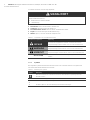 6
6
-
 7
7
-
 8
8
-
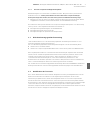 9
9
-
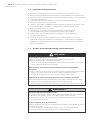 10
10
-
 11
11
-
 12
12
-
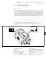 13
13
-
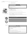 14
14
-
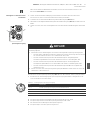 15
15
-
 16
16
-
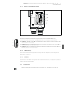 17
17
-
 18
18
-
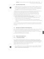 19
19
-
 20
20
-
 21
21
-
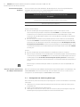 22
22
-
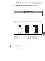 23
23
-
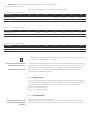 24
24
-
 25
25
-
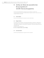 26
26
-
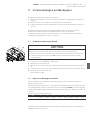 27
27
-
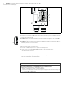 28
28
-
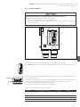 29
29
-
 30
30
-
 31
31
-
 32
32
-
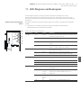 33
33
-
 34
34
-
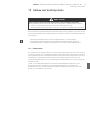 35
35
-
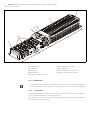 36
36
-
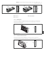 37
37
-
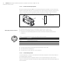 38
38
-
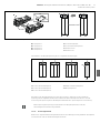 39
39
-
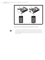 40
40
-
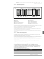 41
41
-
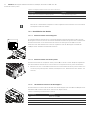 42
42
-
 43
43
-
 44
44
-
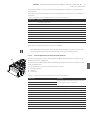 45
45
-
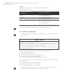 46
46
-
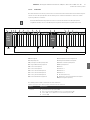 47
47
-
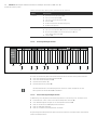 48
48
-
 49
49
-
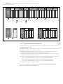 50
50
-
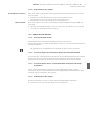 51
51
-
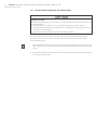 52
52
-
 53
53
-
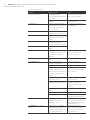 54
54
-
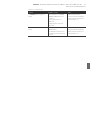 55
55
-
 56
56
-
 57
57
-
 58
58
-
 59
59
-
 60
60
-
 61
61
-
 62
62
-
 63
63
-
 64
64
-
 65
65
-
 66
66
-
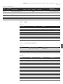 67
67
-
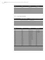 68
68
-
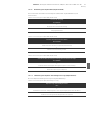 69
69
-
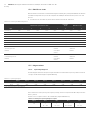 70
70
-
 71
71
-
 72
72
-
 73
73
-
 74
74
-
 75
75
-
 76
76
-
 77
77
-
 78
78
-
 79
79
-
 80
80
-
 81
81
-
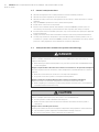 82
82
-
 83
83
-
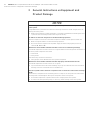 84
84
-
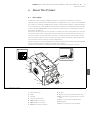 85
85
-
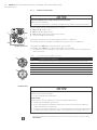 86
86
-
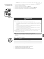 87
87
-
 88
88
-
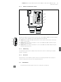 89
89
-
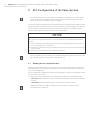 90
90
-
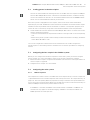 91
91
-
 92
92
-
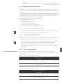 93
93
-
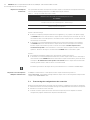 94
94
-
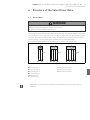 95
95
-
 96
96
-
 97
97
-
 98
98
-
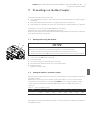 99
99
-
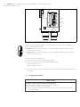 100
100
-
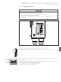 101
101
-
 102
102
-
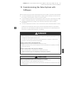 103
103
-
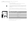 104
104
-
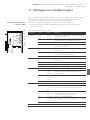 105
105
-
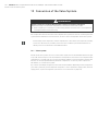 106
106
-
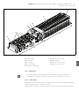 107
107
-
 108
108
-
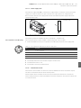 109
109
-
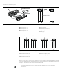 110
110
-
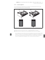 111
111
-
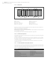 112
112
-
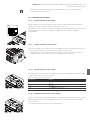 113
113
-
 114
114
-
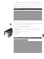 115
115
-
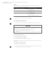 116
116
-
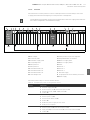 117
117
-
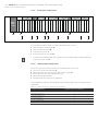 118
118
-
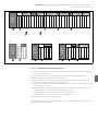 119
119
-
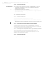 120
120
-
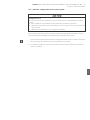 121
121
-
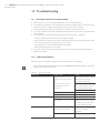 122
122
-
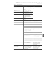 123
123
-
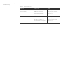 124
124
-
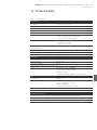 125
125
-
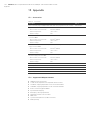 126
126
-
 127
127
-
 128
128
-
 129
129
-
 130
130
-
 131
131
-
 132
132
-
 133
133
-
 134
134
-
 135
135
-
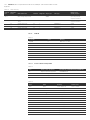 136
136
-
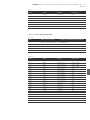 137
137
-
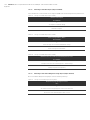 138
138
-
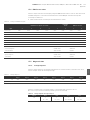 139
139
-
 140
140
-
 141
141
-
 142
142
-
 143
143
-
 144
144
-
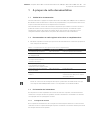 145
145
-
 146
146
-
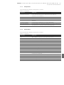 147
147
-
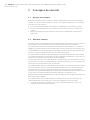 148
148
-
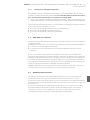 149
149
-
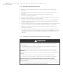 150
150
-
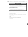 151
151
-
 152
152
-
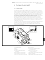 153
153
-
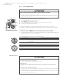 154
154
-
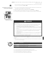 155
155
-
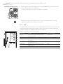 156
156
-
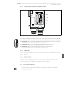 157
157
-
 158
158
-
 159
159
-
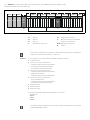 160
160
-
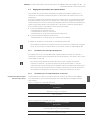 161
161
-
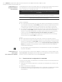 162
162
-
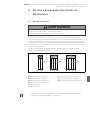 163
163
-
 164
164
-
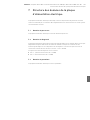 165
165
-
 166
166
-
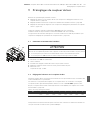 167
167
-
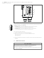 168
168
-
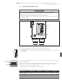 169
169
-
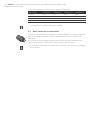 170
170
-
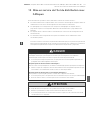 171
171
-
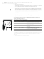 172
172
-
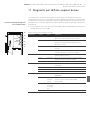 173
173
-
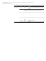 174
174
-
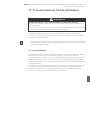 175
175
-
 176
176
-
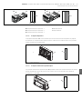 177
177
-
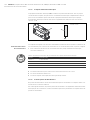 178
178
-
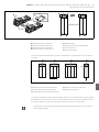 179
179
-
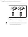 180
180
-
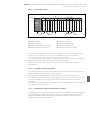 181
181
-
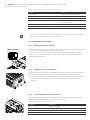 182
182
-
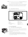 183
183
-
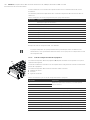 184
184
-
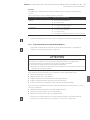 185
185
-
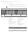 186
186
-
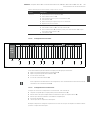 187
187
-
 188
188
-
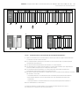 189
189
-
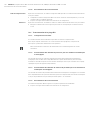 190
190
-
 191
191
-
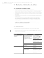 192
192
-
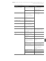 193
193
-
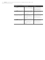 194
194
-
 195
195
-
 196
196
-
 197
197
-
 198
198
-
 199
199
-
 200
200
-
 201
201
-
 202
202
-
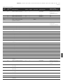 203
203
-
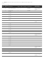 204
204
-
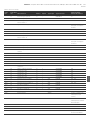 205
205
-
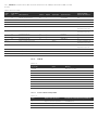 206
206
-
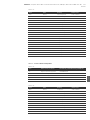 207
207
-
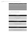 208
208
-
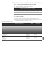 209
209
-
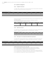 210
210
-
 211
211
-
 212
212
-
 213
213
-
 214
214
-
 215
215
-
 216
216
-
 217
217
-
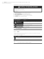 218
218
-
 219
219
-
 220
220
-
 221
221
-
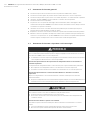 222
222
-
 223
223
-
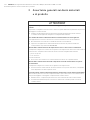 224
224
-
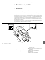 225
225
-
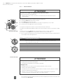 226
226
-
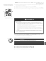 227
227
-
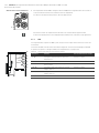 228
228
-
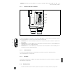 229
229
-
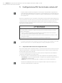 230
230
-
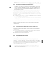 231
231
-
 232
232
-
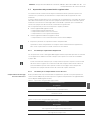 233
233
-
 234
234
-
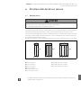 235
235
-
 236
236
-
 237
237
-
 238
238
-
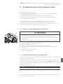 239
239
-
 240
240
-
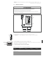 241
241
-
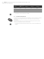 242
242
-
 243
243
-
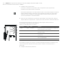 244
244
-
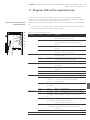 245
245
-
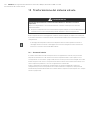 246
246
-
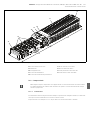 247
247
-
 248
248
-
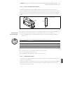 249
249
-
 250
250
-
 251
251
-
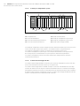 252
252
-
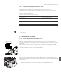 253
253
-
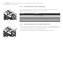 254
254
-
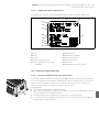 255
255
-
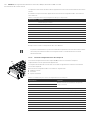 256
256
-
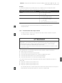 257
257
-
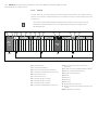 258
258
-
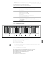 259
259
-
 260
260
-
 261
261
-
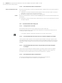 262
262
-
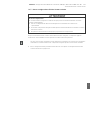 263
263
-
 264
264
-
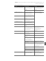 265
265
-
 266
266
-
 267
267
-
 268
268
-
 269
269
-
 270
270
-
 271
271
-
 272
272
-
 273
273
-
 274
274
-
 275
275
-
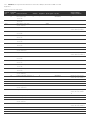 276
276
-
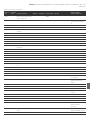 277
277
-
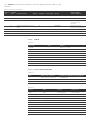 278
278
-
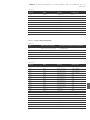 279
279
-
 280
280
-
 281
281
-
 282
282
-
 283
283
-
 284
284
-
 285
285
-
 286
286
-
 287
287
-
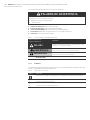 288
288
-
 289
289
-
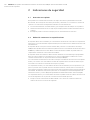 290
290
-
 291
291
-
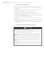 292
292
-
 293
293
-
 294
294
-
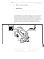 295
295
-
 296
296
-
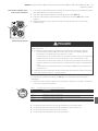 297
297
-
 298
298
-
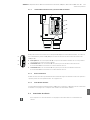 299
299
-
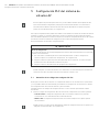 300
300
-
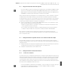 301
301
-
 302
302
-
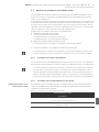 303
303
-
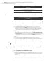 304
304
-
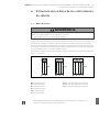 305
305
-
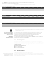 306
306
-
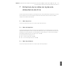 307
307
-
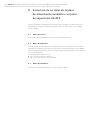 308
308
-
 309
309
-
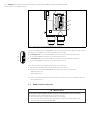 310
310
-
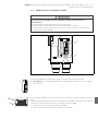 311
311
-
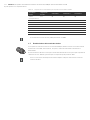 312
312
-
 313
313
-
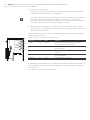 314
314
-
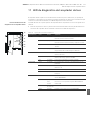 315
315
-
 316
316
-
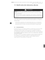 317
317
-
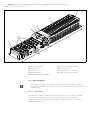 318
318
-
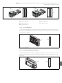 319
319
-
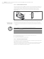 320
320
-
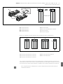 321
321
-
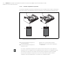 322
322
-
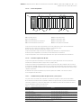 323
323
-
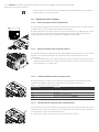 324
324
-
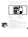 325
325
-
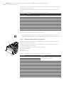 326
326
-
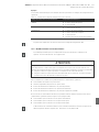 327
327
-
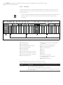 328
328
-
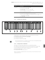 329
329
-
 330
330
-
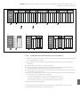 331
331
-
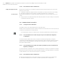 332
332
-
 333
333
-
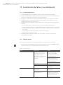 334
334
-
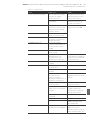 335
335
-
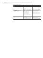 336
336
-
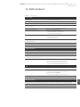 337
337
-
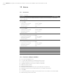 338
338
-
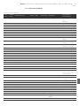 339
339
-
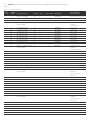 340
340
-
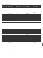 341
341
-
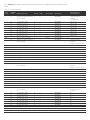 342
342
-
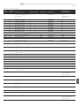 343
343
-
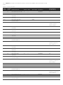 344
344
-
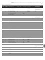 345
345
-
 346
346
-
 347
347
-
 348
348
-
 349
349
-
 350
350
-
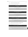 351
351
-
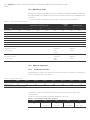 352
352
-
 353
353
-
 354
354
-
 355
355
-
 356
356
-
 357
357
-
 358
358
-
 359
359
-
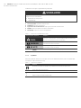 360
360
-
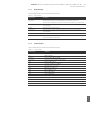 361
361
-
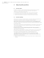 362
362
-
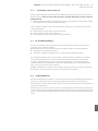 363
363
-
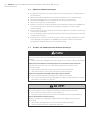 364
364
-
 365
365
-
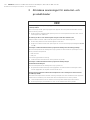 366
366
-
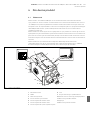 367
367
-
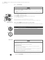 368
368
-
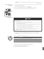 369
369
-
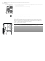 370
370
-
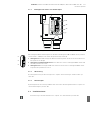 371
371
-
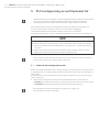 372
372
-
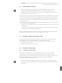 373
373
-
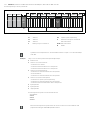 374
374
-
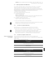 375
375
-
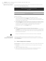 376
376
-
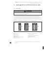 377
377
-
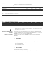 378
378
-
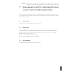 379
379
-
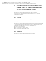 380
380
-
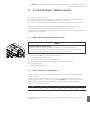 381
381
-
 382
382
-
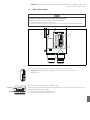 383
383
-
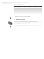 384
384
-
 385
385
-
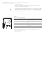 386
386
-
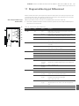 387
387
-
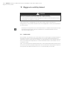 388
388
-
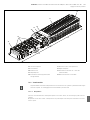 389
389
-
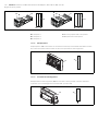 390
390
-
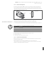 391
391
-
 392
392
-
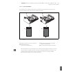 393
393
-
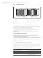 394
394
-
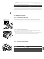 395
395
-
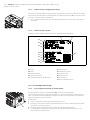 396
396
-
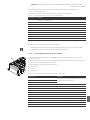 397
397
-
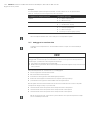 398
398
-
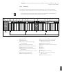 399
399
-
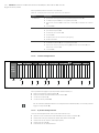 400
400
-
 401
401
-
 402
402
-
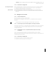 403
403
-
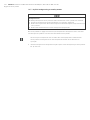 404
404
-
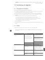 405
405
-
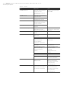 406
406
-
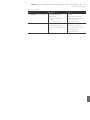 407
407
-
 408
408
-
 409
409
-
 410
410
-
 411
411
-
 412
412
-
 413
413
-
 414
414
-
 415
415
-
 416
416
-
 417
417
-
 418
418
-
 419
419
-
 420
420
-
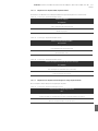 421
421
-
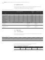 422
422
-
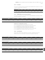 423
423
-
 424
424
-
 425
425
-
 426
426


AVENTICS Bus Coupler AES/Valve Driver AV CANopen Manual de usuario
- Tipo
- Manual de usuario
en otros idiomas
- français: AVENTICS Bus Coupler AES/Valve Driver AV CANopen Manuel utilisateur
- italiano: AVENTICS Bus Coupler AES/Valve Driver AV CANopen Manuale utente
- English: AVENTICS Bus Coupler AES/Valve Driver AV CANopen User manual
- Deutsch: AVENTICS Bus Coupler AES/Valve Driver AV CANopen Benutzerhandbuch
- svenska: AVENTICS Bus Coupler AES/Valve Driver AV CANopen Användarmanual
Artículos relacionados
-
AVENTICS Bus Coupler AES/Valve Driver AV DeviceNet Manual de usuario
-
-
-
-
-
-
-
AVENTICS Bus Coupler AES/Valve Driver AV Ethernet POWERLINK Manual de usuario
-
-
Otros documentos
-
Fagor CANopen protocol (MCP-MCPi) Manual de usuario
-
Vaillant VR 31 El manual del propietario
-
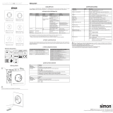 Simon 10002039-13X Manual de usuario
-
SICK MLS Quickstart
-
ProMinent delta 986524 Supplementary Instructions Manual
-
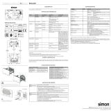 Simon 10003080-13X Manual de usuario
-
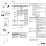 Simon 10003081-13X Manual de usuario
-
Risco RP512ECOB00A GPRS Bus Interface Manual de usuario
-
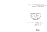 Simon 10002080-13X Manual de usuario
-
PORCELANOSA CAJON MB TONO 1IZQ ROBLE C/GR 120 H20 Guía de instalación


