
Menü
TONE GENERATOR/REALTIME CONTROL/EXTENDED SYNTHESIS
TONE GENERATOR/REALTIME CONTROL/EXTENDED SYNTHESIS
OWNER’S MANUAL
OWNER’S MANUAL
MUSIC SYNTHESIZER/REALTIME CONTROL/EXTENDED SYNTHESIS
MUSIC SYNTHESIZER/REALTIME CONTROL/EXTENDED SYNTHESIS
OWNER’S MANUAL

PRODUCT SAFETY MARKINGS: Yamaha electronic
products may have either labels similar to the graphics shown
below or molded/stamped facsimiles of these graphics on the
enclosure. The explanation of these graphics appears on this
page. Please observe all cautions indicated on this page and
those indicated in the safety instruction section.
ENVIRONMENTAL ISSUES: Yamaha strives to produce
products that are both user safe and environmentally friendly.
We sincerely believe that our products and the production
methods used to produce them, meet these goals. In keeping
with both the letter and the spirit of the law, we want you to be
aware of the following:
Battery Notice: This product MAY contain a small non-
rechargable battery which (if applicable) is soldered in place.
The average life span of this type of battery is approximately
five years. When replacement becomes necessary, contact a
qualified service representative to perform the replacement.
Warning: Do not attempt to recharge, disassemble, or
incinerate this type of battery. Keep all batteries away from
children. Dispose of used batteries promptly and as regulated
by applicable laws. Note: In some areas, the servicer is
required by law to return the defective parts. However, you do
have the option of having the servicer dispose of these parts
for you.
Disposal Notice: Should this product become damaged
beyond repair, or for some reason its useful life is considered
to be at an end, please observe all local, state, and federal
regulations that relate to the disposal of products that contain
lead, batteries, plastics, etc.
NOTICE: Service charges incurred due to lack of knowledge
relating to how a function or effect works (when the unit is
operating as designed) are not covered by the manufacturer’s
warranty, and are therefore the owners responsibility. Please
study this manual carefully and consult your dealer before
requesting service.
NAME PLATE LOCATION: The graphic below indicates the
location of the name plate. The model number, serial number,
power requirements, etc., are located on this plate. You should
record the model number, serial number, and the date of
purchase in the spaces provided below and retain this manual
as a permanent record of your purchase.
Model
Serial No.
Purchase Date
CAUTION
CAUTION
EX5/EX7
EX5R
CAUTION: TO REDUCE THE RISK OF ELECTRIC SHOCK.
DO NOT REMOVE COVER (OR BACK).
NO USER-SERVICEABLE PARTS INSIDE.
REFER SERVICING TO QUALIFIED SERVICE PERSONNEL.
The exclamation point within the equi-
lateral triangle is intended to alert the
user to the presence of important oper-
ating and maintenance (servicing)
instructions in the literature accompa-
nying the product.
The lightning flash with arrowhead
symbol, within the equilateral triangle,
is intended to alert the user to the pres-
ence of uninsulated “dangerous volt-
age” within the product’s enclosure
that may be of sufficient magnitude to
constitute a risk of electrical shock.
IMPORTANT NOTICE: All Yamaha electronic products are
tested and approved by an independent safety testing
laboratory in order that you may be sure that when it is
properly installed and used in its normal and customary
manner, all foreseeable risks have been eliminated. DO NOT
modify this unit or commission others to do so unless
specifically authorized by Yamaha. Product performance
and/or safety standards may be diminished. Claims filed under
the expressed warranty may be denied if the unit is/has been
modified. Implied warranties may also be affected.
SPECIFICATIONS SUBJECT TO CHANGE: The information
contained in this manual is believed to be correct at the time
of printing. However, Yamaha reserves the right to change or
modify any of the specifications without notice or obligation to
update existing units.
SPECIAL MESSAGE SECTION
92-469- 1
RISK OF ELECTRIC SHOCK
DO NOT OPEN
CAUTION
FCC 5/21/98 3:03 PM Page 2

92-469- 3
IMPORTANT SAFETY INSTRUCTIONS
INFORMATION RELATING TO PERSONAL INJURY, ELECTRICAL SHOCK,
AND FIRE HAZARD POSSIBILITIES HAS BEEN INCLUDED IN THIS LIST.
WARNING- When using any electrical or electronic product,
basic precautions should always be followed. These
precautions include, but are not limited to, the following:
1. Read all Safety Instructions, Installation Instructions,
Special Message Section items, and any Assembly
Instructions found in this manual BEFORE making any
connections, including connection to the main supply.
2. Do not attempt to service this product beyond that
described in the user-maintenance instructions. All other
servicing should be referred to qualified service personnel.
3. Main Power Supply Verification: Yamaha products are
manufactured specifically for the supply voltage in the area
where they are to be sold. If you should move, or if any doubt
exists about the supply voltage in your area, please contact
your dealer for supply voltage verification and (if applicable)
instructions. The required supply voltage is printed on the
name plate. For name plate location, please refer to the
graphic found in the Special Message Section of this manual.
4. DANGER-Grounding Instructions: This product must be
grounded and therefore has been equipped with a three pin
attachment plug. If this product should malfunction, the ground
pin provides a path of low resistance for electrical current,
reducing the risk of electrical shock. If your wall socket will not
accommodate this type plug, contact an electrician to have
the outlet replaced in accordance with local electrical codes.
Do NOT modify the plug or change the plug to a different type!
5. WARNING: Do not place this product or any other
objects on the power cord or place it in a position where
anyone could walk on, trip over, or roll anything over power or
connecting cords of any kind. The use of an extension cord is
not recommended! If you must use an extension cord, the
minimum wire size for a 25' cord (or less) is 18 AWG. NOTE:
The smaller the AWG number, the larger the current handling
capacity. For longer extension cords, consult a local
electrician.
6. Ventilation: Electronic products, unless specifically
designed for enclosed installations, should be placed in
locations that do not interfere with proper ventilation. If
instructions for enclosed installations are not provided, it must
be assumed that unobstructed ventilation is required.
7. Temperature considerations: Electronic products should
be installed in locations that do not seriously contribute to their
operating temperature. Placement of this product close to heat
sources such as; radiators, heat registers etc., should be
avoided.
8. This product was NOT designed for use in wet/damp
locations and should not be used near water or exposed to
rain. Examples of wet /damp locations are; near a swimming
pool, spa, tub, sink, or wet basement.
9. This product should be used only with the components
supplied or; a cart ,rack, or stand that is recommended by the
manufacturer. If a cart, rack, or stand is used, please observe
all safety markings and instructions that accompany the
accessory product.
10. The power supply cord (plug) should be disconnected
from the outlet when electronic products are to be left unused
for extended periods of time. Cords should also be
disconnected when there is a high probability of lightening
and/or electrical storm activity.
11. Care should be taken that objects do not fall and
liquids are not spilled into the enclosure through any openings
that may exist.
12. Electrical/electronic products should be serviced by a
qualified service person when:
a. The power supply cord has been damaged; or
b. Objects have fallen, been inserted, or liquids have
been spilled into the enclosure through openings; or
c. The product has been exposed to rain; or
d. The product does not operate, exhibits a marked
change in performance; or
e. The product has been dropped, or the enclosure of the
product has been damaged.
13. This product, either alone or in combination with an
amplifier and headphones or speaker/s, may be capable of
producing sound levels that could cause permanent hearing
loss. DO NOT operate for a long period of time at a high
volume level or at a level that is uncomfortable. If you
experience any hearing loss or ringing in the ears, you should
consult an audiologist.
IMPORTANT: The louder the sound, the shorter the time
period before damage occurs.
14. Some Yamaha products may have benches and/or
accessory mounting fixtures that are either supplied as a part
of the product or as optional accessories. Some of these items
are designed to be dealer assembled or installed. Please
make sure that benches are stable and any optional fixtures
(where applicable) are well secured BEFORE using. Benches
supplied by Yamaha are designed for seating only. No other
uses are recommended.
PLEASE KEEP THIS MANUAL
FCC 5/21/98 3:03 PM Page 3

1. IMPORTANT NOTICE: DO NOT MODIFY THIS UNIT!
This product, when installed as indicated in the instructions
contained in this manual, meets FCC requirements. Modifications
not expressly approved by Yamaha may void your authority, granted
by the FCC, to use the product.
2. IMPORTANT: When connecting this product to accessories and/or
another product use only high quality shielded cables. Cable/s
supplied with this product MUST be used. Follow all installation
instructions. Failure to follow instructions could void your FCC
authorization to use this product in the USA.
3. NOTE: This product has been tested and found to comply with the
requirements listed in FCC Regulations, Part 15 for Class “B” digital
devices. Compliance with these requirements provides a
reasonable level of assurance that your use of this product in a
residential environment will not result in harmful interference with
other electronic devices. This equipment generates/uses radio
frequencies and, if not installed and used according to the
instructions found in the users manual, may cause interference
harmful to the operation of other electronic devices. Compliance
with FCC regulations does not guarantee that interference will not
occur in all installations. If this product is found to be the source of
interference, which can be determined by turning the unit “OFF”
and “ON”, please try to eliminate the problem by using one of the
following measures:
Relocate either this product or the device that is being affected by
the interference.
Utilize power outlets that are on different branch (circuit breaker or
fuse) circuits or install AC line filter/s.
In the case of radio or TV interference, relocate/reorient the
antenna. If the antenna lead-in is 300 ohm ribbon lead, change the
lead-in to co-axial type cable.
If these corrective measures do not produce satisfactory results,
please contact the local retailer authorized to distribute this type of
product. If you can not locate the appropriate retailer, please contact
Yamaha Corporation of America, Electronic Service Division, 6600
Orangethorpe Ave, Buena Park, CA90620
The above statements apply ONLY to those products distributed by
Yamaha Corporation of America or its subsidiaries.
ADVARSEL!
Lithiumbatteri—Eksplosionsfare ved fejlagtig håndtering. Udskiftning
må kun ske med batteri af samme fabrikat og type. Levér det brugte
batteri tilbage til leverandoren.
VARNING
Explosionsfara vid felaktigt batteribyte. Använd samma batterityp
eller en ekvivalent typ som rekommenderas av apparattillverkaren.
Kassera använt batteri enlight fabrikantens instruktion.
VAROITUS
Paristo voi räjähtää, jos se on virheellisesti asennettu. Vaihda paristo
ainoastaan laitevalmistajan suosittelemaan tyyppiin. Hävitä käytetty
paristo valmistajan ohjeiden mukaisesti.
NEDERLAND
NETHERLAND
• Dit apparaat bevat een lithium batterij voor geheugen back-up.
• This apparatus contains a lithium battery for memory back-up.
• Raadpleeg uw leverancier over de verwijdering van de batterij op
het moment dat u het apparaat ann het einde van de levensduur
afdankt of de volgende Yamaha Service Afdeiing:
Yamaha Music Nederland Service Afdeiing
Kanaalweg 18-G, 3526 KL UTRECHT
Tel. 030-2828425
• For the removal of the battery at the moment of the disposal at the
end of the service life please consult your retailer or Yamaha
Service Center as follows:
Yamaha Music Nederland Service Center
Address : Kanaalweg 18-G, 3526 KL UTRECHT
Tel : 030-2828425
• Gooi de batterij niet weg, maar lever hem in als KCA.
• Do not throw away the battery. Instead, hand it in as small chemical
waste.
IMPORTANT NOTICE FOR THE UNITED
KINGDOM
Connecting the Plug and Cord
WARNING: THIS APPARATUS MUST BE EARTHED
IMPORTANT. The wires in this mains lead are coloured in
accordance with the following code:
GREEN-AND-YELLOW: EARTH
BLUE : NEUTRAL
BROWN : LIVE
As the colours of the wires in the mains lead of this apparatus
may not correspond with the coloured markings identifying the
terminals in your plug proceed as follows:
The wire which is coloured GREEN-and-YELLOW must be
connected to the terminal in the plug which is marked by the
letter E or by the safety earth symbol or colored GREEN or
GREEN-and-YELLOW.
The wire which is coloured BLUE must be connected to the
terminal which is marked with the letter N or coloured BLACK.
The wire which is coloured BROWN must be connected to the
terminal which is marked with the letter L or coloured RED.
* This applies only to products distributed by YAMAHA CORPORATION OF AMERICA.
FCC INFORMATION (U.S.A.)
• This applies only to products distributed by Yamaha-Kemble Music (U.K.) Ltd.
FCC 5/21/98 3:03 PM Page 4

PRECAUTIONS
PLEASE READ CAREFULLY BEFORE PROCEEDING
* Please keep these precautions in a safe place for future reference.
WARNING
Always follow the basic precautions listed below to avoid the possibility of serious injury or even death from electrical shock,
short-circuiting, damages, fire or other hazards. These precautions include, but are not limited to, the following:
• This instrument contains no user-serviceable parts. Do not attempt to
disassemble or modify the internal components in any way.
• Do not expose the instrument to rain, use it near water or in damp or wet
conditions, or place containers on it containing liquids which might spill into
any openings.
• If the power cord or plug becomes frayed or damaged, or if there is a sudden
loss of sound during use of the instrument, or if any unusual smells or smoke
should appear to be caused by it, immediately turn off the power switch,
disconnect the electric plug from the outlet, and have the instrument
inspected by qualified Yamaha service personnel.
• Only use the voltage specified as correct for the instrument. The required
voltage is printed on the name plate of the instrument.
• Always connect the three-pin attachment plug to a properly grounded power
source. (For more information about the main power supply, see page 16.)
• Before cleaning the instrument, always remove the electric plug from the
outlet. Never insert or remove an electric plug with wet hands.
• Check the electric plug periodically and remove any dirt or dust which may
have accumulated on it.
CAUTION
Always follow the basic precautions listed below to avoid the possibility of physical injury to you or others, or damage to the
instrument or other property. These precautions include, but are not limited to, the following:
• Do not place the power cord near heat sources such as heaters or radiators,
and do not excessively bend or otherwise damage the cord, place heavy
objects on it, or place it in a position where anyone could walk on, trip over,
or roll anything over it.
• When removing the electric plug from the instrument or an outlet, always hold
the plug itself and not the cord. Pulling by the cord can damage it.
• Do not connect the instrument to an electrical outlet using a multiple-
connector. Doing so can result in lower sound quality, or possibly cause
overheating in the outlet.
• Remove the electric plug from the outlet when the instrument is not to be used
for extended periods of time, or during electrical storms.
• Before connecting the instrument to other electronic components, turn off the
power for all components. Before turning the power on or off for all
components, set all volume levels to minimum.
• Do not expose the instrument to excessive dust or vibrations, or extreme cold
or heat (such as in direct sunlight, near a heater, or in a car during the day) to
prevent the possibility of panel disfiguration or damage to the internal
components.
• Do not use the instrument near other electrical products such as televisions,
radios, or speakers, since this might cause interference which can affect
proper operation of the other products.
• Do not place the instrument in an unstable position where it might
accidentally fall over.
• Before moving the instrument, remove all connected cables.
• When cleaning the instrument, use a soft, dry cloth. Do not use paint
thinners, solvents, cleaning fluids, or chemical-impregnated wiping cloths.
Also, do not place vinyl, plastic or rubber objects on the instrument, since
this might discolor the panel or keyboard.
• Do not rest your weight on, or place heavy objects on the instrument, and do
not use excessive force on the buttons, switches or connectors.
• Use only the stand/rack specified for the instrument. When attaching the stand
or rack, use the provided screws only. Failure to do so could cause damage to
the internal components or result in the instrument falling over.
• Do not operate the instrument for a long period of time at a high or
uncomfortable volume level, since this can cause permanent hearing loss. If
you experience any hearing loss or ringing in the ears, consult a physician.
■ REPLACING THE BACKUP BATTERY
• This instrument contains a non rechargeable internal backup battery which
permits internal data to remain stored even when the power is off. When the
backup battery needs replacing, the message "Change internal battery!" will
display in the LCD. When this happens, immediately back up your data, then
have qualified Yamaha service personnel replace the backup battery.
• Do not attempt to replace the backup battery yourself, in order to prevent the
possible serious hazards. Always have qualified Yamaha service personnel
replace the backup battery.
• Never place the backup battery in a location that a child can reach, since a
child might accidentally swallow the battery. If this should happen, consult a
physician immediately.
■ SAVING USER DATA
• Always save data to a floppy disk frequently, in order to help prevent the loss
of important data due to a malfunction or user operating error.
Yamaha cannot be held responsible for damage caused by improper use or
modifications to the instrument, or data that is lost or destroyed.
Always turn the power off when the instrument is not in use.
(2)AC-2
Intro/E/qx 5/21/98 11:26 AM Page 5

6
The Yamaha EX5 and EX7 Music Synthesizers, and the EX5R Tone Generator, offer more
music performance and production power than ever before available in a single keyboard or
tone generator unit. All three models feature a unique Extended Synthesis system which
incorporates a number of the most advanced tone generator technologies currently available
… plus a full-featured sampling system. There’s also a top-quality internal effect system so
no extra sound-processing equipment is required. 16-track song and 8-track pattern
sequencers provide sophisticated on-board sequence programming and editing capability,
while a unique 4-track arpeggiator function adds extended performance and
accompaniment capability. The EX-series keyboards and tone generator also offer one of the
most versatile and intuitive real-time control systems available, and they’re expandable to
suit a wide range of professional systems and requirements.
We urge you to read through at least the introductory section of this owner’s manual while
familiarizing yourself wit your EX5, EX5R, or EX7, and keep th manual in a safe place for
future reference.
About the Manual
This owner’s manual is divided into two main sections: The Introductory Section, and the Reference
Section:
■Introductory Section
This section has been designed to provide you with an overall understanding of the EX5, EX5R, and EX7, as
well as some hints as how to use these advanced instruments most effectively. It will also refer you to
corresponding sections in the Reference section, so you can refer to the pertinent details as necessary. Use the
Introductory Section as a guide and directory to the main features and functions of the EX5, EX5R, and EX7.
■Reference Section
The Reference Section contains full details and instructions for all of the EX features and functions. You
should be able to find the information you need via the table of contents, the index at the back of the manual,
or via the Introductory Section, described above.
(EX5/5R)
Products bearing the SONDIUS-XG logo are licensed under patents of Stanford University and Yamaha as listed
on the internet web site, <http://www.sondius-xg.com>.
This product is not compatible with the XG format or XG song data.
Included Accessories
Demonstration Disk 1-4
Owner’s Manual
Data List
AC Power Cord
Copying of the commercially available music sequence data and/or digital audio files is strictry prohibited except for your
personal use.
The illustrations and LCD screens as shown in this owner’s manual are for instructional purposes only, and may appear
somewhat different from those on your instrument.
The company names and product names in this Owner’s Manual are the trademarks or registered trademarks of their
respective companies.
Intro/E/qx 6/12/98 5:55 PM Page 6

7
Introductory Section
The Controls & Connectors ................................8
Setting Up ........................................................16
The Supplied Disks, Demos, & Factory Set Data
....25
EX System Overview ........................................28
Extended Synthesis ..........................................29
AWM Synthesis ....................................................29
Virtual Acoustic Synthesis (EX5/5R) ................30
AN Synthesis (Analog Physical Modeling)
............33
FDSP Synthesis
(Formulated Digital Signal Processing) ..............34
Voice and Performance Selection......................36
Voice Structure & Editing Hints ......................40
System Overview ..................................................40
Polyphony..............................................................45
Editing Control ....................................................45
Voice Store Procedure ..........................................48
The Power of the Performance Mode ..............49
Performance Store Procedure ..............................53
Performance Mode DSP Limitations ..................54
The Controllers ................................................55
The EX Controllers ..............................................55
Scene Switching & Morphing..............................57
Controller Sets ......................................................58
Sequencer Functions ........................................60
Sequencer Record Modes & Editing....................62
Play Effects & Groove Quantization ..................64
The EX Effect System ......................................65
Sampling ..........................................................69
The Key Map Mode ..........................................72
Reference Section
Voice Mode........................................................75
Voice Play Mode....................................................75
Voice Edit Mode....................................................76
Voice Job Mode ..................................................148
Wave Edit Mode..................................................150
Wave Job Mode ..................................................154
Performance Mode ..........................................156
Performance Play Mode ....................................156
Performance Edit Mode ....................................158
Performance Job Mode ......................................172
Sample Mode ..................................................175
Sample Play Mode ..............................................175
Sample Record Mode..........................................176
Sample Edit Mode ..............................................179
Sample Job Mode ................................................182
Song Mode ......................................................185
Song Play Mode ..................................................185
Song Record Mode..............................................193
Song Edit Mode ..................................................201
Song Job Mode....................................................206
Pattern Mode ..................................................219
Pattern Play Mode ..............................................219
Pattern Record Mode..........................................223
Pattern Edit Mode ..............................................226
Pattern Job Mode................................................227
Arpeggio Mode................................................238
Arpeggio Record Mode ......................................245
Arpeggio Edit Mode ..........................................247
Arpeggio Job Mode ............................................249
Disk Mode ......................................................259
Utility Mode....................................................270
Appendix ........................................................278
Optional Boards/Memories................................278
Troubleshooting..................................................291
LCD Messages ....................................................294
Specifications ......................................................295
Index....................................................................296
Contents
Introductory
Section
Reference
Section
Voice Mode
Performance
Mode
Sample Mode
Song Mode
Pattern Mode
Arpeggio
Mode
Disk Mode
Utility Mode
Appendix
Intro/E/qx 5/21/98 11:26 AM Page 7

SCENE
2
1
OCTAVE
DOWN UP
PITCH MODULATION 1 MODULATION 2
A D GAIN
VOLUME
MODE
EX5/7
1
OCTAVE [DOWN] and [UP] Keys (EX5 and EX7 only)
Shift the pitch of the keyboard up or down up to five octaves in
one-octave steps. The pitch is shifted one octave in the
corresponding direction, up to the maximum, each time one of
these keys is pressed. When the current octave is higher than
the normal octave the UP indicator will be lit, and vice versa.
Neither indicator will be lit when the normal octave is selected.
2
[PITCH] Wheel (EX5 and EX7 only)
This self-centering pitch wheel allows smooth upward and
downward pitch bends. A range of other control functions can
be assigned to the PITCH wheel.
➡
See page 55 for more information.
3
[MODULATION 1] and [MODULATION 2] Wheels
(EX5 and EX7 only)
Can be assigned to any of the extensive range of controller
parameters for extraordinary expressive control. The
MODULATION 2 wheel can also be used for “scene
morphing” — i.e. smoothly changing from one memorized
scene to the other.
➡
See page 55 for more information.
4
Ribbon Controller (EX5 and EX7 only)
Another expressive EX controller, the Ribbon Controller is
touch sensitive, and is controlled by running a finger lightly
across its surface to the left or right. The Ribbon Controller can
be assigned to the full range of EX parameters.
➡
See page 56 for more information.
9
Floppy Disk Drive
The built-in floppy disk drive allows easy, economical, high-
volume storage of voice data. The disk-in-use LED indicator
below the drive slot lights while any disk operation is in
progress (NEVER attempt to remove a disk or turn the power
off while a disk operation is in progress). The eject key, also
below the disk slot, is used to remove disks from the drive.
➡
See page 259 for more information.
8
Introductory
Section
Introductory Section
The Controls & Connectors
The following brief descriptions of the EX controls and connectors should help you to understand the
overall logic of the interface.
Front Panel
Intro/E/qx 5/21/98 11:27 AM Page 8

9
Introductory
Section
123456
POWER
EXIT
SHIFT
TONE GENERATOR
REALTIME CONTROL
EXTENDED SYNTHESIS
1 2 3 4 5 6
VOICE PERFORM SONG PATTERN SA MPLE
JOB
LMONO R
BREATH PHONES
VOLUME
AD
INPUT
A D GAIN
STORE UTILIT Y
DISK
SC2
SC1
EDIT
COMPARE
KEYMAP BYPASS
ARPEG KNOB
CANCEL
CURSOR
DATA
TOP
REC STOP PLAY
POWER
REW FWD
ON OFF
DEC NO INC YES
SPACE
ABC
0
123
456
789
ENTER
DEF GHI JKL
MNO
PQR
STU
VWX YZ
F1 F2 F3 F4 F5 F6 F7 F8 EXIT
SHIFT
E
VOICE
PERFORMANCE
SONG
PAT TERN SAMPLE
EDIT
JOB STORE UTILITY DISK
FWDREWTOP
KNOB MODE
ARPEGGIO
COMPARE
KEYMAP EF BYPASS REC STOP PLAY
8
Keyboard (EX5 and EX7 only)
The EX5 has a 76-key keyboard while the EX7 has a 61-key keyboard. Both are velocity and
after-touch sensitive for broad, intimate expressive control.
6
A/D Gain Control
Adjusts the input level of the INPUT R and L/MONO jacks (the INPUT jack on the EX7), and
therefore the level of the signal appearing at the input of the A/D (Analog-to-Digital) converter.
This control is important for setting optimum record level when recording samples in the
SAMPLE mode.
➡
See page 70 for more information.
5
SCENE [1] and [2] Keys ([SC1] and [SC2] on the EX5R)
The SCENE [1] and [2] keys can be used to memorize and recall different settings of the
Controller Knobs, so a complete set of knob settings can be recalled instantaneously. Knob
scenes are stored by using the SCENE keys in conjunction with the STORE key (page 57).
When both SCENE indicators are lit (this is done by pressing one SCENE key while holding the
other), the MODULATION 2 wheel or a foot controller can be used to “morph” between the
two scenes stored in the SCENE [1] and [2] keys (page 57).
7
VOLUME Control
Adjusts the volume of the sound delivered via the rear-panel OUTPUT L/MONO and R jacks
as well as the PHONES jack.
EX5R
76
9 5
* 1, 2, 3, 4 and 8 are not available on EX5R.
Intro/E/qx 5/21/98 11:27 AM Page 9

10
Introductory
Section
MODE
VOICE
PERFORMANCE
SONG
PAT TERN SAMPLE
EDIT
JOB STORE UTILITY DISK
FWDREWTOP
KNOB MODE
ARPEGGIO
COMPARE
KEYMAP EF BYPASS REC STOP PLAY
F1 F2 F3 F4 F5 F6 F7 F8
1 2 3 4 5 6
CANCEL
CURSOR
DATA
DEC NO
INC
YES
EXIT
SHIFT
EX5/7
% MODE Keys
The MODE keys select the corresponding
EX modes, or appropriate sub-modes. The
upper row of MODE keys engage the
primary modes, and have LED indicators
to show which mode(s) are currently
active. The lower row of MODE keys
select secondary or utility modes.
You can not enter Pattern mode when
[ARPEGGIO] key or [KEYMAP] key is turned on.
! [ARPEGGIO] Key
([ARPEG] on the EX5R)
This key turns the advanced automatic
arpeggiator on or off. When the
arpeggiator is turned on, the Voice or
Performance Edit mode Arpeggiator edit
display will appear.
➡
See page 238 for more information.
[ARPEGGIO] key functions (can be turned on or
off) when in Voice mode, Performance mode and
Song Play mode.
@ [KEY MAP] Key
Engages the Key Map mode in which
samples, entire patterns, or pattern
tracks can be individually assigned to
separate keys on the keyboard.
➡
See page 72 for more information.
[KEYMAP] key functions (can be turned on or
off) when in Voice mode, Performance mode
and Song mode.
# [EF BYPASS] Key
([BYPASS] on the EX5R)
Turns the type of effects specified in the
Utility mode Other Setup display on or
off. When engaged (i.e. when the
indicator is lit) the specified effects are
bypassed.
➡
See page 276 for more information.
$ Sequencer Keys
The sequencer keys control recording and playback in the Song, Pattern, and Arpeggio modes, and allow you to
locate a specific measure within a song or pattern. Their layout and functions are similar to the transport controls
on a tape recorder.
) [KNOB MODE] Key
([KNOB] on the EX5R)
The six Controller Knobs, described
below, can function either as sound
controllers or data entry knobs. In the
Song, Pattern, Sample, Edit, Job, Store,
Utility and Disk modes the [KNOB
MODE] key switches between data entry
and sound control, allowing you to try out
the effect of knob-related settings without
having to exit from the Edit mode. The
knobs function only as sound controllers
in the Voice and Performance modes.
[
I
]
REC
[
J
]
STOP
[
F
]
START
[ ]
TOP
[
G
]
REW
[
H
]
FWD
Press this key to engage the record ready mode. You have to press the
START key to actually start recording.
Press to stop recording or playback.
Press to start recording or playback.
This key takes you directly to the first measure (the “top”) of the current song
or pattern.
Press briefly to move back one measure, or hold for continuous scrolling.
Press briefly to move forward one measure, or hold for continuous scrolling.
Intro/E/qx 5/21/98 11:27 AM Page 10

11
Introductory
Section
TONE GENERATOR
REALTIME CONTROL
EXTENDED SYNTHESIS
1 2 3 4 5 6
VOICE PERFORM SONG PATTERN SA MPLE
JOB
LMONO R
BREATH PHONES
VOLUME
AD
INPUT
A D GAIN
STORE UTILIT Y
DISK
SC2
SC1
EDIT
COMPARE
KEYMAP BYPASS
ARPEG KNOB
CANCEL
CURSOR
DATA
TOP
REC STOP PLAY
POWER
REW FWD
ON OFF
DEC NO INC YES
SPACE
ABC
0
123
456
789
ENTER
DEF GHI JKL
MNO
PQR
STU
VWX YZ
F1 F2 F3 F4 F5 F6 F7 F8 EXIT
SHIFT
ES
ABC
0
12
45
7
8
DEF GHI
MNO PQR
VWX YZ
& [F1] through [F8] Function, [SHIFT], and [EXIT] Keys
The functions of these keys depend on the selected mode. They are used to engage a function indicated on the
display immediately above the key or select a page of parameters.
When the “S” symbol appears in the lower left corner of the display, the [SHIFT] key can be used to select a
secondary function menu for the function keys: press the appropriate function key while holding the [SHIFT]
key to access a secondary function.
The [EXIT] key will return you to the next highest level in the display hierarchy when in an editing, utility, or
disk function display. In most cases you can return directly to the top-level primary mode display by directly
pressing the appropriate MODE key.
^ LCD Display Screen & Contrast Control
This large multi-function liquid crystal display screen shows all parameters and prompts you need to operate the
EX5, EX5R, or EX7 with optimum ease and efficiency.
Use the contrast control to achieve the best display visibility (LCD visibility varies greatly with viewing angle and
lighting).
* Controller Knobs
These knobs form an important part of the advanced EX user interface. They can can be assigned to control an
impressively wide range of sound parameters in real time during performance/playback, and they can function as
data entry controls in the editing, utility, disk, and some other modes. The [KNOB MODE] key, described above,
determines which function the knobs assume in the appropriate modes.
Normally when you rotate a controller knob being used for data entry, the corresponding value changes in
relative fashion — i.e. the knob increases or decreases the value of the parameter in relation to the value that was
initially on the display. If you rotate a controller knob while holding the [KNOB MODE] key, however, the
relationship between the controller position and the data value becomes absolute, and the central detented
position of the knob will correspond to the exact center of the parameter range.
The Voice mode lets you select, play, and edit individual voices.
The [VOICE] key indicator also blinks to indicate that a MIDI System
Exclusive message is being received. [→ page 75]
In the Performance mode you can select, play, and edit individual
“performance” programs including multiple layered or split voices and effects.
Press the [VOICE] key while holding the [PERFORMANCE] key to go
directly to the Voice Edit mode from the Performance mode.
The [PERFORMANCE] key indicator also blinks to indicate that a MIDI
System Exclusive message is being received. [→ page 156]
The Song mode provides access to the sophisticated sequence recording,
playback, and editing capabilities provided by the EX5, EX5R, and EX7.
[→ page 185]
Sequence “patterns” which can be used individually or incorporated into
complete songs in the Song mode can be recorded, played, and edited in
the Pattern mode. [→ page 219]
Advanced sample recording and editing features are available via the Sample
mode. [→ page 175]
The [EDIT] key accesses the appropriate editing functions for the currently
selected mode: Voice, Performance, Song, Pattern, or Sample.
Each of the primary modes — Voice, Performance, Song, Pattern, and
Sample — have a range of “jobs” which can be accessed by pressing the
[JOB] key.
This key is used to store edited data to an internal memory location, or
controller knob settings to either of the SCENE keys. [→ pages, 48, 53 and 57]
The UTILITY mode includes MIDI, system and other functions that are
essential for general operation. [→ page 270]
The Disk mode includes disk save and load functions as well as all other
functions you need for efficient data storage and management. [→ page 259]
!@ #) * $
&
%
^
EX5R
[VOICE]
[PERFORMANCE]
[SONG]
[PATTERN]
[SAMPLE]
[EDIT]
[JOB]
[STORE]
[UTILITY]
[DISK]
Intro/E/qx 5/21/98 11:27 AM Page 11

12
Introductory
Section
CURSOR
DATA
DEC NO
INC
YES
BANK
PROGRAM
PA RT
TRACK
ELEMENT SELECT ELEMENT ON OFF
COMMON OSC PITCH FILTER AMPLITUDE LFO CONTROL EFFECT
ABCDEFGH
12345678
12341234
910111213141516
SPACE
ABC
0
123
456
7
89
ENTER
DEF GHI JK L
MNO PQR
STU
VWX YZ
CANCEL
6
ELEMENT SELECT ELEMENT ON OFF
COMMON OSC PITCH FILTER AMPLITUDE LFO CONTROL EFFECT
ABCDEFGH
12345678
12341234
910111213141516
XIT
0
123
456
789
EX5/7
¡ [DEC/NO] and [INC/YES] Keys
Used to select voices and edit
parameter values in any of the EX
edit modes. Either key can be pressed
briefly for single stepping in the
specified direction, or held for
continuous scrolling. These keys are
also used to respond “Yes” or “No”
to confirmation prompts when
executing certain operations or
saving/loading data.
º [CANCEL] Key
The [CANCEL] key can be used to
cancel an entered value and return to
the previous value if pressed before a
different parameter is selected.
( Data Dial and
[CURSOR/DATA] Key
The Data Dial provides a fast, efficient way to
cover a broad range of voice numbers when,
for example, you’re looking for a voice but
don’t know the number. It's also handy for
making large value changes in any of the
editing and utility modes.
When editing the Data Dial will normally
increment or decrement the selected
parameter value. When the [CURSOR/DATA]
key is pressed and its indicator is lit, however,
the Data Dial moves the cursor around the
display rather than changing values. This can
be handy when navigating a complex display
which includes many individual parameters.
™ Cursor Keys
These 4 keys move the "cursor" around the display screen, highlighting the various
items that are available for selection or parameters that are available for editing (the
cursor appears as a dark block with inverse characters).
Intro/E/qx 5/21/98 11:27 AM Page 12

13
Introductory
Section
TONE GENERATOR
REALTIME CONTROL
EXTENDED SYNTHESIS
1 2 3 4 5 6
VOICE PERFORM SONG PATTERN SA MPLE
JOB
LMONO R
BREATH PHONES
VOLUME
AD
INPUT
A D GAIN
STORE UTILIT Y
DISK
SC2
SC1
EDIT
COMPARE
KEYMAP BYPASS
ARPEG KNOB
CANCEL
CURSOR
DATA
TOP
REC STOP PLAY
POWER
REW FWD
ON OFF
DEC NO INC YES
SPACE
ABC
0
123
456
789
ENTER
DEF GHI JKL
MNO
PQR
STU
VWX YZ
F1 F2 F3 F4 F5 F6 F7 F8 EXIT
SHIFT
MUSIC SYNTHESIZER
REALTIME CONTROL
EXTENDED SYNTHESIS
£ Numeric Keypad and [ENTER] Key
These keys allow direct entry of numeric values where applicable. Enter the required value
via the numeric keys — the entered number will flash on the displays — then press the
[ENTER] key to actually enter the specified value. The [ENTER] key is also used to enter
notes and other events when editing sequence data, and to execute a specified job or disk
function. The numeric keys are also used to specify note lengths and dynamics (velocity)
when step recording in the SONG or PATTERN mode.
➡
See page 199 for more information.
¢ Bank [A] Through [H] Keys (EX5 and EX7 only)
Each of the EX5 and EX7 voice memories — P1 (Preset 1), P2 (Preset 2), I1 (Internal 1)
and I2 (Internal 2) — has 128 voice memory locations arranged in 8 banks of 16 voices
each. The 128 performance memories are also organized in 8 banks of 16 performance
setups. These keys select the bank from which an individual voice or performance setup
will be selected. When editing voice parameters they are also used to select and mute
elements.
∞ Program Number [1] Through [16] Keys (EX5 and EX7 only)
The program number keys are used in conjunction with the bank keys to select any of the
128 voice memory locations within the currently selected voice memory — P1 (Preset 1), P2
(Preset 2), I1 (Internal 1) and I2 (Internal 2) — in the VOICE mode, or any of the 128
performance memory locations in the Performance mode. In the Voice Edit mode keys [1]
through [8] can be used to directly select the various edit displays.
™ ¡£
(º
EX5R
* ¢ and ∞ are not available on EX5R.
Intro/E/qx 5/21/98 11:27 AM Page 13

14
Introductory
Section
CAUTION
ATTENTION
WARNING
:RISQUE DE CHOC ELECTRIQUE NE PAS OUVRIR.
TO REDUCE THE RISK OF FIRE OR ELECTRIC
SHOCK,DO NOT EXPOSE THIS PRODUCT TO RAIN OR MOISTURE.
POWER
ON
OFF
AC INLET
INDIVIDUAL OUTPUT
A/D
INPUT
6543
OUTPUT
R L MONO
FOOT
SWITCH
FOOT
CONTROLLER
FOOT
VOLUME
SUSTAIN
DIGITAL OUTPUT WORD CLOCK IN
AES EBU
SCSI
MIDI A
OUTTHRU IN
BREATH PHONES
CAUTION
ATTENTION
WARNING
:RISQUE DE CHOC ELECTRIQUE NE PAS OUVRIR.
TO REDUCE THE RISK OF FIRE OR ELECTRIC
SHOCK,DO NOT EXPOSE THIS PRODUCT TO RAIN OR MOISTURE.
POWER
ON
OFF
AC INLET
EX5
EX7
ª
A/D INPUT L/MONO and
R Jacks (A/D INPUT on the EX7)
Line and microphone sampling
sources can be connected to these
jacks. Line or microphone input
sensitivity is switched via the
“line/mic” parameter in the Sample
mode REC display (page 176), and
fine input sensitivity adjustment
can be carried out via the A/D
GAIN control on the control panel.
➡
See page 70 for more
information.
•
INDIVIDUAL OUTPUT 1 and
2 Jacks (EX5 and EX5R only)
In addition to the stereo OUTPUT
L/MONO and R jacks, the EX5 and EX5R
initially have two individual outputs: the
INDIVIDUAL OUTPUT 1 and 2 jacks.
Individual “parts” of a performance setup
can be assigned to different individual
outputs via the PERFORMANCE EDIT
mode PART display (see page 164). Four
individual outputs can be added to the
EX5, EX5R, and EX7 by installing the
optional EXIDO1 Individual Output
Board (page 19.)
§
[POWER] Switch
Press to turn power ON
or OFF. The EX5 and
EX7 power switch is
located on the rear panel
near the AC power cord
socket. The EX5R power
switch is located on the
front panel.
‚
MIDI IN, OUT and THRU Connectors
The MIDI IN connectors receive data from an external sequencer or
other MIDI device which is to control or transmit data to the EX. The
MIDI THRU connector simply re-transmits the data received at the MIDI
IN connector, allowing convenient chaining of MIDI devices. The MIDI
OUT connectors transmit data corresponding to all EX performance and
playback operations.
The EX5 is equipped with two sets of MIDI terminals: MIDI A and MIDI
B. The MIDI A group includes MIDI IN, OUT, and THRU terminals,
while the MIDI B group only has MIDI IN and OUT terminals.
➡
See page 22 for more information.
¶
AC Power Cord Socket
Be sure the plug the AC power cord
into this socket before plugging the
power cord into an AC outlet.
Use only the AC power cord
supplied with the EX5, EX5R, or
EX7. If the supplied cord is lost or
damaged ands needs to be replaced,
contact your Yamaha dealer. The
use of an inappropriate replacement
can pose a fire and shock hazard!
§ ¶
‚
fifl
›‡‹¤⁄ª
* • is not available on EX7.
Rear Panel
Intro/E/qx 5/21/98 11:27 AM Page 14

15
Introductory
Section
AC INLET
CAUTION
ATTENTION
WARNING
RISQUE DE CHOC ELECTRIQUE NE PAS OUVRIR.
TO REDUCE THE RISK OF FIRE OR ELECTRIC SHOCK,
DO NOT EXPOSE THIS PRODUCT TO RAIN OR MOISTURE.
MIDI
OUTTHRU IN
INDIVIDUAL OUTPUT
65 43
DIGITAL OUTPUT
WORD CLOCK IN
AES EBU
INDIVIDUAL OUTPUT
21
OUTPUT
R
L MONO
VOICE PERFORM SONG PATTERN SA MPLE
JOB
LMONO R
BREATH PHONES
VOLUME
AD
INPUT
A D GAIN
STORE UTILIT Y
DISK
SC2
SC1
EDIT
COMPARE
KEYMAP BYPASS
ARPEG KNOB
CURSOR
DATA
TOP
REC STOP PLAY
POWER
REW F WD
ON OFF
DEC NO INC YES
SPACE
ABC
0
123
456
789
ENTER
DEF GHI JKL
MNO
PQR
STU
VWX YZ
INDIVIDUAL OUTPUT
INDIVIDUAL OUTPUT
A/D
INPUT
6543 21
R L MONO
OUTPUT
R L MONO
FOOT
SWITCH
FOOT
CONTROLLER
FOOT
VOLUME
SUSTAIN
DIGITAL OUTPUT WORD CLOCK IN
AES EBU
SCSI
MIDI B MIDI A
OUT IN OUTTHRU IN
BREATH PHONES
EX5R
Front
Rear
⁄
FOOT SWITCH
Jack
(EX5 and EX7 only)
An optional Yamaha
FC4 or FC5 footswitch
can be connected to
this jack to control of a
range of on/off type
functions: sustain,
sotenuto, portamento,
and others.
➡
See page 17 for more
information.
¤
SUSTAIN Jack
(EX5 and EX7
only)
An optional
Yamaha FC4 or
FC5 footswitch
can be connected
here for sustain
control.
‹
FOOT
CONTROLLER
Jack
(EX5 and EX7 only)
This jack accepts a
Yamaha FC7 Foot
Controller which can
be used to control any
of the EX controller
parameters.
➡
See page 17 for
more information.
›
FOOT VOLUME
Jack
(EX5 and EX7 only)
A Yamaha FC7 Foot
Controller can be
plugged in here for
convenient foot
volume or expression
control.
‡
OUTPUT L/MONO and R Jacks
These are the main stereo outputs from
the EX5, EX5R, and EX7. Be sure to
connect both outputs to the appropriate
channels of a stereo sound system in order
to appreciate the full quality of the EX
sound and effects. Connect only the
L/MONO jack when connecting to a mono
sound system.
fl
PHONES Jack
Accepts a standard pair of
stereo headphones (1/4"
stereo phone plug) for
headphone monitoring of
the EX sound without the
need for external
amplification equipment.
The EX5R PHONES jack
is on the front panel.
fi
Breath
Controller Jack
Plug an optional
Yamaha BC3 Breath
Controller in here for
expressive breath
control capability.
➡
See page 56 for
more information.
¶
• ‡‚
߻
§
fi
* ⁄, ¤, ‹ and › are not available on EX5R.
Intro/E/qx 5/21/98 11:27 AM Page 15

16
Introductory
Section
Setting Up
The EX5 or EX7 can be used virtually on its own — with a pair of headphones or a simple
instrument amplifier — or it can be the core of complex and powerful music production
system. Naturally, the EX5R Tone Generator will require an external MIDI keyboard or other
controller.
Power Supply
Before making any other connections the “female” end of the AC power cord supplied with the EX5,
EX5R, and EX7 should be firmly plugged into the rear-panel AC cord socket. Ideally the power cord
should then be plugged into a convenient AC outlet after you've made all other necessary connections
and placed the EX5, EX5R, or EX7 in the position in which it will be used. Always make sure that the
POWER switch is in the OFF (extended) position before plugging the power cord in an AC outlet.
WARNING!
Make sure your EX5, EX5R, or EX7 is rated for the AC voltage supplied in the area in which it is to be
used (as listed on the rear panel). Connecting the unit to the wrong AC supply can cause serious damage to
the internal circuitry and may even pose a shock hazard!
Use only the AC power cord supplied with the EX5, EX5R, or EX7. If the supplied cord is lost or damaged
ands needs to be replaced, contact your Yamaha dealer. The use of an inappropriate replacement can pose a
fire and shock hazard!
The type of AC power cord provided with the EX5, EX5R, or EX7 may be different depending on the
country in which it is purchased (a third prong may be provided for grounding purposes). Improper
connection of the grounding conductor can create the risk of electrical shock. Do NOT modify the plug
provided with the EX5/EX5R/EX7. If the plug will not fit the outlet, have a proper outlet installed by a
qualified electrician. Do not use a plug adapter which defeats the grounding conductor.
AC Power Cord
EX5/7, EX5R
Rear Panel
Basic/E/qx 5/21/98 11:21 AM Page 16

External Controllers
In addition to the many realtime controllers provided on the EX5 and EX7 panel (the PITCH wheel,
MODULATION 1 wheel, MODULATION 2 wheel and Ribbon Controller), plus the six Controller
Knobs provided on the EX5, EX5R and EX7, a number of additional controllers can be plugged into
the appropriate rear-panel jacks as required.
■ Foot Switches (EX5 and EX7)
At the very least you’ll probably want to plug a footswitch into the SUSTAIN jack for piano-type
sustain control. You might also want to plug a second footswitch into the FOOTSWITCH jack to
control other on/off type functions such as sostenuto, portamento, or arpeggio hold for the
sophisticated automatic arpeggiator feature. Footswitch functions are assigned via the UTILITY
mode, as described on page 275.
■ Foot Controllers (EX5 and EX7)
The EX5 and EX7 have jacks for two optional Yamaha FC7 Foot Controller units: FOOT VOLUME
and FOOT CONTROLLER. An FC7 plugged into the FOOT VOLUME jack can be used (as its
name implies) for main volume or expression control. The desired FOOT VOLUME function can
be selected via the UTILITY mode Controller display, as described on page 275. An FC7 plugged
into the FOOT CONTROLLER jack can be assigned for continuous realtime control of a wide
range of parameters (pages 104 and 163).
For more information on Foot Controller setup and operation, see the instructions packed with the supplied
FC7 Foot Controller.
■ Breath Controller
A Breath Controller can be an essential expressive tool for realistic expression with wind-
instrument type voices and unprecedented expressive control with other voices. Plug an optional
BC3 Breath Controller into the BREATH jack. The Breath Controller is ideal for controlling
parameters that would normally be affected by a wind player's breath: dynamics, timbre, pitch, and
others.
For more information on Breath Controller setup and operation, see the instructions packed with the optional
BC3 Breath Controller.
17
Introductory
Section
Basic/E/qx 5/21/98 11:21 AM Page 17

18
Introductory
Section
Audio Connections
■ Headphones
For private listening and practice headphones are ideal. You don't have to hook up and complete
sound system, and you won't disturb the neighbors no matter how loud or late you play.
Recommended Yamaha headphones for EX monitoring are the HPE-170, HPE-160, or HPE-150
Stereo Headphones. Any standard pair of stereo headphones with a 1/4" stereo phone plug can be
used.
■ Instrument Amplifier or Stereo Sound System
The EX voices and effects are designed to sound their best in stereo, so you should always use a
stereo sound system to appreciate the full impact of the EX voices and expressive features. The
OUTPUT L/MONO and R jacks can be connected directly to musical instrument amplifiers
designed for keyboard use, or to the line inputs of a mixing console. It is also possible to connect
the outputs directly to the inputs of a multitrack or stereo tape recorder. When connecting to a
mono sound system be sure to use only the OUTPUT L/MONO jack.
Make sure that both the EX and your sound system are turned OFF when making connections.
MUSIC SYNTHESIZER
REALTIME CONTROL
EXTENDED SYNTHESIS
EX5/7
Headphones
EX5R
PHONES
OUTPUT L /
MONO jack
R
Amplified Speaker L Amplified Speaker R
Headphones
PHONES
OUTPUT L /
MONO jack
R
Amplified Speaker L Amplified Speaker R
MUSIC SYNTHESIZER
REALTIME CONTROL
EXTENDED SYNTHESIS
1 2 3 4 5 6
Basic/E/qx 5/21/98 11:21 AM Page 18

■ Mixing Console
In addition to the stereo OUTPUT L/MONO and R jacks, the EX5 and EX5R initially have two
individual outputs: the INDIVIDUAL OUTPUT 1 and 2 jacks. An additional four individual
outputs (3 through 6) can be added by installing the optional EXIDO1 Individual Output Board.
The stereo and individual outputs can be fed to separate channels of a mixing console for
individual processing. Individual “parts” of a performance setup can be assigned to different
individual outputs via the PERFORMANCE EDIT mode PART display (see page 164).
See page 278 for details on installation of the EXIDO1 Individual Output Board.
The EXIDO1 Individual Output Board and EXDGO1 Digital Output Board use the same option slot, so only
one can be installed at a time.
1 2 3 4 5 6 7 8 9 10 11 12 13 14 15 16 L R
EX5
or
EX5R
Mixer
Speakers
Amp
L
OUTPUT L
OUTPUT
L/MONO
R
R
R
INDIVIDUAL
OUTPUT
123456
1 2 3 4 5 6 7 8
MUSIC SYNTHESIZER
REALTIME CONTROL
EXTENDED SYNTHESIS
1 2 3 4 5 6
MUSIC SYNTHESIZER
REALTIME CONTROL
EXTENDED SYNTHESIS
EXIDO1
MUSIC SYNTHESIZER
REALTIME CONTROL
EXTENDED SYNTHESIS
1 2 3 4 5 6 7 8 9 10 11 12 13 14 15 16 L R
HeadphoneHeadphone
Mixer
Speakers
Amp
L
OUTPUT L
OUTPUT
L/MONO
R
R
R
INDIVIDUAL
OUTPUT
EXIDO1
PHONESPHONES
1234
1 2 3 4 5 6
EX7
1 2 3 4 5 6 7 8 9 10 11 12 13 14 15 16 L R
MUSIC SYNTHESIZER
REALTIME CONTROL
EXTENDED SYNTHESIS
1 2 3 4 5 6
Headphones
EX5
or
EX5R
EX7
Mixer
Speakers
Amp
L
OUTPUT L
R
OUTPUT
L/MONO
PHONES PHONES
INDIVIDUAL
OUTPUT 1
INDIVIDUAL
OUTPUT 2
R
R
1 2 3 4 5 6 7 8 9 10 11 12 13 14 15 16 L R
MUSIC SYNTHESIZER
REALTIME CONTROL
EXTENDED SYNTHESIS
Headphones
Mixer
Speakers
AMP
L
OUTPUT L
R
OUTPUT
L/MONO
R
R
MUSIC SYNTHESIZER
REALTIME CONTROL
EXTENDED SYNTHESIS
19
Introductory
Section
Basic/E/qx 5/21/98 11:21 AM Page 19

20
Introductory
Section
■ Digital Audio (Option)
The optional EXDGO1 Digital Output Board provides an AES/EBU-format digital output which
can be directly connected to an external digital recorder, mixing console, or other digital processing
equipment. This allows the EX sound to be recorded or processed with maximum quality. The
EXDGO1 Digital Output Board also includes a WORD CLOCK IN connector for precise digital
audio synchronization with the external digital devices.
See page 278 for details on installation of the EXDGO1 Digital Output Board.
The EXDGO1 Digital Output Board and EXIDO1 Individual Output Board use the same option slot, so only
one can be installed at a time.
When connecting the EXDGO1 (Digital Output AES/EBU [XLR] jack) and an external audio device, use the
XLR cable with the impedance characteristics, 110 Ω.
When receiving word clock from an external audio device, you are required to connect the EXDGO1 (Word
Clock In [BNC] jack) and the external audio device. In this case, use the BNC connector/coaxial cable with
the impedance characteristics, 75 Ω.
AC INLET
DAT
EX5R
DAT
O3D
INDIVIDUAL OUTPUT
6543
DIGITAL OUTPUT WORD CLOCK IN
AES EBU
DAT
EX5/7
DAT
O3D
INDIVIDUAL OUTPUT
6543
DIGITAL OUTPUT WORD CLOCK IN
AES EBU
Basic/E/qx 5/21/98 11:21 AM Page 20

■ External Sampling Sources
The Sampling mode can be used to sample external audio sources as well as internal voice data.
The external source can be either a line-level source such as a CD player or other audio playback
device, or a microphone for direct sampling of live sound. Line and microphone sources should be
connected to the AD INPUT jacks. Line or microphone input sensitivity is switched via the
“line/mic” parameter in the Sample mode REC display (page 176), and fine input sensitivity
adjustment can be carried out via the A/D GAIN control on the control panel. See page 70 for
details.
SCSI Interface (Option)
When the optional ASIB1 SCSI Interface Board is installed (see page 278) the EX5, EX5R, or EX7 can
be connected directly to an external SCSI data storage device for high-speed, high-volume data storage
and retrieval, and/or to a personal computer to allow data transfer between the EX and the Yamaha
Wave Editor application (separately available) running on the computer.
When connected to an appropriate external storage device — hard disk, ZIP, or JAZZ drive (see
“NOTES,” below) — the storage device can be formatted by the EX5, EX5R, or EX7 via the Disk
mode Device Format display (page 269). Voice, performance, song, pattern, arpeggio, wave and other
data can then be saved to and loaded from the hard disk as required via the Disk mode functions
described on page 259.
EX5/5R/7
MUSIC SYNTHESIZER
REALTIME CONTROL
EXTENDED SYNTHESIS
Hard Disk, etc.
SCSI
ASIB1
MUSIC SYNTHESIZER
REALTIME CONTROL
EXTENDED SYNTHESIS
Audio Device (Stereo)
AD INPUT
L / MONO
R
AD INPUT
L / MONO
R
Mic
(MONO)
RL
Audio Device (Stereo)
Mic
(MONO)
RL
MUSIC SYNTHESIZER
REALTIME CONTROL
EXTENDED SYNTHESIS
1 2 3 4 5 6
EX5R
EX7EX5
Mic
(MONO)
MUSIC SYNTHESIZER
REALTIME CONTROL
EXTENDED SYNTHESIS
AD INPUT
21
Introductory
Section
Basic/E/qx 5/21/98 11:21 AM Page 21

22
When connected to a personal computer (MacOS® or Windows®), either directly or “chained” via an
external hard disk (see “NOTES” regarding SCSI ID numbers, below), wave data can be transferred
from the EX5, EX5R, or EX7 to the computer, edited using the Yamaha Wave Editor TWE application
(saparately available), and then transferred back to the EX5, EX5R, or EX7.
See page 278 for details on installation of the ASIB1 SCSI Interface Board.
Please note that since the EX5, EX5R, and EX7 use a proprietary data format, the external hard disk must be
formatted by the EX5, EX5R, or EX7 to allow direct data storage and retrieval. The EX5, EX5R, or EX7 will not
directly write to or read from a hard disk formatted by any other computer or device, and vice-versa.
When connecting the EX5, EX5R, or EX7 to a personal computer and/or hard disk via the SCSI interface, make
sure that the EX5, EX5R, or EX7 SCSI ID number — set via the UTILITY mode Other Setup display (page 276)
— does not conflict with any other SCSI device in the SCSI chain. In other words, no two devices in the SCSI
chain should be set to the same SCSI ID number.
The ASIB1 SCSI Interface Board only has a single SCSI connector and thus must be connected at the end of the
SCSI chain (the ASIB1 interface is internally terminated).
MIDI Connections
Like any other MIDI instrument the EX5, EX5R, and EX7 can be used with MIDI tone generators,
sequencers, computer software, and controllers for virtually unlimited system expansion and control
capability. You might, for example, like to control it from a Yamaha wind controller such as the WX11
rather than the keyboard for even more realistic wind-instrument feel and expression.
MIDI IN
MIDI
THRU
MIDI OUT
MIDI IN
EX5/5R/7
Sequencer Synthesizer/
Tone Generator
MUSIC SYNTHESIZER
REALTIME CONTROL
EXTENDED SYNTHESIS
MIDI IN
MIDI OUT
MIDI IN
MIDI OUT
EX5/5R/7
Sequencer
MUSIC SYNTHESIZER
REALTIME CONTROL
EXTENDED SYNTHESIS
EX5/5R/7
MUSIC SYNTHESIZER
REALTIME CONTROL
EXTENDED SYNTHESIS
Hard Disk
SCSI
ASIB1
Computer
Introductory
Section
Basic/E/qx 5/21/98 11:21 AM Page 22

23
The EX5R Tone Generator will additionally require an external MIDI master keyboard or other MIDI
controller.
To ensure reliable error-free transmission of MIDI data always use high-quality MIDI cables obtained
from your Yamaha dealer or music equipment store. Also avoid MIDI cables that are longer than about
15 meters, since cables longer than this can pick up noise which can cause data errors.
The EX MIDI receive channel, device number, local on/off, and other parameters are available in the
UTILITY mode MIDI display described on page 274. Make sure these parameters are set to match the
corresponding settings of the external MIDI device(s) used.
For detailed MIDI specifications refer to the “MIDI Data Format” in the Data List book.
When using the EX5, EX5R, or EX7 with other MIDI equipment, it is a good idea to refer to the MIDI
specifications (implementation chart, MIDI data format) of the equipment used to ensure compatibility.
MIDI
OUT
MIDI IN
MIDI Master Keyboard
or
Synthesizer
EX5R
MUSIC SYNTHESIZER
REALTIME CONTROL
EXTENDED SYNTHESIS
1 2 3 4 5 6
MIDI
Interface
MIDI IN
MIDI OUT
MIDI IN
EX5/5R/7
MUSIC SYNTHESIZER
REALTIME CONTROL
EXTENDED SYNTHESIS
Computer
Introductory
Section
Basic/E/qx 5/21/98 11:21 AM Page 23

24
Power-on Procedure
Always follow proper procedure when powering-up a sound system to minimize the possibility of
damage to the equipment (and your ears!).
1 Make sure your sound system's main level/volume control(s) and the EX volume control are
turned all the way down prior to turning power on.
2 Turn on the EX5, EX5R, or EX7.
3 Turn on the sound system.
4 Raise the sound system volume to a reasonable level.
5 Gradually raise the EX VOLUME control while playing the keyboard to set the desired
listening level.
The EX5, EX5R, and EX7 automatically transmits MIDI control change data corresponding to its control
status when its power switch is turned ON or OFF. This can interfere with operation of other MIDI
equipment connected to the EX MIDI OUT connectors. If the EX5, EX5R, or EX7 is transmitting MIDI data
to other MIDI equipment, the EX power switch should be turned ON before, and turned OFF after the power
switche(s) of the receiving MIDI device(s).
VOLUME
VOLUME
EX5/7 EX5R
EX5/5R/7
MIDI Device
Audio Device
12345678910111213141516LR
MUSIC SYNTHESIZER
REALTIME CONTROL
EXTENDED SYNTHESIS
1 2 3 4 5 6
POWER
ON!!
Input
Output
CAUTION
ATTENTION
WARNING
:RISQUE DE CHOC ELECTRIQUE NE PAS OUVRIR.
TO REDUCE THE RISK OF FIRE OR ELECTRIC
SHOCK,DO NOT EXPOSE THIS PRODUCT TO RAIN OR MOISTURE.
POWER
ON
OFF
AC INLET
CANCEL
CURSOR
DATA
TOP
REC STOP PLAY
POWER
REW F WD
ON OFF
DEC NO INC YES
SPACE
ABC
0
123
456
789
ENTER
DEF GHI JKL
MNO
PQR
STU
VWX YZ
EX5/7 EX5R
Introductory
Section
Basic/E/qx 5/21/98 11:21 AM Page 24

25
Introductory
Section
The Supplied Disks, Demos
& Factory Set Data
The EX5, EX5R, and EX7 are supplied with four Demonstration Disks containing various
types of pre-programmed demo data which will give you an idea of some of their advanced
capabilities, as well as provide a number of programming examples that may help you to create
the type of sound you need. Each disk contains an all-data file (suffix “.S1A”) containing a
demonstration song, and a Factory Set file (file name: “FACTSET1/2/3/4.S1Y”) containing the
original factory pre-programmed voices and performance setups.
Try loading these files and playing the songs, patterns, arpeggios, voices, performance setups,
or samples they contain. Full disk loading details are provided on page 259, but to get you
started, here’s the procedure for loading and playing the demo songs.
For information on restoring the Factory Set data, see “Restoring the Factory Set Data,” below.
Load and Play the Demo Songs
1 Insert the Demonstration Disk
Insert the Demonstration disk in the EX floppy disk drive (shutter first, label side up).
2 Engage the Disk mode
Press the [DISK] key to engage the Disk mode.
MODE
VOICE
PERFORMANCE
SONG
PATTERN SAMPLE
EDIT
JOB STORE UTILITY DISK
VOICE PERFORM SONG PATTERN SAMPLE
JOB
LMONO R
BREATH PHONES
VOLUME
AD
INPUT
A D GAIN
STORE UTILIT Y
DISK
SC2
SC1
EDIT
COMPARE
KEYMAP BYPASS
ARPEG KNOB
EX5/7 EX5R
Basic/E/qx 5/21/98 11:21 AM Page 25

26
3 Select File Load
Press the [F2] function key to go to the File Load menu.
4 Select All Data
Press the [F1] function key to select All Data. Please note that all-data files have the suffix “.S1A”
appended to the file name.
5 Select a file and load
Use the Data Dial, [DEC]/[INC] keys, or numeric keypad to select a file number (all of the files on
the Demonstration disk contain different demo songs), then press the [ENTER] key. A
confirmation display will appear.
Press the [INC/YES] key to confirm and load the data.
6 Play the song
When the file has finished loading, first press the [PERFORM (ANCE)] key to select the
Performance mode, next press the [SONG] key to go to the Song mode, and then press the
sequencer PLAY [F] key to start playback of the loaded demo song. Playback will stop
automatically when the song has finished, but you can also stop playback at any time by pressing
the STOP [J] key.
Before playing “DEMO2” song, press the [KEYMAP] key to engage the Key Map mode. To Play the
Demonstrations other than “DEMO2,” always turn the Key Map mode off (pressing the [KEYMAP] key
again cancels the Key Map mode).
7 Try other demo files
Go back to the Disk mode and load other files to play the songs they contain.
MODE
VOICE
PERFORMANCE
SONG
PATTERN SAMPLE
EDIT
JOB STORE UTILITY DISK
F1
F2
Introductory
Section
Basic/E/qx 5/21/98 11:21 AM Page 26

27
Introductory
Section
Restoring the Factory Set Data
In addition to the preset voices (which cannot be erased or overwritten), the EX5, EX5R, and EX7
come with a range of pre-programmed voices, performance setups, and other data in memory. If you
perform any operations that overwrite the data in memory (including system initialization, below),
the factory preset data will be lost. If at any time you want to restore the original factory preset data,
simply load the Factory Set file — file name: “FACTSET1/2/3/4.S1Y” — from the appropriate
Demonstration Disk via the Disk mode Load Synth All function (the same procedure described above
except for the file type selection [2. SYN, in this case] for loading the demo song files).
Loading the Factory Set data will overwrite any other data in the EX voice and performance memories!
Be sure to save any internal voices or performances setups you want toe keep to disk before loading the
Factory Set data.
Each of the Demonstration Disk contains different Factory Set files (their contents are the same except for the
voices numbered 1 through 32 in the Internal voice 1). Refer to the separate Data List book (Internal Voice 1)
and choose the disk which contains the appropriate file for your EX5, EX5R or EX7.
System Initialization
To completely erase all data in the EX internal memory and initialize the entire system, turn on the
power while holding the [EXIT] key.
System initialization will erase all data in the EX voice and performance memories! Be sure to save any
internal voices or performances setups you want to keep to disk before initializing the system.
CAUTION
ATTENTION
WARNING
:RISQUE DE CHOC ELECTRIQUE NE PAS OUVRIR.
TO REDUCE THE RISK OF FIRE OR ELECTRIC
SHOCK,DO NOT EXPOSE THIS PRODUCT TO RAIN OR MOISTURE.
POWER
ON
OFF
AC INLET
CANCEL
CURSOR
DATA
TOP
REC STOP PLAY
POWER
REW F WD
ON OFF
DEC NO INC YES
SPACE
ABC
0
123
456
789
ENTER
DEF GHI JKL
MNO
PQR
STU
VWX YZ
EX5/7
or
EX5R
F8 EXIT
Pressing...
Basic/E/qx 5/21/98 11:21 AM Page 27

28
EX System Overview
The EX system can be broadly categorized into four main blocks, as shown in the diagram
below:
1 The keyboard, controllers, and MIDI control.
The EX5 and EX7 feature keyboards (76 and 61 keys, respectively) and a range of realtime
controllers not available on the EX5R Tone Generator. Full control is available on the EX5R,
however, via a MIDI master keyboard or other MIDI controller.
2 The sequencers: Song, Pattern, and Arpeggiator.
The EX5, EX5R and EX7 feature and range of sequencing functions that give them many of the
capabilities of a sophisticated music production system without the need for any extra equipment.
See pages 185, 219 and 238 for more information.
3 The tone generators: AWM, VL (EX5/5R only), AN, and FDSP.
Extended Synthesis is simply the most powerful array of tone generation technologies ever
provided in a single keyboard or tone generator unit. Whether you need the outstanding sound and
programmability of AWM synthesis, the unmatched playability and musical response of VL
synthesis (EX5 and EX5R only), beefy analog synthesizer voices, or the most responsive effects
and simulated resonant systems available, you need look no further.
The EX5, EX5R, and EX7 also feature a built-in sampling system which is capable of sampling
sounds from external sources (line or microphone) as well as internal voices.
See pages 77, 107, 112 and 123 for more information.
4 Effects.
The EX effect system is a top-quality digital signal processing system which is capable of producing
effects rivalling and even exceeding those of many separate component effect units in quality. In
the EX5, EX5R, and EX7, effect programming is an integral and important part of voice
programming, and the ability to control specific effect parameters in real time makes them
indispensable for expressive control as well.
See page 65 for more information.
Song
Pattern
Arpeggio
AWM Tone Generator
VL Tone Generator
(EX5 & EX5R only)
AN Tone Generator
FDSP Tone Generator
Sampling (wave Data)
1
KEYBOARD (EX5 & EX7), CONTROLLERS, MIDI
4
EFFECTS
SOUND
OUT
2
SEQUENCERS
3
TONE GENERATORS
Introductory
Section
Basic/E/qx 5/21/98 11:21 AM Page 28

29
Introductory
Section
Extended Synthesis
Over the years Yamaha has developed a range of industry-leading music synthesis technologies,
each with its individual strengths and advantages. The EX5, EX5R, and EX7 take an
innovative step forward by combining multiple state-of-the-art Yamaha tone generation
technologies in one extraordinarily versatile instrument. When you need the outstanding
sound and programmability of AWM synthesis, it is there. When you need the unmatched
playability and musical response of VL synthesis (EX5 and EX5R only), it is right at your
fingertips. When you want a beefy analog synthesizer voice, you don’t even have to change
keyboards. And when you want the most responsive effects and simulated resonant systems
available, you need look no further.
This is Extended Synthesis: simply the most powerful array of tone generation technologies
ever provided in a single keyboard or tone generator unit.
About the polyphony of each tone generator, see page 45.
AWM Synthesis
AWM, or “Advanced Wave Memory,” is Yamaha’s original system for effectively using sampled
waveforms in synthesizers and tone generators. Although the basis for all AWM voices is a sampled
waveform — a sample of a “real” existing instrument, a classic synthesizer sound, or other
electronically created sounds — the AWM system provides an extensive range of envelope generator,
filter, modulation, and other parameters which can be applied to the basic waveform. Furthermore, up
to four elements, each with its own “wave” and a complete set of editable parameters, can be assigned
to each voice. The strength of AWM synthesis lies not only in its outstanding sound quality (it uses
16-bit, 44.1 kHz samples), but also in its extraordinary ability to “shape” and control the sound of the
samples.
AWM synthesis also allows the creation of “drum voices” in which different drum and percussion
instruments with individual volume, pitch, and timbre parameters can be assigned to individual notes
of the keyboard (from C-2 through G8).
The EX5, EX5R, and EX7 feature a built-in sampling system which is capable of sampling sounds
from external sources (line or microphone) as well as internal voices. Waveforms sampled using this
feature can be used in AWM voices, so your capacity to create totally new AWM voices is truly
unlimited.
■ AWM System Overview
SAMPLE
AWM
WAVE
FILTER
AMPLITUDE
EFFECT
PEG FEG
LFO
AEG
Basic/E/qx 5/21/98 11:21 AM Page 29

30
Introductory
Section
■ Layered AWM Voices
In AWM voices up to four AWM elements can be layered to create extraordinarily rich voice
textures.
Virtual Acoustic Synthesis (EX5 and EX5R only)
Yamaha’s Virtual Acoustic (“VL”) Synthesis tone generation system does not use oscillators, function
generators, preset waveforms or samples to produce sound. Rather, it applies sophisticated computer-
based “physical modeling” technology to musical sound synthesis. In the same way that computer
“models” are used to simulate weather systems or the flight characteristics of aircraft in the design
stage, the VL system simulates the very complex vibrations, resonances, reflections and other acoustic
phenomena that occur in a real wind or string instrument.
VL synthesis offers many advantages in terms of musical performance. Not just in terms of sound, but
also in terms of the “behavior” that makes acoustic instruments so “musical.” For example, simply
playing a note in the same way does not always produce precisely the same sound — the instrument is
responsive and “alive.” Rather than simply controlling parameters like volume or pitch, you can
control characteristics such as breath and reed pressure with appropriate complex effects on the
timbre of the sound.
■ The VL “Instrument” or “Wave”
The VL “instrument” or “wave” defines the fundamental tone or timbre of the sound. The
instrument model consists primarily of a driver — the reed/mouthpiece, lip/mouthpiece, or
bow/string system — and a resonant system corresponding to the tube and air column or string.
One of the remarkable features of the Virtual Acoustic Synthesis system is that just about any
driver can be used with any type of pipe or string. The EX5/5R provides a range of 272 preset VL
“waves” which integrate all of the necessary characteristics, and which can be assigned to voice
elements in much the same way as AWM waves (VL voices can have 1 VL element plus up to 3
AWM elements).
Pipes/StringDrivers
EL1
Sample Sample Sample
AWM
WAVE
WAVE parameter
EL2
Sample Sample Sample
AWM
WAVE
WAVE parameter
EL3
Sample Sample Sample
AWM
WAVE
WAVE parameter
EL4
Sample Sample Sample
AWM
WAVE
WAVE parameter
Basic/E/qx 5/21/98 11:21 AM Page 30

■ Controllers & Modifiers
The input to an acoustic wind instrument comes from the player's lungs, trachea, oral cavity, and
lips. In a string instrument it comes from the player's arm movement, transmitted to the string via
a bow. These factors actually form an important part of the sound generating system and, in the
VL model, are known as “controllers” (note that these are parameters, not physical controllers like
the modulation wheels or knobs). The player also influences the sound of the instrument by
playing the keys, tone holes, or frets, and this aspect of control constitutes another part of the
“controllers” system.
In essence, the controller parameters determine how the instrument “plays.” All of these
parameters can be assigned to any external controller that can be used with the EX5 and EX5R:
Foot Controller, Modulation Wheel, Controller Knobs, Ribbon Controller, Breath Controller, etc.
The pressure parameter, for example, could be assigned to a breath controller so the player can
control the dynamics of the instrument by varying the breath pressure applied to the controller — a
natural, instinctive way to play wind-instrument voices. At the same time the growl and throat
parameters might also be assigned to the breath controller in order to achieve life-like response and
effects.
Modifiers, such as the Harmonic Enhancer and Dynamic Filter, are applied after the VL
controllers. Although these may appear to be simple effects, they are actually intimately related to
the VL sound-producing model and have a significant effect on the sound.
Some of the controller and modifier parameters provided by the EX5 and EX5R are listed in the
chart below.
Throat Formant
Pressure
Growl
Embouchure
Tonguing
Pitch
Scream
Breath Noise
Damping & Absorption
Harmonic Enhancer
Filter
Controls the characteristics of the "player's" throat or bowing arm.
The amount of breath pressure applied to the reed or mouthpiece, or bow velocity applied to the string.
A periodic pressure (bow velocity) modulation which produces the "growl" effect often heard in wind instruments.
The tightness of the lips against the reed or against each other, or the force of the bow against the string.
Simulates the half-tonguing technique used by saxophone players by changing the "slit" of the reed.
Changes the length of the air column or string, and thereby the pitch of the sound.
Drives the entire system into chaotic oscillation, creating effects that can only be achieved with physical modelling
technology.
Adds breath noise to produce exceptionally realistic effects with many wind instruments.
Simulates the effects of air friction in the pipe or on the string, and of high-frequency losses at the end of the pipe or
string.
The Harmonic Enhancer determines the harmonic structure of the sound to the extent that it can produce radical
timbral variations within an instrument "family" (e.g. saxes).
This modifier is similar to the dynamic filters found in many conventional synthesizers, with high-pass, bandpass, band
elimination, and low-pass modes.
Tonguing
Breath Noise
Throat Formant
Scream
Embouchure
Pitch
Damping &
Absorption
Growl
Pressure
31
Introductory
Section
Basic/E/qx 5/21/98 11:21 AM Page 31

32
Introductory
Section
■ VL System Overview
■ VL + AWM Voices
A single VL element can be combined with up to three AWM elements.
Effects
Elements
1
2
3
4
VL
AWM
AWM
AWM
Element
Driver
Pipe/String
● Pipe (Single-ended)
● Pipe (Double-ended)
● String
● Mouthpiece
● Embouchure
● Bow (for strings)
Modifier Effect
Basic/E/qx 5/21/98 11:21 AM Page 32

33
Introductory
Section
AN Synthesis (Analog Physical Modeling)
Although synthesizers have come a long way since the days of VCOs (Voltage Controlled Oscillators),
VCFs (Voltage Controlled Filters), and VCAs (Voltage Controlled Amplifiers), modern digital tone
generators can’t quite reproduce the punch, power, and interactive control capabilities of such older
systems. Yamaha AN Synthesis (Analog Physical Modeling), however, offers all the benefits of
traditional analog synthesis with the stability, reproduceability, and precise control of digital
technology. It is capable of accurately reproducing the sound of classic analog synthesizer without
patch cables, setting charts, or the frustrating instability that was the bane of the analog age. AN
Synthesis also offers many features that were simply not possible in pure analog systems. It is, for
example, also capable of FM synthesis similar to the type that made the legendary Yamaha DX7 one of
the most popular synthesizers of all time.
In addition to single-element AN voices, the EX5 and EX5R allow two AN elements to be layered to
create even thicker analog synth sounds.
■ AN System Overview
VCO 1
Mixing
VCF
AMP
NOISE
LFO
RING
MODULATER
MASTER SLAVE
SYNC
FM
VCO 2
VCO
Increases/decreases
harmonic overtones.
Increased: brighter sound
Decreased: softer sound
Filter
Adjusts amplitude over time
small
large
Amplifier
LFO wave LFO applied
Original wave
FEEDBACK
Basic/E/qx 5/21/98 11:21 AM Page 33

34
Introductory
Section
■ AN (Poly)+AWM Voices
■ AN (Layer)+AWM Voices
As shown in the diagrams below, a single AN element can be combined with up to three AWM
elements in AN(Poly)+AWM voices. In the EX5 and EX5R, two AN elements can be combined
with up to two AWM elements in AN(Layer)+AWM Voices. AN + FDSP voices are described in
the FDSP Synthesis section, below.
FDSP Synthesis
(Formulated Digital Signal Processing)
FDSP, or “Formulated Digital Sound Processing,” is actually an adjunct to AWM synthesis. It adds a
sophisticated note-dependent effect processor to the basic AWM synthesis system. In contrast to a
standard effect stage, the FDSP synthesis stage uses individual note and velocity data to control effect
parameters, thus making it possible to simulate the characterics of a number of real-world musical
components, as well as produce totally new effects. For example, FDSP can effectively model the
frequency and velocity dependent characteristics of electromagnetic guitar or piano pickups, thus
adding more realistic response to these types of voices, or adding a whole new dimension to other
sounds. It can also alter the delay time of flange or chorus type effects according to the note played,
thus producing totally new sounds that are responsive and “alive.” Many other effects are possible.
■ FDSP System Overview
This block diagram is only one example of an FDSP configuration. In this case the FDSP system is
used to model the response of an electric guitar pickup.
note dependent note dependent
Delay Delay
Integ
Magnetic Field
Distance
Diff
LPF
Cutoff/
Resonance
Output
Input
Picking position Pickup Position
HPF
Highpass
Filter
bypass
Emp
Pickup type
Flet
control
picking notch
pickup
notch
Drive
Effects
Elements
1
2
3
4
AN
AWM
AWM
AWM
Effects
Elements
1
2
3
4
AN
AN
AWM
AWM
Basic/E/qx 5/21/98 11:21 AM Page 34

35
Introductory
Section
■ FDSP Voice Element Structure
In an FDSP voice up to four AWM elements can be fed to the FDSP stage or routed directly to the
normal effect stage as required.
■ AN+FDSP Voices
AN+FDSP voices allow a single AN element to be layered with up to three AWM elements feeding
the FDSP stage.
1
2
3
4
AWM
AWM
AWM
AN
Effects
Elements
FDSP Unit
Effects
Elements
1
2
3
4
AWM
AWM
AWM
AWM
FDSP Unit
Basic/E/qx 5/21/98 11:21 AM Page 35

36
Introductory
Section
Voice & Performance
Selection
One of the first things you'll want to do with your EX5, EX5R, or EX7 is select and play some
of its voices or performance combinations … this section will show you how to do just that.
The EX has 256 preset voices organized into two separate memories — Preset 1 (“P1”), and
Preset 2 (“P2”) — each containing 128 voices. Two 128-voice “Internal” memory areas are
also provided for storage of original voices or voices loaded from an external storage medium:
Internal 1 (“I1”) and Internal 2 (“I2”). The EX voice memory can thus hold up to 512 voices
at once for instant selection and performance.
One internal 128-location memory area is provided for performance combinations, so there’s
no need to switch memory areas as in the Voice mode.
If at any time you want to restore the original factory voices, they can be reloaded from the supplied Factory Set
file as described on page 27.
1 Select the Voice or Performance Mode
To select and play voices, press the [VOICE] MODE button so that its indicator lights and “VOICE
PLAY” appears in the upper left corner of the LCD screen. The voice-mode display provides a few
items of information in addition to the name of the currently selected voice.
The abbreviations in the section separated by a line at the bottom of the display (“P1,” “P2,” etc)
indicate the functions of the corresponding function keys below the display screen.
To select and play performance combinations press the [PERFORMANCE] MODE button so that its
indicator lights and “PERFORM PLAY” appears in the upper left corner of the LCD screen. The
performance-mode display is somewhat simpler than the voice mode display.
MODE
VOICE
PERFORMANCE
SONG
PATTERN SAMPLE
EDIT
JOB STORE UTILITY DISK
Function Menu
Bank &
Number
Performance
Number
Performance Name
MODE
VOICE
PERFORMANCE
SONG
PATTERN SAMPLE
EDIT
JOB STORE UTILITY DISK
Function MenuVoice Type
(See “Extended
Synthesis”, page 29)
Memory
area
Receive
Channel
Transmit
Channel
Bank &
Number
Voice
Number
Voice Name
Basic/E/qx 5/21/98 11:21 AM Page 36

37
Introductory
Section
2 Select a Voice or Performance
In the Voice mode the P1, P2, I1, and I2 memory areas can be directly selected by pressing the
corresponding function key, [F1] through [F4], and successively pressing [ENTER] key.
Each memory area contains 8 banks of 16 voices each (8 x 16 = 128). The Performance mode has
just one 128-location memory area. On the EX5 and EX7, any voice or performance in the current
memory area can be selected by specifying its bank using the BANK keys ([A] through [H]), and its
number using the PROGRAM number keys ([1] through [16]). To select voice or performance
“D7” (number 55), for example, first press the bank [D] key and then the program number [7] key.
The bank [D] key indicator will flash until the program number [7] key is pressed and the D7 voice
or performance is actually engaged.
The Data Dial and [DEC]/[INC] keys, as well as the numeric keypad, can be used to select voices
and performance setups on the EX5R (see “Alternate Selection Methods,” below).
The number of the selected voice or performance will appear in the upper left corner of the display. Note that
each voice or performance in the active memory area can be referred to in two ways: as a decimal number
from 1 to 128, or as a bank and number (A1…A16, B1…B16, etc, through H1…H16).
To select a different voice or performance within the same bank it is only necessary to press the
appropriate PROGRAM number key. To select a different bank, however, you'll always have to
press both a bank key (followed by [ENTER]) and a program number key.
DEC NO
INC
YES
SPACE
ABC
0
123
456
7
89
ENTER
DEF GHI JKL
MNO PQR
STU
VWX YZ
CANCEL
CURSOR
DATA
BANK
PROGRAM
PA R T
TRACK
ELEMENT SELECT ELEMENT ON OFF
COMMON OSC PITCH FILTER AMPLITUDE LFO CONTROL EFFECT
ABCDEFGH
12345678
12341234
9 10111213141516
Basic3pdf/E/qx 11/6/98 6:26 PM Page 37

38
Introductory
Section
■ Alternate Selection Methods
The [INC] and [DEC] Keys
The [INC] and [DEC] Keys are best used for small, step-wise changes — e.g. selecting adjacent
voice or performance numbers, or numbers that are only a few steps away. Press the [DEC] or
[INC] key briefly to decrement or increment the number by one, or hold either key for continuous
decrementing or incrementing in the corresponding direction.
The Data Dial
The Data Dial provides a fast, efficient way to cover a broad range of numbers when, for example,
you’re looking for a voice or performance but don’t know the exact number. Simply rotate the data
dial clockwise for higher numbers or counter-clockwise for lower numbers while watching the
screen.
The Numeric Keypad
The number keys are an excellent choice when you know the decimal number of the voice or
performance you want. Simply enter the number (“1” through “128” using 1, 2, or 3 digits as
required), then press the [ENTER] key to actually select the voice or performance.
■ The Voice/Performance Directory
The voice/performance directory shows the names of 16 voices or performances at a time, with the
cursor located at the currently selected number. To switch to the directory display, press the [F8]
button — located directly below “DIR” on the display. Voices and performances are selected using
the same methods described above, as well as by using the cursor keys to highlight the number and
name of the desired voice or performance.
When the voice directory is initially selected the voice names are preceded by the corresponding
voice number. By pressing the [DIR] function key a second time, however, the voice numbers are
replaced by the voice category abbreviation for that voice (“Pf” for piano, “Or” for organ, etc). A
complete list of the voice categories is provided on page 76.
To return to the normal voice or performance display press the [EXIT] button.
■ Selecting By Category
In both the Voice and Performance modes the [F7] function key is marked “[CTG],” for “Category.”
Press the [CTG] function key to select voices belonging to the same category (e.g. all piano voices
in the “Pf” category) in sequence, beginning with the currently selected voice.
F7
F8
Basic/E/qx 5/21/98 11:22 AM Page 38

39
Introductory
Section
Normal Voices & Drum Voices
AWM voices can be divided into two groups : normal voices and drum voices.
• A normal voice is simply a pitched voice which can be played on a musical scale from low to high,
such as a piano or trumpet.
• A drum voice is a complete set of drum and other percussion sounds, each having a fixed pitch and
being assigned to individual notes of the keyboard (from C-2 through G8). When initially shipped
from the factory, EX instruments have 9 drum voices, numbered 123 through 128 in the Preset 2
bank and 126 through 128 in the Internal 2 bank (see the separate Data List for details). You can
also create your own drum voices (page 141).
DSP Limitations
The DSP (Digital Signal Processing) system used to create the EX effects is also used by the AN,
FDSP, and VL (EX5/5R only) tone generators to create voices. This means that less DSP capacity is
available to produce effects when the aforementioned voice types are used. This imposes limitations
which are different for the EX5/5R and EX7. The Reverb and Chorus effect units function normally
regardless of the type of voice used.
EX5/5R
There are no limitations to using insertion effects in the EX5 or EX5R Voice mode. In the
Performance mode, however, insertion effects can be used on a maximum of 4 parts (voices) if the
performance setup consists entirely of AWM voices. If a VL, AN, or FDSP voice is used in the
performance setup, however, an insertion effect can only be used on one part (voice).
EX7
In the EX7 Voice mode, Insertion effects can be used in AWM voices, but not in any other voice type
(AN or FDSP). In the Performance mode, if the performance setup consists of only AWM voices,
then an insertion effect may be used on one voice. But if the performance setup includes an AN or
FDSP voice, then no insertion effects can be used.
Rev
Cho
Ins
Rev
Cho
AN
Rev
Cho
AWM AN (Poly) FDSP
FDSP
DSP1
One of the followings can be selected
Rev
Cho
Ins
Ins
Ins
Ins
VL
AN
AN
FDSP
FDSP
VL
+
AWM
AWM AN (Poly)/
AN (Layer)
AN
+
FDSP
FDSP
DSP2
One of the followings can be selected
DSP1
Exclusive to
the effects
Basic/E/qx 5/21/98 11:22 AM Page 39

40
Introductory
Section
Voice Structure & Editing Hints
Although the EX Extended Synthesis tone generator system is quite complicated, the overall system
and interface have been designed to make voice editing as easy and efficient as possible. A thorough
understanding of the system will depend on familiarity with the individual parameters connected with
each tone generator type (see list, below), but in this section we’ll provide some information that may
help in grasping how everything fits together, and perhaps in developing an organized approach to
voice editing on the EX5/5R/7.
For details on the individual parameters connected with each tone generator type, see the following
pages:
AWM Parameters ............................Page 75
VL Parameters ..................................Page 107
AN Parameters ................................Page 112
FDSP Parameters..............................Page 123
System Overview
■ Individual Element Structure
Any EX voice, no matter what tone generator type it uses, can have anywhere from one to four
“elements.” The structure of each element consists of four “stages” as shown in the block diagram
below.
Although the individual parameters available in each stage will vary to some degree depending on
the type of tone generator being edited, the basic function of each stage is the same.
OSCILLATOR
This stage is not really an “oscillator” in the traditional sense of the word, but it is here that the
basic sound of the voice is produced.
● In an AWM element, the “oscillator” is the waveform or sample on which the voice is based.
● In a VL element (EX5/5R only), it is the instrument model: the reed/mouthpiece,
lip/mouthpiece, or bow/string system plus the resonant system corresponding to the tube and
air column or string.
● In an AN element it is the simulated VCO (Voltage Controlled Oscillator) of the simulated
analog synthesis system.
● Since FDSP elements are based on AWM synthesis, an AWM oscillator stage is the same as in
an AWM element.
AWM OSCILLATOR parameter details begin on page 80.
VL OSCILLATOR parameter details begin on page 108.
AN OSCILLATOR parameter details begin on page 113.
OSCILLATOR
PITCH
FILTER
AMPLITUDE
Basic/E/qx 5/21/98 11:22 AM Page 40

41
Introductory
Section
PITCH
The PITCH stage determines the pitch of the sound. In addition to allowing the pitch of the voice
to be controlled from the keyboard or via MIDI note data, it allows pitch control from the pitch
bend wheel, keyboard aftertouch, or any other assignable controller. The PITCH stage also includes
programmable pitch envelope generators which can be programmed to produce time-based pitch
variation, as well as key scaling parameters which can be used to produce different tuning curves.
AWM PITCH parameter details begin on page 83.
VL PITCH parameter details begin on page 108.
AN PITCH parameter details begin on page 117.
FILTER
This stage controls the filters provided for the selected tone generator type, and thus allows both
static and dynamic timbral control. Dynamic filters can be set to respond to keyboard touch
response or other controllers, while filter envelope generators can produce time-based timbral
variation. The type and number of filter parameters available varies considerably according to the
selected tone generator type.
AWM FILTER parameter details begin on page 86.
VL FILTER parameter details begin on page 109.
AN FILTER parameter details begin on page 118.
AMPLITUDE
This stage includes all parameters which affect the amplitude or volume level of the sound,
including basic level control, touch dynamics, keyboard level scaling, and amplitude envelope
generation.
AWM AMPLITUDE parameter details begin on page 96.
VL AMPLITUDE parameter details begin on page 110.
AN AMPLITUDE parameter details begin on page 119.
Basic/E/qx 5/21/98 11:22 AM Page 41

42
Introductory
Section
■ Overall System Structure
If we now put all four elements together, and add in the all-important control and effect blocks, the
system looks something like this:
In this diagram note that the KEYBOARD, CONTROLLERS & LFO block affects the PITCH,
FILTER, and AMPLITUDE stages of each element, as well as the EFFECT block.
KEYBOARD, CONTROLLERS & LFO
The EX5 and EX7 keyboards include both initial and aftertouch response which can be used for
realtime control of an extremely wide range of parameters. The EX5R does not have a keyboard,
but it accepts corresponding MIDI data from an external device which can be used to the same
effect. The extremely versatile realtime control assignment system allows just about any controller
to be assigned to any parameter — or multiple parameters, as required — for extraordinary
expressive control. The LFO (in some elements multiple LFOs) can be used for pitch, filter, and/or
amplitude modulation.
CONTROLLER parameter details begin on page 103.
EFFECTS
The EX internal effect system provides an extensive range of programmable effects including
natural reverberation, modulation effects such as chorus and flanging, compression, distortion,
auto-wah, rotary speaker, and much, much more. Controllers can also be assigned to specific effect
parameters for unlimited realtime effect variation.
EFFECT parameter details begin on page 105.
FDSP ELEMENTS
The structure of FDSP elements is just slightly different from those shown above with the addition
of an FDSP stage between the basic AWM element and effect block. The FDSP parameters are
available via the FDSP parameter page which is accessible via the COM (COMMON) parameter
page.
FDSP parameter details begin on page 123.
OSCILLATOR
PITCH
FILTER
AMPLITUDE
ELEMENT 1
OSCILLATOR
PITCH
FILTER
AMPLITUDE
ELEMENT 2
OSCILLATOR
PITCH
FILTER
AMPLITUDE
ELEMENT 3
OSCILLATOR
PITCH
FILTER
AMPLITUDE
EFFECTS
ELEMENT 4
KEYBOARD, CONTROLLERS & LFO
Basic/E/qx 5/21/98 11:22 AM Page 42

43
Introductory
Section
■ Element Configuration
■ Element Combinations
Although the various element combinations possible with each voice type were introduced in the
“Extended Synthesis” section (page 29), we’ll cover them again here because they are so pertinent
to the current topic.
Remember that you can create a voice with only one element, or combine as many as four. The
allowable element combinations, listed below, will greatly affect the way you approach voice
editing. The type of element(s) you use will always be your first decision when creating a new
voice.
AWM Voices (EX5, EX5R, and EX7)
AWM voices can have from 1 to 4 AMW elements. If you’re creating an AWM voice, this is
obviously the type to choose. Please note that you also want to start with an AWM element when
you intend to use a wave you have sampled yourself using the Sampling feature, or sampled
waveforms imported from another source. The ability to combine AWM elements means that you
could, for example, combine separate samples for the attack and sustains portions of an
instrument’s sound, with independent control over each.
More on AWM voices on page 77.
VL Voices (EX5 and EX5R only)
VL voices can have 1 VL element and from 1 to 3 AWM elements. In many cases you’ll probably
want to use the VL element alone to emphasize the full realism and expressive power of the VL
tone generator. But the ability to add AWM elements provides an unprecedented measure of
flexibility for thickening and adding depth to the VL sound.
More on VL voices on page 107.
VL ELEMENT
EFFECTS
AWM ELEMENT
AWM ELEMENT
AWM ELEMENT
OUT
AWM ELEMENT
EFFECTS
AWM ELEMENT
AWM ELEMENT
AWM ELEMENT
OUT
Voice
Elements 1-4
Wave
AWM: 419 presets, up to 1024 waves
AN: VCO1 and VCO 2 waves
VL (VA): 272
FDSP: 419 presets, up to 1024 waves
Sample
Presets: 1-1484
DRAM/FLASH: 1-1024
up to 1024
Element
Basic4pdf/E/qx 3/15/99 8:22 PM Page 43

44
AN(Poly) Voices (EX5, EX5R, and EX7)
A standard (Poly) AN voice can have 1 AN element and from 1 to 3 AWM elements. If you’re
striving to create a classic analog synth or FM synthesizer type sound, it is probably better to start
with the single AN element alone. Add AWM elements as necessary to “modernize” the sound.
More on AN voices on page 112.
AN(Layer) Voices (EX5 and EX5R only)
AN layer voices can have 1 or 2 AN elements and 1 or 2 AWM elements. When you need a really
thick, powerful pad or a punchy analog type voice, try combining the two AN elements in this
voice type. Once again, the AWM elements are there when you need them to add realistic samples
or other textures.
FDSP Voices (EX5, EX5R, and EX7)
FDSP voices have from 1 to 4 AWM elements with an FDSP stage between the elements and the
main effect stage. The FDSP stage can be applied to any or all of the AWM elements used, as
required.
More on FDSP voices on page 123.
AWM ELEMENT
FDSP EFFECTS
AWM ELEMENT
AWM ELEMENT
AWM ELEMENT
OUT
AN ELEMENT
EFFECTS
AN ELEMENT
AWM ELEMENT
AWM ELEMENT
OUT
AN ELEMENT
EFFECTS
AWM ELEMENT
AWM ELEMENT
AWM ELEMENT
OUT
Introductory
Section
Basic/E/qx 5/21/98 11:22 AM Page 44

45
AN+FDSP Voices (EX5 and EX5R only)
AN+FDSP voices can have 1 AN element and from 1 to 3 FDSP elements. The FDSP stage can be
applied to any or all of the AWM elements used, as required.
Polyphony
The maximum polyphony of the EX5 and EX5R is 126 notes, and the maximum polyphony of the
EX7 is 64 notes. Full polyphony, however, is not available for all voice types. The chart below lists the
maximum polyphony for each voice type.
Editing Control
The EX5, EX5R, and EX7 provide a number of tools and techniques to facilitate voice editing. Some
of the more important methods are discussed below.
■ Element Selection
When editing a multi-element voice, you will obviously need to select the specific element you
want to edit. On all models this can be done via the edit display, cursor keys and data entry
dial/keys. The EX5 and EX7 additionally allow element selection via BANK select keys [1] through
[4] (labelled “ELEMENT SELECT), corresponding to elements 1 through 4. In the VOICE EDIT
mode pressing any of these keys will select the corresponding element for editing. The currently
selected element is indicated by an inverse element number on the left side of the edit display, and
by a lit indicator above the corresponding ELEMENT SELECT key. Any element can be selected
and enabled as required in the OSC page, but only elements which are on can be selected when any
other editing page is showing. Only one element can be selected at a time.
Voice Type
AWM/Drum*
VL+AWM
FDSP
AN(Poly)+AWM
AN(Layer)+AWM
AN+FDSP
EX5/5R Polyphony
126
1+AWM
16
2+AWM
1+AWM
AN: 1; FDSP: 8
EX7 Polyphony
64
—
8
1+AWM
—
—
*Please note that the actual polyphony may be reduced under
certain conditions.
AN ELEMENT
FDSP EFFECTS
AWM ELEMENT
AWM ELEMENT
AWM ELEMENT
OUT
Introductory
Section
Basic/E/qx 5/21/98 11:22 AM Page 45

46
■ Element Muting
Another necessity when editing a multi-element voice is the ability to turn individual elements off
or on. You might need to concentrate on the sound of a single element, for example, and need to
“mute” any other elements so you can hear only the target element while making subtle changes.
On the EX5 and EX7 individual element muting can be accomplished via BANK select keys [5]
through [8] (labelled “ELEMENT ON/OFF). The key indicators corresponding to elements which
are on will be lit, and will go out when the corresponding element is muted. Muted elements are
also indicated by a small element number on the left side of the edit display.
On all models, individual elements can also be turned on or off while editing by pressing the
correspondingly-numbered key on the numeric keypad while holding the [SHIFT] key.
■ Direct Edit Page Selection
Once you’ve entered the Voice Edit mode, you can directly select each edit page by one of the
following methods: use the [F1] key to select the edit pages in sequence, or select any individual
page by pressing the corresponding function key while holding the [SHIFT] key. On the EX5 and
EX7 all of the top-level edit pages can also be directly accessed via PROGRAM keys [1] through [8]
— corresponding to the COMMON, OSC, PITCH, FILTER, AMPLITUDE, LFO, CONTROL, and
EFFECT parameter pages, respectively (these are marked on the panel below the corresponding
keys.
■ Controller Knob Mode Switching
The Controller Knobs are conveniently set up to act as data entry controls for voice editing. A
small inverse number beside a parameter in the display indicates that the correspondingly-
numbered Controller Knob will adjust that parameter.
There will be cases, however, where you’ll want to try out the effect of the Controller Knobs as
they apply to the sound of the voice. Simply press the [KNOB MODE] key so that its indicator
lights to instantly switch the knobs back to sound control. When you’re ready to continue editing,
press the [KNOB MODE] key again so that its indicator goes out to reset the knobs to the data
entry mode.
1 2 3 4 5 6
F1
SHIFT
Introductory
Section
Basic/E/qx 5/21/98 11:22 AM Page 46

47
Introductory
Section
■ Relative & Absolute Controller Knob Data Entry
Normally when you rotate a Controller Knob being used for data entry, the corresponding value
changes in relative fashion — i.e. the knob increases or decreases the value of the parameter in
relation to the value that was initially on the display. To put it another way, the central detented
position of the Controller Knob will correspond approximately to the parameter value that was on
the display before the knob was rotated.
If you rotate a Controller Knob while holding the [KNOB MODE] key, however, the relationship
between the controller position and the data value becomes absolute, and the central detented
position of the knob will correspond to the exact center of the parameter range.
■ Compare & Store
The moment you alter any parameter in the Voice Edit mode a small inverse “ ” will appear at
the top left on the display, indicating that the voice has been edited but not yet stored.
You can also press the [EDIT/COMPARE] key while in the edit mode to switch back and forth
between the original and edited sound (an inverse “ ” appears at the top left on the display when
the Compare function is engaged — i.e. the original sound is being monitored).
When you exit from the Voice Edit mode the “ ” will remain at the top left on the display until
you either store the edited voice or select a different voice number or mode. If you do select a
different voice number or mode prior to storing the edited voice, the edited data will be lost! So be
sure to store edited voice data you want to keep, as described on page 48.
If at any time you want to restore the original factory voices, they can be reloaded from the supplied Factory
Set file as described on page 27.
Basic/E/qx 5/21/98 11:22 AM Page 47

48
Voice Store Procedure
To store an edited voice:
1 Press the [STORE] key
After editing the voice as required, press the [STORE] key either while still in the Voice Edit
mode, or immediately after returning to the Voice Play mode (do not select a different voice or
mode before storing the edited data, or the edited data will be lost!).
2 Select the destination voice
Use the Cursor keys in conjunction with the Data Dial, the [DEC]/[INC] keys, the numeric
keypad, or Controller Knob 1 to select the internal Voice memory location to which you want to
store the edited data. The BANK and PROGRAM keys can also be used on the EX5 and EX7.
3 Press [ENTER] and confirm
Press the [ENTER] key. The “Are you sure?” confirmation display will appear. Press the
[INC/YES] key to confirm and actually store th edited data. Press [DEC/NO] if you want to
abort the store operation.
4 Press [EXIT]
When the data has been stored (“Completed!” will appear briefly on the display), press the
[EXIT] key to return to the previous display.
Up to 1024 elements can be stored onto your EX.
SPACE
A B C
0
1 2 3
4 5 6
7
8 9
ENTER
D E F G H I J K L
M N O P Q R
S T U
V W X Y Z
MODE
VOICE
PERFORMANCE
SONG
PATTERN SAMPLE
EDIT
JOB STORE UTILITY DISK
Introductory
Section
Basic4pdf/E/qx 3/15/99 8:22 PM Page 48

49
The Power of the Performance Mode
The EX Performance mode allows up to 16 different voices to be assigned to different “parts” and
combined in a number of ways. The results can be ideal for real-time performance — as the name of
the mode suggests — or for sequencing via the EX Song or Pattern mode, or via external MIDI
control. Either way, the Performance mode offers versatility and control not available in the Voice
mode.
■ Layers
Two different voices (know as “parts” in the Performance mode) can be combined in layers and
played simultaneously. Independent volume, panning, effects, and control parameters are provided
for each part, so you have total control over how the parts are mixed to create the final sound.
Straightforward layering lets you combine similar voices to create exceptionally thick, rich textures.
You can also detune layers in relation to each other for even greater depth. Completely different
voices can also be layered for unique effects: a fairly common example would be layered piano and
strings. But layering is only the beginning …
See the Performance Edit mode parameters, page 158, for part assignment, volume, panning, effects, and
related parameters.
Example: a simple 2-layer performance.
You can layer the voices, though, the sounds being produced may be delayed depending on the voice
combination.
LAYER 1
LAYER 2
Song/Pattern
MIDI CH
1~16
Sequencer
Layer Switch: ON
=
Plays layered
voices
Plays each part
(voice)
Performance
CH1
Part 1~16
Part 1~16
CH16
Performance
Introductory
Section
Basic/E/qx 5/21/98 11:22 AM Page 49

50
Introductory
Section
■ Split Keyboard
Instead of layering voice parts over the same keyboard range, different parts can be assigned to
different areas of the keyboard for split keyboard setups. A simple example would be to assign a
bass voice to the left-hand section of the keyboard and a piano voice to the right-hand section.
The Note Limit parameters in the Performance Edit mode are used to assign the various parts to the required
note ranges (page 166).
Example: simple 2-way split keyboard.
■ Velocity Switching
Velocity switching takes layering a step further by assigning the layered voices to different velocity
ranges. As an example, let’s consider how a slap bass voice could be created using two layers: the
first a smooth fingered bass sound, and the second a snappy slapped bass sound. If we assign the
first layer — the fingered bass — to the velocity range from, say, 1 through 64, and the slapped
layer to velocities from 65 through 128 (the total keyboard velocity range is from 1 to 128), then
when we play the keyboard gently we have the fingered sound, and when we play harder we get
the slapped sound.
Velocity switching can be accomplished by using the Velocity Limit parameters in the Performance Edit mode
(page 166).
Example: velocity switched layers.
PART 2 (Velocity 65...128)
PART 1 (Velocity 1...64)
PART 1
PART 2
Basic/E/qx 5/21/98 11:22 AM Page 50

51
Introductory
Section
■ Arpeggiator Accompaniment
The EX Arpeggiator (page 61) is capable of producing an essentially unlimited range of patterns
which can be tailored to make ideal accompaniment for a wide spectrum of musical styles. The
Arpeggiator can be assigned to any of the Performance mode parts, so in a split-keyboard setup you
could control an Arpeggiator pattern with the left hand while playing a lead line with the right.
You could even have two “contrapuntal” Arpeggiator patterns controlled via different sections of
the keyboard. The Arpeggiator can easily be turned on or off while playing via the panel
[ARPEGGIO] key (the Arpeggio editor display will appear — press [EXIT] to return to the
Performance play display).
Arpeggiator programming is described on page 238, and the Arpeggiator is assigned to Performance parts via
the Arpeggio parameter in the Performance Edit mode (page 160).
Example: left-hand arpeggio control+right-hand lead.
■ Multi-timbre Tone Generator
Another important function of the Performance mode is to assign and set up the various parts for
the internal EX Song or Pattern mode sequencer, or for multi-timbre MIDI control from an
external computer-based or stand-alone MIDI sequencer device. The 16 Performance mode parts
correspond to the 16 Song mode tracks, so voices assigned to the Performance parts are played by
the corresponding Song tracks. The Pattern mode only uses the first 8 tracks/parts. The
Performance mode volume, pan, and effect parameters define the overall sequence mix.
The Song and Pattern modes are described in more detail on pages 185 and 219, respectively.
PART 1 (ARPEGGIATOR)
PART 2 (LEAD)
Basic/E/qx 5/21/98 11:22 AM Page 51

52
■ Voice Editing From the Performance Mode
There may be times when you’ll want to actually edit a voice being used in the Performance mode
rather than just the Performance parameters. You can jump directly to the Voice Edit mode from
the Performance or Performance Edit mode by pressing the [VOICE] key while holding the
[PERFORMANCE] key. First the Performance mode display will appear with the [F1] and [F2]
function keys assigned to part selection.
Use the [F1] and [F2] keys to select the part corresponding to the voice you want to edit, then press
the [EDIT] key to go to the Voice Edit mode. Once the voice has been edited as required, save the
edited data (page 48), then press the [PERFORMANCE] key to return to the Performance mode.
The voice type cannot be changed when this method is used to access the Voice Edit mode. Use the normal
Voice Edit mode — accessed via the Voice mode — if you need to change the voice type.
When you edit the voice with the Layer Switch (page 166) turned on, the voices from the other parts with
the Layer Switch turned on will be produced. When you edit the voice with the Layer Switch turned off,
only the currently editing voice will be produced.
■ Compare & Store
As in the Voice Edit mode, the moment you alter any parameter in the Performance Edit mode a
small inverse “ ” will appear at the top left on the display, indicating that the performance has
been edited but not yet stored.
You can also press the [EDIT/COMPARE] key while in the edit mode to switch back and forth
between the original and edited sound (an inverse “ ” appears at the top left on the display when
the Compare function is engaged — i.e. “ ” the original sound is being monitored).
When you exit from the Performance Edit mode the “ ” will remain at the top left on the display
until you either store the edited performance or select a different performance number or mode. If
you do select a different performance number or mode prior to storing the edited performance, the
edited data will be lost! So be sure to store edited performance data you want to keep, as described
on page 53.
VOICE
PERFORMANCE
F2F1
Part Number Voice Number/Name On/off status of
the Layer Switch
Introductory
Section
Basic/E/qx 5/21/98 11:22 AM Page 52

53
Introductory
Section
Performance Store Procedure
To store an edited performance setup:
1 Press the [STORE] key
After editing the performance setup as required, press the [STORE] key either while still in the
Performance Edit mode, or immediately after returning to the Performance Play mode (do not
select a different performance setup or mode before storing the edited data, or the edited data will
be lost!).
2 Select the destination Performance
Use the Data Dial, the [DEC]/[INC] keys, the numeric keypad, or Controller Knob 1 to select the
Performance memory location to which you want to store the edited data. The BANK and
PROGRAM keys can also be used on the EX5 and EX7.
3 Press [ENTER] and confirm
Press the [ENTER] key. The “Are you sure?” confirmation display will appear. Press the
[INC/YES] key to confirm and actually store the edited data. Press [DEC/NO] if you want to abort
the store operation.
4 Press [EXIT]
When the data has been stored (“Completed!” will appear briefly on the display), press the [EXIT]
key to return to the previous display.
SPACE
ABC
0
123
456
7
89
ENTER
DEF GHI JKL
MNO PQR
STU
VWX YZ
MODE
VOICE
PERFORMANCE
SONG
PATTERN SAMPLE
EDIT
JOB STORE UTILITY DISK
Basic/E/qx 5/21/98 11:22 AM Page 53

54
Performance Mode DSP Limitations
The DSP (Digital Signal Processing) system used to create the EX effects is also used by the AN,
FDSP, and VL (EX5/5R only) tone generators to create voices. This means that less DSP capacity is
available to produce effects when the aforementioned voice types are used. This imposes limitations
which are different for the EX5/5R and EX7. The Reverb and Chorus effect units function normally
regardless of the type of voice used.
EX5/5R
There are no limitations to using insertion effects in the EX5 or EX5R Voice mode. In the
Performance mode, however, insertion effects can be used on a maximum of 4 parts (voices) if the
performance setup consists entirely of AWM voices. If a VL, AN, or FDSP voice is used in the
performance setup, however, an insertion effect can only be used on one part (voice).
EX7
In the EX7 Voice mode, Insertion effects can be used in AWM voices, but not in any other voice
type (AN or FDSP). In the Performance mode, if the performance setup consists of only AWM
voices, then an insertion effect may be used on one voice. But if the performance setup includes an
AN or FDSP voice, then no insertion effects can be used.
Rev
Cho
Ins
Rev
Cho
AN
Rev
Cho
AWM AN (Poly) FDSP
FDSP
DSP1
One of the followings can be selected
Rev
Cho
Ins
Ins
Ins
Ins
VL
AN
AN
FDSP
FDSP
VL
+
AWM
AWM AN (Poly)/
AN (Layer)
AN
+
FDSP
FDSP
DSP2
One of the followings can be selected
DSP1
Exclusive to
the effects
Introductory
Section
Basic/E/qx 5/21/98 11:22 AM Page 54

55
The Controllers
In addition to the standard pitch bend and modulation wheels, the EX5 and EX7 offer a range
of assignable controllers that can be used for unprecedented sound control. The EX5R Tone
Generator also offers extended controller versatility for enhanced programming and
performance control.
The keyboard models feature a second modulation wheel and a ribbon controller, plus full
keyboard initial and aftertouch response. All models also have 6 Controller Knobs which can
be assigned to any of the same parameters as the modulation wheels and ribbon controller,
providing intimate analog-synthesizer type control convenience. Another powerful feature
associated with the Controller Knobs is a “scene” memory, with two scene buttons which can
be used to switch or “morph” between memorized Controller Knob setups. The Controller
knobs also function as data entry controls while editing for fast, efficient operation. Jacks
additionally allow connection of a foot controller (EX5 and EX7) and breath controller
(particularly valuable for use with VL voices).
An important feature of all models is that a number of controller “sets” can be created, with
total assignment freedom: e.g. different controllers can be assigned to totally different
parameters, a single controller can be assigned to several parameters, multiple controllers can
control a single parameter, or just about any combination of the above.
The EX Controllers
All of the controllers that can be used with the EX5 and EX7 are listed below. Since the EX5R is a
tone generator, it does not have many of the physical controllers provided on the keyboard models.
The EX5R does, however, receive MIDI control change data, so the corresponding controllers on the
keyboard or other master MIDI control device can be used in the same way.
Pitch Wheel (EX5/EX7)
The self-centering EX5 and EX7 PITCH wheel can be assigned to a range of internal parameters,
but it's “standard” function is pitch control: roll up (away from the keyboard) to bend the pitch
upward, or down (toward the keyboard) to bend down. Normal pitch is produced with the PITCH
wheel at its center position.
No matter parameter the PITCH wheel is assigned to, operating it always causes MIDI pitch control data to be
transmitted via the MIDI OUT terminal(s).
Modulation 1 Wheel (EX5/EX7)
This wheel produces minimum effect in its lowest position and maximum effect in the highest
position. It can be assigned to the full range of available control parameters, but it’s normal
function is to control modulation depth.
Modulation 2 Wheel (EX5/EX7)
The second modulation is not self-centering, but it has a center click-stop which makes it ideal for
assignment to parameters that have a “normal” central setting with variations above and below.
The MODULATION 2 wheel is also used for “scene morphing” (see “Scene Switching &
Morphing,” below).
An optional foot controller connected to the rear-panel FOOT CONTROLLER jack can also be assigned to the
scene morphing function — page 58.
Introductory
Section
Basic/E/qx 5/21/98 11:22 AM Page 55

56
Ribbon Controller (EX5/EX7)
The Ribbon Controller is a touch sensor that you control by running a finger lightly across its
surface to the left or right. The Ribbon Controller can be assigned to the full range of EX
parameters.
Controller Knobs (EX5/EX5R/EX7)
In addition to their function as data entry controls in the editing, utility, and some other modes,
each of the six Controller Knobs can be independently assigned to any of the available EX
parameters for realtime control in the Voice Play and Performance Play modes.
Breath Controller (EX5/EX5R/EX7)
An optional Yamaha BC3 Breath Controller plugged into the rear-panel BREATH jack can be
assigned to control any of the available EX parameters — but it is a natural candidate for
controlling Pressure, Tonguing, Throat, Growl, and other VL tone generator parameters.
Foot Controller (EX5/EX7)
AN optional Yamaha FC7 Foot Controller connected to the rear-panel FOOT CONTROLLER jack
can be assigned to any EX controller parameter. The advantage of using a foot controller for
parameter control is, obviously, that it leaves both your hands free to play the keyboard (or operate
other controllers).
Foot Switch (EX5/EX7)
An optional Yamaha FC4 or FC5 Footswitch connected to the rear-panel FOOTSWITCH jack can
be assigned to a limited range of parameters via the Utility mode Controller Setup display (page
275). Of course, the footswitch is only really useful with on/off type parameters — not with
parameters that allow continuous control.
Aftertouch (EX5/EX7)
Keyboard aftertouch allows you to control any controller parameter by the pressure you apply to a
key after it is initially pressed. This is perhaps the most “intimate” type of keyboard expression
control. Like most of the EX controllers, keyboard aftertouch can be assigned to the full range of
available parameters.
MIDI (EX5/EX5R/EX7)
Particularly on the EX5R Tone Generator, which does not have the full range of controllers
provided on the keyboard models, most parameter control operations will be carried out via MIDI
control change messages. The MIDI protocol provides a lot of control change numbers, some of
which are pre-assigned to specific controllers — “001” is “Modulation Wheel,” for example. All of
these are available for assignments to the EX controller parameters, so external MIDI control
devices can be used to full advantage.
■ Extended MIDI Control Capability
In addition to controlling the internal tone generator, all of the controllers listed above — with the
sole exception of the PITCH wheel — can be assigned to transmit MIDI control data using any
MIDI control change number, so that the EX controllers can be used to control a wide range of
external MIDI devices and parameters as well.
Introductory
Section
Basic/E/qx 5/21/98 11:22 AM Page 56

57
Scene Switching & Morphing
The SCENE [1] and [2] keys can be used to memorize and recall different settings of the Controller
Knobs for the voices, so a complete set of knob settings can be recalled instantaneously. You can also
“morph” smoothly between memorized scenes for new expressive effects. Scenes can be
independently stored with each internal voice and performance combination, so they will be available
instantly when you recall a voice or performance.
■ Storing a Scene
Either using the preset Controller Knob assignments or assignments you have made yourself, go to
the VOICE PLAY or PERFORMANCE PLAY mode and set the Controller Knobs to produce the
required sound. To store the “scene” simply press either the SCENE [1] or [2] key while holding
the [STORE] key. Repeat as required for the remaining scene.
In order to store the settings you have just made with a voice or performance
combination, it is necessary to execute the voice store (page 48) or performance store
(page 54) operation, otherwise your scene settings will be lost as soon as you select a
different voice, performance, or mode.
■ Scene Recall & Switching
To recall a stored scene simply press the corresponding SCENE key so that its indicator lights. If
you press the same scene button again so that its indicator goes out the recalled scene will be
disengaged and the current panel Controller Knob settings will again take effect. While either scene
is active, you can switch directly to the other scene by pressing its key — the indicator of the
previously active scene key will go out and the new scene indicator will light.
SCENE
2
1
MODE
VOICE
PERFORMANCE
SONG
PATTERN SAMPLE
EDIT
JOB STORE UTILITY DISK
SCENE
2
1
SC2
SC1
EX5/7 EX5R
Introductory
Section
Basic/E/qx 5/21/98 11:22 AM Page 57

Introductory
Section
58
■ Scene Control (Scene Morphing)
The term “morph” comes from the word “metamorphosis,” meaning to change from one form or
shape to another. In the case of the EX scenes it means to change gradually and smoothly from one
scene to another, instead of switching abruptly as described in the preceding section.
To morph between scenes, first press one SCENE key while holding the other so that both SCENE
indicators light simultaneously. You can then use the MODULATION 2 wheel to gradually change
from SCENE 1 (wheel at its lowest position) to SCENE 2 (wheel at its highest position). With the
MODULATION 2 wheel at its center click-stop position you have an approximately 50/50 blend of
the two stored scenes. Press either SCENE key to disengage scene morphing.
Although the MODULATION 2 wheel is normally assigned to scene morphing, the FOOT CONTROLLER
can be used as an alternative (assigned via the UTILITY MODE Controller Setup display - page 276) if you
want to retain use of the MODULATION 2 wheel for other parameters while scene morphing is active.
Controller Sets
One of the most powerful features of the EX controller system is the ability to create controller “sets.”
Up to 16 controller sets can be created for each voice. Each set allows any or all of the “source”
controllers to be assigned to one of the available parameters.
1 2 3 4
Controller Sets
1~16
Voice
Source Controllers
RB,MWI,etc
Utility Voice Mode Setup
Adjusts depth of each
controller
Destination Parameters
Elements
ON/OFF ON/OFF ON/OFF ON/OFF
SCENE
2
1
MODULATION 2
One setting
The other setting
Scene 2
50/50 blend of
the two stored
scenes
Scene 1
Basic/E/qx 5/21/98 11:22 AM Page 58

59
The source controllers are:
The destination parameters are organized into 8 related groups, listed below. The actual parameters
available in each group for a given voice will depend to some extent on the type of voice and how it is
set up, the type of effects selected, etc.
The destination parameter groups are:
A controller set can, for example, assign a single controller such as the Ribbon Controller to a single
parameter such as, say, AWM tone generator LFO amplitude modulation depth. Or it could assign a
number of controllers to the same parameter: the Ribbon Controller, Foot Controller, and Controller
Knob 1 could all be assigned to control AWM tone generator LFO amplitude modulation depth.
On the other hand, the same controller can be assigned to control different parameters in different
controller sets, so you end up with a single controller controlling up to 16 different parameters at the
same time!
Controller set assignment on page 104.
■ Controller Set Remapping
When the Voice Edit mode Controller Set display is selected, “[REMAP]” will appear above the
[F3] function key. This key can be used to “remap” non-contiguous controller set numbers to a
contiguous set of sequential numbers. For example, if you have created controller sets 1, 3, 6, and
10, pressing the [REMAP] key will re-assign these sets to numbers 1, 2, 3, and 4. If a VL voice is
selected, pressing [REMAP] will do the above and add a number of preset “recommended”
controller sets for the selected voice in subsequent controller set numbers.
Display Abbreviation
COM
EF1
EF2
FDSP
AWM
AN
DR
VL
Controller
Common
Effect 1 (Insertion)
Effect 2 (Insertion)
FDSP Tone Generator
AWM Tone Generator
AN Tone Generator
AWM Drum Voice
VL Tone Generator
Display Abbreviation
PB
RB
MW1
MW2
KN1
KN2
KN3
KN4
KN5
KN6
AT
FC
BC
Controller
PITCH Wheel
Ribbon Controller
MODULATION Wheel 1
MODULATION Wheel 2
Controller Knob 1
Controller Knob 2
Controller Knob 3
Controller Knob 4
Controller Knob 5
Controller Knob 6
Keyboard Aftertouch
Foot Controller
Breath Controller
Introductory
Section
Basic/E/qx 5/21/98 11:22 AM Page 59

60
Sequencer Functions
The EX5, EX5R, and EX7 have three separate sequencing functions suited to different purposes:
● The Song Mode
The EX Song Sequencer is a full-featured 16-track sequencer complete with real-time play effects
— including “groove” quantization — and a comprehensive range of editing functions. A 30,000
note memory gives this sequencer plenty of capacity for recording and playback of complete songs
with rich musical textures and complex arrangements. Only one song can be retained in internal
memory at a time, but like all other EX data songs can be saved to and loaded from floppy disk or
another external storage medium as required.
The Song memory will always be erased when the power is turned off. If you want to keep a
recorded song, use the Disk mode Save Song option to save all data to disk.
Song recording and playback details begin on page 185.
● The Pattern Mode
The 8-track “pattern” sequencer has most of the functions and features of the 16-track song
sequencer, but is more suited to the production and management of shorter patterns or phrases
such as drum tracks, dance grooves, or other frequently used phrases. Patterns can be used alone,
they can be used in songs (the Song mode has a dedicated “Pattern Track”), or they can be
assigned to specific keys and played back in a variety of ways in the Key Map mode (page 72). Up
to 50 patterns can be retained in memory and played, sequenced in songs, or mapped to the
keyboard as required.
Pattern recording and playback details begin on page 219.
Introductory
Section
Basic/E/qx 5/21/98 11:22 AM Page 60

61
● The Arpeggiator
4-track arpeggio patterns — from simple to sophisticated — can be stored as performance
parameters for automatic recall and use with individual performance setups, or used with voices in
the Voice mode. The EX Arpeggiator makes it easy to create automatic arpeggios, techno-style
patterns, or a virtually unlimited range of other repeating phrases.
In the Performance mode it can be assigned to any of the Performance mode parts, so in a split-
keyboard setup you could control an Arpeggiator pattern with the left hand while playing a lead
line with the right. You could even have two “contrapuntal” Arpeggiator patterns controlled via
different sections of the keyboard. In both the Voice and Performance modes the Arpeggiator can
easily be turned on or off while playing via the panel [ARPEGGIO] key (the Arpeggio editor
display will appear — press [EXIT] to return to the Performance or Voice play display). The
Arpeggiator has the same advanced play effects and in-depth editing capabilities as the Song and
Pattern sequencers.
50 preset Arpeggiator patterns are provided, and an additional 50 “user” patterns can be created
and retained in memory until needed.
Arpeggio recording and playback details begin on page 238.
Arpeggio Hold
This handy function adds significantly to the Argeggiator’s performance potential. When the hold
function on, the arpeggiator pattern will continue repeating after the keys have been released, until
the next key is pressed. This means that in a split-keyboard performance setup with the arpeggiator
assigned to the left-hand section of the keyboard, for example, you only need to play a left-hand
chord when a chord change is necessary. The rest of the time the arpeggiator will continue playing
automatically while you play a melody on the right-hand section on the keyboard.
In the Performance mode the Hold parameter is turned on or off via the Hold parameter in the
Arpeggio display (page 160). In the Voice mode the Hold parameter is turned on or off via the Arp
Hold parameter in the Utility mode Voice Mode Setup display (page 272). In either mode the Hold
function can be turned on or off by pressing the [ARPEGGIO] key while holding the [SHIFT] key.
Introductory
Section
Basic/E/qx 5/21/98 11:22 AM Page 61

62
Introductory
Section
Sequence Record Modes & Editing
The number and type of recording modes available is different for each EX sequencer function:
● Replace
In the “Replace” real-time record mode the EX5, EX5R, or EX7 records exactly what you play as
you play it, erasing any previous material in the record track as you do so. This is the mode you’ll
usually use when recording a new track “from scratch.” The fact that you’re recording in real-time
means that all the subtle timing and nuances of your performance will be accurately recorded (as
well as the mistakes). If you do need to make changes after making a recording using the Replace
mode, the EX editing functions (page 201) give you full control.
● Overdub
The “Overdub” real-time record mode allows the same type of real-time recording as the Replace
mode, except that previous material in the record track is retained so that you can add new
material to a previously recorded track. This can be particularly useful when recording a drum
track, for example: you can record the bass drum and snare on the first run, then overdub the hi-
hat and tom-toms, and finally overdub the cymbals and fills.
● Punch
The Punch mode, only available in the Song mode, is actually a variation of the real-time Replace
record mode, except that you can specify the measures at which you want to begin and end
recording. You can also specify the measure from which you want to begin playback prior to
recording. This is perfect for re-recording a section of a track — from one or two measures to an
entire chorus, as required — while leaving the rest of the track intact.
RECORD MODES
Replace, Overdub, Step, Multi, Punch
Replace, Overdub, Step, Multi
Replace, Overdub, Step
SEQUENCER FUNCTION
SONG
PATTERN
ARPEGGIO
Basic/E/qx 5/21/98 11:22 AM Page 62

63
Introductory
Section
● Step
The Step record mode lets you enter each track note-by-note, with precise control over the timing,
length, and loudness of each note. You can record entire tracks using the Step mode, or use it to
brush-up and add data to an existing track. The Step record mode lets you record extremely fast or
complex passages that would be impossible to play in real time.
● Multi
The Song and Pattern modes also provide a “Multi” real-time record mode in which all 16 or 8
tracks can be recorded simultaneously. This can be used if, for example, you need to record an
entire sequence from an external sequencer or computer via MIDI. On the EX5 and EX7 to record
one track form the EX keyboard while recording the rest via MIDI.
■ Sequence Editing
Sequence editing can be accomplished both via a comprehensive selection of “jobs,” and via an in-
depth edit mode.
The jobs include a range of functions which can be used to modify all or a portion of a track or
sequence in a variety of ways. You have a range of quantization options, clock shift, gate and
velocity modification, transposition, data extraction, chord sorting, and much more.
The in-depth editing capabilities of the EX5, EX5R, and EX7 make it easy to correct mistakes made
when recording songs, patterns, or arpeggios, and to generally refine your sound. The Song,
Pattern, and Arpeggio edit “change” mode lets you individually modify the timing, pitch, gate time
(length) and velocity (loudness) of each note in the song or pattern. There's also an edit “insert”
mode that allows insertion of note, program change, sustain on/off, pitch bend, modulation, pan,
volume, expression, and other events at any point in the sequence.
Song jobs on page 206, editing details on page 201.
Pattern jobs on page 227, editing details on page 226.
Arpeggio jobs on page 249, editing details on page 247.
When the power is turned off, all sequence data, song, pattern and arpeggio, will be lost.
Please remember that important sequence data should be saved to floppy disk or other optional
backup device (page 259).
Basic/E/qx 5/21/98 11:22 AM Page 63

64
Play Effects & Groove Quantization
An important feature of all EX sequencer functions is “Play Effects,” … including “Groove
Quantization.” Play Effects affect song, pattern, or arpeggio playback in real time, and are not actually
recorded with the sequence data. The Play Effects include Groove Quantization and a range of offset
parameters affecting overall clock timing, velocity, gate time, and transposition.
“Groove Quantization” is different from standard quantization in that specific beats within a track are
shifted away from precise on-the-beat timing to create a natural “groove.” Both the timing and velocity
of certain notes can be affected by groove quantization. This means that unlike standard quantization,
which can make a sequence sound cold and mechanical, groove quantization can significantly enhance
the feel of a track.
100 preset groove “templates” are provided that you can simply select and use. Each groove template
affects different beats in different ways, thus creating different grooves. See the separate Data List
book for a complete list of the available groove templates. There’s also a Groove Editor in which you
can create your own groove template by specifying the precise timing and velocity for each beat.
Groove editing details on page 190.
Introductory
Section
Basic/E/qx 5/21/98 11:22 AM Page 64

65
The EX Effect System
The EX effect system is not an “extra.” It is a top-quality digital signal processing system
which is capable of producing effects rivalling and even exceeding those of many separate
component effect units in quality. In the EX5, EX5R, and EX7, effect programming is an
integral and important part of voice programming, and the ability to control specific effect
parameters in real time makes them indispensable for expressive control as well.
Two main effect types are provided: “system” and “insertion.” System effects apply to the
overall sound, whether it be a voice, an entire performance setup, a song, etc. Insertion effects,
on the other hand, can be applied individually to each voice so, in a performance setup which
uses four voices, for example, you could have completely different insertion effects applied to
each voice, plus overall system effects which apply to all voices in the performance setup.
System Effects
Two system effect “units” are provided for overall sound enhancement: Reverb and Chorus.
■ Reverb
The Reverb effect unit provides 12 different reverb-related effects including realistic simulations of
the natural reverberation in various halls and rooms. Independent reverb settings can be made for
each voice in the Voice mode, and for each performance setup in the Performance mode.
Effect parameter details begin on page 105.
■ Chorus
The Chorus effect unit includes a selection of 17 chorus-type effects, including flanging, phasing,
symphonic, and others. Most of these effects are ideal for thickening and adding animation to the
sound. Independent chorus settings can be made for each voice in the Voice mode, and for each
performance setup in the Performance mode.
See the Data List book for a complete list of the available system effects.
Currently selected Chorus type
Currently selected reverb type
Introductory
Section
Basic/E/qx 5/21/98 11:22 AM Page 65

66
Insertion Effects
Two insertion effect units are provided in addition to the Reverb and Chorus system effect units
described above. The Effect 1 unit includes 24 effects including chorus, distortion and overdrive, amp
simulation, auto wah, equalization and more. The Effect 2 unit adds a range delay, reverb, and other
effects, providing a total of 79 effects. In the Voice mode the insertion effects can be individually
applied to each voice, and can be individually turned on or off for each element within the voice. In
the Performance mode the insertion effects programmed for each voice within the performance setup
can be turned on or off as required.
See the Data List book for a complete list of the available insertion effects.
Effects In the Voice Mode
In the Voice mode, independent effect types and parameter settings can be programmed for each effect
unit (Reverb, Chorus, Insertion Effect) and stored with each voice. Furthermore, the two insertion
effects can be independently turned on or off for each voice element. It is also possible to specify the
insertion effect connection mode (series or parallel), and specify the order of the effect units when
series connection is used. The combined signal from all voice elements — after application of the
insertion effects — is applied to the Reverb and Chorus system effect units.
Voice mode effect assignment details on page 105.
Insertion Effects
Elements 1~4
EF1: EF2 EF1→EF2
21
EF2→EF1
12
Connections
1
2
1
2
OFF
Chorus
Reverb
Currently selected effect type
Introductory
Section
Basic/E/qx 5/21/98 11:22 AM Page 66

67
Effects In the Performance Mode
In the Performance mode the insertion effects apply to the voices exactly as they were set up in the
Voice mode. The Voice mode Reverb and Chorus unit settings, however, are not used in the
Performance mode. In the Performance mode each part has Reverb Send and Chorus Send parameters
which determine how much Reverb or Chorus is applied to the corresponding part. The insertion
effects set up in the Voice mode can be turned on or off for each part in the Performance mode.
Performance mode effect details on page 161.
Effect Bypass
You can temporarily turn specified types of effects “off” or “on” by simply pressing the panel [EF
BYPASS] ([BYPASS] on the EX5R) key. To use this function, you will need to specify the effect to be
bypassed in the Utility mode Other Setup display (page 276).
Part 1~16
performance
Mixer
Chorus
Effects
Reverb
Effects
insertion
effects
1 2 3 4 5 6 16
1/2
Introductory
Section
Basic/E/qx 5/21/98 11:22 AM Page 67

68
DSP Limitations
The DSP (Digital Signal Processing) system used to create the EX effects is also used by the AN,
FDSP, and VL (EX5/5R only) tone generators to create voices. This means that less DSP capacity is
available to produce effects when the aforementioned voice types are used. This imposes limitations
which are different for the EX5/5R and EX7. The Reverb and Chorus effect units function normally
regardless of the type of voice used.
EX5/5R
There are no limitations to using insertion effects in the EX5 or EX5R Voice mode. In the
Performance mode, however, insertion effects can be used on a maximum of 4 parts (voices) if the
performance setup consists entirely of AWM voices. If a VL, AN, or FDSP voice is used in the
performance setup, however, an insertion effect can only be used on one part (voice).
EX7
In the EX7 Voice mode, Insertion effects can be used in AWM voices, but not in any other voice type
(AN or FDSP). In the Performance mode, if the performance setup consists of only AWM voices,
then an insertion effect may be used on one voice. But if the performance setup includes an AN or
FDSP voice, then no insertion effects can be used.
Rev
Cho
Ins
Rev
Cho
AN
Rev
Cho
AWM AN (Poly) FDSP
FDSP
DSP1
One of the followings can be selected
Rev
Cho
Ins
Ins
Ins
Ins
VL
AN
AN
FDSP
FDSP
VL
+
AWM
AWM AN (Poly)/
AN (Layer)
AN
+
FDSP
FDSP
DSP2
One of the followings can be selected
DSP1
Exclusive to
the effects
Introductory
Section
Basic/E/qx 5/21/98 11:22 AM Page 68

69
Sampling
The EX Sample mode lets you “sample” sounds via a microphone or line source which can be
used in AWM voice elements (samples are assigned to voice elements via the Voice Edit OSC
display — page 80), or mapped to individual keys of the keyboard in the Key Map mode (page 72).
It is also possible to sample directly from the internal EX tone genator system, so you can
sample sounds and phrases for Key Mapping, for example, without requiring any external
equipment at all. The Sample mode also includes a range of wave editing features which can be
used to “fine tune” your samples for optimum sound.
During use samples are kept in the internal wave RAM memory. The EX5, EX5R, and EX7 are
supplied with a 1-megabyte wave memory which can be expanded up to 65 megabytes by
installing optional SIMM memory modules (page 278). An additional 8 megabytes of non-
volatile flash memory becomes available for sample storage if the optional EXFLM1 Flash
Memory Board is installed (page 278). Sampled waveforms can be saved to floppy disk, or to
an external storage device via the optional ASIB1 SCSI Interface (page 278). Wave files in
standard WAV, AIFF, or AKAI format produced using other equipment can also be loaded via
the Disk mode Load Wave function (page 266) and used by the EX5, EX5R, and EX7.
Setting Up and Sampling From an External Source
■ Connecting the Source
The first step in setting up for sampling from an external source is to connect your source —
microphone or line — to the EX5, EX5R, or EX7. If you will be using a single microphone, connect
it to the L/MONO A/D INPUT jack on the EX5 or EX5R (the EX7 only has a single A/D INPUT
jack). If you will be using a pair of microphones with the EX5 or EX5R, connect them to the
L/MONO and R A/D INPUT jacks. Standard dynamic microphones with an impedance of about
150 ohms are recommended (the EX instruments do not support phantom-powered condenser
microphones).
AWM Waves
1~1024
Preset Samples
1~1484
DRAM (volatile)
1~1024
FLASH (non-volatile; option)
1~1024
Sampling
Load from a
commercially
available disk
8MB
(EXFLM1)
1MB (can be
expanded up
to 65MB)
* 419 (Factory set)
Introductory
Section
Basic/E/qx 5/21/98 11:22 AM Page 69

70
Introductory
Section
■ Record Mode & Input Settings
Once your sources are connected as required (if you will be sampling from an external source),
press the [SAMPLE] key to engage the Sample mode, and then the [F8] function key (“[REC]”) to
go to the SAMPLE REC display.
If you are sampling with an EX5 or EX5R, you will need to set the Rec Mode parameter for mono
or stereo sampling (this is not necessary with the EX7, since it has a MONO A/D INPUT):
Also be sure to set the Source parameter to “A/D” if you are sampling from an external source, and
the mic/line parameter to “mic” if you will be sampling from a microphone, or “line” if you will be
sampling from a CD player or other line source.
When sampling from a line source with the EX7, you may have to use a stereo-to-mono cable or a
“Y” cable to combine the left- and right-channel output signals from the source device for input to
the EX7’s mono A/D INPUT jack.
■ Setting Levels
Once your source is connected and the Rec Mode, Source, and mic/line parameters have been set as
required, you can use the A/D GAIN control in conjunction with the bar-graph level indicator(s)
to the right of the new sample name(s) to set the optimum input level.
Begin with the A/D GAIN control set all the way to the MIN position, and play your source at the
highest expected volume. Gradually rotate the A/D GAIN control clockwise until the bar graph
extends to around 80% or 90% of its maximum length. This should be approximately the optimum
level setting for your source.
If the bar graph extends all the way to the right regardless of the setting of the A/D GAIN control,
the output level of your source is probably too high. Compensate by reducing the output level of the
source device.
Mic/Line LevelInput Level
Trigger Level
F8
Sample from the L A/D INPUT only
Sample from the R A/D INPUT only
Combine input from the L and R A/D INPUT jacks to a mono sample.
stereo Sample the L and R A/D INPUT signals to separate files.
L
R
L+R
stereo
F8
Basic/E/qx 5/21/98 11:22 AM Page 70

71
■ Recording the Sample
After making sure that your source is properly connected and the input parameters and levels are
set, set the Trigger Level if necessary (page 177), set the desired maximum length of the sameple
via the Length parameter (page 177), and press the [F8] function key (“[STANDBY]”). “Waiting
...” will appear on the display.
Play your source and sampling will begin automatically as soon as a signal which exceeds the
Trigger Level is detected. You can also start sampling manually by pressing the [F8] function key,
which at this point will have changed to “[START].” After sampling has started (“Now recording”
will appear on the display), the [F8] function key will change to “[STOP],” and you can stop
recording at any time by pressing it. Sampling will continue for the amount of time specified by the
Length parameter, or until the end of the sample memory is reached, if not stopped manually.
The EX5, EX5R, and EX7 record at a sample rate of 44.1 kHz.
See page 176 for details on sampling from the internal tone generators.
■ Edit the Sample
Once you have successfully recorded a sample, use the Sample Jobs (page 182) and Sample Edit
mode (page 179) to normalize, extract, tune, loop, and otherwise refine your sample as required.
Save Samples to Disk
Please note than the standard EX sample memory is volatile. That means that its contents will be lost
when the power is turned off. The 8-megabyte flash memory provided on the optional EXFLM1 Flash
Memory Board is non-volatile, and will retain samples which have been saved to it even when the EX
power is off. Since it is only possible to record to the volatile RAM sample memory, you will have to
use the Copy Sample job (page 183) to copy samples to the flash memory.
Whether you have installed the optional flash memory or not, it is always a good idea (essential if you
only have volatile RAM) to save samples you want to keep to disk via the Disk mode Save Wave
function (page 264).
Introductory
Section
Basic/E/qx 5/21/98 11:22 AM Page 71

72
The Key Map Mode
The EX Key Map mode allows you to assign individual samples, patterns, or pattern tracks to
different keys of the keyboard (or MIDI note numbers in the case of the EX5R). The assigned
samples and/or patterns can then be played via the EX5/EX7, or via an external sequencer or
other MIDI controller on all models. Key Mapping makes it possible, for example, to combine
playback of looped rhythm samples with patterns to create new rhythmic textures that can be
controlled “live,” in real time.
Key Mapping Procedure
1 Engage the Key Map mode
Press the [KEYMAP] key to engage the Key Map mode. Non-assigned notes are listed as “off” on
the display. (If necessary, press the [F1] key to select the Mode screen.)
[KEYMAP] key functions (can be turned on or off) when in Voice mode, Performance mode and Song mode.
2 Select a note
Select a note to which you want to map a sample or pattern either by using the cursor ▲ and ▼
keys to highlight the desired note on the display (the note list will scroll up or down as required),
or press the desired key on the keyboard while holding the [F8] function key (“[SEL]”).
3 Select pattern or sample assignment
Use the Data Dial, [DEC]/[INC] keys, or Controller Knob 2 to select “ptn” if you want to assign a
pattern to the key, or “smpl” if you want to assign a sample to the key.
KNOB MODE
ARPEGGIO
KEYMAP EF BYPASS
Introductory
Section
Basic/E/qx 5/21/98 11:22 AM Page 72

73
4 Specify a pattern or sample
If you chose to map a pattern to the selected note, use the cursor keys in conjunction with the Data
Dial, [DEC]/[INC] keys, or appropriate Controller Knobs to specify a track — “Tr1 … Tr8” for an
individual track, or “all” to map the entire pattern — and the pattern number (the pattern name
will appear to the right of the pattern number).
If you chose to map a sample to the selected note, use the cursor keys in conjunction with the Data
Dial, [DEC]/[INC] keys, or appropriate Controller Knobs to specify the “RAM” (internal) or “FLS”
(flash memory, if the optional EXFLM1 Flash Memory Board is installed) sample memory, and the
number of the desired sample (the sample name will appear to the right of the sample number).
5 Specify a play mode
The rightmost parameter on the display, following the pattern or sample number, specifies the play
mode for the corresponding key.
6 Continue as required
Repeat the above process, mapping as many patterns or samples to as many keys as required.
The Key Map assignments will always be erased when the power is turned off. If you want to keep a Key Map
setup, use the Disk mode Save ALL option to save all data to disk.
Only one sample, pattern, or pattern track can be assigned to each key.
The number of samples available for key mapping will depend on the number of samples currently in the EX
sample memory (max. 1024).
Pattern or sample playback begins when the key is pressed, and
stops when the key is pressed a second time.
The pattern or sample begins playing when the key is pressed, and
stops automatically when the pattern or sample has played
completely through once.
Pattern or sample playback starts when the key is pressed and
stops when the key is released.
toggle
oneshot
gating
Introductory
Section
Basic/E/qx 5/21/98 11:22 AM Page 73

74
About The Tune Screen
Pressing the [F2] key selects the Tune screen, which is only available for samples and includes two
tune-related parameters: Coarse and Fine.
Coarse: Raises or lowers the pitch of each sample in semitone steps.
Settings: -64~+63
Fine: Allows fine adjustment of the pitch of each element.
Settings: -64~+63
Using these two parameters you can adjust the playback speed of EX samples as well as data
recorded at different sampling rates.
Introductory
Section
Basic/E/qx 5/21/98 11:22 AM Page 74

75
Voice Mode
Reference Section
Voice
Number
Voice
Number
Bank Bank
Program
Number
Program
Number
001 A 1 065 E 1
002 A 2 066 E 2
003 A 3 067 E 3
004 A 4 068 E 4
005 A 5 069 E 5
006 A 6 070 E 6
007 A 7 071 E 7
008 A 8 072 E 8
009 A 9 073 E 9
010 A 10 074 E 10
011 A 11 075 E 11
012 A 12 076 E 12
013 A 13 077 E 13
014 A 14 078 E 14
015 A 15 079 E 15
016 A 16 080 E 16
017 B 1 081 F 1
018 B 2 082 F 2
019 B 3 083 F 3
020 B 4 084 F 4
021 B 5 085 F 5
022 B 6 086 F 6
023 B 7 087 F 7
024 B 8 088 F 8
025 B 9 089 F 9
026 B 10 090 F 10
027 B 11 091 F 11
028 B 12 092 F 12
029 B 13 093 F 13
030 B 14 094 F 14
031 B 15 095 F 15
032 B 16 096 F 16
033 C 1 097 G 1
034 C 2 098 G 2
035 C 3 099 G 3
036 C 4 100 G 4
037 C 5 101 G 5
038 C 6 102 G 6
039 C 7 103 G 7
040 C 8 104 G 8
041 C 9 105 G 9
042 C 10 106 G 10
043 C 11 107 G 11
044 C 12 108 G 12
045 C 13 109 G 13
046 C 14 110 G 14
047 C 15 111 G 15
048 C 16 112 G 16
049 D 1 113 H 1
050 D 2 114 H 2
051 D 3 115 H 3
052 D 4 116 H 4
053 D 5 117 H 5
054 D 6 118 H 6
055 D 7 119 H 7
056 D 8 120 H 8
057 D 9 121 H 9
058 D 10 122 H 10
059 D 11 123 H 11
060 D 12 124 H 12
061 D 13 125 H 13
062 D 14 126 H 14
063 D 15 127 H 15
064 D 16 128 H 16
Voice Play Mode
Voice Play Mode lets you play the 256 Preset Voices
and User Voices of your own creation.
Voice Play Mode screen
Press [VOICE] key on the panel to enter Voice Play
mode. When you enter Voice Play mode, the following
screen appears. The contents are shown below.
1 Screen Title
Indicates Voice Play mode.
2 Transmit Channel/Receive Channel
Indicates which MIDI channel is used for the voices
in the Voice mode. The transmit/receive channels are
set in the Voice Mode Setup, Utility mode (page 271).
3 Voice Number area
Shows the Memory location, Program number
(001~128) and Bank(A~H)/Program number
(1~16) for the currently selected voice. For example,
the displayed voice number, P1-001(A01) indicates
that this is the 001 voice in Preset 1 memory
location and is the 01 voice in the Bank A.
Memory
There are two types of memories: Preset and Internal
(user). Each Preset—P1 (Preset 1) and P2 (Preset 2)—
contain 128 preset voices. Each Internal—I1 (Internal 1)
and I2 (Internal 2)— contain 128 user areas for your own
voice creation.
Voice Number
Voice numbers are indicated in two ways as shown below:
from 1 through 128 or 8 (A~H) banks of 16 voices each (8
x 16 = 128).
1234
5
Voice Mode
Voice/E.qx 5/21/98 11:29 AM Page 75

76
Voice Mode
4 Voice Category/Name
Voice Category
The respective voices are organized into the two-letter-code
Voice Categories. Each Category code implies the voice’s
property.
Voice Name
Shows the current voice name in up to 12 letters.
5 Voice Type
Indicates the voice type of the current voice.
For more information on the voice type, see page 77.
Selecting Voices
Various methods are available for selecting voices. See
page 36 for more information.
Voice Mode Setup
You can set up the connections with the internal tone
generator and/or an external device for the voices in
the Voice mode and assign the control numbers, in the
Voice Mode Setup, Utility mode (page 271).
LCD
--
Pf
Cp
Or
Gt
Ba
St
En
Br
Rd
Pi
Ld
Category
No Assign
Piano
Chromatic Percussion
Organ
Guitar
Bass
Strings/Orchestral
Ensemble
Brass
Reed
Pipe
Synth Lead
LCD
Pd
Fx
Et
Pc
Se
Dr
Sc
Vo
Co
Wv
Sq
Category
Synth Pad
Synth Sound Effects
Ethnic
Percussive
Sound Effects
Drums
Synth Comping
Vocal
Combination
Material Wave
Sequence
Voice Edit Mode
There are two types of voices: a normal voice and a
drum voice. The edit parameters for each type of voice
are explained separately, as are the different types of
elements that make up a normal voice.
For more information about voices, see page 43. For more
information about elements, see page 43.
[VOICE]
------Normal+[EDIT] AWM Element........................................77
------[F1:COMMON]..........................................................77
------[F6:Parameter] ............................................77
------[F7:Arpeggio]................................................79
------[F3:Arpeggio-Edit]..........................79
------[F8:Name] ....................................................79
------[F2:OSCILLATOR] ..................................................80
------[F6:Wave] ......................................................80
------[F3:Wave-Edit] ................................81
------[F7:Mix] ........................................................81
------[F8:Zone] ......................................................82
------[F3:PITCH] ................................................................83
------[F6:Parameter] ............................................83
------[F7:Scaling] ..................................................83
------[F8:EG] ..........................................................84
------[F4:FILTER] ..............................................................86
------[F4:Static Control Filter] ............................86
------[F5:Dinamic Control Filter] ......................91
------[F6:Sensitivity] ............................................93
------[F7:Scaling] ..................................................94
------[F8:EG] ..........................................................95
------[F5:AMPLITUDE]....................................................96
------[F6:Parameter] ............................................96
------[F7:Scaling] ..................................................97
------[F8:EG] ..........................................................98
------[F6:LFO] ..............................................................100
------[F7:LFO1] ..................................................100
------[F8:LFO2] ..................................................102
------[F7:CONTROLLER] ..............................................103
------[F7:Pitch Control]......................................103
------[F8:Controller Set] ....................................104
------[F3:Remap] ....................................104
------[F8:EFFECT] ..........................................................105
------[F4:Type] ....................................................105
------[F5:Insertion Effect 1] ..............................106
------[F6:Insertion Effect 2] ..............................106
------[F7:Reverb] ................................................107
------[F8:Chorus] ................................................107
------Normal+[EDIT] VL Element ..........................................107
------Normal+[EDIT] AN Element..........................................112
------FDSP......................................................................................123
------Drum+[EDIT] ....................................................................141
Voice/E.qx 5/21/98 11:29 AM Page 76

Press [EDIT] key on the panel while in Voice mode to
enter Voice Edit mode. When you enter Voice Edit
mode, the following menu appears. Below are the eight
menus in Voice Edit mode.
Before entering Voice Edit mode, select the voice to be
edited. All parameters within a voice can be edited and
stored as a new voice.
[F1]: COM (Common settings equally applied to all
elements)
[F2]: OSC (Tone generator settings related to Oscillator)
[F3]: PITCH (Settings related to Pitch)
[F4]: FILT (Settings related to Filter, for tone)
[F5]: AMP (Settings related to Amplitude, for volume)
[F6]: LFO (Settings related to the Low Frequency
Oscillator, for modulation)
[F7]: CTRL (Settings related to the Controllers)
[F8]: EFCT (Settings related to the Effects)
Element Mute
During voice edit you may need to temporarily mute
the rest elements. For information on how to mute
each element, see page 44.
Compare and Store
The moment you alter any parameter in the Voice
Edit mode a small inverse “ ” will appear at the
top left on the display, indicating that the voice has
been edited but not yet stored.
You can also press the [EDIT/COMPARE] key while
in the edit mode to switch back and forth between
the original and edited sound (an inverse “ ”
appears at the top left when the Compare function
is engaged – i.e. the original sound is being
monitored).
F1 F2 F3 F4 F5 F6 F7 F8
When you exit from the Voice Edit mode the “ ”
will remain at the top left on the display until you
either store the edited voice or select a different
voice number or mode. If you do select a different
voice number or mode prior to storing the edited
voice, the edited data will be lost! So be sure to store
edited voice data you want to keep, as described on
page 48.
Compare function is not available, when the voice
type is changed.
If you want to create a voice from scratch, it will be handy to
use initialize voice function (Voice Job mode, see page 148)
to initialize the voice you have selected.
Up to 1024 elements can be stored onto your EX.
Normal Voice (AWM Element)
[F1]: COM (Common)
Common Edit includes settings that affect all elements
(maximum four) in a selected voice. There are three
menus available.
[F6]: PARAM (Parameters)
[F7]: ARP (Arpeggio)
[F3]: [ARP EDIT]
[F8]: NAME (Name)
[F6]: PARAM (Parameters)
Various control parameters such as Voice Type
determine the fundamental characteristics of a voice.
■ Voice Type
For selecting the type of voice. Selecting a voice type
also determines the type of elements that are used in
the voice.
❏ Settings:
AWM:
Uses up to a maximum of four AWM elements. AWM
elements are digitally recorded waveforms, or “samples” of
musical instrument and other sounds.
VL+AWM (EX5/5R only):
Uses one VL element for Virtual Acoustic synthesis, plus
three AWM elements. Once the VL voice type is selected,
the first element in the OSC screen (page 108) is fixed to
the VL element.
77
Voice Mode
Voice4pdf/E.qx 3/15/99 8:34 PM Page 77

DSP Limitations
The DSP (Digital Signal Processing) system used to
create the EX effects is also used by the AN, FDSP,
and VL (EX5/5R only) tone generators to create
voices. This means that less DSP capacity is
available to produce effects when the
aforementioned voice types are used. This imposes
limitations which are different for the EX5/5R and
EX7. The Reverb and Chorus effect units function
normally regardless of the type of voice used.
EX5/5R
There are no limitations to using insertion effects in
the EX5 or EX5R Voice mode. In the Performance
mode, however, insertion effects can be used on a
maximum of 4 parts (voices) if the performance
setup consists entirely of AWM voices. If a VL, AN,
or FDSP voice is used in the performance setup,
however, an insertion effect can only be used on one
part (voice).
EX7
In the EX7 Voice mode, Insertion effects can be used
in AWM voices, but not in any other voice type (AN
or FDSP). In the Performance mode, if the
performance setup consists of only AWM voices,
then an insertion effect may be used on one voice.
But if the performance setup includes an AN or
FDSP voice, then no insertion effects can be used.
Rev
Cho
Ins
Rev
Cho
AN
Rev
Cho
AWM AN (Poly) FDSP
FDSP
DSP1
One of the followings can be selected
Rev
Cho
Ins
Ins
Ins
Ins
VL
AN
AN
FDSP
FDSP
VL
+
AWM
AWM AN (Poly)/
AN (Layer)
AN
+
FDSP
FDSP
DSP2
One of the followings can be selected
DSP1
Exclusive to
the effects
78
Voice Mode
FDSP (Formulated Digital Sound Processing):
Uses each of the four AWM elements (up to a maximum of
four), which are applied to the FDSP unit. Once the FDSP
type is selected, the FDSP menu will also display. It can be
accessed using [F5] at the bottom of the COM screen (see
page 123).
AN (Poly)+AWM (“AN+AWM” on EX7):
Uses one AN element for Analog Physical Modeling
synthesis, plus three AWM elements. Once the Analog Poly
is selected, the first element in the OSC screen (page 113) is
fixed to the AN element.
AN (Layer)+AWM (EX5/5R only):
This type can use two AN elements for Analog Physical
Modeling, plus two AWM elements. This allows for the two
AN elements to be layered. Once the Analog Layer is
selected, the first and second element in the OSC screen
(see page 113) are fixed to AN elements.
AN+FDSP (EX5/5R only):
This type can use one AN element for Analog Physical
Modeling synthesis, plus the three AWM elements, which
can be applied to the FDSP unit. Once Analog+FDSP is
selected, use [F5] at the bottom of the COM screen to
access the FDSP menu (see page 123). Also, the first
element in the OSC screen (page 113) is fixed to an AN
element.
Drum:
Uses up to a maximum of 128 AWM elements, each
assigned to a specific key or note number.
The available parameters and the edit menu in the
Voice Edit mode will change according to the selected
voice type. For more information about VL, see page 30;
FDSP: page 34; Analog: page 33; Drum: page 39.
Polyphony
The maximum polyphony of the EX5 and EX5R is
126 notes, and the maximum polyphony of the EX7
is 64 notes. Full polyphony, however, is not
available for all voice types. The chart below lists
the maximum polyphony for each voice type.
Voice Type
AWM/Drum*
VL+AWM
FDSP
AN(Poly)+AWM
AN(Layer)+AWM
AN+FDSP
EX5/5R Polyphony
126
1+AWM
16
2+AWM
1+AWM
AN: 1; FDSP: 8
EX7 Polyphony
64
—
8
1+AWM
—
—
*Please note that the actual polyphony may be reduced under
certain conditions.
Voice/E.qx 5/21/98 11:29 AM Page 78

79
Voice Mode
■ Mono/Poly
Selects whether the voice is played monophonically
(only one note at a time) or polyphonically (multiple
notes sounding simultaneously).
❏ Settings: mono, poly
■ Key Assign
Selects sngl (single) or mlti (multi) Key Assign. In
sngl (single), if the tone generator receives the same
note twice, the first note is terminated when the
next same note is received again. In mlti (multi),
when the same notes are received, sounds are
assigned to one channel after another, making
multiple part tone generation possible.
❏ Settings: sngl, mlti
■ Volume
Sets the volume of the voice.
❏ Settings: 0~127
■ Vel Depth (Velocity Depth)
Determines the depth of velocity sensitivity.
❏ Settings: –64~0~+63
■ Vel Offset (Velocity Offset)
Sets the velocity offset value.
❏ Settings: –64~0~+63
Changing the value will add to or subtract from the
current velocity value.
[F7]: ARP (Arpeggio)
Following are the parameters related to the
Arpeggiator.
■ Arp Sw (Arpeggio Switch)
Turns the Arpeggiator on and off.
❏ Settings: on, off
The ARPEGGIO key on the front panel serves the same
function.
■ Arp Type (Arpeggio Type)
Selects the type of arpeggio.
❏ Settings: See the Arpeggio Type on page 242.
■ Arp Tempo (Arpeggio Tempo)
Sets the tempo for the arpeggio.
❏ Settings: 30~250
■ Tempo Ctrl (Tempo Control)
Sets whether one of the Knobs controls the arpeggio
tempo, or not.
❏ Settings: off, knob 1~6
■ Arp Note LimitL (Note Limit Low)
Determines the lowest note of the arpeggio range on
the keyboard.
❏ Settings: C–2~G8
The lowest note set here and the note set for Arp Note
High (Note Limit High; see below) determine the range
of notes within which the arpeggio will play.
■ Arp Note LimitH (Note Limit High)
Determines the highest note of the arpeggio range on
the keyboard.
❏ Settings: C–2~G8
[F3]: ARP-EDIT (Arpeggio Edit)
Once the “USR” (USER) arpeggio type is selected,
the ARP EDIT menu is accessible using [F3] at the
bottom of the screen. Press [F3] to access the ARP
EDIT screen, which lets you create your own
custom arpeggio type (User arpeggio). For more
information, see page 238.
[F8]: NAME
Lets you name the edited voice, using up to twelve
characters.
Category name
Voice name
Voice/E.qx 5/21/98 11:29 AM Page 79

80
Voice Mode
Setting the Voice Name
1 Press [F8] to enter the Name screen.
2 Move the [↓] cursor to the far left with the Cursor
key.
3 Use [INC]/[DEC] or Data Dial to select the
Category.
The category names help you to sort the voices you
have created. If you don’t want to specify the name,
select hyphens (--), no assign.
4 Move the [↓] cursor to the Name.
5 Use [INC]/[DEC] or Data Dial to select a letter,
number, or symbol.
6 Move the [↓] Cursor with the cursor keys and
select the next character.
7 Repeat the operations above to set the file name.
You can also enter numbers, letters, or symbols
using the numeric keypad. Several letters or symbols
are assigned to each key (the letters or symbols
listed below correspond to the key above). Upper
and Lower case letters are available. For example,
each time the 0 key is pressed, the available number
and letters are displayed in the following order:
0→A→B→C→a→b→c. “SPACE” (one space) is
assigned to [ENTER] key. You can move through
the input locations using the cursor key as
mentioned above.
Available numbers and letters:
Shown in the above illustration.
[F2]: OSC (Oscillator)
The Oscillator parameters generate the sound waves
that create a voice. A voice consists of a maximum of
four elements (see page 29). You can select the wave
for each element and make adjustments to various
parameters. There are four menus available.
[F6]: WAVE
[F3]: WAVE-EDIT
[F7]: MIX
[F8]: ZONE
[F6]: WAVE
Selects the waves for the elements (maximum four
elements per voice), and sets parameters related to the
Loop configuration for each wave.
■ Bank (Wave Bank)
In the selected Voice Bank, this parameter lets you
choose a wave bank which contains available waves.
You can designate a different bank for each element.
❏ Settings: PRE (Preset), RAM (DRAM), FLS (Flash
Memory)
When an element is not used, hyphens (---) will be
displayed in the bank and the cursor will not be able to
select Num (Number) and some other items.
■ Number
In the selected wave bank, this parameter lets you
select th wave number you want. After the number
is selected, the wave category letter and wave name
are displayed to the right of the number.
❏ Settings: (For information about each wave, see the Wave
List in the separate Data List book.)
Some waves may not contain the category names.
■ Cat (Category)
Selects the category containing the wave you want to
use. Replacing the category from one to another
selects the first wave in the newly selected category.
❏ Settings: See the following list.
Hyphens displayed at the category indicate that the
current wave is not assigned with a category.
LCD
--
Pf
Cp
Or
Gt
Ba
St
En
Br
Rd
Pi
Ld
Category
No Assign
Piano
Chromatic Percussion
Organ
Guitar
Bass
Strings/Orchestral
Ensemble
Brass
Reed
Pipe
Synth Lead
LCD
Pd
Fx
Et
Pc
Se
Dr
Sc
Vo
Co
Wv
Sq
Category
Synth Pad
Synth Sound Effects
Ethnic
Percussive
Sound Effects
Drums
Synth Comping
Vocal
Combination
Material Wave
Sequence
Voice/E.qx 5/21/98 11:29 AM Page 80

81
Voice Mode
■ Wave Play
Switches how the wave is played back. There are five
choices: “FwdLp,” “FwdLpEx,” “FwdNoLp,”
“RevNoLp” or “default.”
❏ Settings:
FwdLp:
While a key is pressed (held down), the wave playback
begins from the Start point, moves to the Top point and
then repeats continuously from the Top point to the End
point.
FwdLpEx:
This is the same as "FwdLp" as long as the key is held.
However, when you release your finger from the keyboard,
the Ex5/5R/7 cancels the loop playback, goes beyond the
End point, and plays the rest of the sample data, then stops
at the data end.
FwdNoLp:
Each time a key is played, the wave will play back one time
from the Start point to the End point.
RevNoLp:
Each time a key is played, the wave will play back in
reverse one time, from the End point to the Start point.
default:
Follows the original setting made in the Wave Edit mode or
Sample Edit mode.
■ KeyOn Delay
Sets the amount of delay from the point at which the
note is played on the keyboard, to when the sound is
produced. A different KeyOn delay amount can be
set for each element.
❏ Settings: 0~127
[F3]: WAVE-EDIT
Lets you edit waves. When you select “RAM” for
the Wave Bank, [F3] (WAVE-EDIT) will be added,
allowing you to edit waves. For more information
about WAVE EDIT, see page 150.
When PRE (Preset) or FLS (Flash memory) is
selected in WAVE, the WAVE-EDIT screen is
unavailable.
Time
Actually starts playback
1270
Key on
Key On Delay
[F7]: MIX
Sets the output balance between the various element
waves that make up a voice.
■ Bank (Wave Bank)
■ Number
■ Cat (Category)
These parameters are the same as those described for
the WAVE screen. For information, see page 80.
■ Level
Sets the output level of each wave, which lets you
adjust the output balance between each element.
❏ Settings: 0~127
■ Pan
Sets the panning of each wave. This function
determines the left or right positioning of each
element in the stereo spectrum.
❏ Settings: scl (Scaling Pan), L63 (far left)~cnt
(center)~R63 (far right), rnd (Random Pan)
In scl (Scaling Pan), a base pitch is set as a reference
that determines the degree to which a sound moves to
the right or left in the stereo spectrum. Control depends
on the pitch that is played on the keyboard in relation
to the base pitch. Rnd (Random Pan) causes the sound
to appear randomly from left to right in the stereo
spectrum. For Scaling Pan and Random Pan settings,
the fixed range of the sound movement and the
standard pitch is designated in KeyFlw (Key Follow),
and Pan parameters in the PARAM screen of AMP
(Amplitude).
■ Detune
Sets the detune value for each wave. Detune is
handy for making the sound thicker by raising or
lowering the pitch of each individual element in fine
increments or decrements, in relation to each other.
❏ Settings: –75~0~+75
The Level, Pan & Detune parameters are also available
from the PITCH PARAM screen.
Voice/E.qx 5/21/98 11:29 AM Page 81

82
Voice Mode
[F8]: ZONE
Sets the zone of each element (the keyboard and
velocity ranges within which the sounds are played). A
different zone can be set for each element.
■ Note Limit Low
Sets the lowest note of the zone on the keyboard, for
each element.
❏ Settings: C–2~G8
The lowest note you set here and the value in Limit
High (Note Limit High; see below) determine the range
of notes which can be played on the keyboard.
■ Note Limit High
Sets the highest note that each element can play.
❏ Settings: C–2~G8
It is not possible to set the Note Limit Low above the
Note Limit High, or the Note Limit High below the
Note Limit Low.
You can designate the key by pressing the key on the
keyboard while holding [F8] key.
■ Note Xfade (Note Cross Fade)
Sets the cross fade range (Note Limit Low and High)
of each element. As the value increases, the range
becomes wider. A setting of “0” produces no effect.
❏ Settings: 0~127
■ Vel Limit Low (Velocity Limit Low)
Sets the lowest velocity value of each element wave
that is detected when the keyboard is played.
❏ Settings: 1~127
The lowest velocity value set here and for the value set
in Vel Limit High (Velocity Limit High) determines the
range of velocity for the selected element wave.
Note Limit HighNote Limit Low
Volume
Note Range
Note
Cross Fade
Note
Cross Fade
127
0
■ Vel Limit High (Velocity Limit High)
Sets the highest velocity value of each element wave
that is detected when the keyboard is played.
❏ Settings: 1~127
■ Vel Xfade (Velocity Cross Fade)
Sets the cross fade velocity range (Vel Limit Low and
High) for each element. As the value increases, the
range becomes wider. A setting of “0” produces no
effect.
❏ Settings: 0~127
Zone Graphical Display
On the left side of this screen the zone (keyboard
and velocity range at which sound will be produced)
is displayed. The note range is indicated by the
horizontal axis, while the velocity note range is
indicated by the vertical axis. As each parameter
value is adjusted, the shape of the black box, which
represents the note range, changes accordingly. The
zones of other elements are stacked and displayed
below the element zone that is currently selected.
127
1
75
C4C–2 G8
Velocity
Note
Range
Note Range
Vel Limit Low Vel Limit High
Velocity
Note Range
Velocity Cross Fade
127
1
Volume
Voice/E.qx 5/21/98 11:29 AM Page 82

83
Voice Mode
[F3]: PITCH
The Pitch parameters adjust the pitch of the wave and
configures the tuning system. There are three menus
with various parameters that can be applied to each
element.
[F6]: PARAM (Parameters)
[F7]: SCALE
[F8]: EG (Envelope Generator)
[F6]: PARAM (Parameters)
Adjusts each wave’s tuning and the PEG settings. A
different value can be set for each element.
■ Coarse Tune
Raises or lowers the pitch of each element wave in
semitones.
❏ Settings: –64~+63
■ Fine Tune
Finely adjusts the pitch of each element wave.
❏ Settings: –64~+63
■ Detune
Sets the detune value for each element. Detune is
effective for making the sound thicker by raising or
lowering the pitch of each element in Hertz (Hz).
❏ Settings: –75~0~+75
The Detune parameter here is the same as in the OSC’s
MIX screen.
■ Vel →EG (Velocity→EG)
Sets the velocity sensitivity for the PEG (Pitch
Envelope Generator). Positive values means the
harder a note is played, the greater the change in
pitch. Negative values will produce the opposite
effect.
❏ Settings: –7~0~+7
■ EG Depth
Sets the amount of pitch change in the PEG. A
setting of “0” produces no change, and maintains the
original pitch.
❏ Settings: –64~0~+63
■ EG Random
Changes the Hold Level (page 85) of the PEG
randomly. The higher the value, the greater the
change in pitch. A setting of “0” produces no change,
and maintains the original pitch.
❏ Settings: 0~15
[F7]: SCALE
Sets the pitch scaling for each element, which
determines the tuning.
■ KeyFollow
Sets the KeyFollow for each element. The KeyFollow
function adjusts the pitch change of the PEG in
accordance with the notes played on the keyboard.
When KeyFollow is applied, the amount of pitch
change of the PEG is adjusted accordingly at every
note relative to the Center pitch (explained below)
on the keyboard.
❏ Settings: 0, 5, 10, 20, 50, 100%
■ Center Key
Sets the basic pitch for the KeyFollow of each
element. The same pitch change set in the PEG can
be obtained exactly for the note set as Center pitch.
The other pitches will be affected in proportion to
the value set for the KeyFollow parameter.
❏ Settings: C–2~G8
Center (Basic Pitch)
Higher range
Lower range
Large
Small
–
+
Speed of PEG
pitch change
Voice/E.qx 5/21/98 11:29 AM Page 83

84
Voice Mode
■ Micro Tuning
Sets the Micro Tuning (tuning system, or
temperament) each element will use. Beginning with
the standard tuning “equal temperament,” there are
32 tuning systems available.
❏ Settings: Each system is listed below.
Type Key Comments
Equal temperament —
No.
00 The “compromise” tuning used for most of
the last 200 years of Western music, and
found on most electronic keyboards. Each
half step is exactly 1/2th of an octave, and
music can be played in any key with equal
ease. However, none of the intervals are
perfectly in tune.
1/4 shifted —28 This is the normal equal tempered scale
shifted up 50 cents.
Twenty–four equally spaced notes per
octave. (Play twenty–four notes to move one
octave.)
Werckmeister —25
Kirnberger —26
Vallotti & Young —27
Pure major C~B01~12
Pure minor A~G# The same as Pure Major, but designed for
the minor scale.
Andreas Werckmeister, a contemporary of
Bach, designed this tuning so that keyboard
instruments could be played in any key.
Each key has a unique character.
Francescantonio Vallotti and Thomas Young
(both mid–1700s) deviced this adjustment
to the Pythagorean tuning in which the first
six fifths are lower by the same amount.
Johan Philipp Kirnberber was also
concerned with tempering the scale to allow
performances in any key.
13~24
This tuning is designed so that most of the
intervals (especially the major third and
perfect fifth) in the major scale are pure. This
means that other intervals will be
correspondingly out of tune. You need to
specify the key (C~B) you will be playing in.
1/4 tone —29
Forty–eight equally spaced notes per octave.
(Play forty–eight notes to move one octave.)
1/8 tone —30
Indian C~B31 Usually observed in the Indian music (white
keys [C-B] only).
[F8]: EG (Pitch Envelope Generator)
Sets the PEG, which determines how the pitch will
change over time, from when the key is pressed, held,
then released. A different value can be set for each
element.
When setting the PEG, press [F8] and two types of
screens will appear alternately. You can switch back
and forth between the screens to set each parameter.
All Parameters Screen
Envelope Screen
■ Hold Time Vel (Hold Time Velocity)
Sets the velocity sensitivity for the Hold Time. When
Hold Time Vel is set to a positive value, the harder
the keyboard is played, the faster a change occurs.
Negative values will have the opposite effect.
❏ Settings: –7~0~+7
This parameter is not displayed in the ENVELOPE
screen.
■ Atck Time Vel (Attack Time Velocity)
Sets the velocity sensitivity for the Attack Time.
When Atck Time Vel is set to a positive value, the
harder the keyboard is played, the faster a change
occurs. Negative values will have the opposite effect.
❏ Settings: –7~0~+7
This parameter is not displayed in the ENVELOPE
screen.
■ Other Time Vel (Other Time Velocity)
Sets the velocity sensitivity for the Decay 1/2 Time
and the Release 1/2 Time. When Other Time Vel is
set to a positive value, the harder the keyboard is
played, the faster a change occurs. Negative values
will have the opposite effect.
❏ Settings: –7~0~+7
This parameter is not displayed in the ENVELOPE
screen.
Voice/E.qx 5/21/98 11:29 AM Page 84

85
Voice Mode
■ Time Scale
The Time Scale function determines the speed of
change in the PEG according to the pitch played on
the keyboard. When the Time Scale is set to a
positive value, the lower the note played on the
keyboard, the slower the change that occurs over
time. The higher the note played on the keyboard,
the faster the change occurs. Negative values will
have the opposite effect.
❏ Settings: –7~0~+7
This parameter is not displayed in the ENVELOPE
screen.
■ L (Loop)
Determines the loop for the PEG. As seen in the
following diagram, this function sets the position to
be returned to after reaching Decay 2 (loop point).
Selecting “off” turns the loop function off.
❏ Settings: off, Hl (Hold), At (Attack), D1 (Decay 1)
This parameter is not displayed in the ENVELOPE
screen.
■ Hold Time
Sets the Hold Time.
❏ Settings: 0~127
■ Atck Time (Attack Time)
Sets the Attack Time.
❏ Settings: 0~127
Hl
(Hl)
At
(At)
D1
D2
(D1)
Loop Point
Loop
Pitch EG
Loop
When set to “Hl”
Basic Pitch
Higher range
Lower range
Higher range
Lower range
+
–
Speed of PEG
pitch change
Speed of PEG
pitch change
Positive value
Negative value
Basic Pitch
+
–
■ Dcy 1/2 Time (Decay 1/2 Time)
Sets the Decay 1/2 Time.
❏ Settings: 0~127
■ Rel1/Rel2 Time (Release 1/2 Time)
Sets the Release 1/2 Time.
❏ Settings: 0~127
■ Hold Level
Sets the Hold Level.
❏ Settings: –128~0~+127
■ Atck Level (Attack Level)
Sets the Attack Level.
❏ Settings: –128~0~+127
■ Dcy 1/2 Level (Decay 1/2 Level)
Sets the Decay 1/2 Level.
❏ Settings: –128~0~+127
■ Rel1/Rel2 Level (Release 1/2 Level)
Sets the Release 1/2 Level.
❏ Settings: –128~0~+127
Setting the Pitch Envelope Generator
There are six Time settings (the speed of the
changes) and six Level settings (for pitch) that
shape how the pitch of the sound changes over time,
from when a key is pressed, then released, and how
the sound decays.
Press [F8] to select the ENVELOPE screen; each
value can be set with the Envelope graphical display.
The pitch of a played note can be set to continue at
a defined level for a fixed period of time by setting
the Hold Level and the Hold Time. Then, the pitch
change over time can be controlled by setting the
Attack Time/Level and the Dcy1/2 Time/Level.
Finally, when the key is released, the pitch change
over time can be controlled by setting the Rel1/2
Time/Level parameter.
If necessary, Time Velocity and Loop can be set in
the ALL PARAMETERS screen.
0
Rel1
Level
Rel2
Level
Attack
Level
Hold Time
Hold Level
Attack
Time
Dcy1
Time
Dcy2
Time
Rel1
Time
Rel2
Time
Dcy1
Level
Dcy2
Level
Key off
Key on
Time
Pitch
Voice/E.qx 5/21/98 11:30 AM Page 85

86
Voice Mode
[F4]: FILT (Filter)
The Filter parameters configure the filter setting which
can be applied to each element to change the timbre of
the sound. There are five menus available.
[F4]: SCF (Static Control Filter)
[F5]: DCF (Dynamic Control Filter)
[F6]: SENS (Sensitivity)
[F7]: SCALE
[F8]: EG (Envelope Generator)
[F4]: SCF (Static Control Filter)
Sets up the parameters for the Static Control Filter. The
SCF has various types of filters that pass a specific
frequency bandwidth while filtering out other
frequencies. A different filtration can be set for each
element.
The EX5/5R/7 has two other filters that make it possible
to create a wide range of sounds. These are two sets of
DCF (Dynamic Control Filter) filters. For information, see
page 91.
■ Type
Selects the type of filter. The parameters available
depend on the selected filter type.
❏ Settings: L/H Shelf (Low/High Shelving Filter), 2L Shelf
(2-Low Shelving Filter), 2H Shelf (2-High
Shelving Filter), LPF (Low Pass Filter), HPF
(High Pass Filter), BPF (Band Pass Filter),
InvertLPF (Inverted Low Pass Filter), PEQ
(Parametric Equalizer), thru, boost
6dB/12dB/18dB
■ Input Gain
Sets the gain of the signal that is sent to the SCF
(Static Control Filter) unit. The higher the value, the
more the amount of gain of the input signal.
❏ Settings: –32~+0
Input Gain is not available with the following types: thru,
boost 6dB/12dB/18dB. Input Gain is common for the all
types except for the above four.
The available filter types and associated parameters are
explained below.
L/H Shelf (Low/High Shelving Filter)
A shelving type filter that can increase or decrease the
signal level in both the high and low frequency ranges.
■ High Freq (High Frequency)
Sets the high frequency shelving point. Use High
Gain (see below) to increase or decrease the signal
level above the specified point.
❏ Settings: 131~241
■ Low Freq (Low Frequency)
Sets the low frequency shelving point. Use Low Gain
(see below) to increase or decrease the signal level
below the specified point.
❏ Settings: 46~182
■ High/Low Freq Vel (High/Low Frequency
Velocity)
Sets the velocity sensitivity for the frequency ranges
specified by the High Freq and Low Freq. When
High/Low Freq Vel is set to a positive value, the
harder a note is played on the keyboard, the higher
the frequencies of the High Freq and Low Freq. This
creates a greater change in the timbre of the sound.
Negative values will have the opposite effect.
❏ Settings: –7~+7
■ High/Low Gain
Sets the signal level for the frequencies passing above
the High Freq point and for those passing below the
High Freq point.
❏ Settings: –32~0~+32
Frequency
–
+
0
Low Freg High Freg
Voice/E.qx 5/21/98 11:30 AM Page 86

87
Voice Mode
■ High/Low Gain Vel (High/Low Gain Velocity)
Sets the velocity sensitivity for signal levels
designated by the High Gain and Low Gain. When
the High/Low Gain Vel is set to a positive value, the
harder a note is played on the keyboard, the more
the amount of gain is applied. Negative values will
have the opposite effect.
❏ Settings: –7~+7
2L Shelf (2-Low Shelving Filter)
A shelving type filter that increases or decreases the
signal levels for two low frequency ranges (Low1 and
Low 2).
■ Low1/2 Freq (Low 1/2 Frequency)
Sets the two low frequency shelving points, Low1
and Low2. Use Low1/2 Gain (see below) to increase
or decrease the signal levels below the specified
point.
❏ Settings: 72~182
The two frequency ranges below the shelving point will
overlap one another.
■ Low1/2 Freq Vel (Low1/2 Frequency Velocity)
Sets the velocity sensitivity for the frequency ranges
specified by the Low1/2 Freq parameter. When
Low1/2 Freq Vel is set to a positive value, the harder
a note is played on the keyboard, the higher the
frequencies of the Low1/2 Freq. This creates a
greater change in the timbre of the sound. Negative
values will have the opposite effect.
❏ Settings: –7~+7
Frequency
–
+
0
Low1
Freg
Low2
Freg
■ Low1/2 Gain
Sets the signal levels for the frequencies passing
below the Low1/2 Freq points.
❏ Settings: –16~0~+16
■ Low1/2 Gain Vel (Low1/2 Gain Velocity)
Sets the velocity sensitivity for signal levels
designated by the Low1/2 Gain. When Low1/2 Gain
Vel is set to a positive value, the harder a note is
played on the keyboard, the more gain that is
applied. Negative values will have the opposite effect.
❏ Settings: –7~+7
2H Shelf (2-High Shelving Filter)
A shelving type filter that increases or decreases the
signal levels for the two high frequency ranges (High1
and High 2).
■ High1/2 Freq (High 1/2 Frequency)
Sets two high frequency shelving points, High1 and
High2. Use High1/2 Gain (see below) to increase or
decrease each signal level above the specified point.
❏ Settings: 131~241
The two frequency ranges above the shelving point over
lap one another.
■ High1/2 Freq Vel (High1/2 Frequency Velocity)
Sets the velocity sensitivity for the frequency ranges
specified by the High1/2 Freq. When High1/2 Freq
Vel is set to a positive value, the harder a note is
played on the keyboard, the higher the frequencies of
the High1/2 Freq. This creates a greater change in
the timbre of the sound. Negative values will have
the opposite effect.
❏ Settings: –7~+7
Frequency
–
+
0
High1
Freg
High2
Freg
Voice/E.qx 5/21/98 11:30 AM Page 87

88
Voice Mode
■ High1/2 Gain
Sets the signal levels for the frequencies passing
above the High1/2 Freq points.
❏ Settings: –16~0~+16
■ High1/2 Gain Vel (High1/2 Gain Velocity)
Sets the velocity sensitivity for signal levels
designated by the High1/2 Gain parameter. When
High1/2 Gain Vel is set to a positive value, the
harder a note is played on the keyboard, the more
the gain that is applied. Negative values will have the
opposite effect.
❏ Settings: –7~+7
LPF (Low Pass Filter)
The LPF passes only the signals below the specified
cutoff frequency (point) set in the Freq parameter
(below), and cuts all signals above it.
■ Freq (Frequency)
Sets the cutoff frequency value. This determines the
cutoff frequency of the filter, or the frequency above
which all other frequencies are filtered out.
❏ Settings: 0~251
■ Freq Vel (Frequency Velocity)
Sets the velocity sensitivity for the cutoff frequency.
When Freq Vel is set to a positive value, the harder a
note is played on the keyboard, the higher the cutoff
frequency. This creates a greater change in the
timbre of the sound. Negative values will have the
opposite effect.
❏ Settings: –7~+7
Range passed
Cutoff frequency Frequency
Cutoff range
VCF Type = Low Pass Filter
■ Freq Random (Frequency Random)
Freq Random causes the cutoff frequency to move
randomly. The higher the value, the wider the
change of the cutoff frequency. A setting of “0”
produces no effect.
❏ Settings: 0~7
■ Freq KeyFollow
Sets the KeyFollow for the cutoff frequency set in the
Freq parameter. The Freq KeyFollow functions to
adjust the cutoff frequency by the notes played on
the keyboard. When Freq KeyFollow is set to a
positive value, the higher the note played on the
keyboard, the higher the cutoff frequency. When a
negative value is set, the lower the note played, the
higher the cutoff frequency becomes.
❏ Settings: –64~+63
■ Reso (Resonance)
Determines the amount of resonance boost, or
emphasis of harmonics located near the cutoff
frequency. A setting of “0” produces no effect.
❏ Settings: 0~31
■ Reso Vel (Resonance Velocity)
Sets the velocity sensitivity for the value designated
in the Reso. When the Reso Vel is set to a positive
value, the harder a note is played on the keyboard,
the greater the resonance becomes, and a greater
change occurs in the timbre of the sound. Negative
values will have the opposite effect.
❏ Settings: –7~+7
■ Reso Random (Resonance Random)
Reso Random causes the amount of the Resonance
effect to vary randomly. The higher the value, the
greater the change in the amount of the resonance. A
setting of “0” produces no effect.
❏ Settings: 0~7
Voice/E.qx 5/21/98 11:30 AM Page 88

89
Voice Mode
HPF (High Pass Filter)
The HPF passes the signals above the specified cutoff
frequency set in the Freq parameter (below), and cuts
the signals below it.
■ Freq (Frequency)
Sets the cutoff frequency. This determines the cutoff
frequency of the filter, or the frequency below which
all other frequencies are filtered out.
❏ Settings: 0~251
All other parameters for this filter are the same as
explained for the LPF (Low Pass Filter) parameters.
For information, see page 88.
BPF (Band Pass Filter)
The BPF filter passes only a band of frequencies
centered at the cutoff frequency, and cuts others.
Range passed
Frequency
Level
Cutoff range Cutoff range
Center frequency
Range passed
Cutoff frequency
Frequency
Level
Cutoff
range
■ Freq (Frequency)
Sets the cutoff frequency. Only the frequencies
around the cutoff frequency will be passed, while
other frequencies will be filtered out.
❏ Settings: 0~251
All other parameters for this filter are the same as
explained for the LPF parameters. For information,
see page 88.
InvertLPF (Inverted Low Pass Filter)
The InvLPF inverts the function of the LPF. The
signals below the specified cutoff frequency are filtered
out, and other frequencies are passed. The InvLPF and
LPF form a symmetrical curve on the horizontal axis.
■ Freq (Frequency)
Sets the cutoff frequency. The frequencies below the
cutoff frequency are filtered out.
❏ Settings: 0~229
All other parameters for this filter are the same as
explained for the LPF parameters. For information,
see page 88.
Range passed
Frequency
Level
Cutoff range
Center frequency
Voice/E.qx 5/21/98 11:30 AM Page 89

90
Voice Mode
PEQ (Parametric Equalizer)
The PEQ increases or decreases the signal levels
around the frequency designated in Freq (see below)
using the Gain parameter.
■ Freq (Frequency)
Sets the center frequency. The signal levels of the
band of frequencies designated here can be increased
or decreased by the Q setting.
❏ Settings: 83~251
■ Freq Vel (Frequency Velocity)
Sets the velocity sensitivity for the frequency
designated in the Freq parameter. When Freq Vel is
set to a positive value, the harder a note is played on
the keyboard, the higher the frequency (set in Freq)
becomes, and a greater change occurs in the timbre
of the sound. Negative values will have the opposite
effect.
❏ Settings: –7~+7
■ Freq Random (Frequency Random)
Freq Random causes the frequency set in the Freq
parameter to move randomly. The higher the value,
the wider the change of the center frequency. A
setting of “0” produces no effect.
❏ Settings: 0~7
Frequency
–
+
0
Freg
Gain
■ Freq KeyFollow
Sets the KeyFollow for the center frequency set in
the Freq. The Freq KeyFollow adjusts the center
frequency by the notes played on the keyboard.
When the Freq KeyFollow is set to a positive value,
the higher the note played on the keyboard, the
higher the center frequency becomes. When a
negative value is set, the lower the note played, the
higher the center frequency becomes.
❏ Settings: –64~+63
■ Gain
Sets the SCF (Static Control Filter) signal level.
This parameter increases or decreases the signal
levels around the frequency designated in the Freq
parameter.
❏ Settings: –32~0~+32
■ Gain Vel (Gain Velocity)
Sets the velocity sensitivity for the signal level
designated in the Gain parameter. When Gain Vel is
set to a positive value, the harder a note is played on
the keyboard, the greater the gain that is applied.
Negative values will have the opposite effect.
❏ Settings: –7~+7
■ Gain Random
Gain Random causes the level set in the Gain
parameter to move randomly. The higher the value,
the greater the change of the gain level. A setting of
“0” produces no effect.
❏ Settings: 0~7
■ Reso (Frequency Characteristics)
Selects the frequency characteristics. There are 32
different Reso types.
❏ Settings: 0~31
Thru
Passes all the frequencies through without any filter
applied.
boost 6dB/12dB/18dB
Increases the volume by 6dB 12dB and 18dB,
respectively.
Voice/E.qx 5/21/98 11:30 AM Page 90

91
Voice Mode
[F5]: DCF (Dynamic Control Filter)
Configures the parameters for the Dynamic Control
Filter. There are various kinds of filters that change the
timbre of the sound by passing only specific
frequencies through from the harmonic contents (other
frequencies are filtered out). A different filtration can
be applied to each element. The DCF filter effect can be
changed over time using the Filter Envelope Generator
(see FEG on page 96).
While the SCF filters are mainly used for basic voicing
without change (over time), the DCF filters are used to
change the harmonic content over time, from the initial
attack to the ending decay by using the FEG. This lets you
simulate various types of musical instruments and create
sounds with a change in timbre over time.
■ DCF1 Type (Filter 1 Type)
Selects the filter type. Available parameters will
differ depending on the selected filter type.
❏ Settings: LPF24A (Low Pass Filter 24A), LPF24D (Low
Pass Filter 24D), LPF18 (Low Pass Filter 18),
LPF12 (Low Pass Filter 12), LPF6 (Low Pass
Filter 6), HPF (High Pass Filter), BPF (Band Pass
Filter), BEF (Band Elimination Filter), thru
■ DCF2 Type (Filter 2 Type)
If a type of filter other than LPF24A, LPF24D,
LPF18, and Thru is selected, two DCF (DCF1/2)
filters can be used simultaneously. The DCF2 Type
parameters will be added to the screen. The two
DCF filters can be connected in series or parallel. For
more information, see the next section.
❏ Settings: LPF (Low Pass Filter), BPF (Band Pass Filter),
HPF (High Pass Filter), BEF (Band Elimination
Filter)
Press [F5] and the following two types of parameter
screens alternately appear. If necessary, change the
screens when adjusting each parameter. For more
information, see the following section.
Frequency Characteristics Screen
All Parameters Screen
■ DCF1/2 Freq (F1/2Frequency)
Sets the cutoff frequency. The cutoff frequency set
here will be effective for the signal which passes
through the DCF 1/2 filters.
❏ Settings: 0~255
■ DCF1/2 Gain
Sets the amount of signal level for the DCF1/2
filters.
❏ Settings: 0~255
If a filter type other than LPF24A, LPF24D and LPF18
is selected, and the Connect setting (below) is set to seri
(serial), hyphens (---) will be displayed in DCF1 Gain.
In this case, the gain of the signals passed through
DCF1 and DCF2 is adjusted by the DCF2 Gain.
■ Reso (Resonance)
Determines the amount of resonance or emphasis
around the cutoff frequency, and adds a pronounced
effect to the sound. The setting made here is equally
applied to both DCF1 and DCF2 filters.
❏ Settings: 0~31
■ Reso. Vel (Resonance Velocity)
Sets the velocity sensitivity for the value designated
in the Reso parameter. When Reso Vel is set to a
positive value, the harder a note is played on the
keyboard, the greater the resonance becomes, and a
greater change occurs in the timbre of the sound.
Negative values will have the opposite effect. The
setting made here is equally applied to both DCF1
and DCF2 filters.
❏ Settings: –7~+7
Voice/E.qx 5/21/98 11:30 AM Page 91

92
Voice Mode
■ Thru Gain
Determines the amount of the signals that does not
pass through the filter, or the original dry sound.
❏ Settings: 0~255
The Thru Gain is displayed and effective only when a
filter type other than LPF24A, LPF24D, LPF18 and
Thru is selected, and the Connect setting (see below) is
set to seri (serial).
■ Connect
Sets how the DCF1 and DCF2 are connected. There
are two types of connections available.
❏ Settings: seri (serial), para (parallel)
The Connect parameter is displayed only when a filter
type other than LPF24A, LPF24D, LPF18 or Thru is
selected.
The following three parameters are displayed only
when a filter type other than LPF24A, LPF24D, LPF18
or Thru is selected, and the Frequency Characteristics
screen is not selected.
The parameters added in the All Parameters Screen.
■ DCF1/2 Reso (F1/2 Resonance)
Turns the resonance effect on or off for the DCF1/2.
❏ Settings: on, off
■ DCF1/2 LFO (F1/2 LFO)
Turns the LFO (Low Frequency Oscillator) effect on
or off for the DCF1/2.
❏ Settings: on, off
■ DCF1/2 EG (F1/2 EG)
Turns the PEG effect on or off for the DCF1/2.
❏ Settings: on, off
The following filter types are available for the DCF 1/2.
Filter
Gain
DCF2DCF1
seri
Thru
Gain
F1
Gain
DCF2
DCF1
para
F2
Gain
LPF (Low Pass Filter)
The LPF passes the signals below the specified cutoff
frequency and cuts the signals above it. There are five
different types of Low Pass Filters for the DCF1.
LPF24A (Low Pass Filter 24A):
Digital dynamic filter similar to a -24dB/oct low pass filter of
an analog synthesizer.
LPF24D (Low Pass Filter 24D):
-24dB/oct low pass filter-type digital dynamic filter with
pronounced resonance.
LPF18 (Low Pass Filter 18):
-18dB/oct low pass filter-type digital dynamic filter.
LPF12 (Low Pass Filter 12):
-12dB/oct low pass filter-type digital dynamic filter.
LPF12
LPF18
Resonance
LPF24D
Rezonance
LPF24A
FrequencyCutoff Frequency
Level
-6db/oct
-12db/oct
-18db/oct
-24db/oct
Voice/E.qx 5/21/98 11:30 AM Page 92

93
Voice Mode
LPF6(Low Pass Filter 6):
-6dB/oct low pass filter-type digital dynamic filter with no
resonance.
HPF (High Pass Filter)
The HPF filter passes the signals above the specified
cutoff frequency, and cuts the signals below it.
BPF (Band Pass Filter)
The BPF filter passes the signals around the specified
cutoff frequency, and cuts other signals.
BEF (Band Elimination Filter)
The BEF filter cuts the signals around the specified
cutoff frequency, and passes other signals.
Cutoff range
Frequency
Level
Range passed Range passed
Center frequency
Range passed
Frequency
Level
Cutoff range Cutoff range
Center frequency
Range passed
Cutoff frequency
Frequency
Level
Cutoff range
LPF6
Thru
The Thru function by-passes the filter and the signal
remains unaffected (dry).
Filter Graphic Display
On the right side of the Frequency Characteristics
screen, the type of the filter frequency
characteristics curve is displayed. The frequency
bandwidth is indicated by the horizontal axis, while
the level is indicated by the vertical axis. As each
parameter value is adjusted, the changes are shown
accordingly in the graphical display. When two DCF
filters (DCF1/2) are used, the two curves are
displayed on top of one another.
[F6]: SENS (Sensitivity)
Sets the sensitivity of the DCF filter for each element.
A different value can be set for the two DCF filters of
each element.
When LPF24A, LPF24D, or LPF18 is selected, only the
DCF1 parameters are displayed (see page 91).
■ F1/2 Vel EG (Filter 1/2 Velocity EG)
Sets the velocity sensitivity for the FEG. When set to
a positive value, the harder a note is played on the
keyboard, the greater the change becomes in the
filtered sound. Negative values will have the opposite
effect.
❏ Settings: –7~+7
Level
Frequency
Voice/E.qx 5/21/98 11:30 AM Page 93

94
Voice Mode
■ F1/2 Vel Freq (Filter 1/2 Velocity Frequency)
Sets the velocity sensitivity for the cutoff frequency
parameter. When F1/2 Vel Freq is set to a positive
value, the harder a note is played on the keyboard,
the higher the cutoff frequency becomes, and a
greater change occurs in the timbre of the sound.
Negative values will have the opposite effect.
❏ Settings: –7~+7
■ F1/2 Vel Gain (Filter 1/2 Velocity Gain)
Sets the velocity sensitivity for the gain level. When
F1/2 Vel Gain is set to a positive value, the harder a
note is played on the keyboard, the more the amount
of gain is applied. Negative values will have the
opposite effect.
❏ Settings: –7~+7
■ F1/2 Freq EG Depth (Filter 1/2 Frequency EG
Depth)
Sets the depth of the change in the cutoff frequency
over time. The higher the value, the wider the
change in depth becomes. Negative values will result
in an inverted envelope.
❏ Settings: –64~0~+63
■ F1/2 Freq Random (Filter 1/2 Frequency
Random)
Freq Random causes the cutoff frequency to move
randomly. The higher the value, the greater the
change in the movement. A setting of “0” produces
no effect.
❏ Settings: 0~15
■ F1/2 Freq KeyFlw (Filter 1/2 Frequency
KeyFollow)
Sets the KeyFollow for the cutoff frequency. The
F1/2 Freq KeyFollow adjusts the cutoff frequency by
the notes played on the keyboard. When the F1/2
Freq KeyFollow is set to a positive value, the larger
the note played on the keyboard, the higher the
cutoff frequency becomes. When a negative value is
set, the lower the note played, the higher the cutoff
frequency becomes.
❏ Settings: –64~+63
[F7]: SCALE
Sets the scaling for the filter. The filter scaling function
adjusts the filter cutoff frequency based on notes played
on the keyboard. There are four Break Points, each
with their own offset level settings. A different value
can be set for the two DCF filters of each element.
Press [F2] and [F3] to select the DCF1 and the DCF2
screens, respectively.
■ BP 1~4 point
■ BP 1~4 Level
❏Settings:
BP 1/2/3/4 Point: C–2~G8
BP 1/2/3/4 Level: –128~+127
Setting the Filter Scaling
Set the note names (pitch) and the offset levels for
each break point (BP1-4) as seen in the following
example.
In this example, with a cutoff frequency of 64, the
note name E1 at the BP 1 Point is set to the offset
value –4. B2 at the BP 2 Point is +10. G4 at the BP
3 Point is +17. And A5 at the BP 4 Point is +4.
Each cutoff frequency will be offset to 60, 74, 81
and 68, respectively. The cutoff frequencies other
than the ones at each Break Point will be on the
straight line connected between the two adjacent
Break Points.
Sets the Break Point note names from the lowest
BP1 to the highest BP4. Be aware that, for example,
the BP1 note name cannot be set higher than the
adjacent BP2.
The Break Point level is an offset value and will
increase or decrease from the currently selected
cutoff frequency. Even if an offset value is set above
or below the limits of the cutoff frequency, it will
not go beyond the upper and lower cutoff frequency
limits.
A note set below the BP1 Break Point becomes the
BP1 level. Likewise, a note set above the BP4 Break
Point becomes the BP4 level.
Voice/E.qx 5/21/98 11:30 AM Page 94

95
Voice Mode
[F8]: EG (Filter Envelope Generator)
Sets the FEG, which determines how the timbre of the
sound will change over time, from when the key is
pressed, held, then released. The FEG is effective for
both DCF1/2, and different settings can be made for
each element.
When setting the FEG, press [F8] and the following
two types of screens appear alternately. You can switch
between screens to set each parameter.
All Parameters Screen
Envelope screen
■ Hold Time Vel (Hold Time Velocity)
Sets the velocity sensitivity for the Hold Time. When
Hold Time Vel is set to a positive value, the softer
the keyboard is played, the longer the Hold Time
becomes. Negative values will have the opposite
effect.
❏ Settings: –7~0~+7
This parameter is not displayed in the ENVELOPE
screen.
■ Atck Time Vel (Attack Time Velocity)
Sets the velocity sensitivity for the Attack Time.
When Atck Time Vel is set to a positive value, the
softer the keyboard is played, the longer the Attack
Time becomes. Negative values will have the
opposite effect.
❏ Settings: –7~0~+7
This parameter is not displayed in the ENVELOPE
screen.
■ Other Time Vel (Other Time Velocity)
Sets the velocity sensitivity for Decay 1/2 Time and
the Release 1/2 Time. When Other Time Vel is set to
a positive value, the softer the keyboard is played,
the longer the change becomes over time. Negative
values will have the opposite effect.
❏ Settings: –7~0~+7
This parameter is not displayed in the ENVELOPE
screen.
■ Time Scale
The Time Scale function determines the speed of
change in the FEG according to the pitch played on
the keyboard. When Time Scale is set to a positive
value, the lower a note that is played on the
keyboard, the slower the change over time becomes.
Likewise, the higher a note that is played on the
keyboard, the faster the change occurs. Negative
values will have the opposite effect.
❏ Settings: –7~0~+7
This parameter is not displayed in the ENVELOPE
screen.
Time
Higher range
Lower range
Higher range
Lower range
+
–
Speed of FEG
pitch change
Speed of FEG
pitch change
Positive value
Negative value
Time
+
–
Voice/E.qx 6/12/98 6:10 PM Page 95

96
Voice Mode
■ L (Loop)
Sets the loop point for the FEG. As seen in the
FOLLOWING diagram, this function sets the
position to be returned to after reaching the Decay 2
(loop point). Selecting “off” turns the loop function
off.
❏ Settings: off, Hl (Hold), Atck (Attack), D1 (Decay 1)
This parameter is not displayed in the ENVELOPE
screen.
■ Hold Time
Sets the Hold Time.
❏ Settings: 0~127
■ Attack Time
Sets the Attack Time.
❏ Settings: 0~127
■ Dcy 1/2 Time (Decay 1/2 Time)
Sets the Decay 1/2 Time.
❏ Settings: 0~127
■ Rel1/Rel2 Time (Release 1/2 Time)
Sets the Release 1/2 Time.
❏ Settings: 0~127
■ Hold Level
Sets the Hold Level.
❏ Settings: -128~0~+127
■ Attack Level
Sets the Attack Level.
❏ Settings: –128~0~+127
■ Dcy 1/2 Level (Decay 1/2 Level)
Sets the Decay 1/2 level.
❏ Settings: –128~0~+127
■ Rel1/Rel2 Level (Release 1/2 Level)
Sets the Release 1/2 Level.
❏ Settings: –128~0~+127
Hl
(Hl)
At
(At)
D1
D2
(D1)
Loop Point
Loop
Filter EG
Loop
When Set to “HI”
Setting the Filter Envelope Generator
There are six Time settings (the speed of changes)
and six Level settings (the amount of changes) that
shape how the timbre of the sound changes over
time, from when a key is hit, then released, and how
the sound decays.
Press [F8] to select the ENVELOPE screen. Each
value can be set with the Envelope graphical display.
The level of a played note can be set to continue at a
defined level for a fixed period of time by setting the
Attack Level and the Attack Time. Then the level
change over time can be controlled by setting Dcy
1/2/3 Time/Level. Finally, when the key is released,
the pitch change over time can be controlled by
setting the Rel 1/2 Time/Level.
Time Velocity and Loop can also be set in the All
Parameters screen.
The level here refers to the amount of offset value
relative to the current cutoff frequency.
[F5]: AMP (Amplitude)
The Amplitude parameters set the volume of each
element. There are three menus available.
[F6]: PARAM (Parameters)
[F7]: SCALE
[F8]: EG (Envelope Generator)
[F6]: PARAM (Parameters)
Determines the output level for each element. A
different value can be set for each element.
■ Level
Sets the output level of each element.
❏ Settings: 0~127
0
Attack
Level
Hold Time
Hold Level
Attack
Time
Dcy1
Time
Dcy2
Time
Rel1
Time
Rel2
Time
Dcy1
Level
Dcy2
Level
Key off
Key on
Time
Cutoff
Frequency
Voice/E.qx 5/21/98 11:30 AM Page 96

97
Voice Mode
■ Level KeyFollow
Sets the Level KeyFollow for each element. The Level
KeyFollow function determines the output level in
accordance with the notes played on the keyboard.
When Level KeyFollow is applied, the output level is
increased or decreased relative to the basic pitch,
which is designated here as C3.
❏ Settings: –64~+63
■ Level Vel (Level Velocity)
Sets the velocity level for each element. This
function lets you control the volume by the velocity
that is played on the keyboard (playing strength).
When Level Vel is set to a positive value, the harder
a note is played on the keyboard, the greater the
change in volume that occurs. Negative values will
have the opposite effect.
❏ Settings: –64~+63
■ ExpLowLimit (Expression Low Limit)
Sets the Expression Low Limit for each element. The
lower limit can be set so that even when a sound is
played below the set value, the volume will not go
below the designated lower limit.
❏ Settings: 0~127
■ Pan
Determines the left or right positioning of each
element in the stereo spectrum. Select “scl” to
activate the scaling pan. In this way, the designated
range of the scaling pan movement from left to right
can be controlled by Pan KeyFollow. Select “rnd” to
activate the Random Pan. In this way, the width of
the sound moving from left to right can be controlled
by Random Depth.
❏ Settings: scl (Scaling Pan), L63~cnt (center)~R63, rnd
(Random)
Low Limit
Volume Volume
Exp
127
0
Exp
127
0
Normal change in volume
When Low Limit is set
The
Lowest
■ Pan KeyFollow
This parameter is displayed when you select “scl”
(Scaling Pan) in Pan. The Pan KeyFollow function
determines the positioning of the sound in the stereo
spectrum in accordance with the notes played on the
keyboard. When Pan KeyFollow is applied, the
positioning shifts accordingly at every note relative
to the basic pitch C3 (as Center).
❏ Settings: 0~15
■ Random Depth
This parameter is displayed when you select “rnd”
(Random Pan) in Pan, to let you set the depth
(width) of the Random Pan. This function causes the
sound to move randomly within the stereo spectrum.
❏ Settings: 0~127
[F7]: SCALE
Sets the amplitude scaling. The amplitude scaling
function allows for control of the output level of the
element by the pitch that is played on the keyboard. A
different value can be set for each element. For
information about setting the level of the element, see
Element Level, page 81.
■ BP 1~4 point
■ BP 1~4 Level
❏ Settings:
BP1/2/3/4 Point: C–2~G8
BP1/2/3/4 Level: –128~+127
Voice/E.qx 5/21/98 11:30 AM Page 97

98
Voice Mode
Setting the Amplitude Scaling
You can set the note (pitch) and the offset level for
each break point (BP1-4), as shown in the following
example.
In this example, E1 has a level of –4. This means
that the present output level is 76, because 80-4
equals 76. B2 has an offset value of +10; therefore,
the level is 80+10=90. G4 is +17, so the level is
80+17=96. And A5, with an offset of +4, would
be 80+4=84. The output levels other than the ones
at each Break Point will be on the straight line
connected between the two adjacent Break Points.
Set the Break Point note names from BP1 to BP4 in
an ascending order.
The Break Point level offset value will increase or
decrease relative to the currently selected value for
the element. The range of possible values for an
element is 0-127. Therefore, even if a Break Point
value of +50 is applied to an element set to 80, the
level will not become 130, but rather 127, which is
the maximum available.
A note set below the BP1 break point will become
the BP1 level. Likewise, a note set above the BP4
break point will become the BP4 level.
[F8]: EG (Amplitude Envelope Generator)
Sets the AEG. This determines how the amplitude will
change over time, from when the key is pressed, held,
then released. A different value can be set for each
element.
When setting the AEG, press [F8] and two types of
screens appear alternately. You can switch between
screens as you set each parameter.
All Parameters Screen
Envelope screen
■ Atck Time Vel (Attack Time Velocity)
Sets the velocity sensitivity for the Attack Time.
When Attack Time Vel is set to a positive value, the
softer the keyboard is played, the longer the Attack
time becomes. Negatives values will have the
opposite effect.
❏ Settings: –7~0~+7
This parameter can be used for Attack Mode1 (see page
99). This parameter is not displayed in the ENVELOPE
screen.
■ Dcy 1 Time Vel (Decay 1 Time Velocity)
Sets the velocity sensitivity for the Decay 1 Time.
When Dcy 1 Time Vel is set to a positive value, the
softer the keyboard is played, the longer the Decay 1
Time becomes. Negatives values will have the
opposite effect.
❏ Settings: –7~0~+7
This parameter can be used for Attack Mode 2 (see
page 99). This parameter is not displayed in the
ENVELOPE screen.
■ Other Time Vel (Other Time Velocity)
Sets the velocity sensitivity for the Decay 2/3 and
the Release 1/2 Time. When Other Time Vel is set to
a positive value, the softer the keyboard is played,
the longer the change in the sound. Negatives values
will have the opposite effect.
❏ Settings: –7~0~+7
This parameter is not displayed in the ENVELOPE
screen.
■ Time Scale
The Time Scale function determines the speed of
change in the AEG according to pitch. When Time
Scale is set to a positive value, the lower the note
that is played on the keyboard, the slower the change
over time becomes. The higher a note is played on
the keyboard, the faster the change that occurs.
Negatives values will have the opposite effect.
❏ Settings: –7~0~+7
This parameter is not displayed in the ENVELOPE
screen.
Slower
Faster
Higher range
Lower range
+7
+3
–4
Voice/E.qx 6/12/98 6:10 PM Page 98

99
Voice Mode
■ Decay Level Vel (Decay Level Velocity)
Increase or decrease the Decay Level with the
velocity.
❏ Settings: –7~0~+7
■ Attack Mode
Selects the Attack Mode (1 or 2) or switches back
and forth between modes.
❏ Settings: 1 (Attack Mode 1), 2 (Attack Mode 2)
More information about each mode is provided below.
■ Release Mode
Selects the Release Mode (1 or 2) or switches back
and forth between modes. When Release mode 2 is
selected, Release Time 2 and Release Level 2 (set at
“0”) are added and an even more complex envelope
curve can be created.
❏ Settings: 1 (Release Mode 1), 2 (Release Mode 2)
■ Attack Time
Sets the Attack Time.
❏ Settings: 0~127
■ Dcy 1~3 Time (Decay 1-3 Time)
Sets the Decay 1-3 Time.
❏ Settings: 0~127
■ Rel (Rel 1/2) Time
Sets the Release Time.
❏ Settings: 0~127
You can set the Release 1/2 Time only when Release
Mode 2 is selected.
■ Init Level (Initial Level)
Sets the Initial level (when in “Hold mode”).
❏ Settings: 0~127
This parameter is effective only when the “Attack mode
1” is selected.
■ Dcy 1~3 Level
Sets the level of Decay 1-3.
❏ Settings: 0~127
■ Rel1 Level
Sets the level of Release 1 (when in Release Mode 2)
❏ Settings: 0~127
Release 1 Level is fixed to “0” in the Release Mode 1.
Release 2 Level is fixed to “0” in the Release Mode 2.
Setting the Amplitude Envelope Generator
There are six Time settings (the speeds of changes)
and seven Level settings that shape how the volume
of the sound changes over time, from when a key is
hit, then released, and how the sound decays.
Press [F8] to select the ENVELOPE screen. Here
each value can be set with the Envelope graphical
display.
There are two types of Attack Modes (1 and 2) for
the AEG. Attack Mode 1 has one attack and Attack
Mode 2 has a two-step attack. Select the Attack
Mode you want to use from the All Parameters
screen.
You can also set the desired values for the Time
Velocity and Time Scaling in the All Parameters
screen.
Attack Mode 1
Initial Level = Attack Level
Attack Mode 2
R1L R2LD1L
Key on
D1T
Key off
D2T
AT D3T R1T R2T
D2L D3L
Time
AL
Output
R1L R2L
AL
Key on
AT
Key off
Intial
Level
(255)
D1T D2T D3T R1T R2T
D1L
D2L
D3L
Time
Output
R1L R2L
AL
Key on
AT
Key off
D1T D2T D3T R1T R2T
D1L
D2L D3L
Time
Output
Voice/E.qx 6/12/98 6:10 PM Page 99

100
Voice Mode
[F6]: LFO (Low Frequency Oscillator)
The LFO parameters set the LFO. The LFO oscillator
generates low frequency signals that allow for
modulation to be applied to specific aspects of the
voice. Applying an LFO wave (shape of modulation) to
the pitch, filter, or amplitude creates effects such as
vibrato, waw, and tremolo. There are two LFOs (LFO1
and LFO2), available for applying the LFO to each
element.
[F7]: LFO1 (Low Frequency Oscillator1)
[F8]: LFO2 (Low Frequency Oscillator2)
[F7]: LFO1 (Low Frequency
Oscillator1)
Sets parameters for the LFO1. A different value can be
set for each element.
■ Wave
Selects the LFO 1 wave. Various kinds of modulated
sounds can be created depending on the selected
wave. Three types of waves are available.
❏ Settings: saw, tri, squ
It is possible for the LFO1 to modulate the pitch, filter
and amplitude simultaneously.
saw
tri (triangle)
squ (square)
■ Sync
This switch turns the Sync on and off . When Sync
is turned on, the LFO oscillator is always reset each
time the keys are pressed.
❏ Settings: off, on
■ Delay
Sets the delay time from when the keyboard is
played to when the LFO modulation begins. As
shown in the diagram below, the larger the value, the
longer the delay time.
❏ Settings: 0~127
Short Delay
Long Delay
This setting can be applied to pitch only.
Key on
Key on
Time
Key on
Time
Key on
Sync onSync off
Voice4pdf/E.qx 3/15/99 8:34 PM Page 100

101
Voice Mode
■ Fade
Sets the fade-in effect of the LFO after the
designated delay time has passed. As shown in the
diagram below, the larger the value, the longer it
takes for the LFO effect to reach the peak in
modulation.
❏ Settings: 0~255
This setting can be applied to pitch only.
■ Speed
Sets the speed of the LFO wave modulation. The
higher the value, the faster the speed.
❏ Settings: 0~63
Slow
Fast
Time
Time
Fade
Delay
Time
Key on
Max
Fade
Max
Delay
Time
Key on
■ Vel (Velocity)
Sets the velocity sensitivity for the LFO speed. When
Vel is set to a positive value, the harder the keyboard
is played, the greater the LFO modulation. Negatives
values will have the opposite effect.
❏ Settings: –7~+7
■ Rndm (Random)
Moves and changes the depth of the LFO speed
(AMOD, PMOD, and FMOD below) randomly. The
larger the value, the greater the change. A setting of
“0” produces no effect.
❏ Settings: 0~15
Small value
Large value
Time
Large value
Time
Small value
Softer Harder
LFO
Change
Positive value
Softer Harder
LFO
Change
Negative value
Voice4pdf/E.qx 3/15/99 8:34 PM Page 101

102
Voice Mode
■ AMD (Amplitude Modulation Depth)
Determines how greatly the LFO will affect the
output level. Larger values widen the range of the
volume change.
❏ Settings: 0~127
■ PMD (Pitch Modulation Depth)
Determines how greatly the LFO will affect the
pitch. Larger values widen the range of the change in
pitch. Negative values reverse the phase of the LFO
wave.
❏ Settings: –255~0~+255
■ FMD (Filter Modulation Depth)
Determines how greatly the LFO will affect the filter
cutoff frequency. Larger values widen the range of
change in the cutoff frequency. Negative values
reverse the phase of the LFO wave.
❏ Settings: –127~0~+127
The effect may not be audible, if the DCF is not
properly set.
[F8]: LFO2 (Low Frequency Oscillator 2)
Sets the parameters for the LFO2. A different value can
be set for each element.
■ Wave
Selects the LFO 2 wave. The waves selected here
modulate the amplitude, filter, and pitch, to create
effects like tremolo, waw, and vibrato, respectively.
❏ Settings: sine, tri, saw u, saw d, squ, trpzd, s/h 1, s/h 2
Compared to the previously explained LFO1, the LFO2
has many more types of waves. However, only one item
can be modulated at a time by the LFO2.
sine (sine wave)
tri (triangle wave)
saw u (saw up wave)
saw d (saw down wave)
squ (square wave)
trpzd (trapezoid wave)
s/h 1 (sample & hold1)
s/h 2 (sample & hold2)
Voice/E.qx 5/21/98 11:30 AM Page 102

103
Voice Mode
■ Sync
The parameters for LFO2 Sync are the same as for
LFO1 Sync. For an explanation, see page 100.
■ Delay
The parameters for LFO2 Delay are the same as for
LFO1 Delay. For an explanation, see page 100.
■ Fade
The parameters for LFO2 Fade are the same as for
LFO1 Fade. For an explanation, see page 101.
■ Speed
The parameters for LFO2 Speed are the same as for
LFO1 Speed. For an explanation, see page 101.
■ Phase
Sets the phase of the LFO frequency modulation
wave at which a key is pressed.
As shown in the diagram below, the values 0-3
correspond to phase degrees as follows: 0 , 90, 180,
and 270, respectively.
❏ Settings: 0~3
■ Dest (Destination)
Selects the objects to be modulated by the LFO2
wave.
❏ Settings: 00: OFF
01: volume
02: pan
03: pitch
04: LFO1speed
05: LFO1 PMD
06: LFO1 AMD
07: LFO1 FMD
■ Depth
Sets the depth of the LFO2 wave modulation.
❏ Settings: 0~127
Time
Phase 0° 90° 180° 270°
01 23
Phase
Value
[F7]: CTRL (Controller)
The Controller parameters set the Controllers. Starting
with the [PITCH] wheel on the front panel, various
controllers can be set for each element. There are two
menus available.
[F7]: PITCH (Pitch Control)
[F8]: SET (Controller Set)
[F3]: [REMAP]
[F7]: PITCH (Pitch Control)
Sets parameters for pitch bend and portamento. A
different value can be set for each element.
■ Pitch Bend Upper
Sets the degree of pitch change in semitones (half
steps) when the [PITCH] wheel is moved in an
upwards direction. For example, a value of +12
means that moving the [PITCH] wheel upwards can
raise the pitch a maximum of one octave.
❏ Settings: –48~0~+24
■ Pitch Bend Lower
Sets the degree of pitch change in semitones (half
steps) when the Pitch Bend Wheel is moved in a
downwards direction. For example, a value of –12
means that moving the [PITCH] wheel downwards
can lower the pitch a maximum of one octave.
❏ Settings: –48~0~+24
■ Port Sw (Portamento Switch)
Turns the portamento “on” and “off.” Portamento
creates a smooth glide in pitch from one note to the
next. Portamento is a common function equally
applied to all elements.
❏ Settings: off, on
■ Port Time (Portamento Time)
Sets the time of the pitch glide between successively
played notes. Higher settings result in a longer
(slower) glide.
❏ Settings: 0~127
Voice/E.qx 5/21/98 11:30 AM Page 103

104
Voice Mode
■ Port Mode (Portamento Mode)
Selects the portamento mode. The way in which the
portamento moves will differ depending on whether
the Mono or Poly parameter is selected in the
Common menu.
❏ Settings: fngr (fingered), full
When “Mono” is selected in the Common menu:
fngr (fingered): Portamento is applied only when you
play legato (playing a note before releasing the previous
one).
full: Portamento is always applied.
When “Poly” is selected in the Common menu:
Same as for the mono (monophonic) mode except that
portamento is applied to multiple notes.
[F8]: SET (Controller Set)
A variety of control change functions can be assigned
to a controller such as the Control Knobs on the front
panel or the keyboard. For example, aftertouch of the
keyboard can be assigned to control vibrato or the
[MODULATION] wheel can be assigned to apply
resonance. The control functions can be assigned to
affect a specific element. The assignment of controls to
a voice is called voice control, and a maximum of 16
different Voice Controller Sets can be assigned to one
voice.
When you select [F8]: SET, [F3]: REMAP function will
be added to the screen.
Controllers
Keyboard,
Modulation Wheel,
Knobs, etc.
Voice Control 1~16
Set 1
Set 16
Elements
1
2
3
4
[F3]: REMAP
The Remap function allows you to arrange the
Voice Controller Sets. For example, when you have
created four Controller Sets, number 1, 3, 4 and 7,
the numbers will be ranged from 1 through 4.
■ Ctrl (Controllers)
Selects the voice control number. When creating a
Voice Controller Set, first select the control number.
❏ Settings: Set 1-16 (Voice Controller set 1-16)
■ Elem Sw (Element Switch)
Sets the controller for each element as active (“on”)
or inactive (“off”).
❏ Settings: For each element 1-4, on, off
■ Src Sw (Source Switch)
Sets the control devices that control the functions
selected with the Dst Param (Destination
Parameter). Set the controllers that you want to use
to “on.” There are 13 types of controllers, and it is
possible to select more than one controller at a time.
❏ Settings: PB (Pitch Bend Wheel), AT (After Touch), FC
(Foot Controller), BC (Breath Controller), RC
(Ribbon Controller), MW1 (Modulation Wheel
1), MW2 (Modulation Wheel 2), KN1~6
(Knobs1-6); for each controller, on, off
When VL or AN elements are selected, Vel (Velocity)
parameter will be added to the “Src Sw.” You can
control Dest Parameters by keyboard velocity.
■ Dest Param (Destination Parameter)
Sets the control function that will be assigned to a
voice control set. The control function that is
selected here will be controlled by the controller
selected in Src Sw (Source Switch).
❏ Settings: (See the Controller List in the separate Data List
book.)
The available destination parameters are from No.45
through No.78. For more information, refer to the
Controller List.
Voice/E.qx 5/21/98 11:30 AM Page 104

105
Voice Mode
■ Dest Depth (Destination Depth)
Sets the depth for the control function selected in
Dst Param.
❏ Settings: –64~0~63
Assigning Controllers to the Controller Set
Due to the 16 voice controller sets, there are many
possible combinations. For example, one Src Sw
(Source Switch) can control various Destinations
Parameter (Dest Param), or various Source Switch
(Src Sw) can control a single Dest Param
(Destination Parameter).
Example 1: One Source Switch controls various
Destination Parameter.
Example 2: Various Sources controls one
Destination.
SET1
MW1(Modulation Wheel 1)=ON
MW2(Modulation Wheel 2)=ON
Src SW
046:AWM PAN
Dest Param
Modulation Wheel 1
and/or Modulation
Wheel 2 affect(s) the
panning.
SET1
MW2
(Modulation
Wheel 2)=ON
Src SW
046:AWM PAN
Dest Param
SET2
MW2
(Modulation
Wheel 2)=ON
Src SW
050:AWM
LFO1 Speed
Dest Param
Turning the Modulation
Wheel 2 affects both
the panning and LFO1
speed.
[F8]: EFCT (Effects)
The Effect parameters sets the parameters related to
the two types of Insertion effects and the System
(Reverb and Chorus) effects. The effects signal flow
can be confirmed in the graphic display screen as you
set values. There are five menus available.
[F4]: TYPE
[F5]: INS1 (Insertion 1)
[F6]: INS2 (Insertion 2)
[F7]: REV (Reverb)
[F8]: CHO (Chorus)
For more information on Insertion and System effects, see
page 65.
F4: TYPE
Sets the type of Insertion Effect 1/2 as well as the
Reverb and Chorus. You can set the send and return
levels of each effect unit.
■
1
InsEF Elem Sw (Insertion Effect Element Switch)
Selects the Insertion Effect unit for each element.
When “off” is selected the Insertion Effect unit is by-
passed.
❏ Settings: For each element, 1 (Insertion Effect unit 1), 2
(Insertion Effect unit 2), off
If you select and edit an AN or FDSP voice on EX7, you
cannot use insertion Effect. For more information, see
page 54.
■ 2 InsEF Connect (Insertion Effects Connect)
Sets how Insertion Effects 1 and 2 are configured.
The graphical display visually maps out the course of
the signal and displays changes made in the type of
connection.
❏ Settings: 1: 2 (parallel connection), 1>2 (the signal
travels from the Insertion Effect 1 to the
Insertion Effect 2 in a serial connection), 2>1
(the signal travels from the Insertion Effect 2 to
Insertion Effect 1 in a serial connection)
12397)!
5468 @#
Voice/E.qx 5/21/98 11:30 AM Page 105

106
Voice Mode
■ 3 InsEF1 (Insertion Effect 1)
Selects the type of effect for Insertion Effect 1.
❏ Settings: 00 (thru)~24
For more information about each type of effect, see the
Effect Type List in the separate Data List book.
■ 4 InsEF2 (Insertion Effect 2)
Selects the type of effect for Insertion Effect 2.
❏ Settings: 00 (thru)~79
For more information about each type of effect, see the
Effect Type List in the separate Data List book.
■ 5 Rev Send (Reverb Send)
Sets the send level of the signal output from
Insertion Effect 1/2 (or by-passed) and sent to the
Reverb unit.
❏ Settings: 0~127
■ 6 Cho Send (Chorus Send)
Sets the send level of the signal output from the
Insertion Effect 1/2 (or by-passed) and sent to the
Chorus unit.
❏ Settings: 0~127
■ 7 Rev (Reverb)
Selects the type of reverb for the Reverb unit.
❏ Settings: 00 (off)~12
For more information about each type of Reverb, see the
Effect Type List in the separate Data List book.
■ 8 Cho (Chorus)
Selects the type of chorus for the Chorus unit.
❏ Settings: 00 (off)~17
For more information about each type of Chorus, see
the Effect Type List in the separate Data List book.
■ 9 Cho→Rev (Chorus→Reverb)
Sets the send level of the signal output from the
Chorus unit and sent to the Reverb unit.
❏ Settings: 0~127
■ ) Rev Pan (Reverb Pan)
Sets the panning of the signal output from the
Reverb unit.
❏ Settings: L64 (far left)~cnt (center)~R63 (far right)
■ ! Cho Pan (Chorus Pan)
Sets the panning of the signal output from the
Chorus unit.
❏ Settings: L64 (far left)~cnt (center)~R63 (far right)
■ @ Rev Return (Reverb Return)
Sets the return level of the signal output from the
Reverb unit.
❏ Settings: 0~127
■ # Cho Return (Chorus Return)
Sets the return level of the signal output from the
Chorus unit.
❏ Settings: 0~127
[F5]: INS1 (Insertion 1)
Sets various parameters for the currently selected
Insertion 1 effect.
❏ Settings: (The number of parameters and values available
differs depending on the currently selected effect
type. For more information, see the Effect
Parameter List in the separate Data List book.)
[F6]: INS2 (Insertion 2)
Sets various parameters for the currently selected
Insertion 2 effect.
❏ Settings: (The number of parameters and values available
differs depending on the currently selected effect
type. For more information, see the Effect
Parameter List in the separate Data List book.)
Currently selected effect type
Currently selected effect type
Voice/E.qx 5/21/98 11:30 AM Page 106

107
Voice Mode
[F7]: REV (Reverb)
Sets various parameters for the currently selected
Reverb effect.
❏ Settings: (The number of parameters and values available
differs depending on the currently selected
Reverb type. For more information, see the Effect
Type List in the separate Data List book.)
[F8]: CHO (Chorus)
Sets various parameters for the currently selected
Chorus effect.
❏ Settings: (The number of parameters and values available
differs depending on the currently selected
Chorus type. For more information, see the
Effect Type List in the separate Data List book.)
Normal Voice (VL Element)
(EX5/5R only)
The following explanations include only the differences
between the VL Element and the AWM Elements. The
remaining functions and parameters are the same as
those for the AWM Elements. For more information,
see the relevant sections starting on page 77.
Currently selected Chorus type
Currently selected reverb type
[VOICE]
------Normal+[EDIT] VL Element
------[F1:COMMON ........................................................107
------[F6:Parameter] ..........................................107
------[F7:Arpeggio] ..................................................79
------[F3:Arpeggio-Edit] ..........................................79
------[F8:Name] ........................................................79
------[F2:OSCILLATOR] ................................................108
------[F6:Wave] ....................................................108
------[F7:Mix] ............................................................81
------[F8:Zone]............................................................82
------[F3:PITCH] ..............................................................108
------[F6:Parameter] ................................................83
------[F7:Scaling] ......................................................83
------[F8:EG] ........................................................109
------[F4:FILTER..............................................................109
------[F7:EQ]........................................................109
------[F8:DCF]......................................................110
------[F5:AMPLITUDE] ..................................................110
------[F6:Parameter] ................................................96
------[F8:EG] ........................................................110
------[F6:LFO] ..................................................................111
------[F8:LFO] ......................................................111
------[F7:CONTROLLER] ..............................................111
------[F7:Pitch Control] ..........................................103
------[F8:Controller Set] ....................................111
------[F3:Remap]..................................................111
------[F8:EFFECT] ................................................................105
------[F4:Type] ........................................................105
------[F5:Insertion Effect 1] ..................................106
------[F6:Insertion Effect 2] ..................................106
------[F7:Reverb]......................................................107
------[F8:Chorus] ....................................................107
*
The parameters in the above grayed menus are the same as
those found in the AWM Elements.
[F1]: COM (Common)
[F6]: PARAM (Parameters)
When VL is selected as a Voice Type from the PARAM
menu, it is possible to create a voice with one VL
Element and three AWM Elements. The first element is
fixed as VL Element, and remaining Elements are for
the AWM Elements. The parameters explained below
will be added to the screen.
Voice/E.qx 6/12/98 6:19 PM Page 107

108
Voice Mode
■ KeyOn Delay
When the VL Element is selected, KeyOn Delay is
inactive and hyphens (---) will display.
[F3]: WAVE-EDIT
When the VL Element is selected, Wave-Edit is
inactive. For more information about Wave-Edit,
see page 150.
[F3]: PITCH (Pitch Parameters)
[F6]: PARAM (Parameters)
Only the Coarse Tune and Detune parameters are
available for the VL Element. The values that can be
set with these parameters are the same as those
explained for AWM Elements on page 83. The
remaining parameters are inactive and hyphens (---)
will be displayed.
[F7]: SCALE
Sets the pitch scaling for the VL element. The available
parameters are the same as those for AWM element on
page 83.
■ VL Mono/Poly (VL Monophonic/Polyphonic)
Selects how the VL Element produces sound. The VL
Element is limited to only one sound at a time.
However, as shown below, the way in which sound
is produced is different depending on whether
“mono” (monophonic) or “poly” (polyphonic) is
selected. Select the mode that best suits your playing
style.
❏ Settings:
mono:
If the one key (which was currently sounding) is released
while the other key is held, a new note will be triggered.
poly:
If the one key (which was currently sounding) is released
while the other keys are held, the other note will not be
retriggered.
For the other three AWM Elements, how each element
produces sound is determined by the Mono/Poly
parameters on page 79.
■ VL Priority
Determines the priority for notes played as the VL
Element. When chords or several notes are played at
the same time, you can select which note will sound:
last (the note that was played last), top (the highest
note), or bottom (the lowest note).
❏ Settings: last, top, btm (bottom)
[F2]: OSC (Oscillator)
[F6]: WAVE
■ Bank
VL can be selected only for the first Element.
■ Number
Selects the VL Element wave number. Displayed to
the right of the number is the category name of the
wave and wave name.
❏ Settings: (For more information about each type of wave,
see the Wave List in the separate Data List book.)
■ WavePlay
When the VL Element is selected, WavePlay is
inactive and hyphens (---) will display.
Voice/E.qx 5/21/98 11:30 AM Page 108

109
Voice Mode
[F8]: EG (Pitch Envelope Generator)
The following screen appears when the VL Element is
selected in the PEG screen.
■ Initial Level
Sets the initial pitch of the VL Element when a note
is played. When the Initial Level is set to a positive
value, the pitch generated will be higher than the
correct pitch. Negative values cause the pitch
generated to be lower than the correct pitch. The
correct pitch is generated when Initial Level is set to
a value of “0.”
❏ Settings: –64~0~+63
■ Attack Time
Sets the amount of time it takes for the VL Element
to reach the correct pitch from when a note is
played. When Attack Time is set to a positive value,
the change occurs more slowly. Negative values
cause the change to occur more quickly.
❏ Settings: –64~0~+63
■ Release Time
Sets the amount of time it takes to reach the
designated Release Level pitch from when a key is
released. When Release Time is set to a positive
value, the change occurs more slowly. Negative
values cause the change to occur more quickly.
❏ Settings: –64~0~+63
■ Release Level
Sets the last pitch of the note from when a key is
released. When Release Level is set to a positive
value, the pitch generated changes towards a higher
pitch. Negative values causes the pitch generated to
be lower. Selecting a value of “0” produces a pitch
that moves towards the correct pitch.
❏ Settings: –49~0~+50
[F4]: FILT (Filter)
When VL Element is selected, following two menus are
available for Filter parameters.
[F7]: EQ (Equalizer)
[F8]: DCF (Dynamic Control Filter)
[F7]: EQ (Equalizer)
The 5-band parametric equalizer with the parameters,
Frequency, Q, and Gain, permit further sound tailoring
capability. There is also a post EQ parameter.
■ EQ1~EQ5 Freq (EQ1~EQ5 Frequency)
Sets the central frequency of each band.
❏ Settings: 0~48 for each point from EQ1~EQ5
■ EQ1~EQ5 Reso (EQ1~EQ5 Resonance)
Increase or decrease the central frequency of each of
the five frequency bands set in Freq. This, combined
with Gain level control capability, lets you create
unique EQ curves.
❏ Settings: 0~127
■ EQ1~EQ5 Gain
Sets each of the central frequency signal levels for
EQ1-EQ5.
❏ Settings: –64~0~+63
■ Post EQ
Adjusts the output level of the signal passed through
the EQ. The signal adjusted here will be sent to an
Insertion Effect.
❏ Settings: –8~0~+8
Reso
Gain
Freq
0
Voice/E.qx 5/21/98 11:30 AM Page 109

110
Voice Mode
[F8]: DCF (Dynamic Control Filter)
■ Resonance
Parameters which let you boost specific frequencies
around the cutoff frequency.
❏ Settings: –64~0~+63
■ Cutoff Freq (Cutoff Frequency)
Sets the cutoff frequency for the filter.
❏ Settings: –64~0~+63
■ Freq EG Depth (Frequency EG Depth)
Sets the depth of the change in the cutoff frequency
over time. The larger the value, the wider the change
in depth becomes. Negative values will produce an
inverted envelope.
❏ Settings: –64~0~+63
■ Freq K.Follow (Frequency Key Follow)
Sets the cutoff frequency for KeyFollow. The Freq
K.Follow function adjusts the cutoff frequency in
accordance with the notes played on the keyboard.
When Freq K.Follow is applied, the cutoff frequency
changes relative to the pitch set in the Freq K.Flw
BP (explained below). When set to a positive value,
the lower the note played, the lower the cutoff
frequency becomes. When a negative value is set, the
higher the note played, the lower the cutoff
frequency.
❏ Settings: –64~+63
■ Freq K.Flw BP (Frequency KeyFollow Break
Point)
Sets the basic pitch for Frequency KeyFollow.
❏ Settings: C–2~G8
[F5]: AMP (Amplitude)
When VL Element is selected, there are two menus
available with Amplitude parameters.
[F6]: PARAM (Parameters)
[F8]: EG (Envelope Generator)
[F6]: PARAM (Parameters)
When the VL Element is selected, Level Vel (Level
Velocity) is inactive. Other settings are the same as for
the AWM Elements. For more information about AWM
Elements, see page 96.
[F8]: EG (Envelope Generator)
Sets the Amplitude Envelope Generator for the VL
Element.
■ Level K.Follow (Level KeyFollow)
Sets the Level KeyFollow for the VL Element. The
Level K.Follow function adjusts the output level in
accordance with the notes played on the keyboard.
When Level K.Follow is applied, the output level
changes relative to the output level set in the Level
K.Flw BP (explained below). When set to a positive
value, the lower the note played, the lower the
output level becomes. When a negative value is set,
the higher the note played, the lower the output level
becomes.
❏ Settings: –64~+63
■ Level K.Flw BP (Level Key Follow Break Point)
Sets the basic pitch for the VL Element Level
KeyFollow.
❏ Settings: C–2~G8
Voice/E.qx 5/21/98 11:30 AM Page 110

111
Voice Mode
■ Attack Time
Sets the amount of time it takes to reach the peak in
volume from when a note is played. When Attack
Time is set to a positive value, the peak is reached
more slowly. Negative values cause the peak to be
reached more quickly.
❏ Settings: –64~0~+63
■ Decay Time
Sets the amount of time it takes to reach the sustain
level from the peak in volume. When Attack Time is
set to a positive value, change occurs more slowly.
Negative values cause change to occur more quickly.
❏ Settings: –64~0~+63
■ Sustain Level
Sets the Sustain Level (after the Decay Time is
finished), where the sound remains at a constant
level while the key is pressed.
❏ Settings: –64~0~+63
■ Release Time
Sets the amount of time it takes for the sound to
decay to a volume of 0 from when the key is
released. When Release Time is set to a positive
value, the decay occurs more slowly. Negative values
cause the decay to occur more quickly.
❏ Settings: –64~0~+63
[F6]: LFO (Low Frequency Oscillator)
When VL Element is selected, one menu of LFO
parameters is available.
[F8]: LFO (Low Frequency Oscillator)
[F8]: LFO (Low Frequency Oscillator)
Sets the LFO parameters for the VL Element. Applying
LFO modulation to the pitch creates vibrato.
■ Vibrato Delay
Sets the delay time from when the keyboard is
played to when the vibrato effect begins. The larger
the value, the longer the delay time before the
vibrato effect begins. Negative values cause the delay
time to be shorter. For more details about Delay, see
page 100.
❏ Settings: –64~0~+63
■ Vibrato Speed
Sets the speed of the vibrato effect. The larger the
value, the faster the movement of the vibrato. For
more information about Speed, see page 101.
❏ Settings: –64~0~+63
■ Vibrato Depth
Sets the depth of the vibrato. The larger the value,
the deeper the vibrato.
❏ Settings: –64~0~+63
[F7]: CTRL (Controller)
The available menus for the VL Element are as follows:
[F7]: PITCH
[F8]: SET
[F3]: REMAP
[F7]: PITCH
The available parameters are the same as those of the
AWM Element (page 103).
[F8]: SET
“Velocity” is added to the Src (Source) parameter. You
can control Dest (Destination) parameters by keyboard
velocity. The available destination parameters are from
No.126 to the end. For more information, refer to the
Controller List in the separate Data List book.
When you select [F8]: SET, [F3]: REMAP function will
also be added to the screen. The Remap function allows
you to arrange the Voice Controller Sets. For example,
when you have created four Controller Sets, number 1,
3, 4 and 7, the numbers will be ranged from 1 through
4. In addition, pressing the [F3] REMAP may provide
you with recommendable preset Voice Controller Sets
depending on the selected VL voice.
When you press [F3] key to execute the Remap function
without enough vacant Controller Sets, “Can’t set VL
control!” will be displayed indicating that the Remap
function is impossible.
Voice/E.qx 5/21/98 11:30 AM Page 111

112
Voice Mode
Normal Voice (AN Element)
Explanations below cover only the differences between
the AN Element and the AWM Elements. The
remaining functions and parameters are the same as for
the AWM Elements. For explanations, see the relevant
sections in this Owner’s Manual.
[F1]: COM (Common)
[F6]: PARAM (Parameters)
When an AN Element Voice Type, AN (Poly)+AWM,
AN (Layer)+AWM or AN+FDSP is selected from the
PARAM menu, the following parameters will be added
to the screen.
AN (Layer)+AWM and AN+FDSP Voice Types are not
available with the EX7.
When AN+FDSP Voice Type is selected, the function key
[F5] for the FDSP at the bottom of the screen will be added
and the FDSP parameters can be accessible. For more
information about the FDSP, see page 123.
When the AN (Poly)+AWM or AN+FDSP Voice Type is
selected, the first Element is fixed as an AN Element.
When the AN (Layer)+AWM is selected, the first and
second Elements are fixed as an AN Element. The
remaining Elements are for the AWM Elements. (Set in
the OSC WAVE screen.)
■ AN Mono/Poly (AN Monophonic/Polyphonic)
Selects how an AN Element produces sound. There
are two types, “mono” for monophonic and “poly”
for polyphonic. However, even if Poly mode is
selected for an AN Element, only one note is
produced with EX7 and two notes at maximum for
EX5/5R. Select the mode that best suits your playing
style.
❏ Settings:
mono:
Only one note can be produced at a time. If two keys are
held simultaneously, a new note will be triggered when the
first key which currently produces sound is released.
poly:
With the EX7, only one sound can be produced at a time.
The EX5/5R in Poly mode can produce one or two sounds
depending on the selected Voice Type. In Poly mode, if two
or more keys are held simultaneously, when the first key
which currently produces sound is released, the other notes
will not be retriggered.
For the other three (or two) AWM Elements, how each
element produces sound is determined by the AWM
Mono/Poly parameter on page 79.
Voice Type
AN(Poly)
AN(Layer)
AN+FDSP
EX5/5R
2 notes
1 note
1 note
EX7
1 note
—
—
VOICE
------Normal+[EDIT] AN Element
------[F1:COMMON]........................................................112
------[F6:Parameter] ..........................................112
------[F7:Arpeggio] ..................................................79
------[F3:Arpeggio-Edit]............................79
------[F8:Name] ........................................................79
------[F2:OSCILLATOR] ................................................113
------[F3:Algorithm] ..........................................113
------[F4:VCO] ....................................................114
------[F5:Modulation] ........................................116
------[F6:Wave] ....................................................116
------[F7:Mix] ............................................................81
------[F8:Zone]............................................................82
------[F3:PITCH] ..............................................................117
------[F6:Parameter] ................................................83
------[F7:Scaling] ......................................................83
------[F8:EG] ........................................................117
------[F4:FILTER] ............................................................118
------[F7:VCF]......................................................118
------[F8:EG] ........................................................119
------[F5:AMPLITUDE]..................................................119
------[F6:Parameter] ................................................96
------[F7:Mixing] ................................................119
------[F8:EG]........................................................120
------[F6:LFO] ..................................................................121
------[F8:LFO]......................................................121
------[F7:CONTROLLER] ..............................................123
------[F7:Pitch Control] ..........................................103
------[F8:Controller Set] ....................................123
------[F8:EFFECT]................................................................105
------[F4:Type] ........................................................105
------[F5:Insertion Effect 1] ..................................106
------[F6:Insertion Effect 2] ..................................106
------[F7:Reverb]......................................................107
------[F8:Chorus] ....................................................107
*
The parameters in the above grayed menus are the same as
those found in the AWM Elements.
Voice/E.qx 5/21/98 11:30 AM Page 112

113
Voice Mode
■ AN Priority
Determines the priority for notes played as an AN
Element. When chords or several notes are played at
the same time, you can select which note will sound,
as follows: last (the note that was played last), top
(the highest note), bottom (the lowest note).
❏ Settings: last, top, btm (bottom)
[F2]: OSC (Oscillator)
In the OSC’s WAVE/MIX/ZONE screen, three menus
related to AN are added to the screen when an AN
element is selected (when the cursor is positioned on
either of the AN element parameters), as shown below.
[F3]: ALG (Algorithm)
[F4]: VCO (Voltage Controlled Oscillator)
[F5]: MOD (Modulation)
[F6]: WAVE
[F7]: MIX
[F8]: ZONE
[F3]: ALG (Algorithm)
An algorithm defines the way the two VCO1 oscillators
(master and slave) are connected in relation to the
FM(Frequency Modulation). Here you can select an
algorithm and set parameters related to the “sync” and
FM.
For more information about the general concepts of the
VCO and AN tone generation, see page 33.
■ Algorithm
For selecting the algorithm. One algorithm can be
selected from the four types of algorithms listed
below. Available parameters differ depending on the
currently selected algorithm.
❏ Settings: only FM, FM/both, FM/mstr (master), FM/slv
(slave)
only FM (Sync is disabled): When selected, no other
parameter is available.
FM/both (Sync is enabled and FM is applied to both
master and Slave oscillators): When selected, Sync
Pitch, Depth, Src parameters are added.
FM/mstr (Sync is enabled and FM is applied to the
master oscillator): When selected, FM Modulator, Depth,
Src parameters are added to those for “FM/both.”
FM/slv (Sync is enabled and FM is applied to the
slave oscillator): The available parameters are the same as
those for “FM/mstr.”
Master of VCO1 Slave VCO1
Master of VCO1
VCO2
LFO1, 2
EG, etc.
FM
Sync
VCO2
LFO1, 2
EG, etc.
Master of VCO1 Slave VCO1
FM
Sync
Master of VCO1 Slave VCO1
Master of VCO1
VCO2
LFO1, 2
EG, etc.
FM
Sync
VCO1
Master of VCO1
VCO2
LFO1,2
EG, etc.
FM
Voice/E.qx 5/21/98 11:30 AM Page 113

114
Voice Mode
Sync
Synchronizing the master and slave oscillator in
VCO1 will increase the wave harmonics and create
a more complex sound. The Sync is automatically
set to “on” when an algorithm other than FM is
selected.
The FM algorithm does not contain the master and
slave oscillators but functions just as one VCO.
FM (Frequency Modulation)
In FM, the source wave that modulates another
wave is called a modulator, while waves that are
modulated are called carriers. No matter what
algorithm is selected for an AN element, VCO1 is
always fixed as the FM carrier. The FM modulator
will differ depending on the algorithm and can be
selected from VCO1 master oscillator, VCO2,
LFO1/2, EG, or others.
The parameters listed below are not related to FM
algorithms. When an FM algorithm is selected, these
parameters are not displayed in the screen.
■ Sync Pitch
Adjusts the pitch of the slave oscillator in semitones.
This lets you create a difference in pitch between the
master and slave oscillators and control the resulting
harmonic interval. A sound with many harmonic
overtones, or a brighter tone can be created. The
larger the value, the greater the effect, whereas the
lower the value, the more rounder and softer the
tone becomes. A setting of “0” produces a pitch
which is the same as the master oscillator.
❏ Settings: –64~0~+63
■ Sync Depth
Sets the amount of depth of control from the Sync
Src (Sync Source) over time. The larger the value,
the greater the change in depth.
❏ Settings: –64~0~+63
■ Sync Src (Sync Source)
Sets the source signal which applies the modulation
over time to the slave oscillator.
❏ Settings: fixed, PEG, FEG, LFO1, LFO2
When set to “fixed,” there is no change in modulation
over time.
■ FM Modulator
Selects the source unit to get the frequency
modulation. The waveform of the source selected
here modulates the VCO1 wave.
❏ Settings: fixed, PEG, FEG, LFO1, LFO2
When set to “fixed,” there is no change in modulation
over time.
■ FM Depth
Adjusts the amount of modulation created by the FM
modulator. The larger the value, the greater the
modulation depth.
❏ Settings: –64~+63
■ FM Src (FM Source)
Sets the modulation source which controls the FM
Depth.
❏ Settings: VCO2, VCO1, VCO1s (sub oscillator), PEG,
FEG, LFO1, LFO2
[F4]: VCO (Voltage Controlled Oscillator)
Sets the parameters related to the two VCOs (VCO1/2)
that can be used by the AN element.
■ VCO1/2 FreqCoarse (VCO1/2Frequency
Coarse)
Adjusts the pitch of each VCO1/2 oscillator in
semitones. A setting of “0” produces a pitch the
same as the basic pitch of the currently selected
VCO1/2 wave.
❏ Settings: –64~0 (basic pitch)~+63
■ VCO1/2 Freq Fine (VCO1/2Frequency Fine)
Adjusts the pitch of each VCO1/2 oscillator in cents.
❏ Settings: –49~0~+50cent
Voice/E.qx 5/21/98 11:30 AM Page 114

115
Voice Mode
■ VCO1/2 PitchScale
Sets the Pitch Scale for each VCO1/2 oscillator. The
Pitch Scale function corrects the pitch change of
VCO1/2 in accordance with the notes played on the
keyboard. When VCO1/2 Pitch Scale is applied, the
pitch change is increased or decreased relative to the
specific pitch, which is designated here as MIDI note
number 64 (E3).
❏ Settings: –64~0~+63
■ VCO1/2 Wave
Selects the wave for each VCO1/2 oscillator. Waves
available for VCO1 depend on the current Sync
status (on/off).
❏ Settings:
VCO1 (when Sync is set to on: other than only FM):
saw, pulse, innr1/2/3 (inner1/2/3)
VCO1 (when Sync is set to off: only FM): saw, pulse,
saw2, mix
VCO2: saw, pulse, saw2, mix
saw (Sawtooth wave)
As seen in the diagram, this wave derives its name from its
shape, and is used to create a brass instrument sounds such as
trumpet and strings such as violin. Since it contains all
harmonics in the spectrum, it produces a full rich sound.
When used with the Pulse Width function (see page 116),
increasing the even harmonics can raise the pitch to a
maximum of a full octave.
pulse (Pulse wave)
The pulse (square) wave, familiar as dial tone of touch-tone
phone, is used to make woodwind instrument sounds. When
the Pulse Width is set to 64, the waveform will contain only
odd-numbered harmonics.
Basic Wave
PW=below 64Basic Wave
saw2 (Sawtooth2)
This wave is slightly different from the saw wave. The
spectrum of the saw2 wave is created by a sawtooth wave
combined with a pulse wave, and therefore. When the Pulse
Width is set to 64, the wave shape is the same as the saw. As
you change the Pulse Width, the even-number harmonics
increase and the saw wave volume becomes larger. Even if the
pitch is raised an octave, the basic pitch remains the same.
mix (Mix)
This mix wave is a mix of the saw and pulse waves.
Innr1 (Inner1: Inner1)
Innr2 (Inner2: Inner2)
Innr3 (Inner3: Inner3)
Active when the Sync function is on. This waveform is
output according to the Sync’s structural formula. These
three types are effective when used with the Pulse Width.
■ VCO1/2 Edge
Adjusts the shape of each VCO1/2 wave. The larger
the value, the sharper the wave becomes, whereas
the smaller the value, the rounder and softer the
wave becomes. This parameter can make the sound
harsher or softer.
❏ Settings: 0~127
Sharper wave Rounder wave Sine wave
Pulse Saw Mix
PW=below 64Basic Wave
Voice/E.qx 5/21/98 11:30 AM Page 115

116
Voice Mode
■ VCO1/2 PulseWidth
Adjusts the width of each VCO1/2 pulse wave.
When the pulse is set to a value of 64, the pulse
wave is equally balanced, generating only odd-
numbered harmonics. When the value of 64 is
increased or decreased, the more the pulse width
changes, the fatter the sound becomes, caused by the
increase in harmonics. In general, the Pulse Width
parameter is used to control the width of the pulse
(pulse wave); however, it can be used for waves
other than the pulse with the EX5/5R/7, providing
much more possibilities in sound creation.
❏ Settings: 0~64~127 (0%~50%~99%)
[F5]: MOD (Modulation)
Settings related to the VCO (VCO1/2) modulation.
■ VCO1/2 Mod (VCO1/2Modulation)
Sets the depth of the pitch modulation for each
VCO1/2 wave applied by LFO1 or LFO2. When set
to a positive setting, the higher the value, the wider
the range of the pitch change becomes. Negative
settings reverse the phase signal waveform of LFO1
or LFO2.
❏ Settings: –128~0~+127
■ VCO1/2 Mod Src (VCO1/2 Modulation Source)
Selects which source signal (LFO1 or LFO2) will be
used to modulate the pitch of each VCO1/2 wave.
❏ Settings: LFO1, LFO2
Basic Pulse Wave
(with only odd-
numbered harmonics)
More HarmonicsMore Harmonics
Pulse Width is
Small
Pulse Width is
64 (50%)
Pulse Width is
Large
■ VCO1 ModSw (VCO1 Modulation Switch)
When the pitch of VCO1 wave is modulated by
LFO1 or LFO2, this setting selects which waveform
(the master oscillator or the slave oscillator inside
VCO1) will be modulated.
❏ Settings: master (master oscillator), slave (slave oscillator),
both (both the master and the slave oscillator)
This is active only when VCO1 is selected, and Sync is
set to “on” (other than only FM). This parameter
cannot be selected with VCO2.
■ VCO1/2 PWM (Pulse Width Modulation)
Sets the amount of depth of the pulse width for each
VCO1/2 wave, which is adjusted by the PWM Src
(Pulse Width Modulation Source). When set to a
positive setting, the higher the value, the greater the
change in the width. Negative settings reverse the
phase signal waveform from the source.
❏ Settings: –64~+63
■ PWM Src (Pulse Width Modulation Source)
Sets the source wave used to modulate the pulse
width of VCO1/2 wave. The pulse width is
modulated by the signal waveform of the source
selected here.
❏ Settings: fixed, PEG, FEG, LFO1, LFO2, LFO2p (phase),
LFO2f (fast)
When set to “fixed,” there is no change in modulation
over time.
Low Frequency Oscillator 2 Phase (LFO2p) shifts the
LFO2 wave later by 60 degrees. Low Frequency
Oscillator 2 Fast (LFO2f) slightly speeds up the LFO2
cycle.
[F6]: WAVE
Voice/E.qx 5/21/98 11:30 AM Page 116

117
Voice Mode
■ Bank
In the COM PARAM screen (explained above),
when the Voice Type, AN (Poly)+AWM or
AN+FDSP is selected, the first Element wave is
always set as an AN Element. When the Analog
Layer is selected, the first and second Elements are
always set as an AN Element. The remaining three
or two Elements can be used as AWM Elements.
❏ Settings: AN, off
Different from the AWM tone generator, the Num
(Wave Number) cannot be accessible in the AN
Element. Also, LoopMode and KeyOn Delay are
inactive and hyphens (---) will be displayed for those
parameters.
[F7]: MIX
The available parameters are the same as those for
AWM Element (page 81).
[F8]: ZONE
The available parameters are the same as those for
AWM Element (page 82).
[F3]: PITCH (Pitch Parameters)
[F6]: PARAM (Parameters)
The parameters, Coarse Tune, Detune, and Random
can be used to set the AN Element. Available settings
are the same as for the AWM Element (see page 83).
All other parameters are inactive, and hyphens (---) will
be displayed.
[F7]: SCALE
Sets the pitch scaling for the AN Element. The
available parameters are the same as those for AWM
Element (page 83).
[F8]: EG (Envelope Generator)
The following screen appears when the AN Element is
selected in the PEG screen.
■ PEG Mode
Selects the VCO that will be affected by the PEG.
❏ Settings: VCO1, VCO2, both (both VCO1 and VCO2)
■ PEG Depth
Sets the amount of pitch change of the PEG in
semitones. When the PEG Decay Time (explained
below) is set to a positive value, the value set here
will be the pitch right after the key is played. Also,
when the PEG Decay Time is set to a negative value,
the value set here will be the last pitch after change
has occurred from the basic pitch (see the graph
below). When set to a positive value, the higher the
value, the higher the pitch becomes. When set to a
negative value, the higher the negative value, the
lower the pitch becomes. A setting of “0” produces
the basic pitch, and the pitch will not change.
❏ Settings: –64~0 (basic pitch)~+63
PEG Decay Time
High
Pitch
PEG Depth
Time
Center Pitch
Low
Pitch
PEG Decay = Negative setting
PEG Decay Time
High
Pitch
PEG Depth
Time
Center pitch
Low
Pitch
PEG Decay = Positive setting
Voice/E.qx 5/21/98 11:30 AM Page 117

118
Voice Mode
■ PEG Decay Time
Sets the PEG Decay Time. When set to a positive
value, this setting determines the amount of time for
the sound to reach its basic pitch from the PEG
Depth level. When a negative value is set, this setting
determines the amount of time starting from the
basic pitch to the set PEG Depth level.
❏ Settings: –64 (0.3 milliseconds)~+63 (10.6 milliseconds)
See the previous pitch change graph for an illustration
of the relationship between PEG Depth and PEG Decay.
[F4]: FILT (Filter)
When an AN Element is selected, there are two types
of menus related to filter settings available.
[F7]: VCF (Voltage Controlled Filter)
[F8]: EG (Envelope Generator)
[F7]: VCF (Voltage Controlled Filter)
Settings related to the VCF. The VCF is a filter which
affects the harmonic structure of the VCO wave by
permitting a specific range of frequencies to pass, while
cutting off the rest. There are various types of filters
that change the timbre of the sound. Also, as explained
later, the FEG can be used to affect how the timbre of
the sound changes over time.
■ Resonance
Sets the strength of the resonance effect. This setting
determines the amount of resonance boost near the
cutoff frequency and create completely unique
sounds.
❏ Settings: –12~0~+102
■ FilterType
Selects the type of filter.
❏ Settings: LPF24, LPF18, LPF12, BPF, HPF, BEF
For more information about each type of filter, see page
86.
■ Cutoff Freq (Cutoff Frequency)
Sets the Cutoff Frequency.
❏ Settings: 0~127
■ HPF Freq (High Pass Filter Cutoff Frequency)
Sets the High Pass Filter cutoff frequency.
Frequencies above the cutoff frequency are passed
while those below are cut off. The larger the value,
the higher the cutoff frequency becomes, resulting in
a brighter sound. This high pass filter functions
separately from the filter currently selected in Filter
Type.
❏ Settings: 0~127
For general concepts about the High Pass Filter, see
page 89.
■ Freq EG Depth (Frequency EG Depth)
Sets the depth of the change in the cutoff frequency
over time. The larger the value, the greater the
amount of change becomes. When set to a negative
value, the shape of the envelope is reversed.
❏ Settings: –127~0~+128
■ Freq K.Follow (Frequency Key Follow)
Sets the Key Follow for the cutoff frequency. This
frequency Key Follow functions to adjust the cutoff
frequency according to the note played on the
keyboard. When set to a positive value, the higher
the note played on the keyboard, the higher the
cutoff frequency becomes. When a negative value is
set, the lower the note played, the higher the cutoff
frequency becomes.
❏ Settings: –32~+63
■ Freq Vel Sens (Frequency Velocity Sensitivity)
Sets the velocity sensitivity for the FEG Depth. The
timbre of the sound can be changed based on the
amount of pressure applied to each key. The effect
can be changed depending on the FEG settings.
❏ Settings: –64~+63
Voice/E.qx 5/21/98 11:30 AM Page 118

119
Voice Mode
[F8]: EG (Filter Envelope Generator)
Sets the FEG for the AN Element. You can control the
change in the timbre of the sound over time, from
when the key is played until it is released. This is
effective for VCF 1/2 filters.
■ Time K.Follow (Time KeyFollow)
Sets the Time Key Follow for the AN Element. This
Time Key Follow function adjusts the speed of the
change in timbre over time according to the note
played on the keyboard. The lower the note that is
played on the keyboard, the slower the change in
time becomes, whereas the higher the note played on
the keyboard, the faster the change in time becomes.
Negative values will produce the opposite effect.
❏ Settings: –64~+63
■ Attack Time
Sets the amount of time from when the note is
played to the maximum cutoff frequency level.
❏ Settings: 0~127
■ Decay Time
Sets the amount of decay time from the maximum
cutoff frequency level to the sustain level.
❏ Settings: 0~127
■ Sustain Level
After passing through the Decay Time, this sets the
sustain level which the cutoff frequency maintains as
long as the key is held (key on).
❏ Settings: 0~127
Slower
Faster
Higher range
Lower range
+63
+40
–40
■ Release Time
Sets the amount of time it takes for the signal to
reach the initial “0” value, after releasing the key.
❏ Settings: 0~127
[F5]: AMP (Amplitude)
When an AN Element is selected, there are three types
of menus available.
[F6]: PARAM (Parameters)
[F7]: MIX
[F8]: EG (Envelope Generator)
[F6]: PARAM (Parameters)
Available settings are the same as for the AWM
Element (see page 96).
[F7]: MIX
Determines the settings related to the volume of VCO1
and VCO2. You can control the balance (mix) of the
VCO1/2, Noise and the Ring Modulator signal levels.
Block Diagram
■ VCO1 Level
Sets the signal level of the wave sent from VCO1 to
the mixer. When you do not want to apply the VCO1
signal, set the level to “0.”
❏ Settings: 0~127
MIXER
VCO2
VCF
VCO1
HPF
VCA
NOISE
Feed Back
RING
MOD
Voice/E.qx 5/21/98 11:31 AM Page 119

120
Voice Mode
■ VCO2 Level
Sets the signal level of the wave sent from VCO2 to
the mixer. When you do not want to apply the VCO2
signal, set the level to “0.”
❏ Settings: 0~127
■ Noise Level
Sets the level of the signal sent from the Noise unit
to the mixer. When you don’t want to apply the
Noise signal, set the level to “0.”
❏ Settings: 0~127
The Noise signal can be used to create unique special
effect type sounds by applying various types of filters to
the Noise signal, such as the VCF and the HPF.
■ Ring Mod Level (Ring Modulation Level)
Sets the level of the signal sent from the Ring
Modulator to the mixer. When you don’t want to
apply the Ring Modulator signal, set the level to “0.”
The Ring Modulator combines VCO1 and VCO2 waves
and outputs a combination of all the frequency
components of both. When a large value is set, you can
make dissonant interval sounds with a clangorous, or
metallic effect.
❏ Settings: 0~127
■ Feedback Level
Sets the level of the feedback signal which is output
from the AMP and “fed back” into the input of the
mixer. Depending on the feedback amount, a fatter
sound can be obtained.
❏ Settings: 0~127
Feedback should be applied slowly and with caution.
Too much feedback can create extremely high
frequencies, potentially resulting in damage to your
speakers.
■ Volume
Sets the output volume from the AMP. This
determines the actual output volume of the AN
Element wave. (The signal does pass into the effects
procession after this point.)
❏ Settings: 0~127
[F8]: EG (Amplitude Envelope
Generator)
Sets the AEG for the AN Element. This lets you
determine the change in volume over time, from when
the key is played to when it is released.
■ Time K.Follow (Time KeyFollow)
Sets the Time Key Follow for the AN Element. This
Time Key Follow function adjusts the speed of the
change in volume over time, according to the note
played on the keyboard. The lower a note that is
played on the keyboard, the slower the change in
time becomes, whereas the higher the note that’s
played on the keyboard, the faster the change in time
becomes. Negative values will produce the opposite
effect.
❏ Settings: –64~+63
■ Attack Time
Sets the amount of time from when the note is
played to the maximum volume level.
❏ Settings: 0~127
■ Decay Time
Sets the amount of decay time from the maximum
volume level to the sustain level.
❏ Settings: 0~127
■ Sustain Level
After passing through the Decay Time, this sets the
sustain level which is maintained as long as the key
is held (key on).
❏ Settings: 0~127
Slower
Faster
Higher range
Lower range
+63
+40
–40
Voice/E.qx 5/21/98 11:31 AM Page 120

121
Voice Mode
■ Release Time
This sets the amount of time it takes for the signal to
reach “0,” after releasing the key.
❏ Settings: 0~127
[F6]: LFO (Low Frequency Oscillator)
When an AN Element is selected, there is one type of
menu related to LFO settings available.
[F8]: LFO (Low Frequency Oscillator)
[F8]: LFO (Low Frequency Oscillator)
Sets the LFO for the AN Element. The LFO is an
oscillator which generates low frequency signals out of
hearing range that can apply modulation to specific
aspects of the voice. Applying an LFO wave (shape of
modulation) to the VCO (pitch), filter, or amplitude
creates effects such as vibrato, waw, and tremolo,
respectively. There are two LFOs (LFO1 and LFO2).
■ LFO1 Wave (Low Frequency Oscillator1 Wave)
Selects the LFO1 wave. Various kinds of modulated
sounds (cyclical) can be created depending on the
selected wave. There are 21 types of waves available.
❏ Settings: sine, sine
↑
, sine
↑↑
, sine180
↑
, sine180
↑↑
,tri, tri
↑
,
tri
↑↑
, tri180
↑
, tri180
↑↑
, squ, squ
↑↑
, squ180
↑↑
,
saw dwn, saw dwn
↑↑
, saw up, saw up
↑↑
, s/h,
s/h
↑↑
, s/h2, s/h2
↑↑
VCO1/2, filter, and amplitude can be modulated
simultaneously by the LFO1.
The settings related to modulation for VCO1/2 can be
set in the OSC MOD screen (see page 116).
Listed below are the basic waveforms for each signal
waveform.
Sine
Sine
Sine
Sine180
Sine180
Sine Wave
Voice/E.qx 5/21/98 11:31 AM Page 121

122
Voice Mode
Square
Square
Square180
Squ (Square) Wave
Triangle
Triangle
Triangle
Triangle180
Triangle180
Tri (Triangle) Wave
s/h
s/h
s/h (Sample & Hold) Wave
s/h2
s/h2
Saw down
Saw down
Saw up
Saw up
Saw (Sawtooth) Wave
Voice/E.qx 5/21/98 11:31 AM Page 122

123
Voice Mode
■ LFO1 Delay
Sets the delay of the time from when the keyboard is
played to when the LFO modulation begins. The
larger the value, the longer the delay time. For more
information, see the Delay concept graph, page 100.
❏ Settings: 0~127
■ LFO1 Speed
Sets the speed of the LFO1 wave. The higher the
value, the faster the speed. For more information, see
the Speed concept graph, page 101.
❏ Settings: 0~255
■ LFO1 Sync
Determines whether the phase of the LFO1 wave is
reset or not when the keyboard is played. As shown
in the diagram below, when the keyboard is played,
the phase of the LFO wave is reset. If you don’t want
the phase to be reset, select the “off” setting.
❏ Settings: on, off
For more information on resetting the phase, see page
103.
■ LFO1 FMD (LFO1Frequency Modulation)
Determines how greatly the LFO1 will affect the
filter cutoff frequency. The larger the value, the
wider the degree of change in the cutoff frequency.
When negative values are set, the phase of the LFO1
is reversed.
❏ Settings: –64~0~+63
■ LFO1 AMD (LFO1 Amplitude Modulation)
Determines how greatly the LFO1 will affect the
volume. The larger the value, the wider the degree of
change in the volume. When negative values are set,
the phase of the LFO1 is reversed.
❏ Settings: –64~0~+63
■ LFO2 Wave (Low Frequency Oscillator 2 Wave)
Selects the waveform signal for LFO2. Using the
wave selected here you can apply modulation to VCO
1/2 to create vibrato. There are two waveform
signals available.
❏ Settings: sine, tri (triangle)
For more information about sine and tri (triangle), see
page 121.
The settings related to modulation for VCO1/2 can be
set in the OSC MOD screen (see page 116).
■ LFO2 Speed
Sets the speed of the LFO2 wave. The higher the
value, the faster the speed. For more information, see
the Speed concept graph, page 101.
❏ Settings: 0~255
[F7]: CTRL (Controller)
[F8]: SET (Controller Set)
“Velocity” is added to the Src (Source) parameter. You
can control Dest (Destination) parameters by keyboard
velocity. The available destination parameters are from
No.79 through No.120. For more information, refer to
the Controller List in the separate Data List book.
FDSP (Formulated Digital
Sound Processing)
When FDSP or AN+FDSP (EX5/5R) is selected as the
Voice Type from the PARAM menu (in COM), FDSP
menu is added to the bottom of the screen as the [F5]
function. Each of the four AWM elements for the FDSP
voice type, and three AWM elements for the
AN+FDSP voice type, utilize the FDSP unit in
creating a voice.
The FDSP unit, through precision processing of each note
data of the voices, has made it possible to add a new
dimension to the voice creation that have never been
realized by adding conventional effects before. For more
information on the general concepts of FDSP, see page 34.
AN+FSDP voice type is not available with the EX7.
[F1]: COM (Common)
[F5]: FDSP
After selecting the FDSP Voice Type (or AN+FDSP),
push [F5] and the FDSP sub menu will be displayed.
Voice/E.qx 5/21/98 11:31 AM Page 123

124
Voice Mode
■ ElmSw (Element Switch)
This switch sets the FDSP unit for each AWM
element as active, “on” or inactive, “off.”
❏ Settings: on or off for each element, 1~4 (for AN+FDSP
voice type, element 2~4)
■ Type
Selects the FDSP type that will be used. Beginning
with guitar pickup simulators, there are a variety of
FDSP types that support new sound creation. The
available parameters will differ depending on the
selected FDSP type.
❏ Settings: 01: EP Pickup (Electric Piano Pickup)
02: EG Pickup (Electric Guitar Pickup)
03: Water
04: PWM (Pulse Width Modulation)
05: Flange
06: Phaser
07: Self FM
08: Tornado
09: Ring Mod (Ring Modulator)
10: Seismic
The FDSP type selected here is equally applied to all the
AWM elements that are set to “on.”
For more information on the parameters for each FDSP
type, see the FDSP Parameter List in the separate Data List
book.
Explanation for each FDSP type
01: EP Pickup (Electric Piano Pickup)
EP Pickup simulates the electromagnetic pickup of an
electric piano. The mechanism how the EP Pickup type
is formed is as follows: first, the signal sent to the
FDSP unit is converted into the vibration of the tine of
an electric piano. Next, the vibration is detected by the
pickup opposite to the tine. Then the signal detected by
the pickup is modified with the frequency
characteristics unique to the electromagnetic pickup,
and output. This system incorporates Yamaha’s Virtual
Acoustic technology.
The underlined items in the diagram are available as the
Destination parameters for the FDSP Controller set (page
141).
Input
Integ
Diff
Magnetic Field
Output
LPF
Position
Cutoff/Resonance
Output
Drive
Pickup type
HPF
Highpass
■ Pickup Type
Sets the type of pickup. There are three types,
normal, integrate, and differentiate.
❏ Settings:
normal:
Produces a slight simulation.
integrate:
Produces a physically correct simulation; relationship
between the tine vibration and the pickup magnetic flux.
different (differentiate):
Produces a simulation that emphasizes the higher range.
■ Drive
Sets the amplitude size of the tine vibration, or the
distance between the tine and pickup. The higher
the value, the more the change in the timbre affected
by the volume change of the input signal is
emphasized.
❏ Settings: –64~0~+63
■ Drive K.Flw(Drive KeyFollow)
Sets the Drive KeyFollow for a voice. The Drive
KeyFollow function controls the change in the
amount of Drive in accordance with the notes played
on the keyboard. When set to a positive value, the
higher the note played on the keyboard, the greater
the change in the timbre becomes. When a negative
value is set, the lower the note played, the greater
the change in the timbre becomes.
Settings: –64~0~+63
■ BP Low (Break Point Low)
Sets the Break Points, which affect the parameters
Position and Out Level in accordance with the pitch
change, in the note range below C3. Values can be set
in semitones from C3, which is regarded as the value
of 0.
❏ Settings: –48 (= C–1)~0 (=C3)
Volume, Distortion
(Drive)
Timbre (Position)
Tine
Pickup
Voice/E.qx 5/21/98 11:31 AM Page 124

125
Voice Mode
■ BP High (Break Point High)
Sets the Break Points, which affect the parameters
Position and Out Level in accordance with the pitch
change, in the note range above C3. Values can be set
in semitones from C3, which is regarded as the value
of 0.
❏ Settings: 0 (=C3)~+48 (=C7)
■ Position
Sets the gap between the tine position and the center
of the pickup to change the harmonics. The larger
the value, the farther the gap position becomes from
the center.
❏ Settings: 0~127
■ Pos High Kf (Position High KeyFollow)
Offsets the gap position in the note range higher
than the BP High (Break Point High). When set to a
positive value, the higher the note played on the
keyboard, the greater the gap position becomes.
When a negative value is set, the higher the note
played, the smaller the gap position becomes.
❏ Settings: –64~0~+63
■ Pos Hmid Kf (Position High Mid KeyFollow)
Offsets the gap position in the note range between
C3 and the BP High (Break Point High).
❏ Settings: –64~0~+63
■ Pos Lmid Kf (Position Low Mid KeyFollow)
Offsets the gap position in the note range between
C3 and the BP Low (Break Point Low). When set to
a positive value, the lower the note played on the
keyboard, the smaller the gap position becomes.
When a negative value is set, the lower the note
played, the greater the gap position becomes.
❏ Settings: –64~0~+63
■ Pos Low Kf (Position Low KeyFollow)
Offsets the gap position in the note range lower than
the BP Low (Break Point Low).
❏ Settings: –64~0~+63
■ Out Level (Output Level)
Sets the pickup output level.
❏ Settings: –64~0~+63
■ Out High Kf (Out High KeyFollow)
Offsets the change in the pickup output level in the
note range higher than the BP High (Break Point
High). When set to a positive value, the higher the
note played on the keyboard, the greater the change
in the output level becomes. When a negative value
is set, the lower the note played, the greater the
change in the output level becomes.
❏ Settings: –64~0~+63
■ Out Hmid Kf (Out High Mid KeyFollow)
Offsets the change in the pickup output level in the
note range between C3 and the BP High (Break
Point High). When set to a positive value, the higher
the note played on the keyboard, the greater the
change in the output level becomes. When a negative
value is set, the lower the note played, the greater
the change in the output level becomes.
❏ Settings: –64~0~+63
■ Out Lmid Kf (Out Low Mid KeyFollow)
Offsets the change in the pickup output level in the
note range between C3 and the BP Low (Break Point
Low). When set to a positive value, the lower the
note played on the keyboard, the smaller the change
in the output level becomes. When a negative value
is set, the lower the note played, the greater the
change in the output level becomes.
❏ Settings: –64~0~+63
■ Out Low Kf (Out Low KeyFollow)
Offsets the change in the pickup output level in the
note range lower than the BP Low (Break Point
Low).
❏ Settings: –64~0~+63
■ HPF (High Pass Filter)
Sets the cutoff frequency which cuts the lower range
of the pickup output signals. However, this setting is
not available when the Pickup Type “differentiate”
is selected.
❏ Settings: 0~127
Voice/E.qx 5/21/98 11:31 AM Page 125

126
Voice Mode
■ HPF K.Flw (High Pass Filter KeyFollow)
Sets the KeyFollow for the High Pass Filter cutoff
frequency. The High Pass Filter KeyFollow function
controls the change in the cutoff frequency by the
notes played on the keyboard. When set to a positive
value, the higher the note played on the keyboard,
the higher the cutoff frequency becomes. When a
negative value is set, the lower the note played, the
higher the cutoff frequency becomes. When set to
“+32,” the KeyFollow functions at 100% and the
cutoff frequency changes in proportion to the pitch.
❏ Settings: –32~0~+64
■ Freq (Frequency)
Sets the low pass filter cutoff frequency which
simulates the inductance (coil’s electric capacity)
characteristics of an electromagnetic pickup. (This
filter cutoff frequency has no relation to that of the
HPF above.)
❏ Settings: 0~127
■ Freq K.Flw (Frequency KeyFollow)
Sets the KeyFollow for the Freq (frequency). The
Frequency KeyFollow function controls the change
in the cutoff frequency by the notes played on the
keyboard. When set to a positive value, the higher
the note played on the keyboard, the higher the
cutoff frequency becomes. When a negative value is
set, the lower the note played, the higher the cutoff
frequency becomes. When set to “+32,” the
KeyFollow functions at 100% and the cutoff
frequency changes in proportion to the pitch.
❏ Settings: –32~0~+64
■ Resonance
Sets the resonance quality of an electromagnetic
pickup. This setting determines the amount of
resonance boost near the cutoff frequency set in
Freq.
❏ Settings: 0~31
■ Pan
Sets the panning for the selected FDSP type. This
function determines the left or right positioning of
each FDSP in the stereo spectrum.
❏ Settings: L63 (far left)~cnt (center)~R63 (far right)
02: EG Pickup (Electric Guitar Pickup)
EG Pickup simulates the electromagnetic pickup of an
electric guitar: tonal changes due to the picking
position and the pickup position, and the
characteristics of an electromagnetic pickup. The
mechanism how the EG Pickup type is formed is as
follows: first, the signal sent to the FDSP unit is
converted into the string vibration. Next, the vibration
is detected by the pickup. Then the signal detected by
the pickup is modified with the frequency
characteristics unique to the electromagnetic pickup,
and output. This system incorporates Yamaha’s Virtual
Acoustic technology.
The underlined items in the diagram are available as the
Destination parameters for the FDSP Controller set (page
141).
Pickup position
Picking position
Nut
Bridge
Pickup
Picking
note dependent note dependent
Delay Delay
Integ
Magnetic Field
Distance
Diff
LPF
Cutoff/
Resonance
Output
Input
Picking position Pickup Position
HPF
Highpass
Filter
bypass
Emp
Pickup type
Flet
control
picking notch
pickup
notch
Drive
Voice/E.qx 5/21/98 11:31 AM Page 126

127
Voice Mode
■ Pickup Type
Sets the type of pickup. There are two types, single
(single coil), and humback.
❏ Settings:
single:
Produces the projective sounds in the high register, one of
the characteristics of a single coil pickup.
humback:
Produces the mellow and warm sounds unique to a hum
backing pickup.
■ Coarse
Sets the basic pitch of the input signal in semitones.
A setting of “0” produces a pitch of C3 = 261.63Hz.
❏ Settings: –24~0 (C3)~+24
■ Picking Pos (Picking Position)
Sets the picking position. A setting of “0” puts the
picking right on the bridge while “127” on the center
of the strings.
❏ Settings: 0~127
■ Picking P Kf (Picking Position KeyFollow)
Sets the KeyFollow for the Picking Position. The
Picking Position KeyFollow function controls the
timbre change that is determined by the picking
position by the notes played on the keyboard. When
set to a positive value, the higher the note played on
the keyboard, the closer the picking position moves
to the nut. When a negative value is set, the lower
the note played, the closer the picking position
moves to the nut.
❏ Settings: –64~0~+63
HumbackSingle
■ PickingNotch
Sets the picking position that provides tonal changes.
When set to a positive value, physically correct
effects are obtained at around the maximum value.
When a negative value is set, physically impossible
effects can be obtained. A setting of “0” produces no
change in the timbre.
❏ Settings: –32~0~+32
When set to “0” here, the parameters “Picking Pos,”
“Picking P Kf,” “Pickup Pos” and “Pickup P Kf” will be
inactive.
■ Pickup Pos (Pickup Position)
Sets the pickup position. A setting of “0” puts the
pickup right on the bridge while “127” on the center
of the strings.
❏ Settings: 0~127
■ Pickup P Kf (Pickup Position KeyFollow)
Sets the KeyFollow for the Pickup Position. The
Pickup Position KeyFollow function controls the
timbre change that is determined by the pickup
position by the notes played on the keyboard. When
set to a positive value, the higher the note played on
the keyboard, the closer the pickup position moves to
the nut. When a negative value is set, the lower the
note played, the closer the pickup position moves to
the nut.
❏ Settings: –64~0~+63
■ Pickup Notch
Sets the pickup position that provides tonal changes.
When set to a positive value, physically correct
effects are obtained at around the maximum value.
When a negative value is set, physically impossible
effects can be obtained. A setting of “0” produces no
change in the timbre.
❏ Settings: –32~0~+32
■ Drive
Sets the amplitude size of the string vibration. The
higher the value, the more the change in the timbre
affected by the volume change of the input signal is
emphasized.
❏ Settings: –48~0~+48
■ Distance
Sets the distance between the pickup and the strings.
The smaller (closer) the value, the greater the output
level becomes and the electromagnetic pickup’s
distortion is emphasized.
❏ Settings: 0~127
Voice/E.qx 5/21/98 11:31 AM Page 127

128
Voice Mode
■ Output
Sets the pickup output level.
❏ Settings: –48~0~+48
■ Output KFlw (Output KeyFollow)
Sets the KeyFollow for the Output. The Output
KeyFollow function controls the pickup output level
in accordance with the notes played on the keyboard.
When set to a positive value, the higher the note
played on the keyboard, the greater the change in the
output level becomes. When a negative value is set,
the lower the note played, the greater the change in
the output level becomes.
❏ Settings: –32~0~+32
■ HPF (High Pass Filter)
Sets the cutoff frequency which cuts the lower range
of the pickup output signals.
❏ Settings: 0~127
■ HPF K.Flw (High Pass Filter KeyFollow)
Sets the KeyFollow for the High Pass Filter cutoff
frequency. The High Pass Filter KeyFollow function
controls the change in the cutoff frequency by the
notes played on the keyboard. When set to a positive
value, the higher the note played on the keyboard,
the higher the cutoff frequency becomes. When a
negative value is set, the lower the note played, the
higher the cutoff frequency becomes. When set to
“+32,” the KeyFollow functions at 100% and the
cutoff frequency changes in proportion to the pitch.
❏ Settings: –32~0~+64
■ Freq (Frequency)
Sets the low pass filter cutoff frequency which
simulates the inductance (coil’s electric capacity)
characteristics of an electromagnetic pickup. (This
filter cutoff frequency has no relation to that of the
HPF above.)
❏ Settings: 0~127
■ Resonance
Sets the resonance quality of an electromagnetic
pickup. This setting determines the amount of
resonance boost near the cutoff frequency set in
Freq.
❏ Settings: 0~31
■ FilterBypass
Sets the amount (percentage) bypassing the Freq
filter above.
❏ Settings: 0~127 (=100%)
■ Pan
The same as the one in the EP Pickup. See page 126
for information.
03: Water
The FDSP unit uses a unique algorithm to change the
input signal to the sound of water, an application of the
Virtual Analog synthesis. The feeling of running water
is created by the Sample & Hold LFO filter modulation
that is applied to the input signal. Also passing the
signal through the resonating strings corresponding to
each pitch gives the feeling of various pitches.
The underlined items in the diagram are available as the
Destination parameters for the FDSP Controller set (page
141).
■ Pitch Coarse
Sets the basic pitch of the input signal in semitones.
A setting of “0” produces a pitch of C3 = 261.63Hz.
❏ Settings: –64~0 (C3)~+63
■ Pitch Fine
Finely adjusts the basic pitch of resonating strings.
❏ Settings: –50~0~+50
■ KeyFollow
Sets the KeyFollow for the pitch of resonating
strings. This KeyFollow function controls the change
in the pitch of the resonating strings in accordance
with the notes played on the keyboard. When set to
a positive value, the higher the note played on the
keyboard, the higher the pitch of the resonating
strings becomes. When a negative value is set, the
lower the note played, the higher the pitch of the
resonating strings becomes. When set to “+32,” the
KeyFollow functions at 100% and the pitch of the
resonating strings moves in proportion to the pitch
played on the keyboard. When set to a value of “0”
the pitch of the resonating strings is fixed.
❏ Settings: –32~0~+64
Noise
LFO
S/H
LPF Cutoff
LPF
Resonance
Input
Output
BPF
Delay
note dependent
FB
Smoothness
Wet
Dry
High dump
Speed
Depth
HPF
HighpassEG
Release
Pitch coarse/fine
Voice/E.qx 5/21/98 11:31 AM Page 128

129
Voice Mode
■ Freq (Frequency)
Sets the central frequency for the Sample & Hold
LFO filter modulation.
❏ Settings: 0~127
■ Freq K.Flw(Frequency KeyFollow)
Sets the KeyFollow for the filter modulation central
frequency. This KeyFollow function controls the
change of the central frequency in accordance with
the notes played on the keyboard. When set to a
positive value, the higher the note played on the
keyboard, the higher the central frequency becomes.
When a negative value is set, the lower the note
played, the higher the central frequency becomes.
❏ Settings: –15~0~+15
■ Resonance
Sets the strength of the filter resonance. This setting
determines the amount of resonance boost near the
central frequency set in Freq.
❏ Settings: 0~63
■ Freq Mod (Frequency Modulation)
Sets the depth of the filter modulation. The larger
the value, the greater the degree of change in the
central frequency. A setting of “0” produces no
effect.
❏ Settings: 0~63
■ Mod Speed (Modulation Speed)
Sets the speed of change for the Sample & Hold LFO
filter modulation. The larger the value, the faster the
change becomes. This let’s you get a sound where
the water appears to be moving rapidly.
❏ Settings: 2~200
■ Mod Smooth (Modulation Smooth)
Sets the smoothness of the Sample & Hold LFO filter
modulation. The larger the value, the greater the
degree of the viscosity becomes.
❏ Settings: 0~63
■ Feedback
Sets the strength of the resonance for the resonating
strings. The larger the value, the more the pitch
becomes articulate. However, if the value is increased
too much, the atmosphere of water will disappear.
❏ Settings: 0~63
■ Feedback Kf (Feedback KeyFollow)
Sets the KeyFollow for the Feedback. Feedback
KeyFollow function controls the change in the
resonance (for the resonating strings) in accordance
with the notes played on the keyboard. When set to
a positive value, the higher the note played on the
keyboard, the greater the change in resonance
becomes. When a negative value is set, the lower the
note played, the greater the change in resonance
becomes.
❏ Settings: –15~0~+15
■ High Dump
Sets the amount of decay in the higher frequencies
for the resonating strings. The larger the value, the
larger the higher frequency decay becomes. This
setting corresponds to the the simulation that
determines the material of the strings.
❏ Settings: 0~15
■ High Dump Kf (High Dump KeyFollow)
Sets the KeyFollow for the amount of the higher
frequency decay. This KeyFollow function controls
the change in the amount of the higher frequency
decay for the resonating strings in accordance with
the notes played on the keyboard. When set to a
positive value, the higher the note played on the
keyboard, the greater the change becomes. When a
negative value is set, the lower the note played, the
greater the change becomes.
❏ Settings: –15~0~+15
■ ReleaseTime
Sets the release time (the time from note-off until the
sound ends).
❏ Settings: 0~48
■ HPF (High Pass Filter)
Sets the cutoff frequency which cuts the lower range
of the water sound.
❏ Settings: 0~127
■ Wet Level
Sets the output level for the water sound. You can
adjust the FDSP (Water) balance by combining this
parameter and the Dry Level below. A setting of “0”
produces no output. Settings with the negative
values reverse the phase of the waveform.
❏ Settings: –64~0~+63
Voice/E.qx 5/21/98 11:31 AM Page 129

130
Voice Mode
■ Dry Level
Sets the output level for the original input signal. A
setting of “0” produces no output. Settings with the
negative values reverse the phase of the waveform.
❏ Settings: –64~0~+63
■ Pan
The same as the one in the EP Pickup. See page 126
for information.
04: PWM (Pulse Width Modulation)
PWM is a sort of chorus effect, similar to the pulse
width modulation found on an analog synthesizer.
Generally, a pulse (square) wave can be obtained by
taking the difference between a phase shifted saw-tooth
wave and the original wave, and by modulating the
delayed phase of the resultant wave using LFO and/or
EG. Utilizing this principle, the frequency
characteristics similar to a comb (comb filter), the
PWM type allows you to simulate the pulse width
modulation of VCO. Chorus effects similar to the
conventional pulse width modulation can be added,
since this program decrease specific harmonics on any
type of the input signal. The LFO can be set for each
individual note or for all notes at one time, while EG
can be set for each individual note.
The underlined items in the diagram are available as the
Destination parameters for the FDSP Controller set (page
141).
■ Pitch Coarse
Adjusts the length of the delay in semitones. A
setting of “0” produces the delay length
corresponding to the pitch of C3 = 261.63Hz. In
general this should be adjusted to the basic pitch of
the input signal.
❏ Settings: –64~0 (C3)~+63
Delay
OutputInput
note dependent
Pitch
coarse
EG
LFO
EG shape
EG mode
Time
LFO depth
PWM depth
Pulse width
Pulse width
Balance
LFO mode
Speed
Wave
Phase
■ KeyFollow
Sets the KeyFollow for the delay length. This
KeyFollow function controls the length of the delay
in accordance with the notes played on the keyboard.
When set to “+32,” the KeyFollow functions at
100% and the length of the delay moves in inverse
proportion to the pitch played on the keyboard.
When set to a value of “0” the length of the delay is
fixed. To prevent the effect from being irregular, the
value should be set at “+32” normally.
❏ Settings: –32~0~+64
When obtaining the pulse width modulation, set this
value to “+32.”
■ Pulse Width
Adjusts the width of the pulse wave. When the Pulse
Width is set to a value of “64,” the pulse wave is
equally balanced, generating only odd-numbered
harmonics. When the value is increased or decreased
from “64,” the pulse width will be narrower,
producing the sound with more harmonics (page 116).
❏ Settings: 0~64~127(0%~50%~99%)
■ PWM Depth (Pulse Width Modulation Depth)
Sets the depth of the pulse width modulated by the
LFO and EG.
❏ Settings: –64~0~+63
■ PWM DepthVel (Pulse Width Modulation Depth
Velocity)
Sets the velocity sensitivity for the PWM depth. The
PWM Depth can be controlled by the velocity at
which the note played on the keyboard.
❏ Settings: –64~0~+63
■ LFO Mode (Low Frequency Oscillator Mode)
Sets the LFO mode (the way in which the LFO
functions). There are three types of modes.
❏ Settings:
common:
The LFO functions the same for all notes. In general this
mode should be selected for the pulse width modulation.
key reset:
The LFO functions for each individual note. Each time a
note is played, the phase of the LFO wave will be reset.
random:
The LFO functions for each individual note. Each time a
note is played, the phase of the LFO wave will change
randomly.
Voice/E.qx 5/21/98 11:31 AM Page 130

131
Voice Mode
■ LFO Depth (Low Frequency Oscillator Depth)
Sets the depth of the LFO wave for the pulse width
modulation. When set to “0,” only the EG functions.
When set to “32,” the LFO wave ranges from “0” to
the extent of the EG amplitude. When set to “64,”
the absolute values of LFO wave range between the
positive and negative extents of the EG amplitude.
❏ Settings: 0~64
■ LFO Speed (Low Frequency Oscillator Speed)
Sets the frequency of the LFO wave. The higher the
value, the faster the speed.
❏ Settings: 1~255
■ LFO Wave (Low Frequency Oscillator Wave)
Selects the LFO wave type. The wave selected here
determines the characteristics of the modulation and
can produce a variety of ways that the sound will be
modulated.
❏ Settings: triangle (Triangle Wave), sin (Sine Wave)
For more information on each LFO wave, see page 121.
■ LFO Phase (Low Frequency Oscillator Phase)
Sets the phase of the LFO wave that is reset when
the note is played.
❏ Settings: 0, 90, 180, 270 (degrees).
■ EG Mode (Envelope Generator Mode)
Sets the EG mode (the way in which the EG
functions). There are three types of modes.
❏ Settings:
decay: The EG effect decays.
attack: The EG effect increases.
EG
Level
EG
Level
fade in: The EG effect increases gradually after a delay.
■ EG Shape (Envelope Generator Shape)
Sets the shape (depth) of the envelope. When set to
“0,” no envelope exist (holds at a maximum value).
When set to “32,” the depth is 50%, and at “64,” the
depth is 100%. If the “fade in” type is selected in EG
Mode, at a value above “32,” the delay works.
❏ Settings: 0~64
EG Mode: decay
EG Mode: attack
EG Mode: fade in
■ EG Time (Envelope Generator Time)
Sets the amount of time from when the note is
played to when the EG terminates.
❏ Settings: 0~127
0
64
32
EG
Level
64
32
0
EG
Level
0
64
32
EG
Level
EG
Level
Voice/E.qx 5/21/98 11:31 AM Page 131

132
Voice Mode
■ Pitch Coarse
Adjusts the length of the delay in semitones. A
setting of “0” produces the delay length
corresponding to the pitch of C3 = 261.63Hz. In
general this should be adjusted to the basic pitch of
the input signal.
❏ Settings: –64~0 (C3)~+63
■ Pitch Fine
Adjusts the length of the delay in increments of
cents.
❏ Settings: –50~0~+50
■ KeyFollow
Sets the KeyFollow for the delay length. This
KeyFollow function controls the length of the delay
in accordance with the notes played on the keyboard.
When set to “+32,” the KeyFollow functions at
100% and the length of the delay moves in inverse
proportion to the pitch played on the keyboard.
When set to a value of “0” the length of the delay is
fixed.
❏ Settings: –32~0~+64
■ EG Depth (Envelope Generator Depth)
Sets the EG depth that affects the delay length.
❏ Settings: –64~0~+63
■ EG Depth Vel (Envelope Generator Depth
Velocity)
Sets the velocity sensitivity for the EG depth. The
EG depth can be controlled by the velocity at which
the note played on the keyboard.
❏ Settings: –64~0~+63
■ Attack Time
Sets the amount of time from when the note is
played to the maximum level.
❏ Settings: 0~127
■ Attack T.Kf (Attack Time KeyFollow)
Sets the KeyFollow for the Attack Time. This
KeyFollow function controls the attack time in
accordance with the notes played on the keyboard.
When set to a positive value, the higher the note
played on the keyboard, the shorter the attack time
becomes. When a negative value is set, the lower the
note played, the shorter the attack time becomes.
❏ Settings: –64~0~+63
■ EG Time Kflw (Envelope Generator Time
KeyFollow)
Sets the KeyFollow for the EG Time. This KeyFollow
function controls the amount of the EG time in
accordance with the notes played on the keyboard.
When set to a positive value, the higher the note
played on the keyboard, the shorter the EG time
becomes. When a negative value is set, the lower the
note played, the shorter the EG time becomes.
❏ Settings: –64~0~+63
■ Balance
Sets the mix balance for the original input signal and
the delayed signal. A setting of “0” means that only
the original input signal is produced. When set to a
positive value, the difference between the input
signal and the delayed signal is produced and the
usual pulse width modulation effect will be obtained
at the value of “+32.” When a negative value is set,
the input signal and the delay signal are added and a
chorus effect is obtained at the value of “–32.”
❏ Settings: –32~0~+32
■ Pan
The same as the one in the EP Pickup. See page 126
for information.
05: Flange
Flange lets you get the flanging effect for each note.
The original input signals and the delayed signals are
mixed together to produce dips and their feedbacks
produce peaks, to create a unique comb filter,
accordingly. The frequencies of the dips and peaks can
be changed by modulating the delay length using LFO
and/or EG. The LFO is set for all notes at one time
while the EG can be set for each individual note.
The underlined items in the diagram are available as the
Destination parameters for the FDSP Controller set (page
141).
Delay
Dry
Wet
FB
Input Output
EG
LFO
note dependent
Attack/
Decay/
Sustain
Release
Depth
Depth
Speed
Wave
Pitch
coarse/fine
EG
Voice/E.qx 5/21/98 11:31 AM Page 132

133
Voice Mode
■ Wet Level
Sets the output level for the signal that is affected by
the flanger. You can adjust the FDSP (Flange)
balance by combining this parameter and the Dry
Level below.
❏ Settings: –64~0~+63
■ Dry Level
Sets the output level for the original input signal.
❏ Settings: –64~0~+63
■ Pan
The same as the one in the EP Pickup. See page 126
for information.
06: Phaser
Phaser lets you get phasing effect for each note. The
original input signals and the shifted phase signals
obtained by passing an all pass filter are mixed together
to produce dips and their feedbacks of the repeated
delay produce peaks. The frequencies of the dips and
peaks can be changed by modulating the factor of the
all pass filter using LFO and/or EG. This allows you to
get special effects by synchronizing the phase-shift to
the pitch frequencies correctly. The LFO is set for all
notes at one time while the EG can be set for each
individual note.
An all pass filter is one type of filter that changes the
characteristics of phases. It is possible to invert the phase
at the border of a specific frequency.
The underlined items in the diagram are available as the
Destination parameters for the FDSP Controller set (page
141).
■ Pitch Coarse
Adjusts the peak frequency in semitones. A setting
of “0” produces the frequency corresponding to the
pitch of C3 = 261.63Hz.
❏ Settings: –64~0 (C3)~+63
note dependent
phase shifter
Dry
Wet
FB
EG mode
Time
Depth
Depth
Pitch coarse
Release
Speed
Input Output
APF
EG
LFO
EG
■ Decay Time
Sets the EG decay time (the time of decay from the
maximum level until reaching the sustain level).
❏ Settings: 0~127
■ Decay T.Kf (Decay Time KeyFollow)
Sets the KeyFollow for the Decay Time. This
KeyFollow function controls the decay time in
accordance with the notes played on the keyboard.
When set to a positive value, the higher the note
played on the keyboard, the shorter the decay time
becomes. When a negative value is set, the lower the
note played, the shorter the decay time becomes.
❏ Settings: –64~0~+63
■ Sustain Lvl (Sustain Level)
Sets the EG sustain level (the level to be reached
from when the note is played, still the note is held).
❏ Settings: 0~127
■ ReleaseTime
Sets the EG release time (the time from key-off until
the sound ends).
❏ Settings: 0~48
■ LFO Depth (Low Frequency Oscillator Depth)
Sets the depth of the LFO wave.
❏ Settings: 0~127
■ LFO Speed (Low Frequency Oscillator Speed)
Sets the frequency of the LFO wave. The higher the
value, the faster the speed.
❏ Settings: 1~255
■ Feedback
Sets the amount of flanger feedback. The larger the
value, the more the frequency peaks are emphasized,
resulting in pronounced sounds.
❏ Settings: –64~0~+63
■ Feedback Vel(Feedback Velocity)
Sets the velocity sensitivity for the amount of
feedback. The amount of feedback can be controlled
by the velocity at which the note played on the
keyboard.
❏ Settings: –64~0~+63
Voice/E.qx 5/21/98 11:31 AM Page 133

134
Voice Mode
■ KeyFollow
Sets the KeyFollow for the peak frequency change.
This KeyFollow function controls the first peak
frequency in accordance with the notes played on
the keyboard. When set to “+32,” the KeyFollow
functions at 100% and the peak frequency moves in
proportion to the pitch played on the keyboard.
When set to a value of “0” the peak frequency is
fixed.
❏ Settings: –32~0~+64
■ EG Depth (Envelope Generator Depth)
Sets the EG depth that affects the peak frequency.
❏ Settings: –64~0~+63
■ EG Depth Vel (Envelope Generator Depth
Velocity)
Sets the velocity sensitivity for the EG depth. The
EG depth can be controlled by the velocity at which
the note played on the keyboard.
❏ Settings: –64~0~+63
■ EG Mode(Envelope Generator Mode)
Sets the EG mode (the way in which the EG
functions). There are two types of modes.
❏ Settings:
decay: The EG effect decays.
attack: The EG effect increases.
■ EG Time (Envelope Generator Time)
Sets the amount of time from when the note is
played to when the EG terminates.
❏ Settings: 0~127
■ EG Time Kflw (Envelope Generator Time
KeyFollow)
Sets the KeyFollow for the EG Time. This KeyFollow
function controls the amount of the EG time in
accordance with the notes played on the keyboard.
When set to a positive value, the higher the note
played on the keyboard, the shorter the EG time
becomes. When a negative value is set, the lower the
note played, the shorter the EG time becomes.
❏ Settings: –64~0~+63
■ ReleaseTime
Sets the EG release time (the time from key-off until
the sound ends).
❏ Settings: 0~48
■ LFO Depth (Low Frequency Oscillator Depth)
Sets the depth of the LFO wave.
❏ Settings: 0~127
■ LFO Speed (Low Frequency Oscillator Speed)
Sets the frequency of the LFO wave. The higher the
value, the faster the speed.
❏ Settings: 1~255
■ Feedback
Sets the amount of phaser feedback. The larger the
value, the more the frequency peaks are emphasized,
resulting in pronounced sounds.
❏ Settings: –64~0~+63
■ Feedback Vel (Feedback Velocity)
Sets the velocity sensitivity for the amount of
feedback. The amount of feedback can be controlled
by the velocity at which the note played on the
keyboard.
❏ Settings: –64~0~+63
■ Wet Level
Sets the output level for the signal that is affected by
the phaser. You can adjust the FDSP (Phaser)
balance by combining this parameter and the Dry
Level below.
❏ Settings: –64~0~+63
■ Dry Level
Sets the output level for the original input signal.
❏ Settings: –64~0~+63
■ Pan
The same as the one in the EP Pickup. See page 126
for information.
Voice/E.qx 5/21/98 11:31 AM Page 134

135
Voice Mode
07: Self FM
Self FM lets you add extra richer harmonics to the
sounds. The mechanism how the Self FM type is
formed is as follows: first, input signals are sent to the
delay unit. Next, the phases of each signal sent from
the delay unit are modulated (phase/frequency) by the
input signals themselves, to cause the waves distorted.
Consequently, extra harmonics are obtained.
The underlined items in the diagram are available as the
Destination parameters for the FDSP Controller set (page
141).
■ Pitch Coarse
Adjusts the length of the delay in semitones. A
setting of “0” produces the delay length
corresponding to the pitch of C3 = 261.63Hz.
Decreasing the value increases the depth of the
modulation. If the input signal’s basic pitch is
lowered an octave (–12), the length of the delay will
be twice as long. A setting of (–24) will lower the
pitch two octaves, and the length of the delay will be
four times as long.
❏ Settings: –64~0 (C3)~+63
■ KeyFollow
Sets the KeyFollow for the delay length. This
KeyFollow function controls the length of the delay
in accordance with the notes played on the keyboard.
When set to “+32,” the KeyFollow functions at
100% and the length of the delay moves in inverse
proportion to the pitch played on the keyboard.
When set to a value of “0” the length of the delay is
fixed. To prevent the effect from being irregular, the
value should be set at “+32” normally.
❏ Settings: –32~0~+64
Input
Phase
Polarity
Delay
Dry
Wet
note dependent
Drive lowpass
(Cutoff)
Output
LPF
EG
Drive
EG mode
Time
EGdepth
Pitch coarse
■ Polarity
Sets the direction of the modulation of the input
signal. There are two settings, positive (0) and
negative (1).
❏ Settings:
0 (positive): The delay increases as the input signal
increases.
1 (negative): The delay decreases as the input signal
increases.
■ Phase
Sets the center position of the phase of the input
signal for modulation. Timbre will change depending
on the designated position.
❏ Settings: 0~127
■ Drive
Sets the depth of the modulation.
❏ Settings: 0~127
■ Drive K.Flw (Drive KeyFollow)
Sets the KeyFollow for the Drive. The Drive
KeyFollow function controls the depth of the
modulation in accordance with the notes played on
the keyboard. When set to a positive value, the
higher the note played on the keyboard, the deeper
the modulation becomes. When a negative value is
set, the lower the note played, the deeper the
modulation becomes.
❏ Settings: –64~0~+63
■ Drive EG (Drive EG Depth)
Sets the EG depth to affect the depth of the
modulation.
❏ Settings: –64~0~+63
■ Drive EG Vel (Drive Envelope Generator
Velocity)
Sets the velocity sensitivity for the Drive EG. The
EG depth can be controlled by the velocity at which
the note played on the keyboard.
❏ Settings: –64~0~+63
■ LPF (Low Pass Filter)
Sets the cutoff frequency which cuts the higher
range of the input signals for modulation.
❏ Settings: 0~127
Voice/E.qx 5/21/98 11:31 AM Page 135

136
Voice Mode
■ LPF K.Flw (Low Pass Filter KeyFollow)
Sets the KeyFollow for the Low Pass Filter cutoff
frequency. The Low Pass Filter KeyFollow function
controls the cutoff frequency in accordance with the
notes played on the keyboard. When set to a positive
value, the higher the note played on the keyboard,
the higher the cutoff frequency becomes. When a
negative value is set, the lower the note played, the
higher the cutoff frequency becomes. When set to
“+32,” the KeyFollow functions at 100% and the
cutoff frequency changes in proportion to the pitch.
❏ Settings: –32~0~+64
■ EG Mode (Envelope Generator Mode)
Sets the EG mode (the way in which the EG
functions). There are two types of modes.
❏ Settings:
decay: The EG effect decays.
attack: The EG effect increases.
■ EG Time (Envelope Generator Time)
Sets the amount of time from when the note is
played to when the EG terminates.
❏ Settings: 0~127
■ EG Time Kflw(Envelope Generator Time
KeyFollow)
Sets the KeyFollow EG time. This KeyFollow
function controls the change in the length of the EG
time in accordance with the notes played on the
keyboard. When set to a positive value, the higher
the note played on the keyboard, the shorter the EG
time becomes. When a negative value is set, the
lower the note played, the shorter the EG time
becomes.
❏ Settings: –64~0~+63
■ Wet Level
Sets the output level for the signal that is affected by
the Self FM. You can adjust the FDSP (Self FM)
balance by combining this parameter and the Dry
Level below.
❏ Settings: –64~0~+63
■ Wet Vel (Wet Level Velocity)
Sets the velocity sensitivity for the Wet Level. This
lets you control the output level of the modulated
signal by the strength at which you play the
keyboard.
❏ Settings: –64~0~+63
■ Dry Level
Sets the output level for the original input signal.
❏ Settings: –64~0~+63
■ Dry Vel (Dry Level Velocity)
Sets the velocity sensitivity for the Dry Level. This
lets you control the output level of the original input
signal by the strength at which you play the
keyboard.
❏ Settings: –64~0~+63
■ Pan
The same as the one in the EP Pickup. See page 126
for information.
08: Tornado
Tornado is a kind of FM synthesis operator with the
carrier frequency “0,” using input signal as a
modulator. The input signal is modified by the LPF and
the special limiter, to form an appropriate modulator
waveform, and the modulator waveform looks up the
sine wave. The greater the modulation intensity, the
greater the change of the phase to be looked up
becomes, to emphasize the higher frequency range. As
the modulation intensity decreases so does the
harmonic content. The feedback for the FM (“Edge
Bias” parameter, below) is available to get sounds with
both true sine wave and rich harmonic contents of the
saw-tooth wave.
The underlined items in the diagram are available as the
Destination parameters for the FDSP Controller set (page
141).
■ Pre Gain
Sets the gain for amplifying the input signal that is
used for modulation.
❏ Settings: 0~120
■ Pre LPF (Low Pass Filter)
Sets the cutoff frequency which cuts the higher
range of the input signals for modulation.
❏ Settings: 0~127
LPF
ThroughRate
Overtone
Sine
HPF LPF
Edge(FB)
Pre lowpass
(cutoff)
Highpass
Lowpass
Ceiling
Input
EG
EdgeEGdepth Bias
Drive
Pre-gain
Output
Decay
Dry
Wet
Velo.
cont.
Depth
EG
Release
Voice/E.qx 5/21/98 11:31 AM Page 136

137
Voice Mode
■ Drive
Sets the depth of the modulation.
❏ Settings: 0~127
■ Drive K.Flw (Drive KeyFollow)
Sets the KeyFollow for the Drive. The Drive
KeyFollow function controls the depth of the
modulation in accordance with the notes played on
the keyboard. When set to a positive value, the
higher the note played on the keyboard, the deeper
the modulation becomes. When a negative value is
set, the lower the note played, the deeper the
modulation becomes.
❏ Settings: –64~0~+63
■ EG Depth (Envelope Generator Depth)
Sets the EG depth to affect the depth of the
modulation.
❏ Settings: –64~0~+63
■ EG Depth Vel (Envelope Generator Depth
Velocity)
Sets the velocity sensitivity for the EG Depth. The
EG depth can be controlled by the velocity at which
the note played on the keyboard.
❏ Settings: –64~0~+63
■ Decay Time
Sets the EG decay time (the time of decay from the
maximum level until reaching the sustain level).
❏ Settings: 0~127
■ ReleaseTime
Sets the EG release time (the time from key-off until
the sound ends).
❏ Settings: 0~48
■ Overtone
Overtone controls the harmonic content. The higher
the value, the more the even-numbered harmonic
overtones increase.
❏ Settings: 0~64
■ Ceiling
Sets the frequency upper limit for the harmonic
overtones that are emphasized.
❏ Settings: 0~127
■ Edge Bias
Determines the amount of FM feedback. The higher
the value, the wider the harmonic range becomes to
include the harmonics in the higher range. The value
set here will be added to the amount of feedback that
is controlled by the EG.
❏ Settings: –64~0~+63
■ Edge EGDepth (Edge Envelope Generator
Depth)
Sets the EG depth for the FM feedback.
❏ Settings: –64~0~+63
■ HPF (High Pass Filter)
Sets the cutoff frequency which cuts the lower range
of the modulated signals.
❏ Settings: 0~127
■ HPF K.Flw (High Pass Filter KeyFollow)
Sets the KeyFollow for the High Pass Filter cutoff
frequency. The High Pass Filter KeyFollow function
controls the cutoff frequency in accordance with the
notes played on the keyboard. When set to a positive
value, the higher the note played on the keyboard,
the higher the cutoff frequency becomes. When a
negative value is set, the lower the note played, the
higher the cutoff frequency becomes. When set to
“+32,” the KeyFollow functions at 100% and the
cutoff frequency changes in proportion to the pitch.
❏ Settings: –32~0~+64
■ LPF (Low Pass Filter)
Sets the cutoff frequency which cuts the higher
range of the modulated signals.
❏ Settings: 0~127
■ LPF K.Flw (Low Pass Filter KeyFollow)
Sets the KeyFollow for the Low Pass Filter cutoff
frequency. The Low Pass Filter KeyFollow function
controls the change in the cutoff frequency in
accordance with the notes played on the keyboard.
When set to a positive value, the higher the note
played on the keyboard, the higher the cutoff
frequency becomes. When a negative value is set, the
lower the note played, the higher the cutoff
frequency becomes. When set to “+32,” the
KeyFollow functions at 100% and the cutoff
frequency changes in proportion to the pitch.
❏ Settings: –32~0~+64
Voice/E.qx 5/21/98 11:31 AM Page 137

138
Voice Mode
■ Wet Gain
Sets the maximum output level for the modulated
signal.
❏ Settings: 0~127
■ Wet Vel (Wet Level Velocity)
Sets the velocity sensitivity for the Wet Level. This
lets you control the output level of the modulated
signal by the strength at which you play the
keyboard.
❏ Settings: –64~0~+63
■ Wet Level
Sets the output level for the signal that is affected by
the Tornado. You can adjust the FDSP (Tornado)
balance by combining this parameter and the Dry
Level below.
❏ Settings: 0~127
■ Dry Level
Sets the output level for the original input signal.
❏ Settings: 0~127
■ Pan
The same as the one in the EP Pickup. See page 126
for information.
09: Ring Mod (Ring Modulator)
Ring Mod modulates the original input signal (as
carrier) using the modulators of the amplitude
modulation (AM). When set to a maximum (200%) of
modulation depth, being equivalent to a conventional
“ring modulator,” two frequency components are
generated: the one as a sum frequency of the carrier
and modulator signals, and the other as a difference of
them. As the modulation depth is decreased, the
intensity of the carrier frequency components is more
dominant in output. When set to 0%, only the original
input signal is output. Even though this program uses a
sine wave as the modulation wave, the Ring Mod
provides with more complicated harmonics because
two AM modulators (main and sub) can be used.
The underlined items in the diagram are available as the
Destination parameters for the FDSP Controller set (page
141).
■ Pitch Coarse
Sets the pitch of the main modulator’s wave in
semitones. A setting of “0” produces a pitch of C3 =
261.63Hz.
❏ Settings: –64~0 (C3)~+63
■ Pitch Fine
Adjusts the pitch of the main modulator’s wave.
❏ Settings: –50~0~+50
■ Sub Pitch
Sets the pitch of the sub modulator’s wave in ca.
semitones, at a ratio to the main modulator’s wave
pitch. A setting of “0” produces a frequency of “0,”
while when set to “127,” the pitch of the sub
modulator wave becomes equal to the one of the
main modulator’s wave pitch.
❏ Settings: 0~127
■ K.Flw Coarse (KeyFollow Coarse)
Sets the KeyFollow for the Pitch Coarse. The
KeyFollow Coarse function controls the pitch of the
modulation wave form in accordance with the notes
played on the keyboard. When set to “+32,” the
KeyFollow functions at 100% and the change in the
pitch of the modulation wave moves in proportion to
the pitch played on the keyboard. When set to a
value of “0” the pitch of the modulation wave is
fixed.
❏ Settings: –32~0~+64
■ K.Flw Fine (KeyFollow Fine)
Sets the KeyFollow for the Pitch Fine to finely
adjusts the KeyFollow Coarse function.
❏ Settings: –64~0~+63
Main
OSC
Sub
OSC
PEG depth
RingMod RingMod
EG
MainEGDepth SubEGDepth
Main freq. -coarse/
Sub freq. -coarse/fine
(fixed)
Input
Output
EG mode
Time
Sub pitch
Pitch
coarse/fine
ModDepth
ModDepth
fine (fixed)
Main Sub
Voice/E.qx 5/21/98 11:31 AM Page 138

139
Voice Mode
■ PEG Depth (Pitch Envelope Generator Depth)
Sets the PEG depth that affects the modulation
wave’s pitch.
❏ Settings: –64~0~+63
■ PEG DepthVel (Pitch Envelope Generator
Depth Velocity)
Sets the velocity sensitivity for the PEG depth. The
PEG depth can be controlled by the velocity at which
the note played on the keyboard.
❏ Settings: –64~0~+63
■ M.FreqCoarse (Main Frequency Coarse)
Sets the offset value for the main modulation wave’s
frequency. The value set here is added or subtracted
to or from the frequency set in the Pitch Coarse.
❏ Settings: –64~0~+63
A negative value will also raise the frequency, though, the
value will be offset if a positive value is set for the other
parameter.
■ M.FreqFine (Main Frequency Fine)
Finely adjusts the offset value set in the
M.FreqCoarse above.
❏ Settings: –64~0~+63
■ S.FreqCoarse (Sub Frequency Coarse)
Sets the offset value for the sub modulation wave’s
frequency. The value set here is added or subtracted
to or from the frequency set in the Sub Pitch.
❏ Settings: –64~0~+63
■ S.FreqFine (Sub Frequency Fine)
Finely adjusts the offset value set in the
S.FreqCoarse above.
❏ Settings: –64~0~+63
When the above four parameters, Main/Sub Frequency
Coarse/Fine, are set to 0, the modulation frequency is
determined only by KeyFollow. In this case, setting the
KeyFollow Coarse to +32 will be equivalent to the result,
which the operator is set to ratio in the FM synthesis.
■ EG Mode (Envelope Generator Mode)
Sets the EG mode (the way in which the EG
functions). There are two types of modes.
❏ Settings:
decay: The EG effect decays.
attack: The EG effect increases.
■ EG Time (Envelope Generator Time)
Sets the amount of time from when the note is
played to when the EG terminates.
❏ Settings: 0~127
■ EG Time Kflw (Envelope Generator Time
KeyFollow)
Sets the KeyFollow for the EG Time. This KeyFollow
function controls the amount of the EG time in
accordance with the notes played on the keyboard.
When set to a positive value, the higher the note
played on the keyboard, the shorter the EG time
becomes. When a negative value is set, the lower the
note played, the shorter the EG time becomes.
❏ Settings: –64~0~+63
■ M.Mod Depth (Main Modulation Depth)
Sets the modulation depth of the main modulator.
❏ Settings: –64~0~+63
■ M.Mod EG
(Main Modulation Envelop Generator Depth)
Sets the EG depth for the modulation depth of the
main modulator.
❏ Settings: –64~0~+63
■ M.Mod EG Vel (Main Modulation Envelop
Generator Velocity)
Sets the velocity sensitivity for the main modulation
EG depth. The main modulation EG depth can be
controlled by the velocity at which the note played
on the keyboard.
❏ Settings: –64~0~+63
■ S.Mod Depth (Sub Modulation Depth)
Sets the modulation depth of the sub modulator.
❏ Settings: –64~0~+63
■ S.Mod EG
(Sub Modulation Envelop Generator Depth)
Sets the EG depth for the modulation depth of the
sub modulator.
❏ Settings: –64~0~+63
■ S.Mod EG Vel (Sub Modulation Envelop
Generator Velocity)
Sets the velocity sensitivity for the sub modulation
EG depth. The sub modulation EG depth can be
controlled by the velocity at which the note played
on the keyboard.
❏ Settings: –64~0~+63
Voice/E.qx 5/21/98 11:31 AM Page 139

140
Voice Mode
■ Pan
The same as the one in the EP Pickup. See page 126
for information.
10: Seismic
The Seismic, as its name implies, makes the sounds
roar. The input signal is sent to the time-variant low-
boost filter, then passed through the overdrive. Since
the low-boost amount can be controlled by the EG,
Seismic will not only emphasize the bottom of the
sounds but provide with a compressor type effect. Also,
since the overdrive is effective for each note, different
from a conventional effector, Seismic can offer you a
new dimension to your sounds.
The underlined items in the diagram are available as the
Destination parameters for the FDSP Controller set (page
141).
■ Input Level
Sets the input level for the FDSP unit.
❏ Settings: –64~0~+16
■ Drive
Sets the low-boost amount.
❏ Settings: 0~127
■ Drive Vel (Drive Velocity)
Sets the velocity sensitivity for the low-boost
amount. The low-boost amount can be controlled by
the velocity at which the note played on the
keyboard.
❏ Settings: –64~0~+63
■ Drive K.Flw (Drive KeyFollow)
Sets the KeyFollow for the Drive. The Drive
KeyFollow function controls the amount of the low-
boost in accordance with the notes played on the
keyboard. When set to a positive value, the higher
the note played on the keyboard, the greater the low-
boost becomes. When a negative value is set, the
lower the note played, the greater the low-boost
becomes.
❏ Settings: –64~0~+63
LBF
time variant
Low-Boost filter
Input
Output
HPF
Drive
Attack/Decay/Sustain
Overdrive
Saturation
Highpass Output
Input
Depth
EG
■ Drive EG (Drive Envelope Generator Depth)
Sets the EG depth to affect the amount of the low-
boost.
❏ Settings: –64~0~+63
■ Drive EG Vel (Drive Envelope Generator
Velocity)
Sets the velocity sensitivity for the Drive EG. The
EG depth can be controlled by the velocity at which
the note played on the keyboard.
❏ Settings: –64~0~+63
■ Attack Time
Sets the amount of time from when the note is
played to the maximum level.
❏ Settings: 0~127
■ Attack T.Kf (Attack Time KeyFollow)
Sets the KeyFollow for the Attack Time. This
KeyFollow function controls the attack time in
accordance with the notes played on the keyboard.
When set to a positive value, the higher the note
played on the keyboard, the shorter the attack time
becomes. When a negative value is set, the lower the
note played, the shorter the attack time becomes.
❏ Settings: –64~0~+63
■ Decay Time
Sets the EG decay time (the time of decay from the
maximum level until the sustain level).
❏ Settings: 0~127
■ Decay T.Kf (Decay Time KeyFollow)
Sets the KeyFollow for the Decay Time. This
KeyFollow function controls the decay time in
accordance with the notes played on the keyboard.
When set to a positive value, the higher the note
played on the keyboard, the shorter the decay time
becomes. When a negative value is set, the lower the
note played, the shorter the decay time becomes.
❏ Settings: –64~0~+63
■ Sustain Lvl (Sustain Level)
Sets the EG sustain level (the level to be reached
from the maximum level).
❏ Settings: 0~127
Voice/E.qx 5/21/98 11:31 AM Page 140

141
Voice Mode
■ Overdrive
Sets the amount of the over drive.
❏ Settings: 0~127
■ HPF (High Pass Filter)
Sets the cutoff frequency which cuts the lower range
of the output signals.
❏ Settings: 0~127
■ HPF K.Flw (High Pass Filter KeyFollow)
Sets the KeyFollow for the High Pass Filter cutoff
frequency. The High Pass Filter KeyFollow function
controls the change in the cutoff frequency in
accordance with the notes played on the keyboard.
When set to a positive value, the higher the note
played on the keyboard, the higher the cutoff
frequency becomes. When a negative value is set, the
lower the note played, the higher the cutoff
frequency becomes. When set to “+32,” the
KeyFollow functions at 100% and the cutoff
frequency changes in proportion to the pitch.
❏ Settings: –32~0~+64
■ Output (Output Level)
Sets the final output level.
❏ Settings: –60~0~+60
■ Pan
The same as the one in the EP Pickup. See page 126
for information.
[F7]: Ctrl (Controller)
[F8]: SET (Controller Set)
The effective “Destinations” for the FDSP voices are No.
36~ No. 44 controls. Refer to the Controller List in the
separate Data List.
Drum Voice
Drum Voice editing lets you create your own drum kit
by assigning AWM Elements to each note (pitch range
C-2~G8) and setting various parameters related to
volume, pitch, and timbre.
You can also use your own sampled data as an element.
For more information about drum voices, see page 39.
Since many of the parameters are the same as for
normal voices (AWM Element), only the parameters
that differ are explained.
VOICE
------Drum+[EDIT]
------[F1:COMMON] ......................................................142
------[F6:Parameter] ..........................................142
------[F7:Arpeggio] ..................................................79
------[F3:Arpeggio-Edit]............................79
------[F8:Name] ........................................................79
------[F2:OSCILLATOR] ................................................142
------[F5:Tune] ....................................................143
------[F6:Wave] ....................................................144
------[F7:Mix] ......................................................145
------[F8:Zone] ....................................................146
------[F3:PITCH]......................................................................83
------[F8:EG] ..............................................................84
------[F4:FILTER] ..................................................................86
------[F4:Static Control Filter] ................................86
------[F5:Dinamic Control Filter] ..........................91
------[F6:Sensitivity]..................................................93
------[F8:EG] ..............................................................95
------[F5:AMPLITUDE]........................................................96
------[F8:EG] ..............................................................98
------[F6:LFO] ..............................................................147
------[F8:LFO]......................................................147
------[F7:CONTROLLER] ..................................................103
------[F7:Pitch Control] ..........................................103
------[F8:Controller Set]..........................................104
------[F8:EFFECT] ..........................................................148
------[F4:Type] ....................................................148
------[F5:Insertion Effect 1] ..................................106
------[F6:Insertion Effect 2] ..................................106
------[F7:Reverb]......................................................107
------[F8:Chorus] ....................................................107
*
The parameters in the above grayed menus are the same as
those found in the AWM Elements.
Voice/E.qx 5/21/98 11:31 AM Page 141

142
Voice Mode
[F1]: COM (Common)
[F6]: PARAM (Parameters)
When Drum is selected for Voice Type in the PARAM
menu, a maximum of 128 AWM Elements can be used
to create drum voices (i.e., drum kits).
When Drum is selected for Voice Type, the panel
ELEMENT SELECT keys 1-4 (EX5/7) for normal voices
become inactive.
For more information about each voice type, see page 29.
[F2]: OSC (Oscillator)
These settings are related to the samples that form a
voice. Because one drum voice (drum kit) can be
formed with a maximum of 128 AWM Elements (see
page 39), OSC lets you select the sample for each
element as well as set minute parameters. There are
four menus available.
[F5]: TUNE
[F6]: WAVE
[F7]: MIX
[F8]: ZONE
For more information about elements and samples, see
page 29.
Steps for Assigning Elements to Each Key, and for Editing
An element can be assigned in the TUNE, WAVE,
MIX, or ZONE screens, available from the OSC
menu.
1 Select a key to which you want to assign an
element.
Turn the Data Dial or KNOB1 to select the key
(note name) that will be assigned an element.
In the screen that has not been assigned an
Element, hyphens (---) will be displayed and the
cursor cannot be moved.
You can also use the INC/DEC key or the
numeric keypad.
2 Assign the Element
Press [F3] to execute the ADD function. The
sample (PRE:0001) is assigned as the first
element for that key.
The key location of the currently assigned
element is confirmed as indicated in the screen.
The display corresponds to the musical scale from
C–2~G8.
If you want, it is possible to assign many
elements to the same key (called layering). To
create layers, continue by pressing [F3] once
more.
A maximum of 128 elements can be layered by
repeating pressing F3 key. However, when one
key uses a number of elements, the number of
elements available for other keys decreases. The
first four elements from the lowest number will
sound at a time for a key.
C4C–2 G8
Note Range
Voice/E.qx 5/21/98 11:31 AM Page 142

143
Voice Mode
3 (When setting the layers more than one for a
key) Select a layer.
When many layers have been assigned to the
currently selected key, move the cursor to Layer,
select the layer to which you want to assign an
element.
These steps are not necessary when you want to
assign an element to the currently selected key.
4 Select a sample.
Move the cursor to the Sample Bank and the
Sample Number to select the desired bank and
number. The sample is assigned to the layer for
the currently selected key.
5 Set the parameters.
Move the cursor to the desired parameter, and
then set each value.
6 Assigning to other keys.
Repeat steps 1~5 above to assign elements to
the remaining keys, then complete a drum voice.
Deleting an Element from Each Key
You can delete an element in either the TUNE,
WAVE, MIX, or ZONE screens, available from the
OSC menu.
1 Select the key that will have an element
deleted.
Turn the Data Dial or KNOB 1 to select the key
(note name) you want to delete.
You can also use the [INC]/[DEC] key or the
numeric keypad.
2 Delete the element.
Press the [F4] key to execute the [DEL] function.
The elements assigned to that key, and all the
layers, will be deleted. Hyphens (---) will be
displayed for each parameter in the screen and
the cursor can no longer be moved to those areas.
[F5]: TUNE
Sets the tuning and the EG for each element. A
different value can be set for each element.
■ Drum Key
Selects the key (note name) that will be assigned an
element. An element (sample) will be assigned to the
key selected here. The key selection can be
confirmed to the left of the screen. For more
information, see page 146.
❏ Settings: C–2~G8
Different from a normal voice, drum elements are
assigned to each key.
When an element has not been assigned to a key,
hyphens (---) will be displayed for each parameter in the
screen and the cursor cannot be moved.
■ Drum Layer
Selects the layer (see above). An element will be
assigned to each layer and the related parameters can
be set for the selected layer. This parameter is
selectable only when elements more than one are
assigned to the current key by pressing F3 (ADD)
key.
❏ Settings: 1~128 (depending on the number of assigned
elements)
Voice/E.qx 5/21/98 11:31 AM Page 143

144
Voice Mode
■ Sample Bank
Selects the desired sample bank. A different bank
can be selected for each element.
❏ Settings: PRE (Preset), RAM (DRAM), FLS (Flash
Memory)
FLS is effective only when an optional EXFLM1 is
mounted onto the EX5/5R/7.
■ Sample Number
Selects the desired sample number from the sample
bank. The category and sample name of the selected
sample number are displayed to the right of the
number. A different sample number can be selected
for each element.
❏ Settings: For more information about each sample, see the
separate Data List book.
■ Coarse Tune
Adjusts the pitch of the sample for each element, in
semitones.
❏ Settings: –64~+63
The setting exceeding the upper or lower limit of the
MIDI note number range (C–2~G8) is ineffective.
■ Fine Tune
Minutely adjusts the pitch of the sample of each
element.
❏ Settings: –64~+63
■ Pitch EG VelSens (PEG Velocity Sensitivity)
Sets the velocity sensitivity for the PEG. With
positive values the harder a note is played, the
greater the change in pitch. Negative values will
produce the opposite effect.
❏ Settings: –7~0~+7
■ Pitch EG Depth
Sets the amount of pitch change in the PEG. A
setting of “0” produces no change, and maintains the
original pitch.
❏ Settings: 0~127
[F6]: WAVE
Selects the element samples (maximum 128) that form
a voice, and determines Loop related settings for each
sample. A different value can be set for each element.
Although the menu name, WAVE is used here for the
Drum Voice like the Normal Voice, the Drum Voice
directly selects a sample, not a wave.
■ Drum key
■ Drum Layer
■ Sample Bank
■ Sample Number
These are the same parameters as those explained
for the TUNE screen. See page 143.
■ Start Offset
Sets the offset value for the point where the sample
sound actually begins.
❏ Settings: 0~65535
■ Loop Length Offset
Sets the end point for the sample loop (see diagram,
above).
❏ Settings: 0~65535
■ KeyOn Delay
Sets the amount of delay from when the key is
played until sound is produced.
❏ Settings: 0~127
Start Loop Top
(Top point: fixed)
Loop Length
Loop End
(End point)
Data End
Loop
Length
Offset
Start
Offset
KeyOn
Delay
Key on
Voice/E.qx 5/21/98 11:31 AM Page 144

145
Voice Mode
■ Sample Play
Sets the way in which the sample will be played.
❏ Settings: FwdLp, FwdLpEx, FwdNoLp, RevNoLp, default
For more information about each setting, see page 81.
■ Recv Note Off (Receive Note Off)
Sets whether or not MIDI Note Off messages for
each element will be received or ignored.
❏ Settings: receive, ignore
[F7]: MIX
Sets the mix (output) balance for the elements’ samples
which configure a drum voice.
■ Drum key
■ Drum Layer
■ Sample Bank
■ Sample Number
These are the same parameters as those explained in
the TUNE screen. See page 143.
■ Level
Sets the output level for each element. This setting
adjusts the output balance for each drum/percussion
instrument that make up the drum voice.
❏ Settings: 0~127
■ Pan
Sets the left and right positioning of each sound
element in the stereo spectrum. This lets you adjust
the positioning of where each instrument of the
drum voice (drum kit) appears in the stereo
spectrum. When set to “rnd” the sound moves
randomly. You can control the range of movement to
the left or right using the next setting, Random
Depth.
❏ Settings: L63 (far left)~cnt (center)~R63 (far right), rnd
(Random Pan)
■ Rev Send (Reverb Send)
Sets the Send level of the signal output from the
Insertion Effects 1/2 (or by-passed) and sent to the
Reverb unit.
❏ Settings: 0~127
The value set here will be multiplied by the value set in
Reverb Send (EFCT screen), and output as an actual
Reverb Send level.
For more information about Effects, see page 148.
■ Cho Send (Chorus Send)
Sets the Send level of the signal that output from the
Insertion Effects 1/2 (or by-passed) and sent to the
Chorus unit.
❏ Settings: 0~127
The value set here will be multiplied by the value set in
Chorus Send (EFCT screen), and output as an actual
Chorus Send level.
For more information about Effects, see page 148.
■ Random Depth
When you select “rnd” (Random Pan) in Pan, this
parameter is displayed. This function causes the
sound to move randomly in the stereo spectrum. Use
this parameter to set the depth (range) of the
Random Pan.
❏ Settings: 1~127
■ ExpLowLimit (Expression Low Limit)
Sets the Expression Low Limit for each sample. The
lower limit can be set so that even when a sound is
played below the set value, the volume will not go
below the designated lower limit.
❏ Settings: 0~127
■ Level Vel (Level Velocity)
Sets the velocity level for each sample. The Level
Velocity function controls the volume based on how
hard the keyboard is played. When a positive value is
set, the harder the keyboard is played, the greater the
change in the volume. Negative values will have the
opposite effect.
❏ Settings: –64~0~+63
Voice/E.qx 5/21/98 11:31 AM Page 145

146
Voice Mode
■ Out (Output Select)
Selects the output for each element. These settings
let you send each element to a different output.
❏ Settings: L&R (OUTPUT L&R), ind1 (INDIVIDUAL
OUTPUT1), ind2, ind3, ind4, ind5, ind6, i1&2
(INDIVIDUAL OUTPUT1&2), i3&4, i5&6
For example, when “i1&2” is selected, the L channel
will be output from INDIVIDUAL OUTPUT1, and the
R channel from INDIVIDUAL OUTPUT2.
EX5 is equipped with two Individual Outputs (1 and 2)
while EX5R and EX7 are not equipped with the
Individual Output. You can increase/equip the
Individual Outputs on your instrument by installing an
optional Individual Output Board (EXIDO1). For more
information, see page 19.
■ InsEF Elem Sw (Insertion Effect Element
Switch)
Selects the Insertion Effects unit that is sent a signal
from each element. When “off” is selected, the
Insertion Effect unit is by-passed.
❏ Settings: For each element, 1 (Insertion Effect unit 1), 2
(Insertion Effect unit 2), off
For more information about Effects, see page 148.
[F8]: ZONE
Sets velocity range at which sound is produced for each
element. A different zone can be set for each element.
■ Drum key
■ Drum Layer
■ Sample Bank
■ Sample Number
These are the same parameters as those explained
for the TUNE screen. See page 143.
■ Vel Limit Low (Velocity Limit Low)
Sets the lowest velocity value of each element sample
that is detected when the keyboard is played.
❏ Settings: 1~127
The lowest velocity value set here and the value set in
Vel Limit High (Velocity Limit High) determine the
range of velocity for the selected element sample.
■ Vel Limit High (Velocity Limit High)
Sets the highest velocity value of each element
sample that is detected when the keyboard is played.
❏ Settings: 1~127
■ Vel Xfade (Velocity Cross Fade)
Sets the cross fade velocity range (Vel Limit Low and
High) for each element. As the value increases, the
range becomes wider. A setting of “0” produces no
effect.
❏ Settings: 0~127
For more information about Velocity Cross Fade, see
page 82.
■ Alternate Group
This setting is used to terminate two sounds that in
a traditional drum kit could not physically sound at
the same time, or would not sound natural when
played simultaneously. For example, it is impossible
for a real drum set to sound a closed hi-hat and open
hi-hat at the same time. Therefore, elements that
should not sound simultaneously should be assigned
to the same group number. There are 127 types of
group numbers. When it does not matter if two
elements sound simultaneously, or when it is
preferable that two sound together, select “off.”
❏ Settings: off, 1~127
■ Key Assign
Selects sngl (single) or mlti (multi) Key Assign. In
sngl (single), if the tone generator receives the same
note twice, the first note is terminated when the
same note is received. In mlti (multi), when the
same notes are received, sounds are assigned to one
channel after another, making multiple tone
generation possible.
❏ Settings: sngl, mlti
[F3]: PITCH
There is one type of menu related to pitch when
editing a Drum Voice. The parameters and settings are
the same as those for AWM Element. For information,
see page 83.
[F8]: EG (Envelope Generator)
Voice/E.qx 5/21/98 11:31 AM Page 146

147
Voice Mode
[F4]: FILT (Filter)
There are four types of menus related to filters when
editing a Drum Voice. The parameters and settings are
the same as those for AWM Element. For information,
see page 86.
[F4]: SCF (Static Control Filter)
[F5]: DCF (Dynamic Control Filter)
[F6]: SENS (Sensitivity)
[F8]: EG (Envelope Generator)
[F5]: AMP (Amplitude)
There is one type of menu related to amplitude when
editing a Drum Voice. The parameters and settings are
the same as those for AWM element. For information,
see page 96.
[F8]: EG (Envelope Generator)
[F6]: LFO (Low Frequency Oscillator)
There is one type of menu with LFO related settings
when editing a Drum Voice.
[F8]: LFO (Low Frequency Oscillator)
[F8]: LFO (Low Frequency Oscillator)
Sets LFO related parameters. A different value can be
set for each element.
■ Wave
Selects the LFO wave. Using the waves selected here,
you can modulate the sound in various ways. There
are three types of waves available.
❏ Settings: saw, tri, squ
The LFO can modulate the pitch, filter, and amplitude
at the same time.
For more information about each wave, see page 122.
■ Sync
This switch turns the Sync on and off. When Sync is
set to “on,” the LFO oscillator is reset every time the
keyboard is played.
❏ Settings: on, off
For more information about resetting the LFO, see page
103.
■ Speed
Sets the speed of change of the LFO wave. The
higher the value, the faster the speed.
❏ Settings: 0~63
For more information, see the Speed concept graph on
page 101.
■ AMD (Amplitude Modulation Depth)
Determines how greatly the LFO will affect the
volume. The larger the value, the wider the degree of
change in the volume.
❏ Settings: 0~127
■ PMD (Pitch Modulation Depth)
Determines how greatly the LFO will affect the
pitch. The larger the value, the wider the degree of
change in the pitch. When negative values are set,
the phase of the LFO is reversed.
❏ Settings: –255~0~+255
■ FMD (Filter Modulation Depth)
Determines how greatly the LFO will affect the filter
cutoff frequency. The larger the value, the wider the
degree of change in the cutoff frequency. When
negative values are set, the phase of the LFO is
reversed.
❏ Settings: –127~0~+127
[F7]: Ctrl (Controller)
[F8]: SET(Controller Set)
The effective “Destinations” for the Drum voices are
No. 121 DRPAN~No. 125 DR FEG Depth controls.
Refer to the Controller List in the separate Data List.
Voice/E.qx 5/21/98 11:31 AM Page 147

148
Voice Mode
[F8]: EFCT (Effects)
Sets the effects for the drum elements. The signals
from the maximum of 128 drum elements can be
connected either to Insertion Effect 1 or 2, then sent to
the Reverb/Chorus unit. “InsRev” and “InsCho”
parameters added to the Type screen allow you to
emphasize the effect for specific drum elements. The
other parameters are the same as those for AWM
elements on page 105.
[F4]: TYPE
■ Ins→Rev
Sets the send level of the signal output from the
Insertion unit and sent to the Reverb unit. By
passing specific elements through Insertion effect
and setting the output level here, you can make
different setting for the amount of Reverb applied to
the specific elements.
❏ Settings: 0~127
■ Ins→Cho
Sets the send level of the signal output from the
Insertion unit and sent to the Chorus unit. By
passing specific elements through Insertion effect
and setting the output level here, you can make
different setting for the amount of Chorus applied to
the specific elements.
❏ Settings: 0~127
You can determine whether or not each effect is applied
to each element in the Mix screen (page 145).
Voice Job Mode
These jobs let you initialize or recall voices that are
created in Voice Edit mode.
Press [JOB] key on the panel while in Voice mode to
enter Voice Job mode. When you enter the Voice Job
mode, the following menu will be displayed. There are
three types of jobs in Voice Job mode. Press [F1]
(INIT), [F2] (RECL), or [F3] (COPY) to select a job.
It is necessary to first select the voice that will be
initialized or recalled, before entering the Voice Job mode.
[F1]: INIT (Initialize)
[F2]: RECL (Recall)
[F3]: COPY (Copy)
Steps for Executing a Job
1 When in the Voice Play mode, select the voice
number you want to execute job operation.
2Press [JOB] to enter the Voice Job mode.
3Press [F1] (INIT), [F2] (RECL), or [F3] (COPY) to
select a job to execute. The selected job screen will
be displayed.
You can also select each job by moving the cursor to the
desired job name on the screen and pressing [ENTER].
4Move the cursor to a parameter and use the
[INC]/[DEC], Data Dial, numeric keypad, or the
Knobs 1~6 to set values.
This operation is not necessary for Initialize and Recall.
F1 F2 F3
Voice/E.qx 5/21/98 11:31 AM Page 148

149
Voice Mode
5Press [ENTER]. The following pop-up menu will
appear, prompting confirmation of the operation.
6Press [YES] to execute the job. “Completed!” will
momentarily appear in the screen indicating that the
job was executed and the previous screen will be
displayed.
Press [NO] to cancel the job.
“Executing...” will appear when the Voice Job takes
some time to execute. Take note that if the power is
turned off while “Executing...” is displayed, the data
may be destroyed.
7Press [EXIT] twice to exit the Voice Job mode and
return to the Voice Play mode.
[F1]: Init Voice(Initialize Voice)
This job lets you call up the initial values for each voice
(to initialize). Initializing should be used before editing,
for example when creating an original voice from
scratch.
[F2]: Recall Voice
Without storing a voice while editing, if you select
another voice, the previous voice’s edit data will be lost.
The Recall job makes it possible to return to the
original data that was being edited, even after selecting
another voice.
Even after turning the power “off” and “on,” you can still
return to the data that was being edited.
[F3]: Copy Voice
This job lets you copy the common data of a voice or
the specific data of a specified element to the currently
editing voice. This job is convenient for utilizing a
portion of a voice’s data in the creation of another
voice.
This job is not to copy a voice as a user voice. Instead, this
job copies the different parameter values for the one voice
to another voice (regardless of the presets and user voices).
■ 1 Source Voice Bank
Sets the source voice bank.
❏ Settings: P1(Preset 1), P2 (Preset 2), I1 (Internal 1), I2
(Internal 2)
■ 2 Source Voice Number
Sets the source voice number that will be copied
from.
❏ Settings: 001~128
■ 3 Source Element
Sets the source voice element that will be copied
from. When copying data that is common to all the
elements, select Common.
❏ Settings: Common (All elements), EL1~4 (Normal voice),
EL1~128 (Drum voice)
1234
56
Voice/E.qx 6/12/98 6:22 PM Page 149

150
Voice Mode
Wave Edit Mode
When you select a DRAM (RAM) bank and AWM
wave number (0001~1024) from the Bank and
Number in the WAVE display of the OSC menu in the
Voice Edit mode, [F3] (WAVE-EDIT) sub menu is
added to the screen.
Press [F3] to enter the Wave Edit mode. In the Wave
Edit mode, you can create waves that make up a voice
by layering preset samples and/or your own samples
that you created, designating the keyboard range for
each sample. Waves that you have created here can be
used the same as preset waves.
(D)RAM bank/number is selectable, only when the AWM
elements are selected for editing.
Press [EXIT] to exit the Wave Edit mode. The
EX5/5R/7 returns to the original display (Voice Edit
mode).
In Wave Edit mode, a sample wave is not changed and
therefore not destroyed. The edit here will not change the
sample waves but designate their layerings, their keyboard
ranges and mix balance between them.
In the Wave Edit mode, there are the following four
types of menus. Press each [F5] (NAME), [F6] (SMPL),
[F7] (MIX), or [F8] (ZONE) to switch to the necessary
display. Also for adding or deleting layers, the “ADD”
function is assigned to [F3] (ADD) and the delete
function is assigned to [F4] (DEL).
[F5]: NAME (Settings for naming waves)
[F6]: SMPL (Settings related to playing back samples)
[F7]: MIX (Settings related to the output balance)
[F8]: ZONE (Settings related to the sound range)
F5 F6 F7 F8
■ 4 Types of Source Data
Selects the type of data that will be copied. It is
possible to designate common data that affects all of
the elements, and specific data for specified
elements.
When Common (All elements) is selected for the
Source Element:
ALL (All voice data), PARAM (Parameter settings), ARP
(Arpeggio settings), EFCT (Effect settings), CTRL
(Controller settings), NAME (Voice name)
When an Element is selected for the Source Element:
ALL (All the data for that element), OSC (Oscillator
settings), PITCH (Pitch settings), FILTER (Filter settings),
AMP (Amplitude settings), LFO (Low Frequency Oscillator
settings)
■ 5 Current Voice
Fixed to the currently editing voice.
■ 6 Destination Element
Sets the destination voice element that will be copied
to. This parameter is displayed only when an
element is selected in the Source Element parameter.
❏ Settings: EL1~4 (Normal voice), EL1~128 (Drum voice)
Voice/E.qx 6/12/98 6:22 PM Page 150

Basic Steps for Wave Edit
(Creating a new wave scratch)
1 In the WAVE display, select the wave number to edit.
Select the DRAM (RAM) bank and a wave number
(Int-Wave) from the bank. [F3] (WAVE-EDIT) will
be added.
2 Press [F3] (WAVE-EDIT) to enter the Wave Edit
mode.
[F3] (ADD) and [F4] (DEL) will be added.
3 Press either [F6] (SMPL), [F7] (MIX), or [F8]
(ZONE) to access the necessary display.
4Press [F3] to execute Add function. The first layer
will be assigned with “PRE: 001.”
5 Select the Sample Bank and sample number you
want to use.
6 Set the necessary parameters for the first layer.
Access other displays according to your objectives
and set the parameters.
7 (If necessary,) press [F3] (ADD) to add the second
layer. At this point, the layer number also
automatically switches to the next number. Also, the
previous layer’s (in this case, the first layer’s)
settings are copied as is to the added layer.
When [F4] is pressed, the currently selected layer will
be deleted.
8 Select a sample that will be used as the second layer.
Layer Number Number of Layers
Sample Bank Sample Number
9 Set the necessary parameters for the second layer.
Access other displays according to your objectives
and set the parameters.
) Repeat steps 7~9 and set the necessary
parameters for each layer.
! Press [F5] (NAME) to access the NAME display and
set the wave name for the wave that you created.
@ Press [EXIT] to exit the Wave Edit mode. The
EX5/5R/7 returns to the Voice Edit mode.
You can use the Wave Job mode (page 154) to copy
already existing waves or to delete unnecessary waves.
[F3] (ADD) and [F4] (DEL) Keys
A wave can be made up of one or more layers (a
maximum of 128 layers). Each layer is assigned
with a sample. By setting the same sound range for
each layer, you can layer two or more samples.
Although you can layer as many samples as you like,
up to two samples sound simultaneously. In this
case, the samples with lowest layer numbers have
the priority.
When you edit a wave for the first time, the default
of layer number is set to one.
You can add a layer each time you press [F3]
(ADD). As shown in the diagram, you can confirm
the current layer number used for the wave and
select a sample for the current layer number.
You can select an unnecessary layer and delete that
layer by pressing [F4] (DEL).
The maximum number of layers are 1024 for
DRAM and FLS (Flash), respectively.
F3 F4
Delete a layer
The current layer
number to be edited
The total number of layers
used for the wave
Add a layer
151
Voice Mode
Voice/E.qx 5/21/98 11:31 AM Page 151

152
Voice Mode
[F5]: NAME
Lets you give a name to the wave with up to eight
characters. You can also put a category name to which
the current wave belongs by moving the cursor to the
left of the wave name and using the [INC]/[DEC] or
the Data Dial to select a two-letter category name.
The method for naming a wave and its category is the
same as that for a Voice. For more information, see page
79.
[F6]: SMPL (Sample)
Provides the settings related to playback for the
samples that make up a wave. You can make settings
for each layer.
■ Layer
Selects the layer number that will be assigned with a
sample. Once a layer number is selected, the
parameter settings of the selected layer will be
displayed. By switching among the layer numbers,
you can make settings for each sample in all layers.
❏ Settings: 1~128 (Differs depending on the total number
of layers used for a wave.)
“Layer” is also found in the same position of the [F7]:
MIX display and the [F8]: ZONE display.
■ Sample Bank
Selects the desired sample bank that contains the
sample that you want to use. A different bank can be
selected for each layer.
❏ Settings: PRE (Preset), DRAM (including SIMM), FLS
(Flash Memory)
“FLS” and its sample number can also be selected,
though, the selection is ineffective unless you install the
optional EXFLM1s in the instrument.
“Sample Bank” is also found in the same position of the
[F7]: MIX display and the [F8]: ZONE display.
■ Sample Number
Selects the desired sample number from the sample
bank. When the sample number is selected, its name
and category are displayed to the right of the
number. A different sample number can be selected
for each layer.
❏ Settings: 0001~1024
“Sample Number” is also found in the same position of
the [F7]: MIX display and the [F8]: ZONE display.
■ Zone Graphical Display
The zone (the keyboard/velocity range within which
a sample is played) of the currently selected layer
can be confirmed visually. For the information how
to set a zone, see page 153.
■ StartOfs (Start Offset)
Sets the offset value for the Start point of the sample
playback. The value set here will increase or
decrease the Start point for each sample.
❏ Settings: 0~65535
■ LpLength (Loop Length)
Sets the offset value for the loop length of the sample
loop playback. The value set here will increase or
decrease the loop length for each sample.
❏ Settings: 0~65535
■ SmplPlay (Sample Play)
Switches how the sample is played back. There are
five choices: “FwdLp,” “FwdLpEx,” “FwdNoLP,”
“RevNoLp” or “default.”
❏ Settings:
FwdLp:
While a key is pressed (held down), the sample playback
begins from the Start point, moves to the Top point and
then repeats continuously from the Top point to the End
point.
FwdLpEx:
This is the same as “FwdLp” as long as the key is held.
However, when you release your finger from the keyboard,
the Ex5/5R/7 cancels the loop playback, goes beyond the
End point, and plays the rest of the sample data, then stops
at the data end.
FwdNoLp:
Each time a key is played, the sample will play back one
time from the Start point to the End point.
RevNoLp:
Each time a key is played, the sample will play back in
reverse one time, from the End point to the Start point.
default:
Follows the original setting made in the Sample Edit mode.
Voice/E.qx 5/21/98 11:31 AM Page 152

[F7]: MIX
Sets the mix (output), pan, and other settings related to
pitch for each sample which make up a wave. Settings
can be made for each layer.
The Layer and Sample Bank/Number parameters here are
the same as those in the SMPL display. For more
information on these parameters, see page 152.
The Zone Graphical Display to the left of the screen shows
the keyboard/velocity range of the currently selected layer.
For more information on the Zone Graphical Display, see
below.
■ Lvl (Level)
Sets the output level for each sample. This setting
adjusts the output balance for the samples/layers.
❏ Settings: 0~127
■ Pan
Sets the left or right positioning of each sample in
the stereo spectrum. This setting adjusts the
positioning of where each sample appears in the
stereo spectrum.
❏ Settings: L64 (far left)~cnt (center)~R63 (far right)
■ Freq Mode (Frequency Mode)
Sets the pitch for each sample either to semitones for
each key (ratio), or to the same pitch for the entire
keyboard (fixed).
❏ Settings: ratio, fixed
■ Coar (Coarse Tune)
Adjusts the pitch of the sample for each layer in
semitones.
❏ Settings: –64~0~+63
■ Fine (Fine Tune)
Finely adjusts the pitch of the sample for each layer.
❏ Settings: –64~0~+63
[F8]: ZONE
Sets the zone of each sample (the keyboard and velocity
ranges within which the sounds are played). A
different zone can be set for each sample/layer.
The Layer and Sample Bank/Number parameters here are
the same as those in the SMPL display. For more
information on these parameters, see page 152.
■ Note Limit Low
Sets the lowest note of the zone on the keyboard, for
each sample.
❏ Settings: C-2~G8
The lowest note set here and the note set in Note Limit
High determine the range where sound will be
produced for the selected sample.
■ Note Limit High
Sets the highest note of the zone on the keyboard,
for each sample.
❏ Settings: C-2~G8
The Note Limit Low note can not be set higher than the
Note Limit High, and vice versa.
■ Vel Limit Low (Velocity Limit Low)
Sets the lowest velocity value of each sample that is
detected when the keyboard is played.
❏ Settings: 1~127
The lowest velocity value set here and the value set in
Vel Limit High determine the range of velocity for the
selected sample.
■ Vel Limit High (Velocity Limit High)
Sets the highest velocity value of each sample that is
detected when the keyboard is played.
❏ Settings: 1~127
The Vel Limit Low value can not be set higher than the
Vel Limit High. Also vice versa, the Vel Limit High
value can not be set lower than the Vel Limit Low.
153
Voice Mode
Voice/E.qx 5/21/98 11:31 AM Page 153

154
Voice Mode
Zone Graphical Display
On the left side of this screen, the zone (keyboard
and velocity range at which sound will be produced)
is displayed. The note range is indicated by the
horizontal axis, while the velocity note range is
indicated by the vertical axis. As each parameter
value is adjusted, the shape of the black box, which
represents the note range, changes accordingly.
When you switch to a different layer, that layer’s
zone is displayed in the Zone Graphical Display. It is
not possible to view more than one zone at the same
time.
127
1
75
C4C–2 G8
Velocity
Note
Range
Note Range
Wave Job Mode
When in the Wave Edit mode, press [JOB] to enter
Wave Job mode. These jobs let you copy and delete
waves that were created in Wave Edit mode.
When you enter the Wave Job mode, the following
menu will be displayed. There are two types of jobs in
Wave Job mode, Copy wave and Delete wave. Press [F1]
(COPY) or [F2] (DEL) to select a job.
[F1]: COPY (Copy wave)
[F2]: DEL (Delete wave)
Steps for Executing a Job
1 When in the Wave Edit mode, press [JOB] to enter
the Wave Job mode.
2 Press [F1] (COPY) or [F2] (DEL), to select a job to
execute. The selected job screen will be displayed.
You can also select each job by moving the cursor to the
desired job name on the screen and pressing [ENTER].
3 Move the cursor to a parameter and use the
[INC]/[DEC], Data Dial, numeric keypad, or the
Knobs 1~6 to set values.
4 Press [ENTER]. The following pop-up menu will
appear, prompting confirmation of the operation.
F1 F2
Voice/E.qx 5/21/98 11:31 AM Page 154

5 Press [YES] to execute the job. “Completed!” will
momentarily appear in the screen indicating that the
job was executed and the previous screen will be
displayed.
Press [NO] to cancel the job.
“Executing...” will appear when the Wave Job takes
some time to execute. Take note that if the power is
turned off while “Executing...” is displayed, the data
may be corrupted.
6 Press [EXIT] twice to exit the Wave Job mode and
return to the Wave Edit mode.
[F1]: Copy Wave
This job copies wave data to a designated wave
number. More than one layer can be copied at the same
time.
■ Src Wave (Source Wave)
Sets the source wave bank/number.
❏ Wave Bank: RAM (DRAM, including SIMM), FLS (Flash
Memory)
“FLS” and its wave number can also be selected,
though, the selection is ineffective unless you install the
optional EXFLM1s in the instrument.
❏ Wave Number: 0001~1024
■ Dst Wave (Destination Wave)
Sets the destination wave bank/number that will be
copied to.
❏ Wave Bank: RAM (DRAM, including SIMM), FLS (Flash
Memory)
❏ Wave Number: 0001~1024
When you copy from RAM to FLS, if there is enough
FLS memory available, the sample data used for the
wave will also be copied together.
“FLS” and its wave number can also be selected,
though, the selection is ineffective unless you install the
optional EXFLM1s in the instrument.
[F2]: Delete Wave
This job deletes a designated wave or all waves at the
same time.
■ Wave
Sets the wave bank/number of the wave that will be
deleted. To delete all of the waves in the selected
bank, set the wave number parameter to “all.”
❏ Wave Bank: RAM (DRAM, including SIMM), FLS (Flash
Memory)
❏ Wave Number: all, 0001~1024
155
Voice Mode
Voice/E.qx 5/21/98 11:31 AM Page 155

Performance Mode
156
Performance Mode
2 Edit/Compare
When the currently selected Performance is being
edited (see page 159), an “ ” (Edit) mark is
displayed. When comparing sounds (page 159), a “ ”
(Compare) mark is displayed.
3 Performance number
The selected Performance number (001~128) and
the Bank (A~H)/Program (1~16) are displayed.
When initially turned on, “001 (A01)” will be
displayed. “001” indicates the Performance number,
“A” indicates the Bank/Program. “01” is the Program
number for the current Bank.
■ About Performance number
Each Performance not only has a Performance
number (listed 001~128), but also a Bank (A-H)
with a Program number from 1~16. With EX5/7
You can access the Performance two different ways,
with the numeric keypad for the Performance
numbers or with the Bank and Program keys for the
Bank/Program numbers.
The Bank and Program keys are not available with the
EX5R.
The relationship between the Performance number
and the Bank/Program number is shown below.
Performance Play Mode
Performance Play mode lets you play the Performances
of your own creation in realtime and use the EX5/5R/7
as a powerful multi timbre tone generator using the
internal sequencer function (Song mode/Pattern mode)
or an external sequencer.
In Performance Edit mode you can assign voices and
drum voices to a maximum of 16 parts with the
different MIDI channel settings. It means the
EX5/5R/7 can operate as 16 individual tone generators
(maximum). Also, multiple parts can be set to the same
MIDI channel to create layers.
For Performances you have created, there are eight
Internal Banks (A-H) each with 16 Programs, a total of
128 memory locations. With EX5/7 all of the
Performances are quickly accessible from the panel by
pressing Bank/Program keys. It will be a powerful tool
for your realtime performance in a studio or on a stage.
Following is an explanation of the screen that appears
when Performance Play mode is selected, and how to
select a Performance.
To obtain the arpeggiator function in Performance mode,
both the Arpeggio Switch and Layer Switch (page 166)
should be on before turning on the Arpeggiator by
ARPEG(GIO) key on the panel.
Performance Play Mode screen
Press [PERFORM] key on the panel to enter
Performance Play mode. When you enter Performance
Play mode, the following screen appears. The contents
are shown below.
1 Screen Title
Indicates Performance Play mode.
123
4
Performance/E/qx 5/21/98 11:35 AM Page 156

Performance Mode
157
4 Performance Category/name
■ Performance Category
A two letter abbreviation for the sound Category is
located to the left of the Performance name. This
abbreviation lets you see at-a-glance the type of voice
selected.
For more information about categories, see page 76.
■ Performance name
A Performance name with a maximum of 12
characters can be displayed.
Performance
Number
Performance
Number
Bank Bank
Program
Number
Program
Number
001 A 1 065 E 1
002 A 2 066 E 2
003 A 3 067 E 3
004 A 4 068 E 4
005 A 5 069 E 5
006 A 6 070 E 6
007 A 7 071 E 7
008 A 8 072 E 8
009 A 9 073 E 9
010 A 10 074 E 10
011 A 11 075 E 11
012 A 12 076 E 12
013 A 13 077 E 13
014 A 14 078 E 14
015 A 15 079 E 15
016 A 16 080 E 16
017 B 1 081 F 1
018 B 2 082 F 2
019 B 3 083 F 3
020 B 4 084 F 4
021 B 5 085 F 5
022 B 6 086 F 6
023 B 7 087 F 7
024 B 8 088 F 8
025 B 9 089 F 9
026 B 10 090 F 10
027 B 11 091 F 11
028 B 12 092 F 12
029 B 13 093 F 13
030 B 14 094 F 14
031 B 15 095 F 15
032 B 16 096 F 16
033 C 1 097 G 1
034 C 2 098 G 2
035 C 3 099 G 3
036 C 4 100 G 4
037 C 5 101 G 5
038 C 6 102 G 6
039 C 7 103 G 7
040 C 8 104 G 8
041 C 9 105 G 9
042 C 10 106 G 10
043 C 11 107 G 11
044 C 12 108 G 12
045 C 13 109 G 13
046 C 14 110 G 14
047 C 15 111 G 15
048 C 16 112 G 16
049 D 1 113 H 1
050 D 2 114 H 2
051 D 3 115 H 3
052 D 4 116 H 4
053 D 5 117 H 5
054 D 6 118 H 6
055 D 7 119 H 7
056 D 8 120 H 8
057 D 9 121 H 9
058 D 10 122 H 10
059 D 11 123 H 11
060 D 12 124 H 12
061 D 13 125 H 13
062 D 14 126 H 14
063 D 15 127 H 15
064 D 16 128 H 16
Selecting a Performance
When selecting a Performance, there are six types of
methods that can be used, depending on your
objectives and the present status.
• Use the Bank/Program keys.
• Designates the Performance number with the
numeric keypad.
• Use the INC/DEC keys.
• Use the Data Dial.
• Use the Category Search function.
• Use the Directory Screen function.
All of the above methods of operation are the same as
the selection methods explained in the Voice Play
mode. For more information about how to select a
voice, see page 36.
You can edit the voice which is used for a specific part of a
performance, in the Performance mode. For more
information, see page 159.
You cannot use two or more AN, FDSP or VL (EX5/5R)
voices for a performance. Also, on EX7, if you use an AN
or FDSP voice for a part, you cannot use insertion Effect
for a voice in the same performance. For more
information, see page 54.
Performance/E/qx 5/21/98 11:35 AM Page 157

158
Performance Mode
Performance Edit
Mode
Following are explanations of the parameters related to
Performance Edit mode. There are parameters whose
settings affect all the parts and parameters which affect
each individual part. These settings can be stored in
each Performance.
Press [EDIT] key on the panel while in Performance
mode to enter Performance Edit mode. When you enter
Performance Edit mode, the following screen will be
displayed. Performance Edit mode is divided into two
groups: COM (common settings applied equally to all
parts) and PART/MLT (settings related to each part).
In PART and MLT (multi) all possible parameter
settings are shared. In the PART screen, each part is
displayed and set individually, whereas in the MLT
screen, all 16 parts are displayed in a chart (list), and
can be set within that chart.
You must first select the Performance that you want to edit
before entering Performance Edit mode.
COM Menu
[F1]: COM (Common settings applied equally to all
elements)
[F2]: PART
[F3]: MLT
[F4]: PARAM (Settings related to Common parameters)
[F5]: ARP (Settings related to Arpeggiator)
[F6]: EFCT (Settings related to the Effects)
[F7]: CTRL (Settings related to the Controllers)
[F8]: NAME (Settings related to a Performance Name)
F1 F2 F3 F4 F5 F6 F7 F8
PART Menu
[F1]: COM
[F2]: PART (Settings for each Part: 1 Part is displayed)
[F3]: MLT
These keys let you access the desired parameter by
jumping to a page.
[F4]: MIX (Settings related to Mix)
[F5]: LYR (Settings related to Layers)
[F6]: SOUND (Settings related to Sound)
[F7]: CTRL (Settings related to Controllers)
[F8]: PRE (Settings related to the Presets)
MULTI Menu
[F1]: COM
[F2]: PART
[F3]: MLT (Settings for each Part: All Parts are displayed)
These keys let you access the desired parameter by
scrolling down/up.
[F4]: MIX (Settings related to Mix)
[F5]: LYR (Settings related to Layers)
[F6]: SOUND (Settings related to Sound)
[F7]: CTRL (Settings related to the Controllers)
[F8]: PRE (Settings related to the Presets)
F1 F2 F3 F4 F5 F6 F7 F8
F1 F2 F3 F4 F5 F6 F7 F8
Performance/E/qx 5/21/98 11:35 AM Page 158

Performance Mode
159
About the E (Edit) mark
Whenever any setting is being made or an
operational change is taking place, the “ ”(Edit)
mark appears in the upper left corner of the screen,
next to the part number. This lets you confirm that
the currently selected Performance is being edited
and has not yet been stored.
The edited settings will be retained even after
entering into Performance Play mode. However,
once you select another Performance the settings are
lost. Therefore if you return to the Performance Edit
mode before selecting another Performance, the “ ”
mark is displayed.
The “ ” mark also displays in the Performance
Play mode screen.
About the Compare function
While in Performance Edit mode, you can listen to
and compare both the original unedited sound and
the edited sound.
1 Press the EDIT key while in the Performance Edit
screen.
The “ ” (Edit) mark which is displayed in the
upper left corner of the screen (next to the part
number) changes into a “ ” (Compare), and you
can hear the original sound before editing (i.e.,
Compare status).
When in Compare status, the cursor will not appear
in the screen and Function keys F1~F8 and Knobs
1~6 cannot be used for editing operations.
2 Press EDIT once more to exit the Compare status
and return to the previous edit in progress.
Voice Editing From the Performance Mode
There may be times when you’ll want to actually
edit a voice being used in the Performance mode
rather than just the Performance parameters. You
can jump directly to the Voice Edit mode from the
Performance or Performance Edit mode by pressing
the [VOICE] key while holding the
[PERFORMANCE] key. First the Performance mode
display will appear with the [F1] and [F2] function
keys assigned to part selection.
Use the [F1] and [F2] keys to select the part
corresponding to the voice you want to edit, then
press the [EDIT] key to go to the Voice Edit mode.
Once the voice has been edited as required, save the
edited data (pege 48), then press the
[PERFORMANCE] key to return to the
Performance mode.
The voice type cannot be changed when this method
is used to access the Voice Edit mode. Use the
normal Voice Edit mode—accessed via the Voice
mode—if you need to change the voice type.
When you edit the voice with the Layer Switch
(page 166) turned on, the voices from the other
parts with the Layer Switch turned on will be
produced. When you edit the voice with the Layer
Switch turned off, only the currently editing voice
will be produced.
[F1]: COM (Common)
The Common parameter settings are equally applied to
all of the 16 parts of the performance. There are five
types of menus available.
[F4]: PARAM (Parameters)
[F5]: ARP (Arpeggiator)
[F6]: EFCT (Effect)
[F7]: CTRL (Controllers)
[F8]: NAME (Performance Name)
[F4]: PARAM (Parameters)
These parameters are related to the overall volume of
the parts, as well as the keyboard/tone generator
settings.
F1 F2 F3 F4 F5 F6 F7 F8
Performance/E/qx 5/21/98 11:35 AM Page 159

Performance Mode
160
■ Total Volume
Sets the overall volume for the performance. The
volume for each part will be explained later (see page
164).
❏ Settings: 0~127
■ Kbd/TG Mode (Keyboard/Tone Generator Mode)
Configures how the tone generator is connected (the
signal flow) when in Performance mode. Select
M.KBD (Master Keyboard) when mainly using the
keyboard for performing, and select TG (Tone
Generator) when mainly used as a tone generator for
the sequencer.
❏ Settings: M.KBD, TG
M.KBD (Master Keyboard)Mode
TG (Tone Generator Mode)
Part 16
Part 1
Part 16
Part 1
MIDI OUT
MIDI IN
TG
Transpose
Curve/Depth
Offset
Key/Vel Limit
Arp
Arp
MIDI OUT
MIDI IN
Part 16
Part 1
Part 16
Part 1
TG
Transpose
Curve/Depth
Offset
Key/Vel Limit
■ Ribbon Mode
Sets how the Ribbon Controller functions. When the
“reset” setting is selected, if you release your finger
from the Ribbon Controller, the value is reset to the
center position on the Ribbon. When the “hold”
setting is selected, if you release your finger from the
Ribbon, the value of the position where your finger
left the Ribbon is maintained.
❏ Settings: reset, hold
This parameter is not available with EX5R.
[F5]: ARP (Arpeggio)
Parameters related to the Arpeggiator. Select the ARP
menu with [F5] and the following setting directory
menu is displayed.
[F5]: [ARP-EDIT] (Arpeggio Edit)
[F8]: ARP
[F5]: ARP-EDIT (Arpeggio Edit)
When “USR” (USER) 51-100 is selected in Arpeggio
Type with the Arpeggiator set to on, the ARP-EDIT
menu is added to the [F5] key at the bottom of the
screen. After entering the ARP-EDIT screen using
[F5], you can perform Arpeggio editing operations. You
can create your own original arpeggio. For more
information, see page 238.
[F8]: ARP
Lets you select the type of arpeggio that will be used in
the selected Performance, as well as determine the way
the arpeggiator functions, and select MIDI related
settings.
Performance/E/qx 5/21/98 11:35 AM Page 160

Performance Mode
161
■ Arp Sw (Arpeggio Switch)
Turns the Arpeggiator on and off.
❏ Settings: off, on
The ARPEGGIO key on the front panel also serves the
same function. However, to actually activate the
function, in the LYR (Layer) screen of each part, set the
Layer Sw (Layer Switch) and the Arpeggio Switch to
“on” (see page 166).
■ Arp Type (Arpeggio Type)
Sets the arpeggio type.
❏ Settings: See the Arpeggio Type List in the separate Data
List book.
■ Arp Tempo (Arpeggio Tempo)
Sets the arpeggio tempo.
❏ Settings: 30~250
■ Tempo Ctrl (Tempo Control)
Sets whether one of the Knobs controls the arpeggio
tempo, or not.
❏ Settings: off, knob 1~6
■ Arp Hold (Arpeggio Hold)
Sets the Arpeggio Hold to “on” or “off.” When
Arpeggio Hold is set to “on,” even if you remove
your fingers from the keyboard after playing, the
arpeggio will continue to loop indefinitely.
❏ Settings: on, off
■ Arp Note LimitL (Note Limit Low)
Sets the lowest note of the arpeggio range on the
keyboard.
❏ Settings: C–2~G8
The lowest note you set here and the note set for the
Arp Note High (Note Limit High) shown below,
determine the range of notes within which the
arpeggios will play.
■ Arp Note LimitH (Note Limit High)
Sets the highest note of the arpeggio range on the
keyboard.
❏ Settings: C–2~G8
■ Arp MIDI Ch (Arpeggio MIDI Channel)
Sets the MIDI channel for the Arpeggiator. The
voice of the part assigned to the same MIDI channel
is arpeggiated.
❏ Settings: 1~16
■ Arp MIDI A/B (Arpeggio MIDI OUT A/B)
Sets the phrase of the Arpeggiator MIDI note to
output from each MIDI OUT A/B when set to “on.”
When set to “off,” no notes are output.
❏ Settings: on, off
Arpeggio MIDI Out A/B is available for EX5. In the
case of EX5R and EX7, only a set of Arp MIDI Out is
available.
[F6]: EFCT (Effects)
These are parameter settings related to the System
Effects (effects equally applied to the entire parts).
When the EFCT menu is selected using [F6], the
following menu will be displayed.
[F6]: TYPE
[F7]: REV (Reverb)
[F8]: CHO (Chorus)
The Insertion Effects (effects applied to each part) is not
set here, but in Voice Edit mode (page 105).
For more information about effects, see page 65.
[F6]: TYPE
Sets the type of Reverb and Chorus effects. You can set
the send and return levels of each effect unit to
complete the total amount of effect signal for all parts.
■
1 Rev Type (Reverb Type)
Selects the type of reverb for the Reverb unit.
❏ Settings: 00 (off)~12
For more information about each type of reverb, see the
Effect Type List in the separate Data List book.
31
267
45
F6 F7 F8
Performance/E/qx 5/21/98 11:35 AM Page 161

Performance Mode
162
■ 2 Cho Type (Chorus Type)
Selects the type of chorus for the Chorus unit.
❏ Settings: 00 (off)~17
For information about each type of chorus, see the
Effect Type List in the separate Data List book.
■ 3 Cho→Rev (Chorus→Reverb)
Sets the send level of the signal output from the
Chorus unit, and then sent to the Reverb unit.
❏ Settings: 0~127
■ 4 Rev Pan (Reverb Pan)
Sets the panning position of the signal output from
the Reverb unit.
❏ Settings: L64 (far left)~cnt (center)~R63 (far right)
■ 5 Cho Pan (Chorus Pan)
Sets the panning position of the signal output from
the Chorus unit.
❏ Settings: L64 (far left)~cnt (center)~R63 (far right)
■ 6 Rev Return (Reverb Return)
Sets the return level of the signal output from the
Reverb unit.
❏ Settings: 0~127
■ 7 Cho Return (Chorus Return)
Sets the return level of the signal output from the
Chorus unit.
❏ Settings: 0~127
[F7]: REV (Reverb)
Sets various parameters for the currently selected
Reverb effect.
❏ Settings: (Available parameters and values that can be set
depend on the type of reverb that is selected. For
more information about each type of reverb, see
the Effect Type List in the separate Data List
book.)
[F8]: CHO (Chorus)
Sets various parameters for the currently selected
Chorus effect.
❏ Settings: (Available parameters and values that can be set
depend on the type of chorus that is selected. For
more information about each type of chorus, see
the Effect Type List in the separate Data List
book.)
[F5]: COPY
When [F7]: REV or [F8]: CHO is selected, the Copy
function will be added to the [F5] key. This Copy
function allows you to copy the reverb or chorus
setting used for the voice of the currently selected
part, and paste it as the Performance's reverb or
chorus setting.
1 Press [F5]: COPY while [F7]: REV or [F8]: CHO is
selected. The following pop-up dialog appears.
2 Press [YES] key to execute the Copy function.
Press [NO] to abort the operation, returning to
the previous screen.
3 “Completed!” momentarily appears to indicate that
the Copy function has been executed.
Performance/E/qx 5/21/98 11:35 AM Page 162

Performance Mode
163
[F7]: CTRL (Controller)
These settings are related to the Controllers. Beginning
with the [PITCH] wheel, the settings that are common
to all parts are arranged in a chart-type screen and can
be set within the chart. When the CTRL menu is
selected with the [F7] key, the following menus are
displayed. The [F6], [F7] and [F8] keys can be used to
easily scroll through the device types.
[F6]: WHEEL
[F7]: KNOB
[F8]: OTHER
Each of the parameters below can be set for the 13
types of devices (controllers), listed above.
■ Assign
Assigns a control function (MIDI control change
number) to each device.
❏ Settings: 000~095 (See the Control List in the separate
Data List book.)
Depending on the device, such as the [PITCH] wheel,
for example, the control function may be fixed.
■ Depth
Sets the depth for the control of the control function
selected in Assign.
❏ Settings: –8~0~+7
■ Ofst (Offset)
Precisely adjusts the depth of control for the value
set in Depth. The value set here will be added to or
subtracted from the value set in Depth.
❏ Settings: –64~0~+63
F6:WHEEL
F7:KNOB
F8:OTHER
PB (Pitch Bend Wheel)
RC (Ribbon Controller)
MW1 (Modulation Wheel 1)
MW2 (Modulation Wheel 2)
KN1 (Knobs 1)
KN2 (Knobs 2)
KN3 (Knobs 3)
KN4 (Knobs 4)
KN5 (Knobs 5)
KN6 (Knobs 6)
AT (Attack Touch)
FC (Foot Controller)
BC (Breath Controller)
■ Curve
Selects the control curve, displayed to the far right of
the screen, which defines the characteristics of the
selected controller.
❏ Settings: –6~+7
The Control Curve
Displayed to the far right of the screen is the current
control curve image for each device. You can refer to
this image when setting each value.
The settings here cannot be recorded to the sequencer.
[F8]: NAME
Lets you give a name to the Performance you have
created with up to twelve characters.
The method for naming a Performance is the same as that
for a Voice. For more information, see page 79.
Category name
Voice name
Performance/E/qx 6/12/98 6:43 PM Page 163

Performance Mode
164
[F2]: PART
Lets you edit any one of the 16 parts that make up a
performance. The parameters that can be set are the
same as those explained for the MLT (multi) screen.
[F4]: MIX
[F5]: LYR (Layer)
[F6]: SOUND (Sound)
[F7]: CTRL (Controller)
[F8]: PRE (Preset)
[F4]: MIX
These parameters are mainly related to output settings
such as volume, pan and effect send levels. With these
settings you can obtain just the right balance between
each part in the mix.
■ Part
Selects the part you will edit. When a part is
selected, the current parameter settings for the
selected part will be displayed.
When “L” is selected, you can adjust the overall
settings (such as volume and pan) for the parts
which “Layer Switches” (LYR menu) are turned on.
Mix ([F4]) and Sound ([F6]) menus are available for
“L” parts.
❏ Settings: L, 1~16
In the PART screen and the MLT screen (explained next),
the part that you want to edit can easily be displayed using
the PART 1-16 keys on the panel (EX5/7 only).
■ Bank (Voice Bank)
Selects the Bank which contains the voice you want
to use for the part. A different Bank can be selected
for each part.
❏ Settings: P1 (Preset 1), P2 (Preset 2), I1 (Internal 1), I2
(Internal 2)
■ Number
Selects the voice number that you want to use from
within the selected voice bank. When a number is
selected here, the selected voice name is displayed to
the right of the voice name. A different voice
number can be selected for each part.
❏ Settings: 001~128 (For information about each voice, see
the Voice List in the separate Data List book.)
■ Volume
Adjusts the volume of each part. These settings let
you control the volume balance of each part.
❏ Settings: 0~127
■ Pan
Adjusts the panning position for each part. These
settings let you position each part in the stereo
spectrum.
❏ Settings: L63 (far left)~cnt (center)~R63 (far right)
■ Out Select (Output Select)
Selects the output for each part. These settings let
you send each part to a different output.
❏ Settings: L&R (OUTPUT L&R), ind1 (INDIVIDUAL
OUTPUT1), ind2, ind3, ind4, ind5, ind6, i1&2
(INDIVIDUAL OUTPUT1&2), i3&4, i5&6,
Drum
For example, when “i1&2” is selected, the L channel
will be output from INDIVIDUAL OUTPUT1, and the
R channel from INDIVIDUAL OUTPUT2.
EX5 and EX5R are equipped with two Individual
Outputs (1 and 2) while EX7 is not equipped with the
Individual Output. You can increase/equip the
Individual Outputs on your instrument by installing an
optional Individual Output Board (EXIDO1). For more
information, see page 278.
When “drum” is selected for the drum voice (part), the
drum elements in the drum voice will be output
according to the output destinations set for each
element in the Output Select (page 146) of the Voice
Edit mode.
■ Detune
Sets the detune value for each part. Detune is
effective for making the sound thicker by raising or
lowering the pitch of each element in fine
increments or decrements in relation to each other.
❏ Settings: –128~0~+127
Performance/E/qx 5/21/98 11:35 AM Page 164

Performance Mode
165
■ MIDI Pan/Vol (MIDI Pan/Volume)
Sets the MIDI Pan/Volume to “on” or “off” when
changing to another performance. Pan and Volume
are sent to MIDI [OUT] when set to “on,” and are
not sent when set to “off.”
❏ Settings: on, off
■ Rev Send (Reverb Send)
Sets each part’s send level of the signal output from
Insertion Effect (or by-passed) and then sent to the
Reverb unit.
❏ Settings: 0~127
■ Cho Send (Chorus Send)
Sets each part’s send level of the signal output from
Insertion Effect (or by-passed) and then sent to the
Chorus unit.
❏ Settings: 0~127
■ InsEF Sw (Insertion Effect Switch)
Sets the Insertion Effect unit for each part to “on” or
“off.” The Insertion Effect is used when set to “on,”
and is not used when set to “off.”
❏ Settings: on, off
The type of Insertion Effect is selected in Voice Edit
mode (see page 106).
If you exceed the DSP limitation (page 54), this switch
cannot be turned on. In this case, “DSP resource full”
may appear on the screen.
■ Mono/Poly (Monophonic/Polyphonic)
Selects whether the voice is played monophonically
(only one note at a time) or polyphonically (multiple
notes sounding simultaneously).
❏ Settings: mono, poly
■ Key Assign
Selects sngl (single) or mlti (multi) Key Assign for
each part. In sngl (single), if the tone generator
receives the same note twice, the first note is
terminated when the same note is subsequently
received. In mlti (multi), when the same notes are
received, sounds are assigned to one channel after
another, making multiple part tone generation
possible.
❏ Settings: sngl, mlti
[F5]: LYR (Layer)
Layer parameters are mainly related to MIDI settings
including the MIDI channel, Arpeggiator on/off, Note
Limit and Velocity for each part. These settings let you
control each part’s MIDI output.
Pressing [F5] Key alternately selects the following two
screens.
Select the appropriate screen for setting each parameter
as required.
• MIDI Signal Graphical Display
• Note/Velocity Limits Graphical Display
■ Part
■ Bank (Voice Bank)
■ Number
These parameters are the same as those explained in
the MIX screen. See page 164.
■
1 MIDI Ch (MIDI Channel)
Sets the MIDI channel for each part.
❏ Settings: 1~16
■ 23Trns MIDI A/B (Transmit to MIDI A/B)
Sets the Trns MIDI A/B to “on” or “off.” MIDI data
from the keyboard/controller is sent to each MIDI
output (MIDI OUT A/B) when set to “on,” and is
not sent when set to “off.”
❏ Settings: on, off
Transmit MIDI Out A/B is available for EX5. In the
case of EX5R and EX7, only a set of MIDI Out is
available.
234156
Performance/E/qx 5/21/98 11:35 AM Page 165

Performance Mode
166
■ 4 ArpeggioSw (Arpeggio Switch)
Determines whether the currently selected part will
be arpeggiated, or not.
❏ Settings: on, off
■ 5 Layer Sw (Layer Switch)
Sets the Layer SW to “on” or “off.” When set to
“on” you can play two parts in a layer.
❏ Settings: on, off
When the parts’ Layer Switches are turned on here, you
can adjust the overall settings (such as volume and pan)
for the parts (page 171).
The layered sounds being produced may be delayed
depending on the voice combination.
■ 6 MIDI to TG (MIDI to Tone Generator)
When this is set to “on,” the MIDI data input at
MIDI IN will be received by the internal tone
generator, and when set to “off,” it will not be
received.
❏ Settings: on, off
About the MIDI Signal Graphical Display
On the left side of the screen is a graphical image
that lets you monitor the signal flow, and easily set
each of the five switches explained above to “on” or
“off.”
■ Note Limit L/H (Note Limit Low/High)
Sets the note range (the lowest and the highest note)
on the keyboard for each part. The part will only
sound within the keyboard range set here.
❏ Settings: Each Low and High (can be set between)
C–2~G8
■ Vel Limit L/H (Vel Limit Low/High)
Sets the velocity range (the lowest and the highest
value) for each part. The part will only sound within
the velocity range set here.
❏ Settings: Each Low and High (can be set between) 0~127
When the Kbd/TG Mode (see page 160) is set to
M.KBD Mode, the Note Limit Low/High and the Vel
Limit Low/High, are active for the MIDI [OUT] output.
About Note/Velocity Limits Graphical Display
The left side of the screen shows each note range
and velocity (note) range for 16 parts, set in the
above parameters.
First, move the cursor to the Part number at the top
left and select the part you want to set the Note
Limit and/or Velocity Limit. Then, move the cursor
to the Note Limit L/H and/or Vel Limit L/H, and
specify each range. Each time you change the values,
the ranges represented by bars will lengthen or
shorten, accordingly.
■ VelCurve (Velocity Curve)
Sets the Velocity Curve for each part. These settings
determine how sound is produced based on the
strength at which notes are played on the keyboard.
To the right of the set value, the velocity curve is
displayed as a graphical image.
❏ Settings: norm (normal), soft, hard, wide, fix
norm (normal): The velocity is in proportion to the
strength at which the keyboard is played.
soft: This curve increases the volume level with a softer
playing style, and is suitable for players with a light key
touch.
hard: This curve increases the volume level with a stronger
playing style, and is suitable for players with a heavy key
touch.
Keyboard Playing Strength
Volume
Keyboard Playing Strength
Volume
Keyboard Playing Strength
Volume
Performance/E/qx 5/21/98 11:35 AM Page 166

Performance Mode
167
wide: This curve decreases the volume level with a light
touch playing and increases the volume level with a heavy
touch playing. This lets you produce a wider dynamic
range.
fix: This sets the velocity to a fixed value, and the tone
generator will produce sound at that value, regardless of the
strength at which the keyboard is played. The fixed value is
set in the Vel Sens Value, below.
■ Vel Sens/Ofst (Velocity Sensitivity/Offset)
Sets the Velocity Sensitivity and Offset values for
each part.
❏ Settings:
Vel Sens (Velocity Sensitivity): 0~127
Vel Ofst (Velocity Offset): –64~0~+63
Vel Sens (Velocity Sensitivity):
As seen in the following graph, the larger the value, the
greater the change in volume.
Vel Ofst (Velocity Offset):
As seen in the following graph, the value set here is added
to or subtracted from the velocity value.
0
Velocity
Volume
Vel Ofst value
Vel Sens value
0
Velocity
Volume
Keyboard Playing Strength
Volume
Keyboard Playing Strength
Volume
■ NoteShift
Transposes the voice pitch of each part in semitones.
❏ Settings: –24~+24
[F6]: SOUND
These parameters are mainly related to sound, such as
the EG and Portamento. These settings let you
determine and control the volume, pitch, and timbre
for each part.
■ Part
■ Bank (Voice Bank)
■ Number
These parameters are the same as those explained in
the MIX screen. See page 164.
EG (Envelope Generator)
For setting the EG for each part. The following three
parameters let you create the change of the pitch,
timbre and volume over time, from when the key is
played until it is released.
■ Attack Time
Sets the amount of time it takes to reach the peak
level, from when a note is played. When Attack
Time is set to a positive value, the peak is reached
more slowly. Negative values cause the peak to be
reached more quickly.
❏ Settings: –64~0~+63
Key on Key off
Attack
Time
Release
Time
Decay
Time
Time
Level
Performance/E/qx 5/21/98 11:35 AM Page 167

Performance Mode
168
■ Decay Time
Sets the amount of time it takes to reach the level set
in the Decay Time, from the peak level. When Decay
Time is set to a positive value, change occurs more
slowly. Negative values cause the change to occur
more quickly.
❏ Settings: –64~0~+63
The Decay Time are set for each voice in Voice Edit
mode.
■ Release Time
Sets the amount of time it takes for the sound to
decay to 0, from when the key is released. When
Release Time is set to a positive value, the decay
occurs more slowly. Negative values cause the decay
to occur more quickly.
❏ Settings: –64~0~+63
PEG (Pitch Envelope Generator)
For setting the PEG for each part. The following four
parameters let you create the change of the pitch over
time, from when the key is played until it is released.
The Attack Time and Release Time set here offset the
value of the same parameters in the EG in Voice Edit
mode.
■ PEG Atck (PEG Attack)
Sets the amount of time it takes to reach the correct
pitch, from when a note is played. When Attack
Time is set to a positive value, the change is more
slowly. Negative values cause change to occur more
quickly.
❏ Settings: –64~0~+63
■ PEG RelL (PEG Release Level)
Sets the amount of time it takes to reach the last
pitch, from when the key is released. When set to a
positive value, the pitch is sharp (higher) in relation
to the correct pitch. Negative values cause the pitch
to change towards a flat (lower) pitch in relation to
the correct pitch. A setting of “0” produces a sound
that changes to the correct pitch.
❏ Settings: –64~0~+63
■ PEG RelT (PEG Release Time)
Sets the amount of time it takes to reach the pitch
set in PEG RelL, from when the key is released.
When set to a positive value, the change occurs more
slowly. Negative values cause the change to occur
more quickly.
❏ Settings: –64~0~+63
■ PEG Init (PEG Initial)
Sets the initial pitch that is produced when the
keyboard is played. When set to a positive value, the
pitch is sharp (higher) in relation to the correct
pitch. Negative values cause the pitch to be flat
(lower) in relation to the correct pitch. A setting of
“0” produces the correct pitch.
❏ Settings: –64~0~+63
■ Bright
Adjusts the cutoff frequency for the filter that is set
for the voice. The values 0~127 are converted to
–64~0~+63, and added to the original voice data.
❏ Settings: –64~0~+63
■ Harmonic
Adjusts the filter resonance that is set for the voice.
The values 0~127 are converted to –64~0~+63,
and added to the original voice data.
❏ Settings: –64~0~+63
Vib (Vibrato)
Settings related to the vibrato effect for each part. The
following three parameters let you create the vibrato
effect.
■ VibRate (Vibrato Rate)
Sets the speed of the vibrato effect. The larger the
value, the faster the vibrato movement.
❏ Settings: –64~0~+63
■ VibDelay (Vibrato Delay)
Sets the delay time, from when the keyboard is
played to when the vibrato effect begins. The larger
the value, the longer the delay time before the
vibrato effect begins. Negative values cause the delay
time to be shorter.
❏ Settings: –64~0~+63
■ VibDepth (Vibrato Depth)
Sets the depth of the vibrato. The larger the value,
the deeper the vibrato.
❏ Settings: –64~0~+63
Performance/E/qx 5/21/98 11:35 AM Page 168

Performance Mode
169
Port (Portamento)
Settings related to the Portamento effect of each part.
The following three parameters are available.
■ Port Sw (Portamento Switch)
Turns the portamento”on” and “off.” Portamento
creates a smooth glide in pitch from one note to the
next.
❏ Settings: off, on
■ Port Time (Portamento Time)
Sets the time of the pitch glide between successively
played notes. Higher settings result in a longer
(slower) glide.
❏ Settings: 0~127
■ Port Mode (Portamento Mode)
Selects the Portamento mode. The way the
Portamento moves will differ depending on whether
the Mono or Poly setting (page 165) in the MIX
screen is selected.
❏ Settings: fngr (fingered), full
When “Mono” is selected in the Mix menu:
fngr (fingered): Fingered portamento is applied only
when you play legato (playing a note before releasing the
previous one).
full: Portamento is always applied.
When “Poly” is selected in the Mix menu:
Same as for the mono (monophonic) mode except that
portamento is applied to multiple notes.
[F7]: CTRL (Controllers)
A variety of control functions can be assigned
beforehand to a controller such as the CONTROL
Knobs on the front panel or the keyboard. For example,
aftertouch of the keyboard can be assigned to control
vibrato or the [MODULATION] wheel can be assigned
to apply resonance. The control functions can be
assigned to affect a specific element in a voice for each
part. The assignment of controls to a voice is called
voice control, and a maximum of 16 different types of
voice controls can be assigned to one voice.
Excluding the master keyboard settings, the voice control
settings made here are the same as those explained in SET
(Controller Set) menu in Voice Edit (see page 104). Only
the content sections that differ from the SET will be
explained below.
■ Part
■ Bank (Voice Bank)
■ Number
These parameters are the same as those explained in
the MIX screen. See page 164.
■ Trns Sw (Transmission Switch)
Selects the necessary controllers to perform as a
master keyboard in Performance mode. Set the
controllers that you want to use to “on.” There are
16 types of controllers, and you can select whether
or not to output.
❏ Settings: PB (Pitch Bend Wheel), FV (Foot Volume), FS
(Foot Switch), Sus (Sustain), AT (After Touch),
FC (Foot Controller), BC (Breath Controller), RB
(Ribbon Controller), MW1 (Modulation Wheel
1), MW2 (Modulation Wheel 2), KN1~6
(Knobs1-6); for each controller, on, off
■ Pitch Bend Upper
Sets the degree of pitch change in semitones (half
steps) when the [PITCH] wheel is moved in an
upwards direction. For example, a value of +12
means that when the [PITCH] wheel is moved
upwards, the pitch can be raised to a maximum of
one octave.
❏ Settings: –48~0~+24
■ Pitch Bend Lower
Sets the degree of pitch change in semitones (half
steps) when the [PITCH] wheel is moved in a
downwards direction. For example, a value of –12
means that when the [PITCH] wheel is moved
downwards, you can lower the pitch a maximum of
one octave.
❏ Settings: –48~0~+24
Performance/E/qx 5/21/98 11:35 AM Page 169

Performance Mode
170
[F8]: PRE (Preset)
Settings related to the preset values and MIDI matters
applied to the tone generator for each part.
■ Part
■ Bank (Voice Bank)
■ Number
These parameters are the same as those explained in
the MIX screen. See page 164.
Bank/PC:MD (Bank/Program Change: MIDI)
Sets the program change and bank select messages that
are sent to an external MIDI device when making
bank/program changes on the front panel of the
EX5/5R/7. A different value can be set for each part.
■ PC To MIDI
Sets whether or not the program change and bank
select messages are sent to an external MIDI device.
When set to “on” messages are sent, and when set to
“off” messages are not sent.
❏ Settings: off, on
■ MD BankMSB (MIDI Bank Select MSB)
Sets the bank select MSB messages that are sent to
an external MIDI device when making
bank/program changes.
❏ Settings: 000~127
■ MD BankLSB (MIDI Bank Select LSB)
Sets the bank select LSB messages that are sent to an
external MIDI device when making bank/program
changes.
❏ Settings: 000~127
Bank Select messages are MIDI messages used to
change a voice bank. With the combination of the two
Bank Select MSB and LSB control change messages, a
single voice bank can be specified. Available banks and
control change numbers will differ depending on the
tone generator that is used. For more information, refer
to the Owner’s Manual for each tone generator that is
in use.
■ MIDI PC (MIDI Program Change)
Sets the MIDI program numbers sent to an external
MIDI device when making bank/program changes.
❏ Settings: 001~128
Note that the program numbers are 001~128, but the
actual MIDI program change numbers range from
0~127. Therefore, keep in mind that the numbers are
shifted by one.
Controller
■ InitVal PB (Initial Value Pitch Bend)
Sets the preset value for the pitch bend for a part.
❏ Settings: 0~127
■ Ctrl To TG (Controller To Tone Generator)
When making bank/program changes, this sets
whether or not the preset values for the six
controllers below (AT, FC, BC, RC, MW1, MW2) are
sent to the internal tone generator. When set to “on”
they are sent, and when set to “off” they are not
sent.
❏ Settings: off, on
■ Ctrl To MIDI (Controller To MIDI)
When making bank/program changes, this sets
whether or not the preset values for the six
controllers below (AT, FC, BC, RC, MW1, MW2) are
sent to an external MIDI device. When set to “on”
they are sent, and when set to “off” they are not
sent.
❏ Settings: off, on
■ InitVal MW1/MW2/AT/FC/BC/RB (Initial
Values)
Sets the control change preset values that are sent by
each controller.
❏ Settings: Each of the following devices can be set from
0~127: AT (After Touch), FC (Foot Controller),
BC (Breath Controller), RB (Ribbon Controller),
MW1 (Modulation Wheel 1), MW2 (Modulation
Wheel 2)
Performance/E/qx 5/21/98 11:35 AM Page 170

171
Performance Mode
Knob
■ Knob To TG (Knob To Tone Generator)
When making bank/program changes, this sets
whether or not the preset values for Knobs 1-6 are
sent to the tone generator. When set to “on” the
messages are sent, and when set to “off” they are not
sent.
❏ Settings: off, on
■ Knob To MIDI
When making bank/program changes, this sets
whether or not the preset values for Knobs 1-6 are
sent to an external MIDI device. When set to “on”
the messages are sent, and when set to “off” they are
not sent.
❏ Settings: off, on
■ InitVal KN1~6 (Initial Values KN1~6)
Sets the control change preset values that are sent by
the Knobs 1-6.
❏ Settings: Each of the Knobs 1-6 can be set from 0~127
The contents of the control change for each controller
and Knobs 1-6 are designated in the CTRL screen.
Auditioning the Settings Done in the Preset Menu
The EX will output the parameter settings done in the
preset menu when you press [ENTER] key while
holding [SHIFT] key. You can audition the results.
[F3]: MLT (Multi)
Setting the parameters for each part in each
Performances is achieved in the chart. Various parts
can be displayed simultaneously and each can be
edited. Available parameters are the same as for those
explained for the PART screen, page 164.
When the MLT menu is selected with [F3], the
following five types of category menus are displayed.
You can easily scroll through the list and select the
desired parameter using the [F4]~[F8] keys.
[F4]: MIX (Settings related to MIX)
[F5]: LYR (Settings related to Layers)
[F6]: SOUND (Settings related to Sound)
[F7]: CTRL (Settings related to the Controllers)
[F8]: PRE (Settings related to the Presets)
Each time [F3] is pressed the Part section changes to
show the Part 1~4, Part 5~10 and Part 11~16,
alternately.
“Lyr” column allows you to adjust the overall settings
(such as volume and pan) for the parts which “Layer
Switches” (LYR menu) are turned on. You can adjust
each setting with the relative values among the balance
of the parts kept.
In the MLT screen, you can directly select the Part that
you want to edit by using the PART keys 1-16 on the panel
(EX5/7).
The available parameters are listed below. For
information about each parameter’s contents and
available values, see the explanation for the PART
screen (page 164).
F3
F3
F3
Lyr~Part 1~4
Part 5~10
Part 11~16
Performance/E/qx 5/21/98 11:35 AM Page 171

Performance Mode
172
Lyr 1:Pf 2:Pf 3:Pf 14:Pf 15:Pf 16:Pf
Bank P1 P1 P1 P1 P1 P1
Number 001 001 001 001 001 001
Volume 100 100 100 100 100 100 100
Pan cnt cnt cnt cnt cnt cnt cnt
Rev Send 40 40 40 40 40 40 40
Cho Send 0 0 0 0 0 0 0
InsEF Sw off off off off off off
Out Sel L&R L&R L&R L&R L&R L&R
Detune +0 +0 +0 +0 +0 +0 +0
MonoPoly poly poly poly poly poly poly poly
KeyAsign mlti mlti mlti mlti mlti mlti
MDPanVol off off off off off off
Layer Sw on on on on on on
Nt Lmt L C-2 C-2 C-2 C-2 C-2 C-2
Nt Lmt H G8 G8 G8 G8 G8 G8
VelLmt L 1 1 1 1 1 1
VelLmt H 127 127 127 127 127 127
NoteShft +0 +0 +0 +0 +0 +0
Vel Sens 64 64 64 64 64 64
Vel Crve norm norm norm norm norm norm
Vel Ofst +0 +0 +0 +0 +0 +0
Arpeggio on on on on on on
Tx MIDIA on on on on on on
Tx MIDIB on on on on on on
MIDItoTG on on on on on on
MIDI Ch 1 2 3 14 15 16
Bright +0 +0 +0 +0 +0 +0 +0
Harmonic +0 +0 +0 +0 +0 +0 +0
Attack +0 +0 +0 +0 +0 +0 +0
Decay +0 +0 +0 +0 +0 +0 +0
Release +0 +0 +0 +0 +0 +0 +0
Vib Rate +0 +0 +0 +0 +0 +0 +0
VibDelay +0 +0 +0 +0 +0 +0 +0
VibDepth +0 +0 +0 +0 +0 +0 +0
PEG Init +0 +0 +0 +0 +0 +0 +0
PEG Atck +0 +0 +0 +0 +0 +0 +0
PEG RelL +0 +0 +0 +0 +0 +0 +0
PEG RelT +0 +0 +0 +0 +0 +0 +0
PortSw off off off off off off off
PortTime 0 0 0 0 0 0 0
PortMode fngr fngr fngr fngr fngr fngr
PB Upper +2 +2 +2 +2 +2 +2
PB Lower -2 -2 -2 -2 -2 -2
PB Trns on on on on on on
RB Trns on on on on on on
MW1 Trns on on on on on on
MW2 Trns on on on on on on
KN1 Trns on on on on on on
KN2 Trns on on on on on on
KN3 Trns on on on on on on
KN4 Trns on on on on on on
KN5 Trns on on on on on on
KN6 Trns on on on on on on
AT Trns on on on on on on
FC Trns on on on on on on
BC Trns on on on on on on
Sus Trns on on on on on on
FS Trns on on on on on on
FV Trns off off off off off off
CtrlToMD off off off off off off
CtrlToTG off off off off off off
KnobToMD off off off off off off
KnobToTG off off off off off off
PC toMD off off off off off off
Bank MSB 063 063 063 063 063 063
Bank LSB 000 000 000 000 000 000
MIDI PC 001 001 001 001 001 001
Init PB 64 64 64 64 64 64
Init MW1 0 0 0 0 0 0
Init MW2 64 64 64 64 64 64
Init AT 0 0 0 0 0 0
Init FC 127 127 127 127 127 127
Init BC 0 0 0 0 0 0
Init RB 64 64 64 64 64 64
Init KN1 64 64 64 64 64 64
Init KN2 64 64 64 64 64 64
Init KN3 64 64 64 64 64 64
Init KN4 64 64 64 64 64 64
Init KN5 64 64 64 64 64 64
Init KN6 64 64 64 64 64 64
Performance Job
Mode
These jobs let you initialize, recall or copy
performances that were created in Performance Edit
mode (or are being edited).
Press [JOB] key on the panel while in Performance
mode to enter Performance Job mode. When you enter
the Performance Job mode, the following menu will be
displayed. There are two types of jobs in Performance
Job mode. Press [F1] (INIT), [F2] (RECL), or [F3]
(COPY) to select a job.
It is necessary to first select the performance that will be
initialized, recalled or copied, before entering the
Performance Job mode (See page 172).
[F1]: INIT (Initialize)
[F2]: RECL(Recall)
[F2]: COPY (Copy)
Steps for Executing a Job
1 When in the Performance Play mode, select the
performance number you want to execute job
operation.
2 Press [JOB] to enter the Performance Job mode.
3 Press [F1] (INIT), [F2] (RECL), or [F3] (COPY) to
select a job to execute. The selected job screen will
be displayed.
You can also select each job by moving the cursor to the
desired job name on the screen and pressing [ENTER].
4 Move the cursor to a parameter and use the
[INC]/[DEC], Data dial, numeric keypad, or the
Knobs 1~6 to set values.
This operation is not necessary for Initialize and Recall.
F1 F2 F3
Performance/E/qx 5/21/98 11:35 AM Page 172

Performance Mode
173
5 Press [ENTER]. The following pop-up menu will
appear, prompting confirmation of the operation.
6 Press [YES] to execute the job. “Completed!” will
momentarily appear in the screen indicating that the
job was executed and the previous screen will be
displayed.
Press [NO] to cancel the job.
“Executing...” will appear when the Performance Job
takes some time to execute. Take note that if the power
is turned off while “Executing...” is displayed, the data
may be destroyed.
7 Press [EXIT] twice to exit the Performance Job mode
and return to the Performance Play mode.
[F1]: Init Perform (Initialize Performance)
This job lets you call up the initial values for each
performance (to initialize). Initializing should be used
before editing, for example when creating an original
performance from scratch.
[F2]: Recall Perform (Recall Performance)
Without storing a performance while editing, if you
select another performance, the previous performance’s
edit data will be lost. The Recall job makes it possible
to return to the original data that was being edited,
even after selecting another performance.
Even after turning the power “off” and “on,” you can still
return to the data that was being edited.
[F3]: Copy Perform (Copy Performance)
This job lets you copy the common data of a
performance and the specific data of a specified part to
the currently selected performance. This job is
convenient for utilizing a portion of a performance’s
data, in the creation of another performance.
This job is not for copying a performance as is to internal
memory. Instead, this job copies the different parameter
values for the one performance to the edit buffer of
another performance.
■ 1 Source Performance Number
Sets the source performance number that will be
copied from.
❏ Settings: 001~128
■ 2 Source Part
Sets the source performance part that will be copied
from. When copying data that is common to all
parts, select Common.
❏ Settings: Common (All parts), PART01 (Part 1)~PART16
(Part 16)
123
45
Performance/E/qx 5/21/98 11:35 AM Page 173

174
■ 3 Types of Source Data
Selects the type of data that will be copied. It is
possible to designate common data that affects all of
the parts, and specific data for specified parts.
When Common (All parts) is selected for the Source
Part:
ALL (All performance data), PARAM (Parameter settings),
ARP (Arpeggio settings), EFCT (Effect settings), CTRL
(Controller settings), NAME (Performance name)
When PART01~16 is selected for the Source Part:
ALL (All the data for that part), MIX (Mix settings),
LAYER (Layer settings), SOUND (Sound settings), CTRL
(Controller settings), PRE (Preset settings)
■ 4 Destination Performance Number
Fixed to the currently selected (destination)
performance.
It is necessary to select the destination performance in
Performance Play mode before entering the
Performance Job mode.
■ 5 Destination Part
Sets the destination performance part that will be
copied to. This parameter is displayed only when a
part is selected in the Source Part parameter.
❏ Settings: PART01~16
Performance Mode
Performance/E/qx 5/21/98 11:35 AM Page 174

175
Sample Mode
Sample Mode
■ Sample Bank
Sets the bank that contains the sample you want to
play. When “stereo” is selected, you can set a
different sample bank for the L (left channel) and
the R (right channel). Although “FLASH” can be
selected, the selection is not effective unless you
install the Flash Memory Board EXFLM1 to your
EX5/5R/7.
❏ Settings: RAM, FLASH
Settings:The EX5/5R/7 contains 1MB of DRAM when
shipped from the factory. Installing a pair of 72 PIN
DRAM SIMMs can increase the internal memory to a
maximum of 65MB (including the original internal
1MB).
The internal DRAM (including the DRAM SIMM) is
volatile, and all the data is erased when the power is
turned off. Thus, when you turn the power back to on,
no sample is available in the internal memory.
■ Sample Number
Sets the sample that you want to play. When
“stereo” is selected, you can set a different sample
bank for the L (left channel) and the R (right
channel).
❏ Settings: 1~1024
Although the sample numbers go to 1024, the amount
of recordable data depends on the available memory.
When the available memory has been consumed,
recording will stop. Therefore although 1024 sample
numbers are displayed, this does not necessarily mean
that all the numbers contain sample data and can be
played back.
The EX5/5R/7 can load and play back the WAV, AIFF
and AKAI format files. For more information on
loading files, see page 265.
When you play back the sample having short loop length
in the high register (or after raised its pitch using
transpose function), noises may be reproduced. In this case
set the loop length (page 180) longer.
The sample having the end point (page 180) at the data
end may produce some noise when it is played back in
loop. In this case try to change the loop length.
Sample Play Mode
This mode lets you select a sample and play it back.
You can also enter the Sample Record mode from the
Sample Play mode and execute sampling sounds. The
internal memory can record up to a maximum of 1024
different samples. Also, for organizing your samples
after they have been recorded, they can be stored to
floppy disk so that you can make use of them whenever
you like.
For more information about the sampling basics, see page
69.
Press [SAMPLE] key on the panel to enter Sample Play
mode. When you enter the Sample Play mode, the
following menu screen will be displayed. You can select
a sample number to play back. You can also perform
sampling by Pressing [F8] (REC) to enter the Sample
Record mode.
At the bottom of the screen, the total memory capacities
(left) and available memories (right) of DRAM and
FLASH are displayed in the unit of words. 1 word is
equivalent to 2 bytes, or 16 bits. Acoordingly, the total
memory capacity of DRAM or FLASH are the half of the
one for the DRAM SIMM or Flash Memory you installed.
■ Play Mode
Sets the sample playback mode. There is “stereo”
and “mono” (monaural). When “stereo” mode is
selected, the sample bank/numbers for two channels,
L (left) and R (right) will be displayed. When
“mono” mode is selected, only one sample
bank/number will be displayed.
❏ Settings: stereo, mono
F8
Sample Bank Sample Number
Sample/E/qx-3 11/6/98 6:33 PM Page 175

176
Sample Mode
■ Source
Selects the recording source. When sampling, for
example, with a microphone connected to the A/D
INPUT jack(s), select “A/D” (Analog/Digital).
When “A/D” is selected, the input level bars for each
channel will be displayed according to the selected
record mode.
If you plan to re-sample a sample from internal
memory, select “Internal.” When “Internal” is
selected, the level bars are not displayed.
❏ Settings: A/D, Internal
■ Mic/Line Level
Set the input level for the A/D INPUT jack(s) (only
when “A/D” is selected above). When a microphone
is connected, select Mic (Mic Level) and when an
audio device such as a CD player is connected, select
Line (Line Level).
❏ Settings: Line, Mic
■ Input Level Bar
When A/D is selected as the recording source, the
input level bars for each channel will be displayed
according to the selected record mode. As you watch
the movement of the bars, you can confirm the input
levels of an external devise, and you can use it as a
guide when adjusting the levels.
■ Trigger
Sets the trigger method (how sampling will be
triggered) for sampling. The type of trigger method
that is available will differ depending on the
currently selected record source.
When “A/D” is set as the record source, you can
select either “manual” or “level.” When “manual” is
selected, you can start sampling whenever you like
by pressing the [F8: START] key. When “level” is
selected, sampling automatically begins when the
input level passes the designated value (trigger level).
If you select “level” here, the value parameter is
added to the screen, and a specified trigger level can
be set with this parameter.
When “Internal” is set as the record source, you can
select either “key” or “seq” (sequencer). When “key”
is selected, you can start sampling by pressing a key
on the keyboard. When “seq” is selected, sampling
automatically begins simultaneously when a
song/pattern playback is begun.
❏ Settings:
When “A/D” is selected as the Source: manual, level
When “Internal” is selected as the Source: key, seq
Sample Record Mode
Sampling takes place in the Sample Record mode.
Connect an external microphone to the EX5/5R/7 to
record (sample) a sound, then that sound can be
performed as an instrument. In addition, the sampled
sound can be re-sampled after processing the sound
with applying various effects (re-sampling function).
You can play the sampled sounds by assigning them to
any note on the keyboard (keymap). In addition, you
can use the Wave Edit function (page 150) to make up
a wave and play it as an AWM voice. (It is necessary to
use an external MIDI keyboard to perform the sample
with the EX5R.) Also, for organizing your samples
after they have been recorded, they can be stored to
floppy disk so that you can make use of them whenever
you like.
The recorded samples can be saved in the EX original file
format to floppy disk or an external SCSI device, such as a
hard disk drive. For more information on saving files, see
page 263.
How to Enter the Sample
Record Mode
When in the Sample Play mode, press [F8] (REC) to
enter the Sample Record mode. The [F8] function key
will change to “STANDBY” and the following screen
will be displayed.
Press [EXIT] to return to Sample Play mode.
■ Rec Mode (Record Mode)
Sets the Sample Record mode. There are the
following selections: L (left channel record mode), R
(right channel record mode), mono (monaural record
mode), and stereo (stereo record mode [only
available for the EX5/5R]).
❏ Settings: L, R, mono, stereo(EX5/5R only)
On the EX7, when “A/D” is selected in the Source(next
explained), “mono” is automatically set as the recording
mode.
Mic/Line LevelInput Level
Trigger Level
F8
Sample/E/qx 5/21/98 11:39 AM Page 176

177
Sample Mode
7 Check the input level of the microphone or audio
device with the input level bar(s).
For setting the destination sample bank/number, (even
when FLS is selected for the sample bank in the Sample
Play mode) an empty DRAM sample number is
automatically selected. Therefore it is not necessary to
select a sample number.
8 Press [F8] (STANDBY) to engage sampling standby
status, and “Waiting...” will be displayed in the
screen.
9 Start sampling using the trigger method specified in
step
5 above.
When “manual” is selected:
Press [F8] (START) to begin sampling.
When “level” is selected:
When the input signal from a microphone, for example,
passes the set value (trigger level), sampling automatically
begins.
When sampling is underway, “Now Recording...” is
displayed.
) Press [F8] (STOP) to stop sampling. The sampled
bank/number will be displayed.
If the set length of the sample is reached before you
press [F8] (STOP), sampling will automatically stop.
! Press [EXIT] to return to the Sample Play mode and
you can audition the newly recorded sample.
@ To execute another sampling, repeat the above steps
1~!.
When the power is turned off, the data in the internal
memory is erased. Remember to save important sample
data to floppy disk or an external storage device (page
259).
You can edit the sampled data using the sample edit
function in the Sample Edit mode and the copy function
in the Sample Job mode. Also, in the Voice Edit mode
(page 76) you can use the sampled data as an
element/wave in creating your original voice.
Furthermore, you can assign the sampled data to each
key (keymap function on page 72) and play them on the
keyboard.
■ Trigger Level
When “level” is selected as the trigger method, this
parameter will be displayed. This parameter sets the
trigger level at which sampling begins. When the
input signal through A/D INPUT jack(s) passes the
set value (trigger level), sampling automatically
begins. When setting the trigger level, you can see
the value level move in the level bar as you adjust
the level. In this way you can compare the starting
trigger value with the input level bar, to confirm the
level at which sampling will begin.
❏ Settings: 0~127
■ Length
This parameter displays the available sampling time
(recording time). The time is displayed both in
seconds and words. The value set here determines
the length (amount of time) that the sample is
recorded.
❏ Settings: The length will differ depending on the amount
of DRAM and FLASH memory capacity. When
shipped from the factory, the EX5/5R/7 contains
1MB of DRAM and this provides for about 12
seconds of monaural recording.
Steps for Sampling 1
(Sampling from an external device such
as a microphone)
First connect the microphone or audio device that you
will use in sampling to the A/D INPUT jack(s) (page
14).
1 When in the Sample Play mode, press [F8] (REC) to
enter the Sample Record mode.
2 Set desired record mode and select “A/D” for the
Source.
3 Set the parameter to the right of Source to “Mic” or
“Line” depending on the type of the input signal
level. When a microphone is connected, select Mic
(Mic Level). When an audio device such as a CD
player is connected, select Line (Line Level).
4 Adjust the input gain with the [A/D GAIN] knob on
the front panel.
5 Set the trigger method in the Trigger parameter.
When “level” is selected, continue by setting the
trigger level.
6 Confirm the available sampling time (recording time)
in the Length parameter. (If necessary,) set the
length of the sampling.
Sample/E/qx 5/21/98 11:39 AM Page 177

178
Sample Mode
Steps for Sampling 2
(Re-sampling from the internal tone
generator/memory)
You can re-sample a previously recorded sample or a
preset wave, as well as a song/pattern phrase.
When re-sampling the previously recorded sample, you
must first edit it in the Sample Edit mode, and use it as an
element/wave for an internal voice in the Voice Edit mode
(page 76), then store the internal voice in memory.
1 In the Voice Play mode, select a voice that you want
to sample. Or in the case when you sample a
song/pattern phrase, first perform the necessary
operations to prepare the phrase for playback (for
example, selecting a performance for song/pattern or
pattern number).
Example 1:
When sampling a voice (select the voice number in the
Voice Play mode)
Example 2:
When sampling a pattern (select a pattern number in the
Pattern Play mode, and select a performance for the pattern
in the Performance Play mode)
2 Enter the Sample Play mode, and press [F8] (REC)
to enter the Sample Record mode.
3 Set desired record mode and select “Internal” for the
Source.
4 Set the trigger method in the Trigger parameter.
When sampling a voice that you play on the
keyboard, select “key,” or when sampling a
song/pattern phrase, select “seq.”
5 Confirm the available sampling time (recording time)
in the Length parameter. (If necessary,) set the
length of the sampling.
For setting the destination sample bank/number, (even
when FLS is selected for the sample bank in the Sample
Play mode) an empty DRAM sample number is
automatically selected. Therefore it is not necessary to
select a sample number.
MODE
VOICE
PERFORMANCE
SONG
PATTERN SAMPLE
EDIT
JOB STORE UTILITY DISK
COMPARE
MODE
VOICE
PERFORMANCE
SONG
PATTERN SAMPLE
EDIT
JOB STORE UTILITY DISK
COMPARE
6 Press [F8] (STANDBY) to engage sampling standby
status, and “Waiting...” will be displayed in the
screen.
7 Start sampling using the trigger method specified in
step 4 above.
When “key” is selected:
Press any key on the keyboard to begin sampling.
When “seq” is selected:
Press the sequencer [PLAY] key to begin sampling.
When sampling is underway, “Now Recording...” is
displayed.
8 Press [F8] (STOP) to stop sampling. The sampled
bank/number will be displayed.
If the set length of the sample is reached before you
press [F8] (STOP), sampling will automatically stop.
9 Press [EXIT] to return to the Sample Play mode and
you can audition the newly recorded sample.
) To execute another sampling, repeat the above steps
1~9.
You can edit the sampled data using the sample edit
function in the Sample Edit mode and the copy function
in the Sample Job mode. Also, in the Voice Edit mode
(page 76) you can use the sampled data as an
element/wave in creating your original voice.
Furthermore, you can assign the sampled data to each
key (keymap function on page 72) and play them on the
keyboard.
Samples are recorded into the DRAM of the internal
memory. However, the recorded samples can be
transferred to FLS (optional Flash Memory Board
EXFLM1; if it is properly installed) using the Copy
Sample function in the Sample Job mode. Once the
recorded or edited samples are transferred to the
EXFLM1, the samples can be used the same as preset
waves (the data is not erased when the power is turned
off).
When the power is turned off, the data in the
internal memory is erased. Remember to save
important sample data to floppy disk or an external
storage device (page 259).
Sample/E/qx 5/21/98 11:39 AM Page 178

179
Sample Mode
Sample Edit Mode
In the Sample Edit mode, you can edit samples
recorded in the Sample Record mode to put them into
the final form as you like.
Press [EDIT] key on the panel while in Sample mode to
enter Sample Edit mode. You cannot enter Sample Edit
mode, if the targeted sample number (in RAM bank)
contains no data. When you enter the Sample Edit
mode, the following sub menu below will be displayed.
There are the next three types of settings available.
Press [F6]~[F8] to select the necessary menu.
[F6]: PARAM (Settings related to playing back samples)
[F7]: LOOP (Settings related to the sample loop)
[F8]: NAME (Settings for naming samples)
In the [F6]: PARAM and [F7]: LOOP screens, [F1]:
KNx*(Knob x [unit]) and [F4]: LP. LOCK (Loop Lock) will
be added. In the [F7]: LOOP screen, [F3]: ZOOM* will also
be added. For the information about each item see the
respective explanations below.
Before entering the Sample Edit mode, it is first necessary
to select the sample that you want to edit in Sample Play
mode (page 175). All parameters can be applied to each
sample. After you have finished editing, remember to save
to floppy disk or an external storage device.
When the power is turned off, the data in the internal
memory is erased. Remember to save important sample data
to floppy disk or an external storage device (page 259).
The sample recorded as stereo data can be edited in stereo.
However, if you combine and set the different two samples
as L/R data, you cannot enter Sample Edit mode.
[F6]: PARAM (Parameter)
There are various parameters for setting the most basic
aspects of sample playback, such as setting the wave
Start/End point as well as how the sample will sound.
F6 F7 F8
■ Wave Type
Displays the sample wave type. The sampling
frequency for a sample recorded on the EX5/5R/7 is
fixed at 16 bit linear/44.1 KHz.
The EX5/5R/7 can load and play back the WAV, AKAI
and AIFF format files. In this case, a wave type other
than 16 bit linear/ 44.1KHz such as 12 bit linear, 8 bit
linear and 8 bit LPC (compressed) may be displayed.
For more information on loading sample files, see page
263.
■ Center key
Assigns the original pitch of the sample to a key on
the keyboard. Using this assigned key as the center
pitch, you can raise or lower the pitch in semitones
and play back the sample.
❏ Settings: C–2~G8
■ LoopTune
Finely adjusts the pitch of the loop section for
playback.
❏ Settings: –63~0~+63
■ SmplPlay (Sample Play)
Switches how the sample is played back. There are
four choices: “FwdLp,” “FwdLpEx,” “FwdNoLp” or
“RevNoLp.”
❏ Settings:
FwdLp:
While a key is pressed (held down), the sample playback
begins from the Start point, moves to the Top point and
then repeats continuously from the Top point to the End
point.
Keyboard
If the sample’s original pitch is “C4” and
the Center key is designated to “F4”
C4 D4 E4 F4 G4 A4 B4
C
I
4D
I
4F
I
4G
I
4A
I
4
G
I
4A
I
4C
I
4D
I
4F4
G3 A3 B3 C4 D4 E4 F
I
4
Actual pitch
Sample/E/qx 5/21/98 11:39 AM Page 179

Sample Mode
180
FwdNoLp:
Each time a key is played, the sample will play back one
time from the Start point to the End point.
RevNoLp:
Each time a key is played, the sample will play back in
reverse one time, from the End point to the Start point.
About the Unit of the Sample Playback Parameters
If you change the following sample playback
parameters using the Data Dial or [INC]/[DEC]
keys, it may take some time for you since the
parameter value is too large. In such cases, press
[F1]: KNx*(Knob x Unit) to change the unit to 10,
100, 1000 or 10000 and use the related knobs to
adjust the values. For example, use the unit of 1000
to roughly search the figure and use the unit of 10
or 1 to finely determine the position or length.
End point
End point
Top point Data EndKeyon
Fwd Lp
Plays back repeatedly until you release the key.
End point
Data EndKeyon
Fwd No Lp
Plays back one time.
Data EndKeyon
Rev No Lp
Plays back in reverse one time.
■ Wave Start
Sets the Start point for the sample playback. As seen
in the next diagram, the Start point can be set to
remove unwanted noise that exists before that point
in the sample.
❏ Settings: Differs depending on the sample length
■ Loop Top
Sets the Top point of the loop playback (the point
where the loop begins) within the range of the entire
sample. For example, when setting a loop for the
sustained sound of a violin, the Top and End point is
usually set after the attack portion of the sound. In
this way, the sample playback begins from the attack
portion which determines the characteristics of the
violin, and repeats basically the same sustained
portion of the sound. For the sounds which don’t
have distinctive attack portion, you can leave this
parameter the same as the Start point.
❏ Settings: Differs depending on the sample length
■ Loop Length
Displays and sets the length from the Top point to
the End point. As this value moves, the End point
value will increase or decrease accordingly.
❏ Settings: Differs depending on the sample length
Keyon
Keyoff
Top point
Loop playback
End point
Start Point
Record Start
Necessary portion
Noise
Sample/E/qx 6/12/98 7:00 PM Page 180

Sample Mode
181
■ Fraction
Finely adjusts the length of the loop. For example,
when the loop is set to 100, and Loop Fraction is set
to 1, the loop becomes 100 points and 1/64 point in
length.
❏ Settings: 0~63
■ Loop End
Sets the End point of the loop playback within the
range of the entire sample. As seen in the next
diagram, the End point can be set to remove
unwanted noise that exists after that point in the
sample.
❏ Settings: Differs depending on the sample length
About the Loop Lock Function
Changing the Start point or Top point may affect the
loop length you have set. Thus, you may
inadvertently change the loop length during editing.
If you don’t want to change the loop length, you can
fix it by pressing the [F4] (LP. LOCK) key. Pressing
it again cancels the Loop Lock function.
[F7]: LOOP
Here you can grasp the over all wave visually. In the
right half of the screen, the Start, End and Top points
are emphasized so that you can accurately set the Start
point, and the Top and End loop playback points.
The parameters here correspond to the ones in the
PARAM (Parameter) display. If you change the values for
some parameters here, the changes are mirrored in the
related parameters in the PARAM, and vice versa.
The following parameters are the same as the ones in
the PARAM display. For more information on the
details of each parameter, see page 179.
Start point
Data end
Loop End
Noise
Necessary portion
■ Fraction (Loop Fraction)
Sets the Loop Fraction. This is the same as in the
PARAM display.
❏ Settings: 0~63
■ START (Start Point)
Sets the Start point for the sample playback.
■ TOP
Sets the Top point of the loop playback (the point
where the loop begins) within the range of the entire
sample.
■ LOOP
Displays and sets the length from the Top point to
the End point. As this value moves, the End point
value will increase or decrease accordingly.
■ END (End Point)
Sets the End point of the loop playback within the
range of the entire sample.
■ Wave Display
Displays an image of the over all sample wave.
Waves for Start/Top/End Points and Magnifying Function
In the right half of the screen, waves for the
Start/Top/End points are displayed. Pressing [F3]
key allows you to magnify the three points for fine
adjustment. Each press changes the magnification
from 8, 4, 2, to 1. Since the End point is followed by
the Top point, you can visually check the point of
loop connection.
Sample/E/qx 5/21/98 11:39 AM Page 181

Sample Mode
182
[F8]: NAME
Lets you give a name to the sample with up to eight
characters.
The method for naming an sample and its category is the
same as that for a Voice. For more information, see page
79.
When edited as a stereo data, only the first five letters will
be effective (e. g. ***** L 01).
F3
F3
F3
F3
Sample Job Mode
These jobs let you copy, delete, or append samples that
are created in Sample Edit mode.
Press [JOB] key on the panel while in Sample mode to
enter Sample Job mode. When you enter the Sample
Job mode, the following menu will be displayed. There
are five types of jobs in the Sample Job mode. Press
[F1] (COPY), [F2] (DEL), [F3] (APND), [F4] (NORM),
or [F5] (EXTR) to select a job.
[F1]: COPY (Copy sample)
[F2]: DEL (Delete sample)
[F3]: APND (Append sample)
[F4]: NORM (Normalize)
[F5]: EXTR (Extract)
Steps for Executing a Job
1 When in the Sample Play mode or the Sample Edit
mode, press [JOB] to enter the Sample Job mode.
2 Press [F1] (COPY), [F2] (DEL), [F3] (APND), [F4]
(NORM), or [F5] (EXTR) to select a job to execute.
The selected job screen will be displayed.
You can also select each job by moving the cursor to the
desired job name on the screen and pressing [ENTER].
3 Move the cursor to a parameter and use the
[INC]/[DEC], Data Dial, numeric keypad, or the
Knobs 1~6 to set values.
F1 F2 F3 F4 F5
F1 F2 F3 F4 F5
Sample/E/qx 5/21/98 11:39 AM Page 182

Sample Mode
183
4 Press [ENTER]. The following pop-up menu will
appear, prompting confirmation of the operation.
5 Press [YES] to execute the job. “Completed!” will
momentarily appear in the screen indicating that the
job was executed and the previous screen will be
displayed.
Press [NO] to cancel the job.
“Executing...” will appear when the Sample Job takes
some time to execute. Take note that if the power is
turned off while “Executing...” is displayed, the data
may be corrupted.
6 Press [EXIT] twice to exit the Sample Job mode and
return to the Sample Play mode.
[F1]: Copy Sample
This job copies data from a source sample to a
designated destination sample. The parameter settings
done in Sample Edit mode are also copied at the same
time.
■ Src Sample (Source Sample Bank)
Selects the source sample bank.
❏ Settings: DRAM, FLS (FLASH)
“FLASH” is effective only , Flash Memory Board
(EXFLM1) has been installed in your EX. Although
“FLASH” can be selected even when the optional Flash
Memory Board is not installed, an error message will
appear and execution will not take place.
■ Src Sample (Source Sample Number)
Selects the source sample number that will be copied
from.
❏ Settings: 0001~1024
■ Dst Sample (Destination Sample Bank)
Selects the destination sample bank.
❏ Settings: DRAM, FLS (FLASH)
■ Dst Sample (Source Sample Number)
Selects the destination sample number that will be
copied to.
❏ Settings: 0001~1024
[F2]: Delete Sample
This job deletes the designated sample. The parameter
settings done in Sample Edit mode are also initialized.
■ Src Sample (Source Sample Bank)
Selects the source sample bank.
❏ Settings: DRAM, FLS (FLASH)
“FLASH” is effective only when the optional Flash
Memory Board (EXFLM1) has been installed in your
EX. Although “FLASH” can be selected even when the
optional Flash Memory Board is not installed, an error
message will appear and execution will not take place.
■ Src Sample (Source Sample Number)
Selects the number of the sample that will be deleted.
Select “all data” to delete all of the samples in the
designated sample bank.
❏ Settings: all data, 0001~1024
[F3]: Append Sample
This job connects the data of source 2 sample to the
end of the source 1 sample (append the source 2 sample
to source 1 sample) and copies to the destination
sample. After Append is executed, the original source
sample 1 and 2 data remain the same. The available
sample bank is DRAM (RAM) only.
Sample/E/qx 5/21/98 11:39 AM Page 183

Sample Mode
184
■ Src1 Sample (Source 1 Sample Number)
Sets the source number of sample 1.
❏ Settings: 0001~1024
■ Src2 Sample (Source 2 Sample Number)
Sets the source number of sample 2 that will be
appended.
❏ Settings: 0001~1024
■ Dst Sample (Destination Sample Number)
Set the destination number of the sample that will be
copied to.
❏ Settings: 0001~1024
[F4]: Normalize Sample
This job normalizes the data of the designated sample
and copies the data to a specified destination. The
normalize job increases the volume of the sampled
sound to the maximum within a range where it is not
distorted. This allows non-distorted correction of data
that was recorded at an extremely low level. After
Normalize is executed, the original source sample data
remains the same. The available sample bank is DRAM
(RAM) only.
■ Src Sample (Source Sample Number)
Sets the source number of the sample that will be
normalized.
❏ Settings: 0001~1024
■ Dst Sample (Destination Sample Number)
Sets the destination number of the sample that the
normalized sample will be copied to.
❏ Settings: 0001~1024
[F5]: Extract Sample
This job extracts a specified part from the designated
sample and copies the data to another sample. The
extracted data is not erased from the source sample.
Different from the Copy Sample function, you can
extract just a part of sample data. The available sample
bank is DRAM (RAM) only.
■ Src Sample (Source Sample Number)
Sets the source number of the sample that will be
extracted.
❏ Settings: 0001~1024
■ Dst Sample (Destination Sample Number)
Sets the destination number of the sample that the
extracted sample data will be copied to.
❏ Settings: 0001~1024
■ Start/End
When the source sample that is extracted is changed,
that sample’s Start/End points are automatically set
here. The length set here will become the length of
the data that is extracted. If necessary you can also
adjust the range of the extracted data.
❏ Settings: These settings will differ depending on the
length of the source sample that is extracted
from.
Sample/E/qx 5/21/98 11:39 AM Page 184

185
Song Mode
Song Mode
■ Remaining Memory
This bar graph indicates the amount of memory
available for recording, or the remaining memory of
the internal sequencer. This is common for all the
internal sequencer functions, Song, Pattern and
Arpeggio.
■ Measure/SONG (Song Name)
The song name and the current measure number
will be displayed. These items cannot be modified.
Track Section
These settings are used to set the Mute and Play Effects
Thru to “on” or “off” for each track even during song
playback.
■ Track Number
One song consists of 1~16 sequence tracks, Pt
(Pattern) tracks, and Fx (Pattern Play Effects) tracks.
The Track Number is highlighted (box colored
black) for tracks that have been recorded on and
contain data.
■ Mute
Sets Mute for a track, by moving the cursor to the
Mute line, and using Data Dial or [INC]/[DEC] to
select “on” or “off.” As shown in the diagram, the
box colored black indicates that Mute is turned “on.”
When Mute is turned “on,” that track is muted
during playback, and the sound is temporarily
suspended. When Mute is turned “off,” only the
outline of the box will be displayed, Mute is
canceled, and sound will once again be produced.
■ Play Effects Thru
Sets FxThru (Play Effects Thru) for a track, by
moving the cursor to the FX Thru line, and using
Data Dial or [INC]/[DEC] to select “on” or “off.” As
shown in the diagram, the box colored black
indicates that FxThru is turned “on.” When FxThru
is turned “on” for a track, Play Effects are
temporarily by-passed during playback. When
FxThru is turned “off,” only the outline of the box
will be displayed, the FxThru function is canceled,
and Play Effect settings become effective once again.
The Play Effects Thru function is not available for the
Pattern Play Effects tracks.
Song Play Mode
This mode uses the internal sequencer to play songs
and has various functions related to song playback. You
can enter the Record mode from the Song Play mode
and record a song. The songs you have recorded can be
stored to floppy disk so that you can make use of them
whenever you like.
For more information about the sequencer, see page 60.
Press [SONG] key on the panel to enter Song Play
mode. When you enter the Song Play mode, the
following menu screen will appear. In the Song Play
mode, there are four types of menus.
[F1]: SONG (Settings related to song playback)
[F2]: PFX (Settings related to Play Effects)
[F3]: TCH (Settings related to the track transmit
channels)
[F4]: NAME (Settings related to naming songs)
[F1]: SONG
These parameters are used to set the Mute and Play
Effects Thru functions for each song track (1~16
tracks, Pt track, Fx track). They can be set to “on” or
“off.” There are also settings related to song playback,
such as Tempo and Loop.
Song NameMeasureRemaining Memory
F1 F2 F3 F4
Song/E/qx 5/21/98 11:40 AM Page 185

186
Song Mode
When the cursor is on the Mute or the FxThru line, you
can directly select a track by pressing corresponding
TRACK [1~16] key on the panel (EX5/7 only). You
can directly set the Mute or FxThru to “on” or “off” by
holding the [F1] PTN key and pressing the targeted
TRACK [1~8] key as far as the cursor is on the Mute
or FxThru line.
■ Meas (Measure)
Sets and indicates the Measure and Beat numbers in
the currently selected song.
❏ Settings: 001~999
The sequencer [REW] and [FWD] keys can also be used
for rewinding and fast forwarding, and [TOP] key
returns you to the first measure of the song.
■ Time Signature
Indicates the time signature of a song. Time
signature can be set in the Song Record mode (see
page 193).
■ Click (Metronome) (Click Mode)
Sets the sound mode for the metronome (Click).
There are four modes, “off”(does not sound),
“rec”(sounds during recording), “play”(sounds
during playback and while recording), and
“all”(sounds always). This function is convenient for
playing in time, when performing or recording.
❏ Settings: off, rec, play, all
In the PFX screen (see page 187), the sound and
volume of the metronome (Click) can be set.
■ Click (Metronome) Beat
Sets the beat(note unit) for when the metronome
(Click) will sound.
❏ Settings: 1/4, 1/8, 1/16
Tracks with the
FxThru turned “on”
Tracks 1~16Pt: Pattern Track Fx: Play Effects Track
Tracks with the
Mute turned “on”
■ Loop
Sets the Loop playback to “on” or “off.” The Loop
function will always play in a loop according to the
measures designated as the Start Point and End
Point.
❏ Settings: on, off
■ Loop Start/End Point
Sets the range of the loop (the beginning measure
and end measure for playback). As stated above,
when Loop is set to “on,” the designated range will
play back repeatedly.
❏ Settings: Each Start Point and End Point can be set from
001~999.
If you start the song at a measure before the loop range,
the loop function will begin when the Start Point is
reached. Whereas, if you start the song at a measure
after the loop range, the song will proceed to play back
like any other song, and automatically stop at the end.
■ Tempo
Sets the tempo for the song that is played.
❏ Settings: 30.0~250.0
■ Pattern
Displays the pattern that is set for the measure of the
currently selected song. When a pattern has not been
recorded in the current pattern track, you can select
a pattern that suits the performance for that song.
Recording for the pattern track is explained on page
196, and is accomplished in Song Record mode.
❏ Settings: off, 01~50, end
In Pattern Record mode (page 223), a maximum of 50
types of patterns can be created.
[F7]/[F8]: LOC1/LOC2 (Location 1/2)
The Function keys, [F7] and [F8], can be
designated with appropriate measure (location)
numbers. Later you can recall these locations
regardless of whether the song is being played or
not. Press [F7] and [F8] to recall these location
points.
To set Location 1, press [F7] while holding down
the [SHIFT] key. In the same way, to set Location
2, press [F8] while holding down the [SHIFT] key
at the measure number of the measure that you
want to recall. Press either [F7] or [F8] to recall the
measure (location) set here.
Song/E/qx 5/21/98 11:40 AM Page 186

187
Song Mode
Song Control
Song playback is controlled with the sequencer keys.
[TOP]: Returns the song to the first measure.
[REW] (Rewind): Rewinds through the song measure
numbers.
[FWD] (Forward): Fast Forwards through song measure
numbers.
[REC] (Recording): Engages the Song Record mode.
[STOP]: Stops playback.
[PLAY]: Begins playback.
[F2]: PFX (Play Effects)
These settings are related to Play Effects. The Play
Effect function lets you temporarily adjust the velocity
and the sound timing of MIDI notes. You can change
the playback groove without altering the original data.
Also you can apply various grooves to a pattern by
using the 100 different types of groove templates or
create your original groove templates. Different Play
Effects can be set for each track.
Press [F2], the PFX screen appears. [F5] (All) ,[F6]
(TR), and [F8] (GROOVE) functions are added to the
screen. Pressing [F8] key opens the Groove Template
screen, where you can make your own groove
templates and confirm the contents of the preset groove
templates.
It is necessary for you to turn off the “Play Effect Thru”
for the track(s) you want to get the Play Effect functions
in advance.
Steps for Setting the Play Effects
1 Start song playback.
Press [PLAY] key for song playback to begin.
Play Effects can be set when the song is stopped,
and also can be set in real time when the song is
playing back. This lets you check and audition
the effect that results from the Play Effects.
FWDREWTOP
REC STOP PLAY
2 Select [F5] ALL or [F6] TR.
When you want to apply the same Play Effects to
all tracks, press [F5] to select ALL(All tracks). On
the other hand, when you want to set the Play
Effects differently for each track individually,
press [F6] to select TR(each track).
3 Select the track to which you want to apply
the Play Effects.
When you select TR (each track) in step 2 above,
select a track from the 16 tracks, Tr 1~16.
This step is unnecessary when you select ALL
(All Tracks) in step 2 above.
4 Select a groove template.
Move the cursor to Type and select a groove
template. When you select a User groove
template, continue by moving the cursor to Val
(Value), and select a Quantize value.
When a template is selected from the 1~100
Preset groove templates, Quantize value can be
confirmed, but not changed.
5 Set each parameter.
Set the necessary parameters.
6 Set the Play Effects for other tracks.
Repeat the steps from 3~5 and set Play Effect
settings for the necessary tracks.
F5 F6
Song/E/qx 6/12/98 7:17 PM Page 187

188
Song Mode
■ Tr (Track Number)
Indicates the currently selected track number
(1~16). Select the track that will be affected by the
Play Effects.
❏ Settings: Tr1~16
TRACK [1~16] keys on the panel can also be used to
select a track number (EX5/7 only).
When ALL is selected with [F5], whichever track you
select here, the Play Effects settings will be the same for
all tracks.
Groove
You can select a groove template of your choice and set
parameters for each groove template.
■ Val (Quantize value)
Indicates the Quantize value for each track. The
Quantize value sets the basic note that each groove
template uses to correct the timing. You can change
this value only when User groove template is
selected.
❏ Settings: off, , , , , , , , ,
■ Type
Displays and sets the Template Type for each track.
To apply various grooves, select a template from the
100 Preset groove templates, or from your own User
groove templates (see page 190). When you don’t use
a template, set to 000 (off).
❏ Settings: 000 (off), 001~100, 101 (usr)
For more information about Preset groove templates,
see the Groove Template List in the separate Data List
book.
■ Str (Quantize Strength)
Sets the degree how much the timing of the song
data is moved toward the grid position (page 191)
predetermined in the groove template. As shown in
the diagram, when set to 100% the timing is exactly
moved to the grid position set in the groove template.
When 0% is set, the song data is not affected at all.
❏ Settings: 0~100%
Original Data
Quantize by “q ”
Quantize Strength = 100%
Quantize Strength = 50%
■ Tim (Timing)
Sets the degree of the Clock Shift (page 189) value,
predetermined in the groove template, to be added to
the timing of the song data. When set to 100%, the
Clock Shift is calculated as is. When set to 0%, the
Clock Shift becomes 0 and the timing of the original
data does not change. When set above 100%, the
Clock Shift value exceeds its original value.
❏ Settings: 0%~100%~200%
■ Vel (Velocity)
Sets the degree of the Velocity Offset (page 189)
value, predetermined in the groove template, to be
added to the velocity of the song data. When set to
100%, the Velocity Offset that was set by the
template is calculated as is. When set to 0%, the
Velocity Offset becomes 0 and the velocity of the
original data does not change. When set above
100%, the Velocity Offset value exceeds its original
value.
❏ Settings: 0%~100%~200%
If the value set here designates the velocity value below
“1,” the value will be replaced with “1.”
If the value set here designates the velocity value above
127, the value will be replaced with “127.”
■ Gat (Gate Time)
Sets the degree of the Gate Time Rate (page 190)
value, predetermined in the groove template, to be
added to the gate time (Gate Time is the length of
notes) of the song data. When set to 100%, the gate
time of the song data will follow to change according
to the predetermined Gate Time Rate. When set to
0%, the gate time of the original data does not
change. When set above 100%, the gate time changes
larger than the Gate Time Rate setting.
❏ Settings: 0%~100%~200%
If the value set here designates the gate time value
below “1,” the value will be replaced with “1.”
Offset
Sets the offset values of the Clock Shift and Velocity for
each track.
Song/E/qx 5/21/98 11:40 AM Page 188

189
Song Mode
■ Clk (Clock Shift)
The Clock Shift function moves (shifts) the playback
timing forwards or backwards in clock units. One
clock unit length is equal to 1/480th of a quarter
note. When set to a positive value, the playback
timing moves backwards. When set to a negative
value, the playback timing moves forwards. For
example as shown in the diagram, when set to
+240, the playback timing is moved backwards half
a quarter note (an 8th note).
❏ Settings: –999~0~+999
■ Vel (Velocity)
Sets the Velocity offset value(velocity is the strength
at which the keyboard is played). The value set here
increases or decreases from the velocity value of the
original data. When set to a positive value, the
velocity becomes stronger. When set to a negative
value, the velocity becomes weaker. When set to 0,
the velocity of the original data does not change.
❏ Settings: –99~0~+99
If the value set here designates the velocity value below
“1,” the value will be replaced with “1.”
If the value set here designates the velocity value above
127, the value will be replaced with “127.”
Original Data
96
(Vel)
(Vel)
(Vel)
64 32 127 96
Velocity Offset = –20
76 44 12 107 76
Velocity Offset = +20
116 84 52 127 116
Original Data
Clock Shift = +240
Clock Shift = –240
Rate
Sets the rate value of the Velocity and Gate Time for
each track.
■ Vel (Velocity)
Sets the Velocity Rate value. Multiplying the velocity
of the original data by the velocity value set here
results in the actual velocity value for playback.
When set to 100%, there is no change from the
original Velocity value. When set to a value larger
than 100%, the velocity becomes stronger. When set
to a value less than 100%, the velocity becomes
weaker.
❏ Settings: 0%~100%~200%
If the value set here designates the velocity value below
“1,” the value will be replaced with “1.”
If the value set here designates the velocity value above
127, the value will be replaced with “127.”
Original Data
96
(Vel)
(Vel)
(Vel)
64 32 127 96
Velocity Rate =50%
48 32 16 63 48
Velocity Rate =150%
127 96 48 127 127
Song/E/qx 5/21/98 11:40 AM Page 189

190
Song Mode
■ Gat (Gate Time)
Sets the Gate Time Rate value. Multiplying the gate
time of the original data by the gate time value set
here results in the actual gate time value for
playback. When set to 100%, there is no change
from the original gate time value. When set to a
value larger than 100%, the gate time becomes
longer. When set to a value less than 100%, the gate
time becomes shorter.
❏ Settings: 0%~100%~200%
If the value set here designates the velocity value below
“1,” the value will be replaced with “1.”
Transpose
■ Trns (Transpose)
Adjusts the pitch in semitones for all of the song
data in each track. For example, when a value of
+12 is set, the pitch of all of the data becomes one
octave higher.
❏ Settings: –127~0~+127
The Transposition setting exceeding the upper/lower
limit of the MIDI note number (0~127) is invalid.
[F5]: ALL [F6]: TR(Track)
When [F5]: ALL is selected, all changes to be made
will be effective for all the tracks.
When [F6]: TR is selected, all changes to be made
will be effective for the specified track.
Original Data
48
(Gate)
(Gate)
(Gate)
48 95 86 48
Gate Time Rate =50%
24 24 47 43 24
Gate Time Rate =150%
72 72 01~46 01~33 72
[F8]: GROOVE (Groove Template)
Pressing [F8] key changes the screen to the GROOVE
display. Here you can create your own User template or
confirm the settings of a Preset groove template. [F6]
COPY function is added to the screen.
The groove templates give you instant access to add
groove feeling to your song by changing the timing of
the song data using the Play Effect function. Each
groove template contains the parameters in one
measure.
You can create your own template by copying a
template from the 100 types of Preset groove templates
and making necessary adjustments. Or you can create a
template by setting all the parameters from scratch.
Steps for creating a User Template.
1 Select a User groove template.
There are two ways to select a User groove template.
If you create a User groove template based on a
Preset groove template:
1.1 Copy a Preset groove template using the Copy (page
192) function.
If you create a User groove template from scratch:
1.2. Designate “usr “(User) in the Tmplt (Template)
parameter to select a User groove template .
2 Set the grid, or the Quantize value.
In the Quant (Quantize value) parameter, select the
note that will be the basic value by which all timing
corrections are made. This selection determines the
template grid.
3 Set the parameters for each grid.
Use the horizontal cursor [Ã/¨] keys to move this
mark u to a grid you want to edit, and use the
vertical cursor [¹/ ] keys to select the necessary
parameters and set a value.
You can edit the parameters even while the song
plays back.
Song/E/qx 5/21/98 11:40 AM Page 190

191
Song Mode
■ Tr (Track Number)
Indicates the currently selected track number
(1~16). Select the track you want to edit the groove
template.
❏ Settings: Tr1~16
TRACK [1~16] keys on the panel can also be used to
select a track number (EX5/7 only).
■ Type
The current template type for each track is displayed
here. The contents for each will be displayed in the
Groove View. Different template types can be
selected. At this point, to create a User template
select “usr.” The parameters below can be selected
and modified only when the User (usr) template is
selected.
❏ Settings: off (000), 001~100, 101 (usr)
■ Quant (Quantize value)
Indicates the Quantize value for the currently
selected groove template. The Quantize value
determines the note that will be the basic value by
which all timing corrections are made for each
groove template. The value set here can be adjusted
by the Groove Strength parameter in the Play Effect
screen. When “usr” Template Type is selected, you
can change the values. As values change, the grids
(see below) on the Groove View change accordingly.
❏ Settings: off, , , , , , , , ,
Groove View
This display lets you visually grasp the Grid, Clock
Shift, Gate Time, and Velocity settings that are
basically based on the Quantize value. Groove View
lets you confirm the settings of the Preset groove
templates, and create and confirm your own User
groove templates.
Grid
The Grid is the basic unit you use when setting a
groove template and is displayed in the Groove View
using the Measure, Beat and Clock unit. The detail
of the grid changes depending on the Quantize
value. The template is configured with eight beats.
uMark
This mark lets you select a specific grid. Use the
horizontal cursor [Ã/¨] keys to move forwards or
backwards through the grids. As the marku is
moved to a grid, the current parameter settings for
the selected grid will be displayed, and you can
confirm the values. When User groove template is
selected, you can set the parameter values in grid
units.
■ ClkSft (Clock Shift)
The Clock Shift parameter moves (shifts) the
playback timing forwards or backwards in clock
units. With the User groove templates, you can set
the amount of movement, forwards or backwards for
the clock number at each grid position. The value set
here can be adjusted by the Groove Timing
parameter in the Play Effect screen.
With the Preset groove templates, Clock Shift values
can be confirmed at each grid, but not be edited.
❏ Settings: Values from the middle Clock number between
the previous note and the current note, to the
middle Clock number between the current note
and the next note (the actual Clock value that
can be set will differ according to the Quantize
value).
■ GrvTim (Groove Gate Time)
The Groove Gate Time parameter changes the gate
time of the original data. With the User groove
templates, you can set the amount of
increments/decrements for the gate time of the
original data at each grid position. The value set here
can be adjusted by the Groove Gate Time parameter
in the Play Effect screen.
With the Preset groove templates, Groove Gate Time
values can be confirmed at each grid, but not be
edited.
❏ Settings: 0%~100%~200%
■ VelOft (Velocity Offset)
The Velocity Offset parameter changes the velocity
of the original data. With the User groove templates,
you can set the amount of increments/decrements
for the velocity value of the original data at each grid
position. The value set here can be adjusted by the
Groove Velocity parameter in the Play Effect screen.
With the Preset groove templates, Velocity Offset
values can be confirmed at each grid, but not be
edited.
❏ Settings: –99~0~+99
Song/E/qx 5/21/98 11:40 AM Page 191

192
Song Mode
[F6]: COPY
Lets you copy the currently selected Preset groove
template to a User groove template. A specific
Preset groove template can be used as the basis for
creating a User groove template.
1Move the cursor to the Type parameter, and
select the Preset groove template that will be
copied.
2Press [F6] (COPY) to execute the Copy function.
When Copy has finished “Completed!” will
momentarily be displayed and a User groove
template is automatically selected.
[F3]: TCH (Transmit Channel)
Sets the transmit channel for each track and where the
data is sent. Move the cursor to a parameter (grids on
the crisscrosses), set the switch to “on” or “off,” and
set the MIDI channels by using [INC]/[DEC].
TRACK [1~16] keys on the panel can also be used to
select a track number (EX5/7 only).
■ TG (Tone Generator)
Sets whether or not each track’s data is output to the
internal tone generator.
❏ Settings: (is output), (is not output)
■ MIDI-A/MIDI-B (MIDI OUT A/B)
Sets whether or not each track’s data is output from
MIDI OUT A/B to an external device.
❏ Settings: (is output), (is not output)
“MIDI B” is inactive on EX5R and EX7.
■ T-Ch (Transmit Channel)
Sets the MIDI transmit channel for each track.
❏ Settings: 1~16
[F5]: ALL [F6]: TR(Track)
When [F5]: ALL is selected, all changes to be made
will be effective for all the tracks.
When [F6]: TR is selected, all changes to be made
will be effective for the specified track.
[F4]: NAME (Song Name)
Lets you name a song using up to a maximum of ten
letters and/or numbers.
Setting a File Name
1 Press [F4] and the NAME screen will be displayed.
2 Use [INC]/[DEC] or Data Dial to select a number,
letter, or symbol.
3 Move the cursor and select the next character.
4 Repeat the above steps 2 and 3 to set the song
file name.
You can also enter numbers, letters, or symbols
using the numeric keypad. Several letters or symbols
are assigned to each key (available letters or symbols
are printed below each key). Upper and lower case
letters are available. For example, each time the 0
key is pressed, the available number and letters are
displayed in the following order:
0→A→B→C→a→b→c. SPACE (one space) is
assigned to [ENTER] key. You can also move
through the input locations (numbers, letters, and
symbols) using the cursor key.
Available numbers and letters:
Shown in the above illustration.
Song/E/qx 5/21/98 11:40 AM Page 192

193
Song Mode
Song Record Mode
In Song Record mode there are two methods available
for recording songs, real time recording and step
recording. There are also various functions related to
recording songs. For organizing your songs after they
have been recorded, they can be stored to floppy disk so
that you can make use of them whenever you like.
Real time recording:
Just like a multi-track recorder, the actual performance
is recorded as you play. Because the performance is
recorded exactly as played, the subtle nuances and the
feeling of the recording are accurately expressed.
Step recording:
Just like writing music on a music score, each note is
programmed in separately. You can confirm each beat
in the measure in the screen as you perform operations.
Therefore this type of recording is perfect for
programming repetitive patterns and phrases, basic
rhythms and bass lines that require precision. This
method of recording is also convenient for inputting
the trigger timing of sample loops for break beats.
You can create songs by utilizing the patterns which
have been made in Pattern mode (see page 219)
beforehands. First create various patterns in Pattern
mode. Next compose the accompaniment part by
putting the patterns on the pattern track in the order
you specify. Then play and record the various parts on
the tracks 1~16 one by one to complete the song.
Pattern tracks and Song tracks share the same 16 parts
of the tone generator. Set the MIDI channels in a way
that prevents the parts from overlapping.
For recording Play Effects in real time for the pattern
track, there is a Pattern Play Effects track, and for
recording tempo data there is a Tempo track.
How to Enter Song Record mode
When in Song Play mode, press the sequencer [REC]
(Recording) key. The [REC] light will be lit indicating
that Song Record mode has been engaged, and is now
in standby status.
Press [REC] once more or [STOP] to return to Song
Play mode.
For information on the basics of the sequencer, see page
60.
When you enter Song Record mode, the menus below
appear in the screen. There are seven menus in Song
Record mode.
Before entering Song Record mode, create the
performances (page 156) and patterns (page 219) that you
want to use.
[F1]: SONG(Settings related to song recording)
[F2]: PFX(Settings related to Play Effects)
Recording Mode
[F4]: MULTI (Selecting Multi mode)
[F5]: STEP (Selecting Step recording)
[F6]: OVER (Selecting Overdubbing)
[F7]: RPLC (Selecting Replace recording)
[F8]: PNCH (Selecting Pinch In recording)
F1 F2 F4 F5 F6 F7 F8
FWDREWTOP
REC STOP PLAY
Song/E/qx 5/21/98 11:40 AM Page 193

194
Song Mode
[F1]: SONG
These are various settings related to song recording,
such as selecting a track for recording, and setting the
time signature and tempo. In addition to those settings,
there are Mute on/off, Play Effect on/off and Loop
playback for each of the playback tracks (tracks 1~16,
Pt track, Fx track).
Many of the parameters here are found in Song Play
mode (page 185). Only the parameters that differ from
those described in Song Play mode will be explained.
■ Meas(Measure)
Set the measure where recording will begin. The
Beat number is also displayed but cannot be
changed.
❏ Settings: 001~999
The sequencer [REW] and [FWD] keys can also be used
for rewinding and fast forwarding, and [TOP] key
returns you to the first measure of the song.
■ Time Signature
Sets the time signature for a song.
❏ Settings:1/4~8/4, 1/8~16/8, 1/16~16/16
The time signature data is recorded on the pattern
track. You can change the time signature of the entire
song, or in the middle even after recording.
When PNCH (Punch In) is selected in Song Record
mode, the parameter “Loop” will change to “Rec
From-To” parameter.
■ Rec From-To
Sets the measures where Punch In recording will
begin and end. Available and displayed only when
the PNCH (Punch In) is selected.
❏ Settings: 001~999 for both From and To.
F1 F2 F4 F5 F6 F7 F8
■ Track
Selects the track for recording. Tracks 1~16 can
also be selected using the TRACK [1~16](EX5/7
only).
❏ Settings: Tr1~16(tracks1~16), Pattern(Pattern track),
PFX(Pattern Play Effects track), Tempo(Tempo
track)
Pattern track, Play Effects track, and Tracks 1~16 are
all positioned in the same line at the top of the screen.
Depending on the track selected, the following
parameters will be added.
For Tracks 1~16
■ Src(Source)
Selects the recording source: the performance data
played on the keyboard (normal) or the arpeggiated
chord data created by the Arpeggiator (Arpeggio).
When a track other than the Tr1~16 (tracks 1~16) is
selected, [F2] (PFX), [F4] (MULTI) and [F5] (STEP)
cannot be selected.
❏ Settings: normal, arpeggio
For information on recording tracks 1~16, see page
196.
For Pattern Track
■ Ptn No (Pattern Number)
Selects the pattern that will be recorded at the
currently selected measure into the Pattern track.
❏ Settings: off, 01~50, end (the location where the song
ends)
For information on recording Pattern track, see page
196.
Song/E/qx 5/21/98 11:40 AM Page 194

195
Song Mode
For Pattern Play Effects (PFX) Track
■ Ptn Tr(Pattern Track)
Selects one of the tracks 1-8 (in a Pattern) to which
the Pattern Play Effects will be applied and recorded.
❏ Settings: Tr1~8, All
For information on recording pattern Play Effects track,
see page 197.
[F2]: PFX (Settings related to Play Effects)
These functions are the same as those explained in
Song Play mode, Play Effects settings can be made for
tracks 1-16. For information on each parameter, see
page 187.
The Play Effects settings in Song Record mode are done
track by track (all tracks cannot be set simultaneously).
Also you cannot create a User groove template here.
Recording Mode
In Song Record mode various recording modes
have been assigned to [F4]~[F8].
[F4]: MULTI
Sets the Multi mode to “on” or “off.” Press [F4],
MULTI is highlighted, Multi mode is turned on,
and all the tracks can be recorded in real time. This
type of recording is mainly utilized when using an
external sequencer. For example, on the currently
selected track, (the track selected in the
parameters), the performance on the EX 5/7
keyboard is recorded, while at the same time
performance data is recorded on other tracks from
an external sequencer.
In Multi mode, you can select either Over Dubbing,
Replace, or Punch In type of recording.
When Multi mode is set to “off,” real time recording
can only take place on one specified track.
[F5]: STEP
Sets the Step recording mode to “on” or to “off.”
Press [F5], STEP is highlighted and the Step
recording mode is turned on. Then notes can be
programmed in one at a time. Press [F6]~[F8] to
cancel the Step recording mode and return to real
time recording.
When one of the modes other than STEP is
highlighted real time recording is always engaged.
[F6]: OVER (Over Dubbing)
Sets the Over dubbing recording to “on” or “off.”
Press [F6], OVER is highlighted and the Over
dubbing is turned on. When recording in real time,
you can record over previously recorded data. For
example, after first recording a bass drum, you can
use this function to record a snare and high-hat on
top without erasing the original data. Press
[F7]/[F8] to cancel the Over Dubbing recording.
[F7]: RPLC (Replace)
Sets the Replace recording to “on” or “off.” Press
[F7], RPLC is highlighted and the Replace
recording is turned on. When recording in real
time, you can record over previously recorded data
(erasing and replacing the original data with the
new data as you record). Press [F6]/[F8] to cancel
the Replace recording.
[F8]: PNCH (Punch In)
Sets the Punch In recording to “on” or “off.” Press
[F8], PNCH is highlighted and the Punch In
recording is turned on. When recording in real
time, you can record (write over the original data)
on the specific range designated in the Rec From-
To parameter. Press [F6]/[F7] to cancel the Punch
In recording.
Song/E/qx 5/21/98 11:41 AM Page 195

196
Song Mode
Real Time Recording: Tr1~Tr16
Real Time recording is just like a multi-track recorder
where you record the performance as it is. There are
three types of recording methods, Over Dubbing
(recording over original data but not erasing it),
Replace (erasing and replacing the original data),
Punch In (record for a designated length of measures).
Also there is Multi mode, that when set to “on” (lets
you record on all the tracks simultaneously) and when
set to “off” (lets you recording one track at a time).
1When in Song Play mode, press [REC] to enter Song
Record mode (record stand-by status).
2Set the parameters necessary for recording, such as
the time signature, tempo, and metronome (Click), in
the SONG screen (see page 194).
If necessary, set the Play Effects for each track in the
PFX screen.
3Set the beginning measure number for recording
with the Meas parameter.
4Select the track (Tr1-16) for recording with the
Track parameter.
5Select either the keyboard performance or Arpeggio
with the Src parameter.
6Select one of the following recording modes: [F6]
(Over Dubbing), [F7] (Replace), [F8] (Punch In). To
record on all the tracks simultaneously, press
[F4](MULTI), Multi mode is turned on and
highlighted.
If you select Punch In, designate the beginning and end
measures for recording (see page 195).
7Press [PLAY] and recording will begin after a two
measure countdown. The [PLAY] green light will
blink in sync with the metronome (Click).
During the two measure countdown, Meas (measure)
will display the countdown from –2 to –1.
When in the Punch In recording, playback will proceed
as usual until the designated beginning measure is
reached, at that measure until the end measure, the data
will be recorded over (the original data is written over
and erased). When the end measure is reached, the
Punch In record function is cancelled, and playback
continues if there is recorded data past that point.
8Press [STOP] to stop recording and the EX5/5R/7
automatically returns to Song Play mode.
After you have finished recording, there are various edit
functions that let you correct misplayed notes or the
timing, in the Song Edit mode (page 206) and the Song
Job mode (page 201).
When the power is turned off, the song data is lost.
Please remember that important song data should be
saved to floppy disk or other optional backup device
(page 259).
Real Time Recording: Pattern
The Pattern real time recording function lets you take
patterns from the previously made 50 types of patterns
in the Pattern Record mode, and record them onto the
Pattern track. Select the pattern that best suits the song
performance and record onto the track. There are the
following two types of recording modes available:
Replace, Punch In. Multi mode and Over Dubbing
recording cannot be used.
1When in Song Play mode, press [REC] to enter Song
Record mode.
2Set the parameters necessary for recording, such as
the time signature, tempo, and metronome (Click), in
the SONG screen (see page 194).
3Set the beginning measure number for recording
with the Meas parameter.
4Select the Pattern track for recording with the Track
parameter.
5Press either [F7](Replace), or [F8](Punch In), to
select the recording mode.
If you select Punch In, designate the beginning and end
measures for recording (see page 195).
6Select the first pattern number to be recorded with
Ptn No parameter.
7Press [PLAY] and recording will begin after a two
measure countdown. The [PLAY] green light will
blink in sync with the metronome click.
During the two measure countdown, Meas (measure)
will display the countdown from –2 to –1.
Song/E/qx 5/21/98 11:41 AM Page 196

197
Song Mode
8Change the pattern numbers you want to use and
record them. While recording, without moving the
cursor from the Ptn No parameter, use Data Dial,
[INC]/[DEC], and the numeric keypad to set the
pattern numbers.
The patterns are recorded in measure units. When “off”
is selected for a measure, a pattern will not be recorded.
Make sure to record “end” at the end of a song. If “end”
is not recorded at the end, the song performance will
not end and the measure number continue to advance
until you press [STOP] key.
When in the Punch In recording, playback will proceed
as usual until the designated beginning measure is
reached, at that measure until the end measure, the data
will be recorded over (the original data is written over
and erased). When the end measure is reached, Punch
In record function is cancelled and playback continues
if there is recorded data past that point.
9Press [STOP] to stop recording and the EX5/5R/7
automatically returns to Song Play mode.
After you have finished recording, there are edit
functions that let you edit the pattern track data in the
Song Edit mode (page 201) and the Song Job mode
(page 206).
When the power is turned off, the song data is lost.
Please remember that important song data should be
saved to floppy disk or other optional backup device
(page 259).
Real Time Recording: PFX
The Pattern Play Effects real time recording function
records the effect of Play Effects for each track (1-8) of
the patterns that have been recorded on the song’s
Pattern Track. The groove of the patterns can be
changed in real time and then can be recorded. While
listening to the playback of the patterns, you can
change the Play Effects parameters by using the Knobs
1-6 and Data Dial and record them. There are the
following three types of recording modes available:
Over Dubbing, Replace, and Punch In.
1When in Song Play mode, press [REC] to enter Song
Record mode.
2Set the parameters necessary for recording, such as
the time signature, tempo, and metronome (Click), in
the SONG screen (see page 194).
3Set the beginning measure number for recording
with the Meas parameter.
4Select the PFX (Pattern Play Effects track) with the
Track parameter.
5Select the pattern track (1-8) to record the effect of
Play Effects with the Ptn Tr parameter.
If you want to record the Play Effects onto the all tracks
at one time, select “All” from the Ptn Tr parameter.
6Select one of the following recording modes: [F6]
(Over Dubbing), [F7] (Replace), [F8] (Punch In).
If you select Punch In, designate the beginning and end
measures for recording (see page 195).
7Press [PLAY], the pattern Play Effects settings screen
will be displayed and recording will begin after a two
measure countdown. The [PLAY] green light will
blink in sync with the metronome click.
During the two measure countdown, Meas (measure)
will display the countdown from –2 to –1.
8Change each parameter while recording. While
recording, move the cursor to the parameters you
want to edit and make changes using the Knobs 1-6.
Or move the cursor to a parameter, and you can use
Data Dial, [INC]/[DEC], or the numeric keypad to
change a value.
All parameter changes will be recorded at the exact
timing just as you change them. The parameters are the
same as those explained in the Song/Pattern Play
modes. For more information, see page 185.
When in the Punch In recording, playback will proceed
as usual until the designated beginning measure is
reached, at that measure until the end measure, the data
will be recorded over (the original data is written over
and erased). When the end measure is reached, the
Punch In record function is cancelled, and playback
continues if there is recorded data past that point.
9Press [STOP] to stop recording, the EX5/5R/7
automatically returns to Song Play mode.
After you have finished recording, there are edit
functions that let you edit the Pattern Play Effects track
data in the Song Edit mode (page 201) and the Song Job
mode (page 206).
When the power is turned off, the song data is lost.
Please remember that important song data should be
saved to floppy disk or other optional backup device
(page 259).
Song/E/qx 5/21/98 11:41 AM Page 197

198
Song Mode
Real Time Recording: Tempo
The Tempo real time recording function records
changes in the tempo onto the song Tempo Track. You
can change the tempo in the middle of the song. There
are the following two types of recording modes
available: Replace, and Punch In. Multi mode and Over
Dubbing cannot be used.
1When in Song Play mode, press [REC] to enter Song
Record mode.
2Set the parameters necessary for recording, such as
the time signature and metronome (Click), in the
SONG screen (see page 194).
3Set the beginning measure number for recording
with the Meas parameter.
4Select the tempo (tempo track) with the Track
parameter.
5Set the first tempo to be recorded, with the Tempo
parameter.
6Press either [F7](Replace), or [F8](Punch In), to
select the recording mode.
If you select Punch In, designate the beginning and end
measures for recording (see page 195).
7Press [PLAY], after a two measure countdown
recording will begin. The [PLAY] green light will
blink in sync with the metronome (Click).
During the two measure countdown, Meas (measure)
will display the countdown from –2 to –1.
8Change the tempo by adjusting the tempo value
while recording. While recording, without moving
the cursor from the Tempo parameter, use Data Dial,
[INC]/[DEC], or the numeric keypad to set the
tempo.
When in the Punch In recording, playback will proceed
as usual until the designated beginning measure is
reached, at that measure until the end measure, the data
will be recorded over (the original data is written over
and erased). When the end measure is reached the
Punch In record function is cancelled and playback
continues if there is recorded data past that point.
9Press [STOP] to stop recording. The EX5/5R/7
automatically returns to Song Play mode.
After you have finished recording, there are edit functions
that let you edit the Tempo track data in the Song Edit
mode (page 201) and the Song Job mode (page 206).
When the power is turned off, the song data is lost. Please
remember that important song data should be saved to
floppy disk or other backup device (page 259).
Step Recording: Tr1~Tr16
In Step recording the performance data (note length
[gate time], pitch, and velocity) is programmed one
note at a time.
Step Recording Screen
When in Step recording (after you press [PLAY]), the
following screen will be displayed.
The available keyboard range is from C-1 through B7.
Using the Cursor Keys in Step Recording
Horizontal cursor [è] keys: moves to the
Measure number, Note Length, Velocity, and Gate
Time within the menu.
Vertical cursor [▲▼] keys: selects the input
location within a measure.
■ Track Number
Indicates the track of the currently selected song that
is being recorded on. The displayed track number
cannot be changed. It is necessary to select the track
for recording before entering the Step recording.
■ Location (Measure, Beat, Clock)
Indicates the current ↓ cursor position, or the note
input location, by displaying the Measure number,
Beat, and Clock. You can change the Measure
number by moving the cursor to the number using
the horizontal cursor key.
Song/E/qx 5/21/98 11:41 AM Page 198

199
Song Mode
■ Time Signature
Displays the time signature of the currently selected
song that is being recorded. The displayed time
signature cannot be changed. It is necessary to select
the time signature for recording before entering the
Step recording.
■ Note Length
Sets the length of the note that will be input. After
selecting Note Length parameter by using the
horizontal cursor keys, designate the note length for
each note with the numeric keypad which has
different note symbols above each key. You can also
use Data Dial or [INC]/[DEC] to adjust the note
length in clock units.
❏ Settings: [using the numeric keypad]
whole note(1920), half note(960), quarter note
(480), 8th note (240), 16th note(120), 32nd
notes(60), quarter note triplet(320), 8th note
triplet(160), 16th note triplet(80), dotted note;
[using Data Dial or [INC]/[DEC]]
any numeric value you enter
■ Velocity
Sets the velocity for the note that is input. After
selecting Velocity parameter by using the horizontal
cursor keys, designate the note velocity for each note
with the numeric keypad which has different
dynamic marks above each key. You can also use
Data Dial or [INC]/[DEC] to finely adjust the
velocity value.
❏ Settings: [using the numeric keypad]
ppp(8), pp(24), p(40), mp(56), norm(64),
mf(72), f(88), ff(104), fff(120);
[using Data Dial or [INC]/[DEC]]
1~127, EXT(select EXT when inputting the
velocity value by keyboard)
■ Gate Time Display
Sets the actual length that the note sounds.
❏ Settings: Stac(Staccato)=50%, Norm(Normal)=90%,
Slur =99%
■ Beat Graph
The Beat Graph lets you confirm and set the note
input location within a measure. One small dash “-”
indicates the length of a 32nd note. Therefore eight
dashes “-” will equal to the length of a quarter note,
and 32 dashes “-” will equal to the length of a whole
note. For example in 4/4 time, 32 dashes “-” indicate
the length of one measure. The Beat location is
indicated with a short vertical line.
When you enter a note using the keyboard, the ↓
cursor will advance by the length of the input note.
You can use the vertical cursor keys to move the ↓
cursor to select the input location. ● mark will be
displayed on “-” at the location where the note is
being input.
The Step recording screen may differ depending on
the currently selected time signature.
Example 1
When set to 5/4 time. A measure requires two screens.
Example 2
When set to 3/4 time.
Song/E/qx 5/21/98 11:41 AM Page 199

200
Song Mode
Keyboard Illustration
Shows the currently input note(s) at the present ↓
cursor position. If you move the ↓ cursor to the
location where the note has been input (the location
where the “●” mark is on the beat graph), the input
note(s) will be indicated on the key(s) on the
keyboard illustration.
You can use the [F7]/[F8] (<-KEY->) to scroll to
the right or left of the keyboard. Using the “+”
mark on the keyboard (fixed at C3) as a reference,
you can display the upper or lower regions of the
keyboard that are not currently displayed.
Notes can be input using the EX5/7 keyboard or an
external MIDI device.
Range of the keyboard displayed: C–2~G8
For the EX5R, use an external MIDI keyboard to input
notes.
■ [F1]/[F2]/[F3]/[F4]:
REST/TIE/DEL(Delete)/BKDEL(Back Delete)
Convenient functions such as inputting rests and
deleting notes are assigned to [F1]/[F2]/[F3]/[F4]
function keys. For more information, see page 201.
The Procedure for Step Recording
1 When in Song Play mode, press [REC] to enter
Song Record mode (record stand-by status).
2 Set the time signature in the SONG screen (see
page 194).
3 Set the beginning measure number for recording
with the Meas parameter.
4 Select the track (Tr1-16) for recording with the
Track parameter.
5 Press [F5](STEP) to select the Step recording
mode.
6 Press [PLAY], the [PLAY] green light will be lit,
and the Step Recording screen will be displayed.
+ mark
7 Set the note length, velocity, and input the note
with the keyboard. The ↓ cursor automatically
moves forward a distance equal to the length of
the note that was just input.
8 Repeat step 7 above, and program in one note at
a time.
9 Press [STOP] to stop recording. The EX5/5R/7
automatically returns to Song Play mode.
After you have finished recording, there are various
edit functions in the Song Edit mode (page 201) and
the Song Job mode (page 206).
When the power is turned off, the song data is lost.
Please remember that important song data should be
saved to floppy disk or other backup device (page 259).
Inputting Notes
1 Set the note length.
Move the horizontal cursors to the Note Length
parameter and designate the note length with the
numeric keypad (with note symbols). The note
length (with numeric values) can also be designated
with Data Dial or [INC]/[DEC] in clock units.
To input the dotted notes, select a basic note value
then press “0” key on the numeric keypad. For
inputting double-dotted note, after designating the
basic note value, press the “0” key twice.
2Set the note velocity.
Move the horizontal cursors to the Velocity
parameter and designate the note velocity with the
numeric keypad (with dynamic marks). The note
velocity (with numeric values) can also be
designated with Data Dial or [INC]/[DEC].
Select “EXT” in the Velocity parameter to input the
actual velocity that is played on the keyboard.
3Input the notes.
When you press down a key, the note with the
length and velocity designated in steps
1 and 2
above will be input at the note (pitch) that is played
on the keyboard. The ↓ cursor automatically moves
forward a distance equal to the length of the note
that was just input.
To input chords, simply play more than one key
simultaneously. A note can also be recorded on top of
the previously recorded note at the same location.
Song/E/qx 5/21/98 11:41 AM Page 200

201
Song Mode
Inputting Staccato and Slurs
Move the cursor to the Gate Time parameter, after
selecting Stac (Staccato) or Slur, play a note on the
keyboard to input that note. The note is input with the
selected gate time. Usually this will be set to Norm
(Normal).
Inputting Rests
After setting the note length with the numeric keypad,
press [F1] REST to input a rest. The ↓ cursor
automatically moves forward a distance equal to the
length of the rest that was just input.
Inputting Ties
This function is used to connect, or tie the adjacent
notes in the same pitch. To execute a tie, simply press
[F2] TIE. The current note length set in the Note
Length parameter will be added to the note input
directly before executing the Tie operation.
Deleting Notes
There are two methods for deleting notes, Delete and
Back Delete. Press [F3]DEL (Delete) to delete the note
at the current ↓ cursor location. Press [F4] BKDEL
(Back Delete) to delete the note just before (one step
backwards) the current ↓ cursor location. For chords,
either function will delete all notes simultaneously.
Song Edit Mode
In Song Edit mode, you can edit events of songs that
were recorded in real time or in step recording.
Press [EDIT] key on the panel while in Song mode to
enter Song Edit mode. When you enter Song Edit
mode, the Track Event List for the currently selected
track in Song Play mode will be displayed. Press
[F1]~[F4] to select one of the four track types (shown
below) to edit. Available data and the Event List to be
displayed will differ depending on the selected track
type.
Methods for Song Edit will be explained for each track
type separately.
[F1]: SEQ (Tr1~16: Editing sequence tracks 1~16)
[F2]: PFX (Editing Pattern Play Effects track)
[F3]: PTN (Editing Pattern track)
[F4]: TEMPO (Editing Tempo track)
About the Location for Each Event
You can grasp the location for each event by
checking Measure/Beat/Clock at the right side of the
screen.
1 Measure: 1~999
2 Beat: 1~16 (maximum value will change depending on
the beat settings)
3 Clock: 000~479
4 Top of Track (indicates the beginning of the track)
5 End of Track (indicates the end of the track)
F6 F8F5
123 4
5
F1 F2 F3 F4
Song/E/qx 5/21/98 11:41 AM Page 201

202
Song Mode
Insert
To insert an event, first designate the insert location and
select the event then press [ENTER].
Change
To change the location of an event, designate the location
and press [ENTER].
Delete
To delete an event, move the cursor to an event and press
[F8] (Delete).
For more information on each event, see below.
Undo/Redo function in Song Job mode allows you to
cancel the edit operation you have done or execute the
operation again.
[F1]: SEQ (Tr1~16: Sequence tracks 1~16)
When editing the sequence tracks, you can insert new
event data as well as change the location and value of
previously existing event data. Press [F1] (SEQ) to
display the Sequence Track Event List screen. [F5]INS
(Insert) and [F6] CHNG (Change) functions are added
to the menu. Also [F8] DEL (Delete) is added for
deleting events.
Event Data That Can Be Edited
■ Note
Edits note data (Note Name, Gate Time, Velocity).
❏ Settings:
1 Note: C–2~G8
2 Gate (Gate Time: Beat/Clock): 00~99/000~479
3 Note symbol: Displays the note length closest to the value
designated in Gate Time.
4 Vel (Velocity): 1~127
1234
■ Bend (Pitch Bend)
Edits the Pitch Bend data (value).
❏ Settings:
1 Value: –8192~+8191
■ PC (Program Change)
Edits the Program Change data (Bank MSB/LSB and
Voice number). Voice will change when this event is
encountered in a song.
❏ Settings:
1 Bank MSB (Bank MSB): 000~127, *** (not assigned)
2 Bank LSB (Bank LSB): 000~127, *** (not assigned)
3 NUM (Number): 001~128
4 Bank/Voice Name (displayed but not selectable)
For more information about voice banks/numbers, see
the Voice List in the separate Data List book.
■ CC (Control Change)
Edits the Control Change data (Control Number and
its value).
❏ Settings:
1 Control: 000~127
2 Value: 0~127
For more information about Control Numbers, see the
separate Data List book.
For more information about Control Change data, see
the separate Data List book.
12
123 4
1
Song/E/qx 5/21/98 11:41 AM Page 202

203
Song Mode
■ CAT (Channel After Touch)
Adjusts the Channel After Touch value. After Touch
is applied to one channel (track).
❏ Settings:
1 Value: 0~127
■ PAT (Polyphonic After Touch)
Edits the Polyphonic After Touch data (note and its
value). After Touch is applied to each note
individually.
❏ Settings:
1 Note: C–2~G8
2 Value: 0~127
■ RPN (Registered Parameter Number)
Edits the Registered Parameter Number (RPN
MSB/LSB and Data entry MSB/LSB).
❏ Settings:
1 RPN MSB: 000~127
2 RPN LSB: 000~127
3 Data (Data entry MSB): *** (not assigned), 000~127
4 Data (Data entry LSB): *** (not assigned), 000~127
12 34
12
1
■ NRPN (Non Registered Parameter Number)
Edits the Non Registered Parameter Number (NRPN
MSB/LSB and Data entry MSB/LSB).
❏ Settings:
1 NRPN MSB: 000~127
2 NRPN LSB: 000~127
3 Data (Data entry MSB): *** (not assigned), 000~127
4 Data (Data entry LSB): *** (not assigned), 000~127
■ Excl (System Exclusive)
Edits the System Exclusive messages (bytes).
Although the F0 (Exclusive status), which indicates the
beginning of the system exclusive message, will
automatically be set and displayed at the beginning, you
are required to enter the F7 (End of exclusive)
manually at the end of the message.
For more information about system exclusive messages,
see the separate Data List book.
Hexadecimal: 00~7F, F7
Decimal: 0~127, 247
Byte (Hexadecimal): 00~7F, F7
12 34
Song/E/qx 5/21/98 11:41 AM Page 203

204
Song Mode
Inserting Events
You can also insert new event data that is not included
in the performance data.
1When in the Song Play mode, press [EDIT] to enter
the Song Edit mode.
2 Press [F1] (SEQ) to display the Sequence Track
Event List.
3Press Track [1~16] to select a track number to edit.
The Event List of the selected track will be
displayed.
For the EX5R, select the track before entering Song Edit
mode.
You can scroll through the Event List and search for
insert locations with the vertical ¹/ cursor keys.
When the cursor is moved to an event, the note data
will sound.
If you press [CURSOR] key to turn its light on, Data
Dial can be used to move the cursor quickly.
4Press [F5] (INS: Insert) and the Insert pop-up menu
will appear.
5Move the cursor to the Event type at the top left side
of the Insert pop-up menu and designate the type of
event that will be inserted.
For more information about types of events, see page
202.
6Move the cursor to Measure/Beat/Clock and
designate the detailed location.
7Move the cursor to each parameter and designate the
value for each.
8Press [ENTER] to insert the event.
Changing Events
You can change the events in the performance data.
1When in Song Play mode, press [EDIT] to enter
Song Edit mode.
2Press [F1] (SEQ) to display the Sequence Track
Event List.
3Press Track[1~16] to select a track number to edit.
The Event List of the selected track will be
displayed.
For the EX5R, select the track before entering Song Edit
mode.
When you follow the steps above, CHNG is highlighted
and is automatically selected. If necessary, press [F6] to
select CHNG.
4Move the cursor to the location of the event that you
want to change, and edit the parameters.
You can scroll through the Event List and search for
event locations and select parameters with the vertical
¹/ cursor keys. Also you can move to a parameter
with the horizontal Ã/¨ cursor keys. When the cursor
is moved to an event, the note data will sound.
If you press [CURSOR] key to turn its light on, Data
Dial can be used to move the cursor quickly.
For more information about types of events and
parameters, see page 202.
5Use [INC]/[DEC], Data Dial or numeric keypad to
change and set values.
6Press [ENTER] to execute the change.
Deleting Events
You can delete a specific event from the performance
data.
1When in Song Play mode, press [EDIT] to enter the
Song Edit mode.
2Press [F1] (SEQ) to display the Sequence Track
Event List.
3Press Track [1~16] to select a track number to edit.
The Event List of the selected track will be
displayed.
For the EX5R, select the track before entering Song Edit
mode.
4Move the cursor to the location of the event that you
want to delete.
5Press [F8] [DEL] (Delete) to delete the currently
selected event (the event where the cursor is
located).
Song/E/qx 5/21/98 11:41 AM Page 204

205
Song Mode
[F2]: PFX (Pattern Play Effects Track)
When editing the Pattern Play Effects Track, you can
insert new Play Effects control data for each pattern
track (1~8), as well as change the location and value
of the existing event data. Press [F2] (PFX) to display
the Pattern Play Effects Track Event List. [F5]INS
(Insert) and [F6] CHNG (Change) functions are added
to the menu. Also [F8] DEL (Delete) is added for
deleting data.
❏ Settings:
1 Measure: 1~999
2 Beat: 1~16
3 Clock: 000~479
4 Tr (Pattern Track): 1~8
5 Control (control type): Groove Type
Quantize Strength
Groove Timing
Groove Velocity
Groove Gate Time
Gate Time Rate
Clock Offset
Velocity Rate
Velocity Offset
Transpose
6 Value: The values will differ depending on the type of
control.
For more information about each type of control and
values, see page 188.
Inserting Control Data
The basic steps are the same as those for inserting
Sequence Tracks. Press [F2] (PFX) to select the Pattern
Play Effects Track, and execute insertions.
1 2 3 4 5 6
Changing Control Data
The basic steps are the same as those for changing
Sequence Tracks. Press [F2] (PFX) to select the Pattern
Play Effects track, and execute changes.
In the Change display, the types of Controls cannot be
changed. Changing the Control type is executed in
inserting Control Data (page 204).
Deleting Control Data
The basic steps are the same as those for deleting
Sequence Tracks. Press [F2] (PFX) to select the Pattern
Play Effects track, and execute deletions.
[F3]: PTN (Pattern Track)
When editing the Pattern Tracks, you can change the
recorded time signature and the patterns in measure
units. Press [F3] (PTN) to display the Pattern Track
Event List. [F6] CHNG (Change) function is added to
the menu. Also [F8] CLR (Clear) is added for erasing
data.
❏ Settings:
1 Measure: 001~999
2 Meter: 1/4~8/4, 1/8~16/8, 1/16~16/16
3 Pattern number: off, 01~50, end
Changing the Time Signature And Patterns
The basic steps are the same as those for changing
Sequence Tracks. Press [F3] (PTN) to select the
Pattern track, and execute changes.
At the end of a song, select and enter the “end” for the
pattern number. If “end” is not entered at the end, the
song performance will not end at the desired location.
Clearing Patterns
The basic steps are the same as those for deleting
Sequence Tracks. Press [F3] (PTN) to select a Pattern
track, and execute Clear function.
Even though you clear a pattern, the time signature will
not be cleared.
12 3
Song/E/qx 5/21/98 11:41 AM Page 205

206
Song Mode
[F4]: TEMPO (Tempo Track)
When editing the Tempo Track, you can insert tempo
data (tempo changes) as well as change the location
and value of the current tempo data. Press [F4]
(TEMPO) to display the Tempo Track Event List. [F5]
INS (Insert) and [F6] CHNG (Change) functions are
added to the menu. Also [F8] DEL (Delete) is added for
deleting data.
❏ Settings:
1 Measure: 1~999
2 Timing: 1~16
3 Clock: 000~479
4 Value: 30.0~250.0
Inserting Tempo Data
The basic operations are the same as those for inserting
Sequence Tracks. Press [F4] (TEMPO) to select the
Tempo track, and execute insertions.
Changing Tempo Data
The basic operations are the same as those for changing
Sequence Tracks. Press [F4] (PTN) to select the Tempo
track, and execute changes.
Deleting Tempo Data
The basic operations are the same as those for deleting
Sequence Tracks. Press [F4] (TEMPO) to select the
Tempo track, and execute deletions.
231 4
Song Job Mode
Here are various jobs for songs that were created in
Song Edit mode (or are being edited). These jobs which
allow you to copy or erase, as well as many other
operations, are executed by a measure or a track.
[F2]: JOB1
[F3]: JOB2
[F4]: JOB3
[F7]: UNDO/REDO
F2 F3 F4 F7
[SONG]
------[JOB]
------[F2:JOB1] ..............................................................207
------[Clear Song] ................................................207
------[Copy Track] ..............................................208
------[Clear Track] ..............................................208
------[Mix Track] ................................................208
------[Normalize Effect] ....................................208
------[Time Stretch] ............................................208
------[F3:JOB2] ..............................................................209
------[Copy Measure]..........................................209
------[Erace Measure] ........................................209
------[Create Measure] ......................................209
------[Delete Measure]........................................210
------[Thin Out] ..................................................210
------[Extract] ......................................................210
------[Chord Sort]................................................211
------[Chord Sparate] ..........................................211
------[F4:JOB3] ..............................................................212
------[Quantize] ..................................................212
------[Move Clock] ..............................................214
------[Modify GateTime] ....................................215
------[Modify Velocity] ......................................216
------[Transpose] ................................................217
------[Shift Note] ................................................217
------[Crescendo] ................................................217
------[Shift Event] ..............................................218
------[F7:UNDO] ..............................................................218
Song/E/qx 5/21/98 11:41 AM Page 206

207
Song Mode
Press [JOB] key on the panel while in Song mode to
enter Song Job mode. When you enter the Song Job
mode, the following menu will be displayed. There are
22 types of jobs in Song Job mode. The jobs are divided
into three groups JOB1~3. Press [F2] (JOB1), [F3]
(JOB2) or [F4] (JOB3) to select a menu. The
Undo/Redo function is assigned to [F7] which cancels
the changes you made in your most recent job
operation.
Steps for Executing a Job
1When in the Song Play mode, select the song track
that you want to execute job operation.
2Press [JOB] to enter the Song Job mode.
3Press [F2] (JOB1), [F3] (JOB2) or [F4] (JOB3) to
select a menu. The selected menu will be displayed.
4Move the cursor to a job and press [ENTER]. The
selected job screen will be displayed.
You can also display each job by pressing [F1]~[F8]
while holding down [SHIFT].
5Move the cursor to a parameter and use the
[INC]/[DEC], Data Dial, numeric keypad, or the
Knobs 1~6 to set values.
Depending on the selected job it may not be necessary
to set values.
6Press [ENTER]. The following pop-up menu will
appear, prompting confirmation of the operation.
7Press [YES] to execute the job. “Completed!” will
momentarily appear in the screen indicating that the
job has been executed and the previous screen will
be displayed.
Press [NO] to cancel the job.
“Executing...” will appear when the Song Job takes
some time to execute. Take note that if the power is
turned off while “Executing...” is displayed, the data
may be destroyed.
8Press [EXIT] twice to exit the Song Job mode and
return to the Song
[F2]: JOB1
Press [F2] (JOB1) and JOB1 menu will be displayed.
There are six jobs that are executed in units of song
tracks.
1. Clear Song (Erases all of the song data.)
2. Copy Track (Copies specific track data onto another
track.)
3. Clear Track (Clears all data from the designated track.)
4. Mix Track (Mixes one track into another.)
5. Normalize Effect (Applies the Play Effects settings
permanently to each track.)
6. Time Stretch (Expands or compresses all timing over
designated range for specific track.)
1. Clear Song
This job erases all track data from a song and initializes
the song’s Play Effects and other settings.
Song/E/qx 5/21/98 11:41 AM Page 207

208
Song Mode
2. Copy Track
This job copies all data from a specified track onto
another. The song’s Play Effects data and other settings
are copied at the same time. This operation overwrites
any data already existing on the destination track.
■ Src Track (Source Track)
Sets the source track that will be copied.
❏ Settings: 1~16
■ Dst Track (Destination Track)
Sets the destination track that will be copied to.
❏ Settings: 1~16
3. Clear Track
This job erases all data from a specified track.
■ Track
Sets the track that will be cleared.
❏ Settings: 1~16 (Sequence tracks 1~16), ptn (Pattern
track), pfx (Pattern Play Effect track), tempo, all
(All tracks)
4. Mix Track
This job mixes all data from a specified sequence track
(Mix source track) with another track’s data (Mix
destination track). When the operation is complete, the
destination track contains both its original data and a
copy of the source track’s data.
■ Src Track (Source track)
Sets the Mix source track.
❏ Settings: 1~16
■ Dst Track (Destination track)
Sets the Mix destination track.
❏ Settings: 1~16
5. Normalize Effect
This job overwrites the data in the specified sequence
track and applies the Play Effects settings (Page 187)
permanently to that track. The Play Effects settings on
the track will be reset to the initial status.
■ Track
Sets the track where Normalize Effect is executed.
❏ Settings:1~16 (Sequence tracks 1~16), all (All tracks)
6. Time Stretch
This job expands or compresses the timing over the
designated range on the specified track. The operation
affects all note step times, gate times, and event timing,
expanding or compressing the entire designated range.
■ Track
Sets the track where Time Stretch is executed.
❏ Settings: 1~16 (Sequence tracks 1~16), all (All tracks)
■ Measure
Sets the measure range (beginning measure to the
end measure) where Time Stretch is executed.
❏ Settings: 001~999 (for the beginning measure and the
end measure)
■ Time
Sets the ratio in percentages of the expansion or
compression in the designated range.
❏ Settings: 50~200%
Song/E/qx 5/21/98 11:41 AM Page 208

209
Song Mode
[F3]: JOB2
Press [F3] (JOB2) and JOB2 menu will be displayed.
There are eight jobs that are executed in measure units.
1. Copy Measure (Copies data in the designated range.)
2. Erase Measure (Erases data in the designated range.)
3. Create Measure (Inserts empty measures in all tracks.)
4. Delete Measure (Deletes specified measures from all
tracks.)
5. Thin Out (Reduces data such as controller data.)
6. Extract (Extracts specific data from the designated
range.)
7. Chord Sort (Sorts chordal note events, by pitch, over a
designated range of a track.)
8. Chord Separate (Arranges chord notes in order with a
specified interval.)
1. Copy Measure
This job copies all data from a specified range on a
track onto another. It is possible to move data within
the same track. This operation overwrites any data
already existing on the destination track.
■ Src Track (source track)
Sets the source track that will be copied.
❏ Settings: 1~16 (Sequence tracks 1~16), ptn (Pattern
track), pfx (Pattern Play Effect track), tempo, all
(All tracks)
As for ptn (Pattern track), pfx (Pattern Play Effect track),
tempo, and all (all tracks), the destination track can only
copy from a source track that is the same as the
destination. When “ptn,” “pfx,” “tempo,” or “all” is
selected the destination track automatically changes to
match the selection.
■ Src Meas (Source Measure)
Sets the range (the beginning measure and the end
measure) in the source track.
❏ Settings: 001~999 (for the beginning measure and the
end measure)
■ Dst Track (Destination Track)
Sets the destination track that will be copied to.
❏ Settings: 1~16 (Sequence tracks 1~16), ptn (Pattern
track), pfx (Pattern Play Effect track), tempo, all
(All tracks)
■ Dst Meas (Destination Measure)
Sets the first destination measure (the measure
where copying will begin) that will be copied to.
❏ Settings: 001~999
■ Times
Sets the number of times copy will take place.
❏ Settings: 01~99
2. Erase Measure
This job erases all data from a specified range on a
track. Even though the data is erased the empty
measures still remain.
■ Track
Sets the track where Erase Measure will be executed.
❏ Settings: 1~16 (Sequence tracks 1~16), ptn (Pattern
track), pfx (Pattern Play Effect track), tempo
■ Measure
Sets the measure range (beginning measure to the
end measure) where Erase Measure is executed.
❏ Settings: 001~999 (for the beginning measure and the
end measure)
3. Create Measure
This job inserts one or more empty measures onto all
tracks (Sequence tracks 1~16, Pattern, Pattern Play
Effect, and Tempo tracks) at the same time.
Song/E/qx 5/21/98 11:41 AM Page 209

210
Song Mode
■ Measure
Sets the location (the beginning measure for
insertion) where empty measures will be inserted.
❏ Settings: 001~999
■ Size
Sets the number of empty measures that will be
inserted.
❏ Settings: 01~99
■ TIME
Sets the time signature for the empty measures.
❏ Settings: 1/4~8/4, 1/8~16/8, 1/16~16/16
Since you can freely set the time signature, you can use
Create Measure function to make a song in an odd
meter.
4. Delete Measure
This job deletes a specified range of measures from a
song. The specified range is removed from all tracks
(sequence tracks 1~16, Pattern, Pattern Play Effect,
and Tempo tracks) at the same time. Any measures
which follow the last measure in the specified range
will move forward to fill the gap.
■ Measure
Sets the measure range (beginning measure to the
end measure) where Delete Measure is executed.
❏ Settings: 001~999 (for the beginning measure and the
end measure)
5. Thin Out
This job removes every other occurrence of a
designated non-note event from the specified track
range. The purpose is to reduce the amount of data and
free up additional memory.
When the interval of each event is larger than 60 clocks,
data is not removed.
■ Track
Sets the track where Thin Out will be executed.
❏ Settings: 1~16(Sequence tracks 1~16), tempo
■ Measure
Sets the measure range (beginning measure to the
end measure) where Thin Out is executed.
❏ Settings: 001~999 (for the beginning measure and the
end measure)
■ Events
Sets the type of event that will be reduced. When
“CC” (Control Change) is selected, a setting
parameter will be added, and the control number can
be designated there.
When “tempo” is selected in Track, the tempo
change is automatically set in Events. Therefore, this
setting is not necessary.
❏ Settings: Pitch Bend, Control Change(Control numbers
range from 000~127), Ch After Touch (Channel
After Touch) , PolyAfter Touch (Polyphonic
After Touch)
6. Extract
This job moves all instances of specific data from a
designated range of a sequence track to the same range
on a different sequence track. Following the operation,
the targeted events no longer exist in the source track.
If data already existed at the destination, the extracted
data and existing data are mixed.
You can also use this job to delete the specified event
data rather than move it. You can do this by setting the
extract destination track to “off.”
Song/E/qx 5/21/98 11:41 AM Page 210

211
Song Mode
■ Track
Select the track that will be extracted from (Extract
source) and the track that will be copied to (Extract
destination).
❏ Settings:
Extract Source: 1~16
Extract Destination: 1~16, off (extracted data is deleted)
■ Measure
Sets the measure range (beginning measure to the
end measure) where Extract is executed.
❏ Settings: 001~999 (for the beginning measure and the
end measure)
■ Events
Sets the type of event that will be extracted.
When an event other than "Sys. Exclusive" is
selected, additional parameters for the event range
will be added, and you can designate the range.
❏ Settings: Note, Program Change, Pitch Bend, Control
Change, Ch After Touch (Channel After Touch) ,
PolyAfterTouch (Polyphonic After Touch),
Sys.Exclusive(System Exclusive)
■ Event Range
Sets the range you want to extract the event. The
unit of the value differs depending on the selected
event.
❏ Note: C–2~G8
❏Program Change, Control Change (Control number),
Ch After Touch, PolyAfterTouch: 0~127
❏ Pitch Bend: –8192~+8192
7. Chord Sort
This job “sorts” chordal note events (simultaneous
note events) by order of pitch. The notes can be either
sorted from the highest pitch to the lowest or from the
lowest pitch to the highest. The chords within the
designated range of the specified sequence track can be
sorted. For example, if notes E3, C3, and G3 all begin at
the same time, the job arranges the order to C3, E3, G3
(if set to “up order”) to G3, E3, C3 (if set to “down
order”).
■ Track
Sets the track where Chord Sort will be executed.
❏ Settings: 1~16 (Sequence tracks 1~16)
■ Measure
Sets the measure range (beginning measure to the
end measure) where Chord Sort is executed.
❏ Settings: 001~999 (for the beginning measure and the
end measure)
■ Type
Sets the type of Chord Sort. When “up order” is
selected, chords are sorted from the lowest pitch to
the highest, while selecting “down order” will sort
from the highest pitch to the lowest.
❏ Settings: up order, down order
8. Chord Separate
This job arranges chord notes in order with a specified
interval (within the designated range of the specified
sequence track). For example, if the Clock value is set
to 30, a block chord consisting of C3,E3,G3 will be
played as a C3 (at the chords original timing) followed
30 clocks later by the E3, and then another 30 clocks
later by the G3. This feature can separate any chord
easily and is useful, for example, when you want to
simulate guitar strokes.
It is not possible to break chord over the next measure
boundary or into the next chord.
■ Track
Sets the track where Chord Separate will be
executed.
❏ Settings: 1~16 (Sequence tracks 1~16)
■ Measure
Sets the measure range (beginning measure to the
end measure) where Chord Separate is executed.
❏ Settings: 001~999 (for the beginning measure and the
end measure)
■ Clock
Sets the clock interval inserted between adjacent
notes.
❏ Settings: 1~999
Song/E/qx 5/21/98 11:41 AM Page 211

212
Song Mode
[F4]: JOB3
Press [F4] (JOB3) and JOB3 menu will be displayed.
There are eight jobs that are effective for note event
data on a specified track.
1. Quantize (Corrects the timing of the notes in a
designated range.)
2. Move Clock (Moves all of the events in a designated
range.)
3. Modify GateTime (Changes the note gate times
[length] in a designated range.)
4. Modify Velocity (Changes the note velocities in a
designated range.)
5. Transpose (Transposes all notes over a selected range.)
6. Shift Note (Replaces all instances of a selected note
with the specified replacement, over a designated
range.)
7. Crescendo (Gradually increases or decreases the note
velocities over a designated range.)
8. Shift Event (Changes one event type into another, over
a designated range.)
1. Quantize
This job quantizes note events over a specified range of
a designated track. You can use this feature, for
example, to correct the imperfect timing of a
performance you have recorded in real time.
The Quantize Strength and Sensitivity functions allow
you to get a variety of settings. The Strength setting
varies the degree of the quantize value, and the
Sensitivity setting designates the range to be applied.
You can combine these settings, for example, to slightly
adjust only those notes that are far away from the
quantizing line, or the original quantize value, while
leaving the closer notes untouched.
Also, the Rate setting will add a “swing” to the rhythm.
This setting allows you to slightly delay the note events
in every even-numbered beats, thereby giving the music
a “swing” feel. If you are using an eighth-note
quantizing value, for example, the delay will be applied
to the note events at the second, fourth, sixth, and
eighth beats in the measure.
You can further improve the swing by changing the
velocity and gate time of the delayed note events.
■ Track
Sets the track where Quantize will be executed.
❏ Settings: 1~16(Sequence tracks 1~16)
■ Measure
Sets the measure range (beginning measure to the
end measure) where Quantize is executed.
❏ Settings: 001~999 (for the beginning measure and the
end measure)
■ Qunt (Quantize Value)
Sets the standard note value by which Quantize
corrects timing.
uses the 16th note and 16th note triplet as its
standard note values, and uses the 8th note
and 8th note triplet as its standard note values. If
you use the quantize value,16th note triplet or 8th
note triplet, for the song which contains the 16th
notes (or 8th notes) and 16th note triplets (or 8th
note triplets), all the notes will be quantized to the
triplet timing, and this may ruin the song. In such
cases, if you use the or for the
standard note values, the notes closer to the 16th
note (or 8th note) timing will be treated as the 16th
notes (or 8th notes) and those closer to the 16th
note triplet (or 8th note triplet) timing as the 16th
note triplets (or 8th note triplets), and thus the
problem can be solved.
❏ Settings: , , , , , , , ,
Original Data
Quantized by “q”
Quantized by “
e”
Quantize Strength=100%
Quantize Strength=100%
A quarter note length
Song/E/qx 6/12/98 7:28 PM Page 212

213
Song Mode
■ Streng (Quantize Strength)
When quantizing, the Strength value sets the degree
how much the timing of the note events is moved
toward the quantizing line, or the original quantize
value.
A setting of 100% moves each note event all the way
to the quantizing line. A setting of 50% moves each
note only halfway to the quantizing line.
❏ Settings: 0%~100%
■ Sens (Quantize Sensitivity)
The Sensitivity lets you designate the range to which
quantize setting is applied. The range of data to be
quantized is indicated in percentage (%) values.
In the diagram below a 100% value means that a
half of the quantize value extends to the right
(forward) and left (backward) of the quantizing line.
If, for example, the quantize value is a quarter note,
the Sensitivity value of 100% indicates the eighth
note positions at the far right and far left from the
quantizing line.
If you set the Sensitivity to 100% (or –100%), then
quantizing applies to all notes.
If you set the Sensitivity to 50%, then quantizing
applies only to notes in the half-interval span
surrounding the quantizing line. As in the previous
example, with a 50% sensitivity with a quarter note
quantizing value, then all notes within a 16th note to
either side of the line are affected, while notes that
are farther away are left untouched.
If you set the Sensitivity to –50% with a quarter
note quantize value, this would quantize all notes
that are more than a 16th note away from the
quantizing line, while leaving closer notes
unaffected. In a word, you use positive values when
you want to shift only notes that are closest to the
line and negative values to shift only notes that are
farthest away from the line.
❏ Settings: –100%~+000%~+100%
Effective range
Exact position
100% 100%
70 50 30 30 50 70
Sensitivity=+100%
Sensitivity=+50%
Sensitivity=+30%
Sensitivity=-30%
Sensitivity=-50%
Sensitivity=-100%
Use of this feature allows you to correct notes that are
markedly off time while retaining the subtle
discrepancies untouched. To achieve this kind of result,
you would generally want to set the sensitivity between
approximately –30% and –50% to quantize notes that
are quite far away from the quantize note.
■ Rate (Swing Rate)
This setting allows you to slightly delay the note
events in every even-numbered beats of the set
quantize value, thereby giving the rhythm a “swing”
feel. If you are using one of the triplet quantize
values, then the EX applies the delay to the notes in
every third beat in the triplet. If you are using the
or quantizing value, the EX applies the delay only
to the even-numbered beats.
Swing Rate (in percentages), how far the note shifts,
can be set from the length of two or three quantize
values. Available Rate settings will differ depending
on the quantize value.
When the quantize value is , , , :
In this case, 100% represents double the length of
the quantize value. Therefore the original position of
the even-numbered beats which will be affected by
the Rate setting is 50%.
A 50% setting produces no adjustment so that the
even-numbered beat remains exactly centered
without any swing.
Values higher than 50% shift the timing forward, to
produce a “swing” feel for the rhythm.
The maximum value, 75%, shifts the timing to one-
half the quantizing value (a dotted note).
0% 50% 75% 100%
Available range
Song/E/qx 5/21/98 11:41 AM Page 213

214
Song Mode
When the quantize value is , , :
In this case, 100% represents three times the length
of the quantize value. Therefore the original position
of the third beat in the triplet which will be affected
by the Rate setting is 66%.
A 66% setting produces no adjustment so that the
third beat in the triplet remains at its original
position without any swing.
Values higher than 66%, shift the timing forward, to
produce a “swing” feel for the rhythm.
The maximum value, 83%, shifts the timing to one-
half the quantizing value (a sextuplet).
When the quantize value is or :
In this case, 100% represents double the length of
or value. Therefore the original position of
the even-numbered beat (the second note) which
will be affected by the Rate setting is 50%.
A 50% setting produces no adjustment so that the
even-numbered beat remains at its original position
without any swing.
Values higher than 50% shift the timing forward, to
produce a “swing” feel for the rhythm.
The maximum value, 66%, shifts the timing to the
third beat in the triplet.
❏ Settings:
When the quantize value is , , , :
50%~75%
When the quantize value is , , :
66%~83%
When the quantize value is or :
50%~66%
If you set Quantize Strength below 100%, the shifted
notes may lie at the later timings than the following
normal notes. In this case, the EX will shift all of the
following notes by an equal amount.
0% 33% 66% 100%
Available range
50%
0% 33% 66% 100%
Available range
83%
■ Vel (Swing Velocity)
This setting allows you to change the velocity of the
note events in every even-numbered beats of the set
quantize value, thereby giving the rhythm a “swing”
feel.
Remember that velocity is the strength at which key
is pressed. You can use this setting, therefore, to
increase or decrease the strength of the notes in
every even-numbered beats.
A setting of 100% leaves the original velocity
unchanged. Settings below 100% decrease the
velocity of the notes in every even-numbered beats,
while settings above 100% increase it.
The velocity value doesn’t exceed the upper and
lower limits,1 and 127.
❏ Settings: 0%~100%~200%
■ Gate (Swing Gate Time)
This setting allows you to change the gate time of
the note events in every even-numbered beats of the
set quantize value, thereby giving the rhythm a
“swing” feel.
The gate time is the length of time that a note is
actually played. You can use this setting, therefore, to
lengthen or shorten the notes in every even-
numbered beats.
A setting of 100% leaves the original gate time
unchanged. Settings below 100% shorten the gate
time of the notes in every even-numbered beats,
while settings above 100% lengthen it.
The gate time value doesn’t exceed the lower limit,1.
❏ Settings: 0%~100%~200%
2. Move Clock
This job shifts all event data for the specified range of
the designated sequence track by clock units. This job
will never move an event beyond the specified range’s
start or end point; any event that would otherwise
move beyond this point is instead deposited at the
beginning or end of the range.
If you wish to move events by measures, you may find it
easier to use the Copy Measure job (Page 209).
Song/E/qx 5/21/98 11:41 AM Page 214

215
Song Mode
■ Track
Sets the track where Move Clock will be executed.
❏ Settings: 1~16 (Sequence tracks 1~16), pfx, tempo
■ Measure
Sets the measure range (beginning measure to the
end measure) where Move Clock is executed.
❏ Settings: 001~999 (for the beginning measure and the
end measure)
■ Clock
Sets the distance that data is moved forward or
backward. Note that there are 480 clock per beat
when setting the distance that the data will be
moved.
❏ Settings: –9999~+0~+9999
3. Modify GateTime
This job alters the gate time of the notes in the
specified range. The gate time indicates the length of
time that a note is held. For sustained voices, the gate
time is equal to the actual playback time span. You can
modify the gate time using two types of parameters: the
Rate and Offset.
The modified gate time will be obtained based on the
formula below.
Modified gate time = original gate time x Rate +
Offset value
The gate time value doesn’t exceed the lower limit,1.
■ Track
Sets the track where Modify GateTime will be
executed.
❏ Settings: 1~16 (Sequence tracks 1~16)
■ Measure
Sets the measure range (beginning measure to the
end measure) where Modify Gate Time is executed.
❏ Settings: 001~999 (for the beginning measure and the
end measure)
■ Rate
Increases or decreases the gate time of all notes in
the designated range by multiplying the Rate value.
A setting of 100% produces no change. A setting less
than 100% will produce a shorter gate time, whereas
a setting above 100% produces a longer gate time.
❏ Settings: 000%~100%~200%
■ Offset
Increases or decreases the gate time of all notes in
the designated range by adding the Offset value. A
setting of 0 produces no change. Negative values
decrease the gate time, while positive values increase
it.
❏ Settings: –9999~+0~+9999
Original Data
32
(Gate)
(Gate)
(Gate)
32 32 48 48
Offset=–20
12 12 12 28 28
Offset=+20
52 52 52 68 68
Original Data
32
(Gate)
(Gate)
(Gate)
32 32 48 48
Gate time rate=50%
16 16 16 24 24
Gate time rate=150%
48 48 48 72 72
Song/E/qx 5/21/98 11:41 AM Page 215

216
Song Mode
4. Modify Velocity
This job alters the velocity of the notes in the specified
range. The velocity refers to the strength at which a
key is pressed. You can change the velocity using two
types of parameters: the Rate and Offset.
The volume may differ depending on the selected voice
that has a different velocity settings in the Voice Edit
mode.
The modified velocity value will be obtained based on
the formula below.
Modified velocity = original velocity value x Rate +
Offset value
The velocity value doesn’t exceed the upper and lower
limits,1 and 127.
■ Track
Sets the track where Modify Velocity will be
executed.
❏ Settings: 1~16 (Sequence tracks 1~16)
■ Measure
Sets the measure range (beginning measure to the
end measure) where Modify Velocity is executed.
❏ Settings: 001~999 (for the beginning measure and the
end measure)
■ Rate
Increases or decreases the velocity of all notes in the
designated range by multiplying the Rate value. A
setting of 100% produces no change. A setting less
than 100% will decrease the velocity, whereas a
setting above 100% increase it.
❏ Settings: 000%~100%~200%
■ Offset
Increases or decreases the velocity of all notes in the
designated range by adding the Offset value. A
setting of 0 produces no change. Negative values
decrease the velocity, while positive values increase
it.
❏ Settings: –99~+00~+99
Original Data
96
(Vel)
(Vel)
(Vel)
64 32 127 96
Velocity offset=–20
76 44 12 107 76
Velocity offset=+20
116 84 52 127 116
Original Data
96
(Vel)
(Vel)
(Vel)
64 32 127 96
Velocity rate=50%
48 32 16 63 48
Velocity rate=150%
127 96 48 127 127
Song/E/qx 5/21/98 11:41 AM Page 216

217
Song Mode
5. Transpose
This job lets you transpose in semitones the notes in
the designated range of a specified sequence track.
■ Track
Sets the track where Transpose will be executed.
❏ Settings: 1~16 (Sequence tracks 1~16)
■ Measure
Sets the measure range (beginning measure to the
end measure) where Transpose is executed.
❏ Settings: 001~999 (for the beginning measure and the
end measure)
■ Transpose
Sets the transposition value (semitones). A value of
+12 transposes all targeted notes up exactly by one
octave, while a value of –12 transposes down by a
octave.
❏ Settings: –99~+0~+99
6. Shift Note
This job replaces all occurrences of a specified pitch
(within the designated range of the specified sequence
track) with some other pitch.
■ Track
Sets the track where Shift Note will be executed.
❏ Settings: 1~16 (Sequence tracks 1~16)
■ Measure
Sets the measure range (beginning measure to the
end measure) where Shift Note is executed.
❏ Settings: 001~999 (for the beginning measure and the
end measure)
■ FromNote (source note)
Sets the source pitch that will be changed.
❏ Settings: C–2~G8
■ To Note(destination note)
Sets the destination pitch.
❏ Settings: C–2~G8
7. Crescendo
This job gradually increases or decreases the volume of
your performance. This job produces the crescendo
(increasing) or diminuendo (decreasing) effect by
applying a gradual change to the velocity of a
designated range of a specified track.
■ Track
Sets the track where Crescendo will be executed.
❏ Settings: 1~16 (Sequence tracks 1~16)
■ Measure
Sets the measure range (beginning measure to the
end measure) where Crescendo is executed.
❏ Settings: 001~999 (for the beginning measure and the
end measure)
■ Range
Sets the amount of the crescendo/diminuendo. You
can specify the final velocity value to be reached at
the end of the designated range. Positive settings will
produce a crescendo, while negative settings produce
a diminuendo. The velocity value doesn’t exceed the
upper and lower limits,1 and 127.
Song/E/qx 5/21/98 11:41 AM Page 217

218
Song Mode
❏ Settings: –99~+0~+99
8. Shift Event
This job replaces all occurrences of a specific event
type (within the designated range of the specified
sequence track) with some other designated event type.
For example, you can use this function to change
breath controller data into channel aftertouch events.
■ Track
Sets the track where Shift Event will be executed.
❏ Settings: 1~16(Sequence tracks 1~16)
■ Measure
Sets the measure range (beginning measure to the
end measure) where Shift Event is executed.
❏ Settings: 001~999 (for the beginning measure and the
end measure)
■ Src Event (Source Event)
Selects the source that will be changed.
❏ Settings: Control Change, Ch After Touch (Channel After
Touch), Pitch Bend, Note (Note#: note
numbers), Note (Vel: velocity values of each
note)
Original Data
64
(Vel)
(Vel)
(Vel)
64 64 6464 64
64 54 44 2434 14
94 114
Range=+40(001: 1~003: 1)
64 74 84 104
Range=–40(001: 1~003: 1)
■ Dst Event (Destination Event)
Sets the destination event that the source event is
changed to.
❏ Settings: Control Change, Ch After Touch (Channel After
Touch), Pitch Bend, Note (Note#: the data
change of the source event will be replaced with
note numbers with the fixed velocity 64 and
fixed gate time 108), Note (Vel: the data change
of the source event will be replaced with
velocities with the fixed pitch C3 and fixed gate
time 108).
[F7]: UNDO/REDO
Undo/Redo function is assigned to [F7]. Undo cancels
the changes you made in your most recent record, edit,
or job operation, restoring the data to its previous state.
Redo, which becomes available only after you execute
an Undo, cancels Undo operation and restores the
changes. When you inadvertently execute a job, make a
mistake while recording or editing, this job is
convenient for restoring important data that would
otherwise be lost.
Undo/Redo is always effective after a record, edit, and
job operation. As soon as you execute an Undo, the job
name changes to REDO. UNDO and REDO alternately
appear after Undo/Redo operation. If data is not
changed, Undo/Redo will not become effective.
Steps for Executing Undo/Redo
1 Press [F7] (UNDO/REDO and the UNDO/REDO
screen will be displayed.
UNDO/REDO:
Available operation, UNDO or REDO, is displayed.
The target of Undo/Redo:
The target of Undo/Redo function will be displayed, that is,
the most recent record, edit, or job operation name.
2 Press [ENTER] to execute Undo/Redo. “Completed!”
will appear in the screen indicating that the
cancellation was executed and the previous screen
will be displayed.
If [F7] (UNDO) is pressed without any previous operation
taking place, “Undefined job” will be displayed and Undo
cannot executed.
UNDO/REDO The target of Undo/Redo
Song/E/qx 5/21/98 11:41 AM Page 218

Pattern Mode
219
Pattern Mode
■ Remaining Memory
This bar graph indicates the amount of memory
available for recording, or the remaining memory of
the internal sequencer. This is common for all the
internal sequencer functions, Song, Pattern and
Arpeggio.
■ Measure/PTN (Pattern Name)
The pattern number/name and the current measure
number will be displayed. These items cannot be
modified.
Track Section
These settings are used to set the Mute and Play Effects
Thru to “on” or “off” for each track even during
pattern playback.
■
1 Track Number
One pattern consists of 1~8 sequence tracks. The
Track Number is highlighted (box colored black) for
tracks that have been recorded on and contain data.
■
2 Mute
Sets Mute for a track, by moving the cursor to the
Mute line, and using Data Dial or [INC]/[DEC] to
select “on” or “off.” As shown in the screen, the box
colored black indicates that Mute is turned “on.”
When Mute is turned “on,” that track is muted
during playback, and the sound is temporarily
suspended. When Mute is turned “off,” only the
outline of the box is displayed, Mute is canceled, and
sound will once again be produced.
1
2
3
5
7
4
9
)
86
Pattern Play Mode
This mode uses the internal sequencer to play patterns
and has various functions related to playing patterns.
You can enter Pattern Record mode from Pattern Play
mode and record patterns, a maximum of 50. These
patterns can be used to create a song. For organizing
your patterns after they have been recorded, store them
on floppy disk so that you can make use of them
whenever you like.
Patterns are configured with several tracks up to 16
measures and always play back in a loop (repeatedly).
For more information about the sequencer, see page 60.
Press [PATTERN] key on the panel to enter Pattern
Play mode. When you enter the Pattern Play mode, the
following menu screen will be displayed. In the Pattern
Play mode there are four types of menus.
[F1]: PTN (Settings related to playing patterns)
[F2]: PFX (Settings related to Play Effects)
[F3]: TCH (Settings related to the track transmit
channels)
[F4]: NAME (Settings related to naming patterns)
You cannot enter Pattern mode when [ARPEGGIO] key or
[KEYMAP] key is turned on.
[F1]: PTN (Pattern)
These parameters are used to set the Mute and Play
Effects Thru functions for each pattern track (1-8
tracks). They can be set to “on” or “off.” There are also
settings related to playing patterns such as Tempo.
Pattern Number/NameMeasureRemaining Memory
F1 F2 F3 F4
Pattern/E/qx 5/21/98 11:43 AM Page 219

220
Pattern Mode
■ 3 Play Effects Thru
Sets FxThru (Play Effects Thru) for a track, by
moving the cursor to FX Thru line, and using Data
Dial or [INC]/[DEC] to select “on” or “off.” As
shown in the screen, the box colored black indicates
that FxThru is turned “on.” When FxThru is turned
“on” for a track, Play Effects are temporarily by-
passed during playback. When FxThru is turned
“off,” only the outline of the box is displayed, the
FxThru function is canceled, and Play Effect settings
become effective once again.
When the cursor is on the Mute or FxThru line, you
can select a track by pressing corresponding TRACK
[1~8] key on the panel (EX5/7 only). You can directly
set the Mute or FxThru to “on” or “off” by holding the
[F1] PTN key and pressing the targeted TRACK [1~8]
key as far as the cursor is on the Mute or FxThru line.
■ 4 No (Pattern Number)
Selects the Pattern Number that will play back. To
the right of the Pattern Number the pattern name
will be displayed.
❏ Settings: 01-50
■ 5 Meas (Measure)
Sets and indicates the Measure and Beat numbers for
the currently selected pattern. Allows you to set by
measures.
❏ Settings: The setting will differ depending on the length of
the pattern (001-016).
The sequencer [REW] and [FWD] keys can also be used
for rewinding and fast forwarding, and [TOP] key
returns you to the first measure of the pattern.
■ 6 Time Signature
Indicates the time signature of a pattern. Setting the
time signature is accomplished in the Pattern Record
mode (page 223).
■
7 Click (Click Mode)
Sets the sound mode for the metronome (Click).
There are four modes, “off” (does not sound), “rec”
(sounds during recording), “play” (sounds during
playback and while recording), and “all” (sounds
always). This function is convenient for playing in
time, when performing or recording.
❏ Settings: off, rec, play, all
■ 8 Metronome (Click) Beat
Sets the beat (note unit) for when the metronome
(Click) will sound.
❏ Settings: 1/4, 1/8, 1/16
■ 9 MaxLng (Maximum Length)
Shows the length of the longest track, set in the
“Length” of [F2]: PFX screen.
■
) Tempo
Sets the tempo for the pattern that is played.
❏ Settings: 30.0~250.0
About Pattern Playback Control
Pattern playback is controlled with the sequencer
keys. The pattern will always automatically play in
a loop, from when you start the pattern until when
you stop it.
[TOP]: Returns the pattern to the first measure.
[REW]: (Rewind):
Rewinds through the pattern measure numbers.
[FWD]: (Forward):
Fast Forwards through the pattern measure numbers.
[REC]: (Recording):
Engages the Pattern Record mode.
[STOP]: Stops playback.
[PLAY]: Begins playback.
[F2]: PFX (Play Effects)
These settings are related to Play Effects. The Play
Effects function lets you temporarily adjust the velocity
and the sound timing of MIDI notes. You can change
the playback groove without altering the original data.
Also you can apply various grooves to a pattern by
using the 100 different types of groove templates or
create your original groove templates. Different Play
Effects can be set to each track.
Press [F2], the PFX screen appears and [F5] (All), [F6]
(TR), and [F8] (GROOVE) functions are added to the
screen. Pressing [F8] key opens the Groove Template
screen, where you can make your own groove
templates and confirm the contents of the preset groove
templates.
FWDREWTOP
REC STOP PLAY
Pattern/E/qx 5/21/98 11:43 AM Page 220

221
Pattern Mode
Steps for Setting the Play Effects
1 Start pattern playback.
Press [PLAY] key for pattern playback to begin.
Play Effects can be set when the pattern is
stopped, and also can be set in real time when
the pattern is playing back. This lets you check
the effect that results from the Play Effects.
2 Select [F5] ALL or [F6] TR.
When you want to apply the same Play Effects to
all tracks, press [F5] to select ALL(All tracks). On
the other hand, when you want to set the Play
Effects differently for each track individually,
press [F6] to select TR(each track).
3 Select the track to which you want to apply
the Play Effects.
When you select TR (each track) in step 2
above, select a track from the eight tracks, Tr 1-8.
This step is unnecessary when you select ALL
(All Tracks) in step 2 above.
4 Set the length of the loop.
Move the cursor to Length (measure/beat/clock),
and set the length of the playback loop (a set
phrase is repeated). The length set here
determines the pattern playback loop.
5 Select a groove template.
Move the cursor to Type and select a groove
template. When a User groove template is
selected, continue by moving the cursor to Val
(Value), and select a Quantize value.
When a template is selected from the 1~100
Preset groove templates, the Quantize value can
be confirmed, but not changed.
F5 F6
6 Set other parameters.
Set other parameters as necessary.
7 Set the Play Effects for other tracks.
Repeat the above steps 3~6 and set the Play
Effects settings for the necessary tracks.
These parameters are the same as those explained for
the PFX screen in Song Play mode. Therefore, only the
parameters that differ will be explained. For
information on the parameters, see page 187.
The parameters that are not in the PFX screen of the
Song Play mode, are added to the bottom of the PFX
screen of the Pattern Play mode.
■ Length (Loop Length)
Sets and displays the loop length
(measure/beat/clock) for each track. Here you can
set the length of each track to determine the length
of each loop that is played back. You can change the
loop length for each track and therefore for example,
as shown in the next diagram, a one measure bass
line loop can have one Play Effects settings, while
the four measure rhythm loop can have different
Play Effects settings. Through combining the two,
you can play even more complicated grooves.
Before recording the pattern, set the length for each
track here.
■ Measure Number
Displays and sets the currently selected track
measure number.
❏ Settings: 1~16
■ Beat Number
Displays and sets the currently selected track beat
number. Available settings will differ depending on
the current time signature.
❏ Settings: 1~8
Track 1: rhythm
Track 2: bass line
Four measure loop
One measure loop
Pattern/E/qx 5/21/98 11:43 AM Page 221

222
Pattern Mode
■ Clock Number
Displays and sets the currently selected track clock
number. Available settings will differ depending on
the current time signature.
❏ Settings: 000~479
■ Unit
You can extend or shorten each track playback time.
For example, a setting of 200% will make the
playback time twice as long and result in a tempo
that is half as fast. Conversely, a setting of 50% will
make the playback time half as long and the tempo
will become twice as fast. When set to 100%, the
original data time does not change. Changing the
speed of each track’s sequence data lets you create
interesting rhythms such as polyrhythms.
❏ Settings: 50%, 66%, 75%, 100%, 133%, 150%, 200%
[F5]: ALL [F6]: TR(Track)
When [F5]: ALL is selected, all changes to be made
will be effective for all the tracks.
When [F6]: TR is selected, all changes to be made
will be effective for the specified track.
[F8]: GROOVE (Groove Template)
Press [F8] (GROOVE) and the GROOVE screen will be
displayed. Here you can create your own User template
for patterns or confirm the contents of a Preset groove
template. Also the [F6] COPY function is added to the
screen.
The groove templates give you instant access to add
groove feeling to your pattern by changing the timing
of the pattern data using the Play Effects function.
Each groove template contains the parameters in one
measure.
A User template can be created by copying a template
from the 100 types of Preset groove templates and
making necessary adjustments or you can create a
template by setting all the parameters from scratch.
All of the GROOVE screen parameters and settings
being used for pattern tracks (tracks1~8) are the same
as those in the GROOVE screen of the Song Play mode.
For more information, see page 190.
Copy function is inactive when “off” is selected for TYPE.
[F3]: TCH (Transmit Channel)
Sets the transmit channel for each track and where
data is sent. Move the cursor to a parameter, set the
switch to “on” or “off,” and set the MIDI channel by
using [INC]/[DEC].
Press the TRACK [1-8] to select each track number
(EX5/7 only).
■ TG (Tone Generator)
Sets whether or not each track’s data is output to the
internal tone generator.
❏ Settings: (is output), (is not output)
■ MIDI-A/MIDI-B (MIDI OUT A/B)
Sets whether or not each track’s data is output from
MIDI OUT A/B to an external device.
❏ Settings: (is output), (is not output)
“MIDI B” is inactive on EX5R and EX7.
■ T-Ch (Transmit Channel)
Sets the MIDI transmit channel for each track.
❏ Settings: 1~16
[F4]: NAME (Pattern Name)
Lets you name a pattern using up to a maximum of
eight letters and/or numbers.
The procedure for naming a pattern is the same as naming
a song. See page 192.
Pattern/E/qx 5/21/98 11:43 AM Page 222

223
Pattern Mode
Pattern Record Mode
In Pattern Record mode there are two methods
available for recording patterns, real time recording and
step recording. There are also various functions related
to recording patterns and a maximum of 50 patterns
can be stored in the internal memory. For organizing
your patterns, they can be stored to floppy disk so that
you can make use of them whenever you like.
Real Time Recording: Just like a multi-track recorder,
the actual performance is recorded as you play. Because
the performance is recorded exactly as played, the
subtle nuances and feeling of the recording are
accurately expressed.
Step Recording: Just like writing music on a music
score, each note is programmed in separately. You can
confirm each beat of the measure in the screen as you
perform operations. Therefore this type of recording is
perfect for programming repetitive patterns and
phrases, basic rhythms and bass lines that require
precision. This method of recording is also convenient
for inputting the trigger timing of sample loops for
break beats.
Previously made patterns are useful for creating songs.
A variety of basic accompaniment patterns can be
created, stored, and easily programmed (recorded) in
any order, on any pattern track in Song Record mode
(see page 193). In this way, it is possible to make an
accompaniment section for a song quickly. The eight
pattern tracks and 16 song tracks share the same 16
parts of the tone generator. Set the MIDI channels in a
way that prevents the parts from overlapping.
How to Enter the Pattern
Record Mode
When in the Pattern Play mode, press the sequencer
[REC] (Recording) key. The [REC] light will be lit
indicating that Pattern Record mode has been engaged,
and is now in standby status.
Press [REC] once more or [STOP] to return to Song
Play mode.
For information on the basics of the sequencer, see page
60.
When you enter the Pattern Record mode, the menus
below appear in the screen. There are five menus in
the Pattern Record mode.
Before entering the Pattern Record mode, create the
performances (page 156) that you want to use.
[F1]: PTN (Settings related to recording patterns)
Recording Mode
[F4]: MULTI (Selecting Multi mode)
[F5]: STEP (Selecting Step recording)
[F6]: OVER (Select Overdubbing)
[F7]: RPLC (Selecting Replace recording)
[F1]: PTN (Pattern)
These are various settings related to recording a
pattern, such as selecting a track for recording, and
setting the time signature and tempo. In addition to
those settings, there are Mute on/off and Play Effects
Thru on/off for each of the playback tracks (tracks
1~8).
Many of the parameters here are found in Pattern Play
mode (page 219). Only the parameters that differ from
those described in Pattern Play mode will be explained.
F1 F3 F5 F6 F7
FWDREWTOP
REC STOP PLAY
Pattern/E/qx 5/21/98 11:43 AM Page 223

224
Pattern Mode
■ No (Pattern Number)
Selects the pattern number of the pattern that will be
recorded. The pattern name will be displayed to the
right of the pattern number.
❏ Settings: 01~50
■ Meas (Measure)
The Measure/Beat numbers will be displayed but
cannot be changed. The start position for recording
is fixed to “001: 1.”
■ Time Signature
Sets the time signature for a pattern.
❏ Settings: 1/4~8/4, 1/8~16/8, 1/16~16/16
You can change the time signature after recording.
■ Track
Selects the track for recording. Tracks 1~8 can also
be selected using the TRACK [1~8] (EX5/7 only).
❏ Settings: Tr1~8(tracks1~8)
The pattern tracks 1~8 are positioned in the same line
at the top of the screen.
Recording Mode
In the Pattern Record mode various recording modes
have been assigned to[F3] and [F5]~[F7].
[F3]: MULTI
Sets MULTI mode to “on” or “off.” Press [F3],
MULTI is highlighted, MULTI mode is turned on,
and all the tracks can be recorded in real time. This
type of recording is mainly utilized when using an
external sequencer. For example, on the currently
selected track, (the track selected in the
parameters), the performance on the EX 5/7
keyboard is recorded, while at the same time
performance data is recorded on other tracks from
an external sequencer.
In MULTI mode, you can select either Over Dubbing
or Replace type of recording.
When MULTI mode is set to “off,” real time
recording can only take place on one specified track
at a time.
[F5]: STEP
Sets the STEP recording mode to “on” or “off.”
Press [F5], STEP is highlighted and the Step
recording mode is turned on. Then notes can be
programmed in one at a time. Press [F6]~[F7] to
cancel Step recording mode and return to real time
recording.
When STEP is not highlighted, real time recording is
always engaged.
[F6]: OVER(Over Dubbing)
Sets the OVER dubbing recording to “on” or “off.”
Press [F6], OVER is highlighted and the OVER
Dubbing is turned on. When recording in real
time, you can record over previously recorded data.
For example, after first recording a bass drum, you
can use this function to record a snare and high
hat on top without erasing the original data. Press
[F5]/[F7] to cancel the Over Dubbing recording.
[F7]: RPLC(Replace)
Sets Replace recording to “on” or “off.” Press [F7],
RPLC is highlighted and the Replace recording is
turned on. When recording in real time, you can
record over previously recorded data (erasing and
replacing the original data with the new data as
you record). Press [F5]/[F6] to cancel the Replace
recording.
Real Time Recording
Real Time recording is just like a multi-track recorder
where you record as you play on each track (Tr1-8).
There are two types of recording methods, Over
Dubbing (recording over original data but not erasing
it) and Replace (erasing and replacing the original
data). Also there is Multi mode, that when set to “on,”
(lets you record on all the tracks simultaneously) and
when set to “off,” (lets you record one track at a time).
1In the PTN display of Pattern Play mode, select a
pattern number (01-50) to be recorded.
2In the PFX display of Pattern Play mode, set the
Length (loop length) for each track (1-8).
3In Pattern Play mode, press [REC] to enter Pattern
Record mode (stand-by record status).
4In the PTN display, set the necessary settings for
recording, such as the time signature and tempo, as
well as the click.
Pattern/E/qx 5/21/98 11:43 AM Page 224

225
Pattern Mode
5Select the track (Tr1-8) for recording with the Track
parameter.
6Select one of the following recording modes: [F6]
(Over Dubbing) or [F7] (Replace). To record on all
the tracks simultaneously, press [F3] (MULTI), Multi
mode is turned on and highlighted.
7Press [PLAY] and recording will begin after a two
measure countdown. Record something by playing
the keyboard. The [PLAY] green light will blink in
sync with the metronome click.
During the two measure countdown, Meas (measure)
will display the countdown from –2 to –1.
8Press [STOP] to stop recording, the EX automatically
returns to the Pattern Play mode.
When you start realtime recording [F8] (DEL: Delete)
will be added to the screen. In the middle of realtime
recording you can delete an unnecessary sound by
pressing the appropriate key while holding down [F8]
(DEL). This is effective for the notes appeared during
the delete operation.
After you have finished recording, there are various edit
functions that let you correct misplayed notes or the
timing in the Pattern Edit mode (page 226) and the
Pattern Job mode (page 227).
Step Recording
In Step recording the performance data (note length,
pitch, and velocity) is programmed one note at a time.
Step Recording Screen
When in Step Recording (after you press [PLAY]), the
following screen will be displayed.
All of these functions are the same as those explained
in STEP recording of the Song Record mode. For more
information about each parameter and the ways to
input notes, see page 198.
The Procedure for Step Recording
1When in the PTN display of Pattern Play mode,
select a pattern number (01-50) to record.
2In the PFX display of Pattern Play mode, set the
Length (loop length) for each track (1-8).
3When in Pattern Play mode, press [REC] to enter
Pattern Record mode (record stand-by status).
4Set the time signature for recording in the PTN
display.
5Set the beginning measure number for recording
with the Meas parameter.
6Select the track (Tr1-8) for recording with the
Track parameter.
7Press [F5] (STEP) to select the Step recording
mode.
8Press [PLAY], the [PLAY] green light will be lit,
and the Step Recording screen will be displayed.
9Set the note length and the velocity, and input
the note with the keyboard. The ↓ cursor
automatically moves forward a distance equal to
the length of the note that was just input.
)Repeat step 9 above, and program in one note at
a time.
!Press [STOP] to stop recording. The EX
automatically returns to Pattern Play mode.
After you have finished recording, there are various
edit functions in Pattern Edit mode (page 226) and
Pattern Job mode (page 227).
Pattern/E/qx-3 11/6/98 6:47 PM Page 225

Pattern Mode
226
Pattern Edit Mode
Press [EDIT] key on the panel while in Pattern mode
to enter Pattern Edit mode. In Pattern Edit mode, you
can edit events of patterns for each sequence track
1~8, that were recorded in real time or in step
recording.
[F5] INS (Insert) allows you to insert new events and
[F6] CHNG (Change) is for changing the position or
value of previously existing data. [F8] DEL (Delete) lets
you delete unnecessary events.
1 Measure: 1~16 (maximum value will change depending on
the Length setting)
2 Beat: 1~16 (maximum value will change depending on the
Beat setting)
3 Clock: 000~479
4 Top of Track (indicates the beginning of the track)
5 End of Track (indicates the end of the track)
[F5]: INS(Insert: insert a new event)
[F6]: CHNG (Change: change the position or value of an
event)
[F8]: DEL (Delete: delete an event)
Undo/Redo function in Pattern Job mode allows you to
cancel the edit operation you have done or execute the
operation again.
Event Data That Can Be Edited
Event data that can be edited is the same as those for
the sequence tracks 1~16 in the Song Edit mode, for
more information see page 202.
Inserting Events
You can insert new event data that is not included in
the pattern data.
1When in the Pattern Play mode, press [EDIT] to
enter the Pattern Edit mode. The Event List will be
displayed.
F5 F6 F8
1 32
5
4
2Press Track [1~8] to select a track number to edit.
The Event List of the selected track will be
displayed.
For the EX5R, select the track before entering Pattern
Edit mode.
You can scroll through the Event List and search for
insert locations with the vertical ¹/ cursor keys.
When the cursor is moved to an event, the note data
will sound.
If you press [CURSOR] key to turn its light on, Data
Dial can be used to move the cursor quickly.
3Press [F5] (INS: Insert) and the Insert pop-up menu
will appear.
4Move the cursor to the Event type at the top left side
of the Insert pop-up menu and designate the type of
event that will be inserted.
For more information about types of events and
parameters, see page 202.
5Move the cursor to Measure/Beat/Clock and
designate the detailed location.
6Move the cursor to each parameter and designate the
value for each.
7Press [ENTER] to insert the event.
Changing Events
You can change the events in the pattern data.
1When in Pattern Play mode, press [EDIT] to enter
Pattern Edit mode.
2Press Track [1~8] to select a track number to edit
(EX5/7 only). The Event List of the selected track
will be displayed.
When you follow the steps above, CHNG is highlighted
and is automatically selected. If necessary, press [F6] to
select CHNG.
Pattern/E/qx 5/21/98 11:43 AM Page 226

Pattern Mode
227
3Move the cursor to the location of the event that you
want to change, and edit the parameters.
You can scroll through the Event List and search for
event locations and select parameters with the vertical
¹/ cursor keys. Also you can move to a parameter
with the horizontal Ã/¨ cursor keys. When the cursor
is moved to an event, the note data will sound.
If you press [CURSOR] key to turn its light on, Data
Dial can be used to move the cursor quickly.
For more information about types of events and
parameters, see page 202.
4Use [INC]/[DEC], Data Dial or numeric keypad to
change and set values.
5Press [ENTER] to execute the change.
Deleting Events
You can delete a specific event from the pattern data.
1When in Pattern Play mode, press [EDIT] to enter
the Pattern Edit mode.
2Press Track [1~8] to select a track number to edit
(EX5/7 only). The Event List of the selected track
will be displayed.
3Move the cursor to the location of the event that you
want to delete.
4Press [F8] [DEL] (Delete) to delete the currently
selected event (the event where the cursor is
located).
Pattern Job Mode
Here are various jobs for patterns that were created in
Pattern Record/Edit mode. These jobs which allow you
to copy or erase, as well as many other operations, are
executed by the measure or the track.
[F2]: JOB1
[F3]: JOB2
[F4]: JOB3
[F7]: UNDO/REDO
F2 F3 F4 F7
[PATTERN]
------[JOB]
------[F2:JOB1] ..............................................................228
------[Copy Pattern]............................................229
------[Clear Pattern]............................................229
------[Copy Track] ..............................................229
------[Clear Track] ..............................................229
------[Mix Track] ................................................229
------[Append Pattern] ......................................230
------[Split Pattern] ............................................230
------[Time Stretch] ............................................231
------[F3:JOB2] ..............................................................231
------[Copy Measure]..........................................231
------[Erase Measure] ........................................231
------[Get Phrase]................................................232
------[Put Phrase]................................................232
------[Thin Out] ..................................................232
------[Extract]......................................................233
------[Chord Sort]................................................233
------[Chord Separate]........................................234
------[F4:JOB3] ..............................................................234
------[Quantize] ..................................................234
------[Move Clock] ..............................................235
------[Modify GateTime]....................................235
------[Modify Velocity] ......................................235
------[Transpose] ................................................236
------[Shift Note] ................................................236
------[Crescendo] ................................................236
------[Shift Event] ..............................................237
------[F7:UNDO] ..............................................................237
Pattern/E/qx 5/21/98 11:43 AM Page 227

Pattern Mode
228
Press [JOB] key on the panel while in Pattern mode to
enter Pattern Job mode. When you enter the Pattern
Job mode, the following menu will be displayed. There
are 24 types of jobs in Pattern Job mode. The jobs are
divided into three groups JOB1~3. Press [F2] (JOB1),
[F3] (JOB2) or [F4] (JOB3) to select a menu. The
Undo/Redo function is assigned to [F7] which cancels
the changes you made in your most recent job
operation.
Steps for Executing a Job
1When in the Pattern Play mode, select the pattern
that you want to execute job operation.
2Press [JOB] to enter the Pattern Job mode.
3Press [F2] (JOB1), [F3] (JOB2) or [F4] (JOB3) to
select a menu. The selected menu will be displayed.
4Move the cursor to a job and press [ENTER]. The
selected job screen will be displayed.
You can also display each job by pressing [F1]~[F8]
while holding down [SHIFT].
5Move the cursor to a parameter and use the
[INC]/[DEC], Data Dial, numeric keypad, or the
Knobs 1~6 to set values.
Depending on the selected job it may not be necessary
to set values.
6Press [ENTER]. The following pop-up menu will
appear, prompting confirmation of the operation.
7Press [YES] to execute the job. “Completed!” will
momentarily appear in the screen indicating that the
job has been executed and the previous screen will
be displayed.
Press [NO] to cancel the job.
“Executing...” will appear when the Pattern Job takes
some time to execute. Take note that if the power is
turned off while “Executing...” is displayed, the data
may be destroyed.
8Press [EXIT] twice to exit the Pattern Job mode and
return to the Pattern Play mode.
[F2]: JOB1
Press [F2] (JOB1) and JOB1 menu will be displayed.
There are eight jobs that are executed in units of
patterns or respective tracks.
1. Copy Pattern (Copies all pattern data onto another
pattern.)
2. Clear Pattern (Clears all data from a pattern.)
3. Copy Track (Copies specific track data onto another
track.)
4. Clear Track (Clears all data from designated track.)
5. Mix Track (Mixes one track into another.)
6. Append Pattern (Appends one pattern to another.)
7. Split Pattern (Splits pattern into two patterns.)
8. Time Stretch (Expands or compresses timing over
designated range for specific track.)
Pattern/E/qx 5/21/98 11:43 AM Page 228

Pattern Mode
229
1. Copy Pattern
This job copies all data from a source pattern to a
designated destination pattern. The pattern’s Play
Effects data and other settings are also copied
simultaneously.
■ Src Ptn (Source Pattern)
Sets the source pattern number that will be copied.
❏ Settings: 1~50
■ Dst Ptn (Destination Pattern)
Sets the destination pattern number that will be
copied to.
❏ Settings: 1~50
2. Clear Pattern
This job erases all data from a pattern and initializes
the pattern’s Play Effects and other settings.
■ Ptn
Sets the pattern number of the pattern that will be
cleared.
❏ Settings: 1~50
3. Copy Track
This job copies all data from a specified track onto
another. The pattern’s Play Effects data and other
settings are also copied simultaneously. This operation
overwrites any data already existing on the destination
track.
■ Src Ptn (Source Pattern)
Sets the source pattern number.
❏ Settings: 1~50
■ SrcTrk (Source Track)
Sets the source track that will be copied.
❏ Settings: 1~8
■ Dst Ptn (Destination Pattern)
Sets the destination pattern number.
❏ Settings: 1~50
■ Dst Trk (Destination Track)
Sets the destination track that will be copied to.
❏ Settings: 1~8
4. Clear Track
This job erases all data from a specified track of the
currently selected pattern. In this case, the job also
initializes all Play Effects and other settings for that
track.
■ Track
Sets the track that will be cleared.
❏ Settings: 1~8, all
5. Mix Track
This job mixes all data from a specified sequence track
(Mix source track) of the currently selected pattern
with another track’s data (Mix destination track).
When the operation is complete, the destination track
contains both its original data and a copy of the source
track’s data.
Pattern/E/qx 5/21/98 11:43 AM Page 229

Pattern Mode
230
■ Src Track (source track)
Sets the Mix source track.
❏ Settings: 1~8
■ Dst Track (Destination track)
Sets the Mix destination track.
❏ Settings: 1~8
6. Append Pattern
This job lets you connect the data of two specific tracks
to complete a pattern. A source pattern (Append
source pattern) is connected to the end of a destination
pattern (Append destination pattern).
■ Src Ptn (Source Pattern)
Sets the Append source pattern number.
❏ Settings: 1~50
■ SrcTrk (Source Track)
Sets the Append source pattern track that will be
copied to the destination pattern.
❏ Settings: 1~8
■ Dst Ptn (Destination Pattern)
Sets the Append destination pattern number.
❏ Settings: 1~50
■ Dst Track (Destination Track)
Sets the Append destination pattern track.
❏ Settings: 1~8
7. Split Pattern
This job splits track data of a pattern (Split source
pattern) at a specified measure and moves the latter
half of the split track data to the beginning of the track
of another pattern (Split destination pattern). The
former half of the split track data remains in its
original location.
The job overwrites any data already existing in the
destination location.
■ Src Ptn (Source Pattern)
Sets the Split source pattern number.
❏ Settings: 1~50
■ SrcTrack (Source Track)
Sets the Split source pattern track.
❏ Settings: 1~8
■ Dst Ptn (Destination Pattern)
Sets the Split destination pattern number that will be
moved to.
❏ Settings: 1~50
■ Dst Track (Destination Track)
Sets the Split destination pattern track that will be
moved to.
❏ Settings: 1~8
■ Measure
Sets the measure number in the designated source
pattern track (this measure number marks the
beginning of the latter half data).
❏ Settings: 1~16
Pattern/E/qx 5/21/98 11:43 AM Page 230

Pattern Mode
231
8. Time Stretch
This job expands or compresses the timing over the
designated range on the specified track. The operation
affects all note step times, gate times, and event timing,
expanding or compressing the entire designated range.
■ Track
Sets the track where Time Stretch is executed.
❏ Settings: 1~8, all
■ Measure
Sets the measure range (beginning measure to the
end measure) where Time Stretch is executed.
❏ Settings: 01~16 (for the beginning measure and the end
measure)
■ Time
Sets the ratio in percentages of the expansion or
compression in the designated range.
❏ Settings: 50~200%
[F3]: JOB2
Press [F3] (JOB2) and JOB2 menu will be displayed.
There are eight jobs that are executed in measure units.
1. Copy Measure (Copies data in the designated range.)
2. Erase Measure (Erases data in the designated range.)
3. Get Phrase (Borrows sequence data from a song track.)
4. Put Phrase (Copies a pattern track data into song
sequence track.)
5. Thin Out (Reduces data such as controller data.)
6. Extract (Extracts specific data from the designated
range.)
7. Chord Sort (Sorts chordal note events, by pitch, over a
designated range of a track.)
8. Chord Separate (Arranges chord notes in order with a
specified interval.)
1. Copy Measure
This job copies all data from a specified range on a
track onto another. It is also possible to copy data
within the same track. This operation overwrites any
data already existing on the destination track.
■ Src Track (Source Track)
Sets the source track that will be copied.
❏ Settings: 1~8, all
■ Src Meas (Source Measure)
Sets the range (the beginning measure and the end
measure) in the source track.
❏ Settings: 01~16 (for the beginning measure and the end
measure)
■ Dst Track (Destination Track)
Sets the destination track that will be copied to.
❏ Settings: 1~8, all
■ Dst Meas (Destination Measure)
Sets the first destination measure (the measure
where copying will begin) that will be copied to.
❏ Settings: 01~16
■ Times
Sets the number of times copy will take place.
❏ Settings: 1~16
2. Erase Measure
This job erases all data from a specified range on a
track. Even though the data is erased the empty
measures still remain.
■ Track
Sets the track where Erase Measure will be executed.
❏ Settings: 1~8, all
Pattern/E/qx 5/21/98 11:43 AM Page 231

Pattern Mode
232
■ Measure
Sets the measure range (beginning measure to the
end measure) where Erase Measure is executed.
❏ Settings: 01~16 (for the beginning measure and the end
measure)
3. Get Phrase
This job borrows sequence data from a song track onto
the currently selected pattern track. The job overwrites
any data already existing in the destination track.
The maximum length of the measures to be taken in are
16. If you attempt to borrow the data longer than 16
measures, the error message will be displayed and Get
Phrase cannot be executed.
■ Src Song Track (Source Song Track)
Sets the source song sequence track.
❏ Settings: 1~16
■ Measure
Sets the measure range (the beginning measure and
the end measure) for the phrase that will be taken
in.
❏ Settings: 01~16 (for the beginning measure and the end
measure)
■ Dst Track (Destination Track)
Sets the destination track for the phrase that will be
taken in.
❏ Settings: 1~8
4. Put Phrase
This job copies specified pattern track data onto a
designated sequence track of a song. Any previous data
existing in the destination sequence track is erased.
Regardless of the time signature, the phrase data is
copied as is to the song.
■ Src Ptn (Source Pattern)
Sets the source pattern number that will be copied.
❏ Settings: 1~50
■ Track (Source Track)
Sets the source pattern track that contains the phrase
that will be copied.
❏ Settings: 1~8
■ Dst Track (Destination Track)
Sets the destination song sequence track for the
phrase that will be copied to.
❏ Settings: 1~16
■ Measure
Sets the beginning destination measure (the measure
where copying will begin) where the phrase is copied
to.
❏ Settings: 001~999
5. Thin Out
This job removes every other occurrence of a
designated non-note event from the specified track
range. The purpose is to reduce the amount of data and
free up additional memory.
When the interval of each event is larger than 60 clocks,
data is not removed.
■ Track
Sets the track where Thin Out will be executed.
❏ Settings: 1~8
■ Measure
Sets the measure range (beginning measure to the
end measure) where Thin Out is executed.
❏ Settings: 01~16 (for the beginning measure and the end
measure)
Pattern/E/qx 5/21/98 11:44 AM Page 232

Pattern Mode
233
■ Events
Sets the type of event that will be reduced. When
“Control Change” is selected, a setting parameter
will be added, and the control number can be
designated there.
❏ Settings: Pitch Bend, Control Change (Control numbers
range from 000~127), Ch After Touch (Channel
After Touch), PolyAfter Touch (Polyphonic
After Touch)
6. Extract
This job moves all instances of specific data from a
designated range of a sequence track to the same range
on a different sequence track. Following the operation,
the targeted events no longer exist in the source track.
If data already existed at the destination, the extracted
data and existing data are mixed.
You can also use this job to delete the specified event
data rather than move it. You can do this by setting the
extract destination track to “off.”
■ Track
Selects the track that will be extracted from (Extract
source) and the track that will be copied to (Extract
destination).
❏ Settings:
Extract source: 1~8
Extract destination: 1~8, off (extracted data is deleted)
■ Measure
Sets the measure range (the beginning measure and
the end measure) where Extract is executed.
❏ Settings: 01~16 (for the beginning measure and the end
measure)
■ Events
Sets the type of event that will be extracted.
When an event other than "Sys. Exclusive" is
selected, additional parameters for the event range
will be added, and you can designate the range.
❏ Settings: Note, Program Change, Pitch Bend, Control
Change, Ch After Touch (Channel After Touch) ,
PolyAfterTouch (Polyphonic After Touch),
Sys.Exclusive(System Exclusive)
■ Event Range
Sets the range you want to extract the event. The
unit of the value differs depending on the selected
event.
❏ Note: C–2~G8
❏Program Change, Control Change (Control number),
Ch After Touch, PolyAfterTouch: 0~127
❏ Pitch Bend: –8192~+8192
7. Chord Sort
This job “sorts” chordal note events (simultaneous
note events) by order of pitch. The notes can be either
sorted from the highest pitch to the lowest or from the
lowest pitch to the highest. The chords within the
designated range of the specified sequence track can be
sorted. For example, if notes E3, C3, and G3 all begin at
the same time, the job arranges the order to C3, E3, G3
(if set to “up order”) to G3, E3, C3 (if set to “down
order”).
■ Track
Sets the track where Chord Sort will be executed.
❏ Settings: 1~8
■ Measure
Sets the measure range (beginning measure to the
end measure) where Chord Sort is executed.
❏ Settings: 01~16 (for the beginning measure and the end
measure)
■ Type
Sets the type of Chord Sort. When “up order” is
selected, chords are sorted from the lowest pitch to
the highest, while selecting “down order” will sort
from the highest pitch to the lowest.
❏ Settings: up order, down order
Pattern/E/qx 5/21/98 11:44 AM Page 233

Pattern Mode
234
8. Chord Separate
This job arranges chord notes in order with a specified
interval (within the designated range of the specified
sequence track). For example, if the Clock value is set
to 30, a block chord consisting of C3, E3, G3 will be
played as a C3 (at the chords original timing) followed
30 clocks later by the E3, and then another 30 clocks
later by the G3. This feature can separate any chord
easily and is useful, for example, when you want to
simulate guitar strokes.
It is not possible to break chord over the next measure
boundary or into the next chord.
■ Track
Sets the track where Chord Separate will be
executed.
❏ Settings: 1~8
■ Measure
Sets the measure range (beginning measure to the
end measure) where Chord Separate is executed.
❏ Settings: 01~16 (for the beginning measure and the end
measure)
■ Clock
Sets the clock interval inserted between adjacent
notes.
❏ Settings: 1~999
[F4]: JOB3
Press [F4] (JOB3) and JOB3 group screen will be
displayed. There are eight jobs that are effective for
note event data on a specified track.
1. Quantize (Corrects the timing of the notes in a
designated range.)
2. Move Clock (Moves all of the events in a designated
range.)
3. Modify GateTime (Changes the note gate time [length]
in a designated range.)
4. Modify Velocity (Changes note velocities in a
designated range.)
5. Transpose (Transposes all notes over a selected range.)
6. Shift Note (Replaces all instances of a selected note
with the specified replacement, over designated range.)
7. Crescendo (Gradually increases or decreases the note
velocities over a designated range.)
8. Shift Event (Changes one event type into another, over
a designated range.)
1. Quantize
This job quantizes note events over a specified range of
a designated track. You can use this feature, for
example, to correct the imperfect timing of a
performance you have recorded in real time.
For more information on functions and each parameter,
see page 212, Quantize in Song Job mode.
■ Track
❏ Settings: 1~8, all
■ Measure
❏ Settings: 01~16 (for the beginning measure and the end
measure)
■ Qunt (Quantize Value)
❏ Settings: , , , , , , , ,
Pattern/E/qx 5/21/98 11:44 AM Page 234

Pattern Mode
235
■ Streng (Quantize Strength)
❏ Settings: 0%~100%
■ Sens (Quantize Sensitivity)
❏ Settings: –100%~+000%~+100%
■ Rate (Swing Rate)
❏ Settings:
When the quantize value is , , , :
50%~75%
When the quantize value is , , :
66%~83%
When the quantize value is or :
50%~66%
■ Vel (Swing Velocity)
❏ Settings: 0%~100%~200%
■ Gate (Swing Gate Time)
❏ Settings: 0%~100%~200%
2. Move Clock
This job shifts all event data for the specified range of
the designated pattern track by clock units. This job
will never move an event beyond the specified range’s
start or end point; any event that would otherwise
move beyond this point is instead deposited at the
beginning or end of the range.
For more information on functions and each parameter,
see page 214, Move Clock in Song Job mode.
■ Track
❏ Settings: 1~8
■ Measure
❏ Settings: 01~16 (for the beginning measure and the end
measure)
■ Clock
❏ Settings: –9999~+0~+9999
3. Modify GateTime
This job alters the gate time of the notes in the
specified range. The gate time indicates the length of
time that a note is held. For sustained voices, the gate
time is equal to the actual playback time span. You can
modify the gate time using two types of parameters: the
Rate and Offset.
For more information on functions and each parameter,
see page 215, Modify Gate Time in Song Job mode.
■ Track
❏ Settings: 1~8
■ Measure
❏ Settings: 01~16 (for the beginning measure and the end
measure)
■ Rate
❏ Settings: 000%~100%~200%
■ Offset
❏ Settings: –9999~+0~+9999
4. Modify Velocity
This job alters the velocity of the notes in the specified
range. The velocity refers to the strength at which a
key is pressed. You can change the velocity using two
types of parameters: the Rate and Offset.
The volume may differ depending on the selected voice
that has a different velocity settings in the Voice Edit
mode.
For more information on functions and each parameter,
see page 216, Modify Velocity in Song Job mode.
■ Track
❏ Settings: 1~8
Pattern/E/qx 5/21/98 11:44 AM Page 235

Pattern Mode
236
■ Measure
❏ Settings: 01~16 (for the beginning measure and the end
measure)
■ Rate
❏ Settings: 000%~100%~200%
■ Offset
❏ Settings: –99~+0~+99
5. Transpose
This job lets you transpose in semitones the notes in
the designated range of a specified pattern track.
For more information on functions and each parameter,
see page 217, Transpose in Song Job mode.
■ Track
❏ Settings: 1~8
■ Measure
❏ Settings: 01~16 (for the beginning measure and the end
measure)
■ Transpose
❏ Settings: –99~+0~+99
6. Shift Note
This job replaces all occurrences of a specified pitch
(within the designated range of the specified pattern
track) with some other pitch.
For more information on functions and each parameter,
see page 217, Shift Note in Song Job mode.
■ Track
❏ Settings: 1~8
■ Measure
❏ Settings: 01~16 (for the beginning measure and the end
measure)
■ FromNote
❏ Settings: C–2~G8
■ To Note
❏ Settings: C–2~G8
7. Crescendo
This job gradually increases or decreases the volume of
the pattern. This job produces the crescendo
(increasing) or diminuendo (decreasing) effect by
applying a gradual change to the velocity of a
designated range of a specified track.
For more information on functions and each parameter,
see page 217, Crescendo in Song Job mode.
■ Track
❏ Settings: 1~8
■ Measure
❏ Settings: 01~16 (for the beginning measure and the end
measure)
■ Range
❏ Settings: –99~+0~+99
Pattern/E/qx 5/21/98 11:44 AM Page 236

237
8. Shift Event
This job replaces all occurrences of a specific event
type (within the designated range of the specified
pattern track) with some other designated event type.
For more information on functions and each parameter,
see page 218, Shift Event in Song Job mode.
■ Track
❏ Settings: 1~8
■ Measure
❏ Settings: 01~16 (for the beginning measure and the end
measure)
■ Src Event (Source Event)
❏ Settings: Control Change, Ch After Touch (Channel After
Touch), Pitch Bend, Note (Note#: note
numbers), Note (Vel: velocity values of each
note)
■ Dst Event (Destination Event)
Sets the Shift Event event that the source event is
changed to.
❏ Settings: Control Change, Ch After Touch (Channel After
Touch), Pitch Bend, Note (Note#: the data
change of the source event will be replaced with
note numbers with the fixed velocity 64 and
fixed gate time 108), Note (Vel: the data change
of the source event will be replaced with
velocities with the fixed pitch C3 and fixed gate
time 108).
[F7]: UNDO/REDO
Undo/Redo function is assigned to [F7]. Undo cancels
the operation you made in your most recent record,
edit, or job operation, restoring the data to its previous
state. Redo, which becomes available only after you
execute an Undo, cancels Undo operation and restores
the changes. When you inadvertently execute a job,
make a mistake while recording or editing, this job is
convenient for restoring important data that would
otherwise be lost.
For more information on Undo/Redo, see page 218.
Pattern Mode
Pattern/E/qx 5/21/98 11:44 AM Page 237

Arpeggio Mode
238
Arpeggio Mode
[F1]: ARP (Settings related to playing arpeggios)
[F2]: PFX (Settings related to Play Effects)
[F3]: MODE (Settings related to the sounding mode for
each arpeggio track)
[F4]: NAME (Settings related to naming arpeggios)
The arpeggio sequencer doesn’t read the messages of the
program change and system exclusive.
[F1]: ARP (Arpeggio)
These parameters are used to set the Mute and Play
Effects Thru functions for each arpeggio track (1-4
tracks). They can be set to “on” or “off.” You can
audition and confirm the contents of the user
arpeggios.
■ Remaining Memory
This bar graph indicates the amount of memory
available for recording, or the remaining memory of
the internal sequencer. This is common for all the
internal sequencer functions, Song, Pattern and
Arpeggio.
■ Measure/ARP (Arpeggio Type Number/Name)
The arpeggio number/name and the current measure
number will be displayed. These items cannot be
modified.
You are required to select the arpeggio type you want to
record, play or edit from “USR” 051~100 in the ARP
menu, COM, Voice/Performance Edit mode, before
displaying the Arpeggio Mode screen.
Arpeggio Number/NameMeasureRemaining Memory
F1 F2 F3 F4
When you select a user arpeggio type from the “Type”
parameter in the ARP (Arpeggio) sub menu of COM in
the Voice Edit mode (or ARP sub menu of COM in the
Performance Edit mode), [ARP-EDIT] function will be
assigned to [F3] key (or [F5] key in the Performance
Edit mode). Press [F3] key (or [F5]) to enter the
Arpeggio Mode.
Press [EXIT] to quit the Arpeggio Mode, returning you
to the Voice Edit mode (or the Performance Edit
mode).
You can also open the Arpeggio Mode screen by pressing
[ARPEGGIO] key on the panel from the Voice Play mode
(or Performance Play mode).
[ARPEGGIO] key functions (can be turned on or off)
when in Voice mode, Performance mode and Song Play
mode.
Arpeggio Mode screen
This screen, available only for the “user” arpeggio
patterns, lets you play back the recorded arpeggio
sequence data track by track and edit each contents
including the Play Effects settings.
You can enter Arpeggio Record mode from this screen
and record your own arpeggio sequence data, a
maximum of 50. For organizing your arpeggio sequence
data after they have been recorded, store them on
floppy disk so that you can make use of them whenever
you like.
For additional information about Arpeggiator, see page 61.
If you want to create an arpeggio that is similar to an
existing preset arpeggio, copy the preset arpeggio to create
a user in the Arpeggio Job mode (page 249) and edit the
detailed settings as you like in this screen or in the
Arpeggio Edit mode(page 247).
When you display the Arpeggio Mode screen, the
following menu screen will be displayed. In the
Arpeggio Mode screen there are four types of sub
menus.
Arpeggio/E/qx 5/21/98 11:50 AM Page 238

239
Arpeggio Mode
Track Section
These settings are used to set the Mute and Play Effects
Thru to “on” or “off” for each track even during
arpeggio playback.
■
1 Track Number
An arpeggio consists of 1~4 sequence tracks. The
Track Number is highlighted (box colored black) for
tracks that have been recorded on and contain data.
■
2 Mute
Sets Mute for a track, by moving the cursor to the
Mute line, and using Data Dial or [INC]/[DEC] to
select “on” or “off.” As shown in the screen, the box
colored black indicates that Mute is turned “on.”
When Mute is turned “on,” that track is muted
during playback, and the sound is temporarily
suspended. When Mute is turned “off,” only the
outline of the box is displayed, Mute is canceled, and
sound will once again be produced.
■
3 Play Effects Thru
Sets FxThru (Play Effects Thru) for a track, by
moving the cursor to FX Thru line, and using Data
Dial or [INC]/[DEC] to select “on” or “off.” As
shown in the screen, the box colored black indicates
that FxThru is turned “on.” When FxThru is turned
“on” for a track, Play Effects are temporarily by-
passed during playback. When FxThru is turned
“off,” only the outline of the box is displayed, the
FxThru function is canceled, and Play Effect settings
become effective once again.
When the cursor is on the Mute or FxThru line, you
can select a track by pressing corresponding TRACK
[1~4] key on the panel (EX5/7 only). You can directly
set the Mute or FxThru to “on” or “off” by holding the
[F1] ARP key and pressing the targeted TRACK [1~4]
key as far as the cursor is on the Mute or FxThru line.
123
■ 4 Meas (Measure)
Indicates the Measure and Beat numbers for the
currently selected arpeggio. Allows you to set by
measures.
❏ Settings: The setting will differ depending on the length of
the arpeggio (001~016).
The sequencer [REW] and [FWD] keys can also be used
for rewinding and fast forwarding, and [TOP] key
returns you to the first measure of the arpeggio.
■ 5 Time Signature
Indicates the time signature of an arpeggio. Setting
the time signature is accomplished in the Arpeggio
Record mode (page 245).
■
6 Click (Click Mode)
Sets the sound mode for the metronome (Click).
There are four modes, “off” (does not sound), “rec”
(sounds during recording), “play” (sounds during
playback and while recording), and “all” (sounds
always). This function is convenient for playing in
time, when performing or recording.
❏ Settings: off, rec, play, all
■ 7 Metronome (Click) Beat
Sets the beat (note unit) for when the metronome
(Click) will sound.
❏ Settings: 1/4, 1/8, 1/16
■ 8 Length
Sets the length of the arpeggio in measures. Here you
can set the length of an arpeggio to determine the
loop length that is actually played back. For example,
if you play back an eight-measure sequence data
with this parameter set to “4,” it will play back to
the end of the fourth measure, then return to the
beginning measure, and play back from the first
measure to the fourth in a loop (repeatedly).
❏ Settings: 1~16
■ 9 Tempo
Sets the tempo for the arpeggio that is played.
❏ Settings: 30.0~250.0
458 )
679 !
Arpeggio/E/qx 5/21/98 11:50 AM Page 239

Arpeggio Mode
240
■ ) Key
Sets the keyboard mode how the arpeggio responds
when keys are pressed. The following three modes
are available:
❏ Settings:
sort:
Plays the arpeggio in ascending order (from the lowest
pitch to the highest).
thru:
Plays the arpeggio in the order keys are pressed.
drct(direct):
Plays the notes as you play on the keyboard. If you program
control changes such as cutoff (brightness) and pan in the
sequence data, the control changes will automatically be
reproduced as the arpeggio plays back.
When you select “sort” and “thru” the order notes are
actually played back depends on the the settings for the
sequence data and the selected mode.
■ ! Vel(Velocity)
Sets the velocity for the arpeggio when played back.
The following two velocity modes are available:
❏ Settings:
seq(sequence):
Selects the velocity preset for the arpeggio sequence data.
thru:
Selects the velocity actually played on the keyboard.
Auditioning the Arpeggiator
If you want to audition the arpeggio sequence data
only, use the sequencer keys on the panel. Press
[PLAY] to start the arpeggio. The arpeggio is played
back repeatedly until you press [STOP] key.
If you want to audition the arpeggio sequence data
with a variety of settings including the Play Effects,
play the keyboard. The Arpeggiator will be activated
with the settings such as current tempo, length and
etc.
[TOP]: Returns the arpeggio to the first measure.
[REW]: (Rewind): Rewinds through the arpeggio measure
numbers.
[FWD]: (Forward): Fast Forwards through the arpeggio
measure numbers.
[REC]: (Recording): Engages the Arpeggio Record mode.
[STOP]: Stops playback.
[PLAY]: Begins playback.
FWDREWTOP
REC STOP PLAY
Pitch Related Settings for Arpeggio
Arpeggiator reproduces the notes (pitches) played
on the keyboard according to the preset sequence
data in a specified manner and in the designated
order. Different from the note names and MIDI note
numbers (for example, C3, 60) used in Songs and
Patterns, the pitch names in programming an
arpeggio are described using Key numbers (1~16)
and Octave numbers.
For example, imagine following sequence data which
reproduces notes at every quarter note timing.
In this case, when you play keyboard, for example,
C3, E3, G3 and B3, the Key numbers are
automatically assigned to each note played on the
keyboard in an ascending order.
Since the sequence data is programmed to sound in
the order shown above (from Key number 1, 2, 3 to
4) and at every quarter note timing, notes C3, E3,
G3 and B3 will be produced in sequence.
Next, when you play keyboard, A2, C3, E3 and G3,
the Key numbers are automatically assigned to each
note played on the keyboard in an ascending order.
Since the sequence data is programmed to sound in
the order shown above (from Key number 1, 2, 3 to
4) and at every quarter note timing, notes A2, C3,
E3 and G3 will be produced in sequence.
In this way, the pitches (notes) played on the
keyboard are assigned to the Key numbers based on
the arpeggio sequence data.
q
q
q
q
Key
Note
1
A2
2
C3
3
E3
4
G3
q
q
q
q
Key
Note
1
C3
2
E3
3
G3
4
B3
Arpeggio/E/qx 5/21/98 11:50 AM Page 240

Arpeggio Mode
241
[F2]: PFX (Play Effects)
These settings are related to Play Effects. The Play
Effects function lets you temporarily adjust the velocity
and the sound timing of MIDI notes. You can change
the playback groove without altering the original data.
Also you can apply various grooves to an arpeggio by
using the 100 different types of groove templates or
create your original groove templates. Different Play
Effects can be set to each track.
Press [F2], the PFX screen appears and [F5] (All) , [F6]
(TR), and [F8] (GROOVE) functions are added to the
screen. Pressing [F8] key opens the Groove Template
screen, where you can make your own groove
templates and confirm the contents of the preset groove
templates.
Steps for Setting the Play Effects
1 Start arpeggio playback by pressing the
sequence [START] key on the panel.
If you want to use the keyboard (EX5/7) to start
arpeggio, you are required to turn the
Arpeggiator on by pressing the [ARPEGGIO] key
on the panel (or by setting the Sw parameter to
“on” in the ARP screen) before selecting the Play
Effects screen.
Actually play the keyboard to activate the
arpeggiator.
Play Effects can be set when the arpeggio is
stopped, and also can be set in real time when
the arpeggio is playing back. This lets you check
the effect that results from the Play Effects.
2 Select [F5] ALL or [F6] TR.
When you want to apply the same Play Effects to
all tracks, press [F5] to select ALL(All tracks). On
the other hand, when you want to set the Play
Effects differently for each track individually,
press [F6] to select TR(each track).
F5 F6
3 Select the track to which you want to apply
the Play Effects.
When you select TR (each track) in step 2
above, select a track from the four tracks, Tr
1~4.
This step is unnecessary when you select ALL
(All Tracks) in step 2 above.
4 Select a groove template.
Move the cursor to Type and select a groove
template. When a User groove template is
selected, continue by moving the cursor to Val
(Value), and select a Quantize value.
When a template is selected from the 1~100
Preset groove templates, the Quantize value can
be confirmed, but not changed.
5 Set other parameters.
Set other parameters as necessary.
6 Set the Play Effects for other tracks.
Repeat the above steps 2~5 and set the Play
Effects settings for the necessary tracks.
These parameters are the same as those explained for
the PFX screen in Song Play mode. Therefore, only the
parameters that differ will be explained. For
information on the parameters, see page 187.
The Unit parameter is added to the PFX screen.
Quantize value Groop template
Track
Arpeggio/E/qx 5/21/98 11:50 AM Page 241

Arpeggio Mode
242
■ Unit
You can extend or shorten each track playback time.
For example, a setting of 200% will make the
playback time twice as long and result in a tempo
that is half as fast. Conversely, a setting of 50% will
make the playback time half as long and the tempo
will become twice as fast. When set to 100%, the
original data time does not change. Changing the
speed of each track’s sequence data lets you create
interesting rhythms such as polyrhythms.
❏ Settings: 50%, 66%, 75%, 100%, 133%, 150%, 200%
[F8]: GROOVE (Groove Template)
Press [F8] (GROOVE) and the GROOVE screen will be
displayed. Here you can create your own User template
for arpeggios or confirm the contents of a Preset groove
template. Also the [F6] COPY function is added to the
screen.
The groove templates give you instant access to add
groove feeling to your arpeggio by changing the timing
of the sequence data using the Play Effects function.
Each groove template contains the parameters in one
measure.
A User template can be created by copying a template
from the 100 types of Preset groove templates and
making necessary adjustments or you can create a
template by setting all the parameters from scratch.
All of the GROOVE screen parameters and settings
being used for arpeggio tracks (tracks1~4) are the
same as those in the GROOVE screen of the Song Play
mode. For more information, see page 190.
[F3]: MODE
Sets the sounding mode for each arpeggio track.
Track Section
These settings are used to set the Mute and Play Effects
Thru to “on” or “off” for each track even during
arpeggio playback. This is the same as that in the ARP
screen.
■ Mode
Sets the sounding mode for the arpeggio tracks 1~4.
The arpeggiated notes are produced according to the
formation rules based on the selected mode as you
play the keyboard. The following 17 modes are
available:
Each Mode is explained using the following arpeggio
sequence data as an example, with the Key
(Keyboard mode on page 240), "sort" selected.
Sequence data (Example)
❏ Settings: Shown below.
00: non search
When the notes (pitches) corresponding to the
arpeggio sequence data are not played on the
keyboard, they will not be reproduced.
C3, E3, G3 and B3 are played in order.
C3 and E3 are played in order.
01: search low
When the notes (pitches) corresponding to the
arpeggio sequence data are not played on the
keyboard, the closest notes to them will be detected
and reproduced.
C3, E3, G3 and B3 are played in order.
C3, E3 and G3 are played in order.
C3 and E3 are played in order.
C3 is played.
q q q q
q
qqq
q
q
q
q
q
q
q
q
q
q
gg
q
q
q
q
timing
001–01–000
001–02–000
001–03–000
001–04–000
key
1
2
3
4
oct
+0
+0
+0
+0
gate
00–432
00–432
00–432
00–432
vel
72
72
72
72
Arpeggio/E/qx 5/21/98 11:50 AM Page 242

Arpeggio Mode
243
In the following modes, the arpeggio reproduction is
independent of the pitch data of the arpeggio
sequence. Typical arpeggiated chords will be formed
according to the notes played on the keyboard and
the timing of the sequence data.
02: note up 1oct (octave): The chord (phrase) you
play ascends up to one octave.
C3, E3, G3 and B3 are played in order.
C3, E3 and G3 are played in order.
C3 and E3 are played in order.
C3 is played.
03: note up 2oct: The chord (phrase) ascends up to
two octaves.
C3, E3, G3 and B3 are played in order.
C3 and E3 are played in order.
C3 is played.
04: note up 4oct: The chord (phrase) ascends up to
four octaves.
q q
qq
q q
qq
q
q
q
q
q
q
q
q
q
q
q
q
q
q
q
q
q q q q q q q q
q q
qq
q
q
q
q
q q
q
q
q
qq
q
q
q
q
q
q
q
q
q
05: note down 1oct: The chord (phrase) descends
down to one octave.
C3, E3, G3 and B3 are played in order.
C3, E3 and G3 are played in order.
C3 and E3 are played in order.
C3 is played.
06: note down 2oct: The chord (phrase) descends
down to two octaves.
07: note down 4oct: The chord (phrase) descends
down to four octaves.
08: alternate1 1oct: The chord (phrase) ascends up
to one octave, then descends down.
C3, E3, G3 and B3 are played in order.
C3, E3 and G3 are played in order.
C3 and E3 are played in order.
C3 is played.
09: alternate1 2oct: The chord (phrase) ascends up
to two octaves, then descends down.
10: alternate1 4oct: The chord (phrase) ascends up
to four octaves, then descends down.
q q q q q q q q
q
q
q
q
q
q
q
q
q
qq
q
q
qq
q
q
q
q
q
q
qq
q
q q q q q q q q
q
q
q
q
q
q
q
q
q
qq q
q
qqq
q
q
q
q
q
q
q
q
Arpeggio/E/qx 5/21/98 11:50 AM Page 243

Arpeggio Mode
244
11: alternate2 1oct: The chord (phrase) ascends up
to one octave, then descends down to the lowest
note. Slightly different from 08 above.
C3, E3, G3 and B3 are played in order.
C3, E3 and G3 are played in order.
C3 and E3 are played in order.
C3 is played.
12: alternate2 2oct: The chord (phrase) ascends up
to two octaves, then descends down. Slightly
different from 09 above.
13: alternate2 4oct: The chord (phrase) ascends up
to four octaves, then descends down. Slightly
different from 10 above.
14: random 1oct: Plays up and down randomly
between one octave, based on the chord (phrase).
15: random 2oct: Plays up and down randomly
between two octaves, based on the chord (phrase).
16: random 4oct: Plays up and down randomly
between four octaves, based on the chord (phrase).
A variety of rhythmic phrases can be created based on
the contents of recorded sequence data.
q q q q q q q q
q q
qq
q q
qq
q q q
qqq
qq
q q
qq
qq
qq
Arpeggio Played back as Chords
An arpeggio sequence data can consist of chords,
several notes at the same location (timing) such as
the data found in the following example.
Sequence data (Example)
In this case, when you play keyboard, for example,
C3, E3, G3 and B3 in order, the resultant arpeggio
will be played back as chords and will vary
depending on the selected mode as follows.
Sequence data
00:non search
01:search low
02:note up 1oct
[F4]: NAME (Arpeggio Type Name)
Lets you name an arpeggio using up to a maximum of
eight letters and/or numbers.
The procedure for naming an arpeggio is the same as
naming a song. See page 192.
q
q
q
q
q
q
q
q
q
q
q
q
q
q
q
q
q
q
q
q
q
q
q
q
q
q
q
q
q
q
q
q
q
q
q
q
q
q
q
q
q
q
q
q
q
q
timing
001–01–000
001–01–000
001–01–000
001–02–000
001–02–000
001–02–000
001–03–000
001–03–000
001–03–000
001–04–000
001–04–000
001–04–000
key
1
2
3
1
2
3
1
2
3
1
2
3
oct
+0
+0
+0
+1
+1
+1
+0
+0
+0
+1
+1
+1
gate
00–432
00–432
00–432
00–432
00–432
00–432
00–432
00–432
00–432
00–432
00–432
00–432
vel
72
72
72
72
72
72
72
72
72
72
72
72
Arpeggio/E/qx 5/21/98 11:50 AM Page 244

Arpeggio Mode
245
Arpeggio Record
Mode
In Arpeggio Record mode there are two methods
available for recording arpeggio sequence data, real
time recording and step recording. There are also
various functions related to recording arpeggios and a
maximum of 50 arpeggios, each of which are
accompanied with the settings in Arpeggio Mode
screen, can be stored in the internal memory. For
organizing your arpeggios, they can be stored to floppy
disk so that you can make use of them whenever you
like.
Real Time Recording: Just like a multi-track recorder,
the actual performance is recorded as you play. Because
the performance is recorded exactly as played, the
subtle nuances and feeling of the recording are
accurately expressed.
Step Recording: Just like writing music on a music
score, each note is programmed in separately. You can
confirm each beat of the measure in the screen as you
perform operations. Therefore this type of recording is
perfect for programming repetitive phrases and bass
lines that require precision.
Arpeggiator will use the sequence data recorded here as
its basic patterns. An arpeggio consists of four tracks.
The arpeggio tracks, pattern tracks and song tracks
share the same 16 parts of the tone generator. The
MIDI channels for each arpeggio track can be set in
Arp CH parameter of the Voice Mode Setup in Voice
mode and of the COM menu in Performance mode,
respectively.
The arpeggio sequencer doesn’t read the messages of the
program change and system exclusive.
How to Enter the Arpeggio
Record Mode
When in the Arpeggio Mode screen, press the
sequencer [REC] (Recording) key. The [REC] light will
be lit indicating that Arpeggio Record mode has been
engaged, and is now in standby status.
Press [REC] once more or [STOP] to return to
Arpeggio Mode screen.
When you enter the Arpeggio Record mode, the sub
menus below appear in the screen. There are four
menus in the Arpeggio Record mode.
[F1]: ARP(Settings related to recording arpeggios)
Recording Mode
[F5]: STEP (Selecting Step recording)
[F6]: OVER (Select Overdubbing)
[F7]: RPLC (Selecting Replace recording)
[F1]: ARP (Arpeggio)
These are various settings related to recording an
arpeggio, such as selecting a track for recording, and
setting the time signature and tempo. In addition to
those settings, there are Mute on/off and Play Effects
Thru on/off for each of the playback tracks (tracks
1~4).
Many of the parameters here are found in Arpeggio
Mode screen (page 238). Only the parameters that
differ from those described in Arpeggio Mode screen
will be explained.
F1 F5 F6 F7
Arpeggio/E/qx 5/21/98 11:50 AM Page 245

Arpeggio Mode
246
■ Meas (Measure)
Sets the measure number where recording will begin,
using the Sequencer keys (the Cursors cannnot be
used).
❏ Settings: 001~016
■ Time Signature
Sets the time signature for an arpeggio.
❏ Settings: 1/4~8/4, 1/8~16/8, 1/16~16/16
You can change the time signature after recording.
■ Track
Selects the track for recording. Tracks 1~4 can also
be selected using the TRACK [1~4] (EX5/7 only).
❏ Settings: Tr1~4(tracks1~4)
The arpeggio tracks 1~4 are positioned in the same
line at the top of the screen.
Recording Mode
In the Arpeggio Record mode various recording
modes have been assigned to[F3] and [F5]~[F7].
[F5]: STEP
Sets the STEP recording mode to “on” or “off.”
Press [F5], STEP is highlighted and the STEP
recording mode is turned on. Then notes can be
programmed in one at a time. Press [F6]~[F7] to
cancel STEP recording mode and return to real
time recording.
When STEP is not highlighted, real time recording is
always engaged.
[F6]: OVER(Over Dubbing)
Sets the OVER dubbing recording to “on” or “off.”
Press [F6], OVER is highlighted and the OVER
Dubbing is turned on. When recording in real
time, you can record over previously recorded data.
For example, after first recording quarter notes,
you can use this function to record fine 16th notes
on top without erasing the original data. Press
[F5]/[F7] to cancel the Over Dubbing recording.
[F7]: RPLC (Replace)
Sets Replace recording to “on” or “off.” Press [F7],
RPLC is highlighted and the Replace recording is
turned on. When recording in real time, you can
record over previously recorded data (erasing and
replacing the original data with the new data as
you record). Press [F5]/[F6] to cancel the Replace
recording.
Real Time Recording
Real Time recording is just like a multi-track recorder
where you record as you play on each track (Tr1-4).
There are two types of recording methods, Over
Dubbing (recording over original data but not erasing
it) and Replace (erasing and replacing the original
data).
1In the Arpeggio Mode screen, press [REC] to enter
Arpeggio Record mode (stand-by record status).
Before displaying the Arpeggio Mode screen, you are
required to select a user arpeggio number for recording.
2In the ARP display, set the necessary settings for
recording, such as the length, time signature and
tempo, as well as the click.
3Set the beginning measure number for recording
with the Meas parameter.
4Select the track (Tr1-4) for recording with the Track
parameter.
5Select one of the following recording modes: [F6]
(Over Dubbing) or [F7] (Replace).
6Press [PLAY] and recording will begin after a two
measure countdown. Record something by playing
the keyboard. The [PLAY] green light will blink in
sync with the metronome click.
During the two measure countdown, Meas (measure)
will display the countdown from –2 to -1.
7Press [STOP] to stop recording, the EX automatically
returns to the Arpeggio Mode screen.
After you have finished recording, there are various edit
functions that let you correct misplayed notes or the
timing in the Arpeggio Edit mode (page 247) and the
Arpeggio Job mode (page 249).
Step Recording
In Step recording the performance data (note length,
pitch, and velocity) is programmed one note at a time.
Step Recording Screen
When in Step Recording (after you press [PLAY]), the
following screen will be displayed.
All of these functions are the same as those explained
in STEP recording of the Song Record mode. For more
information about each parameter and the ways to
input notes, see page 198.
Arpeggio/E/qx 5/21/98 11:50 AM Page 246

Arpeggio Mode
247
The Procedure for Step Recording
1 In the Arpeggio Mode screen, press [REC] to
enter Arpeggio Record mode (stand-by record
status).
Before displaying the Arpeggio Mode screen, you
are required to select a user arpeggio number for
recording.
2In the ARP display, set the necessary settings for
recording, such as the length, time signature and
tempo (see page 246).
3Set the beginning measure number for recording
with the Meas parameter.
4Select the track (Tr1-4) for recording with the
Track parameter.
5Press [F5] (STEP) to select the Step recording
mode.
6Press [PLAY], the [PLAY] green light will be lit,
and the Step Recording screen will be displayed.
7Set the note length and the velocity, and input
the note with the keyboard. The ↓ cursor
automatically moves forward a distance equal to
the length of the note that was just input.
8Repeat step 7 above, and program in one note at
a time.
9Press [STOP] to stop recording. The EX
automatically returns to the Arpeggio Mode
screen.
After you have finished recording, there are various
edit functions in Arpeggio Edit mode and Arpeggio
Job mode (page 249).
Arpeggio Edit Mode
In Arpeggio Mode screen (or Arpeggio Job mode), you
can enter Arpeggio Edit mode by pressing [EDIT] key
on the panel. In Arpeggio Edit mode, you can edit
events for each user arpeggio sequence track 1~4, that
were recorded in real time or in step recording.
[F5] INS (Insert) allows you to insert new events and
[F6] CHNG (Change) is for changing the position or
value of previously existing data. [F8] DEL (Delete) lets
you delete unnecessary events.
1 Measure: 1~16 (maximum value will change depending
on the Length setting)
2 Beat: 1~16 (maximum value will change depending on
the Beat setting)
3 Clock: 000~479
4 Top of Track (indicates the beginning of the track)
5 End of Track (indicates the end of the track)
[F5]: INS(Insert: insert a new event)
[F6]: CHNG (Change: change the position or value of an
event)
[F8]: DEL (Delete: delete an event)
Press [EXIT] to quit the Arpeggio Edit mode, returning
you to the Arpeggio Mode screen.
Event Data That Can Be Edited
Event data that can be edited is the same as those for
the sequence tracks 1~16 in the Song Edit mode, for
more information see page 202.
F5 F6 F8
12 3 4
5
Arpeggio/E/qx 5/21/98 11:50 AM Page 247

Arpeggio Mode
248
Inserting Events
You can insert new event data that is not included in
the arpeggio sequence data.
1When in the Arpeggio Mode screen (or Arpeggio Job
mode), press [EDIT] to enter the Pattern Edit mode.
The Event List will be displayed.
2Press Track [1~4] to select a track number to edit
(EX5/7). The Event List of the selected track will be
displayed.
For the EX5R, select the track before entering Arpeggio
Edit mode.
You can scroll through the Event List and search for
insert locations with the vertical ¹/ cursor keys.
When the cursor is moved to an event, the note data
will sound.
If you press [CURSOR] key to turn its light on, Data
Dial can be used to move the cursor quickly.
3Press [F5] (INS: Insert) and the Insert pop-up menu
will appear.
4Move the cursor to the Event type at the top left side
of the Insert pop-up menu and designate the type of
event that will be inserted.
For more information about types of events and
parameters, see page 202.
5Move the cursor to Measure/Beat/Clock and
designate the detailed location.
6Move the cursor to each parameter and designate the
value for each.
7Press [ENTER] to insert the event.
8Press [EXIT] key to quit the Arpeggio Edit mode,
returning you to the Arpeggio Mode screen.
Changing Events
You can change the events in the arpeggio sequence
data.
1When in the Arpeggio Mode screen (or Arpeggio Job
mode), press [EDIT] to enter the Pattern Edit mode.
The Event List will be displayed.
2Press Track [1~4] to select a track number to edit
(EX5/7). The Event List of the selected track will be
displayed.
For the EX5R, select the track before entering Arpeggio
Edit mode.
When you follow the steps above, CHNG is highlighted
and is automatically selected. If necessary, press [F6] to
select CHNG.
3Move the cursor to the location of the event that you
want to change, and edit the parameters.
You can scroll through the Event List and search for
event locations and select parameters with the vertical
¹/ cursor keys. Also you can move to a parameter
with the horizontal Ã/¨ cursor keys. When the cursor
is moved to an event, the note data will sound.
If you press [CURSOR] key to turn its light on, Data
Dial can be used to move the cursor quickly.
For more information about types of events and
parameters, see page 202.
4Use [INC]/[DEC], Data Dial or numeric keypad to
change and set values.
5Press [ENTER] to execute the change.
6Press [EXIT] key to quit the Arpeggio Edit mode,
returning you to the Arpeggio Mode screen.
Deleting Events
You can delete a specific event from the arpeggio data.
1When in the Arpeggio Mode screen (or Arpeggio Job
mode), press [EDIT] to enter the Pattern Edit mode.
The Event List will be displayed.
2Press Track [1~4] to select a track number to edit
(EX5/7). The Event List of the selected track will be
displayed.
For the EX5R, select the track before entering Arpeggio
Edit mode.
3Move the cursor to the location of the event that you
want to delete.
4Press [F8] [DEL] (Delete) to delete the currently
selected event (the event where the cursor is
located).
5Press [EXIT] key to quit the Arpeggio Edit mode,
returning you to the Arpeggio Mode screen.
Arpeggio/E/qx 5/21/98 11:50 AM Page 248

Arpeggio Mode
249
Arpeggio Job Mode
Here are various jobs for user arpeggios that were
created in Arpeggio Edit mode (or are being edited).
These jobs which allow you to copy or erase, as well as
many other operations, are executed by the measure or
the track.
[F2]: JOB1
[F3]: JOB2
[F4]: JOB3
[F7]: UNDO/REDO
F2 F3 F4 F7
In Arpeggio Mode screen (or Arpeggio Edit mode), you
can enter Arpeggio Job mode by pressing [JOB] key on
the panel. When you enter the Arpeggio Job mode, the
following menu will be displayed. There are 23 types of
jobs in Arpeggio Job mode. The jobs are divided into
three groups JOB1~3. Press [F2] (JOB1), [F3] (JOB2)
or [F4] (JOB3) to select a menu. The Undo/Redo
function is assigned to [F7] which cancels the changes
you made in your most recent job operation.
Steps for Executing a Job
1In Arpeggio Mode screen, select the arpeggio that
you want to execute job operation.
2Press [JOB] key to enter the Arpeggio Job mode.
3Press [F2] (JOB1), [F3] (JOB2) or [F4] (JOB3) to
select a menu. The selected menu will be displayed.
4Move the cursor to a job and press [ENTER]. The
selected job screen will be displayed.
You can also display each job by pressing [F1]~[F8]
while holding down [SHIFT].
5Move the cursor to a parameter and use the
[INC]/[DEC], Data Dial, numeric keypad, or the
Knobs 1~6 to set values.
Depending on the selected job it may not be necessary
to set values.
[ARPEGGIO]
------[JOB]
------[F2:JOB1] ..............................................................250
------[Copy Arpeggio] ........................................250
------[Clear Arpeggio] ........................................250
------[Copy Track] ..............................................251
------[Clear Track] ..............................................251
------[MIX Track]................................................251
------[Append Arpeggio] ....................................251
------[Split Arpeggio]..........................................252
------[Time Stretch] ............................................252
------[F3:JOB2] ..............................................................252
------[Copy Measure]..........................................253
------[Erase Measure] ........................................253
------[Get Phrase]................................................253
------[Thin Out] ..................................................254
------[Extract]......................................................254
------[Chord Sort]................................................255
------[Chord Separate]........................................255
------[F4:JOB3] ..............................................................255
------[Quantize] ..................................................256
------[Move Clock] ..............................................256
------[Modify GateTime]....................................256
------[Modify Velocity] ......................................257
------[Transpose] ................................................257
------[Shift Note] ................................................257
------[Crescendo] ................................................258
------[Shift Event] ..............................................258
------[F7:UNDO] ..............................................................258
Arpeggio/E/qx 5/21/98 11:51 AM Page 249

Arpeggio Mode
250
6Press [ENTER]. The following pop-up menu will
appear, prompting confirmation of the operation.
7Press [YES] to execute the job. “Completed!” will
momentarily appear in the screen indicating that the
job has been executed and the previous screen will
be displayed.
Press [NO] to cancel the job.
“Executing...” will appear when the Arpeggio Job takes
some time to execute. Take note that if the power is
turned off while “Executing...” is displayed, the data
may be destroyed.
8Press [EXIT] twice to exit the Arpeggio Job mode
and return to the Arpeggio Mode screen.
[F2]: JOB1
Press [F2] (JOB1) and JOB1 menu will be displayed.
There are eight jobs that are executed in units of
arpeggios or respective tracks.
1. Copy Arpeggio (Copies all arpeggio data onto another
arpeggio.)
2. Clear Arpeggio (Clears all data from a arpeggio.)
3. Copy Track (Copies specific track data onto another
track.)
4. Clear Track (Clears all data from designated track.)
5. Mix Track (Mixes one track into another.)
6. Append Arpeggio (Appends one arpeggio to another.)
7. Split Arpeggio (Splits arpeggio into two arpeggios.)
8. Time Stretch (expands or compresses timing over
designated range for specific track.)
1. Copy Arpeggio
This job copies all data from a source arpeggio to a
designated destination arpeggio (user number
51~100). The arpeggio’s Play Effects data and other
settings are also copied simultaneously. It will be handy
when you want to create a user arpeggio that is similar
to an existing preset arpeggio.
■ Src Arp (Source Arpeggio)
Sets the source arpeggio number that will be copied.
❏ Settings: 1~100
■ Dst Arp (Destination Arpeggio)
Sets the destination arpeggio number that will be
copied to.
❏ Settings: 51~100
2. Clear Arpeggio
This job erases all data from an arpeggio and initializes
the arpeggio’s Play Effects and other settings.
■ Clear Arp
Sets the arpeggio number of the arpeggio that will be
cleared.
❏ Settings: 51~100
Arpeggio/E/qx 5/21/98 11:51 AM Page 250

Arpeggio Mode
251
3. Copy Track
This job copies all data from a specified track onto
another. The arpeggio’s Play Effects data and other
settings are also copied simultaneously. This operation
overwrites any data already existing on the destination
track.
■ Src Arp (Source Arpeggio)
Sets the source arpeggio number.
❏ Settings: 01~100
■ SrcTrack (Source Track)
Sets the source track that will be copied.
❏ Settings: 1~4
■ Dst Arp (Destination Arpeggio)
Sets the destination arpeggio number.
❏ Settings: 51~100
■ Dst Track (Destination Track)
Sets the destination track that will be copied to.
❏ Settings: 1~4
4. Clear Track
This job erases all data from a specified track of the
currently selected arpeggio. In this case, the job also
initializes all Play Effects and other settings for that
track.
■ Track
Sets the track that will be cleared.
❏ Settings: 1~4, all
5. Mix Track
This job mixes all data from a specified sequence track
(Mix source track) with another track’s data (Mix
destination track). When the operation is complete, the
destination track contains both its original data and a
copy of the source track’s data.
■ Src Track (Source Track)
Sets the Mix source track.
❏ Settings: 1~4
■ Dst Track (Destination Track)
Sets the Mix destination track.
❏ Settings: 1~4
6. Append Arpeggio
This job lets you connect the data of two specific tracks
to complete an arpeggio. A source arpeggio (Append
source arpeggio) is connected to the end of a
destination arpeggio (Append destination arpeggio).
■ Src Arp (Source Arpeggio)
Sets the Append source arpeggio number.
❏ Settings: 51~100
■ SrcTrack (Source Track)
Sets the Append source arpeggio track that will be
copied to the destination arpeggio.
❏ Settings: 1~4
■ Dst Arp (Destination Arpeggio)
Sets the Append destination arpeggio number.
❏ Settings: 51~100
Arpeggio/E/qx 5/21/98 11:51 AM Page 251

Arpeggio Mode
252
■ Dst Track (Destination Track)
Sets the Append destination arpeggio track.
❏ Settings: 1~4
7. Split Arpeggio
This job splits track data of a arpeggio (Split source
arpeggio) at a specified measure and moves the latter
half of the split track data to the beginning of the track
of another arpeggio (Split destination arpeggio). The
former half of the split track data remains in its
original location.
The job overwrites any data already existing in the
destination location.
■ Src Arp (Source Arpeggio)
Sets the Split source arpeggio number.
❏ Settings: 51~100
■ Src Track (Source Track)
Sets the Split source arpeggio track.
❏ Settings: 1~4
■ Dst Arp (Destination Arpeggio)
Sets the Split destination arpeggio number that will
be moved to.
❏ Settings: 51~100
■ Dst Track (Destination Track)
Sets the Split destination arpeggio track that will be
moved to.
❏ Settings: 1~4
■ Measure
Sets the measure number in the designated source
arpeggio track (this measure number marks the
beginning of the latter half data).
❏ Settings: 1~16
8. Time Stretch
This job expands or compresses the timing over the
designated range on the specified track. The operation
affects all note step times, gate times, and event timing,
expanding or compressing the entire designated range.
■ Track
Sets the track where Time Stretch is executed.
❏ Settings: 1~4
■ Measure
Sets the measure range (beginning measure to the
end measure) where Time Stretch is executed.
❏ Settings: 01~16 (for the beginning measure and the end
measure)
■ Time
Sets the ratio in percentages of the expansion or
compression in the designated range.
❏ Settings: 50~200%
[F3]: JOB2
Press [F3] (JOB2) and JOB2 menu will be displayed.
There are seven jobs that are executed in measure
units.
1. Copy Measure (Copies data in the designated range.)
2. Erase Measure (Erases data in the designated range.)
3. Get Phrase (Borrows sequence data from a song track.)
4. Thin Out (Reduces data such as controller data.)
5. Extract (Extracts specific data from the designated
range.)
6. Chord Sort (Sorts chordal note events, by pitch, over a
designated range of a track.)
7. Chord Separate (Arranges chord notes in order with a
specified interval.)
Arpeggio/E/qx 5/21/98 11:51 AM Page 252

Arpeggio Mode
253
■ Track
Sets the track where Erase Measure will be executed.
❏ Settings: 1~4, all
■ Measure
Sets the measure range (beginning measure to the
end measure) where Erase Measure is executed.
❏ Settings: 01~16 (for the beginning measure and the end
measure)
3. Get Phrase
This job borrows sequence data from a song track onto
the currently selected arpeggio track. The job
overwrites any data already existing in the destination
track.
■ Src Song Track (Source Song Track)
Sets the source song sequence track.
❏ Settings: 1~16
■ Measure
Sets the measure range (the beginning measure and
the end measure) for the phrase that will be taken
in.
❏ Settings: 001~999 (for the beginning measure and the
end measure)
■ Dst Track (Destination Track)
Sets the destination track for the phrase that will be
taken in.
❏ Settings: 1~4
1. Copy Measure
This job copies all data from a specified range on an
arpeggio sequence track onto another. It is also possible
to copy data within the same track. This operation
overwrites any data already existing on the destination
track.
■ Src Trk (Source Track)
Sets the source track that will be copied.
❏ Settings: 1~4, all
■ Src Meas (Source Measure)
Sets the range (the beginning measure and the end
measure) in the source track.
❏ Settings: 01~16 (for the beginning measure and the end
measure)
■ Dst Trk (Destination Track)
Sets the destination track that will be copied to.
❏ Settings: 1~4, all
■ Dst Meas (Destination Measure)
Sets the first destination measure (the measure
where copying will begin) that will be copied to.
❏ Settings: 01~16
■ Times
Sets the number of times copy will take place.
❏ Settings: 1~16
2. Erase Measure
This job erases all data from a specified range on a
track. Even though the data is erased the empty
measures still remain.
Arpeggio/E/qx 5/21/98 11:51 AM Page 253

Arpeggio Mode
254
4. Thin Out
This job removes every other occurrence of a
designated non-note event from the specified track
range. The purpose is to reduce the amount of data and
free up additional memory.
When the interval of each event is larger than 60 clocks,
data is not removed.
■ Track
Sets the track where Thin Out will be executed.
❏ Settings: 1~4
■ Measure
Sets the measure range (beginning measure to the
end measure) where Thin Out is executed.
❏ Settings: 001~999 (for the beginning measure and the
end measure)
■ Events
Sets the type of event that will be reduced. When
“Control Change” is selected, a setting parameter
will be added, and the control number can be
designated there.
❏ Settings: Pitch Bend, Control Change (Control numbers
range from 000~127), Ch After Touch (Channel
After Touch), PolyAfter Touch (Polyphonic
After Touch)
5. Extract
This job moves all instances of specific data from a
designated range of a sequence track to the same range
on a different sequence track. Following the operation,
the targeted events no longer exist in the source track.
If data already existed at the destination, the extracted
data and existing data are mixed.
■ Track
Selects the track that will be extracted from (Extract
source) and the track that will be copied to (Extract
destination).
❏ Settings:
Extract source: 1~4
Extract destination: 1~4
■ Measure
Sets the measure range (the beginning measure and
the end measure) where Extract is executed.
❏ Settings: 01~16 (for the beginning measure and the end
measure)
■ Events
Sets the type of event that will be extracted.
When an event other than “Sys. Exclusive” is
selected, additional parameters for the event range
will be added, and you can designate the range.
❏ Settings: Note, Program Change, Pitch Bend, Control
Change, Ch After Touch (Channel After Touch) ,
PolyAfterTouch (Polyphonic After Touch),
Sys.Exclusive(System Exclusive)
■ Event Range
Sets the range you want to extract the event. The
unit of the value differs depending on the selected
event.
❏ Note: Key=1~16, Oct=–4~+3
❏Program Change, Control Change (Control number),
Ch After Touch, PolyAfterTouch: 0~127
❏ Pitch Bend: –8192~+8192
For the information about Key number and Octave
number see page 240.
Arpeggio/E/qx 5/21/98 11:51 AM Page 254

Arpeggio Mode
255
6. Chord Sort
This job “sorts” chordal note events (simultaneous
note events) by order of pitch. The notes can be either
sorted from the highest pitch to the lowest or from the
lowest pitch to the highest. The chords within the
designated range of the specified sequence track can be
sorted. For example, if notes E3, C3, and G3 all begin at
the same time, the job arranges the order to C3, E3, G3
(if set to “up order”) to G3, E3, C3 (if set to “down
order”).
■ Track
Sets the track where Chord Sort will be executed.
❏ Settings: 1~4
■ Measure
Sets the measure range (beginning measure to the
end measure) where Chord Sort is executed.
❏ Settings: 01~16 (for the beginning measure and the end
measure)
■ Type
Sets the type of Chord Sort. When “up order” is
selected, chords are sorted from the lowest pitch to
the highest, while selecting “down order” will sort
from the highest pitch to the lowest.
❏ Settings: up order, down order
7. Chord Separate
This job arranges chord notes in order with a specified
interval (within the designated range of the specified
arpeggio sequence track). For example, if the Clock
value is set to 30, a block chord consisting of C3,E3,G3
will be played as a C3 (at the chords original timing)
followed 30 clocks later by the E3, and then another 30
clocks later by the G3. This feature can separate any
chord easily and is useful, for example, when you want
to simulate guitar strokes.
It is not possible to break chord over the next measure
boundary or into the next chord.
■ Track
Sets the track where Chord Separate will be
executed.
❏ Settings: 1~4
■ Measure
Sets the measure range (beginning measure to the
end measure) where Chord Separate is executed.
❏ Settings: 01~16 (for the beginning measure and the end
measure)
■ Clock
Sets the clock interval inserted between adjacent
notes.
❏ Settings: 1~999
[F4]: JOB3
Press [F4] (JOB3) and JOB3 group screen will be
displayed. There are eight jobs that are effective for
note event data on a specified track.
1. Quantize (Corrects the timing of the notes in a
designated range.)
2. Move Clock (Moves all of the events in a designated
range.)
3. Modify GateTime (Changes the note gate time [length]
in a designated range.)
4. Modify Velocity (Changes note velocities in a
designated range.)
5. Transpose (Transposes all notes over a selected range.)
6. Shift Note (Replaces all instances of a selected note
with the specified replacement, over designated range.)
7. Crescendo (Gradually increases or decreases the note
velocities over a designated range.)
8. Shift Event (Changes one event type into another, over
a designated range.)
Arpeggio/E/qx 5/21/98 11:51 AM Page 255

Arpeggio Mode
256
1. Quantize
This job quantizes note events over a specified range of
a designated track. You can use this feature, for
example, to correct the imperfect timing of a
performance you have recorded in real time.
For more information on functions and each parameter,
see page 212, Quantize in Song Job mode.
■ Track
❏ Settings: 1~4, all
■ Measure
❏ Settings: 01~16 (for the beginning measure and the end
measure)
■ Qunt (Quantize Value)
❏ Settings: , , , , , , , ,
■ Streng (Quantize Strength)
❏ Settings: 0%~100%
■ Sens (Quantize Sensitivity)
❏ Settings: –100%~+000%~+100%
■ Rate (Swing Rate)
❏ Settings:
When the quantize value is , , , :
50%~75%
When the quantize value is , , :
66%~83%
When the quantize value is or :
50%~66%
■ Vel (Swing Velocity)
❏ Settings: 0%~100%~200%
■ Gate (Swing Gate Time)
❏ Settings: 0%~100%~200%
2. Move Clock
This job shifts all event data for the specified range of
the designated arpeggio track by clock units. This job
will never move an event beyond the specified range’s
start or end point; any event that would otherwise
move beyond this point is instead deposited at the
beginning or end of the range.
For more information on functions and each parameter,
see page 214, Move Clock in Song Job mode.
■ Track
❏ Settings: 1~4
■ Measure
❏ Settings: 01~16 (for the beginning measure and the end
measure)
■ Clock
❏ Settings: –9999~+0~+9999
3. Modify GateTime
This job alters the gate time of the notes in the
specified range. The gate time indicates the length of
time that a note is held. For sustained voices, the gate
time is equal to the actual playback time span. You can
modify the gate time using two types of parameters: the
Rate and Offset.
For more information on functions and each parameter,
see page 215, Modify Gate Time in Song Job mode.
■ Track
❏ Settings: 1~4
Arpeggio/E/qx 5/21/98 11:51 AM Page 256

Arpeggio Mode
257
■ Measure
❏ Settings: 01~16 (for the beginning measure and the end
measure)
■ Rate
❏ Settings: 000%~100%~200%
■ Offset
❏ Settings: –9999~+0~+9999
4. Modify Velocity
This job alters the velocity of the notes in the specified
range. The velocity refers to the strength at which a
key is pressed. You can change the velocity using two
types of parameters: the Rate and Offset.
The volume may differ depending on the selected voice
that has a different velocity settings in the Voice Edit
mode.
For more information on functions and each parameter,
see page 216, Modify Velocity in Song Job mode.
■ Track
❏ Settings: 1~4
■ Measure
❏ Settings: 01~16 (for the beginning measure and the end
measure)
■ Rate
❏ Settings: 000%~100%~200%
■ Offset
❏ Settings: –99~+0~+99
5. Transpose
This job lets you transpose in semitones the notes in
the designated range of a specified arpeggio track.
For more information on functions and each parameter,
see page 217, Transpose in Song Job mode.
■ Track
❏ Settings: 1~4
■ Measure
❏ Settings: 01~16 (for the beginning measure and the end
measure)
■ Transpose
❏ Settings: –99~+0~+99
6. Shift Note
This job replaces all occurrences of a specified pitch
(within the designated range of the specified arpeggio
track) with some other pitch.
For more information on functions and each parameter,
see page 217, Shift Note in Song Job mode.
■ Track
❏ Settings: 1~4
■ Measure
❏ Settings: 01~16 (for the beginning measure and the end
measure)
■ From Key: Oct
❏ Settings:
Key Number: 1~16
Octave: -4~0~+3
Arpeggio/E/qx 5/21/98 11:51 AM Page 257

258
■ To Key: Oct
❏ Settings:
Key Number: 1~16
Octave: -4~0~+3
For information on the Key Number and Octave, see page
240.
7. Crescendo
This job gradually increases or decreases the volume of
the arpeggio. This job produces the crescendo
(increasing) or diminuendo (decreasing) effect by
applying a gradual change to the velocity of a
designated range of a specified track.
For more information on functions and each parameter,
see page 217, Crescendo in Song Job mode.
■ Track
❏ Settings: 1~4
■ Measure
❏ Settings: 01~16 (for the beginning measure and the end
measure)
■ Range
❏ Settings: –99~+0~+99
8. Shift Event
This job replaces all occurrences of a specific event
type (within the designated range of the specified
arpeggio track) with some other designated event type.
For more information on functions and each parameter,
see page 218, Shift Event in Song Job mode.
■ Track
❏ Settings: 1~4
■ Measure
❏ Settings: 01~16 (for the beginning measure and the end
measure)
■ Src Event (Source Event)
❏ Settings: Control Change, Ch After Touch (Channel After
Touch), Pitch Bend, Note (Note#: note
numbers), Note (Vel: velocity values of each
note)
■ Dst Event (Destination Event)
Sets the Shift Event event that the source event is
changed to.
❏ Settings: Control Change, Ch After Touch (Channel After
Touch), Pitch Bend, Note (Note#: the data
change of the source event will be replaced with
note numbers with the fixed velocity 64 and
fixed gate time 108), Note (Vel: the data change
of the source event will be replaced with
velocities with the fixed pitch C3 and fixed gate
time 108).
[F7]: UNDO/REDO
Undo/Redo function is assigned to [F7]. Undo cancels
the operation you made in your most recent record,
edit, or job operation, restoring the data to its previous
state. Redo, which becomes available only after you
execute an Undo, cancels Undo operation and restores
the changes. When you inadvertently execute a job,
make a mistake while recording or editing, this job is
convenient for restoring important data that would
otherwise be lost.
For more information on Undo/Redo, see page 218.
Arpeggio Mode
Arpeggio/E/qx 5/21/98 11:51 AM Page 258

259
Disk Mode
In Disk mode you can transfer data between a floppy
disk and the EX5/5R/7; you can save data to floppy
disk and load data back from floppy disk. Also with
installation of the optional SCSI board, data can be
transferred between an external SCSI data storage
device such as a hard disk and your EX5/5R/7.
Devices That Can Be Used
Floppy Disk
On the left side of the unit there is an internal floppy
disk drive. The EX5/5R/7 can use two types of floppy
disk, the 3.5 inch 2HD and the 3.5 inch 2DD.
External SCSI Device:
External SCSI devices such as a hard disk, CD-ROM
(CD-ROM format: ISO 9660, Mac/ISO Hybrid [ISO
data only], Mixed Mode CD [Track1 data only]), ZIP,
and JAZ disk drives can be used.
To use an external SCSI device, the optional SCSI board
(ASIB1) must be installed. For information about
installing the optional SCSI board, see page 278.
Precautions
Handling the Floppy Disk Drive(FDD)
and Floppy Disk
• Be sure to handle floppy disks and treat the disk
drive with care. Follow the important
precautions below.
■ Inserting/Ejecting Floppy Disks
• To insert a floppy disk into the disk drive:
Hold the disk so that the label of the disk is
facing upward and the sliding shutter is facing
forward, towards the disk slot. Carefully insert
the disk into the slot, slowly pushing it all the
way in until it clicks into place and the eject
button pops out.
• To eject a floppy disk:
Before ejecting the disk, be sure to confirm that
the FDD is stopped (check if the LED below the
floppy disk slot is off).
• Press the eject button slowly as far as it will go;
the disk will automatically pop out. When the
disk is fully ejected, carefully remove it by hand.
Disk Mode
• Never attempt to remove the disk or turn the
power off during recording, reading and playing
back. Doing so can damage the disk and possibly
the disk drive.
• If the eject button is pressed too quickly, or if it
is not pressed in as far as it will go, the disk may
not eject properly. The eject button may become
stuck in a half-pressed position with the disk
extending from the drive slot by only a few
millimeters. If this happens, do not attempt to
pull out the partially ejected disk, since using
force in this situation can damage the disk drive
mechanism or the floppy disk. To remove a
partially ejected disk, try pressing the eject
button once again, or push the disk back into the
slot and then repeat the eject procedure.
• Be sure to remove the floppy disk from the disk
drive before turning off the power. A floppy disk
left in the drive for extended periods can easily
pick up dust and dirt that can cause data read
and write errors.
■ Cleaning the Disk Drive Read/Write Head
• Clean the read/write head regularly. This
instrument employs a precision magnetic
read/write head which, after an extended period
of use, will pick up a layer of magnetic particles
from the disks used that will eventually cause
read and write errors.
• To maintain the disk drive in optimum working
order Yamaha recommends that you use a
commercially-available dry-type head cleaning
disk to clean the head about once a month. Ask
your Yamaha dealer about the availability of
proper head-cleaning disks.
Never insert anything but floppy disks into the disk
drive. Other objects may cause damage to the disk
drive or floppy disks.
About the Floppy Disks
■ To handle floppy disks with care:
• Do not place heavy objects on a disk or bend or
apply pressure to the disk in any way. Always
keep floppy disks in their protective cases when
they are not in use.
• Do not expose the disk to direct sunlight,
extremely high or low temperatures, or excessive
humidity, dust or liquids.
Disk/E/qx 5/21/98 11:53 AM Page 259

260
Disk Mode
• Do not open the sliding shutter and touch the
exposed surface of the floppy disk inside.
• Do not expose the disk to magnetic fields, such
as those produced by televisions, speakers,
motors, etc., since magnetic fields can partially or
completely erase data on the disk, rendering it
unreadable.
• Never use a floppy disk with a deformed shutter
or housing.
• Do not attach anything other than the provided
labels to a floppy disk. Also make sure that labels
are attached in the proper location.
■ To protect your data (Write-protect Tab)
To prevent accidental erasure of important data,
slide the disk’s write-protect tab to the protect
position (tab open).
■ Data backup
For maximum data security Yamaha recommends
that you keep two copies of important data on
separate floppy disks. This gives you a backup if
one disk is lost or damaged.
Types of Data
The Disk mode handles the following nine types of
data. The data that can be handled will differ
depending on the type of data.
System, Performance, Voice, Wave, Sample, Song,
Pattern, Arpeggio, Keymap
Types of Files
The eight types of files below can be saved and loaded
by the EX5/5R/7.
■ 1. All Data
An “All Data” file handles all of the data in the
internal memory as a single file.
❏ Data
System, Performance, Voice, Wave, Sample, Song, Pattern,
Arpeggio, Keymap
❏ File Extension
.S1A
■ 2. Synth All
A “Synth All” file handles all of the internal voice
and performance data (265 voices and 128
performances) and the system data as a single file.
❏ Data
System, Performance, Voice
❏ Data that can be handled as a single file when
loading
1 Performance, 1 Voice
❏ File Extension
.S1Y
■ 3. Voice
A “Voice” file handles the 256 voice data (excluding
Wave data) as a single file.
❏ Data
Voice (Element)
❏ Data that can be handled as a single file when
loading
1 Voice (Element)
❏ File Extension
.S1V
■ 4. Wave
A “SMPL” file handles all of the wave and sample
data as a single file.
❏ Data
Wave, Sample
❏ Data that can be handled as a single file when
loading
1 wave and all the samples that wave uses
❏ File Extension
.S1M
■ 5. SMF (MIDI File)
An “SMF” file handles the Sequence track
(TR1~TR16) and Tempo track data created in the
Song mode as a Standard MIDI File (SMF). Play
Effects, Output select, and Controller data are not
included in an “SMF” file.
❏ Data
Save=SMF Format 0
Load=SMF Format 0/1(Note 1) and ESEQ (Note 2)
*Direct Play (Note 3) function(SMF Format 0 file)
❏ File Extension
.MID
Disk/E/qx 5/21/98 11:53 AM Page 260

261
Disk Mode
■ 6. SONG
A “SONG” file handles all of the song data (1 song)
created in Song mode as a single file. Play Effects,
Track Transmit Channel, and Controller data are
included in a “Song” file.
❏ Data
Song
❏ File Extension
.S1S
■ 7. PTN (Pattern):
A “PTN” file handles all of the User pattern data
created in Pattern mode as a single file. Play Effects
and Track Transmit Channel data are included in a
“PTN” file.
❏ Data
Patterns
❏
Data that can be handled as a single file when loading
1 Pattern
❏ File Extension
.S1P
■ 8. ARP (Arpeggio)
An “ARP” file handles all of the User arpeggio data
as a single file. Play Effects and Track Transmit
Channel data are included in a “ARP” file.
❏ Data
Arpeggio
❏ Data that can be handled as a single file when loading
1 Arpeggio
❏ File Extension
.S1R
Note 1:
SMF (Standard MIDI File) is the common file format for
sequence data, supported by many musical instrument
manufacturers and computer software companies. If a song
file is saved in the Standard MIDI File Format, the data
created on one MIDI device can be edited or played on
another MIDI device.
There are two types of Standard MIDI File formats.
• Format 0: Handles data on one track, then transmits it
through multiple MIDI channels.
• Format 1: Handles data on multiple tracks, then
transmits them through multiple MIDI channels.
Note 2:
ESEQ is a sequencer format developed by Yamaha. The
song data created by the Yamaha digital musical
instruments such as QS300, QY700, Disklavier and
Clavanova (excluding the commercially available disks
for Disklavier and Clavanova) can be loaded and played
back.
Note 3:
“Direct Play” function allows you to start the song
playback immediately without loading the data from a
disk. The EX5/5R/7 plays back a Format 0 song file as
it reads the data in a disk. It comes in handy for you to
check the contents of the disk.
Auto Load Function
—Filenames that can automatically load the disk data
In Disk mode there is a function that automatically
loads a file from a floppy disk when the power is
turned on. (For this function a floppy disk should be
inserted in the floppy disk drive before turning the
power on.)
The file type that can automatically be loaded and
played back is an “All Data” file.
• Auto Load: A file named “AUTOLOAD.S1A”
will automatically be loaded when the power is
turned on.
Steps for Disk Mode Operations
1 Press [DISK] on the panel to enter Disk mode. The
following basic menu with the seven types of
operations will be displayed in the screen.
Basic Menu
[F1]: SAVE (File Save: Saving files to a floppy disk)
[F2]: LOAD (File Load: Loading a file from a floppy disk)
[F3]: RNAM (File Rename: Naming or renaming files)
[F4]: DEL (File Delete: Deleting unnecessary files)
[F5]: MKDIR (Make Directory: Setting the file
directories)
[F6]: FORM (Device Format: Formatting the floppy disk
drive)
[F7]: DEV (Device Select: Selecting devices to use)
F1 F2 F3 F4 F5 F6 F7
Disk/E/qx 5/21/98 11:53 AM Page 261

262
Disk Mode
2 Move the cursor to one of the seven types in the
basic menu, and press [ENTER] to select an
operation. Also you can directly select an operation
from the basic menu by pressing [F1]~[F7] under
the screen.
3 (When 1: SAVE, 2: LOAD, 3: RENAME or 4:
DELETE is first selected) select a file type. Move the
cursor to a file type, and press [ENTER] to make a
selection. Also, you can directly select a file type by
pressing [F1]~[F8] under the screen.
When the mark is displayed in the lower left-hand
corner of the screen, [SHIFT] key can be used. Press
[SHIFT] to access the operations of the previous menu
(in this case the basic menu with SAVE, LOAD, RNAM
etc.). Hold down [SHIFT] and press a Function key
[F1]~[F7] to directly select an operation.
Or press [EXIT] located below the right hand corner of
the screen to return to the previous menu.
The Function Keys After Selecting the Basic Menu
In the step 2 above, when one of the basic menu
other than [F6]: Device Format and [F7]: Device
Select is selected, [F2]: 123..., [F3]: ABC..., [F6]:
PLAY, [F7]: NAME, and [F8]: DIR will be displayed
at the bottom of the screen.
[F2]: 123... (Chronological order) and [F3]: ABC... (File Name)
Each time you press the Function keys, the file
names in the accessed disk will be displayed in
order according to the following rule. Press [F2] to
display the files of the specified type in the order
they were saved, and press [F3] to display the files
in alphabetical order. You can search the file you
need quickly using these functions.
[F6]: PLAY
When you select “SMF” file type (with Format 0) in
the load (File Load) operation, [F6] (PLAY) will be
added to the screen indicating that the Direct Play
function (page 261) is active. Press [F6] to play back
the selected SMF file. After playback begins “PLAY”
changes to “STOP.” Press [F6] (STOP) to stop
playback (playback will end and “STOP” will
change back into “PLAY.”
Even when [F6] (PLAY) is added to the screen, you
cannot use this Direct Play function to play back the
“SMF” file type in Format 1.
[F7]: NAME (File Name)
1: When [F1]: SAVE , [F3]: RENAME, or [F5]:
Make Directory is selected from the basic menu,
[F7] NAME (File Name) is added to the screen.
Here you can name the files or change the file
names (page 263).
[F8]: DIR (Directory)
Press [F8] DIR to view the Directory screen (a list
of files). This function is convenient for selecting
files. By pressing [F2] or [F3], it is possible to
display the disk directory files (on the screen) in the
order they were saved or in the alphabetical order.
Move the cursor to the file that you want to select.
To return to the previous screen, press EXIT.
4 (If necessary,) press the cursor keys to move the
cursor to the items and use [INC]/[DEC] or Data
Dial to select the desired file.
File Directory
“DIR” displayed in a file name indicates that there
is a sub-directory. To access the sub-directory, move
the cursor to select the sub-directory name and
press [ENTER]. The file sub-directory will be
displayed one line below the file name that
contained DIR. If you select the file name “up dir”
(up directory) that is within the sub-directory, and
press [ENTER], the screen will return to the
previous directory.
Changing Disks
(When an external disk has been connected)
Move the cursor to Device Name, and use
[INC]/[DEC] or the Data Dial to select a device
(disk) and press [ENTER]. The current disk drive is
replaced with the newly selected disk.
5 (If necessary,) press [F7] to show the Name screen to
name a file.
Disk/E/qx 5/21/98 11:53 AM Page 262

Disk Mode
263
6 Press [ENTER].
The following pop-up menu will appear, prompting
confirmation of the operation.
7 Press [YES] (INC) to execute the operation.
Press [NO] to cancel the job.
When the operation is being executed, “Executing...”
will be displayed . When the operation is completed
“Complete!” will be momentarily displayed.
8 When you have completed operations, press EXIT
(the number of times will vary) to exit the Disk
mode.
You can also exit the Disk mode by pressing another
Mode key.
[F1]: SAVE (File Save)
This operation saves the file you have created to the
disk.
To save data to floppy disk, it is first necessary to format
(initialize) the disk (page 269).
To name a newly saved file, press [F7]: NAME to
display the Name screen, and you can name the file (a
maximum of eight characters). For information on how
to name files, see below.
To write over already existing file names, it is
convenient to press [F8]: DIR and display the Directory
screen.
Pressing [F2] or [F3] key will display the disk files (on
the screen) in the order they were saved or in the
alphabetical order. You can search the file you need
quickly using these functions.
For information on the selectable types of data, see page
260.
When the size of the file is larger than the available space
on the floppy disk, “Disk Full” message will be displayed .
In this case, you can either delete unnecessary files to
create more available memory on the floppy disk, or start
the save operation once more with a different disk.
When you try to save a file which file name already
exists,” Overwrite? Are you sure?” confirmation message
will be displayed.
Take note that mistaken operations will erase
important data from your disk permanently.
Setting a File Name
1 Press [F7] and the NAME screen will be displayed.
2 Use [INC]/[DEC] or Data Dial to select a number,
letter, or symbol.
3 Move the cursor and select the next character.
4 Repeat the above steps 2 and 3 to set the song
file name.
You can also enter numbers, letters, or symbols
using the numeric keypad. Several letters or symbols
are assigned to each key (available letters or symbols
are printed below each key). For example, each time
the 0 key is pressed, the available number and
letters are displayed in the following order:
0→A→B→C. SPACE (one space) is assigned to
[ENTER] key. You can also move through the input
locations (numbers, letters, and symbols) using the
cursor key.
Available numbers and letters:
Shown in the above illustration.
Lower case letters are not available. Setting a name
is based on MS-DOS specifications. If you use a
letter that is not included in MS-DOS, “_”
(underline bar) is automatically located in place of
the unrecognizable letter that was entered.
[F1]: ALL (All Data)
Saves all of the data in the internal memory as a single
file.
❏ Settings:
File number (destination)
Device name/directory (destination)
When there is only one directory layer, the disk
directory indication will not be displayed.
Device name/directory (destination)
File type (source)
File number/name (destination)
Disk/E/qx 5/21/98 11:53 AM Page 263

Disk Mode
264
[F2]: SYN (Synth All)
Saves all of the internal voice and performance data
(265 voices and 128 performances) and the system data
as a single file. Sequence and sample data are not
included in “SYN” files.
❏ Settings:
File number (destination)
Device name/directory (destination)
[F3]: VCE (Voice)
Saves the 256 voice data (excluding wave data) as a
single file. Sample data is not included in “VCE” files.
❏ Settings:
File number (destination)
Device name/directory (destination)
[F4]: WAVE
Saves all of the wave and sample data as a single file.
❏ Settings:
File number (destination)
Device name/directory (destination)
When the internal memory has been increased, a floppy
disk may not be able to accomodate the wave data. In
this case, you cannot save the data by dividing it into
several floppy disks. If necessary, install and use an
external SCSI data storage device.
Device name/directory (destination)
File type (source)
File number/name (destination)
Device name/directory (destination)
File type (source)
File number/name (destination)
Device name/directory (destination)
File type (source)
File number/name (destination)
[F5]: SMF (MIDI File)
Saves the Sequence track (TR1~TR16) and Tempo
track data (created in the Song mode as song data) as a
Standard MIDI File (SMF). Data such as Play Effects
data is not included in a “SMF” file.
❏ Settings:
File number (destination)
Device name/directory (destination)
When saving SMF file, all file types are displayed
and selectable at the file destination. Be aware that
you may inadvertently overwrite and erase your
important data!
[F6]: SONG
Saves all of the song data created in Song mode as a
single file. Data such as Play Effects data is included in
a Song file.
❏ Settings:
File number (destination)
Device name/directory (destination)
[F7]: PTN (Pattern)
Saves all of the User pattern data created in Pattern
mode as a single file.
❏ Settings:
File number (destination)
Device name/directory (destination)
Device name/directory (destination)
File type (source)
File number/name (destination)
Device name/directory (destination)
File type (source)
File number/name (destination)
Device name/directory (destination)
File type (source)
File number/name (destination)
Disk/E/qx 5/21/98 11:53 AM Page 264

Disk Mode
265
[F8]: ARP (Arpeggio)
Saves all of the User arpeggio data as a single file.
❏ Settings:
File number (destination)
Device name/directory (destination)
[F2]: LOAD (File Load)
This operation loads a file from disk to the internal
memory.
If many files exist on a disk, displaying the Directory
screen by pressing [F8]: DIR will help you to find your
desired file.
Pressing [F2] or [F3] key will display the disk files (on
the screen) in the order they were saved or in the
alphabetical order. You can search the file you need
quickly using these functions.
While in the Directory screen, it is possible to display
the disk directory files (on the screen) in the order they
were saved or in the alphabetical order by pressing [F2]
or [F3].
For information on the selectable types of data, see page
260.
There is a function that automatically loads a file from a
floppy disk when the power is turned on. (For this
function, a floppy disk should be inserted in the floppy
disk drive before turning the power on.) For more
information, see Auto Load Function, page 261.
Take note that when data is loaded into the internal
memory, the previously existing data will be lost.
Please be careful.
Take note that mistaken operations will erase
important data from your disk permanently.
Device name/directory (destination)
File type (source)
File number/name (destination)
When the remaining memory is not sufficient, “Memory
full” message will be displayed. In this case, you can either
delete unnecessary data to create more available memory,
or start the load operation once more from the beginning.
When you try to load the file type which is not included in
the disk, “File not found!” will be displayed and the
operation cannot be executed.
[F1]: ALL (All Data)
Loads an “ALL” file from the disk into the internal
memory.
❏ Settings:
Device name/directory (source)
File number (source)
[F2]: SYN (Synth All)
Loads a “Synth All” file from the disk into the internal
memory. You can load all of the performance and voice
data or only a specified performance/voice at a time.
The type of destination data
Device name/directory (source)
The type of source data
File type and file number/name (source)
File type (destination)
Device name/directory (source)
File type and file number/name (source)
Disk/E/qx 5/21/98 11:53 AM Page 265

Disk Mode
266
■ Synth All source data (From)
(If necessary select the source data device,) move the
cursor to a file number, and select a source file for
the load operation. A performance/voice file (128
Performances and 256 Voices) can be loaded. Move
the cursor to “All Data” and use [INC]/[DEC] to
select “Performance” (128 Performances) or “Voice”
(256 Voices). Furthermore, one performance/voice
can be designated and loaded. In this case, only a
specified performance/voice number will be replaced
with the newly loaded data.
■ Synth All destination data (To)
The destination that can be selected will differ
depending on the setting designated in “From.”
❏ Settings:
In an All Data, System data is included.
[F3]: VCE (Voice)
Loads a “Voice” file from the disk into the internal
memory. You can load all of the voices or only a
specified voice at a time.
The type of destination data
Device name/directory (source)
The type of source data
File type and file number/name (source)
Source data (From):
All Data
Performance & Voice
Performance All
001~128
Voice All
Bank I1~I2 (001~128)
Destination (To):
All Data
Performance & Voice
Performance All
001~128
Voice All
Bank I1~I2 (001~128)
■ Voice source data (From)
(If necessary select the source data device,) move the
cursor to a file number, and select a source file for
the load operation. A Voice file (256 Voices) can be
loaded. Furthermore, one voice can be designated
and loaded. In this case, only a specified voice
number will be replaced with the newly loaded data.
■ Voice destination data (To)
The destination that can be selected will differ
depending on the setting designated in “From.”
❏ Settings:
[F4]: WAVE
Loads a wave file from the disk into the internal
memory. You can load all of the wave data or only a
specified wave at a time.
■ Sample source data (From)
(If necessary select the source data device,) move the
cursor to a file number, and select a source file for
the load operation. All wave data can be loaded at a
time. Furthermore, one wave can be designated and
loaded. In this case, only a specified wave number
will be replaced with the newly loaded data.
The type of destination data
Device name/directory (source)
The type of source data
File type and file number/name (source)
Source data (From):
All Data
Voice Bank I1~I2 (001~128)
Destination (To):
All Data
Voice Bank I1~I2 (001~128)
Disk/E/qx 5/21/98 11:53 AM Page 266

Disk Mode
267
■ Sample destination data (To)
The destination that can be selected will differ
depending on the setting designated in “From.”
❏ Settings:
The samples of WAV, AIFF and AKAI file types can be
loaded. As to the WAV and AIFF files, you can select “1
file” or “all files” as the source. When “1 file” is selected,
the currently displayed file will be loaded. When “all files”
is selected, all the WAV (or AIFF) files in the designated
directory will be loaded.
As to the AKAI files, you can load its data via the floppy
disik drive and CD-ROM drive only.
[F5]: SMF (MIDI File)
Loads an ESEQ file with the extension “.ESQ” or a
MIDI file with the extension “.MID” from the disk into
the internal memory.
For more information on ESEQ file format, see File Type
on page 261.
When a Standard MIDI file and ESEQ file co-exist on
the same disk, both files will be displayed in the same
screen.
❏ Settings:
Device name/directory (source)
File number (source)
Direct Play function
With the SMF format 0 file, a file can be played
back without loading. Select a SMF format 0 file,
push [F6] and playback will start immediately. In
this case the data is not loaded into the internal
memory, it is merely read directly from the disk and
played back. This is particularly convenient for
auditioning songs quickly. For more information on
Direct Play, see File Type on page 261.
The type of destination data
Device name/directory (source)
File type and file number/name (source)
Source data (From):
All Data
0001~1024
Destination (To):
All Data
Wave DRAM or FLASH (0001~1024)
[F6]: SONG
Loads a song file from the disk into the internal
memory. Data such as Play Effects, Track Transmit
Channel and Controller data is included in a song file.
❏ Settings:
Device name/directory (source)
File number (source)
[F7]: PTN (Pattern)
Loads a pattern file from the disk into the internal
memory. Data such as Play Effects, Track Transmit
Channel and Controller data is included in a pattern
file.
■ Pattern source data (From)
(If necessary select the source data device,) move the
cursor to a file number, and select a source file for
the load operation. A pattern file (50 patterns) can
be loaded. Furthermore, one pattern can be
designated and loaded. In this case, only a specified
pattern number will be replaced with the newly
loaded data.
The type of destination data
Device name/directory (source)
The type of source data
File type and file number/name (source)
The type of destination data
Device name/directory (destination)
File type and file number/name (source)
Disk4pdf/E/qx 3/15/99 8:41 PM Page 267

Disk Mode
268
■ Pattern destination data (To)
The destination that can be selected will differ
depending on the setting designated in “From.”
❏ Settings:
[F8]: ARP (Arpeggio)
Loads an arpeggio file from the disk into the internal
memory. Data such as Play Effects, Track Transmit
Channel and Controller data is included in an arpeggio
file.
■ Arpeggio source data (From)
(If necessary select the source data device,) move the
cursor to a file number, and select a source file for
the load operation. An arpeggio file (50 arpeggios)
can be loaded. Furthermore, one arpeggio can be
designated and loaded. In this case, only a specified
arpeggio number will be replaced with the newly
loaded data.
■ Arpeggio destination data (To)
The destination that can be selected will differ
depending on the setting designated in “From.”
❏ Settings:
Source data (From):
All Data
Arpeggio 51~100
Destination (To):
All Data
Arpeggio 51~100
The type of destination data
Device name/directory (source)
The type of source data
File type and file number/name (source)
Source data (From):
All Data
Pattern 1~50
Destination (To):
All Data
Pattern 1~50
[F3]: RNAM (File Rename)
This operation renames a file in a disk.
(If necessary, select a device beforehand) select the file
type and file number (name) you want to change, and
press [F7]: NAME to show the Name screen, then
input the new name. For more information on how to
name files, see page 263.
Once you input a file name, press [EXIT] to close the
Name screen and press [ENTER]. The confirmation
message “Rename File: Are you sure?” will be
displayed. Press [INC/YES] to execute the Rename
function or press [DEC/NO] to abort the operation.
A file can not be given a name that is identical to an
already existing file name.
[F4]: DEL (Delete)
This operation deletes a file in a disk.
(If necessary, select a device beforehand) select the file
type and file number (name) to delete, and press
[ENTER]. The confirmation message “Delete File: Are
you sure?” will be displayed. Press [INC/YES] to
execute the Delete function, or press [DEC/NO] to
abort the operation.
Device name/directory
File type and file number/name
File name to be changed (destination)
Device name/directory (source)
File type and
file number/name (source)
Disk/E/qx 5/21/98 11:53 AM Page 268

Disk Mode
269
[F5]: MKDIR (Make Directory)
This operation creates a directory. It is possible to make
directory within a directory which is called a sub-
directory. This allows you to do systematic file
management.
Only a maximum of two layers of a sub-directory can be
made.
A directory can not be given a name that is identical to an
already existing directory name.
When there is only one directory layer, the disk directory
indication will not be displayed.
(If necessary, select a device beforehand) after selecting
a directory, press [F7]: NAME to show the Name
screen, and input the name of the sub-directory that
you will create. For more information on how to name
directories, see page 263.
Once you input a directory name, press [EXIT] to close
the Name screen and press [ENTER]. The
confirmation message “Make Directory: Are you sure?”
will be displayed. Press [INC/YES] to execute the Make
Directory function, or press [DEC/NO] to abort the
operation.
“DIR” displayed in a file name indicates that there is a
sub-directory. To access the sub-directory, move the cursor
to select the sub-directory name and press [ENTER]. The
file sub-directory will be displayed one line below the file
name that contained DIR. If you select the file name “up
dir” (up directory) that is within the sub-directory, and
press [ENTER], the screen will return to the previous
directory.
[F6]: FORM (Device Format)
This operation formats (initializes) the disk. It is
necessary to first format new floppy disks or external
SCSI devices such as hard disk, ZIP, and JAZ disk
drives before use.
For more information on external SCSI devices, see
“Devices That Can Be Used” (page 259).
Since the “TOOL” disk included in the ZIP/JAZ drives has
a special type of processing, the EX5/5R/7 cannot format
these disks. Therefore use a computer to format the disk
using the ZIP/JAZ included software. In general, the
EX5/5R/7 can format normal ZIP/JAZ disks. For more
information on ZIP/JAZ disks, refer to the owner’s
manual for the respective products.
Insert a new disk into the disk drive (when using an
external SCSI device confirm that it is connected
properly) and press [ENTER]. The LED below the
floppy disk drive slot will turn on (blink) and
formatting will begin. While formatting is taking place,
“Executing...” will be displayed.
If you re-format a disk that has already been
formatted and contains data, all of the data will be
erased. Be careful not to erase your important data.
Do not try to forcefully remove the disk from the
disk drive while formatting is taking place. This will
damage the disk drive.
Take proper precautions when more than one
external SCSI device are connected, so that you do
not format, or erase data on the wrong disk drive.
[F7]: DEV (Device Select)
This operation displays the disk contents on a floppy
disk and a connected external SCSI device. Device
name, disk name, amount of memory used and amount
of available memory are displayed.
Disk/E/qx 5/21/98 11:53 AM Page 269

270
Utility Mode
Utility Mode
[F1]: SYN (Synthesizer Setup)
The Synthesizer Setup allows you to make settings for
the entire keyboard such as the volume and pitch.
■ Master Volume
Sets the master volume for the entire keyboard.
❏ Settings: 0~127
■ Master Tune
Adjusts the tuning for the entire keyboard. The pitch
can be finely adjusted in units of cents.
❏ Settings: -102.4~+102.3
■ Master Note Shift
Adjusts the pitch in semitones. This setting affects
only the internal tone generator and will not be
output through MIDI.
❏ Settings: -24~+24
The settings exceeding the upper or lower limit of the
keyboard (C-2~G8) are invalid, therefore the notes
exceeding the limit(s) will be replaced with the notes in
a different octave.
■ Keyboard Transpose
Adjusts the keyboard pitch in semitones. This setting
is output through MIDI.
❏ Settings: -63~+63
This parameter is not available on the EX5R.
The settings exceeding the upper or lower limit of the
keyboard (C-2~G8) are invalid, therefore the notes
exceeding the limit(s) will be replaced with the notes in
a different octave.
In Utility Mode, you can make the settings that are
applied to the entire system, excluding [F2] menu for
Voice Mode settings.
[F1]: SYN (Settings related to the keyboard)
[F2]: VOICE (Settings related to Voice Mode)
[F3]: SEQ (Settings related to the sequencer function)
[F4]: MIDI (Settings related to MIDI)
[F5]: SYS (Settings related to the system)
[F6]: OTHER (Other settings)
[F7]: MSG (Message that appears when the power is
turned on)
Steps for the Utility Mode
Operation
1 Press [UTILITY] to enter the Utility Mode.
2 Press [F1]~[F7] to select a menu.
You can also select a menu by moving the cursor over
the menu and pressing [ENTER].
3 Move the cursor to a parameter and use the Data
Dial, [INC]/[DEC], or the numeric keypad to set the
parameter.
If you select [F2] (Voice) and [F3] (SEQ) menu, each
sub-menu will be added. While a sub-menu is displayed,
you can select the other menu by holding down
[SHIFT] and pressing one of the menu.
When you enter the Utility Mode, [KNOB] key light on
the panel will go out indicating that the Knob function
switches to data input. You can use the Knobs 1~6 to
change the values for each parameter.
4 When you are finished setting the values, press
another mode key to exit the Utility mode.
F1 F2 F3 F4 F5 F6 F7
Utility/E/qx 5/21/98 11:54 AM Page 270

■ 3 Arp MIDI A/B (Arpeggio MIDI A/B)
Sets whether or not the arpeggio data is output from
MIDI OUT A/B to an external device.
❏ Settings: (output), (not output)
MIDI B for the above two parameters is available only
with the EX5.
■ 4 MIDI Trans Ch (MIDI Transmit Channel)
Sets which MIDI channel the operations on the
keyboard and/or controllers will be sent on.
❏ Settings: Ch1~Ch16
■ 5 Arp MIDI Ch (Arpeggio MIDI Channel)
Sets which MIDI channel the arpeggio data will be
sent on.
❏ Settings: Ch1~Ch16
■ Kbd/TG Mode (Keyboard/Tone Generator
Mode)
Sets how the tone generator is connected in the
Voice mode. When used as a master keyboard, select
M.KBD (Master Keyboard). In general this is set to
TG (Tone Generator).
❏ Settings: M.KBD, TG
■ VelCurve (Velocity Curve)
Sets the velocity curve in the Voice mode. This
setting determines how the sound is produced
according to the strength at which notes are played
on the keyboard. To the right of the selected value,
the velocity curve is displayed graphically.
❏ Settings: norm (normal), soft, hard, wide, fix (fixed)
■ Vel Sens/Ofst (Velocity Sensitivity/Offset)
Sets the Velocity Sensitivity and Offset value.
❏ Settings:
Vel Sens (Velocity Sensitivity): 0~127
Vel Ofst (Velocity Offset): -64~0~+63
■ Controller Reset
Sets whether the controller value is retained (hold)
or initialized (reset) when a different voice is
selected. The controllers include Modulation Wheel,
After Touch, Foot Controller, Breath Controller,
Ribbon Controller (except EX5R), and Knobs.
❏ Settings: hold, reset
When “reset” is selected, the following controller
values will be reset to each default.
Pitch Bend: center
Modulation Wheel: minimum
After Touch: minimum
Foot Controller: maximum
Breath Controller: maximum
Ribbon Controller: center
Knobs1~6: center
[F2]: VOICE (Voice Mode Setup)
The Voice Mode Setup allows you to make settings for
the keyboard and controllers used in the Voice mode.
When the Voice Mode Setup is selected, [F7]:
CONNECT and [F8]: CTRL (Controller) sub-menus
will be displayed.
[F7]: CONNECT
Sets the signal flow how the keyboard and/or
controllers are connected to the internal tone generator
as well as other settings such as the velocity curve, for
the Voice mode.
■
1 Global Recv Ch (Global Receive Channel)
Sets the MIDI receive channel for the.
❏ Settings: Ch1~Ch16, omn (omni: all channels)
■ 2 TrnsMIDI A/B (Transmit MIDI A/B)
Sets whether or not the operations on the keyboard
and/or controllers are output from MIDI OUT A/B
to an external device.
❏ Settings: (output), (not output)
1
2
3
54
271
Utility Mode
Utility4pdf/E/qx 3/15/99 8:47 PM Page 271

272
Utility Mode
■ Curve
Sets and changes the controller curve (displayed to
the right of the values).
❏ Settings: -6~0~+7
The Control Curve
Displayed to the far right of the screen is the current
control curve image for each device. You can refer to
this image when selecting the curve.
[F3]: SEQ (Sequencer Setup)
The Sequencer Setup allows you to make settings
related to the sequencer functions. When Sequencer
Setup is selected, [F6]: CLICK, [F7]: FILT (Filter), and
[F8]: SYNC sub-menus will be displayed.
[F6]: CLICK (MIDI Click)
Sets the click sound that is used during recording or
playback.
■ Channel
Sets the MIDI channel for the click sound data to be
sent to the internal tone generator.
❏ Settings: 1~16
■ Normal (Normal: Note name, Velocity)
Selects the note name (percussion) and the velocity
for the normal beats.
❏ Settings: Note Name = C-2~G8, Vel (Velocity) = 1~127
■ Accent (Accent: Note name, Velocity)
Selects the note name (percussion) and the velocity
for the accentuated first beat.
❏ Settings: Note Name = C-2~G8, Vel (Velocity) = 1~127
■ Arp Hold (Arpeggio Hold)
Sets the Arpeggiator Hold function to “on” or “off”
in the Voice mode. When the Arpeggiator Hold
function is set to “on,” once the keyboard (a note) is
played, even if you release your finger from the
keyboard, the Arpeggiator will automatically
continue to play until the next note is played.
❏ Settings: on, off
[F8]: CTRL (Controller)
Sets the parameters related to the controllers in the
Voice mode.
Each of the parameters below can be set for the 13
types of devices (controllers) above.
■ Assign
Sets a control function (MIDI control number) to
each controller.
❏ Settings: 000~095 (See the Control List in the separate
Data List book.)
Some of the controllers such as Pitch Bend Wheel are
fixed with a specific control function and therefore
cannot be changed to another.
■ Depth
Sets the control depth for the currently selected
control function.
❏ Settings: -8~0~+7
■ Ofst (Offset)
Finely adjusts the control depth that is set in Depth.
This value offsets, or increases or decreases the
Depth value.
❏ Settings: -64~0~+63
PB (Pitch Bend Wheel)
RC (Ribbon Controller)
MW1 (Modulation Wheel 1)
MW2 (Modulation Wheel 2)
KN1 (Knobs 1)
KN2 (Knobs 2)
KN3 (Knobs 3)
KN4 (Knobs 4)
KN5 (Knobs 5)
KN6 (Knobs 6)
AT (After Touch)
FC (Foot Controller)
BC (Breath Controller)
Utility/E/qx 5/21/98 11:54 AM Page 272

[F7]: FILT (Filter)
Sets whether or not a filter is applied (the signal is not
input/output) for each MIDI event.
The filter can be applied either when recording or
when playing back data. The filtered MIDI events will
not be recorded or played back.
The following list are MIDI events that can be filtered.
■ Filters
Sys Ex (System Exclusive)
Ch. AT (Channel After Touch)
PolyAT (Polyphonic After Touch)
Note
CtrlChng (Control Change)
Pgm Chng (Program Change)
P. Bend (Pitch Bend)
❏ Settings:
rec (record):
(not input/output)
,
(input/output)
play (playback):
(not input/output)
,
(input/output)
■ SysEX Interval (System Exclusive Interval)
When playing back the system exclusive data (bulk
data) that is recorded on the sequence tracks, this
sets the interval that is inserted for each 1KB.
When the bulk data is sent from the EX to the
external device, a MIDI error may occur because of
the inadequate capacity of the external device. This
setting sets an interval time that provides enough
time for the receiving device to process the bulk data.
❏ Settings: 0~900 (msec)
The playback may be a little slower depending on the
currently set interval. Also when a MIDI error occurs,
try to set the interval a little higher and send the data.
[F8]: SYNC
Sets settings related to synchronization between the
internal sequencer and external devices.
■ Event Chase
Event Chase allows during playback,fast forwarding,
or rewinding, for a designated event not to be
skipped. When Event Chase is set to a specific event,
even if you fast forward or rewind, the playback data
will be reproduced correctly.
❏ Settings: Tempo; Tempo, PC (Tempo, Program Change);
Tempo, PC, Ctrl (Tempo, Program Change,
Control Change); All (All events)
When Event Chase is set, even if a song or phrase is
played from a mid point (of the song or phrase), the
designated event will be detected and played back at a
high speed from the beginning of the song. For this
reason, it may take some time to start playback or the
fast forward/rewind may become slower.
When set to “ALL,” a large amount of MIDI data may
be output through MIDI OUT jack resulting in a MIDI
error for the external MIDI device.
■ Sync
When synchronizing a performance with an external
MIDI device, this parameter selects whether the
EX5/5R/7 uses own internal clock, or the MIDI
clock and MTC signals that are received at MIDI IN.
When set to “internal”, the EX uses the internal
clock. Select “internal” when using the EX alone,
and when using it as a master to control the timing
of external MIDI devices.
When set to “MIDI-A” (or “MIDI-B”), the EX will
be controlled by the MIDI clock signals that are
received at the MIDI IN(-A) jack (or MIDI-B jack).
Select “MIDI-A” (or “MIDI-B”) when the EX is used
as a slave (controlled by an external MIDI device).
When set to “MTC MIDI-A” (or “MTC MIDI-B”),
the EX sends MMC signals from the corresponding
MIDI OUT jack. (For “MTC MIDI-A,” the MIDI
OUT(-A) jack and for “MTC MIDI-B,” the MIDI
OUT-B jack). Select “MTC MIDI-A” (or “MTC
MIDI-B”) when the EX is used as a slave (controlled
by an external device such as a multi-track recorder
corresponding to the MMC standard).
273
Utility Mode
Utility/E/qx 5/21/98 11:54 AM Page 273

Utility Mode
274
MTC (MIDI Time Code) is a Time Code that controls
the timing of multiple audio devices through MIDI
cables. The code is made up of “ hour, minute, second,
and frame.” The EX itself cannot output MTC and
therefore to play in sync using MTC it is necessary to
use a device such as the Yamaha MD4 that is capable of
outputting MTC.
MMC (MIDI Machine Control) is a standard used in
controlling devices such as a multi-track recorder using
a MIDI sequencer. This means that when the
operations such as start/stop, fast forward/rewind are
activated on a sequencer, the multi-track recorder (that
is receiving signals from the sequencer) will
automatically move according to the corresponding
operation. Therefore the multi-track recorder will keeps
the same location as that of the sequencer when played
back. This setting should be used when the EX is being
synced as a slave for performance, or when creating
music using an external device corresponding to the
MMC standard such as a multi-track recorder.
❏ Settings: internal, MIDI-A, MTC MIDI-A, MIDI-B, MTC
MIDI-B
“MIDI B” and “MTC MIDI-B” are available only with
the EX5.
■ MIDI Ctrl In (MIDI Control In)
Sets whether or not the MIDI clock signals (start,
stop, continue start, song position pointer) are
received.
❏ Settings: on (receive), off (not receive)
■ MIDI Ctrl Out (MIDI Control Out)
Sets whether or not the MIDI clock signals (start,
stop, continue start, song position pointer) are sent.
❏ Settings: on (send), off (not send)
■ MTC Start Offset (MTC Start Offset)
Sets the starting location for the internal sequencer
in the following units,”hour, minute, second, and
frame.” The internal sequencer will start at the
predetermined timing when the MTC is received.
❏ Settings: 0~23 for Hour, 0~59 for Minute and Second,
0~29 for Frame
[F4]: MIDI (MIDI Setup)
The MIDI Setup allows you to make settings related to
MIDI for the entire keyboard.
■ Global Recv Ch (Global Receive Channel)
Sets the MIDI receive channel for controlling the EX
with an external device such as a MIDI sequencer or
computer.
❏ Settings: 1~16, omn (omni: all channels)
■ MIDI Trns Ch
Sets which MIDI channel the operations on the
keyboard and/or controllers will be sent on.
❏ Settings: Ch1~Ch16
■ MIDI Echo Back
Outputs from MIDI OUT all data that is received at
MIDI IN(A).
❏ Settings: on (output), off (not output)
When an external MIDI device’s MIDI IN/OUT are
connected to the EX’s MIDI OUT/IN, this setting
should be set to “Off.”
In the case of EX5, this setting is effective only for the
MIDI IN-A.
■ Receive GM On
Sets whether or not the GM On is received. When
set to “enable,” GM On message can be received.
❏ Settings: disable (not receive GM On), enable (receive GM
On)
■ Receive Pgm Chng (Receive Program Change)
Sets whether or not the EX receives program change
messages from an external device. When “ignore
bank select” is selected, EX5/5R/7 receives the
program change message but ignores the bank select
message from an external device.
❏ Settings: on, ignore bank select, off (not receive)
When sequence data is loaded from an external device
or a floppy disk, this setting should be set to “on.”
Utility/E/qx 6/12/98 7:46 PM Page 274

275
Utility Mode
■ Device No (Device Number)
Sets the MIDI device number. When sending or
receiving system exclusive messages such as bulk
dump or parameter change messages with an
external device, you must match the device numbers
for both the EX and the external device.
❏ Settings: off, 1~16, all
■ Trns MIDI A/B
Sets whether or not the operations on the keyboard
and/or controllers are output from MIDI OUT A/B
to an external device.
❏ Settings: on, off
Trns MIDI B parameter is available only with EX5.
■ Local (MIDI Control Out)
Sets the Local to “on” or “off.” When the Local is set
to off, the keyboard and/or the controllers of the
EX5/5R/7 are disconnected from the internal tone
generator, and even if played, the keyboard will not
produce sound. However, the EX performance data
is sent from the MIDI OUT jack, and the the
internal tone generator can receive signals received
at the MIDI IN jack.
❏ Settings: on (connected), off (disconnected)
[F5]: CTRL (Controller Setup)
The Controller Setup allows you to make settings for
various controllers.
As to the Foot Controller, you can set in the Voice
mode (page 104) and Performance mode (page 169).
■ Foot SW Assign (Footswitch Assign)
Selects the control change function for the
Footswitch. When an optional Yamaha FC4 or FC5
footswitch is properly connected, you can control the
function assigned here with your foot.
❏ Settings: off, 000~100
This parameter is not available with EX5R.
For more information on the Control Numbers and the
Control Change function, see the separate Data List
book.
■ Foot Volume Assign
Selects which Control Changes, the Main Volume or
Expression, is controlled by the Foot Volume. When
an optional Yamaha FC7 or FC9 foot controller is
properly connected, you can control the Main
Volume or Expression with your foot.
❏ Settings: 007: Main Vol (Main Volume), 011: Express.
(Expression)
This parameter is not available with EX5R.
For more information on Main Volume and Expression,
see the separate Data List book.
■ Breath Controller Assign
Sets the controller for Breath Control. When “Breath
Ctrl” is selected, Breath Control is accomplished
with the Breath Controller, and likewise when
“Velocity” is selected it is accomplished by the
velocity. Also when “Touch EG” is selected, it is
accomplished by the Touch EG.
❏ Settings: Breath Ctrl (Breath Control), Velocity, Touch EG
Expressivity of Each Controllers
The expressivity will differ depending on the
selected controller.
Original image of breathing
Breath Ctrl
You can accomplish the breathing as you blow the Breath
Controller.
Velocity
The initial attack determines the sustained breath strength
from the beginning through the end.
0
127
Breath
Control
Time
0
127
Breath
Control
Time
0
127
Breath
Control
Time
Utility/E/qx 5/21/98 11:54 AM Page 275

276
Utility Mode
Touch EG
You can express the portion “A” with the velocity and “B”
with the aftertouch.
■ Scene Controller Assign
Sets the controller for Scene Control. You can select
Modulation Wheel 2 or Foot Controller.
❏ Settings: MW2 (Modulation Wheel 2), FC (Foot
Controller)
For more information on Scene Control, see page 57.
■ Ribbon Controller Mode
Sets whether the Ribbon Controller value returns to
a center value when you release your finger from the
Ribbon Controller (reset), or the value is retained at
the value that your finger held before releasing
(hold).
❏ Settings: hold, reset
This parameter is not available with EX5R.
[F6]: OTHER (Other Setup)
The “Other” Setup allows you to make misllaneous
settings that are applied to the entire system.
■ Effect Bypass
Selects the type of effect that is by-passed (the effect
is not applied) when [EF BYPASS] ([BYPASS] on the
EX5R) is pressed on the front panel.
❏ Settings: Rev (Reverb), Cho (Chorus), Ins (Insertion) each
can be set to: ¨ (Off: effect is applied), ■ (On:
effect is by-passed)
0
AB
127
Breath
Control
Time
■ Memory Protect
Sets whether or not the current user Voice,
Performance, and Pattern data are protected. When
set to “on,” it is not possible to store data. This
setting is used on a temporary basis when you don’t
want to lose user data.
❏ Settings: on, off
■ Edit Confirm
Sets whether or not the “Are you sure?”
confirmation message will be displayed when you
execute a Job or store data. You may want to skip the
confirmation when you are accustomed to the EX
operations. When set to “on,” the message will be
displayed, and when set to “off,” the message will
not be displayed.
❏ Settings: on, off
■ SCSI ID
Sets the SCSI ID number for the EX. The EX’s SCSI
ID number is set to “2” when shipped from the
factory. When connecting the EX to a SCSI device
with the same SCSI ID number, it is necessary to
change one of the devices’ ID number.
This “SCSI ID” parameter is not displayed or selected
unless you install an optional ASIB1 SCSI Interface
board.
To connect an external SCSI device to the EX, it is first
necessary to install the separately sold ASIBI (SCSI
board).
When you change the SCSI ID number, it is necessary
for you to turn the power off and back to on again, to
make the change effective.
❏ Settings: 0~7
Utility/E/qx 5/21/98 11:55 AM Page 276

■ Word Clock
Sets whether the EX is used as the Word Clock
master or as a slave. “Word Clock” means
synchronization of the audio signal that passes
through digital devices. It is necessary to use Word
Clock when one or more digital audio devices are
connected for playback or recording.
When the EX is used as a master, the Word clock is
set at a sampling rate of 44.1kHz. When the EX is
used as a slave, the Word Clock automatically
changes to the clock received at WORD CLOCK IN
(WORD CLOCK IN: separately sold EXDGO1 jack).
❏ Settings: internal (EX = master), external (EX = slave)
This “Word Clock” parameter is not displayed or
selected unless you install an optional EXDGO1 Digital
Output Board.
For the EX to output a digital signal, it is necessary to
install the separately sold EXDGO1 (Digital Output
Board).
When receiving word clock from an external audio
device, you will need to connect the EXDGO1 (Word
Clock In [BNC] jack) and the external audio device. In
this case, use the BNC connector/coaxial cable with the
impedance characteristics, 75Ω.
[F7]: MSG (Greeting Message)
Sets the message that will be momentarily displayed in
the screen when the power is turned on. The message
can be up to a maximum of 20 characters.
For more information or how to input characters, see page
79.
277
Utility Mode
Utility/E/qx 5/21/98 11:55 AM Page 277

Appendix
278
Appendix
Precautions When Installing
the Optional Boards
Remember the following precautions and install the
boards properly.
• To avoid using the wrong parts and making mistakes
during installation, follow the steps as written.
• Before starting installation, be sure that you have a
Phillips screwdriver at hand.
• All necessary screws are provided with the optional
boards or are installed on the EX5/5R/7. Therefore
do not use any screws other than what are installed
on the EX5/5R/7 or come with the optional board.
Screws that are not the correct size may cause
damage or result in a malfunction.
• Be careful not to misplace any of the screws since all
of them are used.
• The screw should secure the board so it is
completely stable and does not move in any way.
• Handle the boards with care. Dropping or subjecting
the board to any kind of shock may cause damage or
result in a malfunction.
• When moving a cable, be careful not to let it catch
on the circuit board. Forcing the cable in anyway
may cut the cable, cause damage, or result in a
malfunction.
• Do not touch the exposed metal parts in the circuit
board. Touching these parts may result in a faulty
contact.
• When connecting cables or directly inserting a board
(DRAM SIMM for example), make sure that you
check that they are connected or inserted properly.
Improperly inserted cables and boards may cause
faulty contacts and an electrical short circuit which
may cause damage or result in a malfunction.
• Be careful of static electricity. There are times when
static electricity affects the IC chips on the main
board. Before you lift the optional board, to reduce
the possibility of static electricity, touch the metal
parts other than the painted area or a ground wire
on the devices that are grounded.
A variety of optional boards/memories sold separately
let you expand the functions of your EX5/5R/7. The
following five types of boards/memories can be used
with the EX5/5R/7.
● EXIDO1 (Individual Output Board)
The EXIDO1 increases the number of assignable audio
output jacks. The EX5/5R comes with four outputs,
L/MONO, R, and Individual Output 1, 2. Installing the
board which has four Individual Outputs 3~6 brings
the total of outputs to eight. The EX7 with L/MONO
and R stereo outputs along with the Individual Out
1~4 is capable of a total of six outputs.
● EXDGO1 (Digital Output Board)
The EXDGO1 after installation provides an AES/EBU
digital out jack and a Word Clock In jack.
The EXDGO1 and EXIDO1, two boards can not be
installed at the same time.
● ASIB1 (SCSI Interface Board)
A SCSI connector can be installed in the EX5/5R/7.
This lets you connect external SCSI devices, such as
hard disk drives, ZIP, JAZZ disk drives and CD-ROM
drives. External SCSI device operations are
accomplished in the Disk mode.
● EXFLM1 (Flash Memory Board)
When the power is turned off, all the data in RAM is
lost. However, Flash memory data is not volatile and
remains recorded. When Flash memory is installed, just
like ROM, the data can be used as soon as the system is
turned on. In the EX5/5R/7, Flash memory (4MB x
2=8MB) can be used to store sample data. Also the
data can be overwritten whenever you like.
Take note that the EXFLM1 should always be used in
pairs.
● DRAM SIMM
DRAM SIMM (Single In-line Memory Module) can be
used as RAM for recording sample data. You need to
use 72-pin DRAM SIMMs (4, 8, 16, 32MB) in pairs. It
is possible to increase the 1MB of internal memory, a
maximum of 64MB to a total of 65MB. (However,
because the data is volatile, it is necessary to backup
data to floppy disk or an external SCSI device.)
Take note that DRAM SIMMs with the same memory
capacity should always be used in pairs.
Optional Boards/Memories
Option/E/qx 5/21/98 11:58 AM Page 278

279
Appendix
Precautions When
Purchasing DRAM SIMMs
Some of the commercially available DRAM SIMMs
may not work on the EX5/5R/7. Yamaha cannot
be held responsible for malfunction of DRAM
SIMMs. BEFORE purchasing, please consult
(which to buy) the shop where you bought
EX5/5R/7 or your nearest Yamaha (or the
authorized distributor) listed at the end of this
manual.
Important Notices About DRAM SIMM
Type/Configuration.
• You need to use 72-pin DRAM SIMMs (4, 8, 16,
32MB) with the same memory capacity in pairs.
• You need to use DRAM SIMMs with access time of
70ns or less.
• Both types, parity and non-parity types can be used.
It is also possible to use the EDO type.
• DRAM SIMMs corresponding to ECC cannot be
used.
• For the EX5/7 (keyboard), you need to use DRAM
SIMM with its height less than 32mm.
• Yamaha recommends to select the DRAM SIMMs
that meet the standard specification for internal
configuration set by the JEDEC*. However, be aware
that the recommendation does NOT always assure
that the DRAM SIMMs operate with the EX5/5R/7.
* The JEDEC (Joint Electron Device Engineering Council) is a
technical electronic device association. This association sets
regulations for standard terminal configuration in electronic
devices.
How to Install the
Optional Board/
Memory (EX5/7)
The installation method is different depending on the
instrument types, EX5/7 keyboards and EIA sized
module, EX5R. Both methods are explained separately
on the following pages. Read the explanation carefully
for the instrument that you will use. The board and
cable to be used are described in the beginning of each
installation procedure.
For information on how to handle the EX5R, go to page
285.
Preparation
On the EX5/7, there are two types of covers, one is for
optional boards and the other is for memories. Remove
the appropriate cover according to the board/memory
that you will install.
How to Remove the Optional Board
Cover (EXIDO1, EXDGO1, ASIB1)
1Turn the EX power off, and disconnect the power
cord.
2Turn over the keyboard so you can have direct
access to the underside. To protect the Knobs or
Wheels, place the keyboard so the four corners are
supported by something that provides sufficient
support like magazines or cushions.
Be careful not to drop or bump the keyboard and
make sure that it is well balanced before proceeding.
Place the supports at all four corners,
without touching the Knobs and the
Wheels.
View of the keyboard
from the bottom.
Option/E/qx 5/21/98 11:58 AM Page 279

280
Appendix
3Move to a position facing the rear panel of the
EX5/7, and remove the screws from the optional
board cover on the left side with a Phillips
screwdriver (eight screws). Do not remove the large
screw shown in the illustration.
Remove the optional board cover and you will see
the installation connectors.
How to Remove the Memory Cover
(EXFLM1, DRAM SIMM)
Steps 1 and 2 are the same as those explained in
removing the optional board cover.
3Move to a position facing the rear panel of the
EX5/7, and remove the screws from the memory
cover on the right side with a Phillips screwdriver
(six screws).
Remove the memory cover and you will see the
installation sockets.
For information on how to handle the EX5R, see page
285.
Memory cover
Do not remove this screw.
Optional board cover
Memory cover
Rear panel
How to Install the
EXIDO1
in the EX5/7
Necessary Items
• EXIDO1 (Individual Output Board) x 1
• Flat cable x 1 (included in the EXIDO1 package)
Installation
You can install the EXIDO1 after removing the
optional board cover. For more information on
removing the optional board cover, see How to Remove
the Optional Board Cover.
If the ASIB1 (SCSI Interface Board) is already
installed, it must first be removed before proceeding.
If you want to install the two boards simultaneously,
first install the EXIDO1.
When installing the optional board (from when you
remove the cover to when the cover is replaced
securely) all operations must be done with the power
cord disconnected.
1Remove the two screws from the EXIDO1/EXDGO1
opening cover (hold the cover from inside the EX5/7
as you remove the cover). The two screws will be
used again when securing the EXIDO1. Be careful
not to lose them.
After you take off the cover, do not leave it inside the
EX5/7 and put it in a safe place.
2Remove the EXIDO1/EXDGO1 power cable (1 red
and 4 white, 5 pin cable) from the hook-shaped
bundle tie in the EX5/7. Make sure not to catch the
cable on any other cables or the circuit board while
removing it from the hook-shaped bundle tie and set
it aside. Place the remaining cable back into the
bundle tie.
Power cable
Opening cover
Option/E/qx 5/21/98 11:58 AM Page 280

3Support the EXIDO1 with your hand and use the
two screws removed in step 1 to attach the board to
the rear panel of the EX5/7.
4Use the two screws that are attached to the EXIDO1
to attach the board to the EX5/7 metal fitting.
5Connect the EXIDO1/EXDGO1 power cable that
was set aside in step 2 to the EXIDO1 connector. Be
careful not to connect the connector in the wrong
direction.
6As shown in the diagram, bend the flat cable to the
specified dimensions.
80mm
Indicates that the cable
should be folded upwards
at this line.
Indicates that the cable
should be folded downwards
at this line.
5mm
50mm35mm
Blue marking
Connect the connector
(Make sure that the connector
is facing the correct direction)
Line up the red cable with this mark .
Fix the board with the two screws.
FDD cable
EXIDO1
7Check the location of the DGO/IDO connector in
the EX5/7 and connect the EXIDO1 and EX5/7 with
the flat cable. The DGO/IDO connector is hidden
under the FDD cable. “DGO/IDO” is printed on the
panel.
When you lift up the FDD cable to connect the flat cable
to the DGO/IDO connector, the FDD cable may
inadvertently be pulled out of the connector. Make sure
that the FDD cable is securely connected after connecting
the optional board.
8Replace the optional board cover by following the
steps for removal in the opposite order.
The Individual Output jacks to be added are numbered as
follows.
• EX5: INDIVIDUAL OUTPUT 3~6
• EX7: INDIVIDUAL OUTPUT 1~4
For information on Individual Output settings, see page
19.
DGO/IDO connector
FDD cable
Before connection After connection
Connector on
the EXIDO1
281
Appendix
Option/E/qx 5/21/98 11:58 AM Page 281

282
Appendix
How to Install the
EXDGO1 in the EX5/7
Necessary Items
• EXDGO1 (Digital Output Board) x 1
• Flat cable x 1 (included in the EXDGO1 package)
Installation
You can install the EXDGO1 after removing the
optional board cover. For more information on
removing the optional board cover, see How to Remove
the Optional Board Cover.
If the ASIB1 (SCSI Interface Board) is already
installed, it must first be removed before proceeding.
If you want to install the two boards simultaneously,
first install the EXDGO1.
When installing the optional board (from when you
remove the cover to when the cover is replaced
securely) all operations must be done with the power
cord disconnected.
The procedure for installing the EXDGO1 is the same
as for the EXIDO1. Refer to How to Install the
EXIDO1 in the EX5/7.
For information on Word Clock settings, see Utility mode
(page 277).
When the EXDGO1 is properly installed, L and R
signals will be output digitally.
When connecting the EXDGO1 (Digital Output AES/EBU
[XLR] jack) and an external audio device, use the XLR
cable with the impedance characteristics, 110Ω
When receiving word clock from an external audio device,
you are required to connect the EXDGO1 (Word Clock In
[BNC] jack) and the external audio device. In this case, use
the BNC connector/coaxial cable with the impedance
characteristics, 75Ω
How to Install the ASIB1
in the EX5/7
Necessary Items
• ASIB1 (SCSI Interface Board) x 1
• SCSI cable (Flat cable 50P; length: 280mm) x 1
(included in the ASIB1 package)
• Cutting pliers or scissors (to cut a cable)
When you open the package of the ASIB1 board, you
will find two SCSI cables connected to the ASIB1,
and two (2-pin) power cables, one is plugged to the
ASIB1 and the other is left unplugged. To install the
ASIB1 into the EX, only the short (280mm long)
SCSI cable is used. First, it is necessary to remove
the long (480mm long) SCSI cable and 2-pin power
cable from the ASIB1 board.
Installation
You can install the ASIB1 after removing the optional
board cover. For more information on removing the
optional board cover, see How to Remove the Optional
Board Cover.
When two boards are installed simultaneously such as
the ASIB1 and EXIDO1 (or EXDGO1), first install the
EXIDO1 (or EXDGO1).
When installing the optional board (from when you
remove the cover to when the cover is replaced
securely) all operations must be done with the power
cord disconnected.
1 Remove the two screws from the ASIB1 opening cover (hold
the cover from inside the EX5/7 as you remove the cover).
The two screws will be used again when securing the ASIB1.
Be careful not to lose them.
After you take off the cover, do not leave it inside the
EX5/7 and put it in a safe place.
2Disconnect the long (480mm long) SCSI cable from
the connector (CN1) on the ASIB1 board.
Opening cover
Option/E/qx 5/21/98 11:58 AM Page 282

3Unplug the 2-pin power cable from the ASIB1 and
remove it from the ASIB1. To remove the 2-pin
power cable, cut the cable and then pull it out from
the hoop as shown in the illustration.
4Remove the ASIB1 power cable (1 red and 1 white, 2
pin cable) from the hook-shaped bundle tie in the
EX5/7. Make sure not to catch the cable on any
other cables or the circuit board while removing it
from the hook-shaped bundle tie and set it aside.
Place the remaining cable back into the bundle tie.
5Set the TERM switch (Terminator) to ON on the
ASIB1 board.
6Connect the ASIB1 power cable that was set aside in
step 4 to the CN2 connector (next to the TERM
switch) on the ASIB1. Be careful not to connect the
connector in the wrong direction.
ON TERM OFF
ON TERM OFF
ON TERM OFF
Short (280mm long) SCSI cable
Power cable
E
RM OFF
2cm
E
RM OFF
Cut here
Pull out
7Check the location of the SCSI connector in the
EX5/7 (shown in the illustration) and connect the
ASIB1 and the EX5/7 with the SCSI cable. “SCSI” is
printed on the panel next to the SCSI connector.
8Support the ASIB1 with your hand and use the two
screws removed in step 1 to attach the board to the
rear panel of the keyboard.
9Arrange the SCSI cable so it sits in between the
ASIB1 and the panel.
)Replace the optional board cover by following the
steps for removal in the opposite order.
For information on SCSI ID settings, see the Utility mode
(page 276).
ON TERM OFF
ON TERM OFF
SCSI connector
FDD cable
283
Appendix
Option/E/qx 5/21/98 11:58 AM Page 283

284
Appendix
How to Install the EXFLM1/
DRAM SIMM in the EX5/7
Necessary Items
• EXFLM1 x 2 (use only in pairs)
or
• DRAM SIMM x 2 (use only in pairs)
Make sure always use the EXFLMs in pairs, also always
use the DRAM SIMMs with the same memory capacity in
pairs.
Installation
You can install the EXFLM1 and DRAM SIMM after
removing the memory cover. For more information on
removing the memory cover, see How to Remove the
Memory Cover.
When installing the memory board (from when you
remove the cover to when the cover is replaced
securely) all operations must be done with the power
cord disconnected.
1Check the location of the memory slots. When facing
the rear panel of the EX5/7, on the back of the board
in the EX5/7, the two rows (to the right of the
sockets “EXFLM1” is printed) are the EXFLM1
sockets. The two rows (to the right of the sockets
“DRAM” is printed) before the EXFLM1 are the
DRAM SIMM sockets.
2On the EXFLM1 and the DRAM SIMM memory
there is a cut in the board next to 1PIN. Insert the
board into the socket so that 1PIN lines up with the
1PIN mark (▲) printed on the board in the EX5/7.
Hook
Hook
EXFLM1
Rear
DRAM
DRAM SIMM
DRAM SIMM
YFL
YFL
The sockets for the EXFLM1 and DRAM SIMM look
the same. Be careful not to insert the memory into the
wrong socket.
3Install the EXFLM1 or DRAM SIMM by inserting
the first board into the socket closest to you. Set the
EXFLM1 or DRAM SIMM completely into the
socket at an angle shown in the illustration. Then
push in the direction shown below so that it becomes
upright and the hook snaps into place. Repeat this
step for the second board.
4Replace the memory cover by following the steps for
removal in the opposite order.
To remove a EXFLM1 or DRAM SIMM from a socket,
hold open the two hooks on the socket (one at each end)
and push on the EXFLM1 or DRAM SIMM so that it is
released from the hooks and becomes slanting, and then
pull the EXFLM1 or DRAM SIMM out.
Insert completely into the
socket at this angle.
The hooks catch and the board
stands vertical, securely inserted.
Hook
72PIN 1PIN
Hook hole
Cut that indicates 1 PIN
Hook hole
Hook
Hook
EXFLM1
Rear
DRAM
DRAM SIMM
DRAM SIMM
YFL
YFL
Option/E/qx 5/21/98 11:58 AM Page 284

How to Install the
Optional Board/
Memory (EX5R)
Preparation
On the EX5R, remove the main unit top cover for all
optional board/memory installations.
For information on how to handle the EX5/7, go to page
279.
How to Remove the EX5R Top Cover
1Turn the EX power off, and disconnect the power
cord.
2Turn over the main unit and remove the six screws
on the left and right sides that secure the EX5R top
cover.
Do not remove the other screws.
3Return the unit to its original upright position and
remove the four screws on the top surface located at
the front of the unit and also the seven screws
located on the rear.
Top
Front
Rear
Bottom
4Remove the EX5R top cover by sliding the cover in a
backwards direction and you will see the installation
connectors/sockets.
How to Replace the EX5R Top Cover
Replace the top cover by following the steps for
removal in the opposite order (First replace the seven
rear screws, next the four top screws, and then the
bottom six screws).
For information on how to handle the EX5/7, see page
279.
Front Rear
285
Appendix
Option/E/qx 5/21/98 11:58 AM Page 285

286
Appendix
How to Install the EXIDO1
in the EX5R
Necessary Items
• EXIDO1 (Individual Output Board) x 1
• Flat cable x 1 (included in the EXIDO1 package)
Installation
You can install the EXIDO1 after removing the main
unit top cover. For more information on removing the
main unit top cover, see above.
When installing the optional board (from when you
remove the EX5R top cover to when the cover is
replaced securely) all operations must be done with
the power cord disconnected.
1Remove the two screws from the EXIDO1/EXDGO1
opening cover (hold the cover from inside the EX5R
as you remove the cover). The two screws will be
used again when securing the EXIDO1. Be careful
not to lose them.
After you take off the cover, do not leave it inside the
EX5R and put it in a safe place.
2Remove the EXIDO1/EXDGO1 power cable (1 red
and 4 white, 5 pin cable) from the hook-shaped
bundle tie in the EX5R. Make sure not to catch the
cable on any other cables or the circuit board while
removing it from the hook-shaped bundle tie and set
it aside. Place the remaining cable back into the
bundle tie.
Power cable
Opening cover
3As shown in the diagram, bend the flat cable to the
specified dimensions.
4Connect the flat cable to the EXIDO1.
5Connect the EXIDO1/EXDGO1 power cable that
was set aside in step 2 to the EXIDO1 connector. Be
careful not to connect the connector in the wrong
direction.
6Check the location of the DGO/IDO connector in
the EX5R and connect the EXIDO1 and the EX5R
with the flat cable. When facing the rear panel, the
DGO/IDO connector is on the right side as shown in
the illustration. “DGO/IDO” is printed on the panel.
DGO/IDO
Rear
Line up the red cable
with the mark .
Cable is connected. (Rear)
Make sure that
the connector is
facing the correct
direction.
20mm10mm50mm
20mm
Blue marking
Indicates that the cable
should be folded upwards
at this line.
Indicates that the cable
should be folded downwards
at this line.
50mm
Option/E/qx 5/21/98 11:58 AM Page 286

7Turn over the EXIDO1 and place face down into the
support arms.
The EXIDO1 and the EXDGO is installed in the EX5R
upside down (with the board facing down). If
installed underside down, the output jack numbers
will not match the Individual Out settings.
8Slide the EXIDO1 towards the rear panel of the
EX5R and use the two screws removed in step 1 to
attach the board to the rear panel.
9Replace the EX5R top cover. See How to Replace the
EX5R Top Cover on page 285.
For information on Individual Output settings, see page
19.
MIDI
OUT IN
INDIVIDUAL OUTPUT
65 43
DIGITAL OUTPUT
WORD CLOCK IN
AES EBU
INDIVIDUAL OUTPUT
21
OUTPUT
R
LMONO
Rear
Slide the board
in this direction.
Support arms
Turn over
the board.
Rear
How to Install the
EXDGO1 (Digital Output Board)
in the EX5R
Necessary Items
• EXDGO1 (Digital Output Board) x 1
• Flat cable x 1 (included in the EXDGO1 package)
Installation
You can install the EXDGO1 after removing the EX5R
top cover. For more information on removing the EX5R
top cover, see How to Remove the EX5R Top Cover.
When installing the optional board (from when you
remove the top cover to when the top cover is replaced
securely) all operations must be done with the power
cord disconnected.
The procedure for installing the EXDGO1 is the same
as for the EXIDO1. See How to Install the EXIDO1 in
the EX5R.
Only the points that are different from the EXIDO1
will be explained.
Same as the EXIDO1, the EXDGO1 is installed face down.
For information on Word Clock settings, see Utility mode
(page 277).
When the EXDGO1 is properly installed, L and R
signals will be output digitally.
When connecting the EXDGO1 (Digital Output AES/EBU
[XLR] jack) and an external audio device, use the XLR
cable with the impedance characteristics, 110Ω
When receiving word clock from an external audio device,
you are required to connect the EXDGO1 (Word Clock In
[BNC] jack) and the external audio device. In this case, use
the BNC connector/coaxial cable with the impedance
characteristics, 75Ω
287
Appendix
Option/E/qx 5/21/98 11:58 AM Page 287

288
Appendix
How to Install the ASIB1
(SCSI Interface Board) in the
EX5R
Necessary Items
• ASIB1 (SCSI Interface Board) x 1
• SCSI cable (Flat cable 50P; length: 280mm) x 1
(included in the ASIB1 package)
• Cutting pliers or scissors (to cut a cable)
When you open the package of the ASIB1 board, you
will find two SCSI cables connected to the ASIB1,
and two (2-pin) power cables, one is plugged to the
ASIB1 and the other is left unplugged. To install the
ASIB1 into the EX, only the short (280mm long)
SCSI cable is used. First, it is necessary to remove
the long (480mm long) SCSI cable and 2-pin power
cable from the ASIB1 board.
Installation
You can install the ASIB1 after removing the EX5R top
cover. For more information on removing the EX5R top
cover, see How to Remove the EX5R Top Cover.
When installing the optional board (from when you
remove the top cover to when the top cover is replaced
securely) all operations must be done with the power
cord disconnected.
1Remove the two screws from the ASIB1 opening
cover (hold the cover from inside the EX5R as you
remove the cover). The two screws will be used
again when securing the ASIB1. Be careful not to
lose them.
After you take off the cover, do not leave it inside the
EX5R and put it in a safe place.
2Disconnect the long (480mm long) SCSI cable from
the connector (CN1) on the ASIB1 board.
Opening cover
3Unplug the 2-pin power cable from the ASIB1 and
remove it from the ASIB1. To remove the 2-pin
power cable, cut the cable and then pull it out from
the hoop as shown in the illustration.
4Remove the ASIB1 power cable (1 red and 1 white, 2
pin cable) from the hook-shaped bundle tie in the
EX5R. Make sure not to catch the cable on any other
cables or the circuit board while removing it from
the hook-shaped bundle tie and set it aside. Place the
remaining cable back into the bundle tie.
5Set the TERM switch (Terminator) to ON on the
ASIB1 board.
ON TERM OFF
ON TERM OFF
Short (280mm long) SCSI cable
Power cable
E
RM OFF
2cm
E
RM OFF
Cut here
Pull out
Option/E/qx 5/21/98 11:58 AM Page 288

289
6Connect the ASIB1 power cable that was set aside in
step 4 to the CN2 connector (next to the TERM
switch) on the ASIB1. Be careful not to connect the
connector in the wrong direction.
7Check the location of the SCSI connector in the
EX5R (shown in the illustration), and connect the
ASIB1 and the EX5R with the SCSI cable. “SCSI” is
printed on the panel next to the SCSI connector.
8Support the ASB1 with your hand and use the two
screws removed in step 1 to attach the board to the
rear panel of the EX5R.
ON TERM OFF
9Use the bundle tie next to the ASIB1 to bundle the
cables together.
)Replace the EX5R top cover. See How to Replace the
EX5R Top Cover.
For information on SCSI ID settings, see the Utility mode
(page 276).
ON TERM OFF
ON TERM OFF
Bundle tie
Appendix
Option/E/qx 5/21/98 11:58 AM Page 289

290
How to Install the EXFLM1/
DRAM SIMM in the EX5R
Necessary Items
• EXFLM1 x 2 (use only in pairs)
or
• DRAM SIMM x 2 (use only in pairs)
Make sure always use the EXFLMs in pairs, also always
use the DRAM SIMMs with the same memory capacity in
pairs.
Installation
You can install the EXFLM1 and DRAM SIMM after
removing the EX5R top cover. For more information on
removing the EX5R top cover, see How to Remove the
EX5R Top Cover.
When installing the memory board (from when you
remove the top cover to when the top cover is replaced
securely) all operations must be done with the power
cord disconnected.
1Check the location of the memory slots. When facing
the rear panel of the EX5R, the DRAM SIMM two
rows (to the left of the sockets DRAM is printed) are
on the back of the board on the far left side of the
EX5R. The two rows in front of the DRAM SIMM
rows (to the left of the sockets EXFLM1 is printed)
are the EXFLM1 sockets.
DGO/IDO
Hook
Hook
Front
EXFLM1 DRAM
DRAM SIMM
DRAM SIMM
YFL
YFL
2On the EXFLM1 and the DRAM SIMM memory
there is a cut in the board next to 1PIN. Insert the
board into the socket so that 1PIN lines up with the
1PIN mark (▲) printed on the board in the EX5R.
The sockets for the EXFLM1 and DRAM SIMM look
the same. Be careful not insert the memory into the
wrong socket.
3Install the EXFLM1 or DRAM SIMM by inserting
the first board in the socket farthest from you. Set
the EXFLM1 or DRAM SIMM into the socket at an
angle shown in the illustration. Then push in the
direction shown below so that it becomes upright
and the hook snaps into place. Repeat this step for
the second board.
4Replace the EX5R top cover. See How to Replace the
EX5R Top Cover.
To remove a EXFLM1 or DRAM SIMM from a socket,
hold open the two hooks on the socket (one at each end)
and push on the EXFLM1 or DRAM SIMM so that it is
released from the hooks and becomes slanting, and then
pull the EXFLM1 or DRAM SIMM out.
Insert completely into the
socket at this angle.
The hooks catch and the board
stands vertical, securely inserted.
Hook
1PIN 72PIN
Hook hole
Cut that indicates 1PIN
Hook hole
Hook
Hook
Front
EXFLM1 DRAM
DRAM SIMM
DRAM SIMM
YFL
YFL
Appendix
Option/E/qx 5/21/98 11:58 AM Page 290

Appendix
291
Troubleshooting
The following table provides troubleshooting hints and page references for some common
problems. Most problems may be simply the result of incorrect settings. Before calling for
professional service, refer to the troubleshooting advice below to see if you can find and
correct the cause of the problem.
No sound.
● Is the volume set appropriately? (P. 9)
● (On EX5/7) When the Foot Controller is connected to the FOOT VOLUME jack, is the Foot
Volume pressed down? (P. 17)
● Is the Volume parameter in PARAM, COM menu (Voice Edit) set appropriately? (P. 77)
● Is the Level parameter in PARAM, AMP menu (Voice Edit) set appropriately? (P. 96)
● Is the Level parameter in MIX, OSC menu (Voice Edit) set appropriately? (P. 81)
● Is the note range/velocity (note) range in ZONE, OSC menu (Voice Edit) set appropriately? (P. 82)
● Isn't each element muted? (P. 77)
● Filters set for each element may inadvertently cut almost all the sound? (P. 86)
● (AN elements) Is the PulseWidth parameter in VCO, OSC menu (Voice Edit) set appropriately? (P. 116)
● Are the effect settings appropriate? (P. 105)
● Are the MIDI receive channels set appropriately? (P. 165, 271)
● Is the audio equipment connected appropriately? (P. 18)
● Isn't Local set to off? (P. 275)
● Are the settings, Velocity Sensitivity, Note Limit and Velocity Limit appropriate? (P. 166, 82)
● (When playing back a song using the internal sequencer or an external MIDI device,) are the
volume and expression settings for the song data appropriate?
● (When playing performances using the internal sequencer or an external MIDI device,) Are the
MIDI settings, transmit channels of each sequencer track and receive channels of each part of
the performance, set appropriately? (P. 171)
● (Performance) Is the volume of each part set enough? (P. 167)
● (Performance) Is the Output Select of each part set appropriately? (P. 167)
Appen./E/qx 5/21/98 11:56 AM Page 291

292
No arpeggiator sound.
● Is each part of the arpeggiator muted? (P. 239)
● Are the settings, Velocity Sensitivity and Velocity Limit appropriate? (P. 166)
● Is the note range for the arpeggiator set appropriately? (P. 161)
● (User arpeggio) Are the sequence data properly recorded? (P. 245)
● (Performance mode) Are the Layer Switch and Arpeggio Switch for the part(s) turned on? (P. 171)
Distorted sounds.
● Are the effect settings appropriate? (P. 105)
● Is the volume level set too loud? (P. 79, 96)
● (AN elements) Are the FM parameter and Sync parameter in ALG, OSC menu (Voice Edit) set
too high? (P. 114)
● (AN elements) Is the Feedback Level in MIX, AMP menu (Voice Edit) set too high? (P. 120)
Small sounds.
● Is the MIDI volume or MIDI expression set too low?
● Are the Velocity Sens/Offset in the Voice Mode Setup (Utility mode) set too low? (P. 271)
● Is the cutoff frequency of the filters set too high/low? (P. 110, 118)
Wrong pitch.
● Is the Master Tune in the Synthesizer Setup (Utility mode) set appropriately? (P. 270)
● Are the pitch related parameters in PARAM, PITCH menu (Voice Edit) set appropriately? (P. 83)
● Is the appropriate tuning system selected from Micro Tuning parameter in SCALE, PITCH menu
(Voice Edit)? (P. 84)
● (AN elements) Is the Sync Pitch parameter in ALG, OSC menu (Voice Edit) set appropriately? (P. 114)
● Is the Pitch Modulation Depth in LFO1, LFO menu (Voice Edit) set too high? (P. 102)
● (Performance) Is the Note Shift for each part in LYR (Layer) set to a value other than 0? (P. 171)
● (Performance) Is the Detune for each part in MIX set to a value other than 0? (P. 171)
Sound is choppy and interrupted.
● Do the total number of notes required to the data exceed the maximum polyphony? (P. 78)
● (User arpeggio) Are the velocity and play effects for the arpeggio set appropriately? (P. 239)
Appendix
Appen./E/qx 5/21/98 11:56 AM Page 292

293
Only one note sounds at a time.
● Is the “mono” selected from Mono/Poly parameter in PARAM, COM menu (Voice Edit)? (P. 79)
● (Performance) Is the "mono" selected from Mono/Poly parameter of each part? (P. 165)
No effect applied.
● Is [EF BYPASS] key turned off? (P. 10)
● Is the InsEF Elem Sw in TYPE, EFCT menu turned on? Also, is the effect type other than 00
(thru) selected for each effect type in TYPE, EFCT menu?(P. 105)
● (Performance) Is the InsEF Elem Sw for each part turned off? Also, is the effect type other than
00 (thru) selected for each effect type in EFCT, COM menu?(P. 165)
Appendix
Appen./E/qx 5/21/98 11:56 AM Page 293

LCD Messages
294
Appendix
Failed to process the MIDI data because too much data is received at one time.
Information
Remaining memory of the internal sequencer has been consumed.
An error occurred when receiving MIDI data.
An error occurred when receiving bulk data.
The internal backup battery has been consumed. Replace the battery.
Sequence data (bulk) has been received, but it contains no data.
Wrong MIDI data was received.
Can't select a mode. Turn the Keymap/Arpeggiator off.
Can't select a mode. Turn the Keymap off.
MIDI bulk data has been received.
EX is receiving MIDI bulk data.
Can't edit the data because it is a preset data.
SCSI ID is not properly set.
There is no more memory available on the disk.
Can't find the specified type of file.
The disk is faulty.
The disk has not been inserted.
The disk has not been properly formatted.
The disk is write protected.
The format type of the disk is wrong.
The file with the same name already exists.
The file data is faulty.
Can't make more than two directory levels.
The file format type is not for EX.
The timebase of the designated SMF file is wrong.
VL controller set cannot be created since the controller sets are full.
It is not possible to execute the undo operation.
Bulk data cannot be transmitted/received since the device number is off.
Bulk data cannot be transmitted/received since the device numbers don't match.
EX is transmitting MIDI bulk data.
Wave Editor has been canceled.
EX has received sample data from Wave Editor.
EX is receiving sample data from Wave Editor.
EX is transmitting sample data to Wave Editor.
The number of wave layers are full.
There is no more memory available on the Flash Memory Board.
There is no more memory available on the sample (D)RAM.
The number of waves are full.
The number of samples are full.
DSP has been occupied by another use.
The number of elements are full.
To mute the elements, press an appropriate number key while holding [SHIFT] key.
To store the scene, press [SCENE] key while holding [STORE] key.
Displayed when EX has completed an operation.
Displayed during executing a command.
Displayed when EX is working using the disk, etc.
Displayed during sample recording.
Displayed when EX is ready to record a sample.
Displayed during processing a sample.
Displayed when the disk drive is changed to another.
Displayed during playback using the Direct Play function.
MIDI buffer full!
Messages
Memory full!
MIDI data error!
MIDI checksum err!
Change internal battery!
Data empty!
Illegal data!
Please turn off keymap&arp!
Please turn off keymap!
MIDI bulk received!
MIDI bulk receiving!
Preset data!
SCSI error!
Disk full!
File not found!
Bad disk!
Disk not ready!
Disk unformatted!
Write protected!
Illegal disk!
Already file exist!
Illegal file!
Can't make directory!
Unknown file format!
SMF illegal timebase!
Can't set VL control!
Can't undo. OK?
Device number is off!
Device number mismatch!
MIDI bulk transmitting!
SMDI canceled!
SMDI sample received!
SMDI sample receiving!
SMDI sample transmitting!
Too many wave layers!
Flash memory full!
Sample memory full!
Too many waveforms!
Too many samples!
DSP resource full!
Element memory full!
EL mute - Number Sw [1]..[4]
Press SCENE Sw to store...
Completed!
Executing...
Now working...
Now recording...
Waiting...
Processing data.
Now changing...
Now playing...
1
2
3
4
5
6
7
8
9
10
11
12
13
14
15
16
17
18
19
20
21
22
23
24
25
26
27
28
29
30
31
32
33
34
35
36
37
38
39
40
41
42
43
44
45
46
47
48
49
50
51
More than two layer switches cannot be turned on at one time.Too many layers!52
Appen./E/qx 5/21/98 11:56 AM Page 294

295
Specifications
Appendix
KEYBOARD Number of Keys
Touch
TONE GENERATION SYSTEM
Tone Generators
Polyphony
VOICE Voice Types
Number of Voices
Modes
WAVE Preset
User
Modes
PERFORMANCE Multi-Timbres
Number of Performances
Modes
SAMPLE Sampling
Modes
EFFECT Reverb
Chorus
Insertion
SCENE
SONG Tracks
Note Resolution
MIDI Sync
Capacity
Format
Recording Modes
Modes
PATTERN Tracks
Number of Patterns
Recording Modes
Modes
ARPEGGIATOR Tracks
Number of Arpeggios
Recording Modes
Modes
KEYMAP
DISK File Types
Functions
Others
UTILITY
CONTROLS
CONNECTORS & TERMINALS
DISPLAY
INCLUDED ACCESSORIES
OPTIONAL ACCESSORIES
POWER CONSUMPTION
OUTPUT IMPEDANCE
DIMENSIONS
WEIGHT
* Specifications and descriptions in this owner's manual are for information purposes only. Yamaha Corp. reserves the right to change or modify products or specifications at any time without
prior notice. Since specifications, equipment or options may not be the same in every locale, please check with your Yamaha dealer.
EX5 EX5R EX7
76 -- 61
Velocity sensitive, Aftertouch -- Velocity sensitive, Aftertouch
AWM2, VL, AN, FDSP; Sampling (44.1kHz) AWM2, AN, FDSP; Sampling (44.1kHz)
128 64
AWM, VL+AWM, FDSP, AN+AWM (Poly/Layer), AN+FDSP, Drum AWM, FDSP, AN+AWM, Drum
512 (256 Presets, 256Internals[Users]) *Up to 4 elements for each Normal voice / up to 128 elements for Drum voice
Voice Play, Voice Edit, Voice Store, Voice Job
16MByte
1MB DRAM *Optionally expanded up to 73MB (64MB SIMM + 8MB Flash Memory)
Wave Edit, Wave Job
16
128
Performance Play, Performance Edit, Performance Store, Performance Job
16 bits linear, 44.1KHz
Sample Play, Sample Record, Sample Edit, Sample Job
12
17
79
Scene 1, 2, Scene Control, Scene Store
16 sequence tracks, Pattern, Play Effects, Tempo
1/480 of a quarter note
Internal, MIDI Clock, MTC
ca. 30,000 notes
Song (Load/Save), SMF Format 0 (Load/Save), SMF Format 1 and ESEQ (Load)
Multi, Overdub, Replace, Punch In, Step
Song Play (Play Effects), Song Record, Song Edit, Song Job
8
50
Multi, Overdub, Replace, Step
Pattern Play, Pattern Record, Pattern Edit, Pattern Job
4
50 Presets, 50 Users
Overdub, Replace, Step
Arpeggio Play, Arpeggio Record, Arpeggio Edit, Arpeggio Job
128 assignable keys with Samples and Tracks (1 or all)
All Data, Synth All, Voice, Wave, SMF, Song, Pattern, Arpeggio
Save, Load, Rename, Delete, Make Directory, Format, Device Select
Direct Play, Auto Load * The following files can be loaded (not saved): SMF Format 1 and ESEQ, AKAI, AIFF and WAV
Synthesizer Setup, Voice Mode Setup, Sequencer Setup, MIDI Setup, Controller Setup, Other Setup
Octave Up/Down(EX5/7), Pitch(EX5/7), Modulation 1,2(EX5/7), Ribbon Controller(EX5/7), Floppy Disk Drive, Scene1,2, A/D Gain,
Volume, 10 Mode keys, Arppegio, Knob Mode, Keymap, EF Bypass, 6 Sequencer keys, Shift, F1 -F8, Exit, 6 Knobs, Cursor/Data, Data
dial, Cancel, Inc/Yes, Dec/No, Cursors, Numeric keypad, Enter, 8 Bank keys(EX5/7), 16 Program/Part/Track keys(EX5/7), Power
Individual Output 1,2(EX5/5R), A/D Input L/Mono R(EX5/5R), A/D Input(EX7), Footswitch(EX5/7), Sustain(EX5/7), Foot
Controller(EX5/7), Foot Volume(EX5/7), Output L/Mono R, Phones,Breath, MIDI In, Out, Thru, MIDI B In, Out(EX5),
2 slots for optional boards, AC Inlet * Input/output jacks are phone types.
64 x 240 (Backlit) with Contrast knob
Owner’s Manual, Data List, 4 Demonstration disks (Demonstaration songs and Factory Set files ), AC Power Cord
EXIDO1 Individual Output Board, EXDGO1 Digital Output Board, ASIB1 SCSI Interface Board, EXFLM1 Flash Memory, DRAM SIMM,
FC 4/5 Footswitch, FC 7 Foot Controller, BC 3 Breath Controller
32 watts 30 watts
Output: +18 dBm (10 k ohms), Phones: +12 dBm (33 ohms)
1268(W) x 407(D) x 129(H) mm (49 1/8" x 16" x 5 1/12") 480(W)
x
397(D)
x
138(H) (18 7/8"
x
15 2/3"
x
5 5/12") 1061(W)
x
407(D)
x
129(H) mm (41 3/4"
x
16"
x
5 1/12")
20 kg (44 1/8 lbs.) 9.8 kg (21 5/8 lbs.) 15 kg (33 1/8 lbs.)
Appen./E/qx 5/21/98 11:56 AM Page 295

296
0~9
123... (Chronological order) ...................................... 262
2H Shelf (2-High Shelving Filter) ................................ 87
2L Shelf (2-Low Shelving Filter) .................................. 87
uMark ...................................................................... 191
A
ABC... (File Name) .................................................... 262
About Note/Velocity Limits Graphical Display .......... 166
About Pattern Playback Control ................................ 220
About Performance number ...................................... 156
About the Compare function .................................... 159
About the E (Edit) mark ............................................ 159
About the Floppy Disks ............................................ 259
About the Location for Each Event ............................ 201
About the Loop Lock Function .................................. 181
About the MIDI Signal Graphical Display .................. 166
About The Tune Screen .............................................. 74
About the Unit of the Sample
Playback Parameters ..................................................180
Accent (Accent: Note name, Velocity) ...................... 272
ALL ............................................................ 190, 192, 222
ALG (Algorithm) ........................................................ 113
Algorithm .................................................................. 113
ALL (All Data) .................................................... 263, 265
All Data ...................................................................... 260
Alternate Group ........................................................ 146
Alternate Selection Methods ........................................ 38
AMD (Amplitude Modulation Depth) ................ 102, 147
AMP (Amplitude) ................................ 96, 110, 119, 147
AN (Layer)+AWM Voices ............................................ 34
AN (Poly)+AWM Voices .............................................. 34
AN Mono/Poly (AN Monophonic/Polyphonic) .......... 112
AN Priority ................................................................ 113
AN Synthesis (Analog Physical Modeling) .................. 33
AN System Overview .................................................. 33
AN+FDSP Voices ........................................................ 35
Append Arpeggio ...................................................... 251
Append Pattern .......................................................... 230
Append Sample ........................................................ 183
Appendix .................................................................. 278
ARP (Arpeggio) .......... 79, 160, 238, 245, 261, 265, 268
Arp Hold (Arpeggio Hold) .................................. 161, 272
Arp MIDI A/B (Arpeggio MIDI A/B) .......................... 271
Arp MIDI A/B (Arpeggio MIDI OUT A/B) .................. 161
Arp MIDI Ch (Arpeggio MIDI Channel) .............. 161, 271
Arp Note LimitH (Note Limit High) ...................... 79, 161
Arp Note LimitL (Note Limit Low) ...................... 79, 161
Arp Sw (Arpeggio Switch) .................................. 79, 161
Arp Tempo (Arpeggio Tempo) ............................ 79, 161
Arp Type (Arpeggio Type) .................................... 79, 161
ARP-EDIT (Arpeggio Edit) .................................. 79, 160
Arpeggiator Accompaniment ...................................... 51
Arpeggio destination data (To) .................................. 268
Arpeggio Edit Mode .................................................. 247
Arpeggio Hold ............................................................ 61
Arpeggio Job Mode .................................................. 249
Arpeggio Mode .......................................................... 238
Arpeggio Mode screen .............................................. 238
Arpeggio Played back as Chords .............................. 244
Arpeggio Record Mode ............................................ 245
Arpeggio source data (From) .................................... 268
ArpeggioSw (Arpeggio Switch) ................................ 166
ASIB1 (SCSI Interface Board) .................................. 278
Assign .............................................................. 163, 272
Assigning Controllers to the Controller Set .............. 105
Atck Level (Attack Level) ............................................ 85
Atck Time (Attack Time) .............................................. 85
Atck Time Vel (Attack Time Velocity) .............. 84, 95, 98
Attack Level ................................................................ 96
Attack Mode ................................................................ 99
Attack T.Kf (Attack Time KeyFollow) .................. 132, 140
Attack Time.... 96, 99, 109, 111, 119, 120, 132, 140, 167
Audio Connections ...................................................... 18
Auditioning the Arpeggiator ...................................... 240
Auditioning the Settings Done in the Preset Menu .... 171
Auto Load Function .................................................. 261
AWM Synthesis .......................................................... 29
AWM System Overview .............................................. 29
B
Balance ...................................................................... 132
Bank .................................................................. 108, 117
Bank (Voice Bank) .................... 164, 165, 167, 169, 170
Bank (Wave Bank) ................................................ 80, 81
Bank/PC:MD (Bank/Program Change: MIDI) ............ 170
Basic Steps for Wave Edit
(Creating a new wave scratch) .................................. 151
Beat Graph ................................................................ 199
Beat Number ............................................................ 221
BEF (Band Elimination Filter) ...................................... 93
Bend (Pitch Bend) .................................................... 202
boost 6dB/12dB/18dB ................................................ 90
BP 1~4 Level ........................................................ 94, 97
BP 1~4 point ........................................................ 94, 97
BP High (Break Point High) ...................................... 125
BP Low (Break Point Low) ........................................ 124
BPF (Band Pass Filter) .......................................... 89, 93
Breath Controller ........................................................ 17
Breath Controller Assign .......................................... 275
Bright ........................................................................ 168
C
Cat (Category) ............................................................ 81
CAT (Channel After Touch) ........................................ 203
CC (Control Change) ................................................ 202
Ceiling ...................................................................... 137
Center Key .......................................................... 83, 179
Changing Control Data .............................................. 205
Changing Disks
(When an external disk has been connected) ............ 262
Changing Events ...................................... 204, 226, 248
Changing Tempo Data .............................................. 206
Changing the Time Signature And Patterns .............. 205
Channel .................................................................... 272
Cho (Chorus) ............................................ 106, 107, 162
Cho Pan (Chorus Pan) ...................................... 106, 162
Cho Return (Chorus Return) ............................ 106, 162
Cho Send (Chorus Send) .......................... 106, 145, 165
Cho Type (Chorus Type) ............................................ 162
Chord Separate ........................................ 211, 234, 255
Chord Sort .............................................. 211, 233, 255
Chorus ........................................................................ 65
Cho→Rev (Chorus→Reverb) ............................ 106, 162
Cleaning the Disk Drive Read/Write Head ................ 259
Clear Arp .................................................................. 250
Clear Arpeggio .......................................................... 250
Clear Pattern .............................................................. 229
Clear Song ................................................................ 207
Clear Track ................................................ 208, 229, 251
Clearing Patterns ...................................................... 205
Click (Click Mode) ............................................ 220, 239
Click (Metronome) (Click Mode) .............................. 186
Click (Metronome) Beat ............................................ 186
CLICK (MIDI Click) .................................................... 272
Clk (Clock Shift) ........................................................ 189
ClkSft (Clock Shift) .................................................... 191
Clock ................................ 211, 215, 234, 235, 255, 256
Clock Number ............................................................ 222
Coar (Coarse Tune) .................................................. 153
Coarse ...................................................................... 127
Coarse Tune ........................................................ 83, 144
COM (Common) .................. 77, 107, 112, 123, 142, 159
COM Menu ................................................................ 158
Compare & Store .................................................. 47, 52
Compare and Store .................................................... 77
Connect .............................................................. 92, 271
Connecting the Source ................................................ 69
Controller .................................................................. 170
Controller Knob Mode Switching ................................ 46
Controller Reset ........................................................ 271
Controller Sets ............................................................ 58
Controller Set Remapping .......................................... 59
Controllers & Modifiers .............................................. 31
COPY ................................................................ 162, 192
Copy Arpeggio .......................................................... 250
Copy Measure .......................................... 209, 231, 253
Copy Pattern .............................................................. 229
Copy Perform (Copy Performance) .......................... 173
Copy Sample ............................................................ 183
Copy Track ................................................ 208, 229, 251
Copy Voice ................................................................ 149
Copy Wave ................................................................ 155
Create Measure ........................................................ 209
Crescendo ................................................ 217, 236, 258
CTRL (Controller) .... 103, 111, 123, 141, 147, 163, 272
CTRL (Controller Setup) ............................................ 275
Ctrl (Controllers) .............................................. 104, 169
Ctrl To MIDI (Controller To MIDI) .............................. 170
Ctrl To TG (Controller To Tone Generator) ................ 170
Curve ................................................................ 163, 272
Cutoff Freq (Cutoff Frequency) .......................... 110, 118
D
Data backup .............................................................. 260
DCF (Dynamic Control Filter) .............................. 91, 110
DCF1 Type (Filter 1 Type) ............................................ 91
DCF1/2 EG (F1/2 EG) .................................................. 92
DCF1/2 Freq (F1/2Frequency) ...................................... 91
DCF1/2 Gain ................................................................ 91
DCF1/2 LFO (F1/2 LFO) .............................................. 92
DCF1/2 Reso (F1/2 Resonance) .................................. 92
DCF2 Type (Filter 2 Type) ............................................ 91
Dcy 1 Time Vel (Decay 1 Time Velocity) ...................... 98
Appendix
Index
Appen./E/qx 5/21/98 11:56 AM Page 296

297
Dcy 1/2 Level (Decay 1/2 Level) ............................ 85, 96
Dcy 1/2 Time (Decay 1/2 Time) ............................ 85, 96
Dcy 1~3 Level .............................................................. 99
Dcy 1~3 Time (Decay 1-3 Time) .................................. 99
Decay Level Vel (Decay Level Velocity) ...................... 99
Decay T.Kf (Decay Time KeyFollow) .................. 133, 140
Decay Time .............. 111, 119, 120, 133, 137, 140, 168
DEL (Delete) .............................................................. 268
Delay ................................................................ 100, 103
Delete Measure .......................................................... 210
Delete Sample .......................................................... 183
Delete Wave .............................................................. 155
Deleting an Element from Each Key .......................... 143
Deleting Control Data ................................................ 205
Deleting Events ........................................ 204, 227, 248
Deleting Notes .......................................................... 201
Deleting Tempo Data ................................................ 206
Depth ........................................................ 103, 163, 272
Dest (Destination) .................................................... 103
Dest Depth (Destination Depth) ................................ 105
Dest Param (Destination Parameter) ........................ 104
Destination Part ........................................................ 174
Destination Performance Number ............................ 174
Detune .......................................................... 81, 83, 164
DEV (Device Select) .................................................. 269
Device No (Device Number) ...................................... 275
Devices That Can Be Used ........................................ 259
Digital Audio (Option) .................................................. 20
Direct Edit Page Selection .......................................... 46
Direct Play function .................................................. 267
Disk Mode ................................................................ 259
Distance .................................................................... 127
DRAM SIMM ............................................................ 278
Drive ........................................ 124, 127, 135, 137, 140
Drive EG (Drive EG Depth) ........................................ 135
Drive EG (Drive Envelope Generator Depth) .............. 140
Drive EG Vel
(Drive Envelope Generator Velocity) .................. 135, 140
Drive K.Flw (Drive KeyFollow) .................. 135, 137, 140
Drive K.Flw(Drive KeyFollow) .................................... 124
Drive Vel (Drive Velocity) .......................................... 140
Drum Key .......................................... 143, 144, 145, 146
Drum Layer ...................................... 143, 144, 145, 146
Drum Voice .............................................................. 141
Dry Level .................................. 130, 133, 134, 136, 138
Dry Vel (Dry Level Velocity) ...................................... 136
DSP Limitations .............................................. 39, 68, 78
Dst Arp (Destination Arpeggio) ................ 250, 251, 252
Dst Event (Destination Event) .................. 218, 237, 258
Dst Meas (Destination Measure) .............. 209, 231, 253
Dst Ptn (Destination Pattern) ............................ 229, 230
Dst Sample (Destination Sample Bank) .................... 183
Dst Sample (Destination Sample Number) ................ 184
Dst Sample (Source Sample Number) ...................... 183
Dst Track (Destination Track)
........................ 208, 209, 230, 231, 232, 251, 252, 253
Dst Trk (Destination Track) ................................ 229, 253
Dst Wave (Destination Wave) .................................... 155
E
Edge Bias .................................................................. 137
Edge EGDepth (Edge Envelope Generator Depth) .... 137
Edit Confirm .............................................................. 276
Edit the Sample .......................................................... 71
Editing Control ............................................................ 45
EFCT (Effects) .......................................... 105, 148, 161
Effect Bypass ...................................................... 67, 276
Effects In the Performance Mode ................................ 67
Effects In the Voice Mode .......................................... 66
EG (Amplitude Envelope Generator) .................... 98, 120
EG (Envelope Generator) .......................... 110, 117, 167
EG (Filter Envelope Generator) ............................ 95, 119
EG (Pitch Envelope Generator) ............................ 84, 109
EG Depth .................................................................... 83
EG Depth (Envelope Generator Depth) ...... 132, 134, 137
EG Depth Vel
(Envelope Generator Depth Velocity) ........ 132, 134, 137
EG Mode (Envelope Generator Mode) ...... 131, 136, 139
EG Mode(Envelope Generator Mode) ........................ 134
EG Pickup (Electric Guitar Pickup) ............................ 126
EG Random ................................................................ 83
EG Shape (Envelope Generator Shape) .................... 131
EG Time (Envelope Generator Time) 131, 134, 136, 139
EG Time Kflw
(Envelope Generator Time KeyFollow) ...... 132, 134, 139
EG Time Kflw(Envelope Generator Time KeyFollow) 136
Elem Sw (Element Switch) ........................................ 104
Element Combinations ................................................ 43
Element Configuration ..................................................43
Element Mute .............................................................. 77
Element Muting .......................................................... 46
Element Selection ........................................................ 45
ElmSw (Element Switch) .......................................... 124
END (End Point) ........................................................ 181
EP Pickup (Electric Piano Pickup) ............................ 124
EQ (Equalizer) ............................................................ 109
EQ1~EQ5 Freq (EQ1~EQ5 Frequency) ...................... 109
EQ1~EQ5 Gain .......................................................... 109
EQ1~EQ5 Reso (EQ1~EQ5 Resonance) .................... 109
Erase Measure .......................................... 209, 231, 253
Events .............................................. 210, 211, 233, 254
Event Chase .............................................................. 273
Event Data That Can Be Edited .................. 202, 226, 247
Event Range .............................................. 211, 233, 254
EX System Overview .................................................. 28
Excl (System Exclusive) ............................................ 203
EXDGO1 (Digital Output Board) ................................ 278
EXFLM1 (Flash Memory Board) ................................ 278
EXIDO1 (Individual Output Board) ............................ 278
Explanation for each FDSP type ................................ 124
ExpLowLimit (Expression Low Limit) .................. 97, 145
Expressivity of Each Controllers ................................ 275
Extended MIDI Control Capability ................................ 56
Extended Synthesis .................................................... 29
External Controllers .................................................... 17
External Sampling Sources ........................................ 21
External SCSI Device ................................................ 259
Extract ...................................................... 210, 233, 254
Extract Sample .......................................................... 184
F
[F1]/[F2]/[F3]/[F4]: REST/TIE/DEL(Delete)/
BKDEL(Back Delete) .................................................. 200
F1/2 Freq EG Depth (Filter 1/2 Frequency EG Depth) .. 94
F1/2 Freq KeyFlw (Filter 1/2 Frequency KeyFollow) .... 94
F1/2 Freq Random (Filter 1/2 Frequency Random) .... 94
F1/2 Vel EG (Filter 1/2 Velocity EG) ............................ 93
F1/2 Vel Freq (Filter 1/2 Velocity Frequency) .............. 94
F1/2 Vel Gain (Filter 1/2 Velocity Gain) ........................ 94
[F3] (ADD) and [F4] (DEL) Keys .............................. 151
Fade .................................................................. 101, 103
FDSP ........................................................................ 123
FDSP (Formulated Digital Sound Processing) .......... 123
FDSP Synthesis
(Formulated Digital Signal Processing) ...................... 34
FDSP System Overview .............................................. 34
FDSP Voice Element Structure .................................... 35
Feedback .................................................. 129, 133, 134
Feedback Kf (Feedback KeyFollow) .......................... 129
Feedback Level .......................................................... 120
Feedback Vel (Feedback Velocity) .............................. 134
Feedback Vel(Feedback Velocity) .............................. 133
File Directory ............................................................ 262
FILT (Filter) ................................ 86, 109, 118, 147, 273
Filters ........................................................................ 273
Filter Graphic Display .................................................. 93
FilterBypass .............................................................. 128
FilterType .................................................................. 118
Fine (Fine Tune) ........................................................ 153
Fine Tune ............................................................ 83, 144
Flange ........................................................................ 132
Floppy Disk ................................................................ 259
FM (Frequency Modulation) ...................................... 114
FM Depth .................................................................. 114
FM Modulator ............................................................ 114
FM Src (FM Source) .................................................. 114
FMD (Filter Modulation Depth) .......................... 102, 147
Foot Controllers (EX5 and EX7) .................................. 17
Foot SW Assign (Footswitch Assign) ........................ 275
Foot Switches (EX5 and EX7) ...................................... 17
Foot Volume Assign .................................................. 275
For Pattern Play Effects (PFX) Track .......................... 195
For Pattern Track ...................................................... 194
For Tracks 1~16 ........................................................ 194
FORM (Device Format) .............................................. 269
Fraction .................................................................... 181
Fraction (Loop Fraction) ............................................ 181
Freq (Frequency) .................... 88, 89, 90, 126, 128, 129
Freq EG Depth (Frequency EG Depth) .............. 110, 118
Freq K.Flw (Frequency KeyFollow) ............................ 126
Freq K.Flw BP (Frequency KeyFollow Break Point) .... 110
Freq K.Flw(Frequency KeyFollow) .............................. 129
Freq K.Follow (Frequency Key Follow) .............. 110, 118
Freq KeyFollow ...................................................... 88, 90
Freq Mod (Frequency Modulation) ............................ 129
Freq Mode (Frequency Mode) .................................. 153
Freq Random (Frequency Random) ...................... 88, 90
Freq Vel (Frequency Velocity) ................................88, 90
Freq Vel Sens (Frequency Velocity Sensitivity) .......... 118
From Key: Oct .......................................................... 257
FromNote .................................................................. 236
FromNote (source note) ............................................ 217
Front Panel .................................................................... 8
G
Gain ............................................................................ 90
Gain Random .............................................................. 90
Gain Vel (Gain Velocity) .............................................. 90
Gat (Gate Time) ................................................ 188, 190
Gate (Swing Gate Time) ............................ 214, 235, 256
Gate Time Display .................................................... 199
Get Phrase ........................................................ 232, 253
Global Recv Ch (Global Receive Channel) ........ 271, 274
Grid .......................................................................... 191
Groove ...................................................................... 188
GROOVE (Groove Template) .................... 190, 222, 242
Groove View .............................................................. 191
GrvTim (Groove Gate Time) ...................................... 191
Appendix
Appen4pdf/E/qx 3/16/99 1:17 PM Page 297

298
H
Handling the Floppy Disk Drive(FDD)
and Floppy Disk ........................................................ 259
Harmonic .................................................................. 168
Headphones ................................................................ 18
High Dump ................................................................ 129
High Dump Kf (High Dump KeyFollow) .................... 129
High Freq (High Frequency) ........................................ 86
High/Low Freq Vel (High/Low Frequency Velocity) .... 86
High/Low Gain ............................................................ 86
High/Low Gain Vel (High/Low Gain Velocity) .............. 87
High1/2 Freq (High 1/2 Frequency) ............................ 87
High1/2 Freq Vel (High1/2 Frequency Velocity) .......... 87
High1/2 Gain .............................................................. 88
High1/2 Gain Vel (High1/2 Gain Velocity) .................... 88
Hold Level ............................................................ 85, 96
Hold Time .............................................................. 85, 96
Hold Time Vel (Hold Time Velocity) ...................... 84, 95
How to Enter Song Record mode .............................. 193
How to Enter the Arpeggio Record Mode .................. 245
How to Enter the Pattern Record Mode .................... 223
How to Enter the Sample Record Mode .................... 176
How to Install the ASIB1
(SCSI Interface Board) in the EX5R .......................... 288
How to Install the ASIB1 in the EX5/7 ...................... 282
How to Install the EXDGO1
(Digital Output Board) in the EX5R .......................... 287
How to Install the EXDGO1 in the EX5/7 .................. 282
How to Install the EXFLM1/
DRAM SIMM in the EX5R ........................................ 290
How to Install the EXFLM1/
DRAM SIMM in the EX5/7 ........................................ 284
How to Install the EXIDO1 in the EX5R .................... 286
How to Install the EXIDO1 in the EX5/7 .................... 280
How to Install the Optional Board/ Memory (EX5R) .. 285
How to Install the Optional Board/ Memory (EX5/7) 279
How to Remove the EX5R Top Cover ........................ 285
How to Remove the Memory Cover
(EXFLM1, DRAM SIMM) .......................................... 280
How to Remove the Optional Board Cover
(EXIDO1, EXDGO1, ASIB1) ........................................ 279
How to Replace the EX5R Top Cover ........................ 285
HPF (High Pass Filter) .. 89, 93, 125, 128, 129, 137, 141
HPF Freq (High Pass Filter Cutoff Frequency) .......... 118
HPF K.Flw
(High Pass Filter KeyFollow) ............ 126, 128, 137, 141
I
Individual Element Structure ...................................... 40
Init Level (Initial Level) ................................................ 99
Init Voice(Initialize Voice) .......................................... 149
Init Perform (Initialize Performance) ........................ 173
Initial Level ................................................................ 109
InitVal KN1~6 (Initial Values KN1~6) ........................ 171
InitVal MW1/MW2/AT/FC/BC/RB (Initial Values) ........ 170
InitVal PB (Initial Value Pitch Bend) .......................... 170
Input Gain .................................................................... 86
Input Level ................................................................ 140
Input Level Bar .......................................................... 176
Inputting Notes .......................................................... 200
Inputting Rests .......................................................... 201
Inputting Staccato and Slurs .................................... 201
Inputting Ties ............................................................ 201
INS1 (Insertion 1) .................................................... 106
INS2 (Insertion 2) .................................................... 106
InsEF Connect (Insertion Effects Connect) ................ 105
InsEF Elem Sw
(Insertion Effect Element Switch) ...................... 105, 146
InsEF Sw (Insertion Effect Switch) ............................ 165
InsEF1 (Insertion Effect 1) ........................................ 106
InsEF2 (Insertion Effect 2) ........................................ 106
Inserting Control Data .............................................. 205
Inserting Events ........................................ 204, 226, 248
Inserting Tempo Data ................................................ 206
Inserting/Ejecting Floppy Disks ................................ 259
Insertion Effects .......................................................... 66
Installation ................ 280, 282, 284, 286, 287, 288, 289
Instrument Amplifier or Stereo Sound System .......... 18
Ins→Cho .................................................................. 148
Ins→Rev .................................................................. 148
Introductory Section ...................................................... 8
InvertLPF (Inverted Low Pass Filter) .......................... 89
J
JOB1 ........................................................ 207, 228, 250
JOB2 ........................................................ 209, 231, 252
JOB3 ........................................................ 212, 234, 255
K
K.Flw Coarse (KeyFollow Coarse) .............................. 138
K.Flw Fine (KeyFollow Fine) ...................................... 138
Kbd/TG Mode
(Keyboard/Tone Generator Mode) .................... 160, 271
Key ............................................................................ 240
Key Assign .................................................. 79, 146, 165
Key Mapping Procedure .............................................. 72
Keyboard Illustration ................................................ 200
Keyboard Transpose .................................................. 270
KeyFollow ............................ 83, 128, 130, 132, 134, 135
KeyOn Delay ................................................ 81, 108, 144
Knob .......................................................................... 171
Knob To MIDI ............................................................ 171
Knob To TG (Knob To Tone Generator) .................... 171
L
L (Loop) ................................................................ 85, 96
L/H Shelf (Low/High Shelving Filter) .......................... 86
Layer ........................................................................ 152
Layers .......................................................................... 49
Layer Sw (Layer Switch) .......................................... 166
Layered AWM Voices .................................................. 30
LCD Messages .......................................................... 294
Length .............................................................. 117, 239
Length (Loop Length) .............................................. 221
Level .............................................................. 81, 96, 145
Level K.Flw BP (Level Key Follow Break Point) ........ 110
Level K.Follow (Level KeyFollow) .............................. 110
Level KeyFollow .......................................................... 97
Level Vel (Level Velocity) .................................... 97, 145
LFO (Low Frequency Oscillator) ........ 100, 111, 121, 147
LFO Depth
(Low Frequency Oscillator Depth) ............ 131, 133, 134
LFO Mode (Low Frequency Oscillator Mode) ............ 130
LFO Phase (Low Frequency Oscillator Phase) .......... 131
LFO Speed
(Low Frequency Oscillator Speed) ............ 131, 133, 134
LFO Wave (Low Frequency Oscillator Wave) ............ 131
LFO1 (Low Frequency Oscillator1) ............................ 100
LFO1 AMD (LFO1 Amplitude Modulation) ................ 123
LFO1 Delay ................................................................ 123
LFO1 FMD (LFO1Frequency Modulation) .................. 123
LFO1 Speed .............................................................. 123
LFO1 Sync ................................................................ 123
LFO1 Wave (Low Frequency Oscillator1 Wave) ........ 121
LFO2 (Low Frequency Oscillator 2) .......................... 102
LFO2 Speed .............................................................. 123
LFO2 Wave (Low Frequency Oscillator 2 Wave) ........ 123
LOAD (File Load) ...................................................... 265
Load and Play the Demo Songs .................................. 25
LOC1/LOC2 (Location 1/2) ........................................ 186
Local (MIDI Control Out) .......................................... 275
Location (Measure, Beat, Clock) .............................. 198
LOOP ................................................................ 181, 186
Loop End .................................................................. 181
Loop Length .............................................................. 180
Loop Length Offset .................................................... 144
Loop Start/End Point ................................................ 186
Loop Top .................................................................. 180
LoopTune .................................................................. 179
Low Freq (Low Frequency) .......................................... 86
Low1/2 Freq (Low 1/2 Frequency) .............................. 87
Low1/2 Freq Vel (Low1/2 Frequency Velocity) ............ 87
Low1/2 Gain ................................................................ 87
Low1/2 Gain Vel (Low1/2 Gain Velocity) .................... 87
LPF (Low Pass Filter) ............................ 88, 92, 135, 137
LPF K.Flw (Low Pass Filter KeyFollow) ............ 136, 137
LpLength (Loop Length) .......................................... 152
Lvl (Level) ................................................................ 153
LYR (Layer) .............................................................. 165
M
M.FreqCoarse (Main Frequency Coarse) .................. 139
M.FreqFine (Main Frequency Fine) ............................ 139
M.Mod Depth (Main Modulation Depth) .................... 139
M.Mod EG
(Main Modulation Envelop Generator Depth) ............ 139
M.Mod EG Vel
(Main Modulation Envelop Generator Velocity) ........ 139
Master Note Shift ...................................................... 270
Master Tune .............................................................. 270
Master Volume .......................................................... 270
MaxLng (Maximum Length) ...................................... 220
MD BankLSB (MIDI Bank Select LSB) ...................... 170
MD BankMSB (MIDI Bank Select MSB) .................... 170
Meas (Measure) ........................ 186, 220, 224, 239, 246
Meas(Measure) ........................................................ 194
Measure 208, 209, 210, 211, 212, 215, 216, 217, 218,
230, 231, 232, 233, 234, 235, 236, 237, 252,
253, 254, 255, 256, 257, 258
Measure Number ...................................................... 221
Measure/ARP (Arpeggio Type Number/Name) .......... 238
Measure/PTN (Pattern Name) .................................. 219
Measure/SONG (Song Name) .................................... 185
Memory Protect ........................................................ 276
Metronome (Click) Beat .................................... 220, 239
MIX .................................... 81, 117, 119, 145, 153, 164
Mic/Line Level .......................................................... 176
Micro Tuning .............................................................. 84
MIDI (MIDI Setup) .................................................... 274
MIDI Ch (MIDI Channel) ............................................ 165
MIDI Connections ........................................................ 22
MIDI Ctrl In (MIDI Control In) .................................. 274
MIDI Ctrl Out (MIDI Control Out) .............................. 274
MIDI Echo Back ........................................................ 274
MIDI Pan/Vol (MIDI Pan/Volume) ............................ 165
MIDI PC (MIDI Program Change) ............................ 170
MIDI to TG (MIDI to Tone Generator) ........................ 166
MIDI Trans Ch (MIDI Transmit Channel) .................. 271
Appendix
Appen./E/qx 5/21/98 11:56 AM Page 298

299
MIDI Trns Ch ............................................................ 274
MIDI-A/MIDI-B (MIDI OUT A/B) ........................ 192, 222
Mix Track .................................................. 208, 229, 251
Mixing Console ............................................................ 19
MKDIR (Make Directory) .......................................... 269
MLT (Multi) .............................................................. 171
MODE ........................................................................ 242
MOD (Modulation) .................................................... 116
Mod Smooth (Modulation Smooth) .......................... 129
Mod Speed (Modulation Speed) ................................ 129
Modify GateTime ...................................... 215, 235, 256
Modify Velocity ........................................ 216, 235, 257
Mono/Poly .................................................................. 79
Mono/Poly (Monophonic/Polyphonic) ...................... 165
Move Clock .............................................. 214, 235, 256
MSG (Greeting Message) .......................................... 277
MTC Start Offset (MTC Start Offset) ........................ 274
Multi ............................................................ 63, 195, 224
MULTI Menu .............................................................. 158
Multi-timbre Tone Generator ...................................... 51
Mute .......................................................... 185, 219, 239
N
NAME .................................................. 79, 152, 163, 182
NAME (Arpeggio Type Name) .................................... 244
NAME (Pattern Name) .............................................. 222
NAME (Song Name) .................................................. 192
Necessary Items ...... 280, 282, 284, 286, 287, 288, 289
No (Pattern Number) ........................................ 220, 224
Noise Level ................................................................ 120
Normal (Normal: Note name, Velocity) .................... 272
Normal Voice (AN Element) ...................................... 112
Normal Voice (AWM Element) .................................... 77
Normal Voice (VL Element) (EX5/5R only) ................ 107
Normal Voices & Drum Voices .................................... 39
Normalize Effect ........................................................ 208
Normalize Sample .................................................... 184
Note .......................................................................... 202
Note Length .............................................................. 199
Note Limit High .................................................. 82, 153
Note Limit L/H (Note Limit Low/High) ...................... 166
Note Limit Low .................................................... 82, 153
Note Xfade (Note Cross Fade) .................................... 82
NoteShift .................................................................. 167
NRPN (Non Registered Parameter Number) ............ 203
Number ................ 80, 81, 108, 164, 165, 167, 169, 170
O
Offset ................................ 188, 215, 216, 235, 236, 257
Ofst (Offset) ...................................................... 163, 272
Optional Boards/Memories ........................................ 278
OSC (Oscillator) .................................. 80, 108, 113, 142
OTHER (Other Setup) ................................................ 276
Other Time Vel (Other Time Velocity) .............. 84, 95, 98
Out (Output Select) .................................................. 146
Out High Kf (Out High KeyFollow) ............................ 125
Out Hmid Kf (Out High Mid KeyFollow) .................... 125
Out Level (Output Level) .......................................... 125
Out Lmid Kf (Out Low Mid KeyFollow) ...................... 125
Out Low Kf (Out Low KeyFollow) .............................. 125
Out Select (Output Select) ........................................ 164
Output ...................................................................... 128
Output (Output Level) ................................................ 141
Output KFlw (Output KeyFollow) .............................. 128
OVER (Over Dubbing) .............................................. 195
OVER(Over Dubbing) ........................................ 224, 246
Overall System Structure ............................................ 42
Overdrive .................................................................. 141
Overdub ...................................................................... 62
Overtone .................................................................... 137
P
Pan ........................81, 97, 126, 128, 130, 132, 133, 134,
136, 138, 140, 141, 145, 153, 164
Pan KeyFollow ............................................................ 97
PART ........................................ 164, 165, 167, 169, 170
PARAM (Parameter) .................................................. 179
PARAM (Parameters) .... 77, 83, 96, 107, 108, 110, 112
117, 119, 142, 159
PART Menu .............................................................. 158
PAT (Polyphonic After Touch) .................................. 203
Pattern ...................................................................... 186
Pattern destination data (To) .................................... 268
Pattern Edit Mode ...................................................... 226
Pattern Job Mode ...................................................... 227
Pattern Mode ............................................................ 219
Pattern Play Mode .................................................... 219
Pattern Record Mode ................................................ 223
Pattern source data (From) ...................................... 267
PC (Program Change) .............................................. 202
PC To MIDI ................................................................ 170
PEG (Pitch Envelope Generator) ................................ 168
PEG Atck (PEG Attack) .............................................. 168
PEG Decay Time ........................................................ 118
PEG Depth ................................................................ 117
PEG Depth (Pitch Envelope Generator Depth) .......... 139
PEG DepthVel
(Pitch Envelope Generator Depth Velocity) .............. 139
PEG Init (PEG Initial) ................................................ 168
PEG Mode ................................................................ 117
PEG RelL (PEG Release Level) .................................. 168
PEG RelT (PEG Release Time) .................................. 168
PEQ (Parametric Equalizer) ........................................ 90
Performance Category .............................................. 157
Performance Edit Mode ............................................ 158
Performance Job Mode ............................................ 172
Performance Mode .................................................... 156
Performance Mode DSP Limitations .......................... 54
Performance name .................................................... 157
Performance Play Mode ............................................ 156
Performance Play Mode screen ................................ 156
Performance Store Procedure .................................... 53
PFX (Pattern Play Effects Track) ................................ 205
PFX (Play Effects) .................................... 187, 220, 241
PFX (Settings related to Play Effects) ........................ 195
Phase ................................................................ 103, 135
Phaser ...................................................................... 133
Picking P Kf (Picking Position KeyFollow) ................ 127
Picking Pos (Picking Position) .................................. 127
PickingNotch ............................................................ 127
Pickup Notch ............................................................ 127
Pickup P Kf (Pickup Position KeyFollow) .................. 127
Pickup Pos (Pickup Position) .................................... 127
Pickup Type ...................................................... 124, 127
PITCH .......................................................... 83, 111, 146
PITCH (Pitch Control) ................................................ 103
PITCH (Pitch Parameters) ................................ 108, 117
Pitch Bend Lower .............................................. 103, 169
Pitch Bend Upper .............................................. 103, 169
Pitch Coarse ...................... 128, 130, 132, 133, 135, 138
Pitch EG Depth .......................................................... 144
Pitch EG VelSens (PEG Velocity Sensitivity) .............. 144
Pitch Fine .................................................. 128, 132, 138
Pitch Related Settings for Arpeggio .......................... 240
Play Effects & Groove Quantization ............................ 64
Play Effects Thru ...................................... 185, 220, 239
Play Mode ................................................................ 175
PMD (Pitch Modulation Depth) ........................ 102, 147
PNCH (Punch In) ...................................................... 195
Polarity ...................................................................... 135
Polyphony ............................................................ 45, 78
Port (Portamento) .................................................... 169
Port Mode (Portamento Mode) ........................ 104, 169
Port Sw (Portamento Switch) .......................... 103, 169
Port Time (Portamento Time) .......................... 103, 169
Pos High Kf (Position High KeyFollow) .................... 125
Pos Hmid Kf (Position High Mid KeyFollow) ............ 125
Pos Lmid Kf (Position Low Mid KeyFollow) .............. 125
Pos Low Kf (Position Low KeyFollow) ...................... 125
Position .................................................................... 125
Post EQ .................................................................... 109
Power Supply .............................................................. 16
Power-on Procedure .................................................... 24
PRE (Preset) .............................................................. 170
Pre Gain .................................................................... 136
Pre LPF (Low Pass Filter) .......................................... 136
Precautions .............................................................. 259
Precautions When Installing the Optional Boards .... 278
Precautions When Purchasing DRAM SIMMs .......... 279
Preparation ........................................................ 279, 285
Ptn ............................................................................ 229
PTN (Pattern) ............................ 219, 223, 261, 264, 267
PTN (Pattern Track) .................................................. 205
Ptn No (Pattern Number) .......................................... 194
Ptn Tr(Pattern Track) ................................................ 195
Pulse Width .............................................................. 130
Punch .......................................................................... 62
Put Phrase ................................................................ 232
PWM (Pulse Width Modulation) ................................ 130
PWM Depth (Pulse Width Modulation Depth) .......... 130
PWM DepthVel
(Pulse Width Modulation Depth Velocity) ................ 130
PWM Src (Pulse Width Modulation Source) ............ 116
Q
Quant (Quantize value) .............................................. 191
Quantize .................................................... 212, 234, 256
Qunt (Quantize Value) .............................. 212, 234, 256
R
Random Depth .................................................... 97, 145
Range ........................................................ 217, 236, 258
Rate .................................. 189, 215, 216, 235, 236, 257
Rate (Swing Rate) .................................... 213, 235, 256
Real Time Recording ........................................ 224, 246
Real Time Recording: Pattern .................................... 196
Real Time Recording: PFX ........................................ 197
Real Time Recording: Tempo .................................... 198
Real Time Recording: Tr1~Tr16 ................................ 196
Rear Panel .................................................................. 14
Rec From-To .............................................................. 194
Rec Mode (Record Mode) ........................................ 176
Recall Perform (Recall Performance) ........................ 173
Recall Voice .............................................................. 149
Receive GM On .......................................................... 274
Receive Pgm Chng (Receive Program Change) ........ 274
Appendix
Appen./E/qx 5/21/98 11:56 AM Page 299

300
Record Mode & Input Settings .................................... 70
Recording Mode ........................................ 195, 224, 246
Recording the Sample ................................................ 71
Recv Note Off (Receive Note Off) .............................. 145
Reference Section ...................................................... 75
Rel (Rel 1/2) Time ...................................................... 99
Rel1 Level .................................................................... 99
Rel1/Rel2 Level (Release 1/2 Level) ...................... 85, 96
Rel1/Rel2 Time (Release 1/2 Time) ...................... 85, 96
Relative & Absolute Controller Knob Data Entry ........ 47
Release Level ............................................................ 109
Release Mode .............................................................. 99
Release Time ............................ 109, 111, 119, 121, 168
ReleaseTime ...................................... 129, 133, 134, 137
REMAP ...................................................................... 104
Remaining Memory .................................. 185, 219, 238
Replace ........................................................................ 62
Reso (Frequency Characteristics) ................................ 90
Reso (Resonance) ................................................ 88, 91
Reso Random (Resonance Random) .......................... 88
Reso Vel (Resonance Velocity) .................................... 88
Reso. Vel (Resonance Velocity) .................................. 91
Resonance ................................ 110, 118, 126, 128, 129
Restoring the Factory Set Data .................................... 27
Rev (Reverb) ............................................ 106, 107, 162
Rev Pan (Reverb Pan) ...................................... 106, 162
Rev Return (Reverb Return) .............................. 106, 162
Rev Send (Reverb Send) .......................... 106, 145, 165
Rev Type (Reverb Type) ............................................ 161
Reverb ........................................................................ 65
Ribbon Controller Mode ............................................ 276
Ribbon Mode ............................................................ 160
Ring Mod (Ring Modulator) ...................................... 138
Ring Mod Level (Ring Modulation Level) .................. 120
RNAM (File Rename) ................................................ 268
Rndm (Random) ...................................................... 101
RPLC (Replace) ................................................ 195, 246
RPLC(Replace) .......................................................... 224
RPN (Registered Parameter Number) ...................... 203
S
S.FreqCoarse (Sub Frequency Coarse) ...................... 139
S.FreqFine (Sub Frequency Fine) .............................. 139
S.Mod Depth (Sub Modulation Depth) ...................... 139
S.Mod EG
(Sub Modulation Envelop Generator Depth) .............. 139
S.Mod EG Vel
(Sub Modulation Envelop Generator Velocity) .......... 139
Sample Bank ............................ 144, 145, 146, 152, 175
Sample destination data (To) .................................... 267
Sample Edit Mode .................................................... 179
Sample Job Mode .................................................... 182
Sample Mode ............................................................ 175
Sample Number ........................ 144, 145, 146, 152, 175
Sample Play .............................................................. 145
Sample Play Mode .................................................... 175
Sample Record Mode ................................................ 176
Sample source data (From) ...................................... 266
Sampling .................................................................... 69
SAVE (File Save) ........................................................ 263
Save Samples to Disk .................................................. 71
SCALE ............................................ 83, 94, 97, 108, 117
Scene Control (Scene Morphing) ................................ 58
Scene Controller Assign ............................................ 276
Scene Recall & Switching .......................................... 57
Scene Switching & Morphing ...................................... 57
SCF (Static Control Filter) ............................................ 86
SCSI ID ...................................................................... 276
SCSI Interface (Option) .............................................. 21
SET ............................................................................ 111
Seismic ...................................................................... 140
Selecting a Performance .......................................... 157
Selecting By Category ................................................ 38
Selecting Voices .......................................................... 76
Self FM ...................................................................... 135
Sens (Quantize Sensitivity) ...................... 213, 235, 256
SENS (Sensitivity) ...................................................... 93
SEQ (Sequencer Setup) ............................................ 272
SEQ (Tr1~16: Sequence tracks 1~16) ...................... 202
Sequence Editing ........................................................ 63
Sequence Record Modes & Editing ............................ 62
Sequencer Functions .................................................. 60
SET (Controller Set) .................................. 104, 123, 141
SET(Controller Set) .................................................. 147
Setting a File Name .......................................... 192, 263
Setting Levels .............................................................. 70
Setting the Amplitude Envelope Generator .................. 99
Setting the Amplitude Scaling .................................... 98
Setting the Filter Envelope Generator .......................... 96
Setting the Filter Scaling ............................................ 94
Setting the Pitch Envelope Generator .......................... 85
Setting the Voice Name .............................................. 80
Setting Up .................................................................. 16
Setting Up and Sampling From an External Source .... 69
Shift Event ................................................ 218, 237, 258
Shift Note .................................................. 217, 236, 257
Size ............................................................................ 210
SMF (MIDI File) ........................................ 260, 264, 267
SMPL (Sample) ........................................................ 152
SmplPlay (Sample Play) .................................... 152, 179
SONG ........................................ 185, 194, 261, 264, 267
SONDIUS-XG ................................................................ 6
Song Control ............................................................ 187
Song Edit Mode ........................................................ 201
Song Job Mode ........................................................ 206
Song Mode ................................................................ 185
Song Play Mode ........................................................ 185
Song Record Mode .................................................. 193
SOUND ...................................................................... 167
Source ...................................................................... 176
Source Part .............................................................. 173
Source Performance Number .................................... 173
Specifications ............................................................ 295
Speed ........................................................ 101, 103, 147
Split Arpeggio ............................................................ 252
Split Keyboard ............................................................ 50
Split Pattern .............................................................. 230
Src Arp (Source Arpeggio) ........................ 250, 251, 252
Src Event (Source Event) .......................... 218, 237, 258
Src Meas (Source Measure) ...................... 209, 231, 253
Src Ptn (Source Pattern) .......................... 229, 230, 232
Src Sample (Source Sample Bank) .......................... 183
Src Sample (Source Sample Number) .............. 183, 184
Src Song Track (Source Song Track) ................ 232, 253
Src Sw (Source Switch) ............................................ 104
Src Track (Source Track) .. 208, 209, 230, 231, 251, 252
Src Trk (Source Track) .............................................. 253
Src Wave (Source Wave ............................................ 155
Src(Source) .............................................................. 194
Src1 Sample (Source 1 Sample Number) ................ 184
Src2 Sample (Source 2 Sample Number) ................ 184
SrcTrack (Source Track) .................................... 230, 251
SrcTrk (Source Track) ........................................ 229, 230
START (Start Point) .................................................. 181
Start Offset ................................................................ 144
Start/End .................................................................. 184
StartOfs (Start Offset) .............................................. 152
Step .................................................... 63, 195, 224, 246
Step Recording ................................................ 225, 246
Step Recording Screen ............................ 198, 225, 246
Step Recording: Tr1~Tr16 ........................................ 198
Steps for Assigning Elements to Each Key,
and for Editing .......................................................... 142
Steps for creating a User Template .......................... 190
Steps for Disk Mode Operations .............................. 261
Steps for Executing a Job
.................................. 148, 154, 172, 182, 207, 228, 249
Steps for Executing Undo/Redo ................................ 218
Steps for Sampling 1
(Sampling from an external device such as a microphone)
177
Steps for Sampling 2
(Re-sampling from the internal tone generator/memory)
.. 178
Steps for Setting the Play Effects .............. 187, 221, 241
Steps for the Utility Mode Operation ........................ 270
Storing a Scene .......................................................... 57
Str (Quantize Strength) ............................................ 188
Streng (Quantize Strength) ...................... 213, 235, 256
Sub Pitch .................................................................. 138
Sustain Level ............................................ 111, 119, 120
Sustain Lvl (Sustain Level) ................................ 133, 140
Sync .......................................... 100, 103, 114, 147, 273
SYN (Synth All) ................................................ 264, 265
SYN (Synthesizer Setup) .......................................... 270
Sync Depth ................................................................ 114
Sync Pitch ................................................................ 114
Sync Src (Sync Source) ............................................ 114
Synth All .................................................................... 260
SysEX Interval (System Exclusive Interval) .............. 273
System Effects ............................................................ 65
System Initialization .................................................... 27
System Overview ........................................................ 40
Sythn All destination data (To) .................................. 266
Sythn All source data (From) .................................... 266
T
T-Ch (Transmit Channel) .................................. 192, 222
TCH (Transmit Channel) .................................... 192, 222
Tempo ...................................................... 186, 220, 239
TEMPO (Tempo Track) .............................................. 206
Tempo Ctrl (Tempo Control) ................................ 79, 161
TG (Tone Generator) .......................................... 192, 222
The Arpeggiator .......................................................... 61
The Control Curve ............................................ 163, 272
The Controllers ............................................................ 55
The Controls & Connectors .......................................... 8
The EX Controllers ...................................................... 55
The EX Effect System .................................................. 65
The Function Keys After Selecting the Basic Menu .. 262
The Key Map Mode .................................................... 72
The Pattern Mode ........................................................ 60
The Power of the Performance Mode .......................... 49
The Procedure for Step Recording ............ 200, 225, 247
The Song Mode .......................................................... 60
The Supplied Disks, Demos & Factory Set Data ........ 25
The VL “Instrument” or “Wave” .................................. 30
The Voice/Performance Directory ................................ 38
Thin Out .................................................... 210, 232, 254
Appendix
Appen./E/qx 5/21/98 11:56 AM Page 300

301
Thru ...................................................................... 90, 93
Thru Gain .................................................................... 92
Time .................................................. 208, 210, 231, 252
Tim (Timing) .............................................................. 188
Times ........................................................ 209, 231, 253
Time K.Follow (Time KeyFollow) ...................... 119, 120
Time Scale ...................................................... 85, 95, 98
Time Signature .......... 186, 194, 199, 220, 224, 239, 246
Time Stretch .............................................. 208, 231, 252
TOP .......................................................................... 181
To handle floppy disks with care .............................. 259
To Key: Oct ................................................................ 258
To Note ...................................................................... 236
To Note(destination note) .......................................... 217
To protect your data (Write-protect Tab) .................. 260
Tornado .................................................................... 136
Total Volume .............................................................. 160
Tr (Track Number) ............................................ 188, 191
TR(Track) .................................................. 190, 192, 222
Track 194, 208, 209, 210, 211, 212, 215, 216, 217, 218,
224, 229, 231, 232, 233, 234, 235, 236, 237, 246, 251,
252, 253, 254, 255, 256, 257, 258
Track (Source Track) ................................................ 232
Track Number .................................... 185, 198, 219, 239
Track Section .................................... 185, 219, 239, 242
Transpose .......................................... 190, 217, 236, 257
Trigger ...................................................................... 176
Trigger Level .............................................................. 177
Trns (Transpose) ...................................................... 190
Trns MIDI A/B ............................................................ 275
Trns MIDI A/B (Transmit to MIDI A/B) ...................... 165
Trns Sw (Transmission Switch) ................................ 169
TrnsMIDI A/B (Transmit MIDI A/B) ............................ 271
Troubleshooting ........................................................ 291
TUNE ........................................................................ 143
Type
.... 86, 105, 124, 148, 160, 161, 188, 191, 211, 233, 255
Types of Data ............................................................ 260
Types of Files ............................................................ 260
Types of Source Data ................................................ 174
U
UNDO/REDO .............................................. 218, 237, 258
Unit .................................................................. 222, 242
Using the Cursor Keys in Step Recording ................ 198
Utility Mode .............................................................. 270
V
Val (Quantize value) .................................................. 188
VCE (Voice) ...................................................... 264, 266
VCF (Voltage Controlled Filter) .................................. 118
VCO (Voltage Controlled Oscillator) .......................... 114
VCO1 Level ................................................................ 119
VCO1 ModSw (VCO1 Modulation Switch) ................ 116
VCO1/2 Edge ............................................................ 115
VCO1/2 Freq Fine (VCO1/2Frequency Fine) .............. 114
VCO1/2 FreqCoarse (VCO1/2Frequency Coarse) ...... 114
VCO1/2 Mod (VCO1/2Modulation) ............................ 116
VCO1/2 Mod Src (VCO1/2 Modulation Source) ........ 116
VCO1/2 PitchScale .................................................... 115
VCO1/2 PulseWidth .................................................. 116
VCO1/2 PWM (Pulse Width Modulation) .................. 116
VCO1/2 Wave ............................................................ 115
VCO2 Level ................................................................ 120
Vel (Swing Velocity) .................................. 214, 235, 256
Vel (Velocity) ............................................ 101, 188, 189
Vel Depth (Velocity Depth) .......................................... 79
Vel Limit High (Velocity Limit High) ............ 82, 146, 153
Vel Limit L/H (Vel Limit Low/High) ............................ 166
Vel Limit Low (Velocity Limit Low) ............ 82, 146, 153
Vel Offset (Velocity Offset) .......................................... 79
Vel Sens/Ofst (Velocity Sensitivity/Offset) ........ 167, 271
Vel Xfade (Velocity Cross Fade) .......................... 82, 146
Vel(Velocity) .............................................................. 240
VelCurve (Velocity Curve) .................................. 166, 271
Velocity ...................................................................... 199
Velocity Switching ...................................................... 50
VelOft (Velocity Offset) .............................................. 191
Vel→EG (Velocity→EG) .............................................. 83
Vib (Vibrato) .............................................................. 168
VibDelay (Vibrato Delay) .......................................... 168
VibDepth (Vibrato Depth) .......................................... 168
VibRate (Vibrato Rate) .............................................. 168
Vibrato Delay ............................................................ 111
Vibrato Depth ............................................................ 111
Vibrato Speed ............................................................ 111
Virtual Acoustic Synthesis (EX5 and EX5R only) ........ 30
VL + AWM Voices ........................................................ 32
VL Mono/Poly (VL Monophonic/Polyphonic) ............ 108
VL Priority ................................................................ 108
VL System Overview .................................................. 32
Voice ........................................................................ 260
VOICE (Voice Mode Setup) ...................................... 271
Voice & Performance Selection .................................. 36
Voice destination data (To) ........................................ 266
Voice Edit Mode .......................................................... 76
Voice Editing From the Performance Mode ........ 52, 159
Voice Job Mode ........................................................ 148
Voice Mode ................................................................ 75
Voice Mode Setup ...................................................... 76
Voice Play Mode .......................................................... 75
Voice Play Mode screen .............................................. 75
Voice source data (From) .......................................... 266
Voice Store Procedure ................................................ 48
Voice Structure & Editing Hints .................................. 40
Voice Type .................................................................. 77
Volume ........................................................ 79, 120, 164
W
Water ........................................................................ 128
WAVE
.... 80, 100, 102, 108, 116, 144, 147, 155, 260, 264, 266
Wave Display ............................................................ 181
Wave Edit Mode ........................................................ 150
Wave Job Mode ........................................................ 154
Wave Play .................................................................... 81
Wave Start ................................................................ 180
Wave Type ................................................................ 179
WAVE-EDIT ........................................................ 81, 108
WavePlay .................................................................. 108
Waves for Start/Top/End Points
and Magnifying Function .......................................... 181
Wet Gain .................................................................... 138
Wet Level .................................. 129, 133, 134, 136, 138
Wet Vel (Wet Level Velocity) ............................ 136, 138
Word Clock ................................................................ 277
Z
ZONE .................................................. 82, 117, 146, 153
Zone Graphical Display .............................. 82, 152, 154
Appendix
Appen./E/qx 5/21/98 11:56 AM Page 301

For details of products, please contact your nearest Yamaha or the
authorized distributor listed below.
Pour plus de détails sur les produits, veuillez-vous adresser à Yamaha
ou au distributeur le plus proche de vous figurant dans la liste suivante.
Die Einzelheiten zu Produkten sind bei Ihrer unten aufgeführten Nie-
derlassung und bei Yamaha Vertragshändlern in den jeweiligen
Bestimmungsländern erhältlich.
Para detalles sobre productos, contacte su tienda Yamaha más cercana
o el distribuidor autorizado que se lista debajo.
NORTH AMERICA
CANADA
Yamaha Canada Music Ltd.
135 Milner Avenue, Scarborough, Ontario,
M1S 3R1, Canada
Tel: 416-298-1311
U.S.A.
Yamaha Corporation of America
6600 Orangethorpe Ave., Buena Park, Calif. 90620,
U.S.A.
Tel: 714-522-9011
CENTRAL & SOUTH AMERICA
MEXICO
Yamaha de Mexico S.A. De C.V.,
Departamento de ventas
Javier Rojo Gomez No.1149, Col. Gpe Del
Moral, Deleg. Iztapalapa, 09300 Mexico, D.F.
Tel: 686-00-33
BRASIL
Yamaha Musical do Brasil LTDA.
Ave. Reboucas 2636, São Paulo, Brasil
Tel: 011-853-1377
ARGENTINA
Yamaha Music Argentina S.A.
Viamonte 1145 Piso2-B 1053,
Buenos Aires, Argentina
Tel: 1-371-7021
EUROPE
THE UNITED KINGDOM
Yamaha-Kemble Music (U.K.) Ltd.
Sherbourne Drive, Tilbrook, Milton Keynes,
MK7 8BL, England
Tel: 01908-366700
IRELAND
Danfay Ltd.
61D, Sallynoggin Road, Dun Laoghaire, Co. Dublin
Tel: 01-2859177
GERMANY/SWITZERLAND
Yamaha Europa GmbH.
Siemensstraße 22-34, 25462 Rellingen,
F.R. of Germany
Tel: 04101-3030
AUSTRIA
Yamaha Music Austria
Schleiergasse 20, A-1100 Wien Austria
Tel: 01-60203900
THE NETHERLANDS
Yamaha Music Nederland
Kanaalweg 18G, 3526KL, Utrecht, The Netherlands
Tel: 030-2828411
BELGIUM
Yamaha Music Belgium
Keiberg Imperiastraat 8, 1930 Zaventem, Belgium
Tel: 02-7258220
FRANCE
Yamaha Musique France,
Division Professionnelle
BP 70-77312 Marne-la-Vallée Cedex 2, France
Tel: 01-64-61-4000
AFRICA
Yamaha Corporation,
International Marketing Division
Nakazawa-cho 10-1, Hamamatsu, Japan
430-8650
Tel: 053-460-2312
MIDDLE EAST
TURKEY/CYPRUS
Yamaha Europa GmbH.
Siemensstraße 22-34, 25462 Rellingen,
F.R. of Germany
Tel: 04101-3030
OTHER COUNTRIES
Yamaha Corporation,
International Marketing Division
Nakazawa-cho 10-1, Hamamatsu, Japan
430-8650
Tel: 053-460-2312
ASIA
HONG KONG
Tom Lee Music Co., Ltd.
11/F., Silvercord Tower 1, 30 Canton Road,
Tsimshatsui, Kowloon, Hong Kong
Tel: 730-1098
INDONESIA
PT. Yamaha Music Indonesia (Distributor)
PT. Nusantik
Gedung Yamaha Music Center, Jalan Jend. Gatot
Subroto Kav. 4, Jakarta 12930, Indonesia
Tel: 21-520-2577
KOREA
Cosmos Corporation
#131-31, Neung-Dong, Sungdong-Ku, Seoul
Korea
Tel: 02-466-0021~5
MALAYSIA
Yamaha Music Malaysia, Sdn., Bhd.
16-28, Jalan SS 2/72, Petaling Jaya, Selangor,
Malaysia
Tel: 3-717-8977
PHILIPPINES
Yupangco Music Corporation
339 Gil J. Puyat Avenue, P.O. Box 885 MCPO,
Makati, Metro Manila, Philippines
Tel: 819-7551
SINGAPORE
Yamaha Music Asia Pte., Ltd.
Blk 202 Hougang, Street 21 #02-01,
Singapore 530202
Tel: 382-1922
TAIWAN
Yamaha KHS Music Co., Ltd.
10F, 150, Tun-Hwa Northroad,
Taipei, Taiwan, R.O.C.
Tel: 02-717-3812
THAILAND
Siam Music Yamaha Co., Ltd.
121/60-61 RS Tower 17th Floor,
Ratchadaphisek RD., Dindaeng,
Bangkok 10320, Thailand
Tel: 02-641-2951
THE PEOPLE’S REPUBLIC OF CHINA
AND OTHER ASIAN COUNTRIES
Yamaha Corporation,
International Marketing Division
Nakazawa-cho 10-1, Hamamatsu, Japan
430-8650
Tel: 053-460-2317
OCEANIA
AUSTRALIA
Yamaha Music Australia Pty. Ltd.
17-33 Market Street, South Melbourne, Vic. 3205,
Australia
Tel: 3-699-2388
NEW ZEALAND
Music Houses of N.Z. Ltd.
146/148 Captain Springs Road, Te Papapa,
Auckland, New Zealand
Tel: 9-634-0099
COUNTRIES AND TRUST
TERRITORIES IN PACIFIC OCEAN
Yamaha Corporation,
International Marketing Division
Nakazawa-cho 10-1, Hamamatsu, Japan
430-8650
Tel: 053-460-2317
HEAD OFFICE Yamaha Corporation, Electronic Musical Instrument Division
Nakazawa-cho 10-1, Hamamatsu, Japan 430-8650
Tel: 053-460-2445
SY14
ITALY
Yamaha Musica Italia S.P.A.,
Combo Division
Viale Italia 88, 20020 Lainate (Milano), Italy
Tel: 02-935-771
SPAIN
Yamaha-Hazen Electronica Musical, S.A.
Jorge Juan 30, 28001, Madrid, Spain
Tel: 91-577-7270
PORTUGAL
Valentim de Carvalho CI SA
Estrada de Porto Salvo, Paço de Arcos 2780 Oeiras,
Portugal
Tel: 01-443-3398/4030/1823
GREECE
Philippe Nakas S.A.
Navarinou Street 13, P.Code 10680, Athens, Greece
Tel: 01-364-7111
SWEDEN
Yamaha Scandinavia AB
J. A. Wettergrens Gata 1
Box 30053
S-400 43 Göteborg, Sweden
Tel: 031 89 34 00
DENMARK
YS Copenhagen Liaison Office
Generatorvej 8B
DK-2730 Herlev, Denmark
Tel: 44 92 49 00
FINLAND
Warner Music Finland OY/Fazer Music
Aleksanterinkatu 11, P.O. Box 260
SF-00101 Helsinki, Finland
Tel: 0435 011
NORWAY
Norsk filial av Yamaha Scandinavia AB
Grini Næringspark 1
N-1345 Østerås, Norway
Tel: 67 16 77 70
ICELAND
Skifan HF
Skeifan 17 P.O. Box 8120
IS-128 Reykjavik, Iceland
Tel: 525 5000
OTHER EUROPEAN COUNTRIES
Yamaha Europa GmbH.
Siemensstraße 22-34, 25462 Rellingen, F.R. of
Germany
Tel: 04101-3030
PANAMA AND OTHER LATIN
AMERICAN COUNTRIES/
CARIBBEAN COUNTRIES
Yamaha de Panama S.A.
Torre Banco General, Piso 7, Urbanización Marbella,
Calle 47 y Aquilino de la Guardia,
Ciudad de Panamá, Panamá
Tel: 507-269-5311

Intro/E/qx 5/15/98 10:58 PM Page 16

M.D.G., EMI Division, ©Yamaha Corporation 1998
V006720 903MWIP6.2-04C0 Printed in Japan
OWNER’S MANUAL
Transcripción de documentos
OWNER’S MANUAL MUSIC MUSIC SYNTHESIZER/REALTIME SYNTHESIZER/REALTIME CONTROL/EXTENDED CONTROL/EXTENDED SYNTHESIS SYNTHESIS TONE TONE GENERATOR/REALTIME GENERATOR/REALTIME CONTROL/EXTENDED CONTROL/EXTENDED SYNTHESIS SYNTHESIS OWNER’S MANUAL Menü FCC 5/21/98 3:03 PM Page 2 SPECIAL MESSAGE SECTION PRODUCT SAFETY MARKINGS: Yamaha electronic products may have either labels similar to the graphics shown below or molded/stamped facsimiles of these graphics on the enclosure. The explanation of these graphics appears on this page. Please observe all cautions indicated on this page and those indicated in the safety instruction section. ENVIRONMENTAL ISSUES: Yamaha strives to produce products that are both user safe and environmentally friendly. We sincerely believe that our products and the production methods used to produce them, meet these goals. In keeping with both the letter and the spirit of the law, we want you to be aware of the following: CAUTION Battery Notice: This product MAY contain a small nonrechargable battery which (if applicable) is soldered in place. The average life span of this type of battery is approximately five years. When replacement becomes necessary, contact a qualified service representative to perform the replacement. RISK OF ELECTRIC SHOCK DO NOT OPEN CAUTION: TO REDUCE THE RISK OF ELECTRIC SHOCK. DO NOT REMOVE COVER (OR BACK). NO USER-SERVICEABLE PARTS INSIDE. REFER SERVICING TO QUALIFIED SERVICE PERSONNEL. The exclamation point within the equilateral triangle is intended to alert the user to the presence of important operating and maintenance (servicing) instructions in the literature accompanying the product. The lightning flash with arrowhead symbol, within the equilateral triangle, is intended to alert the user to the presence of uninsulated “dangerous voltage” within the product’s enclosure that may be of sufficient magnitude to constitute a risk of electrical shock. Warning: Do not attempt to recharge, disassemble, or incinerate this type of battery. Keep all batteries away from children. Dispose of used batteries promptly and as regulated by applicable laws. Note: In some areas, the servicer is required by law to return the defective parts. However, you do have the option of having the servicer dispose of these parts for you. Disposal Notice: Should this product become damaged beyond repair, or for some reason its useful life is considered to be at an end, please observe all local, state, and federal regulations that relate to the disposal of products that contain lead, batteries, plastics, etc. NOTICE: Service charges incurred due to lack of knowledge relating to how a function or effect works (when the unit is operating as designed) are not covered by the manufacturer’s warranty, and are therefore the owners responsibility. Please study this manual carefully and consult your dealer before requesting service. NAME PLATE LOCATION: The graphic below indicates the location of the name plate. The model number, serial number, power requirements, etc., are located on this plate. You should record the model number, serial number, and the date of purchase in the spaces provided below and retain this manual as a permanent record of your purchase. IMPORTANT NOTICE: All Yamaha electronic products are tested and approved by an independent safety testing laboratory in order that you may be sure that when it is properly installed and used in its normal and customary manner, all foreseeable risks have been eliminated. DO NOT modify this unit or commission others to do so unless specifically authorized by Yamaha. Product performance and/or safety standards may be diminished. Claims filed under the expressed warranty may be denied if the unit is/has been modified. Implied warranties may also be affected. SPECIFICATIONS SUBJECT TO CHANGE: The information contained in this manual is believed to be correct at the time of printing. However, Yamaha reserves the right to change or modify any of the specifications without notice or obligation to update existing units. EX5/EX7 CAUTION EX5R CAUTION Model Serial No. Purchase Date 92-469- 1 FCC 5/21/98 3:03 PM Page 3 IMPORTANT SAFETY INSTRUCTIONS INFORMATION RELATING TO PERSONAL INJURY, ELECTRICAL SHOCK, AND FIRE HAZARD POSSIBILITIES HAS BEEN INCLUDED IN THIS LIST. WARNING- When using any electrical or electronic product, basic precautions should always be followed. These precautions include, but are not limited to, the following: 1. Read all Safety Instructions, Installation Instructions, Special Message Section items, and any Assembly Instructions found in this manual BEFORE making any connections, including connection to the main supply. 2. Do not attempt to service this product beyond that described in the user-maintenance instructions. All other servicing should be referred to qualified service personnel. 3. 8. This product was NOT designed for use in wet/damp locations and should not be used near water or exposed to rain. Examples of wet /damp locations are; near a swimming pool, spa, tub, sink, or wet basement. 9. This product should be used only with the components supplied or; a cart ,rack, or stand that is recommended by the manufacturer. If a cart, rack, or stand is used, please observe all safety markings and instructions that accompany the accessory product. 10. The power supply cord (plug) should be disconnected from the outlet when electronic products are to be left unused Main Power Supply Verification: Yamaha products are manufactured specifically for the supply voltage in the area where they are to be sold. If you should move, or if any doubt exists about the supply voltage in your area, please contact your dealer for supply voltage verification and (if applicable) instructions. The required supply voltage is printed on the name plate. For name plate location, please refer to the graphic found in the Special Message Section of this manual. for extended periods of time. Cords should also be disconnected when there is a high probability of lightening and/or electrical storm activity. 4. DANGER-Grounding Instructions: This product must be grounded and therefore has been equipped with a three pin 12. Electrical/electronic products should be serviced by a qualified service person when: attachment plug. If this product should malfunction, the ground pin provides a path of low resistance for electrical current, reducing the risk of electrical shock. If your wall socket will not accommodate this type plug, contact an electrician to have the outlet replaced in accordance with local electrical codes. Do NOT modify the plug or change the plug to a different type! a. The power supply cord has been damaged; or b. Objects have fallen, been inserted, or liquids have been spilled into the enclosure through openings; or c. The product has been exposed to rain; or d. The product does not operate, exhibits a marked change in performance; or e. The product has been dropped, or the enclosure of the product has been damaged. 5. WARNING: Do not place this product or any other objects on the power cord or place it in a position where anyone could walk on, trip over, or roll anything over power or connecting cords of any kind. The use of an extension cord is not recommended! If you must use an extension cord, the minimum wire size for a 25' cord (or less) is 18 AWG. NOTE: The smaller the AWG number, the larger the current handling capacity. For longer extension cords, consult a local electrician. 6. Ventilation: Electronic products, unless specifically designed for enclosed installations, should be placed in locations that do not interfere with proper ventilation. If instructions for enclosed installations are not provided, it must be assumed that unobstructed ventilation is required. 7. Temperature considerations: Electronic products should be installed in locations that do not seriously contribute to their operating temperature. Placement of this product close to heat sources such as; radiators, heat registers etc., should be avoided. 11. Care should be taken that objects do not fall and liquids are not spilled into the enclosure through any openings that may exist. 13. This product, either alone or in combination with an amplifier and headphones or speaker/s, may be capable of producing sound levels that could cause permanent hearing loss. DO NOT operate for a long period of time at a high volume level or at a level that is uncomfortable. If you experience any hearing loss or ringing in the ears, you should consult an audiologist. IMPORTANT: The louder the sound, the shorter the time period before damage occurs. 14. Some Yamaha products may have benches and/or accessory mounting fixtures that are either supplied as a part of the product or as optional accessories. Some of these items are designed to be dealer assembled or installed. Please make sure that benches are stable and any optional fixtures (where applicable) are well secured BEFORE using. Benches supplied by Yamaha are designed for seating only. No other uses are recommended. PLEASE KEEP THIS MANUAL 92-469- 3 FCC 5/21/98 3:03 PM Page 4 FCC INFORMATION (U.S.A.) 1. IMPORTANT NOTICE: DO NOT MODIFY THIS UNIT! This product, when installed as indicated in the instructions contained in this manual, meets FCC requirements. Modifications not expressly approved by Yamaha may void your authority, granted by the FCC, to use the product. 2. IMPORTANT: When connecting this product to accessories and/or another product use only high quality shielded cables. Cable/s supplied with this product MUST be used. Follow all installation instructions. Failure to follow instructions could void your FCC authorization to use this product in the USA. 3. NOTE: This product has been tested and found to comply with the requirements listed in FCC Regulations, Part 15 for Class “B” digital devices. Compliance with these requirements provides a reasonable level of assurance that your use of this product in a residential environment will not result in harmful interference with other electronic devices. This equipment generates/uses radio frequencies and, if not installed and used according to the instructions found in the users manual, may cause interference harmful to the operation of other electronic devices. Compliance with FCC regulations does not guarantee that interference will not occur in all installations. If this product is found to be the source of interference, which can be determined by turning the unit “OFF” and “ON”, please try to eliminate the problem by using one of the following measures: Relocate either this product or the device that is being affected by the interference. Utilize power outlets that are on different branch (circuit breaker or fuse) circuits or install AC line filter/s. In the case of radio or TV interference, relocate/reorient the antenna. If the antenna lead-in is 300 ohm ribbon lead, change the lead-in to co-axial type cable. If these corrective measures do not produce satisfactory results, please contact the local retailer authorized to distribute this type of product. If you can not locate the appropriate retailer, please contact Yamaha Corporation of America, Electronic Service Division, 6600 Orangethorpe Ave, Buena Park, CA90620 The above statements apply ONLY to those products distributed by Yamaha Corporation of America or its subsidiaries. * This applies only to products distributed by YAMAHA CORPORATION OF AMERICA. ADVARSEL! Lithiumbatteri—Eksplosionsfare ved fejlagtig håndtering. Udskiftning må kun ske med batteri af samme fabrikat og type. Levér det brugte batteri tilbage til leverandoren. VARNING Explosionsfara vid felaktigt batteribyte. Använd samma batterityp eller en ekvivalent typ som rekommenderas av apparattillverkaren. Kassera använt batteri enlight fabrikantens instruktion. VAROITUS Paristo voi räjähtää, jos se on virheellisesti asennettu. Vaihda paristo ainoastaan laitevalmistajan suosittelemaan tyyppiin. Hävitä käytetty paristo valmistajan ohjeiden mukaisesti. NEDERLAND NETHERLAND • Dit apparaat bevat een lithium batterij voor geheugen back-up. • This apparatus contains a lithium battery for memory back-up. • Raadpleeg uw leverancier over de verwijdering van de batterij op het moment dat u het apparaat ann het einde van de levensduur afdankt of de volgende Yamaha Service Afdeiing: Yamaha Music Nederland Service Afdeiing Kanaalweg 18-G, 3526 KL UTRECHT Tel. 030-2828425 • For the removal of the battery at the moment of the disposal at the end of the service life please consult your retailer or Yamaha Service Center as follows: Yamaha Music Nederland Service Center Address : Kanaalweg 18-G, 3526 KL UTRECHT Tel : 030-2828425 • Gooi de batterij niet weg, maar lever hem in als KCA. • Do not throw away the battery. Instead, hand it in as small chemical waste. • This applies only to products distributed by Yamaha-Kemble Music (U.K.) Ltd. IMPORTANT NOTICE FOR THE UNITED KINGDOM Connecting the Plug and Cord WARNING: THIS APPARATUS MUST BE EARTHED IMPORTANT. The wires in this mains lead are coloured in accordance with the following code: GREEN-AND-YELLOW: EARTH BLUE : NEUTRAL BROWN : LIVE As the colours of the wires in the mains lead of this apparatus may not correspond with the coloured markings identifying the terminals in your plug proceed as follows: The wire which is coloured GREEN-and-YELLOW must be connected to the terminal in the plug which is marked by the letter E or by the safety earth symbol or colored GREEN or GREEN-and-YELLOW. The wire which is coloured BLUE must be connected to the terminal which is marked with the letter N or coloured BLACK. The wire which is coloured BROWN must be connected to the terminal which is marked with the letter L or coloured RED. Intro/E/qx 5/21/98 11:26 AM Page 5 PRECAUTIONS PLEASE READ CAREFULLY BEFORE PROCEEDING * Please keep these precautions in a safe place for future reference. WARNING Always follow the basic precautions listed below to avoid the possibility of serious injury or even death from electrical shock, short-circuiting, damages, fire or other hazards. These precautions include, but are not limited to, the following: • This instrument contains no user-serviceable parts. Do not attempt to disassemble or modify the internal components in any way. • Only use the voltage specified as correct for the instrument. The required voltage is printed on the name plate of the instrument. • Do not expose the instrument to rain, use it near water or in damp or wet conditions, or place containers on it containing liquids which might spill into any openings. • Always connect the three-pin attachment plug to a properly grounded power source. (For more information about the main power supply, see page 16.) • If the power cord or plug becomes frayed or damaged, or if there is a sudden loss of sound during use of the instrument, or if any unusual smells or smoke should appear to be caused by it, immediately turn off the power switch, disconnect the electric plug from the outlet, and have the instrument inspected by qualified Yamaha service personnel. • Before cleaning the instrument, always remove the electric plug from the outlet. Never insert or remove an electric plug with wet hands. • Check the electric plug periodically and remove any dirt or dust which may have accumulated on it. CAUTION Always follow the basic precautions listed below to avoid the possibility of physical injury to you or others, or damage to the instrument or other property. These precautions include, but are not limited to, the following: • Do not place the power cord near heat sources such as heaters or radiators, and do not excessively bend or otherwise damage the cord, place heavy objects on it, or place it in a position where anyone could walk on, trip over, or roll anything over it. • When removing the electric plug from the instrument or an outlet, always hold the plug itself and not the cord. Pulling by the cord can damage it. • Do not connect the instrument to an electrical outlet using a multipleconnector. Doing so can result in lower sound quality, or possibly cause overheating in the outlet. • Remove the electric plug from the outlet when the instrument is not to be used for extended periods of time, or during electrical storms. • Before connecting the instrument to other electronic components, turn off the power for all components. Before turning the power on or off for all components, set all volume levels to minimum. • Do not expose the instrument to excessive dust or vibrations, or extreme cold or heat (such as in direct sunlight, near a heater, or in a car during the day) to prevent the possibility of panel disfiguration or damage to the internal components. • Do not use the instrument near other electrical products such as televisions, radios, or speakers, since this might cause interference which can affect proper operation of the other products. • Do not place the instrument in an unstable position where it might accidentally fall over. • Before moving the instrument, remove all connected cables. • When cleaning the instrument, use a soft, dry cloth. Do not use paint thinners, solvents, cleaning fluids, or chemical-impregnated wiping cloths. Also, do not place vinyl, plastic or rubber objects on the instrument, since this might discolor the panel or keyboard. • Do not rest your weight on, or place heavy objects on the instrument, and do not use excessive force on the buttons, switches or connectors. (2)AC-2 • Use only the stand/rack specified for the instrument. When attaching the stand or rack, use the provided screws only. Failure to do so could cause damage to the internal components or result in the instrument falling over. • Do not operate the instrument for a long period of time at a high or uncomfortable volume level, since this can cause permanent hearing loss. If you experience any hearing loss or ringing in the ears, consult a physician. ■ REPLACING THE BACKUP BATTERY • This instrument contains a non rechargeable internal backup battery which permits internal data to remain stored even when the power is off. When the backup battery needs replacing, the message "Change internal battery!" will display in the LCD. When this happens, immediately back up your data, then have qualified Yamaha service personnel replace the backup battery. • Do not attempt to replace the backup battery yourself, in order to prevent the possible serious hazards. Always have qualified Yamaha service personnel replace the backup battery. • Never place the backup battery in a location that a child can reach, since a child might accidentally swallow the battery. If this should happen, consult a physician immediately. ■ SAVING USER DATA • Always save data to a floppy disk frequently, in order to help prevent the loss of important data due to a malfunction or user operating error. Yamaha cannot be held responsible for damage caused by improper use or modifications to the instrument, or data that is lost or destroyed. Always turn the power off when the instrument is not in use. Intro/E/qx 6/12/98 5:55 PM Page 6 The Yamaha EX5 and EX7 Music Synthesizers, and the EX5R Tone Generator, offer more music performance and production power than ever before available in a single keyboard or tone generator unit. All three models feature a unique Extended Synthesis system which incorporates a number of the most advanced tone generator technologies currently available … plus a full-featured sampling system. There’s also a top-quality internal effect system so no extra sound-processing equipment is required. 16-track song and 8-track pattern sequencers provide sophisticated on-board sequence programming and editing capability, while a unique 4-track arpeggiator function adds extended performance and accompaniment capability. The EX-series keyboards and tone generator also offer one of the most versatile and intuitive real-time control systems available, and they’re expandable to suit a wide range of professional systems and requirements. We urge you to read through at least the introductory section of this owner’s manual while familiarizing yourself wit your EX5, EX5R, or EX7, and keep th manual in a safe place for future reference. About the Manual This owner’s manual is divided into two main sections: The Introductory Section, and the Reference Section: ■ Introductory Section This section has been designed to provide you with an overall understanding of the EX5, EX5R, and EX7, as well as some hints as how to use these advanced instruments most effectively. It will also refer you to corresponding sections in the Reference section, so you can refer to the pertinent details as necessary. Use the Introductory Section as a guide and directory to the main features and functions of the EX5, EX5R, and EX7. ■ Reference Section The Reference Section contains full details and instructions for all of the EX features and functions. You should be able to find the information you need via the table of contents, the index at the back of the manual, or via the Introductory Section, described above. (EX5/5R) Products bearing the SONDIUS-XG logo are licensed under patents of Stanford University and Yamaha as listed on the internet web site, <http://www.sondius-xg.com>. This product is not compatible with the XG format or XG song data. Included Accessories Demonstration Disk 1-4 Owner’s Manual Data List AC Power Cord Copying of the commercially available music sequence data and/or digital audio files is strictry prohibited except for your personal use. The illustrations and LCD screens as shown in this owner’s manual are for instructional purposes only, and may appear somewhat different from those on your instrument. The company names and product names in this Owner’s Manual are the trademarks or registered trademarks of their respective companies. 6 Intro/E/qx 5/21/98 11:26 AM Page 7 Contents Introductory Section Introductory Section Reference Section The Controls & Connectors ................................8 Voice Mode........................................................75 Setting Up ........................................................16 Voice Play Mode....................................................75 The Supplied Disks, Demos, & Factory Set Data ....25 Voice Edit Mode....................................................76 Wave Edit Mode..................................................150 Extended Synthesis ..........................................29 Virtual Acoustic Synthesis (EX5/5R) ................30 Wave Job Mode ..................................................154 Performance Mode ..........................................156 Performance Play Mode ....................................156 AN Synthesis (Analog Physical Modeling)............33 Performance Job Mode ......................................172 Voice and Performance Selection......................36 Sample Mode ..................................................175 Voice Structure & Editing Hints ......................40 Sample Play Mode ..............................................175 Sample Edit Mode ..............................................179 Polyphony..............................................................45 Sample Job Mode ................................................182 Editing Control ....................................................45 Voice Store Procedure ..........................................48 Song Mode ......................................................185 The Power of the Performance Mode ..............49 Song Play Mode ..................................................185 Song Mode Song Record Mode..............................................193 Performance Store Procedure ..............................53 Song Edit Mode ..................................................201 Performance Mode DSP Limitations ..................54 Song Job Mode ....................................................206 The Controllers ................................................55 Pattern Mode ..................................................219 Pattern Play Mode ..............................................219 Scene Switching & Morphing ..............................57 Pattern Mode Pattern Record Mode..........................................223 Controller Sets ......................................................58 Pattern Edit Mode ..............................................226 Sequencer Functions ........................................60 Pattern Job Mode ................................................227 Sequencer Record Modes & Editing....................62 Arpeggio Mode ................................................238 Arpeggio Record Mode ......................................245 The EX Effect System ......................................65 Arpeggio Edit Mode ..........................................247 Sampling ..........................................................69 The Key Map Mode ..........................................72 Sample Mode Sample Record Mode..........................................176 System Overview ..................................................40 Play Effects & Groove Quantization ..................64 Performance Mode Performance Edit Mode ....................................158 FDSP Synthesis (Formulated Digital Signal Processing) ..............34 The EX Controllers ..............................................55 Voice Mode Voice Job Mode ..................................................148 EX System Overview ........................................28 AWM Synthesis ....................................................29 Reference Section Arpeggio Mode Arpeggio Job Mode ............................................249 Disk Mode ......................................................259 Utility Mode....................................................270 Appendix ........................................................278 Disk Mode Optional Boards/Memories................................278 Troubleshooting..................................................291 LCD Messages ....................................................294 Specifications ......................................................295 Index....................................................................296 Utility Mode Appendix 7 Intro/E/qx 5/21/98 11:27 AM Page 8 Introductory Section Introductory Section The Controls & Connectors The following brief descriptions of the EX controls and connectors should help you to understand the overall logic of the interface. Front Panel EX5/7 1 OCTAVE [DOWN] and [UP] Keys (EX5 and EX7 only) Shift the pitch of the keyboard up or down up to five octaves in one-octave steps. The pitch is shifted one octave in the corresponding direction, up to the maximum, each time one of these keys is pressed. When the current octave is higher than the normal octave the UP indicator will be lit, and vice versa. Neither indicator will be lit when the normal octave is selected. 2 [PITCH] Wheel (EX5 and EX7 only) This self-centering pitch wheel allows smooth upward and downward pitch bends. A range of other control functions can be assigned to the PITCH wheel. ➡ See page 55 for more information. 3 [MODULATION 1] and [MODULATION 2] Wheels (EX5 and EX7 only) Can be assigned to any of the extensive range of controller parameters for extraordinary expressive control. The MODULATION 2 wheel can also be used for “scene morphing” — i.e. smoothly changing from one memorized scene to the other. ➡ See page 55 for more information. 4 Ribbon Controller (EX5 and EX7 only) Another expressive EX controller, the Ribbon Controller is touch sensitive, and is controlled by running a finger lightly across its surface to the left or right. The Ribbon Controller can be assigned to the full range of EX parameters. ➡ See page 56 for more information. 9 Floppy Disk Drive The built-in floppy disk drive allows easy, economical, highvolume storage of voice data. The disk-in-use LED indicator below the drive slot lights while any disk operation is in progress (NEVER attempt to remove a disk or turn the power off while a disk operation is in progress). The eject key, also below the disk slot, is used to remove disks from the drive. ➡ See page 259 for more information. 8 A D GAIN MODE VOLUME SCENE 2 OCTAVE DOWN PITCH UP MODULATION 1 1 MODULATION 2 5/21/98 11:27 AM Page 9 Introductory Section Intro/E/qx 5 SCENE [1] and [2] Keys ([SC1] and [SC2] on the EX5R) The SCENE [1] and [2] keys can be used to memorize and recall different settings of the Controller Knobs, so a complete set of knob settings can be recalled instantaneously. Knob scenes are stored by using the SCENE keys in conjunction with the STORE key (page 57). When both SCENE indicators are lit (this is done by pressing one SCENE key while holding the other), the MODULATION 2 wheel or a foot controller can be used to “morph” between the two scenes stored in the SCENE [1] and [2] keys (page 57). VOICE PERFORMANCE SONG PATTERN SAMPLE EDIT JOB STORE UTILITY DISK TOP REW FWD REC STOP PLAY E COMPARE ARPEGGIO KNOB MODE KEYMAP EF BYPASS 6 A/D Gain Control Adjusts the input level of the INPUT R and L/MONO jacks (the INPUT jack on the EX7), and therefore the level of the signal appearing at the input of the A/D (Analog-to-Digital) converter. This control is important for setting optimum record level when recording samples in the SAMPLE mode. ➡ See page 70 for more information. 7 VOLUME Control Adjusts the volume of the sound delivered via the rear-panel OUTPUT L/MONO and R jacks as well as the PHONES jack. 8 Keyboard (EX5 and EX7 only) The EX5 has a 76-key keyboard while the EX7 has a 61-key keyboard. Both are velocity and after-touch sensitive for broad, intimate expressive control. EX5R 9 5 TONE GENERATOR REALTIME CONTROL EXTENDED SYNTHESIS POWER CANCEL CURSOR DATA VOICE PERFORM SONG PATTERN SAMPLE ON SC2 DEC NO EDIT COMPARE JOB STORE UTILITY DISK SC1 SHIFT L MONO R BREATH PHONES F1 F2 F3 F4 F5 F6 F7 F8 EXIT A D GAIN ARPEG KNOB KEYMAP BYPASS 1 2 3 4 5 6 TOP REW FWD REC STOP PLAY A D INPUT VOLUME OFF INC YES 7 8 VWX YZ 4 5 6 MNO PQR STU 1 2 DEF GHI 9 3 JKL ENTER 0 ABC 76 SPACE * 1, 2, 3, 4 and 8 are not available on EX5R. 9 Intro/E/qx 5/21/98 11:27 AM Page 10 EX5/7 Introductory Section % MODE Keys The MODE keys select the corresponding EX modes, or appropriate sub-modes. The upper row of MODE keys engage the primary modes, and have LED indicators to show which mode(s) are currently active. The lower row of MODE keys select secondary or utility modes. ) [KNOB MODE] Key ([KNOB] on the EX5R) The six Controller Knobs, described below, can function either as sound controllers or data entry knobs. In the Song, Pattern, Sample, Edit, Job, Store, Utility and Disk modes the [KNOB MODE] key switches between data entry and sound control, allowing you to try out the effect of knob-related settings without having to exit from the Edit mode. The knobs function only as sound controllers in the Voice and Performance modes. You can not enter Pattern mode when [ARPEGGIO] key or [KEYMAP] key is turned on. ! [ARPEGGIO] Key ([ARPEG] on the EX5R) This key turns the advanced automatic arpeggiator on or off. When the arpeggiator is turned on, the Voice or Performance Edit mode Arpeggiator edit display will appear. ➡ See page 238 for more information. [ARPEGGIO] key functions (can be turned on or off) when in Voice mode, Performance mode and Song Play mode. VOICE PERFORMANCE SONG PATTERN SAMPLE CANCEL EDIT JOB STORE UTILITY DISK CURSOR TOP REW FWD REC STOP PLAY MODE COMPARE @ [KEY MAP] Key Engages the Key Map mode in which samples, entire patterns, or pattern tracks can be individually assigned to separate keys on the keyboard. ➡ See page 72 for more information. SHIFT ARPEGGIO KNOB MODE KEYMAP EF BYPASS F1 F2 F3 F4 F5 F6 F7 F8 DATA EXIT DEC NO 1 2 3 4 5 6 [KEYMAP] key functions (can be turned on or off) when in Voice mode, Performance mode and Song mode. # [EF BYPASS] Key ([BYPASS] on the EX5R) Turns the type of effects specified in the Utility mode Other Setup display on or off. When engaged (i.e. when the indicator is lit) the specified effects are bypassed. ➡ See page 276 for more information. $ Sequencer Keys The sequencer keys control recording and playback in the Song, Pattern, and Arpeggio modes, and allow you to locate a specific measure within a song or pattern. Their layout and functions are similar to the transport controls on a tape recorder. [I] REC Press this key to engage the record ready mode. You have to press the START key to actually start recording. [ [J] STOP Press to stop recording or playback. [G] REW Press briefly to move back one measure, or hold for continuous scrolling. [F] START Press to start recording or playback. [H] FWD Press briefly to move forward one measure, or hold for continuous scrolling. ] TOP 10 This key takes you directly to the first measure (the “top”) of the current song or pattern. INC YES 5/21/98 11:27 AM Page 11 [VOICE] The Voice mode lets you select, play, and edit individual voices. The [VOICE] key indicator also blinks to indicate that a MIDI System Exclusive message is being received. [→ page 75] [PERFORMANCE] In the Performance mode you can select, play, and edit individual “performance” programs including multiple layered or split voices and effects. Press the [VOICE] key while holding the [PERFORMANCE] key to go directly to the Voice Edit mode from the Performance mode. The [PERFORMANCE] key indicator also blinks to indicate that a MIDI System Exclusive message is being received. [→ page 156] [SONG] [PATTERN] The Song mode provides access to the sophisticated sequence recording, playback, and editing capabilities provided by the EX5, EX5R, and EX7. [→ page 185] Sequence “patterns” which can be used individually or incorporated into complete songs in the Song mode can be recorded, played, and edited in the Pattern mode. [→ page 219] [SAMPLE] Advanced sample recording and editing features are available via the Sample mode. [→ page 175] [EDIT] The [EDIT] key accesses the appropriate editing functions for the currently selected mode: Voice, Performance, Song, Pattern, or Sample. [JOB] Each of the primary modes — Voice, Performance, Song, Pattern, and Sample — have a range of “jobs” which can be accessed by pressing the [JOB] key. [STORE] This key is used to store edited data to an internal memory location, or controller knob settings to either of the SCENE keys. [→ pages, 48, 53 and 57] [UTILITY] The UTILITY mode includes MIDI, system and other functions that are essential for general operation. [→ page 270] [DISK] The Disk mode includes disk save and load functions as well as all other functions you need for efficient data storage and management. [→ page 259] ^ LCD Display Screen & Contrast Control This large multi-function liquid crystal display screen shows all parameters and prompts you need to operate the EX5, EX5R, or EX7 with optimum ease and efficiency. Use the contrast control to achieve the best display visibility (LCD visibility varies greatly with viewing angle and lighting). 7 8 VWX YZ 4 5 M NO PQ R ES 1 2 DE F G HI 0 ABC & [F1] through [F8] Function, [SHIFT], and [EXIT] Keys The functions of these keys depend on the selected mode. They are used to engage a function indicated on the display immediately above the key or select a page of parameters. When the “S” symbol appears in the lower left corner of the display, the [SHIFT] key can be used to select a secondary function menu for the function keys: press the appropriate function key while holding the [SHIFT] key to access a secondary function. The [EXIT] key will return you to the next highest level in the display hierarchy when in an editing, utility, or disk function display. In most cases you can return directly to the top-level primary mode display by directly pressing the appropriate MODE key. * Controller Knobs These knobs form an important part of the advanced EX user interface. They can can be assigned to control an impressively wide range of sound parameters in real time during performance/playback, and they can function as data entry controls in the editing, utility, disk, and some other modes. The [KNOB MODE] key, described above, determines which function the knobs assume in the appropriate modes. Normally when you rotate a controller knob being used for data entry, the corresponding value changes in relative fashion — i.e. the knob increases or decreases the value of the parameter in relation to the value that was initially on the display. If you rotate a controller knob while holding the [KNOB MODE] key, however, the relationship between the controller position and the data value becomes absolute, and the central detented position of the knob will correspond to the exact center of the parameter range. & ^ EX5R TONE GENERATOR REALTIME CONTROL EXTENDED SYNTHESIS POWER CANCEL CURSOR DATA VOICE PERFORM SONG PATTERN SAMPLE ON SC2 DEC NO EDIT COMPARE JOB STORE UTILITY DISK SC1 SHIFT L MONO R F1 F2 F3 F4 F5 F6 F7 F8 EXIT A D GAIN ARPEG KNOB 1 2 3 4 5 6 TOP REW FWD A D INPUT BREATH PHONES VOLUME KEYMAP BYPASS REC OFF INC YES STOP 7 8 VWX YZ 9 4 5 6 MNO PQR STU 1 2 DEF GHI 3 JKL ENTER PLAY 0 ABC % ! @ #) * 11 $ SPACE Introductory Section Intro/E/qx Intro/E/qx 5/21/98 11:27 AM Page 12 Introductory Section EX5/7 ( Data Dial and [CURSOR/DATA] Key The Data Dial provides a fast, efficient way to cover a broad range of voice numbers when, for example, you’re looking for a voice but don’t know the number. It's also handy for making large value changes in any of the editing and utility modes. When editing the Data Dial will normally increment or decrement the selected parameter value. When the [CURSOR/DATA] key is pressed and its indicator is lit, however, the Data Dial moves the cursor around the display rather than changing values. This can be handy when navigating a complex display which includes many individual parameters. CANCEL CURSOR DATA XIT DEC NO 7 8 VWX YZ 4 5 6 M NO PQ R ST U 1 2 3 DE F G HI JK L C D E F G H 2 3 ELEMENT SELECT 4 1 2 3 ELEMENT ON OFF 4 BANK 1 2 3 4 5 6 7 8 COMMON OSC PITCH FILTER AMPLITUDE LFO CONTROL EFFECT 9 10 11 12 13 14 15 16 PROGRAM ENTER 0 ABC SPACE ¡ [DEC/NO] and [INC/YES] Keys Used to select voices and edit parameter values in any of the EX edit modes. Either key can be pressed briefly for single stepping in the specified direction, or held for continuous scrolling. These keys are also used to respond “Yes” or “No” to confirmation prompts when executing certain operations or saving/loading data. ™ Cursor Keys These 4 keys move the "cursor" around the display screen, highlighting the various items that are available for selection or parameters that are available for editing (the cursor appears as a dark block with inverse characters). 12 B 1 INC YES 6 º [CANCEL] Key The [CANCEL] key can be used to cancel an entered value and return to the previous value if pressed before a different parameter is selected. A 9 PART TRACK 5/21/98 11:27 AM Page 13 Introductory Section Intro/E/qx £ Numeric Keypad and [ENTER] Key These keys allow direct entry of numeric values where applicable. Enter the required value via the numeric keys — the entered number will flash on the displays — then press the [ENTER] key to actually enter the specified value. The [ENTER] key is also used to enter notes and other events when editing sequence data, and to execute a specified job or disk function. The numeric keys are also used to specify note lengths and dynamics (velocity) when step recording in the SONG or PATTERN mode. ➡ See page 199 for more information. MUSIC SYNTHESIZER REALTIME CONTROL EXTENDED SYNTHESIS ¢ Bank [A] Through [H] Keys (EX5 and EX7 only) Each of the EX5 and EX7 voice memories — P1 (Preset 1), P2 (Preset 2), I1 (Internal 1) and I2 (Internal 2) — has 128 voice memory locations arranged in 8 banks of 16 voices each. The 128 performance memories are also organized in 8 banks of 16 performance setups. These keys select the bank from which an individual voice or performance setup will be selected. When editing voice parameters they are also used to select and mute elements. ∞ Program Number [1] Through [16] Keys (EX5 and EX7 only) The program number keys are used in conjunction with the bank keys to select any of the 128 voice memory locations within the currently selected voice memory — P1 (Preset 1), P2 (Preset 2), I1 (Internal 1) and I2 (Internal 2) — in the VOICE mode, or any of the 128 performance memory locations in the Performance mode. In the Voice Edit mode keys [1] through [8] can be used to directly select the various edit displays. EX5R º TONE GENERATOR REALTIME CONTROL EXTENDED SYNTHESIS ( POWER CANCEL CURSOR DATA VOICE PERFORM SONG PATTERN SAMPLE ON SC2 DEC NO EDIT COMPARE JOB STORE UTILITY DISK 7 SC1 SHIFT L MONO R F1 F2 F3 F4 F5 F6 F7 F8 VWX EXIT A D GAIN ARPEG KNOB 1 2 3 4 5 TOP 6 REW FWD A D INPUT BREATH PHONES VOLUME KEYMAP BYPASS REC OFF INC YES STOP 8 9 YZ 4 5 6 MNO PQR STU 1 2 DEF GHI 3 JKL ENTER PLAY 0 ABC * ¢ and ∞ are not available on EX5R. ™ 13 ¡ £ SPACE Intro/E/qx 5/21/98 11:27 AM Page 14 Rear Panel Introductory Section • INDIVIDUAL OUTPUT 1 and 2 Jacks (EX5 and EX5R only) In addition to the stereo OUTPUT L/MONO and R jacks, the EX5 and EX5R initially have two individual outputs: the INDIVIDUAL OUTPUT 1 and 2 jacks. Individual “parts” of a performance setup can be assigned to different individual outputs via the PERFORMANCE EDIT mode PART display (see page 164). Four individual outputs can be added to the EX5, EX5R, and EX7 by installing the optional EXIDO1 Individual Output Board (page 19.) EX5 § [POWER] Switch Press to turn power ON or OFF. The EX5 and EX7 power switch is located on the rear panel near the AC power cord socket. The EX5R power switch is located on the front panel. ª A/D INPUT L/MONO and R Jacks (A/D INPUT on the EX7) Line and microphone sampling sources can be connected to these jacks. Line or microphone input sensitivity is switched via the “line/mic” parameter in the Sample mode REC display (page 176), and fine input sensitivity adjustment can be carried out via the A/D GAIN control on the control panel. ➡ See page 70 for more information. CAUTION ATTENTION :RISQUE DE CHOC ELECTRIQUE NE PAS OUVRIR. WARNING TO REDUCE THE RISK OF FIRE OR ELECTRIC SHOCK,DO NOT EXPOSE THIS PRODUCT TO RAIN OR MOISTURE. POWER ON AC INLET OFF ¶ AC Power Cord Socket Be sure the plug the AC power cord into this socket before plugging the power cord into an AC outlet. Use only the AC power cord supplied with the EX5, EX5R, or EX7. If the supplied cord is lost or damaged ands needs to be replaced, contact your Yamaha dealer. The use of an inappropriate replacement can pose a fire and shock hazard! ‚ MIDI IN, OUT and THRU Connectors The MIDI IN connectors receive data from an external sequencer or other MIDI device which is to control or transmit data to the EX. The MIDI THRU connector simply re-transmits the data received at the MIDI IN connector, allowing convenient chaining of MIDI devices. The MIDI OUT connectors transmit data corresponding to all EX performance and playback operations. The EX5 is equipped with two sets of MIDI terminals: MIDI A and MIDI B. The MIDI A group includes MIDI IN, OUT, and THRU terminals, while the MIDI B group only has MIDI IN and OUT terminals. ➡ See page 22 for more information. EX7 ª CAUTION INDIVIDUAL OUTPUT 6 5 4 A/D INPUT 3 ⁄¤‹› ‡ FOOT SWITCH SUSTAIN FOOT FOOT CONTROLLER VOLUME OUTPUT R L MONO BREATH PHONES ATTENTION :RISQUE DE CHOC ELECTRIQUE NE PAS OUVRIR. WARNING TO REDUCE THE RISK OF FIRE OR ELECTRIC SHOCK,DO NOT EXPOSE THIS PRODUCT TO RAIN OR MOISTURE. MIDI A DIGITAL OUTPUT WORD CLOCK IN THRU OUT IN AES EBU POWER ON AC INLET OFF SCSI § ¶ ‚ * • is not available on EX7. 14 fifl 5/21/98 11:27 AM Page 15 INDIVIDUAL OUTPUT 6 5 4 INDIVIDUAL OUTPUT 3 2 1 A/D INPUT R FOOT SWITCH L MONO MIDI B DIGITAL OUTPUT OUT WORD CLOCK IN ‹ FOOT CONTROLLER Jack (EX5 and EX7 only) This jack accepts a Yamaha FC7 Foot Controller which can be used to control any of the EX controller parameters. ➡ See page 17 for more information. ¤ SUSTAIN Jack (EX5 and EX7 only) An optional Yamaha FC4 or FC5 footswitch can be connected here for sustain control. ⁄ FOOT SWITCH Jack (EX5 and EX7 only) An optional Yamaha FC4 or FC5 footswitch can be connected to this jack to control of a range of on/off type functions: sustain, sotenuto, portamento, and others. ➡ See page 17 for more information. SUSTAIN › FOOT VOLUME Jack (EX5 and EX7 only) A Yamaha FC7 Foot Controller can be plugged in here for convenient foot volume or expression control. OUTPUT FOOT FOOT CONTROLLER VOLUME R L MONO BREATH PHONES MIDI A IN THRU OUT IN AES EBU SCSI fi Breath Controller Jack Plug an optional Yamaha BC3 Breath Controller in here for expressive breath control capability. ➡ See page 56 for more information. fl PHONES Jack Accepts a standard pair of stereo headphones (1/4" stereo phone plug) for headphone monitoring of the EX sound without the need for external amplification equipment. The EX5R PHONES jack is on the front panel. ‡ OUTPUT L/MONO and R Jacks These are the main stereo outputs from the EX5, EX5R, and EX7. Be sure to connect both outputs to the appropriate channels of a stereo sound system in order to appreciate the full quality of the EX sound and effects. Connect only the L/MONO jack when connecting to a mono sound system. EX5R Front § Rear ¶ POWER CURSOR VOICE EDIT COMPARE PERFORM JOB SONG STORE PATTERN UTILITY SAMPLE DISK DATA SC2 DEC NO ON 7 SC1 VWX L MONO R A D GAIN ARPEG TOP KNOB AC INLET OFF 6 REW FWD A D INPUT 8 BREATH PHONES KEYMAP BYPASS REC YZ 4 5 6 MNO PQR STU STOP 1 2 3 DEF GHI JKL DIGITAL OUTPUT AES EBU THRU MIDI OUT IN INDIVIDUAL OUTPUT 2 1 WORD CLOCK IN R OUTPUT L MONO ATTENTION RISQUE DE CHOC ELECTRIQUE NE PAS OUVRIR. TO REDUCE THE RISK OF FIRE OR ELECTRIC SHOCK, WARNING DO NOT EXPOSE THIS PRODUCT TO RAIN OR MOISTURE. ENTER PLAY 0 ABC ª fi fl 3 9 CAUTION VOLUME INDIVIDUAL OUTPUT 5 4 INC YES SPACE * ⁄, ¤, ‹ and › are not available on EX5R. 15 ‚ • ‡ Introductory Section Intro/E/qx Basic/E/qx 5/21/98 11:21 AM Page 16 Introductory Section Setting Up The EX5 or EX7 can be used virtually on its own — with a pair of headphones or a simple instrument amplifier — or it can be the core of complex and powerful music production system. Naturally, the EX5R Tone Generator will require an external MIDI keyboard or other controller. Power Supply Before making any other connections the “female” end of the AC power cord supplied with the EX5, EX5R, and EX7 should be firmly plugged into the rear-panel AC cord socket. Ideally the power cord should then be plugged into a convenient AC outlet after you've made all other necessary connections and placed the EX5, EX5R, or EX7 in the position in which it will be used. Always make sure that the POWER switch is in the OFF (extended) position before plugging the power cord in an AC outlet. EX5/7, EX5R Rear Panel AC Power Cord WARNING! Make sure your EX5, EX5R, or EX7 is rated for the AC voltage supplied in the area in which it is to be used (as listed on the rear panel). Connecting the unit to the wrong AC supply can cause serious damage to the internal circuitry and may even pose a shock hazard! Use only the AC power cord supplied with the EX5, EX5R, or EX7. If the supplied cord is lost or damaged ands needs to be replaced, contact your Yamaha dealer. The use of an inappropriate replacement can pose a fire and shock hazard! The type of AC power cord provided with the EX5, EX5R, or EX7 may be different depending on the country in which it is purchased (a third prong may be provided for grounding purposes). Improper connection of the grounding conductor can create the risk of electrical shock. Do NOT modify the plug provided with the EX5/EX5R/EX7. If the plug will not fit the outlet, have a proper outlet installed by a qualified electrician. Do not use a plug adapter which defeats the grounding conductor. 16 5/21/98 11:21 AM Page 17 External Controllers In addition to the many realtime controllers provided on the EX5 and EX7 panel (the PITCH wheel, MODULATION 1 wheel, MODULATION 2 wheel and Ribbon Controller), plus the six Controller Knobs provided on the EX5, EX5R and EX7, a number of additional controllers can be plugged into the appropriate rear-panel jacks as required. ■ Foot Switches (EX5 and EX7) At the very least you’ll probably want to plug a footswitch into the SUSTAIN jack for piano-type sustain control. You might also want to plug a second footswitch into the FOOTSWITCH jack to control other on/off type functions such as sostenuto, portamento, or arpeggio hold for the sophisticated automatic arpeggiator feature. Footswitch functions are assigned via the UTILITY mode, as described on page 275. ■ Foot Controllers (EX5 and EX7) The EX5 and EX7 have jacks for two optional Yamaha FC7 Foot Controller units: FOOT VOLUME and FOOT CONTROLLER. An FC7 plugged into the FOOT VOLUME jack can be used (as its name implies) for main volume or expression control. The desired FOOT VOLUME function can be selected via the UTILITY mode Controller display, as described on page 275. An FC7 plugged into the FOOT CONTROLLER jack can be assigned for continuous realtime control of a wide range of parameters (pages 104 and 163). For more information on Foot Controller setup and operation, see the instructions packed with the supplied FC7 Foot Controller. ■ Breath Controller A Breath Controller can be an essential expressive tool for realistic expression with windinstrument type voices and unprecedented expressive control with other voices. Plug an optional BC3 Breath Controller into the BREATH jack. The Breath Controller is ideal for controlling parameters that would normally be affected by a wind player's breath: dynamics, timbre, pitch, and others. For more information on Breath Controller setup and operation, see the instructions packed with the optional BC3 Breath Controller. 17 Introductory Section Basic/E/qx Basic/E/qx 5/21/98 11:21 AM Page 18 Introductory Section Audio Connections ■ Headphones For private listening and practice headphones are ideal. You don't have to hook up and complete sound system, and you won't disturb the neighbors no matter how loud or late you play. Recommended Yamaha headphones for EX monitoring are the HPE-170, HPE-160, or HPE-150 Stereo Headphones. Any standard pair of stereo headphones with a 1/4" stereo phone plug can be used. ■ Instrument Amplifier or Stereo Sound System The EX voices and effects are designed to sound their best in stereo, so you should always use a stereo sound system to appreciate the full impact of the EX voices and expressive features. The OUTPUT L/MONO and R jacks can be connected directly to musical instrument amplifiers designed for keyboard use, or to the line inputs of a mixing console. It is also possible to connect the outputs directly to the inputs of a multitrack or stereo tape recorder. When connecting to a mono sound system be sure to use only the OUTPUT L/MONO jack. Make sure that both the EX and your sound system are turned OFF when making connections. Amplified Speaker L Amplified Speaker R Amplified Speaker L Amplified Speaker R Headphones PHONES OUTPUT L / MONO jack R OUTPUT L / MONO jack R MUSIC SYNTHESIZER REALTIME CONTROL EXTENDED SYNTHESIS MUSIC SYNTHESIZER REALTIME CONTROL EXTENDED SYNTHESIS 1 PHONES 2 3 4 5 EX5R EX5/7 Headphones 18 6 5/21/98 11:21 AM Page 19 ■ Mixing Console In addition to the stereo OUTPUT L/MONO and R jacks, the EX5 and EX5R initially have two individual outputs: the INDIVIDUAL OUTPUT 1 and 2 jacks. An additional four individual outputs (3 through 6) can be added by installing the optional EXIDO1 Individual Output Board. The stereo and individual outputs can be fed to separate channels of a mixing console for individual processing. Individual “parts” of a performance setup can be assigned to different individual outputs via the PERFORMANCE EDIT mode PART display (see page 164). Speakers Speakers Amp AMP L R Mixer R OUTPUT L Mixer R OUTPUT L R L Headphones Headphones 1 2 3 4 5 6 OUTPUT L/MONO PHONES 7 8 9 10 11 12 13 14 15 16 L INDIVIDUAL OUTPUT 1 R R 1 INDIVIDUAL OUTPUT 2 2 3 4 5 6 7 8 9 10 OUTPUT L/MONO PHONES 11 12 13 14 15 16 L R R MUSIC SYNTHESIZER REALTIME CONTROL EXTENDED SYNTHESIS MUSIC SYNTHESIZER REALTIME CONTROL EXTENDED SYNTHESIS EX5 or EX5R EX7 MUSIC SYNTHESIZER REALTIME CONTROL EXTENDED SYNTHESIS 1 2 3 4 5 6 Speakers Speakers Amp Amp L L R Mixer Mixer R OUTPUT L Headphone R OUTPUT L Headphone 1 2 3 4 5 6 7 8 1 2 3 4 5 6 7 8 1 2 3 4 5 6 9 10 11 12 13 14 15 16 L R 1 R PHONES R 2 3 4 5 6 7 8 9 10 11 12 13 14 15 16 L R R INDIVIDUAL OUTPUT 1 2 3 4 5 6 OUTPUT L/MONO EXIDO1 PHONES INDIVIDUAL OUTPUT 1 2 3 4 OUTPUT L/MONO EXIDO1 MUSIC SYNTHESIZER REALTIME CONTROL EXTENDED SYNTHESIS EX5 or EX5R MUSIC SYNTHESIZER REALTIME CONTROL EXTENDED SYNTHESIS EX7 MUSIC SYNTHESIZER REALTIME CONTROL EXTENDED SYNTHESIS 1 2 3 4 5 6 See page 278 for details on installation of the EXIDO1 Individual Output Board. The EXIDO1 Individual Output Board and EXDGO1 Digital Output Board use the same option slot, so only one can be installed at a time. 19 Introductory Section Basic/E/qx Basic/E/qx 5/21/98 11:21 AM Page 20 Introductory Section ■ Digital Audio (Option) The optional EXDGO1 Digital Output Board provides an AES/EBU-format digital output which can be directly connected to an external digital recorder, mixing console, or other digital processing equipment. This allows the EX sound to be recorded or processed with maximum quality. The EXDGO1 Digital Output Board also includes a WORD CLOCK IN connector for precise digital audio synchronization with the external digital devices. EX5/7 INDIVIDUAL OUTPUT 6 5 4 DIGITAL OUTPUT 3 WORD CLOCK IN AES EBU O3D DAT DAT INDIVIDUAL OUTPUT EX5R 6 5 4 3 AC INLET DIGITAL OUTPUT WORD CLOCK IN AES EBU O3D DAT DAT See page 278 for details on installation of the EXDGO1 Digital Output Board. The EXDGO1 Digital Output Board and EXIDO1 Individual Output Board use the same option slot, so only one can be installed at a time. When connecting the EXDGO1 (Digital Output AES/EBU [XLR] jack) and an external audio device, use the XLR cable with the impedance characteristics, 110 Ω. When receiving word clock from an external audio device, you are required to connect the EXDGO1 (Word Clock In [BNC] jack) and the external audio device. In this case, use the BNC connector/coaxial cable with the impedance characteristics, 75 Ω. 20 5/21/98 11:21 AM Page 21 ■ External Sampling Sources The Sampling mode can be used to sample external audio sources as well as internal voice data. The external source can be either a line-level source such as a CD player or other audio playback device, or a microphone for direct sampling of live sound. Line and microphone sources should be connected to the AD INPUT jacks. Line or microphone input sensitivity is switched via the “line/mic” parameter in the Sample mode REC display (page 176), and fine input sensitivity adjustment can be carried out via the A/D GAIN control on the control panel. See page 70 for details. Audio Device (Stereo) L Audio Device (Stereo) R L Mic (MONO) R Mic (MONO) Mic (MONO) AD INPUT L / MONO R AD INPUT MUSIC SYNTHESIZER REALTIME CONTROL EXTENDED SYNTHESIS MUSIC SYNTHESIZER REALTIME CONTROL EXTENDED SYNTHESIS MUSIC SYNTHESIZER REALTIME CONTROL EXTENDED SYNTHESIS 1 EX5 AD INPUT L / MONO 2 3 4 5 6 R EX7 EX5R SCSI Interface (Option) When the optional ASIB1 SCSI Interface Board is installed (see page 278) the EX5, EX5R, or EX7 can be connected directly to an external SCSI data storage device for high-speed, high-volume data storage and retrieval, and/or to a personal computer to allow data transfer between the EX and the Yamaha Wave Editor application (separately available) running on the computer. When connected to an appropriate external storage device — hard disk, ZIP, or JAZZ drive (see “NOTES,” below) — the storage device can be formatted by the EX5, EX5R, or EX7 via the Disk mode Device Format display (page 269). Voice, performance, song, pattern, arpeggio, wave and other data can then be saved to and loaded from the hard disk as required via the Disk mode functions described on page 259. Hard Disk, etc. SCSI ASIB1 EX5/5R/7 21 MUSIC SYNTHESIZER REALTIME CONTROL EXTENDED SYNTHESIS Introductory Section Basic/E/qx Basic/E/qx 5/21/98 11:21 AM Page 22 Introductory Section When connected to a personal computer (MacOS® or Windows®), either directly or “chained” via an external hard disk (see “NOTES” regarding SCSI ID numbers, below), wave data can be transferred from the EX5, EX5R, or EX7 to the computer, edited using the Yamaha Wave Editor TWE application (saparately available), and then transferred back to the EX5, EX5R, or EX7. Hard Disk SCSI ASIB1 MUSIC SYNTHESIZER REALTIME CONTROL EXTENDED SYNTHESIS Computer EX5/5R/7 See page 278 for details on installation of the ASIB1 SCSI Interface Board. Please note that since the EX5, EX5R, and EX7 use a proprietary data format, the external hard disk must be formatted by the EX5, EX5R, or EX7 to allow direct data storage and retrieval. The EX5, EX5R, or EX7 will not directly write to or read from a hard disk formatted by any other computer or device, and vice-versa. When connecting the EX5, EX5R, or EX7 to a personal computer and/or hard disk via the SCSI interface, make sure that the EX5, EX5R, or EX7 SCSI ID number — set via the UTILITY mode Other Setup display (page 276) — does not conflict with any other SCSI device in the SCSI chain. In other words, no two devices in the SCSI chain should be set to the same SCSI ID number. The ASIB1 SCSI Interface Board only has a single SCSI connector and thus must be connected at the end of the SCSI chain (the ASIB1 interface is internally terminated). MIDI Connections Like any other MIDI instrument the EX5, EX5R, and EX7 can be used with MIDI tone generators, sequencers, computer software, and controllers for virtually unlimited system expansion and control capability. You might, for example, like to control it from a Yamaha wind controller such as the WX11 rather than the keyboard for even more realistic wind-instrument feel and expression. MIDI IN MIDI OUT MUSIC SYNTHESIZER REALTIME CONTROL EXTENDED SYNTHESIS MIDI OUT MIDI IN Sequencer EX5/5R/7 Sequencer Synthesizer/ Tone Generator MIDI OUT MIDI IN MIDI IN MIDI THRU MUSIC SYNTHESIZER REALTIME CONTROL EXTENDED SYNTHESIS EX5/5R/7 22 5/21/98 11:21 AM Page 23 Introductory Section Basic/E/qx MIDI IN MUSIC SYNTHESIZER REALTIME CONTROL EXTENDED SYNTHESIS MIDI Interface MIDI OUT MIDI IN Computer EX5/5R/7 The EX5R Tone Generator will additionally require an external MIDI master keyboard or other MIDI controller. MIDI OUT MUSIC SYNTHESIZER REALTIME CONTROL EXTENDED SYNTHESIS MIDI IN 1 MIDI Master Keyboard or Synthesizer 2 3 4 5 6 EX5R To ensure reliable error-free transmission of MIDI data always use high-quality MIDI cables obtained from your Yamaha dealer or music equipment store. Also avoid MIDI cables that are longer than about 15 meters, since cables longer than this can pick up noise which can cause data errors. The EX MIDI receive channel, device number, local on/off, and other parameters are available in the UTILITY mode MIDI display described on page 274. Make sure these parameters are set to match the corresponding settings of the external MIDI device(s) used. For detailed MIDI specifications refer to the “MIDI Data Format” in the Data List book. When using the EX5, EX5R, or EX7 with other MIDI equipment, it is a good idea to refer to the MIDI specifications (implementation chart, MIDI data format) of the equipment used to ensure compatibility. 23 Basic/E/qx 5/21/98 11:21 AM Page 24 Introductory Section Power-on Procedure Always follow proper procedure when powering-up a sound system to minimize the possibility of damage to the equipment (and your ears!). 1 Make sure your sound system's main level/volume control(s) and the EX volume control are turned all the way down prior to turning power on. 2 Turn on the EX5, EX5R, or EX7. POWER CANCEL CAUTION ATTENTION :RISQUE DE CHOC ELECTRIQUE NE PAS OUVRIR. WARNING TO REDUCE THE RISK OF FIRE OR ELECTRIC CURSOR SHOCK,DO NOT EXPOSE THIS PRODUCT TO RAIN OR MOISTURE. DATA ON DEC NO 7 POWER ON OFF INC YES AC INLET 8 VWX 9 YZ OFF RE W TOP REC F WD STOP 4 5 6 MNO PQR STU 1 2 DEF GHI 3 JKL ENTER PLAY 0 ABC EX5/7 SPACE EX5R 3 Turn on the sound system. POWER ON!! Output MUSIC SYNTHESIZER REALTIME CONTROL EXTENDED SYNTHESIS 1 MIDI Device Input 2 3 4 5 6 1 2 3 4 5 6 7 8 9 10 11 12 13 14 15 16 L R EX5/5R/7 Audio Device 4 Raise the sound system volume to a reasonable level. 5 Gradually raise the EX VOLUME control while playing the keyboard to set the desired listening level. VOLUME VOLUME EX5/7 EX5R The EX5, EX5R, and EX7 automatically transmits MIDI control change data corresponding to its control status when its power switch is turned ON or OFF. This can interfere with operation of other MIDI equipment connected to the EX MIDI OUT connectors. If the EX5, EX5R, or EX7 is transmitting MIDI data to other MIDI equipment, the EX power switch should be turned ON before, and turned OFF after the power switche(s) of the receiving MIDI device(s). 24 5/21/98 11:21 AM Page 25 The Supplied Disks, Demos & Factory Set Data The EX5, EX5R, and EX7 are supplied with four Demonstration Disks containing various types of pre-programmed demo data which will give you an idea of some of their advanced capabilities, as well as provide a number of programming examples that may help you to create the type of sound you need. Each disk contains an all-data file (suffix “.S1A”) containing a demonstration song, and a Factory Set file (file name: “FACTSET1/2/3/4.S1Y”) containing the original factory pre-programmed voices and performance setups. Try loading these files and playing the songs, patterns, arpeggios, voices, performance setups, or samples they contain. Full disk loading details are provided on page 259, but to get you started, here’s the procedure for loading and playing the demo songs. For information on restoring the Factory Set data, see “Restoring the Factory Set Data,” below. Load and Play the Demo Songs 1 Insert the Demonstration Disk Insert the Demonstration disk in the EX floppy disk drive (shutter first, label side up). VOICE EDIT COMPARE PERFORM JOB L MONO R BREATH PHONES SONG STORE PATTERN UTILIT Y SAMPLE DISK SC2 SC1 A D GAIN ARPEG KNOB KEYMAP BYPASS A D INPUT EX5/7 EX5R 2 Engage the Disk mode Press the [DISK] key to engage the Disk mode. VOICE PERFORMANCE SONG PATTERN SAMPLE EDIT JOB STORE UTILITY DISK MODE 25 VOLUME Introductory Section Basic/E/qx Basic/E/qx 5/21/98 11:21 AM Page 26 Introductory Section 3 Select File Load Press the [F2] function key to go to the File Load menu. F2 4 Select All Data Press the [F1] function key to select All Data. Please note that all-data files have the suffix “.S1A” appended to the file name. F1 5 Select a file and load Use the Data Dial, [DEC]/[INC] keys, or numeric keypad to select a file number (all of the files on the Demonstration disk contain different demo songs), then press the [ENTER] key. A confirmation display will appear. Press the [INC/YES] key to confirm and load the data. 6 Play the song When the file has finished loading, first press the [PERFORM (ANCE)] key to select the Performance mode, next press the [SONG] key to go to the Song mode, and then press the sequencer PLAY [F] key to start playback of the loaded demo song. Playback will stop automatically when the song has finished, but you can also stop playback at any time by pressing the STOP [J] key. VOICE PERFORMANCE SONG PATTERN SAMPLE EDIT JOB STORE UTILITY DISK MODE Before playing “DEMO2” song, press the [KEYMAP] key to engage the Key Map mode. To Play the Demonstrations other than “DEMO2,” always turn the Key Map mode off (pressing the [KEYMAP] key again cancels the Key Map mode). 7 Try other demo files Go back to the Disk mode and load other files to play the songs they contain. 26 5/21/98 11:21 AM Page 27 Restoring the Factory Set Data In addition to the preset voices (which cannot be erased or overwritten), the EX5, EX5R, and EX7 come with a range of pre-programmed voices, performance setups, and other data in memory. If you perform any operations that overwrite the data in memory (including system initialization, below), the factory preset data will be lost. If at any time you want to restore the original factory preset data, simply load the Factory Set file — file name: “FACTSET1/2/3/4.S1Y” — from the appropriate Demonstration Disk via the Disk mode Load Synth All function (the same procedure described above except for the file type selection [2. SYN, in this case] for loading the demo song files). Loading the Factory Set data will overwrite any other data in the EX voice and performance memories! Be sure to save any internal voices or performances setups you want toe keep to disk before loading the Factory Set data. Each of the Demonstration Disk contains different Factory Set files (their contents are the same except for the voices numbered 1 through 32 in the Internal voice 1). Refer to the separate Data List book (Internal Voice 1) and choose the disk which contains the appropriate file for your EX5, EX5R or EX7. System Initialization To completely erase all data in the EX internal memory and initialize the entire system, turn on the power while holding the [EXIT] key. System initialization will erase all data in the EX voice and performance memories! Be sure to save any internal voices or performances setups you want to keep to disk before initializing the system. POWER CANCEL CAUTION CURSOR ATTENTION :RISQUE DE CHOC ELECTRIQUE NE PAS OUVRIR. WARNING TO REDUCE THE RISK OF FIRE OR ELECTRIC DATA SHOCK,DO NOT EXPOSE THIS PRODUCT TO RAIN OR MOISTURE. ON DEC NO F8 7 EXIT VWX POWER ON OFF INC YES 8 9 YZ AC INLET OFF or Pressing... TOP REC RE W STOP F WD 4 5 6 MNO PQR STU 1 2 DEF GHI 3 JKL ENTER PLAY 0 ABC EX5/7 EX5R 27 SPACE Introductory Section Basic/E/qx Basic/E/qx 5/21/98 11:21 AM Page 28 Introductory Section EX System Overview The EX system can be broadly categorized into four main blocks, as shown in the diagram below: 2 SEQUENCERS 3 TONE GENERATORS AWM Tone Generator Song VL Tone Generator (EX5 & EX5R only) AN Tone Generator Pattern 4 EFFECTS SOUND OUT FDSP Tone Generator Arpeggio Sampling (wave Data) 1 KEYBOARD (EX5 & EX7), CONTROLLERS, MIDI 1 The keyboard, controllers, and MIDI control. The EX5 and EX7 feature keyboards (76 and 61 keys, respectively) and a range of realtime controllers not available on the EX5R Tone Generator. Full control is available on the EX5R, however, via a MIDI master keyboard or other MIDI controller. 2 The sequencers: Song, Pattern, and Arpeggiator. The EX5, EX5R and EX7 feature and range of sequencing functions that give them many of the capabilities of a sophisticated music production system without the need for any extra equipment. See pages 185, 219 and 238 for more information. 3 The tone generators: AWM, VL (EX5/5R only), AN, and FDSP. Extended Synthesis is simply the most powerful array of tone generation technologies ever provided in a single keyboard or tone generator unit. Whether you need the outstanding sound and programmability of AWM synthesis, the unmatched playability and musical response of VL synthesis (EX5 and EX5R only), beefy analog synthesizer voices, or the most responsive effects and simulated resonant systems available, you need look no further. The EX5, EX5R, and EX7 also feature a built-in sampling system which is capable of sampling sounds from external sources (line or microphone) as well as internal voices. See pages 77, 107, 112 and 123 for more information. 4 Effects. The EX effect system is a top-quality digital signal processing system which is capable of producing effects rivalling and even exceeding those of many separate component effect units in quality. In the EX5, EX5R, and EX7, effect programming is an integral and important part of voice programming, and the ability to control specific effect parameters in real time makes them indispensable for expressive control as well. See page 65 for more information. 28 5/21/98 11:21 AM Page 29 Extended Synthesis Over the years Yamaha has developed a range of industry-leading music synthesis technologies, each with its individual strengths and advantages. The EX5, EX5R, and EX7 take an innovative step forward by combining multiple state-of-the-art Yamaha tone generation technologies in one extraordinarily versatile instrument. When you need the outstanding sound and programmability of AWM synthesis, it is there. When you need the unmatched playability and musical response of VL synthesis (EX5 and EX5R only), it is right at your fingertips. When you want a beefy analog synthesizer voice, you don’t even have to change keyboards. And when you want the most responsive effects and simulated resonant systems available, you need look no further. This is Extended Synthesis: simply the most powerful array of tone generation technologies ever provided in a single keyboard or tone generator unit. About the polyphony of each tone generator, see page 45. AWM Synthesis AWM, or “Advanced Wave Memory,” is Yamaha’s original system for effectively using sampled waveforms in synthesizers and tone generators. Although the basis for all AWM voices is a sampled waveform — a sample of a “real” existing instrument, a classic synthesizer sound, or other electronically created sounds — the AWM system provides an extensive range of envelope generator, filter, modulation, and other parameters which can be applied to the basic waveform. Furthermore, up to four elements, each with its own “wave” and a complete set of editable parameters, can be assigned to each voice. The strength of AWM synthesis lies not only in its outstanding sound quality (it uses 16-bit, 44.1 kHz samples), but also in its extraordinary ability to “shape” and control the sound of the samples. AWM synthesis also allows the creation of “drum voices” in which different drum and percussion instruments with individual volume, pitch, and timbre parameters can be assigned to individual notes of the keyboard (from C-2 through G8). The EX5, EX5R, and EX7 feature a built-in sampling system which is capable of sampling sounds from external sources (line or microphone) as well as internal voices. Waveforms sampled using this feature can be used in AWM voices, so your capacity to create totally new AWM voices is truly unlimited. ■ AWM System Overview SAMPLE AWM WAVE FILTER AMPLITUDE PEG FEG AEG LFO 29 EFFECT Introductory Section Basic/E/qx Basic/E/qx 5/21/98 11:21 AM Page 30 Introductory Section ■ Layered AWM Voices In AWM voices up to four AWM elements can be layered to create extraordinarily rich voice textures. AWM WAVE EL1 Sample Sample Sample WAVE parameter Sample Sample WAVE parameter Sample Sample WAVE parameter Sample Sample WAVE parameter AWM WAVE EL2 Sample AWM WAVE EL3 Sample AWM WAVE EL4 Sample Virtual Acoustic Synthesis (EX5 and EX5R only) Yamaha’s Virtual Acoustic (“VL”) Synthesis tone generation system does not use oscillators, function generators, preset waveforms or samples to produce sound. Rather, it applies sophisticated computerbased “physical modeling” technology to musical sound synthesis. In the same way that computer “models” are used to simulate weather systems or the flight characteristics of aircraft in the design stage, the VL system simulates the very complex vibrations, resonances, reflections and other acoustic phenomena that occur in a real wind or string instrument. VL synthesis offers many advantages in terms of musical performance. Not just in terms of sound, but also in terms of the “behavior” that makes acoustic instruments so “musical.” For example, simply playing a note in the same way does not always produce precisely the same sound — the instrument is responsive and “alive.” Rather than simply controlling parameters like volume or pitch, you can control characteristics such as breath and reed pressure with appropriate complex effects on the timbre of the sound. ■ The VL “Instrument” or “Wave” The VL “instrument” or “wave” defines the fundamental tone or timbre of the sound. The instrument model consists primarily of a driver — the reed/mouthpiece, lip/mouthpiece, or bow/string system — and a resonant system corresponding to the tube and air column or string. One of the remarkable features of the Virtual Acoustic Synthesis system is that just about any driver can be used with any type of pipe or string. The EX5/5R provides a range of 272 preset VL “waves” which integrate all of the necessary characteristics, and which can be assigned to voice elements in much the same way as AWM waves (VL voices can have 1 VL element plus up to 3 AWM elements). Drivers Pipes/String 30 5/21/98 11:21 AM Page 31 ■ Controllers & Modifiers The input to an acoustic wind instrument comes from the player's lungs, trachea, oral cavity, and lips. In a string instrument it comes from the player's arm movement, transmitted to the string via a bow. These factors actually form an important part of the sound generating system and, in the VL model, are known as “controllers” (note that these are parameters, not physical controllers like the modulation wheels or knobs). The player also influences the sound of the instrument by playing the keys, tone holes, or frets, and this aspect of control constitutes another part of the “controllers” system. In essence, the controller parameters determine how the instrument “plays.” All of these parameters can be assigned to any external controller that can be used with the EX5 and EX5R: Foot Controller, Modulation Wheel, Controller Knobs, Ribbon Controller, Breath Controller, etc. The pressure parameter, for example, could be assigned to a breath controller so the player can control the dynamics of the instrument by varying the breath pressure applied to the controller — a natural, instinctive way to play wind-instrument voices. At the same time the growl and throat parameters might also be assigned to the breath controller in order to achieve life-like response and effects. Modifiers, such as the Harmonic Enhancer and Dynamic Filter, are applied after the VL controllers. Although these may appear to be simple effects, they are actually intimately related to the VL sound-producing model and have a significant effect on the sound. Some of the controller and modifier parameters provided by the EX5 and EX5R are listed in the chart below. Breath Noise Tonguing Throat Formant Growl Embouchure Pressure Pitch Scream Damping & Absorption Throat Formant Controls the characteristics of the "player's" throat or bowing arm. Pressure The amount of breath pressure applied to the reed or mouthpiece, or bow velocity applied to the string. Growl A periodic pressure (bow velocity) modulation which produces the "growl" effect often heard in wind instruments. Embouchure The tightness of the lips against the reed or against each other, or the force of the bow against the string. Tonguing Simulates the half-tonguing technique used by saxophone players by changing the "slit" of the reed. Pitch Changes the length of the air column or string, and thereby the pitch of the sound. Scream Drives the entire system into chaotic oscillation, creating effects that can only be achieved with physical modelling technology. Breath Noise Adds breath noise to produce exceptionally realistic effects with many wind instruments. Damping & Absorption Simulates the effects of air friction in the pipe or on the string, and of high-frequency losses at the end of the pipe or string. Harmonic Enhancer The Harmonic Enhancer determines the harmonic structure of the sound to the extent that it can produce radical timbral variations within an instrument "family" (e.g. saxes). Filter This modifier is similar to the dynamic filters found in many conventional synthesizers, with high-pass, bandpass, band elimination, and low-pass modes. 31 Introductory Section Basic/E/qx Basic/E/qx 5/21/98 11:21 AM Page 32 Introductory Section ■ VL System Overview Element Driver ● Mouthpiece ● Embouchure ● Bow (for strings) Modifier Effect Pipe/String ● Pipe (Single-ended) ● Pipe (Double-ended) ● String ■ VL + AWM Voices A single VL element can be combined with up to three AWM elements. Elements 1 VL 2 AWM Effects 3 AWM 4 AWM 32 5/21/98 11:21 AM Page 33 AN Synthesis (Analog Physical Modeling) Although synthesizers have come a long way since the days of VCOs (Voltage Controlled Oscillators), VCFs (Voltage Controlled Filters), and VCAs (Voltage Controlled Amplifiers), modern digital tone generators can’t quite reproduce the punch, power, and interactive control capabilities of such older systems. Yamaha AN Synthesis (Analog Physical Modeling), however, offers all the benefits of traditional analog synthesis with the stability, reproduceability, and precise control of digital technology. It is capable of accurately reproducing the sound of classic analog synthesizer without patch cables, setting charts, or the frustrating instability that was the bane of the analog age. AN Synthesis also offers many features that were simply not possible in pure analog systems. It is, for example, also capable of FM synthesis similar to the type that made the legendary Yamaha DX7 one of the most popular synthesizers of all time. In addition to single-element AN voices, the EX5 and EX5R allow two AN elements to be layered to create even thicker analog synth sounds. ■ AN System Overview VCO AMP VCF Filter VCO 1 Amplifier Adjusts amplitude over time SYNC MASTER FM SLAVE Decreased: softer sound RING MODULATER small Mixing Increases/decreases harmonic overtones. VCO 2 large NOISE Increased: brighter sound FEEDBACK LFO Original wave LFO wave LFO applied 33 Introductory Section Basic/E/qx Basic/E/qx 5/21/98 11:21 AM Page 34 Introductory Section ■ AN (Poly)+AWM Voices ■ AN (Layer)+AWM Voices As shown in the diagrams below, a single AN element can be combined with up to three AWM elements in AN(Poly)+AWM voices. In the EX5 and EX5R, two AN elements can be combined with up to two AWM elements in AN(Layer)+AWM Voices. AN + FDSP voices are described in the FDSP Synthesis section, below. Elements 1 Elements 1 AN 2 AWM 2 AN AN Effects Effects 3 AWM 3 AWM 4 AWM 4 AWM FDSP Synthesis (Formulated Digital Signal Processing) FDSP, or “Formulated Digital Sound Processing,” is actually an adjunct to AWM synthesis. It adds a sophisticated note-dependent effect processor to the basic AWM synthesis system. In contrast to a standard effect stage, the FDSP synthesis stage uses individual note and velocity data to control effect parameters, thus making it possible to simulate the characterics of a number of real-world musical components, as well as produce totally new effects. For example, FDSP can effectively model the frequency and velocity dependent characteristics of electromagnetic guitar or piano pickups, thus adding more realistic response to these types of voices, or adding a whole new dimension to other sounds. It can also alter the delay time of flange or chorus type effects according to the note played, thus producing totally new sounds that are responsive and “alive.” Many other effects are possible. ■ FDSP System Overview This block diagram is only one example of an FDSP configuration. In this case the FDSP system is used to model the response of an electric guitar pickup. note dependent Input Flet control note dependent Delay Delay picking notch Picking position pickup notch Pickup Position Magnetic Field Integ Diff Emp HPF LPF Drive Distance Pickup type Highpass 34 Cutoff/ Resonance Output Filter bypass 5/21/98 11:21 AM Page 35 ■ FDSP Voice Element Structure In an FDSP voice up to four AWM elements can be fed to the FDSP stage or routed directly to the normal effect stage as required. Elements 1 AWM FDSP Unit 2 AWM Effects 3 AWM 4 AWM ■ AN+FDSP Voices AN+FDSP voices allow a single AN element to be layered with up to three AWM elements feeding the FDSP stage. Elements 1 AN 2 AWM FDSP Unit Effects 3 AWM 4 AWM 35 Introductory Section Basic/E/qx Basic/E/qx 5/21/98 11:21 AM Page 36 Introductory Section Voice & Performance Selection One of the first things you'll want to do with your EX5, EX5R, or EX7 is select and play some of its voices or performance combinations … this section will show you how to do just that. The EX has 256 preset voices organized into two separate memories — Preset 1 (“P1”), and Preset 2 (“P2”) — each containing 128 voices. Two 128-voice “Internal” memory areas are also provided for storage of original voices or voices loaded from an external storage medium: Internal 1 (“I1”) and Internal 2 (“I2”). The EX voice memory can thus hold up to 512 voices at once for instant selection and performance. One internal 128-location memory area is provided for performance combinations, so there’s no need to switch memory areas as in the Voice mode. If at any time you want to restore the original factory voices, they can be reloaded from the supplied Factory Set file as described on page 27. 1 Select the Voice or Performance Mode To select and play voices, press the [VOICE] MODE button so that its indicator lights and “VOICE PLAY” appears in the upper left corner of the LCD screen. The voice-mode display provides a few items of information in addition to the name of the currently selected voice. The abbreviations in the section separated by a line at the bottom of the display (“P1,” “P2,” etc) indicate the functions of the corresponding function keys below the display screen. Memory Voice Bank & area Number Number VOICE PERFORMANCE SONG PATTERN SAMPLE EDIT JOB STORE UTILITY DISK Transmit Channel Receive Channel MODE Voice Type (See “Extended Synthesis”, page 29) Function Menu Voice Name To select and play performance combinations press the [PERFORMANCE] MODE button so that its indicator lights and “PERFORM PLAY” appears in the upper left corner of the LCD screen. The performance-mode display is somewhat simpler than the voice mode display. Performance Number VOICE PERFORMANCE SONG PATTERN SAMPLE EDIT JOB STORE UTILITY DISK Bank & Number MODE Performance Name 36 Function Menu Basic3pdf/E/qx 11/6/98 6:26 PM Page 37 In the Voice mode the P1, P2, I1, and I2 memory areas can be directly selected by pressing the corresponding function key, [F1] through [F4], and successively pressing [ENTER] key. Each memory area contains 8 banks of 16 voices each (8 x 16 = 128). The Performance mode has just one 128-location memory area. On the EX5 and EX7, any voice or performance in the current memory area can be selected by specifying its bank using the BANK keys ([A] through [H]), and its number using the PROGRAM number keys ([1] through [16]). To select voice or performance “D7” (number 55), for example, first press the bank [D] key and then the program number [7] key. The bank [D] key indicator will flash until the program number [7] key is pressed and the D7 voice or performance is actually engaged. A B C D E F G H BANK 1 2 3 ELEMENT SELECT 4 1 2 3 ELEMENT ON OFF 4 1 2 3 4 5 6 7 8 COMMON OSC PITCH FILTER AMPLITUDE LFO CONTROL EFFECT PROGRAM PART 9 10 11 12 13 14 15 16 TRACK The Data Dial and [DEC]/[INC] keys, as well as the numeric keypad, can be used to select voices and performance setups on the EX5R (see “Alternate Selection Methods,” below). CANCEL CURSOR DATA DEC NO 7 8 VWX YZ 9 4 5 6 M NO PQ R ST U INC YES 1 2 3 DE F G HI JK L ENTER 0 ABC SPACE The number of the selected voice or performance will appear in the upper left corner of the display. Note that each voice or performance in the active memory area can be referred to in two ways: as a decimal number from 1 to 128, or as a bank and number (A1…A16, B1…B16, etc, through H1…H16). To select a different voice or performance within the same bank it is only necessary to press the appropriate PROGRAM number key. To select a different bank, however, you'll always have to press both a bank key (followed by [ENTER]) and a program number key. 37 Introductory Section 2 Select a Voice or Performance Basic/E/qx 5/21/98 11:22 AM Page 38 Introductory Section ■ Alternate Selection Methods The [INC] and [DEC] Keys The [INC] and [DEC] Keys are best used for small, step-wise changes — e.g. selecting adjacent voice or performance numbers, or numbers that are only a few steps away. Press the [DEC] or [INC] key briefly to decrement or increment the number by one, or hold either key for continuous decrementing or incrementing in the corresponding direction. The Data Dial The Data Dial provides a fast, efficient way to cover a broad range of numbers when, for example, you’re looking for a voice or performance but don’t know the exact number. Simply rotate the data dial clockwise for higher numbers or counter-clockwise for lower numbers while watching the screen. The Numeric Keypad The number keys are an excellent choice when you know the decimal number of the voice or performance you want. Simply enter the number (“1” through “128” using 1, 2, or 3 digits as required), then press the [ENTER] key to actually select the voice or performance. ■ The Voice/Performance Directory The voice/performance directory shows the names of 16 voices or performances at a time, with the cursor located at the currently selected number. To switch to the directory display, press the [F8] button — located directly below “DIR” on the display. Voices and performances are selected using the same methods described above, as well as by using the cursor keys to highlight the number and name of the desired voice or performance. When the voice directory is initially selected the voice names are preceded by the corresponding voice number. By pressing the [DIR] function key a second time, however, the voice numbers are replaced by the voice category abbreviation for that voice (“Pf” for piano, “Or” for organ, etc). A complete list of the voice categories is provided on page 76. To return to the normal voice or performance display press the [EXIT] button. F8 ■ Selecting By Category In both the Voice and Performance modes the [F7] function key is marked “[CTG],” for “Category.” Press the [CTG] function key to select voices belonging to the same category (e.g. all piano voices in the “Pf” category) in sequence, beginning with the currently selected voice. F7 38 5/21/98 11:22 AM Page 39 Normal Voices & Drum Voices AWM voices can be divided into two groups : normal voices and drum voices. • A normal voice is simply a pitched voice which can be played on a musical scale from low to high, such as a piano or trumpet. • A drum voice is a complete set of drum and other percussion sounds, each having a fixed pitch and being assigned to individual notes of the keyboard (from C-2 through G8). When initially shipped from the factory, EX instruments have 9 drum voices, numbered 123 through 128 in the Preset 2 bank and 126 through 128 in the Internal 2 bank (see the separate Data List for details). You can also create your own drum voices (page 141). DSP Limitations The DSP (Digital Signal Processing) system used to create the EX effects is also used by the AN, FDSP, and VL (EX5/5R only) tone generators to create voices. This means that less DSP capacity is available to produce effects when the aforementioned voice types are used. This imposes limitations which are different for the EX5/5R and EX7. The Reverb and Chorus effect units function normally regardless of the type of voice used. EX5/5R There are no limitations to using insertion effects in the EX5 or EX5R Voice mode. In the Performance mode, however, insertion effects can be used on a maximum of 4 parts (voices) if the performance setup consists entirely of AWM voices. If a VL, AN, or FDSP voice is used in the performance setup, however, an insertion effect can only be used on one part (voice). DSP1 Exclusive to the effects DSP2 One of the followings can be selected Rev Ins Cho Ins Ins AN AN VL FDSP FDSP Ins AWM VL + AWM AN (Poly)/ AN (Layer) AN + FDSP FDSP EX7 In the EX7 Voice mode, Insertion effects can be used in AWM voices, but not in any other voice type (AN or FDSP). In the Performance mode, if the performance setup consists of only AWM voices, then an insertion effect may be used on one voice. But if the performance setup includes an AN or FDSP voice, then no insertion effects can be used. DSP1 One of the followings can be selected Rev Rev Rev Cho Cho Cho Ins AN FDSP AWM AN (Poly) FDSP 39 Introductory Section Basic/E/qx Basic/E/qx 5/21/98 11:22 AM Page 40 Introductory Section Voice Structure & Editing Hints Although the EX Extended Synthesis tone generator system is quite complicated, the overall system and interface have been designed to make voice editing as easy and efficient as possible. A thorough understanding of the system will depend on familiarity with the individual parameters connected with each tone generator type (see list, below), but in this section we’ll provide some information that may help in grasping how everything fits together, and perhaps in developing an organized approach to voice editing on the EX5/5R/7. For details on the individual parameters connected with each tone generator type, see the following pages: AWM Parameters ............................Page 75 VL Parameters ..................................Page 107 AN Parameters ................................Page 112 FDSP Parameters..............................Page 123 System Overview ■ Individual Element Structure Any EX voice, no matter what tone generator type it uses, can have anywhere from one to four “elements.” The structure of each element consists of four “stages” as shown in the block diagram below. OSCILLATOR FILTER PITCH AMPLITUDE Although the individual parameters available in each stage will vary to some degree depending on the type of tone generator being edited, the basic function of each stage is the same. OSCILLATOR This stage is not really an “oscillator” in the traditional sense of the word, but it is here that the basic sound of the voice is produced. ● In an AWM element, the “oscillator” is the waveform or sample on which the voice is based. ● In a VL element (EX5/5R only), it is the instrument model: the reed/mouthpiece, lip/mouthpiece, or bow/string system plus the resonant system corresponding to the tube and air column or string. ● In an AN element it is the simulated VCO (Voltage Controlled Oscillator) of the simulated analog synthesis system. ● Since FDSP elements are based on AWM synthesis, an AWM oscillator stage is the same as in an AWM element. AWM OSCILLATOR parameter details begin on page 80. VL OSCILLATOR parameter details begin on page 108. AN OSCILLATOR parameter details begin on page 113. 40 5/21/98 11:22 AM Page 41 PITCH The PITCH stage determines the pitch of the sound. In addition to allowing the pitch of the voice to be controlled from the keyboard or via MIDI note data, it allows pitch control from the pitch bend wheel, keyboard aftertouch, or any other assignable controller. The PITCH stage also includes programmable pitch envelope generators which can be programmed to produce time-based pitch variation, as well as key scaling parameters which can be used to produce different tuning curves. AWM PITCH parameter details begin on page 83. VL PITCH parameter details begin on page 108. AN PITCH parameter details begin on page 117. FILTER This stage controls the filters provided for the selected tone generator type, and thus allows both static and dynamic timbral control. Dynamic filters can be set to respond to keyboard touch response or other controllers, while filter envelope generators can produce time-based timbral variation. The type and number of filter parameters available varies considerably according to the selected tone generator type. AWM FILTER parameter details begin on page 86. VL FILTER parameter details begin on page 109. AN FILTER parameter details begin on page 118. AMPLITUDE This stage includes all parameters which affect the amplitude or volume level of the sound, including basic level control, touch dynamics, keyboard level scaling, and amplitude envelope generation. AWM AMPLITUDE parameter details begin on page 96. VL AMPLITUDE parameter details begin on page 110. AN AMPLITUDE parameter details begin on page 119. 41 Introductory Section Basic/E/qx Basic/E/qx 5/21/98 11:22 AM Page 42 Introductory Section ■ Overall System Structure If we now put all four elements together, and add in the all-important control and effect blocks, the system looks something like this: ELEMENT 1 OSCILLATOR PITCH FILTER AMPLITUDE PITCH FILTER AMPLITUDE PITCH FILTER AMPLITUDE PITCH FILTER AMPLITUDE ELEMENT 2 OSCILLATOR ELEMENT 3 OSCILLATOR ELEMENT 4 OSCILLATOR KEYBOARD, CONTROLLERS & LFO EFFECTS In this diagram note that the KEYBOARD, CONTROLLERS & LFO block affects the PITCH, FILTER, and AMPLITUDE stages of each element, as well as the EFFECT block. KEYBOARD, CONTROLLERS & LFO The EX5 and EX7 keyboards include both initial and aftertouch response which can be used for realtime control of an extremely wide range of parameters. The EX5R does not have a keyboard, but it accepts corresponding MIDI data from an external device which can be used to the same effect. The extremely versatile realtime control assignment system allows just about any controller to be assigned to any parameter — or multiple parameters, as required — for extraordinary expressive control. The LFO (in some elements multiple LFOs) can be used for pitch, filter, and/or amplitude modulation. CONTROLLER parameter details begin on page 103. EFFECTS The EX internal effect system provides an extensive range of programmable effects including natural reverberation, modulation effects such as chorus and flanging, compression, distortion, auto-wah, rotary speaker, and much, much more. Controllers can also be assigned to specific effect parameters for unlimited realtime effect variation. EFFECT parameter details begin on page 105. FDSP ELEMENTS The structure of FDSP elements is just slightly different from those shown above with the addition of an FDSP stage between the basic AWM element and effect block. The FDSP parameters are available via the FDSP parameter page which is accessible via the COM (COMMON) parameter page. FDSP parameter details begin on page 123. 42 Basic4pdf/E/qx 3/15/99 8:22 PM Page 43 Voice Elements 1-4 Wave Sample AWM: 419 presets, up to 1024 waves Element Presets: 1-1484 AN: VCO1 and VCO 2 waves up to 1024 VL (VA): 272 DRAM/FLASH: 1-1024 FDSP: 419 presets, up to 1024 waves ■ Element Combinations Although the various element combinations possible with each voice type were introduced in the “Extended Synthesis” section (page 29), we’ll cover them again here because they are so pertinent to the current topic. Remember that you can create a voice with only one element, or combine as many as four. The allowable element combinations, listed below, will greatly affect the way you approach voice editing. The type of element(s) you use will always be your first decision when creating a new voice. AWM Voices (EX5, EX5R, and EX7) AWM voices can have from 1 to 4 AMW elements. If you’re creating an AWM voice, this is obviously the type to choose. Please note that you also want to start with an AWM element when you intend to use a wave you have sampled yourself using the Sampling feature, or sampled waveforms imported from another source. The ability to combine AWM elements means that you could, for example, combine separate samples for the attack and sustains portions of an instrument’s sound, with independent control over each. AWM ELEMENT AWM ELEMENT EFFECTS OUT AWM ELEMENT AWM ELEMENT More on AWM voices on page 77. VL Voices (EX5 and EX5R only) VL voices can have 1 VL element and from 1 to 3 AWM elements. In many cases you’ll probably want to use the VL element alone to emphasize the full realism and expressive power of the VL tone generator. But the ability to add AWM elements provides an unprecedented measure of flexibility for thickening and adding depth to the VL sound. VL ELEMENT AWM ELEMENT EFFECTS AWM ELEMENT AWM ELEMENT More on VL voices on page 107. 43 OUT Introductory Section ■ Element Configuration Basic/E/qx 5/21/98 11:22 AM Page 44 Introductory Section AN(Poly) Voices (EX5, EX5R, and EX7) A standard (Poly) AN voice can have 1 AN element and from 1 to 3 AWM elements. If you’re striving to create a classic analog synth or FM synthesizer type sound, it is probably better to start with the single AN element alone. Add AWM elements as necessary to “modernize” the sound. AN ELEMENT AWM ELEMENT OUT EFFECTS AWM ELEMENT AWM ELEMENT More on AN voices on page 112. AN(Layer) Voices (EX5 and EX5R only) AN layer voices can have 1 or 2 AN elements and 1 or 2 AWM elements. When you need a really thick, powerful pad or a punchy analog type voice, try combining the two AN elements in this voice type. Once again, the AWM elements are there when you need them to add realistic samples or other textures. AN ELEMENT AN ELEMENT EFFECTS OUT AWM ELEMENT AWM ELEMENT FDSP Voices (EX5, EX5R, and EX7) FDSP voices have from 1 to 4 AWM elements with an FDSP stage between the elements and the main effect stage. The FDSP stage can be applied to any or all of the AWM elements used, as required. AWM ELEMENT AWM ELEMENT FDSP AWM ELEMENT AWM ELEMENT More on FDSP voices on page 123. 44 EFFECTS OUT 5/21/98 11:22 AM Page 45 AN+FDSP Voices (EX5 and EX5R only) AN+FDSP voices can have 1 AN element and from 1 to 3 FDSP elements. The FDSP stage can be applied to any or all of the AWM elements used, as required. AN ELEMENT AWM ELEMENT FDSP EFFECTS OUT AWM ELEMENT AWM ELEMENT Polyphony The maximum polyphony of the EX5 and EX5R is 126 notes, and the maximum polyphony of the EX7 is 64 notes. Full polyphony, however, is not available for all voice types. The chart below lists the maximum polyphony for each voice type. Voice Type AWM/Drum* VL+AWM FDSP AN(Poly)+AWM AN(Layer)+AWM AN+FDSP EX5/5R Polyphony EX7 Polyphony 126 64 1+AWM — 16 8 2+AWM 1+AWM 1+AWM — AN: 1; FDSP: 8 — *Please note that the actual polyphony may be reduced under certain conditions. Editing Control The EX5, EX5R, and EX7 provide a number of tools and techniques to facilitate voice editing. Some of the more important methods are discussed below. ■ Element Selection When editing a multi-element voice, you will obviously need to select the specific element you want to edit. On all models this can be done via the edit display, cursor keys and data entry dial/keys. The EX5 and EX7 additionally allow element selection via BANK select keys [1] through [4] (labelled “ELEMENT SELECT), corresponding to elements 1 through 4. In the VOICE EDIT mode pressing any of these keys will select the corresponding element for editing. The currently selected element is indicated by an inverse element number on the left side of the edit display, and by a lit indicator above the corresponding ELEMENT SELECT key. Any element can be selected and enabled as required in the OSC page, but only elements which are on can be selected when any other editing page is showing. Only one element can be selected at a time. 45 Introductory Section Basic/E/qx Basic/E/qx 5/21/98 11:22 AM Page 46 Introductory Section ■ Element Muting Another necessity when editing a multi-element voice is the ability to turn individual elements off or on. You might need to concentrate on the sound of a single element, for example, and need to “mute” any other elements so you can hear only the target element while making subtle changes. On the EX5 and EX7 individual element muting can be accomplished via BANK select keys [5] through [8] (labelled “ELEMENT ON/OFF). The key indicators corresponding to elements which are on will be lit, and will go out when the corresponding element is muted. Muted elements are also indicated by a small element number on the left side of the edit display. On all models, individual elements can also be turned on or off while editing by pressing the correspondingly-numbered key on the numeric keypad while holding the [SHIFT] key. ■ Direct Edit Page Selection Once you’ve entered the Voice Edit mode, you can directly select each edit page by one of the following methods: use the [F1] key to select the edit pages in sequence, or select any individual page by pressing the corresponding function key while holding the [SHIFT] key. On the EX5 and EX7 all of the top-level edit pages can also be directly accessed via PROGRAM keys [1] through [8] — corresponding to the COMMON, OSC, PITCH, FILTER, AMPLITUDE, LFO, CONTROL, and EFFECT parameter pages, respectively (these are marked on the panel below the corresponding keys. SHIFT F1 ■ Controller Knob Mode Switching The Controller Knobs are conveniently set up to act as data entry controls for voice editing. A small inverse number beside a parameter in the display indicates that the correspondinglynumbered Controller Knob will adjust that parameter. 1 2 3 4 5 6 There will be cases, however, where you’ll want to try out the effect of the Controller Knobs as they apply to the sound of the voice. Simply press the [KNOB MODE] key so that its indicator lights to instantly switch the knobs back to sound control. When you’re ready to continue editing, press the [KNOB MODE] key again so that its indicator goes out to reset the knobs to the data entry mode. 46 5/21/98 11:22 AM Page 47 ■ Relative & Absolute Controller Knob Data Entry Normally when you rotate a Controller Knob being used for data entry, the corresponding value changes in relative fashion — i.e. the knob increases or decreases the value of the parameter in relation to the value that was initially on the display. To put it another way, the central detented position of the Controller Knob will correspond approximately to the parameter value that was on the display before the knob was rotated. If you rotate a Controller Knob while holding the [KNOB MODE] key, however, the relationship between the controller position and the data value becomes absolute, and the central detented position of the knob will correspond to the exact center of the parameter range. ■ Compare & Store The moment you alter any parameter in the Voice Edit mode a small inverse “ ” will appear at the top left on the display, indicating that the voice has been edited but not yet stored. You can also press the [EDIT/COMPARE] key while in the edit mode to switch back and forth between the original and edited sound (an inverse “ ” appears at the top left on the display when the Compare function is engaged — i.e. the original sound is being monitored). When you exit from the Voice Edit mode the “ ” will remain at the top left on the display until you either store the edited voice or select a different voice number or mode. If you do select a different voice number or mode prior to storing the edited voice, the edited data will be lost! So be sure to store edited voice data you want to keep, as described on page 48. If at any time you want to restore the original factory voices, they can be reloaded from the supplied Factory Set file as described on page 27. 47 Introductory Section Basic/E/qx Basic4pdf/E/qx 3/15/99 8:22 PM Page 48 Introductory Section Voice Store Procedure To store an edited voice: 1 Press the [STORE] key After editing the voice as required, press the [STORE] key either while still in the Voice Edit mode, or immediately after returning to the Voice Play mode (do not select a different voice or mode before storing the edited data, or the edited data will be lost!). VOICE PERFORMANCE SONG PATTERN SAMPLE EDIT JOB STORE UTILITY DISK MODE 2 Select the destination voice Use the Cursor keys in conjunction with the Data Dial, the [DEC]/[INC] keys, the numeric keypad, or Controller Knob 1 to select the internal Voice memory location to which you want to store the edited data. The BANK and PROGRAM keys can also be used on the EX5 and EX7. 3 Press [ENTER] and confirm Press the [ENTER] key. The “Are you sure?” confirmation display will appear. Press the [INC/YES] key to confirm and actually store th edited data. Press [DEC/NO] if you want to abort the store operation. 7 8 VWX YZ 9 4 5 6 M NO PQ R ST U 1 2 3 DE F G HI JK L ENTER 0 ABC SPACE 4 Press [EXIT] When the data has been stored (“Completed!” will appear briefly on the display), press the [EXIT] key to return to the previous display. Up to 1024 elements can be stored onto your EX. 48 5/21/98 11:22 AM Page 49 The Power of the Performance Mode The EX Performance mode allows up to 16 different voices to be assigned to different “parts” and combined in a number of ways. The results can be ideal for real-time performance — as the name of the mode suggests — or for sequencing via the EX Song or Pattern mode, or via external MIDI control. Either way, the Performance mode offers versatility and control not available in the Voice mode. Performance Part 1~16 Plays layered voices Layer Switch: ON = Performance Part 1~16 Song/Pattern MIDI CH 1~16 CH1 Sequencer CH16 Plays each part (voice) ■ Layers Two different voices (know as “parts” in the Performance mode) can be combined in layers and played simultaneously. Independent volume, panning, effects, and control parameters are provided for each part, so you have total control over how the parts are mixed to create the final sound. Straightforward layering lets you combine similar voices to create exceptionally thick, rich textures. You can also detune layers in relation to each other for even greater depth. Completely different voices can also be layered for unique effects: a fairly common example would be layered piano and strings. But layering is only the beginning … See the Performance Edit mode parameters, page 158, for part assignment, volume, panning, effects, and related parameters. Example: a simple 2-layer performance. LAYER 2 LAYER 1 You can layer the voices, though, the sounds being produced may be delayed depending on the voice combination. 49 Introductory Section Basic/E/qx Basic/E/qx 5/21/98 11:22 AM Page 50 Introductory Section ■ Split Keyboard Instead of layering voice parts over the same keyboard range, different parts can be assigned to different areas of the keyboard for split keyboard setups. A simple example would be to assign a bass voice to the left-hand section of the keyboard and a piano voice to the right-hand section. The Note Limit parameters in the Performance Edit mode are used to assign the various parts to the required note ranges (page 166). Example: simple 2-way split keyboard. PART 2 PART 1 ■ Velocity Switching Velocity switching takes layering a step further by assigning the layered voices to different velocity ranges. As an example, let’s consider how a slap bass voice could be created using two layers: the first a smooth fingered bass sound, and the second a snappy slapped bass sound. If we assign the first layer — the fingered bass — to the velocity range from, say, 1 through 64, and the slapped layer to velocities from 65 through 128 (the total keyboard velocity range is from 1 to 128), then when we play the keyboard gently we have the fingered sound, and when we play harder we get the slapped sound. Velocity switching can be accomplished by using the Velocity Limit parameters in the Performance Edit mode (page 166). Example: velocity switched layers. PART 2 (Velocity 65...128) PART 1 (Velocity 1...64) 50 5/21/98 11:22 AM Page 51 ■ Arpeggiator Accompaniment The EX Arpeggiator (page 61) is capable of producing an essentially unlimited range of patterns which can be tailored to make ideal accompaniment for a wide spectrum of musical styles. The Arpeggiator can be assigned to any of the Performance mode parts, so in a split-keyboard setup you could control an Arpeggiator pattern with the left hand while playing a lead line with the right. You could even have two “contrapuntal” Arpeggiator patterns controlled via different sections of the keyboard. The Arpeggiator can easily be turned on or off while playing via the panel [ARPEGGIO] key (the Arpeggio editor display will appear — press [EXIT] to return to the Performance play display). Arpeggiator programming is described on page 238, and the Arpeggiator is assigned to Performance parts via the Arpeggio parameter in the Performance Edit mode (page 160). Example: left-hand arpeggio control+right-hand lead. PART 2 (LEAD) PART 1 (ARPEGGIATOR) ■ Multi-timbre Tone Generator Another important function of the Performance mode is to assign and set up the various parts for the internal EX Song or Pattern mode sequencer, or for multi-timbre MIDI control from an external computer-based or stand-alone MIDI sequencer device. The 16 Performance mode parts correspond to the 16 Song mode tracks, so voices assigned to the Performance parts are played by the corresponding Song tracks. The Pattern mode only uses the first 8 tracks/parts. The Performance mode volume, pan, and effect parameters define the overall sequence mix. The Song and Pattern modes are described in more detail on pages 185 and 219, respectively. 51 Introductory Section Basic/E/qx Basic/E/qx 5/21/98 11:22 AM Page 52 Introductory Section ■ Voice Editing From the Performance Mode There may be times when you’ll want to actually edit a voice being used in the Performance mode rather than just the Performance parameters. You can jump directly to the Voice Edit mode from the Performance or Performance Edit mode by pressing the [VOICE] key while holding the [PERFORMANCE] key. First the Performance mode display will appear with the [F1] and [F2] function keys assigned to part selection. PERFORMANCE VOICE Part Number F1 F2 Voice Number/Name On/off status of the Layer Switch Use the [F1] and [F2] keys to select the part corresponding to the voice you want to edit, then press the [EDIT] key to go to the Voice Edit mode. Once the voice has been edited as required, save the edited data (page 48), then press the [PERFORMANCE] key to return to the Performance mode. The voice type cannot be changed when this method is used to access the Voice Edit mode. Use the normal Voice Edit mode — accessed via the Voice mode — if you need to change the voice type. When you edit the voice with the Layer Switch (page 166) turned on, the voices from the other parts with the Layer Switch turned on will be produced. When you edit the voice with the Layer Switch turned off, only the currently editing voice will be produced. ■ Compare & Store As in the Voice Edit mode, the moment you alter any parameter in the Performance Edit mode a small inverse “ ” will appear at the top left on the display, indicating that the performance has been edited but not yet stored. You can also press the [EDIT/COMPARE] key while in the edit mode to switch back and forth between the original and edited sound (an inverse “ ” appears at the top left on the display when the Compare function is engaged — i.e. “ ” the original sound is being monitored). When you exit from the Performance Edit mode the “ ” will remain at the top left on the display until you either store the edited performance or select a different performance number or mode. If you do select a different performance number or mode prior to storing the edited performance, the edited data will be lost! So be sure to store edited performance data you want to keep, as described on page 53. 52 5/21/98 11:22 AM Page 53 Performance Store Procedure To store an edited performance setup: 1 Press the [STORE] key After editing the performance setup as required, press the [STORE] key either while still in the Performance Edit mode, or immediately after returning to the Performance Play mode (do not select a different performance setup or mode before storing the edited data, or the edited data will be lost!). VOICE PERFORMANCE SONG PATTERN SAMPLE EDIT JOB STORE UTILITY DISK MODE 2 Select the destination Performance Use the Data Dial, the [DEC]/[INC] keys, the numeric keypad, or Controller Knob 1 to select the Performance memory location to which you want to store the edited data. The BANK and PROGRAM keys can also be used on the EX5 and EX7. 3 Press [ENTER] and confirm Press the [ENTER] key. The “Are you sure?” confirmation display will appear. Press the [INC/YES] key to confirm and actually store the edited data. Press [DEC/NO] if you want to abort the store operation. 7 8 VWX YZ 9 4 5 6 M NO PQ R ST U 1 2 3 DE F G HI JK L ENTER 0 ABC SPACE 4 Press [EXIT] When the data has been stored (“Completed!” will appear briefly on the display), press the [EXIT] key to return to the previous display. 53 Introductory Section Basic/E/qx Basic/E/qx 5/21/98 11:22 AM Page 54 Introductory Section Performance Mode DSP Limitations The DSP (Digital Signal Processing) system used to create the EX effects is also used by the AN, FDSP, and VL (EX5/5R only) tone generators to create voices. This means that less DSP capacity is available to produce effects when the aforementioned voice types are used. This imposes limitations which are different for the EX5/5R and EX7. The Reverb and Chorus effect units function normally regardless of the type of voice used. EX5/5R There are no limitations to using insertion effects in the EX5 or EX5R Voice mode. In the Performance mode, however, insertion effects can be used on a maximum of 4 parts (voices) if the performance setup consists entirely of AWM voices. If a VL, AN, or FDSP voice is used in the performance setup, however, an insertion effect can only be used on one part (voice). DSP1 Exclusive to the effects DSP2 One of the followings can be selected Rev Ins Cho Ins Ins AN AN VL FDSP FDSP Ins AWM VL + AWM AN (Poly)/ AN (Layer) AN + FDSP FDSP EX7 In the EX7 Voice mode, Insertion effects can be used in AWM voices, but not in any other voice type (AN or FDSP). In the Performance mode, if the performance setup consists of only AWM voices, then an insertion effect may be used on one voice. But if the performance setup includes an AN or FDSP voice, then no insertion effects can be used. DSP1 One of the followings can be selected Rev Rev Rev Cho Cho Cho Ins AN FDSP AWM AN (Poly) FDSP 54 5/21/98 11:22 AM Page 55 The Controllers In addition to the standard pitch bend and modulation wheels, the EX5 and EX7 offer a range of assignable controllers that can be used for unprecedented sound control. The EX5R Tone Generator also offers extended controller versatility for enhanced programming and performance control. The keyboard models feature a second modulation wheel and a ribbon controller, plus full keyboard initial and aftertouch response. All models also have 6 Controller Knobs which can be assigned to any of the same parameters as the modulation wheels and ribbon controller, providing intimate analog-synthesizer type control convenience. Another powerful feature associated with the Controller Knobs is a “scene” memory, with two scene buttons which can be used to switch or “morph” between memorized Controller Knob setups. The Controller knobs also function as data entry controls while editing for fast, efficient operation. Jacks additionally allow connection of a foot controller (EX5 and EX7) and breath controller (particularly valuable for use with VL voices). An important feature of all models is that a number of controller “sets” can be created, with total assignment freedom: e.g. different controllers can be assigned to totally different parameters, a single controller can be assigned to several parameters, multiple controllers can control a single parameter, or just about any combination of the above. The EX Controllers All of the controllers that can be used with the EX5 and EX7 are listed below. Since the EX5R is a tone generator, it does not have many of the physical controllers provided on the keyboard models. The EX5R does, however, receive MIDI control change data, so the corresponding controllers on the keyboard or other master MIDI control device can be used in the same way. Pitch Wheel (EX5/EX7) The self-centering EX5 and EX7 PITCH wheel can be assigned to a range of internal parameters, but it's “standard” function is pitch control: roll up (away from the keyboard) to bend the pitch upward, or down (toward the keyboard) to bend down. Normal pitch is produced with the PITCH wheel at its center position. No matter parameter the PITCH wheel is assigned to, operating it always causes MIDI pitch control data to be transmitted via the MIDI OUT terminal(s). Modulation 1 Wheel (EX5/EX7) This wheel produces minimum effect in its lowest position and maximum effect in the highest position. It can be assigned to the full range of available control parameters, but it’s normal function is to control modulation depth. Modulation 2 Wheel (EX5/EX7) The second modulation is not self-centering, but it has a center click-stop which makes it ideal for assignment to parameters that have a “normal” central setting with variations above and below. The MODULATION 2 wheel is also used for “scene morphing” (see “Scene Switching & Morphing,” below). An optional foot controller connected to the rear-panel FOOT CONTROLLER jack can also be assigned to the scene morphing function — page 58. 55 Introductory Section Basic/E/qx Basic/E/qx 5/21/98 11:22 AM Page 56 Introductory Section Ribbon Controller (EX5/EX7) The Ribbon Controller is a touch sensor that you control by running a finger lightly across its surface to the left or right. The Ribbon Controller can be assigned to the full range of EX parameters. Controller Knobs (EX5/EX5R/EX7) In addition to their function as data entry controls in the editing, utility, and some other modes, each of the six Controller Knobs can be independently assigned to any of the available EX parameters for realtime control in the Voice Play and Performance Play modes. Breath Controller (EX5/EX5R/EX7) An optional Yamaha BC3 Breath Controller plugged into the rear-panel BREATH jack can be assigned to control any of the available EX parameters — but it is a natural candidate for controlling Pressure, Tonguing, Throat, Growl, and other VL tone generator parameters. Foot Controller (EX5/EX7) AN optional Yamaha FC7 Foot Controller connected to the rear-panel FOOT CONTROLLER jack can be assigned to any EX controller parameter. The advantage of using a foot controller for parameter control is, obviously, that it leaves both your hands free to play the keyboard (or operate other controllers). Foot Switch (EX5/EX7) An optional Yamaha FC4 or FC5 Footswitch connected to the rear-panel FOOTSWITCH jack can be assigned to a limited range of parameters via the Utility mode Controller Setup display (page 275). Of course, the footswitch is only really useful with on/off type parameters — not with parameters that allow continuous control. Aftertouch (EX5/EX7) Keyboard aftertouch allows you to control any controller parameter by the pressure you apply to a key after it is initially pressed. This is perhaps the most “intimate” type of keyboard expression control. Like most of the EX controllers, keyboard aftertouch can be assigned to the full range of available parameters. MIDI (EX5/EX5R/EX7) Particularly on the EX5R Tone Generator, which does not have the full range of controllers provided on the keyboard models, most parameter control operations will be carried out via MIDI control change messages. The MIDI protocol provides a lot of control change numbers, some of which are pre-assigned to specific controllers — “001” is “Modulation Wheel,” for example. All of these are available for assignments to the EX controller parameters, so external MIDI control devices can be used to full advantage. ■ Extended MIDI Control Capability In addition to controlling the internal tone generator, all of the controllers listed above — with the sole exception of the PITCH wheel — can be assigned to transmit MIDI control data using any MIDI control change number, so that the EX controllers can be used to control a wide range of external MIDI devices and parameters as well. 56 5/21/98 11:22 AM Page 57 Scene Switching & Morphing The SCENE [1] and [2] keys can be used to memorize and recall different settings of the Controller Knobs for the voices, so a complete set of knob settings can be recalled instantaneously. You can also “morph” smoothly between memorized scenes for new expressive effects. Scenes can be independently stored with each internal voice and performance combination, so they will be available instantly when you recall a voice or performance. SCENE 2 SC2 SC1 1 EX5/7 EX5R ■ Storing a Scene Either using the preset Controller Knob assignments or assignments you have made yourself, go to the VOICE PLAY or PERFORMANCE PLAY mode and set the Controller Knobs to produce the required sound. To store the “scene” simply press either the SCENE [1] or [2] key while holding the [STORE] key. Repeat as required for the remaining scene. In order to store the settings you have just made with a voice or performance combination, it is necessary to execute the voice store (page 48) or performance store (page 54) operation, otherwise your scene settings will be lost as soon as you select a different voice, performance, or mode. VOICE PERFORMANCE SONG PATTERN SAMPLE EDIT JOB STORE UTILITY DISK MODE SCENE 2 1 ■ Scene Recall & Switching To recall a stored scene simply press the corresponding SCENE key so that its indicator lights. If you press the same scene button again so that its indicator goes out the recalled scene will be disengaged and the current panel Controller Knob settings will again take effect. While either scene is active, you can switch directly to the other scene by pressing its key — the indicator of the previously active scene key will go out and the new scene indicator will light. 57 Introductory Section Basic/E/qx Basic/E/qx 5/21/98 11:22 AM Page 58 Introductory Section ■ Scene Control (Scene Morphing) The term “morph” comes from the word “metamorphosis,” meaning to change from one form or shape to another. In the case of the EX scenes it means to change gradually and smoothly from one scene to another, instead of switching abruptly as described in the preceding section. To morph between scenes, first press one SCENE key while holding the other so that both SCENE indicators light simultaneously. You can then use the MODULATION 2 wheel to gradually change from SCENE 1 (wheel at its lowest position) to SCENE 2 (wheel at its highest position). With the MODULATION 2 wheel at its center click-stop position you have an approximately 50/50 blend of the two stored scenes. Press either SCENE key to disengage scene morphing. Although the MODULATION 2 wheel is normally assigned to scene morphing, the FOOT CONTROLLER can be used as an alternative (assigned via the UTILITY MODE Controller Setup display - page 276) if you want to retain use of the MODULATION 2 wheel for other parameters while scene morphing is active. SCENE One setting 2 1 The other setting MODULATION 2 Scene 2 50/50 blend of the two stored scenes Scene 1 Controller Sets One of the most powerful features of the EX controller system is the ability to create controller “sets.” Up to 16 controller sets can be created for each voice. Each set allows any or all of the “source” controllers to be assigned to one of the available parameters. Voice Controller Sets 1~16 Utility Voice Mode Setup Source Controllers RB,MWI,etc Destination Parameters ON/OFF ON/OFF ON/OFF ON/OFF Elements 1 2 3 58 4 Adjusts depth of each controller 5/21/98 11:22 AM Page 59 The source controllers are: Display Abbreviation Controller PB PITCH Wheel RB Ribbon Controller MW1 MODULATION Wheel 1 MW2 MODULATION Wheel 2 KN1 Controller Knob 1 KN2 Controller Knob 2 KN3 Controller Knob 3 KN4 Controller Knob 4 KN5 Controller Knob 5 KN6 Controller Knob 6 AT Keyboard Aftertouch FC Foot Controller BC Breath Controller The destination parameters are organized into 8 related groups, listed below. The actual parameters available in each group for a given voice will depend to some extent on the type of voice and how it is set up, the type of effects selected, etc. The destination parameter groups are: Display Abbreviation Controller COM Common EF1 Effect 1 (Insertion) EF2 Effect 2 (Insertion) FDSP FDSP Tone Generator AWM AWM Tone Generator AN AN Tone Generator DR AWM Drum Voice VL VL Tone Generator A controller set can, for example, assign a single controller such as the Ribbon Controller to a single parameter such as, say, AWM tone generator LFO amplitude modulation depth. Or it could assign a number of controllers to the same parameter: the Ribbon Controller, Foot Controller, and Controller Knob 1 could all be assigned to control AWM tone generator LFO amplitude modulation depth. On the other hand, the same controller can be assigned to control different parameters in different controller sets, so you end up with a single controller controlling up to 16 different parameters at the same time! Controller set assignment on page 104. ■ Controller Set Remapping When the Voice Edit mode Controller Set display is selected, “[REMAP]” will appear above the [F3] function key. This key can be used to “remap” non-contiguous controller set numbers to a contiguous set of sequential numbers. For example, if you have created controller sets 1, 3, 6, and 10, pressing the [REMAP] key will re-assign these sets to numbers 1, 2, 3, and 4. If a VL voice is selected, pressing [REMAP] will do the above and add a number of preset “recommended” controller sets for the selected voice in subsequent controller set numbers. 59 Introductory Section Basic/E/qx Basic/E/qx 5/21/98 11:22 AM Page 60 Introductory Section Sequencer Functions The EX5, EX5R, and EX7 have three separate sequencing functions suited to different purposes: ● The Song Mode The EX Song Sequencer is a full-featured 16-track sequencer complete with real-time play effects — including “groove” quantization — and a comprehensive range of editing functions. A 30,000 note memory gives this sequencer plenty of capacity for recording and playback of complete songs with rich musical textures and complex arrangements. Only one song can be retained in internal memory at a time, but like all other EX data songs can be saved to and loaded from floppy disk or another external storage medium as required. The Song memory will always be erased when the power is turned off. If you want to keep a recorded song, use the Disk mode Save Song option to save all data to disk. Song recording and playback details begin on page 185. ● The Pattern Mode The 8-track “pattern” sequencer has most of the functions and features of the 16-track song sequencer, but is more suited to the production and management of shorter patterns or phrases such as drum tracks, dance grooves, or other frequently used phrases. Patterns can be used alone, they can be used in songs (the Song mode has a dedicated “Pattern Track”), or they can be assigned to specific keys and played back in a variety of ways in the Key Map mode (page 72). Up to 50 patterns can be retained in memory and played, sequenced in songs, or mapped to the keyboard as required. Pattern recording and playback details begin on page 219. 60 5/21/98 11:22 AM Page 61 ● The Arpeggiator 4-track arpeggio patterns — from simple to sophisticated — can be stored as performance parameters for automatic recall and use with individual performance setups, or used with voices in the Voice mode. The EX Arpeggiator makes it easy to create automatic arpeggios, techno-style patterns, or a virtually unlimited range of other repeating phrases. In the Performance mode it can be assigned to any of the Performance mode parts, so in a splitkeyboard setup you could control an Arpeggiator pattern with the left hand while playing a lead line with the right. You could even have two “contrapuntal” Arpeggiator patterns controlled via different sections of the keyboard. In both the Voice and Performance modes the Arpeggiator can easily be turned on or off while playing via the panel [ARPEGGIO] key (the Arpeggio editor display will appear — press [EXIT] to return to the Performance or Voice play display). The Arpeggiator has the same advanced play effects and in-depth editing capabilities as the Song and Pattern sequencers. 50 preset Arpeggiator patterns are provided, and an additional 50 “user” patterns can be created and retained in memory until needed. Arpeggio recording and playback details begin on page 238. Arpeggio Hold This handy function adds significantly to the Argeggiator’s performance potential. When the hold function on, the arpeggiator pattern will continue repeating after the keys have been released, until the next key is pressed. This means that in a split-keyboard performance setup with the arpeggiator assigned to the left-hand section of the keyboard, for example, you only need to play a left-hand chord when a chord change is necessary. The rest of the time the arpeggiator will continue playing automatically while you play a melody on the right-hand section on the keyboard. In the Performance mode the Hold parameter is turned on or off via the Hold parameter in the Arpeggio display (page 160). In the Voice mode the Hold parameter is turned on or off via the Arp Hold parameter in the Utility mode Voice Mode Setup display (page 272). In either mode the Hold function can be turned on or off by pressing the [ARPEGGIO] key while holding the [SHIFT] key. 61 Introductory Section Basic/E/qx Basic/E/qx 5/21/98 11:22 AM Page 62 Introductory Section Sequence Record Modes & Editing The number and type of recording modes available is different for each EX sequencer function: SEQUENCER FUNCTION RECORD MODES SONG Replace, Overdub, Step, Multi, Punch PATTERN Replace, Overdub, Step, Multi ARPEGGIO Replace, Overdub, Step ● Replace In the “Replace” real-time record mode the EX5, EX5R, or EX7 records exactly what you play as you play it, erasing any previous material in the record track as you do so. This is the mode you’ll usually use when recording a new track “from scratch.” The fact that you’re recording in real-time means that all the subtle timing and nuances of your performance will be accurately recorded (as well as the mistakes). If you do need to make changes after making a recording using the Replace mode, the EX editing functions (page 201) give you full control. ● Overdub The “Overdub” real-time record mode allows the same type of real-time recording as the Replace mode, except that previous material in the record track is retained so that you can add new material to a previously recorded track. This can be particularly useful when recording a drum track, for example: you can record the bass drum and snare on the first run, then overdub the hihat and tom-toms, and finally overdub the cymbals and fills. ● Punch The Punch mode, only available in the Song mode, is actually a variation of the real-time Replace record mode, except that you can specify the measures at which you want to begin and end recording. You can also specify the measure from which you want to begin playback prior to recording. This is perfect for re-recording a section of a track — from one or two measures to an entire chorus, as required — while leaving the rest of the track intact. 62 5/21/98 11:22 AM Page 63 ● Step The Step record mode lets you enter each track note-by-note, with precise control over the timing, length, and loudness of each note. You can record entire tracks using the Step mode, or use it to brush-up and add data to an existing track. The Step record mode lets you record extremely fast or complex passages that would be impossible to play in real time. ● Multi The Song and Pattern modes also provide a “Multi” real-time record mode in which all 16 or 8 tracks can be recorded simultaneously. This can be used if, for example, you need to record an entire sequence from an external sequencer or computer via MIDI. On the EX5 and EX7 to record one track form the EX keyboard while recording the rest via MIDI. ■ Sequence Editing Sequence editing can be accomplished both via a comprehensive selection of “jobs,” and via an indepth edit mode. The jobs include a range of functions which can be used to modify all or a portion of a track or sequence in a variety of ways. You have a range of quantization options, clock shift, gate and velocity modification, transposition, data extraction, chord sorting, and much more. The in-depth editing capabilities of the EX5, EX5R, and EX7 make it easy to correct mistakes made when recording songs, patterns, or arpeggios, and to generally refine your sound. The Song, Pattern, and Arpeggio edit “change” mode lets you individually modify the timing, pitch, gate time (length) and velocity (loudness) of each note in the song or pattern. There's also an edit “insert” mode that allows insertion of note, program change, sustain on/off, pitch bend, modulation, pan, volume, expression, and other events at any point in the sequence. Song jobs on page 206, editing details on page 201. Pattern jobs on page 227, editing details on page 226. Arpeggio jobs on page 249, editing details on page 247. When the power is turned off, all sequence data, song, pattern and arpeggio, will be lost. Please remember that important sequence data should be saved to floppy disk or other optional backup device (page 259). 63 Introductory Section Basic/E/qx Basic/E/qx 5/21/98 11:22 AM Page 64 Introductory Section Play Effects & Groove Quantization An important feature of all EX sequencer functions is “Play Effects,” … including “Groove Quantization.” Play Effects affect song, pattern, or arpeggio playback in real time, and are not actually recorded with the sequence data. The Play Effects include Groove Quantization and a range of offset parameters affecting overall clock timing, velocity, gate time, and transposition. “Groove Quantization” is different from standard quantization in that specific beats within a track are shifted away from precise on-the-beat timing to create a natural “groove.” Both the timing and velocity of certain notes can be affected by groove quantization. This means that unlike standard quantization, which can make a sequence sound cold and mechanical, groove quantization can significantly enhance the feel of a track. 100 preset groove “templates” are provided that you can simply select and use. Each groove template affects different beats in different ways, thus creating different grooves. See the separate Data List book for a complete list of the available groove templates. There’s also a Groove Editor in which you can create your own groove template by specifying the precise timing and velocity for each beat. Groove editing details on page 190. 64 5/21/98 11:22 AM Page 65 The EX Effect System The EX effect system is not an “extra.” It is a top-quality digital signal processing system which is capable of producing effects rivalling and even exceeding those of many separate component effect units in quality. In the EX5, EX5R, and EX7, effect programming is an integral and important part of voice programming, and the ability to control specific effect parameters in real time makes them indispensable for expressive control as well. Two main effect types are provided: “system” and “insertion.” System effects apply to the overall sound, whether it be a voice, an entire performance setup, a song, etc. Insertion effects, on the other hand, can be applied individually to each voice so, in a performance setup which uses four voices, for example, you could have completely different insertion effects applied to each voice, plus overall system effects which apply to all voices in the performance setup. System Effects Two system effect “units” are provided for overall sound enhancement: Reverb and Chorus. ■ Reverb The Reverb effect unit provides 12 different reverb-related effects including realistic simulations of the natural reverberation in various halls and rooms. Independent reverb settings can be made for each voice in the Voice mode, and for each performance setup in the Performance mode. Effect parameter details begin on page 105. Currently selected reverb type ■ Chorus The Chorus effect unit includes a selection of 17 chorus-type effects, including flanging, phasing, symphonic, and others. Most of these effects are ideal for thickening and adding animation to the sound. Independent chorus settings can be made for each voice in the Voice mode, and for each performance setup in the Performance mode. Currently selected Chorus type See the Data List book for a complete list of the available system effects. 65 Introductory Section Basic/E/qx Basic/E/qx 5/21/98 11:22 AM Page 66 Introductory Section Insertion Effects Two insertion effect units are provided in addition to the Reverb and Chorus system effect units described above. The Effect 1 unit includes 24 effects including chorus, distortion and overdrive, amp simulation, auto wah, equalization and more. The Effect 2 unit adds a range delay, reverb, and other effects, providing a total of 79 effects. In the Voice mode the insertion effects can be individually applied to each voice, and can be individually turned on or off for each element within the voice. In the Performance mode the insertion effects programmed for each voice within the performance setup can be turned on or off as required. Currently selected effect type See the Data List book for a complete list of the available insertion effects. Effects In the Voice Mode In the Voice mode, independent effect types and parameter settings can be programmed for each effect unit (Reverb, Chorus, Insertion Effect) and stored with each voice. Furthermore, the two insertion effects can be independently turned on or off for each voice element. It is also possible to specify the insertion effect connection mode (series or parallel), and specify the order of the effect units when series connection is used. The combined signal from all voice elements — after application of the insertion effects — is applied to the Reverb and Chorus system effect units. Connections EF1: EF2 EF1→EF2 EF2→EF1 1 Insertion Effects 1 Elements 1~4 1 2 2 Reverb OFF Chorus Voice mode effect assignment details on page 105. 66 2 2 1 5/21/98 11:22 AM Page 67 Effects In the Performance Mode In the Performance mode the insertion effects apply to the voices exactly as they were set up in the Voice mode. The Voice mode Reverb and Chorus unit settings, however, are not used in the Performance mode. In the Performance mode each part has Reverb Send and Chorus Send parameters which determine how much Reverb or Chorus is applied to the corresponding part. The insertion effects set up in the Voice mode can be turned on or off for each part in the Performance mode. performance Mixer Reverb Effects Chorus Effects insertion effects 1/2 1 2 3 4 5 6 16 Part 1~16 Performance mode effect details on page 161. Effect Bypass You can temporarily turn specified types of effects “off” or “on” by simply pressing the panel [EF BYPASS] ([BYPASS] on the EX5R) key. To use this function, you will need to specify the effect to be bypassed in the Utility mode Other Setup display (page 276). 67 Introductory Section Basic/E/qx Basic/E/qx 5/21/98 11:22 AM Page 68 Introductory Section DSP Limitations The DSP (Digital Signal Processing) system used to create the EX effects is also used by the AN, FDSP, and VL (EX5/5R only) tone generators to create voices. This means that less DSP capacity is available to produce effects when the aforementioned voice types are used. This imposes limitations which are different for the EX5/5R and EX7. The Reverb and Chorus effect units function normally regardless of the type of voice used. EX5/5R There are no limitations to using insertion effects in the EX5 or EX5R Voice mode. In the Performance mode, however, insertion effects can be used on a maximum of 4 parts (voices) if the performance setup consists entirely of AWM voices. If a VL, AN, or FDSP voice is used in the performance setup, however, an insertion effect can only be used on one part (voice). DSP1 Exclusive to the effects DSP2 One of the followings can be selected Rev Ins Cho Ins Ins AN AN VL FDSP FDSP Ins AWM VL + AWM AN (Poly)/ AN (Layer) AN + FDSP FDSP EX7 In the EX7 Voice mode, Insertion effects can be used in AWM voices, but not in any other voice type (AN or FDSP). In the Performance mode, if the performance setup consists of only AWM voices, then an insertion effect may be used on one voice. But if the performance setup includes an AN or FDSP voice, then no insertion effects can be used. DSP1 One of the followings can be selected Rev Rev Rev Cho Cho Cho Ins AN FDSP AWM AN (Poly) FDSP 68 5/21/98 11:22 AM Page 69 Sampling The EX Sample mode lets you “sample” sounds via a microphone or line source which can be used in AWM voice elements (samples are assigned to voice elements via the Voice Edit OSC display — page 80), or mapped to individual keys of the keyboard in the Key Map mode (page 72). It is also possible to sample directly from the internal EX tone genator system, so you can sample sounds and phrases for Key Mapping, for example, without requiring any external equipment at all. The Sample mode also includes a range of wave editing features which can be used to “fine tune” your samples for optimum sound. During use samples are kept in the internal wave RAM memory. The EX5, EX5R, and EX7 are supplied with a 1-megabyte wave memory which can be expanded up to 65 megabytes by installing optional SIMM memory modules (page 278). An additional 8 megabytes of nonvolatile flash memory becomes available for sample storage if the optional EXFLM1 Flash Memory Board is installed (page 278). Sampled waveforms can be saved to floppy disk, or to an external storage device via the optional ASIB1 SCSI Interface (page 278). Wave files in standard WAV, AIFF, or AKAI format produced using other equipment can also be loaded via the Disk mode Load Wave function (page 266) and used by the EX5, EX5R, and EX7. AWM Waves 1~1024 Preset Samples 1~1484 * 419 (Factory set) DRAM (volatile) 1~1024 Sampling 1MB (can be expanded up to 65MB) FLASH (non-volatile; option) 1~1024 Load from a commercially available disk 8MB (EXFLM1) Setting Up and Sampling From an External Source ■ Connecting the Source The first step in setting up for sampling from an external source is to connect your source — microphone or line — to the EX5, EX5R, or EX7. If you will be using a single microphone, connect it to the L/MONO A/D INPUT jack on the EX5 or EX5R (the EX7 only has a single A/D INPUT jack). If you will be using a pair of microphones with the EX5 or EX5R, connect them to the L/MONO and R A/D INPUT jacks. Standard dynamic microphones with an impedance of about 150 ohms are recommended (the EX instruments do not support phantom-powered condenser microphones). 69 Introductory Section Basic/E/qx Basic/E/qx 5/21/98 11:22 AM Page 70 Introductory Section ■ Record Mode & Input Settings Once your sources are connected as required (if you will be sampling from an external source), press the [SAMPLE] key to engage the Sample mode, and then the [F8] function key (“[REC]”) to go to the SAMPLE REC display. If you are sampling with an EX5 or EX5R, you will need to set the Rec Mode parameter for mono or stereo sampling (this is not necessary with the EX7, since it has a MONO A/D INPUT): F8 L Sample from the L A/D INPUT only R Sample from the R A/D INPUT only L+R Combine input from the L and R A/D INPUT jacks to a mono sample. stereo stereo Sample the L and R A/D INPUT signals to separate files. Also be sure to set the Source parameter to “A/D” if you are sampling from an external source, and the mic/line parameter to “mic” if you will be sampling from a microphone, or “line” if you will be sampling from a CD player or other line source. Input Level Mic/Line Level Trigger Level F8 When sampling from a line source with the EX7, you may have to use a stereo-to-mono cable or a “Y” cable to combine the left- and right-channel output signals from the source device for input to the EX7’s mono A/D INPUT jack. ■ Setting Levels Once your source is connected and the Rec Mode, Source, and mic/line parameters have been set as required, you can use the A/D GAIN control in conjunction with the bar-graph level indicator(s) to the right of the new sample name(s) to set the optimum input level. Begin with the A/D GAIN control set all the way to the MIN position, and play your source at the highest expected volume. Gradually rotate the A/D GAIN control clockwise until the bar graph extends to around 80% or 90% of its maximum length. This should be approximately the optimum level setting for your source. If the bar graph extends all the way to the right regardless of the setting of the A/D GAIN control, the output level of your source is probably too high. Compensate by reducing the output level of the source device. 70 5/21/98 11:22 AM Page 71 ■ Recording the Sample After making sure that your source is properly connected and the input parameters and levels are set, set the Trigger Level if necessary (page 177), set the desired maximum length of the sameple via the Length parameter (page 177), and press the [F8] function key (“[STANDBY]”). “Waiting ...” will appear on the display. Play your source and sampling will begin automatically as soon as a signal which exceeds the Trigger Level is detected. You can also start sampling manually by pressing the [F8] function key, which at this point will have changed to “[START].” After sampling has started (“Now recording” will appear on the display), the [F8] function key will change to “[STOP],” and you can stop recording at any time by pressing it. Sampling will continue for the amount of time specified by the Length parameter, or until the end of the sample memory is reached, if not stopped manually. The EX5, EX5R, and EX7 record at a sample rate of 44.1 kHz. See page 176 for details on sampling from the internal tone generators. ■ Edit the Sample Once you have successfully recorded a sample, use the Sample Jobs (page 182) and Sample Edit mode (page 179) to normalize, extract, tune, loop, and otherwise refine your sample as required. Save Samples to Disk Please note than the standard EX sample memory is volatile. That means that its contents will be lost when the power is turned off. The 8-megabyte flash memory provided on the optional EXFLM1 Flash Memory Board is non-volatile, and will retain samples which have been saved to it even when the EX power is off. Since it is only possible to record to the volatile RAM sample memory, you will have to use the Copy Sample job (page 183) to copy samples to the flash memory. Whether you have installed the optional flash memory or not, it is always a good idea (essential if you only have volatile RAM) to save samples you want to keep to disk via the Disk mode Save Wave function (page 264). 71 Introductory Section Basic/E/qx Basic/E/qx 5/21/98 11:22 AM Page 72 Introductory Section The Key Map Mode The EX Key Map mode allows you to assign individual samples, patterns, or pattern tracks to different keys of the keyboard (or MIDI note numbers in the case of the EX5R). The assigned samples and/or patterns can then be played via the EX5/EX7, or via an external sequencer or other MIDI controller on all models. Key Mapping makes it possible, for example, to combine playback of looped rhythm samples with patterns to create new rhythmic textures that can be controlled “live,” in real time. Key Mapping Procedure 1 Engage the Key Map mode Press the [KEYMAP] key to engage the Key Map mode. Non-assigned notes are listed as “off” on the display. (If necessary, press the [F1] key to select the Mode screen.) ARPEGGIO KNOB MODE KEYMAP EF BYPASS [KEYMAP] key functions (can be turned on or off) when in Voice mode, Performance mode and Song mode. 2 Select a note Select a note to which you want to map a sample or pattern either by using the cursor ▲ and ▼ keys to highlight the desired note on the display (the note list will scroll up or down as required), or press the desired key on the keyboard while holding the [F8] function key (“[SEL]”). 3 Select pattern or sample assignment Use the Data Dial, [DEC]/[INC] keys, or Controller Knob 2 to select “ptn” if you want to assign a pattern to the key, or “smpl” if you want to assign a sample to the key. 72 5/21/98 11:22 AM Page 73 4 Specify a pattern or sample If you chose to map a pattern to the selected note, use the cursor keys in conjunction with the Data Dial, [DEC]/[INC] keys, or appropriate Controller Knobs to specify a track — “Tr1 … Tr8” for an individual track, or “all” to map the entire pattern — and the pattern number (the pattern name will appear to the right of the pattern number). If you chose to map a sample to the selected note, use the cursor keys in conjunction with the Data Dial, [DEC]/[INC] keys, or appropriate Controller Knobs to specify the “RAM” (internal) or “FLS” (flash memory, if the optional EXFLM1 Flash Memory Board is installed) sample memory, and the number of the desired sample (the sample name will appear to the right of the sample number). 5 Specify a play mode The rightmost parameter on the display, following the pattern or sample number, specifies the play mode for the corresponding key. toggle Pattern or sample playback begins when the key is pressed, and stops when the key is pressed a second time. oneshot The pattern or sample begins playing when the key is pressed, and stops automatically when the pattern or sample has played completely through once. gating Pattern or sample playback starts when the key is pressed and stops when the key is released. 6 Continue as required Repeat the above process, mapping as many patterns or samples to as many keys as required. The Key Map assignments will always be erased when the power is turned off. If you want to keep a Key Map setup, use the Disk mode Save ALL option to save all data to disk. Only one sample, pattern, or pattern track can be assigned to each key. The number of samples available for key mapping will depend on the number of samples currently in the EX sample memory (max. 1024). 73 Introductory Section Basic/E/qx Basic/E/qx 5/21/98 11:22 AM Page 74 Introductory Section About The Tune Screen Pressing the [F2] key selects the Tune screen, which is only available for samples and includes two tune-related parameters: Coarse and Fine. Coarse: Raises or lowers the pitch of each sample in semitone steps. Settings: -64~+63 Fine: Allows fine adjustment of the pitch of each element. Settings: -64~+63 Using these two parameters you can adjust the playback speed of EX samples as well as data recorded at different sampling rates. 74 Voice/E.qx 5/21/98 11:29 AM Page 75 Reference Section Voice Play Mode Voice Play Mode lets you play the 256 Preset Voices and User Voices of your own creation. Voice Play Mode screen Press [VOICE] key on the panel to enter Voice Play mode. When you enter Voice Play mode, the following screen appears. The contents are shown below. 1 3 4 2 5 1 Screen Title Indicates Voice Play mode. 2 Transmit Channel/Receive Channel Indicates which MIDI channel is used for the voices in the Voice mode. The transmit/receive channels are set in the Voice Mode Setup, Utility mode (page 271). 3 Voice Number area Shows the Memory location, Program number (001~128) and Bank(A~H)/Program number (1~16) for the currently selected voice. For example, the displayed voice number, P1-001(A01) indicates that this is the 001 voice in Preset 1 memory location and is the 01 voice in the Bank A. Memory There are two types of memories: Preset and Internal (user). Each Preset—P1 (Preset 1) and P2 (Preset 2)— contain 128 preset voices. Each Internal—I1 (Internal 1) and I2 (Internal 2)— contain 128 user areas for your own voice creation. Voice Number Voice numbers are indicated in two ways as shown below: from 1 through 128 or 8 (A~H) banks of 16 voices each (8 x 16 = 128). 75 Voice Number Bank Program Number Voice Number Bank Program Number 001 002 003 004 005 006 007 008 009 010 011 012 013 014 015 016 017 018 019 020 021 022 023 024 025 026 027 028 029 030 031 032 033 034 035 036 037 038 039 040 041 042 043 044 045 046 047 048 049 050 051 052 053 054 055 056 057 058 059 060 061 062 063 064 A A A A A A A A A A A A A A A A B B B B B B B B B B B B B B B B C C C C C C C C C C C C C C C C D D D D D D D D D D D D D D D D 1 2 3 4 5 6 7 8 9 10 11 12 13 14 15 16 1 2 3 4 5 6 7 8 9 10 11 12 13 14 15 16 1 2 3 4 5 6 7 8 9 10 11 12 13 14 15 16 1 2 3 4 5 6 7 8 9 10 11 12 13 14 15 16 065 066 067 068 069 070 071 072 073 074 075 076 077 078 079 080 081 082 083 084 085 086 087 088 089 090 091 092 093 094 095 096 097 098 099 100 101 102 103 104 105 106 107 108 109 110 111 112 113 114 115 116 117 118 119 120 121 122 123 124 125 126 127 128 E E E E E E E E E E E E E E E E F F F F F F F F F F F F F F F F G G G G G G G G G G G G G G G G H H H H H H H H H H H H H H H H 1 2 3 4 5 6 7 8 9 10 11 12 13 14 15 16 1 2 3 4 5 6 7 8 9 10 11 12 13 14 15 16 1 2 3 4 5 6 7 8 9 10 11 12 13 14 15 16 1 2 3 4 5 6 7 8 9 10 11 12 13 14 15 16 Voice Mode Voice Mode Voice/E.qx 5/21/98 11:29 AM Page 76 4 Voice Category/Name Voice Edit Mode Voice Category The respective voices are organized into the two-letter-code Voice Categories. Each Category code implies the voice’s property. Voice Mode LCD Category LCD Category -- No Assign Pd Synth Pad Pf Piano Fx Synth Sound Effects Cp Chromatic Percussion Et Ethnic Or Organ Pc Percussive Gt Guitar Se Sound Effects Ba Bass Dr Drums St Strings/Orchestral Sc Synth Comping En Ensemble Vo Vocal Br Brass Co Combination Rd Reed Wv Material Wave Pi Pipe Sq Sequence There are two types of voices: a normal voice and a drum voice. The edit parameters for each type of voice are explained separately, as are the different types of elements that make up a normal voice. For more information about voices, see page 43. For more information about elements, see page 43. [VOICE] ------Normal+[EDIT] AWM Element........................................77 ------[F1:COMMON]..........................................................77 ------[F6:Parameter] ............................................77 ------[F7:Arpeggio]................................................79 ------[F3:Arpeggio-Edit]..........................79 ------[F8:Name] ....................................................79 ------[F2:OSCILLATOR] ..................................................80 ------[F6:Wave] ......................................................80 ------[F3:Wave-Edit] ................................81 ------[F7:Mix] ........................................................81 ------[F8:Zone] ......................................................82 ------[F3:PITCH] ................................................................83 ------[F6:Parameter] ............................................83 ------[F7:Scaling] ..................................................83 ------[F8:EG]..........................................................84 ------[F4:FILTER] ..............................................................86 ------[F4:Static Control Filter]............................86 ------[F5:Dinamic Control Filter] ......................91 ------[F6:Sensitivity] ............................................93 ------[F7:Scaling] ..................................................94 ------[F8:EG]..........................................................95 ------[F5:AMPLITUDE]....................................................96 ------[F6:Parameter] ............................................96 ------[F7:Scaling] ..................................................97 ------[F8:EG]..........................................................98 ------[F6:LFO] ..............................................................100 ------[F7:LFO1] ..................................................100 ------[F8:LFO2] ..................................................102 ------[F7:CONTROLLER] ..............................................103 ------[F7:Pitch Control]......................................103 ------[F8:Controller Set] ....................................104 ------[F3:Remap]....................................104 ------[F8:EFFECT] ..........................................................105 ------[F4:Type] ....................................................105 ------[F5:Insertion Effect 1] ..............................106 ------[F6:Insertion Effect 2] ..............................106 ------[F7:Reverb] ................................................107 ------[F8:Chorus] ................................................107 Ld Synth Lead Voice Name Shows the current voice name in up to 12 letters. 5 Voice Type Indicates the voice type of the current voice. For more information on the voice type, see page 77. Selecting Voices Various methods are available for selecting voices. See page 36 for more information. Voice Mode Setup You can set up the connections with the internal tone generator and/or an external device for the voices in the Voice mode and assign the control numbers, in the Voice Mode Setup, Utility mode (page 271). ------Normal+[EDIT] VL Element ..........................................107 ------Normal+[EDIT] AN Element..........................................112 ------FDSP......................................................................................123 76 ------Drum+[EDIT] ....................................................................141 3/15/99 8:34 PM Page 77 Press [EDIT] key on the panel while in Voice mode to enter Voice Edit mode. When you enter Voice Edit mode, the following menu appears. Below are the eight menus in Voice Edit mode. When you exit from the Voice Edit mode the “ ” will remain at the top left on the display until you either store the edited voice or select a different voice number or mode. If you do select a different voice number or mode prior to storing the edited voice, the edited data will be lost! So be sure to store edited voice data you want to keep, as described on page 48. Before entering Voice Edit mode, select the voice to be edited. All parameters within a voice can be edited and stored as a new voice. Compare function is not available, when the voice type is changed. F1 F2 F3 F4 F5 F6 F7 If you want to create a voice from scratch, it will be handy to use initialize voice function (Voice Job mode, see page 148) to initialize the voice you have selected. F8 Up to 1024 elements can be stored onto your EX. [F1]: COM (Common settings equally applied to all elements) [F2]: OSC (Tone generator settings related to Oscillator) [F3]: PITCH (Settings related to Pitch) [F4]: FILT (Settings related to Filter, for tone) [F5]: AMP (Settings related to Amplitude, for volume) [F6]: LFO (Settings related to the Low Frequency Oscillator, for modulation) [F7]: CTRL (Settings related to the Controllers) [F8]: EFCT (Settings related to the Effects) Normal Voice (AWM Element) [F1]: COM (Common) Common Edit includes settings that affect all elements (maximum four) in a selected voice. There are three menus available. [F6]: PARAM (Parameters) [F7]: ARP (Arpeggio) [F3]: [ARP EDIT] [F8]: NAME (Name) Element Mute During voice edit you may need to temporarily mute the rest elements. For information on how to mute each element, see page 44. [F6]: PARAM (Parameters) Compare and Store Various control parameters such as Voice Type determine the fundamental characteristics of a voice. The moment you alter any parameter in the Voice Edit mode a small inverse “ ” will appear at the top left on the display, indicating that the voice has been edited but not yet stored. ■ Voice Type For selecting the type of voice. Selecting a voice type also determines the type of elements that are used in the voice. You can also press the [EDIT/COMPARE] key while in the edit mode to switch back and forth between the original and edited sound (an inverse “ ” appears at the top left when the Compare function is engaged – i.e. the original sound is being monitored). ❏ Settings: AWM: Uses up to a maximum of four AWM elements. AWM elements are digitally recorded waveforms, or “samples” of musical instrument and other sounds. VL+AWM (EX5/5R only): Uses one VL element for Virtual Acoustic synthesis, plus three AWM elements. Once the VL voice type is selected, the first element in the OSC screen (page 108) is fixed to the VL element. 77 Voice Mode Voice4pdf/E.qx Voice/E.qx 5/21/98 11:29 AM Page 78 FDSP (Formulated Digital Sound Processing): Uses each of the four AWM elements (up to a maximum of four), which are applied to the FDSP unit. Once the FDSP type is selected, the FDSP menu will also display. It can be accessed using [F5] at the bottom of the COM screen (see page 123). DSP Limitations Voice Mode The DSP (Digital Signal Processing) system used to create the EX effects is also used by the AN, FDSP, and VL (EX5/5R only) tone generators to create voices. This means that less DSP capacity is available to produce effects when the aforementioned voice types are used. This imposes limitations which are different for the EX5/5R and EX7. The Reverb and Chorus effect units function normally regardless of the type of voice used. AN (Poly)+AWM (“AN+AWM” on EX7): Uses one AN element for Analog Physical Modeling synthesis, plus three AWM elements. Once the Analog Poly is selected, the first element in the OSC screen (page 113) is fixed to the AN element. AN (Layer)+AWM (EX5/5R only): This type can use two AN elements for Analog Physical Modeling, plus two AWM elements. This allows for the two AN elements to be layered. Once the Analog Layer is selected, the first and second element in the OSC screen (see page 113) are fixed to AN elements. EX5/5R There are no limitations to using insertion effects in the EX5 or EX5R Voice mode. In the Performance mode, however, insertion effects can be used on a maximum of 4 parts (voices) if the performance setup consists entirely of AWM voices. If a VL, AN, or FDSP voice is used in the performance setup, however, an insertion effect can only be used on one part (voice). AN+FDSP (EX5/5R only): This type can use one AN element for Analog Physical Modeling synthesis, plus the three AWM elements, which can be applied to the FDSP unit. Once Analog+FDSP is selected, use [F5] at the bottom of the COM screen to access the FDSP menu (see page 123). Also, the first element in the OSC screen (page 113) is fixed to an AN element. DSP1 Exclusive to the effects Drum: Uses up to a maximum of 128 AWM elements, each assigned to a specific key or note number. VL+AWM FDSP AN(Poly)+AWM AN(Layer)+AWM AN+FDSP Cho Ins AN AN VL FDSP FDSP Ins VL + AWM AN (Poly)/ AN (Layer) AN + FDSP FDSP EX7 In the EX7 Voice mode, Insertion effects can be used in AWM voices, but not in any other voice type (AN or FDSP). In the Performance mode, if the performance setup consists of only AWM voices, then an insertion effect may be used on one voice. But if the performance setup includes an AN or FDSP voice, then no insertion effects can be used. The maximum polyphony of the EX5 and EX5R is 126 notes, and the maximum polyphony of the EX7 is 64 notes. Full polyphony, however, is not available for all voice types. The chart below lists the maximum polyphony for each voice type. AWM/Drum* Ins AWM Polyphony Voice Type Rev Ins The available parameters and the edit menu in the Voice Edit mode will change according to the selected voice type. For more information about VL, see page 30; FDSP: page 34; Analog: page 33; Drum: page 39. DSP2 One of the followings can be selected EX5/5R Polyphony EX7 Polyphony DSP1 One of the followings can be selected 126 64 1+AWM — 16 8 2+AWM 1+AWM 1+AWM — Ins AN FDSP AN: 1; FDSP: 8 — AWM AN (Poly) FDSP *Please note that the actual polyphony may be reduced under certain conditions. 78 Rev Rev Rev Cho Cho Cho 5/21/98 11:29 AM Page 79 ■ Mono/Poly Selects whether the voice is played monophonically (only one note at a time) or polyphonically (multiple notes sounding simultaneously). ■ Arp Tempo (Arpeggio Tempo) Sets the tempo for the arpeggio. ❏ Settings: 30~250 ❏ Settings: mono, poly ■ Tempo Ctrl (Tempo Control) Sets whether one of the Knobs controls the arpeggio tempo, or not. ■ Key Assign Selects sngl (single) or mlti (multi) Key Assign. In sngl (single), if the tone generator receives the same note twice, the first note is terminated when the next same note is received again. In mlti (multi), when the same notes are received, sounds are assigned to one channel after another, making multiple part tone generation possible. ❏ Settings: off, knob 1~6 ■ Arp Note LimitL (Note Limit Low) Determines the lowest note of the arpeggio range on the keyboard. ❏ Settings: C–2~G8 ❏ Settings: sngl, mlti The lowest note set here and the note set for Arp Note High (Note Limit High; see below) determine the range of notes within which the arpeggio will play. ■ Volume Sets the volume of the voice. ■ Arp Note LimitH (Note Limit High) Determines the highest note of the arpeggio range on the keyboard. ❏ Settings: 0~127 ■ Vel Depth (Velocity Depth) Determines the depth of velocity sensitivity. ❏ Settings: C–2~G8 ❏ Settings: –64~0~+63 [F3]: ARP-EDIT (Arpeggio Edit) ■ Vel Offset (Velocity Offset) Sets the velocity offset value. Once the “USR” (USER) arpeggio type is selected, the ARP EDIT menu is accessible using [F3] at the bottom of the screen. Press [F3] to access the ARP EDIT screen, which lets you create your own custom arpeggio type (User arpeggio). For more information, see page 238. ❏ Settings: –64~0~+63 Changing the value will add to or subtract from the current velocity value. [F7]: ARP (Arpeggio) Following are the parameters related to the Arpeggiator. [F8]: NAME Lets you name the edited voice, using up to twelve characters. ■ Arp Sw (Arpeggio Switch) Turns the Arpeggiator on and off. Category name ❏ Settings: on, off The ARPEGGIO key on the front panel serves the same function. ■ Arp Type (Arpeggio Type) Selects the type of arpeggio. ❏ Settings: See the Arpeggio Type on page 242. 79 Voice name Voice Mode Voice/E.qx Voice/E.qx 5/21/98 11:29 AM Page 80 [F6]: WAVE Setting the Voice Name Selects the waves for the elements (maximum four elements per voice), and sets parameters related to the Loop configuration for each wave. 1 Press [F8] to enter the Name screen. 2 Move the [↓] cursor to the far left with the Cursor key. Voice Mode 3 Use [INC]/[DEC] or Data Dial to select the Category. The category names help you to sort the voices you have created. If you don’t want to specify the name, select hyphens (--), no assign. ■ Bank (Wave Bank) In the selected Voice Bank, this parameter lets you choose a wave bank which contains available waves. You can designate a different bank for each element. 4 Move the [↓] cursor to the Name. 5 Use [INC]/[DEC] or Data Dial to select a letter, number, or symbol. ❏ Settings: PRE (Preset), RAM (DRAM), FLS (Flash Memory) 6 Move the [↓] Cursor with the cursor keys and select the next character. When an element is not used, hyphens (---) will be displayed in the bank and the cursor will not be able to select Num (Number) and some other items. 7 Repeat the operations above to set the file name. ■ Number In the selected wave bank, this parameter lets you select th wave number you want. After the number is selected, the wave category letter and wave name are displayed to the right of the number. You can also enter numbers, letters, or symbols using the numeric keypad. Several letters or symbols are assigned to each key (the letters or symbols listed below correspond to the key above). Upper and Lower case letters are available. For example, each time the 0 key is pressed, the available number and letters are displayed in the following order: 0→A→B→C→a→b→c. “SPACE” (one space) is assigned to [ENTER] key. You can move through the input locations using the cursor key as mentioned above. ❏ Settings: (For information about each wave, see the Wave List in the separate Data List book.) Some waves may not contain the category names. ■ Cat (Category) Selects the category containing the wave you want to use. Replacing the category from one to another selects the first wave in the newly selected category. Available numbers and letters: Shown in the above illustration. ❏ Settings: See the following list. [F2]: OSC (Oscillator) The Oscillator parameters generate the sound waves that create a voice. A voice consists of a maximum of four elements (see page 29). You can select the wave for each element and make adjustments to various parameters. There are four menus available. [F6]: WAVE [F3]: WAVE-EDIT [F7]: MIX [F8]: ZONE LCD Category LCD Category -- No Assign Pd Synth Pad Pf Piano Fx Synth Sound Effects Cp Chromatic Percussion Et Ethnic Or Organ Pc Percussive Gt Guitar Se Sound Effects Ba Bass Dr Drums St Strings/Orchestral Sc Synth Comping En Ensemble Vo Vocal Br Brass Co Combination Rd Reed Wv Material Wave Pi Pipe Sq Sequence Ld Synth Lead Hyphens displayed at the category indicate that the current wave is not assigned with a category. 80 Voice/E.qx 5/21/98 11:29 AM Page 81 ■ Wave Play Switches how the wave is played back. There are five choices: “FwdLp,” “FwdLpEx,” “FwdNoLp,” “RevNoLp” or “default.” [F7]: MIX Sets the output balance between the various element waves that make up a voice. ❏ Settings: Voice Mode FwdLp: While a key is pressed (held down), the wave playback begins from the Start point, moves to the Top point and then repeats continuously from the Top point to the End point. FwdLpEx: This is the same as "FwdLp" as long as the key is held. However, when you release your finger from the keyboard, the Ex5/5R/7 cancels the loop playback, goes beyond the End point, and plays the rest of the sample data, then stops at the data end. ■ Bank (Wave Bank) ■ Number ■ Cat (Category) These parameters are the same as those described for the WAVE screen. For information, see page 80. FwdNoLp: Each time a key is played, the wave will play back one time from the Start point to the End point. ■ Level Sets the output level of each wave, which lets you adjust the output balance between each element. RevNoLp: Each time a key is played, the wave will play back in reverse one time, from the End point to the Start point. ❏ Settings: 0~127 default: Follows the original setting made in the Wave Edit mode or Sample Edit mode. ■ Pan Sets the panning of each wave. This function determines the left or right positioning of each element in the stereo spectrum. ■ KeyOn Delay Sets the amount of delay from the point at which the note is played on the keyboard, to when the sound is produced. A different KeyOn delay amount can be set for each element. ❏ Settings: scl (Scaling Pan), L63 (far left)~cnt (center)~R63 (far right), rnd (Random Pan) In scl (Scaling Pan), a base pitch is set as a reference that determines the degree to which a sound moves to the right or left in the stereo spectrum. Control depends on the pitch that is played on the keyboard in relation to the base pitch. Rnd (Random Pan) causes the sound to appear randomly from left to right in the stereo spectrum. For Scaling Pan and Random Pan settings, the fixed range of the sound movement and the standard pitch is designated in KeyFlw (Key Follow), and Pan parameters in the PARAM screen of AMP (Amplitude). ❏ Settings: 0~127 0 Key on 127 Time Actually starts playback Key On Delay ■ Detune Sets the detune value for each wave. Detune is handy for making the sound thicker by raising or lowering the pitch of each individual element in fine increments or decrements, in relation to each other. [F3]: WAVE-EDIT Lets you edit waves. When you select “RAM” for the Wave Bank, [F3] (WAVE-EDIT) will be added, allowing you to edit waves. For more information about WAVE EDIT, see page 150. ❏ Settings: –75~0~+75 The Level, Pan & Detune parameters are also available from the PITCH PARAM screen. When PRE (Preset) or FLS (Flash memory) is selected in WAVE, the WAVE-EDIT screen is unavailable. 81 Voice/E.qx 5/21/98 11:29 AM Page 82 ■ Vel Limit High (Velocity Limit High) Sets the highest velocity value of each element wave that is detected when the keyboard is played. [F8]: ZONE Sets the zone of each element (the keyboard and velocity ranges within which the sounds are played). A different zone can be set for each element. ❏ Settings: 1~127 Voice Mode ■ Vel Xfade (Velocity Cross Fade) Sets the cross fade velocity range (Vel Limit Low and High) for each element. As the value increases, the range becomes wider. A setting of “0” produces no effect. Volume ■ Note Limit Low Sets the lowest note of the zone on the keyboard, for each element. Velocity Cross Fade ❏ Settings: C–2~G8 The lowest note you set here and the value in Limit High (Note Limit High; see below) determine the range of notes which can be played on the keyboard. 1 ■ Note Limit High Sets the highest note that each element can play. Velocity Note Range Vel Limit Low Vel Limit High 127 ❏ Settings: 0~127 ❏ Settings: C–2~G8 Zone Graphical Display It is not possible to set the Note Limit Low above the Note Limit High, or the Note Limit High below the Note Limit Low. On the left side of this screen the zone (keyboard and velocity range at which sound will be produced) is displayed. The note range is indicated by the horizontal axis, while the velocity note range is indicated by the vertical axis. As each parameter value is adjusted, the shape of the black box, which represents the note range, changes accordingly. The zones of other elements are stacked and displayed below the element zone that is currently selected. You can designate the key by pressing the key on the keyboard while holding [F8] key. ■ Note Xfade (Note Cross Fade) Sets the cross fade range (Note Limit Low and High) of each element. As the value increases, the range becomes wider. A setting of “0” produces no effect. Volume 0 Note Cross Fade 127 Note Range Note Limit Low Note Cross Fade Note Limit High Velocity Note Range ❏ Settings: 0~127 127 75 ■ Vel Limit Low (Velocity Limit Low) Sets the lowest velocity value of each element wave that is detected when the keyboard is played. 1 C–2 C4 G8 Note Range ❏ Settings: 1~127 The lowest velocity value set here and for the value set in Vel Limit High (Velocity Limit High) determines the range of velocity for the selected element wave. 82 5/21/98 11:29 AM Page 83 ■ EG Depth Sets the amount of pitch change in the PEG. A setting of “0” produces no change, and maintains the original pitch. [F3]: PITCH The Pitch parameters adjust the pitch of the wave and configures the tuning system. There are three menus with various parameters that can be applied to each element. ❏ Settings: –64~0~+63 [F6]: PARAM (Parameters) [F7]: SCALE [F8]: EG (Envelope Generator) ■ EG Random Changes the Hold Level (page 85) of the PEG randomly. The higher the value, the greater the change in pitch. A setting of “0” produces no change, and maintains the original pitch. [F6]: PARAM (Parameters) Adjusts each wave’s tuning and the PEG settings. A different value can be set for each element. ❏ Settings: 0~15 [F7]: SCALE ■ Coarse Tune Raises or lowers the pitch of each element wave in semitones. Sets the pitch scaling for each element, which determines the tuning. ❏ Settings: –64~+63 ■ KeyFollow Sets the KeyFollow for each element. The KeyFollow function adjusts the pitch change of the PEG in accordance with the notes played on the keyboard. When KeyFollow is applied, the amount of pitch change of the PEG is adjusted accordingly at every note relative to the Center pitch (explained below) on the keyboard. ■ Fine Tune Finely adjusts the pitch of each element wave. ❏ Settings: –64~+63 ■ Detune Sets the detune value for each element. Detune is effective for making the sound thicker by raising or lowering the pitch of each element in Hertz (Hz). ❏ Settings: 0, 5, 10, 20, 50, 100% ❏ Settings: –75~0~+75 Large Speed of PEG pitch change The Detune parameter here is the same as in the OSC’s MIX screen. + Small ■ Vel→EG (Velocity→EG) Sets the velocity sensitivity for the PEG (Pitch Envelope Generator). Positive values means the harder a note is played, the greater the change in pitch. Negative values will produce the opposite effect. – Lower range Center (Basic Pitch) Higher range ■ Center Key Sets the basic pitch for the KeyFollow of each element. The same pitch change set in the PEG can be obtained exactly for the note set as Center pitch. The other pitches will be affected in proportion to the value set for the KeyFollow parameter. ❏ Settings: –7~0~+7 ❏ Settings: C–2~G8 83 Voice Mode Voice/E.qx Voice/E.qx 5/21/98 11:29 AM Page 84 ■ Micro Tuning Sets the Micro Tuning (tuning system, or temperament) each element will use. Beginning with the standard tuning “equal temperament,” there are 32 tuning systems available. [F8]: EG (Pitch Envelope Generator) Sets the PEG, which determines how the pitch will change over time, from when the key is pressed, held, then released. A different value can be set for each element. ❏ Settings: Each system is listed below. Voice Mode No. Type Key Comments 00 Equal temperament — The “compromise” tuning used for most of the last 200 years of Western music, and found on most electronic keyboards. Each half step is exactly 1/2th of an octave, and music can be played in any key with equal ease. However, none of the intervals are perfectly in tune. 01~12 Pure major C~B When setting the PEG, press [F8] and two types of screens will appear alternately. You can switch back and forth between the screens to set each parameter. All Parameters Screen This tuning is designed so that most of the intervals (especially the major third and perfect fifth) in the major scale are pure. This means that other intervals will be correspondingly out of tune. You need to specify the key (C~B) you will be playing in. Envelope Screen A~G# The same as Pure Major, but designed for the minor scale. 13~24 Pure minor 25 Werckmeister — Andreas Werckmeister, a contemporary of Bach, designed this tuning so that keyboard instruments could be played in any key. Each key has a unique character. 26 Kirnberger — Johan Philipp Kirnberber was also concerned with tempering the scale to allow performances in any key. 27 Vallotti & Young — Francescantonio Vallotti and Thomas Young (both mid–1700s) deviced this adjustment to the Pythagorean tuning in which the first six fifths are lower by the same amount. 28 1/4 shifted — This is the normal equal tempered scale shifted up 50 cents. 29 1/4 tone — Twenty–four equally spaced notes per octave. (Play twenty–four notes to move one octave.) 30 1/8 tone — Forty–eight equally spaced notes per octave. (Play forty–eight notes to move one octave.) 31 Indian C~B Usually observed in the Indian music (white keys [C-B] only). ■ Hold Time Vel (Hold Time Velocity) Sets the velocity sensitivity for the Hold Time. When Hold Time Vel is set to a positive value, the harder the keyboard is played, the faster a change occurs. Negative values will have the opposite effect. ❏ Settings: –7~0~+7 This parameter is not displayed in the ENVELOPE screen. ■ Atck Time Vel (Attack Time Velocity) Sets the velocity sensitivity for the Attack Time. When Atck Time Vel is set to a positive value, the harder the keyboard is played, the faster a change occurs. Negative values will have the opposite effect. ❏ Settings: –7~0~+7 This parameter is not displayed in the ENVELOPE screen. ■ Other Time Vel (Other Time Velocity) Sets the velocity sensitivity for the Decay 1/2 Time and the Release 1/2 Time. When Other Time Vel is set to a positive value, the harder the keyboard is played, the faster a change occurs. Negative values will have the opposite effect. ❏ Settings: –7~0~+7 This parameter is not displayed in the ENVELOPE screen. 84 5/21/98 11:30 AM Page 85 ■ Time Scale The Time Scale function determines the speed of change in the PEG according to the pitch played on the keyboard. When the Time Scale is set to a positive value, the lower the note played on the keyboard, the slower the change that occurs over time. The higher the note played on the keyboard, the faster the change occurs. Negative values will have the opposite effect. ■ Dcy 1/2 Time (Decay 1/2 Time) Sets the Decay 1/2 Time. ❏ Settings: 0~127 ■ Rel1/Rel2 Time (Release 1/2 Time) Sets the Release 1/2 Time. Voice Mode Voice/E.qx ❏ Settings: 0~127 ❏ Settings: –7~0~+7 ■ Hold Level Sets the Hold Level. Positive value ❏ Settings: –128~0~+127 + Speed of PEG pitch change ■ Atck Level (Attack Level) Sets the Attack Level. Higher range Lower range – Basic Pitch ❏ Settings: –128~0~+127 ■ Dcy 1/2 Level (Decay 1/2 Level) Sets the Decay 1/2 Level. Negative value + Speed of PEG pitch change ❏ Settings: –128~0~+127 Higher range Lower range ■ Rel1/Rel2 Level (Release 1/2 Level) Sets the Release 1/2 Level. – Basic Pitch ❏ Settings: –128~0~+127 This parameter is not displayed in the ENVELOPE screen. Setting the Pitch Envelope Generator ■ L (Loop) Determines the loop for the PEG. As seen in the following diagram, this function sets the position to be returned to after reaching Decay 2 (loop point). Selecting “off” turns the loop function off. Pitch EG Loop There are six Time settings (the speed of the changes) and six Level settings (for pitch) that shape how the pitch of the sound changes over time, from when a key is pressed, then released, and how the sound decays. Loop Point Press [F8] to select the ENVELOPE screen; each value can be set with the Envelope graphical display. The pitch of a played note can be set to continue at a defined level for a fixed period of time by setting the Hold Level and the Hold Time. Then, the pitch change over time can be controlled by setting the Attack Time/Level and the Dcy1/2 Time/Level. Finally, when the key is released, the pitch change over time can be controlled by setting the Rel1/2 Time/Level parameter. Loop At D2 (At) D1 Hl (Hl) (D1) When set to “Hl” ❏ Settings: off, Hl (Hold), At (Attack), D1 (Decay 1) This parameter is not displayed in the ENVELOPE screen. If necessary, Time Velocity and Loop can be set in the ALL PARAMETERS screen. ■ Hold Time Sets the Hold Time. Attack Dcy1 Dcy2 Level Level Level Pitch ❏ Settings: 0~127 ■ Atck Time (Attack Time) Sets the Attack Time. Rel1 Rel2 Key off Level Level Hold Level Hold Time 0 Key on ❏ Settings: 0~127 85 Time Attack Dcy1 Dcy2 Time Time Time Rel1 Rel2 Time Time Voice/E.qx 5/21/98 11:30 AM Page 86 L/H Shelf (Low/High Shelving Filter) [F4]: FILT (Filter) The Filter parameters configure the filter setting which can be applied to each element to change the timbre of the sound. There are five menus available. Voice Mode [F4]: [F5]: [F6]: [F7]: [F8]: SCF (Static Control Filter) DCF (Dynamic Control Filter) SENS (Sensitivity) SCALE EG (Envelope Generator) A shelving type filter that can increase or decrease the signal level in both the high and low frequency ranges. + [F4]: SCF (Static Control Filter) Sets up the parameters for the Static Control Filter. The SCF has various types of filters that pass a specific frequency bandwidth while filtering out other frequencies. A different filtration can be set for each element. 0 – Low Freg The EX5/5R/7 has two other filters that make it possible to create a wide range of sounds. These are two sets of DCF (Dynamic Control Filter) filters. For information, see page 91. High Freg Frequency ■ High Freq (High Frequency) Sets the high frequency shelving point. Use High Gain (see below) to increase or decrease the signal level above the specified point. ❏ Settings: 131~241 ■ Low Freq (Low Frequency) Sets the low frequency shelving point. Use Low Gain (see below) to increase or decrease the signal level below the specified point. ■ Type Selects the type of filter. The parameters available depend on the selected filter type. ❏ Settings: 46~182 ■ High/Low Freq Vel (High/Low Frequency Velocity) Sets the velocity sensitivity for the frequency ranges specified by the High Freq and Low Freq. When High/Low Freq Vel is set to a positive value, the harder a note is played on the keyboard, the higher the frequencies of the High Freq and Low Freq. This creates a greater change in the timbre of the sound. Negative values will have the opposite effect. ❏ Settings: L/H Shelf (Low/High Shelving Filter), 2L Shelf (2-Low Shelving Filter), 2H Shelf (2-High Shelving Filter), LPF (Low Pass Filter), HPF (High Pass Filter), BPF (Band Pass Filter), InvertLPF (Inverted Low Pass Filter), PEQ (Parametric Equalizer), thru, boost 6dB/12dB/18dB ■ Input Gain Sets the gain of the signal that is sent to the SCF (Static Control Filter) unit. The higher the value, the more the amount of gain of the input signal. ❏ Settings: –7~+7 ■ High/Low Gain Sets the signal level for the frequencies passing above the High Freq point and for those passing below the High Freq point. ❏ Settings: –32~+0 Input Gain is not available with the following types: thru, boost 6dB/12dB/18dB. Input Gain is common for the all types except for the above four. ❏ Settings: –32~0~+32 The available filter types and associated parameters are explained below. 86 5/21/98 11:30 AM Page 87 ■ High/Low Gain Vel (High/Low Gain Velocity) Sets the velocity sensitivity for signal levels designated by the High Gain and Low Gain. When the High/Low Gain Vel is set to a positive value, the harder a note is played on the keyboard, the more the amount of gain is applied. Negative values will have the opposite effect. ■ Low1/2 Gain Sets the signal levels for the frequencies passing below the Low1/2 Freq points. ❏ Settings: –16~0~+16 ■ Low1/2 Gain Vel (Low1/2 Gain Velocity) Sets the velocity sensitivity for signal levels designated by the Low1/2 Gain. When Low1/2 Gain Vel is set to a positive value, the harder a note is played on the keyboard, the more gain that is applied. Negative values will have the opposite effect. ❏ Settings: –7~+7 2L Shelf (2-Low Shelving Filter) ❏ Settings: –7~+7 2H Shelf (2-High Shelving Filter) A shelving type filter that increases or decreases the signal levels for two low frequency ranges (Low1 and Low 2). + A shelving type filter that increases or decreases the signal levels for the two high frequency ranges (High1 and High 2). 0 + – Low1 Low2 Freg Freg Frequency 0 ■ Low1/2 Freq (Low 1/2 Frequency) Sets the two low frequency shelving points, Low1 and Low2. Use Low1/2 Gain (see below) to increase or decrease the signal levels below the specified point. – High1 High2 Freg Freg Frequency ■ High1/2 Freq (High 1/2 Frequency) Sets two high frequency shelving points, High1 and High2. Use High1/2 Gain (see below) to increase or decrease each signal level above the specified point. ❏ Settings: 72~182 The two frequency ranges below the shelving point will overlap one another. ❏ Settings: 131~241 ■ Low1/2 Freq Vel (Low1/2 Frequency Velocity) Sets the velocity sensitivity for the frequency ranges specified by the Low1/2 Freq parameter. When Low1/2 Freq Vel is set to a positive value, the harder a note is played on the keyboard, the higher the frequencies of the Low1/2 Freq. This creates a greater change in the timbre of the sound. Negative values will have the opposite effect. The two frequency ranges above the shelving point over lap one another. ■ High1/2 Freq Vel (High1/2 Frequency Velocity) Sets the velocity sensitivity for the frequency ranges specified by the High1/2 Freq. When High1/2 Freq Vel is set to a positive value, the harder a note is played on the keyboard, the higher the frequencies of the High1/2 Freq. This creates a greater change in the timbre of the sound. Negative values will have the opposite effect. ❏ Settings: –7~+7 ❏ Settings: –7~+7 87 Voice Mode Voice/E.qx Voice/E.qx 5/21/98 11:30 AM Page 88 ■ High1/2 Gain Sets the signal levels for the frequencies passing above the High1/2 Freq points. ■ Freq Random (Frequency Random) Freq Random causes the cutoff frequency to move randomly. The higher the value, the wider the change of the cutoff frequency. A setting of “0” produces no effect. ❏ Settings: –16~0~+16 ❏ Settings: 0~7 Voice Mode ■ High1/2 Gain Vel (High1/2 Gain Velocity) Sets the velocity sensitivity for signal levels designated by the High1/2 Gain parameter. When High1/2 Gain Vel is set to a positive value, the harder a note is played on the keyboard, the more the gain that is applied. Negative values will have the opposite effect. ■ Freq KeyFollow Sets the KeyFollow for the cutoff frequency set in the Freq parameter. The Freq KeyFollow functions to adjust the cutoff frequency by the notes played on the keyboard. When Freq KeyFollow is set to a positive value, the higher the note played on the keyboard, the higher the cutoff frequency. When a negative value is set, the lower the note played, the higher the cutoff frequency becomes. ❏ Settings: –7~+7 LPF (Low Pass Filter) ❏ Settings: –64~+63 ■ Reso (Resonance) Determines the amount of resonance boost, or emphasis of harmonics located near the cutoff frequency. A setting of “0” produces no effect. ❏ Settings: 0~31 The LPF passes only the signals below the specified cutoff frequency (point) set in the Freq parameter (below), and cuts all signals above it. Range passed ■ Reso Vel (Resonance Velocity) Sets the velocity sensitivity for the value designated in the Reso. When the Reso Vel is set to a positive value, the harder a note is played on the keyboard, the greater the resonance becomes, and a greater change occurs in the timbre of the sound. Negative values will have the opposite effect. Cutoff range Cutoff frequency Frequency ❏ Settings: –7~+7 VCF Type = Low Pass Filter ■ Reso Random (Resonance Random) Reso Random causes the amount of the Resonance effect to vary randomly. The higher the value, the greater the change in the amount of the resonance. A setting of “0” produces no effect. ■ Freq (Frequency) Sets the cutoff frequency value. This determines the cutoff frequency of the filter, or the frequency above which all other frequencies are filtered out. ❏ Settings: 0~7 ❏ Settings: 0~251 ■ Freq Vel (Frequency Velocity) Sets the velocity sensitivity for the cutoff frequency. When Freq Vel is set to a positive value, the harder a note is played on the keyboard, the higher the cutoff frequency. This creates a greater change in the timbre of the sound. Negative values will have the opposite effect. ❏ Settings: –7~+7 88 Voice/E.qx 5/21/98 11:30 AM Page 89 ■ Freq (Frequency) Sets the cutoff frequency. Only the frequencies around the cutoff frequency will be passed, while other frequencies will be filtered out. HPF (High Pass Filter) All other parameters for this filter are the same as explained for the LPF parameters. For information, see page 88. The HPF passes the signals above the specified cutoff frequency set in the Freq parameter (below), and cuts the signals below it. Level Cutoff range InvertLPF (Inverted Low Pass Filter) Range passed Cutoff frequency Frequency The InvLPF inverts the function of the LPF. The signals below the specified cutoff frequency are filtered out, and other frequencies are passed. The InvLPF and LPF form a symmetrical curve on the horizontal axis. ■ Freq (Frequency) Sets the cutoff frequency. This determines the cutoff frequency of the filter, or the frequency below which all other frequencies are filtered out. Level Cutoff range Range passed ❏ Settings: 0~251 All other parameters for this filter are the same as explained for the LPF (Low Pass Filter) parameters. For information, see page 88. Center frequency BPF (Band Pass Filter) Frequency ■ Freq (Frequency) Sets the cutoff frequency. The frequencies below the cutoff frequency are filtered out. ❏ Settings: 0~229 All other parameters for this filter are the same as explained for the LPF parameters. For information, see page 88. The BPF filter passes only a band of frequencies centered at the cutoff frequency, and cuts others. Level Cutoff range Range passed Cutoff range Center frequency Frequency 89 Voice Mode ❏ Settings: 0~251 Voice/E.qx 5/21/98 11:30 AM Page 90 ■ Freq KeyFollow Sets the KeyFollow for the center frequency set in the Freq. The Freq KeyFollow adjusts the center frequency by the notes played on the keyboard. When the Freq KeyFollow is set to a positive value, the higher the note played on the keyboard, the higher the center frequency becomes. When a negative value is set, the lower the note played, the higher the center frequency becomes. PEQ (Parametric Equalizer) Voice Mode The PEQ increases or decreases the signal levels around the frequency designated in Freq (see below) using the Gain parameter. ❏ Settings: –64~+63 ■ Gain Sets the SCF (Static Control Filter) signal level. This parameter increases or decreases the signal levels around the frequency designated in the Freq parameter. + 0 Gain ❏ Settings: –32~0~+32 – Freg Frequency ■ Gain Vel (Gain Velocity) Sets the velocity sensitivity for the signal level designated in the Gain parameter. When Gain Vel is set to a positive value, the harder a note is played on the keyboard, the greater the gain that is applied. Negative values will have the opposite effect. ■ Freq (Frequency) Sets the center frequency. The signal levels of the band of frequencies designated here can be increased or decreased by the Q setting. ❏ Settings: 83~251 ❏ Settings: –7~+7 ■ Freq Vel (Frequency Velocity) Sets the velocity sensitivity for the frequency designated in the Freq parameter. When Freq Vel is set to a positive value, the harder a note is played on the keyboard, the higher the frequency (set in Freq) becomes, and a greater change occurs in the timbre of the sound. Negative values will have the opposite effect. ■ Gain Random Gain Random causes the level set in the Gain parameter to move randomly. The higher the value, the greater the change of the gain level. A setting of “0” produces no effect. ❏ Settings: 0~7 ■ Reso (Frequency Characteristics) Selects the frequency characteristics. There are 32 different Reso types. ❏ Settings: –7~+7 ■ Freq Random (Frequency Random) Freq Random causes the frequency set in the Freq parameter to move randomly. The higher the value, the wider the change of the center frequency. A setting of “0” produces no effect. ❏ Settings: 0~31 Thru Passes all the frequencies through without any filter applied. ❏ Settings: 0~7 boost 6dB/12dB/18dB Increases the volume by 6dB 12dB and 18dB, respectively. 90 5/21/98 11:30 AM Page 91 [F5]: DCF (Dynamic Control Filter) Frequency Characteristics Screen All Parameters Screen Configures the parameters for the Dynamic Control Filter. There are various kinds of filters that change the timbre of the sound by passing only specific frequencies through from the harmonic contents (other frequencies are filtered out). A different filtration can be applied to each element. The DCF filter effect can be changed over time using the Filter Envelope Generator (see FEG on page 96). ■ DCF1/2 Freq (F1/2Frequency) Sets the cutoff frequency. The cutoff frequency set here will be effective for the signal which passes through the DCF 1/2 filters. While the SCF filters are mainly used for basic voicing without change (over time), the DCF filters are used to change the harmonic content over time, from the initial attack to the ending decay by using the FEG. This lets you simulate various types of musical instruments and create sounds with a change in timbre over time. ❏ Settings: 0~255 ■ DCF1/2 Gain Sets the amount of signal level for the DCF1/2 filters. ■ DCF1 Type (Filter 1 Type) Selects the filter type. Available parameters will differ depending on the selected filter type. ❏ Settings: 0~255 ❏ Settings: LPF24A (Low Pass Filter 24A), LPF24D (Low Pass Filter 24D), LPF18 (Low Pass Filter 18), LPF12 (Low Pass Filter 12), LPF6 (Low Pass Filter 6), HPF (High Pass Filter), BPF (Band Pass Filter), BEF (Band Elimination Filter), thru If a filter type other than LPF24A, LPF24D and LPF18 is selected, and the Connect setting (below) is set to seri (serial), hyphens (---) will be displayed in DCF1 Gain. In this case, the gain of the signals passed through DCF1 and DCF2 is adjusted by the DCF2 Gain. ■ DCF2 Type (Filter 2 Type) If a type of filter other than LPF24A, LPF24D, LPF18, and Thru is selected, two DCF (DCF1/2) filters can be used simultaneously. The DCF2 Type parameters will be added to the screen. The two DCF filters can be connected in series or parallel. For more information, see the next section. ■ Reso (Resonance) Determines the amount of resonance or emphasis around the cutoff frequency, and adds a pronounced effect to the sound. The setting made here is equally applied to both DCF1 and DCF2 filters. ❏ Settings: 0~31 ❏ Settings: LPF (Low Pass Filter), BPF (Band Pass Filter), HPF (High Pass Filter), BEF (Band Elimination Filter) ■ Reso. Vel (Resonance Velocity) Sets the velocity sensitivity for the value designated in the Reso parameter. When Reso Vel is set to a positive value, the harder a note is played on the keyboard, the greater the resonance becomes, and a greater change occurs in the timbre of the sound. Negative values will have the opposite effect. The setting made here is equally applied to both DCF1 and DCF2 filters. Press [F5] and the following two types of parameter screens alternately appear. If necessary, change the screens when adjusting each parameter. For more information, see the following section. ❏ Settings: –7~+7 91 Voice Mode Voice/E.qx Voice/E.qx 5/21/98 11:30 AM Page 92 ■ Thru Gain Determines the amount of the signals that does not pass through the filter, or the original dry sound. LPF (Low Pass Filter) The LPF passes the signals below the specified cutoff frequency and cuts the signals above it. There are five different types of Low Pass Filters for the DCF1. ❏ Settings: 0~255 Level Voice Mode The Thru Gain is displayed and effective only when a filter type other than LPF24A, LPF24D, LPF18 and Thru is selected, and the Connect setting (see below) is set to seri (serial). -6db/oct -12db/oct -18db/oct -24db/oct ■ Connect Sets how the DCF1 and DCF2 are connected. There are two types of connections available. Cutoff Frequency Frequency LPF24A (Low Pass Filter 24A): Digital dynamic filter similar to a -24dB/oct low pass filter of an analog synthesizer. ❏ Settings: seri (serial), para (parallel) seri LPF24A DCF1 Filter Gain DCF2 Rezonance Thru Gain para DCF1 F1 Gain DCF2 F2 Gain LPF24D (Low Pass Filter 24D): -24dB/oct low pass filter-type digital dynamic filter with pronounced resonance. LPF24D Resonance The Connect parameter is displayed only when a filter type other than LPF24A, LPF24D, LPF18 or Thru is selected. The following three parameters are displayed only when a filter type other than LPF24A, LPF24D, LPF18 or Thru is selected, and the Frequency Characteristics screen is not selected. LPF18 (Low Pass Filter 18): -18dB/oct low pass filter-type digital dynamic filter. LPF18 The parameters added in the All Parameters Screen. ■ DCF1/2 Reso (F1/2 Resonance) Turns the resonance effect on or off for the DCF1/2. ❏ Settings: on, off LPF12 (Low Pass Filter 12): -12dB/oct low pass filter-type digital dynamic filter. ■ DCF1/2 LFO (F1/2 LFO) Turns the LFO (Low Frequency Oscillator) effect on or off for the DCF1/2. LPF12 ❏ Settings: on, off ■ DCF1/2 EG (F1/2 EG) Turns the PEG effect on or off for the DCF1/2. ❏ Settings: on, off The following filter types are available for the DCF 1/2. 92 Voice/E.qx 5/21/98 11:30 AM Page 93 LPF6(Low Pass Filter 6): -6dB/oct low pass filter-type digital dynamic filter with no resonance. Thru The Thru function by-passes the filter and the signal remains unaffected (dry). LPF6 On the right side of the Frequency Characteristics screen, the type of the filter frequency characteristics curve is displayed. The frequency bandwidth is indicated by the horizontal axis, while the level is indicated by the vertical axis. As each parameter value is adjusted, the changes are shown accordingly in the graphical display. When two DCF filters (DCF1/2) are used, the two curves are displayed on top of one another. HPF (High Pass Filter) The HPF filter passes the signals above the specified cutoff frequency, and cuts the signals below it. Level Cutoff range Range passed Cutoff frequency Frequency Level BPF (Band Pass Filter) The BPF filter passes the signals around the specified cutoff frequency, and cuts other signals. Level Cutoff range Range passed Cutoff range Frequency [F6]: SENS (Sensitivity) Center frequency Frequency Sets the sensitivity of the DCF filter for each element. A different value can be set for the two DCF filters of each element. BEF (Band Elimination Filter) The BEF filter cuts the signals around the specified cutoff frequency, and passes other signals. Level Range passed Cutoff range Range passed When LPF24A, LPF24D, or LPF18 is selected, only the DCF1 parameters are displayed (see page 91). Center frequency Frequency ■ F1/2 Vel EG (Filter 1/2 Velocity EG) Sets the velocity sensitivity for the FEG. When set to a positive value, the harder a note is played on the keyboard, the greater the change becomes in the filtered sound. Negative values will have the opposite effect. ❏ Settings: –7~+7 93 Voice Mode Filter Graphic Display Voice/E.qx 5/21/98 11:30 AM Page 94 Voice Mode ■ F1/2 Vel Freq (Filter 1/2 Velocity Frequency) Sets the velocity sensitivity for the cutoff frequency parameter. When F1/2 Vel Freq is set to a positive value, the harder a note is played on the keyboard, the higher the cutoff frequency becomes, and a greater change occurs in the timbre of the sound. Negative values will have the opposite effect. [F7]: SCALE Sets the scaling for the filter. The filter scaling function adjusts the filter cutoff frequency based on notes played on the keyboard. There are four Break Points, each with their own offset level settings. A different value can be set for the two DCF filters of each element. ❏ Settings: –7~+7 ■ F1/2 Vel Gain (Filter 1/2 Velocity Gain) Sets the velocity sensitivity for the gain level. When F1/2 Vel Gain is set to a positive value, the harder a note is played on the keyboard, the more the amount of gain is applied. Negative values will have the opposite effect. Press [F2] and [F3] to select the DCF1 and the DCF2 screens, respectively. ❏ Settings: –7~+7 ■ BP 1~4 point ■ BP 1~4 Level ■ F1/2 Freq EG Depth (Filter 1/2 Frequency EG Depth) Sets the depth of the change in the cutoff frequency over time. The higher the value, the wider the change in depth becomes. Negative values will result in an inverted envelope. ❏ Settings: BP 1/2/3/4 Point: C–2~G8 BP 1/2/3/4 Level: –128~+127 Setting the Filter Scaling ❏ Settings: –64~0~+63 Set the note names (pitch) and the offset levels for each break point (BP1-4) as seen in the following example. ■ F1/2 Freq Random (Filter 1/2 Frequency Random) Freq Random causes the cutoff frequency to move randomly. The higher the value, the greater the change in the movement. A setting of “0” produces no effect. ❏ Settings: 0~15 In this example, with a cutoff frequency of 64, the note name E1 at the BP 1 Point is set to the offset value –4. B2 at the BP 2 Point is +10. G4 at the BP 3 Point is +17. And A5 at the BP 4 Point is +4. Each cutoff frequency will be offset to 60, 74, 81 and 68, respectively. The cutoff frequencies other than the ones at each Break Point will be on the straight line connected between the two adjacent Break Points. ■ F1/2 Freq KeyFlw (Filter 1/2 Frequency KeyFollow) Sets the KeyFollow for the cutoff frequency. The F1/2 Freq KeyFollow adjusts the cutoff frequency by the notes played on the keyboard. When the F1/2 Freq KeyFollow is set to a positive value, the larger the note played on the keyboard, the higher the cutoff frequency becomes. When a negative value is set, the lower the note played, the higher the cutoff frequency becomes. Sets the Break Point note names from the lowest BP1 to the highest BP4. Be aware that, for example, the BP1 note name cannot be set higher than the adjacent BP2. ❏ Settings: –64~+63 The Break Point level is an offset value and will increase or decrease from the currently selected cutoff frequency. Even if an offset value is set above or below the limits of the cutoff frequency, it will not go beyond the upper and lower cutoff frequency limits. A note set below the BP1 Break Point becomes the BP1 level. Likewise, a note set above the BP4 Break Point becomes the BP4 level. 94 6/12/98 6:10 PM Page 95 ■ Other Time Vel (Other Time Velocity) Sets the velocity sensitivity for Decay 1/2 Time and the Release 1/2 Time. When Other Time Vel is set to a positive value, the softer the keyboard is played, the longer the change becomes over time. Negative values will have the opposite effect. [F8]: EG (Filter Envelope Generator) Sets the FEG, which determines how the timbre of the sound will change over time, from when the key is pressed, held, then released. The FEG is effective for both DCF1/2, and different settings can be made for each element. ❏ Settings: –7~0~+7 When setting the FEG, press [F8] and the following two types of screens appear alternately. You can switch between screens to set each parameter. This parameter is not displayed in the ENVELOPE screen. All Parameters Screen ■ Time Scale The Time Scale function determines the speed of change in the FEG according to the pitch played on the keyboard. When Time Scale is set to a positive value, the lower a note that is played on the keyboard, the slower the change over time becomes. Likewise, the higher a note that is played on the keyboard, the faster the change occurs. Negative values will have the opposite effect. Envelope screen ❏ Settings: –7~0~+7 Positive value Speed of FEG pitch change + Higher range Lower range ■ Hold Time Vel (Hold Time Velocity) Sets the velocity sensitivity for the Hold Time. When Hold Time Vel is set to a positive value, the softer the keyboard is played, the longer the Hold Time becomes. Negative values will have the opposite effect. – Time Negative value + ❏ Settings: –7~0~+7 Higher range Lower range This parameter is not displayed in the ENVELOPE screen. Speed of FEG pitch change – Time ■ Atck Time Vel (Attack Time Velocity) Sets the velocity sensitivity for the Attack Time. When Atck Time Vel is set to a positive value, the softer the keyboard is played, the longer the Attack Time becomes. Negative values will have the opposite effect. This parameter is not displayed in the ENVELOPE screen. ❏ Settings: –7~0~+7 This parameter is not displayed in the ENVELOPE screen. 95 Voice Mode Voice/E.qx Voice/E.qx 5/21/98 11:30 AM Page 96 ■ L (Loop) Sets the loop point for the FEG. As seen in the FOLLOWING diagram, this function sets the position to be returned to after reaching the Decay 2 (loop point). Selecting “off” turns the loop function off. Voice Mode Filter EG Loop Setting the Filter Envelope Generator There are six Time settings (the speed of changes) and six Level settings (the amount of changes) that shape how the timbre of the sound changes over time, from when a key is hit, then released, and how the sound decays. Loop Point Loop At D2 Press [F8] to select the ENVELOPE screen. Each value can be set with the Envelope graphical display. The level of a played note can be set to continue at a defined level for a fixed period of time by setting the Attack Level and the Attack Time. Then the level change over time can be controlled by setting Dcy 1/2/3 Time/Level. Finally, when the key is released, the pitch change over time can be controlled by setting the Rel 1/2 Time/Level. (At) D1 Hl (Hl) (D1) When Set to “HI” ❏ Settings: off, Hl (Hold), Atck (Attack), D1 (Decay 1) This parameter is not displayed in the ENVELOPE screen. Time Velocity and Loop can also be set in the All Parameters screen. ■ Hold Time Sets the Hold Time. The level here refers to the amount of offset value relative to the current cutoff frequency. ❏ Settings: 0~127 Cutoff Frequency ■ Attack Time Sets the Attack Time. Attack Dcy1 Dcy2 Level Level Level Key off Hold Level ❏ Settings: 0~127 Hold Time 0 Key on ■ Dcy 1/2 Time (Decay 1/2 Time) Sets the Decay 1/2 Time. Time Attack Dcy1 Dcy2 Time Time Time Rel1 Rel2 Time Time ❏ Settings: 0~127 ■ Rel1/Rel2 Time (Release 1/2 Time) Sets the Release 1/2 Time. [F5]: AMP (Amplitude) The Amplitude parameters set the volume of each element. There are three menus available. ❏ Settings: 0~127 ■ Hold Level Sets the Hold Level. [F6]: PARAM (Parameters) [F7]: SCALE [F8]: EG (Envelope Generator) ❏ Settings: -128~0~+127 [F6]: PARAM (Parameters) ■ Attack Level Sets the Attack Level. Determines the output level for each element. A different value can be set for each element. ❏ Settings: –128~0~+127 ■ Dcy 1/2 Level (Decay 1/2 Level) Sets the Decay 1/2 level. ❏ Settings: –128~0~+127 ■ Rel1/Rel2 Level (Release 1/2 Level) Sets the Release 1/2 Level. ■ Level Sets the output level of each element. ❏ Settings: –128~0~+127 ❏ Settings: 0~127 96 5/21/98 11:30 AM Page 97 ■ Level KeyFollow Sets the Level KeyFollow for each element. The Level KeyFollow function determines the output level in accordance with the notes played on the keyboard. When Level KeyFollow is applied, the output level is increased or decreased relative to the basic pitch, which is designated here as C3. ■ Pan KeyFollow This parameter is displayed when you select “scl” (Scaling Pan) in Pan. The Pan KeyFollow function determines the positioning of the sound in the stereo spectrum in accordance with the notes played on the keyboard. When Pan KeyFollow is applied, the positioning shifts accordingly at every note relative to the basic pitch C3 (as Center). ❏ Settings: –64~+63 ❏ Settings: 0~15 ■ Level Vel (Level Velocity) Sets the velocity level for each element. This function lets you control the volume by the velocity that is played on the keyboard (playing strength). When Level Vel is set to a positive value, the harder a note is played on the keyboard, the greater the change in volume that occurs. Negative values will have the opposite effect. ■ Random Depth This parameter is displayed when you select “rnd” (Random Pan) in Pan, to let you set the depth (width) of the Random Pan. This function causes the sound to move randomly within the stereo spectrum. ❏ Settings: 0~127 ❏ Settings: –64~+63 [F7]: SCALE Sets the amplitude scaling. The amplitude scaling function allows for control of the output level of the element by the pitch that is played on the keyboard. A different value can be set for each element. For information about setting the level of the element, see Element Level, page 81. ■ ExpLowLimit (Expression Low Limit) Sets the Expression Low Limit for each element. The lower limit can be set so that even when a sound is played below the set value, the volume will not go below the designated lower limit. ❏ Settings: 0~127 Normal change in volume When Low Limit is set Volume Volume The Lowest 0 127 Exp 0 Low Limit Exp 127 ■ BP 1~4 point ■ BP 1~4 Level ❏ Settings: ■ Pan Determines the left or right positioning of each element in the stereo spectrum. Select “scl” to activate the scaling pan. In this way, the designated range of the scaling pan movement from left to right can be controlled by Pan KeyFollow. Select “rnd” to activate the Random Pan. In this way, the width of the sound moving from left to right can be controlled by Random Depth. BP1/2/3/4 Point: C–2~G8 BP1/2/3/4 Level: –128~+127 ❏ Settings: scl (Scaling Pan), L63~cnt (center)~R63, rnd (Random) 97 Voice Mode Voice/E.qx Voice/E.qx 6/12/98 6:10 PM Page 98 ■ Atck Time Vel (Attack Time Velocity) Sets the velocity sensitivity for the Attack Time. When Attack Time Vel is set to a positive value, the softer the keyboard is played, the longer the Attack time becomes. Negatives values will have the opposite effect. Setting the Amplitude Scaling You can set the note (pitch) and the offset level for each break point (BP1-4), as shown in the following example. Voice Mode ❏ Settings: –7~0~+7 This parameter can be used for Attack Mode1 (see page 99). This parameter is not displayed in the ENVELOPE screen. In this example, E1 has a level of –4. This means that the present output level is 76, because 80-4 equals 76. B2 has an offset value of +10; therefore, the level is 80+10=90. G4 is +17, so the level is 80+17=96. And A5, with an offset of +4, would be 80+4=84. The output levels other than the ones at each Break Point will be on the straight line connected between the two adjacent Break Points. ■ Dcy 1 Time Vel (Decay 1 Time Velocity) Sets the velocity sensitivity for the Decay 1 Time. When Dcy 1 Time Vel is set to a positive value, the softer the keyboard is played, the longer the Decay 1 Time becomes. Negatives values will have the opposite effect. ❏ Settings: –7~0~+7 Set the Break Point note names from BP1 to BP4 in an ascending order. This parameter can be used for Attack Mode 2 (see page 99). This parameter is not displayed in the ENVELOPE screen. The Break Point level offset value will increase or decrease relative to the currently selected value for the element. The range of possible values for an element is 0-127. Therefore, even if a Break Point value of +50 is applied to an element set to 80, the level will not become 130, but rather 127, which is the maximum available. ■ Other Time Vel (Other Time Velocity) Sets the velocity sensitivity for the Decay 2/3 and the Release 1/2 Time. When Other Time Vel is set to a positive value, the softer the keyboard is played, the longer the change in the sound. Negatives values will have the opposite effect. A note set below the BP1 break point will become the BP1 level. Likewise, a note set above the BP4 break point will become the BP4 level. ❏ Settings: –7~0~+7 This parameter is not displayed in the ENVELOPE screen. [F8]: EG (Amplitude Envelope Generator) Sets the AEG. This determines how the amplitude will change over time, from when the key is pressed, held, then released. A different value can be set for each element. ■ Time Scale The Time Scale function determines the speed of change in the AEG according to pitch. When Time Scale is set to a positive value, the lower the note that is played on the keyboard, the slower the change over time becomes. The higher a note is played on the keyboard, the faster the change that occurs. Negatives values will have the opposite effect. When setting the AEG, press [F8] and two types of screens appear alternately. You can switch between screens as you set each parameter. All Parameters Screen ❏ Settings: –7~0~+7 Faster +7 +3 Lower range Higher range Envelope screen –4 Slower This parameter is not displayed in the ENVELOPE screen. 98 6/12/98 6:10 PM Page 99 ■ Decay Level Vel (Decay Level Velocity) Increase or decrease the Decay Level with the velocity. ■ Rel1 Level Sets the level of Release 1 (when in Release Mode 2) ❏ Settings: 0~127 ❏ Settings: –7~0~+7 Release 1 Level is fixed to “0” in the Release Mode 1. Release 2 Level is fixed to “0” in the Release Mode 2. ■ Attack Mode Selects the Attack Mode (1 or 2) or switches back and forth between modes. Setting the Amplitude Envelope Generator There are six Time settings (the speeds of changes) and seven Level settings that shape how the volume of the sound changes over time, from when a key is hit, then released, and how the sound decays. ❏ Settings: 1 (Attack Mode 1), 2 (Attack Mode 2) More information about each mode is provided below. ■ Release Mode Selects the Release Mode (1 or 2) or switches back and forth between modes. When Release mode 2 is selected, Release Time 2 and Release Level 2 (set at “0”) are added and an even more complex envelope curve can be created. Press [F8] to select the ENVELOPE screen. Here each value can be set with the Envelope graphical display. There are two types of Attack Modes (1 and 2) for the AEG. Attack Mode 1 has one attack and Attack Mode 2 has a two-step attack. Select the Attack Mode you want to use from the All Parameters screen. ❏ Settings: 1 (Release Mode 1), 2 (Release Mode 2) ■ Attack Time Sets the Attack Time. You can also set the desired values for the Time Velocity and Time Scaling in the All Parameters screen. ❏ Settings: 0~127 ■ Dcy 1~3 Time (Decay 1-3 Time) Sets the Decay 1-3 Time. Attack Mode 1 Output ❏ Settings: 0~127 AL D1L D2L D3L R1L R2L ■ Rel (Rel 1/2) Time Sets the Release Time. Time ❏ Settings: 0~127 AT D1T D2T D3T Key on You can set the Release 1/2 Time only when Release Mode 2 is selected. R1T R2T Key off Initial Level = Attack Level ■ Init Level (Initial Level) Sets the Initial level (when in “Hold mode”). Output AL D1L D2L D3L R1L R2L Intial Level (255) ❏ Settings: 0~127 This parameter is effective only when the “Attack mode 1” is selected. Time AT Key on ■ Dcy 1~3 Level Sets the level of Decay 1-3. D1T D2T D3T R1T R2T Key off Attack Mode 2 Output ❏ Settings: 0~127 AL D1L D2L D3L R1L R2L Time AT D1T D2T D3T Key on 99 R1T R2T Key off Voice Mode Voice/E.qx Voice4pdf/E.qx 3/15/99 8:34 PM Page 100 ■ Sync This switch turns the Sync on and off . When Sync is turned on, the LFO oscillator is always reset each time the keys are pressed. [F6]: LFO (Low Frequency Oscillator) Voice Mode The LFO parameters set the LFO. The LFO oscillator generates low frequency signals that allow for modulation to be applied to specific aspects of the voice. Applying an LFO wave (shape of modulation) to the pitch, filter, or amplitude creates effects such as vibrato, waw, and tremolo. There are two LFOs (LFO1 and LFO2), available for applying the LFO to each element. Sync off Sync on Time [F7]: LFO1 (Low Frequency Oscillator1) [F8]: LFO2 (Low Frequency Oscillator2) Key on Time Key on ❏ Settings: off, on [F7]: LFO1 (Low Frequency Oscillator1) ■ Delay Sets the delay time from when the keyboard is played to when the LFO modulation begins. As shown in the diagram below, the larger the value, the longer the delay time. Sets parameters for the LFO1. A different value can be set for each element. ❏ Settings: 0~127 Short Delay ■ Wave Selects the LFO 1 wave. Various kinds of modulated sounds can be created depending on the selected wave. Three types of waves are available. Key on Long Delay ❏ Settings: saw, tri, squ It is possible for the LFO1 to modulate the pitch, filter and amplitude simultaneously. saw Key on This setting can be applied to pitch only. tri (triangle) squ (square) 100 Voice4pdf/E.qx 3/15/99 8:34 PM Page 101 ■ Fade Sets the fade-in effect of the LFO after the designated delay time has passed. As shown in the diagram below, the larger the value, the longer it takes for the LFO effect to reach the peak in modulation. ■ Vel (Velocity) Sets the velocity sensitivity for the LFO speed. When Vel is set to a positive value, the harder the keyboard is played, the greater the LFO modulation. Negatives values will have the opposite effect. ❏ Settings: –7~+7 Voice Mode ❏ Settings: 0~255 Negative value Fade LFO Change Max Softer Harder Time Positive value Key on Delay Softer Fade LFO Change Harder Max Time ■ Rndm (Random) Moves and changes the depth of the LFO speed (AMOD, PMOD, and FMOD below) randomly. The larger the value, the greater the change. A setting of “0” produces no effect. Key on Delay This setting can be applied to pitch only. ❏ Settings: 0~15 Small value ■ Speed Sets the speed of the LFO wave modulation. The higher the value, the faster the speed. Small value ❏ Settings: 0~63 Time Slow Large value Time Large value Time Fast Time 101 Voice/E.qx 5/21/98 11:30 AM Page 102 ■ AMD (Amplitude Modulation Depth) Determines how greatly the LFO will affect the output level. Larger values widen the range of the volume change. tri (triangle wave) ❏ Settings: 0~127 Voice Mode ■ PMD (Pitch Modulation Depth) Determines how greatly the LFO will affect the pitch. Larger values widen the range of the change in pitch. Negative values reverse the phase of the LFO wave. saw u (saw up wave) ❏ Settings: –255~0~+255 ■ FMD (Filter Modulation Depth) Determines how greatly the LFO will affect the filter cutoff frequency. Larger values widen the range of change in the cutoff frequency. Negative values reverse the phase of the LFO wave. saw d (saw down wave) ❏ Settings: –127~0~+127 The effect may not be audible, if the DCF is not properly set. squ (square wave) [F8]: LFO2 (Low Frequency Oscillator 2) Sets the parameters for the LFO2. A different value can be set for each element. trpzd (trapezoid wave) ■ Wave Selects the LFO 2 wave. The waves selected here modulate the amplitude, filter, and pitch, to create effects like tremolo, waw, and vibrato, respectively. s/h 1 (sample & hold1) ❏ Settings: sine, tri, saw u, saw d, squ, trpzd, s/h 1, s/h 2 Compared to the previously explained LFO1, the LFO2 has many more types of waves. However, only one item can be modulated at a time by the LFO2. sine (sine wave) s/h 2 (sample & hold2) 102 5/21/98 11:30 AM Page 103 ■ Sync The parameters for LFO2 Sync are the same as for LFO1 Sync. For an explanation, see page 100. [F7]: CTRL (Controller) The Controller parameters set the Controllers. Starting with the [PITCH] wheel on the front panel, various controllers can be set for each element. There are two menus available. ■ Delay The parameters for LFO2 Delay are the same as for LFO1 Delay. For an explanation, see page 100. [F7]: PITCH (Pitch Control) [F8]: SET (Controller Set) [F3]: [REMAP] ■ Fade The parameters for LFO2 Fade are the same as for LFO1 Fade. For an explanation, see page 101. [F7]: PITCH (Pitch Control) Sets parameters for pitch bend and portamento. A different value can be set for each element. ■ Speed The parameters for LFO2 Speed are the same as for LFO1 Speed. For an explanation, see page 101. ■ Phase Sets the phase of the LFO frequency modulation wave at which a key is pressed. As shown in the diagram below, the values 0-3 correspond to phase degrees as follows: 0 , 90, 180, and 270, respectively. ■ Pitch Bend Upper Sets the degree of pitch change in semitones (half steps) when the [PITCH] wheel is moved in an upwards direction. For example, a value of +12 means that moving the [PITCH] wheel upwards can raise the pitch a maximum of one octave. ❏ Settings: 0~3 Phase ❏ Settings: –48~0~+24 ■ Pitch Bend Lower Sets the degree of pitch change in semitones (half steps) when the Pitch Bend Wheel is moved in a downwards direction. For example, a value of –12 means that moving the [PITCH] wheel downwards can lower the pitch a maximum of one octave. Time Phase 0° 90° Value 0 1 180° 2 270° 3 ❏ Settings: –48~0~+24 ■ Dest (Destination) Selects the objects to be modulated by the LFO2 wave. ■ Port Sw (Portamento Switch) Turns the portamento “on” and “off.” Portamento creates a smooth glide in pitch from one note to the next. Portamento is a common function equally applied to all elements. ❏ Settings: 00: OFF 01: volume 02: pan 03: pitch 04: LFO1speed 05: LFO1 PMD 06: LFO1 AMD 07: LFO1 FMD ❏ Settings: off, on ■ Port Time (Portamento Time) Sets the time of the pitch glide between successively played notes. Higher settings result in a longer (slower) glide. ■ Depth Sets the depth of the LFO2 wave modulation. ❏ Settings: 0~127 ❏ Settings: 0~127 103 Voice Mode Voice/E.qx Voice/E.qx 5/21/98 11:30 AM Page 104 ■ Port Mode (Portamento Mode) Selects the portamento mode. The way in which the portamento moves will differ depending on whether the Mono or Poly parameter is selected in the Common menu. [F3]: REMAP The Remap function allows you to arrange the Voice Controller Sets. For example, when you have created four Controller Sets, number 1, 3, 4 and 7, the numbers will be ranged from 1 through 4. ❏ Settings: fngr (fingered), full Voice Mode When “Mono” is selected in the Common menu: fngr (fingered): Portamento is applied only when you play legato (playing a note before releasing the previous one). full: Portamento is always applied. ■ Ctrl (Controllers) Selects the voice control number. When creating a Voice Controller Set, first select the control number. When “Poly” is selected in the Common menu: Same as for the mono (monophonic) mode except that portamento is applied to multiple notes. ❏ Settings: Set 1-16 (Voice Controller set 1-16) ■ Elem Sw (Element Switch) Sets the controller for each element as active (“on”) or inactive (“off”). [F8]: SET (Controller Set) A variety of control change functions can be assigned to a controller such as the Control Knobs on the front panel or the keyboard. For example, aftertouch of the keyboard can be assigned to control vibrato or the [MODULATION] wheel can be assigned to apply resonance. The control functions can be assigned to affect a specific element. The assignment of controls to a voice is called voice control, and a maximum of 16 different Voice Controller Sets can be assigned to one voice. ❏ Settings: For each element 1-4, on, off ■ Src Sw (Source Switch) Sets the control devices that control the functions selected with the Dst Param (Destination Parameter). Set the controllers that you want to use to “on.” There are 13 types of controllers, and it is possible to select more than one controller at a time. ❏ Settings: PB (Pitch Bend Wheel), AT (After Touch), FC (Foot Controller), BC (Breath Controller), RC (Ribbon Controller), MW1 (Modulation Wheel 1), MW2 (Modulation Wheel 2), KN1~6 (Knobs1-6); for each controller, on, off When VL or AN elements are selected, Vel (Velocity) parameter will be added to the “Src Sw.” You can control Dest Parameters by keyboard velocity. Controllers Voice Control 1~16 Elements Keyboard, Modulation Wheel, Knobs, etc. Set 1 1 2 3 4 Set 16 ■ Dest Param (Destination Parameter) Sets the control function that will be assigned to a voice control set. The control function that is selected here will be controlled by the controller selected in Src Sw (Source Switch). ❏ Settings: (See the Controller List in the separate Data List book.) When you select [F8]: SET, [F3]: REMAP function will be added to the screen. The available destination parameters are from No.45 through No.78. For more information, refer to the Controller List. 104 5/21/98 11:30 AM Page 105 ■ Dest Depth (Destination Depth) Sets the depth for the control function selected in Dst Param. [F8]: EFCT (Effects) The Effect parameters sets the parameters related to the two types of Insertion effects and the System (Reverb and Chorus) effects. The effects signal flow can be confirmed in the graphic display screen as you set values. There are five menus available. ❏ Settings: –64~0~63 Assigning Controllers to the Controller Set [F4]: TYPE [F5]: INS1 (Insertion 1) [F6]: INS2 (Insertion 2) [F7]: REV (Reverb) [F8]: CHO (Chorus) Due to the 16 voice controller sets, there are many possible combinations. For example, one Src Sw (Source Switch) can control various Destinations Parameter (Dest Param), or various Source Switch (Src Sw) can control a single Dest Param (Destination Parameter). For more information on Insertion and System effects, see page 65. Example 1: One Source Switch controls various Destination Parameter. SET1 F4: TYPE SET2 Src SW MW2 (Modulation Wheel 2)=ON Src SW MW2 (Modulation Wheel 2)=ON Dest Param Dest Param 046:AWM PAN Voice Mode Voice/E.qx Sets the type of Insertion Effect 1/2 as well as the Reverb and Chorus. You can set the send and return levels of each effect unit. Turning the Modulation Wheel 2 affects both the panning and LFO1 speed. 1 2 3 9 7 ) ! 45 6 8 @ # 050:AWM LFO1 Speed Example 2: Various Sources controls one Destination. SET1 Src SW MW1(Modulation Wheel 1)=ON MW2(Modulation Wheel 2)=ON Dest Param ■ 1 InsEF Elem Sw (Insertion Effect Element Switch) Selects the Insertion Effect unit for each element. When “off” is selected the Insertion Effect unit is bypassed. Modulation Wheel 1 and/or Modulation Wheel 2 affect(s) the panning. 046:AWM PAN ❏ Settings: For each element, 1 (Insertion Effect unit 1), 2 (Insertion Effect unit 2), off If you select and edit an AN or FDSP voice on EX7, you cannot use insertion Effect. For more information, see page 54. ■ 2 InsEF Connect (Insertion Effects Connect) Sets how Insertion Effects 1 and 2 are configured. The graphical display visually maps out the course of the signal and displays changes made in the type of connection. ❏ Settings: 1: 2 (parallel connection), 1>2 (the signal travels from the Insertion Effect 1 to the Insertion Effect 2 in a serial connection), 2>1 (the signal travels from the Insertion Effect 2 to Insertion Effect 1 in a serial connection) 105 Voice/E.qx 5/21/98 11:30 AM Page 106 ■ 3 InsEF1 (Insertion Effect 1) Selects the type of effect for Insertion Effect 1. ■ ! Cho Pan (Chorus Pan) Sets the panning of the signal output from the Chorus unit. ❏ Settings: 00 (thru)~24 ❏ Settings: L64 (far left)~cnt (center)~R63 (far right) For more information about each type of effect, see the Effect Type List in the separate Data List book. Voice Mode ■ @ Rev Return (Reverb Return) Sets the return level of the signal output from the Reverb unit. ■ 4 InsEF2 (Insertion Effect 2) Selects the type of effect for Insertion Effect 2. ❏ Settings: 0~127 ❏ Settings: 00 (thru)~79 ■ # Cho Return (Chorus Return) Sets the return level of the signal output from the Chorus unit. For more information about each type of effect, see the Effect Type List in the separate Data List book. ■ 5 Rev Send (Reverb Send) Sets the send level of the signal output from Insertion Effect 1/2 (or by-passed) and sent to the Reverb unit. ❏ Settings: 0~127 [F5]: INS1 (Insertion 1) Sets various parameters for the currently selected Insertion 1 effect. ❏ Settings: 0~127 ■ 6 Cho Send (Chorus Send) Sets the send level of the signal output from the Insertion Effect 1/2 (or by-passed) and sent to the Chorus unit. ❏ Settings: 0~127 Currently selected effect type ■ 7 Rev (Reverb) Selects the type of reverb for the Reverb unit. ❏ Settings: (The number of parameters and values available differs depending on the currently selected effect type. For more information, see the Effect Parameter List in the separate Data List book.) ❏ Settings: 00 (off)~12 For more information about each type of Reverb, see the Effect Type List in the separate Data List book. [F6]: INS2 (Insertion 2) ■ 8 Cho (Chorus) Selects the type of chorus for the Chorus unit. Sets various parameters for the currently selected Insertion 2 effect. ❏ Settings: 00 (off)~17 For more information about each type of Chorus, see the Effect Type List in the separate Data List book. ■ 9 Cho→Rev (Chorus→Reverb) Sets the send level of the signal output from the Chorus unit and sent to the Reverb unit. Currently selected effect type ❏ Settings: (The number of parameters and values available differs depending on the currently selected effect type. For more information, see the Effect Parameter List in the separate Data List book.) ❏ Settings: 0~127 ■ ) Rev Pan (Reverb Pan) Sets the panning of the signal output from the Reverb unit. ❏ Settings: L64 (far left)~cnt (center)~R63 (far right) 106 6/12/98 6:19 PM Page 107 [F7]: REV (Reverb) [VOICE] ------Normal+[EDIT] VL Element ------[F1:COMMON ........................................................107 ------[F6:Parameter] ..........................................107 ------[F7:Arpeggio] ..................................................79 ------[F3:Arpeggio-Edit] ..........................................79 ------[F8:Name] ........................................................79 ------[F2:OSCILLATOR] ................................................108 ------[F6:Wave] ....................................................108 ------[F7:Mix] ............................................................81 ------[F8:Zone]............................................................82 ------[F3:PITCH] ..............................................................108 ------[F6:Parameter] ................................................83 ------[F7:Scaling] ......................................................83 ------[F8:EG]........................................................109 ------[F4:FILTER..............................................................109 ------[F7:EQ]........................................................109 ------[F8:DCF]......................................................110 ------[F5:AMPLITUDE]..................................................110 ------[F6:Parameter] ................................................96 ------[F8:EG] ........................................................110 ------[F6:LFO] ..................................................................111 ------[F8:LFO]......................................................111 ------[F7:CONTROLLER] ..............................................111 ------[F7:Pitch Control] ..........................................103 ------[F8:Controller Set] ....................................111 ------[F3:Remap]..................................................111 ------[F8:EFFECT]................................................................105 ------[F4:Type] ........................................................105 ------[F5:Insertion Effect 1] ..................................106 ------[F6:Insertion Effect 2] ..................................106 ------[F7:Reverb]......................................................107 ------[F8:Chorus] ....................................................107 Sets various parameters for the currently selected Reverb effect. Currently selected reverb type ❏ Settings: (The number of parameters and values available differs depending on the currently selected Reverb type. For more information, see the Effect Type List in the separate Data List book.) [F8]: CHO (Chorus) Sets various parameters for the currently selected Chorus effect. Currently selected Chorus type ❏ Settings: (The number of parameters and values available differs depending on the currently selected Chorus type. For more information, see the Effect Type List in the separate Data List book.) Normal Voice (VL Element) (EX5/5R only) * The parameters in the above grayed menus are the same as those found in the AWM Elements. The following explanations include only the differences between the VL Element and the AWM Elements. The remaining functions and parameters are the same as those for the AWM Elements. For more information, see the relevant sections starting on page 77. [F1]: COM (Common) [F6]: PARAM (Parameters) When VL is selected as a Voice Type from the PARAM menu, it is possible to create a voice with one VL Element and three AWM Elements. The first element is fixed as VL Element, and remaining Elements are for the AWM Elements. The parameters explained below will be added to the screen. 107 Voice Mode Voice/E.qx Voice/E.qx 5/21/98 11:30 AM Page 108 Voice Mode ■ VL Mono/Poly (VL Monophonic/Polyphonic) Selects how the VL Element produces sound. The VL Element is limited to only one sound at a time. However, as shown below, the way in which sound is produced is different depending on whether “mono” (monophonic) or “poly” (polyphonic) is selected. Select the mode that best suits your playing style. ■ KeyOn Delay When the VL Element is selected, KeyOn Delay is inactive and hyphens (---) will display. [F3]: WAVE-EDIT When the VL Element is selected, Wave-Edit is inactive. For more information about Wave-Edit, see page 150. ❏ Settings: mono: If the one key (which was currently sounding) is released while the other key is held, a new note will be triggered. poly: If the one key (which was currently sounding) is released while the other keys are held, the other note will not be retriggered. For the other three AWM Elements, how each element produces sound is determined by the Mono/Poly parameters on page 79. [F3]: PITCH (Pitch Parameters) [F6]: PARAM (Parameters) Only the Coarse Tune and Detune parameters are available for the VL Element. The values that can be set with these parameters are the same as those explained for AWM Elements on page 83. The remaining parameters are inactive and hyphens (---) will be displayed. ■ VL Priority Determines the priority for notes played as the VL Element. When chords or several notes are played at the same time, you can select which note will sound: last (the note that was played last), top (the highest note), or bottom (the lowest note). ❏ Settings: last, top, btm (bottom) [F2]: OSC (Oscillator) [F6]: WAVE [F7]: SCALE Sets the pitch scaling for the VL element. The available parameters are the same as those for AWM element on page 83. ■ Bank VL can be selected only for the first Element. ■ Number Selects the VL Element wave number. Displayed to the right of the number is the category name of the wave and wave name. ❏ Settings: (For more information about each type of wave, see the Wave List in the separate Data List book.) ■ WavePlay When the VL Element is selected, WavePlay is inactive and hyphens (---) will display. 108 Voice/E.qx 5/21/98 11:30 AM Page 109 [F8]: EG (Pitch Envelope Generator) [F4]: FILT (Filter) The following screen appears when the VL Element is selected in the PEG screen. When VL Element is selected, following two menus are available for Filter parameters. [F7]: EQ (Equalizer) The 5-band parametric equalizer with the parameters, Frequency, Q, and Gain, permit further sound tailoring capability. There is also a post EQ parameter. ■ Initial Level Sets the initial pitch of the VL Element when a note is played. When the Initial Level is set to a positive value, the pitch generated will be higher than the correct pitch. Negative values cause the pitch generated to be lower than the correct pitch. The correct pitch is generated when Initial Level is set to a value of “0.” ❏ Settings: –64~0~+63 Gain ■ Attack Time Sets the amount of time it takes for the VL Element to reach the correct pitch from when a note is played. When Attack Time is set to a positive value, the change occurs more slowly. Negative values cause the change to occur more quickly. Reso 0 Freq ❏ Settings: –64~0~+63 ■ EQ1~EQ5 Freq (EQ1~EQ5 Frequency) Sets the central frequency of each band. ■ Release Time Sets the amount of time it takes to reach the designated Release Level pitch from when a key is released. When Release Time is set to a positive value, the change occurs more slowly. Negative values cause the change to occur more quickly. ❏ Settings: 0~48 for each point from EQ1~EQ5 ■ EQ1~EQ5 Reso (EQ1~EQ5 Resonance) Increase or decrease the central frequency of each of the five frequency bands set in Freq. This, combined with Gain level control capability, lets you create unique EQ curves. ❏ Settings: –64~0~+63 ■ Release Level Sets the last pitch of the note from when a key is released. When Release Level is set to a positive value, the pitch generated changes towards a higher pitch. Negative values causes the pitch generated to be lower. Selecting a value of “0” produces a pitch that moves towards the correct pitch. ❏ Settings: 0~127 ■ EQ1~EQ5 Gain Sets each of the central frequency signal levels for EQ1-EQ5. ❏ Settings: –64~0~+63 ❏ Settings: –49~0~+50 ■ Post EQ Adjusts the output level of the signal passed through the EQ. The signal adjusted here will be sent to an Insertion Effect. ❏ Settings: –8~0~+8 109 Voice Mode [F7]: EQ (Equalizer) [F8]: DCF (Dynamic Control Filter) Voice/E.qx 5/21/98 11:30 AM Page 110 [F8]: DCF (Dynamic Control Filter) [F5]: AMP (Amplitude) When VL Element is selected, there are two menus available with Amplitude parameters. [F6]: PARAM (Parameters) [F8]: EG (Envelope Generator) Voice Mode [F6]: PARAM (Parameters) ■ Resonance Parameters which let you boost specific frequencies around the cutoff frequency. When the VL Element is selected, Level Vel (Level Velocity) is inactive. Other settings are the same as for the AWM Elements. For more information about AWM Elements, see page 96. ❏ Settings: –64~0~+63 ■ Cutoff Freq (Cutoff Frequency) Sets the cutoff frequency for the filter. ❏ Settings: –64~0~+63 ■ Freq EG Depth (Frequency EG Depth) Sets the depth of the change in the cutoff frequency over time. The larger the value, the wider the change in depth becomes. Negative values will produce an inverted envelope. [F8]: EG (Envelope Generator) Sets the Amplitude Envelope Generator for the VL Element. ❏ Settings: –64~0~+63 ■ Freq K.Follow (Frequency Key Follow) Sets the cutoff frequency for KeyFollow. The Freq K.Follow function adjusts the cutoff frequency in accordance with the notes played on the keyboard. When Freq K.Follow is applied, the cutoff frequency changes relative to the pitch set in the Freq K.Flw BP (explained below). When set to a positive value, the lower the note played, the lower the cutoff frequency becomes. When a negative value is set, the higher the note played, the lower the cutoff frequency. ■ Level K.Follow (Level KeyFollow) Sets the Level KeyFollow for the VL Element. The Level K.Follow function adjusts the output level in accordance with the notes played on the keyboard. When Level K.Follow is applied, the output level changes relative to the output level set in the Level K.Flw BP (explained below). When set to a positive value, the lower the note played, the lower the output level becomes. When a negative value is set, the higher the note played, the lower the output level becomes. ❏ Settings: –64~+63 ■ Freq K.Flw BP (Frequency KeyFollow Break Point) Sets the basic pitch for Frequency KeyFollow. ❏ Settings: –64~+63 ❏ Settings: C–2~G8 ■ Level K.Flw BP (Level Key Follow Break Point) Sets the basic pitch for the VL Element Level KeyFollow. ❏ Settings: C–2~G8 110 5/21/98 11:30 AM Page 111 ■ Attack Time Sets the amount of time it takes to reach the peak in volume from when a note is played. When Attack Time is set to a positive value, the peak is reached more slowly. Negative values cause the peak to be reached more quickly. ■ Vibrato Delay Sets the delay time from when the keyboard is played to when the vibrato effect begins. The larger the value, the longer the delay time before the vibrato effect begins. Negative values cause the delay time to be shorter. For more details about Delay, see page 100. ❏ Settings: –64~0~+63 ❏ Settings: –64~0~+63 ■ Decay Time Sets the amount of time it takes to reach the sustain level from the peak in volume. When Attack Time is set to a positive value, change occurs more slowly. Negative values cause change to occur more quickly. ■ Vibrato Speed Sets the speed of the vibrato effect. The larger the value, the faster the movement of the vibrato. For more information about Speed, see page 101. ❏ Settings: –64~0~+63 ❏ Settings: –64~0~+63 ■ Sustain Level Sets the Sustain Level (after the Decay Time is finished), where the sound remains at a constant level while the key is pressed. ■ Vibrato Depth Sets the depth of the vibrato. The larger the value, the deeper the vibrato. ❏ Settings: –64~0~+63 ❏ Settings: –64~0~+63 [F7]: CTRL (Controller) ■ Release Time Sets the amount of time it takes for the sound to decay to a volume of 0 from when the key is released. When Release Time is set to a positive value, the decay occurs more slowly. Negative values cause the decay to occur more quickly. The available menus for the VL Element are as follows: [F7]: PITCH [F8]: SET [F3]: REMAP ❏ Settings: –64~0~+63 [F7]: PITCH [F6]: LFO (Low Frequency Oscillator) The available parameters are the same as those of the AWM Element (page 103). When VL Element is selected, one menu of LFO parameters is available. [F8]: SET “Velocity” is added to the Src (Source) parameter. You can control Dest (Destination) parameters by keyboard velocity. The available destination parameters are from No.126 to the end. For more information, refer to the Controller List in the separate Data List book. [F8]: LFO (Low Frequency Oscillator) [F8]: LFO (Low Frequency Oscillator) Sets the LFO parameters for the VL Element. Applying LFO modulation to the pitch creates vibrato. When you select [F8]: SET, [F3]: REMAP function will also be added to the screen. The Remap function allows you to arrange the Voice Controller Sets. For example, when you have created four Controller Sets, number 1, 3, 4 and 7, the numbers will be ranged from 1 through 4. In addition, pressing the [F3] REMAP may provide you with recommendable preset Voice Controller Sets depending on the selected VL voice. When you press [F3] key to execute the Remap function without enough vacant Controller Sets, “Can’t set VL control!” will be displayed indicating that the Remap function is impossible. 111 Voice Mode Voice/E.qx Voice/E.qx 5/21/98 11:30 AM Page 112 Normal Voice (AN Element) [F1]: COM (Common) Explanations below cover only the differences between the AN Element and the AWM Elements. The remaining functions and parameters are the same as for the AWM Elements. For explanations, see the relevant sections in this Owner’s Manual. [F6]: PARAM (Parameters) Voice Mode When an AN Element Voice Type, AN (Poly)+AWM, AN (Layer)+AWM or AN+FDSP is selected from the PARAM menu, the following parameters will be added to the screen. VOICE ------Normal+[EDIT] AN Element ------[F1:COMMON]........................................................112 ------[F6:Parameter] ..........................................112 ------[F7:Arpeggio] ..................................................79 ------[F3:Arpeggio-Edit]............................79 ------[F8:Name] ........................................................79 ------[F2:OSCILLATOR] ................................................113 ------[F3:Algorithm] ..........................................113 ------[F4:VCO] ....................................................114 ------[F5:Modulation] ........................................116 ------[F6:Wave] ....................................................116 ------[F7:Mix] ............................................................81 ------[F8:Zone]............................................................82 ------[F3:PITCH] ..............................................................117 ------[F6:Parameter] ................................................83 ------[F7:Scaling] ......................................................83 ------[F8:EG] ........................................................117 ------[F4:FILTER] ............................................................118 ------[F7:VCF]......................................................118 ------[F8:EG] ........................................................119 ------[F5:AMPLITUDE]..................................................119 ------[F6:Parameter] ................................................96 ------[F7:Mixing] ................................................119 ------[F8:EG]........................................................120 ------[F6:LFO] ..................................................................121 ------[F8:LFO]......................................................121 ------[F7:CONTROLLER] ..............................................123 ------[F7:Pitch Control] ..........................................103 ------[F8:Controller Set] ....................................123 ------[F8:EFFECT]................................................................105 ------[F4:Type] ........................................................105 ------[F5:Insertion Effect 1] ..................................106 ------[F6:Insertion Effect 2] ..................................106 ------[F7:Reverb]......................................................107 ------[F8:Chorus] ....................................................107 AN (Layer)+AWM and AN+FDSP Voice Types are not available with the EX7. When AN+FDSP Voice Type is selected, the function key [F5] for the FDSP at the bottom of the screen will be added and the FDSP parameters can be accessible. For more information about the FDSP, see page 123. When the AN (Poly)+AWM or AN+FDSP Voice Type is selected, the first Element is fixed as an AN Element. When the AN (Layer)+AWM is selected, the first and second Elements are fixed as an AN Element. The remaining Elements are for the AWM Elements. (Set in the OSC WAVE screen.) ■ AN Mono/Poly (AN Monophonic/Polyphonic) Selects how an AN Element produces sound. There are two types, “mono” for monophonic and “poly” for polyphonic. However, even if Poly mode is selected for an AN Element, only one note is produced with EX7 and two notes at maximum for EX5/5R. Select the mode that best suits your playing style. ❏ Settings: mono: Only one note can be produced at a time. If two keys are held simultaneously, a new note will be triggered when the first key which currently produces sound is released. poly: With the EX7, only one sound can be produced at a time. The EX5/5R in Poly mode can produce one or two sounds depending on the selected Voice Type. In Poly mode, if two or more keys are held simultaneously, when the first key which currently produces sound is released, the other notes will not be retriggered. * The parameters in the above grayed menus are the same as those found in the AWM Elements. Voice Type EX5/5R EX7 AN(Poly) 2 notes 1 note AN(Layer) 1 note — AN+FDSP 1 note — For the other three (or two) AWM Elements, how each element produces sound is determined by the AWM Mono/Poly parameter on page 79. 112 Voice/E.qx 5/21/98 11:30 AM Page 113 ■ AN Priority Determines the priority for notes played as an AN Element. When chords or several notes are played at the same time, you can select which note will sound, as follows: last (the note that was played last), top (the highest note), bottom (the lowest note). only FM (Sync is disabled): When selected, no other parameter is available. Master of VCO1 VCO2 LFO1,2 EG, etc. FM Voice Mode ❏ Settings: last, top, btm (bottom) VCO1 [F2]: OSC (Oscillator) FM/both (Sync is enabled and FM is applied to both master and Slave oscillators): When selected, Sync Pitch, Depth, Src parameters are added. In the OSC’s WAVE/MIX/ZONE screen, three menus related to AN are added to the screen when an AN element is selected (when the cursor is positioned on either of the AN element parameters), as shown below. Master of VCO1 VCO2 LFO1, 2 EG, etc. [F3]: ALG (Algorithm) [F4]: VCO (Voltage Controlled Oscillator) [F5]: MOD (Modulation) [F6]: WAVE [F7]: MIX [F8]: ZONE FM Sync Master of VCO1 Slave VCO1 FM/mstr (Sync is enabled and FM is applied to the master oscillator): When selected, FM Modulator, Depth, Src parameters are added to those for “FM/both.” [F3]: ALG (Algorithm) An algorithm defines the way the two VCO1 oscillators (master and slave) are connected in relation to the FM(Frequency Modulation). Here you can select an algorithm and set parameters related to the “sync” and FM. VCO2 LFO1, 2 EG, etc. FM Sync Master of VCO1 Slave VCO1 FM/slv (Sync is enabled and FM is applied to the slave oscillator): The available parameters are the same as those for “FM/mstr.” For more information about the general concepts of the VCO and AN tone generation, see page 33. Master of VCO1 VCO2 LFO1, 2 EG, etc. ■ Algorithm For selecting the algorithm. One algorithm can be selected from the four types of algorithms listed below. Available parameters differ depending on the currently selected algorithm. FM Sync Master of VCO1 ❏ Settings: only FM, FM/both, FM/mstr (master), FM/slv (slave) 113 Slave VCO1 Voice/E.qx 5/21/98 11:30 AM Page 114 ■ FM Modulator Selects the source unit to get the frequency modulation. The waveform of the source selected here modulates the VCO1 wave. Sync Voice Mode Synchronizing the master and slave oscillator in VCO1 will increase the wave harmonics and create a more complex sound. The Sync is automatically set to “on” when an algorithm other than FM is selected. ❏ Settings: fixed, PEG, FEG, LFO1, LFO2 When set to “fixed,” there is no change in modulation over time. The FM algorithm does not contain the master and slave oscillators but functions just as one VCO. ■ FM Depth Adjusts the amount of modulation created by the FM modulator. The larger the value, the greater the modulation depth. FM (Frequency Modulation) In FM, the source wave that modulates another wave is called a modulator, while waves that are modulated are called carriers. No matter what algorithm is selected for an AN element, VCO1 is always fixed as the FM carrier. The FM modulator will differ depending on the algorithm and can be selected from VCO1 master oscillator, VCO2, LFO1/2, EG, or others. ❏ Settings: –64~+63 ■ FM Src (FM Source) Sets the modulation source which controls the FM Depth. ❏ Settings: VCO2, VCO1, VCO1s (sub oscillator), PEG, FEG, LFO1, LFO2 The parameters listed below are not related to FM algorithms. When an FM algorithm is selected, these parameters are not displayed in the screen. [F4]: VCO (Voltage Controlled Oscillator) Sets the parameters related to the two VCOs (VCO1/2) that can be used by the AN element. ■ Sync Pitch Adjusts the pitch of the slave oscillator in semitones. This lets you create a difference in pitch between the master and slave oscillators and control the resulting harmonic interval. A sound with many harmonic overtones, or a brighter tone can be created. The larger the value, the greater the effect, whereas the lower the value, the more rounder and softer the tone becomes. A setting of “0” produces a pitch which is the same as the master oscillator. ■ VCO1/2 FreqCoarse (VCO1/2Frequency Coarse) Adjusts the pitch of each VCO1/2 oscillator in semitones. A setting of “0” produces a pitch the same as the basic pitch of the currently selected VCO1/2 wave. ❏ Settings: –64~0~+63 ■ Sync Depth Sets the amount of depth of control from the Sync Src (Sync Source) over time. The larger the value, the greater the change in depth. ❏ Settings: –64~0 (basic pitch)~+63 ■ VCO1/2 Freq Fine (VCO1/2Frequency Fine) Adjusts the pitch of each VCO1/2 oscillator in cents. ❏ Settings: –64~0~+63 ❏ Settings: –49~0~+50cent ■ Sync Src (Sync Source) Sets the source signal which applies the modulation over time to the slave oscillator. ❏ Settings: fixed, PEG, FEG, LFO1, LFO2 When set to “fixed,” there is no change in modulation over time. 114 5/21/98 11:30 AM Page 115 ■ VCO1/2 PitchScale Sets the Pitch Scale for each VCO1/2 oscillator. The Pitch Scale function corrects the pitch change of VCO1/2 in accordance with the notes played on the keyboard. When VCO1/2 Pitch Scale is applied, the pitch change is increased or decreased relative to the specific pitch, which is designated here as MIDI note number 64 (E3). saw2 (Sawtooth2) This wave is slightly different from the saw wave. The spectrum of the saw2 wave is created by a sawtooth wave combined with a pulse wave, and therefore. When the Pulse Width is set to 64, the wave shape is the same as the saw. As you change the Pulse Width, the even-number harmonics increase and the saw wave volume becomes larger. Even if the pitch is raised an octave, the basic pitch remains the same. ❏ Settings: –64~0~+63 Basic Wave ■ VCO1/2 Wave Selects the wave for each VCO1/2 oscillator. Waves available for VCO1 depend on the current Sync status (on/off). PW=below 64 mix (Mix) This mix wave is a mix of the saw and pulse waves. ❏ Settings: VCO1 (when Sync is set to on: other than only FM): saw, pulse, innr1/2/3 (inner1/2/3) Pulse VCO1 (when Sync is set to off: only FM): saw, pulse, saw2, mix Mix Innr1 (Inner1: Inner1) Innr2 (Inner2: Inner2) Innr3 (Inner3: Inner3) Active when the Sync function is on. This waveform is output according to the Sync’s structural formula. These three types are effective when used with the Pulse Width. VCO2: saw, pulse, saw2, mix saw (Sawtooth wave) As seen in the diagram, this wave derives its name from its shape, and is used to create a brass instrument sounds such as trumpet and strings such as violin. Since it contains all harmonics in the spectrum, it produces a full rich sound. When used with the Pulse Width function (see page 116), increasing the even harmonics can raise the pitch to a maximum of a full octave. Basic Wave Saw ■ VCO1/2 Edge Adjusts the shape of each VCO1/2 wave. The larger the value, the sharper the wave becomes, whereas the smaller the value, the rounder and softer the wave becomes. This parameter can make the sound harsher or softer. PW=below 64 ❏ Settings: 0~127 pulse (Pulse wave) The pulse (square) wave, familiar as dial tone of touch-tone phone, is used to make woodwind instrument sounds. When the Pulse Width is set to 64, the waveform will contain only odd-numbered harmonics. Sharper wave Basic Wave 115 Rounder wave Sine wave Voice Mode Voice/E.qx Voice/E.qx 5/21/98 11:30 AM Page 116 Voice Mode ■ VCO1/2 PulseWidth Adjusts the width of each VCO1/2 pulse wave. When the pulse is set to a value of 64, the pulse wave is equally balanced, generating only oddnumbered harmonics. When the value of 64 is increased or decreased, the more the pulse width changes, the fatter the sound becomes, caused by the increase in harmonics. In general, the Pulse Width parameter is used to control the width of the pulse (pulse wave); however, it can be used for waves other than the pulse with the EX5/5R/7, providing much more possibilities in sound creation. ■ VCO1 ModSw (VCO1 Modulation Switch) When the pitch of VCO1 wave is modulated by LFO1 or LFO2, this setting selects which waveform (the master oscillator or the slave oscillator inside VCO1) will be modulated. ❏ Settings: master (master oscillator), slave (slave oscillator), both (both the master and the slave oscillator) This is active only when VCO1 is selected, and Sync is set to “on” (other than only FM). This parameter cannot be selected with VCO2. ■ VCO1/2 PWM (Pulse Width Modulation) Sets the amount of depth of the pulse width for each VCO1/2 wave, which is adjusted by the PWM Src (Pulse Width Modulation Source). When set to a positive setting, the higher the value, the greater the change in the width. Negative settings reverse the phase signal waveform from the source. ❏ Settings: 0~64~127 (0%~50%~99%) Pulse Width is Small More Harmonics Pulse Width is 64 (50%) Basic Pulse Wave (with only oddnumbered harmonics) Pulse Width is Large More Harmonics ❏ Settings: –64~+63 ■ PWM Src (Pulse Width Modulation Source) Sets the source wave used to modulate the pulse width of VCO1/2 wave. The pulse width is modulated by the signal waveform of the source selected here. [F5]: MOD (Modulation) Settings related to the VCO (VCO1/2) modulation. ❏ Settings: fixed, PEG, FEG, LFO1, LFO2, LFO2p (phase), LFO2f (fast) When set to “fixed,” there is no change in modulation over time. Low Frequency Oscillator 2 Phase (LFO2p) shifts the LFO2 wave later by 60 degrees. Low Frequency Oscillator 2 Fast (LFO2f) slightly speeds up the LFO2 cycle. ■ VCO1/2 Mod (VCO1/2Modulation) Sets the depth of the pitch modulation for each VCO1/2 wave applied by LFO1 or LFO2. When set to a positive setting, the higher the value, the wider the range of the pitch change becomes. Negative settings reverse the phase signal waveform of LFO1 or LFO2. [F6]: WAVE ❏ Settings: –128~0~+127 ■ VCO1/2 Mod Src (VCO1/2 Modulation Source) Selects which source signal (LFO1 or LFO2) will be used to modulate the pitch of each VCO1/2 wave. ❏ Settings: LFO1, LFO2 116 Voice/E.qx 5/21/98 11:30 AM Page 117 ■ Bank In the COM PARAM screen (explained above), when the Voice Type, AN (Poly)+AWM or AN+FDSP is selected, the first Element wave is always set as an AN Element. When the Analog Layer is selected, the first and second Elements are always set as an AN Element. The remaining three or two Elements can be used as AWM Elements. [F8]: EG (Envelope Generator) Voice Mode The following screen appears when the AN Element is selected in the PEG screen. ❏ Settings: AN, off Different from the AWM tone generator, the Num (Wave Number) cannot be accessible in the AN Element. Also, LoopMode and KeyOn Delay are inactive and hyphens (---) will be displayed for those parameters. ■ PEG Mode Selects the VCO that will be affected by the PEG. ❏ Settings: VCO1, VCO2, both (both VCO1 and VCO2) ■ PEG Depth Sets the amount of pitch change of the PEG in semitones. When the PEG Decay Time (explained below) is set to a positive value, the value set here will be the pitch right after the key is played. Also, when the PEG Decay Time is set to a negative value, the value set here will be the last pitch after change has occurred from the basic pitch (see the graph below). When set to a positive value, the higher the value, the higher the pitch becomes. When set to a negative value, the higher the negative value, the lower the pitch becomes. A setting of “0” produces the basic pitch, and the pitch will not change. [F7]: MIX The available parameters are the same as those for AWM Element (page 81). [F8]: ZONE The available parameters are the same as those for AWM Element (page 82). [F3]: PITCH (Pitch Parameters) [F6]: PARAM (Parameters) ❏ Settings: –64~0 (basic pitch)~+63 The parameters, Coarse Tune, Detune, and Random can be used to set the AN Element. Available settings are the same as for the AWM Element (see page 83). All other parameters are inactive, and hyphens (---) will be displayed. PEG Decay = Positive setting High Pitch PEG Depth Center pitch Time Low Pitch [F7]: SCALE Sets the pitch scaling for the AN Element. The available parameters are the same as those for AWM Element (page 83). PEG Decay Time PEG Decay = Negative setting High Pitch PEG Depth Center Pitch Time Low Pitch 117 PEG Decay Time Voice/E.qx 5/21/98 11:30 AM Page 118 Voice Mode ■ PEG Decay Time Sets the PEG Decay Time. When set to a positive value, this setting determines the amount of time for the sound to reach its basic pitch from the PEG Depth level. When a negative value is set, this setting determines the amount of time starting from the basic pitch to the set PEG Depth level. ■ Cutoff Freq (Cutoff Frequency) Sets the Cutoff Frequency. ❏ Settings: 0~127 ■ HPF Freq (High Pass Filter Cutoff Frequency) Sets the High Pass Filter cutoff frequency. Frequencies above the cutoff frequency are passed while those below are cut off. The larger the value, the higher the cutoff frequency becomes, resulting in a brighter sound. This high pass filter functions separately from the filter currently selected in Filter Type. ❏ Settings: –64 (0.3 milliseconds)~+63 (10.6 milliseconds) See the previous pitch change graph for an illustration of the relationship between PEG Depth and PEG Decay. [F4]: FILT (Filter) ❏ Settings: 0~127 When an AN Element is selected, there are two types of menus related to filter settings available. For general concepts about the High Pass Filter, see page 89. [F7]: VCF (Voltage Controlled Filter) [F8]: EG (Envelope Generator) ■ Freq EG Depth (Frequency EG Depth) Sets the depth of the change in the cutoff frequency over time. The larger the value, the greater the amount of change becomes. When set to a negative value, the shape of the envelope is reversed. [F7]: VCF (Voltage Controlled Filter) ❏ Settings: –127~0~+128 ■ Freq K.Follow (Frequency Key Follow) Sets the Key Follow for the cutoff frequency. This frequency Key Follow functions to adjust the cutoff frequency according to the note played on the keyboard. When set to a positive value, the higher the note played on the keyboard, the higher the cutoff frequency becomes. When a negative value is set, the lower the note played, the higher the cutoff frequency becomes. Settings related to the VCF. The VCF is a filter which affects the harmonic structure of the VCO wave by permitting a specific range of frequencies to pass, while cutting off the rest. There are various types of filters that change the timbre of the sound. Also, as explained later, the FEG can be used to affect how the timbre of the sound changes over time. ❏ Settings: –32~+63 ■ Freq Vel Sens (Frequency Velocity Sensitivity) Sets the velocity sensitivity for the FEG Depth. The timbre of the sound can be changed based on the amount of pressure applied to each key. The effect can be changed depending on the FEG settings. ■ Resonance Sets the strength of the resonance effect. This setting determines the amount of resonance boost near the cutoff frequency and create completely unique sounds. ❏ Settings: –64~+63 ❏ Settings: –12~0~+102 ■ FilterType Selects the type of filter. ❏ Settings: LPF24, LPF18, LPF12, BPF, HPF, BEF For more information about each type of filter, see page 86. 118 5/21/98 11:31 AM Page 119 ■ Release Time Sets the amount of time it takes for the signal to reach the initial “0” value, after releasing the key. [F8]: EG (Filter Envelope Generator) Sets the FEG for the AN Element. You can control the change in the timbre of the sound over time, from when the key is played until it is released. This is effective for VCF 1/2 filters. ❏ Settings: 0~127 [F5]: AMP (Amplitude) When an AN Element is selected, there are three types of menus available. [F6]: PARAM (Parameters) [F7]: MIX [F8]: EG (Envelope Generator) ■ Time K.Follow (Time KeyFollow) Sets the Time Key Follow for the AN Element. This Time Key Follow function adjusts the speed of the change in timbre over time according to the note played on the keyboard. The lower the note that is played on the keyboard, the slower the change in time becomes, whereas the higher the note played on the keyboard, the faster the change in time becomes. Negative values will produce the opposite effect. [F6]: PARAM (Parameters) Available settings are the same as for the AWM Element (see page 96). [F7]: MIX Determines the settings related to the volume of VCO1 and VCO2. You can control the balance (mix) of the VCO1/2, Noise and the Ring Modulator signal levels. Faster +63 +40 Lower range Higher range –40 Slower Block Diagram ❏ Settings: –64~+63 VCO1 ■ Attack Time Sets the amount of time from when the note is played to the maximum cutoff frequency level. HPF VCF VCA RING MOD MIXER VCO2 ❏ Settings: 0~127 NOISE ■ Decay Time Sets the amount of decay time from the maximum cutoff frequency level to the sustain level. Feed Back ❏ Settings: 0~127 ■ VCO1 Level Sets the signal level of the wave sent from VCO1 to the mixer. When you do not want to apply the VCO1 signal, set the level to “0.” ■ Sustain Level After passing through the Decay Time, this sets the sustain level which the cutoff frequency maintains as long as the key is held (key on). ❏ Settings: 0~127 ❏ Settings: 0~127 119 Voice Mode Voice/E.qx Voice/E.qx 5/21/98 11:31 AM Page 120 ■ VCO2 Level Sets the signal level of the wave sent from VCO2 to the mixer. When you do not want to apply the VCO2 signal, set the level to “0.” [F8]: EG (Amplitude Envelope Generator) Sets the AEG for the AN Element. This lets you determine the change in volume over time, from when the key is played to when it is released. ❏ Settings: 0~127 Voice Mode ■ Noise Level Sets the level of the signal sent from the Noise unit to the mixer. When you don’t want to apply the Noise signal, set the level to “0.” ❏ Settings: 0~127 ■ Time K.Follow (Time KeyFollow) Sets the Time Key Follow for the AN Element. This Time Key Follow function adjusts the speed of the change in volume over time, according to the note played on the keyboard. The lower a note that is played on the keyboard, the slower the change in time becomes, whereas the higher the note that’s played on the keyboard, the faster the change in time becomes. Negative values will produce the opposite effect. The Noise signal can be used to create unique special effect type sounds by applying various types of filters to the Noise signal, such as the VCF and the HPF. ■ Ring Mod Level (Ring Modulation Level) Sets the level of the signal sent from the Ring Modulator to the mixer. When you don’t want to apply the Ring Modulator signal, set the level to “0.” The Ring Modulator combines VCO1 and VCO2 waves and outputs a combination of all the frequency components of both. When a large value is set, you can make dissonant interval sounds with a clangorous, or metallic effect. Faster +63 +40 ❏ Settings: 0~127 Lower range ■ Feedback Level Sets the level of the feedback signal which is output from the AMP and “fed back” into the input of the mixer. Depending on the feedback amount, a fatter sound can be obtained. Higher range –40 Slower ❏ Settings: –64~+63 ❏ Settings: 0~127 ■ Attack Time Sets the amount of time from when the note is played to the maximum volume level. Feedback should be applied slowly and with caution. Too much feedback can create extremely high frequencies, potentially resulting in damage to your speakers. ❏ Settings: 0~127 ■ Volume Sets the output volume from the AMP. This determines the actual output volume of the AN Element wave. (The signal does pass into the effects procession after this point.) ■ Decay Time Sets the amount of decay time from the maximum volume level to the sustain level. ❏ Settings: 0~127 ❏ Settings: 0~127 ■ Sustain Level After passing through the Decay Time, this sets the sustain level which is maintained as long as the key is held (key on). ❏ Settings: 0~127 120 Voice/E.qx 5/21/98 11:31 AM Page 121 ■ Release Time This sets the amount of time it takes for the signal to reach “0,” after releasing the key. Sine Wave Sine [F6]: LFO (Low Frequency Oscillator) When an AN Element is selected, there is one type of menu related to LFO settings available. Sine [F8]: LFO (Low Frequency Oscillator) [F8]: LFO (Low Frequency Oscillator) Sets the LFO for the AN Element. The LFO is an oscillator which generates low frequency signals out of hearing range that can apply modulation to specific aspects of the voice. Applying an LFO wave (shape of modulation) to the VCO (pitch), filter, or amplitude creates effects such as vibrato, waw, and tremolo, respectively. There are two LFOs (LFO1 and LFO2). Sine Sine180 Sine180 ■ LFO1 Wave (Low Frequency Oscillator1 Wave) Selects the LFO1 wave. Various kinds of modulated sounds (cyclical) can be created depending on the selected wave. There are 21 types of waves available. ❏ Settings: sine, sine↑, sine↑↑, sine180↑, sine180↑↑,tri, tri↑, tri↑↑, tri180↑, tri180↑↑, squ, squ↑↑, squ180↑↑, saw dwn, saw dwn↑↑, saw up, saw up↑↑, s/h, s/h↑↑, s/h2, s/h2↑↑ VCO1/2, filter, and amplitude can be modulated simultaneously by the LFO1. The settings related to modulation for VCO1/2 can be set in the OSC MOD screen (see page 116). Listed below are the basic waveforms for each signal waveform. 121 Voice Mode ❏ Settings: 0~127 Voice/E.qx 5/21/98 11:31 AM Page 122 Saw (Sawtooth) Wave Tri (Triangle) Wave Voice Mode Triangle Saw down Triangle Saw down Triangle Saw up Triangle180 Saw up Triangle180 s/h (Sample & Hold) Wave s/h Squ (Square) Wave Square s/h Square s/h2 Square180 s/h2 122 Voice/E.qx 5/21/98 11:31 AM Page 123 ■ LFO1 Delay Sets the delay of the time from when the keyboard is played to when the LFO modulation begins. The larger the value, the longer the delay time. For more information, see the Delay concept graph, page 100. ■ LFO2 Speed Sets the speed of the LFO2 wave. The higher the value, the faster the speed. For more information, see the Speed concept graph, page 101. ❏ Settings: 0~255 [F7]: CTRL (Controller) ■ LFO1 Speed Sets the speed of the LFO1 wave. The higher the value, the faster the speed. For more information, see the Speed concept graph, page 101. [F8]: SET (Controller Set) “Velocity” is added to the Src (Source) parameter. You can control Dest (Destination) parameters by keyboard velocity. The available destination parameters are from No.79 through No.120. For more information, refer to the Controller List in the separate Data List book. ❏ Settings: 0~255 ■ LFO1 Sync Determines whether the phase of the LFO1 wave is reset or not when the keyboard is played. As shown in the diagram below, when the keyboard is played, the phase of the LFO wave is reset. If you don’t want the phase to be reset, select the “off” setting. FDSP (Formulated Digital Sound Processing) ❏ Settings: on, off When FDSP or AN+FDSP (EX5/5R) is selected as the Voice Type from the PARAM menu (in COM), FDSP menu is added to the bottom of the screen as the [F5] function. Each of the four AWM elements for the FDSP voice type, and three AWM elements for the AN+FDSP voice type, utilize the FDSP unit in creating a voice. For more information on resetting the phase, see page 103. ■ LFO1 FMD (LFO1Frequency Modulation) Determines how greatly the LFO1 will affect the filter cutoff frequency. The larger the value, the wider the degree of change in the cutoff frequency. When negative values are set, the phase of the LFO1 is reversed. The FDSP unit, through precision processing of each note data of the voices, has made it possible to add a new dimension to the voice creation that have never been realized by adding conventional effects before. For more information on the general concepts of FDSP, see page 34. ❏ Settings: –64~0~+63 ■ LFO1 AMD (LFO1 Amplitude Modulation) Determines how greatly the LFO1 will affect the volume. The larger the value, the wider the degree of change in the volume. When negative values are set, the phase of the LFO1 is reversed. ❏ Settings: –64~0~+63 AN+FSDP voice type is not available with the EX7. ■ LFO2 Wave (Low Frequency Oscillator 2 Wave) Selects the waveform signal for LFO2. Using the wave selected here you can apply modulation to VCO 1/2 to create vibrato. There are two waveform signals available. [F1]: COM (Common) [F5]: FDSP After selecting the FDSP Voice Type (or AN+FDSP), push [F5] and the FDSP sub menu will be displayed. ❏ Settings: sine, tri (triangle) For more information about sine and tri (triangle), see page 121. The settings related to modulation for VCO1/2 can be set in the OSC MOD screen (see page 116). 123 Voice Mode ❏ Settings: 0~127 Voice/E.qx 5/21/98 11:31 AM Page 124 ■ ElmSw (Element Switch) This switch sets the FDSP unit for each AWM element as active, “on” or inactive, “off.” Timbre (Position) ❏ Settings: on or off for each element, 1~4 (for AN+FDSP voice type, element 2~4) Voice Mode ■ Type Selects the FDSP type that will be used. Beginning with guitar pickup simulators, there are a variety of FDSP types that support new sound creation. The available parameters will differ depending on the selected FDSP type. Volume, Distortion (Drive) Tine Pickup ❏ Settings: 01: EP Pickup (Electric Piano Pickup) 02: EG Pickup (Electric Guitar Pickup) 03: Water 04: PWM (Pulse Width Modulation) 05: Flange 06: Phaser 07: Self FM 08: Tornado 09: Ring Mod (Ring Modulator) 10: Seismic ■ Pickup Type Sets the type of pickup. There are three types, normal, integrate, and differentiate. ❏ Settings: normal: Produces a slight simulation. integrate: Produces a physically correct simulation; relationship between the tine vibration and the pickup magnetic flux. The FDSP type selected here is equally applied to all the AWM elements that are set to “on.” different (differentiate): Produces a simulation that emphasizes the higher range. For more information on the parameters for each FDSP type, see the FDSP Parameter List in the separate Data List book. ■ Drive Sets the amplitude size of the tine vibration, or the distance between the tine and pickup. The higher the value, the more the change in the timbre affected by the volume change of the input signal is emphasized. Explanation for each FDSP type 01: EP Pickup (Electric Piano Pickup) EP Pickup simulates the electromagnetic pickup of an electric piano. The mechanism how the EP Pickup type is formed is as follows: first, the signal sent to the FDSP unit is converted into the vibration of the tine of an electric piano. Next, the vibration is detected by the pickup opposite to the tine. Then the signal detected by the pickup is modified with the frequency characteristics unique to the electromagnetic pickup, and output. This system incorporates Yamaha’s Virtual Acoustic technology. Drive Magnetic Field ■ Drive K.Flw(Drive KeyFollow) Sets the Drive KeyFollow for a voice. The Drive KeyFollow function controls the change in the amount of Drive in accordance with the notes played on the keyboard. When set to a positive value, the higher the note played on the keyboard, the greater the change in the timbre becomes. When a negative value is set, the lower the note played, the greater the change in the timbre becomes. Output Diff Integ ❏ Settings: –64~0~+63 LPF Input HPF Pickup type Position Settings: –64~0~+63 Output Cutoff/Resonance ■ BP Low (Break Point Low) Sets the Break Points, which affect the parameters Position and Out Level in accordance with the pitch change, in the note range below C3. Values can be set in semitones from C3, which is regarded as the value of 0. Highpass The underlined items in the diagram are available as the Destination parameters for the FDSP Controller set (page 141). ❏ Settings: –48 (= C–1)~0 (=C3) 124 5/21/98 11:31 AM Page 125 ■ BP High (Break Point High) Sets the Break Points, which affect the parameters Position and Out Level in accordance with the pitch change, in the note range above C3. Values can be set in semitones from C3, which is regarded as the value of 0. ■ Out High Kf (Out High KeyFollow) Offsets the change in the pickup output level in the note range higher than the BP High (Break Point High). When set to a positive value, the higher the note played on the keyboard, the greater the change in the output level becomes. When a negative value is set, the lower the note played, the greater the change in the output level becomes. ❏ Settings: 0 (=C3)~+48 (=C7) ❏ Settings: –64~0~+63 ■ Position Sets the gap between the tine position and the center of the pickup to change the harmonics. The larger the value, the farther the gap position becomes from the center. ■ Out Hmid Kf (Out High Mid KeyFollow) Offsets the change in the pickup output level in the note range between C3 and the BP High (Break Point High). When set to a positive value, the higher the note played on the keyboard, the greater the change in the output level becomes. When a negative value is set, the lower the note played, the greater the change in the output level becomes. ❏ Settings: 0~127 ■ Pos High Kf (Position High KeyFollow) Offsets the gap position in the note range higher than the BP High (Break Point High). When set to a positive value, the higher the note played on the keyboard, the greater the gap position becomes. When a negative value is set, the higher the note played, the smaller the gap position becomes. ❏ Settings: –64~0~+63 ■ Out Lmid Kf (Out Low Mid KeyFollow) Offsets the change in the pickup output level in the note range between C3 and the BP Low (Break Point Low). When set to a positive value, the lower the note played on the keyboard, the smaller the change in the output level becomes. When a negative value is set, the lower the note played, the greater the change in the output level becomes. ❏ Settings: –64~0~+63 ■ Pos Hmid Kf (Position High Mid KeyFollow) Offsets the gap position in the note range between C3 and the BP High (Break Point High). ❏ Settings: –64~0~+63 ❏ Settings: –64~0~+63 ■ Pos Lmid Kf (Position Low Mid KeyFollow) Offsets the gap position in the note range between C3 and the BP Low (Break Point Low). When set to a positive value, the lower the note played on the keyboard, the smaller the gap position becomes. When a negative value is set, the lower the note played, the greater the gap position becomes. ■ Out Low Kf (Out Low KeyFollow) Offsets the change in the pickup output level in the note range lower than the BP Low (Break Point Low). ❏ Settings: –64~0~+63 ■ HPF (High Pass Filter) Sets the cutoff frequency which cuts the lower range of the pickup output signals. However, this setting is not available when the Pickup Type “differentiate” is selected. ❏ Settings: –64~0~+63 ■ Pos Low Kf (Position Low KeyFollow) Offsets the gap position in the note range lower than the BP Low (Break Point Low). ❏ Settings: 0~127 ❏ Settings: –64~0~+63 ■ Out Level (Output Level) Sets the pickup output level. ❏ Settings: –64~0~+63 125 Voice Mode Voice/E.qx Voice/E.qx 5/21/98 11:31 AM Page 126 Voice Mode ■ HPF K.Flw (High Pass Filter KeyFollow) Sets the KeyFollow for the High Pass Filter cutoff frequency. The High Pass Filter KeyFollow function controls the change in the cutoff frequency by the notes played on the keyboard. When set to a positive value, the higher the note played on the keyboard, the higher the cutoff frequency becomes. When a negative value is set, the lower the note played, the higher the cutoff frequency becomes. When set to “+32,” the KeyFollow functions at 100% and the cutoff frequency changes in proportion to the pitch. 02: EG Pickup (Electric Guitar Pickup) EG Pickup simulates the electromagnetic pickup of an electric guitar: tonal changes due to the picking position and the pickup position, and the characteristics of an electromagnetic pickup. The mechanism how the EG Pickup type is formed is as follows: first, the signal sent to the FDSP unit is converted into the string vibration. Next, the vibration is detected by the pickup. Then the signal detected by the pickup is modified with the frequency characteristics unique to the electromagnetic pickup, and output. This system incorporates Yamaha’s Virtual Acoustic technology. ❏ Settings: –32~0~+64 ■ Freq (Frequency) Sets the low pass filter cutoff frequency which simulates the inductance (coil’s electric capacity) characteristics of an electromagnetic pickup. (This filter cutoff frequency has no relation to that of the HPF above.) note dependent Input Flet control note dependent Delay Delay picking notch Picking position pickup notch Pickup Position Magnetic Field ❏ Settings: 0~127 Integ Diff Emp HPF LPF Drive Distance ■ Freq K.Flw (Frequency KeyFollow) Sets the KeyFollow for the Freq (frequency). The Frequency KeyFollow function controls the change in the cutoff frequency by the notes played on the keyboard. When set to a positive value, the higher the note played on the keyboard, the higher the cutoff frequency becomes. When a negative value is set, the lower the note played, the higher the cutoff frequency becomes. When set to “+32,” the KeyFollow functions at 100% and the cutoff frequency changes in proportion to the pitch. Pickup type Highpass Cutoff/ Resonance Output Filter bypass Nut Bridge Pickup position ❏ Settings: –32~0~+64 Picking Pickup Picking position ■ Resonance Sets the resonance quality of an electromagnetic pickup. This setting determines the amount of resonance boost near the cutoff frequency set in Freq. The underlined items in the diagram are available as the Destination parameters for the FDSP Controller set (page 141). ❏ Settings: 0~31 ■ Pan Sets the panning for the selected FDSP type. This function determines the left or right positioning of each FDSP in the stereo spectrum. ❏ Settings: L63 (far left)~cnt (center)~R63 (far right) 126 5/21/98 11:31 AM Page 127 ■ Pickup Type Sets the type of pickup. There are two types, single (single coil), and humback. ■ PickingNotch Sets the picking position that provides tonal changes. When set to a positive value, physically correct effects are obtained at around the maximum value. When a negative value is set, physically impossible effects can be obtained. A setting of “0” produces no change in the timbre. ❏ Settings: single: Produces the projective sounds in the high register, one of the characteristics of a single coil pickup. ❏ Settings: –32~0~+32 humback: Produces the mellow and warm sounds unique to a hum backing pickup. When set to “0” here, the parameters “Picking Pos,” “Picking P Kf,” “Pickup Pos” and “Pickup P Kf” will be inactive. ■ Pickup Pos (Pickup Position) Sets the pickup position. A setting of “0” puts the pickup right on the bridge while “127” on the center of the strings. ❏ Settings: 0~127 Single ■ Pickup P Kf (Pickup Position KeyFollow) Sets the KeyFollow for the Pickup Position. The Pickup Position KeyFollow function controls the timbre change that is determined by the pickup position by the notes played on the keyboard. When set to a positive value, the higher the note played on the keyboard, the closer the pickup position moves to the nut. When a negative value is set, the lower the note played, the closer the pickup position moves to the nut. Humback ■ Coarse Sets the basic pitch of the input signal in semitones. A setting of “0” produces a pitch of C3 = 261.63Hz. ❏ Settings: –24~0 (C3)~+24 ■ Picking Pos (Picking Position) Sets the picking position. A setting of “0” puts the picking right on the bridge while “127” on the center of the strings. ❏ Settings: –64~0~+63 ■ Pickup Notch Sets the pickup position that provides tonal changes. When set to a positive value, physically correct effects are obtained at around the maximum value. When a negative value is set, physically impossible effects can be obtained. A setting of “0” produces no change in the timbre. ❏ Settings: 0~127 ■ Picking P Kf (Picking Position KeyFollow) Sets the KeyFollow for the Picking Position. The Picking Position KeyFollow function controls the timbre change that is determined by the picking position by the notes played on the keyboard. When set to a positive value, the higher the note played on the keyboard, the closer the picking position moves to the nut. When a negative value is set, the lower the note played, the closer the picking position moves to the nut. ❏ Settings: –32~0~+32 ■ Drive Sets the amplitude size of the string vibration. The higher the value, the more the change in the timbre affected by the volume change of the input signal is emphasized. ❏ Settings: –64~0~+63 ❏ Settings: –48~0~+48 ■ Distance Sets the distance between the pickup and the strings. The smaller (closer) the value, the greater the output level becomes and the electromagnetic pickup’s distortion is emphasized. ❏ Settings: 0~127 127 Voice Mode Voice/E.qx Voice/E.qx 5/21/98 11:31 AM Page 128 ■ Output Sets the pickup output level. ■ Pan The same as the one in the EP Pickup. See page 126 for information. ❏ Settings: –48~0~+48 03: Water Voice Mode ■ Output KFlw (Output KeyFollow) Sets the KeyFollow for the Output. The Output KeyFollow function controls the pickup output level in accordance with the notes played on the keyboard. When set to a positive value, the higher the note played on the keyboard, the greater the change in the output level becomes. When a negative value is set, the lower the note played, the greater the change in the output level becomes. The FDSP unit uses a unique algorithm to change the input signal to the sound of water, an application of the Virtual Analog synthesis. The feeling of running water is created by the Sample & Hold LFO filter modulation that is applied to the input signal. Also passing the signal through the resonating strings corresponding to each pitch gives the feeling of various pitches. Speed LFO Smoothness S/H LPF ❏ Settings: –32~0~+32 Depth Noise ■ HPF (High Pass Filter) Sets the cutoff frequency which cuts the lower range of the pickup output signals. Cutoff Resonance Input BPF Release ❏ Settings: 0~127 EG Highpass Dry Wet HPF FB note dependent ■ HPF K.Flw (High Pass Filter KeyFollow) Sets the KeyFollow for the High Pass Filter cutoff frequency. The High Pass Filter KeyFollow function controls the change in the cutoff frequency by the notes played on the keyboard. When set to a positive value, the higher the note played on the keyboard, the higher the cutoff frequency becomes. When a negative value is set, the lower the note played, the higher the cutoff frequency becomes. When set to “+32,” the KeyFollow functions at 100% and the cutoff frequency changes in proportion to the pitch. LPF High dump Delay Output Pitch coarse/fine The underlined items in the diagram are available as the Destination parameters for the FDSP Controller set (page 141). ■ Pitch Coarse Sets the basic pitch of the input signal in semitones. A setting of “0” produces a pitch of C3 = 261.63Hz. ❏ Settings: –64~0 (C3)~+63 ❏ Settings: –32~0~+64 ■ Pitch Fine Finely adjusts the basic pitch of resonating strings. ■ Freq (Frequency) Sets the low pass filter cutoff frequency which simulates the inductance (coil’s electric capacity) characteristics of an electromagnetic pickup. (This filter cutoff frequency has no relation to that of the HPF above.) ❏ Settings: –50~0~+50 ■ KeyFollow Sets the KeyFollow for the pitch of resonating strings. This KeyFollow function controls the change in the pitch of the resonating strings in accordance with the notes played on the keyboard. When set to a positive value, the higher the note played on the keyboard, the higher the pitch of the resonating strings becomes. When a negative value is set, the lower the note played, the higher the pitch of the resonating strings becomes. When set to “+32,” the KeyFollow functions at 100% and the pitch of the resonating strings moves in proportion to the pitch played on the keyboard. When set to a value of “0” the pitch of the resonating strings is fixed. ❏ Settings: 0~127 ■ Resonance Sets the resonance quality of an electromagnetic pickup. This setting determines the amount of resonance boost near the cutoff frequency set in Freq. ❏ Settings: 0~31 ■ FilterBypass Sets the amount (percentage) bypassing the Freq filter above. ❏ Settings: –32~0~+64 ❏ Settings: 0~127 (=100%) 128 5/21/98 11:31 AM Page 129 ■ Freq (Frequency) Sets the central frequency for the Sample & Hold LFO filter modulation. ■ Feedback Kf (Feedback KeyFollow) Sets the KeyFollow for the Feedback. Feedback KeyFollow function controls the change in the resonance (for the resonating strings) in accordance with the notes played on the keyboard. When set to a positive value, the higher the note played on the keyboard, the greater the change in resonance becomes. When a negative value is set, the lower the note played, the greater the change in resonance becomes. ❏ Settings: 0~127 ■ Freq K.Flw(Frequency KeyFollow) Sets the KeyFollow for the filter modulation central frequency. This KeyFollow function controls the change of the central frequency in accordance with the notes played on the keyboard. When set to a positive value, the higher the note played on the keyboard, the higher the central frequency becomes. When a negative value is set, the lower the note played, the higher the central frequency becomes. ❏ Settings: –15~0~+15 ■ High Dump Sets the amount of decay in the higher frequencies for the resonating strings. The larger the value, the larger the higher frequency decay becomes. This setting corresponds to the the simulation that determines the material of the strings. ❏ Settings: –15~0~+15 ■ Resonance Sets the strength of the filter resonance. This setting determines the amount of resonance boost near the central frequency set in Freq. ❏ Settings: 0~15 ■ High Dump Kf (High Dump KeyFollow) Sets the KeyFollow for the amount of the higher frequency decay. This KeyFollow function controls the change in the amount of the higher frequency decay for the resonating strings in accordance with the notes played on the keyboard. When set to a positive value, the higher the note played on the keyboard, the greater the change becomes. When a negative value is set, the lower the note played, the greater the change becomes. ❏ Settings: 0~63 ■ Freq Mod (Frequency Modulation) Sets the depth of the filter modulation. The larger the value, the greater the degree of change in the central frequency. A setting of “0” produces no effect. ❏ Settings: 0~63 ■ Mod Speed (Modulation Speed) Sets the speed of change for the Sample & Hold LFO filter modulation. The larger the value, the faster the change becomes. This let’s you get a sound where the water appears to be moving rapidly. ❏ Settings: –15~0~+15 ■ ReleaseTime Sets the release time (the time from note-off until the sound ends). ❏ Settings: 2~200 ❏ Settings: 0~48 ■ Mod Smooth (Modulation Smooth) Sets the smoothness of the Sample & Hold LFO filter modulation. The larger the value, the greater the degree of the viscosity becomes. ■ HPF (High Pass Filter) Sets the cutoff frequency which cuts the lower range of the water sound. ❏ Settings: 0~127 ❏ Settings: 0~63 ■ Wet Level Sets the output level for the water sound. You can adjust the FDSP (Water) balance by combining this parameter and the Dry Level below. A setting of “0” produces no output. Settings with the negative values reverse the phase of the waveform. ■ Feedback Sets the strength of the resonance for the resonating strings. The larger the value, the more the pitch becomes articulate. However, if the value is increased too much, the atmosphere of water will disappear. ❏ Settings: 0~63 ❏ Settings: –64~0~+63 129 Voice Mode Voice/E.qx Voice/E.qx 5/21/98 11:31 AM Page 130 ■ Dry Level Sets the output level for the original input signal. A setting of “0” produces no output. Settings with the negative values reverse the phase of the waveform. ■ KeyFollow Sets the KeyFollow for the delay length. This KeyFollow function controls the length of the delay in accordance with the notes played on the keyboard. When set to “+32,” the KeyFollow functions at 100% and the length of the delay moves in inverse proportion to the pitch played on the keyboard. When set to a value of “0” the length of the delay is fixed. To prevent the effect from being irregular, the value should be set at “+32” normally. ❏ Settings: –64~0~+63 Voice Mode ■ Pan The same as the one in the EP Pickup. See page 126 for information. ❏ Settings: –32~0~+64 04: PWM (Pulse Width Modulation) PWM is a sort of chorus effect, similar to the pulse width modulation found on an analog synthesizer. Generally, a pulse (square) wave can be obtained by taking the difference between a phase shifted saw-tooth wave and the original wave, and by modulating the delayed phase of the resultant wave using LFO and/or EG. Utilizing this principle, the frequency characteristics similar to a comb (comb filter), the PWM type allows you to simulate the pulse width modulation of VCO. Chorus effects similar to the conventional pulse width modulation can be added, since this program decrease specific harmonics on any type of the input signal. The LFO can be set for each individual note or for all notes at one time, while EG can be set for each individual note. When obtaining the pulse width modulation, set this value to “+32.” ■ Pulse Width Adjusts the width of the pulse wave. When the Pulse Width is set to a value of “64,” the pulse wave is equally balanced, generating only odd-numbered harmonics. When the value is increased or decreased from “64,” the pulse width will be narrower, producing the sound with more harmonics (page 116). ❏ Settings: 0~64~127(0%~50%~99%) ■ PWM Depth (Pulse Width Modulation Depth) Sets the depth of the pulse width modulated by the LFO and EG. Balance ❏ Settings: –64~0~+63 note dependent Input Output Delay Pulse width EG shape EG mode Time EG LFO mode Speed Wave Phase LFO ■ PWM DepthVel (Pulse Width Modulation Depth Velocity) Sets the velocity sensitivity for the PWM depth. The PWM Depth can be controlled by the velocity at which the note played on the keyboard. Pitch coarse PWM depth Pulse width LFO depth ❏ Settings: –64~0~+63 The underlined items in the diagram are available as the Destination parameters for the FDSP Controller set (page 141). ■ LFO Mode (Low Frequency Oscillator Mode) Sets the LFO mode (the way in which the LFO functions). There are three types of modes. ■ Pitch Coarse Adjusts the length of the delay in semitones. A setting of “0” produces the delay length corresponding to the pitch of C3 = 261.63Hz. In general this should be adjusted to the basic pitch of the input signal. ❏ Settings: common: The LFO functions the same for all notes. In general this mode should be selected for the pulse width modulation. key reset: The LFO functions for each individual note. Each time a note is played, the phase of the LFO wave will be reset. ❏ Settings: –64~0 (C3)~+63 random: The LFO functions for each individual note. Each time a note is played, the phase of the LFO wave will change randomly. 130 5/21/98 11:31 AM Page 131 ■ LFO Depth (Low Frequency Oscillator Depth) Sets the depth of the LFO wave for the pulse width modulation. When set to “0,” only the EG functions. When set to “32,” the LFO wave ranges from “0” to the extent of the EG amplitude. When set to “64,” the absolute values of LFO wave range between the positive and negative extents of the EG amplitude. fade in: The EG effect increases gradually after a delay. EG Level ❏ Settings: 0~64 ■ LFO Speed (Low Frequency Oscillator Speed) Sets the frequency of the LFO wave. The higher the value, the faster the speed. ■ EG Shape (Envelope Generator Shape) Sets the shape (depth) of the envelope. When set to “0,” no envelope exist (holds at a maximum value). When set to “32,” the depth is 50%, and at “64,” the depth is 100%. If the “fade in” type is selected in EG Mode, at a value above “32,” the delay works. ❏ Settings: 1~255 ■ LFO Wave (Low Frequency Oscillator Wave) Selects the LFO wave type. The wave selected here determines the characteristics of the modulation and can produce a variety of ways that the sound will be modulated. ❏ Settings: 0~64 EG Mode: decay EG Level 0 ❏ Settings: triangle (Triangle Wave), sin (Sine Wave) 32 For more information on each LFO wave, see page 121. ■ LFO Phase (Low Frequency Oscillator Phase) Sets the phase of the LFO wave that is reset when the note is played. 64 EG Mode: attack ❏ Settings: 0, 90, 180, 270 (degrees). EG Level ■ EG Mode (Envelope Generator Mode) Sets the EG mode (the way in which the EG functions). There are three types of modes. 0 32 64 ❏ Settings: decay: The EG effect decays. EG Mode: fade in EG Level EG Level 0 32 64 attack: The EG effect increases. ■ EG Time (Envelope Generator Time) Sets the amount of time from when the note is played to when the EG terminates. EG Level ❏ Settings: 0~127 131 Voice Mode Voice/E.qx Voice/E.qx 5/21/98 11:31 AM Page 132 Voice Mode ■ EG Time Kflw (Envelope Generator Time KeyFollow) Sets the KeyFollow for the EG Time. This KeyFollow function controls the amount of the EG time in accordance with the notes played on the keyboard. When set to a positive value, the higher the note played on the keyboard, the shorter the EG time becomes. When a negative value is set, the lower the note played, the shorter the EG time becomes. ■ Pitch Coarse Adjusts the length of the delay in semitones. A setting of “0” produces the delay length corresponding to the pitch of C3 = 261.63Hz. In general this should be adjusted to the basic pitch of the input signal. ❏ Settings: –64~0 (C3)~+63 ■ Pitch Fine Adjusts the length of the delay in increments of cents. ❏ Settings: –64~0~+63 ■ Balance Sets the mix balance for the original input signal and the delayed signal. A setting of “0” means that only the original input signal is produced. When set to a positive value, the difference between the input signal and the delayed signal is produced and the usual pulse width modulation effect will be obtained at the value of “+32.” When a negative value is set, the input signal and the delay signal are added and a chorus effect is obtained at the value of “–32.” ❏ Settings: –50~0~+50 ■ KeyFollow Sets the KeyFollow for the delay length. This KeyFollow function controls the length of the delay in accordance with the notes played on the keyboard. When set to “+32,” the KeyFollow functions at 100% and the length of the delay moves in inverse proportion to the pitch played on the keyboard. When set to a value of “0” the length of the delay is fixed. ❏ Settings: –32~0~+32 ❏ Settings: –32~0~+64 ■ Pan The same as the one in the EP Pickup. See page 126 for information. ■ EG Depth (Envelope Generator Depth) Sets the EG depth that affects the delay length. 05: Flange ❏ Settings: –64~0~+63 Flange lets you get the flanging effect for each note. The original input signals and the delayed signals are mixed together to produce dips and their feedbacks produce peaks, to create a unique comb filter, accordingly. The frequencies of the dips and peaks can be changed by modulating the delay length using LFO and/or EG. The LFO is set for all notes at one time while the EG can be set for each individual note. ■ EG Depth Vel (Envelope Generator Depth Velocity) Sets the velocity sensitivity for the EG depth. The EG depth can be controlled by the velocity at which the note played on the keyboard. ❏ Settings: –64~0~+63 ■ Attack Time Sets the amount of time from when the note is played to the maximum level. Dry note dependent Input Output Delay Pitch coarse/fine Wet EG Depth Attack/ Decay/ Sustain EG Speed Wave LFO ❏ Settings: 0~127 Release FB ■ Attack T.Kf (Attack Time KeyFollow) Sets the KeyFollow for the Attack Time. This KeyFollow function controls the attack time in accordance with the notes played on the keyboard. When set to a positive value, the higher the note played on the keyboard, the shorter the attack time becomes. When a negative value is set, the lower the note played, the shorter the attack time becomes. Depth The underlined items in the diagram are available as the Destination parameters for the FDSP Controller set (page 141). ❏ Settings: –64~0~+63 132 5/21/98 11:31 AM Page 133 ■ Decay Time Sets the EG decay time (the time of decay from the maximum level until reaching the sustain level). ■ Wet Level Sets the output level for the signal that is affected by the flanger. You can adjust the FDSP (Flange) balance by combining this parameter and the Dry Level below. ❏ Settings: 0~127 ❏ Settings: –64~0~+63 ■ Decay T.Kf (Decay Time KeyFollow) Sets the KeyFollow for the Decay Time. This KeyFollow function controls the decay time in accordance with the notes played on the keyboard. When set to a positive value, the higher the note played on the keyboard, the shorter the decay time becomes. When a negative value is set, the lower the note played, the shorter the decay time becomes. ■ Dry Level Sets the output level for the original input signal. ❏ Settings: –64~0~+63 ■ Pan The same as the one in the EP Pickup. See page 126 for information. ❏ Settings: –64~0~+63 ■ Sustain Lvl (Sustain Level) Sets the EG sustain level (the level to be reached from when the note is played, still the note is held). 06: Phaser Phaser lets you get phasing effect for each note. The original input signals and the shifted phase signals obtained by passing an all pass filter are mixed together to produce dips and their feedbacks of the repeated delay produce peaks. The frequencies of the dips and peaks can be changed by modulating the factor of the all pass filter using LFO and/or EG. This allows you to get special effects by synchronizing the phase-shift to the pitch frequencies correctly. The LFO is set for all notes at one time while the EG can be set for each individual note. ❏ Settings: 0~127 ■ ReleaseTime Sets the EG release time (the time from key-off until the sound ends). ❏ Settings: 0~48 ■ LFO Depth (Low Frequency Oscillator Depth) Sets the depth of the LFO wave. An all pass filter is one type of filter that changes the characteristics of phases. It is possible to invert the phase at the border of a specific frequency. ❏ Settings: 0~127 ■ LFO Speed (Low Frequency Oscillator Speed) Sets the frequency of the LFO wave. The higher the value, the faster the speed. note dependent phase shifter Input Pitch ❏ Settings: 1~255 Depth EG mode Time ■ Feedback Sets the amount of flanger feedback. The larger the value, the more the frequency peaks are emphasized, resulting in pronounced sounds. Dry Output APF coarse Wet FB Release EG EG Depth Speed LFO The underlined items in the diagram are available as the Destination parameters for the FDSP Controller set (page 141). ❏ Settings: –64~0~+63 ■ Feedback Vel(Feedback Velocity) Sets the velocity sensitivity for the amount of feedback. The amount of feedback can be controlled by the velocity at which the note played on the keyboard. ■ Pitch Coarse Adjusts the peak frequency in semitones. A setting of “0” produces the frequency corresponding to the pitch of C3 = 261.63Hz. ❏ Settings: –64~0 (C3)~+63 ❏ Settings: –64~0~+63 133 Voice Mode Voice/E.qx Voice/E.qx 5/21/98 11:31 AM Page 134 Voice Mode ■ KeyFollow Sets the KeyFollow for the peak frequency change. This KeyFollow function controls the first peak frequency in accordance with the notes played on the keyboard. When set to “+32,” the KeyFollow functions at 100% and the peak frequency moves in proportion to the pitch played on the keyboard. When set to a value of “0” the peak frequency is fixed. ■ ReleaseTime Sets the EG release time (the time from key-off until the sound ends). ❏ Settings: 0~48 ■ LFO Depth (Low Frequency Oscillator Depth) Sets the depth of the LFO wave. ❏ Settings: 0~127 ❏ Settings: –32~0~+64 ■ LFO Speed (Low Frequency Oscillator Speed) Sets the frequency of the LFO wave. The higher the value, the faster the speed. ■ EG Depth (Envelope Generator Depth) Sets the EG depth that affects the peak frequency. ❏ Settings: 1~255 ❏ Settings: –64~0~+63 ■ Feedback Sets the amount of phaser feedback. The larger the value, the more the frequency peaks are emphasized, resulting in pronounced sounds. ■ EG Depth Vel (Envelope Generator Depth Velocity) Sets the velocity sensitivity for the EG depth. The EG depth can be controlled by the velocity at which the note played on the keyboard. ❏ Settings: –64~0~+63 ❏ Settings: –64~0~+63 ■ Feedback Vel (Feedback Velocity) Sets the velocity sensitivity for the amount of feedback. The amount of feedback can be controlled by the velocity at which the note played on the keyboard. ■ EG Mode(Envelope Generator Mode) Sets the EG mode (the way in which the EG functions). There are two types of modes. ❏ Settings: ❏ Settings: –64~0~+63 decay: The EG effect decays. attack: The EG effect increases. ■ Wet Level Sets the output level for the signal that is affected by the phaser. You can adjust the FDSP (Phaser) balance by combining this parameter and the Dry Level below. ■ EG Time (Envelope Generator Time) Sets the amount of time from when the note is played to when the EG terminates. ❏ Settings: 0~127 ❏ Settings: –64~0~+63 ■ EG Time Kflw (Envelope Generator Time KeyFollow) Sets the KeyFollow for the EG Time. This KeyFollow function controls the amount of the EG time in accordance with the notes played on the keyboard. When set to a positive value, the higher the note played on the keyboard, the shorter the EG time becomes. When a negative value is set, the lower the note played, the shorter the EG time becomes. ■ Dry Level Sets the output level for the original input signal. ❏ Settings: –64~0~+63 ■ Pan The same as the one in the EP Pickup. See page 126 for information. ❏ Settings: –64~0~+63 134 5/21/98 11:31 AM Page 135 ■ Polarity Sets the direction of the modulation of the input signal. There are two settings, positive (0) and negative (1). 07: Self FM Self FM lets you add extra richer harmonics to the sounds. The mechanism how the Self FM type is formed is as follows: first, input signals are sent to the delay unit. Next, the phases of each signal sent from the delay unit are modulated (phase/frequency) by the input signals themselves, to cause the waves distorted. Consequently, extra harmonics are obtained. ❏ Settings: 0 (positive): The delay increases as the input signal increases. 1 (negative): The delay decreases as the input signal increases. Dry note dependent Delay Input ■ Phase Sets the center position of the phase of the input signal for modulation. Timbre will change depending on the designated position. Output Wet Pitch coarse Phase Polarity Drive lowpass (Cutoff) LPF EG mode Time EG Drive ❏ Settings: 0~127 EGdepth ■ Drive Sets the depth of the modulation. The underlined items in the diagram are available as the Destination parameters for the FDSP Controller set (page 141). ❏ Settings: 0~127 ■ Pitch Coarse Adjusts the length of the delay in semitones. A setting of “0” produces the delay length corresponding to the pitch of C3 = 261.63Hz. Decreasing the value increases the depth of the modulation. If the input signal’s basic pitch is lowered an octave (–12), the length of the delay will be twice as long. A setting of (–24) will lower the pitch two octaves, and the length of the delay will be four times as long. ■ Drive K.Flw (Drive KeyFollow) Sets the KeyFollow for the Drive. The Drive KeyFollow function controls the depth of the modulation in accordance with the notes played on the keyboard. When set to a positive value, the higher the note played on the keyboard, the deeper the modulation becomes. When a negative value is set, the lower the note played, the deeper the modulation becomes. ❏ Settings: –64~0~+63 ❏ Settings: –64~0 (C3)~+63 ■ Drive EG (Drive EG Depth) Sets the EG depth to affect the depth of the modulation. ■ KeyFollow Sets the KeyFollow for the delay length. This KeyFollow function controls the length of the delay in accordance with the notes played on the keyboard. When set to “+32,” the KeyFollow functions at 100% and the length of the delay moves in inverse proportion to the pitch played on the keyboard. When set to a value of “0” the length of the delay is fixed. To prevent the effect from being irregular, the value should be set at “+32” normally. ❏ Settings: –64~0~+63 ■ Drive EG Vel (Drive Envelope Generator Velocity) Sets the velocity sensitivity for the Drive EG. The EG depth can be controlled by the velocity at which the note played on the keyboard. ❏ Settings: –32~0~+64 ❏ Settings: –64~0~+63 ■ LPF (Low Pass Filter) Sets the cutoff frequency which cuts the higher range of the input signals for modulation. ❏ Settings: 0~127 135 Voice Mode Voice/E.qx Voice/E.qx 5/21/98 11:31 AM Page 136 Voice Mode ■ LPF K.Flw (Low Pass Filter KeyFollow) Sets the KeyFollow for the Low Pass Filter cutoff frequency. The Low Pass Filter KeyFollow function controls the cutoff frequency in accordance with the notes played on the keyboard. When set to a positive value, the higher the note played on the keyboard, the higher the cutoff frequency becomes. When a negative value is set, the lower the note played, the higher the cutoff frequency becomes. When set to “+32,” the KeyFollow functions at 100% and the cutoff frequency changes in proportion to the pitch. ■ Dry Level Sets the output level for the original input signal. ❏ Settings: –64~0~+63 ■ Dry Vel (Dry Level Velocity) Sets the velocity sensitivity for the Dry Level. This lets you control the output level of the original input signal by the strength at which you play the keyboard. ❏ Settings: –64~0~+63 ❏ Settings: –32~0~+64 ■ Pan The same as the one in the EP Pickup. See page 126 for information. ■ EG Mode (Envelope Generator Mode) Sets the EG mode (the way in which the EG functions). There are two types of modes. 08: Tornado ❏ Settings: Tornado is a kind of FM synthesis operator with the carrier frequency “0,” using input signal as a modulator. The input signal is modified by the LPF and the special limiter, to form an appropriate modulator waveform, and the modulator waveform looks up the sine wave. The greater the modulation intensity, the greater the change of the phase to be looked up becomes, to emphasize the higher frequency range. As the modulation intensity decreases so does the harmonic content. The feedback for the FM (“Edge Bias” parameter, below) is available to get sounds with both true sine wave and rich harmonic contents of the saw-tooth wave. decay: The EG effect decays. attack: The EG effect increases. ■ EG Time (Envelope Generator Time) Sets the amount of time from when the note is played to when the EG terminates. ❏ Settings: 0~127 ■ EG Time Kflw(Envelope Generator Time KeyFollow) Sets the KeyFollow EG time. This KeyFollow function controls the change in the length of the EG time in accordance with the notes played on the keyboard. When set to a positive value, the higher the note played on the keyboard, the shorter the EG time becomes. When a negative value is set, the lower the note played, the shorter the EG time becomes. Dry Drive Sine Pre-gain LPF Input ThroughRate Depth Ceiling Highpass Overtone Decay Edge(FB) Lowpass Velo. cont. Release EG EG EdgeEGdepth ■ Wet Level Sets the output level for the signal that is affected by the Self FM. You can adjust the FDSP (Self FM) balance by combining this parameter and the Dry Level below. LPF Output Pre lowpass (cutoff) ❏ Settings: –64~0~+63 Wet HPF Bias The underlined items in the diagram are available as the Destination parameters for the FDSP Controller set (page 141). ■ Pre Gain Sets the gain for amplifying the input signal that is used for modulation. ❏ Settings: –64~0~+63 ❏ Settings: 0~120 ■ Wet Vel (Wet Level Velocity) Sets the velocity sensitivity for the Wet Level. This lets you control the output level of the modulated signal by the strength at which you play the keyboard. ■ Pre LPF (Low Pass Filter) Sets the cutoff frequency which cuts the higher range of the input signals for modulation. ❏ Settings: 0~127 ❏ Settings: –64~0~+63 136 5/21/98 11:31 AM Page 137 ■ Drive Sets the depth of the modulation. ■ Edge Bias Determines the amount of FM feedback. The higher the value, the wider the harmonic range becomes to include the harmonics in the higher range. The value set here will be added to the amount of feedback that is controlled by the EG. ❏ Settings: 0~127 ■ Drive K.Flw (Drive KeyFollow) Sets the KeyFollow for the Drive. The Drive KeyFollow function controls the depth of the modulation in accordance with the notes played on the keyboard. When set to a positive value, the higher the note played on the keyboard, the deeper the modulation becomes. When a negative value is set, the lower the note played, the deeper the modulation becomes. ❏ Settings: –64~0~+63 ■ Edge EGDepth (Edge Envelope Generator Depth) Sets the EG depth for the FM feedback. ❏ Settings: –64~0~+63 ❏ Settings: –64~0~+63 ■ HPF (High Pass Filter) Sets the cutoff frequency which cuts the lower range of the modulated signals. ■ EG Depth (Envelope Generator Depth) Sets the EG depth to affect the depth of the modulation. ❏ Settings: 0~127 ❏ Settings: –64~0~+63 ■ HPF K.Flw (High Pass Filter KeyFollow) Sets the KeyFollow for the High Pass Filter cutoff frequency. The High Pass Filter KeyFollow function controls the cutoff frequency in accordance with the notes played on the keyboard. When set to a positive value, the higher the note played on the keyboard, the higher the cutoff frequency becomes. When a negative value is set, the lower the note played, the higher the cutoff frequency becomes. When set to “+32,” the KeyFollow functions at 100% and the cutoff frequency changes in proportion to the pitch. ■ EG Depth Vel (Envelope Generator Depth Velocity) Sets the velocity sensitivity for the EG Depth. The EG depth can be controlled by the velocity at which the note played on the keyboard. ❏ Settings: –64~0~+63 ■ Decay Time Sets the EG decay time (the time of decay from the maximum level until reaching the sustain level). ❏ Settings: –32~0~+64 ❏ Settings: 0~127 ■ LPF (Low Pass Filter) Sets the cutoff frequency which cuts the higher range of the modulated signals. ■ ReleaseTime Sets the EG release time (the time from key-off until the sound ends). ❏ Settings: 0~127 ❏ Settings: 0~48 ■ LPF K.Flw (Low Pass Filter KeyFollow) Sets the KeyFollow for the Low Pass Filter cutoff frequency. The Low Pass Filter KeyFollow function controls the change in the cutoff frequency in accordance with the notes played on the keyboard. When set to a positive value, the higher the note played on the keyboard, the higher the cutoff frequency becomes. When a negative value is set, the lower the note played, the higher the cutoff frequency becomes. When set to “+32,” the KeyFollow functions at 100% and the cutoff frequency changes in proportion to the pitch. ■ Overtone Overtone controls the harmonic content. The higher the value, the more the even-numbered harmonic overtones increase. ❏ Settings: 0~64 ■ Ceiling Sets the frequency upper limit for the harmonic overtones that are emphasized. ❏ Settings: 0~127 ❏ Settings: –32~0~+64 137 Voice Mode Voice/E.qx Voice/E.qx 5/21/98 11:31 AM Page 138 ■ Wet Gain Sets the maximum output level for the modulated signal. Main freq. -coarse/ fine (fixed) Main OSC Pitch coarse/fine ❏ Settings: 0~127 Sub OSC Main Voice Mode ■ Wet Vel (Wet Level Velocity) Sets the velocity sensitivity for the Wet Level. This lets you control the output level of the modulated signal by the strength at which you play the keyboard. Input PEG depth Sub pitch Sub RingMod ModDepth EG mode Time Sub freq. -coarse/fine (fixed) RingMod Output ModDepth MainEGDepth SubEGDepth EG The underlined items in the diagram are available as the Destination parameters for the FDSP Controller set (page 141). ❏ Settings: –64~0~+63 ■ Wet Level Sets the output level for the signal that is affected by the Tornado. You can adjust the FDSP (Tornado) balance by combining this parameter and the Dry Level below. ■ Pitch Coarse Sets the pitch of the main modulator’s wave in semitones. A setting of “0” produces a pitch of C3 = 261.63Hz. ❏ Settings: 0~127 ❏ Settings: –64~0 (C3)~+63 ■ Dry Level Sets the output level for the original input signal. ■ Pitch Fine Adjusts the pitch of the main modulator’s wave. ❏ Settings: 0~127 ❏ Settings: –50~0~+50 ■ Pan The same as the one in the EP Pickup. See page 126 for information. ■ Sub Pitch Sets the pitch of the sub modulator’s wave in ca. semitones, at a ratio to the main modulator’s wave pitch. A setting of “0” produces a frequency of “0,” while when set to “127,” the pitch of the sub modulator wave becomes equal to the one of the main modulator’s wave pitch. 09: Ring Mod (Ring Modulator) Ring Mod modulates the original input signal (as carrier) using the modulators of the amplitude modulation (AM). When set to a maximum (200%) of modulation depth, being equivalent to a conventional “ring modulator,” two frequency components are generated: the one as a sum frequency of the carrier and modulator signals, and the other as a difference of them. As the modulation depth is decreased, the intensity of the carrier frequency components is more dominant in output. When set to 0%, only the original input signal is output. Even though this program uses a sine wave as the modulation wave, the Ring Mod provides with more complicated harmonics because two AM modulators (main and sub) can be used. ❏ Settings: 0~127 ■ K.Flw Coarse (KeyFollow Coarse) Sets the KeyFollow for the Pitch Coarse. The KeyFollow Coarse function controls the pitch of the modulation wave form in accordance with the notes played on the keyboard. When set to “+32,” the KeyFollow functions at 100% and the change in the pitch of the modulation wave moves in proportion to the pitch played on the keyboard. When set to a value of “0” the pitch of the modulation wave is fixed. ❏ Settings: –32~0~+64 ■ K.Flw Fine (KeyFollow Fine) Sets the KeyFollow for the Pitch Fine to finely adjusts the KeyFollow Coarse function. ❏ Settings: –64~0~+63 138 5/21/98 11:31 AM Page 139 ■ PEG Depth (Pitch Envelope Generator Depth) Sets the PEG depth that affects the modulation wave’s pitch. ■ EG Time (Envelope Generator Time) Sets the amount of time from when the note is played to when the EG terminates. ❏ Settings: –64~0~+63 ❏ Settings: 0~127 ■ PEG DepthVel (Pitch Envelope Generator Depth Velocity) Sets the velocity sensitivity for the PEG depth. The PEG depth can be controlled by the velocity at which the note played on the keyboard. ■ EG Time Kflw (Envelope Generator Time KeyFollow) Sets the KeyFollow for the EG Time. This KeyFollow function controls the amount of the EG time in accordance with the notes played on the keyboard. When set to a positive value, the higher the note played on the keyboard, the shorter the EG time becomes. When a negative value is set, the lower the note played, the shorter the EG time becomes. ❏ Settings: –64~0~+63 ■ M.FreqCoarse (Main Frequency Coarse) Sets the offset value for the main modulation wave’s frequency. The value set here is added or subtracted to or from the frequency set in the Pitch Coarse. ❏ Settings: –64~0~+63 ■ M.Mod Depth (Main Modulation Depth) Sets the modulation depth of the main modulator. ❏ Settings: –64~0~+63 A negative value will also raise the frequency, though, the value will be offset if a positive value is set for the other parameter. ❏ Settings: –64~0~+63 ■ M.Mod EG (Main Modulation Envelop Generator Depth) Sets the EG depth for the modulation depth of the main modulator. ■ M.FreqFine (Main Frequency Fine) Finely adjusts the offset value set in the M.FreqCoarse above. ❏ Settings: –64~0~+63 ❏ Settings: –64~0~+63 ■ M.Mod EG Vel (Main Modulation Envelop Generator Velocity) Sets the velocity sensitivity for the main modulation EG depth. The main modulation EG depth can be controlled by the velocity at which the note played on the keyboard. ■ S.FreqCoarse (Sub Frequency Coarse) Sets the offset value for the sub modulation wave’s frequency. The value set here is added or subtracted to or from the frequency set in the Sub Pitch. ❏ Settings: –64~0~+63 ❏ Settings: –64~0~+63 ■ S.FreqFine (Sub Frequency Fine) Finely adjusts the offset value set in the S.FreqCoarse above. ■ S.Mod Depth (Sub Modulation Depth) Sets the modulation depth of the sub modulator. ❏ Settings: –64~0~+63 ❏ Settings: –64~0~+63 ■ S.Mod EG (Sub Modulation Envelop Generator Depth) Sets the EG depth for the modulation depth of the sub modulator. When the above four parameters, Main/Sub Frequency Coarse/Fine, are set to 0, the modulation frequency is determined only by KeyFollow. In this case, setting the KeyFollow Coarse to +32 will be equivalent to the result, which the operator is set to ratio in the FM synthesis. ❏ Settings: –64~0~+63 ■ EG Mode (Envelope Generator Mode) Sets the EG mode (the way in which the EG functions). There are two types of modes. ■ S.Mod EG Vel (Sub Modulation Envelop Generator Velocity) Sets the velocity sensitivity for the sub modulation EG depth. The sub modulation EG depth can be controlled by the velocity at which the note played on the keyboard. ❏ Settings: decay: The EG effect decays. attack: The EG effect increases. ❏ Settings: –64~0~+63 139 Voice Mode Voice/E.qx Voice/E.qx 5/21/98 11:31 AM Page 140 ■ Pan The same as the one in the EP Pickup. See page 126 for information. ■ Drive EG (Drive Envelope Generator Depth) Sets the EG depth to affect the amount of the lowboost. ❏ Settings: –64~0~+63 10: Seismic Voice Mode The Seismic, as its name implies, makes the sounds roar. The input signal is sent to the time-variant lowboost filter, then passed through the overdrive. Since the low-boost amount can be controlled by the EG, Seismic will not only emphasize the bottom of the sounds but provide with a compressor type effect. Also, since the overdrive is effective for each note, different from a conventional effector, Seismic can offer you a new dimension to your sounds. ■ Drive EG Vel (Drive Envelope Generator Velocity) Sets the velocity sensitivity for the Drive EG. The EG depth can be controlled by the velocity at which the note played on the keyboard. ❏ Settings: –64~0~+63 ■ Attack Time Sets the amount of time from when the note is played to the maximum level. Attack/Decay/Sustain Drive EG Depth Input Input Highpass Overdrive HPF LBF time variant Low-Boost filter Output ❏ Settings: 0~127 Output Saturation ■ Attack T.Kf (Attack Time KeyFollow) Sets the KeyFollow for the Attack Time. This KeyFollow function controls the attack time in accordance with the notes played on the keyboard. When set to a positive value, the higher the note played on the keyboard, the shorter the attack time becomes. When a negative value is set, the lower the note played, the shorter the attack time becomes. The underlined items in the diagram are available as the Destination parameters for the FDSP Controller set (page 141). ■ Input Level Sets the input level for the FDSP unit. ❏ Settings: –64~0~+16 ❏ Settings: –64~0~+63 ■ Drive Sets the low-boost amount. ■ Decay Time Sets the EG decay time (the time of decay from the maximum level until the sustain level). ❏ Settings: 0~127 ❏ Settings: 0~127 ■ Drive Vel (Drive Velocity) Sets the velocity sensitivity for the low-boost amount. The low-boost amount can be controlled by the velocity at which the note played on the keyboard. ■ Decay T.Kf (Decay Time KeyFollow) Sets the KeyFollow for the Decay Time. This KeyFollow function controls the decay time in accordance with the notes played on the keyboard. When set to a positive value, the higher the note played on the keyboard, the shorter the decay time becomes. When a negative value is set, the lower the note played, the shorter the decay time becomes. ❏ Settings: –64~0~+63 ■ Drive K.Flw (Drive KeyFollow) Sets the KeyFollow for the Drive. The Drive KeyFollow function controls the amount of the lowboost in accordance with the notes played on the keyboard. When set to a positive value, the higher the note played on the keyboard, the greater the lowboost becomes. When a negative value is set, the lower the note played, the greater the low-boost becomes. ❏ Settings: –64~0~+63 ■ Sustain Lvl (Sustain Level) Sets the EG sustain level (the level to be reached from the maximum level). ❏ Settings: 0~127 ❏ Settings: –64~0~+63 140 Voice/E.qx 5/21/98 11:31 AM Page 141 ■ Overdrive Sets the amount of the over drive. Drum Voice Drum Voice editing lets you create your own drum kit by assigning AWM Elements to each note (pitch range C-2~G8) and setting various parameters related to volume, pitch, and timbre. ❏ Settings: 0~127 Voice Mode ■ HPF (High Pass Filter) Sets the cutoff frequency which cuts the lower range of the output signals. ❏ Settings: 0~127 ■ HPF K.Flw (High Pass Filter KeyFollow) Sets the KeyFollow for the High Pass Filter cutoff frequency. The High Pass Filter KeyFollow function controls the change in the cutoff frequency in accordance with the notes played on the keyboard. When set to a positive value, the higher the note played on the keyboard, the higher the cutoff frequency becomes. When a negative value is set, the lower the note played, the higher the cutoff frequency becomes. When set to “+32,” the KeyFollow functions at 100% and the cutoff frequency changes in proportion to the pitch. You can also use your own sampled data as an element. For more information about drum voices, see page 39. Since many of the parameters are the same as for normal voices (AWM Element), only the parameters that differ are explained. VOICE ------Drum+[EDIT] ------[F1:COMMON] ......................................................142 ------[F6:Parameter] ..........................................142 ------[F7:Arpeggio] ..................................................79 ------[F3:Arpeggio-Edit]............................79 ------[F8:Name] ........................................................79 ------[F2:OSCILLATOR] ................................................142 ------[F5:Tune] ....................................................143 ------[F6:Wave]....................................................144 ------[F7:Mix] ......................................................145 ------[F8:Zone] ....................................................146 ------[F3:PITCH]......................................................................83 ------[F8:EG] ..............................................................84 ------[F4:FILTER] ..................................................................86 ------[F4:Static Control Filter]................................86 ------[F5:Dinamic Control Filter] ..........................91 ------[F6:Sensitivity]..................................................93 ------[F8:EG] ..............................................................95 ------[F5:AMPLITUDE]........................................................96 ------[F8:EG] ..............................................................98 ------[F6:LFO] ..............................................................147 ------[F8:LFO]......................................................147 ------[F7:CONTROLLER] ..................................................103 ------[F7:Pitch Control] ..........................................103 ------[F8:Controller Set]..........................................104 ------[F8:EFFECT] ..........................................................148 ------[F4:Type] ....................................................148 ------[F5:Insertion Effect 1] ..................................106 ------[F6:Insertion Effect 2] ..................................106 ------[F7:Reverb]......................................................107 ------[F8:Chorus] ....................................................107 ❏ Settings: –32~0~+64 ■ Output (Output Level) Sets the final output level. ❏ Settings: –60~0~+60 ■ Pan The same as the one in the EP Pickup. See page 126 for information. [F7]: Ctrl (Controller) [F8]: SET (Controller Set) The effective “Destinations” for the FDSP voices are No. 36~ No. 44 controls. Refer to the Controller List in the separate Data List. * The parameters in the above grayed menus are the same as those found in the AWM Elements. 141 Voice/E.qx 5/21/98 11:31 AM Page 142 [F1]: COM (Common) In the screen that has not been assigned an Element, hyphens (---) will be displayed and the cursor cannot be moved. [F6]: PARAM (Parameters) When Drum is selected for Voice Type in the PARAM menu, a maximum of 128 AWM Elements can be used to create drum voices (i.e., drum kits). You can also use the INC/DEC key or the numeric keypad. Voice Mode 2 Assign the Element Press [F3] to execute the ADD function. The sample (PRE:0001) is assigned as the first element for that key. When Drum is selected for Voice Type, the panel ELEMENT SELECT keys 1-4 (EX5/7) for normal voices become inactive. For more information about each voice type, see page 29. The key location of the currently assigned element is confirmed as indicated in the screen. The display corresponds to the musical scale from C–2~G8. [F2]: OSC (Oscillator) These settings are related to the samples that form a voice. Because one drum voice (drum kit) can be formed with a maximum of 128 AWM Elements (see page 39), OSC lets you select the sample for each element as well as set minute parameters. There are four menus available. [F5]: TUNE [F6]: WAVE [F7]: MIX [F8]: ZONE For more information about elements and samples, see page 29. C–2 C4 G8 Note Range Steps for Assigning Elements to Each Key, and for Editing If you want, it is possible to assign many elements to the same key (called layering). To create layers, continue by pressing [F3] once more. An element can be assigned in the TUNE, WAVE, MIX, or ZONE screens, available from the OSC menu. 1 Select a key to which you want to assign an element. Turn the Data Dial or KNOB1 to select the key (note name) that will be assigned an element. A maximum of 128 elements can be layered by repeating pressing F3 key. However, when one key uses a number of elements, the number of elements available for other keys decreases. The first four elements from the lowest number will sound at a time for a key. 142 5/21/98 11:31 AM Page 143 3 (When setting the layers more than one for a key) Select a layer. When many layers have been assigned to the currently selected key, move the cursor to Layer, select the layer to which you want to assign an element. 2 Delete the element. Press the [F4] key to execute the [DEL] function. The elements assigned to that key, and all the layers, will be deleted. Hyphens (---) will be displayed for each parameter in the screen and the cursor can no longer be moved to those areas. Voice Mode Voice/E.qx These steps are not necessary when you want to assign an element to the currently selected key. [F5]: TUNE 4 Select a sample. Move the cursor to the Sample Bank and the Sample Number to select the desired bank and number. The sample is assigned to the layer for the currently selected key. Sets the tuning and the EG for each element. A different value can be set for each element. ■ Drum Key Selects the key (note name) that will be assigned an element. An element (sample) will be assigned to the key selected here. The key selection can be confirmed to the left of the screen. For more information, see page 146. 5 Set the parameters. Move the cursor to the desired parameter, and then set each value. 6 Assigning to other keys. Repeat steps 1~5 above to assign elements to the remaining keys, then complete a drum voice. ❏ Settings: C–2~G8 Different from a normal voice, drum elements are assigned to each key. When an element has not been assigned to a key, hyphens (---) will be displayed for each parameter in the screen and the cursor cannot be moved. Deleting an Element from Each Key You can delete an element in either the TUNE, WAVE, MIX, or ZONE screens, available from the OSC menu. ■ Drum Layer Selects the layer (see above). An element will be assigned to each layer and the related parameters can be set for the selected layer. This parameter is selectable only when elements more than one are assigned to the current key by pressing F3 (ADD) key. 1 Select the key that will have an element deleted. Turn the Data Dial or KNOB 1 to select the key (note name) you want to delete. You can also use the [INC]/[DEC] key or the numeric keypad. ❏ Settings: 1~128 (depending on the number of assigned elements) 143 Voice/E.qx 5/21/98 11:31 AM Page 144 ■ Sample Bank Selects the desired sample bank. A different bank can be selected for each element. [F6]: WAVE Selects the element samples (maximum 128) that form a voice, and determines Loop related settings for each sample. A different value can be set for each element. ❏ Settings: PRE (Preset), RAM (DRAM), FLS (Flash Memory) Voice Mode FLS is effective only when an optional EXFLM1 is mounted onto the EX5/5R/7. ■ Sample Number Selects the desired sample number from the sample bank. The category and sample name of the selected sample number are displayed to the right of the number. A different sample number can be selected for each element. Although the menu name, WAVE is used here for the Drum Voice like the Normal Voice, the Drum Voice directly selects a sample, not a wave. ■ ■ ■ ■ ❏ Settings: For more information about each sample, see the separate Data List book. ■ Coarse Tune Adjusts the pitch of the sample for each element, in semitones. ❏ Settings: –64~+63 Drum key Drum Layer Sample Bank Sample Number These are the same parameters as those explained for the TUNE screen. See page 143. ■ Start Offset Sets the offset value for the point where the sample sound actually begins. The setting exceeding the upper or lower limit of the MIDI note number range (C–2~G8) is ineffective. KeyOn Delay ■ Fine Tune Minutely adjusts the pitch of the sample of each element. Loop Length Offset Start Offset ❏ Settings: –64~+63 ■ Pitch EG VelSens (PEG Velocity Sensitivity) Sets the velocity sensitivity for the PEG. With positive values the harder a note is played, the greater the change in pitch. Negative values will produce the opposite effect. Loop Length Key on Start Loop Top (Top point: fixed) Loop End (End point) Data End ❏ Settings: 0~65535 ❏ Settings: –7~0~+7 ■ Loop Length Offset Sets the end point for the sample loop (see diagram, above). ■ Pitch EG Depth Sets the amount of pitch change in the PEG. A setting of “0” produces no change, and maintains the original pitch. ❏ Settings: 0~65535 ■ KeyOn Delay Sets the amount of delay from when the key is played until sound is produced. ❏ Settings: 0~127 ❏ Settings: 0~127 144 5/21/98 11:31 AM Page 145 ■ Sample Play Sets the way in which the sample will be played. ■ Rev Send (Reverb Send) Sets the Send level of the signal output from the Insertion Effects 1/2 (or by-passed) and sent to the Reverb unit. ❏ Settings: FwdLp, FwdLpEx, FwdNoLp, RevNoLp, default For more information about each setting, see page 81. ❏ Settings: 0~127 The value set here will be multiplied by the value set in Reverb Send (EFCT screen), and output as an actual Reverb Send level. ■ Recv Note Off (Receive Note Off) Sets whether or not MIDI Note Off messages for each element will be received or ignored. For more information about Effects, see page 148. ❏ Settings: receive, ignore ■ Cho Send (Chorus Send) Sets the Send level of the signal that output from the Insertion Effects 1/2 (or by-passed) and sent to the Chorus unit. [F7]: MIX Sets the mix (output) balance for the elements’ samples which configure a drum voice. ❏ Settings: 0~127 The value set here will be multiplied by the value set in Chorus Send (EFCT screen), and output as an actual Chorus Send level. For more information about Effects, see page 148. ■ ■ ■ ■ Drum key Drum Layer Sample Bank Sample Number These are the same parameters as those explained in the TUNE screen. See page 143. ■ Random Depth When you select “rnd” (Random Pan) in Pan, this parameter is displayed. This function causes the sound to move randomly in the stereo spectrum. Use this parameter to set the depth (range) of the Random Pan. ❏ Settings: 1~127 ■ Level Sets the output level for each element. This setting adjusts the output balance for each drum/percussion instrument that make up the drum voice. ■ ExpLowLimit (Expression Low Limit) Sets the Expression Low Limit for each sample. The lower limit can be set so that even when a sound is played below the set value, the volume will not go below the designated lower limit. ❏ Settings: 0~127 ■ Pan Sets the left and right positioning of each sound element in the stereo spectrum. This lets you adjust the positioning of where each instrument of the drum voice (drum kit) appears in the stereo spectrum. When set to “rnd” the sound moves randomly. You can control the range of movement to the left or right using the next setting, Random Depth. ❏ Settings: 0~127 ■ Level Vel (Level Velocity) Sets the velocity level for each sample. The Level Velocity function controls the volume based on how hard the keyboard is played. When a positive value is set, the harder the keyboard is played, the greater the change in the volume. Negative values will have the opposite effect. ❏ Settings: L63 (far left)~cnt (center)~R63 (far right), rnd (Random Pan) ❏ Settings: –64~0~+63 145 Voice Mode Voice/E.qx Voice/E.qx 5/21/98 11:31 AM Page 146 ■ Out (Output Select) Selects the output for each element. These settings let you send each element to a different output. ■ Vel Limit High (Velocity Limit High) Sets the highest velocity value of each element sample that is detected when the keyboard is played. ❏ Settings: L&R (OUTPUT L&R), ind1 (INDIVIDUAL OUTPUT1), ind2, ind3, ind4, ind5, ind6, i1&2 (INDIVIDUAL OUTPUT1&2), i3&4, i5&6 ❏ Settings: 1~127 Voice Mode ■ Vel Xfade (Velocity Cross Fade) Sets the cross fade velocity range (Vel Limit Low and High) for each element. As the value increases, the range becomes wider. A setting of “0” produces no effect. For example, when “i1&2” is selected, the L channel will be output from INDIVIDUAL OUTPUT1, and the R channel from INDIVIDUAL OUTPUT2. EX5 is equipped with two Individual Outputs (1 and 2) while EX5R and EX7 are not equipped with the Individual Output. You can increase/equip the Individual Outputs on your instrument by installing an optional Individual Output Board (EXIDO1). For more information, see page 19. ❏ Settings: 0~127 For more information about Velocity Cross Fade, see page 82. ■ Alternate Group This setting is used to terminate two sounds that in a traditional drum kit could not physically sound at the same time, or would not sound natural when played simultaneously. For example, it is impossible for a real drum set to sound a closed hi-hat and open hi-hat at the same time. Therefore, elements that should not sound simultaneously should be assigned to the same group number. There are 127 types of group numbers. When it does not matter if two elements sound simultaneously, or when it is preferable that two sound together, select “off.” ■ InsEF Elem Sw (Insertion Effect Element Switch) Selects the Insertion Effects unit that is sent a signal from each element. When “off” is selected, the Insertion Effect unit is by-passed. ❏ Settings: For each element, 1 (Insertion Effect unit 1), 2 (Insertion Effect unit 2), off For more information about Effects, see page 148. [F8]: ZONE Sets velocity range at which sound is produced for each element. A different zone can be set for each element. ■ ■ ■ ■ ❏ Settings: off, 1~127 ■ Key Assign Selects sngl (single) or mlti (multi) Key Assign. In sngl (single), if the tone generator receives the same note twice, the first note is terminated when the same note is received. In mlti (multi), when the same notes are received, sounds are assigned to one channel after another, making multiple tone generation possible. Drum key Drum Layer Sample Bank Sample Number These are the same parameters as those explained for the TUNE screen. See page 143. ❏ Settings: sngl, mlti [F3]: PITCH There is one type of menu related to pitch when editing a Drum Voice. The parameters and settings are the same as those for AWM Element. For information, see page 83. ■ Vel Limit Low (Velocity Limit Low) Sets the lowest velocity value of each element sample that is detected when the keyboard is played. [F8]: EG (Envelope Generator) ❏ Settings: 1~127 The lowest velocity value set here and the value set in Vel Limit High (Velocity Limit High) determine the range of velocity for the selected element sample. 146 5/21/98 11:31 AM Page 147 ■ Sync This switch turns the Sync on and off. When Sync is set to “on,” the LFO oscillator is reset every time the keyboard is played. [F4]: FILT (Filter) There are four types of menus related to filters when editing a Drum Voice. The parameters and settings are the same as those for AWM Element. For information, see page 86. ❏ Settings: on, off For more information about resetting the LFO, see page 103. [F4]: SCF (Static Control Filter) [F5]: DCF (Dynamic Control Filter) [F6]: SENS (Sensitivity) [F8]: EG (Envelope Generator) ■ Speed Sets the speed of change of the LFO wave. The higher the value, the faster the speed. [F5]: AMP (Amplitude) ❏ Settings: 0~63 There is one type of menu related to amplitude when editing a Drum Voice. The parameters and settings are the same as those for AWM element. For information, see page 96. For more information, see the Speed concept graph on page 101. ■ AMD (Amplitude Modulation Depth) Determines how greatly the LFO will affect the volume. The larger the value, the wider the degree of change in the volume. [F8]: EG (Envelope Generator) [F6]: LFO (Low Frequency Oscillator) ❏ Settings: 0~127 There is one type of menu with LFO related settings when editing a Drum Voice. ■ PMD (Pitch Modulation Depth) Determines how greatly the LFO will affect the pitch. The larger the value, the wider the degree of change in the pitch. When negative values are set, the phase of the LFO is reversed. [F8]: LFO (Low Frequency Oscillator) [F8]: LFO (Low Frequency Oscillator) Sets LFO related parameters. A different value can be set for each element. ❏ Settings: –255~0~+255 ■ FMD (Filter Modulation Depth) Determines how greatly the LFO will affect the filter cutoff frequency. The larger the value, the wider the degree of change in the cutoff frequency. When negative values are set, the phase of the LFO is reversed. ❏ Settings: –127~0~+127 ■ Wave Selects the LFO wave. Using the waves selected here, you can modulate the sound in various ways. There are three types of waves available. [F7]: Ctrl (Controller) [F8]: SET(Controller Set) ❏ Settings: saw, tri, squ The effective “Destinations” for the Drum voices are No. 121 DRPAN~No. 125 DR FEG Depth controls. Refer to the Controller List in the separate Data List. The LFO can modulate the pitch, filter, and amplitude at the same time. For more information about each wave, see page 122. 147 Voice Mode Voice/E.qx Voice/E.qx 5/21/98 11:31 AM Page 148 Voice Job Mode [F8]: EFCT (Effects) Voice Mode Sets the effects for the drum elements. The signals from the maximum of 128 drum elements can be connected either to Insertion Effect 1 or 2, then sent to the Reverb/Chorus unit. “InsRev” and “InsCho” parameters added to the Type screen allow you to emphasize the effect for specific drum elements. The other parameters are the same as those for AWM elements on page 105. These jobs let you initialize or recall voices that are created in Voice Edit mode. Press [JOB] key on the panel while in Voice mode to enter Voice Job mode. When you enter the Voice Job mode, the following menu will be displayed. There are three types of jobs in Voice Job mode. Press [F1] (INIT), [F2] (RECL), or [F3] (COPY) to select a job. [F4]: TYPE It is necessary to first select the voice that will be initialized or recalled, before entering the Voice Job mode. F1 ■ Ins→Rev Sets the send level of the signal output from the Insertion unit and sent to the Reverb unit. By passing specific elements through Insertion effect and setting the output level here, you can make different setting for the amount of Reverb applied to the specific elements. F2 F3 [F1]: INIT (Initialize) [F2]: RECL (Recall) [F3]: COPY (Copy) Steps for Executing a Job 1 When in the Voice Play mode, select the voice number you want to execute job operation. ❏ Settings: 0~127 ■ Ins→Cho Sets the send level of the signal output from the Insertion unit and sent to the Chorus unit. By passing specific elements through Insertion effect and setting the output level here, you can make different setting for the amount of Chorus applied to the specific elements. 2Press [JOB] to enter the Voice Job mode. 3Press [F1] (INIT), [F2] (RECL), or [F3] (COPY) to select a job to execute. The selected job screen will be displayed. ❏ Settings: 0~127 You can determine whether or not each effect is applied to each element in the Mix screen (page 145). You can also select each job by moving the cursor to the desired job name on the screen and pressing [ENTER]. 4Move the cursor to a parameter and use the [INC]/[DEC], Data Dial, numeric keypad, or the Knobs 1~6 to set values. This operation is not necessary for Initialize and Recall. 148 Voice/E.qx 6/12/98 6:22 PM Page 149 5Press [ENTER]. The following pop-up menu will appear, prompting confirmation of the operation. [F2]: Recall Voice Voice Mode Without storing a voice while editing, if you select another voice, the previous voice’s edit data will be lost. The Recall job makes it possible to return to the original data that was being edited, even after selecting another voice. 6Press [YES] to execute the job. “Completed!” will momentarily appear in the screen indicating that the job was executed and the previous screen will be displayed. Even after turning the power “off” and “on,” you can still return to the data that was being edited. Press [NO] to cancel the job. “Executing...” will appear when the Voice Job takes some time to execute. Take note that if the power is turned off while “Executing...” is displayed, the data may be destroyed. [F3]: Copy Voice This job lets you copy the common data of a voice or the specific data of a specified element to the currently editing voice. This job is convenient for utilizing a portion of a voice’s data in the creation of another voice. 7Press [EXIT] twice to exit the Voice Job mode and return to the Voice Play mode. [F1]: Init Voice(Initialize Voice) 1 2 3 4 This job lets you call up the initial values for each voice (to initialize). Initializing should be used before editing, for example when creating an original voice from scratch. 5 6 This job is not to copy a voice as a user voice. Instead, this job copies the different parameter values for the one voice to another voice (regardless of the presets and user voices). ■ 1 Source Voice Bank Sets the source voice bank. ❏ Settings: P1(Preset 1), P2 (Preset 2), I1 (Internal 1), I2 (Internal 2) ■ 2 Source Voice Number Sets the source voice number that will be copied from. ❏ Settings: 001~128 ■ 3 Source Element Sets the source voice element that will be copied from. When copying data that is common to all the elements, select Common. ❏ Settings: Common (All elements), EL1~4 (Normal voice), EL1~128 (Drum voice) 149 Voice/E.qx 6/12/98 6:22 PM Page 150 ■ 4 Types of Source Data Selects the type of data that will be copied. It is possible to designate common data that affects all of the elements, and specific data for specified elements. Wave Edit Mode Voice Mode When you select a DRAM (RAM) bank and AWM wave number (0001~1024) from the Bank and Number in the WAVE display of the OSC menu in the Voice Edit mode, [F3] (WAVE-EDIT) sub menu is added to the screen. Press [F3] to enter the Wave Edit mode. In the Wave Edit mode, you can create waves that make up a voice by layering preset samples and/or your own samples that you created, designating the keyboard range for each sample. Waves that you have created here can be used the same as preset waves. When Common (All elements) is selected for the Source Element: ALL (All voice data), PARAM (Parameter settings), ARP (Arpeggio settings), EFCT (Effect settings), CTRL (Controller settings), NAME (Voice name) When an Element is selected for the Source Element: ALL (All the data for that element), OSC (Oscillator settings), PITCH (Pitch settings), FILTER (Filter settings), AMP (Amplitude settings), LFO (Low Frequency Oscillator settings) (D)RAM bank/number is selectable, only when the AWM elements are selected for editing. ■ 5 Current Voice Fixed to the currently editing voice. ■ 6 Destination Element Sets the destination voice element that will be copied to. This parameter is displayed only when an element is selected in the Source Element parameter. Press [EXIT] to exit the Wave Edit mode. The EX5/5R/7 returns to the original display (Voice Edit mode). ❏ Settings: EL1~4 (Normal voice), EL1~128 (Drum voice) In Wave Edit mode, a sample wave is not changed and therefore not destroyed. The edit here will not change the sample waves but designate their layerings, their keyboard ranges and mix balance between them. In the Wave Edit mode, there are the following four types of menus. Press each [F5] (NAME), [F6] (SMPL), [F7] (MIX), or [F8] (ZONE) to switch to the necessary display. Also for adding or deleting layers, the “ADD” function is assigned to [F3] (ADD) and the delete function is assigned to [F4] (DEL). F5 F6 F7 F8 [F5]: NAME (Settings for naming waves) [F6]: SMPL (Settings related to playing back samples) [F7]: MIX (Settings related to the output balance) [F8]: ZONE (Settings related to the sound range) 150 5/21/98 11:31 AM Page 151 Basic Steps for Wave Edit (Creating a new wave scratch) 9 Set the necessary parameters for the second layer. 1 In the WAVE display, select the wave number to edit. ) Repeat steps 7~9 and set the necessary Access other displays according to your objectives and set the parameters. Select the DRAM (RAM) bank and a wave number (Int-Wave) from the bank. [F3] (WAVE-EDIT) will be added. parameters for each layer. ! Press [F5] (NAME) to access the NAME display and set the wave name for the wave that you created. 2 Press [F3] (WAVE-EDIT) to enter the Wave Edit mode. [F3] (ADD) and [F4] (DEL) will be added. @ Press [EXIT] to exit the Wave Edit mode. The EX5/5R/7 returns to the Voice Edit mode. 3 Press either [F6] (SMPL), [F7] (MIX), or [F8] You can use the Wave Job mode (page 154) to copy already existing waves or to delete unnecessary waves. (ZONE) to access the necessary display. 4Press [F3] to execute Add function. The first layer will be assigned with “PRE: 001.” [F3] (ADD) and [F4] (DEL) Keys A wave can be made up of one or more layers (a maximum of 128 layers). Each layer is assigned with a sample. By setting the same sound range for each layer, you can layer two or more samples. 5 Select the Sample Bank and sample number you want to use. Sample Bank Sample Number Although you can layer as many samples as you like, up to two samples sound simultaneously. In this case, the samples with lowest layer numbers have the priority. When you edit a wave for the first time, the default of layer number is set to one. 6 Set the necessary parameters for the first layer. You can add a layer each time you press [F3] (ADD). As shown in the diagram, you can confirm the current layer number used for the wave and select a sample for the current layer number. Access other displays according to your objectives and set the parameters. 7 (If necessary,) press [F3] (ADD) to add the second You can select an unnecessary layer and delete that layer by pressing [F4] (DEL). layer. At this point, the layer number also automatically switches to the next number. Also, the previous layer’s (in this case, the first layer’s) settings are copied as is to the added layer. Layer Number The current layer number to be edited The total number of layers used for the wave Number of Layers F3 Add a layer F4 Delete a layer When [F4] is pressed, the currently selected layer will be deleted. The maximum number of layers are 1024 for DRAM and FLS (Flash), respectively. 8 Select a sample that will be used as the second layer. 151 Voice Mode Voice/E.qx Voice/E.qx 5/21/98 11:31 AM Page 152 ■ Sample Number Selects the desired sample number from the sample bank. When the sample number is selected, its name and category are displayed to the right of the number. A different sample number can be selected for each layer. [F5]: NAME Lets you give a name to the wave with up to eight characters. You can also put a category name to which the current wave belongs by moving the cursor to the left of the wave name and using the [INC]/[DEC] or the Data Dial to select a two-letter category name. Voice Mode ❏ Settings: 0001~1024 “Sample Number” is also found in the same position of the [F7]: MIX display and the [F8]: ZONE display. ■ Zone Graphical Display The zone (the keyboard/velocity range within which a sample is played) of the currently selected layer can be confirmed visually. For the information how to set a zone, see page 153. The method for naming a wave and its category is the same as that for a Voice. For more information, see page 79. ■ StartOfs (Start Offset) Sets the offset value for the Start point of the sample playback. The value set here will increase or decrease the Start point for each sample. [F6]: SMPL (Sample) Provides the settings related to playback for the samples that make up a wave. You can make settings for each layer. ❏ Settings: 0~65535 ■ LpLength (Loop Length) Sets the offset value for the loop length of the sample loop playback. The value set here will increase or decrease the loop length for each sample. ❏ Settings: 0~65535 ■ Layer Selects the layer number that will be assigned with a sample. Once a layer number is selected, the parameter settings of the selected layer will be displayed. By switching among the layer numbers, you can make settings for each sample in all layers. ■ SmplPlay (Sample Play) Switches how the sample is played back. There are five choices: “FwdLp,” “FwdLpEx,” “FwdNoLP,” “RevNoLp” or “default.” ❏ Settings: FwdLp: While a key is pressed (held down), the sample playback begins from the Start point, moves to the Top point and then repeats continuously from the Top point to the End point. ❏ Settings: 1~128 (Differs depending on the total number of layers used for a wave.) “Layer” is also found in the same position of the [F7]: MIX display and the [F8]: ZONE display. FwdLpEx: This is the same as “FwdLp” as long as the key is held. However, when you release your finger from the keyboard, the Ex5/5R/7 cancels the loop playback, goes beyond the End point, and plays the rest of the sample data, then stops at the data end. ■ Sample Bank Selects the desired sample bank that contains the sample that you want to use. A different bank can be selected for each layer. FwdNoLp: Each time a key is played, the sample will play back one time from the Start point to the End point. ❏ Settings: PRE (Preset), DRAM (including SIMM), FLS (Flash Memory) “FLS” and its sample number can also be selected, though, the selection is ineffective unless you install the optional EXFLM1s in the instrument. RevNoLp: Each time a key is played, the sample will play back in reverse one time, from the End point to the Start point. “Sample Bank” is also found in the same position of the [F7]: MIX display and the [F8]: ZONE display. default: Follows the original setting made in the Sample Edit mode. 152 Voice/E.qx 5/21/98 11:31 AM Page 153 [F8]: ZONE Sets the mix (output), pan, and other settings related to pitch for each sample which make up a wave. Settings can be made for each layer. Sets the zone of each sample (the keyboard and velocity ranges within which the sounds are played). A different zone can be set for each sample/layer. Voice Mode [F7]: MIX The Layer and Sample Bank/Number parameters here are the same as those in the SMPL display. For more information on these parameters, see page 152. The Layer and Sample Bank/Number parameters here are the same as those in the SMPL display. For more information on these parameters, see page 152. The Zone Graphical Display to the left of the screen shows the keyboard/velocity range of the currently selected layer. For more information on the Zone Graphical Display, see below. ■ Note Limit Low Sets the lowest note of the zone on the keyboard, for each sample. ❏ Settings: C-2~G8 ■ Lvl (Level) Sets the output level for each sample. This setting adjusts the output balance for the samples/layers. The lowest note set here and the note set in Note Limit High determine the range where sound will be produced for the selected sample. ❏ Settings: 0~127 ■ Note Limit High Sets the highest note of the zone on the keyboard, for each sample. ■ Pan Sets the left or right positioning of each sample in the stereo spectrum. This setting adjusts the positioning of where each sample appears in the stereo spectrum. ❏ Settings: C-2~G8 The Note Limit Low note can not be set higher than the Note Limit High, and vice versa. ❏ Settings: L64 (far left)~cnt (center)~R63 (far right) ■ Vel Limit Low (Velocity Limit Low) Sets the lowest velocity value of each sample that is detected when the keyboard is played. ■ Freq Mode (Frequency Mode) Sets the pitch for each sample either to semitones for each key (ratio), or to the same pitch for the entire keyboard (fixed). ❏ Settings: 1~127 ❏ Settings: ratio, fixed The lowest velocity value set here and the value set in Vel Limit High determine the range of velocity for the selected sample. ■ Coar (Coarse Tune) Adjusts the pitch of the sample for each layer in semitones. ■ Vel Limit High (Velocity Limit High) Sets the highest velocity value of each sample that is detected when the keyboard is played. ❏ Settings: –64~0~+63 ■ Fine (Fine Tune) Finely adjusts the pitch of the sample for each layer. ❏ Settings: 1~127 The Vel Limit Low value can not be set higher than the Vel Limit High. Also vice versa, the Vel Limit High value can not be set lower than the Vel Limit Low. ❏ Settings: –64~0~+63 153 Voice/E.qx 5/21/98 11:31 AM Page 154 Wave Job Mode Zone Graphical Display Voice Mode On the left side of this screen, the zone (keyboard and velocity range at which sound will be produced) is displayed. The note range is indicated by the horizontal axis, while the velocity note range is indicated by the vertical axis. As each parameter value is adjusted, the shape of the black box, which represents the note range, changes accordingly. When in the Wave Edit mode, press [JOB] to enter Wave Job mode. These jobs let you copy and delete waves that were created in Wave Edit mode. When you enter the Wave Job mode, the following menu will be displayed. There are two types of jobs in Wave Job mode, Copy wave and Delete wave. Press [F1] (COPY) or [F2] (DEL) to select a job. When you switch to a different layer, that layer’s zone is displayed in the Zone Graphical Display. It is not possible to view more than one zone at the same time. F1 Velocity Note Range F2 [F1]: COPY (Copy wave) [F2]: DEL (Delete wave) 127 75 Steps for Executing a Job 1 C–2 C4 1 When in the Wave Edit mode, press [JOB] to enter G8 the Wave Job mode. Note Range 2 Press [F1] (COPY) or [F2] (DEL), to select a job to execute. The selected job screen will be displayed. You can also select each job by moving the cursor to the desired job name on the screen and pressing [ENTER]. 3 Move the cursor to a parameter and use the [INC]/[DEC], Data Dial, numeric keypad, or the Knobs 1~6 to set values. 4 Press [ENTER]. The following pop-up menu will appear, prompting confirmation of the operation. 154 Voice/E.qx 5/21/98 11:31 AM Page 155 5 Press [YES] to execute the job. “Completed!” will [F2]: Delete Wave momentarily appear in the screen indicating that the job was executed and the previous screen will be displayed. This job deletes a designated wave or all waves at the same time. Press [NO] to cancel the job. Voice Mode “Executing...” will appear when the Wave Job takes some time to execute. Take note that if the power is turned off while “Executing...” is displayed, the data may be corrupted. ■ Wave Sets the wave bank/number of the wave that will be deleted. To delete all of the waves in the selected bank, set the wave number parameter to “all.” 6 Press [EXIT] twice to exit the Wave Job mode and return to the Wave Edit mode. [F1]: Copy Wave ❏ Wave Bank: RAM (DRAM, including SIMM), FLS (Flash Memory) This job copies wave data to a designated wave number. More than one layer can be copied at the same time. ❏ Wave Number: all, 0001~1024 ■ Src Wave (Source Wave) Sets the source wave bank/number. ❏ Wave Bank: RAM (DRAM, including SIMM), FLS (Flash Memory) “FLS” and its wave number can also be selected, though, the selection is ineffective unless you install the optional EXFLM1s in the instrument. ❏ Wave Number: 0001~1024 ■ Dst Wave (Destination Wave) Sets the destination wave bank/number that will be copied to. ❏ Wave Bank: RAM (DRAM, including SIMM), FLS (Flash Memory) ❏ Wave Number: 0001~1024 When you copy from RAM to FLS, if there is enough FLS memory available, the sample data used for the wave will also be copied together. “FLS” and its wave number can also be selected, though, the selection is ineffective unless you install the optional EXFLM1s in the instrument. 155 Performance/E/qx 5/21/98 11:35 AM Page 156 Performance Mode 2 Edit/Compare Performance Play Mode When the currently selected Performance is being edited (see page 159), an “ ” (Edit) mark is displayed. When comparing sounds (page 159), a “ ” (Compare) mark is displayed. Performance Play mode lets you play the Performances of your own creation in realtime and use the EX5/5R/7 as a powerful multi timbre tone generator using the internal sequencer function (Song mode/Pattern mode) or an external sequencer. 3 Performance number Performance Mode The selected Performance number (001~128) and the Bank (A~H)/Program (1~16) are displayed. When initially turned on, “001 (A01)” will be displayed. “001” indicates the Performance number, “A” indicates the Bank/Program. “01” is the Program number for the current Bank. In Performance Edit mode you can assign voices and drum voices to a maximum of 16 parts with the different MIDI channel settings. It means the EX5/5R/7 can operate as 16 individual tone generators (maximum). Also, multiple parts can be set to the same MIDI channel to create layers. For Performances you have created, there are eight Internal Banks (A-H) each with 16 Programs, a total of 128 memory locations. With EX5/7 all of the Performances are quickly accessible from the panel by pressing Bank/Program keys. It will be a powerful tool for your realtime performance in a studio or on a stage. ■ About Performance number Each Performance not only has a Performance number (listed 001~128), but also a Bank (A-H) with a Program number from 1~16. With EX5/7 You can access the Performance two different ways, with the numeric keypad for the Performance numbers or with the Bank and Program keys for the Bank/Program numbers. Following is an explanation of the screen that appears when Performance Play mode is selected, and how to select a Performance. The Bank and Program keys are not available with the EX5R. To obtain the arpeggiator function in Performance mode, both the Arpeggio Switch and Layer Switch (page 166) should be on before turning on the Arpeggiator by ARPEG(GIO) key on the panel. The relationship between the Performance number and the Bank/Program number is shown below. Performance Play Mode screen Press [PERFORM] key on the panel to enter Performance Play mode. When you enter Performance Play mode, the following screen appears. The contents are shown below. 2 1 3 4 1 Screen Title Indicates Performance Play mode. 156 5/21/98 11:35 AM Page 157 Performance Number Bank Program Number Performance Number Bank Program Number 001 002 003 004 005 006 007 008 009 010 011 012 013 014 015 016 017 018 019 020 021 022 023 024 025 026 027 028 029 030 031 032 033 034 035 036 037 038 039 040 041 042 043 044 045 046 047 048 049 050 051 052 053 054 055 056 057 058 059 060 061 062 063 064 A A A A A A A A A A A A A A A A B B B B B B B B B B B B B B B B C C C C C C C C C C C C C C C C D D D D D D D D D D D D D D D D 1 2 3 4 5 6 7 8 9 10 11 12 13 14 15 16 1 2 3 4 5 6 7 8 9 10 11 12 13 14 15 16 1 2 3 4 5 6 7 8 9 10 11 12 13 14 15 16 1 2 3 4 5 6 7 8 9 10 11 12 13 14 15 16 065 066 067 068 069 070 071 072 073 074 075 076 077 078 079 080 081 082 083 084 085 086 087 088 089 090 091 092 093 094 095 096 097 098 099 100 101 102 103 104 105 106 107 108 109 110 111 112 113 114 115 116 117 118 119 120 121 122 123 124 125 126 127 128 E E E E E E E E E E E E E E E E F F F F F F F F F F F F F F F F G G G G G G G G G G G G G G G G H H H H H H H H H H H H H H H H 1 2 3 4 5 6 7 8 9 10 11 12 13 14 15 16 1 2 3 4 5 6 7 8 9 10 11 12 13 14 15 16 1 2 3 4 5 6 7 8 9 10 11 12 13 14 15 16 1 2 3 4 5 6 7 8 9 10 11 12 13 14 15 16 Selecting a Performance When selecting a Performance, there are six types of methods that can be used, depending on your objectives and the present status. • Use the Bank/Program keys. • Designates the Performance number with the numeric keypad. • Use the INC/DEC keys. • Use the Data Dial. • Use the Category Search function. • Use the Directory Screen function. All of the above methods of operation are the same as the selection methods explained in the Voice Play mode. For more information about how to select a voice, see page 36. You can edit the voice which is used for a specific part of a performance, in the Performance mode. For more information, see page 159. You cannot use two or more AN, FDSP or VL (EX5/5R) voices for a performance. Also, on EX7, if you use an AN or FDSP voice for a part, you cannot use insertion Effect for a voice in the same performance. For more information, see page 54. 4 Performance Category/name ■ Performance Category A two letter abbreviation for the sound Category is located to the left of the Performance name. This abbreviation lets you see at-a-glance the type of voice selected. For more information about categories, see page 76. ■ Performance name A Performance name with a maximum of 12 characters can be displayed. 157 Performance Mode Performance/E/qx Performance/E/qx 5/21/98 11:35 AM Page 158 Performance Edit Mode PART Menu [F1]: COM [F2]: PART (Settings for each Part: 1 Part is displayed) [F3]: MLT Following are explanations of the parameters related to Performance Edit mode. There are parameters whose settings affect all the parts and parameters which affect each individual part. These settings can be stored in each Performance. Performance Mode Press [EDIT] key on the panel while in Performance mode to enter Performance Edit mode. When you enter Performance Edit mode, the following screen will be displayed. Performance Edit mode is divided into two groups: COM (common settings applied equally to all parts) and PART/MLT (settings related to each part). In PART and MLT (multi) all possible parameter settings are shared. In the PART screen, each part is displayed and set individually, whereas in the MLT screen, all 16 parts are displayed in a chart (list), and can be set within that chart. F1 [F4]: [F5]: [F6]: [F7]: [F8]: [F4]: [F5]: [F6]: [F7]: [F8]: F5 F6 F7 F6 F7 F8 MIX (Settings related to Mix) LYR (Settings related to Layers) SOUND (Settings related to Sound) CTRL (Settings related to Controllers) PRE (Settings related to the Presets) F1 F4 F5 [F1]: COM [F2]: PART [F3]: MLT (Settings for each Part: All Parts are displayed) [F1]: COM (Common settings applied equally to all elements) [F2]: PART [F3]: MLT F3 F4 MULTI Menu COM Menu F2 F3 These keys let you access the desired parameter by jumping to a page. You must first select the Performance that you want to edit before entering Performance Edit mode. F1 F2 F2 F3 F4 F5 F6 F7 F8 These keys let you access the desired parameter by scrolling down/up. F8 [F4]: [F5]: [F6]: [F7]: [F8]: PARAM (Settings related to Common parameters) ARP (Settings related to Arpeggiator) EFCT (Settings related to the Effects) CTRL (Settings related to the Controllers) NAME (Settings related to a Performance Name) 158 MIX (Settings related to Mix) LYR (Settings related to Layers) SOUND (Settings related to Sound) CTRL (Settings related to the Controllers) PRE (Settings related to the Presets) 5/21/98 11:35 AM Page 159 About the E (Edit) mark Voice Editing From the Performance Mode Whenever any setting is being made or an operational change is taking place, the “ ”(Edit) mark appears in the upper left corner of the screen, next to the part number. This lets you confirm that the currently selected Performance is being edited and has not yet been stored. There may be times when you’ll want to actually edit a voice being used in the Performance mode rather than just the Performance parameters. You can jump directly to the Voice Edit mode from the Performance or Performance Edit mode by pressing the [VOICE] key while holding the [PERFORMANCE] key. First the Performance mode display will appear with the [F1] and [F2] function keys assigned to part selection. Use the [F1] and [F2] keys to select the part corresponding to the voice you want to edit, then press the [EDIT] key to go to the Voice Edit mode. Once the voice has been edited as required, save the edited data (pege 48), then press the [PERFORMANCE] key to return to the Performance mode. The edited settings will be retained even after entering into Performance Play mode. However, once you select another Performance the settings are lost. Therefore if you return to the Performance Edit mode before selecting another Performance, the “ ” mark is displayed. The “ ” mark also displays in the Performance Play mode screen. The voice type cannot be changed when this method is used to access the Voice Edit mode. Use the normal Voice Edit mode—accessed via the Voice mode—if you need to change the voice type. About the Compare function When you edit the voice with the Layer Switch (page 166) turned on, the voices from the other parts with the Layer Switch turned on will be produced. When you edit the voice with the Layer Switch turned off, only the currently editing voice will be produced. While in Performance Edit mode, you can listen to and compare both the original unedited sound and the edited sound. 1 Press the EDIT key while in the Performance Edit screen. [F1]: COM (Common) The “ ” (Edit) mark which is displayed in the upper left corner of the screen (next to the part number) changes into a “ ” (Compare), and you can hear the original sound before editing (i.e., Compare status). The Common parameter settings are equally applied to all of the 16 parts of the performance. There are five types of menus available. [F4]: [F5]: [F6]: [F7]: [F8]: When in Compare status, the cursor will not appear in the screen and Function keys F1~F8 and Knobs 1~6 cannot be used for editing operations. PARAM (Parameters) ARP (Arpeggiator) EFCT (Effect) CTRL (Controllers) NAME (Performance Name) [F4]: PARAM (Parameters) 2 Press EDIT once more to exit the Compare status and return to the previous edit in progress. These parameters are related to the overall volume of the parts, as well as the keyboard/tone generator settings. F1 159 F2 F3 F4 F5 F6 F7 F8 Performance Mode Performance/E/qx Performance/E/qx 5/21/98 11:35 AM Page 160 ■ Total Volume Sets the overall volume for the performance. The volume for each part will be explained later (see page 164). ■ Ribbon Mode Sets how the Ribbon Controller functions. When the “reset” setting is selected, if you release your finger from the Ribbon Controller, the value is reset to the center position on the Ribbon. When the “hold” setting is selected, if you release your finger from the Ribbon, the value of the position where your finger left the Ribbon is maintained. ❏ Settings: 0~127 Performance Mode ■ Kbd/TG Mode (Keyboard/Tone Generator Mode) Configures how the tone generator is connected (the signal flow) when in Performance mode. Select M.KBD (Master Keyboard) when mainly using the keyboard for performing, and select TG (Tone Generator) when mainly used as a tone generator for the sequencer. ❏ Settings: reset, hold This parameter is not available with EX5R. [F5]: ARP (Arpeggio) ❏ Settings: M.KBD, TG Parameters related to the Arpeggiator. Select the ARP menu with [F5] and the following setting directory menu is displayed. M.KBD (Master Keyboard)Mode MIDI IN Part 16 Part 1 Key/Vel Limit Arp Transpose Curve/Depth Offset [F5]: [ARP-EDIT] (Arpeggio Edit) [F8]: ARP [F5]: ARP-EDIT (Arpeggio Edit) Part 16 Part 1 When “USR” (USER) 51-100 is selected in Arpeggio Type with the Arpeggiator set to on, the ARP-EDIT menu is added to the [F5] key at the bottom of the screen. After entering the ARP-EDIT screen using [F5], you can perform Arpeggio editing operations. You can create your own original arpeggio. For more information, see page 238. MIDI OUT TG TG (Tone Generator Mode) MIDI IN Part 16 Part 1 Key/Vel Limit Transpose Arp Curve/Depth Offset [F8]: ARP Lets you select the type of arpeggio that will be used in the selected Performance, as well as determine the way the arpeggiator functions, and select MIDI related settings. Part 16 MIDI OUT Part 1 TG 160 5/21/98 11:35 AM Page 161 ■ Arp Sw (Arpeggio Switch) Turns the Arpeggiator on and off. ■ Arp MIDI A/B (Arpeggio MIDI OUT A/B) Sets the phrase of the Arpeggiator MIDI note to output from each MIDI OUT A/B when set to “on.” When set to “off,” no notes are output. ❏ Settings: off, on The ARPEGGIO key on the front panel also serves the same function. However, to actually activate the function, in the LYR (Layer) screen of each part, set the Layer Sw (Layer Switch) and the Arpeggio Switch to “on” (see page 166). ❏ Settings: on, off Arpeggio MIDI Out A/B is available for EX5. In the case of EX5R and EX7, only a set of Arp MIDI Out is available. ■ Arp Type (Arpeggio Type) Sets the arpeggio type. [F6]: EFCT (Effects) These are parameter settings related to the System Effects (effects equally applied to the entire parts). When the EFCT menu is selected using [F6], the following menu will be displayed. ❏ Settings: See the Arpeggio Type List in the separate Data List book. ■ Arp Tempo (Arpeggio Tempo) Sets the arpeggio tempo. ❏ Settings: 30~250 ■ Tempo Ctrl (Tempo Control) Sets whether one of the Knobs controls the arpeggio tempo, or not. F6 F7 F8 ❏ Settings: off, knob 1~6 [F6]: TYPE [F7]: REV (Reverb) [F8]: CHO (Chorus) ■ Arp Hold (Arpeggio Hold) Sets the Arpeggio Hold to “on” or “off.” When Arpeggio Hold is set to “on,” even if you remove your fingers from the keyboard after playing, the arpeggio will continue to loop indefinitely. The Insertion Effects (effects applied to each part) is not set here, but in Voice Edit mode (page 105). For more information about effects, see page 65. ❏ Settings: on, off [F6]: TYPE ■ Arp Note LimitL (Note Limit Low) Sets the lowest note of the arpeggio range on the keyboard. Sets the type of Reverb and Chorus effects. You can set the send and return levels of each effect unit to complete the total amount of effect signal for all parts. ❏ Settings: C–2~G8 3 The lowest note you set here and the note set for the Arp Note High (Note Limit High) shown below, determine the range of notes within which the arpeggios will play. ■ Arp Note LimitH (Note Limit High) Sets the highest note of the arpeggio range on the keyboard. 1 4 5 2 6 7 ■ 1 Rev Type (Reverb Type) Selects the type of reverb for the Reverb unit. ❏ Settings: C–2~G8 ■ Arp MIDI Ch (Arpeggio MIDI Channel) Sets the MIDI channel for the Arpeggiator. The voice of the part assigned to the same MIDI channel is arpeggiated. ❏ Settings: 00 (off)~12 For more information about each type of reverb, see the Effect Type List in the separate Data List book. ❏ Settings: 1~16 161 Performance Mode Performance/E/qx Performance/E/qx 5/21/98 11:35 AM Page 162 ■ 2 Cho Type (Chorus Type) Selects the type of chorus for the Chorus unit. [F8]: CHO (Chorus) Sets various parameters for the currently selected Chorus effect. ❏ Settings: 00 (off)~17 For information about each type of chorus, see the Effect Type List in the separate Data List book. ■ 3 Cho→Rev (Chorus→Reverb) Sets the send level of the signal output from the Chorus unit, and then sent to the Reverb unit. ❏ Settings: (Available parameters and values that can be set depend on the type of chorus that is selected. For more information about each type of chorus, see the Effect Type List in the separate Data List book.) ❏ Settings: 0~127 Performance Mode ■ 4 Rev Pan (Reverb Pan) Sets the panning position of the signal output from the Reverb unit. [F5]: COPY ❏ Settings: L64 (far left)~cnt (center)~R63 (far right) When [F7]: REV or [F8]: CHO is selected, the Copy function will be added to the [F5] key. This Copy function allows you to copy the reverb or chorus setting used for the voice of the currently selected part, and paste it as the Performance's reverb or chorus setting. ■ 5 Cho Pan (Chorus Pan) Sets the panning position of the signal output from the Chorus unit. ❏ Settings: L64 (far left)~cnt (center)~R63 (far right) 1 Press [F5]: COPY while [F7]: REV or [F8]: CHO is selected. The following pop-up dialog appears. ■ 6 Rev Return (Reverb Return) Sets the return level of the signal output from the Reverb unit. ❏ Settings: 0~127 ■ 7 Cho Return (Chorus Return) Sets the return level of the signal output from the Chorus unit. 2 Press [YES] key to execute the Copy function. ❏ Settings: 0~127 Press [NO] to abort the operation, returning to the previous screen. [F7]: REV (Reverb) Sets various parameters for the currently selected Reverb effect. 3 “Completed!” momentarily appears to indicate that the Copy function has been executed. ❏ Settings: (Available parameters and values that can be set depend on the type of reverb that is selected. For more information about each type of reverb, see the Effect Type List in the separate Data List book.) 162 Performance/E/qx 6/12/98 6:43 PM Page 163 ■ Curve Selects the control curve, displayed to the far right of the screen, which defines the characteristics of the selected controller. [F7]: CTRL (Controller) These settings are related to the Controllers. Beginning with the [PITCH] wheel, the settings that are common to all parts are arranged in a chart-type screen and can be set within the chart. When the CTRL menu is selected with the [F7] key, the following menus are displayed. The [F6], [F7] and [F8] keys can be used to easily scroll through the device types. ❏ Settings: –6~+7 The Control Curve Displayed to the far right of the screen is the current control curve image for each device. You can refer to this image when setting each value. F6:WHEEL PB (Pitch Bend Wheel) RC (Ribbon Controller) MW1 (Modulation Wheel 1) MW2 (Modulation Wheel 2) F7:KNOB KN1 (Knobs 1) KN2 (Knobs 2) KN3 (Knobs 3) KN4 (Knobs 4) KN5 (Knobs 5) KN6 (Knobs 6) F8:OTHER AT (Attack Touch) FC (Foot Controller) BC (Breath Controller) Performance Mode [F6]: WHEEL [F7]: KNOB [F8]: OTHER The settings here cannot be recorded to the sequencer. [F8]: NAME Each of the parameters below can be set for the 13 types of devices (controllers), listed above. Lets you give a name to the Performance you have created with up to twelve characters. Category name ■ Assign Assigns a control function (MIDI control change number) to each device. Voice name ❏ Settings: 000~095 (See the Control List in the separate Data List book.) Depending on the device, such as the [PITCH] wheel, for example, the control function may be fixed. The method for naming a Performance is the same as that for a Voice. For more information, see page 79. ■ Depth Sets the depth for the control of the control function selected in Assign. ❏ Settings: –8~0~+7 ■ Ofst (Offset) Precisely adjusts the depth of control for the value set in Depth. The value set here will be added to or subtracted from the value set in Depth. ❏ Settings: –64~0~+63 163 Performance/E/qx 5/21/98 11:35 AM Page 164 ■ Number Selects the voice number that you want to use from within the selected voice bank. When a number is selected here, the selected voice name is displayed to the right of the voice name. A different voice number can be selected for each part. [F2]: PART Lets you edit any one of the 16 parts that make up a performance. The parameters that can be set are the same as those explained for the MLT (multi) screen. [F4]: [F5]: [F6]: [F7]: [F8]: MIX LYR (Layer) SOUND (Sound) CTRL (Controller) PRE (Preset) ❏ Settings: 001~128 (For information about each voice, see the Voice List in the separate Data List book.) Performance Mode ■ Volume Adjusts the volume of each part. These settings let you control the volume balance of each part. [F4]: MIX ❏ Settings: 0~127 These parameters are mainly related to output settings such as volume, pan and effect send levels. With these settings you can obtain just the right balance between each part in the mix. ■ Pan Adjusts the panning position for each part. These settings let you position each part in the stereo spectrum. ❏ Settings: L63 (far left)~cnt (center)~R63 (far right) ■ Out Select (Output Select) Selects the output for each part. These settings let you send each part to a different output. ■ Part Selects the part you will edit. When a part is selected, the current parameter settings for the selected part will be displayed. When “L” is selected, you can adjust the overall settings (such as volume and pan) for the parts which “Layer Switches” (LYR menu) are turned on. Mix ([F4]) and Sound ([F6]) menus are available for “L” parts. ❏ Settings: L&R (OUTPUT L&R), ind1 (INDIVIDUAL OUTPUT1), ind2, ind3, ind4, ind5, ind6, i1&2 (INDIVIDUAL OUTPUT1&2), i3&4, i5&6, Drum For example, when “i1&2” is selected, the L channel will be output from INDIVIDUAL OUTPUT1, and the R channel from INDIVIDUAL OUTPUT2. EX5 and EX5R are equipped with two Individual Outputs (1 and 2) while EX7 is not equipped with the Individual Output. You can increase/equip the Individual Outputs on your instrument by installing an optional Individual Output Board (EXIDO1). For more information, see page 278. When “drum” is selected for the drum voice (part), the drum elements in the drum voice will be output according to the output destinations set for each element in the Output Select (page 146) of the Voice Edit mode. ❏ Settings: L, 1~16 In the PART screen and the MLT screen (explained next), the part that you want to edit can easily be displayed using the PART 1-16 keys on the panel (EX5/7 only). ■ Detune Sets the detune value for each part. Detune is effective for making the sound thicker by raising or lowering the pitch of each element in fine increments or decrements in relation to each other. ■ Bank (Voice Bank) Selects the Bank which contains the voice you want to use for the part. A different Bank can be selected for each part. ❏ Settings: –128~0~+127 ❏ Settings: P1 (Preset 1), P2 (Preset 2), I1 (Internal 1), I2 (Internal 2) 164 Performance/E/qx 5/21/98 11:35 AM Page 165 ■ MIDI Pan/Vol (MIDI Pan/Volume) Sets the MIDI Pan/Volume to “on” or “off” when changing to another performance. Pan and Volume are sent to MIDI [OUT] when set to “on,” and are not sent when set to “off.” [F5]: LYR (Layer) Layer parameters are mainly related to MIDI settings including the MIDI channel, Arpeggiator on/off, Note Limit and Velocity for each part. These settings let you control each part’s MIDI output. ❏ Settings: on, off 2 3 41 5 6 ❏ Settings: 0~127 Pressing [F5] Key alternately selects the following two screens. Select the appropriate screen for setting each parameter as required. ■ Cho Send (Chorus Send) Sets each part’s send level of the signal output from Insertion Effect (or by-passed) and then sent to the Chorus unit. • MIDI Signal Graphical Display ❏ Settings: 0~127 ■ InsEF Sw (Insertion Effect Switch) Sets the Insertion Effect unit for each part to “on” or “off.” The Insertion Effect is used when set to “on,” and is not used when set to “off.” • Note/Velocity Limits Graphical Display ❏ Settings: on, off The type of Insertion Effect is selected in Voice Edit mode (see page 106). If you exceed the DSP limitation (page 54), this switch cannot be turned on. In this case, “DSP resource full” may appear on the screen. ■ Part ■ Bank (Voice Bank) ■ Number These parameters are the same as those explained in the MIX screen. See page 164. ■ Mono/Poly (Monophonic/Polyphonic) Selects whether the voice is played monophonically (only one note at a time) or polyphonically (multiple notes sounding simultaneously). ❏ Settings: mono, poly ■ 1 MIDI Ch (MIDI Channel) Sets the MIDI channel for each part. ■ Key Assign Selects sngl (single) or mlti (multi) Key Assign for each part. In sngl (single), if the tone generator receives the same note twice, the first note is terminated when the same note is subsequently received. In mlti (multi), when the same notes are received, sounds are assigned to one channel after another, making multiple part tone generation possible. ❏ Settings: 1~16 ■ 2 3 Trns MIDI A/B (Transmit to MIDI A/B) Sets the Trns MIDI A/B to “on” or “off.” MIDI data from the keyboard/controller is sent to each MIDI output (MIDI OUT A/B) when set to “on,” and is not sent when set to “off.” ❏ Settings: sngl, mlti ❏ Settings: on, off Transmit MIDI Out A/B is available for EX5. In the case of EX5R and EX7, only a set of MIDI Out is available. 165 Performance Mode ■ Rev Send (Reverb Send) Sets each part’s send level of the signal output from Insertion Effect (or by-passed) and then sent to the Reverb unit. Performance/E/qx 5/21/98 11:35 AM Page 166 ■ 4 ArpeggioSw (Arpeggio Switch) Determines whether the currently selected part will be arpeggiated, or not. About Note/Velocity Limits Graphical Display The left side of the screen shows each note range and velocity (note) range for 16 parts, set in the above parameters. ❏ Settings: on, off ■ 5 Layer Sw (Layer Switch) Sets the Layer SW to “on” or “off.” When set to “on” you can play two parts in a layer. ❏ Settings: on, off Performance Mode When the parts’ Layer Switches are turned on here, you can adjust the overall settings (such as volume and pan) for the parts (page 171). First, move the cursor to the Part number at the top left and select the part you want to set the Note Limit and/or Velocity Limit. Then, move the cursor to the Note Limit L/H and/or Vel Limit L/H, and specify each range. Each time you change the values, the ranges represented by bars will lengthen or shorten, accordingly. The layered sounds being produced may be delayed depending on the voice combination. ■ 6 MIDI to TG (MIDI to Tone Generator) When this is set to “on,” the MIDI data input at MIDI IN will be received by the internal tone generator, and when set to “off,” it will not be received. ■ VelCurve (Velocity Curve) Sets the Velocity Curve for each part. These settings determine how sound is produced based on the strength at which notes are played on the keyboard. To the right of the set value, the velocity curve is displayed as a graphical image. ❏ Settings: on, off About the MIDI Signal Graphical Display ❏ Settings: norm (normal), soft, hard, wide, fix On the left side of the screen is a graphical image that lets you monitor the signal flow, and easily set each of the five switches explained above to “on” or “off.” norm (normal): The velocity is in proportion to the strength at which the keyboard is played. Volume Keyboard Playing Strength soft: This curve increases the volume level with a softer playing style, and is suitable for players with a light key touch. ■ Note Limit L/H (Note Limit Low/High) Sets the note range (the lowest and the highest note) on the keyboard for each part. The part will only sound within the keyboard range set here. Volume ❏ Settings: Each Low and High (can be set between) C–2~G8 Keyboard Playing Strength hard: This curve increases the volume level with a stronger playing style, and is suitable for players with a heavy key touch. ■ Vel Limit L/H (Vel Limit Low/High) Sets the velocity range (the lowest and the highest value) for each part. The part will only sound within the velocity range set here. Volume ❏ Settings: Each Low and High (can be set between) 0~127 When the Kbd/TG Mode (see page 160) is set to M.KBD Mode, the Note Limit Low/High and the Vel Limit Low/High, are active for the MIDI [OUT] output. Keyboard Playing Strength 166 Performance/E/qx 5/21/98 11:35 AM Page 167 ■ NoteShift Transposes the voice pitch of each part in semitones. wide: This curve decreases the volume level with a light touch playing and increases the volume level with a heavy touch playing. This lets you produce a wider dynamic range. ❏ Settings: –24~+24 Volume [F6]: SOUND These parameters are mainly related to sound, such as the EG and Portamento. These settings let you determine and control the volume, pitch, and timbre for each part. Keyboard Playing Strength Performance Mode fix: This sets the velocity to a fixed value, and the tone generator will produce sound at that value, regardless of the strength at which the keyboard is played. The fixed value is set in the Vel Sens Value, below. Volume ■ Part ■ Bank (Voice Bank) ■ Number These parameters are the same as those explained in the MIX screen. See page 164. Keyboard Playing Strength ■ Vel Sens/Ofst (Velocity Sensitivity/Offset) Sets the Velocity Sensitivity and Offset values for each part. EG (Envelope Generator) For setting the EG for each part. The following three parameters let you create the change of the pitch, timbre and volume over time, from when the key is played until it is released. ❏ Settings: Vel Sens (Velocity Sensitivity): 0~127 Vel Ofst (Velocity Offset): –64~0~+63 Level Vel Sens (Velocity Sensitivity): As seen in the following graph, the larger the value, the greater the change in volume. Velocity Time 0 Attack Time Key on Volume Release Time Key off ■ Attack Time Sets the amount of time it takes to reach the peak level, from when a note is played. When Attack Time is set to a positive value, the peak is reached more slowly. Negative values cause the peak to be reached more quickly. Vel Ofst (Velocity Offset): As seen in the following graph, the value set here is added to or subtracted from the velocity value. Velocity Vel Sens value Vel Ofst value 0 Decay Time ❏ Settings: –64~0~+63 Volume 167 Performance/E/qx 5/21/98 11:35 AM Page 168 ■ Decay Time Sets the amount of time it takes to reach the level set in the Decay Time, from the peak level. When Decay Time is set to a positive value, change occurs more slowly. Negative values cause the change to occur more quickly. ■ PEG Init (PEG Initial) Sets the initial pitch that is produced when the keyboard is played. When set to a positive value, the pitch is sharp (higher) in relation to the correct pitch. Negative values cause the pitch to be flat (lower) in relation to the correct pitch. A setting of “0” produces the correct pitch. ❏ Settings: –64~0~+63 ❏ Settings: –64~0~+63 The Decay Time are set for each voice in Voice Edit mode. Performance Mode ■ Bright Adjusts the cutoff frequency for the filter that is set for the voice. The values 0~127 are converted to –64~0~+63, and added to the original voice data. ■ Release Time Sets the amount of time it takes for the sound to decay to 0, from when the key is released. When Release Time is set to a positive value, the decay occurs more slowly. Negative values cause the decay to occur more quickly. ❏ Settings: –64~0~+63 ■ Harmonic Adjusts the filter resonance that is set for the voice. The values 0~127 are converted to –64~0~+63, and added to the original voice data. ❏ Settings: –64~0~+63 PEG (Pitch Envelope Generator) ❏ Settings: –64~0~+63 For setting the PEG for each part. The following four parameters let you create the change of the pitch over time, from when the key is played until it is released. The Attack Time and Release Time set here offset the value of the same parameters in the EG in Voice Edit mode. Vib (Vibrato) Settings related to the vibrato effect for each part. The following three parameters let you create the vibrato effect. ■ PEG Atck (PEG Attack) Sets the amount of time it takes to reach the correct pitch, from when a note is played. When Attack Time is set to a positive value, the change is more slowly. Negative values cause change to occur more quickly. ■ VibRate (Vibrato Rate) Sets the speed of the vibrato effect. The larger the value, the faster the vibrato movement. ❏ Settings: –64~0~+63 ■ VibDelay (Vibrato Delay) Sets the delay time, from when the keyboard is played to when the vibrato effect begins. The larger the value, the longer the delay time before the vibrato effect begins. Negative values cause the delay time to be shorter. ❏ Settings: –64~0~+63 ■ PEG RelL (PEG Release Level) Sets the amount of time it takes to reach the last pitch, from when the key is released. When set to a positive value, the pitch is sharp (higher) in relation to the correct pitch. Negative values cause the pitch to change towards a flat (lower) pitch in relation to the correct pitch. A setting of “0” produces a sound that changes to the correct pitch. ❏ Settings: –64~0~+63 ■ VibDepth (Vibrato Depth) Sets the depth of the vibrato. The larger the value, the deeper the vibrato. ❏ Settings: –64~0~+63 ❏ Settings: –64~0~+63 ■ PEG RelT (PEG Release Time) Sets the amount of time it takes to reach the pitch set in PEG RelL, from when the key is released. When set to a positive value, the change occurs more slowly. Negative values cause the change to occur more quickly. ❏ Settings: –64~0~+63 168 5/21/98 11:35 AM Page 169 ■ Part ■ Bank (Voice Bank) ■ Number These parameters are the same as those explained in the MIX screen. See page 164. Port (Portamento) Settings related to the Portamento effect of each part. The following three parameters are available. ■ Port Sw (Portamento Switch) Turns the portamento”on” and “off.” Portamento creates a smooth glide in pitch from one note to the next. ■ Trns Sw (Transmission Switch) Selects the necessary controllers to perform as a master keyboard in Performance mode. Set the controllers that you want to use to “on.” There are 16 types of controllers, and you can select whether or not to output. ❏ Settings: off, on ■ Port Time (Portamento Time) Sets the time of the pitch glide between successively played notes. Higher settings result in a longer (slower) glide. ❏ Settings: PB (Pitch Bend Wheel), FV (Foot Volume), FS (Foot Switch), Sus (Sustain), AT (After Touch), FC (Foot Controller), BC (Breath Controller), RB (Ribbon Controller), MW1 (Modulation Wheel 1), MW2 (Modulation Wheel 2), KN1~6 (Knobs1-6); for each controller, on, off ❏ Settings: 0~127 ■ Port Mode (Portamento Mode) Selects the Portamento mode. The way the Portamento moves will differ depending on whether the Mono or Poly setting (page 165) in the MIX screen is selected. ■ Pitch Bend Upper Sets the degree of pitch change in semitones (half steps) when the [PITCH] wheel is moved in an upwards direction. For example, a value of +12 means that when the [PITCH] wheel is moved upwards, the pitch can be raised to a maximum of one octave. ❏ Settings: fngr (fingered), full When “Mono” is selected in the Mix menu: fngr (fingered): Fingered portamento is applied only when you play legato (playing a note before releasing the previous one). full: Portamento is always applied. ❏ Settings: –48~0~+24 ■ Pitch Bend Lower Sets the degree of pitch change in semitones (half steps) when the [PITCH] wheel is moved in a downwards direction. For example, a value of –12 means that when the [PITCH] wheel is moved downwards, you can lower the pitch a maximum of one octave. When “Poly” is selected in the Mix menu: Same as for the mono (monophonic) mode except that portamento is applied to multiple notes. [F7]: CTRL (Controllers) A variety of control functions can be assigned beforehand to a controller such as the CONTROL Knobs on the front panel or the keyboard. For example, aftertouch of the keyboard can be assigned to control vibrato or the [MODULATION] wheel can be assigned to apply resonance. The control functions can be assigned to affect a specific element in a voice for each part. The assignment of controls to a voice is called voice control, and a maximum of 16 different types of voice controls can be assigned to one voice. ❏ Settings: –48~0~+24 Excluding the master keyboard settings, the voice control settings made here are the same as those explained in SET (Controller Set) menu in Voice Edit (see page 104). Only the content sections that differ from the SET will be explained below. 169 Performance Mode Performance/E/qx Performance/E/qx 5/21/98 11:35 AM Page 170 ■ MIDI PC (MIDI Program Change) Sets the MIDI program numbers sent to an external MIDI device when making bank/program changes. [F8]: PRE (Preset) Settings related to the preset values and MIDI matters applied to the tone generator for each part. ❏ Settings: 001~128 Note that the program numbers are 001~128, but the actual MIDI program change numbers range from 0~127. Therefore, keep in mind that the numbers are shifted by one. Controller Performance Mode ■ Part ■ Bank (Voice Bank) ■ Number These parameters are the same as those explained in the MIX screen. See page 164. ■ InitVal PB (Initial Value Pitch Bend) Sets the preset value for the pitch bend for a part. ❏ Settings: 0~127 ■ Ctrl To TG (Controller To Tone Generator) When making bank/program changes, this sets whether or not the preset values for the six controllers below (AT, FC, BC, RC, MW1, MW2) are sent to the internal tone generator. When set to “on” they are sent, and when set to “off” they are not sent. Bank/PC:MD (Bank/Program Change: MIDI) Sets the program change and bank select messages that are sent to an external MIDI device when making bank/program changes on the front panel of the EX5/5R/7. A different value can be set for each part. ■ PC To MIDI Sets whether or not the program change and bank select messages are sent to an external MIDI device. When set to “on” messages are sent, and when set to “off” messages are not sent. ❏ Settings: off, on ■ Ctrl To MIDI (Controller To MIDI) When making bank/program changes, this sets whether or not the preset values for the six controllers below (AT, FC, BC, RC, MW1, MW2) are sent to an external MIDI device. When set to “on” they are sent, and when set to “off” they are not sent. ❏ Settings: off, on ■ MD BankMSB (MIDI Bank Select MSB) Sets the bank select MSB messages that are sent to an external MIDI device when making bank/program changes. ❏ Settings: off, on ■ InitVal MW1/MW2/AT/FC/BC/RB (Initial Values) Sets the control change preset values that are sent by each controller. ❏ Settings: 000~127 ■ MD BankLSB (MIDI Bank Select LSB) Sets the bank select LSB messages that are sent to an external MIDI device when making bank/program changes. ❏ Settings: Each of the following devices can be set from 0~127: AT (After Touch), FC (Foot Controller), BC (Breath Controller), RB (Ribbon Controller), MW1 (Modulation Wheel 1), MW2 (Modulation Wheel 2) ❏ Settings: 000~127 Bank Select messages are MIDI messages used to change a voice bank. With the combination of the two Bank Select MSB and LSB control change messages, a single voice bank can be specified. Available banks and control change numbers will differ depending on the tone generator that is used. For more information, refer to the Owner’s Manual for each tone generator that is in use. 170 Performance/E/qx 5/21/98 11:35 AM Page 171 Knob Each time [F3] is pressed the Part section changes to show the Part 1~4, Part 5~10 and Part 11~16, alternately. ■ Knob To TG (Knob To Tone Generator) When making bank/program changes, this sets whether or not the preset values for Knobs 1-6 are sent to the tone generator. When set to “on” the messages are sent, and when set to “off” they are not sent. Lyr~Part 1~4 ❏ Settings: off, on F3 ■ Knob To MIDI When making bank/program changes, this sets whether or not the preset values for Knobs 1-6 are sent to an external MIDI device. When set to “on” the messages are sent, and when set to “off” they are not sent. F3 ❏ Settings: off, on Part 11~16 ■ InitVal KN1~6 (Initial Values KN1~6) Sets the control change preset values that are sent by the Knobs 1-6. ❏ Settings: Each of the Knobs 1-6 can be set from 0~127 F3 The contents of the control change for each controller and Knobs 1-6 are designated in the CTRL screen. “Lyr” column allows you to adjust the overall settings (such as volume and pan) for the parts which “Layer Switches” (LYR menu) are turned on. You can adjust each setting with the relative values among the balance of the parts kept. Auditioning the Settings Done in the Preset Menu The EX will output the parameter settings done in the preset menu when you press [ENTER] key while holding [SHIFT] key. You can audition the results. In the MLT screen, you can directly select the Part that you want to edit by using the PART keys 1-16 on the panel (EX5/7). [F3]: MLT (Multi) The available parameters are listed below. For information about each parameter’s contents and available values, see the explanation for the PART screen (page 164). Setting the parameters for each part in each Performances is achieved in the chart. Various parts can be displayed simultaneously and each can be edited. Available parameters are the same as for those explained for the PART screen, page 164. When the MLT menu is selected with [F3], the following five types of category menus are displayed. You can easily scroll through the list and select the desired parameter using the [F4]~[F8] keys. [F4]: [F5]: [F6]: [F7]: [F8]: MIX (Settings related to MIX) LYR (Settings related to Layers) SOUND (Settings related to Sound) CTRL (Settings related to the Controllers) PRE (Settings related to the Presets) 171 Performance Mode Part 5~10 Performance/E/qx 5/21/98 Lyr Performance Mode Bank Number Volume Pan Rev Send Cho Send InsEF Sw Out Sel Detune MonoPoly KeyAsign MDPanVol Layer Sw Nt Lmt L Nt Lmt H VelLmt L VelLmt H NoteShft Vel Sens Vel Crve Vel Ofst Arpeggio Tx MIDIA Tx MIDIB MIDItoTG MIDI Ch Bright Harmonic Attack Decay Release Vib Rate VibDelay VibDepth PEG Init PEG Atck PEG RelL PEG RelT PortSw PortTime PortMode PB Upper PB Lower PB Trns RB Trns MW1 Trns MW2 Trns KN1 Trns KN2 Trns KN3 Trns KN4 Trns KN5 Trns KN6 Trns AT Trns FC Trns BC Trns Sus Trns FS Trns FV Trns CtrlToMD CtrlToTG KnobToMD KnobToTG PC toMD Bank MSB Bank LSB MIDI PC Init PB Init MW1 Init MW2 Init AT Init FC Init BC Init RB Init KN1 Init KN2 Init KN3 Init KN4 Init KN5 Init KN6 100 cnt 40 0 +0 poly +0 +0 +0 +0 +0 +0 +0 +0 +0 +0 +0 +0 off 0 11:35 AM Page 172 1:Pf 2:Pf 3:Pf P1 P1 P1 001 001 001 100 100 100 cnt cnt cnt 40 40 40 0 0 0 off off off L&R L&R L&R +0 +0 +0 poly poly poly mlti mlti mlti off off off on on on C-2 C-2 C-2 G8 G8 G8 1 1 1 127 127 127 +0 +0 +0 64 64 64 norm norm norm +0 +0 +0 on on on on on on on on on on on on 1 2 3 +0 +0 +0 +0 +0 +0 +0 +0 +0 +0 +0 +0 +0 +0 +0 +0 +0 +0 +0 +0 +0 +0 +0 +0 +0 +0 +0 +0 +0 +0 +0 +0 +0 +0 +0 +0 off off off 0 0 0 fngr fngr fngr +2 +2 +2 -2 -2 -2 on on on on on on on on on on on on on on on on on on on on on on on on on on on on on on on on on on on on on on on on on on on on on off off off off off off off off off off off off off off off off off off 063 063 063 000 000 000 001 001 001 64 64 64 0 0 0 64 64 64 0 0 0 127 127 127 0 0 0 64 64 64 64 64 64 64 64 64 64 64 64 64 64 64 64 64 64 64 64 64 Performance Job Mode 14:Pf 15:Pf 16:Pf P1 P1 P1 001 001 001 100 100 100 cnt cnt cnt 40 40 40 0 0 0 off off off L&R L&R L&R +0 +0 +0 poly poly poly mlti mlti mlti off off off on on on C-2 C-2 C-2 G8 G8 G8 1 1 1 127 127 127 +0 +0 +0 64 64 64 norm norm norm +0 +0 +0 on on on on on on on on on on on on 14 15 16 +0 +0 +0 +0 +0 +0 +0 +0 +0 +0 +0 +0 +0 +0 +0 +0 +0 +0 +0 +0 +0 +0 +0 +0 +0 +0 +0 +0 +0 +0 +0 +0 +0 +0 +0 +0 off off off 0 0 0 fngr fngr fngr +2 +2 +2 -2 -2 -2 on on on on on on on on on on on on on on on on on on on on on on on on on on on on on on on on on on on on on on on on on on on on on off off off off off off off off off off off off off off off off off off 063 063 063 000 000 000 001 001 001 64 64 64 0 0 0 64 64 64 0 0 0 127 127 127 0 0 0 64 64 64 64 64 64 64 64 64 64 64 64 64 64 64 64 64 64 64 64 64 These jobs let you initialize, recall or copy performances that were created in Performance Edit mode (or are being edited). Press [JOB] key on the panel while in Performance mode to enter Performance Job mode. When you enter the Performance Job mode, the following menu will be displayed. There are two types of jobs in Performance Job mode. Press [F1] (INIT), [F2] (RECL), or [F3] (COPY) to select a job. It is necessary to first select the performance that will be initialized, recalled or copied, before entering the Performance Job mode (See page 172). F1 F2 F3 [F1]: INIT (Initialize) [F2]: RECL(Recall) [F2]: COPY (Copy) Steps for Executing a Job 1 When in the Performance Play mode, select the performance number you want to execute job operation. 2 Press [JOB] to enter the Performance Job mode. 3 Press [F1] (INIT), [F2] (RECL), or [F3] (COPY) to select a job to execute. The selected job screen will be displayed. You can also select each job by moving the cursor to the desired job name on the screen and pressing [ENTER]. 4 Move the cursor to a parameter and use the [INC]/[DEC], Data dial, numeric keypad, or the Knobs 1~6 to set values. This operation is not necessary for Initialize and Recall. 172 Performance/E/qx 5/21/98 11:35 AM Page 173 5 Press [ENTER]. The following pop-up menu will [F2]: Recall Perform (Recall Performance) appear, prompting confirmation of the operation. Without storing a performance while editing, if you select another performance, the previous performance’s edit data will be lost. The Recall job makes it possible to return to the original data that was being edited, even after selecting another performance. momentarily appear in the screen indicating that the job was executed and the previous screen will be displayed. Even after turning the power “off” and “on,” you can still return to the data that was being edited. Press [NO] to cancel the job. “Executing...” will appear when the Performance Job takes some time to execute. Take note that if the power is turned off while “Executing...” is displayed, the data may be destroyed. [F3]: Copy Perform (Copy Performance) This job lets you copy the common data of a performance and the specific data of a specified part to the currently selected performance. This job is convenient for utilizing a portion of a performance’s data, in the creation of another performance. 7 Press [EXIT] twice to exit the Performance Job mode and return to the Performance Play mode. [F1]: Init Perform (Initialize Performance) 1 2 4 5 3 This job lets you call up the initial values for each performance (to initialize). Initializing should be used before editing, for example when creating an original performance from scratch. This job is not for copying a performance as is to internal memory. Instead, this job copies the different parameter values for the one performance to the edit buffer of another performance. ■ 1 Source Performance Number Sets the source performance number that will be copied from. ❏ Settings: 001~128 ■ 2 Source Part Sets the source performance part that will be copied from. When copying data that is common to all parts, select Common. ❏ Settings: Common (All parts), PART01 (Part 1)~PART16 (Part 16) 173 Performance Mode 6 Press [YES] to execute the job. “Completed!” will Performance/E/qx 5/21/98 11:35 AM Page 174 ■ 3 Types of Source Data Selects the type of data that will be copied. It is possible to designate common data that affects all of the parts, and specific data for specified parts. When Common (All parts) is selected for the Source Part: ALL (All performance data), PARAM (Parameter settings), ARP (Arpeggio settings), EFCT (Effect settings), CTRL (Controller settings), NAME (Performance name) Performance Mode When PART01~16 is selected for the Source Part: ALL (All the data for that part), MIX (Mix settings), LAYER (Layer settings), SOUND (Sound settings), CTRL (Controller settings), PRE (Preset settings) ■ 4 Destination Performance Number Fixed to the currently selected (destination) performance. It is necessary to select the destination performance in Performance Play mode before entering the Performance Job mode. ■ 5 Destination Part Sets the destination performance part that will be copied to. This parameter is displayed only when a part is selected in the Source Part parameter. ❏ Settings: PART01~16 174 Sample/E/qx-3 11/6/98 6:33 PM Page 175 Sample Mode ■ Sample Bank Sets the bank that contains the sample you want to play. When “stereo” is selected, you can set a different sample bank for the L (left channel) and the R (right channel). Although “FLASH” can be selected, the selection is not effective unless you install the Flash Memory Board EXFLM1 to your EX5/5R/7. Sample Play Mode This mode lets you select a sample and play it back. You can also enter the Sample Record mode from the Sample Play mode and execute sampling sounds. The internal memory can record up to a maximum of 1024 different samples. Also, for organizing your samples after they have been recorded, they can be stored to floppy disk so that you can make use of them whenever you like. ❏ Settings: RAM, FLASH Press [SAMPLE] key on the panel to enter Sample Play mode. When you enter the Sample Play mode, the following menu screen will be displayed. You can select a sample number to play back. You can also perform sampling by Pressing [F8] (REC) to enter the Sample Record mode. The internal DRAM (including the DRAM SIMM) is volatile, and all the data is erased when the power is turned off. Thus, when you turn the power back to on, no sample is available in the internal memory. ■ Sample Number Sets the sample that you want to play. When “stereo” is selected, you can set a different sample bank for the L (left channel) and the R (right channel). F8 Sample Bank ❏ Settings: 1~1024 Sample Number Although the sample numbers go to 1024, the amount of recordable data depends on the available memory. When the available memory has been consumed, recording will stop. Therefore although 1024 sample numbers are displayed, this does not necessarily mean that all the numbers contain sample data and can be played back. At the bottom of the screen, the total memory capacities (left) and available memories (right) of DRAM and FLASH are displayed in the unit of words. 1 word is equivalent to 2 bytes, or 16 bits. Acoordingly, the total memory capacity of DRAM or FLASH are the half of the one for the DRAM SIMM or Flash Memory you installed. The EX5/5R/7 can load and play back the WAV, AIFF and AKAI format files. For more information on loading files, see page 265. ■ Play Mode Sets the sample playback mode. There is “stereo” and “mono” (monaural). When “stereo” mode is selected, the sample bank/numbers for two channels, L (left) and R (right) will be displayed. When “mono” mode is selected, only one sample bank/number will be displayed. When you play back the sample having short loop length in the high register (or after raised its pitch using transpose function), noises may be reproduced. In this case set the loop length (page 180) longer. ❏ Settings: stereo, mono The sample having the end point (page 180) at the data end may produce some noise when it is played back in loop. In this case try to change the loop length. 175 Sample Mode Settings:The EX5/5R/7 contains 1MB of DRAM when shipped from the factory. Installing a pair of 72 PIN DRAM SIMMs can increase the internal memory to a maximum of 65MB (including the original internal 1MB). For more information about the sampling basics, see page 69. Sample/E/qx 5/21/98 11:39 AM Page 176 ■ Source Selects the recording source. When sampling, for example, with a microphone connected to the A/D INPUT jack(s), select “A/D” (Analog/Digital). When “A/D” is selected, the input level bars for each channel will be displayed according to the selected record mode. If you plan to re-sample a sample from internal memory, select “Internal.” When “Internal” is selected, the level bars are not displayed. Sample Record Mode Sampling takes place in the Sample Record mode. Connect an external microphone to the EX5/5R/7 to record (sample) a sound, then that sound can be performed as an instrument. In addition, the sampled sound can be re-sampled after processing the sound with applying various effects (re-sampling function). You can play the sampled sounds by assigning them to any note on the keyboard (keymap). In addition, you can use the Wave Edit function (page 150) to make up a wave and play it as an AWM voice. (It is necessary to use an external MIDI keyboard to perform the sample with the EX5R.) Also, for organizing your samples after they have been recorded, they can be stored to floppy disk so that you can make use of them whenever you like. ❏ Settings: A/D, Internal Sample Mode ■ Mic/Line Level Set the input level for the A/D INPUT jack(s) (only when “A/D” is selected above). When a microphone is connected, select Mic (Mic Level) and when an audio device such as a CD player is connected, select Line (Line Level). The recorded samples can be saved in the EX original file format to floppy disk or an external SCSI device, such as a hard disk drive. For more information on saving files, see page 263. ❏ Settings: Line, Mic ■ Input Level Bar When A/D is selected as the recording source, the input level bars for each channel will be displayed according to the selected record mode. As you watch the movement of the bars, you can confirm the input levels of an external devise, and you can use it as a guide when adjusting the levels. How to Enter the Sample Record Mode When in the Sample Play mode, press [F8] (REC) to enter the Sample Record mode. The [F8] function key will change to “STANDBY” and the following screen will be displayed. ■ Trigger Sets the trigger method (how sampling will be triggered) for sampling. The type of trigger method that is available will differ depending on the currently selected record source. Press [EXIT] to return to Sample Play mode. Input Level Mic/Line Level Trigger Level When “A/D” is set as the record source, you can select either “manual” or “level.” When “manual” is selected, you can start sampling whenever you like by pressing the [F8: START] key. When “level” is selected, sampling automatically begins when the input level passes the designated value (trigger level). If you select “level” here, the value parameter is added to the screen, and a specified trigger level can be set with this parameter. F8 ■ Rec Mode (Record Mode) Sets the Sample Record mode. There are the following selections: L (left channel record mode), R (right channel record mode), mono (monaural record mode), and stereo (stereo record mode [only available for the EX5/5R]). When “Internal” is set as the record source, you can select either “key” or “seq” (sequencer). When “key” is selected, you can start sampling by pressing a key on the keyboard. When “seq” is selected, sampling automatically begins simultaneously when a song/pattern playback is begun. ❏ Settings: L, R, mono, stereo(EX5/5R only) On the EX7, when “A/D” is selected in the Source(next explained), “mono” is automatically set as the recording mode. ❏ Settings: When “A/D” is selected as the Source: manual, level When “Internal” is selected as the Source: key, seq 176 Sample/E/qx 5/21/98 11:39 AM Page 177 7 Check the input level of the microphone or audio ■ Trigger Level When “level” is selected as the trigger method, this parameter will be displayed. This parameter sets the trigger level at which sampling begins. When the input signal through A/D INPUT jack(s) passes the set value (trigger level), sampling automatically begins. When setting the trigger level, you can see the value level move in the level bar as you adjust the level. In this way you can compare the starting trigger value with the input level bar, to confirm the level at which sampling will begin. device with the input level bar(s). For setting the destination sample bank/number, (even when FLS is selected for the sample bank in the Sample Play mode) an empty DRAM sample number is automatically selected. Therefore it is not necessary to select a sample number. 8 Press [F8] (STANDBY) to engage sampling standby status, and “Waiting...” will be displayed in the screen. ■ Length This parameter displays the available sampling time (recording time). The time is displayed both in seconds and words. The value set here determines the length (amount of time) that the sample is recorded. 9 Start sampling using the trigger method specified in step 5 above. ❏ Settings: The length will differ depending on the amount of DRAM and FLASH memory capacity. When shipped from the factory, the EX5/5R/7 contains 1MB of DRAM and this provides for about 12 seconds of monaural recording. When “manual” is selected: Press [F8] (START) to begin sampling. When “level” is selected: When the input signal from a microphone, for example, passes the set value (trigger level), sampling automatically begins. Steps for Sampling 1 (Sampling from an external device such as a microphone) When sampling is underway, “Now Recording...” is displayed. ) Press [F8] (STOP) to stop sampling. The sampled bank/number will be displayed. First connect the microphone or audio device that you will use in sampling to the A/D INPUT jack(s) (page 14). 1 When in the Sample Play mode, press [F8] (REC) to enter the Sample Record mode. 2 Set desired record mode and select “A/D” for the Source. If the set length of the sample is reached before you press [F8] (STOP), sampling will automatically stop. 3 Set the parameter to the right of Source to “Mic” or ! Press [EXIT] to return to the Sample Play mode and “Line” depending on the type of the input signal level. When a microphone is connected, select Mic (Mic Level). When an audio device such as a CD player is connected, select Line (Line Level). you can audition the newly recorded sample. @ To execute another sampling, repeat the above steps 1~!. 4 Adjust the input gain with the [A/D GAIN] knob on When the power is turned off, the data in the internal memory is erased. Remember to save important sample data to floppy disk or an external storage device (page 259). the front panel. 5 Set the trigger method in the Trigger parameter. When “level” is selected, continue by setting the trigger level. You can edit the sampled data using the sample edit function in the Sample Edit mode and the copy function in the Sample Job mode. Also, in the Voice Edit mode (page 76) you can use the sampled data as an element/wave in creating your original voice. Furthermore, you can assign the sampled data to each key (keymap function on page 72) and play them on the keyboard. 6 Confirm the available sampling time (recording time) in the Length parameter. (If necessary,) set the length of the sampling. 177 Sample Mode ❏ Settings: 0~127 Sample/E/qx 5/21/98 11:39 AM Page 178 6 Press [F8] (STANDBY) to engage sampling standby Steps for Sampling 2 (Re-sampling from the internal tone generator/memory) status, and “Waiting...” will be displayed in the screen. 7 Start sampling using the trigger method specified in step 4 above. You can re-sample a previously recorded sample or a preset wave, as well as a song/pattern phrase. When “key” is selected: Press any key on the keyboard to begin sampling. When re-sampling the previously recorded sample, you must first edit it in the Sample Edit mode, and use it as an element/wave for an internal voice in the Voice Edit mode (page 76), then store the internal voice in memory. When “seq” is selected: Press the sequencer [PLAY] key to begin sampling. When sampling is underway, “Now Recording...” is displayed. 1 In the Voice Play mode, select a voice that you want to sample. Or in the case when you sample a song/pattern phrase, first perform the necessary operations to prepare the phrase for playback (for example, selecting a performance for song/pattern or pattern number). 8 Press [F8] (STOP) to stop sampling. The sampled bank/number will be displayed. Sample Mode If the set length of the sample is reached before you press [F8] (STOP), sampling will automatically stop. Example 1: When sampling a voice (select the voice number in the Voice Play mode) VOICE PERFORMANCE SONG PATTERN SAMPLE EDIT JOB STORE UTILITY DISK 9 Press [EXIT] to return to the Sample Play mode and you can audition the newly recorded sample. ) To execute another sampling, repeat the above steps 1~9. MODE COMPARE You can edit the sampled data using the sample edit function in the Sample Edit mode and the copy function in the Sample Job mode. Also, in the Voice Edit mode (page 76) you can use the sampled data as an element/wave in creating your original voice. Furthermore, you can assign the sampled data to each key (keymap function on page 72) and play them on the keyboard. Example 2: When sampling a pattern (select a pattern number in the Pattern Play mode, and select a performance for the pattern in the Performance Play mode) VOICE PERFORMANCE SONG PATTERN SAMPLE EDIT JOB STORE UTILITY DISK MODE Samples are recorded into the DRAM of the internal memory. However, the recorded samples can be transferred to FLS (optional Flash Memory Board EXFLM1; if it is properly installed) using the Copy Sample function in the Sample Job mode. Once the recorded or edited samples are transferred to the EXFLM1, the samples can be used the same as preset waves (the data is not erased when the power is turned off). COMPARE 2 Enter the Sample Play mode, and press [F8] (REC) to enter the Sample Record mode. 3 Set desired record mode and select “Internal” for the Source. When the power is turned off, the data in the internal memory is erased. Remember to save important sample data to floppy disk or an external storage device (page 259). 4 Set the trigger method in the Trigger parameter. When sampling a voice that you play on the keyboard, select “key,” or when sampling a song/pattern phrase, select “seq.” 5 Confirm the available sampling time (recording time) in the Length parameter. (If necessary,) set the length of the sampling. For setting the destination sample bank/number, (even when FLS is selected for the sample bank in the Sample Play mode) an empty DRAM sample number is automatically selected. Therefore it is not necessary to select a sample number. 178 Sample/E/qx 5/21/98 11:39 AM Page 179 ■ Wave Type Displays the sample wave type. The sampling frequency for a sample recorded on the EX5/5R/7 is fixed at 16 bit linear/44.1 KHz. Sample Edit Mode In the Sample Edit mode, you can edit samples recorded in the Sample Record mode to put them into the final form as you like. The EX5/5R/7 can load and play back the WAV, AKAI and AIFF format files. In this case, a wave type other than 16 bit linear/ 44.1KHz such as 12 bit linear, 8 bit linear and 8 bit LPC (compressed) may be displayed. Press [EDIT] key on the panel while in Sample mode to enter Sample Edit mode. You cannot enter Sample Edit mode, if the targeted sample number (in RAM bank) contains no data. When you enter the Sample Edit mode, the following sub menu below will be displayed. There are the next three types of settings available. Press [F6]~[F8] to select the necessary menu. For more information on loading sample files, see page 263. ■ Center key Assigns the original pitch of the sample to a key on the keyboard. Using this assigned key as the center pitch, you can raise or lower the pitch in semitones and play back the sample. F6 F7 Sample Mode If the sample’s original pitch is “C4” and the Center key is designated to “F4” F8 [F6]: PARAM (Settings related to playing back samples) [F7]: LOOP (Settings related to the sample loop) [F8]: NAME (Settings for naming samples) I I C4 In the [F6]: PARAM and [F7]: LOOP screens, [F1]: KNx*(Knob x [unit]) and [F4]: LP. LOCK (Loop Lock) will be added. In the [F7]: LOOP screen, [F3]: ZOOM* will also be added. For the information about each item see the respective explanations below. Keyboard C4 D4 I G3 E4 F4 G4 C4 A4 A4 I C4 B3 I G4 I A4 A3 I F4 I G4 Actual pitch I D4 D4 D4 B4 F4 E4 I F4 ❏ Settings: C–2~G8 Before entering the Sample Edit mode, it is first necessary to select the sample that you want to edit in Sample Play mode (page 175). All parameters can be applied to each sample. After you have finished editing, remember to save to floppy disk or an external storage device. ■ LoopTune Finely adjusts the pitch of the loop section for playback. When the power is turned off, the data in the internal memory is erased. Remember to save important sample data to floppy disk or an external storage device (page 259). ❏ Settings: –63~0~+63 ■ SmplPlay (Sample Play) Switches how the sample is played back. There are four choices: “FwdLp,” “FwdLpEx,” “FwdNoLp” or “RevNoLp.” The sample recorded as stereo data can be edited in stereo. However, if you combine and set the different two samples as L/R data, you cannot enter Sample Edit mode. ❏ Settings: [F6]: PARAM (Parameter) FwdLp: While a key is pressed (held down), the sample playback begins from the Start point, moves to the Top point and then repeats continuously from the Top point to the End point. There are various parameters for setting the most basic aspects of sample playback, such as setting the wave Start/End point as well as how the sample will sound. 179 Sample/E/qx 6/12/98 7:00 PM Page 180 ■ Wave Start Sets the Start point for the sample playback. As seen in the next diagram, the Start point can be set to remove unwanted noise that exists before that point in the sample. FwdNoLp: Each time a key is played, the sample will play back one time from the Start point to the End point. RevNoLp: Each time a key is played, the sample will play back in reverse one time, from the End point to the Start point. Necessary portion Noise Fwd Lp Keyon Top point End point Data End Plays back repeatedly until you release the key. Record Start Fwd No Lp Start Point ❏ Settings: Differs depending on the sample length Keyon End point Data End ■ Loop Top Sets the Top point of the loop playback (the point where the loop begins) within the range of the entire sample. For example, when setting a loop for the sustained sound of a violin, the Top and End point is usually set after the attack portion of the sound. In this way, the sample playback begins from the attack portion which determines the characteristics of the violin, and repeats basically the same sustained portion of the sound. For the sounds which don’t have distinctive attack portion, you can leave this parameter the same as the Start point. Plays back one time. Sample Mode Rev No Lp Keyon End point Data End Plays back in reverse one time. About the Unit of the Sample Playback Parameters If you change the following sample playback parameters using the Data Dial or [INC]/[DEC] keys, it may take some time for you since the parameter value is too large. In such cases, press [F1]: KNx*(Knob x Unit) to change the unit to 10, 100, 1000 or 10000 and use the related knobs to adjust the values. For example, use the unit of 1000 to roughly search the figure and use the unit of 10 or 1 to finely determine the position or length. Loop playback Keyon Top point End point Keyoff ❏ Settings: Differs depending on the sample length ■ Loop Length Displays and sets the length from the Top point to the End point. As this value moves, the End point value will increase or decrease accordingly. ❏ Settings: Differs depending on the sample length 180 5/21/98 11:39 AM Page 181 ■ Fraction Finely adjusts the length of the loop. For example, when the loop is set to 100, and Loop Fraction is set to 1, the loop becomes 100 points and 1/64 point in length. ■ Fraction (Loop Fraction) Sets the Loop Fraction. This is the same as in the PARAM display. ❏ Settings: 0~63 ❏ Settings: 0~63 ■ START (Start Point) Sets the Start point for the sample playback. ■ Loop End Sets the End point of the loop playback within the range of the entire sample. As seen in the next diagram, the End point can be set to remove unwanted noise that exists after that point in the sample. ■ TOP Sets the Top point of the loop playback (the point where the loop begins) within the range of the entire sample. ■ LOOP Displays and sets the length from the Top point to the End point. As this value moves, the End point value will increase or decrease accordingly. Necessary portion Noise Loop End Data end ■ END (End Point) Sets the End point of the loop playback within the range of the entire sample. Start point ❏ Settings: Differs depending on the sample length ■ Wave Display Displays an image of the over all sample wave. About the Loop Lock Function Changing the Start point or Top point may affect the loop length you have set. Thus, you may inadvertently change the loop length during editing. If you don’t want to change the loop length, you can fix it by pressing the [F4] (LP. LOCK) key. Pressing it again cancels the Loop Lock function. Waves for Start/Top/End Points and Magnifying Function In the right half of the screen, waves for the Start/Top/End points are displayed. Pressing [F3] key allows you to magnify the three points for fine adjustment. Each press changes the magnification from 8, 4, 2, to 1. Since the End point is followed by the Top point, you can visually check the point of loop connection. [F7]: LOOP Here you can grasp the over all wave visually. In the right half of the screen, the Start, End and Top points are emphasized so that you can accurately set the Start point, and the Top and End loop playback points. The parameters here correspond to the ones in the PARAM (Parameter) display. If you change the values for some parameters here, the changes are mirrored in the related parameters in the PARAM, and vice versa. The following parameters are the same as the ones in the PARAM display. For more information on the details of each parameter, see page 179. 181 Sample Mode Sample/E/qx Sample/E/qx 5/21/98 11:39 AM Page 182 Sample Job Mode These jobs let you copy, delete, or append samples that are created in Sample Edit mode. Press [JOB] key on the panel while in Sample mode to enter Sample Job mode. When you enter the Sample Job mode, the following menu will be displayed. There are five types of jobs in the Sample Job mode. Press [F1] (COPY), [F2] (DEL), [F3] (APND), [F4] (NORM), or [F5] (EXTR) to select a job. F3 F3 F1 Sample Mode [F1]: [F2]: [F3]: [F4]: [F5]: F3 F2 F3 F4 F5 COPY (Copy sample) DEL (Delete sample) APND (Append sample) NORM (Normalize) EXTR (Extract) Steps for Executing a Job 1 When in the Sample Play mode or the Sample Edit mode, press [JOB] to enter the Sample Job mode. F3 2 Press [F1] (COPY), [F2] (DEL), [F3] (APND), [F4] (NORM), or [F5] (EXTR) to select a job to execute. The selected job screen will be displayed. [F8]: NAME Lets you give a name to the sample with up to eight characters. F1 F2 F3 F4 F5 You can also select each job by moving the cursor to the desired job name on the screen and pressing [ENTER]. 3 Move the cursor to a parameter and use the The method for naming an sample and its category is the same as that for a Voice. For more information, see page 79. [INC]/[DEC], Data Dial, numeric keypad, or the Knobs 1~6 to set values. When edited as a stereo data, only the first five letters will be effective (e. g. ***** L 01). 182 Sample/E/qx 5/21/98 11:39 AM Page 183 4 Press [ENTER]. The following pop-up menu will ■ Dst Sample (Destination Sample Bank) Selects the destination sample bank. appear, prompting confirmation of the operation. ❏ Settings: DRAM, FLS (FLASH) ■ Dst Sample (Source Sample Number) Selects the destination sample number that will be copied to. ❏ Settings: 0001~1024 5 Press [YES] to execute the job. “Completed!” will momentarily appear in the screen indicating that the job was executed and the previous screen will be displayed. [F2]: Delete Sample “Executing...” will appear when the Sample Job takes some time to execute. Take note that if the power is turned off while “Executing...” is displayed, the data may be corrupted. 6 Press [EXIT] twice to exit the Sample Job mode and return to the Sample Play mode. ■ Src Sample (Source Sample Bank) Selects the source sample bank. [F1]: Copy Sample ❏ Settings: DRAM, FLS (FLASH) This job copies data from a source sample to a designated destination sample. The parameter settings done in Sample Edit mode are also copied at the same time. “FLASH” is effective only when the optional Flash Memory Board (EXFLM1) has been installed in your EX. Although “FLASH” can be selected even when the optional Flash Memory Board is not installed, an error message will appear and execution will not take place. ■ Src Sample (Source Sample Number) Selects the number of the sample that will be deleted. Select “all data” to delete all of the samples in the designated sample bank. ■ Src Sample (Source Sample Bank) Selects the source sample bank. ❏ Settings: all data, 0001~1024 ❏ Settings: DRAM, FLS (FLASH) [F3]: Append Sample “FLASH” is effective only , Flash Memory Board (EXFLM1) has been installed in your EX. Although “FLASH” can be selected even when the optional Flash Memory Board is not installed, an error message will appear and execution will not take place. This job connects the data of source 2 sample to the end of the source 1 sample (append the source 2 sample to source 1 sample) and copies to the destination sample. After Append is executed, the original source sample 1 and 2 data remain the same. The available sample bank is DRAM (RAM) only. ■ Src Sample (Source Sample Number) Selects the source sample number that will be copied from. ❏ Settings: 0001~1024 183 Sample Mode This job deletes the designated sample. The parameter settings done in Sample Edit mode are also initialized. Press [NO] to cancel the job. Sample/E/qx 5/21/98 11:39 AM Page 184 ■ Src1 Sample (Source 1 Sample Number) Sets the source number of sample 1. [F5]: Extract Sample This job extracts a specified part from the designated sample and copies the data to another sample. The extracted data is not erased from the source sample. Different from the Copy Sample function, you can extract just a part of sample data. The available sample bank is DRAM (RAM) only. ❏ Settings: 0001~1024 ■ Src2 Sample (Source 2 Sample Number) Sets the source number of sample 2 that will be appended. ❏ Settings: 0001~1024 ■ Dst Sample (Destination Sample Number) Set the destination number of the sample that will be copied to. ❏ Settings: 0001~1024 ■ Src Sample (Source Sample Number) Sets the source number of the sample that will be extracted. Sample Mode [F4]: Normalize Sample ❏ Settings: 0001~1024 This job normalizes the data of the designated sample and copies the data to a specified destination. The normalize job increases the volume of the sampled sound to the maximum within a range where it is not distorted. This allows non-distorted correction of data that was recorded at an extremely low level. After Normalize is executed, the original source sample data remains the same. The available sample bank is DRAM (RAM) only. ■ Dst Sample (Destination Sample Number) Sets the destination number of the sample that the extracted sample data will be copied to. ❏ Settings: 0001~1024 ■ Start/End When the source sample that is extracted is changed, that sample’s Start/End points are automatically set here. The length set here will become the length of the data that is extracted. If necessary you can also adjust the range of the extracted data. ❏ Settings: These settings will differ depending on the length of the source sample that is extracted from. ■ Src Sample (Source Sample Number) Sets the source number of the sample that will be normalized. ❏ Settings: 0001~1024 ■ Dst Sample (Destination Sample Number) Sets the destination number of the sample that the normalized sample will be copied to. ❏ Settings: 0001~1024 184 Song/E/qx 5/21/98 11:40 AM Page 185 Song Mode ■ Remaining Memory This bar graph indicates the amount of memory available for recording, or the remaining memory of the internal sequencer. This is common for all the internal sequencer functions, Song, Pattern and Arpeggio. Song Play Mode This mode uses the internal sequencer to play songs and has various functions related to song playback. You can enter the Record mode from the Song Play mode and record a song. The songs you have recorded can be stored to floppy disk so that you can make use of them whenever you like. ■ Measure/SONG (Song Name) The song name and the current measure number will be displayed. These items cannot be modified. For more information about the sequencer, see page 60. Press [SONG] key on the panel to enter Song Play mode. When you enter the Song Play mode, the following menu screen will appear. In the Song Play mode, there are four types of menus. F2 F3 These settings are used to set the Mute and Play Effects Thru to “on” or “off” for each track even during song playback. ■ Track Number One song consists of 1~16 sequence tracks, Pt (Pattern) tracks, and Fx (Pattern Play Effects) tracks. The Track Number is highlighted (box colored black) for tracks that have been recorded on and contain data. F4 [F1]: SONG (Settings related to song playback) [F2]: PFX (Settings related to Play Effects) [F3]: TCH (Settings related to the track transmit channels) [F4]: NAME (Settings related to naming songs) ■ Mute Sets Mute for a track, by moving the cursor to the Mute line, and using Data Dial or [INC]/[DEC] to select “on” or “off.” As shown in the diagram, the box colored black indicates that Mute is turned “on.” When Mute is turned “on,” that track is muted during playback, and the sound is temporarily suspended. When Mute is turned “off,” only the outline of the box will be displayed, Mute is canceled, and sound will once again be produced. [F1]: SONG These parameters are used to set the Mute and Play Effects Thru functions for each song track (1~16 tracks, Pt track, Fx track). They can be set to “on” or “off.” There are also settings related to song playback, such as Tempo and Loop. Remaining Memory Measure ■ Play Effects Thru Sets FxThru (Play Effects Thru) for a track, by moving the cursor to the FX Thru line, and using Data Dial or [INC]/[DEC] to select “on” or “off.” As shown in the diagram, the box colored black indicates that FxThru is turned “on.” When FxThru is turned “on” for a track, Play Effects are temporarily by-passed during playback. When FxThru is turned “off,” only the outline of the box will be displayed, the FxThru function is canceled, and Play Effect settings become effective once again. Song Name The Play Effects Thru function is not available for the Pattern Play Effects tracks. 185 Song Mode F1 Track Section Song/E/qx 5/21/98 11:40 AM Pt: Pattern Track Page 186 Fx: Play Effects Track ■ Loop Sets the Loop playback to “on” or “off.” The Loop function will always play in a loop according to the measures designated as the Start Point and End Point. Tracks 1~16 ❏ Settings: on, off Tracks with the Mute turned “on” Tracks with the FxThru turned “on” ■ Loop Start/End Point Sets the range of the loop (the beginning measure and end measure for playback). As stated above, when Loop is set to “on,” the designated range will play back repeatedly. When the cursor is on the Mute or the FxThru line, you can directly select a track by pressing corresponding TRACK [1~16] key on the panel (EX5/7 only). You can directly set the Mute or FxThru to “on” or “off” by holding the [F1] PTN key and pressing the targeted TRACK [1~8] key as far as the cursor is on the Mute or FxThru line. ❏ Settings: Each Start Point and End Point can be set from 001~999. If you start the song at a measure before the loop range, the loop function will begin when the Start Point is reached. Whereas, if you start the song at a measure after the loop range, the song will proceed to play back like any other song, and automatically stop at the end. ■ Tempo Sets the tempo for the song that is played. Song Mode ❏ Settings: 30.0~250.0 ■ Meas (Measure) Sets and indicates the Measure and Beat numbers in the currently selected song. ■ Pattern Displays the pattern that is set for the measure of the currently selected song. When a pattern has not been recorded in the current pattern track, you can select a pattern that suits the performance for that song. Recording for the pattern track is explained on page 196, and is accomplished in Song Record mode. ❏ Settings: 001~999 The sequencer [REW] and [FWD] keys can also be used for rewinding and fast forwarding, and [TOP] key returns you to the first measure of the song. ■ Time Signature Indicates the time signature of a song. Time signature can be set in the Song Record mode (see page 193). ❏ Settings: off, 01~50, end In Pattern Record mode (page 223), a maximum of 50 types of patterns can be created. ■ Click (Metronome) (Click Mode) Sets the sound mode for the metronome (Click). There are four modes, “off”(does not sound), “rec”(sounds during recording), “play”(sounds during playback and while recording), and “all”(sounds always). This function is convenient for playing in time, when performing or recording. [F7]/[F8]: LOC1/LOC2 (Location 1/2) The Function keys, [F7] and [F8], can be designated with appropriate measure (location) numbers. Later you can recall these locations regardless of whether the song is being played or not. Press [F7] and [F8] to recall these location points. ❏ Settings: off, rec, play, all To set Location 1, press [F7] while holding down the [SHIFT] key. In the same way, to set Location 2, press [F8] while holding down the [SHIFT] key at the measure number of the measure that you want to recall. Press either [F7] or [F8] to recall the measure (location) set here. In the PFX screen (see page 187), the sound and volume of the metronome (Click) can be set. ■ Click (Metronome) Beat Sets the beat(note unit) for when the metronome (Click) will sound. ❏ Settings: 1/4, 1/8, 1/16 186 Song/E/qx 6/12/98 7:17 PM Page 187 2 Select [F5] ALL or [F6] TR. When you want to apply the same Play Effects to all tracks, press [F5] to select ALL(All tracks). On the other hand, when you want to set the Play Effects differently for each track individually, press [F6] to select TR(each track). Song Control Song playback is controlled with the sequencer keys. TOP REW FWD REC STOP PLAY [TOP]: Returns the song to the first measure. [REW] (Rewind): Rewinds through the song measure numbers. [FWD] (Forward): Fast Forwards through song measure numbers. [REC] (Recording): Engages the Song Record mode. [STOP]: Stops playback. [PLAY]: Begins playback. F5 F6 3 Select the track to which you want to apply the Play Effects. When you select TR (each track) in step 2 above, select a track from the 16 tracks, Tr 1~16. These settings are related to Play Effects. The Play Effect function lets you temporarily adjust the velocity and the sound timing of MIDI notes. You can change the playback groove without altering the original data. Also you can apply various grooves to a pattern by using the 100 different types of groove templates or create your original groove templates. Different Play Effects can be set for each track. This step is unnecessary when you select ALL (All Tracks) in step 2 above. 4 Select a groove template. Move the cursor to Type and select a groove template. When you select a User groove template, continue by moving the cursor to Val (Value), and select a Quantize value. Press [F2], the PFX screen appears. [F5] (All) ,[F6] (TR), and [F8] (GROOVE) functions are added to the screen. Pressing [F8] key opens the Groove Template screen, where you can make your own groove templates and confirm the contents of the preset groove templates. When a template is selected from the 1~100 Preset groove templates, Quantize value can be confirmed, but not changed. It is necessary for you to turn off the “Play Effect Thru” for the track(s) you want to get the Play Effect functions in advance. 5 Set each parameter. Set the necessary parameters. 6 Set the Play Effects for other tracks. Repeat the steps from 3~5 and set Play Effect settings for the necessary tracks. Steps for Setting the Play Effects 1 Start song playback. Press [PLAY] key for song playback to begin. Play Effects can be set when the song is stopped, and also can be set in real time when the song is playing back. This lets you check and audition the effect that results from the Play Effects. 187 Song Mode [F2]: PFX (Play Effects) Song/E/qx 5/21/98 11:40 AM Page 188 ■ Tr (Track Number) Indicates the currently selected track number (1~16). Select the track that will be affected by the Play Effects. ■ Tim (Timing) Sets the degree of the Clock Shift (page 189) value, predetermined in the groove template, to be added to the timing of the song data. When set to 100%, the Clock Shift is calculated as is. When set to 0%, the Clock Shift becomes 0 and the timing of the original data does not change. When set above 100%, the Clock Shift value exceeds its original value. ❏ Settings: Tr1~16 TRACK [1~16] keys on the panel can also be used to select a track number (EX5/7 only). ❏ Settings: 0%~100%~200% When ALL is selected with [F5], whichever track you select here, the Play Effects settings will be the same for all tracks. ■ Vel (Velocity) Sets the degree of the Velocity Offset (page 189) value, predetermined in the groove template, to be added to the velocity of the song data. When set to 100%, the Velocity Offset that was set by the template is calculated as is. When set to 0%, the Velocity Offset becomes 0 and the velocity of the original data does not change. When set above 100%, the Velocity Offset value exceeds its original value. Groove You can select a groove template of your choice and set parameters for each groove template. ■ Val (Quantize value) Indicates the Quantize value for each track. The Quantize value sets the basic note that each groove template uses to correct the timing. You can change this value only when User groove template is selected. ❏ Settings: off, , , , , , , , ❏ Settings: 0%~100%~200% Song Mode If the value set here designates the velocity value below “1,” the value will be replaced with “1.” , If the value set here designates the velocity value above 127, the value will be replaced with “127.” ■ Type Displays and sets the Template Type for each track. To apply various grooves, select a template from the 100 Preset groove templates, or from your own User groove templates (see page 190). When you don’t use a template, set to 000 (off). ■ Gat (Gate Time) Sets the degree of the Gate Time Rate (page 190) value, predetermined in the groove template, to be added to the gate time (Gate Time is the length of notes) of the song data. When set to 100%, the gate time of the song data will follow to change according to the predetermined Gate Time Rate. When set to 0%, the gate time of the original data does not change. When set above 100%, the gate time changes larger than the Gate Time Rate setting. ❏ Settings: 000 (off), 001~100, 101 (usr) For more information about Preset groove templates, see the Groove Template List in the separate Data List book. ■ Str (Quantize Strength) Sets the degree how much the timing of the song data is moved toward the grid position (page 191) predetermined in the groove template. As shown in the diagram, when set to 100% the timing is exactly moved to the grid position set in the groove template. When 0% is set, the song data is not affected at all. ❏ Settings: 0%~100%~200% If the value set here designates the gate time value below “1,” the value will be replaced with “1.” Offset Sets the offset values of the Clock Shift and Velocity for each track. Original Data Quantize by “q ” Quantize Strength = 100% Quantize Strength = 50% ❏ Settings: 0~100% 188 Song/E/qx 5/21/98 11:40 AM Page 189 ■ Clk (Clock Shift) The Clock Shift function moves (shifts) the playback timing forwards or backwards in clock units. One clock unit length is equal to 1/480th of a quarter note. When set to a positive value, the playback timing moves backwards. When set to a negative value, the playback timing moves forwards. For example as shown in the diagram, when set to +240, the playback timing is moved backwards half a quarter note (an 8th note). Rate Sets the rate value of the Velocity and Gate Time for each track. ■ Vel (Velocity) Sets the Velocity Rate value. Multiplying the velocity of the original data by the velocity value set here results in the actual velocity value for playback. When set to 100%, there is no change from the original Velocity value. When set to a value larger than 100%, the velocity becomes stronger. When set to a value less than 100%, the velocity becomes weaker. Original Data Clock Shift = +240 Original Data Clock Shift = –240 (Vel) 96 64 32 127 96 16 63 48 48 127 127 ❏ Settings: –999~0~+999 Velocity Rate =50% ■ Vel (Velocity) Sets the Velocity offset value(velocity is the strength at which the keyboard is played). The value set here increases or decreases from the velocity value of the original data. When set to a positive value, the velocity becomes stronger. When set to a negative value, the velocity becomes weaker. When set to 0, the velocity of the original data does not change. 48 32 Velocity Rate =150% (Vel) Original Data 127 96 ❏ Settings: 0%~100%~200% (Vel) 96 64 32 127 96 If the value set here designates the velocity value below “1,” the value will be replaced with “1.” Velocity Offset = –20 If the value set here designates the velocity value above 127, the value will be replaced with “127.” (Vel) 76 44 12 107 76 52 127 116 Velocity Offset = +20 (Vel) 116 84 ❏ Settings: –99~0~+99 If the value set here designates the velocity value below “1,” the value will be replaced with “1.” If the value set here designates the velocity value above 127, the value will be replaced with “127.” 189 Song Mode (Vel) Song/E/qx 5/21/98 11:40 AM Page 190 ■ Gat (Gate Time) Sets the Gate Time Rate value. Multiplying the gate time of the original data by the gate time value set here results in the actual gate time value for playback. When set to 100%, there is no change from the original gate time value. When set to a value larger than 100%, the gate time becomes longer. When set to a value less than 100%, the gate time becomes shorter. [F8]: GROOVE (Groove Template) Pressing [F8] key changes the screen to the GROOVE display. Here you can create your own User template or confirm the settings of a Preset groove template. [F6] COPY function is added to the screen. Original Data (Gate) 48 48 95 86 48 47 43 24 The groove templates give you instant access to add groove feeling to your song by changing the timing of the song data using the Play Effect function. Each groove template contains the parameters in one measure. Gate Time Rate =50% (Gate) 24 24 Gate Time Rate =150% You can create your own template by copying a template from the 100 types of Preset groove templates and making necessary adjustments. Or you can create a template by setting all the parameters from scratch. (Gate) 72 72 01~46 01~33 72 Song Mode ❏ Settings: 0%~100%~200% Steps for creating a User Template. 1 Select a User groove template. There are two ways to select a User groove template. If the value set here designates the velocity value below “1,” the value will be replaced with “1.” If you create a User groove template based on a Preset groove template: 1.1 Copy a Preset groove template using the Copy (page 192) function. Transpose ■ Trns (Transpose) Adjusts the pitch in semitones for all of the song data in each track. For example, when a value of +12 is set, the pitch of all of the data becomes one octave higher. If you create a User groove template from scratch: 1.2. Designate “usr “(User) in the Tmplt (Template) parameter to select a User groove template . 2 Set the grid, or the Quantize value. In the Quant (Quantize value) parameter, select the note that will be the basic value by which all timing corrections are made. This selection determines the template grid. ❏ Settings: –127~0~+127 The Transposition setting exceeding the upper/lower limit of the MIDI note number (0~127) is invalid. [F5]: ALL [F6]: TR(Track) 3 Set the parameters for each grid. Use the horizontal cursor [Ã/¨] keys to move this mark u to a grid you want to edit, and use the vertical cursor [¹/ ] keys to select the necessary parameters and set a value. When [F5]: ALL is selected, all changes to be made will be effective for all the tracks. When [F6]: TR is selected, all changes to be made will be effective for the specified track. You can edit the parameters even while the song plays back. 190 5/21/98 11:40 AM Page 191 uMark ■ Tr (Track Number) Indicates the currently selected track number (1~16). Select the track you want to edit the groove template. This mark lets you select a specific grid. Use the horizontal cursor [Ã/¨] keys to move forwards or backwards through the grids. As the marku is moved to a grid, the current parameter settings for the selected grid will be displayed, and you can confirm the values. When User groove template is selected, you can set the parameter values in grid units. ❏ Settings: Tr1~16 TRACK [1~16] keys on the panel can also be used to select a track number (EX5/7 only). ■ Type The current template type for each track is displayed here. The contents for each will be displayed in the Groove View. Different template types can be selected. At this point, to create a User template select “usr.” The parameters below can be selected and modified only when the User (usr) template is selected. ■ ClkSft (Clock Shift) The Clock Shift parameter moves (shifts) the playback timing forwards or backwards in clock units. With the User groove templates, you can set the amount of movement, forwards or backwards for the clock number at each grid position. The value set here can be adjusted by the Groove Timing parameter in the Play Effect screen. ❏ Settings: off (000), 001~100, 101 (usr) With the Preset groove templates, Clock Shift values can be confirmed at each grid, but not be edited. ■ Quant (Quantize value) Indicates the Quantize value for the currently selected groove template. The Quantize value determines the note that will be the basic value by which all timing corrections are made for each groove template. The value set here can be adjusted by the Groove Strength parameter in the Play Effect screen. When “usr” Template Type is selected, you can change the values. As values change, the grids (see below) on the Groove View change accordingly. ❏ Settings: off, , , , , , , , ❏ Settings: Values from the middle Clock number between the previous note and the current note, to the middle Clock number between the current note and the next note (the actual Clock value that can be set will differ according to the Quantize value). ■ GrvTim (Groove Gate Time) The Groove Gate Time parameter changes the gate time of the original data. With the User groove templates, you can set the amount of increments/decrements for the gate time of the original data at each grid position. The value set here can be adjusted by the Groove Gate Time parameter in the Play Effect screen. , Groove View This display lets you visually grasp the Grid, Clock Shift, Gate Time, and Velocity settings that are basically based on the Quantize value. Groove View lets you confirm the settings of the Preset groove templates, and create and confirm your own User groove templates. With the Preset groove templates, Groove Gate Time values can be confirmed at each grid, but not be edited. ❏ Settings: 0%~100%~200% ■ VelOft (Velocity Offset) The Velocity Offset parameter changes the velocity of the original data. With the User groove templates, you can set the amount of increments/decrements for the velocity value of the original data at each grid position. The value set here can be adjusted by the Groove Velocity parameter in the Play Effect screen. Grid The Grid is the basic unit you use when setting a groove template and is displayed in the Groove View using the Measure, Beat and Clock unit. The detail of the grid changes depending on the Quantize value. The template is configured with eight beats. With the Preset groove templates, Velocity Offset values can be confirmed at each grid, but not be edited. ❏ Settings: –99~0~+99 191 Song Mode Song/E/qx Song/E/qx 5/21/98 11:40 AM Page 192 [F6]: COPY [F5]: ALL [F6]: TR(Track) Lets you copy the currently selected Preset groove template to a User groove template. A specific Preset groove template can be used as the basis for creating a User groove template. When [F5]: ALL is selected, all changes to be made will be effective for all the tracks. When [F6]: TR is selected, all changes to be made will be effective for the specified track. 1Move the cursor to the Type parameter, and select the Preset groove template that will be copied. [F4]: NAME (Song Name) Lets you name a song using up to a maximum of ten letters and/or numbers. 2Press [F6] (COPY) to execute the Copy function. When Copy has finished “Completed!” will momentarily be displayed and a User groove template is automatically selected. [F3]: TCH (Transmit Channel) Sets the transmit channel for each track and where the data is sent. Move the cursor to a parameter (grids on the crisscrosses), set the switch to “on” or “off,” and set the MIDI channels by using [INC]/[DEC]. Setting a File Name 1 Press [F4] and the NAME screen will be displayed. Song Mode 2 Use [INC]/[DEC] or Data Dial to select a number, letter, or symbol. 3 Move the cursor and select the next character. 4 Repeat the above steps 2 and 3 to set the song file name. TRACK [1~16] keys on the panel can also be used to select a track number (EX5/7 only). You can also enter numbers, letters, or symbols using the numeric keypad. Several letters or symbols are assigned to each key (available letters or symbols are printed below each key). Upper and lower case letters are available. For example, each time the 0 key is pressed, the available number and letters are displayed in the following order: 0→A→B→C→a→b→c. SPACE (one space) is assigned to [ENTER] key. You can also move through the input locations (numbers, letters, and symbols) using the cursor key. ■ TG (Tone Generator) Sets whether or not each track’s data is output to the internal tone generator. ❏ Settings: (is output), (is not output) ■ MIDI-A/MIDI-B (MIDI OUT A/B) Sets whether or not each track’s data is output from MIDI OUT A/B to an external device. ❏ Settings: (is output), (is not output) Available numbers and letters: Shown in the above illustration. “MIDI B” is inactive on EX5R and EX7. ■ T-Ch (Transmit Channel) Sets the MIDI transmit channel for each track. ❏ Settings: 1~16 192 Song/E/qx 5/21/98 11:40 AM Page 193 Song Record Mode How to Enter Song Record mode In Song Record mode there are two methods available for recording songs, real time recording and step recording. There are also various functions related to recording songs. For organizing your songs after they have been recorded, they can be stored to floppy disk so that you can make use of them whenever you like. When in Song Play mode, press the sequencer [REC] (Recording) key. The [REC] light will be lit indicating that Song Record mode has been engaged, and is now in standby status. Press [REC] once more or [STOP] to return to Song Play mode. Real time recording: Just like a multi-track recorder, the actual performance is recorded as you play. Because the performance is recorded exactly as played, the subtle nuances and the feeling of the recording are accurately expressed. Step recording: Just like writing music on a music score, each note is programmed in separately. You can confirm each beat in the measure in the screen as you perform operations. Therefore this type of recording is perfect for programming repetitive patterns and phrases, basic rhythms and bass lines that require precision. This method of recording is also convenient for inputting the trigger timing of sample loops for break beats. TOP REW FWD REC STOP PLAY When you enter Song Record mode, the menus below appear in the screen. There are seven menus in Song Record mode. You can create songs by utilizing the patterns which have been made in Pattern mode (see page 219) beforehands. First create various patterns in Pattern mode. Next compose the accompaniment part by putting the patterns on the pattern track in the order you specify. Then play and record the various parts on the tracks 1~16 one by one to complete the song. Pattern tracks and Song tracks share the same 16 parts of the tone generator. Set the MIDI channels in a way that prevents the parts from overlapping. Before entering Song Record mode, create the performances (page 156) and patterns (page 219) that you want to use. F1 For recording Play Effects in real time for the pattern track, there is a Pattern Play Effects track, and for recording tempo data there is a Tempo track. F2 F4 F5 F6 F7 [F1]: SONG(Settings related to song recording) [F2]: PFX(Settings related to Play Effects) Recording Mode [F4]: MULTI (Selecting Multi mode) [F5]: STEP (Selecting Step recording) [F6]: OVER (Selecting Overdubbing) [F7]: RPLC (Selecting Replace recording) [F8]: PNCH (Selecting Pinch In recording) 193 F8 Song Mode For information on the basics of the sequencer, see page 60. Song/E/qx 5/21/98 11:40 AM Page 194 ■ Track Selects the track for recording. Tracks 1~16 can also be selected using the TRACK [1~16](EX5/7 only). [F1]: SONG These are various settings related to song recording, such as selecting a track for recording, and setting the time signature and tempo. In addition to those settings, there are Mute on/off, Play Effect on/off and Loop playback for each of the playback tracks (tracks 1~16, Pt track, Fx track). ❏ Settings: Tr1~16(tracks1~16), Pattern(Pattern track), PFX(Pattern Play Effects track), Tempo(Tempo track) Pattern track, Play Effects track, and Tracks 1~16 are all positioned in the same line at the top of the screen. Many of the parameters here are found in Song Play mode (page 185). Only the parameters that differ from those described in Song Play mode will be explained. Depending on the track selected, the following parameters will be added. For Tracks 1~16 F1 F2 F4 F5 F6 F7 ■ Src(Source) Selects the recording source: the performance data played on the keyboard (normal) or the arpeggiated chord data created by the Arpeggiator (Arpeggio). F8 When a track other than the Tr1~16 (tracks 1~16) is selected, [F2] (PFX), [F4] (MULTI) and [F5] (STEP) cannot be selected. ■ Meas(Measure) Set the measure where recording will begin. The Beat number is also displayed but cannot be changed. Song Mode ❏ Settings: 001~999 The sequencer [REW] and [FWD] keys can also be used for rewinding and fast forwarding, and [TOP] key returns you to the first measure of the song. ❏ Settings: normal, arpeggio ■ Time Signature Sets the time signature for a song. For information on recording tracks 1~16, see page 196. ❏ Settings:1/4~8/4, 1/8~16/8, 1/16~16/16 For Pattern Track The time signature data is recorded on the pattern track. You can change the time signature of the entire song, or in the middle even after recording. ■ Ptn No (Pattern Number) Selects the pattern that will be recorded at the currently selected measure into the Pattern track. When PNCH (Punch In) is selected in Song Record mode, the parameter “Loop” will change to “Rec From-To” parameter. ■ Rec From-To Sets the measures where Punch In recording will begin and end. Available and displayed only when the PNCH (Punch In) is selected. ❏ Settings: off, 01~50, end (the location where the song ends) ❏ Settings: 001~999 for both From and To. For information on recording Pattern track, see page 196. 194 Song/E/qx 5/21/98 11:41 AM Page 195 For Pattern Play Effects (PFX) Track [F5]: STEP ■ Ptn Tr(Pattern Track) Selects one of the tracks 1-8 (in a Pattern) to which the Pattern Play Effects will be applied and recorded. Sets the Step recording mode to “on” or to “off.” Press [F5], STEP is highlighted and the Step recording mode is turned on. Then notes can be programmed in one at a time. Press [F6]~[F8] to cancel the Step recording mode and return to real time recording. When one of the modes other than STEP is highlighted real time recording is always engaged. [F6]: OVER (Over Dubbing) ❏ Settings: Tr1~8, All Sets the Over dubbing recording to “on” or “off.” Press [F6], OVER is highlighted and the Over dubbing is turned on. When recording in real time, you can record over previously recorded data. For example, after first recording a bass drum, you can use this function to record a snare and high-hat on top without erasing the original data. Press [F7]/[F8] to cancel the Over Dubbing recording. For information on recording pattern Play Effects track, see page 197. [F2]: PFX (Settings related to Play Effects) These functions are the same as those explained in Song Play mode, Play Effects settings can be made for tracks 1-16. For information on each parameter, see page 187. Sets the Replace recording to “on” or “off.” Press [F7], RPLC is highlighted and the Replace recording is turned on. When recording in real time, you can record over previously recorded data (erasing and replacing the original data with the new data as you record). Press [F6]/[F8] to cancel the Replace recording. Recording Mode In Song Record mode various recording modes have been assigned to [F4]~[F8]. [F8]: PNCH (Punch In) [F4]: MULTI Sets the Punch In recording to “on” or “off.” Press [F8], PNCH is highlighted and the Punch In recording is turned on. When recording in real time, you can record (write over the original data) on the specific range designated in the Rec FromTo parameter. Press [F6]/[F7] to cancel the Punch In recording. Sets the Multi mode to “on” or “off.” Press [F4], MULTI is highlighted, Multi mode is turned on, and all the tracks can be recorded in real time. This type of recording is mainly utilized when using an external sequencer. For example, on the currently selected track, (the track selected in the parameters), the performance on the EX 5/7 keyboard is recorded, while at the same time performance data is recorded on other tracks from an external sequencer. In Multi mode, you can select either Over Dubbing, Replace, or Punch In type of recording. When Multi mode is set to “off,” real time recording can only take place on one specified track. 195 Song Mode [F7]: RPLC (Replace) The Play Effects settings in Song Record mode are done track by track (all tracks cannot be set simultaneously). Also you cannot create a User groove template here. Song/E/qx 5/21/98 11:41 AM Page 196 8Press [STOP] to stop recording and the EX5/5R/7 automatically returns to Song Play mode. Real Time Recording: Tr1~Tr16 Real Time recording is just like a multi-track recorder where you record the performance as it is. There are three types of recording methods, Over Dubbing (recording over original data but not erasing it), Replace (erasing and replacing the original data), Punch In (record for a designated length of measures). Also there is Multi mode, that when set to “on” (lets you record on all the tracks simultaneously) and when set to “off” (lets you recording one track at a time). After you have finished recording, there are various edit functions that let you correct misplayed notes or the timing, in the Song Edit mode (page 206) and the Song Job mode (page 201). When the power is turned off, the song data is lost. Please remember that important song data should be saved to floppy disk or other optional backup device (page 259). 1When in Song Play mode, press [REC] to enter Song Record mode (record stand-by status). Real Time Recording: Pattern The Pattern real time recording function lets you take patterns from the previously made 50 types of patterns in the Pattern Record mode, and record them onto the Pattern track. Select the pattern that best suits the song performance and record onto the track. There are the following two types of recording modes available: Replace, Punch In. Multi mode and Over Dubbing recording cannot be used. 2Set the parameters necessary for recording, such as the time signature, tempo, and metronome (Click), in the SONG screen (see page 194). If necessary, set the Play Effects for each track in the PFX screen. 3Set the beginning measure number for recording with the Meas parameter. Song Mode 1When in Song Play mode, press [REC] to enter Song Record mode. 4Select the track (Tr1-16) for recording with the Track parameter. 2Set the parameters necessary for recording, such as the time signature, tempo, and metronome (Click), in the SONG screen (see page 194). 5Select either the keyboard performance or Arpeggio with the Src parameter. 6Select one of the following recording modes: [F6] (Over Dubbing), [F7] (Replace), [F8] (Punch In). To record on all the tracks simultaneously, press [F4](MULTI), Multi mode is turned on and highlighted. 3Set the beginning measure number for recording with the Meas parameter. If you select Punch In, designate the beginning and end measures for recording (see page 195). 5Press either [F7](Replace), or [F8](Punch In), to select the recording mode. 4Select the Pattern track for recording with the Track parameter. 7Press [PLAY] and recording will begin after a two measure countdown. The [PLAY] green light will blink in sync with the metronome (Click). If you select Punch In, designate the beginning and end measures for recording (see page 195). 6Select the first pattern number to be recorded with Ptn No parameter. During the two measure countdown, Meas (measure) will display the countdown from –2 to –1. 7Press [PLAY] and recording will begin after a two measure countdown. The [PLAY] green light will blink in sync with the metronome click. When in the Punch In recording, playback will proceed as usual until the designated beginning measure is reached, at that measure until the end measure, the data will be recorded over (the original data is written over and erased). When the end measure is reached, the Punch In record function is cancelled, and playback continues if there is recorded data past that point. During the two measure countdown, Meas (measure) will display the countdown from –2 to –1. 196 5/21/98 11:41 AM Page 197 8Change the pattern numbers you want to use and record them. While recording, without moving the cursor from the Ptn No parameter, use Data Dial, [INC]/[DEC], and the numeric keypad to set the pattern numbers. 5Select the pattern track (1-8) to record the effect of Play Effects with the Ptn Tr parameter. If you want to record the Play Effects onto the all tracks at one time, select “All” from the Ptn Tr parameter. 6Select one of the following recording modes: [F6] (Over Dubbing), [F7] (Replace), [F8] (Punch In). The patterns are recorded in measure units. When “off” is selected for a measure, a pattern will not be recorded. Make sure to record “end” at the end of a song. If “end” is not recorded at the end, the song performance will not end and the measure number continue to advance until you press [STOP] key. If you select Punch In, designate the beginning and end measures for recording (see page 195). 7Press [PLAY], the pattern Play Effects settings screen will be displayed and recording will begin after a two measure countdown. The [PLAY] green light will blink in sync with the metronome click. When in the Punch In recording, playback will proceed as usual until the designated beginning measure is reached, at that measure until the end measure, the data will be recorded over (the original data is written over and erased). When the end measure is reached, Punch In record function is cancelled and playback continues if there is recorded data past that point. During the two measure countdown, Meas (measure) will display the countdown from –2 to –1. 9Press [STOP] to stop recording and the EX5/5R/7 automatically returns to Song Play mode. 8Change each parameter while recording. While recording, move the cursor to the parameters you want to edit and make changes using the Knobs 1-6. Or move the cursor to a parameter, and you can use Data Dial, [INC]/[DEC], or the numeric keypad to change a value. After you have finished recording, there are edit functions that let you edit the pattern track data in the Song Edit mode (page 201) and the Song Job mode (page 206). All parameter changes will be recorded at the exact timing just as you change them. The parameters are the same as those explained in the Song/Pattern Play modes. For more information, see page 185. When the power is turned off, the song data is lost. Please remember that important song data should be saved to floppy disk or other optional backup device (page 259). When in the Punch In recording, playback will proceed as usual until the designated beginning measure is reached, at that measure until the end measure, the data will be recorded over (the original data is written over and erased). When the end measure is reached, the Punch In record function is cancelled, and playback continues if there is recorded data past that point. Real Time Recording: PFX The Pattern Play Effects real time recording function records the effect of Play Effects for each track (1-8) of the patterns that have been recorded on the song’s Pattern Track. The groove of the patterns can be changed in real time and then can be recorded. While listening to the playback of the patterns, you can change the Play Effects parameters by using the Knobs 1-6 and Data Dial and record them. There are the following three types of recording modes available: Over Dubbing, Replace, and Punch In. 9Press [STOP] to stop recording, the EX5/5R/7 automatically returns to Song Play mode. After you have finished recording, there are edit functions that let you edit the Pattern Play Effects track data in the Song Edit mode (page 201) and the Song Job mode (page 206). When the power is turned off, the song data is lost. Please remember that important song data should be saved to floppy disk or other optional backup device (page 259). 1When in Song Play mode, press [REC] to enter Song Record mode. 2Set the parameters necessary for recording, such as the time signature, tempo, and metronome (Click), in the SONG screen (see page 194). 3Set the beginning measure number for recording with the Meas parameter. 4Select the PFX (Pattern Play Effects track) with the Track parameter. 197 Song Mode Song/E/qx Song/E/qx 5/21/98 11:41 AM Page 198 9Press [STOP] to stop recording. The EX5/5R/7 automatically returns to Song Play mode. Real Time Recording: Tempo The Tempo real time recording function records changes in the tempo onto the song Tempo Track. You can change the tempo in the middle of the song. There are the following two types of recording modes available: Replace, and Punch In. Multi mode and Over Dubbing cannot be used. After you have finished recording, there are edit functions that let you edit the Tempo track data in the Song Edit mode (page 201) and the Song Job mode (page 206). When the power is turned off, the song data is lost. Please remember that important song data should be saved to floppy disk or other backup device (page 259). 1When in Song Play mode, press [REC] to enter Song Record mode. Step Recording: Tr1~Tr16 2Set the parameters necessary for recording, such as the time signature and metronome (Click), in the SONG screen (see page 194). In Step recording the performance data (note length [gate time], pitch, and velocity) is programmed one note at a time. 3Set the beginning measure number for recording with the Meas parameter. Step Recording Screen When in Step recording (after you press [PLAY]), the following screen will be displayed. 4Select the tempo (tempo track) with the Track parameter. 5Set the first tempo to be recorded, with the Tempo parameter. Song Mode 6Press either [F7](Replace), or [F8](Punch In), to select the recording mode. The available keyboard range is from C-1 through B7. If you select Punch In, designate the beginning and end measures for recording (see page 195). 7Press [PLAY], after a two measure countdown recording will begin. The [PLAY] green light will blink in sync with the metronome (Click). Using the Cursor Keys in Step Recording Horizontal cursor [à ¨] keys: moves to the Measure number, Note Length, Velocity, and Gate Time within the menu. During the two measure countdown, Meas (measure) will display the countdown from –2 to –1. Vertical cursor [▲▼] keys: selects the input location within a measure. 8Change the tempo by adjusting the tempo value while recording. While recording, without moving the cursor from the Tempo parameter, use Data Dial, [INC]/[DEC], or the numeric keypad to set the tempo. ■ Track Number Indicates the track of the currently selected song that is being recorded on. The displayed track number cannot be changed. It is necessary to select the track for recording before entering the Step recording. When in the Punch In recording, playback will proceed as usual until the designated beginning measure is reached, at that measure until the end measure, the data will be recorded over (the original data is written over and erased). When the end measure is reached the Punch In record function is cancelled and playback continues if there is recorded data past that point. ■ Location (Measure, Beat, Clock) Indicates the current ↓ cursor position, or the note input location, by displaying the Measure number, Beat, and Clock. You can change the Measure number by moving the cursor to the number using the horizontal cursor key. 198 Song/E/qx 5/21/98 11:41 AM Page 199 ■ Time Signature Displays the time signature of the currently selected song that is being recorded. The displayed time signature cannot be changed. It is necessary to select the time signature for recording before entering the Step recording. ■ Beat Graph The Beat Graph lets you confirm and set the note input location within a measure. One small dash “-” indicates the length of a 32nd note. Therefore eight dashes “-” will equal to the length of a quarter note, and 32 dashes “-” will equal to the length of a whole note. For example in 4/4 time, 32 dashes “-” indicate the length of one measure. The Beat location is indicated with a short vertical line. When you enter a note using the keyboard, the ↓ cursor will advance by the length of the input note. You can use the vertical cursor keys to move the ↓ cursor to select the input location. ● mark will be displayed on “-” at the location where the note is being input. ■ Note Length Sets the length of the note that will be input. After selecting Note Length parameter by using the horizontal cursor keys, designate the note length for each note with the numeric keypad which has different note symbols above each key. You can also use Data Dial or [INC]/[DEC] to adjust the note length in clock units. ❏ Settings: [using the numeric keypad] whole note(1920), half note(960), quarter note (480), 8th note (240), 16th note(120), 32nd notes(60), quarter note triplet(320), 8th note triplet(160), 16th note triplet(80), dotted note; The Step recording screen may differ depending on the currently selected time signature. Example 1 When set to 5/4 time. A measure requires two screens. [using Data Dial or [INC]/[DEC]] any numeric value you enter Song Mode ■ Velocity Sets the velocity for the note that is input. After selecting Velocity parameter by using the horizontal cursor keys, designate the note velocity for each note with the numeric keypad which has different dynamic marks above each key. You can also use Data Dial or [INC]/[DEC] to finely adjust the velocity value. ❏ Settings: [using the numeric keypad] ppp(8), pp(24), p(40), mp(56), norm(64), mf(72), f(88), ff(104), fff(120); Example 2 [using Data Dial or [INC]/[DEC]] 1~127, EXT(select EXT when inputting the velocity value by keyboard) When set to 3/4 time. ■ Gate Time Display Sets the actual length that the note sounds. ❏ Settings: Stac(Staccato)=50%, Norm(Normal)=90%, Slur =99% 199 Song/E/qx 5/21/98 11:41 AM Page 200 7 Set the note length, velocity, and input the note with the keyboard. The ↓ cursor automatically moves forward a distance equal to the length of the note that was just input. Keyboard Illustration Shows the currently input note(s) at the present ↓ cursor position. If you move the ↓ cursor to the location where the note has been input (the location where the “●” mark is on the beat graph), the input note(s) will be indicated on the key(s) on the keyboard illustration. You can use the [F7]/[F8] (<-KEY->) to scroll to the right or left of the keyboard. Using the “+” mark on the keyboard (fixed at C3) as a reference, you can display the upper or lower regions of the keyboard that are not currently displayed. 8 Repeat step 7 above, and program in one note at a time. 9 Press [STOP] to stop recording. The EX5/5R/7 automatically returns to Song Play mode. After you have finished recording, there are various edit functions in the Song Edit mode (page 201) and the Song Job mode (page 206). Notes can be input using the EX5/7 keyboard or an external MIDI device. When the power is turned off, the song data is lost. Please remember that important song data should be saved to floppy disk or other backup device (page 259). + mark Inputting Notes 1 Set the note length. Song Mode Move the horizontal cursors to the Note Length parameter and designate the note length with the numeric keypad (with note symbols). The note length (with numeric values) can also be designated with Data Dial or [INC]/[DEC] in clock units. Range of the keyboard displayed: C–2~G8 For the EX5R, use an external MIDI keyboard to input notes. To input the dotted notes, select a basic note value then press “0” key on the numeric keypad. For inputting double-dotted note, after designating the basic note value, press the “0” key twice. ■ [F1]/[F2]/[F3]/[F4]: REST/TIE/DEL(Delete)/BKDEL(Back Delete) Convenient functions such as inputting rests and deleting notes are assigned to [F1]/[F2]/[F3]/[F4] function keys. For more information, see page 201. 2Set the note velocity. Move the horizontal cursors to the Velocity parameter and designate the note velocity with the numeric keypad (with dynamic marks). The note velocity (with numeric values) can also be designated with Data Dial or [INC]/[DEC]. The Procedure for Step Recording 1 When in Song Play mode, press [REC] to enter Select “EXT” in the Velocity parameter to input the actual velocity that is played on the keyboard. Song Record mode (record stand-by status). 2 Set the time signature in the SONG screen (see 3Input the notes. When you press down a key, the note with the length and velocity designated in steps 1 and 2 above will be input at the note (pitch) that is played on the keyboard. The ↓ cursor automatically moves forward a distance equal to the length of the note that was just input. page 194). 3 Set the beginning measure number for recording with the Meas parameter. 4 Select the track (Tr1-16) for recording with the Track parameter. 5 Press [F5](STEP) to select the Step recording To input chords, simply play more than one key simultaneously. A note can also be recorded on top of the previously recorded note at the same location. mode. 6 Press [PLAY], the [PLAY] green light will be lit, and the Step Recording screen will be displayed. 200 5/21/98 11:41 AM Page 201 Song Edit Mode Inputting Staccato and Slurs Move the cursor to the Gate Time parameter, after selecting Stac (Staccato) or Slur, play a note on the keyboard to input that note. The note is input with the selected gate time. Usually this will be set to Norm (Normal). In Song Edit mode, you can edit events of songs that were recorded in real time or in step recording. Press [EDIT] key on the panel while in Song mode to enter Song Edit mode. When you enter Song Edit mode, the Track Event List for the currently selected track in Song Play mode will be displayed. Press [F1]~[F4] to select one of the four track types (shown below) to edit. Available data and the Event List to be displayed will differ depending on the selected track type. Inputting Rests After setting the note length with the numeric keypad, press [F1] REST to input a rest. The ↓ cursor automatically moves forward a distance equal to the length of the rest that was just input. Inputting Ties Methods for Song Edit will be explained for each track type separately. This function is used to connect, or tie the adjacent notes in the same pitch. To execute a tie, simply press [F2] TIE. The current note length set in the Note Length parameter will be added to the note input directly before executing the Tie operation. Deleting Notes F1 There are two methods for deleting notes, Delete and Back Delete. Press [F3]DEL (Delete) to delete the note at the current ↓ cursor location. Press [F4] BKDEL (Back Delete) to delete the note just before (one step backwards) the current ↓ cursor location. For chords, either function will delete all notes simultaneously. F2 F3 F4 [F1]: SEQ (Tr1~16: Editing sequence tracks 1~16) [F2]: PFX (Editing Pattern Play Effects track) [F3]: PTN (Editing Pattern track) [F4]: TEMPO (Editing Tempo track) About the Location for Each Event 1 2 3 4 F5 F6 5 F8 You can grasp the location for each event by checking Measure/Beat/Clock at the right side of the screen. 1 Measure: 1~999 2 Beat: 1~16 (maximum value will change depending on the beat settings) 3 Clock: 000~479 4 Top of Track (indicates the beginning of the track) 5 End of Track (indicates the end of the track) 201 Song Mode Song/E/qx Song/E/qx 5/21/98 11:41 AM Page 202 ■ Bend (Pitch Bend) Edits the Pitch Bend data (value). Insert To insert an event, first designate the insert location and select the event then press [ENTER]. Change To change the location of an event, designate the location and press [ENTER]. Delete To delete an event, move the cursor to an event and press [F8] (Delete). 1 For more information on each event, see below. ❏ Settings: Undo/Redo function in Song Job mode allows you to cancel the edit operation you have done or execute the operation again. 1 Value: –8192~+8191 ■ PC (Program Change) Edits the Program Change data (Bank MSB/LSB and Voice number). Voice will change when this event is encountered in a song. [F1]: SEQ (Tr1~16: Sequence tracks 1~16) Song Mode When editing the sequence tracks, you can insert new event data as well as change the location and value of previously existing event data. Press [F1] (SEQ) to display the Sequence Track Event List screen. [F5]INS (Insert) and [F6] CHNG (Change) functions are added to the menu. Also [F8] DEL (Delete) is added for deleting events. 1 2 3 4 ❏ Settings: 1 Bank MSB (Bank MSB): 000~127, *** (not assigned) 2 Bank LSB (Bank LSB): 000~127, *** (not assigned) 3 NUM (Number): 001~128 4 Bank/Voice Name (displayed but not selectable) Event Data That Can Be Edited For more information about voice banks/numbers, see the Voice List in the separate Data List book. ■ Note Edits note data (Note Name, Gate Time, Velocity). ■ CC (Control Change) Edits the Control Change data (Control Number and its value). 1 2 3 4 ❏ Settings: 1 1 Note: C–2~G8 2 Gate (Gate Time: Beat/Clock): 00~99/000~479 2 ❏ Settings: 3 Note symbol: Displays the note length closest to the value designated in Gate Time. 1 Control: 000~127 2 Value: 0~127 4 Vel (Velocity): 1~127 For more information about Control Numbers, see the separate Data List book. For more information about Control Change data, see the separate Data List book. 202 Song/E/qx 5/21/98 11:41 AM Page 203 ■ CAT (Channel After Touch) Adjusts the Channel After Touch value. After Touch is applied to one channel (track). ■ NRPN (Non Registered Parameter Number) Edits the Non Registered Parameter Number (NRPN MSB/LSB and Data entry MSB/LSB). 1 1 ❏ Settings: ❏ Settings: 1 Value: 0~127 1 NRPN MSB: 000~127 2 3 4 2 NRPN LSB: 000~127 ■ PAT (Polyphonic After Touch) Edits the Polyphonic After Touch data (note and its value). After Touch is applied to each note individually. 3 Data (Data entry MSB): *** (not assigned), 000~127 4 Data (Data entry LSB): *** (not assigned), 000~127 ■ Excl (System Exclusive) Edits the System Exclusive messages (bytes). Decimal: 0~127, 247 1 Song Mode Hexadecimal: 00~7F, F7 2 ❏ Settings: Byte (Hexadecimal): 00~7F, F7 1 Note: C–2~G8 2 Value: 0~127 Although the F0 (Exclusive status), which indicates the beginning of the system exclusive message, will automatically be set and displayed at the beginning, you are required to enter the F7 (End of exclusive) manually at the end of the message. ■ RPN (Registered Parameter Number) Edits the Registered Parameter Number (RPN MSB/LSB and Data entry MSB/LSB). For more information about system exclusive messages, see the separate Data List book. 1 2 3 4 ❏ Settings: 1 RPN MSB: 000~127 2 RPN LSB: 000~127 3 Data (Data entry MSB): *** (not assigned), 000~127 4 Data (Data entry LSB): *** (not assigned), 000~127 203 Song/E/qx 5/21/98 11:41 AM Page 204 3Press Track[1~16] to select a track number to edit. The Event List of the selected track will be displayed. Inserting Events You can also insert new event data that is not included in the performance data. For the EX5R, select the track before entering Song Edit mode. 1When in the Song Play mode, press [EDIT] to enter the Song Edit mode. When you follow the steps above, CHNG is highlighted and is automatically selected. If necessary, press [F6] to select CHNG. 2 Press [F1] (SEQ) to display the Sequence Track Event List. 4Move the cursor to the location of the event that you want to change, and edit the parameters. 3Press Track [1~16] to select a track number to edit. The Event List of the selected track will be displayed. You can scroll through the Event List and search for event locations and select parameters with the vertical ¹/ cursor keys. Also you can move to a parameter with the horizontal Ã/¨ cursor keys. When the cursor is moved to an event, the note data will sound. For the EX5R, select the track before entering Song Edit mode. You can scroll through the Event List and search for insert locations with the vertical ¹/ cursor keys. When the cursor is moved to an event, the note data will sound. If you press [CURSOR] key to turn its light on, Data Dial can be used to move the cursor quickly. For more information about types of events and parameters, see page 202. If you press [CURSOR] key to turn its light on, Data Dial can be used to move the cursor quickly. Song Mode 5Use [INC]/[DEC], Data Dial or numeric keypad to change and set values. 4Press [F5] (INS: Insert) and the Insert pop-up menu will appear. 6Press [ENTER] to execute the change. Deleting Events You can delete a specific event from the performance data. 1When in Song Play mode, press [EDIT] to enter the Song Edit mode. 5Move the cursor to the Event type at the top left side of the Insert pop-up menu and designate the type of event that will be inserted. 2Press [F1] (SEQ) to display the Sequence Track Event List. For more information about types of events, see page 202. 3Press Track [1~16] to select a track number to edit. The Event List of the selected track will be displayed. 6Move the cursor to Measure/Beat/Clock and designate the detailed location. 7Move the cursor to each parameter and designate the value for each. For the EX5R, select the track before entering Song Edit mode. 8Press [ENTER] to insert the event. 4Move the cursor to the location of the event that you want to delete. Changing Events 5Press [F8] [DEL] (Delete) to delete the currently selected event (the event where the cursor is located). You can change the events in the performance data. 1When in Song Play mode, press [EDIT] to enter Song Edit mode. 2Press [F1] (SEQ) to display the Sequence Track Event List. 204 Song/E/qx 5/21/98 11:41 AM Page 205 [F2]: PFX (Pattern Play Effects Track) Changing Control Data When editing the Pattern Play Effects Track, you can insert new Play Effects control data for each pattern track (1~8), as well as change the location and value of the existing event data. Press [F2] (PFX) to display the Pattern Play Effects Track Event List. [F5]INS (Insert) and [F6] CHNG (Change) functions are added to the menu. Also [F8] DEL (Delete) is added for deleting data. The basic steps are the same as those for changing Sequence Tracks. Press [F2] (PFX) to select the Pattern Play Effects track, and execute changes. 1 2 3 4 5 In the Change display, the types of Controls cannot be changed. Changing the Control type is executed in inserting Control Data (page 204). Deleting Control Data 6 The basic steps are the same as those for deleting Sequence Tracks. Press [F2] (PFX) to select the Pattern Play Effects track, and execute deletions. [F3]: PTN (Pattern Track) When editing the Pattern Tracks, you can change the recorded time signature and the patterns in measure units. Press [F3] (PTN) to display the Pattern Track Event List. [F6] CHNG (Change) function is added to the menu. Also [F8] CLR (Clear) is added for erasing data. ❏ Settings: 1 Measure: 1~999 2 Beat: 1~16 3 Clock: 000~479 4 Tr (Pattern Track): 1~8 1 2 3 Song Mode 5 Control (control type): Groove Type Quantize Strength Groove Timing Groove Velocity Groove Gate Time Gate Time Rate Clock Offset Velocity Rate Velocity Offset Transpose ❏ Settings: 1 Measure: 001~999 6 Value: The values will differ depending on the type of control. 2 Meter: 1/4~8/4, 1/8~16/8, 1/16~16/16 3 Pattern number: off, 01~50, end For more information about each type of control and values, see page 188. Changing the Time Signature And Patterns The basic steps are the same as those for changing Sequence Tracks. Press [F3] (PTN) to select the Pattern track, and execute changes. Inserting Control Data The basic steps are the same as those for inserting Sequence Tracks. Press [F2] (PFX) to select the Pattern Play Effects Track, and execute insertions. At the end of a song, select and enter the “end” for the pattern number. If “end” is not entered at the end, the song performance will not end at the desired location. Clearing Patterns The basic steps are the same as those for deleting Sequence Tracks. Press [F3] (PTN) to select a Pattern track, and execute Clear function. Even though you clear a pattern, the time signature will not be cleared. 205 Song/E/qx 5/21/98 11:41 AM Page 206 Song Job Mode [F4]: TEMPO (Tempo Track) When editing the Tempo Track, you can insert tempo data (tempo changes) as well as change the location and value of the current tempo data. Press [F4] (TEMPO) to display the Tempo Track Event List. [F5] INS (Insert) and [F6] CHNG (Change) functions are added to the menu. Also [F8] DEL (Delete) is added for deleting data. 1 2 3 Here are various jobs for songs that were created in Song Edit mode (or are being edited). These jobs which allow you to copy or erase, as well as many other operations, are executed by a measure or a track. 4 F2 F3 F4 F7 [F2]: JOB1 [F3]: JOB2 [F4]: JOB3 [F7]: UNDO/REDO ❏ Settings: 1 Measure: 1~999 2 Timing: 1~16 3 Clock: 000~479 [SONG] ------[JOB] ------[F2:JOB1] ..............................................................207 ------[Clear Song] ................................................207 ------[Copy Track] ..............................................208 ------[Clear Track] ..............................................208 ------[Mix Track] ................................................208 ------[Normalize Effect] ....................................208 ------[Time Stretch] ............................................208 ------[F3:JOB2] ..............................................................209 ------[Copy Measure]..........................................209 ------[Erace Measure] ........................................209 ------[Create Measure] ......................................209 ------[Delete Measure]........................................210 ------[Thin Out] ..................................................210 ------[Extract] ......................................................210 ------[Chord Sort]................................................211 ------[Chord Sparate]..........................................211 ------[F4:JOB3] ..............................................................212 ------[Quantize] ..................................................212 ------[Move Clock] ..............................................214 ------[Modify GateTime]....................................215 ------[Modify Velocity] ......................................216 ------[Transpose] ................................................217 ------[Shift Note] ................................................217 ------[Crescendo] ................................................217 ------[Shift Event] ..............................................218 ------[F7:UNDO] ..............................................................218 4 Value: 30.0~250.0 Song Mode Inserting Tempo Data The basic operations are the same as those for inserting Sequence Tracks. Press [F4] (TEMPO) to select the Tempo track, and execute insertions. Changing Tempo Data The basic operations are the same as those for changing Sequence Tracks. Press [F4] (PTN) to select the Tempo track, and execute changes. Deleting Tempo Data The basic operations are the same as those for deleting Sequence Tracks. Press [F4] (TEMPO) to select the Tempo track, and execute deletions. 206 Song/E/qx 5/21/98 11:41 AM Page 207 6Press [ENTER]. The following pop-up menu will appear, prompting confirmation of the operation. Press [JOB] key on the panel while in Song mode to enter Song Job mode. When you enter the Song Job mode, the following menu will be displayed. There are 22 types of jobs in Song Job mode. The jobs are divided into three groups JOB1~3. Press [F2] (JOB1), [F3] (JOB2) or [F4] (JOB3) to select a menu. The Undo/Redo function is assigned to [F7] which cancels the changes you made in your most recent job operation. 7Press [YES] to execute the job. “Completed!” will momentarily appear in the screen indicating that the job has been executed and the previous screen will be displayed. Steps for Executing a Job 1When in the Song Play mode, select the song track that you want to execute job operation. Press [NO] to cancel the job. “Executing...” will appear when the Song Job takes some time to execute. Take note that if the power is turned off while “Executing...” is displayed, the data may be destroyed. 2Press [JOB] to enter the Song Job mode. 3Press [F2] (JOB1), [F3] (JOB2) or [F4] (JOB3) to select a menu. The selected menu will be displayed. [F2]: JOB1 Press [F2] (JOB1) and JOB1 menu will be displayed. There are six jobs that are executed in units of song tracks. 4Move the cursor to a job and press [ENTER]. The selected job screen will be displayed. 1. Clear Song (Erases all of the song data.) 2. Copy Track (Copies specific track data onto another track.) 3. Clear Track (Clears all data from the designated track.) 4. Mix Track (Mixes one track into another.) 5. Normalize Effect (Applies the Play Effects settings permanently to each track.) 6. Time Stretch (Expands or compresses all timing over designated range for specific track.) You can also display each job by pressing [F1]~[F8] while holding down [SHIFT]. 5Move the cursor to a parameter and use the [INC]/[DEC], Data Dial, numeric keypad, or the Knobs 1~6 to set values. Depending on the selected job it may not be necessary to set values. 1. Clear Song This job erases all track data from a song and initializes the song’s Play Effects and other settings. 207 Song Mode 8Press [EXIT] twice to exit the Song Job mode and return to the Song Song/E/qx 5/21/98 11:41 AM Page 208 ■ Dst Track (Destination track) Sets the Mix destination track. 2. Copy Track This job copies all data from a specified track onto another. The song’s Play Effects data and other settings are copied at the same time. This operation overwrites any data already existing on the destination track. ❏ Settings: 1~16 5. Normalize Effect This job overwrites the data in the specified sequence track and applies the Play Effects settings (Page 187) permanently to that track. The Play Effects settings on the track will be reset to the initial status. ■ Src Track (Source Track) Sets the source track that will be copied. ❏ Settings: 1~16 ■ Dst Track (Destination Track) Sets the destination track that will be copied to. ■ Track Sets the track where Normalize Effect is executed. ❏ Settings: 1~16 ❏ Settings:1~16 (Sequence tracks 1~16), all (All tracks) Song Mode 3. Clear Track 6. Time Stretch This job erases all data from a specified track. This job expands or compresses the timing over the designated range on the specified track. The operation affects all note step times, gate times, and event timing, expanding or compressing the entire designated range. ■ Track Sets the track that will be cleared. ❏ Settings: 1~16 (Sequence tracks 1~16), ptn (Pattern track), pfx (Pattern Play Effect track), tempo, all (All tracks) ■ Track Sets the track where Time Stretch is executed. ❏ Settings: 1~16 (Sequence tracks 1~16), all (All tracks) 4. Mix Track ■ Measure Sets the measure range (beginning measure to the end measure) where Time Stretch is executed. This job mixes all data from a specified sequence track (Mix source track) with another track’s data (Mix destination track). When the operation is complete, the destination track contains both its original data and a copy of the source track’s data. ❏ Settings: 001~999 (for the beginning measure and the end measure) ■ Time Sets the ratio in percentages of the expansion or compression in the designated range. ❏ Settings: 50~200% ■ Src Track (Source track) Sets the Mix source track. ❏ Settings: 1~16 208 Song/E/qx 5/21/98 11:41 AM Page 209 ■ Dst Track (Destination Track) Sets the destination track that will be copied to. [F3]: JOB2 Press [F3] (JOB2) and JOB2 menu will be displayed. There are eight jobs that are executed in measure units. ❏ Settings: 1~16 (Sequence tracks 1~16), ptn (Pattern track), pfx (Pattern Play Effect track), tempo, all (All tracks) ■ Dst Meas (Destination Measure) Sets the first destination measure (the measure where copying will begin) that will be copied to. 1. 2. 3. 4. 5. 6. 7. 8. ❏ Settings: 001~999 Copy Measure (Copies data in the designated range.) Erase Measure (Erases data in the designated range.) Create Measure (Inserts empty measures in all tracks.) Delete Measure (Deletes specified measures from all tracks.) Thin Out (Reduces data such as controller data.) Extract (Extracts specific data from the designated range.) Chord Sort (Sorts chordal note events, by pitch, over a designated range of a track.) Chord Separate (Arranges chord notes in order with a specified interval.) ■ Times Sets the number of times copy will take place. ❏ Settings: 01~99 2. Erase Measure This job erases all data from a specified range on a track. Even though the data is erased the empty measures still remain. Song Mode 1. Copy Measure This job copies all data from a specified range on a track onto another. It is possible to move data within the same track. This operation overwrites any data already existing on the destination track. ■ Track Sets the track where Erase Measure will be executed. ❏ Settings: 1~16 (Sequence tracks 1~16), ptn (Pattern track), pfx (Pattern Play Effect track), tempo ■ Measure Sets the measure range (beginning measure to the end measure) where Erase Measure is executed. ■ Src Track (source track) Sets the source track that will be copied. ❏ Settings: 001~999 (for the beginning measure and the end measure) ❏ Settings: 1~16 (Sequence tracks 1~16), ptn (Pattern track), pfx (Pattern Play Effect track), tempo, all (All tracks) 3. Create Measure As for ptn (Pattern track), pfx (Pattern Play Effect track), tempo, and all (all tracks), the destination track can only copy from a source track that is the same as the destination. When “ptn,” “pfx,” “tempo,” or “all” is selected the destination track automatically changes to match the selection. This job inserts one or more empty measures onto all tracks (Sequence tracks 1~16, Pattern, Pattern Play Effect, and Tempo tracks) at the same time. ■ Src Meas (Source Measure) Sets the range (the beginning measure and the end measure) in the source track. ❏ Settings: 001~999 (for the beginning measure and the end measure) 209 Song/E/qx 5/21/98 11:41 AM Page 210 ■ Measure Sets the location (the beginning measure for insertion) where empty measures will be inserted. ■ Track Sets the track where Thin Out will be executed. ❏ Settings: 1~16(Sequence tracks 1~16), tempo ❏ Settings: 001~999 ■ Measure Sets the measure range (beginning measure to the end measure) where Thin Out is executed. ■ Size Sets the number of empty measures that will be inserted. ❏ Settings: 001~999 (for the beginning measure and the end measure) ❏ Settings: 01~99 ■ Events Sets the type of event that will be reduced. When “CC” (Control Change) is selected, a setting parameter will be added, and the control number can be designated there. ■ TIME Sets the time signature for the empty measures. ❏ Settings: 1/4~8/4, 1/8~16/8, 1/16~16/16 Since you can freely set the time signature, you can use Create Measure function to make a song in an odd meter. When “tempo” is selected in Track, the tempo change is automatically set in Events. Therefore, this setting is not necessary. 4. Delete Measure Song Mode ❏ Settings: Pitch Bend, Control Change(Control numbers range from 000~127), Ch After Touch (Channel After Touch) , PolyAfter Touch (Polyphonic After Touch) This job deletes a specified range of measures from a song. The specified range is removed from all tracks (sequence tracks 1~16, Pattern, Pattern Play Effect, and Tempo tracks) at the same time. Any measures which follow the last measure in the specified range will move forward to fill the gap. 6. Extract This job moves all instances of specific data from a designated range of a sequence track to the same range on a different sequence track. Following the operation, the targeted events no longer exist in the source track. If data already existed at the destination, the extracted data and existing data are mixed. You can also use this job to delete the specified event data rather than move it. You can do this by setting the extract destination track to “off.” ■ Measure Sets the measure range (beginning measure to the end measure) where Delete Measure is executed. ❏ Settings: 001~999 (for the beginning measure and the end measure) 5. Thin Out This job removes every other occurrence of a designated non-note event from the specified track range. The purpose is to reduce the amount of data and free up additional memory. When the interval of each event is larger than 60 clocks, data is not removed. 210 5/21/98 11:41 AM Page 211 ■ Track Select the track that will be extracted from (Extract source) and the track that will be copied to (Extract destination). ■ Track Sets the track where Chord Sort will be executed. ❏ Settings: 1~16 (Sequence tracks 1~16) ❏ Settings: Extract Source: 1~16 Extract Destination: 1~16, off (extracted data is deleted) ■ Measure Sets the measure range (beginning measure to the end measure) where Chord Sort is executed. ❏ Settings: 001~999 (for the beginning measure and the end measure) ■ Measure Sets the measure range (beginning measure to the end measure) where Extract is executed. ■ Type Sets the type of Chord Sort. When “up order” is selected, chords are sorted from the lowest pitch to the highest, while selecting “down order” will sort from the highest pitch to the lowest. ❏ Settings: 001~999 (for the beginning measure and the end measure) ■ Events Sets the type of event that will be extracted. ❏ Settings: up order, down order When an event other than "Sys. Exclusive" is selected, additional parameters for the event range will be added, and you can designate the range. 8. Chord Separate This job arranges chord notes in order with a specified interval (within the designated range of the specified sequence track). For example, if the Clock value is set to 30, a block chord consisting of C3,E3,G3 will be played as a C3 (at the chords original timing) followed 30 clocks later by the E3, and then another 30 clocks later by the G3. This feature can separate any chord easily and is useful, for example, when you want to simulate guitar strokes. ❏ Settings: Note, Program Change, Pitch Bend, Control Change, Ch After Touch (Channel After Touch) , PolyAfterTouch (Polyphonic After Touch), Sys.Exclusive(System Exclusive) ■ Event Range Sets the range you want to extract the event. The unit of the value differs depending on the selected event. It is not possible to break chord over the next measure boundary or into the next chord. ❏ Note: C–2~G8 ❏Program Change, Control Change (Control number), Ch After Touch, PolyAfterTouch: 0~127 ❏ Pitch Bend: –8192~+8192 7. Chord Sort This job “sorts” chordal note events (simultaneous note events) by order of pitch. The notes can be either sorted from the highest pitch to the lowest or from the lowest pitch to the highest. The chords within the designated range of the specified sequence track can be sorted. For example, if notes E3, C3, and G3 all begin at the same time, the job arranges the order to C3, E3, G3 (if set to “up order”) to G3, E3, C3 (if set to “down order”). ■ Track Sets the track where Chord Separate will be executed. ❏ Settings: 1~16 (Sequence tracks 1~16) ■ Measure Sets the measure range (beginning measure to the end measure) where Chord Separate is executed. ❏ Settings: 001~999 (for the beginning measure and the end measure) ■ Clock Sets the clock interval inserted between adjacent notes. ❏ Settings: 1~999 211 Song Mode Song/E/qx Song/E/qx 6/12/98 7:28 PM Page 212 [F4]: JOB3 Original Data Press [F4] (JOB3) and JOB3 menu will be displayed. There are eight jobs that are effective for note event data on a specified track. A quarter note length Quantized by “q” Quantize Strength=100% Quantized by “e” Quantize Strength=100% Also, the Rate setting will add a “swing” to the rhythm. This setting allows you to slightly delay the note events in every even-numbered beats, thereby giving the music a “swing” feel. If you are using an eighth-note quantizing value, for example, the delay will be applied to the note events at the second, fourth, sixth, and eighth beats in the measure. Song Mode 1. Quantize (Corrects the timing of the notes in a designated range.) 2. Move Clock (Moves all of the events in a designated range.) 3. Modify GateTime (Changes the note gate times [length] in a designated range.) 4. Modify Velocity (Changes the note velocities in a designated range.) 5. Transpose (Transposes all notes over a selected range.) 6. Shift Note (Replaces all instances of a selected note with the specified replacement, over a designated range.) 7. Crescendo (Gradually increases or decreases the note velocities over a designated range.) 8. Shift Event (Changes one event type into another, over a designated range.) You can further improve the swing by changing the velocity and gate time of the delayed note events. ■ Track Sets the track where Quantize will be executed. ❏ Settings: 1~16(Sequence tracks 1~16) ■ Measure Sets the measure range (beginning measure to the end measure) where Quantize is executed. 1. Quantize This job quantizes note events over a specified range of a designated track. You can use this feature, for example, to correct the imperfect timing of a performance you have recorded in real time. ❏ Settings: 001~999 (for the beginning measure and the end measure) ■ Qunt (Quantize Value) Sets the standard note value by which Quantize corrects timing. uses the 16th note and 16th note triplet as its standard note values, and uses the 8th note and 8th note triplet as its standard note values. If you use the quantize value,16th note triplet or 8th note triplet, for the song which contains the 16th notes (or 8th notes) and 16th note triplets (or 8th note triplets), all the notes will be quantized to the triplet timing, and this may ruin the song. In such cases, if you use the or for the standard note values, the notes closer to the 16th note (or 8th note) timing will be treated as the 16th notes (or 8th notes) and those closer to the 16th note triplet (or 8th note triplet) timing as the 16th note triplets (or 8th note triplets), and thus the problem can be solved. The Quantize Strength and Sensitivity functions allow you to get a variety of settings. The Strength setting varies the degree of the quantize value, and the Sensitivity setting designates the range to be applied. You can combine these settings, for example, to slightly adjust only those notes that are far away from the quantizing line, or the original quantize value, while leaving the closer notes untouched. ❏ Settings: 212 , , , , , , , , 5/21/98 11:41 AM Page 213 ■ Streng (Quantize Strength) When quantizing, the Strength value sets the degree how much the timing of the note events is moved toward the quantizing line, or the original quantize value. Use of this feature allows you to correct notes that are markedly off time while retaining the subtle discrepancies untouched. To achieve this kind of result, you would generally want to set the sensitivity between approximately –30% and –50% to quantize notes that are quite far away from the quantize note. A setting of 100% moves each note event all the way to the quantizing line. A setting of 50% moves each note only halfway to the quantizing line. ■ Rate (Swing Rate) This setting allows you to slightly delay the note events in every even-numbered beats of the set quantize value, thereby giving the rhythm a “swing” feel. If you are using one of the triplet quantize values, then the EX applies the delay to the notes in every third beat in the triplet. If you are using the or quantizing value, the EX applies the delay only to the even-numbered beats. ❏ Settings: 0%~100% ■ Sens (Quantize Sensitivity) The Sensitivity lets you designate the range to which quantize setting is applied. The range of data to be quantized is indicated in percentage (%) values. Swing Rate (in percentages), how far the note shifts, can be set from the length of two or three quantize values. Available Rate settings will differ depending on the quantize value. In the diagram below a 100% value means that a half of the quantize value extends to the right (forward) and left (backward) of the quantizing line. If, for example, the quantize value is a quarter note, the Sensitivity value of 100% indicates the eighth note positions at the far right and far left from the quantizing line. If you set the Sensitivity to 100% (or –100%), then quantizing applies to all notes. If you set the Sensitivity to 50%, then quantizing applies only to notes in the half-interval span surrounding the quantizing line. As in the previous example, with a 50% sensitivity with a quarter note quantizing value, then all notes within a 16th note to either side of the line are affected, while notes that are farther away are left untouched. When the quantize value is 0% 50 30 30 50 70 , 75% : 100% In this case, 100% represents double the length of the quantize value. Therefore the original position of the even-numbered beats which will be affected by the Rate setting is 50%. A 50% setting produces no adjustment so that the even-numbered beat remains exactly centered without any swing. Values higher than 50% shift the timing forward, to produce a “swing” feel for the rhythm. The maximum value, 75%, shifts the timing to onehalf the quantizing value (a dotted note). Exact position 70 50% , Available range If you set the Sensitivity to –50% with a quarter note quantize value, this would quantize all notes that are more than a 16th note away from the quantizing line, while leaving closer notes unaffected. In a word, you use positive values when you want to shift only notes that are closest to the line and negative values to shift only notes that are farthest away from the line. 100% , 100% Sensitivity=+100% Sensitivity=+50% Sensitivity=+30% Sensitivity=-30% Sensitivity=-50% Sensitivity=-100% Effective range ❏ Settings: –100%~+000%~+100% 213 Song Mode Song/E/qx Song/E/qx 5/21/98 11:41 AM Page 214 When the quantize value is 0% , 33% , ■ Vel (Swing Velocity) This setting allows you to change the velocity of the note events in every even-numbered beats of the set quantize value, thereby giving the rhythm a “swing” feel. : 66% 83% 100% Available range Remember that velocity is the strength at which key is pressed. You can use this setting, therefore, to increase or decrease the strength of the notes in every even-numbered beats. A setting of 100% leaves the original velocity unchanged. Settings below 100% decrease the velocity of the notes in every even-numbered beats, while settings above 100% increase it. The velocity value doesn’t exceed the upper and lower limits,1 and 127. In this case, 100% represents three times the length of the quantize value. Therefore the original position of the third beat in the triplet which will be affected by the Rate setting is 66%. A 66% setting produces no adjustment so that the third beat in the triplet remains at its original position without any swing. Values higher than 66%, shift the timing forward, to produce a “swing” feel for the rhythm. The maximum value, 83%, shifts the timing to onehalf the quantizing value (a sextuplet). When the quantize value is 0% 33% or 50% ❏ Settings: 0%~100%~200% ■ Gate (Swing Gate Time) This setting allows you to change the gate time of the note events in every even-numbered beats of the set quantize value, thereby giving the rhythm a “swing” feel. : 66% 100% Available range Song Mode The gate time is the length of time that a note is actually played. You can use this setting, therefore, to lengthen or shorten the notes in every evennumbered beats. A setting of 100% leaves the original gate time unchanged. Settings below 100% shorten the gate time of the notes in every even-numbered beats, while settings above 100% lengthen it. The gate time value doesn’t exceed the lower limit,1. In this case, 100% represents double the length of or value. Therefore the original position of the even-numbered beat (the second note) which will be affected by the Rate setting is 50%. A 50% setting produces no adjustment so that the even-numbered beat remains at its original position without any swing. Values higher than 50% shift the timing forward, to produce a “swing” feel for the rhythm. The maximum value, 66%, shifts the timing to the third beat in the triplet. ❏ Settings: 0%~100%~200% 2. Move Clock ❏ Settings: When the quantize value is 50%~75% , , , When the quantize value is 66%~83% , , : When the quantize value is 50%~66% or This job shifts all event data for the specified range of the designated sequence track by clock units. This job will never move an event beyond the specified range’s start or end point; any event that would otherwise move beyond this point is instead deposited at the beginning or end of the range. : : If you set Quantize Strength below 100%, the shifted notes may lie at the later timings than the following normal notes. In this case, the EX will shift all of the following notes by an equal amount. If you wish to move events by measures, you may find it easier to use the Copy Measure job (Page 209). 214 Song/E/qx 5/21/98 11:41 AM Page 215 ■ Track Sets the track where Move Clock will be executed. ■ Rate Increases or decreases the gate time of all notes in the designated range by multiplying the Rate value. A setting of 100% produces no change. A setting less than 100% will produce a shorter gate time, whereas a setting above 100% produces a longer gate time. ❏ Settings: 1~16 (Sequence tracks 1~16), pfx, tempo ■ Measure Sets the measure range (beginning measure to the end measure) where Move Clock is executed. Original Data ❏ Settings: 001~999 (for the beginning measure and the end measure) (Gate) 32 32 32 48 48 16 24 24 48 72 72 Gate time rate=50% ■ Clock Sets the distance that data is moved forward or backward. Note that there are 480 clock per beat when setting the distance that the data will be moved. (Gate) 16 16 Gate time rate=150% ❏ Settings: –9999~+0~+9999 (Gate) 48 48 3. Modify GateTime This job alters the gate time of the notes in the specified range. The gate time indicates the length of time that a note is held. For sustained voices, the gate time is equal to the actual playback time span. You can modify the gate time using two types of parameters: the Rate and Offset. ■ Offset Increases or decreases the gate time of all notes in the designated range by adding the Offset value. A setting of 0 produces no change. Negative values decrease the gate time, while positive values increase it. Original Data (Gate) 32 The modified gate time will be obtained based on the formula below. 32 32 48 48 12 28 28 52 68 68 Offset=–20 (Gate) Modified gate time = original gate time x Rate + Offset value 12 The gate time value doesn’t exceed the lower limit,1. Offset=+20 ■ Track Sets the track where Modify GateTime will be executed. (Gate) 52 12 52 ❏ Settings: –9999~+0~+9999 ❏ Settings: 1~16 (Sequence tracks 1~16) ■ Measure Sets the measure range (beginning measure to the end measure) where Modify Gate Time is executed. ❏ Settings: 001~999 (for the beginning measure and the end measure) 215 Song Mode ❏ Settings: 000%~100%~200% Song/E/qx 5/21/98 11:41 AM Page 216 4. Modify Velocity Original Data This job alters the velocity of the notes in the specified range. The velocity refers to the strength at which a key is pressed. You can change the velocity using two types of parameters: the Rate and Offset. (Vel) 96 The volume may differ depending on the selected voice that has a different velocity settings in the Voice Edit mode. 64 32 127 96 16 63 48 48 127 127 Velocity rate=50% (Vel) 48 32 Velocity rate=150% The modified velocity value will be obtained based on the formula below. (Vel) 127 Modified velocity = original velocity value x Rate + Offset value 96 ❏ Settings: 000%~100%~200% The velocity value doesn’t exceed the upper and lower limits,1 and 127. Song Mode ■ Offset Increases or decreases the velocity of all notes in the designated range by adding the Offset value. A setting of 0 produces no change. Negative values decrease the velocity, while positive values increase it. ■ Track Sets the track where Modify Velocity will be executed. ❏ Settings: 1~16 (Sequence tracks 1~16) Original Data ■ Measure Sets the measure range (beginning measure to the end measure) where Modify Velocity is executed. (Vel) 96 ❏ Settings: 001~999 (for the beginning measure and the end measure) 64 32 127 96 12 107 76 52 127 116 Velocity offset=–20 ■ Rate Increases or decreases the velocity of all notes in the designated range by multiplying the Rate value. A setting of 100% produces no change. A setting less than 100% will decrease the velocity, whereas a setting above 100% increase it. (Vel) 76 44 Velocity offset=+20 (Vel) 116 84 ❏ Settings: –99~+00~+99 216 Song/E/qx 5/21/98 11:41 AM Page 217 ■ FromNote (source note) Sets the source pitch that will be changed. 5. Transpose This job lets you transpose in semitones the notes in the designated range of a specified sequence track. ❏ Settings: C–2~G8 ■ To Note(destination note) Sets the destination pitch. ❏ Settings: C–2~G8 7. Crescendo ■ Track Sets the track where Transpose will be executed. This job gradually increases or decreases the volume of your performance. This job produces the crescendo (increasing) or diminuendo (decreasing) effect by applying a gradual change to the velocity of a designated range of a specified track. ❏ Settings: 1~16 (Sequence tracks 1~16) ■ Measure Sets the measure range (beginning measure to the end measure) where Transpose is executed. ■ Transpose Sets the transposition value (semitones). A value of +12 transposes all targeted notes up exactly by one octave, while a value of –12 transposes down by a octave. ■ Track Sets the track where Crescendo will be executed. ❏ Settings: 1~16 (Sequence tracks 1~16) ❏ Settings: –99~+0~+99 ■ Measure Sets the measure range (beginning measure to the end measure) where Crescendo is executed. 6. Shift Note This job replaces all occurrences of a specified pitch (within the designated range of the specified sequence track) with some other pitch. ❏ Settings: 001~999 (for the beginning measure and the end measure) ■ Range Sets the amount of the crescendo/diminuendo. You can specify the final velocity value to be reached at the end of the designated range. Positive settings will produce a crescendo, while negative settings produce a diminuendo. The velocity value doesn’t exceed the upper and lower limits,1 and 127. ■ Track Sets the track where Shift Note will be executed. ❏ Settings: 1~16 (Sequence tracks 1~16) ■ Measure Sets the measure range (beginning measure to the end measure) where Shift Note is executed. ❏ Settings: 001~999 (for the beginning measure and the end measure) 217 Song Mode ❏ Settings: 001~999 (for the beginning measure and the end measure) Song/E/qx 5/21/98 11:41 AM Page 218 ■ Dst Event (Destination Event) Sets the destination event that the source event is changed to. Original Data ❏ Settings: Control Change, Ch After Touch (Channel After Touch), Pitch Bend, Note (Note#: the data change of the source event will be replaced with note numbers with the fixed velocity 64 and fixed gate time 108), Note (Vel: the data change of the source event will be replaced with velocities with the fixed pitch C3 and fixed gate time 108). (Vel) 64 64 64 64 64 64 94 104 114 Range=+40(001: 1~003: 1) (Vel) 64 74 84 [F7]: UNDO/REDO Range=–40(001: 1~003: 1) Undo/Redo function is assigned to [F7]. Undo cancels the changes you made in your most recent record, edit, or job operation, restoring the data to its previous state. Redo, which becomes available only after you execute an Undo, cancels Undo operation and restores the changes. When you inadvertently execute a job, make a mistake while recording or editing, this job is convenient for restoring important data that would otherwise be lost. (Vel) 64 54 44 34 24 14 ❏ Settings: –99~+0~+99 8. Shift Event Song Mode This job replaces all occurrences of a specific event type (within the designated range of the specified sequence track) with some other designated event type. For example, you can use this function to change breath controller data into channel aftertouch events. Undo/Redo is always effective after a record, edit, and job operation. As soon as you execute an Undo, the job name changes to REDO. UNDO and REDO alternately appear after Undo/Redo operation. If data is not changed, Undo/Redo will not become effective. Steps for Executing Undo/Redo 1 Press [F7] (UNDO/REDO and the UNDO/REDO screen will be displayed. UNDO/REDO The target of Undo/Redo ■ Track Sets the track where Shift Event will be executed. ❏ Settings: 1~16(Sequence tracks 1~16) ■ Measure Sets the measure range (beginning measure to the end measure) where Shift Event is executed. UNDO/REDO: Available operation, UNDO or REDO, is displayed. The target of Undo/Redo: The target of Undo/Redo function will be displayed, that is, the most recent record, edit, or job operation name. ❏ Settings: 001~999 (for the beginning measure and the end measure) 2 Press [ENTER] to execute Undo/Redo. “Completed!” ■ Src Event (Source Event) Selects the source that will be changed. will appear in the screen indicating that the cancellation was executed and the previous screen will be displayed. ❏ Settings: Control Change, Ch After Touch (Channel After Touch), Pitch Bend, Note (Note#: note numbers), Note (Vel: velocity values of each note) If [F7] (UNDO) is pressed without any previous operation taking place, “Undefined job” will be displayed and Undo cannot executed. 218 Pattern/E/qx 5/21/98 11:43 AM Page 219 Pattern Mode ■ Remaining Memory This bar graph indicates the amount of memory available for recording, or the remaining memory of the internal sequencer. This is common for all the internal sequencer functions, Song, Pattern and Arpeggio. Pattern Play Mode This mode uses the internal sequencer to play patterns and has various functions related to playing patterns. You can enter Pattern Record mode from Pattern Play mode and record patterns, a maximum of 50. These patterns can be used to create a song. For organizing your patterns after they have been recorded, store them on floppy disk so that you can make use of them whenever you like. ■ Measure/PTN (Pattern Name) The pattern number/name and the current measure number will be displayed. These items cannot be modified. Patterns are configured with several tracks up to 16 measures and always play back in a loop (repeatedly). Track Section For more information about the sequencer, see page 60. These settings are used to set the Mute and Play Effects Thru to “on” or “off” for each track even during pattern playback. Press [PATTERN] key on the panel to enter Pattern Play mode. When you enter the Pattern Play mode, the following menu screen will be displayed. In the Pattern Play mode there are four types of menus. 1 2 3 5 7 4 9 ) 8 F2 F3 F4 ■ 1 Track Number One pattern consists of 1~8 sequence tracks. The Track Number is highlighted (box colored black) for tracks that have been recorded on and contain data. [F1]: PTN (Settings related to playing patterns) [F2]: PFX (Settings related to Play Effects) [F3]: TCH (Settings related to the track transmit channels) [F4]: NAME (Settings related to naming patterns) ■ 2 Mute Sets Mute for a track, by moving the cursor to the Mute line, and using Data Dial or [INC]/[DEC] to select “on” or “off.” As shown in the screen, the box colored black indicates that Mute is turned “on.” When Mute is turned “on,” that track is muted during playback, and the sound is temporarily suspended. When Mute is turned “off,” only the outline of the box is displayed, Mute is canceled, and sound will once again be produced. You cannot enter Pattern mode when [ARPEGGIO] key or [KEYMAP] key is turned on. [F1]: PTN (Pattern) These parameters are used to set the Mute and Play Effects Thru functions for each pattern track (1-8 tracks). They can be set to “on” or “off.” There are also settings related to playing patterns such as Tempo. Remaining Memory Measure Pattern Number/Name 219 Pattern Mode F1 6 Pattern/E/qx 5/21/98 11:43 AM Page 220 ■ 3 Play Effects Thru Sets FxThru (Play Effects Thru) for a track, by moving the cursor to FX Thru line, and using Data Dial or [INC]/[DEC] to select “on” or “off.” As shown in the screen, the box colored black indicates that FxThru is turned “on.” When FxThru is turned “on” for a track, Play Effects are temporarily bypassed during playback. When FxThru is turned “off,” only the outline of the box is displayed, the FxThru function is canceled, and Play Effect settings become effective once again. ■ 9 MaxLng (Maximum Length) Shows the length of the longest track, set in the “Length” of [F2]: PFX screen. ■ ) Tempo Sets the tempo for the pattern that is played. ❏ Settings: 30.0~250.0 About Pattern Playback Control Pattern playback is controlled with the sequencer keys. The pattern will always automatically play in a loop, from when you start the pattern until when you stop it. When the cursor is on the Mute or FxThru line, you can select a track by pressing corresponding TRACK [1~8] key on the panel (EX5/7 only). You can directly set the Mute or FxThru to “on” or “off” by holding the [F1] PTN key and pressing the targeted TRACK [1~8] key as far as the cursor is on the Mute or FxThru line. ■ 4 No (Pattern Number) Selects the Pattern Number that will play back. To the right of the Pattern Number the pattern name will be displayed. TOP REW FWD REC STOP PLAY [TOP]: Returns the pattern to the first measure. [REW]: (Rewind): Rewinds through the pattern measure numbers. ❏ Settings: 01-50 [FWD]: (Forward): Fast Forwards through the pattern measure numbers. ■ 5 Meas (Measure) Sets and indicates the Measure and Beat numbers for the currently selected pattern. Allows you to set by measures. [REC]: (Recording): Engages the Pattern Record mode. [STOP]: Stops playback. Pattern Mode ❏ Settings: The setting will differ depending on the length of the pattern (001-016). [PLAY]: Begins playback. The sequencer [REW] and [FWD] keys can also be used for rewinding and fast forwarding, and [TOP] key returns you to the first measure of the pattern. [F2]: PFX (Play Effects) These settings are related to Play Effects. The Play Effects function lets you temporarily adjust the velocity and the sound timing of MIDI notes. You can change the playback groove without altering the original data. Also you can apply various grooves to a pattern by using the 100 different types of groove templates or create your original groove templates. Different Play Effects can be set to each track. ■ 6 Time Signature Indicates the time signature of a pattern. Setting the time signature is accomplished in the Pattern Record mode (page 223). ■ 7 Click (Click Mode) Sets the sound mode for the metronome (Click). There are four modes, “off” (does not sound), “rec” (sounds during recording), “play” (sounds during playback and while recording), and “all” (sounds always). This function is convenient for playing in time, when performing or recording. Press [F2], the PFX screen appears and [F5] (All), [F6] (TR), and [F8] (GROOVE) functions are added to the screen. Pressing [F8] key opens the Groove Template screen, where you can make your own groove templates and confirm the contents of the preset groove templates. ❏ Settings: off, rec, play, all ■ 8 Metronome (Click) Beat Sets the beat (note unit) for when the metronome (Click) will sound. ❏ Settings: 1/4, 1/8, 1/16 220 5/21/98 11:43 AM Page 221 6 Set other parameters. Set other parameters as necessary. Steps for Setting the Play Effects 1 Start pattern playback. Press [PLAY] key for pattern playback to begin. 7 Set the Play Effects for other tracks. Repeat the above steps 3~6 and set the Play Effects settings for the necessary tracks. Play Effects can be set when the pattern is stopped, and also can be set in real time when the pattern is playing back. This lets you check the effect that results from the Play Effects. These parameters are the same as those explained for the PFX screen in Song Play mode. Therefore, only the parameters that differ will be explained. For information on the parameters, see page 187. 2 Select [F5] ALL or [F6] TR. When you want to apply the same Play Effects to all tracks, press [F5] to select ALL(All tracks). On the other hand, when you want to set the Play Effects differently for each track individually, press [F6] to select TR(each track). F5 The parameters that are not in the PFX screen of the Song Play mode, are added to the bottom of the PFX screen of the Pattern Play mode. ■ Length (Loop Length) Sets and displays the loop length (measure/beat/clock) for each track. Here you can set the length of each track to determine the length of each loop that is played back. You can change the loop length for each track and therefore for example, as shown in the next diagram, a one measure bass line loop can have one Play Effects settings, while the four measure rhythm loop can have different Play Effects settings. Through combining the two, you can play even more complicated grooves. F6 3 Select the track to which you want to apply the Play Effects. When you select TR (each track) in step 2 above, select a track from the eight tracks, Tr 1-8. Before recording the pattern, set the length for each track here. Four measure loop Track 1: rhythm This step is unnecessary when you select ALL (All Tracks) in step 2 above. One measure loop Track 2: bass line 4 Set the length of the loop. Move the cursor to Length (measure/beat/clock), and set the length of the playback loop (a set phrase is repeated). The length set here determines the pattern playback loop. ■ Measure Number Displays and sets the currently selected track measure number. 5 Select a groove template. Move the cursor to Type and select a groove template. When a User groove template is selected, continue by moving the cursor to Val (Value), and select a Quantize value. ❏ Settings: 1~16 ■ Beat Number Displays and sets the currently selected track beat number. Available settings will differ depending on the current time signature. ❏ Settings: 1~8 When a template is selected from the 1~100 Preset groove templates, the Quantize value can be confirmed, but not changed. 221 Pattern Mode Pattern/E/qx Pattern/E/qx 5/21/98 11:43 AM Page 222 ■ Clock Number Displays and sets the currently selected track clock number. Available settings will differ depending on the current time signature. [F3]: TCH (Transmit Channel) Sets the transmit channel for each track and where data is sent. Move the cursor to a parameter, set the switch to “on” or “off,” and set the MIDI channel by using [INC]/[DEC]. ❏ Settings: 000~479 ■ Unit You can extend or shorten each track playback time. For example, a setting of 200% will make the playback time twice as long and result in a tempo that is half as fast. Conversely, a setting of 50% will make the playback time half as long and the tempo will become twice as fast. When set to 100%, the original data time does not change. Changing the speed of each track’s sequence data lets you create interesting rhythms such as polyrhythms. Press the TRACK [1-8] to select each track number (EX5/7 only). ■ TG (Tone Generator) Sets whether or not each track’s data is output to the internal tone generator. ❏ Settings: 50%, 66%, 75%, 100%, 133%, 150%, 200% ❏ Settings: [F5]: ALL [F6]: TR(Track) When [F5]: ALL is selected, all changes to be made will be effective for all the tracks. (is output), (is not output) ■ MIDI-A/MIDI-B (MIDI OUT A/B) Sets whether or not each track’s data is output from MIDI OUT A/B to an external device. When [F6]: TR is selected, all changes to be made will be effective for the specified track. ❏ Settings: (is output), (is not output) “MIDI B” is inactive on EX5R and EX7. [F8]: GROOVE (Groove Template) Pattern Mode Press [F8] (GROOVE) and the GROOVE screen will be displayed. Here you can create your own User template for patterns or confirm the contents of a Preset groove template. Also the [F6] COPY function is added to the screen. ■ T-Ch (Transmit Channel) Sets the MIDI transmit channel for each track. The groove templates give you instant access to add groove feeling to your pattern by changing the timing of the pattern data using the Play Effects function. Each groove template contains the parameters in one measure. A User template can be created by copying a template from the 100 types of Preset groove templates and making necessary adjustments or you can create a template by setting all the parameters from scratch. [F4]: NAME (Pattern Name) ❏ Settings: 1~16 Lets you name a pattern using up to a maximum of eight letters and/or numbers. All of the GROOVE screen parameters and settings being used for pattern tracks (tracks1~8) are the same as those in the GROOVE screen of the Song Play mode. For more information, see page 190. The procedure for naming a pattern is the same as naming a song. See page 192. Copy function is inactive when “off” is selected for TYPE. 222 Pattern/E/qx 5/21/98 11:43 AM Page 223 Pattern Record Mode In Pattern Record mode there are two methods available for recording patterns, real time recording and step recording. There are also various functions related to recording patterns and a maximum of 50 patterns can be stored in the internal memory. For organizing your patterns, they can be stored to floppy disk so that you can make use of them whenever you like. Real Time Recording: Just like a multi-track recorder, the actual performance is recorded as you play. Because the performance is recorded exactly as played, the subtle nuances and feeling of the recording are accurately expressed. TOP REW FWD REC STOP PLAY For information on the basics of the sequencer, see page 60. When you enter the Pattern Record mode, the menus below appear in the screen. There are five menus in the Pattern Record mode. Step Recording: Just like writing music on a music score, each note is programmed in separately. You can confirm each beat of the measure in the screen as you perform operations. Therefore this type of recording is perfect for programming repetitive patterns and phrases, basic rhythms and bass lines that require precision. This method of recording is also convenient for inputting the trigger timing of sample loops for break beats. Before entering the Pattern Record mode, create the performances (page 156) that you want to use. Previously made patterns are useful for creating songs. A variety of basic accompaniment patterns can be created, stored, and easily programmed (recorded) in any order, on any pattern track in Song Record mode (see page 193). In this way, it is possible to make an accompaniment section for a song quickly. The eight pattern tracks and 16 song tracks share the same 16 parts of the tone generator. Set the MIDI channels in a way that prevents the parts from overlapping. [F1]: PTN (Settings related to recording patterns) How to Enter the Pattern Record Mode [F1]: PTN (Pattern) F3 F5 F6 F7 Recording Mode [F4]: MULTI (Selecting Multi mode) [F5]: STEP (Selecting Step recording) [F6]: OVER (Select Overdubbing) [F7]: RPLC (Selecting Replace recording) These are various settings related to recording a pattern, such as selecting a track for recording, and setting the time signature and tempo. In addition to those settings, there are Mute on/off and Play Effects Thru on/off for each of the playback tracks (tracks 1~8). When in the Pattern Play mode, press the sequencer [REC] (Recording) key. The [REC] light will be lit indicating that Pattern Record mode has been engaged, and is now in standby status. Press [REC] once more or [STOP] to return to Song Play mode. Many of the parameters here are found in Pattern Play mode (page 219). Only the parameters that differ from those described in Pattern Play mode will be explained. 223 Pattern Mode F1 Pattern/E/qx 5/21/98 11:43 AM Page 224 ■ No (Pattern Number) Selects the pattern number of the pattern that will be recorded. The pattern name will be displayed to the right of the pattern number. [F5]: STEP Sets the STEP recording mode to “on” or “off.” Press [F5], STEP is highlighted and the Step recording mode is turned on. Then notes can be programmed in one at a time. Press [F6]~[F7] to cancel Step recording mode and return to real time recording. ❏ Settings: 01~50 ■ Meas (Measure) The Measure/Beat numbers will be displayed but cannot be changed. The start position for recording is fixed to “001: 1.” When STEP is not highlighted, real time recording is always engaged. [F6]: OVER(Over Dubbing) ■ Time Signature Sets the time signature for a pattern. Sets the OVER dubbing recording to “on” or “off.” Press [F6], OVER is highlighted and the OVER Dubbing is turned on. When recording in real time, you can record over previously recorded data. For example, after first recording a bass drum, you can use this function to record a snare and high hat on top without erasing the original data. Press [F5]/[F7] to cancel the Over Dubbing recording. ❏ Settings: 1/4~8/4, 1/8~16/8, 1/16~16/16 You can change the time signature after recording. ■ Track Selects the track for recording. Tracks 1~8 can also be selected using the TRACK [1~8] (EX5/7 only). [F7]: RPLC(Replace) ❏ Settings: Tr1~8(tracks1~8) Sets Replace recording to “on” or “off.” Press [F7], RPLC is highlighted and the Replace recording is turned on. When recording in real time, you can record over previously recorded data (erasing and replacing the original data with the new data as you record). Press [F5]/[F6] to cancel the Replace recording. The pattern tracks 1~8 are positioned in the same line at the top of the screen. Recording Mode Pattern Mode In the Pattern Record mode various recording modes have been assigned to[F3] and [F5]~[F7]. [F3]: MULTI Real Time Recording Sets MULTI mode to “on” or “off.” Press [F3], MULTI is highlighted, MULTI mode is turned on, and all the tracks can be recorded in real time. This type of recording is mainly utilized when using an external sequencer. For example, on the currently selected track, (the track selected in the parameters), the performance on the EX 5/7 keyboard is recorded, while at the same time performance data is recorded on other tracks from an external sequencer. Real Time recording is just like a multi-track recorder where you record as you play on each track (Tr1-8). There are two types of recording methods, Over Dubbing (recording over original data but not erasing it) and Replace (erasing and replacing the original data). Also there is Multi mode, that when set to “on,” (lets you record on all the tracks simultaneously) and when set to “off,” (lets you record one track at a time). 1In the PTN display of Pattern Play mode, select a pattern number (01-50) to be recorded. In MULTI mode, you can select either Over Dubbing or Replace type of recording. 2In the PFX display of Pattern Play mode, set the Length (loop length) for each track (1-8). When MULTI mode is set to “off,” real time recording can only take place on one specified track at a time. 3In Pattern Play mode, press [REC] to enter Pattern Record mode (stand-by record status). 4In the PTN display, set the necessary settings for recording, such as the time signature and tempo, as well as the click. 224 11/6/98 6:47 PM Page 225 5Select the track (Tr1-8) for recording with the Track parameter. 3When in Pattern Play mode, press [REC] to enter Pattern Record mode (record stand-by status). 6Select one of the following recording modes: [F6] (Over Dubbing) or [F7] (Replace). To record on all the tracks simultaneously, press [F3] (MULTI), Multi mode is turned on and highlighted. 4Set the time signature for recording in the PTN display. 5Set the beginning measure number for recording with the Meas parameter. 7Press [PLAY] and recording will begin after a two measure countdown. Record something by playing the keyboard. The [PLAY] green light will blink in sync with the metronome click. 6Select the track (Tr1-8) for recording with the Track parameter. 7Press [F5] (STEP) to select the Step recording mode. During the two measure countdown, Meas (measure) will display the countdown from –2 to –1. 8Press [PLAY], the [PLAY] green light will be lit, and the Step Recording screen will be displayed. 8Press [STOP] to stop recording, the EX automatically returns to the Pattern Play mode. 9Set the note length and the velocity, and input the note with the keyboard. The ↓ cursor automatically moves forward a distance equal to the length of the note that was just input. When you start realtime recording [F8] (DEL: Delete) will be added to the screen. In the middle of realtime recording you can delete an unnecessary sound by pressing the appropriate key while holding down [F8] (DEL). This is effective for the notes appeared during the delete operation. )Repeat step 9 above, and program in one note at a time. After you have finished recording, there are various edit functions that let you correct misplayed notes or the timing in the Pattern Edit mode (page 226) and the Pattern Job mode (page 227). !Press [STOP] to stop recording. The EX automatically returns to Pattern Play mode. After you have finished recording, there are various edit functions in Pattern Edit mode (page 226) and Pattern Job mode (page 227). Step Recording In Step recording the performance data (note length, pitch, and velocity) is programmed one note at a time. Step Recording Screen When in Step Recording (after you press [PLAY]), the following screen will be displayed. All of these functions are the same as those explained in STEP recording of the Song Record mode. For more information about each parameter and the ways to input notes, see page 198. The Procedure for Step Recording 1When in the PTN display of Pattern Play mode, select a pattern number (01-50) to record. 2In the PFX display of Pattern Play mode, set the Length (loop length) for each track (1-8). 225 Pattern Mode Pattern/E/qx-3 Pattern/E/qx 5/21/98 11:43 AM Page 226 2Press Track [1~8] to select a track number to edit. The Event List of the selected track will be displayed. Pattern Edit Mode Press [EDIT] key on the panel while in Pattern mode to enter Pattern Edit mode. In Pattern Edit mode, you can edit events of patterns for each sequence track 1~8, that were recorded in real time or in step recording. For the EX5R, select the track before entering Pattern Edit mode. You can scroll through the Event List and search for insert locations with the vertical ¹/ cursor keys. When the cursor is moved to an event, the note data will sound. [F5] INS (Insert) allows you to insert new events and [F6] CHNG (Change) is for changing the position or value of previously existing data. [F8] DEL (Delete) lets you delete unnecessary events. If you press [CURSOR] key to turn its light on, Data Dial can be used to move the cursor quickly. 4 1 2 3 F5 F6 5 3Press [F5] (INS: Insert) and the Insert pop-up menu will appear. F8 1 Measure: 1~16 (maximum value will change depending on the Length setting) 4Move the cursor to the Event type at the top left side of the Insert pop-up menu and designate the type of event that will be inserted. 2 Beat: 1~16 (maximum value will change depending on the Beat setting) 3 Clock: 000~479 For more information about types of events and parameters, see page 202. 4 Top of Track (indicates the beginning of the track) 5 End of Track (indicates the end of the track) Pattern Mode 5Move the cursor to Measure/Beat/Clock and designate the detailed location. [F5]: INS(Insert: insert a new event) [F6]: CHNG (Change: change the position or value of an event) [F8]: DEL (Delete: delete an event) 6Move the cursor to each parameter and designate the value for each. 7Press [ENTER] to insert the event. Undo/Redo function in Pattern Job mode allows you to cancel the edit operation you have done or execute the operation again. Changing Events Event Data That Can Be Edited You can change the events in the pattern data. Event data that can be edited is the same as those for the sequence tracks 1~16 in the Song Edit mode, for more information see page 202. 1When in Pattern Play mode, press [EDIT] to enter Pattern Edit mode. Inserting Events 2Press Track [1~8] to select a track number to edit (EX5/7 only). The Event List of the selected track will be displayed. You can insert new event data that is not included in the pattern data. When you follow the steps above, CHNG is highlighted and is automatically selected. If necessary, press [F6] to select CHNG. 1When in the Pattern Play mode, press [EDIT] to enter the Pattern Edit mode. The Event List will be displayed. 226 Pattern/E/qx 5/21/98 11:43 AM Page 227 3Move the cursor to the location of the event that you want to change, and edit the parameters. Pattern Job Mode Here are various jobs for patterns that were created in Pattern Record/Edit mode. These jobs which allow you to copy or erase, as well as many other operations, are executed by the measure or the track. You can scroll through the Event List and search for event locations and select parameters with the vertical ¹/ cursor keys. Also you can move to a parameter with the horizontal Ã/¨ cursor keys. When the cursor is moved to an event, the note data will sound. If you press [CURSOR] key to turn its light on, Data Dial can be used to move the cursor quickly. For more information about types of events and parameters, see page 202. 4Use [INC]/[DEC], Data Dial or numeric keypad to change and set values. F2 F3 F4 F7 [F2]: JOB1 [F3]: JOB2 [F4]: JOB3 [F7]: UNDO/REDO 5Press [ENTER] to execute the change. Deleting Events [PATTERN] ------[JOB] ------[F2:JOB1] ..............................................................228 ------[Copy Pattern]............................................229 ------[Clear Pattern]............................................229 ------[Copy Track] ..............................................229 ------[Clear Track] ..............................................229 ------[Mix Track] ................................................229 ------[Append Pattern] ......................................230 ------[Split Pattern] ............................................230 ------[Time Stretch] ............................................231 ------[F3:JOB2] ..............................................................231 ------[Copy Measure]..........................................231 ------[Erase Measure] ........................................231 ------[Get Phrase]................................................232 ------[Put Phrase]................................................232 ------[Thin Out] ..................................................232 ------[Extract]......................................................233 ------[Chord Sort]................................................233 ------[Chord Separate]........................................234 ------[F4:JOB3] ..............................................................234 ------[Quantize] ..................................................234 ------[Move Clock] ..............................................235 ------[Modify GateTime]....................................235 ------[Modify Velocity] ......................................235 ------[Transpose] ................................................236 ------[Shift Note] ................................................236 ------[Crescendo] ................................................236 ------[Shift Event] ..............................................237 ------[F7:UNDO]..............................................................237 1When in Pattern Play mode, press [EDIT] to enter the Pattern Edit mode. 2Press Track [1~8] to select a track number to edit (EX5/7 only). The Event List of the selected track will be displayed. 3Move the cursor to the location of the event that you want to delete. 4Press [F8] [DEL] (Delete) to delete the currently selected event (the event where the cursor is located). 227 Pattern Mode You can delete a specific event from the pattern data. Pattern/E/qx 5/21/98 11:43 AM Page 228 6Press [ENTER]. The following pop-up menu will appear, prompting confirmation of the operation. Press [JOB] key on the panel while in Pattern mode to enter Pattern Job mode. When you enter the Pattern Job mode, the following menu will be displayed. There are 24 types of jobs in Pattern Job mode. The jobs are divided into three groups JOB1~3. Press [F2] (JOB1), [F3] (JOB2) or [F4] (JOB3) to select a menu. The Undo/Redo function is assigned to [F7] which cancels the changes you made in your most recent job operation. 7Press [YES] to execute the job. “Completed!” will momentarily appear in the screen indicating that the job has been executed and the previous screen will be displayed. Steps for Executing a Job 1When in the Pattern Play mode, select the pattern that you want to execute job operation. Press [NO] to cancel the job. “Executing...” will appear when the Pattern Job takes some time to execute. Take note that if the power is turned off while “Executing...” is displayed, the data may be destroyed. 2Press [JOB] to enter the Pattern Job mode. 3Press [F2] (JOB1), [F3] (JOB2) or [F4] (JOB3) to select a menu. The selected menu will be displayed. 8Press [EXIT] twice to exit the Pattern Job mode and return to the Pattern Play mode. [F2]: JOB1 Press [F2] (JOB1) and JOB1 menu will be displayed. There are eight jobs that are executed in units of patterns or respective tracks. 4Move the cursor to a job and press [ENTER]. The selected job screen will be displayed. Pattern Mode 1. Copy Pattern (Copies all pattern data onto another pattern.) 2. Clear Pattern (Clears all data from a pattern.) 3. Copy Track (Copies specific track data onto another track.) 4. Clear Track (Clears all data from designated track.) 5. Mix Track (Mixes one track into another.) 6. Append Pattern (Appends one pattern to another.) 7. Split Pattern (Splits pattern into two patterns.) 8. Time Stretch (Expands or compresses timing over designated range for specific track.) You can also display each job by pressing [F1]~[F8] while holding down [SHIFT]. 5Move the cursor to a parameter and use the [INC]/[DEC], Data Dial, numeric keypad, or the Knobs 1~6 to set values. Depending on the selected job it may not be necessary to set values. 228 Pattern/E/qx 5/21/98 11:43 AM Page 229 ■ Src Ptn (Source Pattern) Sets the source pattern number. 1. Copy Pattern This job copies all data from a source pattern to a designated destination pattern. The pattern’s Play Effects data and other settings are also copied simultaneously. ❏ Settings: 1~50 ■ SrcTrk (Source Track) Sets the source track that will be copied. ❏ Settings: 1~8 ■ Dst Ptn (Destination Pattern) Sets the destination pattern number. ❏ Settings: 1~50 ■ Src Ptn (Source Pattern) Sets the source pattern number that will be copied. ■ Dst Trk (Destination Track) Sets the destination track that will be copied to. ❏ Settings: 1~50 ❏ Settings: 1~8 ■ Dst Ptn (Destination Pattern) Sets the destination pattern number that will be copied to. 4. Clear Track This job erases all data from a specified track of the currently selected pattern. In this case, the job also initializes all Play Effects and other settings for that track. ❏ Settings: 1~50 2. Clear Pattern ■ Track Sets the track that will be cleared. ■ Ptn Sets the pattern number of the pattern that will be cleared. ❏ Settings: 1~8, all 5. Mix Track ❏ Settings: 1~50 This job mixes all data from a specified sequence track (Mix source track) of the currently selected pattern with another track’s data (Mix destination track). When the operation is complete, the destination track contains both its original data and a copy of the source track’s data. 3. Copy Track This job copies all data from a specified track onto another. The pattern’s Play Effects data and other settings are also copied simultaneously. This operation overwrites any data already existing on the destination track. 229 Pattern Mode This job erases all data from a pattern and initializes the pattern’s Play Effects and other settings. Pattern/E/qx 5/21/98 11:43 AM Page 230 ■ Src Track (source track) Sets the Mix source track. 7. Split Pattern This job splits track data of a pattern (Split source pattern) at a specified measure and moves the latter half of the split track data to the beginning of the track of another pattern (Split destination pattern). The former half of the split track data remains in its original location. The job overwrites any data already existing in the destination location. ❏ Settings: 1~8 ■ Dst Track (Destination track) Sets the Mix destination track. ❏ Settings: 1~8 6. Append Pattern This job lets you connect the data of two specific tracks to complete a pattern. A source pattern (Append source pattern) is connected to the end of a destination pattern (Append destination pattern). ■ Src Ptn (Source Pattern) Sets the Split source pattern number. ❏ Settings: 1~50 ■ SrcTrack (Source Track) Sets the Split source pattern track. ■ Src Ptn (Source Pattern) Sets the Append source pattern number. ❏ Settings: 1~8 ❏ Settings: 1~50 ■ Dst Ptn (Destination Pattern) Sets the Split destination pattern number that will be moved to. Pattern Mode ■ SrcTrk (Source Track) Sets the Append source pattern track that will be copied to the destination pattern. ❏ Settings: 1~50 ❏ Settings: 1~8 ■ Dst Track (Destination Track) Sets the Split destination pattern track that will be moved to. ■ Dst Ptn (Destination Pattern) Sets the Append destination pattern number. ❏ Settings: 1~8 ❏ Settings: 1~50 ■ Measure Sets the measure number in the designated source pattern track (this measure number marks the beginning of the latter half data). ■ Dst Track (Destination Track) Sets the Append destination pattern track. ❏ Settings: 1~8 ❏ Settings: 1~16 230 Pattern/E/qx 5/21/98 11:43 AM Page 231 8. Time Stretch 1. Copy Measure This job expands or compresses the timing over the designated range on the specified track. The operation affects all note step times, gate times, and event timing, expanding or compressing the entire designated range. This job copies all data from a specified range on a track onto another. It is also possible to copy data within the same track. This operation overwrites any data already existing on the destination track. ■ Track Sets the track where Time Stretch is executed. ■ Src Track (Source Track) Sets the source track that will be copied. ❏ Settings: 1~8, all ❏ Settings: 1~8, all ■ Measure Sets the measure range (beginning measure to the end measure) where Time Stretch is executed. ■ Src Meas (Source Measure) Sets the range (the beginning measure and the end measure) in the source track. ❏ Settings: 01~16 (for the beginning measure and the end measure) ❏ Settings: 01~16 (for the beginning measure and the end measure) ■ Time Sets the ratio in percentages of the expansion or compression in the designated range. ■ Dst Track (Destination Track) Sets the destination track that will be copied to. ❏ Settings: 1~8, all ■ Dst Meas (Destination Measure) Sets the first destination measure (the measure where copying will begin) that will be copied to. [F3]: JOB2 Press [F3] (JOB2) and JOB2 menu will be displayed. There are eight jobs that are executed in measure units. ❏ Settings: 01~16 ■ Times Sets the number of times copy will take place. ❏ Settings: 1~16 2. Erase Measure This job erases all data from a specified range on a track. Even though the data is erased the empty measures still remain. 1. Copy Measure (Copies data in the designated range.) 2. Erase Measure (Erases data in the designated range.) 3. Get Phrase (Borrows sequence data from a song track.) 4. Put Phrase (Copies a pattern track data into song sequence track.) 5. Thin Out (Reduces data such as controller data.) 6. Extract (Extracts specific data from the designated range.) 7. Chord Sort (Sorts chordal note events, by pitch, over a designated range of a track.) 8. Chord Separate (Arranges chord notes in order with a specified interval.) ■ Track Sets the track where Erase Measure will be executed. ❏ Settings: 1~8, all 231 Pattern Mode ❏ Settings: 50~200% Pattern/E/qx 5/21/98 11:44 AM Page 232 ■ Measure Sets the measure range (beginning measure to the end measure) where Erase Measure is executed. ■ Src Ptn (Source Pattern) Sets the source pattern number that will be copied. ❏ Settings: 1~50 ❏ Settings: 01~16 (for the beginning measure and the end measure) ■ Track (Source Track) Sets the source pattern track that contains the phrase that will be copied. 3. Get Phrase This job borrows sequence data from a song track onto the currently selected pattern track. The job overwrites any data already existing in the destination track. ❏ Settings: 1~8 ■ Dst Track (Destination Track) Sets the destination song sequence track for the phrase that will be copied to. The maximum length of the measures to be taken in are 16. If you attempt to borrow the data longer than 16 measures, the error message will be displayed and Get Phrase cannot be executed. ❏ Settings: 1~16 ■ Measure Sets the beginning destination measure (the measure where copying will begin) where the phrase is copied to. ❏ Settings: 001~999 ■ Src Song Track (Source Song Track) Sets the source song sequence track. 5. Thin Out This job removes every other occurrence of a designated non-note event from the specified track range. The purpose is to reduce the amount of data and free up additional memory. ❏ Settings: 1~16 Pattern Mode ■ Measure Sets the measure range (the beginning measure and the end measure) for the phrase that will be taken in. When the interval of each event is larger than 60 clocks, data is not removed. ❏ Settings: 01~16 (for the beginning measure and the end measure) ■ Dst Track (Destination Track) Sets the destination track for the phrase that will be taken in. ■ Track Sets the track where Thin Out will be executed. ❏ Settings: 1~8 4. Put Phrase ❏ Settings: 1~8 This job copies specified pattern track data onto a designated sequence track of a song. Any previous data existing in the destination sequence track is erased. Regardless of the time signature, the phrase data is copied as is to the song. ■ Measure Sets the measure range (beginning measure to the end measure) where Thin Out is executed. ❏ Settings: 01~16 (for the beginning measure and the end measure) 232 5/21/98 11:44 AM Page 233 ■ Events Sets the type of event that will be reduced. When “Control Change” is selected, a setting parameter will be added, and the control number can be designated there. ■ Event Range Sets the range you want to extract the event. The unit of the value differs depending on the selected event. ❏ Note: C–2~G8 ❏ Settings: Pitch Bend, Control Change (Control numbers range from 000~127), Ch After Touch (Channel After Touch), PolyAfter Touch (Polyphonic After Touch) ❏Program Change, Control Change (Control number), Ch After Touch, PolyAfterTouch: 0~127 ❏ Pitch Bend: –8192~+8192 6. Extract 7. Chord Sort This job moves all instances of specific data from a designated range of a sequence track to the same range on a different sequence track. Following the operation, the targeted events no longer exist in the source track. If data already existed at the destination, the extracted data and existing data are mixed. This job “sorts” chordal note events (simultaneous note events) by order of pitch. The notes can be either sorted from the highest pitch to the lowest or from the lowest pitch to the highest. The chords within the designated range of the specified sequence track can be sorted. For example, if notes E3, C3, and G3 all begin at the same time, the job arranges the order to C3, E3, G3 (if set to “up order”) to G3, E3, C3 (if set to “down order”). You can also use this job to delete the specified event data rather than move it. You can do this by setting the extract destination track to “off.” ■ Track Sets the track where Chord Sort will be executed. ■ Track Selects the track that will be extracted from (Extract source) and the track that will be copied to (Extract destination). ❏ Settings: 1~8 ■ Measure Sets the measure range (beginning measure to the end measure) where Chord Sort is executed. ❏ Settings: Extract source: 1~8 Extract destination: 1~8, off (extracted data is deleted) ❏ Settings: 01~16 (for the beginning measure and the end measure) ■ Measure Sets the measure range (the beginning measure and the end measure) where Extract is executed. ■ Type Sets the type of Chord Sort. When “up order” is selected, chords are sorted from the lowest pitch to the highest, while selecting “down order” will sort from the highest pitch to the lowest. ❏ Settings: 01~16 (for the beginning measure and the end measure) ■ Events Sets the type of event that will be extracted. ❏ Settings: up order, down order When an event other than "Sys. Exclusive" is selected, additional parameters for the event range will be added, and you can designate the range. ❏ Settings: Note, Program Change, Pitch Bend, Control Change, Ch After Touch (Channel After Touch) , PolyAfterTouch (Polyphonic After Touch), Sys.Exclusive(System Exclusive) 233 Pattern Mode Pattern/E/qx Pattern/E/qx 5/21/98 11:44 AM Page 234 8. Chord Separate [F4]: JOB3 This job arranges chord notes in order with a specified interval (within the designated range of the specified sequence track). For example, if the Clock value is set to 30, a block chord consisting of C3, E3, G3 will be played as a C3 (at the chords original timing) followed 30 clocks later by the E3, and then another 30 clocks later by the G3. This feature can separate any chord easily and is useful, for example, when you want to simulate guitar strokes. Press [F4] (JOB3) and JOB3 group screen will be displayed. There are eight jobs that are effective for note event data on a specified track. It is not possible to break chord over the next measure boundary or into the next chord. 1. Quantize (Corrects the timing of the notes in a designated range.) 2. Move Clock (Moves all of the events in a designated range.) 3. Modify GateTime (Changes the note gate time [length] in a designated range.) 4. Modify Velocity (Changes note velocities in a designated range.) 5. Transpose (Transposes all notes over a selected range.) 6. Shift Note (Replaces all instances of a selected note with the specified replacement, over designated range.) 7. Crescendo (Gradually increases or decreases the note velocities over a designated range.) 8. Shift Event (Changes one event type into another, over a designated range.) ■ Track Sets the track where Chord Separate will be executed. ❏ Settings: 1~8 ■ Measure Sets the measure range (beginning measure to the end measure) where Chord Separate is executed. 1. Quantize Pattern Mode This job quantizes note events over a specified range of a designated track. You can use this feature, for example, to correct the imperfect timing of a performance you have recorded in real time. ❏ Settings: 01~16 (for the beginning measure and the end measure) ■ Clock Sets the clock interval inserted between adjacent notes. ❏ Settings: 1~999 For more information on functions and each parameter, see page 212, Quantize in Song Job mode. ■ Track ❏ Settings: 1~8, all ■ Measure ❏ Settings: 01~16 (for the beginning measure and the end measure) ■ Qunt (Quantize Value) ❏ Settings: 234 , , , , , , , , Pattern/E/qx 5/21/98 11:44 AM Page 235 ■ Streng (Quantize Strength) 3. Modify GateTime This job alters the gate time of the notes in the specified range. The gate time indicates the length of time that a note is held. For sustained voices, the gate time is equal to the actual playback time span. You can modify the gate time using two types of parameters: the Rate and Offset. ❏ Settings: 0%~100% ■ Sens (Quantize Sensitivity) ❏ Settings: –100%~+000%~+100% ■ Rate (Swing Rate) , , , , , : or : : For more information on functions and each parameter, see page 215, Modify Gate Time in Song Job mode. ■ Vel (Swing Velocity) ■ Track ❏ Settings: 0%~100%~200% ❏ Settings: 1~8 ■ Gate (Swing Gate Time) ■ Measure ❏ Settings: 0%~100%~200% ❏ Settings: 01~16 (for the beginning measure and the end measure) 2. Move Clock ■ Rate This job shifts all event data for the specified range of the designated pattern track by clock units. This job will never move an event beyond the specified range’s start or end point; any event that would otherwise move beyond this point is instead deposited at the beginning or end of the range. ❏ Settings: 000%~100%~200% ■ Offset ❏ Settings: –9999~+0~+9999 4. Modify Velocity This job alters the velocity of the notes in the specified range. The velocity refers to the strength at which a key is pressed. You can change the velocity using two types of parameters: the Rate and Offset. For more information on functions and each parameter, see page 214, Move Clock in Song Job mode. The volume may differ depending on the selected voice that has a different velocity settings in the Voice Edit mode. ■ Track ❏ Settings: 1~8 ■ Measure ❏ Settings: 01~16 (for the beginning measure and the end measure) For more information on functions and each parameter, see page 216, Modify Velocity in Song Job mode. ■ Clock ■ Track ❏ Settings: –9999~+0~+9999 ❏ Settings: 1~8 235 Pattern Mode ❏ Settings: When the quantize value is 50%~75% When the quantize value is 66%~83% When the quantize value is 50%~66% Pattern/E/qx 5/21/98 11:44 AM Page 236 ■ Measure ■ Measure ❏ Settings: 01~16 (for the beginning measure and the end measure) ❏ Settings: 01~16 (for the beginning measure and the end measure) ■ Rate ■ FromNote ❏ Settings: 000%~100%~200% ❏ Settings: C–2~G8 ■ Offset ■ To Note ❏ Settings: –99~+0~+99 ❏ Settings: C–2~G8 5. Transpose 7. Crescendo This job lets you transpose in semitones the notes in the designated range of a specified pattern track. This job gradually increases or decreases the volume of the pattern. This job produces the crescendo (increasing) or diminuendo (decreasing) effect by applying a gradual change to the velocity of a designated range of a specified track. For more information on functions and each parameter, see page 217, Transpose in Song Job mode. ■ Track For more information on functions and each parameter, see page 217, Crescendo in Song Job mode. ❏ Settings: 1~8 ■ Track Pattern Mode ■ Measure ❏ Settings: 1~8 ❏ Settings: 01~16 (for the beginning measure and the end measure) ■ Measure ■ Transpose ❏ Settings: 01~16 (for the beginning measure and the end measure) ❏ Settings: –99~+0~+99 ■ Range 6. Shift Note ❏ Settings: –99~+0~+99 This job replaces all occurrences of a specified pitch (within the designated range of the specified pattern track) with some other pitch. For more information on functions and each parameter, see page 217, Shift Note in Song Job mode. ■ Track ❏ Settings: 1~8 236 Pattern/E/qx 5/21/98 11:44 AM Page 237 8. Shift Event This job replaces all occurrences of a specific event type (within the designated range of the specified pattern track) with some other designated event type. For more information on functions and each parameter, see page 218, Shift Event in Song Job mode. ■ Track ❏ Settings: 1~8 ■ Measure ❏ Settings: 01~16 (for the beginning measure and the end measure) ■ Src Event (Source Event) ❏ Settings: Control Change, Ch After Touch (Channel After Touch), Pitch Bend, Note (Note#: note numbers), Note (Vel: velocity values of each note) Pattern Mode ■ Dst Event (Destination Event) Sets the Shift Event event that the source event is changed to. ❏ Settings: Control Change, Ch After Touch (Channel After Touch), Pitch Bend, Note (Note#: the data change of the source event will be replaced with note numbers with the fixed velocity 64 and fixed gate time 108), Note (Vel: the data change of the source event will be replaced with velocities with the fixed pitch C3 and fixed gate time 108). [F7]: UNDO/REDO Undo/Redo function is assigned to [F7]. Undo cancels the operation you made in your most recent record, edit, or job operation, restoring the data to its previous state. Redo, which becomes available only after you execute an Undo, cancels Undo operation and restores the changes. When you inadvertently execute a job, make a mistake while recording or editing, this job is convenient for restoring important data that would otherwise be lost. For more information on Undo/Redo, see page 218. 237 Arpeggio/E/qx 5/21/98 11:50 AM Page 238 Arpeggio Mode When you select a user arpeggio type from the “Type” parameter in the ARP (Arpeggio) sub menu of COM in the Voice Edit mode (or ARP sub menu of COM in the Performance Edit mode), [ARP-EDIT] function will be assigned to [F3] key (or [F5] key in the Performance Edit mode). Press [F3] key (or [F5]) to enter the Arpeggio Mode. F1 F2 F3 F4 [F1]: ARP (Settings related to playing arpeggios) [F2]: PFX (Settings related to Play Effects) [F3]: MODE (Settings related to the sounding mode for each arpeggio track) [F4]: NAME (Settings related to naming arpeggios) Press [EXIT] to quit the Arpeggio Mode, returning you to the Voice Edit mode (or the Performance Edit mode). The arpeggio sequencer doesn’t read the messages of the program change and system exclusive. You can also open the Arpeggio Mode screen by pressing [ARPEGGIO] key on the panel from the Voice Play mode (or Performance Play mode). [F1]: ARP (Arpeggio) These parameters are used to set the Mute and Play Effects Thru functions for each arpeggio track (1-4 tracks). They can be set to “on” or “off.” You can audition and confirm the contents of the user arpeggios. [ARPEGGIO] key functions (can be turned on or off) when in Voice mode, Performance mode and Song Play mode. Remaining Memory Measure Arpeggio Number/Name Arpeggio Mode screen Arpeggio Mode This screen, available only for the “user” arpeggio patterns, lets you play back the recorded arpeggio sequence data track by track and edit each contents including the Play Effects settings. You can enter Arpeggio Record mode from this screen and record your own arpeggio sequence data, a maximum of 50. For organizing your arpeggio sequence data after they have been recorded, store them on floppy disk so that you can make use of them whenever you like. For additional information about Arpeggiator, see page 61. ■ Remaining Memory This bar graph indicates the amount of memory available for recording, or the remaining memory of the internal sequencer. This is common for all the internal sequencer functions, Song, Pattern and Arpeggio. If you want to create an arpeggio that is similar to an existing preset arpeggio, copy the preset arpeggio to create a user in the Arpeggio Job mode (page 249) and edit the detailed settings as you like in this screen or in the Arpeggio Edit mode(page 247). ■ Measure/ARP (Arpeggio Type Number/Name) The arpeggio number/name and the current measure number will be displayed. These items cannot be modified. When you display the Arpeggio Mode screen, the following menu screen will be displayed. In the Arpeggio Mode screen there are four types of sub menus. You are required to select the arpeggio type you want to record, play or edit from “USR” 051~100 in the ARP menu, COM, Voice/Performance Edit mode, before displaying the Arpeggio Mode screen. 238 Arpeggio/E/qx 5/21/98 11:50 AM Page 239 Track Section These settings are used to set the Mute and Play Effects Thru to “on” or “off” for each track even during arpeggio playback. 4 5 8 ) 6 7 9 ! 1 2 3 ■ 4 Meas (Measure) Indicates the Measure and Beat numbers for the currently selected arpeggio. Allows you to set by measures. ■ 1 Track Number An arpeggio consists of 1~4 sequence tracks. The Track Number is highlighted (box colored black) for tracks that have been recorded on and contain data. ❏ Settings: The setting will differ depending on the length of the arpeggio (001~016). The sequencer [REW] and [FWD] keys can also be used for rewinding and fast forwarding, and [TOP] key returns you to the first measure of the arpeggio. ■ 2 Mute Sets Mute for a track, by moving the cursor to the Mute line, and using Data Dial or [INC]/[DEC] to select “on” or “off.” As shown in the screen, the box colored black indicates that Mute is turned “on.” When Mute is turned “on,” that track is muted during playback, and the sound is temporarily suspended. When Mute is turned “off,” only the outline of the box is displayed, Mute is canceled, and sound will once again be produced. ■ 5 Time Signature Indicates the time signature of an arpeggio. Setting the time signature is accomplished in the Arpeggio Record mode (page 245). ■ 6 Click (Click Mode) Sets the sound mode for the metronome (Click). There are four modes, “off” (does not sound), “rec” (sounds during recording), “play” (sounds during playback and while recording), and “all” (sounds always). This function is convenient for playing in time, when performing or recording. ■ 3 Play Effects Thru Sets FxThru (Play Effects Thru) for a track, by moving the cursor to FX Thru line, and using Data Dial or [INC]/[DEC] to select “on” or “off.” As shown in the screen, the box colored black indicates that FxThru is turned “on.” When FxThru is turned “on” for a track, Play Effects are temporarily bypassed during playback. When FxThru is turned “off,” only the outline of the box is displayed, the FxThru function is canceled, and Play Effect settings become effective once again. ■ 7 Metronome (Click) Beat Sets the beat (note unit) for when the metronome (Click) will sound. ❏ Settings: 1/4, 1/8, 1/16 ■ 8 Length Sets the length of the arpeggio in measures. Here you can set the length of an arpeggio to determine the loop length that is actually played back. For example, if you play back an eight-measure sequence data with this parameter set to “4,” it will play back to the end of the fourth measure, then return to the beginning measure, and play back from the first measure to the fourth in a loop (repeatedly). When the cursor is on the Mute or FxThru line, you can select a track by pressing corresponding TRACK [1~4] key on the panel (EX5/7 only). You can directly set the Mute or FxThru to “on” or “off” by holding the [F1] ARP key and pressing the targeted TRACK [1~4] key as far as the cursor is on the Mute or FxThru line. ❏ Settings: 1~16 ■ 9 Tempo Sets the tempo for the arpeggio that is played. ❏ Settings: 30.0~250.0 239 Arpeggio Mode ❏ Settings: off, rec, play, all Arpeggio/E/qx 5/21/98 11:50 AM Page 240 ■ ) Key Sets the keyboard mode how the arpeggio responds when keys are pressed. The following three modes are available: Pitch Related Settings for Arpeggio Arpeggiator reproduces the notes (pitches) played on the keyboard according to the preset sequence data in a specified manner and in the designated order. Different from the note names and MIDI note numbers (for example, C3, 60) used in Songs and Patterns, the pitch names in programming an arpeggio are described using Key numbers (1~16) and Octave numbers. ❏ Settings: sort: Plays the arpeggio in ascending order (from the lowest pitch to the highest). thru: Plays the arpeggio in the order keys are pressed. For example, imagine following sequence data which reproduces notes at every quarter note timing. drct(direct): Plays the notes as you play on the keyboard. If you program control changes such as cutoff (brightness) and pan in the sequence data, the control changes will automatically be reproduced as the arpeggio plays back. When you select “sort” and “thru” the order notes are actually played back depends on the the settings for the sequence data and the selected mode. ■ ! Vel(Velocity) Sets the velocity for the arpeggio when played back. The following two velocity modes are available: In this case, when you play keyboard, for example, C3, E3, G3 and B3, the Key numbers are automatically assigned to each note played on the keyboard in an ascending order. ❏ Settings: seq(sequence): Selects the velocity preset for the arpeggio sequence data. q q q q thru: Selects the velocity actually played on the keyboard. Key 1 Note C3 Auditioning the Arpeggiator Arpeggio Mode FWD REC STOP PLAY 4 B3 Next, when you play keyboard, A2, C3, E3 and G3, the Key numbers are automatically assigned to each note played on the keyboard in an ascending order. If you want to audition the arpeggio sequence data with a variety of settings including the Play Effects, play the keyboard. The Arpeggiator will be activated with the settings such as current tempo, length and etc. REW 3 G3 Since the sequence data is programmed to sound in the order shown above (from Key number 1, 2, 3 to 4) and at every quarter note timing, notes C3, E3, G3 and B3 will be produced in sequence. If you want to audition the arpeggio sequence data only, use the sequencer keys on the panel. Press [PLAY] to start the arpeggio. The arpeggio is played back repeatedly until you press [STOP] key. TOP 2 E3 q q q q Key 1 Note A2 2 C3 3 E3 4 G3 Since the sequence data is programmed to sound in the order shown above (from Key number 1, 2, 3 to 4) and at every quarter note timing, notes A2, C3, E3 and G3 will be produced in sequence. [TOP]: Returns the arpeggio to the first measure. [REW]: (Rewind): Rewinds through the arpeggio measure numbers. In this way, the pitches (notes) played on the keyboard are assigned to the Key numbers based on the arpeggio sequence data. [FWD]: (Forward): Fast Forwards through the arpeggio measure numbers. [REC]: (Recording): Engages the Arpeggio Record mode. [STOP]: Stops playback. [PLAY]: Begins playback. 240 Arpeggio/E/qx 5/21/98 11:50 AM Page 241 3 Select the track to which you want to apply the Play Effects. When you select TR (each track) in step 2 above, select a track from the four tracks, Tr 1~4. [F2]: PFX (Play Effects) These settings are related to Play Effects. The Play Effects function lets you temporarily adjust the velocity and the sound timing of MIDI notes. You can change the playback groove without altering the original data. Also you can apply various grooves to an arpeggio by using the 100 different types of groove templates or create your original groove templates. Different Play Effects can be set to each track. Track Press [F2], the PFX screen appears and [F5] (All) , [F6] (TR), and [F8] (GROOVE) functions are added to the screen. Pressing [F8] key opens the Groove Template screen, where you can make your own groove templates and confirm the contents of the preset groove templates. This step is unnecessary when you select ALL (All Tracks) in step 2 above. 4 Select a groove template. Move the cursor to Type and select a groove template. When a User groove template is selected, continue by moving the cursor to Val (Value), and select a Quantize value. Quantize value Groop template Steps for Setting the Play Effects 1 Start arpeggio playback by pressing the sequence [START] key on the panel. If you want to use the keyboard (EX5/7) to start arpeggio, you are required to turn the Arpeggiator on by pressing the [ARPEGGIO] key on the panel (or by setting the Sw parameter to “on” in the ARP screen) before selecting the Play Effects screen. When a template is selected from the 1~100 Preset groove templates, the Quantize value can be confirmed, but not changed. Actually play the keyboard to activate the arpeggiator. 6 Set the Play Effects for other tracks. Repeat the above steps 2~5 and set the Play Effects settings for the necessary tracks. Play Effects can be set when the arpeggio is stopped, and also can be set in real time when the arpeggio is playing back. This lets you check the effect that results from the Play Effects. These parameters are the same as those explained for the PFX screen in Song Play mode. Therefore, only the parameters that differ will be explained. For information on the parameters, see page 187. 2 Select [F5] ALL or [F6] TR. When you want to apply the same Play Effects to all tracks, press [F5] to select ALL(All tracks). On the other hand, when you want to set the Play Effects differently for each track individually, press [F6] to select TR(each track). F5 The Unit parameter is added to the PFX screen. F6 241 Arpeggio Mode 5 Set other parameters. Set other parameters as necessary. Arpeggio/E/qx 5/21/98 11:50 AM Page 242 ■ Unit You can extend or shorten each track playback time. For example, a setting of 200% will make the playback time twice as long and result in a tempo that is half as fast. Conversely, a setting of 50% will make the playback time half as long and the tempo will become twice as fast. When set to 100%, the original data time does not change. Changing the speed of each track’s sequence data lets you create interesting rhythms such as polyrhythms. ■ Mode Sets the sounding mode for the arpeggio tracks 1~4. The arpeggiated notes are produced according to the formation rules based on the selected mode as you play the keyboard. The following 17 modes are available: Each Mode is explained using the following arpeggio sequence data as an example, with the Key (Keyboard mode on page 240), "sort" selected. ❏ Settings: 50%, 66%, 75%, 100%, 133%, 150%, 200% Sequence data (Example) timing 001–01–000 001–02–000 001–03–000 001–04–000 [F8]: GROOVE (Groove Template) Press [F8] (GROOVE) and the GROOVE screen will be displayed. Here you can create your own User template for arpeggios or confirm the contents of a Preset groove template. Also the [F6] COPY function is added to the screen. key 1 2 3 4 oct +0 +0 +0 +0 gate 00–432 00–432 00–432 00–432 vel 72 72 72 72 ❏ Settings: Shown below. 00: non search When the notes (pitches) corresponding to the arpeggio sequence data are not played on the keyboard, they will not be reproduced. The groove templates give you instant access to add groove feeling to your arpeggio by changing the timing of the sequence data using the Play Effects function. Each groove template contains the parameters in one measure. A User template can be created by copying a template from the 100 types of Preset groove templates and making necessary adjustments or you can create a template by setting all the parameters from scratch. C3, E3, G3 and B3 are played in order. qq qq C3 and E3 are played in order. qq g g All of the GROOVE screen parameters and settings being used for arpeggio tracks (tracks1~4) are the same as those in the GROOVE screen of the Song Play mode. For more information, see page 190. Arpeggio Mode 01: search low When the notes (pitches) corresponding to the arpeggio sequence data are not played on the keyboard, the closest notes to them will be detected and reproduced. [F3]: MODE Sets the sounding mode for each arpeggio track. C3, E3, G3 and B3 are played in order. qq qq C3, E3 and G3 are played in order. qq qq Track Section C3 and E3 are played in order. These settings are used to set the Mute and Play Effects Thru to “on” or “off” for each track even during arpeggio playback. This is the same as that in the ARP screen. qqqq C3 is played. qqqq 242 5/21/98 11:50 AM Page 243 In the following modes, the arpeggio reproduction is independent of the pitch data of the arpeggio sequence. Typical arpeggiated chords will be formed according to the notes played on the keyboard and the timing of the sequence data. 05: note down 1oct: The chord (phrase) descends down to one octave. C3, E3, G3 and B3 are played in order. qq qq 02: note up 1oct (octave): The chord (phrase) you play ascends up to one octave. C3, E3 and G3 are played in order. qq q q C3, E3, G3 and B3 are played in order. qq qq qq qq qqqq qqqq qqqq qqqq qqqq C3 is played. C3 and E3 are played in order. qqqq qqqq C3 and E3 are played in order. C3, E3 and G3 are played in order. q qq q qq qq qqqq 06: note down 2oct: The chord (phrase) descends down to two octaves. C3 is played. qqqq qqqq 07: note down 4oct: The chord (phrase) descends down to four octaves. 03: note up 2oct: The chord (phrase) ascends up to two octaves. 08: alternate1 1oct: The chord (phrase) ascends up to one octave, then descends down. C3, E3, G3 and B3 are played in order. qq qq q q qq C3, E3, G3 and B3 are played in order. qq C3 and E3 are played in order. qq qq q q C3, E3 and G3 are played in order. q qq q qq qq qq qq C3 is played. q qq q C3 and E3 are played in order. q q q q q q q q qqqq qqqq qqqq qqqq C3 is played. 04: note up 4oct: The chord (phrase) ascends up to four octaves. 09: alternate1 2oct: The chord (phrase) ascends up to two octaves, then descends down. 10: alternate1 4oct: The chord (phrase) ascends up to four octaves, then descends down. 243 Arpeggio Mode Arpeggio/E/qx Page 244 11: alternate2 1oct: The chord (phrase) ascends up to one octave, then descends down to the lowest note. Slightly different from 08 above. Arpeggio Played back as Chords An arpeggio sequence data can consist of chords, several notes at the same location (timing) such as the data found in the following example. C3, E3, G3 and B3 are played in order. qq qq Sequence data (Example) timing 001–01–000 001–01–000 001–01–000 001–02–000 001–02–000 001–02–000 001–03–000 001–03–000 001–03–000 001–04–000 001–04–000 001–04–000 C3, E3 and G3 are played in order. qq qq qqqq C3 and E3 are played in order. qqqq qqqq qqqq qqqq C3 is played. key 1 2 3 1 2 3 1 2 3 1 2 3 oct +0 +0 +0 +1 +1 +1 +0 +0 +0 +1 +1 +1 gate 00–432 00–432 00–432 00–432 00–432 00–432 00–432 00–432 00–432 00–432 00–432 00–432 vel 72 72 72 72 72 72 72 72 72 72 72 72 In this case, when you play keyboard, for example, C3, E3, G3 and B3 in order, the resultant arpeggio will be played back as chords and will vary depending on the selected mode as follows. 12: alternate2 2oct: The chord (phrase) ascends up to two octaves, then descends down. Slightly different from 09 above. Sequence data 00:non search 01:search low 13: alternate2 4oct: The chord (phrase) ascends up to four octaves, then descends down. Slightly different from 10 above. q q qq qq qq qq q q 14: random 1oct: Plays up and down randomly between one octave, based on the chord (phrase). 02:note up 1oct qq q 15: random 2oct: Plays up and down randomly between two octaves, based on the chord (phrase). qq qq qq q q qq qq qq qq q q qq q qq 11:50 AM qq q q qq 5/21/98 q q qq qq Arpeggio/E/qx Arpeggio Mode 16: random 4oct: Plays up and down randomly between four octaves, based on the chord (phrase). [F4]: NAME (Arpeggio Type Name) A variety of rhythmic phrases can be created based on the contents of recorded sequence data. Lets you name an arpeggio using up to a maximum of eight letters and/or numbers. The procedure for naming an arpeggio is the same as naming a song. See page 192. 244 5/21/98 11:50 AM Page 245 Arpeggio Record Mode How to Enter the Arpeggio Record Mode In Arpeggio Record mode there are two methods available for recording arpeggio sequence data, real time recording and step recording. There are also various functions related to recording arpeggios and a maximum of 50 arpeggios, each of which are accompanied with the settings in Arpeggio Mode screen, can be stored in the internal memory. For organizing your arpeggios, they can be stored to floppy disk so that you can make use of them whenever you like. Press [REC] once more or [STOP] to return to Arpeggio Mode screen. When in the Arpeggio Mode screen, press the sequencer [REC] (Recording) key. The [REC] light will be lit indicating that Arpeggio Record mode has been engaged, and is now in standby status. Real Time Recording: Just like a multi-track recorder, the actual performance is recorded as you play. Because the performance is recorded exactly as played, the subtle nuances and feeling of the recording are accurately expressed. When you enter the Arpeggio Record mode, the sub menus below appear in the screen. There are four menus in the Arpeggio Record mode. Step Recording: Just like writing music on a music score, each note is programmed in separately. You can confirm each beat of the measure in the screen as you perform operations. Therefore this type of recording is perfect for programming repetitive phrases and bass lines that require precision. F1 Arpeggiator will use the sequence data recorded here as its basic patterns. An arpeggio consists of four tracks. The arpeggio tracks, pattern tracks and song tracks share the same 16 parts of the tone generator. The MIDI channels for each arpeggio track can be set in Arp CH parameter of the Voice Mode Setup in Voice mode and of the COM menu in Performance mode, respectively. F5 F6 F7 [F1]: ARP(Settings related to recording arpeggios) Recording Mode [F5]: STEP (Selecting Step recording) [F6]: OVER (Select Overdubbing) [F7]: RPLC (Selecting Replace recording) The arpeggio sequencer doesn’t read the messages of the program change and system exclusive. [F1]: ARP (Arpeggio) These are various settings related to recording an arpeggio, such as selecting a track for recording, and setting the time signature and tempo. In addition to those settings, there are Mute on/off and Play Effects Thru on/off for each of the playback tracks (tracks 1~4). Many of the parameters here are found in Arpeggio Mode screen (page 238). Only the parameters that differ from those described in Arpeggio Mode screen will be explained. 245 Arpeggio Mode Arpeggio/E/qx Arpeggio/E/qx 5/21/98 11:50 AM Page 246 ■ Meas (Measure) Sets the measure number where recording will begin, using the Sequencer keys (the Cursors cannnot be used). Real Time Recording Real Time recording is just like a multi-track recorder where you record as you play on each track (Tr1-4). There are two types of recording methods, Over Dubbing (recording over original data but not erasing it) and Replace (erasing and replacing the original data). ❏ Settings: 001~016 ■ Time Signature Sets the time signature for an arpeggio. 1In the Arpeggio Mode screen, press [REC] to enter Arpeggio Record mode (stand-by record status). ❏ Settings: 1/4~8/4, 1/8~16/8, 1/16~16/16 Before displaying the Arpeggio Mode screen, you are required to select a user arpeggio number for recording. You can change the time signature after recording. ■ Track Selects the track for recording. Tracks 1~4 can also be selected using the TRACK [1~4] (EX5/7 only). 2In the ARP display, set the necessary settings for recording, such as the length, time signature and tempo, as well as the click. ❏ Settings: Tr1~4(tracks1~4) 3Set the beginning measure number for recording with the Meas parameter. The arpeggio tracks 1~4 are positioned in the same line at the top of the screen. 4Select the track (Tr1-4) for recording with the Track parameter. Recording Mode 5Select one of the following recording modes: [F6] (Over Dubbing) or [F7] (Replace). In the Arpeggio Record mode various recording modes have been assigned to[F3] and [F5]~[F7]. 6Press [PLAY] and recording will begin after a two measure countdown. Record something by playing the keyboard. The [PLAY] green light will blink in sync with the metronome click. [F5]: STEP Sets the STEP recording mode to “on” or “off.” Press [F5], STEP is highlighted and the STEP recording mode is turned on. Then notes can be programmed in one at a time. Press [F6]~[F7] to cancel STEP recording mode and return to real time recording. During the two measure countdown, Meas (measure) will display the countdown from –2 to -1. Arpeggio Mode 7Press [STOP] to stop recording, the EX automatically returns to the Arpeggio Mode screen. When STEP is not highlighted, real time recording is always engaged. After you have finished recording, there are various edit functions that let you correct misplayed notes or the timing in the Arpeggio Edit mode (page 247) and the Arpeggio Job mode (page 249). [F6]: OVER(Over Dubbing) Sets the OVER dubbing recording to “on” or “off.” Press [F6], OVER is highlighted and the OVER Dubbing is turned on. When recording in real time, you can record over previously recorded data. For example, after first recording quarter notes, you can use this function to record fine 16th notes on top without erasing the original data. Press [F5]/[F7] to cancel the Over Dubbing recording. Step Recording In Step recording the performance data (note length, pitch, and velocity) is programmed one note at a time. Step Recording Screen When in Step Recording (after you press [PLAY]), the following screen will be displayed. [F7]: RPLC (Replace) Sets Replace recording to “on” or “off.” Press [F7], RPLC is highlighted and the Replace recording is turned on. When recording in real time, you can record over previously recorded data (erasing and replacing the original data with the new data as you record). Press [F5]/[F6] to cancel the Replace recording. All of these functions are the same as those explained in STEP recording of the Song Record mode. For more information about each parameter and the ways to input notes, see page 198. 246 Arpeggio/E/qx 5/21/98 11:50 AM Page 247 Arpeggio Edit Mode In Arpeggio Mode screen (or Arpeggio Job mode), you can enter Arpeggio Edit mode by pressing [EDIT] key on the panel. In Arpeggio Edit mode, you can edit events for each user arpeggio sequence track 1~4, that were recorded in real time or in step recording. [F5] INS (Insert) allows you to insert new events and [F6] CHNG (Change) is for changing the position or value of previously existing data. [F8] DEL (Delete) lets you delete unnecessary events. The Procedure for Step Recording 1 In the Arpeggio Mode screen, press [REC] to enter Arpeggio Record mode (stand-by record status). 1 2 3 4 Before displaying the Arpeggio Mode screen, you are required to select a user arpeggio number for recording. 2In the ARP display, set the necessary settings for recording, such as the length, time signature and tempo (see page 246). 5 3Set the beginning measure number for recording with the Meas parameter. F5 F6 F8 1 Measure: 1~16 (maximum value will change depending on the Length setting) 2 Beat: 1~16 (maximum value will change depending on the Beat setting) 4Select the track (Tr1-4) for recording with the Track parameter. 3 Clock: 000~479 4 Top of Track (indicates the beginning of the track) 5Press [F5] (STEP) to select the Step recording mode. 5 End of Track (indicates the end of the track) 6Press [PLAY], the [PLAY] green light will be lit, and the Step Recording screen will be displayed. 7Set the note length and the velocity, and input the note with the keyboard. The ↓ cursor automatically moves forward a distance equal to the length of the note that was just input. Press [EXIT] to quit the Arpeggio Edit mode, returning you to the Arpeggio Mode screen. 8Repeat step 7 above, and program in one note at a time. Event Data That Can Be Edited Event data that can be edited is the same as those for the sequence tracks 1~16 in the Song Edit mode, for more information see page 202. 9Press [STOP] to stop recording. The EX automatically returns to the Arpeggio Mode screen. After you have finished recording, there are various edit functions in Arpeggio Edit mode and Arpeggio Job mode (page 249). 247 Arpeggio Mode [F5]: INS(Insert: insert a new event) [F6]: CHNG (Change: change the position or value of an event) [F8]: DEL (Delete: delete an event) Arpeggio/E/qx 5/21/98 11:50 AM Page 248 2Press Track [1~4] to select a track number to edit (EX5/7). The Event List of the selected track will be displayed. Inserting Events You can insert new event data that is not included in the arpeggio sequence data. For the EX5R, select the track before entering Arpeggio Edit mode. 1When in the Arpeggio Mode screen (or Arpeggio Job mode), press [EDIT] to enter the Pattern Edit mode. The Event List will be displayed. When you follow the steps above, CHNG is highlighted and is automatically selected. If necessary, press [F6] to select CHNG. 2Press Track [1~4] to select a track number to edit (EX5/7). The Event List of the selected track will be displayed. 3Move the cursor to the location of the event that you want to change, and edit the parameters. For the EX5R, select the track before entering Arpeggio Edit mode. You can scroll through the Event List and search for event locations and select parameters with the vertical ¹/ cursor keys. Also you can move to a parameter with the horizontal Ã/¨ cursor keys. When the cursor is moved to an event, the note data will sound. You can scroll through the Event List and search for insert locations with the vertical ¹/ cursor keys. When the cursor is moved to an event, the note data will sound. If you press [CURSOR] key to turn its light on, Data Dial can be used to move the cursor quickly. If you press [CURSOR] key to turn its light on, Data Dial can be used to move the cursor quickly. For more information about types of events and parameters, see page 202. 3Press [F5] (INS: Insert) and the Insert pop-up menu will appear. 4Use [INC]/[DEC], Data Dial or numeric keypad to change and set values. 5Press [ENTER] to execute the change. 6Press [EXIT] key to quit the Arpeggio Edit mode, returning you to the Arpeggio Mode screen. 4Move the cursor to the Event type at the top left side of the Insert pop-up menu and designate the type of event that will be inserted. Deleting Events You can delete a specific event from the arpeggio data. Arpeggio Mode 1When in the Arpeggio Mode screen (or Arpeggio Job mode), press [EDIT] to enter the Pattern Edit mode. The Event List will be displayed. For more information about types of events and parameters, see page 202. 5Move the cursor to Measure/Beat/Clock and designate the detailed location. 2Press Track [1~4] to select a track number to edit (EX5/7). The Event List of the selected track will be displayed. 6Move the cursor to each parameter and designate the value for each. For the EX5R, select the track before entering Arpeggio Edit mode. 7Press [ENTER] to insert the event. 8Press [EXIT] key to quit the Arpeggio Edit mode, returning you to the Arpeggio Mode screen. 3Move the cursor to the location of the event that you want to delete. Changing Events 4Press [F8] [DEL] (Delete) to delete the currently selected event (the event where the cursor is located). You can change the events in the arpeggio sequence data. 5Press [EXIT] key to quit the Arpeggio Edit mode, returning you to the Arpeggio Mode screen. 1When in the Arpeggio Mode screen (or Arpeggio Job mode), press [EDIT] to enter the Pattern Edit mode. The Event List will be displayed. 248 Arpeggio/E/qx 5/21/98 11:51 AM Page 249 Arpeggio Job Mode In Arpeggio Mode screen (or Arpeggio Edit mode), you can enter Arpeggio Job mode by pressing [JOB] key on the panel. When you enter the Arpeggio Job mode, the following menu will be displayed. There are 23 types of jobs in Arpeggio Job mode. The jobs are divided into three groups JOB1~3. Press [F2] (JOB1), [F3] (JOB2) or [F4] (JOB3) to select a menu. The Undo/Redo function is assigned to [F7] which cancels the changes you made in your most recent job operation. Here are various jobs for user arpeggios that were created in Arpeggio Edit mode (or are being edited). These jobs which allow you to copy or erase, as well as many other operations, are executed by the measure or the track. Steps for Executing a Job F2 F3 F4 1In Arpeggio Mode screen, select the arpeggio that you want to execute job operation. F7 2Press [JOB] key to enter the Arpeggio Job mode. 3Press [F2] (JOB1), [F3] (JOB2) or [F4] (JOB3) to select a menu. The selected menu will be displayed. [F2]: JOB1 [F3]: JOB2 [F4]: JOB3 [F7]: UNDO/REDO [ARPEGGIO] ------[JOB] ------[F2:JOB1] ..............................................................250 ------[Copy Arpeggio] ........................................250 ------[Clear Arpeggio] ........................................250 ------[Copy Track] ..............................................251 ------[Clear Track] ..............................................251 ------[MIX Track]................................................251 ------[Append Arpeggio]....................................251 ------[Split Arpeggio]..........................................252 ------[Time Stretch] ............................................252 ------[F3:JOB2] ..............................................................252 ------[Copy Measure]..........................................253 ------[Erase Measure] ........................................253 ------[Get Phrase]................................................253 ------[Thin Out] ..................................................254 ------[Extract]......................................................254 ------[Chord Sort]................................................255 ------[Chord Separate]........................................255 ------[F4:JOB3] ..............................................................255 ------[Quantize] ..................................................256 ------[Move Clock] ..............................................256 ------[Modify GateTime]....................................256 ------[Modify Velocity] ......................................257 ------[Transpose] ................................................257 ------[Shift Note] ................................................257 ------[Crescendo] ................................................258 ------[Shift Event] ..............................................258 ------[F7:UNDO]..............................................................258 You can also display each job by pressing [F1]~[F8] while holding down [SHIFT]. 5Move the cursor to a parameter and use the [INC]/[DEC], Data Dial, numeric keypad, or the Knobs 1~6 to set values. Depending on the selected job it may not be necessary to set values. 249 Arpeggio Mode 4Move the cursor to a job and press [ENTER]. The selected job screen will be displayed. Arpeggio/E/qx 5/21/98 11:51 AM Page 250 6Press [ENTER]. The following pop-up menu will appear, prompting confirmation of the operation. 1. Copy Arpeggio This job copies all data from a source arpeggio to a designated destination arpeggio (user number 51~100). The arpeggio’s Play Effects data and other settings are also copied simultaneously. It will be handy when you want to create a user arpeggio that is similar to an existing preset arpeggio. 7Press [YES] to execute the job. “Completed!” will momentarily appear in the screen indicating that the job has been executed and the previous screen will be displayed. Press [NO] to cancel the job. ■ Src Arp (Source Arpeggio) Sets the source arpeggio number that will be copied. “Executing...” will appear when the Arpeggio Job takes some time to execute. Take note that if the power is turned off while “Executing...” is displayed, the data may be destroyed. ❏ Settings: 1~100 ■ Dst Arp (Destination Arpeggio) Sets the destination arpeggio number that will be copied to. 8Press [EXIT] twice to exit the Arpeggio Job mode and return to the Arpeggio Mode screen. ❏ Settings: 51~100 [F2]: JOB1 Arpeggio Mode Press [F2] (JOB1) and JOB1 menu will be displayed. There are eight jobs that are executed in units of arpeggios or respective tracks. 2. Clear Arpeggio 1. Copy Arpeggio (Copies all arpeggio data onto another arpeggio.) 2. Clear Arpeggio (Clears all data from a arpeggio.) 3. Copy Track (Copies specific track data onto another track.) 4. Clear Track (Clears all data from designated track.) 5. Mix Track (Mixes one track into another.) 6. Append Arpeggio (Appends one arpeggio to another.) 7. Split Arpeggio (Splits arpeggio into two arpeggios.) 8. Time Stretch (expands or compresses timing over designated range for specific track.) ■ Clear Arp Sets the arpeggio number of the arpeggio that will be cleared. This job erases all data from an arpeggio and initializes the arpeggio’s Play Effects and other settings. ❏ Settings: 51~100 250 Arpeggio/E/qx 5/21/98 11:51 AM Page 251 3. Copy Track 5. Mix Track This job copies all data from a specified track onto another. The arpeggio’s Play Effects data and other settings are also copied simultaneously. This operation overwrites any data already existing on the destination track. This job mixes all data from a specified sequence track (Mix source track) with another track’s data (Mix destination track). When the operation is complete, the destination track contains both its original data and a copy of the source track’s data. ■ Src Arp (Source Arpeggio) Sets the source arpeggio number. ■ Src Track (Source Track) Sets the Mix source track. ❏ Settings: 01~100 ❏ Settings: 1~4 ■ SrcTrack (Source Track) Sets the source track that will be copied. ■ Dst Track (Destination Track) Sets the Mix destination track. ❏ Settings: 1~4 ❏ Settings: 1~4 ■ Dst Arp (Destination Arpeggio) Sets the destination arpeggio number. 6. Append Arpeggio This job lets you connect the data of two specific tracks to complete an arpeggio. A source arpeggio (Append source arpeggio) is connected to the end of a destination arpeggio (Append destination arpeggio). ❏ Settings: 51~100 ■ Dst Track (Destination Track) Sets the destination track that will be copied to. ❏ Settings: 1~4 This job erases all data from a specified track of the currently selected arpeggio. In this case, the job also initializes all Play Effects and other settings for that track. ■ Src Arp (Source Arpeggio) Sets the Append source arpeggio number. ❏ Settings: 51~100 ■ SrcTrack (Source Track) Sets the Append source arpeggio track that will be copied to the destination arpeggio. ❏ Settings: 1~4 ■ Track Sets the track that will be cleared. ■ Dst Arp (Destination Arpeggio) Sets the Append destination arpeggio number. ❏ Settings: 1~4, all ❏ Settings: 51~100 251 Arpeggio Mode 4. Clear Track Arpeggio/E/qx 5/21/98 11:51 AM Page 252 ■ Dst Track (Destination Track) Sets the Append destination arpeggio track. 8. Time Stretch This job expands or compresses the timing over the designated range on the specified track. The operation affects all note step times, gate times, and event timing, expanding or compressing the entire designated range. ❏ Settings: 1~4 7. Split Arpeggio This job splits track data of a arpeggio (Split source arpeggio) at a specified measure and moves the latter half of the split track data to the beginning of the track of another arpeggio (Split destination arpeggio). The former half of the split track data remains in its original location. The job overwrites any data already existing in the destination location. ■ Track Sets the track where Time Stretch is executed. ❏ Settings: 1~4 ■ Measure Sets the measure range (beginning measure to the end measure) where Time Stretch is executed. ❏ Settings: 01~16 (for the beginning measure and the end measure) ■ Src Arp (Source Arpeggio) Sets the Split source arpeggio number. ■ Time Sets the ratio in percentages of the expansion or compression in the designated range. ❏ Settings: 51~100 ■ Src Track (Source Track) Sets the Split source arpeggio track. ❏ Settings: 50~200% ❏ Settings: 1~4 [F3]: JOB2 ■ Dst Arp (Destination Arpeggio) Sets the Split destination arpeggio number that will be moved to. Press [F3] (JOB2) and JOB2 menu will be displayed. There are seven jobs that are executed in measure units. Arpeggio Mode ❏ Settings: 51~100 ■ Dst Track (Destination Track) Sets the Split destination arpeggio track that will be moved to. ❏ Settings: 1~4 1. Copy Measure (Copies data in the designated range.) 2. Erase Measure (Erases data in the designated range.) 3. Get Phrase (Borrows sequence data from a song track.) 4. Thin Out (Reduces data such as controller data.) 5. Extract (Extracts specific data from the designated range.) 6. Chord Sort (Sorts chordal note events, by pitch, over a designated range of a track.) 7. Chord Separate (Arranges chord notes in order with a specified interval.) ■ Measure Sets the measure number in the designated source arpeggio track (this measure number marks the beginning of the latter half data). ❏ Settings: 1~16 252 Arpeggio/E/qx 5/21/98 11:51 AM Page 253 ■ Track Sets the track where Erase Measure will be executed. 1. Copy Measure This job copies all data from a specified range on an arpeggio sequence track onto another. It is also possible to copy data within the same track. This operation overwrites any data already existing on the destination track. ❏ Settings: 1~4, all ■ Measure Sets the measure range (beginning measure to the end measure) where Erase Measure is executed. ❏ Settings: 01~16 (for the beginning measure and the end measure) 3. Get Phrase This job borrows sequence data from a song track onto the currently selected arpeggio track. The job overwrites any data already existing in the destination track. ■ Src Trk (Source Track) Sets the source track that will be copied. ❏ Settings: 1~4, all ■ Src Meas (Source Measure) Sets the range (the beginning measure and the end measure) in the source track. ❏ Settings: 01~16 (for the beginning measure and the end measure) ■ Dst Trk (Destination Track) Sets the destination track that will be copied to. ■ Src Song Track (Source Song Track) Sets the source song sequence track. ❏ Settings: 1~4, all ❏ Settings: 1~16 ■ Dst Meas (Destination Measure) Sets the first destination measure (the measure where copying will begin) that will be copied to. ❏ Settings: 01~16 ❏ Settings: 001~999 (for the beginning measure and the end measure) ■ Times Sets the number of times copy will take place. ■ Dst Track (Destination Track) Sets the destination track for the phrase that will be taken in. ❏ Settings: 1~16 2. Erase Measure ❏ Settings: 1~4 This job erases all data from a specified range on a track. Even though the data is erased the empty measures still remain. 253 Arpeggio Mode ■ Measure Sets the measure range (the beginning measure and the end measure) for the phrase that will be taken in. Arpeggio/E/qx 5/21/98 11:51 AM Page 254 ■ Track Selects the track that will be extracted from (Extract source) and the track that will be copied to (Extract destination). 4. Thin Out This job removes every other occurrence of a designated non-note event from the specified track range. The purpose is to reduce the amount of data and free up additional memory. ❏ Settings: Extract source: 1~4 When the interval of each event is larger than 60 clocks, data is not removed. Extract destination: 1~4 ■ Measure Sets the measure range (the beginning measure and the end measure) where Extract is executed. ❏ Settings: 01~16 (for the beginning measure and the end measure) ■ Track Sets the track where Thin Out will be executed. ■ Events Sets the type of event that will be extracted. When an event other than “Sys. Exclusive” is selected, additional parameters for the event range will be added, and you can designate the range. ❏ Settings: 1~4 ■ Measure Sets the measure range (beginning measure to the end measure) where Thin Out is executed. ❏ Settings: Note, Program Change, Pitch Bend, Control Change, Ch After Touch (Channel After Touch) , PolyAfterTouch (Polyphonic After Touch), Sys.Exclusive(System Exclusive) ❏ Settings: 001~999 (for the beginning measure and the end measure) ■ Event Range Sets the range you want to extract the event. The unit of the value differs depending on the selected event. ■ Events Sets the type of event that will be reduced. When “Control Change” is selected, a setting parameter will be added, and the control number can be designated there. ❏ Note: Key=1~16, Oct=–4~+3 Arpeggio Mode ❏ Settings: Pitch Bend, Control Change (Control numbers range from 000~127), Ch After Touch (Channel After Touch), PolyAfter Touch (Polyphonic After Touch) ❏Program Change, Control Change (Control number), Ch After Touch, PolyAfterTouch: 0~127 ❏ Pitch Bend: –8192~+8192 For the information about Key number and Octave number see page 240. 5. Extract This job moves all instances of specific data from a designated range of a sequence track to the same range on a different sequence track. Following the operation, the targeted events no longer exist in the source track. If data already existed at the destination, the extracted data and existing data are mixed. 254 Arpeggio/E/qx 5/21/98 11:51 AM Page 255 ■ Track Sets the track where Chord Separate will be executed. 6. Chord Sort This job “sorts” chordal note events (simultaneous note events) by order of pitch. The notes can be either sorted from the highest pitch to the lowest or from the lowest pitch to the highest. The chords within the designated range of the specified sequence track can be sorted. For example, if notes E3, C3, and G3 all begin at the same time, the job arranges the order to C3, E3, G3 (if set to “up order”) to G3, E3, C3 (if set to “down order”). ❏ Settings: 1~4 ■ Measure Sets the measure range (beginning measure to the end measure) where Chord Separate is executed. ❏ Settings: 01~16 (for the beginning measure and the end measure) ■ Clock Sets the clock interval inserted between adjacent notes. ❏ Settings: 1~999 ■ Track Sets the track where Chord Sort will be executed. [F4]: JOB3 Press [F4] (JOB3) and JOB3 group screen will be displayed. There are eight jobs that are effective for note event data on a specified track. ❏ Settings: 1~4 ■ Measure Sets the measure range (beginning measure to the end measure) where Chord Sort is executed. ■ Type Sets the type of Chord Sort. When “up order” is selected, chords are sorted from the lowest pitch to the highest, while selecting “down order” will sort from the highest pitch to the lowest. 1. Quantize (Corrects the timing of the notes in a designated range.) 2. Move Clock (Moves all of the events in a designated range.) 3. Modify GateTime (Changes the note gate time [length] in a designated range.) 4. Modify Velocity (Changes note velocities in a designated range.) 5. Transpose (Transposes all notes over a selected range.) 6. Shift Note (Replaces all instances of a selected note with the specified replacement, over designated range.) 7. Crescendo (Gradually increases or decreases the note velocities over a designated range.) 8. Shift Event (Changes one event type into another, over a designated range.) ❏ Settings: up order, down order 7. Chord Separate This job arranges chord notes in order with a specified interval (within the designated range of the specified arpeggio sequence track). For example, if the Clock value is set to 30, a block chord consisting of C3,E3,G3 will be played as a C3 (at the chords original timing) followed 30 clocks later by the E3, and then another 30 clocks later by the G3. This feature can separate any chord easily and is useful, for example, when you want to simulate guitar strokes. It is not possible to break chord over the next measure boundary or into the next chord. 255 Arpeggio Mode ❏ Settings: 01~16 (for the beginning measure and the end measure) Arpeggio/E/qx 5/21/98 11:51 AM Page 256 1. Quantize 2. Move Clock This job quantizes note events over a specified range of a designated track. You can use this feature, for example, to correct the imperfect timing of a performance you have recorded in real time. This job shifts all event data for the specified range of the designated arpeggio track by clock units. This job will never move an event beyond the specified range’s start or end point; any event that would otherwise move beyond this point is instead deposited at the beginning or end of the range. For more information on functions and each parameter, see page 212, Quantize in Song Job mode. For more information on functions and each parameter, see page 214, Move Clock in Song Job mode. ■ Track ❏ Settings: 1~4, all ■ Track ■ Measure ❏ Settings: 1~4 ❏ Settings: 01~16 (for the beginning measure and the end measure) ■ Measure ❏ Settings: 01~16 (for the beginning measure and the end measure) ■ Qunt (Quantize Value) ❏ Settings: , , , , , , , , ■ Clock ■ Streng (Quantize Strength) ❏ Settings: –9999~+0~+9999 ❏ Settings: 0%~100% 3. Modify GateTime ■ Sens (Quantize Sensitivity) This job alters the gate time of the notes in the specified range. The gate time indicates the length of time that a note is held. For sustained voices, the gate time is equal to the actual playback time span. You can modify the gate time using two types of parameters: the Rate and Offset. ❏ Settings: –100%~+000%~+100% Arpeggio Mode ■ Rate (Swing Rate) ❏ Settings: When the quantize value is 50%~75% , , , When the quantize value is 66%~83% , , : When the quantize value is 50%~66% or : : For more information on functions and each parameter, see page 215, Modify Gate Time in Song Job mode. ■ Vel (Swing Velocity) ❏ Settings: 0%~100%~200% ■ Track ■ Gate (Swing Gate Time) ❏ Settings: 1~4 ❏ Settings: 0%~100%~200% 256 Arpeggio/E/qx 5/21/98 11:51 AM Page 257 ■ Measure 5. Transpose This job lets you transpose in semitones the notes in the designated range of a specified arpeggio track. ❏ Settings: 01~16 (for the beginning measure and the end measure) ■ Rate ❏ Settings: 000%~100%~200% ■ Offset ❏ Settings: –9999~+0~+9999 For more information on functions and each parameter, see page 217, Transpose in Song Job mode. 4. Modify Velocity ■ Track This job alters the velocity of the notes in the specified range. The velocity refers to the strength at which a key is pressed. You can change the velocity using two types of parameters: the Rate and Offset. ❏ Settings: 1~4 ■ Measure The volume may differ depending on the selected voice that has a different velocity settings in the Voice Edit mode. ❏ Settings: 01~16 (for the beginning measure and the end measure) ■ Transpose ❏ Settings: –99~+0~+99 6. Shift Note This job replaces all occurrences of a specified pitch (within the designated range of the specified arpeggio track) with some other pitch. For more information on functions and each parameter, see page 216, Modify Velocity in Song Job mode. ■ Track ■ Measure ❏ Settings: 01~16 (for the beginning measure and the end measure) For more information on functions and each parameter, see page 217, Shift Note in Song Job mode. ■ Rate ■ Track ❏ Settings: 000%~100%~200% ❏ Settings: 1~4 ■ Offset ■ Measure ❏ Settings: –99~+0~+99 ❏ Settings: 01~16 (for the beginning measure and the end measure) ■ From Key: Oct ❏ Settings: Key Number: 1~16 Octave: -4~0~+3 257 Arpeggio Mode ❏ Settings: 1~4 Arpeggio/E/qx 5/21/98 11:51 AM Page 258 ■ To Key: Oct ■ Measure ❏ Settings: ❏ Settings: 01~16 (for the beginning measure and the end measure) Key Number: 1~16 Octave: -4~0~+3 ■ Src Event (Source Event) For information on the Key Number and Octave, see page 240. ❏ Settings: Control Change, Ch After Touch (Channel After Touch), Pitch Bend, Note (Note#: note numbers), Note (Vel: velocity values of each note) 7. Crescendo This job gradually increases or decreases the volume of the arpeggio. This job produces the crescendo (increasing) or diminuendo (decreasing) effect by applying a gradual change to the velocity of a designated range of a specified track. ■ Dst Event (Destination Event) Sets the Shift Event event that the source event is changed to. ❏ Settings: Control Change, Ch After Touch (Channel After Touch), Pitch Bend, Note (Note#: the data change of the source event will be replaced with note numbers with the fixed velocity 64 and fixed gate time 108), Note (Vel: the data change of the source event will be replaced with velocities with the fixed pitch C3 and fixed gate time 108). For more information on functions and each parameter, see page 217, Crescendo in Song Job mode. [F7]: UNDO/REDO Undo/Redo function is assigned to [F7]. Undo cancels the operation you made in your most recent record, edit, or job operation, restoring the data to its previous state. Redo, which becomes available only after you execute an Undo, cancels Undo operation and restores the changes. When you inadvertently execute a job, make a mistake while recording or editing, this job is convenient for restoring important data that would otherwise be lost. ■ Track ❏ Settings: 1~4 ■ Measure ❏ Settings: 01~16 (for the beginning measure and the end measure) ■ Range Arpeggio Mode For more information on Undo/Redo, see page 218. ❏ Settings: –99~+0~+99 8. Shift Event This job replaces all occurrences of a specific event type (within the designated range of the specified arpeggio track) with some other designated event type. For more information on functions and each parameter, see page 218, Shift Event in Song Job mode. ■ Track ❏ Settings: 1~4 258 Disk/E/qx 5/21/98 11:53 AM Page 259 Disk Mode • Never attempt to remove the disk or turn the power off during recording, reading and playing back. Doing so can damage the disk and possibly the disk drive. In Disk mode you can transfer data between a floppy disk and the EX5/5R/7; you can save data to floppy disk and load data back from floppy disk. Also with installation of the optional SCSI board, data can be transferred between an external SCSI data storage device such as a hard disk and your EX5/5R/7. • If the eject button is pressed too quickly, or if it is not pressed in as far as it will go, the disk may not eject properly. The eject button may become stuck in a half-pressed position with the disk extending from the drive slot by only a few millimeters. If this happens, do not attempt to pull out the partially ejected disk, since using force in this situation can damage the disk drive mechanism or the floppy disk. To remove a partially ejected disk, try pressing the eject button once again, or push the disk back into the slot and then repeat the eject procedure. Devices That Can Be Used Floppy Disk On the left side of the unit there is an internal floppy disk drive. The EX5/5R/7 can use two types of floppy disk, the 3.5 inch 2HD and the 3.5 inch 2DD. External SCSI Device: • Be sure to remove the floppy disk from the disk drive before turning off the power. A floppy disk left in the drive for extended periods can easily pick up dust and dirt that can cause data read and write errors. External SCSI devices such as a hard disk, CD-ROM (CD-ROM format: ISO 9660, Mac/ISO Hybrid [ISO data only], Mixed Mode CD [Track1 data only]), ZIP, and JAZ disk drives can be used. To use an external SCSI device, the optional SCSI board (ASIB1) must be installed. For information about installing the optional SCSI board, see page 278. ■ Cleaning the Disk Drive Read/Write Head • Clean the read/write head regularly. This instrument employs a precision magnetic read/write head which, after an extended period of use, will pick up a layer of magnetic particles from the disks used that will eventually cause read and write errors. Precautions Handling the Floppy Disk Drive(FDD) and Floppy Disk • Be sure to handle floppy disks and treat the disk drive with care. Follow the important precautions below. ■ Inserting/Ejecting Floppy Disks • To insert a floppy disk into the disk drive: Hold the disk so that the label of the disk is facing upward and the sliding shutter is facing forward, towards the disk slot. Carefully insert the disk into the slot, slowly pushing it all the way in until it clicks into place and the eject button pops out. Never insert anything but floppy disks into the disk drive. Other objects may cause damage to the disk drive or floppy disks. About the Floppy Disks ■ To handle floppy disks with care: • Do not place heavy objects on a disk or bend or apply pressure to the disk in any way. Always keep floppy disks in their protective cases when they are not in use. • To eject a floppy disk: Before ejecting the disk, be sure to confirm that the FDD is stopped (check if the LED below the floppy disk slot is off). • Do not expose the disk to direct sunlight, extremely high or low temperatures, or excessive humidity, dust or liquids. • Press the eject button slowly as far as it will go; the disk will automatically pop out. When the disk is fully ejected, carefully remove it by hand. 259 Disk Mode • To maintain the disk drive in optimum working order Yamaha recommends that you use a commercially-available dry-type head cleaning disk to clean the head about once a month. Ask your Yamaha dealer about the availability of proper head-cleaning disks. Disk/E/qx 5/21/98 11:53 AM Page 260 ■ 2. Synth All A “Synth All” file handles all of the internal voice and performance data (265 voices and 128 performances) and the system data as a single file. • Do not open the sliding shutter and touch the exposed surface of the floppy disk inside. • Do not expose the disk to magnetic fields, such as those produced by televisions, speakers, motors, etc., since magnetic fields can partially or completely erase data on the disk, rendering it unreadable. ❏ Data System, Performance, Voice ❏ Data that can be handled as a single file when loading 1 Performance, 1 Voice • Never use a floppy disk with a deformed shutter or housing. ❏ File Extension .S1Y • Do not attach anything other than the provided labels to a floppy disk. Also make sure that labels are attached in the proper location. ■ 3. Voice A “Voice” file handles the 256 voice data (excluding Wave data) as a single file. ■ To protect your data (Write-protect Tab) To prevent accidental erasure of important data, slide the disk’s write-protect tab to the protect position (tab open). ❏ Data Voice (Element) ❏ Data that can be handled as a single file when loading 1 Voice (Element) ■ Data backup For maximum data security Yamaha recommends that you keep two copies of important data on separate floppy disks. This gives you a backup if one disk is lost or damaged. ❏ File Extension .S1V ■ 4. Wave A “SMPL” file handles all of the wave and sample data as a single file. Types of Data ❏ Data Wave, Sample The Disk mode handles the following nine types of data. The data that can be handled will differ depending on the type of data. ❏ Data that can be handled as a single file when loading 1 wave and all the samples that wave uses System, Performance, Voice, Wave, Sample, Song, Pattern, Arpeggio, Keymap ❏ File Extension .S1M ■ 5. SMF (MIDI File) An “SMF” file handles the Sequence track (TR1~TR16) and Tempo track data created in the Song mode as a Standard MIDI File (SMF). Play Effects, Output select, and Controller data are not included in an “SMF” file. Types of Files The eight types of files below can be saved and loaded by the EX5/5R/7. Disk Mode ■ 1. All Data An “All Data” file handles all of the data in the internal memory as a single file. ❏ Data Save=SMF Format 0 Load=SMF Format 0/1(Note 1) and ESEQ (Note 2) *Direct Play (Note 3) function(SMF Format 0 file) ❏ Data System, Performance, Voice, Wave, Sample, Song, Pattern, Arpeggio, Keymap ❏ File Extension .MID ❏ File Extension .S1A 260 Disk/E/qx 5/21/98 11:53 AM Page 261 ■ 6. SONG A “SONG” file handles all of the song data (1 song) created in Song mode as a single file. Play Effects, Track Transmit Channel, and Controller data are included in a “Song” file. Note 3: “Direct Play” function allows you to start the song playback immediately without loading the data from a disk. The EX5/5R/7 plays back a Format 0 song file as it reads the data in a disk. It comes in handy for you to check the contents of the disk. ❏ Data Song Auto Load Function —Filenames that can automatically load the disk data ❏ File Extension .S1S In Disk mode there is a function that automatically loads a file from a floppy disk when the power is turned on. (For this function a floppy disk should be inserted in the floppy disk drive before turning the power on.) ■ 7. PTN (Pattern): A “PTN” file handles all of the User pattern data created in Pattern mode as a single file. Play Effects and Track Transmit Channel data are included in a “PTN” file. The file type that can automatically be loaded and played back is an “All Data” file. ❏ Data Patterns • Auto Load: A file named “AUTOLOAD.S1A” will automatically be loaded when the power is turned on. ❏ Data that can be handled as a single file when loading 1 Pattern ❏ File Extension .S1P Steps for Disk Mode Operations 1 Press [DISK] on the panel to enter Disk mode. The ■ 8. ARP (Arpeggio) An “ARP” file handles all of the User arpeggio data as a single file. Play Effects and Track Transmit Channel data are included in a “ARP” file. following basic menu with the seven types of operations will be displayed in the screen. ❏ Data Arpeggio ❏ Data that can be handled as a single file when loading 1 Arpeggio F1 F2 F3 F4 F5 F6 F7 Basic Menu [F1]: SAVE (File Save: Saving files to a floppy disk) [F2]: LOAD (File Load: Loading a file from a floppy disk) [F3]: RNAM (File Rename: Naming or renaming files) [F4]: DEL (File Delete: Deleting unnecessary files) [F5]: MKDIR (Make Directory: Setting the file directories) [F6]: FORM (Device Format: Formatting the floppy disk drive) [F7]: DEV (Device Select: Selecting devices to use) Note 1:SMF (Standard MIDI File) is the common file format for sequence data, supported by many musical instrument manufacturers and computer software companies. If a song file is saved in the Standard MIDI File Format, the data created on one MIDI device can be edited or played on another MIDI device. There are two types of Standard MIDI File formats. • Format 0: Handles data on one track, then transmits it through multiple MIDI channels. • Format 1: Handles data on multiple tracks, then transmits them through multiple MIDI channels. Note 2: ESEQ is a sequencer format developed by Yamaha. The song data created by the Yamaha digital musical instruments such as QS300, QY700, Disklavier and Clavanova (excluding the commercially available disks for Disklavier and Clavanova) can be loaded and played back. 261 Disk Mode ❏ File Extension .S1R Disk/E/qx 5/21/98 11:53 AM Page 262 2 Move the cursor to one of the seven types in the [F6]: PLAY When you select “SMF” file type (with Format 0) in the load (File Load) operation, [F6] (PLAY) will be added to the screen indicating that the Direct Play function (page 261) is active. Press [F6] to play back the selected SMF file. After playback begins “PLAY” changes to “STOP.” Press [F6] (STOP) to stop playback (playback will end and “STOP” will change back into “PLAY.” basic menu, and press [ENTER] to select an operation. Also you can directly select an operation from the basic menu by pressing [F1]~[F7] under the screen. Even when [F6] (PLAY) is added to the screen, you cannot use this Direct Play function to play back the “SMF” file type in Format 1. 3 (When 1: SAVE, 2: LOAD, 3: RENAME or 4: [F7]: NAME (File Name) 1: When [F1]: SAVE , [F3]: RENAME, or [F5]: Make Directory is selected from the basic menu, [F7] NAME (File Name) is added to the screen. Here you can name the files or change the file names (page 263). DELETE is first selected) select a file type. Move the cursor to a file type, and press [ENTER] to make a selection. Also, you can directly select a file type by pressing [F1]~[F8] under the screen. [F8]: DIR (Directory) Press [F8] DIR to view the Directory screen (a list of files). This function is convenient for selecting files. By pressing [F2] or [F3], it is possible to display the disk directory files (on the screen) in the order they were saved or in the alphabetical order. Move the cursor to the file that you want to select. To return to the previous screen, press EXIT. When the mark is displayed in the lower left-hand corner of the screen, [SHIFT] key can be used. Press [SHIFT] to access the operations of the previous menu (in this case the basic menu with SAVE, LOAD, RNAM etc.). Hold down [SHIFT] and press a Function key [F1]~[F7] to directly select an operation. 4 (If necessary,) press the cursor keys to move the Or press [EXIT] located below the right hand corner of the screen to return to the previous menu. cursor to the items and use [INC]/[DEC] or Data Dial to select the desired file. Disk Mode The Function Keys After Selecting the Basic Menu File Directory In the step 2 above, when one of the basic menu other than [F6]: Device Format and [F7]: Device Select is selected, [F2]: 123..., [F3]: ABC..., [F6]: PLAY, [F7]: NAME, and [F8]: DIR will be displayed at the bottom of the screen. “DIR” displayed in a file name indicates that there is a sub-directory. To access the sub-directory, move the cursor to select the sub-directory name and press [ENTER]. The file sub-directory will be displayed one line below the file name that contained DIR. If you select the file name “up dir” (up directory) that is within the sub-directory, and press [ENTER], the screen will return to the previous directory. [F2]: 123... (Chronological order) and [F3]: ABC... (File Name) Each time you press the Function keys, the file names in the accessed disk will be displayed in order according to the following rule. Press [F2] to display the files of the specified type in the order they were saved, and press [F3] to display the files in alphabetical order. You can search the file you need quickly using these functions. Changing Disks (When an external disk has been connected) Move the cursor to Device Name, and use [INC]/[DEC] or the Data Dial to select a device (disk) and press [ENTER]. The current disk drive is replaced with the newly selected disk. 5 (If necessary,) press [F7] to show the Name screen to name a file. 262 Disk/E/qx 5/21/98 11:53 AM Page 263 6 Press [ENTER]. Setting a File Name The following pop-up menu will appear, prompting confirmation of the operation. 1 Press [F7] and the NAME screen will be displayed. 7 Press [YES] (INC) to execute the operation. Press [NO] to cancel the job. When the operation is being executed, “Executing...” will be displayed . When the operation is completed “Complete!” will be momentarily displayed. 2 Use [INC]/[DEC] or Data Dial to select a number, letter, or symbol. 8 When you have completed operations, press EXIT (the number of times will vary) to exit the Disk mode. 3 Move the cursor and select the next character. You can also exit the Disk mode by pressing another Mode key. 4 Repeat the above steps 2 and 3 to set the song file name. You can also enter numbers, letters, or symbols using the numeric keypad. Several letters or symbols are assigned to each key (available letters or symbols are printed below each key). For example, each time the 0 key is pressed, the available number and letters are displayed in the following order: 0→A→B→C. SPACE (one space) is assigned to [ENTER] key. You can also move through the input locations (numbers, letters, and symbols) using the cursor key. [F1]: SAVE (File Save) This operation saves the file you have created to the disk. Available numbers and letters: Shown in the above illustration. To save data to floppy disk, it is first necessary to format (initialize) the disk (page 269). Lower case letters are not available. Setting a name is based on MS-DOS specifications. If you use a letter that is not included in MS-DOS, “_” (underline bar) is automatically located in place of the unrecognizable letter that was entered. To name a newly saved file, press [F7]: NAME to display the Name screen, and you can name the file (a maximum of eight characters). For information on how to name files, see below. To write over already existing file names, it is convenient to press [F8]: DIR and display the Directory screen. Pressing [F2] or [F3] key will display the disk files (on the screen) in the order they were saved or in the alphabetical order. You can search the file you need quickly using these functions. [F1]: ALL (All Data) Saves all of the data in the internal memory as a single file. Disk Mode File type (source) For information on the selectable types of data, see page 260. When the size of the file is larger than the available space on the floppy disk, “Disk Full” message will be displayed . In this case, you can either delete unnecessary files to create more available memory on the floppy disk, or start the save operation once more with a different disk. Device name/directory (destination) File number/name (destination) ❏ Settings: File number (destination) Device name/directory (destination) When you try to save a file which file name already exists,” Overwrite? Are you sure?” confirmation message will be displayed. When there is only one directory layer, the disk directory indication will not be displayed. Take note that mistaken operations will erase important data from your disk permanently. 263 Disk/E/qx 5/21/98 11:53 AM Page 264 [F2]: SYN (Synth All) [F5]: SMF (MIDI File) Saves all of the internal voice and performance data (265 voices and 128 performances) and the system data as a single file. Sequence and sample data are not included in “SYN” files. Saves the Sequence track (TR1~TR16) and Tempo track data (created in the Song mode as song data) as a Standard MIDI File (SMF). Data such as Play Effects data is not included in a “SMF” file. File type (source) Device name/directory (destination) File type (source) File number/name (destination) Device name/directory (destination) ❏ Settings: File number (destination) Device name/directory (destination) File number/name (destination) ❏ Settings: File number (destination) Device name/directory (destination) When saving SMF file, all file types are displayed and selectable at the file destination. Be aware that you may inadvertently overwrite and erase your important data! [F3]: VCE (Voice) Saves the 256 voice data (excluding wave data) as a single file. Sample data is not included in “VCE” files. File type (source) [F6]: SONG Saves all of the song data created in Song mode as a single file. Data such as Play Effects data is included in a Song file. File type (source) Device name/directory (destination) File number/name (destination) ❏ Settings: File number (destination) Device name/directory (destination) Device name/directory (destination) [F4]: WAVE File number/name (destination) ❏ Settings: File number (destination) Device name/directory (destination) Saves all of the wave and sample data as a single file. File type (source) [F7]: PTN (Pattern) Disk Mode Saves all of the User pattern data created in Pattern mode as a single file. File type (source) Device name/directory (destination) File number/name (destination) ❏ Settings: File number (destination) Device name/directory (destination) Device name/directory (destination) When the internal memory has been increased, a floppy disk may not be able to accomodate the wave data. In this case, you cannot save the data by dividing it into several floppy disks. If necessary, install and use an external SCSI data storage device. File number/name (destination) ❏ Settings: File number (destination) Device name/directory (destination) 264 Disk/E/qx 5/21/98 11:53 AM Page 265 [F8]: ARP (Arpeggio) When the remaining memory is not sufficient, “Memory full” message will be displayed. In this case, you can either delete unnecessary data to create more available memory, or start the load operation once more from the beginning. Saves all of the User arpeggio data as a single file. File type (source) When you try to load the file type which is not included in the disk, “File not found!” will be displayed and the operation cannot be executed. Device name/directory (destination) [F1]: ALL (All Data) File number/name (destination) Loads an “ALL” file from the disk into the internal memory. ❏ Settings: File number (destination) Device name/directory (destination) Device name/directory (source) [F2]: LOAD (File Load) This operation loads a file from disk to the internal memory. File type (destination) File type and file number/name (source) ❏ Settings: Device name/directory (source) File number (source) [F2]: SYN (Synth All) Loads a “Synth All” file from the disk into the internal memory. You can load all of the performance and voice data or only a specified performance/voice at a time. If many files exist on a disk, displaying the Directory screen by pressing [F8]: DIR will help you to find your desired file. Pressing [F2] or [F3] key will display the disk files (on the screen) in the order they were saved or in the alphabetical order. You can search the file you need quickly using these functions. While in the Directory screen, it is possible to display the disk directory files (on the screen) in the order they were saved or in the alphabetical order by pressing [F2] or [F3]. Device name/directory (source) File type and file number/name (source) There is a function that automatically loads a file from a floppy disk when the power is turned on. (For this function, a floppy disk should be inserted in the floppy disk drive before turning the power on.) For more information, see Auto Load Function, page 261. The type of destination data Take note that when data is loaded into the internal memory, the previously existing data will be lost. Please be careful. Take note that mistaken operations will erase important data from your disk permanently. 265 The type of source data Disk Mode For information on the selectable types of data, see page 260. Disk/E/qx 5/21/98 11:53 AM Page 266 ■ Synth All source data (From) (If necessary select the source data device,) move the cursor to a file number, and select a source file for the load operation. A performance/voice file (128 Performances and 256 Voices) can be loaded. Move the cursor to “All Data” and use [INC]/[DEC] to select “Performance” (128 Performances) or “Voice” (256 Voices). Furthermore, one performance/voice can be designated and loaded. In this case, only a specified performance/voice number will be replaced with the newly loaded data. ■ Voice source data (From) (If necessary select the source data device,) move the cursor to a file number, and select a source file for the load operation. A Voice file (256 Voices) can be loaded. Furthermore, one voice can be designated and loaded. In this case, only a specified voice number will be replaced with the newly loaded data. ■ Voice destination data (To) The destination that can be selected will differ depending on the setting designated in “From.” ❏ Settings: ■ Synth All destination data (To) The destination that can be selected will differ depending on the setting designated in “From.” Source data (From): All Data Voice Bank I1~I2 (001~128) ❏ Settings: Source data (From): All Data Performance & Voice Performance All 001~128 Voice All Bank I1~I2 (001~128) Destination (To): All Data Performance & Voice Performance All 001~128 Voice All Bank I1~I2 (001~128) Destination (To): All Data Voice Bank I1~I2 (001~128) [F4]: WAVE Loads a wave file from the disk into the internal memory. You can load all of the wave data or only a specified wave at a time. In an All Data, System data is included. [F3]: VCE (Voice) Loads a “Voice” file from the disk into the internal memory. You can load all of the voices or only a specified voice at a time. Device name/directory (source) The type of destination data Device name/directory (source) Disk Mode The type of destination data File type and file number/name (source) File type and file number/name (source) The type of source data ■ Sample source data (From) (If necessary select the source data device,) move the cursor to a file number, and select a source file for the load operation. All wave data can be loaded at a time. Furthermore, one wave can be designated and loaded. In this case, only a specified wave number will be replaced with the newly loaded data. The type of source data 266 Disk4pdf/E/qx 3/15/99 8:41 PM Page 267 ■ Sample destination data (To) The destination that can be selected will differ depending on the setting designated in “From.” [F6]: SONG Loads a song file from the disk into the internal memory. Data such as Play Effects, Track Transmit Channel and Controller data is included in a song file. ❏ Settings: Device name/directory (destination) Source data (From): All Data 0001~1024 Destination (To): All Data Wave DRAM or FLASH (0001~1024) The samples of WAV, AIFF and AKAI file types can be loaded. As to the WAV and AIFF files, you can select “1 file” or “all files” as the source. When “1 file” is selected, the currently displayed file will be loaded. When “all files” is selected, all the WAV (or AIFF) files in the designated directory will be loaded. As to the AKAI files, you can load its data via the floppy disik drive and CD-ROM drive only. The type of destination data File type and file number/name (source) ❏ Settings: Device name/directory (source) File number (source) [F5]: SMF (MIDI File) [F7]: PTN (Pattern) Loads an ESEQ file with the extension “.ESQ” or a MIDI file with the extension “.MID” from the disk into the internal memory. Loads a pattern file from the disk into the internal memory. Data such as Play Effects, Track Transmit Channel and Controller data is included in a pattern file. For more information on ESEQ file format, see File Type on page 261. Device name/directory (source) Device name/directory (source) File type and file number/name (source) When a Standard MIDI file and ESEQ file co-exist on the same disk, both files will be displayed in the same screen. The type of destination data ❏ Settings: Device name/directory (source) File number (source) The type of source data ■ Pattern source data (From) (If necessary select the source data device,) move the cursor to a file number, and select a source file for the load operation. A pattern file (50 patterns) can be loaded. Furthermore, one pattern can be designated and loaded. In this case, only a specified pattern number will be replaced with the newly loaded data. Direct Play function With the SMF format 0 file, a file can be played back without loading. Select a SMF format 0 file, push [F6] and playback will start immediately. In this case the data is not loaded into the internal memory, it is merely read directly from the disk and played back. This is particularly convenient for auditioning songs quickly. For more information on Direct Play, see File Type on page 261. 267 Disk Mode The type of destination data File type and file number/name (source) Disk/E/qx 5/21/98 11:53 AM Page 268 ■ Pattern destination data (To) The destination that can be selected will differ depending on the setting designated in “From.” [F3]: RNAM (File Rename) This operation renames a file in a disk. Device name/directory (source) ❏ Settings: Source data (From): All Data Pattern 1~50 Destination (To): All Data Pattern 1~50 File name to be changed (destination) [F8]: ARP (Arpeggio) Loads an arpeggio file from the disk into the internal memory. Data such as Play Effects, Track Transmit Channel and Controller data is included in an arpeggio file. Device name/directory (source) File type and file number/name (source) (If necessary, select a device beforehand) select the file type and file number (name) you want to change, and press [F7]: NAME to show the Name screen, then input the new name. For more information on how to name files, see page 263. Once you input a file name, press [EXIT] to close the Name screen and press [ENTER]. The confirmation message “Rename File: Are you sure?” will be displayed. Press [INC/YES] to execute the Rename function or press [DEC/NO] to abort the operation. File type and file number/name (source) A file can not be given a name that is identical to an already existing file name. [F4]: DEL (Delete) The type of destination data The type of source data This operation deletes a file in a disk. Device name/directory ■ Arpeggio source data (From) (If necessary select the source data device,) move the cursor to a file number, and select a source file for the load operation. An arpeggio file (50 arpeggios) can be loaded. Furthermore, one arpeggio can be designated and loaded. In this case, only a specified arpeggio number will be replaced with the newly loaded data. File type and file number/name Disk Mode (If necessary, select a device beforehand) select the file type and file number (name) to delete, and press [ENTER]. The confirmation message “Delete File: Are you sure?” will be displayed. Press [INC/YES] to execute the Delete function, or press [DEC/NO] to abort the operation. ■ Arpeggio destination data (To) The destination that can be selected will differ depending on the setting designated in “From.” ❏ Settings: Source data (From): All Data Arpeggio 51~100 Destination (To): All Data Arpeggio 51~100 268 Disk/E/qx 5/21/98 11:53 AM Page 269 [F5]: MKDIR (Make Directory) This operation creates a directory. It is possible to make directory within a directory which is called a subdirectory. This allows you to do systematic file management. Only a maximum of two layers of a sub-directory can be made. Insert a new disk into the disk drive (when using an external SCSI device confirm that it is connected properly) and press [ENTER]. The LED below the floppy disk drive slot will turn on (blink) and formatting will begin. While formatting is taking place, “Executing...” will be displayed. A directory can not be given a name that is identical to an already existing directory name. If you re-format a disk that has already been formatted and contains data, all of the data will be erased. Be careful not to erase your important data. Do not try to forcefully remove the disk from the disk drive while formatting is taking place. This will damage the disk drive. When there is only one directory layer, the disk directory indication will not be displayed. (If necessary, select a device beforehand) after selecting a directory, press [F7]: NAME to show the Name screen, and input the name of the sub-directory that you will create. For more information on how to name directories, see page 263. Once you input a directory name, press [EXIT] to close the Name screen and press [ENTER]. The confirmation message “Make Directory: Are you sure?” will be displayed. Press [INC/YES] to execute the Make Directory function, or press [DEC/NO] to abort the operation. Take proper precautions when more than one external SCSI device are connected, so that you do not format, or erase data on the wrong disk drive. [F7]: DEV (Device Select) This operation displays the disk contents on a floppy disk and a connected external SCSI device. Device name, disk name, amount of memory used and amount of available memory are displayed. “DIR” displayed in a file name indicates that there is a sub-directory. To access the sub-directory, move the cursor to select the sub-directory name and press [ENTER]. The file sub-directory will be displayed one line below the file name that contained DIR. If you select the file name “up dir” (up directory) that is within the sub-directory, and press [ENTER], the screen will return to the previous directory. [F6]: FORM (Device Format) Disk Mode This operation formats (initializes) the disk. It is necessary to first format new floppy disks or external SCSI devices such as hard disk, ZIP, and JAZ disk drives before use. For more information on external SCSI devices, see “Devices That Can Be Used” (page 259). Since the “TOOL” disk included in the ZIP/JAZ drives has a special type of processing, the EX5/5R/7 cannot format these disks. Therefore use a computer to format the disk using the ZIP/JAZ included software. In general, the EX5/5R/7 can format normal ZIP/JAZ disks. For more information on ZIP/JAZ disks, refer to the owner’s manual for the respective products. 269 Utility/E/qx 5/21/98 11:54 AM Page 270 Utility Mode In Utility Mode, you can make the settings that are applied to the entire system, excluding [F2] menu for Voice Mode settings. F1 [F1]: [F2]: [F3]: [F4]: [F5]: [F6]: [F7]: F2 F3 F4 F5 F6 [F1]: SYN (Synthesizer Setup) The Synthesizer Setup allows you to make settings for the entire keyboard such as the volume and pitch. F7 ■ Master Volume Sets the master volume for the entire keyboard. SYN (Settings related to the keyboard) VOICE (Settings related to Voice Mode) SEQ (Settings related to the sequencer function) MIDI (Settings related to MIDI) SYS (Settings related to the system) OTHER (Other settings) MSG (Message that appears when the power is turned on) ❏ Settings: 0~127 ■ Master Tune Adjusts the tuning for the entire keyboard. The pitch can be finely adjusted in units of cents. ❏ Settings: -102.4~+102.3 ■ Master Note Shift Adjusts the pitch in semitones. This setting affects only the internal tone generator and will not be output through MIDI. Steps for the Utility Mode Operation 1 Press [UTILITY] to enter the Utility Mode. ❏ Settings: -24~+24 2 Press [F1]~[F7] to select a menu. The settings exceeding the upper or lower limit of the keyboard (C-2~G8) are invalid, therefore the notes exceeding the limit(s) will be replaced with the notes in a different octave. You can also select a menu by moving the cursor over the menu and pressing [ENTER]. ■ Keyboard Transpose Adjusts the keyboard pitch in semitones. This setting is output through MIDI. ❏ Settings: -63~+63 This parameter is not available on the EX5R. 3 Move the cursor to a parameter and use the Data Dial, [INC]/[DEC], or the numeric keypad to set the parameter. The settings exceeding the upper or lower limit of the keyboard (C-2~G8) are invalid, therefore the notes exceeding the limit(s) will be replaced with the notes in a different octave. Utility Mode If you select [F2] (Voice) and [F3] (SEQ) menu, each sub-menu will be added. While a sub-menu is displayed, you can select the other menu by holding down [SHIFT] and pressing one of the menu. When you enter the Utility Mode, [KNOB] key light on the panel will go out indicating that the Knob function switches to data input. You can use the Knobs 1~6 to change the values for each parameter. 4 When you are finished setting the values, press another mode key to exit the Utility mode. 270 Utility4pdf/E/qx 3/15/99 8:47 PM Page 271 ■ 3 Arp MIDI A/B (Arpeggio MIDI A/B) Sets whether or not the arpeggio data is output from MIDI OUT A/B to an external device. ■ Controller Reset Sets whether the controller value is retained (hold) or initialized (reset) when a different voice is selected. The controllers include Modulation Wheel, After Touch, Foot Controller, Breath Controller, Ribbon Controller (except EX5R), and Knobs. ❏ Settings: (output), (not output) MIDI B for the above two parameters is available only with the EX5. ❏ Settings: hold, reset When “reset” is selected, the following controller values will be reset to each default. ■ 4 MIDI Trans Ch (MIDI Transmit Channel) Sets which MIDI channel the operations on the keyboard and/or controllers will be sent on. Pitch Bend: center Modulation Wheel: minimum ❏ Settings: Ch1~Ch16 After Touch: minimum Foot Controller: maximum ■ 5 Arp MIDI Ch (Arpeggio MIDI Channel) Sets which MIDI channel the arpeggio data will be sent on. Breath Controller: maximum Ribbon Controller: center ❏ Settings: Ch1~Ch16 Knobs1~6: center ■ Kbd/TG Mode (Keyboard/Tone Generator Mode) Sets how the tone generator is connected in the Voice mode. When used as a master keyboard, select M.KBD (Master Keyboard). In general this is set to TG (Tone Generator). [F2]: VOICE (Voice Mode Setup) The Voice Mode Setup allows you to make settings for the keyboard and controllers used in the Voice mode. When the Voice Mode Setup is selected, [F7]: CONNECT and [F8]: CTRL (Controller) sub-menus will be displayed. ❏ Settings: M.KBD, TG ■ VelCurve (Velocity Curve) Sets the velocity curve in the Voice mode. This setting determines how the sound is produced according to the strength at which notes are played on the keyboard. To the right of the selected value, the velocity curve is displayed graphically. [F7]: CONNECT Sets the signal flow how the keyboard and/or controllers are connected to the internal tone generator as well as other settings such as the velocity curve, for the Voice mode. 1 ❏ Settings: norm (normal), soft, hard, wide, fix (fixed) 2 3 ■ Vel Sens/Ofst (Velocity Sensitivity/Offset) Sets the Velocity Sensitivity and Offset value. 4 5 ❏ Settings: Vel Sens (Velocity Sensitivity): 0~127 Vel Ofst (Velocity Offset): -64~0~+63 ■ 1 Global Recv Ch (Global Receive Channel) Sets the MIDI receive channel for the. ❏ Settings: Ch1~Ch16, omn (omni: all channels) ❏ Settings: (output), Utility Mode ■ 2 TrnsMIDI A/B (Transmit MIDI A/B) Sets whether or not the operations on the keyboard and/or controllers are output from MIDI OUT A/B to an external device. (not output) 271 Utility/E/qx 5/21/98 11:54 AM Page 272 ■ Arp Hold (Arpeggio Hold) Sets the Arpeggiator Hold function to “on” or “off” in the Voice mode. When the Arpeggiator Hold function is set to “on,” once the keyboard (a note) is played, even if you release your finger from the keyboard, the Arpeggiator will automatically continue to play until the next note is played. ■ Curve Sets and changes the controller curve (displayed to the right of the values). ❏ Settings: -6~0~+7 The Control Curve ❏ Settings: on, off Displayed to the far right of the screen is the current control curve image for each device. You can refer to this image when selecting the curve. [F8]: CTRL (Controller) Sets the parameters related to the controllers in the Voice mode. [F3]: SEQ (Sequencer Setup) The Sequencer Setup allows you to make settings related to the sequencer functions. When Sequencer Setup is selected, [F6]: CLICK, [F7]: FILT (Filter), and [F8]: SYNC sub-menus will be displayed. Each of the parameters below can be set for the 13 types of devices (controllers) above. ■ Assign Sets a control function (MIDI control number) to each controller. [F6]: CLICK (MIDI Click) Sets the click sound that is used during recording or playback. ❏ Settings: 000~095 (See the Control List in the separate Data List book.) PB (Pitch Bend Wheel) RC (Ribbon Controller) MW1 (Modulation Wheel 1) MW2 (Modulation Wheel 2) KN1 (Knobs 1) KN2 (Knobs 2) KN3 (Knobs 3) KN4 (Knobs 4) KN5 (Knobs 5) KN6 (Knobs 6) ■ Channel Sets the MIDI channel for the click sound data to be sent to the internal tone generator. AT (After Touch) FC (Foot Controller) BC (Breath Controller) ❏ Settings: 1~16 Some of the controllers such as Pitch Bend Wheel are fixed with a specific control function and therefore cannot be changed to another. ■ Normal (Normal: Note name, Velocity) Selects the note name (percussion) and the velocity for the normal beats. ■ Depth Sets the control depth for the currently selected control function. ❏ Settings: Note Name = C-2~G8, Vel (Velocity) = 1~127 Utility Mode ■ Accent (Accent: Note name, Velocity) Selects the note name (percussion) and the velocity for the accentuated first beat. ❏ Settings: -8~0~+7 ■ Ofst (Offset) Finely adjusts the control depth that is set in Depth. This value offsets, or increases or decreases the Depth value. ❏ Settings: Note Name = C-2~G8, Vel (Velocity) = 1~127 ❏ Settings: -64~0~+63 272 5/21/98 11:54 AM Page 273 [F7]: FILT (Filter) [F8]: SYNC Sets whether or not a filter is applied (the signal is not input/output) for each MIDI event. Sets settings related to synchronization between the internal sequencer and external devices. The filter can be applied either when recording or when playing back data. The filtered MIDI events will not be recorded or played back. The following list are MIDI events that can be filtered. ■ Event Chase Event Chase allows during playback,fast forwarding, or rewinding, for a designated event not to be skipped. When Event Chase is set to a specific event, even if you fast forward or rewind, the playback data will be reproduced correctly. ■ Filters Sys Ex (System Exclusive) Ch. AT (Channel After Touch) PolyAT (Polyphonic After Touch) Note CtrlChng (Control Change) Pgm Chng (Program Change) P. Bend (Pitch Bend) ❏ Settings: Tempo; Tempo, PC (Tempo, Program Change); Tempo, PC, Ctrl (Tempo, Program Change, Control Change); All (All events) When Event Chase is set, even if a song or phrase is played from a mid point (of the song or phrase), the designated event will be detected and played back at a high speed from the beginning of the song. For this reason, it may take some time to start playback or the fast forward/rewind may become slower. ❏ Settings: rec (record): play (playback): (not input/output), (not input/output), (input/output) When set to “ALL,” a large amount of MIDI data may be output through MIDI OUT jack resulting in a MIDI error for the external MIDI device. (input/output) ■ SysEX Interval (System Exclusive Interval) When playing back the system exclusive data (bulk data) that is recorded on the sequence tracks, this sets the interval that is inserted for each 1KB. When the bulk data is sent from the EX to the external device, a MIDI error may occur because of the inadequate capacity of the external device. This setting sets an interval time that provides enough time for the receiving device to process the bulk data. ■ Sync When synchronizing a performance with an external MIDI device, this parameter selects whether the EX5/5R/7 uses own internal clock, or the MIDI clock and MTC signals that are received at MIDI IN. When set to “internal”, the EX uses the internal clock. Select “internal” when using the EX alone, and when using it as a master to control the timing of external MIDI devices. ❏ Settings: 0~900 (msec) The playback may be a little slower depending on the currently set interval. Also when a MIDI error occurs, try to set the interval a little higher and send the data. When set to “MIDI-A” (or “MIDI-B”), the EX will be controlled by the MIDI clock signals that are received at the MIDI IN(-A) jack (or MIDI-B jack). Select “MIDI-A” (or “MIDI-B”) when the EX is used as a slave (controlled by an external MIDI device). When set to “MTC MIDI-A” (or “MTC MIDI-B”), the EX sends MMC signals from the corresponding MIDI OUT jack. (For “MTC MIDI-A,” the MIDI OUT(-A) jack and for “MTC MIDI-B,” the MIDI OUT-B jack). Select “MTC MIDI-A” (or “MTC MIDI-B”) when the EX is used as a slave (controlled by an external device such as a multi-track recorder corresponding to the MMC standard). 273 Utility Mode Utility/E/qx Utility/E/qx 6/12/98 7:46 PM Page 274 [F4]: MIDI (MIDI Setup) MTC (MIDI Time Code) is a Time Code that controls the timing of multiple audio devices through MIDI cables. The code is made up of “ hour, minute, second, and frame.” The EX itself cannot output MTC and therefore to play in sync using MTC it is necessary to use a device such as the Yamaha MD4 that is capable of outputting MTC. The MIDI Setup allows you to make settings related to MIDI for the entire keyboard. MMC (MIDI Machine Control) is a standard used in controlling devices such as a multi-track recorder using a MIDI sequencer. This means that when the operations such as start/stop, fast forward/rewind are activated on a sequencer, the multi-track recorder (that is receiving signals from the sequencer) will automatically move according to the corresponding operation. Therefore the multi-track recorder will keeps the same location as that of the sequencer when played back. This setting should be used when the EX is being synced as a slave for performance, or when creating music using an external device corresponding to the MMC standard such as a multi-track recorder. ■ Global Recv Ch (Global Receive Channel) Sets the MIDI receive channel for controlling the EX with an external device such as a MIDI sequencer or computer. ❏ Settings: 1~16, omn (omni: all channels) ■ MIDI Trns Ch Sets which MIDI channel the operations on the keyboard and/or controllers will be sent on. ❏ Settings: internal, MIDI-A, MTC MIDI-A, MIDI-B, MTC MIDI-B “MIDI B” and “MTC MIDI-B” are available only with the EX5. ❏ Settings: Ch1~Ch16 ■ MIDI Echo Back Outputs from MIDI OUT all data that is received at MIDI IN(A). ■ MIDI Ctrl In (MIDI Control In) Sets whether or not the MIDI clock signals (start, stop, continue start, song position pointer) are received. ❏ Settings: on (output), off (not output) ❏ Settings: on (receive), off (not receive) When an external MIDI device’s MIDI IN/OUT are connected to the EX’s MIDI OUT/IN, this setting should be set to “Off.” ■ MIDI Ctrl Out (MIDI Control Out) Sets whether or not the MIDI clock signals (start, stop, continue start, song position pointer) are sent. In the case of EX5, this setting is effective only for the MIDI IN-A. ❏ Settings: on (send), off (not send) ■ Receive GM On Sets whether or not the GM On is received. When set to “enable,” GM On message can be received. ■ MTC Start Offset (MTC Start Offset) Sets the starting location for the internal sequencer in the following units,”hour, minute, second, and frame.” The internal sequencer will start at the predetermined timing when the MTC is received. ❏ Settings: disable (not receive GM On), enable (receive GM On) ■ Receive Pgm Chng (Receive Program Change) Sets whether or not the EX receives program change messages from an external device. When “ignore bank select” is selected, EX5/5R/7 receives the program change message but ignores the bank select message from an external device. ❏ Settings: 0~23 for Hour, 0~59 for Minute and Second, 0~29 for Frame Utility Mode ❏ Settings: on, ignore bank select, off (not receive) When sequence data is loaded from an external device or a floppy disk, this setting should be set to “on.” 274 Utility/E/qx 5/21/98 11:54 AM Page 275 ■ Device No (Device Number) Sets the MIDI device number. When sending or receiving system exclusive messages such as bulk dump or parameter change messages with an external device, you must match the device numbers for both the EX and the external device. ■ Foot Volume Assign Selects which Control Changes, the Main Volume or Expression, is controlled by the Foot Volume. When an optional Yamaha FC7 or FC9 foot controller is properly connected, you can control the Main Volume or Expression with your foot. ❏ Settings: off, 1~16, all ❏ Settings: 007: Main Vol (Main Volume), 011: Express. (Expression) ■ Trns MIDI A/B Sets whether or not the operations on the keyboard and/or controllers are output from MIDI OUT A/B to an external device. This parameter is not available with EX5R. For more information on Main Volume and Expression, see the separate Data List book. ❏ Settings: on, off ■ Breath Controller Assign Sets the controller for Breath Control. When “Breath Ctrl” is selected, Breath Control is accomplished with the Breath Controller, and likewise when “Velocity” is selected it is accomplished by the velocity. Also when “Touch EG” is selected, it is accomplished by the Touch EG. Trns MIDI B parameter is available only with EX5. ■ Local (MIDI Control Out) Sets the Local to “on” or “off.” When the Local is set to off, the keyboard and/or the controllers of the EX5/5R/7 are disconnected from the internal tone generator, and even if played, the keyboard will not produce sound. However, the EX performance data is sent from the MIDI OUT jack, and the the internal tone generator can receive signals received at the MIDI IN jack. ❏ Settings: Breath Ctrl (Breath Control), Velocity, Touch EG Expressivity of Each Controllers The expressivity will differ depending on the selected controller. ❏ Settings: on (connected), off (disconnected) Original image of breathing 127 [F5]: CTRL (Controller Setup) Breath Control The Controller Setup allows you to make settings for various controllers. 0 Time Breath Ctrl You can accomplish the breathing as you blow the Breath Controller. 127 Breath Control As to the Foot Controller, you can set in the Voice mode (page 104) and Performance mode (page 169). 0 Time ■ Foot SW Assign (Footswitch Assign) Selects the control change function for the Footswitch. When an optional Yamaha FC4 or FC5 footswitch is properly connected, you can control the function assigned here with your foot. Utility Mode Velocity The initial attack determines the sustained breath strength from the beginning through the end. 127 ❏ Settings: off, 000~100 Breath Control This parameter is not available with EX5R. 0 For more information on the Control Numbers and the Control Change function, see the separate Data List book. Time 275 Utility/E/qx 5/21/98 11:55 AM Page 276 ■ Memory Protect Sets whether or not the current user Voice, Performance, and Pattern data are protected. When set to “on,” it is not possible to store data. This setting is used on a temporary basis when you don’t want to lose user data. Touch EG You can express the portion “A” with the velocity and “B” with the aftertouch. 127 Breath Control 0 A ❏ Settings: on, off B Time ■ Edit Confirm Sets whether or not the “Are you sure?” confirmation message will be displayed when you execute a Job or store data. You may want to skip the confirmation when you are accustomed to the EX operations. When set to “on,” the message will be displayed, and when set to “off,” the message will not be displayed. ■ Scene Controller Assign Sets the controller for Scene Control. You can select Modulation Wheel 2 or Foot Controller. ❏ Settings: MW2 (Modulation Wheel 2), FC (Foot Controller) For more information on Scene Control, see page 57. ❏ Settings: on, off ■ Ribbon Controller Mode Sets whether the Ribbon Controller value returns to a center value when you release your finger from the Ribbon Controller (reset), or the value is retained at the value that your finger held before releasing (hold). ■ SCSI ID Sets the SCSI ID number for the EX. The EX’s SCSI ID number is set to “2” when shipped from the factory. When connecting the EX to a SCSI device with the same SCSI ID number, it is necessary to change one of the devices’ ID number. ❏ Settings: hold, reset This parameter is not available with EX5R. [F6]: OTHER (Other Setup) The “Other” Setup allows you to make misllaneous settings that are applied to the entire system. This “SCSI ID” parameter is not displayed or selected unless you install an optional ASIB1 SCSI Interface board. To connect an external SCSI device to the EX, it is first necessary to install the separately sold ASIBI (SCSI board). When you change the SCSI ID number, it is necessary for you to turn the power off and back to on again, to make the change effective. ■ Effect Bypass Selects the type of effect that is by-passed (the effect is not applied) when [EF BYPASS] ([BYPASS] on the EX5R) is pressed on the front panel. ❏ Settings: 0~7 Utility Mode ❏ Settings: Rev (Reverb), Cho (Chorus), Ins (Insertion) each can be set to: ¨ (Off: effect is applied), ■ (On: effect is by-passed) 276 Utility/E/qx 5/21/98 11:55 AM Page 277 ■ Word Clock Sets whether the EX is used as the Word Clock master or as a slave. “Word Clock” means synchronization of the audio signal that passes through digital devices. It is necessary to use Word Clock when one or more digital audio devices are connected for playback or recording. When the EX is used as a master, the Word clock is set at a sampling rate of 44.1kHz. When the EX is used as a slave, the Word Clock automatically changes to the clock received at WORD CLOCK IN (WORD CLOCK IN: separately sold EXDGO1 jack). ❏ Settings: internal (EX = master), external (EX = slave) This “Word Clock” parameter is not displayed or selected unless you install an optional EXDGO1 Digital Output Board. For the EX to output a digital signal, it is necessary to install the separately sold EXDGO1 (Digital Output Board). When receiving word clock from an external audio device, you will need to connect the EXDGO1 (Word Clock In [BNC] jack) and the external audio device. In this case, use the BNC connector/coaxial cable with the impedance characteristics, 75Ω. [F7]: MSG (Greeting Message) Sets the message that will be momentarily displayed in the screen when the power is turned on. The message can be up to a maximum of 20 characters. Utility Mode For more information or how to input characters, see page 79. 277 Option/E/qx 5/21/98 11:58 AM Page 278 Appendix Optional Boards/Memories Precautions When Installing the Optional Boards A variety of optional boards/memories sold separately let you expand the functions of your EX5/5R/7. The following five types of boards/memories can be used with the EX5/5R/7. Remember the following precautions and install the boards properly. ● EXIDO1 (Individual Output Board) • To avoid using the wrong parts and making mistakes during installation, follow the steps as written. The EXIDO1 increases the number of assignable audio output jacks. The EX5/5R comes with four outputs, L/MONO, R, and Individual Output 1, 2. Installing the board which has four Individual Outputs 3~6 brings the total of outputs to eight. The EX7 with L/MONO and R stereo outputs along with the Individual Out 1~4 is capable of a total of six outputs. • Before starting installation, be sure that you have a Phillips screwdriver at hand. • All necessary screws are provided with the optional boards or are installed on the EX5/5R/7. Therefore do not use any screws other than what are installed on the EX5/5R/7 or come with the optional board. Screws that are not the correct size may cause damage or result in a malfunction. ● EXDGO1 (Digital Output Board) The EXDGO1 after installation provides an AES/EBU digital out jack and a Word Clock In jack. • Be careful not to misplace any of the screws since all of them are used. The EXDGO1 and EXIDO1, two boards can not be installed at the same time. • The screw should secure the board so it is completely stable and does not move in any way. • Handle the boards with care. Dropping or subjecting the board to any kind of shock may cause damage or result in a malfunction. ● ASIB1 (SCSI Interface Board) A SCSI connector can be installed in the EX5/5R/7. This lets you connect external SCSI devices, such as hard disk drives, ZIP, JAZZ disk drives and CD-ROM drives. External SCSI device operations are accomplished in the Disk mode. • When moving a cable, be careful not to let it catch on the circuit board. Forcing the cable in anyway may cut the cable, cause damage, or result in a malfunction. ● EXFLM1 (Flash Memory Board) • Do not touch the exposed metal parts in the circuit board. Touching these parts may result in a faulty contact. When the power is turned off, all the data in RAM is lost. However, Flash memory data is not volatile and remains recorded. When Flash memory is installed, just like ROM, the data can be used as soon as the system is turned on. In the EX5/5R/7, Flash memory (4MB x 2=8MB) can be used to store sample data. Also the data can be overwritten whenever you like. • When connecting cables or directly inserting a board (DRAM SIMM for example), make sure that you check that they are connected or inserted properly. Improperly inserted cables and boards may cause faulty contacts and an electrical short circuit which may cause damage or result in a malfunction. Take note that the EXFLM1 should always be used in pairs. • Be careful of static electricity. There are times when static electricity affects the IC chips on the main board. Before you lift the optional board, to reduce the possibility of static electricity, touch the metal parts other than the painted area or a ground wire on the devices that are grounded. ● DRAM SIMM Appendix DRAM SIMM (Single In-line Memory Module) can be used as RAM for recording sample data. You need to use 72-pin DRAM SIMMs (4, 8, 16, 32MB) in pairs. It is possible to increase the 1MB of internal memory, a maximum of 64MB to a total of 65MB. (However, because the data is volatile, it is necessary to backup data to floppy disk or an external SCSI device.) Take note that DRAM SIMMs with the same memory capacity should always be used in pairs. 278 Option/E/qx 5/21/98 11:58 AM Page 279 How to Install the Optional Board/ Memory (EX5/7) Precautions When Purchasing DRAM SIMMs Some of the commercially available DRAM SIMMs may not work on the EX5/5R/7. Yamaha cannot be held responsible for malfunction of DRAM SIMMs. BEFORE purchasing, please consult (which to buy) the shop where you bought EX5/5R/7 or your nearest Yamaha (or the authorized distributor) listed at the end of this manual. The installation method is different depending on the instrument types, EX5/7 keyboards and EIA sized module, EX5R. Both methods are explained separately on the following pages. Read the explanation carefully for the instrument that you will use. The board and cable to be used are described in the beginning of each installation procedure. Important Notices About DRAM SIMM Type/Configuration. For information on how to handle the EX5R, go to page 285. • You need to use 72-pin DRAM SIMMs (4, 8, 16, 32MB) with the same memory capacity in pairs. • You need to use DRAM SIMMs with access time of 70ns or less. Preparation • Both types, parity and non-parity types can be used. It is also possible to use the EDO type. On the EX5/7, there are two types of covers, one is for optional boards and the other is for memories. Remove the appropriate cover according to the board/memory that you will install. • DRAM SIMMs corresponding to ECC cannot be used. • For the EX5/7 (keyboard), you need to use DRAM SIMM with its height less than 32mm. How to Remove the Optional Board Cover (EXIDO1, EXDGO1, ASIB1) • Yamaha recommends to select the DRAM SIMMs that meet the standard specification for internal configuration set by the JEDEC*. However, be aware that the recommendation does NOT always assure that the DRAM SIMMs operate with the EX5/5R/7. 1Turn the EX power off, and disconnect the power cord. 2Turn over the keyboard so you can have direct access to the underside. To protect the Knobs or Wheels, place the keyboard so the four corners are supported by something that provides sufficient support like magazines or cushions. * The JEDEC (Joint Electron Device Engineering Council) is a technical electronic device association. This association sets regulations for standard terminal configuration in electronic devices. View of the keyboard from the bottom. Place the supports at all four corners, without touching the Knobs and the Wheels. Appendix Be careful not to drop or bump the keyboard and make sure that it is well balanced before proceeding. 279 Option/E/qx 5/21/98 11:58 AM Page 280 3Move to a position facing the rear panel of the EX5/7, and remove the screws from the optional board cover on the left side with a Phillips screwdriver (eight screws). Do not remove the large screw shown in the illustration. How to Install the EXIDO1 in the EX5/7 Necessary Items Do not remove this screw. • EXIDO1 (Individual Output Board) x 1 • Flat cable x 1 (included in the EXIDO1 package) Optional board cover Installation Memory cover You can install the EXIDO1 after removing the optional board cover. For more information on removing the optional board cover, see How to Remove the Optional Board Cover. Rear panel Remove the optional board cover and you will see the installation connectors. If the ASIB1 (SCSI Interface Board) is already installed, it must first be removed before proceeding. If you want to install the two boards simultaneously, first install the EXIDO1. How to Remove the Memory Cover (EXFLM1, DRAM SIMM) When installing the optional board (from when you remove the cover to when the cover is replaced securely) all operations must be done with the power cord disconnected. Steps 1 and 2 are the same as those explained in removing the optional board cover. 3Move to a position facing the rear panel of the EX5/7, and remove the screws from the memory cover on the right side with a Phillips screwdriver (six screws). 1Remove the two screws from the EXIDO1/EXDGO1 opening cover (hold the cover from inside the EX5/7 as you remove the cover). The two screws will be used again when securing the EXIDO1. Be careful not to lose them. Memory cover Opening cover Remove the memory cover and you will see the installation sockets. After you take off the cover, do not leave it inside the EX5/7 and put it in a safe place. For information on how to handle the EX5R, see page 285. 2Remove the EXIDO1/EXDGO1 power cable (1 red and 4 white, 5 pin cable) from the hook-shaped bundle tie in the EX5/7. Make sure not to catch the cable on any other cables or the circuit board while removing it from the hook-shaped bundle tie and set it aside. Place the remaining cable back into the bundle tie. Power cable Appendix 280 Option/E/qx 5/21/98 11:58 AM Page 281 3Support the EXIDO1 with your hand and use the two screws removed in step 1 to attach the board to the rear panel of the EX5/7. 7Check the location of the DGO/IDO connector in the EX5/7 and connect the EXIDO1 and EX5/7 with the flat cable. The DGO/IDO connector is hidden under the FDD cable. “DGO/IDO” is printed on the panel. Connector on the EXIDO1 Before connection 4Use the two screws that are attached to the EXIDO1 to attach the board to the EX5/7 metal fitting. Fix the board with the two screws. DGO/IDO connector FDD cable After connection When you lift up the FDD cable to connect the flat cable to the DGO/IDO connector, the FDD cable may inadvertently be pulled out of the connector. Make sure that the FDD cable is securely connected after connecting the optional board. FDD cable 8Replace the optional board cover by following the steps for removal in the opposite order. EXIDO1 The Individual Output jacks to be added are numbered as follows. • EX5: INDIVIDUAL OUTPUT 3~6 • EX7: INDIVIDUAL OUTPUT 1~4 5Connect the EXIDO1/EXDGO1 power cable that was set aside in step 2 to the EXIDO1 connector. Be careful not to connect the connector in the wrong direction. For information on Individual Output settings, see page 19. Line up the red cable with this mark . Connect the connector (Make sure that the connector is facing the correct direction) 6As shown in the diagram, bend the flat cable to the specified dimensions. Indicates that the cable should be folded upwards at this line. Indicates that the cable should be folded downwards at this line. 35mm 50mm Blue marking 80mm Appendix 5mm 281 Option/E/qx 5/21/98 11:58 AM Page 282 How to Install the EXDGO1 in the EX5/7 How to Install the ASIB1 in the EX5/7 Necessary Items Necessary Items • EXDGO1 (Digital Output Board) x 1 • Flat cable x 1 (included in the EXDGO1 package) • ASIB1 (SCSI Interface Board) x 1 • SCSI cable (Flat cable 50P; length: 280mm) x 1 (included in the ASIB1 package) • Cutting pliers or scissors (to cut a cable) Installation When you open the package of the ASIB1 board, you will find two SCSI cables connected to the ASIB1, and two (2-pin) power cables, one is plugged to the ASIB1 and the other is left unplugged. To install the ASIB1 into the EX, only the short (280mm long) SCSI cable is used. First, it is necessary to remove the long (480mm long) SCSI cable and 2-pin power cable from the ASIB1 board. You can install the EXDGO1 after removing the optional board cover. For more information on removing the optional board cover, see How to Remove the Optional Board Cover. If the ASIB1 (SCSI Interface Board) is already installed, it must first be removed before proceeding. If you want to install the two boards simultaneously, first install the EXDGO1. Installation When installing the optional board (from when you remove the cover to when the cover is replaced securely) all operations must be done with the power cord disconnected. You can install the ASIB1 after removing the optional board cover. For more information on removing the optional board cover, see How to Remove the Optional Board Cover. The procedure for installing the EXDGO1 is the same as for the EXIDO1. Refer to How to Install the EXIDO1 in the EX5/7. When two boards are installed simultaneously such as the ASIB1 and EXIDO1 (or EXDGO1), first install the EXIDO1 (or EXDGO1). For information on Word Clock settings, see Utility mode (page 277). When installing the optional board (from when you remove the cover to when the cover is replaced securely) all operations must be done with the power cord disconnected. When the EXDGO1 is properly installed, L and R signals will be output digitally. 1 Remove the two screws from the ASIB1 opening cover (hold the cover from inside the EX5/7 as you remove the cover). The two screws will be used again when securing the ASIB1. Be careful not to lose them. When connecting the EXDGO1 (Digital Output AES/EBU [XLR] jack) and an external audio device, use the XLR cable with the impedance characteristics, 110Ω When receiving word clock from an external audio device, you are required to connect the EXDGO1 (Word Clock In [BNC] jack) and the external audio device. In this case, use the BNC connector/coaxial cable with the impedance characteristics, 75Ω Opening cover After you take off the cover, do not leave it inside the EX5/7 and put it in a safe place. 2Disconnect the long (480mm long) SCSI cable from the connector (CN1) on the ASIB1 board. Appendix 282 Option/E/qx 5/21/98 11:58 AM Page 283 3Unplug the 2-pin power cable from the ASIB1 and remove it from the ASIB1. To remove the 2-pin power cable, cut the cable and then pull it out from the hoop as shown in the illustration. 7Check the location of the SCSI connector in the EX5/7 (shown in the illustration) and connect the ASIB1 and the EX5/7 with the SCSI cable. “SCSI” is printed on the panel next to the SCSI connector. SCSI connector 2cm Cut here ERM OFF ON TERM OFF FDD cable Pull out ERM OFF 8Support the ASIB1 with your hand and use the two screws removed in step 1 to attach the board to the rear panel of the keyboard. 4Remove the ASIB1 power cable (1 red and 1 white, 2 pin cable) from the hook-shaped bundle tie in the EX5/7. Make sure not to catch the cable on any other cables or the circuit board while removing it from the hook-shaped bundle tie and set it aside. Place the remaining cable back into the bundle tie. Power cable 9Arrange the SCSI cable so it sits in between the ASIB1 and the panel. ON TERM OFF 5Set the TERM switch (Terminator) to ON on the ASIB1 board. )Replace the optional board cover by following the steps for removal in the opposite order. ON TERM OFF Short (280mm long) SCSI cable For information on SCSI ID settings, see the Utility mode (page 276). ON TERM OFF Appendix ON TERM OFF 6Connect the ASIB1 power cable that was set aside in step 4 to the CN2 connector (next to the TERM switch) on the ASIB1. Be careful not to connect the connector in the wrong direction. 283 Option/E/qx 5/21/98 11:58 AM Page 284 How to Install the EXFLM1/ DRAM SIMM in the EX5/7 Hook hole Hook hole Cut that indicates 1 PIN 72PIN 1PIN Necessary Items Hook EXFLM1 Hook • EXFLM1 x 2 (use only in pairs) or • DRAM SIMM x 2 (use only in pairs) YFL YFL DRAM DRAM SIMM Make sure always use the EXFLMs in pairs, also always use the DRAM SIMMs with the same memory capacity in pairs. DRAM SIMM Rear The sockets for the EXFLM1 and DRAM SIMM look the same. Be careful not to insert the memory into the wrong socket. Installation You can install the EXFLM1 and DRAM SIMM after removing the memory cover. For more information on removing the memory cover, see How to Remove the Memory Cover. 3Install the EXFLM1 or DRAM SIMM by inserting the first board into the socket closest to you. Set the EXFLM1 or DRAM SIMM completely into the socket at an angle shown in the illustration. Then push in the direction shown below so that it becomes upright and the hook snaps into place. Repeat this step for the second board. When installing the memory board (from when you remove the cover to when the cover is replaced securely) all operations must be done with the power cord disconnected. 1Check the location of the memory slots. When facing the rear panel of the EX5/7, on the back of the board in the EX5/7, the two rows (to the right of the sockets “EXFLM1” is printed) are the EXFLM1 sockets. The two rows (to the right of the sockets “DRAM” is printed) before the EXFLM1 are the DRAM SIMM sockets. Insert completely into the socket at this angle. Hook The hooks catch and the board stands vertical, securely inserted. Hook EXFLM1 Hook YFL YFL DRAM DRAM SIMM DRAM SIMM Rear 2On the EXFLM1 and the DRAM SIMM memory there is a cut in the board next to 1PIN. Insert the board into the socket so that 1PIN lines up with the 1PIN mark (▲) printed on the board in the EX5/7. 4Replace the memory cover by following the steps for removal in the opposite order. Appendix To remove a EXFLM1 or DRAM SIMM from a socket, hold open the two hooks on the socket (one at each end) and push on the EXFLM1 or DRAM SIMM so that it is released from the hooks and becomes slanting, and then pull the EXFLM1 or DRAM SIMM out. 284 Option/E/qx 5/21/98 11:58 AM Page 285 4Remove the EX5R top cover by sliding the cover in a backwards direction and you will see the installation connectors/sockets. How to Install the Optional Board/ Memory (EX5R) Preparation On the EX5R, remove the main unit top cover for all optional board/memory installations. Front Rear For information on how to handle the EX5/7, go to page 279. How to Remove the EX5R Top Cover 1Turn the EX power off, and disconnect the power cord. How to Replace the EX5R Top Cover 2Turn over the main unit and remove the six screws on the left and right sides that secure the EX5R top cover. Replace the top cover by following the steps for removal in the opposite order (First replace the seven rear screws, next the four top screws, and then the bottom six screws). For information on how to handle the EX5/7, see page 279. Bottom Do not remove the other screws. 3Return the unit to its original upright position and remove the four screws on the top surface located at the front of the unit and also the seven screws located on the rear. Front Top Appendix Rear 285 Option/E/qx 5/21/98 11:58 AM Page 286 3As shown in the diagram, bend the flat cable to the specified dimensions. How to Install the EXIDO1 in the EX5R Indicates that the cable should be folded upwards at this line. Indicates that the cable should be folded downwards at this line. Necessary Items 20mm 50mm Blue marking • EXIDO1 (Individual Output Board) x 1 • Flat cable x 1 (included in the EXIDO1 package) 50mm Installation You can install the EXIDO1 after removing the main unit top cover. For more information on removing the main unit top cover, see above. 10mm 20mm 4Connect the flat cable to the EXIDO1. When installing the optional board (from when you remove the EX5R top cover to when the cover is replaced securely) all operations must be done with the power cord disconnected. Make sure that the connector is facing the correct direction. 1Remove the two screws from the EXIDO1/EXDGO1 opening cover (hold the cover from inside the EX5R as you remove the cover). The two screws will be used again when securing the EXIDO1. Be careful not to lose them. Cable is connected. (Rear) 5Connect the EXIDO1/EXDGO1 power cable that was set aside in step 2 to the EXIDO1 connector. Be careful not to connect the connector in the wrong direction. Line up the red cable with the mark . Opening cover After you take off the cover, do not leave it inside the EX5R and put it in a safe place. 2Remove the EXIDO1/EXDGO1 power cable (1 red and 4 white, 5 pin cable) from the hook-shaped bundle tie in the EX5R. Make sure not to catch the cable on any other cables or the circuit board while removing it from the hook-shaped bundle tie and set it aside. Place the remaining cable back into the bundle tie. 6Check the location of the DGO/IDO connector in the EX5R and connect the EXIDO1 and the EX5R with the flat cable. When facing the rear panel, the DGO/IDO connector is on the right side as shown in the illustration. “DGO/IDO” is printed on the panel. DGO/IDO Power cable Rear Appendix 286 Option/E/qx 5/21/98 11:58 AM Page 287 7Turn over the EXIDO1 and place face down into the support arms. How to Install the EXDGO1 (Digital Output Board) in the EX5R Necessary Items • EXDGO1 (Digital Output Board) x 1 • Flat cable x 1 (included in the EXDGO1 package) Turn over the board. Installation Rear You can install the EXDGO1 after removing the EX5R top cover. For more information on removing the EX5R top cover, see How to Remove the EX5R Top Cover. When installing the optional board (from when you remove the top cover to when the top cover is replaced securely) all operations must be done with the power cord disconnected. The procedure for installing the EXDGO1 is the same as for the EXIDO1. See How to Install the EXIDO1 in the EX5R. Only the points that are different from the EXIDO1 will be explained. Support arms Rear Slide the board in this direction. Same as the EXIDO1, the EXDGO1 is installed face down. The EXIDO1 and the EXDGO is installed in the EX5R upside down (with the board facing down). If installed underside down, the output jack numbers will not match the Individual Out settings. For information on Word Clock settings, see Utility mode (page 277). 8Slide the EXIDO1 towards the rear panel of the EX5R and use the two screws removed in step 1 to attach the board to the rear panel. When the EXDGO1 is properly installed, L and R signals will be output digitally. When connecting the EXDGO1 (Digital Output AES/EBU [XLR] jack) and an external audio device, use the XLR cable with the impedance characteristics, 110Ω 6 INDIVIDUAL OUTPUT 5 4 DIGITAL OUTPUT AES EBU MIDI OUT IN INDIVIDUAL OUTPUT 2 1 3 When receiving word clock from an external audio device, you are required to connect the EXDGO1 (Word Clock In [BNC] jack) and the external audio device. In this case, use the BNC connector/coaxial cable with the impedance characteristics, 75Ω WORD CLOCK IN R OUTPUT L MONO 9Replace the EX5R top cover. See How to Replace the EX5R Top Cover on page 285. Appendix For information on Individual Output settings, see page 19. 287 Option/E/qx 5/21/98 11:58 AM Page 288 3Unplug the 2-pin power cable from the ASIB1 and remove it from the ASIB1. To remove the 2-pin power cable, cut the cable and then pull it out from the hoop as shown in the illustration. How to Install the ASIB1 (SCSI Interface Board) in the EX5R 2cm Necessary Items Cut here ERM OFF • ASIB1 (SCSI Interface Board) x 1 • SCSI cable (Flat cable 50P; length: 280mm) x 1 (included in the ASIB1 package) • Cutting pliers or scissors (to cut a cable) Pull out ERM OFF When you open the package of the ASIB1 board, you will find two SCSI cables connected to the ASIB1, and two (2-pin) power cables, one is plugged to the ASIB1 and the other is left unplugged. To install the ASIB1 into the EX, only the short (280mm long) SCSI cable is used. First, it is necessary to remove the long (480mm long) SCSI cable and 2-pin power cable from the ASIB1 board. 4Remove the ASIB1 power cable (1 red and 1 white, 2 pin cable) from the hook-shaped bundle tie in the EX5R. Make sure not to catch the cable on any other cables or the circuit board while removing it from the hook-shaped bundle tie and set it aside. Place the remaining cable back into the bundle tie. Installation You can install the ASIB1 after removing the EX5R top cover. For more information on removing the EX5R top cover, see How to Remove the EX5R Top Cover. When installing the optional board (from when you remove the top cover to when the top cover is replaced securely) all operations must be done with the power cord disconnected. 1Remove the two screws from the ASIB1 opening cover (hold the cover from inside the EX5R as you remove the cover). The two screws will be used again when securing the ASIB1. Be careful not to lose them. Power cable 5Set the TERM switch (Terminator) to ON on the ASIB1 board. Opening cover ON TERM OFF After you take off the cover, do not leave it inside the EX5R and put it in a safe place. Short (280mm long) SCSI cable ON TERM OFF 2Disconnect the long (480mm long) SCSI cable from the connector (CN1) on the ASIB1 board. Appendix 288 Option/E/qx 5/21/98 11:58 AM Page 289 6Connect the ASIB1 power cable that was set aside in step 4 to the CN2 connector (next to the TERM switch) on the ASIB1. Be careful not to connect the connector in the wrong direction. 9Use the bundle tie next to the ASIB1 to bundle the cables together. ON TERM OFF ON TERM OFF Bundle tie ON TERM OFF 7Check the location of the SCSI connector in the EX5R (shown in the illustration), and connect the ASIB1 and the EX5R with the SCSI cable. “SCSI” is printed on the panel next to the SCSI connector. )Replace the EX5R top cover. See How to Replace the EX5R Top Cover. For information on SCSI ID settings, see the Utility mode (page 276). Appendix 8Support the ASB1 with your hand and use the two screws removed in step 1 to attach the board to the rear panel of the EX5R. 289 5/21/98 11:58 AM Page 290 2On the EXFLM1 and the DRAM SIMM memory there is a cut in the board next to 1PIN. Insert the board into the socket so that 1PIN lines up with the 1PIN mark (▲) printed on the board in the EX5R. How to Install the EXFLM1/ DRAM SIMM in the EX5R Necessary Items Hook hole Cut that indicates 1PIN • EXFLM1 x 2 (use only in pairs) or • DRAM SIMM x 2 (use only in pairs) Hook hole 1PIN 72PIN Front Make sure always use the EXFLMs in pairs, also always use the DRAM SIMMs with the same memory capacity in pairs. DRAM DRAM SIMM DRAM SIMM Option/E/qx YFL EXFLM1 Installation YFL You can install the EXFLM1 and DRAM SIMM after removing the EX5R top cover. For more information on removing the EX5R top cover, see How to Remove the EX5R Top Cover. Hook Hook The sockets for the EXFLM1 and DRAM SIMM look the same. Be careful not insert the memory into the wrong socket. When installing the memory board (from when you remove the top cover to when the top cover is replaced securely) all operations must be done with the power cord disconnected. 3Install the EXFLM1 or DRAM SIMM by inserting the first board in the socket farthest from you. Set the EXFLM1 or DRAM SIMM into the socket at an angle shown in the illustration. Then push in the direction shown below so that it becomes upright and the hook snaps into place. Repeat this step for the second board. 1Check the location of the memory slots. When facing the rear panel of the EX5R, the DRAM SIMM two rows (to the left of the sockets DRAM is printed) are on the back of the board on the far left side of the EX5R. The two rows in front of the DRAM SIMM rows (to the left of the sockets EXFLM1 is printed) are the EXFLM1 sockets. Insert completely into the socket at this angle. Hook Front The hooks catch and the board stands vertical, securely inserted. DRAM SIMM DRAM DRAM SIMM YFL EXFLM1 YFL Hook Hook DGO/IDO 4Replace the EX5R top cover. See How to Replace the EX5R Top Cover. Appendix To remove a EXFLM1 or DRAM SIMM from a socket, hold open the two hooks on the socket (one at each end) and push on the EXFLM1 or DRAM SIMM so that it is released from the hooks and becomes slanting, and then pull the EXFLM1 or DRAM SIMM out. 290 5/21/98 11:56 AM Page 291 Troubleshooting The following table provides troubleshooting hints and page references for some common problems. Most problems may be simply the result of incorrect settings. Before calling for professional service, refer to the troubleshooting advice below to see if you can find and correct the cause of the problem. No sound. ● Is the volume set appropriately? (P. 9) ● (On EX5/7) When the Foot Controller is connected to the FOOT VOLUME jack, is the Foot Volume pressed down? (P. 17) ● Is the Volume parameter in PARAM, COM menu (Voice Edit) set appropriately? (P. 77) ● Is the Level parameter in PARAM, AMP menu (Voice Edit) set appropriately? (P. 96) ● Is the Level parameter in MIX, OSC menu (Voice Edit) set appropriately? (P. 81) ● Is the note range/velocity (note) range in ZONE, OSC menu (Voice Edit) set appropriately? (P. 82) ● Isn't each element muted? (P. 77) ● Filters set for each element may inadvertently cut almost all the sound? (P. 86) ● (AN elements) Is the PulseWidth parameter in VCO, OSC menu (Voice Edit) set appropriately? (P. 116) ● Are the effect settings appropriate? (P. 105) ● Are the MIDI receive channels set appropriately? (P. 165, 271) ● Is the audio equipment connected appropriately? (P. 18) ● Isn't Local set to off? (P. 275) ● Are the settings, Velocity Sensitivity, Note Limit and Velocity Limit appropriate? (P. 166, 82) ● (When playing back a song using the internal sequencer or an external MIDI device,) are the volume and expression settings for the song data appropriate? ● (When playing performances using the internal sequencer or an external MIDI device,) Are the MIDI settings, transmit channels of each sequencer track and receive channels of each part of the performance, set appropriately? (P. 171) ● (Performance) Is the volume of each part set enough? (P. 167) ● (Performance) Is the Output Select of each part set appropriately? (P. 167) Appendix Appen./E/qx 291 Appen./E/qx 5/21/98 11:56 AM Page 292 No arpeggiator sound. ● Is each part of the arpeggiator muted? (P. 239) ● Are the settings, Velocity Sensitivity and Velocity Limit appropriate? (P. 166) ● Is the note range for the arpeggiator set appropriately? (P. 161) ● (User arpeggio) Are the sequence data properly recorded? (P. 245) ● (Performance mode) Are the Layer Switch and Arpeggio Switch for the part(s) turned on? (P. 171) Distorted sounds. ● Are the effect settings appropriate? (P. 105) ● Is the volume level set too loud? (P. 79, 96) ● (AN elements) Are the FM parameter and Sync parameter in ALG, OSC menu (Voice Edit) set too high? (P. 114) ● (AN elements) Is the Feedback Level in MIX, AMP menu (Voice Edit) set too high? (P. 120) Small sounds. ● Is the MIDI volume or MIDI expression set too low? ● Are the Velocity Sens/Offset in the Voice Mode Setup (Utility mode) set too low? (P. 271) ● Is the cutoff frequency of the filters set too high/low? (P. 110, 118) Wrong pitch. ● Is the Master Tune in the Synthesizer Setup (Utility mode) set appropriately? (P. 270) ● Are the pitch related parameters in PARAM, PITCH menu (Voice Edit) set appropriately? (P. 83) ● Is the appropriate tuning system selected from Micro Tuning parameter in SCALE, PITCH menu (Voice Edit)? (P. 84) ● (AN elements) Is the Sync Pitch parameter in ALG, OSC menu (Voice Edit) set appropriately? (P. 114) ● Is the Pitch Modulation Depth in LFO1, LFO menu (Voice Edit) set too high? (P. 102) ● (Performance) Is the Note Shift for each part in LYR (Layer) set to a value other than 0? (P. 171) ● (Performance) Is the Detune for each part in MIX set to a value other than 0? (P. 171) Sound is choppy and interrupted. ● Do the total number of notes required to the data exceed the maximum polyphony? (P. 78) ● (User arpeggio) Are the velocity and play effects for the arpeggio set appropriately? (P. 239) Appendix 292 5/21/98 11:56 AM Page 293 Only one note sounds at a time. ● Is the “mono” selected from Mono/Poly parameter in PARAM, COM menu (Voice Edit)? (P. 79) ● (Performance) Is the "mono" selected from Mono/Poly parameter of each part? (P. 165) No effect applied. ● Is [EF BYPASS] key turned off? (P. 10) ● Is the InsEF Elem Sw in TYPE, EFCT menu turned on? Also, is the effect type other than 00 (thru) selected for each effect type in TYPE, EFCT menu?(P. 105) ● (Performance) Is the InsEF Elem Sw for each part turned off? Also, is the effect type other than 00 (thru) selected for each effect type in EFCT, COM menu?(P. 165) Appendix Appen./E/qx 293 Appen./E/qx 5/21/98 11:56 AM Page 294 LCD Messages Appendix 1 2 3 4 5 6 7 8 9 10 11 12 13 14 15 16 17 18 19 20 21 22 23 24 25 26 27 28 29 30 31 32 33 34 35 36 37 38 39 40 41 42 43 44 45 46 47 48 49 50 51 52 Messages MIDI buffer full! Memory full! MIDI data error! MIDI checksum err! Change internal battery! Data empty! Illegal data! Please turn off keymap&arp! Please turn off keymap! MIDI bulk received! MIDI bulk receiving! Preset data! SCSI error! Disk full! File not found! Bad disk! Disk not ready! Disk unformatted! Write protected! Illegal disk! Already file exist! Illegal file! Can't make directory! Unknown file format! SMF illegal timebase! Can't set VL control! Can't undo. OK? Device number is off! Device number mismatch! MIDI bulk transmitting! SMDI canceled! SMDI sample received! SMDI sample receiving! SMDI sample transmitting! Too many wave layers! Flash memory full! Sample memory full! Too many waveforms! Too many samples! DSP resource full! Element memory full! EL mute - Number Sw [1]..[4] Press SCENE Sw to store... Completed! Executing... Now working... Now recording... Waiting... Processing data. Now changing... Now playing... Too many layers! Information Failed to process the MIDI data because too much data is received at one time. Remaining memory of the internal sequencer has been consumed. An error occurred when receiving MIDI data. An error occurred when receiving bulk data. The internal backup battery has been consumed. Replace the battery. Sequence data (bulk) has been received, but it contains no data. Wrong MIDI data was received. Can't select a mode. Turn the Keymap/Arpeggiator off. Can't select a mode. Turn the Keymap off. MIDI bulk data has been received. EX is receiving MIDI bulk data. Can't edit the data because it is a preset data. SCSI ID is not properly set. There is no more memory available on the disk. Can't find the specified type of file. The disk is faulty. The disk has not been inserted. The disk has not been properly formatted. The disk is write protected. The format type of the disk is wrong. The file with the same name already exists. The file data is faulty. Can't make more than two directory levels. The file format type is not for EX. The timebase of the designated SMF file is wrong. VL controller set cannot be created since the controller sets are full. It is not possible to execute the undo operation. Bulk data cannot be transmitted/received since the device number is off. Bulk data cannot be transmitted/received since the device numbers don't match. EX is transmitting MIDI bulk data. Wave Editor has been canceled. EX has received sample data from Wave Editor. EX is receiving sample data from Wave Editor. EX is transmitting sample data to Wave Editor. The number of wave layers are full. There is no more memory available on the Flash Memory Board. There is no more memory available on the sample (D)RAM. The number of waves are full. The number of samples are full. DSP has been occupied by another use. The number of elements are full. To mute the elements, press an appropriate number key while holding [SHIFT] key. To store the scene, press [SCENE] key while holding [STORE] key. Displayed when EX has completed an operation. Displayed during executing a command. Displayed when EX is working using the disk, etc. Displayed during sample recording. Displayed when EX is ready to record a sample. Displayed during processing a sample. Displayed when the disk drive is changed to another. Displayed during playback using the Direct Play function. More than two layer switches cannot be turned on at one time. 294 5/21/98 11:56 AM Page 295 Specifications KEYBOARD Number of Keys Touch TONE GENERATION SYSTEM Tone Generators EX5 EX5R 76 -- 61 Velocity sensitive, Aftertouch -- Velocity sensitive, Aftertouch AWM2, VL, AN, FDSP; Sampling (44.1kHz) Polyphony VOICE Voice Types Number of Voices 64 AWM, VL+AWM, FDSP, AN+AWM (Poly/Layer), AN+FDSP, Drum AWM, FDSP, AN+AWM, Drum 512 (256 Presets, 256Internals[Users]) *Up to 4 elements for each Normal voice / up to 128 elements for Drum voice Voice Play, Voice Edit, Voice Store, Voice Job Preset User 16MByte 1MB DRAM *Optionally expanded up to 73MB (64MB SIMM + 8MB Flash Memory) Modes PERFORMANCE Wave Edit, Wave Job Multi-Timbres 16 Number of Performances Modes SAMPLE EFFECT 128 Performance Play, Performance Edit, Performance Store, Performance Job Sampling 16 bits linear, 44.1KHz Modes Sample Play, Sample Record, Sample Edit, Sample Job Reverb 12 Chorus 17 Insertion 79 SCENE SONG Scene 1, 2, Scene Control, Scene Store Tracks 16 sequence tracks, Pattern, Play Effects, Tempo Note Resolution 1/480 of a quarter note MIDI Sync Internal, MIDI Clock, MTC Capacity Format ca. 30,000 notes Song (Load/Save), SMF Format 0 (Load/Save), SMF Format 1 and ESEQ (Load) Recording Modes Multi, Overdub, Replace, Punch In, Step Modes PATTERN Song Play (Play Effects), Song Record, Song Edit, Song Job Tracks 8 Number of Patterns 50 Recording Modes Multi, Overdub, Replace, Step Modes ARPEGGIATOR Pattern Play, Pattern Record, Pattern Edit, Pattern Job Tracks 4 Number of Arpeggios 50 Presets, 50 Users Recording Modes Overdub, Replace, Step Modes Arpeggio Play, Arpeggio Record, Arpeggio Edit, Arpeggio Job KEYMAP DISK AWM2, AN, FDSP; Sampling (44.1kHz) 128 Modes WAVE EX7 128 assignable keys with Samples and Tracks (1 or all) File Types All Data, Synth All, Voice, Wave, SMF, Song, Pattern, Arpeggio Functions Others UTILITY CONTROLS Save, Load, Rename, Delete, Make Directory, Format, Device Select Direct Play, Auto Load * The following files can be loaded (not saved): SMF Format 1 and ESEQ, AKAI, AIFF and WAV Synthesizer Setup, Voice Mode Setup, Sequencer Setup, MIDI Setup, Controller Setup, Other Setup Octave Up/Down(EX5/7), Pitch(EX5/7), Modulation 1,2(EX5/7), Ribbon Controller(EX5/7), Floppy Disk Drive, Scene1,2, A/D Gain, Volume, 10 Mode keys, Arppegio, Knob Mode, Keymap, EF Bypass, 6 Sequencer keys, Shift, F1 -F8, Exit, 6 Knobs, Cursor/Data, Data dial, Cancel, Inc/Yes, Dec/No, Cursors, Numeric keypad, Enter, 8 Bank keys(EX5/7), 16 Program/Part/Track keys(EX5/7), Power CONNECTORS & TERMINALS Individual Output 1,2(EX5/5R), A/D Input L/Mono R(EX5/5R), A/D Input(EX7), Footswitch(EX5/7), Sustain(EX5/7), Foot Controller(EX5/7), Foot Volume(EX5/7), Output L/Mono R, Phones,Breath, MIDI In, Out, Thru, MIDI B In, Out(EX5), 2 slots for optional boards, AC Inlet * Input/output jacks are phone types. DISPLAY 64 x 240 (Backlit) with Contrast knob INCLUDED ACCESSORIES Owner’s Manual, Data List, 4 Demonstration disks (Demonstaration songs and Factory Set files ), AC Power Cord OPTIONAL ACCESSORIES EXIDO1 Individual Output Board, EXDGO1 Digital Output Board, ASIB1 SCSI Interface Board, EXFLM1 Flash Memory, DRAM SIMM, FC 4/5 Footswitch, FC 7 Foot Controller, BC 3 Breath Controller POWER CONSUMPTION 32 watts OUTPUT IMPEDANCE DIMENSIONS WEIGHT 30 watts Output: +18 dBm (10 k ohms), Phones: +12 dBm (33 ohms) 1268(W) x 407(D) x 129(H) mm (49 1/8" x 16" x 5 1/12") 480(W) x 397(D) x 138(H) (18 7/8" x 15 2/3" x 5 5/12") 1061(W) x 407(D) x 129(H) mm (41 3/4" x 16" x 5 1/12") 20 kg (44 1/8 lbs.) 9.8 kg (21 5/8 lbs.) 15 kg (33 1/8 lbs.) * Specifications and descriptions in this owner's manual are for information purposes only. Yamaha Corp. reserves the right to change or modify products or specifications at any time without prior notice. Since specifications, equipment or options may not be the same in every locale, please check with your Yamaha dealer. 295 Appendix Appen./E/qx Appen./E/qx 5/21/98 11:56 AM Page 296 Index 0~9 123... (Chronological order) ...................................... 262 2H Shelf (2-High Shelving Filter) ................................ 87 2L Shelf (2-Low Shelving Filter) .................................. 87 uMark ...................................................................... 191 A ABC... (File Name) .................................................... 262 About Note/Velocity Limits Graphical Display .......... 166 About Pattern Playback Control ................................ 220 About Performance number ...................................... 156 About the Compare function .................................... 159 About the E (Edit) mark ............................................ 159 About the Floppy Disks ............................................ 259 Arpeggio source data (From) .................................... 268 Cho→Rev (Chorus→Reverb) ............................ 106, 162 ArpeggioSw (Arpeggio Switch) ................................ 166 Cleaning the Disk Drive Read/Write Head ................ 259 ASIB1 (SCSI Interface Board) .................................. 278 Clear Arp .................................................................. 250 Assign .............................................................. 163, 272 Clear Arpeggio .......................................................... 250 Assigning Controllers to the Controller Set .............. 105 Clear Pattern .............................................................. 229 Atck Level (Attack Level) ............................................ 85 Clear Song ................................................................ 207 Atck Time (Attack Time) .............................................. 85 Clear Track ................................................ 208, 229, 251 Atck Time Vel (Attack Time Velocity) .............. 84, 95, 98 Clearing Patterns ...................................................... 205 Attack Level ................................................................ 96 Click (Click Mode) ............................................ 220, 239 Attack Mode ................................................................ 99 Click (Metronome) (Click Mode) .............................. 186 Attack T.Kf (Attack Time KeyFollow) .................. 132, 140 Click (Metronome) Beat ............................................ 186 Attack Time.... 96, 99, 109, 111, 119, 120, 132, 140, 167 CLICK (MIDI Click) .................................................... 272 Audio Connections ...................................................... 18 Clk (Clock Shift) ........................................................ 189 Auditioning the Arpeggiator ...................................... 240 ClkSft (Clock Shift) .................................................... 191 Auditioning the Settings Done in the Preset Menu .... 171 Clock ................................ 211, 215, 234, 235, 255, 256 Auto Load Function .................................................. 261 Clock Number ............................................................ 222 AWM Synthesis .......................................................... 29 Coar (Coarse Tune) .................................................. 153 AWM System Overview .............................................. 29 Coarse ...................................................................... 127 About the Unit of the Sample Playback Parameters ..................................................180 B COM (Common) .................. 77, 107, 112, 123, 142, 159 Accent (Accent: Note name, Velocity) ...................... 272 Balance ...................................................................... 132 COM Menu ................................................................ 158 ALL ............................................................ 190, 192, 222 Bank .................................................................. 108, 117 Compare & Store .................................................. 47, 52 ALG (Algorithm) ........................................................ 113 Bank (Voice Bank) .................... 164, 165, 167, 169, 170 Compare and Store .................................................... 77 Algorithm .................................................................. 113 Bank (Wave Bank) ................................................ 80, 81 Connect .............................................................. 92, 271 ALL (All Data) .................................................... 263, 265 Bank/PC:MD (Bank/Program Change: MIDI) ............ 170 Connecting the Source ................................................ 69 All Data ...................................................................... 260 Basic Steps for Wave Edit (Creating a new wave scratch) .................................. 151 Controller .................................................................. 170 Beat Graph ................................................................ 199 Controller Reset ........................................................ 271 Beat Number ............................................................ 221 Controller Sets ............................................................ 58 BEF (Band Elimination Filter) ...................................... 93 Controller Set Remapping .......................................... 59 Bend (Pitch Bend) .................................................... 202 Controllers & Modifiers .............................................. 31 boost 6dB/12dB/18dB ................................................ 90 COPY ................................................................ 162, 192 BP 1~4 Level ........................................................ 94, 97 Copy Arpeggio .......................................................... 250 BP 1~4 point ........................................................ 94, 97 Copy Measure .......................................... 209, 231, 253 BP High (Break Point High) ...................................... 125 Copy Pattern .............................................................. 229 BP Low (Break Point Low) ........................................ 124 Copy Perform (Copy Performance) .......................... 173 BPF (Band Pass Filter) .......................................... 89, 93 Copy Sample ............................................................ 183 Breath Controller ........................................................ 17 Copy Track ................................................ 208, 229, 251 Breath Controller Assign .......................................... 275 Copy Voice ................................................................ 149 Bright ........................................................................ 168 Copy Wave ................................................................ 155 C Create Measure ........................................................ 209 Cat (Category) ............................................................ 81 CTRL (Controller) .... 103, 111, 123, 141, 147, 163, 272 CAT (Channel After Touch) ........................................ 203 CTRL (Controller Setup) ............................................ 275 CC (Control Change) ................................................ 202 Ctrl (Controllers) .............................................. 104, 169 Ceiling ...................................................................... 137 Ctrl To MIDI (Controller To MIDI) .............................. 170 Center Key .......................................................... 83, 179 Ctrl To TG (Controller To Tone Generator) ................ 170 Changing Control Data .............................................. 205 Curve ................................................................ 163, 272 Arp Sw (Arpeggio Switch) .................................. 79, 161 Changing Disks (When an external disk has been connected) ............ 262 Cutoff Freq (Cutoff Frequency) .......................... 110, 118 Arp Tempo (Arpeggio Tempo) ............................ 79, 161 Changing Events ...................................... 204, 226, 248 Arp Type (Arpeggio Type) .................................... 79, 161 D Changing Tempo Data .............................................. 206 ARP-EDIT (Arpeggio Edit) .................................. 79, 160 Changing the Time Signature And Patterns .............. 205 Arpeggiator Accompaniment ...................................... 51 Channel .................................................................... 272 Arpeggio destination data (To) .................................. 268 Cho (Chorus) ............................................ 106, 107, 162 Arpeggio Edit Mode .................................................. 247 Cho Pan (Chorus Pan) ...................................... 106, 162 Arpeggio Hold ............................................................ 61 Cho Return (Chorus Return) ............................ 106, 162 Arpeggio Job Mode .................................................. 249 Cho Send (Chorus Send) .......................... 106, 145, 165 Arpeggio Mode .......................................................... 238 Cho Type (Chorus Type) ............................................ 162 Arpeggio Mode screen .............................................. 238 Chord Separate ........................................ 211, 234, 255 Arpeggio Played back as Chords .............................. 244 Chord Sort .............................................. 211, 233, 255 Arpeggio Record Mode ............................................ 245 Chorus ........................................................................ 65 About the Location for Each Event ............................ 201 About the Loop Lock Function .................................. 181 About the MIDI Signal Graphical Display .................. 166 About The Tune Screen .............................................. 74 Alternate Group ........................................................ 146 Alternate Selection Methods ........................................ 38 AMD (Amplitude Modulation Depth) ................ 102, 147 AMP (Amplitude) ................................ 96, 110, 119, 147 AN (Layer)+AWM Voices ............................................ 34 AN (Poly)+AWM Voices .............................................. 34 AN Mono/Poly (AN Monophonic/Polyphonic) .......... 112 AN Priority ................................................................ 113 AN Synthesis (Analog Physical Modeling) .................. 33 AN System Overview .................................................. 33 AN+FDSP Voices ........................................................ 35 Append Arpeggio ...................................................... 251 Append Pattern .......................................................... 230 Append Sample ........................................................ 183 Appendix .................................................................. 278 ARP (Arpeggio) .......... 79, 160, 238, 245, 261, 265, 268 Arp Hold (Arpeggio Hold) .................................. 161, 272 Arp MIDI A/B (Arpeggio MIDI A/B) .......................... 271 Arp MIDI A/B (Arpeggio MIDI OUT A/B) .................. 161 Arp MIDI Ch (Arpeggio MIDI Channel) .............. 161, 271 Arp Note LimitH (Note Limit High) ...................... 79, 161 Arp Note LimitL (Note Limit Low) ...................... 79, 161 Coarse Tune ........................................................ 83, 144 Controller Knob Mode Switching ................................ 46 Crescendo ................................................ 217, 236, 258 Appendix 296 Data backup .............................................................. 260 DCF (Dynamic Control Filter) .............................. 91, 110 DCF1 Type (Filter 1 Type) ............................................ 91 DCF1/2 EG (F1/2 EG) .................................................. 92 DCF1/2 Freq (F1/2Frequency) ...................................... 91 DCF1/2 Gain ................................................................ 91 DCF1/2 LFO (F1/2 LFO) .............................................. 92 DCF1/2 Reso (F1/2 Resonance) .................................. 92 DCF2 Type (Filter 2 Type) ............................................ 91 Dcy 1 Time Vel (Decay 1 Time Velocity) ...................... 98 3/16/99 1:17 PM Page 297 Dcy 1/2 Level (Decay 1/2 Level) ............................ 85, 96 Effect Bypass ...................................................... 67, 276 FDSP (Formulated Digital Sound Processing) .......... 123 Dcy 1/2 Time (Decay 1/2 Time) ............................ 85, 96 Effects In the Performance Mode ................................ 67 Dcy 1~3 Level .............................................................. 99 Effects In the Voice Mode .......................................... 66 FDSP Synthesis (Formulated Digital Signal Processing) ...................... 34 Dcy 1~3 Time (Decay 1-3 Time) .................................. 99 EG (Amplitude Envelope Generator) .................... 98, 120 FDSP System Overview .............................................. 34 Decay Level Vel (Decay Level Velocity) ...................... 99 EG (Envelope Generator) .......................... 110, 117, 167 FDSP Voice Element Structure .................................... 35 Decay T.Kf (Decay Time KeyFollow) .................. 133, 140 EG (Filter Envelope Generator) ............................ 95, 119 Feedback .................................................. 129, 133, 134 Decay Time .............. 111, 119, 120, 133, 137, 140, 168 EG (Pitch Envelope Generator) ............................ 84, 109 Feedback Kf (Feedback KeyFollow) .......................... 129 DEL (Delete) .............................................................. 268 EG Depth .................................................................... 83 Feedback Level .......................................................... 120 Delay ................................................................ 100, 103 EG Depth (Envelope Generator Depth) ...... 132, 134, 137 Feedback Vel (Feedback Velocity) .............................. 134 Delete Measure .......................................................... 210 EG Depth Vel (Envelope Generator Depth Velocity) ........ 132, 134, 137 Feedback Vel(Feedback Velocity) .............................. 133 Delete Sample .......................................................... 183 Delete Wave .............................................................. 155 EG Mode (Envelope Generator Mode) ...... 131, 136, 139 FILT (Filter) ................................ 86, 109, 118, 147, 273 Deleting an Element from Each Key .......................... 143 EG Mode(Envelope Generator Mode) ........................ 134 Filters ........................................................................ 273 Deleting Control Data ................................................ 205 EG Pickup (Electric Guitar Pickup) ............................ 126 Filter Graphic Display .................................................. 93 Deleting Events ........................................ 204, 227, 248 EG Random ................................................................ 83 FilterBypass .............................................................. 128 Deleting Notes .......................................................... 201 EG Shape (Envelope Generator Shape) .................... 131 FilterType .................................................................. 118 Deleting Tempo Data ................................................ 206 EG Time (Envelope Generator Time) 131, 134, 136, 139 Fine (Fine Tune) ........................................................ 153 Depth ........................................................ 103, 163, 272 EG Time Kflw (Envelope Generator Time KeyFollow) ...... 132, 134, 139 Fine Tune ............................................................ 83, 144 EG Time Kflw(Envelope Generator Time KeyFollow) 136 Floppy Disk ................................................................ 259 Elem Sw (Element Switch) ........................................ 104 FM (Frequency Modulation) ...................................... 114 Element Combinations ................................................ 43 FM Depth .................................................................. 114 Element Configuration ..................................................43 FM Modulator ............................................................ 114 Element Mute .............................................................. 77 FM Src (FM Source) .................................................. 114 Element Muting .......................................................... 46 FMD (Filter Modulation Depth) .......................... 102, 147 Element Selection ........................................................ 45 Foot Controllers (EX5 and EX7) .................................. 17 ElmSw (Element Switch) .......................................... 124 Foot SW Assign (Footswitch Assign) ........................ 275 END (End Point) ........................................................ 181 Foot Switches (EX5 and EX7) ...................................... 17 EP Pickup (Electric Piano Pickup) ............................ 124 Foot Volume Assign .................................................. 275 EQ (Equalizer) ............................................................ 109 For Pattern Play Effects (PFX) Track .......................... 195 EQ1~EQ5 Freq (EQ1~EQ5 Frequency) ...................... 109 For Pattern Track ...................................................... 194 EQ1~EQ5 Gain .......................................................... 109 For Tracks 1~16 ........................................................ 194 EQ1~EQ5 Reso (EQ1~EQ5 Resonance) .................... 109 FORM (Device Format) .............................................. 269 Erase Measure .......................................... 209, 231, 253 Fraction .................................................................... 181 Events .............................................. 210, 211, 233, 254 Fraction (Loop Fraction) ............................................ 181 Event Chase .............................................................. 273 Freq (Frequency) .................... 88, 89, 90, 126, 128, 129 Event Data That Can Be Edited .................. 202, 226, 247 Freq EG Depth (Frequency EG Depth) .............. 110, 118 Event Range .............................................. 211, 233, 254 Freq K.Flw (Frequency KeyFollow) ............................ 126 Drive K.Flw (Drive KeyFollow) .................. 135, 137, 140 EX System Overview .................................................. 28 Freq K.Flw BP (Frequency KeyFollow Break Point) .... 110 Drive K.Flw(Drive KeyFollow) .................................... 124 Excl (System Exclusive) ............................................ 203 Freq K.Flw(Frequency KeyFollow) .............................. 129 Drive Vel (Drive Velocity) .......................................... 140 EXDGO1 (Digital Output Board) ................................ 278 Freq K.Follow (Frequency Key Follow) .............. 110, 118 Drum Key .......................................... 143, 144, 145, 146 EXFLM1 (Flash Memory Board) ................................ 278 Freq KeyFollow ...................................................... 88, 90 Drum Layer ...................................... 143, 144, 145, 146 EXIDO1 (Individual Output Board) ............................ 278 Freq Mod (Frequency Modulation) ............................ 129 Drum Voice .............................................................. 141 Explanation for each FDSP type ................................ 124 Freq Mode (Frequency Mode) .................................. 153 Dry Level .................................. 130, 133, 134, 136, 138 ExpLowLimit (Expression Low Limit) .................. 97, 145 Freq Random (Frequency Random) ...................... 88, 90 Dry Vel (Dry Level Velocity) ...................................... 136 Expressivity of Each Controllers ................................ 275 Freq Vel (Frequency Velocity) ................................88, 90 DSP Limitations .............................................. 39, 68, 78 Extended MIDI Control Capability ................................ 56 Freq Vel Sens (Frequency Velocity Sensitivity) .......... 118 Dst Arp (Destination Arpeggio) ................ 250, 251, 252 Extended Synthesis .................................................... 29 From Key: Oct .......................................................... 257 Dst Event (Destination Event) .................. 218, 237, 258 External Controllers .................................................... 17 FromNote .................................................................. 236 Dst Meas (Destination Measure) .............. 209, 231, 253 External Sampling Sources ........................................ 21 FromNote (source note) ............................................ 217 Dst Ptn (Destination Pattern) ............................ 229, 230 External SCSI Device ................................................ 259 Front Panel .................................................................... 8 Dst Sample (Destination Sample Bank) .................... 183 Extract ...................................................... 210, 233, 254 Dst Sample (Destination Sample Number) ................ 184 Extract Sample .......................................................... 184 G Dst Sample (Source Sample Number) ...................... 183 F Gain ............................................................................ 90 Gain Vel (Gain Velocity) .............................................. 90 Dst Trk (Destination Track) ................................ 229, 253 [F1]/[F2]/[F3]/[F4]: REST/TIE/DEL(Delete)/ BKDEL(Back Delete) .................................................. 200 Dst Wave (Destination Wave) .................................... 155 F1/2 Freq EG Depth (Filter 1/2 Frequency EG Depth) .. 94 Dest (Destination) .................................................... 103 Dest Depth (Destination Depth) ................................ 105 Dest Param (Destination Parameter) ........................ 104 Destination Part ........................................................ 174 Destination Performance Number ............................ 174 Detune .......................................................... 81, 83, 164 DEV (Device Select) .................................................. 269 Device No (Device Number) ...................................... 275 Devices That Can Be Used ........................................ 259 Digital Audio (Option) .................................................. 20 Direct Edit Page Selection .......................................... 46 Direct Play function .................................................. 267 Disk Mode ................................................................ 259 Distance .................................................................... 127 DRAM SIMM ............................................................ 278 Drive ........................................ 124, 127, 135, 137, 140 Drive EG (Drive EG Depth) ........................................ 135 Drive EG (Drive Envelope Generator Depth) .............. 140 Drive EG Vel (Drive Envelope Generator Velocity) .................. 135, 140 Dst Track (Destination Track) ........................ 208, 209, 230, 231, 232, 251, 252, 253 File Directory ............................................................ 262 Flange ........................................................................ 132 Gain Random .............................................................. 90 F1/2 Freq KeyFlw (Filter 1/2 Frequency KeyFollow) .... 94 E F1/2 Freq Random (Filter 1/2 Frequency Random) .... 94 Edge Bias .................................................................. 137 F1/2 Vel EG (Filter 1/2 Velocity EG) ............................ 93 Edge EGDepth (Edge Envelope Generator Depth) .... 137 F1/2 Vel Freq (Filter 1/2 Velocity Frequency) .............. 94 Edit Confirm .............................................................. 276 F1/2 Vel Gain (Filter 1/2 Velocity Gain) ........................ 94 Edit the Sample .......................................................... 71 [F3] (ADD) and [F4] (DEL) Keys .............................. 151 Editing Control ............................................................ 45 Fade .................................................................. 101, 103 EFCT (Effects) .......................................... 105, 148, 161 FDSP ........................................................................ 123 297 Gat (Gate Time) ................................................ 188, 190 Gate (Swing Gate Time) ............................ 214, 235, 256 Gate Time Display .................................................... 199 Get Phrase ........................................................ 232, 253 Global Recv Ch (Global Receive Channel) ........ 271, 274 Grid .......................................................................... 191 Groove ...................................................................... 188 GROOVE (Groove Template) .................... 190, 222, 242 Groove View .............................................................. 191 GrvTim (Groove Gate Time) ...................................... 191 Appendix Appen4pdf/E/qx Appen./E/qx 5/21/98 11:56 AM Page 298 H InsEF Elem Sw (Insertion Effect Element Switch) ...................... 105, 146 LFO1 Sync ................................................................ 123 Handling the Floppy Disk Drive(FDD) and Floppy Disk ........................................................ 259 InsEF Sw (Insertion Effect Switch) ............................ 165 LFO2 (Low Frequency Oscillator 2) .......................... 102 InsEF1 (Insertion Effect 1) ........................................ 106 LFO2 Speed .............................................................. 123 InsEF2 (Insertion Effect 2) ........................................ 106 LFO2 Wave (Low Frequency Oscillator 2 Wave) ........ 123 Inserting Control Data .............................................. 205 LOAD (File Load) ...................................................... 265 Inserting Events ........................................ 204, 226, 248 Load and Play the Demo Songs .................................. 25 Inserting Tempo Data ................................................ 206 LOC1/LOC2 (Location 1/2) ........................................ 186 Inserting/Ejecting Floppy Disks ................................ 259 Local (MIDI Control Out) .......................................... 275 Insertion Effects .......................................................... 66 Location (Measure, Beat, Clock) .............................. 198 Installation ................ 280, 282, 284, 286, 287, 288, 289 LOOP ................................................................ 181, 186 Instrument Amplifier or Stereo Sound System .......... 18 Loop End .................................................................. 181 Ins→Cho .................................................................. 148 Loop Length .............................................................. 180 Ins→Rev .................................................................. 148 Loop Length Offset .................................................... 144 Introductory Section ...................................................... 8 Loop Start/End Point ................................................ 186 InvertLPF (Inverted Low Pass Filter) .......................... 89 Loop Top .................................................................. 180 J LoopTune .................................................................. 179 JOB1 ........................................................ 207, 228, 250 Low1/2 Freq (Low 1/2 Frequency) .............................. 87 JOB2 ........................................................ 209, 231, 252 Low1/2 Freq Vel (Low1/2 Frequency Velocity) ............ 87 JOB3 ........................................................ 212, 234, 255 Low1/2 Gain ................................................................ 87 How to Enter the Sample Record Mode .................... 176 K Low1/2 Gain Vel (Low1/2 Gain Velocity) .................... 87 How to Install the ASIB1 (SCSI Interface Board) in the EX5R .......................... 288 K.Flw Coarse (KeyFollow Coarse) .............................. 138 LPF K.Flw (Low Pass Filter KeyFollow) ............ 136, 137 K.Flw Fine (KeyFollow Fine) ...................................... 138 LpLength (Loop Length) .......................................... 152 Kbd/TG Mode (Keyboard/Tone Generator Mode) .................... 160, 271 Lvl (Level) ................................................................ 153 Harmonic .................................................................. 168 Headphones ................................................................ 18 High Dump ................................................................ 129 High Dump Kf (High Dump KeyFollow) .................... 129 High Freq (High Frequency) ........................................ 86 High/Low Freq Vel (High/Low Frequency Velocity) .... 86 High/Low Gain ............................................................ 86 High/Low Gain Vel (High/Low Gain Velocity) .............. 87 High1/2 Freq (High 1/2 Frequency) ............................ 87 High1/2 Freq Vel (High1/2 Frequency Velocity) .......... 87 High1/2 Gain .............................................................. 88 High1/2 Gain Vel (High1/2 Gain Velocity) .................... 88 Hold Level ............................................................ 85, 96 Hold Time .............................................................. 85, 96 Hold Time Vel (Hold Time Velocity) ...................... 84, 95 How to Enter Song Record mode .............................. 193 How to Enter the Arpeggio Record Mode .................. 245 How to Enter the Pattern Record Mode .................... 223 How to Install the ASIB1 in the EX5/7 ...................... 282 How to Install the EXDGO1 (Digital Output Board) in the EX5R .......................... 287 How to Install the EXDGO1 in the EX5/7 .................. 282 How to Install the EXFLM1/ DRAM SIMM in the EX5R ........................................ 290 LFO1 Wave (Low Frequency Oscillator1 Wave) ........ 121 Low Freq (Low Frequency) .......................................... 86 LPF (Low Pass Filter) ............................ 88, 92, 135, 137 Key ............................................................................ 240 Key Assign .................................................. 79, 146, 165 Key Mapping Procedure .............................................. 72 LYR (Layer) .............................................................. 165 M M.FreqCoarse (Main Frequency Coarse) .................. 139 How to Install the EXFLM1/ DRAM SIMM in the EX5/7 ........................................ 284 Keyboard Illustration ................................................ 200 How to Install the EXIDO1 in the EX5R .................... 286 KeyFollow ............................ 83, 128, 130, 132, 134, 135 How to Install the EXIDO1 in the EX5/7 .................... 280 KeyOn Delay ................................................ 81, 108, 144 How to Install the Optional Board/ Memory (EX5R) .. 285 Knob .......................................................................... 171 How to Install the Optional Board/ Memory (EX5/7) 279 Knob To MIDI ............................................................ 171 M.Mod EG Vel (Main Modulation Envelop Generator Velocity) ........ 139 How to Remove the EX5R Top Cover ........................ 285 Knob To TG (Knob To Tone Generator) .................... 171 Master Note Shift ...................................................... 270 How to Remove the Memory Cover (EXFLM1, DRAM SIMM) .......................................... 280 L How to Remove the Optional Board Cover (EXIDO1, EXDGO1, ASIB1) ........................................ 279 L (Loop) ................................................................ 85, 96 MaxLng (Maximum Length) ...................................... 220 How to Replace the EX5R Top Cover ........................ 285 L/H Shelf (Low/High Shelving Filter) .......................... 86 MD BankLSB (MIDI Bank Select LSB) ...................... 170 HPF (High Pass Filter) .. 89, 93, 125, 128, 129, 137, 141 Layer ........................................................................ 152 MD BankMSB (MIDI Bank Select MSB) .................... 170 HPF Freq (High Pass Filter Cutoff Frequency) .......... 118 Layers .......................................................................... 49 Meas (Measure) ........................ 186, 220, 224, 239, 246 HPF K.Flw (High Pass Filter KeyFollow) ............ 126, 128, 137, 141 Layer Sw (Layer Switch) .......................................... 166 Meas(Measure) ........................................................ 194 Layered AWM Voices .................................................. 30 Measure I Keyboard Transpose .................................................. 270 M.FreqFine (Main Frequency Fine) ............................ 139 M.Mod Depth (Main Modulation Depth) .................... 139 M.Mod EG (Main Modulation Envelop Generator Depth) ............ 139 Master Tune .............................................................. 270 Master Volume .......................................................... 270 LCD Messages .......................................................... 294 Length .............................................................. 117, 239 208, 209, 210, 211, 212, 215, 216, 217, 218, 230, 231, 232, 233, 234, 235, 236, 237, 252, 253, 254, 255, 256, 257, 258 Measure Number ...................................................... 221 Individual Element Structure ...................................... 40 Length (Loop Length) .............................................. 221 Init Level (Initial Level) ................................................ 99 Level .............................................................. 81, 96, 145 Init Voice(Initialize Voice) .......................................... 149 Level K.Flw BP (Level Key Follow Break Point) ........ 110 Init Perform (Initialize Performance) ........................ 173 Level K.Follow (Level KeyFollow) .............................. 110 Initial Level ................................................................ 109 Level KeyFollow .......................................................... 97 InitVal KN1~6 (Initial Values KN1~6) ........................ 171 Level Vel (Level Velocity) .................................... 97, 145 InitVal MW1/MW2/AT/FC/BC/RB (Initial Values) ........ 170 LFO (Low Frequency Oscillator) ........ 100, 111, 121, 147 InitVal PB (Initial Value Pitch Bend) .......................... 170 Input Gain .................................................................... 86 LFO Depth (Low Frequency Oscillator Depth) ............ 131, 133, 134 Input Level ................................................................ 140 LFO Mode (Low Frequency Oscillator Mode) ............ 130 MIDI (MIDI Setup) .................................................... 274 Input Level Bar .......................................................... 176 LFO Phase (Low Frequency Oscillator Phase) .......... 131 MIDI Ch (MIDI Channel) ............................................ 165 Inputting Notes .......................................................... 200 LFO Speed (Low Frequency Oscillator Speed) ............ 131, 133, 134 MIDI Connections ........................................................ 22 LFO Wave (Low Frequency Oscillator Wave) ............ 131 MIDI Ctrl Out (MIDI Control Out) .............................. 274 LFO1 (Low Frequency Oscillator1) ............................ 100 MIDI Echo Back ........................................................ 274 LFO1 AMD (LFO1 Amplitude Modulation) ................ 123 MIDI Pan/Vol (MIDI Pan/Volume) ............................ 165 LFO1 Delay ................................................................ 123 MIDI PC (MIDI Program Change) ............................ 170 LFO1 FMD (LFO1Frequency Modulation) .................. 123 MIDI to TG (MIDI to Tone Generator) ........................ 166 LFO1 Speed .............................................................. 123 MIDI Trans Ch (MIDI Transmit Channel) .................. 271 Inputting Rests .......................................................... 201 Inputting Staccato and Slurs .................................... 201 Appendix Inputting Ties ............................................................ 201 INS1 (Insertion 1) .................................................... 106 INS2 (Insertion 2) .................................................... 106 InsEF Connect (Insertion Effects Connect) ................ 105 298 Measure/ARP (Arpeggio Type Number/Name) .......... 238 Measure/PTN (Pattern Name) .................................. 219 Measure/SONG (Song Name) .................................... 185 Memory Protect ........................................................ 276 Metronome (Click) Beat .................................... 220, 239 MIX .................................... 81, 117, 119, 145, 153, 164 Mic/Line Level .......................................................... 176 Micro Tuning .............................................................. 84 MIDI Ctrl In (MIDI Control In) .................................. 274 5/21/98 11:56 AM Page 299 MIDI Trns Ch ............................................................ 274 OVER(Over Dubbing) ........................................ 224, 246 Pitch EG VelSens (PEG Velocity Sensitivity) .............. 144 MIDI-A/MIDI-B (MIDI OUT A/B) ........................ 192, 222 Overall System Structure ............................................ 42 Pitch Fine .................................................. 128, 132, 138 Mix Track .................................................. 208, 229, 251 Overdrive .................................................................. 141 Pitch Related Settings for Arpeggio .......................... 240 Mixing Console ............................................................ 19 Overdub ...................................................................... 62 Play Effects & Groove Quantization ............................ 64 MKDIR (Make Directory) .......................................... 269 Overtone .................................................................... 137 Play Effects Thru ...................................... 185, 220, 239 MLT (Multi) .............................................................. 171 MODE ........................................................................ 242 Play Mode ................................................................ 175 P PMD (Pitch Modulation Depth) ........................ 102, 147 PNCH (Punch In) ...................................................... 195 Mod Smooth (Modulation Smooth) .......................... 129 Pan ........................81, 97, 126, 128, 130, 132, 133, 134, 136, 138, 140, 141, 145, 153, 164 Mod Speed (Modulation Speed) ................................ 129 Pan KeyFollow ............................................................ 97 Polyphony ............................................................ 45, 78 Modify GateTime ...................................... 215, 235, 256 PART ........................................ 164, 165, 167, 169, 170 Port (Portamento) .................................................... 169 Modify Velocity ........................................ 216, 235, 257 PARAM (Parameter) .................................................. 179 Port Mode (Portamento Mode) ........................ 104, 169 Mono/Poly .................................................................. 79 PARAM (Parameters) .... 77, 83, 96, 107, 108, 110, 112 117, 119, 142, 159 Port Sw (Portamento Switch) .......................... 103, 169 MOD (Modulation) .................................................... 116 Mono/Poly (Monophonic/Polyphonic) ...................... 165 Move Clock .............................................. 214, 235, 256 MSG (Greeting Message) .......................................... 277 MTC Start Offset (MTC Start Offset) ........................ 274 Multi ............................................................ 63, 195, 224 MULTI Menu .............................................................. 158 Multi-timbre Tone Generator ...................................... 51 Mute .......................................................... 185, 219, 239 N NAME .................................................. 79, 152, 163, 182 NAME (Arpeggio Type Name) .................................... 244 NAME (Pattern Name) .............................................. 222 NAME (Song Name) .................................................. 192 Necessary Items ...... 280, 282, 284, 286, 287, 288, 289 No (Pattern Number) ........................................ 220, 224 Noise Level ................................................................ 120 Normal (Normal: Note name, Velocity) .................... 272 PART Menu .............................................................. 158 PAT (Polyphonic After Touch) .................................. 203 Pattern ...................................................................... 186 Pattern destination data (To) .................................... 268 Pattern Edit Mode ...................................................... 226 Pattern Job Mode ...................................................... 227 Pattern Mode ............................................................ 219 Pattern Play Mode .................................................... 219 Pattern Record Mode ................................................ 223 Pattern source data (From) ...................................... 267 PC (Program Change) .............................................. 202 PC To MIDI ................................................................ 170 PEG (Pitch Envelope Generator) ................................ 168 PEG Atck (PEG Attack) .............................................. 168 PEG Decay Time ........................................................ 118 PEG Depth ................................................................ 117 PEG Depth (Pitch Envelope Generator Depth) .......... 139 Polarity ...................................................................... 135 Port Time (Portamento Time) .......................... 103, 169 Pos High Kf (Position High KeyFollow) .................... 125 Pos Hmid Kf (Position High Mid KeyFollow) ............ 125 Pos Lmid Kf (Position Low Mid KeyFollow) .............. 125 Pos Low Kf (Position Low KeyFollow) ...................... 125 Position .................................................................... 125 Post EQ .................................................................... 109 Power Supply .............................................................. 16 Power-on Procedure .................................................... 24 PRE (Preset) .............................................................. 170 Pre Gain .................................................................... 136 Pre LPF (Low Pass Filter) .......................................... 136 Precautions .............................................................. 259 Precautions When Installing the Optional Boards .... 278 Precautions When Purchasing DRAM SIMMs .......... 279 Preparation ........................................................ 279, 285 Ptn ............................................................................ 229 PTN (Pattern) ............................ 219, 223, 261, 264, 267 Normal Voice (AN Element) ...................................... 112 PEG DepthVel (Pitch Envelope Generator Depth Velocity) .............. 139 PTN (Pattern Track) .................................................. 205 Normal Voice (AWM Element) .................................... 77 PEG Init (PEG Initial) ................................................ 168 Ptn No (Pattern Number) .......................................... 194 Normal Voice (VL Element) (EX5/5R only) ................ 107 PEG Mode ................................................................ 117 Ptn Tr(Pattern Track) ................................................ 195 Normal Voices & Drum Voices .................................... 39 PEG RelL (PEG Release Level) .................................. 168 Pulse Width .............................................................. 130 Normalize Effect ........................................................ 208 PEG RelT (PEG Release Time) .................................. 168 Punch .......................................................................... 62 Normalize Sample .................................................... 184 PEQ (Parametric Equalizer) ........................................ 90 Put Phrase ................................................................ 232 Note .......................................................................... 202 Performance Category .............................................. 157 PWM (Pulse Width Modulation) ................................ 130 Note Length .............................................................. 199 Performance Edit Mode ............................................ 158 PWM Depth (Pulse Width Modulation Depth) .......... 130 Note Limit High .................................................. 82, 153 Performance Job Mode ............................................ 172 Note Limit L/H (Note Limit Low/High) ...................... 166 Performance Mode .................................................... 156 PWM DepthVel (Pulse Width Modulation Depth Velocity) ................ 130 Note Limit Low .................................................... 82, 153 Performance Mode DSP Limitations .......................... 54 Note Xfade (Note Cross Fade) .................................... 82 Performance name .................................................... 157 NoteShift .................................................................. 167 Performance Play Mode ............................................ 156 NRPN (Non Registered Parameter Number) ............ 203 Performance Play Mode screen ................................ 156 Number ................ 80, 81, 108, 164, 165, 167, 169, 170 Performance Store Procedure .................................... 53 O PFX (Pattern Play Effects Track) ................................ 205 Offset ................................ 188, 215, 216, 235, 236, 257 PFX (Settings related to Play Effects) ........................ 195 Ofst (Offset) ...................................................... 163, 272 Phase ................................................................ 103, 135 Optional Boards/Memories ........................................ 278 Phaser ...................................................................... 133 OSC (Oscillator) .................................. 80, 108, 113, 142 Picking P Kf (Picking Position KeyFollow) ................ 127 OTHER (Other Setup) ................................................ 276 Picking Pos (Picking Position) .................................. 127 Other Time Vel (Other Time Velocity) .............. 84, 95, 98 PickingNotch ............................................................ 127 Out (Output Select) .................................................. 146 Pickup Notch ............................................................ 127 Out High Kf (Out High KeyFollow) ............................ 125 Pickup P Kf (Pickup Position KeyFollow) .................. 127 Out Hmid Kf (Out High Mid KeyFollow) .................... 125 Pickup Pos (Pickup Position) .................................... 127 Out Level (Output Level) .......................................... 125 Pickup Type ...................................................... 124, 127 Out Lmid Kf (Out Low Mid KeyFollow) ...................... 125 PITCH .......................................................... 83, 111, 146 Out Low Kf (Out Low KeyFollow) .............................. 125 PITCH (Pitch Control) ................................................ 103 Out Select (Output Select) ........................................ 164 PITCH (Pitch Parameters) ................................ 108, 117 Output ...................................................................... 128 Pitch Bend Lower .............................................. 103, 169 Output (Output Level) ................................................ 141 Pitch Bend Upper .............................................. 103, 169 Output KFlw (Output KeyFollow) .............................. 128 Pitch Coarse ...................... 128, 130, 132, 133, 135, 138 OVER (Over Dubbing) .............................................. 195 Pitch EG Depth .......................................................... 144 PFX (Play Effects) .................................... 187, 220, 241 299 PWM Src (Pulse Width Modulation Source) ............ 116 Q Quant (Quantize value) .............................................. 191 Quantize .................................................... 212, 234, 256 Qunt (Quantize Value) .............................. 212, 234, 256 R Random Depth .................................................... 97, 145 Range ........................................................ 217, 236, 258 Rate .................................. 189, 215, 216, 235, 236, 257 Rate (Swing Rate) .................................... 213, 235, 256 Real Time Recording ........................................ 224, 246 Real Time Recording: Pattern .................................... 196 Real Time Recording: PFX ........................................ 197 Real Time Recording: Tempo .................................... 198 Real Time Recording: Tr1~Tr16 ................................ 196 Rear Panel .................................................................. 14 Rec From-To .............................................................. 194 Rec Mode (Record Mode) ........................................ 176 Recall Perform (Recall Performance) ........................ 173 Recall Voice .............................................................. 149 Receive GM On .......................................................... 274 Receive Pgm Chng (Receive Program Change) ........ 274 Appendix Appen./E/qx Appen./E/qx 5/21/98 11:56 AM Page 300 Record Mode & Input Settings .................................... 70 SCF (Static Control Filter) ............................................ 86 SrcTrack (Source Track) .................................... 230, 251 Recording Mode ........................................ 195, 224, 246 SCSI ID ...................................................................... 276 SrcTrk (Source Track) ........................................ 229, 230 Recording the Sample ................................................ 71 SCSI Interface (Option) .............................................. 21 START (Start Point) .................................................. 181 Recv Note Off (Receive Note Off) .............................. 145 SET ............................................................................ 111 Start Offset ................................................................ 144 Reference Section ...................................................... 75 Seismic ...................................................................... 140 Start/End .................................................................. 184 Rel (Rel 1/2) Time ...................................................... 99 Selecting a Performance .......................................... 157 StartOfs (Start Offset) .............................................. 152 Rel1 Level .................................................................... 99 Selecting By Category ................................................ 38 Step .................................................... 63, 195, 224, 246 Rel1/Rel2 Level (Release 1/2 Level) ...................... 85, 96 Selecting Voices .......................................................... 76 Step Recording ................................................ 225, 246 Rel1/Rel2 Time (Release 1/2 Time) ...................... 85, 96 Self FM ...................................................................... 135 Step Recording Screen ............................ 198, 225, 246 Relative & Absolute Controller Knob Data Entry ........ 47 Sens (Quantize Sensitivity) ...................... 213, 235, 256 Step Recording: Tr1~Tr16 ........................................ 198 Release Level ............................................................ 109 SENS (Sensitivity) ...................................................... 93 Release Mode .............................................................. 99 SEQ (Sequencer Setup) ............................................ 272 Steps for Assigning Elements to Each Key, and for Editing .......................................................... 142 Release Time ............................ 109, 111, 119, 121, 168 SEQ (Tr1~16: Sequence tracks 1~16) ...................... 202 Steps for creating a User Template .......................... 190 ReleaseTime ...................................... 129, 133, 134, 137 Sequence Editing ........................................................ 63 Steps for Disk Mode Operations .............................. 261 REMAP ...................................................................... 104 Sequence Record Modes & Editing ............................ 62 Remaining Memory .................................. 185, 219, 238 Sequencer Functions .................................................. 60 Steps for Executing a Job .................................. 148, 154, 172, 182, 207, 228, 249 Replace ........................................................................ 62 SET (Controller Set) .................................. 104, 123, 141 Reso (Frequency Characteristics) ................................ 90 SET(Controller Set) .................................................. 147 Reso (Resonance) ................................................ 88, 91 Setting a File Name .......................................... 192, 263 Reso Random (Resonance Random) .......................... 88 Setting Levels .............................................................. 70 Steps for Sampling 2 (Re-sampling from the internal tone generator/memory) .. 178 Reso Vel (Resonance Velocity) .................................... 88 Setting the Amplitude Envelope Generator .................. 99 Steps for Setting the Play Effects .............. 187, 221, 241 Reso. Vel (Resonance Velocity) .................................. 91 Setting the Amplitude Scaling .................................... 98 Steps for the Utility Mode Operation ........................ 270 Resonance ................................ 110, 118, 126, 128, 129 Setting the Filter Envelope Generator .......................... 96 Storing a Scene .......................................................... 57 Restoring the Factory Set Data .................................... 27 Setting the Filter Scaling ............................................ 94 Str (Quantize Strength) ............................................ 188 Rev (Reverb) ............................................ 106, 107, 162 Setting the Pitch Envelope Generator .......................... 85 Streng (Quantize Strength) ...................... 213, 235, 256 Rev Pan (Reverb Pan) ...................................... 106, 162 Setting the Voice Name .............................................. 80 Sub Pitch .................................................................. 138 Rev Return (Reverb Return) .............................. 106, 162 Setting Up .................................................................. 16 Sustain Level ............................................ 111, 119, 120 Rev Send (Reverb Send) .......................... 106, 145, 165 Setting Up and Sampling From an External Source .... 69 Sustain Lvl (Sustain Level) ................................ 133, 140 Rev Type (Reverb Type) ............................................ 161 Shift Event ................................................ 218, 237, 258 Sync .......................................... 100, 103, 114, 147, 273 Reverb ........................................................................ 65 Shift Note .................................................. 217, 236, 257 SYN (Synth All) ................................................ 264, 265 Ribbon Controller Mode ............................................ 276 Size ............................................................................ 210 SYN (Synthesizer Setup) .......................................... 270 Ribbon Mode ............................................................ 160 SMF (MIDI File) ........................................ 260, 264, 267 Sync Depth ................................................................ 114 Ring Mod (Ring Modulator) ...................................... 138 SMPL (Sample) ........................................................ 152 Sync Pitch ................................................................ 114 Ring Mod Level (Ring Modulation Level) .................. 120 SmplPlay (Sample Play) .................................... 152, 179 Sync Src (Sync Source) ............................................ 114 RNAM (File Rename) ................................................ 268 SONG ........................................ 185, 194, 261, 264, 267 Synth All .................................................................... 260 Rndm (Random) ...................................................... 101 SONDIUS-XG ................................................................ 6 SysEX Interval (System Exclusive Interval) .............. 273 RPLC (Replace) ................................................ 195, 246 Song Control ............................................................ 187 System Effects ............................................................ 65 RPLC(Replace) .......................................................... 224 Song Edit Mode ........................................................ 201 System Initialization .................................................... 27 RPN (Registered Parameter Number) ...................... 203 Song Job Mode ........................................................ 206 System Overview ........................................................ 40 Song Mode ................................................................ 185 Sythn All destination data (To) .................................. 266 Song Play Mode ........................................................ 185 Sythn All source data (From) .................................... 266 S Steps for Executing Undo/Redo ................................ 218 Steps for Sampling 1 (Sampling from an external device such as a microphone) 177 S.FreqCoarse (Sub Frequency Coarse) ...................... 139 Song Record Mode .................................................. 193 S.FreqFine (Sub Frequency Fine) .............................. 139 SOUND ...................................................................... 167 T S.Mod Depth (Sub Modulation Depth) ...................... 139 Source ...................................................................... 176 T-Ch (Transmit Channel) .................................. 192, 222 S.Mod EG (Sub Modulation Envelop Generator Depth) .............. 139 Source Part .............................................................. 173 TCH (Transmit Channel) .................................... 192, 222 Source Performance Number .................................... 173 Tempo ...................................................... 186, 220, 239 S.Mod EG Vel (Sub Modulation Envelop Generator Velocity) .......... 139 Specifications ............................................................ 295 TEMPO (Tempo Track) .............................................. 206 Speed ........................................................ 101, 103, 147 Tempo Ctrl (Tempo Control) ................................ 79, 161 Split Arpeggio ............................................................ 252 TG (Tone Generator) .......................................... 192, 222 Split Keyboard ............................................................ 50 The Arpeggiator .......................................................... 61 Split Pattern .............................................................. 230 The Control Curve ............................................ 163, 272 Src Arp (Source Arpeggio) ........................ 250, 251, 252 The Controllers ............................................................ 55 Src Event (Source Event) .......................... 218, 237, 258 The Controls & Connectors .......................................... 8 Src Meas (Source Measure) ...................... 209, 231, 253 The EX Controllers ...................................................... 55 Src Ptn (Source Pattern) .......................... 229, 230, 232 The EX Effect System .................................................. 65 Src Sample (Source Sample Bank) .......................... 183 The Function Keys After Selecting the Basic Menu .. 262 Src Sample (Source Sample Number) .............. 183, 184 The Key Map Mode .................................................... 72 Src Song Track (Source Song Track) ................ 232, 253 The Pattern Mode ........................................................ 60 Src Sw (Source Switch) ............................................ 104 The Power of the Performance Mode .......................... 49 Src Track (Source Track) .. 208, 209, 230, 231, 251, 252 The Procedure for Step Recording ............ 200, 225, 247 Src Trk (Source Track) .............................................. 253 The Song Mode .......................................................... 60 Src Wave (Source Wave ............................................ 155 The Supplied Disks, Demos & Factory Set Data ........ 25 Src(Source) .............................................................. 194 The VL “Instrument” or “Wave” .................................. 30 Src1 Sample (Source 1 Sample Number) ................ 184 The Voice/Performance Directory ................................ 38 Src2 Sample (Source 2 Sample Number) ................ 184 Thin Out .................................................... 210, 232, 254 Sample Bank ............................ 144, 145, 146, 152, 175 Sample destination data (To) .................................... 267 Sample Edit Mode .................................................... 179 Sample Job Mode .................................................... 182 Sample Mode ............................................................ 175 Sample Number ........................ 144, 145, 146, 152, 175 Sample Play .............................................................. 145 Sample Play Mode .................................................... 175 Sample Record Mode ................................................ 176 Sample source data (From) ...................................... 266 Sampling .................................................................... 69 SAVE (File Save) ........................................................ 263 Save Samples to Disk .................................................. 71 Appendix SCALE ............................................ 83, 94, 97, 108, 117 Scene Control (Scene Morphing) ................................ 58 Scene Controller Assign ............................................ 276 Scene Recall & Switching .......................................... 57 Scene Switching & Morphing ...................................... 57 300 Appen./E/qx 5/21/98 11:56 AM Page 301 Thru ...................................................................... 90, 93 Vel Depth (Velocity Depth) .......................................... 79 Thru Gain .................................................................... 92 Vel Limit High (Velocity Limit High) ............ 82, 146, 153 Time .................................................. 208, 210, 231, 252 Vel Limit L/H (Vel Limit Low/High) ............................ 166 Tim (Timing) .............................................................. 188 Vel Limit Low (Velocity Limit Low) ............ 82, 146, 153 Times ........................................................ 209, 231, 253 Vel Offset (Velocity Offset) .......................................... 79 Time K.Follow (Time KeyFollow) ...................... 119, 120 Vel Sens/Ofst (Velocity Sensitivity/Offset) ........ 167, 271 Time Scale ...................................................... 85, 95, 98 Vel Xfade (Velocity Cross Fade) .......................... 82, 146 Time Signature .......... 186, 194, 199, 220, 224, 239, 246 Vel(Velocity) .............................................................. 240 Time Stretch .............................................. 208, 231, 252 VelCurve (Velocity Curve) .................................. 166, 271 TOP .......................................................................... 181 Velocity ...................................................................... 199 To handle floppy disks with care .............................. 259 Velocity Switching ...................................................... 50 To Key: Oct ................................................................ 258 VelOft (Velocity Offset) .............................................. 191 To Note ...................................................................... 236 Vel→EG (Velocity→EG) .............................................. 83 To Note(destination note) .......................................... 217 Vib (Vibrato) .............................................................. 168 To protect your data (Write-protect Tab) .................. 260 VibDelay (Vibrato Delay) .......................................... 168 Tornado .................................................................... 136 VibDepth (Vibrato Depth) .......................................... 168 Total Volume .............................................................. 160 VibRate (Vibrato Rate) .............................................. 168 Tr (Track Number) ............................................ 188, 191 Vibrato Delay ............................................................ 111 TR(Track) .................................................. 190, 192, 222 Vibrato Depth ............................................................ 111 Track 194, 208, 209, 210, 211, 212, 215, 216, 217, 218, 224, 229, 231, 232, 233, 234, 235, 236, 237, 246, 251, 252, 253, 254, 255, 256, 257, 258 Vibrato Speed ............................................................ 111 Track (Source Track) ................................................ 232 Track Number .................................... 185, 198, 219, 239 Track Section .................................... 185, 219, 239, 242 Transpose .......................................... 190, 217, 236, 257 Trigger ...................................................................... 176 Trigger Level .............................................................. 177 Trns (Transpose) ...................................................... 190 Trns MIDI A/B ............................................................ 275 Trns MIDI A/B (Transmit to MIDI A/B) ...................... 165 Trns Sw (Transmission Switch) ................................ 169 TrnsMIDI A/B (Transmit MIDI A/B) ............................ 271 Troubleshooting ........................................................ 291 TUNE ........................................................................ 143 Type .... 86, 105, 124, 148, 160, 161, 188, 191, 211, 233, 255 Virtual Acoustic Synthesis (EX5 and EX5R only) ........ 30 VL + AWM Voices ........................................................ 32 VL Mono/Poly (VL Monophonic/Polyphonic) ............ 108 VL Priority ................................................................ 108 VL System Overview .................................................. 32 Voice ........................................................................ 260 VOICE (Voice Mode Setup) ...................................... 271 Voice & Performance Selection .................................. 36 Voice destination data (To) ........................................ 266 Voice Edit Mode .......................................................... 76 Voice Editing From the Performance Mode ........ 52, 159 Voice Job Mode ........................................................ 148 Voice Mode ................................................................ 75 Voice Mode Setup ...................................................... 76 Voice Play Mode .......................................................... 75 Voice Play Mode screen .............................................. 75 Types of Data ............................................................ 260 Voice source data (From) .......................................... 266 Types of Files ............................................................ 260 Voice Store Procedure ................................................ 48 Types of Source Data ................................................ 174 Voice Structure & Editing Hints .................................. 40 Voice Type .................................................................. 77 U UNDO/REDO .............................................. 218, 237, 258 Unit .................................................................. 222, 242 Volume ........................................................ 79, 120, 164 W Using the Cursor Keys in Step Recording ................ 198 Water ........................................................................ 128 Utility Mode .............................................................. 270 WAVE .... 80, 100, 102, 108, 116, 144, 147, 155, 260, 264, 266 V Wave Display ............................................................ 181 Val (Quantize value) .................................................. 188 VCE (Voice) ...................................................... 264, 266 VCF (Voltage Controlled Filter) .................................. 118 VCO (Voltage Controlled Oscillator) .......................... 114 VCO1 Level ................................................................ 119 VCO1 ModSw (VCO1 Modulation Switch) ................ 116 VCO1/2 Edge ............................................................ 115 Wave Edit Mode ........................................................ 150 Wave Job Mode ........................................................ 154 Wave Play .................................................................... 81 Wave Start ................................................................ 180 Wave Type ................................................................ 179 WAVE-EDIT ........................................................ 81, 108 WavePlay .................................................................. 108 VCO1/2 Freq Fine (VCO1/2Frequency Fine) .............. 114 Waves for Start/Top/End Points and Magnifying Function .......................................... 181 VCO1/2 FreqCoarse (VCO1/2Frequency Coarse) ...... 114 Wet Gain .................................................................... 138 VCO1/2 Mod (VCO1/2Modulation) ............................ 116 Wet Level .................................. 129, 133, 134, 136, 138 VCO1/2 Mod Src (VCO1/2 Modulation Source) ........ 116 Wet Vel (Wet Level Velocity) ............................ 136, 138 VCO1/2 PitchScale .................................................... 115 Word Clock ................................................................ 277 VCO1/2 PWM (Pulse Width Modulation) .................. 116 Z VCO1/2 Wave ............................................................ 115 ZONE .................................................. 82, 117, 146, 153 VCO2 Level ................................................................ 120 Zone Graphical Display .............................. 82, 152, 154 Vel (Swing Velocity) .................................. 214, 235, 256 Vel (Velocity) ............................................ 101, 188, 189 301 Appendix VCO1/2 PulseWidth .................................................. 116 For details of products, please contact your nearest Yamaha or the authorized distributor listed below. Pour plus de détails sur les produits, veuillez-vous adresser à Yamaha ou au distributeur le plus proche de vous figurant dans la liste suivante. NORTH AMERICA CANADA Yamaha Canada Music Ltd. 135 Milner Avenue, Scarborough, Ontario, M1S 3R1, Canada Tel: 416-298-1311 U.S.A. Yamaha Corporation of America 6600 Orangethorpe Ave., Buena Park, Calif. 90620, U.S.A. Tel: 714-522-9011 CENTRAL & SOUTH AMERICA Die Einzelheiten zu Produkten sind bei Ihrer unten aufgeführten Niederlassung und bei Yamaha Vertragshändlern in den jeweiligen Bestimmungsländern erhältlich. Para detalles sobre productos, contacte su tienda Yamaha más cercana o el distribuidor autorizado que se lista debajo. ASIA ITALY Yamaha Musica Italia S.P.A., Combo Division Viale Italia 88, 20020 Lainate (Milano), Italy Tel: 02-935-771 SPAIN Yamaha-Hazen Electronica Musical, S.A. Jorge Juan 30, 28001, Madrid, Spain Tel: 91-577-7270 PORTUGAL Valentim de Carvalho CI SA Estrada de Porto Salvo, Paço de Arcos 2780 Oeiras, Portugal Tel: 01-443-3398/4030/1823 GREECE MEXICO Yamaha de Mexico S.A. De C.V., Departamento de ventas Javier Rojo Gomez No.1149, Col. Gpe Del Moral, Deleg. Iztapalapa, 09300 Mexico, D.F. Tel: 686-00-33 BRASIL Yamaha Musical do Brasil LTDA. Ave. Reboucas 2636, São Paulo, Brasil Tel: 011-853-1377 Philippe Nakas S.A. Navarinou Street 13, P.Code 10680, Athens, Greece Tel: 01-364-7111 SWEDEN Yamaha Music Argentina S.A. Viamonte 1145 Piso2-B 1053, Buenos Aires, Argentina Tel: 1-371-7021 PANAMA AND OTHER LATIN AMERICAN COUNTRIES/ CARIBBEAN COUNTRIES Yamaha de Panama S.A. Torre Banco General, Piso 7, Urbanización Marbella, Calle 47 y Aquilino de la Guardia, Ciudad de Panamá, Panamá Tel: 507-269-5311 EUROPE THE UNITED KINGDOM Yamaha-Kemble Music (U.K.) Ltd. Sherbourne Drive, Tilbrook, Milton Keynes, MK7 8BL, England Tel: 01908-366700 IRELAND Danfay Ltd. 61D, Sallynoggin Road, Dun Laoghaire, Co. Dublin Tel: 01-2859177 AUSTRIA Yamaha Music Austria Schleiergasse 20, A-1100 Wien Austria Tel: 01-60203900 THE NETHERLANDS Yamaha Music Nederland Kanaalweg 18G, 3526KL, Utrecht, The Netherlands Tel: 030-2828411 BELGIUM Yamaha Music Belgium Keiberg Imperiastraat 8, 1930 Zaventem, Belgium Tel: 02-7258220 FRANCE Yamaha Musique France, Division Professionnelle BP 70-77312 Marne-la-Vallée Cedex 2, France Tel: 01-64-61-4000 INDONESIA PT. Yamaha Music Indonesia (Distributor) PT. Nusantik Gedung Yamaha Music Center, Jalan Jend. Gatot Subroto Kav. 4, Jakarta 12930, Indonesia Tel: 21-520-2577 KOREA Cosmos Corporation #131-31, Neung-Dong, Sungdong-Ku, Seoul Korea Tel: 02-466-0021~5 MALAYSIA PHILIPPINES Yupangco Music Corporation 339 Gil J. Puyat Avenue, P.O. Box 885 MCPO, Makati, Metro Manila, Philippines Tel: 819-7551 YS Copenhagen Liaison Office Generatorvej 8B DK-2730 Herlev, Denmark Tel: 44 92 49 00 SINGAPORE FINLAND Warner Music Finland OY/Fazer Music Aleksanterinkatu 11, P.O. Box 260 SF-00101 Helsinki, Finland Tel: 0435 011 NORWAY Norsk filial av Yamaha Scandinavia AB Grini Næringspark 1 N-1345 Østerås, Norway Tel: 67 16 77 70 Yamaha Music Asia Pte., Ltd. Blk 202 Hougang, Street 21 #02-01, Singapore 530202 Tel: 382-1922 TAIWAN Yamaha KHS Music Co., Ltd. 10F, 150, Tun-Hwa Northroad, Taipei, Taiwan, R.O.C. Tel: 02-717-3812 THAILAND Siam Music Yamaha Co., Ltd. 121/60-61 RS Tower 17th Floor, Ratchadaphisek RD., Dindaeng, Bangkok 10320, Thailand Tel: 02-641-2951 ICELAND Skifan HF Skeifan 17 P.O. Box 8120 IS-128 Reykjavik, Iceland Tel: 525 5000 OTHER EUROPEAN COUNTRIES Yamaha Europa GmbH. Siemensstraße 22-34, 25462 Rellingen, F.R. of Germany Tel: 04101-3030 GERMANY/SWITZERLAND Yamaha Europa GmbH. Siemensstraße 22-34, 25462 Rellingen, F.R. of Germany Tel: 04101-3030 Tom Lee Music Co., Ltd. 11/F., Silvercord Tower 1, 30 Canton Road, Tsimshatsui, Kowloon, Hong Kong Tel: 730-1098 Yamaha Music Malaysia, Sdn., Bhd. 16-28, Jalan SS 2/72, Petaling Jaya, Selangor, Malaysia Tel: 3-717-8977 Yamaha Scandinavia AB J. A. Wettergrens Gata 1 Box 30053 S-400 43 Göteborg, Sweden Tel: 031 89 34 00 DENMARK ARGENTINA HONG KONG THE PEOPLE’S REPUBLIC OF CHINA AND OTHER ASIAN COUNTRIES Yamaha Corporation, International Marketing Division Nakazawa-cho 10-1, Hamamatsu, Japan 430-8650 Tel: 053-460-2317 AFRICA Yamaha Corporation, International Marketing Division Nakazawa-cho 10-1, Hamamatsu, Japan 430-8650 Tel: 053-460-2312 MIDDLE EAST OCEANIA AUSTRALIA Yamaha Music Australia Pty. Ltd. 17-33 Market Street, South Melbourne, Vic. 3205, Australia Tel: 3-699-2388 NEW ZEALAND Music Houses of N.Z. Ltd. 146/148 Captain Springs Road, Te Papapa, Auckland, New Zealand Tel: 9-634-0099 TURKEY/CYPRUS Yamaha Europa GmbH. Siemensstraße 22-34, 25462 Rellingen, F.R. of Germany Tel: 04101-3030 COUNTRIES AND TRUST TERRITORIES IN PACIFIC OCEAN OTHER COUNTRIES Yamaha Corporation, International Marketing Division Nakazawa-cho 10-1, Hamamatsu, Japan 430-8650 Tel: 053-460-2312 Yamaha Corporation, International Marketing Division Nakazawa-cho 10-1, Hamamatsu, Japan 430-8650 Tel: 053-460-2317 HEAD OFFICE Yamaha Corporation, Electronic Musical Instrument Division SY14 Nakazawa-cho 10-1, Hamamatsu, Japan 430-8650 Tel: 053-460-2445 Intro/E/qx 5/15/98 10:58 PM Page 16 OWNER’S MANUAL M.D.G., EMI Division, ©Yamaha Corporation 1998 V006720 903MWIP6.2-04C0 Printed in Japan-
 1
1
-
 2
2
-
 3
3
-
 4
4
-
 5
5
-
 6
6
-
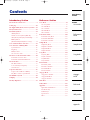 7
7
-
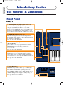 8
8
-
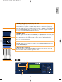 9
9
-
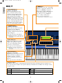 10
10
-
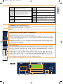 11
11
-
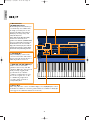 12
12
-
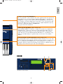 13
13
-
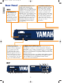 14
14
-
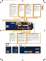 15
15
-
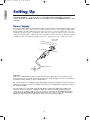 16
16
-
 17
17
-
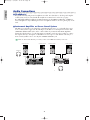 18
18
-
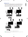 19
19
-
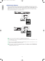 20
20
-
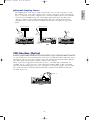 21
21
-
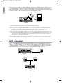 22
22
-
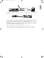 23
23
-
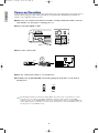 24
24
-
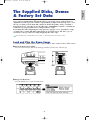 25
25
-
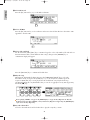 26
26
-
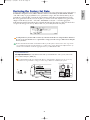 27
27
-
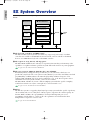 28
28
-
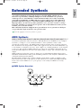 29
29
-
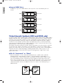 30
30
-
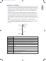 31
31
-
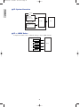 32
32
-
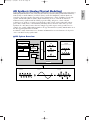 33
33
-
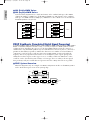 34
34
-
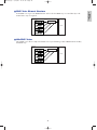 35
35
-
 36
36
-
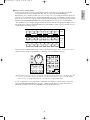 37
37
-
 38
38
-
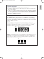 39
39
-
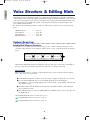 40
40
-
 41
41
-
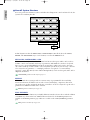 42
42
-
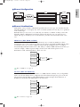 43
43
-
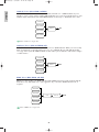 44
44
-
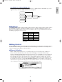 45
45
-
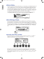 46
46
-
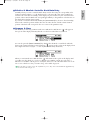 47
47
-
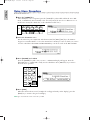 48
48
-
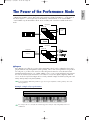 49
49
-
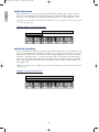 50
50
-
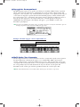 51
51
-
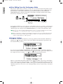 52
52
-
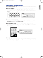 53
53
-
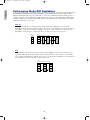 54
54
-
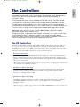 55
55
-
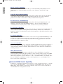 56
56
-
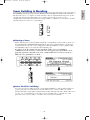 57
57
-
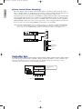 58
58
-
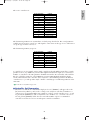 59
59
-
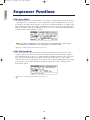 60
60
-
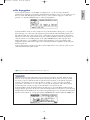 61
61
-
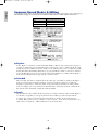 62
62
-
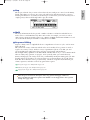 63
63
-
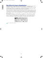 64
64
-
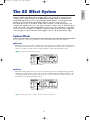 65
65
-
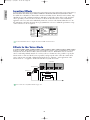 66
66
-
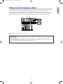 67
67
-
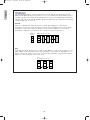 68
68
-
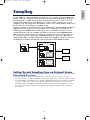 69
69
-
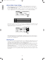 70
70
-
 71
71
-
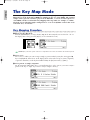 72
72
-
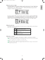 73
73
-
 74
74
-
 75
75
-
 76
76
-
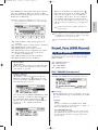 77
77
-
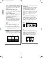 78
78
-
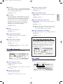 79
79
-
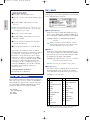 80
80
-
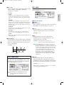 81
81
-
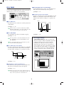 82
82
-
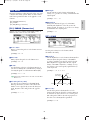 83
83
-
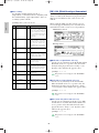 84
84
-
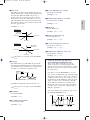 85
85
-
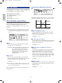 86
86
-
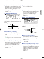 87
87
-
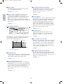 88
88
-
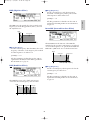 89
89
-
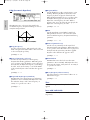 90
90
-
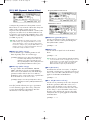 91
91
-
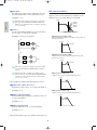 92
92
-
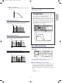 93
93
-
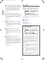 94
94
-
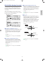 95
95
-
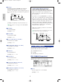 96
96
-
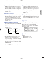 97
97
-
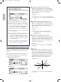 98
98
-
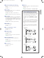 99
99
-
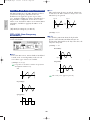 100
100
-
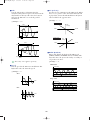 101
101
-
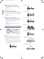 102
102
-
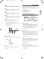 103
103
-
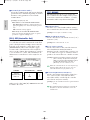 104
104
-
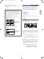 105
105
-
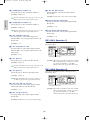 106
106
-
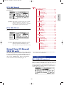 107
107
-
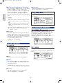 108
108
-
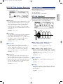 109
109
-
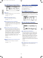 110
110
-
 111
111
-
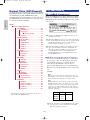 112
112
-
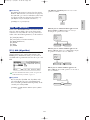 113
113
-
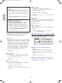 114
114
-
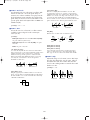 115
115
-
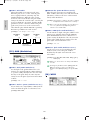 116
116
-
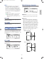 117
117
-
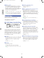 118
118
-
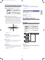 119
119
-
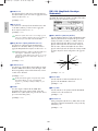 120
120
-
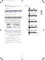 121
121
-
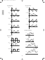 122
122
-
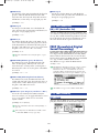 123
123
-
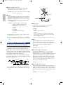 124
124
-
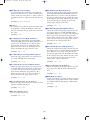 125
125
-
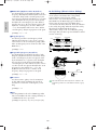 126
126
-
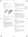 127
127
-
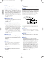 128
128
-
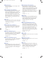 129
129
-
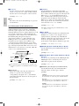 130
130
-
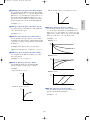 131
131
-
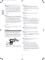 132
132
-
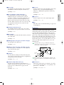 133
133
-
 134
134
-
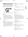 135
135
-
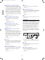 136
136
-
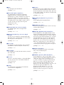 137
137
-
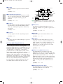 138
138
-
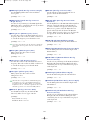 139
139
-
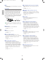 140
140
-
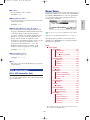 141
141
-
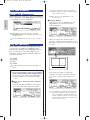 142
142
-
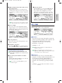 143
143
-
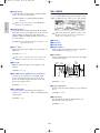 144
144
-
 145
145
-
 146
146
-
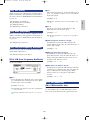 147
147
-
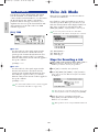 148
148
-
 149
149
-
 150
150
-
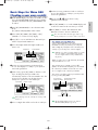 151
151
-
 152
152
-
 153
153
-
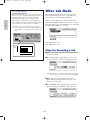 154
154
-
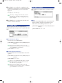 155
155
-
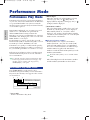 156
156
-
 157
157
-
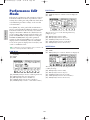 158
158
-
 159
159
-
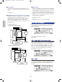 160
160
-
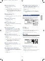 161
161
-
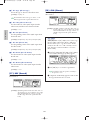 162
162
-
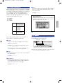 163
163
-
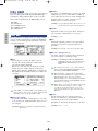 164
164
-
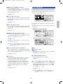 165
165
-
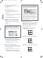 166
166
-
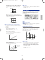 167
167
-
 168
168
-
 169
169
-
 170
170
-
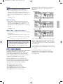 171
171
-
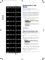 172
172
-
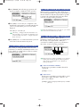 173
173
-
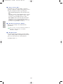 174
174
-
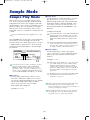 175
175
-
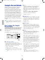 176
176
-
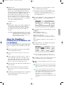 177
177
-
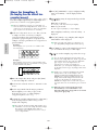 178
178
-
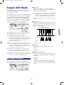 179
179
-
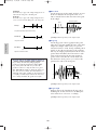 180
180
-
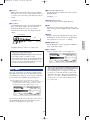 181
181
-
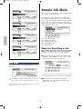 182
182
-
 183
183
-
 184
184
-
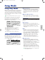 185
185
-
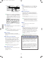 186
186
-
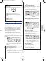 187
187
-
 188
188
-
 189
189
-
 190
190
-
 191
191
-
 192
192
-
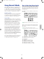 193
193
-
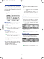 194
194
-
 195
195
-
 196
196
-
 197
197
-
 198
198
-
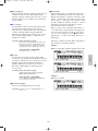 199
199
-
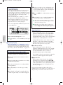 200
200
-
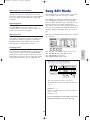 201
201
-
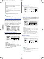 202
202
-
 203
203
-
 204
204
-
 205
205
-
 206
206
-
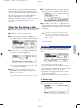 207
207
-
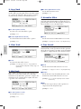 208
208
-
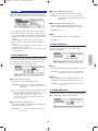 209
209
-
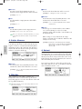 210
210
-
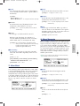 211
211
-
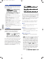 212
212
-
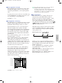 213
213
-
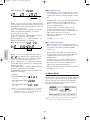 214
214
-
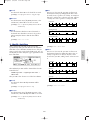 215
215
-
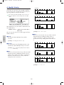 216
216
-
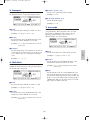 217
217
-
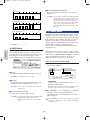 218
218
-
 219
219
-
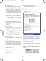 220
220
-
 221
221
-
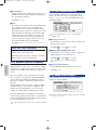 222
222
-
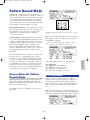 223
223
-
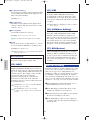 224
224
-
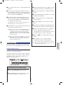 225
225
-
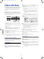 226
226
-
 227
227
-
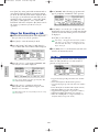 228
228
-
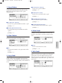 229
229
-
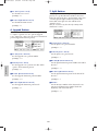 230
230
-
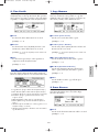 231
231
-
 232
232
-
 233
233
-
 234
234
-
 235
235
-
 236
236
-
 237
237
-
 238
238
-
 239
239
-
 240
240
-
 241
241
-
 242
242
-
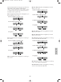 243
243
-
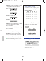 244
244
-
 245
245
-
 246
246
-
 247
247
-
 248
248
-
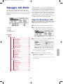 249
249
-
 250
250
-
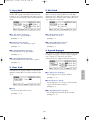 251
251
-
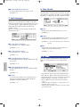 252
252
-
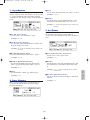 253
253
-
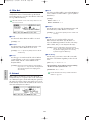 254
254
-
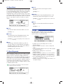 255
255
-
 256
256
-
 257
257
-
 258
258
-
 259
259
-
 260
260
-
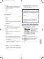 261
261
-
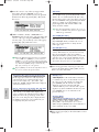 262
262
-
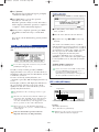 263
263
-
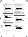 264
264
-
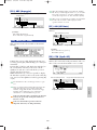 265
265
-
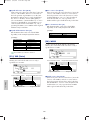 266
266
-
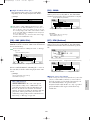 267
267
-
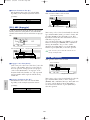 268
268
-
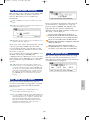 269
269
-
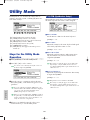 270
270
-
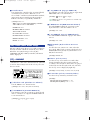 271
271
-
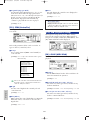 272
272
-
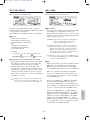 273
273
-
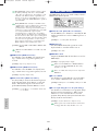 274
274
-
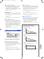 275
275
-
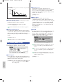 276
276
-
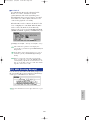 277
277
-
 278
278
-
 279
279
-
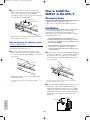 280
280
-
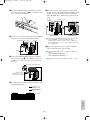 281
281
-
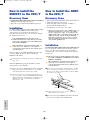 282
282
-
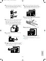 283
283
-
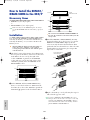 284
284
-
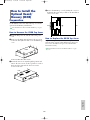 285
285
-
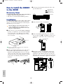 286
286
-
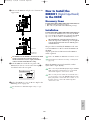 287
287
-
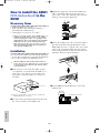 288
288
-
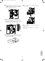 289
289
-
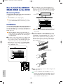 290
290
-
 291
291
-
 292
292
-
 293
293
-
 294
294
-
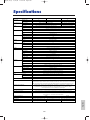 295
295
-
 296
296
-
 297
297
-
 298
298
-
 299
299
-
 300
300
-
 301
301
-
 302
302
-
 303
303
-
 304
304


Yamaha EX5 Manual de usuario
- Categoría
- Sintetizador
- Tipo
- Manual de usuario
en otros idiomas
- français: Yamaha EX5 Manuel utilisateur
- italiano: Yamaha EX5 Manuale utente
- English: Yamaha EX5 User manual
- Deutsch: Yamaha EX5 Benutzerhandbuch
- русский: Yamaha EX5 Руководство пользователя
- Nederlands: Yamaha EX5 Handleiding
- português: Yamaha EX5 Manual do usuário
- dansk: Yamaha EX5 Brugermanual
- polski: Yamaha EX5 Instrukcja obsługi
- čeština: Yamaha EX5 Uživatelský manuál
- svenska: Yamaha EX5 Användarmanual
- Türkçe: Yamaha EX5 Kullanım kılavuzu
- suomi: Yamaha EX5 Ohjekirja
- română: Yamaha EX5 Manual de utilizare
Artículos relacionados
-
Yamaha Version2 El manual del propietario
-
Yamaha QY700 Manual de usuario
-
-
-
-
-
-
Yamaha PLG150-AN El manual del propietario
-
-
Otros documentos
-
Fender G-DEC 30 Manual de usuario
-
Akai Professional Tom Cat Manual de usuario
-
-
-
Ecler ALMA26 Manual de usuario
-
Aim-TTI TGF4242 Guía de inicio rápido
-
Korg KROME EX Guía de inicio rápido
-
-
Hughes & Kettner Black Spirit 200 Manual de usuario
-
Steinberg Padshop Manual de usuario