Polaris PB4-60 Manual de usuario
- Categoría
- Accesorios para piscinas elevadas
- Tipo
- Manual de usuario

WARNING
FOR YOUR SAFETY - This product must be installed and serviced by a contractor who is licensed and qualied
in pool equipment by the jurisdiction in which the product will be installed, where such state or local requirements
exist. In the event no such state or local requirement exists, the maintainer must be a professional with sufcient
experience in pool equipment installation and maintenance, so that all of the instructions in this manual can be
followed exactly. Improper installation and/or operation can create dangerous electrical hazards, which can cause
high voltages to run through the electrical system. Before installing this product, read and follow all warning
notices and instructions that accompany this product. Failure to follow warning notices and instructions may result
in property damage, personal injury, or death. Improper installation and/or operation will void the warranty.
If these instructions are not followed exactly, a re or explosion may result, causing property damage, personal
injury, or death.
ATTENTION INSTALLER: This manual contains important information about the installation,
operation and safe use of this product. This information should be given to the owner/operator of
this equipment.
H0399500 REV E
Pressure Cleaner
Booster Pump
Installation and
Operation Manual
For Polaris PB4-60 Booster Pumps with Serial Numbers beginning with "PB"
and a manufacturing date on or after Dec 1, 2011.
ENGLISH | ESPAÑOL

Page 2 ENGLISH Polaris® PB4-60 Booster Pump | Installation and Operation Manual
Table of Contents
Section 1. IMPORTANT SAFETY
INSTRUCTIONS ............................. 3
1.1 Safety Instructions ............................................ 3
1.2 Pool Pump Suction Entrapment Prevention
Guidelines ......................................................... 5
Section 2. General Description ...................... 6
2.1 Introduction ....................................................... 6
2.2 Description ........................................................ 6
2.3 Preparation ....................................................... 6
Section 3. Installation ..................................... 6
3.1 Electrical Installation ......................................... 6
3.1.1 Voltage Checks ..................................... 6
3.1.2 Bonding and Grounding ......................... 6
3.2 Electrical ........................................................... 6
3.2.1 Electrical Wiring ..................................... 6
3.3 Plumbing ........................................................... 7
3.3.1 Requirements ........................................ 7
3.3.2 Pipe Sizing ............................................. 8
3.3.3 Pump Location ....................................... 8
3.3.4 Install the Pump ..................................... 8
3.3.5 Installation Recommendations .............. 9
3.3.6 Check the Water Flow ........................... 9
3.3.7 Conduct Pressure Test .......................... 10
Section 4. Operation ....................................... 10
4.1 Start-up ............................................................. 10
Section 5. Maintenance .................................. 11
5.1 Winterizing the Pump ........................................ 11
Section 6. Product Specications and
Technical Data ............................... 11
6.1 Replacement Parts List ..................................... 11
6.3 Pump Dimensions ............................................. 12
6.2 Polaris PB4-60 Booster Pump Exploded View . 12
DATE OF INSTALLATION
INSTALLER INFORMATION
INITIAL PRESSURE GAUGE READING (WITH CLEAN FILTER)
PUMP MODEL HORSEPOWER
NOTES:
EQUIPMENT INFORMATION RECORD

Page 3
ENGLISH
Polaris® PB4-60 Booster Pump | Installation and Operation Manual
Section 1. IMPORTANT SAFETY INSTRUCTIONS
READ AND FOLLOW ALL INSTRUCTIONS
1.1 Safety Instructions
All electrical work must be performed by a licensed electrician and conform to all national, state, and local codes.
When installing and using this electrical equipment, basic safety precautions should always be followed, including the
following:
To reduce the risk of injury, do not permit children to use this product.
WARNING
To reduce the risk of property damage or injury, do not attempt to change the backwash (multiport, slide, or full
ow) valve position with the pump running.
WARNING
Polaris pumps are powered by a high voltage electric motor and must be installed by a licensed or certied
electrician or a qualied swimming pool service technician.
WARNING
RISK OF ELECTRIC SHOCK, FIRE, PERSONAL INJURY, OR DEATH. Connect only to a branch circuit that is
protected by a ground-fault circuit-interrupter (GFCI). Contact a qualied electrician if you cannot verify that the
circuit is protected by a GFCI. Make sure such a GFCI should be provided by the installer and should be tested on
a routine basis. To test the GFCI, push the test button. The GFCI should interrupt power. Push the reset button.
Power should be restored. If the GFCI fails to operate in this manner, the GFCI is defective. If the GFCI interrupts
power to the pump without the test button being pushed, a ground current is owing, indicating the possibility
of electrical shock. Do not use the pump. Disconnect the pump and have the problem corrected by a qualied
service representative before using.
Due to the potential risk of re, electric shock, or injuries to persons, Zodiac Pumps must be installed in
accordance with the National Electrical Code® (NEC®), all local electrical and safety codes, and the Occupational
Safety and Health Act (OSHA®). Copies of the NEC may be ordered from the National Fire Protection Association®
(NFPA®) online at www.nfpa.org or call 617-770-3000, or contact your local government inspection agency.
WARNING
Incorrectly installed equipment may fail, causing severe injury or property damage.
WARNING
• Do not connect the system to an unregulated city water system or other external source of pressurized water
producing pressures greater than 35 PSI.
• Trapped air in system can cause the lter lid to be blown off, which can result in death, serious personal injury,
or property damage. Be sure all air is out of the system before operating.
WARNING

Page 4 ENGLISH Polaris® PB4-60 Booster Pump | Installation and Operation Manual
SAVE THESE INSTRUCTIONS
Chemical spills and fumes can weaken pool/spa equipment. Corrosion can cause lters and other equipment to
fail, resulting in severe injury or property damage. Do not store pool chemicals near your equipment.
WARNING
Do not start pump dry! Running the pump dry for any length of time will cause severe damage and will void the
warranty.
CAUTION
To minimize the risk of severe injury or death the lter and/or pump should not be subjected to the piping system
pressurization test.
Local codes may require the pool piping system to be subjected to a pressure test. These requirements are
generally not intended to apply to the pool equipment such as lters or pumps.
Polaris pool equipment is pressure tested at the factory.
However, if the WARNING cannot be followed and pressure testing of the piping system must include the lter
and/or pump, BE SURE TO COMPLY WITH THE FOLLOWING SAFETY INSTRUCTIONS:
• Check all clamps, bolts, lids, lock rings and system accessories to ensure they are properly installed and
secured before testing.
• RELEASE ALL AIR in the system before testing.
• Water pressure for test must NOT EXCEED 35 PSI.
• Water temperature for test must NOT EXCEED 100°F (38°C).
• Limit test to 24 hours. After test, visually check system to be sure it is ready for operation.
NOTICE: These parameters apply to Zodiac equipment only. For non-Zodiac equipment, consult equipment
manufacturer.
WARNING
This pump is for use with permanently installed pools and may also be used with hot tubs and spas if so marked.
Do not use with storable pools. A permanently installed pool is constructed in or on the ground or in a building
such that it cannot be readily disassembled for storage. A storable pool is constructed so that it may be readily
disassembled for storage and reassembled to its original integrity.
CAUTION
Do not install within an outdoor enclosure or beneath the skirt of a hot tub or portable spa. The pump requires
adequate ventilation to maintain air temperature at less than the maximum ambient temperature rating listed on
the motor rating plate.
CAUTION

Page 5
ENGLISH
Polaris® PB4-60 Booster Pump | Installation and Operation Manual
1.2 Pool Pump Suction Entrapment Prevention Guidelines
At least
three (3) feet
Suction Outlet
(Main Drain)
Suction Outlet
(Main Drain)
No valves between
Tee and Main Drains
Listed/certified to latest
published version of
ANSI/ASME A112.19.8 - 2007
or its successor,
ANSI/APSP-16
Anti-entrapment
Cover/Grate or Suction Fitting,
screw-fastened
to Main Drain Sump
Listed/certified to latest
published version of
ANSI/ASME A112.19.8 - 2007
or its successor,
ANSI/APSP-16
Anti-entrapment
Cover/Grate or Suction
Fitting, screw-fastened
to Main Drain Sump
Valves OK between
pump and Tee
Pump
Figure 1. Number of Suction Outlets Per Pump
Pump suction is hazardous and can trap and drown or disembowel bathers. Do not use or operate
swimming pools, spa, or hot tubs if a suction outlet cover is missing, broken, or loose. The following
guidelines provide information for pump installation that minimizes the risk of injury to users of pools, spas, and
hot tubs:
Entrapment Protection - The pump suction system must provide protection against the hazards of suction
entrapment.
Suction Outlet Covers - All suction outlets must have correctly installed, screw-fastened covers in place. All
suction outlet (drain) covers must be maintained. Drain covers must be listed/certied to the latest version of
ANSI®/ASME® A112.19.8 or its successor standard, ANSI/APSP-16. They must be replaced if cracked, broken, or
missing.
Number of Suction Outlets Per Pump - Provide at least two (2) hydraulically-balanced main drains, with covers,
as suction outlets for each circulating pump suction line. The centers of the main drains (suction outlets) on any
one (1) suction line must be at least three (3) feet apart, center to center. See Figure 1.
The system must be built to include at least two (2) suction outlets (drains) connected to the pump whenever
the pump is running. However, if two (2) main drains run into a single suction line, the single suction line may be
equipped with a valve that will shut off both main drains from the pump. The system shall be constructed such that
it shall not allow for separate or independent shutoff or isolation of each drain. See Figure 1.
More than one (1) pump can be connected to a single suction line as long as the requirements above are met.
Water Velocity - The maximum water velocity through the suction tting or cover for any suction outlet must be
1.5 feet per second unless the outlet complies with the latest version of ANSI/ASME A112.19.8 or its successor
standard, ANSI/APSP-16, the standard for Suction Fittings For Use in Swimming Pools, Wading Pools, Spas, and
Hot Tubs. In any case, do not exceed the suction tting’s maximum designed ow rate.
If 100% of the pump’s ow comes from the main drain system, the maximum water velocity in the pump suction
hydraulic system must be six (6) feet per second or less, even if one (1) main drain (suction outlet) is completely
blocked. The ow through the remaining main drain(s) must comply with the latest version of ANSI/ASME
A112.19.8 or its successor standard, ANSI/APSP-16, the standard for Suction Fittings For Use in Swimming
Pools, Wading Pools, Spas, and Hot Tubs.
Testing and Certication - Suction outlet covers must have been tested by a nationally recognized testing
laboratory and found to comply with the latest version of ANSI/ASME A112.19.8 or its successor standard, ANSI/
APSP-16, the standard for Suction Fittings For Use in Swimming Pools, Wading Pools, Spas, and Hot Tubs.
Fittings - Fittings restrict ow; for best efciency use fewest possible ttings (but at least two (2) suction outlets).
Avoid ttings which could cause an air trap.
Pool cleaner suction ttings must conform to applicable International Association of Plumbing and Mechanical
Ofcials (IAPMO®) standards.
WARNING

Page 6 ENGLISH Polaris® PB4-60 Booster Pump | Installation and Operation Manual
Section 2. General Description
2.1 Introduction
This manual contains information for the proper
installation, operation and maintenance of the Polaris
PB4-60 pump. Procedures in this manual must be
followed exactly. To obtain additional copies of this
manual contact Zodiac Pool Systems, Inc. ("Zodiac")
at 800.822.7933. For address information, see the back
cover of this manual.
2.2 Description
The Polaris booster pump, PB4-60, supplies high
pressure water to the Polaris pool cleaner to optimize
cleaner efficiency. The pump is not self-priming and
should only be used when the pool filtration pump is on.
Running the booster pump without a ltration pump
will damage the booster pump. Improper operation
of the booster pump will void the warranty.
CAUTION
2.3 Preparation
1. Upon receipt of the pump, check the carton for
damage. Open the carton and check the pump for
concealed damage, such as cracks, dents or a bent
base. If damage is found, contact the shipper or
distributor where you purchased the pump.
2. Inspect the contents of the carton and verify
that all the parts are included. See Section 7.1,
Replacement Parts List.
Section 3. Installation
3.1 Electrical Installation
3.1.1 Voltage Checks
The correct voltage, as specified on the pump data
plate, is necessary for proper performance and long
motor life. Incorrect voltage will decrease the pump’s
ability to perform and could cause overheating, reduce
the motor life, and result in higher electric bills.
It is the responsibility of the electrical installer to
provide data plate operating voltage to the pump by
ensuring proper circuit sizes and wire sizes for this
specific application.
The National Electrical Code® (NEC®, NFPA-70®)
requires all pool pump circuits be protected with a
Ground Fault Circuit-Interrupter (GFCI). Therefore, it is
also the responsibility of the electrical installer to ensure
that the pump circuit is in compliance with this and all
other applicable requirements of the National Electrical
Code (NEC) and any other applicable installation codes.
Failure to provide data plate voltage (within 10%)
during operation will cause the motor to overheat
and void the warranty.
CAUTION
3.1.2 Bonding and Grounding
1. The motor frame must be grounded to a reliable
grounding point using a solid copper conductor,
No. 8 AWG (8.4mm2) or larger. In Canada, No.
6 AWG (13.3mm2) or larger must be used. If the
pump is installed within five 5 feet (1,5 meter)
of the inside walls of the swimming pool, spa, or
hot tub, the motor frame must be bonded to all
metal parts of the swimming pool, spa, or hot tub
structure and to all electrical equipment, metal
conduit, and metal piping within five (5) feet (1,5
meter) of the inside walls of the swimming pool,
spa, or hot tub.
2. Bond the motor using the provided external lug.
The pump must be permanently connected to a
dedicated electrical circuit. No other equipment,
lights, appliances or outlets may be connected to
the pump circuit, with the exception of devices that
may be required to operate simultaneously with the
pump, such as a chlorinating device or heater.
CAUTION
To avoid the risk of property damage, severe
personal injury, and/or death, always disconnect
the power source before working on a motor or its
connected load.
WARNING
To avoid the risk of property damage, severe
personal injury, and/or death, make sure that
the control switch or time clock is installed in an
accessible location so that in the event of an
equipment failure or a loose plumbing tting the
equipment can be turned off. This location must not
be in the same area as the pool pump, lter, and
other equipment.
WARNING
3.2 Electrical
Motor Rating
HP S.F RPM VOLTS S.F. AMPS
3/4 1.5 3450 230/115, 60Hz, 1PH 6.4/12.8

Page 7
ENGLISH
Polaris® PB4-60 Booster Pump | Installation and Operation Manual
7. A separate time clock (in addition to the filtration
system time clock) is recommended to control the
On/Off functions of the booster pump. A manual
switch can also be used.
8. If a time clock is used, set it to turn the pump
on at least a half an hour after the pool filtration
pump is turned on, and turn the pump off at least
half an hour before the filtration pump shuts off.
Periodically check the time clock settings to make
sure they are properly synchronized.
3.3 Plumbing
Be careful not to overtighten any pipe tting on the
inlet or outlet of the booster pump. Overtightening
can cause the housing to crack.
CAUTION
3.3.1 Requirements
The Polaris Booster Pump requires a dedicated
return line. Plumb the booster pump into the system so
that it always receives flow from the filtration pump.
To ensure proper function of the pump and the cleaner,
refer to Figure 2 and adhere to the following guidelines
for specific equipment.
1. Plumb the dedicated line upstream of all air
inducing equipment.
2. If a heater is installed on the system, tap the
inlet for the booster pump into the return line
3.2.1 Electrical Wiring
1. The pump motor must be securely and adequately
grounded using the green screw provided. Ground
before attempting to connect to an electrical power
supply. Do not ground to a gas supply line.
2. Wire size must be adequate to minimize voltage
drop during the start-up and operation of the
pump. See Table 1 for wire sizes.
3. Insulate all connections carefully to prevent
grounding or short-circuits. Sharp edges on
terminals require extra protection. To prevent
wire nuts from loosening, tape them using a
suitable, listed (UL®, ETL®, CSA®) electrical
insulating tape. For safety, and to prevent entry
of contaminants, reinstall all conduit and terminal
box covers. Do not force connections into the
conduit box.
4. To configure the internal wiring of the pump motor
for the correct voltage, refer to the diagram on the
motor data plate.
5. The starting current of the booster pump motor
may exceed 15 amps on 115 VAC voltage line. It
is recommended that a 20 amp service breaker be
used for the pump connected to 115 VAC.
6. The booster pump motor is factory wired for 230
volts, but can be wired for either 115 or 230 volts.
To rewire to 115 volt, follow the instructions on
the name plate located on the back of the motor or
the sizing plate on the side of the motor.
Minimum
of 3 feet
(1 meter)
From
Pool
Filtration Pump Pool Filter
Heater
Polaris
Plumb the booster pump up-stream
of all air inducing equipment.
To
Pool
Chlorinator
Solar
System
Plumbing
Options
1, 2 or 3*
To
Spa
LXiTM Heater
Booster
Pump
* Refer to Figures 3 and 4
NOTE
Figure 2. Typical Equipment Layout
MAXIMUM WIRE SIZE AND MAXIMUM OVERCURRENT PROTECTION*
Distance from Sub-Panel 0-50 feet (15 meters) 50-100 feet (15-30 meters) 100-200 feet (30-60 meters)
Pump
Model
Branch Fuse AMPs
Class: CC, G, H, J, K, RK, or T
Voltage Voltage Voltage
230 VAC 115 VAC 208-230 VAC 115 VAC 208-230 VAC 115 VAC 208-230 VAC 115 VAC
PB4-60 15A 20A 14 AWG
(2.1mm2)
12 AWG
(3.3mm2)
12 AWG
(3.3mm2)
10 AWG
(5.3mm2)
10 AWG
(5.3mm2)
10 AWG
(5.3mm2)
*Assumes three (3) copper conductors in a buried conduit and 3% maximum voltage loss in branch circuit. All National Electrical Code® (NEC®) and
local codes must be followed. Table shows minimum wire size and branch fuse recommendations for a typical installation per NEC.
Table 1. Maximum Wire Size and Overcurrent Protection

Page 8 ENGLISH Polaris® PB4-60 Booster Pump | Installation and Operation Manual
2. The booster pump inlet connection line should be
at least 3/4” pipe. The Softube Quick Connect
fittings are designed to work with the Polaris
reinforced hose (part #P19) only.
3. Do not tap into the top of a horizontal line.
4. Use 90° street ells to minimize bends and loops in
the Polaris reinforced hose.
3.3.3 Pump Location
1. Zodiac Pool Systems, Inc. recommends installing
the pump within one 1 foot (30 cm) above the
water level. The pump should not be elevated
more than a few feet above the water level of the
pool.
2. If the pump is located below water level, isolation
valves must be installed on both the suction and
return lines to prevent back flow of pool water
during any routine or required servicing.
Some Safety Vacuum Release System (SVRS)
devices are not compatible with installation of check
valves. If the pool has an SVRS device, be sure to
conrm that it will continue to safely operate when
any check valves are installed.
WARNING
3. The pump and other circulation equipment must
be located more than 5 feet (1,5 meter) from the
water. Choose a location that will minimize turns
in the piping.
NOTE In Canada, the pump must be located a
minimum of 3.0 meters [approximately 10 feet]
from the water (CSA C22.1).
4. The pump must be placed on a solid foundation
that will not vibrate. To further reduce the
possibility of vibration noise, bolt the pump to the
foundation.
NOTE Zodiac® recommends bolting the pump directly
to the foundation.
5. The pump foundation must have adequate drainage
to prevent the motor from getting wet. The pump
needs to be protected from the rain and sun.
6. Proper ventilation is required for the pump to
operate normally. All motors generate heat that
must be removed by providing proper ventilation.
7. Provide access for future service by leaving a
clear area around the pump. Allow plenty of space
above the pump for servicing.
8. If the equipment is under cover, provide adequate
lighting.
downstream and at least three (3) feet (1 meter)
from the heater discharge. See Figure 2. Do not
tap the booster pump inlet into the three-foot
(1 meter) section of heat sink pipe that comes
directly out of the heater.
3. Some solar heating systems utilize the entire water
flow when the panels are being purged of air. If the
pump is installed in a non-flow pipe during solar
panel purges, install an automatic override to shut
off the pump.
4. Plumb the booster pump inlet higher, upstream and
as far away as possible from a chlorinator.
3.3.2 Pipe Sizing
1. Use rigid PVC pipe with a minimum diameter
of 3/4”, 1-1/2” is recommended, for the
dedicated return line. Flexible PVC piping is not
recommended for the dedicated pool return line
underground as it can be damaged by expansion
and movement caused by the surge of pump
pressure. Refer to Figures 3 and 4.
Figure 3. Preferred Plumbing Configuration
From Filter or Heater
Horizontal
Leg
To Booster
Pump
Polaris
Reinforced
Hose
Street Ell
Option #1
Pool Return
To Spa
Ground
Level
Figure 4. Alternate Plumbing Configuration
Pool Return
From Filter or Heater
Option #3
Option #2
To Spa
Ground Level
Leave 6"

Page 9
ENGLISH
Polaris® PB4-60 Booster Pump | Installation and Operation Manual
7. Slide/Rotate the connector nut to the barb to
engage threads correctly, do not cross thread
connector nut. Tighten the connector nut until
threads are no longer visible (gap about 1/8” or
just less than the width of two dimes), or until it
touches the barb face. See Figure 6.
3.3.5 Installation Recommendations
1. If the pump is located below water level, isolation
valves must be installed on both sides of the pump
to prevent back flow of pool water during any
routine or required servicing.
2. To help prevent difficulty in priming, install the
suction pipe without high points (above inlet of
pump - inverted “U”s in plumbing), which can trap
air.
3. The piping must be well supported and not forced
together where constant stress will be experienced.
4. Always use properly sized valves. Jandy® Pro
Series diverter valves and ball valves typically
3.3.4 Install the Pump
1. Mount the pump using two (2) concrete expansion
anchors to ensure stability.
2. Apply four (4) to six (6) wraps of Teflon® tape
to the tapered thread of the connecter barb. See
Figure 5 (a).
CAUTION
Pipe dope should NEVER be used on barb threads.
Pipe dope will severely weaken the plastic, causing
leakage and may cause the plastic to fracture. DO
NOT OVERTIGHTEN.
3. Thread and tighten the tapered thread of the
connector barb into the pump port on the pump
body. See Figure 5 (b).
Polaris
Reinforced
Hose
1-1/2" Rigid
PVC Pipe Dedicated return
line to pool
Expansion
Anchor
Inlet
Supply
Line
Figure 7. Complete Installation
have the best flow capabilities.
5. Use the fewest fittings possible. Every additional
fitting has the effect of moving the equipment
farther away from the water.
NOTE If more than 10 suction fittings are needed, the
pipe size must be increased.
3.3.6 Check the Water Flow
NOTE This pump must have minimum outlet pressure
of 45 psi. Lower pressure may cause an over-
current motor condition.
After the system is plumbed, verify water flow to
the booster pump by disconnecting the inlet supply line
at the booster pump and then turning on the filtration
pump. Water should flow from the line.
4. Trim reinforced hose to required length. Make sure
cut is clean and square. Avoid unnecessary loops
or bends in the hose.
5. Slide connector nut onto the trimmed end of the
hose with threaded end toward the cut end of the
hose. See Figure 5 (c).
6. Apply water to connector barb to help hose slide
over barbs. Push trimmed edge of hose fully onto
the connector barb. See Figure 5 (d).
Figure 5. Prep and install Quick Connect barb and
connector nut
a
b
d
c
d
Connector Barb
Connector Nut
Pump Body
Connector Barb
Reinforced Hose
Connector Barb
Barb Face
Connector Nut
Reinforced Hose
Nut Gap
Figure 6. Tighten Connector Nut to Secure Hose

Page 10 ENGLISH Polaris® PB4-60 Booster Pump | Installation and Operation Manual
If there is no water flow, check the following:
1. Verify that the installation is correct. Refer to
Figure 6.
2. Use smaller eyeball fittings in the pool return lines
or plug a return line.
Once flow is established, the pump is ready for
operation.
3.3.7 Conduct Pressure Test
When pressure testing a system with water, air
is often trapped in the system during the lling
process. This air will compress when the system is
pressurized. Should the system fail, this trapped air
can propel debris at a high speed and cause injury.
Every effort to remove trapped air must be taken,
including opening the bleed valve on the lter and
loosening the pump basket lid on the lter pump
while lling the pump.
WARNING
Trapped air in system can cause lter lid to be blown
off, which can result in death, serious personal
injury, or property damage. Be sure all air is properly
out of system before operating. DO NOT USE
COMPRESSED AIR TO PRESSURE TEST OR
CHECK FOR LEAKS.
WARNING
When pressure testing the system with water, it is
very important to make sure that the pump basket
lid on the lter pump is completely secure.
WARNING
Do not pressure test above 35 PSI. Pressure
testing must be done by a trained pool professional.
Circulation equipment that is not tested properly can
fail, which could result in severe injury or property
damage.
WARNING
1. Fill the system with water, using care to eliminate
trapped air.
2. Pressurize the system with water to no more than
35 PSI.
3. Close the valve to trap pressurized water in the
system.
4. Observe the system for leaks and/or pressure
decay.
5. For technical support, contact Zodiac® technical
support at 800.822.7933.
Section 4. Operation
4.1 Start-up
Never run the booster pump without water. Running
the pump “dry” for any length of time can cause
severe damage to both the pump and motor and will
void the warranty.
CAUTION
Never run the booster pump without the cleaner
connected. Running the pump without the cleaner
connected will cause damage to the pump impeller
and will void the warranty.
CAUTION
If this is a new pool installation, make sure all
piping is clear of construction debris and has been
properly pressure tested. The filter should be checked
for proper installation, verifying all connections and
clamps are secure according to the manufacturer's
recommendations.
To avoid risk of damage or injury, verify that all
power is turned off before starting this procedure.
WARNING
1. Turn filtration pump ON.
2. Open the filter pressure release to relieve the
system pressure until water comes out.
3. If the filter pump is located below the water level
of the pool, opening the filter pressure release
valve will prime the pump with water.
4. Once all the air has left the filter, close the
pressure release valve.
5. Turn on the power to the booster pump. Then turn
on the booster pump.
6. The booster pump should prime. The time it takes
to prime will depend on the elevation and length of
pipe used on the suction supply pipe. See Section
3.3.6 for proper elevation and pipe size.
7. If the booster pump does not prime and all the
instructions to this point have been followed,
check for a suction leak.

Page 11
ENGLISH
Polaris® PB4-60 Booster Pump | Installation and Operation Manual
Section 5. Maintenance
5.1 Winterizing the Pump
The pump must be protected when freezing
temperatures are expected. Allowing the pump
to freeze will cause severe damage and void the
warranty.
CAUTION
Do not use antifreeze solutions in the pool,
spa, or hot tub systems! Antifreeze is highly toxic
and may damage the circulation system. The only
exception to this is Propylene Glycol. For more
information see your local pool/spa supply store or
contact a qualied swimming pool service company.
CAUTION
1. Drain all water from the pump, system equipment,
and piping.
2. Remove the drain plug. Store the drain plug in a
safe location and reinstall it when the cold weather
season is over. Do not lose the o-ring. (Drain Plug
with O-ring Set, R0537000).
Section 6. Product Specifications and Technical Data
6.1 Replacement Parts List
To order or purchase parts for Polaris® pumps, contact your nearest Zodiac® dealer. If they cannot supply you with
what you need, contact Zodiac technical support at 800.822.7933 or www.zodiacpoolsystems.com.
3. Keep the motor covered and dry.
NOTE Covering the pump with plastic will create
condensation, and this moisture will damage
the pump. The best way to protect your pump
is to have a qualified service technician or
electrician properly disconnect the electrical
wiring at the switch or junction box. Once the
power is removed, the two (2) quick connect
fittings can be loosened and the pump stored
indoors. For safety, and to prevent entry of
contaminants, reinstall all conduit and terminal
box covers.
4. When the system is reopened for operation, make
sure all piping, valves, wiring, and equipment
are in accordance with the manufacturer's
recommendations. Pay close attention to the filter
and electrical connections.
5. The pump must be primed prior to starting; refer
to Section 4.1, Start-up.
Key
No. Description Qty
Order Part
No. Comments
1Replacement Motor for Booster Pump 1 P61
2O-Ring, Backplate, PB4-60 1 R0536600
3Seal, Ceramic and Spring 1 R0445500
4Impeller, PB4-60 1 R0536400
5Volute, PB4-60 1 R0536300 (Includes Drain Plug with O-Ring)
6Bolts with Washers and Nuts 6 R0536900
7Drain Plug with O-Ring, Common 1 R0537000
8Base, Booster, PB4-60 1 R0537100
9Bolts and Washers, Stainless, Motor, PB4-60 4 R0536800
10 Quick Connect Install Kit 1 R0617100
Kit includes 1 ea 6' length of
reinforced hose and 4 ea Quick
Connect fittings.
11 Quick Connect Fittings 4 R0621000 Comes with 4ea Quick Connect
Fittings and Installation Instructions.
12 Pump Hose 6FT Reinforced 1 P19
13 Backplate PB4-60 1 R0536700 Includes Seal and Backplate O-ring.

Page 12 ENGLISH Polaris® PB4-60 Booster Pump | Installation and Operation Manual
6.2 Polaris PB4-60 Booster Pump Exploded View
2
3
4
13
1
5
6 (Qty 6)
7
8
9 (Qty 4)
6 (Qty 6)
10
11
12
Figure 11. Polaris PB4-60 Booster Pump Exploded View
NOTE When installing pump, leave a minimum of 2.0 feet (60 cm) of clearance above the pump for
service.
6.3 Pump Dimensions
Bolt Holes,
Center to Center
Front Edge of Union
to Center of Bolt Holes
4 "
15/16
6 3/8"
813/16
"151/16
"
1
9/16"
111/2"
13/
16
"
5
22.4 cm 38.3 cm
4 cm
29.2 cm
14.8 cm
12.5 cm
16.2 cm
Figure 12. Polaris PB4-60 Booster Pump Dimensions

Page 13
ENGLISH
Polaris® PB4-60 Booster Pump | Installation and Operation Manual
NOTES

Page 14 ENGLISH Polaris® PB4-60 Booster Pump | Installation and Operation Manual
NOTES

Page 15
ENGLISH
Polaris® PB4-60 Booster Pump | Installation and Operation Manual
NOTES

©2017 Zodiac Pool Systems, Inc. ZODIAC® is a registered trademark of Zodiac
International, S.A.S.U., used under license. Polaris® and the Polaris 3-wheeled cleaner
design are registered trademarks of Zodiac Pool Systems, Inc.
All trademarks referenced herein are the property of their respective owners.
H0399500 REV E
Zodiac Pool Systems, Inc.
2620 Commerce Way, Vista, CA 92081
1.800.822.7933 | www.ZodiacPoolSystems.com

Bomba
reforzadora
del limpiador a
presión
Manual de instalación
y funcionamiento
PARA SU SEGURIDAD - Este producto debe ser instalado y mantenido por un contratista con licencia y calicaciones
para equipos para piscinas otorgadas por la jurisdicción donde se instalará el producto en caso de que existan
tales requisitos estatales o locales. En caso de que no existan tales requisitos estatales o locales, la persona que realiza
el mantenimiento debe ser un profesional con experiencia suciente en la instalación y mantenimiento de equipos para
piscinas de tal forma que pueda seguir al pie de la letra las instrucciones de este manual. La instalación o el funcionamiento
inadecuados pueden crear riesgos eléctricos peligrosos, que pueden causar altas tensiones a través del sistema eléctrico.
Antes de instalar este producto, lea y siga todas las instrucciones y preste atención a las advertencias en el manual adjunto.
No prestar la debida atención a las advertencias e instrucciones puede ocasionar daños a la propiedad, lesiones personales e
incluso la muerte. La instalación y la operación incorrectas será causa de anulación de la garantía.
En caso de no seguir las instrucciones al pie de la letra, se puede producir un incendio o una explosión que puede causar
daños a la propiedad, lesiones personales o incluso la muerte.
ATENCIÓN INSTALADOR: Este manual contiene información importante acerca de la instalación,
el funcionamiento y la utilización seguros de este producto. Esta información debe ser entregada al
dueño u operador de este equipo.
ADVERTENCIA
H0399500 Rev. E
Para bombas reforzadoras Polaris PB4-60 con números de serie que comienzan
con “PB” y con fecha de fabricación a partir del 1º de diciembre de 2011.
ESPAÑOL

PÁGINA 18 ESPAÑOL Polaris® Bomba reforzadora PB4-60 | Manual de instalación y funcionamiento
Índice
Sección 1. IMPORTANTES INSTRUCCIONES
DE SEGURIDAD ............................ 19
1.1 Instrucciones de seguridad ............................... 19
1.2 Pautas de prevención de atrapamiento por
succión de la bomba de la piscina .................... 21
Sección 2. Descripción General ..................... 22
2.1 Introducción ...................................................... 22
2.2 Descripción ....................................................... 22
2.3 Preparación ...................................................... 22
Sección 3. Instalación ..................................... 22
3.1 Instalación eléctrica .......................................... 22
3.1.1 Chequeos de voltaje ............................. 22
3.1.2 Interconectar cables y conectar a tierra 22
3.2 Eléctrico ............................................................ 22
3.2.1 Cableado eléctrico ................................. 22
3.3 Plomería ........................................................... 23
3.3.1 Requisitos 23
3.3.2 Dimensiones de la tubería ..................... 24
3.3.3 Ubicación de la bomba .......................... 24
3.3.4 Instalación de la bomba ......................... 24
3.3.5 Recomendaciones de instalación .......... 25
3.3.6 Revisar el ujo de agua ......................... 25
3.3.7 Realizar prueba de presión ................... 25
Sección 4. Operación ...................................... 26
4.1 Puesta en marcha ............................................. 26
Sección 5. Mantenimiento............................... 26
5.1 Preparación de la bomba para el invierno ........ 26
Sección 6. Especicaciones del producto
y datos técnicos ............................ 27
6.1 Lista de piezas de repuesto ............................. 27
6.3 Dimensiones de la bomba ................................ 28
6.2 Plano de despiece de la bomba reforzadora
Polaris PB4-60 .................................................. 28
DATE OF INSTALLATION
(FECHA DE INSTALACIÓN)
INSTALLER INFORMATION
(Información del instalador)
INITIAL PRESSURE GAUGE READING (WITH CLEAN FILTER)
(LECTURA INICIAL DEL MEDIDOR DE PRESIÓN (CON EL FILTRO LIMPIO))
PUMP MODEL HORSEPOWER
(MODELO DE BOMBA) (CABALLO DE FUERZA)
NOTES:
(NOTAS:)
EQUIPMENT INFORMATION RECORD
(REGISTRO DE INFORMACIÓN DEL EQUIPO)

PÁGINA 19
ESPAÑOL
Polaris® Bomba reforzadora PB4-60 | Manual de instalación y funcionamiento
Sección 1. IMPORTANTES INSTRUCCIONES DE
SEGURIDAD
LEA Y SIGA ESTAS INSTRUCCIONES
1.1 Instrucciones de seguridad
Todo el trabajo de electricidad deberá realizarlo un electricista certificado de conformidad con todos los códigos
nacionales, estadales y regionales. Cuando se instale y utilice este equipo eléctrico, siempre se deberán seguir las
siguientes precauciones básicas de seguridad:
Para reducir el riesgo de lesión, no permita que los niños usen este artefacto.
ADVERTENCIA
Para reducir el riesgo de daños materiales o lesiones, no intente cambiar la posición de la válvula de retro lavado (multipuerto,
deslizamiento o ujo completo) con la bomba en funcionamiento.
ADVERTENCIA
Las bombas Polaris son accionadas por un motor eléctrico de alta tensión y deben ser instaladas por un electricista con
licencia (o certicado) o por un técnico que esté calicado en servicio de piscinas.
ADVERTENCIA
RIESGO DE DESCARGA ELÉCTRICA, DE INCENDIO, LESIONES PERSONALES O DE MUERTE. Conectar solamente
a una rama del circuito que esté protegida por un interruptor de circuito por falla a tierra (GFCI). Contacte a un electricista
autorizado si usted no puede asegurarse de que el circuito esté protegido por un GFCI. Asegúrese de que el instalador
proporcione un GFCI y que sea probado de manera rutinaria. Para probar el GFCI, presione el botón de prueba. El GFCI debe
interrumpir la energía. Presione el botón de reinicio. Se debe restablecer la energía. Si el GFCI no funciona de esta forma,
quiere decir que está defectuoso. Si el GFCI interrumpe la energía a la bomba sin presionar el botón de prueba, quiere decir
que uye corriente de tierra, lo que indica la posibilidad de una descarga eléctrica. No utilice la bomba. Desconéctela y solicite
a un representante de servicio calicado que solucione el problema antes de utilizarla.
Debido al riesgo potencial de incendio, choque eléctrico o lesiones a las personas, las bombas Zodiac se deben instalar
de acuerdo con el Código Eléctrico Nacional (NEC®) de EE. UU., todos los códigos locales eléctricos y de seguridad, y la
Ley de Seguridad y Salud Ocupacionales (OSHA®). Las copias del NEC pueden solicitarse a la National Fire Protection
Association® (NFPA®) en el sitio web www.nfpa.org o llamando al 617-770-3000 o comunicándose con el organismo de
inspecciones gubernamentales de su localidad.
ADVERTENCIA
Los equipos instalados incorrectamente pueden fallar y causar lesiones graves o daños materiales.
ADVERTENCIA
• No conecte el sistema a una red de agua no regulada de la ciudad, o a otra fuente externa de agua
presurizada que produzca presiones mayores a 35 psi.
• Arrancar la bomba cuando hay aire comprimido en el sistema puede hacer que la tapa del ltro salga
expulsada, lo que puede causar serias lesiones e incluso la muerte o daños a la propiedad. Antes de operar
asegúrese de que todo el aire del sistema haya salido.
ADVERTENCIA

PÁGINA 20 ESPAÑOL Polaris® Bomba reforzadora PB4-60 | Manual de instalación y funcionamiento
GUARDE ESTAS INSTRUCCIONES
Los derrames de productos químicos y los gases pueden debilitar los equipos de piscina. La corrosión puede producir fallas
en los ltros y otros equipos, lo que podría resultar en lesiones graves o daños materiales. No almacene productos químicos
para piscinas cerca de sus equipos.
ADVERTENCIA
¡No arranque la bomba en seco! El funcionamiento de la bomba en seco puede causar daños graves e invalidará la garantía.
PRECAUCIÓN
Para minimizar el riesgo de muerte o graves lesiones, el ltro y/o la bomba no deben someterse a la prueba de presurización
del sistema de tuberías.
Las normas locales pueden requerir que el sistema de tuberías de la piscina sea sometido a una prueba de presión. Por lo
general, estos requisitos no tienen la intención de aplicarse a equipos de la piscina, tales como ltros y bombas.
Los equipos de piscina Polaris se prueban por presión en la fábrica.
Sin embargo, si la ADVERTENCIA no se puede observar y las pruebas de presión del sistema de tuberías deben incluir el ltro
y/o la bomba, ASEGÚRESE DE CUMPLIR CON LAS SIGUIENTES INSTRUCCIONES DE SEGURIDAD:
• Compruebe que todas las abrazaderas, pernos, tapas, anillos de bloqueo, y accesorios del sistema estén correctamente
instalados y asegurados antes de la prueba.
• LIBERE TODO EL AIRE en el sistema antes de la prueba.
• La presión del agua para la prueba no debe exceder 35 PSI.
• La temperatura del agua para la prueba no debe exceder 38°C.
• Limite la prueba a 24 hours. Después de la prueba, verique visualmente el sistema para asegurarse de que esté listo para
funcionar.
Aviso: Estos parámetros sólo se aplican a los equipos Zodiac. Para equipos de otras marcas que no sean Zodiac, consulte al
fabricante correspondiente.
ADVERTENCIA
Esta bomba es para uso en piscinas instaladas permanentemente y también se puede utilizar en tinas de hidromasaje y spas,
si estuviera indicado en la documentación. No utilice en piscinas portátiles. La piscina permanente está construída dentro o
sobre el suelo o en un edicio, de tal manera que no se puede desmontar fácilmente para su almacenamiento. La piscina
portátil está construida de manera que puede ser fácilmente desmontada para su almacenamiento y volver a montarse en su
estado original.
PRECAUCIÓN
No la instale dentro de una protección al aire libre ni debajo de la falda de una tina de hidromasaje o un spa portátil. La bomba
requiere una ventilación adecuada para mantener la temperatura del aire por debajo del rango de temperatura ambiente
máxima que aparece en la placa del motor.
PRECAUCIÓN

PÁGINA 21
ESPAÑOL
Polaris® Bomba reforzadora PB4-60 | Manual de instalación y funcionamiento
1.2 Pautas de prevención de atrapamiento por succión de la bomba de la piscina
Al menos
tres (3) pies
Boca de succión
(Drenaje principal)
Boca de succión
(Drenaje principal)
No hay válvulas entre
la T y los drenajes
principales
Con la aprobación de la última
edición publicada de la norma
ANSI/ASME
A112.19.8 - 2007
contra atrapamiento
Cubierta/Rejilla o accesorio de
succión atornillado
al sumidero del drenaje
principal
Con la aprobación de la última
edición publicada de la norma
ANSI/ASME
A112.19.8 - 2007
contra atrapamiento
Cubierta/Rejilla o accesorio
de succión atornillado
al sumidero del drenaje
principal
Válvulas OK entre
la bomba y la T
BOMBA
Figura 1. Número de bocas de succión por bomba
La succión de la bomba es peligrosa y puede atrapar, ahogar y desentrañar a los bañistas. No utilizar ni operar las piscinas,
los spas ni las tinas de hidromasaje si una tapa de la boca de succión está ausente, rota o suelta. Las siguientes indicaciones
proporcionan información para la instalación de la bomba minimizando el riesgo de lesiones para los usuarios de piscinas,
spas y tinas de hidromasaje:
Protección contra atrapamiento - El sistema de succión de la bomba debe proporcionar protección contra los
peligros de atrapamiento por succión.
Tapas de las bocas de succión - Todas las bocas de succión deben tener tapas instaladas correctamente y atornilladas en su lugar.
Debe hacérsele mantenimiento a todas las tapas de las bocas de succión. Las tapas de drenaje deben cumplir con la última edición
de la norma ANSI®/ASME® A112.19.8 o su estándar sucesor, ANSI/APSP-16 . Deben reemplazarse si están agrietadas, rotas o
ausentes.
Número de las bocas de succión por bomba – Deben proporcionarse al menos dos (2) drenajes principales hidráulicamente
equilibrados, con sus tapas, como bocas de succión para cada línea de succión de la bomba de circulación. Los centros de los
drenajes principales (bocas de succión) en una (1) línea de succión deben estar separados por lo menos tres (3) metros de distancia,
de centro a centro. Véase Figura 1.
El sistema debe estar construido para incluir al menos dos (2) bocas de succión (drenajes) conectadas a la bomba siempre
que la bomba esté funcionando. Sin embargo, si dos (2) colectores principales llegan a una sola línea de succión, esta línea de
succión individual puede ser equipada con una válvula que cerrará los dos drenajes principales de la bomba. El sistema deberá ser
construido de tal manera que no permita el cierre por separado o independiente (aislamiento) de cada uno de los drenajes. Véase
Figura 1.
Se puede conectar más de una (1) bomba a una línea de succión única, siempre y cuando se cumplan los requisitos.
Velocidad del agua - La velocidad máxima del agua a través del accesorio de succión o la cubierta de cualquier boca de succión
debe ser de 1.5 metros por segundo, a menos que la boca se ajuste a la última edición de la norma ANSI / ASME A112.19.8 o su
estándar sucesor, ANSI/APSP-16, la norma concerniente a accesorios de succión para el uso en piscinas de natación, piscinas de
chapoteo, jacuzzis, spas y tinas de hidromasaje. En cualquier caso, no exceda la velocidad máxima de ujo del accesorio de succión.
Si el 100% del caudal de la bomba viene del sistema de drenaje principal, la velocidad máxima del agua en el sistema hidráulico
de succión de la bomba debe ser de seis (6) metros por segundo o menos, incluso si uno (1) de los drenajes principales (boca de
succión) está completamente bloqueado. El ujo a través de los drenajes principales restantes debe cumplir con la última edición de
la norma ANSI/ASME A112.19.8 o su estándar sucesor, ANSI/APSP-16, la norma concerniente a accesorios de succión para el uso
en piscinas de natación, piscinas de chapoteo, jacuzzis, spas y tinas de hidromasaje.
Pruebas y certicación – Las tapas de la boca de succión deben haber sido probadas por un laboratorio de pruebas reconocido
a nivel nacional y cumplir con la última edición de la norma ANSI/ASME A112.19.8 o su estándar sucesor, ANSI/APSP-16, la
norma concerniente a accesorios de succión para el uso en piscinas de natación, piscinas de chapoteo, jacuzzis, spas y tinas de
hidromasaje.
Accesorios – Accesorios de restricción de ujo; para la mejor eciencia posible utilizar la menor cantidad de accesorios (pero por
lo menos dos (2) bocas de succión).
Evite accesorios que pudieran atrapar aire.
Las conexiones y accesorios de limpieza por succión deben ajustarse a las normas aplicables de la Association of Plumbing and
Mechanical Ofcials (IAPMO®).
ADVERTENCIA

PÁGINA 22 ESPAÑOL Polaris® Bomba reforzadora PB4-60 | Manual de instalación y funcionamiento
Sección 2. Descripción General
2.1 Introducción
Este manual contiene información para la instalación, el
funcionamiento y el mantenimiento adecuados de la bomba
Polaris PB4-60. Los procedimientos indicados en este manual
se deben seguir con exactitud. Para obtener copias adicionales
de este manual, póngase en contacto con Zodiac Pool Systems,
Inc. (“Zodiac”) al 800.822.7933. Para mayor información de
direcciones, consulte la contraportada de este manual.
2.2 Descripción
La bomba reforzadora Polaris, PB4-60, suministra agua a
alta presión al limpiador de piscinas Polaris para optimizar su
eficiencia. La bomba no se ceba automáticamente y sólo debe
utilizarse cuando esté activada la bomba de filtrado de la piscina.
Si la bomba reforzadora no se utiliza con una bomba de
ltrado, la bomba reforzadora resultará dañada. La operación
incorrecta de la bomba reforzadora anulará la garantía.
PRECAUCIÓN
2.3 Preparación
1. Tras la recepción de la bomba, revise si la caja presenta
daños. Abra la caja y revise si la bomba presenta daños
ocultos, tales como grietas, abolladuras o la base doblada.
Si encuentra algún daño, póngase en contacto con el
proveedor de la bomba.
2. Inspeccione el contenido de la caja y verifique que estén
todas las piezas. Consulte la sección 7.1, Lista de piezas de
repuesto.
Sección 3. Instalación
3.1 Instalación eléctrica
3.1.1 Chequeos de voltaje
El voltaje correcto, como se especifica en la placa de la
bomba, es necesario para un rendimiento adecuado y una larga
vida del motor. Un voltaje incorrecto disminuirá el desempeño de
la bomba y podría causar sobrecalentamiento, reduciendo la vida
útil del motor y resultando en cuentas eléctricas más altas.
Es responsabilidad del instalador eléctrico proporcionar el
voltaje de funcionamiento indicado en los datos de la placa la
bomba, garantizando los tamaños adecuados de circuito y de
cable para esta aplicación específica.
El Código Eléctrico Nacional (NEC®, NFPA-70®) de EE.
UU. requiere que todos los circuitos de bomba de la piscina estan
protegidos con un interruptor del circuito de fallos de conexión
a tierra. Por lo tanto, también es responsabilidad del instalador
eléctrico asegurarse de que el circuito de la bomba esté en el
cumplimiento de éste y todos los demás requisitos aplicables del
Código Eléctrico Nacional (NEC) y otros códigos aplicables a la
instalación.
No proporcionar el voltaje indicado en placa (dentro de
un 10%) durante la operación causará que el motor se
sobrecaliente y anulará la garantía.
PRECAUCIÓN
3.1.2 Interconectar cables y conectar
a tierra
1. La carcasa del motor debe estar conectada a tierra
mediante una conexión a tierra fiable con un conductor
de cobre sólido, Nº. 8 AWG (8.4 mm2) o uno más grande.
En Canadá, debe utilizarse Nº 6 AWG (13.3 mm2) o
mayor. Si la bomba está instalada a no más de cinco
(5) pies (1.5 metros) de las paredes interiores de la piscina,
el spa o la tina de hidromasaje, la carcasa del motor debe
estar interconectada con todas las partes metálicas de la
estructura de la piscina, el spa o la tina de hidromasaje y
con todas las tuberías de los equipos eléctricos, conductos
de metal y tubos de metal a no más de cinco (5) pies
(1.5 metros) de las paredes interiores de la piscina, el spa o
la tina de hidromasaje.
2. Unir el motor utilizando el terminal de externo provisto.
La bomba debe estar permanentemente conectada a un
circuito eléctrico dedicado. Ningún otro equipo, luces,
electrodomésticos, o tomas pueden estar conectados al
circuito de la bomba, con la excepción de los productos que
pueden ser necesarios para operar simultáneamente con la
bomba, como un dispositivo de cloración o la calefacción.
PRECAUCIÓN
Con el n de evitar el riesgo de daños a la propiedad,
lesiones personales graves y/o muerte, siempre desconecte
la fuente de alimentación eléctrica antes de trabajar en un
motor o cualquier componente conectado a él.
ADVERTENCIA
Con el n de evitar el riesgo de daños a la propiedad,
lesiones personales graves y/o muerte, asegúrese de que el
interruptor de control o el reloj registrador estén instalados
en un lugar accesible, de modo que en caso de una falla
del equipo o de las tuberías, el equipo pueda ser fácilmente
apagado. Este lugar debe ser un lugar distinto a donde se
encuentra la bomba de la piscina, ltros y otros equipos.
ADVERTENCIA
3.2 Eléctrico
Potencia del motor
HP S.F RPM VOLTS S.F. AMPS
3/4 1.5 3450 230/115, 60Hz, 1PH 6.4/12.8
3.2.1 Cableado eléctrico
1. El motor de la bomba debe ser puesto a tierra
adecuadamente y de forma segura con el tornillo verde
proporcionado. Complete el aterramiento antes de conectar
al suministro de energía eléctrica. No conecte a tierra en
una tubería de suministro de gas.
2. El tamaño del cable debe ser adecuado para minimizar
la caída de tensión durante el arranque y funcionamiento
de la bomba. Vea la Tabla 1 para conocer los tamaños de
cable sugeridos.
3. Aísle todas las conexiones con cuidado para evitar cable a
tierra o cortocircuitos. Los bordes afilados en los terminales
requieren una protección extra. Para evitar que las tuercas

PÁGINA 23
ESPAÑOL
Polaris® Bomba reforzadora PB4-60 | Manual de instalación y funcionamiento
3.3 Plomería
Tenga cuidado de no apretar demasiado ningún accesorio
de los tubos ya sea en la entrada o la salida de la bomba
reforzadora. Un apriete excesivo podría hacer que la carcasa
resultara agrietada.
PRECAUCIÓN
3.3.1 Requisitos
La bomba reforzadora Polaris necesita una línea de retorno
dedicada. Conecte la bomba reforzadora al sistema de manera tal
que siempre reciba el flujo de la bomba de filtrado.
Para garantizar el funcionamiento correcto de la bomba y
el limpiador, consulte la Figura 2 y observe las siguientes pautas
para equipos específicos.
1. Conecte la línea dedicada en sentido ascendente de todo el
equipo con inducción de aire.
2. Si hay un calentador instalado en el sistema, conecte la
entrada de la bomba reforzadora en la línea de retorno
en sentido descendente y por lo menos a tres (3) pies
(1 metro) de la descarga del calentador. Véase Figura 2. No
conecte la entrada de la bomba reforzadora en la sección de
tres pies (1 metro) del tubo del disipador térmico que sale
directamente del calentador.
3. Algunos sistemas de calentamiento solar utilizan todo el
flujo de agua cuando purgan el aire de los paneles. Si la
bomba está instalada en una tubería sin flujo durante las
purgas del panel solar, instale un mecanismo de desviación
automática para apagar la bomba.
4. Conecte la entrada de la bomba reforzadora en una
ubicación más alta, en sentido ascendente y lo más lejos
posible del clorador.
de los cables se aflojen, séllelas con una cinta aisladora
eléctrica adecuada que tenga una marca de aprobación
reconocida (UL®, ETL®, CSA®). Por razones de seguridad,
y para evitar la entrada de contaminantes, reinstale todos los
conductos y tapas de la caja de terminales. No fuerce las
conexiones en la caja de conexiones.
4. Para configurar el cableado interno del motor de la
bomba en el voltaje correcto, consulte el diagrama que se
encuentra en la placa de datos del motor.
5. La corriente inicial del motor de la bomba reforzadora
puede superar los 15 amp si se trabaja con una línea de
voltaje de 115 VCA. Se recomienda utilizar un disyuntor de
servicio de 20 amp para la bomba conectada a 115 VCA.
6. El motor de la bomba reforzadora está cableado en
fábrica para 230 voltios, pero puede cablearse para 115
o 230 voltios. Para realizar un nuevo cableado para
115 voltios, siga las instrucciones que se encuentran en la
placa de identifiación ubicada en la parte trasera del motor
o en la placa de tamaños al lado del motor.
7. Se recomienda el uso de un reloj registrador independiente
(además del reloj registrador del sistema de filtrado) para
controlar las funciones de encendido/apagado de la bomba
reforzadora. También puede utilizarse un interruptor
manual.
8. Si se utiliza un reloj registrador, configúrelo para que
encienda la bomba por lo menos media hora después de
encender la bomba de filtrado de la piscina y para que
apague la bomba por lo menos media hora antes de que
se apague la bomba de filtrado. Revise periódicamente las
configuraciones del reloj registrador para asgurarse de que
estén sincronizadas correctamente.
Mínimo de
3 pies
(1 metro)
Desde la
piscina
Bomba de
filtrado
Filtro de la piscina
Calentador
Polaris
Conecte la bomba reforzadora en
sentido ascendente de todo
equipo de inducción de aire.
A la
piscina
Clorador
Sistema
solar
Opciones
de plomería
1, 2 o 3*
Al spa
Calentador LXiTM
Impulsador
Bomba
* Consulte las Figuras 3 y 4
NOTA
Figura 2. Disposición típica del equipo
TAMAÑO MÁXIMO DEL CABLE Y MÁXIMA PROTECCIÓN CONTRA SOBRECORRIENTE*
Distancia desde el sub-tablero De 0 a 50 pies (15 metros) De 50 a 100 pies
(de 15 a 30 metros) De 100 a 200 pies
(de 30 a 60 metros)
Modelo
de
bomba
Clase de amperaje del fusible
secundario: CC, G, H, J, K, RK o T Voltaje Voltaje Voltaje
230 VAC 115 VCA 208-230 VAC 115 VCA 208-230 VAC 115 VCA 208-230 VAC 115 VCA
PB4-60 15A 20A 14 AWG
(2,1mm2)12 AWG
(3,3mm2)12 AWG
(3,3mm2)10 AWG
(5,3mm2)10 AWG
(5,3mm2)10 AWG
(5,3mm2)
*Asume tres (3) cables de cobre en un conducto enterrado y un máximo de 3% de pérdida de voltaje por rama del circuito. Deben seguirse todos los códigos
eléctricos locales y los de la National Electrical Code (NEC®) de EE. UU. La tabla muestra el tamaño de cable mínimo y recomendaciones de fusibles
secundarios para una instalación típica según el NEC.
Tabla 1. Tamaño máximo del cable y protección contra sobrecorriente

PÁGINA 24 ESPAÑOL Polaris® Bomba reforzadora PB4-60 | Manual de instalación y funcionamiento
Algunos sistemas de liberación de vacío de seguridad
(SVRS) no son compatibles con la instalación de válvulas
de antirretorno. Si la piscina tiene un dispositivo de SVRS,
asegúrese de conrmar que seguirá operando de manera
segura cuando se instalen las válvulas de antirretorno.
ADVERTENCIA
3. La bomba y los otros equipos de circulación deben estar
ubicados a más de cinco (5) pies (1.5 metros) del agua.
Elija un lugar que reduzca al mínimo las curvas en la
tubería.
NOTA En Canadá, la bomba debe estar ubicada a un mínimo
de 3 metros [aproximadamente 10 pies] del agua (CSA
C22.1).
4. La bomba debe ser colocada sobre una base sólida que no
vaya a vibrar. Para reducir aún más la posibilidad de ruido
por vibración, fije con pernos la bomba a la base.
NOTA Zodiac® recomienda utilizar pernos para fijar la bomba
directamente a la base.
5. La base de la bomba debe tener un drenaje adecuado
para evitar que el motor se moje. La bomba debe estar
protegida de la lluvia y el sol.
6. Es necesaria una ventilación adecuada para que la bomba
funcione con normalidad. Todos los motores generan
calor que debe ser retirado por mediante una ventilación
adecuada.
7. Proporcione acceso para poder realizar el servicio de
mantenimiento o reparaciones, dejando un espacio
suficiente alrededor de la bomba. Deje bastante espacio
encima de la bomba para el servicio de mantenimiento y
reparación.
8. Si el equipo está cubierto, proporcione iluminación
adecuada.
3.3.4 Instalación de la bomba
1. Instale la bomba utilizando dos (2) anclajes de expansión
para hormigón con el objetivo de garantizar la estabilidad.
2. Aplique cuatro (4) a seis (6) capas de cinta de Teflon® a
la rosca cónica del conector de lengüeta. Véase la figura 5
(a).
JAMÁS debe usarse compuesto de tuberías en las roscas de
lengüetas. El compuesto de tuberías debilitará gravemente
el plástico, causando fugas, y puede ocasionar la fractura
del plástico. NO APRIETE DEMASIADO.
PRECAUCIÓN
3. Enrosque y ajuste la rosca cónica del conector lengüeta en
el puerto de la bomba, ubicado en el cuerpo de la bomba.
Véase la figura 5 (b).
4. Recorte la manguera reforzada a la longitud requerida.
Asegúrese de que el corte sea limpio y perpendicular.
Evite los bucles o dobleces innecesarios en la manguera.
5. Deslice la tuerca del conector sobre el extremo recortado
de la manguera con el extremo con rosca mirando hacia la
punta recortada de la manguera. Véase la figura 5 (c).
3.3.2 Dimensiones de la tubería
1. Se recomienda el uso de tubos de PVC rígidos que tengan
un diámetro mínimo de 3/4 pulg., 1-1/2 pulg. para la línea
de retorno dedicada. Los tubos de PVC flexibles no se
recomiendan para la línea de retorno dedicada subterránea
de la piscina, ya que pueden dañarse por la expansión y
los movimientos causados por el aumento de presión de la
bomba. Consulte las Figuras 3 y 4.
Figura 3. Configuración de plomería preferible
Desde el filtro o
el calentador
Pieza horizontal
A la bomba
reforzadora
Manguera
reforzada
Polaris
Codo
Opción N° 1
Retorno a
la piscina
Al spa
Nivel del
suelo
Figura 4. Configuración de plomería alternativa
Retorno a la piscina
Desde el filtro o
el calentador
Opción N° 3
Opción N° 2
Al spa
Nivel del suelo
Deje 6 pulg.
2. La línea de conexión de entrada de la bomba reforzadora
debe ser de al menos 3/4 pulg. La Softube Quick Connect
accesorios fueron diseñada para funcionar con la
manguera reforzada Polaris (pieza n.° P19) únicamente.
3. No la conecte en la parte superior de una línea horizontal.
4. Utilice codos de 90° para minimizar las curvas y los
bucles de la manguera reforzada Polaris.
3.3.3 Ubicación de la bomba
1. Zodiac Pool Systems, Inc. recomienda la instalación de la
bomba a no más de 1 pie (30 cm) por encima del nivel del
agua. La bomba no debe elevarse a más de un metro por
encima del nivel del agua de la piscina.
2. Si la bomba se ubica por debajo del nivel del agua, deben
instalarse válvulas de aislamiento tanto en la línea de
succión como en la de retorno para evitar el reflujo del
agua de la piscina durante cualquier servicio de rutina o
necesario.

PÁGINA 25
ESPAÑOL
Polaris® Bomba reforzadora PB4-60 | Manual de instalación y funcionamiento
NOTA Si son necesarios más de 10 accesorios de succión, el
tamaño de la tubería debe aumentarse.
3.3.6 Revisar el flujo de agua
NOTE Esta bomba debe tener una presión de salida mínima
de 45 psi. Una presión menor puede causar una
condición de sobrecorriente del motor.
Después de instalar la tubería del sistema, verifique el
flujo de agua a la bomba reforzadora desconectando la línea
de suministro de entrada en la bomba reforzadora y luego
encendiendo la bomba de filtrado. El agua debería fluir desde la
línea.
Si no hay flujo de agua, revise lo siguiente:
1. Verifique que la instalación sea correcta. Consulte la
Figura 6.
2. Utilice accesorios de tipo globo ocular más pequeños en
las líneas de retorno de la piscina o conecte una línea de
retorno.
Una vez establecido el flujo, la bomba está lista para
funcionar.
3.3.7 Realizar prueba de presión
Cuando se presuriza un sistema con agua para probarlo,
a menudo queda aire atrapado en el sistema durante el
proceso de llenado. Este aire se comprime cuando el sistema
está bajo presión. En caso de fallo del sistema, el aire
atrapado puede impulsar partículas a gran velocidad y causar
lesiones. Se deben hacer todos los esfuerzos posibles para
eliminar el aire atrapado durante el llenado de la bomba,
incluida la apertura de la válvula de purga del ltro y el
aojamiento de la tapa de la canasta de la bomba.
ADVERTENCIA
El aire atrapado en el sistema puede hacer que salte la
tapa del ltro, lo que puede causar lesiones graves e
incluso la muerte o daño a la propiedad. Antes de operar la
bomba, asegúrese de que todo el aire haya sido extraido
correctamente del sistema. NO USE AIRE COMPRIMIDO
PARA HACER PRUEBAS DE PRESIÓN O COMPROBAR SI
HAY FUGAS.
ADVERTENCIA
6. Aplique agua a la lengüeta del conector para ayudar a
deslizar la manguera sobre las lengüetas. Empuje el borde
recortado de la manguera hasta que cubra por completo la
lengüeta del conector. Véase la figura 5 (d).
7. Deslice/rote la tuerca del conector hasta la lengüeta para
acoplar las roscas correctamente; no estropee la rosca de la
tuerca del conector. Ajuste la tuerca del conector hasta que
ya no se vean las roscas (un espacio de alrededor de 1/8" o
apenas menos del ancho de dos monedas de diez centavos)
o hasta que toque la cara de la lengüeta. Véase la figura 6.
3.3.5 Recomendaciones de instalación
1. Si la bomba se ubica por debajo del nivel del agua, deben
instalarse válvulas de aislamiento en ambos lados de la
bomba para evitar el reflujo del agua de la piscina durante
cualquier servicio de rutina o necesario.
2. Para ayudar a prevenir problemas en el cebado, se debe
instalar la tubería de succión sin puntos elevados (por
encima de la entrada de la bomba - “U” invertida en
plomería) que puedan atrapar el aire.
3. La tubería debe estar bien apoyada y colocada en un lugar
donde no quede expuesta a un estrés constante.
4. Siempre use válvulas del tamaño correcto. Las válvulas
de desviación Jandy® Pro Series y las válvulas de bola
típicamente tienen las mejores capacidades de flujo.
5. Use la menor cantidad de conexiones o accesorios
posibles. Todo accesorio o conexión adicional tiene el
efecto de alejar más el equipo del agua.
Manguera
reforzada
Polaris
Tubo rígido
de PVC
1 1/2 pulg. Línea de retorno
dedicada para
la piscina
Anclaje de
expansión
Línea de
suministro
de entrada
Figura 7. Complete la instalación
Figure 5. Preparación e instalar Quick Connect
lengüeta del conector y tuerca del conector
a
b
d
c
d
Conector lengüeta
Tuerca del conector
Cuerpo de la bomba
Conector lengüeta
Manguera reforzada
Conector lengüeta
Cara de la lengüeta del conector
Tuerca del conector
Manguera reforzada
Brecha de la tuerca
Figure 6. Apriete la tuerca del conector para asegurar
la manguera

PÁGINA 26 ESPAÑOL Polaris® Bomba reforzadora PB4-60 | Manual de instalación y funcionamiento
4. Una vez que haya salido todo el aire del filtro, cierre la
válvula de liberación de presión.
5. Energice la bomba reforzadora. Luego encienda la bomba
reforzadora.
6. La bomba reforzadora debería cebarse. El tiempo que
toma el cebado dependerá de la altura y la longitud de la
tubería utilizada en el suministro de succión. Consulte
la sección 3.3.6 para conocer la elevación correcta y el
tamaño del tubo.
7. Si la bomba reforzadora no se ceba y todas las
instrucciones se han seguido hasta este punto, revise si hay
una fuga de succión.
Sección 5. Mantenimiento
5.1 Preparación de la bomba para
el invierno
La bomba debe protegerse cuando se esperen temperaturas
de congelación. Permitir que la bomba se congele causará
daños graves y anulará la garantía.
PRECAUCIÓN
¡No use soluciones anticongelantes en los sistemas
de piscina, spa, o jacuzzi! El anticongelante es altamente
tóxico y puede dañar el sistema de circulación. La única
excepción a esto es el propilenglicol. Para más información,
consulte en su tienda proveedora de artículos de piscina/
spa o póngase en contacto con una empresa calicada de
servicios de piscina.
PRECAUCIÓN
1. Drene toda el agua de la bomba, el equipo del sistema y las
tuberías.
2. Retire el tapón de drenaje. Almacene el tapón de drenaje
en un lugar seguro y reinstálelo cuando la temporada de
frío haya terminado. No pierda la junta tórica. (Tapón de
drenaje con juego de junta tórica, R0537000).
3. Mantenga el motor cubierto y seco.
NOTA Cubrir la bomba con un plástico hará que se genere
condensación, y esta humedad dañará la bomba.
La mejor forma de proteger su bomba es solicitar a
un técnico o electricista de servicio calificado que
desconecte correctamente el cableado eléctrico en
la caja terminal. Una vez que se quita la electricidad,
pueden aflojarse los dos (2) accesorios de conexión
rápida y la bomba puede almacenarse bajo techo.
Por razones de seguridad, y para evitar la entrada de
contaminantes, reinstale todos los conductos y tapas de
la caja de terminales.
4. Cuando el sistema se vuelva a abrir para usarse, asegúrese
de que todas las tuberías, válvulas, cableado y el equipo
estén de acuerdo con las recomendaciones del fabricante.
Preste mucha atención a las conexiones eléctricas y el
filtro.
5. La bomba debe ser cebada antes de su arranque; Véase la
Sección 4.1, Arranque.
Cuando se realice la prueba de presión del sistema con
agua, es muy importante asegurarse de que la tapa de la
canasta de la bomba de ltro esté completamente aanzada.
ADVERTENCIA
No pruebe con presiones mayores de 35 PSI. La prueba de
presión debe ser realizada por un profesional de piscinas
entrenado. Todo equipo de circulación que no se haya
probado adecuadamente puede fallar, lo que podría provocar
lesiones graves o daños materiales.
ADVERTENCIA
1. Llene el sistema con agua, teniendo cuidado de eliminar el
aire atrapado.
2. Presurice el sistema con agua a no más de 35 PSI.
3. Cierre la válvula para atrapar agua presurizada en el
sistema.
4. Observe el sistema para detectar fugas y/o caídas de
presión.
5. Para obtener soporte técnico, contacto con el soporte
técnico de Zodiac® al 800.822.7933.
Sección 4. Operación
4.1 Puesta en marcha
Nunca opere la bomba reforzadora sin agua. Hacer funcionar
la bomba “en seco” por cualquier cantidad de tiempo puede
causar graves daños a la bomba y al motor y anulará la
garantía.
PRECAUCIÓN
Nunca opere la bomba reforzadora sin haber conectado el
limpiador ya que esto causará daños al impulsor de la bomba
y anulará la garantía.
PRECAUCIÓN
Si se trata de una piscina nueva, asegúrese de que toda la
tubería esté libre de residuos de construcción y que haya sido
debidamente probada a presión. El filtro debe ser revisado para
verificar su correcta instalación, comprobando que todas las
conexiones y abrazaderas estén aseguradas de acuerdo a las
recomendaciones del fabricante.
Para evitar el riesgo de daños a la propiedad o lesiones
personales verique que la alimentación eléctrica esté
apagada antes de iniciar este procedimiento.
ADVERTENCIA
1. Encienda la bomba de filtrado.
2. Abra la liberación de presión del filtro para aliviar la
presión del sistema hasta que salga agua.
3. Si la bomba de filtrado se encuentra por debajo del nivel
del agua de la piscina, abrir la válvula de liberación de
presión del filtro cebará la bomba con agua.

PÁGINA 27
ESPAÑOL
Polaris® Bomba reforzadora PB4-60 | Manual de instalación y funcionamiento
Sección 6. Especificaciones del producto y datos técnicos
6.1 Lista de piezas de repuesto
Para ordenar o comprar piezas para las bombas Polaris®, contacte su distribuidor Zodiac más cercano. Si no pueden suministrarle lo
que necesita, comuníquese con el soporte técnico de Zodiac al 800.822.7933 o visite www.zodiacpoolsystems.com.
Key
No. Description Qty
Order Part
No. Comments
1Motor de repuesto para la bomba 1 P61
2Junta tórica, placa de apoyo, PB4-60 1 R0536600
3Sello, cerámica y resorte 1 R0445500
4Impulsor, PB4-60 1 R0536400
5Voluta, PB4-60 1 R0536300 (Incluye tapón de drenaje con junta
tórica)
6Pernos con arandelas y tuercas 6 R0536900
7Tapón de drenaje con junta tórica, común 1 R0537000
8Base, reforzador, PB4-60 1 R0537100
9Pernos y arandelas, inoxidables, motor,
PB4-60 4 R0536800
10 Quick Connect juego para la instalación 1 R0617100
El kit incluye uno (1) 6' de largo de
manguera reforzada, y 4 Quick Connect
accesorios.
11 Quick Connect guarniciones 4 R0621000 Incluye cuatro (4) Quick Connect
accesorios y instrucciones de instalacion.
12 Manguera de la bomba de 6 pies Reforzada 1 P19
13 Placa de apoyo PB4-60 1 R0536700 Incluye sello y tórica de la placa apoyo

PÁGINA 28 ESPAÑOL Polaris® Bomba reforzadora PB4-60 | Manual de instalación y funcionamiento
6.2 Plano de despiece de la bomba reforzadora Polaris PB4-60
Figura 11. Plano de despiece de la bomba reforzadora Polaris PB4-60
NOTA Cuando instale la bomba, deje un mínimo de 2 pies (60 cm) de espacio libre por encima de ella para el
servicio de mantenimiento y reparación.
6.3 Dimensiones de la bomba
Orificios para pernos
De centro a centro
Borde delantero de la unión
al centro de los orificios para pernos
4 "
15/16
6 3/8"
813/16"15 1/16
"
1
9/16"
111/2"
13/
16
"
5
22,4 cm 38,3 cm
4 cm
29,2 cm
14,8 cm
12,5 cm
16,2 cm
Figure 12. Dimensiones de la bomba Polaris reforzadora PB4-60
2
3
4
13
1
5
6 (Qty 6)
7
8
9 (Qty 4)
6 (Qty 6)
10
11
12

PÁGINA 29
ESPAÑOL
Polaris® Bomba reforzadora PB4-60 | Manual de instalación y funcionamiento
NOTAS

PÁGINA 30 ESPAÑOL Polaris® Bomba reforzadora PB4-60 | Manual de instalación y funcionamiento
NOTAS

PÁGINA 31
ESPAÑOL
Polaris® Bomba reforzadora PB4-60 | Manual de instalación y funcionamiento
NOTAS

©2017 Zodiac Pool Systems, Inc. ZODIAC® es una marca registrada de Zodiac
International, S.A.S.U., utilizada bajo licencia. Polaris® y el diseño del limpiador de tres
ruedas son marcas registradas de Zodiac Pool Systems Inc.
Todas las marcas comerciales a las que se hace referencia en el presente,
son propiedad de sus respectivos dueños.
H0399500 REV. E
Zodiac Pool Systems, Inc.
2620 Commerce Way, Vista, CA 92081
1.800.822.7933 | www.ZodiacPoolSystems.com

IMPORTANT SAFETY INSTRUCTIONS
READ AND FOLLOW ALL INSTRUCTIONS
SAVE THESE INSTRUCTIONS
SUPERFLO® VS
INSTALLATION AND
USER’S GUIDE
VARIABLE SPEED PUMP

SUPERFLO® VS Variable Speed Pump Installation and User’s Guide
i
P/N 353143 Rev. C 11/17/15
TABLE OF CONTENTS
Maintenance ..........................................................
Pump Strainer Basket
Cleaning the Pump Strainer Basket
Winterizing
Servicing ................................................................
Electric Motor Care
Shaft Seal Replacement
Pump Disassembly
Pump Reassembly
Restart Instructions
Troubleshooting ....................................................
Errors and Alarms
Replacement Parts ................................................
Illustrated Parts List
Pump Performance Curves
Pump Specifications
Pump Dimensions
Important Pump Warning and
Safety Instructions ................................................
Pump Overview ......................................................
Pump Overview
General Features
Controller Features
Controller Overview
Control Panel Overview .........................................
Keypad Navigation
Installation ..............................................................
Location
Piping
Fitting and Valves
Electrical Requirements
Wiring Overview and Installation
Control with External Control/Inputs
Connecting to External Controls
Using the Supplied Low Voltage Signal for
Digital Control
Using an External Low Voltage Signal for
Digital Control
External Control Only Mode
Operating the Pump ..............................................
Setting the Clock
Using the Default Schedule
Custom Schedules
Speed Priorities (Non-External Control)
Operating the Pump While Running
Quick Clean
Priming
Quick Clean
Keypad Lockout
Factory Reset
ii
1
1
1
1
1
2
2
3
3
3
3
3
4
5
5
5
6
6
7
7
7
8
9
9
9
10
11
11
12
13
13
13
13
14
14
14
14
15
15
16
17
18
18
19
19
19
If you have questions about ordering Pentair Aquatic Systems replacement parts, and pool products, please contact:
CUSTOMER SERVICE / TECHNICAL SUPPORT
* Translated versions of this manual are available online at / La versión en español de este manual del producto, se puede encontrar en línea a
/
La version française de ce manuel est disponible à
: http://www.pentairpool.com/products/pumps-inground-superflo-vs-variable-speed-
pump-464.htm.
Customer Service and Technical Support, USA
(8 A.M. to 4:30 P.M. — Eastern/Pacific Times)
Phone: (800) 831-7133
Fax: (800) 284-4151
Web site
Visit www.pentairpool.com or www.staritepool.com for
information about Pentair products.*
Sanford, North Carolina (8 A.M. to 4:30 P.M. ET)
Phone: (919) 566-8000
Fax: (919) 566-8920
Moorpark, California (8 A.M. to 4:30 P.M. PT)
Phone: (805) 553-5000 (Ext. 5591)
Fax: (805) 553-5515

SUPERFLO® VS Variable Speed Pump Installation and User’s Guide
ii
IMPORTANT PUMP WARNING AND SAFETY INSTRUCTIONS
When installing and using this electrical equipment, basic safety
precautions should always be followed, include the following:
Do not permit children to use this product.
RISK OF ELECTRICAL SHOCK. Connect only to
a branch circuit protected by a ground-fault circuit-
interrupter (GFCI). Contact a qualified electrician if you cannot verify that
the circuit is protected by a GFCI.
This unit must be connected only to a supply circuit
that is protected by a ground-fault circuit-interrupter
(GFCI). Such a GFCI should be provided by the installer and should
be tested on a routine basis. To test the GFCI, push the test button.
The GFCI should interrupt power. Push the reset button. Power should
be restored. If the GFCI fails to operate in this manner, the GFCI is
defective. If the GFCI interrupts power to the pump without the test button
being pushed, a ground current is flowing, indicating the possibility of an
electric shock. Do not use this pump. Disconnect the pump and have the
problem corrected by a qualified service representative before using.
This pump is for use with permanent swimming
pools and may also be used with hot tubs and spas if
so marked. Do not use with storable pools. A permanently-installed pool
is constructed in or on the ground or in a building such that it cannot be
readily disassembled for storage. A storable pool is constructed so that
it is capable of being readily disassembled for storage and reassembled
to its original integrity.
General Warnings
• Never open the inside of the drive motor enclosure. There is a
capacitor bank that holds a 230 VAC charge even when there is no
power to the unit.
• The pump is not submersible.
• The pump is capable of high flow rates; use caution when installing
and programming to limit pumps performance potential with old or
questionable equipment.
• Code requirements for electrical connection differ from country to
country, state to state, as well as local municipalities. Install equipment
in accordance with the National Electrical Code and all applicable
local codes and ordinances.
• Before servicing the pump; switch OFF power to the pump by
disconnecting the main circuit to the pump.
• This appliance is not intended for use by persons (including children) of
reduced physical, sensory or mental capabilities, or lack of experience
and knowledge, unless they have been given supervision or instruction
concerning the use of the appliance by a person responsible for their
safety.
FAILURE TO FOLLOW ALL INSTRUCTIONS AND
WARNINGS CAN RESULT IN SERIOUS BODILY
INJURY OR DEATH. THIS PUMP SHOULD BE INSTALLED AND
SERVICED ONLY BY A QUALIFIED POOL SERVICE PROFESSIONAL.
INSTALLERS, POOL OPERATORS AND OWNERS MUST READ THESE
WARNINGS AND ALL INSTRUCTIONS IN THE OWNER’S MANUAL
BEFORE USING THIS PUMP. THESE WARNINGS AND THE OWNER’S
MANUAL MUST BE LEFT WITH THE POOL OWNER.
SUCTION ENTRAPMENT HAZARD: STAY OFF
THE MAIN DRAIN AND AWAY FROM ALL SUCTION
OUTLETS!
THE USE OF UNAPPROVED COVERS OR ALLOWING USE OF
THE POOL OR SPA WHEN COVERS ARE MISSING, CRACKED OR
BROKEN CAN RESULT IN BODY OR LIMB ENTRAPMENT, HAIR
ENTANGLEMENT, BODY ENTRAPMENT, EVISCERATION AND/OR
DEATH.
The suction at a drain or outlet can cause:
Limb Entrapment: When a limb is sucked or inserted into an opening
resulting in a mechanical bind or swelling. This hazard is present when
a drain cover is missing, broken, loose, cracked or not properly secured.
Hair Entanglement: When the hair tangles or knots in the drain cover,
trapping the swimmer underwater. This hazard is present when the flow
rating of the cover is too small for the pump or pumps.
Body Entrapment: When a portion of the body is held against the drain
cover trapping the swimmer underwater. This hazard is present when the
drain cover is missing, broken or the cover flow rating is not high enough
for the pump or pumps.
Evisceration/Disembowelment: When a person sits on an open pool
(particularly a child wading pool) or spa outlet and suction is applied directly
to the intestines, causing severe intestinal damage. This hazard is present
when the drain cover is missing, loose, cracked, or not properly secured.
THIS PUMP PRODUCES HIGH LEVELS OF SUCTION AND CREATES
A STRONG VACUUM AT THE MAIN DRAIN AT THE BOTTOM OF THE
BODY OF WATER. THIS SUCTION IS SO STRONG THAT IT CAN TRAP
ADULTS OR CHILDREN UNDER WATER IF THEY COME IN CLOSE
PROXIMITY TO A DRAIN OR A LOOSE OR BROKEN DRAIN COVER
OR GRATE.
This guide provides installation and operation instructions for this pump.
Consult Pentair with any questions regarding this equipment.
Attention Installer: This guide contains important information about the
installation, operation and safe use of this product. This information should
be given to the owner and/or operator of this equipment after installation
or left on or near the pump.
Attention User: This manual contains important information that will help
you in operating and maintaining this product. Please retain it for future
reference.
This is the safety alert symbol. When you see this
symbol on your system or in this manual, look for
one of the following signal words and be alert to
the potential for personal injury.
Warns about hazards that can cause death,
serious personal injury, or major property damage
if ignored.
Warns about hazards that may cause death,
serious personal injury, or major property damage
if ignored.
Warns about hazards that may or can cause minor
personal injury or property damage
if ignored.
NOTE Indicates special instructions not related to
hazards.
Carefully read and follow all safety instructions in this manual and on
equipment. Keep safety labels in good condition; replace if missing
or damaged.
READ AND FOLLOW ALL INSTRUCTIONS
SAVE THESE INSTRUCTIONS
IMPORTANT NOTICE
F

iii
SUPERFLO® VS Variable Speed Pump Installation and User’s Guide
Warning Page P/N 352557 Rev. A 6/15
IMPORTANT PUMP WARNING AND SAFETY INSTRUCTIONS
For Installation of Electrical Controls at Equipment Pad (ON/OFF
Switches, Timers and Automation Load Center)
Install all electrical controls at equipment pad, such as
on/off switches, timers, and control systems, etc. to
allow the operation (startup, shut-down, or servicing)
of any pump or filter so the user does not place any
portion of his/her body over or near the pump strainer
lid, filter lid or valve closures. This installation should
allow the user enough space to stand clear of the
filter and pump during system start-up, shut down or
servicing of the system filter.
SAVE THESE INSTRUCTIONS
HAZARDOUS PRESSURE: STAND CLEAR OF
PUMP AND FILTER DURING START UP
Circulation systems operate under high pressure.
When any part of the circulating system (i.e.
locking ring, pump, filter, valves, etc.) is serviced,
air can enter the system and become pressurized.
Before servicing equipment, make note of the filter pressure. Be sure
that all controls are set to ensure the system cannot inadvertently start
during service. Turn off all power to the pump. IMPORTANT: Place filter
manual air relief valve in the open position and wait for all pressure
in the system to be relieved.
Before starting the system, fully open the manual air relief valve and place
all system valves in the “open” position to allow water to flow freely from the
tank and back to the tank. Stand clear of all equipment and start the pump.
IMPORTANT: Do not close filter manual air relief valve until all
pressure has been discharged from the valve and a steady stream
of water appears. Observe filter pressure gauge and be sure it is not
higher than the pre-service condition.
Pressurized air can cause the pump housing cover, filter lid, and valves
to violently separate which can result in severe personal injury or death.
Filter tank lid and strainer cover must be properly secured to prevent
violent separation. Stand clear of all circulation system equipment when
turning on or starting up pump.
General Installation Information
• All work must be performed by a qualified service professional, and
must conform to all national, state, and local codes.
• Install to provide drainage of compartment for electrical components.
• These instructions contain information for a variety of pump models
and therefore some instructions may not apply to a specific model. All
models are intended for use in swimming pool applications. The pump
will function correctly only if it is properly sized to the specific application
and properly installed.
Pumps improperly sized or installed or used in
applications other than for which the pump was
intended can result in severe personal injury or death. These risks may
include but not be limited to electric shock, fire, flooding, suction
entrapment or severe injury or property damage caused by a structural
failure of the pump or other system component.
The pump can produce high levels of suction within
the suction side of the plumbing system. These high
levels of suction can pose a risk if a person comes within the close
proximity of the suction openings. A person can be seriously injured by
this high level of vacuum or may become trapped and drown. It is
absolutely critical that the suction plumbing be installed in accordance
with the latest national and local codes for swimming pools.
The Virginia Graeme Baker (VGB) Pool and Spa Safety Act creates
new requirements for owners and operators of commercial swimming
pools and spas.
Commercial pools or spas constructed on or after December 19, 2008,
shall utilize:
(A) A multiple main drain system without isolation capability with suction
outlet covers that meet ASME/ANSI A112.19.8a Suction Fittings for
Use in Swimming Pools, Wading Pools, Spas, and Hot Tubs and either:
(i) A safety vacuum release system (SVRS) meeting ASME/ANSI
A112.19.17 Manufactured Safety Vacuum Release systems (SVRS)
for Residential and Commercial Swimming Pool, Spa, Hot Tub,
and Wading Pool Suction Systems and/or ASTM F2387 Standard
Specification for Manufactured Safety Vacuum Release Systems
(SVRS) for Swimming pools, Spas and Hot Tubs or
(ii) A properly designed and tested suction-limiting vent system or
(iii) An automatic pump shut-off system.
Commercial pools and spas constructed prior to December 19, 2008,
with a single submerged suction outlet shall use a suction outlet cover
that meets ASME/ANSI A112.19.8a and either:
(A) A SVRS meeting ASME/ANSI A112.19.17 and/or ASTM F2387, or
(B) A properly designed and tested suction-limiting vent system, or
(C) An automatic pump shut-off system, or
(D) Disabled submerged outlets, or
(E) Suction outlets shall be reconfigured into return inlets.
A clearly labeled emergency shut-off switch for the
pump must be in an easily accessible, obvious place.
TO MINIMIZE THE RISK OF INJURY DUE TO
SUCTION ENTRAPMENT HAZARD:
• A properly installed and secured ANSI/ASME A112.19.8 approved
anti-entrapment suction cover must be used for each drain.
• Each suction cover must be installed at least three (3’) feet apart,
as measured from the nearest point to nearest point.
• Regularly inspect all covers for cracks, damage and advanced
weathering.
• If a cover becomes loose, cracked, damaged, broken or is missing,
replace with an appropriate certified cover.
• Replace drain covers as necessary. Drain covers deteriorate over
time due to exposure to sunlight and weather.
• Avoid getting hair, limbs or body in close proximity to any suction
cover, pool drain or outlet.
• Disable suction outlets or reconfigure into return inlets.
Mechanical Entrapment: When jewelry, swimsuit, hair decorations,
finger, toe or knuckle is caught in an opening of an outlet or drain cover.
This hazard is present when the drain cover is missing, broken, loose,
cracked, or not properly secured.
NOTE: ALL SUCTION PLUMBING MUST BE INSTALLED IN
ACCORDANCE WITH THE LATEST NATIONAL AND LOCAL CODES,
STANDARDS AND GUIDELINES.
Make sure users know where it is and how to use it in case of emergency.
Warnings and safety instructions for Pentair Aquatic Systems
pumps and other related products are available at:
http://www.pentairpool.com/pool-owner/safety-warnings/ or call
(800) 831-7133 for additional free copies of these instructions.
Please refer to http://www.pentairpool.com/pool-owner/
safety-warnings/ for warning and safety instructions related to the
this product.

1
SUPERFLO® VS Variable Speed Pump Installation and User’s Guide
SUPERFLO® VS Variable Speed Pump Installation and User’s Guide
Pump Overview
The perfect choice for all types of pools, the SuperFlo®
VS Variable Speed Pump was specifically designed
to be your best choice for a variety of in-ground pools.
Thick walled body parts, a heavy duty TEFC motor,
and highly engineered hydraulics make this rugged and
tested design perfect for any pool, spa, water feature,
or fountain.
All pumps from Pentair Aquatic Systems incorporate
innovative hydraulic engineering that has been
refined for over 40 years. Compact, rugged, and easy
to maintain, the SuperFlo VS pump will deliver years
of reliable service.
SuperFlo VS Pump
PUMP OVERVIEW
Controller Features
• Simple user interface
• IPX6 certified UV and rain-proof enclosure
• Onboard time of day schedule
• Adjustable priming mode
• Programmable quick clean mode
• Diagnostic alarm display and retention
• Active power factor correction
General Features
• Extremely quiet operation
• Unionized fittings (1.5” and 2”) for simple
replacement
• Cam and Ramp™ Lid for easy cleaning and
maintenance
• Super-duty totally enclosed fan cooled (TEFC)
motor for long life
• Integral volute and pot reduce hydraulic noise
• See-through lid permits easy inspection of
strainer basket
• Self-priming for quick, easy start-up
• UL/CUL/NSF Listed
Controller Overview
The SuperFlo VS Variable Speed Pump uses a premium
efficiency variable speed motor that provides tremendous
program flexibility in terms of motor speed and duration
settings. The pump is intended to run at the lowest speeds
needed to maintain a sanitary environment, which in turn
minimizes energy consumption. Pool size, the presence
of additional water features, chemicals used to maintain
sanitary conditions, and local environmental factors will
impact optimal programming necessary to maximize
energy conservation.
The integrated electronics interface controls the speed
settings as well as the run durations. The pump can
operate at speeds ranging between 300 and 3450 RPM
and will operate within the voltage range of 99-253
Vrms at either 50 or 60Hz input frequency.
Program
customization may require some trial-and-error to
determine the most satisfactory settings as dictated by
the conditions. In most cases, setting the pump at the
lowest speed for the longest duration is the best strategy
to minimize energy consumption. However, conditions
may require running the
pump
at a higher speed for some
duration of time each day to maintain proper filtration to
achieve satisfactory sanitation.
Note: Optimize the pump to suit individual pool conditions.
Specific conditions including pool size, other devices,
features and environmental factors can all impact the
optimal settings.
This pump is for use with 115/208-230 Vrms
nominal, and in pool pump applications ONLY.
Connection to the wrong voltage, or use in other application may cause
damage to equipment or personal injury.
• Accepts 99-253V, 50/60Hz input power
• Auto power limiting protection circuit
• 24hr. clock retention for power outages
• Keypad lockout mode
• Accepts low voltage digital inputs from external
controls

2
SUPERFLO® VS Variable Speed Pump Installation and User’s Guide
If power is connected to the SuperFlo® VS Variable Speed Pump motor, pressing any of the
following buttons referred to in this section could result in the motor starting. Failure to recognize this
could result in personal injury or damage to equipment.
CONTROL PANEL OVERVIEW
(1) Speed Buttons
(2) External
Control Only
LED Indicator
(3) Start/Stop
Button
(7) Power LED
Indicator
(4) Display Mode
LED Indicators
(5) Display Button
(6) Quick Clean
Button
(8) “+” and “-”
Arrows
Keypad Navigation
1. Speed Buttons - Used to select the run speed desired. The LED above the Speed Buttons will illuminate
when that speed is selected or is currently running. A flashing LED indicates that an External Control is
active on that speeds channel.
2. External Control Only LED Indicator - Indicates that the pump is operating in External Control Only
mode. When LED is illuminated the schedule is disabled and the only input is from the low voltage external
controls.
3. Start/Stop Button - Used to Start and Stop the pump. When the pump is stopped and the LED is not
illuminated, the pump is unable to run from any type of input.
4. Display Mode LED Indicators - An illuminated LED indicates the information being displayed on the screen
at any specific point. A flashing LED indicates that the parameter is currently being edited.
5. Display Button - Used to toggle between the different available display modes. This button is also used to
set the 24-hour clock and screen resolution.
6. Quick Clean Button - Used to run a selected speed and duration programmed for Quick Clean. When the
LED is illuminated the Quick Clean schedule is active.
7. Power LED Indicator - An illuminated LED indicates that there is live power being supplied to the pump.
8. “+” and “-” Arrows - Used to make on screen adjustments to the pump settings. The “+” arrow increases
the value of a given setting, while “-” decreases the value of a given setting. Pressing and holding down
either arrow button will increase or decrease the incremental changes faster.

3
SUPERFLO® VS Variable Speed Pump Installation and User’s Guide
SUPERFLO® VS Variable Speed Pump Installation and User’s Guide
INSTALLATION
Fittings and Valves
1. Do not install 90° elbows directly into pump inlet.
2. Flooded suction systems should have gate valves installed
on suction and discharge pipes for maintenance, however,
the suction gate valve should be no closer than five times
the suction pipe diameter as described in this section.
3. Use a check valve in the discharge line when using this
pump for any application where there is significant height
to the plumbing after the pump.
4. Be sure to install check valves when plumbing in parallel
with another pump. This helps prevent reverse rotation
of the impeller and motor.
Electrical Requirements
• Install all equipment in accordance with the National
Electrical code and all applicable local codes and
ordinances.
• A means for disconnection must be incorporated in the
fixed wiring in accordance with the wiring rules.
Only a qualified plumbing professional should install the SuperFlo® VS Variable Speed Pump. Refer to “Pump Warning And
Safety Instructions” on pages ii-iii for additional installation and safety information.
5 x SUCTION PIPE DIAMETER
ELBOW
Figure 2.
Location
Note: Do not install this pump within an outer enclosure
or beneath the skirt of a hot tub or spa unless marked
accordingly.
Note: Ensure that the pump is mechanically secured to the
equipment pad.
Be sure the pump location meets the following
requirements:
1. Install the pump as close to the pool or spa as possible.
To reduce friction loss and improve efficiency, use short,
direct suction and return piping.
2. Install a minimum of 5 feet (1.52 meters) from the inside
wall of the pool and spa. Canadian installations require
a minimum of 9.8 feet (3 meters) from the inside wall
of the pool.
3. Install the pump a minimum of 3 feet (.9 meters) from
the heater outlet.
4. Do not install the pump more than 10 feet (3.1 meters)
above the water level.
5. Install the pump in a well ventilated location protected
from excess moisture (i.e. rain gutter downspouts,
sprinklers, etc.).
6. Install the pump with a rear clearance of at least 3 inches
(7.6 cm) so that the motor can be removed easily for
maintenance and repair. See Figure 1.
Piping
1. For improved pool plumbing, it is recommended to use
a larger pipe size.
2. Piping on the suction side of the pump should be the
same or larger than the return line diameter.
3. Plumbing on the suction side of the pump should be as
short as possible.
4. For most installations Pentair recommends installing a
valve on both the pump suction and return lines so that
the pump can be isolated during routine maintenance.
However, we also recommend that a valve, elbow or
tee installed in the suction line should be no closer to
the front of the pump than five (5) times the suction line
diameter. See Figure 2.
Example: A 2.5 inch pipe requires a 12.5 inch (31.8
cm) straight run in front of the suction inlet of the pump.
This will help the pump prime faster and last longer.
Note: DO NOT install 90° elbows directly into the
pump inlet or outlet.
3 IN.
MINIMUM
Figure 1. 6 IN. (15.2 CM)
MINIMUM

4
SUPERFLO® VS Variable Speed Pump Installation and User’s Guide
6. Bond the motor to all metal parts of the pool structure
and to all electrical equipment, metal conduit and
metal pipping within 5 feet (1.5 M) of the inside walls
of the swimming pool, spa or hot tub in accordance
with the current National Electrical Code. UL requires
use of a solid copper bonding conductor not smaller
than 8 AWG. See Figure 3.
Note: For Canada, a 6 AWG or larger solid copper
bonding conductor is required.
7. The pump should be permanently connected to either
a circuit breaker, 2-pole timer or 2-pole relay. If AC
power is supplied by a GFCI circuit breaker, use a
dedicated circuit breaker that has no other electrical
loads.
8.
Connect the pump permanently to a circuit. Make
sure no other lights or appliances are on the same
circuit.
The pump must be wired according to the local electrical
codes and standards. Always refer to the National Electrical
Code. This pump should be installed by a licensed
electrician.
The pump accepts 99-253V, 50 or 60Hz single phase input
power. The terminal block connections are capable of
handling up to 10AWG solid or stranded wire. There are
also fast-on type quick connectors, however, check the local
electrical codes for the desired connection method. The
connections must be permanently made to the grounding
terminal (see Figure 3) in the field wiring compartment
according to the local electrical code. The motor controller
will automatically regulate the pump’s speed when running
on lower voltage to keep the current below 13.2A. There is
no wiring change required to run the pump on 110V nominal
power, the same terminals are used as with high voltage
wiring.
The drive will operate on 2-phase Line-Line-Ground
electrical systems as well as Line-Neutral-Ground systems.
This pump must be permanently connected by a circuit
breaker as specified in the local electrical code.
1. Be sure all electrical breakers and switches are turned
off before wiring motor. Always wait five (5) minutes after
disconnecting the power from the pump before opening
or servicing the drive.
2. Choose a wire size for the pump in accordance with the
current National Electrical Code and all applicable local
codes and ordinances. When in doubt use a heavier gauge
(larger diameter) wire. Be sure the wiring voltage is within
the operating range.
3. Be sure all electrical connections are clean and tight.
4. Cut wires to the appropriate length so they do not overlap
or touch when connected to the terminal board.
5. Permanently ground the motor using the ground screw
located on the inside rear of the controller interface (see
Figure 3). Use the correct wire size and type specified by
the current National Electrical Code. Be sure the ground
wire is connected to an electrical service ground.
Wiring Overview and Installation
Figure 3.
Bonding
Lug
AC Power
Connections
Grounding
Terminal
The field wiring compartment has a 1/2” NPT
threaded conduit port for the liquid tight fitting.
The bonding lug should be used to bond the motor
frame to the equipment pad.
Power should be turned off when installing,
servicing, or repairing electrical components.
Observe all warning notices posted on the existing equipment, pump,
and in these installation instructions.
RISK OF ELECTRICAL SHOCK OR ELECTROCUTION. The SuperFlo® VS Variable Speed Pump must be installed by a licensed or
certified electrician or a qualified service professional in accordance with the National Electrical Code and all applicable local codes
and ordinances. Improper installation will create an electrical hazard which could result in death or serious injury to users, installers, or
others due to electrical shock, and may also cause damage to property.
Always disconnect power to the pump at the circuit breaker before servicing the pump. Failure to do so could result in death
or serious injury to service people, pool users or others due to electric shock and/or property damage.
Read all servicing instructions before working on the pump.

5
SUPERFLO® VS Variable Speed Pump Installation and User’s Guide
SUPERFLO® VS Variable Speed Pump Installation and User’s Guide
Control with External Control and Digital Inputs
The user can run the SuperFlo® VS Variable Speed Pump with automation external controls, allowing all four
programmed Speeds to be controlled remotely. The pump has a sealed connector that can be used with Pentair
External Control Wiring Kit (Pentair P/N 353129Z) to run the Speeds using digital input signals. When there is an
external low voltage signal present on the Speed Digital Input line, the pump will run the speed programmed for
that Digital Input. The supplied +5V signal is the recommended input used for external control and Speed Digital
Inputs.
Connecting to External Controls
Using the Supplied Low Voltage Signal for Digital Control
The SuperFlo VS provides a low voltage output signal that can be used to trigger its own Digital Inputs. This signal
will need to be switched via the External Control system to engage the speed that it is connected to as in Figure
4. This could be an automation relay or switch in another piece of equipment. This feature could be useful for
ensuring that the pump is running a certain program when a specific speed is needed to perform a task.
The wire included with the External Control Wiring Kit (Pentair P/N 353129Z) will need to be cut to length for the
installation. Do not leave excess wire around the installation, and the wire should be supported by something rigid
if conduit is not used. At one end of the cable is a custom molded, watertight connection that plugs into the panel
connection on the side of the drive. The opposite end has 6 wires that are defined by Table 1 below. When using
the +5V signal supplied by the drive, the speeds should be wired as shown in Figure 4.
When there is a low voltage signal present on the Speed Digital Input line the pump will run the speed that is
programmed for the speed that is being triggered. The +5V signal supplied via the (red) wire is the suggested
input for the Speed Digital Inputs. See Figure 4.
Note: Any relay can be associated to any Digital Input. Figure 4 shows one of many potential wiring options
available to the installer, allowing you to install External Controls in the way that best suits your needs.
Note: This +5V Signal (red wire) is output from the drive only, and should never be wired to another power
supply!
When a Speed Digital Input is triggered, the LED above the Speed button will begin to blink and the display will
toggle between the display parameter and “EC” indicating an External Control is running. The pump will run this
speed as long as the Digital Input trigger is present. This will override the schedule or any user inputs for Speed
selections via the keypad. The Display button is still functional along with the Start/Stop button. Once the Digital
Input trigger is removed from all of the Speed Digital Input wires, the pump will resume the programmed schedule.
RELAY 1 RELAY 2 RELAY 3 RELAY 4
RELAY
LINE 1
LOAD 1
LOAD 2
LINE 2
POWER RELAY (DPST)
RED
+5V OUTPUT FOR D.I. TRIGGERS
GREEN
SPEED 1 DIGITAL INPUT
YELLOW
SPEED 2 DIGITAL INPUT
ORANGE
SPEED 3 DIGITAL INPUT
BROWN
SPEED 4 DIGITAL INPUT
BLACK
GROUND
Figure 4:
External Control Kit Wiring Diagram
Denition Signal Range
Wire
Color
+5V Output for Digital Inputs 0 - 20mA Red
Speed 1 Digital Input 0, 5 - 30V AC/DC Green
Speed 2 Digital Input 0, 5 - 30V AC/DC Yellow
Speed 3 Digital Input 0, 5 - 30V AC/DC Orange
Quick Clean Digital Input 0, 5 - 30V AC/DC Brown
Common Ground 0V Black
Table 1:
Automation Control System Input Wiring Chart

6
SUPERFLO® VS Variable Speed Pump Installation and User’s Guide
Using an Externally Supplied Low Voltage Signal for External Control
When using an externally supplied low voltage signal as the Digital Input trigger, the wire should be connected as
shown in Figure 5. The low voltage input needs to be within the range of 5-30V AC or DC. In this case the red
+5V supply from the motor control will not be used.
Note: This +5V signal (red wire) is output from the drive only and should never be wired to a voltage
supply!
The external low voltage signal can be regulated by switches or relays to activate the desired Digital Input. If more
than one Digital Input is active at one time then they will be resolved by priority.
Note: If the pump has been stopped via the Start/Stop button, the pump will not run until the pump is turned back
on by pressing the Start/Stop button. If the Start/Stop LED is illuminated, that indicates the pump is on and will
run via Digital Inputs.
Note: If multiple low voltage triggers are present it will be resolved by this priority: Quick Clean, Speed 3, Speed 2,
and then Speed 1.
External Control Only Mode
External Control Only mode will only allow the pump to run from external controls/inputs. When this mode is
active the programmed pump schedule is deactivated, and user speed requests from the keypad will not be
accepted. If the pump is stopped a user can still program the speeds for all four Speed buttons.
9:00Pm
Figure 6: Activating External Control Only
RED
+5V OUTPUT FOR D.I. TRIGGER
GREEN
SPEED 1 DIGITAL INPUT
YELLOW
SPEED 2 DIGITAL INPUT
ORANGE
SPEED 3 DIGITAL INPUT
BROWN
SPEED 4 DIGITAL INPUT
BLACK
GROUND
EXTERNAL LOW
VOLTAGE SUPPLY
5-30 V AC/DC
GROUND
Figure 5: Low Voltage Power Supply Wiring Diagram
To activate External Control Only mode:
1. Stop the pump by pressing the Start/Stop button.
2. Activate External Control Only mode by pressing
and holding the Start/Stop button for 3 seconds.
3. If successful the LED next to Ext. Control Only will
illuminate. See Figure 6.
4. The Start/Stop button must be pressed again to
allow the pump to run.
To deactivate External Control Only mode:
1. Stop the pump by pressing the Start/Stop button.
2. Deactivate External Control Only mode by
pressing and holding the Start/Stop button for 3
seconds.
3. If successful the LED next to Ext. Control Only will
turn off. See Figure 6.
4. The Start/Stop button must be pressed again to
allow the pump to run.

7
SUPERFLO® VS Variable Speed Pump Installation and User’s Guide
SUPERFLO® VS Variable Speed Pump Installation and User’s Guide
OPERATING THE PUMP
Setting the Clock
When the pump is first plugged in, the clock will blink
to indicate that is has not been set. Any daily schedule
set by the user will be based on this clock setting, so it
will be necessary to set the clock first.
To Set the Clock:
1. Press and hold the Display button for 3 seconds.
2. Use the “+” and “-” arrows to choose between a 12
or 24 hour time format.
3. Press Display to advance in the Clock Setup menu
4. Use the “+” and “-” arrows to change the time to
the correct time of day. In the 12 hour time format
AM/PM will display in the bottom right corner.
5. Press Display to advance.
6. Use the “+” and “-” arrows to adjust the screen
backlight brightness.
7. Press Display to exit the Clock Setup menu. The
clock is now set.
During a power outage, the drive will retain the clock
setting in memory for as long as 24 hours. If the power
is out longer than 24 hours the clock will have to be set
again. If the drive has lost the user set time, the clock
will continuously blink until the time is reset. Once the
time is reset the clock will stop blinking.
Note: When power is returned to the pump after
a prolonged outage (24+ hours) the clock will
automatically set itself to the Speed 1 start time, blink
and advance. The pump will also run the associated
schedule from that start time.
Using the Default Schedule
The default schedule is designed to provide enough
daily turnover to service a typical pool. See Table 2
for default schedule.
Duration
(Hours)
Speed
(RPM)
SPEED 1 2 3000
SPEED 2 10 1400
SPEED 3 2 2200
Table 2: Default Schedule.
SPEED 1 is set to begin at 8:00am and run at 3000
RPM for a duration of 2 hours. When SPEED 1 is
complete the pump immediately begins running the
default SPEED 2. SPEED 2 is factory default to
1400 RPM and will last for 10 hours. When SPEED
2 has completed its run the pump will run SPEED 3
at 2200 RPM for a duration of two hours.
After 14 hours of run time and completing its run of
SPEED 3, the pump will enter a stationary/paused
state for the next 10 hours. The pump will restart
at 8:00am the next morning and cycle through the
default schedule again. The pump will continue to
run in this in this manner until a custom schedule is
programmed into the drive by the user.
Note: The Start/Stop button must be pressed, and
the LED lit, for the pump to run.

8
SUPERFLO® VS Variable Speed Pump Installation and User’s Guide
Custom Schedules
To customize the run schedule for your SuperFlo® VS
Variable Speed Pump, the pump must be stopped.
Be sure that the Start/Stop button LED is not
illuminated.
Programming a Custom Schedule:
Note: When programming, the LED light next to the
parameter (“Speed”, “Time” and “Duration”) you are
setting will blink.
1. Stop the pump if it is running by pressing the
Start/Stop button.
2. Press the “1” button. The LED above the
selected SPEED will begin to blink and the
“Speed” parameter LED will blink while editing.
See Figure 7.
3. Use the “+” and “-” arrows to adjust the speed in
RPM for SPEED 1.
Note: Speed is adjusted up or down by
increments of 10 RPM.
4. Press the “1” button again and the display will
change to SPEED 1 start time. The “Time”
parameter LED will begin to blink. See Figure 8.
5. Use the “+” and “-” arrows to adjust the daily start
time for SPEED 1.
Note: If the pump has been stopped via the Start/
Stop button, the pump will not run until the pump
is turned back on by the Start/Stop button. If the
Start/Stop LED is illuminated then the pump is on
and will run the programmed schedule.
3000
Figure 7: Setting Speed
8:00AM
Figure 8: Setting Start Time
6. Press the “1” button again and the display will
change to SPEED 1 duration. The “Duration”
parameter LED will begin to blink. See Figure 9.
7. Use the “+” and “-” arrows to adjust the duration for
SPEED 1 in hours and minutes.
Note: The duration parameter is adjusted in 15
minute increments.
8. Pressing the “1” button will continue to cycle
through these parameters, but the changes are
immediately saved as they are adjusted.
9. Press the “2” button. The LED above SPEED 2 will
begin to flash and the corresponding parameter
LED will flash while editing.
10. Use the “+” and “-” arrows to adjust the speed in
RPM for SPEED 2.
11. Press the “2” button again and the display will
change to SPEED 2 duration.
Note: SPEEDs 2 and 3 do not have a start time,
as they begin their duration immediately after the
previous SPEED finishes.
12. Use the “+” and “-” arrows to adjust the duration for
SPEED 2 in hours and minutes.
13. Repeat steps 9-12 to program SPEED 3 and
QUICK CLEAN.
Note: Remember that the duration allowed for
SPEED 3 will be limited to the remaining time in
a 24 hour day. Any time in the 24 hour day not
programmed into SPEEDs 1-3, the pump will
remain in a stationary state.
[ SPEED 1 + SPEED 2 + SPEED 3 < 24 Hours ]
14. Press the Start/Stop button and ensure the LED
is lit. The pump is now on and will run the custom
user-programmed schedule.
2:00
Figure 9: Setting Duration

9
SUPERFLO® VS Variable Speed Pump Installation and User’s Guide
SUPERFLO® VS Variable Speed Pump Installation and User’s Guide
Operating the Pump While Running
Pressing the Display button will cycle through the current
parameters.
• Speed — current run speed
• Time — current time of day
• Duration — amount of time remaining at the
current run speed
• Watts — amount of watts currently being
consumed
Pressing any of the Speed Buttons (“1”, “2”, “3”,
“Quick Clean”) while the pump is running will act as
temporary override. It will run the speed and duration
that is programmed for that button. Once completed it will
default back to the appropriate point in the programmed
schedule.
Note: If you adjust the speeds of the schedule while
the pump is running, it will run the adjusted speed
for the rest of the current duration, but will not save
the adjustments. Exception: Speed and Duration
adjustments to QUICK CLEAN will always be
immediately saved.
Quick Clean
If running Quick Clean, pressing the “+” or “-” arrows
will change the speed accordingly. Pressing the Quick
Clean button again within 10 seconds of pressing the “+”
or “-” arrows will allow you to adjust the duration of Quick
Clean via the “+” and “-” arrows. These changes will be
saved immediately and are the new defaults for Quick
clean. Pressing the Quick Clean button again will cycle
through the two Quick Clean settings. The pump will exit
out of editing mode if no additional buttons are pressed
within 10 seconds.
If Quick Clean is running and you wish to stop the Quick
Clean prior to the duration being completed you can
press and hold the Quick Clean button for 3 seconds
and the pump will return to the appropriate point in the
programmed schedule.
If power is connected to the pump motor, pressing any of the
following buttons referred to in this section could result in the motor
starting. Failure to recognize this could result in personal injury or
damage to equipment.
Speed Priorities (Non-External Control)
For schedule duration settings, SPEEDs are
prioritized as follows: SPEED 1 -> SPEED 2 ->
SPEED 3. SPEED 1 is the highest priority, while
SPEED 3 is the lowest.
The drive will not allow a user to program a schedule
of more than 24 hours. When the 24th hour of
duration is programmed it will take time from the
lower priority speeds in order to add them to the
SPEED currently being adjusted.
Example:
Starting Schedule (Before Adjustment)
SPEED 1 duration = 20 hours
SPEED 2 duration = 2 hours
SPEED 3 duration = 2 hours
If the user reprograms SPEED 1 to run for
23 hours, SPEED 2 (lower priority speed) will
automatically adjust to a 1 hour duration and
SPEED 3 (lowest priority speed) will adjust to a
0 hour duration.
End Schedule (After Adjustment)
SPEED 1 duration = 23 hours
SPEED 2 duration = 1 hour
SPEED 3 duration = 0 hours
Note: If a user wants to have a period of time during
the day when the pump is not running, any of the
SPEEDs can be programmed to 0 RPM. This
will cause the pump to remain stationary/paused
throughout the duration of that SPEED.

10
SUPERFLO® VS Variable Speed Pump Installation and User’s Guide
This pump is shipped with Priming mode ENABLED. Unless the Priming settings are changed in the menu, be aware
that the pump will speed up to the priming speed when the pump is powered on for the first time, and the
start/stop button is pressed.
Before turning the pump ON, be sure the following conditions are met:
1. Open filter air relief valve.
2. Open valves.
3. Pool return is completely open and clear of any blockages.
4. Water in the pump basket.
5. Stand clear of the filter or other pressurized vessels.
DO NOT run the pump dry. If the pump is run dry, the mechanical seal will be damaged and the pump will start leaking.
If this occurs, the damaged seal must be replaced. ALWAYS maintain proper water level in your pool (half way up
skimmer opening). If the water level falls below the skimmer opening, the pump will draw air through the skimmer, losing the prime and
causing the pump to run dry, resulting in a damaged seal. Continued operation in this manner could cause a loss of pressure, resulting
in damage to the pump case, impeller and seal and may cause property and personal injury.
Priming will automatically run when the SuperFlo® VS
Variable Speed Pump is started from a stopped state,
except when running in Quick Clean mode. Priming
will run at 3450 RPM by default, and will last for 5
minutes. The drive’s screen will display and cycle
through the following things “PrI - Priming Speed,
PrI -- Remaining Time”.
Once priming has begun, the speed can be adjusted
between 3450 and 1700 RPM using the “+” and “-”
arrows. If it is adjusted below 1700 RPM, Priming
mode will be disabled and the pump will immediately
begin to run the scheduled speed.
When priming is disabled and the pump is started
from a stopped state, the screen will display, “PrI
- OFF” for 10 seconds while running the scheduled
speed (See Figure 10). This allows the user time to
enable priming mode by pressing the “+” arrow. If the
user chooses to re-enable priming mode, the pump
will then transition from the scheduled speed to 1700
RPM. The user can increase the priming speed from
1700 RPM by pressing the “+” arrow. The 5 minute
priming countdown timer starts when priming is first
engaged.
The installer should set the priming speed to be
sufficient for priming the pump from a fresh install,
but not so fast that there is a substantial waste of
energy during the 5 minute priming window. The time
the pump needs to achieve prime can change based
on local environmental conditions such as water
temperature, atmospheric pressure, and your pool’s
water level. All of these things should be taken into
consideration when setting the priming speed, however
in most cases the pump will not need to run at 3450
RPM to successfully prime itself.
Please test and verify chosen priming speeds more
than once, letting the water drain from the system in
between each test.
Note: The pump strainer basket should always remain
full to the bottom of the inlet in order to prevent air from
entering the system.
Figure 10: Priming Deactivation
PrI OFF
Priming

11
SUPERFLO® VS Variable Speed Pump Installation and User’s Guide
SUPERFLO® VS Variable Speed Pump Installation and User’s Guide
Quick Clean
The SuperFlo® VS Variable Speed Pump is equipped
with a Quick Clean feature, which can be engaged
to temporarily run at higher or lower speeds ranging
between 300 to 3450 RPM. Once the Quick Clean
duration has elapsed, the pump will automatically
return to the programmed schedule.
Programming Quick Clean:
1. Stop the pump if it is running by pressing the
Start/Stop button.
2. Press the Quick Clean button. The LED
above the Quick Clean button and the “Speed”
parameter LED will flash while editing. See
Figure 11.
3. Use the “+” and “-” arrows to adjust the speed in
RPM for Quick Clean.
4. Press the Quick Clean button again and the
display will change to Quick Clean duration. The
“Duration” parameter LED will flash while editing.
See Figure 12.
Note: The Quick Clean feature does not have a
start time.
5. Use the “+” and “-” arrows to adjust the duration
in hours and minutes for Quick Clean.
6. Press the Start/Stop button and ensure the LED
is illuminated. The pump is now on and will run
the speed and duration set for Quick Clean.
Note: When the Quick Clean duration ends, the pump
resumes the 24 hour schedule at the point where it
normally would be running at that time. The Quick
Clean duration will not affect the start or stop times
of the 24 hour schedule. For example, if Quick Clean
runs during a period overlapping with a later part of
SPEED 1 and an early part of SPEED 2, the start time
of SPEED 3 is not affected.
Note: Pressing/Holding Quick Clean key for more than
three (3) seconds will cancel Quick Clean mode.
Note: During the Quick Clean mode, the pump will not
start with the priming sequence.
Note: It is recommended that you do not set the Quick
Clean duration to 0 HRS. Setting the Quick Clean
duration to 0 HRS will not allow you to change the
duration setting while the motor is running. The motor
will have to be stopped in order to change the Quick
Clean settings if the duration is set to 0 HRS.
Keypad Lockout
The SuperFlo VS Variable Speed Pump user interface
has a Keypad Lockout feature to prevent unwanted
changes to the settings. When locked, the keypad will
only accept input from pressing the Display button to
cycle the displayed information on the screen and input
to stop the motor from a press of Start/Stop button.
The keypad can be locked by pressing and holding the
“1” button and the Quick Clean button at the same time
for at least three seconds. “Loc On” will be displayed if
successful.
To unlock the keypad press and hold the “1” button and
the Quick Clean button at the same time for at least
three seconds. “Loc OFF” will be displayed if successful.
Note: While operating in Keypad Lockout mode the motor
can still be stopped by pressing the Start/Stop button.
However, the motor can not be started again until the
user unlocks the keypad.
Key lockout will not prevent the motor from being stopped by pressing
the Start/Stop button. It will then be unable to be restarted until the
keypad has been unlocked. If the motor is operating in Keypad Lockout
mode, and being controlled through external controls, it can only run
when the Start/Stop LED is illuminated.
3450
Figure 11: Setting Speed for Quick Clean
2:00
Figure 12: Setting Duration for Quick Clean

12
SUPERFLO® VS Variable Speed Pump Installation and User’s Guide
Factory Reset
The drive can be reset to factory settings if
necessary. A Factory Reset will wipe out all of the
saved user settings that have been programmed,
except for the time of day. Be sure that it is
necessary before performing a Factory Reset, as the
results are immediate.
To perform a Factory Reset:
1. Stop the pump if necessary by pressing the
Start/Stop button.
2. Record all of the custom schedule settings using
Table 3. You can find these setting by pressing
the “1”, “2”, “3”, and “Quick Clean” buttons and
cycling through all the screens. Also write down
the Priming Speed.
3. Press and hold the “1”, “2”, “3”, and “Quick
Clean” buttons for 3 seconds.
4. The screen will display “FACt rSt” if factory
reset is successful. See Figure 13.
5. Be sure to reprogram the schedule and priming
speed after the factory reset. The pump must
be turned back on with the Start/Stop button
before it will run again. The pump will run the
programmed schedule upon initial start-up.
Note: Factory Reset can not be performed from
a Keypad Lockout state.
Speed
(RPM)
Duration
(Hours)
Start Time
(Time Clock)
SPEED 1
SPEED 2
SPEED 3
QUICK
CLEAN
Priming
Speed
Table 3: User Programmed Schedules
Figure 13: Drive Factory Reset
FACt rSt

13
SUPERFLO® VS Variable Speed Pump Installation and User’s Guide
SUPERFLO® VS Variable Speed Pump Installation and User’s Guide
MAINTENANCE
Pump Strainer Basket
The pump strainer basket (or ‘strainer pot’, ‘hair and lint
pot’), is located in front of the volute. Inside the chamber
is the basket which must be kept clean of leaves and
debris at all times. View basket through the ‘See Through
Lid’ to inspect for leaves and debris.
Regardless of the length of time between filter cleaning,
it is most important to visually inspect the basket at least
once a week.
DO NOT open the strainer pot if SuperFlo® VS Variable Speed Pump fails to prime or if pump has been operating without water in
the strainer pot. Pumps operated in these circumstances may experience a build up of vapor pressure and may contain scalding
hot water. Opening the pump may cause serious personal injury. In order to avoid the possibility of personal injury, make sure the
suction and discharge valves are open and strainer pot temperature is cool to touch, then open with extreme caution.
To prevent damage to the pump and for proper operation of the system, clean pump strainer and skimmer baskets regularly.
Cleaning the Pump Strainer Basket
1. Press the Start/Stop button to stop the pump and
turn off the pump at the circuit breaker.
2. Relieve pressure in the system by allowing the water
to cool.
3. Gently tap the clamp in a counter-clockwise direction
to remove the clamp and lid.
4. Remove debris and rinse out the basket. Replace
the basket if it is cracked.
5. Put the basket back into the housing. Be sure to align
the notch in the bottom of the basket with the rib in
the bottom of the volute.
6. Fill the pump pot and volute up to the inlet port with
water.
7. Clean the cover, O-ring, and sealing surface of the
pump pot. Note: It is important to keep the lid O-ring
clean and well lubricated.
8. Reinstall the lid by placing the lid on the pot. Be sure
the lid O-ring is properly placed. Seat the clamp and
lid on the pump then turn clockwise until the handles
are horizontal.
9. Turn the power on at the house circuit breaker. Reset
the pool time clock to the correct time, if applicable.
10. Open the manual air relief valve on top of the filter.
11. Stand clear of the filter. Start the pump.
12. Bleed air from the filter until a steady stream of water
comes out. Close the manual air relief valve.
THIS SYSTEM OPERATES UNDER HIGH
PRESSURE. When any part of the circulating
system (e.g., Lock Ring, Pump, Filter, Valves, etc.)
is serviced, air can enter the system and become
pressurized. Pressurized air can cause the lid to
separate which can result in serious injury, death,
or property damage. To avoid this potential hazard,
follow above instructions. Strainer Pot Assembly
Winterizing
You are responsible for determining when freezing
conditions may occur. If freezing conditions are
expected, take the following steps to reduce the risk of
freeze damage. Freeze damage is not covered under
warranty.
To prevent freeze damage, follow the procedures below:
1. Press the Start/Stop button to stop the pump and
shut off electrical power for the pump at the circuit
breaker.
2. Drain the water out of the pump housing by
removing the two thumb-twist drain plugs from the
housing. Store the plugs in the pump basket.
3. Cover the motor to protect it from severe rain, snow
and ice.
CLAMP
LID
O-RING
BASKET
VOLUTE
Note: Do not wrap motor with plastic or other air tight
materials during winter storage. The motor may be
covered during a storm, winter storage, etc., but never
when operating or expecting operation.
Note: In mild climate areas, when temporary freezing
conditions may occur, run your filtering equipment all
night to prevent freezing.

14
SUPERFLO® VS Variable Speed Pump Installation and User’s Guide
Electric Motor Care
Protect from heat
1. Shade the motor from the sun.
2. Any enclosure must be well ventilated to prevent
overheating.
3. Provide ample cross ventilation.
Protect against dirt
1. Protect from any foreign matter.
2. Do not store (or spill) chemicals on or near the motor.
3. Avoid sweeping or stirring up dust near the motor
while it is operating.
4. If a motor has been damaged by dirt it may void the
motor warranty.
5. Clean the lid and clamp, O-ring, and sealing surface
of the pump pot.
Protect against moisture
1. Protect from splashing or sprayed water.
2. Protect from extreme weather such as flooding.
3. If motor internals have become wet - let them dry
before operating. Do not allow the pump to operate if
it has been flooded.
4. If a motor has been damaged by water it may void
the motor warranty.
SERVICING
Always disconnect power to the SuperFlo® VS Variable Speed Pump at the circuit breaker and disconnect the communication cable
before servicing the pump. Failure to do so could result in death or serious injury to service people, users or others due to electric
shock. Read all servicing instructions before working on the pump.
DO NOT open the strainer pot if pump fails to prime or if pump has been operating without water in the strainer pot. Pumps operated
in these circumstances may experience a build up of vapor pressure and may contain scalding hot water. Opening the pump may
cause serious personal injury. In order to avoid the possibility of personal injury, make sure the suction and discharge valves are open and strainer pot
temperature is cool to touch, then open with extreme caution.
Be sure not to scratch or mar the polished shaft seal faces; seal will leak if faces are damaged. The polished and lapped faces of
the seal could be damaged if not handled with care.
Pump Disassembly
All moving parts are located in the rear sub-assembly
of this pump.
Tools required:
• 1/4 inch socket or open end wrench.
• 3/8 inch socket or open end wrench.
• 9/16 inch open end wrench.
• 1/4 inch Allen Key
• Flat blade screwdriver.
To remove and repair the motor subassembly, follow the
steps below:
1. Press the Start/Stop button to stop the pump and
turn off the pump circuit breaker at the main panel.
2. Drain the pump by removing the drain plugs.
3. Remove the 4 bolts that hold the main pump body
(strainer pot/volute) to the rear sub-assembly.
4. GENTLY pull the two pump halves apart, removing
the rear sub-assembly.
5. Remove the three hex head screws holding the
diffuser in position.
6. Hold the impeller securely in place and remove the
impeller lock screw by using a flat blade screwdriver
or wrench. The screw is a left-handed thread and
loosens in a clockwise direction.
7. To unscrew the impeller from the shaft, insert a 1/4
inch Allen key into the center of the motor fan cover
and twist the impeller counter-clockwise.
8. Remove the four bolts from the seal plate to the
motor using a 9/16 inch wrench.
9. Place the seal plate face down on a flat surface
and tap out the ceramic seal.
10. Clean the seal plate, seal housing, and the motor
shaft.
Shaft Seal Replacement
The Shaft Seal consists primarily of two parts, a
rotating member and a ceramic seal.
The pump requires little or no service other than
reasonable care, however, a Shaft Seal may
occasionally become damaged and must be replaced.
Note: The polished and lapped faces of the seal could
be damaged if not handled with care.

15
SUPERFLO® VS Variable Speed Pump Installation and User’s Guide
SUPERFLO® VS Variable Speed Pump Installation and User’s Guide
DO NOT run the pump dry. If the pump is run dry, the mechanical seal will be damaged and the pump will start leaking. If this occurs,
the damaged seal must be replaced. ALWAYS maintain proper water level. If the water level falls below the suction port, the pump will
draw air through the suction port, losing the prime and causing the pump to run dry, resulting in a damaged seal. Continued operation in this manner could
cause a loss of pressure, resulting in damage to the pump case, impeller and seal and may cause property damage and personal injury.
Restart Instructions
If SuperFlo® VS Variable Speed Pump is installed
below the water level of the pool, close return and
suction lines prior to opening hair and lint pot on pump.
Make sure to re-open valves prior to operating.
Priming the Pump
The pump strainer pot must be filled with water before
the pump is initially started.
Follow these steps to prime the pump:
1. Remove the pump lid plastic clamp. Remove the
pump lid.
2. Fill the pump strainer pot with water.
3. Reassemble the pump cover and plastic clamp onto
the strainer pot. The pump is now ready to prime.
4. Open the air release valve on the filter, and stand
clear of the filter.
5. Turn on the power to the pump.
6. Press the Start/Stop button on the drive keypad. If
the pump is currently scheduled to run it will start.
Note: If the pump is not schedule to start, press a
Speed button to begin a manual override that will
start the pump.
7. When water comes out of the air release valve,
close the valve. The system should now be free of
air and recirculating water to and from the pool.
DIFFUSER
DIFFUSER SCREWS (3X)
DIFFUSER SEAL
IMPELLER
IMPELLER SET SCREW
(REVERSE THREAD)
SEAL PLATE O-RING
SEAL PLATE
MECHANICAL SEAL
MOTOR TO SEALPLATE
HARDWARE (4X)
MOTOR
DRIVE
DRIVE COVER
DRIVE COVER TO
DRIVE SCREWS (4X)
Pump Reassembly
1. When installing the replacement seal into the seal
plate, use soapy water to wet the rubber boot before
pressing it into the seal plate.
2. Remount the seal plate to the motor.
3. Before installing the rotating portion of the seal on
the motor shaft, wet the motor shaft with soapy water
and slide the seal onto the motor shaft. Ensure that
the carbon face contacts the ceramic face of the
stationary seat. Press the seal into the seal plate
with your thumbs and wipe off the ceramic with a
clean cloth.
4. Screw impeller onto the motor shaft (clockwise to
tighten).
5. Screw in the impeller lock screw (counter-clockwise
to tighten).
Note: Insert a 1/4” hex Allen wrench into the motor
shaft through the hole in the rear motor fan cover.
This will prevent the motor shaft from rotating and
you screw in the impeller lock screw.
6. Remount the diffuser onto the seal plate. Make
sure the plastic pins and holding screw inserts are
aligned.
7. Grease the diffuser quad ring and seal plate O-ring
prior to reassembly.
8. Assemble the motor sub-assembly to the strainer
pot-pump body. Tighten the bolts until all 4 bolts are
in place and finger tightened.
9. Fill the pump with water.
10. Reinstall the pump lid and plastic clamp; see the
next section, ‘Restart Instructions’.
11. Re-prime the system.
Motor Assembly

16
SUPERFLO® VS Variable Speed Pump Installation and User’s Guide
TROUBLESHOOTING
Problem Possible Cause Corrective Action
Pump failure. Pump will not prime - Air leak, too much air.
Pump will not prime - Not enough water.
Pump stainer gasket is clogged.
Pump strainer gasket is defective.
Check suction piping and valve glands on any suction
gate valves. Secure lid on pump strainer pot and be
sure lid gasket is in place. Check water level to be
sure skimmer is not drawing air.
Be sure the suction lines, pump, strainer, and pump
volute are full of water. Be sure valve on suction line
is working and open (some systems do not have
valves). Check water level to make sure water is
available through skimmer.
Clean pump strainer pot.
Replace gasket.
Reduced capacity and/or
head.
Air pockets or leaks in suction line.
Clogged impeller.
Pump strainer clogged.
Check suction piping and valve glands on any suction
gate valves. Secure lid on pump strainer pot and be
sure lid gasket is in place. Check water level to be
sure skimmer is not drawing air.
Turn off electrical power to the pump.
Disassemble (see page 14, ‘Pump Disassembly’)
Clean debris from impeller. If debris cannot be
removed, complete the following steps:
1. Remove left hand thread anti-spin bolt and o-ring.
2. Remove, clean, and reinstall impeller.
Reassemble (see page 15, ‘Pump Reassembly’)
Clean suction trap.
Pump fails to start. Mains Voltage is not present
Pump shaft is locked
Pump shaft is damaged
1. Replace fuse, reset breaker/GFCI.
2. Tighten mains wire connections.
Check if the pump can be rotated by hand and
remove any blockage.
Replace pump.
Pump runs then stops. Over temperature FAULT
Over current FAULT
Check that back of pump is free from dirt and debris.
Use compressed air to clean.
Pump will automatically restart after one (1) minute.
Pump is noisy. Debris in contact with fan
Debris in strainer basket
Loose mounting
Check that back of pump is free from dirt and debris.
Use compressed air to clean.
Clean strainer basket.
Check that mounting bolts of pump and pump are
tight.
Diagnosing certain symptoms may require close interaction with, or in close proximity to, components that are energized with
electricity. Contact with electricity can cause death, personal injury, or property damage. When trouble shooting the pump,
diagnostics involving electricity should be cared for by a licensed professional.

17
SUPERFLO® VS Variable Speed Pump Installation and User’s Guide
SUPERFLO® VS Variable Speed Pump Installation and User’s Guide
Troubleshooting (Cont.)
Problem Possible Cause Corrective Action
Pump runs without flow. Impeller is loose
Air leak
Clogged or restricted plumbing
Check that pump is spinning by looking at fan on back
of SuperFlo VS Variable Speed Pump. If so, check
that pump impeller is correctly installed.
Check plumbing connections and verify they are tight.
Check for blockage in strainer or suction side piping.
Checked for blockage in discharge piping including
partially closed valve or dirty pool filter.
Errors and Alarms
If an alarm is triggered the drive’s LCD screen will display the fault code text and the SuperFlo® VS Variable
Speed Pump will stop running. Disconnect power to the pump and wait until the keypad LEDs have all turned
off. At this point, reconnect power to the pump. If the error has not cleared then proper troubleshooting will be
required. Use the error description table below to begin troubleshooting.
– Communication Link between the HMI and Motor control has been lost: Check the jacketed wire on
the back side of the keypad inside the drive top cover. Ensure that the 5 pin connector is properly plugged into
the socket and that there is no damage to the cable.
– Power Module over current detected: If this error displays multiple times, then there may be a problem
with the pump’s rotating assembly. Please disassemble the pump and investigate to see if there is a problem with
the impeller or mechanical seal. See page 14 “Pump Disassembly” for instructions for disassembling the pump.
– Absolute AC Under Voltage Detected: This indicates that the supply voltage has dropped below the
operating range of 99v. This could be caused by normal voltage variation and will clear itself. Otherwise there
could be excess voltage sag caused by improper installation or improper supply voltage.
,, , , , , , – Internal Errors: These errors can occur based on operating conditions
and the UL 60730 required self-diagnostic safety software. If they do not clear after multiple restart attempts the
drive should undergo a hard power cycle. Disconnect main power by turning off the breaker long enough for the
keypad LEDs to turn off. After power is reconnected if one of these errors continues to reappear, the drive may
need service.
Fault Code Description
Communication link between HMI and motor control has been lost
Power Module over current detected
Phase Current Offset out of range
Phase Current Imbalance detected
Absolute AC under voltage detected
Absolute Phase current limit exceeded
Absolute Diode Bridge temperature limit exceeded
Absolute Power Module temperature limit exceeded
Absolute Power Factor Correction (PFC) temperature limit exceeded
DC bus over voltage detected
DC bus under voltage detected

18
SUPERFLO® VS Variable Speed Pump Installation and User’s Guide
SuperFlo® VS Variable Speed Pump Replacement Parts List
17
16
15
14
13
26
10
11
12
98
22
75
24 20 1921
3
1
2
4
23
27 25
28
18
6
Item No. Part No. Descripon Item No.
1353123DRIVE COVER 16
2353127DRIVE ASSEMBLY17
3353134S MOTOR 18
4353132S MOTOR/DRIVE ASSEMBLY19
5356012SEALPLATE 20
6355619SEALPLATE GASKET21
7355074IMPELLER22
8355618DIFFUSER23
9355030DIFFUSER SEAL 24
10 350094 BASE 25
11 071131 DRAIN PLUG 26
12 192115 O-RING, DRAIN PLUG 27
13 350089 VOLUTE 28
14 357255 O-RING, LID #2-357 *
15 355667 BASKET
Part No. Descripon
350091 LID, SEE THROUGH
350090 CLAMP, CAM AND RAMP
353010 VOLUTE ASSEMBLY (INCLUDES ITEMS 11-17)
072184 WASHER 3/8 IN. SS, 8 REQ.
355621 SCREW 3/8-16 X 2 1/4 HEX HEAD, 4 REQ.
355334 SCREW #8-32 HEX WASHER HEAD, 3 REQ.
355389 SCREW, IMPELLER LOCKING
354545S SEAL SET
354290 HEX HEAD SCREW 3/8-16, 4 REQ.
350092 NUT, 2 REQ.
350093 ADAPTER, 2 REQ.
6020018O-RING ADAPTER #2-226, 2 REQ.
350157 SUPERFLO UNION KIT (CONTAINS 2X ITEMS 26-28)
353129ZKIT DIG INPUT 25' SUPERFLO/SUPERMAX
REPLACEMENT PARTS

19
SUPERFLO® VS Variable Speed Pump Installation and User’s Guide
Overall Ratings
Input Voltage 115-230 Vrms nominal
Input Current 13.2/12.0-11.5 A
Input Frequency Single phase, 50 or 60 Hz
Control Terminals 18-30V AC (24V AC+/- 20%) or
9-30V DC (12/24V DC +/- 20%)
Maximum Continuous Load 2.0 THP (Total Horse Power)
Speed Range 300 - 3450 RPM
Environmental Rating NEMA Type 3
Ambient Conditions
Storage -40ºC to +85ºC (-40ºF to +185°)
Operating 0ºC to +50ºC (+32°F to +122°F)
Humidity Relative 0 to 95 % non-condensing
10.62
269.7
12.52
318
9.33
237
7.74
196.6
6.32
160.5
9.00
228.7
14.26
362.3
10.07
255.7
8.73
221.7
7.71
195.9
Pump Specications Pump Dimensions
Pump Performance Curves
0
10
20
30
40
50
60
70
80
90
100
0102030405060708090100 110120
Total Dynamic Head in Ft of Water
Volumetric Flow Rate in Gallons Per Minute
SuperFlo® VS Performance Curves for Preset Speeds
Speed 1 / 3000 RPM
(110/230V)
Quick Clean / 3450 RPM
(230V Only)
Speed 3 / 2200 RPM
(110/230V)
Quick Clean / 3450 RPM
(110V Only)
Speed 2 / 1400 RPM
(110/230V)

1620 HAWKINS AVE., SANFORD, NC 27330 • (919) 566-8000
10951 WEST LOS ANGELES AVE., MOORPARK, CA 93021 • (805) 553-5000
WWW.PENTAIRPOOL.COM
All Pentair trademarks and logos are owned by Pentair or one of its global affiliates. Pentair Aquatic Systems®, SuperFlo®, Eco Select® and Cam
and Ramp™ are trademarks and/or registered trademarks of Pentair Water Pool and Spa, Inc. and/or its affiliated companies in the United States
and/ or other countries. Unless expressly noted, names and brands of third parties that may be used in this document are not used to indicate an
affiliation or endorsement between the owners of these names and brands and Pentair Water Pool and Spa, Inc. Those names and brands may be
the trademarks or registered trademarks of those third parties. Because we are continuously improving our products and services, Pentair reserves
the right to change specifications without prior notice. Pentair is an equal opportunity employer.
© 2015 Pentair Water Pool and Spa, Inc. All rights reserved. This document is subject to change without notice.
P/N 353143 REV. C 11/17/15
*353143*
-
 1
1
-
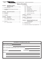 2
2
-
 3
3
-
 4
4
-
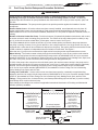 5
5
-
 6
6
-
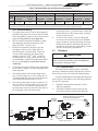 7
7
-
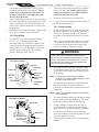 8
8
-
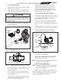 9
9
-
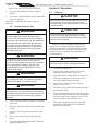 10
10
-
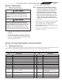 11
11
-
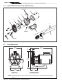 12
12
-
 13
13
-
 14
14
-
 15
15
-
 16
16
-
 17
17
-
 18
18
-
 19
19
-
 20
20
-
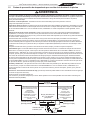 21
21
-
 22
22
-
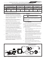 23
23
-
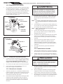 24
24
-
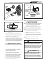 25
25
-
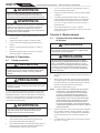 26
26
-
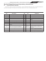 27
27
-
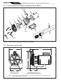 28
28
-
 29
29
-
 30
30
-
 31
31
-
 32
32
-
 33
33
-
 34
34
-
 35
35
-
 36
36
-
 37
37
-
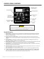 38
38
-
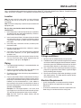 39
39
-
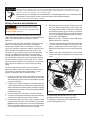 40
40
-
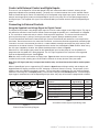 41
41
-
 42
42
-
 43
43
-
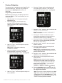 44
44
-
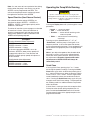 45
45
-
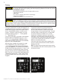 46
46
-
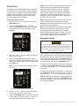 47
47
-
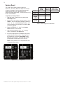 48
48
-
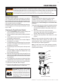 49
49
-
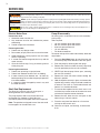 50
50
-
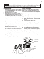 51
51
-
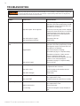 52
52
-
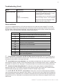 53
53
-
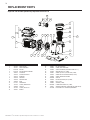 54
54
-
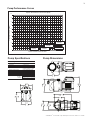 55
55
-
 56
56


Polaris PB4-60 Manual de usuario
- Categoría
- Accesorios para piscinas elevadas
- Tipo
- Manual de usuario
En otros idiomas
- English: Polaris PB4-60 User manual
Documentos relacionados
Otros documentos
-
Pentair 340039 Guía del usuario
-
Pentair CRISTAL-FLO II Guía del usuario
-
Pentair Sand Dollar / Cristal-Flo II Aboveground El manual del propietario
-
-
Pentair 348195SR Guía del usuario
-
Jandy JEP-R Manual de usuario
-
BLACK DECKER BD-137 Manual de usuario
-
Zodiac JEP-R Instrucciones de operación
-
Lifesmart LS450DX Manual de usuario
-
Flotec FPT20515 El manual del propietario