
INSTRUCTION MANUAL
Read and understand all of the instructions and
safety information in this manual before operating
or servicing this tool.
Register this product at www.greenlee.com
99971690 © 2019 Greenlee Tools, Inc. IM 975 REV 15 2/19
882 and 882CB
HydraulicBenders
for 1-1/4", 1-1/2", and 2" Conduit
Serial Numbers FT 16000 and up
Español ............... 15
Français .............. 29

882 and 882CB Hydraulic Benders
Greenlee Tools, Inc. 4455 Boeing Dr. • Rockford, IL 61109-2988 USA • 815-397-7070
2
Description
The 882 Conduit Bender is intended to bend EMT
(electrical metallic tubing). The 882CB Conduit Bender
is intended to bend EMT, IMC (intermediate metallic
conduit), GRC (galvanized rigid conduit), and Schedule
40 Pipe. Bending shoes are available to accommodate
1-1/4" through 2" conduit and pipe.
The bender is to be coupled to any Greenlee hydraulic
pump capable of developing 10,000 psi (689.5 bar).
Suggested models include:
Hand Pump: 755
Electric Pump (120 V): 960 SAPS
975
Electric Pump (220 V): 976-22FS
976-22PS
Safety
Safety is essential in the use and maintenance of
Greenlee tools and equipment. This instruction manual
and any markings on the tool provide information for
avoiding hazards and unsafe practices related to the
use of this tool. Observe all of the safety information
provided.
Purpose of this Manual
This manual is intended to familiarize all personnel with
the safe operation and maintenance procedures for the
following Greenlee tools:
882 and 882CB Hydraulic Benders
Keep this manual available to all personnel.
Replacement manuals are available upon request at no
charge at www.greenlee.com.
All specications are nominal and may change as design
improvements occur. Greenlee Tools, Inc. shall not be liable for
damages resulting from misapplication or misuse of its products.
KEEP THIS MANUAL
Table of Contents
Description .................................................................... 2
Safety ............................................................................ 2
Purpose of this Manual ................................................. 2
Important Safety Information ........................................ 3
Identication .................................................................. 4
Setup ............................................................................. 5
Operating Instructions ................................................... 6
Glossary of Bending Terms ........................................... 7
Laying Out Bends ..................................................... 8-10
Special Bending Information Chart ........................ 11-13
Illustration—882 Series Hydraulic Benders ................. 43
Parts List—882 Series Hydraulic Benders .................. 44
Shoe Groups ............................................................... 45
Attachment Groups ..................................................... 46
Illustration and Parts List—Conversion Kit .................. 47

882 and 882CB Hydraulic Benders
Greenlee Tools, Inc. 4455 Boeing Dr. • Rockford, IL 61109-2988 USA • 815-397-7070
3
IMPORTANT SAFETY INFORMATION
SAFETY
ALERT
SYMBOL
This symbol is used to call your attention to hazards
or unsafe practices which could result in an injury or
property damage. The signal word, dened below,
indicates the severity of the hazard. The message
after the signal word provides information for pre-
venting or avoiding the hazard.
Immediate hazards which, if not avoided, WILL result
in severe injury or death.
Hazards which, if not avoided, COULD result in
severe injury or death.
Hazards or unsafe practices which, if not avoided,
MAY result in injury or property damage.
Read and understand all of the
instructions and safety information
in this manual before operating or
servicing this tool.
Failure to observe this warning could
result in severe injury or death.
Pinch points:
Keep hands away from bending shoe,
follow bar, saddle, and conduit when
bender is in use.
Wear eye protection when operating
this tool.
Failure to wear eye protection could
result in serious eye injury from ying
debris and hydraulic oil.
• Do not stand in direct line with the hydraulic ram. A
component failure could propel parts with sufcient
force to cause severe injury or death.
• Do not operate while wearing loose clothing. Loose
clothing could get caught in moving parts.
Failure to observe these warnings could result in
severe injury or death.
• Conduit moves rapidly as it is bent. The path of
the conduit must be clear of obstructions. Be sure
clearance is adequate before starting the bend.
• Inspect the bender, pump, and hose before each
use. Replace damaged, worn or missing parts with
Greenlee replacement parts. A damaged or improp-
erly assembled component could break and strike
nearby personnel.
• Some of the bender parts and accessories are
heavy and may require more than one person to lift
and assemble. Improper lifting can result in back
injury.
Failure to observe these precautions may result in
injury or property damage.
Make sure all hose ttings are properly seated before
starting the bend. Incomplete connections may not
allow the ram to retract after the bend is complete.
Note: Keep all decals clean and legible, and replace
when necessary.

882 and 882CB Hydraulic Benders
Greenlee Tools, Inc. 4455 Boeing Dr. • Rockford, IL 61109-2988 USA • 815-397-7070
4
Identification
1. Hydraulic Pump
2. Hose Unit, 3/8" x 6 ft, High-Pressure
3. 12-ton Hydraulic Ram
4. Upper Connecting Plate
5. Lower Connecting Plate
6. Hitch Pin
7. Roller Unit
8. Yoke Pin
9. Saddle Pin
10. Yoke
11. Shoe
12. Saddle
13. Follow Bar
1
4
6
7
5
2
3
8
9
11
12
13
10

882 and 882CB Hydraulic Benders
Greenlee Tools, Inc. 4455 Boeing Dr. • Rockford, IL 61109-2988 USA • 815-397-7070
5
Setup
Note: Shoes, follow bars, and saddles marked
“EMT” are for EMT conduit only. Parts marked
“Rigid/IMC” are for rigid and IMC conduit,
and Schedule 40 pipe.
Loading Conduit
Ready to Bend
Completed Bend
1. Mark the conduit. See the instructions under
“Laying Out Bends” in this manual.
2. Select the bending shoe, follow bar, and saddle that
correspond to the size and type of conduit.
3. Remove the locking hitch pin from the roller unit.
Lift the hinged upper connecting plate. Remove the
yoke pin from the yoke.
4. Position the shoe, lettered side up, so that the 1"
diameter hole is in the yoke slot. Align the 1" shoe
hole with the yoke hole that is:
• farthest from the ram when using the 1-1/4" and
1-1/2" shoe
• closest to the ram when using the 2" shoe
5. Insert the yoke pin through the yoke and the shoe.
6. Place the follow bar, with legs down, over the lower
connecting plate.
7. Place the conduit into the follow bar. Slip the saddle
over the conduit and pin the saddle to the shoe with
the saddle pin.
8. Lower the upper connecting plate over the roller pin
and replace the locking hitch pin.
9. Align the bending mark on the conduit with the
outside edge of the saddle. Be sure that the pins for
the yoke and saddle are fully engaged.
10. Connect the high-pressure hydraulic hose to the
ram and to the pump.
Note: Clean the quick-change couplers before
making connections. Hand-tighten the couplers com-
pletely. Do not use tools.
Follow the instructions and safety information
supplied with your hydraulic pump.

882 and 882CB Hydraulic Benders
Greenlee Tools, Inc. 4455 Boeing Dr. • Rockford, IL 61109-2988 USA • 815-397-7070
6
Operating Instructions
Bending
1. Loosen the ram travel scale nut; set the ram travel
scale, which is read at the edge of the block, to
zero. Tighten the nut. See the illustration under
“Ram Travel Table for Common Bends.”
2. Use the hydraulic pump and advance the ram until
the shoe contacts the conduit and the conduit is
seated in the follow bar. Check the placement of the
conduit to be sure that the bending mark is aligned
with the outside edge of the saddle.
Note: For specific pump operating instructions, see
the instruction manual supplied with the hydraulic
pump.
3. Consult the “Ram Travel Table” to nd the amount
of ram travel necessary to accomplish the bend.
4. Use the hydraulic pump to advance the ram by the
necessary amount of ram travel.
5. Release the hydraulic pressure at the pump and
move the conduit to the next bending position.
Note: If making an offset bend, rotate the conduit
180° before making the second bend. If making a
three-bend saddle, rotate the conduit 180° before
making the second and third bends; the second
bend angle is twice the number of degrees and
requires more ram travel than the first and third
bends. If making a 4-bend saddle, rotate the conduit
before making the second and fourth bends.
6. Repeat steps 2–5 until the last bend is made.
7. Release the hydraulic pressure at the pump.
Remove the locking hitch pin to release the upper
connecting plate. Lift the plate clear of the shoe,
follow bar, and saddle.
8. Remove the conduit from the bender.
Ram Travel Table for Common Bends
Ram Travel:
Read Scale at
Edge of Block
Ram Travel (approximate)
Angle of
Bend
FOR IMC/RIGID CONDUIT
1-1/4" 1-1/2" 2"
5° 2-1/8" 7/8" 13/16"
10° 2-3/8" 1-1/16" 1-1/16"
15° 2-5/8" 1-3/8" 1-7/16"
30° 3-5/16" 2-1/16" 2-1/2"
45° 4-1/8" 2-7/8" 3-9/16"
60° 4-15/16" 3-11/16" 4-5/8"
90° 6-1/4" 5-13/16" 6-11/16"
Angle of
Bend
FOR EMT CONDUIT
1-1/4" 1-1/2" 2"
5° 2-1/16" 7/8" 1-3/8"
10° 2-1/4" 1-1/8" 1-5/8"
15° 2-7/16" 1-5/16" 1-7/8"
30° 3-1/8" 2-1/16" 2-5/8"
45° 3-7/8" 2-7/8" 3-3/8"
60° 4-5/8" 3-11/16" 4-3/16"
90° 6-3/16" 5-3/8" 5-1/2"
Note: Consult the table that corresponds to the type
of conduit to be bent. Find the degree of bend in the left
most column and find the size of conduit to the right.
The number shown on the table is the amount of ram
travel needed.

882 and 882CB Hydraulic Benders
Greenlee Tools, Inc. 4455 Boeing Dr. • Rockford, IL 61109-2988 USA • 815-397-7070
7
Glossary of Bending Terms with Illustrations
1. amount of offset — the dis-
tance that the conduit or pipe
must be re-routed to avoid an
obstruction; see offset in this
glossary and “Offset” bending
instructions in this manual
2. back-to-back bend — any
U-shaped bend formed by
two parallel 90° bends with a
straight section of conduit or
pipe between the bends
3. center-to-center distance —
the distance between the suc-
cessive bends that make
up an offset or a three-bend
saddle
4. depth of offset — same as
amount of offset
5. height of offset — same as
amount of offset
6. leg length — the distance from
the end of a horizontal section
of conduit or pipe to the bend;
measured from the end to the
center line, inside edge, or
outside edge of the conduit
or pipe
7. 90° bend — any bend that
changes the direction of the
conduit or pipe by 90 degrees
8. O.D. — the size of any piece of
conduit or pipe as measured by
its outside diameter
9. offset bend — two bends with
the same degree of bend; used
to avoid an obstruction block-
ing the run of the conduit or
pipe
10. ram travel — the distance that
the ram of hydraulic bender
moves to accomplish a particu-
lar bend; inches of ram travel
are proportionate to degrees of
bend
11. rise — the distance from the
end of a vertical section of
conduit or pipe to the bend;
measured from the end to the
center line, inside edge, or
outside edge of the conduit or
pipe
12. shrink — the amount of conduit
“lost” when laying out an
offset bend working toward an
obstruction; see the detailed
explanation under “Offset”
bending in this manual
13. springback — the amount,
measured in degrees, that
a conduit or pipe tends to
straighten after being bent
14. stub — same as rise
15. stub-up — same as rise

882 and 882CB Hydraulic Benders
Greenlee Tools, Inc. 4455 Boeing Dr. • Rockford, IL 61109-2988 USA • 815-397-7070
8
Laying Out Bends
The following drawings and bending charts are intended
to provide the information necessary to accomplish the
most common types of bends. The “Special Bending
Information Chart” contains information for the most
commonly needed bending dimensions.
Stubs
MARK
Y
HEIGHT
ANGLE
1. Select the size and type of conduit to be bent.
Determine the height of stub and the angle of bend.
2. Find the chart that corresponds to the type and size
of conduit selected in Step 1.
3. Under the column labeled ANGLE, nd the angle of
bend.
4. Find the row labeled Y. In the row at the top of the
page, nd the height (H) of the stub. The number
shown at this intersection is the dimension Y. Place
the bending mark Y inches from the end of the
conduit.
5. See the bending instructions.
Offset
An offset is used to route the conduit around an
obstruction. To make an offset, two equal bends are
required. The distance between the two bends is the
center-to-center distance. This is represented by L1 in
the bending tables.
When working past an obstruction, it is necessary to
determine the location of the rst bend. The center-to-
center distance is then used to nd the location of the
second bend.
When working toward an obstruction, it is necessary to
determine the location of the second bend. The center-
to-center distance is then used to nd the location of
the rst bend.
Offsets: Working Past an Obstruction
BENDING
MARK 2
BENDING
MARK 1
LENGTH – X
LENGTH
L1
ANGLE
HEIGHT
START OF
FIRST BEND
1. Select the size and type of conduit to be bent.
Measure the height of the obstruction and the dis-
tance labeled LENGTH. Select the angle to be used.
2. Find the chart that corresponds to the type and size
of conduit selected in Step 1.
3. To the right of the size and type of conduit, nd the
dimension labeled X. Subtract X from LENGTH.
Place the rst bending mark (Bending Mark 1) this
distance from the end of the conduit.
4. Under the column labeled ANGLE, nd the angle
of bend. Find the row labeled L1. In the row at the
top of the page, nd the height (H) of the offset.
The number at this intersection is the dimension L1.
Place the second bending mark (Bending Mark 2)
L1 inches from the rst bending mark.
5. See the bending instructions.

882 and 882CB Hydraulic Benders
Greenlee Tools, Inc. 4455 Boeing Dr. • Rockford, IL 61109-2988 USA • 815-397-7070
9
Laying Out Bends (cont’d)
Offsets: Working Toward an Obstruction
BENDING
MARK 1
BENDING
MARK 2
LENGTH TO END OF SECOND BEND
LENGTH – Z L1
HEIGHT
ANGLE
1. Select the size and type of conduit to be bent.
Measure the height of the obstruction and the
distance labeled LENGTH TO END OF SECOND
BEND. Select the angle to be used.
2. Find the chart that corresponds to the type and size
of conduit selected in Step 1.
3. Under the column labeled ANGLE, nd the angle of
bend. Find the row labeled Z. In the row at the top
of the page, nd the height (H) of the offset. The
number shown at this intersection is the dimen-
sion Z. Subtract Z from LENGTH TO THE END OF
SECOND BEND. Place the rst bending mark this
distance from the end of the conduit.
4. In the same column, nd the row labeled L1. Place
the second bending mark L1 inches from the rst
bending mark.
5. See the bending instructions.
Three-Bend Saddle
BENDING
MARK 2
BENDING
MARK 1
BENDING
MARK 3
LENGTH – Z
LENGTH TO CENTER
L1 L2
ANGLE
HEIGHT
1. Select the size and type of conduit to be bent.
Measure the height of the obstruction and the
distance from the end of the conduit to the center
(LENGTH TO CENTER) of the bend. Select the angle
to be used.
Note: The second bend angle will be twice the
number of degrees as the first and third bends.
2. Find the chart that corresponds to the type and size
of conduit selected in Step 1.
3. Under the column labeled ANGLE, nd the angle of
bend needed. Find the row labeled Z. In the row at
the top of the page, nd the height (H) of the offset.
The number shown at this intersection is Z. Subtract
Z from the LENGTH TO CENTER. Place the rst
bending mark this distance from the end of the
conduit.
4. In the same column, nd the row labeled L1. Place
the second bending mark L1 inches from the rst
bending mark.
5. In the same column, nd the row labeled L2. Place
the third bending mark L2 inches from the second
bending mark.
6. See the bending instructions.

882 and 882CB Hydraulic Benders
Greenlee Tools, Inc. 4455 Boeing Dr. • Rockford, IL 61109-2988 USA • 815-397-7070
10
Laying Out Bends (cont’d)
Four-Bend Saddle
BENDING
MARK 2
BENDING
MARK 1
BENDING
MARK 4
BENDING
MARK 3
LENGTH – Z
LENGTH
STRAIGHT
SECTION
L1 L1
ANGLE
HEIGHT
L2 + STRAIGHT SECTION
U-Bends
LENGTH
HEIGHT
Y L1
BENDING
MARK 1
BENDING
MARK 2
1. Select the size and type of conduit to be bent.
Measure the height of the obstruction, the dis-
tance labeled LENGTH, and the distance labeled
STRAIGHT SECTION. Select the angle to be used.
2. Find the chart that corresponds to the type and size
of conduit selected in Step 1.
3. Under the column labeled ANGLE, nd the angle of
bend needed. Find the row labeled Z. In the row at
the top of the page, nd the height (H) of the offset.
The number shown at this intersection is Z. Subtract
Z from the LENGTH. Place the rst bending mark
this distance from the end of the conduit.
4. In the same column, nd the row labeled L1. Place
the second bending mark L1 inches from the rst
bending mark.
5. In the same column, nd the row labeled L2. Add L2
to the STRAIGHT SECTION. Place the third bending
mark this distance from the rst bending mark.
6. Make the nal bending mark L1 inches from the
third bending mark.
7. See the bending instructions.
1. Select the size and type of conduit to be bent.
Determine the LENGTH and the HEIGHT.
2. Find the chart that corresponds to the type and size
of conduit selected in Step 1.
3. Under the column labeled ANGLE, nd 90°.
4. Find the row labeled Y. In the row at the top of the
page, nd the height (H) that corresponds to the
LENGTH. The number shown at this intersection is
the dimension Y. Place the bending mark Y inches
from the end of the conduit.
5. Find the row labeled L1, and go to the right to nd
the height (H) that corresponds to the HEIGHT. The
number shown at this intersection is the dimension
L1. Place the second bending mark L1 inches from
the rst mark.
6. See the bending instructions.

882 and 882CB Hydraulic Benders
Greenlee Tools, Inc. 4455 Boeing Dr. • Rockford, IL 61109-2988 USA • 815-397-7070
11
Y 15.00 0.41 8.14 15.87 23.59 31.32 39.05 50.64 62.23 85.41 131.78
L1 15.00 7.72 15.44 23.17 30.90 38.63 46.35 57.94 69.54 92.72 139.08
L2 15.00 9.66 17.39 25.12 32.84 40.57 48.30 59.89 71.48 94.66 141.03
Z 15.00 12.84 20.30 27.77 35.23 42.70 50.16 61.36 72.55 94.95 139.73
MINIMUM H=1.39
Y 22.50 3.58 8.81 14.03 19.26 24.49 32.33 40.17 55.84 87.20
L1 22.50 10.41 15.64 20.87 26.09 31.32 39.16 47.00 62.68 94.03
L2 22.50 13.33 18.56 23.78 29.01 34.24 42.08 49.92 65.59 96.95
Z 22.50 16.03 20.86 25.69 30.52 35.35 42.59 49.83 64.32 93.29
MINIMUM H=2.44
Y 30.00 1.08 5.08 9.08 13.08 17.08 23.08 29.08 41.08 65.08
L1 30.00 7.91 11.91 15.91 19.91 23.91 29.91 35.91 47.91 71.91
L2 30.00 11.80 15.80 19.80 23.80 27.80 33.80 39.80 51.80 75.80
Z 30.00 14.33 17.79 21.26 24.72 28.19 33.38 38.58 48.97 69.76
MINIMUM H=3.70
Y 45.00 0.92 3.75 6.58 9.41 13.65 17.89 26.38 43.35
L1 45.00 10.99 13.82 16.65 20.89 25.14 33.62 50.59
L2 45.00 16.83 19.66 22.49 26.73 30.97 39.46 56.43
Z 45.00 17.58 19.58 21.58 24.58 27.58 33.58 45.58
MINIMUM H=6.77
Y 60.00 0.66 2.97 5.27 8.74 12.20 19.13 32.99
L1 60.00 13.06 16.52 19.99 26.91 40.77
L2 60.00 20.84 24.30 27.77 34.69 48.55
Z 60.00 18.93 20.66 22.39 25.86 32.78
MINIMUM H=10.39
Y 90.00 0.40 3.40 6.40 12.40 24.39
L1 90.00 20.81 32.81
L2 90.00 32.48 44.48
Z 90.00 18.28 18.28
MINIMUM H=18.28
Y 15.00 7.18 14.91 22.64 30.36 38.09 49.68 61.27 84.45 130.82
L1 15.00 7.71 15.44 23.17 30.90 38.62 46.35 57.94 69.53 92.72 139.08
L2 15.00 9.89 17.62 25.34 33.07 40.80 48.52 60.12 71.71 94.89 141.25
Z 15.00 13.47 20.93 28.40 35.86 43.33 50.79 61.99 73.18 95.57 140.36
MINIMUM H=1.55
Y 22.50 2.71 7.93 13.16 18.39 23.61 31.45 39.29 54.97 86.33
L1 22.50 10.41 15.64 20.86 26.09 31.31 39.15 46.99 62.67 94.03
L2 22.50 13.67 18.90 24.12 29.35 34.57 42.41 50.25 65.93 97.29
Z 22.50 16.78 21.61 26.44 31.26 36.09 43.34 50.58 65.06 94.03
MINIMUM H=2.73
Y 30.00 0.22 4.22 8.22 12.22 16.22 22.22 28.22 40.22 64.22
L1 30.00 11.90 15.90 19.90 23.90 29.90 35.90 47.90 71.90
L2 30.00 16.24 20.24 24.24 28.24 34.24 40.24 52.24 76.24
Z 30.00 18.66 22.12 25.59 29.05 34.25 39.44 49.84 70.62
MINIMUM H=4.13
Y 45.00 0.00 2.83 5.65 8.48 12.72 16.97 25.45 42.42
L1 45.00 10.96 13.78 16.61 20.86 25.10 33.58 50.55
L2 45.00 17.48 20.30 23.13 27.37 31.62 40.10 57.07
Z 45.00 18.70 20.70 22.70 25.70 28.70 34.70 46.70
MINIMUM H=7.56
Y 60.00 1.93 4.24 7.70 11.17 18.10 31.95
L1 60.00 12.96 16.43 19.89 26.82 40.68
L2 60.00 21.66 25.12 28.58 35.51 49.37
Z 60.00 20.33 22.06 23.80 27.26 34.19
MINIMUM H=11.61
Y 90.00 2.01 5.01 11.01 23.01
L1 90.00 20.44 32.44
L2 90.00 33.48 45.48
Z 90.00 20.42 20.42
MINIMUM H=20.42
DIM ANGLE 2" 4" 6" 8" 10" 12" 15" 18" 24" 36"
1-1/4 EMT Dia. = 1.51 Radius = 7.43 X = 3.42
1-1/2 EMT Dia. = 1.74 Radius = 8.3 X = 3.82
HEIGHT (H)
Special Bending Information Chart

882 and 882CB Hydraulic Benders
Greenlee Tools, Inc. 4455 Boeing Dr. • Rockford, IL 61109-2988 USA • 815-397-7070
12
Y 15.00 6.01 13.74 21.47 29.19 36.92 48.51 60.10 83.29 129.65
L1 15.00 7.71 15.44 23.17 30.90 38.62 46.35 57.94 69.53 92.71 139.08
L2 15.00 10.22 17.95 25.68 33.41 41.13 48.86 60.45 72.04 95.23 141.59
Z 15.00 13.92 21.38 28.85 36.31 43.78 51.24 62.44 73.63 96.02 140.81
MINIMUM H=1.67
Y 22.50 1.74 6.97 12.19 17.42 22.65 30.48 38.32 54.00 85.36
L1 22.50 10.40 15.63 20.86 26.08 31.31 39.15 46.99 62.67 94.02
L2 22.50 14.17 19.40 24.62 29.85 35.07 42.91 50.75 66.43 97.79
Z 22.50 17.40 22.23 27.06 31.89 36.72 43.96 51.20 65.69 94.66
MINIMUM H=2.96
Y 30.00 3.30 7.30 11.30 15.30 21.30 27.30 39.30 63.30
L1 30.00 11.88 15.88 19.88 23.88 29.88 35.88 47.88 71.88
L2 30.00 16.90 20.90 24.90 28.90 34.90 40.90 52.90 76.90
Z 30.00 19.46 22.93 26.39 29.85 35.05 40.25 50.64 71.42
MINIMUM H=4.53
Y 45.00 1.86 4.68 7.51 11.76 16.00 24.48 41.45
L1 45.00 13.73 16.56 20.80 25.04 33.53 50.50
L2 45.00 21.26 24.09 28.33 32.58 41.06 58.03
Z 45.00 21.87 23.87 26.87 29.87 35.87 47.87
MINIMUM H=8.40
Y 60.00 0.81 3.12 6.58 10.05 16.98 30.83
L1 60.00 16.29 19.75 26.68 40.54
L2 60.00 26.33 29.80 36.72 50.58
Z 60.00 23.66 25.40 28.86 35.79
MINIMUM H=12.99
Y 90.00 0.38 3.38 9.38 21.38
L1 90.00 19.88 31.88
L2 90.00 34.95 46.95
Z 90.00 23.11 23.11
MINIMUM H= 23.11
Y 15.00 7.31 15.04 22.77 30.50 38.22 49.82 61.41 84.59 130.95
L1 15.00 7.72 15.44 23.17 30.90 38.63 46.35 57.94 69.54 92.72 139.08
L2 15.00 9.67 17.40 25.13 32.85 40.58 48.31 59.90 71.49 94.67 141.04
Z 15.00 13.38 20.85 28.31 35.77 43.24 50.70 61.90 73.09 95.49 140.27
MINIMUM H=1.53
Y 22.50 2.85 8.07 13.30 18.53 23.75 31.59 39.43 55.11 86.47
L1 22.50 10.41 15.64 20.87 26.09 31.32 39.16 47.00 62.68 94.03
L2 22.50 13.35 18.57 23.80 29.03 34.25 42.09 49.93 65.61 96.97
Z 22.50 16.58 21.41 26.24 31.06 35.89 43.13 50.38 64.86 93.83
MINIMUM H=2.65
Y 30.00 0.39 4.39 8.39 12.39 16.39 22.39 28.39 40.39 64.39
L1 30.00 7.91 11.91 15.91 19.91 23.91 29.91 35.91 47.91 71.91
L2 30.00 11.82 15.82 19.82 23.82 27.82 33.82 39.82 51.82 75.82
Z 30.00 14.88 18.35 21.81 25.27 28.74 33.93 39.13 49.52 70.31
MINIMUM H=3.98
Y 45.00 0.27 3.10 5.92 8.75 13.00 17.24 25.72 42.69
L1 45.00 10.99 13.82 16.65 20.89 25.13 33.62 50.59
L2 45.00 16.86 19.69 22.52 26.76 31.00 39.49 56.46
Z 45.00 18.14 20.14 22.14 25.14 28.14 34.14 46.14
MINIMUM H=7.17
Y 60.00 0.02 2.33 4.64 8.10 11.56 18.49 32.35
L1 60.00 13.05 16.52 19.98 26.91 40.77
L2 60.00 20.88 24.34 27.80 34.73 48.59
Z 60.00 19.50 21.24 22.97 26.43 33.36
MINIMUM H=10.90
Y 90.00 2.75 5.75 11.75 23.75
L1 90.00 20.79 32.79
L2 90.00 32.53 44.53
Z 90.00 18.89 18.89
MINIMUM H=18.89
DIM ANGLE 2" 4" 6" 8" 10" 12" 15" 18" 24" 36"
2 EMT Dia. = 2.2 Radius = 9.59 X = 3.93
1-1/4 IMC/RIGID Dia. = 1.66 Radius = 7.47 X = 3.95
HEIGHT (H)
Special Bending Information Chart (cont’d)

882 and 882CB Hydraulic Benders
Greenlee Tools, Inc. 4455 Boeing Dr. • Rockford, IL 61109-2988 USA • 815-397-7070
13
Y 15.00 6.62 14.34 22.07 29.80 37.52 49.12 60.71 83.89 130.25
L1 15.00 7.71 15.44 23.17 30.90 38.62 46.35 57.94 69.53 92.72 139.08
L2 15.00 9.94 17.67 25.39 33.12 40.85 48.58 60.17 71.76 94.94 141.31
Z 15.00 13.75 21.22 28.68 36.14 43.61 51.07 62.27 73.46 95.86 140.64
MINIMUM H=1.63
Y 22.50 2.23 7.46 12.68 17.91 23.13 30.97 38.81 54.49 85.85
L1 22.50 10.41 15.64 20.86 26.09 31.31 39.15 46.99 62.67 94.03
L2 22.50 13.75 18.97 24.20 29.43 34.65 42.49 50.33 66.01 97.37
Z 22.50 17.09 21.92 26.75 31.57 36.40 43.64 50.89 65.37 94.34
MINIMUM H=2.84
Y 30.00 3.77 7.77 11.77 15.77 21.77 27.77 39.77 63.77
L1 30.00 11.90 15.90 19.90 23.90 29.90 35.90 47.90 71.90
L2 30.00 16.35 20.35 24.35 28.35 34.35 40.35 52.35 76.35
Z 30.00 19.00 22.46 25.93 29.39 34.59 39.78 50.17 70.96
MINIMUM H=4.30
Y 45.00 2.40 5.23 8.06 12.30 16.54 25.03 42.00
L1 45.00 10.95 13.78 16.60 20.85 25.09 33.58 50.55
L2 45.00 17.62 20.45 23.28 27.52 31.77 40.25 57.22
Z 45.00 19.09 21.09 23.09 26.09 29.09 35.09 47.09
MINIMUM H=7.84
Y 60.00 1.49 3.80 7.27 10.73 17.66 31.51
L1 60.00 12.94 16.41 19.87 26.80 40.66
L2 60.00 21.84 25.31 28.77 35.70 49.56
Z 60.00 20.79 22.53 24.26 27.72 34.65
MINIMUM H=12.01
Y 90.00 1.50 4.50 10.50 22.50
L1 90.00 20.35 32.35
L2 90.00 33.70 45.70
Z 90.00 21.05 21.05
MINIMUM H=21.05
Y 15.00 5.06 12.79 20.52 28.25 35.97 47.56 59.16 82.34 128.70
L1 15.00 7.71 15.44 23.17 30.90 38.62 46.35 57.94 69.53 92.72 139.08
L2 15.00 10.11 17.83 25.56 33.29 41.02 48.74 60.33 71.93 95.11 141.47
Z 15.00 14.47 21.93 29.40 36.86 44.33 51.79 62.99 74.18 96.58 141.36
MINIMUM H=1.81
Y 22.50 0.93 6.16 11.38 16.61 21.84 29.68 37.52 53.19 84.55
L1 22.50 10.41 15.63 20.86 26.08 31.31 39.15 46.99 62.67 94.03
L2 22.50 13.99 19.22 24.45 29.67 34.90 42.74 50.58 66.26 97.61
Z 22.50 17.89 22.72 27.55 32.38 37.21 44.45 51.69 66.18 95.15
MINIMUM H=3.15
Y 30.00 2.58 6.58 10.58 14.58 20.58 26.58 38.58 62.58
L1 30.00 11.89 15.89 19.89 23.89 29.89 35.89 47.89 71.89
L2 30.00 16.67 20.67 24.67 28.67 34.67 40.67 52.67 76.67
Z 30.00 19.89 23.35 26.82 30.28 35.48 40.68 51.07 71.85
MINIMUM H=4.75
Y 45.00 1.25 4.08 6.91 11.15 15.39 23.88 40.85
L1 45.00 13.75 16.58 20.82 25.06 33.55 50.52
L2 45.00 20.93 23.76 28.00 32.24 40.73 57.70
Z 45.00 22.17 24.17 27.17 30.17 36.17 48.17
MINIMUM H=8.61
Y 60.00 0.30 2.61 6.07 9.54 16.46 30.32
L1 60.00 16.34 19.80 26.73 40.59
L2 60.00 25.91 29.37 36.30 50.16
Z 60.00 23.81 25.55 29.01 35.94
MINIMUM H=13.12
Y 90.00 0.07 3.07 9.07 21.07
L1 90.00 20.08 32.08
L2 90.00 34.43 46.43
Z 90.00 22.88 22.88
MINIMUM H=22.88
2 IMC/RIGID Dia. = 2.375 Radius = 9.14 X = 4.6
DIM ANGLE 2" 4" 6" 8" 10" 12" 15" 18" 24" 36"
1-1/2 IMC/RIGID Dia. = 1.9 Radius = 8.5 X = 4.05
HEIGHT (H)
Special Bending Information Chart (cont’d)

882 and 882CB Hydraulic Benders
Greenlee Tools, Inc. 4455 Boeing Dr. • Rockford, IL 61109-2988 USA • 815-397-7070
14

MANUAL DE INSTRUCCIONES
Lea y entienda todas las instrucciones y la
información sobre seguridad que aparecen en
este manual, antes de manejar esta herramienta o
darle mantenimiento.
Registre este producto en www.greenlee.com
99971690 © 2019 Greenlee Tools, Inc. IM 975 REV 15 2/19
Dobladoras hidráulicas
882 y 882CB
para tubos portacables de
1-1/4 pulg., 1-1/2 pulg. y 2 pulg.
Números de Serie FT 16000 y superiores

Dobladoras hidráulicas 882 y 882CB
Greenlee Tools, Inc. 4455 Boeing Dr. • Rockford, IL 61109-2988 USA • 815-397-7070
16
Descripción
La Dobladora 882 para tubos portacables está diseñada
para doblar EMT (tubería eléctrica metálica). La
Dobladora 882CB para tubos portacables está diseñada
para doblar tubos EMT, IMC (tubo portacables metálico
intermedio), GRC (tubo portacables rígido galvanizado),
y tubería 40. Hay disponibles zapatas de plegado para
el uso con tubos portacables y tubería desde 1-1/4
pulg. a 2 pulg.
La dobladora debe acoplarse a cualquier bomba
hidráulica Greenlee, capaz de lograr presiones de hasta
10.000 libras por pulgada
2
(689,5 bar) Los modelos
sugeridos incluyen:
Bomba de mano: 755
Bomba eléctrica (120 V): 960 SAP
975
Bomba eléctrica (220 V): 976-22FS
976-22PS
Acerca de la seguridad
Es fundamental observar métodos seguros al utilizar
y dar mantenimiento a las herramientas y equipo
Greenlee. Este manual de instrucciones y todas
las marcas que ostenta la herramienta le ofrecen la
información necesaria para evitar riesgos y hábitos
poco seguros relacionados con su uso. Siga toda la
información sobre seguridad que se proporciona.
Propósito de este manual
Este manual tiene como propósito familiarizar a todo
el personal con los procedimientos de operación y
mantenimiento seguros para las siguientes herramientas
Greenlee:
Dobladoras hidráulicas 882 y 882CB
Manténgalo siempre al alcance de todo el personal.
Altre copie di questo manuale sono disponibili
gratuitamente su richiesta al sito www.greenlee.com.
Todas las especicaciones son nominales y pueden cambiar cuando
se realicen mejoras en el diseño. Greenlee Tools, Inc. no será
responsable por daños que resulten de la aplicación o uso indebidos
de sus productos.
CONSERVE ESTE MANUAL
Índice
Descripción ................................................................. 16
Acerca de la seguridad ................................................ 16
Propósito de este manual ........................................... 16
Información importante sobre seguridad .................... 17
Identicación ............................................................... 18
Instalación ................................................................... 19
Instrucciones de operación ......................................... 20
Glosario de términos de plegado ................................ 21
Cómo realizar dobleces ..........................................22-24
Tabla de información
sobre plegados especiales .....................................25-27
Ilustración — Dobladoras hidráulicas serie 882 .......... 43
Lista de piezas —
Dobladoras hidráulicas serie 882 ............................... 44
Grupos de zapatas ...................................................... 45
Grupos de aditamentos ............................................... 46
Ilustración y lista de piezas —
Conjunto para conversión ........................................... 47

Dobladoras hidráulicas 882 y 882CB
Greenlee Tools, Inc. 4455 Boeing Dr. • Rockford, IL 61109-2988 USA • 815-397-7070
17
IMPORTANTE INFORMACIÓN SOBRE SEGURIDAD
SÍMBOLO DE
ALERTA SOBRE
SEGURIDAD
Este símbolo se utiliza para indicar un riesgo o
práctica poco segura que podría ocasionar lesiones
o daños materiales. Cada uno de los siguientes
términos denota la gravedad del riesgo. El mensaje
que sigue a dichos términos le indica cómo puede
evitar o prevenir ese riesgo.
Peligros inmediatos que, de no evitarse,
OCASIONARÁN graves lesiones o incluso la muerte.
Peligros que, de no evitarse, PODRÍAN OCASIONAR
graves lesiones o incluso la muerte.
Peligro o prácticas peligrosas que, de no evitarse,
PUEDEN OCASIONAR lesiones o daños materiales.
Lea y entienda todas las
instrucciones y la información sobre
seguridad que aparecen en este
manual, antes de manejar esta
herramienta o darle mantenimiento.
De no observarse esta advertencia
podrían sufrirse graves lesiones o
incluso la muerte.
Puntos de aplastamiento:
Mantenga las manos alejadas de
las zapatas de plegado, de la barra
seguidora, de la silla y del tubo
portacables cuando se esté utilizando
la dobladora.
Al operar la dobladora utilice
protectores para ojos.
De no utilizar protectores para
ojos podría sufrir graves lesiones
oculares ocasionadas si el aceite
para aparatos hidráulicos, o restos de
materiales llegaran a saltar.
• No se pare en línea recta con el pistón hidráulico.
Un fallo del componente podría lanzar partes con
suciente fuerza para ocasionar lesiones graves o
la muerte.
• No opere esta dobladora si lleva puesta vestimenta
holgada. La vestimenta holgada podría quedar
atrapada en las partes movibles.
De no observarse estas advertencias podrían sufrirse
lesiones graves o incluso la muerte.
• El tubo portacables se mueve rápidamente
conforme se dobla. La trayectoria del tubo
portacables debe estar libre de obstáculos. Antes
de comenzar a doblar, asegúrese que el espacio
libre sea el adecuado.
• Revise minuciosamente la dobladora, la bomba
y la manguera antes de cada uso. Reemplace los
componentes dañados, gastados o faltantes con
piezas de repuesto de Greenlee. Los componentes
dañados o mal armados pueden quebrarse y
golpear al personal que esté cerca de la unidad.
• Algunas piezas y accesorios de las dobladoras son
pesados y podría necesitarse más de una persona
para levantarlos e instalarlos. El levantamiento
de objetos de manera errónea puede ocasionar
lesiones en la columna.
De no observarse estas precauciones podrían sufrirse
graves lesiones o daños materiales.
Asegúrese que todos los accesorios de las
mangueras estén debidamente asentados antes de
comenzar el doblez. Las conexiones incompletas
podrían impedir que el pistón se retraiga después de
terminar el doblez.
Aviso: Mantenga limpias y legibles todas las
calcomanías y reemplácelas cuando sea necesario.

Dobladoras hidráulicas 882 y 882CB
Greenlee Tools, Inc. 4455 Boeing Dr. • Rockford, IL 61109-2988 USA • 815-397-7070
18
Identificación
1. Bomba hidráulica
2. Unidad de manguera, 3/8 pulg. x 1,8 m,
para alta presión
3. Pistón hidráulico de 12 toneladas
4. Placa superior de conexión
5. Placa inferior de conexión
6. Clavija de enganche
7. Rodillo
8. Clavija de la horquilla
9. Clavija de la silla
10. Horquilla
11. Zapata
12. Silla
13. Barra seguidora
1
4
6
7
5
2
3
8
9
11
12
13
10

Dobladoras hidráulicas 882 y 882CB
Greenlee Tools, Inc. 4455 Boeing Dr. • Rockford, IL 61109-2988 USA • 815-397-7070
19
Instalación
Nota: Las zapatas, las barras seguidoras y las sillas
con la marca “EMT” son para tubo portacables EMT
solamente. Los componentes marcados con “Rigid/
IMC” son para el uso con tubo portacables rígido e IMC,
y para tubería 40.
Carga del tubo portacables
Listo para doblar
Doblez completo
1. Haga una marca en el tubo portacables. Consulte
las instrucciones “Cómo realizar dobleces” en este
manual.
2. Seleccione la zapata plegadora, la barra seguidora,
y la silla que correspondan al tamaño y al tipo de
tubo portacables.
3. Retire la clavija de enganche de bloqueo del rodillo.
Levante la placa de conexión superior articulada.
Retire la clavija de la horquilla de la horquilla misma.
4. Coloque la zapata, con el lado con letras orientado
hacia arriba, de modo que el oricio de 1 pulg. de
diámetro quede en la ranura de la horquilla. Alinee
el oricio de 1 pulg. de la zapata con el oricio de la
horquilla que esté:
• lo más lejos posible del pistón al usar las zapatas
de 1-1/4 pulg. y 1-1/2 pulg.
• lo más cerca posible al pistón al usar la zapata de
2 pulg.
5. Introduzca la clavija de la horquilla a través de la
horquilla y la zapata.
6. Coloque la barra seguidora, con las patas hacia
abajo, sobre la placa inferior de conexión.
7. Coloque el tubo portacables en la barra seguidora.
Deslice la silla sobre el tubo portacables y je la silla
a la zapata con la clavija de la silla.
8. Baje la placa superior de conexión sobre la clavija
del rodillo y vuelva a colocar la clavija de enganche
de sujeción.
9. Alinee la marca de plegado en el tubo portacables
con el borde exterior de la silla. Asegúrese
que las clavijas para la horquilla y la silla estén
completamente enganchadas.
10. Conecte la manguera hidráulica para alta presión al
pistón y a la bomba.
Nota: Limpie los acopladores de cambio rápido
antes de establecer las conexiones. Apriete a
mano completamente los acopladores. No utilice
herramientas.
Siga las instrucciones y la información de seguridad
suministradas con su bomba hidráulica.

Dobladoras hidráulicas 882 y 882CB
Greenlee Tools, Inc. 4455 Boeing Dr. • Rockford, IL 61109-2988 USA • 815-397-7070
20
Instrucciones de operación
Plegado
1. Aoje la tuerca de la escala de carrera del pistón;
ponga a cero la escala de carrera del pistón, la cual
se lee en el borde del bloque. Apriete la tuerca.
Consulte la ilustración bajo “Tabla de carreras del
pistón para dobleces comunes”.
2. Accione la bomba hidráulica y avance el pistón
hasta que la zapata entre en contacto con el
tubo portacables y éste quede asentado en la
barra seguidora. Verique la colocación del tubo
portacables para asegurarse que la marca de
plegado esté alineada con el borde exterior de la
silla.
Nota: Para instrucciones de operación de su bomba
específica, consulte el manual de operación incluido
con la bomba hidráulica.
3. Consulte la “Tabla de carreras del pistón” para
determinar la longitud de carrera de pistón
necesaria para realizar el doblez.
4. Utilice la bomba hidráulica para avanzar el pistón la
longitud necesaria de carrera del pistón.
5. Libere la presión hidráulica en la bomba y mueva el
tubo portacables a la siguiente posición de plegado.
Nota: Si se va a realizar un doblez de compen-
sación, gire el tubo portacables 180° antes de efec-
tuar el segundo doblez. Si va a realizar una silla de
tres dobleces, gire el tubo portacables 180° antes
de hacer el segundo y tercer doblez; el segundo
ángulo de doblez es dos veces el número de grados
y requiere más carrera del pistón que el primer y
tercer doblez. Si intenta realizar una silla de cuatro
dobleces, gire el tubo portacables antes de efectuar
el segundo y el cuarto doblez.
6. Repita los pasos 2 hasta el 5 hasta efectuar el
último doblez.
7. Libere la presión hidráulica en la bomba. Retire la
clavija de sujeción para liberar la placa superior de
conexión. Levante la placa fuera de la zapata, la
barra seguidora y la silla.
8. Retire el tubo portacables de la dobladora.
Tabla de carreras del pistón para dobleces comunes
Carrera del pistón:
Lea la escala en el
borde del bloque
Carrera del pistón (aproximada)
Ángulo de
doblez
PARA TUBERÍA PORTABLES IMC/RIGID
1-1/4" 1-1/2" 2"
5° 2-1/8" 7/8" 13/16"
10° 2-3/8" 1-1/16" 1-1/16"
15° 2-5/8" 1-3/8" 1-7/16"
30° 3-5/16" 2-1/16" 2-1/2"
45° 4-1/8" 2-7/8" 3-9/16"
60° 4-15/16" 3-11/16" 4-5/8"
90° 6-1/4" 5-13/16" 6-11/16"
Ángulo de
doblez
PARA TUBO PORTACABLES EMT
1-1/4" 1-1/2" 2"
5° 2-1/16" 7/8" 1-3/8"
10° 2-1/4" 1-1/8" 1-5/8"
15° 2-7/16" 1-5/16" 1-7/8"
30° 3-1/8" 2-1/16" 2-5/8"
45° 3-7/8" 2-7/8" 3-3/8"
60° 4-5/8" 3-11/16" 4-3/16"
90° 6-3/16" 5-3/8" 5-1/2"
Nota: Consulte la tabla que corresponda al tipo de
conducto a doblar. Encuentre el grado de doblez en la
columna extrema izquierda y encuentre el tamaño del
tubo portacables a la derecha. El número mostrado en
la tabla es la longitud de carrera necesaria del pistón.

Dobladoras hidráulicas 882 y 882CB
Greenlee Tools, Inc. 4455 Boeing Dr. • Rockford, IL 61109-2988 USA • 815-397-7070
21
Glosario de términos de plegado con ilustraciones
1. cantidad de desviación —
la distancia que debe desviarse
el tubo portacables o tubería
para evitar un obstáculo;
consulte el término desviación
en este glosario y las
instrucciones de plegado para
“Desviaciones” en este manual
2. doblez contiguo — cualquier
doblez en forma de U formado
por dos dobleces paralelos de
90° con una sección recta de
tubo portacables o tubería entre
los dobleces.
3. distancia centro a centro —
la distancia entre los dobleces
sucesivos que conforman
una desviación o silla de tres
dobleces.
4. profundidad de desviación
— lo mismo que cantidad de
desviación
5. altura de desviación —
lomismo que cantidad de
desviación
6. longitud de la pata —
ladistancia desde el extremo de
una sección horizontal del tubo
portacables o tubería hasta
el doblez; medida desde el
extremo hasta la línea central, el
borde interior o el borde exterior
del tubo portacables o tubería.
7. codo de 90° — cualquier
doblez que cambie 90° la
dirección del tubo portacables
otubería
8. D.E. — el diámetro de cualquier
pieza del tubo portacables o
tubería según se mide a través
de su diámetro exterior
9. doblez de desviación —
dos dobleces con el mismo
grado de doblez; utilizado
para esquivar un obstáculo
que bloquee el paso del tubo
portacables o tubería
10. carrera del pistón —
ladistancia que el pistón
de la dobladora hidráulica
se desplaza para lograr un
doblez particular; las pulgadas
de carrera del pistón son
proporcionales a los grados de
doblez
11. elevación — la distancia desde
el extremo de una sección
horizontal del tubo portacables
o tubería hasta el doblez;
medida desde el extremo hasta
la línea central, el borde interior
o el borde exterior del tubo
portacables o tubería.
12. contracción — la cantidad
de tubo portacables “que
se pierde” cuando se tiende
un doblez de desviación
trabajando hacia un obstáculo;
consulte la explicación bajo
“Plegado de desviación” en
este manual.
13. resistencia al doblez—
lacantidad, medida en grados,
que un tubo portacables o
tubería tiende a enderezarse
luego del doblez
14. codo — lo mismo que
elevación
15. codo hacia arriba — lo mismo
que elevación

Dobladoras hidráulicas 882 y 882CB
Greenlee Tools, Inc. 4455 Boeing Dr. • Rockford, IL 61109-2988 USA • 815-397-7070
22
Cómo realizar dobleces
Las siguientes ilustraciones y tablas de plegado tienen
como nalidad proporcionar la información necesaria
para obtener los tipos de dobleces más comunes.
La “Tabla de información sobre plegados especiales”
contiene información sobre las dimensiones de plegado
necesarias de uso más frecuente.
Codos
MARCA
Y
ALTURA
ÁNGULO
1. Seleccione el tamaño y tipo de tubo portacables a
doblar. Determine la altura del codo y el ángulo de
doblez.
2. Encuentre la tabla que corresponda al diámetro
y tipo de tubo portacables seleccionados en el
Paso1.
3. Bajo la columna titulada ÁNGULO, encuentre el
ángulo del doblez.
4. Encuentre la la titulada Y. En la la de la parte
superior de la página, encuentre la altura (A) del
codo. El número mostrado en esta intersección es
la dimensión Y. Coloque la marca de plegado a Y
pulgadas del extremo del tubo portacables.
5. Consulte las instrucciones de plegado.
Desviación
Se utiliza una desviación para encaminar el tubo
portacables alrededor de un obstáculo. Para realizar
una desviación, se requieren dos dobleces iguales. La
distancia entre dos dobleces es la distancia centro a
centro. Ésta se representa en las tablas de plegado por
medio de L1.
Al sobrepasar un obstáculo, será necesario determinar
la ubicación del primer doblez. Entonces, se utiliza la
distancia centro a centro para determinar la ubicación
del segundo doblez.
Al avanzar hacia un obstáculo, será necesario
determinar la ubicación del segundo doblez. Entonces,
se utiliza la distancia centro a centro para determinar la
ubicación del primer doblez.
Desviaciones: Para sobrepasar un obstáculo
MARCA DE
PLEGADO 2
MARCA DE
PLEGADO 1
LONGITUD
– X
LONGITUD
L1
ÁNGULO
ALTURA
INICIO DEL
PRIMER DOBLEZ
1. Seleccione el tamaño y tipo de tubo portacables a
doblar. Mida la altura del obstáculo y la distancia
titulada LONGITUD. Seleccione el ángulo que se va
a utilizar.
2. Encuentre la tabla que corresponda al diámetro
y tipo de tubo portacables seleccionados en el
Paso1.
3. A la derecha del diámetro y tipo de tubo
portacables, encuentre la dimensión titulada X.
Reste X de LONGITUD. Coloque la primera marca
de plegado (Marca de plegado 1) a esta distancia
del extremo del tubo portacables.
4. Bajo la columna titulada ÁNGULO, encuentre
el ángulo del doblez. Encuentre la la titulada
L1. En la la de la parte superior de la página,
encuentre la altura (A) de la desviación. El valor en
esta intersección es la dimensión L1. Coloque la
segunda marca de plegado (Marca de plegado 2) a
L1 pulgadas de la primera marca de plegado.
5. Consulte las instrucciones de plegado.

Dobladoras hidráulicas 882 y 882CB
Greenlee Tools, Inc. 4455 Boeing Dr. • Rockford, IL 61109-2988 USA • 815-397-7070
23
Cómo realizar dobleces (continuación)
Desviaciones: Avanzando hacia un obstáculo
MARCA DE
PLEGADO 1
MARCA DE
PLEGADO 2
LONGITUD HASTA EL EXTREMO
DEL SEGUNDO DOBLEZ
LONGITUD
– Z L1
ALTURA
ÁNGULO
1. Seleccione el tamaño y tipo de tubo portacables a
doblar. Mida la altura del obstáculo y la distancia
titulada LONGITUD HASTA EL EXTREMO DEL
SEGUNDO DOBLEZ. Seleccione el ángulo que se
va a utilizar.
2. Encuentre la tabla que corresponda al diámetro
y tipo de tubo portacables seleccionados en el
Paso1.
3. Bajo la columna titulada ÁNGULO, encuentre el
ángulo del doblez. Encuentre la la titulada Z. En
la la de la parte superior de la página, encuentre
la altura (A) de la desviación. El valor mostrado en
esta intersección es la dimensión Z. Reste Z de la
LONGITUD AL EXTREMO DEL SEGUNDO DOBLEZ.
Coloque la primera marca de plegado a esta
distancia del extremo del tubo portacables.
4. En la misma columna, encuentre la la titulada
L1. Coloque la segunda marca de plegado a L1
pulgadas de la primera marca de plegado.
5. Consulte las instrucciones de plegado.
Silla de tres dobleces
MARCA DE
PLEGADO 2
MARCA DE
PLEGADO 1
MARCA DE
PLEGADO 3
LONGITUD
– Z
LONGITUD HASTA
EL CENTRO
L1 L2
ÁNGULO
ALTURA
1. Seleccione el tamaño y tipo de tubo portacables a
doblar. Mida la altura del obstáculo y la distancia
desde el extremo del tubo portacables al centro
(LONGITUD AL CENTRO) del doblez. Seleccione el
ángulo que se va a utilizar.
Nota: El segundo ángulo de doblez será el doble del
número de grados que el primero y el tercer doblez.
2. Encuentre la tabla que corresponda al diámetro
y tipo de tubo portacables seleccionados en el
Paso1.
3. Bajo la columna titulada ÁNGULO, encuentre el
ángulo del doblez necesario. Encuentre la la
titulada Z. En la la de la parte superior de la
página, encuentre la altura (A) de la desviación. El
valor que aparece en esta intersección es Z. Reste
Z de la LONGITUD AL CENTRO. Coloque la primera
marca de plegado a esta distancia del extremo del
tubo portacables.
4. En la misma columna, encuentre la la titulada
L1. Coloque la segunda marca de plegado a L1
pulgadas de la primera marca de plegado.
5. En la misma columna, encuentre la la titulada L2.
Coloque la tercera marca de plegado a L2 pulgadas
de la segunda marca de plegado.
6. Consulte las instrucciones de plegado.

Dobladoras hidráulicas 882 y 882CB
Greenlee Tools, Inc. 4455 Boeing Dr. • Rockford, IL 61109-2988 USA • 815-397-7070
24
Cómo realizar dobleces (continuación)
Silla de cuatro dobleces
MARCA DE
PLEGADO 2
MARCA DE
PLEGADO 1
MARCA DE
PLEGADO 4
MARCA DE
PLEGADO 3
LONGITUD
– Z
LONGITUD
SECCIÓN
RECTA
L1 L1
ÁNGULO
ALTURA
L2 +
SECCIÓN RECTA
1. Seleccione el tamaño y tipo de tubo portacables
a doblar. Mida la altura del obstáculo, la distancia
titulada LONGITUD, y la distancia titulada SECCIÓN
RECTA. Seleccione el ángulo que se va a utilizar.
2. Encuentre la tabla que corresponda al diámetro
y tipo de tubo portacables seleccionados en el
Paso1.
3. Bajo la columna titulada ÁNGULO, encuentre el
ángulo del doblez necesario. Encuentre la la
titulada Z. En la la de la parte superior de la
página, encuentre la altura (A) de la desviación. El
valor que aparece en esta intersección es Z. Reste
Z de la LONGITUD. Coloque la primera marca
de plegado a esta distancia del extremo del tubo
portacables.
4. En la misma columna, encuentre la la titulada
L1. Coloque la segunda marca de plegado a L1
pulgadas de la primera marca de plegado.
5. En la misma columna, encuentre la la titulada L2.
Añada L2 a la SECCIÓN RECTA. Coloque la tercera
marca de plegado a esta distancia de la primera
marca de plegado.
6. Coloque la última marca de plegado a L1 pulgadas
de la tercera marca de plegado.
7. Consulte las instrucciones de plegado.
Dobleces en U
LONGITUD
ALTURA
Y L1
MARCA DE
PLEGADO 1
MARCA DE
PLEGADO 2
1. Seleccione el tamaño y tipo de tubo portacables a
doblar. Determine la LONGITUD y la ALTURA.
2. Encuentre la tabla que corresponda al diámetro
y tipo de tubo portacables seleccionados en el
Paso1.
3. Bajo la columna titulada ÁNGULO, encuentre 90°.
4. Encuentre la la titulada Y. En la la de la parte
superior de la página, encuentre la altura (A) que
corresponde a la LONGITUD. El número mostrado
en esta intersección es la dimensión Y. Coloque la
marca de plegado a Y pulgadas del extremo del
tubo portacables.
5. Encuentre la la titulada L1; luego vaya a la derecha
y encuentre la altura (A) que corresponde a la
ALTURA. El valor que aparece en esta intersección
es la dimensión L1. Coloque la segunda marca de
plegado a L1 pulgadas de la primera marca.
6. Consulte las instrucciones de plegado.

Dobladoras hidráulicas 882 y 882CB
Greenlee Tools, Inc. 4455 Boeing Dr. • Rockford, IL 61109-2988 USA • 815-397-7070
25
Y 15,00 0,41 8,14 15,87 23,59 31,32 39,05 50,64 62,23 85,41 131,78
L1 15,00 7,72 15,44 23,17 30,90 38,63 46,35 57,94 69,54 92,72 139,08
L2 15,00 9,66 17,39 25,12 32,84 40,57 48,30 59,89 71,48 94,66 141,03
Z 15,00 12,84 20,30 27,77 35,23 42,70 50,16 61,36 72,55 94,95 139,73
ALTURA MÍNIMA=1,39
Y 22,50 3,58 8,81 14,03 19,26 24,49 32,33 40,17 55,84 87,20
L1 22,50 10,41 15,64 20,87 26,09 31,32 39,16 47,00 62,68 94,03
L2 22,50 13,33 18,56 23,78 29,01 34,24 42,08 49,92 65,59 96,95
Z 22,50 16,03 20,86 25,69 30,52 35,35 42,59 49,83 64,32 93,29
ALTURA MÍNIMA=2,44
Y 30,00 1,08 5,08 9,08 13,08 17,08 23,08 29,08 41,08 65,08
L1 30,00 7,91 11,91 15,91 19,91 23,91 29,91 35,91 47,91 71,91
L2 30,00 11,80 15,80 19,80 23,80 27,80 33,80 39,80 51,80 75,80
Z 30,00 14,33 17,79 21,26 24,72 28,19 33,38 38,58 48,97 69,76
ALTURA MÍNIMA=3,70
Y 45,00 0,92 3,75 6,58 9,41 13,65 17,89 26,38 43,35
L1 45,00 10,99 13,82 16,65 20,89 25,14 33,62 50,59
L2 45,00 16,83 19,66 22,49 26,73 30,97 39,46 56,43
Z 45,00 17,58 19,58 21,58 24,58 27,58 33,58 45,58
ALTURA MÍNIMA=6,77
Y 60,00 0,66 2,97 5,27 8,74 12,20 19,13 32,99
L1 60,00 13,06 16,52 19,99 26,91 40,77
L2 60,00 20,84 24,30 27,77 34,69 48,55
Z 60,00 18,93 20,66 22,39 25,86 32,78
ALTURA MÍNIMA=10,39
Y 90,00 0,40 3,40 6,40 12,40 24,39
L1 90,00 20,81 32,81
L2 90,00 32,48 44,48
Z 90,00 18,28 18,28
ALTURA MÍNIMA=18,28
Y 15,00 7,18 14,91 22,64 30,36 38,09 49,68 61,27 84,45 130,82
L1 15,00 7,71 15,44 23,17 30,90 38,62 46,35 57,94 69,53 92,72 139,08
L2 15,00 9,89 17,62 25,34 33,07 40,80 48,52 60,12 71,71 94,89 141,25
Z 15,00 13,47 20,93 28,40 35,86 43,33 50,79 61,99 73,18 95,57 140,36
ALTURA MÍNIMA=1,55
Y 22,50 2,71 7,93 13,16 18,39 23,61 31,45 39,29 54,97 86,33
L1 22,50 10,41 15,64 20,86 26,09 31,31 39,15 46,99 62,67 94,03
L2 22,50 13,67 18,90 24,12 29,35 34,57 42,41 50,25 65,93 97,29
Z 22,50 16,78 21,61 26,44 31,26 36,09 43,34 50,58 65,06 94,03
ALTURA MÍNIMA=2,73
Y 30,00 0,22 4,22 8,22 12,22 16,22 22,22 28,22 40,22 64,22
L1 30,00 11,90 15,90 19,90 23,90 29,90 35,90 47,90 71,90
L2 30,00 16,24 20,24 24,24 28,24 34,24 40,24 52,24 76,24
Z 30,00 18,66 22,12 25,59 29,05 34,25 39,44 49,84 70,62
ALTURA MÍNIMA=4,13
Y 45,00 0,00 2,83 5,65 8,48 12,72 16,97 25,45 42,42
L1 45,00 10,96 13,78 16,61 20,86 25,10 33,58 50,55
L2 45,00 17,48 20,30 23,13 27,37 31,62 40,10 57,07
Z 45,00 18,70 20,70 22,70 25,70 28,70 34,70 46,70
ALTURA MÍNIMA=7,56
Y 60,00 1,93 4,24 7,70 11,17 18,10 31,95
L1 60,00 12,96 16,43 19,89 26,82 40,68
L2 60,00 21,66 25,12 28,58 35,51 49,37
Z 60,00 20,33 22,06 23,80 27,26 34,19
ALTURA MÍNIMA=11,61
Y 90,00 2,01 5,01 11,01 23,01
L1 90,00 20,44 32,44
L2 90,00 33,48 45,48
Z 90,00 20,42 20,42
ALTURA MÍNIMA=20,42
DIM ÁNGULO 2" 4" 6" 8" 10" 12" 15" 18" 24" 36"
EMT de 1-1/4 pulg. Diám. = 1,51 Radio = 7,43 X = 3,42
EMT de 1-1/2 pulg. Diám. = 1.74 Radio = 8.3 X = 3.82
ALTURA (A)
Tabla de información sobre plegados especiales

Dobladoras hidráulicas 882 y 882CB
Greenlee Tools, Inc. 4455 Boeing Dr. • Rockford, IL 61109-2988 USA • 815-397-7070
26
Y 15,00 6,01 13,74 21,47 29,19 36,92 48,51 60,10 83,29 129,65
L1 15,00 7,71 15,44 23,17 30,90 38,62 46,35 57,94 69,53 92,71 139,08
L2 15,00 10,22 17,95 25,68 33,41 41,13 48,86 60,45 72,04 95,23 141,59
Z 15,00 13,92 21,38 28,85 36,31 43,78 51,24 62,44 73,63 96,02 140,81
ALTURA MÍNIMA=1,67
Y 22,50 1,74 6,97 12,19 17,42 22,65 30,48 38,32 54,00 85,36
L1 22,50 10,40 15,63 20,86 26,08 31,31 39,15 46,99 62,67 94,02
L2 22,50 14,17 19,40 24,62 29,85 35,07 42,91 50,75 66,43 97,79
Z 22,50 17,40 22,23 27,06 31,89 36,72 43,96 51,20 65,69 94,66
ALTURA MÍNIMA=2,96
Y 30,00 3,30 7,30 11,30 15,30 21,30 27,30 39,30 63,30
L1 30,00 11,88 15,88 19,88 23,88 29,88 35,88 47,88 71,88
L2 30,00 16,90 20,90 24,90 28,90 34,90 40,90 52,90 76,90
Z 30,00 19,46 22,93 26,39 29,85 35,05 40,25 50,64 71,42
ALTURA MÍNIMA=4,53
Y 45,00 1,86 4,68 7,51 11,76 16,00 24,48 41,45
L1 45,00 13,73 16,56 20,80 25,04 33,53 50,50
L2 45,00 21,26 24,09 28,33 32,58 41,06 58,03
Z 45,00 21,87 23,87 26,87 29,87 35,87 47,87
ALTURA MÍNIMA=8,40
Y 60,00 0,81 3,12 6,58 10,05 16,98 30,83
L1 60,00 16,29 19,75 26,68 40,54
L2 60,00 26,33 29,80 36,72 50,58
Z 60,00 23,66 25,40 28,86 35,79
ALTURA MÍNIMA=12,99
Y 90,00 0,38 3,38 9,38 21,38
L1 90,00 19,88 31,88
L2 90,00 34,95 46,95
Z 90,00 23,11 23,11
ALTURA MÍNIMA= 23,11
Y 15,00 7,31 15,04 22,77 30,50 38,22 49,82 61,41 84,59 130,95
L1 15,00 7,72 15,44 23,17 30,90 38,63 46,35 57,94 69,54 92,72 139,08
L2 15,00 9,67 17,40 25,13 32,85 40,58 48,31 59,90 71,49 94,67 141,04
Z 15,00 13,38 20,85 28,31 35,77 43,24 50,70 61,90 73,09 95,49 140,27
ALTURA MÍNIMA=1,53
Y 22,50 2,85 8,07 13,30 18,53 23,75 31,59 39,43 55,11 86,47
L1 22,50 10,41 15,64 20,87 26,09 31,32 39,16 47,00 62,68 94,03
L2 22,50 13,35 18,57 23,80 29,03 34,25 42,09 49,93 65,61 96,97
Z 22,50 16,58 21,41 26,24 31,06 35,89 43,13 50,38 64,86 93,83
ALTURA MÍNIMA=2,65
Y 30,00 0,39 4,39 8,39 12,39 16,39 22,39 28,39 40,39 64,39
L1 30,00 7,91 11,91 15,91 19,91 23,91 29,91 35,91 47,91 71,91
L2 30,00 11,82 15,82 19,82 23,82 27,82 33,82 39,82 51,82 75,82
Z 30,00 14,88 18,35 21,81 25,27 28,74 33,93 39,13 49,52 70,31
ALTURA MÍNIMA=3,98
Y 45,00 0,27 3,10 5,92 8,75 13,00 17,24 25,72 42,69
L1 45,00 10,99 13,82 16,65 20,89 25,13 33,62 50,59
L2 45,00 16,86 19,69 22,52 26,76 31,00 39,49 56,46
Z 45,00 18,14 20,14 22,14 25,14 28,14 34,14 46,14
ALTURA MÍNIMA=7,17
Y 60,00 0,02 2,33 4,64 8,10 11,56 18,49 32,35
L1 60,00 13,05 16,52 19,98 26,91 40,77
L2 60,00 20,88 24,34 27,80 34,73 48,59
Z 60,00 19,50 21,24 22,97 26,43 33,36
ALTURA MÍNIMA=10,90
Y 90,00 2,75 5,75 11,75 23,75
L1 90,00 20,79 32,79
L2 90,00 32,53 44,53
Z 90,00 18,89 18,89
ALTURA MÍNIMA=18,89
DIM ÁNGULO 2" 4" 6" 8" 10" 12" 15" 18" 24" 36"
EMT de 2 pulg. Diám. = 2,2 Radio = 9,59 X = 3,93
1-1/4 IMC/RIGID Diám. = 1,66 Radio = 7,47 X = 3,95
ALTURA (A)
Tabla de información sobre plegados especiales (continuación)

Dobladoras hidráulicas 882 y 882CB
Greenlee Tools, Inc. 4455 Boeing Dr. • Rockford, IL 61109-2988 USA • 815-397-7070
27
Y 15,00 6,62 14,34 22,07 29,80 37,52 49,12 60,71 83,89 130,25
L1 15,00 7,71 15,44 23,17 30,90 38,62 46,35 57,94 69,53 92,72 139,08
L2 15,00 9,94 17,67 25,39 33,12 40,85 48,58 60,17 71,76 94,94 141,31
Z 15,00 13,75 21,22 28,68 36,14 43,61 51,07 62,27 73,46 95,86 140,64
ALTURA MÍNIMA=1,63
Y 22,50 2,23 7,46 12,68 17,91 23,13 30,97 38,81 54,49 85,85
L1 22,50 10,41 15,64 20,86 26,09 31,31 39,15 46,99 62,67 94,03
L2 22,50 13,75 18,97 24,20 29,43 34,65 42,49 50,33 66,01 97,37
Z 22,50 17,09 21,92 26,75 31,57 36,40 43,64 50,89 65,37 94,34
ALTURA MÍNIMA=2,84
Y 30,00 3,77 7,77 11,77 15,77 21,77 27,77 39,77 63,77
L1 30,00 11,90 15,90 19,90 23,90 29,90 35,90 47,90 71,90
L2 30,00 16,35 20,35 24,35 28,35 34,35 40,35 52,35 76,35
Z 30,00 19,00 22,46 25,93 29,39 34,59 39,78 50,17 70,96
ALTURA MÍNIMA=4,30
Y 45,00 2,40 5,23 8,06 12,30 16,54 25,03 42,00
L1 45,00 10,95 13,78 16,60 20,85 25,09 33,58 50,55
L2 45,00 17,62 20,45 23,28 27,52 31,77 40,25 57,22
Z 45,00 19,09 21,09 23,09 26,09 29,09 35,09 47,09
ALTURA MÍNIMA=7,84
Y 60,00 1,49 3,80 7,27 10,73 17,66 31,51
L1 60,00 12,94 16,41 19,87 26,80 40,66
L2 60,00 21,84 25,31 28,77 35,70 49,56
Z 60,00 20,79 22,53 24,26 27,72 34,65
ALTURA MÍNIMA=12,01
Y 90,00 1,50 4,50 10,50 22,50
L1 90,00 20,35 32,35
L2 90,00 33,70 45,70
Z 90,00 21,05 21,05
ALTURA MÍNIMA=21,05
Y 15,00 5,06 12,79 20,52 28,25 35,97 47,56 59,16 82,34 128,70
L1 15,00 7,71 15,44 23,17 30,90 38,62 46,35 57,94 69,53 92,72 139,08
L2 15,00 10,11 17,83 25,56 33,29 41,02 48,74 60,33 71,93 95,11 141,47
Z 15,00 14,47 21,93 29,40 36,86 44,33 51,79 62,99 74,18 96,58 141,36
ALTURA MÍNIMA=1,81
Y 22,50 0,93 6,16 11,38 16,61 21,84 29,68 37,52 53,19 84,55
L1 22,50 10,41 15,63 20,86 26,08 31,31 39,15 46,99 62,67 94,03
L2 22,50 13,99 19,22 24,45 29,67 34,90 42,74 50,58 66,26 97,61
Z 22,50 17,89 22,72 27,55 32,38 37,21 44,45 51,69 66,18 95,15
ALTURA MÍNIMA=3,15
Y 30,00 2,58 6,58 10,58 14,58 20,58 26,58 38,58 62,58
L1 30,00 11,89 15,89 19,89 23,89 29,89 35,89 47,89 71,89
L2 30,00 16,67 20,67 24,67 28,67 34,67 40,67 52,67 76,67
Z 30,00 19,89 23,35 26,82 30,28 35,48 40,68 51,07 71,85
ALTURA MÍNIMA=4,75
Y 45,00 1,25 4,08 6,91 11,15 15,39 23,88 40,85
L1 45,00 13,75 16,58 20,82 25,06 33,55 50,52
L2 45,00 20,93 23,76 28,00 32,24 40,73 57,70
Z 45,00 22,17 24,17 27,17 30,17 36,17 48,17
ALTURA MÍNIMA=8,61
Y 60,00 0,30 2,61 6,07 9,54 16,46 30,32
L1 60,00 16,34 19,80 26,73 40,59
L2 60,00 25,91 29,37 36,30 50,16
Z 60,00 23,81 25,55 29,01 35,94
ALTURA MÍNIMA=13,12
Y 90,00 0,07 3,07 9,07 21,07
L1 90,00 20,08 32,08
L2 90,00 34,43 46,43
Z 90,00 22,88 22,88
ALTURA MÍNIMA=22,88
IMC/RIGID de 2 pulg. Diám. = 2,375 Radio = 9,14 X = 4,6
DIM ÁNGULO 2" 4" 6" 8" 10" 12" 15" 18" 24" 36"
IMC/RIGID de 1-1/2 pulg. Diám. = 1,9 Radio = 8,5 X = 4,05
ALTURA (A)
Tabla de información sobre plegados especiales (continuación)

Dobladoras hidráulicas 882 y 882CB
Greenlee Tools, Inc. 4455 Boeing Dr. • Rockford, IL 61109-2988 USA • 815-397-7070
28

99971690 © 2019 Greenlee Tools, Inc. IM 975 REV 15 2/19
Cintreuses hydrauliques
882 et 882CB
pour conduit de 1-1/4 po, 1-1/2 po et 2 po
Numéros de série FT 16000 et au-dessus
MANUEL D’INSTRUCTIONS
Nous vous conseillons de lire attentivement et
de bien comprendre les instructions suivantes
avant d’utiliser ou de procéder à l’entretien de
cet outil.
Enregistrez votre produit en ligne, www.greenlee.com

Cintreuses hydrauliques 882 et 882CB
Greenlee Tools, Inc. 4455 Boeing Dr. • Rockford, IL 61109-2988 USA • 815-397-7070
30
Description
La cintreuse 882 est destinée au cintrage d’EMT
(tube électrique métallique). La cintreuse 882CB est
destinée au cintrage d’EMT, d’IMC (conduit métallique
intermédiaire), de GRC (conduit rigide galvanisé) et
de tuyau en acier de nomenclature 40. Des sabots de
cintrage sont proposés pour des conduits et tuyaux de
1-1/4 po à 2 po.
La cintreuse se raccorde à toute pompe hydraulique
Greenlee d’une capacité de 10 000 psi (689,5 bar).
Lesmodèles conseillés sont notamment :
Pompe manuelle : 755
Pompe électrique (120 V) : 960 SAPS
975
Pompe électrique (220 V) : 976-22FS
976-22PS
Sécurité
Lors de l’utilisation et de l’entretien des outils et de
l’équipement de Greenlee, votre sécurité est une
priorité. En suivant les instructions de ce manuel et
celles inscrites sur l’outil, vous pourrez éliminer les
risques et les dangers liés à son utilisation. Respectez
toutes les consignes de sécurité.
Objet de ce manuel
Ce manuel a pour objet de familiariser les utilisateurs
avec les procédures préconisées pour une utilisation et
un entretien sans danger des outils Greenlee suivants :
Cintreuses hydrauliques 882 et 882CB
Mettez ce manuel à la disposition de tous les employés.
On peut obtenir des exemplaires gratuits sur simple
demande www.greenlee.com.
Toutes les spécications sont nominales et peuvent changer avec
l’amélioration de la conception. Greenlee Tools, Inc. ne peut être tenue
responsable des dommages résultant d’une application inappropriée
ou d’un mauvais usage de ses produits.
CONSERVEZ CE MANUEL
Table des matières
Description .................................................................. 30
Sécurité ....................................................................... 30
Objet de ce manuel ..................................................... 30
Informations de sécurité importantes.......................... 31
Identication ................................................................ 32
Mise en service ............................................................ 33
Mode d’emploi ............................................................ 34
Glossaire des termes de cintrage ................................ 35
Préparation des cintrages ......................................36-38
Table de données de cintrage spéciales ................ 39-41
Illustration — Cintreuses hydrauliques série 882 ........ 43
Nomenclature des pièces —
Cintreuses hydrauliques série 882 .............................. 44
Groupes de sabots ...................................................... 45
Groupes d’accessoires ................................................ 46
Illustration et nomenclature des pièces —
Nécessaire de conversion ........................................... 47

Cintreuses hydrauliques 882 et 882CB
Greenlee Tools, inc. 4455 Boeing Dr. • Rockford, IL 61109-2988 USA • 815-397-7070
31
INFORMATIONS DE SÉCURITÉ IMPORTANTES
SYMBOLE
D’AVERTISSEMENT
Ce symbole met en garde contre les risques et les
manipulations dangereuses pouvant entraîner des
blessures ou l’endommagement du matériel. Le
mot indicateur, déni ci-dessous, indique la gravité
du danger. Le message qui suit le mot indicateur
indique comment empêcher le danger.
Danger immédiat qui, s’il n’est pas pris en
considération ENTRAINERA des blessures graves,
voire mortelles.
Danger qui, s’il n’est pas pris en considération,
POURRAIT entraîner des blessures graves, voire
mortelles.
Dangers ou manipulations dangereuses qui, s’ils
ne sont pas pris en considération, POURRAIENT
EVENTUELLEMENT entraîner des dommages à la
propriété ou causer des blessures.
Nous vous conseillons de lire
attentivement et de bien comprendre
les instructions suivantes avant
d’utiliser ou de procéder à l’entretien
de cet outil.
Le non-respect de cette mise en
garde peut entraîner des blessures
graves ou la mort.
Points de pincement :
Tenir les mains à l’écart du sabot de
cintrage, du rail suiveur, de l’étrier et
du conduit durant l’utilisation de la
cintreuse.
Porter une protection oculaire durant
l’utilisation de la cintreuse.
L’absence de protection oculaire peut
entraîner des lésions oculaires graves
causées par des projections de
débris ou de liquide hydraulique.
• Ne pas se tenir directement en face du vérin
hydraulique. Une défaillance du système peut
projeter des pièces avec sufsamment de force
pour provoquer des blessures graves ou la mort.
• Ne pas porter des vêtements amples lors de
l’utilisation de la machine. Les vêtements amples
peuvent se prendre dans les pièces en mouvement.
Le non-respect de ces mises en garde peut entraîner
des blessures graves ou la mort.
• Le conduit se déplace rapidement durant le
cintrage. Le passage du conduit doit être dégagé
de tout obstacle. S’assurer que l’espace disponible
est sufsant avant de démarrer le cintrage.
• Contrôler la cintreuse, la pompe et le exible
hydraulique avant chaque utilisation. Remplacer
les pièces endommagées, usées ou manquantes
par des pièces de rechange Greenlee. Un élément
endommagé ou mal assemblé peut se casser et
blesser les personnes proches.
• En raison de leur poids, le levage et l’assemblage
de certains accessoires et pièces de la cintreuse
peuvent nécessiter plus d’une personne. Un levage
incorrect peut provoquer une lésion du dos.
Le non-respect de ces précautions peut entraîner des
blessures ou des dégâts matériels.
Vérier que tous les raccords de exible sont
correctement engagés avant de commencer un
cintrage. De mauvais raccordements peuvent
empêcher le retrait du vérin une fois que le cintrage
est effectué.
Remarque: Conserver toutes les décalcomanies dans
un état propre et lisible et les remplacer au besoin.

Cintreuses hydrauliques 882 et 882CB
Greenlee Tools, Inc. 4455 Boeing Dr. • Rockford, IL 61109-2988 USA • 815-397-7070
32
Identification
1. Pompe hydraulique
2. Flexible haute pression, 3/8 po x 1,8 m
3. Vérin hydraulique de 12 tonnes
4. Plaque de raccordement supérieure
5. Plaque de raccordement inférieure
6. Goupille
7. Galet
8. Broche de chape
9. Broche d’étrier
10. Chape
11. Sabot
12. Étrier
13. Rail suiveur
1
4
6
7
5
2
3
8
9
11
12
13
10

Cintreuses hydrauliques 882 et 882CB
Greenlee Tools, inc. 4455 Boeing Dr. • Rockford, IL 61109-2988 USA • 815-397-7070
33
Mise en service
Remarque : Les sabots, rails suiveurs et étriers marqués
« EMT » s’utilisent avec les conduits EMT seulement.
Les pièces marquées « Rigid/IMC » s’utilisent
avec les conduits rigides et IMC et les tuyaux de
nomenclature40.
Placement du conduit
Prêt pour le cintrage
Cintrage terminé
1. Marquer le conduit. Voir les instructions sous «
Préparation des cintrages » dans le présent manuel.
2. Sélectionner le sabot, le rail suiveur et l’étrier qui
correspondent à la taille et au type de conduit.
3. Retirer la goupille de blocage du galet. Relever
la plaque de raccordement supérieure. Retirer la
broche de chape de la chape.
4. Mettre le sabot en place, marquage sur le dessus,
avec le trou de 1 po de diamètre dans l’entrefer de
la chape. Aligner le trou de 1 po du sabot avec le
trou de la chape qui est :
• du côté opposé au vérin s’il s’agit du sabot de
1-1/4 po ou 1-1/2 po
• du côté du vérin s’il s’agit du sabot de 2 po
5. Enler la broche de chape à travers la chape et le
sabot.
6. Placer le rail suiveur, pattes en bas, sur la plaque de
raccordement inférieure.
7. Placer le conduit dans le rail suiveur. Glisser l’étrier
par-dessus le conduit et l’attacher au sabot avec la
broche d’étrier.
8. Abaisser la plaque de raccordement supérieure sur
la l’axe du galet et remettre la goupille en place.
9. Aligner le repère de cintrage sur le conduit et le
bord extérieur de l’étrier. Vérier que les broches de
chape et d’étrier sont engagées jusqu’au bout.
10. Raccorder le exible hydraulique au vérin et à la
pompe.
Remarque : Nettoyer les raccords rapides avant
d’effectuer ces branchements. Serrer les raccords à
fond à la main. Ne pas utiliser d’outil.
Suivre les instructions et les mesures de sécurité
fournies avec la pompe hydraulique.

Cintreuses hydrauliques 882 et 882CB
Greenlee Tools, Inc. 4455 Boeing Dr. • Rockford, IL 61109-2988 USA • 815-397-7070
34
Mode d’emploi
Cintrage
1. Desserrer l’écrou de l’échelle de course du vérin;
régler l’échelle graduée de course du vérin, qui se
lit sur le bord du bloc, à zéro. Resserrer l’écrou.
Voir l’illustration sous « Course du vérin pour les
cintrages courants ».
2. Actionner la pompe hydraulique pour déployer le
vérin jusqu’à ce que le sabot touche le conduit et
que le conduit soit au fond du rail suiveur. Vérier
que le repère de cintrage du conduit et le bord
extérieur de l’étrier sont bien alignés.
Remarque : Si une pompe hydraulique est utilisée,
se reporter aux instructions du manuel fourni avec
lapompe.
3. Voir la longueur de course nécessaire pour réaliser
le cintrage dans la table de course du vérin.
4. Actionner la pompe hydraulique pour faire avancer
le vérin de la longueur de course indiquée.
5. Libérer la pression au niveau de la pompe et amener
le conduit jusqu’à la position de cintrage suivante.
Remarque : Pour réaliser un décalage, faire tourner
le conduit de 180° avant d’effectuer le deuxième
cintrage. Pour réaliser un dos d’âne à trois coudes,
faire tourner le conduit de 180° avant d’effectuer les
deuxième et troisième cintrages ; le deuxième coude
est deux fois plus cintré et nécessite une course
plus longue du vérin que les premier et troisième
coudes. Pour réaliser un dos d’âne à 4 coudes, faire
tourner le conduit avant d’effectuer les deuxième et
quatrième cintrages.
6. Répéter les étapes 2 à 5 jusqu’à ce que le dernier
coude soit réalisé.
7. Libérer la pompe hydraulique au niveau de la
pompe. Retirer la goupille de blocage pour libérer
la plaque de raccordement supérieure. Relever
la plaque pour dégager le sabot, le rail suiveur et
l’étrier.
8. Enlever le conduit de la cintreuse.
Course du vérin pour les cintrages courants
Course du vérin :
Lire la graduation
sur le bord du
bloc cylindre
Course du vérin (approximative)
Angle de
cintrage
CONDUIT IMC/RIGIDE
1-1/4" 1-1/2" 2"
5° 2-1/8" 7/8" 13/16"
10° 2-3/8" 1-1/16" 1-1/16"
15° 2-5/8" 1-3/8" 1-7/16"
30° 3-5/16" 2-1/16" 2-1/2"
45° 4-1/8" 2-7/8" 3-9/16"
60° 4-15/16" 3-11/16" 4-5/8"
90° 6-1/4" 5-13/16" 6-11/16"
Angle de
cintrage
CONDUIT EMT
1-1/4" 1-1/2" 2"
5° 2-1/16" 7/8" 1-3/8"
10° 2-1/4" 1-1/8" 1-5/8"
15° 2-7/16" 1-5/16" 1-7/8"
30° 3-1/8" 2-1/16" 2-5/8"
45° 3-7/8" 2-7/8" 3-3/8"
60° 4-5/8" 3-11/16" 4-3/16"
90° 6-3/16" 5-3/8" 5-1/2"
Remarque : Consulter la table qui correspond au type
de conduit à cintrer. Trouver l’angle de cintrage dans
la colonne de gauche et la taille de conduit à droite. La
valeur indiquée dans la table est la longueur de course
de vérin nécessaire.

Cintreuses hydrauliques 882 et 882CB
Greenlee Tools, inc. 4455 Boeing Dr. • Rockford, IL 61109-2988 USA • 815-397-7070
35
Glossaire des termes de cintrage avec illustrations
1. quantité de décalage —
distance dont un conduit ou
un tuyau doit être dérouté
pour éviter un obstacle ; voir
décalage dans ce glossaire et
les instructions de réalisation
d’un décalage dans ce manuel
2. cintre dos-à-dos — tout
cintrage en forme de U
constitué de deux coudes de
90° parallèles avec une portion
droite de conduit ou de tuyau
entre les coudes
3. distance centre à centre —
distance entre deux coudes
successifs formant un décalage
ou un dos d’âne à trois coudes
4. profondeur de décalage
— synonyme de quantité de
décalage
5. hauteur de décalage —
synonyme de quantité de
décalage
6. longueur de branche —
distance entre l’extrémité
d’une portion horizontale d’un
conduit ou tuyau et le coude ;
mesurée de l’extrémité à la ligne
médiane, au bord intérieur ou
au bord extérieur du conduit ou
du tuyau
7. coude à 90° — tout coude qui
change la direction du conduit
ou tuyau de 90 degrés
8. dia. ext. — taille de tout conduit
ou tuyau mesuré par son
diamètre extérieur
9. décalage — deux coudes
d’angles égaux ; s’utilise
pour éviter un obstacle sur le
passage du conduit ou tuyau
10. course du vérin — distance
de déplacement du vérin
d’une cintreuse hydraulique
pour la réalisation d’un coude
particulier ; la longueur
de la course du vérin est
proportionnelle à l’angle de
cintrage
11. élévation — distance entre
l’extrémité d’une portion
verticale d’un conduit ou tuyau
et le coude ; mesurée de
l’extrémité à la ligne médiane,
au bord intérieur ou au bord
extérieur du conduit ou du
tuyau
12. retrait — quantité de conduit
« perdue » par la formation
d’un décalage pour éviter un
obstacle ; voir l’explication
détaillée sous « Décalage »
dans ce manuel
13. retour élastique — exprimé en
degrés, mesure dans laquelle
un conduit ou tuyau tend à se
redresser après le cintrage.
14. colonne — synonyme
d’élévation
15. colonne montante —
synonyme d’élévation

Cintreuses hydrauliques 882 et 882CB
Greenlee Tools, Inc. 4455 Boeing Dr. • Rockford, IL 61109-2988 USA • 815-397-7070
36
Préparation des cintrages
Les dessins et tables de cintrage qui suivent ont pour
objet de fournir les renseignements nécessaires pour
la réalisation des types de cintrage les plus courants.
La « Table de données de cintrage spéciales » fournit
des indications pour les dimensions de cintrage les plus
couramment utilisées.
Colonnes
REPÈRE
Y
HAUTEUR
ANGLE
1. Sélectionner la taille et le type de conduit à cintrer.
Déterminer la hauteur de la colonne et l’angle de
cintrage.
2. Se reporter à la table qui correspond au type et à la
taille de conduit sélectionnés à l’étape 1.
3. Sous la colonne ANGLE, trouver l’angle de cintrage
souhaité.
4. Se reporter à la ligne marquée Y. Dans la ligne
d’en-tête de la table, trouver la hauteur (H) de la
colonne. La valeur indiquée à cette intersection
est la dimension Y. Tracer le repère de cintrage à Y
pouces de l’extrémité du conduit.
5. Voir les instructions de cintrage.
Décalage
Un décalage sert à faire passer le conduit autour d’un
obstacle. Pour réaliser un décalage, deux cintrages
égaux sont requis. La distance entre les deux coudes
est la distance centre à centre. Elle est représentée par
la grandeur L1 dans les tables de cintrage.
Pour réaliser un décalage après l’obstacle, il est
nécessaire de déterminer l’emplacement du premier
coude. La distance centre à centre est ensuite utilisée
pour déterminer l’emplacement du deuxième coude.
Pour réaliser un décalage avant l’obstacle, il est
nécessaire de déterminer l’emplacement du deuxième
coude. La distance centre à centre est ensuite utilisée
pour déterminer l’emplacement du premier coude.
Décalages : Réalisation après un obstacle
REPÈRE DE
CINTRAGE 2
REPÈRE DE
CINTRAGE 1
LONGUEUR
– X
LONGUEUR
L1
ANGLE
HAUTEUR
DÉBUT DU
PREMIER COUDE
1. Sélectionner la taille et le type de conduit à cintrer.
Mesurer la hauteur de l’obstacle et la distance
LONGUEUR. Sélectionner l’angle à utiliser.
2. Se reporter à la table qui correspond au type et à la
taille de conduit sélectionnés à l’étape 1.
3. À droite de la taille et du type de conduit, trouver
la dimension X. Retrancher X de la LONGUEUR.
Placer le premier repère de cintrage (Repère de
cintrage 1) à cette distance par rapport à l’extrémité
du conduit.
4. Sous la colonne ANGLE, trouver l’angle de cintrage
souhaité. Se reporter à la ligne marquée L1. Dans
la ligne d’en-tête de la table, trouver la hauteur (H)
du décalage. La valeur indiquée à cette intersection
est la dimension L1. Placer le deuxième repère de
cintrage (Repère de cintrage 2) à L1 pouces du
premier repère de cintrage.
5. Voir les instructions de cintrage.

Cintreuses hydrauliques 882 et 882CB
Greenlee Tools, inc. 4455 Boeing Dr. • Rockford, IL 61109-2988 USA • 815-397-7070
37
Préparation des cintrages (suite)
Décalages : Réalisation avant un obstacle
REPÈRE DE
CINTRAGE 1
REPÈRE DE
CINTRAGE 2
LONGUEUR JUSQU'À LA FIN
DU DEUXIÈME COUDE
LONGUEUR
– Z
L1
HAUTEUR
ANGLE
1. Sélectionner la taille et le type de conduit à cintrer.
Mesurer la hauteur de l’obstacle et la distance
LONGUEUR JUSQU’À LA FIN DU DEUXIÈME
COUDE. Sélectionner l’angle à utiliser.
2. Se reporter à la table qui correspond au type et à la
taille de conduit sélectionnés à l’étape 1.
3. Sous la colonne ANGLE, trouver l’angle de cintrage
souhaité. Se reporter à la ligne marquée Z. Dans la
ligne d’en-tête de la table, trouver la hauteur (H) du
décalage. La valeur indiquée à cette intersection
est la dimension Z. Retrancher Z de la LONGUEUR
JUSQU’À LA FIN DU DEUXIÈME COUDE. Placer
le premier repère de cintrage à cette distance par
rapport à l’extrémité du conduit.
4. Dans la même colonne, se reporter à la ligne
marquée L1. Placer le deuxième repère de cintrage
à L1 pouces du premier repère de cintrage.
5. Voir les instructions de cintrage.
Dos d’âne à trois coudes
REPÈRE DE
CINTRAGE 2
REPÈRE DE
CINTRAGE 1
REPÈRE DE
CINTRAGE 3
LONGUEUR
– Z
LONGUEUR
JUSQU'AU CENTRE
L1 L2
ANGLE
HAUTEUR
1. Sélectionner la taille et le type de conduit à cintrer.
Mesurer la hauteur de l’obstacle et la distance
de l’extrémité du conduit au centre (LONGUEUR
JUSQU’AU CENTRE) du coude. Sélectionner l’angle
à utiliser.
Remarque : Le deuxième coude est deux fois plus
cintré (en degrés) que les premier et troisième
coudes.
2. Se reporter à la table qui correspond au type et à la
taille de conduit sélectionnés à l’étape 1.
3. Sous la colonne ANGLE, trouver l’angle de cintrage
nécessaire. Se reporter à la ligne marquée Z. Dans
la ligne d’en-tête de la table, trouver la hauteur (H)
du décalage. La valeur indiquée à cette intersection
est Z. Retrancher Z de la valeur LONGUEUR
JUSQU’AU CENTRE. Placer le premier repère de
cintrage à cette distance par rapport à l’extrémité
du conduit.
4. Dans la même colonne, se reporter à la ligne
marquée L1. Placer le deuxième repère de cintrage
à L1 pouces du premier repère de cintrage.
5. Dans la même colonne, se reporter à la ligne
marquée L2. Placer le troisième repère de cintrage à
L2 pouces du deuxième repère de cintrage.
6. Voir les instructions de cintrage.

Cintreuses hydrauliques 882 et 882CB
Greenlee Tools, Inc. 4455 Boeing Dr. • Rockford, IL 61109-2988 USA • 815-397-7070
38
Préparation des cintrages (suite)
Dos d’âne à quatre coudes
REPÈRE DE
CINTRAGE 2
REPÈRE DE
CINTRAGE 1
REPÈRE DE
CINTRAGE 4
REPÈRE DE
CINTRAGE 3
LONGUEUR
– Z
LONGUEUR
SECTION
DROITE
L1 L1
ANGLE
HAUTEUR
L2 +
SECTION DROITE
1. Sélectionner la taille et le type de conduit à cintrer.
Mesurer la hauteur de l’obstacle, la distance
LONGUEUR et la distance SECTION DROITE.
Sélectionner l’angle à utiliser.
2. Se reporter à la table qui correspond au type et à la
taille de conduit sélectionnés à l’étape 1.
3. Sous la colonne ANGLE, trouver l’angle de cintrage
nécessaire. Se reporter à la ligne marquée Z. Dans
la ligne d’en-tête de la table, trouver la hauteur (H)
du décalage. La valeur indiquée à cette intersection
est Z. Retrancher Z de la valeur LONGUEUR. Placer
le premier repère de cintrage à cette distance par
rapport à l’extrémité du conduit.
4. Dans la même colonne, se reporter à la ligne
marquée L1. Placer le deuxième repère de cintrage
à L1 pouces du premier repère de cintrage.
5. Dans la même colonne, se reporter à la ligne
marquée L2. Ajouter L2 à la valeur SECTION
DROITE. Placer le troisième repère de cintrage à
cette distance par rapport au premier repère de
cintrage.
6. Placer le dernier repère de cintrage à L1 pouces du
troisième repère de cintrage.
7. Voir les instructions de cintrage.
Cintrages en U
LONGUEUR
HAUTEUR
Y L1
REPÈRE DE
CINTRAGE 1
REPÈRE DE
CINTRAGE 2
1. Sélectionner la taille et le type de conduit à cintrer.
Déterminer la LONGUEUR et la HAUTEUR.
2. Se reporter à la table qui correspond au type et à la
taille de conduit sélectionnés à l’étape 1.
3. Sous la colonne ANGLE, trouver 90°.
4. Se reporter à la ligne marquée Y. Dans la ligne
d’en-tête de la table, trouver la hauteur (H) qui
correspond à la valeur LONGUEUR. La valeur
indiquée à cette intersection est la dimension
Y. Tracer le repère de cintrage à Y pouces de
l’extrémité du conduit.
5. Se reporter à la ligne L1, puis se déplacer vers
la droite jusqu’à la hauteur (H) qui correspond à
la valeur HAUTEUR. La valeur indiquée à cette
intersection est la dimension L1. Placer le deuxième
repère de cintrage à L1 pouces du premier repère.
6. Voir les instructions de cintrage.

Cintreuses hydrauliques 882 et 882CB
Greenlee Tools, inc. 4455 Boeing Dr. • Rockford, IL 61109-2988 USA • 815-397-7070
39
Y 15,00 0,41 8,14 15,87 23,59 31,32 39,05 50,64 62,23 85,41 131,78
L1 15,00 7,72 15,44 23,17 30,90 38,63 46,35 57,94 69,54 92,72 139,08
L2 15,00 9,66 17,39 25,12 32,84 40,57 48,30 59,89 71,48 94,66 141,03
Z 15,00 12,84 20,30 27,77 35,23 42,70 50,16 61,36 72,55 94,95 139,73
H MINIMUM=1,39
Y 22,50 3,58 8,81 14,03 19,26 24,49 32,33 40,17 55,84 87,20
L1 22,50 10,41 15,64 20,87 26,09 31,32 39,16 47,00 62,68 94,03
L2 22,50 13,33 18,56 23,78 29,01 34,24 42,08 49,92 65,59 96,95
Z 22,50 16,03 20,86 25,69 30,52 35,35 42,59 49,83 64,32 93,29
H MINIMUM=2,44
Y 30,00 1,08 5,08 9,08 13,08 17,08 23,08 29,08 41,08 65,08
L1 30,00 7,91 11,91 15,91 19,91 23,91 29,91 35,91 47,91 71,91
L2 30,00 11,80 15,80 19,80 23,80 27,80 33,80 39,80 51,80 75,80
Z 30,00 14,33 17,79 21,26 24,72 28,19 33,38 38,58 48,97 69,76
H MINIMUM=3,70
Y 45,00 0,92 3,75 6,58 9,41 13,65 17,89 26,38 43,35
L1 45,00 10,99 13,82 16,65 20,89 25,14 33,62 50,59
L2 45,00 16,83 19,66 22,49 26,73 30,97 39,46 56,43
Z 45,00 17,58 19,58 21,58 24,58 27,58 33,58 45,58
H MINIMUM=6,77
Y 60,00 0,66 2,97 5,27 8,74 12,20 19,13 32,99
L1 60,00 13,06 16,52 19,99 26,91 40,77
L2 60,00 20,84 24,30 27,77 34,69 48,55
Z 60,00 18,93 20,66 22,39 25,86 32,78
H MINIMUM=10,39
Y 90,00 0,40 3,40 6,40 12,40 24,39
L1 90,00 20,81 32,81
L2 90,00 32,48 44,48
Z 90,00 18,28 18,28
H MINIMUM=18,28
Y 15,00 7,18 14,91 22,64 30,36 38,09 49,68 61,27 84,45 130,82
L1 15,00 7,71 15,44 23,17 30,90 38,62 46,35 57,94 69,53 92,72 139,08
L2 15,00 9,89 17,62 25,34 33,07 40,80 48,52 60,12 71,71 94,89 141,25
Z 15,00 13,47 20,93 28,40 35,86 43,33 50,79 61,99 73,18 95,57 140,36
H MINIMUM=1,55
Y 22,50 2,71 7,93 13,16 18,39 23,61 31,45 39,29 54,97 86,33
L1 22,50 10,41 15,64 20,86 26,09 31,31 39,15 46,99 62,67 94,03
L2 22,50 13,67 18,90 24,12 29,35 34,57 42,41 50,25 65,93 97,29
Z 22,50 16,78 21,61 26,44 31,26 36,09 43,34 50,58 65,06 94,03
H MINIMUM=2,73
Y 30,00 0,22 4,22 8,22 12,22 16,22 22,22 28,22 40,22 64,22
L1 30,00 11,90 15,90 19,90 23,90 29,90 35,90 47,90 71,90
L2 30,00 16,24 20,24 24,24 28,24 34,24 40,24 52,24 76,24
Z 30,00 18,66 22,12 25,59 29,05 34,25 39,44 49,84 70,62
H MINIMUM=4,13
Y 45,00 0,00 2,83 5,65 8,48 12,72 16,97 25,45 42,42
L1 45,00 10,96 13,78 16,61 20,86 25,10 33,58 50,55
L2 45,00 17,48 20,30 23,13 27,37 31,62 40,10 57,07
Z 45,00 18,70 20,70 22,70 25,70 28,70 34,70 46,70
H MINIMUM=7,56
Y 60,00 1,93 4,24 7,70 11,17 18,10 31,95
L1 60,00 12,96 16,43 19,89 26,82 40,68
L2 60,00 21,66 25,12 28,58 35,51 49,37
Z 60,00 20,33 22,06 23,80 27,26 34,19
H MINIMUM=11,61
Y 90,00 2,01 5,01 11,01 23,01
L1 90,00 20,44 32,44
L2 90,00 33,48 45,48
Z 90,00 20,42 20,42
H MINIMUM=20,42
DIM ANGLE 2" 4" 6" 8" 10" 12" 15" 18" 24" 36"
1-1/4 EMT Dia. = 1,51 Rayon = 7,43 X = 3,42
1-1/2 EMT Dia. = 1.74 Radius = 8.3 X = 3.82
HAUTEUR (H)
Table de données de cintrage spéciales

Cintreuses hydrauliques 882 et 882CB
Greenlee Tools, Inc. 4455 Boeing Dr. • Rockford, IL 61109-2988 USA • 815-397-7070
40
Y 15,00 6,01 13,74 21,47 29,19 36,92 48,51 60,10 83,29 129,65
L1 15,00 7,71 15,44 23,17 30,90 38,62 46,35 57,94 69,53 92,71 139,08
L2 15,00 10,22 17,95 25,68 33,41 41,13 48,86 60,45 72,04 95,23 141,59
Z 15,00 13,92 21,38 28,85 36,31 43,78 51,24 62,44 73,63 96,02 140,81
H MINIMUM=1,67
Y 22,50 1,74 6,97 12,19 17,42 22,65 30,48 38,32 54,00 85,36
L1 22,50 10,40 15,63 20,86 26,08 31,31 39,15 46,99 62,67 94,02
L2 22,50 14,17 19,40 24,62 29,85 35,07 42,91 50,75 66,43 97,79
Z 22,50 17,40 22,23 27,06 31,89 36,72 43,96 51,20 65,69 94,66
H MINIMUM=2,96
Y 30,00 3,30 7,30 11,30 15,30 21,30 27,30 39,30 63,30
L1 30,00 11,88 15,88 19,88 23,88 29,88 35,88 47,88 71,88
L2 30,00 16,90 20,90 24,90 28,90 34,90 40,90 52,90 76,90
Z 30,00 19,46 22,93 26,39 29,85 35,05 40,25 50,64 71,42
H MINIMUM=4,53
Y 45,00 1,86 4,68 7,51 11,76 16,00 24,48 41,45
L1 45,00 13,73 16,56 20,80 25,04 33,53 50,50
L2 45,00 21,26 24,09 28,33 32,58 41,06 58,03
Z 45,00 21,87 23,87 26,87 29,87 35,87 47,87
H MINIMUM=8,40
Y 60,00 0,81 3,12 6,58 10,05 16,98 30,83
L1 60,00 16,29 19,75 26,68 40,54
L2 60,00 26,33 29,80 36,72 50,58
Z 60,00 23,66 25,40 28,86 35,79
H MINIMUM=12,99
Y 90,00 0,38 3,38 9,38 21,38
L1 90,00 19,88 31,88
L2 90,00 34,95 46,95
Z 90,00 23,11 23,11
H MINIMUM= 23,11
Y 15,00 7,31 15,04 22,77 30,50 38,22 49,82 61,41 84,59 130,95
L1 15,00 7,72 15,44 23,17 30,90 38,63 46,35 57,94 69,54 92,72 139,08
L2 15,00 9,67 17,40 25,13 32,85 40,58 48,31 59,90 71,49 94,67 141,04
Z 15,00 13,38 20,85 28,31 35,77 43,24 50,70 61,90 73,09 95,49 140,27
H MINIMUM=1,53
Y 22,50 2,85 8,07 13,30 18,53 23,75 31,59 39,43 55,11 86,47
L1 22,50 10,41 15,64 20,87 26,09 31,32 39,16 47,00 62,68 94,03
L2 22,50 13,35 18,57 23,80 29,03 34,25 42,09 49,93 65,61 96,97
Z 22,50 16,58 21,41 26,24 31,06 35,89 43,13 50,38 64,86 93,83
H MINIMUM=2,65
Y 30,00 0,39 4,39 8,39 12,39 16,39 22,39 28,39 40,39 64,39
L1 30,00 7,91 11,91 15,91 19,91 23,91 29,91 35,91 47,91 71,91
L2 30,00 11,82 15,82 19,82 23,82 27,82 33,82 39,82 51,82 75,82
Z 30,00 14,88 18,35 21,81 25,27 28,74 33,93 39,13 49,52 70,31
H MINIMUM=3,98
Y 45,00 0,27 3,10 5,92 8,75 13,00 17,24 25,72 42,69
L1 45,00 10,99 13,82 16,65 20,89 25,13 33,62 50,59
L2 45,00 16,86 19,69 22,52 26,76 31,00 39,49 56,46
Z 45,00 18,14 20,14 22,14 25,14 28,14 34,14 46,14
H MINIMUM=7,17
Y 60,00 0,02 2,33 4,64 8,10 11,56 18,49 32,35
L1 60,00 13,05 16,52 19,98 26,91 40,77
L2 60,00 20,88 24,34 27,80 34,73 48,59
Z 60,00 19,50 21,24 22,97 26,43 33,36
H MINIMUM=10,90
Y 90,00 2,75 5,75 11,75 23,75
L1 90,00 20,79 32,79
L2 90,00 32,53 44,53
Z 90,00 18,89 18,89
H MINIMUM=18,89
DIM ANGLE 2" 4" 6" 8" 10" 12" 15" 18" 24" 36"
2 EMT Dia. = 2,2 Rayon = 9,59 X = 3,93
1-1/4 IMC/RIGIDE Dia. = 1,66 Radius = 7,47 X = 3,95
HAUTEUR (H)
Table de données de cintrage spéciales (suite)

Cintreuses hydrauliques 882 et 882CB
Greenlee Tools, inc. 4455 Boeing Dr. • Rockford, IL 61109-2988 USA • 815-397-7070
41
Y 15,00 6,62 14,34 22,07 29,80 37,52 49,12 60,71 83,89 130,25
L1 15,00 7,71 15,44 23,17 30,90 38,62 46,35 57,94 69,53 92,72 139,08
L2 15,00 9,94 17,67 25,39 33,12 40,85 48,58 60,17 71,76 94,94 141,31
Z 15,00 13,75 21,22 28,68 36,14 43,61 51,07 62,27 73,46 95,86 140,64
H MINIMUM=1,63
Y 22,50 2,23 7,46 12,68 17,91 23,13 30,97 38,81 54,49 85,85
L1 22,50 10,41 15,64 20,86 26,09 31,31 39,15 46,99 62,67 94,03
L2 22,50 13,75 18,97 24,20 29,43 34,65 42,49 50,33 66,01 97,37
Z 22,50 17,09 21,92 26,75 31,57 36,40 43,64 50,89 65,37 94,34
H MINIMUM=2,84
Y 30,00 3,77 7,77 11,77 15,77 21,77 27,77 39,77 63,77
L1 30,00 11,90 15,90 19,90 23,90 29,90 35,90 47,90 71,90
L2 30,00 16,35 20,35 24,35 28,35 34,35 40,35 52,35 76,35
Z 30,00 19,00 22,46 25,93 29,39 34,59 39,78 50,17 70,96
H MINIMUM=4,30
Y 45,00 2,40 5,23 8,06 12,30 16,54 25,03 42,00
L1 45,00 10,95 13,78 16,60 20,85 25,09 33,58 50,55
L2 45,00 17,62 20,45 23,28 27,52 31,77 40,25 57,22
Z 45,00 19,09 21,09 23,09 26,09 29,09 35,09 47,09
H MINIMUM=7,84
Y 60,00 1,49 3,80 7,27 10,73 17,66 31,51
L1 60,00 12,94 16,41 19,87 26,80 40,66
L2 60,00 21,84 25,31 28,77 35,70 49,56
Z 60,00 20,79 22,53 24,26 27,72 34,65
H MINIMUM=12,01
Y 90,00 1,50 4,50 10,50 22,50
L1 90,00 20,35 32,35
L2 90,00 33,70 45,70
Z 90,00 21,05 21,05
H MINIMUM=21,05
Y 15,00 5,06 12,79 20,52 28,25 35,97 47,56 59,16 82,34 128,70
L1 15,00 7,71 15,44 23,17 30,90 38,62 46,35 57,94 69,53 92,72 139,08
L2 15,00 10,11 17,83 25,56 33,29 41,02 48,74 60,33 71,93 95,11 141,47
Z 15,00 14,47 21,93 29,40 36,86 44,33 51,79 62,99 74,18 96,58 141,36
H MINIMUM=1,81
Y 22,50 0,93 6,16 11,38 16,61 21,84 29,68 37,52 53,19 84,55
L1 22,50 10,41 15,63 20,86 26,08 31,31 39,15 46,99 62,67 94,03
L2 22,50 13,99 19,22 24,45 29,67 34,90 42,74 50,58 66,26 97,61
Z 22,50 17,89 22,72 27,55 32,38 37,21 44,45 51,69 66,18 95,15
H MINIMUM=3,15
Y 30,00 2,58 6,58 10,58 14,58 20,58 26,58 38,58 62,58
L1 30,00 11,89 15,89 19,89 23,89 29,89 35,89 47,89 71,89
L2 30,00 16,67 20,67 24,67 28,67 34,67 40,67 52,67 76,67
Z 30,00 19,89 23,35 26,82 30,28 35,48 40,68 51,07 71,85
H MINIMUM=4,75
Y 45,00 1,25 4,08 6,91 11,15 15,39 23,88 40,85
L1 45,00 13,75 16,58 20,82 25,06 33,55 50,52
L2 45,00 20,93 23,76 28,00 32,24 40,73 57,70
Z 45,00 22,17 24,17 27,17 30,17 36,17 48,17
H MINIMUM=8,61
Y 60,00 0,30 2,61 6,07 9,54 16,46 30,32
L1 60,00 16,34 19,80 26,73 40,59
L2 60,00 25,91 29,37 36,30 50,16
Z 60,00 23,81 25,55 29,01 35,94
H MINIMUM=13,12
Y 90,00 0,07 3,07 9,07 21,07
L1 90,00 20,08 32,08
L2 90,00 34,43 46,43
Z 90,00 22,88 22,88
H MINIMUM=22,88
2 IMC/RIGIDE Dia. = 2,375 Radius = 9,14 X = 4,6
DIM ANGLE 2" 4" 6" 8" 10" 12" 15" 18" 24" 36"
1-1/2 IMC/RIGIDE Dia. = 1,9 Rayon = 8,5 X = 4,05
HAUTEUR (H)
Table de données de cintrage spéciales (suite)

Cintreuses hydrauliques 882 et 882CB
Greenlee Tools, Inc. 4455 Boeing Dr. • Rockford, IL 61109-2988 USA • 815-397-7070
42

882 and 882CB Hydraulic Benders
Greenlee Tools, Inc. 4455 Boeing Dr. • Rockford, IL 61109-2988 USA • 815-397-7070
43
Illustration — 882 Series Hydraulic Benders
2
3
4
5
5A
6
12
9
11
10
3A
8
3
7
1
21
21
20
16
18
40
41
39
38
13
17
18
23
25
24
27
22
26
13
14
19
36
37
29
28
33*
34
35
32
42
29
30
31
CUTAWAY VIEW
*Attach the lanyard (33) to
22 (upper connecting bar unit)
with 19 (screw)
44
44

882 and 882CB Hydraulic Benders
Greenlee Tools, Inc. 4455 Boeing Dr. • Rockford, IL 61109-2988 USA • 815-397-7070
44
Parts List — 882 Hydraulic Bender
Key Part No. Description Qty
50295365 882CB Hydraulic Bender for 1-1/4"–2" EMT, IMC, Rigid Conduit,
and Schedule 40 Pipe; includes items 1-44 and all
shoe groups on the following page
50151282 882CB Hydraulic Bender for 1-1/4"–2" EMT Conduit; includes
items 1–44 and the EMT shoe groups on the following page
1 50151290 Ram, 12-ton model 1738 (consists of items 2–14) .................................. 1
2 90508076 Coupler, quick, 3/8" female ....................................................................... 1
3* 50134965 Washer, at, .321 x .460 x .040 nylon (used since 12/96) ......................... 2
3A* 50034200 Washer, at, .321 x .428 x .040 nylon (used before 12/96) ....................... 1
4 50034774 Retainer, spring ......................................................................................... 2
5 50017179 Screw, rear spring retainer (used since 12/96) .......................................... 1
5A 50113410 Screw, rear spring retainer (used before 12/96) ........................................ 1
6 50151320 Spring, extension, .820 x 1.11 x 8.43 ....................................................... 1
7* 90511336 O-ring, 1.75 x 2.125 x .187 ....................................................................... 1
8* 90517520 Backup ring, single turn 1.76 x 2.125 x .0781 .......................................... 1
9 50151312 Piston ........................................................................................................ 1
10 90502264 Screw, front spring retainer ....................................................................... 1
11 50121219 Decal, safety ............................................................................................. 1
12 50151304 Cylinder ..................................................................................................... 1
13 90504348 Ring, retaining, 5/16 .................................................................................. 1
14 50151517 Pin, piston ................................................................................................. 1
50165631 Frame unit (includes items 16– 35) ........................................................... 1
16 50151495 Block, cylinder .......................................................................................... 1
17 50151509 Pin, hinge .................................................................................................. 1
18 90502833 Ring, retaining, 3/4" .................................................................................. 2
19 90524012 Screw, machine #10-32 x 3/8 slotted pan head ....................................... 1
20 50151355 Bar, connecting lower ............................................................................... 1
21 50151479 Stud, anchor, 5/8-11 x 3.06 ...................................................................... 2
22 50151363 Bar unit, connecting upper (consists of items 22–27) ............................... 1
23 50151371 Bracket, hinge ........................................................................................... 1
24 90505468 Screw, cap, 1/2-13 x 1.75 hex head ......................................................... 2
25 90506405 Nut, hex, 1/2-13 hex ................................................................................. 2
26 Spacer, hinge ............................................................................................ 1
27 50299409 Decal, ram travel ....................................................................................... 1
28 50387782 Roller unit with pin (includes items 29–35) ................................................ 1
29 50387715 Shaft, roller ................................................................................................ 1
30 90540301 Washer, thrust, 1.00 x 1.56 x .032 ............................................................ 1
31 50247271 Roller, 1.00 x 2.50 x 4.00........................................................................... 1
32 90543033 Pin, hitch, .375 x 1.50 ............................................................................... 1
33 90541796 Lanyard ..................................................................................................... 1
34 90513010 Ring, retaining, .987 .................................................................................. 1
35 90543041 Nut, hex, 1-14 lock .................................................................................... 1
36 50040863 Pin, yoke, .995 x 3.62................................................................................ 1
37 50299379 Pin, saddle, .620 x 5.00 ............................................................................ 1
38 90508483 Nut, hex, 3/8-24 light jam ......................................................................... 1
39 50151452 Yoke .......................................................................................................... 1
40 50219545 Scale, ram travel ....................................................................................... 1
41 90528670 O-ring, .437 x .625 x .093 ......................................................................... 1
42 50112899 Hose unit, 3/8" x 6' with couplers (consists of 43 and 44) ....................... 1
43 90507606 Hose, 3/8 x 6' ............................................................................................ 1
44 90508238 Coupler, quick, 3/8" male .......................................................................... 2
* Item 3 is larger than item 3A; use item 3 if possible.
50232746 Box, steel storage (not pictured) ............................................................... 1
* 50293486 Kit, repair, for 1738 hydraulic ram (contains items with *)

882 and 882CB Hydraulic Benders
Greenlee Tools, Inc. 4455 Boeing Dr. • Rockford, IL 61109-2988 USA • 815-397-7070
45
Shoe Groups
Cat. No. Part No. Description Qty
T-G7 50025449 Shoe Group for 1-1/4" EMT
(consists of the following three items) ............................................... 1
50111469 Shoe (7-7/32" centerline bending radius) .......................................... 1
50110756 Saddle ................................................................................................ 1
50111264 Follow bar .......................................................................................... 1
T-G8 50025457 Shoe Group for 1-1/2" EMT
(consists of the following three items) ............................................... 1
50142879 Shoe (8-1/16" centerline bending radius) .......................................... 1
50110721 Saddle ................................................................................................ 1
50111078 Follow bar .......................................................................................... 1
T-G9 50025465 Shoe Group for 2" EMT
(consists of the following three items) ............................................... 1
50111329 Shoe (9-5/16" centerline bending radius) .......................................... 1
50142798 Saddle ................................................................................................ 1
50110896 Follow bar .......................................................................................... 1
RI-G20 50299468 Shoe Group for 1-1/4" Rigid/IMC
(consists of the following three items) ............................................... 1
50294741 Shoe (7-1/4" centerline bending radius) ............................................ 1
50294652 Saddle ................................................................................................ 1
50294776 Follow bar .......................................................................................... 1
RI-G24 50299492 Shoe Group for 1-1/2" Rigid/IMC
(consists of the following four items) ................................................. 1
50294709 Shoe (8-1/4" centerline bending radius) ............................................ 1
50294644 Saddle ................................................................................................ 1
50294725 Follow bar .......................................................................................... 1
50299379 Saddle pin .......................................................................................... 1
RI-G32 50299506 Shoe Group for 2" Rigid/IMC
(consists of the following four items) ................................................. 1
50294660 Shoe (8-7/8" centerline bending radius) ............................................ 1
50294636 Saddle ................................................................................................ 1
50294687 Follow bar .......................................................................................... 1
50299379 Saddle pin .......................................................................................... 1

882 and 882CB Hydraulic Benders
Greenlee Tools, Inc. 4455 Boeing Dr. • Rockford, IL 61109-2988 USA • 815-397-7070
46
Attachment Groups
Rigid/IMC Shoes, Saddles, and Follow Bars: Turn an 882 into an 882CB
882RIG1 50299484 Attachment Group for 1-1/4"–2" Rigid/IMC
for 1-1/4" 50294741 Shoe (7-1/4" centerline bending radius) ............................................ 1
50294652 Saddle ................................................................................................ 1
50294776 Follow bar .......................................................................................... 1
for 1-1/2" 50294709 Shoe (8-1/4" centerline bending radius) ............................................ 1
50294644 Saddle ................................................................................................ 1
50294725 Follow bar .......................................................................................... 1
for 2" 50294660 Shoe (8-7/8" centerline bending radius) ............................................ 1
50294636 Saddle ................................................................................................ 1
50294687 Follow bar .......................................................................................... 1
for all sizes 50299379 Saddle pin .......................................................................................... 1
EMT Shoes, Saddles, and Follow Bars: Turn an 882RI into an 882CB
882T-G1 50299476 Attachment Group for 1-1/4"–2" EMT
for 1-1/4" 50111469 Shoe (7-7/32" centerline bending radius) .......................................... 1
50110756 Saddle ................................................................................................ 1
50111264 Follow bar .......................................................................................... 1
for 1-1/2" 50142879 Shoe (8-1/16" centerline bending radius) .......................................... 1
50110721 Saddle ................................................................................................ 1
50111078 Follow bar .......................................................................................... 1
for 2" 50111329 Shoe (9-5/16" centerline bending radius) .......................................... 1
50142798 Saddle ................................................................................................ 1
50110896 Follow bar .......................................................................................... 1

882 and 882CB Hydraulic Benders
Greenlee Tools, Inc. 4455 Boeing Dr. • Rockford, IL 61109-2988 USA • 815-397-7070
47
Illustration and Parts List — 50394479 Conversion Kit
Converts to the newer Roller Pin Unit (for models manufactured before January 1994)
19
29
30
34
35
32
33
Note: These two items
are not included with
this conversion kit.
Key Part No. Description Qty
50394479 Roller Pin Conversion Kit
19 90524012 Screw, machine #10-32 x 3/8 slotted pan head ....................................... 1
29 50387715 Shaft, roller ................................................................................................ 1
30 90540301 Washer, thrust, 1.00 x 1.56 x .032 ............................................................ 1
32 90543033 Pin, hitch, .375 x 1.50 ............................................................................... 1
33 90541796 Lanyard ..................................................................................................... 1
34 90513010 Ring, retaining, .987 .................................................................................. 1
35 90543041 Nut, hex, 1-14 lock .................................................................................... 1

4455 Boeing Drive • Rockford, IL 61109-2988 • USA • 815-397-7070
©2019 Greenlee Tools, Inc. • An ISO 9001 Company
USA Tel: 800-435-0786
Fax: 800-451-2632
Canada Tel: 800-435-0786
Fax: 800-524-2853
International Tel: +1-815-397-7070
Fax: +1-815-397-9247
www.greenlee.com
Transcripción de documentos
INSTRUCTION MANUAL Español................ 15 Français............... 29 882 and 882CB Hydraulic Benders for 1-1/4", 1-1/2", and 2" Conduit Serial Numbers FT 16000 and up Read and understand all of the instructions and safety information in this manual before operating or servicing this tool. Register this product at www.greenlee.com 99971690 © 2019 Greenlee Tools, Inc. IM 975 REV 15 2/19 882 and 882CB Hydraulic Benders Table of Contents Description Description..................................................................... 2 Safety............................................................................. 2 Purpose of this Manual.................................................. 2 Important Safety Information......................................... 3 Identification................................................................... 4 Setup.............................................................................. 5 Operating Instructions.................................................... 6 Glossary of Bending Terms............................................ 7 Laying Out Bends...................................................... 8-10 Special Bending Information Chart......................... 11-13 Illustration—882 Series Hydraulic Benders.................. 43 Parts List—882 Series Hydraulic Benders................... 44 Shoe Groups................................................................ 45 Attachment Groups...................................................... 46 Illustration and Parts List—Conversion Kit................... 47 The 882 Conduit Bender is intended to bend EMT (electrical metallic tubing). The 882CB Conduit Bender is intended to bend EMT, IMC (intermediate metallic conduit), GRC (galvanized rigid conduit), and Schedule 40 Pipe. Bending shoes are available to accommodate 1-1/4" through 2" conduit and pipe. The bender is to be coupled to any Greenlee hydraulic pump capable of developing 10,000 psi (689.5 bar). Suggested models include: Hand Pump: 755 Electric Pump (120 V): 960 SAPS 975 Electric Pump (220 V): 976-22FS 976-22PS Safety Safety is essential in the use and maintenance of Greenlee tools and equipment. This instruction manual and any markings on the tool provide information for avoiding hazards and unsafe practices related to the use of this tool. Observe all of the safety information provided. Purpose of this Manual This manual is intended to familiarize all personnel with the safe operation and maintenance procedures for the following Greenlee tools: 882 and 882CB Hydraulic Benders Keep this manual available to all personnel. Replacement manuals are available upon request at no charge at www.greenlee.com. All specifications are nominal and may change as design improvements occur. Greenlee Tools, Inc. shall not be liable for damages resulting from misapplication or misuse of its products. KEEP THIS MANUAL Greenlee Tools, Inc. 2 4455 Boeing Dr. • Rockford, IL 61109-2988 USA • 815-397-7070 882 and 882CB Hydraulic Benders IMPORTANT SAFETY INFORMATION SAFETY ALERT SYMBOL Wear eye protection when operating this tool. Failure to wear eye protection could result in serious eye injury from flying debris and hydraulic oil. This symbol is used to call your attention to hazards or unsafe practices which could result in an injury or property damage. The signal word, defined below, indicates the severity of the hazard. The message after the signal word provides information for preventing or avoiding the hazard. • Do not stand in direct line with the hydraulic ram. A component failure could propel parts with sufficient force to cause severe injury or death. • Do not operate while wearing loose clothing. Loose clothing could get caught in moving parts. Failure to observe these warnings could result in severe injury or death. Immediate hazards which, if not avoided, WILL result in severe injury or death. Hazards which, if not avoided, COULD result in severe injury or death. • Conduit moves rapidly as it is bent. The path of the conduit must be clear of obstructions. Be sure clearance is adequate before starting the bend. • Inspect the bender, pump, and hose before each use. Replace damaged, worn or missing parts with Greenlee replacement parts. A damaged or improperly assembled component could break and strike nearby personnel. • Some of the bender parts and accessories are heavy and may require more than one person to lift and assemble. Improper lifting can result in back injury. Failure to observe these precautions may result in injury or property damage. Hazards or unsafe practices which, if not avoided, MAY result in injury or property damage. Read and understand all of the instructions and safety information in this manual before operating or servicing this tool. Failure to observe this warning could result in severe injury or death. Make sure all hose fittings are properly seated before starting the bend. Incomplete connections may not allow the ram to retract after the bend is complete. Pinch points: Keep hands away from bending shoe, follow bar, saddle, and conduit when bender is in use. Greenlee Tools, Inc. Note: Keep all decals clean and legible, and replace when necessary. 3 4455 Boeing Dr. • Rockford, IL 61109-2988 USA • 815-397-7070 882 and 882CB Hydraulic Benders Identification 1 8 9 11 12 13 4 2 3 6 5 7 1. 2. 3. 4. 5. 6. 7. 8. 9. 10. 11. 12. 13. Hydraulic Pump Hose Unit, 3/8" x 6 ft, High-Pressure 12-ton Hydraulic Ram Upper Connecting Plate Lower Connecting Plate Hitch Pin Roller Unit Greenlee Tools, Inc. 10 4 Yoke Pin Saddle Pin Yoke Shoe Saddle Follow Bar 4455 Boeing Dr. • Rockford, IL 61109-2988 USA • 815-397-7070 882 and 882CB Hydraulic Benders Setup 1. Mark the conduit. See the instructions under “Laying Out Bends” in this manual. 2. Select the bending shoe, follow bar, and saddle that correspond to the size and type of conduit. 3. Remove the locking hitch pin from the roller unit. Lift the hinged upper connecting plate. Remove the yoke pin from the yoke. 4. Position the shoe, lettered side up, so that the 1" diameter hole is in the yoke slot. Align the 1" shoe hole with the yoke hole that is: • farthest from the ram when using the 1-1/4" and 1-1/2" shoe • closest to the ram when using the 2" shoe 5. Insert the yoke pin through the yoke and the shoe. 6. Place the follow bar, with legs down, over the lower connecting plate. 7. Place the conduit into the follow bar. Slip the saddle over the conduit and pin the saddle to the shoe with the saddle pin. 8. Lower the upper connecting plate over the roller pin and replace the locking hitch pin. 9. Align the bending mark on the conduit with the outside edge of the saddle. Be sure that the pins for the yoke and saddle are fully engaged. 10. Connect the high-pressure hydraulic hose to the ram and to the pump. Note: Clean the quick-change couplers before making connections. Hand-tighten the couplers completely. Do not use tools. Note: Shoes, follow bars, and saddles marked “EMT” are for EMT conduit only. Parts marked “Rigid/IMC” are for rigid and IMC conduit, and Schedule 40 pipe. Loading Conduit Ready to Bend Follow the instructions and safety information supplied with your hydraulic pump. Completed Bend Greenlee Tools, Inc. 5 4455 Boeing Dr. • Rockford, IL 61109-2988 USA • 815-397-7070 882 and 882CB Hydraulic Benders Operating Instructions Bending 1. Loosen the ram travel scale nut; set the ram travel scale, which is read at the edge of the block, to zero. Tighten the nut. See the illustration under “Ram Travel Table for Common Bends.” 2. Use the hydraulic pump and advance the ram until the shoe contacts the conduit and the conduit is seated in the follow bar. Check the placement of the conduit to be sure that the bending mark is aligned with the outside edge of the saddle. Note: For specific pump operating instructions, see the instruction manual supplied with the hydraulic pump. 3. Consult the “Ram Travel Table” to find the amount of ram travel necessary to accomplish the bend. 4. Use the hydraulic pump to advance the ram by the necessary amount of ram travel. 5. Release the hydraulic pressure at the pump and move the conduit to the next bending position. Note: If making an offset bend, rotate the conduit 180° before making the second bend. If making a three-bend saddle, rotate the conduit 180° before making the second and third bends; the second bend angle is twice the number of degrees and requires more ram travel than the first and third bends. If making a 4-bend saddle, rotate the conduit before making the second and fourth bends. 6. Repeat steps 2–5 until the last bend is made. 7. Release the hydraulic pressure at the pump. Remove the locking hitch pin to release the upper connecting plate. Lift the plate clear of the shoe, follow bar, and saddle. 8. Remove the conduit from the bender. Greenlee Tools, Inc. Ram Travel Table for Common Bends Ram Travel: Read Scale at Edge of Block Ram Travel (approximate) FOR IMC/RIGID CONDUIT Angle of Bend 1-1/4" 1-1/2" 2" 5° 2-1/8" 7/8" 13/16" 10° 2-3/8" 1-1/16" 1-1/16" 15° 2-5/8" 1-3/8" 1-7/16" 30° 3-5/16" 2-1/16" 2-1/2" 45° 4-1/8" 2-7/8" 3-9/16" 60° 4-15/16" 3-11/16" 4-5/8" 90° 6-1/4" 5-13/16" 6-11/16" FOR EMT CONDUIT Angle of Bend 1-1/4" 1-1/2" 2" 5° 2-1/16" 7/8" 1-3/8" 10° 2-1/4" 1-1/8" 1-5/8" 15° 2-7/16" 1-5/16" 1-7/8" 30° 3-1/8" 2-1/16" 2-5/8" 45° 3-7/8" 2-7/8" 3-3/8" 60° 4-5/8" 3-11/16" 4-3/16" 90° 6-3/16" 5-3/8" 5-1/2" Note: Consult the table that corresponds to the type of conduit to be bent. Find the degree of bend in the left most column and find the size of conduit to the right. The number shown on the table is the amount of ram travel needed. 6 4455 Boeing Dr. • Rockford, IL 61109-2988 USA • 815-397-7070 882 and 882CB Hydraulic Benders Glossary of Bending Terms with Illustrations 1. amount of offset — the distance that the conduit or pipe must be re-routed to avoid an obstruction; see offset in this glossary and “Offset” bending instructions in this manual 9. offset bend — two bends with the same degree of bend; used to avoid an obstruction blocking the run of the conduit or pipe 10. ram travel — the distance that the ram of hydraulic bender moves to accomplish a particular bend; inches of ram travel are proportionate to degrees of bend 2. back-to-back bend — any U-shaped bend formed by two parallel 90° bends with a straight section of conduit or pipe between the bends 3. center-to-center distance — the distance between the successive bends that make up an offset or a three-bend saddle 11. rise — the distance from the end of a vertical section of conduit or pipe to the bend; measured from the end to the center line, inside edge, or outside edge of the conduit or pipe 4. depth of offset — same as amount of offset 12. shrink — the amount of conduit “lost” when laying out an offset bend working toward an obstruction; see the detailed explanation under “Offset” bending in this manual 5. height of offset — same as amount of offset 6. leg length — the distance from the end of a horizontal section of conduit or pipe to the bend; measured from the end to the center line, inside edge, or outside edge of the conduit or pipe 13. springback — the amount, measured in degrees, that a conduit or pipe tends to straighten after being bent 7. 90° bend — any bend that changes the direction of the conduit or pipe by 90 degrees 14. stub — same as rise 15. stub-up — same as rise 8. O.D. — the size of any piece of conduit or pipe as measured by its outside diameter Greenlee Tools, Inc. 7 4455 Boeing Dr. • Rockford, IL 61109-2988 USA • 815-397-7070 882 and 882CB Hydraulic Benders Laying Out Bends Offset An offset is used to route the conduit around an obstruction. To make an offset, two equal bends are required. The distance between the two bends is the center-to-center distance. This is represented by L1 in the bending tables. When working past an obstruction, it is necessary to determine the location of the first bend. The center-tocenter distance is then used to find the location of the second bend. When working toward an obstruction, it is necessary to determine the location of the second bend. The centerto-center distance is then used to find the location of the first bend. The following drawings and bending charts are intended to provide the information necessary to accomplish the most common types of bends. The “Special Bending Information Chart” contains information for the most commonly needed bending dimensions. Stubs HEIGHT ANGLE Offsets: Working Past an Obstruction Y START OF FIRST BEND MARK 1. Select the size and type of conduit to be bent. Determine the height of stub and the angle of bend. 2. Find the chart that corresponds to the type and size of conduit selected in Step 1. 3. Under the column labeled ANGLE, find the angle of bend. 4. Find the row labeled Y. In the row at the top of the page, find the height (H) of the stub. The number shown at this intersection is the dimension Y. Place the bending mark Y inches from the end of the conduit. 5. See the bending instructions. Greenlee Tools, Inc. LENGTH HEIGHT ANGLE LENGTH – X BENDING MARK 1 L1 BENDING MARK 2 1. Select the size and type of conduit to be bent. Measure the height of the obstruction and the distance labeled LENGTH. Select the angle to be used. 2. Find the chart that corresponds to the type and size of conduit selected in Step 1. 3. To the right of the size and type of conduit, find the dimension labeled X. Subtract X from LENGTH. Place the first bending mark (Bending Mark 1) this distance from the end of the conduit. 4. Under the column labeled ANGLE, find the angle of bend. Find the row labeled L1. In the row at the top of the page, find the height (H) of the offset. The number at this intersection is the dimension L1. Place the second bending mark (Bending Mark 2) L1 inches from the first bending mark. 5. See the bending instructions. 8 4455 Boeing Dr. • Rockford, IL 61109-2988 USA • 815-397-7070 882 and 882CB Hydraulic Benders Laying Out Bends (cont’d) Three-Bend Saddle Offsets: Working Toward an Obstruction LENGTH TO END OF SECOND BEND LENGTH TO CENTER HEIGHT HEIGHT ANGLE LENGTH – Z BENDING MARK 1 LENGTH – Z L1 BENDING MARK 1 BENDING MARK 2 L1 L2 BENDING MARK 2 BENDING MARK 3 1. Select the size and type of conduit to be bent. Measure the height of the obstruction and the distance from the end of the conduit to the center (LENGTH TO CENTER) of the bend. Select the angle to be used. Note: The second bend angle will be twice the number of degrees as the first and third bends. 2. Find the chart that corresponds to the type and size of conduit selected in Step 1. 3. Under the column labeled ANGLE, find the angle of bend needed. Find the row labeled Z. In the row at the top of the page, find the height (H) of the offset. The number shown at this intersection is Z. Subtract Z from the LENGTH TO CENTER. Place the first bending mark this distance from the end of the conduit. 4. In the same column, find the row labeled L1. Place the second bending mark L1 inches from the first bending mark. 5. In the same column, find the row labeled L2. Place the third bending mark L2 inches from the second bending mark. 6. See the bending instructions. 1. Select the size and type of conduit to be bent. Measure the height of the obstruction and the distance labeled LENGTH TO END OF SECOND BEND. Select the angle to be used. 2. Find the chart that corresponds to the type and size of conduit selected in Step 1. 3. Under the column labeled ANGLE, find the angle of bend. Find the row labeled Z. In the row at the top of the page, find the height (H) of the offset. The number shown at this intersection is the dimension Z. Subtract Z from LENGTH TO THE END OF SECOND BEND. Place the first bending mark this distance from the end of the conduit. 4. In the same column, find the row labeled L1. Place the second bending mark L1 inches from the first bending mark. 5. See the bending instructions. Greenlee Tools, Inc. ANGLE 9 4455 Boeing Dr. • Rockford, IL 61109-2988 USA • 815-397-7070 882 and 882CB Hydraulic Benders Laying Out Bends (cont’d) Four-Bend Saddle U-Bends LENGTH STRAIGHT SECTION LENGTH HEIGHT ANGLE HEIGHT L2 + STRAIGHT SECTION LENGTH – Z L1 L1 Y BENDING BENDING MARK 1 MARK 2 BENDING MARK 3 L1 BENDING MARK 4 BENDING MARK 1 1. Select the size and type of conduit to be bent. Measure the height of the obstruction, the distance labeled LENGTH, and the distance labeled STRAIGHT SECTION. Select the angle to be used. 2. Find the chart that corresponds to the type and size of conduit selected in Step 1. 3. Under the column labeled ANGLE, find the angle of bend needed. Find the row labeled Z. In the row at the top of the page, find the height (H) of the offset. The number shown at this intersection is Z. Subtract Z from the LENGTH. Place the first bending mark this distance from the end of the conduit. 4. In the same column, find the row labeled L1. Place the second bending mark L1 inches from the first bending mark. 5. In the same column, find the row labeled L2. Add L2 to the STRAIGHT SECTION. Place the third bending mark this distance from the first bending mark. 6. Make the final bending mark L1 inches from the third bending mark. 7. See the bending instructions. Greenlee Tools, Inc. BENDING MARK 2 1. Select the size and type of conduit to be bent. Determine the LENGTH and the HEIGHT. 2. Find the chart that corresponds to the type and size of conduit selected in Step 1. 3. Under the column labeled ANGLE, find 90°. 4. Find the row labeled Y. In the row at the top of the page, find the height (H) that corresponds to the LENGTH. The number shown at this intersection is the dimension Y. Place the bending mark Y inches from the end of the conduit. 5. Find the row labeled L1, and go to the right to find the height (H) that corresponds to the HEIGHT. The number shown at this intersection is the dimension L1. Place the second bending mark L1 inches from the first mark. 6. See the bending instructions. 10 4455 Boeing Dr. • Rockford, IL 61109-2988 USA • 815-397-7070 882 and 882CB Hydraulic Benders Special Bending Information Chart DIM 1-1/4 EMT ANGLE Dia. = 1.51 2" 4" HEIGHT (H) 6" 8" Radius = 7.43 10" 12" 15" 18" 24" 36" X = 3.42 Y 15.00 0.41 8.14 15.87 23.59 31.32 39.05 50.64 62.23 85.41 L1 15.00 7.72 15.44 23.17 30.90 38.63 46.35 57.94 69.54 92.72 L2 15.00 9.66 17.39 25.12 32.84 40.57 48.30 59.89 71.48 94.66 Z 15.00 12.84 20.30 27.77 35.23 42.70 50.16 61.36 72.55 94.95 MINIMUM H=1.39 131.78 139.08 141.03 139.73 Y 22.50 3.58 8.81 14.03 19.26 24.49 32.33 40.17 55.84 87.20 L1 22.50 10.41 15.64 20.87 26.09 31.32 39.16 47.00 62.68 94.03 L2 22.50 13.33 18.56 23.78 29.01 34.24 42.08 49.92 65.59 96.95 Z 22.50 16.03 20.86 25.69 30.52 35.35 42.59 49.83 64.32 93.29 MINIMUM H=2.44 Y 30.00 1.08 5.08 9.08 13.08 17.08 23.08 29.08 41.08 65.08 L1 30.00 7.91 11.91 15.91 19.91 23.91 29.91 35.91 47.91 71.91 L2 30.00 11.80 15.80 19.80 23.80 27.80 33.80 39.80 51.80 75.80 Z 30.00 14.33 17.79 21.26 24.72 28.19 33.38 38.58 48.97 69.76 MINIMUM H=3.70 Y 45.00 0.92 3.75 6.58 9.41 13.65 17.89 26.38 43.35 L1 45.00 10.99 13.82 16.65 20.89 25.14 33.62 50.59 L2 45.00 16.83 19.66 22.49 26.73 30.97 39.46 56.43 Z 45.00 17.58 19.58 21.58 24.58 27.58 33.58 45.58 MINIMUM H=6.77 Y 60.00 0.66 2.97 5.27 8.74 12.20 19.13 32.99 L1 60.00 13.06 16.52 19.99 26.91 40.77 L2 60.00 20.84 24.30 27.77 34.69 48.55 Z 60.00 18.93 20.66 22.39 25.86 32.78 MINIMUM H=10.39 Y 90.00 0.40 3.40 6.40 12.40 24.39 L1 90.00 20.81 32.81 L2 90.00 32.48 44.48 Z 90.00 18.28 18.28 MINIMUM H=18.28 1-1/2 EMT Dia. = 1.74 Radius = 8.3 X = 3.82 Y 15.00 7.18 14.91 22.64 30.36 38.09 49.68 61.27 84.45 130.82 L1 15.00 7.71 15.44 23.17 30.90 38.62 46.35 57.94 69.53 92.72 139.08 L2 15.00 9.89 17.62 25.34 33.07 40.80 48.52 60.12 71.71 94.89 141.25 Z 15.00 13.47 20.93 28.40 35.86 43.33 50.79 61.99 73.18 95.57 140.36 MINIMUM H=1.55 Y 22.50 2.71 7.93 13.16 18.39 23.61 31.45 39.29 54.97 L1 22.50 10.41 15.64 20.86 26.09 31.31 39.15 46.99 62.67 L2 22.50 13.67 18.90 24.12 29.35 34.57 42.41 50.25 65.93 Z 22.50 16.78 21.61 26.44 31.26 36.09 43.34 50.58 65.06 MINIMUM H=2.73 86.33 94.03 97.29 94.03 Y 30.00 0.22 4.22 8.22 12.22 16.22 22.22 28.22 40.22 L1 30.00 11.90 15.90 19.90 23.90 29.90 35.90 47.90 L2 30.00 16.24 20.24 24.24 28.24 34.24 40.24 52.24 Z 30.00 18.66 22.12 25.59 29.05 34.25 39.44 49.84 MINIMUM H=4.13 64.22 71.90 76.24 70.62 Y 45.00 0.00 2.83 5.65 8.48 12.72 16.97 25.45 42.42 L1 45.00 10.96 13.78 16.61 20.86 25.10 33.58 50.55 L2 45.00 17.48 20.30 23.13 27.37 31.62 40.10 57.07 Z 45.00 18.70 20.70 22.70 25.70 28.70 34.70 46.70 MINIMUM H=7.56 Y 60.00 1.93 4.24 7.70 11.17 18.10 31.95 L1 60.00 12.96 16.43 19.89 26.82 40.68 L2 60.00 21.66 25.12 28.58 35.51 49.37 Z 60.00 20.33 22.06 23.80 27.26 34.19 MINIMUM H=11.61 Y 90.00 2.01 5.01 11.01 23.01 L1 90.00 20.44 32.44 L2 90.00 33.48 45.48 Z 90.00 20.42 20.42 MINIMUM H=20.42 Greenlee Tools, Inc. 11 4455 Boeing Dr. • Rockford, IL 61109-2988 USA • 815-397-7070 882 and 882CB Hydraulic Benders Special Bending Information Chart (cont’d) DIM 2 EMT ANGLE Dia. = 2.2 2" 4" HEIGHT (H) 6" 8" Radius = 9.59 10" 12" 15" 18" 24" 36" X = 3.93 Y 15.00 6.01 13.74 21.47 29.19 36.92 48.51 60.10 83.29 129.65 L1 15.00 7.71 15.44 23.17 30.90 38.62 46.35 57.94 69.53 92.71 139.08 L2 15.00 10.22 17.95 25.68 33.41 41.13 48.86 60.45 72.04 95.23 141.59 Z 15.00 13.92 21.38 28.85 36.31 43.78 51.24 62.44 73.63 96.02 140.81 MINIMUM H=1.67 Y 22.50 1.74 6.97 12.19 17.42 22.65 30.48 38.32 54.00 85.36 L1 22.50 10.40 15.63 20.86 26.08 31.31 39.15 46.99 62.67 94.02 L2 22.50 14.17 19.40 24.62 29.85 35.07 42.91 50.75 66.43 97.79 Z 22.50 17.40 22.23 27.06 31.89 36.72 43.96 51.20 65.69 94.66 MINIMUM H=2.96 Y 30.00 3.30 7.30 11.30 15.30 21.30 27.30 39.30 63.30 L1 30.00 11.88 15.88 19.88 23.88 29.88 35.88 47.88 71.88 L2 30.00 16.90 20.90 24.90 28.90 34.90 40.90 52.90 76.90 Z 30.00 19.46 22.93 26.39 29.85 35.05 40.25 50.64 71.42 MINIMUM H=4.53 Y 45.00 1.86 4.68 7.51 11.76 16.00 24.48 41.45 L1 45.00 13.73 16.56 20.80 25.04 33.53 50.50 L2 45.00 21.26 24.09 28.33 32.58 41.06 58.03 Z 45.00 21.87 23.87 26.87 29.87 35.87 47.87 MINIMUM H=8.40 Y 60.00 0.81 3.12 6.58 10.05 16.98 30.83 L1 60.00 16.29 19.75 26.68 40.54 L2 60.00 26.33 29.80 36.72 50.58 Z 60.00 23.66 25.40 28.86 35.79 MINIMUM H=12.99 Y 90.00 0.38 3.38 9.38 21.38 L1 90.00 19.88 31.88 L2 90.00 34.95 46.95 Z 90.00 23.11 23.11 MINIMUM H= 23.11 1-1/4 IMC/RIGID Dia. = 1.66 Radius = 7.47 X = 3.95 Y 15.00 7.31 15.04 22.77 30.50 38.22 49.82 61.41 84.59 L1 15.00 7.72 15.44 23.17 30.90 38.63 46.35 57.94 69.54 92.72 L2 15.00 9.67 17.40 25.13 32.85 40.58 48.31 59.90 71.49 94.67 Z 15.00 13.38 20.85 28.31 35.77 43.24 50.70 61.90 73.09 95.49 MINIMUM H=1.53 130.95 139.08 141.04 140.27 Y 22.50 2.85 8.07 13.30 18.53 23.75 31.59 39.43 55.11 86.47 L1 22.50 10.41 15.64 20.87 26.09 31.32 39.16 47.00 62.68 94.03 L2 22.50 13.35 18.57 23.80 29.03 34.25 42.09 49.93 65.61 96.97 Z 22.50 16.58 21.41 26.24 31.06 35.89 43.13 50.38 64.86 93.83 MINIMUM H=2.65 Y 30.00 0.39 4.39 8.39 12.39 16.39 22.39 28.39 40.39 64.39 L1 30.00 7.91 11.91 15.91 19.91 23.91 29.91 35.91 47.91 71.91 L2 30.00 11.82 15.82 19.82 23.82 27.82 33.82 39.82 51.82 75.82 Z 30.00 14.88 18.35 21.81 25.27 28.74 33.93 39.13 49.52 70.31 MINIMUM H=3.98 Y 45.00 0.27 3.10 5.92 8.75 13.00 17.24 25.72 42.69 L1 45.00 10.99 13.82 16.65 20.89 25.13 33.62 50.59 L2 45.00 16.86 19.69 22.52 26.76 31.00 39.49 56.46 Z 45.00 18.14 20.14 22.14 25.14 28.14 34.14 46.14 MINIMUM H=7.17 Y 60.00 0.02 2.33 4.64 8.10 11.56 18.49 32.35 L1 60.00 13.05 16.52 19.98 26.91 40.77 L2 60.00 20.88 24.34 27.80 34.73 48.59 Z 60.00 19.50 21.24 22.97 26.43 33.36 MINIMUM H=10.90 Y 90.00 2.75 5.75 11.75 23.75 L1 90.00 20.79 32.79 L2 90.00 32.53 44.53 Z 90.00 18.89 18.89 MINIMUM H=18.89 Greenlee Tools, Inc. 12 4455 Boeing Dr. • Rockford, IL 61109-2988 USA • 815-397-7070 882 and 882CB Hydraulic Benders Special Bending Information Chart (cont’d) DIM 1-1/2 IMC/RIGID ANGLE Dia. = 1.9 2" 4" HEIGHT (H) 6" 8" Radius = 8.5 10" 12" 15" 18" 24" 36" X = 4.05 Y 15.00 6.62 14.34 22.07 29.80 37.52 49.12 60.71 83.89 130.25 L1 15.00 7.71 15.44 23.17 30.90 38.62 46.35 57.94 69.53 92.72 139.08 L2 15.00 9.94 17.67 25.39 33.12 40.85 48.58 60.17 71.76 94.94 141.31 Z 15.00 13.75 21.22 28.68 36.14 43.61 51.07 62.27 73.46 95.86 140.64 MINIMUM H=1.63 Y 22.50 2.23 7.46 12.68 17.91 23.13 30.97 38.81 54.49 L1 22.50 10.41 15.64 20.86 26.09 31.31 39.15 46.99 62.67 L2 22.50 13.75 18.97 24.20 29.43 34.65 42.49 50.33 66.01 Z 22.50 17.09 21.92 26.75 31.57 36.40 43.64 50.89 65.37 MINIMUM H=2.84 85.85 94.03 97.37 94.34 Y 30.00 3.77 7.77 11.77 15.77 21.77 27.77 39.77 L1 30.00 11.90 15.90 19.90 23.90 29.90 35.90 47.90 L2 30.00 16.35 20.35 24.35 28.35 34.35 40.35 52.35 Z 30.00 19.00 22.46 25.93 29.39 34.59 39.78 50.17 MINIMUM H=4.30 63.77 71.90 76.35 70.96 Y 45.00 2.40 5.23 8.06 12.30 16.54 25.03 L1 45.00 10.95 13.78 16.60 20.85 25.09 33.58 L2 45.00 17.62 20.45 23.28 27.52 31.77 40.25 Z 45.00 19.09 21.09 23.09 26.09 29.09 35.09 MINIMUM H=7.84 42.00 50.55 57.22 47.09 Y 60.00 1.49 3.80 7.27 10.73 17.66 L1 60.00 12.94 16.41 19.87 26.80 L2 60.00 21.84 25.31 28.77 35.70 Z 60.00 20.79 22.53 24.26 27.72 MINIMUM H=12.01 31.51 40.66 49.56 34.65 Y 90.00 1.50 4.50 10.50 L1 90.00 20.35 L2 90.00 33.70 Z 90.00 21.05 MINIMUM H=21.05 22.50 32.35 45.70 21.05 2 IMC/RIGID Dia. = 2.375 Radius = 9.14 X = 4.6 Y 15.00 5.06 12.79 20.52 28.25 35.97 47.56 59.16 82.34 128.70 L1 15.00 7.71 15.44 23.17 30.90 38.62 46.35 57.94 69.53 92.72 139.08 L2 15.00 10.11 17.83 25.56 33.29 41.02 48.74 60.33 71.93 95.11 141.47 Z 15.00 14.47 21.93 29.40 36.86 44.33 51.79 62.99 74.18 96.58 141.36 MINIMUM H=1.81 Y 22.50 0.93 6.16 11.38 16.61 21.84 29.68 37.52 53.19 84.55 L1 22.50 10.41 15.63 20.86 26.08 31.31 39.15 46.99 62.67 94.03 L2 22.50 13.99 19.22 24.45 29.67 34.90 42.74 50.58 66.26 97.61 Z 22.50 17.89 22.72 27.55 32.38 37.21 44.45 51.69 66.18 95.15 MINIMUM H=3.15 Y 30.00 2.58 6.58 10.58 14.58 20.58 26.58 38.58 62.58 L1 30.00 11.89 15.89 19.89 23.89 29.89 35.89 47.89 71.89 L2 30.00 16.67 20.67 24.67 28.67 34.67 40.67 52.67 76.67 Z 30.00 19.89 23.35 26.82 30.28 35.48 40.68 51.07 71.85 MINIMUM H=4.75 Y 45.00 1.25 4.08 6.91 11.15 15.39 23.88 40.85 L1 45.00 13.75 16.58 20.82 25.06 33.55 50.52 L2 45.00 20.93 23.76 28.00 32.24 40.73 57.70 Z 45.00 22.17 24.17 27.17 30.17 36.17 48.17 MINIMUM H=8.61 Y 60.00 0.30 2.61 6.07 9.54 16.46 30.32 L1 60.00 16.34 19.80 26.73 40.59 L2 60.00 25.91 29.37 36.30 50.16 Z 60.00 23.81 25.55 29.01 35.94 MINIMUM H=13.12 Y 90.00 0.07 3.07 9.07 21.07 L1 90.00 20.08 32.08 L2 90.00 34.43 46.43 Z 90.00 22.88 22.88 MINIMUM H=22.88 Greenlee Tools, Inc. 13 4455 Boeing Dr. • Rockford, IL 61109-2988 USA • 815-397-7070 882 and 882CB Hydraulic Benders Greenlee Tools, Inc. 14 4455 Boeing Dr. • Rockford, IL 61109-2988 USA • 815-397-7070 MANUAL DE INSTRUCCIONES Dobladoras hidráulicas 882 y 882CB para tubos portacables de 1-1/4 pulg., 1-1/2 pulg. y 2 pulg. Números de Serie FT 16000 y superiores Lea y entienda todas las instrucciones y la información sobre seguridad que aparecen en este manual, antes de manejar esta herramienta o darle mantenimiento. Registre este producto en www.greenlee.com 99971690 © 2019 Greenlee Tools, Inc. IM 975 REV 15 2/19 Dobladoras hidráulicas 882 y 882CB Índice Descripción Descripción.................................................................. 16 Acerca de la seguridad................................................. 16 Propósito de este manual............................................ 16 Información importante sobre seguridad..................... 17 Identificación................................................................ 18 Instalación.................................................................... 19 Instrucciones de operación.......................................... 20 Glosario de términos de plegado................................. 21 Cómo realizar dobleces........................................... 22-24 Tabla de información sobre plegados especiales...................................... 25-27 Ilustración — Dobladoras hidráulicas serie 882........... 43 Lista de piezas — Dobladoras hidráulicas serie 882 ................................ 44 Grupos de zapatas....................................................... 45 Grupos de aditamentos................................................ 46 Ilustración y lista de piezas — Conjunto para conversión............................................ 47 La Dobladora 882 para tubos portacables está diseñada para doblar EMT (tubería eléctrica metálica). La Dobladora 882CB para tubos portacables está diseñada para doblar tubos EMT, IMC (tubo portacables metálico intermedio), GRC (tubo portacables rígido galvanizado), y tubería 40. Hay disponibles zapatas de plegado para el uso con tubos portacables y tubería desde 1-1/4 pulg. a 2 pulg. La dobladora debe acoplarse a cualquier bomba hidráulica Greenlee, capaz de lograr presiones de hasta 10.000 libras por pulgada2 (689,5 bar) Los modelos sugeridos incluyen: Bomba de mano: 755 Bomba eléctrica (120 V): 960 SAP 975 Bomba eléctrica (220 V): 976-22FS 976-22PS Acerca de la seguridad Es fundamental observar métodos seguros al utilizar y dar mantenimiento a las herramientas y equipo Greenlee. Este manual de instrucciones y todas las marcas que ostenta la herramienta le ofrecen la información necesaria para evitar riesgos y hábitos poco seguros relacionados con su uso. Siga toda la información sobre seguridad que se proporciona. Propósito de este manual Este manual tiene como propósito familiarizar a todo el personal con los procedimientos de operación y mantenimiento seguros para las siguientes herramientas Greenlee: Dobladoras hidráulicas 882 y 882CB Manténgalo siempre al alcance de todo el personal. Altre copie di questo manuale sono disponibili gratuitamente su richiesta al sito www.greenlee.com. Todas las especificaciones son nominales y pueden cambiar cuando se realicen mejoras en el diseño. Greenlee Tools, Inc. no será responsable por daños que resulten de la aplicación o uso indebidos de sus productos. CONSERVE ESTE MANUAL Greenlee Tools, Inc. 16 4455 Boeing Dr. • Rockford, IL 61109-2988 USA • 815-397-7070 Dobladoras hidráulicas 882 y 882CB IMPORTANTE INFORMACIÓN SOBRE SEGURIDAD SÍMBOLO DE ALERTA SOBRE SEGURIDAD Al operar la dobladora utilice protectores para ojos. De no utilizar protectores para ojos podría sufrir graves lesiones oculares ocasionadas si el aceite para aparatos hidráulicos, o restos de materiales llegaran a saltar. Este símbolo se utiliza para indicar un riesgo o práctica poco segura que podría ocasionar lesiones o daños materiales. Cada uno de los siguientes términos denota la gravedad del riesgo. El mensaje que sigue a dichos términos le indica cómo p uede evitar o prevenir ese riesgo. • No se pare en línea recta con el pistón hidráulico. Un fallo del componente podría lanzar partes con suficiente fuerza para ocasionar lesiones graves o la muerte. • No opere esta dobladora si lleva puesta vestimenta holgada. La vestimenta holgada podría quedar atrapada en las partes movibles. De no observarse estas advertencias podrían sufrirse lesiones graves o incluso la muerte. Peligros inmediatos que, de no evitarse, OCASIONARÁN graves lesiones o incluso la muerte. Peligros que, de no evitarse, PODRÍAN OCASIONAR graves lesiones o incluso la muerte. Peligro o prácticas peligrosas que, de no evitarse, PUEDEN OCASIONAR lesiones o daños materiales. • El tubo portacables se mueve rápidamente conforme se dobla. La trayectoria del tubo portacables debe estar libre de obstáculos. Antes de comenzar a doblar, asegúrese que el espacio libre sea el adecuado. • Revise minuciosamente la dobladora, la bomba y la manguera antes de cada uso. Reemplace los componentes dañados, gastados o faltantes con piezas de repuesto de Greenlee. Los componentes dañados o mal armados pueden quebrarse y golpear al personal que esté cerca de la unidad. • Algunas piezas y accesorios de las dobladoras son pesados y podría necesitarse más de una persona para levantarlos e instalarlos. El levantamiento de objetos de manera errónea puede ocasionar lesiones en la columna. De no observarse estas precauciones podrían sufrirse graves lesiones o daños materiales. Lea y entienda todas las instrucciones y la información sobre seguridad que aparecen en este manual, antes de manejar esta herramienta o darle mantenimiento. De no observarse esta advertencia podrían sufrirse graves lesiones o incluso la muerte. Puntos de aplastamiento: Mantenga las manos alejadas de las zapatas de plegado, de la barra seguidora, de la silla y del tubo portacables cuando se esté utilizando la dobladora. Asegúrese que todos los accesorios de las mangueras estén debidamente asentados antes de comenzar el doblez. Las conexiones incompletas podrían impedir que el pistón se retraiga después de terminar el doblez. Aviso: Mantenga limpias y legibles todas las calcomanías y reemplácelas cuando sea necesario. Greenlee Tools, Inc. 17 4455 Boeing Dr. • Rockford, IL 61109-2988 USA • 815-397-7070 Dobladoras hidráulicas 882 y 882CB Identificación 1 8 9 11 12 13 4 2 3 6 5 7 8. 9. 10. 11. 12. 13. 1. Bomba hidráulica 2. Unidad de manguera, 3/8 pulg. x 1,8 m, para alta presión 3. Pistón hidráulico de 12 toneladas 4. Placa superior de conexión 5. Placa inferior de conexión 6. Clavija de enganche 7. Rodillo Greenlee Tools, Inc. 10 18 Clavija de la horquilla Clavija de la silla Horquilla Zapata Silla Barra seguidora 4455 Boeing Dr. • Rockford, IL 61109-2988 USA • 815-397-7070 Dobladoras hidráulicas 882 y 882CB Instalación 1. Haga una marca en el tubo portacables. Consulte las instrucciones “Cómo realizar dobleces” en este manual. 2. Seleccione la zapata plegadora, la barra seguidora, y la silla que correspondan al tamaño y al tipo de tubo portacables. 3. Retire la clavija de enganche de bloqueo del rodillo. Levante la placa de conexión superior articulada. Retire la clavija de la horquilla de la horquilla misma. 4. Coloque la zapata, con el lado con letras orientado hacia arriba, de modo que el orificio de 1 pulg. de diámetro quede en la ranura de la horquilla. Alinee el orificio de 1 pulg. de la zapata con el orificio de la horquilla que esté: • lo más lejos posible del pistón al usar las zapatas de 1-1/4 pulg. y 1-1/2 pulg. • lo más cerca posible al pistón al usar la zapata de 2 pulg. 5. Introduzca la clavija de la horquilla a través de la horquilla y la zapata. 6. Coloque la barra seguidora, con las patas hacia abajo, sobre la placa inferior de conexión. 7. Coloque el tubo portacables en la barra seguidora. Deslice la silla sobre el tubo portacables y fije la silla a la zapata con la clavija de la silla. 8. Baje la placa superior de conexión sobre la clavija del rodillo y vuelva a colocar la clavija de enganche de sujeción. 9. Alinee la marca de plegado en el tubo portacables con el borde exterior de la silla. Asegúrese que las clavijas para la horquilla y la silla estén completamente enganchadas. 10. Conecte la manguera hidráulica para alta presión al pistón y a la bomba. Nota: Limpie los acopladores de cambio rápido antes de establecer las conexiones. Apriete a mano completamente los acopladores. No utilice herramientas. Nota: Las zapatas, las barras seguidoras y las sillas con la marca “EMT” son para tubo portacables EMT solamente. Los componentes marcados con “Rigid/ IMC” son para el uso con tubo portacables rígido e IMC, y para tubería 40. Carga del tubo portacables Listo para doblar Doblez completo Siga las instrucciones y la información de seguridad suministradas con su bomba hidráulica. Greenlee Tools, Inc. 19 4455 Boeing Dr. • Rockford, IL 61109-2988 USA • 815-397-7070 Dobladoras hidráulicas 882 y 882CB Instrucciones de operación Plegado 1. Afloje la tuerca de la escala de carrera del pistón; ponga a cero la escala de carrera del pistón, la cual se lee en el borde del bloque. Apriete la tuerca. Consulte la ilustración bajo “Tabla de carreras del pistón para dobleces comunes”. 2. Accione la bomba hidráulica y avance el pistón hasta que la zapata entre en contacto con el tubo portacables y éste quede asentado en la barra seguidora. Verifique la colocación del tubo portacables para asegurarse que la marca de plegado esté alineada con el borde exterior de la silla. Nota: Para instrucciones de operación de su bomba específica, consulte el manual de operación incluido con la bomba hidráulica. 3. Consulte la “Tabla de carreras del pistón” para determinar la longitud de carrera de pistón necesaria para realizar el doblez. 4. Utilice la bomba hidráulica para avanzar el pistón la longitud necesaria de carrera del pistón. 5. Libere la presión hidráulica en la bomba y mueva el tubo portacables a la siguiente posición de plegado. Nota: Si se va a realizar un doblez de compensación, gire el tubo portacables 180° antes de efectuar el segundo doblez. Si va a realizar una silla de tres dobleces, gire el tubo portacables 180° antes de hacer el segundo y tercer doblez; el segundo ángulo de doblez es dos veces el número de grados y requiere más carrera del pistón que el primer y tercer doblez. Si intenta realizar una silla de cuatro dobleces, gire el tubo portacables antes de efectuar el segundo y el cuarto doblez. 6. Repita los pasos 2 hasta el 5 hasta efectuar el último doblez. 7. Libere la presión hidráulica en la bomba. Retire la clavija de sujeción para liberar la placa superior de conexión. Levante la placa fuera de la zapata, la barra seguidora y la silla. 8. Retire el tubo portacables de la dobladora. Greenlee Tools, Inc. Tabla de carreras del pistón para dobleces comunes Carrera del pistón: Lea la escala en el borde del bloque Carrera del pistón (aproximada) Ángulo de doblez 5° PARA TUBERÍA PORTABLES IMC/RIGID 1-1/4" 1-1/2" 2" 2-1/8" 7/8" 13/16" 10° 2-3/8" 1-1/16" 1-1/16" 15° 2-5/8" 1-3/8" 1-7/16" 30° 3-5/16" 2-1/16" 2-1/2" 45° 4-1/8" 2-7/8" 3-9/16" 60° 4-15/16" 3-11/16" 4-5/8" 90° 6-1/4" 5-13/16" 6-11/16" PARA TUBO PORTACABLES EMT Ángulo de doblez 1-1/4" 1-1/2" 2" 5° 2-1/16" 7/8" 1-3/8" 10° 2-1/4" 1-1/8" 1-5/8" 15° 2-7/16" 1-5/16" 1-7/8" 30° 3-1/8" 2-1/16" 2-5/8" 45° 3-7/8" 2-7/8" 3-3/8" 60° 4-5/8" 3-11/16" 4-3/16" 90° 6-3/16" 5-3/8" 5-1/2" Nota: Consulte la tabla que corresponda al tipo de conducto a doblar. Encuentre el grado de doblez en la columna extrema izquierda y encuentre el tamaño del tubo portacables a la derecha. El número mostrado en la tabla es la longitud de carrera necesaria del pistón. 20 4455 Boeing Dr. • Rockford, IL 61109-2988 USA • 815-397-7070 Dobladoras hidráulicas 882 y 882CB Glosario de términos de plegado con ilustraciones 1. cantidad de desviación — la distancia que debe desviarse el tubo portacables o tubería para evitar un obstáculo; consulte el término desviación en este glosario y las instrucciones de plegado para “Desviaciones” en este manual 2. doblez contiguo — cualquier doblez en forma de U formado por dos dobleces paralelos de 90° con una sección recta de tubo portacables o tubería entre los dobleces. 3. distancia centro a centro — la distancia entre los dobleces sucesivos que conforman una desviación o silla de tres dobleces. 4. profundidad de desviación — lo mismo que cantidad de desviación 5. altura de desviación — lo mismo que cantidad de desviación 6. longitud de la pata — la distancia desde el extremo de una sección horizontal del tubo portacables o tubería hasta el doblez; medida desde el extremo hasta la línea central, el borde interior o el borde exterior del tubo portacables o tubería. 7. codo de 90° — cualquier doblez que cambie 90° la dirección del tubo portacables o tubería 8. D.E. — el diámetro de cualquier pieza del tubo portacables o tubería según se mide a través de su diámetro exterior Greenlee Tools, Inc. 9. doblez de desviación — dos dobleces con el mismo grado de doblez; utilizado para esquivar un obstáculo que bloquee el paso del tubo portacables o tubería 10. carrera del pistón — la distancia que el pistón de la dobladora hidráulica se desplaza para lograr un doblez particular; las pulgadas de carrera del pistón son proporcionales a los grados de doblez 11. elevación — la distancia desde el extremo de una sección horizontal del tubo portacables o tubería hasta el doblez; medida desde el extremo hasta la línea central, el borde interior o el borde exterior del tubo portacables o tubería. 12. contracción — la cantidad de tubo portacables “que se pierde” cuando se tiende un doblez de desviación trabajando hacia un obstáculo; consulte la explicación bajo “Plegado de desviación” en este manual. 13. resistencia al doblez— la cantidad, medida en grados, que un tubo portacables o tubería tiende a enderezarse luego del doblez 14. codo — lo mismo que elevación 15. codo hacia arriba — lo mismo que elevación 21 4455 Boeing Dr. • Rockford, IL 61109-2988 USA • 815-397-7070 Dobladoras hidráulicas 882 y 882CB Cómo realizar dobleces Desviación Se utiliza una desviación para encaminar el tubo portacables alrededor de un obstáculo. Para realizar una desviación, se requieren dos dobleces iguales. La distancia entre dos dobleces es la distancia centro a centro. Ésta se representa en las tablas de plegado por medio de L1. Al sobrepasar un obstáculo, será necesario determinar la ubicación del primer doblez. Entonces, se utiliza la distancia centro a centro para determinar la ubicación del segundo doblez. Al avanzar hacia un obstáculo, será necesario determinar la ubicación del segundo doblez. Entonces, se utiliza la distancia centro a centro para determinar la ubicación del primer doblez. Las siguientes ilustraciones y tablas de plegado tienen como finalidad proporcionar la información necesaria para obtener los tipos de dobleces más comunes. La “Tabla de información sobre plegados especiales” contiene información sobre las dimensiones de plegado necesarias de uso más frecuente. Codos ALTURA ÁNGULO Desviaciones: Para sobrepasar un obstáculo Y INICIO DEL PRIMER DOBLEZ MARCA 1. Seleccione el tamaño y tipo de tubo portacables a doblar. Determine la altura del codo y el ángulo de doblez. 2. Encuentre la tabla que corresponda al diámetro y tipo de tubo portacables seleccionados en el Paso 1. 3. Bajo la columna titulada ÁNGULO, encuentre el ángulo del doblez. 4. Encuentre la fila titulada Y. En la fila de la parte superior de la página, encuentre la altura (A) del codo. El número mostrado en esta intersección es la dimensión Y. Coloque la marca de plegado a Y pulgadas del extremo del tubo portacables. 5. Consulte las instrucciones de plegado. Greenlee Tools, Inc. LONGITUD ALTURA ÁNGULO LONGITUD – X MARCA DE PLEGADO 1 L1 MARCA DE PLEGADO 2 1. Seleccione el tamaño y tipo de tubo portacables a doblar. Mida la altura del obstáculo y la distancia titulada LONGITUD. Seleccione el ángulo que se va a utilizar. 2. Encuentre la tabla que corresponda al diámetro y tipo de tubo portacables seleccionados en el Paso 1. 3. A la derecha del diámetro y tipo de tubo portacables, encuentre la dimensión titulada X. Reste X de LONGITUD. Coloque la primera marca de plegado (Marca de plegado 1) a esta distancia del extremo del tubo portacables. 4. Bajo la columna titulada ÁNGULO, encuentre el ángulo del doblez. Encuentre la fila titulada L1. En la fila de la parte superior de la página, encuentre la altura (A) de la desviación. El valor en esta intersección es la dimensión L1. Coloque la segunda marca de plegado (Marca de plegado 2) a L1 pulgadas de la primera marca de plegado. 5. Consulte las instrucciones de plegado. 22 4455 Boeing Dr. • Rockford, IL 61109-2988 USA • 815-397-7070 Dobladoras hidráulicas 882 y 882CB Cómo realizar dobleces (continuación) Desviaciones: Avanzando hacia un obstáculo Silla de tres dobleces LONGITUD HASTA EL EXTREMO DEL SEGUNDO DOBLEZ LONGITUD HASTA EL CENTRO ALTURA ALTURA ÁNGULO LONGITUD – Z MARCA DE PLEGADO 1 LONGITUD – Z L1 MARCA DE PLEGADO 1 MARCA DE PLEGADO 2 L1 L2 MARCA DE PLEGADO 2 MARCA DE PLEGADO 3 1. Seleccione el tamaño y tipo de tubo portacables a doblar. Mida la altura del obstáculo y la distancia desde el extremo del tubo portacables al centro (LONGITUD AL CENTRO) del doblez. Seleccione el ángulo que se va a utilizar. Nota: El segundo ángulo de doblez será el doble del número de grados que el primero y el tercer doblez. 2. Encuentre la tabla que corresponda al diámetro y tipo de tubo portacables seleccionados en el Paso 1. 3. Bajo la columna titulada ÁNGULO, encuentre el ángulo del doblez necesario. Encuentre la fila titulada Z. En la fila de la parte superior de la página, encuentre la altura (A) de la desviación. El valor que aparece en esta intersección es Z. Reste Z de la LONGITUD AL CENTRO. Coloque la primera marca de plegado a esta distancia del extremo del tubo portacables. 4. En la misma columna, encuentre la fila titulada L1. Coloque la segunda marca de plegado a L1 pulgadas de la primera marca de plegado. 5. En la misma columna, encuentre la fila titulada L2. Coloque la tercera marca de plegado a L2 pulgadas de la segunda marca de plegado. 6. Consulte las instrucciones de plegado. 1. Seleccione el tamaño y tipo de tubo portacables a doblar. Mida la altura del obstáculo y la distancia titulada LONGITUD HASTA EL EXTREMO DEL SEGUNDO DOBLEZ. Seleccione el ángulo que se va a utilizar. 2. Encuentre la tabla que corresponda al diámetro y tipo de tubo portacables seleccionados en el Paso 1. 3. Bajo la columna titulada ÁNGULO, encuentre el ángulo del doblez. Encuentre la fila titulada Z. En la fila de la parte superior de la página, encuentre la altura (A) de la desviación. El valor mostrado en esta intersección es la dimensión Z. Reste Z de la LONGITUD AL EXTREMO DEL SEGUNDO DOBLEZ. Coloque la primera marca de plegado a esta distancia del extremo del tubo portacables. 4. En la misma columna, encuentre la fila titulada L1. Coloque la segunda marca de plegado a L1 pulgadas de la primera marca de plegado. 5. Consulte las instrucciones de plegado. Greenlee Tools, Inc. ÁNGULO 23 4455 Boeing Dr. • Rockford, IL 61109-2988 USA • 815-397-7070 Dobladoras hidráulicas 882 y 882CB Cómo realizar dobleces (continuación) Silla de cuatro dobleces Dobleces en U SECCIÓN RECTA LONGITUD ALTURA LONGITUD ÁNGULO L2 + SECCIÓN RECTA LONGITUD – Z ALTURA L1 L1 MARCA DE MARCA DE PLEGADO 1 PLEGADO 2 MARCA DE MARCA DE PLEGADO 3 PLEGADO 4 Y 1. Seleccione el tamaño y tipo de tubo portacables a doblar. Mida la altura del obstáculo, la distancia titulada LONGITUD, y la distancia titulada SECCIÓN RECTA. Seleccione el ángulo que se va a utilizar. 2. Encuentre la tabla que corresponda al diámetro y tipo de tubo portacables seleccionados en el Paso 1. 3. Bajo la columna titulada ÁNGULO, encuentre el ángulo del doblez necesario. Encuentre la fila titulada Z. En la fila de la parte superior de la página, encuentre la altura (A) de la desviación. El valor que aparece en esta intersección es Z. Reste Z de la LONGITUD. Coloque la primera marca de plegado a esta distancia del extremo del tubo portacables. 4. En la misma columna, encuentre la fila titulada L1. Coloque la segunda marca de plegado a L1 pulgadas de la primera marca de plegado. 5. En la misma columna, encuentre la fila titulada L2. Añada L2 a la SECCIÓN RECTA. Coloque la tercera marca de plegado a esta distancia de la primera marca de plegado. 6. Coloque la última marca de plegado a L1 pulgadas de la tercera marca de plegado. 7. Consulte las instrucciones de plegado. Greenlee Tools, Inc. L1 MARCA DE PLEGADO 1 MARCA DE PLEGADO 2 1. Seleccione el tamaño y tipo de tubo portacables a doblar. Determine la LONGITUD y la ALTURA. 2. Encuentre la tabla que corresponda al diámetro y tipo de tubo portacables seleccionados en el Paso 1. 3. Bajo la columna titulada ÁNGULO, encuentre 90°. 4. Encuentre la fila titulada Y. En la fila de la parte superior de la página, encuentre la altura (A) que corresponde a la LONGITUD. El número mostrado en esta intersección es la dimensión Y. Coloque la marca de plegado a Y pulgadas del extremo del tubo portacables. 5. Encuentre la fila titulada L1; luego vaya a la derecha y encuentre la altura (A) que corresponde a la ALTURA. El valor que aparece en esta intersección es la dimensión L1. Coloque la segunda marca de plegado a L1 pulgadas de la primera marca. 6. Consulte las instrucciones de plegado. 24 4455 Boeing Dr. • Rockford, IL 61109-2988 USA • 815-397-7070 Dobladoras hidráulicas 882 y 882CB Tabla de información sobre plegados especiales DIM EMT de 1-1/4 pulg. ÁNGULO 2" 4" ALTURA (A) 6" 8" Diám. = 1,51 Radio = 7,43 10" 12" 15" 18" 24" 36" X = 3,42 Y 15,00 0,41 8,14 15,87 23,59 31,32 39,05 50,64 62,23 85,41 L1 15,00 7,72 15,44 23,17 30,90 38,63 46,35 57,94 69,54 92,72 L2 15,00 9,66 17,39 25,12 32,84 40,57 48,30 59,89 71,48 94,66 Z 15,00 12,84 20,30 27,77 35,23 42,70 50,16 61,36 72,55 94,95 ALTURA MÍNIMA=1,39 131,78 139,08 141,03 139,73 Y 22,50 3,58 8,81 14,03 19,26 24,49 32,33 40,17 55,84 87,20 L1 22,50 10,41 15,64 20,87 26,09 31,32 39,16 47,00 62,68 94,03 L2 22,50 13,33 18,56 23,78 29,01 34,24 42,08 49,92 65,59 96,95 Z 22,50 16,03 20,86 25,69 30,52 35,35 42,59 49,83 64,32 93,29 ALTURA MÍNIMA=2,44 Y 30,00 1,08 5,08 9,08 13,08 17,08 23,08 29,08 41,08 65,08 L1 30,00 7,91 11,91 15,91 19,91 23,91 29,91 35,91 47,91 71,91 L2 30,00 11,80 15,80 19,80 23,80 27,80 33,80 39,80 51,80 75,80 Z 30,00 14,33 17,79 21,26 24,72 28,19 33,38 38,58 48,97 69,76 ALTURA MÍNIMA=3,70 Y 45,00 0,92 3,75 6,58 9,41 13,65 17,89 26,38 43,35 L1 45,00 10,99 13,82 16,65 20,89 25,14 33,62 50,59 L2 45,00 16,83 19,66 22,49 26,73 30,97 39,46 56,43 Z 45,00 17,58 19,58 21,58 24,58 27,58 33,58 45,58 ALTURA MÍNIMA=6,77 Y 60,00 0,66 2,97 5,27 8,74 12,20 19,13 32,99 L1 60,00 13,06 16,52 19,99 26,91 40,77 L2 60,00 20,84 24,30 27,77 34,69 48,55 Z 60,00 18,93 20,66 22,39 25,86 32,78 ALTURA MÍNIMA=10,39 Y 90,00 0,40 3,40 6,40 12,40 24,39 L1 90,00 20,81 32,81 L2 90,00 32,48 44,48 Z 90,00 18,28 18,28 ALTURA MÍNIMA=18,28 EMT de 1-1/2 pulg. Diám. = 1.74 Radio = 8.3 X = 3.82 Y 15,00 7,18 14,91 22,64 30,36 38,09 49,68 61,27 84,45 130,82 L1 15,00 7,71 15,44 23,17 30,90 38,62 46,35 57,94 69,53 92,72 139,08 L2 15,00 9,89 17,62 25,34 33,07 40,80 48,52 60,12 71,71 94,89 141,25 Z 15,00 13,47 20,93 28,40 35,86 43,33 50,79 61,99 73,18 95,57 140,36 ALTURA MÍNIMA=1,55 Y 22,50 2,71 7,93 13,16 18,39 23,61 31,45 39,29 54,97 L1 22,50 10,41 15,64 20,86 26,09 31,31 39,15 46,99 62,67 L2 22,50 13,67 18,90 24,12 29,35 34,57 42,41 50,25 65,93 Z 22,50 16,78 21,61 26,44 31,26 36,09 43,34 50,58 65,06 ALTURA MÍNIMA=2,73 86,33 94,03 97,29 94,03 Y 30,00 0,22 4,22 8,22 12,22 16,22 22,22 28,22 40,22 L1 30,00 11,90 15,90 19,90 23,90 29,90 35,90 47,90 L2 30,00 16,24 20,24 24,24 28,24 34,24 40,24 52,24 Z 30,00 18,66 22,12 25,59 29,05 34,25 39,44 49,84 ALTURA MÍNIMA=4,13 64,22 71,90 76,24 70,62 Y 45,00 0,00 2,83 5,65 8,48 12,72 16,97 25,45 42,42 L1 45,00 10,96 13,78 16,61 20,86 25,10 33,58 50,55 L2 45,00 17,48 20,30 23,13 27,37 31,62 40,10 57,07 Z 45,00 18,70 20,70 22,70 25,70 28,70 34,70 46,70 ALTURA MÍNIMA=7,56 Y 60,00 1,93 4,24 7,70 11,17 18,10 31,95 L1 60,00 12,96 16,43 19,89 26,82 40,68 L2 60,00 21,66 25,12 28,58 35,51 49,37 Z 60,00 20,33 22,06 23,80 27,26 34,19 ALTURA MÍNIMA=11,61 Y 90,00 2,01 5,01 11,01 23,01 L1 90,00 20,44 32,44 L2 90,00 33,48 45,48 Z 90,00 20,42 20,42 ALTURA MÍNIMA=20,42 Greenlee Tools, Inc. 25 4455 Boeing Dr. • Rockford, IL 61109-2988 USA • 815-397-7070 Dobladoras hidráulicas 882 y 882CB Tabla de información sobre plegados especiales (continuación) DIM ÁNGULO EMT de 2 pulg. 2" 4" ALTURA (A) 6" 8" Diám. = 2,2 Radio = 9,59 10" 12" 15" 18" 24" 36" X = 3,93 Y 15,00 6,01 13,74 21,47 29,19 36,92 48,51 60,10 83,29 129,65 L1 15,00 7,71 15,44 23,17 30,90 38,62 46,35 57,94 69,53 92,71 139,08 L2 15,00 10,22 17,95 25,68 33,41 41,13 48,86 60,45 72,04 95,23 141,59 Z 15,00 13,92 21,38 28,85 36,31 43,78 51,24 62,44 73,63 96,02 140,81 ALTURA MÍNIMA=1,67 Y 22,50 1,74 6,97 12,19 17,42 22,65 30,48 38,32 54,00 85,36 L1 22,50 10,40 15,63 20,86 26,08 31,31 39,15 46,99 62,67 94,02 L2 22,50 14,17 19,40 24,62 29,85 35,07 42,91 50,75 66,43 97,79 Z 22,50 17,40 22,23 27,06 31,89 36,72 43,96 51,20 65,69 94,66 ALTURA MÍNIMA=2,96 Y 30,00 3,30 7,30 11,30 15,30 21,30 27,30 39,30 63,30 L1 30,00 11,88 15,88 19,88 23,88 29,88 35,88 47,88 71,88 L2 30,00 16,90 20,90 24,90 28,90 34,90 40,90 52,90 76,90 Z 30,00 19,46 22,93 26,39 29,85 35,05 40,25 50,64 71,42 ALTURA MÍNIMA=4,53 Y 45,00 1,86 4,68 7,51 11,76 16,00 24,48 41,45 L1 45,00 13,73 16,56 20,80 25,04 33,53 50,50 L2 45,00 21,26 24,09 28,33 32,58 41,06 58,03 Z 45,00 21,87 23,87 26,87 29,87 35,87 47,87 ALTURA MÍNIMA=8,40 Y 60,00 0,81 3,12 6,58 10,05 16,98 30,83 L1 60,00 16,29 19,75 26,68 40,54 L2 60,00 26,33 29,80 36,72 50,58 Z 60,00 23,66 25,40 28,86 35,79 ALTURA MÍNIMA=12,99 Y 90,00 0,38 3,38 9,38 21,38 L1 90,00 19,88 31,88 L2 90,00 34,95 46,95 Z 90,00 23,11 23,11 ALTURA MÍNIMA= 23,11 1-1/4 IMC/RIGID Diám. = 1,66 Radio = 7,47 X = 3,95 Y 15,00 7,31 15,04 22,77 30,50 38,22 49,82 61,41 84,59 L1 15,00 7,72 15,44 23,17 30,90 38,63 46,35 57,94 69,54 92,72 L2 15,00 9,67 17,40 25,13 32,85 40,58 48,31 59,90 71,49 94,67 Z 15,00 13,38 20,85 28,31 35,77 43,24 50,70 61,90 73,09 95,49 ALTURA MÍNIMA=1,53 130,95 139,08 141,04 140,27 Y 22,50 2,85 8,07 13,30 18,53 23,75 31,59 39,43 55,11 86,47 L1 22,50 10,41 15,64 20,87 26,09 31,32 39,16 47,00 62,68 94,03 L2 22,50 13,35 18,57 23,80 29,03 34,25 42,09 49,93 65,61 96,97 Z 22,50 16,58 21,41 26,24 31,06 35,89 43,13 50,38 64,86 93,83 ALTURA MÍNIMA=2,65 Y 30,00 0,39 4,39 8,39 12,39 16,39 22,39 28,39 40,39 64,39 L1 30,00 7,91 11,91 15,91 19,91 23,91 29,91 35,91 47,91 71,91 L2 30,00 11,82 15,82 19,82 23,82 27,82 33,82 39,82 51,82 75,82 Z 30,00 14,88 18,35 21,81 25,27 28,74 33,93 39,13 49,52 70,31 ALTURA MÍNIMA=3,98 Y 45,00 0,27 3,10 5,92 8,75 13,00 17,24 25,72 42,69 L1 45,00 10,99 13,82 16,65 20,89 25,13 33,62 50,59 L2 45,00 16,86 19,69 22,52 26,76 31,00 39,49 56,46 Z 45,00 18,14 20,14 22,14 25,14 28,14 34,14 46,14 ALTURA MÍNIMA=7,17 Y 60,00 0,02 2,33 4,64 8,10 11,56 18,49 32,35 L1 60,00 13,05 16,52 19,98 26,91 40,77 L2 60,00 20,88 24,34 27,80 34,73 48,59 Z 60,00 19,50 21,24 22,97 26,43 33,36 ALTURA MÍNIMA=10,90 Y 90,00 2,75 5,75 11,75 23,75 L1 90,00 20,79 32,79 L2 90,00 32,53 44,53 Z 90,00 18,89 18,89 ALTURA MÍNIMA=18,89 Greenlee Tools, Inc. 26 4455 Boeing Dr. • Rockford, IL 61109-2988 USA • 815-397-7070 Dobladoras hidráulicas 882 y 882CB Tabla de información sobre plegados especiales (continuación) DIM ÁNGULO IMC/RIGID de 1-1/2 pulg. 2" 4" ALTURA (A) 6" 8" Diám. = 1,9 Radio = 8,5 10" 12" 15" 18" 24" 36" X = 4,05 Y 15,00 6,62 14,34 22,07 29,80 37,52 49,12 60,71 83,89 130,25 L1 15,00 7,71 15,44 23,17 30,90 38,62 46,35 57,94 69,53 92,72 139,08 L2 15,00 9,94 17,67 25,39 33,12 40,85 48,58 60,17 71,76 94,94 141,31 Z 15,00 13,75 21,22 28,68 36,14 43,61 51,07 62,27 73,46 95,86 140,64 ALTURA MÍNIMA=1,63 Y 22,50 2,23 7,46 12,68 17,91 23,13 30,97 38,81 54,49 L1 22,50 10,41 15,64 20,86 26,09 31,31 39,15 46,99 62,67 L2 22,50 13,75 18,97 24,20 29,43 34,65 42,49 50,33 66,01 Z 22,50 17,09 21,92 26,75 31,57 36,40 43,64 50,89 65,37 ALTURA MÍNIMA=2,84 85,85 94,03 97,37 94,34 Y 30,00 3,77 7,77 11,77 15,77 21,77 27,77 39,77 L1 30,00 11,90 15,90 19,90 23,90 29,90 35,90 47,90 L2 30,00 16,35 20,35 24,35 28,35 34,35 40,35 52,35 Z 30,00 19,00 22,46 25,93 29,39 34,59 39,78 50,17 ALTURA MÍNIMA=4,30 63,77 71,90 76,35 70,96 Y 45,00 2,40 5,23 8,06 12,30 16,54 25,03 L1 45,00 10,95 13,78 16,60 20,85 25,09 33,58 L2 45,00 17,62 20,45 23,28 27,52 31,77 40,25 Z 45,00 19,09 21,09 23,09 26,09 29,09 35,09 ALTURA MÍNIMA=7,84 42,00 50,55 57,22 47,09 Y 60,00 1,49 3,80 7,27 10,73 17,66 L1 60,00 12,94 16,41 19,87 26,80 L2 60,00 21,84 25,31 28,77 35,70 Z 60,00 20,79 22,53 24,26 27,72 ALTURA MÍNIMA=12,01 31,51 40,66 49,56 34,65 Y 90,00 1,50 4,50 10,50 L1 90,00 20,35 L2 90,00 33,70 Z 90,00 21,05 ALTURA MÍNIMA=21,05 22,50 32,35 45,70 21,05 IMC/RIGID de 2 pulg. Diám. = 2,375 Radio = 9,14 X = 4,6 Y 15,00 5,06 12,79 20,52 28,25 35,97 47,56 59,16 82,34 128,70 L1 15,00 7,71 15,44 23,17 30,90 38,62 46,35 57,94 69,53 92,72 139,08 L2 15,00 10,11 17,83 25,56 33,29 41,02 48,74 60,33 71,93 95,11 141,47 Z 15,00 14,47 21,93 29,40 36,86 44,33 51,79 62,99 74,18 96,58 141,36 ALTURA MÍNIMA=1,81 Y 22,50 0,93 6,16 11,38 16,61 21,84 29,68 37,52 53,19 84,55 L1 22,50 10,41 15,63 20,86 26,08 31,31 39,15 46,99 62,67 94,03 L2 22,50 13,99 19,22 24,45 29,67 34,90 42,74 50,58 66,26 97,61 Z 22,50 17,89 22,72 27,55 32,38 37,21 44,45 51,69 66,18 95,15 ALTURA MÍNIMA=3,15 Y 30,00 2,58 6,58 10,58 14,58 20,58 26,58 38,58 62,58 L1 30,00 11,89 15,89 19,89 23,89 29,89 35,89 47,89 71,89 L2 30,00 16,67 20,67 24,67 28,67 34,67 40,67 52,67 76,67 Z 30,00 19,89 23,35 26,82 30,28 35,48 40,68 51,07 71,85 ALTURA MÍNIMA=4,75 Y 45,00 1,25 4,08 6,91 11,15 15,39 23,88 40,85 L1 45,00 13,75 16,58 20,82 25,06 33,55 50,52 L2 45,00 20,93 23,76 28,00 32,24 40,73 57,70 Z 45,00 22,17 24,17 27,17 30,17 36,17 48,17 ALTURA MÍNIMA=8,61 Y 60,00 0,30 2,61 6,07 9,54 16,46 30,32 L1 60,00 16,34 19,80 26,73 40,59 L2 60,00 25,91 29,37 36,30 50,16 Z 60,00 23,81 25,55 29,01 35,94 ALTURA MÍNIMA=13,12 Y 90,00 0,07 3,07 9,07 21,07 L1 90,00 20,08 32,08 L2 90,00 34,43 46,43 Z 90,00 22,88 22,88 ALTURA MÍNIMA=22,88 Greenlee Tools, Inc. 27 4455 Boeing Dr. • Rockford, IL 61109-2988 USA • 815-397-7070 Dobladoras hidráulicas 882 y 882CB Greenlee Tools, Inc. 28 4455 Boeing Dr. • Rockford, IL 61109-2988 USA • 815-397-7070 MANUEL D’INSTRUCTIONS Cintreuses hydrauliques 882 et 882CB pour conduit de 1-1/4 po, 1-1/2 po et 2 po Numéros de série FT 16000 et au-dessus Nous vous conseillons de lire attentivement et de bien comprendre les instructions suivantes avant d’utiliser ou de procéder à l’entretien de cet outil. Enregistrez votre produit en ligne, www.greenlee.com 99971690 © 2019 Greenlee Tools, Inc. IM 975 REV 15 2/19 Cintreuses hydrauliques 882 et 882CB Table des matières Description Description................................................................... 30 Sécurité........................................................................ 30 Objet de ce manuel...................................................... 30 Informations de sécurité importantes.......................... 31 Identification................................................................. 32 Mise en service............................................................. 33 Mode d’emploi............................................................. 34 Glossaire des termes de cintrage................................. 35 Préparation des cintrages....................................... 36-38 Table de données de cintrage spéciales................. 39-41 Illustration — Cintreuses hydrauliques série 882......... 43 Nomenclature des pièces — Cintreuses hydrauliques série 882............................... 44 Groupes de sabots....................................................... 45 Groupes d’accessoires................................................. 46 Illustration et nomenclature des pièces — Nécessaire de conversion............................................ 47 La cintreuse 882 est destinée au cintrage d’EMT (tube électrique métallique). La cintreuse 882CB est destinée au cintrage d’EMT, d’IMC (conduit métallique intermédiaire), de GRC (conduit rigide galvanisé) et de tuyau en acier de nomenclature 40. Des sabots de cintrage sont proposés pour des conduits et tuyaux de 1-1/4 po à 2 po. La cintreuse se raccorde à toute pompe hydraulique Greenlee d’une capacité de 10 000 psi (689,5 bar). Les modèles conseillés sont notamment : Pompe manuelle : 755 Pompe électrique (120 V) : 960 SAPS 975 Pompe électrique (220 V) : 976-22FS 976-22PS Sécurité Lors de l’utilisation et de l’entretien des outils et de l’équipement de Greenlee, votre sécurité est une priorité. En suivant les instructions de ce manuel et celles inscrites sur l’outil, vous pourrez éliminer les risques et les dangers liés à son utilisation. Respectez toutes les consignes de sécurité. Objet de ce manuel Ce manuel a pour objet de familiariser les utilisateurs avec les procédures préconisées pour une utilisation et un entretien sans danger des outils Greenlee suivants : Cintreuses hydrauliques 882 et 882CB Mettez ce manuel à la disposition de tous les employés. On peut obtenir des exemplaires gratuits sur simple demande www.greenlee.com. Toutes les spécifications sont nominales et peuvent changer avec l’amélioration de la conception. Greenlee Tools, Inc. ne peut être tenue responsable des dommages résultant d’une application inappropriée ou d’un mauvais usage de ses produits. CONSERVEZ CE MANUEL Greenlee Tools, Inc. 30 4455 Boeing Dr. • Rockford, IL 61109-2988 USA • 815-397-7070 Cintreuses hydrauliques 882 et 882CB INFORMATIONS DE SÉCURITÉ IMPORTANTES SYMBOLE D’AVERTISSEMENT Porter une protection oculaire durant l’utilisation de la cintreuse. L’absence de protection oculaire peut entraîner des lésions oculaires graves causées par des projections de débris ou de liquide hydraulique. Ce symbole met en garde contre les risques et les manipulations dangereuses pouvant entraîner des blessures ou l’endommagement du matériel. Le mot indicateur, défini ci-dessous, indique la gravité du danger. Le message qui suit le mot indicateur indique comment empêcher le danger. • Ne pas se tenir directement en face du vérin hydraulique. Une défaillance du système peut projeter des pièces avec suffisamment de force pour provoquer des blessures graves ou la mort. • Ne pas porter des vêtements amples lors de l’utilisation de la machine. Les vêtements amples peuvent se prendre dans les pièces en mouvement. Le non-respect de ces mises en garde peut entraîner des blessures graves ou la mort. Danger immédiat qui, s’il n’est pas pris en considération ENTRAINERA des blessures graves, voire mortelles. Danger qui, s’il n’est pas pris en considération, POURRAIT entraîner des blessures graves, voire mortelles. • Le conduit se déplace rapidement durant le cintrage. Le passage du conduit doit être dégagé de tout obstacle. S’assurer que l’espace disponible est suffisant avant de démarrer le cintrage. • Contrôler la cintreuse, la pompe et le flexible hydraulique avant chaque utilisation. Remplacer les pièces endommagées, usées ou manquantes par des pièces de rechange Greenlee. Un élément endommagé ou mal assemblé peut se casser et blesser les personnes proches. • En raison de leur poids, le levage et l’assemblage de certains accessoires et pièces de la cintreuse peuvent nécessiter plus d’une personne. Un levage incorrect peut provoquer une lésion du dos. Le non-respect de ces précautions peut entraîner des blessures ou des dégâts matériels. Dangers ou manipulations dangereuses qui, s’ils ne sont pas pris en considération, POURRAIENT EVENTUELLEMENT entraîner des dommages à la propriété ou causer des blessures. Nous vous conseillons de lire attentivement et de bien comprendre les instructions suivantes avant d’utiliser ou de procéder à l’entretien de cet outil. Le non-respect de cette mise en garde peut entraîner des blessures graves ou la mort. Vérifier que tous les raccords de flexible sont correctement engagés avant de commencer un cintrage. De mauvais raccordements peuvent empêcher le retrait du vérin une fois que le cintrage est effectué. Points de pincement : Tenir les mains à l’écart du sabot de cintrage, du rail suiveur, de l’étrier et du conduit durant l’utilisation de la cintreuse. Greenlee Tools, inc. Remarque : Conserver toutes les décalcomanies dans un état propre et lisible et les remplacer au besoin. 31 4455 Boeing Dr. • Rockford, IL 61109-2988 USA • 815-397-7070 Cintreuses hydrauliques 882 et 882CB Identification 1 8 9 11 12 13 4 2 3 6 5 7 1. 2. 3. 4. 5. 6. 7. 8. 9. 10. 11. 12. 13. Pompe hydraulique Flexible haute pression, 3/8 po x 1,8 m Vérin hydraulique de 12 tonnes Plaque de raccordement supérieure Plaque de raccordement inférieure Goupille Galet Greenlee Tools, Inc. 10 32 Broche de chape Broche d’étrier Chape Sabot Étrier Rail suiveur 4455 Boeing Dr. • Rockford, IL 61109-2988 USA • 815-397-7070 Cintreuses hydrauliques 882 et 882CB Mise en service 1. Marquer le conduit. Voir les instructions sous « Préparation des cintrages » dans le présent manuel. 2. Sélectionner le sabot, le rail suiveur et l’étrier qui correspondent à la taille et au type de conduit. 3. Retirer la goupille de blocage du galet. Relever la plaque de raccordement supérieure. Retirer la broche de chape de la chape. 4. Mettre le sabot en place, marquage sur le dessus, avec le trou de 1 po de diamètre dans l’entrefer de la chape. Aligner le trou de 1 po du sabot avec le trou de la chape qui est : • du côté opposé au vérin s’il s’agit du sabot de 1-1/4 po ou 1-1/2 po • du côté du vérin s’il s’agit du sabot de 2 po 5. Enfiler la broche de chape à travers la chape et le sabot. 6. Placer le rail suiveur, pattes en bas, sur la plaque de raccordement inférieure. 7. Placer le conduit dans le rail suiveur. Glisser l’étrier par-dessus le conduit et l’attacher au sabot avec la broche d’étrier. 8. Abaisser la plaque de raccordement supérieure sur la l’axe du galet et remettre la goupille en place. 9. Aligner le repère de cintrage sur le conduit et le bord extérieur de l’étrier. Vérifier que les broches de chape et d’étrier sont engagées jusqu’au bout. 10. Raccorder le flexible hydraulique au vérin et à la pompe. Remarque : Nettoyer les raccords rapides avant d’effectuer ces branchements. Serrer les raccords à fond à la main. Ne pas utiliser d’outil. Remarque : Les sabots, rails suiveurs et étriers marqués « EMT » s’utilisent avec les conduits EMT seulement. Les pièces marquées « Rigid/IMC » s’utilisent avec les conduits rigides et IMC et les tuyaux de nomenclature 40. Placement du conduit Prêt pour le cintrage Suivre les instructions et les mesures de sécurité fournies avec la pompe hydraulique. Cintrage terminé Greenlee Tools, inc. 33 4455 Boeing Dr. • Rockford, IL 61109-2988 USA • 815-397-7070 Cintreuses hydrauliques 882 et 882CB Mode d’emploi Cintrage 1. Desserrer l’écrou de l’échelle de course du vérin ; régler l’échelle graduée de course du vérin, qui se lit sur le bord du bloc, à zéro. Resserrer l’écrou. Voir l’illustration sous « Course du vérin pour les cintrages courants ». 2. Actionner la pompe hydraulique pour déployer le vérin jusqu’à ce que le sabot touche le conduit et que le conduit soit au fond du rail suiveur. Vérifier que le repère de cintrage du conduit et le bord extérieur de l’étrier sont bien alignés. Remarque : Si une pompe hydraulique est utilisée, se reporter aux instructions du manuel fourni avec la pompe. 3. Voir la longueur de course nécessaire pour réaliser le cintrage dans la table de course du vérin. 4. Actionner la pompe hydraulique pour faire avancer le vérin de la longueur de course indiquée. 5. Libérer la pression au niveau de la pompe et amener le conduit jusqu’à la position de cintrage suivante. Remarque : Pour réaliser un décalage, faire tourner le conduit de 180° avant d’effectuer le deuxième cintrage. Pour réaliser un dos d’âne à trois coudes, faire tourner le conduit de 180° avant d’effectuer les deuxième et troisième cintrages ; le deuxième coude est deux fois plus cintré et nécessite une course plus longue du vérin que les premier et troisième coudes. Pour réaliser un dos d’âne à 4 coudes, faire tourner le conduit avant d’effectuer les deuxième et quatrième cintrages. 6. Répéter les étapes 2 à 5 jusqu’à ce que le dernier coude soit réalisé. 7. Libérer la pompe hydraulique au niveau de la pompe. Retirer la goupille de blocage pour libérer la plaque de raccordement supérieure. Relever la plaque pour dégager le sabot, le rail suiveur et l’étrier. 8. Enlever le conduit de la cintreuse. Greenlee Tools, Inc. Course du vérin pour les cintrages courants Course du vérin : Lire la graduation sur le bord du bloc cylindre Course du vérin (approximative) CONDUIT IMC/RIGIDE Angle de cintrage 1-1/4" 1-1/2" 2" 5° 2-1/8" 7/8" 13/16" 10° 2-3/8" 1-1/16" 1-1/16" 15° 2-5/8" 1-3/8" 1-7/16" 30° 3-5/16" 2-1/16" 2-1/2" 45° 4-1/8" 2-7/8" 3-9/16" 60° 4-15/16" 3-11/16" 4-5/8" 90° 6-1/4" 5-13/16" 6-11/16" CONDUIT EMT Angle de cintrage 1-1/4" 1-1/2" 2" 5° 2-1/16" 7/8" 1-3/8" 10° 2-1/4" 1-1/8" 1-5/8" 15° 2-7/16" 1-5/16" 1-7/8" 30° 3-1/8" 2-1/16" 2-5/8" 45° 3-7/8" 2-7/8" 3-3/8" 60° 4-5/8" 3-11/16" 4-3/16" 90° 6-3/16" 5-3/8" 5-1/2" Remarque : Consulter la table qui correspond au type de conduit à cintrer. Trouver l’angle de cintrage dans la colonne de gauche et la taille de conduit à droite. La valeur indiquée dans la table est la longueur de course de vérin nécessaire. 34 4455 Boeing Dr. • Rockford, IL 61109-2988 USA • 815-397-7070 Cintreuses hydrauliques 882 et 882CB Glossaire des termes de cintrage avec illustrations 1. quantité de décalage — distance dont un conduit ou un tuyau doit être dérouté pour éviter un obstacle ; voir décalage dans ce glossaire et les instructions de réalisation d’un décalage dans ce manuel 2. cintre dos-à-dos — tout cintrage en forme de U constitué de deux coudes de 90° parallèles avec une portion droite de conduit ou de tuyau entre les coudes 3. distance centre à centre — distance entre deux coudes successifs formant un décalage ou un dos d’âne à trois coudes 4. profondeur de décalage — synonyme de quantité de décalage 5. hauteur de décalage — synonyme de quantité de décalage 6. longueur de branche — distance entre l’extrémité d’une portion horizontale d’un conduit ou tuyau et le coude ; mesurée de l’extrémité à la ligne médiane, au bord intérieur ou au bord extérieur du conduit ou du tuyau 7. coude à 90° — tout coude qui change la direction du conduit ou tuyau de 90 degrés 8. dia. ext. — taille de tout conduit ou tuyau mesuré par son diamètre extérieur Greenlee Tools, inc. 9. décalage — deux coudes d’angles égaux ; s’utilise pour éviter un obstacle sur le passage du conduit ou tuyau 10. course du vérin — distance de déplacement du vérin d’une cintreuse hydraulique pour la réalisation d’un coude particulier ; la longueur de la course du vérin est proportionnelle à l’angle de cintrage 11. élévation — distance entre l’extrémité d’une portion verticale d’un conduit ou tuyau et le coude ; mesurée de l’extrémité à la ligne médiane, au bord intérieur ou au bord extérieur du conduit ou du tuyau 12. retrait — quantité de conduit « perdue » par la formation d’un décalage pour éviter un obstacle ; voir l’explication détaillée sous « Décalage » dans ce manuel 13. retour élastique — exprimé en degrés, mesure dans laquelle un conduit ou tuyau tend à se redresser après le cintrage. 14. colonne — synonyme d’élévation 15. colonne montante — synonyme d’élévation 35 4455 Boeing Dr. • Rockford, IL 61109-2988 USA • 815-397-7070 Cintreuses hydrauliques 882 et 882CB Préparation des cintrages Décalage Un décalage sert à faire passer le conduit autour d’un obstacle. Pour réaliser un décalage, deux cintrages égaux sont requis. La distance entre les deux coudes est la distance centre à centre. Elle est représentée par la grandeur L1 dans les tables de cintrage. Pour réaliser un décalage après l’obstacle, il est nécessaire de déterminer l’emplacement du premier coude. La distance centre à centre est ensuite utilisée pour déterminer l’emplacement du deuxième coude. Pour réaliser un décalage avant l’obstacle, il est nécessaire de déterminer l’emplacement du deuxième coude. La distance centre à centre est ensuite utilisée pour déterminer l’emplacement du premier coude. Les dessins et tables de cintrage qui suivent ont pour objet de fournir les renseignements nécessaires pour la réalisation des types de cintrage les plus courants. La « Table de données de cintrage spéciales » fournit des indications pour les dimensions de cintrage les plus couramment utilisées. Colonnes HAUTEUR ANGLE Décalages : Réalisation après un obstacle Y DÉBUT DU PREMIER COUDE REPÈRE LONGUEUR 1. Sélectionner la taille et le type de conduit à cintrer. Déterminer la hauteur de la colonne et l’angle de cintrage. 2. Se reporter à la table qui correspond au type et à la taille de conduit sélectionnés à l’étape 1. 3. Sous la colonne ANGLE, trouver l’angle de cintrage souhaité. 4. Se reporter à la ligne marquée Y. Dans la ligne d’en-tête de la table, trouver la hauteur (H) de la colonne. La valeur indiquée à cette intersection est la dimension Y. Tracer le repère de cintrage à Y pouces de l’extrémité du conduit. 5. Voir les instructions de cintrage. Greenlee Tools, Inc. HAUTEUR ANGLE LONGUEUR – X REPÈRE DE CINTRAGE 1 L1 REPÈRE DE CINTRAGE 2 1. Sélectionner la taille et le type de conduit à cintrer. Mesurer la hauteur de l’obstacle et la distance LONGUEUR. Sélectionner l’angle à utiliser. 2. Se reporter à la table qui correspond au type et à la taille de conduit sélectionnés à l’étape 1. 3. À droite de la taille et du type de conduit, trouver la dimension X. Retrancher X de la LONGUEUR. Placer le premier repère de cintrage (Repère de cintrage 1) à cette distance par rapport à l’extrémité du conduit. 4. Sous la colonne ANGLE, trouver l’angle de cintrage souhaité. Se reporter à la ligne marquée L1. Dans la ligne d’en-tête de la table, trouver la hauteur (H) du décalage. La valeur indiquée à cette intersection est la dimension L1. Placer le deuxième repère de cintrage (Repère de cintrage 2) à L1 pouces du premier repère de cintrage. 5. Voir les instructions de cintrage. 36 4455 Boeing Dr. • Rockford, IL 61109-2988 USA • 815-397-7070 Cintreuses hydrauliques 882 et 882CB Préparation des cintrages (suite) Dos d’âne à trois coudes Décalages : Réalisation avant un obstacle LONGUEUR JUSQU'À LA FIN DU DEUXIÈME COUDE LONGUEUR JUSQU'AU CENTRE HAUTEUR HAUTEUR ANGLE LONGUEUR – Z REPÈRE DE CINTRAGE 1 LONGUEUR – Z L1 REPÈRE DE CINTRAGE 1 REPÈRE DE CINTRAGE 2 L1 REPÈRE DE CINTRAGE 2 L2 REPÈRE DE CINTRAGE 3 1. Sélectionner la taille et le type de conduit à cintrer. Mesurer la hauteur de l’obstacle et la distance de l’extrémité du conduit au centre (LONGUEUR JUSQU’AU CENTRE) du coude. Sélectionner l’angle à utiliser. Remarque : Le deuxième coude est deux fois plus cintré (en degrés) que les premier et troisième coudes. 2. Se reporter à la table qui correspond au type et à la taille de conduit sélectionnés à l’étape 1. 3. Sous la colonne ANGLE, trouver l’angle de cintrage nécessaire. Se reporter à la ligne marquée Z. Dans la ligne d’en-tête de la table, trouver la hauteur (H) du décalage. La valeur indiquée à cette intersection est Z. Retrancher Z de la valeur LONGUEUR JUSQU’AU CENTRE. Placer le premier repère de cintrage à cette distance par rapport à l’extrémité du conduit. 4. Dans la même colonne, se reporter à la ligne marquée L1. Placer le deuxième repère de cintrage à L1 pouces du premier repère de cintrage. 5. Dans la même colonne, se reporter à la ligne marquée L2. Placer le troisième repère de cintrage à L2 pouces du deuxième repère de cintrage. 6. Voir les instructions de cintrage. 1. Sélectionner la taille et le type de conduit à cintrer. Mesurer la hauteur de l’obstacle et la distance LONGUEUR JUSQU’À LA FIN DU DEUXIÈME COUDE. Sélectionner l’angle à utiliser. 2. Se reporter à la table qui correspond au type et à la taille de conduit sélectionnés à l’étape 1. 3. Sous la colonne ANGLE, trouver l’angle de cintrage souhaité. Se reporter à la ligne marquée Z. Dans la ligne d’en-tête de la table, trouver la hauteur (H) du décalage. La valeur indiquée à cette intersection est la dimension Z. Retrancher Z de la LONGUEUR JUSQU’À LA FIN DU DEUXIÈME COUDE. Placer le premier repère de cintrage à cette distance par rapport à l’extrémité du conduit. 4. Dans la même colonne, se reporter à la ligne marquée L1. Placer le deuxième repère de cintrage à L1 pouces du premier repère de cintrage. 5. Voir les instructions de cintrage. Greenlee Tools, inc. ANGLE 37 4455 Boeing Dr. • Rockford, IL 61109-2988 USA • 815-397-7070 Cintreuses hydrauliques 882 et 882CB Préparation des cintrages (suite) Dos d’âne à quatre coudes Cintrages en U SECTION DROITE LONGUEUR HAUTEUR LONGUEUR ANGLE L2 + SECTION DROITE LONGUEUR – Z REPÈRE DE CINTRAGE 1 L1 REPÈRE DE CINTRAGE 2 HAUTEUR L1 REPÈRE DE CINTRAGE 3 REPÈRE DE CINTRAGE 4 Y 1. Sélectionner la taille et le type de conduit à cintrer. Mesurer la hauteur de l’obstacle, la distance LONGUEUR et la distance SECTION DROITE. Sélectionner l’angle à utiliser. 2. Se reporter à la table qui correspond au type et à la taille de conduit sélectionnés à l’étape 1. 3. Sous la colonne ANGLE, trouver l’angle de cintrage nécessaire. Se reporter à la ligne marquée Z. Dans la ligne d’en-tête de la table, trouver la hauteur (H) du décalage. La valeur indiquée à cette intersection est Z. Retrancher Z de la valeur LONGUEUR. Placer le premier repère de cintrage à cette distance par rapport à l’extrémité du conduit. 4. Dans la même colonne, se reporter à la ligne marquée L1. Placer le deuxième repère de cintrage à L1 pouces du premier repère de cintrage. 5. Dans la même colonne, se reporter à la ligne marquée L2. Ajouter L2 à la valeur SECTION DROITE. Placer le troisième repère de cintrage à cette distance par rapport au premier repère de cintrage. 6. Placer le dernier repère de cintrage à L1 pouces du troisième repère de cintrage. 7. Voir les instructions de cintrage. Greenlee Tools, Inc. L1 REPÈRE DE CINTRAGE 1 REPÈRE DE CINTRAGE 2 1. Sélectionner la taille et le type de conduit à cintrer. Déterminer la LONGUEUR et la HAUTEUR. 2. Se reporter à la table qui correspond au type et à la taille de conduit sélectionnés à l’étape 1. 3. Sous la colonne ANGLE, trouver 90°. 4. Se reporter à la ligne marquée Y. Dans la ligne d’en-tête de la table, trouver la hauteur (H) qui correspond à la valeur LONGUEUR. La valeur indiquée à cette intersection est la dimension Y. Tracer le repère de cintrage à Y pouces de l’extrémité du conduit. 5. Se reporter à la ligne L1, puis se déplacer vers la droite jusqu’à la hauteur (H) qui correspond à la valeur HAUTEUR. La valeur indiquée à cette intersection est la dimension L1. Placer le deuxième repère de cintrage à L1 pouces du premier repère. 6. Voir les instructions de cintrage. 38 4455 Boeing Dr. • Rockford, IL 61109-2988 USA • 815-397-7070 Cintreuses hydrauliques 882 et 882CB Table de données de cintrage spéciales DIM 1-1/4 EMT ANGLE Dia. = 1,51 2" 4" HAUTEUR (H) 6" 8" Rayon = 7,43 10" 12" 15" 18" 24" 36" X = 3,42 Y 15,00 0,41 8,14 15,87 23,59 31,32 39,05 50,64 62,23 85,41 L1 15,00 7,72 15,44 23,17 30,90 38,63 46,35 57,94 69,54 92,72 L2 15,00 9,66 17,39 25,12 32,84 40,57 48,30 59,89 71,48 94,66 Z 15,00 12,84 20,30 27,77 35,23 42,70 50,16 61,36 72,55 94,95 H MINIMUM=1,39 131,78 139,08 141,03 139,73 Y 22,50 3,58 8,81 14,03 19,26 24,49 32,33 40,17 55,84 87,20 L1 22,50 10,41 15,64 20,87 26,09 31,32 39,16 47,00 62,68 94,03 L2 22,50 13,33 18,56 23,78 29,01 34,24 42,08 49,92 65,59 96,95 Z 22,50 16,03 20,86 25,69 30,52 35,35 42,59 49,83 64,32 93,29 H MINIMUM=2,44 Y 30,00 1,08 5,08 9,08 13,08 17,08 23,08 29,08 41,08 65,08 L1 30,00 7,91 11,91 15,91 19,91 23,91 29,91 35,91 47,91 71,91 L2 30,00 11,80 15,80 19,80 23,80 27,80 33,80 39,80 51,80 75,80 Z 30,00 14,33 17,79 21,26 24,72 28,19 33,38 38,58 48,97 69,76 H MINIMUM=3,70 Y 45,00 0,92 3,75 6,58 9,41 13,65 17,89 26,38 43,35 L1 45,00 10,99 13,82 16,65 20,89 25,14 33,62 50,59 L2 45,00 16,83 19,66 22,49 26,73 30,97 39,46 56,43 Z 45,00 17,58 19,58 21,58 24,58 27,58 33,58 45,58 H MINIMUM=6,77 Y 60,00 0,66 2,97 5,27 8,74 12,20 19,13 32,99 L1 60,00 13,06 16,52 19,99 26,91 40,77 L2 60,00 20,84 24,30 27,77 34,69 48,55 Z 60,00 18,93 20,66 22,39 25,86 32,78 H MINIMUM=10,39 Y 90,00 0,40 3,40 6,40 12,40 24,39 L1 90,00 20,81 32,81 L2 90,00 32,48 44,48 Z 90,00 18,28 18,28 H MINIMUM=18,28 1-1/2 EMT Dia. = 1.74 Radius = 8.3 X = 3.82 Y 15,00 7,18 14,91 22,64 30,36 38,09 49,68 61,27 84,45 130,82 L1 15,00 7,71 15,44 23,17 30,90 38,62 46,35 57,94 69,53 92,72 139,08 L2 15,00 9,89 17,62 25,34 33,07 40,80 48,52 60,12 71,71 94,89 141,25 Z 15,00 13,47 20,93 28,40 35,86 43,33 50,79 61,99 73,18 95,57 140,36 H MINIMUM=1,55 Y 22,50 2,71 7,93 13,16 18,39 23,61 31,45 39,29 54,97 L1 22,50 10,41 15,64 20,86 26,09 31,31 39,15 46,99 62,67 L2 22,50 13,67 18,90 24,12 29,35 34,57 42,41 50,25 65,93 Z 22,50 16,78 21,61 26,44 31,26 36,09 43,34 50,58 65,06 H MINIMUM=2,73 86,33 94,03 97,29 94,03 Y 30,00 0,22 4,22 8,22 12,22 16,22 22,22 28,22 40,22 L1 30,00 11,90 15,90 19,90 23,90 29,90 35,90 47,90 L2 30,00 16,24 20,24 24,24 28,24 34,24 40,24 52,24 Z 30,00 18,66 22,12 25,59 29,05 34,25 39,44 49,84 H MINIMUM=4,13 64,22 71,90 76,24 70,62 Y 45,00 0,00 2,83 5,65 8,48 12,72 16,97 25,45 42,42 L1 45,00 10,96 13,78 16,61 20,86 25,10 33,58 50,55 L2 45,00 17,48 20,30 23,13 27,37 31,62 40,10 57,07 Z 45,00 18,70 20,70 22,70 25,70 28,70 34,70 46,70 H MINIMUM=7,56 Y 60,00 1,93 4,24 7,70 11,17 18,10 31,95 L1 60,00 12,96 16,43 19,89 26,82 40,68 L2 60,00 21,66 25,12 28,58 35,51 49,37 Z 60,00 20,33 22,06 23,80 27,26 34,19 H MINIMUM=11,61 Y 90,00 2,01 5,01 11,01 23,01 L1 90,00 20,44 32,44 L2 90,00 33,48 45,48 Z 90,00 20,42 20,42 H MINIMUM=20,42 Greenlee Tools, inc. 39 4455 Boeing Dr. • Rockford, IL 61109-2988 USA • 815-397-7070 Cintreuses hydrauliques 882 et 882CB Table de données de cintrage spéciales (suite) DIM 2 EMT ANGLE Dia. = 2,2 2" 4" HAUTEUR (H) 6" 8" Rayon = 9,59 10" 12" 15" 18" 24" 36" X = 3,93 Y 15,00 6,01 13,74 21,47 29,19 36,92 48,51 60,10 83,29 129,65 L1 15,00 7,71 15,44 23,17 30,90 38,62 46,35 57,94 69,53 92,71 139,08 L2 15,00 10,22 17,95 25,68 33,41 41,13 48,86 60,45 72,04 95,23 141,59 Z 15,00 13,92 21,38 28,85 36,31 43,78 51,24 62,44 73,63 96,02 140,81 H MINIMUM=1,67 Y 22,50 1,74 6,97 12,19 17,42 22,65 30,48 38,32 54,00 85,36 L1 22,50 10,40 15,63 20,86 26,08 31,31 39,15 46,99 62,67 94,02 L2 22,50 14,17 19,40 24,62 29,85 35,07 42,91 50,75 66,43 97,79 Z 22,50 17,40 22,23 27,06 31,89 36,72 43,96 51,20 65,69 94,66 H MINIMUM=2,96 Y 30,00 3,30 7,30 11,30 15,30 21,30 27,30 39,30 63,30 L1 30,00 11,88 15,88 19,88 23,88 29,88 35,88 47,88 71,88 L2 30,00 16,90 20,90 24,90 28,90 34,90 40,90 52,90 76,90 Z 30,00 19,46 22,93 26,39 29,85 35,05 40,25 50,64 71,42 H MINIMUM=4,53 Y 45,00 1,86 4,68 7,51 11,76 16,00 24,48 41,45 L1 45,00 13,73 16,56 20,80 25,04 33,53 50,50 L2 45,00 21,26 24,09 28,33 32,58 41,06 58,03 Z 45,00 21,87 23,87 26,87 29,87 35,87 47,87 H MINIMUM=8,40 Y 60,00 0,81 3,12 6,58 10,05 16,98 30,83 L1 60,00 16,29 19,75 26,68 40,54 L2 60,00 26,33 29,80 36,72 50,58 Z 60,00 23,66 25,40 28,86 35,79 H MINIMUM=12,99 Y 90,00 0,38 3,38 9,38 21,38 L1 90,00 19,88 31,88 L2 90,00 34,95 46,95 Z 90,00 23,11 23,11 H MINIMUM= 23,11 1-1/4 IMC/RIGIDE Dia. = 1,66 Radius = 7,47 X = 3,95 Y 15,00 7,31 15,04 22,77 30,50 38,22 49,82 61,41 84,59 L1 15,00 7,72 15,44 23,17 30,90 38,63 46,35 57,94 69,54 92,72 L2 15,00 9,67 17,40 25,13 32,85 40,58 48,31 59,90 71,49 94,67 Z 15,00 13,38 20,85 28,31 35,77 43,24 50,70 61,90 73,09 95,49 H MINIMUM=1,53 130,95 139,08 141,04 140,27 Y 22,50 2,85 8,07 13,30 18,53 23,75 31,59 39,43 55,11 86,47 L1 22,50 10,41 15,64 20,87 26,09 31,32 39,16 47,00 62,68 94,03 L2 22,50 13,35 18,57 23,80 29,03 34,25 42,09 49,93 65,61 96,97 Z 22,50 16,58 21,41 26,24 31,06 35,89 43,13 50,38 64,86 93,83 H MINIMUM=2,65 Y 30,00 0,39 4,39 8,39 12,39 16,39 22,39 28,39 40,39 64,39 L1 30,00 7,91 11,91 15,91 19,91 23,91 29,91 35,91 47,91 71,91 L2 30,00 11,82 15,82 19,82 23,82 27,82 33,82 39,82 51,82 75,82 Z 30,00 14,88 18,35 21,81 25,27 28,74 33,93 39,13 49,52 70,31 H MINIMUM=3,98 Y 45,00 0,27 3,10 5,92 8,75 13,00 17,24 25,72 42,69 L1 45,00 10,99 13,82 16,65 20,89 25,13 33,62 50,59 L2 45,00 16,86 19,69 22,52 26,76 31,00 39,49 56,46 Z 45,00 18,14 20,14 22,14 25,14 28,14 34,14 46,14 H MINIMUM=7,17 Y 60,00 0,02 2,33 4,64 8,10 11,56 18,49 32,35 L1 60,00 13,05 16,52 19,98 26,91 40,77 L2 60,00 20,88 24,34 27,80 34,73 48,59 Z 60,00 19,50 21,24 22,97 26,43 33,36 H MINIMUM=10,90 Y 90,00 2,75 5,75 11,75 23,75 L1 90,00 20,79 32,79 L2 90,00 32,53 44,53 Z 90,00 18,89 18,89 H MINIMUM=18,89 Greenlee Tools, Inc. 40 4455 Boeing Dr. • Rockford, IL 61109-2988 USA • 815-397-7070 Cintreuses hydrauliques 882 et 882CB Table de données de cintrage spéciales (suite) DIM 1-1/2 IMC/RIGIDE ANGLE Dia. = 1,9 2" 4" HAUTEUR (H) 6" 8" Rayon = 8,5 10" 12" 15" 18" 24" 36" X = 4,05 Y 15,00 6,62 14,34 22,07 29,80 37,52 49,12 60,71 83,89 130,25 L1 15,00 7,71 15,44 23,17 30,90 38,62 46,35 57,94 69,53 92,72 139,08 L2 15,00 9,94 17,67 25,39 33,12 40,85 48,58 60,17 71,76 94,94 141,31 Z 15,00 13,75 21,22 28,68 36,14 43,61 51,07 62,27 73,46 95,86 140,64 H MINIMUM=1,63 Y 22,50 2,23 7,46 12,68 17,91 23,13 30,97 38,81 54,49 L1 22,50 10,41 15,64 20,86 26,09 31,31 39,15 46,99 62,67 L2 22,50 13,75 18,97 24,20 29,43 34,65 42,49 50,33 66,01 Z 22,50 17,09 21,92 26,75 31,57 36,40 43,64 50,89 65,37 H MINIMUM=2,84 85,85 94,03 97,37 94,34 Y 30,00 3,77 7,77 11,77 15,77 21,77 27,77 39,77 L1 30,00 11,90 15,90 19,90 23,90 29,90 35,90 47,90 L2 30,00 16,35 20,35 24,35 28,35 34,35 40,35 52,35 Z 30,00 19,00 22,46 25,93 29,39 34,59 39,78 50,17 H MINIMUM=4,30 63,77 71,90 76,35 70,96 Y 45,00 2,40 5,23 8,06 12,30 16,54 25,03 L1 45,00 10,95 13,78 16,60 20,85 25,09 33,58 L2 45,00 17,62 20,45 23,28 27,52 31,77 40,25 Z 45,00 19,09 21,09 23,09 26,09 29,09 35,09 H MINIMUM=7,84 42,00 50,55 57,22 47,09 Y 60,00 1,49 3,80 7,27 10,73 17,66 L1 60,00 12,94 16,41 19,87 26,80 L2 60,00 21,84 25,31 28,77 35,70 Z 60,00 20,79 22,53 24,26 27,72 H MINIMUM=12,01 31,51 40,66 49,56 34,65 Y 90,00 1,50 4,50 10,50 L1 90,00 20,35 L2 90,00 33,70 Z 90,00 21,05 H MINIMUM=21,05 22,50 32,35 45,70 21,05 2 IMC/RIGIDE Dia. = 2,375 Radius = 9,14 X = 4,6 Y 15,00 5,06 12,79 20,52 28,25 35,97 47,56 59,16 82,34 128,70 L1 15,00 7,71 15,44 23,17 30,90 38,62 46,35 57,94 69,53 92,72 139,08 L2 15,00 10,11 17,83 25,56 33,29 41,02 48,74 60,33 71,93 95,11 141,47 Z 15,00 14,47 21,93 29,40 36,86 44,33 51,79 62,99 74,18 96,58 141,36 H MINIMUM=1,81 Y 22,50 0,93 6,16 11,38 16,61 21,84 29,68 37,52 53,19 84,55 L1 22,50 10,41 15,63 20,86 26,08 31,31 39,15 46,99 62,67 94,03 L2 22,50 13,99 19,22 24,45 29,67 34,90 42,74 50,58 66,26 97,61 Z 22,50 17,89 22,72 27,55 32,38 37,21 44,45 51,69 66,18 95,15 H MINIMUM=3,15 Y 30,00 2,58 6,58 10,58 14,58 20,58 26,58 38,58 62,58 L1 30,00 11,89 15,89 19,89 23,89 29,89 35,89 47,89 71,89 L2 30,00 16,67 20,67 24,67 28,67 34,67 40,67 52,67 76,67 Z 30,00 19,89 23,35 26,82 30,28 35,48 40,68 51,07 71,85 H MINIMUM=4,75 Y 45,00 1,25 4,08 6,91 11,15 15,39 23,88 40,85 L1 45,00 13,75 16,58 20,82 25,06 33,55 50,52 L2 45,00 20,93 23,76 28,00 32,24 40,73 57,70 Z 45,00 22,17 24,17 27,17 30,17 36,17 48,17 H MINIMUM=8,61 Y 60,00 0,30 2,61 6,07 9,54 16,46 30,32 L1 60,00 16,34 19,80 26,73 40,59 L2 60,00 25,91 29,37 36,30 50,16 Z 60,00 23,81 25,55 29,01 35,94 H MINIMUM=13,12 Y 90,00 0,07 3,07 9,07 21,07 L1 90,00 20,08 32,08 L2 90,00 34,43 46,43 Z 90,00 22,88 22,88 H MINIMUM=22,88 Greenlee Tools, inc. 41 4455 Boeing Dr. • Rockford, IL 61109-2988 USA • 815-397-7070 Cintreuses hydrauliques 882 et 882CB Greenlee Tools, Inc. 42 4455 Boeing Dr. • Rockford, IL 61109-2988 USA • 815-397-7070 43 4455 Boeing Dr. • Rockford, IL 61109-2988 USA • 815-397-7070 2 4 3 3A 1 Greenlee Tools, Inc. 12 5 5A 11 6 18 7 10 8 17 3 21 9 23 21 25 24 26 44 16 18 41 13 22 20 40 14 39 27 13 19 38 *Attach the lanyard (33) to 22 (upper connecting bar unit) with 19 (screw) 44 36 42 37 34 35 31 30 28 29 CUTAWAY VIEW 29 32 33* 882 and 882CB Hydraulic Benders Illustration — 882 Series Hydraulic Benders 882 and 882CB Hydraulic Benders Parts List — 882 Hydraulic Bender Key Part No. Description Qty 50295365 882CB Hydraulic Bender for 1-1/4"–2" EMT, IMC, Rigid Conduit, and Schedule 40 Pipe; includes items 1-44 and all shoe groups on the following page 50151282 882CB Hydraulic Bender for 1-1/4"–2" EMT Conduit; includes items 1–44 and the EMT shoe groups on the following page 1 50151290 Ram, 12-ton model 1738 (consists of items 2–14) ................................... 1 2 90508076 Coupler, quick, 3/8" female........................................................................ 1 3* 50134965 Washer, flat, .321 x .460 x .040 nylon (used since 12/96).......................... 2 3A* 50034200 Washer, flat, .321 x .428 x .040 nylon (used before 12/96)........................ 1 4 50034774 Retainer, spring.......................................................................................... 2 5 50017179 Screw, rear spring retainer (used since 12/96)........................................... 1 5A 50113410 Screw, rear spring retainer (used before 12/96)......................................... 1 6 50151320 Spring, extension, .820 x 1.11 x 8.43........................................................ 1 7* 90511336 O-ring, 1.75 x 2.125 x .187........................................................................ 1 8* 90517520 Backup ring, single turn 1.76 x 2.125 x .0781........................................... 1 9 50151312 Piston......................................................................................................... 1 10 90502264 Screw, front spring retainer........................................................................ 1 11 50121219 Decal, safety.............................................................................................. 1 12 50151304 Cylinder...................................................................................................... 1 13 90504348 Ring, retaining, 5/16................................................................................... 1 14 50151517 Pin, piston.................................................................................................. 1 50165631 Frame unit (includes items 16– 35)............................................................ 1 16 50151495 Block, cylinder........................................................................................... 1 17 50151509 Pin, hinge................................................................................................... 1 18 90502833 Ring, retaining, 3/4"................................................................................... 2 19 90524012 Screw, machine #10-32 x 3/8 slotted pan head........................................ 1 20 50151355 Bar, connecting lower................................................................................ 1 21 50151479 Stud, anchor, 5/8-11 x 3.06....................................................................... 2 22 50151363 Bar unit, connecting upper (consists of items 22–27)................................ 1 23 50151371 Bracket, hinge............................................................................................ 1 24 90505468 Screw, cap, 1/2-13 x 1.75 hex head.......................................................... 2 25 90506405 Nut, hex, 1/2-13 hex.................................................................................. 2 26 Spacer, hinge............................................................................................. 1 27 50299409 Decal, ram travel........................................................................................ 1 28 50387782 Roller unit with pin (includes items 29–35)................................................. 1 29 50387715 Shaft, roller................................................................................................. 1 30 90540301 Washer, thrust, 1.00 x 1.56 x .032............................................................. 1 31 50247271 Roller, 1.00 x 2.50 x 4.00........................................................................... 1 32 90543033 Pin, hitch, .375 x 1.50................................................................................ 1 33 90541796 Lanyard...................................................................................................... 1 34 90513010 Ring, retaining, .987................................................................................... 1 35 90543041 Nut, hex, 1-14 lock..................................................................................... 1 36 50040863 Pin, yoke, .995 x 3.62................................................................................ 1 37 50299379 Pin, saddle, .620 x 5.00............................................................................. 1 38 90508483 Nut, hex, 3/8-24 light jam.......................................................................... 1 39 50151452 Yoke........................................................................................................... 1 40 50219545 Scale, ram travel........................................................................................ 1 41 90528670 O-ring, .437 x .625 x .093.......................................................................... 1 42 50112899 Hose unit, 3/8" x 6' with couplers (consists of 43 and 44)........................ 1 43 90507606 Hose, 3/8 x 6'............................................................................................. 1 44 90508238 Coupler, quick, 3/8" male........................................................................... 2 * Item 3 is larger than item 3A; use item 3 if possible. 50232746 Box, steel storage (not pictured)................................................................ 1 * 50293486 Kit, repair, for 1738 hydraulic ram (contains items with *) Greenlee Tools, Inc. 44 4455 Boeing Dr. • Rockford, IL 61109-2988 USA • 815-397-7070 882 and 882CB Hydraulic Benders Shoe Groups Cat. No. Part No. Description Qty T-G7 50025449 Shoe Group for 1-1/4" EMT (consists of the following three items)................................................ 1 50111469 Shoe (7-7/32" centerline bending radius)........................................... 1 50110756 Saddle................................................................................................. 1 50111264 Follow bar........................................................................................... 1 T-G8 50025457 Shoe Group for 1-1/2" EMT (consists of the following three items)................................................ 1 50142879 Shoe (8-1/16" centerline bending radius)........................................... 1 50110721 Saddle................................................................................................. 1 50111078 Follow bar........................................................................................... 1 T-G9 50025465 50111329 50142798 50110896 Shoe Group for 2" EMT (consists of the following three items)................................................ 1 Shoe (9-5/16" centerline bending radius)........................................... 1 Saddle................................................................................................. 1 Follow bar........................................................................................... 1 RI-G20 50299468 50294741 50294652 50294776 Shoe Group for 1-1/4" Rigid/IMC (consists of the following three items)................................................ 1 Shoe (7-1/4" centerline bending radius)............................................. 1 Saddle................................................................................................. 1 Follow bar........................................................................................... 1 RI-G24 50299492 50294709 50294644 50294725 50299379 Shoe Group for 1-1/2" Rigid/IMC (consists of the following four items).................................................. 1 Shoe (8-1/4" centerline bending radius)............................................. 1 Saddle................................................................................................. 1 Follow bar........................................................................................... 1 Saddle pin........................................................................................... 1 RI-G32 50299506 50294660 50294636 50294687 50299379 Shoe Group for 2" Rigid/IMC (consists of the following four items).................................................. 1 Shoe (8-7/8" centerline bending radius)............................................. 1 Saddle................................................................................................. 1 Follow bar........................................................................................... 1 Saddle pin........................................................................................... 1 Greenlee Tools, Inc. 45 4455 Boeing Dr. • Rockford, IL 61109-2988 USA • 815-397-7070 882 and 882CB Hydraulic Benders Attachment Groups Rigid/IMC Shoes, Saddles, and Follow Bars: Turn an 882 into an 882CB 882RIG1 50299484 Attachment Group for 1-1/4"–2" Rigid/IMC for 1-1/4" 50294741 50294652 50294776 Shoe (7-1/4" centerline bending radius)............................................. 1 Saddle................................................................................................. 1 Follow bar........................................................................................... 1 for 1-1/2" 50294709 50294644 50294725 Shoe (8-1/4" centerline bending radius)............................................. 1 Saddle................................................................................................. 1 Follow bar........................................................................................... 1 for 2" 50294660 50294636 50294687 Shoe (8-7/8" centerline bending radius)............................................. 1 Saddle................................................................................................. 1 Follow bar........................................................................................... 1 for all sizes 50299379 Saddle pin........................................................................................... 1 EMT Shoes, Saddles, and Follow Bars: Turn an 882RI into an 882CB 882T-G1 50299476 Attachment Group for 1-1/4"–2" EMT for 1-1/4" 50111469 50110756 50111264 Shoe (7-7/32" centerline bending radius)........................................... 1 Saddle................................................................................................. 1 Follow bar........................................................................................... 1 for 1-1/2" 50142879 50110721 50111078 Shoe (8-1/16" centerline bending radius)........................................... 1 Saddle................................................................................................. 1 Follow bar........................................................................................... 1 for 2" 50111329 50142798 50110896 Shoe (9-5/16" centerline bending radius)........................................... 1 Saddle................................................................................................. 1 Follow bar........................................................................................... 1 Greenlee Tools, Inc. 46 4455 Boeing Dr. • Rockford, IL 61109-2988 USA • 815-397-7070 882 and 882CB Hydraulic Benders Illustration and Parts List — 50394479 Conversion Kit Converts to the newer Roller Pin Unit (for models manufactured before January 1994) 33 19 29 32 30 Note: These two items are not included with this conversion kit. 34 35 Key Part No. Description 19 29 30 32 33 34 35 50394479 90524012 50387715 90540301 90543033 90541796 90513010 90543041 Roller Pin Conversion Kit Screw, machine #10-32 x 3/8 slotted pan head........................................ 1 Shaft, roller................................................................................................. 1 Washer, thrust, 1.00 x 1.56 x .032............................................................. 1 Pin, hitch, .375 x 1.50................................................................................ 1 Lanyard...................................................................................................... 1 Ring, retaining, .987................................................................................... 1 Nut, hex, 1-14 lock..................................................................................... 1 Greenlee Tools, Inc. Qty 47 4455 Boeing Dr. • Rockford, IL 61109-2988 USA • 815-397-7070 4455 Boeing Drive • Rockford, IL 61109-2988 • USA • 815-397-7070 ©2019 Greenlee Tools, Inc. • An ISO 9001 Company www.greenlee.com USA Tel: 800-435-0786 Fax: 800-451-2632 Canada Tel: 800-435-0786 Fax: 800-524-2853 International Tel: +1-815-397-7070 Fax: +1-815-397-9247-
 1
1
-
 2
2
-
 3
3
-
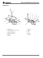 4
4
-
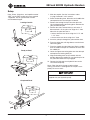 5
5
-
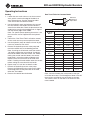 6
6
-
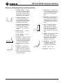 7
7
-
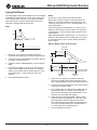 8
8
-
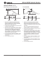 9
9
-
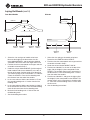 10
10
-
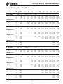 11
11
-
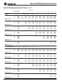 12
12
-
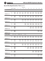 13
13
-
 14
14
-
 15
15
-
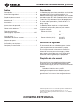 16
16
-
 17
17
-
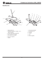 18
18
-
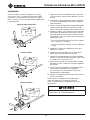 19
19
-
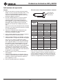 20
20
-
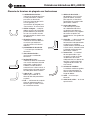 21
21
-
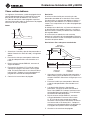 22
22
-
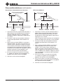 23
23
-
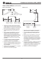 24
24
-
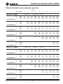 25
25
-
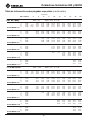 26
26
-
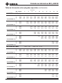 27
27
-
 28
28
-
 29
29
-
 30
30
-
 31
31
-
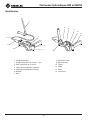 32
32
-
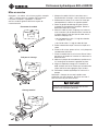 33
33
-
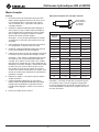 34
34
-
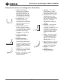 35
35
-
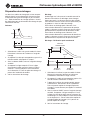 36
36
-
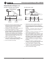 37
37
-
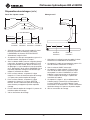 38
38
-
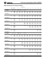 39
39
-
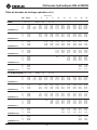 40
40
-
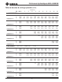 41
41
-
 42
42
-
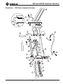 43
43
-
 44
44
-
 45
45
-
 46
46
-
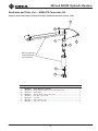 47
47
-
 48
48


Greenlee 882 & 882CB Hydraulic Bender Manual de usuario
- Tipo
- Manual de usuario
- Este manual también es adecuado para
en otros idiomas
Artículos relacionados
-
Greenlee 881 & 881CT Cam Trak Hydraulic Bender Manual de usuario
-
-
-
-
-
-
-
-
-
Otros documentos
-
Toro HFLO Precision Spray Sprinkler, 4" Pop-Up with Nozzle, 8'-15' Quarter (53892) Manual de usuario
-
-
Klein Tools 51609 Instrucciones de operación
-
Milwaukee 48-22-4070 Guía de inicio rápido
-
Southwire MXB2000 Manual de usuario
-
RIDGID 300 Series Plumbing Benders Instruction Sheet
-
 JAVAC JAV-1016 Safety Instructions & Operation Manual
-
TAYMAC UCB050 Instrucciones de operación
-
DeLOCK 65882 Ficha de datos
-
DeLOCK 65881 Ficha de datos
