

About this Document
This document includes instructions for installing AXIS
P3363-VE, AXIS P3364-VE and AXIS P3364-LVE on your
network. Previous experience of networking will be beneficial
when installing the product.
Legal Considerations
Video and audio surveillance can be prohibited by laws that vary
from country to country. Check the laws in your local region
before using this product for surveillance purposes.
This product includes one (1) H.264 decoder license. To purchase
further licenses, contact your reseller.
Trademark Acknowledgements
Apple, Boa, Bonjour, Ethernet, Internet Explorer, Linux,
Microsoft, Mozilla, Real, SMPTE, QuickTime, UNIX, Windows,
Windows Vista and WWW are registered trademarks of the
respective holders. Java and all Java-based trademarks and
logos are trademarks or registered trademarks of Oracle
and/or its affiliates. UPnPTM is a certification mark of the
UPnPTM Implementers Corporation.
Electromagnetic Compatibility (EMC)
This equipment has been designed and tested to fulfill applicable
standards for:
Radio frequency emission when installed according to the
instructions and used in its intended environment.
Immunity to electrical and electromagnetic phenomena when
installed according to the instructions and used in its intended
environment.
USA - Using an unshielded network cable (UTP): This equipment
has been tested using an unshielded network cable (UTP) and
found to comply with the limits for a Class A digital device,
pursuant to part 15 of the FCC Rules. These limits are designed
to provide reasonable protection against harmful interference
when the equipment is operated in a commercial environment.
This equipment generates, uses, and can radiate radio frequency
energy and, if not installed and used in accordance with the
instruction manual, may cause harmful interference to radio
communications. Operation of this equipment in a residential
area is likely to cause harmful interference in which case the
user will be required to correct the interference at his own
expense.
Using a shielded network cable (STP): This equipment has also
been tested using a shielded network cable (STP) and found to
comply with the limits for a Class B digital device, pursuant to
part 15 of the FCC Rules. These limits are designed to provide
reasonable protection against harmful interference in a
residential installation. This equipment generates, uses and can
radiate radio frequency energy and, if not installed and used in
accordance with the instructions, may cause harmful
interference to radio communications. However, there is no
guarantee that interference will not occur in a particular
installation. If this equipment does cause harmful interference
to radio or television reception, which can be determined by
turning the equipment off and on, the user is encouraged to try
to correct the interference by one or more of the following
measures:
• Reorient or relocate the receiving antenna.
• Increase the separation between the equipment and receiver.
• Connect the equipment into an outlet on a circuit different
from that to which the receiver is connected.
• Consult the dealer or an experienced radio/TV technician for
help.
Canada - This Class B digital apparatus complies with Canadian
ICES-003.
Europe - This product fulfills the requirements for
immunity according to EN 55024 office and commercial
environments.
This product fulfills the requirements for immunity according to
EN 61000-6-1 residential, commercial and light-industry
environments.
This product fulfills the requirements for immunity according to
EN 61000-6-2 industrial environments.
Australia - This digital equipment fulfills the requirements for
RF emission according to the Class B limit of AS/NZS CISPR 22.
Equipment Modifications
This equipment must be installed and used in strict accordance
with the instructions given in the user documentation. This
equipment contains no user-serviceable components.
Unauthorized equipment changes or modifications will
invalidate all applicable regulatory certifications and approvals.
Safety
This product complies with EN/IEC/UL 60950-1 and
EN/IEC/UL 60950-22, Safety of Information Technology
Equipment.
EN 50121-4
This product fulfills the requirements for emissions and
immunity according to EN 50121-4 railway applications.
Liability
Every care has been taken in the preparation of this document.
Please inform your local Axis office of any inaccuracies or
omissions. Axis Communications AB cannot be held responsible
for any technical or typographical errors and reserves the right
to make changes to the product and documentation without
prior notice. Axis Communications AB makes no warranty of any
kind with regard to the material contained within this
document, including, but not limited to, the implied warranties
of merchantability and fitness for a particular purpose. Axis
Communications AB shall not be liable nor responsible for
incidental or consequential damages in connection with the
furnishing, performance or use of this material.
RoHS
This product complies with both the European RoHS
directive, 2002/95/EC, and the Chinese RoHS
regulations, ACPEIP.
WEEE Directive
The European Union has enacted a Directive
2002/96/EC on Waste Electrical and Electronic
Equipment (WEEE Directive). This directive is
applicable in the European Union member states.
The WEEE marking on this product (see right) or its
documentation indicates that the product must not be disposed
of together with household waste. To prevent possible harm to
human health and/or the environment, the product must be
disposed of in an approved and environmentally safe recycling
process. For further information on how to dispose of this
product correctly, contact the product supplier, or the local
authority responsible for waste disposal in your area.
Business users should contact the product supplier for
information on how to dispose of this product correctly. This
product should not be mixed with other commercial waste. For
more information, visit www.axis.com/techsup/commercial
waste
Support
Should you require any technical assistance, please contact your
Axis reseller. If your questions cannot be answered immediately,
your reseller will forward your queries through the appropriate
channels to ensure a rapid response. If you are connected to the
Internet, you can:
• download user documentation and firmware updates
• find answers to resolved problems in the FAQ database. Search
by product, category, or phrases
• report problems to Axis support by logging in to your private
support area.
Japan - B
Korea -
ࢇ̛̛Еɼࢽࡈ%̗ࢷળࢶଢ̛̛Ի۰
࣯Իɼࢽ߾۰یࡈଜЕʨࡶּࢶࡳԻଜֲֻҘ
एࠇ߾۰یࡈଟܹݡТЬ

ENGLISH
Safeguards
Please read through this Installation Guide carefully before installing the Axis product. Keep the
Installation Guide for further reference.
• Store the Axis product in a dry and ventilated environment.
• Avoid exposing the Axis product to vibration, shocks or heavy pressure. Do not install the
product on unstable brackets, unstable or vibrating surfaces or walls, since this could cause
damage to the product.
• Only use applicable tools when installing the Axis product; excessive force could cause
damage to the product.
• Do not use chemicals, caustic agents, or aerosol cleaners. Use a damp cloth for cleaning.
• Use only accessories that comply with technical specification of the product. These can be
provided by Axis or a third party.
• Use only spare parts provided by or recommended by Axis.
• Do not attempt to repair the product by yourself, contact Axis or your Axis reseller for ser-
vice matters.
• This Axis product shall be used in compliance with local laws and regulations.
• The Axis product should be installed by a trained professional. Observe relevant national
and local regulations for the installation.
Transportation
• When transporting the Axis product, use the original packaging or equivalent to prevent
damage to the product.

Battery Replacement
This Axis product uses a 3.0 V CR2032 lithium battery as the power supply for its internal real-time
clock (RTC). Under normal conditions this battery will last for a minimum of 5 years. Low battery
power affects the operation of the RTC, causing it to reset at every power-up. A log message will
appear when the battery needs replacing. The battery should not be replaced unless required!
If the battery does need replacing, please contact www.axis.com/techsup for assistance.
• Dispose of used batteries according to the manufacturer's instructions.
• Risk of explosion if battery is incorrectly replaced.
• Replace only with the same or equivalent battery, as recommended by the manufacturer.
Dome Cover Cleaning
• Be careful not to scratch or damage the dome cover. Keep the protective plastic on the
dome cover until the installation is complete. Do not clean a dome cover that looks clean to
the eye and never polish the surface. Excessive cleaning could damage the surface.
• For general cleaning of a dome cover it is recommended to use a non-abrasive, solvent-free
neutral soap or detergent with water and a soft cloth. Rinse well with clean lukewarm
water. Dry with a soft cloth to prevent water spotting.
• Never use harsh detergents, gasoline, benzene or acetone etc. and avoid cleaning in direct
sunlight or at elevated temperatures.
• Domes for L products come with an anti-scratch surface. Avoid leaving finger prints on the
dome surface since this might impair image quality.

AXIS P33-VE Network Cameras Installation Guide Page 5
ENGLISH
AXIS P3363-VE/P3364-VE/P3364-LVE
Network Camera Installation Guide
Follow these instructions to install the network camera
1. “Package contents” on page 5
2. “Hardware overview” on page 6
3. “Install the hardware” on page 7
4. “Access the video stream” on page 10
5. “Adjust the Lens” on page 10
6. “Complete the installation” on page 11
Notes:
• Before you begin, make sure that the package contents, power supply, and the required cables, tools, and
documentation are available. See Package contents below.
• This network camera is intended to operate with PoE; if not available use Axis PoE Midspan 1 port (not
included)
Package contents
Item Models/variants/notes
Network camera
with heating module
AXIS P3363-VE
AXIS P3364-VE
AXIS P3364-LVE
Mounting bracket
Dome covers Clear transparent cover (not for AXIS P3364-LVE)
Smoked transparent cover
Weather shield Not applicable for AXIS P3364-LVE
Labels 2 adhesive serial no. labels
Mounting kit Resitorx screw driver, 2 long screws, drill template, 5-meter network cable
with gasket, 1 gasket, terminal block connector
CD Installation and Management Software CD
Printed Materials Installation Guide (this document)
AVHS Authentication key
Optional accessories Threaded adaptor with cable shield
See www.axis.com for information on available accessories

Page 6 AXIS P33-VE Network Cameras Installation Guide
Hardware overview
Dimension (HxW)
AXIS P3363-VE/AXIS P3364-VE/AXIS P3364-LVE = 110 x 179 x 179 mm (4.33 x 7.05 x 7.05")
Weight
AXIS P3363-VE/AXIS P3364-VE = 1.5 kg (3.2 lb.)
AXIS P3364-LVE = 1.5 kg (3.3 lb.)
Unit casing
Camera unit
Dome cover
Side holes with
LED indicators
Control button
Camera AXIS P3364-L
Audio in
Audio out
SD memory card slot
Serial no.
Heater
Spring
routed along the wall
for cablesgaskets
I/O connector
Mounting bracket
Caution! The heater in the camera unit may be hot.
Network connector
(PoE)
Holes for cables
routed through the wall

AXIS P33-VE Network Cameras Installation Guide Page 7
ENGLISH
Install the hardware
Prepare the network cable
If a cable other than the provided cable is
used, you need to prepare a network cable
with a gasket. Gently force the cable through
the gasket provided and attach a network
connector. It may be necessary to pierce a
hole in the gasket with the resitorx screwdriver.
Notes:
• Do not force the network connector into the gasket.
• Do not pierce the gasket with a knife or other sharp object.
Prepare the unit casing (routing cables along the wall)
If the cables are to be routed along the wall, prepare the unit casing as follows:
Note: The cable shield is an optional accessory, not supplied with the product.
1. Loosen the two screws on the cable shield (not supplied) and detach the bottom part.
2. Attach the bottom part of the cable shield to the unit casing with the screw.
Replace clear/smoked dome cover (optional)
AXIS P3363-VE/AXIS P3364-VE is supplied with an optional dome. To replace the dome cover:
1. Loosen the 4 screws under the dome cover that hold the dome in place.
2. Transfer the gasket from the old dome to the new.
3. Replace the old dome with the new and tighten the screws.
Top part
Bottom part
Cable shield Unit casing
(optional accessory)

Page 8 AXIS P33-VE Network Cameras Installation Guide
Route the cables
Depending on whether you want to route the cables through or along the wall, follow the relevant
instructions below.
Routing cables through the wall
1. Using the drill template drill 4
holes in the wall.
2. Route the network cable (and the
I/O, audio cable if necessary)
through the wall and through the
holes in the mounting bracket.
3. Attach the mounting bracket to
the wall using 4 screws
appropriate for the wall material.
4. Remove the camera unit from the unit casing by pushing the springs aside.
5. Remove the gaskets from the back holes in the unit casing. If there is only one cable, remove
only one gasket.
6. Route the cables through these holes.
7. Drag the gaskets along the cables and plug them into the holes. The gaskets should fit snugly
with no folds or bends.
8. Attach the unit casing to the mounting bracket by tightening the four screws.
Routing cables along the wall
1. Using the drill template drill 4 holes in the wall.
2. Attach the mounting bracket to the wall using 4 screws appropriate for the wall material.
3. Remove the camera unit from the unit casing by pushing the springs aside.
4. Remove the gaskets from the side holes in the unit casing. If there is only one cable, remove
only one gasket.
5. Place the unit casing on the mounting bracket and attach it by tightening the four screws.
6. Pull the cables up through the side holes in the unit casing.
7. Drag the gaskets along the cable and plug them into the holes. The gaskets should fit snugly in
the holes with no folds or bends.
8. Re-attach the top part of the cable shield by tightening the two screws.
Note: The AXIS P3363-VE/P3364-VE/P3364-LVE can also be fitted with a metal conduit for protecting
the cabling when cables are routed along the wall.
Mounting bracket
Network cable with gasket
Unit casing
Remove gaskets
from holes

AXIS P33-VE Network Cameras Installation Guide Page 9
ENGLISH
Install the camera unit
1. Attach the network cable to the camera unit; and the cable for audio and I/O if required.
Note: Be careful not to stretch or bend the network cable too much since this could cause damage to
the network cable.
2. Insert the SD memory card (optional).
3. Pull aside the springs in the unit casing and click the camera unit in place.
4. Attach the fan connector to the connector in the camera unit.
5. Attach the two M4x8 20 screws to the camera for greater stability.
These screws are only necessary to secure against heavy shocks and vibrations.
Note: The AXIS P3363-VE/P3364-VE/P3364-LVE can also be fit-
ted with a metal conduit for protecting the cabling when
cables are routed along the wall.
Connector for fan
Camera unit
Network cable
Attach
screw to camera
Conduit

Page 10 AXIS P33-VE Network Cameras Installation Guide
Access the video stream
Use the tools provided on the Installation and Management Software CD to assign an IP address,
set the password and access the video stream. This information is also available from the support
pages on www.axis.com/techsup
Adjust the Lens
Open the Live View page in the web interface and make the following adjustments to the camera:
1. Loosen the locking screw.
2. Turn the lens holder to the desired position.
3. Turn the lens to make sure the (horizontal) lines on either side of the lens are aligned
horizontally.
Note: Ensure that the mark on the lens cover, between the horizontal lines, is facing up.
4. Once satisfied, gently tighten the locking screw and to secure the camera’s position.
5. Open the Focus Adjustment page in the Web interface under Setup > Basic Setup > Focus &
Zoom, and follow the on-screen instructions. Use the image window to adjust the focus and
zoom. See the online help files for more information.
Notes:
• Due to the dome’s refraction, the image may appear slightly out of focus once the dome has been placed.
To correct this go to the Focus Adjustment page in the Web interface under Setup > Basic Setup > Focus
& Zoom, and adjust the focus again.
• When the zoom and focus are adjusted, the IR illumination is automatically aligned to the defined angle of
view.
Caution!
Adjusting the focus and zoom manually can damage the lens.
Locking screw
Horizontal line
Mark
Lens holder
Optical shield

AXIS P33-VE Network Cameras Installation Guide Page 11
ENGLISH
Complete the installation
1. Rotate the black protective shield inside the dome cover so it is aligned
with the camera’s position (not applicable to AXIS P3364-LVE).
2. If required, attach the weather shield to the camera before you attach
the dome cover (not applicable to AXIS P3364-LVE). To do this remove
the two screws in the dome cover. Transfer the washers from these
screws to the two long screws provided. Attach the weather shield
using the two long screws.
3. Attach the dome cover to the unit casing by tightening the 4 screws.
Note: AXIS P3364-LVE Network Camera: Before attaching the dome cover make sure the optical shield
sits well in place. See image on page 10.
For the AXIS P3364-LVE Network Camera, when the lens holder is tilted at a certain angle the
dome cover may block part of the IR illumination. In that case:
• loosen the locking screw
• rotate the lens holder 180°
• tighten the locking screw
• for correct image orientation, rotate the lens by 180°; make sure the horizontal lines are aligned and the
mark between them is facing up.
Black protective shield

Page 12 AXIS P33-VE Network Cameras Installation Guide
Unit connectors
Network connector - RJ-45 Ethernet connector. Supports Power over Ethernet.
The product shall be connected using a shielded network cable (STP). All cables connecting the
product to the network switch shall be shielded (STP) and intended for their specific use. Make
sure that the network switch is properly grounded. See Electromagnetic Compatibility (EMC) on
page 2 for regulatory requirements.
Audio in - 3.5mm input for a mono microphone, or a line-in mono signal (left channel is used from
a stereo signal).
Audio out - Audio output (line level) that can be connected to a public address (PA) system or an
active speaker with a built-in amplifier. A pair of headphones can also be attached. A stereo
connector must be used for the audio out.
SDHC memory card slot - The SD memory card can be used for local recording with removable
storage.
I/O terminal connector - Used in applications for e.g. motion detection,
event triggering, time lapse recording and alarm notifications. In addition to
an auxiliary power and a GND pin, it provides the interface to:
• 1 transistor output - For connecting external devices such as
relays and LEDs. Connected devices can be activated by the
VAPIX® Application Programming Interface (API), by the output buttons on the Live
View page or by an Action Rule. The output will show as active (shown under System
Options > Ports & Devices) if the alarm device is activated.
• 1 digital input - An alarm input for connecting devices that can toggle between an
open and closed circuit, for example: PIRs, door/window contacts, and glass break
detectors. When a signal is received the state changes and the input becomes active
(shown under System Options > Ports & Devices).
Function Pin Notes Specifications
GND 1 Ground
3.3V DC
Power
2 Can be used to power auxiliary equipment.
Note: This pin can only be used as power out.
Max. load = 50mA
Digital
Input
3 Connect to GND to activate, or leave floating (or
unconnected) to deactivate.
Min. input= 0 to - 40V DC
Max. input=0 to + 40V DC
Digital
Output
4 Uses an open-drain NFET transistor with the source
connected to GND. If used with an external relay, a
diode must be connected in parallel with the load,
for protection against voltage transients.
Max. load = 100mA
Max voltage = + 40V DC
Pin1
Pin2
Pin3
Pin4

AXIS P33-VE Network Cameras Installation Guide Page 13
ENGLISH
The following connection diagram gives an example of how to connect an auxiliary device to the
AXIS P3363-VE/P3364-VE/P3364-LVE.
LED indicators
LED Color Indication
Network Green Steady for connection to a 100 Mbit/s network. Flashes for network activity.
Amber Steady for connection to 10 Mbit/s network. Flashes for network activity.
Unlit No network connection.
Status Green Steady green for normal operation.
Amber Steady during startup; flashes once during reset to factory default or while
restoring settings.
Red Slow flash for failed upgrade.
Power Green Normal operation.
Amber Flashes green/amber during firmware upgrade.
1
2
E.g. push button
3
4
3.3V
max. 50mA
D
S
G

Page 14 AXIS P33-VE Network Cameras Installation Guide
Resetting to the Factory Default Settings
This will reset all parameters, including the IP address, to the factory default settings:
1. Disconnect power from the camera.
2. Press and hold the Control button and reconnect power (see “Hardware overview” on page 6).
3. Keep the Control button pressed for about 15 seconds until the Status indicator displays amber.
4. Release the Control button. The process is complete after about 1 minute (when the Status
indicator turns green). The network camera has been reset to the factory default settings. The
default IP address is 192.168.0.90
5. Re-assign the IP address.
6. Refocus the camera.
It is also possible to reset parameters to factory default via the web interface. Go to Setup > System
Options > Maintenance.
Further information
The user manual is available from the Axis Web site at www.axis.com. To learn more about Axis'
products and technologies, visit www.axis.com/academy, the global learning center for network
video.
Tip!
Visit www.axis.com/techsup to check if there is updated firmware available for your Axis product.
To see the currently installed firmware version, see Setup > About in your web interface.
Warranty
For information about Axis' product warranty and thereto related information, please see
www.axis.com/warranty

FRANÇAIS
Mesures de sécurité
Lisez attentivement le présent Guide d'installation avant d'installer le produit Axis. Conservez le
Guide d'installation pour une utilisation ultérieure.
• Conservez le produit Axis dans un environnement sec et aéré.
• Évitez d'exposer le produit Axis aux vibrations, aux chocs ou à une forte pression.
N'installez pas le produit sur un support instable, ou des surfaces ou des murs instables ou
vibrants, car cela pourrait l'endommager.
• N'utilisez que les outils applicables pour installer le produit Axis ; une force excessive
pourrait endommager le produit.
• Pour le nettoyage, n’utilisez ni produits chimiques, ni substances caustiques ou aérosols.
Utilisez un chiffon humide pour le nettoyage.
• N’utilisez que des accessoires conformes aux caractéristiques techniques du produit. Ceux-
ci peuvent être fournis par Axis ou par un fournisseur tiers.
• Utilisez uniquement des pièces de rechange fournies ou recommandées par Axis.
• Ne tentez pas de réparer le produit vous-même, contactez Axis ou votre revendeur Axis
pour toute réparation.
• Ce produit Axis doit être utilisé conformément aux lois et réglementations locales en
vigueur.
• Pour pouvoir être utilisé à l'extérieur, ce produit Axis doit être placé dans un boîtier
d'extérieur homologué.
• Le produit Axis doit être installé par un professionnel qualifié. Veuillez vous conformer aux
règlements nationaux et locaux relatifs à l'installation.
Transport
• Pour transporter le produit Axis et éviter de l'endommager, utilisez l'emballage d'origine ou
un emballage équivalent.

Remplacement des piles
Ce produit Axis nécessite une pile au lithium CR2032 de 3,0 V pour l'alimentation de son horloge en
temps réel interne. Dans des conditions normales d'utilisation, cette pile est censée durer au moins
5 ans. Si la pile est faible, le fonctionnement de l'horloge en temps réel peut être affecté et
entraîner sa réinitialisation à chaque mise sous tension. Un message enregistré apparaît lorsque la
pile doit être remplacée. Ne remplacez la pile qu'en cas de nécessité !
Si la pile doit être remplacée, veuillez contacter www.axis.com/techsup pour obtenir de l’aide.
• Jetez les piles usagées conformément aux consignes du fabricant.
• Le remplacement incorrect de la pile peut entraîner un risque d'explosion.
• Remplacez la pile par une pile identique ou équivalente uniquement, en respectant les
recommandations du fabricant.
Nettoyer la bulle du dôme
• Veillez à ne pas rayer ou endommager la bulle du dôme. Ne nettoyez pas la bulle du dôme si
elle semble propre à l'œil nu et ne frottez jamais sa surface. Un nettoyage excessif peut
l'endommager.
• Pour le nettoyage général de la bulle du dôme, il est recommandé d'utiliser un savon ou un
détergent neutre sans solvant, non abrasif, avec de l'eau et un chiffon doux. Rincez
abondamment avec de l’eau tiède et propre. Séchez à l'aide d'un chiffon doux pour éviter
les tâches d'eau.
• N'utilisez jamais de détergents forts, d'essence, de benzène ou d'acétone, etc. et évitez
toute exposition directe aux rayons du soleil ou à des températures élevées lors du
nettoyage.
• Les bulles pour les produits L sont livrées avec une surface anti-rayures et le nettoyage de
la bulle est recommandé, cependant veuillez respecter les précautions ci-dessus.

Guide d’installation des Caméra réseau AXIS P33-VE Page 17
FRANÇAIS
AXIS P3363-VE/P3364-VE/P3364-LVE
Guide d’installation de la caméra réseau
Procédez comme suit pour installer la caméra réseau.
1. « Contenu de l’emballage » à la page 17
2. « Présentation du matériel » à la page 18
3. « Installation du matériel » à la page 19
4. « Accéder au flux vidéo » à la page 22
5. « Réglage de l’objectif » à la page 22
6. « Fin de l’installation » à la page 23
Remarques :
• Avant de commencer, vérifiez le contenu de l’emballage et assurez-vous que l’alimentation ainsi que les
câbles, les outils et la documentation nécessaires sont disponibles. Voir Contenu de l’emballage ci-dessous.
• Cette caméra réseau est conçue pour fonctionner avec un connecteur réseau (PoE). Si vous n’en disposez
pas, utilisez l’injecteur PoE Axis à 1 port (non fourni).
Contenu de l’emballage
Élément Modèles/variantes/remarques
Caméra réseau
avec module chauffant
AXIS P3363-VE
AXIS P3364-VE
AXIS P3364-LVE
Support de fixation
Bulles de dôme Bulle transparente non fumée (non applicable pour l’AXIS P3364-LVE)
Bulle transparente fumée
Protection étanche Non applicable pour l’AXIS P3364-LVE
Étiquettes 2 étiquettes adhésives portant le numéro de série
Kit de montage Tournevis Resitorx, 2 vis longues, gabarit de perçage, câble réseau de
5 mètres avec joint, 1 joint, connecteur de bornier.
CD CD du logiciel d'installation et de gestion
Documentation imprimée Guide d’installation (le présent document)
Clé d’authentification AVHS
Accessoires en option Adaptateur filet avec câble blindé
Rendez-vous sur www.axis.com pour en savoir plus sur les accessoires
disponibles.

Page 18 Caméra réseau AXIS P33-VE Guide d’installation
Présentation du matériel
Dimensions (H x l)
AXIS P3363-VE, AXIS P3364-VE, AXIS P3364-LVE = 110 x 179 x 179 mm (4,33 x 7,05 x 7,05")
Poids
AXIS P3363-VE, AXIS P3364-VE = 1,5 kg
AXIS P3364-LVE = 1,5 kg
Boîtier de l’unité
Caméra
Couvercle du dôme
Trous latéraux avec
Voyants lumineux
Bouton de commande
Caméra AXIS P3363
Entrée audio
Sortie audio
Logement pour carte mémoire SD
Numéro de série
Élément chauffant
Ressort
acheminés le long du mur
pour les câblesjoints
Connecteur d’E/S
Support de fixation
Attention : l’élément thermique de la caméra peut être chaud.
Connecteur réseau
(PoE)
Trous pour les câbles
acheminés dans le mur

Guide d’installation des Caméra réseau AXIS P33-VE Page 19
FRANÇAIS
Installation du matériel
Préparation du câble réseau
Si vous utilisez un câble autre que celui fourni,
il est nécessaire de préparer un câble réseau
avec un joint. Faites passer délicatement le
câble à travers le joint fourni et complétez-le
par un connecteur réseau. Il peut être
nécessaire de percer un trou dans le joint à l’aide du tournevis Resitorx.
Remarques :
• Ne forcez pas l’entrée du connecteur réseau dans le joint.
• Ne percez pas le joint avec un couteau ou tout autre objet tranchant.
Préparation du boîtier de l’unité (acheminement des câbles le long du mur)
Si les câbles doivent être acheminés le long du mur, préparez le boîtier de l’unité de la manière
suivante :
Remarque : Le blindage de câble est facultatif, et n’est pas fourni avec le produit.
1. Dévissez les deux vis sur le blindage de câble (non fourni) et détachez la partie inférieure.
2. Fixez la partie inférieure du blindage de câble au boîtier de l’unité avec la vis.
Remplacement de la bulle de dôme fumée ou non fumée (facultatif)
Les caméras AXIS P3363-VE et AXIS P3364-VE sont livrées avec un dôme facultatif. Pour remplacer
la bulle du dôme :
1. Sous la bulle du dôme, dévissez les 4 vis qui maintiennent le dôme en place.
2. Transférez le joint de l’ancien dôme au nouveau dôme.
3. Remplacez l’ancien dôme par le nouveau et serrez les vis.
Partie supérieure
Partie inférieure
Blindage de câble Boîtier de l’unité
(facultatif)

Page 20 Caméra réseau AXIS P33-VE Guide d’installation
Acheminement des câbles
Selon que vous souhaitez faire passer les câbles le long du mur ou dans le mur, suivez les
instructions correspondantes ci-dessous.
Acheminement des câbles dans le mur
1. En vous servant du gabarit de
perçage, percez 4 trous dans le
mur.
2. Faites passer le câble réseau (ainsi
que le câble d’E/S audio si
nécessaire) dans le mur et dans les
trous du support de fixation.
3. Fixez le support de fixation au mur
en utilisant 4 vis appropriées.
4. Retirez la caméra du boîtier de l’unité en écartant les ressorts.
5. Retirez les joints des trous arrière du boîtier de l’unité. S’il n’y a qu’un seul câble, retirez un seul
joint.
6. Acheminez les câbles par ces trous.
7. Faites glisser les joints le long des câbles et fixez-les dans les trous. Les joints doivent être
parfaitement ajustés, sans plis ni courbures.
8. Fixez le boîtier de l’unité au support de fixation en serrant les quatre vis.
Acheminement des câbles le long du mur
1. En vous servant du gabarit de perçage, percez 4 trous dans le mur.
2. Fixez le support de fixation au mur en utilisant 4 vis appropriées.
3. Retirez la caméra du boîtier de l’unité en écartant les ressorts.
4. Retirez les joints des trous latéraux du boîtier de l’unité. S’il n’y a qu’un seul câble, retirez un
seul joint.
5. Posez le boîtier de l’unité sur le support de fixation et fixez-le en serrant les quatre vis.
6. Faites passer les câbles à travers les trous latéraux du boîtier de l’unité.
7. Faites glisser les joints le long du câble et fixez-les dans les trous. Les joints doivent être
parfaitement ajustés aux trous, sans plis ni courbures.
8. Fixez à nouveau la partie supérieure du blindage de câble en resserrant les deux vis.
Remarque : Les caméras AXIS P3363-VE/P3364-VE/P3364-LVE peuvent également être dotées d’un tube
métallique pour protéger le câblage lors de l’acheminement des câbles le long du mur.
Support de fixation
Câble réseau avec joint
Boîtier de l’unité
Retirez les joints
des trous

Guide d’installation des Caméra réseau AXIS P33-VE Page 21
FRANÇAIS
Installation de la caméra
1. Fixez le câble réseau à la caméra ainsi que le câble audio et d’E/S si nécessaire.
Remarque : Veillez à ne pas trop étirer ou tordre le câble réseau. Cela pourrait l’endommager.
2. Insérez la carte mémoire SD (facultatif).
3. Écartez les ressorts du boîtier de l’unité et insérez la caméra (vous devez entendre un clic
lorsque la caméra est correctement enclenchée).
4. Fixez le connecteur du ventilateur au connecteur de la caméra.
5. Fixez les deux vis M4x8 20 à la caméra pour une meilleure stabilité.
Ces vis sont uniquement nécessaires pour protéger l’unité contre les vibrations et les chocs
importants.
Remarque : Les caméras AXIS P3363-VE/P3364-VE/P3364-LVE
peuvent également être dotées d’un tube métallique
servant à protéger le câblage lors d’un acheminement
des câbles le long du mur.
Connecteur pour ventilateur
Caméra
Câble réseau
Vis
fixée à la caméra
Tube

Page 22 Caméra réseau AXIS P33-VE Guide d’installation
Accéder au flux vidéo
Utilisez les outils fournis dans le CD d’installation contenant les logiciels de gestion vidéo pour
attribuer une adresse IP, définir le mot de passe et accéder au flux vidéo. Ces informations sont
également disponibles sur les pages de support en ligne à l’adresse www.axis.com/techsup
Réglage de l’objectif
Ouvrez la page Live View (Vidéo en
direct) dans l’interface Web et effectuez
les réglages suivants sur la caméra :
1. Dévissez la vis de verrouillage.
2. Tournez le porte-objectif dans la
position souhaitée.
3. Tournez l’objectif de manière à ce
que les lignes (horizontales) de
chaque côté de l’objectif soient
alignées horizontalement.
Remarque : Assurez-vous que la marque sur
le couvercle de l’objectif, entre les lignes horizontales, est dirigée vers le haut.
4. Une fois que vous avez terminé, serrez délicatement la vis de verrouillage pour bien fixer la
caméra.
5. Ouvrez la page Focus Adjustment (Réglage de la mise au point) de l’interface Web sous Setup
> Basic Setup > Focus & Zoom (Configuration > Configuration de base > Mise au point et
zoom), et suivez les instructions à l’écran. Utilisez la fenêtre d’image pour régler le zoom et la
mise au point. Reportez-vous à l’aide en ligne pour plus d’informations.
Remarques :
• Du fait de la réfraction du dôme, l’image peut apparaître légèrement floue une fois le dôme installé. Pour
corriger l’image, ouvrez la page Focus Adjustment (Réglage de la mise au point) de l’interface Web sous
Setup > Basic Setup > Focus & Zoom (Configuration > Configuration de base > Mise au point et zoom) et
réglez à nouveau la mise au point.
• Une fois le zoom et la mise au point réglés, la lumière infrarouge est automatiquement alignée sur l’angle
de vue défini.
Attention !
Le réglage manuel de la mise au point et du zoom peut endommager l’objectif.
Vis de verrouillage
Ligne horizontale
Marque
Porte-objectif
Protection optique

Guide d’installation des Caméra réseau AXIS P33-VE Page 23
FRANÇAIS
Fin de l’installation
1. Tournez l’écran protecteur noir à l’intérieur de la bulle du dôme afin de
l’aligner avec la position de la caméra (non applicable pour l’AXIS
P3364-LVE).
2. Si nécessaire, fixez la protection étanche sur la caméra avant de fixer la
bulle du dôme (non applicable pour l’AXIS P3364-LVE). Pour cela, retirez
les deux vis de la bulle du dôme. Transférez les rondelles de ces vis sur
les deux longues vis fournies. Fixez la protection étanche en utilisant les deux vis longues.
3. Fixez la bulle du dôme sur le boîtier de l’unité en serrant les 4 vis.
Remarque : Caméra réseau AXIS P3364-LVE: Avant de fixer le couvercle du dôme veuillez-vous assurer
que la protection optique est bien en place. Voir illustration ci-dessus (page 22).
Pour la Caméra réseau AXIS P3364-LVE, lorsque le porte-objectif est incliné selon un certain
angle, la bulle du dôme peut bloquer la lumière infrarouge. Dans ce cas :
• Dévissez la vis de verrouillage.
• Tournez le porte-objectif de 180°.
• Serrez la vis de verrouillage.
• Pour une bonne orientation de l’image, tournez l’objectif de 180°. Assurez-vous que les lignes horizontales
sont alignées et que la marque entre elles est dirigée vers le haut.
Connecteurs de l’unité
Connecteur réseau : connecteur Ethernet RJ-45. Compatible avec l’alimentation par Ethernet.
Attention !
Conformément aux réglementations locales ou environnementales et compte tenu des conditions
électriques dans lesquelles le produit doit être utilisé, un câble réseau blindé (STP) peut convenir,
voire s’avérer obligatoire. Les câbles réseau acheminés dans des environnements extérieurs ou
similaires doivent être blindés (STP) et conçus pour cet usage spécifique. Assurez-vous que le
commutateur réseau soit correctement mis à la terre. Pour consulter les réglementations
correspondantes, reportez-vous à la section Compatibilité électromagnétique.
Entrée audio : entrée de 3,5 mm pour microphone mono ou signal mono avec entrée de haut
niveau (le canal de gauche est utilisé pour le signal stéréo).
Sortie audio : sortie audio (niveau de ligne) qui peut être connectée à un système d’annonce
publique ou à un haut-parleur actif avec amplificateur intégré. Il est également possible de
connecter une paire d’écouteurs. Un connecteur stéréo doit être utilisé pour la sortie audio.
Logement de carte mémoire SDHC : la carte mémoire SD peut être utilisée pour l’enregistrement
local avec stockage amovible.
Écran protecteur noir

Page 24 Caméra réseau AXIS P33-VE Guide d’installation
Connecteur pour terminaux E/S : Utilisé dans le cadre d’applications telles
que la détection de mouvements, le déclenchement d’événements,
l’enregistrement à intervalles et les notifications d’alarmes. En plus d’une
alimentation auxiliaire et d’une broche GND, il assure l’interface avec :
• 1 sortie transistor, qui permet de connecter des périphériques
externes, comme des relais ou des DEL. Les périphériques connectés peuvent être
activés par l’interface de programmation d’applications (API) VAPIX, à l’aide des
boutons de sortie sur la page Live View (Vidéo en direct) ou par une règle d’action. La
sortie est considérée comme étant active (comme indiqué dans System Options > Ports
& Devices (Options Système > Ports & Dispositifs)) si le dispositif d’alarme est activé.
• 1 entrée numérique : une entrée d’alarme utilisée pour connecter des périphériques
pouvant passer d’un circuit ouvert à un circuit fermé, soit par exemple : des détecteurs
infrarouges passifs, des contacts de porte/fenêtre et des détecteurs de bris de verre.
Lorsqu’un signal est reçu, l’état change et l’entrée devient active (comme indiqué dans
System Options > Ports & Devices (Options Système > Port & Dispositifs))
Fonction Broche Remarques Caractéristiques
techniques
GND (Terre) 1 Mise à la terre
Alimentation
3,3 V CC
2 Peut servir à alimenter le matériel auxiliaire.
Remarque : la broche peut être utilisée uniquement
comme sortie d’alimentation.
Charge max. = 50 mA
Entrée
numérique
3 La connecter à la terre pour l’activer ou la laisser
flotter (ou déconnectée) pour ne pas l’activer.
Entrée minimum = de
0 à -40 V CC
Entrée maximum = de
0 à 40 V CC
Sortie
numérique
4 Utilise un transistor NFET à drain ouvert avec la
source connectée à la terre. En cas d’utilisation avec
un relais externe, une diode doit être connectée en
parallèle avec la charge, en guise de protection
contre les tensions transitoires.
Charge max. = 100 mA
Tension maximale =
+40 V CC
Broche 1
Broche 2
Broche 3
Broche 4

Guide d’installation des Caméra réseau AXIS P33-VE Page 25
FRANÇAIS
Le schéma de câblage suivant fournit un exemple de connexion d’un périphérique auxiliaire à la
caméra AXIS P3363-VE/P3364-VE/P3364-LVE.
Voyants lumineux
Voyant Couleur Indication
Réseau Vert Continu en cas de connexion à un réseau de 100 Mbit/s. Clignote en cas d’activité
réseau.
Orange Continu en cas de connexion à un réseau de 10 Mbit/s. Clignote en cas d’activité
réseau.
Éteint Pas de connexion réseau.
État Vert Vert continu en cas de fonctionnement normal.
Orange En continu pendant le démarrage, clignote une fois pendant la réinitialisation des
valeurs d’usine par défaut ou la restauration des paramètres.
Rouge Clignote lentement en cas d’échec de la mise à niveau.
Alimenta-
tion
Vert Fonctionnement normal.
Orange Le voyant vert/orange clignote pendant la mise à niveau des micrologiciels.
1
2
E.g. push button
3
4
3.3V
max. 50mA
D
S
G

Page 26 Caméra réseau AXIS P33-VE Guide d’installation
Rétablissement des paramètres d’usine par défaut
Procédez comme suit pour rétablir les paramètres par défaut définis en usine et réinitialiser
l’adresse IP :
1. Mettez la caméra hors tension.
2. Maintenez le bouton de commande enfoncé et remettez la caméra sous tension (voir
« Présentation du matériel » à la page 18).
3. Appuyez sur le bouton de commande pendant environ 15 secondes, jusqu’à ce que l’indicateur
d’état devienne orange.
4. Relâchez le bouton de commande. Le processus prend fin après environ 1 minute (lorsque le
voyant d’état devient vert). Les paramètres d’usine de la caméra réseau ont été rétablis.
L’adresse IP par défaut est 192.168.0.90.
5. Réattribuez l’adresse IP.
6. Recommencez la mise au point de la caméra.
Il est également possible de rétablir les paramètres d’usine à partir de l’interface web. Cliquez sur
Setup > System Options > Maintenance (Configuration > Options système > Maintenance).
Plus d’informations
Le Manuel d’utilisation est disponible sur le site Internet d’Axis à l’adresse www.axis.com. Pour en
savoir plus sur les produits et technologies Axis, rendez-vous sur www.axis.com/academy, le centre
de formation mondial pour la vidéo sur IP.
Conseil utile !
Consultez le site www.axis.com/techsup pour vérifier si des mises à jour des micrologiciels sont
disponibles pour votre produit Axis. Pour connaître la version du micrologiciel actuellement
installée, reportez-vous à la page Setup > About (Configuration > À propos de) dans votre interface
web.
Garantie
Pour plus d'informations sur la garantie des produits Axis et des informations générales relatives à
celle-ci merci de consulter le site www.axis.com/warranty

DEUTSCH
Sicherheitsvorkehrungen
Bitte lesen Sie diese Installationsanleitung sorgfältig durch, bevor Sie mit der Installation des Axis
Produkts beginnen. Halten Sie die Installationsanleitung bereit, falls Sie darauf zurückgreifen
müssen.
• Lagern Sie das Axis-Produkt in einer trockenen und belüfteten Umgebung.
• Setzen Sie das Axis Produkt keinen Vibrationen, Erschütterungen oder starkem Druck aus.
Installieren Sie das Produkt nicht an instabilen Halterungen oder instabilen oder
vibrierenden Oberflächen oder Mauern, da dadurch das Produkt beschädigt werden könnte.
• Verwenden Sie bei der Installation des Axis Produkts nur geeignetes Werkzeug; zu hoher
Kraftaufwand kann das Produkt beschädigen.
• Verwenden Sie keine chemischen, ätzenden oder aerosolhaltigen Reinigungsmittel.
Verwenden Sie zur Reinigung ein feuchtes Tuch.
• Verwenden Sie nur Zubehör, das den technischen Spezifikationen des Produkts entspricht.
Dieses ist von Axis oder Drittanbietern erhältlich.
• Verwenden Sie nur Ersatzteile, die von Axis empfohlen bzw. bereitgestellt wurden.
• Versuchen Sie nicht, das Produkt selbst zu reparieren. Wenden Sie sich bei Service-
Angelegenheiten an Axis oder an Ihren Axis-Händler.
• Verwenden Sie dieses Axis-Produkt unter Beachtung der vor Ort geltenden rechtlichen
Bestimmungen.
• Um dieses Axis-Produkt im Freien verwenden zu können, muss es in einem zugelassenen
Außengehäuse installiert werden.
• Das Axis Produkt sollte nur von geschultem Fachpersonal installiert werden. Beachten Sie
bei der Montage die geltenden nationalen und lokalen Bestimmungen.
Transport
• Bewahren Sie die Schutzverpackung auf. Beim Transport des Axis Produkts muss die
Schutzverpackung an ihre ursprüngliche Position gesetzt werden.

Batteriewechsel
Dieses Axis-Produkt ist mit einer 3,0 V CR2032 Lithium-Batterie als Stromversorgung für die
interne Echtzeituhr (RTC) ausgestattet. Unter normalen Bedingungen hält die Batterie mindestens 5
Jahre. Bei entladener Batterie ist der Betrieb der Echtzeituhr nicht mehr ausreichend gewährleistet,
so dass die Uhr bei jedem Systemstart zurückgesetzt wird. Sie erhalten eine Protokollnachricht,
wenn ein Batteriewechsel erforderlich ist. Die Batterie sollte erst bei Bedarf gewechselt werden.
Unter www.axis.com/techsup finden Sie Informationen darüber, was Sie beim Austausch der
Batterie beachten müssen.
• Verbrauchte Batterien sind gemäß den Herstelleranweisungen zu entsorgen.
• Explosionsgefahr bei fehlerhaftem Batteriewechsel!
• Die Batterie muss durch dasselbe oder ein gleichwertiges Fabrikat ersetzt werden, das vom
Hersteller zugelassen ist.
Reinigung der Kuppelabdeckung
• Achten Sie darauf, die Kuppelabdeckung nicht zu zerkratzen oder zu beschädigen. Reinigen
Sie die Kuppelabdeckung nicht, solange sie sauber aussieht, und polieren Sie niemals die
Oberfläche. Übermäßiges Reinigen kann die Oberfläche beschädigen.
• Zur allgemeinen Reinigung einer Kuppelabdeckung wird die Verwendung einer nicht
aggressiven, lösungsmittelfreien neutralen Seife bzw. eines solchen Reinigungsmittels
zusammen mit Wasser und einem weichen Tuch empfohlen. Spülen Sie gut mit sauberem,
lauwarmem Wasser nach. Trocknen Sie die Kuppelabdeckung mit einem weichen Tuch ab,
um Wasserflecken zu vermeiden.
• Verwenden Sie niemals scharfe Reinigungsmittel, Benzin, Benzol, Aceton o. Ä., und führen
Sie die Reinigung nicht unter direkter Sonneneinstrahlung oder bei hohen Temperaturen
durch.
• Dome-Abdeckungen für L-Produkte sind mit einer Anti-Kratz-Oberfläche ausgestattet. Eine
Reinigung des Domes wird empfohlen, allerdings sollten Sie hierbei die zuvor genannten
Punkte beachten.

AXIS P33-VE Netzwerk-Kameras Installationsanleitung Seite 29
DEUTSCH
AXIS P3363-VE/P3364-VE/P3364-LVE
Installationsanleitung für die
Netzwerk-Kamera
Führen Sie zur Installation der Netzwerk-Kamera die folgenden Schritte aus:
1. „Inhalt des Produktpakets“ auf Seite 29
2. „Hardwareübersicht“ auf Seite 30
3. „Installation der Hardware“ auf Seite 31
4. „Zugriff auf den Video Stream“ auf Seite 34
5. „Anpassen des Objektivs“ auf Seite 34
6. „Installation abschließen“ auf Seite 35
Hinweise:
• Stellen Sie vor der Installation sicher, dass der Lieferumfang vollständig ist und das Netzteil sowie die
erforderlichen Kabel, Werkzeuge und Dokumentationen verfügbar sind. Siehe Inhalt des Produktpakets
unten.
• Diese Netzwerk-Kamera wird über Power over Ethernet (PoE) mit Strom versorgt. Falls PoE nicht zur
Verfügung steht, verwenden Sie den AXIS PoE Midspan 1-Anschluss (separat erhältlich)
Inhalt des Produktpakets
Artikel Modelle/Varianten/Notizen
Netzwerk-Kamera
mit Heizmodul
AXIS P3363-VE
AXIS P3364-VE
AXIS P3364-LVE
Montagehalterung
Kuppelabdeckungen Klare transparente Abdeckung (gilt nicht für AXIS P3364-LVE)
Abdeckung aus Rauchglas
Wetterschutz Gilt nicht für AXIS P3364-LVE
Etiketten Zwei Klebe-Etiketten mit der Seriennummer
Montagesatz Resitorx-Schraubendreher, zwei lange Schrauben, Bohrschablone, 5 m langes
Netzwerkkabel mit Dichtung, eine Dichtung, Anschlussblockstecker
CD-ROM CD mit Installations- und Verwaltungssoftware
Gedruckte Dokumentation Installationsanleitung (dieses Dokument)
AVHS-Authentifizierungsschlüssel
Optionales Zubehör Gewindeadapter mit Kabelabdeckung
Unter www.axis.com finden Sie Informationen zum verfügbaren Zubehör

Seite 30 AXIS P33-VE Netzwerk-Kameras Installationsanleitung
Hardwareübersicht
Abmessungen (H x B)
AXIS P3363-VE/AXIS P3364-VE/AXIS P3364-LVE = 110 x 179 x 179 mm
Gewicht
AXIS P3363-VE/AXIS P3364-VE = 1,5 kg
AXIS P3364-LVE = 1,5 kg
Kameragehäuse
Kameraeinheit
Kuppelabdeckung
Seitenlöcher mit
LED-Anzeigen
Steuertaste
Kamera AXIS P3363
Audio-Eingang
Audio-Ausgang
SD-Speicherkarteneinschub
Seriennummer
Heizelement
Feder
entlang geführte Kabel
für an der WandDichtungen
E/A-Anschluss
Montagehalterung
Vorsicht! Das Heizelement in der Kameraeinheit kann heiß sein.
Netzwerkanschluss
(PoE)
Löcher für durch
die Wand geführte Kabel

AXIS P33-VE Netzwerk-Kameras Installationsanleitung Seite 31
DEUTSCH
Installation der Hardware
Vorbereiten des Netzwerkkabels
Falls ein anderes als das mitgelieferte Kabel
verwendet wird, müssen Sie ein
Netzwerkkabel mit einer Dichtung
vorbereiten. Führen Sie das Kabel vorsichtig
durch die mitgelieferte Dichtung und bringen
Sie einen Netzwerkstecker am Kabel an. Möglicherweise müssen Sie mit dem
Resitorx-Schraubendreher ein Loch in die Dichtung stechen.
Hinweise:
• Versuchen Sie nicht, den Netzwerkstecker durch die Dichtung zu führen.
• Stechen Sie nicht mit einem Messer oder einem anderen scharfen Gegenstand in die Dichtung.
Vorbereiten des Kameragehäuses (wenn die Kabel an der Wand entlang geführt
werden)
Wenn die Kabel an der Wand entlang geführt werden sollen, bereiten Sie das Kameragehäuse wie
folgt vor:
Hinweis: Die Kabelabdeckung ist ein optionales Zubehörteil und wird nicht mit dem Produkt mitgeliefert.
1. Lösen Sie die beiden Schrauben an der Kabelabdeckung und nehmen Sie den unteren Teil ab.
2. Befestigen Sie den unteren Teil der Kabelabdeckung mit der Schraube am Kameragehäuse.
Austauschen der klaren/getönten Kuppelabdeckung (optional)
Die AXIS P3363-VE/AXIS P3364-VE wird mit einer optionalen Kuppel geliefert. So tauschen Sie die
Kuppelabdeckung aus:
1. Lösen Sie die vier Schrauben unter der Kuppelabdeckung, die die Kuppel an ihrer Position
halten.
2. Entfernen Sie die Dichtung von der alten Kuppel, und bringen Sie sie an der neuen an.
3. Tauschen Sie die alte Kuppel gegen die neue aus, und ziehen Sie die Schrauben fest.
oberer Teil
unterer Teil
Kabelabdeckung Kameragehäuse
(optionales Zubehörteil)

Seite 32 AXIS P33-VE Netzwerk-Kameras Installationsanleitung
Ziehen der Kabel
Befolgen Sie abhängig davon, ob Sie die Kabel durch die Wand oder an der Wand entlang führen
möchten, die entsprechenden nachstehenden Anweisungen.
Kabel durch die Wand führen
1. Bohren Sie mithilfe der
Bohrschablone vier Löcher in die
Wand.
2. Führen Sie das Netzwerkkabel
(sowie bei Bedarf das E/A- bzw.
Audiokabel) durch die Wand und
durch die Löcher in der Halterung.
3. Befestigen Sie die
Montagehalterung mit vier
geeigneten Schrauben an der Wand.
4. Entfernen Sie die Kameraeinheit aus dem Kameragehäuse, indem Sie die Federn zur Seite
drücken.
5. Entfernen Sie die Dichtungen von den Löchern in der Rückseite des Kameragehäuses. Falls nur
ein Kabel vorhanden ist, entfernen Sie nur eine Dichtung.
6. Führen Sie die Kabel durch diese Löcher.
7. Ziehen Sie die Dichtungen an den Kabeln entlang, und drücken Sie sie in die Löcher. Die
Dichtungen müssen ohne Falten oder Krümmungen fest sitzen.
8. Befestigen Sie das Kameragehäuse an der Halterung, indem Sie die vier Schrauben anziehen.
Kabel an der Wand entlang führen
1. Bohren Sie mithilfe der Bohrschablone vier Löcher in die Wand.
2. Befestigen Sie die Montagehalterung mit vier geeigneten Schrauben an der Wand.
3. Entfernen Sie die Kameraeinheit aus dem Kameragehäuse, indem Sie die Federn zur Seite
drücken.
4. Entfernen Sie die Dichtungen von den Seitenlöchern im Kameragehäuse. Falls nur ein Kabel
vorhanden ist, entfernen Sie nur eine Dichtung.
5. Setzen Sie das Kameragehäuse auf die Halterung, und befestigen Sie es, indem Sie die vier
Schrauben anziehen.
6. Ziehen Sie die Kabel durch die Seitenlöcher im Kameragehäuse nach oben.
7. Ziehen Sie die Dichtungen am Kabel entlang, und drücken Sie sie in die Löcher. Die Dichtungen
müssen ohne Falten oder Krümmungen fest in den Löchern sitzen.
8. Bringen Sie den oberen Teil der Kabelabdeckung wieder an, indem Sie die beiden Schrauben
anziehen.
Hinweis: Die AXIS P3363-VE/P3364-VE/P3364-LVE kann auch mit einer Kabelführung aus Metall zum
Schutz der Kabel ausgestattet werden, wenn die Kabel an der Wand entlang geführt werden.
Montagehalterung
Netzwerkkabel mit Dichtung
Kameragehäuse
Dichtungen aus
Löchern entfernen

AXIS P33-VE Netzwerk-Kameras Installationsanleitung Seite 33
DEUTSCH
Installieren der Kameraeinheit
1. Schließen Sie das Netzwerkkabel sowie bei Bedarf das Kabel für Audio und E/A an die
Kameraeinheit an.
Hinweis: Das Netzwerkkabel sollte nicht zu sehr gespannt oder geknickt werden, da dies das
Netzwerkkabel beschädigen könnte.
2. Setzen Sie die SD-Speicherkarte ein (optional).
3. Ziehen Sie die Federn im Kameragehäuse zur Seite, und setzen Sie die Kameraeinheit so ein,
dass sie in ihrer Position einrastet.
4. Schließen Sie den Stecker des Lüfters am Lüfteranschluss in der Kameraeinheit an.
5. Bringen Sie die beiden M4x8 20-Schrauben an der Kamera an, um die Stabilität zu erhöhen.
Diese Schrauben sind nur zum Schutz vor starken Erschütterungen und Vibrationen erforderlich.
Hinweis: Die AXIS P3363-VE/P3364-VE/P3364-LVE kann auch mit
einer Kabelführung aus Metall zum Schutz der Kabel
ausgestattet werden, wenn die Kabel an der Wand
entlang geführt werden.
Lüfteranschluss
Kameraeinheit
Netzwerkkabel
Schraube
an Kamera anbringen
Kabelführung

Seite 34 AXIS P33-VE Netzwerk-Kameras Installationsanleitung
Zugriff auf den Video Stream
Verwenden Sie die Werkzeuge auf der Installations- und Management-Software CD, um
IP-Adressen zuzuweisen, das Passwort festzulegen und auf den Videostream zuzugreifen. Sie finden
diese Informationen auch auf den Support-Seiten unter www.axis.com/techsup
Anpassen des Objektivs
Öffnen Sie die Seite Live View
(Live-Ansicht), und nehmen Sie die
folgenden Einstellungen an der Kamera vor:
1. Lösen Sie die Arretierschraube.
2. Drehen Sie den Objektivhalter in die
gewünschte Position.
3. Drehen Sie das Objektiv, um
sicherzustellen, dass die (horizontalen)
Linien auf jeder Seite des Objektiv
horizontal fluchten.
Hinweis: Stellen Sie sicher, dass die Markierung
auf der Objektivabdeckung zwischen den horizontalen Linien nach oben zeigt.
4. Wenn die richtige Ausrichtung erreicht ist, schrauben Sie die Arretierschraube vorsichtig wieder
fest, um die Kameraposition zu sichern.
5. Öffnen Sie über die Weboberfläche unter Setup > Basic Setup > Focus & Zoom (Einrichtung >
Basiskonfiguration > Fokus und Zoom) die Seite Focus Adjustment (Bildschärfe einstellen) und
befolgen Sie die Bildschirmanweisungen. Stellen Sie mit dem Bildfenster die Bildschärfe und
den Zoom ein. Weitere Informationen hierzu finden Sie in der Online-Hilfe.
Hinweise:
• Aufgrund der Lichtbrechungen auf der Glasoberfläche kann das Bild leicht unscharf erscheinen, nachdem
die Kuppel installiert wurde. Sie können dies korrigieren, indem Sie in der Weboberfläche unter Setup >
Basic Setup > Focus & Zoom (Einrichtung > Basiskonfiguration > Fokus und Zoom) die Seite Focus
Adjustment (Bildschärfe einstellen) öffnen und die Bildschärfe erneut anpassen.
• Nach der Einstellung von Zoom und Bildschärfe wird das IR-Licht automatisch auf den festgelegten
Kamerawinkel ausgerichtet.
Vorsicht!
Das manuelle Einstellen der Bildschärfe kann das Objektiv beschädigen.
Feststellschraube
Horizontale Linie
Markierung
Objektivhalter
Optischer Schutz

AXIS P33-VE Netzwerk-Kameras Installationsanleitung Seite 35
DEUTSCH
Installation abschließen
1. Bringen Sie die schwarze Schutzabdeckung in der Kuppelabdeckung
durch Drehen in Übereinstimmung mit der Kameraposition (gilt nicht
für AXIS P3364-LVE).
2. Befestigen Sie bei Bedarf den Wetterschutz an der Kamera, bevor Sie
die Kuppelabdeckung anbringen (gilt nicht für AXIS P3364-LVE).
Entfernen Sie dazu die beiden Schrauben in der Kuppelabdeckung.
Nehmen Sie die Unterlegscheiben von diesen Schrauben ab, und setzen Sie sie auf die beiden
mitgelieferten langen Schrauben. Befestigen Sie den Wetterschutz mit den beiden langen
Schrauben.
3. Befestigen Sie die Kuppelabdeckung am Kameragehäuse, indem Sie die vier Schrauben
anziehen.
Hinweis: AXIS P3364-LVE Netzwerk-Kamera: Bevor Sie die Dom-Abdeckung montieren, stellen Sie bitte
sicher, dass der optische Schutz fest an der vorgesehenen Stelle sitzt. Siehe obiges Bild (Seite34).
Wenn der Objektivhalter bei der AXIS P3364-LVE Netzwerk-Kamera in einem bestimmten Winkel
geneigt wird, kann die Dome-Abdeckung einen Teil des IR-Lichts blockieren. In diesem Fall ist
Folgendes zu tun:
• Lösen Sie die Arretierschraube.
• Drehen Sie den Objekthalter um 180°.
• Drehen Sie die Arretierschraube wieder fest.
• Zur korrekten Bildausrichtung drehen Sie das Objekt um 180° und stellen Sie dabei sicher, dass die
horizontalen Linien fluchten und die Markierung dazwischen nach oben weist.
Geräteanschlüsse
Netzwerkanschluss – RJ-45-Ethernetanschluss. Unterstützt Power over Ethernet.
Vorsicht!
Aufgrund örtlicher Bestimmungen oder der Umgebungs- und elektrischen Bedingungen, in denen
das Produkt eingesetzt werden soll, ist eventuell ein abgeschirmtes Netzwerkkabel (STP)
vorteilhaft oder erforderlich. Netzwerkkabel, welche in Außenumgebungen oder ähnlichem
geführt werden, müssen abgeschirmt sein (STP) und für diesen Zweck vorgesehen sein. Stellen Sie
sicher, dass der Netzwerk-Switch ordnungsgemäß geerdet ist. Behördliche Anforderungen finden
Sie unter „Elektromagnetische Verträglichkeit (EMV)“.
Audioeingang – 3,5-mm-Anschluss für ein Monomikrofon oder ein Monosignal (linker Kanal wird
von einem Stereosignal benutzt).
Audioausgang – Audioausgang (Leistungsstufe) zum Anschließen einer Rundrufanlage (PA) oder
eines Aktivlautsprechers mit integriertem Verstärker. Auch ein Kopfhörer kann angeschlossen
werden. Für den Audioausgang muss ein Stereostecker benutzt werden.
Schwarzes Schutzschild

Seite 36 AXIS P33-VE Netzwerk-Kameras Installationsanleitung
SDHC-Speicherkarteneinschub – Die SD-Speicherkarte kann zur lokalen Aufzeichnung mit
Wechselmedien verwendet werden.
E/A-Anschluss - Wird z. B. für Bewegungserkennung, Ereignisauslösung,
Zeitrafferaufnahmen, Alarmbenachrichtigungen usw. verwendet. Zusätzlich
zu den Anschlüssen für die Zusatzstromversorgung und Masse fungiert er als
Schnittstelle für:
• 1 Transistorausgang – Zum Anschluss externer Geräte, wie Relais
und LEDs. Angeschlossene Geräte können über die VAPIX API (Application Programming
Interface), über die Ausgabeschaltflächen auf der Seite „Live View“ (Live-Ansicht) oder
durch eine Ereignisregel aktiviert werden. Der Ausgang wird als aktiv (siehe System
Options > Ports & Devices (Systemoptionen > Schnittstellen und Geräte)) angezeigt,
wenn die Alarmvorrichtung eingeschaltet ist.
• Ein digitaler Eingang – Alarmeingang für den Anschluss von Geräten, die zwischen
geöffnetem und geschlossenem Schaltkreis wechseln können, z. B. PIR-Kameras,
Tür-Fensterkontakte und Glasbruchmelder. Bei Empfang eines Signals ändert sich der
Status und der Eingang wird aktiviert (siehe >System Options > Ports & Devices
(Systemoptionen > Schnittstelle und Geräte)).
Funktion Kontakt Hinweise Spezifikationen
Masse
(GND)
1 Masse
3,3 V
Gleich-
strom
2 Kann für die Stromversorgung von
Zusatzgeräten verwendet werden.
Hinweis: Dieser Kontakt kann nur für die
Stromversorgung verwendet werden.
Max. Stromstärke = 50 mA
Digitaler
Eingang
3 Zum Aktivieren mit dem Masseanschluss
verbinden, zum Deaktivieren nicht anschließen.
Min. Eingang = 0 bis - 40 V
Gleichstrom
Max. Eingang = 0 bis + 40 V
Gleichstrom
Digitaler
Ausgang
4 Verwendet einen NFET-Transistor mit offener
Senke, wobei die Quelle mit der Masse
verbunden ist. Zum Schutz vor
Spannungsspitzen muss bei der Kombination mit
einem externen Relais eine Diode parallel zur
Last geschaltet werden.
Max. Stromstärke = 100 mA
Max. Spannung = + 40 V
Gleichstrom
Anschluss 1
Anschluss 2
Anschluss 3
Anschluss 4

AXIS P33-VE Netzwerk-Kameras Installationsanleitung Seite 37
DEUTSCH
Das folgende Anschlussschaltbild zeigt ein Beispiel für den Anschluss eines Zusatzgeräts an den
AXIS P3363-VE/P3364-VE/P3364-LVE.
LED-Anzeigen
LED Farbe Bedeutung
Netzwerk Grün Leuchtet dauerhaft bei Verbindung mit einem 100-MBit/s-Netzwerk. Blinkt bei
Netzwerkaktivität.
Gelb Leuchtet dauerhaft bei Verbindung mit einem 10-MBit/s-Netzwerk. Blinkt bei
Netzwerkaktivität.
Leuchtet
nicht
Keine Netzwerkverbindung vorhanden.
Status Grün Leuchtet bei Normalbetrieb konstant grün.
Gelb Leuchtet konstant beim Einschalten, blinkt einmal während der Wiederherstellung
der Werkseinstellungen bzw. von vorherigen Einstellungen.
Rot Blinkt langsam bei Aktualisierungsfehler.
Power Grün Normaler Betrieb.
Gelb Blinkt grün/gelb während Firmware-Aktualisierung.
1
2
E.g. push button
3
4
3.3V
max. 50mA
D
S
G

Seite 38 AXIS P33-VE Netzwerk-Kameras Installationsanleitung
Wiederherstellen der werkseitigen Standardeinstellungen
Gehen Sie wie folgt vor, um sämtliche Parameter einschließlich der IP-Adresse auf die werkseitigen
Standardeinstellungen zurückzusetzen:
1. Trennen Sie die Kamera von der Stromversorgung.
2. Halten Sie die Steuertaste gedrückt und stellen Sie die Stromversorgung wieder her (weitere
Informationen hierzu finden Sie unter „Hardwareübersicht“ auf Seite 30).
3. Halten Sie die Steuertaste etwa 15 Sekunden gedrückt, bis die Statusanzeige gelb aufleuchtet.
4. Lassen Sie die Steuertaste los. Der Vorgang ist nach etwa einer Minute abgeschlossen (die
Statusanzeige wird grün). Die Netzwerk-Kamera wurde auf die werkseitigen
Standardeinstellungen zurückgesetzt. Die Standard-IP-Adresse lautet 192.168.0.90.
5. Weisen Sie die IP-Adresse erneut zu.
6. Führen Sie die Fokussierung der Kamera erneut durch.
Die Parameter können auch über die Weboberfläche auf die werkseitigen Einstellungen
zurückgesetzt werden. Wählen Sie „Setup > System Options > Maintenance“ (Setup >
Systemoptionen > Wartung).
Weitere Informationen
Das Benutzerhandbuch steht auf der Website von Axis unter „www.axis.com“ zur Verfügung. Um
mehr über Produkte und Technologien von Axis zu erfahren, besuchen Sie uns unter
„www.axis.com/academy“, dem globalem Lernzentrum für Netzwerk-Video.
Tipp!
Unter „www.axis.com/techsup“ finden Sie Firmware-Aktualisierungen für Ihr Axis-Produkt.
Informationen zur aktuellen Firmware-Version finden Sie in Ihrer Weboberfläche unter „Setup“ >
„About“ (Info).
Garantie
Die Garantiebedingungen für Axis Produkte sowie weitere Informationen zum Thema Garantie
finden Sie unter www.axis.com/warranty

ITALIANO
Sicurezza
Leggere attentamente questa Guida all'installazione prima di installare un prodotto Axis.
Conservare la Guida all'installazione per ulteriori riferimenti.
• Conservare il prodotto Axis in un ambiente asciutto e ben ventilato.
• Evitare di esporre il prodotto Axis alle vibrazioni, agli urti o a forte pressione. Non installare
il prodotto su staffe instabili, superfici o pareti instabili o vibranti, poiché ciò potrebbe
danneggiare il prodotto.
• Utilizzare solo strumenti idonei quando si installa il prodotto Axis. Una forza eccessiva
potrebbe danneggiare il prodotto.
• Non utilizzare sostanze chimiche, agenti caustici o detergenti spray. Utilizzare un panno
umido per la pulizia.
• Utilizzare solo accessori conformi con le specifiche tecniche del prodotto. Queste possono
essere fornite da Axis o da terze parti.
• Utilizzare solo parti di ricambio fornite o raccomandate da Axis.
• Non tentare di riparare il prodotto da soli, contattare Axis o il rivenditore di zona Axis per
assistenza.
• Questo prodotto Axis deve essere utilizzato in conformità alle leggi e alle disposizioni locali.
• Per utilizzare questo prodotto Axis all'esterno, è necessario installarlo in un alloggiamento
per esterni approvato.
• Il prodotto Axis deve essere installato da un tecnico qualificato. Osservare le disposizioni
nazionali e locali per l'installazione.
Trasporto
• Quando si trasporta il prodotto Axis, utilizzare l'imballo originale o un imballo equivalente
per evitare di danneggiare il prodotto.

Sostituzione della batteria
Questo prodotto Axis utilizza una batteria al litio CR2032 da 3.0 V per alimentare il real-time clock
(RTC) interno. In normali condizioni questa batteria ha una durata di almeno 5 anni. La batteria
scarica influisce sul funzionamento dell'RTC, che viene reimpostato ad ogni accensione. Un
messaggio di registro apparirà quando la batteria dovrà essere sostituita. La batteria non deve
essere sostituita a meno che non sia necessario.
Se la batteria non deve essere sostituita, contattare www.axis.com/techsup per assistenza.
• Smaltire le batterie usate secondo le istruzioni del produttore.
• Rischio di esplosione se la batteria non viene sostituita correttamente.
• Sostituire solo con una batteria identica o equivalente, come raccomandato dal produttore.
Pulizia della copertura a cupola
• Fare attenzione a non graffiare o danneggiare la copertura a cupola. Non pulire una
copertura a cupola visivamente pulita e non lucidare mai la superficie. Una pulizia eccessiva
potrebbe danneggiare la superficie.
• Per la pulizia generale della copertura a cupola si raccomanda l'uso di un sapone neutro,
non abrasivo e privo di solventi o di un detergente con acqua e un panno morbido.
Risciacquare perfettamente con acqua tiepida pulita. Asciugare con un panno morbido per
evitare macchie d'acqua.
• Non utilizzare detergenti irritanti, benzina, benzene o acetone, ecc. ed evitare di pulire alla
luce diretta del sole o a temperature elevate.
• Le cupole per i prodotti in versione L sono caratterizzate da superfici antigraffio e ne è
possibile e consigliata la pulitura. Tuttavia si prega di osservare le seguenti precauzioni.

Guida all'installazione di AXIS P33-VE Network Cameras Pagina 41
ITALIANO
AXIS P3363-VE/P3364-VE/P3364-LVE
Guida all'installazione della telecamera di rete
Per installare la telecamera di rete, attenersi alla seguente procedura
1. “Contenuto della confezione” alla pagina 41
2. “Panoramica dell'hardware” alla pagina 42
3. “Installazione dell'hardware” alla pagina 43
4. “Accesso al flusso video” alla pagina 46
5. “Regolazione dell'obiettivo” alla pagina 46
6. “Completare l’installazione” alla pagina 47
Note:
• Prima di iniziare, verificare che sia disponibile tutto il contenuto della confezione, l'alimentatore, i cavi
necessari, gli utensili e la documentazione. Vedere Contenuto della confezione di seguito.
• Questa telecamera di rete è progettata per essere utilizzata con la tecnologia PoE. Se tale tecnologia non è
disponibile, utilizzare un midspan PoE Axis a 1 porta (non fornito di serie).
Contenuto della confezione
Elemento Modelli/varianti/note
Telecamera di rete
con modulo riscaldatore
AXIS P3363-VE
AXIS P3364-VE
AXIS P3364-LVE
Staffa di montaggio
Coperture a cupola Copertura trasparente chiara (non applicabile per AXIS P3364-LVE)
Copertura trasparente sfumata
Schermo di protezione contro
gli agenti atmosferici
Non applicabile per AXIS P3364-LVE
Etichette 2 etichette adesive con numero di serie
Kit di montaggio Cacciavite Resitorx, 2 viti lunghe, maschera di foratura, cavo di rete da 5
metri con guarnizione, 1 guarnizione, morsettiera
CD CD di installazione e gestione
Documentazione cartacea Guida all'installazione (questo documento)
Chiave di autenticazione AVHS
Accessori opzionali Adattatore filettato con schermo per i cavi
Visitare il sito Web www.axis.com per informazioni sugli accessori disponibili

Pagina 42 AXIS P33-VE Network CamerasGuida all'installazione
Panoramica dell'hardware
Dimensioni (HxL)
AXIS P3363-VE/AXIS P3364-VE/AXIS P3364-LVE = 110 x 179 x 179 mm
Peso
AXIS P3363-VE/AXIS P3364-VE = 1,5 kg
AXIS P3364-LVE = 1,5 kg
Involucro dell'unità
Telecamera
Copertura a cupola
Fori laterali con
Indicatori LED
Pulsante di comando
Telecamera AXIS P3363
Ingresso audio
Uscita audio
Alloggiamento per schede di memoria SD
Numero di serie
Riscaldatore
Molla
da far correre lungo la parete
per i cavi
guarnizioni
Connettore I/O
Staffa di montaggio
Attenzione! Il riscaldatore della telecamera potrebbe essere caldo.
Connettore di rete
(PoE)
Fori per i cavi
da far passare attraverso
la parete

Guida all'installazione di AXIS P33-VE Network Cameras Pagina 43
ITALIANO
Installazione dell'hardware
Preparazione del cavo di rete
Se si utilizza un cavo diverso da quello fornito,
sul cavo di rete è necessario montare una
guarnizione. Spingere delicatamente il cavo
nella guarnizione fornita e fissarlo al
connettore di rete. Può talvolta essere
necessario forare la guarnizione con il cacciavite Resitorx .
Note:
• Non spingere a forza il connettore di rete nella guarnizione.
• Non forare la guarnizione con un coltello o un altro oggetto appuntito.
Preparazione dell'alloggiamento (installazione dei cavi nella parete)
Se i cavi devono passare lungo la parete, attenersi alla seguente procedura per preparare
l'alloggiamento:
Nota: La schermo per il cavo è un accessorio opzionale, non incluso nella dotazione.
1. Allentare le due viti sullo schermo del cavo (non fornito) e staccare la parte inferiore.
2. Utilizzando la vite, fissare la parte inferiore dello schermo del cavo all'alloggiamento.
Sostituzione della copertura a cupola trasparente/oscurata (facoltativo)
La telecamera AXIS P3363-VE/AXIS P3364-VE viene fornita con una cupola opzionale. Per sostituire
la copertura a cupola:
1. Allentare le 4 viti che fissano la cupola in posizione sotto la copertura a cupola.
2. Staccare la guarnizione dalla vecchia copertura e montarla su quella nuova.
3. Sostituire la cupola esistente con quella nuova e serrare le viti.
Sezione superiore
Sezione inferiore
Schermo del cavo Involucro dell'unità
(accessorio opzionale)

Pagina 44 AXIS P33-VE Network CamerasGuida all'installazione
Installazione dei cavi
Attenersi alle procedure descritte di seguito, dipendenti dal percorso dei cavi, attraverso o lungo la
parete.
Installazione dei cavi attraverso la
parete
1. Usare l'apposita maschera per
praticare 4 fori nella parete.
2. Inserire nella parete il cavo di rete
(e, se necessario, il cavo I/O e
audio), facendolo passare
attraverso i fori sulla staffa di
montaggio.
3. Fissare la staffa di montaggio alla
parete utilizzando 4 viti idonee al materiale della parete.
4. Rimuovere la telecamera dall'alloggiamento allontanando le molle.
5. Rimuovere le guarnizioni dai fori posteriori dell'alloggiamento. Se è presente un solo cavo,
rimuovere una sola guarnizione.
6. Far passare i cavi attraverso i fori.
7. Far scorrere le guarnizioni lungo i cavi e inserirle nei fori. Controllare che le guarnizioni si
inseriscano a fondo, senza pieghe o curvature.
8. Fissare l'alloggiamento alla staffa di montaggio serrando le quattro viti.
Installazione dei cavi lungo la parete
1. Usare l'apposita maschera per praticare 4 fori nella parete.
2. Fissare la staffa di montaggio alla parete utilizzando 4 viti idonee al materiale della parete.
3. Rimuovere la telecamera dall'alloggiamento allontanando le molle.
4. Rimuovere le guarnizioni dai fori laterali dell'alloggiamento. Se è presente un solo cavo,
rimuovere una sola guarnizione.
5. Posizionare l'alloggiamento sulla staffa di montaggio e fissarlo in posizione serrando le quattro
viti.
6. Tirare i cavi attraverso i fori laterali dell'alloggiamento.
7. Far scorrere le guarnizioni lungo il cavo e inserirle nei fori. Controllare che le guarnizioni si
inseriscano a fondo nei fori, senza pieghe o curvature.
8. Rimontare la parte superiore della schermatura del cavo serrando le due viti.
Nota: La telecamera AXIS P3363-VE/P3364-VE/P3364-LVE può essere munita di un tubo protettivo in
metallo per proteggere i cavi nel caso in cui vengano fatti passare lungo la parete.
Staffa di montaggio
Cavo di rete con guarnizione
Involucro dell'unità
Rimuovere le
guarnizioni dai fori

Guida all'installazione di AXIS P33-VE Network Cameras Pagina 45
ITALIANO
Installazione della telecamera
1. Fissare il cavo di rete alla telecamera, quindi fissare i cavi audio e I/O, se necessario.
Nota: Fare attenzione a non tirare o piegare eccessivamente il cavo di rete, poiché lo si potrebbe
danneggiare.
2. Installazione della scheda di memoria SD (facoltativo)
3. Allontanare le molle dell'alloggiamento e installare la telecamera facendola scattare in
posizione.
4. Fissare il connettore della ventola a quello sulla telecamera.
5. Per maggiore stabilità, installare le due viti M4x8 20 sulla telecamera.
Queste viti sono necessarie solo per proteggere la telecamera da urti e vibrazioni molto forti.
Nota: La telecamera AXIS P3363-VE/P3364-VE/P3364-LVE può
essere munita di un tubo protettivo in metallo per
proteggere i cavi in caso di installazione lungo la parete.
Connettore per ventola
Telecamera
Cavo di rete
Fissare
la vite alla telecamera
Tubo protettiv

Pagina 46 AXIS P33-VE Network CamerasGuida all'installazione
Accesso al flusso video
Utilizzare gli strumenti software forniti nel CD d’Installazione e Gestione per assegnare indirizzi IP,
impostare password e accedere al flusso video. È anche possibile consultare la pagina
www.axis.com/techsup per reperire gli stessi.
Regolazione dell'obiettivo
Aprire la pagina Live View
(Immagini dal vivo) dell'interfaccia
Web ed effettuare le seguenti
regolazioni sulla telecamera:
1. Allentare la vite di arresto.
2. Posizionare il supporto
dell'obiettivo nella posizione
desiderata.
3. Ruotare l'obiettivo per garantire
che le linee (orizzontali) sui due
lati siano allineate
orizzontalmente.
Nota: Assicurarsi che il simbolo di riferimento sul coperchio dell'obiettivo tra le linee orizzontali sia
rivolto verso l'alto.
4. Stringere delicatamente la vite di fissaggio e bloccare la telecamera nella posizione desiderata.
5. Aprire la pagina Focus Adjustment (Regolazione messa a fuoco) nell'interfaccia Web in Setup
> Basic Setup > Focus & Zoom (Impostazione > Configurazione di base > Messa a fuoco e
zoom) e seguire le istruzioni visualizzate. Utilizzare la finestra di regolazione delle immagini per
impostare la messa a fuoco e lo zoom. Per ulteriori informazioni, consultare la Guida in linea.
Note:
• A causa della rifrazione della cupola, dopo aver posizionato la cupola è possibile che l'immagine appaia
leggermente sfocata. Per correggere questo problema, aprire la pagina Focus Adjustment (Regolazione
messa a fuoco) nell'interfaccia Web in Setup > Basic Setup > Focus & Zoom (Impostazione >
Configurazione di base > Messa a fuoco e zoom) e regolare nuovamente la messa a fuoco.
• Dopo aver regolato la messa a fuoco e lo zoom, la luce IR è automaticamente allineata all'angolo di
visualizzazione definito.
Attenzione!
La regolazione manuale della messa a fuoco e dello zoom può danneggiare l'obiettivo.
Vite di fissaggio
Linea orizzontale
Simbolo di
Supporto per
l'obiettivo
riferimento
Protezione dell’ottica

Guida all'installazione di AXIS P33-VE Network Cameras Pagina 47
ITALIANO
Completare l’installazione
1. Ruotare lo schermo di protezione nero all'interno della copertura a
cupola in modo che sia allineato con la posizione della telecamera (non
applicabile per AXIS P3364-LVE).
2. Se necessario, prima di installare la copertura a cupola rimontare sulla
telecamera lo schermo di protezione contro gli agenti atmosferici (non
applicabile per AXIS P3364-LVE). Per effettuare questa operazione, è
necessario rimuovere le due viti sulla copertura a cupola. Spostare le rondelle da queste viti a
quelle più lunghe fornite con la telecamera. Fissare in posizione lo schermo di protezione contro
gli agenti atmosferici utilizzando le due viti lunghe.
3. Fissare la copertura a cupola all'alloggiamento serrando le 4 viti.
Nota: AXIS P3364-LVE Network Camera: Prima di installare la copertura a cupola si prega di controllare
che la protezione dell'ottica sia stata installata ed orientata correttamente. Vedere l'immagine
illustrativa precedente (pagina 46).
Per la telecamera AXIS P3364-LVE Network Camera, quando il supporto dell'obiettivo è inclinato a
una certa angolazione, la copertura a cupola può bloccare parte della luce IR. In questo caso:
• allentare la vite di arresto;
• ruotare il supporto dell'obiettivo di 180°;
• serrare la vite di arresto;
• per correggere l'orientamento dell'immagine, ruotare l'obiettivo di 180°; assicurarsi che le linee orizzontali
siano allineate e che il simbolo di riferimento tra le stesse sia rivolto verso l'alto.
Note:
• Per aprire una finestra MS-DOS in Windows: dal menu Start, scegliere Run (Esegui)... e digitare cmd. Fare
clic su OK.
• Per utilizzare il comando ARP in Mac OS X, usare l'utility Terminal, in Applicazioni > Utilità.
Connettori
Connettore di rete. Connettore RJ-45 Ethernet. Supporta Power over Ethernet.
Attenzione!
A causa delle disposizioni locali e delle condizioni ambientali ed elettriche in cui il prodotto deve
essere usato, può essere appropriato o necessario un cavo di rete schermato (STP). Tutti i cavi di
rete usati in ambienti esterni o simili devono essere schermati (STP) e destinati al loro uso
specifico. Assicurarsi che lo switch di rete sia adeguatamente connesso a terra. Per i requisiti di
legge vedere le norme di Compatibilità elettromagnetica (EMC).
Ingresso audio. Ingresso audio da 3,5 mm per microfono in mono o segnale mono line-in (il canale
sinistro è usato da un segnale stereo).
Schermo protettivo nero

Pagina 48 AXIS P33-VE Network CamerasGuida all'installazione
Uscita audio. Uscita audio che può essere connessa a un sistema di indirizzo pubblico (PA) oppure a
un altoparlante con amplificatore integrato. È possibile collegare un paio di cuffie. Per l'uscita audio
è necessario usare un connettore stereo.
Slot per scheda di memoria SDHC. Le schede di memoria SD possono essere usate per la
registrazione locale con unità di memorizzazione rimovibili.
Morsettiera I/O Utilizzato per varie applicazioni; ad esempio la rilevazione
del movimento, l'attivazione di eventi, la registrazione continua, la notifica
di allarmi. Oltre a fungere da connettore di alimentazione ausiliario e pin di
messa a terra, può essere usato come interfaccia per:
• 1 uscita transistor: per collegare dispositivi esterni come relé o
LED. I dispositivi connessi possono essere attivati mediante API VAPIX® o i pulsanti di
controllo nella pagina Live View (Immagini da vivo) oppure tramite Action Rule (Regola
di azione). L'uscita verrà visualizzata come attiva (visualizzata in System Options >
Ports & Devices) (Opzioni di sistema > Porte e dispositivi) se l'allarme è attivato.
• 1 ingresso digitale: ingresso dell'allarme per collegare i dispositivi che possono passare
dal circuito chiuso al circuito aperto, ad esempio: PIR, contatti per porte/finestre e
rilevatori di effrazione dei vetri. La ricezione di un segnale provoca il cambiamento
dello stato e l'attivazione dell'ingresso (condizioni visualizzate in System Options >
Ports & Device) (Opzioni di sistema > Porte e dispositivo).
Funzione Pin Note Specifiche
GND 1 Terra
Alimenta-
zione a
3.3V CC
2 Utilizzabile per alimentare ulteriori
apparecchiature.
Nota: questo pin può essere usato solo come
uscita di alimentazione.
Carico massimo = 50mA
Ingresso
digitale
3 Collegare a terra (GND) per attivarlo oppure
lasciarlo isolato (o scollegato) per disattivarlo.
Ingresso min = da 0 a - 40 V CC
Ingresso max = da 0 a + 40 V CC
Uscita
digitale
4 Utilizza un transistor NFET open-drain con
connessione della fonte a terra. Se si utilizza un
relè esterno, è necessario collegare un diodo in
parallelo al carico per proteggere il dispositivo da
sovratensioni transitorie.
Carico massimo = 100 mA
Tensione massima = + 40 V CC
Pin 1
Pin 2
Pin 3
Pin 4

Guida all'installazione di AXIS P33-VE Network Cameras Pagina 49
ITALIANO
Il seguente schema dei collegamenti mostra come collegare un dispositivo ausiliario alla telecamera
AXIS P3363-VE/P3364-VE/P3364-LVE.
Indicatori LED
LED Colore Indicazione
Rete Verde Luce fissa: connessione di rete a 100 Mbit/s. Luce lampeggiante: attività di rete.
Giallo Luce fissa: connessione di rete a 10 Mbit/s. Luce lampeggiante: attività di rete.
Spento Assenza di connessione.
Stato Verde Luce verde fissa: condizioni di normale utilizzo.
Giallo Luce fissa: lampeggia una volta durante il ripristino delle impostazioni predefinite
in fabbrica o della configurazione.
Rosso Luce lampeggiante lenta: aggiornamento non riuscito.
Alimenta-
zione
Verde Normale utilizzo.
Giallo Luce lampeggiante verde/gialla: aggiornamento firmware.
1
2
E.g. push button
3
4
3.3V
max. 50mA
D
S
G

Pagina 50 AXIS P33-VE Network CamerasGuida all'installazione
Ripristino delle impostazioni predefinite
Questa procedura consentirà di ripristinare le impostazioni predefinite per tutti i parametri, incluso
l'indirizzo IP.
1. Scollegare l'alimentazione dalla telecamera.
2. Tenere premuto il pulsante Control e ricollegare il cavo di alimentazione (vedere “Panoramica
dell'hardware” alla pagina 42).
3. Tenere premuto il pulsante per circa 15 secondi, fino a quando l'indicatore di stato non inizia a
lampeggiare in giallo.
4. Rilasciare il pulsante. Il processo è completo dopo circa 1 minuto (quando l'indicatore di stato
diventa verde). La telecamera di rete è stata reimpostata alle impostazioni predefinite in
fabbrica. L'indirizzo IP predefinito è 192.168.0.90
5. Riassegnare l'indirizzo IP.
6. Rimettere a fuoco la telecamera.
È inoltre possibile reimpostare i parametri alle impostazioni predefinite di fabbrica mediante
l'interfaccia Web. Selezionare Setup > System Options > Maintenance (Impostazioni > Opzioni di
sistema > Manutenzione).
Ulteriori informazioni
La guida per l'utente è disponible sul sito Web di Axis all'indirizzo www.axis.com. Per maggiori
informazioni sui prodotti e sulle tecnologie di Axis, visitare la pagina www.axis.com/academy, il
centro di apprendimento globale per i video di rete.
Suggerimento!
Visitare il sito di Axis all'indirizzo www.axis.com/techsup per verificare la disponibilità di
aggiornamenti del firmware per il proprio prodotto Axis. Per conoscere la versione installata del
software, selezionare Setup > About (Configurazione > Informazioni su) nell'interfaccia Web.
Garanzia
Per informazioni relative alla garanzia del prodotto AXIS ed ogni altra ulteriore informazione
correlata, si prega di consultare la pagina http://www.axis.com/warranty

ESPAÑOL
Medidas preventivas
Lea detenidamente esta Guía de instalación antes de instalar el producto Axis. Guarde la Guía de
instalación para poder consultarla en el futuro.
• Guarde el producto Axis en un entorno seco y ventilado.
• Evite exponer el producto Axis a vibraciones, golpes o presiones excesivas. No instale el
producto en soportes inestables ni en superficies o paredes inestables o con vibraciones, ya
que esto podría dañarlo.
• Utilice solo las herramientas apropiadas para instalar el producto Axis; una fuerza excesiva
podría dañarlo.
• No utilice productos químicos, agentes cáusticos ni limpiadores en aerosol. Límpielo con un
paño húmedo.
• Utilice solo accesorios que cumplan las especificaciones técnicas del producto. Puede
obtenerlos de Axis o de un tercero.
• Utilice solo piezas de recambio suministradas o recomendadas por Axis.
• No intente reparar el producto usted mismo, póngase en contacto con Axis o con el
distribuidor de Axis para los temas de servicio técnico.
• Este producto Axis se utilizará de conformidad con la legislación y normativas locales.
• Para utilizar este producto Axis en exteriores, se instalará en una carcasa protectora para
exteriores aprobada.
• La instalación del producto Axis debe realizarla un profesional cualificado. Siga las
normativas nacionales y locales aplicables para la instalación.
Transporte
• A la hora de transportar el producto Axis, utilice el embalaje original o uno equivalente para
no dañar el producto.

Sustitución de la batería
Este producto Axis utiliza una batería de litio CR2032 3.0 de 3,0 V como fuente de alimentación
para su reloj de tiempo real interno (RTC). En condiciones normales, esta batería durará un mínimo
de 5 años. Cuando la batería tiene poca carga, el funcionamiento del RTC se puede ver afectado, ya
que esto puede hacer que se reinicie cada vez que se encienda. Aparecerá un mensaje de registro
cuando sea necesario sustituir la batería. No se debe sustituir la batería a menos que sea necesario.
Si necesita sustituir la batería, visite la página www.axis.com/techsup para recibir asistencia.
• Deseche las baterías usadas según las instrucciones del fabricante.
• Existe peligro de explosión si la batería se sustituye de forma incorrecta.
• Utilice solo baterías de recambio iguales o equivalentes, de acuerdo con las
recomendaciones del fabricante.
Limpieza de la cubierta del domo
• Tenga cuidado de no arañar ni dañar la cubierta del domo. No limpie una cubierta del domo
que parezca limpia y no pula nunca la superficie. El exceso de limpieza podría dañar la
superficie.
• Para la limpieza general de la cubierta del domo se recomienda utilizar un jabón neutro no
abrasivo y sin disolvente o un detergente con agua y un paño suave. Aclare bien con agua
limpia y tibia. Seque con un paño suave para evitar las manchas de agua.
• No utilice detergentes abrasivos, gasolina, benceno, acetona, etc., y evite limpiarlo con luz
directa del sol o a temperaturas elevadas.
• Los domos de los productos L vienen con una superficie resistente a los arañazos y la
limpieza del domo se recomienda teniendo en cuenta las precauciones citadas
anteriormente.

Guía de instalación de las Cámaras de red AXIS P33-VE Página 53
ESPAÑOL
Guía de instalación de la cámara de red
AXIS P3363-VE/P3364-VE/P3364-LVE
Siga estas instrucciones para instalar la cámara de red
1. “Contenido del paquete” en la página 53
2. “Presentación del hardware” en la página 54
3. “Instalación del hardware” en la página 55
4. “Acceso al flujo de video” en la página 58
5. “Ajuste del objetivo” en la página 58
6. “Finalización de la instalación” en la página 59
Notas:
• Antes de comenzar, asegúrese de que el contenido del paquete, la fuente de alimentación y los cables,
herramientas y documentación necesarios se encuentran disponibles. Consulte Contenido del paquete más
adelante.
• Esta cámara de red se ha diseñado para que funcione con PoE; si no se encuentra disponible, utilice
Midspan PoE de AXIS con 1 puerto (no incluido).
Contenido del paquete
Artículo Modelos/variantes/notas
Cámara de red
con módulo de calefacción
AXIS P3363-VE
AXIS P3364-VE
AXIS P3364-LVE
Escuadra de montaje
Cubiertas de domo Cubierta transparente clara (no procede para el modelo AXIS P3364-LVE)
Cubierta transparente ahumada
Pantalla de protección No procede para el modelo AXIS P3364-LVE
Etiquetas 2 etiquetas adhesivas de número de serie
Kit de montaje Destornillador Resitorx, 2 tornillos largos, plantilla de taladrado, cable de red
de 5 metros con junta, 1 junta, conector del bloque de terminales
CD CD de Software de Instalación y Gestión
Material impreso Guía de instalación (este documento)
Clave de autenticación AVHS
Accesorios opcionales Adaptador de rosca con protección de cables
Visite www.axis.com para obtener información sobre los accesorios
disponibles

Página 54 Guía de instalación de las Cámaras de red AXIS P33-VE
Presentación del hardware
Dimensiones (Alt. x Anch.)
AXIS P3363-VE/AXIS P3364-VE/AXIS P3364-LVE= 110 x 179 x 179 mm
Peso
AXIS P3363-VE/AXIS P3364-VE= 1,5 kg
AXIS P3364-LVE= 1,5 kg
Carcasa de la unidad
Unidad de cámara
Cubierta del domo
Orificios laterales con
Indicadores LED
Botón de control
Cámara AXIS P3363
Entrada de audio
Salida de audio
Ranura para tarjeta de memoria SD
Nº de serie
Calefactor
Muelle
a lo largo de la pared
para cables guiadosjuntas
Conector de E/S
Escuadra de montaje
¡Precaución! El calefactor de la cámara puede estar caliente.
Conector de red
(PoE)
Orificios para cables
pasados a través de la pared

Guía de instalación de las Cámaras de red AXIS P33-VE Página 55
ESPAÑOL
Instalación del hardware
Preparación del cable de red
Si se utiliza un cable diferente al
suministrado, tendrá que preparar un cable de
red con una junta. Fuerce suavemente el cable
a través de la junta suministrada y acople un
conector de red. Puede que sea necesario
perforar un orificio en la junta con el destornillador Resitorx.
Notas:
• No pase el conector de red a través de la junta.
• No perfore la junta con un cuchillo u otro objeto afilado.
Preparación de la carcasa de la unidad (guiando los cables a lo largo de la pared)
Si se van a guiar los cables a lo largo de la pared, prepare la carcasa de la unidad del siguiente
modo:
Nota: La protección de cables es un accesorio opcional que no se suministra con el producto.
1. Afloje los dos tornillos de la protección de cables (no suministrada) y separe la parte inferior.
2. Conecte la parte inferior de la protección de cables a la carcasa de la unidad con el tornillo.
Sustitución de la cubierta de domo clara/ahumada (opcional)
La cámara AXIS P3363-VE/AXIS P3364-VE se suministra con un domo opcional. Para sustituir la
cubierta del domo:
1. Afloje los 4 tornillos bajo la cubierta que sostiene al domo.
2. Transfiera la junta del domo antiguo al nuevo.
3. Sustituya el domo antiguo por el nuevo y apriete los tornillos.
Pieza superior
Pieza inferior
Protección de cables Carcasa de la unidad
(accesorio opcional)

Página 56 Guía de instalación de las Cámaras de red AXIS P33-VE
Extensión de los cables
En función de si desea guiar los cables a través de la pared o a lo largo de ella, siga las instrucciones
pertinentes que se indican a continuación.
Extensión de los cables a través de la
pared
1. Mediante la plantilla de taladrado,
haga 4 orificios en la pared.
2. Haga pasar el cable de red (y el
cable de audio o de E/S, si es
necesario) a través de la pared y de
los orificios de la escuadra de
montaje.
3. Fije la escuadra de montaje a la
pared con 4 tornillos adecuados para el material de la pared.
4. Aparte los muelles para retirar la cámara de la carcasa de la unidad.
5. Retire las juntas de los orificios traseros de la carcasa de la unidad. Si solo hay un cable, retire
únicamente una junta.
6. Haga pasar los cables a través de estos orificios.
7. Arrastre las juntas a lo largo de los cables y conéctelas a los orificios. Las juntas deben encajar
perfectamente sin dobleces ni curvas.
8. Fije la carcasa de la unidad a la escuadra de montaje apretando los cuatro tornillos.
Extensión de los cables a lo largo de la pared
1. Mediante la plantilla de taladrado, haga 4 orificios en la pared.
2. Fije la escuadra de montaje a la pared con 4 tornillos adecuados para el material de la pared.
3. Aparte los muelles para retirar la cámara de la carcasa de la unidad.
4. Retire las juntas de los orificios laterales de la carcasa de la unidad. Si solo hay un cable, retire
únicamente una junta.
5. Coloque la carcasa de la unidad en la escuadra de montaje y acóplela apretando los cuatro
tornillos.
6. Haga pasar los cables por los orificios laterales de la carcasa de la unidad.
7. Arrastre las juntas a lo largo del cable y conéctelas a los orificios. Las juntas deben encajar
perfectamente en los orificios sin dobleces ni curvas.
8. Vuelva a acoplar la parte superior de la protección de cables apretando los dos tornillos.
Nota: La cámara AXIS P3363-VE/P3364-VE/P3364-LVE también se puede instalar con un conducto
metálico para proteger el cableado cuando los cables se guíen a lo largo de la pared.
Escuadra de montaje
Cable de red con junta
Carcasa de la unidad
Retire las juntas
de los orificios

Guía de instalación de las Cámaras de red AXIS P33-VE Página 57
ESPAÑOL
Instalación de la cámara
1. Conecte el cable de red a la cámara y el cable para audio y E/S, si es necesario.
Nota: Tenga cuidado de no estirar o doblar demasiado el cable de red, ya que podría dañarlo.
2. Inserte la tarjeta de memoria SD (opcional).
3. Retire los muelles de la carcasa y encaje la cámara hasta que escuche un clic.
4. Fije el conector del ventilador al conector de la cámara.
5. Fije los dos tornillos M4x8 20 a la cámara para mejorar la estabilidad.
Estos tornillos solo son necesarios para proteger la cámara frente a impactos y vibraciones
fuertes.
Nota: La cámara AXIS P3363-VE/P3364-VE/P3364-LVE también
se puede instalar con un conducto metálico para proteger
el cableado cuando los cables se guíen a lo largo de la
pared.
Conector para ventilador
Unidad de cámara
Cable de red
Fije
el tornillo a la cámara
Conducto

Página 58 Guía de instalación de las Cámaras de red AXIS P33-VE
Acceso al flujo de video
Utilice las herramientas incluidas en el CD de Software de Instalación y Gestión para asignar una
dirección IP, establecer la contraseña y acceder al flujo de video. Esta información también está
disponible en las páginas de asistencia técnica en www.axis.com/techsup
Ajuste del objetivo
Abra la página Live View en la interfaz
web y realice los siguientes ajustes en la
cámara:
1. Afloje el tornillo de bloqueo.
2. Gire el soporte del objetivo hasta la
posición que desee.
3. Gire el objetivo para asegurarse de
que las líneas (horizontales) de ambos
lados del objetivo estén alineadas
horizontalmente.
Nota: Asegúrese de que la marca de la
cubierta del objetivo, entre las líneas horizontales, está hacia arriba.
4. Una vez que haya conseguido la posición deseada, apriete con cuidado el tornillo de bloqueo
para fijar la posición de la cámara.
5. Abra la página Focus Adjustment (Ajuste de enfoque) en la interfaz web en Setup
(Configuración) > Basic Setup (Configuración básica) > Focus & Zoom (Enfoque y zoom) y
siga las instrucciones que aparecen en pantalla. Utilice la ventana de la imagen para ajustar el
enfoque y el zoom. Para obtener más información, consulte los archivos de ayuda en línea.
Notas:
• Debido a la refracción del domo, puede que la imagen aparezca ligeramente desenfocada una vez que se
haya colocado el domo. Para corregir esto, vaya a la página Focus Adjustment (Ajuste de enfoque) en la
interfaz web en Setup (Configuración) > Basic Setup (Configuración básica) > Focus & Zoom (Enfoque
y zoom) y vuelva a ajustar el enfoque.
• Una vez que se han ajustado el zoom y el enfoque, la luz infrarroja se alinea automáticamente con el
ángulo de visión definido.
¡Precaución!
Ajustar manualmente el enfoque y el zoom puede dañar el objetivo.
Tornillo de bloqueo
Línea horizontal
Marca
Soporte del
objetivo
Escudo óptico

Guía de instalación de las Cámaras de red AXIS P33-VE Página 59
ESPAÑOL
Finalización de la instalación
1. Gire el revestimiento de protección negro del interior de la
cubierta del domo para que coincida con la posición de la cámara
(no procede para el modelo AXIS P3364-LVE).
2. Si es necesario, fije la pantalla de protección a la cámara antes de
fijar la cubierta del domo (no procede para el modelo AXIS
P3364-LVE). Para ello, retire los dos tornillos de la cubierta del
domo. Transfiera las arandelas de estos tornillos a los dos tornillos largos suministrados. Fije la
pantalla de protección utilizando los dos tornillos largos.
3. Fije la cubierta del domo a la carcasa de la unidad apretando los 4 tornillos.
Nota: Cámara de red AXIS P3364-LVE: Antes de colocar la cubierta del domo asegurarse de que el
escudo óptico se asiente bien en su lugar. Ver imagen de arriba (página 58).
En el modelo Cámara de red AXIS P3364-LVE, cuando el soporte del objetivo se inclina en un
ángulo determinado, es posible que la cubierta del domo bloquee parte de la luz infrarroja. En ese
caso:
• afloje el tornillo de bloqueo
• gire el soporte del objetivo 180°
• apriete el tornillo de bloqueo
• para que la imagen esté correctamente orientada, gire el objetivo 180°; asegúrese de que las líneas
horizontales están alineadas y que la marca que se encuentra entre ellas está hacia arriba.
Conectores
Conector de red: conector Ethernet RJ-45. Compatible con PoE (alimentación a través de Ethernet).
¡Precaución!
Debido a la normativa local o a las condiciones ambientales y eléctricas en las que vaya a utilizar
el producto, puede que sea conveniente o necesario un cable de red blindado (STP). Todos los
cables de red que se utilicen en exteriores o similares deberán estar blindados (STP) y diseñados
para su uso específico. Asegúrese de que el switch de red disponga de una conexión a tierra
adecuada. Consulte Compatibilidad electromagnética (EMC) para conocer los requisitos
normativos.
Entrada de audio: conector de 3,5 mm para micrófono mono, o entrada de línea de señal mono (se
usa el canal izquierdo de una señal estéreo).
Salida de audio: salida de audio (nivel de línea) que se puede conectar a un sistema de megafonía
pública o a un altavoz con amplificador incorporado. También pueden conectarse unos auriculares.
Debe utilizarse un conector estéreo.
Ranura para tarjeta de memoria SDHC: se puede usar la tarjeta de memoria SD para grabación
local con almacenamiento extraíble.
Revestimiento de protección negro

Página 60 Guía de instalación de las Cámaras de red AXIS P33-VE
Conector del terminal de E/S: se utiliza en aplicaciones como detección de
movimiento, activación de eventos, grabación de secuencias y notificaciones
de alarma. Además de un pin de alimentación auxiliar y un pin de conexión a
tierra GND, proporciona a la interfaz la conexión de:
• 1 salida de transistor: para conectar relés e indicadores LED. Se
pueden activar dispositivos conectados mediante la interfaz de programación de
aplicaciones (API) VAPIX®, los botones de salida de la página Live View o mediante una
norma de actuación. La salida se mostrará activa en System Options (Opciones del
sistema) > Ports & Devices (Puertos y dispositivos) si el dispositivo de alarma está
activado.
• 1 entrada digital: una entrada de alarma para conectar dispositivos que puedan
alternar circuitos cerrados y abiertos, como PIR, contactos de puertas y ventanas y
detectores de rotura de cristales. Cuando se recibe una señal, el estado cambia y la
entrada se vuelve activa, como se indica en System Options (Opciones del sistema) >
Ports & Devices (Puertos y dispositivos).
Función Pin Notas Especificaciones
Conector a
tierra (GND)
1 Conector a tierra (GND)
Alimentación
de 3,3 V CC
2 Se puede utilizar para alimentar equipos auxiliares.
Nota: Este pin solo se puede usar como salida de
alimentación.
Carga máx.= 50 mA
Entrada
digital
3 Conecte a una toma de tierra (GND) para activarla
o déjela suelta (o desconectada) para desactivarla.
Entrada mín.= de 0 a - 40
V CC
Entrada máx.= de 0 a + 40
V CC
Salida digital 4 Utiliza un transistor NFET de drenaje abierto con la
fuente conectada a la toma de tierra (GND). Si se
utiliza con un relé externo, debe conectarse un
diodo en paralelo a la carga como protección ante
oscilaciones de tensión.
Carga máx.= 100 mA
Voltaje máx.= + 40 V CC
Pin1
Pin2
Pin3
Pin4

Guía de instalación de las Cámaras de red AXIS P33-VE Página 61
ESPAÑOL
El diagrama de conexiones siguiente ofrece un ejemplo de cómo conectar un dispositivo auxiliar a
la cámara AXIS P3363-VE/P3364-VE/P3364-LVE.
Indicadores LED
LED Color Indicación
Red Verde Fijo para indicar la conexión a una red de 100 Mbits/s. Parpadea para indicar
actividad en la red.
Ámbar Fijo para indicar conexión a una red de 10 Mbits/s. Parpadea para indicar actividad
en la red.
Apagado Sin conexión a la red.
Estado Verde Verde fijo para indicar funcionamiento normal.
Ámbar Fijo durante el inicio; parpadea una vez durante el restablecimiento de los valores
originales o al restaurar la configuración.
Rojo Parpadeo lento si no se puede realizar una actualización.
Encendido Verde Funcionamiento normal.
Ámbar Parpadea en verde/ámbar durante la actualización del firmware.
1
2
E.g. push button
3
4
3.3V
max. 50mA
D
S
G

Página 62 Guía de instalación de las Cámaras de red AXIS P33-VE
Restablecimiento de los valores iniciales
Mediante esta operación se restablecerá la configuración predeterminada original de todos los
parámetros, incluida la dirección IP:
1. Desconecte la alimentación de la cámara.
2. Mantenga pulsado el botón de control y vuelva a conectar la alimentación (consulte
“Presentación del hardware” en la página 54).
3. Mantenga pulsado el botón de control unos 15 segundos hasta que el indicador de estado
emita una luz ámbar.
4. Suelte el botón de control. El proceso finalizará aproximadamente en 1 minuto (cuando el
indicador de estado se ilumine en color verde). La cámara de red habrá recuperado los valores
iniciales. La dirección IP predeterminada es 192.168.0.90.
5. Vuelva a asignar la dirección IP.
6. Vuelva a enfocar la cámara.
También es posible restablecer los parámetros a los valores iniciales mediante la interfaz web. Vaya
a Setup (Configuración) > System Options (Opciones del sistema) > Maintenance (Mantenimiento).
Más información
El manual del usuario está disponible en el sitio web de Axis en www.axis.com. Para obtener más
información sobre los productos y tecnologías de Axis, visite www.axis.com/academy, centro de
formación mundial para el vídeo en red.
Un consejo:
Visite www.axis.com/techsup para comprobar si hay disponible firmware actualizado para su
producto de Axis. Para consultar la versión de firmware que tiene instalada actualmente, vaya a
Setup (Configuración) > About (Acerca de) en la interfaz web.
Garantía
Para información sobre la garantía de productos Axis e información relacionada, por favor consulte
www.axis.com/warranty.


-
 1
1
-
 2
2
-
 3
3
-
 4
4
-
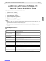 5
5
-
 6
6
-
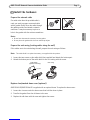 7
7
-
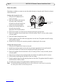 8
8
-
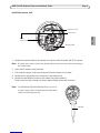 9
9
-
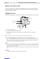 10
10
-
 11
11
-
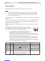 12
12
-
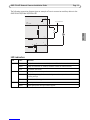 13
13
-
 14
14
-
 15
15
-
 16
16
-
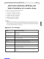 17
17
-
 18
18
-
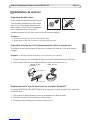 19
19
-
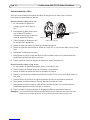 20
20
-
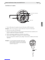 21
21
-
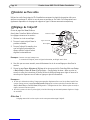 22
22
-
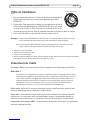 23
23
-
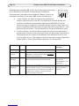 24
24
-
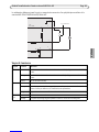 25
25
-
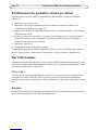 26
26
-
 27
27
-
 28
28
-
 29
29
-
 30
30
-
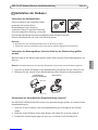 31
31
-
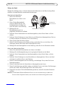 32
32
-
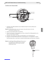 33
33
-
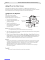 34
34
-
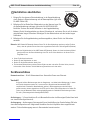 35
35
-
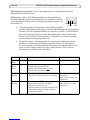 36
36
-
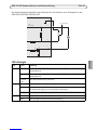 37
37
-
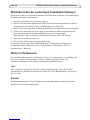 38
38
-
 39
39
-
 40
40
-
 41
41
-
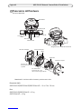 42
42
-
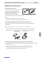 43
43
-
 44
44
-
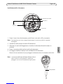 45
45
-
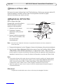 46
46
-
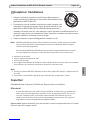 47
47
-
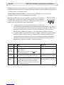 48
48
-
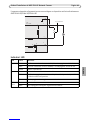 49
49
-
 50
50
-
 51
51
-
 52
52
-
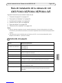 53
53
-
 54
54
-
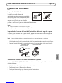 55
55
-
 56
56
-
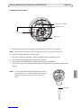 57
57
-
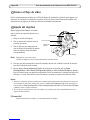 58
58
-
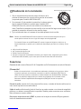 59
59
-
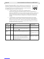 60
60
-
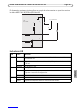 61
61
-
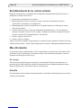 62
62
-
 63
63
-
 64
64


