Haier AD12MS1ERAD Operating Manual And Instructions
- Tipo
- Operating Manual And Instructions

No.0150513771 E
Polski
AD24MS1ERA
AD24MS1ERA(D)
AD28NS1ERA(S)
AD36NS1ERA(S)
AD48NS1ERA(S)
AD12MS1ERA
AD12MS1ERA(D)
AD18MS1ERA
AD18MS1ERA(D)
AD24MS2ERA
AD24MS2ERA(D)
AD28MS2ERA(S)
AD28MS2ERA(S)(D)


DUCT TYPE AIR CONDITIONER
OPERATION MANUAL AND INSTALLATION MANUAL
Contents
Please read this manual carefully before installation.
Keep this operation manual for future reference.
English
Cautions
Safety Precautions
Parts and Functions
Operation
Installation Manual For Wire Controller
Heating Mode
Care and Maintenance
Troubleshooting
Precaution for Installation
Is The Unit Installed Correctly
Installation Procedure
3
4
7
10
14
15
16
17
20
21
22
AD24MS1ERA
AD24MS1ERA(D)
AD28NS1ERA(S)
AD36NS1ERA(S)
AD48NS1ERA(S)
AD12MS1ERA
AD12MS1ERA(D)
AD18MS1ERA
AD18MS1ERA(D)
AD24MS2ERA
AD24MS2ERA(D)
AD28MS2ERA(S)
AD28MS2ERA(S)(D)

CE
All the products are in conformity with the following
European provision:
-Low voltage Directive
-Electomagnetic CompatibilitY
ROHS
Your air conditioning product is marked with this
symbol.This means that electrical and electronic
products shall not be mixed with unsorted
household waste.Do not try to dismantle the
system yourself:the dismantling of the air
conditioning system,treatment of the refrigerant,of oil and of
other part must be done by a qualified installer in accordance
with relevant local and national legislation.Air conditioners
must be treated at a specialized treatment facility for reuse,
recycling and recovery.By ensuring this product is disposed
of correctly,you will help to prevent potential negative cons-
equences for the environment and humen health.Please
contact the installer or local authority for more information.
Battery must be removed from the remote controller and dis-
posed of separately in accordance with relevant local and
nationl legislation.
The products are fulfilled with the requirements in the
council on the Restriction of the use of Certain Hazardous
Substances in Electrical and Electronic Equipment(EU
RoHS Directive)
WEEE
In accordance with the directive 2012/19/EU of the European
parliament,herewith we inform the consumer about the dis-
posal requirements of the electrical and electronic products.
DISPOSAL REQUIREMENTS:
Contains fluorinated greenhouse gases
covered by the Kyoto Protocol
This product contains fluorinated greenhouse gases covered
by the Kyoto Protocol.Do not vent into the atmosphere.
Refrigerant type:R410A
GWP=global warming potential
Please fill in with indelible ink,
1 the factory refrigerant charge of the product
2 the additional refrigerant amount charged in the field
and
1+2 the total refrigerant charge
on the refrigerant charge label supplied with the product.
The filled out label muset be adhered in the proximity of the
product charging port(e.g.onto the inside of the stop value
cover).
A contains fluorinated greenhouse gases covered by the
Kyoto Protocol
B fatory refrigerant charge of the product:see unit name
plate
C additional refrigerant amount charged in the field
D total refrigerant charge
E outdoor unit
F refrigerant cylinder and manifold for charging
Haier Industrial Park, No.1 Haier road, Qingdao,P.R.China
A
B
C
D
kg
kg
kg
R410A
WARNING
If the supply cord is damaged, it must be replaced by the manufacturer, its service agent or similarly qualified persons in
order to avoid a hazard.
This appliance is not intended for use by persons (including children) with reduced physical, sensory or mental capabilities,
or lack of experience and knowledge, unless they have been given supervision or instruction concerning use of the appliance
by a person responsible for their safety.
Children should be supervised to ensure that they do not play with the appliance.
This appliance can be used by children aged from 8 years and above and persons with reduced physical, sensory or
mental capabilities or lack of experience and knowledge if they have been given supervision or instruction concerning use
of the appliance in a safe way and understand the hazards involved. Children shall not play with the appliance. Cleaning
and user maintenance shall not be made by children without supervision.
The appliances are not intended to be operated by means of an external timer or separate remote-control system.
Keep the appliance and its cord out of reach of children less than 8 years.
EUROPEAN REGULATIONS
CONFORMITY FOR THE MODELS
IMPORTANT INFORMATION REGA-
RDING THE REFRIGERANT USED
2011/65/EU
directive of the European parliament and of
GWP:2088

3
Cautions
Disposal of the old air conditioner
Before disposing an old air conditioner that goes out of use, please make sure it's inoperative and safe. Unplug the air conditioner
in order to avoid the risk of child entrapment.
It must be noticed that air conditioner system contains refrigerants, which require specialized waste disposal. The valuable
materials contained in a air conditioner can be recycled. Contact your local waste disposal center for proper disposal of an old
air conditioner and contact your local authority or your dealer if you have any question. Please ensure that the pipework of your
air conditioner does not get damaged prior to being picked up by the relevant waste disposal center, and contribute to environmental
awareness by insisting on an appropriate, anti-pollution method of disposal.
Disposal of the packaging of your new air conditioner
All the packaging materials employed in the package of your new air conditioner may be disposed without any danger to the
environment.
The cardboard box may be broken or cut into smaller pieces and given to a waste paper disposal service. The wrapping bag
made of polyethylene and the polyethylene foam pads contain no fluorochloric hydrocarbon.
All these valuable materials may be taken to a waste collecting center and used again after adequate recycling.
Consult your local authorities for the name and address of the waste materials collecting centers and waste paper disposal
services nearest to your house.
Safety Instructions and Warnings
Damaged air conditioners are not to be put into operation. In case of doubt, consult your supplier.
Use of the air conditioner is to be carried out in strict compliance with the relative instructions set forth in the User's Guide.
Installation shall be done by professional people, don't install unit by yourself.
For the purpose of safety, the air conditioner must be properly grounded in accordance with specifications.
Always remember to unplug the air conditioner before opening inlet grill. Never unplug your air conditioner by pulling on the
power cord. Always grip plug firmly and pull straight out from the outlet.
All electrical repairs must be carried out by qualified electricians. Inadequate repairs may result in a major source of danger for
the user of the air conditoiner.
Do not damage any parts of the air conditioner that carry refrigerant by piercing or perforating the air conditioner's tubes with
sharp or pointed items, crushing or twisting any tubes, or scraping the coatings off the surfaces. If the refrigerant spurts out and
gets into eyes, it may result in serious eye injuries.
Do not obstruct or cover the ventilation grille of the air conditioner. Do not put fingers or any other things into the inlet/outlet and
swing louver.
Do not allow children to play with the air conditioner. In no case should children be allowed to sit on the outdoor unit.
This appliance is not intended for use by persons (including children) with reducedphysical, sensory or mental capabilities, or
lack of experience and knowledge, unless they have been given supervision or instruction concerning use of the appliance by
a person responsible for their safety.
Children should be supervised to ensure that they do not play with the appliance.
Before starting the air conditioner, read the information given in the User's Guide carefully. The User's Guide contains very
important observations relating to the assembly, operation and maintenance of the air conditioner.
The manufacturer does not accept responsibility for any damages that may arise due to non-observation of the following
instruction.

4
Safety Precautions
Before starting to use the system, read carefully this "SAFETY PRECAUTIONS" to ensure a proper operation of the system.
Safety precautions described here are classified to " WARNING" and " CAUTION". Precautions which are shown
in the column of " WANING" means that an improper handing could lead to a grave result like a death, serious injury,
etc. However, even if precautions are shown in the column of " CAUTION", a very serious problem could occur depending
on situation. Make sure to observe these safety precautions faithfully because they are very important information to ensure
the safety.
Symbols which appear frequently in the text have following meanings.
Strictly prohibited.
Observe instructions faithfully.
Provide a positive grounding.
When you have read through the manual, keep it always at hand for read consultation. If the operator is replaced, make
sure to hand over this manual to the new operator.
CAUTIONS FOR INSTALLATION
ON
OFF
WARNING
CAUTION
The system should be applied to places as office,
restaurant, residence and the like.
The system should be installed by your dealer or
a professional installer.
When you need some optional devices such as a
humidifier, electric heater, etc., be sure to use the products
which are recommended by us. These devices should
be attached by a professional installer.
Application to inferior environment such as an
engineering shop, could cause equipment
malfunction and serious injury or death.
Installation by yourself is not encouraged because
it could cause such problems as water leakage,
electrical shock or fire accident by some improper
handing.
Installation by yourself is not encouraged because it could
cause such problems as water leakage, electrical shock
or fire accident by some improper handing.
Do not install nearby the place where may have
leakage of flammable gas.
Depending on the place of installation, a circuit
breaker may be necessary.
Drain pipe should be arranged to provide a positive
draining.
If the gas leakes and gathers around, it may cause
the fire.
Unless the circuit breaker is installed, it could cause
elecrical shocks.
Where strong winds may prevail, the system
should be fixed securely to prevent a collapse.
Install on the place where can endure the weight
of air conditioner.
Make sure the system is grounded.
If the pipe is arranged improperly, furniture or the
likes may be damaged by leaked water.
Bodily injury could result by a collapse. Bodily injury could result by a careless installation. Grounding cable should never be connected to
a gas pipe, city water pipe, lightning conductor
rod or grounding cable of telephone. If the
grounding cable is not set properly, it could cause
electric shocks.
WARNING
CAUTIONS FOR TRANSFER OR REPAIR
Modification of the system is strictly prohibited. When the system needs a
repair, consult your dealer.
When the air conditioner is relocated, contact your dealer or a professional
installer.
Improper practice of repair could cause water leakage, electric shock or
fire.
Improper practice of installation could cause water leakage, electric shock
or fire.

Do not wash the air conditioner with water.
Do not install the system where the air outlet
reaches directly the flora and fauna.
Make sure to use a fuse of proper electric rating.
Do not operate the system while the air outlet grill
is removed.
It is strictly prohibited to place a container of
combustible gas or liquid near the air conditioner
or to spray it directly with the gas or liquid.
Neither stand on the air conditioner nor
place something on it.
Do not use the power switch to turn on or off the
system.
Do not touch the air outlet section while the swing
louver is operating.
Do not use such equipment as a water heater, etc.
around the indoor unit or the wire controller.
ON
OFF
It could cause electric shocks. It will not be good for their health. Use of steel or copper wire in place of a fuse is
strictly prohibited because it could result in a trouble
or fire accident.
There is a risk of injury.It could cause a fire accident.There are risks of falling or injury by collapsed
object.
It could cause a fire or water leakage. There is a risk of injury. If the system is operated at the vicinity of such
equipment which generates steam, condensed
water may drip during cooling operation or it could
cause a fault current or short-circuit.
When operating the system simultaneously with
a combustion apparatus, indoor air must be
ventilated frequently.
Check occasionally the support structure of the
unit for any damage after a use of long period of
time.
Insufficient ventilation could cause an oxygen
deficiency accident.
If the structure is not repaired immediately, the
unit could topple down to cause a personal injury.
When cleaning the system, stop the operation and
turn off the power switch.
Do not put water containers on the unit such as a flower vase, etc.
Cleaning should never be done while the internal
fans are running with high speed.
If the water enters into the unit and damages the electric insulation material, it may cause electric shock.
WARNING
CAUTION
CAUTIONS FOR OPERATION
You should refrain from exposing your body directly
to cool wind for a long time.
Do not poke the air inlet or outlet with a bar, etc. When any abnormal condition (scorching smell or
others) is found, stop the operation immediately
and turn off the power switch. Then consult your
dealer.
It could affect your physical condition or cause
some health problems.
Since the internal fan is operating with a high
speed, it could cause an injury.
If you continue the operation without removing the
cause, it could result in a trouble, electric shock
or fire.
The system should never be used for any other
purposes than intended such as for preservation
of food, flora and fauna, precision devices or work
of art.
Do not handle switches with a wet hand. Combustion apparatus should not be placed
allowing a direct exposure to wind of air conditioner.
Incomplete combustion could occur on the
apparatus.
It could cause electric shocks.It could cause deterioration of food or other
problems.
5
Safety Precautions

6
Safety Precautions
1. Applicable ambient temperature range:
The machine is adaptive in following situation
Cooling
Heating
Indoor temperature
Outdoor temperature
Indoor temperature
Outdoor temperature
max. DB/WB
min. DB/WB
max. DB/WB
min. DB/WB
max. DB/WB
min. DB/WB
max. DB/WB
min. DB/WB
32/23 C
18/14 C
46/26 C
10/6 C
27 C
15 C
24/18 C
-15 C
2. If the supply cord is damaged, it must be replaced by the manufacturer or its service agent or a similar qualified person.
3. If the fuse on the indoor PC board is broken please change it with the type of T 6.3A /250VAC(For series 24,28,36,48).
4. The wiring method should be in line with the local wiring standard.
5. The power cable should be:
H05RN-F 3G 4.0mm
2
(For series 12,18,24);
The connecting cable should be:
H05RN-F 4G 1.3mm
2
(For series 12,18,24,28,36,48)
All the cables shall have got the European authentication certificate. During installation, when the connecting cables
break off, it must be assured that the grouding wire is the last one to be broken off.
6. The power cable and connect cable should be self-provided.
7. The breaker of the air conditioner should be all-pole switch, and the distance between its two contacts should be no
less than 3mm.
8. The indoor unit installation height is at least 2.5m.
9. A leakage breaker must be installed.
10.For AD12MS1ERA and AD12MS1ERA(D),AD18MS1ERA,AD18MS1ERA(D),AD24MS2ERA,AD24MS2ERA(D),
AD28MS2ERA(S),AD28MS2ERA(S)(D),we can get the 4 different ESP through adjust the indoor unit PCB SW1-4 and
SW1-5, please refer below:
Attention: cut off the power supply to adjust the SW1-4, and SW1-5, or else the operation is invalid.
SW1
(1) (2) (3) (4) (5) (6) (7) (8)
Static pressure
10 Pa
30 Pa
50 Pa
70 Pa
OFFOFF
OFFON
ON OFF
ON ON
- - - - - -
- - - - - -
- - - - - -
- - - - - -

Attention:
Unit model with the letter D is the mechine without water pump.
Unit model without the letter D is the mechine with water pump.
AD12MS1ERA AD12MS1ERA(D)
AD24MS1ERA
AD28NS1ERA(S) AD36NS1ERA(S) AD48NS1ERA(S)
AD24MS1ERA(D)
7
Parts and Functions
Electrical components Case
Drain pan Evaporator
Air outlet frame
The pump
drain opening
Electrical components Case
Air outlet frame
Drain pan Evaporator
The pump
drain opening
Air outlet
Air inlet
Duct
The pump
drain opening
Electrical components Case
Drain pan
Evaporator
Air outlet frame
Electrical components Case
Drain pan Evaporator
Air outlet frame
Drain opening
Electrical components Case
Air outlet frame
Drain pan Evaporator
Drain opening
Drain opening
Electrical components Case
Drain pan Evaporator
Air outlet frame
AD18MS1ERA AD24MS2ERA AD28MS2ERA(S) AD18MS1ERA(D) AD24MS2ERA(D) AD28MS2ERA(S)(D)

8
Parts and Functions
Buttons of the wire controller
Reset key
When in abnormal state, push the
reset key with a spike, which may
return the unit to normal
Health switch
Used to control oxygen
function and negative ion
Filter reset
After cleaning air inlet
and filter, press
this switch. The unit
begins to run
ON/OFF switch
Do on and off function. The unit is
on when pressing it; and is off
when pressing it again.
Fan speed switch
Change wind speed
Time switch
It is used to regulate setting time.
Self-inspection
switch
It is used for inspection
service
Air change switch
It is used to open and close air
change function. The mode is as
follows:
No display-air change (automatic)-
air change (RECOVERY)-air
change (NORMAL)
Clock, timing and address setting
Timing switch
It is used for choosing
timing running
Mode switch
Choose running mode
Swing switch
Open and close air flap
TEMP switch
Used for changing set temperature
AUTO
FAN ONLY
COOL
DRY
HEAT
TES
FAN
AUTO
HIGH
LOW
FIX
CENTRAL
OPERATION
STANDBY
PRE-HEAT
DEFROST
FILTER
MODE
HEALTH
SWING
CHECK
UNIT NO.
C
F
DEMAND
CEN. ADD.
SYS. ADD.
MANUAL
ROOM TEMP.
SET TEMP.
TIMER
VENTILATION
CLOCK UP DOWN
ON
OFF
DAILY
AUTO
RECOVERY
NORMAL
MODE FAN SWING
HEALTH
CLOCK
TIMER
CHECK FILTER
RESET
ON/OFF
SET RECOVERY
TEMP
TIME
MED

9
Parts and Functions
Standby display
When the unit is on power and in
"abnormity mode", or outdoor unit
malfunction show alarm , "standby" is
shown to reflect no need to unit.
Display of the wire controller
Remarks
The models in the manual don't have health, filter reset and Air change function.
Running mode display
Show the selected mode
Wind swing display
Filter screen warning
sign
When the sign is
shown, please clean
the filter screen
Centralized display
When controlled by centralized
controller, and chosen by "centralize or
lock" mode, this information is shown.
Timing operation
display
Show timing operation
content
Temperature
display
Display the room
temperature, setting
temperature, and
unit number
Air volume display
Display the setting speed
Inspection status display
Air change display
Health function display
Unit number display
Centralized adress
display
System adress display
Running display
When the compressor runs, it displays.
Demand display
When forced to run,"DEMAND"
will be displayed , or show HH/LL
in the temperature zone.
"Defrost" is shown
when defrosting.
When in preheating
status, "preheating" is
shown.
AUTO
FAN ONLY
COOL
DRY
HEAT
TES
FAN
AUTO
HIGH
LOW
FIX
CENTRAL
OPERATION
STANDBY
PRE-HEAT
DEFROST
FILTER
MODE
HEALTH
SWING
CHECK
UNIT NO.
C
F
DEMAND
CEN. ADD.
SYS. ADD.
MANUAL
ROOM TEMP.
SET TEMP.
TIMER
VENTILATION
CLOCK UP DOWN
ON
OFF
DAILY
AUTO
RECOVERY
NORMAL
MODE FAN SWING
HEALTH
CLOCK
TIMER
CHECK FILTER
RESET
ON/OFF
SET RECOVERY
TEMP
TIME
MED

10
Operation
ON/OFF operation
Press ON/OFF switch on line controller directly
The line controller displays the running state in the latest
time (timing and swing state may not be displayed).
1. Press "ON/OFF" switch.
The air conditioner starts operating, and the light on the
wired controller is on.
3.Press "TEMP" switch
Change set temperature:press TEMP or TEMP every
time, [SET] will display,and set temperature will
increase/reduce
4.Press "FAN SPEED" switch
FAN ONLY Operation:
Press "FAN SPEED" switch to change to
"HIGH"--"MED"--"LOW"--"HIGH"
In AUTO,COOL,DRY,HEAT Operation:
Press "FAN SPEED" switch to change to
"AUTO"--"HIGH"--"MED"--"LOW"--"AUTO"
Avoid pressing "ON/OFF" switch frequently.
Do not press line controller or switches by sharp objects.
The temperature is on the basis of the setting value. The wind temperature may not reach the setting value because of
the outer air conditioner and system protection.
When the wired controller is power on, the screen fully displays it for two seconds. and clock zone "8888"-"888"-"88"-"8"
flicker for 30 seconds. All the switches are invalid at the time.
Remarks
Note
5.Press "swing" switch on the line controller to
swing the wind screen.
6.Press "ON/OFF"switch, off.
The light on the line controller is off.
2.Choose operation mode.
Press "mode"switch to change to
"AUTO"---"FAN ONLY"---"COOL"---"DRY"---"HEAT".
HIGH
C
ROOM TEMP.
COOL
FAN
OPERATION
MODE
CLOCK
MODE FAN SWING
HEALTH
CLOCK
TIMER
CHECK FILTER
RESET
ON/OFF
SET RECOVERY
TEMP
TIME
2
4
5
3
1
6
Several seconds after the operation of the line controller,
the setting of the unit will change.

11
Operation
1.Press "CLOCK" switch
2.Press " " and " " to regulate the time.
Setting of power failure compensation function
When SW1-6 on PCB of wire controller is OFF, it will be in power failure compensation. If the SW1-6 is ON, it has no
compensation function.
When the power is on after blackout, the unit will return to the former state if compensation function is set. Otherwise, it
will stop. When restarting the unit, press "ON/OFF" switch on wired controller.
3.Press "setting" switch. The setting is achieved.
"CLOCK" flickers, and the time displayed is the real time.
The time increases a minute each time you press " " switch.
The time decreases a minute each time you press " " switch.
If not in timing, the screen displays the real time.
If in timing, the screen displays the timing time.
If you want to know the real time, go to the first step.
Notes
The timing is based on the real time. Thus, the real time should be regulated in advance.
The clock regulation steps are as follows:
123
HIGH
C
ROOM TEMP.
HEAT
FAN
OPERATION
MODE
CLOCK UP
MODE FAN SWING
HEALTH
CLOCK
TIMER
CHECK FILTER
RESET
ON/OFF
SET RECOVERY
TEMP
TIME
Present time setting

12
Operation
2.Set up "TIMER"
The display changes with the following sequence:
on
OFF
OFF
CYCLE
ON
no display
1.Press "TIME" switch.
The shorter setting time will be carried out firstly.
If the ON timing and OFF timing are the same, the setting is invalid.
Even in timing condition, you may start or close the unit through pressing "ON/OFF" switch.
Notes
Timing setting
Press "ON/OFF" switch
firstly, and set up operation
mode.
Please regulate the clock in
advance before using the
timing function.
3.Time setting is achieved. Press"setting"switch.
If you want to change the timing mode to normal operation,
press "timing" until there is no timing display. When the
timing is invalid, the mode is in normal operation.
Cancel timing
1.The unit starts or stops at the setting time. Meanwhile, it displays the timing time.
2."ON Timing, OFF timing and circulation"means that the unit is on and off at the setting time everyday.
When timing ON or timing OFF flickers, press " " or " " to
regulate the time
Press" "or " "set up ON/OFF time.
The setting time increases ten minutes each time you press " "
switch.
The setting time decreases ten minutes each time you press " "
switch.
When setting timing ON and timing OFF at the same time,
press "timing" switch to change the setting item.
on
OFF
HIGH
C
ROOM TEMP.
123
COOL
FAN
OPERATION
MODE
TIMER
ON
MODE FAN SWING
HEALTH
CLOCK
TIMER
CHECK FILTER
RESET
ON/OFF
SET RECOVERY
TEMP
TIME
OFF timing: when a set time has elapsed, the unit stops running.
ON timing: when a set time has elapsed, the unit starts.
parts of wired controller explanation :

1. Switches or jumper wire must be adjusted when the wire controller is powered off. If the wire controller is
powered on, the above operations will be invalid.
2. Function difference between master wire controller and slave one:
Notes
Factory Setting OFF default settingSW1-8
Installation Manual For Wire Controller
Factory Seting ON default settingSW1-7
13
Operation
Query indoor malfunction history:
In the state of power on or power off, press [CHECK] button, enter the malfunction-querying mode of all indoor units in
the group. Then [CHECK] and [UNIT NO.] will display, and the actual indoor numbers will be displayed in some sequence
(unit number is in decimals). At the same time, in the time region, there will be the current malfunction and the latest time
malfunction, the displaying format is [XX:YY], in which XX stands for the current malfunction, if normal, it will display "--";
YY stands for the latest time malfunction. The failure code of every unit will display for 3 seconds. After the failure codes
of all indoor units in the whole group are displayed, the mode will quit automatically.
How to change the function switches?
Master wire
controller
Slave wire controller
Function All of functions
Only with below functions: ON/OFF, MODE, FAN
SPEED, SET TEMP., SWING
Contrastive
items
No. Type State of switch Function description
Select the master or
the slave controller
ON set as the slave controller
OFF
SW1-1
OFF set as the master controller
Select the controller
mode
ON
standard controller
SW1-2
air handler controller
Room temperature
display option
ON
visible room temperature
SW1-3
invisible room temperature
26
o
lock
ON
Unavailable 26
o
lock
SW1-4
available 26
o
lock
Temperature sensor
position option
ON
Sensor of the controller
SW1-5
Sensor in the unit
OFF
Auto restart
ON unavailable
SW1-6
available
OFF
OFF
OFF
3.Wiring instruction
Use shielded wire between indoor and wire controller.And be earthed on one side, or the unit will not work normally
because of interference.
Note:Confirm the terminal connection firmly, and do not get in tough with shielded wire.
4.Place wire controller on the holder, and pay attention not to pressing any wires.
10.45
Screw holes
5.3
Bracket
Wire controller
1. Take down wire controller from the holder
2. Install the controller holder
According to the position of 2 screw holes on the
holder, drill 2 holes on the wall, and strike the wood
stopper to the holes respectively.
Then align the 2 screw holes of wired controller
holder to the wood stopper, fix the holder on the wall
with wood screw.
Note:Try a wall as flat as possible for installation.
Don't use excessive force to tighten screws,
otherwise, the holder will be damaged.
AUTO
FAN ONLY
COOL
DRY
HEAT
TES
FAN
AUTO
HIGH
LOW
FIX
CENTRAL
OPERATION
STANDBY
PRE-HEAT
DEFROST
FILTER
MODE
HEALTH
SWING
CHECK
UNIT NO.
C
F
DEMAND
CEN. ADD.
SYS. ADD.
MANUAL
ROOM TEMP.
SET TEMP.
TIMER
VENTILATION
CLOCK UP DOWN
ON
OFF
DAILY
AUTO
RECOVERY
NORMAL
MODE FAN SWING
HEALTH
CLOCK
TIMER
CHECK FILTER
RESET
ON/OFF
SET RECOVERY
TEMP
TIME
MED

Installation Manual For Wire Controller
14
5. Wiring connections of wire controller:
Indoor 1
Wire controller
A B C
Wire controller
Polar wire
Indoor 1
Wire controller
A B C
Wire controller
Polar wire
A B C
Wire controller
Polar wire
BC
A B C A B C
ABCABCAB
ABC
CABCABC
Indoor 1 Indoor 2 Indoor N Indoor 15 Indoor 16
Wire controller
Control wiring
of wire
controller
TYPE 2, FOR AD24MS1ERA, AD24MS1ERA(D),AD28/36/48NS1ERA(S)
ABCABC
AB
ABC
C
ABC
ABC
A
Indoor 1
Wire controller
port
Indoor 2 Indoor N Indoor 15 Indoor 16
Wire controller
Control wiring
of wire
controller
Wire controller
port
Wire controller
port
Wire controller
port
Wire controller
port
(master unit)
Wire controller
port
Wire controller
port
Wire controller
port
Wire controller
port
Wire controller
port
(master unit)
TYPE 1, FOR AD12/18MS1ERA,AD12/18MS1ERA(D),AD24MS2ERA,AD24MS2ERA(D),AD28MS2ERA(S),AD28MS2ERA(S)(D)
There are three methods to connection wire controller and the indoor units:
A.One wired controller can control max. up to 16 sets of indoor units, and 3 pieces of polar wire must connect the wire
controller and the master unit (the indoor unit connected with wire controller directly), the others connect with the master
unit through 2 pieces of polar wire( 3 pieces for model AD12/18MS1ERA, AD12/18MS1ERA(D),AD24MS2ERA,
AD24MS2ERA(D) and the bridge CN22 CN23 on slave units PCB should be cut
off ).
B. One wire controller controls one indoor unit, and the indoor unit connects with the wire controller through 3 pieces of
polar wire.
C. Two wired controllers control one indoor unit. The wire controller connected with indoor unit is called master one, the
other is called slave one. Master wire controller and indoor unit; master and slave wire controllers are all connected
through 3 pieces of polar wire.
6. Communication wiring:
The wire controller is equipped with special communication wiring in the accessories. 3-core terminal (1-white 2-yellow 3-
red) is connected with the terminal A, B, C of wire controller respectively.
The communication wiring is 5 meter long; if the actual length is more than it, please distribute wiring according to below
table:
Communication wiring length(m) Dimensions of wiring
< 100 0.3mm
2
x3-core shielded wire
100 and <200 0.5mm
2
x3-core shielded wire
200 and <300 0.75mm
2
x3-core shielded wire
300 and <400 1.25mm
2
x3-core shielded wire
400 and <600 2mm
2
x3-core shielded wire
*One side of the shielded sheet of communication wire must be earthed.
, AD28MS2ERA(S), AD28MS2ERA(S)(D)

"HOT KEEP" function
Heating Mode
15
"HOT KEEP" is operated in the following cases.
When heating is started:
In order to prevent blowing out of cool wind, the indoor unit fan stopped according to the room temperature which heating
operation is started. Wait for approx. 2 to 3 minute, and the operation will be automatically changed to the ordinary heating
mode.
Defrosting operation (in the heating mode):
When it is liable to frost, the heating operation is stopped automatically for 5 to 12 minutes once per approx. one hour,
and defrosting is operated. After defrosting is completed, operation mode is automatically changed to ordinary heating
operation.
When the room thermostat is actuated:
When room temperature increases and room temperature controller actuates, the fan speed is automatically changed to
stop under low temperature condition of indoor heat exchanger. When room temperature decreases, air conditioner
automatically changes over to ordinary heating operation.
Heat pump type warming
With the heat pump type warming, the mechanism of heat pump that concentrate heat of outdoor air with the help of
refrigerant to warm the indoor space, is utilized.
Defrosting operation
When a room is warmed with a heat pump type air conditioner, frost accumulates on the heat exchanger of outdoor unit
along with the drop of indoor temperature. Since the accumulated frost reduces the effect of warming, it is necessery to
automatically switch the operation to the defrosting mode. During the defrosting operation, heating operation is interrupted.
Atmospheric temperature and warming capacity
Warming capacity of heat pump type air conditioner decreases along with the drop of outdoor temperature.
When the warming capacity is not sufficient, it is recommended to use another heating implement.
Period of warm-up
Since the heat pump type air conditioner employs a method to circulate warm winds to warm
the entire space of a room, it takes time before the room temperature rises.
It is recommendable to start the operation a little earlier in a very cold morning.
Warming operation

Points to observe
Turn off the power supply switch. Do not touch with wet hand. Do not use hot water or volatile liquid.
ON
OFF
Thinner
Do not
use!
Benzine
Tooth powder
Cleaning the air filter
Do not dry the air filter with fire.
Do not run the air conditioner without the air filter.
Pre-Season Care
See that there are no obstacles blocking the air inlet and air outlet of both indoor and outdoor units.
Make sure that the air filter is not dirty.
Cut in the power supply switch 12 hours before starting run.
Post-Season Care
Operate the unit with FAN mode on a fair day for about half a day to dry the inside of the unit well.
Stop operation and turn off the power supply switch. Electric power is consumed even the air conditioner is in stop.
Clean the air filter and set it in the place.
Care and Cleaning of the unit
Clean with soft and dry cloth.
If it is very dirty, dissolve neutral detergent in the lukewarm water and make the cloth wet with the water. After wiping,
clean off the detergent using clean water.
1.Clean the air filter by lightly tapping it or with the cleaner. It is more effective to clean
the air filter with water.
If the air filter is very dirty, dissolve neutral detergent in the lukewarm water (approx. 30 C),
rinse the air filter in the water, and thoroughly wash the air filter off the detergent
in the plain water.
2.After drying the air filter, set it up on the air conditioner.
Do not open the inlet grill until fan stops completely.
Fan will continue rotating for a while by the law of inertia after operation is being stopped.
CAUTION
CAUTION
Care and Maintenance
16

Please check the following things about your air conditioner before making a service call.
When the air conditioner does not operate properly after you have checked the above mentioned items or when the following
phenomenon is observed, stop the operation of the air conditioner and contact your sales dealer.
The fuse or breaker often shuts down.
Water drops off during cooling operation.
There is a irregularity in operation or abnormal sound is audible.
When the CHECK LED (red) flickers, an irregularity has occurred in the air conditioner.
Unit fails to start
ON
OFF
Is the power source switch
adjust cut in?
Is city supply power in
normal?
Isn't the signal receiving
section exposed to the direct
sunlight or strong illumination?
Isn't the earth leakage breaker
in action?
It is dangerous. Turn off the
power supply switch
immediately and contact the
sales dealer.
Power supply switch is not
ON.
Cooling or heating is not sufficient
Is the thermostat adjust as
required?
Isn't the air filter dirty? Isn't any doors or windows
left open?
Doesn't any obstacle exist at
the air inlet or outlet?
Cooling is not sufficient
Isn't sun-shine invading direct? Isn't any unexpected heating
load generated?
Isn't the room much crowded?
Isn't the swing louver horizontal? (At HEATING mode)
If swing louver is horizontal, the blow wind does not reach floor.
The wind does not blow during
heating operation
Isn't it warming up?
Power
stoppage?
Troubleshooting
17

The followings are not malfunction
Shuru
Shuru
When the air conditioner is started, when the compressor starts or stops
during operation or when the air conditioner is stopped, it sometimes sounds
"shuru shuru" or "gobo gobo". It is the flowing sound of the refrigerant, and it
is not a trouble.
Water flowing sound is heard.
This is caused by heat expansion or contraction of plastics.Cracking sound is heard.
It smells. Air which blows out from the indoor unit sometimes smells. The smell results
from residents of tobacco smoke or cosmetics stuck inside of unit.
When the air conditioner is used at restaurant etc. where dense edible oil
fume is always exists, white fog sometimes blows out of air outlet during
operation. In this case consult sales dealer for cleaning the heat exchanger.
During operation, white fog comes out
of indoor unit.
Unit does
not start
Wait for
three
minutes
It is switched into the FAN mode during
cooling.
To prevent frost from being accumulated on the indoor unit heat exchanger,
it is sometimes automatically switched to the FAN mode,but it will soon return
to the cooling mode.
Even if the operation switch is turned on, cooling, dehumidifying or heating
is not operable for three minutes after the conditioner is stopped. Because
the protecting circuit is activated. (During this time air conditioner operates
in fan mode.)
The air conditioner can not be restarted
soon after it stops.
Air does not blow or the fan speed can
not be changed during dehumidifying.
During operation, operation mode has
changed over automatically.
Water or steam generates from the outdoor
unit during heating.
When it is excessively cooled during dehumidifying, the blower
automatically repeats reducing and lowering the fan speed.
Isn't the AUTO mode selected?
In the case of AUTO mode, operation mode is changed automatically from
cooling to heating or vise-versa according to the room temperature.
This results when frost accumulated on the outdoor unit is removed (during
defrosting operation).
Troubleshooting
18

19
Troubleshooting
When failure happens,the fan of indoor unit stop running.The method of check failure code see page 12.
For outdoor failure,the failure code is outdoor failure LED flash times + 20.
For example,the failure code of outdoor unit is 2. the wired controller of indoor unit will display 16(using hexadecimal method).
Ta: ambient temperature sensor
Tm: coil temperature sensor

WARNING
Please read these "Safety Precautions" first and then accurately execute the installation work.
Though the precautionary points indicated herein are divided under two headings, and , those
points which are related to the strong possibility of an installation done in error resulting in death or serious injury are
listed in the section. However, there is also a possibility of serious consequences in relationship to the
points listed in the section as well. In either case, important safety related information is indicated, so by all
means, properly observe all that is mentioned.
After completing the installation, along with confirming that no abnormalities were seen from the operation tests, please
explain operating methods as well as maintenance methods to the user (customer) of this equipment, based on the owner's
manual. Moreover, ask the customer to keep this sheet together with the owner's manual.
This system should be applied to places as office, restaurant, residence and the like. Application to inferior environment
such as engineering shop could cause equipment malfunction.
Please entrust installation to either the company which sold you the equipment or to a professional contractor. Defects
from improper installations can be the cause of water leakage, electric shocks and fires.
Execute the installation accurately, based on following the installation manual. Again, improper installations can result
in water leakage, electric shocks and fires.
When a large air-conditioning system is installed to a small room, it is necessary to have a prior planned countermeasure
for the rare case of a refrigerant leakage, to prevent the exceeding of threshold concentration. In regards to preparing
this countermeasure, consult with the company from which you perchased the equipment, and make the installation
accordingly. In the rare event that a refrigerant leakage and exceeding of threshold concentration does occur, there is
the danger of a resultant oxygen deficiency accident.
For installation, confirm that the installation site can sufficiently support heavy weight. When strength is insufficient,
injury can result from a falling of the unit.
Execute the prescribed installation construction to prepare for earthquakes and the strong winds of typhoons and
hurricanes, etc. Improper installations can result in accidents due to a violent falling over of the unit.
For electrical work, please see that a licensed electrician executes the work while following the safety standards related
to electrical equipment, and local regulations as well as the installation instructions, and that only exclusive use circuits
are used. Insufficient power source circuit capacity and defective installation execution can be the cause of electric
shocks and fires.
Accurately connect wiring using the proper cable, and insure that the external force of the cable is not conducted to
the terminal connection part, through properly securing it. Improper connection or securing can result in heat generation
or fire.
Take care that wiring does not rise upward, and accurately install the lid/service panel. Its improper installation can
also result in heat generation or fire.
When setting up or moving the location of the air conditioner, do not mix air etc. or anything other than the designated
refrigerant (R410A) within the refrigeration cycle. Rupture and injury caused by abnormal high pressure can result from
such mixing.
Always use accessory parts and authorized parts for installation construction. Using parts not authorized by this company
can result in water leakage, electric shock, fire and refrigerant leakage.
WARNING
CAUTION
Execute proper grounding. Do not connect the ground wire to a gas pipe, water pipe, lightning rod or a telephone ground
wire. Improper placement of ground wires can result in electric shock.
The installation of an earth leakage breaker is necessary depending on the established location of the unit. Not installing
an earth leakage breaker may result in electric shock.
Do not install the unit where there is a concern about leakage of combustible gas.
The rare event of leaked gas collecting around the unit could result in an outbreak of fire.
For the drain pipe, follow the installation manual to insure that it allows proper drainage and thermally insulate it to
prevent condensation. Inadequate plumbing can result in water leakage and water damage to interior items.
CAUTION
WARNING
CAUTION
Precaution for Installation
20

For inspection and maintenance
When you change your address or the installation place
Electric work
Confirm the following items for safe and comfortable use of air conditioner.
The installation work is to be burden on the sales dealer, and do not conduct it by yourself.
Installation place
Avoid installing the air conditioner near
the place where possibility of
inflammable gas leakage exists.
Install the unit at well ventilated place.
Install the air conditioner firmly on the
foundation that can fully support the
weight of the unit.
If not, it may cause vibration or noise.If some obstacle exist, it may cause
capacity reduction or noise increase.
Explosion (Ignition) may occur.
Select the place so as not to annoy
neighbor with the hot air or noise.
Snow protection work is necessary
where outdoor unit is blocked up by
snow.
It is advisable not to install the air con-
ditioner at the following special place.
It may cause malfunction, consult the
sales dealer when you have to install
the unit on such a place.
The place where corrosive gas
generates (Hot spring area etc.)
The place where salt breeze blows
(Seaside etc.)
The place where dense soot smoke
exists
The place where humidity is
extraordinarily high
The place where near the machine
which radiates the electromagnetic
wave
The place where voltage variation is
considerably large
For details consult your sales dealer.
The electric work must be burden on the authorized engineer with qualification for electric work and grounding work, and
the work must be conducted in accordance with electric equipment technical standard.
The power source for the unit is to be of exclusive use.
An earth leakage breaker should be installed.(This is necessary to prevent electric shock.)
The unit must be grounded.
Special technology is required for removal or reinstallation of air conditioner, consult the sales dealer. Besides, construction
expense is charged for removal or reinstallation.
The capacity of air conditioner will decrease by contamination of inside of unit when it is used for about three years although
depending upon the circumstances under which it is used, and so in addition to the usual maintenance service, special
inspection/maintenance service is necessary. It is recommended to make a maintenance contract (charged) by consulting
your sales dealer.
Is The Unit Installed Correctly
21

22
Avoid installation and use at those places listed below.
Places exposed to oil splashes or steam (e.g. kitchens and machine plants).
Installation and use at such places incur deteriorations in the performance or corrosion with the heat exchanger or damage
in molded synthetic resin parts.
Places where corrosive gas (such as sulfurous acid gas) or inflammable gas (thinner, gasoline etc.) in generated or
remains. Installation and use at such places cause corrosion in the heat exchanger and damage in molded synthetic
resin parts.
Places adjacent to equipment generating electromagnetic waves or high-frequency waves such as in hospitals.
Generated noise may cause malfunctioning of the controller.
NOTE
All wiring of this installation must comply with NATIONAL, STATE AND LOCAL REGULATIONS. These instructions
do not cover all variations for every kind of installation circumstance. Should further information be desired or should particular
problems occur, the matter should be referred to your local distributor.
WARNING
BE SURE TO READ THESE INSTRUCTIONS CAREFULLY BEFORE BEGINNING INSTALLATION. FAILURE TO FOLLOW
THESE INSTRUCTIONS COULD CAUSE SERIOUS INJURY OR DEATH, EQUIPMENT MALFUNCTION AND/OR
PROPERTY DAMAGE.
Preparation of indoor unit
Before or during the installation of the unit, assemble necessary optional panel etc. depending on the specific type.
Select places for installation satisfying following conditions and at the same time obtain the consent on the part
of your client user.
Places where chilled or heated air circulates freely. When the installation height exceeds 3m warmed air stays close to
the ceiling. In such cases, suggest your client users to install air circulators.
Places where perfect drainage can be prepared and sufficient drainage.
Places free from air disturbances to the suction port and blowout hole of the indoor unit, places where the fire alarm
may not malfunction or short-circuit.
Places with the environmental dew-point temperature is lower than 28 and the relative humidity is less than 80 %.
(When installing at a place under a high humidity environment, pay sufficient attention to the prevention of dewing such
as thermal insulation of the unit. )
Ceiling height shall have the following height.
50mm
Obstacle
Installation space
C
Combination
with silent
panel
416mm
366mm
a.
b.
c.
d.
e.
a.
b.
c.
Indoor Unit
100mm 100mm
Pipe size
AD28NS1ERA(S)
AD36NS1ERA(S)
AD48NS1ERA(S)
AD12MS1ERA AD12MS1ERA(D)
AD18MS1ERA AD18MS1ERA(D)
AD24MS1ERA AD24MS1ERA(D)
AD24MS2ERA AD24MS2ERA(D)
AD28MS2ERA(S) AD28MS2ERA(S)(D)
AD12MS1ERA AD12MS1ERA(D)
AD24MS1ERA AD24MS1ERA(D)
AD24MS2ERA AD24MS2ERA(D)
AD28NS1ERA(S) AD28MS2ERA(S)
AD28MS2ERA(S)(D)AD36NS1ERA(S)
Installation Procedure
Model Liquid side Gas side
9.52mm 15.88mm
9.52mm 19.05mm
6.35mm 9.52mm
6.35mm 12.7mm
AD18MS1ERA AD18MS1ERA(D)
AD48NS1ERA(S)

2.Installation of indoor unit
Fix the indoor unit to the hanger bolts.
If required, it is possible to suspend the unit to the beam, etc. Directly
by use of the bolts without using the hanger bolts.
When the dimensions of main unit and ceiling holes does not match,
it can be adjusted with the slot holes of hanging bracket.
Note
Adjusting to the levelness
(a) Adjust the out-of levelness using a level or by the following method.
Make adjustment so that the relation between the lower surface
of the unit proper and water level in the hose becomes as given
below.
(b) Unless the adjustment to the levelness is made properly,
malfunctioning or failure of the float switch may occur.
Tap selection on blower unit
(When the high performance filter is used.)
Taps of blower unit are set at the standard selection at the shipping
from factory. Where the static pressure is raised by employing such
option as the high performance filter, etc., change the connection of
connectors provided at the flank of control box as shown below.
PVC hose
Piping side
Supply water
Water level
0~5 mm
(0~0.2")
Bring the piping side slightly lower.
Hanging bolt
M10 nut
Main unit
M10 washer
M10 spring washer
Red
Yellow
White
Standard tap (at shipping) High speed tap
Black
White
Connector white
Connector white
Control box side
Moter side
Moter side
Red
Blue
Red
Yellow
White
Blue
Red
Yellow
White
Blue
White
Blue
Red
1. Preparation for suspending the unit
a.Size of hole at ceiling and position of hanging bolts
<Combination with silent panel>
b.Hanger bolts installation
Use care of the piping direction when the unit is installed.
Hanging bolt M10
Hole-in anchor
Hole-in plug
Insert
Concrete
Indoor Unit
150
A
B
C
Hanging bolt position
Ceiling hole size
Panel dimensions
300
30
30
Ceiling ~ panel
wrap dimensions
Ceiling ~ panel
wrap dimensions
Hanging bolt position
Ceiling hole size
Panel dimensions
75
D
E
F
70
Pipe connection
side
150
A
B
C
Hanging bolt position
Ceiling hole size
Panel dimensions
300
30
30
Ceiling ~ panel
wrap dimensions
Ceiling ~ panel
wrap dimensions
Hanging bolt position
Ceiling hole size
Panel dimensions
75
D
E
F
70
Pipe connection
side
Installation Procedure
23
AD12MS1ERA AD12MS1ERA(D) AD24MS1ERA AD24MS1ERA(D)
AD18MS1ERA AD18MS1ERA(D) AD28NS1ERA(S) AD36NS1ERA(S)
AD24MS2ERA AD24MS2ERA(D) AD48NS1ERA(S)
AD28MS2ERA(S) AD28MS2ERA(S)(D)
Dimensions
A(mm)
B(mm)C(mm)
Model
D(mm)E(mm) F(mm)
987
1172
1437
1622
1497
1682
545
480
690
625
750
685
705
983
1155
1433
1215
1493
595
595
740
740
800
800
AD28NS1ERA(S) AD36NS1ERA(S)
AD48NS1ERA(S)
AD24MS1ERA AD24MS1ERA(D)
AD12MS1ERA AD12MS1ERA(D)
AD18MS1ERA AD18MS1ERA(D)
AD24MS2ERA AD24MS2ERA(D)
AD28MS2ERA(S) AD28MS2ERA(S)(D)

Drain Piping
Drain piping should always be in a downhill grade (1/50~1/100) and avoid riding across an elevation or making traps.
When connecting the drain pipe to unit, pay suffcient attention
not to apply excess force to the piping on the unit side. Also, fix
the piping at a point as close as possible to the unit.
For unit with water pump drain pipeuse hard PVC general purpose
pipe VP which can be purchased locally. When connecting, insert
a PVC pipe end securely into the drain socket before tightening
securely using the attached drain hose and clamp. Adhesive must
not be used for connection of the drain socket and drain hose
(accessory).
Drain hose
Stage
difference
part
Drain socket
Drain socket
Main unit
VP(field purchased)
Pipe cover(large)
[for insulation]
(accessory)
VP(field purchased)
Pipe cover
[for insulation]
(field purchased)
Drain hose
(accessory)
Pipe cover(small)
[for insulation]
(accessory)
Clamp
(accessory)
Adhesion
Do not pipe under water
Keep free from traps
Avoid riding across an elevation
Air vent
Improper pipingGood piping
1.5m ~ 2m
Suspension
bolts
Heat
insulation
A downhill grade
of 1/100 or more
(b)
(c)
VP-30
Secure the elevation as high as possible
(approx. 100 mm)
A downhill grade of
1/100 or more
Right overhead
Drain hose
Joint for VP
(Local procurement)
600
(Maximum local drain up dimension)
290~325mm
Avoid positioning the drain piping outlet at a place where generation
of odor may be stimulated. Do not lead the drain piping direct into
a sewer from where sulfur gas may generate.
(d)
(e)
(f)
(h)
(a)
When constructing drain piping for several units, position the
common pipe about 100 mm below the drain outlet of each unit
as shown in the sketch. Use VP-30(11/4") or thicker pipe for this
purpose.
The hard PVC pipe put indoor side should be heat insulated. Do
not ever provide an air vent.
The height of the drain head can be elevated up to a point 500
mm above the ceiling, and when an obstacle exists in the ceiling
space, elevate the piping to avoid the obstacle using an elbow
or corresponding gadget. When doing this, if the stretch for the
needed height is higher than 500 mm, the back-flow quantity of
drain at the event of interruption of the operation gets too much
and it may cause overflow at the drain pan. Therefore, make the
height of the drain pipe within the distance given in the sketch
below.
Drain Pipe
For unit without water pump
For unit without water pump,please refer to the digram and select
drain pipe size according to drain opening inner diameter size.
The drain pipe shall be slant downwards (greater than 1/100).
The horizontal length of the drain pipe shall be less than 20 m.
In case of long pipe, supports shall be provided every 1.5~2m to
prevent wavy form.
Central piping shall be laid out according to the right figure.
Take care not to apply external force onto the drain pipe connection
part.
(g)
For unit with water pump
Installation Procedure
24
1.5m~2m
Support
Insulation (supplied by the user)
Down slope above 1/100
AD28NS1ERA(S) AD36NS1ERA(S)
AD48NS1ERA(S)
AD24MS1ERA AD24MS1ERA(D) 15.5mm
AD12MS1ERA AD12MS1ERA(D)
AD18MS1ERA AD18MS1ERA(D) 21mm
AD24MS2ERA AD24MS2ERA(D)
AD28MS2ERA(S) AD28MS2ERA(S)(D)
33mm
Unit model The size of drain opening

Installation work for air outlet ducts
Calculate the draft and external static pressure and select the length,
shape and blowout.
A Blowout duct
2-spot, 3-spot and 4-spot with 200 type duct are the standard
specifications.
Note (1) Shield the central blowout hole for 2-spot.
(2) Shield the blowout hole around the center for 3-spot.
Limit the difference in length between spots at less than 2:1.
Reduce the length of duct as much as possible.
Reduce the number of bends as much as possible. (Corner R should
be as larger as possible.)
Use a band. etc. to connect the main unit and the blowout duct
flange.
Conduct the duct installation work before finishing the ceiling.
Connection of suction, exhaust ducts
a.Fresh air inlet
Inlet can be selected from the side or rear faces depending on the
working conditions.
Use the rear fresh air inlet when the simultaneous intake and exhaust
is conducted. (Side inlet cannot be used.)
b.Exhaust (Make sure to use also the suction.)
Use the side exhaust port.
Good exampleBad exampleBad example
Exhaust hole
State seeing from top of unit
Side fresh air inlet
Rear fresh air inlet
Fig.1
Fig.2
Drainage Test
Conduct a drainage test after completion of the electrical work.
During the trial, make sure that drain flows properly through the
piping and that no water leaks from connections.
In case of a new building, conduct the test before it is furnished
with the ceiling.
Be sure to conduct this test even when the unit is installed in the
heating season.
Attached drain hose clamp
Drain piping
Main unit
Drain situation can be checked with transparent socket
Remove grommet.
Make sure to install
it back after test.
Insert water supply hose
for 20 mm ~ 30 mm to
supply water.
(Insert hose facing
toward bottom.)
Pour water into a convex joint.
Procedures
Supply about 1000 cc of water to the unit through the air outlet
using a feed water pump.
Check the drain while cooling operation.
Before the electrical work has not been completed, connect a convex
joint in the drain pipe connection to provide a water inlet. Then, check
if water leaks from the piping system and that drain flows through
the drain pipe normally.
(1)
(2)
(3)
(4)
(a)
(b)
Ceiling surface
Heat
insulation
Suction panel
(Silent panel)
Air conditioner main unit
Special
blowout
(Option)
Blowout duct
(Optional or
marketed
item)
Hole for check
special inlet
(option) (with air
filter)
inlet duct
(optional or
marketat item)
B
A
C
Drain Pipe
Air Duct
Installation Procedure
25
Installation Procedure

Electrical wiring
WARNING
DANGER OF BODILY INJURY OR DEATH
TURN OFF ELECTRIC POWER AT CIRCUIT BREAKER OR POWER SOURCE BEFORE MAKING ANY ELECTRIC
CONNECTIONS.
GROUND CONNECTIONS MUST BE COMPLETED BEFORE MAKING LINE VOLTAGE CONNECTIONS.
Precautions for electrical wiring
Electrical wiring work should be conducted only by authorized personnel.
Do not connect more than three wires to the terminal block. Always use round type crimped terminal lugs with insulated
grip on the ends of the wires.
Use copper conductor only.
Installation Procedure
26
Selection of size of power supply and interconnecting wires
Select wire sizes and circuit protection from table below. (This table shows 20 m length wires with less than 2% voltage drop.)
Wiring connection
Make wiring to supply power to the outdoor unit, so that the power for the indoor unit is supplied by terminals.
Item
Model
Phase
Switch
breaker
(A)
Circuit breaker
Overcurrent
protector
rated capacity
(A)
Power source
wire size
(minimum)
(mm
2
)
Switch
breaker(A)
Earth leakage breaker
Leak
current(mA)
301 40 30 6.0 40
AD48NS1ERA(S)(Outdoor 3 phase type)
Outdoor unit
terminal block
Indoor unit
terminal block
Power supply:1PH,220-230V~,50Hz
Y/G
1 2 3
Y/G
1 2 3
L N
Outdoor unit
terminal block
Indoor unit
terminal block
Power supply:380-400V, 3N~,50Hz
Y/G
1 2 3
Y/G
1 2 3
R S T N
301 40 26 4.0 40
AD28MS2ERA(S) AD28MS2ERA(S)(D)
AD28NS1ERA(S) AD36NS1ERA(S)
AD48NS1ERA(S)
AD12MS1ERA AD12MS1ERA(D)
AD18MS1ERA AD18MS1ERA(D)
AD24MS1ERA AD24MS1ERA(D)
AD24MS2ERA AD24MS2ERA(D)
AD12MS1ERA AD12MS1ERA(D)
AD18MS1ERA AD18MS1ERA(D)
AD24MS1ERA AD24MS1ERA(D)
AD24MS2ERA AD24MS2ERA(D)
AD28MS2ERA(S) AD28MS2ERA(S)(D)
AD28NS1ERA(S) AD36NS1ERA(S)
AD48NS1ERA(S)(Outdoor single phase type)


Address:Haier Industrial Park,Qianwangang Road,Eco-Tech Development Zone,Qingdao 266555,Shandong,P.R.C.
Contacts: TEL +86-532-88936943; FAX +86-532-8893-6999
Website: www.haier.com

APARATO DE AIRE ACONDICIONADO DE TIPO
CONDUCTOS
MANUALES DE USO E INSTALACIÓN
Lea detenidamente este manual antes de instalar el aparato.
Guarde este manual de uso para futuras consultas.
Contenido
l
o
ñ
a
p
s
E
Precauciones para el uso
Avvertenze
Denominación de los componentes
Componentes y funciones
Funcionamiento
Manual de instalación del controlador de
cableado
Modo Calefacción
Mantenimiento
Guía para la búsqueda de las averías
Diagnóstico mod. Inverter
Precauciones para la instalación
Para una instalación correcta
Instalación de la unidad interior
Tuberías de desagüe del agua de
condensación
Prueba de drenaje
Instalación de los conductos del aire
Conexiones eléctricas
Prueba de funcionamiento
3
4
5
6
8
12
13
14
15
17
18
19
20
22
23
23
24
25
AD24MS1ERA
AD24MS1ERA(D)
AD28NS1ERA(S)
AD36NS1ERA(S)
AD48NS1ERA(S)
AD12MS1ERA
AD12MS1ERA(D)
AD18MS1ERA
AD18MS1ERA(D)
AD24MS2ERA
AD24MS2ERA(D)
AD28MS2ERA(S)
AD28MS2ERA(S)(D)

CONFORMIDAD DE LOS MODELOS
SEGÚN LAS NORMATIVAS EUROPEAS
CE
Todos los productos cumplen los requisitos de las siguientes
normas europeas:
- Directiva de baja tensión
- Compatibilidad electromagnética
ROHS
Los productos cumplen los requisitos de la directiva 2011/65/
EU establecida por el Parlamento Europeo y el Consejo sobre
la Restricción del uso de determinadas sustancias peligrosas en
aparatos eléctricos y electrónicos (Directiva RoHS de la Unión
Europea).
WEEE
De acuerdo con la directiva 2012/19/EU del Parlamento Europeo,
se informa al consumidor acerca de los requisitos que han de
cumplirse para deshacerse de productos eléctricos y electrónicos.
REQUISITOS DE DESECHO:
Su aparato de aire acondicionado ha sido
marcado con este símbolo que significa que
los productos de tipo eléctrico y electrónico
no deben mezclarse con la basura doméstica
sin clasificar. No intente desmontar el sistema
por sí mismo: tanto el desmontaje del sistema de aire
acondicionado como la manipulación del refrigerante, el
aceite y cualquier otro componente deben ser llevados
a cabo por un instalador cualificado, de acuerdo con la
legislación local y nacional aplicable. Los aparatos de aire
acondicionado deben ser tratados en instalaciones de
manipulación especializadas para su reutilización, reciclado
y recuperación. Al garantizar la correcta eliminación de
este producto, estará contribuyendo a evitar las posibles
consecuencias negativas que podría provocar sobre el
medioambiente y la salud humana. Póngase en contacto
con el instalador o la autoridad local pertinente si desea
obtener más información. Las pilas deben ser extraídas del
mando a distancia y eliminadas de forma independiente, de
acuerdo con la legislación local y nacional aplicable.
INFORMACIÓN IMPORTANTE ACER-
CA DEL REFRIGERANTE UTILIZADO
Este producto contiene gases fluorados de efecto invernadero
regulados por el Protocolo de Kioto. No los libere a la atmósfera.
Tipo de refrigerante: R410A
GWP: 2088
GWP = Potencial de contribución al calentamiento global
Escriba con tinta indeleble:
• 1 La carga de refrigerante que contiene el producto de fábrica
• 2 La cantidad de refrigerante adicional cargada in situ y
• 1+2 La carga total de refrigerante en la etiqueta de refrigerante
suministrada con el producto. Una vez escritos los datos
correspondientes, la etiqueta deberá adherirse cerca de la
conexión de carga del producto (por ejemplo, sobre la parte interna
de la cubierta de la válvula de retención).
A Contiene gases fluorados de efecto invernadero regulados por
el Protocolo de Kioto.
B Carga de refrigerante que contiene el producto de fábrica:
consulte la placa de características de la unidad.
C Cantidad de refrigerante adicional cargada in situ.
D Carga total de refrigerante.
E Unidad exterior.
F Botella de refrigerante y analizador para carga.
Haier Industrial Park, No.1 Haier Road, Qingdao, República Popular China
Contiene gases uorados de efecto invernadero
regulados por el Protocolo de Kioto.
Kg
Kg
Kg
DECLARACIÓN
S
i el cable de alimentación estuviese dañado, debe ser reemplazado por el fabricante, su agente postventa o personal
cualificado para evitar posiblesdaños.
E
ste equipo no debe utilizarse por personas (incluyendo niños) con capacidades físicas, sensoriales o mentales
disminuidas, o con falta de experiencia o conocimiento del mismo, a no ser que sea con supervisión o instrucción del
uso del equipo por una persona responsable de su seguridad.
L
os niños deberán ser supervisados para asegurar que no jueguen con el equipo.
E
ste equipo puede usarse por niños a partir de 8 años de edad y personas con capacidades físicas, sensoriales o
mentales o falta de experiencia o conocimiento del mismo si son supervisados o instruidos en el uso del equipo en un
modo seguro y entienden los peligros implicados. Los niños no deben jugar con el dispositivo. La limpieza y
mantenimiento no deben ser realizados por niños sin supervisión.
L
os dispositivos no deben ser gestionados por un temporizador o control remoto externo.
Mantenga el dispositivo y su cable de alimentación fuera del alcance de niños menores de 8 años.

• Antes de usar el climatizador lea el presente manual de
instrucciones
• Las precauciones de seguridad que figuran a continuación
se subdividen en PELIGRO y ATENCIÓN. La palabra
PELIGRO corresponde a precauciones que, en caso de no
observarse, pueden comportar serias consecuencias como
muerte, lesiones graves, etc. No obstante, la palabra
ATENCIÓN también corresponde a precauciones que, en
caso de no observarse, pueden causar serios problemas,
según la situación.
• Conserve las Precauciones de seguridad siempre a mano,
para que pueda consultarlas siempre que sea necesario.
PELIGRO
No dirija el flujo de aire frío directamente
sobre las personas y no deje disminuir
demasiado la temperatura ambiente, ya
que podría ocasionar problemas de
salud.
No introduzca objetos en la rejilla de
aspiración o en la boca de salida de la
unidad exterior mientras el climatizador
esté en funcionamiento. El ventilador que
gira a alta velocidad puede ocasionar heridas graves.
En caso de mal funcionamiento como olor de quemado, pare
inmediatamente el aparato y desenchúfelo de la toma de
corriente. Póngase en contacto con el servicio de asistencia.
En estos casos, si el climatizador siguiera funcionando podría
sufrir graves daños, o podría producirse un incendio.
ATENCIÓN
No use el aparato para conservar
comida, obras de arte, aparatos de
precisión, para la cría de animales o el
cultivo de plantas.
No toque el interruptor con las manos
mojadas.
No instale el aparato cerca de una
chimenea u otros equipos para la
calefacción.
No vierta agua sobre el climatizador para limpiarlo.
No ponga plantas o animales
directamente expuestos al flujo del aire.
Use un fusible con las especificaciones
eléctricas adecuadas.
No use en modo alguno hilo de cobre o
de acero en lugar del fusible.
No apoye ningún objeto sobre el aparato
ni se suba encima del mismo.
No coloque bombonas de gas inflamable
y no utilice líquidos en spray cerca del
aparato.
No ponga el climatizador en marcha si
se ha retirado la rejilla de salida de la
unidad exterior.
No pare o ponga en marcha el aparato
mediante el interruptor de alimentación.
No toque la zona de salida del flujo de aire mientras el
deflector esté en movimiento.
No coloque hervidores ni similares cerca
de la unidad interior ni del mando a
distancia: el agua de condensación que
puede acumularse debido al vapor
generado podría provocar un cortocircuito.
Ventile la estancia de vez en cuando si, al
mismo tiempo, está funcionando un
electrodoméstico a gas. Una ventilación
insuficiente puede ocasionar asfixia.
Verifique periódicamente que el soporte
de la unidad exterior esté en perfectas
condiciones.
Antes de limpiar el aparato, apague el climatizador y
desconecte la alimentación.
No apoye jarrones con flores o recipientes con agua sobre el
aparato.
Póngase en contacto con el servicio de asistencia para
eventuales reparaciones. Operaciones no adecuadas podrían
ocasionar electrocuciones, incendios y pérdidas de agua.
Póngase en contacto con el servicio de asistencia en caso de
mudanza. Operaciones no adecuadas podrían ocasionar
electrocuciones, incendios y pérdidas de agua.
Precauciones para el uso
3

Avvertenze
• Si el cable de alimentación está dañado, deberá ser sustituido
por personal del servicio de asistencia o en cualquier caso por
personal cualificado.
• Si el fusible de la tarjeta electrónica salta, sustituirlo por uno del
tipo T.3.15A/250VAC(modelos 24, 28, 26, 48).
• El método de cableado debe estar en línea con el estándar
local.
• Se entrega sin los cables de alimentación y de conexión.
• Instale un disyuntor; la distancia entre los dos contactos debe
ser de cómo mínimo 3 mm.
• La altura mínima de instalación de la unidad interior es de 2,5
metros.
• Todos los cables deben tener el certificado de autenticidad
Europea.
• Se entrega sin los cables de alimentación y de conexión.
• Si durante la instalación se rompe un cable, asegúrese de que
el cable de toma de tierra no sea interrumpido.
4
Límites de funcionamiento
Gama útil de las temperaturas ambiente:
BS: Temperatura con
Bulbo Seco
BU: Temperatura con
Bulbo Húmedo
Temperatura interna
Temperatura externa
Temperatura interna
Temperatura externa
Refrigeración
Calefacción
máx. BS/BH
mín. BS/BH
máx. BS/BH
mín. BS/BH
máx. BS
mín. BS
máx. BS/BH
mín. BS
32/23°C
18/14°C
46/26°C
10/6°C
27°C
15°C
24/18°C
-15°C
Especificaciones del cable de alimentación:
Para los modelos 12, 18, 24: Monofásico H05RN-F 3G 4.0mm
2
Especificaciones del cable de conexión:
Para los modelos 12, 18, 24, 28, 36, 48 : H05RN-F 4G 1.3 mm
2
•
SW1
(1) (2) (3) (4) (5) (6) (7) (8)
10 Pa
30 Pa
50 Pa
70 Pa
--- ---
--- ---
--- ---
--- ---
Presión estática
exterior 4 equipo de diferentes.
dispuestas en el ordenador de bordo
siembra de códigos
Como se muestra en la figura siguiente: Nota: ajustar la
necesidad de códigos siembra apague la operación,
la configuración no es válida.
OFF OFF
OFF ON
ON OFF
ON ON
A través del
Interior están
en el artículo 4, 5, puede que la
máquina tiene la presión
AD28MS2ERA(S),AD28MS2ERA(S)(D)
AD12MS1ERA, AD12MS1ERA(D),AD18MS1ERA,
AD18MS1ERA(D), AD24MS2ERA,AD24MS2ERA(D),

Denominación de los componentes
Salida aire
Entrada aire
Conducto
5
Carcasa de componentes
eléctricos
Marco de salida
de aire
Evaporadora
Bandeja de
desagüe
AD12MS1ERA AD12MS1ERA(D)
AD24MS1ERA
AD28NS1ERA(S) AD36NS1ERA(S) AD48NS1ERA(S)
AD24MS1ERA(D)
Carcasa de componentes
eléctricos
Marco de salida
de aire
Evaporadora
Bandeja de
desagüe
Evaporadora
Bandeja de
desagüe
Marco de salida
de aire
Carcasa de componentes
eléctricos
Marco de salida
de aire
Carcasa de componentes
eléctricos
Evaporadora
Bandeja de
desagüe
Marco de salida
de aire
Carcasa de componentes
eléctricos
Evaporadora
Bandeja de
desagüe
Marco de salida
de aire
Carcasa de componentes
eléctricos
Evaporadora
Bandeja de
desagüe
Bomba de drenaje
Bomba de drenaje
Bomba de drenaje
Drain
Drain
Drain
AL igual que con la letra D y sin máquina de la bomba,para aumentar la bomba sin la máquina letra D
AD18MS1ERA AD24MS2ERA AD28MS2ERA(S) AD18MS1ERA(D) AD24MS2ERA(D) AD28MS2ERA(S)(D)

6
Componentes y funciones
Botones del controlador de cableado
Interruptor de
temporización
Se utiliza para elegir el
funcionamiento en modo
de temporización.
Interruptor de
autoinspección
Se utiliza para el
servicio de inspección.
Interruptor de velocidad del
ventilador
Permite cambiar la velocidad del
aire.
Interruptor de oscilación
Permite abrir y cerrar el deector de
aire.
Interruptor
TEMPERATURA
Se utiliza para cambiar la
temperatura establecida.
Conguración del reloj, de la
temporización y de la dirección
Interruptor de temporización
Se utiliza para regular el
tiempo establecido.
Interruptor de cambio de aire
Se utiliza para abrir y cerrar la
función de cambio de aire. El modo
es el siguiente:
No hay indicación-Cambio de
aire (automático)-Cambio de aire
(RECUPERACIÓN)-Cambio de aire
(NORMAL)
Interruptor de ENCENDIDO y
APAGADO
Función de encendido y apagado.
La unidad se enciende al pulsar
este interruptor y se apaga cuando
se vuelve a pulsar (no es necesario
abrir la tapa frontal).
Botón de restablecimiento
Si se produce un estado anómalo,
pulse el botón del establecimiento
con un objeto alado. Esta
operación puede devolver el estado
de funcionamiento normal a la
unidad.
Interruptor de modo
Elija el modo de
funcionamiento.
Interruptor de modo
saludable
Se utiliza para controlar
la función de oxígeno y
los iones negativos.
Restablecimiento del
ltro
Después de limpiar la
entrada y el ltro de aire,
pulse este interruptor.
La unidad comenzará a
funcionar.

7
Componentes y funciones
Pantalla del controlador de cableado
Indicación del volumen
de aire
Mostrar la velocidad
establecida
Indicación del modo de
funcionamiento
Mostrar el modo
seleccionado
Indicación de la función
del modo saludable
Indicación del número
de la unidad
Indicación de la
temperatura
Mostrar la
temperatura de
la habitación,
la temperatura
establecida y el
número de unidad
Indicación del
funcionamiento en
modo de temporizador
Mostrar el contenido de
funcionamiento en modo
de temporizador
Indicación del estado de
inspección
Indicación de demanda
Si se fuerza su funcionamiento, se
mostrará “DEMAND” (DEMANDA).
Indicación centralizada
Cuando se gobierna mediante
el controlador centralizado, se
muestra esta información.
Indicación del modo de
funcionamiento
Cuando el compresor está en
funcionamiento, se muestra esta
información.
Indicación del modo de espera
Cuando la unidad recibe
alimentación y se encuentra el
modo de espera, se muestra el
mensaje "Standby" (Espera).
En el estado de
precalentamiento,
se muestra mensaje
"Preheating"
(Precalentamiento).
Después del
calentamiento, se
muestra el mensaje
“Defrost” (Desescarcha)
cuando se realiza el
desescarche.
Indicación de
advertencia de la
pantalla del ltro
Cuando se muestre
la indicación, limpie la
pantalla del ltro.
Indicación del
cambio de aire
Indicación de la
oscilación del aire
•--Los modelos del manual no tienen las funciones Saludable, Restablecimiento del ltro y Cambio de aire.
Comentarios

8
Funcionamiento
ENCENDIDO y APAGADO
Pulse el interruptor ON/OFF (ENCENDIDO/APAGADO) de
la línea directamente.
El controlador de línea muestra el estado de funcionamiento
de la última vez (el tiempo y el estado oscilación no se
pueden mostrar).
1. Pulse el interruptor "ON/OFF" (ENCENDIDO/
APAGADO).
El aparato de aire acondicionado comenzará a funcionar y
la luz del controlador de cableado se iluminará.
2. Elija el modo de funcionamiento.
Pulse el interruptor "Mode" (Modo) para cambiar entre
"AUTOMÁTICO"—"SOLO VENTILADOR"—
"REFRIGERACIÓN"—"SECO"—"CALEFACCIÓN".
3. Pulse el interruptor "TEMP".
Cambie la temperatura establecida: Pulse TEMP
o
TEMP cada vez. [SET] se mostrará en la pantalla y la
temperatura establecida aumentará o reducirá 1°C
4. Pulse el interruptor "FAN SPEED" (VELOCIDAD DEL
VENTILADOR).
Funcionamiento en modo SOLO VENTILADOR:
Pulse el interruptor "FAN SPEED" (VELOCIDAD DEL
VENTILADOR) para cambiar entre
"ALTA"-"MEDIA"-"BAJA"-"ALTA".
5. Pulse el interruptor "Swing" (Oscilación) del
controlador de línea para hacer oscilar el aire.
6. Pulse el interruptor "ON/OFF" (ENCENDIDO/
APAGADO) para apagar el aparato.
La luz del controlador de línea se apagará.
• No pulse el interruptor "ON/OFF" (ENCENDIDO/APAGADO) frecuentemente.
• No pulse el controlador o los interruptores de línea con objetos afilados.
• La temperatura se basa en el valor establecido. La temperatura del aire puede no alcanzar el valor establecido debido al
aparato de aire acondicionado exterior y a la protección del sistema.
• Cuando el controlador de cableado está encendido, la pantalla lo muestra completamente durante dos segundos y la zona
del reloj "8888"-"888"-"88"-"8" parpadea durante 30 segundos. Ninguno de los interruptores es válido en ese momento.
Comentarios
Varios segundos después de la operación del controlador
de línea, la configuración de la unidad cambiará.
Comentarios
Nota

9
Funcionamiento
Establecer la hora actual
1. Pulse el interruptor "CLOCK" (RELOJ).
"RELOJ" parpadeará y la hora mostrada será la hora real.
2. Pulse “ ” o “ ” para ajustar la hora.
La hora aumentará en un minuto cada vez que pulse el
interruptor "
".
La hora se reducirá en un minuto cada vez que pulse el
interruptor "
".
3. Pulse el interruptor "Set" (Establecer). La conguración
se jará.
Establecer la función de compensación de error de alimentación
Si el interruptor SW1-6 de la placa de circuito impreso está en la posición de APAGADO, estará en el modo de
compensación de error de alimentación. Si el interruptor SW1-6 se encuentra en la posición de ENCENDIDO, la función
de compensación estará desactivada.
Si la alimentación está activada después de un corte de corriente, la unidad recuperará el estado anterior si la función
de compensación está establecida. De lo contrario, se detendrá. Al reiniciar la unidad, pulse el interruptor "ON/OFF"
(ENCENDIDO/APAGADO) del controlador de cableado.
• Si el estado de temporización no está activado, la pantalla
muestra la hora real.
• Si el estado de temporización está activado, la pantalla
muestra la configuración de dicha temporización.
• Si desea conocer la hora real, vaya al primer paso.
Notas
• La temporización se basa en la hora real. Por tanto, la hora real se debe establecer por adelantado.
• A continuación se indican los pasos para ajustar el reloj:

10
Funcionamiento
Establecer la temporización
• Temporización de APAGADO: una vez transcurrido el tiempo establecido, la unidad dejará de funcionar.
• Temporización de ENCENDIDO: una vez transcurrido el tiempo establecido, la unidad comenzará a funcionar.
Pulse el interruptor "ON/
OFF" (ENCENDIDO/
APAGADO) primero y,
después, congure el modo
de funcionamiento. Ajuste
el reloj antes de utilizar la
función de temporización.
Si desea cambiar el modo de temporización al modo de
funcionamiento normal, pulse "Timing" (Temporización) hasta
que desaparezca la indicación de temporización. Cuando la
temporización no sea válida, el modo de funcionamiento será
normal.
Cancelar la temporización
Explicación de las partes del controlador de cableado:
1. La unidad se inicia o detiene en la hora establecida. Mientras tanto muestra el valor de temporización.
2. "Temporización de ENCENDIDO, Temporización de APAGADO y Circulación" signica que la unidad se enciende y
apaga en el valor del tiempo establecido todos los días.
•--En primer lugar se llevará a cabo el tiempo de establecimiento más corto.
•--Si las temporizaciones de encendido y apagado coinciden, la configuración no será válida.
•--Incluso en el modo de temporización, puede poner en marcha o apagar la unidad mediante el interruptor "ON/OFF"
(ENCENDIDO/APAGADO).
Notas
1. Pulse el interruptor "TIME" (HORA).
La pantalla cambiará según la siguiente secuencia:
2. Congure el "TEMPORIZADOR".
Si la temporización de encendido o la temporización de
apagado parpadea, pulse " " o " " para ajustar la hora.
Pulse " " o " " para congurar el tiempo de ENCENDIDO y
APAGADO.
La hora aumentará en un minuto cada vez que pulse el
interruptor " ".
La hora se reducirá en un minuto cada vez que pulse el
interruptor " ".
Cuando establezca el tiempo de ENCENDIDO y de APAGADO
al mismo tiempo, pulse el interruptor "Timer" (Temporizador)
para cambiar el elemento de conguración.
3. La conguración de hora se jará. Pulse el interruptor
"Set" (Establecer).
ACTIVADO
activado
DESACTIVADO
activado
DESACTIVADO
DESACTIVADO
ciclo
no se
muestra
nada

11
Funcionamiento
Consultar el historial de errores de funcionamiento de las unidades interiores:
En el estado de encendido o apagado, pulse el botón [CHECK] (COMPROBAR). Entrará en el modo de consulta de
errores de funcionamiento de todas las unidades interiores del grupo. A continuación [COMPROBAR] y [Nº DE UNIDAD]
se mostrarán en la pantalla y los números de unidades interiores reales se mostrarán según una determinada secuencia
(el número de unidad se muestra en los decimales). Al mismo tiempo, en la zona de la hora, se mostrará el error de
funcionamiento actual y el error de funcionamiento de la última vez. El formato de visualización es [XX:YY], donde XX
signica el error de funcionamiento actual y YY equivale al error de funcionamiento ocurrido a última vez. El código de error
de cada unidad se mostrará durante 3 segundos. Cuando se muestren los códigos de error de todas las unidades interiores
de todo el grupo, el modo se cerrará automáticamente.
¿Cómo cambiar los interruptores de función?
Nº Tipo
Estado del
interruptor
Descripción de la función
SW1-1
Seleccionar el controlador
maestro o esclavo.
ACTIVADO Establecido como controlador esclavo.
DESACTIVADO Establecido como controlador maestro.
SW1-2
Seleccionar el modo de
controlador.
ACTIVADO Controlador estándar.
DESACTIVADO Controlador de aire.
SW1-3
Opción de visualización de la
temperatura de la habitación.
ACTIVADO Temperatura de la habitación visible.
DESACTIVADO Temperatura de la habitación no visible.
SW1-4 Bloqueo a los 26°.
ACTIVADO Bloqueo a los 26º no disponible.
DESACTIVADO Bloqueo a los 26º disponible.
SW1-5
Opción de posición del sensor de
temperatura.
ACTIVADO Sensor del controlador.
DESACTIVADO Sensor de la unidad.
SW1-6 Reinicio automático.
ACTIVADO No disponible.
DESACTIVADO Disponible.
SW1-7 Conguración de fábrica. ACTIVADO Conguración predeterminada.
SW1-8 Conguración de fábrica. DESACTIVADO Conguración predeterminada.
1. Los interruptores o los cables de los puentes se deben ajustar cuando el controlador de cableado se
apaga. Si el controlador de cableado está encendido, las operaciones anteriores se invalidarán.
2. Diferencia de funciones entre el controlador de cableado maestro y el esclavo:
Elementos de
contraste
Controlador de
cableado maestro
Controlador de cableado esclavo
Función Todas las funciones Solamente con las funciones siguientes: ENCENDIDO/APAGADO,
MODO, VELOCIDAD DEL VENTILADOR, ESTABLECIMIENTO DE
TEMPERATURA, OSCILACIÓN
Notas
1. Sacar el controlador de cableado del soporte
2. Instalar el soporte del controlador
Conforme a la posición de los 2 oricios para tornillos
del soporte, taladre 2 oricios en la pared e introduzca
los tacos de madera en dichos oricios.
A continuación, alinee los 2 oricios para tornillos del
soporte del controlador de cableado con los tacos de
madera y je el soporte en la pared con los tornillos de
madera.
Nota: elija una pared tan plana como sea posible para
la instalación. No utilice una fuerza excesiva para
apretar los tornillos ya que el soporte podría resultar
dañado.
Controlador de
cableado
Soporte
Oricios para los
tornillos
3. Instrucciones de cableado
Conecte la toma de tierra en un lado o la unidad no funcionarán normalmente debido a interferencias.
Nota: asegúrese de que la conexión de los terminales es rme y que no entra en contacto con el cable apantallado.
4. Coloque el controlador de cableado en el soporte y preste atención para no presionar ningún cable.
Manual de instalación del controlador de cableado

Manual de instalación del controlador de cableado
12
5. Conexiones de cableado del controlador de cableado:
Existen tres métodos para conectar el controlador de cableado y las unidades interiores:
A.Un controlador de cableado puede controlar hasta 16 juegos de unidades interiores. Tres piezas de cable polarizado
se deben conectar al controlador de cableado y a la unidad maestra (la unidad interior conectada con el controlador de
cableado directamente). El resto se deben conectar a la unidad maestra a través de 2 piezas de cable polarizado.
B. Un controlador de cableado controla una unidad interna, la cual se conecta con dicho controlador a través de tres piezas
de cable polarizado.
C. Dos controladores de cableado controlan una unidad interna. En el controlador de cableado conectado a la unidad
interna se denomina maestro
y el otro se denomina esclavo. El controlador de cableado maestro y la unidad interior y los controladores de cableado
maestro y esclavo están todos conectados a través de tres piezas de cable polarizado.
6. Cableado de comunicación:
El controlador de cableado cuenta con un cableado de comunicación especial en los accesorios. El terminal de 3 núcleos (1
blanco, 2 amarillo y 3 rojo) se conecta al terminal A, B, C del controlador de cableado respectivamente.
El cableado de comunicación tiene una longitud de 5 metros; si la longitud real es superior, distribuya el cableado conforme
a la tabla siguiente:
Longitud del cableado de
comunicación (m)
Dimensiones del cableado
< 100 Cable apantallado de 0,3mmm
2
×3 núcleos
100 y < 200 Cable apantallado de 0,3mmm
2
×3 núcleos
200 y < 300 Cable apantallado de 0,75 mm
2
×3 núcleos
300 y < 400 Cable apantallado de 1,25mm
2
×3 núcleos
400 y < 500 Cable apantallado de 2mm
2
×3 núcleos
*Un lado de la placa apantallada del cable de comunicación debe estar conectado a tierra.
ABCABCAB
ABC
CABCABC
ABCABC
AB
ABC
C
ABC
ABC
A
Interior 1 Interior 2 Interior N Interior 15 Interior 16
(unidadmaestra)
Controlador de
cableado
Controlador de
cableado
Controlador de
cableado
Controlador de
cableado
Controlador de
cableado
Cableado de control
del controlador de
cableado (polarizado).
Controlador de
cableado
Interior 1 Interior 2 Interior N Interior 15 Interior 16
(unidadmaestra)
Controlador de
cableado
Controlador de
cableado
Controlador de
cableado
Controlador de
cableado
Controlador de
cableado
Cableado de control
del controlador de
cableado (polarizado).
Controlador de
cableado
Interior 1
Controlador de
cableado
Cable
polarizado
Interior 1
Controlador de
cableado
Cable
polarizado
Controlador de
cableado
Controlador de
cableado
Controlador de
cableado
Cable polarizado
(3 piezas para el modelo
Tipo1,para
Tipo2,para
AD24MS1ERA, AD24MS1ERA(D),AD28/36/48NS1ERA(S)
AD12/18MS1ERA, AD12/18MS1ERA(D), AD24MS2ERA, AD24MS2ERA(D),
cortar puente
CN22 CN23 para unidad esclava PCB ).
AD12/18MS1ERA,AD12/18MS1ERA(D),AD24MS2ERA,AD24MS2ERA(D),AD28MS2ERA(S),AD28MS2ERA(S)(D)
AD28MS2ERA(S),
AD28MS2ERA(S)(D)

Modo Calefacción
Función “HOT KEEP”
La función “HOT KEEP” se activa en los siguientes casos:
• Cuando se activa el modo Calefacción:
Para evitar que la unidad emita aire frío, cuando se pone en marcha el modo Calefacción el ventilador de la unidad interior se cierra
si la temperatura ambiente es baja. Espere 2 o 3 minutos, tras los cuales el ventilador volverá a funcionar normalmente en modo
Calefacción.
• Durante la función de autodesescarche:
Cuando existe la posibilidad de que el aparato se congele, el modo Calefacción se para automáticamente durante 5-10 minutos
cada hora aproximadamente y se activa la función de autodesescarche. Una vez completado el autodesescarche, el modo Cale-
facción se vuelve a activar automáticamente.
• Cuando entra en funcionamiento el sensor de temperatura ambiente: Cuando sube la temperatura ambiente, el sensor hace ralen-
tizar la velocidad del ventilador hasta LO (baja) o hace que se pare completamente si el intercambiador de calor de la unidad interior
tiene una temperatura baja. Tan pronto como la temperatura ambiente vuelve a bajar, el ventilador volverá a funcionar normalmente
en modo Calefacción.
Funcionamiento de los modelos bomba de calor
• El funcionamiento de los modelos bomba de calor se basa en un mecanismo que, mediante el gas refrigerante, concentra el calor
del aire exterior para calentar el ambiente interior.
• Función de “autodesescarche”. Cuando se usa un modelo con bomba de calor para calentar una estancia, en el intercambiador de
calor de la unidad exterior se acumula escarcha a medida que la temperatura exterior desciende.
La escarcha acumulada reduce las prestaciones en calefacción y por lo tanto el climatizador debe entrar necesariamente en el modo
“autodesescarche”. Durante el funcionamiento en autodesescarche, el funcionamiento en modo Calefacción se interrumpe.
• Temperatura exterior y potencia en Calefacción. Para un climatizador con bomba de calor, la potencia en Calefacción disminuye con
la disminución de la temperatura exterior.
• Período de precalefacción. Puesto que el funcionamiento de un modelo con bomba de calor usa
la circulación de un flujo de aire caliente para calentar todo el volumen de una estancia, a veces
pasa un tiempo antes de que suba la temperatura ambiente.
Se aconseja encender el climatizador con un poco de antelación en las mañanas muy frías.
13

Mantenimiento
Lleve el interruptor de la alimentación
general a la posición OFF.
PUNTOS QUE DEBEN OBSERVARSE
No toque el aparato con las manos
mojadas.
No use agua caliente o líquidos volátiles.
ATENCIÓN
• No abra la rejilla de entrada del aire hasta que el ventilador no esté totalmente parado.
• Una vez apagado el aparato, el ventilador sigue girando durante un cierto tiempo debido a la fuerza de inercia.
Limpieza del filtro
1. Limpie el filtro del aire sacudiéndolo ligeramente o usando una aspiradora.
Es más eficaz limpiar el filtro con agua.
Si el filtro estuviera muy sucio, disuelva detergente neutro en agua templada
(aproximadamente 30ºC), sumerja el filtro, después enjuáguelo con agua limpia.
2. Después de haber secado bien el filtro, vuelva a colocarlo en el climatizador.
ATENCIÓN
• No seque el filtro en el fuego.
• No haga funcionar el climatizador sin el filtro.
Mantenimiento y limpieza del aparato
• Limpie con un paño suave y seco.
• Si el filtro estuviera muy sucio, disuelva detergente neutro en agua templada y sumerja el paño en la misma.
Después de haber pasado el paño, elimine el detergente con agua limpia.
Mantenimiento a final de estación
• Deje el climatizador funcionando en modo Ventilación durante un día que haga buen tiempo para que se sequen las partes
interiores de la unidad.
• Desconecte el suministro eléctrico De hecho, cuando el climatizador no funciona también hay un consumo de energía eléctrica .
• Limpie el filtro y vuelva a colocarlo en el climatizador.
Mantenimiento a principios de estación
• Verifique que no haya obstáculos delante de las rejillas de aspiración y de salida de las unidades interior y exterior.
• Compruebe que el filtro de aire esté limpio.
• Conéctelo al suministro eléctrico durante al menos 12 horas antes de poner en marcha el climatizador.
14

Guía para la búsqueda de las averías
Rogamos que realice los siguientes controles antes de dirigirse al Servicio de Asistencia.
Si después de haber realizado estos controles el climatizador aun no funciona correctamente, o si se verifican los siguientes
problemas, apague inmediatamente el aparato y póngase en contacto con el vendedor.
• Los fusibles o el magnetotérmico de protección se funden o saltan a menudo.
• Se forman gotas de condensación durante el funcionamiento en el modo Refrigeración o Deshumidificación.
• El funcionamiento no es normal o se oyen ruidos inusuales.
• Si el indicador luminoso CHECK (rojo) parpadea significa que se ha producido una anomalía de funcionamiento.
¿El interruptor de la corriente
está activado? (El interruptor
de la corriente no está en ON).
¿El suministro eléctrico de la
red es normal?
¿El sensor de las señales en
la unidad interior está
expuesto a la luz del sol o a
una gran iluminación?
¿El magnetotérmico de
protección ha saltado?
Es muy peligroso:
desconecte inmediatamente
la corriente y contacte con el
vendedor.
EL CLIMATIZADOR NO SE PONE EN MARCHA
ON
OFF
¿Apagón?
¿Hay fuentes de calor
“ocultas” en la estancia?
¿La luz solar entra
directamente en la estancia?
¿La estancia está atestada? En modo Calefacción no se
emite aire.
¿El climatizador está en fase
de precalefacción?
LA REFRIGERACIÓN ES INSUFICIENTE
¿Se ha programado
correctamente la temperatura
ambiente?
¿El filtro del aire está sucio? ¿Hay obstáculos al flujo de
aire de las rejillas de
aspiración o de salida?
¿Están las puertas o las
ventanas abiertas?
REFRIGERACIÓN O CALEFACCIÓN INSUFICIENTE
15

Guía para la búsqueda de las averías
Se oye ruido de agua que fluye.
Se oyen crujidos.
Emisión de olores.
Durante el funcionamiento, la unidad interior
emite neblina.
El aparato pasa al modo Ventilación durante la
Refrigeración.
El climatizador no se pone en marcha después
de la detención.
En el modo Deshumidificación no se difunde
aire o bien la velocidad de ventilación no se
puede modificar.
La unidad exterior produce agua o vapor en
modo Calefacción.
En el modo Calefacción, el ventilador de la uni-
dad interior sigue funcionando también después
del paro del climatizador.
Al poner en marcha el climatizador, cuando el compresor se pone en marcha o se
para durante el funcionamiento o cuando el climatizador se apaga, a veces se oye
ruido de agua que fluye. Se trata del flujo del refrigerante dentro de las tuberías y no
constituye ninguna anomalía.
Lo ocasiona la dilatación o contracción del plástico debido a las variaciones de tem-
peratura.
La unidad interior emite malos olores. Estos olores se deben al humo de cigarrillo o
al barniz de los muebles que hay en la estancia, que son absorbidos por el apara-
to y vueltos a poner en circulación.
En el modo Refrigeración o Deshumidificación, a veces de la rejilla de salida de la
unidad interior sale una neblina blanca. Se debe a la condensación formada por la
brusca variación de temperatura en el aire.
Para evitar que se acumule escarcha en el intercambiador de calor de la unidad
interior, a veces se produce el paso automático al modo Ventilación, pero el apara-
to vuelve rápidamente al modo Refrigeración.
Aunque esté pulsada la tecla de funcionamiento, la refrigeración, deshumidificación
o la calefacción no se pueden activar durante tres minutos después de la detención
del climatizador. Ello se debe a la activación del circuito de protección.
Esperar tres minutos.
Si la temperatura ambiente es demasiado fría en el modo deshumidificación, el ven-
tilador reduce automáticamente la velocidad de ventilación a intervalos regulares.
Esto ocurre cuando la escarcha acumulada en la unidad exterior se elimina (duran-
te la operación de autodesescarche).
Para eliminar el exceso de calor, el ventilador de la unidad interior sigue girando
durante un cierto tiempo después del paro del climatizador.
Los siguientes fenómenos no constituyen anomalías de funcionamiento:
16

Diagnóstico mod. Inverter
17
Cuando se produce un fallo, el ventilador de la unidad interior deja de funcionar. En el caso de un error de la unidad
exterior, el código de error es el número de veces que el LED parpadea + 20.
Por ejemplo, si el código de error de la unidad exterior es 2, el controlador de cableado de la unidad interior mostrará 16 (si
se utiliza el método hexadecimal).
Ta: sensor de temperatura ambiente
Tm: sensor de temperatura de la bobina
Veces de destellos del
LED del temporizador
(PCB LED4 interior)
Veces de destellos del LED
de funcionamiento (PCB
LED3 interior)
0 1 01 E1 Falla del sensor de la
temperatura Ta
Sensor desconectado,o roto, o en la
posición incorrecta , o cortocircuito
0 2 02 E2 Falla del sensor de la
temperatura Te
Sensor desconectado,o roto, o en la
posicion incorrecta , o cortocircuito
0 4 04 F8 EEPROM ERROR Falla de la unidad interior PCB
0 7 07 E9 Comunicación anormal entre las
unidades interiores y exteriores
Conección incorrecta, o cables
desconectados, o la configuración
incorrecta de la unidad interior, o falla de
suministro de potencia o falla de PCB
0 8 NO VISUALIZACIÓN
DE CÓDIGO DE
ERROR
E8 Comunicación anormal entre el
controlador interior con cable y la
unidad interior PCB
Comunicación anormal entre el
controlador interior con cable y la unidad
interior PCB
0 12 0C E0 Sistema de drenaje anormal La bomba de motor desconectado, o en
la posición in
correcta, o el interruptor de
flotador roto, o el interruptor de flotador
desconectado, o en la posición incorrecta
0 13 OD EF Señal incorrecta del cruce por
cero
Detectada incorrecta la señal del cruce
por cero
0 16 10 F3 Modo interior anormal Diferente del modo de la unidad exterior
2 1 15 / Unidad exterior anormal
2 2 16 / Unidad exterior anormal
2 4 18 / Unidad exterior anormal
2 5 19 / Unidad exterior anormal
2 7 1B / Unidad exterior anormal
2 8 1C / Unidad exterior anormal
2 9 1D / Unidad exterior anormal
3 0 1E / Unidad exterior anormal
3 1 1F / Unidad exterior anormal
3 2 20 / Unidad exterior anormal
3 3 21 / Unidad exterior anormal
3 5 23 / Unidad exterior anormal
3 6 24 / Unidad exterior anormal
3 7 25 / Unidad exterior anormal
3 8 26 / Unidad exterior anormal
3 9 27 / Unidad exterior anormal
4 3 2B / Unidad exterior anormal
4 4 2C / Unidad exterior anormal
4 7 2F / Unidad exterior anormal
4 8 30 / Unidad exterior anormal
4 9 31 / Unidad exterior anormal
5 8 3A / Unidad exterior anormal
5 9 3B / Unidad exterior anormal
6 3 3F / Unidad exterior anormal
6 4 40 / Unidad exterior anormal
Razones posibles
Consulte la lista de localización de averí
as de la unidad exterior
1. Para la falla interior, sólo el LED de funcionamiento en receptor remoto se indicará.
2. Para la falla exterior, el LED del temporizador y el LED de funcionamiento se indicarán. El LED del temporizador del receptor remoto se visualiza en el lugar diez, y el
LED de funcionamiento se visualiza en el lugar de uno. El
LED del temporizador se destella primero, después de 2 segundos, el LED de funcionamiento también se
destella. Después, 4 segundos más tarde, se detellarán en vueltas otra vez. Las veces de destellos se equivalen al código de falla del exterior más 20. Por ejemplo, el c
ódigo de falla del exterior es 2, la unidad interior debe visualizarse 22. Como resultado,luego el LED de funcionamiento se d
estella dos veces.
3.Para obtener más detalles de falla de la unidad exterior,por favor consulte la lista de localización de averías de la unidad exterior.
Código de falla (de tarjeta receptora) Código de falla (de
controlador con
cable)
Código de
falla (de
controlador de
panel )
Localización de averías

Precauciones para la instalación
• Se ruega que lean las presentes “Precauciones de
Seguridad” antes de proceder a la atenta ejecución del
trabajo de instalación.
• Las precauciones descritas a continuación se dividen en:
ATENCIÓN y ADVERTENCIAS. Las precauciones que se
reúnen bajo la voz “ATENCIÓN” indican que un
comportamiento impropio podría tener serias consecuencias
como la muerte, lesiones graves, etc. De todos modos,
también las precauciones agrupadas bajo la voz
“ADVERTENCIAS” se refieren a situaciones que podrían
comportar consecuencias muy graves. Asegúrese de
observar atentamente estas precauciones de seguridad
dado que constituyen informaciones muy importantes para
garantizar la seguridad.
• Después de haber completado la instalación, además de
confirmar que no se ha hallado ninguna anomalía en la
prueba de funcionamiento, se ruega explicar al usuario
(cliente) de este aparato el método de funcionamiento y de
mantenimiento, basándose en el manual de instrucciones.
Pida además al cliente que conserve este manual junto con
el de instrucciones.
ATENCIÓN
• Este aparato debería instalarse en lugares tales como
oficinas, restaurantes, casas. La instalación en locales más
pequeños como talleres podría ocasionar un mal
funcionamiento del aparato.
• Se ruega que confíen la instalación a la empresa que ha
vendido el aparato o a un profesional. Defectos debidos a
una instalación inadecuada podrían provocar pérdidas de
agua, descargas eléctricas e incendios.
• Realice la instalación con cuidado, siguiendo las indicaciones
del manual de instalación. También en este caso, una
instalación inadecuada podría provocar pérdidas de agua,
descargas eléctricas e incendios.
• Si un climatizador de grandes dimensiones se instala en una
estancia de pequeñas dimensiones, es necesario disponer
medidas preventivas para evitar superar el umbral de
concentración, en el raro caso de que se produjeran
escapes de refrigerante. Respecto a la preinstalación de
estas medidas preventivas, consulte la empresa que le ha
suministrado el aparato, e instale el climatizador según lo
prescrito. En el raro caso de que se produjera un escape de
refrigerante y se superara el umbral de concentración se
corre el riesgo de que se produzcan accidentes debidos a la
falta de oxígeno.
• Verifique que el lugar de instalación pueda sostener con
facilidad el peso del aparato. Si el soporte es insuficiente,
una caída del aparato podría ocasionar heridas graves.
• Respete las instrucciones de instalación prescritas en caso
de producirse unas condiciones atmosféricas adversas.
Una instalación inadecuada puede provocar incidentes
debidos a la violenta caída del aparato
• Para las conexiones eléctricas, se ruega que sea un
electricista autorizado quien realice la instalación, siguiendo
las normas de seguridad relativas a los equipos eléctricos,
las normas locales y las instrucciones de instalación, y que
se usen circuitos adecuados. Una capacidad insuficiente del
circuito y una instalación defectuosa pueden ser la causa de
descargas eléctricas y de incendios.
• Conecte con cuidado los cables usando para ello un cable
adecuado, y asegúrese que la fuerza exterior del cable no
descargue sobre la caja de conexiones, fijándolo
adecuadamente. Una conexión o una fijación inadecuada
podría ocasionar un calentamiento o un incendio.
• Cuando se instala o se traslada un climatizador no deje que
en el circuito de refrigeración entre aire u otro, a parte del
refrigerante prescrito (R410A). Esto podría provocar roturas y
heridas debido a la presión anormalmente elevada.
• Quando si installa o si sposta il condizionatore, non far
entrare aria o altro, oltre al refrigerante prescritto (R410A),
all’interno del circuito di refrigerazione. Questo potrebbe
provocare rotture e ferite dovute alla pressione
anormalmente alta.
• Use siempre accesorios y piezas autorizadas para la
instalación. El uso de piezas no autorizadas por el fabricante
podría provocar pérdidas de agua, descargas eléctricas,
incendios y pérdidas de líquido refrigerante.
ADVERTENCIAS
• Realice una toma de tierra adecuada. No conecte el hilo de
la masa a tubos del gas, tubos del agua, barras de
pararrayos o hilos de masa del teléfono. Una posición
inadecuada de los hilos de masa puede provocar descargas
eléctricas.
• Según la posición del aparato es necesario instalar un
disyuntor de corriente. La falta de instalación de un disyuntor
de corriente puede ocasionar descargas eléctricas.
• No instale el aparato donde haya posibilidad de escapes de
gases combustibles. La rara eventualidad de que un gas se
concentre entorno al aparato podría provocar un incendio.
• En cuanto al tubo de desagüe del agua de condensación
siga el manual de instalación para asegurar que el desagüe
se realiza de modo adecuado, y aislarlo térmicamente para
prevenir la formación de agua de condensación. Una obra
hidráulica no adecuada puede provocar pérdidas de agua y
daños al mobiliario por infiltraciones de agua.
• Le recordamos que la instalación de los aparatos debe
realizarse de acuerdo con las normas para permitir el acceso
directo a los mismos para su mantenimiento. Queda
excluido de la cobertura de la garantía el uso eventual de
andamiajes, grúas, etc. para realizar el mantenimiento.
18

Para una instalación correcta
Compruebe que se respetan las siguientes condiciones para un uso seguro y eficaz del climatizador.
El trabajo de instalación va a cargo del vendedor, no instale el climatizador usted solo.
Conexiones eléctricas
Las conexiones eléctricas deben ser realizadas por personal cualificado y autorizado, respetando las normativas vigentes.
• La alimentación del climatizador debe ser de uso exclusivo para el climatizador.
• Deberá instalarse un disyuntor de corriente para evitar descargas eléctricas.
• Se debe realizar la toma de tierra.
En caso de mudanza o reubicación del climatizador
En caso de mudanza o reubicación del climatizador, diríjase a personal especializado.
Control y mantenimiento
Las prestaciones del climatizador tienden a disminuir después de usarlo durante unos 3 años (según las condiciones de uso).
Por lo tanto, además del mantenimiento ordinario, es necesario que una empresa especializada realice controles extraordinarios.
No instale el climatizador cerca de un
lugar en el que exista la posibilidad de
escapes de gas inflamable.
Podrían producirse explosiones o
incendios.
No instale la unidad exterior allí donde el
aire caliente o el ruido puedan molestar
a los vecinos.
LUGAR DE INSTALACIÓN
Instale el aparato en un lugar bien
ventilado. Si el aparato está rodeado de
obstáculos, se pueden producir
disminuciones en las prestaciones o un
aumento del nivel de ruido.
Es necesario preparar una protección de
la nieve para la unidad exterior en los
lugares sujetos a nevadas.
Para más información, consulte con el
vendedor.
Instale la unidad exterior sobre un
soporte que sea capaz de sostener con
firmeza el peso de la unidad.
En caso contrario podrían producirse
vibraciones o ruidos.
Se aconseja no instalar el climatizador
en los siguientes lugares, para evitar
daños o inconvenientes:
• Lugar donde se generan gases
corrosivos (fuentes termales, etc.).
• Lugar donde sopla una brisa salobre
(regiones costeras, etc.)
• Lugar en el que hay mucho hollín.
• Lugar en el que la humedad exterior es
muy elevada.
• Lugar en el que trabajan equipos que
emiten ondas electromagnéticas.
• Lugar sujeto a grandes oscilaciones de
tensión.
19

ATENCIÓN
ASEGÚRESE DE HABER LEÍDO ATENTAMENTE LAS PRESENTES INSTRUCCIONES ANTES DE INICIAR LA INSTALACIÓN
EL INCUMPLIMIENTO DE LAS PRESENTES INSTRUCCIONES PODRÍA OCASIONAR HERIDAS GRAVES O LA MUERTE,
DISFUNCIONES DEL APARATO Y/O DAÑOS A LAS COSAS.
Preequipo para la instalación
Antes de instalar la unidad, montar el panel opcional, etc., según el modelo específico.
Elección del lugar de instalación
a) Emplazamiento en que el aire emitido por el climatizador pueda circular libremente. En caso de que la unidad se instale a más de
3 m de altura el aire caliente tiende a permanecer cerca del techo. En estos casos, aconseje al cliente que instale ventiladores
para hacer circular el aire.
b) Posición que garantiza el perfecto drenaje del agua de condensación y la pendiente suficiente del tubo de desagüe del agua de
condensación.
c) Emplazamiento sin obstáculos para evitar la obstrucción de la aspiración y la salida del aire de la unidad interior.
d) Ubicación que no interfiera con el buen funcionamiento de la alarma antiincendios.
e) Ubicación en la que la temperatura ambiente de condensación sea inferior a 28°C y la humedad relativa sea inferior al 80%.
(Si se instala el aparato en lugares de humedad elevada, presta la máxima atención a prevenir la formación del agua de
condensación, por ejemplo aislando térmicamente el aparato de modo adecuado).
f) Emplazamiento en que la altura del techo y la distancia a las paredes sea según lo que se indica a continuación:
g) No instale el aparato donde pueda estar expuesto a salpicaduras de aceite o emisiones de vapor (p. ej. cocinas y naves
industriales). La instalación y el uso en dichos lugares ocasiona prestaciones insuficientes, corrosión del intercambiador de calor y
daños a las partes de resina sintética.
h) No instale el aparato en lugares en los que se produzcan o desprendan gases corrosivos (como ácido sulfúrico) o inflamables
(disolvente, gasolina, etc.). La instalación y el uso en dichos lugares puede producir corrosión en el intercambiador de calor y
daños a las partes de resina.
i) No instale el aparato cerca de televisores, radios o aparatos que generen ondas electromagnéticas u ondas de alta frecuencia
(hospitales): podrían causar anomalías de funcionamiento del mando con cable.
Medidas tuberías
Instalación de la unidad interior
50mm
Obstáculo
100mm 100mm
1000mm
20
Model
Lado líquido Lado gas
416mm366mm
AD28NS1ERA(S)
AD36NS1ERA(S)
AD48NS1ERA(S)
AD12MS1ERA AD12MS1ERA(D)
AD18MS1ERA AD18MS1ERA(D)
AD24MS1ERA AD24MS1ERA(D)
AD24MS2ERA AD24MS2ERA(D)
AD28MS2ERA(S) AD28MS2ERA(S)(D)
ALTURA
TECHO
AD12MS1ERA AD12MS1ERA(D) 6.35mm 9.52mm
AD24MS1ERA AD24MS1ERA(D)
AD24MS2ERA AD24MS2ERA(D) 9.52mm 15.88mm
AD28NS1ERA(S) AD28MS2ERA(S)
AD28MS2ERA(S)(D)AD36NS1ERA(S)
AD48NS1ERA(S) 9.52mm 19.05mm
AD18MS1ERA AD18MS1ERA(D) 6.35mm 12.7mm

1.Medidas del orificio en el techo y posición de los pernos de anclaje
2. Fije los pernos de anclaje
Durante la instalación del aparato, preste atención a la dirección de
las tuberías.
3. Instale la unidad interior
Fije la unidad interior a los pernos de anclaje. Si fuera necesario, la
unidad se puede fijar directamente a una viga, etc., usando
tornillos, sin necesidad de los pernos de anclaje.
4. Poner la unidad a nivel
a) Use un nivel de albañil o proceda según el siguiente método: la
relación entre el lado inferior de la unidad y el nivel del agua en el
tubo de desagüe del agua de condensación debe ser igual al
valor que se indica en la figura.
b) si el aparato no está perfectamente instalado a nivel, puede ser
que el interruptor de flotador funcione mal o no funcione en
absoluto.
5. Selección del enchufe de corte compresor
(cuando se usa el filtro a altas prestaciones)
Los enchufes de corte vienen programados de fábrica de modo
estándar. Cuando se usa la opción “filtro de altas prestaciones”
y la presión estática sube, es necesario modificar la conexión de
los conectores situados en el lado de la caja de control como se
indica en la tabla.
57
A
B
C
137
30
30
Medidas
borde panel
75 70
Lado tuberías
Pernos de anclaje
Abertura en el cielo raso
Medidas panel
Medidas
borde panel
Pernos de anclaje
Abertura en el cielo raso
Medidas panel
Fijación interior
Cemento
Perno de
anclaje M10
Insertar
Perno de anclaje
Tuerca M10
Unidad interior
Arandela M10
Arandela con tornillo M10
Tubo de PVC
Lado tuberías
Verter agua
Nivel agua
0~5 mm
(0~0.2")
Incline ligeramente la unidad del lado tuberías
Rojo
Amarillo
Blanco
Programación estándar Programación alta velocidad
Negro
Blanco
Rojo
Conector blanco
Conector blanco
Lado caja de control
Lado caja de control
Lado motor
Lado motor
Azul
Rojo
Amarillo
Blanco
Azul
Rojo
Amarillo
Blanco
Azul
Blanco
Azul
Rojo
21
Instalación de la unidad interior
D
E
F
57
A
B
C
137
30
30
Medidas
borde panel
75 70
Lado tuberías
Pernos de anclaje
Abertura en el cielo raso
Medidas panel
Medidas
borde panel
Pernos de anclaje
Abertura en el cielo raso
Medidas panel
D
E
F
AD12MS1ERA AD12MS1ERA(D) AD24MS1ERA AD24MS1ERA(D)
AD18MS1ERA AD18MS1ERA(D) AD28NS1ERA(S) AD36NS1ERA(S)
AD24MS2ERA AD24MS2ERA(D) AD48NS1ERA(S)
AD28MS2ERA(S) AD28MS2ERA(S)(D)
A(mm) B(mm)C(mm)
Model
D(mm)E(mm) F(mm)
987
1172
1437
1622
1497
1682
545
480
690
625
750
685
705
983
1155
1433
1215
1493
595
595
740
740
800
800
AD28NS1ERA(S) AD36NS1ERA(S)
AD48NS1ERA(S)
AD24MS1ERA AD24MS1ERA(D)
AD12MS1ERA AD12MS1ERA(D)
AD18MS1ERA AD18MS1ERA(D)
AD24MS2ERA AD24MS2ERA(D)
AD28MS2ERA(S) AD28MS2ERA(S)(D)

(a) Las tuberías de desagüe del agua de condensación deberán instalarse siempre con una inclinación hacia abajo de 1/50 - 1/100.
Evite hacerlas pasar por un punto más elevado y provocar sifones.
(b) Cuando conecte las tuberías de desagüe del agua de
condensación al aparato, preste atención de no aplicar una fuerza
excesiva a las tuberías del lado de la unidad interior.
Además, fije las tuberías lo más cerca posible del aparato.
Para la conexión, introduzca el extremo del tubo de PVC dentro
del empalme de la desagüe del agua de condensación, luego
apriete bien usando el pasador y el tubo rígido incluido entre los
accesorios. No use cinta adhesiva para unir el tubo rígido
(accesorio) al orificio de desagüe del agua de condensación.
condensación para más de una unidad interior, coloque el tubo en
común unos 100 mm por debajo de la apertura de desagüe del
agua de condensación de cada unidad (véase figura).
Con este fin, use un tubo del tipo VP-30 (11/4”) u otro tubo aun
más grueso.
máximo de 500 mm por encima del techo y, si hay un obstáculo
en el techo, levantar las tubería para evitarlo usando un codo o lo
necesario. Al efectuar esta operación, tenga presente que si la
distancia necesaria para cubrir el desnivel es superior a 500 mm,
el reflujo del desaguadero en caso de interrupción del
funcionamiento sería excesivo y podría causar rebosamientos de
la bandeja de recogida del agua de condensación.
Por lo tanto predisponga la altura del tubo de desagüe dentro de
la distancia indicada.
No haga desembocar la tubería de desagüe en un canal de alcantarillado donde podría generarse gas sulfúrico.
Tuberías de desagüe del agua de condensación
No sumergir el tubo en el agua
Sin sifones
No pasar sobre una elevación
Respiradero
Drenaje agua de condens
sación erróneo
1.5m ~ 2m
Pernos
de anclaje
Aislamiento
térmico
Inclinación de
1/100 o más
Empalme desagüe del
agua de condensación
Empalme desagüe del
agua de condensación
Tubo rígido de desagüe del
agua de condensación
Unidad interior
Junta VP (no
suministrado)
Material aislante
grande (accesorio)
Tubo VP
(no suministrado)
Material aislante
pequeño (accesorio)
Tubo rígido
(accesorio)
Material aislante
(no suministrado)
Pasador
Adhesivo
Tubo VP-30
Posición lo más ata posible (100 mm aproximadamente )
Pendiente hacia abajo
igual a 1/100 o más
Tubo de desagüe del
agua de condensación
Desaguadero del agua de
condensación tapado
Desaguadero del agua de
condensación tapado
Junta para tubo VP
(no suministrada)
600
Altura máxima
Vista desde arriba
290~325mm
NO INSTALE LA UNIDAD INVERTIDA
22
1,5 mm~2 m
Soporte
Pendiente descendente superior al 1%
Aislante (no incluido)
NO CON bombas en la máquina
ación correcto
Drenaje agua de conden
Escurrirtamaño
Model
(c)
(d)
(e)
(h)
(g)
Evite situar la salida de la tubería de desagüe donde puedan producirse olores desagradables.
Si se tienen que disponer las tuberías de desagüe del agua de
Para máquina con bombas
interior del orificeo
de
salida
del
drenaje
SELECCIONE
Tamaño
El tubo de desagüe debe tener una pendiente descendente
(superior al 1%).
En el caso de un tubo largo, se debe proporcionar un
soporte cada 1,5 - 2 m para evitar formas onduladas.
Los tubos centrales se deben organizar conforme a la gura de la
derecha.
Tenga cuidado para no aplicar una fuerza excesiva en la pieza de
unión del tubo de desagüe.
(f)
La altura de la cabeza del desaguadero se puede subir hasta un
Para máquina con bombas , por favorÿconsulte con el diámetro
Para máquina con bombas
tuberías de desagüe del agua
de condensación use un
tubo de PVC rígido de uso genérico VP
AD28NS1ERA(S) AD36NS1ERA(S)
AD48NS1ERA(S)
AD24MS1ERA AD24MS1ERA(D) 15.5mm
AD12MS1ERA AD12MS1ERA(D)
AD18MS1ERA AD18MS1ERA(D) 21mm
AD24MS2ERA AD24MS2ERA(D)
AD28MS2ERA(S) AD28MS2ERA(S)(D)
33mm

1) Realice una prueba de drenaje después de haber completado las conexio-
nes eléctricas.
2) Durante la prueba, verifique que el agua de condensación fluye con regu-
laridad en las tuberías y que no hay pérdidas de agua en las juntas.
3) En el caso de edificios de nueva construcción, realice la prueba antes de
que se coloque el techo.
4) Realice la prueba también si el aparato se instala durante el invierno.
Como proceder:
(a) Vierta aproximadamente 1000 cc de agua dentro de la unidad interior, a
través del orificio del desaguadero del agua de condensación usando para
ello una bomba para agua (véase figura superior).
(b) Verifique el desagüe del agua de condensación en el modo Refrigeración.
Si la conexión eléctrica no se ha completado, inserte una junta convexa en la
conexión de las tuberías de desagüe del agua de condensación para poder
verter el agua dentro (véase figura).
Prueba de drenaje
Retire el anillo de estanqueidad de
caucho. Recuerde volverlo a
colocar en su sitio después del test.
Inserte el tubito del agua
unos 20 o 30 mm dentro
de la unidad.
Pasador
Tubos de desagüe del agua
de condensación
Unidad interior
Se puede verificar el drenaje del agua de condensación mediante el empalme
transparente
Vierta el agua mediante una junta convexa
Calcule el tiro del aire y la presión estática exterior, y elija en
consecuencia la longitud, la forma y el tipo de los conductos
de salida del aire.
Conducto de salida del aire A
• Los modelos estándar prevén 2, 3 o 4 bridas salida aire
con un diámetro de 200.
(1) Blinde el orificio de salida central en el caso de 2 bridas.
(2) Blinde el orificio de salida central en el caso de 3 bridas.
• Limite la diferencia de longitud entre las bridas de salida
aire a menos de 2:1.
• Reduzca lo máximo posible la longitud del conducto.
• Reduzca al máximo el número de curvas. (La curvatura
debiera ser lo más amplia posible).
• Use una cinta, etc. para unir la unidad interior a la brida de
salida de aire.
• Realice la instalación de los conductos antes de que se termine el techo.
Conexión de los conductos de entrada y de salida
(a) Ubicación de conducto de toma de aire:
• El punto de entrada del aire puede estar en la parte lateral o
en la parte posterior de la unidad, según las exigencias de
instalación.
• Use el punto de entrada posterior cuando la entrada y la
salida del aire se producen al mismo tiempo. (En este caso, no
se puede usar el punto de entrada lateral.)
(b) Para la ubicación del conducto de salida del aire, use el
orificio de salida lateral
Instalación de los conductos del aire
Superficie
del techo
Salida aire B
(opcional)
Conducto
salida aire A
Orificio de inspección
Toma de aire C
(opcional) con filtro
del aire
Panel de
toma de
aire
Unidad interior
principal
Conducto
de toma de
aire
aislamiento
térmico
Orificio de salida de
Vista superior
Entrada aire lateral
Entrada aire posterior
Fig.1
Fig.2
Correcto ErróneoErróneo
23

Modelo
Circuito
Fase
ATENCIÓN
PELIGRO DE LESIONES O DE MUERTE ANTES DE REALIZAR LAS CONEXIONES ELÉCTRICAS, DESCONECTE LA CORRIENTE
CON EL DISYUNTOR DE CORRIENTE O CON EL INTERRUPTOR DE LA ALIMENTACIÓN ELÉCTRICA.
LAS CONEXIONES DE TOMA DE TIERRA DEBEN REALIZARSE ANTES DE EFECTUAR LAS CONEXIONES DE LA TENSIÓN DE
LÍNEA.
Precauciones
• Las conexiones eléctricas deberán ser realizadas únicamente por personal autorizado.
• No conecte más de 3 cables a la caja de conexiones. Use siempre terminales engastados de tipo redondo con ajuste aislado en
el extremo de los cables.
• Use únicamente conductores de cobre.
Características eléctricas
Seleccione la medida de los cables eléctricos y del circuito de protección según la siguiente tabla (longitud total de los cables: 20 m;
caída de tensión: inferior al 2%):
Esquemas eléctricos
Primero conecte la alimentación a la unidad exterior, así es que la alimentación para la unidad interior viene suministrada por los bornes.
Conexiones eléctricas
Dispersión masa
Medidas
Cable de
alimentación
24
Caja de conexiones
unidad exterior
Suministro eléctrico
380-400V,
3N~, 50Hz
Caja de conexiones
unidad interior
Suministro eléctrico
Caja de conexiones
unidad exterior
Caja de conexiones
unidad interior
30
30
3026
140
140
corriente
corriente
Disyuntor de
Dispersión de
4.0 40
6.0 40
corriente
protección
Disyuntor de
Magnetotérmico de
AD48NS1ERA(S)
AD28MS2ERA(S) AD28MS2ERA(S)(D)
AD28NS1ERA(S) AD36NS1ERA(S)
AD48NS1ERA(S)
AD12MS1ERA AD12MS1ERA(D)
AD18MS1ERA AD18MS1ERA(D)
AD24MS1ERA AD24MS1ERA(D)
AD24MS2ERA AD24MS2ERA(D)
AD12MS1ERA AD12MS1ERA(D)
AD18MS1ERA AD18MS1ERA(D)
AD24MS1ERA AD24MS1ERA(D)
AD24MS2ERA AD24MS2ERA(D)
AD28MS2ERA(S) AD28MS2ERA(S)(D)
AD28NS1ERA(S) AD36NS1ERA(S)
AD48NS1ERA(S)

Haga funcionar el climatizador de acuerdo con lo que figura en el Manual de Instrucciones.
Durante la prueba de funcionamiento, puntee las siguientes casillas:
¿Las conexiones eléctricas de la unidad interior y de la exterior son correctas?
¿El cable de conexión entre la unidad interior y la exterior está fuertemente fijado?
¿Las juntas de las tuberías se han aislado térmicamente?
¿El funcionamiento en modo Enfriamiento es normal?
¿El sensor de temperatura ambiente funciona de modo correcto?
¿El voltaje de la alimentación corresponde con el previsto por las normas vigentes?
¿Hay pérdidas de gas refrigerante en las juntas de las tuberías?
¿El drenaje del agua de condensación se realiza correctamente?
¿El cable de toma de tierra esta fuertemente fijado?
¿Se oyen ruidos raros?
¿El display del mando con cable muestra correctamente el estado de funcionamiento?
Prueba de funcionamiento
25

Dirección: Parque Industrial Haier, Calle Qianwangang, Zona de Desarrollo Económico y Tecnológico, Qingdao 266555,
Contactos: TEL +86-532-88936943; FAX +86-532-8893-6999
Sitio web: www.haier.com
Shandong, R.P.C.

CONDIZIONATORE DI TIPO CANALIZZABILE
MANUALE D’USO E MANUALE D’INSTALLAZIONE
Leggere con attenzione questo manuale prima dell'installazione.
Conservare questo manuale per riferimenti futuri.
Indice
o
n
a
ilatI
Precauzioni per l’uso
Limiti di funzionamento
Denominazione dei componenti
Parti e funzioni
Funzionamento
Manuale d’installazione per il telecomando
Modalità Riscaldamento
Manutenzione
Guida alla ricerca dei guasti
Diagnostica mod
Precauzioni per l’installazione
Per un’installazione corretta
Installazione dell'unità interna
Tubazioni scarico condensa
Test di drenaggio
Installazione dei condotti dell’aria
Collegamenti elettrici
Test di funzionamento
3
4
5
6
8
12
13
14
15
17
18
19
20
22
23
23
24
25
AD24MS1ERA
AD24MS1ERA(D)
AD28NS1ERA(S)
AD36NS1ERA(S)
AD48NS1ERA(S)
AD12MS1ERA
AD12MS1ERA(D)
AD18MS1ERA
AD18MS1ERA(D)
AD24MS2ERA
AD24MS2ERA(D)
AD28MS2ERA(S)
AD28MS2ERA(S)(D)

CONFORMITÀ AI REGOLAMENTI
EUROPEI PER I MODELLI
CE
Tutti i prodotti sono conformi alle seguenti disposizioni europee:
- Direttiva bassa tensione 73/23/CEE
- Compatibilità elettromagnetica
ROHS
I prodotti sono conformi ai requisiti della direttiva 2011/65/EU
del Parlamento e del Consiglio Europeo sulla limitazione dell'uso
di alcune sostanze pericolose nei dispositivi elettrici ed elettronici
(Direttiva RoHS UE).
WEEE
In conformità alla direttiva 2012/19/EU del Parlamento Europeo,
informiamo il consumatore relativamente ai requisiti per lo smalti-
mento dei prodotti elettrici ed elettronici.
REQUISITI PER LO SMALTIMENTO:
Il condizionatore è marchiato con questo simbo-
lo. Ciò significa che i prodotti elettrici ed elettro-
nici non devono essere smaltiti insieme ai rifiuti
urbani indifferenziati. Non tentare di aprire il
sistema da soli: Lo smantellamento del sistema
di condizionamento, il trattamento del refrigerante, dell’olio e
di altre parti, deve essere eseguito da un tecnico qualificato
in conformità alle norme locali e nazionali. I condizionatori
devono essere trattati presso strutture di trattamento spe-
cializzate per il riutilizzo, il riciclaggio e recupero. Assicuran-
dosi che questo prodotto sia smaltito in mood appropriato
si aiuterà nella prevenzione di potenziali effetti negativi sull’
ambiente e sulla salute umana. Contattare l'installatore o
l'autorità locale per ulteriori informazioni. Le batterie usate
del telecomando devono essere smaltite separatamente in
conformità alle norme locali e nazionali.
IMPORTANTI INFORMAZIONI RELATI-
VE AL REFRIGERANTE UTILIZZATO
Questo prodotto contiene gas serra fluorinato, oggetto del Proto-
collo di Kyoto. Non lasciar sfogare nell'atmosfera.
Tipo di refrigerante: R410A
GWP: 2088
GWP=global warming potential
Inserire, con inchiostro indelebile,
• 1 il carico di refrigerante del prodotto inserito in fabbrica
• 2 il quantitativo aggiuntivo di refrigerante caricato sul campo e
• 1+2 Il totale di refrigerante caricato sull'etichetta di caricamen-
to del refrigerante fornita col prodotto. L'etichetta compilata deve
essere attaccata accanto alla porta di caricamento del prodotto (es.
all'interno del coperchio con il valore di arresto).
A questo prodotto contiene gas serra fluorinato, trattato nel Proto-
collo di Kyoto
B carico di refrigerante del prodotto inserito in fabbrica: vedere la
piastra con il nome dell'unità
C Il refrigerante aggiuntivo caricato durante l'installazione
D Il totale di refrigerante caricato
E Unità esterna
F F cilindro di refrigerante e collettore per la carica
Haier Industrial Park, N.1 Haier Road, Qingdao, Repubblica Popolare Cinese
Questo prodotto contiene gas serra uorinato,
trattato nel Protocollo di Kyoto
Kg
Kg
Kg
Se il cavo dialimentazione è danneggiato, deve essere sostituitodal produttore, dal suo servizio assistenzaoda
personalequalificato,al fine dievitare pericoli.
Q
uesto apparecchiononè destinato all'usoda parte di persone(inclusi ibambini) concapacità fisiche, sensoriali
omentali ridotte, omancanzadiesperienza e conoscenza, a meno chenon siano controllatio istruiti
all'usodell'apparecchioda una personaresponsabile della loro sicurezza.
I
bambini devono esseresorvegliati per assicurarsi chenon giochinocon l'apparecchio.
Questo apparecchiopuò essere utilizzato dabambini di età maggiore di 8anni e da personecon ridotte capacità
fisiche, sensoriali omentali,o mancanza diesperienza e conoscenza, a patto che siano controllatio istruiti
all'usodell'apparecchioinmodo sicuro eche possano comprendere irischicoinvolti. I bambininon devonogiocare con
l'apparecchio. Pulizia emanutenzione da parte dell'utentenonpossono essere effettuatidai bambinisenza
supervisione
Gli apparecchinon sono costruiti peressere azionati da untimeresterno o un sistemadi comando a
distanzaseparato
T
enere l'apparecchio e il suo cavolontano dalla portata deibambini con meno di8 anni
ATTENZIONE

• Si prega di leggere il presente manuale di istruzioni prima di
utilizzare il climatizzatore.
• Le precauzioni di sicurezza di seguito elencate si
suddividono in PERICOLO e ATTENZIONE. La voce
PERICOLO riguarda precauzioni che, se non seguite,
possono portare a serie conseguenze, quali morte, gravi
lesioni, ecc. Tuttavia, anche la voce ATTENZIONE riguarda
precauzioni che, se non osservate, possono causare seri
problemi, a seconda della situazione.
• Tenere le Precauzioni di sicurezza sempre a portata di
mano, affinché possano essere consultate in qualsiasi
momento.
PERICOLO
Non dirigere il flusso d'aria fredda
direttamente sulle persone, e non lasciar
diminuire troppo la temperatura
ambiente, perché ciò può causare
problemi di salute.
Non inserire oggetti nella griglia di
aspirazione o nella bocca di uscita
dell'unità esterna mentre il climatizzatore
è in funzione. Il ventilatore che gira ad alta
velocità può causare gravi ferite.
In caso di disfunzioni quali odore di bruciato, arrestare
immediatamente l'apparecchio e staccare l'alimentazione.
Contattare il servizio assistenza. Se in questi casi il
climatizzatore continuasse a funzionare, potrebbe subire gravi
danni, oppure potrebbe scoppiare un incendio.
ATTENZIONE
Non utilizzare l'apparecchio allo scopo di
conservare cibo, opere d'arte,
attrezzature di precisione, per
allevamento di animali o coltivazione di
piante.
Non agire sull'interruttore con le mani
bagnate.
Non installare l'apparecchio vicino a un
caminetto o altre apparecchiature per il
riscaldamento.
Non versare acqua sul climatizzatore per pulirlo.
Non disporre piante o animali
direttamente esposti al flusso dell'aria.
Usare un fusibile con le specifiche
elettriche appropriate. Non usare
assolutamente filo di rame o di acciaio al
posto del fusibile.
Non appoggiare alcun oggetto
sull'apparecchio e non salirvi sopra.
Non collocare bombolette di gas
infiammabile e non utilizzare liquidi spray
nelle vicinanze dell'apparecchio.
Non avviare il climatizzatore se la griglia di
uscita dell'unità esterna è stata rimossa.
Non arrestare o avviare l'apparecchio
agendo sull'interruttore dell'alimentazione.
Non toccare la zona di uscita del flusso
d'aria mentre il deflettore è in movimento.
Non collocare bollitori e simili nei pressi
dell'unità interna e del telecomando: la
condensa che si può accumulare a
causa del vapore generato può
provocare un corto circuito.
Aerare la stanza di tanto in tanto se è
contemporaneamente in funzione un
elettrodomestico a gas. Un'aerazione
insufficiente può causare soffocamento.
Controllare periodicamente che il
supporto dell'unità esterna sia in perfette
condizioni.
Prima di pulire l'apparecchio, spegnere il climatizzatore e
staccare l'alimentazione.
Non appoggiare vasi di fiori o contenitori d'acqua
sull'apparecchio.
Contattare il Servizio assistenza per eventuali riparazioni.
Operazioni non adeguate potrebbero provocare folgorazioni,
incendi e perdite d'acqua.
Contattare il Servizio assistenza in caso di trasloco. Operazioni
non adeguate potrebbero provocare folgorazioni, incendi e
perdite d'acqua.
Precauzioni per l’uso
3

Limiti di funzionamento
Gamma utile delle temperature ambiente:
BS: Temperatura a
Bulbo Secco
BU: Temperatura a
Bulbo Umido
• Se il cavo dell'alimentazione è danneggiato, deve essere sosti-
tuito da personale del servizio assistenza o comunque da per-
sonale qualificato.
• Se il fusibile sulla scheda elettronica salta, sostituirlo con uno di
tipo T.3.15A/250VAC
• Il metodo di cablaggio deve essere in linea con lo standard
locale.
• Il cavo di alimentazione e il cavo di collegamento non sono forniti.
• Installare un sezionatore di corrente; la distanza tra i due con-
tatti deve essere almeno di 3mm.
• L'altezza minima di installazione dell'unità interna è di 2,5 metri.
• Tutti cavi devono avere il certificato di autenticità Europea
• I cavi di collegamento e di alimentazione non sono forniti
• Se durante l’installazione si rompe un cavo, assicurarsi che il
cavo messa a terra non sia interrotto.
4
Specifiche del cavo di collegamento:
2
Specifiche del cavo di alimentazione:
Temperatura interna
Temperatura esterna
Temperatura interna
Temperatura esterna
Raffreddamento
Riscaldamento
max. BS/BU
min. BS/BU
max. BS/BU
min. BS/BU
max. BS
min. BS
max. BS/BU
min. BS
32/23°C
18/14°C
46/26°C
10/6°C
27°C
15°C
24/18°C
-15°C
(Per i modelli 24, 28, 26, 48).
Per i modelli
: monofase
12, 18, 24
H05RN-F 3G 4.0mm
2
Per i modelli
12, 18, 24, 28, 36, 48 : H05RN-F 4G 1.3 mm
•
SW1
(1) (2) (3) (4) (5) (6) (7) (8)
10 Pa
30 Pa
50 Pa
70 Pa
--- ---
--- ---
--- ---
--- ---
sul computer di bordo giocare metri, 4 °, è
possibile
equipaggiare la macchina con una diversa pressione
statica esterna 4-velocità.
Pressione statica
OFF OFF
OFF ON
ON OFF
ON ON
Impostando
il SW1 coperta
AD28MS2ERA(S),AD28MS2ERA(S)(D)
AD12MS1ERA, AD12MS1ERA(D),AD18MS1ERA,
AD18MS1ERA(D), AD24MS2ERA,AD24MS2ERA(D),

Denominazione dei componenti
Uscita aria
Entrata aria
Condotto
5
Uscita aria
Evaporatore
Vaschetta
di scarico
Scatola elettrica
AD12MS1ERA AD12MS1ERA(D)
AD24MS1ERA
AD28NS1ERA(S) AD36NS1ERA(S) AD48NS1ERA(S)
AD24MS1ERA(D)
Vaschetta
di scarico
Scatola elettrica
Uscita aria
Evaporatore
Vaschetta
di scarico
Scatola elettrica
Uscita aria
Evaporatore
Uscita aria
Evaporatore
Vaschetta
di scarico
Scatola elettrica
Vaschetta
di scarico
Scatola elettrica
Uscita aria
Evaporatore
Uscita aria
Evaporatore
Vaschetta
di scarico
Scatola elettrica
Drain
Drain
Drain
Pompa di scarico
Pompa di scarico
Pompa di scarico
Come con la lettera D senza macchina pompa,per aumentare la pompa senza la macchina lettera D
AD18MS1ERA AD24MS2ERA AD28MS2ERA(S) AD18MS1ERA(D) AD24MS2ERA(D) AD28MS2ERA(S)(D)

6
Parti e funzioni
Tasti del comando
Tasto MODE
(Modalità)
Usato per selezionare la
modalità
Tasto HEALTH
(Benessere)
Usato per controllare la fun-
zione ossigeno e ionizzatore
Tasto TIMER
Usato per impostare il timer
d’accensione/spegnimento
Tasto CHECK
(Diagnostica)
Usato per eseguire la dia-
gnostica
Tasto FILTER
(Filtro)
Dopo la pulizia della presa
d’aria e del ltro, premere
questo tasto per ripristinare
la funzione. L’unità si avvia.
Tasto FAN (Ventilatore)
Usato per cambiare la velocità del
ventilatore
Tasto SWING (Oscillazione)
Usato per fare oscillare i deettori
dell’aria
Tasto TEMP (Temperatura)
Usato per modicare l’impostazione
della temperatura
Impostazione di orologio, timer ed
indirizzo
Tasto TIME (Ora)
Usato per regolare l’ora.
Tasto RECOVERY (funzione di
ricambio dell’aria)
Usato per attivare e disattivare la
funzione di ricambio dell’aria. La
funzione passa ciclicamente tra le
seguenti modalità:
Nessuna dicitura (funzione disattiva)
– AUTO (ricambio dell’aria automati-
co) – RECOVERY (rinnovo dell’aria)
– NORMAL (ricambio dell’aria nor-
male)
Tasto ON/OFF
Usato per l’accensione/spegnimen-
to. L’unità si accende premendo il
tasto e si spegne premendo di nuo-
vo il tasto (non è necessario aprire il
coperchio).
Tasto RESET (Ripristino)
Quando l’unità è in stato di anoma-
lia, premere il tasto RESET con un
oggetto appuntito per ripristinarla
allo stato di normalità.

7
Parti e funzioni
Display del comando
Impostazione ventola
Visualizza l’impostazione
della velocità
Impostazione modalità
Mostra la modalità selezionata
Funzione benessere
Numero unità
Temperatura
Visualizza la tempe-
ratura d’ambiente, la
temperatura impo-
stata ed in numero
di unità
Impostazione timer
Mostra le impostazioni
del timer
Stato
Richiesta
Quando il funzionamento è forzato, sarà
visualizzato “DEMAND” (Richiesta).
Centrale
Quando l’unità è controlla-
ta dal telecomando centra-
lizzato, saranno visualiz-
zate queste informazioni.
Funzionamento
È visualizzato quando il
compressore è in funzione.
Standby
Quando l’unità è accesa
ed in modalità di standby,
è visualizzata la dicitura
�STANDBY�.
Quando l’unità è stato
di pre-riscaldamento, è
visualizzata la dicitura
�PRE-HEAT�.
Quando l’unità è sta-
to di sbrinamento, è
visualizzata la dicitura
�DEFROST�.
Avviso ltro
Pulire il ltro quando è
visualizzata la dicitura
�FILTER�.
Avviso ricambio aria
Oscillazione
• I modelli di questo manuale non sono dotati delle funzioni benessere (HEALTH), cambio ltro (FILTER RESET) e ricambio
aria (AIR CHANGE).
Osservazioni

8
Funzionamento
Uso della funzione ON/OFF
Premere il tasto ON/OFF per accendere direttamente il
comando
Sul display è visualizzata l’ultima modalità operativa (timer
e oscillazione potrebbero non essere visualizzati).
1. Premere il tasto "ON/OFF".
Il condizionatore avvia il funzionamento ed il LED del tele-
comando è acceso.
2. Scegliere la modalità operativa.
Premere il tasto "Mode" per passare tra
"AUTO" — "FAN ONLY" (Solo ventilatore) — "COOL" (Raf-
freddamento) — "DRY" (Deumidicatore) — "HEAT" (Ri-
scaldamento).
3. Premere il tasto "TEMP" (Temperatura).
Cambiare la temperatura impostata: pigiare TEMP
oppure TEMP ogni volta che si preme il tasto TEMP la
temperatura aumenta o diminuisce di 1 °C
4. Premere il tasto "FAN" (Ventilatore).
Funzione FAN ONLY (Solo ventilatore):
Premere il tasto "FAN" (Ventilatore) per cambiare in se-
quenza la velocità tra
"HIGH" (Alta) - "MED" (Media) - "LOW" (Bassa) - "HIGH"
(Alta)
5. Premere il tasto "SWING" (Oscillazione) del co-
mando per fare oscillare i deettori.
6. Premere l’interruttore "ON/OFF" per spegnere.
Il LED del comando si spegne.
• Evitare di premere con frequenza il tasto "ON/OFF". Evitare di premere con frequenza il tasto "ON/OFF".Evitare di premere con frequenza il tasto "ON/OFF".
• None esercitare pressioni sul telecomando o sui tasti usando oggetti affilati. None esercitare pressioni sul telecomando o sui tasti usando oggetti affilati.None esercitare pressioni sul telecomando o sui tasti usando oggetti affilati.
• La temperatura si basa sui valori impostati. La temperatura del flusso d’aria potrebbe non raggiungere il valore impostato La temperatura si basa sui valori impostati. La temperatura del flusso d’aria potrebbe non raggiungere il valore impostatoLa temperatura si basa sui valori impostati. La temperatura del flusso d’aria potrebbe non raggiungere il valore impostato
a causa dell’unità esterna e del sistema di protezione.
• Quando si accende il telecomando, il display visualizza tutte le icone e diciture per due secondi, l’orologio visualizza per Quando si accende il telecomando, il display visualizza tutte le icone e diciture per due secondi, l’orologio visualizza perQuando si accende il telecomando, il display visualizza tutte le icone e diciture per due secondi, l’orologio visualizza per
30 secondi le cifre "8888"-"888"-"88"-"8" lampeggianti. Durante questo intervallo tutti i tasti sono inattivi.
Osservazioni
Diversi secondi dopo l'accensione del telecomando, l’impo-
stazione dell’unità cambierà.
Osservazioni
Nota

9
Funzionamento
Impostazione dell’ora corrente
1. Premere il tasto "CLOCK" (Orologio).
La dicitura "CLOCK" lampeggia e l’ora visualizzata è l’ora cor-
rente.
2. Premere il tasto “
” e “ ” per regolare l’ora.
L’ora aumenta di un minuto ogni volta che si premere il tasto "
".
L’ora diminuisce di un minuto ogni volta che si premere il tasto "
".
3. Premere il tasto "SET" (Imposta). L'impostazione è salvata.
Impostazione della funzione di compensazione da black-out
Quando gli interruttori SW1-6 della PCB del telecomando sono impostati su OFF, il sistema sarà in modalità di compen-
sazione da black-out. Se gli interruttori SW1-6 sono impostati su ON, la funzione di compensazione del sistema non è
impostata.
Quando la corrente è ripristinata dopo un black-out, l’unità tornerà allo stato precedente se è impostata la funzione di
compensazione da black-out. Diversamente resterà spento. Quando si riavvia l'unità, premere il tasto "ON/OFF" del tele-
comando.
• Il display visualizza l’ora corrente se non è impostata la funzio-
ne Timer.
• Il display visualizza l’orario del Timer, se la funzione è impo-
stata.
• Per sapere l’ora corrente, andare al primo punto.
Nota
• L’orario si basa sull’ora corrente. Quindi, l’ora corrente deve essere regolata in anticipo.
• Di seguito è illustrata la procedura per regolare l’ora:

10
Funzionamento
Impostazione dell’ora
1. Premere il tasto "TIME" (Ora).
Il display visualizza la sequenza che segue:
2. Impostazione del "TIMER"
Quando la dicitura ON o OFF lampeggia, premere il tasto " " o
" " per regolare l’ora.
Premere il tasto " " o " " per impostare l’orario ON/OFF (ac-
censione/spegnimento).
L’ora aumenta di un minuto ogni volta che si premere il tasto " ".
L’ora diminuisce di un minuto ogni volta che si premere il tasto " ".
Se l’orario d’accensione ON e di spegnimento OFF sono impo-
stati sulla stessa ora, premere il tasto "TIME" per modicare l’
impostazione.
3. L'impostazione è salvata. Premere il tasto "SET" (Imposta).
• Orario di spegnimento OFF: Quando giunge l’orario impostato, l’unità si arresta.
• Orario d’accensione ON: Quando giunge l’orario impostato, l’unità si avvia.
Prima premere il tasto
"ON/OFF" e poi impostare
la modalità. Regolare l’ora
esatta prima di usare la
funzione Timer.
Se si vuole passare dalla modalità Timer alla modalità normale,
premere il tasto TIMER finché non è visualizzata nessuna icona
o dicitura. Annullando la modalità Timer si passa alla modalità
normale.
Annullamento del Timer
Spiegazione del telecomando:
1. L’unità si avvia o si arresta all’orario impostato. Nel frattempo visualizza l’orario.
2. TIMER "ON" (Timer accensione), "OFF" (Timer spegnimento) e "CYCLE" (Ricorrente) indicano che l’unità si accenderà e
si spegnerà ogni giorno all’orario impostato.
• Per primo sarà annullato l’intervallo più breve. Per primo sarà annullato l’intervallo più breve.Per primo sarà annullato l’intervallo più breve.
• Se l’accensione e lo spegnimento sono impostati sullo stesso orario, l’impostazione non sarà valida. Se l’accensione e lo spegnimento sono impostati sullo stesso orario, l’impostazione non sarà valida.Se l’accensione e lo spegnimento sono impostati sullo stesso orario, l’impostazione non sarà valida.
• L’unità può essere accesa o spenta usando il tasto "ON/OFF" anche se è attivata la modalità Timer. L’unità può essere accesa o spenta usando il tasto "ON/OFF" anche se è attivata la modalità Timer.L’unità può essere accesa o spenta usando il tasto "ON/OFF" anche se è attivata la modalità Timer.
Nota
ON
Accensione/
Spegnimento
Accensione/
Spegnimento
Spegnimento
Ricorrente
Nessuna vi-
sualizzazione

11
Funzionamento
Controllo cronologia guasti unità interna:
In stato d’accensione o spegnimento, premere il tasto [CHECK] (Controllo) per accedere alla modalità di controllo guasti di
tutte le unità interne del gruppo. Sarà visualizzato: [CHECK] (Controllo) [UNIT NO.] (Numero unità); il numero di unità inter-
ne sarà visualizzato in sequenza (i numeri delle unità sono in formato decimale). Nell’area dove è solitamente visualizzata l’
ora, sarà indicato il guasto corrente ed il guasto precedente, il formato di visualizzazione è [XX:YY] dove XX indica il guasto
corrente e YY indica il guasto precedente. Il codice errore di ciascuna unità sarà visualizzato per 3 secondi. Dopo avere
visualizzato i codici errore di tute le unità interne del gruppo, è eseguita l’uscita automatica dalla modalità di controllo.
Come si cambia la funzione degli interruttori?
N. Tipo Stato dell’interruttore Descrizione della funzione
SW1-1
Selezione del telecomando
master o slave
ON Imposta come telecomando slave
OFF (Spegnimento) Imposta come telecomando master
SW1-2
Selezione della modalità del
telecomando
ON Telecomando standard
OFF (Spegnimento) Telecomando AHU (unità trattamento aria)
SW1-3
Opzione visualizzazione
temperatura ambiente
ON Temperatura ambiente visibile
OFF (Spegnimento) Temperatura ambiente non visibile
SW1-4 Blocco 26°
ON Blocco 26° non disponibile
OFF (Spegnimento) Blocco 26° disponibile
SW1-5
Opzione sensore tempera-
tura
ON Sensore del telecomando
OFF (Spegnimento) Sensore dell’unità
SW1-6 Riavvio automatico
ON Non disponibile
OFF (Spegnimento) Disponibile
SW1-7 Impostazioni predenite ON Impostazioni predenite
SW1-8 Impostazioni predenite OFF (Spegnimento) Impostazioni predenite
1. Gli interruttori o i cavi dei jumper devono essere regolati solo quando il telecomando è spento. Se il tele- Gli interruttori o i cavi dei jumper devono essere regolati solo quando il telecomando è spento. Se il tele-Gli interruttori o i cavi dei jumper devono essere regolati solo quando il telecomando è spento. Se il tele-
comando è acceso le regolazioni non andranno a buon fine.
2. Differenza delle funzioni tra telecomando master e slave: Differenza delle funzioni tra telecomando master e slave:Differenza delle funzioni tra telecomando master e slave:
Elementi contrastivi Telecomando master Telecomando slave
Funzione Tutte le funzioni Solo le funzioni che seguono: ON/OFF (Accensione/Spegnimento),
MODE (Modalità), FAN (velocità ventilatore), SET (Impostazione
temperatura), SWING (Oscillazione)
Nota
Manuale d’installazione per il telecomando
1. Estrarre il telecomando dal supporto
2. Installare il supporto del telecomando
Effettuare 2 fori sulla parete in corrispendenza dei due
fori del supporto del comando a lo.
Allineare i due fori con 2 viti per il legno.
Nota: Installare su una parete più liscia possibile. Non
usare forza eccessiva per stringere le viti, diversamen-
te il supporto si danneggerà.
3. Istruzioni per il collegamento dei cavi elettrici:
Usare cavi schermati per collegare l’unità interna ed il telecomando. Eseguire la messa a terra, diversamente l’unità non
funzionerà in modo appropriato a causa delle interferenze.
Nota: Accertarsi che il collegamento ai terminali sia sicuro e non tirare i cavi schermati.
4. Mettere il telecomando nel supporto e prestare attenzione a non premere alcun cavo.
Telecomando
Staffa
Fori per le viti

Manuale d’installazione per il telecomando
12
5. Collegamento dei cavi elettrici del telecomando:
Ci sono tre modi per collegare il telecomando e le unità interne:
A. Un unico telecomando controlla no a 16 unità interne. In questo caso, 3 li di segnale collegano il telecomando all'unità
principale (cioè l'unità interna collegata direttamente al telecomando) e le altre unità interne sono collegate all'unità principa-
le tramite 2 li di segnale.
B. Un telecomando controlla una unità interna: l'unità interna è collegata al telecomando per mezzo di 3 li di segnale.
C. Due telecomandi controllano l’unità interna. Il telecomando collegato all’unità esterna è detto master, l’altro
è detto slave. Il telecomando master e l'unità interna, e i due telecomandi master e slave sono collegati per mezzo di 3 li di
segnale.
6. Collegamento dei cavi di comunicazione:
Tra gli accessori del telecomando ci sono dei cavi speciali per la comunicazione. I 3 li (bianco, giallo e rosso) del cavo van-
no collegati rispettivamente ai terminali A, B e C del telecomando.
Il cavo di comunicazione è lungo 5 metri; se la lunghezza necessaria è superiore, distribuire i cavi come illustrato nella tabel-
la che segue:
Lunghezza del cavo comunicazione (m) Dimensioni dei cavi
< 100 Cavo schermato a 3 li 0,3mm
2
100 e < 200 Cavo schermato a 3 li 0,5mm
2
200 e < 300 Cavo schermato a 3 li 0,75mm
2
300 e < 400 Cavo schermato a 3 li 1.25mm
2
400 e < 500 Cavo schermato a 3 li 2mm
2
*Un lato del rivestimento schermato del cavo di comunicazione deve essere dotato di messa a terra.
Telecomando
Unità interna 1
Telecomando
Filo di segnale
Unità interna 1
Telecomando
Filo di segnale
Telecomando
TelecomandoTelecomando
Filo di segnale
Cavo di controllo
segnale del
telecomando.
ABCABCAB
ABC
CABCABC
ABCABC
AB
ABC
C
ABC
ABC
A
Unità interna 1 Unità interna 2
Unità interna 15 Unità interna 16
Unità interna N
(Unità master)
Telecomando
Telecomando
Telecomando
Telecomando
Cavo di controllo
segnale del
telecomando.
Telecomando
Telecomando
Unità interna 1 Unità interna 2
Unità interna 15 Unità interna 16
Unità interna N
Telecomando
Telecomando
Telecomando
Telecomando
Telecomando
Tipo1,per
Tipo2,per
(3 pezzi per il modello
AD24MS1ERA, AD24MS1ERA(D),AD28/36/48NS1ERA(S)
AD12/18MS1ERA, AD12/18MS1ERA(D), AD24MS2ERA, AD24MS2ERA(D),
tagliare ponte CN22 CN23 per unità slave PCB) .
AD12/18MS1ERA,AD12/18MS1ERA(D),AD24MS2ERA,AD24MS2ERA(D),AD28MS2ERA(S),AD28MS2ERA(S)(D)
AD28MS2ERA(S),
AD28MS2ERA(S)(D)

Modalità Riscaldamento
Funzione “HOT KEEP”
La funzione “HOT KEEP” viene attivata nei seguenti casi:
• Quando viene avviata la modalità Riscaldamento:
Per evitare che l’unità emetta aria fredda, quando viene avviata la modalità Riscaldamento il ventilatore dell’unità interna si ferma se
la temperatura ambiente è bassa. Attendere per circa 2 o 3 minuti, dopodiché il ventilatore riprenderà a funzionare normalmente in
modalità Riscaldamento.
• Durante la funzione di auto-sbrinamento:
Quando c’è la possibilità che l’apparecchio si congeli, la modalità Riscaldamento si arresta automaticamente per 5-10 minuti ogni
ora circa e viene attivata la funzione di auto-sbrinamento.
Una volta completato l’auto-sbrinamento, la modalità Riscaldamento viene riattivata automaticamente.
• Quando entra in funzione il sensore temperatura ambiente:
Quando la temperatura ambiente si alza, il sensore fa rallentare la velocità del ventilatore fino a LO (bassa) o lo fa arrestare del tutto
se lo scambiatore di calore dell’unità interna ha una temperatura bassa. Non appena la temperatura ambiente si abbassa di nuovo,
il ventilatore riprenderà a funzionare normalmente in modalità Riscaldamento.
Funzionamento dei modelli pompa di calore
• Il funzionamento dei modelli pompa di calore si basa su un meccanismo che, per mezzo del gas refrigerante, concentra il calore
dell’aria esterna per riscaldare l’ambiente interno.
• Funzione di “auto-sbrinamento”
Quando si utilizza un modello a pompa di calore per riscaldare una stanza, sullo scambiatore di calore dell’unità etserna si
accumula della brina man mano che la temperatura esterna scende. Poiché la brina accumulata riduce le prestazioni in
riscaldamento, il climatizzatore deve necessariamente entrare in modalità “auto-sbrinamento”.
Durante il funzionamento in auto-sbrinamento, il funzionamento in modalità Riscaldamento viene interrotto.
• Temperatura esterna e potenza in Riscaldamento
Per un climatizzatore a pompa di calore, la potenza in Riscaldamento diminuisce con il diminuire
della temperatura esterna.
• Periodo di pre-riscaldamento
Poiché il funzionamento di un modello a pompa di calore utilizza la circolazione di un flusso
d’aria calda per riscaldare l’intero volume di una stanza, occorre del tempo prima che la
temperatura ambiente si alzi. Si consiglia di accendere il climatizzatore con un po’ di anticipo
nelle mattine molto fredde.
13

Manutenzione
Portare l’interruttore dell’alimentazione
generale in posizione OFF.
PUNTI DA OSSERVARE
Non toccare l’apparecchio con le mani
bagnate.
Non usare acqua calda o liquidi volatili.
ATTENZIONE
• Non aprire la griglia di entrata dell’aria finché il ventilatore non è completamente fermo.
• Una volta spento l’apparecchio, il ventilatore continua a girare per un certo tempo per forza di inerzia.
Pulizia del filtro
1. Pulire il filtro dell’aria sbattendolo leggermente o utilizzando un aspirapolvere. È più
efficace pulire il filtro con acqua. Se il filtro è molto sporco, sciogliere del detergente
neutro in acqua tiepida (circa 30°C), e immergervi il filtro, quindi risciacquare il filtro con
acqua pulita.
2. Dopo aver asciugato bene il filtro, reinserirlo nel climatizzatore.
ATTENZIONE
• Non asciugare il filtro sul fuoco.
• Non far funzionare il climatizzatore senza il filtro.
Manutenzione e pulizia dell’apparecchio
• Pulire con un panno morbido e asciutto.
• Se l’apparecchio è molto sporco, sciogliere del detergente neutro in acqua tiepida e immergervi il panno. Dopo aver passato il
panno, rimuovere il detersivo con acqua pulita.
Manutenzione a fine stagione
• Lasciare in funzione il climatizzatore in modalità Ventilazione in una giornata di bel tempo allo scopo di asciugare le parti interne
dell’unità.
• Staccare l’alimentazione elettrica. Infatti, si ha un consumo di energia elettrica anche quando il climatizzatore non è in funzione.
• Pulire il filtro e reinserirlo nel climatizzatore.
Manutenzione a inizio stagione
• Controllare che non vi siano ostacoli davanti alle griglie di aspirazione e di uscita delle unità interna ed esterna.
• Accertarsi che il filtro dell’aria sia pulito.
• Inserire l’alimentazione elettrica almeno 12 ore prima di avviare il climatizzatore.
14

Guida alla ricerca dei guasti
Si prega di effettuare i seguenti controlli prima di rivolgersi al Servizio Assistenza.
Se il climatizzatore ancora non funziona correttamente dopo aver effettuato questi controlli, o se si verificano i seguenti problemi, si
prega di spegnere immediatamente l’apparecchio e di contattare il proprio rivenditore.
• I fusibili o il magnetotermico di protezione fondono o saltano spesso.
• Formazione di gocce di condensa durante il funzionamento in modalità Raffreddamento o Deumidificazione.
• Il funzionamento è anormale o si sentono rumori insoliti.
• Se l'indicatore luminoso CHECK (rosso) lampeggia, significa che si è verificata un'anomalia di funzionamento.
L’interruttore della corrente è
attivato? (L’interruttore della
corrente non è su ON).
La fornitura elettrica della rete
è normale?
Il sensore dei segnali
sull'unità interna è esposto
alla luce del sole o a forte
illuminazione?
Il magnetotermico di
protezione è scattato? È
molto pericoloso: staccare
immediatamente la corrente
e contattare il proprio
rivenditore.
IL CLIMATIZZATORE NON SI AVVIA
ON
OFF
Black
out?
Vi sono fonti di calore
“nascoste” nella stanza?
La luce solare entra
direttamente nella stanza?
La stanza è sovraffollata? In modalità Riscaldamento
non viene emessa aria. Il
climatizzatore è in fase di pre-
riscaldamento?
IL RAFFREDDAMENTO È INSUFFICIENTE
La temperatura ambiente è
impostata correttamente?
Il filtro dell’aria è sporco? Ci sono degli ostacoli al
flusso d’aria delle griglie di
aspirazione o di uscita?
Vi sono porte o finestre
aperte?
RAFFREDDAMENTO O RISCALDAMENTO INSUFFICIENTE
15

Guida alla ricerca dei guasti
Si sente rumore di acqua che scorre.
Si sentono scricchiolii.
Emissione di odori.
Durante il funzionamento, viene emessa della
nebbiolina dall’unità interna.
L’apparecchio passa in modalità Ventilazione
durante il Raffreddamento.
Il climatizzatore non si riavvia dopo l’arresto.
In modalità Deumidificazione, non c’è diffusione
d’aria oppure la velocità di ventilazione non può
essere modificata.
L’unità esterna produce acqua o vapore in
modalità Riscaldamento.
In modalità Riscaldamento, il ventilatore dell'uni-
tà interna continua a funzionare anche dopo l'ar-
resto del climatizzatore.
All’avviamento del climatizzatore, quando il compressore si avvia o si arresta duran-
te il funzionamento o quando il climatizzatore viene spento, si avvertono talvolta dei
rumori di acqua che scorre. Si tratta del flusso del refrigerante all’interno delle tuba-
zioni e non costituisce un’anomalia.
Ciò è causato dalla dilatazione o contrazione della plastica dovuta alle variazioni di
temperatura.
Cattivi odori vengono emessi dall’unità interna. Questi odori sono dovuti al fumo di
sigaretta o alla vernice dei mobili presenti nella stanza, che vengono assorbiti dal-
l’apparecchio e rimessi in circolo.
In modalità Raffreddamento o Deumidificazione, una nebbiolina bianca viene talvol-
ta emessa dalla griglia d’uscita dell'unità interna. Ciò è dovuto alla condensa for-
matasi per la brusca variazione di temperatura nell'aria.
Per evitare che si accumuli brina sullo scambiatore di calore dell’unità interna, tal-
volta avviene automaticamente il passaggio in modalità Ventilazione, ma l’apparec-
chio torna presto in modalità Raffreddamento.
Anche se viene premuto il tasto di funzionamento, il raffreddamento, la deumidifica-
zione o il riscaldamento non sono attivabili per tre minuti dopo l’arresto del climatiz-
zatore. Ciò è dovuto all’attivazione del circuito di protezione. Attendere tre minuti.
Se la temperatura ambiente è eccessivamente fredda in modalità deumidificazione,
il ventilatore riduce automaticamente la velocità di ventilazione a intervalli regolari.
Questo si verifica quando la brina accumulata sull’unità esterna viene eliminata
(durante l’operazione di auto-sbrinamento).
Per eliminare il calore in eccesso, il ventilatore dell'unità interna continua a girare per
un certo tempo dopo l'arresto del climatizzatore.
I seguenti fenomeni non costituiscono anomalie di funzionamento:
16

Diagnostica mod
17
Flash a volte LED
contando il tempo( o
PCB LED4 interno)
Flash a volte LED
funzionando (o
PCB LED3 interno)
0 1 01 E1 Sensore di temperatura Ta
difettoso
Sensore scollegato, o rotto, o in
posizione errata, o corto circuito
0 2 02 E2 Sensore di temperatura Te
difettoso
Sensore scollegato, o rotto, o in
posizione errata, o corto circuito
0 4 04 F8 EEPROM SBAGLIATO Unità PCB interna difettosa
0 7 07 E9 Comunicazione anomala tra unit
à interna ed esterna
Un collegamento errato, o i fili
essere disinserito, o
l'impostazione indirizzo errato
dell'unità interna o
alimentazione non corretta o
0 8 NIENTE EEROR
CODICE MOSTRA
E8 Comunicazione anomala tra il
controllore a filo interno e l'unità
interna PCB
Comunicazione anomala tra il
controllore a filo interno e l'unità
interna PCB
0 12 0C E0 Drenaggio sistema anormale Pompa motore scollegato, o in
posizione errata, o l'interruttore
a galleggiante rotto, o
l'interruttore a galleggiante
scollegato, o in posizione errata.
0 13 OD EF Zero croce segnale sbagliato Segnale zero croce rilevato
sbagliato
0 16 10 F3 Modo interno anomalo Diversa dalla modalità unità
esterna
2 1 15 / Unità esterna anomala
2 2 16 / Unità esterna anomala
2 4 18 / Unità esterna anomala
2 5 19 / Unità esterna anomala
2 7 1B / Unità esterna anomala
2 8 1C / Unità esterna anomala
2 9 1D / Unità esterna anomala
3 0 1E / Unità esterna anomala
3 1 1F / Unità esterna anomala
3 2 20 / Unità esterna anomala
3 3 21 / Unità esterna anomala
3 5 23 / Unità esterna anomala
3 6 24 / Unità esterna anomala
3 7 25 / Unità esterna anomala
3 8 26 / Unità esterna anomala
3 9 27 / Unità esterna anomala
4 3 2B / Unità esterna anomala
4 4 2C / Unità esterna anomala
4 7 2F / Unità esterna anomala
4 8 30 / Unità esterna anomala
4 9 31 / Unità esterna anomala
5 8 3A / Unità esterna anomala
5 9 3B / Unità esterna anomala
6 3 3F / Unità esterna anomala
6 4 40 / Unità esterna anomala
Motivi possibili
Fare riferimento alla lista di
risoluzione dei problemi dell'unit
à esterna
1. Per il fallimento interno, funziona solo LED ON che il ricevitore remoto indicherà..
2. Per il fallimento esterno,il cronometro LED e funzionante LED indicano.Il cronometro LED di ricevitore remoto resta al luogo di dieci, e il
funzionante LED resta al luogo di uno. Il cronometro LED lampeggia a primo, fra 2
secondi, anche il funzionante LED lampeggia. Dopo che, fra 4
secondi,che lampeggiano a turno ancora.Lampeggia volte pari al errore codice esterno più 20.Per esampio,il errore codice esterno è 2, l'unità
interna deve mostrare 22. Come un risultato,il cronometro LED lampeggia 2 volte a primo, poi il funzionante LED lampeggia 2 volte.
3.Per prendere i più dettagli del fallimento esterno,per favore rifer
ire alla lista di risoluzione dei problemi dell'unità esterna.
Errore codice (dalla scheda di ricezione) Errore codice (dal
controllore a filo)
Errore codice
(dal controllore
a pannello )
Risoluzione dei problemi
Ad esempio: il codice d’errore dell’unità esterna è 2. Il telecomando dell'unità interna visualizzerà 16 (usando il sistema esa-
decimale).
Ta: Sensore temperatura ambiente
Tm: Sensore temperatura serpentina
Guasto unità esterna. the failure code is outdoor failure LED ash times + 20.
Quando il fallimento succede, il ventilatore dell'unità interna smette di funzionare.
Il metodo del codice di controllo fallimento come segue.
PCB interna difettosa
PCB difettosa

Precauzioni per l’installazione
• Si prega di leggere le presenti “Precauzioni di Sicurezza”
prima di procedere all’attenta esecuzione del lavoro di
installazione.
• Le precauzioni descritte qui di seguito sono divise in:
ATTENZIONE e AVVERTENZE. Le precauzioni sotto la voce
“ATTENZIONE” indicano che un comportamento improprio
potrebbe avere serie conseguenze come morte, lesioni gravi
ecc. Tuttavia, anche le precauzioni riportate sotto la voce
“AVVERTENZE” si riferiscono a situazioni che potrebbero
comportare conseguenze molto serie. Accertarsi di
osservare attentamente queste precauzioni di sicurezza dato
che costituiscono informazioni molto importanti per garantire
la sicurezza.
• Dopo aver completato l’installazione, oltre a confermare che
nessuna anomalia è stata riscontrata nel test di
funzionamento, si prega di spiegare la metodica di
funzionamento e di manutenzione all’utente (cliente) di
questo apparecchio, basandosi sul manuale di istruzioni.
Chiedere inoltre al cliente di conservare questo foglio
unitamente al manuale di istruzioni.
ATTENZIONE
• Questo apparecchio dovrebbe essere installato in luoghi
quali uffici, ristoranti, abitazioni. L’installazione in ambienti più
piccoli quali officine potrebbe causare disfunzioni
dell’apparecchio.
• Si prega di affidare l’installazione alla ditta che ha venduto
l’apparecchio o ad un professionista. Difetti dovuti ad
installazione impropria potrebbero causare perdite d’acqua,
scosse elettriche ed incendi.
• Eseguire l’installazione accuratamente, seguendo le
indicazioni del manuale di installazione. Anche in questo
caso, un’installazione impropria potrebbe provocare perdite
d’acqua, scosse elettriche ed incendi.
• Se un condizionatore di grandi dimensioni viene installato in
una stanza di piccole dimensioni, è necessario predisporre
misure preventive nella rara eventualità di fughe di
refrigerante, per evitare il superamento della soglia di
concentrazione. Riguardo alla predisposizione di queste
misure preventive, consultare la ditta che ha fornito
l’apparecchio, ed installare il climatizzatore secondo quanto
prescritto. Nel raro caso che si verifichi una fuga di
refrigerante e si superi la soglia di concentrazione, vi è
pericolo di incidenti dovuti alla mancanza di ossigeno.
• Verificare che il luogo di installazione possa sostenere
agevolmente il peso dell’apparecchio. Se il supporto è
insufficiente, una caduta dell’apparecchio potrebbe causare
gravi ferite.
• Rispettare le istruzioni di installazione prescritte
nell’eventualità di condizioni atmosferiche avverse.
Un’installazione impropria può provocare incidenti dovuti alla
caduta violenta dell’apparecchio.
• Per i collegamenti elettrici, si prega di fare in modo che un
elettricista autorizzato esegua l’impianto, seguendo le norme
di sicurezza relative alle apparecchiature elettriche, le norme
locali e le istruzioni di installazione, e che siano usati circuiti
dedicati. Una capacità insufficiente del circuito ed
un’installazione difettosa possono essere causa di scosse
elettriche ed incendi.
• Collegare accuratamente i fili utilizzando un cavo adeguato,
ed accertarsi che la forza esterna del cavo non scarichi sulla
morsettiera, fissandolo adeguatamente. Un collegamento o
fissaggio improprio potrebbe provocare riscaldamento od
incendi.
• Controllare che i fili non siano rivolti verso l’alto ed installare
accuratamente il pannello di servizio. Anche l’installazione
impropria di quest’ultimo potrebbe provocare riscaldamento
od incendi.
• Quando si installa o si sposta il condizionatore, non far
entrare aria o altro, oltre al refrigerante prescritto (R410A),
all’interno del circuito di refrigerazione. Questo potrebbe
provocare rotture e ferite dovute alla pressione
anormalmente alta.
• Utilizzare sempre accessori e pezzi autorizzati per
l’installazione. L’utilizzo di pezzi non autorizzati dal produttore
potrebbe provocare perdite d’acqua, scosse elettriche,
incendi e perdite di liquido refrigerante.
AVVERTENZE
• Eseguire un’adeguata messa a terra. Non collegare il filo
della massa a tubi del gas, tubi dell’acqua, aste di
parafulmini o fili di massa del telefono. Una posizione
impropria dei fili di massa può provocare scosse elettriche.
• L’installazione di un sezionatore di corrente è necessaria a
seconda della posizione dell’apparecchio. La mancata
installazione di un sezionatore di corrente può provocare
scosse elettriche.
• Non installare l’apparecchio dove vi siano possibilità di fughe
di gas combustibili. La rara eventualità che un gas si
raccolga intorno all’apparecchio potrebbe provocare un
incendio.
• Per quanto riguarda il tubo di scarico condensa, seguire il
manuale di installazione per assicurare che lo scarico
avvenga in modo appropriato, ed isolarlo termicamente per
prevenire la formazione di condensa. Un’opera idraulica non
appropriata può provocare perdite d’acqua e danni alla
mobilia per infiltrazioni d’acqua.
• Vi ricordiamo che l’installazione degli impianti deve essere
effettuata a regola d’arte al fine di permettere l’accessibilità
diretta degli apparecchi per la loro manutenzione. Rimane
escluso dalla copertura della garanzia l’eventuale utilizzo di
ponteggi, gru, ecc. ai fini della manutenzione.
18

Per un’installazione corretta
Accertarsi che siano rispettate le seguenti condizioni per un uso sicuro ed efficace del climatizzatore.
L’opera di installazione è a carico del rivenditore, non installare il climatizzatore da soli.
Collegamenti elettrici
I collegamenti elettrici devono essere effettuati da personale qualificato e autorizzato e il lavoro deve essere eseguito in accordo con
le norme in vigore.
• L’alimentazione del climatizzatore deve essere di uso esclusivo del climatizzatore.
• Dovrebbe essere installato un sezionatore di corrente per evitare scosse elettriche.
• Deve essere effettuata la messa a terra.
In caso di trasloco o di riposizionamento del climatizzatore
In caso di trasloco o di riposizionamento del climatizzatore, rivolgersi a personale specializzato.
Controllo e manutenzione
Le prestazioni del climatizzatore tendono a diminuire dopo un utilizzo di circa 3 anni (a seconda delle condizioni di utilizzo). È quindi
necessario, oltre alla manutenzione ordinaria, effettuare anche dei controlli straordinari per mezzo di una ditta specializzata.
Non installare il climatizzatore nelle
vicinanze di un luogo dove esista la
possibilità di fughe di gas infiammabile.
Potrebbero verificarsi esplosioni o
incendi.
Non installare l’unità esterna in un luogo
dove l’aria calda o il rumore possano
dare fastidio ai vicini.
LUOGO DI INSTALLAZIONE
Installare l’apparecchio in un luogo ben
ventilato. Se l’apparecchio è circondato
da ostacoli, si possono verificare
diminuzioni nelle prestazioni o aumento
del livello di rumorosità.
È necessario predisporre una protezione
dalla neve per l’unità esterna nei luoghi
soggetti a nevicate. Per maggiori
dettagli, consultare il rivenditore.
Installare l’unità esterna su un supporto
che sia in grado di sostenere
saldamente il peso dell’unità. In caso
contrario, si possono verificare vibrazioni
o rumore.
È consigliabile non installare il
climatizzatore nei seguenti luoghi, per
evitare guasti o inconvenienti:
• Luogo dove si generano gas corrosivi
(sorgenti termali, ecc.).
• Luogo dove soffia una brezza
salmastra (paesi di mare, ecc.).
• Luogo dove c’è una densa fuliggine.
• Luogo dove l’umidità relativa è molto
elevata.
• Luogo dove operano apparecchi che
emettono onde elettromagnetiche.
• Luogo soggetto a grossi sbalzi di
tensione.
19

ATTENZIONE
ASSICURARSI DI AVER LETTO ATTENTAMENTE LE PRESENTI ISTRUZIONI PRIMA DI INIZIARE L’INSTALLAZIONE.
L’INOSSERVANZA DELLE PRESENTI ISTRUZIONI POTREBBE PROVOCARE FERITE GRAVI O MORTE, DISFUNZIONI
DELL’APPARECCHIO E/O DANNI ALLE COSE.
Predisposizione per l'installazione
Prima di installare l’unità, montare il pannello opzionale, ecc., a seconda del modello specifico.
Scelta del luogo di installazione
a) Posizione in cui l’aria emessa dal climatizzatore possa circolare liberamente. Nel caso in cui l’unità sia installata a più di 3m di
altezza, l’aria riscaldata tende a rimanere vicino al soffitto. In questi casi, consigliare al cliente di installare delle ventole per far
circolare l’aria.
b) Posizione che garantisca il perfetto drenaggio della condensa e una sufficiente pendenza del tubo scarico condensa.
c) Posizione libera da ogni ostacolo onde evitare di ostruire l’aspirazione e l’uscita dell'aria dall’unità interna.
d) Posizione che non interferisca con il buon funzionamento dell’allarme anti-incendio.
e) Posizione in cui la temperatura ambiente di condensazione sia inferiore a 28°C e l’umidità relativa sia inferiore all’80%. (Se si
installa l’apparecchio in ambiente ad elevata umidità, prestare la massima attenzione a prevenire la formazione di condensa, per
esempio isolando termicamente l’apparecchio in maniera adeguata).
f) Posizione dove l’altezza del soffitto e la distanza dalle pareti sia secondo quanto sotto indicato:
g) Non installare l’apparecchio dove sia esposto a spruzzi di olio o emissioni di vapore (per es. cucine e impianti industriali).
L’installazione e l’utilizzo in tali luoghi causa prestazioni insufficienti, corrosione dello scambiatore di calore e danni alle parti in
resina sintetica.
h) Non installare l’apparecchio in luoghi dove vengano prodotti o aleggino gas corrosivi (come acido solforico) o infiammabili
(diluente, benzina ecc.). L’installazione e l’utilizzo in tali luoghi può causare corrosione dello scambiatore di calore e danni alle parti
in resina.
i) Non installare l’apparecchio in prossimità di televisioni, radio o attrezzature che generano onde elettromagnetiche od onde ad alta
frequenza (ospedali): ciò potrebbe causare anomalie di funzionamento del comando a filo.≥
Dimensioni Tubazioni
Installazione dell'unità interna
50mm
Ostacolo
100mm 100mm
20
liquido
Lato gas
Modello
Lato
416mm366mm
AD28NS1ERA(S)
AD36NS1ERA(S)
AD48NS1ERA(S)
AD12MS1ERA AD12MS1ERA(D)
AD18MS1ERA AD18MS1ERA(D)
AD24MS1ERA AD24MS1ERA(D)
AD24MS2ERA AD24MS2ERA(D)
AD28MS2ERA(S) AD28MS2ERA(S)(D)
ALTEZZA
SOFFITTO
AD12MS1ERA AD12MS1ERA(D) 6.35mm 9.52mm
AD24MS1ERA AD24MS1ERA(D)
AD24MS2ERA AD24MS2ERA(D) 9.52mm 15.88mm
AD28NS1ERA(S) AD28MS2ERA(S)
AD28MS2ERA(S)(D)AD36NS1ERA(S)
AD48NS1ERA(S) 9.52mm 19.05mm
AD18MS1ERA AD18MS1ERA(D) 6.35mm 12.7mm

1.Dimensioni del foro sul soffitto e posizione dei bulloni di ancoraggio
2. Fissare i bulloni di ancoraggio
Durante l'installazione dell'apparecchio, fare attenzione alla
direzione delle tubazioni.
3. Installare l'unità interna
Fissare l'unità interna ai bulloni di ancoraggio. Se necessario, è
possibile fissare direttamente l'unità a una trave, ecc., utilizzando
delle viti, senza bisogno di bulloni di ancoraggio.
4. Posizionare l'unità a livello
a) Utilizzare una livella o procedere secondo il metodo seguente: il
rapporto tra il lato inferiore dell’unità e il livello dell’acqua nel tubo
scarico condensa deve essere pari al valore indicato in figura.
b) Se l’apparecchio non è installato perfettamente a livello, è possibile
che l’interruttore a galleggiante funzioni male o non funzioni affatto.
5. Selezione della spina di intercettazione compressore
(quando si usa il filtro ad alte prestazioni)
Le spine di intercettazione sono impostate in modo standard dalla
casa di produzione. Quando viene usata l'opzione "filtro ad alte
prestazioni" e la pressione statica si alza, bisogna modificare il
collegamento dei connettori posti sul lato della scatola di controllo
come indicato in tabella.
57
A
B
C
137
30
30
Dimensioni
sbordo
pannello
75 70
Lato tubazioni
Bulloni di ancoraggio
Apertura nel soffitto
Dimensioni pannello
Dimensioni
sbordo
pannello
Bulloni di ancoraggio
Apertura nel soffitto
Dimensioni pannello
Fissaggio interno
Cemento
Bulloni di
ancoraggio M10
Inserire
Bullone di ancoraggio
Dado M10
Unità interna
Rondella M10
Rondella a vite M10
Tubo in PVC
Lato tubazioni
Versare acqua
Livello acqua
0~5 mm
(0~0.2")
Inclinare leggermente l'unità dal lato tubazioni
Rosso
Giallo
Bianco
Impostazione standard Impostazione alta velocità
Nero
Bianco
Rosso
Connettore bianco
Connettore bianco
Lato box controllo
Lato box controllo
Lato motore
Lato motore
Blu
Rosso
Giallo
Bianco
Blu
Rosso
Giallo
Bianco
Blu
Bianco
Blu
Rosso
21
Installazione dell'unità interna
D
E
F
Modello
57
A
B
C
137
30
30
Dimensioni
sbordo
pannello
75 70
Lato tubazioni
Bulloni di ancoraggio
Apertura nel soffitto
Dimensioni pannello
Dimensioni
sbordo
pannello
Bulloni di ancoraggio
Apertura nel soffitto
Dimensioni pannello
D
E
F
AD12MS1ERA AD12MS1ERA(D) AD24MS1ERA AD24MS1ERA(D)
AD18MS1ERA AD18MS1ERA(D) AD28NS1ERA(S) AD36NS1ERA(S)
AD24MS2ERA AD24MS2ERA(D) AD48NS1ERA(S)
AD28MS2ERA(S) AD28MS2ERA(S)(D)
A(mm) B(mm)C(mm)D(mm)E(mm) F(mm)
987
1172
1437
1622
1497
1682
545
480
690
625
750
685
705
983
1155
1433
1215
1493
595
595
740
740
800
800
AD28NS1ERA(S) AD36NS1ERA(S)
AD48NS1ERA(S)
AD24MS1ERA AD24MS1ERA(D)
AD12MS1ERA AD12MS1ERA(D)
AD18MS1ERA AD18MS1ERA(D)
AD24MS2ERA AD24MS2ERA(D)
AD28MS2ERA(S) AD28MS2ERA(S)(D)

(a) Le tubazioni di scarico condensa dovrebbero sempre essere installate con una pendenza verso il basso di 1/50 - 1/100. Evitare di
farle passare attraverso un punto più elevato e di provocare sifoni.
(b) Quando si collegano le tubazioni di scarico condensa
all’apparecchio, prestare attenzione a non applicare una forza
eccessiva alle tubazioni a lato dell’unità interna. Inoltre, fissare le
tubazioni il più vicino possibile all’apparecchio.
rigido di uso generico VP. Per il collegamento, inserire
l’estremità del tubo di PVC all’interno del raccordo scarico
condensa, quindi stringere bene utilizzando il fermaglio e il tubo
rigido compresi fra gli accessori. Non utilizzare nastro adesivo per
unire il tubo rigido (accessorio) al foro scarico condensa.
di una unità interna, posizionare il tubo in comune circa 100mm al
di sotto dell’apertura di scarico condensa di ogni unità (vedi figura).
A questo scopo, utilizzare un tubo di tipo VP-30 (11/4”) o altro
tubo ancora più spesso.
massimo di 500 mm al di sopra del soffitto e, se vi è un ostacolo
nel soffitto, sollevare le tubazioni per evitare l’ostacolo utilizzando
un gomito o attrezzo adeguato. Nell’effettuare questa operazione,
tenere presente che se la distanza necessaria per coprire il
dislivello è superiore a 500 mm, il riflusso dello scarico in caso
d’interruzione del funzionamento diventa eccessivo e potrebbe
causare straboccamenti della vaschetta raccogli condensa.
Pertanto predisporre l’altezza del tubo di scarico entro la distanza
indicata.
zione di
scarico in un canale di fognatura dove si potrebbe generare gas solforico.
Tubazioni scarico condensa
Non immergere il tubo nell'acqua
Libero da sifoni
Non passare su un'elevazione
Sfiato
Drenaggio condensa corretto Drenaggio condensa errato
1.5m ~ 2m
Bulloni di
ancoraggio
Isolamento
termico
Inclinazione di
1/100 o più
Raccordo scarico
condensa
Raccordo scarico
condensa
Tubo rigido
scarico condensa
Unità interna
Giunto VP (non fornito)
Materiale isolante
grande (accessorio)
Tubo VP
(non fornito)
Materiale isolante
(non fornito)
Tubo rigido
(accessorio)
Materiale isolante
piccolo (accessorio)
Fermaglio
Adesivo
Tubo VP-30
Posizione più alta possibile (circa 100mm)
Pendenza verso il basso
pari a 1/100 o più
Tubo scarico condensa
Scarico condensa tappato Scarico condensa tappato
Giunto per tubo
VP (non fornito)
600
Altezza massima
Veduta dall'alto
290~325mm
NON INSTALLARE L’UNITÀ CAPOVOLTA
22
1,5 mm – 2 m
Supporto
Inclinazione verso il basso superiore a 1/100
Isolamento (fornito dall’utente)
Per le machine senza pompa
Scolateledimensioni
Modello
Per machine con pompa
Si prega di fare riferimento al diametro interno della porta di
uscita dello scarico Scegli le
dimensioni
Il tubo di scarico deve essere inclinato verso il basso (con
un'inclinazione superiore a 1/100).
La lunghezza del tubo di scarico deve essere inferiore a 20
m. In caso di tubi più lungi, devono essere forniti dei sup-
porti ogni 1,5 – 2 m per prevenire ondulazioni.
I tubi devono essere disposti come illustrato nella gura.
Prestare attenzione a non applicare forza esterna sul collegamento
del tubo di scarico.
(h)
(g)
(f)
Evitare di posizionare l’uscita della tubazione di scarico dove possano prodursi odori sgradevoli. Non far sfociare la tuba
L’altezza della testa dello scarico può essere innalzata fino a un
(e)
Isolare termicamente i tubi in PVC posti all’interno dell’edificio. Non predisporre mai uno sfiato.
(d)
Se si deve provvedere alle tubazioni di scarico condensa per più
(c)
Per machine con pompa le tubazioni di scarico, utilizzare un tubo in PVC
AD28NS1ERA(S) AD36NS1ERA(S)
AD48NS1ERA(S)
AD24MS1ERA AD24MS1ERA(D) 15.5mm
AD12MS1ERA AD12MS1ERA(D)
AD18MS1ERA AD18MS1ERA(D) 21mm
AD24MS2ERA AD24MS2ERA(D)
AD28MS2ERA(S) AD28MS2ERA(S)(D)
33mm

1) Eseguire un test di drenaggio dopo aver completato i collegamenti
elettrici.
2) Durante il test, verificare che la condensa scorra regolarmente nelle
tubazioni e che non ci siano perdite d’acqua dai giunti.
3) Nel caso di edifici di nuova costruzione, eseguire il test prima che
venga collocato il soffitto.
4) Eseguire il test anche se l’apparecchio viene installato durante la
stagione invernale.
Come procedere:
(a) Versare circa 1000cc di acqua dentro l’unità interna attraverso il
foro di scarico condensa utilizzando una pompa per l’acqua (vedi
figura in alto).
(b) Verificare lo scarico della condensa in modalità Raffreddamento.
Se l’allacciamento elettrico non è stato completato, inserire un giunto
convesso nella connessione delle tubazioni scarico condensa per
poter versare l’acqua all’interno (vedi figura).
Test di drenaggio
Rimuovere l'anello di tenuta
in gomma. Accertarsi di rimetterlo
al suo posto dopo il test.
Inserire il tubicino dell'acqua per
20-30mm all'interno dell'unità.
Fermaglio
Tubazioni scarico condensa
Unità interna
Si può verificare il drenaggio condensa per mezzo del raccordo trasparente
Versare l'acqua per mezzo di un giunto convesso
Calcolare il tiraggio dell’aria e la pressione statica esterna e
quindi scegliere la lunghezza, la forma e il tipo di condotti di
uscita dell’aria.
Condotto uscita aria A
• I modelli standard prevedono 2, 3 o 4 flangie uscita aria con
diametro 200.
(1) Schermare il foro di uscita centrale nel caso di 2 flangie.
(2) Schermare il foro di uscita accanto a quello centrale nel
caso di 3 flangie.
• Limitare la differenza di lunghezza tra le flangie uscita aria a meno di 2:1.
• Ridurre il più possibile la lunghezza del condotto.
• Ridurre il più possibile il numero di curve. (La curvatura
dovrebbe essere il più ampia possibile).
• Utilizzare un nastro, ecc., per collegare l’unità interna alla
flangia uscita aria.
• Eseguire l’installazione dei condotti prima che il soffitto sia finito.
Collegamento dei condotti di entrata e di uscita
(a) Posizionamento del condotto di ripresa aria:
• Il punto di entrata dell’aria può trovarsi nella parte laterale o
nella parte posteriore dell’unità, a seconda delle esigenze di
installazione.
• Utilizzare il punto di entrata posteriore quando la ripresa e
l’uscita dell’aria avvengono contemporaneamente. (In questo
caso, il punto di entrata laterale non può essere usato).
(b) Per il posizionamento del condotto uscita aria, utilizzare il foro
di uscita laterale.
Installazione dei condotti dell’aria
Superficie
del soffitto
Uscita aria B
(opzionale)
Condotto uscita
aria A
Foro di ispezione
Ripresa aria C
(opzionale) con filtro
dell'aria
Pannello
ripresa aria
Unità interna
principale
Condotto
ripresa aria
Isolamento
termico
Foro uscita aria
Vista superiore
Entrata aria laterale
Entrata aria posteriore
Fig.1
Fig.2
CorrettoErratoErrato
23

Modello
Circuito
Fase
ATTENZIONE
PERICOLO DI LESIONI O DI MORTE. STACCARE LA CORRENTE CON IL SEZIONATORE DI CORRENTE O L’INTERRUTTORE
DELL’ALIMENTAZIONE ELETTRICA PRIMA DI EFFETTUARE LE CONNESSIONI ELETTRICHE.
LE CONNESSIONI DI MESSA A TERRA DEVONO ESSERE COMPLETATE PRIMA DI EFFETTUARE I COLLEGAMENTI DELLA
TENSIONE DI LINEA.
Precauzioni
• I collegamenti elettrici devono essere eseguiti esclusivamente da personale autorizzato.
• Non collegare più di 3 fili alla morsettiera. Utilizzare sempre terminali incastonati di tipo rotondo con serraggio isolato all’estremità
dei fili.
• Utilizzare esclusivamente conduttori in rame.
Specifiche elettriche
Selezionare la dimensione dei fili elettrici e del circuito di protezione secondo la seguente tabella (lunghezza complessiva dei fili: 20m;
caduta di tensione: inferiore al 2%):
Schemi elettrici
Prima collegare l'alimentazione all'unità esterna, cosicché l'alimentazione per l'unità interna viene fornita dai morsetti.
Collegamenti elettrici
Dispersione massa
Dimensioni
cavo di
alimentazione
24
Morsettiera
unità interna
Morsettiera
unità esterna
Alimentazione
380-400V, 3N~, 50Hz
Alimentazione
Morsettiera
unità interna
Morsettiera
unità esterna
30
30
3026
140
140
4.0 40
6.0 40
Sezionatore
Dispersione
di corrente
di corrente
Sezionatore
Magnetotermico
di corrente
di protezione
AD48NS1ERA(S)
AD28MS2ERA(S) AD28MS2ERA(S)(D)
AD28NS1ERA(S) AD36NS1ERA(S)
AD48NS1ERA(S)
AD12MS1ERA AD12MS1ERA(D)
AD18MS1ERA AD18MS1ERA(D)
AD24MS1ERA AD24MS1ERA(D)
AD24MS2ERA AD24MS2ERA(D)
AD12MS1ERA AD12MS1ERA(D)
AD18MS1ERA AD18MS1ERA(D)
AD24MS1ERA AD24MS1ERA(D)
AD24MS2ERA AD24MS2ERA(D)
AD28MS2ERA(S) AD28MS2ERA(S)(D)
AD28NS1ERA(S) AD36NS1ERA(S)
AD48NS1ERA(S)

Far funzionare il climatizzatore secondo quanto riportato nel Manuale di istruzioni.
Durante il test di funzionamento, spuntare le seguenti caselle:
I collegamenti elettrici dell'unità interna e dell'unità esterna sono corretti?
Il cavo di collegamento tra unità interna ed esterna è fissato saldamente?
I giunti delle tubazioni sono stati isolati termicamente?
Il funzionamento in modalità Raffreddamento è normale?
Il sensore temperatura ambiente funziona in modo corretto?
Il voltaggio dell'alimentazione corrisponde a quello previsto dalle norme vigenti?
Vi sono perdite di gas refrigerante dai giunti delle tubazioni?
Il drenaggio della condensa avviene in modo corretto?
Il filo di messa a terra è collegato saldamente?
Si sentono rumori insoliti?
Il display del comando a filo visualizza lo stato di funzionamento correttamente?
Test di funzionamento
25

Indirizzo: Zona industriale di Haier, Via Qianwangang, Zona di Sviluppo Ecologico e Tecnologico, Qingdao 266555, Shandong,
Contatti: TEL +86-532-88936943; FAX +86-532-8893-6999
Sito Web: www.haier.com
Repubblica Popolare Cinese

CLIMATISEUR À CONDUIT
MANUEL D'UTILISATION ET D'INSTALLATION
Veuillez lire ce manuel attentivement avant d'installer l'appareil.
Conservez ce manuel d’utilisation pour toute référence ultérieure.
Table des matières
s
iaçna
r
F
Précautions d’utilisation
Limites de fonctionnement
Dénomination des composants
Pièces et fonctions
Utilisation
Manuel d'installation de la commande
filaire
Mode Chauffage
Entretien
Guide de dépannage
Diagnostic mod
Précautions lors de l'installation
Pour une installation correcte
Installation de l’unité intérieure
Tuyauteries évacuation condensats
Test de drainage
Installation des conduits d'air
Branchements électriques
3
4
5
6
8
12
13
14
15
17
18
19
20
22
23
23
24
25
Test de fonctionnement
AD24MS1ERA
AD24MS1ERA(D)
AD28NS1ERA(S)
AD36NS1ERA(S)
AD48NS1ERA(S)
AD12MS1ERA
AD12MS1ERA(D)
AD18MS1ERA
AD18MS1ERA(D)
AD24MS2ERA
AD24MS2ERA(D)
AD28MS2ERA(S)
AD28MS2ERA(S)(D)

CONFORMITÉ DES MODÈLES
À LA LÉGISLATION EUROPÉENNE
CE
Tous les appareils sont conformes aux directives Européennes
suivantes :
- Directive basse tension
- Compatibilité électro-magnétique
ROHS
Les appareils répondent aux exigences de la directive 2011/65/
EU du parlement européen et du conseil sur la limitation des
substances dangereuses dans les Équipements Électriques et
Électroniques (Directive UE RoHS).
DEEE
Conformément à la Directive 2012/19/EU du Parlement Européen,
nous informons ici-même le consommateur des conditions d'élimi-
nation des appareils électriques et électroniques.
CONDITIONS D'ÉLIMINATION
Votre climatiseur porte ce symbole. Ceci signifie
que les produits électriques et électroniques ne
doivent pas être mis au rebut avec les déchets
domestiques non triés. Ne pas tenter de démonter le sys-
tème par soi-même : le démontage du système de climatisa-
tion, le traitement du liquide réfrigérant, de l'huile et d'autres
pièces doivent être effectués par un installateur qualifié
conformément à la législation locale et nationale. Les clima-
tiseurs doivent être traités dans des installations spéciali-
sées pour réutilisation, recyclage et récupération. S'assurer
que le produit est éliminé de façon correcte permet d'aider
à éviter des conséquences potentielles négatives sur l'envi-
ronnement et la santé humaine. Merci de contacter l'instal-
lateur ou les autorités locales pour plus d'information. Les
piles doivent être enlevées de la télécommande et faire l'objet
d'une élimination séparée conformément à la législation
locale et nationale.
INFORMATIONS IMPORTANTES
CONCERNANT LE LIQUIDE RÉFRI-
GÉRANT UTILISÉ
Cet appareil contient des gaz à effet de serre fluorés couverts par
le protocole de Kyoto. Ne pas ventiler à l'air.
Type de réfrigérant : R410A
GWP: 2088
GWP = global warming potential - potentiel de réchauffement de la
planète.
Merci de remplir à l'encre indélébile;
• 1 La charge de réfrigérant usine de l'appareil
• 2 la quantité supplémentaire de réfrigérant chargée sur place
et
• 1+2 charge totale de réfrigérant sur l’étiquette de charge de
réfrigérant fournie avec le produit. L'étiquette renseignée doit être
collée à proximité du port de chargement de l'appareil (par ex.sur
l'intérieur du couvercle de valeur d'arrêt).
A contient des gaz à effet de serre fluorés couverts par le proto
-
cole de Kyoto.
B charge de réfrigérant usine de l'appareil : voir sur la plaque
signalétique de l'unité
C quantité supplémentaire de liquide réfrigérant chargée sur place
D Charge totale de réfrigérant
E Unité extérieure
F cylindre réfrigérant et orifice d'admission de chargement
Haier Industrial Park, No.1 Haier Road, Qingdao, RR. Chine
Contient des gaz à effet de serre uorés
couverts par le protocole de Kyoto.
Kg
Kg
Kg
Déclaration
S
i le cordon d'alimentation est endommagé, il faut le remplacer par le fabricant, son agent de service ou des
personnes qualifiées de même fonction afin d'éviter tout danger.
C
et appareil n'est pas conçu pour l’utilisation par les personnes (y compris les enfants) ayant un handicap
physique, sensoriel ou mental, ou le manque d'expérience et de connaissance, à moins qu'elles ne soient
surveillées ou instruites à l'égard de l'utilisation de l'appareil par une personne responsable de leur sécurité.
L
es enfants doivent être surveillés pour garantir qu'ils ne jouent pas avec l'appareil.
C
et appareil peut être utilisé par les enfants âgés de 8 ans et plus et les personnes ayant un handicap physique,
sensoriel ou mental ou le manque d'expérience et de connaissance si elles sont surveillées ou instruites à l'égard
de l'utilisation de l'appareil d'une manière sûre et comprennent les dangers impliqués. Les enfants ne doivent pas
jouer avec l'appareil. Le nettoyage et l'entretien de l'utilisateur ne doivent pas être effectués par les enfants sans
surveillance
L
es appareils ne sont pas conçus pour l’opération au moyen d'un temporisateur externe ou d'un système séparé
de commande à distance
G
ardez l'appareil et son cordon hors de la portée des enfants de moins de 8 ans

• Veuillez lire ce mode d’emploi avant d’utiliser le climatiseur.
• Les précautions de sécurité indiquées ci-après se divisent en
deux catégories : DANGER et ATTENTION.
Le non-respect des précautions de la catégorie DANGER
peut causer de graves conséquences (mort, blessures
graves, etc.).
Toutefois, le non-respect des précautions de la catégorie
ATTENTION peut causer de graves problèmes en fonction
de la situation.
• Tenez toujours les précautions de sécurité à portée de main
afin qu’elles puissent être consultées à tout moment.
DANGER
Ne pas diriger le flux d'air froid
directement sur les personnes, et ne pas
abaisser trop la température ambiante,
car cela peut entraîner des problèmes de
santé..
Ne pas introduire d'objets dans la grille
d'aspiration ou dans la bouche de sortie
quand le climatiseur est en marche.
La rotation du ventilateur peut causer de
graves blessures.
En cas de mauvais fonctionnement ou d'odeur de brûlé,
arrêter immédiatement l'appareil et le débrancher.
Contacter le SAV
Si, dans de tels cas, le climatiseur continuait de marcher, il
pourrait subir des dégâts graves ou déclencher un incendie.
ATTENTION
Ne pas utiliser l’appareil pour conserver
des aliments, des oeuvres d’art ou des
équipements de précision, ni pour élever
des animaux ou cultiver des plantes.
Ne pas toucher l'interrupteur avec les
mains mouillées.
Ne pas installer l'appareil près d'une
cheminée ou autres appareils de
chauffage.
Ne pas verser d'eau sur le climatiseur pour le nettoyer.
Ne pas placer de plantes ou d'animaux
directement dans le flux d'air.
Utiliser un fusible de calibre adapté.
Ne pas utiliser de fil de cuivre ou d'acier à
la place du fusible.
Ne pas poser d'objets sur l'appareil et ne
pas monter dessus.
Ne pas placer ou utiliser de bombes
aérosols à gaz inflammable ou de sprays
près de l'appareil.
Ne pas mettre le climatiseur en marche si
la grille de sortie de l'unité extérieure a
été enlevée.
Ne pas arrêter ou mettre en marche
l'appareil à l'aide de l'interrupteur
d'alimentation.
Ne pas toucher la zone de sortie du flux d'air quand le
déflecteur est en mouvement.
Ne pas placer de bouilloires ou autres
près de l'unité intérieure et de la
télécommande: la vapeur d'eau qui se
dégage condense et peut provoquer un
court-circuit.
Aérer la pièce de temps en temps si un
appareil électroménager à gaz fonctionne
en même temps. Le manque d’aération
peut être la cause d’un étouffement.
Contrôler régulièrement que le support
de l'unité extérieure est en parfait état.
Avant de nettoyer l'appareil, éteindre le climatiseur et le
débrancher.
Ne pas poser de vases ou de récipients pleins d'eau sur
l'appareil.
Contacter le SAV pour toute réparation.
Une installation non correcte pourrait provoquer des
électrocutions, des incendies et des fuites d'eau.
Contacter le SAV en cas de déménagement.
Une installation non correcte pourrait provoquer des
électrocutions, des incendies et des fuites d'eau.
Précautions d’utilisation
3

Limites de fonctionnement
Plage utile des températures ambiantes
BS: température à
bulbe sec
BH: température à
bulbe humide
• Si le câble d'alimentation est endommagé, il doit être remplacé
par le SAV ou par un technicien spécialisé
• Si le fusible sur la carte électronique saute, le remplacer par un
fusible du type T.3.15A/250 V
• La méthode de câblage doit être conforme au standard local.
• Le câble d'alimentation et le câble de branchement ne sont
pas fournis.
• Installer un dispositif de coupure; la distance entre les deux
contacts doit être d'au moins 3mm.
• L'unité intérieure doit être installée à une hauteur minimum de
2,5 - 3 mètres
• Tous les fils doivent avoir un certificat européen de conformité
• Les fils de raccordement et d’alimentation ne sont pas fournis
• Si un fil casse pendant l’installation, s’assurer que le fil de mise
à la terre n’est pas interrompu.
4
Pour les modèles 12, 18, 24 : monophasé
Spécifications du câble d’alimentation
Spécifications du câble de raccordement
Température intérieure
Température extérieure
Température intérieure
Température extérieure
Refroidissement
Chauffage
max. BS/BH
min. BS/BH
max. BS/BH
min. BS/BH
max. BS
min. BS
max. BS/BH
min. BS
32/23°C
18/14°C
46/26°C
10/6°C
27°C
15°C
24/18°C
-15°C
2
H05RN-F 3G 4.0mm
2
12, 18, 24, 28, 36, 48 : H05RN-F 4G 1.3 mm
24, 28, 26, 48).
Pour les modèles
( Pour les modèles
•
SW1
(1) (2) (3) (4) (5) (6) (7) (8)
10 Pa
30 Pa
50 Pa
70 Pa
--- ---
--- ---
--- ---
--- ---
érents JiWai
hydrostatique.
Par la mise en place de
panneaux à l’intérieur des ordinateurs SW1 é
ventuelle
sur les paragraphes 4, 5, les quatre machines de diff
Comme le montre la figure ci-dessous : Remarque : ajuster
les semis nécessité de codes de puissance vers le bas de
l'opération, le programme d'installation n'est pas valide.
pression statique
OFF OFF
OFF ON
ON OFF
ON ON
AD28MS2ERA(S),AD28MS2ERA(S)(D)
AD12MS1ERA, AD12MS1ERA(D),AD18MS1ERA,
AD18MS1ERA(D), AD24MS2ERA,AD24MS2ERA(D),

Dénomination des composants
’
Conduit
5
Évaporateur
Bac de vidange
AD12MS1ERA AD12MS1ERA(D)
AD24MS1ERA
AD28NS1ERA(S) AD36NS1ERA(S) AD48NS1ERA(S)
AD24MS1ERA(D)
Boîtier des composants
électriques
Grille de la
sortie d'air
Bac de vidange
Boîtier des composants
électriques
Bac de vidange
Boîtier des composants
électriques
Évaporateur
Grille de la
sortie d'air
Évaporateur
Grille de la
sortie d'air
Bac de vidange
Boîtier des composants
électriques
Évaporateur
Grille de la
sortie d'air
Bac de vidange
Boîtier des composants
électriques
Bac de vidange
Boîtier des composants
électriques
Évaporateur
Grille de la
sortie d'air
Évaporateur
Grille de la
sortie d'air
Entrée d air
S ’ortie d air
La pompe de vidange
La pompe de vidange
La pompe de vidange
Vidange
Vidange
Vidange
Comme avec la letter D sans machine à pompe,pour augmenter la pompe sans la letter de la machine D
AD18MS1ERA AD24MS2ERA AD28MS2ERA(S) AD18MS1ERA(D) AD24MS2ERA(D) AD28MS2ERA(S)(D)

6
Pièces et fonctions
Boutons sur la commande filaire
Bouton Mode
Choisissez le mode de
fonctionnement
Bouton Santé
Cette fonction permet de
contrôler l'oxygène et l'ion
négatif
Bouton Minuterie
Ce bouton est utilisé pour
choisir le fonctionnement
avec minuterie
Bouton auto-inspection
Bouton utilisé pour effectuer
une inspection
Réinitialisation ltre
Après le nettoyage de l'en-
trée d'air et du ltre, appuyez
sur ce bouton. L'unité se met
en marche
Bouton Régime ventilateur
Permet de modier la vitesse
du ventilateur
Bouton Position
Permet d'ouvrir et de fermer le
volet d'air
Bouton TEMP
Utilisez ce bouton pour modier
la température dénie
Réglage de l'heure, de la minuterie
et de l'adresse
Bouton Heure
Utilisez ce bouton pour régler
l'heure.
Bouton Modier air
Utilisez ce bouton pour ouvrir et fer-
mer la fonction modier air. Ce mode
fonctionne de la façon suivante :
Pas d'afchage - modication air
(automatique) - modication air
(RÉCUPÉRATION) - modication air
(NORMAL)
Bouton MARCHE/ARRÊT
Fonction de mise sous et hors ten-
sion. L'unité est sous tension lors-
que vous appuyez sur ce bouton.
Appuyez à nouveau sur ce bouton
pour la mettre hors tension (inutile
d'ouvrir le couvercle avant)
Touche Réinitialisation
En cas d'état anormal, appuyez sur
la touche Réinitialisation avec un
objet pointu. L'unité reprend son
statut normal.

7
Pièces et fonctions
Écran de la commande filaire
Afchage du volume d'air
Afche le réglage du
régime
Écran du mode de
fonctionnement.
Afche le mode sélectionné
Afchage de la fonction
santé
Afchage du numéro
de l'unité
Afchage de la
température
Afche la tempéra-
ture de la pièce, la
température réglée
et le numéro de
l'unité
Afchage du fonc-
tionnement minuterie
Afche le contenu re-
latif au fonctionnement
avec minuterie
Afchage du statut d'inspection
Afchage de la demande
Lorsque le fonctionnement est
forcé, "DEMANDE" s'afche.
Afchage centralisé
Lorsque l'unité est contrô-
lée par une commande
centralisée, cette informa-
tion s'afche.
Afchage
fonctionnement
S'afche lorsque le com-
presseur est en marche.
Afchage Veille
"Veille" s'afche lorsque
l'unité est sous tension et
en mode veille.
Lorsque l'unité est en
préchauffage, "pré-
chauffage" s'afche.
Après le chauffage,
"dégivrage" s'afche en
cas de dégivrage.
Symbole
d'avertissement pour
l'écran ltrant
Lorsque ce symbole
s'afche, veuillez net-
toyer l'écran ltrant.
Afchage
modication de l'air
Afchage
basculement vent
• Les modèles dans ce manuel, ne dispose pas de fonction Santé, Réinitialisation ltre et Modication air.
Remar-
ques

Utilisation
MARCHE/ARRÊT
Appuyez sur l'interrupteur MARCHE/ARRÊT directement
sur la ligne.
La commande de ligne afche le dernier état de fonction-
nement (la minuterie et la position des volets ne sont pas
forcément afchées).
1. Appuyez sur l'interrupteur "MARCHE/ARRÊT".
Le climatiseur se met en marche et le voyant sur la com-
mande laire s'allume.
2. Choisissez le mode de fonctionnement.
Appuyez sur l'interrupteur "mode" pour choisir le mode
"AUTO"—"VENTILATEUR UNIQUEMENT"—"REFROIDIS-
SEMENT"—"SEC"—"CHAUFFAGE".
3. Appuyez sur l'interrupteur "TEMP"
Pour modier la température : appuyez sur TEMP
ou
plusieurs fois sur TEMP , [RÉGLAGE] s'afche. La tem-
pérature de réglage augmente/baisse d'1°C.
4. Appuyez sur l'interrupteur "VITESSE DE VENTILA-
TION"
Fonctionnement en VENTILATEUR UNIQUEMENT :
Appuyez sur l'interrupteur "VITESSE DE VENTILATION"
pour modier sa vitesse :
"ÉLEVÉ"-"MOYEN"-"FAIBLE"-"ÉLEVÉ"
5. Appuyez sur l'interrupteur "position" de la comman-
de en ligne pour modier la position de l'écran d'air.
6. Appuyez sur l'interrupteur "MARCHE/ARRÊT", arrêt.
Le voyant de la commande en ligne s'éteint.
• Évitez d'appuyer trop fréquemment sur l'interrupteur "MARCHE/ARRÊT".
• N'appuyez pas sur la commande filaire ou les boutons avec des objets pointus.
• La température permet de définir la base des réglages. La température du flux n'atteint peut-être pas la valeur de réglage
en raison du climatiseur extérieure et la protection du système.
• Lorsque la commande filaire est sous tension, l'écran complet s'affiche pendant deux secondes. La zone horloge
"8888"-"888"-"88"-"8" clignote pendant 30 secondes. Aucun bouton n'est alors disponible.
Remarques
Plusieurs secondes après la mise sous tension de la com-
mande en ligne, le réglage de l'unité se modifie.
Remarques
Remarque
8

Utilisation
Réglage de l'heure actuelle
1. Appuyez sur l'interrupteur "HORLOGE"
"HORLOGE" clignote. L'heure afchée est l'heure réelle.
2. Appuyez sur “ ” et “ ” pour régler l'heure.
Les minutes augmentent une à une à chaque pression du bou-
ton "
".
Les minutes diminuent une à une à chaque pression du bouton
"
".
3. Appuyez sur le bouton "réglage" Le réglage est terminé.
Réglage de la fonction de compensation en cas de panne d'électricité
Lorsque le SW1-6 sur la carte à circuits imprimés de la commande filaire est DÉSACTIVÉ, il est en mode de compensa-
tion en cas de panne d'électricité. Si le SW1-6 est ACTIVÉ, il n'a pas de fonction de compensation.
Lorsque l'alimentation est à nouveau disponible après une coupure, l'unité se remet dans le mode de fonctionnement pré-
cédent, si la fonction de compensation est activée. Si la fonction est désactivée, l'unité ne se remet pas en marche. Lors-
que vous redémarrez l'unité, appuyez sur l'interrupteur "MARCHE/ARRÊT" de la commande filaire.
• Si le fonctionnement ne dépend pas du minuteur, l'écran affi-
che l'heure réelle.
• Si le fonctionnement dépend du minuteur, l'écran affiche
l'heure du minuteur.
• Si vous voulez connaître l'heure réelle, recommencez à la pre-
mière étape.
Remarques
• Le minuteur se base sur l'heure réelle. Il faut donc commencer par régler l'heure.
• Les étapes du réglage de l'horloge sont les suivantes :
9

Utilisation
Réglage de l'heure
• Minuteur ARRÊT : lorsque l'heure paramétrée est atteinte, l'unité cesse de fonctionner.
• Minuteur MARCHE : lorsque l'heure paramétrée est atteinte, l'unité se met en marche.
Appuyez d'abord sur le
bouton "MARCHE/ARRÊT"
et paramétrez le mode de
fonctionnement. Commen-
cez pas régler l'horloge
avant d'utiliser la fonction
minuterie.
1. Appuyez sur le bouton "HEURE".
L'afchage change selon la séquence suivante :
2. Réglage du "MINUTEUR"
Lorsque MARCHE ou ARRÊT du minuteur clignote, appuyez
sur " " ou " " pour régler l'heure.
Appuyez sur " " ou " " pour régler l'heure de la mise en MAR-
CHE/ARRÊT.
Les minutes augmentent une à une à chaque pression du bou-
ton " ".
Les minutes diminuent une à une à chaque pression du bouton
" ".
Lorsque vous régler la mise en MARCHE et l'ARRÊT du minu-
teur en même temps, appuyez sur le bouton "minuteur" pour
changer le réglage.
3. Le réglage de l'heure est terminé. Appuyez sur le bouton
"réglage"
MARCHE
cycle
marche
ARRÊT
marche
ARRÊT
pas
d'afchage
ARRÊT
Si vous voulez passer du mode minuteur au mode normal,
appuyez sur "minuteur" jusqu'à ce que le minuteur ne s'affiche
plus. Si le minuteur est invalide, le mode est en fonctionnement
normal.
Annuler le minuteur
explication des différentes parties de la commande laire :
1. L'unité se met en marche ou s'arrête à l'heure dénie. Les heures du minuteur sont également afchées.
2. "Minuteur MARCHE, minuteur ARRÊT et circulation" indiquent que l'unité se met en marche et s'arrête chaque jour aux
heures dénies.
• L'heure définie la plus tôt sera celle qui sera d'abord prise en considération.
• Si le réglage Marche minuteur et Arrêt minuteur est le même, le réglage sera invalide.
• Même avec le minuteur activé, vous devrez démarrer ou stopper l'unité en appuyant sur le bouton "MARCHE/ARRÊT".
Remarques
10

Utilisation
11
Demande de l'historique des dysfonctionnements intérieurs :
Que l'appareil soit ou non sous tension, appuyez sur le bouton [CONTRÔLE], accédez au mode demande-dysfonctionne-
ment pour toutes les unités intérieures du groupe. [CONTRÔLE] et [N° UNITÉ] s'afchent ensuite. Les numéros correspon-
dants aux unités intérieures existantes s'afchent en séquence (les numéros des unités sont des nombres décimaux). S'af-
chent alors dans la zone d'afchage de l'heure, le code erreur actuel ainsi que le dernier code erreur enregistré. Le format
d'afchage est [XX:YY]. XX correspond au code erreur actuel, YY correspond au dernier code erreur. Seul le dernier code
erreur YY s'afche si le fonctionnement de l'unité est normal. Le code de défaillance de chaque unité s'afche pendant 3 se-
condes. Une fois que tous les codes de défaillance de toutes les unités intérieures du groupe se sont afchés, l'unité quitte
automatiquement ce mode.
Comment modier les boutons fonction ?
N° Type
Statut du bou-
ton
Description de la fonction
SW1-1
Choisir la commande maître
ou esclave
MARCHE déni comme commande esclave
ARRÊT déni comme commande maître
SW1-2
Choisir le mode de la
commande
MARCHE commande standard
ARRÊT commande de la centrale de traitement d'air
SW1-3
Option d'afchage de la
température de la pièce
MARCHE température de la pièce visible
ARRÊT température de la pièce non visible
SW1-4 verrouillage à 26°
MARCHE Verrouillage 26° indisponible
ARRÊT Verrouillage 26° disponible
SW1-5
Option de position du
capteur de température
MARCHE Capteur de la commande
ARRÊT Capteur sur l'unité
SW1-6 Démarrage automatique
MARCHE indisponible
ARRÊT disponible
SW1-7 Réglage d'usine MARCHE paramètre par défaut
SW1-8 Réglage d'usine ARRÊT paramètre par défaut
1. Les interrupteurs ou les fils de liaison sont à ajuster lorsque la télécommande est hors tension. Si la
télécommande filaire est sous tension, les opérations susmentionnées seront invalides.
2. Différence de fonctions entre la commande filaire maître et la commande filaire esclave :
Éléments contrastifs Commande laire maître Commande laire esclave
Fonction Toutes les fonctions Uniquement avec les fonctions suivantes : MARCHE/ARRÊT,
MODE, RÉGIME VENTILATEUR, RÉGLER TEMP, POSITION
Remarques
Manuel d'installation de la commande laire
1. Retirez la commande laire du support
2. Installez le support de la commande
En fonction de la position des 2 trous de vis du sup-
port, percez 2 trous sur le mur. Enfoncez les vis butoir
en bois dans les trous.
Alignez ensuite les deux trous de vis du support de la
commande laire aux vis butoir. Fixez le support a mur
en utilisant les vis à bois.
Remarque : Fixez l'appareil sur un mur plan. Ne
serrez pas trop les vis, vous risquez d'endommager le
support.
3. Instructions relatives au câblage
Utilisez un câble blindé entre l'unité intérieure et la commande laire. Il doit être mis à la terre. Le cas échéant, l'unité risque
de ne pas fonctionner correctement en raison des interférences.
Remarque : Le raccordement des bornes doit être serré, sans rentrer en contact avec le câble blindé.
4. Placez la commande laire dans le support. Attention de ne pas pincer les câbles.
Commande
laire
Support
Trous pour
les vis

Manuel d'installation de la commande laire
12
5. Connexions des câbles de la commande laire :
Vous avez le choix entre trois méthodes de connexion de la commande laire et des unités intérieures :
A. Une commande laire peut contrôler au maximum 16 unités intérieures. 3 ls polaires servent à connecter la commande
laire à l'unité maître (l'unité intérieure connectée directement par câble à la commande). Les autres câbles, 2 ls polaires,
sont à relier à l'unité maître.
B. Une commande laire commande une unité intérieure. L'unité intérieure est reliée à la commande laire par 3 ls polai-
res.
C. Deux commandes laires commandent une unité intérieure. La commande laire branchée sur l'unité intérieure est appe-
lée commande maître.
L'autre est appelée commande esclave. La commande maître et l'unité intérieure ; les commandes laires maître et esclave
sont toutes les deux reliées à l'unité par 3 ls polaires.
6. Câblage de communication :
La commande laire est équipée d'un câble particulier de communication, disponible dans les accessoires. La cosse à 3
âmes (1- blanche, 2- jaune et 3- rouge) est connectée respectivement aux bornes A, B et C de la commande laire.
Le câble de communication fait 5 mètres de long ; si cette longueur est insufsante, distribuez le câblage selon le tableau ci-
dessous :
Longueur du câblage de communi-
cation (m)
Dimensions du câblage
< 100 câble blindé à 3 âmes de 0,3mm
2
100 et < 200 câble blindé à 3 âmes de 0,5 mm
2
200 et < 300 câble blindé à 3 âmes de 0,75mm
2
300 et < 400 câble blindé à 3 âmes de 1,25mm
2
400 et < 500 câble blindé à 3 âmes de 2mm
2
*Une extrémité de la feuille blindée du câble de communication doit être mise à la terre.
Intérieur 1
Commande laire
Fil polaire
Intérieur 1
Commande laire
Fil polaire
Commande laire
Commande laireCommande laire
Fil polaire
ABCABCAB
ABC
CABCABC
ABCABC
AB
ABC
C
ABC
ABC
A
Intérieur 1 Intérieur 2
Commande
laire
Intérieur N Intérieur 15 Intérieure 16
(unité
maître)
Commande
laire
Commande
laire
Commande
laire
Commande
laire
Câblage de
contrôle de
la commande
laire, polaire.
Commande
laire
Intérieur 1 Intérieur 2
Commande
laire
Intérieur N Intérieur 15 Intérieure 16
(unité
maître)
Commande
laire
Commande
laire
Commande
laire
Commande
laire
Câblage de
contrôle de
la commande
laire, polaire.
Commande
laire
couper pont CN22 CN23 pour unité esclavePCB).
Type1, pour
Type2, pour
( Trois pièces pour le modèle
AD24MS1ERA, AD24MS1ERA(D),AD28/36/48NS1ERA(S)
AD12/18MS1ERA, AD12/18MS1ERA(D), AD24MS2ERA,
AD24MS2ERA(D),
AD12/18MS1ERA,AD12/18MS1ERA(D),AD24MS2ERA,AD24MS2ERA(D),AD28MS2ERA(S),AD28MS2ERA(S)(D)
AD28MS2ERA(S),
AD28MS2ERA(S)(D)

Mode Chauffage
Fonction "HOT KEEP"
La fonction "HOT KEEP" est activée dans les cas suivants:
• Quand le mode Chauffage se met en marche:
Pour éviter que l'unité ne souffle de l'air froid, quand le mode Chauffage se met en route le ventilateur de l'unité intérieure s'arrête si
la température ambiante est basse.
Attendre environ 2-3 minutes, après quoi le ventilateur se remet automatiquement en marche en mode Chauffage.
• Pendant la fonction d'auto-dégivrage:
Quand une prise en glace de l'appareil est probable, le mode Chauffage s'arrête automatiquement pendant 5-10 minutes toutes
les heures et la fonction d'auto-dégivrage est activée.
Quand l'auto-dégivrage est terminé, le mode Chauffage est réactivé automatiquement.
• Quand le capteur température ambiante entre en fonction:
Quand la température ambiante augmente, le capteur fait ralentir la vitesse du ventilateur jusqu'à LO (basse) ou l'arrête tout à fait si
l'échangeur de chaleur de l'unité intérieure a une température basse.
Dès que la température ambiante baisse de nouveau, le ventilateur recommence à fonctionner normalement en mode Chauffage.
Fonctionnement des modèles pompe à chaleur
• Le fonctionnement des modèles pompe à chaleur se base sur un mécanisme qui, au moyen du gaz frigorigène, concentre la cha-
leur de l'air extérieur pour chauffer l'intérieur de la pièce.
• Fonction d'"auto-dégivrage"
Quand on utilise un modèle à pompe à chaleur pour chauffer une pièce, sur l'échangeur de chaleur de l'unité extérieure du givre
s'accumule au fur et à mesure que la température extérieure baisse. Comme le givre accumulé réduit les performances en chauffa-
ge, le climatiseur doit nécessairement entrer en mode "auto-dégivrage".
Pendant le fonctionnement en auto-dégivrage, le fonctionnement en mode Chauffage est interrompu.
• Température extérieure et puissance en Chauffage
Pour un climatiseur à pompe à chaleur, la puissance en Chauffage diminue quand la tempéra-
ture extérieure baisse.
• Période de pré-chauffage
Comme un modèle à pompe à chaleur utilise la circulation d'un flux d'air chaud pour chauffer
tout le volume d'une pièce, il faut du temps avant que la température ambiante augmente.
Il est conseillé de mettre le climatiseur en marche un peu à l'avance lorsqu'il fait très froid le
matin.
13

Entretien
Mettre l'interrupteur général sur OFF.
POINTS A OBSERVER
Ne pas toucher l'appareil avec les mains
mouillées.
Ne pas utiliser d'eau chaude ou de liqui-
des volatiles.
ATTENTION
• Ne pas ouvrir la grille d'entrée de l'air tant que le ventilateur n'est pas complètement arrêté.
• Le ventilateur continue à tourner pendant un certain temps après l'arrêt de l'appareil sous l'effet de la force d'inertie.
Nettoyage du filtre
1. Nettoyer le filtre de l'air en le secouant légèrement ou à l'aide d'un aspirateur. Il est plus
efficace de nettoyer le filtre avec de l'eau. Si le filtre est encrassé, dissoudre du déter-
gent neutre dans de l'eau tiède (environ 30°C) , faire tremper le filtre, puis le rincer à
l'eau propre.
2. Faire sécher le filtre puis le remettre en place dans le climatiseur.
ATTENTION
• Ne pas sécher le filtre sur le feu.
• Ne pas faire fonctionner le climatiseur sans le filtre.
Entretien et nettoyage de l'appareil
• Nettoyer avec un chiffon doux et sec.
• Si l'appareil est très sale, le laver avec un chiffon trempé dans de l'eau tiède et un détergent neutre. Puis rincer avec de l'eau pro-
pre.
Entretien en fin de saison
• Laisser le climatiseur en marche en mode Ventilation un jour où il fait beau pour faire sécher les composants à l'intérieur de l'ap-
pareil.
• Débrancher l'alimentation électrique. En effet, même à l'arrêt l'appareil consomme de l'énergie.
• Nettoyer le filtre et le replacer dans le climatiseur.
Entretien en début de saison
• Contrôler qu'il n'y a pas d'obstacles devant les grilles d'aspiration et de sortie des unités intérieure et extérieure.
• Vérifier que le filtre à air est propre.
• Brancher le climatiseur au moins 12 heures avant de le mettre en marche.
14

Guide de dépannage
Effectuer les contrôles suivants avant de vous adresser au SAV.
Si, après ces contrôles, le climatiseur ne marche toujours pas correctement ou si les problèmes suivants se présentent, arrêter l’ap-
pareil immédiatement et contacter le revendeur habituel.
• Les fusibles ou la protection magnétothermique brûlent ou sautent souvent.
• Formation de gouttes de condensation pendant le fonctionnement en mode Refroidissement ou Déshumidification.
• Le fonctionnement est anormal ou l’on entend des bruits étranges.
• Si le témoin lumineux CHECK (rouge) clignote, cela signifie qu'une anomalie de fonctionnement s'est produite.
L’interrupteur du courant est
activé? (L’interrupteur du
courant n’est pas sur ON).
La fourniture électrique du
secteur est normale?
Le capteur des signaux sur
l'unité intérieure est exposé à
la lumière du soleil ou à une
forte illumination?
La protection magnétother-
mique s’est déclenchée?
Danger ! Couper le courant
immédiatement et contacter
le revendeur habituel.
LE CLIMATISEUR NE DÉMARRE PAS
ON
OFF
Black
out?
Il y a des sources de chaleur
"cachées" dans la pièce?
La lumière solaire entre direc-
tement dans la pièce?
La pièce est bondée? En mode refroidissement
l'appareil ne souffle pas d'air.
Le climatiseur est en pré-
chauffage?
LE REFROIDISSEMENT EST INSUFFISANT
La température ambiante est
programmée correctement?
Le filtre à air est sale? Le flux d’air des grilles d’aspi-
ration et de soufflage rencon-
tre des obstacles?
Il y a des portes ou des fenê-
tres ouvertes?
REFROIDISSEMENT OU CHAUFFAGE INSUFFISANT
15

Guide de dépannage
On entend le bruit de l’eau qui coule.
On entend des craquements.
Émission d’odeurs.
Pendant le fonctionnement, l’unité inter-
ne émet de la buée.
L’appareil passe en mode Ventilation
pendant la Refroidissement.
Le climatiseur ne repart pas après l’arrêt.
En mode Déshumidification, l’air n’est
pas diffusé ou la vitesse de ventilation ne
peut pas être modifiée.
L'unité extérieure produit de l'eau ou de
la vapeur en mode Chauffage.
En mode Chauffage, le ventilateur de l’u-
nité intérieure continue de fonctionner
même après l’arrêt du climatiseur.
Au démarrage du climatiseur, quand le compresseur se met en marche ou s’arrête pen-
dant le fonctionnement ou quand on éteint le climatiseur, on entend parfois des bruits d’eau
qui coule. Il s’agit du flux du réfrigérant à l’intérieur des tuyaux, ce n’est pas une anomalie.
Cela est provoqué par la dilatation ou la contraction de la matière plastique dues aux varia-
tions de température.
L’unité interne émet de mauvaises odeurs. Ces odeurs sont dues à la fumée de cigarette
ou à la peinture des meubles qui se trouvent dans la pièce : elles sont absorbées par l’ap-
pareil et remises en circulation.
En mode Refroidissement ou Déshumidification, la grille de soufflage de l’unité interne peut
parfois émettre une légère vapeur blanche. Cela est dû à la condensation qui se forme en
raison de la brusque variation de température dans l’air.
Pour éviter la formation de givre sur l‘échangeur de chaleur de l’unité interne, l'appareil pas-
se quelquefois automatiquement en mode Ventilation, mais il revient très vite en mode
Refroidissement.
Même en appuyant sur la touche de fonctionnement, Refroidissement, Déshumidification
et Chauffage ne peuvent pas être activés pendant les trois minutes qui suivent l’arrêt du cli-
matiseur. Cela est dû au déclenchement du circuit de protection. Attendre trois minutes.
Si la température ambiante est excessivement froide en mode Déshumidification, le venti-
lateur réduira automatiquement la vitesse de ventilation à intervalles réguliers.
Cela se produit quand le givre accumulé sur l'unité extérieure est éliminé (pendant le dégi-
vrage automatique).
Pour éliminer l’excès de chaleur, le ventilateur de l’unité intérieure continue de tourner pen-
dant un certain temps après l’arrêt du climatiseur.
Les phénomènes suivants ne constituent pas d’anomalie de fonctionnement:
16

Diagnostic mod
17
Ta : capteur de la température ambiante
Tm : capteur de la température de la bobine
Nombre de fois de
clignotements de
Chronométrage
LED(ou
intérieur PCB LED4)
Nombre de fois de
clignotements de
Course LED(ou
intérieur PCB LED3)
0 1 01 E1 Sonde de température Ta dé
fectueuse
Capteur débranché ou cassé ou en
mauvais position ou court-circuité
0 2 02 E2 Sonde de température défectueuse Te Capteur débranché ou cassé ou en
mauvais position ou court-circuité
0 4 04 F8 EEPROM INCORRECT Unité intérieure défectueuse PCB
0 7 07 E9 Communication anormale entre les
unités intérieures et extérieures
Connexion incorrecte ou fils débranché
s ou paramètrage de mauvaise
adresse de l'unité intérieure ou
alimentation électrique défectueuse ou
PCB défectueux
0 8 PAS
D'AFFICHAGE
DE CODE
ERRONE
E8 Communication anormale entre contrô
leur filaire intérieure et unité intérieure
PCB
Communication anormale entre le contr
ôleur filaire intérieure et l'unité inté
rieure PCB
0 12 0C E0 Système de drainage anormal Moteur de pompe déconneté ou à la ù
auvaise position ou l'interrupteur à
flotteur est cassé ou à la mauvaise
position
0 13 OD EF Signal de croix zéro incorrecte Signal de croix zéro détécté incorrecte
0 16 10 F3 Mode intérieur anormal Différent du mode de l'unité extérieure
2 1 15 / Mode extérieur anormal
2 2 16 / Mode extérieur anormal
2 4 18 / Mode extérieur anormal
2 5 19 / Mode extérieur anormal
2 7 1B / Mode extérieur anormal
2 8 1C / Mode extérieur anormal
2 9 1D / Mode extérieur anormal
3 0 1E / Mode extérieur anormal
3 1 1F / Mode extérieur anormal
3 2 20 / Mode extérieur anormal
3 3 21 / Mode extérieur anormal
3 5 23 / Mode extérieur anormal
3 6 24 / Mode extérieur anormal
3 7 25 / Mode extérieur anormal
3 8 26 / Mode extérieur anormal
3 9 27 / Mode extérieur anormal
4 3 2B / Mode extérieur anormal
4 4 2C / Mode extérieur anormal
4 7 2F / Mode extérieur anormal
4 8 30 / Mode extérieur anormal
4 9 31 / Mode extérieur anormal
5 8 3A / Mode extérieur anormal
5 9 3B / Mode extérieur anormal
6 3 3F / Mode extérieur anormal
6 4 40 / Mode extérieur anormal
Raisons possibles
Consulter la liste de dépannage des
unités extérieures
1. Pour la défaillance intérieure seulement LED ON récepteur de course à distance indiquera.
2. Pour la défaillance intérieure, le chronomètre LED et LED de course indiquera le chronomètre LED du récepteur à distance signifiant le lieu de dix, et LED de
course signifie la place de Un. Le chronomètre LED
clignote tout d'abord, 2 secondes plus tard, LED de course clignote aussi. Puis 4 secondes plus tard, ils
commencent à clignoter à tour de rôle à nouveau. Le nombre de fois de clignotements est égal au code d'erreur intérieur plus de 20. pPar exemple, code de dé
faillance extérieur est 2, l'unité intérieure doit afficher 22, ainsi, le chronomètre LED clignote deux fois, tout d'abord, puis LED de cou
rse clignote deux fois.
3. Pour obtenir plus de détails de défaillance de l'unité extérieure, veuillez vous reporter à la la liste de dépannage d'unité extérieure.
Code de panne (à partir du tableau de ré
ception)
Failure code (à
partir du contrô
leur câblé)
Code de
panne(à partir
du contrôleur
de panneau)
Dépannage
+20.
Exemple : le code de défaillance de l'unité extérieure est 2. La commande laire de l'unité intérieure afche 16 (utilisation de
la méthode héxadécimale).
Défaillance de l'unité extérieure. Le code de défaillance de l'unité extérieure repose sur un voyant DEL qui clignote
Lorsqu'une panne se produit, le ventilateur de l'unité intérieure s'arrête de fonctionner. La méthode de vérification sur le
code de panne est comme suit.

Précautions lors de l'installation
• Lire attentivement ces "Consignes de Sécurité" avant de pro-
céder à l'installation.
• Les consignes ci-dessous sont divisées en : ATTENTION et
AVERTISSEMENTS. La colonne "ATTENTION" indique les
dangers qu'une mauvaise manipulation pourrait provoquer
(accident mortel ou dommages corporels graves). Les "AVER-
TISSEMENTS" signalent des situations qui pourraient avoir
des conséquences très graves. Respecter soigneusement
ces consignes de sécurité car elles sont très importantes pour
garantir la sécurité.
• Après avoir terminé l'installation, confirmer qu'aucune anoma-
lie n'a été trouvée lors des tests de fonctionnement, et expli-
quer le fonctionnement et l'entretien à l'utilisateur (client) de cet
appareil, d'après la notice d'instructions.
De plus demander au client de conserver ce feuillet avec le liv-
ret d'instructions.
ATTENTION
• Cet appareil est conçu pour être installé dans des bureaux,
restaurants, habitations. L'installation dans des endroits plus
petits tels que des ateliers pourrait causer un mauvais fonc-
tionnement de l'appareil.
• L'installation du climatiseur doit être réalisée par le vendeur ou
par un installateur professionnel. Une installation incorrecte
peut causer des fuites d'eau, des décharges électriques et
des incendies.
• L'installation doit être faite avec soin, suivant les instructions
données dans le livret d'installation.
Nous vous rappelons qu'une installation incorrecte peut pro-
voquer des fuites d'eau, des décharges électriques et des
incendies.
• Si un climatiseur de grandes dimensions est installé dans une
pièce de petites dimensions, il faut prévoir des mesures de
prévention dans l'éventualité, rare, d'une fuite de frigorigène,
afin d'éviter de dépasser le seuil de concentration. Pour ce qui
concerne ces mesures de prévention, consulter l'entreprise
qui a vendu l'appareil et installer le climatiseur conformément
aux prescriptions.
S'il se produit une fuite de frigorigène et que le seuil de
concentration est dépassé, il y a un risque d'accidents dus au
manque d'oxygène.
• Vérifier que l'endroit où l'appareil sera installé est assez solide
pour supporter le poids de l'appareil. Si le support n'est pas
assez solide, une chute de l'appareil pourrait causer de gra-
ves blessures.
• Respecter les instructions d'installation prescrites en cas de
mauvaises conditions atmosphériques. Une installation incor-
recte peut provoquer des accidents dus à la chute violente de
l'appareil.
• Les branchements électriques doivent être réalisés par un
électricien agréé, conformément aux normes de sécurité rela-
tives aux appareils électriques, aux réglementations locales et
aux instructions d'installation. Utiliser un circuit d'alimentation
indépendant. Une capacité insuffisante du circuit et une instal-
lation défectueuse peuvent être la cause de décharges élec-
triques et d'incendies.
• Raccorder soigneusement les fils en utilisant un câble adapté,
et s'assurer que le câble ne tire pas sur le bornier, en le fixant
correctement. Un raccordement ou une fixation incorrects
pourrait provoquer un échauffement ou un risque d'incendie.
• Contrôler que les fils ne sont pas dirigés vers le haut et instal-
ler soigneusement le panneau de service. L'installation incor-
recte de ce dernier pourrait également provoquer un échauf-
fement et un risque d'incendie.
• Attention à ne pas faire entrer d'air, ou autres substances,
dans le circuit de réfrigération, en plus du frigorigène prescrit
(R410A), lors de l'installation ou du déplacement du climati-
seur. Cela pourrait provoquer des ruptures et des blessures
dues à une pression anormalement élevée.
• Toujours utiliser des accessoires et des pièces agréés.
L'utilisation de pièces non-agréées par le fabricant pourrait
provoquer des fuites d'eau, des décharges électriques, des
incendies et des fuites de liquide frigorigène.
RECOMMANDATIONS
• Réaliser une mise à la terre adéquate. Ne pas raccorder le
câble de terre aux tuyaux du gaz, de l'eau, aux tiges de para-
tonnerre ou aux câbles de terre du téléphone. Une mauvaise
position des fils de terre peut provoquer des décharges élec-
triques.
• L'installation d'un dispositif de coupure est nécessaire selon
l'emplacement de l'appareil. La non-installation d'un dispositif
de coupure peut provoquer des décharges électriques.
• Ne pas installer l'appareil où il peut se produire des fuites de
gaz combustibles. Si un gaz se concentre autour de l'appareil
cela peut provoquer un incendie.
• Pour ce qui concerne le tuyau d'évacuation des condensats,
respecter le manuel d'installation afin que l'évacuation se fas-
se correctement, et le calorifuger afin d'éviter la formation de
condensation. Des travaux de plomberie non appropriés peu-
vent provoquer des fuites d'eau et des infiltrations d'eau qui
peuvent endommager le mobilier.
• Nous rappelons que l’installation doit être effectuée dans les
règles de l’art afin d’assurer l’accès direct aux appareils pour
leur entretien. La garantie ne couvre pas l’éventuelle utilisation
d’échafaudages, de grues, etc. pour l’entretien.
18

Pour une installation correcte
Respecter les conditions suivantes pour garantir une sécurité et une efficacité optimales lors de l'utilisation du climatiseur.
Les travaux d'installation doivent être effectués par le vendeur, ne pas installer le climatiseur soi-même.
Branchements électriques
Les branchements électriques doivent être effectués par un technicien qualifié et agréé et ils doivent être conformes aux réglementa-
tions en vigueur.
• Utiliser un circuit d'alimentation séparé.
• Il est conseillé d'installer un disjoncteur différentiel pour éviter des décharges électriques.
• L'appareil doit être relié à la terre.
En cas de déménagement ou de réinstallation du climatiseur
En cas de déménagement ou de changement de position du climatiseur, adressez-vous à un technicien spécialisé.
Contrôle et entretien
Les prestations du climatiseur tendent à diminuer après environ 3 ans d’utilisation (en fonction des conditions d’utilisation). En plus
de l’entretien ordinaire, il est donc nécessaire de faire effectuer des contrôles extraordinaires par une société spécialisée.
Ne pas installer le climatiseur près d'un
endroit où des gaz inflammables peuvent
se dégager.
Cela peut provoquer une explosion ou un
incendie.
Ne pas installer l'unité extérieure dans un
endroit où l'air chaud ou le bruit peuvent
gêner les voisins.
CHOIX DE L'EMPLACEMENT
Installer l'appareil dans un lieu bien venti-
lé. Il ne doit pas y avoir d'obstacles autour
du climatiseur, cela entraîne une diminu-
tion des performances ou une augmenta-
tion du niveau sonore.
Il faut prévoir une protection contre la nei-
ge pour l'unité extérieure dans les régions
où il neige beaucoup.
Pour plus de détails, s'adresser au reven-
deur.
Installer l'unité extérieure sur un support
assez solide pour supporter le poids de
l'unité.
En cas contraire, il peut se produire des
vibrations ou du bruit.
Il est conseillé de ne pas installer le cli-
matiseur dans les endroits suivants, afin
d'éviter des pannes ou des inconvé-
nients:
• Endroit où se dégagent des gaz corro-
sifs (sources thermales etc.)
• Endroit où souffle une brise saumâtre
(bord de mer etc.)
• Endroit où il y a beaucoup de suie.
• Endroit où l'humidité relative est très éle-
vée.
• Endroit où fonctionnent des appareils
émettant des ondes électromagné-
tiques.
• Endroit sujets à des sauts de tension
importants.
19

ATTENTION
S’ASSURER D’AVOIR LU ATTENTIVEMENT LES INSTRUCTIONS AVANT DE COMMENCER L’INSTALLATION.
LE NON-RESPECT DES INSTRUCTIONS POURRAIT PROVOQUER DES BLESSURES GRAVES VOIRE MEME LE DECES, DES
MAUVAIS FONCTIONNEMENTS DE L’APPAREIL ET/OU DES DOMMAGES AUX OBJETS.
Préparation à l’installation
Avant d'installer l'unité, monter le panneau en option etc. selon le modèle.
Choix du lieu de l’installation
a) Position où l'air émis par le climatiseur peut circuler librement. Si l'unité est installée à plus de 3 m de hauteur l'air réchauffé tend à
rester près du plafond.
Dans ce cas conseiller au client d'installer des ventilateurs pour faire circuler l'air.
b) Position qui garantit une parfaite évacuation des condensats et une pente suffisante du tuyau d'évacuation des condensats.
c) Position où il n'y a pas obstacles pouvant boucher l'aspiration et la sortie de l'air de l'unité intérieure.
d) Position qui n'interfère pas avec le bon fonctionnement de l'alarme anti-incendie.
e) Position où la température ambiante de condensation est inférieure à 28°C et l'humidité relative est inférieure à 80%.
(si on installe l'appareil dans une pièce très humide, faire en sorte d'éviter la formation de condensation, par exemple en calorifu-
geant l'appareil de manière appropriée).
f) Position où la hauteur du plafond et l'écartement avec les murs sont conformes à ce qui est indiqué ci-dessous.
g) Ne pas installer l'appareil à un endroit où il pourrait être exposé à des vaporisations d'huile ou des émissions de vapeur (par ex.
cuisines et installations industrielles). L'installation et l'utilisation dans ces endroits entraîne des performances insuffisantes, une
corrosion de l'échangeur de chaleur et des dommages aux pièces en résine synthétique.
h) Ne pas installer l'appareil dans des endroits où des gaz corrosifs (comme de l'acide sulfurique) ou inflammables (diluant, essence
etc.) peuvent être dégagés ou en suspension. L'installation et l'utilisation dans ces endroits peut provoquer une corrosion de l'é-
changeur de chaleur et des dommages aux pièces en résine.
i) Ne pas installer l'appareil à proximité de téléviseurs, radios ou appareils qui génèrent des ondes électromagnétiques ou des ondes
à haute fréquence (hôpitaux): cela pourrait entraîner un mauvais fonctionnement de la commande filaire.
Dimensions tuyauteries
Installation de l’unité intérieure
50mm
Obstacle
100mm 100mm
1000mm
20
liquide ø
Côté gaz ø
Modèle
Côté
416mm366mm
AD28NS1ERA(S)
AD36NS1ERA(S)
AD48NS1ERA(S)
AD12MS1ERA AD12MS1ERA(D)
AD18MS1ERA AD18MS1ERA(D)
AD24MS1ERA AD24MS1ERA(D)
AD24MS2ERA AD24MS2ERA(D)
AD28MS2ERA(S) AD28MS2ERA(S)(D)
HAUTEUR
PLAFOND
AD12MS1ERA AD12MS1ERA(D) 6.35mm 9.52mm
AD24MS1ERA AD24MS1ERA(D)
AD24MS2ERA AD24MS2ERA(D) 9.52mm 15.88mm
AD28NS1ERA(S) AD28MS2ERA(S)
AD28MS2ERA(S)(D)AD36NS1ERA(S)
AD48NS1ERA(S) 9.52mm 19.05mm
AD18MS1ERA AD18MS1ERA(D) 6.35mm 12.7mm

1. Dimensions du trou au plafond et position des boulons d'ancrage
2.Fixer les boulons d'ancrage
Lors de l'installation de l'appareil, faire attention à la direction des
tuyauteries.
3.Installer l'unité intérieure
Fixer l'unité intérieure aux boulons d'ancrage.
Si nécessaire il est possible de fixer directement l'unité à une poutre
etc. à l'aide de vis, sans boulons d'ancrage.
4.Mettre l'unité de niveau
a) Utiliser un niveau ou procéder selon la méthode suivante: le rapport
entre le côté inférieur de l'unité et le niveau de l'eau dans le tuyau
d'évacuation des condensats doit être égal à la valeur indiquée
dans la figure.
b) Si l'appareil n'est pas installé parfaitement de niveau, il est possible
que l'interrupteur à flotteur fonctionne mal ou même pas du tout.
5.Sélection du connecteur d'arrêt compresseur
(quand on utilise le filtre hautes performances)
Les connecteurs d'arrêt sont configurés en mode standard par le
fabricant. Quand on utilise l'option "filtre hautes performances" et
que la pression statique augmente, il faut modifier le raccordement
des connecteurs placés sur le côté du boîtier de contrôle (voir
tableau).
57
A
B
C
137
30
30
Dimensions
bord
panneau
75 70
Côté tuyauteries
Boulons d'ancrage
Ouverture dans le plafond
Dimensions panneau
Dimensions
bord
panneau
Boulons d'ancrage
Ouverture dans le plafond
Dimensions panneau
Fixation intérieure
Ciment
Boulon
d'ancrage M10
Insérer
Boulon d'ancrage
Écrou M10
Unité
intérieure
Rondelle M10
Rondelle M10
Tuyau en PVC
Côté
tuyauteries
Verser de l'eau
Niveau d'eau
0~5 mm
(0~0.2")
Incliner légèrement l'unité du côté tuyauteries
Rouge
Jaune
Blanc
Configuration standard Configuration haute vitesse
Noir
Blanc
Rouge
Connecteur blanc
Connecteur blanc
Côté boîtier contrôle
Côté boîtier contrôle
Côté moteur
Côté moteur
Bleu
Rouge
Jaune
Blanc
Bleu
Rouge
Jaune
Blanc
Bleu
Blanc
Bleu
Rouge
21
Installation de l’unité intérieure
D
E
F
Modèle
57
A
B
C
137
30
30
Dimensions
bord
panneau
75 70
Côté tuyauteries
Boulons d'ancrage
Ouverture dans le plafond
Dimensions panneau
Dimensions
bord
panneau
Boulons d'ancrage
Ouverture dans le plafond
Dimensions panneau
D
E
F
AD12MS1ERA AD12MS1ERA(D) AD24MS1ERA AD24MS1ERA(D)
AD18MS1ERA AD18MS1ERA(D) AD28NS1ERA(S) AD36NS1ERA(S)
AD24MS2ERA AD24MS2ERA(D) AD48NS1ERA(S)
AD28MS2ERA(S) AD28MS2ERA(S)(D)
A(mm) B(mm)C(mm)D(mm)E(mm) F(mm)
987
1172
1437
1622
1497
1682
545
480
690
625
750
685
705
983
1155
1433
1215
1493
595
595
740
740
800
800
AD28NS1ERA(S) AD36NS1ERA(S)
AD48NS1ERA(S)
AD24MS1ERA AD24MS1ERA(D)
AD12MS1ERA AD12MS1ERA(D)
AD18MS1ERA AD18MS1ERA(D)
AD24MS2ERA AD24MS2ERA(D)
AD28MS2ERA(S) AD28MS2ERA(S)(D)

(a) Les tuyauteries d'évacuation des condensats devraient toujours être installées avec une pente d'au moins 1/50 – 1/100.
Éviter de les faire passer à travers un point plus élevé et de provoquer des siphons.
(b) En raccordant les tuyauteries d'évacuation des condensats à l'ap-
pareil, faire attention à ne pas appliquer une force excessive sur les
tuyauteries à côté de l'unité intérieure.
En outre, fixer les tuyauteries le plus près possible de l'appareil.
rigide en PVC d'utilisation générale VP
Pour le raccordement, insérer l'extrémité du tuyau de PVC à l'inté-
rieur du raccord évacuation des condensats, puis bien serrer à l'ai-
de du collier et du tuyau rigide compris dans les accessoires.
Ne pas utiliser de ruban adhésif pour raccorder le tuyau rigide
(accessoire) au trou évacuation condensats.
pour plusieurs unités intérieures, placer le tuyau commun 100 mm
environ au-dessous de l'ouverture d'évacuation des condensats
de chaque unité (voir figure). Pour cela utiliser un tuyau de type VP-30 (11/4") ou un tuyau encore plus épais.
500 mm maximum au-dessus du plafond et, s'il y a un obstacle
dans le plafond, soulever les tuyauteries pour éviter l'obstacle à
l'aide d'un coude ou d'un outil adapté. Lors de cette opération
tenir compte que si la distance nécessaire pour couvrir le dénivelé
est supérieure à 500 mm le reflux de l'évacuation en cas d'inter-
ruption du fonctionnement devient excessif et pourrait faire débor-
der le bac à condensats. Par conséquent la hauteur du tuyau d'é-
vacuation doit respecter la valeur indiquée.
Ne pas faire déboucher la tuyauterie d'évacuation dans un canal d'égout où du gaz sulfurique pourrait se dégager.
Tuyauteries évacuation condensats
Ne pas immerger le tuyau dans
Sans
siphons
Ne pas passer sur un point élevé
Purge
Évacuation condensats
sats incorrecte
1.5m ~ 2m
Boulons
d'ancrage
Isolation
thermique
Inclinaison de
1/100 ou plus
Raccord évacuation des
condensats
Raccord évacuation
des condensats
Tuyau rigide
évacuation condensats
Unité
intérieure
Joint VP (non fourni)
Matériau calorifuge
large (accessoire)
Tuyau VP
(non fourni)
Matériau calorifuge
(non fourni)
Tuyau rigide
(accessoire)
Matériau calorifuge
étroit (accessoire)
Collier
Adhésif
Tuyau VP-30
Position la plus haute possible (environ 100mm)
Pente vers le bas de
1/100 ou plus
Tuyau évacuation
condensats
Evacuation des
condensats obstruée
Evacuation des
condensats obstruée
Raccord pour tuyau
VP (non fourni)
600
Hauteur maximale
Vue de haut
290~325mm
NE PAS INSTALLER L’UNITE RENVERSEE
22
1,5mm~2m
Support
Pente descendante sup. à 1/100
Isolation (fournie par l'utilisateur)
En ce qui concerne les machines avec pompes
gouttertailleÉ
Modèle
Pour les machines avec pompes
(c)
(d)
(h)
la taille
S'il vous plait se referrer au diamètre intérieur de I'orifice de sortie
du drain sélectionner
Pour les machines avec pompes tuyauteries d'évacuation, utiliser un tuyau
Si on doit installer des tuyauteries d'évacuation des condensats
(e)
Calorifuger les tuyaux en PVC placés à l'intérieur du bâtiment. Ne jamais poser de purgeur.
(f)
La hauteur de refoulement de l'évacuation peut être relevée jusqu'à
(g)
Éviter de placer la sortie de la tuyauterie d'évacuation où des odeurs désagréables peuvent se dégager.
Le tuyau de vidange doit présenter une pente vers le sol
La longueur horizontale du tuyau de vidange doit être inférieure à 20 m.
Si un tuyau plus long est requis, installez des supports tous les 1,5 à 2
mètres pour éviter la déformation du conduit.
La partie médiane du tuyau doit être disposée comme le montre l'illus -
tration de droite.
Attention de ne pas appliquer de force externe sur le raccord du tuyau
de vidange.
(supérieure à 1/100).
correcte
Evacuation conden
AD28NS1ERA(S) AD36NS1ERA(S)
AD48NS1ERA(S)
AD24MS1ERA AD24MS1ERA(D) 15.5mm
AD12MS1ERA AD12MS1ERA(D)
AD18MS1ERA AD18MS1ERA(D) 21mm
AD24MS2ERA AD24MS2ERA(D)
AD28MS2ERA(S) AD28MS2ERA(S)(D)
33mm

1) Effectuer un test de drainage après avoir terminé les raccorde-
ments électriques.
2) Pendant le test, vérifier que les condensats s'écoulent régulière-
ment dans les tuyauteries et qu'il n'y a pas de fuites d'eau aux
jonctions.
3) En cas de bâtiments neufs, exécuter le test avant que le plafond
ne soit terminé.
4) Exécuter le test même si l'appareil est installé pendant l'hiver.
Comment procéder:
(a) Verser environ 1000 cc d'eau dans l'unité intérieure à travers le
trou d'évacuation des condensats à l'aide d'une pompe à eau
(voir figure ci-contre).
(b) Vérifier l'évacuation des condensats en mode Refroidissement.
Si le raccordement électrique n'est pas terminé, insérer un joint
convexe dans le raccord des tuyaux d'évacuation condensats pour
pouvoir verser l'eau à l'intérieur (voir figure).
Test de drainage
Retirer la bague d'étanchéité en
caoutchouc. Ne pas oublier de la
remettre en place après le test.
Introduire le tube de l'eau sur
20-30 mm à l'intérieur de l'unité
Collier
Tuyauteries évacuation
condensats
Unité intérieure
L'évacuation des condensats peut se produire par le raccord transparent.
Verser l'eau au moyen d'un raccord convexe.
Calculer le tirage de l'air et la pression statique extérieure puis
choisir la longueur, la forme et le type des conduits de sortie
d'air.
Conduit de sortie air A
• Les modèles standard prévoient 2, 3 ou 4 raccords sorties
d'air avec diamètre 200.
(1) Fermer le trou de sortie centrale en cas de 2 raccords.
(2) Fermer le trou de sortie à côté du trou central en cas de 3
raccords.
• Limiter la différence de longueur entre les raccords sortie air à moins de 2:1.
• Réduire le plus possible la longueur du conduit.
• Réduire le plus possible le nombre de coudes.
(le cintrage devrait être le plus large possible).
• Utiliser un ruban etc. pour raccorder l'unité intérieure au rac-
cord de sortie air.
• Installer les conduits avant que le plafond ne soit terminé.
Raccordement des conduits d'entrée et de sortie
(a) Positionnement du conduit de reprise d'air:
• Le point d'entrée de l'air peut se trouver sur le côté ou à l'ar-
rière de l'unité, selon les exigences d'installation.
• Utiliser le point d'entrée central arrière quand la reprise et la
sortie d'air sont simultanées. (dans ce cas, le point d'entrée
latéral ne peut pas être utilisé)
(b) Pour le positionnement du conduit de sortie d'air, utiliser le
trou de sortie latéral.
Installation des conduits d'air
Surface du
plafond
Sortie air B
(option)
Conduit de
sortie air A
Trou d'inspection
Reprise d'air C
(option) avec
filtre à air
Panneau
reprise d'air
Unité intérieure
principale
Conduit
reprise d'air
Isolation
thermique
Trou sortie air
Vue de dessus
Entrée air latérale
Entrée air arrière
Fig.1
Fig.2
CorrectErronéErroné
23

ATTENTION
DANGER DE BLESSURES OU DE MORT. DEBRANCHER LE COURANT A L'AIDE DU DISPOSITIF DE COUPURE OU DE L'IN-
TERRUPTEUR AVANT D'EFFECTUER LES BRANCHEMENTS ELECTRIQUES.
LES RACCORDEMENTS A LA TERRE DOIVENT ETRE TERMINES AVANT D'EFFECTUER LES BRANCHEMENTS AU RESEAU.
Précautions
• Les branchements électriques doivent être exécutés impérativement par un professionnel agréé.
• Ne pas connecter plus de 3 fils au bornier. Utiliser toujours des cosses serties rondes avec serrage isolé à l'extrémité des fils.
• Utiliser exclusivement des conducteurs en cuivre.
Spécifications électriques
Sélectionner la dimension des fils électriques et du circuit de protection en fonction du tableau suivant (longueur globale des fils: 20
m; chute de tension: inférieure à 2%).
Schémas électriques
Brancher d'abord l'unité extérieure afin que l'alimentation pour l'unité intérieure soit fournie par les bornes.
Modèle
Circuit
Disjoncteur
Protection
magnétothermique
Phase
Branchements électriques
Dispersion vers la terre
Disjoncteur
Dispersion de
courant
Dimensions
câble
d’alimentation
24
Bornier
unité extérieure
Alimentation
380-400V, 3N~, 50Hz
Bornier
unité intérieure
Bornier
unité extérieure
Bornier
unité intérieure
Alimentation
30
30
3026
140
140
4.0 40
6.0 40
AD48NS1ERA(S)
AD28MS2ERA(S) AD28MS2ERA(S)(D)
AD28NS1ERA(S) AD36NS1ERA(S)
AD48NS1ERA(S)
AD12MS1ERA AD12MS1ERA(D)
AD18MS1ERA AD18MS1ERA(D)
AD24MS1ERA AD24MS1ERA(D)
AD24MS2ERA AD24MS2ERA(D)
AD12MS1ERA AD12MS1ERA(D)
AD18MS1ERA AD18MS1ERA(D)
AD24MS1ERA AD24MS1ERA(D)
AD24MS2ERA AD24MS2ERA(D)
AD28MS2ERA(S) AD28MS2ERA(S)(D)
AD28NS1ERA(S) AD36NS1ERA(S)
AD48NS1ERA(S)

Faire fonctionner le climatiseur selon les instructions données dans la Notice.
Pendant le test de fonctionnement, cocher les cases suivantes:
Les branchements électriques de l'unité intérieure et de l'unité extérieure sont corrects?
Le câble de raccordement entre unité intérieure et extérieure est bien fixé?
les joints des tuyauteries ont-ils été calorifugés?
le fonctionnement en mode Refroidissement est-il normal?
le capteur température ambiante fonctionne-t-il correctement?
la tension est-elle conforme aux prescriptions des normes en vigueur?
Il y a des fuites de gaz frigorigène aux raccords des tuyauteries?
le drainage des condensats se fait-il correctement?
le fil de mise à la terre est-il solidement fixé?
Y a-t-il des bruits insolites?
L'écran de la commande filaire affiche l'état de fonctionnement?
Test de fonctionnement
25

Adresse: Parc industriel Haier, Route Qianwangang, Zone de développement éco-Tech, Qingdao 266555, Shandong, Chine
Contacts : Tél +86-532-88936943; Fax +86-532-8893-6999
Web Site: www.haier.com

KLIMAANLAGE VOM TYP ROHRLEITUNG
ANLEITUNG ZUR BEDIEUNG UND INSTALLATION
Lesen Sie dieses Handbuch vor der Inbetriebnahme bitte sorgfältig durch.
Bewahren Sie diese Anleitung für eine spätere Bezugnahme gut auf.
Inhalt
hcst
u
eD
Vorsichtsmaßnahmen beim Gebrauch
Betriebsgrenzen
Bezeichnung der Geräteteile
Teile und Funktionen
Bedienung
Installationsanleitung für verdrahtete
Steuereinheit
Heizmodus
Instandhaltung
Anleitung zur Fehlersuche
Diagnose Invertermod.
Vorsichtsmaßnahmen bei der Installation
Für die fachgerechte Installation
Installation des Innengeräts
Kondensabflussleitungen
Entleerungstest
Installation der Luftleitungen
Elektrische Anschlüsse
Funktionstest
3
4
5
6
8
12
13
14
15
17
18
19
20
22
23
23
24
25
AD24MS1ERA
AD24MS1ERA(D)
AD28NS1ERA(S)
AD36NS1ERA(S)
AD48NS1ERA(S)
AD12MS1ERA
AD12MS1ERA(D)
AD18MS1ERA
AD18MS1ERA(D)
AD24MS2ERA
AD24MS2ERA(D)
AD28MS2ERA(S)
AD28MS2ERA(S)(D)

ÜBEREINSTIMMUNG MIT EUROPÄ-
ISCHEN VORSCHRIFTEN FÜR DIE
MODELLE
CE
Alle Produkte stimmen mit folgenden europäischen Bestimmungen
überein:
- Niederspannungsrichtlinie
- Elektomagnetische Verträglichkeit
ROHS
Die Produkte stimmen mit den Anforderungen der Richtlinie
2011/65/EU des Europäischen Parlaments und des Rates zur
Beschränkung der Verwendung bestimmter gefährlicher Stoffe in
Elektro- und Elektronikgeräten (EG-RoHS-Richtlinie) überein.
WEEE
Gemäß Richtlinie 2012/19/EU des Europäischen Parlaments infor-
mieren wir den Kunden hiermit über die Entsorgungsvorschriften
für Elektro- und Elektronikgeräte.
ENTSORGUNGSVORSCHRIFTEN:
Ihr Klimaanlageprodukt ist mit diesem Symbol
gekennzeichnet. Dies bedeutet, dass Elektro-
und Elektronikprodukte nicht zusammen mit
dem unsortierten Hausmüll entsorgt werden
dürfen. Versuchen Sie nicht, das System zu
demontieren: Die Demontage des Klimaanlagesystems, die
Handhabung von Kältemittel, Öl und anderer Teile muss von
einem qualifizierten Installateur gemäß einschlägiger lokaler
und nationaler Vorschriften vorgenommen werden. Klima
-
anlagen müssen in einer speziellen Aufbereitungsanlage für
Wiederverwendung, Recycling und Rückgewinnung auf-
bereitet werden. Durch Sicherstellung einer sachgemäßen
Entsorgung dieses Produkts tragen Sie dazu bei, potentiell
negative Auswirkungen auf die Umwelt und die menschliche
Gesundheit zu verhindern. Weitere Auskunft erteilt Ihnen
gerne der Installateur oder Ihre Behörde vor Ort. Die Batte-
rie muss aus der Fernbedienung hergenommen und gemäß
einschlägiger lokaler und nationaler Vorschriften getrennt
entsorgt werden.
WICHTIGE INFORMATIONEN ZUM
VERWENDETEN KÄLTEMITTEL
Dieses Produkt enthält fluorierte Treibhausgase, die unter das
Kyoto-Protokoll fallen. Nicht in die Atmosphäre ablassen.
Kältemitteltyp: R410A
GWP: 2088
GWP=Treibhauspotenzial
Bitte mit dokumentenechter Tinte ausfüllen:
• 1 Die werkseitige Kältemittelladung des Produkts
• 2 Die zusätzliche Menge an Kältemittel, die im Installationsbe
-
reich nachgefüllt wurde, und
• 1+2 Die gesamte Kältemittelladung auf dem mit dem Produkt
versehenen Kältemittelladungsetikett. Das ausgefüllte Etikett muss
neben dem Ladeport des Produkts aufgeklebt werden (z. B. auf der
Innenseite des Sperrventildeckels).
A Enthält fluorierte Treibhausgase, die unter das Kyoto-Protokoll
fallen
B Werkseitige Kältemittelladung des Produkts: Siehe Typenschild
des Geräts
C Zusätzliche Menge an Kältemittel, die im Installationsbereich
nachgefüllt wurde
D gesamte Kältemittelladung
E Außengerät
F Kältemittelzylinder und Anschlussstück zum Nachfüllen
Haier Industrial Park, No.1 Haier Road, Qingdao, VR-China
Enthält uorierte Treibhausgase, die unter
das Kyoto-Protokoll fallen
Kg
Kg
Kg
Erklärung
I
st das Netzkabel beschädigt, muss es zur Gefahrenvermeidung vom Hersteller, dessen Kundendienstmitarbeitern oder
ähnlich qualifizierten Personen ausgetauscht werden.
D
ieses Gerät ist nicht für die Verwendung durch Personen (einschließlich Kinder) mit eingeschränkten körperlichen,
sensorischen oder mentalen Fähigkeiten oder Mangel an Kenntnis und Wissen vorgesehen, es sei denn, eine für deren
Sicherheit verantwortliche Person hat für Aufsicht oder Erläuterung bezüglich der Geräteverwendung gesorgt.
K
inder sollten beaufsichtigt werden, um sicherzustellen, dass sie nicht mit dem Gerät spielen.
D
ieses Gerät kann von Kindern ab 8 Jahren sowie von Personen mit eingeschränkten körperlichen, sensorischen und
mentalen Fähigkeiten sowie Mangel an Erfahrung und Wissen verwendet werden, wenn für Aufsicht oder Erläuterungen
bezüglich der sicheren Geräteverwendung gesorgt wird und die damit verbundenen Gefahren verstanden werden. Kinder
dürfen nicht mit dem Gerät spielen. Kinder dürfen das Gerät ohne Aufsicht nicht reinigen oder instand halten.
D
as Gerät ist nicht dafür vorgesehen, über eine externe Zeitschaltuhr oder separate Fernbedienung gesteuert zu
werden.
G
erät und Kabel dürfen nicht in die Hände von Kindern unter 8 Jahren gelangen.

• Bitte lesen Sie dieses Bedienungshandbuch vor dem
Gebrauch des Klimageräts aufmerksam durch.
• Die nachfolgend aufgelisteten Sicherheitsmaßnahmen sind in
GEFAHR und ACHTUNG unterteilt. Das Stichwort GEFAHR
bezieht sich auf Sicherheitsmaßnahmen, deren Missachtung
ernste Folgen, wie Tod, schwere Verletzungen usw. haben
kann. Auch das Stichwort ACHTUNG bezieht sich auf Sicher-
heitsmaßnahmen, deren Missachtung situationsbedingt
schwere Folgen haben kann.
• Halten Sie die Sicherheitsmaßnahmen immer griffbereit, damit
Sie jederzeit darin nachschlagen können.
GEFAHR
Den Kaltluftstrom nie direkt auf Personen
richten und die Raumtemperatur nie zu
stark absinken lassen, da dies zu
gesundheitlichen Problemen führen könnte.
Während das Klimagerät in Betrieb ist, kei-
ne Gegenstände in das Ansauggitter oder
den Ausblas des Außengeräts einführen.
Der bei hoher Drehzahl laufender Lüfter
kann schwere Verletzungen verursachen.
Bei Betriebsstörungen, beispielsweise Brandgeruch, muss das
Gerät sofort ausgeschaltet und die Spannungsversorgung
unterbrochen werden. Den Kundendienst anfordern. Wenn
das Klimagerät in diesen Fällen weiter betrieben wird, kann es
schwer beschädigt werden oder könnte es in Brand geraten.
ACHTUNG
Das Gerät darf nicht für die Aufbewahrung
von Speisen, Kunstwerken und Präzi-
sionsinstrumenten bzw. für die Aufzucht
von Tieren oder Pflanzen verwendet wer-
den.
Den Schalter nicht mit nassen Händen
bedienen.
Das Gerät nicht neben einem offenen Kamin
oder anderen Heizgeräten installieren.
Für die Reinigung kein Wasser auf das Gerät schütten.
Den vom Klimagerät abgegebenen Luft-
strom nicht direkt auf Pflanzen oder Tiere
richten.
Eine Schmelzsicherung mit den angemes-
senen elektrischen Spezifikationen ver-
wenden. Auf keinen Fahl Kupfer- oder
Stahldraht anstelle der Schmelzsicherung
verwenden.
Keine Gegenstände auf dem Gerät abstel-
len und nicht auf das Gerät steigen.
Keine Dosen mit entflammbarem Gas in die
Nähe des Geräts bringen und keine Spray-
flüssigkeiten in seiner Nähe verwenden
Das Klimagerät nicht in Betrieb nehmen,
wenn das Ausblasgitter des Außenge-
räts entfernt wurde..
Das Gerät nicht mit Hilfe des Stromversor-
gungsschalters ein- oder ausschalten.
Den Austrittsbereich des Luftstroms nicht berühren, während
sich die Luftleitlamelle bewegt.
Keine Wasserkocher oder ähnliche Geräte
in der Nähe des Innengeräts oder der
Fernbedienung aufstellen: Das Konden-
sat, das sich möglicherweise aufgrund
des erzeugten Dampfs bildet, kann einen
Kurzschluss bewirken.
Den Raum regelmäßig belüften, wenn
gleichzeitig ein gasbetriebenes Haushalts-
gerät in Funktion ist. Unzureichende Belüf-
tung kann zu Erstickung führen.
Die Halterung des Außengeräts regelmäßig
auf einwandfreien Zustand kontrollieren.
Das Gerät vor der Reinigung ausschalten und die Spannungs-
versorgung unterbrechen.
Keine Blumenvasen oder Behälter mit Wasser auf das Klimage-
rät stellen.
Für eventuelle Reparaturen den Kundendienst anfordern.
Unsachgemäße Arbeiten können zu Wasserleckagen, Strom-
schlägen oder Bränden führen.
Bei Umzug den Kundendienst anfordern. Unsachgemäße
Arbeiten können zu Wasserleckagen, Stromschlägen oder
Bränden führen.
Vorsichtsmaßnahmen beim Gebrauch
3

Betriebsgrenzen
Sollbereich der Raumtemperaturen:
• Wenn das Netzkabel beschädigt ist, muss es durch den Kun-
dendienst oder eine andere qualifizierte Person ausgewechselt
werden.
• Wenn die Schmelzsicherung an der Elektronikplatine auslöst,
muss sie durch eine Schmelzsicherung des Typs
T.3.15A/250VAC ersetzt werden
• Die Verkabelung muss den örtlichen Vorschriften entsprechen.
• Das Anschluss- und das Netzkabel sind nicht im Lieferumfang
inbegriffen.
• Einen Netztrennschalter einbauen; die Kontaktöffnungsweite
muss mindestens 3 mm betragen.
• Das Innengerät muss in einer Höhe von mindestens 2,5 m
installiert werden.
• Alle Kabel müssen über eine europäische Konformitätsbe-
scheinigung verfügen.
• Die Anschluss- und Netzkabel sind nicht im Lieferumfang inbe-
griffen.
• Wenn während der Installation ein Kabel beschädigt wird,
sicherstellen, dass das Kabel für die Erdung nicht unterbro-
chen ist.
4
TK: Trockenkugeltemperatur
FK: Feuchtkugeltemperatur
Innentemperatur
Außentemperatur
Innentemperatur
Außentemperatur
Kühlbetrieb
Heizbetrieb
max. TK/FK
min. TK/FK
max. TK/FK
min. TK/FK
max. TK
min. TK
max. TK/FK
min. TK
32/23°C
18/14°C
46/26°C
10/6°C
27°C
15°C
24/18°C
-15°C
Spezifikationen des Netzkabels:
Spezifikationen des Anschlusskabels:
Für die Modelle 12, 18, 24, 28 , 36, 48
24, 28, 26, 48).
Pour les modèles 12, 18, 24 : monophasé
2
H05RN-F 3G 4.0mm
2
( Für die Modelle
Für die Modelle 12, 18, 24 : einphasig
: H05RN-F 4G 1.3 mm
•
SW1
(1) (2) (3) (4) (5) (6) (7) (8)
10 Pa
30 Pa
50 Pa
70 Pa
--- ---
--- ---
--- ---
--- ---
erner
statischer Druck ausrüsten.
Durch Festlegen der indoor
SW1 auf dem Computer Board spielen Werften,
4th, knnen
man die Maschine mit einem verschiedenen 4-Gang-ext
Wie in der Abbildung unten dargestellt: Hinweis: seeding
Codes müssen Herunterfahren Vorgang anpassen, das
Setup ist ungültig.
statischer Druck
OFF OFF
OFF ON
ON OFF
ON ON
AD28MS2ERA(S),AD28MS2ERA(S)(D)
AD12MS1ERA, AD12MS1ERA(D),AD18MS1ERA,
AD18MS1ERA(D), AD24MS2ERA,AD24MS2ERA(D),

Bezeichnung der Geräteteile
tritt
Lufteintrittaria
Leitung
5
Luftauslassrahmen
Verdampfer Ablaufwanne
AD12MS1ERA AD12MS1ERA(D)
AD24MS1ERA
AD28NS1ERA(S) AD36NS1ERA(S) AD48NS1ERA(S)
AD24MS1ERA(D)
Gehäuse mit elektrischen
Komponenten
Verdampfer Ablaufwanne
Verdampfer Ablaufwanne Verdampfer Ablaufwanne
Verdampfer Ablaufwanne Verdampfer Ablaufwanne
Luftauslassrahmen
Gehäuse mit elektrischen
Komponenten
Luftauslassrahmen
Gehäuse mit elektrischen
Komponenten
Luftauslassrahmen
Gehäuse mit elektrischen
Komponenten
Luftauslassrahmen
Gehäuse mit elektrischen
Komponenten
Luftauslassrahmen
Gehäuse mit elektrischen
Komponenten
Ablauf
Ablauf
Ablauf
Ablauf pumpe
Ablauf pumpe
Ablauf pumpe
Wie mit dem Buchstaben D Ohne pumpe maschine,um die pumpe ohne den buchstaben D maschine zu erhohen
AD18MS1ERA AD24MS2ERA AD28MS2ERA(S) AD18MS1ERA(D) AD24MS2ERA(D) AD28MS2ERA(S)(D)

6
Teile und Funktionen
Tasten der verdrahteten Steuereinheit
Betriebsart
Wählen Sie hiermit die
Betriebsart
Gesundheit
Steuern Sie hiermit die
Sauerstoff-Funktion und
negative Ionen
Zeitschalter
Hiermit wählen Sie die
Betriebszeit
Selbstprüfung
Für den Prüfdienst
Rücksetzung
Drücken Sie nach dem
Reinigen des Luftein-
lasses und des Filters
diese Taste. Das Gerät
setzt sich in Betrieb
Lüfterdrehzahl
Ändert die Geschwindigkeit des
Lufstroms
Schwenken
Öffnet und schließt die Luftklappe
Temperatur
Ändern Sie hiermit die eingestellte
Temperatur
Taste Set zur Einstellung der Uhr,
der Betriebszeit und der Adresse
Taste Zeit
Hiermit regulieren Sie die eingestell-
te Zeit
Wiederherstellung zur Änderung
des Luftstroms
Hiermit aktivieren und deaktivieren
Sie die Funktion zur Änderung des
Luftstroms. Der Modus ist wie folgt:
Keine Anzeige-Luftstromänderung
(automatisch) - Luftstromänderung
(WIEDERHERSTELLUNG) - Luft-
stromänderung (NORMAL)
Taste EIN/AUS
Schaltet das Gerät ein und aus. Das
Gerät schaltet sich ein, wenn diese
Taste gedrückt wird, und aus, wenn
sie erneut gedrückt wird (vordere
Abdeckung braucht nicht geöffnet
zu werden)
Taste Zurücksetzen
Bendet sich das Gerät in einem
unnormalen Zustand, drücken Sie
diese Taste mit einem spitzen Ge-
genstand, woraufhin sich das Gerät
auf Normalbetrieb zurücksetzen
sollte

7
Teile und Funktionen
Anzeige der verdrahteten Steuereinheit
Anzeige des Luftvolumens
Anzeige der eingestellten
Drehzahl
Anzeige der Betriebsart.
Zeigt die ausgewählte
Betriebsart an
Anzeige der
Gesundheitsfunktion
Anzeige der
Gerätenummer
Temperaturanzeige
Zeigt die
Zimmertemperatur, die
eingestellte Temperatur
und die Gerätenummer
an
Anzeige des
Zeitbetriebs
Zeigt den Inhalt des
Zeitbetriebs an
Anzeige des Überprüfungszustands
Demand-Anzeige (Bedarf)
Bei erzwungenem Betrieb wird
“Bedarf” angezeigt.
Zentralisierte Anzeige
Diese Info wird Steuerung
über die zentrale Steuer-
einheit angezeigt.
Betriebsanzeige
Dies wird angezeigt, wenn
der Kompressor in Betrieb
ist.
Standby-Anzeige
Ist das Gerät eingeschaltet
und bendet es sich in der
Betriebsart Standby, wird
"Standby" angezeigt.
Während des Vorhei-
zens wird "Vorheizen"
angezeigt.
Wird während des
Heizens entfrostet, wird
“Entfrosten” angezeigt.
Warnsymbol für Filter
Wenn dieses Symbol
angezeigt wird, reinigen
Sie bitte den Filter
Anzeige der
Lufstromänderung
Anzeige für
Windschwenkung
• Die Modelle in diesem Handbuch besitzen keine Funktionen für Gesundheit, Filterrücksetzung und Luftstromänderung.
Hinweise

8
Bedienung
EIN/AUS-Betrieb
Drücken Sie direkt den ON/OFF (Ein/Ausschalter) auf der
Leitung.
Die Steuereinheit zeigt den letzmaligen Betriebszustand
an (Zeit und Schwenkstatus werden eventuell nicht ange-
zeigt).
1. Drücken Sie den "ON/OFF" (Ein-/Ausschalter).
Die Klimaanlage setzt sich in Betrieb und das Licht auf der
verdrahteten Steuereinheit leuchtet.
2. Wählen Sie die Betriebsart.
Drücken Sie den "Mode"-Schalter (Betriebsart) um zu
"AUTO" (Autom.) —"FAN ONLY" (Nur Lüfter) —"COOL"
(Kühlen) —"DAY" (Entfeuchten) — "HEAT" (Heizen) zu
wechseln.
3. Drücken Sie die Taste "TEMP" (Temperatur).
Ändern Sie die eingestellte Temperatur: Drücken Sie je-
weils TEMP
oder TEMP , wird [SET] (Einstellen) ange-
zeigt und die eingestellte Temperatur erhöht/verringert sich
um 1°C.
4. Drücken Sie die Taste "FAN SPEED" (Lüfterdreh-
zahl).
NUR LÜFTER-Betgrieb:
Drücken Sie die Taste "FAN SPEED" (Lüfterdrehzahl), um
"HIGH" (Hoch)-"MED" (Mittel)-"LOW" (Niedrig)-"HIGH"
(Hoch) einzustellen.
5. Drücken Sie die Taste "Swing" (Schwenken) auf
der Steuereinheit, um die Blasrichtung des Windes zu
schwenken.
6. Setzen Sie den Ein-/Ausschalter ("ON/OFF") auf OFF
(Aus).
Das Licht auf der Steuereinheit erlischt.
• Vermeiden Sie ein häufiges Drücken der Taste "ON/OFF" (Ein/Aus).
• Betätigen Sie die Steuereinheit oder die Tasten nicht mit scharfkantigen Gegenständen.
• Die Temperatur basiert auf dem eingestellten Wert. Die Windtemperatur erreicht möglicherweise nicht den eingestellten
Wert aufgrund der äußeren Klimaanlage und des Systemschutzes.
• Wird die verdrahtete Steuereinheit eingeschaltet, wird zwei Sekunden lang ein volles Display angezeigt und der Uhrab-
schnitt "8888"-"888"-"88"-"8" blinkt 30 Sekunden lang. Alle Tasten sind zu diesem Zeitpunkt deaktiviert.
Hinweise
Einige Sekunden nach dem Betrieb der verdrahteten Steu-
ereinheit, ändert sich die Einstellung des Geräts.
Hinweis

9
Bedienung
Aktuelle Zeiteinstellung
1. Drücken Sie die Taste "CLOCK" (Uhr).
"CLOCK" (Uhr) blinkt und es wird die aktuelle Zeit angezeigt.
2. Drücken Sie “ ” und “ ”, um die Zeit einzustellen.
Jedesmal, wenn Sie die Taste "
" drücken, erhöht sich die Zeit
um jeweils eine Minute.
Jedesmal, wenn Sie die Taste "
" drücken, verringert sich die
Zeit um jeweils eine Minute.
3. Drücken Sie die Taste "SET" (Einstellung). Es wird eine
Einstellung vorgenommen.
Einstellen der Ausgleichsfunktion bei Stromausfall
Wenn der SW1-6 auf der Leiterplatte der verdrahteten Steuereinheit auf OFF (Aus) gesetzt ist, befindet er sich im Aus-
gleichsmodus bei Stromausfall. Ist der SW1-6 auf ON (Ein) gesetzt, besitzt er keine Ausgleichsfunktion.
Wird nach einem Stromausfall wieder Strom zugeführt, kehrt das Gerät wieder zum vorherigen Zustand zurück, sofern die
Ausgleichsfunktion eingestellt ist. Andernfalls hält das Gerät an. Drücken Sie für den Neustart des Geräts den Ein/Aus-
schalter ("ON/OFF") auf der verdrahteten Steuereinheit.
• Wird keine Betriebszeit angezeigt, sehen Sie die aktuelle Zeit.
• In der Betriebsart Timer (Zeitschaltung) wird die Betriebszeit
angezeigt.
• Wenn Sie die aktuelle Zeit sehen möchten, gehen Sie zum
ersten Schritt.
Hinweise
• Die Zeit basiert auf der aktuellen Zeit. Daher sollte die aktuelle Zeit im voraus eingestellt werden.
• Die Schritte zur Einstellung der Uhr sind wie folgt:

10
Bedienung
Zeiteinstellung
• Timer OFF (Aus): Ist die eingestellte Zeit abgelaufen, hält das Gerät an.
• Timer ON (Ein): Ist die eingestellte Zeit abgelaufen, startet das Gerät.
1. Drücken Sie die Taste “TIME” (Zeit).
Die Anzeige ändert sich in folgender Reihenfolge:
2. Richten Sie den "TIMER" ein.
Wenn Timer ON (Ein) oder Timer OFF (Aus) blinkt, drücken Sie
die Taste "
" oder " ", um die Zeit zu regulieren.
Drücken Sie die Taste " " oder " ", um die Zeitanzeige ein/
auszuschalten.
Jedesmal, wenn Sie die Taste " " drücken, erhöht sich die Zeit
um jeweils eine Minute.
Jedesmal, wenn Sie die Taste " " drücken, verringert sich die
Zeit um jeweils eine Minute.
Wird Timer ON und Timer OFF gleichzeitig eingestellt, drücken
Sie die Taste "Timer", um die Einstellung dieses Punktes zu
ändern.
3. Die Zeit wird jetzt eingestellt. Drücken Sie die Taste
"SET" (Einstellung).
Drücken Sie zuerst die
Taste "ON/OFF" (Ein/Aus)
und legen Sie dann die
Betriebsart fest. Stellen Sie
die Uhr im voraus ein, be-
vor Sie die Timer-Funktion
verwenden.
Ein
Zyklus
ein
AUS
ein
AUS
keine
Anzeige
Aus
Wenn Sie von der Betriebsart Timer wieder zum Normalbetrieb
zurückkehren möchten, drücken Sie die Taste "Timer", bis keine
Zeitschaltung mehr angezeigt wird. Bei ungültiger Zeitschaltung
läuft das Gerät im Normalbetrieb.
Timer abbrechen
Erklärung zu den Teilen der verdrahteten Steuereinheit:
1. Das Gerät startet oder stoppt zur eingestellten Zeit. Während dessen zeigt es die Zeit an.
2. "Timer ON (Ein), Timer OFF (Aus) und Zirkulation" bedeutet, dass sich das Gerät täglich zur eingestellten Zeit ein- und
ausschaltet.
• Die näherliegende Zeiteinstellung wird zuerst ausgeführt.
• Sind die Einstellungen Timer ON (Ein) und Timer OFF (Aus) identisch, ist die Einstellung ungültig.
• Auch im Timer-Betrieb können Sie das Gerät durch Drücken der Taste "ON/OFF" (Ein/Aus) starten oder ausschalten.
Hinweise

Bedienung
11
Abfrage des Störungsverlaufs des Innengeräts:
Ist das Gerät ein- oder ausgeschaltet, wird beim Drücken der Taste [CHECK] (Prüfen) der Störungsabfragemodus aller
Innengeräte in der Gruppe aufgerufen. Es werden dann [CHECK] (Prüfen) und [UNIT NO.] (Gerätenr.) angezeigt, wobei die
tatsächlichen Nummern der Innengeräte der Reihe nach angezeigt werden will (die Gerätenummern erscheinen als Dezi
-
malzahlen). Gleichzeitig wird im Zeitabschnitt die Stromstörung und die kürzlichste Zeitstörung im Format [XX:YY] ange-
zeigt, wobei XX für die Stromstörung und im Normalfall YY für die kürzlichste Zeitstörung steht. Der Fehlercode jedes ein-
zelnen Geräts wird 3 Sekunden lang zu sehen sein. Nachdem die Fehlercode aller Innengeräte angezeigt wurden, beendet
sich dieser Modus automatisch.
Wie ändert man die Funktionsschalter?
Nr. Typ Schalterzustand Funktionsbeschreibung
SW1-1
Wählt die Master- oder
Slave-Steuereinheit
Ein Einstellung als Slave-Steuereinheit
Aus Einstellung als Master-Steuereinheit
SW1-2
Wählt den Modus der
Steuereinheit
Ein Sandard-Steuereinheit
Aus Steuereinheit der Luftversorgungseinheit
SW1-3
Anzeigeoption für
Zimmertemperatur
Ein Sichtbare Zimmertemperatur
Aus Unsichtbare Zimmertemperatur
SW1-4 26°-Sperre
Ein 26°-Sperre nicht verfügbar
Aus 26°-Sperre verfügbar
SW1-5
Positionsoption des
Temperatursensors
Ein Sensor der Steuereinheit
Aus Sensor im Gerät
SW1-6 Automatischer Neustart
Ein Nicht verfügbar
Aus Verfügbar
SW1-7 Werkseinstellung Ein Standardeinstellung
SW1-8 Werkseinstellung Aus Standardeinstellung
1. Switche (SW) oder Jumper müssen eingestellt werden, wenn die verdrahtete Steuereinheit ausgeschal-
tet ist. Ist die verdrahtete Steuereinheit eingeschaltet, sind obige Vorgänge ungültig.
2. Funktionsunterschiede zwischen verdrahtete Steuereinheiten Master und Slave:
Kontrastierende
Einheiten
Verdrahtete
Steuereinheit Master
Verdrahtete Steuereinheit Slave
Funktion Alle Funktionen Nur folgende Funktionen: ON/OFF (Ein/Aus), MODE (Betriebsart),
FAN SPEED (Lüfterdrehzahl), SET TEMP (Temperatureinstellung),
SWING (Schwenken)
Hinweise
Installationsanleitung für verdrahtete Steuereinheit
1. Nehmen Sie die verdrahtete Steuereinheit aus dem Halter heraus
2. Installieren Sie den Halter der Steuereinheit
Bohren Sie entsprechend den Positionen der 2
Schraubenlöcher im Halter 2 Löcher in die Wand und
stecken Sie Holzpropfen in die jeweiligen Löcher.
Richten Sie dann die 2 Schraubenlöcher im Halter der
verdrahteten Steuereinheit mit den Holzpropfen aus
und befestigen Sie den Halter mit Holzschrauben an
der Wand.
Hinweis: Montieren Sie den Halter an einer möglichst
achen Wand. Ziehen Sie die Schrauben nicht zu fest
an, denn sonst wird der Halter beschädigt.
3. Anleitung zur Verdrahtung
Verwenden Sie eine abgeschirmte Drahtleitung zwischen dem Innengerät und der verdrahteten Steuereinheit, wobei ein
Schutzleiter eingebaut werden muss, denn sonst funktioniert das Gerät aufgrund von Störungen nicht normal.
Hinweis: Achten Sie auf eine feste Verbindung mit der Anschlussleiste und kommen Sie nicht in Kontakt mit der abge-
schirmten Drahtleitung.
4. Setzen Sie die verdrahtete Steuereinheit im Halter ein und achten Sie dabei darauf, keine Drähte einzuklemmen.
Verdrahtete
Steuereinheit
Halterung
Schraubenlöcher

Installationsanleitung für verdrahtete Steuereinheit
12
5. Drahtverbindungen der verdrahteten Steuereinheit:
Es gibt drei Methoden, die verdrahtete Steuereinheit und die Innengeräte miteinander zu verbinden:
A. Eine verdrahtete Steuereinheit kann maximal bis zu 16 Innengeräte steuern, wobei 3 gepolte Drähte mit der verdrahteten
Steuereinheit und dem Hauptgerät (das Innengerät, das direkt mit der verdrahteten Steuereinheit verbunden ist) und die
anderen über 2 gepolte Drähte mit dem Hauptgerät verbunden werden müssen.
B. Eine verdrahtete Steuereinheit steuert ein Innengerät, wobei das Innengerät über 3 gepolte Drähte mit der verdrahteten
Steuereinheit verbunden ist.
C. Zwei verdrahtete Steuereinheiten steuern ein Innengerät. Die mit dem Innengerät verbundene verdrahtete Steuereinheit
wird Master genannt, die
andere heißt Slave. Verdrahtete Steuereinheit und Innengerät (Master); die verdrahtete Steuereinheiten Master und Slave
sind alle über 3 gepolte Drähte miteinander verbunden.
6. Verdrahtung für Kommunikation:
Die verdrahtete Steuereinheit ist als Zubehör mit einer speziellen Verdrahtung für Kommunikation ausgestattet. Der 3-polige
Anschluss (1-weiß 2-gelb 3-rot) ist jeweils mit dem Anschluss A, B, C der verdrahteten Steuereinheit verbunden.
Die Verdrahtung für Kommunikation ist 5 Meter lang, wobei die tatsächliche Länge diesen Wert überschreitet; verteilen Sie
die Verdrahtung bitte gemäß folgender Tabelle:
Länge der Verdrahtung für Kommu-
nikation (m)
Verdrahtungsmaße
< 100
0,3mm
2
×3-poliger abgeschirmter Draht
100 und < 200
0,5mm
2
×3-poliger abgeschirmter Draht
200 und < 300
0,75mm
2
×3-poliger abgeschirmter Draht
300 und < 400
1,25mm
2
×3-poliger abgeschirmter Draht
400 und < 500 2 mm
2
×3-poliger abgeschirmter Draht
*Eine Seite der abgeschirmten Kommunikationsverdrahtung muss geerdet sein.
Innengerät 1
Verdrahtete
Steuereinheit
Gepolte
Verdrahtung
Innengerät 1
Verdrahtete
Steuereinheit
Gepolte
Verdrahtung
Verdrahtete
Steuereinheit
Verdrahtete
Steuereinheit
Verdrahtete
Steuereinheit
Gepolte Verdrahtung
ABCABCAB
ABC
CABCABC
ABCABC
AB
ABC
C
ABC
ABC
A
Innengerät 1
Verdrahtete
Steuereinheit
Innengerät 2
Verdrahtete
Steuereinheit
Innengerät N
Verdrahtete
Steuereinheit
Innengerät 15
Verdrahtete
Steuereinheit
Innengerät 16
(Hauptgerät Master)
Verdrahtete
Kontrollverdrahtung
der verdrahteten
Steuereinheit, gepolt.
Verdrahtete
Steuereinheit
Steuereinheit
Innengerät 1
Verdrahtete
Steuereinheit
Innengerät 2
Verdrahtete
Innengerät N
Verdrahtete
Steuereinheit
Innengerät 15
Verdrahtete
Steuereinheit
Innengerät 16
(Hauptgerät Master)
Verdrahtete
Steuereinheit
Kontrollverdrahtung
der verdrahteten
Steuereinheit, gepolt.
Verdrahtete
Typ 1,für
Typ 2,für
( 3 Stück für Modell
AD24MS1ERA, AD24MS1ERA(D),AD28/36/48NS1ERA(S)
AD12/18MS1ERA,
AD12/18MS1ERA(D), AD24MS2ERA, AD24MS2ERA(D),
AD12/18MS1ERA,AD12/18MS1ERA(D),AD24MS2ERA,AD24MS2ERA(D),AD28MS2ERA(S),AD28MS2ERA(S)(D)
AD28MS2ERA(S), AD28MS2ERA(S)(D)
abschneiden Brücke
CN22 CN23 für Slave-Einheit PCB) .

Heizmodus
Funktion “HOT KEEP”
Die Funktion “HOT KEEP” wird in den folgenden Fällen aktiviert:
• Wenn der Heizmodus eingeschaltet wird:
Um zu vermeiden, dass das Gerät beim Einschalten des Heizmodus Kaltluft abgibt, schaltet sich der Lüfter des Innengeräts bei
niedriger Raumtemperatur aus. 2 oder 3 Minuten warten, danach läuft der Lüfter im Heizmodus normal weiter.
• Während des automatischen Abtaubetriebs:
Wenn für das Gerät Frostgefahr besteht, schaltet sich der Heizmodus ca. jede Stunde automatisch für 5–10 Minuten aus und der
automatische Abtaubetrieb schaltet sich ein.
Nach dem Ende des automatischen Abtaubetriebs schaltet sich der Heizmodus automatisch wieder ein.
• Wenn der Raumtemperaturfühler anspricht:
Wenn die Raumtemperatur steigt, verringert der Fühler die Lüfterdrehzahl auf LO (niedrig) oder schaltet den Lüfter ganz aus, wenn
die Temperatur des Wärmetauschers des Innengeräts niedrig ist.
Sobald die Raumtemperatur erneut sinkt, nimmt der Lüfter seinen normalen Betrieb im Heizmodus wieder auf.
Betrieb der Wärmepumpenmodelle
• Der Betrieb der Wärmepumpenmodelle basiert auf einem Mechanismus, der die Wärme der Außenluft über Kältemittel
konzentriert, um den Innenraum zu beheizen.
• Funktion “automatischer Abtaubetrieb”
Wenn zum Beheizen des Raums ein Wärmepumpenmodell verwendet wird, sammelt sich bei sinkender Außentemperatur am
Wärmetauscher des Außengeräts Reif an.
Da der angesammelte Reif die Leistungen im Heizmodus verringert, muss das Klimagerät notwendigerweise auf die Betriebsart
“automatischer Abtaubetrieb” wechseln.
Während des automatischen Abtaubetriebs wird der Betrieb im Heizmodus unterbrochen.
• Außentemperatur und Leistung im Heizbetrieb
Bei einem Wärmpumpen-Klimagerät verringert sich die Heizleistung bei sinkender Außentemperatur.
• Vorheizzeit
Da beim Betrieb eines Wärmepumpenmodells das gesamte Volumen des Innenraums mit
zirkulierender Warmluft beheizt wird, kann es einige Zeit dauern, bis sich die Raumtemperatur
erhöht. An sehr kalten Tagen wird empfohlen, das Klimagerät am Morgen etwas früher
einzuschalten.
13

Instandhaltung
Den Schalter der Hauptversorgung auf
OFF stellen.
WICHTIGE PUNKTE
Das Gerät nicht mit nassen Händen
berühren.
Kein heißes Wasser oder flüchtige
Flüssigkeiten verwenden.
ACHTUNG
• Das Luftansauggitter erst dann öffnen, wenn der Lüfter vollkommen still steht.
• Nach dem Ausschalten des Geräts dreht sich der Lüfter durch die Trägheitskraft noch einige Zeit weiter.
Reinigung des Filters
1. Den Filter zur Reinigung leicht ausklopfen oder mit einem Staubsauger reinigen.
Mit Wasser wird der Filter besser sauber. Wenn der Filter stark verschmutzt ist,
Neutralreiniger in warmem Wasser (ca. 30 °C) auflösen, den Filter darin eintauchen und
dann mit sauberem Wasser nachspülen.
2. Den Filter gut trocknen und erneut in das Klimagerät einbauen.
ACHTUNG
• Den Filter nicht am Feuer trocknen.
• Das Klimagerät nicht ohne Filter betreiben.
Instandhaltung und Reinigung des Geräts
• Mit einem weichen, trockenen Tuch reinigen.
• Wenn das Gerät stark verschmutzt ist, Neutralreiniger in warmem Wasser auflösen und das Tuch darin eintauchen.
Das Gerät mit dem Tuch abreiben und den Reiniger mit sauberem Wasser entfernen.
Instandhaltung bei Saisonende
• Das Klimagerät an einem sonnigen Tag im Lüftungsmodus betreiben, damit die Innenteile des Geräts trocknen.
• Die Stromversorgung unterbrechen. Auch wenn das Klimagerät ausgeschaltet ist, verbraucht es nämlich Strom.
• Den Filter reinigen und erneut in das Gerät einbauen.
Instandhaltung bei Saisonbeginn
• Sicherstellen, dass sich keine Hindernisse vor den Ansaug- und Ausblasgittern des Innengeräts und des Außengeräts befinden.
• Sicherstellen, dass der Luftfilter sauber ist.
• Die Stromversorgung mindestens 12 Stunden vor Inbetriebnahme des Klimageräts einschalten.
14

Anleitung zur Fehlersuche
Vor Anforderung des Kundendienstes bitte folgenden Kontrollen durchführen.
Wenn das Klimagerät auch nach diesen Kontrollen nicht einwandfrei funktioniert oder wenn die folgenden Probleme auftreten,
schalten Sie bitte das Gerät sofort aus und wenden Sie sich an Ihren Händler.
• Die Schmelzsicherung oder der magnetothermische Schutzschalter lösen häufig aus.
• Bildung von Kondensattropfen während des Betriebs im Kühl- oder im Entfeuchtungsmodus.
• Auffälligkeiten beim Betrieb oder ungewöhnliche Geräusche.
• Wenn die Kontrollleuchte CHECK (rot) blinkt, liegt eine Betriebsstörung vor.
Ist der Netzschalter einge-
schaltet? (Der Netzschalter
steht nicht auf ON)
Ist die Netzstromversorgung
normal?
Ist der Sensor für die Signale
am Innengerät dem Sonnen-
licht oder starker Beleuchtung
ausgesetzt?
Hat der magnetothermische
Schutzschalter ausgelöst?
Dies ist sehr gefährlich:
Sofort die Stromzufuhr unter-
brechen und sich an den
Händler wenden.
DAS KLIMAGERÄT SCHALTET SICH NICHT EIN
ON
OFF
Black
out?
Gibt es im Raum “verborge-
ne” Wärmequellen?
Ist der Raum direktem Son-
nenlicht ausgesetzt?
Ist der Raum überfüllt?
Im Heizbetrieb tritt keine Luft
aus.
Befindet sich das Klimagerät
in der Vorheizphase?
DIE KÜHLLEISTUNG IST ZU SCHWACH
Ist die Raumtemperatur richtig
eingestellt?
Ist der Luftfilter verschmutzt? Ist der Luftstrom an den
Ansaug- oder Ausblasgittern
behindert?
Sind Türen oder Fenster
geöffnet?
SCHLECHTE KÜHL- ODER HEIZLEISTUNG
15

Anleitung zur Fehlersuche
Geräusch von fließendem Wasser.
Knackende Geräusche.
Geruchsbildung.
Während des Betriebs tritt aus dem Innengerät
Dunst aus.
Das Gerät schaltet während des Kühlbetriebs
auf Lüftung um.
Das Klimagerät schaltet sich nach dem Aus-
schalten nicht wieder ein.
Im Entfeuchtungsmodus erfolgt keine Luftvertei-
lung bzw. die Lüfterdrehzahl kann nicht geän-
dert werden.
Das Außengerät erzeugt im Heizbetrieb Wasser
oder Dampf.
Im Heizbetrieb läuft der Lüfter des Innengeräts
auch nach dem Ausschalten des Klimageräts
weiter.
Beim Einschalten des Klimageräts sind gelegentlich, wenn sich der Verdichter wäh-
rend des Betriebs einschaltet oder ausschaltet oder wenn das Klimagerät ausge-
schaltet wird, Geräusche von fließendem Wasser zu hören. Es handelt sich um den
Kältemittelfluss in den Leitungen und nicht um eine Betriebsstörung.
Dies ist auf die Ausdehnung bzw. das Zusammenziehen des Kunststoffs infolge der
Temperaturveränderung zurückzuführen.
Austritt von üblen Gerüchen aus dem Innengerät. Diese Gerüche sind auf Zigaret-
tenrauch oder Möbellacke im Zimmer zurückzuführen, die das Gerät aufnimmt und
in Umlauf bringt.
Im Kühlbetrieb oder bei der Entfeuchtung tritt manchmal weißer Dunst aus dem
Ausblasgitter des Innengeräts. Dies ist auf das Kondenswasser zurückzuführen, das
sich aufgrund der plötzlichen Temperaturänderung in der Luft gebildet hat.
Um zu vermeiden, dass sich am Wärmetauscher des Innengeräts Reif bildet, schal-
tet das Gerät gelegentlich automatisch auf Lüftung um, kehrt jedoch kurz darauf
wieder zum Kühlbetrieb zurück.
Auch bei Drücken der entsprechenden Taste können der Kühlbetrieb, die Ent-
feuchtung oder der Heizbetrieb nach dem Ausschalten des Klimageräts für drei
Minuten nicht eingeschaltet werden. Dies ist auf die Aktivierung der Schutzschaltung
zurückzuführen. Drei Minuten lang abwarten.
Wenn die Raumtemperatur bei der Entfeuchtung zu stark absinkt, verringert sich die
Lüfterdrehzahl in regelmäßigen Abständen automatisch.
Dies tritt ein, wenn der Reif entfernt wird, der sich am Außengerät angesammelt hat
(beim automatischen Abtaubetrieb).
Um übermäßige Wärme abzubauen, läuft der Lüfter des Innengeräts auch nach
dem Ausschalten des Klimageräts für eine bestimmte Zeit weiter.
Die folgenden Erscheinungen sind keine Betriebsstörungen:
16

Diagnose Invertermod.
17
Bei einem Ausfall des Außengeräts ist der Fehlercode die LED-Blinkzeit + 20.
Ist der Fehlercode des Außengeräts z. B. 2, zeigt die verdrahtete Steuereinheit des Innengeräts 16 an (aufgrund der Hexa-
dezimalmethode)
Ta: Umgebungstemperatursensor
Tm: Spulentemperatursensor
Blink-Zeit von Zeitnahme-
LED ( oder innen
gedruckten Leiterplatte
LED4)
Blink-Zeit von Betriebs-
LED(oder innen
gedruckten Leiterplatte
LED3)
0 1 01 E1 Temperaturfühler Ta fehlerhaft Sensor unterbrochen, oder
defekt, oder an falscher Position
oder Kurzschluss
0 2 02 E2 Temperaturfühler Te fehlerhaft Sensor unterbrochen, oder
defekt, oder an falscher Position
oder Kurzschluss
0 4 04 F8 EEPROM Falsch Fehlerhafte Inneneinheit der
Platine
0 7 07 E9 Abnormal Kommunikation
zwischen Innen- und Außengerät
Falscher Anschluss oder die Drä
hte getrennt werden, oder
falsche Einstellung der Adresse
der Inneneinheit oder defektes
Netzteil oder defekte Platine
0 8 keine
Fehlercodeanzeig
e
E8 Abnormal Kommunikation
zwischen innen
kabelgebundenen Controller und
Innengerät der Platine;
Abnormal Kommunikation
zwischen innen
kabelgebundenen Controller und
Innengerät der Platine;
0 12 0C E0 Entwässerungssystem abnorme Pumpenmotor unterbrochen oder
an der falschen Position oder der
Schwimmerschalter kaputt oder
der Schwimmerschalter
unterbrochen oder an der
falschen Position
0 13 OD EF Nulldurchgangssigal falsch Erkanntes Nulldurchgangssigal
falsch
0 16 10 F3 Innenmodus abnorme Anders als Außengerät -Modus
2 1 15 / Außengerät abnorme
2 2 16 / Außengerät abnorme
2 4 18 / Außengerät abnorme
2 5 19 / Außengerät abnorme
2 7 1B / Außengerät abnorme
2 8 1C / Außengerät abnorme
2 9 1D / Außengerät abnorme
3 0 1E / Außengerät abnorme
3 1 1F / Außengerät abnorme
3 2 20 / Außengerät abnorme
3 3 21 / Außengerät abnorme
3 5 23 / Außengerät abnorme
3 6 24 / Außengerät abnorme
3 7 25 / Außengerät abnorme
3 8 26 / Außengerät abnorme
3 9 27 / Außengerät abnorme
4 3 2B / Außengerät abnorme
4 4 2C / Außengerät abnorme
4 7 2F / Außengerät abnorme
4 8 30 / Außengerät abnorme
4 9 31 / Außengerät abnorme
5 8 3A / Außengerät abnorme
5 9 3B / Außengerät abnorme
6 3 3F / Außengerät abnorme
6 4 40 / Außengerät abnorme
1. Für den Inneneinheitsausfall nur Betriebs-LED ON, Fern-Empfänger wird anzeigen.
2. Für den Aussensausfall, Zeitnahme- und Betriebs-LED wird anzeigen. Zeitnahme-LED vom Fern-Empfänger steht für Zehner und Betriebs-LED steht für
ein Platz. Zeitnahme-LED wird zunächst blinken, 2 Sekunden später Betriebs-LED wird auch blinken. Nachdem, das heisst 4 Sekunden später, sie blinken
abwechselnd wieder. Blinkszeit ist gleich der Fehlercode vom Aussensgerät plus 20. Zum Beispiel, Fehlerco
de von aussensgerät ist 2, das Innengerät sollte
22 anzeigen. Infolgedessen, Zeitnahme-LED wird erstens zweimal blinken, dann wird Betriebs-LED zweimal blinken.
3. Fuer mehr Details ueber Außengerätesfehler, bitte siehe Fehlersuche-Liste des Außengerätes
Mögliche Gründe
Siehe Fehlersuchesliste der Auß
eneinheit
Fehlercode (von Empfangs-Penal) Fehlercode (von
kabelgebundenen
Controller)
Fehlercode (von
Panel-
Controller)
Fehlerbehebung
Beim Ausfall wird der Vertilator der Inneneinheit nicht mehr laufen.The Verfahren der ?berprüfung fuer Fehlercode ist wie
folgt.

Vorsichtsmaßnahmen bei der Installation
• Bitte lesen Sie diese Hinweise zu den
“Sicherheitsmaßnahmen” vor der Installation des Geräts
aufmerksam durch.
• Die hier beschriebenen Vorsichtsmaßnahmen sind unterteilt
in: ACHTUNG und WARNHEINWEISE
Die Missachtung der Vorsichtsmaßnahmen in der Spalte
“ACHTUNG” kann ernste Folgen, wie Tod, schwere
Verletzungen usw. haben.
Auch die Vorsichtsmaßnahmen in der Spalte
“WARNHINWEISE” beziehen sich auf Situationen, die
schwere Folgen haben können.
Sicherstellen, dass diese Sicherheitshinweise aufmerksam
beachtet werden, da sie äußerst wichtige Informationen
beinhalten, um die Sicherheit zu gewährleisten.
• Nach der Installation nicht nur bestätigen, dass der
Funktionstest mit positivem Ergebnis abgeschlossen wurde,
sondern dem Benutzer (Kunden) bitte auch die
Funktionsweise und Instandhaltung dieses Geräts anhand
der Gebrauchsanweisung erläutern.
Den Kunden außerdem bitten, dieses Blatt zusammen mit
der Gebrauchsanweisung aufzubewahren.
ACHTUNG
• Dieses Gerät sollte an Orten wie Büros, Restaurants,
Wohnungen installiert werden.
Die Installation in kleineren Räumen, wie Werkstätten, könnte
zu Betriebsstörungen des Geräts führen.
• Bitte beauftragen Sie die Firma, die das Gerät verkauft hat,
oder einen Fachmann mit der Installation.
Fehler durch unsachgemäße Installation können zu
Wasserleckagen, Stromschlägen oder Bränden führen.
• Die Installation fachgerecht und gemäß den Angaben im
Installationshandbuch durchführen.
Auch in diesem Fall kann eine unsachgemäße Installation zu
Wasserleckagen, Stromschlägen oder Bränden führen.
• Falls ein großes Klimagerät in einem kleinen Raum installiert
wird, müssen geeignete Maßnahmen ergriffen werden, damit
bei eventuell austretendem Kältemittel die
Konzentrationsschwelle nicht überschritten wird.
Für die Vorbereitung dieser Maßnahmen den Lieferanten des
Geräts kontaktieren und das Klimagerät vorschriftsmäßig
installieren.
Falls bei austretendem Kältemittel die
Konzentrationsschwelle überschritten wird, besteht
Unfallgefahr durch Sauerstoffmangel.
• Vor der Installation sicherstellen, dass der Installationsort für
das Gewicht des Geräts geeignet ist.
Wenn das Gerät unzureichend abgestützt ist, kann es
herunterfallen und schwere Verletzungen verursachen.
• Die Installationsvorschriften für schlechte Wetterbedingungen
beachten.
Die unsachgemäße Installation kann zu Unfällen durch
Herabfallen des Geräts führen.
• Die elektrischen Anschlüsse müssen von einem autorisierten
Elektriker unter Einhaltung der Sicherheitsnormen für
Elektrogeräte, der örtlichen Bestimmungen und der
Installationsanleitung ausgeführt werden. Es müssen eigene
separate Stromkreise hergestellt werden.
Ein Stromkreis mit unzureichender Leistung und eine
fehlerhafte Installation können zu Stromschlägen und
Bränden führen.
• Ein passendes Kabel verwenden und die Drähte sorgfältig
anschließen. Das Kabel ausreichend befestigen, damit das
Gewicht des Kabels nicht auf dem Klemmkasten lastet.
Der unsachgemäße Anschluss oder die unzureichende
Befestigung können zu Überhitzung oder Bränden führen.
• Sicherstellen, dass die Drähte nicht nach oben zeigen und
das Servicepaneel sorgfältig installieren.
Auch die unsachgemäße Installation des Servicepaneels
kann zu Überhitzung oder Bränden führen.
• Bei der Installation oder bei Ortswechsel des Klimageräts
darf nur das vorgeschriebene Kältemittel (R407C) und keine
Luft oder sonstiges in den Kältekreislauf gelangen.
Hierdurch könnten die Leitungen infolge des übermäßig
hohen Drucks beschädigt werden.
• Nur Zubehör und Geräteteile verwenden, die für die
Installation freigegeben sind.
Die Verwendung von Geräteteilen, die nicht vom Hersteller
freigegeben sind, kann zu Wasserleckagen, Stromschlägen,
Bränden und Kältemittelleckagen führen.
WARNHINWEISE
• Die Erdung vorschriftsmäßig ausführen.
Den Erdungsdraht nicht an Gasleitungen, Wasserleitungen,
Blitzableiterstangen oder Erdungsdrähten des Telefons
anschließen. Falsch verlegte Erdungsdrähte können
Stromschläge verursachen.
• Je nach Position des Geräts muss ein Netztrennschalter
eingebaut werden. Wenn kein Netztrennschalter eingebaut
wurde, kann dies zu Stromschlägen führen.
• Das Gerät nicht an Orten installieren, an denen Brenngase
austreten können. Falls sich Brenngase um das Gerät
ansammeln, kann ein Brand ausbrechen.
• Für den Kondensatschlauch die Angaben im
Installationshandbuch beachten, damit der Abfluss korrekt
erfolgt. Den Schlauch thermisch isolieren, um
Kondensatbildung zu vermeiden. Unsachgemäße Arbeiten
an der Hydraulik können zu Wasserleckagen führen und
aufgrund von eindringendem Wasser Schäden an den
Einrichtungsgegenständen verursachen.
• Es wird darauf hingewiesen, dass die Anlageninstallation
fachgerecht erfolgen muss, damit die Geräte für die
Instandhaltung direkt zugänglich sind.
Der Gebrauch von Gerüsten, Kränen, usw. bei der
Instandhaltung ist von der Garantie ausgenommen.
18

Für die fachgerechte Installation
Sicherstellen, dass die nachfolgenden Bedingungen für den sicheren und wirksamen Gebrauch des Klimageräts eingehalten werden.
Die Installation ist vom Händler auszuführen, das Gerät nicht auf eigene Faust installieren.
Elektrische Anschlüsse
Die elektrischen Anschlüsse sind von befugtem Fachpersonal gemäß den geltenden gesetzlichen Bestimmungen vorzunehmen.
• Das Klimagerät muss über eine eigene Versorgungsleitung verfügen.
• Um Stromschläge zu vermeiden, sollte ein Netztrennschalter eingebaut werden.
• Das Gerät muss geerdet werden.
Bei Umzug oder Ortswechsel des Klimageräts
Bei Umzug oder Ortswechsel des Klimageräts wenden Sie sich bitte an Fachleute.
Kontrolle und Instandhaltung
Die Leistungen des Klimageräts verringern sich tendenziell nach einem Betriebszeitraum von circa 3 Jahren (je nach
Einsatzbedingungen). Zusätzlich zur Wartung ist daher auch ein Fachunternehmen mit Kontrollen im Rahmen der Instandsetzung zu
beauftragen.
Das Klimagerät nicht an Orten
installieren, an denen die entflammbare
Gase austreten können.
Dies könnte zu Explosionen oder
Bränden führen.
Das Außengerät nicht an einem Ort
installieren, an dem die heiße Luft oder
das Betriebsgeräusch die Nachbarn
belästigen könnten.
INSTALLATIONSORT
Das Gerät an einem gut belüfteten Ort
installieren. Wenn das Gerät von
Hindernissen umgeben ist, können die
Leistungen vermindert oder der
Geräuschpegel erhöht werden.
Falls das Außengerät an von Schneefall
betroffenen Orten aufgestellt wird, ist ein
Schneeschutz anzubringen.
Für genauere Angaben hierzu wenden
Sie sich an den Händler.
Das Außengerät auf einer für das
Gewicht des Geräts geeigneten
Unterlage installieren. Anderenfalls
können Schwingungen oder Lärm
erzeugt werden.
Um Defekte oder Störungen zu
vermeiden, sollte das Klimagerät nicht
an folgenden Orten installiert werden:
• Orte, an denen korrosive Gase
entstehen (Thermalquellen usw.)
• Orte, an denen eine salzhaltige Brise
weht (am Meer usw.)
• Orte mit starker Rußbildung
• Orte mit einer sehr hohen relativen
Luftfeuchtigkeit
• Orte, an denen Geräte betrieben
werden, die elektromagnetische Wellen
erzeugen
• Orte, an denen erhebliche
Spannungsschwankungen auftreten
19

ACHTUNG
DIESE ANWEISUNGEN SIND VOR INSTALLATIONSBEGINN AUFMERKSAM DURCHZULESEN.
DIE MISSACHTUNG DIESER ANWEISUNGEN KANN ZU SCHWEREN VERLETZUNGEN ODER ZUM TOD FÜHREN BZW.
BETRIEBSSTÖRUNGEN AM GERÄT UND/ODER SACHSCHÄDEN VERURSACHEN.
Vorbereitungen für die Installation
Vor der Installation des Geräts je nach Gerätetyp das optionale Paneel usw. montieren.
Auswahl des Installationsorts
a) Die vom Klimagerät abgegebene Luft muss frei zirkulieren können. Falls das Gerät in einer Höhe über 3 m installiert wird, bleibt die
erhitzte Luft tendenziell in Deckennähe. In diesem Fall sollte dem Kunden die Installation von Gebläsen für die Luftzirkulation
empfohlen werden.
b) Das Kondensat muss frei ablaufen können und der Schlauch muss die richtige Neigung aufweisen.
c) Die Luftansaugung und der Luftausblas des Innengeräts dürfen nicht durch Hindernisse versperrt sein.
d) Die einwandfreie Funktion des Feuerschutzalarms muss gewährleistet sein.
e) Die Raumtemperatur für die Verflüssigung muss weniger als 28 °C und die relative Feuchtigkeit weniger als 80 % betragen.
(Wenn das Gerät in einem Raum mit hoher Luftfeuchtigkeit installiert wird, muss der Kondensatbildung vorgebeugt werden,
beispielsweise indem das Gerät ausreichend thermisch isoliert wird).
f) Die Deckenhöhe und der Abstand von den Wänden müssen den nachfolgend vorgeschriebenen Werten entsprechen:
g) Das Gerät nicht an Orten installieren, an denen es Ölspritzern oder austretenden Dämpfen ausgesetzt ist (z. B. Küchen und
Industrieanlagen). Die Installation und Verwendung an diesen Orten führt zu unzureichenden Leistungen, zur Korrosion des
Wärmetauschers und zu Schäden an den Kunstharzteilen.
h) Es dürfen keine korrosiven Gase (Schwefelsäure) oder entflammbaren Gase (Verdünner, Benzin usw.) entstehen oder vorhanden
sein. Die Installation und Verwendung an diesen Orten kann zur Korrosion des Wärmetauschers und zu Schäden an den
Kunstharzteilen führen.
i) Das Gerät nicht in der Nähe von Fernseh- und Funkgeräten oder anderen Geräten installieren, die elektromagnetische oder
Hochfrequenzwellen (Krankenhäuser) erzeugen: Dies könnte Betriebsstörungen an der Kabelsteuerung verursachen.
Abmessungen der Leitungen
Installation des Innengeräts
DECKENHÖHE
50mm
Hindernis
100mm 100mm
1000mm
20
Modell
Flüssigkeitsseite
Gasseite
416mm366mm
AD28NS1ERA(S)
AD36NS1ERA(S)
AD48NS1ERA(S)
AD12MS1ERA AD12MS1ERA(D)
AD18MS1ERA AD18MS1ERA(D)
AD24MS1ERA AD24MS1ERA(D)
AD24MS2ERA AD24MS2ERA(D)
AD28MS2ERA(S) AD28MS2ERA(S)(D)
AD12MS1ERA AD12MS1ERA(D) 6.35mm 9.52mm
AD24MS1ERA AD24MS1ERA(D)
AD24MS2ERA AD24MS2ERA(D) 9.52mm 15.88mm
AD28NS1ERA(S) AD28MS2ERA(S)
AD28MS2ERA(S)(D)AD36NS1ERA(S)
AD48NS1ERA(S) 9.52mm 19.05mm
AD18MS1ERA AD18MS1ERA(D) 6.35mm 12.7mm

1. Abmessungen der Deckenöffnung und Position der Verankerungsschrauben
2. Befestigung der Verankerungsschrauben
Bei der Installation des Geräts die Richtung der Leitungen
beachten.
3. Installation des Innengeräts
Das Innengerät an den Verankerungsschrauben befestigen.
Gegebenenfalls kann das Gerät mit Hilfe von Schrauben ohne
Verankerungsschrauben direkt an einem Träger usw. befestigt
werden.
4. Nivellieren des Geräts
a) Eine Wasserwaage verwenden oder die nachfolgenden
Arbeitsschritte befolgen: Das Verhältnis zwischen der Unterseite
des Geräts und dem Wasserstand im Kondensatschlauch muss
dem in der Abbildung angegebenen Wert entsprechen.
b) Wenn das Gerät nicht perfekt waagrecht installiert ist, funktioniert
der Schwimmerschalter nicht einwandfrei oder gar nicht.
5. Auswahl des Absperrstifts des Verdichters
(bei Benutzung des Hochleistungsfilters)
Die Absperrstifte sind vom Hersteller standardmäßig eingestellt.
Wenn die Option “Hochleistungsfilter” verwendet wird und der
statische Druck steigt, muss der Anschluss der Steckverbinder
auf der Seite des Schaltkastens entsprechend den Angaben in
der Tabelle geändert werden.
57
A
B
C
137
30
30
Abmessungen
des Überstands
des Paneels
75 70
Seite der Leitungen
Verankerungsschrauben
Deckenöffnung
Abmessungen des Paneels
Abmessungen des
Überstands des
Paneels
Verankerungsschrauben
Deckenöffnung
Abmessungen des Paneels
Innenbefestigung
Beton
Verankerungsschraube M10
Einsetzen
Verankerungsschraube
Mutter M10
Innengerät
Unterlegscheibe M10
Schraubscheibe M10
PVC-Rohr
Seite der Leitungen
Wasser einfüllen
Wasserstand
0~5 mm
(0~0.2")
Das
Gerät von der Seite der Leitungen leicht neigen
rot
gelb
weiß
Standardeinstellung Hochgeschwindigkeitseinstellung
schwarz
Weiß
Rot
Connettore bianco
Connettore bianco
Schaltkastenseite
Schaltkastenseite
Motorseite
Motorseite
blau
rot
gelb
weiß
blau
rot
gelb
weiß
blau
weiß
blau
rot
21
Installation des Innengeräts
D
E
F
Modell
57
A
B
C
137
30
30
Abmessungen
des Überstands
des Paneels
75 70
Seite der Leitungen
Verankerungsschrauben
Deckenöffnung
Abmessungen des Paneels
Abmessungen des
Überstands des
Paneels
Verankerungsschrauben
Deckenöffnung
Abmessungen des Paneels
D
E
F
AD12MS1ERA AD12MS1ERA(D) AD24MS1ERA AD24MS1ERA(D)
AD18MS1ERA AD18MS1ERA(D) AD28NS1ERA(S) AD36NS1ERA(S)
AD24MS2ERA AD24MS2ERA(D) AD48NS1ERA(S)
AD28MS2ERA(S) AD28MS2ERA(S)(D)
A(mm) B(mm)C(mm)D(mm)E(mm) F(mm)
987
1172
1437
1622
1497
1682
545
480
690
625
750
685
705
983
1155
1433
1215
1493
595
595
740
740
800
800
AD28NS1ERA(S) AD36NS1ERA(S)
AD48NS1ERA(S)
AD24MS1ERA AD24MS1ERA(D)
AD12MS1ERA AD12MS1ERA(D)
AD18MS1ERA AD18MS1ERA(D)
AD24MS2ERA AD24MS2ERA(D)
AD28MS2ERA(S) AD28MS2ERA(S)(D)

(a) Die Kondensatleitungen sollten mit einer Neigung nach unten von 1/50–1/100 verlegt werden.
Nicht über höher gelegene Stellen führen und keinen Siphon bilden.
(b) Beim Anschluss der Kondensatabflussleitungen an das Gerät darf
keine übermäßige Kraft auf die Leitungen an der Seite des Innenge-
räts ausgeübt werden.
Die Leitungen so nah wie möglich am Gerät befestigen.
wendung VP einsetzen.
Für den Anschluss das Ende des PVC-Rohrs in das Anschlussstück
für den Kondensatabfluss einsetzen und mit Hilfe der Klammer
sowie des im Zubehör enthaltenen Rohrs gut festziehen. Kein Kle-
beband für die Verbindung des Rohrs (Zubehör) mit der Konden-
satabflussöffnung verwenden.
sind, den gemeinsamen Schlauch ca. 100 mm unterhalb der Kon-
densatöffnung jedes Geräts positionieren (siehe Abbildung). Zu die-
sem Zweck ein Rohr Typ VP-30 (11/4") oder ein anderes, noch dik-
keres Rohr verwenden.
Decke befinden. Wenn die Decke ein Hindernis aufweist, die Lei-
tungen mit einem Eckstück oder einem geeigneten Werkzeug
anheben, um das Hindernis zu vermeiden.
Wenn der zur Überwindung des Höhenunterschieds erforderli-
che Abstand mehr als 500 mm beträgt, wird bei einer Unterbre-
chung des Betriebs ein übermäßiger Rückfluss des Abflusses
bewirkt und dies könnte zum Überlaufen der Kondensatschale
führen. Die Höhe des Abflussrohrs darf daher maximal dem
angegebenen Abstand entsprechen.
lei-
tungen nicht in eine Kanalisation einführen, wo Schwefelgas erzeugt werden könnte.
Kondensabflussleitungen
Das Rohr nicht in Wasser tauchen
siphonfrei
Nicht über eine Erhöhung führen
Entlüftung
Korrekter Kondensatabfluss Falscher Kondensatabfluss
1.5m ~ 2m
Verankerungsschrauben
Wärmeisolierung
Neigung
mindestens 1/100
Anschluss für
Kondensatabfluss
Anschluss für
Kondensatabfluss
Kondensatabflussrohr
Innengerät
Fitting VP (nicht mitgeliefert)
Isoliermaterial,
groß (Zubehör)
Rohr VP
(nicht mitgeliefert)
Isoliermaterial
(nicht mitgeliefert)
Rohr
(Zubehör)
Isoliermaterial,
groß (Zubehör)
Klammer
Kleber
Rohr VP-30
Möglichst hohe Lage (ca. 100 mm)
Neigung nach unten
mindestens 1/100
Kondensatschlauch
Kondensatabfluss verstopft Kondensatabfluss verstopft
Fitting für Rohr VP
(nicht mitgeliefert)
600
Maximale Höhe
Ansicht von oben
290~325mm
DAS GERÄT NICHT UMGEKIPPT INSTALLIEREN
22
1,5 mm~2 m
Stütze
Abwärtsneigung über 1/100
Isolierung (vom Benutzer beigesteuert)
Für Maschinen ohne Pumpe
Draingröße
Modell
Für Maschinen mit Pumpe
(c)
(h)
BitteaufdenInnendurchmesserderAuslaßöffnungdesDrainAuswahlgröße beziehen
Das Abussrohr muss schräg nach unten weisen (über
1/100).
Das Abussrohr sollte in der horizontale nicht länger als
20 m sein. Ein langes Rohr muss alle 1,5 - 2 m abgestützt
werden, damit es sich nicht wellig verformt.
Die zentrale Rohrleitung muss gemäß Abbildung rechts verlegt
werden.
Achten Sie darauf, keinen Druck von außen auf das Verbindungs-
teil des Abussrohrs auszuüben.
(d)
Wenn Kondensatleitungen für mehr als ein Innengerät erforderlich
(e)
Die im Gebäude verlegten PVC-Rohre thermisch isolieren. Keine Entlüftung ausbilden.
(f)
Das Abflusskopfstück darf sich maximal 500 mm oberhalb der
(g)
Den Austritt der Abflussleitungen nicht an einer Stelle positionieren, wo unangenehme Gerüche entstehen können. Die Abfluss
Für Maschinen Mit Pumpe die Kondensatabflussleitungen ein
PVC-Rohr für allgemeine Ver
AD28NS1ERA(S) AD36NS1ERA(S)
AD48NS1ERA(S)
AD24MS1ERA AD24MS1ERA(D) 15.5mm
AD12MS1ERA AD12MS1ERA(D)
AD18MS1ERA AD18MS1ERA(D) 21mm
AD24MS2ERA AD24MS2ERA(D)
AD28MS2ERA(S) AD28MS2ERA(S)(D)
33mm

1) Nach der Fertigstellung der elektrischen Anschlüsse einen Entlee-
rungstest durchführen.
2) Während des Tests sicherstellen, dass das Kondenswasser ord-
nungsgemäß in den Leitungen fließt und dass keine Wasserlecka-
gen an den Verbindungsstücken vorliegen.
3) Bei Neubauten ist der Test durchzuführen, bevor die Decke einge-
baut wird.
4) Den Test auch durchführen, wenn das Gerät während der Winter-
saison installiert wird.
Vorgehensweise:
(a) Mit einer Wasserpumpe etwa 1000 cc Wasser über die Konden-
satöffnung in das Innengerät einfüllen (siehe Abbildung oben).
(b) Sicherstellen, dass das Kondenswasser im Kühlbetrieb abfließt.
Wenn der elektrische Anschluss noch nicht fertiggestellt ist, ein konve-
xes Verbindungsstück in den Anschluss der Kondensatabflussleitun-
gen einsetzen, um Wasser einzufüllen (siehe Abbildung).
Entleerungstest
Den Gummidichtring entfernen.
Den Ring nach dem Test wieder
einsetzen.
Das Wasserröhrchen etwa
20–30 mm weit in das
Innengerät einführen
Klammer
Kondensatabflussleitungen
Innengerät
Der Kondensatabfluss kann über das durchsichtige Verbindungsstück
kontrolliert werden.
Das Wasser über ein konvexes Verbindungsstück einfüllen
Das Zugverhalten der Luft und den externen statischen Druck
berechnen und dann Länge, Form und Typ der Luftaustrittsleitun-
gen festlegen.
Luftaustrittsleitung A
• Bei den Standardmodellen sind 2, 3 oder 4 Luftaustrittsflansche
mit Durchmesser 200 vorgesehen.
(1) Bei zwei Flanschen die mittige Austrittsöffnung abschirmen.
(2) Bei drei Flanschen die Austrittsöffnung neben der mittigen
Öffnung abschirmen.
• Den Längenunterschied zwischen den Luftaustrittsflanschen
auf ein Verhältnis unter 2:1 begrenzen.
• Die Leitung so kurz wie möglich ausbilden.
• Die Leitung mit möglichst wenigen Biegungen verlegen.
(Die Biegung muss so weit wie möglich sein).
• Ein Band usw. für den Anschluss des Innengeräts an den Luft-
austrittsflansch verwenden.
• Die Leitungen verlegen, bevor die Decke fertiggestellt ist.
Anschluss der Eintritts- und Austrittsleitungen
(a) Positionierung der Lufteintrittsleitung:
• Die Lufteintrittsstelle kann sich je nach Installationsanforderun-
gen seitlich oder auf der Rückseite des Geräts befinden.
• Die Lufteintrittsstelle rückseitig ausbilden, wenn Lufteintritt und
Luftaustritt gleichzeitig erfolgen. (In diesem Fall kann die seitliche
Eintrittsstelle nicht verwendet werden).
(b) Zur Positionierung der Luftaustrittsleitung die seitliche Aus-
trittsöffnung verwenden.
Installation der Luftleitungen
Deckenoberfläche
Luftaustritt B
(optional)
Luftaustrittsleitung A
Inspektionsöffnung
Lufteintritt C
(optional) mit Luftfilter
Lufteintrittspaneel
Hauptgerät
(innen)
Lufteintrittsleitung
Wärmeisolierung
Luftaustrittsöffnung
Aufsicht
Seitlicher Lufteintritt
Rückseitiger Lufteintritt
Abb.1
Abb.2
Richtig FalschFalsch
23

Modell
Stromkreis
Schutzschalter
Phase
ACHTUNG
VERLETZUNGS- ODER TODESGEFAHR. VOR AUSFÜHRUNG DER ELEKTRISCHEN ANSCHLÜSSE DIE STROMVERSORGUNG
MIT DEM NETZTRENNSCHALTER ODER DEM EIN-/AUS-SCHALTER UNTERBRECHEN.
DIE ERDUNG MUSS VOR DEN ANSCHLÜSSEN AN DIE NETZSPANNUNGSVERSORGUNG VORGENOMMEN WERDEN.
Vorsichtsmaßnahmen
• Die elektrischen Anschlüsse dürfen ausschließlich von Fachpersonal vorgenommen werden.
• Höchstens drei Drähte an die Klemmleiste anschließen. Stets eingebettete Ringkabelschuhe mit an den Enden der Drähte isolierter
Klemmung verwenden.
• Nur Kupferleiter verwenden.
Spezifikationen zur Elektrik
Die Abmessungen der elektrischen Drähte und der Schutzschaltung gemäß folgender Tabelle auswählen (Gesamtlänge der Drähte:
20 m; Spannungsabfall: unter 2 %):
Stromlaufpläne
Zuerst den Anschluss der Stromversorgung an das Innengerät vornehmen, sodass die Versorgung für das Innengerät über die
Klemmen geliefert wird.
Elektrische Anschlüsse
Erdung
Abmessungen
Netzkabelaliment
24
Klemmleiste
Außengerät
Netzstromversorgung
380-400V, 3N~, 50Hz
Klemmleiste
Innengerät
Klemmleiste
Außengerät
Klemmleiste
Innengerät
Netzstromversorgung
30
30
3026
140
140
4.0 40
6.0 40
Netztrennschalter
Fehlerstrom
Netztrennschalter
Magnetothermischer
AD48NS1ERA(S)
AD28MS2ERA(S) AD28MS2ERA(S)(D)
AD28NS1ERA(S) AD36NS1ERA(S)
AD48NS1ERA(S)
AD12MS1ERA AD12MS1ERA(D)
AD18MS1ERA AD18MS1ERA(D)
AD24MS1ERA AD24MS1ERA(D)
AD24MS2ERA AD24MS2ERA(D)
AD12MS1ERA AD12MS1ERA(D)
AD18MS1ERA AD18MS1ERA(D)
AD24MS1ERA AD24MS1ERA(D)
AD24MS2ERA AD24MS2ERA(D)
AD28MS2ERA(S) AD28MS2ERA(S)(D)
AD28NS1ERA(S) AD36NS1ERA(S)
AD48NS1ERA(S)

Das Gerät gemäß den Angaben im Bedienungshandbuch betreiben.
Während des Funktionstests die folgenden Kästchen abhaken:
Sind die elektrischen Anschlüsse des Innengeräts und des Außengeräts richtig ausgeführt?
Ist das Anschlusskabel zwischen dem Innengerät und dem Außengerät richtig befestigt?
Sind die Verbindungen der Leitungen wärmeisoliert?
Ist der Betrieb im Kühlmodus normal?
Funktioniert der Raumtemperaturfühler richtig?
Entspricht die Voltzahl der Netzspannung den geltenden Normen?
Gibt es an den Verbindungen der Leitungen Kältemittelleckagen?
Fließt das Kondenswasser richtig ab?
Ist der Erdungsdraht richtig angeschlossen?
Sind auffällige Geräusche zu hören?
Visualisiert das Display der Kabelsteuerung den Betriebsstatus richtig?
Funktionstest
25

Adresse: Haier Industrie-Park, Qianwangang Straÿ, Eco-Tech Entwicklungszone, Qingdao 266555, Shandong, VR China
Kontakte: TEL +86-532-88936943; FAX +86-532-8893-6999
Webseite: www.haier.com

KLIMATYZATOR KANAŁOWY
INSTRUKCJA OBSŁUGI
Prosimy o przeczytanie niniejszej instrukcji obsługi przed
korzystaniem z klimatyzatora.
Instrukcję należy zachować na przyszłość.
6SLVWUHĞFL
Polski
Ostrzeżenia 3
Względybezpieczeństwa 4
Częściskładowe 7
KorzystaniezKlimatyzatora 10
Trybogrzewania 14
Konserwacja 14
Rozwiązywanieproblemów 15
AD24MS1ERA
AD24MS1ERA(D)
AD28NS1ERA(S)
AD36NS1ERA(S)
AD48NS1ERA(S)
AD12MS1ERA
AD12MS1ERA(D)
AD18MS1ERA
AD18MS1ERA(D)
AD24MS2ERA
AD24MS2ERA(D)
AD28MS2ERA(S)
AD28MS2ERA(S)(D)

:V]\VWNLHZ\URE\SR]RVWDMąZ]JRGQRĞFL]]DSLVDPL
QDVWĊSXMąF\FKHXURSHMVNLFKDNWyZ
=DZLHUDIOXRURZDQHJD]\FLHSODUQLDQH
REMĊWHSURWRNRáHP].LRWR
3URGXNW\VSHáQLDMąZ\PRJL'\UHNW\Z\3DUODPHQWX
LORĞFLQLHNWyU\FKVXEVWDQFMLQLHEH]SLHF]Q\FK
ZXU]ąG]HQLDFKHOHNWU\F]Q\FKLHOHNWURQLF]Q\FK
=JRGQLH]SRVWDQRZLHQLDPL'\UHNW\Z\3DUODPHQWX
HOHNWU\F]Q\FKLHOHNWURQLF]Q\FKSRGDMHVLĊGRZLDGRPRĞFL
.OLHQWDZ\PDJDQLDZW\P]DNUHVLH
1DNOLPDW\]DWRU]H]QDMGXMHVLĊWHQV\PERO
2]QDF]DRQĪHXU]ąG]HQLDHOHNWU\F]QH
LHOHNWURQLF]QHQLHPRJąE\üXW\OL]RZDQH
UD]HP]QLHVHJUHJRZDQ\PLRGSDGDPL
]JRVSRGDUVWZGRPRZ\FK
1LHZROQRVDPRG]LHOQLHGHPRQWRZDüNOLPDW\]DWRUD
±GHPRQWDĪXU]ąG]HQLDRG]\VNF]\QQLNDFKáRGQLF]HJR
ROHMXLSRV]F]HJyOQ\FKF]ĊĞFLPRĪHZ\NRQ\ZDüMHG\QLH
FHUW\ILNRZDQ\SHUVRQHOZ]JRG]LH]]DSLVDPLSUDZD
LORNDOQ\PLSU]HSLVDPL'RVHUZLVRZDQLDGHPRQWDĪX
LXW\OL]DFMLNOLPDW\]DWRUyZVáXĪ\VSHFMDOLVW\F]Q\VSU]ĊW
'EDMąFRSUDZLGáRZąXW\OL]DFMĊXU]ąG]HQLDFKURQLP\
ĞURGRZLVNRQDWXUDOQHL]GURZLHOXG]LSU]HGSRWHQFMDOQLH
V]NRGOLZ\PLQDVWĊSVWZDPL:LĊFHMLQIRUPDFMLPRĪQD
X]\VNDüRGLQVWDODWRUyZOXEORNDOQ\FKZáDG]%DWHULH
PXV]ąE\üZ\MĊWH]SLORWDLXW\OL]RZDQHRGG]LHOQLH
]JRGQLH]SU]HSLVDPLRJyOQ\PLLORNDOQ\PL
.OLPDW\]DWRUMHVWQDSHáQLRQ\F]\QQLNLHPFKáRGQLF]\P
NWyU\MHVWIOXRURZDQ\PJD]HPFLHSODUQLDQ\PREMĊW\P
]DSLVDPL3URWRNRáX].LRWR1LHZROQRZ\SXV]F]Dü
JRGRDWPRVIHU\
5RG]DMF]\QQLNDFKáRGQLF]HJR5$
3RWHQFMDáWZRU]HQLDHIHNWXFLHSODUQLDQHJR
1DOHĪ\ZWUZDá\VSRVyEZSLVDüQDHW\NLHFLH
NOLPDW\]DWRUD
IDEU\F]QHQDSHáQLHQLHXU]ąG]HQLD
LORĞüF]\QQLNDGRGDQąSRGF]DVLQVWDORZDQLD
NOLPDW\]DWRUD
FDáNRZLWHQDSHáQLHQLHXNáDGX
8]XSHáQLRQDHW\NLHWDSRZLQQD]QDMGRZDüVLĊZSREOLĪX
]DZRUXGRQDSHáQLDQLDXU]ąG]HQLD
(OHPHQW\HW\NLHW\
$]DSLVR]DZDUWRĞFLIOXRURZDQHJRJD]X
FLHSODUQLDQHJR
%IDEU\F]QHQDSHáQLHQLHF]\QQLNLHPFKáRGQLF]\P
SDWU]WDEOLF]ND]QDPLRQRZD
&LORĞüF]\QQLNDGRGDQDZWUDNFLHPRQWDĪX
'VXPDU\F]QHQDSHáQLHQLHNOLPDW\]DWRUD
(MHGQRVWND]HZQĊWU]QD
)EXWOD]F]\QQLNLHPLVSU]ĊWGRQDSHáQLDQLD
=*2'12ĝû85=Ą'=(ē
=(8523(-6.,0,$.7$0,35$:1<0,
:$ĩ1(,1)250$&-(2&=<11,.8
&+à2'1,&=<0
&(
5R+6
87</,=$&-$85=Ą'=(ē(/(.75<&=1<&+
:(((
'\UHNW\Z\QLVNRQDSLĊFLRZHM
'\UHNW\Z\R]JRGQRĞFLHOHNWURPDJQHW\F]QHM
Deklaracja
J
eśli kabel zasilający zostanie uszkodzony, jego wymiany musi dokonać producent, jego przedstawiciel usługowy lub
podobnie wykwalifikowana osoba, aby uniknąć zagrożenia.
N
iniejsze urządzenie nie jest przeznaczone do wykorzystania przez osoby (w tym dzieci) o ograniczonych zdolnościach
fizycznych, sensorycznych lub umysłowych, a także nieposiadające odpowiedniego doświadczenia i wiedzy, chyba że
są nadzorowane lub instruowane w zakresie użytkowania urządzenia przez osobę odpowiedzialną za ich
bezpieczeństwo.
D
zieci należy pilnować, aby nie bawiły się urządzeniem.
N
iniejsze urządzenie może być wykorzystywane przez dzieci od 8 roku życia i osoby o ograniczonych zdolnościach
fizycznych, sensorycznych lub umysłowych, a także nieposiadające odpowiedniego doświadczenia i wiedzy, jeśli są one
nadzorowane lub instruowane w zakresie użytkowania urządzenia w bezpieczny sposób i rozumieją związane z tym
zagrożenia. Dzieci nie powinny bawić się urządzeniem. Czyszczenie i konserwacja urządzenia nie powinny być
wykonywane przez dzieci bez nadzoru.
U
rządzenia nie są przeznaczone do wykorzystywania za pośrednictwem zewnętrznego timera lub oddzielnego systemu
zdalnego sterowania.
N
ależy trzymać urządzenie i jego przewód poza zasięgiem dzieci w wieku poniżej 8 lat.
(XURSHMVNLHJR
RXW\OL]DFMLRGSDGyZ
2012/19/EU
GWP:2088
(XURSHMVNLHJRL5DG\
RRJUDQLF]DQLX
2011/65/EU

3
.
Polski
Ostrzeżenia
Utylizacja starego klimatyzatorar
Do utylizacji nadają się stare klimatyzatory, które są niesprawne i nie stwarzają zagrożenia. W trosce o bezpieczeństwo dzieci,
urządzenia te muszą być odłączone od zasilania.
Należy pamiętać, że w klimatyzatorach znajdują się czynniki chłodnicze, z którymi trzeba odpowiednio postępować. Niektóre
materiały nadają się do odzysku. Konkretnych informacji na temat prawidłowego postępowania ze starym klimatyzatorem udzieli
firma zbierająca odpady, lokalne władze, bądź przedstawiciel handlowy. Należy zadbać, aby przed fachowym demontażem nie
uległy uszkodzeniu przewody czynnika chłodniczego. W trosce o środowisko naturalne i powszechną świadomość w tym
zakresie, warto dopilnować, aby stary klimatyzator został zutylizowany w odpowiedni sposób.
Utylizacja opakowania nowego klimatyzatora
Wszystkie materiały opakowania można zutylizować bez szkody dla środowiska naturalnego.
Kartony można podrzeć lub pociąć na mniejsze kawałki i postąpić, jak z innymi odpadami papierowymi. Ani folia polietylenowa,
ani przekładki piankowe nie zawierają substancji chlorowcopochodnych.
Materiały te po odpowiednim przetworzeniu można powtórnie wykorzystać. W lokalnych urzędach można uzyskać adresy
najbliższych punktów zbierania odpadów i firm świadczących usługi w tym zakresie.
Nie wolno korzystać z uszkodzonych klimatyzatorów. W razie wątpliwości należy skonsultować się z przedstawicielem
producenta.
Eksploatacja klimatyzatora powinna ściśle odpowiadać zapisom instrukcji obsługi.
Montaż klimatyzatora może przeprowadzić tylko profesjonalny personel. Nie wolno instalować urządzenia samodzielnie.
Ze względów bezpieczeństwa klimatyzator musi być prawidłowo uziemiony.
Przed otwarciem obudowy trzeba zawsze odłączyć zasilanie klimatyzatora. Wtyczkę należy pewnie uchwycić i równo wyjąć z
gniazdka.
Wszelkie prace elektryczne może wykonywać tylko wykwalifikowany personel. Nieprofesjonalna naprawa stwarza poważne
zagrożenia dla użytkownika i samego urządzenia.
Nie wolno uszkadzać przewodów czynnika i innych elementów obiegu chłodniczego poprzez przecinanie, wyginanie,
dziurawienie, odrywanie itp. Wyciekający czynnik chłodniczy może spowodować odmrożenia i uszkodzenia oczu.
Nie wolno zastawiać ani zasłaniać wlotu i wylotu powietrza z klimatyzatora. Pomiędzy kratki i kierownice powietrza nie wolno
wkładać palców, bądź jakichkolwiek przedmiotów.
Nie wolno pozwalać dzieciom na zabawę klimatyzatorem. W żadnym przypadku nie mogą siadać na jednostce zewnętrznej.
Porady w zakresie bezpieczeństwa i ostrzeżenia
Przed uruchomieniem klimatyzatora należy uważnie przeczytać instrukcję jego użytkowania. Znajdują się w niej istotne
informacje na temat montażu, eksploatacji i konserwacji urządzenia.
Producent nie bierze odpowiedzialności za uszkodzenia powstałe w wyniku nie zastosowania się do poniższych uwag:

.
4
Zakaz wykonywania
określonych czynności
Nakaz wykonania
określonych zaleceń
Konieczność uziemienia
określonej części
UWAGI NA TEMAT INSTALOWANIA KLIMATYZATORA
A
ON
OFF
Urządzenie jest przeznaczone dla takich
pomieszczeń, jak biura, restauracje, wille.
OSTRZEŻENIE
Urządzenie może zamontować jedynie przedstawiciel
producenta lub profesjonalny instalator.
Ewentualne wyposażenie dodatkowe, jak nawilżacz,
nagrzewnica elektryczna itp. powinno być zalecanego
przez nas typu i zamontowane przez profesjonalnego
instalatora.
Eksploatacja w środowisku o gorszej jakości (np.
w warsztacie) może być przyczyną awarii lub
wypadku.
Nie należy instalować urządzenia samodzielnie, gdyż
grozi to wyciekiem wody, porażeniem elektrycznym,
pożarem itp.
Nie należy instalować takich urządzeń samodzielnie,
gdyż
grozi to wyciekiem wody, porażeniem
elektrycznym, pożarem itp.
Klimatyzatora nie wolno instalować w pobliżu
miejsc, gdzie mogą się ulatniać palne gazy.
UWAGA
W zależności od miejsca montażu, może się okazać
niezbędny wyłącznik w obwodzie zasilania.
Należy odpowiednio poprowadzić przewód
odprowadzania skroplin.
Wyciek i gromadzenie się takiego gazu w
pobliżu urządzenia grozi pożarem.
Brak wyłącznika może stać się przyczyną
porażenia elektrycznego.
W miejscach narażonych na działanie silnego
wiatru należy szczególnie pewnie zamocować
podzespoły układu.
Urządzenie należy zamocować do elementów
nośnych o odpowiedniej wytrzymałości
mechanicznej.
Urządzenie trzeba prawidłowo uziemić
Jeśli się o to nie zadba, może dojść do
zniszczenia mebli itp. przez cieknącą wodę.
Zbyt słabe zamocowanie grozi wypadkiem. Zbyt słabe zamocowanie grozi wypadkiem. Przewodu uziemiającego nie wolno podłączać
do rur wodociągowych i gazowych, ani do
przewodów oświetleniowych i telefonicznych.
Nieprawidłowe uziemienie grozi porażeniem
elektrycznym.
UWAGI NA TEMAT PRZENOSZENIA I NAPRAW
Zabrania się wszelkich modyfikacji urządzenia. Napraw może dokonywać
tylko fachowy personel.
Przenosin klimatyzatora może dokonywać tylko fachowy personel.
Nieprawidłowy serwis grozi wyciekiem wody, porażeniem elektrycznym i
pożarem.
Nieprawidłowy serwis grozi wyciekiem wody, porażeniem elektrycznym i
pożarem.
OSTRZEŻENIEG
Względy bezpieczeństwa
Użytkownik powinien po przeczytaniu zachować tę instrukcję na przyszłość i udostępniać ją osobom, które będą
dokonywać obsługi technicznej, napraw, bądź przenosin klimatyzatora. Należy też udostępnić instrukcję ewentualnemu
nowemu właścicielowi urządzenia.
W celu prawidłowej obsługi klimatyzatora uprzednio należy uważnie przeczytać poniższe informacje.
Ostrzeżenia i zalecenia bezpieczeństwa podano na dwa sposoby, jako OSTRZEŻENIA i UWAGI.
OSTRZEŻENIE dotyczy sytuacji, gdy niewłaściwa obsługa grozi śmiercią lub poważnymi obrażeniami. Również zapisy
opatrzone słowem UWAGA ostrzegają o groźbie wystąpienia poważnych problemów, w zależności od sytuacji. Prosimy
o uważne czytanie tych komunikatów, gdyż mają istotne znaczenie dla bezpieczeństwa obsługi klimatyzatora.
Symbole występujące w tekście mają następujące znaczenie:

Urządzenie nie zapewni odpowiednich warunków
do utrzymania jakości takich obiektów.
Nawiewu powietrza nie należy kierować wprost
na zwierzęta domowe i rośliny.
Grozi to niezupełnym i niecałkowitym spalaniem.
Nie wolno demontować osłony wylotu powietrza.W pobliżu klimatyzatora nie wolno
przechowywać, ani używać żadnych sprayów z
palnymi substancjami.
Na jednostce zewnętrznej nie wolno
stawać, siadać, ani kłaść jakichkolwiek
przedmiotów.
Do włączania i wyłączania klimatyzatora w
trakcie normalnej eksploatacji nie wolno używać
wyłącznika zasilania.
Nie należy dotykać poruszających się kierownic
powietrza.
W pobliżu jednostki wewnętrznej i sterownika nie
wolno używać czajników itp.
ON
Nie wolno używać odcinków drutu, ani innych
elementów, gdyż grozi to awarią i pożarem.
Kontakt z wentylatorem jest niebezpieczny i grozi
zranieniem.
Grozi to pożarem i wyciekiem wody.
Grozi to zranieniem.
Powstająca w tych urządzeniach para wodna
może się kondensować na elementach
klimatyzatora i stać się przyczyną zwarcia
elektrycznego.
Przy jednoczesnym korzystaniu z klimatyzatora i
urządzenia spalinowego występuje konieczność
okresowego przewietrzania pomieszczenia.
Po dłuższym czasie eksploatacji klimatyzatora
należy sprawdzić jego zamocowanie.
Uszkodzony wspornik itp. grozi oberwaniem się
urządzenia i wypadkiem.
Czyszczenie klimatyzatora można przeprowadzić
tylko po wyłączeniu urządzenia i odłączeniu
zasilania.
Zapobiegnie to porażeniu elektrycznemu i
zranieniu przez wirujący wentylator.
Na urządzeniu nie wolno umieszczać naczyń z wodą, jak np. wazon z kwiatami itp.
Dostanie się wody do wnętrza urządzenia grozi zwarciem i porażeniem elektrycznym.
OSTRZEŻENIE
UWAGA
UWAGI NA TEMAT EKSPLOATACJIA
Nie należy wystawiać się na zbyt długotrwałe
bezpośrednie oddziaływanie chłodnego
strumienia powietrza.
W razie jakichkolwiek oznak nieprawidłowej
pracy (woni spalenizny itp.) należy natychmiast
zatrzymać klimatyzator i odłączyć zasilanie.
Następnie wezwać profesjonalny serwis.
Zagraża to samopoczuciu i zdrowiu. Kontakt z wirującym z dużą prędkością
wentylatorem grozi zranieniem.
Dalsza praca urządzenia bez usunięcia
problemu grozi awarią, porażeniem
elektrycznym i pożarem.
Klimatyzator nie jest przeznaczony dla
pomieszczeń służących do przechowywania
żywności i dzieł sztuki, czy do hodowli zwierząt i
roślin, bądź do innych specjalnych celów.
Nie wolno obsługiwać klimatyzatora
mokrymi dłońmi.
W strumieniu powietrza z klimatyzatora nie należy
umieszczać żadnych urządzeń spalinowych
Grozi to porażeniem elektrycznym.
5
Względy bezpieczeństwa
Do kratek wlotu i wylotu powietrza nie
wolno wtykać żadnych przedmiotów.
Nie wolno myć klimatyzatora wodą.
Grozi to porażeniem elektrycznym.
Szkodzi to ich zdrowiu.
Można stosować tylko dozwolone typy
bezpieczników.
Upadek zagraża życiu i zdrowiu.
Grozi to pożarem.
Niewystarczająca wentylacja może spowodować
trudności w oddychaniu.
Polski

6
2 Uszkodzony przewód zasilający musi wymienić producent, jego przedstawiciel, albo osoba o podobnych kwalifikacjach.
3 Uszkodzony bezpiecznik elektronicznej płyty głównej należy zastąpić elementem typu T3.15A/250VAC (dla modeli
24,28,36,48).
4 Połączenia elektryczne muszą odpowiadać lokalnym normom i przepisom.
5 Wyłącznik w sieci zasilającej klimatyzator powinien odłączać wszystkie przewody, a odległość pomiędzy stykami
powinna być nie mniejsza niż 3 mm.
6 Jednostkę wewnętrzną należy zainstalować na wysokości co najmniej 2,5 m.
7 Odległość jednostki wewnętrznej od zewnętrznej nie powinna przekraczać 5 m. Jeśli musi być większa, to przekrój
przewodu elektrycznego łączącego jednostki powinien zostać zwiększony, zgodnie z lokalnymi normami.
8 Zużyte baterie trzeba utylizować w prawidłowy sposób.
1. Dopuszczalne temperatury robocze – termometr suchy / termometr mokry:
Należy zapewnić odpowiednie warunki pracy urządzenia
Względy bezpieczeństwa
Chłodzenie
Grzanie
Temp. wewnętrzna
Temp. zewnętrzna
Temp. wewnętrzna
Temp. zewnętrzna
32/23 C
18/14 C
46/24 C
18 C
27 C
15 C
24/18 C
-15 C
Maksymalnie
Minimalnie
Maksymalnie
Minimalnie
Maksymalnie
Minimalnie
Maksymalnie
Minimalnie
Części składowe i dostępne funkcje
SW1
(1) (2) (3) (4) (5) (6) (7) (8)
Ciśnienie statyczne
10 Pa
30 Pa
50 Pa
70 Pa
--- ---
--- ---
--- ---
--- ---
Uwaga! Przy regulacji SW 1-4 lub SW 1-5 należy odciąć zasilanie, aby
uniknąć błędów w działaniu jednostki.
OFF OFF
OFF ON
ON OFF
ON ON
można uzyskać 4 różne spręże poprzez dopasowanie
AD28MS2ERA(S),AD28MS2ERA(S)(D)
AD12MS1ERA, AD12MS1ERA(D),AD18MS1ERA, AD18MS1ERA(D), AD24MS2ERA,AD24MS2ERA(D),
9 Dla modeli
obwodu drukowanego jednostki wewnętrznej (SW 1-4 lub SW 1-5).

7
Polski
Części składowe
Skrzynka połączeń
elektrycznych
Rama wlotu powietrza
Taca ociekowa Parownik
Wylot powietrza
Wlot powietrza
Kanał
AD12MS1ERA AD12MS1ERA(D)
AD24MS1ERA
AD28NS1ERA(S) AD36NS1ERA(S) AD48NS1ERA(S)
AD24MS1ERA(D)
Taca ociekowa Parownik
Taca ociekowa Parownik
Taca ociekowa Parownik Taca ociekowa Parownik
Skrzynka połączeń
elektrycznych
Rama wlotu powietrza
Skrzynka połączeń
elektrycznych
Rama wlotu powietrza
Rama wlotu powietrza
Skrzynka połączeń
elektrycznych
Rama wlotu powietrza
Skrzynka połączeń
elektrycznych
Rama wlotu powietrza
Skrzynka połączeń
elektrycznych
Taca ociekowa Parownik
pompa spustowa
pompa spustowa
pompa spustowa
Odplyw
Odplyw
Odplyw
Jak sie na litere D bez maszyny pompyÿaby zwiekszyc pompe bez pisma maszynowego D
AD18MS1ERA AD24MS2ERA AD28MS2ERA(S) AD18MS1ERA(D) AD24MS2ERA(D) AD28MS2ERA(S)(D)

8
Części składowe i dostępne funkcje
Klawisze sterownika
Tryb pracy
Wybór trybu pracy
Wentylator
Zmiana wydajności wentylatora
Kierownice
Otwarcie i zamknięcie kierownic
powietrza
Temperatura
Zmiana nastawy temperatury
Tryb zdrowotny
Sterowanie funkcją jakości powietrza
i jonizacji
Czas
Nastawianie czasu
Zatwierdzanie nastaw
Wentylacja
Sterowanie funkcją wymiany
powietrza.
Dostępne są następujące opcje:
automatyczna, odzysk (RECOVERY),
wymiana (NORMAL)
Zegar
Programowanie pracy w trybie zegarowym
Kontrola
Załączenie trybu kontrolnego
Filtr
Uruchomienie urządzenia po czyszczeniu
wlotu powietrza i filtra
Reset
W razie nieprawidłowej pracy
urządzenia
użycie ostro zakończonego
przedmiotu
przywróci stan normalny
Włącznik
Włączanie i wyłączanie
klimatyzatora.

9
Części składowe i dostępne funkcje
Wyświetlacz sterownika
Wydajność
Nastawiona prędkość wentylatora
Tryb pracy
Wybrany tryb pracy
Wskaźnik trybu
zdrowotnego
Numer jednostki
Adres w układzie
scentralizowanym
Adres w systemie
Temperatura
Wyświetla temperaturę
w pomieszczeniu,
temperaturę nastawianą
i numer jednostki
Tryb zegarowy
Parametry pracy w trybie zegarowym
Tryb kontrolny
Praca wymuszona
Pojawia się komunikat DEMAND lub symbole HH/ LL na wyświetlaczu temperatury
Sterowanie zewnętrzne
W przypadku sterowania z
zewnętrznego,
scentralizowanego układu regulacji
lub zablokowania sterownika
pojawia się napis CENTRAL
Praca
Pracę sprężarki sygnalizuje
komunikat OPERATION
Gotowość
STANDBY sygnalizuje tryb awaryjny
lub awarię jednostki zewnętrznej
PREHEAT oznacza
wstępne ogrzewanie
DEFROST oznacza tryb
odszraniania
Brudny filtr
Komunikat FILTER
sygnalizuje
konieczność
oczyszczenia filtra
Wentylacja
Kierownice powietrza
Modele opisane w instrukcji nie posiadają trybu zdrowotnego, sygnalizacji brudnego filtra i funkcji sterowania
wentylacją.
Uwaga
Polski

10
Włączanie i wyłączanie klimatyzatora
Do włączania klimatyzatora służy klawisz sterownika ON/OFF.
Na wyświetlaczu pojawi się ostatni tryb pracy (opcje trybu
zegarowego i stan kierownic powietrza mogą nie być
sygnalizowane).
1. Nacisnąć klawisz ON/OFF
Klimatyzator się włączy, a na sterowniku zapali się
kontrolka.
3. Nastawić temperaturę
Każdorazowe przyciśnięcie klawisza TEMP lub TEMP powoduje
pojawienie się komunikatu SET i odpowiednio podwyższenie lub
obniżenie nastawianej wartości temperatury o 1°C.
4. Nastawić prędkość wentylatora
W trybie wentylacji (FAN ONLY) dostępne są następujące opcje
nastawy prędkości wentylatora wybierane klawiszem FAN SPEED:
„HIGH” (wysoka) – „MED” (średnia) – „LOW” (niska).
W trybach AUTO, COOL, DRY, HEAT klawisz FAN SPEED
udostępnia opcje:
„AUTO” – „HIGH” – „MED” – „LOW”.
Klawisza ON/OFF nie należy używać raz za razem.
Nie wciskać klawiszy ostrymi przedmiotami.
Temperatura bazuje na wartości zadanej. Temperatura nawiewu może nie osiągnąć nastawionej wartości ze względu
na warunki zewnętrzne lub zabezpieczenia układu.
Po podłączeniu sterownika do zasilania wyświetlacz rozjaśnia się na dwie sekundy, po czym na wyświetlaczu zegara
przez 30 sekund migają symbole „8888” – „888” – „88” – „8”. W tym czasie wszystkie klawisze są nieaktywne.
Remarks
Korzystanie z klimatyzatora
HIGH
C
ROOM TEMP.
5. Nastawić położenie kierownic powietrza
klawiszem SWING
6. Wyłączenie klawiszem ON/OFF
Klimatyzator się wyłączy, a kontrolka na sterowniku
zgaśnie
2. Wybrać tryb pracy
Klawiszem MODE wybrać tryb spośród:
„AUTO” – „FAN ONLY” (wentylacja) – „COOL” (chłodzenie) –
„DRY” (osuszanie) – „HEAT” (ogrzewanie).
E
2
4
5
3
1
6
COOL
FAN
OPERATION
MODE
CLOCK
MODE FAN
SWING
HEALTH
CLOCK
TIMER
CHECK FILTER
RESET
ON/OFF
SET RECOVERY
TEMP
TIME
UWAGA
Zmiany nastaw skutkują z pewnym opóźnieniem.

11
123
Załączanie funkcji kompensacji zaniku zasilania
Jeśli przełącznik SW1-6 na elektronicznej płycie głównej sterownika jest w pozycji OFF, to funkcja kompensacji zaniku
zasilania jest aktywna. Pozycja ON przełącznika SW1-6 oznacza brak tej funkcji.
Kompensacja zaniku zasilania sprawia, że po przywróceniu napięcia klimatyzator powraca do ostatnich nastaw. W
przeciwnym przypadku urządzenie się wyłącza. Jego rozruch wymaga użycia klawisza ON/OFF na sterowniku.
UWAGI
Korzystanie z klimatyzatora
HIGH
C
ROOM TEMP.
Nastawianie zegara
Tryb zegarowy bazuje na zegarze czasu rzeczywistego. Dlatego należy go wcześniej
nastawić. Nastawianie zegara odbywa się następująco:
3. Nastawę zatwierdzić klawiszem SET
Jeśli klimatyzator nie pracuje w trybie zegarowym, to
sterownik wyświetla czas rzeczywisty.
W trybie pracy zegarowej sterownik wyświetla jego
nastawę.
Aby wyświetlić aktualną godzinę, należy przejść do kroku.
1. Wcisnąć klawisz CLOCK (Czas)
Miga napis „CLOCK” i wyświetla się godzina
przyjmowana aktualnie przez sterownik.
.
2. Nastawić czas klawiszami TIME i TIME
Każdorazowe wciśnięcie klawisza przyspiesza wskazanie o
minutę.
Każdorazowe wciśnięcie klawisza opóźnia wskazanie o
minutę.
.
HEAT
FAN
OPERATION
MODE
CLOCK UP
MODE FAN SWING
HEALTH
CLOCK
TIMER
CHECK FILTER
RESET
ON/OFF
SET RECOVERY
TEMP
TIME
Polski

12
2. Wprowadzić nastawę
on
OFF
OFF
CYCLE
ON
no display
1. Wcisnąć klawisz TIMER (Zegar)
Każdorazowe wciśnięcie zmienia wskazanie według
następującego cyklu:
Najpierw zostanie uwzględniona krótsza nastawa czasu.
Jednakowa nastawa czasu włączenia i wyłączenia unieważnia tryb pracy zegarowej.
Nawet jeśli klimatyzator znajduje się w trybie pracy zegarowej, to można go uruchomić lub zatrzymać klawiszem ON/OFF.
UWAGI
Korzystanie z klimatyzatora
HIGH
C
ROOM TEMP.
Najpierw należy włączyć
urządzenie klawiszem ON/OFF i
wybrać tryb pracy.
Trzeba też ustawić aktualną
godzinę, zanim załączy się pracę
zegarową.
Praca zegarowa
Timer OFF – po upływie nastawionego czasu klimatyzator się wyłączy.
Timer ON – po upływie nastawionego czasu klimatyzator się załączy.
3. Nastawę należy zatwierdzić klawiszem SET
Aby powrócić do normalnej pracy klimatyzatora, należy wciskać
klawisz Zegara (TIMER) aż do zniknięcia sygnalizacji pracy zegarowej
z wyświetlacza. Wprowadzenie nieprawidłowej nastawy trybu pracy
zegarowej również powoduje powrót do normalnej pracy urządzenia.
Anulowanie pracy
zegarowej
Komunikaty na wyświetlaczu sterownika:
1. Klimatyzator włączy się i wyłączy po upływie zadanego czasu. Wyświetlacz pokazuje jego bieżącą wartość.
2. Nastawa cykliczna („CYCLE”) oznacza, że klimatyzator włącza się i wyłącza w trybie pracy zegarowej każdego dnia.
Gdy miga symbol ON lub OFF, należy nastawić czas włączenia
lub wyłączenia (odpowiednio) klimatyzatora klawiszami TIME
i TIME .
Każdorazowe wciśnięcie klawisza przyspiesza nastawę o 10
minut.
Każdorazowe wciśnięcie klawisza opóźnia nastawę o 10
minut.
Użycie klawisza TIMER pozwala kolejno nastawić czas
włączenia, jak i wyłączenia klimatyzatora.
on
OFF
123
COOL
FAN
OPERATION
MODE
TIMER
ON
MODE FAN SWING
HEALTH
CLOCK
TIMER
CHECK FILTER
RESET
ON/OFF
SET RECOVERY
TEMP
TIME

13
Polski
1. Przełączniki należy przestawiać po odłączeniu sterownika od zasilania. W przeciwnym przypadku nie
będzie żadnego efektu.
2. Różnice w funkcjonowaniu sterownika nadrzędnego (master) i podległego (slave):
UWAGA
ON
OFF
Nastawa fabryczna
Nastawa fabryczna
Historia błędów jednostek wewnętrznych
Wciśnięcie podczas pracy lub postoju urządzenia klawisza Trybu kontrolnego (CHECK) spowoduje sygnalizację raportu o
błędach wszystkich jednostek wewnętrznych w danej grupie. Na wyświetlaczu pojawią się napisy „CHECK” i „UNIT NO.”
oraz kolejne numery jednostek wewnętrznych (na pozycjach dziesiętnych). Jednocześnie wyświetlacz zegara pokaże kod
błędu i ostatni czas jego wystąpienia – w formacie „XX:YY”, gdzie „XX” jest numerem błędu („- -” oznacza brak błędu), a
„YY”, to czas wystąpienia. Kod błędu wyświetla się przez 3 sekundy. Po zakończeniu sekwencji wyświetlania kodów
błędów urządzenie wychodzi z trybu kontrolnego.
Korzystanie z klimatyzatora
Jak ustawić przełączniki?
Master
Slave
Aktywne funkcje
i klawisze
Wszystkie
Tylko: ON/OFF, MODE, FAN SPEED, SET
TEMP., SWING
Sterownik
Numer Stan Opcja
Sterownik
nadrzędny (master)
lub podległy (slave)
ON
OFF
SW1-1
OFF
Tryb pracy sterownika
ON
Sterownik podległy (slave)
Sterownik nadrzędny (master)
Standardowy
SW1-2
Opcje wyświetlania
temperatury w
pomieszczeniu
ON
SW1-3
Blokada 26°
ON
SW1-4
Wybór czujnika
temperatury
ON
SW1-5
OFF
Kompensacja zaniku zasilania
ON
SW1-6
Regulacja przepływu powietrza
Widoczna
Niewidoczna
Wyłączona
Aktywna
Czujnik w sterowniku
OFF
OFF
OFF
Funkcja
Czujnik w jednostce wewnętrznej
Wyłączona
Aktywna
SW1-7
SW1-8
Nastawa fabryczna
Nastawa fabryczna

Uwaga
Nie używać gorącej wody, ani cieczy łatwo
parujących
ON
OFF
Rozpuszczalnik
Benzyna
Proszek do mycia zębów
Funkcja podtrzymywania ogrzewania “HOT KEEP”
Klimatyzator utrzymuje tryb ogrzewania
w następujących przypadkach.
Po rozpoczęciu ogrzewania:
Aby zapobiec nawiewaniu zimnego powietrza zaraz po
włączeniu się klimatyzatora w trybie ogrzewania, wentylator
jednostki wewnętrznej pozostaje wyłączony przez około 2 do 3
minut. Dopiero potem uruchamia się, a urządzenie pracuje w
normalnym trybie ogrzewania.
Po odszranianiu (w trybie ogrzewania):
W warunkach powstawania szronu na wymienniku ciepła
jednostki zewnętrznej, tryb ogrzewania ulega zawieszeniu na 5
do 12 minut – raz na około godzinę. Ma wtedy miejsce
odszranianie, a po jego zakończeniu klimatyzator samoczynnie
powraca do normalnego trybu ogrzewania.
Po zadziałaniu termostatu:
Gdy czujnik temperatury w pomieszczeniu zarejestruje jej
wzrost do zadanej wartości, wentylator jednostki wewnętrznej
zatrzymuje się. Po spadku temperatury w pomieszczeniu
klimatyzator samoczynnie powraca do zwykłego trybu
ogrzewania.
Ogrzewanie pompą ciepła
Klimatyzator działa na zasadzie pompy ciepła, odbierając
niskotemperaturowe ciepło z otoczenia i przekazując je z
pomocą obiegu czynnika chłodniczego do pomieszczenia
ogrzewanego, przy odpowiednio wyższej temperaturze.
Odszranianie Podczas ogrzewania pomieszczenia za pomocą
pompy ciepła, na wymienniku ciepła jednostki zewnętrznej
narasta szron. Pogarsza on wydajność urządzenia, aż do
uniemożliwienia osiągnięcia założonej temperatury w
pomieszczeniu. Zachodzi zatem konieczność okresowego
usuwania szronu, co jest realizowane automatycznie. W trakcie
odszraniania zawieszeniu ulega ogrzewanie pomieszczenia.
Temperatura otoczenia i wydajność grzewcza
Wydajność grzewcza klimatyzatora pracującego na zasadzie
pompy ciepła maleje wraz ze spadkiem temperatury otoczenia.
Gdy wydajność pompy ciepła okazuje się niewystarczająca,
należy skorzystać z innego urządzenia grzewczego.
Czas rozruchu
Klimatyzator pracujący na zasadzie pompy ciepła wymaga po
włączeniu pewnego czasu na osiągnięcie parametrów
roboczych. W zimne poranki zaleca się więc wcześniejsze
włączenie urządzenia.
Praca w trybie ogrzewania
Czyszczenie filtra powietrza
1. Filtr należy oczyścić lekko go opukując lub posługując się
odkurzaczem.
Bardziej efektywne jest czyszczenie filtra za pomocą wody.
Mocno zabrudzony filtr można wypłukać w letniej wodzie (ok. 30°
C) z dodatkiem nieagresywnego detergentu. Detergent należy
następnie starannie zmyć czystą wodą.
2. Po wysuszeniu filtra należy go z powrotem zamontować w
klimatyzatorze.
14
Tryb ogrzewania
Konserwacja
UWAGA
Nie otwierać pokrywy przed całkowitym zatrzymaniem się wentylatora.
Zaraz po wyłączeniu klimatyzatora wentylator obraca się jeszcze na
skutek bezwładności.
UWAGA
Nie wolno suszyć filtra nad płomieniem.
Nie wolno włączać klimatyzatora pozbawionego
filtra powietrza.
.
Przed sezonem
Sprawdzić, czy nic nie blokuje wlotu lub wylotu powietrza z
jednostki zewnętrznej i wewnętrznej.
Upewnić się, że filtr powietrza jest czysty.
Zasilanie włączyć na 12 godzin przed włączeniem
klimatyzatora.
Konserwacja posezonowa
W pogodny dzień włączyć klimatyzator w trybie wentylacji (FAN) na
około pół dnia, co pozwoli wysuszyć wnętrze urządzenia.
Po zatrzymaniu klimatyzatora odłączyć zasilanie. W przeciwnym
przypadku urządzenie pobiera energię, nawet gdy jest wyłączone.
Wyczyścić filtr powietrza i zamontować go z powrotem w
klimatyzatorze.
Czyszczenie klimatyzatora
Czyszczenie klimatyzatora
Obudowę należy czyścić miękką i suchą tkaniną.
Duże zabrudzenia można usunąć tkaniną zamoczoną w letniej wodzie z
dodatkiem nieagresywnego detergentu. Detergent należy starannie
usunąć tkaniną moczoną w czystej wodzie.
Wyłączyć zasilanie.
Nie dotykać mokrą dłonią.
Nie
używać

Przed wezwaniem serwisu należy sprawdzić poniższe objawy.
Urządzenie się nie włącza
ON
OFF
Czy włącznik w obwodzie
zasilania jest w pozycji
załączonej?
Czy jest napięcie w sieci
elektrycznej?
Czy zadziałał bezpiecznik w
obwodzie elektrycznym?
Należy natychmiast odłączyć
zasilanie i wezwać serwis.
Odłączone zasilanie.
Czy termostat został
właściwie nastawiony?
Niedostateczne chłodzenie lub ogrzewanie
Czy są zamknięte drzwi lub
okna?
Czy nic nie blokuje wlotu i
wylotu powietrza?
Niedostateczne chłodzenie
Czy nie ma
nieprzewidzianych
zysków ciepła?
Czy pomieszczenie nie jest
zanadto zatłoczone?
Podczas rozruchu w trybie
ogrzewania powietrze nie jest
nawiewane przez pewien czas.
Poniższe objawy nie są oznakami niesprawności
Shuru
Shuru
Po włączeniu lub wyłączeniu klimatyzatora oraz po włączeniu się lub
wyłączeniu sprężarki w trakcie pracy urządzenia można usłyszeć odgłosy
przelewania się cieczy powstające podczas przepływu czynnika
chłodniczego. Jest to normalna sytuacja.
Słychać odgłosy przepływu cieczy.
Są one wydawane przez obudowę rozszerzającą się lub kurczącą na skutek
zmiany temperatury.
Słychać trzaski.
Jeśli klimatyzator obsługuje pomieszczenia restauracji itp., narażony jest na
działanie np. oparów oleju. Mogą one powodować powstawanie mgiełki u
wylotu powietrza. Należy wtedy wezwać serwis w celu oczyszczenia
klimatyzatora.
Mgła u wylotu powietrza z jednostki
wewnętrznej.
Podczas chłodzenia włącza się tryb
wentylacji (FAN).
Aby zapobiec narastaniu szronu na wymienniku ciepła jednostki
wewnętrznej, urządzenie przechodzi niekiedy samoczynnie w tryb wentylacji.
Tryb chłodzenia zostanie wkrótce przywrócony.
Po wyłączeniu klimatyzatora muszą upłynąć trzy minuty, zanim możliwe stanie
się podjęcie pracy w trybie chłodzenia, osuszania, czy ogrzewania. Jest to
typowe działanie zabezpieczeń.
(W tym czasie klimatyzator może jedynie pracować w trybie wentylacji.)
Nie można włączyć klimatyzatora zaraz po
jego wyłączeniu.
Brak nawiewu lub brak
możliwości zmiany
prędkości wentylatora
podczas osuszania.
Tryb pracy zmienia się samoczynnie.
W trybie ogrzewania u wylotu jednostki
zewnętrznej pojawia się woda lub mgła.
W przypadku zbytniego wychłodzenia w trybie
osuszania, obroty wentylatora ulegają zmniejszeniu.
Czy klimatyzator pracuje w trybie AUTO?
W trybie AUTO chłodzenie i ogrzewanie załącza się automatycznie, w
zależności od temperatury w pomieszczeniu.
Dzieje się tak podczas usuwania szronu z powierzchni wymiennika ciepła
(podczas odszraniania).
Zanik
napięcia
15
Rozwiązywanie problemów
Jeśli po sprawdzeniu powyższych okoliczności klimatyzator nadal nie działa, to należy go wyłączyć i wezwać serwis. Należy tak
postąpić również wtedy, gdy stwierdzi się poniższe objawy.
Częste działanie bezpiecznika.
Kapanie wody podczas chłodzenia.
Zakłócenia w pracy lub niepokojące odgłosy.
.
Czy na odbiornik sygnału
sterującego nie pada
promieniowanie słoneczne
lub silne światło?
Czy filtr powietrza jest czysty?
Czy do pomieszczenia
nie wpada bezpośrednie
promieniowanie słoneczne?
Zapachy w pomieszczeniu.
Powodem może być rozprowadzanie przez urządzenie woni dymu papierosowego
lub kosmetyków używanych w pomieszczeniach.
Zaczekaj 3
minuty
Polski

16
Liczba błysków diody LED
zegara (lub LED4 na
płycie głównej jednostki
wewnętrznej))
Liczba błysków roboczej
diody LED (lub LED3 na
płycie głównej jednostki
wewnętrznej))
0 1 01 E1
Wadliwy czujnik temperatury
otoczenia
Czujnik odłączony, uszkodzony, źle
podłączony; zwarcie elektryczne
0 2 02 E2
Wadliwy czujnik temperatury
wymiennika ciepła
Czujnik odłączony, uszkodzony, źle
podłączony; zwarcie elektryczne
0 4 04 F8
Błąd EEPROM
Wadliwa płyta główna jedn. wewnętrznej
0707E9
Błąd komunikacji jednostki
wewnętrznej i zewnętrznej
Złe połączenie lub jego brak, zły
adres jednostki, wewnętrznej,
brak zasilania, wadliwa płyta
główna
08NO EEROR
CODE DISPLAY
E8
Błąd komunikacji sterownika i
jednostki wewnętrznej
Błąd komunikacji sterownika i
jednostki wewnętrznej
0 12 0C E0
Złe odprowadzanie skroplin Odłączony lub źle podłączony
silnik pompki, wadliwy,
odłączony , lub źle podłączony
włącznik pływakowyn.
0 13 OD EF
Błąd odbioru sygnału Błąd odbioru sygnału
0 16 10 F3
Niewłaściwa praca jedn. wew.
Inny tryb pracy niż jednostki zewnętrznej
2 1 15 /
Niewłaściwa praca jedn. wew.
2 2 16 /
Niewłaściwa praca jedn. wew.
2 4 18 /
Niewłaściwa praca jedn. wew.
2 5 19 /
Niewłaściwa praca jedn. wew.
2 7 1B /
Niewłaściwa praca jedn. wew.
2 8 1C /
Niewłaściwa praca jedn. wew.
2 9 1D /
Niewłaściwa praca jedn. wew.
3 0 1E /
Niewłaściwa praca jedn. wew.
3 1 1F /
Niewłaściwa praca jedn. wew.
3 2 20 /
Niewłaściwa praca jedn. wew.
3 3 21 /
Niewłaściwa praca jedn. wew.
3 5 23 /
Niewłaściwa praca jedn. wew.
3 6 24 /
3 7 25 /
3 8 26 /
3 9 27 /
4 3 2B /
4 4 2C /
4 7 2F /
4 8 30 /
4 9 31 /
5 8 3A /
5 9 3B /
6 3 3F /
6 4 40 /
Możliwe przyczyny
Patrz: Rozwiązywanie
problemów z jednostką
zewnętrzną
1. Awarie jednostki wewnętrznej sygnalizuje tylko robocza dioda LED.
2. Opis awarii jednostki zewnętrznej znajduje się w jej instrukcji obsługi w dziale Rozwiązywanie
problemów.
Kod awarii sygnalizowany diodami LED)
Kod awarii wyświetlany
na sterowniku
Kod awarii
wyświetlany na
panelu kontrolnym
Rodzaj awarii
Rozwiązywanie problemów
W przypadku awarii, wentylator jednostki wewnętrznej zatrzymuje się. Poniżej podano metodę sprawdzenia kodu awarii.
Jeśli awaria dotyczy jednostki zewnętrznej, to kod równa się liczbie błysków diody LED powiększonej o 20.
Przykładowo, 2 błyski sygnalizują kod awarii jednostki zewnętrznej 22. Sterownik wyświetla wtedy wartość 16 (w systemie
szesnastkowym).
Niewłaściwa praca jedn. wew.
Niewłaściwa praca jedn. wew.
Niewłaściwa praca jedn. wew.
Niewłaściwa praca jedn. wew.
Niewłaściwa praca jedn. wew.
Niewłaściwa praca jedn. wew.
Niewłaściwa praca jedn. wew.
Niewłaściwa praca jedn. wew.
Niewłaściwa praca jedn. wew.
Niewłaściwa praca jedn. wew.
Niewłaściwa praca jedn. wew.
Niewłaściwa praca jedn. wew.
Niewłaściwa praca jedn. wew.


Adres: Haier Park Przemysÿwy, Qianwangang Road, Eco-Tech Strefa Rozwoju, Qingdao 266555,Shandong,P.R.C
Contacts: TEL +86-532-88936943; FAX +86-532-8893-6999
Website: www.haier.com
-
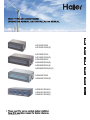 1
1
-
 2
2
-
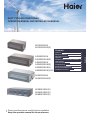 3
3
-
 4
4
-
 5
5
-
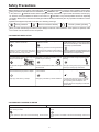 6
6
-
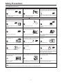 7
7
-
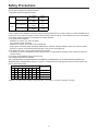 8
8
-
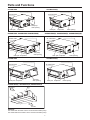 9
9
-
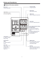 10
10
-
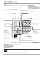 11
11
-
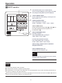 12
12
-
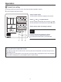 13
13
-
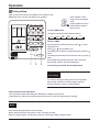 14
14
-
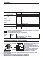 15
15
-
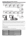 16
16
-
 17
17
-
 18
18
-
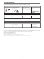 19
19
-
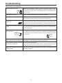 20
20
-
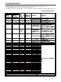 21
21
-
 22
22
-
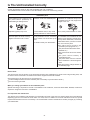 23
23
-
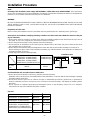 24
24
-
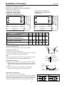 25
25
-
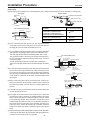 26
26
-
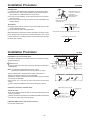 27
27
-
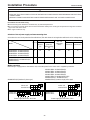 28
28
-
 29
29
-
 30
30
-
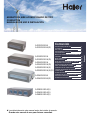 31
31
-
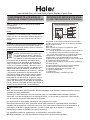 32
32
-
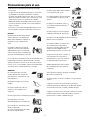 33
33
-
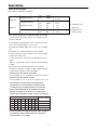 34
34
-
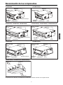 35
35
-
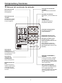 36
36
-
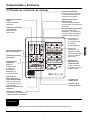 37
37
-
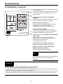 38
38
-
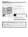 39
39
-
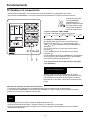 40
40
-
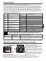 41
41
-
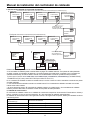 42
42
-
 43
43
-
 44
44
-
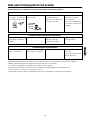 45
45
-
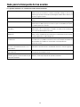 46
46
-
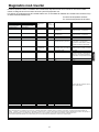 47
47
-
 48
48
-
 49
49
-
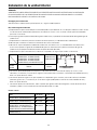 50
50
-
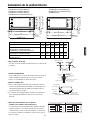 51
51
-
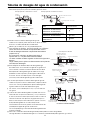 52
52
-
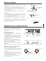 53
53
-
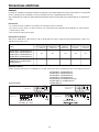 54
54
-
 55
55
-
 56
56
-
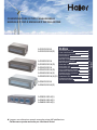 57
57
-
 58
58
-
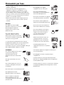 59
59
-
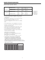 60
60
-
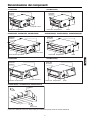 61
61
-
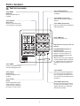 62
62
-
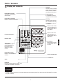 63
63
-
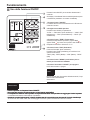 64
64
-
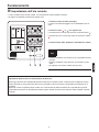 65
65
-
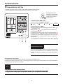 66
66
-
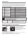 67
67
-
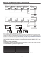 68
68
-
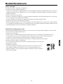 69
69
-
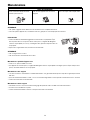 70
70
-
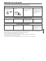 71
71
-
 72
72
-
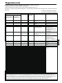 73
73
-
 74
74
-
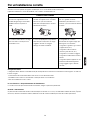 75
75
-
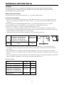 76
76
-
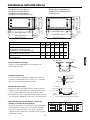 77
77
-
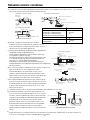 78
78
-
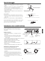 79
79
-
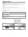 80
80
-
 81
81
-
 82
82
-
 83
83
-
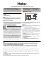 84
84
-
 85
85
-
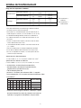 86
86
-
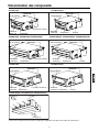 87
87
-
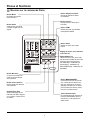 88
88
-
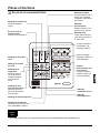 89
89
-
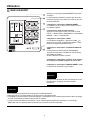 90
90
-
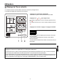 91
91
-
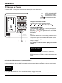 92
92
-
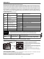 93
93
-
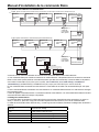 94
94
-
 95
95
-
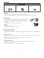 96
96
-
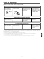 97
97
-
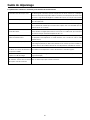 98
98
-
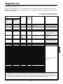 99
99
-
 100
100
-
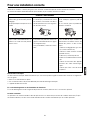 101
101
-
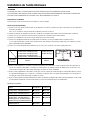 102
102
-
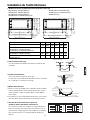 103
103
-
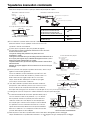 104
104
-
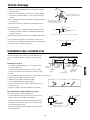 105
105
-
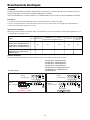 106
106
-
 107
107
-
 108
108
-
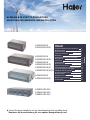 109
109
-
 110
110
-
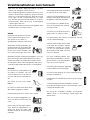 111
111
-
 112
112
-
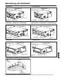 113
113
-
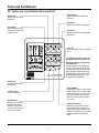 114
114
-
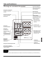 115
115
-
 116
116
-
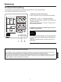 117
117
-
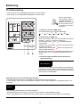 118
118
-
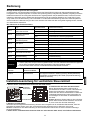 119
119
-
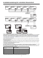 120
120
-
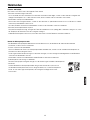 121
121
-
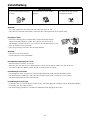 122
122
-
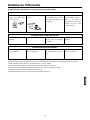 123
123
-
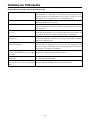 124
124
-
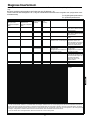 125
125
-
 126
126
-
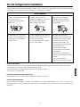 127
127
-
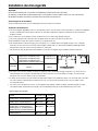 128
128
-
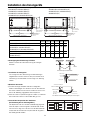 129
129
-
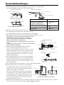 130
130
-
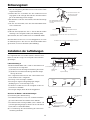 131
131
-
 132
132
-
 133
133
-
 134
134
-
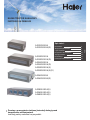 135
135
-
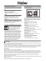 136
136
-
 137
137
-
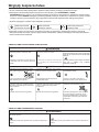 138
138
-
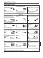 139
139
-
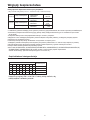 140
140
-
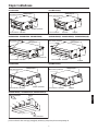 141
141
-
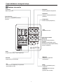 142
142
-
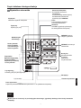 143
143
-
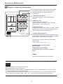 144
144
-
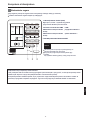 145
145
-
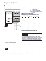 146
146
-
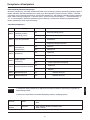 147
147
-
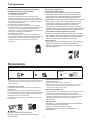 148
148
-
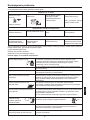 149
149
-
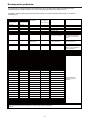 150
150
-
 151
151
-
 152
152


Haier AD12MS1ERAD Operating Manual And Instructions
- Tipo
- Operating Manual And Instructions
en otros idiomas
- français: Haier AD12MS1ERAD
- italiano: Haier AD12MS1ERAD
- English: Haier AD12MS1ERAD
- Deutsch: Haier AD12MS1ERAD
- polski: Haier AD12MS1ERAD
Artículos relacionados
-
Haier AP48KS1ERA Operation Manual And Installation Manual
-
Haier AC28ES1ERA Manual de usuario
-
Haier 10552537 Manual de usuario
-
-
-
-
-
-
Haier QACT17A Manual de usuario
-
Otros documentos
-
mundoclima Series MUPO-H8 Guía de instalación
-
Toyotomi TRG-856ZR Manual de usuario
-
Mitsubishi Electric PKA-A12HA7 El manual del propietario
-
 Olimpia Splendid Sherpa AQUADUE S2 Manuale d'installazione
-
Fujitsu UTY-XWZXZJ Guía de instalación
-
 Olimpia Splendid Ci2 Wall Series Manual de usuario
-
Samsung MRW-TS Manual de usuario

