
MODELS: REG-183A

FOR "fOUR RECORDS
Write the mode_ and serial numbers here:
Model #
Serial #
You can find them on a label on the side of each unit,
Dealer's Name
Date Pu_sed
m Staple your receipt to this page in the event you need
to p_ date of purcha_ or for warranty issues.
READ THiS MANUAL
inside you _11 find maw helpful hlnLs on how to u_ and
main_in your air conditioner prop,edy.Just a liWe prevenU_
_re on your part _n s_ you a groat deal of time and
money Mr _e I_ of your air conditioner.
You'll find many answersi to common problems in _e chart
of troubleshooting tj_. If you _i_ our _art of
Troubleshooting Tips first, you may not n_ to _ll for
servi_ at all.
• Contact the authorized _r¢|ce technic_Jan_r repair
or maintenan_ of this unit, Call 1-877-755-7932to
locate _e nearest ASC.
• Contact the installer for installation of th_ unit.
• The air conditioner is not intended for u_ by young
children or irrcal_s without supervision,
• Young children should _ su_rvised to ensure that
they do not prelacywith the air conditioner.
• When the power cerd is. to be replaced, replacement
_rk shall be _rfermed by authorized personnel only
using only _nuine repla_ment parts.
• installation work mu_ be performed in acco_ance
with the National Ele_c _de by quailed and
authorized personnel only.
2 Room Air Conditioner

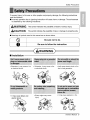
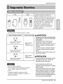
Safety Precautions
To prevent injury to the user or other people and property damage, the following instructions
must be followed.
II incorrect operation due to ignoring instruction will cause harm or damage. The seriousness
is classified by the fol!owing indications,
WAiRNIr-,IG This symbol indicates the possibility' of death or serious i_ury. "]
............... --I
[.& CAUTION Thissym_indicates the possibility of injury or damage to properties only...,J
[] Meanings of symbols used in this manual are as shown below.
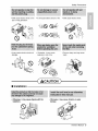
[] Installation
• Othe_isie, it may cause a fire
or electricaJ shock.
• Stmay cause failure and
electric sh_ck.
WARNINQ
* Othentvise, it may cause a fire
or electrical shock.
* Itwill cause electric sh_k or fire
due to heat generation.
* Sharp edges may cause
injur_y.
• It may cause explosion or fire,
Owner's Manual 3

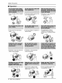
Safety Precautions
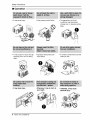
[] Operation
• There is danger of fire or electric
sh_k,
* It may cause fire and el_tric
sh_k.
• Jtwill cause electric shock or fire
due to heat generation,
° it will cause failure of machine or
electric sh_k.
• Otherwise, it may _use a fire
or electrical shock,
• The _pearance of the air
° Otherwise it may cause fire and
electric shock accident.
* An oxygen shortage may occur,
° Otherwise, it may"electrical
shock and failure.
conditioner may deteriorate,
change color, or develop surface
flaws.
• Since the fan rotates at high
speed during operation, it may
cause Injury
4 Room Air Conditioner
• Prevent accidental startup and
the possibility of injury:

Safety Precautions
, it will cause electric shock or fire • It will cause electric shock or fire. ,. Itwill cause electric sh_k
due to heat generation
I/ --,v
• It may cause electric shock and
damage.
- Othe_ise, it may cause
explosion, and a fire.
CAUTION
[] Installation
• Otherwi_, it may cau_ dispute _th the
oThey are sharp and may cause
injury.
• _erwise, it may cause vibration or water
Owner's Manual 5

Safety Precautions
[] Operation
• It may cause injury: • it may Ruse product failure • The appearance d the air
conditioner may deteriorate,
change color, or decelop surface
flaws,
° It may cause an injury through
dropping of the unit or falling
down
• It may cause injury.
• Operation without filters will
cause failure,
, It contains containments and will
make you sicL
• Otherwi_, it may do harm
your health,
@
6 Room Air Conditioner
• _erwise, it may _use
personal injury.

Before Operation
1. Contact an installation specialist for installation.
2. Plug in the power plug properly.
3. Use a dedicated circuit.
4. Do not use an extension cord.
5. Do not start/st:op operation by plugging/unplugging the power cord.
6. If the cord/plug is damaged, replace it with only an authorized replacement
part.
i. Being exposed to direct airflow for an extended period of time could be
hazardous to your health. Do not expose occupants, pets, or plants to direct
ai_low for extended periods of time.
2. Due to the possibility of oxygen deficiency, ventilate the room when used
together with stoves or other heating devices.
3. Do not use this air conditioner for non-specified special purposes (e.g.
preseP¢ing precision devices, food, pets, plants, and art o_ects). Such usage
could damage the items.
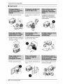
1. Do not touch the metal parts of the unit when removing the filter. Injuries can
occur when handling sharp metal edges.
2. Do not use water to clean inside the air conditioner. Exposure to water can
destroy the insulation, leading to possible electric shock.
3. When cleaning the unit, first make sure that the power and breaker are turned
off. The fan rotates at a very high speed during operation. There is a
possibility of inju_ if the unit's power is accidentally triggered on while
cleaning inner parts of the unit.
For repair and maintenance, contact your authorized service dealer.
Owner's Manual 7

Introduction
This symbol alerts you to the, risk of electric shock,
This symbol alerts you to hazards that _uld cause harm to,
the air cond_ioner.
This,symbol indicates sp_ial notes.
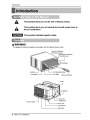
This, appliance _o, uid _ insta_liedin a_o, rdan_ _th the National Elect:rioC_e,
Ve_ical!Air D,efl_tor
(HorizontalLouver)
HorizontalAir IDefl_tor
(Vert_a! Louver)
1
Air Di_harge
Remote,_,n_roiller
Elec[dcHea_,_
BasePan
PowerCord
ControliBeard
Evaporator
8 Room A# Conditioner

ElectricalSafety
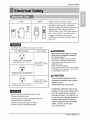
115V_- 230V~
m
Power cord may include a current
interrupter device, A test and reset button is
provided on the plug case. The device
should be tested on a periodic basis by first
pressing the TEST bu_on and then the
RESET button if the TEST button does not
trip or if the RESET button will not stay
engaged, discontinue use of the air
conditioner and contact a qualified service
technician.
The shape may be different according to its model
Use Wall Receptacle Power Supply
S_a_ 12:5V,3_wiregrounding
receptacle rated 15A, 125V AC
Standard 250V_ 3-wire grounding
receptacle rated 15A 250V AC
Standard 250V 3wire grounding
receptacle rated 20A, 250V A©
Use 15 AMP, time
delay fuse or 15 AMP.
circuit breaker,
Use 20 AMP, time
delay fuse or" 20 AMP
c_rcuit breaker,
DO NOT USE AN EXTENSION CORD on 230,
20& and 230/208 Volt units
NI wiring should be made in accordance with local
electrical codes and regulations.
Aluminum house wiring may pose special
problem& Consult a qualified electrician,
Never push the test button on the plug
while the unit is operating .Damage to
the plug may result.
This d_ice contains chemical including
lead, known to the State of California to
_use cancer, and birth defects or other
reproductive harm,
Wash hands after handling.
Do not remove, modify or immerse this plug.
If this device trips, the cause must be found
corrected before further use,
The conductors insidethis cord are
surrounded by shields, whichmonitor
leakage current.
These shields are not grounded.
Periodically examine the cord for any
damage. Do not use this product in the
event _e shields become _posed,
Avoid sh_k hazard. The p,lugcan not
be user serviced, Opening the tamper
resistant sealed portion of _e plug
voids all warranties and performance
claims. DO NOT use the plug
as an on-off switch.
Owner's Manual 9

Electrical Safety
IMPORTANT
(PL_SF_ READ CAREFULLY)
FOR THE USER'S PERSONAL SAFETY, THIS
APPLIANCE MUST BE PROPERLY GROUNDED
The power cord of this appliance is equip_d with a
three-prong (grounding) plug. Use this with a standard
three-s_ot (grounding) wa_l power outlet to minimize the
hazard d electric shock. The customer should have
the wall receptacle and circuit checked by a qualified
electrician to make sure the receptacle is properly
grounded.
DO NOT CUT OR REMOVE THE THIRD (GROUND)
PRONG FROM THE POWER PLUG.
USE OF EXTENSION CORDS
Because of potentiaJ safety hazards, we strongly
discourage the use d an extension cord.
10 Room Air Conditioner

Installation
I14Bubble
INSIDE
FOAM ...........
COOLED
AIR_
OUTSIDE FENCE
AWNING
HEAT
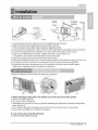
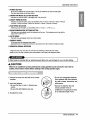
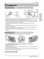
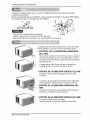
1,To avoid vibration and noise, make sure the unit is installed securely and firmly,
2. install the unit where the sunlight does not shine directly on the unit.
If the unit receives direct sunlight, build an awning to shade the cabinet,
3, There should be no obstacle, like a fence, within 20" which might restrict heat radiation from the condenser
4. To prevent reducing performance, install the unit so that louvers of the cabinet are not blocked.
5, Install the unit a little slanted so the back is slightly lower than the front (about 1/2"
or 1/4 bubble ), TNs will force condensed water to flow to the outside.
6, Install the unit with i_ bottom portion 30~60" above the floor level,
7. Stuff the foam between the top of the unit and the,wall to prevent air and insects from getting into the room,
8. The power cord must be connected to an independent circuit. The green wire must be grounded.
9. Connect the drain tube to the base pan hole in the rear side if you need to drain (consult a dealer.)
Plastic hose or equivalent may be connected to the drain tube,
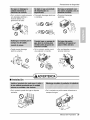
The grille is designed to clean the filter both upward and down_rd.
(a) (b) (c)
A. Before attaching the front grille to the cabinet, ff you want to pull out the filter upward;
1. Open the inlet grille slightly (a).
2_Turn inside out the front grille (a),
3, Disassemble the inlet grille from the front grille with separating the hinged part by inserting a straight type
screw-driver tip (b),
4. Then, rotate the inlet grille 180 degree,sand insert the hooks into bottom holes of the front grille.
5. Insert the filter and attach the front grille to the _binet.
B. ff you want to puff out the filter downward;
The grille is already designed that way.
Owner's Manual 11

Installation
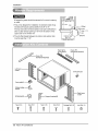
All supporting parts should be secured to firm wood, masonry,
or metal.
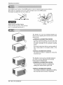
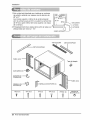
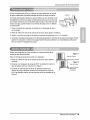
1.This unit is designed for installation in standard double hung
windows with actual opening widths from 29" to 41'L
The top and bosom window sashes must open sufficiently to
allow a clear verti_l opening of 18" from the bottom of the
upper sash to the window sill.
2. The sill offset (height between the interior and e_edor sills)
must be less than 1 1/4".
29" to 41'_
18" rain
Sill
_:_.._'= Offset
Less
_"\i' than1 '/4"
..* Exterior
Ty_ A (14) Type B (7) Type C(5) TypeD (2)
g
_rfiage Bolt (2) L_k Nut (4)
i2 Room Air Conditioner

installation
SCREWDRIVER(+,-), RULER, KNIFE, HAMMER, PENCIL, LEVEL
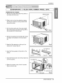
PREPARATION OF CHASSIS
1_Remove the screws which fasten the cabinet at
both sides and at the back.
2. Slide the unit out from the cabinet by gripping
the base pan handle and pulling forward while
bracing the cabinet.
3 Cut the window sash seal to the proper length
Peel off the backing and attach the Foam-PE to
the underside of the window sash.
Shippingscrews
Fig. 1
4. Remove the backing from Foam-P'E with 3 holes
and attach it to the bottom of the Top retainer
bar.
5 Attach the Top retainer bar on the top of the
cabinet with 3 screws (_jpe A).
Fig, 2
6. Insert the Frame guides into the bottom of the
cabinet.
7. Insert the Frame Curtain intothe Top retainer bar
and Frame guides.
8. Fasten the curtains to the unit with 10 screws
(Type A) at both sides.
FoamoPE
Top re_ir,er bar
Top retainerbar
"Frameguide
Sicrew_ype A}
Fig. 4
Owner_ Manual 13

Installation
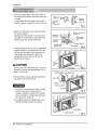
I. Open the window. Mark a line on the center of
the window stool between the side window stop
molding&
Loosely attach the siil bracket to the support
bracket using the carriage bolt and the look nut.
SJ]l
Bracket
Carriag
Bolt
(M-Screw)
nut
Fig, 5
2. Attach the sill bracket to the window sill using
the screws (Type B),
Carefully place the cabinet on the window sill
and aiign the center mark on the bottom front
with the center line marked window sill.
3, Using the M-screw and the lock nut, attach the
support bracket to the cabinet track hole, Use
the first track hole after the sill bracket on the
outer edge of the window sill. Tighten the
carriage bolt and the lock nut. Be sure the
cabinet slan_ outward,
,ik CAUTION
Do not drill a hole inthe bosom pan. The unit is
designed to operate with approximately 1/2" of
water in bottom pan.
4. Pull the boEom window sash down behind the
Top retainer bar until they meet.
1. Do not pull the window sash down so tightly
that the movement of Frame curtain is
restricted Attach the cabinet to the window
stool by driving the _rews (Type B) through
the cabinet into window sill.
2.The cabinet should be installed with a very
slight tilt downward toward the outside.
Outer edge
d window
sill
B)
Sill bracket
Fig, 6
retainer
bar
Windowst_l
Frontangle Fig. 7
Windowsash retainerbar
Framecurtain
Foam-PE
Fig. 8
FrontA_ie
Screw(TypeB) Fig, 9
14 Room Air Conditioner

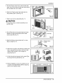
& Pull each Frame curtain fully to each window sash
track, and pull the bottom window sash down behind
the Top retainer bar until it meets.
6. Attach each Frame curtain the window sash by
using screws (Type C.) (See Fig. 1O)
7, Slide the unit into the cabinet(See Fig, 11)
CAUTION
For security purpose, reinstall screws(Type A) at
cabinet's sides
8. Cut the Foam-strip to the proper length and insert
between the upper window sash and the lower
window sash.(See Fig. 12)
Installation
c)
rew
Fig, !0
PowerCord
Screw(TypeA)
Fig. 11
Fig, i2
9. Attach the Window locking bracket with a screw
(Type C) (See Fig, 13)
10. Attach the front grille to the cabinet by insertingthe
tabs on the grille into the tabs on the front of the
cabinet, Push the grille in until it:snaps into
place.(See Fig.14)
11. Lift the inlet grille and secure it with a screw (Type
A),through the front grille.(See Fig. 14)
12. Window installation d room air conditioner is now
completed. See ELECTRICAL DATA for attaching
power cord to electrical outlet.
I I III.J w o ow
Fig, 13
14
_iii!iiii!lilliilliilliiii!¸_''¸¸J,'%iii!ii!ii!ii!ii!ii!ii!ii!ii!ilii_
15
Owner_ Manual 15

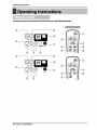
Opemting Instructions
The mote control and control panel will look like one of _ following picPdres.
® ®
®
Q
®
®
®
®
®
®
®
®
®
®
16 Room Air Conditioner

Operating Instructions
To_rn t_ aircondi_ne_ON,p_ash_ _ton. Toturntheairc_oner OFF,p,Jsht_ _tton again.
_ buttontakes_rity oH anyotherbuttons.
2. OPERATION MODE SELECTION BU_ON
Eve_ime_u pushthisbutton,it_11_gle COOL,FANa_ HEhZ
3. ON/OFF TIMER BUTTON
Eve_ime _u pushthis button,_merissetasfollows,(1H_r_ 2Hou__ 3_u_ _ 4Hours_ 5Hou_
-) 6Hou_-) 7Hours_ 8Hou_-) 9Hours_ 10Hou_-) 11Hou__ 12Hou_-) Car_J)
4. FAN SPEED SELEC_R
Ever_me_u p_h thisbu_, itis_ as_1_. (Hi[F2]-) L_ F=] -) Hi[F2 ]....)
5. ROOM TEMPERATURE SE_NG BUTTON
Thisbuttoncanautoma_lly _'ol the_m_rature _t;'_ room_Thetemperatu_canbesetwi_ina
_nge of60°Fto86°FbyI°E
6. AU_ SWING
Thisb_on canautom_ca_lycc_o_theairfle,vdi_en.
7. ENERGY SAVER
_e fa_st_ when_ comer stops_l_ng_
_ma_ every3 _nu_es_ _n will_rn onandch_ the,_m _ todetermine_coolingisneeded.
8. REMOCON SIGNAL RECEIVER
A slightheat odormay come _m the unit when first switching to HEAT after the _ling
sea_n isover._ _or, _u_ by_ne dust _es _ the heater, will disappear qul_ly.
CAUTION
When the air condl_o_r has _n perfo_ed _ cooling ope_ion and is turned off or set to the fan
pos_ion, wait at least 3 min_.es _fom resetting to the cooling operation again,
i. Remove _e _ver from _e _ of the mrr_te
_n_l_er.
2. Insert two batteries.
• Be sure that the (+) and (-) directions are
correct.
• Be sure _at both batten_ are new.
3. Re-a_ach the cover.
, Do not use rechargeable battens.
Such batteries differ _om s_ndard
d_ _lls in shape, dimensions, and
• Remove the _tteries from the
remote _ntroller if the air
conditioner is not going to _ u_
_r an extended length of time.
Owners Manual 17

Operating Instructions
The ventilation lever must be in the CLOSE position in order to maintain the best cooling conditions.
When fresh air is necessary in the room, set the ventilation lever to the OPEN position.
The damper is opened and room air is drawn out.
Before using the ventilation feature,
position the lever; as shown. First, pull down
part _._to horizontal line with part (f_).
The direction of air can be controlled wherever you
want to cool by adjusting the horizontal louver and the
vertical louver,
HORIZONTAL AIR-DIRECTION _ONTROL
To control horizontal direction of air flow, set to the
ON position the air-swing switch and the air flow will
be swept horizontally by the automatic air-swing
system.
If you want to stop the air flow from moving, switch off
the air swing switch at the desired position of the
vane_
• VERTICAL AIR-DIRECTION CONTROL
The vertical air direction is adjusted by moving the
horizontal louver.
The direction of air can be controlled wherever
you want to cool by adjusting the horizontal
louver and the vertical louver.
• HORIZONTAL AIR-DIRECTION CONTROL
The horizontal air direction is adjusted by
rotating the vertical louver right or left.
• VERTICAL AIR-DIRECTION CONTROL
The vertical air direction is adjusted by rotating
the horizontal louver forward or backward.
i8 Room Air Conditioner

Operatinginstructions
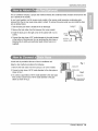
_e air conditioner employs a proper drain melhod whereby the condensed water (moisture re_ved from the
air) is,drained to the ou_ide,
In very humid weather, (and for reverse cycle models in the reverse mo_) excessive, condensate water
removed from the,air may cause _me water to collect, To remove this excess,water you can install the drain
pan as detai_d _low.
1,Take Me drain pan which is bcated in the air di_harge
2. Remove the hole rubber from the base-pan (for some m_els),.
CABINET
3, Install the drain pan to the right corner of the cabinet with 4 (or 2)
_rews.
4. Conned the drain ho,_ of 315' insi_ diameter to the outlet l_ated
at the bottom of the drain pan You can purcha_ the drain hose or
tubing locally to satiny your particular needs. (Drain hose is not
supplied),.
DRAIN
PAN
DRAIN HOSE
A drain ho_ is.provided at the rear d the air conditio,ner unit
Select a drain me_hodaccording to Me folilowing.
1, Remove the hole rubber kom the b,a_-pan (for _me models)
2, Conned a drain ho,_ of 9/t6 °'indde diameter to Me @ain pipe,as
_own in Fig. 1..
3. Or conned a pipe elbow d 9/16" insid_ diameter to the drain pipe,
then conned .adrain ho_ of 9/16" inside diameter to the pi_
elbow as shown in Fig.,2,
DRAIN HOSE
Owner_ Manual 19

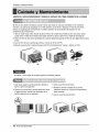
Maintenance and Service
TURN THE AiR CONDITIONER OFF AND REMOVE THE PLUG FROM THE POWER OUTLET,
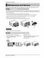
The air filter should be checked at least twice a month to see if cleaning is necessary. Trapped particles in the
filter will build up and block the airflow.This reduces the cooling capacity and also causes an accumulation of
frost on the cooling coil&
1.Open the inlet grille upward by pulling out the bottom of the inlet grille.(a)
In another case, you can open the inlet grille downward by pulling out the top of the inlet grille,(b)
2, Remove the air filter from the front grille assembiy by pulling the air filter up or down slightly,
3.Wash the filter using lukewarm water below 40°0 (104°F).(c)
4, Gently shake the excess water from the filter completely. Replace the filter.
(a) (b) (c)
Mark A of inlet grille means opening dir_tion,_
1. Pull down front grille from the cabinet top.
2. Push front gri]le's tips toward the _binet in order
to insert front gdlie's tabs into
the cabinet.
3. Open the inlet grille.
4. Tighten the screw through the front grille into the
plate of the evaporator or base pan,
5. Close inlet grille.
20 Room Air Conditioner

MaintenanceandService
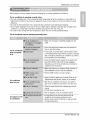
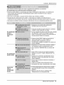
BeDre calling Dr service, please review the Di]owing list of common problems and solutions.
The air conditioner is operating normally when:
• You hear a pinging noise. This is caused by water being picked up by the condenser on rainy days or in
highly humid conditions, This feature is designed to help remove moisture in the air and improve cooling
efficiency_
° You hear the thermostat click, This is caused by the compressor cycle starting and stopping
• You see water dripping from the rear of the unit. Water may be collected in the base pan in highly humid
conditions or on rainy days. This water overflows and drips from the rear of the unit.
• You hear the fan running while the compressor is silent This is a normal operational feature,
The air conditioner may be, operating abnormally when:
° Make sure the plug is completely plugged into the
outlet
The air conditioner
does not operate
at all
Air conditioner
does not cool
ice appears on the
air conditioner.
° Check the fuse/circuit breaker box and replace the
fuse or reset the breaker
° in the event of a power failure, set the power control
to OFF (Mechani_l Type). When the power is restored,
wait 3 minutes to restart the air conditioner to prevent
the compressor from overloading
° Press the RESET bu_on located on the power cord
plug. Ifthe RESET button will not st_ engaged,
discontinue use of:the air conditioner and contact a
qualified service technician
° Make sure there are no curtains, blinds, furniture or
other obstacles in front of the air conditioner
• Set the TEMP control to a lower number,
°Clean the filter at least every 2 weeks Refer to the
"Maintenance and Service" s_tion of the manual,
° After the air conditioner is turned on, you need to
give the air conditioner some time to cooi the room.
• Check for open furnace floor resisters and cold air
returns.
° CLOSE the air conditioner vent
° See lce appears on the air conditioner below
• Ice may block the air flow and obstruct the air
conditioner from properly cooling the room,
° Set the mode control at HIGH fan or high cool with
the high temperature.
Owner's Manual 21

,o
PARA SUS ARCHIVOS
Escriba aquf el modelo y nQmero de serie:
Modelo n °:
Serie n°:
Puede encont:rar estos datos en la etiqueta situada en el
lateral de cada unJdad,
Nombre del distri_idor:
Fecha de _mpra:
= Adjunte su reci_ a esta p4gina con Eagrapadora para
el momento que }o necesite para probar Jafecha de su
adquisici6n o para la validaci6n de la garant[a
LEA ESTE MANUAL
En su interior encont_r4 muchos _nsejos Qti]es sobre ]a
utiiizacJ6n y mantenimiento de su acondJcionador de aire,
Unos pocos cuidados _r su parte le pueden ahorrar
mucho tiempo y dinero durante la vida de su
acondicJonador de aire
En ia tabia de _nsejos para la soluci6n r4pida de
proMemas encontrar_ muchas respues_s a los problemas
mas habituales, Si revisa prJmero nuestra Tabla de
Consejos _ra la soluci6n r,_pida de problemas, ta_ vez no
necesite I_amar nunca a_servicio t_nico
* Contacte a un Centre de _rvicio Autorizado para reparar
o realizar el mantenimiento de esta unidad. Llame a
i-877-75_7932 para ubicar el CSA mas cercano.
° P6ngase en contacto con un instalador para realizar
la instalaci6n de esta unidad,
° Cuando se va a carnbiar el cable electrico, el trabajo
de reemplazamiento debe ser realizado _nicamente
pot personal autori_do, utilizando las pie_s de
cambio genuinas Qnicamente,
° E,Itrabajo de reemplazamiento de_ _r realizado de
acuerdo con el C6digo EI6ctrico Nacional
_nicamente por personal autorizado.
22 Aire Acondicionador

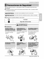
Precaucionesde,Segundad
Para evitar lesiones al usuario o a otras personas y dafios a la propiedad, estas instrucciones
esten seguirse,
m Unaoperaci6nincorrectaporignorarlasinstruccionesprovocaralesioneso daSos.Laseriedadseclasifi_
potlassiguientesindicacione&
h
Estesimbolo indicala posibilidaddernuerteo deseria lesi6n, /
Estesimbolo indicas61olaposibilidadde lesioneso da_osa la propiedad 1
[] Significados de los simbolos utilizados en este manual. _
No hater. 1
Siga estas instrucciones. J
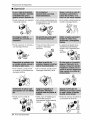
ml Instalaci6n
• De Io contrario, podfia provocar • De b contrario, podffa provocar
un incendio o descarga
el6ctrica.
° Puede ocasionar fallos y una
descarga electrica
un incendio o descarga
el6ctr[ca.
• Los bordes afilados pueden
provocar lesiones,
• De lo contrario, puede provocar
una descarga el6ctrica o
incendio debido a [a
generaci6n de calor.
• Podrfa ocurrir una explosi6n o
incendio
®
Manual del Propietario
23

Precauciones de Seguridad
I Operacibn
• Puede ocasionar una explosi6n
o descarga el6ctrica.
• De 1ocontrario,pu_e pr_,ocaruna • De Io contrario, p_r/a provocar un
descargael@trica o incendiodebJdo incendio o descargael_ctrica.
a la generacidnde c_lor.
• Puede ocasionar un incendio y
una descarga el_ctrica
° De Io contrario, puede ocurrir
• Puede provocar fallos en el
producto o descargas
el_ctdcas_
• La apadenciadel aparatode aire
acondicionadopu_e deteriorar,
cambiarel coloro desarrollarflujos
en las
supedicies.
un incendio y un accidente por
descarga el6ctrica.
• Puede ocurdr un falta de
oxfgeno.
• De Io contrario, pueden ocurrir
descargas elect:ricas y faHos.
• DebJdoa que el ventilador gira a
alta velocidad durante el
funcionamiento, podrfa ocasionar
lesiones.
24 Aire Acondicionador
, Evitar_. el arranque accidental y
la posibifidad de lesiones.

Precauciones de Seguridad
• De Io contrario, puede provocar
una descarga el_ctrica o
incendio debido a la
generaci6n de calor.
• Puede causar descarga
el6ctrica y daSos.
• ProvocarA descargas el_ctricas
o incendios,
• Provocar4 descargas
el_ctrJcas_
• De [o contrario, podrfa ocurrir
una explosi6n o incendio.
• Son puntiagudas y pueden
provocar Uesiones.
II Instalacibn
° De I0 contrario puede dar lugar a disputas
vecinales.
• De Io contrario se podrfa causar vibraciones o
escapes de agua,
Manual del Propietario 25

PrecaucionesdeSeguridad
[] Operacibn
,' Podr/a ocasionar lesiones. • Puede causar una aveda en el
aparato,
- La aparienciadel aparatode aire
acondicionadopu_e deteriorar,
cambiarel coDr o desarrollarflujos
en lassuperficies.
* Puede lesionarse al caerse del
apara_o o al caerse los objetos
que haya colocado,
° Podrfa ocasionar lesiones,
• El funcionamiento sin filtros
puede provocar failos
• De Io contrario, podr[a da_ar su
saD&
&
26 Aire Acondicionador
• De Io contrario, podrlan ocurrir
lesiones personales.

Antes de poner el equipo en funcionamiento
1. P6ngase en contacto con un especialista para realizar la instalaci6n.
2. Enchufe correctamente la toma de alimentaci6n.
3. Utilice un circuito dedicado.
4. No utilice un cable alargador.
5. No inicie/cese el funcionamiento enchufando/desenchufando el cable
electrico.
6. Si el cableienchufe esta daffado, sustit0yalo solo por una pieza autorizada.
1. Estando expuesto a la circulaci6n directa de aire durante un extenso perfodo
de tiempo podrfa resultar peligroso para su salud. No exponga alas personas,
animales dom4sticos, o a las plantas a la circulaci6n de aire durante largos
perfodos de tiempo.
2. Debido a la probabilidad de falta de oxfgeno, ventile el cuarto cuando est4
utilizado el aparato junto con estufas u otros aparatos de calefacci6n.
3. No utilice este aire acondicionado con prop6sitos especiales no especificados
(Ej.: consewaci6n de dispositivos de precisi6n, comida, animales dom4sticos,
plantas y objetos de arte). Tal uso podrfa daffar los artfculos.
1. No toque las piezas metAlicas de la unidad al retirar el filtro. Manejar aristas
afiladas de metal puede causar lesiones.
2. No utilice el agua para limpiar el interior del aire acondicionado. La exposici6n
a[ agua puede destruir el aislamiento, conduciendo a posibles descargas
electricas.
3. AI limpiar la unidad, aseg0rese antes de que la electricidad y el interruptor
esta.n apagados. El ventilador rota a muy alta velocidad durante el
funcionamiento del equipo. Existe la posibilidad de iesiones si acciona
accidentalmente la electricidad de la unidad mientras limpia el interior de la
unidad.
Para cuestiones de reparaci6n y mantenimiento, p6ngase en contacto con su
distribuidor de servicio autorizado.
Manual del Propietario 27

lntroduccidn
Este sim_!o !o ,advie_e de un _!igm, de a_idente por
corriente e,lectric&
Este sim_lo Io adiverte de u=npeligro que pu_a cau_r un
daSo del ventliador.
Este sim_lo significa condicciones especiales.
Este apamto, _beda instal,arse _ ac_erdo con las normas del _dig,o Eli_tdco Nacion,al
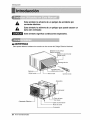
Deflectorde sirevertica_
(Reji_a _rizontsl)
Odle_or de aidehorizonta_
l
Oe_sNa de aim
GaL_net,e
Entra_ de aire
_Filtro, de sire
Controlremo!,o
Ca_n_dor
Cable de slime_la,c:ion
Pane; de conirol
Evaporsdor
28 Aire Acondicionador

SeguraidaElectrica
115V~ 230V~
= =
El cable de aaimentaci6n puede incUuirun
dispositivo interruptor de corfiente La
carcasa de1enchufe cuenta con un bot6n de
prueba y otto de reinicio, El dispositivo debe
comprobarse peri6dicamente presionando
pfimero el bot6n TEST y despu6s RESET
Si ei bot6n TEST no se descon_ta o si el
bot6n RESET no perman_e activo,
suspenda el uso del aire acondicionado y
p6ngase en contacto con un t6cnico de
servicio cualificado,
La forma puede s.er diferente segQn su modelo.
Utilice el enchufe de la pared Consumo de Energia
St_dard 125V, enchufe de 3
Lineas de 15A_125V AC
Stan_rd 250V, er_ch_e de 3
Lfneas de 15A_ 250V AC
Utilice un fusib_ de
15AMP o un
Interrupter de 15AMR
(_ Utilice un fusib_ de
20AMP. o un
Interruptor de 20AMP,
Standard 250V, enchufe de 3
Linens de 2OA, 250V AC
No use un cable de extension.
Todo el cableado deber_, realizarse de acuerdo
con los c6digos y reglamentos el6ctricos
Iocales.
El cableado dom6stico de aluminio podrla
ocasionar problemas especiale& Consulte aun
electricista calificado.
Nopresionenuncaelbot6n de pruebaduranteel
funcionamiento,deIocontrarioelenchufe_dria
resultar daS_o.
Estedispositivocontie_ productosqu/mi_s,
incluyendopl_o, conocidoeneiestado
California_o productocanceriger#ycau_nte de
defectos@nacimientoy otrosdaScLsal sis_ema
reproductor.
LAve_ bienInsman_ trasmanipulareldisp_ivo
No@smonte,m_ifique ni surnedaenaguaeste
end_ufe.
Siei disp_Hivoseactivara,deberacorregirla_usa
antesdev@er a utilizarl&
L_ hil_ conductor_d_trodelcable_tan rodeados
potblindajes,quesu_rdsanlacordentedefu_.
Estosblindajesnoestanpue_osatJerra.
Examine_rbdicamenteelc_bleenbusca
c_lquierdaSo.Noutiliceestepro@ctosilos_indajes
resulta_anexpuest0s,
Ev_eelriesgodedes_rgasel_as; estaun_adno
puedesetreparadapotelusuariopotsetres_tentey
ap_ue_'Adealteacbnes.M_ipularlaporcion_llada
delaun_adanularatodaslasgaranfiasyquejasde
ren@iento.Estaunidadno_ta diseSadaparasuuso
comouninter[upto_deen_ndido-a_gado.
Manual del Propietario 29

SeguraidaElectrica
IMPORTANTE
(FAVORL_ CON ATENCION)
POR LASEGURIDADPERSONALDEL USUARIO,
ESTEAPARATODEBESERDEBIDAMENTE
NEUTRALIZADO.
El cord6n de energia de 6ste aparato es_
equipado con tres patas(_He a tierra). Utilice
6ste con un enchufe de pared de tres salidas(a
tierra) para minimizar el peligro, de choque
el6ctrico. El cliente debe revisar el receptor de
pared y el circJJito pot un electricista calificado
para asegurarse que la recepci6n esta
debidamente neutralizada.
NO CORTE 0 REMUEVA _ TERCERA
PATA(GROUND) DEL ENCHUFE
USO DE EXTENSIONES
Debido al peligro potencial, no recomendamos
la utilizaci6n de extensiones.
30 Aire Acondicionador

Instalacion
TOLDO
BARDA
FOAM
1/4 Ampolla RADIACION
NR DE CALOR
ENFR_
1. Para evitar vibraci6n y ruido, aseflJrese de que la unidad est_ instalada de manera segura y firmemente.
2. Instale la unidad en lugares fuera de luzsoiar directa dir_tamente sobre la unidad.
3. El exterior de1gabinete deber_ extenderse hacia afuera cuando menos 10" y no deben existir obstAculos
tales como una barda o pared, dentro de una distancia de 20" desde la pparte posterior del gabinet:e
porque esto evitarA Ia radiaci6n de calor del oondensador
La restricci6n del aire exterior reducirA en gran manera la eficiencia de enfriamiento dot aire
acondidonado.
4. Para prevenir la reduccidn de la eficiencia del funcionamiento, instale la unidad para que las rejillas del
cabinete no scan bloqueados
5. Instaie la unidad un poco obliouamente hacia afuera para no dejar escapar el agua condensado a la
habitaci6n (aproximadamente 1/2" o 1/4 ampolla con nivel).
6. Llene la espuma entre el tope de Ia unidad y la pared para prevenir que el aire e insectos entren en Ia
habitaci6n.
La rejilla es diseSada para limpiar el filtro tanto hacia arriba como hacia abajo.
i_iiii_i_ii__I_I!(I!I_/
®
(a) (b) (c)
A. Antes de Instalar la rejilla frontal en el cabinete, si usted deseasacar el filtro por arriba;
1. Abra la rejilla de entrada ligeramente (a).
2_Vuelte la rejilla frontal (a)
3. Separe la parte engoznada insertando la punta del destornillador de tipo "-" para desensamblar la rejilla
de entrada desde la rejilla frontal. (b).
4. Luego, gire la rejilla de entrada 180 grados e inserte los ganchos en los huecos inferiores del rijilla frontal.
5. Inserte el filtro e instale la rejilla frontal al cabinete.
B, Si usted desea sacar el filtro pot abajo;
La rejil[a es ya diseSada para tal manera.
Manual del Propietario 31

Instalacion
1. Esta unidad esta diseSada para instalarse en ventanas
de guillotina estAndar _n esp,esor real de abertura de
29" a 41 ".
Los marcos superior e inferior de la ventana deveran
abdr ]osuficiente para permitir una abertura vertical libre
de 18" de la parte inferior del marco superior a la repisa
de ]a ventana.
2. El desplazamiento de la repisa (altura entre ]a repisa y el
a]f6izar) debe ser menor a 1 1/4% '
I............29" to 4!
18" min
REPrSA
PARED fl'_ERI(
......EXTER] OR
/
TIPOA(14)
?
TIPO B (7) TIPO(5) TIPO D(2)
Y
PERNO (2)
?
TUERCA DE
SEGURIDAD (4)
32 Aire Acondicionador

Instatacion
[
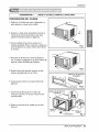
PREPARACION DEL CHASIS
1. Retire los 4 tornillos que unen el gabinete a la
parte _stedor y lateral de la unidad.
DESARMADOR (+, - )_REGLA, CUCH|LLO, MARTiLO, LAPIZ:, NIVEL
2 Deslice la unidad fuera del gabiete tomando la
manija de la charoia de la base y jaie hacia
adelante mientras sostiene el gabinete.
3. Corte el sell_e chasis de la ventana a la
Iongitud apropiada. Pele el resfuerzo y aplique la
Cinta de Espuma a la parte inferior del chais de
la ventana.
Fig, 1
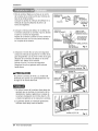
4. Remueva el refuerzo de la Cinta de Espuma
con 3 huecos y agreguelo en la parte inferior del
tope de la barra de Retencion Superior.
5 Sujete la barra de retenci6n superior al lado
superior del gabinete con los 3 torni.
6. Inserta la guia marco en la parte inferior del
gabinete.
7. Inserte los paneles guias en la barra de
retention superior yen la guia marco del aire
acondicionado.
& Sujete las cortinas de la unidad con tornilios
(Ti_ A),
BARRA DE RETENCION
SUPERIOR
de Espuma
BARRA DE RETENCION
SUPERIOR
TORNILLO
(TIP(I)A) TORNILLO
(TIPO A)
"-GUiA MACRO Fig. 4
Manual del Propietario 33

Instalacion
1, Abra la ventana Marque una I¢neaen el centro
de Jarepisa de la ventana entre las molduras de
tope de la ventana lateral.
Coloque sin apretar la m_nsula del alf_izar en la
m6nsula de soporte utilizando el pemoy la
tuerca de segutidad,
i iiii
MENSULADEL
ALFEI_R
BULON
!NSULA
DESOPORTE
DE
SEGUR_DA
Fig. 5
2_Coloque la m_nsula del alf_izar en e! alf@zar de
la ventana utilizando los tornillos (Tipo B), Apriete
el perno y la tuerca de seguridad.
Repisa de la ventana y alinee la marca central en
el frente del rondo con la h'nea centrai marcada
en la repisa de la ventana,
ORIFIC/ODE
TORNILLOPARA
METALES(TiPOD)Y
TUERCADESEGURIDA
_--"'_ TORNILLO(TIPOB)
MEN_ULA
DEL ALFEIZAR Fig. 6
3_Utilizando el tornillo M y la tuerca de seguridad,
coloque la m6nsuia de soporte en el odficio de la
gu_a del gabinete, Use ei primer orificio de la gu/a
despu_s de la m_nsula del alf_zar en el borde
exterior del alf_izar de la ventana.
Apriete el perno y la tuerca de seguridad
Aseg8rese de que el gabinete est6 inclinado
hacia afuera,
No perfore la charola del fondo, La unidad estA
diseSada para operar con aproximadamente 1/2"
de agua en la charoia del rondo.
1. No hale el marco de la ventana hacia abajo tan
apretado que se restrinja el movimient:o de los
desiizadores, Sujete el gabinete a ia repisa de
la ventana insstalando los tornillos (tipo A o B)
a trav6s del gabinete en la repisa de la ventana,
2. El gabinete deberA ser instalado ligeramente
inclinado hacia abajo hacia el exterior
SUPERIOR
MARCODELA
REPISADEVENTANA
INTERIORFig, 7
BARRADE
RETENCIONSUPERIOR
CINTADE"J
ESPUMA
GABINETE
PANEL
GUIA
CINTA DE
ESPUMA Fig, 8
ParteFrontalInterior
TORNiLLO(TIPOB) Fig, 9
34 Aire Acondicionador

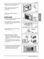
5 Hale cada panel gufa completamente a cada
lado de la ven_na y repita del paso 2,,
6_Adjunte cada panel gufa a cada lado de la
ventana usando torniHos (T[po C).
(Ver Fig. 10)
Instaladon
TORNILLO
Fig. 10
7, Deslice el chasis dentro deI gabinete,
(Ver Fig.11 )
Por razones de seguridad, re instale los tornillos
(Tipo A) en los lados del gabinete.
8, Corte la tira de goma a [a medida apropiada e
introdOzcala entre la parte superior e inferior de
la ventana. (Ver Fig. 12)
TORNILLO
CORDON DE
ALIa,4ENTAC:ION
ELETRICA
11
DE GOMA
Fig. 12:
9. Se debe instalar el asa antes de fijar el frente
de_rativo. (Ver Fig. 13)
10. Instale la rejilla frontal en el cabinete
insertando [a [engOeta en [a rejil[a a la
[engOeta en el frente del cabinete. Empuje la
rejilia hasta que se cierre con sonido de golpe
(Vet Fig. 14)
11. Levante la rejilla de entrada y asegOrela con
un tornil[o (tipo A) a traves de la rejilla frontal.
(Vet Fig,14)
.._j._....._L__ SOPORTE DE
CERRADURA
Fig, i3
12. Ahora [a instalaci6n de[ aire acondicionado en
la ventana es completada. Vea los DATOS
ELECTRIOOS para instaiar el cable de
alimentaci6n en la toma de corriente.
m
15
Manual del Propietario 35

Instruccionnes de Funcionamiento
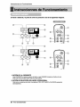
El n'_n_ a dis_ncia y el panel _ _ntrol se pareceran a los de las siguientes im_es.
® ®
®
Q
®
®
® ®
®
®
--®
1. BOT(_N DE _ CORRIE_
ParaENCENDERel sis_ma prosioneel bot6n,y paraAPAGARLOpresio_ elbot6notrawT_
Este _n _enepdoHdadlsobretodoslosotrosbotones.
2. BOT6N DE SELECCI6N DEL MODO OPERACIONAL
Cadavezque presioneestebotSn, lasp_r_ FRIO,VENTI_R y CALENTARapa.r_cerdn
altemadamente.
36 Aire Acondicionador

instruccionnesdeFuncionamiento
3, BOT_N O_IOFF TIMER
Carla vez que pres_ne _ _n, el maxcador de tiempo _ _us_r_ de la siguiente ma_tera:
(I Hora 4, 2 Horas 4, 3 Horas 4, 4 Horas 4, 5 Horas 4, 6 Hofas 4, 7 Horas 4,
8 Horas 4, 9 Horas 4, 10 Horas 4, 11 Horas 4, i2 Horas 4, Cance_r).
4. SELECTOR DE _ VELOCIDAD DEL VEN_LA_R
Cada vez que pres_ne este _n, el ajuste es como sigue_
(AIt_ F2 ] _ Bajo[ F l] -) Alto[ F2 ].,.)
5. B_ON DE SELECCION DE LA TEMPERATURA DE LA HAB|TACION
Este bot_ pue_ controlax _atem_ratura _1 _arto autom_i_mente. La tem_ratura se
puede aju_r de grado en grado, _sde 60"F basra 86"F cada I_E
6. AUTOGIRO
Este bot_ pue_ _ntrolar automdticament la dire_6n del flujo _ _re,
7. AHORRADOR DE ENERG|A
El ventila_r se det_e cuando el _mpressor no sigue enfriando_
Aproximadamente carla 3 m_nutosel vent_lador _ en_nderd, y necesitar& vetlficar la
tem_ratum _ cuarto para s_er si es n_ado m_tsenfdamlento.
8. RECEPTOR DE SENAL
Un _eveolor podia de_irse de la unidad laprimera _z que enctende HEAT(Calentar) al
terminal_atemporada _ enfr_miento. E_ olor es pot h_ _postta_ un pec-ode p_
sobre el _lentador y va a d_paxecer _pida,ment_
Cuandoelaimaco_ionado ha_do _mndo ba_ _ fasedeenfdam_ntoy se _ga o seaj_a laposi_n de
ventlla_, es-_ _ _ _nos 3 mlnut_ antesde reln_r lao_ de enfr_miente,
i. Quite la tapa de la parte posterior de_
telemando. _ra e_o haga deslizar la ta_
_n la direcci6n della flecha.
2. Introduzca las.dos bater_as, asegur&ndose de
que I_ direcciones (+) y (-) est_n coloc_das
_rrectament. U_ baterfas nuevas.
3. Vol_r a cerrar, resbalan_ la tapa hasta la
posici6n inicial°
•.No util_e baterl's recargables,
_stas son diferentes de forma,
de dimensi6n y uso res_o a
las bater_'as _s usuales.
, Seque las bater[as dei
telemando cuando el
acondidonador no vaya a _r
usado durante un largo
Manual del 37

lnstruccionnes de Funcionamiento
La palan_ de ventilad6n delta estar en la pos[ci6nCLOSE (Cerrado) para poder mantener las mejores
_ndiciones de enfriamiento.
Cuando se necesite aire fres_ en la habitaci6n, coloque la paJancade ventilaci6n en laposici6n OPEN (Abierto).
El amortiguador se abre y se descarga e]aire de la habitaci6n.
CERRAR VENTILAC_ON ABR]R
Antes de usar la caractedstica de ,¢entilaci6n,
coloque Ia palan_ como se muestra, Primero, jaie hacia
Part®
abajo la _rte ® r._ra que quede en una I[nea horizontal con ]a parte _).
La direcci6n de! aire puede controlarse hacia donde usted desee
enfriar ajustando la persiana horizontal y lapersiana vertical.
I, CONTROL DE LA DIRECCION HORIZONTAL
DEL AIRE
Para controlar la direcci6n horizontal dei flujo del aire, coloque el
interruptor de osci]aci6n de aire en la posici6n ON y e] fiujo de
aire soplara horizontaimente pot medic del sistema de o_ilaci6n
automatica de aire.
Si desea detener el flujo de aire, _]oque el interruptor de
osciiaci6n de aire en la posici6n deseada de la aleta.
• CONTROL DE LA DiRECCION VERTICAL DEL AIRE
La direcci6n de aire vertical es ajustada moviendo la reji[a
horizontal
La direcci6n del aire puede ser controlada cuando usted desee
enfriar, ajustando la palanca vertical y la palanca horiziontal.
• CONTROL DE LA DIRECCI@I HORIZONTAL DEL
La direcci6n horizontal del aire es ajustada rotando la palanca
vertical hacia la derecha o hacia la izquierda.
• CONTROL DE LA DIRECCION VERTICAL DEL AIRE
La direcci6n vertical del aire es ajustada
rotando la palanca horizontal hacia adelanto o hacia atr_.s.
38 Aire Acondicionador

tnstruccionnesdeFuncionamient,o
E[ aire acondidenado utiHziaun meted,o,de purga adecuadlo en donde
el agua condensada. (humedad retirada del aire) se prurgaal exterior,
En climas demasiado, hum_os (y para m_e_,os de cido invertido, en la
m_alidad de inversion) e[ agua conden_da excesiva que _ retira dell
aire pu_e ocasionar que _ recollecte a[go de agua. Para eIiminar este
excese de agua, puede in_alar una charo,_ade purga come se detaHa
a contJnuaci6n_
1,Tome la charoia de purga que se !oca!iza en la de_arga de aire o
en Iiabarrera.
DEPUBGA
2. Retire el orificio de huJe de la charola de la ba_. (para algunos m_eios).
3_ instale la ,charola de purga ,en el extermo izquierdo del gabinete con 4 (o 2) torniHos,
4. Cene_e [a manguera de purga en la descarga Iocaliza.da en el fondo de Jacharola ,de purga. Puede
ad,quirir [a manguera o tuberta de purgga _o_lmente para safisfacer sus n_sidades particulates
(No,se Jnduiye Ilamanguera de purga).,
Existe una manguera de purga inclulda en Ila_Me de atr&s de Ila
unidad de aire acondicionado,..
Elija un m6todo de purga de acuerdo a Io,siguiente,
1. Retire el orificio de hule de la charola de la base. (para aigunos
modelos),.
2:. Conecte una manguera de purga de 9/'16'°de diametro interior al
tube de p,urga come se mue_ra en la Figura 1.
3i Conecte un code de tu_, de 9/16" de di_metro interior a [a
tuberia de purga, deslpu6s conecte una manguera de purga de
9/16" de diametro interior al code de tube come, se muestra en Iia
Figura 2.
DEPURGA
Manual del Prop,ietario 39

Cuidado y Mantenimiento
APAGUE EL AIRE A NADO Y SAQUE EL ENCHUFE DEL TOMA DE LA PARED.
EEfiltro de aire devera, revisarse cuando menos dos veces al rues para vertioficar si es necesado
limpiado. Las _rt/culas atrapadas en el filtro podrfan acumularse y bJoquear el flujo de aire. Esto
reduce la capacidad de enfdamiento y tambien ocasiona la acumulaci6n de escarcha en ios
serpentines de enfriamiento,
1. Abra la rejilla hacia arriba tirando la parte inferior de la rejilla de entrada (a). En otro caso, usted
puede abrir la rejilla de entrada hacia abajo tirando la parte superior de la rejilla de entrada.(b)
2. Retire el filtro de aire del ensamblaje de la parrilla delantera jalando el filtro de aire ligeramente hacia
arriba
3. Lave el filtro de aire usando agua tibia a menos de 40°0 (t 04°F).
4. Sacuda suavemente el exceso de agua del filtro completamente. Vuelva a colocar el filtro.
(a) (b) (o)
La marca A de la rejilla de entrada significa la direccion abierta.
1,Jale hacia abajo la parrilla delantera desde la
parte superior del gabinete,
2, Op,rima las puntas de la _rrilla delantera hacia
el gabinete _ra insertar las leng0etas de la
parrilla delantera en el gabinete.
3. Abra la parrNla de admisi6n.
4. Apriete el tornillo a traves de la parrilla
delantera dentro en la placa de evaporador o
base cacerola,
5. Cierre la pardlla de admisi6n.
40 Aire Acondicionador

Cuidadoy Mantenimiento
Antes de llamar al servicio,tenga abien revi_r ]asiguientelis_ de probiemasy sus _]uciones.
E! acondicionadordeaim es_ funcionandonormalmentecuando:
. Escuchaun_nido met_lico.Lo cau_ elaguaque recogeel condensadoren dias Iluviososo encondicionesde
muchahumedad.Es_ _racteflsti_ est_ diseSadaparaayudara quitarla hum_ad en el ake y mejorarla
_paci_d de enfdamiento.
• Oyeun clic einel termostato.Locau_ elciclo de]compresorqueicomienzay sedetiene.
•Ve gotearagua de ]a parte_stefior de [aunidad. El agua pu_e set recogidaen [a bandejade baseen
condicionesde muchahum_ad o d/as de lluvia. Estaagua des_rda y goteadesde la parte posteriorde la unidad.
° Oyefuncionarel ventiladormientrasel comp[esorestersilencioso.Esto es una _racteflstica o_rativa normal,
• Aseg5rese que el enchufe est&comp]etamente
enchdado dentro del tomacorr[ente
El acondicionador
de aire no
funciona _ra
na_
El acondicionador
de aire noenfria
Apar_ hielo
sobreel
acondicionador
de airea
Compruebe el fusible/la caia del disyunbr y reemplace
el fusible o vue]va el disyuntor a su lugar:
Si ocurr el apag6n,d_ vuelta al control del modo a apagado
(Tipo Mecanico). Cuando es la energ[a se restaura,
espera 3 minutos para re_menzar el acond[cionadorde
aire pare prevenir disparar de]compresor.
Preslone el bot6n RESET s[tuado en el enchufede]
cable de alimentaci6noSi el bot6n RESET no
permanece activo, suspenda e] uso del aire
acondicionado y p6ngase en contacto con un t6cnico de
servicio cuaiificado,
° Aseg_rese que nohaya corflnas, persianas, muebles u
otros obstAculosfrente al acondic_onadorde aire
° Gire el control de TEMPERATURA a unnt_merom_s
baio.
• Limpie el fiitro al menos una vez _da dos semanas.
Refierasea la secci6n "Cui_do y Mantenimiento"del
manual.
• Despu6sque se enciende el acondicionador de aire,
debe _rle un tiempo al acondicionador de aire para
enffiar la habitaci6n
° Busquea[guna homalla de resistencia encendida y el
aire frio vuelve.
C[ERRE la ventilad6n del acondic[ona_r de aire
• Vea Aparece hielo sobre el acondicionador de a_re_ajo
• E]hielo puede bloquear la corriente de aJree impedir
que el acond[donador de aire enfrie correctamente la
habitaci6n.
° Ajustar el control de modo en 'Ventilaci6nalW o
Erfriamiento alto' con la temperatura a_ta.
Manual del Propietario 41

Nota
42 Aire Acondicionador

Specifications and performance data subject to change without notice.
HEAT CONTRDLLER, INC.
1900 WELLWORTH AVENUE • JACKSON, MICHIGAN 49203
THE QUALITY LEADER IN CONDITIONING AIR
P/No: 3828A21015V Printed in China
-
 1
1
-
 2
2
-
 3
3
-
 4
4
-
 5
5
-
 6
6
-
 7
7
-
 8
8
-
 9
9
-
 10
10
-
 11
11
-
 12
12
-
 13
13
-
 14
14
-
 15
15
-
 16
16
-
 17
17
-
 18
18
-
 19
19
-
 20
20
-
 21
21
-
 22
22
-
 23
23
-
 24
24
-
 25
25
-
 26
26
-
 27
27
-
 28
28
-
 29
29
-
 30
30
-
 31
31
-
 32
32
-
 33
33
-
 34
34
-
 35
35
-
 36
36
-
 37
37
-
 38
38
-
 39
39
-
 40
40
-
 41
41
-
 42
42
-
 43
43


COMFORT-AIRE RAD-243A El manual del propietario
- Tipo
- El manual del propietario
En otros idiomas
- English: COMFORT-AIRE RAD-243A Owner's manual
Documentos relacionados
Otros documentos
-
Panasonic HQ-2243TH Manual de usuario
-
Goldstar WG1805R El manual del propietario
-
LG BG8000ER El manual del propietario
-
LG HBLG1400E El manual del propietario
-
-
LG M8003R El manual del propietario
-
-