Craftsman 13953914 El manual del propietario
- Categoría
- Abridor de puerta de garage
- Tipo
- El manual del propietario

Owner's Manual/Manual Del Propietario
1/2 HP
GARAGE DOOR OPENER
ABRIDOR DE PUERTA DE COCHERA
For Residential Use Oniy/Sbio para uso residencial
Model/Modelo • 139.53914
m
m
o_
Z_
Read and follow all safety rules
and operating instructions before
first use of this product.
Fasten the manual near the garage
door after installation.
Leer y seguir todas ias regias de
seguridad y las instrucciones de
operacibn antes de usar este
producto por primera vez.
Guardar este manual cerca de la
puerta de la cochera.
Periodic checks of the opener are
required to ensure safe operation.
Se deben realizar revisiones
peribdicas del abridor de puertas
para asegurar su operacibn
segura.
Sears, Roebuck and Co., Hoffman Estates, IL 60179 U.S.A
www.sears.com/craftsman

TABLE OF CONTENTS
Introduction 2.7
Safety symbol and signal word review ........................ 2
Preparing your garage door ........................................ 3
Tools needed ............................................................... 3
Planning .................................................................. 4-5
Carton inventory .......................................................... 6
Hardware inventory ..................................................... 7
Assembly 8-11
Assemble the rail and install the trolley ...................... 8
Fasten the rail to the motor unit and
install the idler pulley ................................................... 9
install the belt and attach the belt cap retainer ......... 10
Set the tension .......................................................... 11
Installation 11.26
installation safety instructions .................................... 11
Determine the header bracket location ..................... 12
install the header bracket .......................................... 13
Attach the rail to the header bracket ......................... 14
Position the opener ................................................... 15
Hang the opener ....................................................... 16
install the door control ............................................... 17
install the lights ......................................................... 18
Attach the emergency release rope and handle .......18
Electrical requirements .............................................. 19
install The Protector System ®.............................. 20-22
Fasten the door bracket ....................................... 23-24
Connect the door arm to the trolley ..................... 25-26
Adjustment 27.29
Adjust the travel limits ............................................... 27
Adjust the force ......................................................... 28
Test the safety reversal system ................................. 29
Test The Protector System ®...................................... 29
Operation 30.34
Operation safety instructions ..................................... 30
Using your garage door opener ................................ 30
Using the walt-mounted Door Control ....................... 31
To open the door manually ........................................ 31
Care of your garage door opener .............................. 32
Having a problem? .................................................... 33
Diagnostic chart ......................................................... 34
Programming 35-36
To add or reprogram a hand-held remote control .....35
To erase all codes ..................................................... 35
3-Function Remotes .................................................. 35
To add, reprogram or change
a Keyless Entry PIN .................................................. 36
Repair Parts 37.38
Rail assembly parts ................................................... 37
installation parts ........................................................ 37
Motor unit assembly parts ......................................... 38
Accessories 39
Warranty
Repair Parts and Service
39
40
INTRODUCTION
Safety Symbol
and Signal Word Review
This garage door opener has been designed and tested to offer safe service provided it is installed, operated,
maintained and tested in strict accordance with the instructions and warnings contained in this manual.
Mechanical
Electrical
When you see these Safety Symbols and Signal
Words on the following pages, they will alert you to
the possibility of serious injury or death if you do
not comply with the warnings that accompany them.
The hazard may come from something mechanical
or from electric shock. Read the warnings carefully.
When you see this Signal Word on the following
pages, it will alert you to the possibility of damage to
your garage door and/or the garage door opener if
you do not comply with the cautionary statements
that accompany it. Read them carefully.
2

Preparing your garage door
Before you begin:
• Disable locks
• Remove any ropes connected to garage door
• Complete the following test to make sure your
garage door is balanced and is not sticking or
binding:
1 Lift the door about halfway as shown. Release
the door. If balanced, it should stay in place,
supported entirely by its springs.
2 Raise and lower the door to see if there is any
binding or sticking
If your door binds, sticks, or is out of balance, call a
trained door systems technician.
Sectional Door
To prevent possibleSERIOUSINJURYor DEATH:
• ALWAYScall a trained door systems technician if
garage door binds, sticks, or is out of balance.An
unbalancedgaragedoor may not reversewhen
required
• NEVERtry to loosen, move or adjust garage door,door
springs, cables,pulleys, brackets or their hardware, all
of which are under EXTREMEtension.
• DisableALL locksand remove ALL ropes connectedto
garage door BEFOREinstalling and operating garage
door openerto avoid entanglement.
To preventdamageto garagedoor and opener:
• ALWAYSdisable locks BEFOREinstalling and operating
the opener.
• ONLYoperategaragedoor openerat 120V,60 Hz to
avoid malfunction and damage
One-Piece Door
Tools needed
During assembly, installation and adjustment of the
opener, instructions will call for hand tools as
illustrated below.
Carpenter's _ _1 _ J_ \;_
Level (optional) _ _ Hack Raw °_ _1
Tape Measure _ f_ -- -
_ Wire Cutters / ";""_
_ Claw Hammer
Drill Bits
_k_ and 5/32" Pliers Screwdriver
O0 o
Stepladder U e c _ _ v
1/2,6/8,7/16,9/16 Locking pl_ers Adlustable End Wrench
and 1/4"
3

Planning
Identify the type and height of your garage door.
Survey your garage area to see if any of the
conditions below apply to your installation. Additional
materials may be required. You may find it helpful to
refer back to this page and the accompanying
illustrations as you proceed with the installation of
your opener.
Depending on your requirements, there are several
installation steps which may call for materials or
hardware not included in the carton.
• Installation Step 1 - Look at the walt or ceiling
above the garage door. The header bracket must
be securely fastened to structural supports.
• Installation Step 5 - Do you have a finished ceiling
in your garage? If so, a support bracket and
additional fastening hardware may be required.
• Installation Step 10 - Depending upon garage
construction, extension brackets or wood blocks
may be needed to install sensors.
• Installation Step 10 -Alternate floor mounting of
the safety reversing sensor will require hardware
not provided.
Do you have an access door in addition to the
garage door? If not, Model 53702 Emergency Key
Release is required. See Accessories page.
Look at the garage door where it meets the floor.
Any gap between the floor and the bottom of the
door must not exceed 1/4" (6 mm). Otherwise, the
safety reversal system may not work properly. See
Adjustment Step 3. Floor or door should be
repaired.
SECTIONAL DOOR INSTALLATIONS
Do you have a steel, aluminum, fiberglass or glass
panel door? If so, horizontal and vertical
reinforcement is required (Installation Step 11).
The opener should be installed above the center of
the door. If there is a torsion spring or center
bearing plate in the way of the header bracket, it
may be installed within 4 feet (1.22 m) to the left or
right of the door center. See Installation Steps 1
and 11.
If your door is more than 7 feet (2.13 m) high, see
rail extension kits listed on Accessories page.
SECTIONAL DOOR INSTALLATION
Horizontal and vertical reinforcement
is needed for lightweight garage doors
(fiberglass, steel, aluminum, door with
glass panels, etc.). See page 23 for details.
Header Wall
Rail
Extension Spring
OR
j Torsion Spring
FINISHED CEILING
Support bracket &
fastening hardware
is required.
See page 16.
)runit
Walt*
moun_d
Door Access Door
Cont_l
Safety
Gap between floor Reversing
and bottom of door Sensor
must not exceed 1/4" {6 mm).
CLOSED POSITION
Header
Brack_ T_lley
S_p Bolt T_lley
Gamge
Door
Sp_ng
Curved
Door
Arm
B_cket
Belt
Emergency Release
Rope & Handle
4

Planning (Continued)
ONE-PIECE DOOR INSTALLATIONS
• Generally, a one-piece door does not require
reinforcement. If your door is lightweight, refer to
the information relating to sectional doors in
Installation Step 11.
• Depending on your door's construction, you may
need additional mounting hardware for the door
bracket (Step 11).
Without a properly working safety reversalsystem,
persons (particularly small children) could be
SERIOUSLYINJUREDor KILLEDbya closing garage
door.
• The gap betweenthe bottom of the garagedoor and
the floor MUSTNOTexceed 1/4" (6 ram). Otherwise,
the safety reversalsystem may not work properly.
• Thefloor or the garagedoor MUSTbe repairedto
eliminate the gap.
ONE-PIECE DOOR WITHOUT TRACK
FINISHED CEILING
Support bracket,
& fastening
hardware is required.
See page 16.
f
Safety Reversing Sensor
Rail
Gap between floor
and bottom of door must not exceed 1/4" (6 mm).
Wall-mounted
D_or Control
ACCESS
Safety Reversing
Sensor
leader
Vail
Motor Unit
CLOSED POSITION
Trolley Stop Bolt
Belt Trolley
Bracket
Door Bracket Emergency
Release
Rope & Handle
Straight Curved
Door Door
Arm Arm •
Garage
ONE-PIECE DOOR WITH TRACK
Access I
Door I
ol
Reversing
Gap between floor Sensor
J and bottom of door
Safety must not exceed 1/4" (6 mm).
Reversing Sensor
CLOSED POSITION 1
Trolley Stop Bolt Belt Trolley
_Nea_le _ \Bracket DoorArm_ Rail
DOO_..... Doorl..... )j !_ i_ergenCYRope&
1_ Bracket Straight Release
DGoararge Arm Handle
5

Carton Inventory
Your garage door opener is packaged in one carton
which contains the motor unit and all parts illustrated
below. Accessories wilt depend on the model
purchased. If anything is missing, carefully check the
packing material. Parts may be stuck in the foam.
Hardware for assembly and installation is shown on
the next page. Save the carton and packing material
until installation and adjustment is complete.
Premium Control Console
SECURITY_
3-Function Remote Control (2)
Belt Cap Retainer
Trolley
SECURITY_
Keyless Entry
Motor Unit with 2 Light Lenses
Idler Pulley
Rai_
Center/Back
Sections
Rraolnt(header)
Y
Safety Sensor
Bracket (2)
Header Bracket
Be_t
Door Bracket
(2) Safety Reversing Sensors
(1 Sending Eye and I Receiving Eye)
with 2-Conductor White & White/Black
Bell Wire attached
Curved Door
Arm Section
2*Conductor Bell Wire
White & White/Red
Safety Labels
and
Literature
11
Hanging Brackets
Straight Door
Arm Section
6

Hardware Inventory
Separate all hardware and group as shown below for the assembly and installation procedures.
@
@
Spring/Trolley Nut (1)
Bolt 1/4"-20x1-3/4 (1)
ASSEMBLY HARDWARE
© ©©
Lock Nut Lock Washer Nut
1/4"-20 (2) 3/8" (1) 3/8" (1)
Trolley Threaded Shaft (1)
INSTALLATION HARDWARE
i
Master
Link (2)
Idler Bolt (1)
Carriage Bolt
1/4"-20xl/2" (2)
q:p ©
Wing Nut Ring
1/4"-20 (2) Fastener (3)
Lag Screw
5/16"-9x%5/8"(2)
Lag Screw
5/16"-18xl-7/8"(2)
@
Carriage Bolt
5/16"-18x2-1/2" (2)
o_
Clevis Pin
5/16"x1-1/2" (1)
Hex Bolt
5/16"-18x7/8" (4)
©
Nut 5/16"-18 (6)
©
Lock Washer 5/16" (7)
Handle
Insulated
Staples (30)
Screw
6ABx1-1/4" (2) Screw 6-32x1"(2)
Drywall Anchors (2)
Spacer(2)
ol IE ol
Clevis Pin Clevis Pin
5/16"xl" (1) 5116"xl -1/4" (1)
l
Rope
7

ASSEMBLY STEP 1
Assemble the Rail & Install the l_olley
To avoid installation difficulties, do not run the
garage door opener until instructed to do so.
The front rail has a cut out "window" at the door end
(see illustration). The hole above this window is
larger on the top of the rail than on the bottom. A
smaller hole 3-1/2" (8.9 cm) away is close to the rail
edge. Rotate the back rail so it has a similar hole
close to the opposite edge, about 4-3/4" (12 cm)
from the far end. NOTE: Using the sequence above
the clips will be facing down.
1. Remove the straight door arm and hanging
bracket packaged inside the front rail and set
aside for Installation Step 5 and 12. NOTE: To
prevent INJURY while unpacking the rail carefully
remove the straight door arm stored within the rail
section.
2. Align the rail sections on a flat surface as shown
and slide the tapered ends into the larger ones.
Tabs along the side will lock into place.
To prevent INJURYfrom pinching, keephands and
fingers away from the joints while assembling the rail.
NOTE: Rail sections may be assembled with the
clips up or down (down is preferred) disassembly of
rail may damage clips.
3. Place the motor unit on packing material to protect
the cover, and rest the back end of the rail on top.
For convenience, put a support under the front
end of the rail.
4. As a temporary trolley stop, clamp locking pliers
onto the rail 8" (20 cm) from the center of the idler
pulley hole, as shown.
5.Check to be sure there are 4 plastic wear pads
inside the inner trolley. If they became loose
during shipping, check all packing material. Snap
them back into position as shown.
6.Slide the trolley assembly along the rail from the
back end to the locked pliers.
Trolley
KEEP LARGER
HOLE ON TOP
FRONT RAIL
(TOP)
Tapered
End
Clip
Tapered
End of
Rail
End
(TO MOTOR UNIT)
End
8" (20 cm) Distance from
Idleru,t,_u__Pulle _
FHole
Tabs
Window
Cut-Out nt Rail
Idler _._ (TO DOOR)
Pulley
Hole __Locking
Pliers
End
Inner Trolley
Wear Pads
8

ASSEMBLY STEP 2
Fasten the Rail to the Motor Unit
• Insert a 1/4"-20xl-3/4 bolt into the cover protection
bolt hole on the back end of the rail as shown.
Tighten securely with a 1/4"-20 lock nut. Do NOT
overtighten.
• Remove the two bolts from the top of the motor
unit.
• Place the "U" bracket, flat side down, on the motor
unit and align the bracket holes with the bolt holes.
Fasten with the previously removed bolts.
• Align the rail assembly with the top of the motor
unit. Slide the rail end onto the "U" bracket, all the
way to the stops that protrude on the top and sides
of the bracket.
Toavoid SERIOUSdamageto garagedoor opener,
useONLYthose bolts/fasteners mounted in the top of
the opener.
Cover
Protection
Bolt Hole '
"U" Bracket
Bolt
I
Bolts
Motor Unit
Sprocket
HARDWARE SHOWN ACTUAL SIZE
©
Lock Nut
Bolt 1/4"-20xl-3/4 1/4"-20
I
I
Lock Nut
SLIDE RAIL TO STOPS
ON TOP AND SIDES
OF BRACKET
ASSEMBLY STEP 3
Install the Idler Pulley
• Lay the belt beside the rail, as shown. Grasp the
end with the hooked trolley connector and pass
approximately 12" (30 cm) of belt through the
window. Keep the ribbed side toward the rail, and
allow it to hang until Assembly Step 5.
• Remove the tape from the idler pulley. The inside
center should be pre-greased. If dry, regrease to
ensure proper operation.
• Place the idler pulley into the window as shown.
• Insert the idler bolt from the top through the rail
and pulley. Tighten with a 3/8" lock washer and nut
underneath the rail until the lock washer is
compressed.
• Rotate the pulley to be sure it spins freely.
• Insert a 1/4"-20xl-3/4 bolt into the trolley stop hole
in the front of the rail as shown. Tighten securely
with a 1/4"-20 lock nut.
Lock Washer
3/8"
I_) Nut 3/8"
I
Bolt
Trolley
Grease Stop Hole
inside Pulley _
Idler Pulley
Trolley j _
Connector .,,_lV_ _1_
Idler L Nut
Pulley
Idler Bolt
HARDWARE SHOWN ACTUAL SIZE
Bolt t/4"-20xl*3/4 Lock Nut 1/4"-20 Nut 3/8" Lock Washer 3/8"
9

ASSEMBLY STEP 4
Install the Belt
and Attach the Belt Cap Retainer
1. Pull the belt around the idler pulley and toward the
trolley. The ribbed side must contact the pulley.
2. Hook the trolley connector into the retaining slot
on the trolley as shown.
3. With the trolley against the pliers, dispense the
remainder of the belt along the rail length toward
the motor unit and around the sprocket. The
sprocket teeth must engage the belt.
4. Check to make sure the belt is not twisted, then
connect it to the flat end of the trolley threaded
shaft with the master link, as illustrated:
Toavoid possible SERIOUSINJURYto fingers from
moving garage door opener:
• ALWAYSkeep handclear of sprocket while operating
opener.
• Securely attach sprocket cover BEFOREoperating.
• Push pins of master link bar through holes in
end of belt and trolley threaded shaft.
• Push master link cap over pins and past pin
notches.
• Slide clip-on spring over cap and onto pin
notches until both pins are securely locked in
place.
5. Insert the trolley threaded shaft through the hole in
the trolley. Be sure the belt is not twisted, and the
ribbed side faces the rail.
HARDWARE SHOWN ACTUAL SIZE
Hex Screw 8x3/8"
Spring/Trolley Nut
6. Hold the belt at the trolley shaft as you thread the
spring nut by hand onto the shaft until finger tight
against the trolley. Do not use any tools.
7. Remove the locking pliers.
8. Position the belt cap retainer over the motor unit /_
sprocket as shown and fasten to the mounting /_/.,,_/
plate with 8x3/8 hex screws provided." _lla_t_rnL&pkring _/__/
Master Link Cap "- "
Threaded Link Bar
C:) Shaft
@ Round
Retaining
Trolley Slot
MOtOr Unit
: J Sprocket
f -Mounting
Plate
lO

ASSEMBLY STEP 5
Set the Tension
• Insert a screwdriver tip into one of the nut ring
slots and brace it firmly against the trolley.
• Place a 7/16" open end wrench on the square
end. Rotate the nut about 1/4 turn until the spring
releases and snaps the nut ring against the trolley.
This sets the spring to optimum belt tension.
You have now finished assembling your garage
door opener. Please read the following warnings
before proceeding to the installation section.
J
Nut Ring Slot
Trolley
Square
End Nut Ring
(2.5 cm) (3.18 cm)
Nut Ring,
INSTALLATION
IMPORTANT INSTALLATION INSTRUCTIONS
To reduce the risk of severe injury or death:
1. READAND FOLLOWALL INSTALLATIONWARNINGS
AND INSTRUCTIONS.
2. Install garage door opener only on properly balanced
and lubricated garagedoor. An improperly balanced
door may not reversewhen required and could result in
SEVEREINJURYor DEATH.
3. All repairs to cables,spring assembliesand other
hardware MUSTbe madeby a trained door systems
technician BEFOREinstalling opener.
4. Disableall locksand remove all ropesconnected to
garagedoor BEFOREinstalling openerto avoid
entanglement.
5. Install garage door opener 7 feet (2.13 m) or more
abovefloor.
6. Mount emergency releasehandle 6 feet (1.83 m) above
floor.
7. NEVERconnect garagedoor openerto power source
until instructed to do so.
8. NEVERwear watches,rings or loose clothing while
installing or servicing opener.Theycould be caught in
garage door or opener mechanisms.
9. Install wall-mounted garagedoor control:
• within sight of the garage door.
• out of reach of children at minimum height of 5 feet
(1.5m).
• away from all moving parts of the door.
10. Placeentrapment warning label on wall next to garage
door control.
11. Placemanualrelease/safetyreversetest label in plain
view on inside of garage door.
12. Uponcompletion of installation, test safety reversal
system. Door MUSTreverseon contact with a
1-1/2" (3.8 cm) high object (or a 2x4 laid flat) on
the floor.
11

INSTALLATION STEP 1
Determine the Header Bracket
Location
To prevent possible SERIOUSINJURYor DEATH:
• Headerbracket MUSTbe RIGIDLYfastenedto
structural support on headerwall or ceiling, otherwise
garage door might not reversewhen required. DONOT
install header bracketover drywall.
• Concreteanchors MUST be used if mounting header
bracket or 2x4 into masonry.
• NEVERtry to loosen, move or adjust garage door,
springs, cables,pulleys, brackets, or their hardware,
all of which are under EXTREMEtension.
• ALWAYScall a trained door systems technician if
garage door binds, sticks, or is out of balance.An
unbalancedgaragedoor might not reversewhen
required.
Installation procedures vary according to garage door
types. Follow the instructions which apply to your
door.
1.Close the door and mark the inside vertical
centerline of the garage door.
2. Extend the line onto the header wall above the
door.
You can fasten the header bracket within 4 feet
(1.22 m) of the left or right of the door center
only if a torsion spring or center bearing plate
is in the way; or you can attach it to the ceiling
(see page 13) when clearance is minimal. (It
may be mounted on the wall upside down if
necessary, to gain approximately 1/2" (1 cm).
If you need to install the header bracket on a 2x4
(on wall or ceiling), use lag screws (not provided)
to securely fasten the 2x4 to structural supports as
shown here and on page 13.
3. Open your door to the highest point of travel as
shown. Draw an intersecting horizontal line on the
header walt above the high point:
• 2" (5 cm) above the high point for sectional door
and one-piece door with track.
• 8" (20 cm) above the high point for one-piece
door without track.
This height wilt provide travel clearance for the top
edge of the door.
NOTE: If the total number of inches exceeds the
height available in your garage, use the maximum
height possible, or refer to page 13 for ceiling
installation.
Header Wall
Unfinishe_
Ceilin OPTIONAL
g CEILING
MOUNT
FOR
HEADER
BRACKET
Vertical Centerline
of Garage Door
2x4
Structural
Suppods
Header Wall
='_'_2" (5 cm) Track
of Travel
Door
Sectional door with curved track
Header Wall Track
Highest Point
0%e2 o,
Y
I7
One-piece door with horizontal track
Header Wall
p;oomj
Doer Highest
One-piece door without track:
jamb hardware
Highest
Point
of Travel
Pivot
One=piece door without track:
pivot hardware
12

INSTALLATION STEP 2
Install the Header Bracket
You can attach the header bracket either to the wall
above the garage door, or to the ceiling. Follow the
instructions which will work best for your particular
requirements. Do not install the header bracket
over drywall. If installing into masonry, use
concrete anchors (not provided).
WALL HEADER BRACKET INSTALLATION
• Center the bracket on the vertical centerline with
the bottom edge of the bracket on the horizontal
line as shown (with the arrow pointing toward the
ceiling).
• Mark the vertical set of bracket holes (do not use
the holes designated for ceiling mount). Drill 3/16"
pilot holes and fasten the bracket securely to a
structural support with the hardware provided.
HARDWARESHOWNACTUALSIZE
Lag Screw
5/16"-9xl-5/8"
Wall Mount
Optional
Mounting Holes
Header
.- f:
Horizontal / /
Line
/
/*
Highest Point of
Garage Door Travel
Vertical
Centedine
of Garage Door
Lag Screws
5/18"x9xl-5/8"
DoorSp#ng
Garage
Door
Centerline
of Garage Door
CEILING HEADER BRACKET INSTALLATION
• Extend the vertical centerline onto the ceiling as
shown.
• Center the bracket on the vertical mark, no more
than 6" (15 cm) from the walt. Make sure the arrow
is pointing away from the wall. The bracket can be
mounted flush against the ceiling when clearance
is minimal.
• Mark the side holes. Drill 3/16" pilot holes and
fasten bracket securely to a structural support with
the hardware provided.
Ceiling Mounting Holes
_ -- Finished Ceiling --
f_
/" -- _ Vertical Centerline
of Garage Door
Header _
Bracket _
8" (15 cm) Maximum
Door
Sprin _ Lag Screws
5/16"xgx1-5/8"
Header Wall
13

INSTALLATION STEP 3
Attach the Rail to the Header
Bracket
NOTE: (Optional) With some existing installations,
you may re-use the old header bracket with the two
plastic spacers included in the hardware bag. Place
the spacers inside the bracket on each side of the
rail, as illustrated.
Position the opener on the garage floor below the
header bracket. Use packing material as a
protective base. NOTE: If the door spring is in the
way you'll need help. Have someone hold the
opener securely on a temporary support to allow
the rail to clear the spring.
Position the rail bracket against the header
bracket.
Align the bracket holes and join with a clevis pin
5/16"xl-1/2" as shown.
Insert a ring fastener to secure.
Mounting
Hole
Clevis
Spacer
Hole
OPTION WITH
SOME EXISTING
INSTALLATIONS
Garage
Door
Opener Ca_on or
Temporary
Support
HARDWARE SHOWN ACTUAL SIZE
0
Clevis Pin 5/16"x1-1/2" Ring Fastener
14

INSTALLATION STEP 4
Position the Opener
Follow instructions which apply to your door type as
illustrated.
SECTIONAL DOOR OR ONE-PIECE DOOR WITH
TRACK
A 2x4 laid flat is convenient for setting an ideal
door-to-rail distance.
• Remove foam packaging.
• Raise the opener onto a stepladder. You will need
help at this point if the ladder is not tall enough.
• Open the door all the way and place a 2x4 laid flat
on the top section beneath the rail.
• If the top section or panel hits the trolley when you
raise the door, pull down on the trolley release arm
to disconnect inner and outer sections. Slide the
outer trolley toward the motor unit. The trolley can
remain disconnected until Installation Step 12
is completed.
Toprevent damageto garage door, rest garage door
opener rail on 2x4 placedon top section of door.
ENGAGED
ONE-PIECE DOOR WITHOUT TRACK
A 2x4 on its side is convenient for setting an ideal
door-to-rail distance.
• Remove foam packaging.
• Raise the opener onto a stepladder. You will need
help at this point if the ladder is not tall enough.
• Open the door all the way and place a 2x4 on its
side on the top section of the door beneath the rail.
• The top of the door should be level with the top of
the motor unit. Do not position the opener more
than 4" (10 cm) above this point.
_Nea_e, ii
_ the correct mounting height
from ceiling.
15

INSTALLATION STEP 5
Hang the Opener
Three representative installations are shown. Yours
may be different. Hanging brackets should be angled
(Figure 1) to provide rigid support. On finished
ceilings (Figure 2 and Figure 3), attach a sturdy
metal bracket to structural supports before installing
the opener. This bracket and fastening hardware are
not provided.
1. Measure the distance from each side of the motor
unit to the structural support.
2. Cut both pieces of the hanging bracket to required
lengths.
3. Drill 3/16" pilot holes in the structural supports.
4. Attach one end of each bracket to a support with
5/16"-18xl -7/8" lag screws.
5. Fasten the opener to the hanging brackets with
5/16"-18x7/8" hex bolts, lock washers and nuts.
6. Check to make sure the rail is centered over the
door (or in line with the header bracket if the
bracket is not centered above the door).
7. Remove the 2x4. Operate the door manually. If the
door hits the rail, raise the header bracket.
NOTE: DO NOT connect power to opener at
this time.
HARDWARE SHOWN ACTUAL SIZE
Hex Bolt
5/16"- 18x7/6"
©©
Nut 5/16"q8 Lock Washer 5/16"
Toavoid possible SERIOUSINJURYfrom a falling
garage door opener,fasten it SECURELYto structural
supports of the garage.Concreteanchors MUSTbe used
if installing any brackets into masonry.
Figure 1
Suppods
Measure _
Distance
Bolt 5/16"- 18x7/6"
Nut 5/16"-16
Lag Screws
5/16"- 18xl -7/8"
Figure 2
Lock Washer 6/16"
Nut 5/16"q8
FINISHED CEILING
(Not Provided)
BoIt 5/! 6"-18x7/6"
Lock Washer 5/16"
Nut 6/16"-18
Figure 3
Lag Screws
5/16"- 18xl _7/8"
Bolt 6/16"-18x7/8"
Lock Washer 5/16"
Nut 5/16"q8
(Not Provided)
Bolt 5/16"-18x7/8"
Lock Washer 5/16"
Nut 5/16"-16
16

INSTALLATION STEP 6
Install the Door Control
Locate door control within sight of door, at a
minimum height of 5 feet (1.5 m) where small
children cannot reach, away from moving parts of
door and door hardware. If installing into drywall, drill
5/32" holes and use the anchors provided. For
pre-wired installations (as in new home
construction), it may be mounted to a single gang
box (Figure 2).
1. Strip 7/16" (11 mm) of insulation from one end of
bell wire and connect to the two screw terminals
on back of door control by color: white wire to
2 and white/red wire to the 1.
2. Remove white cover by gently prying at slot in top
of the cover with a small flat head screwdriver.
Fasten with 6ABx1-1/4" self-tapping screws
(drywall installation) or 6-32x1" machine screws
(into gang box) as follows:
• Install bottom screw, allowing 1/8" (3 mm) to
protrude above wall surface.
• Position bottom of door control on screw head
and slide down to secure. Adjust screw
for snug fit.
• Drill and install top screw with care to avoid
cracking plastic housing. Do not overtighten.
• Insert top tabs and snap on cover.
3. (For standard installation only) Run bell wire up
walt and across ceiling to motor unit. Use
insulated staples to secure wire in several places.
Do not pierce wire with a staple, creating a short
or open circuit.
4. Strip 7/16" (11 mm) of insulation from end of bell
wire. Connect bell wire to the quick-connect
terminals as follows: white to white and white/red
to red.
NOTE: When connecting multiple door controls to
the opener, twist same color wires together. Insert
wires into quick-connect holes: white to white and
red/white to red.
5. Position the antenna wire as shown.
6. Use tacks or staples to permanently attach
entrapment warning label to wall near door
control, and manual release/safety reverse test
label in a prominent location on inside of
garage door.
NOTE: DO NOT connect power and operate
opener at this time. The trolley will travel to the full
open position but will not return to the close
position until the sensor beam is connected and
properly aligned.
Bell
Wire
To prevent possible SERIOUSINJURYor DEATHfrom
electrocution:
• Be sure power is not connectedBEFOREinstalling door
control.
• ConnectONLYto 24 VOLTlow voltage wires.
To prevent possible SERIOUSINJURYor DEATHfrom a
closing garage door:
Installdoor control within sight of garage door, out of
reachof children at a minimum height of 5 feet
(1.5 m), and awayfrom all moving parts of door.
NEVERpermit children to operateor playwith door
control push buttons or remote control transmitters.
Activate door ONLYwhen it can be seenclearly,is
properly adjusted, and there are no obstructions to door
travel.
ALWAYSkeepgaragedoor in sight until completely
closed. NEVERpermit anyoneto cross path of closing
garagedoor.
Outside Keylock Accessory Connections
To opener quick-connect terminals: white to white;
white/red to red.
HARDWARE SHOWN ACTUAL SIZE
Control Console (std installation) _]/ Yl_
Insulated
Staples
Control Console (pre-wired) Drywall Anchors
Figure 1 Figure 2
REMOVE & REPLACE COVER PRE*WIREDo_ IfT-_/'/li_
TO Replace, To Remove, INSTALLATI
insert Top _ Twist _I
Tabs__First _ _ Here
24 Volt
2*Conductor
Bell Wire in
Gang Box
PREMIUM
CONTROL CONSOLE Lighted
Top Push Button
Mounting
Hole
Terminal
Screws
Bottom
Mounting
Hole
(BACK VIEW)
Quick-Connect
Door Control
Connections
Strip wire 7/16" (11 mm)
(7/16 (11 r _nl))
TO release wire, push in
tab with screwdriver tip
_ed White Grey
J
Antenna
F
17

INSTALLATION STEP 7
Install the Lights
• Press the release tabs on both sides of lens.
Gently rotate lens back and downward until the
lens hinge is in the fully open position. Do not
remove the lens.
• Install up to a 100 watt maximum light bulb in each
socket. The lights will turn ON and remain lit for
approximately 4-1/2 minutes when power is
connected. Then the lights wilt turn OFR
• Reverse the procedure to close the lens.
• If the bulbs burn out prematurely due to vibration,
replace with a Garage Door Opener bulb.
NOTE: Use only standard light bulbs. The use of
short neck or speciality light bulbs may overheat the
endpanel or light socket.
To prevent possible OVERHEATINGof the endpanelor
light socket:
• DONOTuse short neck or specialty light bulbs.
• DONOTuse halogen bulbs. UseONLYincandescent.
Release Tab
i,
1O0 Watt (Max)
Standard ___
Ught Bulb
1O0Watt (Max)
Standard Light Bulb
ILenn__
INSTALLATION STEP 8
Attach the Emergency Release
Rope and Handle
• Thread one end of the rope through the hole in the
top of the red handle so "NOTICE" reads right side
up as shown. Secure with an overhand knot at
least 1" (2.5 cm) from the end of the rope to
prevent slipping.
• Thread the other end of the rope through the hole
in the release arm of the outer trolley.
• Adjust rope length so the handle is 6 feet (1.83 m)
above the floor. Ensure that the rope and handle
clear the tops of all vehicles to avoid
entanglement. Secure with an overhand knot.
NOTE: If it is necessary to cut the rope, heat seal
the cut end with a match or lighter to prevent
unraveling.
Toprevent possible SERIOUSINJURYor DEATHfrom a
falling garage door:
• If possible, useemergency releasehandleto
disengagetrolley ONLYwhen garagedoor is
CLOSED.Weak or broken springs or unbalanced
door could result in an open door falling rapidly
and/or unexpectedly.
• NEVERuseemergency releasehandle unless garage
doorway is clear of persons and obstructions.
NEVERusehandle to pull door open or closed. If rope
knot becomesuntied, you could fall.
Trolley
Edge°+ o 3 h°nd
Release Handle )_,
18

INSTALLATION STEP 9
Electrical Requirements
To avoid installation difficulties, do not run the
opener at this time.
To reduce the risk of electric shock, your garage door
opener has a grounding type plug with a third
grounding pin. This plug will only fit into a grounding
type outlet. If the plug doesn't fit into the outlet you
have, contact a qualified electrician to install the
proper outlet.
RIGHO
If permanent wiring is required by your local
code, refer to the following procedure.
To make a permanent connection through the 7/8"
hole in the top of the motor unit:
• Remove the motor unit cover screws and set the
cover aside.
• Remove the attached 3-prong cord.
• Connect the black (line) wire to the screw on the
brass terminal; the white (neutral) wire to the
screw on the silver terminal; and the ground wire
to the green ground screw. The opener must be
grounded.
• Reinstall the cover.
To avoid installation difficulties, do not run the
opener at this time.
To prevent possible SERIOUSINJURYor DEATHfrom
electrocution or fire:
• Be sure poweris not connectedto the opener,and
disconnect power to circuit BEFOREremovingcover to
establish permanent wiring connection.
• Garagedoor installation and wiring MUSTbe in
compliance with all local electrical and building codes.
• NEVERusean extension cord, 2-wire adapter, or
change plug in any way to make it fit outlet. Be sure
the opener is grounded.
PERMANENT WIRING
CONNECTION
Ground Tab
\
Green
Ground Screw
Black
. Wire
White Wire
19

INSTALLATION STEP 10
Install The Protector System _
The safety reversing sensor must be connected
and aligned correctly before the garage door
opener will move in the down direction.
IMPORTANT INFORMATION ABOUT
THE SAFETY REVERSING SENSOR
When properly connected and aligned, the sensor
will detect an obstacle in the path of its electronic
beam. The sending eye (with an orange indicator
light) transmits an invisible light beam to the
receiving eye (with a green indicator light). If an
obstruction breaks the light beam while the door is
closing, the door will stop and reverse to full open
position, and the opener lights will flash 10 times.
The units must be installed inside the garage so that
the sending and receiving eyes face each other
across the door, no more than 6" (15 cm) above the
floor. Either can be installed on the left or right of the
door as long as the sun never shines directly into the
receiving eye lens.
The mounting brackets are designed to clip onto the
track of sectional garage doors without additional
hardware.
• Besure poweris not connectedto the garagedoor
opener BEFOREinstalling the safety reversing sensor.
• To prevent SERIOUSINJURYor DEATHfrom a closing
garagedoor:
- Correctly connect and align the safety reversing
sensor.This required safety device MUSTNOTbe
disabled.
- Installthe safety reversing sensor so beamis NO
HIGHERthan 6"(15 cm) abovegarage floor.
If it is necessary to mount the units on the wall, the
brackets must be securely fastened to a solid
surface such as the wall framing. Extension brackets
(see accessories) are available if needed. If
installing in masonry construction, add a piece of
wood at each location to avoid drilling extra holes in
masonry if repositioning is necessary.
The invisible light beam path must be unobstructed.
No part of the garage door (or door tracks, springs,
hinges, rollers or other hardware) may interrupt the
beam while the door is closing.
Sensor Beam Invisible Light Beam
6" (15 cm) max. Protection Area
above floor
Sensor Beam
6" (I 5 cm) max.
above floor
Facing the door from inside the garage
2O

INSTALLING THE BRACKETS
Be sure power to the opener is disconnected.
Install and align the brackets so the sensors will face
each other across the garage door, with the beam no
higher than 6" (15 cm) above the floor. They may be
installed in one of three ways, as follows.
Garage door track installation (preferred):
• Slip the curved arms over the rounded edge of
each door track, with the curved arms facing the
door. Snap into place against the side of the track.
It should lie flush, with the lip hugging the back
edge of the track, as shown in Figure 1.
If your door track wilt not support the bracket
securely, wall installation is recommended.
Wall installation (Figure 2 & 3):
• Place the bracket against the wall with curved
arms facing the door. Be sure there is enough
clearance for the sensor beam to be unobstructed.
• If additional depth is needed, an extension bracket
(See Accessories) or wood blocks can be used.
• Use bracket mounting holes as a template to
locate and drill (2) 3/16" diameter pilot holes on
the walt at each side of the door, no higher than 6"
(15 cm) above the floor.
• Attach brackets to wall with lag screws
(Not provided).
• if using extension brackets or wood blocks, adjust
right and left assemblies to the same distance out
from the mounting surface. Make sure all door
hardware obstructions are cleared.
Floor installation (Figure 4):
• Use wood blocks or extension brackets (See
Accessories) to elevate sensor brackets so the
lenses will be no higher than 6" (15 cm) above the
floor.
• Carefully measure and place right and left
assemblies at the same distance out from the wall.
Be sure all door hardware obstructions are
cleared.
• Fasten to the floor with concrete anchors as
shown.
Figure I
I
Sensor
Bracket
Figure 2
Figure 3
Figure 4
DOOR TRACK MOUNT
BOOr
Track
RIGHT SIDE)
Indicator
Light
WALL MOUNT (RIGHT SIDE)
Fasten Wood Block to Wall with
/Lag Screws (Not Provided)
Indicator
Light Sensor
Bracket
(Not Provided)
Lens
WALL MOUNT (RIGHT SIDE)
Extension
Bracket
(See Accessories)
Lens Light
FLOOR MOUNT (RIGHT SIDE)
HARDWARESHOWNACTUALS_E
Carriage Bolt Wing Nut Staples
t/4"-20xt/2" 1/4"-20
i A_ach with
Concrete Anchors
: (Not Provided)
Light
B_c_t
21

MOUNTING AND WIRING THE SAFETY SENSORS
• Slide a 1/4"-20xl/2" carriage bolt head into the slot
on each sensor. Use wing nuts to fasten sensors to
brackets, with lenses pointing toward each other
across the door. Be sure the lens is not obstructed
by a bracket extension (Figure 5).
• Finger tighten the wing nuts.
• Run the wires from both sensors to the opener. Use
insulated staples to secure wire to wall and ceiling.
• Strip 7/16" (11 mm) of insulation from each set of
wires. Separate white and white/black wires
sufficiently to connect to the opener quick-connect
terminals. Twist like colored wires together. Insert
wires into quick-connect holes: white to white and
white/black to grey (Figure 6).
ALIGNING THE SAFETY SENSORS
• Plug in the opener. The indicator lights in both the
sending and receiving eyes will glow steadily if
wiring connections and alignment are correct.
The sending eye orange indicator light will glow
regardless of alignment or obstruction. If the green
indicator light in the receiving eye is off, dim, or
flickering (and the invisible light beam path is not
obstructed), alignment is required.
• Loosen the sending eye wing nut and readjust,
aiming directly at the receiving eye. Lock in place.
• Loosen the receiving eye wing nut and adjust
sensor until it receives the sender's beam. When
the green indicator light glows steadily, tighten the
wing nut.
Figure 6
Bell Wire
Finished
Ceiling
Figure 5
Carriage Bolt -"_
1/4"-20xl/2"
TROUBLESHOOTING THE SAFETY SENSORS
1. If the sending eye indicator light does not glow
steadily after installation, check for:
• Electric power to the opener.
• A short in the white or white/black wires. These
can occur at staples, or at opener connections.
• Incorrect wiring between sensors and opener.
• A broken wire.
2. If the sending eye indicator light glows steadily but
the receiving eye indicator light doesn't:
• Check alignment.
• Check for an open wire to the receiving eye.
3. If the receiving eye indicator light is dim, realign
either sensor.
NOTE: When the invisible beam path is obstructed
or misaligned while the door is closing, the door will
reverse. If the door is already open, it will not close.
The opener lights will blink 10 times. See page 20.
Connect Wire to
Quick-Connect Terminal
Bell Wire
2. Twist like colored
wires together
Sensor f
_ensor invisible Light Beam
Protection Area
3. insert into
appropriate terminals
Red White (
Quick-Connect Terminal
22

INSTALLATION STEP 11
Fasten the Door Bracket
Follow instructions which apply to your door type
as illustrated below or on the following page.
A horizontal reinforcement brace should be long
enough to be secured to two vertical supports. A
vertical reinforcement brace should cover the
height of the top panel.
The illustration shows one piece of angle iron as the
horizontal brace. For the vertical brace, two pieces of
angle iron are used to create a U-shaped support
(Figure 1). The best solution is to check with your
garage door manufacturer for an opener installation
door reinforcement kit.
NOTE: Many vertical brace installations provide for
direct attachment of the clevis pin and door arm. In
this case you will not need the door bracket; proceed
to Installation Step 12.
SECTIONAL DOORS
• Center the door bracket on the previously marked
vertical centerline used for the header bracket
installation. Note correct UP placement, as
stamped inside the bracket (Figure 2).
• Position the bracket on the face of the door within
the following limits:
A) The top edge of the bracket 2"-4" (5-10 cm)
below the top edge of the door.
B) The top edge of the bracket directly below any
structural support across the top of the door.
Fiberglass,aluminum or lightweight steel garagedoors
Will. REQUIREreinforcement BEFOREinstallation of
door bracket. Contactyour door manufacturer for
reinforcement kit.
HARDWARE SHOWN ACTUAL SIZE
G ©
Nut 5/16"-18 LockWasher 5/16"
Carriage Bolt
5/16"-18x2-1/2"
• Mark and drill 5/16" left and right fastening holes.
Secure the bracket as shown in Figure 1 if there is
vertical reinforcement.
If your installation doesn't require vertical
reinforcement but does need top and bottom
fastening holes for the door bracket, fasten as shown
in Figure 2.
Horizontal and vertical reinforcement
is needed for lightweight garage doors
(fiberglass, aluminum, steel, doors with
Figure 1
ure 2
23

ONE-PIECE DOORS
Please read and comply with the warnings and
reinforcement instructionson the previous page.
They apply to one-piece doors also.
• Center the door bracket on the top of the door, in
line with the header bracket as shown. Mark either
the left and right, or the top and bottom holes.
• Drill 5/16" pilot holes and fasten the bracket with
hardware supplied.
If the door has no exposed framing, drill 3/16" pilot
holes and fasten the bracket with 5/16"x1-1/2" lag
screws (not provided) to the top of the door.
NOTE: The door bracket may be installed on the top
edge of the door if required for your installation.
(Refer to the dotted line optional placement drawing.)
Drill 3/16" pilot holes and substitute 5/16"xl- 1/2" lag
screws (not provided) to fasten the bracket to the
door.
HARDWARE SHOWN ACTUAL SIZE
© ©
Nut 5/16"-18 LockWasher 5/t6"
Carriage Bolt
5/16"q 8x2-1/2"
Header Wall
2x4
Header
Bracket
Optional
Placement
of Door
Bracket
Finished Ceiling
Door
Bracket
Vertical
Centarline
of Garage
Door
Horizontal and vertical
reinforcement is needed for
.=dOOrS
(fiberglass, aluminum, steel,
door with glass panel, etc.).
(Not Provided)
For a door with no exposed framing,
or for the optional installation, use
5/16"xt-t/2" lag screws (Not provided)
to fasten door bracket.
®
_Lock
Washer
' 5/16"
i
i
I ' Top of Door
/ (inside Garage
_ h TopEdge/"
_,_ 5 °f D°°r
J,) opt,ooa,
/_ _'_ Placement
_Carriage Bolt
5/16 "_18x2-1/2"
24

INSTALLATION STEP 12
Connect Door Arm to Trolley
Follow instructions which apply to your door type as
illustrated below and on the following page.
SECTIONAL DOORS ONLY
• Make sure garage door is fully closed. Pull the
emergency release handle to disconnect the outer
trolley from the inner trolley. Slide the outer trolley
back (away from the pulley) about 8" (20 cm) as
shown in Figures 1, 2 and 3.
• Figure 1:
- Fasten straight door arm section to outer trolley
with the 5/16"xl" clevis pin. Secure the
connection with a ring fastener.
- Fasten curved section to the door bracket in the
same way, using the 5/16"xl-1/4" clevis pin.
• Figure 2:
- Bring arm sections together. Find two pairs of
holes that line up and join sections. Select holes
as far apart as possible to increase door arm
rigidity.
• Figure 3, Hole alignment alternative:
- If holes in curved arm are above holes in straight
arm, disconnect straight arm. Cut about 6"
(15 cm) from the solid end. Reconnect to trolley
with cut end down as shown.
- Bring arm sections together.
- Find two pairs of holes that line up and join with
bolts, lock washers and nuts.
• Pull the emergency release handle toward the
opener at a 45° angle so that the trolley release
arm is horizontal. Proceed to Adjustment Step 1,
page 27. Trolley wilt re-engage automatically when
opener is operated.
HARDWARESHOWNACTUALSIZE
©©0
Nut 5/16"-18 Lock Washer 5/16" Ring Fastener
C °lC ol
Clevis Pin Clevis Pin Hex Bolt
5/16"x1" (Trolley) 5/16"x1-1/4" (Door Bracket) 5/16"-18x7/8"
Pulley
/i,-0
i i
"(20 cm) rain._.)I
tt_ Oute r
_ Trolley
Clevis Pin
Fastener 5/16"xl"
/
/
/ Emergency
0 Door Release
: Bracket
Str°i0ht
Door Arm
C_! ed Door Arm
Figure 1
Figure 2
Pulley
Bolts
DoorBmc_t
Pulley
/ !(.--8" (20 cm)min.._)i
" _t
BOltS
2D8x ,0
CUt this end
Figure 3
25

ALL ONE-PIECE DOORS
1.Assemble the door arm, Figure 4:
• Fasten the straight and curved door arm sections
together to the longest possible length (with a 2
or 3 hole overlap).
• With the door closed, connect the straight door
arm section to the door bracket with the
5/16"xl -1/4" clevis pin.
• Secure with a ring fastener.
2. Adjustment procedures, Figure 5:
• On one-piece doors, before connecting the door
arm to the trolley, the travel limits must be
adjusted. Limit adjustment screws are located on
the left side panel as shown on page 27. Follow
adjustment procedures below.
• Open door adjustment: decrease UP
travel limit
- Turn the UP limit adjustment screw
counter-clockwise 4 turns.
- Press the Door Control push button. The trolley
wilt travel to the fully open position.
- Manually raise the door to the open position
(parallel to the floor), and lift the door arm to the
trolley. The arm should touch the trolley just in
back of the door arm connector hole. Refer to
the fully open trolley/door arm positions in the
illustration. If the arm does not extend far
enough, adjust the limit further. One full turn
equals 2" (5 cm) of trolley travel.
• Closed door adjustment: decrease DOWN
travel limit
- Turn the DOWN limit adjustment screw
clockwise 4 complete turns.
Figure 5
Door
Bracket
Clevis Pin Straight
5/16"xlq/4" Arm
Fastener
Lock
Washers
5/16"
Nuts
5/16"-18
Figure 4
BOltS
5/t6"-t8x7/8
Cu_ed
Door Arm
- Press the Door Control push button. The trolley
will travel to the fully closed position.
- Manually close the door and lift the door arm to
the trolley. The arm should touch the trolley just
ahead of the door arm connector hole. Refer to
the fully closed trolley/door arm positions in the
illustration. If the arm is behind the connector
hole, adjust the limit further. One full turn equals
2" (5 cm) of trolley travel.
3. Connect the door arm to the trolley:
• Close the door and join the curved arm to the
connector hole in the trolley with the remaining
clevis pin. It may be necessary to lift the door
slightly to make the connection.
• Secure with a ring fastener.
• Run the opener through a complete travel cycle.
If the door has a slight "backward" slant in full
open position as shown in the illustration,
decrease the UP limit until the door is parallel
to the floor.
NOTE: When setting the up limit on the following
page, the door should not have a "backward' slant
when fully open as illustrated below. A slight
backward slant will cause unnecessary bucking
and/or jerking operation as the door is being opened
or closed from the fully open position.
Inner Trolley
Outer Trolley
Door Arm
Emergency Release Handle
Closed
inner Trolley
Outer Trolley
- - ........................ "- _ Door with
Open Door (Incorrect)
26

ADJUSTMENT STEP 1
Adjust the UP and DOWN Travel
Limits
Limit adjustment settings regulate the points at which
the door will stop when moving up or down.
To operate the opener, press the Door Control push
bar. Run the opener through a complete travel cycle.
• Does the door open and close completely?
• Does the door stay closed and not reverse
unintentionally when fully closed?
If your door passes both of these tests, no limit
adjustments are necessary unless the reversing test
fails (Adjustment Step 3, page 29).
Adjustment procedures are outlined below. Read the
procedures carefully before proceeding to
Adjustment Step 2. Use a screwdriver to make limit
adjustments. Run the opener through a complete
travel cycle after each adjustment.
NOTE: Repeated operation of the opener during
adjustment procedures may cause the motor to
overheat and shut off. Simply wait 15minutes and
try again.
NOTE: If anything interferes with the door's upward
travel, it will stop. If anything interferes with the
door's downward travel (including binding or
unbalanced doors), it will reverse.
HOW AND WHEN TO ADJUST THE LIMITS
• ff the door does not open completely but opens
at least five feet (1.5 m):
Increase up travel. Turn the UP limit adjustment
screw clockwise. One turn equals 2" (5 cm) of
travel.
NOTE: Toprevent the trolley from hitting the cover
protection bolt, keep a minimum distance of 2-4"
(5 cm - 10 cm) between the trolley and the bolt.
• ff door does not open at least 5 feet (1.5 m):
Adjust the UP (open) force as explained in
Adjustment Step 2.
• If the door does not close completely:
Increase down travel. Turn the down limit
adjustment screw counterclockwise. One turn
equals 2" (5 cm) of travel.
If door still won't close completely and the trolley
bumps into the pulley bracket (page 4), try
lengthening the door arm (page 25) and
decreasing the down limit.
• ff the opener reverses in fully closed position:
Decrease down travel. Turn the down limit
adjustment screw clockwise. One turn equals 2"
(5 cm) of travel.
Without a properlyinstalled safety reversal system,
persons(particularly small children) could be
SERIOUSLYINJUREDor KILLEDby a closing garage
door.
• Incorrect adjustment of garagedoor travel limits will
interfere with proper operation of safety reversal
system.
• If one control (force or travel limits) is adjusted,the
other control mayalso needadjustment.
• After ANYadjustments are made, the safety reversal
system MUSTbe tested. Door MUST reverseon
contact with 1-1/2" high (3.8 cm) object (or 2x4 laid
flat) on floor.
Toprevent damageto vehicles, besure fully open door
provides adequateclearance.
[
Cover Protection Bolt
I
Left Panel Limit Adjustment
Screws
ADJUSTMENT LABEL
• If the door reverses when closing and there is
no visible interference to travel cycle:
If the opener lights are flashing, the Safety
Reversing Sensors are either not installed,
misaligned, or obstructed. See Troubleshooting,
page 22.
Test the door for binding: Pull the emergency
release handle. Manually open and close the door.
If the door is binding or unbalanced, call for a
trained door systems technician. If the door is
balanced and not binding, adjust the DOWN
(close) force. See Adjustment Step 2.
27

ADJUSTMENT STEP 2
Adjust the Force
Force adjustment controls are located on the right
panel of the motor unit. Force adjustment settings
regulate the amount of power required to open and
close the door.
If the forces are set too light, door travel may be
interrupted by nuisance reversals in the down
direction and stops in the up direction. Weather
conditions can affect the door movement, so
occasional adjustment may be needed.
The maximum force adjustment range is about
3/4 of a complete turn. Do not force controls
beyond that point. Turn force adjustment controls
with a screwdriver.
NOTE: If anything interferes with the door's upward
travel, it will stop. If anything interferes with the
door's downward travel (including binding or
unbalanced doors), it will reverse.
Without a properly installed safety reversal system,
persons (particularly small children) could be
SERIOUSLYINJUREDor KILLEDby a closing garage
door.
• Too much force on garagedoor will interfere with
proper operationof safety reversalsystem.
• NEVERincreaseforce beyondminimum amount
required to close garagedoor.
• NEVERuseforce adjustments to compensatefor a
binding or sticking garage door.
• If one control (force or travel limits) is adjusted,the
other control may also needadjustment.
• After ANYadjustments are made,the safety reversal
system MUSTbe tested. Door MUSTreverseon
contact with 1-1/2" high (3.8 cm) object (or 2x4 laid
flat) on floor.
HOW AND WHEN TO ADJUST THE FORCES
1. Test the DOWN (close) force
• Grasp the door bottom when the door is about
halfway through DOWN (close) travel. The door
should reverse. Reversal halfway through down
travel does not guarantee reversal on a 1-1/2"
(3.8 cm) obstruction. See Adjustment Step 3,
page 29. If the door is hard to hold or doesn't
reverse, DECREASE the DOWN (close) force by
turning the control counterclockwise. Make small
adjustments until the door reverses normally.
After each adjustment, run the opener through a
complete cycle.
• If the door reverses during the down (close)
cycle and the opener lights aren't flashing,
INCREASE DOWN (close) force by turning the
control clockwise. Make small adjustments until
the door completes a close cycle. After each
adjustment, run the opener through a complete
travel cycle. Do not increase the force beyond the
minimum amount required to close the door.
2. Test the UP (open) force
• Grasp the door bottom when the door is about
halfway through UP (open) travel. The door
should stop. If the door is hard to hold or
doesn't stop, DECREASE UP (open) force by
turning the control counterclockwise. Make small
adjustments until the door stops easily and opens
fully. After each adjustment, run the opener
through a complete travel cycle.
• If the door doesn't open at least 5 feet (1.5 m),
INCREASE UP (open) force by turning the
control clockwise. Make small adjustments until
door opens completely. Readjust the UP limit if
necessary. After each adjustment, run the opener
through a complete travel cycle.
Right Pmnel
_1;::;7'oo
Force Adjustment
Controls
O\.,
\
ADJUSTMENT LABEL
Open Force Close Force
28

ADJUSTMENT STEP 3
Test the Safety Reversal System
TEST
• With the door fully open, place a 1-1/2" (3.8 cm)
board (or a 2x4 laid flat) on the floor, centered
under the garage door.
• Operate the door in the down direction. The door
must reverse on striking the obstruction.
ADJUST
• If the door stops on the obstruction, it is not
traveling far enough in the down direction.
Increase the DOWN limit by turning the DOWN
limit adjustment screw counterclockwise 1/4 turn.
NOTE: On a sectional door, make sure limit
adjustments do not force the door arm beyond a
straight up and down position. See the illustration
on page 25.
• Repeat the test.
• When the door reverses on the 1-1/2" (3.8 cm)
board, remove the obstruction and run the opener
through 3 or 4 complete travel cycles to test
adjustment.
• If the unit continues to fail the Safety Reverse Test,
call for a trained door systems technician.
IMPORTANT SAFETY CHECK:
Test the Safety Reverse System after:
• Each adjustment of door arm length, limits, or
force controls.
• Any repair to or adjustment of the garage door
(including springs and hardware).
• Any repair to or buckling of the garage floor.
• Any repair to or adjustment of the opener.
Without a properly installed safety reversal system,
persons (particularly small children) could be
SERIOUSLYINJUREDor KILLEDby a closing garage
door.
• Safetyreversalsystem MUSTbe tested every month.
• If one control (force or travel limits) is adjusted, the
other control may also needadjustment.
• After ANYadjustments are made,the safety reversal
system MUSTbe tested. Door MUSTreverseon
contact with 1-1/2" high (3.8 cm) object (or 2x4 laid
flat) on thefloor.
/1 '1L__
J
J
1 f/2 (38cm)board
(or a 2x4 laid flat)
ADJUSTMENT STEP 4
Test The Protector System _
• Press the remote control push button to open the
door.
• Place the opener carton in the path of the door.
• Press the remote control push button to close the
door. The door will not move more than an inch
(2.5 cm), and the opener lights will flash.
The garage door opener will not close from a remote
if the indicator light in either sensor is off (alerting
you to the fact that the sensor is misaligned or
obstructed).
If the opener closes the door when the safety
reversing sensor is obstructed (and the sensors
are no more than 6" (15 cm) above the floor), call
for a trained door systems technician.
Without a properly installed safety reversing sensor,
persons (particularly small children) could be
SERIOUSLYINJUREDor KILLEDby a closing garage
door.
Safety R_eversing Sensor Safety Reversing Sensor
29

OPERATION
IMPORTANT SAFETY INSTRUCTIONS
To reduce the risk of severe injury or death:
1. READAND FOLLOWALL WARNINGSAND
INSTRUCTIONS.
2. ALWAYSkeepremote controls out of reachof children.
NEVERpermit children to operateor play with garage
door control push buttons or remote controls.
3. ONLYactivategarage door when it can be seenclearly, it
is properly adjusted,and there are no obstructions to
door travel.
4. ALWAYSkeepgaragedoor in sight until completely
closed. NOONESHOULDCROSSTHEPATHOFTHE
MOVINGDOOR.
5. NOONESHOULDGOUNDERA STOPPED,PARTIALLY
OPENEDDOOR.
6. If possible,use emergencyreleasehandleto disengage
trolley ONLYwhen garagedoor is CLOSED.Weakor
broken springs or unbalanceddoor could result in an
open door falling rapidly and/or unexpectedly.
7. NEVERuseemergency releasehandle unless garage
doorway is clear of personsand obstructions.
8. NEVERuse handleto pull garagedoor open or closed. If
rope knot becomesuntied, you couldfall.
9. If one control (force or travel limits) is adjusted,the
other control mayalso needadjustment.
10. After ANYadjustments are made,the safety reversal
system MUSTbetested.
11. Safetyreversalsystem MUSTbetestedevery month.
Garagedoor must reverseon contact with 1-1/2" high
(3.8 cm) object (or a 2x4 laid flat) on the floor.
12. ALWAYSKEEPGARAGEDOORPROPERLYBALANCED
(seepage3). An improperly balanceddoor may not
reversewhen requiredand could result in SEVERE
INJURYor DEATH.
13. All repairsto cables, spring assemblies and other
hardware,all of which are under EXTREMEtension,
MUSTbe madeby a trained door systems technician.
14. ALWAYSdisconnect electric power to garage door
openerBEFOREmakingany repairsor removing
covers.
15.SAVETHESEINSTRUCTIONS.
Using Your Garage Door Opener
Your Security÷ ®opener and hand-held remote
control have been factory-set to a matching code
which changes with each use, randomly accessing
over 100 billion new codes. Your opener will operate
with up to eight Security4 ,_ remote controls and one
Security÷ ®Keyless Entry System. If you purchase a
new remote, or if you wish to deactivate any remote,
follow the instructions in the Programming section.
Activate your opener with any of the following:
• The hand-held Remote Control: Hold the large
push button down until the door starts to move.
• The wall-mounted Door Control: Hold the push
button or bar down until the door starts to move.
• The Keyless Entry (See Accessories): If provided
with your garage door opener, it must be
programmed before use. See Programming.
When the opener is activated (with the safety
reversing sensor correctly installed and aligned)
1. If open, the door will close. If closed, it wilt open.
2. If closing, the door will reverse.
3. If opening, the door will stop.
4. If the door has been stopped in a partially open
position, it will close.
5. If obstructed while closing, the door will reverse, if
the obstruction interrupts the sensor beam, the
opener lights will blink for five seconds.
6. If obstructed while opening, the door will stop.
7. If fully open, the door will not close when the beam
is broken. The sensor has no effect in the opening
cycle.
If the sensor is not installed, or is misaligned, the
door won't close from a hand-held remote. However,
you can close the door with the Door Control, the
Outdoor Key Switch, or Keyless Entry, if you activate
them until down travel is complete. If you release
them too soon, the door will reverse.
The opener lights will turn on under the following
conditions: when the opener is initially plugged in;
when power is restored after interruption; when the
opener is activated.
They will turn off automatically after 4-1/2 minutes or
provide constant light when the Light feature on the
Premium Control Console is activated. Bulb size is
100 watts maximum.
Security,_ light feature: Lights will also turn on
when someone walks through the open garage door.
With a Premium Control Console, this feature may be
turned off as follows: With the opener lights off, press
and hold the light button for 10 seconds, until the
light goes on, then off again. To restore this feature,
start with the opener lights on, then press and hold
the light button for 10 seconds until the light goes off,
then on again.
3O

Using the Wall.Mounted
Door Control
THE PREMIUM CONTROL
CONSOLE
Press the lighted push button to
open or close the door. Press
again to reverse the door during
the closing cycle or to stop the
door while it's opening.
Lighted
Light
Button
Lock
U[ton
Light feature
Press the Light button to turn the opener light on or
off. It will not control the opener lights when the door
is in motion. If you turn it on and then activate the
opener, the light will remain on for 4-1/2 minutes.
Press again to turn it off sooner. The 4-1/2 minute
interval can be changed to 1-1/2, 2-1/2, or 3-1/2
minutes as follows: Press and hold the Lock button
until the light blinks (about 10 seconds). A single blink
indicates that the timer is reset to 1-1/2 minutes.
Repeat the procedure and the light will blink twice,
resetting the timer to 2-1/2 minutes. Repeat again for
a 3-1/2 minute interval, etc., up to a maximum of four
blinks and 4-1/2 minutes.
Lock feature
Designed to prevent operation of the door from
hand-held remote controls. However, the door wilt
open and close from the Door Control, the Outdoor
Key Switch and the Keyless Entry Accessories.
To activate, press and hold the Lock button for 2
seconds. The push button light will flash as long as
the Lock feature is on.
To turn off, press and hold the Lock button again for
2 seconds. The push button light will stop flashing.
The Lock feature will also turn off whenever the
"learn" button on the motor unit panel is activated.
Additional feature when used with the 3-Function
hand-held remote
To control the opener lights:
In addition to operating the door,
you may program the remote to
operate the lights.
1.With the door closed, press and hold a small
remote button that you want to control the light.
2. Press and hold the Light button on the door
control.
3. While holding the Light button, press and hold the
Lock button on the door control.
4. After the opener lights flash, release all buttons.
To Open the Door Manually
To prevent possible SERIOUSINJURYor DEATHfrom a
falling garage door:
• If possible, useemergency releasehandleto
disengagetrolley ONLYwhen garagedoor is
CLOSED.Weakor broken springs or unbalanced
door could result in an open door falling rapidly
and/or unexpectedly.
• NEVERuseemergency releasehandle unless garage
doorway is clear of persons and obstructions.
NEVERuse handleto pull door open or closed. If rope
knot becomesuntied, you could fall.
DISCONNECT THE TROLLEY:
The door should be fully
closed if possible. Pull
down on the emergency
release handle (so that the
trolley release arm snaps
into a vertical position) and
lift the door manually. The
lockout feature prevents
the trolley from
reconnecting automatically,
and the door can be raised
and lowered manually as
often as necessary.
Trolley
t
Trolley ..J
Release Arm
(In Manual
Disconnect
Position)
b
Lockout position
(Manual disconnect)
TO RE-CONNECT THE
TROLLEY:
Pull the emergency
release handle toward the
opener at an angle so that
the trolley release arm is
horizontal. The trolley will
reconnect on the next UP
or DOWN operation,
either manually or by
using the door control or
remote.
Trolley
Trolley
Release
Emergency )_
Release Handle __
(Down and Back _,,_'
To reconnect
31

CARE OF YOUR OPENER THEREMOTECONTROLBATTERY
LIMIT AND FORCE ADJUSTMENTS:
Weather conditions may FORCECONTROLS
cause some minor changes
in door operation requiring
some re-adjustments,
particularly during the first
year of operation.
Pages 27 and 28 refer to the MMITCONTROLS
limit and force adjustments. _ (D_ _.(_) _
Only a screwdriver is
required. Follow the
instructions carefully.
Repeat the safety reverse test (Adjustment
Step 3, page 29) after any adjustment of limits or
force.
To preventpossible SERIOUSINJURYor DEATH:
• NEVERallow small children near batteries.
• If battery is swallowed, immediately notify doctor.
The lithium battery should
produce power for up to
5 years. To replace battery,
use the visor clip or
screwdriver blade to pry open
the case as shown. Insert
battery positive side up (+).
Open this end
first to avoid
cracking
Dispose of old battery properly.
MAINTENANCE SCHEDULE
Once a Month
• Manually operate door. If it is unbalanced or
binding, call a trained door systems technician.
• Check to be sure door opens & closes fully. Adjust
limits and/or force if necessary. (See pages 27
and 28)
• Repeat the safety reverse test. Make any
necessary adjustments. (See Adjustment Step 3)
Once a Year
• Oil door rollers, bearings and hinges. The opener
does not require additional lubrication. Do not
grease the door tracks.
NOTICE:To comply with FCC and or b]dustpj Canada _ules (IC), adjustment or
modifications of this receiverand/or tlansmgter are prohibited, exceptfor cLangingthe
codesettingor repiacg]gthe battery THEREARENOOTHERUSERSERVICEABLEPARTS
Testedto Complywith ECCStandaidsFORHOMEOROFFICEUSE.Operationissubject to
the foll0wing lw0 conditions: (f) this device may notcause harmfulintedelence, and
(2) this device must accept any interference _eceived,including interference that may
causeundesP_doperation
32

HAVING A PROBLEM?
1.My door will not close and the light bulbs blink
on my motor unit: The safety reversing sensor
must be connected and aligned correctly before the
garage door opener wilt move in the down direction.
• Verify the safety sensors are properly installed,
aligned and free of any obstructions. Refer to
Installation Step 10: Install The Protector
SysterrP.
• Check diagnostic LED for flashes on the motor
unit then refer to the Diagnostic Charton the
following page.
2. My remotes will not activate the door:
• Verify your Multi-Function Door control is not
blinking. If it is blinking, deactivate the Lock Mode
following the instructions for Using the Premium
Control Console.
• Reprogram remotes following the programming
instructions. Refer to Programming.
• If remote wilt still not activate your door, check
diagnostic LED for flashes on motor unit then
refer to Diagnostic Chart on the following page.
Safety Sensor
Bell Wire
Sending Eye Safety Sensor
(Amber Indicator Light)
Receiving Eye Safety Sensor
(Green indicator Light)
3. My door reverses for no apparent reason:
Repeat safety reverse test after adjustments to
force or travel limits. The need for occasional
adjustment for the force and limit settings is normal.
Weather conditions in particular can affect door
travel.
• Manually check door for balance or any binding
problems.
• Refer to Adjustment Step 2, Adjust the Force.
4. My door reverses for no apparent reason after
fully closing and touching the floor: Repeat
safety reverse test after adjustments to force or
travel limits. The need for occasional adjustment for
the force and limit settings is normal. Weather
conditions in particular can affect door travel.
• Refer to Adjustment Step 1,Adjust the UP and
DOWN Travel Limits. Decrease down travel by
turning down limit adjustment screw clockwise.
5.My lights will not turn off when door is open:
• The garage door opener is equipped with a
security light feature. This feature activates the
light on when the safety sensor beam has been
obstructed. Refer to Operation section; Using the
Wall Mounted Door Control, Light Feature.
6. My motor unit hums briefly:
• First verify that the trolley is against the stop bolt.
• Release the door from the opener by pulling the
Emergency Release Rope.
• Manually bring the door to a closed position.
• Loosen the chain by adjusting the outernut4 to
5 turns. This relieves the tension.
• Run the motor unit from the remote control or
door control. The trolley should travel towards
the door and stop. If the trolley re-engages with
the door, pull the Emergency Release Rope to
disengage.
• Decrease the UP travel by turning the UP Travel
adjustment screw 2 full turns awayfrom
the arrow.
• Re-Tighten the outer nut until the trolley spring is
approximately 1-1/4" (3.18 cm) in length.
• If the trolley does not move away from the bolt,
repeat the steps above.
33

i j i
,
i _ _ Diagnostics _
i - LocatedO_ / ] [ }
LED or
' " " -" " r garage door opener is programmed with
.,Le,_._ _ self-diagnostic capabilities. The "Learn" button/diagnostic
SafetySensor _Bu_on __ r LED will flash a number of times then pause signifying it
has found a potential issue. Consult Diagnostic Chart below.
Diagnostic Chart
Safety sensors wire open
(broken or disconnected).
OR
Safety sensors wire
shorted or black/white
wire reversed.
Door control or
wire shorted.
Safety Sensors
slightly misaligned
(dim or flashing LED).
Motor overheated or
possible RPM sensor
failure. Unplug to reset.
Motor Circuit Failure.
Replace Receiver
Logic Board.
One or both of the Indicator lights on the safety sensors do
not glow steady.
• Inspect sensor wires for a short (staple in wire), correct wiring polarity
(black/white wires reversed), broken or disconnected wires, replace/attach
as needed.
• Disconnect all wires from back of motor unit.
• Remove sensors from brackets and shorten sensor wires to 1-2 ft (30-60 cm)
from back each of sensor.
• Reattach sending eye to motor unit using shortened wires. If sending eye
indicator light glows steadily, attach the receiving eye.
• Align sensors, if the indicator lights glow replace the wires for the sensors. If
the sensor indicator lights do not light, replace the safety sensors.
LED is not lit on door control.
• Inspect door control/wires for a short (staple in wire), replace as needed.
• Disconnect wires at door control, touch wires together. If motor unit activates,
replace door control.
• If motor unit does not activate, disconnect door control wires from motor unit.
Momentarily short across red and white terminals with jumper wire. If motor
unit activates, replace door control wires.
Sending indicator light glows steadily, receiving indicator light
is dim or flashing.
• Realign receiving eye sensor, clean lens and secure brackets.
• Verify door track is firmly secured to wall and does not move.
Motor has overheated; the motor unit does not operate or
, is stuck on stop bolt = Motor unit hums briefly; RPM Sensor =
Short travel 6-8" (15-20 cm).
• Unplug unit to reset. Try to operate motor unit, check diagnostic code.
• If it is still flashing 5 times and motor unit moves 6-8" (15-20 cm), replace RPM
sensor.
• If motor unit doesn't operate, motor unit is overheated. Wait 30 minutes and
retry. If motor unit still will not operate replace logic board.
Motor unit doesn't operate.
• Replace logic board because motor rarely fails.
34

PROGRAMMING
NOTICE: If this Security,_ garage door opener is operated with a non-rolling code transmitter, the technical
measure in the receiver of the garage door opener, which provides security against code-theft devices, will be
circumvented. The owner of the copyright in the garage door opener does not authorize the purchaser or
supplier of the non-rolling code transmitter to circumvent that technical measure.
Your garage door opener has already been programmed at the factory to operate with your hand-held remote
control. The door will open and close when you press the large push button.
Below are instructions for programming your opener to operate with additional Security÷ ®remote controls.
To Add or Reprogram a Hand.held Remote Control
USING THE "LEARN" BUTTON USING THE PREMIUM CONTROL CONSOLE
J
1. Press and release the "learn"
button on the motor unit. The
learn indicator light will glow
steadily for 30 seconds.
2. Within 30 seconds, press and
hold the button on the hand-held
remote* that you wish to operate
your garage door.
3. Release the button when the
motor unit lights blink. It has
learned the code. If light bulbs are
not installed,two clicks will be
heard.
1.Press and hold the button on the
hand-held remote* that you wish
to operate your garage door.
2. While holding the ENTER button,
press and hold the LIGHT button
on the Premium Control Console.
3. Continue holding the ENTER and
LIGHT buttons while you press
the push bar on the Premium
Control Console (all three buttons
are held).
4. Release buttons when the motor
unit lights blink. It has learned the
code. If light bulbs are not
installed,two clicks will be heard.
To Erase All Codes From Motor
Unit Memory
To deactivate any unwanted remote, /
first erase all codes:
l
Press and hold the "learn" button on
motor unit until the learn indicator light
goes out (approximately 6 seconds). All
previous codes are now erased. Reprogram each
remote or keyless entry you wish to use.
*3.Function" Remotes
If provided with your garage door opener, the large
button isfactory programmed to operate it. Additional
buttons on any
Security.l ®3-Function
remote or compact
remote can be
programmed to operate
other Security.l ®garage
door openers.
35

To Add, Reprogram or Change a Keyless Entry PIN
NOTE: Your new Keyless Entry must be programmed to operate your garage door opener.
USING THE "LEARN" BUTTON USING THE PREMIUM CONTROL CONSOLE
)
1.Press and release the "learn"
button on motor unit. The learn
indicatorlight will glow steadily for
30 seconds.
2. Within 30 seconds, enter a four
digit personal identification
number (PIN) of your choice on
the keypad. Then press and hold
the ENTER button.
3. Release the button when the
motor unit lights blink. It has
learned the code. If light bulbs are
not installed, two clicks will be
heard.
To change an existing, known PIN
If the existing PIN is known, it may be changed by one
person without using a ladder.
1. Press the four buttons for the present PIN, then
press and hold the # button.
The opener light will blink twice. Release the #
button.
2. Press the new 4-digit PIN you have chosen, then
press Enter.
The motor unit lights will blink once when the PIN has
been learned.
Test by pressing the new PIN, then press Enter. The
door should move.
To set a temporary PIN
You may authorize access by visitors or service people
with a temporary 4-digit PIN. After a programmed
number of hours or number of accesses, this temporary
PIN expires and will no longer open the door. It can be
used to closethe door even after it has expired. To set
a temporary PIN:
1. Press the four buttons for your personal entry PIN
(not the last temporary PIN), then press and hold the
button.
The opener light will blink three times. Release the
button.
NOTE: This method requires two people if the Keyless
Entry is already mounted outside the garage.
1.Enter a four digit personal
identification number (PIN) of your
choice on the keypad. Then press
and hold ENTER.
2. While holding the ENTER button,
press and hold the LIGHT button
on the Premium Control Console.
3. Continue holding the ENTER and
LIGHT buttons while you press
the push bar on the Premium
Control Console (all three buttons
are held).
4. Release buttons when the motor
unit lights blink. It has learned the
code. If light bulbs are not
installed, two clicks will be heard.
36
2. Press the temporary 4-digit PIN you have chosen,
then press Enter.
The opener light will blink four times.
3. To set the number of hoursthis temporary PIN will
work, press the number of hours (up to 255), then
press _.
OR
3. To set the number of times this temporary PIN will
work, press the number of times (up to 255), then
press #.
The opener light will blink once when the temporary PIN
has been learned.
Test by pressing the four buttons for the temporary PIN,
then press Enter. The door should move. If the
temporary PIN was set to a certain number of openings,
remember that the test has used up one opening. To
clear the temporary password, repeat steps 1-3, setting
the number of hours or times to 0 in step 3.

REPAIR PARTS
Rail Assembly Parts _j
5 _ J NO. NO. DESCRIPTION
2 41C5141-1 Complete trolley assembly
J_J _ 3 41A5665 Complete rail
...,_.f_J ___f_./ 4 41B4103 Spring trolley nut
f"_f_._ 5 144C54 Idler pulley
7 6 41A5250 Full belt assembly
7 12D598-1 "U" bracket
NOT SHOWN
183A163 Wear pads
41A145 Rail clip
Installation Parts
I
KEY
NO.
1
2
3
4
5
6
7
8
10
11
12
13
14
15
16
PART
NO. DESCRIPTION
41A4884
41A5076
10A20
29B137
31D431
31B430
10A2
41A2828
41B4494-1
41A5047-2
41A5047
178B35
178B34
12B350
41A5034
41A5266-1
41A5258-6
114A2847
Premium control console
3-Function remote control case
(no circuit board)
3V 2032 Lithium battery
Visor clip
Keyless entry keypad cover
Keyless entry battery cover
9V battery
Emergency release rope and handle
assembly
2-Conductor bell wire: white and
white/red
Header bracket w/clevis pin and
fastener
Door bracket w/clevis pin and fastener
Curved door arm section
Straight door arm section
Hanging brackets
Safety sensor kit: receiving and sending
eyes with 3' 2-conductor bell wire
attached
Safety sensor bracket
NOT SHOWN
Installation hardware bag
(includes hardware listed on page 7)
Owner's manual
37

Motor Unit Assembly Parts
7
5
11
/
13
/'
_ /'/
'14 /
(Down) LIMIT SWITC H ASSY ]BrowoCoota
Wire
\
/
Gear
Center Limit (Up)
Contact Contact Wire
KEY PART
NO. NO.
1 41A4371
2 41A4885-4
3 41A2817
4 41B4245
5 41 D178-1
6 4A1344
7 108D67
8 30B363
9 12A373
10 41A3150
11 41C4842
KEY PART
DESCRIPTION NO. NO. DESCRIPTION
Belt cap retainer 12 41A5525-10
Gear and sprocket assembly. 13 41A2818
Complete with: Spring washer, 14 41D3452
thrust washer, retaining ring,
bearing plate, roll pins (2), drive 15 41A2822-1
gear and worm gear, helical gear 16 41C4398A
w/retainer and grease 17 41A5483-5B
Drive/worm gear kit w/grease,
roll pins (2)
Line cord
End panels w/all labels
Light socket
Lens
Capacitor - 1/2 HP
Capacitor bracket
Terminal block w/screws
Universal replacement motor &
bracket assembly.
Complete with: Motor, worm,
bracket, bearing assembly, RPM
18 41C5499
41C5500
19 41A5484-3
41A2826
41A2825
Cover
Limit switch drive & retainer
Limit switch assembly
Interrupter cup
RPM sensor assembly
Receiver logic board assembly.
Complete with: Logic board, end
panel w/all labels, light socket
High voltage wire harness
Low voltage wire harness
End panel w/all labels
NOT SHOWN
Motor shaft bearing kit
Opener assembly hardware kit
(includes screws not designated
by a number in illustration)
sensor
38

ACC ESSORI ES
139.53702
139.53728
139.53729
139.53589
Emergency Key Release:
Required for a garage with NO
access door. Enables homeowner to
open garage door manually from
outside by disengaging trolley.
8 Foot Rail Extension:
To allow an 8 foot (2.4 m) door to
open fully.
10 Foot Rail Extension:
To allow a 10 foot (3 m) door to open
fully.
Support Brackets:
For finished ceilings or where
additional support is required, based
on garage construction. Includes
brackets and fastening hardware.
139.53681
139.53680
139.53684
139.53687
SECURITY,IP 3-Function Remote
Control:
Includes visor clip.
SECURITY4 _ Compact
3-Function Remote Control:
With loop for attaching key ring.
SECURITY,IP Keyless Entry:
Enables homeowner to operate garage
door opener from outside by entering a
password. Also can add a temporary
password for visitors or service persons.
Premium Control Console:
Provides a lock feature to prevent
operation of garage door from portable
remotes. A light feature controls the
opener lights. Can be used to program
the opener to accept additional remotes.
41A5281 Extension Brackets: 139.53786
(Available only through Sears
Parts & Service)
(Optional) For safety sensor
installation onto the wall or floor.
139.53709 Door Clearance Brackets:
(For Sectional Doors Only)
Replaces top brackets and rollers on
door to reduce height of door travel.
For use when installingopener in
garage with low headroom clearance.
Plug-In Light Control:
Enables homeowner to turn on a lamp,
television or other appliance from car,
bedside, or anywhere in the home with
a remote.
WARRANTY
SEARS WARRANTY
FULL 3 YEAR WARRANTY ON GARAGE DOOR OPENER
For 3 year from the date of purchase, Sears will repair this Garage Door Opener, free of charge, if defective in material or workmanship.
LIMITED WARRANTY ON MOTOR
1/2RP MOTOR: After I year and through 10 years, if the motor on this Garage Door Opener is defective, Sears will furnish a
replacement motor, free of charge. You pay for labor.
LIMITATION ON LIABILITY
SEARS WILL NOT BE LIABLE FOR LOSS OR DAMAGE TO PROPERTY OR ANY INCIDENTAL OR CONSEQUENTIAL LOSS OR
EXPENSE FROM PROPERTY DAMAGE DUE DIRECTLY OR INDIRECTLY TO THE USE OF THIS PRODUCT. Some states do not
allow the exclusion or limitation of incidental or consequential damages, so the above limitation or exclusion may not apply to you.
This warranty does not cover light bulbs or repair parts necessary because of operator abuse or negligence, including the failure to
install, adjust and operate this garage door opener according to instructions contained in the owner's manual.
WARRANTY SERVICE IS AVAILABLE BY CONTACTING THE NEAREST SEARS SERVICE CENTER IN THE UNITED STATES.
This warranty applies only while this product is in use in the United States.
This warranty gives you specific legal rights, and you may also have other rights which vary from state to state.
Sears, Roebuck and Co., Dept. 817WA, Hoffman Estates, IL 60179
39

CONTENIDO
Introducci6n 2.7
Revisi6n de los sfmbolos y t6rminos de seguridad .........2
Preparaci6n de la puerta de su cochera ......................... 3
Herramientas necesarias ................................................. 3
Planificaci6n ................................................................. 4-5
Inventario de la caja de cart6n ........................................ 6
Inventario de piezas......................................................... 7
Montaje 8.11
Monte el riel y instale el trole ........................................... 8
Fije el riel al motor e instale la polea Ioca ....................... 9
Fije el riel a la unidad del motor y instale la polea Ioca -9
Instale la banda y sujete el ret_n
de la cubierta de la banda ............................................ 10
Fije la tensi6n de la banda ............................................. 11
lnstalaci6n 11-26
Instrucci6nes de seguridad para la instalaci6n .............. 11
Determine d6nde va a instalar
la m6nsula del cabezal .................................................. 12
Instale la m6nsula del cabezal ...................................... 13
Coloque el riel en la m_nsula del cabezal ..................... 14
Coloque el abridor en posici6n ...................................... 15
Cuelgue el abridor ......................................................... 16
Instale la unidad de control de la puerta ....................... 17
Instale las luces ............................................................. 18
Instale la manija y la cuerda de emergencia ................. 18
Requisitos para la instalaci6n el_ctrica ......................... 19
Instale La Sistema de Protecci6n_ ........................... 20-22
Fije la m_nsula de la puerta ..................................... 23-24
Conecte el brazo de la puerta al trole ...................... 25-26
Ajustes 27.29
Ajuste el Ifmite del recorrido .......................................... 27
Ajuste la fuerza .............................................................. 28
Pruebe el sistema de retroceso de seguridad ...............29
Pruebe La Sistema de Protecci6n®................................ 29
Operaci6n 30-34
Instrucci6nes de seguridad para la operaci6n ...............30
C6mo usar su abridor de puerta de cochera ................. 30
C6mo usar la unidad de control de pared ..................... 31
C6mo abrir la puerta manualmente ............................... 31
Mantenimiento de su abridor de puerta de cochera.._..32
Si tiene alg0n problema ................................................. 33
Tabla de diagn6stico ...................................................... 34
C6mo Programar el Abridor 35.36
06mo _gar ¢ rep_gramar un
control remoto manual ................................................... 35
C6mo borrar todos los c6digos ...................................... 35
Controles remotos de 3 funciones ................................. 35
C6mo agregar, reprogramar o cambiar un
c6digo de entrada sin Ilave ............................................ 36
Accesorios 37
Garantia 37
Nbmeros de Servicio
Contratapa
INTRODUCCION
Revisi6n de los Simbolos y T6rminos
de Seguridad
Este abridor de puerta de cochera ha sido disefiado y probado para un funcionamiento seguro, siempre y cuando se instale,
se pruebe, se opere y se le de mantenimiento como se indica en este manual, cumpliendo al pie de la letra con todas las
advertencias e instrucciones generales aquf contenidas.
Mecdnica
El_ctrica
Estas advertencias y/o sfmbolos de seguridad que
aparecen en este manual le alertar&n de que existe el
riesgo de una lesiSn seria o de muerte si no se siguen
las instrucciones correspondientes. El peligro puede ser
electrico (electrocuci6n) o mec&nico. Lea las instrucciones
con mucho cuidado.
Cuando yea esta palabra y/o sfmbolo de seguridad en este
manual, le alertar& de que existe el riesgo de daSar la
puerta de la cochera y/o el abridor si no se siguen las
instrucciones correspondientes. Lea las instrucciones con
mucho cuidado.
2

Preparaci6n de la puerta de
su cochera
Antes de comenzar:
• Quite los seguros.
• Retire cualquier cuerda o cable que este conectado
a la puert&
• Haga le eiguiente prueba con su puerte pare verificar
que este belanceada y que no se atore ni se pandee:
1. Levante le puerta haste le mited de su recorrido
come se muestre. Suelte la puerte. Si est&
balenceade, deber& mentenerse en esa posici6n con
s61oel soporte de los resortes.
2. Sube y beje la puerta; observe si se atora con algo o
si se pandea.
Si su puerta se atora o se pandee, o no est&
belanceada Ileme e un tecnico especializado en
sistemas de puertas.
Puerta seccional
Paraevitar una LESIONGRAVEo INOLUSOLA MUERTE:
• SIEMPREIlarnea un t6cnico profesional para que le d6
servicio a su puerta de cocherasi 6sta seatora, se pandeao
est_ desbalanceada.Una puertade cochera que no est6 bien
balanceadapuede queno retrocedacorns se requiere.
• NUNCAintente aflojar, mover ni ajustar la puerta desu
cochera, los resortes de la puerta, los cables, las poleas,las
rn_nsulasni la tornilleria, pues todos estos elernentosest_n
bajo tensi6n EXTREMA.
• Quite TODOSlos seguros y retire TODASlas cuerdas
conectadasa la puerta de cocheraANTESde instalar y
operar el abridor de la puertade cocherapara evitar que
se enreden.
Paraevitarquesedarienel puertayel abridor:
• SIEMPREquitelossegurosANTESdeinstalary/o deoperar
el abridor.
• SOLAMENTEspereel abddordepuertadecscheracon
corrientede 120V,60Hzconobjetodeevitarsurnal
funcionarnientoyqueel abridorsedafie.
Puerta de una sola pieza
Herramientas necesarias
Durante el montaje, instalaciSn y ajuste del abridor, las
instrucciones le indicar&n cSmo usar las herramientas que
aparecen en la siguiente ilustraci6n.
Cinlade medit
L_piz
Cortadomde a_ambre
S[e[rB do mano
Esc_era
Ta_adro Brocasde3/16, 5/16
da
U{_ 7/16,9/16 y _/4depulga&
Pinzasconseguro
Destomillado_
Llaveinglesa
3

Planificaci6n
Identifique la altura y el tipo de su puerta de cochera.
Revise el &rea de su cochera y observe si alguna de
las siguientes instalaciones corresponden a la suya.
A veces se requieren materiales adicionales, asi que tal
vez sea conveniente tener esta hoja y las ilustraciones
correspondientes a mano cuando inicie la instalaci6n de su
abridor.
Dependiendo de sus necesidades individuales, es posible
queen algunos casos veya a necesitar materiales o
herramientas que no se incluyen con este producto.
• Instalaci6n Paso 1 - Observe la pared o el cielo raso
justo por encima de la puerta de la cochera. La mensula
del cabezal debe estar firmemente sujeta a los soportes
de la estructura.
• Instalaci6n Paso 5 - Si el plaf6n o cielo raso de su
cochera tiene acabado, es posible que necesite una
mensula de soporte y/o m&s pernos y tornilleria para la
instalaci6n.
• Instalaci6n Paso 10 - Dependiendo del tipo de
construcci6n de su cochera, es posible que necesite
mensulas de extensi6n o bloques de medere para
instalar los sensores.
• Instalaci6n Paso 10 - El montaje en el piso del sensor
que active el sistema de retroceso de seguridad podria
requerir piezas que no se incluyen.
&Hay otra puerta que de acceso a la cochera? Si no es
esi, ser& necesario contar con el sistema de Ilave de
emergencia Modelo 53702. Yea la p&gina de Accesorios.
Observe el punto donde la puerta hace contacto con el
piso. El espacio entre la base de la puerta y el piso no
debe exceder 6 mm (1/4 de pulgada). Si no es asi, se
corre el riesgo de que el sistema de retroceso de
emergencia no funcione correctamente. Vea Ajustes,
Paso 3. Ser& necesario reparer ya sea el piso o la
puerta.
INSTALACI(_N CON UNA PUERTA SECCIONAL
Si tiene una puerta de acero, aluminio, fibra de vidrio o
con paneles de vidrio, necesitara refuerzos verticales y
horizontales en la puerta. (Instalaci6n, Paso 11.)
El abridor se debe instalar por encima del centro de la
puerta, pero si existe alg_n resorte de tensi6n o placa de
apoyo en el paso de la mensula del cabezal, se puede
instalar hasta a 1.22 m (4 pies) a la derecha o a la
izquierda del centro de la puerta. Vea Instalaci6n, Pasos
del 1 al 11.
• Si su puerta es de m&s de 2.13 m (7 pies) de altura, vea
Extensiones de riel en la secci6n de Accesorios.
INSTALACI6N CON UNA PUERTA SECCIONAL
LOSrefuerzosvertica_esy horiZOnlalesson
necesadosparataspuertasde cccherade
materialesm_s livianos(fibrade viddo,ace_o,
aluminioo puettas con panelesde vid_io).
Vea Iap_gina23, dondeencontrar_rn_sdetalles.
ClELO PASO CONACABADO
Se requie_em_nsulade
soporteytomilios o
sujetado_esYea la p_ginat6.
Pa_eddetantera
Resortede extensi6n
O
Resortede torsi6n
Unidaddel motor
Unidadde
controlde
la puerta,
instalada acceso
la puetta de
garage
SensordeI sietema
de retrocesode seguridad
Elespado entre labasede
la pued,ayel pisono debe
exceder6 mm(1/4de puig.).
Sensordelsistema
de _etrocesodeseguddad
4
M_nsula
delcabezaJ Pemo de
Brazo
tred cuwo de
)lanter_ la puerla
Jeria de la
}la puerta
ehera
ENPOSICIONCERRADA
Troie
Banda
Cuerday manija
delsistemade
tibe_aciSn
de emergencia

Planificaci6n (contin(aa)
INSTALACION CON PUERTAS DE UNA SOLA PIEZA
• Generalmente una puerta de una sola pieza no requiere
refuerzos adicionales Si usted tiene una puerta de
material IMano y quiere reforzarla, consulte la
informaci6n respecto a puertas seccionales, contenida
en InstalaciSn, Paso 11
• Dependiendo del dise5o de su puerta, tal vez necesite
piezas de montaje adicionales para la mensula de la
puerta (Paso 11)
Sinunsistemaderetrocesodeseguridadquefuncione
debidamente,al cerrarlapuertadelacocherasecorreel
riesgodequelaspersonas(yenparticularlosniSos
pequeSos)sufranLESIONESGRAVESo INCLUSOLA MUERTE
• Elespacioentrela basedelapuertadelacocherayel piso
NODEBEexceder6 mm (!/4 depulgada)Denoserasi,el
sistemade retrocesodeseguridadnovaafuncionar
debidamente
• Elpisoo lapuertadelacocheraSEDEBErepararpara
eliminaresteespacio
PUERTA DE UNA SOLA PIEZA
SIN CARRIL
Pared delante_a
CtELORASOCON ACABADO
Se repaierem_nsulade soparte
y tomilioso sujetadores
Vea la p_gina16
Riel
UnideddeImotor
J
Puerta de
acceso
Sensorpalsistemade
retrocesodesegurided
Elespacio entrela base
18puertay el pisono debede
excepar6mm (1/4de putg)
Sensordelsistemade
_etrocesode segurided
Unidadde controlde tapaer{a,
instaladeen la pared
ENPOSICiONCERRADA
Pemode paro
Banda Trole
B_azorecto B_azo
de lapae_a de la
paeda
ou_vo
Puertade
la ccchera
Cuerda ymanija
del sistemade
tibe_acipade
emergencia
PUERTA DE UNA PIEZA CON CARRIL
Sensordel sistemade
retrccesode segurided
Etespacio entre_abasede
la paetta yetpisono papa de
excede_6 rnm(1/4de palg.).
J
Puedede
acceso
©
Sensordel
sistemade
ret_ocesodesegde_lad
Pared a_
delanter
EN POSlCI(_ CERRADA
Pernode paro Bande Trole
Riel
_gerda y manija
del sistemade
liberaci6n
de emergencia
5

Inventario de la Caja de Cart6n
Su abridor viene empacado en una caja de cartSn que
contiene el motor y las piezas que se muestran en la
siguiente ilustraci6n. Tome nota de que los accesorios
depender&n del modelo que haya comprado. Si falta
alguna pieza, revise con cuidado el material de empaque
ya que en ocasiones las piezas se atoran en el mismo.
Toda la tornilleda y las piezas necesarias para el montaje e
instalaciSn de su puerta se ilustran en la siguiente p&gina.
Conserve la caja y los materiales de empaque haste que la
instalaciSn y el ajuste se hayan terminado.
SECURITY"I"
Controies_emo[ode 3f_nciones (2)
Consoladecontrolpremium
Cubieria de la bande Trole
Seccionescentral
yposteriordeidel
SECURITY,I"
Entradesintlave
UnideddelmoIo_condoslente
PoleaLoca
Sec_n delantera
M_nsulasparalossensoresdel
sistema de _etrocesode seguridad(2)
Sensoresdelsistemade
retrocesodesegu_d (un ojo emisor
y unojo receptor)conectadosa uncable
de campanade doscondectores.
Biancoy blanco/negro(2)
Seccidacurva del
brazode la puerta
Cablede campanade 2conducto[es
Blancoy blanco/rojo
Etiquetasde
seguridady
literatura
M_nsulasparacoigar
Secciderecta
delbrazode
Iapueda
6

Inventario de Piezas
Antes de la instalaciSn,organice todas las piezas en grupos como se muestra en la siguiente ilustraciSn
TORNILLERiA Y PIEZAS PARA EL MONTAJE
Resorie/ tuercadelt_ole(I)
Pernode
1/4-20xt-3/4pulg.(2)
© ©©
Tuerca de Amndelade Tuercade
i/4*20 (2) 3/8 pulg.(1) 3/8pulg.(1)
i
EnIacemaestro(2)
FIecharoscadadeItrole(i)
TORNILLERIA Y PIEZAS PARA LA INSTALACION
Pemoloco(1)
Pemo de coche Tuercade maripos_ Anillo suietador(3)
de i/4-20xl/2 pulg.(2) 1/4-20pulg.(2)
Tornillode cabeza cuadrada
de 5/t 6-9xt-5/8 de pulg.(2)
Tomillo de cabezacuadmda
de 5/1648xt-7/8 pulg. (2)
PernodecochedeS/16-18x2q/2 pulg.(2)
ol
Pasadorde chaveta
de 5/t6xlq/2 putg.(1)
Pernohexagonal
deS/16q8x7/8 pulg.(4)
TomiIIo6ABxlq/4 putg.(2)
Taqueteparamuro lasso(2)
Pasadordechavela
de 5/16xi putg. (1)
©
Tuetca de
5/16-18pulg.(6)
©
Atandeiade 5/i6 pulg.(7)
Manija
Grapascon
aislamiento(30)
Tomillo de 6-32xl pulg.(2)
Espaciador(2)
Pasadotdechaveta
de5/16xld/4pulg.(0
I
Cuerda
7

MONTAJE, PASO 1
Monte el Riel e instale el Trole
No encienda ni use el abridor hasta que Ilegue al
paso de la instalaci6n correspondiente, de otra
manera corre el riesgo de compticar el proceso de
instalaci6n,
El riel delantero tiene una "ventana" cortada en el
extremo de la puerta (yea la ilustracidn). El orificio que
se encuentra por encima de esta ventana es m_s
grande en la parte superior del riel queen/a parte
inferio_ Hay un orificio m_s peque_o que se encuentra a
8.9 cm (3-1/2 pulg.) y estb cerca de la orilla del riel. Gire
el riel posterior de manera que tenga un orificio similar
cerca de la orilla opuesta, m_s o menos a 12 cm (4-3/4
pulg.) del extremo. NOTA: AI seguir la sucesfon de los
pasos explicados arriba, los ganchos orientados hacia
abajo.
1. Quite el brazo recto de la puerta, las mensulas para
colgar y el pasador de chaveta que viene empacado
dentro del riel delantero y p6ngalos a un lado para
usarlos en el Paso 5 y 12 de la Instalaci6n. NOTA:
Para no sufrir una LESI(_N al desempacar el riel,
mueva con cuidado el brazo recto de la puerta que
est_ almacenado dentro de la seccidn de rieL
2. Alinee las secciones del riel sobre una superficie
plana exactamente como se indica y luego deslice los
extremos m&s peque_os dentro de los m&s grandes.
ParaevitarQUESEPELLIZQUE,conservelosmanosy dedos
lejosdelasjuntascuandomonteel reil.
Las pestaSas que se encuentran a Io largo de los lados del
riel se van a ajustar en su lugar.
NOTA: Las secciones del riel se pueden armar con los
ganchos orientados hacia arriba o hacia abajo (hacia abajo
preferible); desmontar el riel puede da#ar los ganchos.
3. Coloque el motor sobre el material de empaque para
proteger la cubierta del mismo y apoye el extremo
posterior del riel encima. Para que le resulte m&s
cOmodo, ponga algOn tipo de apoyo bajo el extremo
delantero del rieL
4 Ponga en el riel una pinzas con seguro como tope
temporal del trole a 20 cm (8 pulg.) del centro del orificio
de la polea Ioca, como se indica en la ilustraciOn.
5. Revise y cerci6rese de que haya 4 cojinetes de
desgaste dentro del trole interno, estos cojinetes son de
pl&stico. Si los cojinetes se han soltado durante el
transporte, revise todo el material de empaque. Ponga
los cojinetes de desgaste en su lugar como se indica.
6. Deslice el trole a Io largo del riel desde
el extremo posterior hacia las pinzas.
Trole
MANTENGAEL
_ORIFICIO MAS
GRANDE
HACIAARIBA
RIEL DELANTERO
Ext_mom&s
pequeSo
Ext_mom&s
pequeSo
G3nch{
Ex_rnom_s
pequeSode riel
pequeSo
Rlelesposteriores
(AL MOTOR)
Odficio de
nistancla de 20cm(8 pulg.)
desde elodficio
de la poleaIoca
niel delantero
(AL_PUERTA)
\
Extremom_s
pequeSo
T_oleinlemo
Troleexlerno
\
Cojinetesdedesgaste
8

MONTAJE, PASO 2
Fije el Riel a la Unidad del Motor
• Coloque un perno de 1/4-20xl-3/4 de pulg. dentro del
orificio de la cubierta de protecci6n que se encuentra en
el extremo posterior del riel, como se indica en la
ilustraci6n. Apriete bien el pemo con tuerca de
1/4-20 de pulg. NO ajuste demasiado la tuerca.
• Quite dos pernos de la parte superior del motor.
• Ponga la mensula en 'U' sobre el motor con el lado
piano hacia abajo y alinee los orificios de la mensula
con los orificios de los pernos. Sujete con los pernos
que quito antes.
• Alinee el riel con la parte superior del motor. Deslice el
extremo del riel en la mensula en 'U', hasta los topes
que sobresalen en la parte superior y a los lados de la
m#nsula.
• Fijeeldesplegadordecadenacon2tornillosalaunidad deprotecci6n
del motor.
Orificio papa
el demo en
la cubie_ta \
UseS6L0 el pernoy latuercaquevienenmontadosenlaparte
superiordelabridsrparaevitarqueelabridordelapuertade
cocherasedaSeSERIAMEI_ITE
M6nsulaen 'U'
Pemo
I
Rueda dentadadelmotor
ESTAS PIEZAS SE MUESTRAN EN SU TAMAI_IO REAL
/11/1/1//1
Tuercade
[_U Pemode 1/4-20xl-3/4 de pulg. 1/4-20depulg.
i LOSTOPESQUEESTANEN
I_ LA PARTESUPERIORYA LOS
i Tue_ca LADOSDELAMENSULA
MONTAJE, PASO 3
Instale la Polea Loca
• Ponga la cadena y cable a un lado del riel como se
muestra en la ilustraci6n. Tome el extremo del cable y
pase por la ventana aproximadamente 30 cm (12 pulg.)
Dejelo que cuelgue hasta que Ileque al Paso 5 de
Montaje.
• Retire la cinta de la polea Ioca. El interior del centro
debe estar engrasado. Si se ha secado, vuelva a
engrasarlo para asegurar que la operaci6n sea
adecuad&
• Coloque la polea Ioca dentro de la ventana como se
muestra en la ilustraci6n.
• Inserte el perno Ioco desde ia parte superior y a traves
del riel y la polea. Apriete con una arandela y una tuerca
de 3/8 de pulg. por debajo del riel hasta que la arandela
quede comprimida.
• Haga girar la polea para cerciorarse de que da vuelta
libremente.
• Pase un perno de 1/4-20xl-3/4 de pulg. por el orificio de
paro del trole que se encuentra en la parte delantera del
riel, como se muestra en la ilustraci6n. Apriete bien con
una tuerca de 1/4-20 de pulg.
Arandetade Conector
3/8de deltrote
Tuercade
i 3/8de pulg.
Pemo Ioco
ESTAS PIEZAS SE MUESTRAN EN SU TAMAI_O REAL
Pemode 1/4-20x1_3/4deputg. Tuetca de Tuema de
1/4_20de putg. 3/8 de pulg.
9
Odficio de
parodel l_ole
\
PeMO
A[andela de
3/8 de pulg.

MONTAJE, PASO 4
Instale la banda y sujete el ret6n de
la cubierta de la banda
1. Jale la banda alrededor de la polea Ioca hacia el trole.
El lado acanalado debe estar en contacto con la polea.
2. Enganche el conectador del trole en la ranura de
retenciSn que se encuentra en el trole como se indica en
la ilustraci6n.
ParaevitarposiblesLESIONESGRAVESenlosdedoscausadas
por laspartesrn6vilesdelabridordepuertadecochera:
• SIEMPRErnantengalasmanoslejosdela ruedadentada
mientrasest_funcionandoel abridor.
• Fijebienel desplegadordecadenaANTESdeoperar
el abddor.
3. Ponga el trole contra las pinzas y alimente el resto de la
banda a todo Io largo del riel hacia la unidad del motor y
alrededor de la rueda dentada. Los dientes de la rueda
dentada deben retener la polea.
4. Verifique que la banda no este torcida y luego conectela
al lado piano de la flecha dentada del trole con el
eslab6n maestro, como aparece en la ilustraci6n.
• Ponga los pasadores de la barra del eslab6n maestro a
traves de los orificios que se encuentran en el extremo
de la banda y por la flecha dentada del trole.
• Ponga la cubierta del eslab6n maestro sobre los
pasadores y m&s all& de las ranuras de los pasadores.
• Deslice el resorte de clip sobre la cubierta yen las
ranuras de los pasadores hasta que ambos pasadores
queden firmes y seguros en su lugar.
5. Inserte la flecha dentada del trole en el orificio del trole.
Cerci6rese de que la banda no este torcida y que el lado
acanalado est6 hacia el rieL
ESTAS PIEZAS SE MUESTRAN
EN SU TAMANO NORMAL
Tornillohexagonal
8x3/8 pulg. Resorte/ tuercadel trole
6. Sostenga la banda en la fiecha del trole a medida que
atornilla la tuerca de resorte manualmente en la fiecha
hasta que este bien ajustada contra el trole. No use
herramientas para hacer esto.
7. Retire las pinzas. J_
8. Coloque el reten de la cubierta de la banda sobre la J_/
rueda dentada del abridor como se muestra en la -_. / j.,1"_dY'/
...... Resortede clip
,lustrac,on, y su]etelaplacademontajeconlostornlllo de,eniacemaest,o _ ._.J_J
hexagonales de 8 x 3/8 pulg que se incluyen. Tapadel / _'.'_._"_1_"
ado _
Eje toscado det pemo Barradel
det[role enlacemaestro
Orificio
redondo
Orificio
Coneoto[ COn _sJ3t_ra
Torniilohexagona_s
Polea RetChde la ' 8x3/8 p_lg.
,' ," _I delta°tot
Placade
resorte
lO

MONTAJE, PASO 5
Fije la tensi6n de la banda
• Ponga la punta de un destornillador dentro de una de
las ranuras del anillo de la tuerca y sujetelo firmemente
contra el trole
• Ponga una Ilave abierta de 7/16 pulg en el extremo
cuadrado De vuelta a la tuerca m&s o menos un 1/4 de
su giro completo hasta que se suelte el resorte y el
anillo de la tuerca quede contra el trole
Esto fija el resorte a la tensi6n 5ptima de la band&
Ya termind de armar su abridor de puerta de cochera.
Lea les siguientes advertencias antes de continuar a
la secci6n de instalaci6n.
Ex_emo
¢uadrado
f
Trole
Anillo de latuerca
(25 cm)
Ranuradei anillode la tuerca
DESPUESDE SUELTE
_E8 1-1/4 pul!
(318 era)
INSTALACION
INSTRUCCIONES IMPORTANTES PARA
LA INSTALACION
Para reducir el riesgo de una lesibn grave o
la muerte:
1. LEAYSIGA AL PIE DELA LETRATODASLAS
INSTRUCCIONESPARALA INSTALACI6N.
2. Instale el abridor de puerta de cocheras61osi la puerta de la
cocheraest_ debidamentebalanceaday lubricada. Si la puerta
no est_ debidamente balanceadaes posible queno retroceda
cuando se requiera,Io que podria ocasionar una LESION
GRAVEo INCLUSOLA MUERTE.
3.Todas las reparacionesde los cables, resortesy otras piezas
las DEBEIlevara cabo un t6cnico especializadoen sistemas
de puertas,ANTESde instalar el abridor.
4. Quitetodos los seguros y retire todas las cuerdasconectadas
ala puertade la cocheraANTESde instalar el abridor para de
evitar que se enreden.
5. Instale el abridor de la puerta de cochera a una distanciade
2.13 m (7 pies) del piso.
6. Monte la manija de liberaci6n de emergenciaa una distancia
de 1.83 m (6 pies) del piso.
7. NUNCAconecteel abridor dela puertade cocheraa unafuente
deenergiael6ctricahastaqueasi seindique.
8. NUNCAIleve puestos relojes, anillos ni ropa muy floja
mientras est_ instalando o dando servicio al abridor, pues
podrian atorarse en lapuerta de la cocherao en los
mecanismos del abridor.
9. Instale el control de paredde la puertade cochera:
• de manera que quedea la vista desde la puerta de
la cochera.
• fuera del alcancede los nifios y auna altura minima de
5 pies (1.5 m).
• lejos de todas las partes m6viles de la puerta.
10. Coloquelacalcomaniaqueadviertesobreel riesgodeatraparse
cercadelcontrol dela puertadelacochera,en lapared.
11. Coloquela calcomaniaque contiene la prueba de retroceso
de seguridad y liberaci6n de emergenciaa plenavista en la
parte interior de la puerta de la cochera.
12. AIconcluir la instalaci6n, pruebe el sistema de retroceso de
seguridad. La puerta DEBEretrocederal entrar en contacto
con un objeto de 3.8 cm (1-1/2 pulg.) o bien con un pedazo
de madera de 5x10 cm (2x4 pulg.) puesto piano sobre el
piso
11

INSTALACION, PASO 1
Determine d6nde va a instalar
la M_nsula del Cabezal
Paraevitar una posible LESIONGRAVEo INCLUSOLAMUERTE:
• La m6nsula del cabezalDEBEquedar RiGIDAMENTEsujeta
al soporte estructural en la pared delantera o en el cielo
raso, de no ser asi es posible que la puerta de lacochera no
retroceda cuando serequiera. NO instale ]am6nsula del
cabezalen muros falsos.
• Se DEBENusar sujetadores para concreto si el montaje de la
m6nsula delcabezalo del pedazode maderade 5x10 cm
(2x4 pulg.) se haceen mamposteria.
• NUNCAtrate deaflojar, mover ni ajustar la puerta de la
cochera, los resortes, los cables, laspoleas, las m6nsulas ni
la tornilleria, pues todas estas piezas est_nbajo unatensi6n
EXTREMA.
• SIEMPREIlamea un t6cnico especializadoen sistemas de
puertas si la puerta de cocherase pandea,seatora o si est_
desbalanceada.Una puertade cochera que no est6
balanceadapuede no retrocedercuando se requiera.
Pared
delantera
INST,_LACli)N OPCIONALDE
LAMENSULADELCABEZAL
EN ELCIELO RASO _
Cietoraso
sin acabado
Lineacentral
ver_al de la
Pedazode madera
de 5x_Ocm (2x4pulp)
Sopo_esde
El proceso de instalaci6n varia dependiendo de los
diferentes tipos de puerta de cochera. Siga las
instrucciones que correspondan a su puerta.
1. Cierre la puerta y marque la linea central vertical del
interior de la puerta.
2. Contint_e marcando esta linea hacia arriba hasta Ilegar
a la pared delantera, por encima de la puerta.
Es posible instalar la m6nsula det cabezal hasta una
dlstancia mdxima de 1.22 m (4 pies) a cada lado del
centro de la puerta, pero dnicamente si un resorte
de torsibn o un placa central de apoyo se encuentra
en el recorrido. Tambl_n cuando et espacio es
reducido, se puede instalar la mdnsula en et clelo
raso o plafbn de la cochera (vea la pdgina 13).
(Asimismo, se puede instalar lnvettida sobre la
pared s| es necesario, esto le dard aproximadamente
1 cm (1/2 pulg.) de espacto).
Si necesita instalar la mensula del cabezal en un
pedazo de madera de 5x10 cm (2x4 pulp.) (ya sea en la
pared o en el techo), use tornillos de cabeza cuadrada o
pijas (no se incluyen) para sujetar el pedazo de madera
a los soportes estructurales, come se indica aqui yen la
p&gina 13.
3. Abra la puerta hasta el punto m&s alto de su recorrido
come se muestra. Marque una linea horizontal que
intersecte en la pared delantera y a del punto m&s alto
del recorrido:
• 5 cm (2 pulg.) per encima del punto m&s alto en el
case de puertas seccionales y puertas de una sola
pieza con rieL
• 20 cm (8 pulp.) por encima del punto m&s alto en el
caso de puertas de una sola pieza sin rieL
A esta altura, el extreme superior de la puerta tendra
suficiente espacio para su recorrido.
NOTA: Si el mJmero total de centfmetros excede la
altura disponible en su cochera, use la altura mE_xima
posible o consulte la p_gina 13 para la InstalaciSn en el
cielo raso o plafSn.
Pareddelantera
Puntom&salto
del recorrido
Puedasecclonalcon catrilcurvo
Pareddetantem
Pueria Puntom_s allo
deIrecoredo
det
Puetta de unaso]a piezasincarr_l_
tora_iler_ade_montante
Pareddelarltera
_'--5 cm(2 pulp.)Carfil
Punton_salto
17
Puedade unasola plezacon
cardl hodzontal
Pareddelantem
Pivote
Puedadettnaptezasin carrih
tomillerla del pivote
12

INSTALACION, PASO 2
Instale la M6nsula del Cabezal
La mensula del cabezal se puede fijar a la pared justo por
encima de la puerta de la cochera o en el cielo raso. Siga
las instrucciones que sean m&s adecuadas para su
cochera. No lnstale la m_nsula del cabezal en un muro
faleo. Si va a fijar la m_nsula del cabezal a ladrillo o
mamposteria, asegt_rese de utilizar sujetadores de
cemento (no se incluyen).
INSTALACION DE LA MENSULA DEL CABEZAL EN LA
PARED DELANTERA
• Coloque la mensula sobre la linea central vertical con el
borde inferior sobre la linea horizontal, come se muestra
en la ilustraciSn (con la flecha de la mensula apuntando
hacia el techo).
• Marque los orificios de la mensula que van en linea
vertical. Taladre los orificios con una broca de 3/16 de
pulgada y sujete la mensula al soporte de la estructura
con la tornilleria que se incluye.
ESTAS PIEZAS SE MUESTRAN EN SU
TAMANO REAL
de 5/t6 po_9x1_5/8pulgadas
Montajeen iapared
Orificiosopcionales
parelainstaJaci6n
Pared
delantera
Pedazo
mederade
5xi0cm
Linea
horizontales
/
/
/
i
Puntom_s altodel
_ecorridode la pueria
de la cochora
Lines central
vedical do la
f pt_ertade garaje
.Tomillosdo caboza
cuadredade
5/16x9xt-5/8 pulgedas
Resortede la puerta
Puertade la coche_a
Linescentral
puertadegaraje
INSTALACI()N DE LA MENSULA DEL CABEZAL EN EL
ClELO RASO
• Extienda la linea central vertical sobre el cielo raso
come se muestra en la ilustraciOn.
• Coloque la mensula en el centre de la linea a no mAs
de 15 cm (6 pulg.) de la pared, CerciOrese de que la
flecha de la mensula apunte hacia el lade opuesto de la
pared. La mensula puede ser instalada pegada al cielo
raso cuando el espacio es muy reducido
• Marque d6nde va a taladrar los orificios laterales.
Taladre los orificios con una broca de 3116 de pulgada y
fije la mensula firmemente al soporte de la estructura
con la tornilleria que se incluye,
0[ificios paralainstalaci6n
on ol cielo [&so
J
Resortede
la puerta cuedredade
;pulgedas
Pareddetantem
13

INSTALACION, PASO 3
Coloque el Riel en la M6nsula
del Cabezal
NOTA: (Opcional) Con algunas instalaciones anteriores
puede reutilizar la antigua m6nsula del cabezal con los dos
espaciadores de pl_stico que se incluyen en la bolsa de
componentes Coloque los espaciadores en el interior de
la m6nsula, a cada lade del riel, tal y come se muestra en
la ilustraciSn
• Coloque el abridor sobre el piso de la cochera debajo
de la mensula del cabezaL Use el material de empaque
come base para protegerlo NOTA: Si el resorte de la
puerta est_ obstruyendo, va a necesitar ayuda Otra
persona tendr_ que sostener el abridor firmemente
sobre un soporte temporal para permitir que el riel
pueda librar el resorte
• Coloque el extreme del riel delantero dentro de la
mensula del cabezal y una ambos elementos con un
pasador de chaveta de 5/16 per 1-1/2 pulg, como se
muestra en la Bustraci6n
• Sujetelos con un anBIo sujetador
O_if+¢iode
ontaje
Espaciad°r Odfick
de montaje
OPCK)N PARAALGUNAS
+NSTALACIONESPREVIA
Caja de+abt_dor
o soportetemporal
ESTAS PIEZAS SE MUESTRAN EN SU TAMAI;IO REAL
G el ©
Pasadorde chavetade Anillo sujetado_
5/16 pot €-1/2 pulg
14

INSTALACION, PASO 4
Coloque el Abridor en Posici6n
Siga las instrucciones correspondientes al tipo de puerte
de su cochera, como se muestra en la ilustraci6n.
PUERTA SECCIONAL O PUERTA DE UNA SOLA PIEZA
CON CARRIL
Un pedazo de madera de 5x10 cm (2x4 pulg.) le ser& de
ayuda al determinar la distancia ideal entre la puerta
y el rieL
• Retire la espuma de embalaje.
• Ponga el abridor sobre la escalera; si la escalera no es
Io suficientemente alta, va a necesitar ayuda.
• Abra completamente la puerta y coloque el pedazo de
madera de 5x10 cm (2x4 pulg.) en la secci6n superior,
de manera que quede debajo del rieL
• Si el panel superior golpea el trole al levantar la puerta,
tire hacia abajo el braze de liberaci6n del trole para
desconectar las secciones interna y externa del mismo.
Deslice el trole externo hacia el motor. El trole puede
permanecer desconectado hasta el final del Paso 12 de
la secci6n de Instalaci6n.
Paraevitarquela puertadecocherasufradaSos,apoyeel riel
delabridordela mismassbreunpedazode maderade 5x10
cm (2x4pulg,)colocadoenla secci6nsuperiordelapuerta,
Riel
Ul!
se ulitizaparadelerminarla distanciacorrecta
de instalac_n desdeeltecho.
deltrole
CONECTADO
PUERTA DE UNA SOLA PIEZA SIN CARRIL
Coloque un pedazo de madera de 5x10 cm (2x4 pulg.)
sobre su lade de ayuda al determinar la distancia ideal
entre la puerta y el rieL
• Retire la espuma de embalaje.
• Ponga el abridor sobre la escalera; si la escalera no es
Io suficientemente alta, va a necesitar ayuda.
• Abra completamente la puerta y coloque un pedazo de
madera de 5x10 cm (2x4 pulg.) sobre su lade en la
secciSn superior, de manera que quede debajo del rieL
• La parte superior de la puerta debe estar alineada con
la parte superior de la unidad del motor. No instale el
abridor a m&s de 10 cm (4 pulg.) por encima de este
punte.
I
\
15

INSTALACION, PASO 5
Cuelgue el Abridor
Aqui se muestran tres ejemplos distintos para la
instalaci6n; sin embargo, es posible que su cochera no
concuerde con ninguno de ellos. Las mensulas de soporte
deben estar en &ngulo (Figura 1), para que proporcionen
un soporte rigido. En caso de tener un cielo raso acabado
(Figura 2 y Figura 3), instale una mensula de metal
resistente en alg_n soporte de la estrucura antes de
instalar el abridor. No se incluye esta mensula ni la
tornillerfa.
1. Mida la distancia desde cada lado de la unidad del
motor hasta el soporte de la estructura.
2. Certe las dos partes de las mensulas colgantes a la
medida adecuada.
3. Taladre los orificios de 3/16 de pulgada en los soportes
de la estructura.
4. Fije un extremo de cada mensula al soperte con
tornillos de cabeza cuadrada de 5/16 -18xl-7/8 pulg
5. Fije el abridor alas mensulas colgantes con pernos
hexagonales de 5/16 -18x7/8 pulg. y sus tuercas y
arandelas correspondientes.
6. Verifique que el abridor este centrado sobre la puerta (o
alineado con la mensula del cabezal, si la mensula no
est& centrada sobre la puerta).
7. Quite el pedazo de madera de 5x10 cm (2x4 pulg.).
Haga funcionar la puerta manualmente. Si la puerta
golpea el riel, suba la mensula del cabezaL
NOTA: NO conecte el abridor a la fuente de energfa
electrica en este memento.
ESTAS PIEZAS SE MUESTRAN EN SU
TAMA/;IO REAL
Tomillode cahezacuadrade
de 5/16-18xl-7/8 p_lg.
©
Pernohexagonal Tuercade
de 5/1648x7/8 puIg. 5/16+18putg.
©
Arandetade 5/16 pulg.
ParaevitarlaposibilidaddeunaLESIONGRAVEsi secaeel
abridordelapuertade cochera,suj6teloFIRMEMENTEa los
soportesestructuralesdela cochera.SeDEBENusar
sujetadoresparaconcretosialgunadelasm_nsulassevaa
instalarenmamposteria,
Flgura 1
Midata ,,
Pernosde
5/16-18x7/8pulg.
Tuercasde
5/16pulg.
Arandelasde
5/t6-t8 puIg.
Tornillosde cabeza
cuadfadade
5/1648x1-7/8 pulg.
Figura 2
Pernosde
5/16-t8x7/8 pulg.
Tue_casde
5/16 pulg.
Arandelas_e
5/t6-t8 puIg.
(Nose induyen)
Pemosde
5/16-18x7/8puIg.
Tuercasde 5/16 pulg.
A_andelasde 5/t6-t8 pulg.
Figura 3
Pemosde
5/16-18x7/8pelg.
Tue_casde
5/16pulg.
A_andelasde
5/16-18pulg.
Perrios_e
5/1648x7/8pukJ.
Tuercasde5/16pukj.
Araridetasde5/16-18pulg.
16

INSTALACION, PASO 6
Instale la Unidad de Control de la Puerta
Ubique el control de la puerta de manera que quede a la
vista desde la puerta y auna altura minima de 15 m
(5 pies) donde los niSos pequeSos no Io puedan alcanzar y
lejos de las partes m6viles de la puerta y de la tornilleria. Si
se va a instalar en un muro falso, taladre dos orificios de
5/32 de pulg. y use los sujetadores que se incluyen. Para
una instalaci6n precableada, (por ejemplo, en una casa en
construcci6n) los modelos de consola se pueden instalar en
una caja mSItiple estandar (Figura 2)
1. Pele 11 mm (7/16 de pulg.) del extremo del cable de
campana y conectelo a las terminales de tornillo
correspondientes al color del cable en la parte posterior de
la unidad de control de la puerta; blanco a 2 y blanco y
rojo a 1
2 Con un destornillador abra la tapa por el costado Sujete con
un tornillo autorroscante de 6AB por 1-1/4 pulgadas
(instalaci6n en muro falso) o con un tornillo para metales de
6-32 por I pulgadas (dentro de la caja m_ltiple) como se
indica a continuaci6n:
• Instale el tornillo de la parte inferior de manera que
sobresalga por Io menos 3 mm (1/8 de pulg) de la pared
• Coloque la parte inferior de la unidad de control de la
puerta sobre la cabeza del tornillo y deslicelo para
sujetarlo, vuelva a apretar el tornillo para un ajuste firme
• Taladre y coloque el tornillo de la parte superior con
precauci6n de no romper la cubierta pl_stica de la
unidad. No apriete en exce$o.
• Inserte las leng_etas superiores y cierre la cubierta.
3. (!'lnicamente para las instalaciones estdndar) Corra el
cable de campana al motora Io largo de la pared y el techo;
use grapas con aislamientoen variospuntosa Io largo del
cable para sujetarlo. Tengacuidadode noperforarel cable
al engraparlo,creando asi un cortocircuitoo un circuito
abierto.
4. Pele 11 mm (7/16 pulg.) del aislamiento en un extremo del
cable de campana. Conecte el cable alas terminales de
conexi6n rapida de acuerdo a su color, como sigue: el
blanco al blanco y el blanco/rojo al rojo.
NOTA: AI conectar controles mEdtiples de la puerta al
abridor de puerta, tuerza juntos los cables del mismo
color. Inserte los cables en los orificios de conexidn rapida:
blanco a blanco y rojo/blanco a rojo.
5 Coloque el cable de la antena como se indica
6 Use tachuelas o grapas para sujetar permanentemente
la calcomania de advertencia sabre el riesgo de quedar
atrapado; esta calcomania debe estar en la pared y
cerca del control de la puerta La calcomania de
advertencia de la prueba de retroceso de seguridad
y liberaci6n manual debe colocarse en un punto
prominente del interior de la puerta de la cochera.
NOTA: NO conecte el abridor a la energ[a
electrica ni Io haga funcionar en este memento.
El trole hara el recorrido hasta Ilegar a la posicidn
completamente abierta, pero no regresarg, a la
posicidn cerrada hasta que el rayo del sensor
est_ conectado y alineado debidamente.
Paraevitar la posibilidadde una LESIONGRAVEo INCLUSOLA
MUERTEpor electrocuci6n:
• ANTESde instalar el control de la puerta, cerci6resede que la
energia el6ctrica no est6 conectada
• Conecteel control SOLOacablesde bajovoltaje de 24
VOLTIOS.
Paraevitar la posibilidad de una LESIONGRAVEe INCLUSO
LA MUERTEcuando la puerta de la cocbera eeest_ cerrando:
• Instaleel control de la puerta de maneraque quedea la vista
desde la puertade lacochera,fuera del alcancede los niSos a
unaaltura minima de 1.5 m (5 pies),y alejado de laepartes
m6viles de la puerta.
• NUNCApermita que los niSos haganfuncionar o jueguen con
los botonesde control de lapuerta ni con los transmisores de
control remoto.
• Hagafuncionar la puertaSOLO sila puedever claramente,ei
la puerta est_ debidamenteajustada,y sino no hay ninguna
obstrucci6n en su recorrido.
• SlEMPREtenga a la vista la puertade la cochera basra que
est6 completamente cerrada. NUNCApermita que alguien ee
atravieseen el recorrido de la puerta de la cocbera cuando se
est_ cerrando.
Conexiones para la Unidad de Control Exterior
Conecte alas terminales de conexi6n r_.pida:el blanco al
b anco; blanco/ro o a ro o
ESTAS PIEZAS SE MUESTRAN EN SU TAMAI_O REAL
_ Grapascon
6AB pot 1q/4 pulg.(instalsci6nest_ndar) sislarniento
6-32por1 pulg.(instalsci6npr_cableada) Sujetsdomspars mum falso
Figura 1 Figura 2 tNSTALACtONPRECABLEADA
QUITARY VOLVERA
PONERLA TAP_ __
Paravoivera ponede,
primeroinserie Paraquitdea,
las leng_etas done
superiores _ _ aqu{
/ •
24 voltiosde dosconductores
CONSOLADE
CONTROL PREMIUM Bot6ncon luz
superior
de montaje •
Tornillos
terminales
Odficio
CaNede infedor
camp demontsje
(VISTA POSTERIOR)
Parasolta_el cable,empuje
la leng_etahaciadentrocon
la puntade un
destorniliador
Peteel cable
11 mm(7/16 putg.)
Cablede
camp_a
dodos
condectores
Segu_o
Luz
Terminaiesde
conexi6n r_pids
Antena
qojo Bianco Gde
17

INSTALACION, PASO 7
Instale las Luces
• Oprima las leng0etas de Iiberaci6n a ambos lados
de la lente Rote la lente suavemente hacia atr&s y
hacia abajo hasta que la bisagra quede en la posici6n
totalmente abierta No quite la lente
• Instale bombillos de hasta 100 vatios como m&ximo en
cada portal&mpara En cuanto se conecte la
electricidad, las luces se ENCENDERAN y
permanecer&n encendidas por aproximadamente cuatro
minutos y medio; luego las luces se APAGAN
• Invierta el procedimiento para cerrar la lente
• Si los bombillos se funden prematuramente debido a la
vibraci6n, use los bombillos para el abridor de puerta
de cochera
NOTA: $61o utilice bombillos est_ndar El uso de bombillos
de cuello corto o especiales puede sobrecalentar el panel
o la portal&mpara
Paraevitarun posible SOBRECALENTAMIENT0del
portabombillas:
• NOutilice bombillas de cuello corto ni de tipo especial
• NOutilice bombillas hal6genas Utilice S6L0 bombillas
incandescentes
Lengdeta
de Iiberaci6n
8omL411oest_nda_
de 100ratios _
(m_imo)
INSTALACION, PASO 8
Coloque la Cuerda y la Manija
de Emergencia
• Pase un extremo de la cuerda a traves del orificio que
se encuentra en la parte superior de la manija roja de
manera que la palabra "NOTICE" (aviso) sea legible,
como se indica en la ilustraci6n Aseg_rela con un
nudo por Io menos a 25 cm (1 pulg) del extremo de la
cuerda para evitar que se resbale
• Pase el otro extremo de la cuerda a traves del orificio
del brazo de liberaci6n del trole exterior
• Ajuste el largo de la cuerda de tal manera que la
manija quede a 183 m (6 pies) del piso Haga un nudo
para asegurarla Para evitar que la cuerda o la manija
se enganche en algo, aseg_rese de que no toquen el
techo de ning_n vehiculo
NOTA: Si es neeesario eortar la cuerda, queme con un
cerillo o un eneendedor el extremo clue eortd para sellarla
y evitar que se desenrede.
Paraevitar la posibilidad de unaLESIONGRAVEo INCLUSO
LA MUERTEsi la puerta de la cochera secae:
• Deser posible, use la manijade emergencia parasoltar el
trole SOLOcuando la puertade la cocheraest_ CERRADA
Si los resortes est_ d6bileso rotos, o bien si la puerta
est_ desbalanceada,la puerta abierta podria caerser_pida
y/o inesperadamente
• NUNCAusela manijade emergenciaa rnenos que la
entrada a la cochera est_libre de obstrucciones y no haya
ninguna persona presente
NUNCAusela rnanija para tirar de la puerta para abrirla o
cerrarla Si el nudo de la cuerda se suelta, usted podria
caerse
Trole
. n,iade Node
emergenda _ )_
18

INSTALACION, PASO 9
Requisitos para la Instalaci6n EI6ctrica
Para evitar dtficultades con la lnstalact6n, no encienda
nl use et abridor en este momento.
Para reducir el riesgo de cheque electrico, su abridor para
puerta de cochera viene con una clavija de conexi6n a
tierra de tres patas. Esta clavija s61ose puede conectar a
una toma de corriente puesta a tierra y con tres entradas.
Si la clavija no entra en la toma de corriente que usted
tiene, dirijase a un electricista profesional para que le
instale la toma de cordente correcta.
Si la reglamentactbn local exige que su abrtdor tenga
cabteado permanente, slga los sigutentes pasos.
Para conectar el abridor a la corriente electrica de forma
permanente a traves del orificio de 7/8 pulg. Iocalizado en
la parte superior del motor:
• Quite los tornillos de la cubierta de la unidad del motor y
deje la cubierta a un lado.
• Quite el cable de tres entradas.
• Conecte el cable negro (Ifnea) al tornillo de la terminal de
cobre, el cable blanco (neutral) al tornillo de la terminal
color plata, y el cable verde (tierra) al tornillo verde de la
puesta a tierra. El abridor debe estar puesto a Uerra.
• Vuelva a porter la cubierta en su lugar y atornfllela.
Para evitar dtficultades con la lnstalact6n, no enclenda
nl use et abridor en este momento.
Paraevitar la posibilidad de gnaLESIONGRAVEo INOLUSO
LA MUERTEpor electrocgci6n o incendio:
• Cerci6resede qgeel abridor no est_ conectado a la energia
el_ctrica, y desconecte laalimentaci6n el_ctrica al circuito
ANTESde quitar la cubierta paraestablecer laconexi6n del
cableadopermanente.
• Tantola instalaci6n como el cableadode la puertade
cochera DEBENcumplir con todos los c6digos locales de
construcci6n y el6ctricos.
• NUNCA useuna extensi6n ni un adaptador de dos hilos,
tarnpoco rnodifique ]aclavija para poderenchufada.
Aseg_rese de que el abridor est6 puestoatierra.
CONEXI6N CON
CABLEADOPERMANENTE
LengOeta
de la tie_ra
Tomillo verde
de puestaa tierra
CaNe
Cable a tJerm negro
Cableblanco
negro
19

INSTALACION, PASO 10
Instale La Sistema de Protecci6n _
El sensor del sfstema de retroceso de segurldad debe
estar fnstalado y alineado correctamente, antes de que
el abrtdor de la puerta de cochera mueva la puerta
hacia abajo.
INFORMACION IMPORTANTE CON RESPECTO
AL SENSOR DEL SISTEMA DE RETROCESO
DE SEGURIDAD
Si se instala y se alinea correctamente, el sensor del
sistema de retroceso de seguridad detectar& cualquier
obst&culo que se cruce en el recorrido del rayo electr6nico
El ojo emisor (el que tiene la luz indicadora de color
anaranjado) envia un rayo electr6nico invisible al ojo
receptor (el que tiene la luz indicadora de color verde)
Si algOn objeto obstruyera este rayo invisible mientras la
puerta se est& cerrando, la puerta se detendr&
autom&ticamente, retroceder& hasta abrirse per
complete, y la luz del abridor parpadear& diez veces
Estos sensores se deben instalar en el interior de la
cochera de manera que el ojo emisor y el ojo receptor
esten uno frente al otro a ambos lades de la puerta y a
una distancia m&xima de 15 cm (6 pulg) del piso Ambos
sensores se pueden instalar en cualquiera de los dos
lades de la puerta, ya sea el derecho o el izquierdo,
siempre y cuando nunca le de el sol directamente a la
lente del ojo receptor
• Cerci6resedequelaenergiael_ctricano est6conectadaal
abridordelapuertade lacocheraANTESde instalarel
sensordelsistemade retrocesodesegurida¢
• ParaevitarunaLESIONGRAVEo INCLUSOLAMUERTE
cuandolapuertadelacocheraseest_cerrando:
- Conecteyalineecorrectamenteelsensordelsistemade
retrocesodeseguridadEstedispositivodeseguridades
necesarioy NOSEDEBEdesactivar
- Instaleel sensordelsistemaderetrocesodeseguridadde
maneraqueel rayoNOESTEa m_sde15 cm(6 pulg)
delpiso
Las mensulas para la instalaci6n han side diseRadas para
que se sujeten directamente al carril de la puerta, sin la
necesidad de tornilleria ni piezas adicionales
Si es necesario instalar las unidades sobre la pared,
asegOrese de que todas las mensulas esten sujetas a una
superficie sSIida, por ejemplo, uno de los soportes de la
pared Las mensulas de extensi6n est&n disponibles, si se
necesitan (vea la secciSn de accesorios) Si va a instalar
los sensores sobre ladrillo o mamposteria, use un pedazo
de madera para evitar hacer orificios innecesarios sobre la
mamposteria en case que necesite cambiarlos de lugar
El trayecto del rayo elecr6nico invisible debe estar Iibre de
cualquier obstrucci6n Ninguna de las partes de la puerta
(los carriles, resortes, bisagras, rodillos, u otras piezas o
tornilleria) debe interrumpir el rayo cuando la puerta se
este cerrando
Rayodel sensora
unadistanda mkxima
de 15cm (6pulg)
det piso
RSyOde[ sensor a
unadislanciam_xima
de 15cm (6 pulg)
delpiso
/
Areade protecci6ndet
rayoelectr6nicoinvisible
Vista de la puerta desde el interior de la cochera
2O

INSTALACION DE LAS MENSULAS
Asegdrese de que el abrldor no eetd conectado a la
corriente el_ctrica.
Instale y alinee las mensulas de manera que los sensores
esten uno frente al otro en los lados opuestos de la
puerta, a una distancia m&xima de 15 cm (6 pulg.) del
piso. Instale las mensulas de una de las tres maneras
siguientes:
Instalaci6n en el carril de la puerta de la cochera
(recomendada):
• Deslice los brazos curvos sobre la orilla redondeada de
cada uno de los carriles de la puerta, con los brazos
curvos apuntando hacia la puerta. Col6quelos en su
posicidn contra el costado del carriL Debe quedar ras,
con el reborde pegado a la orilla posterior del carril,
como se ilustra en la Figura 1.
Si el carril de su puerta no soporta la mensula firmemente,
se recomienda que la instale sobre la pared.
InstalaciSn en la pared (Figura 2 y 3):
• Coloque la mensula contra la pared con los brazos
curvos apuntando hacia la puerta. CerciSrese de que
haya suficiente espacio para que el rayo del sensor no
este obstruido.
• Si es necesario tener m&s profundidad, puede usar
mensulas de extensiSn (Vea Accesorios) o bloques
de madera.
• Use los orificios de montaje de la mensula para marcar
y taladrar los (2) orificios de 3/16 de pulgada de
di&metro a cada lado de la puerta a una distancia
m&xima de 15 cm (6 pulg.) del piso.
• Fije la mensula a la pared con tornillos de cabeza
cuadrada (no se incluyen).
• Si est& usando mensulas de extensidn o bloques de
madera por la falta de espacio, aseg_rese de que las
dos unidades queden a la misma distancia de la
superficie de montaje. Asimismo, aseg_rese de
que no haya ninguna obstrucci6n.
InstalaciSn en el piso (Figura 4):
• Use bloques de madera o mensulas de extensidn (Vea
Accesorios) para elevar las mensulas de los sensores
de manera que las lentes queden a una distancia
m&xima de 15 cm (6 pulg.) del piso.
• Cuidadosamente mida e instale las unidades derecha y
izquierda a la misma distancia con respecto a la pared.
Asegerese de que no haya ninguna obstruccidn.
• Fije al piso las mensulas para los sensores con los
sujetadores para cemento, como se muestra en
la ilustracidn.
ESTAS PIEZAS SE MUESTRAN EN SU TAMANO REAL
Pernode coche Tuercade mariposa Grapascon
de t/4-20xl/2 pulg. t/4-20 putg. aislamiento
Figura1 INSTALACIONEN EL CARRtLDE LA PUERTA(LADe DERECHO)
I Ca_rilde
M_nsula I
delsensor
Luz
indicadora
Figura2
INSTALACIONEN LA PARED(LADO DERECHO)
Fijeel bloquede made_aa la paredcon tornillosde
_ cabezacuadrada(Noseincluyen)
LUZ
indicado_a M_nsula
_'_Lb __ (Noseinduyen)
Figura3
INSTALACI6N EN LA PARED(LADO DERECHO)
Mdnsulade extensi6n
(Yea Accesorios)
(Se incbye en el
paquetede las
:- /_ PmaaqnUseutlasdeextensisn)
(Seincluye en
el paquetede
las mdnsulas _
de extensidn)
delsensor
indicadora
Lente
Figura4 INSTALACIONEN EL PISO(LADO DERECHO)
J
i Use sujetadores
o pernos para
, copcreto
i
I {No se hcluyen)
det sensor
21

MONTAJE Y CABLEADO DE LOS SENSORES DEL
SISTEMA DE RETROCESO DE SEGURIDAD
• Deslice la cabeza de un perno de coche de 1/4-20xl/2 de
pulgada dentro de la ranura de los sensores. Use tuercas
de mariposa para sujetar los sensores a las mensulas,
con las lentes de cada sensor frente a frente a ambos
lades de la puerta. Cerci6rese de que la extensi6n de la
mensula no obstruya las lentes (Figura 5).
• Apriete las tuercas de mariposa a mane.
• Lleve los cables de los dos sensores al abridor. Utilice
grapas con aislamiento para sujetar el cable a la pared y
al cielo raso.
• Pele 11 mm (7/16 pulg.) del aislamiento en cada juego de
cables. Separe los alambres blanco y blanco/negro los
suficiente para que pueda conectarlos a las terminales de
conexi6n r&pida del abridor, de la forma siguiente. Tuerza
juntos los cables del mismo color. Inserte los cables en
los orificios de conexi6n r&pida: el blanco al blanco y el
blanco/negro al gris (Figura 6).
COMO ALINEAR LOS SENSORES DE SEGURIDAD
• Conecte el abridor; las luces del sensor emisory del
sensor receptor se deben de encender y permanecer
encendidas si todas las conexiones del cableado y la
alineaci6n se han hecho correctamente.
La luz anaranjada del sensor que emite el rayo se
encender_ aunque este obstruido o fuera de alineaciSn,
pero si la luz verde del sensor receptordel rayo est&
apagada, parpadea o se ve baja, (y no hay ninguna
obstrucciSn en el recorrido del rayo de luz invisible), ser&
necesario alinearlos.
• Afloje la tuerca de mariposa del sensor emisor y reajuste
el sensor. Apunte directamente al otro sensor y apriete la
tuerca de mariposa.
• Afloje la tuerca de mariposa del sensorreceptordel rayo,
y reajuste hasta que reciba el rayo del sensor emisor.
Una vez que la luz verde brille continuamente, apriete la
tuerca de mariposa.
Figura 6
Cabledecampana
Cielo raso con acabado
Figura _=
Tuercade maddesa
de 1/4+20xt/2pu_g.
DIAGNOSTICO DE FALLAS CON RESPECTO
A LOS SENSORES DEL SISTEMA DE REVERSA
DE SEGURIDAD
1. Si la luz verde del sensorque emite el rayo no
permanece encendida despues de la instalaciOn,
verifique Io siguiente:
• El suministro de corriente electrica al abridor.
• Que haya un corto circuito en alguno de los cables
ya sea el blanco, o el blanco/negro. Esto ocurre
frecuentemente donde hay alguna grapa.
• Algt_n error en la conexi6n de los cables de los
sensores al abridor.
• Algt_n cable rote.
2. Si la luz indicadora del sensor que emite el rayo
enciende ypermanece encendida, pero la luz del otro
sensor no enciende:
• Verifique que esten correctamente alineados.
• Verifique que no haya un alambre rote en el cable del
sensor receptor.
3. Si la luz indicadora del sensor receptoresta debil o
baja, verifique la alineaciOn de los sensores.
NOTA: Si la trayectoria del rayo invisible se ve obstruida o
est_ fuera de alineacidn, al tratar de cerrar la puerta esta
se abrir_ autom,_ticamente. Si la puerta est_ abierta,
simplemente no se podr_ cerrar, y las luces de
abridor parpadear_n diez veces. Vea la p_gina 20.
Conecteel cablea las
te_minaiesde conexi6nr&pide
Area de proleccidedet
rayoelectrdeicoinvisible
Cable de campana
/
Se£so[
Insedeen las
terminalesaprop_adas
Rojo Blanco GrIS
TerminaIesdeconexider_pida
22

INSTALACION, PASO 11
Fije la M_nsula de la Puerta
Siga las instrucciones que correspondan al tipo de puerta
de cochera que usted tenga, como se muestra en la
ilustraciOn o en la p&gina siguiente
Si usa un puntal horizontal, dste debe set Io
suficientemente largo para sujetarlo a dos soportes
verticales. Si usa un puntai vertical, dste debe set
de la altura del panel superior.
La ilustraci6n muestra una pieza de hierro en &ngulo como
puntal horizontaL Para el puntal vertical se deben usar dos
piezas de hierro en &ngulo con objeto de crear un soporte
en "U" (Figura 1) La mejor soluci6n es ponerse en
contacto con la compaSia fabricante de la puerta de su
cochera e informarse acerca de los juegos de refuerzos de
puertas para la instalaci6n de un abridor
NOTA: Muchas de las instalaciones con soporte o
puntal vertical toman en cuenta la instalacidn directa de los
pasadores de chaveta y el brazo de la puerta En este
caso, no necesitar_ instalar la m#nsula para la puerta;
proceda al Paso 12
PUERTAS SECCIONALES
• Coloque la mensula para la puerta sobre la linea
central vertical que habia marcado previamente para
la instalaci6n de la mensula del cabezaL Asegt_rese
de que la leyenda "UP" (arriba) este en la posici6n
correcta, como est& indicado en la parte interior de
la mensula (Figura 2)
• Coloque la mensula sobre la parte frontal de la puerta,
dentro de los limites siguientes:
A) El borde superior de la mensula 5-10 cm (2-4 pulg)
debajo del borde superior de la puerta
Enel caso de puertas defibra de vidrio, aluminio o acero
ligero, ESNECESARI0colocar un refuerzoANTESde instalar
el marco de la puerta P6ngaseen contacto con el fabricante
de su puertapara obtener un kit de refuerzo
ESTAS PIEZAS SE MUESTRAN EN SU TAMAI;IO REAL
©
de pulgade Arandelade5/16de pulgade
Pernode cochede
5/16+18pot 2-1/2 pulgade
B) La orilla superior de la mensula debe estar
directamente debajo de algt_n soporte de la
estructura a Io largo de la parte superior de la puerta
• Marque y taladre dos orificios de 5/16 pulg para los
sujetadores a la derecha y a la izquierda Sujete la
mensula al refuerzo vertical (si este existe), como se
muestra en la Figura 1
Si el tipo de instalaciOn de su cochera no requiere
refuerzos verticales, pero si necesita los orificios para
los sujetadores de la mensula, taladre y fijelos como se
muestra en la Figura 2
M_nsuladetcabezal
Si su puertaes demetal,alumlnio,
Figura 1
Figura 2
23

PUERTAS DE UNA SOLA PIEZA
Lea y respete todas las advertencias e instrucciones
respecto a los refuerzos, contenidas en la p&gina anterior,
Instalaci6n de puertas seccionales, ya que todos los
refuerzos para su puerta de una sola pieza son
losmismos,
• Coloque la m@nsula de la puerta en el centre de la parte
superior de la misma, alineada con la mensula del
cabezal, seg_n se indica en la ilustraciSn. Marque ya
sea los orificios derecho e izquierdo o superior y inferior.
• Taladre los orificios piloto de 5/16 pulg. y sujete la
mensula con la tornilleria que se incluye.
Si la puerta no tiene un marco exterior expuesto, taladre
dos orificios de 3/16 pulg. y sujete la mensula a la parte
superior de la puerta con tornillos de cabeza cuadrada de
5/16x1-1/2 pulg. (no se incluyen).
NOTA: La mensula para la puerta puede ser instalada
sobre la orilla superior de la puerta si es necesario para su
instalacidn en particular: (Vea la ilustracidn de colocacidn
opcional, seSalada con la Ifnea punteada). Taladre dos
orificios de 3/16 de pulg. y sujete la m#nsula a la parte
superior de la puerta con tornillos de cabeza cuadrada de
5/16xl-1/2 pulgadas (no se incluyen).
ESTAS PIEZAS SE MUESTRAN EN SU TAMAble REAL
©
de pulgade Arandelade5/16 depulgade
Pernode cochede
5/16+18per 2-1/2pulgade
Pareddelantera
Maderade5x10cm
(2x4pulg.)
$1supuertaes de metal,aluminto,
fibra de vtdrloo con panelesde
. riffle, s[empreson necesar[os
refuerz_s verttcalesyhorlzontales
(No se incluyen,)
Sisu pueriano tieneun marcoexterior
expuesto,o encasede quetenga que
recurdra la instalacideopcional,use
tomilios de cabezacuadradade 5/16x1-t/2 puig
pa_ suietaria m_nsuiade Ispue_a {Estos
tomilios no se incl_yen.)
24

INSTALACION, PASO 12
Conecte el Braze de la Puerta al Trole
Siga las instrucciones que correspondan al tipo de puerta
de cochera que usted tenga, come se muestra
a continuaci6n yen la p&gina siguiente
SOLO PARA PUERTAS SECCIONALES
• Cerci6rese de que ia puerta de la cochera este
completamente cerrada Tire de la manija de emergencia
para desconectar el trole exterior del trole interior
Deslice el trole exterior hacia atr&s (en direcci6n opuesta
a la polea) per Io menos 20 cm (8 pulg) come se indica
en las Figuras 1,2 y 3
• Figura 1:
- Fije la secci6n recta del braze de la puerta al trole
exterior usando un pasador de chaveta de 5/16xl pulg
Asegure la conexi6n con el anillo sujetador
- Fije la secci6n curva del braze a la mensula de
la puerta de la misma manera, con un pasador de
chaveta de 5/16 per 1-1/4 pulg
• Figura 2:
- Junte las dos secciones del braze, Iocalizando dos
pares de orificios que se puedan alinear Seleccione
dos orificios que esten tan separados come sea
posible para aumentar la rigidez del braze de la
puerta
• Figura 3, Opciones para alinear los orificios:
- En case de que los orificios del braze curve no se
puedan alinear con los orificios del braze recto,
desconecte el braze recto y corte aproximadamente
15 cm (6 pulg) del extreme que no tiene orificios
Vuelva a conectarlo al trole, con el extreme cortado
hacia abajo, come se muestra
- Junte las dos secciones de los brazes
- Localice dos pares de orificios de ambas secciones
que se puedan alinear y tinalos con tomillos,
arandelas y tuercas
• Tire de la manija de emergencia hacia el abridor en
un &ngulo de 45 grades, de manera que el braze de
Iiberaci6n del trole este en posici6n horizontal Proceda
a la secci6n de Ajustes, Paso 1, en la p&gina 27 El trole
volver& a estar Iisto autom&ticamente, cuando se opere
el abridor
ESTAS PIEZAS SE MUESTRAN EN SU TAMA_IO REAL
© © 0
Tuercade Arandetade Anillosqetader
5/t6-t 8 de pulgada 5/t 6de putgada
o o
-- Pern_"_
Pasado_dechavetade Pasade_de chavetade hexagonalde
5/16xl pt_lg.(paraeltrote) 5/16x14/4 de pulg.(pare 5/16-18x7/8
la mdesuiade lapueria) de pulgade
Figura 1
Figura 2
Figura 3
Pemode tope
del trole
Anillo
sujetador
/
O Mdesulade
la puefla
Brazec_wo
Pasadorde chaveta
de 5/t6xl 4/4 pulg.
Polea
/
Pemode tope
det trole
A_andelas
de 5/16-18
Tuercasde pulgades
5/1648 pulg. __
M_nsulade la puerla
Potea
Lomeaos20 cm :
Pernode tope
delt_ole
Amndelas
de 5/1648
Tuercasde
5/16-18pulg.
Trole
exterior
de 5/16xl pulg
Manija de
eme_gencia
T
_Pemos de
5/1648x7/8
de pqgada
Pemosde
5/16-18x7/8
de pulgada
Co_e esteextreme
25

TODAS LAS PUERTAS DE UNA SOLA PIEZA
1. Arme el brazo de la puerta, Figura 4:
• Sujete las dos secciones de los brazes de la puerta
(recto y curve) a la mayor distancia posible, de
manera que dos o tres de los orificios se sobrepongan
uno al otro.
• Cierre la puerta y fije la secci6n recta del braze a la
mensula de la puerta con el pasador de chaveta de
5/16x1-1/4 de pulgada.
• AsegOrelos con un anillo sujetador.
2. Procedimiento de ajuste, Figura 5:
• Si tiene una puerta de una sola pieza, deber& ajustar
los limites del recorrido antes de conectar el braze de
la puerta. Los tornillos de ajuste del limite de recorride
se encuentran en el panel del lade izquierdo, come se
muestra en la ilustraciOn que aparece en la p&gina 27.
Siga el procedimiento de ajuste que aparece a
continuaci6n.
• Ajuste de la puerta al abrirla: Disminuya el limite
del recorrido HACIA ARRIBA
- Ajuste el tornillo para ajustar el limite del recorrido
HACIAARRIBA, d&ndole 4 vueltas hacia la izquierda.
- Oprima el boton de control de la puerta. El trole
deber& ir hasta la posici6n completamente abierta.
- Abra la puerta manualmente de manera que este
paralela con el piso y suba el braze de la puerta al
trole. El braze de la puerta deber& tocar el trole justo
en la parte posterior del orificio conector. Consulte la
ilustraciOn correspondiente al braze de la puerta y al
trole en su posici6n completamente abierta. Si el
braze no se extiende Io suficiente, ajuste el limite del
recorrido de la puerta; cada vuelta completa del
tornillo equivale a 2 pulg. (5 cm) del recorrido del
trole
• Ajuste de la puerta al cerrarla: Disminuya el limite
del recorrido HACIA ABAJO
- Ajuste el tornillo para ajustar el limite del recorrido
HACIAABAdO, d&ndole 4 vueltas completas hacia la
derecha
Mdesulade la puetta
Anillo sujelader
_r Tuercads_
A_andelade 5/16-18
5/16 de pulgada pulgadas
de pulgada Perrlos de
Flgura 4 dep_lgade Brazocurvo
- Oprima el bot6n de control de la puerta, el trole
deber& ir hasta la posici6n completamente cerrada.
- Cierre la puerta manualmente y suba el braze de la
puerta al trole. El braze de la puerta deber& tocar el
trole justo delante del orificio conector del braze de la
puerta. Consulte la ilustraci6n correspondiente al
braze de la puerta y al trole en su posici6n
completamente cerrada. Si el brazo queda detr&s del
orificio conector, ajuste el limite del recorrido de la
puerta; cada vuelta completa del tornillo equivale a
2 pulg. (5 cm) de recorrido del trole.
3. Conecte el brazo de la puerta al trole:
• Cierre la puerta y sujete el braze curve al orificio
conector del trole con el _ltimo pasador de chaveta.
Es posible que necesite levantar un poce la puerta
manualmente para poder hacer esta conexi6n.
• Asegure con un anillo sujetador.
• Opere el abridor durante un ciclo completo del
recorrido. Si la puerta parece estar en cierto &ngulo
(hacia atr&s) cuando est& completamente abierta,
come se muestra en la siguiente ilustraci6n, disminuya
el limite del recorrido hacia arriba hasta que la puerta
quede paralela al piso.
NOTA: AI establecer el I[mite hacia arriba como se indica
en la p_gina siguiente, la puerta no debe tener una
inclinacidn "hacia atr,_s" cuando est_ totalmente abierta,
como se ilustra abajo. Una ligera inclinacidn hacia atr_s
ocasionar_ que la puerta se pandee innecesariamente y/o
que la operacidn no sea uniforme al abrir o cerrar la puerta
desde la posicidn totalmente abierta.
Flgura 5
T_oleinterno
Trole exlemo
Brazode la puerla
Manijade emergencia
Pueda
Troleinlerno
Tfoleextemo
i='%%%%%'-I
Angulo cortecto
- _....... ....
Puertaabieda Angulode la pueria
(incorrecto)
26

AJUSTES, PASO 1
Ajuste el Limite del Recorrido
HACIA ARRIBA y HACIA ABAJO
AI ajustar el limite del recorrido de la puerta, se regula
hasta que punto esta se detendr& al abrir y al cerrar.
Para poner en marcha el abridor, oprima el bot6n de
control de la puerta. Haga funcionar el abridor durante
un ciclo completo del recorrido.
• _,La puerta se abre y se cierra completamente?
• _,La puerta se mantiene cerrada y no retrocede
indebidamente cuando est& completamente cerrada?
Si su puerta pasa estas dos pruebas, no necesitar& hacer
m&s ajustes al limite del recorrido. Pero si no pasa la
prueba de la retroceso, tendr& que ajustar el limite del
recorrido. (Vea Ajustes. Paso 3. en la p&gina 29.)
El procedimiento de ajuste se explica a continuaci6n: Lea
el procedimiento con cuidado antes de continuar con el
Paso 2 de la secci6n de Ajustes. Use un destornillador
para hacer los ajustes al limite del recorrido. Despu_s de
Ilevar a cabo un ajuste, haga funcionar el abridor
durante un ctclo completo del recorrido.
NOTA: El abrir y cerrar /a puerta varias veces durante el
procedimiento de ajuste puede causar que el abridor se
sobrecaliente y al sobrecalentarse se apagar_. $51o
espere quince minutos y continue con los ajustes
necesarios.
NOTA: Si algo interfiere con el recorrido de la puerta en su
trayectoria hacia arriba, #sta se detendr_. Pero si algo la
obstruye en su trayectoria hacia abajo (incluyendo un
posible desnivel o desbalanceo), la puerta retroceder_.
COMO Y CUANDO AJUSTAR LOS LiMITES
• Si la puerta no se abre completamente, pero abre
por Io menos 1.5 m (5 pies):
Aumente el limite del recorrido HACIA ARRIBA
De vuelta al tornillo de ajuste del limite hacia arriba.
gir&ndolo hacia la derecha. Cada vuelta del tornillo
equivale a 2 pulg. (5 cm) del recorrido.
NOTA: Para evitar que el trole golpee el perno de la
cubierta de protecciSn, mantenga una distancia minima
de 5 a 10 cm (2 a 4 pulg.) entre el trole y el pemo.
• Si la puerta no se abre per Io menos 1.5 m (5 pies):
Ajuste la fuerza del movimiento hacia arriba de la puerta
(abierta), como se indica en el Paso 2 de la secci6n
de Ajustes.
• Si la puerta no clerra cempletamente:
Aumente el limite del recorrido hacia abajo. De vuelta
al tornillo de ajuste del limite del recorrido hacia la
izquierda. (direcci6n opuesta alas manecillas del reloj);
cada vuelta del tornillo equivale a 2 pulg. (5 cm) del
recorrido.
Si a_n despues de este ajuste y del trole contra
mensula de la polea del cable (page 4), la puerta
continea sin cerrar completamente, alargue el brezo de
la puerta (p&gina 25) y disminuya el limite del recorrido
hacia ebajo.
Si el sistema de retrocesode seguridad no se ha instalado
debidamente,las personas (y los niSos pequeSosen
particular) podrian sufrir LESIONESGRAVESo INCLUS0 LA
MUERTEcuando se cierra lapuerta de la cochera.
• Elajuste incorrecto de los limites del recorrido de la puerta
de lacochera interferir_ con la operaci6n adecuadadel
sistema de retroceso desegurida&
• Si seajusta uno de los controles (limites de la fuerza o del
recorrido), esposible que seanecesario ajustar tambi6n el
otro control.
• Despu_sde Ilevara cabo CUALQUlERajuste, SEDEBE
probar el sistema de retroceso de seguridad. La puerta DEBE
retroceder al entrar encontacto con un objeto de 3.8cm
(1-1/2 pulg.) de altura o bien un pedazode maderade 5x10
crn (2x4) acostadoen el piso.
Paraevitar que los vehiculos sufran daSos, cerci6rese de que
cuando la puerta est6 completamente abiertahaya espacio
suficiente.
Pemodelacubiertadeprolecci6n
O O O
m.._5 a 10 cm
(2 a4 pulg.)
/
/
Paneldel ladoizquie_do Tornillospapaelajuste
del limitedelreoorf_o
CALCOMANiADEAJUSTES
• Si la puerta retrocede cuando est_ en la posici6n
completamente cerrada:
Disminuya el limite del recorrido hacia abajo De vuelta
al tornillo de ajuste del limite del recorrido hacia la
derecha (direcci6n de las manecillas del reloj); cada
vuelta del tornillo equivele a 2 pulg. (5 cm) del recorrido.
• Si la puerta retrocede al cerrar y no hay ningune
interferencia visible en el ciclo del recorrido:
Si la luces del abridor parpadean, esto significa que los
sensores del sistema de retroceso de seguridad no
est&n instalados, no estan alineados correctamente
o hay alguna obstrucci6n. Yea la secci6n de
Diegn6stico de fallas en la pagina 22.
Pruebe la puerta para verificar que no se doble ni se
pandee. Tire de la manije de liberaci6n de emergencia,
y abra y cierre la puerta manualmente. Si la puerta se
pandea, Ilame e un tecnico especializado en sistemas
de puertas. Si la puerta no parece estar desbalanceada
ni se pandea, continee con el ajuste de la fuerza del
movimiento HAClA ABAJO de la puerta (cerrada), como
se indice en el Paso 2 de de la secci6n de Ajustes.
27

AJUSTES, PASO 2
Ajuste la Fuerza
Los controles para el ajuste de la fuerza del abridor se
encuentran en el panel de posterior de la unidad del motor.
Estos ajustes controlar&n la fuerza que ser& necesaria
pare abrir y cerrar la puerta.
Si la fuerza es muy debil, es posible que la puerta haga
esos molestos retrocesos al cerrarla (movimiento hacie
abajo) y que se detenga al abrirle (movimiento hacia
arriba). El clima puede afectar el movimiento de la puerta,
asi que es posible que tenga que hacer elgunos ejustes
ocasionelmente.
El mdximo margen de ajuste de la fuerza es 3/4 de una
vuelta, no trate de forzar el control mbs allb de este
punto. Use un destomillador pare hater los ajustes
NOTA: Si algo interfiere con el recorrido de la puerta en su
trayectoria hacia arriba, #sta se detendr_. Pero si algo la
obstruye en su trayectoria hacia abajo (incluyendo un
posible desnivel o desbalanceo), esto activar_ la retroceso
y la puerta retroceder_.
COMO Y CUANDO AJUSTAR LA FUERZA
DEL ABRIDOR
1. Pruebe la fuerza del recorrido HACIA ABAJO (cerrar)
• Sujete la puerta manualmente agarr&ndola por la parte
inferior y detengala m&s o menos ala mitad del
recorrido HACIA ABAJO (cerrar); la puerta deber&
retroceder. Si la puerta retrocede ala mitad del
recorrido, esto no garantiza que la puerta retroceder_
al toparse con una obstruccidn de 3.8 cm (1-1/2 pulg).
Dir[jase al Paso 3 de la seccidn de Ajustes, en la
p_gina 29 SI es dtficil sostener la puerta o bien si
la puerta no retrocede, DISMINUYA la fuerza del
movimiento HACIA ABAJO (cerrar), con el control de
ajuste dandole vuelta hacia la izquierda. Hags
pequeSos ajustes haste que la puerta retrocede
correctamente. Despues de Ilever a cabo un ajuste,
haga funcionar el abridor durente un ciclo completo
del recorrido.
• SI la puerta retrocede automdticamente en la
trayectorla hacia abajo (cerrar), y la luces del
abrldor no eetbn parpadeando, AUMENTE la fuerza
de la trayectoria HACIAABAJO (cerrar) con el control
de ajuste d&ndole vuelta hacia la derecha Haga
pequeSos ajustes hasta que la puerta complete un
ciclo de cerrado Despues de Ilevar a cabo el ajuste,
haga funcionar el abridor durante un ciclo completo
del recorrido. No aumente la fuerza m_s de/mfnimo
necesario pare cerrar la puerta.
2. Pruebe la fuerza del recorrido HACIA ARRIBA (abrir)
• Sujete la puerta manualmente agarr&ndola por le parte
inferior y detengala m&s o menos ala mitad del
recorrido HAClA ARRIBA (abrir); la puerta deber&
detenerse. Si Is puerts no se detiene o es difictl
sostenerls, DISMINUYA la fuerza de la puerta HAClA
ARRIBA con el control de ajuste, d&ndole vuelta hacie
la izquierda. Hags pequeSos ajustes haste que le
puerta pare f&cilmente y abra completamente.
Despues de Ilevar a cabo cads ajuste, hega funcioner
el abridor durante un ciclo completo del recorrido.
Si el sisterna de retrocesode seguridad no seha instalado
debidarnente,las personas (y los niSos pequeSosen
particular) podrian sufrir LESIONESGRAVESo INCLUS0 LA
MUERTEcuando se cierra lapuerta de la cochera.
• Si el limite de lafuerza de la puertade la cochera es excesivo
interferir_ con la operaci6n adeeuadadel sisterna de
retroceso deseguridad.
• NUNCAaurnente la fuerza rn_sall_ de la cantidad minima
quese requiera para cerrar la puerta de lacochera.
• NUNCAuse los ajustes de lafuerza paracompensar si la
puertade lacochera se pandeao sestore.
• Si seajusta uno de los controles (lirnites de la fuerza o del
recorrido), esposible que seanecesario ajustar tarnbi6n el
otro control.
• Despu_sde Ilevara cabo CUALQUlERajuste, SEDEBE
prober el sisterna de retroceso de seguridad. La puerta DEBE
retroceder al entrar encontacto con un objeto de 3.8crn
(1-1/2 pulg.) de altura (o bien un pedazode rnaderade 5x10
crn (2x4) acostadoen el piso.
Controlespareelajuste
de la fue_zade lapueria
Paneldel ladoderecho
_I,=7oo
CALCOMANiADEAJUSTES
La fuerzade abr{[ Lafuerza de cer_a_
• St la puerta no se abre por Io menos 1.5 m (5
pies), AUMENTE la fuerza del RECORRIDO HACIA
ARRIBA (abrir) con el control de ajuste, d&ndole
vuelta hacia la derecha Haga pequeSos ajustes hasta
que la puerta abra completamente Reajuste el limite
del recorrido HACIAARRIBA si es necesario. Despues
de Ilevar a cabo cada ajuste, hags funcioner el ebridor
durente un ciclo completo del recorrido.
28

AJUSTES, PASO 3
Pruebe el Sistema de Retroceso de
Seguridad
PRUEBA
• Abra completamente la puerta, coloque un pedazo de
madera de 38 cm (1-1/2 pulg) (o un pedazo de madera
de 5x10 cm (2x4 pulg) acostado sobre el piso) en el
centre de la puerta de la cochera
• Opere la puerta en la direcci6n hacia abajo La puerta
deber_ retroceder autom&ticamente al hacer
contacto con la obstrucci6n
AJUSTE
• Si la puerta se detiene al toparse con la obstrucci6n,
esto significa que el recorrido HACIA ABAJO (cerrar) no
es suficiente Aumente el limite del recorrido HACIA
ABAJO, con el tornillo correspondiente, haciendolo girar
1/4 de vuelta hacia la izquierda
NOTA: Si su puerta es seccional, aseg#rese de que los
ajustes al Ifmite no hagan que el braze de la puerta se
mueva m_s all_ de una posiciSn recta hacia arriba y
hacia abajo Vea la ilustraciSn en la p_gina 25
• Repita la prueba
• Si la puerta retrocede autom&ticamente al hacer
contacto con el pedazo de madera de 38 cm
(1-1/2 pulg ), quite la obstrucci6n y abra y cierre la
puerta completamente per Io menos tres o cuatro veces
para verificar que el ajuste sea adecuado
• Si la unidad sigue fallando la prueba del sistema de
reversa de seguridad, Ilame a un tecnico en sistemas de
puertas
VERIFICACION IMPORTANTE DE SEGURIDAD:
Compruebe el sistema de reversa de seguridad despues
de que:
• Se hagan ajustes al largo del braze de la puerta, los
limites del recorrido, o los controles de la fuerza
• Se hagan reparaciones o ajustes a la puerta de la
cochera (incluyendo los resortes y la tornilleria)
• Se hagan reparaciones el piso de la cochera porque
este desnivelado, etc
• Se hagan reparaciones o ajustes al abridor
AJUSTES, PASO 4
Pruebe La Sistema de Protecci6n _
• Oprima el botSn de la unidad de control remote para
abrir la puert&
• Coloque la caja de cartSn del abridor en la trayectoria
de la puert&
• Oprima de nuevo el botSn de la unidad de control
remote para cerrar la puerta; esta no se deber& mover
m&s de una pulgada (25 cm) y las luces del abridor
empezar&n a parpadear
La puerta no se podr& cerrar con ninguno de los controles
remotos si las luces indicadoras de cualquiera de los
sensores est&n apagadas (indic&ndole que los sensores
est&n fuera de alineaciSn, o que existe alguna obstrucci6n)
Si el abridor cierra la puerta cuando et sensor de!
sistema de retroceso de seguridad estd obstrutdo (y los
sensores no estdn a mds de 15 cm (6 pulg.) de! piso),
name a un t_cnico especializado en s|stemas de puertas.
Siel sistemaderetrocesodeseguddadno sehainstalado
debidamente,laspersonas(ylosnifiospequefiosen
particular)podriansufrir LESIONESGRAVESo INCLUS0
LAMUERTEcuandosecierrala puertade lacochera
• ElsistemaderetrocesodeseguridadSEDEBEprobar
cadames
• Siseajustaunodeloscontroles(limitesdelafuerzao del
recorrido),esposiblequeseanecesarioajustartambi6nel
otrocontrol
• Despu6sdeIlevara caboCUALQUIERajuste,SEDEBE
probarel sistemaderetrocesodeseguridadLapuertaDEBE
retrocederal entraren contactoconunobjetode38 cm
(1-1/2pulg)dealtura(obienunpedazodemaderade5x10
cm (2x4)acostadoenelpiso
J
(2x4 pulg) acostadosobreetpiso)
Siel sensorde retrocesodeseguridadnoseha instalado
debidamente,laspersonas(ylosnifiospequefiosen
particular)podriansufrir LESIONESGRAVESoINCLUS0
LAMUERTEcuandosecierrala puertadela cochera
29
.J
Sensordelsistemade Sensordelsistema de
retrocesode segt_ddad _etrccesode seguridad

OPERACION
INSTRUCCIONES IMPORTANTES DE SEGURIDAD
Para reducir el riesgo de lesiones graves o la muerte:
1. LEAY SIGATODASLASADVERTENCIASY LAS
INSTRUCCIONESDEOPERACI6N.
2. SIEMPREconserve los controles remotos fuera del alcance
de los ni_os. NUNCApermita que los ni_os operen ojueguen
con los botonesdel control de la puerta de la cocherani con
los controles remotos.
3. SOLOactive la puertade la cocherasiempre y cuando la
pueda ver con claridad, est_ debidamenteajustada y no haya
ninguna obstrucci6n en el recorrido de lapuerta al cerrarse.
4. SIEMPREtenga lapuertade la cocheraa lavista hastaque
est6completamentecerrada.NADIEDEBEATRAVESAREL
RECORRIDODELA PUERTACUANDOEST/_ENMOVIMIENTO.
5. NADIEDEBEPASARPORDEBAJODELA PUERTASl EST/_
DETENIDAY PARCIALMENTEABIERTA.
6, De ser posible, use la liberaci6n de emergenciapara soltar el
trole SOLOcuando la puerta de la cochera est6CERRADA.Si
los resortes est_n d6biles o rotos, o bien si la puerta est_
desbalanceada,puede quela puertase caiga rdpiday/o
inesperadamentecuando est_ abierta.
7. NUNCAuse la manijade liberaci6n de emergencia amenos
que la entrada ala cochera est_libre de obstrucciones y no
hayaninguna persona presente.
8. NUNCAusela manijapara tirar de lapuerta paraabrirla o
cerrada.Si elnudo de la cuerda se suelta,usted podria caerse.
9. Si ajusta uno de los controles (limites de la fuerza o del
recorrido), esposible que seanecesarioajustar tarnbi_n el
otro control.
10. Despu_sde Ilevaracabo CUALQUlERajuste, SEDEBE
prober el sistema de retroceso de seguridad.
11. El sisterna de retrocesode seguridad SEDEBEprober cada
rues. La puertaDEBEretroceder al entrar en contacto con
un objeto de3.8 cm (1-1/2 pulg.) de altura o bien un pedazo
de madera de5x10 cm (2x4) acostado en el piso.
12. SIEMPREMANTENGALA PUERTADE LACOCHERA
DEBIDAMENTEBALANCEADA(veala pAgina3). Si la puerta
no est_ debidamente balanceadapodria no retroceder.
cuando se requiera,Io que podria ocasionar una LESION
GRAVEo INCLUSOLAMUERTE.
13. Todas las reparaciones necesariasen los cables, resortes y
otras piezas lasDEBEIlevara cabo un t6cnico especializado
ensietemas de puertas, puestodas estas piezas est_nbajo
unatensi6n EXTREMA.
14. SIEMPREdesconecteel suministro de energia el_ctrica al
abridor de la puerta de la cochera ANTESde Ilevara cabo
cualquier reparaci6n ode quitar las cubiertas.
15.CONSERVEESTASINSTRUCCIONES.
C6mo Usar su Abridor de Puerta de
Cochera
Su abridor Security÷ y el control remoto manual han sido
programados en la f&brica con un c6digo coincidente que
cambia cada vez que se usa, accesando al azar m&s de
100,000 millones de cSdigos nuevos. Su abridor funcionar&
hasta con 8 controles remotos Security÷ _y un sistema de
entrada sin Ilave Security÷". Si compra un control remoto
nuevo, o si desea desactivar algL_ncontrol remoto, siga las
instrucciones que aparecen en la secci6n sobre C6mo
programar el abrido_:
Active su abridor de alguna de las siguientes maneras:
• El Control remoto manual: Mantenga oprimido el bot6n
grande hasta que la puerta se empiece a mover,
• El Control de pared de la puerta: Mantenga oprimido el
botSn hasta que la puerta se empiece a mover.
• La Entrada sin Ilave (Vea Accesorios): Si su abridor de
puerta de cochera viene con este accesorio, deber&
estar programado antes de usarlo. Vea C6mo programar
el abrido_:
Una vez activado el abridor (con el sensor de seguridad
de retroceso correctamente instalado y alineado)
1 Si la puerta est& abierta se vaa cerrar Si la puerta est&
cerrada se vaa abrir.
2. Si la puerta se est& cerrando va a retroceder.
3 Si la puerta se est& abriendo se va a detener
4. Si la puerta se ha detenido en un punto parcialmente
abierta, se va a cerrar.
5. Sial cerrarse la puerta se top6 con alguna obstrucciSn,
va a retroceder. Si la obstrucciSn interrumpe el rayo del
sensor, las luces del abridor van a parpadear durante
cinco segundos.
6. Sial abrirse la puerta se top6 con alguna obstrucci6n,
se va a detener.
7. Si la puerta est& completamente abierta, no va a cerrar
si el rayo est& interrumpido. El sensor no tiene ningQn
efecto en el ciclo de apertura.
Si el sensor no se ha instalado o est& desalineado, la
puerta no se cerrar& con el control remoto manual. Sin
embargo, la puerta se puede cerrar con el Control de la
puerta, el Interruptor de Ilave extemo, o la Entrada sin
Ilave, siempre y cuando los active hasta que el recorrido
hacia abajo haya terminado. Si los suelta demasiado
pronto, la puerta va a retroceder&.
Les luces del abridor se encender&n en los siguientes
casos: Siempre que conecte el abridor inicialmente;
cuando se restaura el suministro de energfa despues de
una interrupci6n; cuando el abridor se activa.
Las luces se apagan autom&ticamente despues de 4
minutos y 1/2 o se quedan encendidas cuando se active
Luz en la console de control premium. Los bombillos
deben ser de 100 vatios m&ximo.
La funci6n de le luz del Security4_: Las luces se
encender&n tambien si alguien camina por la puerta de la
cochera cuando est& abierta. Si tiene la consola de control
premium, esta funci6n puede desactivarse como sigue:
Con las luces del abridor apagadas, oprima y mantenga
oprimido el boton de la luz durante 10 segundos hasta que
la luz se encienda y se apague de nuevo. Para volver a
activar esta funciSn, empiece el procedimiento con las
luces encendidas, luego oprima y mantenga oprimido el
botSn de la luz durante 10 segundos hasta que la luz se
apague y luego se encienda de nuevo.
3O

C6mo Usar la Unidad de Control
de Pared
C6mo Abrir la Puerta Manualmente
LA CONSOLA DE CONTROL
PREMIUM
Oprima el botSn iluminado para abrir
o cerrar la puerta. Oprima de nuevo
para que la puerta retroceda en el
ciclo de cierre o para detener la
puerta cuando se est& abriendo.
LUZ
_ £ot6n
IIt_minado
£ot6n
de
la luz
BOtH
det
segu_o
Oprima el botSn de Luz para encender o apagar la luz del
abridor. Este bot6n no controla las luces del abridor cuando
la puerta est& en movimiento. Si usted enciende la luz y
luego activa el abridor, la luz permanecer& encendida
durante cuatro minutos y medio. Oprima el bot6n
nuevamente para que la luz se apague antes. El intervalo
de 4 minutos y 1/2 puede cambiarse a 1 minuto y 1/2, 2
minutos y 1/2 o 3 minutos y 1/2, como sigue: Oprima y
mantenga oprimido el boton del seguro (Lock) hasta que la
luz empiece a parpadear (alrededor de 10 segundos). Si
parpadea una vez, esto indica que el medidor de tiempo se
ha fijado a un minuto y medio. Repita el procedimiento y la
luz parpadear& dos veces, Io que significa que el intervalo
se ha fijado en 2 minutos y 1/2. Repita una vez m&s si
desea un intervalo de 3 minutos y 1/2, etc., hasta un
m&ximo de 4 minutos y 1/2, en cuyo caso la luz
parpadear& cuatro veces.
Seguro
Esta funciSn est& disefiada para evitar la operaci6n de la
puerta con los controles remotos manuales. No obstante, la
puerta se puede abrir y cerrar con los siguientes
accesorios: el Control de la puerta, el Interruptor de Ilave
externo, y la Entrada sin Ilave.
Para activar esta funci6n, oprima y mantenga oprimido el
bot6n del seguro (Lock) por dos segundos. La luz del botSn
va a parpadear&n mientras este activado el seguro.
Para desactivar la funci6n, oprima y mantenga oprimido el
bot6n del seguro por dos segundos. La luz del botSn dejar&
de parpadear. La funci6n del seguro tambien se apaga
siempre que el botSn "aprender" del panel del motor este
activado.
Funci6n adicional cuando se usa con el control remoto
manual de tres funciones
Para controlar las luces del abridor:
Adem&s de la operaciSn de la puerta,
tambien puede programar el control
remoto para el funcionamiento de las
luces.
1. Con la puerta cerrada, oprima y mantenga oprimido un
botSn pequefio del control remoto que desee usar para
el control de la luz.
2. Oprima y mantenga oprimido el bot6n de Luz del control
de la puerta.
3. Mientras mantiene oprimido el boton de Luz, oprima y
mantenga oprimido el boton del seguro (Lock) del control
de la puerta.
4. Despues de que las luces del abridor se enciendan
brevemente, suelte todos los botones.
Paraevitar la posibilidad de unaLESI()NGRAVEo INCLUSO
LA MUERTEsi la puerta de la cochera secae:
• Deser posible, use la.manijade liberaci6n de emergencia
para soltar el trole SOLOcuando la puerta de la cochera
est_ CERRADA.Si los resortes est_nd6biles o rotos, o
bien si la puerta estAdesbalanceada,la puerta abierta
podria caerse r_piday/o inesperadamente.
• NUNCAuse la manija de liberaci6n deemergencia a
menos quela entradaa la cocheraest6 libre de
obstrucciones y no haya ninguna persona presente.
NUNCAusela manija para tirar de la puerta para abrirla o
cerrada. Si el nudo de la cuerdase suelta, usted podria caerse.
COMO DESCONECTAR EL TROLE:
La puerta debe estar completamente cerrada si es posible.
Tire de la manija de liberaci6n T_ole
de emergencia (de manera
que el brazo de liberaci6n del
trole quede en una posici6n
vertical) y levante la puerta
manualmente. La funci6n de
seguro evita que el trole se B_azode ..J
liberBci6n
vuelva a conectar (enlap0sici6n
autom&ticamente, y la puerta dedesconexi6n
pueda subirse y bajarse manual)
manualmente con la
frecuencia que sea necesaria. '_'
Posicibnconel seguro
(desconexibnmanual)
COMO RECONECTAR EL
TROLE:
Tire de la manija de liberaci6n de emergencia hacia el
abridor en un &ngulo que el
brazo de liberaci6n del trole
quede horizontal. El trole se
reconecta en la siguiente
operaci6n HACIA ARRIBA o
HACIA ABAJO, ya sea
manual o mediante el uso del
control de la puerta o del
control remoto.
Trole
- f
Brazo de
liberaci6n
tiberac_Snde _s_., _
emergencia .-
(pot debajoy pordetr _
Para reconectar
31

MANTENIMIENTO DE SU
ABRIDOR DE PUERTA DE
COCHERA
AJUSTES DE LiMITE Y FUERZA:
Las condiciones
climatolSgicas pueden
ocasionar cambios menores
en la operaci6n de la puerta,
los cuales van a requerir
algunos reajustes,
en particular durante el primer
CONTROLESDEFUERZA
aSo de operaciSn. CONTROLESDELiMITE
Eoasp,0nes27y20seO)(.O
encuentra la informaci6n
sobre los ajustes de limite y
de fuerza Lo (mice que
necesita es un destornillador Siga las instrucciones con
cuidado
Repita la prueba de retroceso de seguridad (Ajustes,
Paso 3, Pdgina 29) despuds de hacer ajustes a los
limitee o la fuerza.
CALENDARIO DE MANTENIMIENTO
Una vez a/mes
• Haga funcionar la puerta manualmente Siest&
desbalanceada o se pandea, Ilame a un tecnico
especializado en sistemas de puertas
• Revise para cerciorarse de que la puerta se abra y se
cierre cempletamente Ajuste los limites y/o la fuerza de
ser necesario (Vea las p&ginas 27 y 280
• Repita la prueba de la retroceso de seguridad Haga los
ajustes necesarios (Vea Ajustes, Paso 3)
Una vez al a_o
• Ponga aceite en los rodillos, los cojinetes y las bisagras
de la puerta El abridor no necesita lubricaci6n adicional
No lubrique los carriles de la puerta
LA BATERiA DEL CONTROL REMOTO
Paraevitarlaposibilidadde LESIONESGRAVESo INCLUS0
LAMUERTE:
• NUNCApermitaquelosniSospequeSosest_ncercade
lasbaterias
• Sialguiensetragaunabateria,Ilameal m6dicode
inmediato
La bateria de litio debe producir
energia durante cinco aSos Para Abraesteexkemo
prime_07_Upara
cambiar la baterfa use el clip del evitarque
visor o un destornillador para abrir lacajase
ilustraci6n Coloque la bateria con
el lado positivo hacia arriba (+)
Deseche las baterias viejas de la manera adecuada
AVISO:Faracumplirconlasreglasdela FCCy/ode Canad_(IC),_iusteso modificadonesdeeste|
receptory/o emisorest_nprohibidos,exceptopotel cambiode la graduaci6ndel c6digoo eli
reemplazodelapila NOHAYOTRASPIEZASREPARABLESDELUSUARIO
/
Seha probadoparacumplircon lasnorrr_sdela FCCparaUSODELHOGARO DELAOFICINA
La operaciba es[_ s_ieta a las dos condiciones sig_ieates:(11 este dispositivo no puede causer
intefferenda perjudicial<y (2) estedispositivodebe aceptarcualquietinterfetenciatecibida,|
ncuyendo a ntefferendaqL_epuedecausarunaopetac_Snnodeseabe |
/
32

Sl TIENE ALGLIN PROBLEMA
1. La puerta no cierra y las luces de la unidad de! motor
parpadean: El sensor del sistema de retroceso de
seguridad debe estar instalado y alineado correctamente
para que el sistema de apertura de la puerta de la
cochera se mueva en sentido descendente
• Asegt_rese de que los sensores de seguridad esten
instalados y alineados correctamente, y que esten
Iibres de obstrucciones Consulte la secciSn Instalaci6n,
Paso 10: Instale La Sistema de Protecci6rP
• Compruebe los LED de diagnpetico de la unidad del
motor pare ver si parpadean Luego consulte la tabla
de diagnSstico en la siguiente p&gina
2. El control remoto no active la puerta:
• Compruebe el control puerta de premium para ver si
parpadea. En caso afirmativo, desactive el modo de
bloqueo seg_n las instrucciones sobre el uso della
Consola de Control Premium
• Vuelva a programar el control remote segt_n las
instrucciones Consulte la secciSn sobre su
programaci6n
• Si el control remoto sigue sin activar la puerta,
compruebe el LED de diagnpetico de la unidad del
motor para ver si parpadea; luego consulte la tabla de
diagn6stico en la siguiente p&gina
Cablede campana
Sensordeseguirdadsensorernisor
(Luz indicadom_m_r)
Sensorde seguirdadsensor_ecepto
(Luzindicado_averde)
3. La puerta invierte el movimiento sin ninguna razbn
aparente: ajuste la fuerza o los limites del recorrido y
repita la prueba de retroceso de seguridad Es normal
tener que ajustar la fuerza y los limites del recorrido
periSdicamente Las condiciones atmosfericas pueden
afectar al recorrido de la puerta
• Compruebe manualmente si la puerta tiene problemas
de equilibrado o si queda atascada
• Consulte el apartado Ajustes, Paso 2: Ajuste la fuerza
4. La puerta se cierra completamente, toca el suelo y se
vuelve a abrir, sin ningt_n motivo aparente: ajuste la
fuerza o los limites del recorrido y repita la prueba de
retroceso de seguridad Es normal tener que ajustar la
fuerza y los limites del recorrido peri6dicamente Las
condiciones atmosfericas pueden afectar al recorrido de
la puerta.
• Consulte el apartado Ajustes, Paso 1:Ajuste los Ifmites
del recorrido hacia ARRIBA y hacia ABAJO Reduzca el
recorrido hacia abajo, girando el tornillo de ajuste en
sentido horario
6. La unidad del motor emite un breve zumbido:
• En primer lugar, compruebe si el trole est& atascado
en el perno de tope
• Libere la puerta del abridor tirando de la cuerda de
emergencia
• Cierre la puerta manualmente
• Afloje la cadena haciendo girar la tuerca exterior4 5 5
vueltas Se aliviar& la tensiSn
• Haga funcionar la unidad del motor con el control
remoto o con el conmutador de pared El trole debe
desplazarse hacia la puerta, y detenerse Si se
engrana con la puerta, tire de la cuerda de liberaci6n
de emergencia para desengranarlo
• Reduzca el recorrido hacia arriba, girando el tornillo
del recorrido hacia ARRIBA dos vueltas completas, en
direcci6n opuesta ala flecha
5. Lee luces no se apagan cuando la puerta se abre:
• El sistema de apertura de la puerta de la cochera
cuenta con una funciSn de seguridad de luz Esta
funciSn active la luz cuando el haz del sensor est&
obstruido Consulte la secciSn OperaciSn; C6mo usar la
unidad de control de puerta, funciSn Luz
3.18cm
(14/4 pt_lg.)
• Vuelva a apretar la tuerca exterior hasta que el resorte
del trole este aproximadamente a 318 cm
(1-1/4 pulgadas) de Iongitud
• Repita estos pasos si el trole no se libera del perno
de tope.
33

Cable de campana
\
Tabla de Diagn6stico
El ctrculto de los sensores
de seguridad estd ablerto
(cable roto o desconectado).
0 BIEN
Hay un cortocirculto en el
cable de los sensores de
seguridad, o los cables
blanco y negro estdn
invertidos.
El control de la puerta o el
cable tienen un
cortoctrculto.
Los sensores de seguridad
estdn ligeramente mal
allneados (LED ddbil o
parpadeante).
El motor se calienta o hay
un posibte fallo de RPM.
Descondctelo para
reinlclarlo.
Fallael circuito impreso
del motor. Cambie el circuito
impreso del receptor.
El sistema de apertura de la puerta cuenta con una funciSn de
autodiagn6stico. El botSn "Aprender'/LED de diagn6stico
parpadear_ varias veces antes de detenerse, indicando que ha
encontrado un posible problema. Consulte la tabla de diagnSstico
a continuaciSn.
S(ntoma: Una o ambas luces indicadoras de los sensores de seguridad no
permanecen encendidas.
• Inspeccione los cables de los sensores para determinar si presentan un cortocircuito
(grapa en el cable), corrija la polaridad de los cables (cables blanco y negro invertidos),
cables rotes o desconectados, sustituir/conectar segtTn proceda.
• Desconecte todos los cables en el dorso de la unidad del motor.
"'0
• Quite los sensores de sus soportes y acorte sus cables a 30-60 cm desde la parte
posterior de cada sensor
• Vuelva a conectar la celula transmisora con la unidad del motor, utilizando los cables
cortos Si la luz indicadora de la celula transmisora permanece encendida, conecte la
celula receptora
• Alinee los sensores Si las luces indicadoras se encienden, sustituya los cables de los
sensores Si las luces de los sensores no se encienden, sustituya los sensores de
seguridad
S(ntoma: El LED del control de la puerta no se enciende.
• Inspeccione la unidad de control de la puerta/cable para ver si tienen un cortocircuito
(grapa clavada en el cable) y sustituya Io que proceda
• Desconecte los cables de la unidad de control de la puerta y haga puente con los
cables Si la unidad del motor se activa, sustituya la unidad de control
• Si el motor no se activa, desconecte del motor los cables de control de la puert& Con
un cable, haga puente entre los terminales rojo y blanco Si el motor se activa, cambie
los cables de control de la puerta
S(ntoma: La luz indicadora de la c#lula transmisora permanece encendida; la luz
de Is c#lula receptora es d#bil o parpadea.
• Vuelva a alinear la celula del sensor del receptor, Iimpie la lente y asegure el soporte
• Aseg_rese de que el riel de la puerta este fijado firmemente a la pared y que no se
mueva
S(ntoma: El motor est_ muy caliente; E1 motor no funciona correctamente o el trole
est_ atascado en el perno de tope. = E1motor emite un breve zumbido; Sensor de
RPM = Recorrido corto 15-20 cm (6-8 pulg.).
• Desconecte la unidad para reiniciarla Intente hacer funcionar el motor, compruebe el
c6digo de diagn6stico
• Si sigue parpadeando 5 veces y el motor se mueve 15-20 cm (6-8 pulg ), cambie el
sensor de RPM
• Si el motor no funciona, significa que est& muy caliente Deje pasar 30 minutes y
vuelva a intentarlo Si el motor sigue sin funcionar, cambie el circuito impreso
•._ S(ntoma: El motor no funciona.
• Cambie el circuito impreso ya que es raro que falle el motor
34

COMO PROGRAMAR EL ABRIDOR
AVlSO: Si utiliza este abre puertas de garaje Security.l_ con un transmisor no dotado de un sistema de c6digos de salto
(cSdigo aleatorio), se ver_n circunvenidas las medidas t#cnicas incorporadas en el receptor del abridor para proteger contra
los aparatos de captura de cSdigos. El propietario de los derechos propiedad intelectual del abridor no autoriza ni al
comprador ni al proveedor de un transmisor no dotado de un sistema de cSdigos de salto (cSdigo aleatorio) a circunvenir
dichas medidas t#cnicas.
Su abridor de puerta de cochera ya viene programado de f&brica para operar con su control remote manual. La puerta se
abrir& y se cerrar& cuando oprima el bot6n grande.
A continuaci6n se proveen las instrucciones para programar su abridor para que opere con controles remotos
Security+ _'_adicionales.
C6mo Agregar o Reprogramar un Control Remoto Manual
COMO USAR EL BOTON LEARN (APRENDER) COMO USAR LA CONSOLA DE CONTROL PREMIUM
1. Oprima y suelte el bot6n "Aprender"
de la unidad del motor La luz
indicadora de este bot6n estar&
encendida por 30 segundos.
2. En los 30 segundos, oprima y
mantenga oprimido el bot6n del
control remote manual* que desee
usar para su puerta de cochera.
3. Suelte el boton cuando las luces de
la unidad del motor empiecen a
parpadear. Ya aprendi6 el c6digo.
Si no se han puesto bombillos, se
escuchar&n dos chasquidos.
Para Borrar Todos los C6digos de la
Memoria de la Unidad del Motor
Para desactk,ar cualquier control remote que no desee usar,
antes que nada borre todos los c6digos:
Oprima y mantenga oprimido el bot6n
"Aprender" de la unidad del motor, hasta que
la luz del indicador de Aprender se apague
(aprox madamente 6 segundos). Ya estar&n L
borrados todos los c6digos anteriores.
Vuelva a programar cada uno de los controles remotos o la
entrada sin Ilave que desee usar.
1. Oprima y mantenga oprimido el bot6n
del control remote manual* que
desee usar para la puerta de su
cochera.
2.
3.
4.
Mientras mantiene oprimido el bot6n
ENTER, oprima y mantenga oprimido
el bot6n de la luz (LIGHT) de la
Consola de Control Premium.
ContinUe oprimiendo los dos botones
ENTER y LIGHT, mientras oprime
tambien la barra de la Consola de
Control Premium (con los tres
botones oprimidos).
Suelte los botones cuando las luces
de la unidad del motor empiecen a
parpadear. Ya aprendi6 el c6digo.
Si no se han puesto bombillos, se
escuchar&n dos chasquidos.
*Controles Remotos de 3 Funciones
Si es provisto con su abridor de puerta de la cochera, el
bot6n grande ha sido programado en la fabrica para
operaci6n de su abridor. Los botones adicionales de
cualquier control remoto de
funciones m_ltiples
Security+' o de un
minicontrol remoto pueden
programarse para operar
otros abridores de puerta
de cochera Security_t
35

C6mo Agregar, Reprogramar o Cambiar un C6digo de Entrada sin Llave
NOTA: Su nueva Entrada sin Ilave debe programarse para que opere el abridor de la puerta de su cochera.
COMO USAR EL BOTON LEARN (APRENDER) COMO USAR LA CONSOLA DE CONTROL PREMIUM
)
1. Oprima y suelte el botSn "Aprender"
de la unidad del motor La luz
indicadora de este bot6n estar&
encendida por 30 segundos.
2. En los 30 segundos, introduzca un
nt_mero de identificaci6n personal
(PIN) que haya elegido, usando el
teclado. Luego oprima y mantenga
oprimido el bot6n ENTER.
3. Suelte el bot6n cuando las luces de
la unidad del motor empiecen a
parpadear. Ya aprendi6 el cSdigo. Si
no ha instalado bombillos, se
escuchar&n dos chasquidos.
Para cambiar un PIN existente
Si el PiN existente ya es conocido, una persona Io puede
cambiar sin usar una escalera.
1. Oprima los cuatro botones que correspondan al PiN
actual, luego oprima y mantenga oprimido el bot6n #.
La luz del abridor parpadear& dos veces. Suelte el
bot6n #.
2. Oprima el nuevo PIN de cuatro digitos y luego oprima
Enter.
Las luces de la unidad del motor parpadear&n una vez
cuando el PIN se haya aprendido.
Pruebe oprimiendo el nuevo PIN, luego oprima Enter.
La puerta debe moverse.
Para poner un PIN temporal
Usted puede autorizar el acceso a sus visitas o a personal
de servicio con un PIN temporal de cuatro digitos.
Despues de un determinado nemero de horas
programadas, o nemero de accesos, este PIN temporal
expira y no vuelve a abrir la puerta. Se puede usar para
cerrar la puerta at_ndespues de que haya expirado. Haga
Io siguiente para poner un PIN temporal:
1. Oprima los cuatro botones correspondientes a su PIN
de entrada personal (no el _ltimo PIN temporal); luego
oprima y mantenga oprimido el bot6n 2.
La luz del abridor va a parpadear tres veces. Suelte el
bot6n.
36
NOTA: Este m6todo requiem dos personas si la Entrada
sin Ilave ya est& montada fuera de la cochera.
1. Introduzca un n_mero de
identificaci6n personal (PIN) que
haya elegido, usando el teclado.
Luego oprima y mantenga oprimido
el bot6n ENTER.
2. Mientras mantiene oprimido el bot6n
ENTER, oprima y mantenga
oprimido el bot6n de la luz (LIGHT)
de la Consola de Control Premium.
3. Contint_e oprimiendo los dos
botones, ENTER y LIGHT, mientras
oprime tambien la barra de la
Consola de Control Premium
(con los tres botones oprimidos).
4. Suelte los botones cuando las luces
de la unidad del motor empiecen a
parpadear. Ya aprendi6 el c6digo.
Si no ha instalado bombillos, se
escuchar&n dos chasquidos.
2. Oprima los cuatro digitos del PiN temporal que haya
elegido, luego oprima Enter.
La luz del abridor va a parpadear& cuatro veces.
3. Para fijar el nt_mero de horas que el PIN temporal debe
funcionar, oprima el nt_mero de horas (hasta 255), luego
oprima 2.
0
3. Para fijar el nt_mero de veces que el PIN temporal debe
funcionar, oprima el nt_mero de veces (hasta 255), luego
oprima #.
La luz del abridor parpadear& una vez cuando el PIN
temporal haya sido aprendido.
Pruebe oprimiendo los cuatro botones correspondientes al
PIN temporal, luego oprima Enter. La puerta debe
moverse. Si el PIN temporal se ha fijado para abrir la
puerta un determinado n_mero de veces, recuerde que la
prueba constituye una vez. Para borrar la contraseSa
temporal, repita los pasos del 1 al 3; fijando el nt_mero de
horas o de veces en 0, en el paso 3.

ACCESORIOS
139.53702
139.53728
139.53729
139.53589
41A5281
139.53709
Libetador de la Ilave de emergencia:
Se requiere en las cocheras que NO
tienen puerta de acceso. Permite al
dueSo de la casa abrir la puerta de la
cochera manualmente desde el exterior,
desconectando el trole.
Extensi6n del riel de 2.40 m (8 pies):
Permite que una puerta de 240 m
(8 pies) se abra cempletamente
Extensibn del riel de 3 m (10 pies):
Permite que una puerta de 3 m (10 pies)
se abra completamente.
139.53681
139.53680
139.53684
139.53687
M_nsulas de soporte:
Para cielos rases sin acabados o en los
cases en que se necesite soporte
adicional, basado en la construcciSn de
la cochera. Incluye las mensulas y los
sujetadores.
M_nsulas de extensi6n: 139.53786
(Sdlo est_n disponibles a tray, s de
Refacciones y Servicio Sears)
(Opcionales) Para la instalaciSn del
sensor de seguridad en la pared o en el
piso.
M_nsulss para la sltura de la puerta: (Sblo
pare puertss seccionales)
Sustituyen a las mensulas superiores y los
rodillos de la puerta para reducir la altura del
recorrido de la puert& Para usarse cuando
se instala el abridor en una cochera con poca
tolerancia (altura).
SECURITY÷ _ Control remoto de
3 funciones:
Incluye el clip del visor.
SECURITY÷ _ Control remoto compacto de
3 funciones:
Con lazada para ponerse en el Ilavero.
SECURITY÷ _ Entrada sin IIsve:
Permite al dueSo de la casa operar la puerta
de la cochera desde el exterior, ingresando
una contraseSa. Tambien puede agregarse
una contraseSa temporal para visitas o
personal de servicio.
Consola de control Premium:
Cuenta con una funciSn de seguro para evitar
que la puerta de la cochera funcione desde
controles remotos port&tiles. Cuenta tambien
con una funcibn de luz que controla las luces
del abridor. Se puede usar para programar el
abridor para aceptar controles remotos
adicionales.
Control de luz enchufable:
Permite al due_o de la casa encender una
I&mpara, la televisiSn, u otro aparato
domestico con el control remote desde el
coche, la cam& o dondequiera que se
encuentre en la cas&
GARANTiA
GARANTiA SEARS
EL ABRIDORDE PUERTADE COCHERATIENE UNAGARANTiACOMPLETADE 3 AI;IOS
Durante3 ahos a part# de lafechadecompra,Searshar&lasreparacioneade suAbridorde puertade ccoherasin costopara ustedsi el
abridortiane defectosen rnatedalesomanode obra.
GARANTiA LIMITADADELMOTOR
Motorde 1/2 caballode fuerza:Despu_sde}primerat_oyhastaunplazode 10ahos,si el motordelAbridorde puertade ccoheraest&
defectuoso,Searsproporcionar&un motorde repuesto,sin costoalguno. Ustedpagalarnanode obra.
LiMITE DE LARESPONSABILIDAD
SEARS NO SER/t. RESPONSABLEPORLASPERDIDASODAI_OSQUESUFRALAPROPIEDAD, NIPORPP_RDIDASOGASTO_INClDENTALESO
CONSECUENTESDERWADOSDEDAI_DS ALAPROPIEDADQUEPUDIERANDIRECTAOINDIRECTAMENTEsenELRESULTADODELUSARESTE
PRODUCTO.Ena_gunosestadosr_ est&permi_dolaexdL_i_o limitedelosdahosincid_alesoconsecuantes,demaneraquee_limiteo exclusi6narriba
ci_dopueder_ aplicarensucaso.
Estagarar_ianocubrefocosnipiezasderepuestonecesariascuaqdoesteprcductosehatratadoindebidamenteoconnegligencia,incluyendonoIlevar
acabolainstalaci6n,ajustey operaci6ndeesteabridordepuertadeccoheradeacuerdoalasinstruccionescontenidasenel ins-_'uctivodelpropietario.
EL SERVICIO DE GARANTiA EST,g, DISPONIBLE CON PONERSE EN CONTACTO CON EL CENTRO DE SERVlOlO SEARS M,g,S CERCANO EN LOS
ESTADOS UNIDOS.
Estagarantiaaplioasolamenternientrasesteproduotoseest6usandoen los EstadosUnidos.
Estagarantialeotorgaderechoslegalesespecificos,y ustedpodria tenerotrosderechosquepuedenser diferentesen carlaestado.
Sears, Roebuck and Co., Dept. 817WA, Hoffman Estates, IL 60179
37

Your Home
For repair-in your home-of all major brand appliances,
lawn and garden equipment, or heating and cooling systems,
no matter who made it, no matter who sold it!
For the replacement parts, accessories and
owner's manuals that you need to do-it-yourself.
For Sears professional installation of home appliances
and items like garage door openers and water heaters.
1-800-4-MY-HOME ® (1-800-469-4663)
Call anytime, day or night (U.S.A. and Canada)
..............................................................................www:sears:c°m ..............www:sears:ca ...............................................................................
Our Home
For repair of carry-in items like vacuums, lawn equipment,
and electronics, call or go on-line for the location of your nearest
Sears Parts & Repair Center.
1-800-488-1222
Call anytime, day or night (U.S.A. only)
www=sears=com
To purchase a protection agreement (U.S.A.)
or maintenance agreement (Canada) on a product serviced by Sears:
1-800-827-6655 (U.S.A.) 1-800-361-6665 (Canada)
Para pedir servicio de reparaci6n
a domicilio, y para ordenar piezas:
1-888-SU-HOGAR sM
(1-888-784-6427)
Au Canada pour service en fran_ais:
1-800-LE-FOYER Mc
(1-800-533-6937)
www.sears.ca
114A2847
® Registered Trademark / _ Trademark / s_ Service Mark of Sears, Roebuck and Co.
® Marca Registrada / TMMarca de F_brica / _ Marca de Servicio de Sears, Roebuck and CO.
,_cMarque de commerce / _° Marque d_pos_e de Sears, Roebuck and Co.
@ 2004 Sears, Roebuck and CO.
Printed in Mexico
-
 1
1
-
 2
2
-
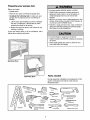 3
3
-
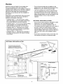 4
4
-
 5
5
-
 6
6
-
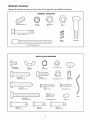 7
7
-
 8
8
-
 9
9
-
 10
10
-
 11
11
-
 12
12
-
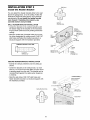 13
13
-
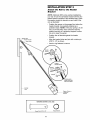 14
14
-
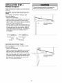 15
15
-
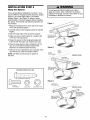 16
16
-
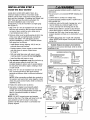 17
17
-
 18
18
-
 19
19
-
 20
20
-
 21
21
-
 22
22
-
 23
23
-
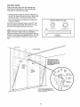 24
24
-
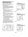 25
25
-
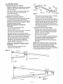 26
26
-
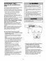 27
27
-
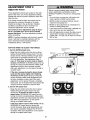 28
28
-
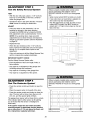 29
29
-
 30
30
-
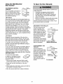 31
31
-
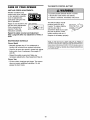 32
32
-
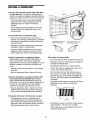 33
33
-
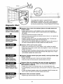 34
34
-
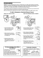 35
35
-
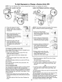 36
36
-
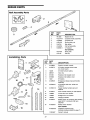 37
37
-
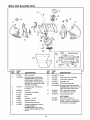 38
38
-
 39
39
-
 40
40
-
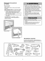 41
41
-
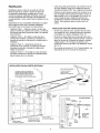 42
42
-
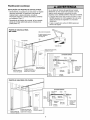 43
43
-
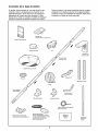 44
44
-
 45
45
-
 46
46
-
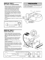 47
47
-
 48
48
-
 49
49
-
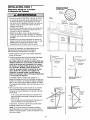 50
50
-
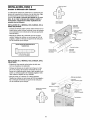 51
51
-
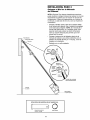 52
52
-
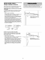 53
53
-
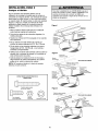 54
54
-
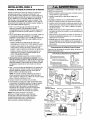 55
55
-
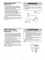 56
56
-
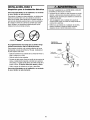 57
57
-
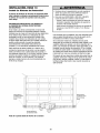 58
58
-
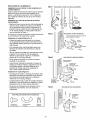 59
59
-
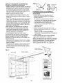 60
60
-
 61
61
-
 62
62
-
 63
63
-
 64
64
-
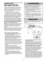 65
65
-
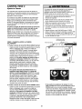 66
66
-
 67
67
-
 68
68
-
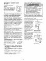 69
69
-
 70
70
-
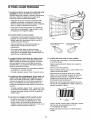 71
71
-
 72
72
-
 73
73
-
 74
74
-
 75
75
-
 76
76


Craftsman 13953914 El manual del propietario
- Categoría
- Abridor de puerta de garage
- Tipo
- El manual del propietario
En otros idiomas
- English: Craftsman 13953914 Owner's manual
Documentos relacionados
-
Craftsman 139.53919 El manual del propietario
-
Craftsman 139.53964SRT El manual del propietario
-
-
-
-
-
-
-
-