
BBV27900 11/2019 1/88
ENGLISH
INSTRUCTION SHEET
for HMISTO5pp and HMISTUp55/p55W
PROGRAMMING THE HUMAN MACHINE INTERFACE (HMI)
To program the Harmony HMISTO/STU products, download the free,
demonstration version of Vijeo Designer1 from www.schneider-electric.com:
1 Software used to create HMI unit project data.
To program any other Harmony devices, order Vijeo Designer from your
Schneider Electric vendor.
Note: Before downloading an application to a new HMIS5T using Vijeo
Designer V6.0 SP3 or higher :
• Ensure that your application is configured to use the target model HMIS5T.
If not, change the target model to HMIS5T before downloading.
Or
• Upgrade Vijeo Designer to version 6.1 to avoid any misuse.
RELEVANT STANDARDS
These products are manufactured in accordance with:
• Standard UL 508 and CSA C22.2 n°142 for Industrial Control Equipment
• Standard ANSI/ISA - 12.12.01 and CSA C22.2 n°213 for Electrical
Equipment for Use in Class I, Division 2 Hazardous Locations
Notes: HMISTO5pp are designed to comply to merchant navy rules.
The HMISTUp55/p55W are certified by merchant marine agencies and comply
with Bridge installation (refer to the Schneider Web site for installation
guidelines).
Modules Minimum Vijeo Designer Version
HMISTO501 6.0 or later
HMISTO511/512 5.1 or later
HMISTO531/532 6.0 SP1 or later
HMISTU655 PV 04 5.1 or later
HMISTU655 PV 04 6.1 SP1 or later
HMISTU855 PV 03 5.1 SP2 or later
HMISTU855 PV 03 6.1 SP1 or later
HMISTU655W 6.1 SP1 or later
HMISTU855W 6.1 SP1 or later
HMIS5T 6.1 SP1 or later

2/88 BBV27900 11/2019
ENGLISH
The HMISTO5pp and HMISTUp55/p55W must be installed, used and
maintained in accordance with:
• Standard WEEE, Directive 2002/96/EC
• Standard RoHS, Directive 2011/65/EU
• Standard RoHS China, Standard SJ/T 11364-2014
HMIZSUKIT
The Accessory Kit for the HMISTUp55/p55W contains:
• USB standard Type A cable holder
• USB Mini-B holder
• Anti-rotation Tee
• Panel adaptor
INSTALLATION PREREQUISITES
For use in Pollution Degree 2 environments.
For use on a flat surface of a Type 13 and/or Type 4X (Indoor Use Only)
Enclosure.

BBV27900 11/2019 3/88
ENGLISH
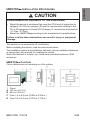
HMISTUp55/p55W INSTALLATION
This caution is not covered by UL certification.
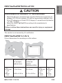
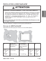
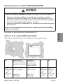
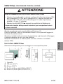
HMISTUp55/p55W CUT-OUTS
Cut-out dimensions for mounting on a flat surface:
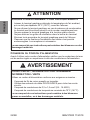
CAUTION
ENVIRONMENTAL HAZARDS TO THE EQUIPMENT
• Mount the device in enclosure that meet the IP54 level of protection for
category 3G, IP6x for category 3D and the requirements relating to the
3G or 3D categories in Zones 2/22 (Category 3: normal level of protection
- G: Gas - D: Dust).
• Mount the HMISTUp55/p55W according to the manufacturer's
specifications.
Failure to follow these instructions can result in injury or equipment
damage.
A B (Steel sheet,
for example,
cabinet door)
B (Glass fiber
reinforced
plastics,
minimum GF30)
CD
+0
22.50 mm
-0.30
+0
0.88 in.
-0.01
1.5 to 6 mm
0.06 to 0.23 in.
3 to 6 mm
0.11 to 0.23 in.
+0
30.00 mm
-0.20
+0
1.18 in.
-0.007
+0
4.00 mm
-0.20
+0
0.15 in.
-0.007

4/88 BBV27900 11/2019
ENGLISH
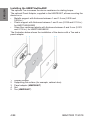
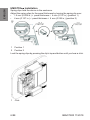
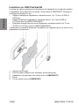
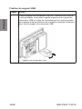
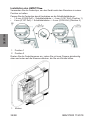
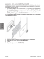
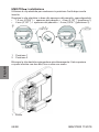
Installing the HMISTUp55/p55W
The optional Tee increases the device resistance to rotating torque.
The optional Panel Adaptor, supplied in the HMIZSUKIT, allows mounting the
device on a:
• Metallic support with thickness between 1 and 1.5 mm (0.039 and
0.059 in.)
• Plastic support with thickness between 1 and 3 mm (0.039 and 0.118 in.)
for HMISTU655/655W
• Glass fiber reinforced plastic with thickness between 2 and 3 mm (0.078
and 0.118 in.) for HMISTU855/855W
The illustration below shows the installation of the device with a Tee and a
panel adaptor:
1 Display module
2 Supporting flat surface (for example, cabinet door)
3 Panel adaptor (HMIZSUKIT)
4 Nut
5 Tee (HMIZSUKIT)

BBV27900 11/2019 5/88
ENGLISH
HMISTO5pp INSTALLATION PROCEDURES
This caution is not covered by UL certification.
Before installing the device, read the instructions below.
The installation gasket and installation fasteners (screw installation fasteners
or spring clips) are required for installing the device.
Mount the terminal in a clean, dry, robust and controlled enclosure (IP65
enclosure).
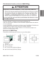
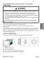
HMISTO5pp Cut-Outs
Cut-out dimensions for mounting on a flat surface:
1 Panel
A 105 mm (4.13 in.)
B 66 mm (2.60 in.)
C From 1.5 to 6.0 mm (0.059 to 0.236 in.)
R From 2.0 to 3.0 mm (0.079 to 0.118 in.)
CAUTION
ENVIRONMENTAL HAZARDS TO THE EQUIPMENT
• Mount the device in enclosure that meet the IP54 level of protection for
category 3G, IP6x for category 3D and the requirements relating to the
3G or 3D categories in Zones 2/22 (Category 3: normal level of protection
- G: Gas - D: Dust).
• Mount the HMISTO5pp according to the manufacturer's specifications.
Failure to follow these instructions can result in injury or equipment
damage.

6/88 BBV27900 11/2019
ENGLISH
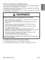
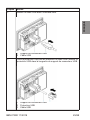
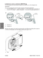
HMISTO5pp Installation
Spring clips hold the device in the enclosure.
Adjust the spring clips for the panel thickness by turning the spring clip over:
• 1.5 mm (0.059 in.) panel thickness 4 mm (0.157 in.) (position 1)
• 4 mm (0.157 in.) panel thickness 6 mm (0.236 in.) (position 2)
Lock the spring clips by pressing the clip’s top and bottom until you hear a click.
1 Position 1
2 Position 2
1 Click

BBV27900 11/2019 7/88
ENGLISH
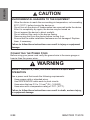
START-UP, OPERATION AND MAINTENANCE
You must follow all the recommendations described in the HMISTO5pp User
Manual and the HMISTUp55/p55W User Manual.
Schneider Electric cannot be held responsible for any application or installation
not recommended in these manuals.
This equipment is suitable for use in Class I, Division 2, Groups A, B, C and D
or non-hazardous locations only.
For HMISTO501/51p, interfaces are: COM1 and USB1.
For HMISTO53p, interfaces are: ETHERNET and USB1.
For HMISTUp55/p55W, interfaces are: COM1, ETHERNET and USB1.
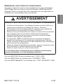
WARNING
RISK OF EXPLOSION IN HAZARDOUS LOCATIONS
• Verify the power, input, and output (I/O) wiring are in accordance with
Class I, Division 2 wiring methods.
• Do not substitute any components that impair compliance to Class I,
Division 2.
• Do not connect or disconnect equipment unless power has been
switched off or the area is non-hazardous.
• Securely lock externally connected units and each interface before
turning on the power supply.
• The USB2 connector is for temporary connection only during
maintenance and setup of the device. Do not use, connect, or disconnect
USB2 cable unless area is known to be non-hazardous.
• Potential electrostatic charging hazard: wipe the front panel of the
terminal with a damp cloth before turning ON.
• Use an insulated stylus to activate the touchscreen.
Failure to follow these instructions can result in death, serious injury,
or equipment damage.

8/88 BBV27900 11/2019
ENGLISH
CONNECTING THE POWER CORD
Before using your power cord verify the ground wire is the same gauge or
heavier than the power wires.
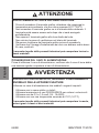
CAUTION
ENVIRONMENTAL HAZARDS TO THE EQUIPMENT
• Allow the device to reach the surrounding air temperature, not exceeding
50°C (122°F), before turning the device on.
• Do not turn on the device if condensation has occurred inside the device.
After it is completely dry again, the device may be turned on.
• Do not expose the device to direct sunlight.
• Do not obstruct the vents in the device casing.
• Remove any dust from the device before turning it on.
• Ensure that the cable installation fasteners are not damaged. Replace
them, if necessary.
Failure to follow these instructions can result in injury or equipment
damage.
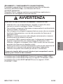
WARNING
SHORT CIRCUITS, FIRE, OR UNINTENDED EQUIPMENT
OPERATION
Use a power cord that meets the following requirements:
• Uses copper solid or stranded wires.
• Use D25CE/AZ5CE cable ends to short circuits.
• Uses wires that are 0.2 to 1.5 mm2 (24 - 16 AWG).
• Uses wires with a temperature rating of 75°C (167°F).
Failure to follow these instructions can result in death, serious injury,
or equipment damage.

BBV27900 11/2019 9/88
ENGLISH
Note: Mounting screws torque : 0.22 to 0.25 Nm (1.95 to 2.2 lb-in).
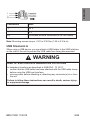
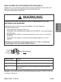
USB STANDARD A
When using a USB device, you can attach a USB holder to the USB interface
on the side of the unit to prevent the USB cable from being disconnected.
Connection Wire
+ 24 V
- 0 V
FG Grounded terminal connected to the unit chasis.
WARNING
RISK OF EXPLOSION IN HAZARDOUS LOCATIONS
In hazardous locations as described in ANSI/ISA - 12.12.01:
• confirm that the USB cable has been attached with the USB cable clamp
before using the USB host interface.
• remove power before attaching or detaching any connector(s) to or from
the unit.
Failure to follow these instructions can result in death, serious injury,
or equipment damage.

10/88 BBV27900 11/2019
ENGLISH
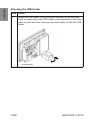
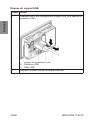
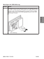
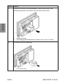
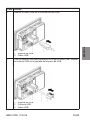
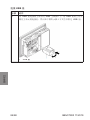
Attaching the USB Holder
Step Action
1Attach the USB holder to the USB Host Interface on the main unit.
Hook the upper pick of the USB holder to the attachment hole of the
main unit and insert the lower pick as shown below to affix the USB
holder.
1 USB holder

BBV27900 11/2019 11/88
ENGLISH
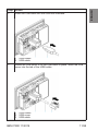
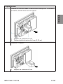
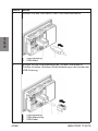
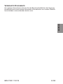
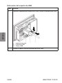
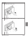
2Insert the USB cable into the USB host interface.
1 USB holder
2 USB cable
3Attach the USB cover to fix the USB cable in place. Insert the USB
cover into the tab of the USB holder.
1 USB holder
2 USB cover
3 USB cable
Step Action

12/88 BBV27900 11/2019
ENGLISH
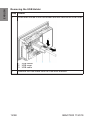
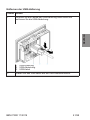
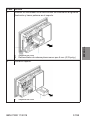
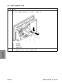
Removing the USB Holder
Step Action
1Push down the tab of the USB holder and then remove the USB cover.
1 USB holder
2 USB cover
3 USB cable
2Remove the USB cable from the USB host interface.

BBV27900 11/2019 13/88
ENGLISH
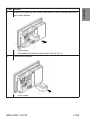
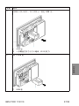
3Insert a screwdriver into the slot as shown in the following illustration,
pry up the holder.
1 USB holder
2 Flat-blade Screwdriver less than 6 mm (0.23 in.)
4Remove the holder.
1 USB holder
Step Action

14/88 BBV27900 11/2019
ENGLISH
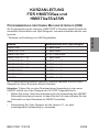
RELATED DOCUMENTS
For further information, you can download the Harmony Small Panels User
Manuals and other technical information from our website at
www.schneider-electric.com

BBV27900 11/2019 15/88
FRANÇAIS
FICHE D'INSTRUCTIONS
pour HMISTO5pp et HMISTUp55/p55W
PROGRAMMATION D’ INTERFACE HOMME MACHINE (IHM)
Pour programmer les produits HMI Harmony STO/STU, téléchargez la version
de démonstration gratuite de Vijeo Designer1 sur www.schneider-electric.com:
1 Logiciel utilisé pour créer des données de projet de l’unité IHM.
Pour programmer tout autre produit Harmony, commandez Vijeo Designer
auprès de votre fournisseur Schneider Electric.
Remarque : Avant de charger une application sur un nouveau HMIS5T à l'aide
de Vijeo Designer V6.0 SP3 ou version ultérieure :
• Vérifiez que votre application est configurée pour utiliser le modèle cible
HMIS5T. Si tel n'est pas le cas, remplacez le modèle cible par HMIS5T
avant de procéder au chargement.
Ou
• Mettez Vijeo Designer au niveau de la version 6.1 pour éviter toute
utilisation malencontreuse.
Modules Version minimale de Vijeo Designer
HMISTO501 6.0 ou ultérieur
HMISTO511/512 5.1 ou ultérieur
HMISTO531/532 6.0 SP1 ou ultérieur
HMISTU655 PV 04 5.1 ou ultérieur
HMISTU655 PV 04 6.1 SP1 ou ultérieur
HMISTU855 PV 03 5.1 SP2 ou ultérieur
HMISTU855 PV 03 6.1 SP1 ou ultérieur
HMISTU655W 6.1 SP1 ou ultérieur
HMISTU855W 6.1 SP1 ou ultérieur
HMIS5T 6.1 SP1 ou ultérieur

16/88 BBV27900 11/2019
FRANÇAIS
NORMES PERTINENTES
Ces produits ont été fabriqués conformément aux normes suivantes :
• Norme UL 508 et CSA C22.2 n°142 pour équipement de contrôle
industriel
• Norme ANSI/ISA - 12.12.01 et CSA C22.2 n°213 pour équipement
électrique à utiliser dans des emplacements dangereux de classe I,
division 2
Remarques : Les HMISTO5pp sont conçus pour être conformes aux règles de
la marine marchande.
Les appareils HMISTUp55/p55W sont conçus pour répondre aux exigences de
passerelle et de pont de la marine marchande (consultez le site web Schneider
pour les règles d'installation).
Les appareils HMISTO5pp et HMISTUp55/p55W doivent être installés, utilisés
et entretenus conformément aux normes suivantes :
• Norme DEEE, directive 2002/96/CE
• Norme RoHS, directive 2011/65/EU
• Norme RoHS Chine, norme SJ/T 11364-2014
HMIZSUKIT
Le kit d'accessoires pour le HMISTUp55/p55W contient :
• Support de câble USB standard type A
• Support mini USB B
• Téton antirotation
• Adaptateur de panneau
CONDITIONS REQUISES POUR L'INSTALLATION
A utiliser dans des environnements de degré de pollution 2.
Pour utilisation sur une surface plane d'un boîtier Type 13 et/ou Type 4X
(utilisation intérieure seulement).

BBV27900 11/2019 17/88
FRANÇAIS
INSTALLATION DU HMISTUp55/p55W
Cet avis "Attention" n’est pas couvert par la certification UL.
Découpe du HMISTUp55/p55W
Dimensions de découpe pour fixation sur une surface plane :;
ATTENTION
RISQUES D'ENVIRONNEMENT POUR LES EQUIPEMENTS
• Montez les terminaux graphiques dans des boîtiers conformes au niveau
de protection IP54 pour les catégories 3G, IP6x pour la catégorie 3D et
les exigences relatives aux catégories 3G ou 3D dans des zones 2/22
(catégorie 3 : niveau de protection normal – G : Gaz – D : Poussière).
• Montez l'appareil HMISTUp55/p55W selon les spécifications du
constructeur.
Le non-respect de ces instructions peut entraîner des blessures ou des
dommages matériels.
A B (tôle, par
exemple, porte
d'armoire)
B (Plastiques
renforcés fibre de
verre, minimum
GF30)
CD
+0
22,50 mm
-0,30
+0
0,88 po
-0,01
1,5 à 6 mm
0,06 à 0,23 po
3 à 6 mm
0,11 à 0,23 po
+0
30,00 mm
-0,20
+0
1,18 po
-0,007
+0
4,00 mm
-0,20
+0
0,15 po
-0,007

18/88 BBV27900 11/2019
FRANÇAIS
Installation du HMISTUp55/p55W
Le téton en option augmente la résistance de l'appareil au couple de rotation.
L'adaptateur pour panneau en option, fourni dans le HMIZSUKIT autorise le
montage du produit sur un :
• Support métallique d'épaisseur comprise entre 1 et 1,5 mm (0,039 et
0,059 po)
• Support plastique d'épaisseur comprise entre 1 et 3 mm (0,039 et
0,118 po) pour le HMISTU655/655W
• Plastique chargé fibre de verre d'épaisseur comprise entre 2 et 3 mm
(0,078 et 0,118 po) pour le HMISTU855/855W
L'illustration ci-dessous présente l'installation de l'appareil avec un téton et un
adaptateur de panneau :
1 Module d'affichage
2 Surface plane support (par exemple, porte d'armoire)
3 Adaptateur de panneau (en option avec le HMIZSUKIT)
4 Ecrou
5 Té (en option avec le HMIZSUKIT)

BBV27900 11/2019 19/88
FRANÇAIS
PROCÉDURES D'INSTALLATION DU HMISTO5pp
Cet avis "Attention" n’est pas couvert par la certification UL.
Lisez les instructions ci-dessous avant d'installer l'appareil dans une armoire
ou sur un panneau.
Le joint d'installation et les pièces de fixation (pour l'installation à l'aide des vis
et des attaches à ressort) sont requis pour installer l'appareil.
Installez le bornier dans un boîtier offrant un environnement propre, sec,
robuste et contrôlé (boîtier IP65).
Découpe du HMISTO5pp:
Dimensions de découpe pour fixation sur une surface plane :
1 Panneau
A 105 mm (4,13 po)
B 66 mm (2,59 po)
C de 1,5 à 6,0 mm (0,059 à 0,236 po)
R de 2,0 à 3,0 mm (0,079 à 0,118 po)
ATTENTION
RISQUES D'ENVIRONNEMENT POUR LES EQUIPEMENTS
• Montez les terminaux graphiques dans des boîtiers conformes au niveau
de protection IP54 pour les catégories 3G, IP6x pour la catégorie 3D et
les exigences relatives aux catégories 3G ou 3D dans des zones 2/22
(catégorie 3 : niveau de protection normal – G : Gaz – D : Poussière).
• Montez l'appareil HMIST05pp selon les spécifications du constructeur.
Le non-respect de ces instructions peut entraîner des blessures ou des
dommages matériels.

20/88 BBV27900 11/2019
FRANÇAIS
Installation du HMISTO5pp
Utilisez les agrafes à ressort pour maintenir l'appareil en place après son
insertion.
Réglez les agrafes à ressort en fonction de l'épaisseur du panneau par
retournement :
• 1,5 mm (0,059 po) épaisseur du panneau 4 mm (0,157 po)
(position 1)
• 4 mm (0,157 po) épaisseur du panneau 6 mm (0,236 po) (position 2)
Verrouillez les agrafes à ressort en appuyant simultanément sur le haut et le
bas de l'agrafe avec deux doigts jusqu'au déclic.
1 Position 1
2 Position 2
1 Cliquez

BBV27900 11/2019 21/88
FRANÇAIS
DÉMARRAGE, EXPLOITATION ET MAINTENANCE
Vous devez respecter toutes les recommandations du manuel d'utilisation
HMISTO5pp, ainsi que celles du manuel d'utilisation HMISTUp55/p55W.
Schneider Electric ne saurait être tenu responsable de toute application ou
installation non recommandée dans ces manuels.
Pour les HMISTO501/51p, les interfaces sont : COM1, USB1.
Pour les HMISTO53p, les interfaces sont : ETHERNET, USB1.
Pour les HMISTUp55/p55W, les interfaces sont : COM1, ETHERNET, USB1.
AVERTISSEMENT
RISQUE D’EXPLOSION EN ENVIRONNEMENTS DANGEREUX
• Vérifiez que l’alimentation, les câblages d’entrées et sorties (E/S) sont
conformes aux méthodes de câblage de Classe I, Division 2.
• Ne procédez à aucun remplacement de composant, qui risquerait de
porter atteinte à la conformité à la Classe I Division 2.
• Assurez-vous que l’alimentation est coupée ou que la zone ne présente
aucun danger avant de connecter ou déconnecter l’équipement.
• Verrouillez de facon sure les unités à connexion externe et chaque
interface avant d’activer l’alimentation.
• Le connecteur USB2 n’est destiné qu’à une connexion temporaire
pendant la maintenance et la configuration de l’équipement. Ne pas
utiliser, connecter ou déconnecter le câble USB2 avant de s’être assuré
que la zone est non dangereuse.
• Risque de charge électrostatique potentielle : essuyez le panneau avant
du terminal avec un chiffon humide avant de l’allumer.
• Utilisez un styler isolé pour activer l’écran tactile.
Le non-respect de ces instructions peut conduire à des blessures
graves ou mortelles, ou à des dommages matériels.

22/88 BBV27900 11/2019
FRANÇAIS
CONNEXION DU CORDON D’ALIMENTATION
Avant d’utiliser votre cordon d’alimentation vérifiez que le conducteur de terre
est de section égale ou supérieure à celle des conducteurs d’alimentation.
ATTENTION
RISQUES D'ENVIRONNEMENT POUR LES EQUIPEMENTS
• Laissez le terminal graphique atteindre la température de l'air ambiant,
qui ne doit pas dépasser 50°C (122°F), avant de l'allumer.
• Ne pas allumer le terminal graphique en cas de présence de condensation.
Le terminal peut être allumé quand il est à nouveau complètement sec.
• Ne pas exposer le terminal graphique à la lumière solaire directe.
• Ne pas obstruer les grilles de ventilation dans le boîtier du terminal.
• Eliminez toute poussière du terminal graphique avant de l'allumer.
• S'assurer que les fixations d'installation des câbles n'ont pas été
endommagées. Les remplacer si nécessaire.
Le non-respect de ces instructions peut entraîner des blessures ou des
dommages matériels.
AVERTISSEMENT
COURT-CIRCUIT, INCENDIE OU FONCTIONNEMENT
INCORRECT DE L’UNITE
Utilisez un cordon d’alimentation conforme aux exigences suivantes :
• Composé de fils de cuivre massifs ou torsadés.
• Utilisez des embouts de câble D25CE/AZ5CE pour éviter les courts-
circuits.
• Composé de conducteurs de 0,2 a 1,5 mm2 (24 - 16 AWG).
• Composé de conducteurs de temperature nominale de 75°C (167°F).
Le non-respect de ces instructions peut conduire à des blessures
graves ou mortelles, ou à des dommages matériels.

BBV27900 11/2019 23/88
FRANÇAIS
Remarque : Couple des vis d'assemblage : 0,22 à 0,25 Nm (1,95 à 2,2 lb-po).
USB STANDARD A
Lorsque vous utilisez un périphérique USB, vous pouvez fixer un support de
connecteur USB sur l’interface USB située sur le côté de l’unité afin
d’empêcher le câble USB de se débrancher.
Connexion Fil
+ 24 V
- 0 V
FG Borne de terre raccordée au châssis de l’unité.
AVERTISSEMENT
RISQUE D’EXPLOSION EN ENVIRONNEMENTS DANGEREUX
Dans des environnements dangereux tels que décrits dans les normes ANSI/
ISA - 12.12.01 :
• Vérifiez que le câble USB a été fixé avec le collier de câble USB avant
d’utiliser l’interface USB hôte.
• Veillez à couper l’alimentation avant de brancher ou de débrancher tout
connecteur de l’unité.
Le non-respect de ces instructions peut provoquer la mort, des
blessures graves ou des dommages matériels.
+
-
FG
Sens
d’insertion

24/88 BBV27900 11/2019
FRANÇAIS
Fixation du support USB
Etapes Action
1Fixez le support de connecteur USB sur l’interface hôte USB de
l’unité principale. Accrochez la partie supérieure du support de
connecteur USB à l’orifice de raccordement de l’unité principale,
puis insérez la partie inférieure de la manière indiquée ci-dessous
pour fixer le support de connecteur USB.
1 Support de connecteur USB

BBV27900 11/2019 25/88
FRANÇAIS
2Insérez le câble USB dans l’interface hôte.
1 Support de connecteur USB
2 Câble USB
3Fixez la protection USB afin de maintenir le câble USB. Insérez la
protection USB dans la languette du support de connecteur USB.
1 Support de connecteur USB
2 Protection USB
3 Câble USB
Etapes Action

26/88 BBV27900 11/2019
FRANÇAIS
Dépose du support USB
Etapes Action
1Rabattez vers le bas la languette du support USB, puis déposez la
protection USB.
1 Support de connecteur USB
2 Protection USB
3 Câble USB
2Déposez le câble USB de l’interface USB hôte.

BBV27900 11/2019 27/88
FRANÇAIS
3Insérez un tournevis dans la fente comme indiqué sur l’illustration
suivante, et faites levier sur le support.
1 Support de connecteur USB
2 Tournevis plat de moins de 6 mm (0,23 po)
4Déposez le support.
1 Support de connecteur USB
Etapes Action

28/88 BBV27900 11/2019
FRANÇAIS
DOCUMENTS ASSOCIES
Pour plus d'informations, vous pouvez télécharger les Manuels d'Utilisation des
Petits Ecrans Harmony et d'autres informations techniques à partir de notre site
internet : www.schneider-electric.com

BBV27900 11/2019 29/88
DEUTSCH
KURZANLEITUNG
FÜR HMISTO5pp und
HMISTUp55/p55W
PROGRAMMIERUNG DER HUMAN MACHINE INTERFACE (HMI)
Zur Programmierung der Harmony HMISTO/STU-Produkte laden Sie bitte die
kostenlose Demoversion von Vijeo Designer1 von www.schneider-electric.com
herunter:
1 Software zur Erstellung von HMI-Projektdaten.
Zur Programmierung anderer Harmony-Produkte bestellen Sie bitte Vijeo
Designer bei Ihrem Schneider Electric-Anbieter.
Hinweise: Führen Sie vor dem Download einer Anwendung in eine neue
HMIS5T mithilfe von Vijeo Designer ab V6.0 SP3 Folgendes durch:
• Stellen Sie sicher, dass Ihre Anwendung für die Verwendung des HMIS5T-
Zielmodells konfiguriert wurde. Ist das nicht der Fall, dann müssen Sie das
Zielmodell vor dem Download auf HMIS5T einstellen.
Oder
• Aktualisieren Sie Vijeo Designer auf die Version 6.1, um jede
unsachgemäße Verwendung zu vermeiden.
Module Mindestversion von Vijeo-Designer
HMISTO501 6.0 oder höher
HMISTO511/512 5.1 oder höher
HMISTO531/532 6.0 SP1 oder höher
HMISTU655 PV 04 5.1 oder höher
HMISTU655 PV 04 6.1 SP1 oder höher
HMISTU855 PV 03 5.1 SP2 oder höher
HMISTU855 PV 03 6.1 SP1 oder höher
HMISTU655W 6.1 SP1 oder höher
HMISTU855W 6.1 SP1 oder höher
HMIS5T 6.1 SP1 oder höher

30/88 BBV27900 11/2019
DEUTSCH
RELEVANTE NORMEN
Diese Produkte wurden gemäß folgender Normen hergestellt:
• Norm UL 508 und CSA C22.2 Nr. 142 für industrielle Regeleinrichtungen
• Norm ANIS/ISA - 12.12.01 und CSA 22.2 Nr. 213 für elektrische
Betriebsmittel für explosionsgefährdete Bereiche der Klasse I, Division 2
Hinweise: HMISTO5pp erfüllt die Handelsmarinevorschriften.
Die Modelle HMISTUp55/p55W erfüllen die Handelsmarineanforderungen für
Brücke und Deck. (Richtlinien für die Installation finden Sie auf der Website von
Schneider Electric).
HMISTO5pp und HMISTUp55/p55W müssen entsprechend der Vorschriften
der folgenden Normen installiert, betrieben und gewartet werden:
• WEEE-Norm, Richtlinie 2002/96/EC
• RoHS-Norm, Richtlinie 2011/65/EU
• RoHS-Norm für China, Norm SJ/T 11364-2014
HMIZSUKIT
Das Zubehörpaket für HMISTUp55/p55W enthält folgende Teile:
• Standard-USB-Kabelhalter Typ A
• Mini-USB-Halter B
• Verdrehsicherung
• Schalttafeladapter
INSTALLATIONSVORAUSSETZUNGEN
Für die Verwendung in Umgebungen gemäß Verschmutzungsgrad 2 geeignet.
Für den Tafeleinbau (Typ 13) und/oder den Einbau in Gehäuse des Typs 4X
(nicht im Freien) geeignet.

BBV27900 11/2019 31/88
DEUTSCH
INSTALLATION DER HMIp55/p55W
Diese Warnung unterliegt keiner UL-Zertifizierung.
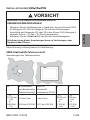
HMISTUp55/p55W-Tafelausschnitt
Abmessungen des Tafelausschnitts:
VORSICHT
GEFAHR VON GERÄTESCHÄDEN DURCH
UMGEBUNGSBEDINGUNGEN
• Montieren Sie die Grafikterminals in Gehäusen, die der Schutzart IP54
für Kategorie 3G, IP6x für Kategorie 3D und den Anforderungen
hinsichtlich der Kategorien 3G oder 3D in den Zonen 2/22 (Kategorie 3:
normaler Schutz – G: Gas – D: Staub) entsprechen.
• Montieren Sie die HMIp55/p55W gemäß den Herstellerangaben.
Nichtbeachtung dieser Anweisungen kann zu Verletzungen oder
Geräteschäden führen.
A B (Stahlblech,
zum Beispiel eine
Schaltschranktür)
B (GFK-
Kunststoff,
mindestens GF30)
CD
+0
22,50 mm
-0,30
+0
0,88 Zoll.
-0,01
1,5 bis 6 mm
0,06 bis 0,23 Zoll
3 bis 6 mm
0,11 bis 0,23 Zoll
+0
30,00 mm
-0,20
+0
1,18 Zoll
-0,007
+0
4,00 mm
-0,20
+0
0,15 Zoll
-0,007

32/88 BBV27900 11/2019
DEUTSCH
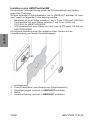
Installieren des HMISTUp55/p55W
Die optionale Verdrehsicherung erhöht die Widerstandskraft des Gerätes
gegenüber Verdrehen.
Mit dem optionalen Schalttafeladapter, der im HMIZSUKIT enthalten ist, kann
das Produkt an folgenden Teilen befestigt werden:
• Metalltafel mit einer Stärke zwischen 1 und 1,5 mm (0,039 und 0,059 Zoll)
• Kunststofftafel mit einer Stärke zwischen 1 und 3 mm (0,039 und
0,118 Zoll) für HMISTU655/655W
• GFK-Kunststoff mit einer Stärke von 2 bis 3 mm (0,078 und 0,118 Zoll) für
HMISTU855/855W
Die folgende Abbildung zeigt die Installation eines Gerätes mit der
Verdrehsicherung und einem Schalttafeladapter:
1 Anzeigemodul
2 Plane Einbaufläche (zum Beispiel eine Schaltschranktür)
3 Schalttafeladapter (optional, in HMIZSUKIT enthalten)
4 Mutter
5 Verdrehsicherung (optional, in HMIZSUKIT enthalten)

BBV27900 11/2019 33/88
DEUTSCH
INSTALLATIONSVERFAHREN FÜR HMISTO5pp
Diese Warnung unterliegt keiner UL-Zertifizierung.
Lesen Sie vor der Installation des Gerätes in einen Schrank oder eine
Schalttafel die folgenden Anweisungen.
Zum Installieren des Gerätes sind die Installationsdichtung und
Installationsklemmen (Installationsschraubklemmen oder -federklemmen)
erforderlich.
Installieren Sie das Terminal in einem Gehäuse, das eine saubere, trockene,
stabile und kontrollierte Umgebung bietet (IP65-Gehäuse).
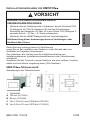
HMISTO5pp-Tafelausschnitt:
Abmessungen des Tafelausschnitts:
1 Schalttafel
A 105 mm (4,13 Zoll)
B 66 mm (2,59 Zoll)
C Von 1,5 bis 6,0 mm (0,059 bis 0,236 Zoll)
R Von 2,0 bis 3,0 mm (0,079 bis 0,118 Zoll)
VORSICHT
GEFAHR VON GERÄTESCHÄDEN DURCH
UMGEBUNGSBEDINGUNGEN
• Montieren Sie die Grafikterminals in Gehäusen, die der Schutzart IP54
für Kategorie 3G, IP6x für Kategorie 3D und den Anforderungen
hinsichtlich der Kategorien 3G oder 3D in den Zonen 2/22 (Kategorie 3:
normaler Schutz – G: Gas – D: Staub) entsprechen.
• Montieren Sie die HMISTO5pp gemäß den Herstellerangaben.
Nichtbeachtung dieser Anweisungen kann zu Verletzungen oder
Geräteschäden führen.

34/88 BBV27900 11/2019
DEUTSCH
Installation des HMISTO5pp
Verwenden Sie die Federclips, um das Gerät nach dem Einsetzen in seiner
Position zu halten.
Passen Sie die Federclips durch Umdrehen an die Schalttafelstärke an:
• 1,5 mm (0,059 Zoll) Schalttafelstärke: 4 mm (0,157 Zoll) (Position 1)
• 4 mm (0,157 Zoll) Schalttafelstärke: 6 mm (0,236 Zoll) (Position 2)
Rasten Sie die Federklemmen ein, indem Sie mit zwei Fingern gleichzeitig
oben und unten auf die Klemme drücken, bis Sie ein Klicken hören.
1 Klicken
1 Position 1
2 Position 2

BBV27900 11/2019 35/88
DEUTSCH
INBETRIEBNAHME, BETRIEB UND WARTUNG
Befolgen Sie alle Anweisungen und Empfehlungen im HMISTO5pp-
Benutzerhandbuch und im HMISTUp55/p55W-Benutzerhandbuch.
Schneider Electric übernimmt für andere Anwendungen oder Installationen als
die in diesen Anleitungen empfohlenen keine Haftung.
Die Schnittstellen der HMISTO501/51p sind: COM1, USB1.
Die Schnittstellen der HMISTO53p sind: ETHERNET, USB1.
Die Schnittstellen der HMISTUp55/p55W sind: COM1, ETHERNET, USB1.
WARNUNG
EXPLOSIONSGEFAHR IN EX-BEREICHEN
• Stellen Sie sicher, dass die Verdrahtung von Stromversorgung,
Eingängen und Ausgängen (E/A) den Verdrahtungsverfahren nach
Klasse I, Division 2 entspricht.
• Tauschen Sie keine Komponenten aus, die die Konformität mit Klasse I,
Division 2 beeinträchtigen.
• Schließen Sie Geräte nur an oder trennen Sie Anschlüsse von Geräten
nur, wenn Sie zuvor die Stromversorgung abgeschaltet haben oder wenn
bekannt ist, dass im betreffenden Bereich keine Gefahr besteht.
• Befestigen Sie alle extern angeschlossenen Komponenten und
Schnittstellen vor dem Einschalten der Stromversorgung.
• Der USB2-Steckverbinder ist nur für den temporären Anschluss während
der Wartung und Einrichtung des Geräts gedacht. Verwenden Sie USB2
nur, schließen Sie Geräte nur an USB2 an oder trennen Sie Anschlüsse
von Geräten nur von USB2, wenn bekannt ist, dass der betreffenden
Bereich Ex-frei ist.
• Potentielle Gefahr elektrostatischer Entladung: Wischen Sie die
Frontplatte des Terminals vor dem Einschalten mit einem feuchten Tuch
ab.
• Verwenden Sie einen isolierten Stift, um den Touchscreen zu betätigen.
Nichtbeachtung dieser Anweisungen kann zum Tod, zu schweren
Verletzungen und zu Geräteschäden führen.

36/88 BBV27900 11/2019
DEUTSCH
VORSICHT
GEFAHR VON GERÄTESCHÄDEN DURCH
UMGEBUNGSBEDINGUNGEN
• Lassen Sie das Grafikterminal vor dem Einschalten die
Umgebungstemperatur annehmen, die jedoch 50°C (122°F) nicht
überschreiten darf.
• Schalten Sie das Grafikterminal nicht ein, wenn sich Feuchtigkeit
niedergeschlagen hat (Kondensation). Nach dem vollständigen
Abtrocknen der Feuchtigkeit kann das Terminal eingeschaltet werden.
• Setzen Sie das Grafikterminal nicht dem direkten Sonnenlicht aus.
• Verdecken Sie die Lüftungsöffnungen des Terminalgehäuses nicht.
• Entfernen Sie vor dem Einschalten allen Staub vom Grafikterminal.
• Stellen Sie sicher, dass die Kabelbefestigungen nicht beschädigt sind.
Tauschen Sie sie aus, wenn erforderlich.
Nichtbeachtung dieser Anweisungen kann zu Verletzungen oder
Geräteschäden führen.

BBV27900 11/2019 37/88
DEUTSCH
ANSCHLIEßEN DES STROMVERSORGUNGSKABELS
Stellen Sie vor Verwendung des Stromversorgungskabels sicher, dass der
Erdleiter mindestens den gleichen Durchmesser wie die
Stromversorgungsleitungen hat.
Hinweis: Anzugsdrehmoment der Befestigungsschrauben: 0,22 bis 0,25 Nm
(1,95 bis 1,00 kg-in).
WARNUNG
KURZSCHLÜSSE, BRÄNDE ODER UNBEABSICHTIGTER
BETRIEB VON GERÄTEN
Verwenden Sie ein Stromversorgungskabel, das die folgenden
Anforderungen erfüllt:
• Verwenden Sie Volldraht oder Litze.
• Verwenden Sie Kabelterminierungen D25CE/AZ5CE, um Kurzschlüssen
• vorzubeugen.
• Verwenden Sie Drähte mit einem Querschnitt von 0,2 bis 1,5 mm2 (24 -
• 16 AWG).
• Verwenden Sie Drähte mit einer Temperaturspezifikation von 75°C
(167°F).
Nichtbeachtung dieser Anweisungen kann zum Tod, zu schweren
Verletzungen und zu Geräteschäden führen.
Anschlussn Draht
+ 24 V
- 0 V
FG Am Gehäuse des Geräts angeschlossene, geerdete
Klemme.
+
-
FG
Einsetzrichtung

38/88 BBV27900 11/2019
DEUTSCH
USB STANDARD A
Wenn Sie ein USB-Gerät verwenden, können Sie eine USB-Halterung an der
USB-Schnittstelle an der Geräteseite anbringen, damit sich das USB-Kabel
nicht lösen kann.
WARNUNG
EXPLOSIONSGEFAHR IN EX-BEREICHEN
In explosionsgefährdeten Bereichen wie in ANSI/ISA - 12.12.01
beschrieben:
• Vergewissern Sie sich, dass das USB-Kabel mithilfe der USB-
Kabelklemme befestigt wurde, bevor Sie die USB-Hostschnittstelle
verwenden.
• Trennen Sie die Stromversorgung, bevor Sie Steckverbinder an das
Gerät anschließen oder vom Gerät trennen.
Die Nichtbeachtung dieser Anweisungen kann Tod, schwere
Körperverletzungen oder Sachschäden zur Folge haben.

BBV27900 11/2019 39/88
DEUTSCH
Befestigen der USB-Halterung
Schritt Aktion
1Befestigen Sie die USB-Halterung an der USB-Hostschnittstelle
am Gerät. Führen Sie den oberen Haken der USB-Halterung wie
gezeigt in die obere Befestigungsöffnung des Gerätes und den
unteren Haken in die untere Befestigungsöffnung, um die USB-
Halterung zu fixieren.
1 USB-Halterung

40/88 BBV27900 11/2019
DEUTSCH
2Stecken Sie das USB-Kabel in die USB-Hostschnittstelle:
1 USB-Halterung
2 USB-Kabel
3Bringen Sie die USB-Abdeckung an, um das USB-Kabel in
Position zu halten. Schieben Sie die Abdeckung in die Laschen der
USB-Fixierung.
1USB-Halterung
2 USB-Abdeckung
3 USB Kabel
Schritt Aktion

BBV27900 11/2019 41/88
DEUTSCH
Entfernen der USB-Halterung
Schritt Aktion
1Drücken Sie die Lasche der USB-Halterung nach unten und
entfernen Sie die USB-Abdeckung.
1 USB-Halterung
2 USB-Abdeckung
3 USB-Kabel
2Ziehen Sie das USB-Kabel aus der USB-Hostschnittstelle:

42/88 BBV27900 11/2019
DEUTSCH
3Stecken Sie einen Schraubendreher in den Schlitz wie in der
Abbildung gezeigt und hebeln Sie die Halterung heraus.
1 USB-Halterung
2 Flachklingenschraubendreher kleiner als 6 mm (0,23 Zoll)
4Entfernen Sie die Halterung.
1 USB-Halterung
Schritt Aktion

BBV27900 11/2019 43/88
DEUTSCH
VERWANDTE DOKUMENTE
Für weitere Informationen können Sie die Benutzerhandbücher der Harmony
Kleinbildschirme sowie andere technische Informationen von unserer Website
herunterladen: www.schneider-electric.com.

44/88 BBV27900 11/2019
DEUTSCH

BBV27900 11/2019 45/88
ESPAÑOL
HOJA DE INSTRUCCIONES
de HMISTO5pp y HMISTUp55/p55W
PROGRAMACIÓN DE LA UNIDAD HUMAN MACHINE INTERFACE
(HMI)
Para programar los productos Harmony HMISTO/STU, descargue la versión
gratuita de demostración de Vijeo Designer1 en www.schneider-electric.com:
1 Software utilizado para crear datos de proyecto en la unidad HMI.
Para programar cualquier otro producto de Harmony, solicite Vijeo Designer a
su proveedor de Schneider Electric.
Nota: Antes de descargar una aplicación en un nuevo HMIS5T con Vijeo
Designer V6.0 SP3 o una versión superior:
• Asegúrese de que la aplicación esté configurada para utilizar el modelo
de destino HMIS5T. En caso contrario, cambie el modelo de destino a
HMIS5T antes de iniciar la descarga.
O bien
• Actualice Vijeo Designer a la versión 6.1 para evitar cualquier uso no
apropiado.
ESTÁNDARES RELEVANTES
Estos productos se han fabricado de acuerdo con:
• Estándar UL 508 y CSA C22.2 n°142 para equipos de control industrial
• Estándar ANSI/ISA - 12.12.01 y CSA C22.2 n°213 para equipo eléctrico
no inflamable para su uso en zonas peligrosas de Clase I, División 2
Notas: HMISTO5pp están diseñados para cumplir las normativas de la marina
mercante.
Módulos Versión mínima de Vijeo Designer
HMISTO501 6.0 o posterior
HMISTO511/512 5.1 o posterior
HMISTO531/532 6.0 SP1 o posterior
HMISTU655 PV 04 5.1 o posterior
HMISTU655 PV 04 6.1 SP1 o posterior
HMISTU855 PV 03 5.1 SP2 o posterior
HMISTU855 PV 03 6.1 SP1 o posterior
HMISTU655W 6.1 SP1 o posterior
HMISTU855W 6.1 SP1 o posterior
HMIS5T 6.1 SP1 o posterior

46/88 BBV27900 11/2019
ESPAÑOL
Las unidades HMISTUp55/p55W están diseñadas para cumplir con los
requisitos sobre puentes y cubiertas en marina mercante (consulte el sitio web
de Schneider para ver las directrices de instalación).
Las unidades HMISTO5pp y HMISTUp55/p55W deben instalarse, usarse y
mantenerse de acuerdo con:
• Estándar WEEE, directiva 2002/96/CE
• Estándar RoHS, directiva 2011/65/EU
• Estándar RoHS China, estándar SJ/T 11364-2014
HMIZSUKIT
El kit de accesorios de la unidad HMISTUp55/p55W contiene:
• Soporte del cable USB estándar de tipo A
• Soporte USB mini-B
• Separador antirotación
• Adaptador del panel
REQUISITOS PREVIOS A LA INSTALACIÓN
Uso en un entorno con un grado de contaminación 2.
Para uso en una superficie plana de un cerramiento de tipo 13 y/o de tipo 4X
(sólo uso en el interior).

BBV27900 11/2019 47/88
ESPAÑOL
INSTALACIÓN DE LA UNIDAD HMISTUp55/p55W
Este aviso no está cubierto por la certificación UL.
Orificios de la unidad HMISTUp55/p55W
Dimensiones del orificio para el montaje en una superficie plana:
AVISO
RIESGOS MEDIOAMBIENTALES DE DAÑOS EN EL EQUIPO
• Monte los terminales gráficos en recintos que cumplan el nivel de
protección IP54 para la categoría 3G, IP6x para la categoría 3D y los
requisitos relativos a las categorías 3G o 3D en las zonas 2/22 (categoría
3: nivel de protección normal - G: gas - D: polvo).
• Monte la unidad HMISTUp55/p55W de acuerdo con las especificaciones
del fabricante.
Si no se observan estas instrucciones, pueden producirse heridas o
daños en el equipo.
A B (lámina de
acero, por ejemplo,
puerta del armario)
B (plástico
reforzado con
fibra de vidrio,
mínimo GF30)
CD
+0
22,50 mm
-0,30
+0
0,88 pulg.
-0,01
De 1,5 a 6 mm
De 0,06 a
0,23 pulg.
De 3 a 6 mm
De 0,11 a
0,23 pulg.
+0
30,00 mm
-0,20
+0
1,18 pulg.
-0,007
+0
4,00 mm
-0,20
+0
0,15 pulg.
-0,007

48/88 BBV27900 11/2019
ESPAÑOL
Instalación de la unidad HMISTUp55/p55W
El separador opcional aumenta la resistencia de la unidad al par de rotación.
El Adaptador opcional de panel, suministrado con el HMIZSUKIT, permite el
montaje del producto en un:
• Un soporte metálico con un grosor entre 1 y 1,5 mm (0,039 y 0,059 pulg.)
• Un soporte de plástico con un grosor entre 1 y 3 mm (0,039 y 0,118 pulg.)
para HMISTU655/655W
• Plástico reforzado de fibra de vidrio con un espesor de entre 2 y 3 mm
(0,078 y 0,118 pulg.) para HMISTU855/855W
En la siguiente figura se muestra la instalación de la unidad con un separador
y un adaptador de panel:
1 Módulo de pantalla
2 Superficie plana de soporte, (por ejemplo, puerta del armario)
3 Adaptador del panel (opcional de HMIZSUKIT)
4 Tuerca
5 Separador (opcional de HMIZSUKIT)

BBV27900 11/2019 49/88
ESPAÑOL
PROCEDIMIENTOS DE INSTALACIÓN DE LAS UNIDADES
HMISTO5pp
Este aviso no está cubierto por la certificación UL.
Antes de instalar la unidad en un armario o panel, lea las siguientes
instrucciones.
Para instalar la unidad, son necesarios la junta de instalación y los elementos de
fijación de instalación (tornillos de fijación de instalación o grapas de resorte).
Monte el terminal en una carcasa que ofrezca un entorno limpio, seco, sólido y
controlado (carcasa IP65).
Orificio de HMISTO5pp:
Dimensiones del orificio para el montaje en una superficie plana:
1 Panel
A 105 mm (4,13 pulg.)
B 66 mm (2,59 pulg.)
C De 1,5 a 6,0 mm (de 0,059 a 0,236 pulg.)
R De 2,0 a 3,0 mm (de 0,079 a 0,118 pulg.)
AVISO
RIESGOS MEDIOAMBIENTALES DE DAÑOS EN EL EQUIPO
• Monte los terminales gráficos en recintos que cumplan el nivel de
protección IP54 para la categoría 3G, IP6x para la categoría 3D y los
requisitos relativos a las categorías 3G o 3D en las zonas 2/22 (categoría
3: nivel de protección normal - G: gas - D: polvo).
• Monte las unidades HMISTO5pp de acuerdo con las especificaciones del
fabricante.
Si no se observan estas instrucciones, pueden producirse heridas o
daños en el equipo.

50/88 BBV27900 11/2019
ESPAÑOL
Instalación de las unidades HMISTO5pp
Use las grapas de resorte para sujetar la unidad en su sitio después de
insertarla.
Ajuste las grapas de resorte según el grosor del panel girándolo:
• 1,5 mm (0,059 pulg.) grosor del panel 4 mm (0,157 pulg.) (posición 1)
• 4 mm (0,157 pulg.) grosor del panel 6 mm (0,236 pulg.) (posición 2)
Bloquee las grapas de resorte presionando simultáneamentela parte superior
e inferior de la grapa con dos dedos hasta que oiga un clic.
1 Posición 1
2 Posición 2
1 Clic

BBV27900 11/2019 51/88
ESPAÑOL
PUESTA EN MARCHA, FUNCIONAMIENTO Y MANTENIMIENTO
Debe seguir todas las recomendaciones descritas en el Manual de usuario
HMISTO5pp y el Manual de usuario HMISTUp55/p55W.
Schneider Electric no puede aceptar responsabilidad de ninguna aplicación
o instalación que no esté recomendada en estos manuales.
Para las unidades HMISTO501/51p, las interfaces son: COM1, USB1.
Para las unidades HMISTO53p, las interfaces son: ETHERNET, USB1.
Para la unidad HMISTUp55/p55W, las interfaces son: COM1, ETHERNET,
USB1.
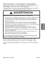
ADVERTENCIA
RIESGO DE EXPLOSIÓN EN ZONAS PELIGROSAS
• Compruebe que el cableado de alimentación y entrada y salida (E/S) está
de acuerdo con los métodos de cableado para la clase I, división 2.
• No sustituya ningún componente que afecte a la compatibilidad con la
Clase I, División 2.
• No conecte ni desconecte el equipo a menos que haya apagado la
alimentación eléctrica o esté seguro de que la zona no es peligrosa.
• Sujete bien las unidades conectadas externamente y todas las interfaces
antes de encender la fuente de alimentación.
• El conector USB2 sólo es para una conexión temporal durante el
mantenimiento y la configuración del dispositivo. No use, conecte ni
desconecte las conexiones de los cables USB2 a menos que se sepa que
la zona no es peligrosa.
• Riesgo de posible carga electrostática: pase un paño húmedo por el
panel frontal del terminal antes de encenderlo.
• Use un lápiz aislado para activar la pantalla táctil.
Si no se observan estas instrucciones, pueden producirse heridas
graves o la muerte, o daños en el equipo.

52/88 BBV27900 11/2019
ESPAÑOL
CONEXIÓN DEL CABLE DE ALIMENTACIÓN
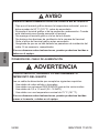
AVISO
RIESGOS MEDIOAMBIENTALES DE DAÑOS EN EL EQUIPO
• Deje que el terminal gráfico alcance la temperatura ambiental, que no
debe exceder de 50 °C (122 °F), antes de encenderlo.
• Encienda el terminal gráfico si se ha producido condensación. Cuando
esté totalmente seco puede encender el terminal.
• No exponga el terminal gráfico a la luz del sol directa.
• No obstruya las aberturas de ventilación de la carcasa del terminal.
• Quite el polvo del terminal gráfico antes encenderlo.
• Asegúrese de que no se han dañado los pasadores de instalación del
cable. Si es necesario, reemplácelos.
Si no se observan estas instrucciones, pueden producirse heridas o
daños en el equipo.
ADVERTENCIA
CORTOCIRCUITO, INCENDIO O FUNCIONAMIENTO
IMPREVISTO DEL EQUIPO
Use un cable de alimentación que cumpla los siguientes requisitos:
• Usa cables de cobre sólidos o trenzados.
• Usa cables con extremos D25CE/AZ5CE para evitar cortocircuitos.
• Usa cables de 0,2 a 1,5 mm2 (24 - 16 AWG).
• Usa cables con una temperatura nominal de 75 °C (167 °F).
Si no se observan estas instrucciones, pueden producirse heridas
graves o la muerte, o daños en el equipo.

BBV27900 11/2019 53/88
ESPAÑOL
Nota: Par de los tornillos de montaje: entre 0,22 y 0,25 Nm (entre 1,95 y 2,2 lb-
pulg.).
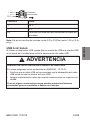
USB A ESTÁNDAR
Al utilizar un dispositivo USB, puede fijar un soporte de USB a la interfaz USB
en el lateral de la unidad para evitar la desconexión del cable USB.
Conexión Cable
+ 24 V
- 0 V
FG Terminal con toma de tierra conectado al chasis de
la unidad.
ADVERTENCIA
RIESGO DE EXPLOSIÓN EN ZONAS PELIGROSAS
En zonas peligrosas como se describe en ANSI/ISA - 12.12.01:
• Confirme que el cable USB se ha conectado con la abrazadera del cable
USB antes de usar la interfaz del host USB.
• Apague la alimentación antes de conectar o desconectar un conector a la
unidad.
Si no se siguen estas instrucciones pueden producirse lesiones
personales graves o mortales o daños en el equipo.
+
-
FG
Dirección
de inserción

54/88 BBV27900 11/2019
ESPAÑOL
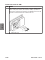
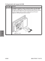
Fijación del soporte de USB
Paso Acción
1Fijar el soporte USB a la interfaz de host USB en la unidad principal.
Ajustar el enganche superior del soporte de USB en el orificio de
fijación de la unidad principal e insertar el enganche inferior como se
muestra a continuación para fijar el soporte de USB.
1 Soporte de USB

BBV27900 11/2019 55/88
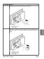
ESPAÑOL
2Insertar el cable USB en la interfaz de host USB.
1 Soporte de USB
2 Cable USB
3Fijar la cubierta USB para colocar en su lugar el cable USB. Insertar
la cubierta USB en la pestaña del soporte de USB.
1 Soporte de USB
2 Cubierta USB
3 Cable USB
Paso Acción

56/88 BBV27900 11/2019
ESPAÑOL
Extracción del soporte de USB
Paso Acción
1Apretar la pestaña del soporte de USB y retirar la cubierta del USB.
1 Soporte de USB
2 Cubierta USB
3 Cable USB
2Quitar el cable USB de la interfaz de host USB.

BBV27900 11/2019 57/88
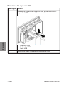
ESPAÑOL
3Insertar un atornillador en la ranura como se muestra en la siguiente
ilustración y hacer palanca en el soporte.
1 Soporte de USB
2 Destornillador de cabeza plana menor que 6 mm (0,23 pulg.)
4Quitar el soporte.
1 Soporte de USB
Paso Acción

58/88 BBV27900 11/2019
ESPAÑOL
DOCUMENTOS RELACIONADOS
Para obtener más información, puede descargar los manuales del usuario de
los paneles pequeños Harmony y otra información técnica de nuestro sitio web
www.schneider-electric.com.

BBV27900 11/2019 59/88
ITALIANO
SCHEDA D'ISTRUZIONI
per HMISTO5pp e HMISTUp55/p55W
PROGRAMMAZIONE DELL'HUMAN MACHINE INTERFACE (HMI)
Per programmare i prodotti Harmony HMISTO/STU, scaricare gratuitamente la
versione demo di Vijeo Designer1 dal sito www.schneider-electric.com:
1 Software usato per creare dati di progetto dell'unità HMI.
Per programmare tutti gli altri prodotti Harmony, ordinare Vijeo Designer presso
il rivenditore Schneider Electric.
Nota: Prima di scaricare un'applicazione su un nuovo HMIS5T usando la
versione di Vijeo Designer V6.0 SP3 o successiva:
• Assicurarsi che l'applicazione sia configurata per potere usare il modello di
destinazione HMIS5T. Nel caso contrario, cambiare il modello di
destinazione in HMIS5T prima di effettuare lo scaricamento.
oppure
• Aggiornare Vijeo Designer alla versione 6.1 per evitare un uso
inappropriato.
Moduli Versione minima Vijeo Designer
HMISTO501 6.0 o successive
HMISTO511/512 5.1 o successive
HMISTO531/532 6.0 SP1 o successive
HMISTU655 PV 04 5.1 o successive
HMISTU655 PV 04 6.1 SP1 o successive
HMISTU855 PV 03 5.1 SP2 o successive
HMISTU855 PV 03 6.1 SP1 o successive
HMISTU655W 6.1 SP1 o successive
HMISTU855W 6.1 SP1 o successive
HMIS5T 6.1 SP1 o successive

60/88 BBV27900 11/2019
ITALIANO
STANDARD PERTINENTI
Questi prodotti sono stati fabbricati in conformità di:
• Standard UL 508 e CSA C22.2 n°142 per apparecchiature di controllo
industriali
• Standard ANSI/ISA - 12.12.01 e CSA C22.2 n°213 per apparecchiature
elettriche da utilizzarsi in ambienti pericolosi di classe I, divisione 2
Nota: le unità HMISTO5pp sono state sviluppate per le navi mercantili.
Le unità HMISTUp55/p55W sono progettate per conformarsi ai requisiti dei
ponti e dei pontili della marina mercantile (per istruzioni sull'installazione,
visitare il sito Web di Schneider).
Le unità HMISTO5pp e HMISTUp55/p55W devono essere installate, utilizzate
e sottoposte a manutenzione secondo:
• Standard WEEE, Direttiva 2002/96/CE
• Standard RoHS, Direttiva 2011/65/EU
• Standard RoHS Cina, Standard SJ/T 11364-2014
HMIZSUKIT
Il kit accessori per l'unità HMISTU55/p55W contiene:
• Portacavi USB standard tipo A
• Alloggiamento USB mini B
• Elemento a T antirotazione
• Pannello adattatore
REQUISITI DI INSTALLAZIONE
Adatto all'uso in ambienti con grado di inquinamento 2.
Adatta all'uso su una superficie piana di un quadro tipo 13 e/o tipo 4X (solo per
uso in ambienti interni).

BBV27900 11/2019 61/88
ITALIANO
HMISTUp55/p55W: INSTALLAZIONE
Questa avvertenza non è coperta dalla certificazione UL.
Interruttori HMISTUp55/p55W
Dimensioni dell'apertura per il montaggio su una superficie piana:
ATTENZIONE
RISCHI AMBIENTALI ALLE APPARECCHIATURE
• Montare i terminali grafici in cabinet conformi al livello di protezione IP54
per la categoria 3G, IP6x per la categoria 3D e i requisiti correlati alle
categorie 3G o 3D nelle zone 2/22 (categoria 3: livello di protezione
normale - G: gas - D: polvere).
• Montare l'unità HMISTUp55/p55W secondo le specifiche del fabbricante.
Il mancato rispetto delle presenti istruzioni può comportare lesioni
o danni materiali.
A B (Lamiera di
acciaio, per
esempio, sportello
del quadro)
B (plastica
rinforzata con
fibra di vetro,
minimo GF30)
CD
+0
22,50 mm
-0,30
+0
0,88 "
-0,01
da 1,5 a 6 mm
da 0,06 a 0,23 "
da 3 a 6 mm
da 0,11 a 0,23 "
+0
30,00 mm
-0,20
+0
1,18 "
-0,007
+0
4,00 mm
-0,20
+0
0,15 "
-0,007

62/88 BBV27900 11/2019
ITALIANO
Installazione di HMISTUp55/p55W
L'elemento a T opzionale aumenta la resistenza dell'unità alla coppia di
rotazione.
L'Adattatore del Pannello opzionale, fornito in dotazione nell'HMIZSUKIT
consente il montaggio del prodotto su un:
• Un supporto metallico di spessore compreso tra 1 e 1,5 mm
(0,039 e 0,059 ")
• Un supporto in plastica di spessore compreso tra 1 e 3 mm
(0,039 e 0,118 ") per l'HMISTU655/655W
• Plastica rinforzata in fibra di vetro con uno spessore tra 2 e 3 mm
(0,078 e 0,118 ") per l'HMISTU855/855W
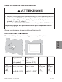
L'illustrazione seguente mostra l'installazione dell'unità con un dispositivo a T
e un panello adattatore:
1 Modulo del display
2 Superficie piana di supporto (per esempio, sportello del quadro)
3 Adattatore del pannello (opzionale da HMIZSUKIT)
4 Dado
5 Raccordo (opzionale da HMIZSUKIT)

BBV27900 11/2019 63/88
ITALIANO
HMISTO5pp: PROCEDURE D'INSTALLAZIONE
Questa avvertenza non è coperta dalla certificazione UL.
Prima di installare l’unità in un ambiente chiuso o in un pannello leggere le
istruzioni di questa sezione.
Quando si installa l’unità occorrono la guarnizione e gli elementi di fissaggio
o fermagli adeguati (a vite o con clip elastica).
Montare il terminale in un cabinet pulito, asciutto, robusto e controllato
(classe IP65).
Interruttore HMISTO5pp:
Dimensioni dell'apertura per il montaggio su una superficie piana:
1 Pannello
A 105 mm (4,13 ")
B 66 mm (2,59 ")
C Da 1,5 a 6,0 mm (da 0,059 a 0,236 ")
R Da 2,0 a 3,0 mm (da 0,079 a 0,118 ")
ATTENZIONE
RISCHI AMBIENTALI ALLE APPARECCHIATURE
• Montare i terminali grafici in cabinet conformi al livello di protezione IP54
per la categoria 3G, IP6x per la categoria 3D e i requisiti correlati alle
categorie 3G o 3D nelle zone 2/22 (categoria 3: livello di protezione
normale - G: gas - D: polvere).
• Montare l'unità HMISTO5pp secondo le specifiche del fabbricante.
Il mancato rispetto delle presenti istruzioni può comportare lesioni
o danni materiali.

64/88 BBV27900 11/2019
ITALIANO
HMISTO5pp: installazione
Utilizzare le clip elastiche per mantenere in posizione l'unità dopo averla
inserita.
Regolare le clip elastiche in base allo spessore del pannello, capovolgendolo:
• 1,5 mm (0,059 ") spessore del pannello 4 mm (0,157 ") (posizione 1)
• 4 mm (0,157 ") spessore del pannello 6 mm (0,236 ") (posizione 2)
Bloccare le clip elastiche spingendone simultaneamente il lato superiore
e quello inferiore con due dita, fino a udire uno scatto.
1 Posizione 1
2 Posizione 2
1 Scatto

BBV27900 11/2019 65/88
ITALIANO
AVVIAMENTO, FUNZIONAMENTO E MANUTENZIONE
È necessario seguire tutte le raccomandazioni descritte nel Manuale
dell'Utente dell'HMISTO5pp, e nel Manuale dell'Utente
dell'HMISTUp55/p55W.
Schneider Electric respinge qualsiasi responsabilità per applicazioni o
installazioni non consigliate nei succitati manuali.
Le interfacce per l'unità HMISTO501/51p sono le seguenti: COM1, USB1.
Le interfacce per l'unità HMISTO53p sono le seguenti: ETHERNET, USB1.
Le interfacce per l'unità HMISTUp55/p55W sono le seguenti: COM1,
ETHERNET, USB1.
AVVERTENZA
RISCHIO DI ESPLOSIONE IN AMBIENTI PERICOLOSI
• Verificare che i cavi di alimentazione, ingresso e uscita (I/O) siano
conformi ai metodi di cablaggio Classe I, Divisione 2.
• Non sostituire componenti che possano compromettere la conformità alle
norme di Classe I, Divisione 2.
• Non collegare né scollegare le apparecchiature a meno che non sia stata
disattivata l’alimentazione o non sia stato accertato che l'area non è
soggetta a rischi.
• Bloccare in maniera sicura le unità collegate esternamente e ciascuna
interfaccia prima di attivare la corrente.
• Il connettore USB2 e previsto soltanto per il collegamento temporaneo
durante la manutenzione è la configurazione del dispositivo. Non
utilizzare, collegare o scollegare il cavo USB2 a meno che non sia stato
accertato che l’area non è soggetta a rischi.
• Rischio potenziale di scariche elettrostatiche: pulire la parte anteriore del
terminale con un panno umido prima di accendere l’apparecchio.
• Utilizzare una penna ottica isolata per attivare il touchscreen.
Il mancato rispetto delle presenti istruzioni può comportare la morte,
lesioni gravi o danni ai beni materiali.

66/88 BBV27900 11/2019
ITALIANO
.
CONNESSIONE DEL CAVO DI ALIMENTAZIONE
Prima di utilizzare il cavo di alimentazione, verificare che il cavo di terra abbia
una sezione uguale o superiore ai cavi di alimentazione.
ATTENZIONE
RISCHI AMBIENTALI ALLE APPARECCHIATURE
• Prima di accendere il terminale grafico, attendere che raggiunga la
temperatura aria ambiente, che non deve superare 50°C (122°F).
• Non accendere il terminale grafico se si è formata della condensa. Il
terminale potrà essere acceso solo dopo che si sarà asciugato
perfettamente.
• Non esporre il terminale grafico alla luce diretta del sole.
• Non ostruire le prese di ventilazione nel telaio del terminale.
• Rimuovere la polvere dal terminale grafico prima di accenderlo.
• Verificare che i fissaggi d'installazione dei cavi non abbiano subito danni.
Al caso, sostituirli.
Il mancato rispetto delle presenti istruzioni può comportare lesioni o
danni materiali.
AVVERTENZA
RISCHIO DI CORTOCIRCUITO, INCENDIO O AZIONAMENTO
ANOMALO DELLE APPARECCHIATURE
Utilizzare un cavo di alimentazione che soddisfi i seguenti requisiti:
• Utilizzare cavi in rame solido o a trefoli.
• Utilizzare terminazioni di cavi D25CE/AZ5CE per evitare i cortocircuiti.
• Utilizzare cavi da 0,2 a 1,5 mm2 (24 - 16 AWG).
• Utilizzare cavi con una temperatura nominale di 75°C (167°F).
Il mancato rispetto delle presenti istruzioni può comportare la morte,
lesioni gravi o danni ai beni materiali.

BBV27900 11/2019 67/88
ITALIANO
Nota: Coppia di serraggio delle viti di montaggio: da 0,22 a 0,25 Nm.
Quando si utilizza un dispositivo USB è possibile collegare un supporto
all’interfaccia che si trova sul lato dell’unità per impedire il distacco del cavo
USB.
Connessione Cavo
+ 24 V
- 0 V
FG Terminale di terra collegato al telaio dell’unità.
AVVERTENZA
RISCHIO DI ESPLOSIONE IN AMBIENTI PERICOLOSI
Negli ambienti pericolosi, così come descritti in ANSI/ISA - 12.12.01:
• verificare che il cavo USB sia stato fissato con il morsetto per cavi USB
prima di utilizzare l’interfaccia host USB.
• prima di collegare o staccare qualsiasi connettore dall’unità, isolare
l’alimentazione.
Il mancato rispetto di queste istruzioni può provocare morte, gravi
infortuni o danni alle apparecchiature.
+
-
FG
Dirección
de inserción

68/88 BBV27900 11/2019
ITALIANO
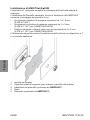
Collegamento del supporto USB
Passaggio Azione
1Collegare il supporto USB all’interfaccia host USB dell’unità
principale. Agganciare la parte superiore del supporto USB
nell’apposito alloggiamento dell’unità principale, quindi inserire
la parte inferiore come indicato nella figura per fissare il
supporto USB nella posizione corretta.
1 Supporto USB

BBV27900 11/2019 69/88
ITALIANO
2Inserire il cavo USB nell’interfaccia host USB.
1 Supporto USB
2 Cavo USB
3Applicare il coperchio USB per bloccare il cavo nella posizione
corretta. Inserire il coperchio USB nella linguetta del supporto
USB.
1 Supporto USB
2 Coperchio USB
3 Cavo USB
Passaggio Azione

70/88 BBV27900 11/2019
ITALIANO
Rimozione del supporto USB
Passaggio Azione
1Premere la linguetta del supporto USB, quindi rimuovere il
coperchio USB.
1 Supporto USB
2 Coperchio USB
3 Cavo USB
2Rimuovere il cavo USB dall’interfaccia host USB.

BBV27900 11/2019 71/88
ITALIANO
3Inserire un cacciavite nello slot come indicato nella seguente
illustrazione, sollevando il supporto con forza.
1 Supporto USB
2 Cacciavite a lama piatta inferiore a 6 mm (0,23 ")
4Rimuovere il supporto.
1 Supporto USB
Passaggio Azione

72/88 BBV27900 11/2019
ITALIANO
DOCUMENTAZIONE CORRELATA
Per ulteriori informazioni è possibile scaricare i Manuali d'uso dei pannelli
piccoli Harmony e altre informazioni tecniche dal nostro sito all'indirizzo
www.schneider-electric.com

BBV27900 11/2019 73/88
ㆶ։ѣᮽ
䜘Ԧ〠
Part Name
ᴹᇣ⢙䍘 Hazardous Substances
䫵
(Pb)
⊎
(Hg)
䭹
(Cd)
ޝԧ䬜
(Cr
(VI))
ཊⓤ
㚄㤟
(PBB)
ཊⓤҼ
㤟䟊
(PBDE)
䠁䜘Ԧ
Metal parts
XOOO O O
ກᯉ䜘Ԧ
Plastic parts
OOOO O O
⭥ᆀԦ
Electronic
XOOO O O
䀖⛩
Contacts
OOOO O O
㓯㔶઼㓯㔶䱴Ԧ
Cables &
cabling
accessories
OOOO O O
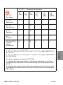
ᵜ㺘Ṭᦞ 6-7 Ⲵ㿴ᇊ㕆ࡦDŽ
O: 㺘⽪䈕ᴹᇣ⢙䍘൘䈕䜘Ԧᡰᴹ൷䍘ᶀᯉѝⲴਜ਼䟿൷൘GB/T 26572㿴ᇊⲴ
䲀䟿㾱≲ԕлDŽ
X: 㺘⽪䈕ᴹᇣ⢙䍘㠣ቁ൘䈕䜘ԦⲴḀа൷䍘ᶀᯉѝⲴਜ਼䟿䎵ࠪ GB/T 26572
㿴ᇊⲴ䲀䟿㾱≲DŽ
This tableismade according to SJ/T 11364.
O: indicates that the concentration ofhazardous substance in all ofthe
homogeneous materialsfor this part is belowthe limit as stipulated in GB/T
26572.
X: indicates that concentration ofhazardous substance in atleast one ofthe
homogeneous materials used for this part is above the limit as stipulated in
GB/T 26572.

74/88 BBV27900 11/2019
ㆶ։ѣᮽ

BBV27900 11/2019 75/88
ㆶ։ѣᮽ
䈪᱄㺞
䘸⭞ӄ HMISTO5pp
ૂ HMISTUp55/p55W
ᵜᤷইᵜ䓛ᒦᵚᨀ↓⺞ Harmonyӗ૱ᡰ䴰Ⲵ䏣ཏؑDŽ൘֯⭘ᵜᤷই
ѻࡽ䈧ݸ䰵䈫ᒦ⨶䀓⭘ᡧDŽ
Ѱ HUMAN MACHINE INTERFACE (HMI) 㕌ぁ
㾱Ѫ Harmony HMISTO/STU 㕆〻ˈ䈧Ӿ www.schneider-electric.com л䖭ݽ
䍩Ⲵ Vijeo Designer1 ╄⽪⡸˖
1⭘Ҿࡋᔪ HMI䇮༷ᐕ〻ᮠᦞⲴ䖟ԦDŽ
㾱ѪަԆԫօ Harmony ӗ૱㕆〻ˈ䈧Ӿ Schneider Electric 䬰୶༴䍝Ҡ Vijeo
DesignerDŽ
⌞φ ൘֯⭘ Vijeo Designer V6.0 SP3 ᡆᴤ儈⡸ᵜл䖭ᓄ⭘〻ᒿࡠᯠⲴ HMIS5T
ѻࡽˈ䈧˖
•⺞؍ᛘⲴᓄ⭘〻ᒿᐢ䝽㖞ᡀ֯⭘ⴞḷ⁑ර HMIS5T ྲ᷌нᱟˈ䈧൘л
䖭ѻࡽݸሶⴞḷ⁑රᴤ᭩Ѫ HMIS5TDŽ
㒥劔
•ሶVijeo Designerॷ㓗Ѫ 6.1⡸ԕ䚯ݽԫօ䈟⭘DŽ
⁗ඍ ᴶք Vijeo Designer ⡾ᵢ
HMISTO501 6.0 ᡆᴤ儈⡸ᵜ
HMISTO511/512 5.1 ᡆᴤ儈⡸ᵜ
HMISTO531/532 6.0 SP1 ᡆᴤ儈⡸ᵜ
HMISTU655 PV 04 5.1 ᡆᴤ儈⡸ᵜ
HMISTU655 PV 04 6.1 SP1 ᡆᴤ儈⡸ᵜ
HMISTU855 PV 03 5.1 SP2 ᡆᴤ儈⡸ᵜ
HMISTU855 PV 03 6.1 SP1 ᡆᴤ儈⡸ᵜ
HMISTU655W 6.1 SP1 ᡆᴤ儈⡸ᵜ
HMISTU855W 6.1 SP1 ᡆᴤ儈⡸ᵜ
HMIS5T 6.1 SP1 ᡆᴤ儈⡸ᵜ

76/88 BBV27900 11/2019
ㆶ։ѣᮽ
ީḽ
䘉Ӌӗ૱Ⲵࡦ䙐ㅖਸԕлḷ߶˖
•䘲⭘Ҿᐕъ᧗ࡦ㻵༷Ⲵ CSA C22.2 n°142 ḷ߶
•䘲⭘Ҿ൘ I ㊫ 2 ࠶㊫Ⲵড䲙ս㖞֯⭘Ⲵ⭥≄䇮༷Ⲵ
ANSI/ISA - 12.12.01 ઼ CSA C22.2 n°213 ḷ߶
⌞φ HMISTO5pp Ⲵ䇮䇑䚥Ӿ୶㡩㿴ࡉDŽ
HMISTUp55/p55W অݳⲴ䇮䇑ㅖਸ୶㡩Ⲵ㡠ẕ઼⭢ᶯ㾱≲ ˄ᴹޣᆹ㻵ᤷইˈ
䈧৲䰵 Schneider 㖁ㄉ˅DŽ
HMISTO5pp ઼HMISTUp55/p55W অݳⲴᆹ㻵ǃ֯⭘઼㔤ᣔᗵ享ㅖਸԕлḷ
߶˖
• WEEE ḷ߶ˈ㿴〻 2002/96/EC
• RoHS ḷ߶ˈ㿴〻 2011/65/EU
• RoHS/ ѝഭḷ߶ˈḷ߶ SJ/T SJ/T 11364-2014
HMIZSUKIT
HMISTUp55/p55W Ⲵ䱴Ԧ྇Ԧवᤜ˖
• USB ḷ߶ A ර⭥㔶പᇊᷦ
• USB mini B പᇊᷦ
•䱢䖜 T ᖒ᧕ཤ
•䶒ᶯ䘲䝽ಘ
ᆿ㻻ⲺࢃᨆᶗԬ
⭘൘⊑ḃ〻ᓖѪ 2Ⲵ⧟ຳѝDŽ
൘㊫ර 13 ઼/ᡆ㊫ර 4X ˄ӵ䲀ᇔ֯⭘˅ᵪ༣Ⲵᒣ━㺘䶒к֯⭘DŽ

BBV27900 11/2019 77/88
ㆶ։ѣᮽ
HMISTUp55/p55W ᆿ㻻
ᵢ⌞ᝅӁ亯уኔ UL䇚䇷㤹⮪Ⱦ
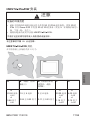
HMISTUp55/p55W ᔶᆊ
൘ᒣ━㺘䶒кᆹ㻵ᰦⲴᔰਓቪረ˖
⌞ᝅ
䇴༽Ⲻ⧥ູধ䲟
•ᵪḌѝⲴമᖒ㓸ㄟⲴᆹ㻵ᓄㅖਸ㊫࡛ 3G Ⲵ IP54 ؍ᣔ㓗࡛ǃ㊫࡛ 3D Ⲵ
IP6x ԕ৺ Zones 2/22 ѝ㊫࡛ 3G ᡆ 3D Ⲵ㾱≲˄㊫࡛ 3˖ ᑨ㿴؍ᣔ㓗࡛ -
G˖≄փ - D˖ ⚠ቈ˅DŽ
•ṩᦞࡦ䙐୶Ⲵ䈤᰾Җᆹ㻵 HMISTUp55/p55WDŽ
у䚫ᆾ䘏ӑ䈪᱄ਥ㜳ሲ㠪Ӱ䓡՚ᇩᡌ䇴༽ᦕඅȾ
AB˄䫒ᶯˈֻྲˈ
₡Ḍ䰘˅
Bδ⧫⪳㓔㔤໎
ᕪກᯉˈᴰվ
GF30˅
CD
+0
22.50 ∛㊣
-0.30
+0
0.88 㤡ረ
-0.01
1.5 㠣 6 ∛㊣
0.06 㠣 0.23 㤡ረ
3 㠣 6 ∛㊣
0.11 㠣 0.23 㤡ረ
+0
30.00 ∛㊣
-0.20
+0
1.18 㤡ረ
-0.007
+0
4.00 ∛㊣
-0.20
+0
0.15 㤡ረ
-0.007

78/88 BBV27900 11/2019
ㆶ։ѣᮽ
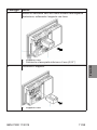
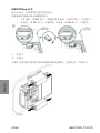
ᆿ㻻 HMISTUp55/p55W
ਟ䘹 T ᖒ᧕ཤਟ໎ᕪঅݳᣥᣇᢝ⸙Ⲵ㜭࣋DŽ
֯⭘䲿 HMIZSUKIT ᨀⲴਟ䘹䶒ᶯ䘲䝽ಘˈਟԕሶӗ૱ᆹ㻵ࡠԕлᶀᯉк˖
•䠁᭟ᷦˈᓖѪ 1 㠣 1.5 ∛㊣ ˄0.039 㠣 0.059 㤡ረ˅ѻ䰤DŽ
•ሩҾ HMISTU655/655Wˈກᯉ᭟ᷦˈᓖѪ 1 㠣 3 ∛㊣ ˄0.039 㠣
0.118 㤡ረ˅ѻ䰤DŽ
•ሩҾ HMISTU855/855Wˈਟᆹ㻵൘ᓖѪ 2 ࡠ 3 ∛㊣ ˄0.078 㠣
0.118 㤡ረ˅ѻ䰤Ⲵ⧫⪳㓔㔤࣐ᕪກᯉкDŽ
лമᱮ⽪ᑖᴹ T ᖒ᧕ཤ઼䶒ᶯ䘲䝽ಘⲴঅݳⲴᆹ㻵˖
2ᱮ⽪⁑ඇ
3᭟᫁ᒣ━㺘䶒 ˄ֻྲˈ₡Ḍ䰘˅
4䶒ᶯ䘲䝽ಘ ˄HMIZSUKIT˅
5㷪ᑭ
67 ᖒ᧕ཤ ˄HMIZSUKIT˅

BBV27900 11/2019 79/88
ㆶ։ѣᮽ
HMISTO5pp ᆿ㻻↛僚
ᵜ⌘һ亩н UL䇔䇱㤳⮤DŽ
൘ሶᵜঅݳᆹ㻵ࡠᵪḌᡆ䶒ᶯкѻࡽˈ䈧ݸ䰵䈫ԕл䈤᰾DŽ
ᆹ㻵ᵜঅݳᰦˈ䴰㾱֯⭘ᆹ㻵㺜ෛ઼ᆹ㻵ᢓԦ ˄㷪䪹ᆹ㻵ᢓԦᡆᕩ㉗ཀྵ˅DŽ
ሶ䇮༷ᆹ㻵൘ᨀᒢ߰ǃᒢ⠕ǃ⢒പ઼ਟ᧗⧟ຳⲴᵪḌ ˄IP65 ᵪḌ˅ѝDŽ
HMISTO5pp ᔶਙφ
൘ᒣ━㺘䶒кᆹ㻵ᰦⲴᔰਓቪረ˖
槱㨎
A 105 ∛㊣ ˄4.13 㤡ረ˅
B 66 ∛㊣ ˄2.59 㤡ረ˅
C 1.5 㠣 6.0 ∛㊣ ˄0.059 㠣 0.236 㤡ረ˅
R 2.0 㠣 3.0 ∛㊣ ˄0.079 㠣 0.118 㤡ረ˅
⌞ᝅ
䇴༽Ⲻ⧥ູধ䲟
•ᵪḌѝⲴമᖒ㓸ㄟⲴᆹ㻵ᓄㅖਸ㊫࡛ 3G Ⲵ IP54 ؍ᣔ㓗࡛ǃ㊫࡛ 3D Ⲵ
IP6x ԕ৺ Zones 2/22 ѝ㊫࡛ 3G ᡆ 3D Ⲵ㾱≲˄㊫࡛ 3˖ ᑨ㿴؍ᣔ㓗࡛ -
G˖≄փ - D˖ ⚠ቈ˅DŽ
•ṩᦞࡦ䙐୶Ⲵ䈤᰾Җᆹ㻵 HMISTO5ppDŽ
у䚫ᆾ䘏ӑ䈪᱄ਥ㜳ሲ㠪Ӱ䓡՚ᇩᡌ䇴༽ᦕඅȾ

80/88 BBV27900 11/2019
ㆶ։ѣᮽ
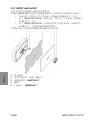
HMISTO5pp ᆿ㻻
ᨂޕঅݳਾˈ֯⭘ᕩ㉗ཀྵሶަപᇊࡠսDŽ
ṩᦞ䶒ᶯᓖ䙊䗷䖜ࣘ䈳ᮤᕩ㉗ཀྵ˖
• 1.5 ∛㊣ ˄0.059 㤡ረ˅ 䶒ᶯᓖ 4 ∛㊣ ˄0.157 㤡ረ˅˄ս㖞 1˅
•4 ∛㊣ ˄0.157 㤡ረ˅ 䶒ᶯᓖ 6 ∛㊣ ˄0.236 㤡ረ˅˄ս㖞 2˅
⭘єњᤷ਼ᰦ᤹ᕩ㉗ཀྵⲴ亦䜘઼ᓅ䜘䬱ᇊᕩ㉗ཀྵˈⴤࡠੜࡠа༠ૄం༠DŽ
1ս㖞 1
2ս㖞 2
䬱ᇊ䫞

BBV27900 11/2019 81/88
ㆶ։ѣᮽ
ࣞȽᬃ֒ૂ㔪ᣚ
ᗵ享䚥ᗚ HMISTO5pp ⭘ᡧ઼ HMISTUp55/p55W ⭘ᡧѝᡰ䘠Ⲵޘ䜘
ᔪ䇞DŽ
Schneider Electric ሩѝᵚ᧘㦀Ⲵᓄ⭘઼ᆹ㻵ᾲн䍏䍓Ⱦ
ሩҾ HMISTO501/51pθ᧕ਓवᤜφ COM1ȽUSB1Ⱦ
ሩҾ HMISTO53pθ᧕ਓवᤜ˖ ETHERNETȽUSB1Ⱦ
ሩҾ HMISTUp55/p55Wθ᧕ਓवᤜφ COM1ȽETHERNETȽUSB1Ⱦ
䆜
ᆎ൞⠼⛮ধ䲟Ⲻধ䲟փ㖤
•⺞؍⭥Ⓚǃ䗃ޕ઼䗃ࠪ (I/O)᧕㓯ㅖਸ I㊫ 2࠶㊫ᐳ㓯ᯩᔿDŽ
•䈧यᢗ㹼ਟ㜭䘍৽ I㓗 2㊫ޣ㿴ᇊⲴ㓴ԦᴯᦒDŽ
•䲔䶎⭥Ⓚᐢޣ䰝ᡆ⺞ᇊ४ฏᰐড䲙ˈࡉ䈧य䘎᧕䇮༷ᡆᯝᔰ䇮༷Ⲵ
䘎 ᧕DŽ
•ᢃᔰ⭥Ⓚࡽ⢒പൠ䬱ᇊཆ䜘䘎᧕Ⲵ䇮઼༷⇿њ᧕ਓDŽ
• USB2䘎᧕ಘਚ䘲ਸ㻵㖞㔤ᣔ઼䇮㖞ᵏ䰤ⲴѤᰦ䘎᧕DŽ 䲔䶎⺞⸕४ฏ
ᰐড䲙ˈࡉ䈧य֯⭘ǃ䘎᧕ᡆᯝᔰ USB2⭥㔶DŽ
•▌൘Ⲵ䶉⭥ݵ⭥ড䲙˖ ᢃᔰ⭥Ⓚࡽ䈧⭘⒯ᐳᬖᤝ㓸ㄟⲴࡽ䶒ᶯDŽ
•֯⭘㔍㕈䀖ㅄ◰⍫䀖᪨ቿDŽ
ྸ᷒у䚫ᆾ䘏ӑ䈪᱄θሼՐሲ㠪↱ӗȽћ䠃՚ᇩᡌ䇴༽ᦕඅȾ

82/88 BBV27900 11/2019
ㆶ։ѣᮽ
䘔⭫Ⓠ㓵
֯⭘⭥Ⓚ㓯ѻࡽˈ⺞؍᧕ൠ㓯ቪረо⭥Ⓚ㓯਼ᡆ∄ѻᴤབྷDŽ
⌞ᝅ
䇴༽Ⲻ⧥ູধ䲟
•൘ᔰࡽˈݱ䇨䇮༷䗮ࡠઘതⲴオ≄ᓖˈн䎵䗷 50°C (122°F)DŽ
•ྲ᷌ࠪ⧠ߧࠍ⧠䊑䈧यᢃᔰമᖒ㓸ㄟDŽ ਚᴹᆼޘᒢ⠕ਾˈਟԕᢃᔰമᖒ
㓸ㄟDŽ
•䈧यሶമᖒ㓸ㄟᴍ䵢൘䱣ݹⴤሴлDŽ
•䈧य䱫ຎ㓸ㄟཆ༣кⲴ䙊仾ਓDŽ
•ᢃᔰ⭥Ⓚࡽ䲔മᖒ㓸ㄟкⲴ⚠ቈDŽ
•⺞؍⭥㔶ᆹ㻵ཀྵᆼྭᰐᦏDŽ ྲᴹᗵ㾱ˈ䈧ᴤᦒᦏⲴ䜘ԦDŽ
у䚫ᆾ䘏ӑ䈪᱄ਥ㜳ሲ㠪Ӱ䓡՚ᇩᡌ䇴༽ᦕඅȾ
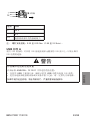
䆜
⸣䐥Ƚ⚡⚴ᡌᝅཌⲺ䇴༽ᬃ֒
֯⭘┑䏣лࡇ㾱≲Ⲵ⭥Ⓚ㓯˖
•֯⭘䬌ᇎᗳ㓯ᡆ䬌ᢝ㓯DŽ
•֯⭘ D25CE/AZ5CE⭥㔶㓸ㄟԕ䚯ݽ⸝䐟DŽ
•֯⭘ 0.2㠣 1.5 mm2 (24 - 16 AWG)Ⲵ⭥㓯DŽ
•֯⭘ᓖ仍ᇊ٬Ѫ 75°C (167°F)Ⲵ⭥㓯DŽ
ྸ᷒у䚫ᆾ䘏ӑ䈪᱄θሼՐሲ㠪↱ӗȽћ䠃՚ᇩᡌ䇴༽ᦕඅȾ

BBV27900 11/2019 83/88
ㆶ։ѣᮽ
⌞φ 㷰䪿ᆿ㻻ᢣ⸟φ0.22 㠩 0.25 Nm δ1.95 㠩 2.2 lb-inεȾ
USB ḽ A
֯⭘ 86% 䇮༷ᰦˈਟԕሶ 86% ᓗ䘎᧕ࡠঅݳח䶒Ⲵ 86% ᧕ਓкˈԕ䱢→ᯝᔰ
86%⭥㔶Ⲵ䘎᧕DŽ
䘔 ሲ㓵
+ 24 V
-0 V
FG 䘎᧕ࡠ䇮༷ཆ༣Ⲵ᧕ൠㄟᆀDŽ
䆜
ᆎ൞⠼⛮ধ䲟Ⲻধ䲟փ㖤
൘ྲḷ߶ ANSI/ISA - 12.12.01ѝᡰ䘠Ⲵড䲙ս㖞φ
•൘֯⭘ USBѫᵪ᧕ਓࡽˈ⺞؍ᐢ֯⭘ USB⭥㔶ཀྵ䘎᧕86%⭥㔶DŽ
•ᢺԫօ䘎᧕ಘ䘎᧕ࡠ䇮༷ᡆӾ䇮༷ѝᤄлѻࡽˈ䈧аᇊ㾱ݸޣ䰝⭥ⓀDŽ
ྸ᷒у䚫ᆾ䘏ӑ䈪᱄θሼՐሲ㠪↱ӗȽћ䠃՚ᇩᡌ䇴༽ᦕඅȾ
+
-
FG
㙡⏴㡈⚠

84/88 BBV27900 11/2019
ㆶ։ѣᮽ
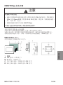
䘔 USB ᓝ
↛僚 ࣞ֒
1ሶUSB ᓗ䘎᧕ࡠѫঅݳⲴ USB ѫᵪ᧕ਓкDŽሶ USB ᓗⲴкケ㠼
䫙տѫঅݳⲴ䘎᧕ᆄˈ❦ਾྲлമᡰ⽪ᨂޕлケ㠼ԕപᇊ USBᓗDŽ
86% ᓝ

BBV27900 11/2019 85/88
ㆶ։ѣᮽ
2ሶUSB⭥㔶ᨂޕ USBѫᵪ᧕ਓDŽ
USB ᓗ
USB ⭥㔶
3࣐к USB ᣔⴆԕ֯ USB ⭥㔶പᇊࡠսDŽሶ USB ᣔⴆᨂޕ USB
ᓗⲴ━⡷ѝDŽ
USB ᓗ
USB ⴆ
USB ⭥㔶
↛僚 ࣞ֒

86/88 BBV27900 11/2019
ㆶ։ѣᮽ
মс USB ᓝީᮽẙ
↛僚 ࣞ֒
1ੁл᤹ USBᓗⲴᥑ䶒ˈ❦ਾਆл USBⴆDŽ
USB ᓗ
USB ⴆ
USB ⭥㔶
2ӾUSBѫᵪ᧕ਓкਆл USB⭥㔶DŽ

BBV27900 11/2019 87/88
ㆶ։ѣᮽ
3ሶ㷪э࠰ᨂޕѝˈྲлമᡰ⽪ˈ䎧 USBᓗDŽ
USB ᓝ
жᆍ㷰ѓ࠶ተሮቅӄ 6 ∡㊩ δ0.23 㤧ሮε
4с USB ᓝȾ
USB ᓝ
↛僚 ࣞ֒

88/88 BBV27900 11/2019
ㆶ։ѣᮽ
ީᮽẙ
ᴹޣᴤཊ䈖㓶ؑˈ䈧ӾᡁԜⲴ㖁ㄉл䖭 Harmony ሿ䶒ᶯ⭘ᡧԕ৺ަԆ
ᢰᵟ䍴ᯉˈ㖁൰Ѫ www.schneider-electric.com
11/2019
Printed in
-
 1
1
-
 2
2
-
 3
3
-
 4
4
-
 5
5
-
 6
6
-
 7
7
-
 8
8
-
 9
9
-
 10
10
-
 11
11
-
 12
12
-
 13
13
-
 14
14
-
 15
15
-
 16
16
-
 17
17
-
 18
18
-
 19
19
-
 20
20
-
 21
21
-
 22
22
-
 23
23
-
 24
24
-
 25
25
-
 26
26
-
 27
27
-
 28
28
-
 29
29
-
 30
30
-
 31
31
-
 32
32
-
 33
33
-
 34
34
-
 35
35
-
 36
36
-
 37
37
-
 38
38
-
 39
39
-
 40
40
-
 41
41
-
 42
42
-
 43
43
-
 44
44
-
 45
45
-
 46
46
-
 47
47
-
 48
48
-
 49
49
-
 50
50
-
 51
51
-
 52
52
-
 53
53
-
 54
54
-
 55
55
-
 56
56
-
 57
57
-
 58
58
-
 59
59
-
 60
60
-
 61
61
-
 62
62
-
 63
63
-
 64
64
-
 65
65
-
 66
66
-
 67
67
-
 68
68
-
 69
69
-
 70
70
-
 71
71
-
 72
72
-
 73
73
-
 74
74
-
 75
75
-
 76
76
-
 77
77
-
 78
78
-
 79
79
-
 80
80
-
 81
81
-
 82
82
-
 83
83
-
 84
84
-
 85
85
-
 86
86
-
 87
87
-
 88
88


Schneider Electric HMISTU655 Instrucciones de operación
- Tipo
- Instrucciones de operación
- Este manual también es adecuado para
en otros idiomas
Artículos relacionados
-
Schneider Electric ZBY9120 Instrucciones de operación
-
Schneider Electric HMIGTO1300 Manual de usuario
-
-
-
-
-
Eurotherm TCSMCNAM3M002P USB to RS485 converter El manual del propietario
-
-
Schneider Electric Zelio Logic 2 Manual de usuario