PRESIDENT Bill ASC El manual del propietario
- Tipo
- El manual del propietario

Manuel d’utilisation / Manual del usuario
Owner’s manual / Instrukcja obsługi
BILL

Un vistazo a vuestro PRESIDENT BILL ASC
Your PRESIDENT BILL ASC at a glance
Votre PRESIDENT BILL ASC en un coup d'œil
Twój PRESIDENT BILL ASC

3
SOMMAIRE
INSTALLATION 5
UTILISATION 8
FONCTIONS À L’ALLUMAGE DU POSTE 11
MENUS 12
CARACTÉRISTIQUES TECHNIQUES 14
GUIDE DE DÉPANNAGE 15
COMMENT ÉMETTRE/RECEVOIR UN MESSAGE 15
GLOSSAIRE 16
DÉCLARATION DE CONFORMITÉ EU SIMPLIFIÉE 18
CONDITIONS GÉNÉRALES DE GARANTIE 19
TABLEAUX DES FRÉQUENCES 66 ~ 68
NORMES - F 70
Français
SUMARIO
INSTALACIÓN 21
UTILIZACIÓN 24
FUNCIONES AL ENCENDER LA EMISORA 27
MENÚS 28
CARACTERÍSTICAS TÉCNICAS 31
GUÍA DE PROBLEMAS 31
COMO EMITIR O RECIBIR UN MENSAJE 32
LÉXICO 32
DECLARACIÓN DE CONFORMIDAD EU SIMPLIFICADA 34
CONDICIONES GENERALES DE GARANTÍA 35
TABLAS DE FRECUENCIAS 66 ~ 68
NORMAS - F 70
Español
English
Polski
SUMMARY
INSTALLATION 37
HOW TO USE YOUR CB 40
FUNCTIONS TURNING ON THE UNIT 43
MENU 44
TECHNICAL CHARACTERISTICS 46
TROUBLE SHOOTING 47
HOW TO TRANSMIT OR RECEIVE A MESSAGE 47
GLOSSARY 47
SIMPLIFIED DECLARATION OF CONFORMITY 49
GENERAL WARRANTY CONDITIONS 50
FREQUENCY TABLES 66 ~ 68
NORMS - F 70
SPIS TREŚCI
INSTALACJA 52
JAK KORZYSTAĆ Z CB RADIA 55
WŁĄCZANIE FUNKCJI URZĄDZENIA 58
MENU 59
CHARAKTERYSTYKA TECHNICZNA 61
ROZWIĄZYWANIE PROBLEMÓW 62
JAK PRZESYŁAĆ LUB ODBIERAĆ WIADOMOŚĆ 62
SŁOWNICZEK 62
UPROSZCZONA DEKLARACJA ZGODNOŚCI UE 63
ZOBOWIĄZANIA GWARANTA 64
TABELE CZĘSTOTLIWOŚCI 66 ~ 68
NORMY - F 70

4
ATTENTION !
APPAREIL MULTI-NORMES !
Avant toute utilisation, prenez garde de ne
jamais émettre sans avoir branché l’antenne
(connecteur B situé sur la face arrière de
l’appareil), ni réglé le TOS (Taux d’Ondes
Stationnaires)! Sinon, vous risquez de détruire
l’amplificateur de puissance, ce qui n’est
pas couvert par la garantie.
Voir «F» page 11 et tableau des Configu-
rations page 70
Français
La garantie de cet article n’est valable que dans le pays d’achat.

5
Bienvenue dans le monde des émetteurs-récepteurs
CB de la dernière génération. Cette nouvelle gamme
de postes vous fait accéder à la communication élec-
tronique la plus performante. Grâce à l’utilisation de
technologies de pointe garantissant des qualités sans
précédent, votre PRESIDENT BILL ASC est un nouveau
jalon dans la convivialité et la solution par excellence
pour le pro de la CB le plus exigeant. Pour tirer le meilleur
parti de toutes ses possibilités, nous vous conseillons de
lire attentivement ce mode d’emploi avant d’installer
et d’utiliser votre CB PRESIDENT BILL ASC.
A) INSTALLATION
1) CHOIX DE L’EMPLACEMENT, MONTAGE DU POSTE
MOBILE
a) Choisissez l’emplacement le plus approprié à une utili-
sation simple et pratique de votre poste mobile.
b) Veillez à ce qu’il ne gêne pas le conducteur ni les pas-
sagers du véhicule.
c) Prévoyez le passage et la protection des différents câbles,
(alimentation, antenne, accessoires...) afin qu’ils ne
viennent en aucun cas perturber la conduite du véhicule.
Montage avec de berceau de fixation (schéma 1)
d) Utilisez pour le montage le berceau (1) livré avec l’appa-
reil, fixez-le solidement à l’aide des vis auto taraudeuse (2)
fournies (diamètre de perçage 3,2 mm). Prenez garde de
ne pas endommager le système électrique du véhicule
lors du perçage.
e) Lors du montage, n’oubliez pas d’insérer les rondelles de
caoutchouc (3) entre le poste et son support. Celles-ci
jouent en effet un rôle «d’amortisseur» et permettent une
orientation et un serrage en douceur du poste.
Schéma général de montage
Schéma 1
Français

6
f) Choisissez un emplacement pour le support du micro et
prévoyez le passage de son cordon.
Montage avec le support de montage rapide (schéma 2)
d) Utilisez le support de montage rapide (1) livré avec
l’appareil, fixez-le solidement à l’aide des vis auto tarau-
deuse (2) fournies (diamètre de perçage 3,2 mm). Prenez
garde de ne pas endommager le système électrique du
véhicule lors du perçage.
e) Choisissez un emplacement pour le support du micro et
prévoyez le passage de son cordon.
f) Faites coulisser le poste
dans la glissière du support
et fixez-le en clipsant les
languettes latérales dans
les encoches du poste (3).
- NOTA : Votre poste mobile
possédant une prise mi-
cro en façade peut être
encastré dans le tableau
de bord. Dans ce cas,
il est recommandé d’y
adjoindre un haut-parleur
externe pour une meilleure
écoute des communica-
tions (connecteur EXT.SP
situé sur la face arrière
de l’appareil : C). Rensei-
gnez-vous auprès de votre
revendeur le plus proche
pour le montage sur votre
appareil.
2) INSTALLATION DE L’ANTENNE
a) Choix de l’antenne
- En CB, plus une antenne est grande, meilleur est son
rendement. Votre Point Conseil saura orienter votre choix.
b) Antenne mobile
- Il faut l’installer à un endroit du véhicule où il y a un
maximum de surface métallique (plan de masse), en
s’éloignant des montants du pare-brise et de la lunette
arrière.
- Dans le cas où une antenne radiotéléphone est déjà
installée, l’antenne CB doit être au-dessus de celle-ci.
- Il existe 2 types d’antennes : les préréglées et les réglables.
- Les préréglées s’utilisent de préférence avec un bon plan
de masse (pavillon de toit ou malle arrière).
- Les réglables offrent une plage d’utilisation beaucoup
plus large et permettent de tirer parti de plans de masse
moins importants (voir § RÉGLAGE DU TOS page 8).
- Pour une antenne à fixation par perçage, il est nécessaire
d’avoir un excellent contact antenne/plan de masse ;
pour cela, grattez légèrement la tôle au niveau de la
vis et de l’étoile de serrage.
- Lors du passage du câble coaxial, prenez garde de
ne pas le pincer ou l’écraser (risque de rupture ou de
court-circuit).
- Branchez l’antenne (B).
c) Antenne fixe
- Veillez à ce qu’elle soit dégagée au maximum. En cas de
fixation sur un mât, il faudra éventuellement haubaner
conformément aux normes en vigueur (se renseigner
auprès d’un professionnel). Les antennes et accessoires
Schéma 2
Français

7
que nous distribuons sont spécialement conçus pour un
rendement optimal de chaque appareil de la gamme.
3) CONNEXION DE L’ALIMENTATION
Votre PRESIDENT BILL ASC est muni d’une protection
contre les inversions de polarité. Néanmoins, avant tout
branchement, vérifiez vos connexions.
Votre poste doit être alimenté par une source de courant
continu de 12 volts (A). À l’heure actuelle, la plupart des
voitures et des camions fonctionnent avec une mise à
la masse négative. On peut s’en assurer en vérifiant que
la borne (-) de la batterie soit bien connectée au bloc
moteur ou au châssis. Dans le cas contraire, consultez
votre revendeur.
ATTENTION : Les camions possèdent généralement deux
batteries et une installation électrique en 24 Volts. Il sera
donc nécessaire d’intercaler dans le circuit électrique
un convertisseur 24/12 Volts (Type PRESIDENT CV 24/12).
Toutes les opérations de branchement suivantes doivent
être effectuées cordon d’alimentation non raccordé au
poste :
Lobe de rayonnement
a) Assurez-vous que l’alimentation soit bien de 12 Volts.
b) Repérez les bornes (+) et (-) de la batterie (+ = rouge,
- = noir). Dans le cas où il serait nécessaire de rallonger
le cordon d’alimentation, utilisez un câble de section
équivalente ou supérieure.
c) Il est nécessaire de se connecter sur un (+) et un (-)
permanents. Nous vous conseillons donc de brancher
directement le cordon d’alimentation sur la batterie (le
branchement sur le cordon de l’autoradio ou sur d’autres
parties du circuit électrique pouvant dans certains cas
favoriser la réception de signaux parasites).
d) Branchez le fil rouge (+) à la borne positive de la batterie
et le fil noir (-) à la borne négative de la batterie.
e) Branchez le cordon d’alimentation au poste.
ATTENTION :
Ne jamais
remplacer le
fusible d’ori-
gine par un
modèle d’une
valeur diffé-
rente !
4) OPÉRATIONS DE BASE À EFFECTUER AVANT LA
PREMIÈRE UTILISATION, SANS PASSER EN ÉMISSION
(c’est-à-dire sans appuyer sur la pédale du micro)
a) Branchez le micro,
b) Vérifiez le branchement de l’antenne,
c) Mise en marche de l’appareil : tourner le bouton du
volume VOL (1) dans le sens des aiguilles d’une montre,
d) Tournez le bouton du squelch SQ (2) au minimum (dans
le sens inverse des aiguilles d’une montre) en position M,
Français

8
e) Réglez le volume à un niveau convenable,
f) Amenez le poste sur le canal 20 soit à l’aide des touches
s/t de l’appareil ou des boutons UP/DN du micro (3).
5) RÉGLAGE DU TOS (Taux d’ondes stationnaires)
ATTENTION : Opération à effectuer impérativement
lors de la première utilisation de l’appareil ou lors d’un
changement d’antenne. Ce réglage doit être fait dans
un endroit dégagé, à l’air libre.
* Réglage avec TOS-mètre externe (type TOS-1 PRE-
SIDENT)
a) Branchement du Tos-mètre :
- Brancher le Tos-mètre entre le poste et l’antenne, le plus
près possible du poste (utiliser pour cela un câble de (40
cm) maximum type CA-2C PRESIDENT).
b) Réglage du Tos :
- Amener le poste sur le canal 20 en AM.
- Positionner le commutateur du Tos-mètre en position FWD
(calibrage).
- Appuyer sur la pédale PTT (11) pour passer en émission.
- Amener l’aiguille sur l’index t à l’aide du bouton de
calibrage.
- Basculer le commutateur en position REF (lecture de la
valeur du TOS). La valeur lue sur le vu-mètre doit être
très proche de 1. Dans le cas contraire, rajuster votre
antenne jusqu’à obtention d’une valeur aussi proche
que possible de 1 (une valeur de TOS comprise entre 1
et 1,8 est acceptable).
- Il est nécessaire de recalibrer le Tos-mètre, entre chaque
opération de réglage de l’antenne.
Remarque : Afin d’éviter les pertes et atténuations dans
les câbles de connexion entre la radio et ses accessoires,
PRESIDENT recommande une longueur de câble inférieure
à 3 m.
Maintenant, votre poste est prêt à fonctionner.
B) UTILISATION
1) MARCHE/ARRÊT - VOLUME
a) Pour allumer votre poste, tourner le bouton VOL (1) dans
le sens des aiguilles d’une montre. Si la fonction BIP DE
TOUCHES est activée, 4 notes sont émises à la mise en
marche.
Remarque : À l’allumage, afin d’informer l’utilisateur, le
type de micro programmé s’affiche durant 2 secondes
(voir le § TYPE DE MICRO page 14).
Voir le § FONCTIONS À L’ALLUMAGE DU POSTE page 11.
b) Pour augmenter le volume sonore, continuer à tourner
ce bouton dans le sens des aiguilles d’une montre.
2) ASC (Automatic Squelch Control) / SQUELCH
MANUEL
Cette fonction permet de supprimer les bruits de fond
indésirables en l’absence de communication. Le squel-
ch ne joue ni sur le volume sonore ni sur la puissance
d’émission, mais il permet d’améliorer considérablement
le confort d’écoute.
a) ASC : SQUELCH A RÉGLAGE AUTOMATIQUE
Brevet mondial, exclusivité PRESIDENT
Tourner le bouton SQ (2) dans le sens inverse des aiguilles
d’une montre. ASCapparaît. Aucun réglage manuel
répétitif et optimisation permanente entre la sensibili-
Français

9
té et le confort d’écoute lorsque l’ASC est actif. Il est
débrayable par rotation du bouton SQ (2) dans le sens
des aiguilles d’une montre. Dans ce cas le réglage du
squelch redevient manuel. disparaît de l’afficheur.
b) SQUELCH MANUEL
Tournez le bouton du squelch SQ (2) dans le sens des
aiguilles d’une montre jusqu’au point exact où tout bruit
de fond disparaît. C’est un réglage à effectuer avec
précision, car mis en position maximum dans le sens
des aiguilles d’une montre, seuls les signaux les plus forts
peuvent être perçus.
3) SÉLECTEUR DE CANAUX ~ SCAN
SÉLECTEUR DE CANAUX : touches s/t sur l’ap-
pareil et touches UP/DN sur le micro
(pression brève)
Le cadre de l’afficheur LCD pivote sur un axe horizontal.
Une pression sur la partie supérieure de l’afficheur s ou
sur la touche UP (3) du microphone permet d’effectuer
une montée des canaux. Une pression sur la partie infé-
rieure de l’afficheur t ou sur la touche DN (3) permet
d’effectuer une descente des canaux.
Un bip est émis à chaque changement de canal si la
fonction BIP DE TOUCHES est activée. Voir fonction BIP
DE TOUCHES page 12.
SCAN (pression longue)
Pour activer la fonction SCAN (balayage des canaux)
appuyer jusqu’à ce qu’un bip soit émis (voir fonction
BIP DE TOUCHES page 12) ou que «SCAN» apparaisse
sur l’afficheur. Appuyer la touche s (3) du cadre de
l’afficheur LCD ou sur la touche UP (3) du microphone
pour scanner en ordre croissant. Appuyer la touche t
(3) du cadre de l’afficheur LCD ou sur la touche DN (3)
du microphone pour scanner en ordre décroissant.
Le balayage s’arrête dès qu’un canal est actif. Le ba-
layage démarre automatiquement 3 secondes après la
fin de l’émission si aucune touche n’est activée pendant
ce temps. Le balayage redémarre aussi dans un ordre
croissant avec les touches s/UP (3), ou dans un ordre
décroissant avec les touches t/DN (3).
Quand le SCAN est actif, «SCAN» clignote.
Appuyer sur la pédale PTT (11) pour quitter la fonction
SCAN. «SCAN» disparaît de l’afficheur.
4) AFFICHEUR
Il permet de visualiser l’ensemble des fonctions :
Indique l’émission
Mode AM sélectionné
Mode FM sélectionné
Mode FM sélectionné (configuration U/ENG uni-
quement)
Mode MENU activé
Fonction BIP DE TOUCHES activée
Automatic Squelch Control activé
Fonction ROGER BEEP activée
Indique la bande de fréquences sélectionnée (voir
p. 11)
Français

10
visualise le niveau de réception et le niveau de
puissance émise.
Canal prioritaire1 (personnalisable) actif
Canal prioritaire 2 (personnalisable) actif
Fonction VERROUILLAGE DU CLAVIER activée
Filtre NB activé
Filtre HI-CUT activé
Filtre ANL activé
Fonction SCAN activée
Indique la fréquence ou le menu actif (COLOR, KEY-BP,
RG-BP, EMG-ST, MIC-TP, RESET) dans le mode MENUS
Indique le canal en cours
5) F - SÉLECTION DE LA BANDE DE FRÉQUENCES
Voir le § FONCTIONS À L’ALLUMAGE DU POSTE page 11.
6) ANL/NB ~ HI-CUT
ANL/NB
(pression brève)
Une pression brève sur la touche ANL/NB (6) permet
d’activer le ou les filtres suivants : aucun filtre activé
(défaut) / ANL activée / ANL et NB activés.
L’icône du ou des filtres actifs apparaît dans l’afficheur.
NB : Noise Blanker / ANL : Automatic Noise Limiter. Ces
filtres permettent de réduire les bruits de fond et certains
parasites de réception.
Remarque : Le filtre ANL ne fonctionne qu’en mode AM.
HI-CUT (pression longue)
Une pression longue sur la touche HI-CUT (6) active/
désactive (défaut) le filtre HI-CUT. Quand un filtre est
actif «HI-CUT» s’affiche.
HI-CUT : Coupe les interférences de haute fréquence et
doit être utilisé en fonction des conditions de réception.
7) AM/FM ~ VERROUILLAGE DU CLAVIER
AM/FM
(pression brève)
La touche AM/FM (7) permet de sélectionner le mode de
modulation AM ou FM. Votre mode de modulation doit
correspondre à celui de votre interlocuteur. L’afficheur
indique le mode sélectionné.
Modulation d’Amplitude/ AM : Communications sur terrain
avec reliefs et obstacle sur moyenne distance (mode le
plus utilisé en France, défaut.
Modulation de Fréquence/ FM : Communication rappro-
chée sur terrain plat et dégagé.
En configuration U uniquement : Appuyer sur la touche
AM/FM (7) pour alterner entre ENG et CEPT. “UK” s’affiche
lorsque la bande de fréquence ENG est sélectionné.
Lorsque la bande de fréquence CEPT est sélectionnée.
“UK” disparaît de l’afficheur (voir tableau page 66).
VERROUILLAGE DU CLAVIER (pression longue)
Appuyer et maintenir enfoncée la touche (7) pour
verrouiller le poste. L’icône « » apparaît.
Appuyer et maintenir à nouveau enfoncée la touche
(7) pour désactiver (défaut) la fonction LOCK. « »
disparaît de l’afficheur.
Remarque : la pédale PTT (11) reste accessible même si
la fonction LOCK est activée.
Français

11
8) EMG
Les canaux prioritaires sont automatiquement sélection-
nés en appuyant sur la touche EMG (8). Une première
pression sélectionne le premier canal prioritaire person-
nalisé (ou par défaut : canal 9 / AM). «EMG1» s’affiche.
Une seconde pression sélectionne le second canal
prioritaire personnalisé (ou par défaut : canal 19/AM).
«EMG 2» s’affiche.
Une nouvelle pression sur la touche EMG (8) ramène au
canal initial. «EMG...» disparaît de l’afficheur.
Voir le menu AFFECTATION DES CANAUX PRIORITAIRES
page 13.
9) PRISE DE CHARGE USB
La prise USB (9) permet de recharger un smartphone, une
tablette ou tout autre appareil rechargeable 5 V - 2,1 A.
10) PRISE MICRO 6 BROCHES
Elle se situe en façade de votre appareil et facilite ainsi
son intégration à bord de votre véhicule. Le BILL ASC
accepte les micros de type electret ou dynamique (voir
menu TYPE DE MICRO page 14).
Voir schéma de branchement en page 69.
11) PTT (Push To Talk)
Pédale d’émission, appuyer pour parler,
s’affiche.
Relâcher pour recevoir un message.
TOT (Time Out Timer)
Si la touche PTT (11) est appuyée pendant plus de 3
minutes, l’afficheur clignote et l’émission se termine.
Un bip est émis jusqu’à ce que la touche PTT (11) soit
relâchée.
C) FONCTIONS À L’ALLUMAGE DU POSTE
2 fonctions supplémentaires sont disponibles. La SÉLEC-
TION DE LA BANDE FRÉQUENCES, touche F (5) et le mode
MENUS, touche AM/FM (7).
Pour activer une fonction, éteindre l’appareil puis rallumer
l’appareil en maintenant appuyée la touche correspon-
dante (5) ou (7).
1) SÉLECTION DE LA BANDE DE FRÉQUENCES (touche F)
(Configuration : EU ; PL ; d ; EC ; U ; In)
Les bandes de fréquences doivent être choisies selon le
pays où vous utilisez votre appareil. N’utilisez en aucun cas
une configuration différente. Certains pays nécessitent
une licence d’utilisation. Voir tableau page 71.
1. Allumer l’appareil en maintenant appuyée la touche F
(5). La lettre correspondant à la configuration actuelle
clignote.
2. Pour changer de configuration, utiliser les touches s/t
(3) ou les boutons UP/DN du microphone (3).
3. Quand la configuration désirée est affichée, appuyez 1
seconde sur la touche F (5). La lettre correspondant à la
configuration s’affiche en continu, un bip est émis.
4. À ce stade, confirmer la sélection en éteignant puis en
allumant à nouveau l’appareil.
Voir les bandes de fréquences pages 66 à 68 /
tableau de configuration page 70.
Français

12
2) MODE MENUS (touche AM/FM)
1. Allumer l’appareil en maintenant appuyée la touche AM/
FM (7) pour entrer dans le mode MENUS.
s’affiche.
L’ordre croissant des 6 menus est celui décrit dans ce
manuel. Toutefois, le menu affiché en entrant dans le
mode MENUS sera le dernier menu modifié par l’utili-
sateur.
Quel que soit le menu, la procédure est identique :
2. Utiliser les touches s/t (3) sur l’appareil ou UP/DN (3)
du microphone pour sélectionner le menu à paramétrer
parmi les 6.
3. Appuyer sur la touche F (5) pour valider le menu choisi. Le
paramètre de réglage du menu clignote dans l’afficheur.
4. Utiliser les touches s/t (3) sur l’appareil ou UP/DN (3)
du microphone pour modifier la valeur du paramètre.
5. Une nouvelle pression sur la touche F (5) permet de
valider la valeur du paramètre choisi. Le paramètre
cesse de clignoter et, si la fonction possède plus d’un
seul paramètre, le paramètre suivant clignote. Repartir
au point 2 pour régler une autre fonction ou...
6. Appuyer sur la pédale d’émission PTT (11) pour valider le
dernier réglage et sortir du mode MENUS.
disparaît
de l’afficheur.
7. Si aucune touche n’est pressée durant 10 secondes,
sortie du mode MENUS.
disparaît de l’afficheur.
D) MENUS
1) COULEUR
1. Entrer dans le mode MENUS (voir § MODE MENUS, point
1)
2. Utiliser les touches s/t (3) sur l’appareil ou UP/DN (3)
du microphone pour sélectionner le menu COLOR.
3. Valider avec la touche F (5). Le symbole de la couleur
actuelle clignote,
(rouge),
(vert), (bleu), (cyan),
(jaune), (violet) ou (bleu clair).
4. Utiliser les touches s/t (3) sur l’appareil ou UP/DN (3)
du microphone pour changer la couleur.
5. Appuyez sur la touche F (5) pour valider votre choix de
couleur. Repartir au point 2 pour régler une autre fonction
ou...
6. Appuyer sur la pédale PTT (11) pour valider et sortir du
mode MENUS,
disparaît de l’afficheur.
7. Si aucune touche n’est pressée durant 10 secondes,
sortie du mode MENUS.
disparaît de l’afficheur.
La couleur par défaut est
(rouge).
2) BIP DE TOUCHES
Certaines opérations comme le changement de canal,
l’appui sur les touches, etc. sont confirmées par un bip.
Ce bip peut être activé ou désactivé de la manière
suivante :
1. Entrer dans le mode MENUS (voir § MODE MENUS, point
1 page 12)
2. Utiliser les touches s/t (3) sur l’appareil ou UP/DN (3)
du microphone pour sélectionner le menu KEY-BP.
3. Valider avec la touche F (5). Le paramètre actuel clignote.
4. Utiliser les touches s/t (3) sur l’appareil ou UP/DN (3) du
microphone pour changer la valeur de la fonction BIP
DE TOUCHES, On (défaut)/Of.
Français

13
5. Appuyez sur la touche F (5) pour valider. Repartir au point
2 pour régler une autre fonction ou...
6. Appuyer sur la pédale PTT (11) pour valider et sortir du
mode MENUS,
disparaît de l’afficheur.
7. Si aucune touche n’est pressée durant 10 secondes,
sortie du mode MENUS.
disparaît de l’afficheur.
Quand la fonction est active, «
» s’affiche.
3) ROGER BEEP
Le ROGER BEEP est émis quand la pédale d’émission PTT
(11) est relâchée afin de prévenir votre interlocuteur que
vous avez terminer et lui laisser la parole. Historiquement,
la CB étant un mode de communication «simplex», c’est-
à-dire qu’il n’est pas possible de parler et d’écouter en
même temps (comme c’est le cas pour le téléphone par
exemple), il était d’usage de dire «Roger» une fois que
l’on avait fini de parler afin de prévenir son correspon-
dant qu’il pouvait parler à son tour. Le mot «Roger» a été
remplacé par un bip significatif, d’où son nom “Roger
Beep”.
Cette fonction peut être activée ou désactivée de la
manière suivante :
1. Entrer dans le mode MENUS (voir § MODE MENUS, point
1 page 12)
2. Utiliser les touches s/t (3) sur l’appareil ou UP/DN (3)
du microphone pour sélectionner le menu RG-BP.
3. Valider avec la touche F (5). Le paramètre actuel clignote.
4. Utiliser les touches s/t (3) sur l’appareil ou UP/DN (3) du
microphone pour changer la valeur de la fonction ROGER
BEEP, On/Of (défaut).
5. Appuyez sur la touche F (5) pour valider. Repartir au point
2 pour régler une autre fonction ou...
6. Appuyer sur la pédale PTT (11) pour valider et sortir du
mode MENUS,
disparaît de l’afficheur.
7. Si aucune touche n’est pressée durant 10 secondes,
sortie du mode MENUS.
disparaît de l’afficheur.
Quand la fonction est active «
» s’affiche.
4) AFFECTATION DES CANAUX PRIORITAIRES
Les canaux prioritaires peuvent être affectés à n’importe
quel canal dans le mode AM ou FM. Pour définir un
nouveau canal d’urgence :
1. Entrer dans le mode MENUS (voir § MODE MENUS, point
1 page 12)
2. Utiliser les touches s/t (3) sur l’appareil ou UP/DN (3)
du microphone pour sélectionner le menu EMG-ST.
3. Valider avec la touche F (5). Le premier paramètre (1 ou
2) clignote.
4. Utiliser les touches s/t (3) sur l’appareil ou UP/DN (3) du
microphone pour paramétrer, au choix, le canal prioritaire
1 ou 2.
5. Appuyez sur la touche F (5) pour valider. Le second pa-
ramètre (le canal), clignote.
6. Utiliser les touches s/t (3) sur l’appareil ou UP/DN (3)
du microphone pour sélectionner le canal à affecter.
7. Appuyez sur la touche F (5) pour valider le canal choisi.
Le troisième paramètre, (le mode), clignote.
8. Utiliser les touches s/t (3) sur l’appareil ou UP/DN (3)
du microphone pour sélectionner le mode AM ou FM.
9. Une nouvelle pression sur la touche F (5) permet de valider
le choix du mode. Repartir au point 2 pour régler une
autre fonction ou...
10. Appuyer sur la pédale PTT (11) pour valider et sortir du
mode MENUS,
disparaît de l’afficheur.
Français

14
11. Si aucune touche n’est pressée durant 10 secondes,
sortie du mode MENUS.
disparaît de l’afficheur.
Les canaux prioritaires par défaut sont respectivement
le canal 9 / AM (EMG1) et le canal 19 / AM (EMG2).
5) TYPE DE MICRO
Le PRESIDENT BILL peut-être utilisé tant avec un micro
electret que dynamique, 6 broches PRESIDENT (voir
câblage du micro page 69).
Le type peut être défini de la manière suivante :
1. Entrer dans le mode MENUS (voir § MODE MENUS, point
1 page 12)
2. Utiliser les touches s/t (3) sur l’appareil ou UP/DN (3)
du microphone pour sélectionner le menu MIC-TP.
3. Valider avec la touche F (5). Le type de mircro actuel
clignote.
4. Utiliser les touches s/t (3) sur l’appareil ou UP/DN (3) du
microphone pour changer la valeur du type, EL(micro
electret) / Dy (micro dynamique).
5. Appuyez sur la touche F (5) pour valider. Repartir au point
2 pour régler une autre fonction ou...
6. Appuyer sur la pédale PTT (11) pour valider et sortir du
mode MENUS,
disparaît de l’afficheur.
7. Si aucune touche n’est pressée durant 10 secondes,
sortie du mode MENUS.
disparaît de l’afficheur.
Le type de micro par défaut est EL
(electret).
Remarque : À l’allumage, afin d’informer l’utilisateur, le
type de micro programmé s’affiche durant 2 secondes
(voir le § MARCHE/ARRÊT page 8)
6) RESET
Permet de réinitialiser tous les paramètres definis par l’utili-
sateur et de revenir aux valeurs par défaut.
1. Entrer dans le mode MENUS (voir § MODE MENUS, point 1
page 12)
2. Utiliser les touches s/t (3) sur l’appareil ou UP/DN (3)
du microphone pour sélectionner le menu RESET.
3. Appuyez sur la touche F (5). ALclignote dans afficheur.
4. Appuyer à nouveau sur la touche F (5) pour de restaurer
les paramètres d’usine. L’appareil sort des MENUS.
5. Si aucune touche n’est pressée durant 10 secondes,
sortie du mode MENUS.
disparaît de l’afficheur.
A) ALIMENTATION (13,2 V)
B) PRISE D’ANTENNE (SO-239)
C) PRISE POUR HAUT-PARLEUR EXTÉRIEUR (8 Ω, Ø 3,5
mm)
E) CARACTÉRISTIQUES TECHNIQUES
1) GÉNÉRALES
- Canaux : 40
- Modes de modulation : AM/FM
- Gamme de fréquence : de 26,965 MHz à 27,405 MHz
- Impédance d’antenne : 50 ohms
- Tension d’alimentation : 13,2 V
- Dimensions (en mm) : 102 (L) x 100 (P) x 25 (H)
- Poids :
±
0,320 kg
- Accessoires inclus : 1 microphone Electret et son
support, 1 berceau, 1 clip de
fixation rapide, vis de fixation
Français

15
2) ÉMISSION
- Tolérance de fréquence : +/- 200 Hz
- Puissance porteuse : 4 W AM / 4 W FM
- Émissions parasites : inférieure à 4 nW (- 54 dBm)
- Réponse en fréquence : 300 Hz à 3 kHz en AM/FM
- Puissance émise dans le
canal adjacent : inférieure à 20 µW
- Sensibilité du microphone : 7 mV
- Consommation maximum : 1,7 A
- Distorsion maximum du
signal modulé : 2 %
3) RÉCEPTION
- Sensibilité max. à 20 dB sinad : 0,5 µV - 113 dBm AM
0,35 µV - 116 dBm FM
- Réponse en fréquence : 300 Hz à 3 kHz
- Sélectivité du canal adj. : 60 dB
- Puissance audio maxi : 2,5 W
- Sensibilité du squelch : min. 0,2 µV - 120 dBm
max. 1 mV - 47 dBm
- Taux de réjection
fréquence image : 60 dB
- Taux de réjection
fréquence intermédiaire : 70 dB
- Consommation : 180 ~ 500 mA
F) GUIDE DE DÉPANNAGE
1) VOTRE POSTE N’ÉMET PAS OU VOTRE ÉMISSION EST
DE MAUVAISE QUALITÉ
Vérifiez que :
- L’antenne soit correctement branchée et que le TOS soit
bien réglé.
- Le micro soit bien branché.
- La configuration programmée soit la bonne (voir tableau
page 70).
2) VOTRE POSTE NE REÇOIT PAS OU VOTRE RÉCEP-
TION EST DE MAUVAISE QUALITÉ
Vérifiez que :
- Le niveau du squelch soit correctement réglé.
- La configuration programmée soit la bonne (voir tableau
page 70).
- Le bouton Volume soit réglé à un niveau convenable.
- Le micro soit branché.
- L’antenne soit correctement branchée et le TOS bien
réglé.
- Vous êtes bien sur le même type de modulation que
votre interlocuteur.
3) VOTRE POSTE NE S’ALLUME PAS
Vérifiez :
- Votre alimentation.
- Qu’il n’y ait pas d’inversion des fils au niveau de votre
branchement.
- L’état du fusible.
G) COMMENT ÉMETTRE OU RECEVOIR UN MES-
SAGE ?
Maintenant que vous avez lu la notice, assurez-vous que
votre poste est en situation de fonctionner (antenne
branchée).
Choisissez votre canal (19, 27).
Choisissez votre mode (AM, FM) qui doit être le même
Français

16
que celui de votre interlocuteur.
Vous pouvez alors appuyer sur la pédale de votre micro,
et lancer le message «Attention stations pour un essai TX»
ce qui vous permet de vérifier la clarté et la puissance
de votre signal et devra entraîner une réponse du type
«Fort et clair la station».
Relâchez la pédale, et attendez une réponse. Dans le
cas où vous utilisez un canal d’appel (19, 27), et que la
communication est établie avec votre interlocuteur, il
est d’usage de choisir un autre canal disponible afin de
ne pas encombrer le canal d’appel.
H) GLOSSAIRE
Au fil de l’utilisation de votre TX, vous découvrirez parfois
un langage particulier employé par certains cibistes. Afin
de vous aider à mieux le comprendre, vous trouverez
ci-après dans le glossaire et le code «Q.» un récapitulatif
des termes utilisés. Toutefois, il est évident qu’un langage
clair et précis facilitera le contact entre tous les amateurs
de radiocommunication. C’est la raison pour laquelle
les termes que vous lirez ci-dessous sont donnés à titre
indicatif, mais ne sont pas à utiliser de façon formelle.
ALPHABET PHONÉTIQUE INTERNATIONAL
A Alpha H Hotel O Oscar V Victor
B Bravo I India P Papa W Whiskey
C Charlie J Juliett Q Quebec X X-ray
D Delta K Kilo R Romeo Y Yankee
E Echo L Lima S Sierra Z Zulu
F Foxtrott M Mike T Tango
G Golf N November U Uniform
LANGAGE TECHNIQUE
AM : Amplitude Modulation (modulation d’amplitude)
BLU : Bande latérale unique
BF : Basse fréquence
CB : Citizen Band (canaux banalisés)
CH : Channel (canal)
CQ : Appel général
CW : Continuous waves (morse)
DX : Liaison longue distance
DW : Dual watch (double veille)
FM : Frequency modulation (modulation de fréquence)
GMT : Greenwich Meantime (heure méridien Greenwich)
GP : Ground plane (antenne verticale)
HF : High Frequency (haute fréquence)
LSB : Low Side Band (bande latérale inférieure)
RX : Receiver (récepteur)
SSB : Single Side Band (Bande latérale unique)
SWR : Standing Waves Ratio
SWL : Short waves listening (écoute en ondes courtes)
SW : Short waves (ondes courtes)
TOS : Taux d’ondes stationnaires
TX : Transceiver. Désigne un poste émetteur-récepteur
CB. Indique aussi l’émission.
UHF : Ultra-haute fréquence
USB : Up Side Band (bande latérale supérieure)
VHF : Very high Frequency (très haute fréquence)
LANGAGE CB
ALPHA LIMA : Amplificateur linéaire
BAC : Poste CB
BASE : Station de base
BREAK : Demande de s’intercaler, s’inter-
rompre
Français

17
CANNE À PÊCHE : antenne
CHEERIO BY : Au revoir
CITY NUMBER : Code postal
COPIER : Écouter, capter, recevoir
FIXE MOBILE : Station mobile arrêtée
FB : Fine business (bon, excellent)
INFERIEURS : Canaux en-dessous des 40 canaux
autorisés (interdits en France)
MAYDAY : Appel de détresse
MIKE : Micro
MOBILE : Station mobile
NÉGATIF : Non
OM : Opérateur radio
SUCETTE : Micro
SUPÉRIEURS : Canaux au-dessus des 40 canaux
autorisés (interdits en France)
TANTE VICTORINE : Télévision
TONTON : Amplificateur de puissance
TPH : Téléphone
TVI : Interférences TV
VISU : Se voir
VX : Vieux copains
WHISKY : Watts
WX : Le temps
XYL : L’épouse de l’opérateur
YL : Opératrice radio
51 : Poignée de mains
73 : Amitiés
88 : Grosses bises
99 : Dégager la fréquence
144 : Polarisation horizontale, aller se
coucher
318 : Pipi
600 ohms : le téléphone
813 : Gastro liquide (apéritif)
CODE «Q»
QRA : Emplacement de la station
QRA Familial : Domicile de la station
QRA PRO : Lieu de travail
QRB : Distance entre 2 stations
QRD : Direction
QRE : Heure d’arrivée prévue
QRG : Fréquence
QRH : Fréquence instable
QRI : Tonalité d’émission
QRJ : Me recevez-vous bien ?
QRK : Force des signaux (R1 à R5)
QRL : Je suis occupé
QRM : Parasites, brouillage
QRM DX : Parasites lointains
QRM 22 : Police
QRN : Brouillage atmosphérique (orages)
QRO : Fort, très bien, sympa
QRP : Faible, petit
QRPP : Petit garçon
QRPPette : Petite fille
QRQ : Transmettez plus vite
QRR : Nom de la station
QRRR : Appel de détresse
QRS : Transmettez plus lentement
QRT : Cessez les émissions
QRU : Plus rien à dire
QRV : Je suis prêt
Français

18
DÉCLARATION DE CONFORMITÉ
EU SIMPLIFIÉE
Par la présente, Groupe President Electronics, dé-
clare que l’équipement radio:
Marque : PRESIDENT
Type: TXPR001
Nom Commercial : BILL ASC
Est conforme à la directive 2014/53 / UE.
Le texte intégral de la déclaration de conformité de
l’UE est disponible à l’adresse Internet suivante:
https://president-electronics.com/DC/TXPR001
QRW : Avisez que j’appelle
QRX : Restez en écoute un instant
QRZ : Indicatif de la station : par qui suis-
je appelé?
QSA : Force de signal (S1 à S9)
QSB : Fading, variation
QSJ : Prix, argent, valeur
QSK : Dois-je continuer la transmission ?
QSL : Carte de confirmation de contact
QSO : Contact radio
QSP : Transmettre à...
QSX : Voulez-vous écouter sur...
QSY : Dégagement de fréquence
QTH : Position de station
QTR : Heure locale
CANAUX D’APPEL
27 AM : appel général en zone urbaine
19 AM : Routiers
9 AM : Appel d’urgence
Français

19
CONDITIONS GÉNÉRALES DE GARANTIE
Ce poste est garanti 2 ans pièces et main d’œuvre dans son pays d’achat contre tout vice
de fabrication reconnu par notre service technique. *Le Laboratoire SAV de PRESIDENT se
réserve le droit de ne pas appliquer la garantie si une panne est provoquée par une antenne
autre que celles distribuées par la marque PRESIDENT, si la dite antenne est à l’origine
de la panne. Une extension de garantie de 3 ans est proposée systématiquement pour
l’achat et l’utilisation d’une antenne de la marque PRESIDENT, amenant la durée totale de
la garantie à 5 ans, et sur justificatif retourné sous 30 jours suivant l’achat au SAV de la
Société Groupe President Electronics, ou toute filiale étrangère.
Il est recommandé de lire attentivement les conditions ci-après et de les respecter sous
peine d’en perdre le bénéfice.
• Pour être valable, la garantie doit nous être retournée au plus tard 1 mois après l’achat.
• Détacher après l’avoir fait remplir la partie ci-contre et la retourner dûment complétée.
• Toute intervention effectuée dans le cadre de la garantie sera gratuite et les frais de
réexpédition pris en charge par notre Société.
• Une preuve d’achat doit être jointe obligatoirement avec le poste à réparer.
• Les dates inscrites sur le bon de garantie et la preuve d’achat doivent concorder.
• Ne pas procéder à l’installation de votre appareil sans avoir lu ce manuel d’instructions.
• Aucune pièce détachée ne sera envoyée ni échangée par nos services au titre de la
garantie. La garantie est valable dans le pays d’achat.
Ne sont pas couverts :
• Les dommages causés par accident , choc ou emballage insuffisant.
• Les transistors de puissance, les micros, les lampes, les fusibles et les dommages dus à
une mauvaise utilisation (antenne mal réglée, TOS trop important, inversion de polarité,
mauvaises connexions, surtension, etc.)
• La garantie ne peut être prorogée par une immobilisation de l’appareil dans nos ateliers,
ni par un changement d’un ou plusieurs composants ou pièces détachées.
• Les interventions ayant modifiées les caractéristiques d’agrément, les réparations ou
modifications effectuées par des tiers non agréés par notre Société.
Si vous constatez des défauts de fonctionnement :
• Vérifier l’alimentation de votre appareil et la qualité du fusible.
• Contrôlez les différents branchements: jacks, prise d’antenne, prise du microphone...
• Assurez-vous de la bonne position des différents réglages de votre appareil: gain micro
en position maxi, squelch au minimum, commutateur PA/CB, etc.
• En cas de non prise en charge au titre de la garantie, l’intervention et la réexpédition du
matériel seront facturés.
• Cette partie doit être conservée même après la fin de la garantie et si vous revendez votre
poste, donnez la au nouveau propriétaire pour le suivi SAV.
• En cas de dysfonctionnement réel, mettez-vous d’abord en rapport avec votre revendeur
qui décidera de la conduite à tenir.
• Dans le cas d’une intervention hors garantie, un devis sera établi avant toute réparation.
Vous venez de faire confiance à la qualité et à l’expérience de PRESIDENT et nous vous
remercions. Pour que vous soyez pleinement satisfait de votre achat, nous vous conseillons
de lire attentivement ce manuel. N’oubliez pas de nous retourner la partie droite de ce bon
de garantie, c’est très important pour vous car cela permet d’identifier votre appareil lors
de son passage éventuel dans nos ateliers. Quant au questionnaire, son objectif est de
mieux vous connaître et ainsi en répondant à vos aspirations, nous œuvrerons ensemble
pour l’avenir de la CB.
La Direction Technique
et
Le Service Qualité
Date d’achat :
Type : Radio CB BILL ASC
N° de série : .............................................................
!
SANS LE CACHET DU DISTRIBUTEUR LA GARANTIE SERA NULLE
Français

20
President Electronics Ibérica S.A.U. Declara bajo su responsabilidad, que este aparato cumple con lo dispues-
to en la Directiva 2014/53/UE del Parlamento Europeo y del Consejo de 16 de Abril de 2014.
¡ ATENCIÓN !
Antes de la utilización tengan cuidado de
nunca emitir sin haber previamente co-
nectado la antena (conector "B" situado
en la parte trasera de su equipo), ajustada
la ROE (Relación de Ondas Estacionarias)!
Sino, se expone a dañar el amplificador
de potencia, no cubierto por la garantía.
EQUIPO MULTI-NORMAS !
Ver la función “F” en pág. 27 y la tabla
de Configuraciones en la pág. 70.
La garantía de este artículo sólo es válida en el país de compra.
Español

21
Bienvenido al mundo de los emisores-receptores CB de
última generación. Esta nueva gama de estaciones le
permite acceder a la comunicación electrónica más
competitiva. Gracias a la utilización de tecnología
punta que garantiza una calidad sin precedentes,
su PRESIDENT BILL ASC representa un nuevo hito en
la facilidad de uso y la solución por excelencia para
el usuario más exigente de CB. Para sacar el máximo
partido de todas sus posibilidades, le aconsejamos
leer atentamente estas instrucciones de uso antes de
instalar y utilizar su CB PRESIDENT BILL ASC.
A) INSTALACIÓN
1) ELEGIR EL EMPLAZAMIENTO Y MONTAJE DEL PUES-
TO MÓVIL
a) Escoja el emplazamiento más apropiado para una
utilización simple y práctica de su estación móvil.
b) Procure que no moleste ni al conductor ni a los pasajeros
del vehículo.
c) Prevea el paso y la protección de los diferentes cables,
(alimentación, antena, accesorios) con el fin de que en
ningún caso perturben la conducción del vehículo.
Montaje con el soporte de montaje (Esquema 1)
d) Utilice para el montaje el soporte (1) entregado con el
aparato, fíjelo sólidamente con ayuda de los tornillos
auto-roscantes (2) proporcionados (diámetro de agu-
jero de 3,2 mm). Tenga cuidado de no dañar el sistema
eléctrico del vehículo en el momento del taladro del
salpicadero.
e) En el momento del montaje, no se olvide de insertar las
arandelas de caucho (3) entre la estación y su soporte.
Éstas tienen, en efecto, un papel “amortiguador” y per-
miten una orientación y presión suaves de la estación.
Esquema 1
Español
Esquema general de montaje

22
f) Escoja un emplazamiento para el soporte del micro y
prevea el paso de su cable.
Montaje con el soporte de fixación rápida (Esquema 2)
d) Utilice el soporte de fixación rápida (1) suministrado con
la unidad, asegúrelo con los tornillos autorroscantes (2)
suministrados (diámetro del orificio de 3.2 mm). Tenga
cuidado de no dañar el sistema eléctrico del vehículo
en el momento del taladro del salpicadero.
e) Escoja un emplazamiento para el soporte del micro y
prevea el paso de su cable.
f) Deslice la publicación en el
riel de soporte y asegúrela
abrochando las pestañas
laterales en las muescas
de la estación (3).
- NOTA: Su estación móvil
que posee una toma de
micro en la parte frontal
puede ser empotrada en
el cuadro de mandos. En
ese caso, se recomien-
da añadirle un altavoz
externo para una mejor
escucha de las comuni-
caciones (conector EXT.SP
situado en la cara posterior
del aparato: C). Infórmese
con su vendedor más
próximo para el montaje
en su aparato.
2) INSTALACIÓN DE LA ANTENA
a) Elección de la antena
- En CB, cuanto más grande es una antena, mejor es su
rendimiento. Su Centro de Asesoramiento sabrá orientarle
en su elección.
b) Antena móvil
- Hay que instalarla en un lugar del vehículo donde haya
un máximo de superficie metálica (plano de masa), ale-
jándose de los montantes del parabrisas y de la luneta
trasera.
- En caso de que se haya instalado una antena de ra-
dio-teléfono, la antena CB debe estar por encima de
ésta.
- Existen 2 tipos de antenas: las preajustadas y las regula-
bles.
- Las preajustadas se utilizan preferentemente con un
buen plano de masa (en el techo o en el maletero).
- Las regulables ofrecen un campo de uso mucho más
ancho y permiten sacar partido de planos de masa
menos importantes (véase § AJUSTE DE LA ROE página
24).
- Para una antena de fijación por taladro, es necesario
tener un contacto excelente entre la antena y el plano
de masa; para ello, rasque ligeramente la chapa al nivel
del tornillo y de la estrella de presión.
- En el momento del paso del cable coaxial, tenga cui-
dado de no pellizcarlo ni aplastarlo (riesgo de rotura o
cortocircuito).
- Conecte la antena (B).
Esquema 2
Español

23
c) Antena fija
- Procure abrirla al máximo. En caso de fijación sobre un
poste, habrá que sostenerla eventualmente conforme
a las normas vigentes (infórmese con un profesional).
Las antenas y los accesorios PRESIDENT han sido espe-
cialmente concebidos para un rendimiento óptimo de
todos los aparatos de la gama.
Las siguientes operaciones de conexión deben ser efec-
tuadas con el cable de alimentación no conectado a
la estación:
a) Asegúrese de que la alimentación sea de 12 voltios.
b) Localice los bornes (+) y (-) de la batería (+ = rojo, - =
negro). En caso de que sea necesario alargar el cable
de alimentación, utilice un cable de sección equivalente
o superior.
c) Es necesario conectarse a un (+) y un (-) permanentes. Le
aconsejamos pues, que conecte directamente el cable
de alimentación a la batería (el acoplamiento al cable
de la auto-radio o a otras partes del circuito eléctrico
pueden, en ciertos casos, favorecer la recepción de
señales parásitas).
d) Conecte el hilo rojo (+) al borne positivo de la batería y
el hilo negro (-) al borne negativo de la batería.
e) Conecte el cable de alimentación a la estación.
ATENCIÓN:
¡Nunca re-
emplace el
fusible de
origen por
un modelo
de un valor
diferente!
4) OPERACIONES DE BASE QUE HAY QUE EFECTUAR
ANTES DE LA PRIMERA UTILIZACIÓN, SIN PASAR
POR EMISIÓN (sin apretar la palanca del micro)
a) Conecte el micro,
b) Verifique la conexión de la antena,
Lóbulo de radiación
3) CONEXIÓN DEL ALIMENTADOR
Su PRESIDENT BILL ASC está provista de una protección
contra las inversiones de polaridad.
Vuestra emisora debe ser alimentada por una fuente
de corriente continua de 12 voltios (A). Actualmente,
la mayoría de los coches y camiones funcionan con
una conexión de masa negativa. Podemos asegurarnos
verificando que el borne (-) de la batería esté bien co-
nectado al bloque motor o al chasis. En el caso contrario,
consulte a su vendedor.
ATENCIÓN: Los camiones poseen generalmente dos
baterías y una instalación eléctrica de 24 voltios. Será
necesario pues intercalar en el circuito eléctrico un
convertidor de 24/12 voltios (Tipo PRESIDENT CV 24/12).
Español

24
c) Puesta en marcha del aparato: gire el botón del volumen
VOL (1) en el sentido de las agujas del reloj hasta oír un
“clic”,
d) Gire el botón del squelch SQ (2) al mínimo, en la posición
M,
e) Ajuste el volumen (1) a un nivel conveniente,
f) Dirija la estación al canal 20 con ayuda de la teclas s/t
de la estación o de los botones UP/DN (3) del micrófono.
5) AJUSTE DE LA ROE (Relación de Ondas Estacio-
narias)
ATENCIÓN: Esta operación debe efectuarse necesa-
riamente en el momento de la primera utilización del
aparato o en el momento de un cambio de antena.
Este ajuste debe se realizar en un lugar abierto, al aire
libre.
* Ajustes con el medidor de ROE externo (tipo TOS-1
PRESIDENT):
a) Empalme del medidor de ROE
- Conecte el medidor de ROE entre la estación y la antena,
lo más cerca posible de la estación (utilice para ello un
cable de 40 cm máximo tipo CA-2C PRESIDENT).
b) Ajuste de la ROE
- Posicione la estación hacia el canal 20 en AM.
- Sitúe el conmutador del medidor de ROE en posición
FWD (calibración).
- Apriete la palanca PTT (11) del micro para pasar a emi-
sión.
- Dirija la aguja al índice ▼ con ayuda del botón de ca-
libración.
- Ponga el conmutador en posición REF (lectura del valor de
la ROE). El valor leído en el indicador debe estar muy cerca
de 1. En caso contrario, reajuste su antena hasta obtener un
valor lo más cerca posible a 1 (puede aceptarse un valor de
la ROE comprendido entre 1 y 1,8).
- Es necesario recalibrar el medidor de ROE entre cada
operación de ajuste de la antena.
Observación: Con el fin de evitar las pérdidas y las ate-
nuaciones en los cables de conexión entre la radio y
sus accesorios, PRESIDENT recomienda una longitud de
cable inferior a 3m.
Ahora, su estación está preparada para funcionar.
B) UTILIZACIÓN
1) INTERRUPTOR - VOLUMEN
a) Para encender la emisora girar el botón VOL (1) en el
sentido de las agujas del reloj. Si la función KEY BEEP
esta activa, 4 notas se emiten cuando se enciende la
emisora.
Nota: Al encender la emisora, para informar al usuario,
el tipo de micrófono programado se muestra durante 2
segundos (ver § TIPO DE MICRÓFONO página 30).
Ver § FUNCIONES AL ENCENDER LA EMISORA página 27.
b) Para aumentar el volumen girar el botón en el sentido
de las agujas del reloj.
2) ASC (Automatic Squelch Control)/SQUELCH
Permite suprimir los ruidos de fondo indeseables en la
ausencia de comunicación. El squelch no interviene ni
Español

25
en el volumen ni en la posición de emisión, pero permite
escuchar confortablemente.
a) ASC (AJUSTE AUTOMÁTICO DEL SQUELCH)
Patente mundial, exclusividad de PRESIDENT.
Girar el botón del squelch SQ (2) en el sentido inverso
de las agujas del reloj en la posición ASC. ASC aparece
en la pantalla. En lugar de un ajuste manual repetitivo,
se produce una optimización permanente entre la sen-
sibilidad y la escucha confortable cuando el ASC está
activado. Esta función es conmutable por la rotación
del botón en sentido de las agujas de un reloj, en este
caso el ajuste del squelch vuelve a ser manual. ASC
desaparece de la pantalla.
b) SQUELCH MANUAL
Girar el botón del squelch SQ (2)en el sentido de las agujas
del reloj justo hasta el punto exacto, todos los ruidos de
fondo desaparecerán. Es un ajuste que se ha de hacer
con precisión, pues colocado en posición máxima en
el sentido de las agujas del reloj, únicamente las señales
más fuertes pueden ser recibidas.
3) SELECTOR DE CANALES ~ SCAN
SELECTOR DE CANALES: teclas s/t en la emiso-
ra y teclas UP/DN en el micrófono
(presión breve)
El cuadro de la pantalla LCD gira sobre un eje horizontal.
Una presión en la parte superior de la pantalla s (3) o
en la tecla UP (3) en el micrófono permite ascender de
un canal. Una presión en la parte inferior de la pantalla
t (3) o la tecla DN (3) permite descender de un canal.
Se emite un “Beep” sonoro en cada cambio de canal
si se activa la función KEY BEEP (Véase Función KEY BEEP
página 29).
SCAN (presión larga)
Para activar la función SCAN (barrido de los canales)
apriete hasta oír un “beep” (véase Función KEY BEEP pá-
gina 29) o hasta que “SCAN” aparezca en la pantalla.
Apriete la tecla s (3) o la tecla UP (3) en el micrófono
para un orden creciente. Apriete la tecla t (3) o la tecla
DN (3) en el micrófono para un orden decreciente.
El barrido se para tan pronto como un canal esté acti-
vo. El barrido se pone en marcha automáticamente 3
segundos después del fin de la emisión si no se activa
ningún botón durante este tiempo.
El barrido se vuelve a poner en marcha en un orden
creciente con la teclas s/UP (3), o en un orden decre-
ciente con las teclas t/DN(3).
Cuando la función está activa “SCAN” parpadea en la
pantalla.
Presione la palanca de emisión PTT (11) para desactivar
la función SCAN. “SCAN” desaparece de la pantalla.
4) PANTALLA
Permite visualizar todas las funciones.
Indica la emisión
Modo AM seleccionado
Modo FM seleccionado
Español

26
Modo FM seleccionado (solo en configuración U/
ENG)
Modo MENÚS activado
Función KEY BEEP (bip de teclado) activada
Automatic Squelch Control activado
Función ROGER BEEP activada
Indica la banda de frecuencias seleccionada.(ver
p. 27)
Indica el nivel de recepción y el nivel de la potencia
emitida.
Canal de emergencia 1 (personalizable) activado
Canal de emergencia 2 (personalizable) activado
Función BLOQUEO DEL TECLADO activada
Filtro NB activado
Filtro HI-CUT activado
Filtro ANL activado
Función SCAN activada
Indica la frecuencia o el menú activo (COLOR, KEY-BP,
RG-BP, EMG-ST, MIC-TP, RESET) en el modo MENÚS
Indica el canal actual
5) F - SELECCIÓN DE LA BANDA DE FRECUENCIAS
Véase el § FUNCIONES AL ENCERDER LA EMISORA página
27.
6) ANL/NB - HI-CUT
ANL/NB
(presión breve)
Presione brevemente la tecla ANL/NB (6) para activar
los siguientes filtros: sin filtro activado (predeterminado)
/ ANL activado/ ANL y NB activados.
El ícono del o de los filtros activos aparece en la pantalla.
NB: Noise Blanker / ANL: limitador de ruido automático.
Estos filtros reducen el ruido de fondo y algunos parásitos
de recepción.
Nota: El filtro ANL solo funciona en modo AM.
HI-CUT (presión larga)
Una presión larga en la tecla HI-CUT (6) activa / desactiva
(predeterminado) el filtro HI-CUT. Cuando el filtro está
activo, se muestra “HI-CUT”.
HI-CUT: elimina las interferencias de alta frecuencia
y se debe utilizar de acuerdo con las condiciones de
recepción.
7) AM/FM ~ LOCK
AM/FM
(presión breve)
La tecla AM/FM (7) permite seleccionar el modo de
modulación AM o FM.
Su modo de modulación debe corresponder al de su
interlocutor. La pantalla muestra el modo seleccionado.
Modulación de Amplitud / AM: Comunicaciones sobre
el terreno con relieves y obstáculos a media distancia
(el modo más utilizado en España).
Modulación de Frecuencia / FM: Comunicación cercana
en terreno llano y libre.
Solo en configuración U: Apriete la tecla AM/FM (7) para
alternar entre ENG y CEPT. “UK” aparece en la pantalla
cuando la banda de frecuencia ENG esta seleccionada.
Cuando la banda de frecuencia CEPT esta seleccionada,
“UK” desaparece de la pantalla (Véase la tabla pagina
66).
Español

27
LOCK - BLOQUEO DEL TECLADO (presión larga)
Apriete y mantenga presionada la tecla « » (7) para
bloquear el teclado. “ ” aparece en la pantalla.
Apriete y mantenga presionada la tecla « » (7) nue-
vamente para desactivar (predeterminado) la función
LOCK. “
” desaparece en la pantalla.
Nota: la palanca PTT (11) se queda accesible incluso si
la función LOCK esta activada.
8) EMG
Los canales de emergencia son automáticamente se-
leccionados presionando la tecla EMG (8). Una primera
pulsación selecciona el primer canal de emergencia
personalizado (o el predeterminado: canal 9 / AM).
“EMG1” se muestra. Una segunda pulsación selecciona
el segundo canal de emergencia (o el predeterminado:
canal 19 / AM). “EMG 2” se visualiza.
Presionando la tecla EMG (8) nuevamente regresa al
canal inicial. “EMG...” desaparece de la pantalla.
Vea el menú ASIGNACIÓN DE CANALES DE EMERGENCIA
página 29.
9) CARGA USB
La toma USB (9) permite cargar un smartphone, tableta
o otro dispositivo recargable de 5 V a 2.1 A.
10) TOMA DE MICRÓFONO DE 6 PINS
Está situada en el panel frontal del equipo, facilitando
su integración en el tablero de su vehículo. El BILL ASC
acepta micrófono electret o dinámico (vea el menú
TIPO DE MICRÓFONO la página 30).
Véase esquema de conexión en la página 69.
11) PTT (Push To Talk)
Palanca de emisión, presione la para hablar aparece
en la pantalla. Suelte la para recibir mensajes.
TOT (Time Out Timer)
Si se pulsa la tecla PTT (11) durante más de 3 minutos, la
pantalla parpadeará y el programa finalizará. Se emite
un sonido hasta que se suelta la tecla de emisión PTT
(11).
C) FUNCIONES AL ENCENDER LA EMISORA
2 funciones suplementarias son disponibles. La SELECCIÓN
DE LA BANDA DE FRECUENCIA, tecla F (5) y el modo
MENÚS, tecla AM/FM (7).
Para activar la función, apagar el equipo, encender el
equipo manteniendo la tecla correspondiente (5) o (7).
1) SELECCIÓN DE LA BANDA DE FRECUENCIA (tecla F)
(configuración: EU ; PL ; d ; EC ; U; In).
Deben escogerse las bandas de frecuencias según
el país donde usted usa su dispositivo. En ningún caso
debe utilizarse una configuración diferente al país de
uso. En algunos países se necesita una licencia para su
uso. Véase la tabla de la página 71.
1. Encienda el aparato manteniendo apretada la tecla F.
La letra que corresponde a la configuración parpadea.
2. Para cambiar de configuración, utilice las teclas s/t
(3) en la unidad o los botones UP/DN en el micrófono.
Español

28
3. Cuando se elija la configuración, apriete 1 segundo el
botón F. La letra que corresponde a la configuración se
muestran de forma continua, se emite un «Beep».
4. En esta fase, confirme la selección apagando y luego
encendiendo de nuevo el aparato.
Véanse las bandas de frecuencias páginas 66 a 68
/ tabla de configuraciones página 70.
6. Presione la palanca de transmisión PTT (11) para confir-
mar la última configuración y salir del modo MENÚS.
desaparece de la pantalla.
7. Si no se presiona ninguna tecla durante 10 segundos, se
sale del modo MENÚS.
desaparece de la pantalla.
D) MENÚS
1) COLOR
1. Ingrese al modo MENÚS (vea § MODO MENÚS, punto
1)
2. Utilice las teclas s/t (3) en la unidad o los botones UP/
DN (3) en el micrófono para seleccionar el menú COLOR.
3. Confirmar con la tecla F (5). El símbolo de color actual
parpadea
(rojo), (verde), (azul), (cian),
(amarillo), (violeta) o (azul claro).
4. Utilice las teclas s/t (3) en la unidad o los botones UP/
DN (3) en el micrófono para cambiar el color.
5. Presione F (5) para confirmar su elección de color. Co-
mience nuevamente en el punto 2 para establecer otra
función o...
6. Presione la palanca de transmisión PTT (11) para confirmar
y salir del modo MENÚS,
desaparece de la pantalla.
7. Si no se presiona ninguna tecla durante 10 segundos, se
sale del modo MENÚS.
desaparece de la pantalla.
El color predeterminado es
(rojo).
La utilización de la banda correcta en cada país es
responsabilidad del usuario.
2) MODO MENÚS (tecla AM/FM)
1. Encienda la unidad mientras mantiene presionada la
tecla AM/FM (7) para ingresar al modo MENÚS.
aparece.
El orden creciente de los 6 menús es el descrito en este
manual. Sin embargo, el menú que se muestra al ingresar
al modo MENÚS será el último menú editado por el
usuario.
Cualquier que sea el menú, el procedimiento es el mismo:
2. Utilice las teclas s/t (3) en la unidad o UP/DN (3) en el
micrófono para seleccionar el menú entre los 6.
3. Presione la tecla F (5) para confirmar el menú elegido.
La configuración de configuración del menú parpadea
en la pantalla.
4. Utilice las teclas s/t (3) en la unidad o los botones UP/
DN en el micrófono para cambiar el valor del parámetro.
5. Presione la tecla F (5) nuevamente para confirmar el valor
del parámetro elegido. El parámetro deja de parpadear
y, si la función tiene más de un parámetro, el siguiente
parámetro parpadea. Comience nuevamente en el
punto 2 para modificar otra función o...
Español

29
2) KEY BEEP
Algunas operaciones como cambio de canales, pul-
saciones en tecla, etc. son confirmadas mediante un
“beep” sonoro. Este puede ser activado o desactivado
con el siguiente procedimiento:
1. Ingrese al modo MENÚS (vea § MODO MENÚS, punto 1
página 28)
2. Utilice las teclas s/t (3) en la unidad o los botones UP/
DN (3) en el micrófono para seleccionar el menú KEY-BP.
3. Confirmar con la tecla F (5). El parámetro actual parpa-
dea.
4. Utilice las teclas s/t (3) en la unidad o los botones
UP/DN (3) en el micrófono para cambiar el valor de la
función KEY BEEP, On (predeterminado)/OF.
5. Presione F (5) para confirmar. Comience nuevamente
en el punto 2 para establecer otra función o...
6. Presione la palanca de transmisión PTT (11) para confirmar
y salir del modo MENÚS,
desaparece de la pantalla.
7. Si no se presiona ninguna tecla durante 10 segundos, se
sale del modo MENÚS.
desaparece de la pantalla.
Cuando la función esta activada, “
” aparece en la
pantalla.
3) ROGER BEEP
El ROGER BEEP emite un pitido cuando se suelta la pa-
lanca del micro para dejarle la palabra a su interlocutor.
Históricamente, al ser la CB un modo de comunicación
“simplex”, es decir que no es posible hablar y escuchar
al mismo tiempo (como en el caso del teléfono por
ejemplo), era usual decir “Roger” cuando se había
terminado de hablar para avisar al interlocutor que ya
podía hablar. La palabra “Roger” ha sido reemplazada
por un “beep” significativo, de ahí su nombre “Roger
Beep”.
Esta función puede ser activada o desactivada con el
siguiente procedimiento:
1. Ingrese al modo MENÚS (vea § MODO MENÚS, punto 1
página 28)
2. Utilice las teclas s/t (3) en la unidad o los botones UP/
DN (3) en el micrófono para seleccionar el menú RG-BP.
3. Confirmar con la tecla F (5). El parámetro actual parpa-
dea.
4. Utilice las teclas s/t (3) en la unidad o los botones
UP/DN (3) en el micrófono para cambiar el valor de la
función ROGER BEEP, On/OF (predeterminado).
5. Presione F (5) para confirmar. Comience nuevamente
en el punto 2 para establecer otra función o...
6. Presione la palanca de transmisión PTT (11) para confirmar
y salir del modo MENÚS,
desaparece de la pantalla.
7. Si no se presiona ninguna tecla durante 10 segundos,
sale del modo MENÚS.
desaparece de la pantalla.
Cuando la función esta activada, “
” aparece en la
pantalla.
4) ASIGNACIÓN DE LOS CANALES DE EMERGENCIA
El canal de emergencia puede ser asignado a cualquier
canal con el modo AM o FM. Para definir un nuevo canal
de emergencia:
1. Ingrese al modo MENÚS (vea § MODO MENÚS, punto 1
página 28)
2. Utilice las teclas s/t (3) en la unidad o los botones UP/
DN (3) en el micrófono para seleccionar el menú EMG-ST.
Español

30
3. Confirmar con la tecla F (5). el primer parámetro (1 o 2)
parpadea.
4. Utilice las teclas s/t (3) en la unidad o los botones UP/DN
(3) en el micrófono para elegir el canal de emergencia
1 o 2.
5. Presione F (5) para confirmar. El segundo parámetro (el
canal) parpadea.
6. Utilice las teclas s/t (3) en la unidad o los botones
UP/DN (3) en el micrófono para seleccionar el canal a
asignar.
7. Confirmar con la tecla F (5). para validar el canal. El
tercer parámetro (el modo) parpadea.
8. Utilice las teclas s/t (3) en la unidad o los botones UP/
DN (3) en el micrófono para seleccionar el modo, AM o
FM.
9. Presione F (5) para confirmar su elección de el modo.
Comience nuevamente en el punto 2 para establecer
otra función o...
10. Presione la palanca de transmisión PTT (11) para confirmar
y salir del modo MENÚS,
desaparece de la pantalla.
11. Si no se presiona ninguna tecla durante 10 segundos, se
sale del modo MENÚS.
desaparece de la pantalla.
Los canales de emergencia son el canal 9 / AM (EMG1)
y el canal 19 / AM (EMG2).
5) TIPO DE MICRÓFONO
El PRESIDENT BILL se puede utilizar tanto con un micrófono
electret como con un micrófono dinámico, PRESIDENTE
de 6 pins (vease el cableado del micrófono en la página
69).
El tipo se puede definir de la siguiente manera:
1. Ingrese al modo MENÚS (vea § MODO MENÚS, punto 1
página 28)
2. Utilice las teclas s/t (3) en la unidad o los botones UP/
DN (3) en el micrófono para seleccionar el menú MIC-TP.
3. Confirmar con la tecla F (5). El tipo actual parpadea.
4. Utilice las teclas s/t (3) en la unidad o los botones UP/
DN (3) en el micrófono para cambiar el valor de el tipo,
EL (Electret) / Dy (dinámico).
5. Presione F (5) para confirmar. Comience nuevamente
en el punto 2 para establecer otra función o...
6. Presione la palanca de transmisión PTT (11) para confir-
mar y salir del modo MENÚS,
desaparecerá de la
pantalla.
7. Si no se presiona ninguna tecla durante 10 segundos, se
sale del modo MENÚS.
desaparece de la pantalla.
El tipo de micrófono predeterminado es EL (electret).
Nota: Al encender la emisora, para informar al usuario,
el tipo de micrófono programado se muestra durante 2
segundos (ver § INTERRUPTOR página 24).
6) RESET
Restablece todas las configuraciones de usuario y regresa
a los valores predeterminados.
1. Ingrese al modo MENÚS (vea § MODO MENÚS, punto 1
página 28)
2. Utilice las teclas s/t (3) en la unidad o los botones UP/
DN (3) en el micrófono para seleccionar el menú RESET.
3. Presione la tecla F (5). AL parpadea.
4. Presione F (5) para confirmar y restablecer los valores de
fábrica. Se sale del modo MENÚS.
A) ALIMENTACIÓN (13,2 V)
B) ANTENA (SO-239)
C) ALTAVOZ EXTERIOR (8 Ω, Ø 3,5 mm)
Español

31
E) CARACTERÍSTICAS TÉCNICAS
1) GENERALES
- Canales : 40
- Modos de modulación : AM/FM
- Gama de frecuencias : de 26,965 MHz a 27,405 MHz
- Impedancia de la antena : 50 ohms
- Tensión de la alimentación : 13,2 V
- Dimensiones (en mm) : 102 (L) x 100 (P) x 25 (A)
- Peso :
~
0,320 kg.
- Ac ces ori os in cluido s : 1 micrófono UP/DOWN y su soporte,
1 soporte de montaje y tornillos
de fijación, un clip de fixación
rápida, cable de alimentación
con fusible.
2) EMISIÓN
- Tolerancia de frecuencia : +/- 200 Hz
- Potencia portadora : 4 W AM / 4 W FM
- Emisiones parásitas : inferior a 4 nW (- 54 dBm)
- Respuesta en frecuencia : 300 Hz a 3 KHz en AM/FM
- Potencia emisión en el
canal adyacente : inferior a 20 µW
- Sensibilidad del micrófono : 7 mV
- Consumo máximo : 1,7 A
- Distorsión máx. de la señal
modulada : 2 %
3) RECEPCIÓN
- Sensibilidad máx. a 20dB sinad : 0,5 µV - 113 dBm AM
0,35 µV - 116 dBm FM
- Respuesta en frecuencia : 300 Hz a 3 KHz
- Sensibilidad del canal
adyacente : 60 dB
- Potencia audio máxima : 2,5 W
- Sensibilidad del
silenciador
(squelch) : mini 0,2 µV -120 dBm
máx. 1 mV - 47 dBm
- Tasa de rechazo
frecuencia imagen : 60 dB
- Tasa de rechazo
frecuencia intermediaria : 70 dB
- Consumo : 180 ~550
F) GUÍA DE PROBLEMAS
1) LA EMISORA NO EMITE O VUESTRA EMISIÓN ES DE
MALA CALIDAD
- Verificar que la antena esté correctamente conectada
y que la ROE esté bien regulada.
- Verificar que el micro esté bien instalado.
- Verificar que la configuración programada sea la buena
(véase p. 70).
2) LA EMISORA NO RECIBE O VUESTRA RECEPCIÓN
ES DE MALA CALIDAD
- Verificar que el nivel del silenciador (squelch) esté co-
rrectamente regulado.
- Verificar que la configuración programada sea la buena
(véase p. 70).
- Verificar que el botón de volumen esté regulado con-
venientemente.
- Verificar que el micro esté bien instalado.
- Verificar que la antena esté correctamente instalada y
la ROE bien regulada.
- Verificar si Vd. está utilizando el mismo tipo de modulación
que su interlocutor.
Español

32
3) LA EMISORA NO SE ILUMINA
- Verificar el alimentador.
- Verificar que no haya una inversión en los hilos al nivel
de la acometida.
- Verificar el fusible.
G) ¿ COMO EMITIR O RECIBIR UN MENSAJE ?
Ahora que ha leído la nota de aviso, asegure que su
emisora esté lista para funcionar (antena conectada).
Elija el canal (19 o 27).
Elija el modo (AM, FM) teniendo en cuenta que debe
ser el mismo que el de su interlocutor.
Puede entonces apretar sobre la palanca de su micró-
fono, y lanzar el mensaje “atención estaciones, ensayo
de emisora”, lo que permite verificar la claridad y la
potencia de su señal y debe provocar una contestación
de tipo: “fuerte y claro la estación”.
Suelte la palanca y espere una contestación. Si utiliza
un canal de llamada (19 o 27), y la comunicación se
establece, es preciso elegir otro canal disponible para
no obstruir el canal de llamada.
H) LÉXICO
Durante la utilización de su emisora, descubrirán un len-
guaje particular empleado por algunos cebeistas. Para
ayudarles a entenderlo mejor, le damos, en el léxico y
el código «Q», un recapitulativo de las palabras utiliza-
das. Sin embargo, es evidente que un lenguaje claro y
preciso facilitará el contacto entre los aficionados de
radiocomunicación. Por eso, las palabras mencionadas
a continuación son solo indicativas, y no deben ser utili-
zadas de manera formal
ALFABETO FONÉTICO INTERNACIONAL:
A Alpha H Hotel O Oscar V Victor
B Bravo I India P Papa W Whiskey
C Charlie J Juliett Q Quebec X X-ray
D Delta K Kilo R Romeo Y Yankee
E Echo L Lima S Sierra Z Zulu
F Foxtrott M Mike T Tango
G Golf N November U Uniform
TERMINOS DEL ARGOT CEBEISTA:
A.L. : Amplificador lineal
ARMONICOS : Hijos
AVE MARIA : Amplitud de modulación
BARBAS : Interferencias de canales
próximos
BARRA MOVIL : Estación de movimiento
BASE : Estación fija
BIGOTADA : Reunión de aficionados
BREAK : Solicitar transmisión o entrada
BREAKER : El que interrumpe
CAJA TONTA : Televisión
CHICHARRA : Amplificador lineal
CORTINERO : Radioescucha
CRUCE DE ANTENAS : Comunicación en CB
DOS METROS HORIZONTALES : La cama
ENCENDER FILAMENTOS : Encender el equipo de CB
ESPIRAS : Edad
FOTOCOPIA : Hermano/hermana
Español

33
FRECUENCIA : Megahertzios que correspon-
den al canal
KAS : Pesetas expresadas general-
mente en mil
LABORO : Trabajo, ocupación
LADRILLO : Emisora de 27 MHz
LINEA DE BAJA O LINEA
DE 500 : Teléfono
MODULAR : Hablar emitiendo
O.K. : Conforme, de acuerdo
OKAPA : Conforme
P.A. : Megafonia
PASTILLA : Micrófono
P.O. BOX : Apartado de Correos
PRIMERISIMOS : Padres
PUNTITO : Lugar de reunión
PUNTOS VERDES : Guardia Civil
E. : Recibido
RX. : Receptor
SAXO : Marido, novia
SECRETARIA : Amplificador lineal
TIA VINAGRE O TIA VIRGINIA : Televisión
TRASMATA : Radioescucha
TX : Transmisor
VERTICAL : Encontrarse en persona
VIA BAJA : Teléfono
VITAMINARSE : Comer, cenar
WISKIES : Watios
ZAPATILLA : Amplificador lineal
33 : Saludos amisosos
51 : Abrazos
55 : Mucho éxito
73 : Saludos
88 : Besos y cariños
CÓDIGO «Q»:
QRA : Nombre de estación u operador
QRB : Distancia aproximada en línea recta entre dos
estaciones
QRG : Frecuencia exacta
QRI : Tonalidad de una emisión valorada de 1 a 3
QRK : Legibilidad, comprensibilidad de una señal.
En CB, Radio valorado de 1 a 5
QRL : Estar ocupado, trabajando
QRM : Interferencia, valorado de 1 a 5
QRO : Aumentar la potencia del emisor
QRP : Disminuir la potencia del emisor
QRT : Cesar la emisión
QRV : Estar preparado, dispuesto
QRX : Cita para transmitir. En CB, «Manténgase a la Escu-
cha»
QRY : Turno para transmitir
QRZ : Nombre de la estación que llama. En CB, «Quedar
a la escucha»
QSA : Fuerza de una señal. En CB Santiago. Valorado de
1 a 9
QSB : Variaciones de la fuerza de señal.
Desvanecimiento. Fading. Valorado de 1 a 5
QSL : Acuse de recibo. Tarjeta confirmando comunica-
ción
QSO : Solicitar comunicación. En CB, además, comuni-
cación directa entre dos o más estaciones
QSP : Retransmisión a través de estación puente
QSY : Pasar a transmitir en otra frecuencia o canal
Español

34
DECLARACIÓN DE
CONFORMIDAD
EU SIMPLIFICADA
Por este medio, Grupe President Electronics, decla-
ra que el equipo de radio:
Marca: PRESIDENT
Tipo: TXPR001
Nombre Comercial : BILL ASC
Cumple con la Directiva 2014/53 / UE.
El texto completo de la declaración de conformidad
de la UE está disponible en la siguiente dirección de
Internet:
https://president-electronics.com/DC/TXPR001
QTC : Mensaje a transmitir
QTH : Localización geográfica de la estación
QTR : Hora exacta
QUT : Localización geográfica de accidente o siniestro
NOTA: El Código Q es la fusión de las dos definiciones, como pre-
gunta y como respuesta, es una sola definición aceptada
en CB.
Español

35
CONDICIONES GENERALES DE GARANTÍA
De acuerdo con la Ley 23/2003 de 10 de julio y el artículo 3 de la Directiva 1999/44CE del parla-
mento Europeo y del Consejo sobre las garantías de los bienes de consumo, la garantía incluye
los siguientes derechos:
Reparación gratuita de los vicios o defectos de origen y los daños y perjuicios por ellos ocasionados.
En el supuesto de que la reparación no fuese satisfactoria i el aparato no cumpla las condiciones
de uso para el cual fue diseñado, el titular de la garantía tiene derecho a la substitución por otro de
idénticas características o a la devolución del precio pagado.
Este aparato tiene una garantía de 2 años de piezas y mano de obra. La garantía ampara la
reparación totalmente gratuita de cualquier vicio o defecto de fabricación que sea reconocido
por nuestro departamento técnico, en base a las condiciones siguientes, que aconsejamos leer
detenidamente, para así, observándolas, poder disfrutar de su cobertura.*El laboratorio del SPV
de President Electronics Ibérica S.A., se reserva el derecho de no aplicar la garantía, si una avería
ha sido provocada por una antena no distribuida por la marca PRESIDENT. Una extensión de
garantía de 3 años se aplicará sistemáticamente, por la compra y utilización de una antena de la
marca PRESIDENT, aumentando la garantía total a 5 años, y cuando el justificante sea remitido
al Servicio Postventa de PRESIDENT, dentro de los 30 días siguientes a la compra. La garantía
es valida en el país de compra.
• Para un mejor servicio recorte la parte lateral de esta tarjeta y devuélvanosla debidamente
cumplimentada hasta 30 días después de la fecha de compra.
• La prueba de compra, factura de venta, debe ser obligatoriamente adjunta al aparato cuando se
envíe para su reparación.
• Las fechas inscritas en el resguardo de garantía y la prueba de compra deben concordar.
• No instale el aparato antes de leer el Manual de Instrucciones.
• Ninguna pieza de recambio será enviada, por nuestro departamento técnico, en base a la garantía.
Esta garantía no cubre:
• Los daños causados por accidentes o golpes motivados por envoltorios defectuosos al sernos
remitido el aparato (utilice preferentemente el embalaje de origen y una protección suplementaria).
• Los daños que se produzcan por una manipulación indebida, golpes, antena mal ajustada,
ROE (relación de ondas estacionarias) excesiva o demasiado grande (mayor que 2), inversión
de polaridad de la tensión de alimentación, conexiones incorrectas, sobre tensiones, la tensión
nominal de la alimentación no puede superar la de una batería de 12V, etc.
• Las modificaciones de las Normas de Telecomunicaciones, las reparaciones y/o modificaciones
efectuadas por terceros, sin la aprobación de nuestra empresa.
Si Ud. observa defectos de funcionamiento:
• Compruebe la alimentación de su aparato y el estado del fusible.
• Controle los enchufes de los distintos conectores; tomas de antena, micrófono y alimentación.
• Verifique la posición de los distintos mandos del aparato, ganancia de micro al máximo, squelch
al mínimo, conmutador PA/CB, etc.
Fecha de compra:
Tipo: Radio CB BILL ASC
N° de Serie: ..............................................................
SIN SELLO DEL DISTRIBUIDOR LA GARANTÍA NO SERÁ VALIDA
Español
• En el supuesto que la intervención no esté amparada por la garantía, se facturarán las piezas, la
mano de obra y los gastos de envío.
• Conserve este resguardo de su garantía, aunque ésta haya caducado. Si Ud. vende su aparato
entregue el resguardo de su garantía al nuevo propietario a fin de facilitarle el Servicio Post Venta.
• Consulte con su vendedor quien le aconsejará y se ocupará del seguimiento de su aparato, por
intermedio nuestro si ha lugar.
• Para toda intervención, fuera de garantía, cuyo importe se juzgue elevado en relación al valor
del aparato, se hará un presupuesto previo por escrito para su eventual aceptación.
Ud. ha confiado en la experiencia y calidad de PRESIDENT y se lo agradecemos. Para que quede
totalmente satisfecho de su compra, aconsejamos leer atentamente este manual. No olvide de
devolvernos la parte derecha de su bono de garantía; es muy importante para Ud., ya que permite
una fácil identificación de su aparato durante una eventual intervención en nuestros servicios
técnicos. Respecto al cuestionario, nuestro objetivo es conocerle mejor y así, contestando a sus
aspiraciones, trabajar juntos para el porvenir de la CB.
La Dirección Técnica y el
Departamento de Calidad
!

36
WARNING !
MULTI-NORMS TRANSCEIVER!
Before using, be careful never to transmit without
first having connected the antenna (connection
"B" situated on the back panel of the equipment)
or without having set the SWR (Standing Wave
Ratio) ! Failure to do so may result in destruction
of the power amplifier, which is not covered by
the guarantee.
See function “F” on page 43 and the Con-
figuration table on page 70.
The guarantee of this transceiver is valid only in the country of purchase.
English

37
Welcome to the world of the new generation of CB
radios. The new PRESIDENT range gives you access
to top performance CB equipment. With the use of
up-to-date technology, which guarantees unprece-
dented quality, your PRESIDENT BILL ASC is a new step
in personal communication and is the surest choice
for the most demanding of professional CB radio users.
To ensure that you make the most of all its capacities,
we advise you to read carefully this manual before
installing and using your PRESIDENT BILL ASC.
A) INSTALLATION
1) WHERE AND HOW TO MOUNT YOUR MOBILE CB
RADIO
a) You should choose the most appropriate setting from a
simple and practical point of view.
b) Your CB radio should not interfere with the driver or the
passengers.
c) Remember to provide for the passing and protection of
different wires (e.g. power, antenna, accessory cabling)
so that they do not in any way interfere with the driving
of the vehicle.
MOUNTING WITH THE CRADLE (diagram 1)
d) To install your equipment, use the cradle (1) and the
self-tapping screws [2] provided (drilling diameter 3.2
mm). Take care not to damage the vehicle’s electrical
system while drilling the dash board.
e) Do not forget to insert the rubber joints (3) between the
CB and its support as these have a shock-absorbing
effect which permits gentle orientation and tightening
of the set.
f) Choose where to place the microphone support and
remember that the microphone cord must stretch to the
driver without interfering with the controls of the vehicle.Diagram 1
English
Mounting diagram

38
MOUNTING WITH THE QUICK FIXATION CLIP (diagram 2)
d) To install your equipment,
use the quick fixation clip
(1) and the self-tapping
screws [2] provided (drilling
diameter 3.2 mm). Take
care not to damage the
vehicle’s electrical system
while drilling the dash
board.
e) Choose where to place
the microphone support
and remember that the
microphone cord must
stretch to the driver without
interfering with the controls
of the vehicle.
f) Slide the unit into the slide
of the support and fix it by
clipping the side tabs into
the notches of the CB (3).
- Note: As the transceiver
has a frontal microphone
socket, it can be set into
the dash board. In this case, you will need to add an
external loud speaker to improve the sound quality of
communications (connector EXT.SP situated on the back
panel: C). Ask your dealer for advice on mounting your
CB radio.
2) ANTENNA INSTALLATION
a) Choosing your antenna
- For CB radios, the longer the antenna, the better its results.
Your dealer will be able to help you with your choice of
antenna.
b) Mobile antenna
- Must be fixed to the vehicle where there is a maximum of
metallic surface (ground plane), away from windscreen
mountings.
- If you already have a radio-telephone antenna installed,
the CB antenna should be higher than this.
- There are two types of antenna: pre-regulated which
should be used on a good ground plane (e.g. car roof
or lid of the boot), and adjustable which offer a much
larger range and can be used on a smaller ground plane
(see § ADJUSTMENT OF SWR page 39).
- For an antenna which must be fixed by drilling, you will
need a good contact between the antenna and the
ground plane. To obtain this, you should lightly scratch
the surface where the screw and tightening star are to
be placed.
- Be careful not to pinch or flatten the coaxial cable (as
this runs the risk of break down and/or short-circuiting).
- Connect the antenna (B).
c) Fixed antenna
Output radius pattern
Diagram 2
English

39
- A fixed antenna should be installed in a clear space as
possible. If it is fixed to a mast, it will perhaps be neces-
sary to stay it, according to the laws in force (you should
seek professional advice). All PRESIDENT antennas and
accessories are designed to give maximum efficiency
to each CB radio within the range.
3) POWER CONNECTION
Your PRESIDENT BILL ASC is protected against an inversion
of polarities. However, before switching it on, you are
advised to check all the connections. Your equipment
must be supplied with a continued current of 12 volts (A).
Today, most cars and lorries are negative earth. You can
check this by making sure that the negative terminal (-)
of the battery is connected either to the engine block
or to the chassis. If this is not the case, you should consult
your dealer.
WARNING: Lorries generally have two batteries and
an electrical installation of 24 volts, in which case it will
be necessary to insert a 24/12 volt converter (type CV
24/12 PRESIDENT) into the electrical circuit. The following
connection steps should be carried out with the power
cable disconnected from the set.
a) Check that the battery is of 12 volts.
b) Locate the positive and negative terminals of the battery
(+ is red and - is black). Should it be necessary to lengthen
the power cable, you should use the same or a superior
type of cable.
c) It is necessary to connect your CB to a permanent (+) and
(-). We advise you to connect the power cable directly
to the battery (as the connection of the CB cable to
the wiring of the car-radio or other parts of the electrical
circuit may, in some cases, increase the likelihood of
interference).
d) Connect the red wire (+) to the positive terminal of the
battery and the black (-) wire to the negative terminal
of the battery.
e) Connect the
power cable to
your CB radio.
WARNING: Nev-
er replace the
original fuse by
one of a differ-
ent value.
4) BASIC OPERATIONS TO BE CARRIED OUT BEFORE
USING YOUR SET FOR THE FIRST TIME (without trans-
mitting and without using the «push-to-talk» switch
on the microphone)
a) Connect the microphone,
b) Check the antenna connections,
c) Turn the set on by turning the volume knob VOL (1)
clockwise,
d) Turn the squelch SQ knob (2) to minimum (M position),
e) Adjust the volume to a comfortable level,
f) Go to Channel 20 using either s/t keys (3) on the unit
or the UP/DN keys (3) on the microphone.
5) ADJUSTMENT OF SWR (Standing wave ratio)
WARNING: This must be carried out when you use your
CB radio for the first time (and whenever you re-position
your antenna). The adjustment must be carried out in an
obstacle-free area.
English

40
* Adjustment with external SWR-meter (e.g. TOS-1
PRESIDENT)
a) To connect the SWR meter
- Connect the SWR meter between the CB radio and the
antenna as close as possible to the CB (use a maximum
of 40 cm cable, type President CA-2C).
b) To adjust the SWR meter
- Set the CB on channel 20.
- Put the switch on the SWR-meter to position FWD (cali-
bration).
- Press the «push-to-talk» switch on the microphone (11)
to transmit.
- Bring the index needle to t by using the calibration key.
- Change the switch to position REF (reading of the SWR
level). The reading on the Meter should be as near as
possible to 1. If this is not the case, re-adjust your antenna
to obtain a reading as close as possible to 1. (An SWR
reading between 1 and 1.8 is acceptable).
- It will be necessary to re-calibrate the SWR meter after
each adjustment of the antenna.
WARNING: In order to avoid any losses and attenuations
in cables used for connection between the radio and
its accessories, PRESIDENT recommends to use a cable
with a length inferior to 3m.
Your CB is now ready for use.
B) HOW TO USE YOUR CB
1) ON/OFF - VOLUME
a) To turn the set on, turn the VOL knob (1) clockwise.
If the KEY BEEP function is activated, 4 tones sound when
you turn the CB radio on.
Note: On power up, in order to inform the user, the pro-
grammed microphone type is displayed for 2 seconds
(see § MIC TYPE page 45).
See FUNCTIONS TURNING ON THE UNIT on page 43.
b) To increase the sound level, turn the same knob further
clockwise.
2) ASC (Automatic Squelch Control) / SQUELCH
Suppresses undesirable background noises when there
is no communication. Squelch does not affect neither
sound nor transmission power, but allows a considerable
improvement in listening comfort.
a) ASC: AUTOMATIC SQUELCH CONTROL
Worldwide patent, a PRESIDENT exclusivity.
Turn the SQ knob (2) anti-clockwise into ASC position. «AS
appears on the display. No repetitive manual adjustment
and a permanent improvement between the sensitivity
and the listening comfort when ASC is active. This function
can be disconnected by turning the switch clockwise.
In this case the squelch adjustment becomes manual
again. SC» disappears on the display.
English

41
b) MANUAL SQUELCH
Turn the SQ knob (2) clockwise to the exact point where
all background noises disappear. This adjustment should
be done with precision as, if set to maximum (fully clock-
wise), only the strongest signals will be received.
3) CHANNEL SELECTOR ~ SCAN
CHANNEL SELECTOR: s/t keys on the unit and
UP/DN keys on the microphone
(short press)
The LCD display rotates on a horizontal axis. Press the
upper display s or the UP (3) key on the microphone to
increase a channel. Press the lower display t or the DN
(3) key to decrease a channel.
A beep sounds each time the channel changes if the
KEY BEEP function is activated. See KEY BEEP function
page 44.
SCAN (long press)
To activate the SCAN function (channel research), press
until a beep sounds (see KEY BEEP function page 44)
or “SCAN” appears on the display. Press the s key (3)
on the LCD display or the UP key (3) on the microphone
for to scan in increasing order. Press the t (3) key on the
LCD display or the DN key (3) on the microphone to scan
in decreasing order.
The scanning stops as soon as there is a busy channel.
The scanning automatically starts 3 seconds after the
end of the transmission and no key is activated during 3
s. The scan also restarts in increasing order with the s/UP
(3) keys, or in decreasing order with the t/ DN (3) keys.
When the SCAN function is activated, “SCAN” blinks on
the display.
Press the PTT switch (11) to deactive the SCAN function.
“SCAN” disappears on the display.
4) DISPLAY
It shows all functions:
Indicates transmission
AM mode selected
FM mode selected
FM mode selected (only U configuration / ENG)
MENU mode activated
KEY BEEP function activated
Automatic Squelch Control activated
ROGER BEEP function activated
Indicates the selected frequency band (see page
43)
Indicates the reception level and the output power
level
Emergency channel 1 (customizable) is activated
Emergency channel 2 (customizable) is activated
KEY LOCK function is activated
NB filter is activated
HI-CUT filter is activated
ANL filter is activated
SCAN function is activated
English

42
Indicates the frequency or the current menu (COLOR,
KEY-BP, RG-BP, EMG-ST, MIC-TP, RESET) in MENU mode.
Indicates current channel
5) F - FREQUENCY BAND SELECTION
See § FUNCTIONS TURNING ON THE UNIT page 43.
6) ANL/NB ~ HI-CUT
ANL/NB
(short press)
A short press on the ANL/NB key (6) allows you to alternate
between the following settings: no filter (default) / ANL
activated / ANL and NB activated.
The icon of the active filter appears on the display.
Warning: ANL filter works only in AM mode
HI-CUT (long press)
A long press on the HI-CUT key (6) activates/ deactivates
(defaults) the HI-CUT filter. When the filter is activated
“HI-CUT”appears on the display.
HI-CUT: Cuts out the high frequency interferences and has
to be used in accordance with the reception conditions.
When active, the filter is displayed on display.
7) AM/FM ~ KEY LOCK
AM/FM
(short press)
The AM/FM key (7) allows you to select the modulation
mode AM or FM. Your modulation mode has to corre-
spond to the one of your correspondent. Selected mode
is displayed on the LCD.
Amplitude Modulation / AM: communication on a field
with relief and obstacles at middle distance (the most
used).
Frequency Modulation / FM: for nearby communications
on a flat open field.
In U configuration ONLY: press AM/FM key (7) to alter-
nate the frequency band between ENG and CEPT. “UK”
appears in the display when the ENG band is selected.
“UK” disappears on the display when CEPT is selected
(see table at page 66).
KEY LOCK (long press)
Press and hold the key (7) to lock then unit. “ ”
appears on the display.
Press and hold the key (7) again to unlock (default)
then unit. “ ” disappears from then display.
Note: The PTT switch (11) remains enable while the unit is
locked.
8) EMG
Emergency channel is automatically selected when by
pressing EMG Key (8). First short press to call the first emer-
gency customisable channel (or the default channel 9 /
AM). “EMG1” appears on the display. Second short press
to call the second emergency customisable channel
(or the default channel 19 / AM). “EMG 2” appears on
the display. Third short press to go back to the current
channel. “EMG...” disappears on the display.
See the menu EMG SETTING page 45.
English

43
9) USB CHARGING SOCKET
The USB socket (9) can be used to charge a smartphone,
tablet or other rechargeable device with 5 V - 2.1 A.
10) 6 PIN MICROPHONE PLUG
The plug is located on the front panel of the transceiver
and makes the setting of the equipment into the dash-
board easier. The BILL ASC accepts electret or dynamic
microphone (see menu MIC TYPE on page 45).
See cabling diagram page 69.
11) PTT (Push To Talk)
Transmission key, press PTT switch to transmit a message,
is displayed and release to listen to an incoming
communication.
TOT (Time Out Timer)
If the PTT switch (11) key is pressed for more than 3 minutes,
the display starts blinking and the transmission ends.
A beep will sound until the PTT switch (11) key is released.
C) FUNCTIONS TURNING ON THE UNIT
2 additional functions are available. FREQUENCY BAND
SELECTION, F key (5) and the MENU mode, AM/FM key
(7).
To activate a function, first turn off the unit. Then turn on
the radio while pressing the corresponding key (5) or (7).
1) F - FREQUENCY BAND SELECTION (F key)
(Configuration: EU; PL; d; EC; U; In)
The frequency bands have to be chosen according to the
country of use. Don’t use any other configuration. Some
countries need a user’s licence. See table page 71.
1. Turn on the power while pressing the F key (5). The letter
corresponding to the current configuration is blinking.
2. In order to change the configuration, use the s/t keys
(3) on the unit or the UP/DN key (3) on the microphone.
3. When the configuration is selected, press the F key (5) 1
second. The letter corresponding to the configuration is
continuously displayed and a confirmation beep sounds.
4. At this point, confirm the selection by switching off the
transceiver and then switching it on again.
See the frequency bands table at pages 66 to 68 /
configuration table page 70.
2) MENU MODE (AM/FM key)
1. Turn on the radio while pressing the AM/FM key (7) to
enter into the MENU mode.
appears.
The order of the 6 menus is the one described in this
manual. However, the menu displayed when entering
the MENU mode will be the last menu edited by the
user.
Whatever the menu, the procedure is the same:
2. Use s/t (3) on the unit or UP/DN (3) on the microphone
to select the menu to be set.
3. Press the F (5) key to confirm the chosen menu. The
parameter of the menu blinks in the display.
4. Use s/t (3) on the unit or UP/DN (3) on the microphone
to select the parameter value.
5. Press again the F (5) key to confirm the value of the chosen
parameter. The parameter stops blinking and, if the function
has more than one parameter, then the next parameter
blinks. Start again at point 2 to set another menu or...
English

44
6. Press the PTT switch (11) to confirm the last setting and
exit the MENU mode.
disappears on the display.
7. If no key is pressed, the unit exits the MENU mode after
10 seconds.
disappears on the display.
D) MENU
1) COLOR
1. Enter into the MENU mode (see § MENU MODE, point 1)
2. Use s/t (3) on the unit or UP/DN (3) on the microphone
to select the COLOR menu.
3. Press the F (5) key to confirm. The actual color symbol
blinks in the display,
(red), (green), (blue),
(cyan), (yellow), (purple), (cyan light).
4. Use s/t (3) on the unit or UP/DN (3) on the microphone
to change the color.
5. Once the color choice is made, press the F (5) key again
to confirm. Start again at point 2 to set another menu
or...
6. Press the PTT switch (11) to validate and exit the MENU
mode.
disappears on the display.
7. If no key is pressed, the unit exits the MENU mode after
10 seconds.
disappears on the display.
Default color is
(red).
2) KEY BEEP
Some operations such as changing channels, pressure
on keys etc. are confirmed by a beep tone. This function
can be activated or deactivated as follows:
1. Enter into the MENU mode (see § MENU MODE, point 1)
2. Use s/t (3) on the unit or UP/DN (3) on the microphone
to select the KEY-BP menu.
3. Press the F (5) key to confirm. The actual value blinks.
4. Use s/t (3) on the unit or UP/DN (3) on the microphone
to change the value of the KEY BEEP, On (default)/Of.
5. Press again the F (5) key to confirm. Start again at point
2 to set another menu or...
6. Press the PTT switch (11) to confirm and exit the MENU
mode.
disappears on the display.
7. If no key is pressed, the unit exits the MENU mode after
10 seconds.
disappears on the display.
When the function is activated, “BP” appears on the
display.
3) ROGER BEEP
The ROGER BEEP sounds when the PTT switch (11) of the
microphone is released in order to let your correspondent
speak. Historically as CB is a “simplex” communication
mode, it is not possible to speak and listen at the same
time (as it is the case with a telephone). Once the con-
versation was over, he said “Roger” in order to prevent
his correspondent that it was his turn to talk. The word
“Roger” has been replaced by a significant beep. That
is where the name “Roger beep” comes from.
This function can be activated or deactivated as follows:
1. Enter into the MENU mode (see § MENU MODE, point 1
page 43)
English

45
2. Use s/t (3) on the unit or UP/DN (3) on the microphone
to select the RG-BP menu.
3. Press the F (5) key to confirm. The actual value blinks.
4. Use s/t (3) on the unit or UP/DN (3) on the microphone
to change the value of the ROGER BEEP, On/Of (default).
5. Press again the F (5) key to confirm. Start again at point
2 to set another menu or...
6. Press the PTT switch (11) to confirm and exit the MENU
mode.
disappears on the display.
7. If no key is pressed, the unit exits the MENU mode after
10 seconds.
disappears on the display.
When the function is activated, “
” appears on the
display.
4) EMG SETTING
Priority channels can be set to any channel in AM or FM
mode. To set a new emergency channel:
1. Enter into the MENU mode (see § MENU MODE, point 1
page 43)
2. Use s/t (3) on the unit or UP/DN (3) on the microphone
to select the EMG-ST menu.
3. Press the F (5) key to confirm. The first parameter (1 or 2)
blinks.
4. Use s/t (3) on the unit or UP/DN (3) on the microphone
to set the emergency channel 1 or 2.
5. Press again the F (5) key to confirm. The second parameter
(the channel) blinks.
6. Use s/t (3) on the unit or UP/DN (3) on the microphone
to set the channel.
7. Press the F (5) button to validate the selected channel.
The third parameter (mode) blinks.
8. Use s/t (3) on the unit or UP/DN (3) on the microphone
to select AM or FM mode.
9. Press again the F (5) key to validate the Mode selection.
Start again at point 2 to set another function or...
10. Press the PTT switch (11) to confirm and exit the MENU
mode.
disappears on the display.
11. If no key is pressed, the unit exits the MENU mode after
10 seconds.
disappears on the display.
The default emergency channels are channel 9 / AM
(EMG1) and channel 19 / AM (EMG2) respectively.
5) MIC TYPE
The PRESIDENT BILL can be used with either an electret
or dynamic 6-pin PRESIDENT microphone (see wiring the
microphone page 69).
The Mic type can be defined as follows:
1. Enter into the MENU mode (see § MENU MODE, point 1
page 43)
2. Use s/t (3) on the unit or UP/DN (3) on the microphone
to select the MIC-TP menu.
3. Press the F (5) key to confirm. The actual value blinks.
4. Use s/t (3) on the unit or UP/DN (3) on the microphone
to change the type, EL (electret) / Dy (dynamic).
5. Press again the F (5) key to confirm. Start again at point
2 to set another menu or...
6. Press the PTT switch (11) to confirm and exit the MENU
mode.
disappears on the display.
English

46
7. If no key is pressed, the unit exits the MENU mode after
10 seconds.
disappears on the display.
The default microphone type is EL (electret).
Note: On power up, in order to inform the user, the pro-
grammed microphone type is displayed for 2 seconds
(see § ON/OFF page 40).
6) RESET
Allows to reset all the user’s parameters and return to
default values.
1. Enter into the MENU mode (see § MENU MODE, point 1
page 43)
2. Use s/t (3) on the unit or UP/DN (3) on the microphone
to select the RESET menu.
3. Press the F (5). AL blinks.
4. Press again the F (5) key to reset all the parameters and
exit the MENU mode.
5. If no key is pressed, the unit exits the MENU mode after
10 seconds.
disappears on the display.
A) DC-POWER TERMINAL (13,2 V)
B) ANTENNA CONNECTOR (SO-239)
C) EXTERNAL SPEAKER JACK (8 Ω, Ø 3,5 mm)
E) TECHNICAL CHARACTERISTICS
1) GENERAL
- Channels : 40
- Modulation modes : AM/FM
- Frequency ranges : from 26.965 MHz to 27.405 MHz
- Antenna impedance : 50 ohms
- Power supply : 13.2 V
- Dimensions (in mm) : 102 (L) x 100 (H) x 25 (D)
- Weight :
±
0.320 kg
- Accessories supplied : Electret microphone with
support, mounting cradle,
quick fixation clip, screws.
2) TRANSMISSION
- Frequency allowance : +/- 200 Hz
- Carrier power : 4 W AM / 4 W FM
- Transmission interference : inferior to 4 nW (- 54 dBm)
- Audio response : 300 Hz to 3 KHz in AM/FM
- Emitted power in the adj.
channel : inferior to 20 µW
- Microphone sensitivity : 7 mV
- Maximum drain : 1.7 A
- Modul. signal distortion : 2 %
3) RECEPTION
- Maxi. sensitivity at 20
dB sinad : 0.5 µV - 113 dBm AM / 0.35 µV -
116 dBm FM
- Frequency response : 300 Hz to 3 kHz
- Adjacent chan. selectivity : 60 dB
- Maximum audio power : 2.5 W
- Squelch sensitivity : minimum 0.2 µV - 120 dBm
maximum 1 mV - 47 dBm
- Frequency image
rejection rate : 60 dB
- Intermediate frequency
rejection rate : 70 dB
- Drain : 180 ~ 500 mA
English

47
F) TROUBLE SHOOTING
1) YOUR CB RADIO WILL NOT TRANSMIT OR YOUR
TRANSMISSION IS OF POOR QUALITY
- Check that the antenna is correctly connected and that
the SWR is properly adjusted.
- Check that the microphone is properly plugged in.
- Check that the programmed configuration is the correct
one (see table page 70).
2) YOUR CB RADIO WILL NOT RECEIVE OR RECEP-
TION IS POOR
- Check that the squelch level is properly adjusted.
- Check that the programmed configuration is the correct
one (see table page 70).
- Check that the volume is set to a comfortable listening
level.
- Check that the microphone is properly plugged in.
- Check that the antenna is correctly connected and that
the SWR is properly adjusted.
- You are using the same modulation mode than your
correspondent.
3) YOUR CB WILL NOT LIGHT UP
- Check the power supply.
- Check the connection wiring.
- Check the fuse.
G) HOW TO TRANSMIT OR RECEIVE A MESSAGE
Now that you have read the manual, make sure that your
CB Radio is ready for use (i.e. check that your antenna
is connected).
Choose your channel (19, 27).
Press the «push-to-talk» switch (8) and announce your
message «Attention stations, transmission testing» which
will allow you to check the clearness and the power of
your signal. Release the switch and wait for a reply. You
should receive a reply like, «Strong and clear».
If you use a calling channel (19, 27) and you have es-
tablished communication with someone, it is common
practice to choose another available channel so as not
to block the calling channel.
H) GLOSSARY
Below you will find some of the most frequently used CB
radio expressions. Remember this is meant for fun and
that you are by no means obliged to use them. In an
emergency, you should be as clear as possible.
INTERNATIONAL PHONETIC ALPHABET
A Alpha H Hotel O Oscar V Victor
B Bravo I India P Papa W Whiskey
C Charlie J Juliett Q Quebec X X-ray
D Delta K Kilo R Romeo Y Yankee
E Echo L Lima S Sierra Z Zulu
F Foxtrott M Mike T Tango
G Golf N November U Uniform
English

48
TECHNICAL VOCABULARY
AM : Amplitude Modulation
CB : Citizen’s Band
CH : Channel
CW : Continuous Wave
DX : Long Distance Liaison
DW : Dual Watch
FM : Frequency Modulation
GMT : Greenwich Meantime
HF : High Frequency
LF : Low Frequency
LSB : Lower Side Band
RX : Receiver
SSB : Single Side Band
SWR : Standing Wave Ratio
SWL : Short Wave Listening
SW : Short Wave
TX : CB Transceiver
UHF : Ultra High Frequency
USB : Upper Side Band
VHF : Very High Frequency
CB LANGUAGE
Advertising : Flashing lights of police car
Back off : Slow down
Basement : Channel 1
Base station : A CB set in fixed location
Bear : Policeman
Bear bite : Speeding fine
Bear cage : Police station
Big slab : Motorway
Big 10-4 : Absolutely
Bleeding : Signal from an adjacent chan-
nel interfering with the trans-
mission
Blocking the channel : Pressing the PTT switch without
talking
Blue boys : Police
Break : Used to ask permission to join
a conversation
Breaker : A CBer wishing to join a channel
Clean and green : Clear of police
Cleaner channel : Channel with less interference
Coming in loud and proud : Good reception
Doughnut : Tyre
Down and gone : Turning CB off
Down one : Go to a lower channel
Do you copy? : Understand?
DX : Long distance
Eighty eights : Love and kisses
Eye ball : CBers meeting together
Good buddy : Fellow CBer
Hammer : Accelerator
Handle : CBer’s nickname
Harvey wall banger : Dangerous driver
How am I hitting you? : How are you receiving me?
Keying the mike : Pressing the PTT switch without
talking
Kojac with a kodak : Police radar
Land line : Telephone
Lunch box : CB set
Man with a gun : Police radar
Mayday : SOS
Meat wagon : Ambulance
Midnight shopper : Thief
Modulation : Conversation
English

49
SIMPLIFIED EU
DECLARATION OF CONFORMITY
Hereby, Groupe President Electronics, declares that
the radio equipment :
Brand: PRESIDENT
Type: TXPR001
Commercial Name: BILL ASC
is in compliance with Directive 2014/53/EU.
The full text of the EU declaration of conformity is
available at the following internet address:
https://president-electronics.com/DC/TXPR001
Negative copy : No reply
Over your shoulder : Right behind you
Part your hair : Behave yourself - police ahead
Pull your hammer back : Slow down
Rat race : Congested traffic
Rubberbander : New CBer
Sail boat fuel : Wind
Smokey dozing : Parked police car
Smokey with a camera : Police radar
Spaghetti bowl : Interchange
Stinger : Antenna
Turkey : Dumb CBer
Up one : Go up one channel
Wall to wall : All over/everywhere
What am I putting to you? : Please give me an S-meter
reading
English

50
• Check that the antenna, the microphone are correctly connected.
• Check that the squelch level is properly adjusted; the programmed configuration is the
correct one...
• In case the device is not under warranty, the repair and return of the device will be charged.
• All related documents must be preserved even after the end of the warranty period and if
you resell your device, given to the new owner for the After-sales follow-up.
• In case of real malfunction, please contact your dealer first; they will decide action to be
taken.
• In case of an intervention not covered by the warranty, an estimate will be established
before any repair.
Thank you for your trust in the PRESIDENT quality and experience. We recommend that you
read this manual carefully so that you are completely satisfied with your purchase. Do not
forget to return the detachable warranty certificate on the right hand side of this page; it is
very important for the identification of your device during a possible rendering of our services.
Technical Manager
and
Quality Manager
GENERAL WARRANTY CONDITIONS
This device is guaranteed 2 years parts and labour in its country of purchase against any
manufacturing defects validated by our technical department. *The After-sales Service of
PRESIDENT reserves the right not to apply the warranty if a breakdown is caused by an
antenna other than those distributed by PRESIDENT, and if said antenna is at the origin
of the breakdown. An extension of 3 years warranty is proposed systematically for the
purchase and use of a PRESIDENT antenna, bringing the total duration of the warranty to 5
years. In order to be valid, the warranty certificate must be returned within a period of 30
days after the purchase date to the After-sales Service of the company Groupe President
Electronics, or any foreign subsidiary.
It is recommended to carefully read the following conditions and to respect them under
penalty of losing their benefit.
• To be valid the warranty certificate must be returned to us at the latest 1 month after the
purchase.
• Please duly complete the warranty certificate on the right hand side of the page, detach it
(portion to be removed marked by dotted line) and send it back.
• Any repair under warranty will be free and the return delivery costs will be borne by our
company.
• A purchase proof must be necessarily included with the device to be repaired.
• The dates listed on the warranty certificate and proof of purchase must match.
• Do not proceed with the installation of the device without reading the user manual.
• No spare part will be sent nor exchanged by our services under warranty.
The warranty is only valid in the country of purchase.
Exclusions (are not covered):
• Damages caused by accident, shock or inadequate packaging.
• Power transistors, microphones, lights, fuses and the non respect of the installation and
use of specifications (including but not limited to antenna used with too high power, final
output power transistors (SWR), inversion of polarities, bad connections, overvoltage,….)
• The warranty cannot be extended due to the non-availability of the device while it is being
serviced at our technical services location, nor by a change of one or more components
or spare parts.
• Transceivers which have been modified. The warranty application is excluded in case of
modification or poor maintenance done by a third party not approved by our company.
If you note malfunctions:
• Check the power supply of your device and the quality of the fuse.
NOT COVERED BY THE WARRANTY WITHOUT THE DEALER STAMP
Date of the purchase:
Type: CB Radio BILL ASC
Serial Number: ..........................................................
English
!

51
Gwarancja tego urządzenia ważna jest wyłącznie w kraju zakupu.
OSTRZEŻENIE!
RADIOTELEFON
WIELOSTANDARDOWY!
Przed użyciem należy zwrócić uwagę, aby nigdy nie
korzystać z urządzenia bez uprzedniego podłączenia
anteny (połączenie „B” znajduje się na tylnym panelu
urządzenia) lub bez ustawienia SWR (współczynnik
fali stojącej)! Nieprzestrzeganie powyższych zale-
ceń może spowodować uszkodzenie wzmacniacza
mocy, który nie jest objęty gwarancją.
Zobacz funkcję „F” na stronie 58 i tabelę kon-
guracji na stronie 70.
Polski

52
c) Przy instalacji należy zapewnić odpowiednie prowadzenie
i zabezpieczenie przewodów (np. przewodu zasilającego,
antenowego, itp.), aby przewody te w żaden sposób nie
przeszkadzaływprowadzeniupojazdu.
Montaż z obejmą (schemat 1)
d) Należyużyćdostarczonejwzestawieobejmy(1)iwkrętów
samogwintujących(2)(średnicawiercenia3,2mm).Podczas
wierceniadeskirozdzielczejnależyuważać,abynieuszkodzić
instalacjielektrycznejpojazdu.
e) Należypamiętać,abywłożyćgumowepodkładki(3)pomiędzy
CB radioa obejmę, ponieważpochłaniają one wstrząsy, a
ponadtoumożliwiatodokładnedopasowanieizamocowanie
zestawu.
f) Wybrać miejsce, w którym zostanie umieszczony uchwyt
mikrofonu.Należypamiętać,żeprzewódmikrofonuniemoże
utrudniaćkierowcyprowadzeniapojazdu.
Rys. 1
Polski
Witamy w świecie radia CB nowej generacji. Nowa gama
produktów PRESIDENT zapewnia dostęp do najwyższej
klasy sprzętu CB. Dzięki zastosowaniu nowoczesnej
technologii, która gwarantuje bezprecedensową jakość,
PRESIDENT BILL ASC jest nowym krokiem w osobistej
komunikacji i jest najpewniejszym wyborem dla najbardziej
wymagających profesjonalnych użytkowników radia CB.
Aby w pełni wykorzystać wszystkie możliwości, zalecamy
uważne przeczytanie niniejszej instrukcji przed zainstalo-
waniem i używaniem PRESIDENT BILL ASC.
A) INSTALACJA
1) GDZIE I JAK ZAMONTOWAĆ MOBILNE RADIO
CB
a) Należywybraćmiejscezamontowanianajbardziejdogodnez
praktycznegopunktuwidzenia.
b) RadioCBniepowinnoprzeszkadzaćkierowcyanipasażerom.
Schemat montażu

53
- WprzypadkuCBradia–imdłuższaantena,tymlepszyzasięg.
Sprzedawcabędziepomocnywwyborzeodpowiedniejanteny.
b) Antena przenośna (magnetyczna)
- Należyzamocowaćjąnapojeździe,namaksymalniedużej
powierzchnimetalowej(płaszczyznauziemienia),zdalaod
przedniejszyby.
- Jeślijestjużzainstalowanaantenaradiowa,antenaradiaCB
powinnabyćwyższa.
- Istniejądwarodzajeanten:wstępniestrojone,którepowinny
byćstosowanenadobrejpłaszczyźniepodłoża(np.dachsa-
mochodulubpokrywabagażnika),imontażowe(dostrojenia),
którezapewniająznaczniewiększyzasięgimogąbyćużytena
mniejszychpłaszczyznachuziemienia(zob. § REGULACJA
SWR str. 55 ).
- Wprzypadkuanteny,któramusibyćzamocowanazapomo-
cąwiercenia,niezbędnyjestdobrykontaktmiędzyantenąa
płaszczyznąuziemienia(masą).Wtymcelunależydelikatnie
oczyścićzlakierupowierzchnię,naktórejmabyćumieszczona
śrubaigwiaździstapodkładkadociągająca.
- Należy uważać, aby kabel koncentryczny nie został zgnie-
cionylubspłaszczony(ponieważgrozitoprzerwaniemi/lub
zwarciem).
- Podłączyćantenę(B).
c) Antena stała
Antena stała powinna być zainstalowana w jak najbardziej
otwartej(nieosłoniętej)przestrzeni.Jeślijestprzymocowana
domasztu,prawdopodobniekoniecznebędziepozostawienie
jejwmiejscuzamocowania,przyspełnieniuobowiązujących
wymogówprawnych(należyzasięgaćporadyprofesjonalnej).
WszystkieantenyiakcesoriaPRESIDENTsązaprojektowa-
netak, abyzapewnić maksymalnąwydajność dlakażdego
radiotelefonupozostającegowzasięgu.
Szybki montaż z użyciem szybkozłączki (schemat 2)
d) Abyzainstalowaćsprzętwtakisposób,należyużyćszybkoz-
łączki(1),wkrętówsamogwintujących(2)(średnicawiercenia
3,2mm).Podczaswierceniadeskirozdzielczejnależyuważać,
abynieuszkodzićinstalacjielektrycznejpojazdu.
e) Wybraćmiejsce,wktórymzo-
stanie umieszczony uchwyt
mikrofonu.Należypamiętać,
że przewód mikrofonu nie
może utrudniać kierowcy
prowadzeniapojazdu.
f) Wsunąć urządzenie w pro-
wadnicę wspornika i zamo-
cować, przycinając boczne
wypustki w wycięciach CB
(3).
- Uwaga:Ponieważurządze-
nieposiadaprzedniegniazdo
mikrofonowe, można go
zamocować na desce roz-
dzielczej.Wtakimprzypadku
konieczne będzie dodanie
zewnętrznegogłośnika,aby
poprawić jakość odbiera-
nego dźwięku (złącze EXT.
SP umieszczone na tylnym
panelu: C). Proszę zapytać
swojegosprzedawcęoradę
wsprawiemontażuradiaCB.
2) INSTALACJA ANTENY
a) Wybór anteny
Rys. 2
Polski

54
3) PODŁĄCZENIE ZASILANIA
PRESIDENTBILLASCjestzabezpieczonyprzedpomyłko-
wymodwróceniempolaryzacjizasilania.Przedwłączeniem
należyjednaksprawdzić wszystkiepołączenia. Urządzenie
musi być zasilane napięciem stałym 12 V (A). Większość
współczesnych samochodów i ciężarówek ma podłączony
minusdomasy.Możnatosprawdzićupewniającsię,żebiegun
ujemnyakumulatorajestpodłączonydoblokusilnikalubdo
nadwozia/karoserii.Wraziewątpliwościnależyskonsultować
sięzesprzedawcą.
UWAGA:Samochodyciężarowemająnaogółdwaakumulatory
iinstalacjęelektrycznąonapięciu24V.Wtakimprzypadku
konieczne będzie umieszczenie w obwodzie elektrycznym
przetwornicy24/12V(CV24/12PRESIDENT).Poniższeetapy
połączenianależywykonaćpoodłączeniukablazasilającego
odzestawu:
a) Sprawdzić,czyakumulatormanapięcie12V.
b) Znaleźć dodatnie i ujemne zaciski baterii (+/plus jest czer-
wony,a-/minusjestczarny).Jeślikoniecznejestwydłużenie
przewoduzasilającego,należyużyćtegosamegolubkabla
olepszychparametrach.
c) Konieczne jest podłączenie radia CB do stałego (+) i (-).
Zalecasiępodłączeniekablazasilającegobezpośredniodo
akumulatora,ponieważpodłączeniekablanadajnikadooka-
blowaniaradia samochodowego lub innych częściobwodu
elektrycznego może w niektórych przypadkach zwiększyć
prawdopodobieństwozakłóceń.
d) Podłączyć czerwony przewód (+) do bieguna dodatniego
akumulatora, a czarny (-) przewód do ujemnego zacisku
akumulatora.
e) Podłączyćkabelzasi-
lający do radiotelefo-
nu.
UWAGA: Nigdy nie
wymieniać oryginal-
nego bezpiecznika
na inny o odmiennej
wartości.
4) PODSTAWOWE CZYNNOŚCI DO WYKONANIA
PRZED PIERWSZYM UŻYCIEM ZESTAWU (bez
nadawania i bez użycia przełącznika „push-to-talk”
– naciśnij, by mówić – na mikrofonie)
a) Podłączyćmikrofon.
b) Sprawdzićpodłączenieanteny.
c) Włączyćurządzenie,przekręcającpokrętłoVOL(głośność)
(1)zgodniezruchemwskazówekzegara.
d) PrzekręcićpokrętłoSQ(squelch-blokadaszumów)(2) do
minimum(pozycjaM).
e) Ustawićgłośnośćnaodpowiadającympoziomie.
f) Przejśćnakanał20zapomocąprzyciskóws/t(3)naurzą-
dzeniulubprzyciskówUP/DN(3)namikrofonie.
Charakterystyka promieniowania anteny
Polski

55
5) REGULACJA SWR (współczynnika fali stojącej)
OSTRZEŻENIE:Należytozrobić,gdyradioCBużywanejest
porazpierwszy(iprzykażdejzmianiepozycjianteny).Regu-
lacjamusiodbywaćsięwobszarzewolnymodprzeszkód.
* Regulacja za pomocą zewnętrznego miernika SWR
(np. PREZYDENT TOS-1)
a) Aby podłączyć miernik SWR
- Podłączyć miernik SWR między radiem CB a anteną, jak
najbliżejCB(używaćkablaomaksymalnejdługości40cm,
typuPresidentCA-2C).
b) Aby ustawić miernik SWR
- UstawićCBnakanale20.
- UstawićprzełączniknamiernikuSWRwpozycjiFWD(kali-
bracja).
- Wcisnąćprzełącznik«naciśnij,abymówić»namikrofonie(11),
abyrozpocząćnadawanie.
- Przesunąćwskazówkędopozycjit,używającpotencjometru
kalibracyjnego..
- ZmienićprzełączniknapozycjęREF(odczytpoziomuSWR).
Odczytnamiernikupowinienbyćmaksymalniezbliżonydo
1.Jeślitakniejest,należyposzukaćumiejscowieniaanteny
wtakimpołożeniu,abywartośćodczytubyłajaknajbardziej
zbliżonado1(dopuszczalnyjestodczytwartościSWRmiędzy
1a1,8).
- PonownakalibracjamiernikaSWRbędziekoniecznapokażdej
regulacjianteny.
OSTRZEŻENIE:Abyuniknąćstratitłumieniawkablachuży-
wanychdopołączeniaradiazjegoakcesoriami,PRESIDENT
zalecaużywaniekablaodługościmniejszejniż3m.
RadioCBjestterazgotowedoużycia.
B) JAK KORZYSTAĆ Z CB RADIA
1) ON / OFF – VOLUME
a) Abywłączyćzestaw,obrócićpokrętłoVOL(1)zgodniezruchem
wskazówekzegara.JeślifunkcjaKEY BEEPjestwłączona,
powłączeniuradiaCBrozlegnąsię4tony.
Uwaga:Powłączeniuzasilania,przez2sekundywyświetla
sięinformacjaotypiezaprogramowanegomikrofonu.
Zob. WŁĄCZANIE FUNKCJI URZĄDZENIA na stronie 58.
b) Abyzwiększyćpoziom głośności,obrócićtosamo pokrętło
dalejzgodniezruchemwskazówekzegara.
2) ASC (automatyczna blokada szumów) / SQUELCH
Wyłączaniepożądanedźwiękitła,gdy niemakomunikacji.
Blokadaszumówniewpływaaninadźwięk,aninamocnadaw-
czą,alepozwalanaznacznąpoprawękomfortusłuchania.
a) ASC: Automatyczna Kontrola Szumów
Rozwiązanie chronione jest patentem na całym świecie.
WyłącznośćposiadarmaPRESIDENT.
Obrócić pokrętło SQ(2) w kierunku przeciwnym do ruchu
wskazówek zegara, do pozycji ASC. «AS pojawia się na
wyświetlaczu. Nie ma możliwości ręcznych ustawień oraz
stałejpoprawyczułości ikomfortusłuchania, gdyASC jest
aktywne.Funkcjatamożezostaćodłączonapoprzezobrócenie
przełącznikawprawo.Wtakimprzypadkuzniknie zwy-
świetlacza.
b) RĘCZNA REGULACJA SZUMÓW
PrzekręcićpokrętłoSQ(2)zgodniezruchemwskazówekze-
garadokładniedomiejsca,wktórymzniknąwszystkieszumy.
Polski

56
Regulacjatapowinnabyćwykonanaprecyzyjnie,ponieważ
jeślipokrętłoSQzostanieustawionenamaksimum(wkierunku
zgodnymzruchemwskazówekzegara),odbieranebędątylko
najsilniejszesygnały.
3) WYBÓR KANAŁU ~ SCAN
WYBÓR KANAŁU: poprzez przyciski s/t na
urządzeniu i klawisze UP / DN na mikrofonie
(krótkie naciśnięcie)
WyświetlaczLCDobracasięnaosipoziomej.Nacisnąćprzy-
cisknawyświetlaczuslubklawiszUP(3)namikrofonie,aby
zmienićkanałnawyższy.Naciśnijprzycisknawyświetlaczu
tlubprzyciskDN(3),abyzmienićkanałnaniższy.
Zakażdymrazem,gdyzmieniasiękanał,pojawiasięsygnał
dźwiękowy,jeśliaktywowanajestfunkcjaKEY BEEP.Zobacz
funkcji PRZYCISK BEEP na stronie 59.
SCAN (długie naciśnięcie)
AbywłączyćfunkcjęSCAN(przeszukiwaniekanałów),nacisnąć
przycisk,ażrozlegniesięsygnałdźwiękowy(Zobacz funkcji
PRZYCISK BEEP na stronie 59) lub na wyświetlaczu
pojawisiękomunikat„SCAN”.Nacisnąćprzycisks(3)na
wyświetlaczu LCD lub przycisk UP(3) na mikrofonie, aby
skanować w rosnącej kolejności. Nacisnąć przycisk t (3)
nawyświetlaczuLCDlubprzyciskDN(3)namikrofonie,aby
skanowaćwkolejnościmalejącej.
Skanowanie zostanie zatrzymane, gdy tylko pojawi się ak-
tywnykanał.Skanowanierozpoczniesięautomatycznie po
3 sekundach od zakończenia transmisji, a żaden klawisz
niezostanieaktywowanyprzez3sekundy.Skanowaniejest
również uruchamiane ponownie w porządku rosnącym za
pomocąprzyciskóws/UP(3)lubwporządkumalejącymza
pomocąprzyciskówt/DN(3).
PowłączeniufunkcjiSCANnawyświetlaczumigasiękomunikat
„SCAN”.
Nacisnąć przycisk PTT(11), aby wyłączyć funkcję SCAN.
Komunikat„SCAN”znikniezwyświetlacza.
4) WYŚWIETLACZ
Pokazujewszystkiefunkcje:
Wskazujetransmisję
WybranotrybAM
WybranotrybFM
WybranytrybFM(tylkokonguracjaU/ENG)
TrybMENUwłączony
AktywowanafunkcjaKEYBEEP
Automatycznablokadaszumów(ASC)aktywowana
WłączonofunkcjęROGERBEEP
Wskazuje wybrane pasmo częstotliwości (patrz str.
58)
Wskazujepoziomodbioruipoziommocywyjściowej
Kanaławaryjny1(kongurowalny)jestaktywny
Kanaławaryjny2(kongurowalny)jestaktywny
FunkcjaKEYLOCKjestwłączona
FiltrNBjestwłączony
FiltrHI-CUTjestaktywny
Polski

57
FiltrANLjestaktywny
FunkcjaSCANjestwłączona
Wskazujeczęstotliwośćlubbieżącemenu(COLOR,KEY-BP,
RG-BP,EMG-ST,MIC-TP,RESET)wtrybieMENU
Wskazujebieżącykanał
5) F - WYBÓR ZAKRESU CZĘSTOTLIWOŚCI
Patrz § WŁĄCZENIE FUNKCJI URZĄDZENIA strona 58.
6) FILTRY ANL / NB ~ HI-CUT
ANL / NB
(krótkie naciśnięcie)
KrótkienaciśnięcieklawiszaANL/NB(6)pozwalanazmianę
następujących ustawień: brak ltra (domyślny) / ltr ANL
aktywny/ltryANL i NBaktywne.
Ikonaaktywnegoltrapojawisięnawyświetlaczu.
NB:Filtrprzeciwzakłóceniowy/ANL:Automatycznyogranicznik
zakłóceń.Filtryteumożliwiająredukcjęzakłóceńnaziemnych
iniektórychzakłóceńodbiorczych.
Uwaga:FiltrANLdziałatylkowtrybieAM
HI-CUT (długie naciśnięcie)
DługienaciśnięcieprzyciskuHI-CUT( 6)aktywuje/dezaktywuje
(domyślny)ltrHI-CUT.Powłączeniultranawyświetlaczu
pojawiasię„HI-CUT”.
HI-CUT:ltrwycinatonyowysokiejczęstotliwościimusibyć
stosowanyzgodniezwarunkamiodbioru.Gdyjestaktywny,
symbolltrajestwyświetlanynaekranie.
7) AM/FM ~ KEY LOCK
AM/FM
(krótkie naciśnięcie)
KlawiszAM/FM( 7)pozwalawybraćtrybmodulacjiAMlubFM.
Wybranytrybmodulacjimusiodpowiadaćtrybowirozmówcy.
WybranytrybjestwyświetlanynawyświetlaczuLCD.
Modulacja amplitudy / AM:dokomunikacjinaobszaracho
bardziejzróżnicowanejrzeźbieterenu,naśrednichdystansach
(najczęściejużywana).
Modulacja częstotliwości / FM:dobliskiejkomunikacjina
płaskim,otwartymterenie.
Wyłącznie w konguracji U:nacisnąćprzyciskAM/FM(7),
aby zmienić pasmo częstotliwości pomiędzy ENG i CEPT.
„UK”pojawiasięnawyświetlaczupowybraniupasmaENG.
„UK”znikazwyświetlaczapowybraniuCEPT(zob. tabela
na stronie 66).
KEY LOCK – KLAWISZ BLOKADY (długie naciśnięcie)
Nacisnąćiprzytrzymać (7),abyzablokowaćurządzenie.
“ ”pojawisięnawyświetlaczu.
Nacisnąći przytrzymać (7)ponownie, abyodblokować
(domyślny)urządzenie.Symbol“ ”znikniezwyświetlacza.
Uwaga:PrzełącznikPTT(11)pozostajewłączony,gdyurzą-
dzeniejestzablokowane.
8) EMG
Kanałalarmowyjestwybieranyautomatycznieponaciśnięciu
klawiszaEMG(8).Najpierwkrótkienaciśnięcie,abypołączyć
sięz pierwszym awaryjnym kongurowalnym kanałem (lub
domyślnymkanałem9/AM).„EMG1”pojawisięnawyświe-
tlaczu.Drugiekrótkienaciśnięcie,abypołączyćsięzdrugim
Polski

58
awaryjnymkongurowalnymkanałem(lubdomyślnymkanałem
19/AM).„EMG 2”pojawisięnawyświetlaczu.Trzeciekrótkie
naciśnięciepowodujepowrótdobieżącegokanału.„EMG ...”
znikazwyświetlacza.
Zob. menu USTAWIENIA KANAŁU ALARMOWEGO strona
60.
9) GNIAZDO ŁADOWANIA USB
Gniazda USB (9) można używać do ładowania smartfona, ta-
bletu lub innego urządzenia nadającego się do ładowania przy
napięciu 5 V - 2,1 A.
10) GNIAZDO PODŁĄCZENIA MIKROFONU 6 PIN
Gniazdoznajdujesięnaprzednimpaneluradioodbiornikai
umożliwiaustawienieurządzenianadescerozdzielczej.Do
radiaBILLASC możnapodłączyć mikrofonelektretowy lub
dynamiczny(zob. menu TYP MIKROFONU na stronie 60).
Patrz schemat okablowania strona 69.
11) PTT
Przycisktransmisji;nacisnąć,abyprzesłaćwiadomość,
jest
wyświetlanyizwolnić,abyodsłuchaćkomunikatprzychodzący.
TOT (Time Out Timer)
Jeśli przycisk PTT (11) zostanie wciśnięty na dłużej niż 3
minut,numerkanałuorazzacznąmigaćitransmisjazostanie
zakończona.Dźwięktime-outbędziesłychaćdopókiprzycisk
PTT(11)niezostaniezwolniony.
C) WŁĄCZANIE FUNKCJI URZĄDZENIA
Dostępnesą2dodatkowefunkcje.WYBÓR ZAKRESU CZĘ-
STOTLIWOŚCI,klawiszF(5)itrybMENU,przyciskAM/FM
(7).
Abyaktywowaćfunkcję,należynajpierwwyłączyćurządzenie.
Następniewłączyćradio,naciskającodpowiedniklawisz(5)
lub(7).
1) F - WYBÓR ZAKRESU CZĘSTOTLIWOŚCI (klawisz F)
(Konfiguracja: EU; PL; d; EC; U; In)
Pasmaczęstotliwościmusząbyćwybranezgodniezkrajem
użytkowania.Nieużywajżadnejinnejkonguracji.Wniektórych
krajachwymaganajestlicencjaużytkownika.Zob. tabelę na
stronie 71.
1. Włączyćzasilanie,naciskającklawiszF(5).Nawyświetlaczu
migaliteraodpowiadającabieżącejkonguracji.
2. Abyzmienićkongurację,należyużyćprzyciskóws/t(3)
naurządzeniulubprzyciskuUP/DN(3)namikrofonie.
3. PowybraniukonguracjinacisnąćklawiszF( 5)przez1sekun-
dę.Literaodpowiadającakonguracjijeststalewyświetlana
irozlegasięsygnałpotwierdzenia.
4. Wtymmomencienależypotwierdzićwybór,wyłączającra-
diotelefon,anastępniewłączającgoponownie.
Zob. tabelę pasm częstotliwości na stronach 66 - 68 /
tabela konguracji na stronie 70.
2) MENU MODE (przycisk AM/FM)
1. Włączyćradio,naciskającprzyciskAM/FM(7),abywejśćdo
trybuMENU.
jestwyświetlone
Kolejnośćwewszystkich6rodzajachmenujesttaka,jakta
Polski

59
opisanawniniejszejinstrukcji.Jednakżemenuwyświetlane
przywejściudotrybuMENUbędzieostatnimmenuedyto-
wanymprzezużytkownika.
Niezależnieodmenuprocedurajesttakasama:
2. Użyćprzyciskóws/t(3)naurządzeniulubUP/DN(3)na
mikrofonie,abywybraćmenu,któremazostaćustawione.
3. Nacisnąć przycisk F(5), aby potwierdzić wybrane menu.
Parametrmenumiganawyświetlaczu.
4. Użyćprzyciskóws/t(3)naurządzeniulubUP/DN(3)na
mikrofonie,abywybraćwartośćparametru.
5. PonownienacisnąćprzyciskF(5),abypotwierdzićwartość
wybranegoparametru.Parametrprzestajemigać,ajeślifunk-
cjamawięcejniżjedenparametr,miganastępnyparametr.
Rozpocząćponownie,jakwpunkcie2,abyustawićinnemenu
lub...
6. NacisnąćprzyciskPTT (11),abypotwierdzićostatnieustawienie
iwyjśćztrybuMENU.
znikanawyświetlaczu.
7. Jeśliżadenklawiszniezostanienaciśnięty,urządzeniewycho-
dziztrybuMENUpo10sekundach,
znikazwyświetlacza.
D) MENU
1) KOLOR
1. PrzejśćdotrybuMENU (zob. § TRYB MENU, punkt 1 strona
58).
2. Użyćprzyciskóws/t(3)naurządzeniulubUP/DN(3)na
mikrofonie,abywybraćmenuCOLOR.
3. Nacisnąć przycisk F(5), aby potwierdzić.Aktualny symbol
koloru miga na wyświetlaczu:
(czerwony), (zielony),
(niebieski), (cyjan), (żółty), (oletowy), (jasny
cyjan).
4. Użyćprzyciskóws/t(3)naurządzeniulubUP/DN(3)na
mikrofonie,abyzmienićkolor.
5. Po wybraniu koloru, nacisnąć ponownie klawisz F(5), aby
potwierdzić.Rozpocząćponownie,jakwpunkcie2,abyustawić
innemenulub:
6. NacisnąćprzyciskPTT(11),abyzatwierdzićiwyjśćztrybu
MENU.
znikazwyświetlacza.
7. Jeśliżadenklawiszniezostanienaciśnięty,urządzeniewycho-
dziztrybuMENUpo10sekundach,
znikazwyświetlacza.
Domyślnym kolorem jest
(czerwony).
2) PRZYCISK BEEP (KEY BEEP)
Niektóreoperacje,takiejakzmianakanałów,naciskaniena
klawisze itp., są potwierdzane sygnałem dźwiękowym. Ta
funkcjamożebyćaktywowanalubdezaktywowanawnastę-
pującysposób:
1. PrzejśćdotrybuMENU (patrz § TRYB MENU, punkt 1 strona
58).
2. Użyćprzyciskóws/t(3)naurządzeniulubUP/DN(3)na
mikrofonie,abywybraćmenuKEY-BP.
3. NacisnąćprzyciskF(5),abypotwierdzić.Aktualnawartość
miga.
4. Użyćprzyciskóws/t(3)naurządzeniulubUP/DN(3)na
mikrofonie,abyzmienićwartośćKEY BEEP,On (domyślny)
/Of.
5. NacisnąćponownieprzyciskF( 5),abypotwierdzić.Rozpocząć
ponowniewpunkcie2,abyustawićinnemenulub:
6. NacisnąćprzyciskPTT(11),abypotwierdzićiwyjśćztrybu
MENU.
znikazwyświetlacza.
7. Jeśliniezostanienaciśniętyżadenprzycisk,urządzeniewyjdzie
Polski

60
ztrybuMENUpo10sekundach. znikazwyświetlacza.
Gdyfunkcjajestwłączona,nawyświetlaczupojawiasię„BP”.
3) SYGNAŁ DŹWIĘKOWY ROGER (ROGER BEEP)
SygnałdźwiękowyROGERrozbrzmiewapozwolnieniuprzy-
ciskuPTT (11)mikrofonu,abynaszrozmówcamógłmówić.
Z historycznego punktu widzenia, jako że CB jest trybem
komunikacji„simplex”,niejestmożliwejednoczesnemówienie
isłuchanie(takjakwprzypadkutelefonu).Pozakończeniu
wypowiedzi wymawiano słowo „Roger”, aby w ten sposób
daćznać rozmówcy, żeprzyszła jego kolejw prowadzonej
konwersacji. Słowo „Roger” zostało zastąpione sygnałem
dźwiękowym.Stądwywodzisięnazwa„RogerBeep”.
Ta funkcja może być aktywowana lub dezaktywowana w
następującysposób:
1. PrzejśćdotrybuMENU (patrz § TRYB MENU, punkt 1 strona
58).
2. Użyćprzyciskóws/t(3)naurządzeniulubUP/DN(3)na
mikrofonie,abywybraćmenuRG-BP.
3. NacisnąćprzyciskF(5),abypotwierdzić.Aktualnawartość
miga.
4. Użyćprzyciskóws/t(3)naurządzeniulubUP/DN(3)na
mikrofonie,abyzmienićwartość,abyzmienićwartośćROGER
BEEP,On/Of (domyślny).
5. NacisnąćponownieprzyciskF( 5),abypotwierdzić.Rozpocząć
ponowniewpunkcie2,abyustawićinnemenulub:
6. NacisnąćprzyciskPTT(11),abypotwierdzićiwyjśćztrybu
MENU.
znikazwyświetlacza.
7. Jeśliniezostanienaciśniętyżadenprzycisk,urządzeniewyjdzie
ztrybuMENUpo10sekundach.
znikazwyświetlacza.
Gdyfunkcjajestwłączona,nawyświetlaczupojawiasię„
”.
4) USTAWIENIA KANAŁU ALARMOWEGO (EMG)
Kanałypriorytetowemożnaustawićdladowolnegokanałuw
trybieAMlubFM.Abyustawićnowykanaławaryjny:
1. PrzejśćdotrybuMENU (patrz § TRYB MENU, punkt 1 strona
58).
2. Użyćprzyciskóws/t(3)naurządzeniulubUP/DN(3)na
mikrofonie,abywybraćmenuEMG-ST.
3. NaciśnijprzyciskF(5),abypotwierdzić.Pierwszyparametr
(1lub2)miga.
4. Użyćprzyciskóws/t(3)naurządzeniulubUP/DN(3)na
mikrofonie,abyustawićkanałalarmowy1lub2.
5. Nacisnąć ponownie przycisk F(5), aby potwierdzić. Drugi
parametr(kanał)miga.
6. Użyćprzyciskóws/t(3)naurządzeniulubUP/DN(3)na
mikrofonie,abyustawićkanał.
7. NacisnąćponownieprzyciskF(5),abyzatwierdzićwybrany
kanał.Trzeciparametr(tryb)miga.
8. Użyćprzyciskóws/t(3)naurządzeniulubUP/DN(3)na
mikrofonie,abywybraćtrybAMlubFM.
9. Nacisnąć ponownie przycisk F(5), aby zatwierdzić wybór
trybu.Rozpocząćponowniewpunkcie2,aby ustawićinną
funkcjęlub:
10.NacisnąćprzyciskPTT(11),abypotwierdzićiwyjśćztrybu
MENU.
znikazwyświetlacza.
11. Jeśliniezostanienaciśniętyżadenprzycisk,urządzeniewyjdzie
ztrybuMENUpo10sekundach.
znikazwyświetlacza.
Domyślne kanały alarmowe to odpowiednio kanał 9 / AM
(EMG1)ikanał19/AM(EMG2).
5) TYP MIKROFONU (MIC TYPE)
PRESIDENT BILL może być używany z elektretowym lub
Polski

61
dynamicznym 6-pinowym mikrofonem PRESIDENT (patrz
podłączenie mikrofonu – strona 69).
TypMicmożnazdeniowaćwnastępującysposób:
1. PrzejśćdotrybuMENU (patrz § TRYB MENU, punkt 1 strona
58).
2. Użyćprzyciskóws/t(3)naurządzeniulubUP/DN(3)na
mikrofonie,abywybraćmenuMIC-TP.
3. NacisnąćprzyciskF(5),abypotwierdzić.Aktualnawartość
miga.
4. Użyćprzyciskóws/t(3)naurządzeniulubUP/DN(3)na
mikrofonie,abyzmienićtyp:EL(elektretowy)/Dy(dynamiczny).
5. NacisnąćponownieprzyciskF( 5),abypotwierdzić.Rozpocząć
ponowniewpunkcie2,abyustawićinnemenulub:
6. NacisnąćprzyciskPTT(11),abypotwierdzićiwyjśćztrybu
MENU.
znikazwyświetlacza.
7. Jeśliniezostanienaciśniętyżadenprzycisk,urządzeniewyjdzie
ztrybuMENUpo10sekundach.
znikazwyświetlacza.
DomyślnymtypemmikrofonujestEL(elektretowy).
Uwaga:Powłączeniuzasilania,przez2sekundywyświetla
sięinformacjaotypiezaprogramowanegomikrofonu.
6) RESETOWANIE (RESET)
Pozwala zresetować wszystkie parametry użytkownika i
powrócićdowartościdomyślnych.
1. PrzejśćdotrybuMENU (patrz § TRYB MENU, punkt 1 strona
58).
2. Użyćprzyciskóws/t(3)naurządzeniulubUP/DN(3)na
mikrofonie,abywybraćmenuRESET.
3. NacisnąćprzyciskF(5).ALmiga.
4. NacisnąćponownieprzyciskF(5),abyzresetowaćwszystkie
parametryiwyjśćztrybuMENU.
5. Jeśliniezostanienaciśniętyżadenprzycisk,urządzeniewyjdzie
ztrybuMENUpo10sekundach.
znikazwyświetlacza.
A) NAPIĘCIE STAŁE URZĄDZENIA (13,2 V)
B) ZŁĄCZE ANTENOWE (SO-239)
C) GNIAZDO GŁOŚNIKÓW ZEWNĘTRZNYCH (8 Ω, Ø
3,5 mm)
E) CHARAKTERYSTYKA TECHNICZNA
1) OGÓLNE
-Kanały : 40
-Trybymodulacji : AM/FM
-Zakresyczęstotliwości : od26,965MHzdo27,405MHz
-Impedancjaanteny : 50omów
-Zasilanie : 13,2V
-Wymiary(wmm) : 102(L)x100(W)x25(D)
-Waga : ±0,320kg
-Dostarczoneakcesoria : mikrofonelektretowyz
uchwytem,uchwytmontażowy,
klipsszybkiegomocowania,
śruby.
2) NADAWANIE
-Tolerancjaczęstotliwości : +/-200Hz
-Mocprzenoszenia : 4WAM/4WFM
-Zakłóceniatransmisji : mniejszeniż4nW(-54dBm)
-Odbieraniedźwięku : od300Hzdo3KHzwtrybie
AM/FM
-Emitowanamocwwybranym
kanale : mniejszaniż20μW
-Czułośćmikrofonu : 7mV
-Pobórprądu : 1,7A
-Zniekształceniamodulowanego
sygnału : 2%
Polski

62
3) ODBIÓR
-Maksymalnaczułośćprzy
20dBsinad : 0,5μV-113dBmAM
0,35μV-116dBmFM
-Pasmoprzenoszenia : od300Hzdo3kHz
-Selektywnośćmiędzykanałowa : 60dB
-Maksymalnamocdźwięku : 2,5W
-Czułośćblokadyszumów : minimalna0,2μV-120dBm,
maksymalna1mV-47dBm
-Tłumienieczęstotliwości
lustrzanej : 60dB
-Odpornośćnaintermodulację : 70dB
-Zużycieprądu : 180~500mA
F) ROZWIĄZYWANIE PROBLEMÓW
1) CB RADIO NIE NADAJE LUB NADAJE W
BARDZO ZŁEJ JAKOŚCI
- Sprawdzić,czyantenajestprawidłowopodłączonaiczySWR
jestustawionyprawidłowo.
- Sprawdzić,czymikrofonjestpodłączonyprawidłowo.
- Sprawdź,czyzaprogramowanakonguracjajestprawidłowa
(zob. tabela na stronie 70).
2) CB RADIO NIE ODBIERA LUB ODBIERA W
BARDZO ZŁEJ JAKOŚCI
- Sprawdzić, czy poziom blokady szumów jest odpowiednio
ustawiony.
- SSprawdzić,czyzaprogramowanakonguracjajestprawi-
dłowa(zob. tabela na stronie 70).
- Sprawdzić, czy głośność jest ustawiona na odpowiednim
poziomie.
- Sprawdzić,czymikrofonjestprawidłowopodłączony.
- Sprawdzić,czyantenajestprawidłowopodłączonaiczySWR
jestustawionyprawidłowo.
- Sprawdzić, czy używany jest ten sam trybu modulacji jak
rozmówcy.
3) CB RADIO NIE JEST PODŚWIETLONE
- Sprawdzićzasilanie.
- Sprawdzićpodłączenieprzewodów.
- Sprawdzićbezpiecznik.
G) JAK PRZESYŁAĆ LUB ODBIERAĆ
WIADOMOŚĆ
Poprzeczytaniuinstrukcjinależyupewnićsię,żeCBRadiojest
gotowedoużycia(tzn.sprawdzić,czyantenajestpodłączona).
Wybraćswójkanał(19,28).
NacisnąćprzełącznikPTT(11)ipodaćdowiadomościkomu-
nikat „ Uwaga, próba nadawania”, który pozwoli sprawdzić
czystośćimocsygnału.
Zwolnić przełącznik i poczekać na odpowiedź. Odpowiedź
powinnabrzmieć„Głośnoiwyraźnie„
Jeśliużywamykanałuwywoławczego(19,28)izostałanawią-
zanakomunikacja,powszechnąpraktykąjestwybranieinnego
dostępnegokanału,abynieblokowaćkanałuwywoławczego.
H) SŁOWNICZEK
MIĘDZYNARODOWY ALFABET FONETYCZNY
A Alpha H Hotel O Oscar V Victor
B Bravo I India P Papa W Whiskey
C Charlie J Juliett Q Quebec X X-ray
Polski

63
D Delta K Kilo R Romeo Y Yankee
E Echo L Lima S Sierra Z Zulu
F Foxtrott M Mike T Tango
G Golf N November U Uniform
Terminologia techniczna
AM : Modulacjaamplitudy
CB : Pasmo tzw.obywatelskie[pasmoczęstotliwości do ko-
munikacjiprywatnej
CH : Kanał
CW : Falaciągła
DX : Łącznośćnabardzodużąodległość
DW : DW(dualwatch)-funkcjaCBRadiapozwalającanana-
słuchiwaniedwóchkanałównaprzemian.Jeślinaktórymś
cośsiępojawitoradiopozostanienatymaktywnymkanale
FM : Modulacjaczęstotliwości
GMT : CzasuniwersalnyGreenwich
HF : Wysokaczęstotliwość
LF : Niskaczęstotliwość
LSB : WstęgadolnaSSB
RX : Odbiornik
SSB : Modulacjaamplitudowajednowstęgowa
SWR: Współczynnikfalistojącej
SWL : Nasłuchnafalachkrótkich
SW : Falekrótkie
TX : NadajnikCB
UHF : Częstotliwośćultrawysoka
USB : Wstęgagórna(przymodulacjiamplitudowejjednowstę-
gowej)
VHF : Bardzowysokaczęstotliwości
Polski
UPROSZCZONA DEKLARACJA
ZGODNOŚCI UE
Niniejszym, Groupe President Electronics oświad-
cza, że sprzęt radiowy:
Marka: PRESIDENT
Typ: TXPR001
Nazwa Handlowa: BILL ASC
jest zgodny z dyrektywą 2014/53/UE.
Pełny tekst deklaracji zgodności UE jest dostępny
pod następującym adresem internetowym:
https://president-electronics.com/DC/TXPR001

64
ZOBOWIĄZANIA GWARANTA
1. PRESIDENTELECTRONICSPOLANDSp.zo.o.zsiedzibąwCzę-
stochowie, ul. Jagiellońska 67/71 (zwany - Gwarantem) zapewnia
najwyższą jakość i sprawne działanie swojego sprzętu nabytego w
handludetalicznymlubwkażdyminnympunkciedystrybucyjnympo-
siadającymautoryzacjęPRESIDENTELECTRONICSPOLANDSp.z
o.o..
2. Gwarancjanasprzedanytowarkonsumpcyjnyniewyłącza,nieograni-
czaaniniezawieszauprawnieńkupującegowynikającychzniezgod-
nościtowaruzumową.
3. Gwarancjiudzielasięnaokres2lat(24miesięcy)oddatysprzedaży
sprzętu,potwierdzonej na załączonej karcie gwarancyjnej podpisem
orazwyraźnymoznaczeniemosobysprzedającej,jakipodmiotu,który
dokonałsprzedaży(np.pieczęćpunktusprzedażyorazpieczęćimien-
na).
4. Nabywcom nie będącym przedsiębiorcami przysługuje dodatkowy
3letni(36miesięcy) okres gwarancyjny,oilenadajnikCB-radiobę-
dzieużytkowanyzzakupionąwrazznimantenąCBrmyPresident.
Warunkiemwykonanianaprawygwarancyjnejwdodatkowymokresie
gwarancyjnym jest dołączenie do zgłoszenia dowodu zakupu (para-
gon,fakturaimienna,)antenyCBmarkiPresident.
5. Wadyujawnionewokresiegwarancjibędąbezpłatnieusuwanewter-
minie14dniroboczychoddatydostarczeniawadliwegosprzętupod
adres rmy dokonującej sprzedaży.W przypadku konieczności usu-
nięciawadyprzezPRESIDENTELECTRONICSPOLANDSp.zo.o.
lubGROUPPRESIDENTweFrancji,okrestenmożebyćwydłużony
maksymalnieododatkowe45dniroboczych.
6. Wokresiegwarancyjnymuszkodzonysprzętzostaniebezpłatniena-
prawiony,lubwprzypadkutrzykrotnejnaprawytegosamegopodze-
społu - wymieniony przez Gwaranta na taki sam, wolny od wad. W
przypadku,gdynaprawabądźwymianaurządzeniananowejestnie-
możliwa,reklamującemuprzysługujeprawodowyboruinnegosprzętu
o podobnych walorach i specykacji. Ewentualna różnica pieniężna
zostanieuregulowanaprzezGwaranta,bądźprzezreklamującego,w
Polski
zależnościodkosztusprzętuwybranegoprzezreklamującegowpo-
równaniudocenyreklamowanegourządzenia.
7. Okres gwarancji ulega przedłużeniu o czas trwania naprawy. Jeżeli
wwykonaniuswoichobowiązkówGwarantdostarczyłuprawnionemu
zamiastrzeczywadliwejrzeczwolnąodwadalbo dokonał istotnych
naprawrzeczyobjętejgwarancją,termingwarancjibiegnienanowo,
odchwilidostarczeniarzeczywolnejodwadlubzwróceniarzeczyna-
prawionej. Jeżeli PRESIDENT ELECTRONICS POLAND Sp. z o.o.
wymienił jedynie część podzespołów, przepis powyższy stosuje się
odpowiedniodoczęściwymienionych,których gwarancjabiegniena
nowo.
Czynności związane z uruchomieniem gwarancji
8. Naprawygwarancyjnejdokonujepunktsprzedaży,wktórymdokonano
zakupu.Dotyczytorównieżsprzedażynaodległość(internet,telefon)
orazpozalokalem(sprzedażbezpośrednia).Wwiększościwypadków
autoryzowanysprzedawca jest w staniezrealizowaćwszelkie usługi
gwarancyjne w swoim oddziale, co dodatkowo wpływa na szybkość
iwygodęprocedurygwarancyjnej.PRESIDENTELECTRONICSPO-
LAND Sp. z o.o. z siedzibą w Częstochowie zapewnia serwis gwa-
rancyjny w przypadku, gdy autoryzowany sprzedawca zaprzestał
działalności lub kontakt z nim jest znacznie utrudniony, bądź, jeżeli
sprzedawcauzna,żejesttokonieczne.Wostatnimprzypadkunastę-
pujetozajegopośrednictwem.
9. W celu dokonania naprawy gwarancyjnej należy dostarczyć sprzęt
dopunktusprzedażywrazzważnąkartągwarancyjną(pkt.3),dowo-
demzakupu(faktura,paragon)orazzpodaniemnumerufabrycznego
radia,znajdującegosięnaopakowaniuoraznatablicyznamionowej
radia(niedotyczyinnychproduktów).Powykonaniunaprawysprzęt
zostanieodesłanyreklamującemunakosztGwaranta.
10.Reklamującypowiniendostarczyćsprzętodpowiedniozabezpieczony
przed uszkodzeniem w czasie transportu. Reklamujący odpowiada
zazaginięciesprzętuwczasiedodostarczeniadopunktusprzedaży.
PunktsprzedażylubGwarantzobowiązująsiędostarczyćnaprawiony
sprzętdoreklamującegoiodpowiadajązazaginięciewczasietrans-
portu.

65
Polski
Utrata uprawnień z tytułu gwarancji
1. Niniejsza gwarancja obejmuje usterki sprzętu wynikłe w trakcie po-
prawnejeksploatacjilubspowodowanedefektamiprodukcyjnymiinie
stosujesiędosystemówmocowaniaCB-Radia,materiałóweksploata-
cyjnychlubinnegowyposażeniadodatkowego.
2. Gwarancjanieobejmujewadwynikłychnaskutek:
a.Samowolnychnapraw,dokonywanychprzezużytkownikalubinne
nieupoważnione osoby, przeróbek lub zmian konstrukcyjnych, w
tymusuwaniaplombzabezpieczającychorazmontażuizestrajania
radiazanteną.
b.Uszkodzeńmechanicznych,termicznych,chemicznychlubcelowe-
gouszkodzeniasprzętu,wszczególnościpoprzezspaleniestopnia
końcowego wysokiej częstotliwości w skutek nieprofesjonalnego
montażuczyzestrojeniazanteną.
c. Nieprawidłowego przechowywania i konserwacji oraz innych
uszkodzeńpowstałychzwinyużytkownika.
d.Obniżanie się jakości produktu spowodowanego naturalnym pro-
cesemzużycianp.ścieraniesięzewnętrznejpowłoki,zarysowania,
pęknięciaitp.
e.Uszkodzeń powstałych w wyniku nieprzestrzegania zasad prawi-
dłowejeksploatacji,atakżeużytkowaniasprzętuniezgodniezjego
przeznaczeniem.
3. Wprzypadkuutratyuprawnieńzniniejszejumowynaprawamożebyć
dokonywanaodpłatniezawcześniejszązgodąReklamującego.
4. Niniejsza gwarancja dotyczy produktów zakupionych na terenie RP
tylko od Gwaranta, który jest wyłącznym importerem, oraz za po-
średnictwemjegosiecidystrybucyjnej.Niedotyczyona towarówza-
kupionychnainnychobszarachcelnych. Wprzypadkustwierdzenia,
że towar narusza przepisy prawa (w szczególności, gdy okaże się,
żejesttowarempodrobionym)podlegaonzatrzymaniuiprzekazaniu
odnośnymorganom.

66
N° du canal Fréquences N° du canal Fréquences
Nº Canal Frecuencia Nº Canal Frecuencia
Channel Frequency Channel Frequency
Kanał Częstotliwość Kanał Częstotliwość
1 26,965 MHz 21 27,215 MHz
2 26,975 MHz 22 27,225 MHz
3 26,985 MHz 23 27,255 MHz
4 27,005 MHz 24 27,235 MHz
5 27,015 MHz 25 27,245 MHz
6 27,025 MHz 26 27,265 MHz
7 27,035 MHz 27 27,275 MHz
8 27,055 MHz 28 27,285 MHz
9 27,065 MHz 29 27,295 MHz
10 27,075 MHz 30 27,305 MHz
11 27,085 MHz 31 27,315 MHz
12 27,105 MHz 32 27,325 MHz
13 27,115 MHz 33 27,335 MHz
14 27,125 MHz 34 27,345 MHz
15 27,135 MHz 35 27,355 MHz
16 27,155 MHz 36 27,365 MHz
17 27,165 MHz 37 27,375 MHz
18 27,175 MHz 38 27,385 MHz
19 27,185 MHz 39 27,395 MHz
20 27,205 MHz 40 27,405 MHz
TABLEAU DES FRÉQUENCES pour EU / EC / U (CEPT)
TABLA DE FRECUENCIAS para EU / EC / U (CEPT)
FREQUENCY TABLE for EU / EC / U (CEPT)
TABELA CZĘSTOTLIWOŚCI dla EU / EC / U (CEPT)
TABLEAU DES FRÉQUENCES pour U (ENG)
TABLA DE FRECUENCIAS para U (ENG)
FREQUENCY TABLE for U (ENG)
TABELA CZĘSTOTLIWOŚCI dla U (ENG)
N° du canal Fréquences N° du canal Fréquences
Nº Canal Frecuencia Nº Canal Frecuencia
Channel Frequency Channel Frequency
Kanał Częstotliwość Kanał Częstotliwość
1 27,60125 MHz 21 27,80125 MHz
2 27,61125 MHz 22 27,81125 MHz
3 27,62125 MHz 23 27,82125 MHz
4 27,63125 MHz 24 27,83125 MHz
5 27,64125 MHz 25 27,84125 MHz
6 27,65125 MHz 26 27,85125 MHz
7 27,66125 MHz 27 27,86125 MHz
8 27,67125 MHz 28 27,87125 MHz
9 27,68125 MHz 29 27,88125 MHz
10 27,69125 MHz 30 27,89125 MHz
11 27,70125 MHz 31 27,90125 MHz
12 27,71125 MHz 32 27,91125 MHz
13 27,72125 MHz 33 27,92125 MHz
14 27,73125 MHz 34 27,93125 MHz
15 27,74125 MHz 35 27,94125 MHz
16 27,75125 MHz 36 27,95125 MHz
17 27,76125 MHz 37 27,96125 MHz
18 27,77125 MHz 38 27,97125 MHz
19 27,78125 MHz 39 27,98125 MHz
20 27,79125 MHz 40 27,99125 MHz

67
N° du canal Fréquences N° du canal Fréquences
Nº Canal Frecuencia Nº Canal Frecuencia
Channel Frequency Channel Frequency
Kanał Częstotliwość Kanał Częstotliwość
1 26,965 MHz 21 27,215 MHz
2 26,975 MHz 22 27,225 MHz
3 26,985 MHz 23 27,255 MHz
4 27,005 MHz 24 27,235 MHz
5 27,015 MHz 25 27,245 MHz
6 27,025 MHz 26 27,265 MHz
7 27,035 MHz 27 27,275 MHz
8 27,055 MHz 28 27,285 MHz
9 27,065 MHz 29 27,295 MHz
10 27,075 MHz 30 27,305 MHz
11 27,085 MHz 31 27,315 MHz
12 27,105 MHz 32 27,325 MHz
13 27,115 MHz 33 27,335 MHz
14 27,125 MHz 34 27,345 MHz
15 27,135 MHz 35 27,355 MHz
16 27,155 MHz 36 27,365 MHz
17 27,165 MHz 37 27,375 MHz
18 27,175 MHz 38 27,385 MHz
19 27,185 MHz 39 27,395 MHz
20 27,205 MHz 40 27,405 MHz
N° du canal Fréquences N° du canal Fréquences
Nº Canal Frecuencia Nº Canal Frecuencia
Channel Frequency Channel Frequency
Kanał Częstotliwość Kanał Częstotliwość
41 26,565 MHz 61 26,765 MHz
42 26,575 MHz 62 26,775 MHz
43 26,585 MHz 63 26,785 MHz
44 26,595 MHz 64 26,795 MHz
45 26,605 MHz 65 26,805 MHz
46 26,615 MHz 66 26,815 MHz
47 26,625 MHz 67 26,825 MHz
48 26,635 MHz 68 26,835 MHz
49 26,645 MHz 69 26,845 MHz
50 26,655 MHz 70 26,855 MHz
51 26,665 MHz 71 26,865 MHz
52 26,675 MHz 72 26,875 MHz
53 26,685 MHz 73 26,885 MHz
54 26,695 MHz 74 26,895 MHz
55 26,705 MHz 75 26,905 MHz
56 26,715 MHz 76 26,915 MHz
57 26,725 MHz 77 26,925 MHz
58 26,735 MHz 78 26,935 MHz
59 26,745 MHz 79 26,945 MHz
60 26,755 MHz 80 26,955 MHz
TABLEAU DES FRÉQUENCES pour d
TABLA DE FRECUENCIAS para d
FREQUENCY TABLE for d
TABELA CZĘSTOTLIWOŚCI dla d

68
TABLEAU DES FRÉQUENCES pour PL
TABLA DE FRECUENCIAS para PL
FREQUENCY TABLE for PL
TABELA CZĘSTOTLIWOŚCI dla PL
TABLEAU DES FRÉQUENCES pour In
TABLA DE FRECUENCIAS para In
FREQUENCY TABLE for In
TABELA CZĘSTOTLIWOŚCI dla In
N° du canal Fréquences N° du canal Fréquences
Nº Canal Frecuencia Nº Canal Frecuencia
Channel Frequency Channel Frequency
Kanał Częstotliwość Kanał Częstotliwość
1 26,965 MHz 21 27,215 MHz
2 26,975 MHz 22 27,225 MHz
3 26,985 MHz 23 27,255 MHz
4 27,005 MHz 24 27,235 MHz
5 27,015 MHz 25 27,245 MHz
6 27,025 MHz 26 27,265 MHz
7 27,035 MHz 27 27,275 MHz
8 27,055 MHz
9 27,065 MHz
10 27,075 MHz
11 27,085 MHz
12 27,105 MHz
13 27,115 MHz
14 27,125 MHz
15 27,135 MHz
16 27,155 MHz
17 27,165 MHz
18 27,175 MHz
19 27,185 MHz
20 27,205 MHz
N° du canal Fréquences N° du canal Fréquences
Nº Canal Frecuencia Nº Canal Frecuencia
Channel Frequency Channel Frequency
Kanał Częstotliwość Kanał Częstotliwość
1 26,960 MHz 21 27,210 MHz
2 26,970 MHz 22 27,220 MHz
3 26,980 MHz 23 27,250 MHz
4 27,000 MHz 24 27,230 MHz
5 27,010 MHz 25 27,240 MHz
6 27,020 MHz 26 27,260 MHz
7 27,030 MHz 27 27,270 MHz
8 27,050 MHz 28 27,280 MHz
9 27,060 MHz 29 27,290 MHz
10 27,070 MHz 30 27,300 MHz
11 27,080 MHz 31 27,310 MHz
12 27,100 MHz 32 27,320 MHz
13 27,110 MHz 33 27,330 MHz
14 27,120 MHz 34 27,340 MHz
15 27,130 MHz 35 27,350 MHz
16 27,150 MHz 36 27,360 MHz
17 27,160 MHz 37 27,370 MHz
18 27,170 MHz 38 27,380 MHz
19 27,180 MHz 39 27,390 MHz
20 27,200 MHz 40 27,400 MHz

69
PRISE MICRO 6 BROCHES
CONEXIÓN DEL MICRO 6 PINS
6-PIN MICROPHONE PLUG
WTYK MIKROFONU 6-PIN
1 Modulation Modulación Modulation Modulacja
2 RX RX RX RX
3 TX - UP/DOWN TX - UP/DOWN TX - UP/DOWN TX - UP/DOWN
4 _ _ _ _
5 Masse Masa Ground Masa
6 Alimentation Alimentación Power Supply Zasilanie

70
La bande de fréquence et la puissance d’émission de votre appareil doivent correspondre à la configuration autorisée dans le pays où il est utilisé.
La banda de frecuencias y la potencia de emisión de su aparato deben corresponder a la configuración autorizada en el país donde él es utilizado.
The frequency band and the transmission power of your transceiver must correspond with the configuration authorized in the country where it is used.
Częstotliwość oraz moc nadawania Twojego radiotelefonu musi być zgodna z wymaganiami kraju, w którym jest on używany.
NORMES • F - NORMAS • F - NORMS • F - NORMY • F
Remarque :
Dans la configuration
U
: Pour sélectionner la bande de fréquences
ENG
, appuyer plusieurs fois sur la touche F (
5
) jusqu’à ce que «UK» apparaisse dans l’afficheur. Pour sélectionner la bande de
fréquences
CEPT
, appuyer plusieurs fois sur la touche F (
5
) jusqu’à ce que «UK» disparaisse de l’afficheur
(voir tableau page 66)
.
Observación:
En la configuración
U
: Para seleccionar la banda de frecuencia
ENG
, apriete varias veces la tecla F (
5
) hasta que “UK” aparezca en la pantalla. Para seleccionar la banda de frecuencia
CEPT
,
apriete varias veces la tecla F (
5
) hasta que “UK” desaparezca de la pantalla
(véase cuadro página 66)
.
Note:
In
U
configuration: In order to select the frequency band
ENG
, press several times F key (
5
) until “UK” appears in the display. In order to select the
CEPT
frequency band, press several times F key (
5
) until
“UK” disappears from the display
(see table at page 66)
.
Uwaga:WkonfiguracjiU:WceluwybraniapasmaczęstotliwościENG,naciśnijkilkakrotnieklawiszF(5),aż„UK”pojawisięnawyświetlaczu.WceluwybraniapasmaczęstotliwościCEPT,naciśnijkilkakrotnieklawisz
F(5),aż„UK”znikniezwyświetlacza(patrz tabela na stronie 66).

71
Dernière mise à jour de ce tableau sur le site : www.president-electronics.com, rubrique «les Postes Radio-CB» puis, «La CB PRESIDENT et l’Europe».
Le rogamos encontrar la última versión de esta información en nuestro sitio web www.president-electronics.com en la página «Emisoras de radio-cb» / «PRESIDENT y la
reglamentación en Europa».
Please see updated table on website www.president-electronics.com, page «The CB radios» then «President Radio CB and Europe».
Ostatnia aktualizacja tej tabeli na stronie www.president-electronics.com, rubryka “les Postes Radio-CB” i “La CB PRESIDENT et l’Europe”.

SIEGE SOCIAL/HEAD OFFICE - FRANCE
Route de Sète - BP 100 - 34540 BALARUC
Site Internet : http://www.president-electronics.com
E-mail : [email protected]
1928/04-18 v2.03
FR
ESP
UK
POL
Transcripción de documentos
BILL Manuel d’utilisation / Manual del usuario Owner’s manual / Instrukcja obsługi Votre PRESIDENT BILL ASC en un coup d'œil Your PRESIDENT BILL ASC at a glance Un vistazo a vuestro PRESIDENT BILL ASC Twój PRESIDENT BILL ASC SOMMAIRE is França INSTALLATION UTILISATION FONCTIONS À L’ALLUMAGE DU POSTE MENUS CARACTÉRISTIQUES TECHNIQUES GUIDE DE DÉPANNAGE COMMENT ÉMETTRE/RECEVOIR UN MESSAGE GLOSSAIRE DÉCLARATION DE CONFORMITÉ EU SIMPLIFIÉE CONDITIONS GÉNÉRALES DE GARANTIE TABLEAUX DES FRÉQUENCES NORMES - F SUMMARY INSTALLATION HOW TO USE YOUR CB FUNCTIONS TURNING ON THE UNIT MENU TECHNICAL CHARACTERISTICS TROUBLE SHOOTING HOW TO TRANSMIT OR RECEIVE A MESSAGE GLOSSARY SIMPLIFIED DECLARATION OF CONFORMITY GENERAL WARRANTY CONDITIONS FREQUENCY TABLES NORMS - F SUMARIO 5 8 11 12 14 15 15 16 18 19 66 ~ 68 70 ol Españ INSTALACIÓN 21 UTILIZACIÓN 24 FUNCIONES AL ENCENDER LA EMISORA 27 MENÚS 28 CARACTERÍSTICAS TÉCNICAS 31 GUÍA DE PROBLEMAS 31 COMO EMITIR O RECIBIR UN MENSAJE 32 LÉXICO 32 DECLARACIÓN DE CONFORMIDAD EU SIMPLIFICADA 34 CONDICIONES GENERALES DE GARANTÍA 35 TABLAS DE FRECUENCIAS 66 ~ 68 NORMAS - F 70 English SPIS TREŚCI 37 40 43 44 46 47 47 47 49 50 66 ~ 68 70 Polski INSTALACJA JAK KORZYSTAĆ Z CB RADIA WŁĄCZANIE FUNKCJI URZĄDZENIA MENU CHARAKTERYSTYKA TECHNICZNA ROZWIĄZYWANIE PROBLEMÓW JAK PRZESYŁAĆ LUB ODBIERAĆ WIADOMOŚĆ SŁOWNICZEK UPROSZCZONA DEKLARACJA ZGODNOŚCI UE ZOBOWIĄZANIA GWARANTA TABELE CZĘSTOTLIWOŚCI NORMY - F 3 52 55 58 59 61 62 62 62 63 64 66 ~ 68 70 Français ATTENTION ! Avant toute utilisation, prenez garde de ne jamais émettre sans avoir branché l’antenne (connecteur B situé sur la face arrière de l’appareil), ni réglé le TOS (Taux d’Ondes Stationnaires)! Sinon, vous risquez de détruire l’amplificateur de puissance, ce qui n’est pas couvert par la garantie. APPAREIL MULTI-NORMES ! Voir «F» page 11 et tableau des Configurations page 70 La garantie de cet article n’est valable que dans le pays d’achat. 4 Français Bienvenue dans le monde des émetteurs-récepteurs CB de la dernière génération. Cette nouvelle gamme de postes vous fait accéder à la communication électronique la plus performante. Grâce à l’utilisation de technologies de pointe garantissant des qualités sans précédent, votre PRESIDENT BILL ASC est un nouveau jalon dans la convivialité et la solution par excellence pour le pro de la CB le plus exigeant. Pour tirer le meilleur parti de toutes ses possibilités, nous vous conseillons de lire attentivement ce mode d’emploi avant d’installer et d’utiliser votre CB PRESIDENT BILL ASC. A) INSTALLATION Schéma général de montage 1) CHOIX DE L’EMPLACEMENT, MONTAGE DU POSTE MOBILE b) Veillez à ce qu’il ne gêne pas le conducteur ni les passagers du véhicule. c) Prévoyez le passage et la protection des différents câbles, (alimentation, antenne, accessoires...) afin qu’ils ne viennent en aucun cas perturber la conduite du véhicule. a) Choisissez l’emplacement le plus approprié à une utilisation simple et pratique de votre poste mobile. Montage avec de berceau de fixation (schéma 1) d) Utilisez pour le montage le berceau (1) livré avec l’appareil, fixez-le solidement à l’aide des vis auto taraudeuse (2) fournies (diamètre de perçage 3,2 mm). Prenez garde de ne pas endommager le système électrique du véhicule lors du perçage. e) Lors du montage, n’oubliez pas d’insérer les rondelles de caoutchouc (3) entre le poste et son support. Celles-ci jouent en effet un rôle «d’amortisseur» et permettent une orientation et un serrage en douceur du poste. Schéma 1 5 Français f) 2) INSTALLATION DE L’ANTENNE Choisissez un emplacement pour le support du micro et prévoyez le passage de son cordon. a) Choix de l’antenne Montage avec le support de montage rapide (schéma 2) - d) Utilisez le support de montage rapide (1) livré avec l’appareil, fixez-le solidement à l’aide des vis auto taraudeuse (2) fournies (diamètre de perçage 3,2 mm). Prenez garde de ne pas endommager le système électrique du véhicule lors du perçage. e) Choisissez un emplacement pour le support du micro et prévoyez le passage de son cordon. f) - b) Antenne mobile - - Faites coulisser le poste dans la glissière du support et fixez-le en clipsant les languettes latérales dans les encoches du poste (3). NOTA : Votre poste mobile possédant une prise micro en façade peut être encastré dans le tableau de bord. Dans ce cas, il est recommandé d’y adjoindre un haut-parleur externe pour une meilleure écoute des communications (connecteur EXT.SP situé sur la face arrière de l’appareil : C). Renseignez-vous auprès de votre revendeur le plus proche pour le montage sur votre appareil. En CB, plus une antenne est grande, meilleur est son rendement. Votre Point Conseil saura orienter votre choix. - - Il faut l’installer à un endroit du véhicule où il y a un maximum de surface métallique (plan de masse), en s’éloignant des montants du pare-brise et de la lunette arrière. Dans le cas où une antenne radiotéléphone est déjà installée, l’antenne CB doit être au-dessus de celle-ci. Il existe 2 types d’antennes : les préréglées et les réglables. Les préréglées s’utilisent de préférence avec un bon plan de masse (pavillon de toit ou malle arrière). Les réglables offrent une plage d’utilisation beaucoup plus large et permettent de tirer parti de plans de masse moins importants (voir § RÉGLAGE DU TOS page 8). Pour une antenne à fixation par perçage, il est nécessaire d’avoir un excellent contact antenne/plan de masse ; pour cela, grattez légèrement la tôle au niveau de la vis et de l’étoile de serrage. Lors du passage du câble coaxial, prenez garde de ne pas le pincer ou l’écraser (risque de rupture ou de court-circuit). Branchez l’antenne (B). c) Antenne fixe - Schéma 2 6 Veillez à ce qu’elle soit dégagée au maximum. En cas de fixation sur un mât, il faudra éventuellement haubaner conformément aux normes en vigueur (se renseigner auprès d’un professionnel). Les antennes et accessoires Lobe de rayonnement 3) CONNEXION DE L’ALIMENTATION ATTENTION : Ne jamais remplacer le fusible d’origine par un modèle d’une valeur différente ! Votre PRESIDENT BILL ASC est muni d’une protection contre les inversions de polarité. Néanmoins, avant tout branchement, vérifiez vos connexions. Votre poste doit être alimenté par une source de courant continu de 12 volts (A). À l’heure actuelle, la plupart des voitures et des camions fonctionnent avec une mise à la masse négative. On peut s’en assurer en vérifiant que la borne (-) de la batterie soit bien connectée au bloc moteur ou au châssis. Dans le cas contraire, consultez votre revendeur. 4) OPÉRATIONS DE BASE À EFFECTUER AVANT LA PREMIÈRE UTILISATION, SANS PASSER EN ÉMISSION (c’est-à-dire sans appuyer sur la pédale du micro) ATTENTION : Les camions possèdent généralement deux batteries et une installation électrique en 24 Volts. Il sera donc nécessaire d’intercaler dans le circuit électrique un convertisseur 24/12 Volts (Type PRESIDENT CV 24/12). Toutes les opérations de branchement suivantes doivent être effectuées cordon d’alimentation non raccordé au poste : a) Branchez le micro, b) Vérifiez le branchement de l’antenne, c) Mise en marche de l’appareil : tourner le bouton du volume VOL (1) dans le sens des aiguilles d’une montre, d) Tournez le bouton du squelch SQ (2) au minimum (dans le sens inverse des aiguilles d’une montre) en position M, 7 Français a) Assurez-vous que l’alimentation soit bien de 12 Volts. b) Repérez les bornes (+) et (-) de la batterie (+ = rouge, - = noir). Dans le cas où il serait nécessaire de rallonger le cordon d’alimentation, utilisez un câble de section équivalente ou supérieure. c) Il est nécessaire de se connecter sur un (+) et un (-) permanents. Nous vous conseillons donc de brancher directement le cordon d’alimentation sur la batterie (le branchement sur le cordon de l’autoradio ou sur d’autres parties du circuit électrique pouvant dans certains cas favoriser la réception de signaux parasites). d) Branchez le fil rouge (+) à la borne positive de la batterie et le fil noir (-) à la borne négative de la batterie. e) Branchez le cordon d’alimentation au poste. que nous distribuons sont spécialement conçus pour un rendement optimal de chaque appareil de la gamme. Français e) Réglez le volume à un niveau convenable, f) Amenez le poste sur le canal 20 soit à l’aide des touches s/t de l’appareil ou des boutons UP/DN du micro (3). PRESIDENT recommande une longueur de câble inférieure à 3 m. Maintenant, votre poste est prêt à fonctionner. 5) RÉGLAGE DU TOS (Taux d’ondes stationnaires) B) UTILISATION ATTENTION : Opération à effectuer impérativement lors de la première utilisation de l’appareil ou lors d’un changement d’antenne. Ce réglage doit être fait dans un endroit dégagé, à l’air libre. * 1) MARCHE/ARRÊT - VOLUME a) Pour allumer votre poste, tourner le bouton VOL (1) dans le sens des aiguilles d’une montre. Si la fonction BIP DE TOUCHES est activée, 4 notes sont émises à la mise en marche. Réglage avec TOS-mètre externe (type TOS-1 PRESIDENT) a) Branchement du Tos-mètre : - Remarque : À l’allumage, afin d’informer l’utilisateur, le type de micro programmé s’affiche durant 2 secondes (voir le § TYPE DE MICRO page 14). Brancher le Tos-mètre entre le poste et l’antenne, le plus près possible du poste (utiliser pour cela un câble de (40 cm) maximum type CA-2C PRESIDENT). Voir le § FONCTIONS À L’ALLUMAGE DU POSTE page 11. b) Réglage du Tos : - - b) Pour augmenter le volume sonore, continuer à tourner ce bouton dans le sens des aiguilles d’une montre. Amener le poste sur le canal 20 en AM. Positionner le commutateur du Tos-mètre en position FWD (calibrage). Appuyer sur la pédale PTT (11) pour passer en émission. Amener l’aiguille sur l’index t à l’aide du bouton de calibrage. Basculer le commutateur en position REF (lecture de la valeur du TOS). La valeur lue sur le vu-mètre doit être très proche de 1. Dans le cas contraire, rajuster votre antenne jusqu’à obtention d’une valeur aussi proche que possible de 1 (une valeur de TOS comprise entre 1 et 1,8 est acceptable). Il est nécessaire de recalibrer le Tos-mètre, entre chaque opération de réglage de l’antenne. 2) ASC (Automatic Squelch Control) / SQUELCH MANUEL Cette fonction permet de supprimer les bruits de fond indésirables en l’absence de communication. Le squelch ne joue ni sur le volume sonore ni sur la puissance d’émission, mais il permet d’améliorer considérablement le confort d’écoute. a) ASC : SQUELCH A RÉGLAGE AUTOMATIQUE Brevet mondial, exclusivité PRESIDENT Tourner le bouton SQ (2) dans le sens inverse des aiguilles d’une montre. ASCapparaît. Aucun réglage manuel répétitif et optimisation permanente entre la sensibili- Remarque : Afin d’éviter les pertes et atténuations dans les câbles de connexion entre la radio et ses accessoires, 8 b) SQUELCH MANUEL Tournez le bouton du squelch SQ (2) dans le sens des aiguilles d’une montre jusqu’au point exact où tout bruit de fond disparaît. C’est un réglage à effectuer avec précision, car mis en position maximum dans le sens des aiguilles d’une montre, seuls les signaux les plus forts peuvent être perçus. Appuyer sur la pédale PTT (11) pour quitter la fonction SCAN. «SCAN» disparaît de l’afficheur. 4) AFFICHEUR 3) SÉLECTEUR DE CANAUX ~ SCAN Il permet de visualiser l’ensemble des fonctions : SÉLECTEUR DE CANAUX : touches s/t sur l’appareil et touches UP/DN sur le micro (pression brève) Le cadre de l’afficheur LCD pivote sur un axe horizontal. Une pression sur la partie supérieure de l’afficheur s ou sur la touche UP (3) du microphone permet d’effectuer une montée des canaux. Une pression sur la partie inférieure de l’afficheur t ou sur la touche DN (3) permet d’effectuer une descente des canaux. Un bip est émis à chaque changement de canal si la fonction BIP DE TOUCHES est activée. Voir fonction BIP DE TOUCHES page 12. Indique l’émission Mode AM sélectionné Mode FM sélectionné Mode FM sélectionné (configuration U/ENG uniquement) Mode MENU activé Fonction BIP DE TOUCHES activée Automatic Squelch Control activé Fonction ROGER BEEP activée Indique la bande de fréquences sélectionnée (voir p. 11) SCAN (pression longue) Pour activer la fonction SCAN (balayage des canaux) appuyer jusqu’à ce qu’un bip soit émis (voir fonction BIP DE TOUCHES page 12) ou que «SCAN» apparaisse sur l’afficheur. Appuyer la touche s (3) du cadre de l’afficheur LCD ou sur la touche UP (3) du microphone pour scanner en ordre croissant. Appuyer la touche t 9 Français (3) du cadre de l’afficheur LCD ou sur la touche DN (3) du microphone pour scanner en ordre décroissant. Le balayage s’arrête dès qu’un canal est actif. Le balayage démarre automatiquement 3 secondes après la fin de l’émission si aucune touche n’est activée pendant ce temps. Le balayage redémarre aussi dans un ordre croissant avec les touches s/UP (3), ou dans un ordre décroissant avec les touches t/DN (3). Quand le SCAN est actif, «SCAN» clignote. té et le confort d’écoute lorsque l’ASC est actif. Il est débrayable par rotation du bouton SQ (2) dans le sens des aiguilles d’une montre. Dans ce cas le réglage du squelch redevient manuel. disparaît de l’afficheur. Français HI-CUT : Coupe les interférences de haute fréquence et doit être utilisé en fonction des conditions de réception. visualise le niveau de réception et le niveau de puissance émise. Canal prioritaire1 (personnalisable) actif Canal prioritaire 2 (personnalisable) actif Fonction VERROUILLAGE DU CLAVIER activée Filtre NB activé Filtre HI-CUT activé Filtre ANL activé Fonction SCAN activée Indique la fréquence ou le menu actif (COLOR, KEY-BP, RG-BP, EMG-ST, MIC-TP, RESET) dans le mode MENUS Indique le canal en cours 7) AM/FM ~ VERROUILLAGE DU CLAVIER AM/FM (pression brève) La touche AM/FM (7) permet de sélectionner le mode de modulation AM ou FM. Votre mode de modulation doit correspondre à celui de votre interlocuteur. L’afficheur indique le mode sélectionné. Modulation d’Amplitude/ AM : Communications sur terrain avec reliefs et obstacle sur moyenne distance (mode le plus utilisé en France, défaut. 5) F - SÉLECTION DE LA BANDE DE FRÉQUENCES Modulation de Fréquence/ FM : Communication rapprochée sur terrain plat et dégagé. Voir le § FONCTIONS À L’ALLUMAGE DU POSTE page 11. En configuration U uniquement : Appuyer sur la touche AM/FM (7) pour alterner entre ENG et CEPT. “UK” s’affiche lorsque la bande de fréquence ENG est sélectionné. Lorsque la bande de fréquence CEPT est sélectionnée. “UK” disparaît de l’afficheur (voir tableau page 66). 6) ANL/NB ~ HI-CUT ANL/NB (pression brève) Une pression brève sur la touche ANL/NB (6) permet d’activer le ou les filtres suivants : aucun filtre activé (défaut) / ANL activée / ANL et NB activés. L’icône du ou des filtres actifs apparaît dans l’afficheur. VERROUILLAGE DU CLAVIER (pression longue) Appuyer et maintenir enfoncée la touche (7) pour verrouiller le poste. L’icône « » apparaît. Appuyer et maintenir à nouveau enfoncée la touche (7) pour désactiver (défaut) la fonction LOCK. « » disparaît de l’afficheur. NB : Noise Blanker / ANL : Automatic Noise Limiter. Ces filtres permettent de réduire les bruits de fond et certains parasites de réception. Remarque : Le filtre ANL ne fonctionne qu’en mode AM. Remarque : la pédale PTT (11) reste accessible même si la fonction LOCK est activée. HI-CUT (pression longue) Une pression longue sur la touche HI-CUT (6) active/ désactive (défaut) le filtre HI-CUT. Quand un filtre est actif «HI-CUT» s’affiche. 10 Un bip est émis jusqu’à ce que la touche PTT (11) soit relâchée. Les canaux prioritaires sont automatiquement sélectionnés en appuyant sur la touche EMG (8). Une première pression sélectionne le premier canal prioritaire personnalisé (ou par défaut : canal 9 / AM). «EMG1» s’affiche. Une seconde pression sélectionne le second canal prioritaire personnalisé (ou par défaut : canal 19/AM). «EMG 2» s’affiche. Une nouvelle pression sur la touche EMG (8) ramène au canal initial. «EMG...» disparaît de l’afficheur. C) FONCTIONS À L’ALLUMAGE DU POSTE 2 fonctions supplémentaires sont disponibles. La SÉLECTION DE LA BANDE FRÉQUENCES, touche F (5) et le mode MENUS, touche AM/FM (7). Pour activer une fonction, éteindre l’appareil puis rallumer l’appareil en maintenant appuyée la touche correspondante (5) ou (7). Voir le menu AFFECTATION DES CANAUX PRIORITAIRES page 13. 1) SÉLECTION DE LA BANDE DE FRÉQUENCES (touche F) 9) PRISE DE CHARGE USB (Configuration : EU ; PL ; d ; EC ; U ; In) Les bandes de fréquences doivent être choisies selon le pays où vous utilisez votre appareil. N’utilisez en aucun cas une configuration différente. Certains pays nécessitent une licence d’utilisation. Voir tableau page 71. La prise USB (9) permet de recharger un smartphone, une tablette ou tout autre appareil rechargeable 5 V - 2,1 A. 10) PRISE MICRO 6 BROCHES 1. Allumer l’appareil en maintenant appuyée la touche F (5). La lettre correspondant à la configuration actuelle clignote. 2. Pour changer de configuration, utiliser les touches s/t (3) ou les boutons UP/DN du microphone (3). 3. Quand la configuration désirée est affichée, appuyez 1 seconde sur la touche F (5). La lettre correspondant à la configuration s’affiche en continu, un bip est émis. 4. À ce stade, confirmer la sélection en éteignant puis en allumant à nouveau l’appareil. Elle se situe en façade de votre appareil et facilite ainsi son intégration à bord de votre véhicule. Le BILL ASC accepte les micros de type electret ou dynamique (voir menu TYPE DE MICRO page 14). Voir schéma de branchement en page 69. 11) PTT (Push To Talk) Pédale d’émission, appuyer pour parler, Relâcher pour recevoir un message. s’affiche. Voir les bandes de fréquences pages 66 à 68 / tableau de configuration page 70. TOT (Time Out Timer) Si la touche PTT (11) est appuyée pendant plus de 3 minutes, l’afficheur clignote et l’émission se termine. 11 Français 8) EMG Français 2) MODE MENUS (touche AM/FM) 2. Utiliser les touches s/t (3) sur l’appareil ou UP/DN (3) du microphone pour sélectionner le menu COLOR. 3. Valider avec la touche F (5). Le symbole de la couleur actuelle clignote, (rouge), (vert), (bleu), (cyan), (jaune), (violet) ou (bleu clair). 4. Utiliser les touches s/t (3) sur l’appareil ou UP/DN (3) du microphone pour changer la couleur. 1. Allumer l’appareil en maintenant appuyée la touche AM/ FM (7) pour entrer dans le mode MENUS. s’affiche. L’ordre croissant des 6 menus est celui décrit dans ce manuel. Toutefois, le menu affiché en entrant dans le mode MENUS sera le dernier menu modifié par l’utilisateur. Quel que soit le menu, la procédure est identique : 2. Utiliser les touches s/t (3) sur l’appareil ou UP/DN (3) du microphone pour sélectionner le menu à paramétrer parmi les 6. 3. Appuyer sur la touche F (5) pour valider le menu choisi. Le paramètre de réglage du menu clignote dans l’afficheur. 4. Utiliser les touches s/t (3) sur l’appareil ou UP/DN (3) du microphone pour modifier la valeur du paramètre. 5. Une nouvelle pression sur la touche F (5) permet de valider la valeur du paramètre choisi. Le paramètre cesse de clignoter et, si la fonction possède plus d’un seul paramètre, le paramètre suivant clignote. Repartir au point 2 pour régler une autre fonction ou... 6. Appuyer sur la pédale d’émission PTT (11) pour valider le dernier réglage et sortir du mode MENUS. disparaît de l’afficheur. 7. Si aucune touche n’est pressée durant 10 secondes, sortie du mode MENUS. disparaît de l’afficheur. 5. Appuyez sur la touche F (5) pour valider votre choix de couleur. Repartir au point 2 pour régler une autre fonction ou... 6. Appuyer sur la pédale PTT (11) pour valider et sortir du mode MENUS, disparaît de l’afficheur. 7. Si aucune touche n’est pressée durant 10 secondes, sortie du mode MENUS. disparaît de l’afficheur. La couleur par défaut est (rouge). 2) BIP DE TOUCHES Certaines opérations comme le changement de canal, l’appui sur les touches, etc. sont confirmées par un bip. Ce bip peut être activé ou désactivé de la manière suivante : 1. Entrer dans le mode MENUS (voir § MODE MENUS, point 1 page 12) 2. Utiliser les touches s/t (3) sur l’appareil ou UP/DN (3) du microphone pour sélectionner le menu KEY-BP. 3. Valider avec la touche F (5). Le paramètre actuel clignote. 4. Utiliser les touches s/t (3) sur l’appareil ou UP/DN (3) du microphone pour changer la valeur de la fonction BIP DE TOUCHES, On (défaut)/Of. D) MENUS 1) COULEUR 1. Entrer dans le mode MENUS (voir § MODE MENUS, point 1) 12 Quand la fonction est active, « Quand la fonction est active « » s’affiche. 4) AFFECTATION DES CANAUX PRIORITAIRES » s’affiche. Les canaux prioritaires peuvent être affectés à n’importe quel canal dans le mode AM ou FM. Pour définir un nouveau canal d’urgence : 3) ROGER BEEP Le ROGER BEEP est émis quand la pédale d’émission PTT (11) est relâchée afin de prévenir votre interlocuteur que vous avez terminer et lui laisser la parole. Historiquement, la CB étant un mode de communication «simplex», c’està-dire qu’il n’est pas possible de parler et d’écouter en même temps (comme c’est le cas pour le téléphone par exemple), il était d’usage de dire «Roger» une fois que l’on avait fini de parler afin de prévenir son correspondant qu’il pouvait parler à son tour. Le mot «Roger» a été remplacé par un bip significatif, d’où son nom “Roger Beep”. 1. Entrer dans le mode MENUS (voir § MODE MENUS, point 1 page 12) 2. Utiliser les touches s/t (3) sur l’appareil ou UP/DN (3) du microphone pour sélectionner le menu EMG-ST. 3. Valider avec la touche F (5). Le premier paramètre (1 ou 2) clignote. 4. Utiliser les touches s/t (3) sur l’appareil ou UP/DN (3) du microphone pour paramétrer, au choix, le canal prioritaire 1 ou 2. 5. Appuyez sur la touche F (5) pour valider. Le second paramètre (le canal), clignote. 6. Utiliser les touches s/t (3) sur l’appareil ou UP/DN (3) du microphone pour sélectionner le canal à affecter. 7. Appuyez sur la touche F (5) pour valider le canal choisi. Le troisième paramètre, (le mode), clignote. 8. Utiliser les touches s/t (3) sur l’appareil ou UP/DN (3) du microphone pour sélectionner le mode AM ou FM. 9. Une nouvelle pression sur la touche F (5) permet de valider le choix du mode. Repartir au point 2 pour régler une autre fonction ou... 10. Appuyer sur la pédale PTT (11) pour valider et sortir du mode MENUS, disparaît de l’afficheur. Cette fonction peut être activée ou désactivée de la manière suivante : 1. Entrer dans le mode MENUS (voir § MODE MENUS, point 1 page 12) 2. Utiliser les touches s/t (3) sur l’appareil ou UP/DN (3) du microphone pour sélectionner le menu RG-BP. 3. Valider avec la touche F (5). Le paramètre actuel clignote. 4. Utiliser les touches s/t (3) sur l’appareil ou UP/DN (3) du microphone pour changer la valeur de la fonction ROGER BEEP, On/Of (défaut). 5. Appuyez sur la touche F (5) pour valider. Repartir au point 2 pour régler une autre fonction ou... 13 Français 6. Appuyer sur la pédale PTT (11) pour valider et sortir du mode MENUS, disparaît de l’afficheur. 7. Si aucune touche n’est pressée durant 10 secondes, sortie du mode MENUS. disparaît de l’afficheur. 5. Appuyez sur la touche F (5) pour valider. Repartir au point 2 pour régler une autre fonction ou... 6. Appuyer sur la pédale PTT (11) pour valider et sortir du mode MENUS, disparaît de l’afficheur. 7. Si aucune touche n’est pressée durant 10 secondes, sortie du mode MENUS. disparaît de l’afficheur. Français 6) RESET 11. Si aucune touche n’est pressée durant 10 secondes, sortie du mode MENUS. disparaît de l’afficheur. Permet de réinitialiser tous les paramètres definis par l’utilisateur et de revenir aux valeurs par défaut. Les canaux prioritaires par défaut sont respectivement le canal 9 / AM (EMG1) et le canal 19 / AM (EMG2). 1. Entrer dans le mode MENUS (voir § MODE MENUS, point 1 page 12) 2. Utiliser les touches s/t (3) sur l’appareil ou UP/DN (3) du microphone pour sélectionner le menu RESET. 3. Appuyez sur la touche F (5). ALclignote dans afficheur. 4. Appuyer à nouveau sur la touche F (5) pour de restaurer les paramètres d’usine. L’appareil sort des MENUS. 5. Si aucune touche n’est pressée durant 10 secondes, sortie du mode MENUS. disparaît de l’afficheur. 5) TYPE DE MICRO Le PRESIDENT BILL peut-être utilisé tant avec un micro electret que dynamique, 6 broches PRESIDENT (voir câblage du micro page 69). Le type peut être défini de la manière suivante : 1. Entrer dans le mode MENUS (voir § MODE MENUS, point 1 page 12) 2. Utiliser les touches s/t (3) sur l’appareil ou UP/DN (3) du microphone pour sélectionner le menu MIC-TP. 3. Valider avec la touche F (5). Le type de mircro actuel clignote. 4. Utiliser les touches s/t (3) sur l’appareil ou UP/DN (3) du microphone pour changer la valeur du type, EL(micro electret) / Dy (micro dynamique). 5. Appuyez sur la touche F (5) pour valider. Repartir au point 2 pour régler une autre fonction ou... 6. Appuyer sur la pédale PTT (11) pour valider et sortir du mode MENUS, disparaît de l’afficheur. 7. Si aucune touche n’est pressée durant 10 secondes, sortie du mode MENUS. disparaît de l’afficheur. A) ALIMENTATION (13,2 V) B) PRISE D’ANTENNE (SO-239) C) PRISE POUR HAUT-PARLEUR EXTÉRIEUR (8 Ω, Ø 3,5 mm) E) CARACTÉRISTIQUES TECHNIQUES 1) GÉNÉRALES - Canaux : - Modes de modulation : - Gamme de fréquence : - Impédance d’antenne : - Tension d’alimentation : - Dimensions (en mm) : - Poids : - Accessoires inclus : Le type de micro par défaut est EL (electret). Remarque : À l’allumage, afin d’informer l’utilisateur, le type de micro programmé s’affiche durant 2 secondes (voir le § MARCHE/ARRÊT page 8) 14 40 AM/FM de 26,965 MHz à 27,405 MHz 50 ohms 13,2 V 102 (L) x 100 (P) x 25 (H) ± 0,320 kg 1 microphone Electret et son support, 1 berceau, 1 clip de fixation rapide, vis de fixation 3) RÉCEPTION - Sensibilité max. à 20 dB sinad: - Réponse en fréquence : - Sélectivité du canal adj. : - Puissance audio maxi : - Sensibilité du squelch : - Taux de réjection fréquence image : - Taux de réjection fréquence intermédiaire : - Consommation : - +/- 200 Hz 4 W AM / 4 W FM inférieure à 4 nW (- 54 dBm) 300 Hz à 3 kHz en AM/FM Le micro soit bien branché. La configuration programmée soit la bonne (voir tableau page 70). 2) VOTRE POSTE NE REÇOIT PAS OU VOTRE RÉCEPTION EST DE MAUVAISE QUALITÉ inférieure à 20 µW 7 mV 1,7 A Vérifiez que : - Le niveau du squelch soit correctement réglé. - La configuration programmée soit la bonne (voir tableau page 70). - Le bouton Volume soit réglé à un niveau convenable. - Le micro soit branché. - L’antenne soit correctement branchée et le TOS bien réglé. - Vous êtes bien sur le même type de modulation que votre interlocuteur. 2% 0,5 µV - 113 dBm AM 0,35 µV - 116 dBm FM 300 Hz à 3 kHz 60 dB 2,5 W min. 0,2 µV - 120 dBm max. 1 mV - 47 dBm 3) VOTRE POSTE NE S’ALLUME PAS Vérifiez : - Votre alimentation. - Qu’il n’y ait pas d’inversion des fils au niveau de votre branchement. - L’état du fusible. 60 dB 70 dB 180 ~ 500 mA G) COMMENT ÉMETTRE OU RECEVOIR UN MESSAGE ? F) GUIDE DE DÉPANNAGE 1) VOTRE POSTE N’ÉMET PAS OU VOTRE ÉMISSION EST DE MAUVAISE QUALITÉ Maintenant que vous avez lu la notice, assurez-vous que votre poste est en situation de fonctionner (antenne branchée). Choisissez votre canal (19, 27). Choisissez votre mode (AM, FM) qui doit être le même Vérifiez que : - L’antenne soit correctement branchée et que le TOS soit bien réglé. 15 Français 2) ÉMISSION - Tolérance de fréquence : - Puissance porteuse : - Émissions parasites : - Réponse en fréquence : - Puissance émise dans le canal adjacent : - Sensibilité du microphone : - Consommation maximum : - Distorsion maximum du signal modulé : LANGAGE TECHNIQUE Français que celui de votre interlocuteur. Vous pouvez alors appuyer sur la pédale de votre micro, et lancer le message «Attention stations pour un essai TX» ce qui vous permet de vérifier la clarté et la puissance de votre signal et devra entraîner une réponse du type «Fort et clair la station». Relâchez la pédale, et attendez une réponse. Dans le cas où vous utilisez un canal d’appel (19, 27), et que la communication est établie avec votre interlocuteur, il est d’usage de choisir un autre canal disponible afin de ne pas encombrer le canal d’appel. AM : BLU : BF : CB : CH : CQ : CW : DX : DW : FM : GMT : GP : HF : LSB : RX : SSB : SWR : SWL : SW : TOS : TX : UHF : USB : VHF : H) GLOSSAIRE Au fil de l’utilisation de votre TX, vous découvrirez parfois un langage particulier employé par certains cibistes. Afin de vous aider à mieux le comprendre, vous trouverez ci-après dans le glossaire et le code «Q.» un récapitulatif des termes utilisés. Toutefois, il est évident qu’un langage clair et précis facilitera le contact entre tous les amateurs de radiocommunication. C’est la raison pour laquelle les termes que vous lirez ci-dessous sont donnés à titre indicatif, mais ne sont pas à utiliser de façon formelle. ALPHABET PHONÉTIQUE INTERNATIONAL A B C D E F G Alpha Bravo Charlie Delta Echo Foxtrott Golf H I J K L M N Hotel India Juliett Kilo Lima Mike November O P Q R S T U Oscar Papa Quebec Romeo Sierra Tango Uniform V W X Y Z Victor Whiskey X-ray Yankee Zulu Amplitude Modulation (modulation d’amplitude) Bande latérale unique Basse fréquence Citizen Band (canaux banalisés) Channel (canal) Appel général Continuous waves (morse) Liaison longue distance Dual watch (double veille) Frequency modulation (modulation de fréquence) Greenwich Meantime (heure méridien Greenwich) Ground plane (antenne verticale) High Frequency (haute fréquence) Low Side Band (bande latérale inférieure) Receiver (récepteur) Single Side Band (Bande latérale unique) Standing Waves Ratio Short waves listening (écoute en ondes courtes) Short waves (ondes courtes) Taux d’ondes stationnaires Transceiver. Désigne un poste émetteur-récepteur CB. Indique aussi l’émission. Ultra-haute fréquence Up Side Band (bande latérale supérieure) Very high Frequency (très haute fréquence) LANGAGE CB ALPHA LIMA : Amplificateur linéaire BAC : Poste CB BASE : Station de base BREAK : Demande de s’intercaler, s’inter rompre 16 318 600 ohms 813 : Pipi : le téléphone : Gastro liquide (apéritif) CODE «Q» QRA QRA Familial QRA PRO QRB QRD QRE QRG QRH QRI QRJ QRK QRL QRM QRM DX QRM 22 QRN QRO QRP QRPP QRPPette QRQ QRR QRRR QRS QRT QRU QRV 17 : : : : : : : : : : : : : : : : : : : : : : : : : : : Emplacement de la station Domicile de la station Lieu de travail Distance entre 2 stations Direction Heure d’arrivée prévue Fréquence Fréquence instable Tonalité d’émission Me recevez-vous bien ? Force des signaux (R1 à R5) Je suis occupé Parasites, brouillage Parasites lointains Police Brouillage atmosphérique (orages) Fort, très bien, sympa Faible, petit Petit garçon Petite fille Transmettez plus vite Nom de la station Appel de détresse Transmettez plus lentement Cessez les émissions Plus rien à dire Je suis prêt Français CANNE À PÊCHE : antenne CHEERIO BY : Au revoir CITY NUMBER : Code postal COPIER : Écouter, capter, recevoir FIXE MOBILE : Station mobile arrêtée FB : Fine business (bon, excellent) INFERIEURS : Canaux en-dessous des 40 canaux autorisés (interdits en France) MAYDAY : Appel de détresse MIKE : Micro MOBILE : Station mobile NÉGATIF : Non OM : Opérateur radio SUCETTE : Micro SUPÉRIEURS : Canaux au-dessus des 40 canaux autorisés (interdits en France) TANTE VICTORINE : Télévision TONTON : Amplificateur de puissance TPH : Téléphone TVI : Interférences TV VISU : Se voir VX : Vieux copains WHISKY : Watts WX : Le temps XYL : L’épouse de l’opérateur YL : Opératrice radio 51 : Poignée de mains 73 : Amitiés 88 : Grosses bises 99 : Dégager la fréquence 144 : Polarisation horizontale, aller se coucher Français QRW : QRX : QRZ : QSA : QSB : QSJ : QSK : QSL : QSO : QSP : QSX : QSY : QTH : QTR : Avisez que j’appelle Restez en écoute un instant Indicatif de la station : par qui suisje appelé? Force de signal (S1 à S9) Fading, variation Prix, argent, valeur Dois-je continuer la transmission ? Carte de confirmation de contact Contact radio Transmettre à... Voulez-vous écouter sur... Dégagement de fréquence Position de station Heure locale DÉCLARATION DE CONFORMITÉ EU SIMPLIFIÉE Par la présente, Groupe President Electronics, déclare que l’équipement radio: Marque : PRESIDENT Type: TXPR001 Nom Commercial : BILL ASC Est conforme à la directive 2014/53 / UE. CANAUX D’APPEL 27 AM 19 AM 9 AM Le texte intégral de la déclaration de conformité de l’UE est disponible à l’adresse Internet suivante: https://president-electronics.com/DC/TXPR001 : appel général en zone urbaine : Routiers : Appel d’urgence 18 • Cette partie doit être conservée même après la fin de la garantie et si vous revendez votre poste, donnez la au nouveau propriétaire pour le suivi SAV. • En cas de dysfonctionnement réel, mettez-vous d’abord en rapport avec votre revendeur qui décidera de la conduite à tenir. • Dans le cas d’une intervention hors garantie, un devis sera établi avant toute réparation. Vous venez de faire confiance à la qualité et à l’expérience de PRESIDENT et nous vous remercions. Pour que vous soyez pleinement satisfait de votre achat, nous vous conseillons de lire attentivement ce manuel. N’oubliez pas de nous retourner la partie droite de ce bon de garantie, c’est très important pour vous car cela permet d’identifier votre appareil lors de son passage éventuel dans nos ateliers. Quant au questionnaire, son objectif est de mieux vous connaître et ainsi en répondant à vos aspirations, nous œuvrerons ensemble pour l’avenir de la CB. Ce poste est garanti 2 ans pièces et main d’œuvre dans son pays d’achat contre tout vice de fabrication reconnu par notre service technique. *Le Laboratoire SAV de PRESIDENT se réserve le droit de ne pas appliquer la garantie si une panne est provoquée par une antenne autre que celles distribuées par la marque PRESIDENT, si la dite antenne est à l’origine de la panne. Une extension de garantie de 3 ans est proposée systématiquement pour l’achat et l’utilisation d’une antenne de la marque PRESIDENT, amenant la durée totale de la garantie à 5 ans, et sur justificatif retourné sous 30 jours suivant l’achat au SAV de la Société Groupe President Electronics, ou toute filiale étrangère. Il est recommandé de lire attentivement les conditions ci-après et de les respecter sous peine d’en perdre le bénéfice. • Pour être valable, la garantie doit nous être retournée au plus tard 1 mois après l’achat. • Détacher après l’avoir fait remplir la partie ci-contre et la retourner dûment complétée. • Toute intervention effectuée dans le cadre de la garantie sera gratuite et les frais de réexpédition pris en charge par notre Société. • Une preuve d’achat doit être jointe obligatoirement avec le poste à réparer. • Les dates inscrites sur le bon de garantie et la preuve d’achat doivent concorder. • Ne pas procéder à l’installation de votre appareil sans avoir lu ce manuel d’instructions. • Aucune pièce détachée ne sera envoyée ni échangée par nos services au titre de la garantie. La garantie est valable dans le pays d’achat. La Direction Technique et Le Service Qualité ! Date d’achat : Type : Radio CB BILL ASC Ne sont pas couverts : • Les dommages causés par accident , choc ou emballage insuffisant. • Les transistors de puissance, les micros, les lampes, les fusibles et les dommages dus à une mauvaise utilisation (antenne mal réglée, TOS trop important, inversion de polarité, mauvaises connexions, surtension, etc.) • La garantie ne peut être prorogée par une immobilisation de l’appareil dans nos ateliers, ni par un changement d’un ou plusieurs composants ou pièces détachées. • Les interventions ayant modifiées les caractéristiques d’agrément, les réparations ou modifications effectuées par des tiers non agréés par notre Société. N° de série :.............................................................. SANS LE CACHET DU DISTRIBUTEUR LA GARANTIE SERA NULLE Si vous constatez des défauts de fonctionnement : • Vérifier l’alimentation de votre appareil et la qualité du fusible. • Contrôlez les différents branchements: jacks, prise d’antenne, prise du microphone... • Assurez-vous de la bonne position des différents réglages de votre appareil: gain micro en position maxi, squelch au minimum, commutateur PA/CB, etc. • En cas de non prise en charge au titre de la garantie, l’intervention et la réexpédition du matériel seront facturés. 19 Français CONDITIONS GÉNÉRALES DE GARANTIE President Electronics Ibérica S.A.U. Declara bajo su responsabilidad, que este aparato cumple con lo dispuesto en la Directiva 2014/53/UE del Parlamento Europeo y del Consejo de 16 de Abril de 2014. ¡ ATENCIÓN ! Español Antes de la utilización tengan cuidado de nunca emitir sin haber previamente conectado la antena (conector "B" situado en la parte trasera de su equipo), ajustada la ROE (Relación de Ondas Estacionarias)! Sino, se expone a dañar el amplificador de potencia, no cubierto por la garantía. EQUIPO MULTI-NORMAS ! Ver la función “F” en pág. 27 y la tabla de Configuraciones en la pág. 70. La garantía de este artículo sólo es válida en el país de compra. 20 Español Bienvenido al mundo de los emisores-receptores CB de última generación. Esta nueva gama de estaciones le permite acceder a la comunicación electrónica más competitiva. Gracias a la utilización de tecnología punta que garantiza una calidad sin precedentes, su PRESIDENT BILL ASC representa un nuevo hito en la facilidad de uso y la solución por excelencia para el usuario más exigente de CB. Para sacar el máximo partido de todas sus posibilidades, le aconsejamos leer atentamente estas instrucciones de uso antes de instalar y utilizar su CB PRESIDENT BILL ASC. A) INSTALACIÓN Esquema general de montaje 1) ELEGIR EL EMPLAZAMIENTO Y MONTAJE DEL PUESTO MÓVIL b) Procure que no moleste ni al conductor ni a los pasajeros del vehículo. c) Prevea el paso y la protección de los diferentes cables, (alimentación, antena, accesorios) con el fin de que en ningún caso perturben la conducción del vehículo. a) Escoja el emplazamiento más apropiado para una utilización simple y práctica de su estación móvil. Montaje con el soporte de montaje (Esquema 1) d) Utilice para el montaje el soporte (1) entregado con el aparato, fíjelo sólidamente con ayuda de los tornillos auto-roscantes (2) proporcionados (diámetro de agujero de 3,2 mm). Tenga cuidado de no dañar el sistema eléctrico del vehículo en el momento del taladro del salpicadero. e) En el momento del montaje, no se olvide de insertar las arandelas de caucho (3) entre la estación y su soporte. Éstas tienen, en efecto, un papel “amortiguador” y permiten una orientación y presión suaves de la estación. Esquema 1 21 f) 2) INSTALACIÓN DE LA ANTENA Escoja un emplazamiento para el soporte del micro y prevea el paso de su cable. a) Elección de la antena Montaje con el soporte de fixación rápida (Esquema 2) - d) Utilice el soporte de fixación rápida (1) suministrado con la unidad, asegúrelo con los tornillos autorroscantes (2) suministrados (diámetro del orificio de 3.2 mm). Tenga cuidado de no dañar el sistema eléctrico del vehículo en el momento del taladro del salpicadero. b) Antena móvil - Español e) Escoja un emplazamiento para el soporte del micro y prevea el paso de su cable. f) - En CB, cuanto más grande es una antena, mejor es su rendimiento. Su Centro de Asesoramiento sabrá orientarle en su elección. Deslice la publicación en el riel de soporte y asegúrela abrochando las pestañas laterales en las muescas de la estación (3). - NOTA: Su estación móvil que posee una toma de micro en la parte frontal puede ser empotrada en el cuadro de mandos. En ese caso, se recomienda añadirle un altavoz externo para una mejor escucha de las comunicaciones (conector EXT.SP situado en la cara posterior del aparato: C). Infórmese con su vendedor más próximo para el montaje en su aparato. - - Esquema 2 22 Hay que instalarla en un lugar del vehículo donde haya un máximo de superficie metálica (plano de masa), alejándose de los montantes del parabrisas y de la luneta trasera. En caso de que se haya instalado una antena de radio-teléfono, la antena CB debe estar por encima de ésta. Existen 2 tipos de antenas: las preajustadas y las regulables. Las preajustadas se utilizan preferentemente con un buen plano de masa (en el techo o en el maletero). Las regulables ofrecen un campo de uso mucho más ancho y permiten sacar partido de planos de masa menos importantes (véase § AJUSTE DE LA ROE página 24). Para una antena de fijación por taladro, es necesario tener un contacto excelente entre la antena y el plano de masa; para ello, rasque ligeramente la chapa al nivel del tornillo y de la estrella de presión. En el momento del paso del cable coaxial, tenga cuidado de no pellizcarlo ni aplastarlo (riesgo de rotura o cortocircuito). Conecte la antena (B). - Procure abrirla al máximo. En caso de fijación sobre un poste, habrá que sostenerla eventualmente conforme a las normas vigentes (infórmese con un profesional). Las antenas y los accesorios PRESIDENT han sido especialmente concebidos para un rendimiento óptimo de todos los aparatos de la gama. a) b) c) d) Lóbulo de radiación e) Las siguientes operaciones de conexión deben ser efectuadas con el cable de alimentación no conectado a la estación: Asegúrese de que la alimentación sea de 12 voltios. Localice los bornes (+) y (-) de la batería (+ = rojo, - = negro). En caso de que sea necesario alargar el cable de alimentación, utilice un cable de sección equivalente o superior. Es necesario conectarse a un (+) y un (-) permanentes. Le aconsejamos pues, que conecte directamente el cable de alimentación a la batería (el acoplamiento al cable de la auto-radio o a otras partes del circuito eléctrico pueden, en ciertos casos, favorecer la recepción de señales parásitas). Conecte el hilo rojo (+) al borne positivo de la batería y el hilo negro (-) al borne negativo de la batería. Conecte el cable de alimentación a la estación. ATENCIÓN: ¡Nunca reemplace el fusible de origen por un modelo de un valor diferente! 3) CONEXIÓN DEL ALIMENTADOR Su PRESIDENT BILL ASC está provista de una protección contra las inversiones de polaridad. Vuestra emisora debe ser alimentada por una fuente de corriente continua de 12 voltios (A). Actualmente, la mayoría de los coches y camiones funcionan con una conexión de masa negativa. Podemos asegurarnos verificando que el borne (-) de la batería esté bien conectado al bloque motor o al chasis. En el caso contrario, consulte a su vendedor. 4) OPERACIONES DE BASE QUE HAY QUE EFECTUAR ANTES DE LA PRIMERA UTILIZACIÓN, SIN PASAR POR EMISIÓN (sin apretar la palanca del micro) ATENCIÓN: Los camiones poseen generalmente dos baterías y una instalación eléctrica de 24 voltios. Será necesario pues intercalar en el circuito eléctrico un convertidor de 24/12 voltios (Tipo PRESIDENT CV 24/12). a) Conecte el micro, b) Verifique la conexión de la antena, 23 Español c) Antena fija c) Puesta en marcha del aparato: gire el botón del volumen VOL (1) en el sentido de las agujas del reloj hasta oír un “clic”, d) Gire el botón del squelch SQ (2) al mínimo, en la posición M, e) Ajuste el volumen (1) a un nivel conveniente, f) Dirija la estación al canal 20 con ayuda de la teclas s/t de la estación o de los botones UP/DN (3) del micrófono. - - Español Observación: Con el fin de evitar las pérdidas y las atenuaciones en los cables de conexión entre la radio y sus accesorios, PRESIDENT recomienda una longitud de cable inferior a 3m. 5) AJUSTE DE LA ROE (Relación de Ondas Estacionarias) ATENCIÓN: Esta operación debe efectuarse necesariamente en el momento de la primera utilización del aparato o en el momento de un cambio de antena. Este ajuste debe se realizar en un lugar abierto, al aire libre. * Ahora, su estación está preparada para funcionar. B) UTILIZACIÓN 1) INTERRUPTOR - VOLUMEN Ajustes con el medidor de ROE externo (tipo TOS-1 PRESIDENT): a) Para encender la emisora girar el botón VOL (1) en el sentido de las agujas del reloj. Si la función KEY BEEP esta activa, 4 notas se emiten cuando se enciende la emisora. a) Empalme del medidor de ROE - Conecte el medidor de ROE entre la estación y la antena, lo más cerca posible de la estación (utilice para ello un cable de 40 cm máximo tipo CA-2C PRESIDENT). Nota: Al encender la emisora, para informar al usuario, el tipo de micrófono programado se muestra durante 2 segundos (ver § TIPO DE MICRÓFONO página 30). b) Ajuste de la ROE - Ponga el conmutador en posición REF (lectura del valor de la ROE). El valor leído en el indicador debe estar muy cerca de 1. En caso contrario, reajuste su antena hasta obtener un valor lo más cerca posible a 1 (puede aceptarse un valor de la ROE comprendido entre 1 y 1,8). Es necesario recalibrar el medidor de ROE entre cada operación de ajuste de la antena. Posicione la estación hacia el canal 20 en AM. Sitúe el conmutador del medidor de ROE en posición FWD (calibración). Apriete la palanca PTT (11) del micro para pasar a emisión. Dirija la aguja al índice ▼ con ayuda del botón de calibración. Ver § FUNCIONES AL ENCENDER LA EMISORA página 27. b) Para aumentar el volumen girar el botón en el sentido de las agujas del reloj. 2) ASC (Automatic Squelch Control)/SQUELCH Permite suprimir los ruidos de fondo indeseables en la ausencia de comunicación. El squelch no interviene ni 24 Para activar la función SCAN (barrido de los canales) apriete hasta oír un “beep” (véase Función KEY BEEP página 29) o hasta que “SCAN” aparezca en la pantalla. Apriete la tecla s (3) o la tecla UP (3) en el micrófono para un orden creciente. Apriete la tecla t (3) o la tecla DN (3) en el micrófono para un orden decreciente. El barrido se para tan pronto como un canal esté activo. El barrido se pone en marcha automáticamente 3 segundos después del fin de la emisión si no se activa ningún botón durante este tiempo. El barrido se vuelve a poner en marcha en un orden creciente con la teclas s/UP (3), o en un orden decreciente con las teclas t/DN(3). Cuando la función está activa “SCAN” parpadea en la pantalla. Presione la palanca de emisión PTT (11) para desactivar la función SCAN. “SCAN” desaparece de la pantalla. a) ASC (AJUSTE AUTOMÁTICO DEL SQUELCH) Patente mundial, exclusividad de PRESIDENT. Girar el botón del squelch SQ (2) en el sentido inverso de las agujas del reloj en la posición ASC. ASC aparece en la pantalla. En lugar de un ajuste manual repetitivo, se produce una optimización permanente entre la sensibilidad y la escucha confortable cuando el ASC está activado. Esta función es conmutable por la rotación del botón en sentido de las agujas de un reloj, en este caso el ajuste del squelch vuelve a ser manual. ASC desaparece de la pantalla. b) SQUELCH MANUAL Girar el botón del squelch SQ (2)en el sentido de las agujas del reloj justo hasta el punto exacto, todos los ruidos de fondo desaparecerán. Es un ajuste que se ha de hacer con precisión, pues colocado en posición máxima en el sentido de las agujas del reloj, únicamente las señales más fuertes pueden ser recibidas. 4) PANTALLA Permite visualizar todas las funciones. 3) SELECTOR DE CANALES ~ SCAN SELECTOR DE CANALES: teclas s/t en la emisora y teclas UP/DN en el micrófono (presión breve) El cuadro de la pantalla LCD gira sobre un eje horizontal. Una presión en la parte superior de la pantalla s (3) o en la tecla UP (3) en el micrófono permite ascender de un canal. Una presión en la parte inferior de la pantalla t (3) o la tecla DN (3) permite descender de un canal. Se emite un “Beep” sonoro en cada cambio de canal si se activa la función KEY BEEP (Véase Función KEY BEEP página 29). Indica la emisión Modo AM seleccionado Modo FM seleccionado 25 Español SCAN (presión larga) en el volumen ni en la posición de emisión, pero permite escuchar confortablemente. Español Modo FM seleccionado (solo en configuración U/ ENG) Modo MENÚS activado Función KEY BEEP (bip de teclado) activada Automatic Squelch Control activado Función ROGER BEEP activada Indica la banda de frecuencias seleccionada.(ver p. 27) Indica el nivel de recepción y el nivel de la potencia emitida. Canal de emergencia 1 (personalizable) activado Canal de emergencia 2 (personalizable) activado Función BLOQUEO DEL TECLADO activada Filtro NB activado Filtro HI-CUT activado Filtro ANL activado Función SCAN activada Indica la frecuencia o el menú activo (COLOR, KEY-BP, RG-BP, EMG-ST, MIC-TP, RESET) en el modo MENÚS Indica el canal actual NB: Noise Blanker / ANL: limitador de ruido automático. Estos filtros reducen el ruido de fondo y algunos parásitos de recepción. Nota: El filtro ANL solo funciona en modo AM. HI-CUT (presión larga) Una presión larga en la tecla HI-CUT (6) activa / desactiva (predeterminado) el filtro HI-CUT. Cuando el filtro está activo, se muestra “HI-CUT”. HI-CUT: elimina las interferencias de alta frecuencia y se debe utilizar de acuerdo con las condiciones de recepción. 7) AM/FM ~ LOCK AM/FM (presión breve) La tecla AM/FM (7) permite seleccionar el modo de modulación AM o FM. Su modo de modulación debe corresponder al de su interlocutor. La pantalla muestra el modo seleccionado. 5) F - SELECCIÓN DE LA BANDA DE FRECUENCIAS Modulación de Amplitud / AM: Comunicaciones sobre el terreno con relieves y obstáculos a media distancia (el modo más utilizado en España). Véase el § FUNCIONES AL ENCERDER LA EMISORA página 27. Modulación de Frecuencia / FM: Comunicación cercana en terreno llano y libre. 6) ANL/NB - HI-CUT Solo en configuración U: Apriete la tecla AM/FM (7) para alternar entre ENG y CEPT. “UK” aparece en la pantalla cuando la banda de frecuencia ENG esta seleccionada. Cuando la banda de frecuencia CEPT esta seleccionada, “UK” desaparece de la pantalla (Véase la tabla pagina 66). ANL/NB (presión breve) Presione brevemente la tecla ANL/NB (6) para activar los siguientes filtros: sin filtro activado (predeterminado) / ANL activado/ ANL y NB activados. El ícono del o de los filtros activos aparece en la pantalla. 26 LOCK - BLOQUEO DEL TECLADO (presión larga) Véase esquema de conexión en la página 69. 11) PTT (Push To Talk) Apriete y mantenga presionada la tecla « » (7) para bloquear el teclado. “ ” aparece en la pantalla. Apriete y mantenga presionada la tecla « » (7) nuevamente para desactivar (predeterminado) la función LOCK. “ ” desaparece en la pantalla. Palanca de emisión, presione la para hablar aparece en la pantalla. Suelte la para recibir mensajes. Si se pulsa la tecla PTT (11) durante más de 3 minutos, la pantalla parpadeará y el programa finalizará. Se emite un sonido hasta que se suelta la tecla de emisión PTT (11). 8) EMG Los canales de emergencia son automáticamente seleccionados presionando la tecla EMG (8). Una primera pulsación selecciona el primer canal de emergencia personalizado (o el predeterminado: canal 9 / AM). “EMG1” se muestra. Una segunda pulsación selecciona el segundo canal de emergencia (o el predeterminado: canal 19 / AM). “EMG 2” se visualiza. Presionando la tecla EMG (8) nuevamente regresa al canal inicial. “EMG...” desaparece de la pantalla. C) FUNCIONES AL ENCENDER LA EMISORA 2 funciones suplementarias son disponibles. La SELECCIÓN DE LA BANDA DE FRECUENCIA, tecla F (5) y el modo MENÚS, tecla AM/FM (7). Para activar la función, apagar el equipo, encender el equipo manteniendo la tecla correspondiente (5) o (7). Vea el menú ASIGNACIÓN DE CANALES DE EMERGENCIA página 29. 1) SELECCIÓN DE LA BANDA DE FRECUENCIA (tecla F) (configuración: EU ; PL ; d ; EC ; U; In). Deben escogerse las bandas de frecuencias según el país donde usted usa su dispositivo. En ningún caso debe utilizarse una configuración diferente al país de uso. En algunos países se necesita una licencia para su uso. Véase la tabla de la página 71. 9) CARGA USB La toma USB (9) permite cargar un smartphone, tableta o otro dispositivo recargable de 5 V a 2.1 A. 10) TOMA DE MICRÓFONO DE 6 PINS 1. Encienda el aparato manteniendo apretada la tecla F. La letra que corresponde a la configuración parpadea. 2. Para cambiar de configuración, utilice las teclas s/t (3) en la unidad o los botones UP/DN en el micrófono. Está situada en el panel frontal del equipo, facilitando su integración en el tablero de su vehículo. El BILL ASC acepta micrófono electret o dinámico (vea el menú TIPO DE MICRÓFONO la página 30). 27 Español TOT (Time Out Timer) Nota: la palanca PTT (11) se queda accesible incluso si la función LOCK esta activada. 3. Cuando se elija la configuración, apriete 1 segundo el botón F. La letra que corresponde a la configuración se muestran de forma continua, se emite un «Beep». 4. En esta fase, confirme la selección apagando y luego encendiendo de nuevo el aparato. 6. Presione la palanca de transmisión PTT (11) para confirmar la última configuración y salir del modo MENÚS. desaparece de la pantalla. 7. Si no se presiona ninguna tecla durante 10 segundos, se sale del modo MENÚS. desaparece de la pantalla. Véanse las bandas de frecuencias páginas 66 a 68 / tabla de configuraciones página 70. D) MENÚS La utilización de la banda correcta en cada país es responsabilidad del usuario. 1) COLOR Español 1. Ingrese al modo MENÚS (vea § MODO MENÚS, punto 1) 2. Utilice las teclas s/t (3) en la unidad o los botones UP/ DN (3) en el micrófono para seleccionar el menú COLOR. 3. Confirmar con la tecla F (5). El símbolo de color actual (rojo), (verde), (azul), (cian), parpadea (amarillo), (violeta) o (azul claro). 4. Utilice las teclas s/t (3) en la unidad o los botones UP/ DN (3) en el micrófono para cambiar el color. 2) MODO MENÚS (tecla AM/FM) 1. Encienda la unidad mientras mantiene presionada la tecla AM/FM (7) para ingresar al modo MENÚS. aparece. El orden creciente de los 6 menús es el descrito en este manual. Sin embargo, el menú que se muestra al ingresar al modo MENÚS será el último menú editado por el usuario. Cualquier que sea el menú, el procedimiento es el mismo: 2. Utilice las teclas s/t (3) en la unidad o UP/DN (3) en el micrófono para seleccionar el menú entre los 6. 3. Presione la tecla F (5) para confirmar el menú elegido. La configuración de configuración del menú parpadea en la pantalla. 4. Utilice las teclas s/t (3) en la unidad o los botones UP/ DN en el micrófono para cambiar el valor del parámetro. 5. Presione la tecla F (5) nuevamente para confirmar el valor del parámetro elegido. El parámetro deja de parpadear y, si la función tiene más de un parámetro, el siguiente parámetro parpadea. Comience nuevamente en el punto 2 para modificar otra función o... 5. Presione F (5) para confirmar su elección de color. Comience nuevamente en el punto 2 para establecer otra función o... 6. Presione la palanca de transmisión PTT (11) para confirmar y salir del modo MENÚS, desaparece de la pantalla. 7. Si no se presiona ninguna tecla durante 10 segundos, se sale del modo MENÚS. desaparece de la pantalla. El color predeterminado es 28 (rojo). 2) KEY BEEP podía hablar. La palabra “Roger” ha sido reemplazada por un “beep” significativo, de ahí su nombre “Roger Beep”. Algunas operaciones como cambio de canales, pulsaciones en tecla, etc. son confirmadas mediante un “beep” sonoro. Este puede ser activado o desactivado con el siguiente procedimiento: 1. Ingrese al modo MENÚS (vea § MODO MENÚS, punto 1 página 28) 2. Utilice las teclas s/t (3) en la unidad o los botones UP/ DN (3) en el micrófono para seleccionar el menú RG-BP. 3. Confirmar con la tecla F (5). El parámetro actual parpadea. 4. Utilice las teclas s/t (3) en la unidad o los botones UP/DN (3) en el micrófono para cambiar el valor de la función ROGER BEEP, On/OF (predeterminado). 5. Presione F (5) para confirmar. Comience nuevamente en el punto 2 para establecer otra función o... 6. Presione la palanca de transmisión PTT (11) para confirmar y salir del modo MENÚS, desaparece de la pantalla. 7. Si no se presiona ninguna tecla durante 10 segundos, sale del modo MENÚS. desaparece de la pantalla. 1. Ingrese al modo MENÚS (vea § MODO MENÚS, punto 1 página 28) 2. Utilice las teclas s/t (3) en la unidad o los botones UP/ DN (3) en el micrófono para seleccionar el menú KEY-BP. 3. Confirmar con la tecla F (5). El parámetro actual parpadea. 4. Utilice las teclas s/t (3) en la unidad o los botones UP/DN (3) en el micrófono para cambiar el valor de la función KEY BEEP, On (predeterminado)/OF. 5. Presione F (5) para confirmar. Comience nuevamente en el punto 2 para establecer otra función o... 6. Presione la palanca de transmisión PTT (11) para confirmar y salir del modo MENÚS, desaparece de la pantalla. 7. Si no se presiona ninguna tecla durante 10 segundos, se sale del modo MENÚS. desaparece de la pantalla. Cuando la función esta activada, “ pantalla. Cuando la función esta activada, “ pantalla. ” aparece en la ” aparece en la 4) ASIGNACIÓN DE LOS CANALES DE EMERGENCIA 3) ROGER BEEP El canal de emergencia puede ser asignado a cualquier canal con el modo AM o FM. Para definir un nuevo canal de emergencia: El ROGER BEEP emite un pitido cuando se suelta la palanca del micro para dejarle la palabra a su interlocutor. Históricamente, al ser la CB un modo de comunicación “simplex”, es decir que no es posible hablar y escuchar al mismo tiempo (como en el caso del teléfono por ejemplo), era usual decir “Roger” cuando se había terminado de hablar para avisar al interlocutor que ya 1. Ingrese al modo MENÚS (vea § MODO MENÚS, punto 1 página 28) 2. Utilice las teclas s/t (3) en la unidad o los botones UP/ DN (3) en el micrófono para seleccionar el menú EMG-ST. 29 Español Esta función puede ser activada o desactivada con el siguiente procedimiento: Español 2. Utilice las teclas s/t (3) en la unidad o los botones UP/ DN (3) en el micrófono para seleccionar el menú MIC-TP. 3. Confirmar con la tecla F (5). El tipo actual parpadea. 4. Utilice las teclas s/t (3) en la unidad o los botones UP/ DN (3) en el micrófono para cambiar el valor de el tipo, EL (Electret) / Dy (dinámico). 5. Presione F (5) para confirmar. Comience nuevamente en el punto 2 para establecer otra función o... 6. Presione la palanca de transmisión PTT (11) para confirdesaparecerá de la mar y salir del modo MENÚS, pantalla. 7. Si no se presiona ninguna tecla durante 10 segundos, se sale del modo MENÚS. desaparece de la pantalla. 3. Confirmar con la tecla F (5). el primer parámetro (1 o 2) parpadea. 4. Utilice las teclas s/t (3) en la unidad o los botones UP/DN (3) en el micrófono para elegir el canal de emergencia 1 o 2. 5. Presione F (5) para confirmar. El segundo parámetro (el canal) parpadea. 6. Utilice las teclas s/t (3) en la unidad o los botones UP/DN (3) en el micrófono para seleccionar el canal a asignar. 7. Confirmar con la tecla F (5). para validar el canal. El tercer parámetro (el modo) parpadea. 8. Utilice las teclas s/t (3) en la unidad o los botones UP/ DN (3) en el micrófono para seleccionar el modo, AM o FM. 9. Presione F (5) para confirmar su elección de el modo. Comience nuevamente en el punto 2 para establecer otra función o... 10. Presione la palanca de transmisión PTT (11) para confirmar y salir del modo MENÚS, desaparece de la pantalla. 11. Si no se presiona ninguna tecla durante 10 segundos, se sale del modo MENÚS. desaparece de la pantalla. Los canales de emergencia son el canal 9 / AM (EMG1) y el canal 19 / AM (EMG2). El tipo de micrófono predeterminado es EL (electret). Nota: Al encender la emisora, para informar al usuario, el tipo de micrófono programado se muestra durante 2 segundos (ver § INTERRUPTOR página 24). 6) RESET Restablece todas las configuraciones de usuario y regresa a los valores predeterminados. 1. Ingrese al modo MENÚS (vea § MODO MENÚS, punto 1 página 28) 2. Utilice las teclas s/t (3) en la unidad o los botones UP/ DN (3) en el micrófono para seleccionar el menú RESET. 3. Presione la tecla F (5). AL parpadea. 4. Presione F (5) para confirmar y restablecer los valores de fábrica. Se sale del modo MENÚS. 5) TIPO DE MICRÓFONO El PRESIDENT BILL se puede utilizar tanto con un micrófono electret como con un micrófono dinámico, PRESIDENTE de 6 pins (vease el cableado del micrófono en la página 69). El tipo se puede definir de la siguiente manera: A) ALIMENTACIÓN (13,2 V) B) ANTENA (SO-239) C) ALTAVOZ EXTERIOR (8 Ω, Ø 3,5 mm) 1. Ingrese al modo MENÚS (vea § MODO MENÚS, punto 1 página 28) 30 E) CARACTERÍSTICAS TÉCNICAS - Tasa de rechazo frecuencia imagen - Tasa de rechazo frecuencia intermediaria - Consumo 1) GENERALES - Canales : 40 - Modos de modulación : AM/FM - Gama de frecuencias : de 26,965 MHz a 27,405 MHz - Impedancia de la antena : 50 ohms - Tensión de la alimentación : 13,2 V - Dimensiones (en mm) : 102 (L) x 100 (P) x 25 (A) - Peso : ~ 0,320 kg. - Accesorios incluidos : 1 micrófono UP/DOWN y su soporte, 1 soporte de montaje y tornillos de fijación, un clip de fixación rápida, cable de alimentación con fusible. Tolerancia de frecuencia Potencia portadora Emisiones parásitas Respuesta en frecuencia Potencia emisión en el canal adyacente - Sensibilidad del micrófono - Consumo máximo - Distorsión máx. de la señal modulada : : : : - +/- 200 Hz 4 W AM / 4 W FM inferior a 4 nW (- 54 dBm) 300 Hz a 3 KHz en AM/FM Verificar que la antena esté correctamente conectada y que la ROE esté bien regulada. Verificar que el micro esté bien instalado. Verificar que la configuración programada sea la buena (véase p. 70). 2) LA EMISORA NO RECIBE O VUESTRA RECEPCIÓN ES DE MALA CALIDAD - : 2% 3) RECEPCIÓN - 0,5 µV - 113 dBm AM 0,35 µV - 116 dBm FM 300 Hz a 3 KHz - 60 dB 2,5 W mini 0,2 µV -120 dBm máx. 1 mV - 47 dBm 31 Verificar que el nivel del silenciador (squelch) esté correctamente regulado. Verificar que la configuración programada sea la buena (véase p. 70). Verificar que el botón de volumen esté regulado convenientemente. Verificar que el micro esté bien instalado. Verificar que la antena esté correctamente instalada y la ROE bien regulada. Verificar si Vd. está utilizando el mismo tipo de modulación que su interlocutor. Español 1) LA EMISORA NO EMITE O VUESTRA EMISIÓN ES DE MALA CALIDAD : inferior a 20 µW : 7 mV : 1,7 A - Sensibilidad máx. a 20dB sinad : - Respuesta en frecuencia : - Sensibilidad del canal adyacente : - Potencia audio máxima : - Sensibilidad del silenciador (squelch) : : 70 dB : 180 ~550 F) GUÍA DE PROBLEMAS 2) EMISIÓN - : 60 dB 3) LA EMISORA NO SE ILUMINA - radiocomunicación. Por eso, las palabras mencionadas a continuación son solo indicativas, y no deben ser utilizadas de manera formal Verificar el alimentador. Verificar que no haya una inversión en los hilos al nivel de la acometida. Verificar el fusible. ALFABETO FONÉTICO INTERNACIONAL: A B C D E F G G) ¿ COMO EMITIR O RECIBIR UN MENSAJE ? Español Ahora que ha leído la nota de aviso, asegure que su emisora esté lista para funcionar (antena conectada). Elija el canal (19 o 27). Elija el modo (AM, FM) teniendo en cuenta que debe ser el mismo que el de su interlocutor. Puede entonces apretar sobre la palanca de su micrófono, y lanzar el mensaje “atención estaciones, ensayo de emisora”, lo que permite verificar la claridad y la potencia de su señal y debe provocar una contestación de tipo: “fuerte y claro la estación”. Suelte la palanca y espere una contestación. Si utiliza un canal de llamada (19 o 27), y la comunicación se establece, es preciso elegir otro canal disponible para no obstruir el canal de llamada. Alpha Bravo Charlie Delta Echo Foxtrott Golf H I J K L M N Hotel India Juliett Kilo Lima Mike November O P Q R S T U Oscar Papa Quebec Romeo Sierra Tango Uniform V W X Y Z Victor Whiskey X-ray Yankee Zulu TERMINOS DEL ARGOT CEBEISTA: A.L.: Amplificador lineal ARMONICOS : Hijos AVE MARIA : Amplitud de modulación BARBAS : Interferencias de canales próximos BARRA MOVIL : Estación de movimiento BASE : Estación fija BIGOTADA : Reunión de aficionados BREAK : Solicitar transmisión o entrada BREAKER : El que interrumpe CAJA TONTA : Televisión CHICHARRA : Amplificador lineal CORTINERO : Radioescucha CRUCE DE ANTENAS : Comunicación en CB DOS METROS HORIZONTALES : La cama ENCENDER FILAMENTOS : Encender el equipo de CB ESPIRAS : Edad FOTOCOPIA : Hermano/hermana H) LÉXICO Durante la utilización de su emisora, descubrirán un lenguaje particular empleado por algunos cebeistas. Para ayudarles a entenderlo mejor, le damos, en el léxico y el código «Q», un recapitulativo de las palabras utilizadas. Sin embargo, es evidente que un lenguaje claro y preciso facilitará el contacto entre los aficionados de 32 Megahertzios que corresponden al canal Pesetas expresadas generalmente en mil Trabajo, ocupación Emisora de 27 MHz 73 88 : Saludos : Besos y cariños CÓDIGO «Q»: QRA : Nombre de estación u operador QRB : Distancia aproximada en línea recta entre dos estaciones QRG : Frecuencia exacta QRI : Tonalidad de una emisión valorada de 1 a 3 QRK : Legibilidad, comprensibilidad de una señal. En CB, Radio valorado de 1 a 5 QRL : Estar ocupado, trabajando QRM : Interferencia, valorado de 1 a 5 QRO : Aumentar la potencia del emisor QRP : Disminuir la potencia del emisor QRT : Cesar la emisión QRV : Estar preparado, dispuesto QRX : Cita para transmitir. En CB, «Manténgase a la Escu cha» QRY : Turno para transmitir QRZ : Nombre de la estación que llama. En CB, «Quedar a la escucha» QSA : Fuerza de una señal. En CB Santiago. Valorado de 1 a 9 QSB : Variaciones de la fuerza de señal. Desvanecimiento. Fading. Valorado de 1 a 5 QSL : Acuse de recibo. Tarjeta confirmando comunica ción QSO : Solicitar comunicación. En CB, además, comuni cación directa entre dos o más estaciones QSP : Retransmisión a través de estación puente QSY : Pasar a transmitir en otra frecuencia o canal Teléfono Hablar emitiendo Conforme, de acuerdo Conforme Megafonia Micrófono Apartado de Correos Padres Lugar de reunión Guardia Civil Recibido Receptor Marido, novia Amplificador lineal Televisión Radioescucha Transmisor Encontrarse en persona Teléfono Comer, cenar Watios Amplificador lineal Saludos amisosos Abrazos Mucho éxito 33 Español FRECUENCIA : KAS : LABORO : LADRILLO : LINEA DE BAJA O LINEA DE 500 : MODULAR : O.K. : OKAPA : P.A. : PASTILLA : P.O. BOX : PRIMERISIMOS : PUNTITO : PUNTOS VERDES : E. : RX. : SAXO : SECRETARIA : TIA VINAGRE O TIA VIRGINIA : TRASMATA : TX : VERTICAL : VIA BAJA : VITAMINARSE : WISKIES : ZAPATILLA : 33 : 51 : 55 : QTC QTH QTR QUT : : : : Mensaje a transmitir Localización geográfica de la estación Hora exacta Localización geográfica de accidente o siniestro NOTA: El Código Q es la fusión de las dos definiciones, como pregunta y como respuesta, es una sola definición aceptada en CB. DECLARACIÓN DE CONFORMIDAD EU SIMPLIFICADA Español Por este medio, Grupe President Electronics, declara que el equipo de radio: Marca: PRESIDENT Tipo: TXPR001 Nombre Comercial : BILL ASC Cumple con la Directiva 2014/53 / UE. El texto completo de la declaración de conformidad de la UE está disponible en la siguiente dirección de Internet: https://president-electronics.com/DC/TXPR001 34 • En el supuesto que la intervención no esté amparada por la garantía, se facturarán las piezas, la mano de obra y los gastos de envío. • Conserve este resguardo de su garantía, aunque ésta haya caducado. Si Ud. vende su aparato entregue el resguardo de su garantía al nuevo propietario a fin de facilitarle el Servicio Post Venta. • Consulte con su vendedor quien le aconsejará y se ocupará del seguimiento de su aparato, por intermedio nuestro si ha lugar. • Para toda intervención, fuera de garantía, cuyo importe se juzgue elevado en relación al valor del aparato, se hará un presupuesto previo por escrito para su eventual aceptación. Ud. ha confiado en la experiencia y calidad de PRESIDENT y se lo agradecemos. Para que quede totalmente satisfecho de su compra, aconsejamos leer atentamente este manual. No olvide de devolvernos la parte derecha de su bono de garantía; es muy importante para Ud., ya que permite una fácil identificación de su aparato durante una eventual intervención en nuestros servicios técnicos. Respecto al cuestionario, nuestro objetivo es conocerle mejor y así, contestando a sus aspiraciones, trabajar juntos para el porvenir de la CB. De acuerdo con la Ley 23/2003 de 10 de julio y el artículo 3 de la Directiva 1999/44CE del parlamento Europeo y del Consejo sobre las garantías de los bienes de consumo, la garantía incluye los siguientes derechos: Reparación gratuita de los vicios o defectos de origen y los daños y perjuicios por ellos ocasionados. En el supuesto de que la reparación no fuese satisfactoria i el aparato no cumpla las condiciones de uso para el cual fue diseñado, el titular de la garantía tiene derecho a la substitución por otro de idénticas características o a la devolución del precio pagado. Este aparato tiene una garantía de 2 años de piezas y mano de obra. La garantía ampara la reparación totalmente gratuita de cualquier vicio o defecto de fabricación que sea reconocido por nuestro departamento técnico, en base a las condiciones siguientes, que aconsejamos leer detenidamente, para así, observándolas, poder disfrutar de su cobertura.*El laboratorio del SPV de President Electronics Ibérica S.A., se reserva el derecho de no aplicar la garantía, si una avería ha sido provocada por una antena no distribuida por la marca PRESIDENT. Una extensión de garantía de 3 años se aplicará sistemáticamente, por la compra y utilización de una antena de la marca PRESIDENT, aumentando la garantía total a 5 años, y cuando el justificante sea remitido al Servicio Postventa de PRESIDENT, dentro de los 30 días siguientes a la compra. La garantía es valida en el país de compra. • Para un mejor servicio recorte la parte lateral de esta tarjeta y devuélvanosla debidamente cumplimentada hasta 30 días después de la fecha de compra. • La prueba de compra, factura de venta, debe ser obligatoriamente adjunta al aparato cuando se envíe para su reparación. • Las fechas inscritas en el resguardo de garantía y la prueba de compra deben concordar. • No instale el aparato antes de leer el Manual de Instrucciones. • Ninguna pieza de recambio será enviada, por nuestro departamento técnico, en base a la garantía. La Dirección Técnica y el Departamento de Calidad ! Fecha de compra: Tipo: Radio CB BILL ASC N° de Serie:............................................................... Esta garantía no cubre: • Los daños causados por accidentes o golpes motivados por envoltorios defectuosos al sernos remitido el aparato (utilice preferentemente el embalaje de origen y una protección suplementaria). • Los daños que se produzcan por una manipulación indebida, golpes, antena mal ajustada, ROE (relación de ondas estacionarias) excesiva o demasiado grande (mayor que 2), inversión de polaridad de la tensión de alimentación, conexiones incorrectas, sobre tensiones, la tensión nominal de la alimentación no puede superar la de una batería de 12V, etc. • Las modificaciones de las Normas de Telecomunicaciones, las reparaciones y/o modificaciones efectuadas por terceros, sin la aprobación de nuestra empresa. SIN SELLO DEL DISTRIBUIDOR LA GARANTÍA NO SERÁ VALIDA Si Ud. observa defectos de funcionamiento: • Compruebe la alimentación de su aparato y el estado del fusible. • Controle los enchufes de los distintos conectores; tomas de antena, micrófono y alimentación. • Verifique la posición de los distintos mandos del aparato, ganancia de micro al máximo, squelch al mínimo, conmutador PA/CB, etc. 35 Español CONDICIONES GENERALES DE GARANTÍA WARNING ! Before using, be careful never to transmit without first having connected the antenna (connection "B" situated on the back panel of the equipment) or without having set the SWR (Standing Wave Ratio) ! Failure to do so may result in destruction of the power amplifier, which is not covered by the guarantee. English MULTI-NORMS TRANSCEIVER! See function “F” on page 43 and the Configuration table on page 70. The guarantee of this transceiver is valid only in the country of purchase. 36 Welcome to the world of the new generation of CB radios. The new PRESIDENT range gives you access to top performance CB equipment. With the use of up-to-date technology, which guarantees unprecedented quality, your PRESIDENT BILL ASC is a new step in personal communication and is the surest choice for the most demanding of professional CB radio users. To ensure that you make the most of all its capacities, we advise you to read carefully this manual before installing and using your PRESIDENT BILL ASC. A) INSTALLATION c) Remember to provide for the passing and protection of different wires (e.g. power, antenna, accessory cabling) so that they do not in any way interfere with the driving of the vehicle. a) You should choose the most appropriate setting from a simple and practical point of view. b) Your CB radio should not interfere with the driver or the passengers. MOUNTING WITH THE CRADLE (diagram 1) d) To install your equipment, use the cradle (1) and the self-tapping screws [2] provided (drilling diameter 3.2 mm). Take care not to damage the vehicle’s electrical system while drilling the dash board. e) Do not forget to insert the rubber joints (3) between the CB and its support as these have a shock-absorbing effect which permits gentle orientation and tightening of the set. f) Choose where to place the microphone support and remember that the microphone cord must stretch to the driver without interfering with the controls of the vehicle. Diagram 1 37 English Mounting diagram 1) WHERE AND HOW TO MOUNT YOUR MOBILE CB RADIO MOUNTING WITH THE QUICK FIXATION CLIP (diagram 2) - English d) To install your equipment, use the quick fixation clip (1) and the self-tapping screws [2] provided (drilling diameter 3.2 mm). Take care not to damage the vehicle’s electrical system while drilling the dash board. e) Choose where to place the microphone support and remember that the microphone cord must stretch to the driver without interfering with the controls of the vehicle. f) Slide the unit into the slide of the support and fix it by clipping the side tabs into the notches of the CB (3). - For CB radios, the longer the antenna, the better its results. Your dealer will be able to help you with your choice of antenna. b) Mobile antenna - - - Note: As the transceiver has a frontal microphone Diagram 2 socket, it can be set into the dash board. In this case, you will need to add an external loud speaker to improve the sound quality of communications (connector EXT.SP situated on the back panel: C). Ask your dealer for advice on mounting your CB radio. - Must be fixed to the vehicle where there is a maximum of metallic surface (ground plane), away from windscreen mountings. If you already have a radio-telephone antenna installed, the CB antenna should be higher than this. There are two types of antenna: pre-regulated which should be used on a good ground plane (e.g. car roof or lid of the boot), and adjustable which offer a much larger range and can be used on a smaller ground plane (see § ADJUSTMENT OF SWR page 39). For an antenna which must be fixed by drilling, you will need a good contact between the antenna and the ground plane. To obtain this, you should lightly scratch the surface where the screw and tightening star are to be placed. Be careful not to pinch or flatten the coaxial cable (as this runs the risk of break down and/or short-circuiting). Connect the antenna (B). c) Fixed antenna 2) ANTENNA INSTALLATION Output radius pattern a) Choosing your antenna 38 circuit may, in some cases, increase the likelihood of interference). d) Connect the red wire (+) to the positive terminal of the battery and the black (-) wire to the negative terminal of the battery. e) Connect the power cable to your CB radio. A fixed antenna should be installed in a clear space as possible. If it is fixed to a mast, it will perhaps be necessary to stay it, according to the laws in force (you should seek professional advice). All PRESIDENT antennas and accessories are designed to give maximum efficiency to each CB radio within the range. 3) POWER CONNECTION Your PRESIDENT BILL ASC is protected against an inversion of polarities. However, before switching it on, you are advised to check all the connections. Your equipment must be supplied with a continued current of 12 volts (A). Today, most cars and lorries are negative earth. You can check this by making sure that the negative terminal (-) of the battery is connected either to the engine block or to the chassis. If this is not the case, you should consult your dealer. WARNING: Never replace the original fuse by one of a different value. 4) BASIC OPERATIONS TO BE CARRIED OUT BEFORE USING YOUR SET FOR THE FIRST TIME (without transmitting and without using the «push-to-talk» switch on the microphone) WARNING: Lorries generally have two batteries and an electrical installation of 24 volts, in which case it will be necessary to insert a 24/12 volt converter (type CV 24/12 PRESIDENT) into the electrical circuit. The following connection steps should be carried out with the power cable disconnected from the set. a) Connect the microphone, b) Check the antenna connections, c) Turn the set on by turning the volume knob VOL (1) clockwise, d) Turn the squelch SQ knob (2) to minimum (M position), e) Adjust the volume to a comfortable level, f) Go to Channel 20 using either s/t keys (3) on the unit or the UP/DN keys (3) on the microphone. a) Check that the battery is of 12 volts. b) Locate the positive and negative terminals of the battery (+ is red and - is black). Should it be necessary to lengthen the power cable, you should use the same or a superior type of cable. c) It is necessary to connect your CB to a permanent (+) and (-). We advise you to connect the power cable directly to the battery (as the connection of the CB cable to the wiring of the car-radio or other parts of the electrical 5) ADJUSTMENT OF SWR (Standing wave ratio) WARNING: This must be carried out when you use your CB radio for the first time (and whenever you re-position your antenna). The adjustment must be carried out in an obstacle-free area. 39 English - * B) HOW TO USE YOUR CB Adjustment with external SWR-meter (e.g. TOS-1 PRESIDENT) a) To connect the SWR meter 1) ON/OFF - VOLUME - a) To turn the set on, turn the VOL knob (1) clockwise. If the KEY BEEP function is activated, 4 tones sound when you turn the CB radio on. Connect the SWR meter between the CB radio and the antenna as close as possible to the CB (use a maximum of 40 cm cable, type President CA-2C). b) To adjust the SWR meter - English - Note: On power up, in order to inform the user, the programmed microphone type is displayed for 2 seconds (see § MIC TYPE page 45). Set the CB on channel 20. Put the switch on the SWR-meter to position FWD (calibration). Press the «push-to-talk» switch on the microphone (11) to transmit. Bring the index needle to by using the calibration key. Change the switch to position REF (reading of the SWR level). The reading on the Meter should be as near as possible to 1. If this is not the case, re-adjust your antenna to obtain a reading as close as possible to 1. (An SWR reading between 1 and 1.8 is acceptable). It will be necessary to re-calibrate the SWR meter after each adjustment of the antenna. See FUNCTIONS TURNING ON THE UNIT on page 43. b) To increase the sound level, turn the same knob further clockwise. 2) ASC (Automatic Squelch Control) / SQUELCH Suppresses undesirable background noises when there is no communication. Squelch does not affect neither sound nor transmission power, but allows a considerable improvement in listening comfort. a) ASC: AUTOMATIC SQUELCH CONTROL WARNING: In order to avoid any losses and attenuations in cables used for connection between the radio and its accessories, PRESIDENT recommends to use a cable with a length inferior to 3m. Worldwide patent, a PRESIDENT exclusivity. Turn the SQ knob (2) anti-clockwise into ASC position. «AS appears on the display. No repetitive manual adjustment and a permanent improvement between the sensitivity and the listening comfort when ASC is active. This function can be disconnected by turning the switch clockwise. In this case the squelch adjustment becomes manual again. SC» disappears on the display. Your CB is now ready for use. 40 b) MANUAL SQUELCH Press the PTT switch (11) to deactive the SCAN function. “SCAN” disappears on the display. Turn the SQ knob (2) clockwise to the exact point where all background noises disappear. This adjustment should be done with precision as, if set to maximum (fully clockwise), only the strongest signals will be received. 4) DISPLAY It shows all functions: 3) CHANNEL SELECTOR ~ SCAN The LCD display rotates on a horizontal axis. Press the upper display s or the UP (3) key on the microphone to increase a channel. Press the lower display t or the DN (3) key to decrease a channel. A beep sounds each time the channel changes if the KEY BEEP function is activated. See KEY BEEP function page 44. Indicates transmission AM mode selected FM mode selected FM mode selected (only U configuration / ENG) MENU mode activated KEY BEEP function activated Automatic Squelch Control activated ROGER BEEP function activated Indicates the selected frequency band (see page 43) Indicates the reception level and the output power level Emergency channel 1 (customizable) is activated Emergency channel 2 (customizable) is activated KEY LOCK function is activated NB filter is activated HI-CUT filter is activated ANL filter is activated SCAN function is activated SCAN (long press) To activate the SCAN function (channel research), press until a beep sounds (see KEY BEEP function page 44) or “SCAN” appears on the display. Press the s key (3) on the LCD display or the UP key (3) on the microphone for to scan in increasing order. Press the t (3) key on the LCD display or the DN key (3) on the microphone to scan in decreasing order. The scanning stops as soon as there is a busy channel. The scanning automatically starts 3 seconds after the end of the transmission and no key is activated during 3 s. The scan also restarts in increasing order with the s/UP (3) keys, or in decreasing order with the t/ DN (3) keys. When the SCAN function is activated, “SCAN” blinks on the display. 41 English CHANNEL SELECTOR: s/t keys on the unit and UP/DN keys on the microphone (short press) Amplitude Modulation / AM: communication on a field with relief and obstacles at middle distance (the most used). Frequency Modulation / FM: for nearby communications on a flat open field. Indicates the frequency or the current menu (COLOR, KEY-BP, RG-BP, EMG-ST, MIC-TP, RESET) in MENU mode. Indicates current channel 5) F - FREQUENCY BAND SELECTION See § FUNCTIONS TURNING ON THE UNIT page 43. In U configuration ONLY: press AM/FM key (7) to alternate the frequency band between ENG and CEPT. “UK” appears in the display when the ENG band is selected. “UK” disappears on the display when CEPT is selected (see table at page 66). 6) ANL/NB ~ HI-CUT ANL/NB (short press) A short press on the ANL/NB key (6) allows you to alternate between the following settings: no filter (default) / ANL activated / ANL and NB activated. The icon of the active filter appears on the display. KEY LOCK (long press) Press and hold the key (7) to lock then unit. “ ” appears on the display. Press and hold the key (7) again to unlock (default) then unit. “ ” disappears from then display. Warning: ANL filter works only in AM mode HI-CUT (long press) Note: The PTT switch (11) remains enable while the unit is locked. English A long press on the HI-CUT key (6) activates/ deactivates (defaults) the HI-CUT filter. When the filter is activated “HI-CUT”appears on the display. 8) EMG Emergency channel is automatically selected when by pressing EMG Key (8). First short press to call the first emergency customisable channel (or the default channel 9 / AM). “EMG1” appears on the display. Second short press to call the second emergency customisable channel (or the default channel 19 / AM). “EMG 2” appears on the display. Third short press to go back to the current channel. “EMG...” disappears on the display. HI-CUT: Cuts out the high frequency interferences and has to be used in accordance with the reception conditions. When active, the filter is displayed on display. 7) AM/FM ~ KEY LOCK AM/FM (short press) The AM/FM key (7) allows you to select the modulation mode AM or FM. Your modulation mode has to correspond to the one of your correspondent. Selected mode is displayed on the LCD. See the menu EMG SETTING page 45. 42 9) USB CHARGING SOCKET The USB socket (9) can be used to charge a smartphone, tablet or other rechargeable device with 5 V - 2.1 A. 1. 10) 6 PIN MICROPHONE PLUG 2. The plug is located on the front panel of the transceiver and makes the setting of the equipment into the dashboard easier. The BILL ASC accepts electret or dynamic microphone (see menu MIC TYPE on page 45). 3. 4. See cabling diagram page 69. 11) PTT (Push To Talk) The frequency bands have to be chosen according to the country of use. Don’t use any other configuration. Some countries need a user’s licence. See table page 71. Turn on the power while pressing the F key (5). The letter corresponding to the current configuration is blinking. In order to change the configuration, use the s/t keys (3) on the unit or the UP/DN key (3) on the microphone. When the configuration is selected, press the F key (5) 1 second. The letter corresponding to the configuration is continuously displayed and a confirmation beep sounds. At this point, confirm the selection by switching off the transceiver and then switching it on again. See the frequency bands table at pages 66 to 68 / configuration table page 70. Transmission key, press PTT switch to transmit a message, is displayed and release to listen to an incoming communication. 1. Turn on the radio while pressing the AM/FM key (7) to enter into the MENU mode. appears. The order of the 6 menus is the one described in this manual. However, the menu displayed when entering the MENU mode will be the last menu edited by the user. Whatever the menu, the procedure is the same: 2. Use s/t (3) on the unit or UP/DN (3) on the microphone to select the menu to be set. 3. Press the F (5) key to confirm the chosen menu. The parameter of the menu blinks in the display. 4. Use s/t (3) on the unit or UP/DN (3) on the microphone to select the parameter value. 5. Press again the F (5) key to confirm the value of the chosen parameter. The parameter stops blinking and, if the function has more than one parameter, then the next parameter blinks. Start again at point 2 to set another menu or... TOT (Time Out Timer) If the PTT switch (11) key is pressed for more than 3 minutes, the display starts blinking and the transmission ends. A beep will sound until the PTT switch (11) key is released. C) FUNCTIONS TURNING ON THE UNIT 2 additional functions are available. FREQUENCY BAND SELECTION, F key (5) and the MENU mode, AM/FM key (7). To activate a function, first turn off the unit. Then turn on the radio while pressing the corresponding key (5) or (7). 1) F - FREQUENCY BAND SELECTION (F key) (Configuration: EU; PL; d; EC; U; In) 43 English 2) MENU MODE (AM/FM key) 6. Press the PTT switch (11) to confirm the last setting and exit the MENU mode. disappears on the display. 7. If no key is pressed, the unit exits the MENU mode after 10 seconds. disappears on the display. 1. 2. 3. 4. D) MENU 5. 1) COLOR 6. 1. Enter into the MENU mode (see § MENU MODE, point 1) 2. Use s/t (3) on the unit or UP/DN (3) on the microphone to select the COLOR menu. 3. Press the F (5) key to confirm. The actual color symbol (red), (green), (blue), blinks in the display, (cyan), (yellow), (purple), (cyan light). 4. Use s/t (3) on the unit or UP/DN (3) on the microphone to change the color. 7. When the function is activated, “BP” appears on the display. 3) ROGER BEEP English The ROGER BEEP sounds when the PTT switch (11) of the microphone is released in order to let your correspondent speak. Historically as CB is a “simplex” communication mode, it is not possible to speak and listen at the same time (as it is the case with a telephone). Once the conversation was over, he said “Roger” in order to prevent his correspondent that it was his turn to talk. The word “Roger” has been replaced by a significant beep. That is where the name “Roger beep” comes from. 5. Once the color choice is made, press the F (5) key again to confirm. Start again at point 2 to set another menu or... 6. Press the PTT switch (11) to validate and exit the MENU mode. disappears on the display. 7. If no key is pressed, the unit exits the MENU mode after 10 seconds. disappears on the display. Default color is on keys etc. are confirmed by a beep tone. This function can be activated or deactivated as follows: Enter into the MENU mode (see § MENU MODE, point 1) Use s/t (3) on the unit or UP/DN (3) on the microphone to select the KEY-BP menu. Press the F (5) key to confirm. The actual value blinks. Use s/t (3) on the unit or UP/DN (3) on the microphone to change the value of the KEY BEEP, On (default)/Of. Press again the F (5) key to confirm. Start again at point 2 to set another menu or... Press the PTT switch (11) to confirm and exit the MENU mode. disappears on the display. If no key is pressed, the unit exits the MENU mode after 10 seconds. disappears on the display. (red). This function can be activated or deactivated as follows: 1. Enter into the MENU mode (see § MENU MODE, point 1 page 43) 2) KEY BEEP Some operations such as changing channels, pressure 44 7. Press the F (5) button to validate the selected channel. The third parameter (mode) blinks. 2. Use s/t (3) on the unit or UP/DN (3) on the microphone to select the RG-BP menu. 3. Press the F (5) key to confirm. The actual value blinks. 4. Use s/t (3) on the unit or UP/DN (3) on the microphone to change the value of the ROGER BEEP, On/Of (default). 5. Press again the F (5) key to confirm. Start again at point 2 to set another menu or... 6. Press the PTT switch (11) to confirm and exit the MENU mode. disappears on the display. 7. If no key is pressed, the unit exits the MENU mode after 10 seconds. disappears on the display. 9. Press again the F (5) key to validate the Mode selection. Start again at point 2 to set another function or... 10. Press the PTT switch (11) to confirm and exit the MENU mode. disappears on the display. 11. If no key is pressed, the unit exits the MENU mode after 10 seconds. disappears on the display. ” appears on the The default emergency channels are channel 9 / AM (EMG1) and channel 19 / AM (EMG2) respectively. 4) EMG SETTING 5) MIC TYPE The PRESIDENT BILL can be used with either an electret or dynamic 6-pin PRESIDENT microphone (see wiring the microphone page 69). The Mic type can be defined as follows: Priority channels can be set to any channel in AM or FM mode. To set a new emergency channel: 1. Enter into the MENU mode (see § MENU MODE, point 1 page 43) 2. Use s/t (3) on the unit or UP/DN (3) on the microphone to select the EMG-ST menu. 3. Press the F (5) key to confirm. The first parameter (1 or 2) blinks. 1. Enter into the MENU mode (see § MENU MODE, point 1 page 43) 2. Use s/t (3) on the unit or UP/DN (3) on the microphone to select the MIC-TP menu. 3. Press the F (5) key to confirm. The actual value blinks. 4. Use s/t (3) on the unit or UP/DN (3) on the microphone to change the type, EL (electret) / Dy (dynamic). 5. Press again the F (5) key to confirm. Start again at point 2 to set another menu or... 6. Press the PTT switch (11) to confirm and exit the MENU mode. disappears on the display. 4. Use s/t (3) on the unit or UP/DN (3) on the microphone to set the emergency channel 1 or 2. 5. Press again the F (5) key to confirm. The second parameter (the channel) blinks. 6. Use s/t (3) on the unit or UP/DN (3) on the microphone to set the channel. 45 English When the function is activated, “ display. 8. Use s/t (3) on the unit or UP/DN (3) on the microphone to select AM or FM mode. 7. If no key is pressed, the unit exits the MENU mode after 10 seconds. disappears on the display. - Frequency ranges : - Antenna impedance : - Power supply : - Dimensions (in mm) : - Weight : - Accessories supplied : The default microphone type is EL (electret). Note: On power up, in order to inform the user, the programmed microphone type is displayed for 2 seconds (see § ON/OFF page 40). 2) TRANSMISSION - Frequency allowance - Carrier power - Transmission interference - Audio response - Emitted power in the adj. channel - Microphone sensitivity - Maximum drain - Modul. signal distortion 6) RESET 1. 2. 3. 4. English 5. Allows to reset all the user’s parameters and return to default values. Enter into the MENU mode (see § MENU MODE, point 1 page 43) Use s/t (3) on the unit or UP/DN (3) on the microphone to select the RESET menu. Press the F (5). AL blinks. Press again the F (5) key to reset all the parameters and exit the MENU mode. If no key is pressed, the unit exits the MENU mode after 10 seconds. disappears on the display. B) ANTENNA CONNECTOR (SO-239) C) EXTERNAL SPEAKER JACK (8 Ω, Ø 3,5 mm) E) TECHNICAL CHARACTERISTICS 1) GENERAL - Channels - Modulation modes : : : : +/- 200 Hz 4 W AM / 4 W FM inferior to 4 nW (- 54 dBm) 300 Hz to 3 KHz in AM/FM : : : : inferior to 20 µW 7 mV 1.7 A 2% 3) RECEPTION - Maxi. sensitivity at 20 dB sinad : 116 dBm FM - Frequency response : - Adjacent chan. selectivity : - Maximum audio power : - Squelch sensitivity : - Frequency image rejection rate : - Intermediate frequency rejection rate : - Drain : A) DC-POWER TERMINAL (13,2 V) : 40 : AM/FM 46 from 26.965 MHz to 27.405 MHz 50 ohms 13.2 V 102 (L) x 100 (H) x 25 (D) ± 0.320 kg Electret microphone with support, mounting cradle, quick fixation clip, screws. 0.5 µV - 113 dBm AM / 0.35 µV 300 Hz to 3 kHz 60 dB 2.5 W minimum 0.2 µV - 120 dBm maximum 1 mV - 47 dBm 60 dB 70 dB 180 ~ 500 mA F) TROUBLE SHOOTING G) HOW TO TRANSMIT OR RECEIVE A MESSAGE 1) YOUR CB RADIO WILL NOT TRANSMIT OR YOUR TRANSMISSION IS OF POOR QUALITY - Check that the antenna is correctly connected and that the SWR is properly adjusted. Check that the microphone is properly plugged in. Check that the programmed configuration is the correct one (see table page 70). 2) YOUR CB RADIO WILL NOT RECEIVE OR RECEPTION IS POOR - Check that the squelch level is properly adjusted. Check that the programmed configuration is the correct one (see table page 70). Check that the volume is set to a comfortable listening level. Check that the microphone is properly plugged in. Check that the antenna is correctly connected and that the SWR is properly adjusted. You are using the same modulation mode than your correspondent. H) GLOSSARY Below you will find some of the most frequently used CB radio expressions. Remember this is meant for fun and that you are by no means obliged to use them. In an emergency, you should be as clear as possible. 3) YOUR CB WILL NOT LIGHT UP - INTERNATIONAL PHONETIC ALPHABET Check the power supply. Check the connection wiring. Check the fuse. A B C D E F G 47 Alpha Bravo Charlie Delta Echo Foxtrott Golf H I J K L M N Hotel India Juliett Kilo Lima Mike November O P Q R S T U Oscar Papa Quebec Romeo Sierra Tango Uniform V W X Y Z Victor Whiskey X-ray Yankee Zulu English - Now that you have read the manual, make sure that your CB Radio is ready for use (i.e. check that your antenna is connected). Choose your channel (19, 27). Press the «push-to-talk» switch (8) and announce your message «Attention stations, transmission testing» which will allow you to check the clearness and the power of your signal. Release the switch and wait for a reply. You should receive a reply like, «Strong and clear». If you use a calling channel (19, 27) and you have established communication with someone, it is common practice to choose another available channel so as not to block the calling channel. TECHNICAL VOCABULARY English AM CB CH CW DX DW FM GMT HF LF LSB RX SSB SWR SWL SW TX UHF USB VHF : : : : : : : : : : : : : : : : : : : : Bleeding : Signal from an adjacent chan nel interfering with the trans mission Blocking the channel : Pressing the PTT switch without talking Blue boys : Police Break : Used to ask permission to join a conversation Breaker : A CBer wishing to join a channel Clean and green : Clear of police Cleaner channel : Channel with less interference Coming in loud and proud : Good reception Doughnut : Tyre Down and gone : Turning CB off Down one : Go to a lower channel Do you copy? : Understand? DX : Long distance Eighty eights : Love and kisses Eye ball : CBers meeting together Good buddy : Fellow CBer Hammer : Accelerator Handle : CBer’s nickname Harvey wall banger : Dangerous driver How am I hitting you? : How are you receiving me? Keying the mike : Pressing the PTT switch without talking Kojac with a kodak : Police radar Land line : Telephone Lunch box : CB set Man with a gun : Police radar Mayday : SOS Meat wagon : Ambulance Midnight shopper : Thief Modulation : Conversation Amplitude Modulation Citizen’s Band Channel Continuous Wave Long Distance Liaison Dual Watch Frequency Modulation Greenwich Meantime High Frequency Low Frequency Lower Side Band Receiver Single Side Band Standing Wave Ratio Short Wave Listening Short Wave CB Transceiver Ultra High Frequency Upper Side Band Very High Frequency CB LANGUAGE Advertising Back off Basement Base station Bear Bear bite Bear cage Big slab Big 10-4 : : : : : : : : : Flashing lights of police car Slow down Channel 1 A CB set in fixed location Policeman Speeding fine Police station Motorway Absolutely 48 Negative copy : No reply Over your shoulder : Right behind you Part your hair : Behave yourself - police ahead Pull your hammer back : Slow down Rat race : Congested traffic Rubberbander : New CBer Sail boat fuel : Wind Smokey dozing : Parked police car Smokey with a camera : Police radar Spaghetti bowl : Interchange Stinger : Antenna Turkey : Dumb CBer Up one : Go up one channel Wall to wall : All over/everywhere What am I putting to you? : Please give me an S-meter reading SIMPLIFIED EU DECLARATION OF CONFORMITY Hereby, Groupe President Electronics, declares that the radio equipment : Brand: PRESIDENT Type: TXPR001 Commercial Name: BILL ASC is in compliance with Directive 2014/53/EU. English The full text of the EU declaration of conformity is available at the following internet address: https://president-electronics.com/DC/TXPR001 49 GENERAL WARRANTY CONDITIONS • Check that the antenna, the microphone are correctly connected. • Check that the squelch level is properly adjusted; the programmed configuration is the correct one... • In case the device is not under warranty, the repair and return of the device will be charged. • All related documents must be preserved even after the end of the warranty period and if you resell your device, given to the new owner for the After-sales follow-up. • In case of real malfunction, please contact your dealer first; they will decide action to be taken. • In case of an intervention not covered by the warranty, an estimate will be established before any repair. Thank you for your trust in the PRESIDENT quality and experience. We recommend that you read this manual carefully so that you are completely satisfied with your purchase. Do not forget to return the detachable warranty certificate on the right hand side of this page; it is very important for the identification of your device during a possible rendering of our services. English This device is guaranteed 2 years parts and labour in its country of purchase against any manufacturing defects validated by our technical department. *The After-sales Service of PRESIDENT reserves the right not to apply the warranty if a breakdown is caused by an antenna other than those distributed by PRESIDENT, and if said antenna is at the origin of the breakdown. An extension of 3 years warranty is proposed systematically for the purchase and use of a PRESIDENT antenna, bringing the total duration of the warranty to 5 years. In order to be valid, the warranty certificate must be returned within a period of 30 days after the purchase date to the After-sales Service of the company Groupe President Electronics, or any foreign subsidiary. It is recommended to carefully read the following conditions and to respect them under penalty of losing their benefit. • To be valid the warranty certificate must be returned to us at the latest 1 month after the purchase. • Please duly complete the warranty certificate on the right hand side of the page, detach it (portion to be removed marked by dotted line) and send it back. • Any repair under warranty will be free and the return delivery costs will be borne by our company. • A purchase proof must be necessarily included with the device to be repaired. • The dates listed on the warranty certificate and proof of purchase must match. • Do not proceed with the installation of the device without reading the user manual. • No spare part will be sent nor exchanged by our services under warranty. The warranty is only valid in the country of purchase. Technical Manager and Quality Manager ! Date of the purchase: Type: CB Radio BILL ASC Serial Number:........................................................... Exclusions (are not covered): • Damages caused by accident, shock or inadequate packaging. • Power transistors, microphones, lights, fuses and the non respect of the installation and use of specifications (including but not limited to antenna used with too high power, final output power transistors (SWR), inversion of polarities, bad connections, overvoltage,….) • The warranty cannot be extended due to the non-availability of the device while it is being serviced at our technical services location, nor by a change of one or more components or spare parts. • Transceivers which have been modified. The warranty application is excluded in case of modification or poor maintenance done by a third party not approved by our company. NOT COVERED BY THE WARRANTY WITHOUT THE DEALER STAMP If you note malfunctions: • Check the power supply of your device and the quality of the fuse. 50 OSTRZEŻENIE! Przed użyciem należy zwrócić uwagę, aby nigdy nie korzystać z urządzenia bez uprzedniego podłączenia anteny (połączenie „B” znajduje się na tylnym panelu urządzenia) lub bez ustawienia SWR (współczynnik fali stojącej)! Nieprzestrzeganie powyższych zaleceń może spowodować uszkodzenie wzmacniacza mocy, który nie jest objęty gwarancją. RADIOTELEFON WIELOSTANDARDOWY! Gwarancja tego urządzenia ważna jest wyłącznie w kraju zakupu. 51 Polski Zobacz funkcję „F” na stronie 58 i tabelę konfiguracji na stronie 70. Witamy w świecie radia CB nowej generacji. Nowa gama produktów PRESIDENT zapewnia dostęp do najwyższej klasy sprzętu CB. Dzięki zastosowaniu nowoczesnej technologii, która gwarantuje bezprecedensową jakość, PRESIDENT BILL ASC jest nowym krokiem w osobistej komunikacji i jest najpewniejszym wyborem dla najbardziej wymagających profesjonalnych użytkowników radia CB. Aby w pełni wykorzystać wszystkie możliwości, zalecamy uważne przeczytanie niniejszej instrukcji przed zainstalowaniem i używaniem PRESIDENT BILL ASC. A) INSTALACJA 1) GDZIE I JAK ZAMONTOWAĆ MOBILNE RADIO CB Schemat montażu c) Przy instalacji należy zapewnić odpowiednie prowadzenie i zabezpieczenie przewodów (np. przewodu zasilającego, antenowego, itp.), aby przewody te w żaden sposób nie przeszkadzały w prowadzeniu pojazdu. a) Należy wybrać miejsce zamontowania najbardziej dogodne z praktycznego punktu widzenia. b) Radio CB nie powinno przeszkadzać kierowcy ani pasażerom. Montaż z obejmą (schemat 1) Polski d) Należy użyć dostarczonej w zestawie obejmy (1) i wkrętów samogwintujących (2) (średnica wiercenia 3,2 mm). Podczas wiercenia deski rozdzielczej należy uważać, aby nie uszkodzić instalacji elektrycznej pojazdu. e) Należy pamiętać, aby włożyć gumowe podkładki (3) pomiędzy CB radio a obejmę, ponieważ pochłaniają one wstrząsy, a ponadto umożliwia to dokładne dopasowanie i zamocowanie zestawu. f) Wybrać miejsce, w którym zostanie umieszczony uchwyt mikrofonu. Należy pamiętać, że przewód mikrofonu nie może utrudniać kierowcy prowadzenia pojazdu. Rys. 1 52 Szybki montaż z użyciem szybkozłączki (schemat 2) - d) Aby zainstalować sprzęt w taki sposób, należy użyć szybkozłączki (1), wkrętów samogwintujących (2) (średnica wiercenia 3,2 mm). Podczas wiercenia deski rozdzielczej należy uważać, aby nie uszkodzić instalacji elektrycznej pojazdu. e) Wybrać miejsce, w którym zostanie umieszczony uchwyt mikrofonu. Należy pamiętać, że przewód mikrofonu nie może utrudniać kierowcy prowadzenia pojazdu. f) Wsunąć urządzenie w prowadnicę wspornika i zamocować, przycinając boczne wypustki w wycięciach CB (3). Uwaga: Ponieważ urządzenie posiada przednie gniazdo mikrofonowe, można go zamocować na desce rozdzielczej. W takim przypadku konieczne będzie dodanie zewnętrznego głośnika, aby poprawić jakość odbieranego dźwięku (złącze EXT. SP umieszczone na tylnym panelu: C). Proszę zapytać swojego sprzedawcę o radę w sprawie montażu radia CB. b) Antena przenośna (magnetyczna) - - - Należy zamocować ją na pojeździe, na maksymalnie dużej powierzchni metalowej (płaszczyzna uziemienia), z dala od przedniej szyby. Jeśli jest już zainstalowana antena radiowa, antena radia CB powinna być wyższa. Istnieją dwa rodzaje anten: wstępnie strojone, które powinny być stosowane na dobrej płaszczyźnie podłoża (np. dach samochodu lub pokrywa bagażnika), i montażowe (do strojenia), które zapewniają znacznie większy zasięg i mogą być użyte na mniejszych płaszczyznach uziemienia (zob. § REGULACJA SWR str. 55 ). W przypadku anteny, która musi być zamocowana za pomocą wiercenia, niezbędny jest dobry kontakt między anteną a płaszczyzną uziemienia (masą). W tym celu należy delikatnie oczyścić z lakieru powierzchnię, na której ma być umieszczona śruba i gwiaździsta podkładka dociągająca. Należy uważać, aby kabel koncentryczny nie został zgnieciony lub spłaszczony (ponieważ grozi to przerwaniem i / lub zwarciem). Podłączyć antenę (B). c) Antena stała Antena stała powinna być zainstalowana w jak najbardziej otwartej (nieosłoniętej) przestrzeni. Jeśli jest przymocowana do masztu, prawdopodobnie konieczne będzie pozostawienie jej w miejscu zamocowania, przy spełnieniu obowiązujących wymogów prawnych (należy zasięgać porady profesjonalnej). Wszystkie anteny i akcesoria PRESIDENT są zaprojektowane tak, aby zapewnić maksymalną wydajność dla każdego radiotelefonu pozostającego w zasięgu. Rys. 2 2) INSTALACJA ANTENY a) Wybór anteny 53 Polski - W przypadku CB radia – im dłuższa antena, tym lepszy zasięg. Sprzedawca będzie pomocny w wyborze odpowiedniej anteny. c) Konieczne jest podłączenie radia CB do stałego (+) i (-). Zaleca się podłączenie kabla zasilającego bezpośrednio do akumulatora, ponieważ podłączenie kabla nadajnika do okablowania radia samochodowego lub innych części obwodu elektrycznego może w niektórych przypadkach zwiększyć prawdopodobieństwo zakłóceń. d) Podłączyć czerwony przewód (+) do bieguna dodatniego akumulatora, a czarny (-) przewód do ujemnego zacisku akumulatora. e) Podłączyć kabel zasilający do radiotelefonu. Charakterystyka promieniowania anteny 3) PODŁĄCZENIE ZASILANIA PRESIDENT BILL ASC jest zabezpieczony przed pomyłkowym odwróceniem polaryzacji zasilania. Przed włączeniem należy jednak sprawdzić wszystkie połączenia. Urządzenie musi być zasilane napięciem stałym 12 V (A). Większość współczesnych samochodów i ciężarówek ma podłączony minus do masy. Można to sprawdzić upewniając się, że biegun ujemny akumulatora jest podłączony do bloku silnika lub do nadwozia/karoserii. W razie wątpliwości należy skonsultować się ze sprzedawcą. UWAGA: Nigdy nie wymieniać oryginalnego bezpiecznika na inny o odmiennej wartości. 4) PODSTAWOWE CZYNNOŚCI DO WYKONANIA PRZED PIERWSZYM UŻYCIEM ZESTAWU (bez nadawania i bez użycia przełącznika „push-to-talk” – naciśnij, by mówić – na mikrofonie) UWAGA: Samochody ciężarowe mają na ogół dwa akumulatory i instalację elektryczną o napięciu 24 V. W takim przypadku konieczne będzie umieszczenie w obwodzie elektrycznym przetwornicy 24/12 V (CV 24/12 PRESIDENT). Poniższe etapy połączenia należy wykonać po odłączeniu kabla zasilającego od zestawu: Polski a) Podłączyć mikrofon. b) Sprawdzić podłączenie anteny. c) Włączyć urządzenie, przekręcając pokrętło VOL (głośność) (1) zgodnie z ruchem wskazówek zegara. d) Przekręcić pokrętło SQ (squelch - blokada szumów) (2) do minimum (pozycja M). e) Ustawić głośność na odpowiadającym poziomie. f) Przejść na kanał 20 za pomocą przycisków s/t (3) na urządzeniu lub przycisków UP/DN (3) na mikrofonie. a) Sprawdzić, czy akumulator ma napięcie 12 V. b) Znaleźć dodatnie i ujemne zaciski baterii (+/plus jest czerwony, a -/minus jest czarny). Jeśli konieczne jest wydłużenie przewodu zasilającego, należy użyć tego samego lub kabla o lepszych parametrach. 54 B) JAK KORZYSTAĆ Z CB RADIA 5) REGULACJA SWR (współczynnika fali stojącej) OSTRZEŻENIE: Należy to zrobić, gdy radio CB używane jest po raz pierwszy (i przy każdej zmianie pozycji anteny). Regulacja musi odbywać się w obszarze wolnym od przeszkód. a) Aby włączyć zestaw, obrócić pokrętło VOL (1) zgodnie z ruchem wskazówek zegara. Jeśli funkcja KEY BEEP jest włączona, po włączeniu radia CB rozlegną się 4 tony. Regulacja za pomocą zewnętrznego miernika SWR (np. PREZYDENT TOS-1) Uwaga: Po włączeniu zasilania, przez 2 sekundy wyświetla się informacja o typie zaprogramowanego mikrofonu. a) Aby podłączyć miernik SWR - Podłączyć miernik SWR między radiem CB a anteną, jak najbliżej CB (używać kabla o maksymalnej długości 40 cm, typu President CA-2C). Zob. WŁĄCZANIE FUNKCJI URZĄDZENIA na stronie 58. b) Aby zwiększyć poziom głośności, obrócić to samo pokrętło dalej zgodnie z ruchem wskazówek zegara. b) Aby ustawić miernik SWR - - 2) ASC (automatyczna blokada szumów) / SQUELCH Ustawić CB na kanale 20. Ustawić przełącznik na mierniku SWR w pozycji FWD (kalibracja). Wcisnąć przełącznik «naciśnij, aby mówić» na mikrofonie (11), aby rozpocząć nadawanie. Przesunąć wskazówkę do pozycji t, używając potencjometru kalibracyjnego.. Zmienić przełącznik na pozycję REF (odczyt poziomu SWR). Odczyt na mierniku powinien być maksymalnie zbliżony do 1. Jeśli tak nie jest, należy poszukać umiejscowienia anteny w takim położeniu, aby wartość odczytu była jak najbardziej zbliżona do 1 (dopuszczalny jest odczyt wartości SWR między 1 a 1,8). Ponowna kalibracja miernika SWR będzie konieczna po każdej regulacji anteny. Wyłącza niepożądane dźwięki tła, gdy nie ma komunikacji. Blokada szumów nie wpływa ani na dźwięk, ani na moc nadawczą, ale pozwala na znaczną poprawę komfortu słuchania. a) ASC: Automatyczna Kontrola Szumów Rozwiązanie chronione jest patentem na całym świecie. Wyłączność posiada firma PRESIDENT. Obrócić pokrętło SQ (2) w kierunku przeciwnym do ruchu wskazówek zegara, do pozycji ASC. «AS pojawia się na wyświetlaczu. Nie ma możliwości ręcznych ustawień oraz stałej poprawy czułości i komfortu słuchania, gdy ASC jest aktywne. Funkcja ta może zostać odłączona poprzez obrócenie przełącznika w prawo. W takim przypadku zniknie z wyświetlacza. OSTRZEŻENIE: Aby uniknąć strat i tłumienia w kablach używanych do połączenia radia z jego akcesoriami, PRESIDENT zaleca używanie kabla o długości mniejszej niż 3m. b) RĘCZNA REGULACJA SZUMÓW Przekręcić pokrętło SQ (2) zgodnie z ruchem wskazówek zegara dokładnie do miejsca, w którym znikną wszystkie szumy. Radio CB jest teraz gotowe do użycia. 55 Polski * 1) ON / OFF – VOLUME Regulacja ta powinna być wykonana precyzyjnie, ponieważ jeśli pokrętło SQ zostanie ustawione na maksimum (w kierunku zgodnym z ruchem wskazówek zegara), odbierane będą tylko najsilniejsze sygnały. pomocą przycisków t/DN (3). Po włączeniu funkcji SCAN na wyświetlaczu miga się komunikat „SCAN”. Nacisnąć przycisk PTT (11), aby wyłączyć funkcję SCAN. Komunikat „SCAN” zniknie z wyświetlacza. 3) WYBÓR KANAŁU ~ SCAN 4) WYŚWIETLACZ WYBÓR KANAŁU: poprzez przyciski s/t na urządzeniu i klawisze UP / DN na mikrofonie Pokazuje wszystkie funkcje: (krótkie naciśnięcie) Wyświetlacz LCD obraca się na osi poziomej. Nacisnąć przycisk na wyświetlaczu s lub klawisz UP (3) na mikrofonie, aby zmienić kanał na wyższy. Naciśnij przycisk na wyświetlaczu lub przycisk DN (3), aby zmienić kanał na niższy. Za każdym razem, gdy zmienia się kanał, pojawia się sygnał dźwiękowy, jeśli aktywowana jest funkcja KEY BEEP. Zobacz funkcji PRZYCISK BEEP na stronie 59. Wskazuje transmisję Wybrano tryb AM Wybrano tryb FM Wybrany tryb FM (tylko konfiguracja U / ENG) Tryb MENU włączony Aktywowana funkcja KEY BEEP Automatyczna blokada szumów (ASC) aktywowana Włączono funkcję ROGER BEEP Wskazuje wybrane pasmo częstotliwości (patrz str. 58) Wskazuje poziom odbioru i poziom mocy wyjściowej Kanał awaryjny 1 (konfigurowalny) jest aktywny Kanał awaryjny 2 (konfigurowalny) jest aktywny Funkcja KEY LOCK jest włączona Filtr NB jest włączony Filtr HI-CUT jest aktywny SCAN (długie naciśnięcie) Polski Aby włączyć funkcję SCAN (przeszukiwanie kanałów), nacisnąć przycisk, aż rozlegnie się sygnał dźwiękowy (Zobacz funkcji PRZYCISK BEEP na stronie 59) lub na wyświetlaczu pojawi się komunikat „SCAN”. Nacisnąć przycisk s (3) na wyświetlaczu LCD lub przycisk UP (3) na mikrofonie, aby skanować w rosnącej kolejności. Nacisnąć przycisk t (3) na wyświetlaczu LCD lub przycisk DN (3) na mikrofonie, aby skanować w kolejności malejącej. Skanowanie zostanie zatrzymane, gdy tylko pojawi się aktywny kanał. Skanowanie rozpocznie się automatycznie po 3 sekundach od zakończenia transmisji, a żaden klawisz nie zostanie aktywowany przez 3 sekundy. Skanowanie jest również uruchamiane ponownie w porządku rosnącym za pomocą przycisków s/UP (3) lub w porządku malejącym za 56 7) AM/FM ~ KEY LOCK Filtr ANL jest aktywny Funkcja SCAN jest włączona Wskazuje częstotliwość lub bieżące menu (COLOR, KEY-BP, RG-BP, EMG-ST, MIC-TP, RESET) w trybie MENU Wskazuje bieżący kanał AM/FM (krótkie naciśnięcie) Klawisz AM/FM (7) pozwala wybrać tryb modulacji AM lub FM. Wybrany tryb modulacji musi odpowiadać trybowi rozmówcy. Wybrany tryb jest wyświetlany na wyświetlaczu LCD. 5) F - WYBÓR ZAKRESU CZĘSTOTLIWOŚCI Modulacja amplitudy / AM: do komunikacji na obszarach o bardziej zróżnicowanej rzeźbie terenu, na średnich dystansach (najczęściej używana). Patrz § WŁĄCZENIE FUNKCJI URZĄDZENIA strona 58. 6) FILTRY ANL / NB ~ HI-CUT ANL / NB (krótkie naciśnięcie) Modulacja częstotliwości / FM: do bliskiej komunikacji na płaskim, otwartym terenie. Krótkie naciśnięcie klawisza ANL/NB (6) pozwala na zmianę następujących ustawień: brak filtra (domyślny) / filtr ANL aktywny / filtry ANL i NB aktywne. Ikona aktywnego filtra pojawi się na wyświetlaczu. Wyłącznie w konfiguracji U: nacisnąć przycisk AM/FM (7), aby zmienić pasmo częstotliwości pomiędzy ENG i CEPT. „UK” pojawia się na wyświetlaczu po wybraniu pasma ENG. „UK” znika z wyświetlacza po wybraniu CEPT (zob. tabela na stronie 66). NB: Filtr przeciwzakłóceniowy/ ANL: Automatyczny ogranicznik zakłóceń. Filtry te umożliwiają redukcję zakłóceń naziemnych i niektórych zakłóceń odbiorczych. KEY LOCK – KLAWISZ BLOKADY (długie naciśnięcie) Nacisnąć i przytrzymać (7), aby zablokować urządzenie. “ ” pojawi się na wyświetlaczu. Nacisnąć i przytrzymać (7) ponownie, aby odblokować (domyślny) urządzenie. Symbol “ ” zniknie z wyświetlacza. Uwaga: Filtr ANL działa tylko w trybie AM HI-CUT (długie naciśnięcie) Długie naciśnięcie przycisku HI-CUT (6) aktywuje / dezaktywuje (domyślny) filtr HI-CUT. Po włączeniu filtra na wyświetlaczu pojawia się „HI-CUT”. Uwaga: Przełącznik PTT (11) pozostaje włączony, gdy urządzenie jest zablokowane. Kanał alarmowy jest wybierany automatycznie po naciśnięciu klawisza EMG (8). Najpierw krótkie naciśnięcie, aby połączyć się z pierwszym awaryjnym konfigurowalnym kanałem (lub domyślnym kanałem 9 / AM). „EMG1” pojawi się na wyświetlaczu. Drugie krótkie naciśnięcie, aby połączyć się z drugim 57 Polski 8) EMG HI-CUT: filtr wycina tony o wysokiej częstotliwości i musi być stosowany zgodnie z warunkami odbioru. Gdy jest aktywny, symbol filtra jest wyświetlany na ekranie. C) WŁĄCZANIE FUNKCJI URZĄDZENIA awaryjnym konfigurowalnym kanałem (lub domyślnym kanałem 19 / AM). „EMG 2” pojawi się na wyświetlaczu. Trzecie krótkie naciśnięcie powoduje powrót do bieżącego kanału. „EMG ...” znika z wyświetlacza. Dostępne są 2 dodatkowe funkcje. WYBÓR ZAKRESU CZĘSTOTLIWOŚCI, klawisz F (5) i tryb MENU, przycisk AM/FM (7). Aby aktywować funkcję, należy najpierw wyłączyć urządzenie. Następnie włączyć radio, naciskając odpowiedni klawisz (5) lub (7). Zob. menu USTAWIENIA KANAŁU ALARMOWEGO strona 60. 9) GNIAZDO ŁADOWANIA USB 1) F - WYBÓR ZAKRESU CZĘSTOTLIWOŚCI (klawisz F) Gniazda USB (9) można używać do ładowania smartfona, tabletu lub innego urządzenia nadającego się do ładowania przy napięciu 5 V - 2,1 A. (Konfiguracja: EU; PL; d; EC; U; In) 10) GNIAZDO PODŁĄCZENIA MIKROFONU 6 PIN Pasma częstotliwości muszą być wybrane zgodnie z krajem użytkowania. Nie używaj żadnej innej konfiguracji. W niektórych krajach wymagana jest licencja użytkownika. Zob. tabelę na stronie 71. Gniazdo znajduje się na przednim panelu radioodbiornika i umożliwia ustawienie urządzenia na desce rozdzielczej. Do radia BILL ASC można podłączyć mikrofon elektretowy lub dynamiczny (zob. menu TYP MIKROFONU na stronie 60). 1. Włączyć zasilanie, naciskając klawisz F (5). Na wyświetlaczu miga litera odpowiadająca bieżącej konfiguracji. 2. Aby zmienić konfigurację, należy użyć przycisków s/t (3) na urządzeniu lub przycisku UP/DN (3) na mikrofonie. 3. Po wybraniu konfiguracji nacisnąć klawisz F (5) przez 1 sekundę. Litera odpowiadająca konfiguracji jest stale wyświetlana i rozlega się sygnał potwierdzenia. 4. W tym momencie należy potwierdzić wybór, wyłączając radiotelefon, a następnie włączając go ponownie. Patrz schemat okablowania strona 69. 11) PTT Przycisk transmisji; nacisnąć, aby przesłać wiadomość, jest wyświetlany i zwolnić, aby odsłuchać komunikat przychodzący. TOT (Time Out Timer) Zob. tabelę pasm częstotliwości na stronach 66 - 68 / tabela konfiguracji na stronie 70. Polski Jeśli przycisk PTT (11) zostanie wciśnięty na dłużej niż 3 minut, numer kanału oraz zaczną migać i transmisja zostanie zakończona. Dźwięk time-out będzie słychać dopóki przycisk PTT (11) nie zostanie zwolniony. 2) MENU MODE (przycisk AM/FM) 1. Włączyć radio, naciskając przycisk AM/FM (7), aby wejść do trybu MENU. jest wyświetlone Kolejność we wszystkich 6 rodzajach menu jest taka, jak ta 58 3. 4. 5. 6. 7. 5. Po wybraniu koloru, nacisnąć ponownie klawisz F (5), aby potwierdzić. Rozpocząć ponownie, jak w punkcie 2, aby ustawić inne menu lub: 6. Nacisnąć przycisk PTT (11), aby zatwierdzić i wyjść z trybu MENU. znika z wyświetlacza. 7. Jeśli żaden klawisz nie zostanie naciśnięty, urządzenie wychodzi z trybu MENU po 10 sekundach, znika z wyświetlacza. Domyślnym kolorem jest (czerwony). 2) PRZYCISK BEEP (KEY BEEP) Niektóre operacje, takie jak zmiana kanałów, naciskanie na klawisze itp., są potwierdzane sygnałem dźwiękowym. Ta funkcja może być aktywowana lub dezaktywowana w następujący sposób: 1. Przejść do trybu MENU (patrz § TRYB MENU, punkt 1 strona 58). 2. Użyć przycisków s/t (3) na urządzeniu lub UP/DN (3) na mikrofonie, aby wybrać menu KEY-BP. 3. Nacisnąć przycisk F (5), aby potwierdzić. Aktualna wartość miga. 4. Użyć przycisków s/t (3) na urządzeniu lub UP/DN (3) na mikrofonie, aby zmienić wartość KEY BEEP, On (domyślny) /Of. 5. Nacisnąć ponownie przycisk F (5), aby potwierdzić. Rozpocząć ponownie w punkcie 2, aby ustawić inne menu lub: 6. Nacisnąć przycisk PTT (11), aby potwierdzić i wyjść z trybu MENU. znika z wyświetlacza. 7. Jeśli nie zostanie naciśnięty żaden przycisk, urządzenie wyjdzie D) MENU 1) KOLOR 1. Przejść do trybu MENU (zob. § TRYB MENU, punkt 1 strona 58). 2. Użyć przycisków s/t (3) na urządzeniu lub UP/DN (3) na mikrofonie, aby wybrać menu COLOR. 3. Nacisnąć przycisk F (5), aby potwierdzić. Aktualny symbol koloru miga na wyświetlaczu: (czerwony), (zielony), (niebieski), (cyjan), (żółty), (fioletowy), (jasny cyjan). 4. Użyć przycisków s/t (3) na urządzeniu lub UP/DN (3) na 59 Polski 2. mikrofonie, aby zmienić kolor. opisana w niniejszej instrukcji. Jednakże menu wyświetlane przy wejściu do trybu MENU będzie ostatnim menu edytowanym przez użytkownika. Niezależnie od menu procedura jest taka sama: Użyć przycisków s/t (3) na urządzeniu lub UP/DN (3) na mikrofonie, aby wybrać menu, które ma zostać ustawione. Nacisnąć przycisk F (5), aby potwierdzić wybrane menu. Parametr menu miga na wyświetlaczu. Użyć przycisków s/t (3) na urządzeniu lub UP/DN (3) na mikrofonie, aby wybrać wartość parametru. Ponownie nacisnąć przycisk F (5), aby potwierdzić wartość wybranego parametru. Parametr przestaje migać, a jeśli funkcja ma więcej niż jeden parametr, miga następny parametr. Rozpocząć ponownie, jak w punkcie 2, aby ustawić inne menu lub... Nacisnąć przycisk PTT (11), aby potwierdzić ostatnie ustawienie i wyjść z trybu MENU. znika na wyświetlaczu. Jeśli żaden klawisz nie zostanie naciśnięty, urządzenie wychodzi z trybu MENU po 10 sekundach, znika z wyświetlacza. z trybu MENU po 10 sekundach. 4) USTAWIENIA KANAŁU ALARMOWEGO (EMG) znika z wyświetlacza. Gdy funkcja jest włączona, na wyświetlaczu pojawia się „BP”. Kanały priorytetowe można ustawić dla dowolnego kanału w trybie AM lub FM. Aby ustawić nowy kanał awaryjny: 3) SYGNAŁ DŹWIĘKOWY ROGER (ROGER BEEP) 1. Przejść do trybu MENU (patrz § TRYB MENU, punkt 1 strona 58). 2. Użyć przycisków s/t (3) na urządzeniu lub UP/DN (3) na mikrofonie, aby wybrać menu EMG-ST. 3. Naciśnij przycisk F (5), aby potwierdzić. Pierwszy parametr (1 lub 2) miga. 4. Użyć przycisków s/t (3) na urządzeniu lub UP/DN (3) na mikrofonie, aby ustawić kanał alarmowy 1 lub 2. 5. Nacisnąć ponownie przycisk F (5), aby potwierdzić. Drugi parametr (kanał) miga. 6. Użyć przycisków s/t (3) na urządzeniu lub UP/DN (3) na mikrofonie, aby ustawić kanał. 7. Nacisnąć ponownie przycisk F (5), aby zatwierdzić wybrany kanał. Trzeci parametr (tryb) miga. 8. Użyć przycisków s/t (3) na urządzeniu lub UP/DN (3) na mikrofonie, aby wybrać tryb AM lub FM. 9. Nacisnąć ponownie przycisk F (5), aby zatwierdzić wybór trybu. Rozpocząć ponownie w punkcie 2, aby ustawić inną funkcję lub: 10. Nacisnąć przycisk PTT (11), aby potwierdzić i wyjść z trybu MENU. znika z wyświetlacza. 11. Jeśli nie zostanie naciśnięty żaden przycisk, urządzenie wyjdzie z trybu MENU po 10 sekundach. znika z wyświetlacza. Sygnał dźwiękowy ROGER rozbrzmiewa po zwolnieniu przycisku PTT (11) mikrofonu, aby nasz rozmówca mógł mówić. Z historycznego punktu widzenia, jako że CB jest trybem komunikacji „simplex”, nie jest możliwe jednoczesne mówienie i słuchanie (tak jak w przypadku telefonu). Po zakończeniu wypowiedzi wymawiano słowo „Roger”, aby w ten sposób dać znać rozmówcy, że przyszła jego kolej w prowadzonej konwersacji. Słowo „Roger” zostało zastąpione sygnałem dźwiękowym. Stąd wywodzi się nazwa „Roger Beep”. Ta funkcja może być aktywowana lub dezaktywowana w następujący sposób: Polski 1. Przejść do trybu MENU (patrz § TRYB MENU, punkt 1 strona 58). 2. Użyć przycisków s/t (3) na urządzeniu lub UP/DN (3) na mikrofonie, aby wybrać menu RG-BP. 3. Nacisnąć przycisk F (5), aby potwierdzić. Aktualna wartość miga. 4. Użyć przycisków s/t (3) na urządzeniu lub UP/DN (3) na mikrofonie, aby zmienić wartość, aby zmienić wartość ROGER BEEP, On/Of (domyślny). 5. Nacisnąć ponownie przycisk F (5), aby potwierdzić. Rozpocząć ponownie w punkcie 2, aby ustawić inne menu lub: 6. Nacisnąć przycisk PTT (11), aby potwierdzić i wyjść z trybu MENU. znika z wyświetlacza. 7. Jeśli nie zostanie naciśnięty żaden przycisk, urządzenie wyjdzie z trybu MENU po 10 sekundach. znika z wyświetlacza. Gdy funkcja jest włączona, na wyświetlaczu pojawia się „ Domyślne kanały alarmowe to odpowiednio kanał 9 / AM (EMG1) i kanał 19 / AM (EMG2). 5) TYP MIKROFONU (MIC TYPE) PRESIDENT BILL może być używany z elektretowym lub ”. 60 A) NAPIĘCIE STAŁE URZĄDZENIA (13,2 V) B) ZŁĄCZE ANTENOWE (SO-239) C) GNIAZDO GŁOŚNIKÓW ZEWNĘTRZNYCH (8 Ω, Ø 3,5 mm) dynamicznym 6-pinowym mikrofonem PRESIDENT (patrz podłączenie mikrofonu – strona 69). Typ Mic można zdefiniować w następujący sposób: 1. Przejść do trybu MENU (patrz § TRYB MENU, punkt 1 strona 58). 2. Użyć przycisków s/t (3) na urządzeniu lub UP/DN (3) na mikrofonie, aby wybrać menu MIC-TP. 3. Nacisnąć przycisk F (5), aby potwierdzić. Aktualna wartość miga. 4. Użyć przycisków s/t (3) na urządzeniu lub UP/DN (3) na mikrofonie, aby zmienić typ: EL (elektretowy) / Dy (dynamiczny). 5. Nacisnąć ponownie przycisk F (5), aby potwierdzić. Rozpocząć ponownie w punkcie 2, aby ustawić inne menu lub: 6. Nacisnąć przycisk PTT (11), aby potwierdzić i wyjść z trybu MENU. znika z wyświetlacza. 7. Jeśli nie zostanie naciśnięty żaden przycisk, urządzenie wyjdzie z trybu MENU po 10 sekundach. znika z wyświetlacza. 1) OGÓLNE - Kanały - Tryby modulacji - Zakresy częstotliwości - Impedancja anteny - Zasilanie - Wymiary (w mm) - Waga - Dostarczone akcesoria : : : : : : : : 40 AM / FM od 26,965 MHz do 27,405 MHz 50 omów 13,2 V 102 (L) x 100 (W) x 25 (D) ± 0,320 kg mikrofon elektretowy z uchwytem, uchwyt montażowy, klips szybkiego mocowania, śruby. 2) NADAWANIE - Tolerancja częstotliwości - Moc przenoszenia - Zakłócenia transmisji - Odbieranie dźwięku : : : : +/- 200 Hz 4 W AM / 4 W FM mniejsze niż 4 nW (- 54 dBm) od 300 Hz do 3 KHz w trybie AM / FM Domyślnym typem mikrofonu jest EL (elektretowy). Uwaga: Po włączeniu zasilania, przez 2 sekundy wyświetla się informacja o typie zaprogramowanego mikrofonu. 6) RESETOWANIE (RESET) 1. 2. 3. 4. 5. Pozwala zresetować wszystkie parametry użytkownika i powrócić do wartości domyślnych. Przejść do trybu MENU (patrz § TRYB MENU, punkt 1 strona 58). Użyć przycisków s/t (3) na urządzeniu lub UP/DN (3) na mikrofonie, aby wybrać menu RESET. Nacisnąć przycisk F (5). AL miga. Nacisnąć ponownie przycisk F (5), aby zresetować wszystkie parametry i wyjść z trybu MENU. Jeśli nie zostanie naciśnięty żaden przycisk, urządzenie wyjdzie z trybu MENU po 10 sekundach. znika z wyświetlacza. - Emitowana moc w wybranym kanale : - Czułość mikrofonu : - Pobór prądu : - Zniekształcenia modulowanego sygnału : 61 mniejsza niż 20 μW 7 mV 1,7 A 2% Polski E) CHARAKTERYSTYKA TECHNICZNA 3) ODBIÓR - Maksymalna czułość przy 20 dB sinad - : 0,5 μV - 113 dBm AM 0,35 μV - 116 dBm FM - Pasmo przenoszenia : od 300 Hz do 3 kHz - Selektywność międzykanałowa : 60 dB - Maksymalna moc dźwięku : 2,5 W - Czułość blokady szumów : minimalna 0,2 μV - 120 dBm, maksymalna 1 mV - 47 dBm - Tłumienie częstotliwości lustrzanej : 60 dB - Odporność na intermodulację : 70 dB - Zużycie prądu : 180 ~ 500 mA - 3) CB RADIO NIE JEST PODŚWIETLONE - Po przeczytaniu instrukcji należy upewnić się, że CB Radio jest gotowe do użycia (tzn. sprawdzić, czy antena jest podłączona). Wybrać swój kanał ( 19, 28 ). Nacisnąć przełącznik PTT (11) i podać do wiadomości komunikat „ Uwaga, próba nadawania”, który pozwoli sprawdzić czystość i moc sygnału. Zwolnić przełącznik i poczekać na odpowiedź. Odpowiedź powinna brzmieć „ Głośno i wyraźnie „ Jeśli używamy kanału wywoławczego (19, 28) i została nawiązana komunikacja, powszechną praktyką jest wybranie innego dostępnego kanału, aby nie blokować kanału wywoławczego. 1) CB RADIO NIE NADAJE LUB NADAJE W BARDZO ZŁEJ JAKOŚCI - Sprawdzić, czy antena jest prawidłowo podłączona i czy SWR jest ustawiony prawidłowo. Sprawdzić, czy mikrofon jest podłączony prawidłowo. Sprawdź, czy zaprogramowana konfiguracja jest prawidłowa (zob. tabela na stronie 70). 2) CB RADIO NIE ODBIERA LUB ODBIERA W BARDZO ZŁEJ JAKOŚCI - Polski - Sprawdzić zasilanie. Sprawdzić podłączenie przewodów. Sprawdzić bezpiecznik. G) JAK PRZESYŁAĆ LUB ODBIERAĆ WIADOMOŚĆ F) ROZWIĄZYWANIE PROBLEMÓW - Sprawdzić, czy mikrofon jest prawidłowo podłączony. Sprawdzić, czy antena jest prawidłowo podłączona i czy SWR jest ustawiony prawidłowo. Sprawdzić, czy używany jest ten sam trybu modulacji jak rozmówcy. H) SŁOWNICZEK Sprawdzić, czy poziom blokady szumów jest odpowiednio ustawiony. S Sprawdzić, czy zaprogramowana konfiguracja jest prawidłowa (zob. tabela na stronie 70). Sprawdzić, czy głośność jest ustawiona na odpowiednim poziomie. MIĘDZYNARODOWY ALFABET FONETYCZNY A Alpha B Bravo C Charlie 62 H Hotel I India J Juliett O Oscar P Papa Q Quebec V Victor W Whiskey X X-ray D E F G Delta Echo Foxtrott Golf K L M N Kilo Lima Mike November R S T U Romeo Sierra Tango Uniform Y Yankee Z Zulu UPROSZCZONA DEKLARACJA ZGODNOŚCI UE Terminologia techniczna CH CW DX DW FM GMT HF LF LSB RX SSB SWR SWL SW TX UHF USB VHF : Modulacja amplitudy : Pasmo tzw. obywatelskie [pasmo częstotliwości do komunikacji prywatnej : Kanał : Fala ciągła : Łączność na bardzo dużą odległość : DW (dual watch) - funkcja CB Radia pozwalająca na nasłuchiwanie dwóch kanałów na przemian. Jeśli na którymś coś się pojawi to radio pozostanie na tym aktywnym kanale : Modulacja częstotliwości : Czas uniwersalny Greenwich : Wysoka częstotliwość : Niska częstotliwość : Wstęga dolna SSB : Odbiornik : Modulacja amplitudowa jednowstęgowa : Współczynnik fali stojącej : Nasłuch na falach krótkich : Fale krótkie : Nadajnik CB : Częstotliwość ultra wysoka : Wstęga górna (przy modulacji amplitudowej jednowstęgowej) : Bardzo wysoka częstotliwości Niniejszym, Groupe President Electronics oświadcza, że sprzęt radiowy: Marka: PRESIDENT Typ: TXPR001 Nazwa Handlowa: BILL ASC jest zgodny z dyrektywą 2014/53/UE. Pełny tekst deklaracji zgodności UE jest dostępny pod następującym adresem internetowym: https://president-electronics.com/DC/TXPR001 Polski AM CB 63 ZOBOWIĄZANIA GWARANTA zależności od kosztu sprzętu wybranego przez reklamującego w porównaniu do ceny reklamowanego urządzenia. 7. Okres gwarancji ulega przedłużeniu o czas trwania naprawy. Jeżeli w wykonaniu swoich obowiązków Gwarant dostarczył uprawnionemu zamiast rzeczy wadliwej rzecz wolną od wad albo dokonał istotnych napraw rzeczy objętej gwarancją, termin gwarancji biegnie na nowo, od chwili dostarczenia rzeczy wolnej od wad lub zwrócenia rzeczy naprawionej. Jeżeli PRESIDENT ELECTRONICS POLAND Sp. z o.o. wymienił jedynie część podzespołów, przepis powyższy stosuje się odpowiednio do części wymienionych, których gwarancja biegnie na nowo. Polski 1. PRESIDENT ELECTRONICS POLAND Sp. z o.o. z siedzibą w Częstochowie, ul. Jagiellońska 67/71 (zwany - Gwarantem) zapewnia najwyższą jakość i sprawne działanie swojego sprzętu nabytego w handlu detalicznym lub w każdym innym punkcie dystrybucyjnym posiadającym autoryzację PRESIDENT ELECTRONICS POLAND Sp. z o.o.. 2. Gwarancja na sprzedany towar konsumpcyjny nie wyłącza, nie ogranicza ani nie zawiesza uprawnień kupującego wynikających z niezgodności towaru z umową. 3. Gwarancji udziela się na okres 2 lat (24 miesięcy) od daty sprzedaży sprzętu, potwierdzonej na załączonej karcie gwarancyjnej podpisem oraz wyraźnym oznaczeniem osoby sprzedającej, jak i podmiotu, który dokonał sprzedaży (np. pieczęć punktu sprzedaży oraz pieczęć imienna). 4. Nabywcom nie będącym przedsiębiorcami przysługuje dodatkowy 3 letni (36 miesięcy) okres gwarancyjny, o ile nadajnik CB-radio będzie użytkowany z zakupioną wraz z nim anteną CB firmy President. Warunkiem wykonania naprawy gwarancyjnej w dodatkowym okresie gwarancyjnym jest dołączenie do zgłoszenia dowodu zakupu (paragon, faktura imienna,) anteny CB marki President. 5. Wady ujawnione w okresie gwarancji będą bezpłatnie usuwane w terminie 14 dni roboczych od daty dostarczenia wadliwego sprzętu pod adres firmy dokonującej sprzedaży. W przypadku konieczności usunięcia wady przez PRESIDENT ELECTRONICS POLAND Sp. z o.o. lub GROUP PRESIDENT we Francji, okres ten może być wydłużony maksymalnie o dodatkowe 45 dni roboczych. 6. W okresie gwarancyjnym uszkodzony sprzęt zostanie bezpłatnie naprawiony, lub w przypadku trzykrotnej naprawy tego samego podzespołu - wymieniony przez Gwaranta na taki sam, wolny od wad. W przypadku, gdy naprawa bądź wymiana urządzenia na nowe jest niemożliwa, reklamującemu przysługuje prawo do wyboru innego sprzętu o podobnych walorach i specyfikacji. Ewentualna różnica pieniężna zostanie uregulowana przez Gwaranta, bądź przez reklamującego, w Czynności związane z uruchomieniem gwarancji 8. Naprawy gwarancyjnej dokonuje punkt sprzedaży, w którym dokonano zakupu. Dotyczy to również sprzedaży na odległość (internet, telefon) oraz poza lokalem (sprzedaż bezpośrednia). W większości wypadków autoryzowany sprzedawca jest w stanie zrealizować wszelkie usługi gwarancyjne w swoim oddziale, co dodatkowo wpływa na szybkość i wygodę procedury gwarancyjnej. PRESIDENT ELECTRONICS POLAND Sp. z o.o. z siedzibą w Częstochowie zapewnia serwis gwarancyjny w przypadku, gdy autoryzowany sprzedawca zaprzestał działalności lub kontakt z nim jest znacznie utrudniony, bądź, jeżeli sprzedawca uzna, że jest to konieczne. W ostatnim przypadku następuje to za jego pośrednictwem. 9. W celu dokonania naprawy gwarancyjnej należy dostarczyć sprzęt do punktu sprzedaży wraz z ważną kartą gwarancyjną (pkt. 3), dowodem zakupu (faktura, paragon) oraz z podaniem numeru fabrycznego radia, znajdującego się na opakowaniu oraz na tablicy znamionowej radia (nie dotyczy innych produktów). Po wykonaniu naprawy sprzęt zostanie odesłany reklamującemu na koszt Gwaranta. 10. Reklamujący powinien dostarczyć sprzęt odpowiednio zabezpieczony przed uszkodzeniem w czasie transportu. Reklamujący odpowiada za zaginięcie sprzętu w czasie do dostarczenia do punktu sprzedaży. Punkt sprzedaży lub Gwarant zobowiązują się dostarczyć naprawiony sprzęt do reklamującego i odpowiadają za zaginięcie w czasie transportu. 64 Utrata uprawnień z tytułu gwarancji 1. Niniejsza gwarancja obejmuje usterki sprzętu wynikłe w trakcie poprawnej eksploatacji lub spowodowane defektami produkcyjnymi i nie stosuje się do systemów mocowania CB-Radia, materiałów eksploatacyjnych lub innego wyposażenia dodatkowego. 2. Gwarancja nie obejmuje wad wynikłych na skutek: a. Samowolnych napraw, dokonywanych przez użytkownika lub inne nieupoważnione osoby, przeróbek lub zmian konstrukcyjnych, w tym usuwania plomb zabezpieczających oraz montażu i zestrajania radia z anteną. b. Uszkodzeń mechanicznych, termicznych, chemicznych lub celowego uszkodzenia sprzętu, w szczególności poprzez spalenie stopnia końcowego wysokiej częstotliwości w skutek nieprofesjonalnego montażu czy zestrojenia z anteną. c. Nieprawidłowego przechowywania i konserwacji oraz innych uszkodzeń powstałych z winy użytkownika. d. Obniżanie się jakości produktu spowodowanego naturalnym procesem zużycia np. ścieranie się zewnętrznej powłoki, zarysowania, pęknięcia itp. e. Uszkodzeń powstałych w wyniku nieprzestrzegania zasad prawidłowej eksploatacji, a także użytkowania sprzętu niezgodnie z jego przeznaczeniem. Polski 3. W przypadku utraty uprawnień z niniejszej umowy naprawa może być dokonywana odpłatnie za wcześniejszą zgodą Reklamującego. 4. Niniejsza gwarancja dotyczy produktów zakupionych na terenie RP tylko od Gwaranta, który jest wyłącznym importerem, oraz za pośrednictwem jego sieci dystrybucyjnej. Nie dotyczy ona towarów zakupionych na innych obszarach celnych. W przypadku stwierdzenia, że towar narusza przepisy prawa (w szczególności, gdy okaże się, że jest towarem podrobionym) podlega on zatrzymaniu i przekazaniu odnośnym organom. 65 TABLEAU DES FRÉQUENCES pour EU / EC / U (CEPT) TABLA DE FRECUENCIAS para EU / EC / U (CEPT) FREQUENCY TABLE for EU / EC / U (CEPT) TABELA CZĘSTOTLIWOŚCI dla EU / EC / U (CEPT) TABLEAU DES FRÉQUENCES pour U (ENG) TABLA DE FRECUENCIAS para U (ENG) FREQUENCY TABLE for U (ENG) TABELA CZĘSTOTLIWOŚCI dla U (ENG) N° du canal Fréquences N° du canal Fréquences N° du canal Fréquences N° du canal Fréquences Nº Canal Frecuencia Nº Canal Frecuencia Nº Canal Frecuencia Nº Canal Frecuencia Channel Frequency Channel Frequency Channel Frequency Channel Frequency Kanał Częstotliwość Kanał Częstotliwość Kanał Częstotliwość Kanał Częstotliwość 1 26,965 MHz 21 27,215 MHz 1 27,60125 MHz 21 27,80125 MHz 2 26,975 MHz 22 27,225 MHz 2 27,61125 MHz 22 27,81125 MHz 3 26,985 MHz 23 27,255 MHz 3 27,62125 MHz 23 27,82125 MHz 4 27,005 MHz 24 27,235 MHz 4 27,63125 MHz 24 27,83125 MHz 5 27,015 MHz 25 27,245 MHz 5 27,64125 MHz 25 27,84125 MHz 6 27,025 MHz 26 27,265 MHz 6 27,65125 MHz 26 27,85125 MHz 7 27,035 MHz 27 27,275 MHz 7 27,66125 MHz 27 27,86125 MHz 8 27,055 MHz 28 27,285 MHz 8 27,67125 MHz 28 27,87125 MHz 9 27,065 MHz 29 27,295 MHz 9 27,68125 MHz 29 27,88125 MHz 10 27,075 MHz 30 27,305 MHz 10 27,69125 MHz 30 27,89125 MHz 11 27,085 MHz 31 27,315 MHz 11 27,70125 MHz 31 27,90125 MHz 12 27,105 MHz 32 27,325 MHz 12 27,71125 MHz 32 27,91125 MHz 13 27,115 MHz 33 27,335 MHz 13 27,72125 MHz 33 27,92125 MHz 14 27,125 MHz 34 27,345 MHz 14 27,73125 MHz 34 27,93125 MHz 15 27,135 MHz 35 27,355 MHz 15 27,74125 MHz 35 27,94125 MHz 16 27,155 MHz 36 27,365 MHz 16 27,75125 MHz 36 27,95125 MHz 17 27,165 MHz 37 27,375 MHz 17 27,76125 MHz 37 27,96125 MHz 18 27,175 MHz 38 27,385 MHz 18 27,77125 MHz 38 27,97125 MHz 19 27,185 MHz 39 27,395 MHz 19 27,78125 MHz 39 27,98125 MHz 20 27,205 MHz 40 27,405 MHz 20 27,79125 MHz 40 27,99125 MHz 66 TABLEAU DES FRÉQUENCES pour d TABLA DE FRECUENCIAS para d FREQUENCY TABLE for d TABELA CZĘSTOTLIWOŚCI dla d N° du canal Fréquences N° du canal Fréquences N° du canal Fréquences N° du canal Fréquences Nº Canal Frecuencia Nº Canal Frecuencia Nº Canal Frecuencia Nº Canal Frecuencia Channel Frequency Channel Frequency Channel Frequency Channel Frequency Kanał Częstotliwość Kanał Częstotliwość Kanał Częstotliwość Kanał Częstotliwość 1 26,965 MHz 21 27,215 MHz 41 26,565 MHz 61 26,765 MHz 2 26,975 MHz 22 27,225 MHz 42 26,575 MHz 62 26,775 MHz 3 26,985 MHz 23 27,255 MHz 43 26,585 MHz 63 26,785 MHz 4 27,005 MHz 24 27,235 MHz 44 26,595 MHz 64 26,795 MHz 5 27,015 MHz 25 27,245 MHz 45 26,605 MHz 65 26,805 MHz 6 27,025 MHz 26 27,265 MHz 46 26,615 MHz 66 26,815 MHz 7 27,035 MHz 27 27,275 MHz 47 26,625 MHz 67 26,825 MHz 8 27,055 MHz 28 27,285 MHz 48 26,635 MHz 68 26,835 MHz 9 27,065 MHz 29 27,295 MHz 49 26,645 MHz 69 26,845 MHz 10 27,075 MHz 30 27,305 MHz 50 26,655 MHz 70 26,855 MHz 11 27,085 MHz 31 27,315 MHz 51 26,665 MHz 71 26,865 MHz 12 27,105 MHz 32 27,325 MHz 52 26,675 MHz 72 26,875 MHz 13 27,115 MHz 33 27,335 MHz 53 26,685 MHz 73 26,885 MHz 14 27,125 MHz 34 27,345 MHz 54 26,695 MHz 74 26,895 MHz 15 27,135 MHz 35 27,355 MHz 55 26,705 MHz 75 26,905 MHz 16 27,155 MHz 36 27,365 MHz 56 26,715 MHz 76 26,915 MHz 17 27,165 MHz 37 27,375 MHz 57 26,725 MHz 77 26,925 MHz 18 27,175 MHz 38 27,385 MHz 58 26,735 MHz 78 26,935 MHz 19 27,185 MHz 39 27,395 MHz 59 26,745 MHz 79 26,945 MHz 20 27,205 MHz 40 27,405 MHz 60 26,755 MHz 80 26,955 MHz 67 TABLEAU DES FRÉQUENCES pour PL TABLA DE FRECUENCIAS para PL FREQUENCY TABLE for PL TABELA CZĘSTOTLIWOŚCI dla PL TABLEAU DES FRÉQUENCES pour In TABLA DE FRECUENCIAS para In FREQUENCY TABLE for In TABELA CZĘSTOTLIWOŚCI dla In N° du canal Fréquences N° du canal Fréquences N° du canal Fréquences N° du canal Fréquences Nº Canal Frecuencia Nº Canal Frecuencia Nº Canal Frecuencia Nº Canal Frecuencia Channel Frequency Channel Frequency Channel Frequency Channel Frequency Kanał Częstotliwość Kanał Częstotliwość Kanał Częstotliwość Kanał Częstotliwość 27,215 MHz 1 26,960 MHz 21 27,210 MHz 1 26,965 MHz 21 2 26,970 MHz 22 27,220 MHz 2 26,975 MHz 22 27,225 MHz 3 26,980 MHz 23 27,250 MHz 3 26,985 MHz 23 27,255 MHz 4 27,000 MHz 24 27,230 MHz 4 27,005 MHz 24 27,235 MHz 5 27,010 MHz 25 27,240 MHz 5 27,015 MHz 25 27,245 MHz 6 27,020 MHz 26 27,260 MHz 6 27,025 MHz 26 27,265 MHz 7 27,030 MHz 27 27,270 MHz 7 27,035 MHz 27 27,275 MHz 8 27,050 MHz 28 27,280 MHz 8 27,055 MHz 9 27,060 MHz 29 27,290 MHz 9 27,065 MHz 10 27,070 MHz 30 27,300 MHz 10 27,075 MHz 11 27,080 MHz 31 27,310 MHz 11 27,085 MHz 12 27,100 MHz 32 27,320 MHz 12 27,105 MHz 13 27,110 MHz 33 27,330 MHz 13 27,115 MHz 14 27,120 MHz 34 27,340 MHz 14 27,125 MHz 15 27,130 MHz 35 27,350 MHz 15 27,135 MHz 16 27,150 MHz 36 27,360 MHz 16 27,155 MHz 17 27,160 MHz 37 27,370 MHz 17 27,165 MHz 18 27,170 MHz 38 27,380 MHz 18 27,175 MHz 19 27,180 MHz 39 27,390 MHz 19 27,185 MHz 20 27,200 MHz 40 27,400 MHz 20 27,205 MHz 68 PRISE MICRO 6 BROCHES CONEXIÓN DEL MICRO 6 PINS 6-PIN MICROPHONE PLUG WTYK MIKROFONU 6-PIN 1 2 3 4 5 6 Modulation RX TX - UP/DOWN _ Masse Alimentation Modulación RX TX - UP/DOWN _ Masa Alimentación Modulation RX TX - UP/DOWN _ Ground Power Supply Modulacja RX TX - UP/DOWN _ Masa Zasilanie 69 NORMES • F - NORMAS • F - NORMS • F - NORMY • F Remarque : Dans la configuration U : Pour sélectionner la bande de fréquences ENG, appuyer plusieurs fois sur la touche F (5) jusqu’à ce que «UK» apparaisse dans l’afficheur. Pour sélectionner la bande de fréquences CEPT, appuyer plusieurs fois sur la touche F (5) jusqu’à ce que «UK» disparaisse de l’afficheur (voir tableau page 66). Observación: En la configuración U: Para seleccionar la banda de frecuencia ENG, apriete varias veces la tecla F (5) hasta que “UK” aparezca en la pantalla. Para seleccionar la banda de frecuencia CEPT, apriete varias veces la tecla F (5) hasta que “UK” desaparezca de la pantalla (véase cuadro página 66). Note: In U configuration: In order to select the frequency band ENG, press several times F key (5) until “UK” appears in the display. In order to select the CEPT frequency band, press several times F key (5) until “UK” disappears from the display (see table at page 66). Uwaga: W konfiguracji U: W celu wybrania pasma częstotliwości ENG, naciśnij kilkakrotnie klawisz F (5), aż „UK” pojawi się na wyświetlaczu. W celu wybrania pasma częstotliwości CEPT, naciśnij kilkakrotnie klawisz F (5), aż „UK” zniknie z wyświetlacza (patrz tabela na stronie 66). La bande de fréquence et la puissance d’émission de votre appareil doivent correspondre à la configuration autorisée dans le pays où il est utilisé. La banda de frecuencias y la potencia de emisión de su aparato deben corresponder a la configuración autorizada en el país donde él es utilizado. The frequency band and the transmission power of your transceiver must correspond with the configuration authorized in the country where it is used. Częstotliwość oraz moc nadawania Twojego radiotelefonu musi być zgodna z wymaganiami kraju, w którym jest on używany. 70 Dernière mise à jour de ce tableau sur le site : www.president-electronics.com, rubrique «les Postes Radio-CB» puis, «La CB PRESIDENT et l’Europe». Le rogamos encontrar la última versión de esta información en nuestro sitio web www.president-electronics.com en la página «Emisoras de radio-cb» / «PRESIDENT y la reglamentación en Europa». Please see updated table on website www.president-electronics.com, page «The CB radios» then «President Radio CB and Europe». Ostatnia aktualizacja tej tabeli na stronie www.president-electronics.com, rubryka “les Postes Radio-CB” i “La CB PRESIDENT et l’Europe”. 71 FR ESP UK POL 1928/04-18 v2.03 SIEGE SOCIAL/HEAD OFFICE - FRANCE Route de Sète - BP 100 - 34540 BALARUC Site Internet : http://www.president-electronics.com E-mail : [email protected]-
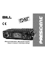 1
1
-
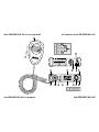 2
2
-
 3
3
-
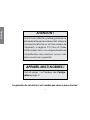 4
4
-
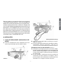 5
5
-
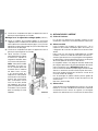 6
6
-
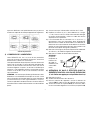 7
7
-
 8
8
-
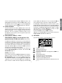 9
9
-
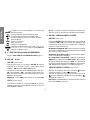 10
10
-
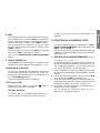 11
11
-
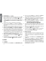 12
12
-
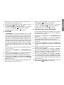 13
13
-
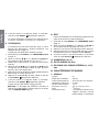 14
14
-
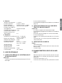 15
15
-
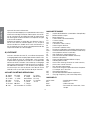 16
16
-
 17
17
-
 18
18
-
 19
19
-
 20
20
-
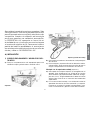 21
21
-
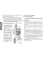 22
22
-
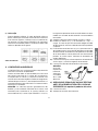 23
23
-
 24
24
-
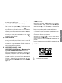 25
25
-
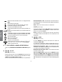 26
26
-
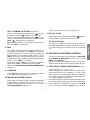 27
27
-
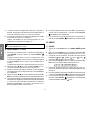 28
28
-
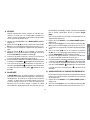 29
29
-
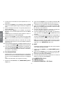 30
30
-
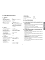 31
31
-
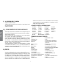 32
32
-
 33
33
-
 34
34
-
 35
35
-
 36
36
-
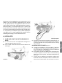 37
37
-
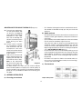 38
38
-
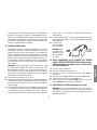 39
39
-
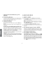 40
40
-
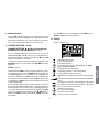 41
41
-
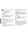 42
42
-
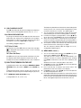 43
43
-
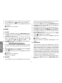 44
44
-
 45
45
-
 46
46
-
 47
47
-
 48
48
-
 49
49
-
 50
50
-
 51
51
-
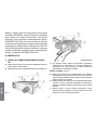 52
52
-
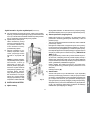 53
53
-
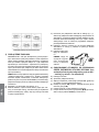 54
54
-
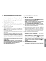 55
55
-
 56
56
-
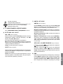 57
57
-
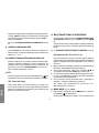 58
58
-
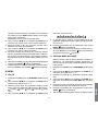 59
59
-
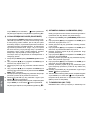 60
60
-
 61
61
-
 62
62
-
 63
63
-
 64
64
-
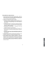 65
65
-
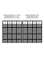 66
66
-
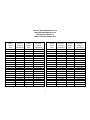 67
67
-
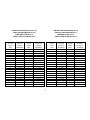 68
68
-
 69
69
-
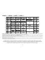 70
70
-
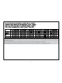 71
71
-
 72
72


PRESIDENT Bill ASC El manual del propietario
- Tipo
- El manual del propietario
en otros idiomas
- français: PRESIDENT Bill ASC Le manuel du propriétaire
- English: PRESIDENT Bill ASC Owner's manual
- polski: PRESIDENT Bill ASC Instrukcja obsługi
Artículos relacionados
-
PRESIDENT Taylor FCC El manual del propietario
-
-
-
-
-
PRESIDENT Richard El manual del propietario
-
PRESIDENT Ronald 10 El manual del propietario
-
-
-