Kawasaki KRH300AC El manual del propietario
- Categoría
- Herramientas de jardín
- Tipo
- El manual del propietario
Este manual también es adecuado para


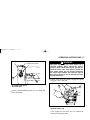
READ THIS FIRST!
For your safety, read this Owner’s Manual and understand it thoroughly before operating this HAND HELD BLOWER.
G
eneral
A power blower is a high-speed power tool, not a toy. For your own safety and the safety of others, read and be sure you
understand all of the safety precautions contained in the Owner’s Manual before operating the hand held blower. Keep
this
Owner’s Manual, and make it available to all persons who will be using the
hand held
blower. Periodically, review the
manual
to refresh your understanding of the safety instructions contained in it.
Careless or improper use can cause serious injury.
Obey the safety instructions contained in this manual as well as all applicable governmental and workplace safety
standards, regulations and ordinances. Your authorized Kawasaki dealer can show you how to operate your hand held
blower properly.
High pressure of air flow or small blown objects could injure eyes.
Do not direct airthe blast towards people or animals.
Do not allow children to operate the hand held blower.
Operators must
have
sufficient size, strength and
maturity
to be able
to lift and operate the
hand held
blower correctly for
extended periods of use. They must also be able to read, understand and follow the safety instructions in this manual.
Exhaust fumes contain poisonous carbon monoxide gas.
Operate your hand held blower only outdoors in a well-ventilated area. Stop the engine immediately if exhaust fumes
cause
you to experience symptoms of headache or nausea.
Gasoline is highly flammable and can be explosive under certain conditions.
Before refueling, stop the engine and allow it to cool. Do not smoke. Make sure areathe is well ventilated and free from
any source of flame or sparks, including appliances with a pilot light. Wipe up fuel spills immediately. Check for and
repair
an they fuel leaks before starting hand held blower.
O
perator
Inattention or fatigue can lead to serious injury.
Never operate the hand held blower under the influence of drugs or alcohol. Do not use the hand held blower if you
are sick
or taking medication that causes drowsiness. If you get tired while using the hand held blower, take a break.
Always wear appropriate protective gear to avoid injury.
Eye protection in the form of goggles or properly fitted safety glasses must be worn. Hearing protection, such as
earplugs, should also be used. Have your hearing checked regularly. Protect your hands and feet by always wearing
heavy-duty boots and non-slip gloves when operating the hand held blower.
E
N
G
L
I
S
H

Loose clothing or hair can lead to injury.
Unconfined hair and loose articles of clothing such as scarves, neckties, jewelry, and so forth, can be drawn into
intake of
the
thethe power blower. Always wear sturdy close-fitting long-sleeve shirts and long pants that still allow
freedom of movement. Secure hairyour to itkeep away from blower intake.
Stop the engine and make sure that the
blower fan is completely stopped before cleaning, checking, performing maintenace
or working on the hand held blower.
Gasoline is highly flammable and can burn or irritate skin.
Change clothing immediately if fuel is spilled on it. Never remove fuel cap while the engine is running.
Be alert for signs of repetitive stress injury.
Using a
hand held
blower or any vibrating
machinery
over a period of time may
cause
numbness, burning
sensations, or
other indications of injury. If you
experience
any
such symptoms
,
discontinue use
of the hand held blower and consult your
doctor.
Hand Held
Blower
Modifying the hand held blower may make it unsafe.
Never modify your
hand held
blower
,
except
as
advised
by Kawasaki in writing. Use only Kawasaki supplied or approved
attachments and repair parts.
Recoil starter rope can injure you if released suddenly.
When starting the engine, grasp the recoil starter firmly by the grip. Do not grasp the starter rope itself. Always control
the rope during rewind into the
the
housing. Releasing the starter rope suddenly may allow the rope to whip around and
injure you or damage the recoil starter mechanism.
Proper maintenance is essential for safety.
A well-maintained hand held blower is safer and
operates more
efficiently. Regularly
check hand held
blower
adjustments
and
replace worn or damaged parts. A worn out or damaged muffler can emit sparks and cause a fire. Increased
noise
levels can lead to hearing loss. Observe maintenance schedule in the Owner’s Manual.
Store hand held blower safely to prevent fire or equipment damage.
To avoid fuel leakage and fire hazard, always empty the fuel tank and r theun carburetor dry before storing your hand
blower. Old fuel can clog the carburetor and lead to hard starting or poor running conditions. Store
your
hand held
blower in
a dry, secure location out of the reach of children. When transporting hand heldyour blower in a
vehicle
, take
precautions
to secure it against damage from falling over and fuel spillage.
held

Whenever you see the symbols shown below, heed their
instructions!
Always follow safe operating and maintenance practices.
This warning symbol identifies special instruc-
tions or procedures which, if not correctly fol-
lowed, could result in personal injury, or loss of
life.
CAUTION
This caution symbol identifies special instruc-
tions or procedures which, if not strictly ob-
served, could result in damage to, or destruction
of equipment.
NOTE
This note symbol indicates points of particular interest
for more efficient and convenient operation.
WARNING
ENVIRONMENTAL PROTECTION
To protect our environment, properly dispose of used batteries, engine oil, gasoline, coolant, or other components that
you might discard.
Consult your authorized Kawasaki dealer or local environmental waste agency for the proper disposal procedures.

EMISSION CONTROL INFORMATION
Fuel Information
THIS ENGINE IS CERTIFIED TO OPERATE ON UNLEADED REGULAR GRADE GASOLINE ONLY.
A minimum of 87 octane of the antiknock index is recommended. The antiknock index is posted on service station
pumps in the U.S.A.
Emission Control Information
To protect the environment in which we all live, Kawasaki has incorporated exhaust emission control system
(EM) in
an
compliance with applicable regulations of the United States Environmental Protection Agency and the California
Air
Resources Board.
Also, depending on when your engine was produced, it
may have an assigned emissions durability
period.
* See below for the engine emissions durability period that may apply to your engine.
Exhaust Emission Control System
This system reduces the amount of pollutants discharged into the atmosphere by the exhaust of this engine. The fuel,
ignition and exhaust systems of this engine have been carefully designed and constructed to ensure an efficient engine
with low exhaust pollutant levels.
Engine Emissions Compliance Period
California All Other States
Model Year - 2007 and later Engines less than 50 cc
Durability Period - 300 hours Model Year - 2007 and later
Durability Period - 300 hours
* If your engine has an assigned emissions durability period it will be located on the certification label attached
to the engine (IMPORTANT ENGINE INFORMATION : useful life hours).
Evaporative Emission Control System
The evaporative emission control system for KRH300AC model consists of low permeation fuel tank.
Additionally, Kawasaki has incorporated an evaporative emission control system in compliance with
applicable regulations of the California Air Resources Board.

Maintenance and Warranty
Proper maintenance is necessary
to
ensure
that your hand held blower will continue to have low emission levels. This
Owner
’s
Manual contains those maintenance recommendations for your engine. Those items identified by the Periodic
Maintenance Chart are necessary to ensure compliance with the applicable standards.
As the owner of
this
hand held
blower
,
you have the
responsibility
to make sure that
the
recommended
maintenance
is
carried out according to the instructions in this Owner’s Manual at your own expense.
The Kawasaki Limited Emission
Control System Warranty
requires that
you return
your
to an authorized
Kawasaki dealer for remedy under warranty. Please read the warranty carefully, and keep it valid by complying with the
owner
’s
obligations it contains.
Tampering with Emission Control System Prohibited
Federal law and California state law prohibits the following acts or the causing thereof: (1) the removal or rendering
inoperative by any person other than for purposes of maintenance, repair, or replacement, of any device or element of
design incorporated into any new engine for the purposes of emission control prior to its sale or delivery to the ultimate
purchaser or while it is in use, or (2) the use of the engine after such device or element of design has been removed or
rendered inoperative by any person.
Among those acts presumed to constitute tampering are the acts listed below.
Do not tamper with the original emission related parts.
Carburetor and internal parts
Spark plug
Magneto or electronic ignition system
Fuel Filter
Muffler or any internal portion of the muffler
Air
Fuel tank
cleaner element
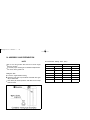
ITEM Specification
Valve Clearance Not Applicable
Not Adjustable
Not Adjustable
Not Adjustable
Ignition Timing
Idle Speed
Idle Mixture Screw
High Mixture Screw
Spark Plug Gap
hand held blower
2,800 3,200 r/min (rpm)

FOREWORD
We are pleased you have chosen the Kawasaki Hand Held Blower.
This Owner ’s
Owner ’s Manual.
Man
ual is provided to aid you in the safe and reliable operation of your hand held blower. READ
To
ensure
a long, trouble-free life for your Hand Held Blower, give it proper care and
maintenance
in
accordance with
this
or by any means, electronic mechanical photocopying, recording or otherwise, without the prior written permisson of
Kawasaki Motors Corp., U.S.A. Although every possible care has been taken
to make this manual as complete and accurate
as possible, Kawasaki cannot guarantee against errors and omissions. Due
to improvements in design and performance
during production, procedures and specifications are subject to change without prior notice. Illustrations are provided for general
reference purposes, and may differ from actual product aspects and components.
All rights reserved. No part of this publication may be reproduced, stored in a retrieval system, or transmitted in any form
KAWASAKI MOTORS Corp.,U. S. A.
2007
First Edition (1) : March 2007 (I)
AND UNDERSTAND IT THOROUGHLY BEFORE OPERATING YOUR HAND HELD BLOWER.

TABLE OF CONTENTS
Specifications..............................................................................8
Assembly and Preparation ......................................................... 9
.................................10
Fuel and Oil...........................................................................13
Operating Instructions .............................................................. 15
Starting the Engine ...............................................................15
Warming Up ..........................................................................18
Stopping the Engine..............................................................19
Maintenance and Adjustment...................................................20
Periodic Maintenance Chart..................................................20
Air Cleaner Service. ...............................................................22
Fuel Filter Service.................................................................23
Spark Arrester Cleaning Service ..........................................24
Storage.....................................................................................25
Catalytic Converter ...................................................................26
Troubleshooting Guide..............................................................27
............................28
.................................................... 9
.................................................................10
.......................................................12
Location of Parts and Tools
Location of Parts for Engine Assembly
Location of Labels
Blower Pipes Installation
Emission Control Systems Limited Warranty

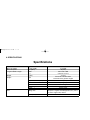
8 SPECIFICATIONS
Specifications
v
eight
Model
Max. Air olume
Max. Air speed
Length x Width x Height
W
Engine
Fuel
m
3
/min (CFM)
m/s (MPH)
Metric
(in.)
kg (lbs)
Type
Displacement ml (cu. in)
Carburetor
Ignition
Spark plug
Starter
Mixing ratio
ank capacity LT
KRH300A/AC
12.5 (450)
56 (125)
340 x 245 x 360
(13.4 x 9.7 x 14.2)
4.4 (9.7)
Forced air cooled 2-stroke,
horizontal shaft, gasoline engine
26.3 (1.61)
Diaphragm type
Solid state ignition
NGK BPMR7A-9
Recoil starter
50 parts of regular unleaded gasoline to 1 part of
2-stroke engine oil by volume
0.5

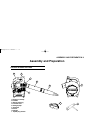
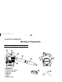
ASSEMBLY AND PREPARATION 9
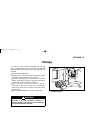
Assembly and Preparation
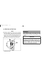
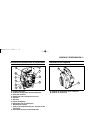
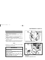
Location of Parts and Tools
A
B
C
D
E
F
G
H
I
A. Engine assembly
B. Handle
C. Blower housing
D. Throttle lever
E. Straight pipe
F. End pipe
G. Cover
H. Goggle
I. Spark plug wrench

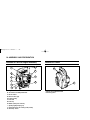
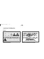
Location of LabelsLocation of Parts for Engine Assembly
A. Emission certification label
B. Warning label
A. Engine cover
B. Air cleaner assembly/Carburetor
C. Recoil starter
D. Recoil starter grip
E. Priming pump
F. Fuel tank
G. Tank cap
H. Muffler (with spark arrester)
I . Spark plug/Spark plug cap
10 ASSEMBLY AND PREPARATION
J. Enrichment lever for starting cold (choke)
K. Start/stop switch
A
B
A
B
C
D
E
F
G
H
I
J
K

ASSEMBLY AND PREPARATION 11
Labels
Warning Label
Emission Certification Label
! !
W A R N I N G D A N G E R
ROTATING FAN! WHEN USED AS A BLOWER THE AIR
INTAKE SCREEN MUST BE CLOSED AND SECURE WITH THE
KNOB NUT, WHEN USED AS A VACUUM THE VACUUM TUBE
AND BAG MUST BE IN PLACE AND SECURELY FASTENED.

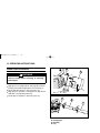
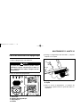
12 OPERATING INSTRUCTIONS
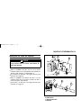
Blower Pipes Installation
Stop the engine before installing or removing
blower pipes.
WARNING
Align groove in straight pipe B with pegs D on blower
housing A and slide straight pipe B on to housing (1).
Rotate pipe B clockwise to lock it into place (2).
Align groove in end pipe C with pegs D on pipe B and
slide pipe C until proper position (3).
Rotate pipe C clockwise to lock it into place (4).
A. Blower housing
B. Straight pipe
C. End pipe
D. Peg
A
B
B
D
A
C
(1)
(2)
(1)
(2)
(3)
(4)

13ASSEMBLY AND PREPARATION
Fuel and Oil
Type:
The fuel is mixture of gasoline and oil. A 50 to 1 mixture
is recommended (50 parts gasoline to 1 part oil). Mix it
thoroughly before pouring it into the hand
held blower
fuel
tank.
CAUTION
Alcohol or "gasohol" may damage the engine.
The hand held blower is designed to run on a
50-to-1
mixture of regular unleaded gasoline (87 octane)
and quality TC class 2–stroke oil or JASO FC
class for air-cooled engines.
The octane rating of gasoline is a measure of its
Pour the measured amount of 2-stroke oil into an approved
resistance to detonation or "knocking". Use a gasoline
with an octane rating equal to or higher than that sho
gasoline container and add the specified amount of gasoline
to the container.
wn
in the table. The Antiknock Index is an average of
the
Research Octane No. (RON) and the Motor Octane
No.
(MON). The Antiknock Index is posted on service
station
pumps in the U.S.A. If the Antiknock Index is not
posted,
be sure the Research Octane No. is adequate.
Minimum
Octane Rating Method
Rating
(RON
+
MON)
Antinock Index
2
87
Researc h Octane Number (RON) 91
Recommended engine oil: High quality 2-stroke air
cooled engine oil
JASO service Clasification: FC class
Mixing:
Gasoline is highly flammable and can be explo-
sive under certain circumstances.
Never overfill the thetank so that fuel rises into
filler neck. Heat may thecause fuel to expand
and overflow through vents in thethe tank cap.
After refueling, make sure cap is closed securely.
If gasoline is spilled on engine or tank, wipe it off
immediately.
WARNING

ASSEMBLY AND PREPARATION14
NOTE
Do not use the gasoline that has been stored longer
than two months.
To ensure proper starting at low ambient temperatures,
use fresh,
Filling the Tank:
winter grade fuel.
Level the engine before fueling.
Open the fuel tank cap and fill the tank with 50:1 gas/
oil pre-mixed fuel.
Pour slowly to avoid "spit back” and allow air to escape
from the tank.
Recommended Mixing Ratio (50:1)
Gasoline 2 stroke oil
Gal Liter OZ mL
1 3.79 2.6 76
2 7.6 5.1 152
3 11.4 7.8 228
4 15.1 10.4 304
5 18.9 13.0 380
6 22.7 15.6 456

OPERATING INSTRUCTIONS 15
Operating Instructions
Starting the Engine
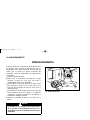
Checking throttle operation
Move the throttle lever and setting lever through its full
range of motion. It must move smoothly all the way, as
shown, without sticking or binding.
CAUTION
Start (ON) Stop
B
A
A. Throttle lever
B. Throttle setting lever
Place the hand held blower on firm ground.
Move the stop switch to the "ON" position.
Starting the engine
Engine speed can not be adjusted if the throttle
lever and setting lever does not move
smoothly all the way and
without binding.
A
A. Stop switch

16 OPERATING INSTRUCTIONS
Slowly push the priming pump several times until the
fuel comes out of the overflow tube. When the gasoline
flows, stop pushing the priming pump.
NOTE
NOTE
The fuel that flows by pushing the priming pump is
designed to return to the fuel tank.
There is no fear of flooding the engine, so push the
priming pump enough times to get the engine started.
Firmly turn the enrichment lever to the "Starting"
position. (The enrichment lever will be turned to
"clockwise direction" according to "Arrow mark"
indicated on the lever.)
When moving the enrichment lever to the "Starting"
position, it will lock in to place.
The enrichment lever will automatically return to the
running position when the operator grasps the throttle
lever momentarily.
When the engine is already warm or on hot days, do
not turn the enrichment lever.
A
B
C
A. Priming pump
B. Overflow tube
C. Enrichment lever
Running position
Starting position

OPERATING INSTRUCTIONS 17
WARNING
A. Throttle setting lever
B. Throttle lever
Hold the Hand Held Blower with your left hand and
press down firmly.
The recoil starter rope can cause injury if it is
released suddenly. When starting the engine,
grasp the recoil starter firmly by the grip. Do not
grasp the starter rope itself. Always control the
rope during rewind into the housing. Releasing
the starter rope suddenly may allow the rope to
whip around and injure you or damage the recoil
starting mechanism.
Pull the recoil starter grip slowly to engage the starter,
then give a short, quick pull.
A. Handle
B. Recoil starter grip
If the engine fires, but does not run continuously,
repeat the starting procedure.
A
B
B
Idle Position Half Position
Full Throttle Position
A

18 OPERATING INSTRUCTIONS
NOTE
Warming Up
CAUTION
Should the engine fail to start, do not try to pull the
recoil starter grip too many times with the enrichment
lever at the "Starting" position. This will cause the fuel
to flood into the cylinder and make starting even more
difficult. In this case, set the enrichment lever to the
"Running" position and repeat the starting procedure.
After starting, vary the engine speed a few minutes.
A
A. Enrichment lever
After starting the engine, run the engine at the idling
speed (throttle lever position is fully CLOSED) for a few
minutes.
Allow sufficient warm-up time to prevent engine
damage. The hand held blower should be run at
idling speed for 3 to 5 minutes to allow it to warm
up before applying a load. This will allow oil to
reach all engine parts, and allow piston
clearance to reach design specifications.

OPERATING INSTRUCTIONS 19
Stopping the Engine
Ordinary Stop
Return the throttle lever to the idling position, and keep
the engine running at idling speed for a few second.
Slide the switch to the "STOP" position with "click".
Slide the switch to the "STOP" position with "click".
Emergency Stop
Release the throttle lever.
A. Engine switch
A
NOTE
If adjustment is needed, it should be performed by
your authorized Kawasaki dealer.
A
A. Idling screw
Idling Speed
If the engine does not run at the idling speed, it may be
set too low, turn the idling adjust screw clockwise to
increase the engine idling speed. The stable idling
speed is about 3000 r/min (rpm).
Fuel Adjustment
The carburetor has been adjusted to the optimum fuel
supply at the factory. Do not reset the carburetor setting.

20
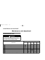
Maintenance and Adjustment
Periodic Maintenance Chart
Accidental engine starting can cause injury. Al-
ways remove the spark plug cap before servicing
the engine to prevent accidental starting.
Interval
Maintenance
Daily First20
hours
Every
20
hours
Every
50
hours
Every
100
hours
Check and replenish fuel
Check for fuel leakage
Check bolts, nuts and screws for looseness and loss
Check throttle lever operation
Check start/stop switch operation
Clean fuel filter
* Clean air cleaner element
Tighten bolts, nuts and screws
Clean spark plug and adjust electrode gap
MAINTENANCE AND ADJUSTMENT
WARNING

21
Interval
Maintenance
Daily First20
hours
Every
20
hours
Every
50
hours
Every
100
hours
Remove carbon deposits in the exhaust pipe of muffler
Clean spark arrester screen
K
Chec
K
k the sliding portion of crankshaft, connecting rod etc.
Fuel tube
Replace every 3 years
NOTE
The service intervals indicated are to be used as a
guide.
Service with an Asterisk (*) should be performed more
frequently depending on the severity of operating
condition.
Remove dust and dirt from cylinder fins
Remove carbon deposits on piston head and inside cylinder
MAINTENANCE AND ADJUSTMENT
K:
Service should be performed by an authorized
Kawasaki dealer.

22
Air Cleaner Service
Clean the element every 20 hours.
Twist off the air cleaner cap, and remove the element.
NOTE
Operating in dusty condition may require more frequent
maintenance.
CAUTION
Improper air cleaner cleaning can result in
engine
damage.
Do not use compressed air to clean or dry
the the
the
air cleaner. Do not operate engine with air
cleaner removed.
A. Air cleaner cap
B. Element
C. Air cleaner case
MAINTENANCE AND ADJUSTMENT
A. Air cleaner cap
Clean the element in a bath of kerosene or high flash-
point solvent.
Soak the element in new 2-stroke engine oil, and
squeeze it to remove excess oil.
Fit the element in the air cleaner case, then reinstall
the air cleaner cap firmly.
Always clean the air cleaner with an approved
high flash point solvent only. Never use gasoline.
A
C
B
A

23
Fuel Filter Service
Clean the fuel filter element every 20 hours of operation.
Improper use of solvents can result in fire or an
explosion.
Clean the fuel filter in a well-ventilated area
away from sources of sparks or flame, including
appliances with a pilot light. Never use gasoline
or low-flash point solvents to clean the fuel filter.
Take the fuel filter out of the fuel tank, and then
remove the fuel filter assembly from the fuel tube.
Clean the fuel filter assembly in a bath of high flash-
point solvent.
Dry the fuel filter assembly before installing.
If fuel does not flow better with the fuel filter cleaned,
replace the fuel filter assembly with a new one.
A. Fuel filter
B. Fuel tank
C. Fuel tube
MAINTENANCE AND ADJUSTMENT
WARNING
A
C
B

24
MAINTENANCE AND ADJUSTMENT
Spark Arrester Cleaning Service
Clean sparthe k arrester every 100 hours of operation.
Hot engine parts can cause severe burns.
Allow the engine to stop and cool before servicing.
Remove the arrester cover.
A. Muffler
B. Spark arrester cover
C. Spark arrester
D. Screw
Take the spark arrester out of the muffler, and then
clean by brushing it.
A. Spark arrester
B. Brush
Reinstall the spark arrester, and the arrester cover.
Tighten all fasteners securely.
WARNING
A
B
C
D
A
B

STORAGE 25
WARNING
Storage
If you plan to store the hand held blower for over 30
days, completely drain the fuel to prevent gum deposits
forming on essential carburetor parts, the fuel filter, and
fuel tank
Clean the hand held blower.
Remove all the fuel from the tank and run the engine
at an idle to use up the fuel in the carburetor.
Remove the spark plug, pour in 0.5 ml of new 2-stroke
engine oil through the plug hole, pull the recoil starter
several times, and reinstall the spark plug.
Slowly pull the recoil starter until you feel the
resistance of the piston rising on its compression
stroke. This closes both the intake and exhaust ports
with the piston.
Store the hand held blower in a clean and dry place.
Gasoline is a toxic substance. Dispose of
gasoline properly. Contact your local authorities
for approved disposal methods.
A
A. Spark plug hole

26 CATALYTIC CONVERTER
Catalytic Converter
Catalytic Converter:
This small engine is equipped with a catalytic converter
in the exhaust system to significantly reduce exhaust
emissions. The catalytic converter converts carbon
monoxide and hydrocarbons into harmless carbon dioxide
and water.
The catalytic converter requires special care.
Use only unleaded gasoline. Never use leaded gaso-
line.
Leaded gasoline significantly reduces the capability of
the catalytic converter.
Do not use 2–stroke oil that contains Phosphorus (P),
Lead (Pb), or Sulfur (S). These elements will reduce
the life and performance of the catalytic converter.
Before shutting the engine off, allow it to idle for a short
while.
NOTE
Never stop the engine during operation while running
above idle speed.
Shut off the engine and allow it to cool before trans-
porting or storing the unit.
Do not put the unit on dry grass or near any flammable
object unless the engine is cold or cooled down.

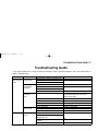
27TROUBLESHOOTING GUIDE
Troubleshooting Guide
If the engine malfunctions, carefully examine the symptoms and the operating conditions, and use the table below as
a guide to troubleshooting.
Symptom Probable cause Remedy
Engine won’t Insufficient
Faulty Piston, Cylinder and Piston ring
K
start or output compression
Loose spark plug Tighten properly.
is low
Loose cylinder bolts
No fuel to
No fuel in fuel tank Fill fuel tank.
combustion
Blocked fuel filter or tube Clean.
chamber
Blocked air vent in tank cap
Faulty carburetor
K
Spark plug
Over-rich fuel/air mixture
fouled by
Rotate engine with spark plug
fuel
removed to discharge excess fuel.
Clean spark plug.
Clogged air cleaner Clean.
Faulty carburetor
K
Incorrect grade/type of fuel Change gasoline.
Water in fuel
No spark or
Faulty spark plug Replace spark plug.
Replace spark plug.
weak spark
Faulty ignition coil
K
Engine switch left in "O" (Stop) position Tu r n
engine switch
to "l" (Start) position.
Low output Engine over-
heats
Clogged air cleaner Clean.
Recoil starter or cooling air path
clogged with dirt.
Carbon built-up in combusition
K
chamber
Poor ventilation around engine Select a better location.
K: Service should be performed by an authorized Kawasaki dealer.

28
KAWASAKI LIMITED WARRANTY CALIFORNIA
AND FEDERAL EMISSIONS CONTROL SYSTEMS
SMALL OFF-ROAD ENGINES
The California Air Resources Board, the Environmental Protection Agency (EPA), and Kawasaki Motors Corp., U.S.A. (hereinafter
"Kawasaki") are pleased to explain the Emissions Control Systems Warranty on your Kawasaki small off-road engine. In California and
other states, new small off-road engines must be designed, built and equipped to meet stringent anti-smog standards. Kawasaki must
warrant the emissions control system on your small off-road engine for the period of time listed below provided there has been no
abuse, neglect or improper maintenance of your small off-road engine. Your emissions control system may include parts such as the
carburetor or fuel-injection system, the ignition system, and catalytic converter. Also included may be hoses, belts, connectors and other
emissions related assemblies. Where a warrantable condition exists, Kawasaki will repair your small off-road engine at no cost to you
including diagnosis (if the diagnostic work is performed at a Kawasaki small off-road engine dealer), parts and labor.
OWNERS WARRANTY RESPONSIBILITIES. The following obligations must be fulfilled by the owner to maintain the validity of the
Kawasaki California / EPA Emissions Systems Warranty:
(a) As the small off-road engine owner, you are responsible for the performance of the required maintenance listed in your owner's
manual. Kawasaki recommends that you retain all receipts covering maintenance on your small off-road engine, but Kawasaki
cannot deny warranty solely for the lack of receipts or for your failure to ensure the performance of all scheduled maintenance.
(b) You are responsible for presenting your small off-road engine to an authorized Kawasaki small off-road engine Dealer as soon as
a problem exists. The warranty repairs should be completed in a reasonable amount of time, not to exceed 30 days.
(c) As the small off-road engine owner, you should also be aware that Kawasaki may deny you warranty coverage if your small off-
road engine or a part has failed due to abuse, neglect, improper maintenance or unapproved modifications.
(d) If you have any questions regarding your warranty rights and responsibilities, you should contact Kawasaki Motors Corp., U.S.A.,
Consumer Services Department, 5080 36th Street, S.E., Grand Rapids, MI 49512, 949-460-5687.
1. COVERAGE. Kawasaki warrants to the initial owner and each subsequent purchaser that the small off-road engine is free from
defects in materials and workmanship which cause a failure of a warranted part for a period of two years. Kawasaki is liable for
damages to other engine components caused by the failure of a warranted part still under warranty. The 1995 and later small off-road
engines are warranted for two years in California. In all other states, 1997 and later model year small off-road engines are warranted
for two years. If any emissions-related part on your engine is defective, the part will be repaired or replaced by Kawasaki. This
warranty time period shall begin on the date the small off-road engine is delivered to the initial purchaser, or on the date the small
off-road engine is first placed in service.
Warranty defects shall be remedied during customary business hours at any authorized Kawasaki small off-road engine dealer
located within the United States of America. Any manufacturer-approved replacement part may be used in the performance of any
warranty maintenance or repairs on emissions-related parts, and must be provided without charge to the owner if the part is still
under warranty. Any part or parts replaced under this warranty shall become the property of Kawasaki.

29
The emissions related warranted parts are specifically defined by the California Air Resources Board's Emissions Warranty Parts
List. (EPA's regulations do not include a parts list, but EPA considers emissions-related parts to include all parts listed here.) These
warranted parts are: carburetor and internal parts, spark advance/retard system, cold start enrichment system, magneto or
electronic ignition system, catalytic converter, intake manifold, exhaust manifold, air cleaner element, fuel tank, and fuel tank cap,
and spark plugs if failure occurs prior to the first required scheduled replacement, hoses, clamps, fittings, gaskets, sealing devices,
mounting hardware and tubing used directly in these parts.
Since emissions related parts may vary slightly from model to model, certain models may not contain all of these parts and certain
models may contain functionally equivalent parts.
2. LIMITATIONS. This Emissions Control Systems Warranty shall not cover any of the following:
(a) Repair or replacement required as a result of (i) misuse or neglect, (ii) lack of required maintenance, (iii) repairs improperly
performed or replacements improperly installed, (iv) use of replacement parts or accessories not conforming to Kawasaki
specifications which adversely affect performance and/or durability, (v) alterations or modifications not recommended or approved
in writing by Kawasaki.
(b) Replacement of parts and other services and adjustments necessary for required maintenance at and after the first scheduled
replacement point.
3. LIMITED LIABILITY.
(a) The liability of Kawasaki under this Emissions Control Systems Warranty is limited solely to the remedying of defects in materials
or workmanship by any authorized Kawasaki small off-road engine dealer at its place of business during customary business
hours. This warranty does not cover inconvenience or loss of use of the small off-road engine or transportation of the small off-
road engine to or from the Kawasaki Dealer. KAWASAKI SHALL NOT BE LIABLE FOR ANY OTHER EXPENSE, LOSS OR
DAMAGE, WHETHER DIRECT, INCIDENTAL, CONSEQUENTIAL (EXCEPTION LISTED UNDER COVERAGE) OR
EXEMPLARY ARISING IN CONNECTION WITH THE SALE OR USE OF OR INABILITY TO USE THE KAWASAKI SMALL OFF-
ROAD ENGINE FOR ANY PURPOSE.
(b)
NO EXPRESS EMISSIONS CONTROL SYSTEMS WARRANTY IS GIVEN BY KAWASAKI WITH RESPECT TO THE KAWASAKI
SMALL OFF-ROAD ENGINE EXCEPT AS SPECIFICALLY SET FORTH HEREIN. ANY EMISSIONS CONTROL SYSTEMS
WARRANTY IMPLIED BY LAW, INCLUDING ANY WARRANTY OF MERCHANTABILITY OR FITNESS FOR A PARTICULAR
PURPOSE, IS EXPRESSLY LIMITED TO THE EMISSIONS CONTROL SYSTEMS WARRANTY TERMS SET FORTH HEREIN.
THE FOREGOING STATEMENTS OF WARRANTY ARE EXCLUSIVE AND IN LIEU OF ALL OTHER REMEDIES.
(c) No dealer is authorized to modify this Kawasaki Limited Emissions Control Systems Warranty.
(d) Kawasaki is not liable for parts which are not genuine Kawasaki parts except when genuine Kawasaki parts cause damage to
non-Kawasaki parts.
4. LEGAL RIGHTS. THIS WARRANTY GIVES YOU SPECIFIC LEGAL RIGHTS, AND YOU MAY ALSO HAVE OTHER RIGHTS.
5. THIS WARRANTY IS IN ADDITION TO THE KAWASAKI LIMITED SMALL OFF-ROAD ENGINE WARRANTY.
Effective 12/01/2005 P/N 99969-1942
Printed in U.S.A S:WTY


¡LEA ESTO PRIMERO!
Por su seguridad, lea el Manual del Propietario y comprenda su contenido antes de comenzar la utilización del
SOPLADOR DE MANO.
General
Un soplador de mano es una herramienta de alta velocidad, no es un juguete. Para su propia seguridad y la de los
demás, lea y asegúrese de entender todas las precauciones sobre seguridad que vienen contenidas en el Manual del
Propietario antes de comenzar a utilizar el soplador de mano. Guarde este Manual del Propietario, y póngalo a
disposición de todas las personas que vayan a hacer uso del soplador de mano. También le recomendamos que lea de
vez en cuando el manual para no olvidar sus conocimientos sobre las instrucciones sobre seguridad que vienen
contenidas en el mismo.
Una utilización descuidada o inadecuada puede ser causa de serias lesiones.
Observe las instrucciones sobre seguridad contenidas en este manual así como todas las normas gubernamentales y
reglas de seguridad en los lugares de trabajo, regulaciones y ordenanzas. Su distribuidor autorizado de Kawasaki
puede enseñarle cómo utilizar el soplador de mano de manera adecuada.
El soplado de un flujo de aire a gran presión o el soplado de pequeños objetos puede causar lesiones oculares.
No dirija el chorro de aire hacia personas o animales.
No permita que ningún niño manipule el soplador de mano.
Los operarios que vayan a utilizar el soplador de mano deberán tener la suficiente masa corporal, fuerza y ser lo
suficiente maduros como para levantar y utilizar correctamente el soplador de mano durante un periodo de utilización
lo suficientemente amplio. Estos deberán también ser capaces de leer, entender y seguir las instrucciones sobre
seguridad contenidas en este manual.
Los gases de escape contienen gases venenosos de monóxido de carbono.
Utilice este soplador de mano sólo en lugares abiertos y bien ventilados. Pare inmediatamente el soplador de mano si
nota que los gases o humos de escape le producen síntomas de dolor de cabeza o nauseas.
La gasolina es un producto altamente inflamable y puede convertirse en una sustancia explosiva en algunas
circunstancias.
Antes de proceder al rellenado de gasolina, pare el motor y permita que este se enfríe. No fume. Asegúrese de que la
zona está bien ventilada y que no haya fuentes de fuego o chispas, incluyendo aparatos con luces piloto. Limpie los
vertidos que se puedan haber desparramado inmediatamente. Compruebe y repare cualquier fuga de combustible
antes de arrancar el soplador de mano.
E
S
P
A
Ñ
O
L

Operario
Una distracción o la fatiga puede ser conducir a serias lesiones.
Nunca opere el soplador de mano bajo la influencia de drogas o alcohol. No utilice el soplador de mano si usted está
enfermo o en caso de que esté tomando medicamentos que causen somnolencia. Si se cansa mientras utiliza el
soplador de mano, coja un descanso.
Siempre lleve puesta ropa protectora apropiada para evitar heridas.
Es necesario que utilice anteojos o gafas de seguridad adecuadamente ajustadas para protegerse los ojos. Proteja
también sus oídos, usando por ejemplo tapones para oídos. Haga que le examinen sus oídos regularmente. Proteja
sus manos y pies llevando siempre botas resistentes y guantes no resbaladizos cuando opere el soplador de mano.
Una ropa o cabello suelto puede ser causa de lesiones o heridas.
El cabello largo y los artículos de ropa sueltos, tales como bufandas, collares, joyas, etc. pueden quedar cogidos en
ramas o en partes o piezas rotatorias del soplador de mano. Póngase siempre camisas resistentes de mangas largas
bien ajustadas y pantalones largos que le permitan a la vez libertad de movimiento. Asegure su cabello de manera que
no pueda ser cogido por la entrada del soplador de mano.
Pare el motor y asegúrese de que el ventilador está completamente parado antes de realizar las labores de limpieza,
de comprobación, cualquier labor de mantenimiento o realizar cualquier trabajo en el soplador de mano.
La gasolina es altamente inflamable y puede quemar o irritar la piel.
Cámbiese la ropa inmediatamente si le caen salpicaduras de combustible sobre la ropa. Nunca remueva el tapón del
combustible mientras el motor está funcionando.
Esté alerta para evitar heridas por fatiga.
Utilizando un soplador de mano o cualquier maquinaria vibratoria durante un periodo de tiempo prolongado puede
causar entumecimiento, sensaciones de quemadura, y otras indicaciones de heridas. Si usted experimenta cualquier
de estos síntomas, deje de utilizar el soplador de mano y consulte a su doctor.
Soplador De Mano
La modificación del soplador de mano lo puede hacer inseguro.
Nunca modifique su soplador de mano, excepto si esto es aconsejado por Kawasaki mediante escrito. Utilice sólo
aditamentos y repuestos suministrados o aprobados por Kawasaki.
La cuerda del arrancador de retroceso puede herirle al soltarla repentinamente.
Al poner en marcha el motor, tenga el arrancador de retroceso firmemente cogido por la empuñadura. No sujete la
cuerda del mismo arrancador. Siempre controle la cuerda durante el rebobinado dentro del alojamiento. Soltando la
cuerda del arrancador de repente puede hacer que la cuerda dé latigazos alrededor y le hiera o dañe el mecanismo del
arrancador de retroceso.

Un mantenimiento adecuado es esencial para su seguridad.
Un soplador de mano bien mantenido es más seguro y su utilización más eficiente. Compruebe regularmente los
ajustes del soplador de mano y sustituya partes o piezas que estén gastadas o dañadas. Un tubo de escape que esté
deteriorado o dañado puede emitir chispas y causar un incendio. Un ruido de niveles desproporcionados puede
conducir a una pérdida auditiva. Observe los periodos de mantenimiento en el Manual del Propietario.
Almacene el soplador de mano de manera segura para prevenir incendios o el deterioro del equipo.
Para evitar fugas de combustible y peligro de fuego, vacíe siempre el tanque de combustible y haga que se consuma el
combustible que haya en el carburador antes de almacenar su soplador de mano. El viejo combustible puede atascar el
carburador y empeorar las condiciones de arranque y funcionamiento. Almacene su soplador de mano en un lugar
seco y seguro que no esté al alcance de los niños. Cuando transporte el soplador de mano en un vehículo, tome
precauciones para asegurarlo contra los daños que pudieran ocasionarse al caerse y salpicar de combustible.

PRECAUCIÓN
NOTA
AVISO
PROTECCIÓN MEDIO AMBIENTAL
Para proteger nuestro medio ambiente, deseche correctamente de las pilas usadas, el aceite del motor, la gasolina, el
fluido refrigerante u otros componentes que pueda desechar en el futuro.
Consulte a un concesionario autorizado Kawasaki o a la oficina medio ambiental local para informarse de los
procedimientos adecuado.
Siempre que usted vea los símbolos mostrados aquí,
preste atención a sus instrucciones. Siempre siga las
prácticas de la operación y mantenimiento seguros.
Este símbolo de aviso indica instrucciones o
procedimientos especiales que, si no se cumplen
correctamente, podrían resultar en herida
personal o pérdida de la vida.
Este símbolo de precaución identifica
instrucciones o procedimientos especiales que, si
no se observan estrictamente, podrían resultar en
daño o destrucción del equipo.
Este símbolo indica puntos de particular interés para
operación más eficiente y conveniente.

INFORMACIÓN SOBRE EL CONTROL DE EMISIONES
Información sobre el Combustible
ESTE MOTOR HA SIDO CONCEBIDO PARA SER UTILIZADO SÓLO CON GASOLINA REGULAR SIN PLOMO.
Se recomienda un mínimo octanaje de índice antidetonante de 87 octanos. El índice antidetonante está publicado en
las estaciones de servicio en los Estados Unidos.
Información sobre el Control de Emisiones
Para proteger el medio ambiente en el que vivimos, Kawasaki ha incorporado un sistema de control de las emisiones
de escape (EM) que cumplen las regulaciones existentes de la Agencia de Protección Medioambiental de los Estados
Unidos, y del Comité de Recursos del Aire de California. Adicionalmente, Kawasaki ha incorporado un sistema de
control de emisiones evaporativas de acuerdo con las regulaciones aplicables del Comité de Recursos del Aire de
California. También, dependiendo de cuándo se fabricó su motor, puede que se le haya asignado un periodo de
durabilidad.
*Vea debajo el periodo de durabilidad de las emisiones del motor que puede serle aplicado a su motor.
Sistema de Control de las Emisiones de Escape
Este sistema reduce la cantidad de elementos que producen polución descargados a la atmósfera por el sistema de
escape del motor. El combustible, el sistema de encendido y el sistema de escape de este motor han sido
cuidadosamente diseñados y construidos para asegurar un motor eficiente con niveles de contaminantes de escape
bajos.
Sistema de Control de Emisiones Evaporativas
El sistema de control de las emisiones evaporantes para el modelo KRH300AC consiste en un depósito de combustible
de baja permeación.
Periodo de Conformidad de las Emisiones del Motor
California
Año Modelo – 2007 y posterior
Periodo de Durabilidad – 300 horas
Todos los demás Estados
Motores de menos de 50 cc
Año Modelo - 2007 y posterior
Periodo de Durabilidad – 300 horas
* Si a su motor se le ha asignado un periodo de durabilidad de las emisiones, este aparecerá en la etiqueta de
certificación que hay pegado sobre el motor (INFORMACIÓN IMPORTANTE SOBRE EL MOTOR: horas de
utilización).

ELEMENTO Especificaciones
Holgura de la válvula No aplicable
No ajustable
No ajustable
No ajustable
Reglaje del encendido
Velocidad en vacío
Tornillo Mezclado Ralentí
Tornillo Mezcla Alta
Holgura de la Bujía
2.800 – 3.200 r/min. (rpm)
0,8 - 0,9 mm (0,031 - 0,035 pul.)
Mantenimiento y Garantía
Un mantenimiento apropiado es necesario para asegurar que su soplador de mano siga manteniendo los niveles bajos
de emisión. Este Manual del Propietario contiene esas recomendaciones sobre mantenimiento que deben llevarse en su
motor. Esos elementos identificados por el Gráfico de Mantenimiento Periódico son necesarios para asegurar que
cumplen los requisitos con las normas aplicables.
Como propietario de este soplador de mano, usted tiene la responsabilidad para asegurar que se las labores de
mantenimiento son llevadas a cabo de acuerdo con las instrucciones del Manual del Propietario por sus propios medios.
La garantía Limitada del Sistema de Control de Emisiones requiere que usted lleve el soplador de mano a un
distribuidor de Kawasaki autorizado para que se ponga remedio bajo la garantía. Por favor lea la garantía
cuidadosamente, y manténgala para que esta sea validad cumpliendo las obligaciones sobre el propietario que contiene.
Manipulación con el Sistema de Control de Emisiones Prohibido
Las leyes federales y del Estado de California prohíben los siguientes actos o hacer lo siguiente: (1) La extracción o
hacer que resulte inútil por cualquier persona excepto si se trata de tareas de mantenimiento, reparación o sustitución de
cualquier dispositivo o elemento de diseño incorporado en algún nuevo motor con propósitos de control de emisiones
anterior a su venta o entrega a su último comprador o mientras todavía en esté en uso, o (2) la utilización de un motor
después de que se haya retirado un dispositivo o elemento de diseño, o cuando se haya manipulado y dejado el motor
inoperante por cualquier persona.
Entre los actos presumibles que constituyen un acto de manipulación inadecuada aparecen los actos de la lista de
abajo:
No manipule los componentes relacionados con las emisiones originales.
Carburador y componentes internos
Bujías
Magneto o sistema de encendido electrónico
Filtro del aire
Silenciador o parte interna del silenciador
Elemento purificador del aire
Depósito de combustible

PREFACIO
Primera Edición (1): Marzo de 2007 (I)
Quisiéramos agradecerle el haber adquirido un soplador de mano de Kawasaki.
Este Manual del Propietario le provee ayuda en la operación segura y confiable de su soplador de mano. LEA Y
ENTIENDA COMPLETAMENTE ESTE MANUAL ANTES DE OPERAR SU SOPLADOR DE MANO.
Para asegurar un uso prolongado y evitar la aparición de problemas, préstele cuidado y un mantenimiento adecuado de
acuerdo con este Manual del Propietario.
Todos los derechos reservados. Ninguna parte de esta publicación puede reproducirse, guardarse en un sistema de
localización selectiva y extracción de datos o transmitirse de ninguna forma o por ningún medio, fotocopiarse o grabarse
mecánica y electrónicamente, etc. sin obtener antes el permiso por escrito de Kawasaki Motors Corp., U.S.A. Aún
cuando se ha tomado todo el cuidado posible para hacer este manual lo más completo y preciso posible, Kawasaki no
puede garantizar que esté exento de errores y omisiones. Debido a mejoras en diseño y rendimiento durante la
producción, los procedimientos y especificaciones están sujetos a cambios sin previo aviso. Las ilustraciones se proveen
para fines de referencia general y puede que sean diferentes a los aspectos y componentes del producto real.
KAWASAKI MOTORS Corp., U.S.A.
2007

TABLA DEL CONTENIDO
Especificaciones.........................................................................9
Montaje y Preparación
.............................................................
..............
.............................................................
......................................................
................................................................
.......................................................................
..................................................................
............................................................
....................................
.................................
..........................................
......................
......................................................................
...............................................................
..............................................
...........................
..............
.......................................
....................................................
10
11
Combustible y Aceite 14
Instrucciones de Operación 16
Arranque del motor 16
Calentamiento 19
Parada del motor 20
Mantenimiento y Ajuste 21
Cuadro de mantenimiento periódico 21
23
Mantenimiento del Purificador de Aire
Servicio del filtro de combustible
24
Labores de Mantenimiento del Apagachispas.25
Almacenamiento.26
Convertidor Catalítico 27
Guía de Localización de Averías 28
29
10
11
13
Ubicación de las Diferentes Partes y Herramientas
Ubicación de las Diferentes Partes del Conjunto Motor
Ubicación de las Etiquetas
Montaje de los Tubos del Soplador
Emission Control Systems Limited Warranty

ESPECIFICACIONES 9
Especificaciones
Modelo
Volumen de aire máx.
Velocidad de aire máx.
Largo x Ancho x Alto
Peso
Motor
Combustible
m /min. (CFM)
3
m/s (MPH)
Métrico
(pul.)
Kg (lbs)
Tipo
Desplazamiento (pul. cu)
Carburador
Ignición
Bujía
Arranque
Razón de mezcla
Capacidad del depósito (L)
KRH300A/AC
12,5 (450)
56 (125)
340 x 245 x 360
(13,4 x 9,7 x 14,2)
4,4 (9,7)
Motor de gasolina, eje horizontal,
de 2 tiempos enfriado por aire forzado.
26,3 (1,61)
Tipo diafragma
Ignición estado sólido
NGK BPMR7A-9
Arranque de retroceso
50 partes de gasolina sin plomo normal y una parte
de aceite de moto de 2 tiempos por volumen
0,5

10 MONTAJE Y PREPARACIÓN
Montaje y Preparación
A
B
C
D
E
F
G
H
I
A. Conjunto Motor
B. Empuñadura
C. Alojamiento del soplador
D. Palanca del obturador
E. Tubo recto
F. Tubo final
G. Cubierta
H. Gafas
I. Llave para bujías
Ubicación de las Diferentes Partes y Herramientas

Ubicación de las Etiquetas
A. Etiqueta de certificación de las emisiones
B. Etiqueta de advertencia
MONTAJE Y PREPARACIÓN 11
Ubicación de las Diferentes Partes del Conjunto Motor
A. Cubierta del motor
B. Conjunto del depurador de aire/Carburador
C. Arranque retroceso
D. Empuñadura del arranque de retroceso
E. Cebador
F. Depósito
G. Tapón del depósito
H. Silenciador (con apagachispas)
I. Bujía/Pipa de la bujía
J. Palanca de enriquecimiento para arranque en frío
(obturador)
K. Interruptor de puesta en marcha/parada
A
B
A
B
C
D
E
F
G
H
I
J
K

12 MONTAJE Y PREPARACIÓN
Etiquetas
Etiqueta de advertencia
Etiqueta de certificación de las emisiones
! !
W A R N I N G D A N G E R
ROTATING FAN! WHEN USED AS A BLOWER THE AIR
INTAKE SCREEN MUST BE CLOSED AND SECURE WITH THE
KNOB NUT, WHEN USED AS A VACUUM THE VACUUM TUBE
AND BAG MUST BE IN PLACE AND SECURELY FASTENED.

MONTAJE Y PREPARACIÓN 13
Montaje de los Tubos del Soplador
AVISO
Alinee la hendidura del tubo recto B con las partes
salientes D que hay en el alojamiento del soplador A y
deslice el tubo recto B en el alojamiento (1).
Gire el tubo B en dirección a las agujas del reloj para
ajustarlo en su lugar (2).
Alinee la hendidura del extremo del tubo C con los
salientes D que hay en el tubo B y deslice el tubo C
hasta su posición adecuada (3).
Gire el tubo C en dirección a las agujas del reloj para
ajustarlo en su lugar (4).
A. Alojamiento del soplador
B. Tubo Recto
C. Extremo del tubo
D. Saliente
Pare el motor antes de montar o desmontar los
tubos del soplador.
A
B
B
D
A
C
(1)
(2)
(1)
(2)
(3)
(4)

14 MONTAJE Y PREPARACIÓN
Combustible y Aceite
Tipo:
PRECAUCIÓN
Razón
Mínima
Método de Razón de Octanos
(RON
+
MON)
Índice Antidetonación
2
87
Número de octanos de investigación (RON)
91
Mezcla:
AVISO
El combustible es una mezcla de gasolina y aceite. Se
recomienda una mezcla de 50 a 1 (50 partes de
gasolina por 1 parte de aceite). Mézclelo completamente
antes de verterlo en el tanque de combustible del
soplador de mano.
Alcohol o “gasohol” puede dañar el motor. El soplador
de mano está diseñado para funcionar con una mezcla
de 50-a-1 de gasolina normal sin plomo (87 octanos) y
clase de calidad TC o aceite de 2 tiempos de clase FC
JASO para motores enfriados por aire.
La razón de octanos de gasolina es una medida de
resistencia a la detonación o "knocking”. Use una
gasolina con una razón de octanos igual o superior a la
mostrada en la tabla. El índice Antidetonación es un
promedio del Número de octanos de investigación
(RON) y el Número de octanos de motor (MON). El
índice de Antidetonación está anunciado en las
estaciones de servicio de los U.S.A. Si el índice de
Antidetonación no está anunciado asegúrese de que el
Núm. de octanos de investigación es adecuado.
Aceite de motor recomendado: Aceite de motor enfriado
por aire de 2 tiempos de
alta calidad
Clasificación de servicio JASO: Clase FC
La gasolina es altamente inflamable y puede ser
explosiva bajo ciertas circunstancias.
Nunca rellene el tanque de manera que el
combustible se eleve dentro del orificio de llenado.
El calor puede hacer que el combustible se expanda
y rebose por los respiros del tapón del tanque.
Después de rellenar, asegúrese de que el tapón está
firmemente cerrado. Si la gasolina se salpica al
motor o tanque, límpiela inmediatamente.
Vierta la cantidad medida de aceite de 2 tiempos dentro
de un recipiente de gasolina aprobado, y añada gasolina
a la cantidad del recipiente especificado.

MONTAJE Y PREPARACIÓN 15
NOTA
Llenado del tanque:
Razón de mezcla recomendada (50:1)
Gasolina Aceite de 2 tiempos
Galón Litro ONZ. ml
1 3,79 2,6 76
2 7,6 5,1 152
3 11,4 7,8 228
4 15,1 10,4 304
5 18,9 13,0 380
6 22,7 15,6 456
No use la gasolina que ha sido almacenada por más
de dos meses.
Para asegurar el arranque apropiado a la temperatura
ambiente, tiene que usarse combustible nuevo de
grado de invierno.
Nivele el motor antes del llenado.
Abra el tapón del tanque de combustible y llene el
tanque con combustible premezclado de gas/aceite
50:1.
Vierta lentamente para evitar “salpicaduras” y permitir
que el aire se escape del tanque.
Gasolina
Aceite de motor
de 2 tiempos
Recipiente de mezcla de combustible (Ejemplo)

16 INSTRUCCIONES DE OPERACIÓN
Instrucciones de Operación
Arranque del motor
Comprobación del Funcionamiento del Obturador
Mueva la palanca del obturador y la palanca de ajuste
todo su recorrido. Debe moverse suavemente todo su
recorrido, como se muestra, sin que se agarrote.
PRECAUCIÓN
Puesta en marcha (ON) Parada
B
A
A. Palanca del obturador
B. Palanca de fijación
Coloque el soplador de mano sobre tierra firme.
Mueva el interruptor de parada a la posición de “ON”.
Ponga en marcha el motor
La velocidad del motor no puede ser ajustada si
la palanca del obturador y la palanca de fijación
no se mueven suavemente todo su recorrido y sin
agarrotamientos.
A
A. Interruptor de parada

INSTRUCCIONES DE OPERACIÓN 17
Empuje la bomba de cebado suavemente varias veces
hasta que el combustible salga del tubo de
desbordamiento, cuando se la gasolina fluya pare de
empujar la bomba de cebado.
NOTA
NOTA
El combustible que fluye empujando la bomba de
cebado ha sido diseñado para que vuelva al depósito
de gasolina.
No hay miedo de inundar el motor, así que presione la
bomba de cebado las veces necesarias para poner el
motor en marcha.
Coloque la palanca de enriquecimiento en la posición
de “Starting” (Puesta en marcha). (La palanca de
enriquecimiento será girada en dirección a las agujas
del reloj de acuerdo con el símbolo en forma de flecha
que hay indicado en la palanca.)
Cuando la palanca de enriquecimiento sea colocada en
su la posición de arranque “Starting” se fijará en su lugar.
La palanca de enriquecimiento volverá automáticamente
a la posición de marcha cuando el operario agarre la
palanca del obturador momentáneamente.
Cuando el motor esté caliente o en días calurosos, no
gire la palanca de enriquecimiento.
A
B
C
A. Bomba de cebado
B. Tubo de sobrellenado
C. Palanca de enriquecimiento
Posición de marcha
Posición de puesta en marcha

18 INSTRUCCIONES DE OPERACIÓN
AVISO
A. Palanca de ajuste del obturador
B. Palanca del obturador
Sujete el Soplador de mano con su mano izquierda y
presiónelo hacia abajo con firmeza.
Si se libera el arranque de retroceso de manera
repentina puede ser causa de lesiones
personales. Cuando arranque el motor, coja la
empuñadura delarranque con firmeza. No coja el
cable del arranque e intente tirar de el. Controle
siempre la cuerda mientras se recoge en su
alojamiento. Si se libera la cuerda del arranque de
manera repentina puede que esta se enrolle y le
cause lesiones o puede que dañe el mecanismo
de arranque de retroceso.
Tire de la empuñadura del arranque de retroceso
lentamente para engranar el arranque, una vez hecho esto
tire de la empuñadura rápidamente y de un corto tirón.
A. Asa
B. Empuñadura del arranque de retroceso
A
B
B
Posición en ralentí Posición media
Posición de Todo Gas
(1)
(2)
A

INSTRUCCIONES DE OPERACIÓN 19
NOTA
Calentamiento
PRECAUCIÓN
Si el motor no arrancase, no intente tirar de la
empuñadura del arranque de retroceso demasiadas
veces con la palanca de enriquecimiento en la
posición de “Starting” (puesta en marcha). Esto
causará que el combustible inunde el interior del
cilindro y por lo tanto hacer que el arranque se lleve a
cabo con una mayor dificultad. En este caso, ponga la
palanca de enriquecimiento en la posición de
“Running” y repita el procedimiento de arranque del
motor.
Después de haber puesto en marcha, varíe la
velocidad del motor unos minutos.
A
A. Palanca de enriquecimiento
Después de haber arrancado el motor, haga girar el
motor a velocidad de vacío (la posición de la palanca
reguladora está en posición de CERRADA,
“CLOSED”) durante unos minutos.
Permita el tiempo suficiente para que se caliente
el motor, para de esta forma evitar que el motor
se resienta. El soplador de mano deberá estar en
funcionamiento a velocidad de motor vacío de 3
a 5 minutos para permitir que se caliente antes
de aplicarle una carga. Esto hará que el aceite
llegue a las partes del motor, y permite que la
holgura el pistón alcance las especificaciones de
diseño.
Si el motor se enciende pero no funciona
continuadamente, repita el procedimiento .

20 INSTRUCCIONES DE OPERACIÓN
Parada del motor
Parada ordinaria
Parada de emergencia
A. Interruptor del motor
Vuelva la palanca del obturador a la posición de vacío,
y mantenga el motor funcionando a velocidad de
ralentí durante unos segundos.
Deslice el interruptor de ajuste en la posición de
“STOP” lo cual hará que se oiga un “clic”.
Suelte la palanca del obturador.
Deslice el interruptor a la posición de “STOP” lo cual
hará que se oiga un “clic”.
A
NOTA
Si fuera necesario ajustar el carburador se deberá
hacerlo en su distribuidor autorizado de Kawasaki.
A
A. Tornillo de regulación del ralentí
Velocidad en Vacío
Si el motor no funciona a velocidad de vacío, puede que
esté ajustado demasiado bajo, gire el tornillo del ralentí
en dirección a las agujas del reloj para incrementar la
velocidad de motor en vacío. La velocidad de ralentí
estable es de unos 3000 r/min (rpm).
Ajuste del Combustible
El carburador ha sido ajustado en fábrica para que el
suministro de combustible sea al óptimo. No intente
reajustar el carburador.

MANTENIMIENTO Y AJUSTE 21
Mantenimiento y Ajuste
Cuadro de mantenimiento periódico
Intervalo
Mantenimiento
Diario Primeras
20
horas
Cada
20
horas
Cada
50
horas
Cada
100
horas
Compruebe y rellene de combustible
Compruebe por fuga de combustible
Compruebe pernos, tuercas y tornillos por flojedad y pérdida
Compruebe operación de gatillo del obturador
Compruebe operación de marcha/parada
Limpie filtro de combustible
* Limpie el elemento del depurador de aire
Apriete pernos, tuercas y tornillos
Limpie bujía y ajuste separación de electrodo
AVISO
Un arranque accidental del motor puede causar herida.
Siempre remueva la tapa de la bujía antes de servir el
motor para evitar arranque accidental.

Remueva depósitos de carbón en el tubo de escape del silenciador
Limpieza del amortiguador de chispas
K
Compruebe la porción deslizante de cigüenãl, varilla conectora, etc.
K
Tubo de combustible
Sustituya cada 3 años
NOTA
Remueva polvo y suciedad de aletas de cilindro
Remueva depósitos de carbón en cabeza de pistón y cilindro interior
22 MANTENIMIENTO Y AJUSTE
Intervalo
Mantenimiento
Diario Primeras
20
horas
Cada
20
horas
Cada
50
horas
Cada
100
horas
Los intervalos de los periodos de las labores de
mantenimiento son para ser utilizados como guía.
Las labores de mantenimiento que aparecen con un
asterisco (*) deberán ser efectuadas más
frecuentemente dependiendo de la condiciones de
operatividad.
K
: El servicio debe efectuarse por un distribuidor de
Kawasaki autorizado.

Mantenimiento del Purificador de Aire
NOTA
PRECAUCIÓN
A. Tapón de purificador de aire
B. Elemento
C. Envuelta de depurador de aire
MANTENIMIENTO Y AJUSTE 23
A. Tapón de purificador de aire
Limpie el elemento cada 20 horas.
Saque el tapón del purificador de aire y retire el
elemento.
Limpie el elemento en un baño de queroseno o
solvente de un punto de alta inflamabilidad.
Remoje el elemento en un nuevo aceite para motor de
2 tiempos y exprímalo para retirar el aceite que
hubiese en exceso.
Ajuste el elemento en la caja del filtro de aire, luego
reinstale el tapón del purificador de aire firmemente.
Operando en condición polvorienta puede requerir
mantenimiento más frecuente.
Una limpieza del filtro de aire inadecuada puede
deteriorar el motor.
No utilice aire comprimido para limpiar o secar el
filtro de aire. No haga funcionar el motor con el
filtro de aire retirado.
Siempre limpie el filtro de aire sólo con un
solvente aprobado, de un punto de alta
inflamabilidad. Nunca use gasolina.
A
C
B
A

Servicio del filtro de combustible
A. Filtro del combustible
B. Depósito de combustible
C. Tubo del combustible
24 MANTENIMIENTO Y AJUSTE
AVISO
Limpie el elemento del filtro del aire cada 20 horas de
funcionamiento.
El uso inadecuado de solventes puede resultar en
incendio o una explosión.
Limpie el filtro de combustible en un área bien
ventilada lejos de fuentes de chispas o llama,
incluyendo dispositivos con una luz piloto. Nunca
utilice gasolina o solventes de un punto de baja
inflamabilidad para limpiar el filtro de
combustible.
Saque el filtro de combustible fuera del depósito y,
luego, remueva el conjunto del filtro de combustible del
tubo.
Limpie el conjunto del filtro de combustible en un baño
de solvente de un punto de alta inflamabilidad.
Seque el conjunto del filtro de combustible antes de
instalarlo.
Si el combustible no fluye mejor con el filtro de
combustible limpio, sustituya el conjunto del filtro de
combustible con uno nuevo.
A
C
B

MANTENIMIENTO Y AJUSTE 25
Labores de Mantenimiento del Apagachispas
Limpie el Apagachispas cada 100 horas.
Retire la cubierta del apagachispas.
A. Silenciador
B. Cubierta del apagachispas
C. Apagachispas
D. Tornillo
A. Apagachispas
B. Cepillo
AVISO
Las partes del motor calientes pueden causar
quemaduras severas. Permita que el motor se
pare y enfríe antes de realizar cualquier tarea de
mantenimiento.
Extraiga el apagachispas del silenciador, y después
límpielo con un cepillo.
Vuelva a colocar el apagachispas, y la cubierta del
apagachispas. Apriete todos los ajustar bien todos los
sujetadores.
A
B
C
D
A
B

26 ALMACENAMIENTO
AVISO
Almacenamiento
Si piensa almacenar el soplador de mano durante más
de 30 días, debe purgarse completamente todo el
combustible para evitar depósitos de menudos de
carbón que se formen en partes esenciales del
carburador, el filtro de combustible y en el depósito del
combustible.
Limpie el soplador de mano.
Retire todo el combustible del depósito y haga
funcionar el motor en vacío para usar todo el
combustible que haya en el carburador.
Retire la bujía, vierta dentro 0,5 ml de un nuevo aceite
para motor de 2 tiempos a través del orificio de la
bujía, tire del arrancador de retroceso varias veces y
reinstale la bujía.
Tire lentamente del arrancador de retroceso hasta que
sienta resistencia. Esto trae el pistón a su tiempo de
compresión, cerrando las lumbreras de admisión y
exhaustación mediante el pistón.
Almacene el soplador de mano en un lugar seco y
limpio.
La gasolina es una sustancia tóxica. Deshágase
de la gasolina adecuadamente. Consulte sus
autoridades locales para métodos de evacuación
aprobados.
A
A. Orificio de la bujía

CONVERTIDOR CATALÍTICO 27
Convertidor Catalítico
NOTA
Convertidor Catalítico:
Este pequeño motor viene equipado con un convertidor
catalítico en el sistema de escape para reducir
significativamente las emisiones de escape. El
convertidor catalítico convierte el monóxido de carbono
en dióxido de carbono no pernicioso y agua.
El convertidor catalítico requiere un especial cuidado.
Use sólo gasolina sin plomo. Nunca utilice gasolina
con plomo. La gasolina con plomo reduce
significativamente la capacidad del convertidor
catalítico.
No utilice aceite para motores de 2 tiempos que
contenga Fósforo (P), Plomo (Pb), o Sulfuro (S). Estos
elementos acortan la vida y reducen el rendimiento del
convertidor catalítico.
Antes de apagar el motor, déjelo en marcha a vacío
durante un corto periodo de tiempo.
Nunca pare el motor durante su utilización a más
revoluciones que las del ralentí.
Pare el motor y déjelo enfriar antes de transportarlo o
almacenar la unidad.
No coloque la unidad sobre hierba seca o cerca de
objetos inflamables a menos que el motor este frío o
se haya enfriado.

28 GUÍA DE LOCALIZACIÓN DE AVERÍAS
Guía de Localización de Averías
Síntoma Causa probable Remedio
Motor no arranca
o potencia es
baja
Insuficiente
compresión
Pistón, cilindro y aro de pistón defectuosos
K
Bujía floja Apretar adecuadamente.
Pernos de cilindro flojos
No combustible
a cámara de
combustión
No combustible en el tanque Llenar tanque de combustible.
Filtro o tubo de combustible bloqueado Limpiar.
Respiro de aire bloqueado en tapón del tanque
Carburador defectuoso
K
Bujía ensuciada
por combustible
Combustible/mezcla de aire en demasía
Haga girar el motor con la bujía quitada
para retirar el exceso de combustible.
Limpiar bujía.
Depurador de aire atascado Limpiar.
Carburador defectuoso
K
Grado/tipo de combustible incorrecto Cambie la gasolina.
Agua en combustible
No chispa o
chispa débil
Bujía defectuosa Sustituir bujía.
Sustituir bujía.
Bobina de ignición defectuosa
K
Se ha dejado al interruptor de encendido
en la posición de parado “O”(STOP).
Gire el interruptor del motor en la posición
de en marcha “I”(START).
Potencia baja Motor se
recalienta
Depurador de aire atascado Limpiar.
Arrancador de retroceso o paso de aire
de enfriamiento atascados con suciedad
Carbón acumulado en cámara de combustión
K
Pobre ventilación alrededor de motor Seleccionar un lugar mejor.
K: El servicio debe efectuarse por un distribuidor de Kawasaki autorizado.
Si el motor no funciona bien, cuidadosamente examine los síntomas y las condiciones de operación, y utilice la tabla de
abajo como una guía para localizar as averías.

-
 1
1
-
 2
2
-
 3
3
-
 4
4
-
 5
5
-
 6
6
-
 7
7
-
 8
8
-
 9
9
-
 10
10
-
 11
11
-
 12
12
-
 13
13
-
 14
14
-
 15
15
-
 16
16
-
 17
17
-
 18
18
-
 19
19
-
 20
20
-
 21
21
-
 22
22
-
 23
23
-
 24
24
-
 25
25
-
 26
26
-
 27
27
-
 28
28
-
 29
29
-
 30
30
-
 31
31
-
 32
32
-
 33
33
-
 34
34
-
 35
35
-
 36
36
-
 37
37
-
 38
38
-
 39
39
-
 40
40
-
 41
41
-
 42
42
-
 43
43
-
 44
44
-
 45
45
-
 46
46
-
 47
47
-
 48
48
-
 49
49
-
 50
50
-
 51
51
-
 52
52
-
 53
53
-
 54
54
-
 55
55
-
 56
56
-
 57
57
-
 58
58
-
 59
59
-
 60
60


Kawasaki KRH300AC El manual del propietario
- Categoría
- Herramientas de jardín
- Tipo
- El manual del propietario
- Este manual también es adecuado para
en otros idiomas
- English: Kawasaki KRH300AC Owner's manual
Artículos relacionados
-
Cub Cadet ULTIMA ZT2-60 El manual del propietario
-
Kawasaki FX921V General Purpose Engine El manual del propietario
-
-
-
Kawasaki FX1000V - El manual del propietario
-
-
Otros documentos
-
Maruyama MD830 El manual del propietario
-
-
-
-
-
-
-
Cub Cadet ULTIMA ZT3-60 Manual de usuario
-
-
Zenoah EBZ8000/8000RH Manual de usuario