La página se está cargando...

This instruction manual contains important information necessary for the proper assembly and safe
use of the appliance. Read and follow all warnings and instructions before assembling and using the
appliance. Keep this manual for future reference.
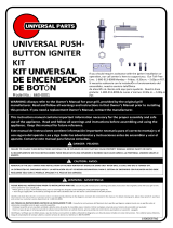
UNIVERSAL
ELECTRONIC IGNITER
KIT
KIT
ELECTRÓNICO
UNIVERSAL DE
ENCENDEDOR
19000598A0
FAILURE TO FOLLOW THESE INSTRUCTIONS MAY RESULT IN AN EXPLOSION OR FIRE THAT MAY CAUSE PROPERTY DAMAGE, SERIOUS INJURY OR DEATH.
EL INCUMPLIMIENTO DE ESTAS INSTRUCCIONES PUEDE RESULTAR EN UNA EXPLOSIÓN O INCENDIO QUE CAUSE DAÑOS A LA PROPIEDAD, LESIONES GRAVES O
MUERTE.
WARNING: ADVERTENCIA:
DANGER: PELIGRO:
▲
▲
!
!
Model No.: 660-0002
Este manual de instrucciones contiene información importante necesaria para el correcto montaje y el uso
seguro del aparato. Lea y siga todas las advertencias y instrucciones antes de ensamblar y usar el aparato.
Conserve este manual para futuras consultas.
If you should require assistance with the igniter installation or
operation, our call center is here to
support you. Our Toll-Free Line: 1-800-913-8999 Monday – Friday:
8:30a.m. – 5:00p.m PST.
Si necesita asistencia con la instalaciÓn o funcionamiento del
encendidor, nuestro servicio telefÓnico de atención al cliente
está aqui para ayudarlo. Nuestra linea gratuita: 1-800-913-8999 de
Lunes a Viernes: 8:30a.m. – 5:00p.m PST.
CAUTION: AVISO:
▲
!
REMOVAL OF THE OLD IGNITER AND INSTALLATION OF THE NEW IGNITER KIT SHOULD BE DONE ONLY WHEN GRILL IS COOL AND GAS IS TURNED OFF.
LA EXTRACCIÓN DEL ENCENDIDO VIEJO Y LA INSTALACIÓN DEL KIT DE REEMPLAZOUNIVERSAL PARA EL SISTEMA DE ENCENDIDO CON PULSADOR NUEVO DEBE
REALIZARSE SÓLO CON LA PARRILLA APAGADA,EL PASO DE GAS CERRADO Y LA PARRILLA ESTÉ FRÍA.
PLEASE READ ALL INSTRUCTIONS PRIOR TO INSTALLATION AND USE. Consult the grill manufacturer’s warnings and safety instructions that originally came with your grill on the correct
system for your specific grill.
• Move grill to an open, well-ventilated area prior to removing the old igniter and installing the new electronic igniter kit.
• Turn the gas supply OFF at the tank by turning the tank valve clockwise and turn the burner control knobs to the OFF position.
Identify and check that all parts are present and are not damaged by referring to the diagrams and parts list contained in this manual. To obtain missing parts, please have proof-of –purchase
and contact our customer service department at: 1-800-913-8999.
LEA TODAS LAS INSTUCCINOES ANTES DE LA INSTALACION Y USO. Consulte las instrucciones del fabricante de la parrilla que llegaron original mente con su parrilla sobre el sistema de
encendido correcto para su parrilla especifica.
• Coloque la parrilla en un area bien ventilada y abierta antes de quitar el encendido viejo e instalar el kit de reemplazo universal para el sistema de encendido con pulsador.
• Cierre el suministro de gas en el tanque girando la válvula manual del mismo en sentido horario, gire las perillas de control de los quemadores a la posiciÓn apagado.
Identifique y verifique que todas las partes estan presentes y si daños utilizando los diagramas y la lista de piezas incluidos en estas instrucciones. Para obtener piezas faltantes, tenga el
comprobante de compra y llame a nuestro servicio de atenciÓn al cliente al: 1-800-913-8999.
WARNING: Always refer to the Owner’s Manual for your grill, provided by the original grill
manufacturer. Read and follow all warnings and instructions in that Owner’s Manual prior to installing
this product. If you need a replacement Owner’s Manual, contact the manufacturer.

FOR MISSING PARTS, PLEASE CALL CUSTOMER SERVICE AT 1-800-913-8999
INSTALLATION INSTRUCTIONS
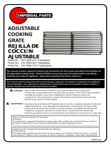
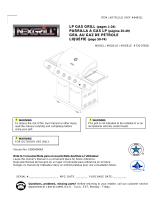
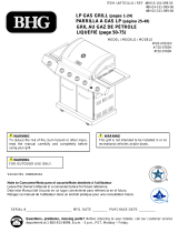
Parts List:
1) 1 Igniter Module
2) 1 Electrode Cap
3) 2 Square Nuts
4) 2 Washers
5) 1 Collector Box
6) 2 Electrode Lead Wires
7) 1 Electrode Assembly
8) 1 Ground Lug
9) 2 Short Screws
10) 2 Long Screws
11) 2 Adjustable Electrodes
12) 2 Plastic Ties
Step 1. Start by removing all of the warming racks,
cooking grates, heat tents, lava rocks, etc., from
the grill so that the burners are exposed,
following the instructions contained in the
Owner’s Manual provided by the original grill
manufacturer. See Illustration 1.
Step 2. To replace the electrode and collector box on an “H”
or “tube” burner, insert the electrode assembly into
the center hole of the collector box and securely
fasten with a short screw. See Illustratoin-2.
Step 3a. For a “H” burner: Align the collector box with
the bracket rest along the lip of the burner.
Ensure that the attached wire of the electrode is
facing downward toward the bottom of the grill.
Attach the collector box to the burner using the
long screws provided. See Illustration 3. You may
have to remove the burner to complete this step.
If so, re-install the burner into the firebox of the
grill by following the instructions contained in the
Owner’s Manual for your grill.
5
❻X2
7
Illustration-1
Illustration-2.
Illuatration-3.
Tools Required:
1) Wrench
2) Screwdriver
3) Number 2 Phillips Head
❶
❷
❸
❹ ❽
❾
❿
⓬
⓬

FOR MISSING PARTS, PLEASE CALL CUSTOMER SERVICE AT 1-800-913-8999
INSTALLATION INSTRUCTIONS
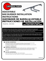
Note: When reinstalling the burner, it is very important that the
venturi tube from the burner lines up with the valve orifice.
The venturi tubes should overlap the valve orifices by ¼
inch.
Step 3b. For Tube Burner: In order to replace the electrode on a tube
burner, fasten the adjustable electrode to the existing
mounting points next to the tube burner with a screw, washer
and nut, which are provided in the kit. If there is not an
appropriate hole for fastening the hardware, carefully drill a
3/16-inch hole. Bend and cut the adjustable electrode
accordingly so that the spark gap is ¼ inches. The spark should
jump to an area of the burner that has burner ports holes.
See Illustration-5.
Step 3c. For Side Burner: In order to replace the electrode on a side
burner fasten the adjustable electrode to the existing
mounting points next to the tube burner with a screw, washer
and nut, which are provided in the kit. If there is not an
appropriate hole for fastening hardware, carefully drill a
3/16-inch hole. Bend and cut the adjustable electrode
accordingly so the distance between the electrode and the side
burner is ¼ inches. See Illustration-6.
Step 3d. For Rear Burner: In order to replace the electrode on a rear
burner, fasten the adjustable electrode to the existing
mounting points next to the tube burner with a screw, washer
and nut, which are provided in the kit. If there is not an
appropriate hole for fastening hardware, carefully drill a 3/16-
inch hole. Bend and cut the adjustable electrode accordingly so
the distance between the electrode and the rear burner is ¼
inches. See Illustration-7.
Illustration-4.
Illustration-5.
Illuatration-6.
Illuatration-7.
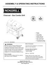
Step 4. Attach the electrode lead wires to the igniter module
according to the wiring guide provided below. If
there is an open port on the igniter module, one of
the electrode lead wires will need to be grounded.
Fasten the ground lug to a metal leg or side
shelf with a self tapping short screw, which is provided in the kit.
Electrodes: Lead 1 Lead 2 Lead 3
1 Active Ground Electrode Cap
2 Active Active Ground
3 Active Active Active

FOR MISSING PARTS, PLEASE CALL CUSTOMER SERVICE AT 1-800-913-8999
INSTALLATION INSTRUCTIONS
Lista de Piezas:
❶ 1 Modulo de Encendido
❷ 1 Tapa de Electrodo
❸ 2 Tuercas Cuadradas
❹ 2 Arandelas
❺ 1 Caja Colectora
❻ 2 Cables Conductores del Electrodo
❼ 1 Ensamble del Electrodo
❽ 1 LengÜeta de Puesta a Tierra
❾ 2 Tornillos Cortos
❿ 2 Tornillos Largos
⓬ 2 Electrodos Ajustables
⓬ 2 Sujetadores Plasticos
INSTRUCCIONES DE INSTALACIÓN
Quite y reemplace las piezas viejas como sea necesario. Algunas de las piezas viejas se pueden reutilizar si
están en buenas condiciónes. Este manual proporciona instrucciones generales para el reemplazo de piezas del encendedor
Paso 1. Comience por removiendo las rejillas de
calientamiento, la parrilla de cocciÓn, las placas de
calor, la roca volcanica, etc., de la parrilla siguiendo
las instrucciones proporcionado por el fabricante
original de la parrilla. Véa la ilustración 1
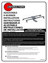
Illustration-8
Igniter Module
❶
❷
❸
❹
❺
❻X2
❼
❽
❾
❿
⓬
⓬
IlustraciÓn-1
Step 6: Reinstall all warming racks, cooking grates, heat tents, lava
rocks, etc., into the grill by following the instructions
contained in the Owner’s Manual for your grill.
WARNING: DO NOT OPEN THE PROPANE
TANK VALVE OR TURN ON THE BURNER CONTROL
KNOBS.
Step 5. ● While looking at the end of the electrode tip and pressing
the igniter button (you may need to press the button a
couple of times), check for a spark emitting from the end of
the electrode. The spark should be visible inside the
collector box and on the burner.
●If a spark is not visible, check all the electrical
connections and ensure that all the wires are
connected. Also make sure the spark gap is
¼ inches from the burner. Try the
previous step again. Do not attempt to light the grill
until you are getting a spark.
▲
!
Install the igniter module onto the control panel of
the grill. Secure into place by inserting the module
from behind the face plate of the control panel and
fastening with a plastic tie, which is provided in the kit.
Insert the AA battery and screw on the cap. Ensure that all
wires will not be exposed to flames or direct heat when the
grill is in operation. See Illustration-8.

Paso 2. Para colocar el electrodo y la caja de recolección en
un quemador estilo "H" o "Bar", inserte el electrodo
en el orificio central de la caja del colector y asegure
firmemente con un tornillo corto. Vea Ilustracion-2.
Paso 3a. Deslice la caja de recolección en todo el centro de
su "H" o "Bar" quemador de estilo hasta que las
muescas del soporte descanse sobre lo largo del
labio del quemador. Asegurar que el cable
conectado del conjunto de electrodo se enfrenta
hacia abajo, hacia la parte inferior de la parrilla. Fije
la caja colectora al quemador mediante usando los
tornillos largos proporcionados. Vea Ilustracion-3.
tenga que quitar el quemador para completar este
paso. Si es así, vuelva a instalar al quemador en el
fuego de la parrilla siguiendo las instrucciones
contenidas en el Manual del propietario para la
parrilla.
Nota: Al volver a instalar el quemador, es muy importante
que el venturi se alínea de la hornilla con los
orificios de la válvula. Venturi debe ser de ¼ "sobre la
válvulas. Vea Ilustracion-4.
Paso 3b. Para reemplazar el electrodo en un quemador de tubo,
sujetar el electrodo ajustable para montaje existente
al lado del quemador de tubo con un tornillo, la
arandela y la tuerca. Si no hay un agujero apropiado
para la fijación del hardware, perfore cuidadosamente
un "agujero de 3/16. Doble y corte el electrodo
ajustable en consecuencia para que el hueco de la
chispa sea de ¼ ". La chispa debe saltar a un área de la
quemador que tiene agujeros puertos del quemador.
Vea Ilustracion-5.
IlustraciÓn-5
IlustraciÓn-2
IlustraciÓn-4
IlustraciÓn-3
INSTRUCCIONES DE INSTALLACIÓN
SI FALTAN PIEZAS, LLAME AL SERVICIO DE ATENCIÓN AL CLIENTE 1-800-913-8999

Paso 3c. Para reemplazar el electrodo en un quemador lateral,
sujetar el electrodo ajustable para montaje existente
al quemador lateral con un tornillo, la arandela y
tuerca. Si no hay un agujero apropiado para la fijación
del hardware, perfore cuidadosamente un "agujero
de 3/16. Doble y corte el electrodo ajustable en
consecuencia para que la distancia entre el
electrodo y el quemador lateral sea de ¼ ". Vea
Ilustracion-6.
Paso 3d. Para reemplazar el electrodo en un quemador
posterior, sujetar el electrodo ajustable para montaje
existente al lado del quemador trasero con un tornillo,
la arandela y la tuerca. Si no hay un agujero apropiado
para la fijación del hardware, perfore cuidadosamente
un "agujero de 3/16. Doble y corte el electrodo
ajustable en consecuencia por lo que la distancia entre
el electrodo y el quemador trasero es de ¼ ". Vea
Ilustracion-7.
Paso 4. Conecte los cables conductores del electrodo al módulo
del encendedor de acuerdo con la guía de cableado
a continuación. Si hay un puerto abierto en el módulo
del encendedor uno de los cables conductores tendrán
que ser conectado a tierra. Fije el terminal de tierra a
una pierna de metal o de lado estante, con un tornillo
corto autorroscante.
Electrodos: Conductor 1 Conductor 2 Conductor 3
1 Active Ground Electrode Cap
2 Active Active Ground
3 Active Active Active
Instale el módulo del encendedor en el panel de
control de la parrilla. Asegure en su lugar insertando
el módulo por detrás de la placa frontal del panel de
control y sujetar con una tuerca de plástico. Inserte la
batería AA y tornillo de la tapa. Mantenga todos los
cables de llama directa y el calor excesivo. Vea
Ilustracion-8.
IlustraciÓn-8
MÓdulo de Encendido
IlustraciÓn-7
IlustraciÓn-6
INSTRUCCIONES DE INSTALLACIÓN
SI FALTAN PIEZAS, LLAME AL SERVICIO DE ATENCIÓN AL CLIENTE 1-800-913-8999
ADVERTENCIA: NO ABRA EL TANQUE DE PROPANO
O LAS PERILLAS DE CONTROL DEL QUEMADOR.
▲
!
Paso 5. ● Mientras observa el extremo de la punta del electrodo y pulsando
el botón del encendedor (es posible que tenga que pulsar el botón un
par de veces). Una chispa debe ser visible dentro de la caja del
colector y en el quemador lateral si es aplicable.
●Si una chispa no es visible, revise todas las conexiones
eléctricas y asegurarse que todos los cables estén
conectados. También asegúrese de que la brecha de
chispa es ¼ para la conexión del quemador lateral. Prueba el anterior
paso de nuevo. No intente encender la parrilla hasta que están
recibiendo una chispa.
Paso 6. ● Vuelva a instalar todas las parrillas de calentamiento, cocinar
parrillas de coccion, placas de calor, la roca volcanica, etc. en la
parrilla siguiendo las instrucciones contenidas en el Manual del
propietario para la parrilla.

Made in China / Hecho en China
©2016 Nexgrill Industries, Inc.
Chino, CA. 91710
www.nexgrill.com
1-800-913-8999
For 90 days from the date of purchase, UNIVERSAL PARTS warrants the product against defects due to workmanship or materials to the original purchaser.
UNIVERSAL PARTS obligation under this warranty are limited to the following guidelines:
• This warranty does not cover units that have been altered/modified or damaged due to: normal wear, rust, abuse, improper maintenance and/or improper use.
• This warranty does not cover surface scratches, rust or heat damage to the finish, which is considered normal wear.
• UNIVERSAL PARTS may elect, at their option, to repair, replace, or offer the depreciated value for damaged units covered under the terms of this warranty.
• UNIVERSAL PARTS, at their option, may satisfy this warranty by offering to replace component parts with any alternative compatible component part based on stock available the
time the request for the replacement parts is made.
• This warranty extends to the original purchaser only and is not transferable or assignable to subsequent purchasers.
UNIVERSAL PARTS requires reasonable proof of purchase. Therefore, we strongly recommend that you retain your sales receipt or invoice. To obtain a replacement for your product
under the terms of this warranty, please call our Customer Service Department at 1-800-913-8999. A receipt will be required. UNIVERSAL PARTS will not be responsible for any units
forwarded to us without prior authorization.
EXCEPT AS ABOVE STATED, UNIVERSAL PARTS MAKES NO OTHER EXPRESS WARRANTY.
THE IMPLIED WARRANTIES OF MERCHANTABILITY AND FITNESS FOR A PARTICULAR PURPOSE ARE LIMITED IN DURATION TO THOSE LISTED ABOVE FROM THE DATE OF PURCHASE.
SOME STATES DO NOT ALLOW LIMITATIONS ON HOW LONG AN IMPLIED WARRANTY LASTS, SO THE ABOVE LIMITATION MAY NOT APPLY TO YOU.
ANY LIABILITY FOR INDIRECT, INCIDENTAL OR CONSEQUENTIAL DAMAGES ARISING FROM THE FAILURES OF THE PRODUCT TO COMPLY WITH THIS WARRANTY OR ANY IMPLIED
WARRANTY IS EXCLUDED. CUSTOMER ACKNOWLEDGES THAT THE PURCHASE PRICE CHARGED IS BASED UPON THE LIMITATIONS CONTAINED WITHIN THE WARRANTY SET OUT
ABOVE. SOME STATES DO NOT ALLOW THE EXCLUSION OR LIMITATION OF INCIDENTAL OR CONSEQUENTIAL DAMAGES, SO THE ABOVE LIMITATION OR EXCLUSION MAY NOT APPLY
TO YOU. THIS WARRANTY GIVES YOU SPECIFIC LEGAL RIGHTS, AND YOU MAY HAVE OTHER RIGHTS WHICH VARY FROM STATE TO STATE.
90 DAY LIMITED WARRANTY
Por 90 dias a partir de la fecha de la compra, UNIVERSAL PARTS garantiza el producto contra defectos en la fabricaciÓn o los materiales al comprador original.
Las obligaciones de UNIVERSAL PARTS con respecto a esta garantia se limitan a lo siguiente:
• Esta garantía no cubre unidades que hayan sido alteradas/modificadas o dañadas debido a: uso normal, herrumbre, maltrato, mantenimiento inadecuado y/o uso inapropiado.
• Esta garantía no cubre rayones superficiales, daño por herrumbre or por calor al acabado, lo cual se considera como uso normal.
• UNIVERSAL PARTS puede decidir, a su opcion, a reparar, reemplazar o ofrecer el valor depreciado de las unidades dañadas cubiertas bajo los términos de esta garantia.
• UNIVERSAL PARTS , a su discreción , puede satisfacer esta garantía ofreciendo reemplazar componentes con cualquier componente alternativo compatible basado
en el inventario disponible al momento en que se hizo la solicitud de las piezas de repuesto.
• Esta garantía se otorga al comprador original únicamente y no es transferible o asignable a los compradores posteriores.
UNIVERSAL PARTS requiere un comprobante de compra razonable. Por lo tanto, le recomendamos enfaticamente que retenga su recibo o factura de venta. Para obtener un
reemplazo de su producto bajo los terminos de esta garantia, sirvase contactar al Departamento de Servicio al Cliente al 1-800-913-8999. Se exigira la presentacion de un recibo.
UNIVERSAL PARTS no sera responsable de ninguna unidades devuelta a nosotros sin autorizaciÓn previa.
EXCEPTO POR LO INDICADO ARRIBA, UNIVERSAL PARTS NO OTORGA NINGUNA OTRA GARANTIA EXPRESA.
LAS GARANTÍAS IMPLÍCITAS DE COMERCIABILIDAD Y ADECUACIÓN CON UN FIN ED PARTICULAR SON DE DURACION LIMITADA DE ACUERDO A LO INDICADO ARRIBA A PARTIR DE LA
FECHA DE COMPRA. ALGUNOS ESTADOS NO PERMITEN LIMITACIONES DE DURACION DE UNA GARANTÍA IMPLÍCITA; POR LO TANTO, LA LIMITACIÓN PRODRÍA NO SER APLICABLE EN
SU CASO.
SE EXCLUYE CUALQUIER RESPONSIBILIDAD POR DANOS INDIRECTOS, INCIDENTALES O CONSIGUIENTES DERIVADOS DE LA FALTA DE CUMPLIMIENTO DE ESTA GARANTIA O DE
CUALQUIER GARANTIA IMPLÍCITA DE PRODUCTO. EL CLIENTE RECONOCE QUE EL PRECIO DE COMPRA COBRADO SE BASA EN LAS LIMITACIÓNES CONTENIDAS EN LA GARANTIA
ANTERIOR. ALGUNOS ESTADOS NO PERMITEN LA EXCLUSION O LIMITACIÓN DE LOS DAÑOS INCIDENTALES O CONSIGUIENTES; POR LO TANTO, LA LIMITACIÓN O EXCLUSIÓN
ANTERIOR PODRÍA NO SER APLICABLE EN SU CASO. ESTA GARANTÍA LE OTORGA DERECHOS LEGALES ESPECÍFICOS Y USTED PUEDE TENER ADEMAS OTROS DERECHOS QUE VARÍAN
DE UN ESTADO A OTRO.
GARANTIA LIMITADA DE 90 DIAS
State of California Proposition 65 Warnings:
WARNING
This equipment is equipped to operate on propane gas which contains the chemical Benzene, known to
the State of California to cause cancer and birth defects and other reproductive harm.
Advertencias de la Proposición 65 del estado de California:
ADVERTENCIA
Este equipo está equipado para funcionar con gas propano, que contiene el benceno químico, conocido
en el estado de California como causantes de cáncer y defectos congénitos y otros daños reproductivos.
/