Nexgrill 730-0830PM El manual del propietario
- Categoría
- Barbacoas
- Tipo
- El manual del propietario
Este manual también es adecuado para

Questions, problems, missing parts? Before returning to your retailer, call our customer service
department at Canada: 800-648-5864, U.S.: 800-913-8999, 8 a.m.-5 p.m., PST, Monday-Friday.
OUTDOOR GAS GRILL
• This instructions manual contains important information necessary for the proper
assembly and safe use of the appliance.
• Read and follow all warnings and instructions before assembling and using the
appliance.
• Keep this manual for future reference.
SERIAL # ____________________ MFG. DATE _____________ PURCHASE DATE: ____________
MODEL #720/730-0830PM Pages 2 -44
19000435A0
MODELO 720/730-0830PM páginas45-87
PARRILLA DE GAS AL
AIRE LIBRE

Des questions, des problèmes, des pièces manquantes? Avant de retourner l’article au
détaillant, communiquez avec le service à la clientèle au Canada: 800-648-5864, U.S.: 800-913-8999,
entre8h et18hHNP, du lundi au vendredi et entre 8h et 12 h, le samedi. Assurez-vous d’avoir votre
numéro de série en main. Ce numéro se situe à l’intérieur de la porte avant de votre barbecue.
Table of Contents
Grill Lighting Instruction . . . . . . . . . . . . . . . .
Lighting Instruction. . . . . . . . . . . . . . . . . . . .
Care and Maintenance . . . . . . . . . . . . . . . . .
Trouble Shooting . . . . . . . . . . . . . . . . . . . . .
Ordering Parts . . . . . . . . . . . . . . . . . . . . . . . .
Grill Hints . . . . . . . . . . . . . . . . . . . . . . . . . . .
Grill Cooking Chart . . . . . . . . . . . . . . . . . .. .
Grill Recipe Suggestion . . . . . . . . . . . . . . .
Limited Warranty . . . . . . . . . . . . . . . . . . . . .
Natural Gas Conversion …………………
25-26
26-27
28
29-30
31
31
31-32
33-34
35
36-45
Safety Instruction . . . . . . . . . . . . . . . . . . . . .
Package Contents List . . . . . . . . . . . . . . . . .
Hardware Contents . . . . . . . . . . . . . . . . . . . .
Exploded View . . . . . . . . . . . . . . . . . . . . . . . .
Part List . . . . . . . . . . . . . . . . . . . . . . . . . . . .
Assembly Instruction . . . . . . . . . . . . . . . . . .
Motor Instruction . . . .. . . . . . . . . . . . . . ……
Gas Hook –Up . . . . . . . . . . . . . . . . . . . . . . .
Installer Final Check List. . . . . . . . . . . . . . . .
Leak Testing . . . . . . . . . . . . . . . . . . . . . . . .
Operating Instruction . . . . . . . . . . . . . . . . . . .
3-6
7-8
9
10
11-12
13-20
21
22
23
23-24
24-25
• Cemanueld’instructionscontientd’importantesinformationsessentielles à un
assemblage approprié et sécuritairede l’appareil.
• Lire et respecter tousles avertissementset toutesles instructions avant
l’assemblageet l’utilisationde l’appareil.
• Conserver cemanuel à titrede référenceultérieure.
2

DANGER
If you smell gas:
1. Shut off gas to the appliance.
2. Extinguish any open flame.
3. Open lid.
4. If odor continues, keep away from the
appliance and immediately call your
gas supplier or your fire department.
WARNING
1. Do not store or use gasoline or
other flammable liquids or vapors in
the vicinity of this or any other
appliance.
2. An LP cylinder not connected for
use shall not be stored in the
vicinity of this or any other
appliance.
Failure to comply with these instructions could result in a fire or explosion that
could cause serious bodily injury, death, or property damage.
Combustion by products produced when using this product contain chemicals
known to the States of California to cause cancer, birth defects, or other reproductive
harm.
Your grill will be very hot. Never lean over the cookingarea while using your grill.
Do not touch cooking surfaces, grill housing, lid or any other grill parts while the grill
is in operation, or until the gas grill has cooled down after use.
Safety Instruction
3

WARNING
ELECTRICAL GROUNDING INSTRUCTIONSfor Rotisserie Motor-This appliance is equipped with a plug and should be
plugged directly into a properly grounded receptacle. When installed, must be electrically grounded in accordance with local
codes or in the absence of local codes, with the National Electrical Code, ANSI/NFPA 70 or the Canadian Electrical Code,
CSA C22.1 DO NOT cut or remove the grounding prong from this plug.
1. To protect against electric shock, do not immerse cord or plugs in water or other liquid.
2. Unplug from the outlet when not in use and before cleaning. Allow to cool before putting on or taking off parts.
3. Do not operate any outdoor cooking gas appliance with a damaged cord, plug, or after the appliance malfunctions or
has been damaged in any manner. Contact the manufacturer for repair.
4. Do not let the cord hang over the edge of a table of touch hot surface.
5. Do not use an outdoor cooking gas appliance for purposes other than intended.
6. When connecting, first connect plug to the outdoor cooking gas appliance then plug appliance into the outlet.
7. Use only a Ground Fault Interrupt (GFI) protected circuit with this outdoor cooking gas appliance.
8. Never remove the grounding plug or use with an adapter of 2 prongs.
9. Use only extension cords with a 3 prong grounding plug, rated for the power of the equipments, and approved for
outdoor use with a W-A marking.
Safety Instruction
WARNING
Do not try lighting this appliance without reading the
“LIGHTING INSTRUCTIONS” section of this manual.
CAUTION: Beware of Flashback
TESTED IN ACCORDANCE WITH ANS Z21.58b CSA
1.6b-2012 STANDARD FOR OUTDOOR COOKING GAS
APPLIANCE. THIS GRILL IS FOR OUTDOOR USE ONLY.
CAUTION: Spiders and small insects occasionally
spin webs or make nest in the grill
burner tubes during transit and
warehousing. These webs can lead
to gas flow obstruction, which could
result in a fire in and around burner
tubes. This type of fire is known as
“FLASH-BACK” and can cause serious damage to your grill
and create an unsafe operating condition for the user.
Although an obstructed burner tube is not the only cause of
“FLASH-BACK”, it is the most common cause.
To reduce the chance of “FLASH-BACK”, you must clean the
burner tubes before assembling your grill, and at least once a
month in late summer or early fall when spiders are most
active. Also perform this burner tube cleaning procedure if
your grill has not been used for an extended period of time. A
clogged tube can be lead to a fire beneath the grill.
Grill Installation Codes
Check your local building codes for the proper method of
installation. in the absence of local codes, this unit should
be installed in accordance with the National Fuel Gas
Code ,ANSI Z223.1/NFPA 54,Storage and Handling of
Liquefied Petroleum Gases, ANSI /NFPA B149.2 or CSA
B149.1 Natural Gas and Propane Installation Code, and
the National Electrical Code, ANSI/NFPA 70.
Correct LP Gas Tank Use
LP gas grill models are designed for use with a standard 20
lb. Liquid Propane Gas tank, not included with grill. Never
connect your gas grill to an LP gas tank that exceeds this
capacity.
If an external electrical source is utilized: The outdoor
cooking gas appliance, when installed, must be electrically
grounded in accordance with local codes or, in the absence
of local codes, with the National Electrical Code,
ANSI/NFPA 70, or the Canadian Electrical Code, CSA
C22.1.
WARNING
Keep any electrical supply cord and the fuel supply hose
away from any heated surfaces.
NOTE: The normal flow of gas through the regulator and
hose assembly can create a humming noise. A low volume
of noise is perfectly normal and will not interfere with
operation of the grill. If humming noise is loud and
excessive you may need to purge air from the gas line or
reset the regulator excess gas flow device. This purging
procedure should be done every time a new LP gas tank is
connected to your grill.
Visually check the burner flames prior to each use. The
flames should look like this picture. If they do not, refer to the
burner main tenancy part of this manual.
4

Safety Instruction continued
LP-Gas Supply System
• If the information is not followed exactly, a fire resulting in
death or serious injury could occur.
• A 20lb tank of approximately 12-1/4 inches in diameter by 18-
1/4 inches high is the maximum size LP gas tank to use.
• The safety feature prevents the tank from being overfilled,
which can cause malfunction of the LP gas tank, regulator
and/or grill.
• The LP gas supply cylinder to be used must be constructed
and marked in accordance with the specifications for LP –
Gas cylinder of the U.S. Department of Transportation (DOT)
or the National Standard of Canada ,CAN/CSA –B339,
Cylinders, Spheres and Tubes for Transportation of
Dangerous Goods and Commission .
• The LP gas tank must have a shutoff valve terminating in an
LP valve outlet that is compatible with a Type 1. LP gas
supply cylinder must have a shut off valve terminating in a
valve outlet specified for connection type QCC1 in the
standard for compressed gas cylinder valve outlet and inlet
connection ANSI/CGA-V-1 as applicable. LP gas supply
cylinder must be fitted with an Overfill Protection Device
(O.P.D) The LP gas tank must also have a safety relief
device that has a direct connection with the vapor space of
the tank.
• The tank supply system must be arranged for vapor
withdrawal.
• The LP gas tank used must have a collar to protect the tank
valve.
• Place dust cap on cylinder valve outlet whenever the cylinder
is not in use. Only install the type of dust cap on the cylinder
valve outlet that is provided with the cylinder valve. Other
types of cap or plugs may result in leakage of propane.
• Never connect an unregulated LP gas tank to your gas grill.
• This outdoor cooking gas appliance is equipped with a high
capacity hose/regulator assembly for connection to a
standard 20lb. Liquid propane cylinder.
• Have your LP gas tank filled by a reputable propane gas
dealer and visually inspected and re-qualified at each filling.
• Do not store a spare LP gas cylinder under or near this
appliance.
• Never fill the cylinder beyond 80 percent full.
• Always keep LP gas tanks in an upright position.
• Do not store or use gasoline or other flammable vapors and
liquids in the vicinity of this or any other appliance.
• Storage of an outdoor cooking gas appliance indoors is
permissible only if the cylinder is disconnected and removed
from the outdoor cooking gas appliance.
• When your gas grill is not in use the gas must be turned off at
LP gas tank.
• The gas must be turned off at the supply cylinder when the
outdoor cooking gas appliance is not in use.
• LP gas tank must be stored outdoors in a well-ventilated area
and out of reach of children. Disconnected LP gas tanks must
not be stored in a building, garage or any other enclosed area.
• Do Not obstruct the flow of ventilation air around the gas grill
housing. Only use the regulator and the hose assembly
supplied with your gas grill. Replacement regulators and hose
assemblies must be those specified in this manual.
• The regulator and hose assembly must be inspected before
each use of the grill. If there is excessive abrasion or wear or
if the hose is cut, it must be replaced prior to the grill beingput
into operation. The replacement hose assembly shall be that
specified by the manufacturer.
• Pressure regulator and hose assembly supplied with the
outdoor cooking gas appliance must be used. Never
substitute other types of regulator. Contact customer service
for manufacturer specified replacement parts.
• This outdoor cooking gas appliance is equipped with a
pressure regulator comply with the standard for Pressure
Regulating Valves for LP Gas ANSI/ UL 144.
• Do not use briquettes of any kind in the grill.
• The grill is designed for optimum performance without the use
of briquettes. Do not place briquettes on the radiant as this will
block off the area for the grill burners to vent. Adding
briquettes can damage ignition components and knobs, and
void the warranty.
• Keep the back and side cart free and clear from debris. Keep
any electrical supply cord, or the rotisserie motor cord away
from the heated areas of the grill.
• Never use the grill in extremely windy conditions. If located in
a consistently windy area (oceanfront, mountaintop, etc.) a
windbreak will be required. Always adhere to the specified
clearance.
• Never use a dented or rusty propane tank.
• Keep any electrical supply cord and the fuel supply hose away
from any heated surface.
• While lighting, keep your face and hands as far away from the
grill as possible.
• Burner adjustment should only be performed after the burner
has cooled.
WARNING
Your grill will get very hot. Never lean over the cooking area
while using your grill. Do not touch cooking surfaces, grill
housing, lid or any other grill parts while the grill is in
operation, or until the gas grill has cooled down after use.
Failure to comply with these instructions may result in
serious bodily injury.
CAUTION: TO ENSURE CONTINUED PROTECTION
AGAINST RISK OF ELECTRIC SHOCK, CONNECT TO
PROPERLY GROUNDED OUTLETS ONLY, TO REDUCE
THE RISK OF ELECTRIC SHOCK, KEEP EXTENSION
CORD CONNECTION DRY AND OFF THE GROUND.
PROPER PLACEMENT AND CLEARANCE OF GRILL
• Never use your gas grill in a garage, porch, shed,
breezeway or any other enclosed area. Your gas grill is
to be used outdoors only.
Do Not install this unit into combustible enclosures.
Minimum clearance from sides and back of unit to
combustible construction, 24 inches (61cm) from sides
and 24 inches (61cm) from back.
• DO NOT use this appliance under overhead combustible
surfaces. This outdoors cooking gas appliance is not
intend to be installed in or on recreational vehicles and/or
boats.
5

Safety Instruction continued
INSECT WARNING
Spiders and insects can nest in the burners of this and any
other grill, and cause the gas to flow improperly. This is a
very dangerous condition, which can cause a fire to occur
behind and beneath the valve panel, thereby damaging the
grill and making it unsafe to operate. Inspect the grill at least
twice a year.
WARNING
Keep a spray bottle of soapy water near the gas supply
valve and check the connections before each use.
DO NOT USE ALUMINUM FOIL TO LINE THE GRILL
RACKS OR GRILL BOTTOM.
This can severely upset combustion airflow or trap excessive
heat in the control area.
DO NOT LEAVE THE GRILL UNATTENDED WHILE
COOKING.
SAFETY PRACTICES TO AVOID PERSONAL INJURY
When properly cared for your grill will provide safe, reliable
service for many years. However, extreme care must be
used as the grill produces intense heat that can increase
accident potential. When using this appliance basic safety
practices must be followed, including the following:
Do not repair or replace any part of the grill unless
specifically recommended in this manual. All other service
should be referred to a qualified technician.
This grill is not intended to be installed in or on recreational
vehicles or boats.
Children should not be left alone or unattended in an area
where the grill is being used. Do not allow them to sit, stand
or play in or around the grill at any time.
Do not store items of interest to children around or below the
grill.
Do not permit clothing, pot holders or other flammable
materials to come in contact with or too close to any grate,
burner or hot surface until it has cooled. The fabric could
ignite and cause personalinjury.
For personal safety, wear proper apparel. Loose fitting
garments or sleeves should never be worn while using this
appliance. Some synthetic fabrics are highly flammable and
should not be worn while cooking.
Only certain types of glass, heat-proof glass ceramic,
earthenware, or other glazed utensils are suitable for grill use.
These materials may break with sudden temperature
changes. Use only on low or medium heat settings in
accordance with the manufacturer’s guidelines.
Do not heat unopened food containers. A build-up of
pressure may cause the containers to burst.
Use a covered hand when opening the grill lid.
Never lean over an open grill.
When lighting a burner, pay close attention to what you are
doing. Make certain you are aware of which burner you are
lighting, so your body and clothing remain clear of open
flames.
When using the grill, do not touch the grill rack, burner
grate or immediate surroundings as these areas become
extremely hot and could cause burns. Use only dry
potholders. Moist or damp potholders on hot surfaces may
cause steam burns. Do not use a towel or bulky cloth in
place or potholders. Do not allow potholders to touch hot
portions of the grill rack.
Grease is flammable. Let hot grease cool before attempting
to handle it. Do not allow grease deposits to collect in the
grease tray at the bottom of the grill’s firebox. Clean the
grease tray often
Do not use aluminum foil to line the grill racks or grill
bottom. This can severely upset combustion air flow or trap
excessive heat in the control area.
For proper lighting and performance of the burners keep
the burner ports clean. It is necessary to clean them
periodically for optimum performance.The burners will only
operate in one position and must be mounted correctly for
safe operation.
Clean the grill with caution. To avoid steam burns, do not
use a wet sponge or cloth to clean the grill while it is hot.
Some cleaners produce toxic fumes or can ignite if applied
to a hot surface.
Turn off grill controls and make certain the grill is cool
before using any type of aerosol cleaner on or around the
grill. The chemical that produces the spraying action could,
in the presence of heat, ignite or cause metal parts to
corrode.
Do not use the grill to cook excessively fatty meats or other
products which promote flare – ups.
Do not operate the grill under unprotected combustible
constructions. Use only in well ventilated areas. Do not use
in buildings, garages, sheds, breezeways or other such
enclosed areas.
Keep the area surrounding the grill free from combustible
materials including, fluids, trash, and vapors such as
gasoline or charcoal lighter fluid. Do not obstruct the flow of
combustion and ventilation air.
WARNING
This outdoor cooking gas appliance is not intended
to be installed in or on boats. And other recreational
vehicles.
6

Package Contents List
A. Firebox assembly-1pc B. Left side shelf -1pc C. Side burner assembly -1pc
D. Grease pan -1pc
E. Grease cup-1pc F. Back panel, middle-1pc
G. Back panel, bottom-1pc H. Right side panel -1pc I. Left side panel -1pc
J. Cart frame-1pc K. Diagonal bar barrier -1pc L. Bottom panel -1pc
M. Tank bolt -1pc
N. Right Triangle bracket -1pc O. Left Triangle bracket -1pc
7

Package Contents List
P. Swivel caster -1pc Q. Swivel caster with brake -1pc R. Stationary caster -2pcs
S. Right door -1pc
T. Left door -1pc U. Door handle assembly -2pcs
V. Warming rack -1pc W. Cooking grid with hole -2pcs X. Flame tamer -4pcs
Y. Side burner -1pc Z. Grease cup bracket-2 pcs AA. Side burner cooking grid -1
pc
AB. Control knob -1 pc AC. Battery -1 pc
8

Hardware Contents
9
Item Description Specification Quantity
Truss Head Screw
Truss Head Screw
Flat Head Screw
Flat Washer
Flat Washer
Flat Washer
4pcsDD 5/32''
6pcsEE 1/4"
47pcs
BB
AA 1/4'' x 15mm
5/32'' x 10mm 20pcs
5/32'' x 10mm
4PCS
GG
Truss Head Screw
5/32'' x 10mm 4PCS
FF
内径
4.2
,外径
12
12pcsCC
1/4"*10mm
22pcs
Truss Head Screw with Locking Washer
Truss Head Screw with Locking Washer
Flat Head Screw
Flat Washer
Flat Washer (aluminum)
Flat Washer
5 /32”
Truss Head Screw

Explode View
10
1
3
4
5
6
7
8
9
11
12
13
14
15
16
17
18
19
20
21
22
25
32
34
35
36
37
38
40
45
46
47
48
49
59
60
61
62
63
64
73
72
69
70
67
66
22
65
23
23
50
24
44
43
42
41
37
51
58
57
52
56
53
55
54
2
2
10
27
28
29
30
31
71
33
75
78e
78d
78c
78b
78a
78f
76
74
74
68
39
77
26

Part List
No. Part (Description)
Warranty
coverage
(year)
QT
Y
No. Part (Description)
Warranty
coverage
(year)
QTY
1 Main lid 1 1 27 Rotisserie gas valve 1 1
2 Main lid screw 1 2 28 Side burner gas valve 1 1
3 Temperature gauge 1 1 29
Side burner Flex Gas
Line
1 1
4
Temperature gauge
Housing
1 1 30 Side manifold 1 1
5 Logo 1 1 31 Regulator, LP 1 1
6 Main lid handle seat, left 1 1 32 Pulse igniter module 1 1
7 Main lid handle tube 1 1 33 Main manifold 1 1
8 Main lid handle seat, right 1 1 34 Main control panel 1 1
9 Flame tamer 1 4 35 Bezel A 1 4
10 R shape pin 1 4 36 Bezel B (Small) 1 1
11 Main burner 5 4 37 Control Knob A 1 5
12 Main burner igniter wire A 1 1 38 Control Knob B (Small) 1 1
13 Main burner igniter wire B 1 1 39 Grease pan 1 1
14 Main burner igniter wire C 1 1 40 Grease cup 1 1
15 Main burner igniter wire D 1 1 41 Spit fork 1 2
16 Rotisserie heat shield 1 1 42 Rotisserie motor bracket 1 1
17 Rear baffle 1 1 43 Rotisserie motor 1 1
18 Rotisserie igniter wire 1 1 44 Spit rod 1 1
19 Rotisserie Burner 1 1 45 Warming rack 1 1
20
Rotisserie burner orifice
w/ brass elbow
1 1 46 Cooking grid with hole 1 2
21
Rotisserie burner flex gas
line
1 1 47 Back panel, top 1 1
22
Rotisserie burner igniter
bracket
1 2 48 Side shelf, left 1 1
23 Hood buffer 1 2 49 Side shelf front panel, left 1 1
24
Main burner bowl
assembly
Non-
replaceable
1 50 Side shelf hooks 1 4
25 Front baffle 1 1 51 Side burner control panel 1 1
26 Main gas valve 1 4 52 Side burner bowl 1 1
11

Part List
11Triangle Bracket, left7221Side burner hinge rod54
11Cart frame7321Burner pin assembly55
No. Part (Description)
Warranty
coverage
(year)
QTY No. Part (Description)
Warranty
coverage
(year)
QTY
53 Side burner lid 1 1 71 Door magnet 1 2
56 Side burner cooking grid 1 1 74 Door handle assembly 1 2
57 Side burner pipe 1 1 75 Door ,left 1 1
58 Side burner igniter wire 1 1 76 Door ,right 1 1
59 Back panel, middle 1 1 77 Lighting Rod 1 1
60 Back panel, bottom 1 1 78 NG conversion kit
Sold
separately
as set
1
61 Side panel, left 1 1 78a
NG Gas Hose with
Quick Connector
assembly
sold
separately
with #78
1
62 Swivel caster with Brake 1 1 78b NG Regulator assembly 1
63 Swivel caster 1 1 78c
Truss Head Screw with
lock
2
64 Bottom panel 1 1 78d Flat washer 2
65 Tank bolt 1 1 78e 6 mm Nut driver 1
66 Side panel, right 1 1 78f 6mm wrench 1
67 Diagonal Bar barrier 1 1 NG orifice pack 1 1
68 Caster 1 2 KD-assembly hardware 1 1
69 Triangle Bracket, right 1 1 Grill cover 1 1
70 Door iron piece 1 1 Manual 1 1
*Natural gas conversion kit sold separately
12

Assembly Instructions
1. Caster Assembly
Turn over the bottom panel for assembling casters.
Mount the casters onto the bottom panel (L) using
sixteen 1/4-in. x 15-mm truss head screws with
locking washer (AA) and sixteen Flat washers (EE) .
The swivel caster with brake(Q)should be
positioned under the left rear of the cart bottom and
the swivel caster (P) should be positioned under
left front as shown in Fig. 1.
The two stationary casters (R) should be
positioned under the rightside.
Note: The gap of the two stationary casters should
be facing the inside bottom panel.
2. Side Panel Assembly
Use three 1/4-in. x 15-mm truss head
screws with locking washer (AA) to connect
the bottom of the left side panel (I) to the
bottom panel (L). Make the left side panel
flush with the rear of bottom panel and
tighten the screws as shown in Fig. 2.
Repeat for the right side panel (H).
Fig. 2
L
16 x AA
16 x EE
R
P
Q
Fig. 1
I
6 x AA
L
H
3. Back Panel, bottom Assembly
a). Position the back panel, bottom (G) with the flat
side facing outward. Attach the back panel, bottom
(G)to the bottom panel (L) with three1/4-in. x 15-
mm truss head screws with locking washer (AA)
as shown in Fig. 3.
b). Use four 1/4-in. x 15-mm truss head screws
with locking washer (AA)to connect the back
panel, bottom(G) to the rightand left side
panels(H/I)as shown in Fig. 3
Fig. 3
G
L
AA7X
I
H
13

5. Back Panel, middle Assembly
a). Use four 1/4-in. x 15-mm truss head screws
with locking washer (AA)to connect back
panel, middle (F) to the right and left side
panels (H / I )as shown in Fig. 5
Assembly Instructions
Fig. 4
4. Door Triangle Bracket Assembly
a)Loosen but do not remove four 5/32-in. x
10-mm truss head screws with locking
washer (BB) mount the Left Side Panel (I)
and Bottom Panel (L), two screws on cart
Right Side Panel (H) and two on the Bottom
Panel (L). Align the holes of the triangle
bracket (O) with screws on Left Side Panel
(I) and Bottom Panel (L). Then tighten the
screws as shown in Fig. 4.
b)Repeat the steps a) for attaching the
triangle bracket (N) to the Right Panel (H)
and bottom Panel (L)
L
H
I
O
N
6. Diagonal Bar Barrier Assembly
Use two 5/32-in. x 10-mm truss head screws with
locking washer (BB) to attach Diagonal Bar Barrier (K)
to the bottom panel (L) and upside of the Back panel,
bottom (G). As shown in Fig. 6.
Fig. 5
2 x BB
L
G
K
Fig. 6
F
4 x AA
I
H
14

Assembly Instructions
Attached the door handle assembly (U) to the
each door (S/T) using eight 5/32-in. x 10-mm
truss head screws with locking washer (BB),
as shown in Fig. 7.
HINT: Four screws for each door.
7.Door Assembly
Fig.7
8xBB
S
T
U
8. Cart frame Assembly
a). Use four 1/4-in. x 15-mm truss head
screws with locking washer (AA) to add
the cart frame (J) to the right and left
side panels, as shown in Fig. 8.
Fig.8
J
4 x AA
HINT: Six screws for each door.
b). Attach the two door’s hinges to the right
and left side panels (I/H) using twelve 5/32-
in. x 10-mm flat head screws (CC) as
shown in Fig. 9.
Fig. 9
I
H
12 x CC
15

Assembly Instructions
9. Install the Grease pan
a). Attach the grease cup brackets (Z) to the
grease pan (D) by using four 5/32-in. x 10-mm
truss head screws (GG.) and four 5/32-in flat washer
(aluminum)(FF) as shown in Fig.10.
b). Install the grease pan (D) onto the cart by using
four 5/32” x10mm truss head screws with locking washer
(BB). As shown in Fig. 11.
c). Install the grease cup (E) under the grease tray
(D). As shown in Fig. 12.
Fig.10 4x GG
4x FF
D
Z
4X BB
Fig.11
D
Fig.12
D
E
16

Fig.13
Assembly Instructions
Fig.14
10. FireboxAssembly
a). Remove the firebox assembly (A) from the
cartonand carefully place onto the grill cart. As
shown in Fig. 13.
A
b) Attach firebox to the left and right side
panels by using four ¼-in. x 15-mm truss
head screws with locking washer(AA). As
shown in Fig. 14.
1 x AA
CAUTIONThe firebox assembly is heavy
and will require two or more people to lift and
position onto grill cart. Failure to do so may
result in injury.
1 x AA
1 x AA
1 x AA
17

11. Side Burner Assembly
a). Loosen the two screws which pre-assembled
onto firebox right side panel (H) but do not
remove Completely. Align the bottom key holes
on side burner (C) with the two loosened screws
as show in Fig. 15, and then tighten. .
b). Use three ¼-in x15-mm truss head screws with
locking washer (AA) and three ¼-in x15-in flat
washers (EE) to keep the right side burner in
place (These three ¼-in screws are screwed
through the front and the rear screw holes which
are located on the top of the right burner). As
shown in Fig. 15.
Note: The top three screws of the firebox should be
screwed from the inside to outside for right side
burner shelf. But the bottom 2 screws should be
tightened from outside to inside.
c). Secure the right side burner control panel and
main control panel by using two 5/32-in x 10-mm
truss head screws with locking washer (BB) and
two 5/32-in flat washers (DD). As shown in Fig.
15.
Fig.15
Fig 16
Assembly Instructions
C
3 x AA
3 x EE
H
12.Side Burner Valve Installation
a) Remove the 2 screws that are pre-attached to the
valve. Do not screw out fully .Insert the side burner
valve into the Side Burner Shelf Control Panel . Align
the screws on the valve with the large side of the
holes on the bezel. Slide the screws down to the
smaller holes and tighten the screws to secure.As
shown in Fig. 16.
b)Insert Side Burner Control Knob (AB) onto the
valve stem. As shown in Fig. 17
Fig 17
AB
18
2 x BB
2 x DD

13. Side Burner Installation
a). From underneath the side burner remove
two screws which are assembled on the
bottom of the side burner shelf (C). Open
side burner lid and place the Side Tube
burner (V) through the opening. Place the
side Tube Burner (V) tube over the side
burner gas valve and make sure
side Burner gas valve is inserted into side burner tube.
as shown in Fig.18.
b). Then with two screws secure the side burner
from underneath to the Side Burner Shelf (C).
as shown in Fig.18.
A
C
V
Fig 18
Assembly Instructions
c)..Connectthe ignition wire from Firebox
assembly (A) control panel to the side
burner igniter pin from underneath the
side Burner Shelf &Control Panel(D).
as shown in Fig.19.
Fig 19
14. Side Shelves Assembly
a). Loosen the two screws which pre-assembled
onto firebox left side panel (I) but do not
remove Completely. Align the bottom key holes
on side shelf (B) with the two loosened screws as
show in Fig. 20, and then tighten. .
b). Use three ¼-in x15-mm truss head screws with
locking washer(AA) and three ¼-in x15-flat
washers (EE) to keep the left side shelf
in place (These three ¼-in screws are screwed
through the front and the rear screw holes which
are located on the top of the left shelf). As
shown in Fig. 20.
Note: The top 3 screws of the firebox should be
screwed from the inside to outside for left side
shelf. But the bottom 2 screws should be
tightened from outside to inside.
c). Secure the left side shelf front panel and
main control panel by using two 5/32-in x 10-mm
truss head screws with locking washer(BB) and
two 5/32-in flat washers (DD). As shown in Fig.
20.
Fig. 20
B
3x AA
2x BB
2x DD
3x EE
I
19

Assembly Instructions
Fig.21
V
W
X
15. Flame Tamers, Cooking Grids Installation
Place the flame tamers (X), main cooking grids (W),
warming rack (V) and side burner cooking grid (AA) into the
grill as shown in Fig. 21.
AA
16. Liquid Propane TankInstallation
Place the liquid propane tankinto the hole
in the bottom panel and tighten the tank
bolt (M) at the back of the grill tosecure as
shown in Fig. 22
Fig.22
M
17. Battery Assembly
Unscrew the electronic igniter button and place the
battery (AC) into the housing with the positive terminal
(+) facing outward. Replace the ignition button after
the battery has been installed as shown in Fig. 23.
Fig.23
Y
20

Motor Instruction
ROTISSERIE DRIVE MOTOR
USE ONLY FOR OUTDOORS. DO NOT EXPOSE TO RAIN.
CAUTION: TO ENSURE CONTINUED PROTECTION AGAINST RISK OF ELECTRIC SHOCK,
CONNECT TO PROPERLY GROUNDED OUTLETS ONLY, TO REDUCE THE RISK OF
ELECTRIC SHOCK, KEEP EXTENSION CORD CONNECTION DRY AND OFF THE GROUND.
WARNING
ELECTRICAL GROUNDING INSTRUCTIONS : This appliance (rotisserie motor) is equipped
with a plug and should be plugged directly into a properly grounded receptacle. DO NOT cut
or remove the grounding prong from this plug.
Keep the rotisserie motor electric cord away from the heated surfaces of the grill. When not in use,
remove and store the motor in a dry location.
This motor is set for 120V AC & 60Hz, 4W, 40mA. If voltage is exceeded, motor will burn out.
• TO USE MOTOR SAFELY, PLEASE READ WARNING PRIOR TO USE
Rotisserie Operating illustrations:
1. Place rotisserie motor onto the motor bracket, using two 5/32-in. x 10-mm truss head
screws (BB) to attach the motor bracket to connect the firebox left and tighten the screws.
Plug into a properly grounded outlet. Ensure that the rotisseriespit rod is inserted into the
motor prior to turning on the motor.
2. When finished using rotisserie motor, switch to “off” position and unplug.
21

Gas Hook -Up
NEVER CONNECT AN UNREGULATED GAS
SUPPLY LINE TO THE APPLIANCE. USE THE
REGULATOR/HOSE ASSEMBLY SUPPLIED.
This is a liquid propane configured grill. Do not attempt
to use a natural gas supply unless the grill has been
reconfigured for natural gas use.
Total gas consumption (per hour) of this stainless
steel gas grill with all burners on “HIGH”:
Main burner 48,000 Btu/hr
Rear burner 13,000 Btu/hr
Side burner 12,000 Btu/hr
Total 73,000 Btu/hr
L.P. TANK REQUIREMENT
A dented or rusty L.P. tank may be hazardous and
should be checked by your L.P. supplier. Never use a
cylinder with a damaged valve. The L.P. gas cylinder
must be constructed and marked in accordance with
the specifications for L.P. gas cylinders of the U.S.
Department of Transportation (DOT) or the National
Standard of Canada, CAN/CSA-B339, Cylinders,
Spheres and Tubes for Transportation of Dangerous
Goods; and Commission, as applicable. Overfilling
prevention device (OPD) shall be provided on cylinder
& QCCI connection on the cylinder valve, ANSI/CGA-
V-1. The cylinder supply system must be arrange for
vapor withdrawal. The cylinder must include a collar to
protect the cylinder valve. The cylinder must be
provided with a shut off valve terminal in an L.P.
gas supply cylinder valve outlet specified, as applicable,
for connection type QCC1 in the standard for
compressed gas cylinder valve outlet and inlet
connection ANSI/CGA-V-1.
Manifold pressure: 11”(27.94cm) water column (W.C.).
L.P. GAS HOOK-UP
Ensure that the black plastic grommets on the LP
cylinder valve are in place and that the hose does not
come into contact with the grease tray or the grill head.
CONNECTION
Your stainless steel grill is equipped with gas supply
orifices for use only with liquid propane gas. It is also
equipped with a high capacity hose/regulator assembly
for connection to a standard 20lb. L.P. cylinder (18-1/4”
(46.35cm) high, 12-1/4”(31cm) diameter). To connect
the L.P. gas supply cylinder, please follow the steps
below:
1. Make sure tank valve is in the complete off position
(turn clockwise to stop)
2. Check tank valve to ensure it has proper external
male threads (type 1 connection per ANSIZ21.81)
3. Make sure all burner valves are in their off position.
4. Inspect valve connections, port, and regulator
assembly. Look for any damage or debris. Remove
any debris. Inspect hose for damage. Never attempt
to use damaged or obstructed equipment. See your
local L.P. gas dealer for repair.
5. When connecting regulator assembly to the valve,
hand tighten the quick coupling nut clockwise to a
complete stop. Do not use a wrench to tighten. Use
of a wrench may damage the quick coupling nut and
result in a hazardous condition.
6. Open the tank valve fully (counterclockwise). Apply
the soap solution with a clean brush to all gas
connections. See below. If growing bubbles appear
in the solution the connection is not properly sealed.
Check each fitting and tighten or repair if necessary.
7. If you have a gas connection leak you cannot repair,
turn gas OFF at supply tank, disconnect fuel line
from your grill and call Canada: 800-648-5864,
U.S.: 800-913-8999 or your gas supplier for repair
assistance.
8. Also apply soapy solution to the tank seams. See
below. If growing bubbles appear, shut tank OFF
and do not use or move it! Contact an LP gas
supplier or your fire department for assistance.
TO DISCONNECT THE L.P GAS CYLINDER:
1. Turn the burner valves off.
2. Turn the tank valve off fully (turn clockwise to stop).
3. Detach the regulator assembly from the tank valve by
turning the quick coupling nut counterclockwise.
22

Installer Final Check List
ü Minimum clearance from sides and back of unit to
combustible construction, 24 inches (61cm) from
sides and 24 inches (61cm) from back
ü All internal packaging removed.
ü Knobs turn freely.
ü Burners are tight and sitting properly onto orifices.
ü Pressure regulator connected and set. Gas
connections to grill using hose & regulator
assembly provided (pre-set for 11.0” water
column).
ü Unit tested and free of leaks.
ü User informed of gas supply shut off valve
location
USER, PLEASE RETAIN THIS MANUAL FOR
FUTURE REFERENCE.
PROPANE CYLINDER CAUTIONS
a) Do Not store a spare LP-gas cylinder under or
near this appliance.
b) NEVER fill the cylinder beyond 80 percent full.
c) If the information in “a” and “b” is not
followed exactly, a fire or explosion causing
death or serious injury may occur.
Leak Testing
GENERAL
Although all gas connections on the grill are leak
tested at the factory prior to shipment, a complete gas
tightness check must be performed at the installation
site due to possible mishandling in shipment, or
excessive pressure unknowingly being applied to the
unit. Periodically check the whole system for leaks
following the procedures listed below. If the smell of
gas is detected at anytime you should immediately
check the entire system for leaks.
BEFORE TESTING
Make sure that all packing material is removed from
the grill including tie-down straps.
DO NOT SMOKE WHILE LEAK TESTING.
NEVER PERFORM LEAK TEST WITH AN OPEN
FLAME.
Make a soap solution of one part liquid detergent and
one part water. You will need a spray bottle, brush, or
rag to apply the solution to the fittings. For the initial
leak test, make sure the L.P. cylinder is 80% full.
TO TEST
1. Make sure the control valves are in the “OFF”
position, and turn on the gas supply.
2. Check all connections from the LP gas
regulator and supply valve up to and including
the connection to the manifold pipe assembly
(the pipe that goes to the burners). Soap
bubbles will appear where a leak is present.
3. If a leak is present, immediately turn off the gas
supply and tighten the leaky fittings.
4. Turn the gas back on and recheck.
5. Should the gas continue to leak from any of the
fittings, turn off the gas supply and contact
customer service at Canada: 800-648-5864,
U.S.: 800-913-8999 .
Only those parts recommended by the manufacturer
should be used on the grill.
Substitution will void the warranty. Do not use the grill
until all connections have been checked and do not leak.
GAS FLOW CHECK
Each grill burner is tested and adjusted at the factory
prior to shipment; however, variations in the local gas
supply may make it necessary to adjust the burners. The
flames of tips, excessive noise or lithe burners should be
visually checked.
Flames should be blue and stable with no yellow. If any
of these conditions exist, check to see if the air shutter or
burner ports are blocked by dirt, debris, spider webs, etc.
If you have any questions regarding flame stability,
please call customer service Canada: 800-648-5864,
U.S.: 800-913-8999 .
ALWAYS CHECK FOR LEAKS AFTER EVERY L.P.
TANK CHANGE
Check all gas supply fittings for leaks before each
use. It is handy to keep a spray bottle of soapy
water near the shut-off valve of the gas supply line.
Spray all the fittings. Bubbles indicate leaks.
23

Leak Testing continued
CAUTIONS
Place dust cap on cylinder valve outlet when the cylinder is notin use. Only install the type of dust cap
on the cylinder valve outlet that is provided with the cylinder valve. Other types of caps or plugs may
result in leakage of propane.
The gas must be turned off at the supply cylinder when the unit is not in use.
If the appliance is stored indoors the cylinder must be disconnected and removed from the appliance.
Cylinders must be stored outdoors in a well-ventilated area out of the reach of children.
Your grill is ready to use!
320
456
Propane tank: height = 456mm, diameter = 320mm
24

TO MATCH LIGHT THE GRILL
If the burner will not light after several attempts then the
burner can be match lit.
Match light extension rod is located on the inside panel of
the door.
If you’ve attempted to light the burner with the igniter,
allow 5 minutes for any accumulated gas to dissipate.
Keep your face and hands as far away from the grill as
possible.
Insert a lit match attached to the lighting rod through the
cooking grids to the burner.
Press the control knob and rotate left to the HIGH/ON
setting continue to press the knob until the burner ignites.
Burner should light immediately.
If the burner does not light in 5 seconds turn the knob off,
wait 5 minutes and try again.
Operating Instructions
GENERAL USE OF THE GRILL AND ROTISSERIE
Each main burner is rated at 12,000 Btu/hr. The main
grill burners encompass the entire cooking area and
are side ported to minimize blockage from falling
grease and debris. The igniter knobs are located on
the lower center portion of the valve panel. Each rotary
igniter is labeled on the control panel.
USING THE GRILL
Grilling requires high heat for searing and proper
browning. Most foods are cooked at the “HIGH” heat
setting for the entire cooking time. However, when
grilling large pieces of meat or poultry, it may be
necessary to turn the heat to the lower setting after the
initial browning. This cooks the food through without
burning the outside. Foods cooked for a long time or
foods basted with a sugary marinade may need the
lower heat setting near the end of the cooking time.
NOTE: This barbecue unit is designed to grill efficiently
without the use of lava rocks or briquettes of any kind.
Heat is radiated by the stainless steel flame tamers
positioned above each burner.
NOTE: The hot grill sears the food, sealing in the juices.
The longer the grill is preheated, the faster the meat
browns and the darker the grill marks.
DO NOT LEAVE THE GRILL UNATTENDED WHILE
COOKING.
Grill Lighting Instructions
WARNING: IMPORTANT!
BEFORE LIGHTING…
Inspect the gas supply hose prior to turning the gas
“ON”. If there is evidence of cuts, wear, or abrasion,
it must be replaced prior to use. Do not use the grill
if the odor of gas is present. Do not use any other
hose connection other than the regulator hose
assembly that came with the unit.
Never substitute regulators and hose assembly for
those supplied with the grill. If a replacement is
necessary, contact the manufacturer for proper
replacement. The replacement must be specified in
the owners manual.
WARNING: Always keep your face and body as
far away from the burner as possible when
lighting.
TO LIGHT THE MAIN BURNER
Make sure all knobs are “OFF” then turn on the gas
supply from the LP (Liquid Propane) tank. Always
keep your face and body as far from the grill as
possible when lighting.
Your grill has an exclusive patented built-in ignition.
The igniter is built into the valve. To ignite each
burner simply push and turn the control knobs to the
HI setting, you will hear the valve click as it sends a
spark to the pilot flame. If the burner does not light
wait 5 minutes for any accumulated gas to dissipate
and then retry.
25

Main Burners
Rear Burner
IGNITE / HIGH
LOW
OFF
IGNITE / HIGH
LOW
IGNITE / HIGH
LOW
OFF
1
3
2
IGNITE / HIGH
LOW
IGNITE / ON
IGNITE / ON
1
2
OFF OFF
OFF
IGNITE / HIGH
LOW
OFF
Make sure the lid is open.
Push and turn Main Burner knob slowly to
IGNITE/HIGH,. Keep knob pressed in until the burner
is lit.
If burner does not light within 5 seconds, turn the knob
to OFF and repeat the lighting instruction.
If burner does not light up after step 3, turn the knob to
OFF, wait 5 minutes, and repeat the lighting procedure
or light by match.
Grill Lighting Instructions continued
FLAME CHARACTERISTICS
Check for proper burner flame characteristics.
Burner flames should be blue and stable with no yellow
tips, excessive noise, or lifting. If any of these conditions
exist call our customer service line. If the flame is yellow,
this is a indication of insufficient air. If the flame is noisy
and tends to lift away from the burner, this is a indication
of excessive oxygen.
Each burner is adjusted prior to shipment;
however, variations in the local gas supply
may make minor adjustments necessary.
Visually check the burner flames prior to each
use, The flames should look like this picture, if
they do not, refer to the burner maintenance
part of this manual.
Lighting Instructions
Note: Remove all packaging, including straps, before using the grill
1
2
3
4
26
Side burner
IGNITE / HIGH
LOW
OFF

Lighting Instructions continued
IGNITE / ON
1
2
OFF
Make sure the lid is open.
Push and slowly turn the Rear Burner knob to IGNITE/ON
position. Keep knob pressed in until the burner is lit. Once
it is lit, continue to press and hold for another 15 seconds to
ensure the burner stays lit.
If burner does not light within 5 seconds, turn the knob to
OFF position and repeat the lighting procedure.
If burner fails to light after step 3, turn the knob to OFF
position, wait 5 minutes, then repeat the lighting procedure
or light by match.
1
2
3
1. If the burner will not light after several attempts then the burner can be match lit, before using the match
allow 5 minutes for any accumulated gas to dissipate.
2. Clip a paper match on one end of the lighting rod.
3. Light match.
4. Hold lighting rod and insert lighted match right next to the burner ports or ceramic tile.
5. Push and turn the designated control knob to IGNITE/HIGH.
6. Burner should ignite immediately.
Match light
4
Main burner
Rear burner
27
Side burner

1. Keep outdoor cooking gas appliance area clear and
free from combustible materials, gasoline and other
flammable vapors and liquids.
2. Do not obstruct the flow of combustible and
ventilation air.
3. Keep the ventilation openings of the cylinder
enclosure free and clear from debris.
Care and Maintenance
STAINLESS STEEL
There are many different stainless steel cleaners available.
Always use the mildest cleaning procedure first, scrubbing in
the direction of the grain. Specks of grease can gather on the
surfaces of the stainless steel and bake on to the surface and
give the appearance of rust. For removal use a mild abrasive
pad in conjunction with a stainless steel cleaner.
GRILL GRATE
The easiest way to clean the grill is immediately after cooking
is completed and after turning off the flame. Wear a barbeque
mitt to protect your hand from the heat and steam. Dip a brass
bristle barbeque brush in water and scrub the hot grill. Dip the
brush frequently in the bowl of water. Steam, created as water
contacts the hot grill, assists the cleaning process by softening
any food particles. If the grill is allowed to cool before cleaning,
cleaning will be more difficult.
ENSURE THAT THE GAS SUPPLY AND THE KNOBS ARE
IN THE “OFF” POSITION. MAKE SURE THE RANGETOP
BURNER IS COOL BEFORE REMOVAL.
GRILL BURNERS
Extreme care should be taken when moving a burner as it
must be correctly centered on the orifice before any attempt is
made to relight the grill. Frequency of cleaning will depend on
how often you use the grill.
MAIN GRILL BURNER CLEANING
Ensure the gas supply is off and the knobs are in the “OFF”
position. Make sure the grill is cool. Clean the exterior of the
burner with a wire brush. Remove excessive build up with a
metal scraper. Clear any clogged ports with a straightened
paper clip. Never use a wooden toothpick as it may break off
and clog the port. Please note if insects or other obstructions
are blocking the flow of gas through the burner, and if so you
will need to call our customer service line Canada: 800-648-
5864, U.S.: 800-913-8999
GREASE TRAY CLEANING
The grease tray should be emptied and wiped down
periodically and washed with a mild detergent and warm water
solution. A small amount of sand may be placed in bottom of
grease tray to absorb the grease. Check the grease tray
frequently, do not allow excess grease to accumulate and
overflow out of the grease tray.
BURNER CLEANING
1. Turn off the gas supply, and make sure all the knobs are
in the “OFF” position.
2. Wait for the grill to cool.
3. Clean the exterior of the burner with a wire brush. Use
a metal scrapper to stubborn stains.
4. Clear clogged port with a straightened paper clip. Never
use a wooden toothpick as it may break off and clog the
port.
5. If inserts or other obstructions are blocking the flow of
gas through the burner, call customer service at Canada:
800-648-5864, U.S.: 800-913-8999
Warning: If you wish to replace main burner, we
strongly recommend that you hire a
professionally trained technician to replace it.
Please understand that we will not be responsible
for any liability, personal injury, or property
damage resulting from an improperly assembled
burner.
HOW TO REPLACE MAIN BURNER
Step 1. Insert the burner onto the orifice. As show below,
make sure burner hole aim at orifice .
Step 2. Secure the main burner on the back wall of fire box
with 1 Pin and secure it at the front of fire box with 1 screw.
STAINLESS STEEL
There are many different stainless steel cleaners available.
Always use the mildest cleaning procedure first, scrubbing
in the direction of the grain. Do not use steel wool as it will
scratch the surface. To touch up noticeable scratches in the
stainless steel, sand very lightly with dry 100 grit emery
paper in the direction of the grain.
CAUTION
28

Trouble Shooting
SPIDER AND INSECT WARNING
Checking and cleaning burner/ venturitubes for insects and insect nests. A clogged tube can lead to a fire beneath the grill.
Spiders and small insects occasionally spin webs or make nests in the grill burner tubes during transit and warehousing.
These webs can lead to gas flow obstruction which could result in a fire in and around burner tubes. This type of fire is known
as “FLASH-BACK” and can cause serious damage to your grill and create an unsafeoperating condition for the user.
Although an obstructed burner tube is not the only cause of “FLASH-BACK”, it is the most common cause.
To reduce the chance of “FLASH-BACK”, you must clean the burner tubes before assembling your grill, and at least once a
month in late summer or early fall when spiders are most active.Also perform this burner tube cleaning procedure if your grill
has not been used for an extended period of time.
WHEN TO LOOK FOR SPIDERS
You should inspect the burners at least once a year or immediately after any of the following conditions occur:
1. The smell of gas in conjunction with the burner flames appearing yellow.
2. The grill does not reach temperature.
3. The grill heats unevenly.
4. The burners make popping noises.
BEFORE CALLING FOR SERVICE
If the grill does not function properly, use the following checklist before contacting your dealer for service. You may save the
cost of a service call.
PREHEATING: The grill lid should be in a closed position during the preheattime period. It is necessary to preheat the grill
before cooking certain foods, depending on the type of food and the cooking temperature. Food that requires a high cooking
temperature needs a pre-heat
period of five minutes; food that requires a lower cooking temperature needs only a period of two to three minutes.
COOKING TEMPERATURES
High setting-Use this setting for fast warm-up, for searing steaks and chops, and grilling.
Low setting-Use this setting for all roasting, baking, and when cooking verylean cuts such as fish.
These temperatures may vary with the outside temperature and theamount of wind.
Cooking with in-direct Heat: You can cook poultry and large cuts of meat slowly to perfection on one side of the grill by indirect
heat from the burner on the other side. Heat from the lighted burner circulates gently throughout the grill, cooking the meat or
poultry without any direct flame touching it. This method greatly reduces flare-ups when cooking extra fatty cuts, because
there is no direct flame to light the fats and juices that drip down during cooking.
CAUTION: If burners go out during operation, close gas supply at source, and turn all gas valves off. Open lid and wait five
minutes before attempting to re-light (this allows accumulated gas fumes to clear).
CAUTION: Should a grease fire occur, close gas supply at source, turn off all burners and leave lid closed until fire is out.
CAUTION: DO NOT attempt to disconnect any gas fitting while your grill is in operation. As with all appliances, proper care
and maintenance will keep appliances in top operating condition and will prolong the life of the appliance . Your gas gill is no
exception.
29

Trouble Shooting continued
PROBLEM SOLUTION
When attempting to light my grill, it will
not light immediately.
Make sure you have a spark while you are trying to light the burner (if no spark)
Ensure that the wire is connected to the electrode assembly.
Clean wire (s) and / or electrode with rubbing alcohol and a clean swab. Wipe
with a clean cloth.
Check to see if the other burners operate. If so. Check the gas orifice on the
malfunctioning burner for an obstruction.
Rotisserie burner will not light when the
igniter button is pushed.
Check to see if debris is blocking the electrode.
Check to see if there is a spark that jumps to the burner from the electrode. If no
spark is seen, check the battery located inside the igniter box.To open turn
counter
Does the infrared back burner light when attempting to light with a match ? If not,
check to ensure the gas is on.
Regulator makes noise. Vent hose on the regulator may be plugged or regulator may be faulty. Ensure
the vent hole on the regulator is not obstructed. Clear the hole, close the gas
control valves. Wait ten minutes and re-start.
Check your flames for proper performance. If the flames are not correct, replace
regulator.
Full size cover does not fit the grill. Cover may be incorrect for your grill. It may be a tight fit.
Ensure the cover is the correct length for your grill.
Measure it left to right. Compare to the grill’s measurement.
Compare the location and size of the hood portion of the cover to your grill.
Spread the cover and allow it to relax, preferably in warm sunlight or in a warm
room.
For grill with a side shelf bunch the cover like a sock, put onleft to right.
Rotisserie motor will not turn Ensure the motor is connected to a properly grounded power supply.
Ensure the on / off switch is in the on position.
Ensure that the spit is fully inserted into the rotisserie motor.
Ensure that the load does not exceed the 40 pounds operational capacity.
Ensure that there is no encumbrance or drag.
Grill only heats to 200-300 degrees. Check to see if the fuel hose is bent or kinked.
Make sure the grill area is clear of dust.
Make sure the burner and orifices are clean.
Check for spiders and insects.
The regulator has a safety device that restricts the flow of gasin the event of a
leak. This safety device can be triggered without a gas leak. To reset the safety
device, turn off all burners and close the LP tank valve. Disconnect the regulator
from the LP tank and wait one minute. Reconnect the regulator to the LP tank
and slowly open the LP tank valve until the valve is fully open.Light all burners
and observe the temperature.
Grill takes a long time to preheat. Normal preheat 500-600 degrees, takes about 10-15 min. Cold weather and
wind may effect your preheat time.
If you are using volcanic rock or briquettes they can increase the preheat time
and maximum temperature.
Burner flames are not light blue. Too much or not enough air for the flame.
Elevation is the principal cause, however cold weather can affect the mixture.
Burner adjustment may be required.
Grill is in a windy location.
30

Ordering Parts
HOW TO ORDER REPLACEMENT PARTS
To make sure you obtain the correct replacement part (s)
for your gas grill, please refer to the parts list on pages
10-11. The following information is required to assure
getting the correct part. Please note the shipping cost for
the delivery of any replacement parts will be on yourself.
•Gas grills model number (see data sticker on grill).
•Part number of replacement part needed.
•Description of replacement part needed.
•Quantity of parts needed.
To obtain replacement parts, contact our customer
service hotline Canada: 800-648-5864, U.S.: 800-913-
8999
IMPORTANT
Use only factory authorized parts. The use of any part
that is not factory authorized can be dangerous. This will
also void your warranty.
Keep this assembly and operating instruction manual for
convenient referral, and for replacement parts ordering.
CAUTION
Gas valves are present at the factory (valve assembly
will be marked accordingly). If you wish to convert at
some later date, be sure to contact your gas supplier or
grill dealer before making the conversion.
Different orifices must be installed when converting from
one type of gas to another. You will also need a data
plate indicating what type of gas is used by the grill.
Grill Hints
The doneness of meat, whether rare, medium, or
well done, is affected to a large degree by the
thickness of the cut. Expert chefs say it is
impossible to have a rare doneness with a thin cut
of meat.
The cooking time is affected by the kind of meat,
the size and shape of the cut, the temperature of
the meat when cooking begins, and the degree of
doneness desired.
When defrosting meats it is recommended that it
be done overnight in the refrigerator as opposed to
a microwave. This in general yields a juicier cut of
meat.
Use a spatula instead of tongs or a fork to turn the meat, as
a spatula will not puncture the meat and let the juices run
out.
To get the juiciest meats, add seasoning or salt after the
cooking is finished on each side and turn the meat only
once (juices are lost when the meat is turned several
times). Turn the meat just after the juices begin to bubble
to the surface.
Trim any excess fat from the meat before cooking. To
prevent steaks or chops from curling during cooking, slit
the fat around the edges at 2-inch intervals.
DO NOT LEAVE THE GRILL UNATTENDED WHILE
COOKING.
Grill Cooking Chart
FOOD
WEIGHT OR
THICKNESS
HEAT
SETTING
APPROXIMATE
TIME
SPECIAL INSTRUCTIONS
AND TIPS
VEGETABLES
Slice. Dot with butter or margarine. Wrap in
heavy -duty foil. Grill, turning occasionally.
Fresh Beets Carrots
Turnips Medium 12 to 20 minutes
Grill, turning once. Brush occasionally with
melted butter or margarine.
Onion 1/2 inch slices Medium 8 to 20 minutes
Season with Italian dressing, butter, or
margarine.
Potatoes Sweet
White
Whole
6 to 8 ounces
Medium
High
40 to 60 minutes
45 to 60 minutes
Wrap individually in heavy -duty foil. Grill,
rotating occasionally.
Frozen Asparagus
Peas Green beans
Sprouts Medium 15 to 30 minutes
Dot with butter or margarine.
Wrap in heavy -duty foil. Grill, turning
occasionally.
31

Grill Cooking Chart continued
FOOD
WEIGHT OR
THICKNESS
HEAT
SETTING
APPROXIMATE
TIME
SPECIAL INSTRUCTIONS
AND TIPS
French fries Medium 15 to 30 minutes
Place in aluminum foil pan.
Grill, stirring occasionally
MEATS BEEF
Hamburgers 1/2 to 3/4 inch
Medium
10 to 18 minutes
Grill, turning once when juices rise to the surfaces.
Do not leave hamburgers unattended since a
flare-up could occur quickly. Cook to internal
temperature of 160 degrees
Tenderloin High 8 to 15 minutes
Rare 1 inch High 8 to 14 minutes
Trim edges. Grill, turning once
Medium
1-1/2 inch
1 inch
1-1/2 inch
High
Medium
to High
11 to 18 minutes
12 to 22 minutes
16 to 27 minutes
Well -done
1 inch
1-1/2 inches
Medium
Medium
18 to 30 minutes
16 to 35 minutes
LAMB
Chop & Steaks
Rare
1 inch
1-1/2 inch
Medium
to
High
10 to 15 minutes
14 to 18 minutes
Trim edges. Grill, turning once.
Medium
1 inch
1-1/2 inch
Medium
to
High
13 to 20 minutes
18 to 25 minutes
PORK
Chops
1 inch Medium 20 to 30 minutes
Trim edges. Grill, turning once. Cook to desired
doneness.
Well -done 1 -1/2 inches Medium 30 to 40 minutes
Ribs Medium 30 to 40 minutes
Grill, turning occasionally.
During last few minutes brush with barbecue
sauce. Turn several times.
Ham steaks
(precooked)
1 inch slices High 4 to 8 minutes Trim edges. Grill, turning once.
Hot dogs Low 5 to 10 minutes Slit skin. Grill, turning once.
POULTRY
2 to 3 pounds
Low
or
Medium
Up to 1 hour
Place skin side up. Grill, turning and brushing
frequently with melted butter, margarine, oil or
marinade.
Breasts
well –done
Medium 30 to 45 minutes Marinate as desired.
FISH AND
SEAFOOD
Halibut
Salmon
Swordfish
3/4 to 1 inch Medium
to
High
8 to 15 minutes
Grill, turning once. Brush with melted butter,
margarine or oil to keep moist.
Whole
Catfish
Rainbow trout
4 to 8 ounce Medium
to
High 12 to 20 minutes
Grill, turning once. Brush with melted butter,
margarine or oil. Brush with melted butter and
lemon juice.
32

Grill Recipe Suggestion
BBQ SALMON
2 large salmon steaks
2 tbs. Oil
Salt & pepper
2 oz. thin bacon slices
2 tbs. Butter
1 tbs. Lemon juice
Spring of parsley
Lemon wedges
Preheat the BBQ.
Brush the steaks with oil and season
with salt and pepper. Place on BBQ grill
and cook for 10 minutes, turning steaks
over halfway cooking time.
Meanwhile fry the bacon in a pan on
the side burner. Drain on paper towels.
Meld the butter in a small saucepan
taking care not to discolor it. Arrange
the fish and bacon on serving plates.
Pour the butter over and sprinkle with
lemon juice. Garnish with parsley
springs and lemon wedges. Serve with
boiled potatoes tossed in butter and
sprinkled with chopped parsley and a
crisp lettuce salad.
Note: Substitute catfish, halibut or cod
for salmon.
BAKED CHILI CORN
6 medium ears corn, husked
3 tbs. Butter or margarine, melted
Dash ground cumin
Dash ground coriander
About ½ hour before cooking, turn the
butter on for grill. Place each corn on a
heavy-duty foil. In a bowl, combine
remaining ingredients. Mix well. Brush
1-1/2 tsp. Butter mixture over each ear.
Close foil and fold up ends to seal.
Place on grill. Cook, turning packets
occasionally 10 to 12 minutes or until
cooked through.
TANGY SEAFOOD KABOBS
1 lb. Large shrimp, shelled & deveined
¾ lbs. sea scallops
2/3 c. chili sauce
¼ c. cider vinegar
butter and sprinkled with chopped
parsley and a crisp lettuce salad.
In medium bowl, combine shrimp and
scallops. In small bowl combine chili
sauce and next six ingredients. Pour
over seafood. Toss to coat.
Cover, refrigerate 2 hours.
3 tbs. chopped parsley
1 tbs. vegetable oil
1 tbs. Worcestershire sauce
½ tsp. prepared horseradish
1 cove garlic, minced
1 20 oz. Can pineapple chunks in juice,
drained half hour before cooking, turn
the burner to the grill on full. Drain
seafood reserving marinade. On each
of twelve 10” skewers, thread 2 shrimps
and 2 scallops, alternating with
pineapple chunks. Place skewers on
grill. Cook 7-10 minutes, often basting
and turning.
PORK CHOPS
4 Pork chops
Marinade
1 large onion
2 tbs. lemon juice or vinegar
2 tbs. oil
½ tsp. powdered mustard
2 tsp. Worcestershire sauce
½ tsp. freshly ground black pepper
1 tsp. sugar
½ tsp. paprika
1 clove garlic
Peel, grate onion, and add rest of the
ingredients except the pork chops. Mix
well. Pour over chops and marinate one
hour in a cool place. Turn the BBQ grill
on full. Heat 10 minutes.
BBQ the chops brushing with the
marinade occasionally. Serve with
mixed salad, dressed with vinaigrette
flavored with fresh dill.
BARBECUED LONDON BROIL
4 to 6 servings
¾ c. Italian dressing
1 tsp. Worcestershire sauce
1 tsp. dry mustard
¼ tsp. thyme, crushed
1 medium onion, sliced
1 pound flank steak, scored
2 tbs. butter, melted
Combine first 4 ingredients, add onion
and marinade flank steak with it.
Refrigerate at least 4 hours or
overnight. Remove steak and grill on
your preheated BBQ grill. Grill 5 to 7
minutes on each side basting
frequently with the marinade. In the
meantime sauté onions from the
marinade in butter in a skillet on your
side burner for 3 minutes. To serve,
slice steak diagonally into thin slices,
sprinkle onions over top. Garnish with
vegetable kabobs.
BARBECUED POTATOES and
CHEESE
1-1/2 cups shredded cheddar cheese
1 can (10-3/4 oz.) condensed cream
of mushroom soup
1/3 cup milk
2 tbs. barbecue sauce
¼ tsp. oregano
¼ tsp. salt
1/8 tsp. pepper
4 cups thinly sliced potatoes (4
medium-sized potatoes)
Preheat grill. Combine cheese,
condensed soup, milk, BBQ sauce,
oregano, salt and pepper in a large
mixing bowl. Stir in potatoes until well
coated. Turn into well buttered1-1/2
quart rectangular baking dish. Cover
dish with aluminum foil. Bake covered
25 minutes on medium with the lid of
your BBQ grill closed. Remove foil
and continue baking 15 minutes
longer or until potatoes are tender. Let
stand 5 minutes before serving.
VEGETABLE KABOBS
3 medium-sized zucchini
12 cherry tomatoes
12 fresh mushrooms
Grated Parmesan cheese
Parboil whole zucchini 5 minutes on
your side burner or until just tender.
Drain and cut into ½ inch slices.
Thread zucchini, tomatoes and
mushrooms alternately on each of six
skewers. Brush with marinade made
of Italian dressing, Worcestershire
sauce, mustard and thyme. Grill 5 to 7
minutes turning and basting
occasionally. Sprinkle liberally with
Parmesan cheese.
33

Grill Recipe Suggestion continued
FAJITAS
1-1/2 lb. flank steak or boned chicken
breasts
2 tbs. oil
½ cup limejuice
½ tsp. salt
½ tsp. celery salt
¼ tsp. garlic powder
½ tsp. pepper
¼ tsp. oregano
¼ tsp. cumin
Flour tortillas lemon
Pound flank steak to ¼ inch thickness
or flatten chicken breasts. Mix oil, lime
juice and seasonings in a zip lock bag.
Add meat and shake bag to coat the
meat. Refrigerate overnight or at least 6
to 8 hours. Wrap tortillas in foil.
Remove meat from marinade. Cook on
a pre-heated gas grill for 5 to 8 minutes
on each side. While meat is cooking,
heat tortillas on grill. Slice meat across
grain in thin slices. Place on hot platter.
Squeeze lemon juice over. Wrap meat
and any of the following toppings in
tortillas: chopped tomatoes, guacamole,
sour cream, taco sauce.
BEEF AND LAMB KABOBS
Serve 4
½ lb. boneless sirloin or beef cut into 1”
cubes
½ lb. boneless loin of lamb cut into 1”
cubes
2/3 c. water, divided
¼ c. chopped onion
2 tbs. soy sauce
¼ c. vegetable oil, divided
1 tbs. dark brown sugar
1 tbs. fresh lemon juice
2 cloves garlic, minced
¼ tsp. ground cumin
¼ tsp. ground coriander
¼ tsp. ground turmeric
1/8 tsp. ground red pepper
1/8 tsp. ground ginger
1 red pepper cut into chunks
1 large banana, cut into chunks
8 small mushrooms
1/3 c. smooth peanut butter
In blender, process 1/3 c. water, onion,
soy sauce, 2 tsp. oil and the next 8
ingredients until smooth. Pour over
meat cubes and marinate about 4 hours,
turning occasionally. Drain and reserve
marinade. Onto to four 12” skewers
alternately thread meat, pepper,
banana and mushrooms. Preheat grill.
Brush the kabobs with oil. Grill 7-8
minutes each side.
Bring marinade to boil on the side
burner in a saucepan. Add remaining
1/3 c. water and peanut butter. Stir to
blend. Heat through. If sauce gets too
thick, add 1 tbs. water. Serve sauce
with kabobs.
EGGPLANT CAVIAR
1 large eggplant
2 tbs. olive oil
2 tbs. wine vinegar
2 tbs. finely chopped onion
½ clove garlic, minced
1 medium tomato, chopped salt and
pepper
Roast eggplant on gas grill over
medium flame, turning occasionally
until thoroughly cooked. This may take
30 minutes. Remove from grill and cool
for handling. Strip off the skin and chop
eggplant finely. Add all the seasonings.
Chill thoroughly and serve on toast.
CHICKEN TANDOORI STYLE
8 large chicken thighs or drumsticks
1 c. plain nonfat yogurt
½ c. lemon juice
2 tsp. salt
½ tsp. cayenne
½ tsp. black pepper
½ tsp. crushed garlic
½ tsp. grated ginger
1 tbs. corn oil
Combine all the ingredients in a large
mixing bowl and marinate the chicken
for 8 hours in the refrigerator. Drain the
chicken and spread on the spit running
the rod on the fleshier side of the bone.
Rotisusing the rotisserie burner. Cook
on medium high heat for 40 minutes
basting occasionally with the remainder
of the marinade mixture. Serve with
sliced onions and lemon wedges.
SPARE RIBS
Marinade:
1 c. soy sauce
½ c. honey
½ c. vinegar
½ c. dry sherry
2 tsp. chopped garlic
2 tsp. sugar
1 c. water
1 chicken bouillon cube
1 can beer for basting sauce
Marinade ribs for 3 hours. Use
marinade for basting by adding beer
to it. Place pan under the ribs and
baste frequently. To cook ribs select
lean, meaty ribs and accordion pleat
them with your spit. Slide four prong
meat hook down the length of spit and
tighten. At the beginning of
the rack and to its center, penetrate
the second rib with the pointed end of
the spit and push it between the meat.
Skip a couple and continue the
process until the entire rack is
accordion pleated. Fasten the second
meat hook into the rack. Turn your
rotisserie burner on high. Rotisfor 50
minutes or until done.
PORK ROAST
Apple cider vinegar basting sauce:
1 c. apple cider vinegar
6 oz. water
½ stick butter
Salt, pepper, parsley and garlic
seasoning
2 oz. lemon juice
10 lbs. pork roast
Time: 1-1/2 hours to 2 hours
Bring pork to room temperature before
placing it on the spit rod. Place on the
rod and test for balance. Light rotis
burner. Turn control knob to high. Use
the above basting sauce for rotissing.
TURKEY
12 lb. turkey
Beer basting sauce:
1 can beer
12 oz. water
1 stick butter
1 tsp. salt
1 tsp. pepper
½ tsp. garlic flakes
1 tsp. parsley
Thaw the bird completely. Wash
inside out. Securely tie the legs and
wings. Light rotisserie burner. Turn to
high. Combine all the ingredients for
basting sauce in a shallow pan. Place
it under the turkey 15 to 20 minutes.
Cook for approximately 3 hours. The
basting sauce combined with turkey
drippings makes a delicious gravy.
34

LIMITED WARRANTY (Model # 720/730-0830PM)
The manufacturer warrants to the original consumer-purchaser only that this product (Model #720/730-0830PM) shall be free from defects in
workmanship and materials after correct assembly and under normal and reasonable home use for the periods indicated below beginning on the
date of purchase. The manufacturer reserves the right to require photographic evidence of damage, or that defective parts be returned, postage
and/or freight pre-paid by the consumer, for review and examination.
• TUBE BURNERS: 5 years LIMITED warranty against perforation.
• COOKING GRIDS and FLAME TAMERS: 1 year LIMITED warranty; does not cover dropping, chipping, scratching, or surface damage.
• STAINLESS STEEL PARTS: 1 year LIMITED warranty against perforation; does not cover cosmetic issues like surface corrosion, scratchesand
rust.
• ALL OTHER PARTS: 1 year LIMITED warranty (Includes, but not limited to, valves, frame, housing, cart, control panel, igniter, regulator, hoses)
*Does not cover chipping, scratching, cracking surface corrosion, scratches or rust.
Upon consumer supplying proof of purchase as provided herein, Manufacturer will repair or replace the parts which are proven defective during the
applicable warranty period. Parts required to complete such repair or replacement shall be free of charge to you except for shipping costs, as long
as the purchaser is within the warranty period from the originaldate of purchase. The original consumer-purchaser will be responsible for all
shipping charges of parts replaced under the terms of this limited warranty. This limited warranty is applicable in the United States and Canada
only, is only available to the original owner of the product andis not transferable. Manufacturer requires reasonable proof of your date of purchase.
Therefore, you should retain your sales receipt and/or invoice. If the unit was received as a gift, please ask the gift-giver to send in the receipt on
your behalf, to the below address. Defective or missing parts subject to this limited warranty will not be replaced without registration or proof of
purchase. This limited warranty applies to the functionality of the product ONLY and does not cover cosmetic issues such as scratches, dents,
corrosions or discoloring by heat, abrasive and chemical cleaners or any tools used in the assembly or installation of the appliance, surface rust, or
the discoloration of stainless steel surfaces. Surface rust, corrosion, or powder paint chipping on metal parts that does not affect the structural
integrity of the product is not considered a defect in workmanship or material and is not covered by this warranty. This limited warranty will not
reimburse you for the cost of any inconvenience, food, personal injury or property damage. If an original replacement part is not available, a
comparable replacement part will be sent. You will be responsible for all shipping charges of parts replaced under the terms of this limited warranty.
MANUFACTURER WILL NOT PAY FOR:
•Service calls to your home.
•Repairs when your product is used for other than normal, single-family household or residential use.
•Damage resulting from accident, alteration, misuse, lack of maintenance/cleaning, abuse, fire, flood, acts of God, improper installation, and
installation not in accordance with electrical or plumbing codesor misuse of product..
•Any food loss due to product failures.
•Replacement parts or repair labor costs for units operated outside the United States or Canada.
•Pickup and delivery of your product.
•Postage fees or photo processing fees for photos sent in as documentation.
•Repairs to parts or systems resulting from unauthorized modifications made to the product.
•The removal and/or reinstallation of your product.
•Shipping cost, standard or expedited, for warranty/non warranty and replacement parts.
DISCLAIMER OF IMPLIED WARRANTIES; LIMITATION OF REMEDIES
Repair or replacement of defective parts is your exclusive remedy under the terms of this limited warranty. Manufacturer will notbe responsible for
any consequential or incidental damages arising from the breach of either this limited warranty or any applicable implied warranty, or for failure or
damage resulting from acts of God, improper care and maintenance, grease fire, accident, alteration, replacement of parts by anyone other than
manufacturer, misuse, transportation, commercial use, abuse, hostile environments (inclement weather, acts of nature, animal tampering), improper
installation or installation not in accordance with local codes or printed manufacturer instructions.
THIS LIMITED WARRANTY IS THE SOLE EXPRESS WARRANTY GIVEN BY THE MANUFACTURER. NO PRODUCT PERFORMANCE
SPECIFICATION OR DESCRIPTION WHEREVER APPEARING IS WARRANTED BY MANUFACTURER EXCEPT TO THE EXTENT SET FORTH
IN THIS LIMITED WARRANTY. ANY IMPLIED WARRANTY PROTECTION ARISING UNDER THE LAWS OF ANY STATE, INCLUDING IMPLIED
WARRANTY OF MERCHANTABILITY OR FITNESS FOR A PARTICULAR PURPOSE OR USE, IS HEREBY LIMITED IN DURATION TO THE
DURATION OF THIS LIMITED WARRANTY.
Neither dealers nor the retail establishment selling this product has any authority to make any additional warranties or to promise remedies in
addition to or inconsistent with those stated above. Manufacturer's maximum liability, in any event, shall not exceed the documented purchase price
of the product paid by the original consumer. This warranty onlyapplies to units purchased from an authorized retailer and or re-seller. NOTE:
Some states do not allow an exclusion or limitation of incidental or consequential damages, so some of the above limitations or exclusions may not
apply to you; this limited warranty gives you specific legal rights as set for herein. You may also have other rights which varyfrom state to state.
If you wish to obtain performance of any obligation under this limited warranty, you should write to:
NexgrillCustomer Relations
14050 Laurel wood PL,
Chino, CA 91710
All consumer returns, parts orders, general questions, and troubleshooting
assistance can be acquired by calling Canada: 800-648-5864, U.S.: 800-913-8999
Limited Warranty
35

Natural Gas Conversion for Model# 720/730-0830PM
NG Conversion Kit for Model # 720/730-0830PM
WARNING! FALURE TO HEED THESE WARNINGS COULD RESULT IN A FIRE OREXPLOSION THAT
COULD CAUSE SERIOUS BODILY INJURY, DEATH OR PROPERTY DAMAGE.
Installation of this Natural Gas Conversion kit must be performed by a QUALIFIED GAS TECHNICIAN ONLY.
DO NOT ATTEMPT TO INSTALL THIS KIT YOURSELF. Improper installation could result in a gas leak which
could cause a fire or explosion and cause serious bodily injury,death or property damage. Leaks due to improper
installation could occur immediately or slowly over time. If youhear any unusual noise , smell gas or unusual
odors, or notice anything unusual with the operation of your gasappliance after the installation, immediately shut
off the gas supply and discontinue use until the appliance is repaired by a QUALIFIED GAS TECHNICIAN.
If there are damaged or missing parts when you unpack this kit, call Canada: 800-648-5864, U.S: 800-913-8999.
DO NOT have your QUALIFIED GAS TECHNICIAN attempt to install this kit until you receive replacement for any
damaged or missing parts.
Orifice Chart
The different burner valves in this grill have different BTU ratings. This means that the amount of gas coming
from each orifice varies in order to create the BTU's. The holes in the orifices themselves are drilled to different
sizes to allow the proper amount of gas to flow through them. Please note: You may use the chart below as a
easy reference for the various orifice opening sizes for the different valves in the grill.
720-0830PM, 730-0830PM orifice size
Liquid Propane (LP) Natural Gas (NG)
Components Orifice Size BTU Orifice Size BTU
Main Burner 1.02mm 12,000 1.70mm 12,000
Rear Burner 1.07mm 13,000 1.84mm 13,000
Side Burner 1.02mm 12,000 1.70mm 12,000
Below tools are included in package:
6mm Nut Driver
6mm Wrench
36

Natural Gas Conversion for Model# 720/730-0830PM
Warning: Make sure all grill components are completely cooled down and gas supply is turned off and removed
from grill prior to performing the conversion.
NG Hose and Regulator Conversion
Tools required:
14mm wrench
Phillips Head Screwdriver (+)
1. Turn all knobs OFF. Turn off LP (Liquid Propane) gas supply andremove the LP (Liquid Propane) cylinder
from the grill cart. Remove the brass adapter of the LP regulator from the manifold with a wrench.
2. Install the NG (Natural Gas) regulator hose to the manifold and secure using a wrench. Tighten the NG
regulator on the side panel with two 5/32*10mm screws that pre-assemble on the NG regulator.
37

Natural Gas Conversion for Model# 720/730-0830PM
Main Tube Burner Conversion
Tools required:
Phillips Head Screwdriver (+)
6 mm Nut Driver
Steps:
1. Remove the warming rack, cooking grids, and flame tamers.
2. Remove the main tube burners by removing the pin securing the burners near the back wall of the firebox
and the screw near the front of the firebox that secures the igniter bracket to the burner. Gently lift the tube
burners up and out.
3. Remove LP (Liquid Propane) orifice with 6mm nut driver for each of the main burners, and replace with
1.77mm NG orifice by hand (4 main burners).
4. Replace the tube burners and screw back into original position.
Needle nose
pliers
38

Natural Gas Conversion for Model# 720/730-0830PM
Rear Burner Conversion
Tools required:
Steps:
1. Remove the two screws securing the rotisserie heat shield from inside the firebox. Remove three securing
screws and drop off the Rear Baffle from the back of the grill.
2. Remove the (Liquid Propane) orifice with 6mm wrench.
3. Replace with 1.84MM NG orifice with 6mm wrench. Then put rear baffle and screw back into the original
position.
6mm Wrench
Phillips Head Screwdriver (+)
39

Natural Gas Conversion for Model# 720/730-0830PM
Side Tube Burner Conversion
Tools required:
Phillips Head Screwdriver (+)
6 mm Nut Driver
Steps:
1. Remove the side burner cooking grid. Remove two screws from the bottom of side burnertubethen
remove the side burner tube.
2. Remove the side burner LP (Liquid Propane) orifice with 6mm driver, then Replace the NG (Natural Gas)
orifice to the connector by hand, then replace the side burner to the original position.
3. Tighten the screws andplace the side burner cooking grid into the side burner
40

Natural Gas Conversion for Item# /Model# 720/730-0830PM
For Main Tube Burner Conversion Only
(The 3 steps below are not necessary for the Rear burner )
You will need to adjust the High Flame setting screw when converting the barbecue from Propane to Natural Gas.
Please follow the steps as shown below.
1. Pull each Control Knob of main tube burners by hand.
2. Use a precision screw driver to turn the High Flame Set Screw located inside the valve stem clockwise
approximately 90 degree.
3. Check that the burner operates at the new high flame setting -it may be necessary to adjust the screw
setting slightly to get the ideal burner flame height.
Warning!! Gas Valves are preset at the factory to operate on LP gas or NGgas. If you wish to convert, be sure to
consult your gas supplier or trained technician for the conversion.
A. After the Natural Gas regulator has been installed to the grill,attach the PVC Gas hose to the regulator
(See drawing below).
B. Connect the other end of the PVC Gas Hose to the house gas line using the quick-connect fitting. To use
the quick connect fitting, lift the head of the connector back. Insert the end of the PVC hose and release the
head of the connector. Double check that the connection is secure.
There is a brass adapter for natural gas lines that is pre-regulated. If the gas line is not pre-regulated, remove the
brass adapter and connect the regulator directly to the PVC gas hose.
Once conversion is complete, please attach the NG CSA certification sticker to the grill.
If you should have any questions regarding natural gas conversion, please contact customer service at
Canada: 800-648-5864, U.S.: 800-913-8999
41

Natural Gas Conversion for Model# 720/730-0830PM
WARNING: IMPORTANT!
BEFORE LIGHTING…
Inspect the gas supply hose prior to turning the gas
“ON”. If there is evidence of cuts, wear, or abrasion,
Gas supply hose must be replaced prior to use. Do
not use the grill if the odor of gas is present. Only
the pressure regulator and hose assembly supplied
with the unit should be used.
Never substitute regulators and hose assembly for
those supplied with the grill. If a replacement is
necessary, contact the manufacturer for proper
replacement. The replacement must be that
specified in the manual.
WARNING: Always keep your face and body as
far away from the burner as possible when
lighting.
TO LIGHT THE MAIN BURNER
Make sure all knobs are “OFF” then turn on the gas.
Always keep your face and body as far from the grill
as possible when lighting.
Your grill has an exclusive patented built-in ignition.
The igniter is built into the valve. To ignite each
burner simply push and turn the control knobs to the
HI setting, you will hear the valve click as it sends a
spark to the pilot flame. If the burner does not light
wait 5 minutes for any excess gas to dissipate and
then retry.
TO LIGHT THE SEARING SIDE BURNER
To light the searing side burner, remove any cooking
utensils from the burner grate. Push and turn the control
knob counterclockwise to the “IGNITE/ON” position. If the
burner does not light, turn the control knob to “OFF”. If the
smell of gas is detected and the igniter is not functioning,
immediately turn the control knob “OFF”. Allow 5 minutes
for any accumulated gas to dissipate. If the side burner
igniter is not functioning, see the following section for
match lighting.
TO MATCH LIGHT THE GRILL
If the burner will not light after several attempts then the
burner can be match lit.
Match light extension rod is located on the inside panel of
the door.
If you’ve just attempted to light the burner with the igniter,
allow 5 minutes for any accumulated gas to dissipate.
Keep your face and hands as far away from the grill as
possible.
Insert a lit match attached to the lighting rod through the
cooking grids to the burner.
Press the control knob and rotate left to the HI/ON setting
continue to press the knob until the burner ignites.
Burner should light immediately.
If the burner does not light in 4 seconds turn the knob off,
wait 5 minutes and try again.
TO MATCH LIGHT THE SIDE BURNER
Hold a lit extended match near the side burner ports,
turn the control knob counterclockwise to “IGNITE/HI”.
Move your hand immediately once the burner is lit.
Rotate the control knob to the desired setting.
Do not attempt to light the grill if odor of gas is
present. Call for service Canada: 800-648-5864,
U.S.: 800-913-8999
FLAME CHARACTERISTICS
Check for proper burner flame characteristics.
Burner flames should be blue and stable with no yellow
tips, excessive noise, or lifting. If any of these conditions
exist call our customer service line. If the flame is yellow,
it indicates insufficient air. If the flame is noisy and tends
to lift away from the burner, it indicates too much air.
Each burner is adjusted prior to shipment;
however, variations in the local gas supply may
make minor adjustments necessary.
Visually check the burner flames prior to each
use, the flames should look like this picture, if
they do not ,refer to the burner maintenance
part of this manual.
42

Natural Gas Conversion for Model# 720/730-0830PM
Note: Remove all packaging, including straps, before using the grill
Make sure the lid is open.
Push and turn Main Burner knob slowly to
IGNITE/HIGH. Keep knob pressed in until the burner is
lit.
If burner does not light within 5 seconds, turn the knob
to OFF and repeat the lighting instruction.
If burner does not light up after step 3, turn the knob to
OFF, wait 5 minutes, and repeat the lighting procedure
or light by match.
1
2
3
4
IGNITE / ON
1
2
OFF
Make sure the lid is open.
Push and slowly turn the Rear Burner knob to
IGNITE/ON position. Keep knob pressed in until the
burner is lit. Once it is lit, continue to press and hold
for another 15 seconds to ensure the burner stays lit.
If burner does not light within 5 seconds, turn the
knob to OFF position and repeat the lighting
procedure.
If burner fails to light after step 3, turn the knob to
OFF position, wait 5 minutes, then repeat the lighting
procedure or light by match.
1
2
3
4
43
Side burner
Main Burners
Rear Burner
IGNITE / HIGH
LOW
OFF
IGNITE / HIGH
LOW
IGNITE / HIGH
LOW
OFF
1
3
2
IGNITE / HIGH
LOW
IGNITE / ON
IGNITE / ON
1
2
OFF OFF
OFF
IGNITE / HIGH
LOW
OFF
IGNITE / HIGH
LOW
OFF

Natural Gas Conversion for Model# 720/730-0830PM
1. If the burner will not light after several attempts them the burner can be match lit, before using the match
allow 5 minutes for any accumulated gas to dissipate.
2. Clip a paper match on one end of the lighting rod.
3. Light match.
4. Hold lighting rod and insert lighted match right next to the burner ports or ceramic file.
5. Push and turn the designated control knob to IGNITE/HIGH.
6. Burner should ignite immediately.
Match light
Main burner
Rear burner
44
Side burner

Instruccionesde paraencenderla parrilla. . .
Instruccionesparaencender. . . .. . . . . . . . .
Cuidadoy mantenimiento.. . . . . . . . . . . . . . .
Resoluci ónde problem as. . . . …………..
Ordenarrepuestos. . . . . . . . . . . . . . . . . . . . .
Consejosparael usode la parrilla. . . . . . . . .
Tablade cocciónen la parrilla. . . . .. . . . . .
Sugerenciasde recetasparahaceren la
parrilla. . . . . . . . . . . . . . . . . . . . . . . . . . . . . .
Garantíalimitada. . . . . . . . . . . . . . . . . . . . .
Conversióna gas natural. . . . . . . . . . . . . . .
68-69
69-70
71
72-73
74
74
74-75
76-77
78
79-87
Instruccionesde seguridad.. . . . . . . . . . . . . .
Listadel contenidodel paquetede . . . . . . .
Contenidode ferretería. . . . . . . . . . . . .. . . . .
Vista en detallada. . . . . . . . . . . . . . . . . . . . .
Listade piezas. . . . . . . . . . . . . . . . . . . . . . . .
Instruccionesde ensamblaje. . . . . . . . . . . . .
Instruccionesde motor..................................
Conexiónparael gas. . . . . . . . . . . . . . . . . . .
Verificacionfinal del instalador. . . . . . ……...
Control de fugas.. . . . . . . . . . . . . . . . . . . . . .
Instruccionesde uso…. . . . . . . . . . . . . . . . . .
46-49
50-51
52
53
54-55
56-63
64
65
66
66-67
68
Índice
45

Instruccionesde seguridad
PELIGRO
En caso de que usted huela gas:
1. Cierre el suministro de gas del
aparato.
2. Apague cualquier tipo de llama
abierta.
3. Abra la tapa.
4. Si el olor persiste, manténgase alejado
del aparatoy llame inmediatamente a
su proveedor del servicio de gas o al
departamento de bomberos.
ADVERTENCIA
1. No almaceneniuse gasolinau
otroslíquidoso vapores
inflamablesen lascercaníasde
esteo cualquierotroaparato.
2. No se debealmacenaren las
cercaníasde esteo cualquierotro
aparatoun cilindrode propano
líquido(LP, porsussiglasen
inglés) queno esté conectadopara
suuso.
En caso de que estas instrucciones no se cumplieran, ello podría dar como
resultado un incendio o una explosión que podría causar lesiones corporales graves,
la muerte o daños a la propiedad.
Los productos derivados de la combustión que se producen al usar este
producto contienen químicos que, según el Estado de California causan cáncer,
defectos congénitos u otro trastornos del aparato reproductor
Su parrilla llegará a tener una temperatura muy elevada. Nunca se incline sobre
el área de cocción mientras use la parrilla. No toque las superficies de cocción, la
carcasa de la parrilla, la tapa u otras partes de la parrilla mientras se encuentra en uso
o hasta que la parrilla a gas se haya enfriado después del uso.
46

ADVERTENCIA
INSTRUCCIONES SOBRE LA CONEXIÓN A TIERRA parael motor del asador- Esteaparatoestá equipadocon un enchufequese debe
enchufardirectamenteen un receptáculocorrectamenteconectadoa tierra.Al instalarel aparato, éstedebeconectadoa tierra
eléctricamentesegúnlo dispuestoen loscódigoslocales, o en casode no existircódigoslocales, se debecumplircon lo establecidoen el
CódigoNacionalde Electricidad, ANSI/NFPA 70 o en el CódigoCanadiensede Electricidad, CSA C22.1. NO corteniquite la patade
conexióna tierrade esteenchufe.
1. Para evitar que se produzca una descarga eléctrica, no sumerja el cable o los enchufes en agua u otro líquido.
2. Desenchufe el aparatode la red eléctrica cuando no esté en uso y antes de limpiarlo. Deje enfirar antes de colocar o quitar alguna
parte.
3. No utilice ningún aparatode cocción a gas para uso en el exterior que tenga el cable o el enchufe dañado o después de que el
aparatohaya sufrido algún daño o falla en el funcionamiento. Comuníquese con el fabricante para solicitar la reparación.
4. No deje que el cable cuelgue por encima del borde de una mesa con superficie caliente al tacto.
5. No use un aparatode cocción a gas para uso en el exterior para otro fin que no sea el indicado.
6. Al conectar el aparato, primero conecte el enchufe al aparatode cocción a gas para uso en el exterior y luego enchufe el aparatoal
tomacorriente.
7. Sólo utilice un circuito protegido con un interruptor de circuito por fallas conectado atierracon este aparato de cocción a gas para
uso en el exterior.
8. Nunca quite el enchufe de la conexión a tierra ni utilice un adaptador de 2 patas.
9. Use solamente cables de extensión con un enchufe con conexión a tierra de 3 patas, con el nivel adecuado de potencia para los
equipos y aprobado para su uso en el exterior conla marca W-A.
Instruccionesde seguridad
ADVERTENCIA
No intenteencenderesteaparatosin antes leer la sección
“INSTRUCCIONES PARA ENCENDER” en el presentemanual.
PRECAUCIÓN: Tengacuidadocon los
fogonazos
PROBADO CONFORME AL ESTÁNDAR ANS Z21.58b CSA
1.6b-2012 PARA APARATOSDE COCCIÓN A GAS PARA USO
EN EXTERIORES. ESTA PARILLA ES EXCLUSIVA PARA USO
AL AIRE LIBRE.
PRECAUCIÓN: Las arañase insectospequeñospueden
ocasionalmente
tejertelillaso hacernidosen lostubosde
losmecherosde la parrilladuranteel
transporteo mientrasestánen el depósito.
Estastelillaspuedencausarobstrucciones
en el flujode gas, quepodríanhacerquese
quemenlostubosde losmecherosy las áreas
circundantes. Estaclasede fuegose denomina
“FOGONAZO” y puedeprovocardañosseriosen la parrillay crear
unacondiciónde operacióninseguraparael usuario.
Aunqueel tubode un mecheroobstruidono esla únicacausapara
quese genereun "FOGONAZO", esla máscomún.
A fin de minimizarlasprobabilidadesde queelloocurra, usteddebe
limpiarlostubosde losmecherosantes de armarla parrillay luego
porlo menosunavezal meshaciael final del veranoo a principios
del otoñoqueescuandolasarañastienenmayor actividad.
Asimismorealiceesteprocedimientode limpiezasiustedno ha
usadola parrilladuranteun tiempoprolongado. Un tuboobstruido
puedeocasionarun incendiodebajode la parrilla.
Códigos de instalación de la parrilla
Para utilizar el método correcto de instalación, verifique los
códigos locales correctos. En caso de no existir códigos locales,
la presente unidad deberá instalarse de acuerdo con lo dispuesto
en el Código Nacional de Gas Combustible, ANSI Z223.1/NFPA
54, Almacenamiento y Manipulación de gases de petróleo
licuados, ANSI / NFPA B149.2 o CSA B149.1Código de
Instalación de Gas Natural y Propano, y el Código Nacional de
Electricidad., ANSI/NFPA 70.
Uso correcto del tanque de gas LP
Los modelos de parrilla de gas LP están diseñadas para que se
usen con un tanque de gas propano líquido de 20 lb estándar,
que no está incluido con la parrilla. Nunca conecte su parrilla de
gas a un tanque de gas propano líquido que supere esta
capacidad.
En caso de utilizar una fuente de electricidad externa: Al
instalar el aparatode cocción a gas para uso en exteriores,este
debe conectarse a tierrasegún lo dispuesto en los códigos
locales. En caso de no existir códigos locales, se debe cumplir
con lo establecido en el Código Nacional de Electricidad,
ANSI/NFPA 70, o en el Código Canadiense de Electricidad, CSA
C22.1.
ADVERTENCIA
Mantenga todos los cables con electricidad y la manguera de
combustible alejadas de superficies calientes.
NOTA: El flujonormal de gas quevaporel ensambledel
reguladory la manguerapuedecausarun zumbido. Un volumen
bajode ruidoesperfectamentenormal y no interferirá con la
operaciónde la parrilla. Siel zumbidoesfuertey excesivo, es
posiblequedebapurgarel airede la líneade gas o reajustarel
dispositivode flujode gas en excesodel regulador. Este
procedimientode purgadebehacersecadavezquese conecte
un nuevotanquede gas LP a la parrilla.
Controleen forma visual lasllamas de losmecherosantes de cada
uso. Las llamas debenverse comoen la foto. Sino se venasí,
diríjasea la partede mantenimientode losmecherosen este
manual.
47

Instruccionesde seguridad continuación
Sistema de suministro de gas LP
• El incumplimiento de la información brindada podría ocasionar un
incendio que provoque la muerte o lesiones graves.
• Un tanque de 20 libras de 12 pulgadas de diámetro por 18-1/4
pulgadas de alto aproximadamente es el tamaño máximo del tanque
de gas LP para usar en la parrilla.
• Esta función de seguridad evita que el tanque se sobrecargue ya que
esto puede ocasionar un funcionamiento incorrecto del tanque de gas
LP, del regulador y/o de la parrilla.
• El cilindro de suministro de gas LP debe estar construido y
comercializado según lo dispuesto para los cilindros de gas LP del
Departamento de Transporte de los Estados Unidos de América (DOT
por sus siglas en inglés) o según los Estándares Nacionales de
Canadá, CAN/CSA-B339, Cilindros, Esferas y Tubos para el
Transporte de Artículos y Comisiones peligrosos.
• El tanque de gas propano líquido debe tener una válvula de cierre con
una terminal en una válvula de salida de LP que sea compatible con
un tipo 1. El cilindro de suministro de gas propano líquido debe tener
una válvula de cierre con una terminal en una válvula de salida
específica para conexiones tipo QCC1 según los estándares para
salidas de válvulas de los cilindros para gas comprimido y las
conexiones de entrada ANSI/CGA-V-1, según corresponda. El cilindro
de suministro de gas propano líquido debe estar equipado con un
Dispositivo de Prevención de Sobrecarga. El tanque de gas propano
líquido también debe contar con un dispositivo de escape de
seguridad que tenga una conexión directa con el espacio de vapor del
tanque.
• El sistema de suministro del tanque debe estar adaptado para la
salida de vapores.
• El tanque de gas LP debe tener un collarín que proteja la válvula del
tanque.
• Coloque la tapa anti-polvo sobre la salida de la válvula del cilindro
siempre que el mismo no esté en uso. Instale sólo el tipo de tapa anti-
polvo sobre la salida de la válvula del cilindro que viene con la
mencionada válvula. Otros tipos de tapas o tapones pueden causar
fugas de propano.
• Jamás conecte un tanque de gas LP sin regular a la parrilla a gas.
• El aparatode cocción a gas para espacios abiertos está equipado
con una manguera/regulador de alta capacidad para que se lo
conecte a un cilindro de propano líquido estándar de 20lb. Cilindro de
propano líquido.
• Haga llenar su tanque de gas LP por un distribuidor de gas propano
autorizado y que éste realice una inspección ocular y lo deje en
condiciones cada vez que llene el tanque.
• No guarde un cilindro de gas LP de repuesto debajo de o cerca de
este aparato.
• Al llenar el cilindro, jamás supere el 80 por ciento de su capacidad.
• Siempre mantenga los tanques de gas LP en posición vertical.
• No almacene ni use combustible u otros vapores o líquidos
inflamables en las cercanías de este o cualquier otro aparato.
• Podrá guardar el aparato de cocción a gas para espacios abiertos en
un lugar cerrado sólo si desconecta el cilindro y lo quita del aparato.
• Cuando su parrilla a gas no esté en uso, se debe cerrar el paso de
gas en el tanque de gas LP.
• Debe cerrar el paso de gas desde el cilindro de suministro cunado no
esté utilizando el aparato de cocción a gas para espacios abiertos.
• Los tanques de gas LP deben guardarse en espacios abiertos, en
áreas bien ventiladas y fuera del alcance de los niños. No deben
guardarse los tanques de gas LP desconectados en viviendas, garajes
o en cualquier otro tipo de lugar cerrado.
• No obstruya el flujo de aire de la ventilación que se encuentra en la
carcasa de la parrilla a gas. Sólo use el ensamble del regulador y la
manguera que vienen con su parrilla a gas. Los ensambles de los
reguladores y de la manguera de reemplazo deben ser los que se
especifican en este manual.
• El ensamble del regulador y la manguera deben inspeccionarse con
anterioridad cada vez que utilice la parrilla. En caso de que exista
abrasión o desgaste excesivo o si la manguera está cortada, esta debe
reemplazarse antes de utilizar la parrilla. El ensamble de la manguera
reemplazada debe ser el que indica el fabricante.
• Deben utilizarse el regulador de presión y el ensamble de la manguera
que vienen con el aparato de cocción a gas para espacios abiertos.
Jamás utilice otros tipos de reguladores. Póngase en contacto con el
departamento de servicio al cliente para solicitar al fabricante piezas
de repuesto específicas.
• Este aparato de cocción a gas para espacios abiertos está equipado
con un regulador de presión que cumple con los estándares de las
válvulas reguladoras de presión para gas LP ANSI/UL 144.
• No use ningún tipo de briquetas en la parrilla.
• La parrilla está diseñada para funcionar correctamente sin la utilización
de briquetas. No coloque briquetas en la hornilla ya que esto
bloqueará el área por la que se ventilan los mecheros de la parrilla. El
agregado de briquetas pueden dañar los componentes y las perillas de
encendido y dejará sin efecto la garantía.
• Mantenga los laterales y la parte trasera la carreta libre y limpia de
desechos. Mantenga cualquier cable de electricidad, o el cable del
motor del asador alejado de las áreas calientes de la parrilla.
• Jamás utilice la parrilla cuando las condiciones climáticas sean muy
ventosas. En caso de utilizarla en un área de viento constante (frente
al mar, cima de una montaña, etc.) necesitará utilizar un protector
contra el viento. Siempre mantenga el espacio libre circundante
adecuado.
• Jamás utilice un tanque de propano abollado u oxidado.
• Mantenga todos los cables con electricidad y la manguera de
combustible alejadas de superficies calientes.
• Mientras la enciende, mantenga su rostro y manos lo más alejadas
posibles de la parrilla.
• Cualquier ajuste a los mecheros debe realizarse una vez que estos se
han enfriado.
ADVERTENCIA
Su parrilla llegará a tener una temperatura muy elevada. Nunca se
incline sobre el área de cocción mientras use la parrilla. No toque
las superficies de cocción, la carcasa de la parrilla, la tapa o
cualquier otra pieza de la parrilla mientras ésta esté operando o
hasta que la parrilla de gas se haya enfriado luego de usarla.
El incumplimiento de estas instrucciones puede dar como
resultado lesiones corporales graves.
PRECAUCIÓN: PARA GARANTIZAR LA PROTECCIÓN
CONTINUA CONTRA EL RIESGO DE DESCARGA ELÉCTRICA,
CONECTE ADECUADAMENTE SÓLO A TOMACORRIENTEA
CON CONEXIÓN A TIERRA. PARA REDUCIR EL RIESGO DE
DESCARGA ELÉCTRICA, MANTENGA LA CONEXIÓN DEL
CABLE DE EXTENSIÓN SECO Y ELEVADO DEL NIVEL DEL
SUELO.
UBICACIÓN Y ESPACIO LIBRE APROPIADO PARA LA
PARRILLA
•Nunca use la parrilla de gas en un garaje, entrada, cobertizo, corredor o
cualquier otro lugar cerrado. La parrilla a gas es para uso exclusivo en
espacios abiertos (al aire libre).
No instale esta unidad en recintos combustibles.
Los laterales y la parte trasera de la unidad deben estar a una distancia
mínima de construcciones combustibles: 24 pulgadas (61cm) en los
laterales y 24 pulgadas (61cm) la parte trasera.
•NO instale esta unidad en recintos combustibles elevados. No instale
este aparatode cocción a gas para espacios abiertos dentro o en
vehículos y/o barcos recreacionales.
48

Instruccionesde seguridad continuación
ADVERTENCIA SOBRE INSECTOS
Las arañas y los insectos pueden anidarse en los mecheros de
esta o de cualquier otra parrilla y esto hará que el gas no fluya
correctamente. Este es un cuadro muy peligroso ya que puede
provocar un incendio detrás o debajo del panel de válvulas y por lo
tanto, se podría dañar la parrilla y su utilización no sería del todo
segura. Inspeccione la parrilla al menos dos veces por año.
ADVERTENCIA
Tenga una botella con una mezcla de agua y jabón cerca de la
válvula de suministro de gas y controle las conexiones antes de
cada uso.
NO UTILICE PAPEL DE ALUMINIO PARA REVESTIR LAS
REJILLAS DE LA PARRILLA NI LA PARTE INFERIOR DE ÉSTA.
Esto podría alterar el flujo de aire para la combustión o atrapar
demasiado calor en el área de control.
NO DESCUIDE LA PARRILLA DURANTE LA COCCIÓN.
PRÁCTICAS DE SEGURIDAD PARA EVITAR LESIONES
PERSONALES
Mientras sea utilizada con el cuidado debido, la parrilla le brindará
un servicio seguro y confiable durante años. Sin embargo, debe
tenerse extremo cuidado ya que la parrilla produce calor intenso
que puede aumentar las posibilidades de que ocurra un accidente.
Al utilizar esteaparato, se deben seguir ciertas prácticas de
seguridad básicas entre las que se encuentran:
No repare o reemplace ninguna parte de la parrilla a menos que se
recomiende lo contrario en el presente manual. Todos los demás
servicios de mantenimiento los debe realizar un técnico capacitado.
Esta parrilla no debe instalarse en o sobre vehículos o barcos
recreacionales.
No se debe dejar a los niños solos o descuidados en el área en la
que se está utilizando la parrilla. Jamás les permita sentarse,
pararse o jugar en o cerca de la parrilla.
No guarde artículos que pudieran interesarle a los niños cerca o
debajo de la parrilla.
No permita que telas, agarraderas o cualquier otro material
inflamable entren en contacto o estén muy cerca de la armadura,
un mechero o superficie caliente hasta que se haya enfriado. La
tela podría prenderse fuego y ocasionar lesiones físicas.
Para su seguridad personal, utilice vestimenta adecuada. No debe
utilizar prendas sueltas ni con mangas cuando utiliza el aparato.
Algunas telas sintéticas son muy inflamables y por lo tanto, sería
apropiado que quien cocina no vista este tipo de prendas.
Sólo algunos tipos de vidrio, vidrios cerámicos resistentes al calor,
vajilla de barro cocido u otros utensilios vidriados son aptos para
utilizarse en la parrilla. Estos materiales podrían romperse con los
cambios bruscos de temperatura. Utilícelos sólo con temperaturas
bajas o medias, de acuerdo con las pautas del fabricante.
No caliente envases de comida cerrados. Una acumulación de
presión podría hacer que el envase explote.
Cuando abra la tapa de la parrilla, utilice un guante.
Jamás se incline sobre la parrilla cuando ésta esté abierta.
Cuando esté encendiendo un mechero, preste atención a lo que
está haciendo. Asegúrese de saber qué mechero está
encendiendo para así mantener su cuerpo y ropas alejados de las
llamas encendidas.
Cuando utilice la parrilla, no toque la rejilla de la parrilla, la
armadura de los mecheros o las áreas circundantes ya que éstas
alcanzan temperaturas elevadas y podrían provocarle
quemaduras. Sólo utilice agarraderas secas. Las agarraderas
húmedas o mojadas sobre superficies calientes podrían ocasionar
quemaduras por vapor. No utilice toallas o telas gruesas para
reemplazar las agarraderas. No permita que las agarraderas
entren en contacto con las partes calientes de la rejilla de la
parrilla.
La grasa es inflamable. Antes de deshacerse de la grasa, déjela
enfriar. No deje que se acumulen depósitos de grasa en la
bandeja para grasa que se encuentra debajo del fogón de la
parrilla. Limpie con frecuencia la bandeja para grasa
No utilice papel de aluminio para revestir las rejillas de la parrilla ni
la parte inferior de ésta. Esto podría alterar el flujo de aire para la
combustión o atrapardemasiado calor en el área de control.
Para que los mecheros se enciendan y funcionen correctamente,
mantenga limpios los orificios de los mecheros. Es necesario
limpiarlos con frecuencia para que su funcionamiento sea óptimo.
Los mecheros sólo funcionarán en una posición y deben
instalarse correctamente para que su funcionamiento sea seguro.
Limpie la parrilla con cuidado. Para evitar quemaduras por vapor,
no utilice una esponja o tela húmedas para limpiar la parrilla
cuando esté caliente. Algunos artículos de limpieza producen
gases tóxicos o puedenprenderfuego si se los utiliza sobre
superficies calientes.
Apague los controles de la parrilla y asegúrese de que la parrilla
esté fría antes de aplicar algún limpiador en aerosol sobre o cerca
de la parrilla. El químico que se produce cuando se pulveriza,
podría, ante la presencia de calor, causar un incendio o corroer
las partes metálicas.
No utilice la parrilla para cocinar carnes con mucha grasa u otros
productos que pudieran ocasionar llamaradas.
No utilice la parrilla debajo de construcciones combustibles no
protegidas. Utilícela solo en áreas bien ventiladas. No la utilice en
edificios, garajes, galpones, galerías u otras áreas cerradas.
Mantenga el área de alrededor de la parrilla libre de materiales
combustibles como fluidos, desechos, y vapores tales como
fluidos de encendido de gasolina o carbón. No obstruya el flujo de
combustión y del aire de la ventilación.
ADVERTENCIA
No instaleesteaparatode coccióna gas paraespaciosabiertos
dentroo sobrebarcos. Y otrosvehículosrecreacionales.
49

A. B. C.
D. Bandeja paragrasa---1 pieza
E. F. Panel trasero, Medio-----1pieza
G. Estante del mechero lateral,
inferior------1 pieza
H. Panel lateral derecho---1
pieza
I.Panel lateral izquierdo---1 pieza
J. K. L.
M.
50
Ensamble del fogón------1 pieza . Estante lateral izquierdo-1 pieza
Recipienteparagrasa---1 pieza
Panel inferior------------1 pieza
. Pernoparala bandejadel
tanque---1 pieza
N. Abrazaderatriangular,
derecha---1 pieza
O. Abrazadortriangular,
izquierda------1 pieza
Armazóndel carro---1 pieza
Ensamble del mechero lateral –
1 pieza
Lista de contenido del paquetede
Barrera de barradiagonal--1
pieza

P. Q. R.
S.
T. U. Mango de la puerta----2 piezas
V.
W. Rejillade coccióncon agujero--
-2 piezas
X.
Y. Z. AA.
AB. AC.
51
Ruedagiratoria---1 pieza Ruedagiratoriacon freno
---1 pieza
Rueda inmóvil--------2 piezas
Puerta, ladoderecho--1 pieza Puerta, ladoizquierdo
---1 pieza
Plataforma de calentamiento –
--------1 pieza
Domador de llamas----4 piezas
Mecherolateral --1 pieza
Batería ------------1 pieza
Rejilla de cocción
del mechero lateral---1 pieza
Perilla de control---1 pieza
Recipienteparagrasa
abrazadera---2 piezas
Lista de contenido del paquetede

Contenidodel ferreteria
52
Item Description Specification Quantity
Truss Head Screw
Truss Head Screw
Flat Head Screw
Flat Washer
Flat Washer
Flat Washer
4pcsDD 5/32''
6pcsEE 1/4"
47pcs
BB
AA 1/4'' x 15mm
5/32'' x 10mm 20pcs
5/32'' x 10mm
4PCS
GG
Truss Head Screw
5/32'' x 10mm 4PCS
FF
内径
4.2
,外径
12
12pcsCC
1/4"*10mm
Tornillos de cabeza reforzada con
la arandela
Tornillosde cabezaplana
Arandelaplana
Arandelaplana
Arandelaplana(aluminio)
Tornillode cabezaovalada
Tornillos de cabeza reforzada
con la arandela
5 /32”
22pcs

Vista en detallada
1
3
4
5
6
7
8
9
11
12
13
14
15
16
17
18
19
20
21
22
25
32
34
35
36
37
38
40
45
46
47
48
49
59
60
61
62
63
64
73
72
69
70
67
66
22
65
23
23
50
24
44
43
42
41
37
51
58
57
52
56
53
55
54
2
2
10
27
28
29
30
31
71
33
75
78e
78d
78c
78b
78a
78f
76
74
74
68
39
77
26
53

Listade piezas
No
.
Pieza(Descripción)
Cobertur
ade
garantía
(año)
CAN
T.
N
o.
Pieza(Descripción)
Cobertu
rade
garantía
(año)
CAN
T.
1 Tapaprincipal 1 1 24
Ensamblede la tazadel
mecheroprincipal
No
reemplaz
able
1
2 Tornillode la tapaprincipal 1 2 25 Compuertadelantera 1 1
3 Medidorde temperatura 1 1 26 Válvulade gas principal 1 4
4
Carcasadel medidorde
temperatura
1 1 27 Válvulade gas del asador 1 1
5 Logotipo 1 1 28
Válvulade gas del mechero
lateral
1 1
6
Asientodel mango de la
tapaprincipal, izquierdo
1 1 29
Líneade gas flexible parael
mecherolateral
1 1
7
Tubodel mango de la tapa
principal
1 1 30 Colectorlateral 1 1
8
Asientodel mango de la
tapaprincipal, derecho
1 1 31
Regulador, del propano
líquido
1 1
9 Domadorde llama 1 4 32
Módulodel encendedorde
pulso
1 1
10
Pinen forma de R
1 4 33 Colectorprincipal 1 1
11 Mecheroprincipal 5 4 34 Panel de control principal 1 1
12
Cable del encendedordel
mecheroprincipal A
1 1 35 BiselA 1 4
13
Cable del encendedordel
mecheroprincipal B
1 1 36 BiselB (pequeño) 1 1
14
Cable del encendedordel
mecheroprincipal C
1 1 37 Perillade control A 1 5
15
Cable del encendedordel
mecheroprincipal D
1 1 38
Perillade control B
(pequeña)
1 1
16 Protector térmicodel asador 1 1 39 Bandejaparagrasa 1 1
17 Compuertatrasera 1 1 40 Recipienteparagrasa 1 1
18
Cable del encendedordel
asador
1 1 41 Tenedordel asador 1 2
19 Mecherodel asador 1 1 42
Abrazaderadel motor del
asador
1 1
20
Orificiodel mecherodel
asadorcon codometálico
1 1 43 Motor del asador 1 1
21
Líneade gas flexible parael
mecherodel asador
1 1 44 Varilladel asador 1 1
22
Soportedel encendedordel
mecherodel asador
1 2 45 Plataformacalentadora 1 1
23 Amortiguadorde la cubierta 1 2 46
Rejillade coccióncon
agujero
1 2
54

Listade piezas
11
Abrazaderatriangular
derecha
6911Estantelateral izquierdo48
11
Piezade la puertade
hierro
7011
Panel frontal del estante
lateral
49
21Imánparala puerta7141
Ganchosdel estante
lateral
50
11
Abrazaderatriangular
izquierda
7211
Panel de control del
mecherolateral
51
11Armazóndel carro7311Tazadel mecherolateral52
No. Pieza(Descripción)
Cobertura
de
garantía
(año)
CAN
T.
No. Pieza(Descripción)
Cobertura
de
garantía
(año)
CAN
T.
47
Panel trasero, parte
superior
1 1 68 Rueda 1 2
53 Tapadel mecherolateral 1 1 74
Conjuntode mango de la
puerta
1 2
54
Varilla de la bisagra del
mechero lateral
1 2 75 Puerta, ladoizquierdo 1 1
55
Montajedel pernodel
quemador
1 2 76 Puerta, ladoderecho 1 1
56
Parrilladel quemador
lateral
1 1 77 Varillade encendido 1 1
57 Tubodel mecherolateral 1 1 78 Kit de conversiónNG
Se vende
por
separado
como
conjunto
1
58
Cable de encendedordel
quemadorlateral
1 1 78a
Manguerade gas natural
con ensambledel
conectorrápido
se vende
por
separado
con #78
1
59 Panel trasero, partemedia 1 1 78b
Ensambledel reguladorde
gas natural
1
60
Panel trasero, parte
inferior
1 1 78c
Tornillode cabezaovalada
con bloqueo
2
61 Panel lateral, izquierdo 1 1 78d Arandelaplana 2
62 Ruedagiratoriacon freno 1 1 78e
Llaveparatuercas de 6
mm
1
63 Ruedagiratoria 1 1 78f Llaveinglesade 6 mm 1
64 Panel inferior 1 1
Partede entradade gas
natural
1 1
65 Pernodel tanque 1 1
Componentesdel conjunto
KD
1 1
66 Panel lateral, ladoderecho 1 1 Cubiertade la parrilla 1 1
67 Barrera de barradiagonal 1 1 Manual 1 1
*juegode conversióna gas natural se vende
por
separado
55

Instruccionesde ensamblaje
1. Ensamble de las ruedas
Dé vuelta el panel inferior para el armado de las
ruedas.
Monte las ruedas al panel inferior (L) usando 16
Tornillos de cabeza reforzada con la arandelade ¼
pulgadas x 15 mm (AA)and sixteen arandela plana(EE).
La rueda giratoria con freno (Q) debe colocarse debajo
del lado trasero izquierdo de la parte inferior del carro,
y la rueda giratoria (P) debe colocarse debajo del lado
trasero derecho, como muestra la Fig. 1.
Las dos ruedas inmóviles (R) deben colocarse debajo
del lado derecho.
Nota: El espacio de ambas ruedas inmóviles debe
estar frente alpanel inferior interior.
Fig. 3
2. Ensamble del panel lateral
Use tres Tornillos de cabeza reforzada con
la arandelade ¼ pulgadas x 15 mm (AA) para
unir la parte inferior del panel lateral izquierdo (I)
al panel inferior (L). Haga que el panel lateral
izquierdo esté alineadocon la parte trasera del
panel inferior y ajuste los tornillos como se
muestra en la Fig. 2.
Repita este proceso con el panel lateral
derecho (H).
Fig. 2
I
6 x AA
L
H
Fig. 1
3. Ensambledel panel trasero, inferior
a). Coloqueel panel traseroinferior (G) con el lado
planohaciaafuera. Unael panel trasero, inferior (G)
con el panel inferior (L) con tresTornillos de cabeza
reforzada con la arandela1/4-in. x 15-mm (AA) como
se muestraen la Fig. 3.
b) Use cuatroTornillos de cabeza reforzada con
la arandelade ¼ pulgadasx 15 mm. (AA) para
conectarel panel trasero, inferior (G) con los
panelesdel ladoderechoe izquierdo(H/I)
comose muestraen la Fig. 3
56
G
L
AA7X
I
H
L
16 x AA
16 x EE
R
P
Q

5. Ensambledel panel trasero, medio
a). Use cuatroTornillos de cabeza reforzada con
la arandelade 1/4 pulgadasx 15 mm. (AA) para
conectarel panel trasero, medio(F) a lospaneles
derechoe izquierdo(H / I ) comose muestraen la
Fig. 5
Fig. 4
4. Ensamblede la abrazaderade la puerta
a) Aflojeperono retire cuatroTornillos de
cabeza reforzada con la arandela5/32-in. x
10-mm (BB) monteel panel lateral
izquierdo(I) y el panel inferior (L), dos
tornillosen el carrodel panel lateral
derecho(H) y dos en el panel inferior (L).
Alineelosorificiosde la abrazadera
triangular (O) con lostornillosdel panel
lateral izquierdo(I) y el panel inferior (L).
Aprieteentonceslostornilloscomose
muestraen la Fig. 4.
b) Repitalospasosa) parasujetarla
abrazaderatriangular (N) al panel derecho
(H) y al panel inferior (L).
L
H
.
I
O
N
6. Armadodel listónde barreradiagonal
Use dos Tornillos de cabeza reforzada con
la arandela5/32-pulg. x 10-mm (BB) paraunirel
listónde barreradiagonal (K) al panel inferior (L) y a
la partesuperior del panel trasero, inferior (G). Como
se muestraen la Fig. 6.
Fig. 5
2 x BB
L
G
K
Fig. 6
F
4 x AA
I
H.
57
Instruccionesde ensamblaje

Sujeteel conjuntodel mango de la puerta(U) a
cadapuerta(S/T) usandoochoTornillos de
cabeza reforzada con la arandelade 5/32
pulgadasx 10 mm (BB), comomuestrala Fig.
7.
SUGERENCIA: Cuatrotornillosparacada
puerta.
7.Ensamblede la puerta
Fig.7
8xBB
S
T
U
8. Ensamblajedel armazóndel carro
a). Use cuatroTornillos de cabeza reforzada
con la arandelade ¼ pulgadasx 15 mm
(AA) paraconectarel armazóndel carro(J)
con lospaneleslateralesderechoe
izquierdo, comose muestrala Fig. 8.
Fig.8
J
4 x AA
SUGERENCIA: Seistornillosparacada
puerta
b). Sujeteambasbisagrasde la puertaa
lospaneleslateralesderechoe izquierdo
(I/H) usando12 Tornillos de cabeza
reforzada con la arandelade 5/32
pulgadasx 10 mm (CC), comomuestra
la Fig. 9.
Fig. 9
I
H.
12 x CC
58
Instruccionesde ensamblaje

9. Instalaciónde la bandejaparagrasa
a). Sujetelasabrazaderasdel recipienteparagrasa(Z)
a la bandejaparagrasa usandocuatrotornillos
de cabezaovaladade 5/32-pulg. x 10-mm (GG) y
cuatroarandelasplanasde 5/32-pulg. (aluminio)(FF)
comose muestraen la Fig.10.
b). Instalela bandejaparagrasa(D) en el carro
utilizandocuatrotornillosde cabezaovalada5/32”
x10mm (BB). Talcomose muestraen la Fig 11.
c). Instaleel recipienteparagrasa(E) debajode la
bandejaparagrasa(D). Como se muestraen la
Fig.12.
Fig.10 4x GG
4x FF
D
Z
4x BB
Fig.11
D
Fig.12
D
E
59
Instruccionesde ensamblaje

Fig.13
Fig.14
10. Ensamblajedel fogón
a). Retire el ensamblajedel fogón(A) de la cajay
colóquelocuidadosamentesobreel carrode la
parrilla.Talcomose muestraen la Fig. 13.
A
b) Sujeteel fogóna lospaneleslaterales
derechoe izquierdousandocuatroTornillos
de cabeza reforzada con la arandela ¼-pulg.
x 15-mm (AA). Como se muestraen la Fig14.
1 x AA
PRECAUCIÓN El ensambledel fogónes
pesadoy se necesitarándos o máspersonas
paralevantarloy colocarloen sulugarsobreel
carrode la parrilla. En casode queestas
instruccionesno se cumplieran, ellopodría
resultaren lesiones.
1 x AA
1 x AA
1 x AA
60
Instruccionesde ensamblaje

Fig.15
Fig 16
C
3 x AA
3 x EE
H
Fig 17
AB
61
2 x BB
2 x DD
11. Ensamble del mechero lateral
a).Afloje los dos tornillos del panel lateral derecho
del fogón (H) pero no los quite por completo.
Alinee los agujeros guía del fondo del mechero
lateral (C) con los dos tornillos aflojados, como
se muestra en la Fig.15, y después apriételos.
b).Use tres tornillos de cabeza reforzada con la
arandela de ¼ pulgadas x 15 mm (AA) y tres
arandelas planas de ¼ pulgadas (EE) para
mantener firme el estante del mechero lateral
derecho. (Estos tres tornillos de ¼ pulgadas se
atornillan a los agujeros delanteros y traseros
que se encuentran en la parte superior del
mechero derecho). Como se muestra en la
Fig.15.
Nota: Los tres tornillos superiores del fogón deben
atornillarse desde adentro hacia afuera en el
estante del mechero lateral derecho. Pero los
dos tornillos inferiores deben ajustarse desde
afuera hacia adentro.
c).Fije el panel de control del mechero lateral
derecho y el panel de control principal con dos
tornillos de cabeza reforzada con la arandela
de 5/32" x 10 mm (BB) y dos arandelas planas
de 5/32" (DD). Como se muestra en la Fig.15.
12. Instalación de la válvula del mechero
lateral
a).Retire los 2 tornillos que ya vienen atornillados
en la válvula. No los desatornille por completo.
Inserte la válvula del mechero lateral en el
estante del mechero lateral del panel de
control. Alinee los tornillos de la válvula con el
lado grande de los orificios del bisel. Deslice
los tornillos hacia abajo dentro de los orificios
pequeños y apriételos para fijarlos. Como se
muestra en la Fig.16.
b).Inserte la perilla de control del mechero lateral
(AB) dentro del soporte de la válvula Tal como
se muestra en la Fig.17.
Instruccionesde ensamblaje

A
C
V
Fig 18
Fig 19
Fig. 20
B
3x AA
2x BB
2x DD
3x EE
I
62
13. Instalación del mechero lateral
a). Desde debajo del mechero lateral quite los dos
tornillos que están atornillados en el fondo del
estante del mechero lateral (C). Abra la tapa del
mechero lateral y coloque el tubo del mechero
lateral (V) a través de la apertura. Coloque el
tubo del mechero lateral (V) por encima de la
válvula de gas del mechero lateral y cerciórese
de que la válvula de gas del mechero lateral
esté insertada en el tubo del mechero lateral.
Como se muestra en la figura 19.
b).Después, con dos tornillos fije el mechero
lateral desde abajo del estante del mechero
lateral (C).Como se muestra en la figura 19.
c).Conecte el cable de ignición del panel de control
del conjunto del fogón (A) al pin de ignición del
mechero lateral desde abajo del estante del
mechero lateral y el panel de control (D). Como
se muestra en la figura 19.
14. Armadode losestanteslaterales
a) . Aflojelosdos tornillosqueestánpre-ensamblados
en el panel izquierdodel fogón(I) perono losretire
completamente. Alineelosorificiosguíainferiores
del estantelateral (B) con losdos tornillosflojos
comose muestraen la Fig. 20, y después
apriételos. .
b). Use trestornillosde cabezareforzadacon la
arandelade ¼-pulg. x15-mm (AA) y tresarandelas
planasde ¼-pulg. x15-(EE) parasujetarel estante
lateral izquierdo
en sulugar(estostrestornillosde ¼-pulg. están
atornilladosa travésde losoficiosdel frentey atrás
queestánubicadosen la partesuperior del estante
izquierdo). Talcomose muestraen la figura20.
Nota: Los trestornillossuperioresdel fogóndeben
atornillarsedesdeadentrohaciaafueraen el
estantedel mecherolateral izquierdo. Perolosdos
tornillosinferioresdebenajustarsedesdeafuera
haciaadentro.
c). Asegureel estantelateral izquierdo, el panel frontal
y el panel de control principal usandodos tornillos
de cabezareforzadacon la arandelade 5/32-pulg. x
10-mm (BB) y dos arandelaplanasde 5/32-pulg.
(DD). Como se muestraen la figura20.
Instruccionesde ensamblaje

Fig.21
V
W
X
AA
16.
Fig.22
M
17.
Fig.23
Y
63
15. Instalación de domadores de llama, Rejillas
de cocción
Coloque los domadores de llama (X), las rejillas
principales de cocción (W), la rejilla de cocción del
mechero lateral (V) y la plataforma de calentamiento
(AA) en la parrilla, como muestra la figura21.
Instalación del tanque de propano líquido
Coloque el tanque de propano líquido en el
orificiodel panel inferior y ajuste el perno del
tanque en la parte posterior de la parrilla para
asegurar, como muestrala figura22.
Ensamblaje de las baterías
Destornille el botón de encendido eléctrico y coloque la
batería (AC) en el orificiocon el extremo positivo (+)
hacia afuera. Vuelva el botón de encendido a su lugar
luego de haber instalado la batería, tal como se muestra
en la figura23.
Instruccionesde ensamblaje

Instrucciones para el motor
MOTOR DE ACCIONAMIENTO DEL ROSTIZADOR
SÓLO PARA USO AL AIRE LIBRE. NO LO EXPONGA A LA LLUVIA.
CUIDADO: PARA ASEGURAR LA PROTECCIÓN CONTINUA CONTRA EL RIESGO DE
ELECTROCUSIÓN, CONECTE EL APARATO A CONTACTOS CONECTADOS
ADECUADAMENTE A TIERRA. PARA REDUCIR EL RIESGO DE ELECTROCUSIÓN,
MANTENGA EL CABLE DE EXTENSIÓN SECO Y SEPARADO DEL SUELO.
ADVERTENCIA
INSTRUCCIONES DE CONEXIÓN A TIERRA Este aparato (motor del rostizador), se ha
equipado con un enchufe y se debe conectar directamente a un enchufe adecuadamente
conectado a tierra. NO corte ni quite la terminal de puesta a tierra del enchufe.
Mantenga el cable del motor eléctrico del rostizador alejado de las superficies calientes del
asador. Cuando no esté en uso, quite el motor y guárdelo en un lugar seco.
Este motor se ha diseñado para 120V CA y 60 Hertzios, 4W, 40mA. Si se excede el voltaje, el
motor se quemará.
•PARA USAR EL MOTOR DE MANERA SEGURA, SÍRVASE LEER LA
ADVERTENCIA ANTES DEL USO
Ilustraciones de funcionamiento del rostizador:
1. Coloque el motor del rostizador sobre el soporte de este y enchúfelo en un contacto
adecuadamente conectado a tierra. Asegúrese de insertar el espetón del rostizador en
el motor antes de encenderlo.
2. Cuando haya terminado de usar el motor del rostizador, ponga el aparato en la
posición de "off" (apagado) y desconéctelo.
64

Conexiónde gas
NUNCA CONECTE AL APARATOUNA TUBERÍA
DE SUMINISTRO DE GAS SIN REGULAR. USE EL
ENSAMBLE DE REGULADOR/MANGUERA SUMINISTRADO.
Ésta es una parrilla diseñada para utilizarse con propano
líquido.. No intente usar un suministro de gas natural a menos
que la parrilla haya sido diseñada para su uso con gas natural.
El consumo total de gas (por hora) de esta parrilla
de acero inoxidable con todos los mecheros en posición
MÁXIMA "HIGH":
Mechero principal 48.000 Btu/hr
Mechero trasero 13.000 Btu/hr
Mecherolateral 12,000 Btu/hr
Total 73.000 Btu/hr
REQUISITOS DEL TANQUE DE PROPANO LÍQUIDO
Un tanque de propano líquido abollado u oxidado puede
resultar peligroso y su proveedor de LP debe controlarlo. Nunca
use un cilindro con una válvula dañada. El cilindro de gas
propano líquido debe estar construido y marcado según las
especificaciones para los cilindros de gas LP del Departamento
de Transporte. de los EE.UU. (DOT) o según los Estándares
Nacionales de Canadá, CAN/CSA-B339, Cilindros, Esferas y
Tubos para el Transporte de Artículos Peligrosos; y Comisión,
según corresponda. Debe haber un dispositivo de prevención
de sobrecarga (OPD) en el cilindro y la conexión QCCI de la
válvula del cilindro, ANSI/CGA-V-1. El sistema de suministro del
cilindro debe estar adaptado para la salida de vapores. El
cilindro debe incluir un collarín para proteger la válvula del
cilindro. El cilindro debe estar equipado con una válvula de
cierre con una terminal en una válvula de salida del cilindro de
suministro de gas propano líquido compatible, según
corresponda, para el tipo de conexión QCC1 en el estándar para
salidas de válvulas de los cilindros de gas comprimido y las
conexiones de entrada ANSI/CGA-V-1.
Presión del colector: 11” (27,94cm) columna de agua (c.d.a).
INSTALACIÓN DEL GAS LP
Asegúrese de que las arandelas aislantes de plástico negro en
la válvula del cilindro de propano líquido se encuentren en su
lugar y que la manguera no entre en contacto con la bandeja
para grasa o con la parte superior de la parrilla.
CONEXIÓN
Su parrilla de acero inoxidable está equipada con orificios de
suministro de gas para usar únicamente con gas propano
líquido. Además, está equipada con una manguera/regulador de
alta capacidad para que se lo conecte a un cilindro estándar de
propano líquido de 20lb (18-1/4” (46,35cm) de alto por 12-
1/4”(31cm) de diámetro). Para conectar el cilindro de suministro
de gas LP, siga los siguientes pasos
a continuación:
1.Asegúrese de que la válvula del tanque está en total posición
de apagado (gírela en sentido de las agujas del reloj para
cerrarla).
2. Verifique la válvula del tanque para asegurarse de que tiene
las roscas macho externas adecuadas (conexión tipo 1 por
ANSIZ21.81).
3. Asegúrese de que todas las válvulas de los mecheros
estén en posición de apagado (OFF).
4. Revise las conexiones de las válvulas, los puertos y el
ensamble del regulador. Observe si hay daños o residuos.
Quite cualquier tipo de desechos. Observe bien la
manguera para detectar daños. Jamás intente utilizar
equipamiento dañado u obstruído. Póngase en contacto
con su proveedor local de gas LP para solicitar
reparaciones.
5. Cuando conecte el ensamble del regulador a la válvula,
ajuste en forma manual, y en sentido de las agujas del
reloj, la tuerca de acoplado rápido hasta cerrarla por
completo. No utilice una llave de tuercas para ajustarla. Si
utiliza una llave de tuercas, esto podría dañar la tuerca de
acoplado rápido y generar una situación peligrosa.
6. Abra la válvula del tanque por completo (en sentido
contrario de las agujas del reloj) Aplique la solución
jabonosa con un cepillo limpio en todas las conexiones de
gas. Observe a continuación. Si aparecen formaciones de
burbujas en la solución, las conexiones no están selladas
apropiadamente. Verifique cada conexión y ajústelas o
repárelas según sea necesario.
7. Si tiene una fuga en la conexión de gas que no pueda
reparar, cierre el paso de gas (OFF) en el tanque de
suministro, desconecte la línea de combustible de la
parrilla y llame al Canada: 800-648-5864, U.S./Mexico:
100-913-8999o a su proveedor de servicios de gas para
que lo asista en la reparación.
8. Asimismo, aplique la solución jabonosa en las junturas del
tanque. Observe a continuación. Si aparecen formaciones
de burbujas, cierre el tanque (OFF) y no lo use ni lo
mueva. Contacte al proveedor especialista en gas LP o al
departamento de bomberos de su localidad para obtener
asistencia.
Para desconectar el cilindro de gas LP:
1. Cierre las válvulas de los mecheros.
2. Cierre por complete la válvula del tanque (gírela en sentido
de las agujas del reloj para cerrarla).
3. Desprenda el ensamble del regulador de la válvula del
tanque girando la tuerca de acoplado rápido en sentido
contrario de las agujas del reloj.
65

Verificacionfinal del instalador
ü Los laterales y la parte trasera de la unidad están a una
distancia mínima de construcciones combustibles de
24 pulgadas (61cm) en los laterales y 24 pulgadas
(61cm) la parte trasera
ü Las perillas giran con libertad
ü Los mecheros están ajustados y se encuentran sobre
los orificios
ü El regulador de presión está conectado y ajustado Las
conexiones de gas de la parrilla utilizan la manguera y
el regulador de ensamble provistos (pre ajustados
para c.d.a. de 11.0")
ü Unidad verificada y sin fugas
ü Se le indica al usuario dónde se encuentra la válvula
de cierre del suministro de gas
EL USUARIO DEBE CONSERVAR EL PRESENTE
MANUAL PARA REALIZAR FUTURAS CONSULTAS
ADVERTENCIAS SOBRE EL CILINDRO DE PROPANO
a) No guarde un cilindro de gas LP de repuesto
debajo de o cerca de este aparato
b) Al llenar el cilindro, JAMÁS supere el80 por ciento
de su capacidad
c) Si no se cumplen con las instrucciones en “a” y en
“b”, podría ocurrir un incendio o explosión que
provoque la muerte o lesiones graves
Control de fugas
GENERAL
A pesar de que en la fábrica se verifican todas las
conexiones de gas de la parrilla antes de despacharla, se
debe llevar a cabo otro control de las instalaciones de gas
en el lugar donde se vaya a instalar el aparato,
ya que durante el envío la unidad puede haber sufrido
algún maltrato o se le puede haber aplicado demasiada
presión sin darse cuenta. Reviseperiódicamente todo el
sistema para detectar fugas siguiendo los procedimientos
descritosa continuación. Si detecta olor a gas
en cualquier momento debe revisar todo el sistema
de inmediato para detectar posibles fugas.
ANTES DE REALIZAR LAS PRUEBAS
Asegúrese de retirar todo el material de empaque
de la parrilla, incluso las correas utilizadas para atar.
NO FUME MIENTRAS BUSCA FUGAS DE GAS.
NUNCA BUSQUE FUGAS DE GAS CUANDO HAYA UNA
LLAMA ENCENDIDA .
Haga una solución de jabón: mitad de detergente líquido y
mitad de agua. Necesitará una botella rociadora, un cepillo
o un trapo para aplicar la solución sobre los accesorios.
Para la prueba inicial, asegúrese de que el cilindro de LP
esté lleno en un 80%.
PARA HACER LA PRUEBA
1.Asegúrese que las válvulas de control estén apagadas y
abra el suministro de gas.
2. Verifique todas las conexiones del regulador de gas LP y
de la válvula de suministro, incluso la conexión al
ensamble de la tubería del colector (la tubería que va hacia
los mecheros). En caso de que haya alguna fuga,
aparecerán burbujas de jabón.
3. En caso de que haya una fuga, cierre el suministro de
gas de inmediato y ajuste los accesorios que tengan fugas.
4. Vuelve a encender el gas y verifique nuevamente.
5. En caso de que alguno de los accesorios siga teniendo
fugas, cierreel suministro de gas y póngase en contacto
con el servicio al cliente al
Canada: 800-648-5864, U.S./Mexico: 800-913-8999
Sólo deben utilizarse en la parrilla aquellas partes que
recomienda el fabricante.
El reemplazo de cualquier parte dejará sin efecto la garantía.
No utilice la parrilla hasta no haber verificado todas las
conexiones y que éstas no tengan fuga.
CONTROL DEL FLUJO DE GAS
Cada mechero de la parrilla se controla y ajusta en la fábrica
antes de despacharlo. Sin embargo, puede que sea necesario
ajustar los mecheros debido a variaciones en los suministros
de gas locales. Las llamas de los mecheros deben verificarse
visualmente.
Las llamas deben ser azules y estables y las puntas no deben
ser amarillas. Tampoco deben producir ruido en exceso ni
levantarse. En caso de presentarse alguno de estos cuadros,
compruebe que los obturadores de aire o los puertos de los
mecheros no estén obstruidos con suciedad, desechos, telas
de araña, etc. Si tiene alguna duda respecto de la estabilidad
de las llamas, póngase en contacto con el servicio al cliente al
Canada: 800-648-5864, U.S./Mexico: 800-913-8999
LUEGO DE CAMBIAR UN TANQUE LP, SIEMPRE
DEBE VERIFICAR QUE NO HAYA FUGAS.
Antes de utilizar la parrilla, verifique todos los
accesorios de suministro de gas para buscar
posibles fugas. Se aconseja tener un rociador con
agua con jabón cerca de la válvula de cierre de la
tubería de suministro de gas. Rocíe todos los
accesorios. Si aparecen burbujas, esto indicará
que hay fugas.
66

Control de fugas continuación
PRECAUCIONES
Coloque la tapa anti-polvo sobre la salida de la válvula del cilindro siempre que el mismo no esté en
uso. Instale sólo el tipo de tapa anti-polvo sobre la salida de la válvula del cilindro que viene con la
mencionada válvula. Otros tipos de tapas o tapones pueden causar fugas de propano.
Debe cerrar el paso de gas desde el cilindro de suministro cuando no esté utilizando el aparato.
Si guarda la unidad en un espacio cerrado, debe desconectar y quitar el cilindro. Los cilindros deben
guardarse en espacios abiertos, en áreas bien ventiladas y fuera del alcance de los niños.
¡Su parrillaestá listaparausar!
320
456
Tanque de propano:
Altura= 456mm, diámetro = 320mm
67

Instruccionesde uso
USO GENERAL DE LA PARRILLA Y EL ASADOR
Cada mechero principal tiene una tolerancia de 12,000
Btu/hr. Los mecheros principales de la parrilla comprenden
toda el área de cocción y cuentan con un puerto lateral para
minimizar el bloqueo causado por la caída de grasa y
residuos. Las perillas de encendido están ubicadas en la
parte inferior del panel de válvulas. Cada encendedor
rotatorio está rotulado en el panel de control.
CÓMO UTILIZAR LA PARRILLA
Para asar algo es necesario tener altas temperaturas para
que el fuego sea abrazador y la comida se dore
correctamente. La mayoría de los alimentos se cocinan en la
posición de máximo (HIGH) durante todo el tiempo de
cocción. Sin embargo, cuando se asan piezas grandes de
carme o aves, puede que sea necesario bajar el calor a la
temperatura mínima una vez que el alimento ya se doró.
Este procedimiento cocina la comida por dentro sin quemar
la parte externa. Los alimentos que requieren un largo
tiempo de cocción o aquellos que se rocían con algún
adobadodulce, pueden necesitar una temperatura menor
una vez que ya están casi listos.
NOTA: Esta parilla fue diseñada para asar correctamente sin
la necesidad de utilizar rocas volcánicas o briquetas de ningún
tipo. Los domadores de llamas que se encuentran sobre cada
uno de los mecheros son los que irradian el calor.
NOTA: Cuando la parrilla está caliente, la comida se dora
rápidamente y los jugos quedan dentro de esta. Cuanto más
se precaliente la parrilla, más rápido se dorará la carne y las
marcas de la parrilla serán más oscuras.
NO DESCUIDE LA PARRILLA DURANTE LA COCCIÓN.
ADVERTENCIA: ¡IMPORTANTE!
USO DEL MECHERO LATERAL
Inspeccione la manguera del suministro de gas antes de abrir
el paso del gas (ON). Si hubiera evidencias de cortes,
desgaste o abrasión, debe reemplazarla antes de usar la
parrilla. No use el mechero lateral si hubiera olor a gas.
Instrucciones de para encender la parrilla
ADVERTENCIA: ¡IMPORTANTE!
ANTES DE ENCENDERLA…
Inspeccione la manguera del suministro de gas antes de
abrir el paso del gas (ON). Si hubiera evidencias de
cortes, desgaste o abrasión, debe reemplazarla antes de
usar la parrilla. No utilice la parrilla si hubiera olor a gas.
Sólo debe utilizar el regulador de presión y el ensamble
de la manguera que vienen con la unidad.
Jamás reemplace los ensambles de los reguladores y de
la manguera por otros que no sean los que vienen con la
parrilla. Si es necesario cambiarlos, póngase en contacto
con el fabricante para realizar el cambio adecuado. El
cambio debe ser aquel que se especifica en el manual.
ADVERTENCIA: Siempre mantenga su rostro y su
cuerpo tan alejado como pueda del mechero al
encenderlo.
ENCENDIDO DEL MECHERO PRINCIPAL
Asegúrese de que todas las perillas estén en la posición
de apagado (OFF) y luego encienda el suministro de gas
del tanque de propano líquido. Cuando encienda la
parrilla, siempre mantenga su rostro y su cuerpo tan
alejado como pueda de ésta.
Su parrilla cuenta con un encendido incorporado
exclusivo patentado. El encendedor está incorporado en
la válvula. Para encender cada mechero simplemente
presione y gire las perillas de control hacia la posición de
MÁXIMO (HI), la válvula hará un clic a medida que envía
una chispa a la llama piloto. Si el mechero no enciende,
espere 5 minutos para que se disipe el gas en exceso e
intente nuevamente.
CÓMO ENCENDER LA PARRILLA CON UN CERILLO
Si tras varios intentos el mechero aún no enciende, puede
prenderlo con un cerillo.
La varilla de extensión para el encendido con cerillo se
encuentra en el panel interior de la puerta.
Luego de haber intentado encender el mechero con el
encendido eléctrico, deje pasar 5 minutos para que se disipe el
gas. Mantenga su rostro y manos lo más alejados posibles de
la parrilla.
Coloque un cerillo encendido en la varilla de encendido y
páselo a través de las rejillas de cocción hasta el mechero.
Presione la perilla de control y gírela hacia la izquierda hasta la
posición de ENCENDIDO/MÁXIMO y continúe apretándola
hasta que se encienda el mechero.
El mechero debe encenderse de inmediato.
Si el mechero no se enciende en cinco segundos, cierre la
perilla, espere 5 minutos e intente nuevamente.
68

Instruccionesde paraencenderla parrilla continuación
CARACTERÍSTICAS DE LA LLAMA
Controle que la llama del mechero tenga las características
adecuadas.
Las llamas del mechero deben ser azules y estables y las puntas no
deben ser amarillas. Tampoco deben producir ruido en exceso ni
levantarse. En caso de que hubiera alguna de estas condiciones,
póngase en contacto con la línea de servicio al cliente. La llama
amarilla indica aire insuficiente. Si la llama hace ruido y parecería
pagarse, esto quiere decir que hay demasiado aire.
Cada mechero se ajusta antes de despachar la parilla. Sin
embargo, debido a que los suministros de gas locales
varían, puede ser necesario realizar algunos ajustes
menores.
Inspeccione visualmente las llamas del mechero antes de
cada uso. Las llamas deben ser iguales a las de la imagen,
en caso contrario, consulte la sección sobre el
mantenimiento del mechero en este manual.
Instruccionesparaencender
Nota: Retire todoel envoltorio, inclusolascorreas, antes de usarla parrilla
Asegúrese de que la tapa esté abierta.
Presione y gire la perilla del mechero principal lentamente
hasta la posición de ENCENDIDO/MÁXIMO (IGNITE/HIGH).
Mantenga la perilla presionada hasta que encienda el
mechero.
Si el mechero no se enciende dentro de 5 segundos, gire la
perilla a la posición de apagado (OFF) y repita el
procedimiento de encendido.
Si el mechero no se enciende luego del paso 3, gire la perilla
a la posición de apagado (OFF), aguarde 5 minutos y repita
el procedimiento de encendido o enciéndalo con un cerillo.
1
2
3
4
26
Side burner
Main Burners
Rear Burner
IGNITE / HIGH
LOW
OFF
IGNITE / HIGH
LOW
IGNITE / HIGH
LOW
OFF
1
3
2
IGNITE / HIGH
LOW
IGNITE / ON
IGNITE / ON
1
2
OFF OFF
OFF
IGNITE / HIGH
LOW
OFF
69
Side burner
Mecheros Principales
Mechero trasero
Mecherolateral
OFF
APAGADO
IGNITE/HIGH
ENCENDER /
MÁXIMO
LOW
BAJA
IGNITE/ON
ENCENDER /
ENCENDIDO
IGNITE / HIGH
LOW
OFF
1pulgada

Instruccionesparaencender continuación
IGNITE / ON
1
2
OFF
Asegúrese de que la tapa esté abierta.
Presione y gire lentamente la perilla del mechero trasero hasta la
posición ENCENDIDO (IGNITE/ON) Mantenga la perilla
presionada hasta que encienda el mechero. Cuando se encienda,
continúe presionándolo y manténgalo así por otros 15 segundos
para asegurarse de que el mechero permanece encendido.
Si el mechero no se enciende dentro de 5 segundos, gire la
perilla a la posición de apagado (OFF) y repita el procedimiento
de encendido.
Si el mechero no se enciende luego del paso 3, gire la perilla ala
posición de apagado (OFF), aguarde 5 minutos y repita el
procedimiento de encendido o enciéndalo con un cerillo.
1
2
3
1.Si el mechero no se enciende después de varios intentos, entonces puede encender el mechero con un
cerillo; antes de utilizar el cerillo, deje pasar 5 minutos paraque se disipe el gas acumulado.
2.Sujete un cerillo de papel en un extremo de la varilla de encendido.
3.Encendido con un cerillo.
4.Sostenga la varilla de encendido e inserte el cerillo encendido junto a los puertos del mechero o la pieza de
cerámica.
5.Presione y gire la perilla de control que corresponda a la posición de máximo (IGNITE/HIGH).
6.El mechero debe encenderse de inmediato.
Encendidocon un cerillo
4
APAGADO
ENCENDER /
MÁXIMO
Mecherolateral
Mechero trasero
Mechero principal
70

Cuidadoy mantenimiento
ACERO INOXIDABLE
Hay diversas clases de limpiadores de acero inoxidable que se
pueden utilizar. Siempre aplique primero el procedimiento de limpieza
más suave, y limpie en la dirección de la mancha. Pueden juntarse
manchas de grasa en la superficie del acero inoxidable y derretirse
en la superficie y parecerá que la parrilla está oxidada. Para quitarlas,
utilice una almohadilla abrasiva suave junto con un limpiador para
acero inoxidable.
ARMADURA DE LA PARILLA
La manera más fácil de limpiar la parrilla es hacerlo apenas terminó
la cocción y se apagó la llama. Utilice un guante para proteger su
mano del calor y el vapor. Sumerja en agua un cepillo con cerdasde
bronce y refriegue la parrilla caliente. Sumerja el cepillo en el envase
con agua de manera frecuente. El vapor que se crea cuando el agua
entra en contacto con la superficie caliente ayuda al proceso de
limpieza ya que ablanda las partículas de comida. Si deja que la
parrilla se enfríe antes de limpiarla, será más difícil limpiarla.
ASEGÚRESE DE QUE EL SUMINISTRO DE GAS Y LAS PERILLAS
ESTÉN EN LA POSICIÓN DE APAGADO (OFF). ASEGÚRESE DE
QUE EL MECHERO SUPERIOR ESTÉ FRÍO ANTES DE
QUITARLO.
MECHEROS DE LA PARRILLA
Debe tener extremo cuidado cuando mueva un mechero ya que debe
estar centrado correctamente en el orificio antes de que intente
volver a encender la parrilla. La frecuencia de limpiado dependerá de
cuán a menudo utilice la parrilla.
LIMPIEZA DEL MECHERO PRINCIPAL DE LA PARRILLA
Asegúrese de que el suministro de gas esté apagado y que las
perillas estén en la posición de apagado (OFF). Asegúrese de que la
parrilla esté fría. Limpie la parte externa del mechero con un cepillo
de alambre. Quite el óxido difícil de sacar con una espátula de metal.
Limpie los puertos obstruidos con un clip estirado. Jamás utilice un
palillo de madera ya que podría romperse y obstruir el puerto.
Controle que ningún insecto u otro tipo de obstrucción interfieran en
el flujo de gas a través del mechero. En caso de ser así, póngase en
contacto con la línea de servicio al cliente al Canada: 800-648-5864,
U.S./Mexico: 800-913-8999
LIMPIEZA DE LA BANDEJA PARA GRASA
La bandeja para grasa debe vaciarse, secarse en forma periódica y
lavarse con una solución hecha con detergente suave y agua tibia.
Se puede colocar una pequeña cantidad de arena en la parte inferior
de la bandeja para grasa a fin de que la absorba. Verifique con
frecuencia la bandeja para grasa, no permita que se acumule grasa
en exceso ni que haya desbordes en dicha bandeja.
LIMPIEZA DEL MECHERO
1. Cierre el suministro de gas y asegúrese de que las perillas
estén en la posición de apagado (OFF).
2. Espere hasta que la parrilla se enfríe.
3. Limpie la parte externa del mechero con un cepillo de alambre.
Utilice una espátula de metal para quitar los manchas difíciles.
4. Limpie los puertos obstruidos con un clip estirado. Nunca use
un palillo de madera ya que podría romperse y obstruir el
puerto.
5. Si hay algún insecto u otra clase obstrucción que bloquee el
flujo de gas a través del mechero, comuníquese con el servicio
al cliente al Canada: 800-648-5864, U.S./Mexico: 800-913-8999
Advertencia: Si desea reemplazar el mechero principal,
recomendamos que contrate un técnico profesional
para hacerlo. Tenga en cuenta que no nos haremos
responsables en caso de obligación, lesión física o
daño al bien como consecuencia de un mechero
armado de manera incorrecta.
CÓMO REEMPLAZAR EL MECHERO PRINCIPAL
Paso 1. Inserte el mechero en el orificio. Tal como se muestra a
continuación, asegúrese de que el agujero del mechero apunta al
orificio.
Paso 2. Sujete el mechero principal sobre la pared trasera del
fogón con 1 alfiler y asegúrelo a la parte delantera del fogón con 1
tornillo.
ACERO INOXIDABLE
Hay diversas clases de limpiadores de acero inoxidable que se
pueden utilizar. Siempre aplique primero el procedimiento de
limpieza más suave, y limpie en la dirección de la mancha. No
utilice lana de acero dado que rayará la superficie. Para retocar
los rayones visibles en el acero inoxidable, lijar muy suavemente
con papel de esmeril seco de grano n° 100 en la dirección de la
mancha.
PRECAUCIÓN
1. Mantenga despejada y sin materiales combustibles,
gasolina y demás vapores y líquidos inflamables el área
donde se encuentra el aparatode coccióna gas para
exteriores.
2. No obstruya el flujo de combustible y del aire de la
ventilación.
3. Mantenga las aberturas de ventilación del cilindro libre y
despejada de residuos.
71

Localizacióny resoluciónde problemas
ADVERTENCIA SOBRE ARAÑAS E INSECTOS
Inspeccione y limpie los mecheros / tubos de Venturi en caso de que haya insectos o nidos de insectos. Un tubo obstruido
puede ocasionar un incendio debajo de la parrilla.
Las arañas y los insectos pequeños pueden ocasionalmente tejer telillas o hacer nidos en los tubos de los mecheros de la
parrilla durante el transporte o mientras están en el depósito. Estas telillas pueden causar obstrucciones en el flujo de gas
que podrían hacer que se quemen los tubos de los mecheros y áreas circundantes. Este tipo de evento se lo conoce como
“FOGONAZO” y puede causar graves daños a la parrilla y generar condiciones de operación riesgosas para el usuario.
Aunque el tubo de un mechero obstruido no es la única causa para que se genere un "FOGONAZO", es la más común.
A fin de minimizar las probabilidades de que ello ocurra, usted debe limpiar los tubos de los mecheros antes de armar la
parrilla y luego por lo menos una vez al mes hacia el final del verano o a principios del otoño que es cuando las arañas tienen
mayor actividad. Asimismo realice este procedimiento de limpiezasi usted no ha usado la parrilla durante un tiempo
prolongado.
CUÁNDO INSPECCIONAR EN BÚSQUEDA DE ARAÑAS
Debe inspeccionar los mecheros una vez al año o inmediatamente después de que ocurra cualquiera de las siguientes
situaciones:
1. Olor a gas junto con llamas amarillas en los mecheros.
2. La parrilla no alcanza la temperatura.
3. La parrilla no se calienta de manera uniforme.
4. Los mecheros hacen ruido como si reventaran.
ANTES DE LLAMAR AL SERVICIO
ISi la parrilla no funciona adecuadamente, emplee la siguiente lista de verificación antes de llamar a su proveedor para
solicitar servicios. Puede ahorrarse el costo de una llamada de servicio.
PRECALENTAMIENTO: La tapa de la parrilla debe estar cerrada mientras se precalienta la parrilla. Es necesario
precalentar la parrilla antes de cocinar ciertos alimentos, según el tipo de alimento y la temperatura de cocción. Los alimentos
que requieran una alta temperatura de cocción necesitarán un
precalentamiento de cinco minutos; los alimentos que requieran una temperatura de cocción baja necesitarán un período de
dos a tres minutos.
TEMPERATURAS DE COCCIÓN
Temperatura máxima: utilice esta posición para calentar rápidamente, para dorar bifes y costillas y para cocinar a las brasas.
Temperatura mínima: utilice esta posición cuando ase, hornee y cuando cocine cortes magros, tales como el pescado.
Estas temperaturas variarán según la temperatura en el ambiente y la cantidad de viento.
Cocción con calor indirecto: Puede cocinar aves y grandes trozos de carne a la perfección a fuego lento de un lado de la
parrilla ya que le puede dar calor indirecto de uno de los mecheros del lado opuesto. El calor del mechero encendido circula
a través de la parrilla y de este modo cocina la carne o el ave sin quelo toque ninguna llama directamente. Este método
reduce muchísimo las llamaradas cuando se cocinan cortes muy grasosos ya queno hay ninguna llama directa que encienda
las grasas y los jugos que caen durante la cocción.
PRECAUCIÓN: Si los mecheros se apagan mientras los está utilizando, cierre la fuente del suministro de gas y todas las
válvulas de gas. Abra la tapa y espere cinco minutos antes de intentar volver a encenderlos. (Esto hará que los gases
acumulados se disipen).
PRECAUCIÓN: En caso de que la grasa prenda fuego, cierre la fuente del suministro de gas, cierre todos los mecheros y
deje la tapa cerrada hasta que se apague el fuego.
PRECAUCIÓN: NO intente desconectar ningún accesorio de gas mientras la parrilla esté en funcionamiento. Al igual que
con todos los aparatos, el cuidadoy mantenimiento adecuados harán que la unidad continúe funcionando correctamente y
prolongará su vida útil. Esta parrilla a gas no es una excepción a esta regla.
PRECAUCIÓN: La tapa del mechero lateral se calentará si se utiliza con la tapa cerrada.
72

Localizacióny resoluciónde problemas continuación
PROBLEMA SOLUCIÓN
Cuando intento encender la parrilla, esta no
enciende de inmediato.
Asegúrese de que haya chispa cuando intente encender el mechero (si no hay chispa)
Asegúrese de que el cable está conectado al ensamble del electrodo.
Limpie los cables y/o electrodos frotándolos con alcohol y un hisopo limpio. Séquelos con
un trapo limpio.
Verifique si los otros mecheros funcionan. De ser así. verifique si el orificio de gas del
mechero que funciona mal tiene una obstrucción.
El mechero del asador no enciende al
presionar el botón de encendido.
Verifique que no haya residuos que bloqueen el electrodo.
Verifique que haya una chispa que salta al mechero desde el electrodo. Si no hay
ninguna chispa visible, verifique la batería que se encuentra dentro de la caja del
encendedor. Para abrir, gire en el sentido contrario al de las agujas del reloj
¿El mechero infrarojo trasero enciende cuando intenta con un cerillo? De no ser así,
verifique que el suministro de gas esté abierto.
El regulador hace ruido. La manguera de ventilación en el regulador puede estar tapada o el regulador puede
tener fallas. Asegúrese de que el orificio de ventilación en el regulador no esté
obstruído. Limpie el orificio, cierre las válvulas de control de gas. Espere diez minutos y
ábralas de nuevo.
Verifique que las llamas funcionen correctamente. Si las llamas no son como deberían
ser, cambie el regulador.
La funda no cubre toda la parrilla. La funda puede no ser la adecuada para su parrilla. Puede que sea muy ajustada.
Asegúrese de que la funda tenga el largo apropiado para su parrilla.
Mídala de izquierda a derecha. Compárela con la medida de la parrilla.
Compare la ubicación y el tamaño de la campana de la funda con la parrilla.
Abra la funda y déjela reposar preferentemente al sol o en una habitación cálida.
Para las parrillas que tiene un estante lateral, arremangue a funda como una media y
colóquela de izquierda a derecha.
El motor del asador no gira Asegúrese de que el motor esté conectado a un suministro eléctrico adecuadamente
conectado a tierra.
Asegúrese de que el interruptor de encendido y apagado (on/off) esté en la posición
correcta.
Asegúrese de que el extremo puntiagudo esté totalmente insertado dentro del motor del
asador.
Asegúrese de que la carga no supera la capacidad de operación de 40 libras.
Asegúrese de que no haya ningún estorbo o carga.
La parrilla sólo calienta entre 200 y 300°. Verifique si la manguera de combustible está doblada o torcida.
Asegúrese de que el área de la parrilla no esté sucia.
Asegúrese de que los quemadores y los orificios estén limpios.
Verifique que no haya arañas ni insectos.
El regulador tienen un dispositivo de seguridad que impide el flujo de gas en caso de que
haya una fuga. El dispositivo de seguridad puede activarse sin que haya una fuga. Para
resetear el dispositivo de seguridad, apague todos los mecheros y cierre la válvula del
tanque LP. Desconecte el regulador del tanque LP y aguarde un minuto. Vuelva a
conectar el regulador al tanque LP y abra lentamente la válvula del tanque LP hasta
abrirla por completo. Encienda todos los mecheros y observe la temperatura.
La parrilla toma mucho tiempo para
precalentarse.
La temperatura normal de precalentamiento es 500-600° y demora entre 10 y 15 min. Con
temperaturas bajas o clima ventoso posiblemente el tiempo de precalentamiento sea
mayor.
Si utiliza rocas volcánicas o briquetas, estas pueden aumentar el tiempo de
precalentamiento y la temperatura máxima.
Las llamas de los mecheros no son celestes. Hay demasiado o poco aire para la llama.
La altura es la causa principal. Sin embargo, el clima frío puede afectar la mezcla. Puede
que sea necesario reajustar los mecheros.
La parrilla está en un lugar con mucho viento.
73

Ordenarrepuestos
CÓMO SOLICITAR PIEZAS DE REPUESTO
Para asegurarse de que recibe el / los repuesto(s) adecuado(s) para
su parrilla a gas, consulte la lista de partes en las páginas 51-52. Es
necesaria la siguiente información para asegurarse que obtenga el
repuesto correcto. Tenga en cuenta que el costo de envío para la
entrega de piezas de repuesto corre por su cuenta.
•Número de modelo de las parrillas a gas (ver la etiqueta de
información en la parrilla).
•Es necesario saber el número de repuesto de la pieza solicitada.
•Es necesario hacer una descripción del repuesto que se necesita.
•Cantidad de partes que necesita.
Para obtener piezas de repuesto, comuníquese con la línea de
Atención al Cliente al Canada: 800-648-5864, U.S./Mexico: 800-913-
8999
IMPORTANTE
Sólo utilice repuestos autorizados de fábrica. Puede ser peligroso que
utilice repuestos no autorizados de fábrica. Esto también dejará sin
validez su garantía.
Conserve este manual de armado e instrucciones de uso para
consultas futuras y para ordenar repuestos.
PRECAUCIÓN
Las válvulas de gas se encuentran en la fábrica (por consiguiente, se
marcará el armado de la válvula). Si quiere transformarla más
adelante, póngase en contacto con su proveedor de gas o de parrillas
antes de realizar la transformación.
Deben instalarse orificios distintos cuando convierte la parrilla de un
tipo de gas a otro. Asimismo, necesitará tener una placa de
información que indique qué tipo de gas utiliza la parrilla.
Consejosparael usode la parrilla
La cocción de la carne, ya sea poca, media o bien cocida,
depende en gran medida del grosor del corte. Los chefs
expertos sostienen que es imposible que un corte de carne
angosto quede poco cocido.
El tiempo de cocción depende del tipo de carne, del tamaño y
la forma del corte, de la temperatura de la carne cuando
comienza la cocción y del grado de cocción que se desea.
Cuando se descongelan carnes, es recomendable dejarlas en
la heladera durante la noche y no descongelarlas en el
microondas. Por lo general, esto hace que el corte de carne
sea más jugoso.
Para dar vuelta la carne utilice una espátula en lugar de pinzas o un
tenedor ya que con la espátula no pincha la carne y por lo tanto, no se
saldrán los jugos.
Para obtener carnes bien jugosas, agregue condimentos o sal de cada
lado una vez que la cocción ha finalizado y dé vuelta la carne sólo una
vez (se pierden los jugos cuando se da vuelta la carne varias veces). De
vuelta la carne luego de que los jugos comiencen a hacer burbujas en la
superficie.
Quite cualquier exceso de grasa de la carne antes de cocinarla. Para
evitar que los bifes o las costillas se encojan durante la cocción, corte la
grasa en los extremos cada 2 pulgadas.
NO DESCUIDE LA PARRILLA DURANTE LA COCCIÓN.
Tablade cocciónen la parrilla
ALIMENTO
PESO O
ESPESOR
NIVEL
DE
TEMPERA
TURA
TIEMPO
APROXIMADO
INSTRUCCIONES ESPECIALES
Y SUGERENCIAS
VEGETALES
Corte en rodajas. Salpique con mantequilla o
margarina. Envuelva con papel de aluminio
resistente. Cocínelos en la parrilla dándolos vuelta
en forma ocasional.
Remolachas,
zanahorias,
nabos frescos Media De 12 a 20 minutos
Cocínelos en la parrilla dándolos vuelta una vez.
Use brocha para bañar ocasionalmente con
manteca o margarina derretida.
Cebolla
Rodajas de 1/2
pulgada Media De 8 a 20 minutos
Sazonar con aderezo italiano, manteca o
margarina.
Batatas
blancas
Entera
de 6 a 8 onzas
Media
alta
de 40 a 60 minutos
de 45 a 60 minutos
Envuelva cada patata con una hoja de papel
aluminio a resistente. Cocinela en la parrilla,
dándola vuelta en forma ocasional.
Esparragos congelados
Arvejas habichuelas
Col Media De 15 a 30 minutos
Salpique con manteca o margarina.
Envuelva con una hoja de papel aluminio
resistente. Cocínelos en la parrilla dándolos vuelta
en forma ocasional.
74

Tablade cocciónen la parrilla continuación
ALIMENTO
PESO O
ESPESOR
NIVEL
DE
TEMPERATU
RA
TIEMPO
APROXIMADO
INSTRUCCIONES ESPECIALES
Y SUGERENCIAS
Patatasfritas Media De 15 a 30 minutos
Coloqueen unabandejade papelde aluminio.
Cocineen la parrilla, revolviendoen forma ocasional
CARNE DE
VACA
Hamburgesas ½ a ¾ pulgadas
Media
De 10 a 18 minutos
Cocine en la parrilla, dando vuelta una vez cuando los
jugos asciendan a la superficie.
No descuide las hamburguesas durante la cocción
debido a que rápidamente podría producirse una
llamarada. Cocine a una temperatura interna de 160
grados
Lomo Alta De 8 a 15 minutos
Poco cocido 1 pulgada Alta De 8 a 14 minutos
Recorte los bordes. Cocínelos en la parrilla dándolos
vuelta una vez
Media
1-1/2 pulgada
1 pulgada
1-1/2 pulgada
Alta
Media
a alta
de 11 a18 minutos
de 12 a 22 minutos
de 16 a 27 minutos
Bien cocido
1 pulgada
1-1/2 pulgadas
Media
media
de 18 a 30 minutos
de 16 a 35 minutos
CORDERO
Costillas y bifes
Poco cocido
1 pulgada
1-1/2 pulgadas
Media
a
alta
de 10 a 15 minutos
de 14 a 18 minutos
Recorte los bordes. Cocínelos en la parrilla dándolos
vuelta una vez.
Media
1 pulgada
1-1/2 pulgadas
Media
a
alta
de 13 a 20 minutos
de 18 a 25 minutos
CERDO
Costillas
1 pulgada Media
De 20 a 30 minutos
Recorte los bordes. Cocínelos en la parrilla dándolos
vuelta una vez. Cocine hasta el nivel de cocción
deseado.
Bien cocido 1 -1/2 pulgadas Media De 30 a 40 minutos
Costillas Media De 30 a 40 minutos
Cocine en la parrilla, dando vuelta en forma ocasional.
Durante los últimos minutos, pinte con una salsa de
barbacoa. Delo vuelta varias veces.
Rodajas de
jamón
(precocido)
Rodajas de 1
pulgada Alta De 4 a 8 minutos
Recorte los bordes. Cocínelos en la parrilla dándolos
vuelta una vez.
Salchichas Baja De 5 a 10 minutos
Saque la piel. Cocínelos en la parrilla dándolos vuelta
una vez.
CARNE DE AVE
2 a 3 libras
Baja
o
media
Hasta 1 hora
Coloque el lado de la piel hacia arriba. Cocine en la
parrilla, dándolo vuelta y pintando frecuentemente con
manteca derretida, margarina, aceite o adobo.
Pechugas
bien cocidas Media De 30 a 45 minutos Marine a gusto.
PESCADOS Y
MARISCOS
Halibut
Salmón
Pez espada
¾ a 1 pulgada Media
a
alta
De 8 a 15 minutos
Cocínelos en la parrilla dándolos vuelta una vez.
Coloque una mezcla de mantequilla, de margarina o de
aceite para mantener la humedad.
Entero
Bagre
Trucha arco iris
De 4 a 8 onzas Media
a
alta De 12 a 20 minutos
Cocínelos en la parrilla dándolos vuelta una vez.
Coloque una mezcla de mantequilla, de margarina o de
aceite. Use una brocha para bañarlos con una mezcla
de mantequilla derretida y jugo de limón.
75

Sugerenciade recetaparahaceren la parrilla
SALMÓN ASADO
2 filetes grandes de salmón
2 cucharadas Aceite
Sal y pimienta
2 onzas de panceta cortada fina
2 cucharadas Mantequilla
1 cucharadas Jugo de limón
Perejil picado
Trozos de limón
Precaliente la parrilla.
Rocíe los filetes con aceite y condiméntelos
con sal y pimienta. Colóquelos sobre la
parrilla y cocínelos durante 10 minutos.
Délos vuelta a la mitad del tiempo de
cocción.
Mientras tanto, fría la panceta en una sartén
en uno de los mecheros. Escúrrala en
servilletas de papel. Derrita la manteca en
una olla pequeña sin que esta pierda el
color. Coloque el pescado y la panceta en
platos para servir. Esparza la manteca
sobre estos y rocíelos con jugo de limón.
Decórelo con perejil picado y trozos de
limón. Sírvalo con papas hervidas
mezcladas con manteca y esparza perejil
picado y una ensalada de lechuga fresca.
Nota: Reemplace el bagre, el lenguado o el
bacalao por salmón.
CHOCLO FRESCO ASADO
6 choclos de media espiga pelados
3 cucharadas Mantequilla o margarina
derretida
Una pizca de comino molido
Una pizca de cilantro molido
Media hora antes de cocinar, ponga la
manteca sobre la parrilla. Coloque cada uno
de los choclos sobre papel de aluminio
resistente. Mezcle los ingredientes restantes
en un recipiente. Mezcle bien. Coloque una
cucharada y media de la mezcla con
manteca sobre cada espiga. Cierre el papel
de aluminio y doble los extremos para
sellarlo. Colóquelos sobre la parrilla.
Cocínelos entre 10 y 12 minutos. girando
los envoltorios ocasionalmente, o hasta que
se hayan cocinado.
BROCHETTES DE MARISCOS ÁCIDOS
1 camarón grande de 1 lb, desconchado y
desvenado
¾ lbs. de vieiras de mar
2/3 taza de salsa picante
¼ taza de vinagre de manzana
manteca y esparza perejil picado y una
ensalada de lechuga fresca.
Coloque los camarones y las vieiras en un
recipiente mediano. Mezcle la salsa picante
y los seis ingredientes restantes en un
recipiente pequeño. Espárzalo sobre los
mariscos. Mezcle para cubrirlos.
Una vez cubiertos, guárdelos en la heladera
por dos horas.
3 cucharadas grandes de perejil picado
1 cucharada grande de aceite vegetal
1 cucharadas Salsa inglesa
1/2 cucharada grande de rábano picante
preparado
1 diente de ajo picado
1 lata de 20 oz de ananá en almíbar,
escúrralos media hora antes de cocinarlos,
ponga al máximo el mechero de la parrilla.
Escurra el adobo de los mariscos. En cada
una de las 12 brochetas de 10”, coloque 2
camarones y dos vieiras, alternándolos con
trozos de ananá. Coloque las brochetas
sobre la parrilla. Cocínelas entre 7 y 10
minutos y rocíelas y délas vuelta a menudo.
COSTILLAS DE CERDO
4 costillas de cerdo
Adobo
1 cebolla grande
2 cucharadas grandes de jugo de limón o
vinagre
2 cucharadas grandes de aceite
½ cucharada de mostaza en polvo
2 cucharadas grandes de Salsa inglesa
½ cucharada de pimienta negra molida
1 cucharadas de azúcar
½ cucharada de paprika
1 diente de ajo
Pele y ralle la cebolla y agregue el resto de
los ingredientes excepto los costillas de
cerdo. Mezcle bien. Agregue las costillas y
déjelas reposar una hora en un lugar frío.
Encienda la parrilla al máximo. Caliéntela
durante 10 minutos.
Ase las costillas y rocíelas con adobo de
vez en cuando. Sírvalas con una ensalada
mixta, condimentada con vinagreta y eneldo
fresco.
FALDA ASADA
De 4 a 6 porciones
¾ taza de aderezo italiano
1 cucharadas grandes de Salsa inglesa
1 cucharada de mostaza seca
¼ cucharada de tomillo picado
Media cebolla cortada
1 falda de 1 lb. con cortes
2 cucharadas de manteca derretida
Mezcle los primeros cuatro ingredientes,
agregue la cebolla y la falda marinada.
Guárdelo en la heladera por lo menos
durante cuatro horas o toda la noche.
Tome la falda y colóquela sobre la parrilla
precalentada. Ásela entre 5 y 7 minutos de
cada lado mientras la rocía con el adobo.
Mientras tanto, saltee las cebollas del
adobo en manteca en una sartén en uno
de los mecheros durante tres minutos.
Para servirla, corte la falda en fetas
diagonales y échele la cebolla encima.
Decórela con brochetas de vegetales.
Papas y queso asados
1 ½ tazas de queso cheddar rallado
1 lata (10-3/4 oz) de crema condensada
de champiñones
1/3 taza de leche
2 cucharadas de salsa barbacoa
¼ cucharadas de orégano
¼ cucharadas de sal
1/8 cucharada de pimienta
4 tazas de papas cortadas finas (4 papas
medianas)
Precaliente la parrilla Mezcle el queso, la
crema condensada, la leche, la salsa
barbacoa, el orégano, la sal y la pimienta
en un recipiente grande. Revuelva las
papas hasta que estén bien cubiertas.
Colóquelas en una fuente para hornear
rectangular de 1-1/2 lts. bien
enmantecada. Cubra la fuente con papel
de aluminio. Cocínelas durante 25 minutos
a temperatura media con la tapa de la
parrilla cerrada. Quite el papel de aluminio
y continúe cocinándolas durante 15
minutos o hasta que las papas estén
blandas. Déjelas reposar cinco minutos
antes de servirlas.
BROCHETAS DE VEGETALES
3 zucchinis medianos
12 tomates cherry
12 champiñones frescos
Queso parmesano rayado
Hierva todos los zucchinis durante 5
minutos en uno de los mecheros o hasta
que estén blandos. Escúrralos y córtelos
en rodajas de ½ pulgada. Coloque los
zucchinis, los tomates y los champiñones
de manera alternada en las seis
brochetas. Rocíelas con un adobo hecho
con aderezo italiano, salsa inglesa,
mostaza y tomillo. Cocínelas entre 5 y 7
minutos girándolas y rociándolas de vez
en cuando. Agregue queso parmesano a
gusto.
76

Sugerenciasde recetasparahaceren la parrilla continuación
FAJITAS
1-1/2 lb. de falda o pechugas de pollo
deshuesadas
2 cucharadas grandes de aceite
½ taza de jugo de lima
½ cucharada de sal
½ cucharada de sal de apio
¼ cucharada de ajo en polvo
½ cucharada de pimienta
¼ cucharadas de orégano
¼ cucharadas de comino
Enharine las tortillas
Golpee la falda hasta que quede de 1/4
pulgada de ancho o aplaste las pechugas
de pollo. Mezcle el aceite, el jugo de lima y
los aderezos en una bolsa hermética.
Agregue la carne y agite la bolsa para que
la carne se cubra de los aderezos. Guárdelo
en la heladera durante una noche o por lo
menos entre 6 y 8 horas. Envuelva las
tortillas en papel de aluminio. Quite la carne
del adobo. Cocínela de cada lado en una
parrilla a gas precalentada entre 5 y 8
minutos. Mientras se cocina la carne,
caliente las tortillas en la parrilla. Corte la
carne en forma trasversal en fetas
angostas. Colóquela en una fuente caliente.
Exprima jugo de limón sobre esta. Envuelva
la carne y cualquiera de los siguientes
ingredientes en las tortillas: Tomates
cortados, guacamole, crema agria, salsa
para tacos.
BROCHETAS DE TERNERA Y CORDERO
4 porciones
½ lb de carne o ternera deshuesada cortada
en cubos de 1”
1/2 lb de lomo de cordero deshuesado
cortado en cubos de 1”
2/3 taza de agua, en partes
¼ c. cebolla cortada
2 cucharadas de salsa de soja
¼ taza de aceite vegetal, en partes
1 cucharada de azúcar negra
1 cucharada grande de jugo de limón fresco
2 dientes de ajo picados
¼ cucharadas de comino molido
¼ cucharadas de cilantro molido
¼ cucharadas de azafrán molido
1/8 cucharada de pimiento colorado molido
1/8 cucharada de jengibre molido
1/8 cucharada de jengibre molido
1 banana grande cortada en trozos
8 champiñones pequeños
1/3 taza de mantequilla de maní suave
En la licuadora, procese 1/3 taza de agua,
cebollas, salsa de soja, 2 cucharadas de
aceite y los otros ocho ingredientes hasta
que no queden grumos. Agregue cubos de
carne y marínelos alrededor de 4 horas,
revolviéndolos de vez en cuando. Escúrrala
y guarde el adobo. En cuatro brochetas de
12”, coloque de manera alternada carne,
pimiento, banana y champiñones.
Precaliente la parrilla Rocíe las brochetas
con aceite. Cocínelas entre 7 y 8 minutos de
cada lado.
Coloque el adobo en una sartén sobre uno
de los mecheros y hágalo hervir. Agregue la
mezcla restante de 1/3 taza de agua y
mantequilla de maní. Revuelva para que se
mezclen los ingredientes. Caliéntelos. Si la
salsa se pone muy espesa, agregue una
cucharada de agua. Sirva las brochetas con
la salsa.
CAVIAR DE BERENJENA
1 berenjena grande
2 cucharadas grandes de aceite de oliva
2 cucharadas de vinagre de alcohol
2 cucharadas de cebolla picada fina
½ dientes de ajo picados
1 tomate mediano cortado, sal y pimienta
Ase la berenjena sobre la parrilla a gas a
fuego medio, dela vuelta de vez en cuando
hasta que esté cocida. Esto puede llevar
unos 30 minutos. Quítela de la parrilla y
espere que se enfríe para prepararla.
Quítele la cáscara y corte la berenjena muy
fina. Agregue todos los condimentos. Deje
que se enfríe y sírvala con tostadas.
POLLO TANDORI
8 muslos o patas de pollo grandes
1 taza de yogurt bajo en grasa
½ taza de jugo de limón
2 cucharadas de sal
½ cucharada de pimienta de cayena
½ cucharada de pimienta negra
½ cucharada de ajo molido
½ cucharada de jengibre rayado
1 cucharada de aceite de maíz
Mezcle todos los ingredientes en un
recipiente grande y deje marinar el pollo
durante 8 horas en la heladera. Escurra el
pollo y colóquelo en el spiedo con la varilla
en la parte más carnosa del hueso.
Áselo utilizando el mechero para spiedo.
Cocínelo a fuego medio durante 40 minutos
y rocíelo con la mezcla restante de adobo.
Sírvalo con cebollas cortadas y trozos de
limón.
COSTILLAS
Adobo:
1 taza de salsa de soja
½ taza de miel
½ taza de vinagre
½ taza de jerez seco
2 cucharadas de ajo picado
2 cucharadas de azúcar
1 taza de agua
1 cubo de caldo pollo
1 lata de cerveza para la salsa para rociar
Marine las costillas durante tres horas.
Agréguele cerveza al adobo con el que va
a rociar la carne. Coloque una sartén
debajo de las costillas y rocíelas con
frecuencia. Para cocinar costillas, elija
aquellas que no tengan grasa y sean
carnosas y plíselas con su asador.
Coloque cuatro ganchos para carne a lo
largo del asador y ajústelos. Al comienzo
del
costillar y hacia el centro, inserte la
segunda costilla con el extremo
puntiagudo del asador y empújelo a través
de la carne. Saltee un par y continúe el
proceso hasta que todo el costillar quede
plisado. Ajuste el segundo gancho para
carne en el costillar. Suba la temperatura
del mechero para spiedo. Cocínelo
durante 50 minutos o hasta que esté
cocido.
ASADO DE CERDO
Salsa para rociar de vinagre de manzana
1 taza de vinagre de manzana
6 oz de agua
60 gramos de manteca
Sal, pimienta, perejil y ajo para
condimentar
2 oz. de jugo de limón
10 lbs de asado de cerdo
Tiempo: 1 ½ a 2 horas
Deje que el cerdo tome temperatura
ambiente antes de colocarlo en la varilla
del asador. Coloque la varilla y asegúrese
de que quede balanceada. Encienda el
mechero para asar. Ponga la perilla de
control en la posición de máximo. Utilice la
salsa para rociar antes mencionada
durante la cocción.
PAVO
12 lb de pavo
Salsa de cerveza para rociar:
1 lata de cerveza
340,19 g de agua
125 gramos de manteca
1 cucharadas de sal
1 cucharada de pimienta
½ cucharada de ajo
1 cucharada de perejil
Descongele el ave por completo. Lávela
íntegramente. Ate las patas y las alas.
Encienda el mechero para asar. Póngalo
en máximo. Mezcle todos los ingredientes
de la salsa para rociar en una cacerola
poco profunda. Colóquela debajo del pavo
entre 15 y 20 minutos. Cocínelo por 3
horas, aproximadamente. Puede obtener
una salsa deliciosa si mezcla la salsa para
rociar con los jugos que caen del pavo.
77

Garantíalimitada
Nexgrill garantiza al consumidor/comprador original sólo que este producto (Modelo N
°
720/730-0830PM) no debe tener defectos de fábrica ni de materiales
luego de su correcto armado y bajo un uso doméstico normal y razonable durante el período indicado a continuación y a partir de la fecha de compra. El
fabricante se reserva el derecho a solicitar pruebas fotográficas del daño, o la devolución de las partes defectuosas, para llevar a cabo una revisión y examen. El
consumidor deberá enfrentar los gastos de envío y/o flete.
Mecheros: 5 años de garantía LIMITADA contra perforación
Rejillas, superficie de la parrilla y encendido electrónico: 1 años de garantía LIMITADA
* No cubre caídas, raspados, ralladuras o daño en la superficie
Partes de acero inoxidable: 1 años de garantía LIMITADA contra perforación
* No cubre cuestiones estéticas tales como corrosión, rayones u óxido en la superficie
Todas las demás partes: 1 años de garantía LIMITADA
* No cubre raspados, rayones, corrosión en la superficie agrietada, rayas u óxido
Luego de que el cliente presente pruebas de la compra, tal como se lo establece en la presente, el Fabricante reparará o reemplazará las partes que presenten
defectos durante el período de garantía aplicable. No debe cobrarse al cliente por las partes solicitadas para realizar la reparación o el cambio excepto los
gastos de envío en tanto el comprador se encuentre dentro del período de garantía a partir de la fecha original de compra. El consumidor/comprador original se
hará cargo de todos los gastos de envío de las partes reemplazadas según los términos de la presente garantía limitada. La presente garantía limitada sólo es
aplicable dentro de los Estados Unidos de América, sólo está disponible para el dueño original del producto y no es transferible. El fabricante solicitará prueba
razonable de su fecha de compra. Por lo tanto, debe conservar surecibo de compra y/o factura. En caso de que le hayan regalado esta unidad, solicítele a quien
se la regaló que envíe la factura, en su nombre a la dirección que aparece a continuación. Las partes defectuosas o faltantes a esta garantía limitada no serán
reemplazadas sin la debida inscripción o prueba de compra. Esta garantía limitada sólocorrespondeal funcionamiento del producto y no cubre cuestiones
estéticas tales como rayones, abolladuras, corrosión o decoloración por calor, limpiadores abrasivos y químicos o cualquier otra herramienta utilizada para armar
o instalar la unidad, óxido en la superficie, o decoloración en las superficies de acero inoxidable. El óxido en la superficie, la corrosión, o el raspado de la pintura
sobre las partes de metal no afectan la integridad de la estructura de este producto y por lo tanto, no se consideran como defectos de fábrica o de materiales y
no están cubiertos por esta garantía. Esta garantía limitada no le reembolsará los costos de ningún inconveniente, alimento, lesión personal o daño a la
propiedad. En caso de no estar disponible un repuesto original, se le enviará uno similar. Usted será responsable de todos los gastos de envío de las partes
reemplazadas según los términos de la presente garantía limitada.
ARTÍCULOS POR LOS CUALES NO PAGARÁ EL FABRICANTE:
Visitas a domicilio
Reparaciones cuando utilice el producto con otra finalidad que no sea el uso normal en casas de familia o residencias.
Daños que resulten de accidentes, alteraciones, mal uso, falta de mantenimiento / limpieza, abuso, incendio, inundaciones, casos fortuitos, instalación
incorrecta, e instalación que no cumple con los códigos de electricidad o plomería o el uso de productos no autorizados por el fabricante.
Cualquier pérdida de alimentos ocasionada por fallas en los productos.
Repuestos o costos de reparación de unidades que se utilizan fuera de los Estados Unidos de América o de Canadá.
Recogido y entrega del producto.
Facturas de envío o facturas de revelado de fotos por las fotos que se enviaron como prueba.
Reparaciones de partes o sistemas que surgieran como consecuencia de la realización de modificaciones no autorizadas al producto.
Extracción y/o reinstalación del producto.
Costo de envío, estándar o urgente, de la garantía/no-garantía y repuestos.
RENUNCIA A LAS GARANTÍAS IMPLÍCITAS; LIMITACIÓN DE ACCIONES Y RECURSOS LEGALES
La reparación o el cambio de partes defectuosas es la única acción legal que puede ejercer según los términos de la presente garantía limitada. El Fabricante
no se responsabilizará porningún daño consecuente o incidental que surja del incumplimiento ya sea de esta garantía limitada o de cualquier garantía aplicable
implícita, o de ninguna falla o daño que surja como consecuencia de hechos fortuitos, cuidado y mantenimiento indebidos, incendio provocado por grasa,
accidente, alteración, cambio de partes que realice otra persona que no sea el Fabricante, mal uso, transporte, uso comercial, abuso, ambientes hostiles
(inclemencias del tiempo, actos de la naturaleza, acción de los animales), instalación indebida o instalación que no cumpla con los códigos locales o con las
instrucciones impresas del fabricante.
ESTA GARANTÍA LIMITADA ES LA ÚNICA GARANTÍA EXPRESA QUE OTORGA EL FABRICANTE. EL FABRICANTE NO GARANTIZA NINGUNA
ESPECIFICACIÓN DE USO O DESCRIPCIÓN DONDE SEA QUE APAREZCAN, EXCEPTO HASTA EL PUNTO INDICADO EN LAPRESENTE GARANTÍA
LIMITADA. CUALQUIER PROTECCIÓN IMPLÍCITA DE LA GARANTÍA QUE SURJA DE LAS LEYES DE CUALQUIER ESTADO, INCLUYENDO LA GARANTÍA
IMPLÍCITA DE COMERCIALIZACIÓN O ADECUACIÓN PARA UN DETERMINADO USO O PROPÓSITO, TENDRÁ LA MISMA DURACIÓN LIMITADA QUE LA
PRESENTE GARANTÍA LIMITADA.
Ningún proveedor ni el establecimiento de venta que comercialice esteproducto tiene derecho a ofrecer garantías adicionales o a prometer otras acciones
legales posibles además de o contrarias a las establecidas con anterioridad. La responsabilidad máxima del fabricante, en cualquier caso, no debe superar el
precio de compra documentado del producto que abonó el consumidor original. Esta garantía solo corresponde a la unidades adquiridas en un minorista o en un
mercado de reventa. NOTA: Algunos estados no permiten la exclusión o limitación de daños incidentales o consecuentes. Por lo tanto, algunas de las
limitaciones y exclusiones antes mencionadas pueden no corresponder a su caso en particular. La presente garantía limitada le otorga derechos legales
específicos tal como aquí se estipula. También puede gozar de otros derechos que varían en los diversos estados.
Si desea hacer cumplir cualquiera de las obligaciones estipuladas en la presente garantía limitada, escriba a:
Atención al cliente de Nexgrill
14050 Laurelwood Place,
Chino, CA 91710
Puede solicitar devoluciones, ordenar repuestos, formular preguntas generales y obtener ayuda sobre localización y resolución de problemas
comunicándose al Canada: 800-648-5864, U.S./Mexico: 800-913-8999
.
78

Conversióna gas natural parael ModeloN°720/730-0830PM
Conversióna gas natural parael ModeloN°720/730-0830PM
¡ADVERTENCIA! SI HACE CASO OMISO DE ESTAS ADVERTENCIAS, ELLO PODRÍA DAR COMO RESULTADO UN
INCENDIO O UNA EXPLOSIÓN QUE PODRÍA CAUSAR LESIONES CORPORALES GRAVES, LA MUERTE O DAÑOS A
LA PROPIEDAD.
La instalación de este kit de conversión a gas natural la debe realizar únicamente un TÉCNICO ESPECIALIZADO EN GAS.
NO INTENTE INSTALAR ESTE KIT USTED MISMO. La instalación incorrecta podría provocar una fuga de gas que podría
dar como resultado un incendio o una explosión que podría causar lesiones corporales graves, la muerte o daños a la
propiedad. Las fugas causadas por la instalación incorrecta podrían producirse inmediatamente o lentamente con el paso del
tiempo. Si oye algún ruido o fuga inusual, hay olor a gas u otro olor inusual o advierte algo fuera de lo normal durante el uso
de suaparatoa gas después de la instalación, cierre inmediatamente el suministro de gas y discontinúe el uso hasta que el
aparatosea reparado por un TÉCNICO ESPECIALISTA EN GAS.
En caso de piezas dañadas o faltantes al sacar este kit de la caja, comuníquese al Canada: 800-648-5864, U.S./Mexico: 800-
913-8999 NO haga que su TÉCNICO ESPECIALISTA EN GASintente instalar este kit hasta que haya recibido el reemplazo
de la pieza dañada o faltante.
Tabla de orificios
Las diferentes válvulas de los mecheros de esta parrilla tienen diferentes tolerancias de BTU. Esto significa que la cantidad
de gas que sale de cada orificio varía para crear los BTU. Los agujeros de los orificios mismos están perforados en diferentes
tamaños para permitir el paso de la cantidad adecuada de gas a través de ellos. Observe el siguiente cuadro como
referencia rápida de los diferentes tamaños de abertura de los orificios para las diferentes válvulas de la parrilla.
720-0830PM, 730-0830PM tamañode orificio
Propanolíquido Gas natural
Componentes
Tamaño del
orificio BTU
Tamaño del
orificio BTU
Mechero principal 1.02mm 12,000 1.70mm 12,000
Mechero trasero 1.07mm 13,000 1.84mm 13,000
1.02mm 12,000 1.70mm 12,000
Las siguientes herramientas están incluidas en la caja:
Llave de tuercasde 6 mm
Llave inglesa de 6 mm
Mecherolateral
79

Conversióna gas natural parael ModeloN°720/730-0830PM
Advertencia: Asegúrese de que todos los componentes de la parrilla estén totalmente fríos y que el suministro de
gas esté cerrado y alejado de la parrilla antes de realizar la conversión.
Conversión de la manguera y el
regulador a gas natural
Herramientas necesarias:
Llave inglesa de 14mm
Destornillador tipo Phillps (+)
1. Apague todas las perillas. Cierre el suministro de gas propano líquido y retire el cilindro de propano líquido del carro
de la parrilla. Retire del colector el adaptador de metal del regulador de propano líquido utilizando una llave inglesa.
2. Instale la manguera del regulador de gas natural en el colector y ajuste con una llave inglesa. Ajuste el regulador de
gas natural en el panel lateral con dos tornillos de 5/32* 10 mmque están preinstalados en el regulador de gas natural.
80

Conversióna gas natural parael ModeloN°720/730-0830PM
Conversión del mechero del tubo principal
Herramientas necesarias:
DestornilladortipoPhillps(+)
Llavede tuercasde 6mm
Pasos:
1. Retire la plataforma de calentamiento, las rejillas de cocción y los domadores de llamas.
2. Retire los mecheros del tubo principal retirando el pin quesujeta los mecheros ubicado cerca de la pared
trasera del fogón y el tornillo ubicado cerca de la parte delantera del fogón que sujeta la abrazadera del
encendedor al mechero. Levante suavemente los mecheros del tubo hacia arriba y afuera.
3. Retire el orificio de propano líquido con llave de tuercasde6 mm de los mecheros principales y reemplace
por el orificio de gas natural manualmente (4 mecheros principales).
4. Vuelva a colocar los mecheros del tubo y atornille nuevamente a su posición original.
Pinzaalicate
81

Conversióna gas natural parael ModeloN°720/730-0830PM
Conversióndel mecherolateral paramarcado
Herramientasnecesarias:
DestornilladortipoPhillps(+)
Llave de tuercasde6 mm
1. Retire los dos tornillos que sujetan el protector térmicodel asador desde el interior del fogón. Retire los
tres tornillos y deje caer la compuerta trasera de la parte trasera de la parrilla.
2. Retire el orificio de propano líquido con una llave inglesa de 6 mm.
3. Reemplace por el orificio de gas natural de 1.84 mm con una llave inglesa de 6 mm. Vuelva a colocar la
compuerta trasera y atornille nuevamente a su posición original.
82

Natural Gas Conversion for Model# 720/730-0830PM
Steps:
1. Retire la Parrilladel quemadorlateral.Retire los dos tornillos de la parte inferior del tubo del mechero
lateral a continuación, retire el tubo del mechero lateral.
83
Conversióndel mecherolateral paramarcado
Herramientasnecesarias:
DestornilladortipoPhillps(+)
Llave de tuercasde 6
mm
2. Retire el orificio de propano líquido del mechero lateral para marcado con un destornillador de
6mm, luego reemplace por el orificio de gas natural en el conector manualmente,luego vuelva a
colocar el mechero lateral en la posición original,
3. Apriete los tornillosy colocar la rejilla de cocción del quemador lateral en el quemador lateral.

Conversióna gas natural parael ArtículoN°/ ModeloN°720/730-0830PM
Únicamente para la conversión del mechero del tubo principal
(Los 3 siguientes pasos no son necesarios para el mechero trasero)
Será necesario ajustar el tornillo de ajuste de la llama tras convertir la parrilla de propano a gas natural.
Siga los pasos que se detallan a continuación.
1. Tire con la mano de cada perilla de control de los mecheros tubulares principales.
2. Use un destornillador de precisión para girar el tornillo de ajuste de la llama en el sentido de las agujas del reloj
aproximadamente 90 grados.
3. Verifique que el mechero opere de acuerdo con el nuevo ajuste de llama; posiblemente sea necesario ajustar el
tornillo levemente para obtener una altura de llama ideal.
¡Advertencia! Las válvulas de gas se configuran previamente en la fábrica para operar con propano líquido o gas natural. Si
desea realizar la conversión, asegúrese de consultar su proveedor de gas o técnico capacitado para la conversión.
A. Después de instalar el regulador de gas natural, fije la manguera de gas de PVC al regulador (Observe el gráfico a
continuación).
B. Conecte el otro extremo de la manguera de gas de PVC a la línea de gas domiciliaria mediante el accesorio de
conexión rápida. Para utilizar el accesorio de conexión rápida, levante el cabezal del conector hacia atrás. Inserte el
extremo de la manguera de PVC y suelte el cabezal del conector. Asegúrese de que la conexión sea segura.
El aparatotieneun adaptador de metal para las líneas de gas natural que está pre-regulado. En caso de que la línea de gas
no esté regulada previamente, quite el adaptador de metal y conecte el regulador directamente en la manguera de gas de
PVC.
Tras completar la conversión, pegue la etiqueta de certificación de gas natural CSA a la parrilla.
En caso de dudas con respecto a la conversión a gas natural, comuníquese con servicio al cliente llamando al
Canada: 800-648-5864, U.S./Mexico: 800-913-8999
84

Conversióna gas natural parael ModeloN°720/730-0830PM
ADVERTENCIA: ¡IMPORTANTE!
ANTES DE ENCENDERLA…
Inspeccionela mangueradel suministrode gas antes de
abrirel pasodel gas (ON). Sihubieraevidenciasde
cortes, desgasteo abrasión, debereemplazarlaantes de
usarla parrilla. No utilicela parrillasihubieraolora gas.
Sólodebeutilizarel reguladorde presióny el ensamble
de la mangueraquevienencon la unidad.
Jamásreemplacelosensamblesde losreguladoresy de
la mangueraporotrosqueno seanlosquevienencon la
parrilla. Siesnecesariocambiarlos, póngaseen contacto
con el fabricantepararealizarel cambioadecuado. El
cambiodebeser aquelquese especificaen el manual.
ADVERTENCIA: Siempremantengasurostroy su
cuerpotan alejadocomopuedadel mecheroal
encenderlo.
ENCENDIDO DEL MECHERO PRINCIPAL
Asegúresede quetodaslasperillasesténen la posición
de apagado"OFF" y abrael gas. Cuandoenciendala
parrilla, siempremantengasurostroy sucuerpotan
alejadocomopuedade ésta.
Su parrillacuentacon un encendidoincorporado
exclusivopatentado. El encendedorestá incorporadoen
la válvula. Para encendercadamecherosimplemente
presioney girelasperillasde control haciala posiciónde
MÁXIMO (HI), la válvulahará un clica medidaqueenvía
unachispaa la llama piloto. Siel mecherono enciende,
espere5 minutosparaquese disipeel gas en excesoe
intentenuevamente.
ENCENDIDO DEL MECHERO LATERAL PARA MARCADO
Para encenderel mecherolateral paramarcado, retire
cualquierutensiliode cocciónde la armadurade losmecheros.
Presioney girela perillade control en el sentidocontrarioal de
lasagujasdel relojhastala posiciónde ENCENDIDO
"IGNITE/ON". Siel mecherono se enciende, girela perillade
control a la posiciónde apagado"OFF". Sidetectaolora gas y
el encendedorno funciona, gireinmediatamentela perillade
control a la posiciónde APAGADO "OFF" Dejepasar5 minutos
paraquese disipeel gas acumulado. Siel encendedordel
mecherolateral no funciona, consultela siguientesección
sobreel encendidocon un cerillo.
CÓMO ENCENDER LA PARRILLA CON UN CERILLO
Sitrasvariosintentosel mecheroaúnno enciende, puede
prenderlocon un cerillo.
La varillade extensiónparael encendidocon cerillose
encuentraen el panel interior de la puerta.
Luegode haberintentadoencenderel mecherocon el
encendidoeléctrico, dejepasar5 minutosparaquese disipeel
gas. Mantengasurostroy manoslo másalejadosposiblesde
la parrilla.
Coloqueun cerilloencendidoen la varillade encendidoy
páseloa travésde lasrejillasde cocciónhastael mechero.
Presionela perillade control y gírelahaciala izquierdahastala
posiciónde ENCENDIDO/MÁXIMO y continúeapretándola
hastaquese enciendael mechero.
El mecherodebeencendersede inmediato.
Siel mecherono se enciendeen cuatrosegundos, cierrela
perilla, espere5 minutose intentenuevamente.
ENCENDIDO DEL MECHERO LATERAL CON UN CERILLO
Sostengaun cerilloextendidoencendidocercade lospuertos
del mecherolateral, girela perillade control en el sentido
contrarioal de lasagujasdel relojhastala posición
ENCENDIDO MÁXIMO "IGNITE/HI". Retire sumano
inmediatamenteunavezqueel mecherose enciende. Girela
perillade control hastala posicióndeseada.
No intenteencenderla parrillasihubieraolora gas. Para
obtenerasistenciacomuníqueseal Canada: 800-648-5864,
U.S./Mexico: 800-913-8999
CARACTERÍSTICAS DE LA LLAMA
Controlequela llama del mecherotengalascaracterísticas
adecuadas.
Las llamas del mecherodebenser azulesy establesy las
puntasno debenser amarillas. Tampocodebenproducirruido
en excesonilevantarse. En casode quehubieraalgunade
estascondiciones, póngaseen contactocon la líneade
servicioal cliente. La llama amarillaindcaaireinsuficiente. Si
la llama haceruidoy pareceríapagarse, estoquieredecirque
hay demasiadoaire.
Cadamecherose ajustaantes de despacharla parilla. Sin
embargo, debidoa quelossuministrosde gas locales
varían, puedeser necesariorealizaralgunosajustes
menores.
Inspeccionevisualmentelasllamas del mechero
antes de cadauso. Las llamas debenser igualesa
lasde la imagen, en casocontrario, consultela
secciónsobreel mantenimientodel mecheroen este
manual.
85

Conversióna gas natural parael ModeloN°720/730-0830PM
Nota: Retire todo el envoltorio, incluso las correas, antes de usar la parrilla
Asegúrese de que la tapa esté abierta.
Presione y gire la perilla del mechero principal
lentamente hasta la posición de
ENCENDIDO/MÁXIMO (IGNITE/HIGH). Mantenga la
perilla presionada hasta que encienda el mechero.
Si el mechero no se enciende dentro de 5 segundos,
gire la perilla a la posición de apagado (OFF) y repita
el procedimiento de encendido.
Si el mechero no se enciende luego del paso 3, gire la
perilla a la posición de apagado (OFF), aguarde 5
minutos y repita el procedimiento de encendido o
enciéndalo con un cerillo.
1
2
3
4
IGNITE / ON
1
2
OFF
Asegúrese de que la tapa esté abierta.
Presione y gire lentamente la perilla del mechero trasero
hasta la posición ENCENDIDO (IGNITE/ON) Mantenga la
perilla presionada hasta que encienda el mechero. Cuando
se encienda, continúe presionándolo y manténgalo así por
otros 15 segundos para asegurarse de que el mechero
permanece encendido.
Si el mechero no se enciende dentro de 5 segundos, gire la
perilla a la posición de apagado (OFF) y repita el
procedimiento de encendido.
Si el mechero no se enciende luego del paso 3, gire la
perilla a la posición de apagado (OFF), aguarde 5 minutos
y repita el procedimiento de encendido o enciéndalo con un
cerillo.
1
2
3
4
Mecheros Principales
APAGADO
APAGADO
ENCENDER
/ MÁXIMO
ENCENDER /
ENCENDIDO
BAJA
Main Burners
Rear Burner
IGNITE / HIGH
LOW
OFF
IGNITE / HIGH
LOW
IGNITE / HIGH
LOW
OFF
1
3
2
IGNITE / HIGH
LOW
IGNITE / ON
IGNITE / ON
1
2
OFF OFF
OFF
IGNITE / HIGH
LOW
OFF
IGNITE / HIGH
LOW
OFF
Mechero de trasero
Mecherolateral
86

Conversióna gas natural parael ModeloN°720/730-0830PM
1. Si el mechero no se enciende después de varios intentos, entonces puede encender el mechero con un
cerillo; antes de utilizar el cerillo, deje pasar 5 minutos paraque se disipe el gas acumulado.
2. Sujete un cerillo de papel en un extremo de la varilla de encendido.
3. Encendido con un cerillo.
4. Sostenga la varilla de encendido e inserte el cerillo encendido junto a los puertos del mechero o la pieza
de cerámica.
5. Presione y gire la perilla de control que corresponda a la posición de máximo (IGNITE/HIGH).
6. El mechero debe encenderse de inmediato.
Encendido con un cerillo
Mechero principal
87
Mecherolateral
Mechero trasero
-
 1
1
-
 2
2
-
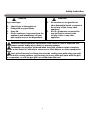 3
3
-
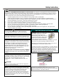 4
4
-
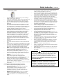 5
5
-
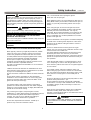 6
6
-
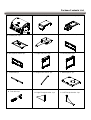 7
7
-
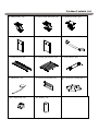 8
8
-
 9
9
-
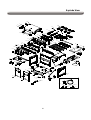 10
10
-
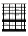 11
11
-
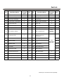 12
12
-
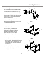 13
13
-
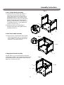 14
14
-
 15
15
-
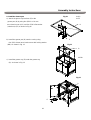 16
16
-
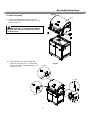 17
17
-
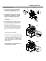 18
18
-
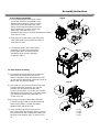 19
19
-
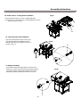 20
20
-
 21
21
-
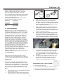 22
22
-
 23
23
-
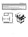 24
24
-
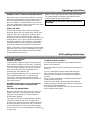 25
25
-
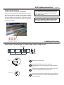 26
26
-
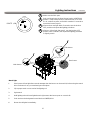 27
27
-
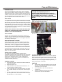 28
28
-
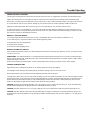 29
29
-
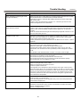 30
30
-
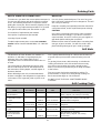 31
31
-
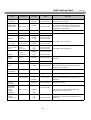 32
32
-
 33
33
-
 34
34
-
 35
35
-
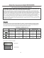 36
36
-
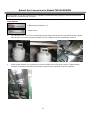 37
37
-
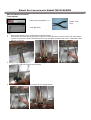 38
38
-
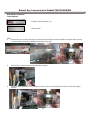 39
39
-
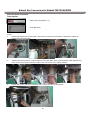 40
40
-
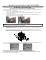 41
41
-
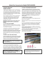 42
42
-
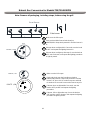 43
43
-
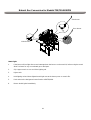 44
44
-
 45
45
-
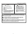 46
46
-
 47
47
-
 48
48
-
 49
49
-
 50
50
-
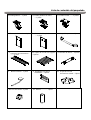 51
51
-
 52
52
-
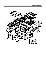 53
53
-
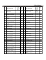 54
54
-
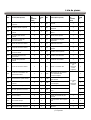 55
55
-
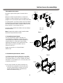 56
56
-
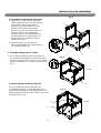 57
57
-
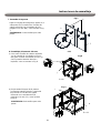 58
58
-
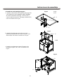 59
59
-
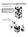 60
60
-
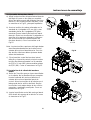 61
61
-
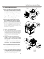 62
62
-
 63
63
-
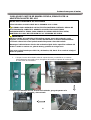 64
64
-
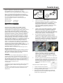 65
65
-
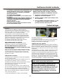 66
66
-
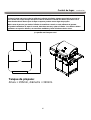 67
67
-
 68
68
-
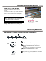 69
69
-
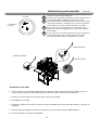 70
70
-
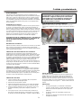 71
71
-
 72
72
-
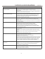 73
73
-
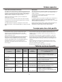 74
74
-
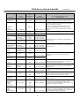 75
75
-
 76
76
-
 77
77
-
 78
78
-
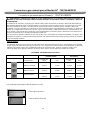 79
79
-
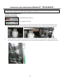 80
80
-
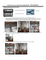 81
81
-
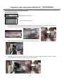 82
82
-
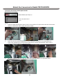 83
83
-
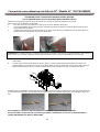 84
84
-
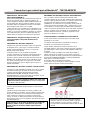 85
85
-
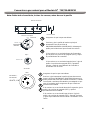 86
86
-
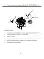 87
87


Nexgrill 730-0830PM El manual del propietario
- Categoría
- Barbacoas
- Tipo
- El manual del propietario
- Este manual también es adecuado para
en otros idiomas
- English: Nexgrill 730-0830PM Owner's manual
Artículos relacionados
-
Nex 720-0888 El manual del propietario
-
 Nexgrill 720-0830FP El manual del propietario
-
 Nexgrill 720-0786A Guía de instalación
-
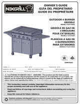 Nexgrill 720-0786A Instrucciones de operación
-
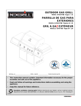 Nexgrill 720-0778B El manual del propietario
-
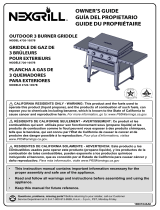 Nexgrill 720-1057B Instrucciones de operación
-
-
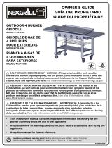 Nexgrill 720-0786 Instrucciones de operación
-
Nexgrill 820-0033 El manual del propietario
-
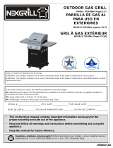 Nexgrill 720-0864 El manual del propietario


Otros documentos
-
Member's Mark 730-0778C El manual del propietario
-
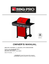 BBQ Pro 720-0894C El manual del propietario
-
 BBQ-Pro 720-0894C El manual del propietario
-
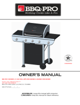 BBQ Pro 720-0894D El manual del propietario
-
 Megamaster 720-0888M El manual del propietario
-
Members Mark 730-0839 El manual del propietario
-
KitchenAid 730-0787 El manual del propietario
-
-
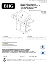 BHG 720-0783H El manual del propietario
-
Kenmore 720-0830A El manual del propietario


