Universal 540-0004 El manual del propietario
- Tipo
- El manual del propietario

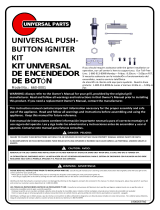
This instruction manual contains important information necessary for the proper assembly and safe
use of the appliance. Read and follow all warnings and instructions before assembling and using the
appliance. Keep this manual for future reference.
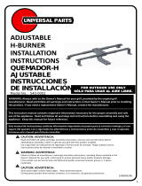
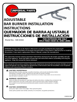
ADJUSTABLE
LARGE BURNER
INSTALLATION
INSTRUCTIONS
QUEMADOR
GRANDE AJUSTABLE
INSTRUCCIONES DE
INSTALLACIÓN
19000593A0
CAUTION: ADVERTENCIA:
Read and follow all safety warnings, assembly instructions, and use care directions before attempting to assembly,
install or operate your grill with this product installed.
Antes de empezar a armar y a cocinar, lea y siga todas las instrucciones de armado y las instrucciones de uso y de
cuidado.
WARNING: ADVERTENCIA:
Failure to follow all manufacture’s warnings and safety instructions, including those contained in the Owner’s Manual
for your grill, could result in serious personal injury and/or property damage.
El no cumplir con las instrucciones del fabricante puede occasionar lesiones graves y danos materiales.
CAUTION: ADVERTENCIA:
Some parts may contain sharp edges. Wear protective gloves.
Ciertas partes pueden tener bordes cortantes. Si es necesario, use guantes protectores.
FOR OUTDOOR USE ONLY
SÓLO PARA USAR AL AIRE LIBRE.
1
▲
!
Model No.: 540-0004
WARNING: Always refer to the Owner’s Manual for your grill, provided by the original grill
manufacturer. Read and follow all warnings and instructions in that Owner’s Manual prior to installing
this product. If you need a replacement Owner’s Manual, contact the manufacturer.
!
▲
!
▲
!

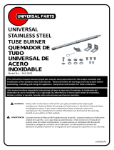
INSTALLATION INSTRUCTIONS
FOR MISSING PARTS, PLEASE CALL CUSTOMER SERVICE AT 1-800-913-8999
THE FOLLOWING TOOLS ARE REQUIRED TO INSTALL THE UNIVERSAL PARTS
REPLACEMENT BURNER KIT:
•Phillips Screwdriver
•Small Adjustable Wrench
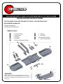
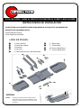
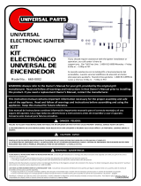
PARTS LIST:
ASSEMBLY
Step 1. Attach one of the springs provided to one of the
venturi tubes using one of the “M4x6mm” bolts as shown in
Illustration 1. Repeat this step using the other venturi tube
and spring.
❶ 2 Venturi Tubes
❷ 2 Seal Plates
❸ 2 Springs
❹ 4 Brackets
❺ 4 Burner Extension Tubes
❻ 1 Burner
❼ 2 M4 Nuts
❽ 10 M4 X 6mm Bolts
❾ 2 M4 X 10mm Bolts
2
❶
❷
❸
❹
❺
❻
❼
❽
❾
❺
Illustration-1

INSTALLATION INSTRUCTIONS
FOR MISSING PARTS, PLEASE CALL CUSTOMER SERVICE AT 1-800-913-8999
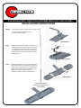
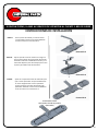
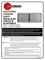
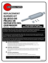
Step 2. Attach the seal plates and the venturi tubes to the
burner using two “M4x6mm” bolts
as shown in Illustration 2.
3
Step 3. Attach the brackets as shown in Illustration 3 to
the bottom of the extension tube burner using
one “M4x10mm” bolt and “M4” nut. Repeat
assembly step for the remaining bracket and
extension tube burner components as shown
in Illustration 3.
Step 4. Adjust the extension tube parts by sliding them
back and forth until the new burner is the same
length as the original burner. Once the desired
length of the burner has been achieved, secure
the burner extension tubes using four
“M4x6mm” bolts as shown in Illustration 4.
UNIVERSAL PARTS
Adjustable Large Burner
(Assembled)
Illustration-2
Illustration-3
Illustration-4

INSTALLATION INSTRUCTIONS
FOR MISSING PARTS, PLEASE CALL CUSTOMER SERVICE AT 1-800-913-8999
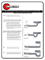
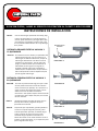
Step 1. With the gas tubes pointed down, lower the
assembled burner into the firebox of the grill.
4
Step 2a If the distance between the valve tip and the
venturi tube is short enough for a single 90°
angle bend in the venturi tube, attach the
venturi tube directly to the valve tip as shown in
Illustration 1. Using your thumb and index finger,
gently grip the flexible venturi tube on either
side and extend the tube until it can be attached
securely to the valve tip. Repeat this step for the
remaining venturi tube.
Step 2b. If the venturi tube is too long to enable the
installation as shown in Illustration 1, gently
bend the venturi tube to create a smooth “U”
shape as shown in Illustration 2. This may
require stretching the venturi tubes to fit
properly into the firebox. Using your thumb and
index finger, gently grip the flexible venturi
tube on either side and extend the tube until it
can be attached securely to the valve tip.
Repeat this step for the remaining venturi tube.
LONG DISTANCE BETWEEN VALVE/BURNER
Step 3. After attaching the venturi tubes to the
valve tips, ensure that the burner is level.
SHORT DISTANCE BETWEEN VALVE/BURNER
Valve Tip
Illustration-1
Illustration-2
Illustration-3
Illustration-4
Step 4. Using the spring, secure the venturi tube onto
the valve tip as shown in Illustrations 3 and 4.
Repeat this step for the remaining venturi tube.

INSTRUCCINOES DE INSTALLACIÓN
SI FALTAN PIEZAS, LLAME AL SERVICIO DE ATENCIÓN AL CLIENTE 1-800-913-8999
SE NECESITAN LAS SIGUINTES PIEZAS PARA INSTALAR EL EQUIPO DE QUEMADOR DE
REPUESTO DE UNIVERSAL PARTS:
•Destornillador Phillips
•Llave Pequena Ajustable
LISTA DE PIEZAS:
MONTAJE
Paso 1. Coloque el resorte previsto al tubo venturi
utilizando uno de los pernos M4x6mm como
se ilustra. Repita este paso para el otro tubo
de venturi.
❶ 2 Tubos Venturi
❷ 2 Placas de sellado
❸ 2 Resortes
❹ 4 Soportes
❺ 2 Tubos de ExtensiÓn del Quemador
❻ 1 Quemador
❼ 2 Tuercas M4
❽ 10 Pernos M4 X 6mm
❾ 2 Pernos M4x10mm
5
❶
❷
❸
❹
❺
❻
❼
❽
❾
❺

INSTRUCCIONES DE INSTALLACIÓN
Paso 2. Una las placas de sellado y los tubos venturi
a el quemador usando los tornillos M4x6mm.
Como se muestra en la ilustración 2.
6
Paso 3. Fije los soportes como se muestra en la figura 3
para la parte inferior de el quemador de tubo de
extensión utilizando un M4x10mm tornillo y una
tuerca M4. Repita el paso de montaje para el otro
soporte y quemador tubo de extensión.
Paso 4. Ajuste los conjuntos de tubos de extensión para
que el nuevo quemador sea aproximadamente
el mismo longitud total como el quemador
original. Asegure los tubos de extensión del
quemador utilizando cuatro tornillos M4x6mm
como se muestra en la ilustración 4.
UNIVERSAL PARTS
Quemador Grande Ajustable
(Montado)
SI FALTAN PIEZAS, LLAME AL SERVICIO DE ATENCIÓN AL CLIENTE 1-800-913-8999
Ilustración-2
Ilustración-3
Ilustración-4

INSTRUCCIONES DE INSTALLACIÓN
Paso 1. Con los tubos de gas apuntando hacia abajo, baje
la barra del quemador en la caja de fuego de la
parrilla. Ajuste la distancia y el ángulo de los pies
para asegurar el quemador se siente nivel y este
en una posición estable dentro de la caja de fuego
de la parrilla.
7
Paso 2a. Si la distancia entre la válvula y el quemador este
suficiente para permitir una curva suave en el
tubo de gas sin dobleces adicionales, coloque el
tubo de gas directamente a la válvula como se
muestra en la ilustración-1. Usar el agarre del
pulgar y el dedo de índice para suavemente el
tubo flexible en dos lugares a lo largo de su
longitud y expandir hasta que se extiende lo
suficiente para completamente comprometerse
sobre cada punta de la válvula. Repita este paso
para el segundo tubo de gas.
Paso 2b. Si el tubo es ya demasiado largo para que el tubo
venturi pueda conectarse a través de la válvula
como se muestra por ejemplo, en la ilustracion-1,
utilice el exceso de longitud para hacer una lisa
doble curva como lo indica mostrado en
ilustración-2. Esto puede requerir estiramiento del
gas tubo para caber. Repita este paso para el tubo
venturi restantes.
DISTANCIA GRANDE ENTRE LA VALVULA Y
EL QUEMADOR
Paso 4. Después de que el quemador grande ajustable se
coloca en la caja de fuego de la parrilla, jale el
tubo del quemador ajustable, conectado de gas
sobre la válvula de control. Amarre el tubo
conectado de gas ajustable conectado en la
válvula de control con el muelle incluido. Como se
muestra en las ilustraciones-3 y 4. Repita este paso
para el segundo tubo de gas.
DISTANCIA PEQUENA ENTRE LA VALVULA Y
EL QUEMADOR
Boquilla de la
Válvula
IlustraciÓn-1
IlustraciÓn-2
IlustraciÓn-3
IlustraciÓn-4
SI FALTAN PIEZAS, LLAME AL SERVICIO DE ATENCIÓN AL CLIENTE 1-800-913-8999
Paso 3. Después de sujetar los tubos de venturi para la
Consejos de la válvula, asegúrese de que el
quemador esté nivelada.

Made in China / Hecho en China
©2016 Nexgrill Industries, Inc.
Chino, CA. 91710
www.nexgrill.com
1-800-913-8999
8
For 90 days from the date of purchase, UNIVERSAL PARTS warrants the product against defects due to workmanship or materials to the original purchaser.
UNIVERSAL PARTS obligation under this warranty are limited to the following guidelines:
• This warranty does not cover units that have been altered/modified or damaged due to: normal wear, rust, abuse, improper maintenance and/or improper use.
• This warranty does not cover surface scratches, rust or heat damage to the finish, which is considered normal wear.
• UNIVERSAL PARTS may elect, at their option, to repair, replace, or offer the depreciated value for damaged units covered under the terms of this warranty.
• UNIVERSAL PARTS, at their option, may satisfy this warranty by offering to replace component parts with any alternative compatible component part based on stock available the
time the request for the replacement parts is made.
• This warranty extends to the original purchaser only and is not transferable or assignable to subsequent purchasers.
UNIVERSAL PARTS requires reasonable proof of purchase. Therefore, we strongly recommend that you retain your sales receipt or invoice. To obtain a replacement for your product
under the terms of this warranty, please call our Customer Service Department at 1-800-913-8999. A receipt will be required. UNIVERSAL PARTS will not be responsible for any units
forwarded to us without prior authorization.
EXCEPT AS ABOVE STATED, UNIVERSAL PARTS MAKES NO OTHER EXPRESS WARRANTY.
THE IMPLIED WARRANTIES OF MERCHANTABILITY AND FITNESS FOR A PARTICULAR PURPOSE ARE LIMITED IN DURATION TO THOSE LISTED ABOVE FROM THE DATE OF PURCHASE.
SOME STATES DO NOT ALLOW LIMITATIONS ON HOW LONG AN IMPLIED WARRANTY LASTS, SO THE ABOVE LIMITATION MAY NOT APPLY TO YOU.
ANY LIABILITY FOR INDIRECT, INCIDENTAL OR CONSEQUENTIAL DAMAGES ARISING FROM THE FAILURES OF THE PRODUCT TO COMPLY WITH THIS WARRANTY OR ANY IMPLIED
WARRANTY IS EXCLUDED. CUSTOMER ACKNOWLEDGES THAT THE PURCHASE PRICE CHARGED IS BASED UPON THE LIMITATIONS CONTAINED WITHIN THE WARRANTY SET OUT
ABOVE. SOME STATES DO NOT ALLOW THE EXCLUSION OR LIMITATION OF INCIDENTAL OR CONSEQUENTIAL DAMAGES, SO THE ABOVE LIMITATION OR EXCLUSION MAY NOT APPLY
TO YOU. THIS WARRANTY GIVES YOU SPECIFIC LEGAL RIGHTS, AND YOU MAY HAVE OTHER RIGHTS WHICH VARY FROM STATE TO STATE.
90 DAY LIMITED WARRANTY
Por 90 dias a partir de la fecha de la compra, UNIVERSAL PARTS garantiza el producto contra defectos en la fabricaciÓn o los materiales al comprador original.
Las obligaciones de UNIVERSAL PARTS con respecto a esta garantia se limitan a lo siguiente:
• Esta garantía no cubre unidades que hayan sido alteradas/modificadas o dañadas debido a: uso normal, herrumbre, maltrato, mantenimiento inadecuado y/o uso inapropiado.
• Esta garantía no cubre rayones superficiales, daño por herrumbre or por calor al acabado, lo cual se considera como uso normal.
• UNIVERSAL PARTS puede decidir, a su opcion, a reparar, reemplazar o ofrecer el valor depreciado de las unidades dañadas cubiertas bajo los términos de esta garantia.
• UNIVERSAL PARTS , a su discreción , puede satisfacer esta garantía ofreciendo reemplazar componentes con cualquier componente alternativo compatible basado
en el inventario disponible al momento en que se hizo la solicitud de las piezas de repuesto.
• Esta garantía se otorga al comprador original únicamente y no es transferible o asignable a los compradores posteriores.
UNIVERSAL PARTS requiere un comprobante de compra razonable. Por lo tanto, le recomendamos enfaticamente que retenga su recibo o factura de venta. Para obtener un
reemplazo de su producto bajo los terminos de esta garantia, sirvase contactar al Departamento de Servicio al Cliente al 1-800-913-8999. Se exigira la presentacion de un recibo.
UNIVERSAL PARTS no sera responsable de ninguna unidades devuelta a nosotros sin autorizaciÓn previa.
EXCEPTO POR LO INDICADO ARRIBA, UNIVERSAL PARTS NO OTORGA NINGUNA OTRA GARANTIA EXPRESA.
LAS GARANTÍAS IMPLÍCITAS DE COMERCIABILIDAD Y ADECUACIÓN CON UN FIN ED PARTICULAR SON DE DURACION LIMITADA DE ACUERDO A LO INDICADO ARRIBA A PARTIR DE LA
FECHA DE COMPRA. ALGUNOS ESTADOS NO PERMITEN LIMITACIONES DE DURACION DE UNA GARANTÍA IMPLÍCITA; POR LO TANTO, LA LIMITACIÓN PRODRÍA NO SER APLICABLE EN
SU CASO.
SE EXCLUYE CUALQUIER RESPONSIBILIDAD POR DANOS INDIRECTOS, INCIDENTALES O CONSIGUIENTES DERIVADOS DE LA FALTA DE CUMPLIMIENTO DE ESTA GARANTIA O DE
CUALQUIER GARANTIA IMPLÍCITA DE PRODUCTO. EL CLIENTE RECONOCE QUE EL PRECIO DE COMPRA COBRADO SE BASA EN LAS LIMITACIÓNES CONTENIDAS EN LA GARANTIA
ANTERIOR. ALGUNOS ESTADOS NO PERMITEN LA EXCLUSION O LIMITACIÓN DE LOS DAÑOS INCIDENTALES O CONSIGUIENTES; POR LO TANTO, LA LIMITACIÓN O EXCLUSIÓN
ANTERIOR PODRÍA NO SER APLICABLE EN SU CASO. ESTA GARANTÍA LE OTORGA DERECHOS LEGALES ESPECÍFICOS Y USTED PUEDE TENER ADEMAS OTROS DERECHOS QUE VARÍAN
DE UN ESTADO A OTRO.
GARANTIA LIMITADA DE 90 DIAS
State of California Proposition 65 Warnings:
WARNING
This equipment is equipped to operate on propane gas which contains the chemical Benzene, known to
the State of California to cause cancer and birth defects and other reproductive harm.
Advertencias de la Proposición 65 del estado de California:
ADVERTENCIA
Este equipo está equipado para funcionar con gas propano, que contiene el benceno químico, conocido
en el estado de California como causantes de cáncer y defectos congénitos y otros daños reproductivos.
-
 1
1
-
 2
2
-
 3
3
-
 4
4
-
 5
5
-
 6
6
-
 7
7
-
 8
8


Universal 540-0004 El manual del propietario
- Tipo
- El manual del propietario
en otros idiomas
- English: Universal 540-0004 Owner's manual
Artículos relacionados
-
 Universal 540-0002 El manual del propietario
-
 Universal 540-0003 El manual del propietario
-
 Universal 660-0002 El manual del propietario
-
 Universal 550-0002 El manual del propietario
-
 Universal 660-0001 El manual del propietario
-
Universal 540-0006 El manual del propietario
-
 Universal 710-0006 El manual del propietario
-
 Nexgrill 540-0001 El manual del propietario
-
 Universal 540-0005 El manual del propietario
-
 Universal 670-0004 El manual del propietario


