SICK RS25-WL334000 Instrucciones de operación
- Categoría
- Iluminación de conveniencia
- Tipo
- Instrucciones de operación

de
RS25-WL334000
Register Sensors
SAFETY INSTRUCTIONS
en
fr
es
it
da
pl
cs


© SICK AG • Presence Detection • Irrtümer und Änderungen vorbehalten • 8016127.YYC9 3
Safety instructions Register Sensors RS25-WL334000
de
Informationen zu diesem Dokument
Dieses Dokument enthält zusätzliche Sicherheitshinweise zum Umgang mit den Register-Sensoren RS25-
WL334000. Für ergänzende Informationen zur Montage und zum elektrischen Anschluss sowie Informationen zur
Funktionsweise, Bedienung, Parametrierung und Störungsbehebung siehe separates Quickstart und die Betriebs-
anleitung. Die Betriebsanleitung können Sie über das Internet „www.mysick.com/de/RS25“ herunterladen.
Diese Anleitung gilt nur für den Optikkopf mit Lichtwellenleiter mit mindestens 3,2 m Länge in Verbindung mit der
Auswerteeinheit als zugehöriges elektrischen Betriebsmittel.
Bestimmungsgemäße Verwendung
Der Register-Sensor RS25 ist ein optoelektronischer Sensor und wird zum optischen, berührungslosen Erfassen
von Druckmarken und Kontrastmarkierungen eingesetzt.
Der Register-Sensor RS25-WL334000 entspricht der Schutzart für Betriebsmittel zur Verwendung in explosions-
gefährdeten Bereichen mit brennbaren Gasen nach EN 60079-0, EN 60079-10, EN 60079-11, EN 60079-28,
Richtlinie 2014/34/EU und TRBS2153.
Der Register-Sensor RS25-WL334000 ist für folgenden Einsatz zugelassen:
• Auswerteeinheit: ATEX Ex II (2)G [Ex op is Gb] IIB
• Optikkopf: ATEX Ex II 2G Ex op is IIB T4 Gb
• Der Optikkopf darf in explosionsgefährdete Bereiche der „Zone 1“ und „Zone 2“ eingesetzt werden. Die Auswer-
teeinheit ist das zugehörige Betriebsmittel und darf nicht im explosionsgefährdeten Bereich eingesetzt werden.
Typenschild Auswerteeinheit
Das Typenschild bendet sich auf der Rückseite der Auswerteeinheit.
Class 2
DC24V ±20%
≤ 250mA
SICK AG
Erwin-Sick Str.1
D-79183 Waldkirch
Made in Germany
1. SICK-Logo
2. Herstelleradresse
3. Typenbezeichnung
4. Materialnummer
5. Datum-Code
(JJ/WW) (YY/WW)
6. Fortlaufende Seriennummer
7. Leistungsmerkmale
8. 2D-Matrix-Code
9. UL-Logo
ß RCM-Logo
à QS-Kennung
á ATEX-Zertizierung
â CE-Logo
ã Schutzklasse III
ä Mac-Adresse
å ATEX-Kennzeichnung
æ Umgebungstemperatur-
begrenzung:
–10 C° ≤ Ta +55 C°
ç TÜV SÜD Produkt Service
GmbH
è Ex-Kennzeichnung
Typenschild Optikkopf
Folgendes Typenschild bendet sich auf dem Optikkopf:
SICK AG
II 2G Ex op is IIB T4 Gb
TPS 13 ATEX 25204 005 X
TÜV SÜD Produkt Service GmbH
Erwin Sick Str.1
D-79183 Waldkirch
1. SICK-Logo
2. Ex-Kennzeichnung
3. ATEX-Zertizierung
4. TÜV SÜD Produkt Service GmbH
5. Herstelleradresse
6. ATEX-Kennzeichnung

Safety instructions Register Sensors RS25-WL334000
4 © SICK AG • Presence Detection • Irrtümer und Änderungen vorbehalten • 8016127.YYC9
de
Kennzeichnung
Der Register-Sensor RS25-WL334000 ist für folgenden Einsatz zugelassen:
• Auswerteeinheit: ATEX Ex II (2)G [Ex op is Gb] IIB
• Optikkopf: ATEX Ex II 2G Ex op is IIB T4 Gb
Bezeichnung Beschreibung
II Gerätegruppe II: Geräte zur Verwendung im Übertagebereich
2G Gerätekategorie 2 für Zone 1 (Gas)
op is Zündschutzart: inhärent sichere optische Strahlung
IIB Betriebsmittelgruppe: Betriebsmittelgruppe II steht für elektrische Betriebsmittel für alle
explosionsgefährdeten Bereiche außer schlagwettergefährdete Grubenbaue.
Betriebsmittelgruppe IIB: mittlere Anforderungen aus Gruppe II.
T4 Temperaturklasse T4: Oberächentemperatur bis 135 °C
Gb Geräteschutzniveau Gb: Gewährleistet die Sicherheit auch im Ein-Fehler-Fall.
(2)G Die Klammer steht dafür, dass das so gekennzeichnete Gerät nicht innerhalb der hier de-
nierten Zone sitzen darf. Es ist zugehöriges Betriebsmittel.
[ ] Die Klammer steht dafür, dass das so gekennzeichnete Gerät nicht innerhalb der hier de-
nierten Zone sitzen darf. Es ist zugehöriges Betriebsmittel.
Gewährleistung
Reparaturen dürfen nur vom Hersteller durchgeführt werden. Bei Eingriffen und Änderungen am Register-Sensor
RS25 entfällt die Gewährleistung des Herstellers, wie z.B.:
• Öffnen des Sensorgehäuses
• Entfernen der Lichtwellenleiter
• Zerstörung der Kabeldichtungen der Lichtwellenleiter.
Allgemeine Sicherheitshinweise
• Vor der Inbetriebnahme diese Anleitung und das Quickstart lesen.
• Anschluss, Montage und elektrische Inbetriebnahme nur durch Fachpersonal.
• Die Strahlung des Sendelichts nicht durch zusätzliche optische Bauteile fokussieren.
• Trennen Sie die elektrischen Anschlüsse des Gerätes nur in spannungsfreiem Zustand. Beim Trennen von
stromführenden Teilen können Funken entstehen, dadurch besteht im explosionsgefährdeten Bereich Lebens-
gefahr.
• Gerät bei Inbetriebnahme vor Feuchte und Verunreinigung schützen.
• Keine Veränderungen am Register-Sensor vornehmen.
• Bei sichtbarer Beschädigung des Sensors, insbesondere der Lichtwellenleiter, Sensor umgehend auswechseln.
• Nach einer Ummontage des Optikkopfes, Optikkopf und insbesondere Lichtwellenleiter auf sichtbare Beschädi-
gung prüfen und ggf. auswechseln.
Sicherheitskonzept
Es ist sichergestellt, dass durch die optische Ausgangsleistung eine Lösemittelatmosphäre nicht gezündet werden
kann.
Führen Sie folgende Schritte durch:
• Auswerteeinheit nur in Zusammenhang mit SICK Optikkopf OSRA200 verwenden.
• Auswerteeinheit nur außerhalb des explosionsgefährdeten Bereiches montieren.
• Auswerteeinheit erden. Die Erdung für die Auswerteeinheit muss über den eigensicheren Erdungsanschluss der
Anlage durchgeführt werden. Optikkopf erden. Die Erdung für den Optikkopf muss nicht über einen eigensiche-
ren Erdungsanschluss erfolgen.

© SICK AG • Presence Detection • Irrtümer und Änderungen vorbehalten • 8016127.YYC9 5
Safety instructions Register Sensors RS25-WL334000
de
• Sender und Empfänger des Optikkopfes laut Beschriftung der Lichtwellenleiter mit der Auswerteeinheit verbinden.
• Lichtwellenleiter des Optikkopfes geführt verlegen.
• Versorgungsspannung: Netzteil mit sicherer Kleinspannung 24V ± 20 %
Installationsvorgaben – Auswerteeinheit
• Auswerteeinheit nicht im explosionsgefährdeten Bereich einsetzen.
• Die Auswerteeinheit erfüllt IP65.
• Auswerteeinheit nicht zwischen den Seitengestellen der Druckwerke und nicht im Bediengang zwischen den
Druckwerken montieren. In jedem Fall einen Abstand von > 500 mm zu farbführenden Teilen der Druckmaschi-
ne und einen Abstand von > 250 mm zum Bedruckstoff einhalten.
• Auswerteeinheit über die vier dafür vorgesehenen Anschraubelaschen auf eine leitfähige Montageplatte schrau-
ben.
• Die Verschraubung muss über eine Zahnscheibe zwischen Gehäuse und Schraube erfolgen, damit die Erdung
sicher gewährleistet werden kann
Installationsvorgaben – Optikkopf
• Der Optikkopf darf in explosionsgefährdete Bereiche der „Zone 1“ und „Zone 2“ eingesetzt werden.
• Lichtwellenleiter (Sender und Empfänger) gemäß Beschriftung mit der Auswerteeinheit verbinden. Auf die rich-
tige Montage von Sender und Empfänger achten. Siehe hierzu die Beschriftung auf Optikkopf und Auswerteein-
heit. Das empfohlene Anzugmoment der Überwurfmuttern beträgt 1,2 Nm.
• Lichtwellenleiter geschützt verlegen.
• Optikkopf mit zwei Schrauben an geeignete Halter anschrauben. Eine ausreichende Ableitfähigkeit des Gehäu-
ses zur Maschinenerde sicherstellen (R < 1 MOhm).
• Optikkopf in den lokalen Potenzialausgleich der Maschine mit einbinden, d.h. erden.
• Korrekte Tastweite zwischen Materialoberäche und Optikkopf beachten.
• Tastweite möglichst konstant halten.
• Der Neigungswinkel zur Materialoberäche muss in x- und y-Richtung zwischen –15° … +15° liegen.
Installationsvorgaben – Erdungskonzept
• Auswerteeinheit erden. Die Erdung für die Auswerteeinheit über den eigensicheren Erdungsanschluss der Anla-
ge durchführen.
• Auswerteeinheit über die vier dafür vorgesehenen Anschraubelaschen auf eine leitfähige Montageplatte
schrauben.
• Die Verschraubung muss über eine Zahnscheibe zwischen Gehäuse und Schraube erfolgen, damit die Er-
dung sicher gewährleistet werden kann.
• Optikkopf erden. Die Erdung für den Optikkopf muss nicht über einen eigensicheren Erdungsanschluss erfolgen.
• Optikkopf in den lokalen Potenzialausgleich der Maschine mit einbinden, d.h. erden.
Elektrischer Anschluss – Sicherheit
• Verdrahtungsarbeiten nur im spannungslosen Zustand durchführen. Leitungsverbindungen nur im spannungslo-
sen Zustand verbinden und trennen.
Elektrischer Anschluss – Vorgaben
• Minimalen Biegeradius der Lichtwellenleiter von 80 mm nicht unterschreiten.
• Versorgungsspannung: Netzteil mit sicherer Kleinspannung 24V ± 20 %
• Für Versorgungsspannung nur abgeschirmte Leitungen verwenden.
• Für Ethernet nur abgeschirmte Leitungen mit paarweise verdrillten Adern verwenden.

Safety instructions Register Sensors RS25-WL334000
6 © SICK AG • Presence Detection • Irrtümer und Änderungen vorbehalten • 8016127.YYC9
de
Anschlussschema – Versorgungsspannung
M12 (A-coded)
FE (shield)
L+
nc
nc
1
2
brn
wht
3
blu
5
gra
nc
4
blk
1
M
1
1
12
4 3
5
1 nc: nicht belegt (not connected)
Kontakt Kennzeich-
nung
Aderfarbe Beschreibung
1 L+ braun Versorgungsspannung:
+24 V DC ± 20 %
(max. Strom: 250 mA)
2 nc weiß nicht belegt
3 M blau Versorgungsspannung: 0 V
4 nc schwarz nicht belegt
5 nc grau nicht belegt
Anschlussschema – Ethernet
Der Register-Sensor verfügt über einen 100Base-T-Ethernetanschluss.
Rx+
Tx+
Rx–
Tx–
1
2
4
3
M12 (D-coded)
1
4
2
3
Kontakt Kennzeichnung Beschreibung
1 Rx+ Datensignal empfangen, nicht
invertiert
2 Tx+ Datensignal senden, nicht invertiert
3 Rx– Datensignal empfangen, invertiert
4 Tx– Datensignal senden, invertiert
Reinigung und Wartung
SICK- Sensoren sind wartungsfrei. Wir empfehlen, in regelmäßigen Abständen
• die optischen Grenzächen mit feuchtem Tuch zu reinigen
• übermäßige Staubablagerungen zu beseitigen.
Die Entfernung von Farbverschmutzungen des Optikkopfes kann auch mit einem lösemittelgetränkten Reinigungs-
tuch (Ethanol) erfolgen. Überschüssige Lösemittel entfernen.
Störungen
Für technische Auskünfte steht unser Kundendienst zur Verfügung. Für Ihre Vertretung siehe Rückseite.
Reparatur
Reparaturen dürfen nur vom Hersteller durchgeführt werden. Bei Eingriffen und Änderungen am Sensor entfällt
die Gewährleistung des Herstellers.
Technische Daten
HINWEIS!
Über das Internet „www.mysick.com/de/RS25“ können Sie sich für Ihren Register-Sensor das
zugehörige Online-Datenblatt mit technischen Daten, Abmessungen und Anschlussschemata
herunterladen, speichern und drucken.

© SICK AG • Presence Detection • Irrtümer und Änderungen vorbehalten • 8016127.YYC9 7
Safety instructions Register Sensors RS25-WL334000
de
Abmessungen
37
47
4
19,15
14
74
126
152
200
100
88
188
13
4
6
5
7
6
6
6
áàß9â
2
ø 5,5 (4x)
8
Alle Maße in mm
1 Anschluss Optikkopf Empfänger
2 Anschluss Optikkopf Sender
3 Anschluss Versorgungsspannung
4 Anschluss Ethernet Powerlink
5 Anschluss Ethernet Powerlink
6 Befestigungsbohrung
7 Fläche eloxalfrei
8 Anzeige- und Bedieneinheit
9 Funktionsanzeige LED (grün) „Eth, Link und Act“
10 Funktionsanzeige LED (grün) „Eth, Link und Act“
11 Funktionsanzeige LED (grün/rot) „S/E“
12 Funktionsanzeige LED (gelb) „MF“
13 Funktionsanzeige LED (grün) „Power“
30
40
3,2
3
3
37
27
30°
TW
10
Sender
Empfänger
8
6,5
7,9
8
15
5
1
2
3
4
5
5
6
Alle Maße in mm
1 Optische Achse Sender
2 Optische Achse Empfänger
3 Lichtwellenleiter Sender
4 Lichtwellenleiter Empfänger
5 Befestigungsbohrung
6 Tastweite (TW) in mm

Safety instructions Register Sensors RS25-WL334000
8 © SICK AG • Presence Detection • Irrtümer und Änderungen vorbehalten • 8016127.YYC9
de
Optik/Perfomance
Lichtsender
1)
LED rot, grün, blau
Wellenlänge 400 nm ... 700 nm
Lichteckgröße 1,1 mm x 2,0 mm
Nenntastweite 10 mm
Tastweitentoleranz ± 1 mm
Maximale Anzahl Marken pro Register 20
Startcode Einstellbar
Genauigkeit ≤ 40 µm
Maximale optische Ausgangsleistung • ab Optikaustritt Auswerteeinheit: < 100 mW
• ab Lichtaustritt Optikkopf: < 35 mW
Schutzschaltungen Alle Ausgänge: kurzschlussgeschützt, störimpulsunterdrückt
1) Mittlere Lebensdauer 100.000 h bei T
U
= +25 °C.
Versorgung
Versorgungsspannung U
V
1)
24 V DC ± 20 %
Stromaufnahme (ohne Last) < 250 mA
Restwelligkeit < 5 V
ss
innerhalb der zulässigen Versorgungsspannung U
V
(Darf UV Toleranzen nicht über- oder unterschreiten.)
Schutzschaltungen Verpolsicher
1) Grenzwerte: Betrieb in kurzschlussgeschütztem Netz max. 8 A.
Umgebungsbedingung
ATEX (Ex Zulassung) • Auswerteeinheit: Ex II 2(G) [Ex op is Gb] IIB
• Optikkopf: Ex II 2G Ex op is IIB T4 Gb
Schutzklasse
1)
III
Elektromagnetische Verträglichkeit EN 61000-6-4
Umgebungstemperaturbereich –10 °C … +55 °C
Lagertemperaturbereich –20 °C … +70 °C
Maximale Oberächentemperatur
Optikkopf
60 °C, max. 5 K über Betriebsumgebungstemperatur
Fremdlichtsicherheit 30.000 lx
Schutzart IP 65
Rauschen EN 60068-2-64
Schockfestigkeit EN 60086-2-27
1) Bemessungsspannung DC 50 V
Konstruktiver Aufbau
Abmessungen → Siehe Seite 7.
Gewicht • Auswerteeinheit: 1000 g
• Optikkopf: 450 g inkl. Lichtwellenleiter

© SICK AG • Presence Detection • Irrtümer und Änderungen vorbehalten • 8016127.YYC9 9
Safety instructions Register Sensors RS25-WL334000
de
Werkstoffe • Auswerteeinheit: Aluminium
• Optikkopf: Aluminiumlegierung, sandgestrahlt
• Frontscheibe: Glas
Anschlüsse • 1 Stecker M12, 5-polig: Anschluss Versorgungsspannung
1)
• 2 Buchsen M12, 4-polig: Anschluss Ethernet
2)
Anschlusskabel Optikkopf • 1 Lichtwellenleiter Sender, 1 Lichtwellenleiter Empfänger
• Länge: mindestens 3.200 mm
• Durchmesser: ≤ 8 mm
• Minimaler Biegeradius: 80 mm (dynamisch), 40 mm (statisch)
• Außenhülle: Säurebeständig
• Oberäche: Lichtwellenleiter sind mit einem Metallschutzschlauch
ummantelt. Darüber bendet sich ein PA-Mantel. Werkstoff Metall-
schutzschlauch: Stahl verzinkt, Kaltband DC03 nach EN 10139,
verzinkt, Fe/Zn 3
• Werkstoff optische Faser: Glas
Anzeige 6 Stellen mit einer 5 x 7 Punkt-Matrix
1) Abgeschirmte Leitungen verwenden.
2) Verdrillte und abgeschirmte Leitungen verwenden.
Betrachtete Normen
• 2014/34/EU
Richtlinie des europäischen Parlaments und des Rates zur Harmonisierung der Rechtsvorschriften der Mit-
gliedstaaten für Geräte und Schutzsysteme zur bestimmungsgemäßen Verwendung in explosionsgefährdeten
Bereichen.
• EN 60079-0
Elektrische Betriebsmittel für gasexplosionsgefährdete Bereiche – Teil 0: Allgemeine Anforderungen
(aktuell gültige Ausgabe)
• EN 60079-10
Elektrische Betriebsmittel für gasexplosionsgefährdete Bereiche – Teil 10: Einteilung der explosionsgefährdeten
Bereiche (aktuell gültige Ausgabe)
• EN 60079-11
Explosionsfähige Atmosphäre – Teil 11: Geräteschutz durch Eigensicherheit „i“ (aktuell gültige Ausgabe, soweit
zutreffend)
• EN 60079-28
Explosionsfähige Atmosphäre – Teil 28: Schutz von Einrichtungen und Übertragungssystemen, die mit optischer
Strahlung arbeiten (aktuell gültige Ausgabe)
• TRBS2153 – Vermeidung von Zündgefahren infolge elektrostatischer Auadungen Technische Regeln für
Betriebssicherheit (aktuell gültige Ausgabe)
EU-Konformitätserklärung
→ Die EU-Konformitätserklärung bendet sich im Anhang (siehe S. 67)

Safety instructions Register Sensors RS25-WL334000
10 © SICK AG • Presence Detection • Irrtümer und Änderungen vorbehalten • 8016127.YYC9
de

© SICK AG • Presence Detection • Subject to change without notice • 8016127.YYC9 11
Safety instructions Register Sensors RS25-WL334000
en
About this document
This document contains additional safety notes for working with RS25-WL334000 register sensors. For further
information on mounting and electrical connection, as well as information about functionality, operation, congura-
tion and troubleshooting, refer to the separate Quick Start guide and the operating instructions. You can download
the operating instructions from "www.mysick.com/en/RS25".
This instruction manual only applies to the optical head with ber-optic cable at least 3.2 m long combined with
the evaluation unit as associated electrical equipment.
Correct use
The RS25 register sensor is an opto-electronic sensor and is used for optical, non-contact recording of print marks
and contrast markings.
The RS25-WL334000 register sensor complies with the enclosure rating for equipment used in potentially explosi-
ve atmospheres with combustible gases as per EN 60079-0; EN 60079-10; EN 60079-11; EN 60079-28; Directi-
ve 2014/34/EC and TRBS2153.
The RS25-WL334000 register sensor is approved for the following applications:
• Evaluation unit: ATEX Ex II (2)G [Ex op is Gb] IIB
• Optical head: ATEX Ex II 2G Ex op is IIB T4 Gb
• The optical head may be used in the potentially explosive atmospheres of "Zone 1" and "Zone 2". The evaluation
unit is the associated equipment and may not be used in potentially explosive atmospheres.
Evaluation unit type label
The type label is located on the back of the evaluation unit.
Class 2
DC24V ±20%
≤ 250mA
SICK AG
Erwin-Sick Str.1
D-79183 Waldkirch
Made in Germany
1. SICK logo
2. Manufacturer address
3. Type designation
4. Material number
5. Date code (JJ/WW) (YY/WW)
6. Sequential serial number
7. Performance characteristics
8. Data Matrix code
9. UL logo
ß RCM logo
à QA ID
á ATEX certication
â CE logo
ã Protection class III
ä Mac address
å ATEX designation
æ Ambient temperature limit:
–10 C° ≤ T
a
+55 C°
ç
TÜV SÜD Product Service GmbH
è Explosive designation
Optical head type label
The optical head has the following type label:
SICK AG
II 2G Ex op is IIB T4 Gb
TPS 13 ATEX 25204 005 X
TÜV SÜD Produkt Service GmbH
Erwin Sick Str.1
D-79183 Waldkirch
1. SICK logo
2. Explosive designation
3. ATEX certication
4. TÜV SÜD Product Service GmbH
5. Manufacturer address
6. ATEX designation

Safety instructions Register Sensors RS25-WL334000
12 © SICK AG • Presence Detection • Subject to change without notice • 8016127.YYC9
en
Classication
The RS25-WL334000 register sensor is approved for the following applications:
• Evaluation unit: ATEX Ex II (2)G [Ex op is Gb] IIB
• Optical head: ATEX Ex II 2G Ex op is IIB T4 Gb
Designation Description
II Device group II applies to devices used at the surface level
2G Category 2 for zone 1 (gas)
op is Flammable protection: inherently safe optical radiation
IIB Equipment group: equipment group II refers to electrical equipment for all potentially explo-
sive atmospheres, excluding redamp-endangered mine openings.
Equipment group IIB refers to the average requirements from group II.
T4 Temperature class T4: surface temperature up to 135 °C
Gb Equipment protection level Gb: guarantees safety even in the event of a single fault.
(2)G The brackets mean that the designated device must not be situated inside the zone dened
here. It is associated equipment.
[ ] The brackets mean that the designated device must not be situated inside the zone dened
here. It is associated equipment.
Warranty
Repairs may only be carried out by the manufacturer. Any manipulation or modication of the RS25 register sensor
will invalidate the manufacturer's warranty. For example:
• Opening the sensor housing
• Removing ber-optic cables
• Destroying the cable seals of the ber-optic cables
General safety notes
• Read this instruction manual and the Quick Start guide before commissioning.
• Connection, mounting, and electrical commissioning must only be carried out by trained specialists.
• Do not focus the radiation of the emitted light with additional optical elements.
• Make sure electrical connectors are de-energized before disconnecting them from the device. When disconnec-
ting electrical conductors, sparks can occur, thus posing a fatal risk in potentially explosive atmospheres.
• When commissioning, protect the device against moisture and contamination.
• Do not carry out any modications to the register sensor.
• If the sensor is visibly damaged, particularly with regard to the ber-optic cables, replace the sensor immediately.
• Following reassembly of the optical head, check the optical head and in particular the ber-optic cables for
visible damage and replace if necessary.
Safety concept
There is no possibility of a solvent atmosphere being ignited by the optical output.
Carry out the following steps:
• Only use the evaluation unit together with SICK OSRA200 optical head.
• Install the evaluation unit away from any explosive atmosphere.
• Ground the evaluation unit. The evaluation unit must be grounded via the system's intrinsically safe ground
connection. Ground the optical head. The optical head need not be grounded via an intrinsically safe ground
connection.

© SICK AG • Presence Detection • Subject to change without notice • 8016127.YYC9 13
Safety instructions Register Sensors RS25-WL334000
en
• Connect the sender and receiver of the optical head according to the labels on the ber-optic cables and evalua-
tion unit.
• Make sure the ber-optic cable of the optical head is properly routed.
• Supply voltage: power supply unit with safe low voltage 24V +/20%
Installation requirements – evaluation unit
• Do not use the evaluation unit in a potentially explosive atmosphere.
• The evaluation unit satises IP65.
• Do not mount the evaluation unit between the side frames of the printing unit, nor in the operator aisle between
the printing units. Always observe a distance of > 500 mm from the ink-bearing parts of the printing machine
and a distance of > 250 mm from the printing substrate.
• Screw the evaluation unit to a conductive installation plate via the four specially provided mounting brackets.
• The screw connection must be made using a toothed lock washer between the housing and screw to ensure
safe grounding.
Installation requirements – optical head
• The optical head may be used in the potentially explosive atmospheres of "Zone 1" and "Zone 2".
• Connect the ber-optic cables (sender and receiver) to the evaluation unit in accordance with the labels. Make
sure the sender and receiver are mounted correctly. Refer to the labels on the optical head and evaluation unit.
The recommended tightening torque of the cap nuts is 1.2 Nm.
• Lay the ber-optic cables with suitable protection.
• Fasten the optical head to suitable brackets using two screws. Make sure the housing has adequate conductivi-
ty to ground the machine (R <1 MOhm).
• Integrate (i.e. ground) the optical head with the machine's local equipotential bonding.
• Ensure the correct sensing range between the material surface and the optical head.
• Keep the sensing range as constant as possible.
• The inclination angle relative to the material surface in the x and y directions must be between –15° and +15°.
Installation requirements – earthing method
• Ground the evaluation unit. Ground the evaluation unit via the system's intrinsically safe ground connection.
• Screw the evaluation unit to a conductive installation plate via the four specially provided mounting brackets.
• The screw connection must be made using a toothed lock washer between the housing and screw to ensure
safe grounding.
• Ground the optical head. The optical head need not be grounded via an intrinsically safe ground connection.
• Integrate (i.e. ground) the optical head with the machine's local equipotential bonding.
Electrical connection – safety
• Only carry out wiring work when the power is off. Only connect and disconnect cable connections when the
power is off.
Electrical connection – requirements
• Do not bend the ber-optic cable with a bend radius of less than 80 mm.
• Supply voltage: power supply unit with safe low voltage 24V +/20%
• Use screened cables only for the supply voltage.
• For Ethernet use only screened cables with twisted-pair wires.

Safety instructions Register Sensors RS25-WL334000
14 © SICK AG • Presence Detection • Subject to change without notice • 8016127.YYC9
en
Connection diagram – supply voltage
M12 (A-coded)
FE (shield)
L+
nc
nc
1
2
brn
wht
3
blu
5
gra
nc
4
blk
1
M
1
1
12
4 3
5
1 nc = not connected
Contact Marking Wire color Description
1 L+ Brown Supply voltage:
+24 V DC ±20%
(max. current: 250 mA)
2 nc White Not assigned
3 M Blue Supply voltage: 0 V
4 nc Black Not assigned
5 nc Gray Not assigned
Connection diagram – Ethernet
The register sensor has a 100Base-T Ethernet connection.
Rx+
Tx+
Rx–
Tx–
1
2
4
3
M12 (D-coded)
1
4
2
3
Contact Marking Description
1 Rx+ Receive data signal, not inverted
2 Tx+ Send data signal, not inverted
3 Rx– Receive data signal, inverted
4 Tx– Send data signal, inverted
Cleaning and maintenance
SICK sensors are maintenance-free. We recommend doing the following regularly:
• Clean the external lens surfaces with a damp cloth
• Remove excessive dust deposits
Ink contamination can also be removed from the optical head using a cleaning cloth dipped in solvent (ethanol).
Remove excess solvent.
Faults
Do not hesitate to contact our customer service should you require any technical information. Please refer to the
back page of these operating instructions for your agent's contact details.
Repair
Repairs may only be carried out by the manufacturer. Any manipulation or modication of the sensor will invalidate
the manufacturer's warranty.
Technical data
NOTE
You can download, save, and print the relevant data sheet for your register sensor, including
technical data, dimensions, and connection diagrams from "www.mysick.com/en/RS25".

© SICK AG • Presence Detection • Subject to change without notice • 8016127.YYC9 15
Safety instructions Register Sensors RS25-WL334000
en
Dimensions
37
47
4
19.15
14
74
126
152
200
100
88
188
13
4
6
5
7
6
6
6
áàß9â
2
ø 5.5 (4x)
8
All dimensions in mm
1 Optical head receiver connection
2 Optical head sender connection
3 Supply voltage connection
4 Ethernet Powerlink connection
5 Ethernet Powerlink connection
6 Fixing hole
7 Non-anodized surface
8 Display and control unit
9 LED function indicator (green) "Eth/Link/Act"
10 LED function indicator (green) "Eth/Link/Act"
11 LED function indicator (green/red) "S/E"
12 LED function indicator (yellow) "MF"
13 LED function indicator (green) "Power"
30
40
3.2
3
3
37
27
30°
TW
10
Sender
Receiver
8
6.5
7.9
8
15
5
1
2
3
4
5
5
6
All dimensions in mm
1 Optical axis, sender
2 Optical axis, receiver
3 Fiber-optic cable, sender
4 Fiber-optic cable, receiver
5 Fixing hole
6 Sensing range in mm

Safety instructions Register Sensors RS25-WL334000
16 © SICK AG • Presence Detection • Subject to change without notice • 8016127.YYC9
en
Optics/Performance
Light sender
1)
LED, red, green, blue
Wavelength 400 nm to 700 nm
Light spot size 1.1 mm x 2.0 mm
Nominal sensing range 10 mm
Sensing range tolerance ±1 mm
Max. number of marks per register 20
Start code Congurable
Accuracy ≤ 40 µm
Maximum optical output power • from evaluation unit optical output: < 100 mW
• from optical head light output: < 35 mW
Circuit protection All outputs: short-circuit protected and interference-suppressed
1) Average service life 100,000 h at T
U
= +25 °C.
Power Supply
Supply voltage U
V
1)
24 V DC ± 20%
Current consumption (without load) < 250 mA
Residual ripple < 5 V
ss
within the permissible supply voltage U
V
(must not exceed or fall below UV tolerances)
Circuit protection Reverse polarity protected
1) Limit values: max. 8 A for operation in a short-circuit protected network.
Ambient conditions
ATEX (Ex approval) • Evaluation unit: Ex II 2(G) [Ex op is Gb] IIB
• Optical head: Ex II 2G Ex op is IIB T4 Gb
Protection class
1)
III
Electromagnetic compatibility EN 61000-6-4
Ambient temperature range –10 °C to +55 °C
Storage temperature range –20 °C to +70 °C
Maximum surface temperature of opti-
cal head
60 °C, max. 5 K above ambient operating temperature
Ambient light safety 30,000 lx
Enclosure rating IP 65
Noise EN 60068-2-64
Shock resistance EN 60086-2-27
1) Rated voltage 50 V DC
Structural design
Dimensions → See Seite 15.
Weight • Evaluation unit: 1,000 g
• Optical head: 450 g including ber-optic cable

© SICK AG • Presence Detection • Subject to change without notice • 8016127.YYC9 17
Safety instructions Register Sensors RS25-WL334000
en
Materials • Evaluation unit: aluminum
• Optical head: aluminum alloy, sandblasted
• Front screen: glass
Connections • 1 x M12 male connector, 5-pin: supply voltage connection
1)
• 2 x M12 female connectors, 4-pin: Ethernet connection
2)
Optical head connecting cable • 1 x sender ber-optic cable, 1 x receiver ber-optic cable
• Length: at least 3,200 mm
• Diameter ≤ 8 mm
• Minimum bend radius: 80 mm (dynamic), 40 mm (static)
• Outer shell: acid-resistant
• Surface: ber-optic cables are enclosed in a protective metal shea-
thing. This is covered by a PA cladding. Protective metal sheathing
material: galvanized steel, cold strip DC03 as per EN 10139, zinc-
plated, Fe/Zn 3.
• Optical ber material: glass
Display 6-digit with a 5 x 7 dot matrix
1) Use screened cables.
2) Use twisted and screened cables.
Observed standards
• 2014/34/EC
Directive of the European Parliament and the Council on the harmonisation of the laws of the Member States
concerning devices and protective systems intended for correct use in potentially explosive environments.
• EN 60079-0
Electrical apparatus for explosive gas atmospheres – Part 0: General requirements (current edition)
• EN 60079-10
Electrical apparatus for explosive gas atmospheres – Part 10: Classication of hazardous areas (current edition)
• EN 60079-11
Explosive atmospheres – Part 11: Equipment protection by intrinsic safety "i" (current edition, in so far as appli-
cable)
• EN 60079-28
Explosive atmospheres – Part 28: Protection of equipment and transmission systems using optical radiation
(current edition)
• TRBS2153 – Avoidance of ignition hazards due to electrostatic charges, technical rules for occupational safety
(current edition)
EC declaration of conformity
→ The EC declaration of conformity can be found in the appendix (see p. 67)

Safety instructions Register Sensors RS25-WL334000
18 © SICK AG • Presence Detection • Subject to change without notice • 8016127.YYC9
en

© SICK AG • Presence Detection • Sujet à modication sans préavis • 8016127.YYC9 19
Safety instructions Register Sensors RS25-WL334000
fr
À propos de ce document
Ce document contient des consignes de sécurité supplémentaires pour le maniement des détecteurs de repères
RS25-WL334000. Consultez le guide de démarrage rapide et la notice d’instruction pour obtenir des informa-
tions complémentaires sur le montage et le raccordement électrique ainsi que sur le fonctionnement, l’utilisation,
la conguration et l’élimination des défauts. Vous pouvez télécharger la notice d’instruction sur Internet
« www.mysick.com/en/RS25 ».
Cette notice n’est valable que pour la tête optique avec une bre optique d’une longueur d’au moins 3,2 m et
reliée à l’unité de traitement en tant que matériel électrique annexe.
Utilisation conforme
Le détecteur de repères RS25 est un capteur optoélectronique utilisé pour la détection optique sans contact de
repères imprimés et de marques contrastées.
Le détecteur de repères RS25-WL334000 est conforme à l’indice de protection des équipements destinés à une
utilisation dans des zones explosives contenant des gaz inammables, et ce suivant les standards européens
EN 60079-0, EN 60079-10, EN 60079-11 et EN 60079-28, la directive 2014/34/UE et TRBS2153.
Le détecteur de repères RS25-WL334000 est autorisé pour l’emploi suivant :
• Unité de traitement : ATEX Ex II (2)G [Ex op is Gb] IIB
• Tête optique : ATEX Ex II 2G Ex op is IIB T4 Gb
• La tête optique peut être utilisée dans des zones explosives « zone 1 » et « zone 2 ». L’unité de traitement est un
équipement annexe et ne doit pas être montée dans une zone explosive.
Plaque signalétique de l’unité de traitement
La plaque signalétique se trouve sur la face arrière de l’unité de traitement.
Class 2
DC24V ±20%
≤ 250mA
SICK AG
Erwin-Sick Str.1
D-79183 Waldkirch
Made in Germany
1. Logo SICK
2. Adresse du fabricant
3. Désignation du type
4. Référence du matériel
5. Code de la date
(AA/SS) (YY/WW)
6. Numéro de série continu
7. Caractéristiques de
performance
8. Code DataMatrix
9. Logo UL
ß Logo RCM
à Numéro QA
á Certication ATEX
â Logo CE
ã Classe de protection III
ä Adresse Mac
å Marquage ATEX
æ Limite de température
ambiante:
–10 C° ≤ T
a
+55 C°
ç
TÜV SÜD Produkt Service GmbH
è Marquage Ex
Plaque signalétique de la tête optique
La plaque signalétique suivante se trouve sur la tête optique :
SICK AG
II 2G Ex op is IIB T4 Gb
TPS 13 ATEX 25204 005 X
TÜV SÜD Produkt Service GmbH
Erwin Sick Str.1
D-79183 Waldkirch
1. Logo SICK
2. Marquage Ex
3. Certication ATEX
4. TÜV SÜD Produkt Service GmbH
5. Adresse du fabricant
6. Marquage ATEX
Marquage

Safety instructions Register Sensors RS25-WL334000
20 © SICK AG • Presence Detection • Sujet à modication sans préavis • 8016127.YYC9
fr
Le détecteur de repères RS25-WL334000 est autorisé pour l’emploi suivant :
• Unité de traitement : ATEX Ex II (2)G [Ex op is Gb] IIB
• Tête optique : ATEX Ex II 2G Ex op is IIB T4 Gb
Désignation Description
II Groupe d’appareils II : appareils destinés à une utilisation dans une zone exposée aux déa-
grations en surface
2G Catégorie d’appareils 2 pour zone 1 (gaz)
op is Protection contre explosion : inhérente au principe d’un rayon optique sûr
IIB Groupe d’appareils : le groupe d’appareils II comprend les appareils électriques destinés à
être utilisés dans toutes les zones explosives à l’exception des mines grisouteuses.
Groupe d’appareils IIB : exigences moyennes du groupe II.
T4 Classe de température T4 : température de surface jusqu’à 135 °C
Gb Niveau de protection des appareils Gb : garantit la sécurité même en cas d’erreur unique.
(2)G Les parenthèses indiquent que l’appareil portant ce marquage ne doit pas être utilisé dans
la zone en question. Il s’agit de matériel annexe.
[ ] Les parenthèses indiquent que l’appareil portant ce marquage ne doit pas être utilisé dans
la zone en question. Il s’agit de matériel annexe.
Garantie
Les réparations ne doivent être effectuées que par le fabricant. La garantie du fabricant est exclue en cas
d’interventions et de modications sur le détecteur de repères RS25, telles que :
• ouverture du boîtier du détecteur
• retrait des bres optiques
• destruction des étanchéités de câble des bres optiques
Consignes générales de sécurité
• Lire cette notice et le guide de démarrage rapide avant la mise en service.
• Faire effectuer le raccordement, le montage et la mise en service électrique uniquement par un personnel spécialisé.
• Ne pas concentrer le faisceau de lumière émise par d’autres composants optiques supplémentaires.
• Débrancher les raccordements électriques de l’appareil qu’à l’état hors tension. Des étincelles peuvent appa-
raître au débranchement de pièces conductrices ce qui constitue un danger mortel dans une zone explosive.
• Protéger l’appareil contre l’humidité et les impuretés lors de la mise en service.
• Ne pas effectuer de modications sur le détecteur de repères.
• En cas de dommage visible sur le détecteur, notamment sur les bres optiques, procéder immédiatement à son
remplacement.
• Après un démontage de la tête optique, examiner la tête optique et, notamment, les bres optiques pour vérier
l’absence d’éventuels dommages visibles nécessitant le cas échéant un remplacement.
Stratégie de sécurité
Le système garantit que la puissance de sortie optique ne peut pas provoquer d’explosion dans une atmosphère
de solvants.
Effectuer les étapes suivantes :
• N’utiliser l’unité de traitement qu’avec la tête optique SICK OSRA200.
• Monter l’unité de traitement uniquement à l’extérieur de la zone explosive.
• Mettre à la terre l’unité de traitement. La mise à la terre de l’unité de traitement doit être effectuée en utilisant
le raccord de mise à la terre à sécurité intrinsèque de l’installation. Mettre à la terre la tête optique. La mise à
la terre de la tête optique ne doit pas nécessairement être effectuée en utilisant un raccord de mise à la terre à
sécurité intrinsèque.

© SICK AG • Presence Detection • Sujet à modication sans préavis • 8016127.YYC9 21
Safety instructions Register Sensors RS25-WL334000
fr
• Raccorder l’émetteur et le récepteur de la tête optique comme indiqué par le marquage sur les bres optiques
et l’unité de traitement.
• Poser les bres optiques de la tête optique de manière à ce qu’elles ne traînent pas.
• Tension d’alimentation : bloc-réseau à basse tension de sécurité 24 V ± 20 %
Indications concernant l’installation – unité de traitement
• Ne pas utiliser l’unité de traitement dans une zone explosive.
• L’unité de traitement satisfait à IP65.
• Ne pas monter l’unité de traitement entre les cylindres d’impression ni dans le passage de service entre les
cylindres d’impression. Dans tous les cas, garder une distance > 500 mm par rapport aux éléments porteurs
d’encre de la machine à imprimer ainsi qu’une distance >250 mm par rapport aux supports à imprimer.
• Visser l’unité de traitement sur une platine de montage (en matériau conducteur) à l’aide des quatre pattes
prévues à cet effet.
• Le vissage doit être fait avec une rondelle éventail entre boîtier et vis an d’assurer une mise à la terre efcace.
Indications concernant l’installation – tête optique
• La tête optique peut être utilisée dans des zones explosives « zone 1 » et « zone 2 ».
• Relier les bres optiques (émetteur et récepteur) à l’unité de traitement comme indiqué sur le marquage. Faire
attention à ce que le montage de l’émetteur et du récepteur soit correct. Pour cela, voir le marquage sur la tête
optique et l’unité de traitement. Le couple de serrage recommandé pour les écrous-raccords est de 1,2 Nm.
• Poser les bres optiques de manière à ce qu’elles soient protégées.
• Visser la tête optique à l’aide de deux vis sur un support adapté. Assurer que la résistance entre boîtier et mas-
se de la machine est sufsamment basse (R < 1 Mohm).
• Intégrer la tête optique dans la mise à la terre locale de la machine.
• Respecter la bonne distance de détection entre la surface du matériau et la tête optique.
• Maintenir la distance de détection aussi constante que possible.
• L’angle d’inclinaison par rapport à la surface du matériau doit être compris entre –15° et +15° dans les axes x et
y.
Indications concernant l’installation – système de mise à la terre
• Mettre à la terre l’unité de traitement. Effectuer la mise à la terre de l’unité de traitement en utilisant le raccord
de mise à la terre à sécurité intrinsèque de l’installation.
• Visser l’unité de traitement sur une platine de montage (en matériau conducteur) à l’aide des quatre pattes
prévues à cet effet.
• Le vissage doit être fait avec une rondelle éventail entre boîtier et vis an d’assurer une mise à la terre efcace.
• Mettre à la terre la tête optique. La mise à la terre de la tête optique ne doit pas nécessairement être effectuée
en utilisant un raccord de mise à la terre à sécurité intrinsèque.
• Intégrer la tête optique dans la mise à la terre locale de la machine.
Raccordement électrique – sécurité
• Effectuer les travaux de câblage qu’à l’état hors tension. Raccorder et couper les connexions qu’à l’état hors tension.
Raccordement électrique – spécications
• Ne pas descendre en dessous du rayon de courbure minimal des bres optiques de 80 mm.
• Tension d’alimentation : bloc-réseau à basse tension de sécurité 24 V ± 20 %
• N’utiliser que des câbles blindés pour la tension d’alimentation.
• N’utiliser que des câbles blindés avec des paires de ls torsadés pour Ethernet.

Safety instructions Register Sensors RS25-WL334000
22 © SICK AG • Presence Detection • Sujet à modication sans préavis • 8016127.YYC9
fr
Schéma de raccordement – tension d’alimentation
M12 (code A)
FE (blindage)
L+
nc
nc
1
2
brn
wht
3
blu
5
gra
nc
4
blk
1
M
1
1
12
4 3
5
1 nc : non affecté (not connected)
Contact Marquage Couleur
du l
Description
1 L+ marron tension d’alimentation :
+24 V CC ± 20 %
(courant max. : 250 mA)
2 nc blanc non affecté
3 M bleu tension d’alimentation : 0 V
4 nc noir non affecté
5 nc gris non affecté
Schéma de raccordement – Ethernet
Le détecteur de repères dispose d’un raccordement Ethernet 100Base-T.
Rx+
Tx+
Rx–
Tx–
1
2
4
3
M12 (code D)
1
4
2
3
Contact Marquage Description
1 Rx+ réception du signal de données, pas
inversé
2 Tx+ envoi du signal de données, pas
inversé
3 Rx– réception du signal de données,
inversé
4 Tx– envoi du signal de données, inversé
Nettoyage et maintenance
Les capteurs SICK ne nécessitent aucune maintenance. Nous vous recommandons de procéder régulièrement
• au nettoyage des interfaces optiques avec un chiffon humide,
• à la suppression des dépôts poussiéreux excessifs.
Il est également possible de supprimer les taches d’encre sur la tête optique à l’aide d’un chiffon nettoyant imbibé
de solvant (éthanol). Supprimer l’excédent de solvant.
Défauts
Notre service clientèle est à votre disposition pour tous renseignements techniques. Voir au dos pour votre repré-
sentant.
Réparation
Les réparations ne doivent être effectuées que par le fabricant. La garantie du fabricant est exclue en cas
d’interventions et de modications sur le détecteur.
Caractéristiques techniques
REMARQUE !
Sur Internet « www.mysick.com/en/RS25 », vous pouvez télécharger, sauvegarder et imprimer
la che technique en ligne comprenant les caractéristiques techniques, les dimensions et les
schémas de raccordement de votre détecteur de repères.

© SICK AG • Presence Detection • Sujet à modication sans préavis • 8016127.YYC9 23
Safety instructions Register Sensors RS25-WL334000
fr
Dimensions
37
47
4
19,15
14
74
126
152
200
100
88
188
13
4
6
5
7
6
6
6
áàß9â
2
ø 5,5 (4x)
8
Toutes les dimensions
en mm
1 Raccordement de la tête optique, récepteur
2 Raccordement de la tête optique, émetteur
3 Raccordement de la tension d’alimentation
4 Raccordement Ethernet Powerlink
5 Raccordement Ethernet Powerlink
6 Trou de xation
7 Surface sans anodisation
8 Module d’afchage et de commande
9 Témoin de fonctionnement LED (vert) « Eth, Link et Act »
10 Témoin de fonctionnement LED (vert) « Eth, Link et Act »
11 Témoin de fonctionnement LED (vert/rouge) « S/E »
12 Témoin de fonctionnement LED (jaune) « MF »
13 Témoin de fonctionnement LED (vert) « Power »
30
40
3,2
3
3
37
27
30°
TW
10
Emetteur
Récepteur
8
6,5
7,9
8
15
5
1
2
3
4
5
5
6
Toutes les dimensions en mm
1 Axe optique, émetteur
2 Axe optique, récepteur
3 Fibres optiques, émetteur
4 Fibres optiques, récepteur
5 Trou de xation
6 Distance de détection (DT) en mm

Safety instructions Register Sensors RS25-WL334000
24 © SICK AG • Presence Detection • Sujet à modication sans préavis • 8016127.YYC9
fr
Optique/performance
Source d’émission
1)
LED rouge, verte, bleue
Longueur d’onde 400 nm à 700 nm
Taille du spot lumineux 1,1 mm x 2,0 mm
Distance nominale de détection 10 mm
Tolérance de distance de détection ± 1 mm
Nombre maximal de marques par
repère
20
Code de démarrage réglable
Précision ≤ 40 µm
Puissance de sortie optique maximale • à partir de la sortie optique de l’unité de traitement : < 100 mW
• à partir de la sortie de lumière de la tête optique : < 35 mW
Protection électrique Toutes les sorties : protection contre les courts-circuits, suppression des
impulsions parasites
1) Durée de vie moyenne 100 000 h pour T
U
= +25 °C.
Alimentation
Tension d’alimentation U
V
1)
24 V CC ± 20 %
Courant absorbé (sans charge) < 250 mA
Ondulation résiduelle < 5 V
ss
dans la tension d’alimentation admissible U
V
(ne doit pas dépasser les tolérances de UV)
Protection électrique protégé contre l’inversion de polarité
1) Valeurs limites : fonctionnement en réseau protégé contre les courts-circuits 8 A max.
Conditions ambiantes
ATEX (homologation Ex) • unité de traitement : Ex II 2(G) [Ex op is Gb] IIB
• tête optique : Ex II 2G Ex op is IIB T4 Gb
Classe de protection
1)
III
Compatibilité électromagnétique EN 61000-6-4
Plage de température ambiante –10 °C à +55 °C
Température de stockage –20 °C à +70 °C
Température de surface maximale,
tête optique
60 °C, max. 5 K au-dessus de la température de service
Immunité aux lumières parasites 30 000 lx
Indice de protection IP 65
Bruit EN 60068-2-64
Immunité aux chocs EN 60086-2-27
1) Tension nominale 50 V CC
Constitution
Dimensions → voir Seite 23.
Poids • unité de traitement : 1000 g
• tête optique : 450 g, bres optiques comprises

© SICK AG • Presence Detection • Sujet à modication sans préavis • 8016127.YYC9 25
Safety instructions Register Sensors RS25-WL334000
fr
Matériaux • unité de traitement : aluminium
• tête optique : alliage d’aluminium, sablage
• vitre frontale : verre
Raccordements • 1 connecteur mâle M12, 5 pôles : raccordement de la tension
d’alimentation
1)
• 2 connecteurs femelles M12, 4 pôles : raccordement Ethernet
2)
Câble de raccordement, tête optique • 1 émetteur à bres optiques, 1 récepteur à bres optiques
• longueur : au moins 3.200 mm
• diamètre : ≤ 8 mm
• rayon de courbure minimal : 80 mm (dynamique), 40 mm (statique)
• enveloppe extérieure : résistante aux acides
• surface : les bres optiques sont enveloppées dans une gaine mé-
tallique. Le tout est recouvert d’une gaine en polyamide. Matériaux
de la gaine métallique : acier galvanisé; feuillard laminé à froid DC03
selon EN 10139, zingué, Fe/Zn 3
• matériau de la bre optique : verre
Afchage 6 caractères avec matrice 5 x 7 points
1) Utiliser des câbles blindés.
2) Utiliser des câbles torsadés et blindés.
Normes prises en compte
• 2014/34/UE
Directive du Parlement européen et du Conseil concernant le rapprochement des législations des États
membres pour les appareils et les systèmes de protection destinés à être utilisés en zones explosives.
• DIN EN 60079-0
Appareils électriques destinés à être utilisés dans les zones explosives – partie 0 : Exigences générales (édition
en cours)
• EN 60079-10
Appareils électriques destinés à être utilisés dans les zones explosives – partie 10 : Classication des zones
explosives (édition en cours)
• EN 60079-11
Atmosphères explosives – partie 11 : Protection de l’équipement par sécurité intrinsèque « i » (édition en cours,
dans la mesure où elle est applicable)
• EN 60079-28
Atmosphères explosives – partie 28 : Protection du matériel et des systèmes de transmission utilisant le rayon-
nement optique (édition en cours)
• TRBS2153 – Éviter les risques d’ignition à la suite de décharges électrostatiques - règles techniques pour la
sécurité d’exploitation (édition en cours)
Déclaration de conformité UE
→ La déclaration de conformité UE se trouve en annexe (voir page 67)

Safety instructions Register Sensors RS25-WL334000
26 © SICK AG • Presence Detection • Sujet à modication sans préavis • 8016127.YYC9
fr

© SICK AG • Presence Detection • Sujeto a cambio sin previo aviso • 8016127.YYC9 27
Safety instructions Register Sensors RS25-WL334000
es
Acerca de este documento
Este documento contiene instrucciones de seguridad adicionales para el uso de los sensores de registro RS25-
WL334000. Para obtener más información sobre el montaje y la conexión eléctrica, así como sobre el modo
de funcionamiento, el manejo, la conguración de parámetros y la resolución de fallos, consulte la guía de
inicio rápido y las instrucciones de servicio. Puede descargar las instrucciones de servicio desde Internet en
"www.mysick.com/en/RS25".
Estas instrucciones se aplican solo al cabezal óptico con cable de bra óptica con una longitud mínima de 3,2 m
en combinación con la unidad de evaluación como equipo eléctrico correspondiente.
Uso conforme a lo previsto
El sensor de registro RS25 es un sensor optoelectrónico empleado para la detección óptica y sin contacto de
marcas tipográcas y de contraste.
El sensor de registro RS25-WL334000 corresponde al tipo de protección para equipos de uso en zonas con riesgo
de explosión con gases inamables, de conformidad con las normas EN 60079-0, EN 60079-10, EN 60079-11,
EN 60079-28, la directiva 2014/34/UE y TRBS2153.
El sensor de registro RS25-WL334000 cuenta con autorización para las siguientes aplicaciones:
• Unidad de evaluación: ATEX Ex II (2)G [Ex op is Gb] IIB
• Cabezal óptico: ATEX Ex II 2G Ex op is IIB T4 Gb
• El cabezal óptico puede utilizarse en las zonas potencialmente explosivas "zona 1" y "zona 2". La unidad de
evaluación es el equipo asociado y no debe montarse en una zona potencialmente explosiva.
Placa de características de la unidad de evaluación
La placa de características se encuentra en la parte posterior de la unidad de evaluación.
Class 2
DC24V ±20%
≤ 250mA
SICK AG
Erwin-Sick Str.1
D-79183 Waldkirch
Made in Germany
1. Logo SICK
2. Dirección del fabricante
3. Denominación de tipo
4. Número de material
5. Código de fecha
(AA/SS) (YY/WW)
6. Número de serie consecutivo
7. Características de rendimiento
8. Código de matrix 2D
9. Logo UL
ß Logo RCM
à Identicación del control de
calidad
á Certicación ATEX
â Logo CE
ã Clase de protección III
ä Dirección MAC
å Marcado ATEX
æ Límite de temperatura
ambiente:
–10 C° ≤ T
a
+55 C°
ç
TÜV SÜD Produkt Service GmbH
è Marcado Ex
Placa de características del cabezal óptico
La siguiente placa de características se encuentra sobre el cabezal óptico:
SICK AG
II 2G Ex op is IIB T4 Gb
TPS 13 ATEX 25204 005 X
TÜV SÜD Produkt Service GmbH
Erwin Sick Str.1
D-79183 Waldkirch
1. Logo SICK
2. Marcado Ex
3. Certicación ATEX
4. TÜV SÜD Produkt Service GmbH
5. Dirección del fabricante
6. Marcado ATEX

Safety instructions Register Sensors RS25-WL334000
28 © SICK AG • Presence Detection • Sujeto a cambio sin previo aviso • 8016127.YYC9
es
Certicación:
El sensor de registro RS25-WL334000 cuenta con autorización para las siguientes aplicaciones:
• Unidad de evaluación: ATEX Ex II (2)G [Ex op is Gb] IIB
• Cabezal óptico: ATEX Ex II 2G Ex op is IIB T4 Gb
Denominación Descripción
II Grupo II: equipos de uso en supercie.
2G Categoría 2 de equipos para la zona 1 (gas)
op is Tipo de protección: radiación óptica de seguridad inherente.
IIB Grupo de equipos: el grupo de equipos II incluye los equipos eléctricos para todas las zonas
con riesgo de explosión excepto las excavaciones subterráneas con peligro de grisú.
Grupo de equipos IIB: nivel medio de exigencia en el grupo II.
T4 Clase de temperatura T4: temperatura de la supercie de hasta 135 °C.
Gb Nivel de protección de dispositivos Gb: garantiza la seguridad incluso en caso de fallo.
(2)G Los paréntesis indican que el dispositivo marcado de esta forma no debe incluirse en la
zona denida en ese caso. Es un equipo relacionado.
[ ] Los paréntesis indican que el dispositivo marcado de esta forma no debe incluirse en la
zona denida en ese caso. Es un equipo relacionado.
Garantía
Únicamente el fabricante puede llevar a cabo reparaciones. La garantía del fabricante quedará anulada en caso
de llevar a cabo cualquier intervención o modicación en el sensor de registro RS25, como por ejemplo:
• Abrir la carcasa del sensor
• Retirar el cable de bra óptica
• Romper las juntas del cable de bra óptica.
Indicaciones generales de seguridad
• Antes de la puesta en servicio del aparato, lea estas instrucciones y la guía de inicio rápido.
• Las operaciones de conexión, montaje y puesta en servicio eléctrica deben llevarlas a cabo exclusivamente
técnicos especialistas.
• No deben utilizarse componentes ópticos adicionales para concentrar el haz del emisor.
• Desenchufe las conexiones eléctricas del aparato únicamente cuando este no reciba tensión eléctrica. Al
desconectar las piezas conductoras de corriente pueden producirse chispas, lo que implica un riesgo mortal en
áreas potencialmente explosivas.
• Proteja el equipo contra la humedad y la suciedad durante la puesta en servicio.
• No lleve a cabo ningún tipo de modicación en el sensor de registro.
• Si existen daños visibles en el sensor, especialmente en el cable de bra óptica, se debe sustituir inmediatamente.
• Si se modica la posición de montaje del cabezal óptico, es necesario vericar su estado (especialmente del
cable de bra óptica) por si existieran daños visibles y sustituirlo en caso necesario.
Política de seguridad
Queda garantizado que la potencia óptica de salida no es capaz de causar la ignición de atmósferas que conten-
gan disolventes.
Siga los siguientes pasos:
• Use la unidad de evaluación únicamente con el cabezal óptico OSRA200 de SICK.
• La unidad de evaluación debe montarse únicamente fuera de la zona potencialmente explosiva.
• Conecte a tierra la unidad de evaluación a través de una conexión a tierra de seguridad intrínseca en la instalación.
Conecte a tierra el cabezal óptico, pero no a través de una conexión a tierra de seguridad intrínseca.

© SICK AG • Presence Detection • Sujeto a cambio sin previo aviso • 8016127.YYC9 29
Safety instructions Register Sensors RS25-WL334000
es
• Conecte el transmisor y el receptor del cabezal óptico siguiendo la descripción del cable de bra óptica con la
unidad de evaluación.
• Tienda de forma guiada el cable de bra óptica del cabezal óptico.
• Tensión de alimentación: fuente de alimentación con tensión baja de seguridad (24 V ± 20 %).
Requisitos para la instalación de la unidad de evaluación
• La unidad de evaluación no debe instalarse en áreas potencialmente explosivas.
• La unidad de evaluación corresponde al tipo de protección IP 65.
• La unidad de evaluación no debe montarse entre los bastidores laterales de los dispositivos de impresión ni en
la ruta de control de estos últimos. En cualquier caso, se debe dejar una separación superior a 500 mm respec-
to a las piezas portadoras de tinta en el impresor y superior a 250 mm respecto al medio de impresión.
• La unidad de evaluación debe atornillarse a los cuatro cubrejuntas previstos a tal efecto sobre una placa de
montaje conductiva.
• A n de que la conexión a tierra quede totalmente asegurada, se deben utilizar arandelas dentadas entre la
carcasa y los tornillos.
Requisitos para la instalación del cabezal óptico
• El cabezal óptico puede utilizarse en las zonas potencialmente explosivas "zona 1" y "zona 2".
• Los cables de bra óptica (del transmisor y del receptor) deben conectarse a la unidad de evaluación según su
descripción. Preste atención a que el montaje del transmisor y el receptor se realice correctamente. Para ello,
consulte la descripción del cabezal óptico y de la unidad de evaluación. El par de apriete recomendado para las
tuercas de unión es de 1,2 Nm.
• Tienda el cable de bra óptica de forma que quede protegido.
• El cabezal óptico debe montarse sobre un soporte adecuado mediante dos tornillos. Asegúrese de que existe
una conductividad suciente de la carcasa a la toma de tierra de la máquina (R < 1 MΩ).
• El cabezal óptico debe incluirse en la conexión equipotencial de la máquina, es decir, conectarse a tierra.
• Respetar la distancia de detección correcta entre la supercie del material y el cabezal óptico.
• Mantener la distancia de detección lo más constante posible.
• El ángulo de inclinación respecto a la supercie del material debe tener un valor de entre –15° y +15° en los
ejes X e Y.
Requisitos para conexión a tierra
• Conecte a tierra la unidad de evaluación a través de la conexión a tierra de seguridad intrínseca de la instalación.
• La unidad de evaluación debe atornillarse a los cuatro cubrejuntas previstos a tal efecto sobre una placa de
montaje conductiva.
• A n de que la conexión a tierra quede totalmente asegurada, se deben utilizar arandelas dentadas entre la
carcasa y los tornillos.
• Conecte a tierra el cabezal óptico, pero no a través de una conexión a tierra de seguridad intrínseca.
• El cabezal óptico debe incluirse en la conexión equipotencial de la máquina, es decir, conectarse a tierra.
Conexión eléctrica: seguridad
• Realice los trabajos de cableado solo cuando no se recibe tensión eléctrica. Conecte y separe los conectores de
línea solo cuando no se recibe tensión eléctrica.
Requisitos para la conexión eléctrica
• Respete el radio de curvatura mínimo de 80 mm en el cable de bra óptica.
• Tensión de alimentación: fuente de alimentación con tensión baja de seguridad (24 V ± 20 %).
• Para la alimentación eléctrica, utilice solo cables apantallados.
• Para la conexión Ethernet, utilice solo cables con hilos de par trenzado.

Safety instructions Register Sensors RS25-WL334000
30 © SICK AG • Presence Detection • Sujeto a cambio sin previo aviso • 8016127.YYC9
es
Esquema de conexión: tensión de alimentación
M12 (codif. A)
FE (blindaje)
L+
nc
nc
1
2
brn
wht
3
blu
5
gra
nc
4
blk
1
M
1
1
12
4 3
5
1 nc: sin ocupar (not connected)
Contacto Denomina-
ción:
Color del
hilo
Descripción
1 L+ marrón Tensión de alimentación:
+24 V CC ± 20 %
(Corriente máx.: 250 mA)
2 nc blanco sin ocupar
3 M azul Tensión de alimentación: 0 V
4 nc negro sin ocupar
5 nc gris sin ocupar
Esquema de conexión: Ethernet
El sensor de registro dispone de una conexión Ethernet 100Base-T.
Rx+
Tx+
Rx–
Tx–
1
2
4
3
M12 (codif. D)
1
4
2
3
Contacto Denominación: Descripción
1 Rx+ Recibir señal de datos, no invertido
2 Tx+ Enviar señal de datos, no invertido
3 Rx– Recibir señal de datos, invertido
4 Tx– Enviar señal de datos, invertido
Limpieza y mantenimiento
Los sensores SICK no requieren mantenimiento. A intervalos regulares, recomendamos:
• Limpiar las supercies ópticas externas con un paño húmedo.
• Eliminar el polvo acumulado en exceso.
Las manchas de tinta del cabezal óptico también pueden eliminarse usando un paño de limpieza impregnado con
disolvente (etanol). Se debe eliminar el exceso de disolvente.
Averías
Para obtener información técnica, póngase en contacto con nuestro servicio de atención al cliente. Para encontrar
los datos de contacto, consulte la parte posterior.
Reparación
Únicamente el fabricante puede llevar a cabo reparaciones. La garantía del fabricante quedará anulada en caso
de llevar a cabo cualquier intervención o modicación en el sensor.
Datos técnicos
INDICACIÓN
En la dirección de Internet "www.mysick.com/en/RS25" puede descargar, guardar e imprimir la
hoja de datos correspondiente a su sensor de registro, que incluye datos técnicos, dimensiones
y esquemas de conexión.

© SICK AG • Presence Detection • Sujeto a cambio sin previo aviso • 8016127.YYC9 31
Safety instructions Register Sensors RS25-WL334000
es
Dimensiones
37
47
4
19,15
14
74
126
152
200
100
88
188
13
4
6
5
7
6
6
6
áàß9â
2
ø 5,5 (4x)
8
Todas las medidas en mm
1 Conexión del receptor del cabezal óptico
2 Conexión del transmisor del cabezal óptico
3 Conexión de la tensión de alimentación
4 Conexión de Ethernet Powerlink
5 Conexión de Ethernet Powerlink
6 Oricio de jación
7 Supercie no anodizada
8 Unidad de control y visualización
9 Indicador de función LED (verde) "Eth, Link y Act"
10 Indicador de función LED (verde) "Eth, Link y Act"
11 Indicador de función LED (verde/rojo) "S/E"
12 Indicador de función LED (amarillo) "MF"
13 Indicador de función LED (verde) "Power"
30
40
3,2
3
3
37
27
30°
TW
10
Transmisor
Receptor
8
6,5
7,9
8
15
5
1
2
3
4
5
5
6
Todas las medidas en mm
1 Eje óptico del transmisor
2 Eje óptico del receptor
3 Cable de bra óptica del transmisor
4 Cable de bra óptica del receptor
5 Oricio de jación
6 Distancia de detección (TW) en mm

Safety instructions Register Sensors RS25-WL334000
32 © SICK AG • Presence Detection • Sujeto a cambio sin previo aviso • 8016127.YYC9
es
Óptica/Rendimiento
Emisor de luz
1)
LED rojo, verde y azul
Longitud de onda 400 nm ... 700 nm
Tamaño del punto de luz 1,1 mm x 2,0 mm
Distancia nominal de detección 10 mm
Tolerancia de la distancia de detecci-
ón
± 1 mm
Número máximo de marcas por
registro
20
Código de inicio Ajustable
Precisión ≤ 40 µm
Potencia máxima de salida óptica • a partir de la salida óptica de la unidad de evaluación: < 100 mW
• a partir de la salida de luz del cabezal óptico: < 35 mW
Circuitos de protección Todas las salidas: con protección contra cortocircuito, con supresión de
impulsos parásitos
1) Vida útil media de 100 000 h a T
U
= +25 °C.
Alimentación
Tensión de alimentación U
V
1)
24 V CC ± 20 %
Consumo de corriente (sin carga) < 250 mA
Ondulación residual < 5 V
ss
dentro de la tensión de alimentación admisible U
V
(No debe sobrepasar por exceso o por defecto las tolerancias UV).
Circuitos de protección Protección contra polarización inversa
1) Valores límite: funcionamiento en red protegida contra cortocircuito, máx. 8 A.
Condiciones del entorno
ATEX (certicación Ex) • Unidad de evaluación: Ex II 2(G) [Ex op is Gb] IIB
• Cabezal óptico: Ex II 2G Ex op is IIB T4 Gb
Clase de protección
1)
III
Compatibilidad electromagnética EN 61000-6-4
Intervalo de temperatura ambiente –10 °C ... +55 °C
Intervalo de temperatura de alma-
cenamiento
–20 °C ... +70 °C
Temperatura máxima de la supercie
del cabezal óptico
60 °C (máx. 5 K por encima de la temperatura ambiente de servicio)
Insensibilidad a la luz articial 30 000 lx
Tipo de protección IP 65
Ruido EN 60068-2-64
Resistencia a choque EN 60086-2-27
1) Tensión de dimensionamiento 50 V CC
Diseño constructivo
Dimensiones → Véase la Seite 31.

© SICK AG • Presence Detection • Sujeto a cambio sin previo aviso • 8016127.YYC9 33
Safety instructions Register Sensors RS25-WL334000
es
Peso • Unidad de evaluación: 1000 g
• Cabezal óptico: 450 g con el cable de bra óptica
Materiales • Unidad de evaluación: aluminio
• Cabezal óptico: aleación de aluminio tratada con chorro de arena
• Cristal frontal: vidrio
Conexiones • 1 conector macho M12, de 5 polos: conexión de la tensión de ali-
mentación
1)
• 2 conectores hembra M12, de 4 polos: conexión Ethernet
2)
Cable de conexión del cabezal óptico • 1 cable de bra óptica para el transmisor, 1 cable de bra óptica
para el receptor
• Longitud: 3.200 mm como mínimo
• Diámetro: ≤ 8 mm
• Radio de curvatura mínimo: 80 mm (dinámico), 40 mm (estático)
• Envoltura exterior: resistente a los ácidos
• Supercie: los cables de bra óptica están revestidos con un tubo e-
xible de aislamiento metálico cubierto a su vez por un revestimiento
de PA. Material del tubo de aislamiento metálico: acero galvanizado,
eje laminado en frío DC03 conforme a EN 10139, galvanizado, Fe/
Zn 3.
• Material de la bra óptica: vidrio
Indicación 6 dígitos con una matriz de 5 x 7 puntos
1) Utilizar cables apantallados.
2) Utilizar cables trenzados y apantallados.
Normas aplicables
• 2014/34/UE
Directiva del Parlamento Europeo y del Consejo relativa a la aproximación de las legislaciones de los Estados
miembros sobre los aparatos y sistemas de protección para uso conforme a lo previsto en atmósferas potenci-
almente explosivas.
• EN 60079-0
Equipos eléctricos para su uso zonas con riesgo de explosión. Parte 0: Requisitos generales (edición actual).
• EN 60079-10
Equipos eléctricos para su uso zonas con riesgo de explosión. Parte 10: División de las zonas con riesgo de
explosión (edición actual).
• EN 60079-11
Atmósferas explosivas. Parte 11: Protección de equipos mediante seguridad intrínseca "i" (edición actual, si
procede).
• EN 60079-28
Atmósferas explosivas. Parte 28: Protección de equipos y sistemas de transmisión que funcionen con radiación
óptica (versión actual).
• TRBS2153: Prevención de riesgos de ignición debidos a cargas electrostáticas. Normas técnicas de seguridad
de funcionamiento (edición actual).
Declaración de conformidad UE
→ La declaración de conformidad de la UE puede consultarse en el anexo (véase pág. 67)

Safety instructions Register Sensors RS25-WL334000
34 © SICK AG • Presence Detection • Sujeto a cambio sin previo aviso • 8016127.YYC9
es

© SICK AG • Presence Detection • Contenuti soggetti a modiche senza preavviso • 8016127.YYC9 35
Safety instructions Register Sensors RS25-WL334000
it
In merito al documento in oggetto
Il presente documento contiene avvertenze di sicurezza aggiuntive sull'utilizzo dei sensori di registro RS25-
WL334000. Per informazioni integrative sul montaggio e sul collegamento elettrico nonché per informazioni su
funzionamento, utilizzo, parametrizzazione ed eliminazione difetti, vedere le indicazioni di avvio rapido separate e
le istruzioni d'uso. Le istruzioni d'uso possono essere scaricate dal sito Internet "www.mysick.com/en/RS25".
Le presenti istruzioni sono valide solo per la testa ottica con cavo a bra ottica di lunghezza minima 3,2 m in abbi-
namento all'unità di controllo come relativo prodotto elettrico.
Uso conforme alle prescrizioni
Il sensore di registro RS25 è un sensore optoelettronico utilizzato per il rilevamento ottico senza contatto di marchi
stampati e marchi in contrasto.
Il sensore di registro RS25-WL334000 è conforme al tipo di protezione per i prodotti da utilizzare in ambienti a
rischio di esplosione con gas inammabili ai sensi di EN 60079-0, EN 60079-10, EN 60079-11, EN 60079-28,
direttiva 2014/34/EU e TRBS2153.
Il sensore di registro RS25-WL334000 è omologato per i seguenti impieghi:
• Unità di controllo: ATEX Ex II (2)G [Ex op is Gb] IIB
• Testa ottica: ATEX Ex II 2G Ex op is IIB T4 Gb
• La testa ottica può essere utilizzata negli ambienti a rischio di esplosione di "zona 1" e "zona 2". L'unità di cont-
rollo è il relativo prodotto e non può essere utilizzata negli ambienti a rischio di esplosione.
Targhetta di tipo unità di controllo
La targhetta di tipo si trova sul retro dell'unità di controllo.
Class 2
DC24V ±20%
≤ 250mA
SICK AG
Erwin-Sick Str.1
D-79183 Waldkirch
Made in Germany
1. Logo SICK
2. Indirizzo del produttore
3. Denominazione dei tipi
4. Numero materiale
5. Data codice (anno/settimana)
6. Numero di serie progressivo
7. Caratteristiche di prestazione
8. Codice matrice 2D
9. Logo UL
ß Logo RCM
à Identicazione QS
(garanzia di qualità)
á Certicazione ATEX
â Logo CE
ã Classe di protezione III
ä Indirizzo Mac
å Denominazione ATEX
æ Limite temperatura
ambientale:
–10 C° ≤ T
a
+55 C°
ç
TÜV SÜD Produkt Service GmbH
è Denominazione Ex
Targhetta di tipo testa ottica
La seguente targhetta di tipo si trova sulla testa ottica.
SICK AG
II 2G Ex op is IIB T4 Gb
TPS 13 ATEX 25204 005 X
TÜV SÜD Produkt Service GmbH
Erwin Sick Str.1
D-79183 Waldkirch
1. Logo SICK
2. Denominazione Ex
3. Certicazione ATEX
4. TÜV SÜD Produkt Service GmbH
5. Indirizzo del produttore
6. Denominazione ATEX

Safety instructions Register Sensors RS25-WL334000
36 © SICK AG • Presence Detection • Contenuti soggetti a modiche senza preavviso • 8016127.YYC9
it
Identicazione
Il sensore di registro RS25-WL334000 è omologato per i seguenti impieghi:
• Unità di controllo: ATEX Ex II (2)G [Ex op is Gb] IIB
• Testa ottica: ATEX Ex II 2G Ex op is IIB T4 Gb
Denominazione Descrizione
II Gruppo apparecchiature II: apparecchiature da utilizzare in ambienti all'aperto
2 G Categoria apparecchiature 2 per zona 1 (gas)
op is Tipo di protezione antideagrante: raggi visivi sicuri inerenti
IIB Gruppo prodotti: il gruppo prodotti II comprende i componenti elettrici per tutti gli ambienti a
rischio di esplosione tranne le cave a rischio di esplosione di polveri.
Gruppo di prodotti IIB: requisiti medi del gruppo II.
T4 Classe di temperatura T4: temperatura supercie no a 135°C
Gb
Livello di protezione apparecchiatura Gb: garantisce la sicurezza anche in caso di singolo difetto.
(2)G La parentesi signica che le apparecchiature così identicate non possono essere posiziona-
te all'interno della zona indicata tra parentesi. Riguarda il relativo prodotto.
[ ] La parentesi signica che le apparecchiature così identicate non possono essere posiziona-
te all'interno della zona indicata tra parentesi. Riguarda il relativo prodotto.
Garanzia
Le riparazioni possono essere eseguite solo dal produttore. In caso di interventi o modiche sul sensore di registro
RS25, la garanzia del produttore decade, ad es. nei seguenti casi:
• Apertura della scatola del sensore
• Asportazione del cavo a bra ottica
• Rottura dell'isolamento del cavo a bra ottica.
Indicazioni di sicurezza generali
• Prima della messa in funzione leggere le presenti istruzioni e le indicazioni di avvio rapido.
• Allacciamento, montaggio e messa in funzione elettrica solo a cura di personale tecnico specializzato.
• I raggi della luce trasmessa non devono essere messi a fuoco mediante componenti ottici integrativi.
• Scollegare gli allacciamenti elettrici dell'apparecchio solo in assenza di tensione. Quando si scollegano i componen-
ti sotto tensione possono sprigionarsi scintille, con conseguente pericolo di vita in ambienti a rischio di esplosione.
• Alla messa in funzione proteggere l'apparecchio dall'umidità e dalla sporcizia.
• Non modicare il sensore di registro.
• In caso di danneggiamento visibile del sensore, in particolare del cavo a bra ottica, è necessario sostituire
immediatamente il sensore.
• Dopo lo smontaggio della testa ottica è necessario controllare la presenza di danni visibili nella testa ottica e in
particolare nel cavo a bra ottica; se necessario, effettuare la sostituzione.
Concetto di sicurezza
Si deve garantire che con la tensione di uscita ottica non possa crearsi un'atmosfera potenzialmente pericolosa.
Effettuare le seguenti operazioni:
• Utilizzare l'unità di controllo solo in abbinamento alla testa ottica SICK OSRA200.
• L'unità di controllo può essere montata solo esternamente ad ambienti a rischio di esplosione.
• Mettere a terra l'unità di controllo. La messa a terra dell'unità di controllo deve essere effettuata tramite il
collegamento a terra a protezione intrinseca dell'impianto. Mettere a terra la testa ottica. La messa a terra della
testa ottica non deve essere effettuata tramite il collegamento a terra a protezione intrinseca.
• Collegare trasmettitore e ricevitore della testa ottica all'unità di controllo conformemente alle indicazioni riporta-
te sul cavo a bra ottica.

© SICK AG • Presence Detection • Contenuti soggetti a modiche senza preavviso • 8016127.YYC9 37
Safety instructions Register Sensors RS25-WL334000
it
• Posare il cavo a bra ottica della testa ottica in una guida.
• Tensione di alimentazione: rete con bassa tensione sicura 24V ± 20%
Indicazioni per l'installazione – Unità di controllo
• Non utilizzare l'unità di controllo in ambienti a rischio di esplosione.
• L'unità di controllo è conforme a IP65.
• Non montare l'unità di controllo a lato delle aree di stampa e nei passaggi tra le aree di stampa. In ogni caso
osservare una distanza di >500 mm dai componenti sotto tensione della macchina di stampa e una distanza
di >250 mm dal materiale stampato.
• Avvitare l'unità di controllo su una piastra di montaggio conduttrice tramite le quattro alette previste per il colle-
gamento a vite.
• Il collegamento a vite deve avvenire con una rondella dentata posizionata tra alloggiamento e vite, al ne di
garantire un'adeguata messa a terra
Indicazioni per l'installazione – Testa ottica
• La testa ottica può essere utilizzata negli ambienti a rischio di esplosione di "zona 1" e "zona 2".
• Collegare i cavi a bra ottica (trasmettitore e ricevitore) all'unità di controllo come descritto. Rispettare l'altezza
di montaggio di emettitore e ricevitore. Vedere in proposito le indicazioni riportate sulla testa ottica e sull'unità
di controllo. La coppia di serraggio consigliata per i dadi di bloccaggio è 1,2 Nm.
• Posare il cavo a bra ottica in una guida.
• La testa ottica deve essere avviata a un supporto idoneo con due viti. Deve essere garantita un'adeguata capa-
cità di dissipazione elettrostatica dell'alloggiamento verso la messa a terra della macchina (R < 1 MOhm).
• La testa ottica deve essere collegata alla compensazione di potenziale locale della macchina, ovvero deve esse-
re messa a terra.
• Osservare la corretta distanza di ricezione tra la supercie del materiale e la testa ottica.
• Mantenere la distanza di ricezione il più possibile costante.
• L'angolo di inclinazione rispetto alla supercie del materiale deve essere compreso tra –15° e +15° in direzione x e y.
Indicazioni per l'installazione – Concetto di messa a terra
• Mettere a terra l'unità di controllo. Eseguire la messa a terra dell'unità di controllo tramite il collegamento a
terra a protezione intrinseca dell'impianto.
• Avvitare l'unità di controllo su una piastra di montaggio conduttrice tramite le quattro alette previste per il
collegamento a vite.
• Il collegamento a vite deve avvenire con una rondella dentata posizionata tra alloggiamento e vite al ne di
garantire un'adeguata messa a terra.
• Mettere a terra la testa ottica. La messa a terra della testa ottica non deve essere effettuata tramite il collega-
mento a terra a protezione intrinseca.
• La testa ottica deve essere collegata alla compensazione di potenziale locale della macchina, ovvero deve
essere messa a terra.
Allacciamento elettrico – Sicurezza
• Eseguire i lavori di cablaggio soltanto in assenza di tensione. Collegare e scollegare le linee soltanto in assenza
di tensione.
Allacciamento elettrico – Indicazioni
• Non scendere sotto il raggio minimo di curvatura di 80 mm del cavo a bra ottica.
• Tensione di alimentazione: rete con bassa tensione sicura 24V ± 20%
• Per la tensione di alimentazione utilizzare solo cavi schermati.
• Per Ethernet utilizzare solo cavi schermati con li attorcigliati a coppie.

Safety instructions Register Sensors RS25-WL334000
38 © SICK AG • Presence Detection • Contenuti soggetti a modiche senza preavviso • 8016127.YYC9
it
Schema collegamenti – Tensione di alimentazione
M1
2 (codif. A)
FE (schermatura
)
L+
nc
nc
1
2
brn
wht
3
blu
5
gra
nc
4
blk
1
M
1
1
12
4 3
5
1 nc: non occupato (non connesso)
Contatto Identicazi-
one
Colore lo Descrizione
1 L+ marrone Tensione di alimentazione:
+24 V DC ± 20 %
(max. corrente: 250 mA)
2 nc bianco non occupato
3 M blu Tensione di alimentazione: 0 V
4 nc nero non occupato
5 nc grigio non occupato
Schema collegamenti – Ethernet
Il sensore di registro dispone di allacciamento T-Ethernet 100Base.
Rx+
Tx+
Rx–
Tx–
1
2
4
3
M12 (codif. D)
1
4
2
3
Contatto Identicazione Descrizione
1 Rx+ Ricevere segnale dati, non invertito
2 Tx+ Inviare segnale dati, non invertito
3 Rx– Ricevere segnale dati, invertito
4 Tx– Inviare segnale dati, invertito
Pulizia e manutenzione
I sensori SICK non hanno bisogno di manutenzione. A intervalli regolari si consiglia di
• pulire le superci limite ottiche con un panno umido
• e di eliminare la polvere depositata.
L'asportazione di imbrattamenti di colore dalla testa ottica può anche avvenire con un panno imbevuto di solvente
(etanolo). Asportare i solventi in eccesso.
Anomalie
Per informazioni tecniche è a disposizione il nostro servizio di assistenza clienti. Vedere sul retro il recapito del
rispettivo centro di riferimento.
Riparazione
Le riparazioni possono essere eseguite solo dal produttore. In caso di interventi o modiche nel sensore, la garan-
zia del produttore decade.
Dati tecnici
NOTA!
Tramite il sito internet "www.mysick.com/en/RS25" è possibile scaricare, salvare e stampare
la scheda tecnica online relativa a ciascun tipo di sensore di registro, completa di dati tecnici,
misure e schemi di collegamento.

© SICK AG • Presence Detection • Contenuti soggetti a modiche senza preavviso • 8016127.YYC9 39
Safety instructions Register Sensors RS25-WL334000
it
Dimensioni
37
47
4
19,15
14
74
126
152
200
100
88
188
13
4
6
5
7
6
6
6
áàß9â
2
ø 5,5 (4x)
8
Tutte le quote in mm
1 Collegamento testa ottica ricevitore
2 Collegamento testa ottica emettitore
3 Collegamento tensione di alimentazione
4 Collegamento Ethernet Powerlink
5 Collegamento Ethernet Powerlink
6 Foro di ssaggio
7 Supercie non ossidata
8 Unità di comando e visualizzazione
9 Spia funzione a LED (verde) "Eth, Link e Act"
10 Spia funzione a LED (verde) "Eth, Link e Act"
11 Spia funzione a LED (verde/rossa) "S/E"
12 Spia funzione a LED (gialla) "MF"
13 Spia funzione a LED (verde) "Power"
30
40
3,2
3
3
37
27
30°
TW
10
Emettitore
Trasmettitore
8
6,5
7,9
8
15
5
1
2
3
4
5
5
6
Tutte le quote in mm
1 Asse ottico trasmettitore
2 Asse ottico ricevitore
3 Cavo a bra ottica emettitore
4 Cavo a bra ottica ricevitore
5 Foro di ssaggio
6 Distanza di ricezione (TW) in mm

Safety instructions Register Sensors RS25-WL334000
40 © SICK AG • Presence Detection • Contenuti soggetti a modiche senza preavviso • 8016127.YYC9
it
Ottica/Prestazioni
Emettitore luce
1)
LED rosso, verde, blu
Lunghezza d'onda: 400 nm ... 700 nm
Dimensioni zona illuminata 1,1 mm x 2,0 mm
Distanza di tastatura nominale 10 mm
Tolleranza distanza di ricezione ± 1 mm
Numero massimo di marchi per
registro
20
Codice di avvio Regolabile
Accuratezza ≤ 40 µm
Massima tensione di uscita ottica • da uscita ottica unità di controllo: < 100 mW
• da uscita luce testa ottica: < 35 mW
Commutazioni di protezione Tutte le uscite: protezione contro il cortocircuito, soppressione impulsi di
disturbo
1) Durata media 100.000 h con T
U
= +25 °C.
Alimentazione
Tensione di alimentazione U
V
1)
24 V DC ± 20 %
Assorbimento di corrente (senza
carico)
< 250 mA
Ondulazione residua: < 5 V
ss
entro la tensione di alimentazione ammessa U
V
(Non può oltrepassare per eccesso o per difetto i valori di tolleranza UV).
Commutazioni di protezione Protetta dall'inversione di polarità
1) Valori limite: funzionamento in rete protetta da cortocircuiti max. 8 A.
Condizioni ambiente
ATEX (omologazione Ex) • Unità di controllo: Ex II 2(G) [Ex op is Gb] IIB
• Testa ottica: Ex II 2G Ex op is IIB T4 Gb
Classe di protezione
1)
III
Compatibilità elettromagnetica EN 61000-6-4
Campo di temperature ambiente –10 °C … +55 °C
Campo di temperature immagazzinag-
gio
–20 °C … +70 °C
Massima temperatura supercie testa
ottica
60 °C, max. 5 K oltre la temperatura ambiente d'esercizio
Sicurezza luci esterne 30.000 lx
Tipo di protezione IP 65
Rumorosità EN 60068-2-64
Resistenza agli urti EN 60086-2-27
1) Tensione nominale 50 V DC
Struttura costruttiva
Dimensioni → Vedere Seite 39.

© SICK AG • Presence Detection • Contenuti soggetti a modiche senza preavviso • 8016127.YYC9 41
Safety instructions Register Sensors RS25-WL334000
it
Peso • Unità di controllo: 1000 g
• Testa ottica: 450 g incl. cavo a bra ottica
Materiali • Unità di controllo: alluminio
• Testa ottica: lega di alluminio, sabbiata
• Pannello anteriore: vetro
Collegamenti • 1 connettore M12, 5 poli: collegamento tensione di alimentazione
1)
• 2 bussole M12, 4 poli: collegamento Ethernet
2)
Cavo di collegamento testa ottica • 1 cavo a bra ottica emettitore, 1 cavo a bra ottica ricevitore
• Lunghezza: minimo 3.200 mm
• Diametro: ≤ 8 mm
• Minimo raggio di curvatura: 80 mm (dinamico), 40 mm (statico)
• Guaina esterna: resistente agli acidi
• Supercie: i cavi a bra ottica sono rivestiti con un tubo essibile
in metallo. Inoltre occorre un rivestimento esterno in PA. Materiale
del tubo essibile di protezione metallico: acciaio zincato; nastro in
metallo DC03 a norma EN 10139, zincato, Fe/Zn 3.
• Materiale delle bre ottiche: vetro
Display 6 posizioni con matrice a punti 5 x 7
1) Utilizzare cavi schermati.
2) Utilizzare cavi schermati e con li attorcigliati.
Norme applicate
• 2014/34/EU
Direttiva del Parlamento Europeo e del Consiglio concernente il ravvicinamento delle legislazioni degli Stati
membri relative agli apparecchi e sistemi di protezione destinati a essere utilizzati in atmosfera potenzialmente
esplosiva.
• EN 60079-0
Prodotti elettrici per ambienti a rischio di esplosione – Parte 0: Requisiti generali (formulazione attualmente
vigente)
• EN 60079-10
Prodotti elettrici per ambienti a rischio di esplosione – Parte 10: Classicazione degli ambienti a rischio di esp-
losione (formulazione attualmente vigente)
• EN 60079-11
Atmosfera esplosiva – Parte 11: Protezione degli apparecchi tramite sicurezza propria "i" (formulazione attual-
mente vigente, se applicabile)
• EN 60079-28 Atmosfera esplosiva – Parte 28: Protezione di dispositivi e sistemi di trasmissione operanti con
raggi visivi (formulazione attualmente vigente)
• TRBS2153 – Evitare pericoli derivanti da scintille in seguito a cariche elettrostatiche. Regole tecniche per la
sicurezza d'esercizio (formulazione attualmente vigente)
Dichiarazione di conformità EU
→ La dichiarazione di conformità EU è a disposizione in appendice (vedi pag. 67)

Safety instructions Register Sensors RS25-WL334000
42 © SICK AG • Presence Detection • Contenuti soggetti a modiche senza preavviso • 8016127.YYC9
it

© SICK AG • Presence Detection • Der tages forbehold for fejl og ændringer • 8016127.YYC9 43
Safety instructions Register Sensors RS25-WL334000
da
Informationer om dette dokument
Dette dokument indeholder supplerede sikkerhedsanvisninger om håndteringen af registersensorerne RS25-
WL334000. Se separat hurtigstart og betjeningsvejledningen for supplerende informationer om montering og om
elektrisk tilslutning samt informationer om funktionsmåde, betjening, parametrering og fejlafhjælpning. Du kan
downloade betjeningsvejledningen via internettet "www.mysick.com/en/RS25".
Denne vejledning gælder kun for det optiske hoved med lyslederkabel, der er mindst 3,2 m langt i forbindelse med
analyseenheden som tilhørende elektrisk materiel.
Anvendelse efter hensigten
Registersensor RS25 er en optoelektronisk sensor og anvendes til optisk, berøringsfri registrering af trykmærker
og kontrastmærkninger.
Registersensor RS25-WL334000 svarer til beskyttelsesklassen for materiel til anvendelse i eksplosionsfarlige
områder med brændbare gasser iht. EN 60079-0, EN 60079-10, EN 60079-11, EN 60079-28, direktiv
2014/34/EF og TRBS2153.
Registersensor RS25-WL334000 er godkendt til følgende anvendelse:
• Analyseenhed: ATEX Ex II (2)G [Ex op is Gb] IIB
• Optisk hoved: ATEX Ex II 2G Ex op is IIB T4 Gb
• Det optiske hoved må anvendes i de eksplosionsfarlige områder "zone 1" og "zone 2". Analyseenheden er det
tilhørende materiel og må ikke anvendes i det eksplosionsfarlige område.
Typeskilt analyseenhed
Typeskiltet ndes på bagsiden af analyseenheden.
Class 2
DC24V ±20%
≤ 250mA
SICK AG
Erwin-Sick Str.1
D-79183 Waldkirch
Made in Germany
1. SICK-logo
2. Producentens adresse
3. Typebetegnelse
4. Materialenummer
5. Datokode (ÅÅ/UU) (YY/WW)
6. løbende serienummer
7. Effektdata
8. 2D-matrikskode
9. UL-logo
ß RCM-logo
à QS-identikationskode
á ATEX-certicering
â CE-logo
ã Beskyttelsesklasse III
ä Mac-adresse
å ATEX-mærkning
æ Omgivelsestemperaturgrænse:
–10 C° ≤ T
a
+55 C°
ç
TÜV SÜD Produkt Service GmbH
ç Ex-mærkning
Typeskilt optisk hoved
På det optiske hoved ndes følgende typeskilt:
SICK AG
II 2G Ex op is IIB T4 Gb
TPS 13 ATEX 25204 005 X
TÜV SÜD Produkt Service GmbH
Erwin Sick Str.1
D-79183 Waldkirch
1. SICK-logo
2. Ex-mærkning
3. ATEX-certicering
4. TÜV SÜD Produkt Service GmbH
5. Producentens adresse
6. ATEX-mærkning

Safety instructions Register Sensors RS25-WL334000
44 © SICK AG • Presence Detection • Der tages forbehold for fejl og ændringer • 8016127.YYC9
da
Identikation
Registersensor RS25-WL334000 er godkendt til følgende anvendelse:
• Analyseenhed: ATEX Ex II (2)G [Ex op is Gb] IIB
• Optisk hoved: ATEX Ex II 2G Ex op is IIB T4 Gb
Betegnelse Beskrivelse
II Apparatgruppe II: Apparater til anvendelse over jord
2G Apparatkategori 2 for zone 1 (gas)
op is Tændingsbeskyttelse: egensikker optisk stråling
IIB Materielgruppe: Materielgruppe II står for elektrisk materiel til alle eksplosionsfarlige områ-
der med undtagelse af minearbejde med risiko for metangas.
Materielgruppe IIB: normalkrav iht. gruppe II.
T4 Temperaturklasse T4: overadetemperatur på op til 135 °C
Gb Udstyrsbeskyttelsesniveau Gb: garanterer også sikkerheden ved fejl, der optræder i enkelt-
tilfælde.
(2)G Parentesen betyder, at det apparat, der er mærket på denne måde, ikke må sidde i de her
denerede zoner. Det er et tilhørende materiel.
[ ] Parentesen betyder, at det apparat, der er mærket på denne måde, ikke må sidde i de her
denerede zoner. Det er et tilhørende materiel.
Garanti
Reparationer må kun udføres af producenten. Producentens garanti bortfalder ved indgreb og ændringer på regis-
tersensor RS25 som f.eks.:
• Åbning af sensorhuset
• Afmontering af lyslederne
• Ødelæggelse at kabeltætningerne til lyslederne.
Generelle sikkerhedsanvisninger
• Læs denne vejledning og Hurtigstart før idrifttagningen.
• Tilslutning, montering og elektrisk idrifttagning må kun udføres af fagfolk.
• Transmissionslysets stråling må ikke fokuseres gennem andre optiske komponenter.
• Apparatets elektriske tilslutninger må kun afbrydes i spændingsfri tilstand. Når strømførende dele afbrydes, kan
der opstå gnister og dermed forårsage livsfare i eksplosionsfarlige områder.
• Beskyt apparatet mod fugt og tilsmudsning i forbindelse med idrifttagning.
• Der må ikke foretages ændringer på registersensoren.
• Ved synlige skader på sensoren, især på lyslederkablet, skal sensoren omgående udskiftes.
• Efter en genmontering af det optiske hoved skal dette og især lyslederkablet kontrolleres for synlige skader og
evt. udskiftes.
Sikkerhedskoncept
Det er sikret, at en atmosfære af opløsningsmidler ikke kan antændes via den optiske udgangsydelse.
Udfør følgende trin:
• Analyseenheden må kun bruges i sammenhæng med SICK optisk hoved OSRA200.
• Analyseenheden må kun monteres uden for det eksplosionsfarlige område.
• Forbind analyseenheden til jord. Jordforbindelsen for analyseenheden skal oprettes via en egensikker jordtilslut-
ning i anlægget. Forbind det optiske hoved til jord. Jordforbindelsen for det optiske hoved må ikke etableres via
en egensikker jordtilslutning.
• Sender/modtager på det optiske hoved skal tilsluttes analyseenheden i henhold til påskriften på lyslederne.

© SICK AG • Presence Detection • Der tages forbehold for fejl og ændringer • 8016127.YYC9 45
Safety instructions Register Sensors RS25-WL334000
da
• Træk lyslederne til det optiske hoved fagligt korrekt.
• Forsyningsspænding: Netadapter med sikker lavspænding 24V ± 20 %
Installationsangivelser – analyseenhed
• Brug ikke analyseenheden i eksplosionsfarlige områder.
• Analyseenheden opfylder IP65.
• Analyseenheden må ikke monteres mellem trykværkets siderammer og ikke i betjeningsgangen mellem tryk-
værkerne. I alle tilfælde skal der holdes en afstand på >500 mm til farveførende dele i trykmaskinen samt en
afstand på >250 mm til trykmaterialet.
• Analyseenheden skal skrues på en ledende monteringsplade ved hjælp af de re dertil beregnede påskrunings-
beslag.
• Forskruningen skal ske via en tandfjederskive mellem huset og skruen, således at der er sikker jordforbindelse.
Installationsangivelser – optisk hoved
• Det optiske hoved må anvendes i de eksplosionsfarlige områder "zone 1" og "zone 2".
• Lyslederkablerne (sender og modtager) skal tilsluttes analyseenheden iht. påskrift. Sørg for, at sender og mod-
tager monteres korrekt. Se påskriften på det optiske hoved og analyseenheden. Det anbefalede tilspændings-
moment for omløbermøtrikkerne er på 1,2 Nm.
• Træk lyslederkablerne, så de er godt beskyttet.
• Skru det optiske hoved på en egnet holder med to skruer. Det skal sikres, at huset har en tilstrækkelig aed-
ningsevne til maskinens jord (R < 1 Mohm).
• Det optiske hoved skal integreres i maskinens lokale potentialudligning, dvs. have jordforbindelse.
• Overhold den korrekte føleafstand mellem materialets overade og det optiske hoved.
• Føleafstanden skal så vidt muligt holdes konstant.
• Hældningsvinklen til materialets overade skal ligge på mellem –15° … +15° i x- og y-retning.
Installationsangivelser – jordingskoncept
• Forbind analyseenheden til jord. Jordforbindelsen for analyseenheden skal oprettes via en egensikker jordtilslut-
ning i anlægget.
• Analyseenheden skal skrues på en ledende monteringsplade ved hjælp af de re dertil beregnede påskrun-
ingsbeslag.
• Forskruningen skal ske via en tandfjederskive mellem huset og skruen, således at der er sikker jordforbindel-
se.
• Forbind det optiske hoved til jord. Jordforbindelsen for det optiske hoved må ikke etableres via en egensikker
jordtilslutning.
• Det optiske hoved skal integreres i maskinens lokale potentialudligning, dvs. have jordforbindelse.
Elektrisk tilslutning - sikkerhed
• Ledninger må kun trækkes i spændingsfri tilstand. Ledningsforbindelse må kun tilsluttes og afbrydes i spæn-
dingsfri tilstand.
Elektrisk tilslutning – anvisninger
• Lyslederkablernes minimale bøjeradius på 80 mm må ikke underskrides.
• Forsyningsspænding: Netadapter med sikker lavspænding 24V ± 20 %
• Brug kun skærmede ledninger til forsyningsspændingen.
• Brug kun skærmede ledninger med parvist snoede ledere til Ethernettet.

Safety instructions Register Sensors RS25-WL334000
46 © SICK AG • Presence Detection • Der tages forbehold for fejl og ændringer • 8016127.YYC9
da
Tilslutningsskema – forsyningsspænding
M12 (A-kodet)
FE (skærm)
L+
nc
nc
1
2
brn
wht
3
blu
5
gra
nc
4
blk
1
M
1
1
12
4 3
5
1 nc: ikke tilsluttet (not connected)
Kontakt Identika-
tion
Lederfarve Beskrivelse
1 L+ brun Forsyningsspænding:
+24 V DC ± 20 %
(maks. strøm: 250 mA)
2 nc hvid ikke tilsluttet
3 M blå Forsyningsspænding: 0 V
4 nc sort ikke tilsluttet
5 nc grå ikke tilsluttet
Tilslutningsskema – Ethernet
Registersensoren råder over en 100Base-T-Ethernettilslutning.
Rx+
Tx+
Rx–
Tx–
1
2
4
3
M12 (D-kodet)
1
4
2
3
Kontakt Identikation Beskrivelse
1 Rx+ Modtag datasignal, ikke inverteret
2 Tx+ Send datasignal, ikke inverteret
3 Rx– Modtag datasignal, inverteret
4 Tx– Send datasignal, inverteret
Rengøring og vedligeholdelse
SICK-sensorer er vedligeholdelsesfrie. Vi anbefaler med regelmæssige mellemrum at
• rense de optiske grænseader med en fugtig klud,
• fjerne for store støvaejringer.
Der kan også fjernes farvetilsmudsning af det optiske hoved med en klud, der er vædet med opløsningsmiddel
(ethanol). Fjern overskydende opløsningsmiddel.
Fejl
Vores kundeservice står altid til tjeneste med tekniske oplysninger. Se bagside med henblik på kontaktperson.
Reparation
Reparationer må kun udføres af producenten. Producentens garanti bortfalder ved indgreb og ændringer på sen-
soren.
Tekniske data
BEMÆRK!
Du kan downloade, gemme og udskrive det tilhørende online-datablad med tekniske data, mål
og tilslutningsskemaer til registersensoren via internettet "www.mysick.com/en/RS25".

© SICK AG • Presence Detection • Der tages forbehold for fejl og ændringer • 8016127.YYC9 47
Safety instructions Register Sensors RS25-WL334000
da
Mål
37
47
4
19,15
14
74
126
152
200
100
88
188
13
4
6
5
7
6
6
6
áàß9â
2
ø 5,5 (4x)
8
Alle mål i mm
1 Tilslutning modtager optisk hoved
2 Tilslutning sender optisk hoved
3 Tilslutning forsyningsspænding
4 Tilslutning Ethernet Powerlink
5 Tilslutning Ethernet Powerlink
6 Fastgørelseshuller
7 Eloxalfri ade
8 Visnings- og betjeningsenhed
9 Funktionsvisning LED (grøn) "Eth, Link og Act"
10 Funktionsvisning LED (grøn) "Eth, Link og Act"
11 Funktionsvisning LED (grøn/rød) "S/E"
12 Funktionsvisning LED (gul) "MF"
13 Funktionsvisning LED (grøn) "Power"
30
40
3,2
3
3
37
27
30°
TW
10
Sender
Modtager
8
6,5
7,9
8
15
5
1
2
3
4
5
5
6
Alle mål i mm
1 Sender optisk akse
2 Modtager optisk akse
3 Sender lyslederkabel
4 Modtager lyslederkabel
5 Fastgørelseshuller
6 Føleafstand (TW) i mm

Safety instructions Register Sensors RS25-WL334000
48 © SICK AG • Presence Detection • Der tages forbehold for fejl og ændringer • 8016127.YYC9
da
Optik/funktionskarakteristika
Lyssender
1)
LED: rød, grøn, blå
Bølgelængde 400 nm ... 700 nm
Lyspletstørrelse 1,1 mm x 2,0 mm
Bredde af mærketaster 10 mm
Føleafstandstolerance ± 1 mm
Maks. antal mærker per register 20
Startkode Indstillelig
Nøjagtighed ≤ 40 µm
Maks. optisk udgangseffekt • Fra optikudgang analyseenhed: < 100 mW
• Fra lysudgang optisk hoved: < 35 mW
Relæer Alle udgange: Beskytter kortslutning, undertrykker fejlimpulser
1) Middellevetid 100.000 h ved T
U
= +25 °C.
Forsyning
Forsyningsspænding U
V
1)
24 V DC ± 20 %
Strømforbrug (uden belastning) < 250 mA
Rippel < 5 V
ss
inden for den tilladte forsyningsspænding U
V
(Må ikke over- eller underskride UV-tolerancer.)
Relæer Sikret mod forkert polaritet
1) Grænseværdi: Drift i kortslutningsbeskyttet net maks. 8 A.
Omgivelsesbetingelser
ATEX (Ex-godkendelse) • Analyseenhed: Ex II 2(G) [Ex op is Gb] IIB
• Optisk hoved: Ex II 2G Ex op is IIB T4 Gb
Beskyttelsesklasse
1)
III
Elektromagnetisk kompatibilitet EN 61000-6-4
Omgivelsestemperaturområde –10 °C … +55 °C
Opbevaringstemperaturområder –20 °C … +70 °C
Det optiske hoveds maksimale overa-
detemperatur
60 °C, maks. 5 K over driftsomgivelsestemperaturen
Sikkerhed mod eksternt lys 30.000 lx
Kapslingsklasse IP 65
Støj EN 60068-2-64
Stødfasthed EN 60086-2-27
1) Målespænding 50 V DC
Konstruktionens opbygning
Mål → Se Seite 47.
Vægt • Analyseenhed: 1000 g
• Optisk hoved: 450 g inkl. lyslederkabel

© SICK AG • Presence Detection • Der tages forbehold for fejl og ændringer • 8016127.YYC9 49
Safety instructions Register Sensors RS25-WL334000
da
Materialer • Analyseenhed: Aluminium
• Optisk hoved: Aluminiumslegering, sandblæst
• Forrude: Glas
Tilslutninger • 1 stik M12, 5-polet: Tilslutning forsyningsspænding
1)
• 2 hunstik M12, 4-polet: Tilslutning Ethernet
2)
Tilslutningskabel optisk hoved • 1 lyslederkabel sender, 1 lyslederkabel modtager
• Længde: Mindst 3.200 mm
• Diameter: ≤ 8 mm
• Min. bøjeradius: 80 mm (dynamisk), 40 mm (statisk)
• Udv. kappe: Syrefast
• Overade: Lyslederkablerne er omgivet af en beskyttelsesslange af
metal. Derover er der en PA-kappe. Beskyttelsesslangens materiale:
Galvaniseret stål, koldbånd DC03 iht. EN 10139, galvaniseret,
Fe/Zn 3
• Materiale optiske bre: Glas
Visning 6 steder med en 5 x 7 punkts matrix
1) Brug skærmede ledninger.
2) Brug snoede og skærmede ledninger.
Anvendte standarder
• 2014/34/EF
Det Europæiske Parlaments og Rådets Direktiv til samordning af medlemslandenes retsforskrifter for apparater
og beskyttelsessystemer til bestemmelsesmæssig brug i eksplosionsfarlige områder.
• EN 60079-0
Elektrisk materiel til gaseksplosionsfarlige områder – del 0: Generelle krav (aktuelt gældende udgave)
• EN 60079-10
Elektrisk materiel til gaseksplosionsfarlige områder – del 10: Inddeling af de eksplosionsfarlige områder (aktu-
elt gældende udgave)
• EN 60079-11
Eksplosionsfarlig atmosfære – del 11: Beskyttelse af apparater i kraft af egensikkerhed "i"" (aktuelt gældende
udgave, såfremt korrekt)
• EN 60079-28
Eksplosionsfarlig atmosfære – del 28: Beskyttelse af anordninger og overførselssystemer, der arbejder med
optisk stråling (aktuelt gældende udgave)
• TRBS2153 – Forebyggelse af fare for antændelse som følge af elektrostatisk opladning, tekniske regler for
driftssikkerhed (aktuelt gældende udgave)
EF-overensstemmelseserklæring
→ EF-overensstemmelseserklæringen fremgår af bilag (se side 67)

Safety instructions Register Sensors RS25-WL334000
50 © SICK AG • Presence Detection • Der tages forbehold for fejl og ændringer • 8016127.YYC9
da

© SICK AG • Presence Detection • Pomyłki i zmiany zastrzeżone • 8016127.YYC9 51
Safety instructions Register Sensors RS25-WL334000
pl
Informacje o tym dokumencie
Niniejszy dokument zawiera dodatkowe instrukcje bezpieczeństwa dotyczące obsługi czujników rejestrujących
RS25-WL334000. Uzupełniające informacje dotyczące montażu i podłączenia do zasilania elektrycznego, a także
informacje na temat zasady działania, obsługi, ustawiania parametrów i usuwania usterek – patrz osobna instruk-
cja szybkiego uruchomienia i instrukcja eksploatacji. Instrukcję eksploatacji można pobrać na stronie internetowej
„www.mysick.com/en/RS25”.
Niniejsza instrukcja dotyczy wyłącznie głowicy optycznej ze światłowodem o długości co najmniej 3,2 m
w połączeniu z analizatorem jako przynależnym urządzeniem elektrycznym.
Użytkowanie zgodne z przeznaczeniem
Czujnik rejestrujący RS25 jest czujnikiem optoelektronicznym, stosowanym do optycznego, bezkontaktowego rejes-
trowania znaczników drukarskich i znaczników kontrastu.
Czujnik rejestrujący RS25-WL334000 odpowiada stopniu ochrony dla urządzeń stosowanych w przestrze-
niach zagrożonych wybuchem z gazami palnymi zgodnie z normami EN 60079-0, EN 60079-10, EN 60079-11,
EN 60079-28, dyrektywą 2014/34/WE i TRBS2153.
Czujnik rejestrujący RS25-WL334000 jest dopuszczony do następujących zastosowań:
• Analizator: ATEX Ex II (2)G [Ex op is Gb] IIB
• Głowica optyczna: ATEX Ex II 2G Ex op is IIB T4 Gb
• Głowica optyczna może być używana w przestrzeniach zagrożonych wybuchem „strefy 1” i „strefy 2”. Zabronione
jest używanie analizatora i przynależnego urządzenia w przestrzeniach zagrożonych wybuchem.
Tabliczka znamionowa analizatora
Tabliczka znamionowa znajduje się z tyłu analizatora.
Class 2
DC24V ±20%
≤ 250mA
SICK AG
Erwin-Sick Str.1
D-79183 Waldkirch
Made in Germany
1. Logo SICK
2. Adres producenta
3. Kod typu
4. Numer materiału
5. Kod daty (RR/TT) (YY/WW)
6. Bieżący numer seryjny
7. Parametry
8. Kod Data Matrix
9. Logo UL
ß Logo RCM
à Identykator QS
á Certykacja ATEX
â Logo CE
ã Klasa ochrony III
ä Adres MAC
å Oznakowanie ATEX
æ Graniczna temperatura
otoczenia:
–10 C° ≤ T
a
+55 C°
ç
TÜV SÜD Produkt Service GmbH
è Oznakowanie Ex
Tabliczka znamionowa głowicy optycznej
Na głowicy optycznej znajduje się następująca tabliczka znamionowa:
SICK AG
II 2G Ex op is IIB T4 Gb
TPS 13 ATEX 25204 005 X
TÜV SÜD Produkt Service GmbH
Erwin Sick Str.1
D-79183 Waldkirch
1. Logo SICK
2. Oznakowanie Ex
3. Certykacja ATEX
4. TÜV SÜD Produkt Service GmbH
5. Adres producenta
6. Oznakowanie ATEX

Safety instructions Register Sensors RS25-WL334000
52 © SICK AG • Presence Detection • Pomyłki i zmiany zastrzeżone • 8016127.YYC9
pl
Oznakowanie
Czujnik rejestrujący RS25-WL334000 jest dopuszczony do następujących zastosowań:
• Analizator: ATEX Ex II (2)G [Ex op is Gb] IIB
• Głowica optyczna: ATEX Ex II 2G Ex op is IIB T4 Gb
Nazwa Opis
II Grupa urządzeń II: urządzenia do zastosowań naziemnych
2G Kategoria urządzeń 2 dla strefy 1 (gaz)
op is Stopień ochrony zapłonowej: bezpieczne promieniowanie optyczne
IIB Grupa urządzeń: grupa urządzeń II oznacza urządzenia elektryczne do wszystkich przestrze-
ni zagrożonych wybuchem oprócz wyrobisk zagrożonych wybuchem.
Grupa urządzeń IIB: średnie wymagania z grupy II.
T4 Klasa temperaturowa T4: temperatura powierzchni do 135 °C
Gb Poziom ochrony urządzeń Gb: gwarantuje bezpieczeństwo także w przypadku błędu.
(2)G Nawias informuje o tym, że oznaczone w ten sposób urządzenie nie może się znajdować
w zdeniowanej stree. Jest to urządzenie przynależne.
[ ] Nawias informuje o tym, że oznaczone w ten sposób urządzenie nie może się znajdować
w zdeniowanej stree. Jest to urządzenie przynależne.
Gwarancja
Naprawy mogą być wykonywane wyłącznie przez producenta. W przypadku ingerencji i dokonania zmian w czujniku
rejestrującym RS25 następuje utrata gwarancji producenta. Dotyczy to np. następujących przypadków:
• otwarcie obudowy czujnika
• usunięcie światłowodu
• zniszczenie uszczelek światłowodu.
Ogólne instrukcje bezpieczeństwa
• Przed pierwszym uruchomieniem przeczytać niniejszą instrukcję i instrukcję szybkiego uruchomienia.
• Podłączenie, montaż i uruchomienie elektryczne może wykonać wyłącznie wykwalikowany personel.
• Nie skupiać promieniowania światła nadajnika za pomocą dodatkowych elementów optycznych.
• Rozłączać przyłącza elektryczne urządzenia tylko po odłączeniu zasilania. Podczas odłączania części znajdujących
się pod napięciem mogą powstać iskry stanowiące zagrożenie dla życia w przestrzeni zagrożonej wybuchem.
• Podczas uruchamiania chronić urządzenie przed wilgocią i zanieczyszczeniem.
• Nie dokonywać żadnych zmian w czujniku rejestrującym.
• W przypadku widocznego uszkodzenia czujnika, w szczególności światłowodu, natychmiast wymienić czujnik.
• Po ponownym zamontowaniu głowicy optycznej sprawdzić głowicę – a w szczególności światłowód – pod kątem
widocznych uszkodzeń i w razie potrzeby wymienić.
Koncepcja bezpieczeństwa
Zapewnione jest, że optyczna moc wyjściowa nie może spowodować zapalenia atmosfery rozpuszczalnika.
Należy wykonać następujące czynności:
• Używać analizatora tylko w połączeniu z głowicą optyczną SICK OSRA200.
• Montować analizator tylko poza przestrzenią zagrożoną wybuchem.
• Uziemić analizator. Uziemienie analizatora należy wykonać za pomocą samobezpiecznego przyłącza uziemienia
urządzenia. Uziemić głowicę optyczną. Uziemienie głowicy optycznej nie musi być wykonane za pomocą samo-
bezpiecznego przyłącza uziemienia.
• Podłączyć nadajnik i odbiornik głowicy optycznej do analizatora zgodnie z opisem światłowodu.

© SICK AG • Presence Detection • Pomyłki i zmiany zastrzeżone • 8016127.YYC9 53
Safety instructions Register Sensors RS25-WL334000
pl
• Ułożyć światłowód głowicy optycznej.
• Napięcie zasilania: zasilacz z bezpiecznym napięciem obniżonym 24 V +/20 %
Wytyczne dotyczące instalacji – analizator
• Nie używać analizatora w przestrzeni zagrożonej wybuchem.
• Analizator spełnia wymagania stopnia ochrony IP65.
• Nie montować analizatora pomiędzy podstawami bocznymi zespołów drukujących oraz w ciągu obsługowym
pomiędzy zespołami drukującymi. W każdym przypadku należy zachować odstęp > 500 mm od części maszyny
drukującej prowadzących farby oraz odstęp > 250 mm od materiału, na który nanoszony jest druk.
• Przykręcić analizator za pomocą czterech przewidzianych w tym celu łączników do płytki montażowej
przewodzącej prąd.
• Do przykręcenia użyć podkładki zębatej umieszczanej pomiędzy obudową i śrubą, aby zapewnione było uziemienie.
Wytyczne dotyczące instalacji – głowica optyczna
• Głowica optyczna może być używana w przestrzeniach zagrożonych wybuchem „strefy 1” i „strefy 2”.
• Światłowody (nadajnik i odbiornik) połączyć z analizatorem zgodnie z rysunkiem. Zwrócić uwagę na prawidłowy
montaż nadajnika i odbiornika. Patrz opis na głowicy optycznej i analizatorze. Zalecany moment dokręcenia
nakrętek złączkowych wynosi 1,2 Nm.
• Ułożyć światłowód w sposób zabezpieczony.
• Przykręcić głowicę optyczną do odpowiedniego uchwytu dwiema śrubami. Zadbać o wystarczające odprowadza-
nie ładunków z obudowy poprzez uziemienie maszyny (R < 1 MΩ).
• Głowicę optyczną podłączyć do lokalnego układu wyrównania potencjału maszyny (uziemić).
• Zwrócić uwagę na prawidłową odległość odczytu między powierzchnią materiału i głowicą optyczną.
• W miarę możliwości utrzymywać stałą odległość odczytu.
• Kąt nachylenia względem powierzchni materiału w kierunku x i y musi wynosić od –15° do +15°.
Wytyczne dotyczące instalacji – koncepcja uziemienia
• Uziemić analizator. Uziemienie analizatora należy wykonać za pomocą samobezpiecznego przyłącza uziemienia
urządzenia.
• Przykręcić analizator za pomocą czterech przewidzianych w tym celu łączników do płytki montażowej
przewodzącej prąd.
• Do przykręcenia użyć podkładki zębatej umieszczanej pomiędzy obudową i śrubą, aby zapewnione było uziemienie.
• Uziemić głowicę optyczną. Uziemienie głowicy optycznej nie musi być wykonane za pomocą samobezpiecznego
przyłącza uziemienia.
• Głowicę optyczną podłączyć do lokalnego układu wyrównania potencjału maszyny (uziemić).
Podłączenie do zasilania elektrycznego – bezpieczeństwo
• Wszystkie prace związane z podłączeniem przewodów przeprowadzać tylko po odłączeniu zasilania. Podłączać
i odłączać przewody tylko po odłączeniu zasilania.
Podłączenie do zasilania elektrycznego – wytyczne
• Nie stosować mniejszego promienia gięcia światłowodu niż wartość minimalna wynosząca 80 mm.
• Napięcie zasilania: zasilacz z bezpiecznym napięciem obniżonym 24 V +/20 %
• W przypadku napięcia zasilania stosować tylko przewody ekranowane.
• W przypadku Ethernetu używać tylko ekranowanych przewodów z podwójnie skręconymi żyłami.

Safety instructions Register Sensors RS25-WL334000
54 © SICK AG • Presence Detection • Pomyłki i zmiany zastrzeżone • 8016127.YYC9
pl
Schemat podłączenia – napięcie zasilania
M12 (kodowanie A)
FE (ekran)
L+
nc
nc
1
2
brn
wht
3
blu
5
gra
nc
4
blk
1
M
1
1
12
4 3
5
1 nc: nieprzyporządkowany
(not connected)
Styk Oznakowa-
nie
Kolor żyły Opis
1 L+ brązowy Napięcie zasilania:
+24 V DC ± 20%
(maks. natężenie prądu: 250 mA)
2 nc biały nieprzyporządkowany
3 M niebieski Napięcie zasilania: 0 V
4 nc czarny nieprzyporządkowany
5 nc szary nieprzyporządkowany
Schemat podłączenia – Ethernet
Czujnik rejestrujący jest wyposażony w przyłącze ethernetowe 100 Base-T
Rx+
Tx+
Rx–
Tx–
1
2
4
3
M1
2 (kodowanie
D)
1
4
2
3
Styk Oznakowanie Opis
1 Rx+ Odbiór sygnału danych, nieinwerto-
wany
2 Tx+ Wysyłanie sygnału danych, nieinwer-
towany
3 Rx– Odbiór sygnału danych, inwertowany
4 Tx– Wysyłanie sygnału danych, inwerto-
wany
Czyszczenie i konserwacja
Czujniki rmy SICK nie wymagają konserwacji. Zalecane jest, aby w regularnych odstępach czasu:
• czyścić optyczne powierzchnie graniczne zwilżoną szmatką,
• usuwać nadmiar kurzu.
Zabrudzenia farbami można usuwać z głowicy optycznej za pomocą szmatki nasączonej rozpuszczalnikiem (etano-
lem). Usunąć nadmiar rozpuszczalnika.
Usterki
Informacje techniczne można uzyskać w naszym dziale serwisowym. Najbliższy przedstawiciel handlowy – patrz
strona odwrotna.
Naprawa
Naprawy mogą być wykonywane wyłącznie przez producenta. W przypadku ingerencji i dokonania zmian w czujniku
następuje utrata gwarancji producenta.
Dane techniczne
WSKAZÓWKA!
Za pośrednictwem strony internetowej „www.mysick.com/en/RS25” mogą Państwo pobrać,
zapisać i wydrukować odpowiednią kartę katalogową z danymi technicznymi, wymiarami i sche-
matami podłączenia czujnika rejestrującego.

© SICK AG • Presence Detection • Pomyłki i zmiany zastrzeżone • 8016127.YYC9 55
Safety instructions Register Sensors RS25-WL334000
pl
Wymiary
37
47
4
19,15
14
74
126
152
200
100
88
188
13
4
6
5
7
6
6
6
áàß9â
2
ø 5,5 (4x)
8
Wszystkie wymiary
w mm
1 Przyłącze odbiornika głowicy optycznej
2 Przyłącze nadajnika głowicy optycznej
3 Przyłącze napięcia zasilania
4 Przyłącze Ethernet Powerlink
5 Przyłącze Ethernet Powerlink
6 Otwór do zamocowania
7 Powierzchnia nieeloksalowana
8 Jednostka wskaźnikowa i obsługowa
9 Wskaźnik funkcji LED (zielony) „Eth, Link i Act”
10 Wskaźnik funkcji LED (zielony) „Eth, Link i Act”
11 Wskaźnik funkcji LED (zielony/czerwony) „S/E”
12 Wskaźnik funkcji LED (żółty) „MF”
13 Wskaźnik funkcji LED (zielony) „Power”
30
40
3,2
3
3
37
27
30°
TW
10
Nadajnik
Odbiornik
8
6,5
7,9
8
15
5
1
2
3
4
5
5
6
Wszystkie wymiary w mm
1 Oś optyczna – nadajnik
2 Oś optyczna – odbiornik
3 Światłowód – nadajnik
4 Światłowód – odbiornik
5 Otwór do zamocowania
6 Odległość odczytu (OO) w mm

Safety instructions Register Sensors RS25-WL334000
56 © SICK AG • Presence Detection • Pomyłki i zmiany zastrzeżone • 8016127.YYC9
pl
Element optyczny/wydajność
Nadajnik optyczny
1)
Dioda LED czerwona, zielona, niebieska
Długość fali 400 nm ... 700 nm
Wielkość plamki świetlnej 1,1 mm x 2,0 mm
Znamionowa odległość odczytu 10 mm
Tolerancja odległości odczytu ± 1 mm
Maksymalna liczba znaczników na
rejestr
20
Kod startowy Regulowany
Dokładność ≤ 40 µm
Maksymalna optyczna moc wyjściowa • od wyjścia elementu optycznego analizatora: < 100 mW
• od wyjścia światła głowicy optycznej: < 35 mW
Układy zabezpieczające Wszystkie wyjścia: chronione przed zwarciem, pomijanie impulsów
zakłócających
1) Średni okres eksploatacji 100 000 h przy T
U
= +25°C.
Zasilanie
Napięcie zasilania U
V
1)
24 V DC ± 20%
Pobór prądu (bez obciążenia) < 250 mA
Tętnienia szczątkowe < 5 V
ss
w zakresie dopuszczalnego napięcia zasilania U
V
(zabronione jest przekraczanie tolerancji UV lub spadek poniżej mini-
malnych wartości tolerancji UV)
Układy zabezpieczające Zabezpieczenie przed zamianą biegunów
1) Wartości graniczne: praca w sieci zabezpieczonej przed zwarciem maks. 8 A.
Warunki otoczenia
ATEX (dopuszczenie Ex) • Analizator: Ex II 2(G) [Ex op is Gb] IIB
• Głowica optyczna: Ex II 2G Ex op is IIB T4 Gb
Klasa ochrony
1)
III
Kompatybilność elektromagnetyczna EN 61000-6-4
Zakres temperatur otoczenia –10°C … +55°C
Zakres temperatur przechowywania –20°C … +70°C
Maksymalna temperatura powierzchni
głowicy optycznej
60°C, maks. 5 K powyżej temperatury otoczenia podczas pracy
Odporność na światło z obcego źródła 30 000 lx
Stopień ochrony IP 65
Szum EN 60068-2-64
Odporność na wstrząsy EN 60086-2-27
1) Napięcie znamionowe 50 V DC
Budowa konstrukcyjna
Wymiary → patrz Seite 55.
Masa • Analizator: 1000 g
• Głowica optyczna: 450 g wraz ze światłowodem

© SICK AG • Presence Detection • Pomyłki i zmiany zastrzeżone • 8016127.YYC9 57
Safety instructions Register Sensors RS25-WL334000
pl
Materiały • Analizator: aluminium
• Głowica optyczna: stop aluminium, piaskowany
• Szyba przednia: szkło
Przyłącza • 1 wtyczka M12, 5-biegunowa: przyłącze napięcia zasilania
1)
• 2 gniazda M12, 4-biegunowe: przyłącze Ethernetu
2)
Przewód przyłączeniowy głowicy opty-
cznej
• 1 światłowód – nadajnik, 1 światłowód – odbiornik
• Długość: co najmniej 3.200 mm
• Średnica: ≤ 8 mm
• Minimalny promień gięcia: 80 mm (dynamicznie), 40 mm (statycznie)
• Osłona wewnętrzna: odporna na kwas
• Powierzchnia: światłowody są osłonięte metalowym płaszczem
ochronnym. Warstwę wierzchnią stanowi płaszcz PA. Materiał meta-
lowego płaszcza ochronnego: stal ocynkowana; taśma walcowana na
zimno DC03 wg normy EN 10139, ocynkowana, stal/Zn 3
• Materiał włókien optycznych: szkło
Wyświetlacz 6 pozycji z matrycą 5 x 7 punktów
1) Używać ekranowanych przewodów.
2) Używać skręconych i ekranowanych przewodów.
Zastosowane normy
• 2014/34/WE
Dyrektywa Parlamentu Europejskiego i Rady z dnia 23 marca 1994 r. w sprawie zbliżenia ustawodawstw Państw
Członkowskich dotyczących urządzeń i systemów ochronnych przeznaczonych do użytku w przestrzeniach
zagrożonych wybuchem.
• EN 60079-0
Urządzenia elektryczne w przestrzeniach zagrożonych wybuchem – Część 0: Wymagania ogólne (aktualnie
obowiązująca wersja)
• EN 60079-10
Urządzenia elektryczne w przestrzeniach zagrożonych wybuchem – Część 10: Klasykacja przestrzeni
zagrożonych wybuchem (aktualnie obowiązująca wersja)
• EN 60079-11
Atmosfery wybuchowe – Część 11: Zabezpieczenie urządzeń za pomocą iskrobezpieczeństwa „i” (aktualnie
obowiązująca wersja)
• EN 60079-28
Atmosfery wybuchowe – Część 28: Zabezpieczenie urządzeń oraz systemów transmisji wykorzystujących promie-
niowanie optyczne (aktualnie obowiązująca wersja)
• TRBS2153 – Unikanie zagrożeń związanych z zapłonem na skutek wyładowań elektrostatycznych – przepisy
techniczne dotyczące bezpieczeństwa pracy (aktualnie obowiązująca wersja)
Deklaracja zgodności WE
→ Deklaracja zgodności WE znajduje się w załączniku (patrz s. 67)

Safety instructions Register Sensors RS25-WL334000
58 © SICK AG • Presence Detection • Pomyłki i zmiany zastrzeżone • 8016127.YYC9
pl

© SICK AG • Presence Detection • Změny vyhrazeny • 8016127.YYC9 59
Safety instructions Register Sensors RS25-WL334000
cs
Informace k tomuto dokumentu
Tento dokument obsahuje doplňující bezpečnostní pokyny pro manipulaci se senzory RS25-WL33400. Doplňující
informace k montáži a elektrickému připojení, stejně jako o principu funkce, obsluze, parametrování a odstranění
závad naleznete v samostatném návodu pro rychlé uvedení do provozu a v provozním návodu Provozní návod je
volně přístupný na internetu na adrese "www.mysick.com/en/RS25".
Tento návod se vztahuje pouze na optickou hlavu s optickým kabelem s délkou alespoň 3,2 m nebo vyšší ve spo-
jení s vyhodnocovací jednotkou jako příslušným provozním prostředkem.
Použití v souladu s určením
Senzor RS25 je optoelektronický senzor a používá se k optické, bezdotykové detekci tištěných a kontrastních
značek.
Senzor RS25-WL33400 odpovídá třídě krytí pro provozní prostředky pro použití v explozivních oblastech s
hořlavými plyny podle EN 60079-0; EN 60079-10; EN 60079-11; EN 60079-28; směrnice 2014/34/ES a
TRBS2153.
Senzor RS25-WL33400 je certikován pro následující způsob použití:
• Vyhodnocovací jednotka: ATEX Ex JI (2)G [Ex op is Gb] JIB
• Optická hlava: ATEX Ex JI 2G Ex op is JIB T4 Gb
• Optická hlava smí být použita v explozivních oblastech „zóny 1“ a „zóny 2“ Vyhodnocovací jednotka je přiřazena
k senzoru a nesmí být používána v explozivním prostředí
Typový štítek vyhodnocovací jednotky
Typový štítek je umístěn na zadní straně vyhodnocovací jednotky
Class 2
DC24V ±20%
≤ 250mA
SICK AG
Erwin-Sick Str.1
D-79183 Waldkirch
Made in Germany
1. Logo společnosti SICK
2. Adresa výrobce
3. Typové označení
4. Číslo materiálu
5. Kód data (RR/TT) (YY/WW)
6. Pořadové sériové číslo
7. Výkonové parametry
8. 2D matrix kód
9. Logo UL
ß Logo RCM
à Značka QS
á Certikace ATEX
â Logo CE
ã Ochranná třída III
ä Mac adresa
å Označení ATEX
æ Mez okolní teploty:
–10 C° ≤ T
a
+55 C°
ç
TÜV SÜD Produkt Service GmbH
è Označení Ex
Typový štítek optické hlavy
Následující typový štítek je umístěn na optické hlavě
SICK AG
II 2G Ex op is IIB T4 Gb
TPS 13 ATEX 25204 005 X
TÜV SÜD Produkt Service GmbH
Erwin Sick Str.1
D-79183 Waldkirch
1. Logo společnosti SICK
2. Označení Ex
3. Certikace ATEX
4. TÜV SÜD Produkt Service GmbH
5. Adresa výrobce
6. Označení ATEX

Safety instructions Register Sensors RS25-WL334000
60 © SICK AG • Presence Detection • Změny vyhrazeny • 8016127.YYC9
cs
Označení:
Senzor RS25-WL33400 je certikován pro následující způsob použití:
• Vyhodnocovací jednotka: ATEX Ex JI (2)G [Ex op is Gb] JIB
• Optická hlava: ATEX Ex JI 2G Ex op is JIB T4 Gb
Označení Popis
JI Skupina zařízení II platí pro zařízení používaná v nadzemních prostorách.
2G Kategorie 2 pro zónu 1 (plyn)
op is Nevýbušné provedení „inherentně bezpečné optické záření“
JIB Skupina provozních prostředků: skupina provozních prostředků II reprezentuje elekt-
rické provozní prostředky pro všechny oblasti s nebezpečím exploze, s výjimkou dolů s
nebezpečím výbušné atmosféry.
Skupina provozních prostředků JIB: střední požadavky ze skupiny II.
T4 Teplotní třída T4: teplota povrchu do 135°C
Gb Úroveň ochrany přístroje Gb: zaručuje bezpečnost i v případě chyby
(2) G Závorka znamená, že takto označený přístroj nesmí být umístěn v rámci zde denované
zóny. Je to příslušný provozní prostředek.
[ ] Závorka znamená, že takto označený přístroj nesmí být umístěn v rámci zde denované
zóny. Je to příslušný provozní prostředek.
Záruka
Opravy smí provádět pouze výrobce V případě změn nebo jiných zásahů do senzoru RS25 zaniká nárok na záruku
ze strany výrobce, jako například:
• Otevření krytu senzoru
• Odstranění optického vodiče
• Poškození kabelového těsnění optického vodiče
Všeobecné bezpečnostní pokyny
• Před uvedením do provozu si pozorně prostudujte tento návod a návod k rychlému uvedení do provozu
• Připojení, montáž a elektrické uvedení do provozu pouze odborným personálem.
• Záření vysílaného světla nesmí být zaostřováno dodatečnými optickými díly.
• Elektrické přípojky přístroje odpojujte pouze tehdy, není-li přístroj pod napětím. Při odpojování dílů, které vedou
proud, mohou vznikat jiskry; v explozivním prostředí je proto riziko úrazu
• Zařízení chraňte při uvedení do provozu před vlhkostí a znečištěním.
• Neprovádějte na senzoru žádné úpravy
• Při viditelném poškození senzoru, především optického kabelu, je třeba jej neprodleně vyměnit.
• Po demontáži optické hlavy je třeba ji zkontrolovat, především optický kabel, s ohledem na viditelné poškození a
případně je vyměnit.
Bezpečnostní koncept
Je zajištěno, že optickým výstupním výkonem nelze zažehnout atmosféru s výpary z rozpouštědel.
Postupujte podle následujících kroků
• Vyhodnocovací jednotku používejte pouze ve spojení s optickou hlavou OSRA200 značky SICK
• Vyhodnocovací jednotku instalujte výlučně mimo explozivní oblasti.
• Vyhodnocovací jednotku uzemněte. Uzemnění vyhodnocovací jednotky musí být provedeno přes jiskrově
bezpečnou zemnicí přípojku zařízení. Optickou hlavu uzemněte. Uzemnění pro optickou hlavu nemusí být prove-
deno přes jiskrově bezpečnou zemnicí přípojku.

© SICK AG • Presence Detection • Změny vyhrazeny • 8016127.YYC9 61
Safety instructions Register Sensors RS25-WL334000
cs
• Vysílač/přijímač optické hlavy propojte s vyhodnocovací jednotkou podle popisu na optickém kabelu
• Optický kabel veďte odpovídajícím způsobem optickou hlavou
• Napájení: Síťový zdroj s bezpečným nízkým napětím 24V ± 20 %
Podmínky instalace – vyhodnocovací jednotka
• Vyhodnocovací jednotku nepoužívejte v explozivním prostředí
• Vyhodnocovací jednotka odpovídá IP65
• Montáž vyhodnocovací jednotky nesmí být provedena mezi bočními stojany tiskařského stroje a v uličkách pro
obsluhu mezi tiskařskými stroji. V každém případě je nutné dodržet vzdálenost >500 mm k dílům s barvou a
také vzdálenost >250 mm k látce určené k potisku.
• Vyhodnocovací jednotku přišroubujte pomocí čtyř šroubových spojek na vodivou montážní desku.
• Přišroubování musí být provedeno s ozubenou podložkou mezi krytem a šroubem, aby bylo spolehlivě zajištěno
uzemnění.
Podmínky instalace – optická hlava
• Optická hlava smí být použita v explozivních oblastech „zóny 1“ a „zóny 2“
• Optický kabel (vysílač a přijímač) propojte podle značení s vyhodnocovací jednotkou Věnujte pozornost správné
montáži vysílače a přijímače Viz popisky na optické hlavě a vyhodnocovací jednotce Doporučený utahovací mo-
ment převlečných matic je 1,2 Nm.
• Optický kabel musí být chráněný
• Optickou hlavu přišroubujte na příslušný držák dvěma šrouby. Je třeba zajistit dostatečnou vybíjecí schopnost ke
kostře stroje (R<1 MOhm).
• Optická hlava musí být napojena na místní vyrovnání potenciálů stroje, tzn. uzemněna.
• Věnujte pozornost správné vzdálenosti snímání mezi povrchem materiálu a optickou hlavou
• Vzdálenost snímání udržujte pokud možno konstantní
• Úhel naklonění k povrchu materiálu musí být v ose X a Y mezi –15° až +15°
Podmínky instalace – koncept zemnění
• Vyhodnocovací jednotku uzemněte. Uzemnění vyhodnocovací jednotky musí být provedeno přes jiskrově
bezpečnou zemnicí přípojku zařízení.
• Vyhodnocovací jednotku přišroubujte pomocí čtyř šroubových spojek na vodivou montážní desku.
• Přišroubování musí být provedeno s ozubenou podložkou mezi krytem a šroubem, aby bylo spolehlivě
zajištěno uzemnění.
• Optickou hlavu uzemněte. Uzemnění pro optickou hlavu nemusí být provedeno přes jiskrově bezpečnou zemnicí
přípojku.
• Optická hlava musí být napojena na místní vyrovnání potenciálů stroje, tzn. uzemněna.
Elektrické připojení - bezpečnost
• Kabelová propojení provádějte pouze tehdy, není-li přístroj pod napětím Kabely připojujte a odpojujte pouze
tehdy, není-li přístroj pod napětím.
Elektrické připojení - podmínky
• Dodržujte minimální poloměr zakřivení optického vodiče 80 mm
• Napájení: Síťový zdroj s bezpečným nízkým napětím 24V ± 20 %
• Pro napájecí napětí používejte výlučně odstíněné kabely.
• Proethernet používejte pouze odstíněné kabely s párově kroucenými žilami.

Safety instructions Register Sensors RS25-WL334000
62 © SICK AG • Presence Detection • Změny vyhrazeny • 8016127.YYC9
cs
Schéma zapojení – napájecí napětí
M12 (A-coded)
FE (shield)
L+
nc
nc
1
2
brn
wht
3
blu
5
gra
nc
4
blk
1
M
1
1
12
4 3
5
1 nc: neobsazeno (not connected)
kontakt Označení: Barva žíly Popis
1 L+ hnědá Napájecí napětí:
+24 V DC ± 20 %
(max. proud: 250 mA)
2 nc bílá neobsazený
3 M modrá Napájecí napětí: 0 V
4 nc černá neobsazený
5 nc šedá neobsazený
Schéma zapojení – ethernet
Senzor má k dispozici 100 bázovou T-ethernetovou přípojku
Rx+
Tx+
Rx–
Tx–
1
2
4
3
M12 (D-coded)
1
4
2
3
Kontakt Označení Popis
1 Rx+ Příjem datového signálu, neinverto-
vaného
2 Tx+ Odeslání datového signálu, neinver-
tovaného
3 Rx- Příjem datového signálu, invertova-
ného
4 Tx- Odeslání datového signálu, inverto-
vaného
Čištění a údržba
Senzory společnosti SICK jsou bezúdržbové. Doporučujeme v pravidelných intervalech
• čistit optické styčné plochy vlhkým hadříkem,
• odstraňovat nadměrné usazeniny prachu.
Odstraňování znečištění optické hlavy barvou lze provádět také s čisticím hadříkem namočeném v rozpouštědle
(etanolu). Odstranit nadměrné množství rozpouštědla
Poruchy
Technickou pomoc vám poskytne náš zákaznický servis Vašeho lokálního zástupce najdete na webových stránkách
Opravy
Opravy smí provádět pouze výrobce V případě změn nebo jiných zásahů do senzoru zaniká nárok na záruku ze
strany výrobce.
Technické údaje
Upozornění
Na internetových stránkách „www.mysick.com/en/RS25“ naleznete datový list , rozměry a sché-
ma zapojení vašeho senzoru.

© SICK AG • Presence Detection • Změny vyhrazeny • 8016127.YYC9 63
Safety instructions Register Sensors RS25-WL334000
cs
Rozměry
37
47
4
19,15
14
74
126
152
200
100
88
188
13
4
6
5
7
6
6
6
áàß9â
2
ø 5,5 (4x)
8
Všechny rozměry v mm
1 Připojení optické hlavy/ přijímač
2 Připojení optické hlavy/ vysílačč
3 Připojení napájecího napětí
4 Připojení Ethernet Powerlink
5 Připojení Ethernet Powerlink
6 Předvrtané upevňovací otvory
7 Plocha bez oxidace hliníku
8 Zobrazovací a obslužná jednotka
9 LED indikátor (zelený) "Eth, Link a Act"
10 LED indikátor (zelený) "Eth, Link a Act"
11 LED indikátor (červený/ zelený) "S/E"
12 LED indikátor (žlutý) "MP"
13 LED indikátor (zelený) "Power"
30
40
3,2
3
3
37
27
30°
TW
10
Vysílač
Přijímač
8
6,5
7,9
8
15
5
1
2
3
4
5
5
6
Všechny rozměry v mm
1 Optická osa vysílač
2 Optická osa přijímač
3 Optický kabel vysílač
4 Optický kabel přijímač
5 Předvrtané upevňovací otvory
6 Vzdálenost snímání (TW) v mm

Safety instructions Register Sensors RS25-WL334000
64 © SICK AG • Presence Detection • Změny vyhrazeny • 8016127.YYC9
cs
Optika/ výkon
Vysílač světla
1)
LED diody: červená, zelená, modrá
Vlnová délka 400 nm ... 700 nm
Velikost světelné stopy 1,1 mm x 2,0 mm
Jmenovitá šířka snímání 10 mm
Tolerance vzdálenosti snímání ± 1 mm
Maximální počet značek v registru 20
Iniciační kód Nastavitelný
Přesnost ≤ 40 µm
Maximální výstupní výkon optiky • optický vystup vyhodnocovací jednotka < 100 mW
• od výstupu světla optické hlavy < 35 mW
Ochranné okruhy všechny výstupy: chráněné proti zkratu, potlačení rušivých impulzů
1) Půměrná životnost 100.000 h při T
U
= +25 °C.
Napájení
Napájecí napětí U
V
1)
24 V DC ± 20 %
Příkon (bez zátěže) <250 mA
Zbytkové vlnění < 5 V
ss
v rámci přípustného napájecího napětí U
V
(nesmí přesáhnout horní ani dolní mez U
V
tolerance)
Ochranné okruhy Chráněný před přepólováním
1) Limitní hodnoty v síti chráněné proti zkratu max. 8 A
Podmínky prostředí
ATEX (certikace Ex) • Vyhodnocovací jednotka: Ex II 2(G) [Ex op is Gb] JIB
• Optická hlava: Ex II 2G Ex op is JIB T4 Gb
Ochranná třída
1)
III
EMC EN 61000-6-4
Rozsah okolních teplot –10 °C … +55 °C
Rozsah skladových teplot –20 °C … +70 °C
Maximální povrchová teplota optické
hlavy
60 °C, max. 5 K nad provozní teplotu prostředí
Odolnost vůči okolnímu světlku 30 000 lx
Třída krytí IP 65
Šumy EN 60068-2-64
Otřesuvzdornost EN 60086-2-27
1) Jmenovité napětí 50 V DC
Konstrukce
Rozměry → Viz. Seite 63.
Hmotnost • Vyhodnocovací jednotka 1000 g
• Optická hlava 450 g včetně optického kabelu

© SICK AG • Presence Detection • Změny vyhrazeny • 8016127.YYC9 65
Safety instructions Register Sensors RS25-WL334000
cs
Materiál • Vyhodnocovací jednotka: hliník
• Optická hlava: hliníkové legování, pískování
• Čelní okno: sklo
Přípojky • 1 konektor M12, 5-pin: přípojka napájecí napětí
1)
• 2 zásuvky M12, 4-pin, přípojka ethernet napětí
2)
Připojovací kabel optická hlava • 1 optický kabel vysílač, 1 optický kabel přijímač
• Délka min. 3.200 mm
• Průměr ≤ 8 mm
• Minimální průměr zakřivení" 80 mm (dynamický), 40 mm (statický)
• Vnější plášť odolný vůči kyselinám
• Povrch: optické kabely mají ochranný kovový plášť Mezi se nachází
plášť z PA. Svazky optických kabelů jsou chráněny kovovým pláštěm
pozinkovaná ocel; pásová ocel válcovaná za studena podle EN
10139, Fe/Zn 3
• Materiál optických vláken: sklo
Indikátor 6 pozic s 5 x 7 bodovým matrixem
1) použijte odstíněné kabely
2) použijte kroucené a odstíněné kabely
Vztažené normy
• 2014/34/ES
Směrnice Evropského parlamentu a Rady o sbližování předpisů členských států týkajících se zařízení a
ochranných systémů určených pro použití v prostředí s nebezpečím výbuchu.
• EN 60079-0
Elektrické pracovní prostředky pro oblasti s rizikem exploze plynu – část 0: Všeobecné požadavky (aktuálně
platné vydání)
• EN 60079-10
Elektrické pracovní prostředky pro oblasti s rizikem exploze plynu – část 10: Klasikace explozivních oblastí
(aktuálně platné vydání)
• EN 60079-11
Explozivní prostředí – část 11: Ochrana přístroje v důsledku jiskrové bezpečnosti "i" (aktuálně platné vydání)
• EN 60079-28
Explozivní atmosféra – část 28: ochrana zařízení a přenosových soustav, které pracují s optickým zářením
(aktuálně platné vydání)
• TRBS2153 – Předcházení nebezpečí vznícení v důsledku elektrostatického výboje Technické předpisy pro
bezpečnost provozu (aktuálně platné vydání)
ES Prohlášení o shodě
→ ES Prohlášení o shodě se nachází v příloze (viz str. 67)

Safety instructions Register Sensors RS25-WL334000
66 © SICK AG • Presence Detection • Změny vyhrazeny • 8016127.YYC9
cs

2016-06-24 9208052.pdf 1 / 6

used directives and standards
Pos Pos.text Short.desc. Document-No. Issued SICK-Id-No. Pos-Exchg.
0110 OJEU L 96 EMC-DIRECTIVE 2014/30/EU RL 2014/30/EU 2014-02-26 8606191
0150 OJEU L 96 ATEX-DIRECTIVE 2014/34/EU EXPL.ATMOSPH RL 2014/34/EU 2014-02-26 8606193
2000 EMC EMC,IMMUNITY FOR INDUSTRIAL ENVIRONMENTS EN 61000-6-2 2005-08-01 8605737
2010 EMC EMC, EMISSION INDUSTRIAL ENVIRONMENTS EN 61000-6-4 2007-01-01 8605870
2020 EMC EMC, EMISSION INDUSTRIAL ENVIRONMENTS EN 61000-6-4/A1 2011-02-01 8606052
4030 ATEX ELECTRICAL APPARATUS FOR EXPLOSIVE GAS EN 60079-28 2007-03-01 8605902
4060 ATEX ELECTRICAL APPARATUS FOR EXPLOSIVE GAS EN 60079-11 2012-01-01 8606084
as of 2016-06-21 EU declaration of conformity 9208052
2016-06-24 9208052.pdf 2 / 6
used standards of the type-examination certificate
Pos Pos.text Short.desc. Document-No. Issued SICK-Id-No. Pos-Exchg.
4170 CERT EXPLOSIVE ATMOSPHERES, GAS, DUST EN 60079-0 2012-08-01 8606139
4175 CERT EXPLOSIVE ATMOSPHERES, GAS, DUST EN 60079-0/A11 2013-11-01 8606140
as of 2016-06-21 EU declaration of conformity 9208052
2016-06-24 9208052.pdf 3 / 6

SICK AG • Erwin-Sick-Straße 1 • 79183 Waldkirch • Deutschland • Tel. +49 7681 202-0 • Fax +49 7681 202-3863 • www.sick.com
Aufsichtsrat: Gisela Sick (Ehrenvorsitzende) • Klaus M. Bukenberger (Vorsitzender)
Vorstand: Dr. Robert Bauer (Sprecher) • Reinhard Bösl • Markus Paschmann • Markus Vatter
Sitz: Waldkirch i. Br. • Handelsregister: Freiburg i. Br. HRB 280355 • WEEE-Reg.-Nr. DE 14165396
Ident-Nr.: 9212475 YYC9
Declaration
In Compliance with the EC Directive ATEX 2014/34/EU
We hereby declare that the devices (see page 6)
of the product family RS25-WL..
comply with the basic requirements of the EC Directive specified under Page 2. If an item of equipment listed
overleaf is modified without our approval then this declaration loses its validity for this equipment.
Following inspection result have been achieved for the listed devices:
ORSA200-XXXXSXX (with XXXX > 3000)
II 2G Ex op is IIB T4 Gb
+10°C < Ta < +60°C
RS25-WLXXXX
II (2)G [Ex op is Gb] IIB
+10°C < Ta < +60°C
Note for the inspection result:
---
The notified body: TÜV SÜD Product Service GmbH , ID-number 0123, has issued the EU-type-
examination TPS 13 ATEX 25204 005 X for above mentioned product family.
The approval of the QM-system was granted by notified body: TÜV Nord CERT GmbH,
ID-number 0044, certificate TÜV 02 ATEX 1845 Q
Conformance of a type examplation belonging to the above-mentioned product family with the regulations
from the listed EC directives has been certified.
used directives and standards
Pos Pos.text Short.desc. Document-No. Issued SICK-Id-No. Pos-Exchg.
0110 OJEU L 96 EMC-DIRECTIVE 2014/30/EU RL 2014/30/EU 2014-02-26 8606191
0150 OJEU L 96 ATEX-DIRECTIVE 2014/34/EU EXPL.ATMOSPH RL 2014/34/EU 2014-02-26 8606193
2000 EMC EMC,IMMUNITY FOR INDUSTRIAL ENVIRONMENTS EN 61000-6-2 2005-08-01 8605737
2010 EMC EMC, EMISSION INDUSTRIAL ENVIRONMENTS EN 61000-6-4 2007-01-01 8605870
2020 EMC EMC, EMISSION INDUSTRIAL ENVIRONMENTS EN 61000-6-4/A1 2011-02-01 8606052
4030 ATEX ELECTRICAL APPARATUS FOR EXPLOSIVE GAS EN 60079-28 2007-03-01 8605902
4060 ATEX ELECTRICAL APPARATUS FOR EXPLOSIVE GAS EN 60079-11 2012-01-01 8606084
as of 2016-06-21 EU declaration of conformity 9208052
2016-06-24 9208052.pdf 2 / 6

SICK AG • Erwin-Sick-Straße 1 • 79183 Waldkirch • Deutschland • Tel. +49 7681 202-0 • Fax +49 7681 202-3863 • www.sick.com
Aufsichtsrat: Gisela Sick (Ehrenvorsitzende) • Klaus M. Bukenberger (Vorsitzender)
Vorstand: Dr. Robert Bauer (Sprecher) • Reinhard Bösl • Markus Paschmann • Markus Vatter
Sitz: Waldkirch i. Br. • Handelsregister: Freiburg i. Br. HRB 280355 • WEEE-Reg.-Nr. DE 14165396
Ident-Nr.: 9212475 YYC9
Erklärung
im Sinne der EG-Richtlinie ATEX 2014/34/EU
Hiermit erklären wir, dass die Geräte (siehe Seite 6)
der Produktfamilie RS25-WL..
mit den grundlegenden Anforderungen der auf Seite 2 aufgeführten EU-Richtlinien übereinstimmen. Bei einer
nicht mit uns abgestimmten Änderung eines auf der Seite 6 aufgeführten Gerätes verliert diese Erklärung, für
dieses Gerät, ihre Gültigkeit.
Folgendes Prüfergebnis wurde für die aufgeführten Geräte erzielt:
ORSA200-XXXXSXX (mit XXXX > 3000)
II 2G Ex op is IIB T4 Gb
+10°C < Ta < +60°C
RS25-WLXXXX
II (2)G [Ex op is Gb] IIB
+10°C < Ta < +60°C
Bemerkungen zum Prüfergebnis:
---
Die notifizierte Stelle: TÜV SÜD Product Service GmbH, Kennnummer 0123, hat die EG/EU-
Baumusterprüfbescheinigung TPS 13 ATEX 25204 005 X für die oben genannte Produktfamilie
ausgestellt
Die Anerkennung des QM-Systems erfolgte durch die notifizierte Stelle TÜV Nord CERT GmbH,
Kennnummer 0044, mit dem Zertifikat TÜV 02 ATEX 1845 Q
Die Erklärung bescheinigt die Übereinstimmung mit den genannten Richtlinien, beinhaltet jedoch keine
Zusicherung von Eigenschaften.
Die Sicherheitshinweise der mitgelieferten Produktdokumentationen sind zu beachten.
List of devices (count: 1)
SICK-ID-No. Device-type
1061571 RS25-WL334000
as of 2016-06-21
EU declaration of conformity 9208052
2016-06-24 9208052.pdf 6 / 6

List of devices (count: 1)
SICK-ID-No. Device-type
1061571 RS25-WL334000
as of 2016-06-21
EU declaration of conformity 9208052
2016-06-24 9208052.pdf 6 / 6
List of devices (count: 1)
SICK-ID-No. Device-type
1061571 RS25-WL334000
as of 2016-06-21
EU declaration of conformity 9208052
2016-06-24 9208052.pdf 6 / 6

SICK AG | Waldkirch | Germany | www.sick.com
8016127.YYC9/2016-07-19 ∙ KOD/ITL ∙ (2016-07) ∙ A4 4c int43
Australia
Phone +61 3 9457 0600
1800 33 48 02 – tollfree
E-Mail [email protected]
Belgium/Luxembourg
Phone +32 (0)2 466 55 66
E-Mail [email protected]
Brasil
Phone +55 11 3215-4900
E-Mail marketing@sick.com.br
Canada
Phone +1 905 771 14 44
E-Mail [email protected]
Česká republika
Phone +420 2 57 91 18 50
E-Mail sic[email protected]
China
Phone +86 4000 121 000
E-Mail [email protected]
Phone +852-2153 6300
E-Mail [email protected]
Danmark
Phone +45 45 82 64 00
E-Mail sic[email protected]
Deutschland
Phone +49 211 5301-301
E-Mail [email protected]
España
Phone +34 93 480 31 00
E-Mail [email protected]
France
Phone +33 1 64 62 35 00
E-Mail [email protected]
Great Britain
Phone +44 (0)1727 831121
E-Mail [email protected]
India
Phone +91–22–4033 8333
E-Mail [email protected]
Israel
Phone +972-4-6881000
E-Mail info@sick-sensors.com
Italia
Phone +39 02 27 43 41
E-Mail [email protected]
Japan
Phone +81 (0)3 5309 2112
E-Mail suppor[email protected]
Magyarország
Phone +36 1 371 2680
E-Mail off[email protected]
Nederland
Phone +31 (0)30 229 25 44
E-Mail [email protected]
Norge
Phone +47 67 81 50 00
E-Mail sic[email protected]
Österreich
Phone +43 (0)22 36 62 28 8-0
E-Mail off[email protected]
Polska
Phone +48 22 837 40 50
E-Mail [email protected]
România
Phone +40 356 171 120
E-Mail of[email protected]
Russia
Phone +7-495-775-05-30
E-Mail [email protected]
Schweiz
Phone +41 41 619 29 39
E-Mail [email protected]
Singapore
Phone +65 6744 3732
E-Mail [email protected]
Slovenija
Phone +386 (0)1-47 69 990
E-Mail off[email protected]
South Africa
Phone +27 11 472 3733
E-Mail [email protected]
South Korea
Phone +82 2 786 6321/4
E-Mail info@sickkorea.net
Suomi
Phone +358-9-25 15 800
E-Mail [email protected]
Sverige
Phone +46 10 110 10 00
E-Mail [email protected]
Taiwan
Phone +886 2 2375-6288
E-Mail [email protected]
Türkiye
Phone +90 (216) 528 50 00
E-Mail [email protected]
United Arab Emirates
Phone +971 (0) 4 88 65 878
E-Mail [email protected]
USA/México
Phone +1(952) 941-6780
1 (800) 325-7425 – tollfree
E-Mail info@sickusa.com
More representatives and agencies
at www.sick.com
-
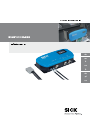 1
1
-
 2
2
-
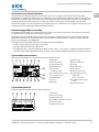 3
3
-
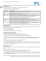 4
4
-
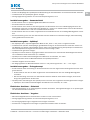 5
5
-
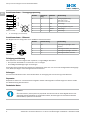 6
6
-
 7
7
-
 8
8
-
 9
9
-
 10
10
-
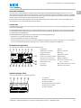 11
11
-
 12
12
-
 13
13
-
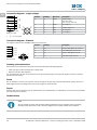 14
14
-
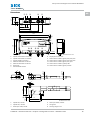 15
15
-
 16
16
-
 17
17
-
 18
18
-
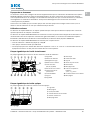 19
19
-
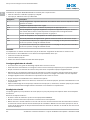 20
20
-
 21
21
-
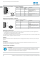 22
22
-
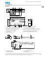 23
23
-
 24
24
-
 25
25
-
 26
26
-
 27
27
-
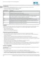 28
28
-
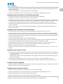 29
29
-
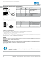 30
30
-
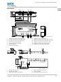 31
31
-
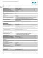 32
32
-
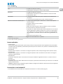 33
33
-
 34
34
-
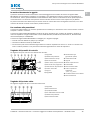 35
35
-
 36
36
-
 37
37
-
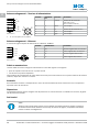 38
38
-
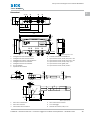 39
39
-
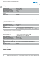 40
40
-
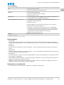 41
41
-
 42
42
-
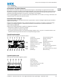 43
43
-
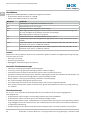 44
44
-
 45
45
-
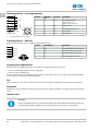 46
46
-
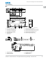 47
47
-
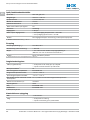 48
48
-
 49
49
-
 50
50
-
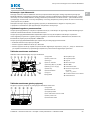 51
51
-
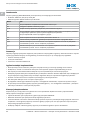 52
52
-
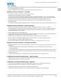 53
53
-
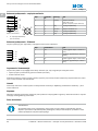 54
54
-
 55
55
-
 56
56
-
 57
57
-
 58
58
-
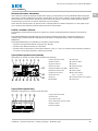 59
59
-
 60
60
-
 61
61
-
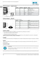 62
62
-
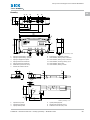 63
63
-
 64
64
-
 65
65
-
 66
66
-
 67
67
-
 68
68
-
 69
69
-
 70
70
-
 71
71
-
 72
72


SICK RS25-WL334000 Instrucciones de operación
- Categoría
- Iluminación de conveniencia
- Tipo
- Instrucciones de operación
En otros idiomas
- français: SICK RS25-WL334000 Mode d'emploi
- italiano: SICK RS25-WL334000 Istruzioni per l'uso
- Deutsch: SICK RS25-WL334000 Bedienungsanleitung
- dansk: SICK RS25-WL334000 Betjeningsvejledning
- polski: SICK RS25-WL334000 Instrukcja obsługi
Documentos relacionados
-
SICK Inductive Proximity Sensors / Induktive Näherungssensoren Instrucciones de operación
-
-
-
-
-
-
-
-
SICK WL18X-3P930 Instrucciones de operación
-
Otros documentos
-
RCA HDP50 Manual de usuario
-
Phoenix Contact NEARFI D ETH B Guía de instalación
-
Sulzer Channel Monster™ – CDD-XDS2.0 Installation, Operating And Maintenance Instructions
-
-
-
ABB TF42 Operating Instructions Manual