
1
Serial Number Purchase Date
Questions, problems, missing parts? Before returning to your retailer, call our
customer service department at 1-888-3KOBALT (1-888-356-2258), 8 a.m - 8 p.m., EST,
Monday - Friday.
ATTACH YOUR RECEIPT HERE
ITEM #0597147
MODEL #0056645
WIDE
STORAGE
CABINET
Français p. 13
Español p. 25
AB15107
Lowes.com
KOBALT® and the K Design® are registered
trademarks of LF, LLC. All Rights Reserved.

TABLE OF CONTENTS
2
Lowes.com
Package Contents
Hardware Contents
Safety Information
Preparation
Assembly Instructions
Troubleshooting
Warranty
Replacement Parts List
......................................................................................................................3
.....................................................................................................................4
......................................................................................................................4
.................................................................................................................................4
................................................................................................................5
........................................................................................................................12
...................................................................................................................................12
............................................................................................................12

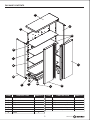
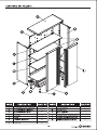
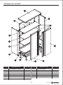
PACKAGE CONTENTS
PART QUANTITY
A
B
C
D
E
F
G
1
1
1
1
1
1
3
1
1
4
1
1
1
Top back panel
Left side
Right side
Top
Base
Bottom shelf
Shelf
DESCRIPTION PART QUANTITY
H
I
J
K
L
M
Left door
Right door
Leg leveler assembly
Top middle back panel
Bottom middle back panel
Bottom back panel
DESCRIPTION
B
K
L
M
A
D
G
C
I
H
J
E
F
3
Lowes.com

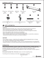
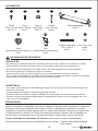
HARDWARE CONTENTS
ST4.8 x 10 mm
Screw
Qty. 8 + 2
ST4 x 20 mm
Screw
Qty. 4
Wall strap
Qty. 2
Lock
(preassembled to right door (I))
Qty. 1
Key
(preassembled to right door (I))
Qty. 2
AA
BB
CC
DD
EE
FF
#8-32 Nut
Qty. 4
#8-32 x 3/8 in.
Bolt
Qty. 4
GG
SAFETY INFORMATION
PREPARATION
Before beginning assembly of product, make sure all parts are present. Compare parts with
package contents list and hardware contents above. If any part is missing or damaged, do not
attempt to
It is recommended that this product be assembled on a clean, soft surface, such as a piece of
cardboard.
assemble the product. Contact customer service for replacement parts.
Estimated Assembly Time: 45 minutes (does not include unpacking time)
Tools Required for Assembly (not included):
Drill, Phillips screwdriver,
Adjustable wrench
CAUTION
• Do not overload shelf (100 lbs. max.) or store loose or heavy items on the top of the unit.
• When storing items on the middle shelf or bottom shelf, equally distribute loads.
• Do not store flammable liquids in the unit unless they are secured in an approved container.
• Do not store gasoline in the unit under any circumstances.
• When mounting unit to wall, ensure studs are plumb and square.
• When mounting multiple units to a wall, check local building codes or consult with a contractor to
determine the maximum load rating for your desired installation.
WARNING
• Do not stand on, step on, or alter this unit for anything outside the designed function of storage.
• Use care when handling and assembling metal plates.
• The metal may have sharp edges or corners. The use of protective gloves is recommended.
• Always remember to use proper lifting techniques when moving the boxed or assembled unit.
HH II
5 x 15 x 1.2 mm
Washer
Qty. 2
ST4.8 x 100 mm Pan
head screws
Qty. 2
4
Lowes.com

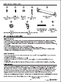
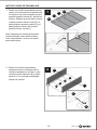
ASSEMBLY INSTRUCTIONS
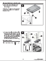
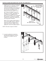
2
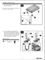
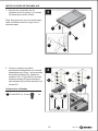
2.
Slide preassembled screws into key
slots of the assembled unit from Step 1
to connect left side (B) and right side
(C) to the assembled unit. Tighten the
screws.
B
M
L
K
A
C
M
L
K
A
1
B
M
1.
Slide preassembled screws into key slots
of top back panel (A) to connect top back
panel (A) to top middle back panel (K).
Tighten the screws. Repeat process to
connect bottom middle back panel (L) to
top middle back panel (K) and bottom
back panel (M) to bottom middle back
panel (L).
Note: Be sure to keep the backs on a soft
surface, such as carpeting or a piece of
cardboard, to protect them from scratches.
5
Lowes.com

J
E
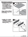
ASSEMBLY INSTRUCTIONS
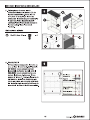
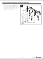
3
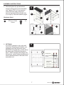
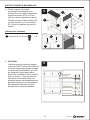
3. Screw leg leveler assemblies (J) to
base (E) until tight.
4.
Push and tighten the preassembled
screws on the assembled unit from Step
2 to the key slots of base (E). Tighten the
ST4.8 x 10 mm screws (AA) to the front
edge of the base (E) to connect left side
(B) and right side (C) to base (E).
J
E
Note: Ensure all four legs are level before
moving on to the next step.
Hardware Used
AA
x 4ST4.8 x 10 mm
Screw
6
Lowes.com
4
C
AA
E
M
C
E
A
K
L
M
A
K
L
M
B
B
C
E
E

ASSEMBLY INSTRUCTIONS
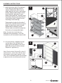
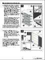
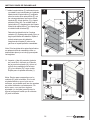
Hardware Used
AA
x 4ST4.8 x 10 mm
Screw
5.
Slide and tighten the preassembled
screws in the top (D) to the assembled
unit. Tighten ST4.8 x 10 mm screws
(AA) to the front edge of top (D) to
connect the left side (B) and right side
(C) to top (D). Place the cabinet upright.
6
Carriage bolts
Outside cabinet
brackets
Inside cabinet
brackets
Flat washers
Flange nuts
6.
OPTIONAL
If you plan to hang the unit on the wall
using the K-Rail
®
(Item #0103683, sold
separately) and Wall Mount Kit (Item
#0345926, sold separately), please follow
the below step. Otherwise, proceed to
Step 7. Attach carriage bolts, flange nuts,
flat washers, outside cabinet brackets and
inside cabinet brackets to the back of the
assembled unit.
7
Lowes.com
C
D
A
AA
5
B
B
D
C
C

ASSEMBLY INSTRUCTIONS
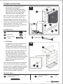
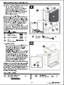
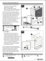
7. Install the bottom shelf (F) by tipping it
to the side and inserting it into the
cabinet. With bottom shelf (F) at an
angle, align the cut-outs on the bottom
shelf (F) with the back seams caused
by left side (B), right side (C), and
bottom back panel (M). Carefully lower
the bottom shelf (F), ensuring the front
of the bottom shelf (F) goes over the
front flange of the base (E).
Determine the location for the other 3
shelves (G). Hold the shelves (G) at an
angle to make them easier to install.
Repeat above method to install.
Please make sure shelf (G) snaps into
the hooks on the assembled back.
8. Lift and pull the L-shaped pivot pin
on the edge of the left door (H),
aligning the assembling hole of the
base (E) and top (D), then release.
Repeat for right door (I).
Note: If inside front shelf tabs are
flattened during assembly, use a flat
screwdriver (not included) to adjust tabs.
8
Lowes.com
7
G
F
F
E
G
G
8
H
I
E
D
H
E
Note: Check and see if the top (D) is level. If
not level due to uneven floor, the two doors
will probably not be properly aligned. In this
case, use an adjustable wrench (not included)
to adjust the hex nut until the top (D) is level.

ASSEMBLY INSTRUCTIONS
Hardware Used
EE
x 2
x 4
x 4
x 4
Wall strap
BB
#8-32 x 3/8 in. Bolt
CC
#8-32 Nut
DD
ST4 x 20 mm
Screw
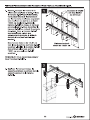
9. Screw one end of wall strap (EE) to
the top back panel (A) with
#8-32 x 3/8 in. bolts (BB) and #8-32
nuts (CC). Secure the other end to the
wall with ST4 x 20 mm screws (DD).
Repeat for another wall strap (EE).
10.
OPTIONAL
Hardware Used
x 2 x 2
HH
ST4.8 x 100 mm Pan
head screws
II
5 x 15 x 1.2 mm
Washer
A
10
II
HH
To install the unit to the wall without a
K-Rail
®
, follow the below step.
Otherwise proceed to optional K-Rail
®
mounting instructions on the next page.
Move the unit to the wall, making sure
the back of the unit is flush with the
wall. Feed the ST4.8 x 100 mm pan
head screws (HH) through the 5 x 15 x
1.2 mm washers (II) and top back panel
(A). Screw the ST4.8 x 100 mm pan
head screws into wall studs, and
tighten securely.
Note: Screws must be placed into wall studs.
The unit will not be secured if screwed into
drywall. If there is a gap between the unit and
the wall due to moulding on the garage floor,
please make the unit press against the
moulding and be parallel to the wall.
9
Lowes.com
Wall
Note: This cabinet should be anchored to the
wall using the wall strap (EE) to avoid any
potential danger from cabinet falling. Check
and see if the top (D) is level. If not level due to
uneven floor, the two doors will probably not be
properly aligned. In this case, use an
adjustable wrench (not included) to adjust the
hex nut until the top (D) is level.
EE
A
D
9
DD
BB
CC
EE
Wall

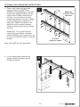
OPTIONAL K-RAIL MOUNTING INSTRUCTIONS
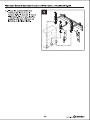
2
2. Lift the cabinet and insert the top
outside cabinet brackets into the
K-Rail
®
on the top.
1
1. Ensure wall studs are plumb and
square. Place the
K-Rail
®
(Item
#0103683, sold
separately) on the wall
studs at the desired location, with the
center of the
K-Rail
®
a minimum of
61-3/4 in. from the floor. Level the
K-Rail
®
and mark the location.
K-Rail
®
must be attached to a minimum of 3
wall studs. Attach the
K-Rail
®
to the
wall studs at the marked locations
using two wood screws (not provided)
per stud.
Measure 51-1/2 in. down from the
center of the top
K-Rail
®
. Install the
second
K-Rail
®
so the center of the rail
is 51-1/2 in. below the center of the top
K-Rail
®
.
Minimum
61-3/4 in. from
the floor
51-1/2 in.
center to center
Note: 2 K-Rails
®
must be purchased.
10
Lowes.com

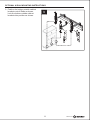
OPTIONAL K-RAIL MOUNTING INSTRUCTIONS
3
3. Position the bottom outside cabinet
brackets onto
K-Rail
®
as shown.
Lock the bottom outside cabinet
brackets into position as shown.
11
Lowes.com

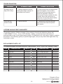
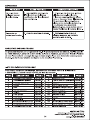
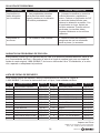
TROUBLESHOOTING
LIFETIME HASSLE-FREE GUARANTEE
REPLACEMENT PARTS LIST
For replacement parts, call custom service at 1-888-3KOBALT, 8 a.m. - 8 p.m., EST, Monday - Friday.
PROBLEM POSSIBLE CAUSE CORRECTIVE ACTION
Screw(s) will not
align into hole(s).
1. Natual properties of sheet
metal cause slight changes in
pre-drilled hole location.
1. Unit is not level. 1. Remove the unit from the wall
and ensure the studs are plumb
and square.
1. Place screws into all aligned holes
and hand tighten. Push a 3/8 in.
hole-punch through both holes to
force the alignment. With the
hole-punch in place, tighten all other
screws. When the hole-punch is
removed, the screw(s) should easily
fit into the remaining hole(s).
Doors will not
remain closed.
PART PART #
A
B
C
D
E
F
G
H
I
J
K
L
M
Top back panel
Left side
Right side
Top
Base
Bottom shelf
Shelf
Left door
Right door
Leg leveler assembly
Top middle back panel
Bottom middle back panel
Bottom back panel
597147-A
597147-B
597147-C
597147-D
597147-E
597147-F
597147-G
597147-H
597147-I
597147-J
597147-K
597147-L
597147-M
597147-N
597147-O
597147-P
597147-AA
597147-BB
597147-CC
597147-DD
597147-EE
597147-FF
597147-GG
597147-HH
597147-II
597147-JJ
DESCRIPTION PART
N
O
P
AA
BB
CC
DD
EE
FF
GG
HH
II
JJ
Door magnet
Door L shape pivot pin
Spring
ST4.8 x 10 mm screw
#8-32 x 3/8 in. bolt
#8-32 Nut
ST4 x 20 mm screw
Wall strap
Lock
Key
ST4.8 x 100 mm Pan head screws
5 x 15 x 1.2 mm Washer
Electrical bushing
DESCRIPTION PART #
This product carries a lifetime warranty. If the product is found to be defective, please call
1-888-3KOBALT, 8 a.m. - 8 p.m., EST, Monday - Friday, or return the item to the place of
purchase with a copy of the original sales receipt. The distributor will, at its option, repair or replace
the product. This warranty gives you specific legal rights, and you may have other rights that vary
from state to state.
12
Lowes.com
Printed in China
KOBALT® and the K Design® are registered
trademarks of LF, LLC. All Rights Reserved.

ARMOIRE DE
RANGEMENT
LARGE
KOBALT® et le motif de K® sont des marques de
commerce déposées de LF, LLC. Tous droits réservés.


25
Lowes.com
Número de serie Fecha de compra
ADJUNTE SU RECIBO AQUÍ
ARTÍCULO #0597147
MODELO #0056645
GABINETE DE
ALMACENAJE
ANCHO
¿Preguntas, problemas, piezas faltantes? Antes de volver a la tienda, llame a nuestro
Departamento de Servicio al Cliente al 1-888-3KOBALT (1-888-356-2258), de lunes a
viernes de 8 a.m. a 8 p.m., hora estándar del Este.
KOBALT® y K Design® son marcas registradas
de LF, LLC. Todos los derechos reservados.

ÍNDICE
26
Lowes.com
Contenido del paquete
Aditamentos
Información de seguridad
Preparación
Instrucciones de ensamblaje
Solución de problemas
Garantía
Lista de piezas de repuesto
..............................................................................................................27
..............................................................................................................................28
.........................................................................................................28
...............................................................................................................................28
....................................................................................................29
.............................................................................................................36
...................................................................................................................................36
.....................................................................................................36

27
Lowes.com
A
B
C
D
E
F
G
1
1
1
1
1
1
3
1
1
4
1
1
1
Panel posterior superior
Lado izquierdo
Lado derecho
Cubierta
Base
Repisa inferior
Repisa
H
I
J
K
L
M
Puerta izquierda
Puerta derecha
Conjunto nivelador de la pata
Panel posterior superior central
Panel posterior inferior central
Panel posterior inferior
PIEZA CANTIDADDESCRIPCIÓN PIEZA CANTIDADDESCRIPCIÓN
CONTENIDO DEL PAQUETE
B
K
L
M
A
D
G
C
I
H
J
E
F

28
Lowes.com
INFORMACIÓN DE SEGURIDAD
PREPARACIÓN
Tiempo estimado de ensamblaje: 45 minutos (no incluye el tiempo de desembalaje)
Herramientas necesarias para el ensamblaje (no se incluyen):
Taladro, destornillador phillips,
llave inglesa
PRECAUCIÓN
• No sobrecargue la repisa (45,36 kg máx.) ni almacene artículos sueltos o pesados en la cubierta de la unidad.
• Cuando almacene artículos en la repisa central o la repisa inferior, distribuya el peso uniformemente.
• No almacene líquidos inflamables en la unidad a menos que estén aseguradas en un envase aprobado.
• No almacene gasolina en la unidad bajo ninguna circunstancia.
• Cuando monte la unidad en la pared, asegúrese de que los montantes estén a plomo y a escuadra.
• Si va a montar varias unidades en una pared, revise los códigos de construcción locales o consulte con contratista
para determinar la capacidad de carga máxima para la ubicación deseada.
ADVERTENCIA
• No se pare, pise ni modifique esta unidad para ningún uso que no sea la función de almacenamiento
para la que se diseñó.
• Tenga cuidado al manipular y ensamblar las placas de metal.
• El metal puede tener bordes o esquinas afiladas. Se recomienda el uso de guantes de protección.
• Siempre recuerde usar técnicas adecuadas de levantamiento cuando mueva la unidad ya sea en su
caja o una vez ensamblada.
ADITAMENTOS
Antes de comenzar a ensamblar el producto, asegúrese de tener todas las piezas. Compare las
piezas con la lista del contenido del paquete y la lista de aditamentos anteriores. No intente
ensamblar el producto si falta alguna pieza o si estas están dañadas. Póngase en contacto con
el Departamento de Servicio al Cliente para obtener piezas de repuesto. Se recomienda que
este producto se ensamble sobre una superficie limpia y suave; como un trozo de cartón.
Seguro
(preensamblado a la puerta derecha (I))
Cant. 1
Llave
(preensamblada a la puerta derecha (I))
Cant. 2
Tornillo
ST4,8 x 10 mm
Cant. 8 + 2
Tornillo
ST4 x 20 mm
Cant. 4
Banda para pared
Cant. 2
Tuerca
#8-32 pulg
Cant. 4
Perno
#8-32 x 3/8 pulg
Cant. 4
AA
BB
CC
DD
EE
FF
GG HH II
5 mm x 15 mm x 1,2 mm
Arandela
Cant. 2
Tornillos de cabeza plana
ST4,8 x 100 mm
Cant.
2

2
B
M
L
K
A
C
M
L
K
A
1
B
M
29
Lowes.com
INSTRUCCIONES DE ENSAMBLAJE
1.
Deslice los tornillos ensamblados previa-
mente en los chaveteros del panel poste-
rior superior (A) para conectarlo al panel
posterior superior central (K). Apriete los
tornillos. Repita el proceso para conectar
el panel posterior inferior central (L) al
panel posterior superior central (K) y el
panel posterior inferior (M) al panel
posterior inferior central (L).
Nota: Asegúrese de mantener las partes
posteriores sobre una superficie suave,
como una alfombra o un trozo de cartón,
para evitar rayarlo.
2.
Deslice los tornillos ensamblados
previamente en los chaveteros de la
unidad ensamblada en el Paso 1 para
conectar el lado izquierdo (B) y el lado
derecho (C) a la unidad ensamblada.
Apriete los tornillos.

J
E
3
J
E
30
Lowes.com
INSTRUCCIONES DE ENSAMBLAJE
3. Atornille los ensambles de los
niveladores de las patas (J) a la base
(E) hasta que queden firmes.
4.
Coloque y apriete los tornillos
previamente ensamblados en la unidad
ensamblada en el Paso 1 en las ranuras
de la llave de la base (E). Apriete los
tornillos T4,8 x 10 mm (AA) en el borde
frontal de la base (E) para conectar el
lado izquierdo (B) y el lado derecho (C) a
la base (E).
Nota: Asegúrese de que las cuatro patas
están niveladas antes de seguir con el
siguiente paso.
Aditamentos utilizados
AA
x 4Tornillo ST4,8 x 10 mm
4
C
AA
E
M
C
E
A
K
L
M
A
K
L
M
B
B
C
E
E

6
31
Lowes.com
Pernos cabeza
de hongo
Abrazaderas para
gabinetes exteriores
Abrazaderas para
gabinetes interiores
Arandelas planas
Tuercas de brida
INSTRUCCIONES DE ENSAMBLAJE
5.
Deslice y apriete los tornillos
previamente ensamblados en la
cubierta (D) en la unidad ensamblada.
Apriete los tornillos ST4,8 x 10 mm
(AA) en el borde frontal de la cubierta
(D) para conectar el lado izquierdo (B)
y el lado derecho (C) con la cubierta
(D). Coloque el gabinete en posición
vertical.
6.
OPCIONAL
Si piensa colgar la unidad en la pared
usando el K-Rail
®
(artículo #0103683, se
vende por separado) y Kit para montaje
en pared (artículo #0345926, se vende
por separado), siga el paso que se
presenta a continuación. De lo contrario,
siga con el paso 7. Fije los pernos de
carrocería, las tuercas de brida, las
arandelas planas, las abrazaderas para
gabinetes exteriores y las abrazaderas
para gabinetes interiores a la parte
posterior de la unidad ensamblada.
Aditamentos utilizados
AA
x 4Tornillo ST4,8 x 10 mm
C
D
A
AA
5
B
B
D
C
C

32
Lowes.com
INSTRUCCIONES DE ENSAMBLAJE
7. Instale la repisa inferior (F) inclinándola hacia
un costado, luego introdúzcala en el gabinete.
Manteniendo la repisa inferior (F) angulada,
alinee los cortes de la repisa inferior (F) con
las uniones posteriores que forman el lado
izquierdo (B), el lado derecho (C) y el panel
posterior inferior (M). Con cuidado, baje la
repisa inferior (F), asegúrese de que la parte
frontal de la repisa inferior (F) se superponga
a la brida frontal de la base (E).
Determine la ubicación de las 3 repisas
restantes (G). Sostenga las repisas (G) en un
ángulo para facilitar la instalación. Repita el
método anterior para la instalación.
Asegúrese de la repisa (G) calce en los
ganchos en la parte posterior ensamblada.
8. Levante y jale del pasador giratorio
en forma de L ubicado en el borde
de la puerta izquierda (H), alinee el
orificio de ensamblaje de la base
(E) y la cubierta (D), luego suelte.
Repita para la puerta derecha (I).
Nota: Si las lengüetas de la repisa frontal interior
se aplanan durante el ensamblaje, utilice un
destornillador plano (no se incluye) para ajustar
las lengüetas.
Nota: Revise para comprobar que la
cubierta (D) esté nivelada. Si no está
nivelada debido a que el piso no es
uniforme, es probable que las dos puertas
no estén alineadas correctamente. En
dicho caso, use una llave inglesa
ajustable (no incluida) para ajustar la
tuerca hexagonal hasta que la cubierta
(D) esté nivelada.
7
G
F
F
E
G
G
8
H
I
E
D
H
E

EE
x 2
x 2
II
A
10
II
HH
33
Lowes.com
Banda
para pared
5 mm x 15 mm x 1,2 mm
Arandela
Pared
EE
A
D
9
DD
BB
CC
EE
Pared
INSTRUCCIONES DE ENSAMBLAJE
9. Atornille un extremo de la banda para
pared (EE) en el Panel posterior
superior (A) con pernos
#8/32 x 3/8 pulg (BB) y tuercas
#8/32 pulg (CC). Fije el otro extremo a la
pared con tornillos ST4 x 20 mm (DD).
Aditamentos utilizados
x 4
x 4
x 4
BB
Perno #8-32 x 3/8 pulg
CC
Tuerca #8-32 pulg
DD
Tornillo
ST4 x 20 mm
10.
OPCIONAL
Para instalar la unidad en la pared sin un
K-Rail
®
, siga el paso a continuación. De lo
contrario, proceda a las instrucciones de
montaje opcional K-Rail
®
en la siguiente página.
Mueva la unidad a la pared, verifique que la
parte posterior de la unidad esté al ras con la
pared. Coloque los tornillos de cabeza plana
ST4,8 x 100 mm a través de las arandelas de
5 x 15 x 1,2 mm (II) y el panel superior
posterior (A). Atornille los tornillos de cabeza
plana de ST4,8 x 100 mm en las vigas de la
pared y apriete firmemente.
Nota: Los tornillos deben colocarse directamente en
las vigas de la pared. La unidad no podrá asegurarse
si se atornilla en el panel de yeso. Si existe un
espacio entre la unidad y la pared debido a la
moldura en el piso del garaje, haga que la unidad
presione la moldura y que esté paralela a la pared.
Aditamentos utilizados
x 2
HH
Tornillos de cabeza plana
ST4,8 x 100 mm
Nota: Este gabinete se debe anclar a la
pared con la banda para pared (EE) para
prevenir algún riesgo de que el gabinete
se caiga. Revise para comprobar que la
cubierta (D) esté nivelada. Si no está
nivelada debido a que el piso no es
uniforme, es probable que las dos puertas
no estén alineadas correctamente. En
dicho caso, use una llave inglesa
ajustable (no incluida) para ajustar la
tuerca hexagonal hasta que la cubierta
(D) esté nivelada.

2
1
34
Lowes.com
1. Asegúrese de que todos los montantes
estén a plomo y a escuadra. Coloque
el K-Rail
®
(artículo #0103683, se
vende por separado) en los montantes
de la pared en la ubicación deseada,
con el centro del K-Rail
®
a una
distancia mínima de 156,85 cm del
piso. Nivele el K-Rail
®
y marque la
ubicación. El K-Rail
®
debe fijarse en
un mínimo de 3 montantes de la
pared. Fije el K-Rail
®
en los montantes
de la pared en la ubicación marcada
usando dos tornillos para madera (no
se incluyen) por montante.
Mida 130,81 cm hacia abajo desde el
centro del K-Rail
®
superior. Instale el
segundo K-Rail
®
de manera que el
centro del riel esté a 130,81 cm por
debajo del centro del K-Rail
®
superior.
INSTRUCCIONES PARA MONTAJE CON RIEL EN FORMA DE K
2. Levante el gabinete e inserte las
abrazaderas del gabinete superior
exterior en el K-Rail
®
, como se
muestra.
NOTA: Necesita comprar 2 K-Rail
®
.
A una distancia
mínima de 156,85
cm del piso
130,81 cm
de centro a centro

3
35
Lowes.com
INSTRUCCIONES PARA MONTAJE CON RIEL EN FORMA DE K
3. Coloque las abrazaderas del gabinete
inferior exterior en el K-Rail
®
, como
se muestra. Fije las abrazaderas para
gabinete exteriores inferiores en su
posición, como se muestra.

597147-A
597147-B
597147-C
597147-D
597147-E
597147-F
597147-G
597147-H
597147-I
597147-J
597147-K
597147-L
597147-M
597147-N
597147-O
597147-P
597147-AA
597147-BB
597147-CC
597147-DD
597147-EE
597147-FF
597147-GG
597147-HH
597147-II
597147-JJ
36
Lowes.com
GARANTÍA SIN PROBLEMAS DE POR VIDA
LISTA DE PIEZAS DE REPUESTO
SOLUCIÓN DE PROBLEMAS
PROBLEMA CAUSA POSIBLE ACCIÓN CORRECTIVA
1. Las propiedades naturales
de la placa de metal causan
ligeros cambios en la ubicación
del orificio pretaladrado.
1. La unidad no está nivelada. 1. Retire la unidad de la pared y
asegúrese de que los montantes
estén a plomo y a escuadra.
1. Coloque los tornillos en todos los
orificios alineados y apriételos a
mano. Coloque un perforador de 3/8"
a través de ambos orificios para
obtener la alineación a presión. Con
el perforador en lugar, apriete los
tornillos restantes. Cuando retire el
perforador, los tornillos deben
ingresar fácilmente en los orificios
restantes.
Las puertas no
se cierran.
Este producto cuenta con una garantía de por vida. Si el producto presenta defectos, llame al a 8
p.m. hora estándar del Este, o devuelva el artículo al lugar de compra junto con una copia del
recibo de venta original.1-888-3KOBALT, de lunes a viernes de 8 a.m. El distribuidor, a su elec-
ción, reparará o reemplazará el producto.
Los tornillos no
están alineados
con los orificios.
Para obtener piezas de repuesto, llame al Departamento de Servicio al Cliente al
1-888-3KOBALT, de lunes a viernes de 8 a.m. a 8 p.m., hora estándar del Este.
A
B
C
D
E
F
G
H
I
J
K
L
M
Panel posterior superior
Lado izquierdo
Lado derecho
Cubierta
Base
Repisa inferior
Repisa
Puerta izquierda
Puerta derecha
Conjunto nivelador de la pata
Panel posterior superior central
Panel posterior inferior central
Panel posterior inferior
N
O
P
AA
BB
CC
DD
EE
FF
GG
HH
II
JJ
Imán para puerta
Pasador giratorio en forma de L para puerta
Resorte
Tornillo ST4,8 x 10 mm
Perno #8-32 x 3/8 pulg
Tuerca #8-32 pulg
Tornillo ST4 x 20 mm
Banda para pared
Seguro
Llave
Tornillos de cabeza plana ST4,8 x 100 mm
5 x 15 x 1,2 mm Arandela
Conector eléctrico
PIEZA PIEZA #DESCRIPCIÓN PIEZA PIEZA #DESCRIPCIÓN
Impreso en China
KOBALT® y K Design® son marcas registradas
de LF, LLC. Todos los derechos reservados.
-
 1
1
-
 2
2
-
 3
3
-
 4
4
-
 5
5
-
 6
6
-
 7
7
-
 8
8
-
 9
9
-
 10
10
-
 11
11
-
 12
12
-
 13
13
-
 14
14
-
 15
15
-
 16
16
-
 17
17
-
 18
18
-
 19
19
-
 20
20
-
 21
21
-
 22
22
-
 23
23
-
 24
24
-
 25
25
-
 26
26
-
 27
27
-
 28
28
-
 29
29
-
 30
30
-
 31
31
-
 32
32
-
 33
33
-
 34
34
-
 35
35
-
 36
36


en otros idiomas
- English: Kobalt 56645 User manual
Artículos relacionados
Otros documentos
-
Craftsman CMST24800RB Guía de instalación
-
Lowes FR8606 Guía de inicio rápido
-
 Blue Hawk BHBDD27GB Guía de instalación
-
allen+roth allen roth 1483VA-48-201 48-In Vanity Manual de usuario
-
Project Source 17967-001 Guía de instalación
-
Allen + Roth 1789VA-48-310 Guía de instalación
-
Style Selections 33116 Guía de instalación
-
-
-
