Dell Latitude 7212 Rugged Extreme El manual del propietario
- Tipo
- El manual del propietario

Latitude 12 Rugged Extreme Tablet – 7212
Owner's Manual
Regulatory Model: T03H
Regulatory Type: T03H002
April 2021
Rev. A03

Notas, precauciones y avisos
NOTA: Una NOTA indica información importante que le ayuda a hacer un mejor uso de su producto.
PRECAUCIÓN: Una PRECAUCIÓN indica la posibilidad de daños en el hardware o la pérdida de datos, y le explica
cómo evitar el problema.
AVISO: Un mensaje de AVISO indica el riesgo de daños materiales, lesiones corporales o incluso la muerte.
© 2017-2021 Dell Inc. or its subsidiaries. All rights reserved. Dell, EMC, and other trademarks are trademarks of Dell Inc. or its
subsidiaries. Other trademarks may be trademarks of their respective owners.

Chapter 1: Manipulación del equipo............................................................................................... 6
Safety instructions.............................................................................................................................................................. 6
Before working inside your computer.............................................................................................................................6
Turning off your computertablet — Windows 10........................................................................................................ 7
Después de manipular el interior del equipo.................................................................................................................. 7
Chapter 2: Extracción e instalación de componentes..................................................................... 8
Herramientas recomendadas............................................................................................................................................ 8
Screw size list.......................................................................................................................................................................8
Batería.................................................................................................................................................................................... 9
Removing the battery...................................................................................................................................................9
Removing the battery when the cross strap is attached - Optional............................................................... 12
Instalación de la batería.............................................................................................................................................. 13
Installing the battery when the cross strap is attached - Optional....................................................................... 14
Tarjeta del módulo de identidad de suscripciones (SIM)..........................................................................................14
Removing uSIM.............................................................................................................................................................14
Inserción de la uSIM.................................................................................................................................................... 15
Ensamblaje de la pantalla................................................................................................................................................. 15
Removing display assembly....................................................................................................................................... 15
Installing display assembly..........................................................................................................................................19
Lápiz..................................................................................................................................................................................... 20
Removing stylus...........................................................................................................................................................20
Instalación del lápiz digital......................................................................................................................................... 20
Tarjeta WLAN......................................................................................................................................................................21
Removing WLAN card.................................................................................................................................................21
Instalación de la tarjeta WLAN................................................................................................................................. 22
Tarjeta WWAN................................................................................................................................................................... 22
Removing WWAN card...............................................................................................................................................22
Instalación de la tarjeta WWAN............................................................................................................................... 23
Batería CMOS.................................................................................................................................................................... 23
Removing CMOS battery.......................................................................................................................................... 23
Installing CMOS battery.............................................................................................................................................24
Ensamblaje del botón de encendido..............................................................................................................................25
Removing power button assembly.......................................................................................................................... 25
Installing power button assembly............................................................................................................................ 26
Micropuerto serie y puerto del conector de alimentación.......................................................................................27
Removing micro serial port and power connector port......................................................................................27
Installing micro serial port and power connector port........................................................................................29
Cámara frontal................................................................................................................................................................... 29
Removing front camera............................................................................................................................................. 29
Installing front camera................................................................................................................................................32
Micrófono............................................................................................................................................................................33
Removing microphone................................................................................................................................................33
Installing microphone.................................................................................................................................................. 34
Contents
Contents 3

Heat sink for SSD..............................................................................................................................................................34
Removing heatsink for SSD or PCIE.......................................................................................................................34
Installing heatsink for SSD or PCIE.........................................................................................................................35
Unidad de estado sólido (SSD) PCIe............................................................................................................................35
Removing PCIe Solid State Drive - SSD................................................................................................................35
Installing PCIe Solid State Drive - SSD.................................................................................................................. 36
Ventilador del sistema...................................................................................................................................................... 37
Removing system fan................................................................................................................................................. 37
Installing system fan................................................................................................................................................... 37
Placa base........................................................................................................................................................................... 38
Removing system board............................................................................................................................................ 38
Installing system board...............................................................................................................................................44
Docking Board....................................................................................................................................................................44
Removing docking board........................................................................................................................................... 44
Installing docking board............................................................................................................................................. 45
Back Camera...................................................................................................................................................................... 46
Removing back camera.............................................................................................................................................. 46
Installing back camera................................................................................................................................................ 47
Smartcard holder...............................................................................................................................................................48
Removing smartcard holder......................................................................................................................................48
Installing smartcard holder........................................................................................................................................50
Bottom base assembly.....................................................................................................................................................50
Removing bottom base assembly............................................................................................................................50
Installing bottom base assembly.............................................................................................................................. 52
Chapter 3: Tecnología y componentes......................................................................................... 53
Adaptador de alimentación............................................................................................................................................. 53
USB features...................................................................................................................................................................... 53
Funciones de la memoria.................................................................................................................................................55
Chapter 4: Software....................................................................................................................56
Sistemas operativos compatibles..................................................................................................................................56
Downloading drivers......................................................................................................................................................... 56
Intel audio drivers.............................................................................................................................................................. 57
Intel chipset drivers.......................................................................................................................................................... 57
Intel HD Graphics drivers.................................................................................................................................................57
Network drivers.................................................................................................................................................................58
System devices drivers....................................................................................................................................................58
Storage drivers.................................................................................................................................................................. 58
Chapter 5: Especificaciones del sistema......................................................................................60
Visión general del producto............................................................................................................................................ 60
Funciones principales................................................................................................................................................. 60
Power and battery-status light......................................................................................................................................60
Especificaciones del sistema........................................................................................................................................... 61
Especificaciones del procesador.................................................................................................................................... 61
Especificaciones de la memoria......................................................................................................................................61
Especificaciones de almacenamiento............................................................................................................................61
Audio specifications...........................................................................................................................................................61
4
Contents

Especificaciones de vídeo............................................................................................................................................... 62
Camera specifications...................................................................................................................................................... 62
Especificaciones de comunicación................................................................................................................................62
Especificaciones de puertos y conectores..................................................................................................................63
Especificaciones de la pantalla.......................................................................................................................................63
Especificaciones de toque...............................................................................................................................................64
Adapter specifications......................................................................................................................................................64
Especificaciones de las dimensiones físicas................................................................................................................65
Especificaciones ambientales.........................................................................................................................................65
Chapter 6: System Setup (Configuración del sistema)................................................................ 66
Secuencia de inicio............................................................................................................................................................66
Teclas de navegación....................................................................................................................................................... 66
Descripción general del programa de configuración del sistema........................................................................... 67
Opciones de la pantalla General (General)............................................................................................................67
Opciones de la pantalla System Configuration (Configuración del sistema)................................................ 68
Opciones de la pantalla Video (Vídeo)....................................................................................................................70
Opciones de la pantalla Security (Seguridad).......................................................................................................70
Inicio seguro.................................................................................................................................................................. 72
Extensiones Intel software Guard............................................................................................................................72
Opciones de la pantalla Performance (Rendimiento)......................................................................................... 72
Administración de alimentación................................................................................................................................73
Comportamiento durante la POST.......................................................................................................................... 74
Capacidad de administración.................................................................................................................................... 75
Opciones de Compatibilidad con la virtualización................................................................................................ 76
Opciones de modo inalámbrico.................................................................................................................................76
Mantenimiento............................................................................................................................................................. 76
System Log (Registro del sistema)......................................................................................................................... 77
Resolución del sistema SupportAssist.................................................................................................................... 77
Chapter 7: Solución de problemas................................................................................................78
Dell Enhanced Pre-Boot System Assessment - ePSA diagnostic 3.0.................................................................. 78
Diagnostic LED...................................................................................................................................................................78
Solución de problemas generales...................................................................................................................................79
Chapter 8: Accesorios del ecosistema.......................................................................................... 81
Active Stylus....................................................................................................................................................................... 81
Getting the stylus ready for use.....................................................................................................................................81
Setting the Stylus Mode..................................................................................................................................................82
Vista inferior del sistema................................................................................................................................................. 83
System right view............................................................................................................................................................. 84
Dock front view................................................................................................................................................................. 84
Keyboard Dock ..................................................................................................................................................................85
Turn the Backlight On - Off and Adjust Brightness ...........................................................................................85
Keyboard Function - Fn Key Lock ..........................................................................................................................86
Dock rear view................................................................................................................................................................... 86
Input Output module.........................................................................................................................................................87
Rugged tablet vehicle dock.............................................................................................................................................87
Contents
5

Manipulación del equipo
Temas:
• Safety instructions
•
Before working inside your computer
• Turning off your computertablet — Windows 10
• Después de manipular el interior del equipo
Safety instructions
Use the following safety guidelines to protect your computer from potential damage and to ensure your personal safety. Unless
otherwise noted, each procedure included in this document assumes that the following conditions exist:
● You have read the safety information that shipped with your computer.
● A component can be replaced or, if purchased separately, installed by performing the removal procedure in the reverse
order.
NOTE:
Disconnect all power sources before opening the computer cover or panels. After you finish working inside the
computer, replace all covers, panels, and screws before connecting to the power source.
NOTE: Before working inside your computer, read the safety information that shipped with your computer. For additional
safety best practices information, see the Regulatory Compliance Homepage at www.dell.com/regulatory_compliance
CAUTION: Many repairs may only be done by a certified service technician. You should only perform
troubleshooting and simple repairs as authorized in your product documentation, or as directed by the online or
telephone service and support team. Damage due to servicing that is not authorized by Dell is not covered by
your warranty. Read and follow the safety instructions that came with the product.
CAUTION: To avoid electrostatic discharge, ground yourself by using a wrist grounding strap or by periodically
touching an unpainted metal surface that is grounded to ground yourself before you touch the computer to
perform any disassembly tasks.
CAUTION: Handle components and cards with care. Do not touch the components or contacts on a card. Hold a
card by its edges or by its metal mounting bracket. Hold a component such as a processor by its edges, not by
its pins.
CAUTION: When you disconnect a cable, pull on its connector or on its pull-tab, not on the cable itself. Some
cables have connectors with locking tabs; if you are disconnecting this type of cable, press in on the locking
tabs before you disconnect the cable. As you pull connectors apart, keep them evenly aligned to avoid bending
any connector pins. Also, before you connect a cable, ensure that both connectors are correctly oriented and
aligned.
NOTE: The color of your computer and certain components may appear differently than shown in this document.
Before working inside your computer
To avoid damaging your computer, perform the following steps before you begin working inside the computer.
1. Ensure that you follow the Safety instruction.
2. Ensure that your work surface is flat and clean to prevent the computer cover from being scratched.
3. Turn off your computer.
4. If the computer is connected to a docking device (docked) such as the optional Media Base or Battery Slice, undock it.
1
6 Manipulación del equipo

CAUTION: To disconnect a network cable, first unplug the cable from your computer and then unplug the
cable from the network device.
5. Disconnect all network cables from the computer.
6. Disconnect your computer and all attached devices from their electrical outlets.
7. Turn the computer upside-down on a flat work surface.
NOTE: Ensure to close the display if the system is a laptop. To avoid damaging the system board, remove the main
battery before you service the computer.
8. Remove the main battery.
9. Turn the computer top-side up.
NOTE: Open the display if the system is a laptop.
10. Press the power button to ground the system board.
CAUTION: Before touching anything inside your computer, ground yourself by touching an unpainted metal
surface, such as the metal at the back of the computer. While you work, periodically touch an unpainted
metal surface to dissipate static electricity, which could harm internal components.
11. Remove any installed ExpressCards or Smart Cards from the appropriate slots.
Turning off your computertablet — Windows 10
PRECAUCIÓN:
To avoid losing data, save and close all open files and exit all open programs before you turn off
your computer or remove the side cover.
1. Click or tap .
2. Click or tap
and then click or tap Shut down.
NOTA:
Ensure that the computer and all attached devices are turned off. If your computer and attached devices did not
automatically turn off when you shut down your operating system, press and hold the power button for about 6 seconds
to turn them off.
Después de manipular el interior del equipo
Una vez finalizado el procedimiento de instalación, asegúrese de conectar los dispositivos externos, las tarjetas y los cables
antes de encender el equipo.
PRECAUCIÓN:
Para evitar daños en la computadora, utilice únicamente la batería diseñada específicamente para
esta computadora Dell. No utilice baterías diseñadas para otros equipos Dell.
1. Conecte los dispositivos externos, como un replicador de puerto o la base para medios y vuelva a colocar las tarjetas, como
una tarjeta ExpressCard.
2. Conecte los cables telefónicos o de red al equipo.
PRECAUCIÓN:
Para conectar un cable de red, enchúfelo primero en el dispositivo de red y, después, en el
equipo.
3. Conecte el equipo y todos los dispositivos conectados a la toma eléctrica.
4. Encienda el equipo.
Manipulación del equipo
7

Extracción e instalación de componentes
Esta sección ofrece información detallada sobre cómo extraer o instalar los componentes de su equipo.
Temas:
• Herramientas recomendadas
• Screw size list
• Batería
• Installing the battery when the cross strap is attached - Optional
• Tarjeta del módulo de identidad de suscripciones (SIM)
• Ensamblaje de la pantalla
• Lápiz
• Tarjeta WLAN
• Tarjeta WWAN
• Batería CMOS
• Ensamblaje del botón de encendido
• Micropuerto serie y puerto del conector de alimentación
• Cámara frontal
• Micrófono
• Heat sink for SSD
• Unidad de estado sólido (SSD) PCIe
• Ventilador del sistema
• Placa base
• Docking Board
• Back Camera
• Smartcard holder
• Bottom base assembly
Herramientas recomendadas
Los procedimientos de este documento requieren el uso de las siguientes herramientas:
● Destornillador Phillips núm. 0
● Destornillador Phillips núm. 1
● Punta trazadora de plástico DSP estándar
Screw size list
Table 1. Latitude 7212 Rugged Extreme Tablet screw size list
Componen
t
M2*2 M2*2.5 M2*3 M2*4 M2*5 M2.5*3 M2.5*5 M2.5*8
Smart card 6
Bottom
Base
6 81 19
Front
Camera
2
Rear
Camera
3
2
8 Extracción e instalación de componentes

Table 1. Latitude 7212 Rugged Extreme Tablet screw size list
Componen
t
M2*2 M2*2.5 M2*3 M2*4 M2*5 M2.5*3 M2.5*5 M2.5*8
Protective
Rubber
Bumper( all
four
corners)
8
WLAN 1
WWAN 1
M.2 SSD 1
System
Board
Assembly
(System
Board and
Fan)
14
Power
Button
Assembly
1
DC-In Cable
and Bracket
3
Kensington
Lock
Bracket
3
LCD Bezel 19
Bracket
Docking
1
Batería
Removing the battery
WARNING:
Using an incompatible battery may increase the risk of fire or explosion. Replace the battery only
with a compatible battery purchased from Dell. The battery is designed to work with your Dell Tablet. Do not use
a battery from any other computer with your tablet.
WARNING: Before removing or replacing the battery, turn off the computer, disconnect the AC adapter from
the electrical outlet and the tablet, and remove any other external cables from the tablet.
1. Follow the procedure in Before Working Inside Your Computer.
2. Locate the battery and slide the battery latch to unlock the battery release latch [1].
3. Push the button in a downward direction to release the battery [2].
Extracción e instalación de componentes
9

The battery is released from the battery bay.
4. Lift the edge of the battery that pops up.
10
Extracción e instalación de componentes

Extracción e instalación de componentes 11

Removing the battery when the cross strap is attached - Optional
WARNING: Using an incompatible battery may increase the risk of fire or explosion. Replace the battery only
with a compatible battery purchased from Dell. The battery is designed to work with your Dell Tablet. Do not use
a battery from any other computer with your tablet.
WARNING: Before removing or replacing the battery, turn off the computer, disconnect the AC adapter from
the electrical outlet and the tablet, and remove any other external cables from the tablet.
1. Follow the procedure in Before Working Inside Your Computer.
2. Peel off the velcro strap.
3. Slide the strap and release the strap from the holder to access the battery latch.
4. Slide the battery latch to unlock the battery release latch and then push the latch in a downward direction to release the
battery.
12
Extracción e instalación de componentes

The battery is released from the battery bay.
5. Lift the edge of the battery that pops up to release the battery.
Instalación de la batería
1. Inserte la batería en su ranura.
NOTA: Asegúrese de que la pata de metal de la batería esté alineada en su lugar.
2. Deslice la batería en su ranura hasta que encaje en su lugar.
3. Asegúrese de que el pestillo de la batería esté de nuevo en estado bloqueado.
NOTA: Hay dos baterías. Realice los pasos del 1 al 3 para instalar la batería 1 y la batería 2 en la tableta.
4. Siga los procedimientos que se describen en Después de manipular el interior del equipo.
Extracción e instalación de componentes
13

Installing the battery when the cross strap is attached
- Optional
1. Insert the battery into the battery slot.
2. Slide the battery into the slot until it clicks into place and locked.
3. Slide the velcro strap into the strap holder.
4. Affix the velcro strap.
5. Follow the procedure in After working inside your computer.
Tarjeta del módulo de identidad de suscripciones
(SIM)
Removing uSIM
1. Follow the procedure in Before working inside your computer.
2. Remove the left battery.
3. Lift the latch [1] and pull the SIM slot cap [2].
4. Pull the SIM from the slot until it is released [3].
NOTE: Use a flat pointed scribe to ease removing the SIM.
5. Press the SIM slot cap to initial state.
6. Install the:
a. Left battery
14
Extracción e instalación de componentes

Inserción de la uSIM
1. Extraiga la batería izquierda.
2. Para insertar el uSIM:
a. Levante el pestillo y extraiga la tapa de la ranura para tarjeta SIM.
b. Inserte la tarjeta SIM en la ranura hasta que está bloqueada.
NOTA: Asegúrese de que el chip dorado esté orientado hacia abajo en la ranura.
c. Presione la tapa de la ranura para tarjeta SIM hasta que alcance el estado inicial.
3. Siga los procedimientos que se describen en Después de manipular el interior del equipo.
Ensamblaje de la pantalla
Removing display assembly
1. Follow the procedure in Before working inside your computer.
2. Remove the:
a. Battery
3. To remove the display assembly (with plastic scribe):
a. Place the display side of system on a smooth flat surface.
b. Remove the screws (19) that secures the display panel to the tablet.
4. Flip the system so that the display assembly is at top view.
Extracción e instalación de componentes
15

5. Insert a plastic scribe near the Windows button [1].
NOTE:
Pointed tip of the plastic scribe should be inserted to avoid damage to the seal on the LCD and to the clips that
secure the LCD display to the tablet chassis.
6. Pry the edges starting from Windows button clockwise [1,2].
NOTE: Gently pry the edges evenly to unlock the plastic clips that secures the display assembly to the tablet chassis.
7. Lift the display assembly [1] by angle 15° and slide it from the chassis [2].
16
Extracción e instalación de componentes

8. Flip the display assembly by an angle less than 90°.
NOTE:
Ensure not to flip more than 90° angle, as the display assembly ports and cables are connected to the system
board and may damage the display cables.
9. Before removing display assembly:
a. Place the bottom edge of the display panel inside the bottom edge of the rear chassis.
b. Flip open the display panel to 90° angle and lay it angled on the tablet chassis.
10. To disconnect the display cable:
Extracción e instalación de componentes
17

a. Remove the adhesive tape that secures the LVDS cable on the system board [1].
b. Lift the latch with a plastic scribe on the system board.
c. Disconnect the connector of LVDS cable from the slot by a plastic scribe [2] and remove the cable [3].
d. Remove the adhesive tape that secures the Function Key cable on the system board [4].
e. Lift the latch by a plastic scribe and release the Touch cable connected to the system board [5].
NOTE:
Disconnect only the display cable from the system board. NEVER disconnect the display cable from the display
panel.
11. Remove the display assembly from the tablet.
18
Extracción e instalación de componentes

NOTE: DO NOT remove any cable or adhesive tape from the display panel, unless you are replacing the cables
separately.
Installing display assembly
1. Place the system chassis on a plane surface.
2. Place the bottom edge of the display assembly inside the bottom edge of the rear chassis.
3. Rest the display assembly by less than 90° angle.
NOTE: Use a support to attain the required angle.
4. Connect the touch cable, function keys cable, and LVDS cable to the connector on the system board.
5. Release the latch to secure the cables to the respective connecting ports.
NOTE: Make sure to insert the cable under the clips, if not, the system may not display video after reassembling.
6. Paste the adhesive tapes to secure the connected slots.
NOTE: Ensure to secure the adhesive tapes, to protect the display assembly from electrostatic discharge damage.
7. Align the display assembly on the tablet chassis and press the edges to snap-in.
NOTE:
● Ensure that the Window button on the display assembly aligns with the docking pogo pins on the system
board chassis.
● Press the edges starting from Windows button clockwise until they snap-in evenly from all sides. Ensure
to hear a click sound when the display assembly is aligned in correct position.
8. Flip the system so that the battery is at top view.
NOTE: Ensure to place the system in a flat surface.
9. Replace the screws (19) to secure the display assembly to the tablet.
Extracción e instalación de componentes
19

NOTE: DO NOT tighten the screws too much, to avoid damage the screws thread.
10. Install the:
a. Battery
11. Follow the procedure in After working inside your computer.
Lápiz
Removing stylus
1. Follow the procedure in Before working inside your computer.
2. Locate the stylus at the top of the tablet.
3. Pull the stylus by the thread upward.
NOTE: Avoid pulling the stylus attached with the stretchable thread.
4. Pull the stylus from the groove on the tablet.
NOTE: Pull the stylus until the tip of the pen is visible at the mouth of the groove.
The stylus is ready to assist you in using the rugged tablet.
For more details, see Getting the stylus ready for use
Instalación del lápiz digital
1. Alinee el lápiz digital con la ranura de la tableta.
2. Presione y deslice con suavidad para asegurar el lápiz digital.
20
Extracción e instalación de componentes

NOTA: Evite colgar el lápiz digital separado de su ranura cuando no lo utilice.
3. Siga los procedimientos que se describen en Después de manipular el interior del equipo.
Tarjeta WLAN
Removing WLAN card
1. Follow the procedure in Before working inside your computer.
2. Remove the:
a. Battery
b. Display assembly
3. To remove the WLAN card:
a. Place the back side of system on a flat surface.
b. Locate the WLAN card.
c. Remove the screw that secures the WLAN bracket to the system board [1].
d. Lift the metal bracket [2] from the WLAN card.
e. Disconnect the two antenna cables [3] with a plastic scribe.
NOTE: Insert the edge of the plastic scribe between the tiny gap of cable copper head and WLAN card button pin.
f. Slide and lift the WLAN card from the slot on the system board [4].
NOTE: Ensure to lift the WLAN card by NOT more than 35° angle.
CAUTION: Never touch the metal pins or the circuit with bare hands. Touch at the side of the WLAN card.
Extracción e instalación de componentes 21

Instalación de la tarjeta WLAN
1. Inserte la tarjeta WLAN en la ranura de la placa base.
NOTA: Asegúrese de que la pata de metal esté hacia abajo hacia la ranura de la placa base y que se mantenga un ángulo
INFERIOR a 30°.
2. Conecte los cables WLAN a los conectores de la tarjeta WLAN.
NOTA: Asegúrese de que los cables estén alineados hacia arriba y presione suavemente en la parte superior para que a
la cabeza de cobre del cable encaje en la pata del botón de la tarjeta WLAN.
3. Para fijar la tarjeta WLAN, coloque el soporte de la antena soporte y ajuste el tornillo M2.0 x 3.0.
4. Coloque:
a. Ensamblaje de la pantalla
b. Batería
5. Siga los procedimientos que se describen en Después de manipular el interior del equipo.
Tarjeta WWAN
Removing WWAN card
1. Follow the procedure in Before working inside your computer.
2. Remove the:
a. Battery
b. Display assembly
3. To remove the WWAN card:
a. Place the back side of system on a flat surface.
b. Locate the WWAN card.
c. Remove the screw that secures the WWAN bracket to the system board [1].
d. Lift the metal bracket [2] from the system board.
e. Disconnect main and auxiliary cables [3] with a plastic scribe from the connector on the WWAN card.
NOTE: Insert the edge of the plastic scribe between the tiny gap of cable copper head and WWAN card button pin.
f. Slide and lift the WWAN card from the slot on the system board [4].
NOTE: Ensure to lift the WWAN card by an angle NOT more than 35°.
CAUTION: Never touch the metal pins or the circuit with bare hands. Touch at the side of the WWAN
card.
22 Extracción e instalación de componentes

Instalación de la tarjeta WWAN
1. Inserte la tarjeta WWAN en la ranura de la placa base.
NOTA: Asegúrese de que la pata de metal esté hacia abajo hacia la ranura de la placa base.
2. Conecte los cables de la tarjeta WWAN a los conectores de la tarjeta WWAN.
NOTA: El número IMEI se ve en la tarjeta WWAN.
3. Para fijar la tarjeta WWAN, coloque el soporte de metal y apriete el tornillo M2.0 x 3.0.
4. Coloque:
a. Ensamblaje de la pantalla
b. Batería
5. Siga los procedimientos que se describen en Después de manipular el interior del equipo.
Batería CMOS
Removing CMOS battery
1. Follow the procedure in Before working inside your computer.
2. Remove the:
a. Battery
b. Display assembly
3. To remove the CMOS battery:
a. Place the back side of system on a flat surface.
Extracción e instalación de componentes
23

b. Locate the CMOS battery.
c. Lift the fingerprint reader cable latch by a plastic scribe and push the cable gently from the latch [1].
NOTE: Ensure to unlock the fingerprint reader cable to release the CMOS battery.
d. Remove the CMOS cable from the routing clip on the system board [2].
e. Push the pin connected to the system board CMOS slot by a plastic scribe [3].
NOTE: Push the cable pin head with a plastic scribe at an angle not more than 30°. DO NOT push too hard, as it
may damage the cable pin head.
f. Lift the CMOS battery from the adhesive tape [4].
NOTE: Ensure not to pull the CMOS battery upwards as it is positioned beneath the fingerprint reader cable. Gently
release the battery from the adhesive tape.
NOTE: Replace the CMOS battery when checksum error is displayed in booting.
Installing CMOS battery
1. Align the CMOS battery over the rubber pad on top of the fingerprint reader.
2. Press the CMOS battery on the adhesive tape.
NOTE:
CMOS battery for the tablet is insulated in a protective shield. To avoid poor connection of the wire with
battery, NEVER tear the protective shield.
3. Connect the CMOS battery cable to the slot on the system board.
4. Slide the fingerprint reader cable beneath the latch and close the latch.
NOTE: Install the CMOS battery cable, and then connect the fingerprint reader cable.
5. Install the:
24
Extracción e instalación de componentes

a. Display assembly
b. Battery
6. Follow the procedure in After working inside your computer.
Ensamblaje del botón de encendido
Removing power button assembly
1. Follow the procedure in Before working inside your computer.
2. Remove the:
a. Battery
b. Display assembly
3. To remove the power button assembly:
a. Place the back side of system on a flat surface.
b. Locate the power button assembly.
c. Lift the latch by an angle 35° to unlock and gently release the power button assembly cable [1].
d. Remove the screw (1) that secures the power button assembly to the system board [2].
NOTE: DO NOT try to remove the power assembly without removing the screw.
e. Push with plastic scribe, and pull the power button bracket [3].
Extracción e instalación de componentes
25

NOTE: Power button assembly bus cable is routed between the square gap in the power button bracket.
f. Release the adhesive tape that secures the power button assembly.
g. Push and release the power button assembly from the chassis by a plastic scribe [4].
h. Lift and remove the power button bracket together with the power button assembly.
NOTE: Power button is encapsulated within a power button bracket.
Installing power button assembly
1. Assemble the power assembly button with the power button bracket.
NOTE: Ensure that the power button cable is routed between the square gap in the power button bracket.
2. Push the power button assembly in the slot on the tablet chassis.
NOTE: Ensure NOT to insert the power button from the exterior right view.
3. Secure the power button assembly with the adhesive tape.
4. Replace the screw to secure the power button assembly to the tablet chassis.
5. Connect the power button assembly cable, and close the latch on the system board.
26
Extracción e instalación de componentes

6. Install the:
a. Display assembly
b. Battery
7. Follow the procedure in After working inside your computer.
Micropuerto serie y puerto del conector de
alimentación
Removing micro serial port and power connector port
1. Follow the procedure in Before working inside your computer.
2. Remove the:
a. Battery
b. Display assembly
3. To remove the micro serial port and power connector port:
a. Place the back side of system on a flat surface.
b. Locate the micro serial port and power connector port.
c. Push to disconnect the power connecter cable [1] and remove the screw that secures power connector cable to the
system board [2].
d. Lift the latch and disconnect the micro serial port cable from the connector [3].
e. Lift the rubber bracket upward that secures the cable with system chassis [4].
NOTE: Ensure to release the bracket, after the micro serial port cable is connected.
f. Remove the metal bracket screws (5) that secure the micro serial port and USB-C port to the system chassis [5].
NOTE: Ensure to remove USB-C bracket in order to remove the micro serial port.
g. Lift the micro serial port bracket first, then the USB-C port bracket from the system [6].
h. Lift the micro serial port and power connector port on the system board [7].
NOTE:
The micro serial port is still attached to the power connector port, lift only enough to set it aside in order to
remove the power connector port screw
i. Remove the screw (1) that secures the power connector port and lift the power connector port along with the micro
serial port from the system board [8,9].
Extracción e instalación de componentes
27

Power connector port and micro serial port are assembled as one single component to connect on the tablet system board.
NOTE: Malfunction of either component requires to remove both power connector port and micro serial port.
28 Extracción e instalación de componentes

Installing micro serial port and power connector port
1. Insert the power connector port and micro serial port into the slot on the chassis.
2. Align the metal brackets that secure the ports on the system chassis.
NOTE: The USB-C port bracket is followed by the micro serial port bracket, as the micro serial port bracket sits on top
of the USB-C port bracket with screw (1).
3. Replace the screws (5) to secure the micro serial port and power connector port to the chassis.
4. Align the rubber bracket and push to slide in the channel .
NOTE: Rubber bracket ensures to secure the micro serial port cable from damage.
5. Insert the micro serial port cable into the connector.
6. Close the latch to secure the micro serial port cable to the system board.
7. Align the power connector port cable to the system board and affix the ground wire with the screw (1) to the system board.
8. Install the:
a. Display assembly
b. Battery
9. Follow the procedure in After working inside your computer.
Cámara frontal
Removing front camera
1. Follow the procedure in Before working inside your computer.
2. Remove the:
a. Battery
b. Display assembly
3. To remove the front camera:
a. Place the back side of system on a flat surface.
b. Locate the front camera.
c. Slide the camera shutter towards right, to bring the lens cover is in the open position [1].
d. Insert the edge of the plastic scribe between the gap of lens shutter and lift camera lens shutter [2].
Extracción e instalación de componentes
29

e. Remove the screws (2) that secure the camera on the system chassis [1].
f. Lift the lens case at the edge to insert the plastic scribe in the gap and lift the lens case by an angle not more than 35°
and push upward to release the camera lens case [2].
30
Extracción e instalación de componentes

g. Flip the camera circuit board with a plastic scribe [1].
h. Disconnect the camera cable that secures the cable to the system board [2].
Extracción e instalación de componentes
31

Installing front camera
1. Align the front camera circuit board over the camera chassis.
NOTE: Opposite side of the camera circuit board is placed to connect cable in the connector.
2. Connect the front camera cable and plug in the cable to the connector.
3. Flip the front camera circuit board, and align front camera circuit board with screw hole.
4. Align the camera lens case to the camera placeholder.
5. Replace the screw to secure the front camera circuit board on the system board.
6. Slide the lens shutter in the lens channel and push towards left.
7. Install the:
a. Display assembly
b. Battery
8. Follow the procedure in After working inside your computer.
32
Extracción e instalación de componentes

Micrófono
Removing microphone
1. Follow the procedure in Before working inside your computer.
2. Remove the:
a. Battery
b. Display assembly
3. To remove the microphone:
a. Place the back side of system on a flat surface.
b. Locate the microphone.
c. Lift the latch and gently release the power microphone cable [1].
d. Remove the screws (2) that secures the integrated microphone assembly circuit board and microphone bracket that hold
the microphone to the system board [2].
NOTE: Ensure to remove the screw of the bracket which hold the microphone when the microphone circuit board is
aligned. Non-removal of the bracket can damage the rubber seal.
e. Release the microphone assembly and, lift the microphone form the tablet chassis [3].
Extracción e instalación de componentes 33

NOTE: NEVER pull the microphone by the cable. In case the circuit board is not released smoothly, push from below
the microphone circuit board by a plastic scribe.
Installing microphone
1. Align the microphone system board on the tablet chassis.
2. Align the microphone input in the slot on the chassis, with the microphone input against the tablet chassis
3. Replace the bracket behind and against the microphone input and replace the screw (1) in the bracket to secure the
microphone to the tablet chassis.
4. Align the microphone IC board on the chassis and replace the screw (1) to secure the IC board to the chassis.
5. Slide the microphone bus cable in the port on system board and close the latch to secure the cable.
6. Install the:
a. Display assembly
b. Battery
7. Follow the procedure in After working inside your computer.
Heat sink for SSD
Removing heatsink for SSD or PCIE
1. Follow the procedure in Before working inside your computer.
2. Remove the:
a. Battery
b. Display assembly
3. To remove the heatsink:
a. Place the back side of system on a flat surface.
b. Locate the heatsink.
c. Remove the screws (4) securing the heatsink on the system board [1].
d. Lift the heat sink from the outlet connected on the heatsink fan and the system board [2].
NOTE:
The thermal pad attached to the heatsink stick to the fan and SSD. Applying strong force can bend the
heatsink while lifting the heatsink from the system.
34 Extracción e instalación de componentes

CAUTION: When the system has been on or in use, the surface of the heat sink may be hot. Ensure to lift
the heat sink cautiously when the heatsink cools.
CAUTION: DO NOT bend or damage the copper heat sink tunnel. Any damage results in malfunction and
over heating of the tablet.
Installing heatsink for SSD or PCIE
1. Align the heatsink on the system board.
NOTE: Ensure the SSD card in connected in the slot on the system board.
NOTE: Do ensure thermal pad is applied in the heatsink and the heatsink is not damaged. If the heatsink is reused,
ensure not to damage while removal.
2. Replace the screws (4) to secure the heatsink to the tablet chassis.
3. Install the:
a. Display assembly
b. Battery
4. Follow the procedure in After working inside your computer.
Unidad de estado sólido (SSD) PCIe
Removing PCIe Solid State Drive - SSD
1. Follow the procedure in Before working inside your computer.
2. Remove the:
a. Battery
b. Display assembly
c. Heat sink
Extracción e instalación de componentes
35

3. To remove the SDD:
a. Place the back side of system on a flat surface.
b. Locate the SSD.
c. Remove the screws (1) that secures the SSD on the system board [1].
d. Slide and lift the SSD card from the connector on the system board [2].
NOTE: Ensure to lift the SSD card by an angle NOT more than 30°.
CAUTION: Lift the SSD card by the side. DO NOT touch the circuit.
Installing PCIe Solid State Drive - SSD
1. Slide and insert the SSD module in the connector on the system board.
NOTE:
Ensure that the IC on the SSD module is positioned upward in the connector on the system board. Do ensure to
insert the SSD module by an angle not more than 30° to 35°.
2. Replace the screw (1) to secure the SSD module to the tablet chassis.
3. Install the:
a. Heat sink
b. Display assembly
c. Battery
4. Follow the procedure in After working inside your computer.
36
Extracción e instalación de componentes

Ventilador del sistema
Removing system fan
1. Follow the procedure in Before working inside your computer.
2. Remove the:
a. Battery
b. Display assembly
c. Heat sink
3. To remove the system fan:
a. Locate the system fan.
b. Release the cable that connects the system fan on the system board with a plastic scribe [1].
NOTE: Push the bulge edge of the system fan connector by a plastic scribe.
c. Remove the speaker cable from the routing channel [2].
CAUTION: Ensure to unroute the cable, to avoid damaging the cable and cable connector.
d. Remove the screws (4) that secure the system fan on the system board [3].
Installing system fan
1. Align the system fan in the slot on the system chassis.
2. Route the speaker cable through the routing channel.
Extracción e instalación de componentes
37

3. Replace the screws (4) to secure the system fan to the tablet chassis.
4. Connect the system fan cable to the system board.
5. Install the:
a. Heat sink
b. Display assembly
c. Battery
6. Follow the procedure in After working inside your computer.
Placa base
Removing system board
1. Follow the procedure in Before working inside your computer.
2. Remove the:
a. Battery
b. Micro SIM
c. Display assembly
d. Heat sink
e. SSD
f. System fan
g. WLAN
h. WWAN
3. Perform the following before removing the system board:
a. Place the back side of system on a flat surface.
b. Lift the latch, and disconnect the microphone cable from the system board [1].
c. Remove the radio antennae cable from the routing clip with a plastic scribe on the system board [2],[3],[4].
d. Lift the latch, and remove the fingerprint reader cable [5].
e. Remove the CMOS battery cable from the connector on the system board [6].
38
Extracción e instalación de componentes

f. Lift the latch, and remove the back camera cable [1].
g. Disconnect the power button cable and NFC cable with a plastic scribe on the system board [2].
h. Remove the adhesive tape that insulates the micro SD card reader cable [3].
i. Lift the latch, and slide to remove the micro SD card reader cable [4].
j. Lift the latch, and remove the micro serial port cable from the connector [5].
k.
Extracción e instalación de componentes
39

l. Disconnect the microphone latch, and remove the cable [1].
m. Disconnect the smart card reader latch, and remove the cable [2].
n. Disconnect the cable [3], and remove the cable from the routing clip [4].
o. Remove the screws(2) that secures the front camera cable [5].
p. Remove the bracket that covers the front camera cable [6].
q. Lift and remove the front camera cable from the connector [7].
r. Release and gently pull the NFC contactless smart card and smart card cable through the narrow slit in the rubber gasket
[8].
40
Extracción e instalación de componentes

s. Remove the adhesive tape protecting the docking board cable connector [1].
t. Lift the latch, and slide to remove the docking board cable on the system board [2].
u. Push with a plastic scribe to release the DC-in cable [3], and remove the screw (1) that secures the power connector
assembly cable [4].
v. Disconnect the battery 1 cable from the connector [5].
NOTE: Push on the connector pin head evenly to securely remove the battery cable.
w. Disconnect the battery 2 cable from the connector [6].
x. Lift the latch with a plastic scribe, and remove the pogo pin docking cable [7].
y. Disconnect the speaker cable with a plastic scribe [8].
Extracción e instalación de componentes
41

CAUTION: Speaker cable is accessible after you remove the pogo pin docking connector cable. Ensure to
remove pogo pin docking cable before removing speaker cable.
4. To remove the system board:
a. Remove the screw (1) that connects the antennas for radio pass-through connectors on the system board [1].
b. Flip the connector upward [2].
NOTE: Avoid peeling off the copper shield, and ensure not to flap the copper shield by more than 75°.
c. Disconnect the antennas for radio pass-through connectors cable on the system board with a plastic scribe [3].
d. Remove the screws (5) that secures the micro serial port, and USB Type-C port metal bracket [4].
e. Lift the metal bracket from the system chassis [5].
NOTE: Metal bracket are secured with 5 screws. Lift both the brackets.
42 Extracción e instalación de componentes

f. Remove the screw (7) that secures the system board to the tablet chassis [1].
g. Insert the plastic scribe near the system fan screw slot, and slide to release and lift the system board from the tablet
chassis [2].
Extracción e instalación de componentes
43

NOTE: Ensure all connected cables are disconnected prior to lifting the system board.
Installing system board
1. Align the system board with the screw holes on the tablet chassis.
2. Replace the screws (7) to secure the system board to the tablet chassis.
3. Connect the cables to respective slot that were disconnected while removing the system board. See removing system board
4. Install the:
a. WWAN
b. WLAN
c. System fan
d. Heat sink
e. Display assembly
f. SSD
g. Battery
h. Micro SIM
5. Follow the procedure in After working inside your computer.
Docking Board
Removing docking board
1. Follow the procedure in Before working inside your computer.
2. Remove the:
a. Battery
b. Display assembly
c. Heat sink
d. System fan
44
Extracción e instalación de componentes

e. WLAN
f. WWAN
g. System board
3. To remove the docking board:
a. Remove the adhesive tape that secures the docking circuit board on the system chassis [1].
b. Remove the screws (4) that secures the docking circuit board on the system board chassis [2].
NOTE:
As the docking board is positioned beneath the system motherboard, ensure to remove the system
motherboard, to replace a faulty docking board.
c. Lift the latch, and slide to remove the docking board cable on the system board [3].
Ensure to remove all components, to resolve issues in bottom base assembly when troubleshooting issues not resolved by
replacing the FRU-CRU components.
Installing docking board
1. Connect the docking board cable to the connector.
NOTE: Slide the cable through the connector clips and release the latch.
2. Align the docking board with the screw holes on the tablet chassis.
3. Replace the screws (4) to secure the back docking board to the tablet chassis.
4. Ensure to replace the adhesive tape to secure the docking board to the system chassis.
CAUTION:
Connect the cables to respective slot that were disconnected while removing the docking board.
See removing system board.
5. Install the:
Extracción e instalación de componentes
45

a. System board
b. WWAN
c. WLAN
d. System fan
e. Heat sink
f. Display assembly
g. Battery
6. Follow the procedure in After working inside your computer.
Back Camera
Removing back camera
1. Follow the procedure in Before working inside your computer.
2. Remove the:
a. Battery
b. Display assembly
c. Heat sink
d. System fan
e. WLAN
f. WWAN
g. System board
3. To remove the back camera:
a. Remove the copper adhesive tape that secures the back camera circuit board on the base assembly [1].
46
Extracción e instalación de componentes

b. Remove the screws (3) that secures the back camera circuit board on the system board chassis [2].
NOTE: Finger print reader cable head is disconnected from the system board.
c. Lift the latch, and slide to remove the back camera board cable on the system board [3].
Ensure to remove all components, to resolve issues in bottom base assembly when troubleshooting issues are not
resolved by replacing the FRU-CRU components.
Installing back camera
1. Connect the back camera cable to the connector.
2. Align the back camera circuit board with the screw holes on the tablet chassis.
3. Replace the screws (3) to secure the back camera circuit board to the tablet chassis.
4. Connect the finger print reader cable on the system board.
CAUTION:
Connect the cables to respective slot that were disconnected while removing the back camera
circuit board. See removing system board.
5. Install the:
a. System board
b. WWAN
c. WLAN
d. System fan
e. Heat sink
f. Display assembly
g. Battery
6. Follow the procedure in After working inside your computer.
Extracción e instalación de componentes
47

Smartcard holder
Removing smartcard holder
1. Follow the procedure in Before working inside your computer.
2. Remove the:
a. Battery
b. Display assembly
c. System board
3. To remove the smartcard holder:
a. Place the back side of system on a flat surface.
b. Locate the smartcard holder.
c. Remove the screws (10) that secures the smartcard holder to the system board.
4. Remove the copper adhesive shield that secures the smartcard holder.
48
Extracción e instalación de componentes

5. Lift the smartcard from the tablet chassis.
Extracción e instalación de componentes
49

Installing smartcard holder
1. Align the smartcard holder in the tablet chassis.
2. Align and press the copper shield to secure the smart card holder.
3. Replace the screws (10) to secure the smartcard.
4. Install the:
a. Display assembly
b. System board
c. Battery
5. Follow the procedure in After working inside your computer.
Bottom base assembly
Removing bottom base assembly
1. Follow the procedure in Before working inside your computer.
2. Remove the:
a. Battery
b. Display assembly
c. Heat sink
d. System fan
e. WLAN
f. WWAN
g. System board
h. Back camera
3. To remove the bottom base assembly:
a. Remove the following components of the bottom base assembly:
50
Extracción e instalación de componentes

● Antenna Left Ground Plate
● Antenna LTE Aux GPS
● Antenna LTE Main Psensor
● Antenna Main Ground Plate
● Antenna Right Ground Plate
● Antenna WLAN Aux
● Antenna WLAN Main
● Bottom Casing Assembly
● Bumper Brackets
● Conductive Dock
● Conductive Dock FPC Cable
● DC-In Cable
● DC-In Door
● Fingerprint Reader Bracket
● Fingerprint Reader cable
● Fingerprint Sensor Module
● I/O Door (Left and Right)
● Kensington Lock Bracket
● LTE PTH Cable
● Magnets for Docking System
● NFC Antenna
● Passthrough Board
● Power Button Assembly
● Power Button Cable
● SIM Card Door
● Smart Card Daughterboard (include cable)
● Speakers (Left and Right)
Extracción e instalación de componentes
51

● Strapcover (Left and Right)
● Stylus Tube Assembly
● WLAN PTH Cable
CAUTION: Ensure to remove all components cable from the routing clip with a plastic scribe on the
system board. to avoid damage to the connected cables.
Installing bottom base assembly
1. Connect the back camera cable to the connector.
2. Align the back camera circuit board with the screw holes on the tablet chassis.
3. Replace the screws (3) to secure the back camera circuit board to the tablet chassis.
4. Connect the finger print reader cable on the system board.
CAUTION:
Connect the cables to respective slot that were disconnected while removing the back camera
circuit board. See removing system board.
5. Install the:
a. System board
b. WWAN
c. WLAN
d. System fan
e. Heat sink
f. Display assembly
g. Battery
6. Follow the procedure in After working inside your computer.
52
Extracción e instalación de componentes

Tecnología y componentes
En este capítulo se ofrece información detallada de la tecnología y los componentes disponibles en el sistema.
Temas:
• Adaptador de alimentación
• USB features
• Funciones de la memoria
Adaptador de alimentación
Este equipo portátil se envía con un adaptador de alimentación.
AVISO: Cuando desconecte el cable del adaptador de CA del portátil, sujete el conector del cable, no el propio
cable, y tire firmemente, pero con cuidado de no dañar el cable.
AVISO: El adaptador de alimentación funciona con tomas de alimentación eléctrica de todo el mundo. No
obstante, los conectores de alimentación y los enchufes múltiples varían de un país a otro. El uso de un cable
incompatible o la conexión incorrecta de un cable al enchufe múltiple o al tomacorriente pueden dañar el equipo
o provocar un incendio.
USB features
The Universal Serial Bus, or well known as USB was introduced to the PC world in 1996 which dramatically simplified the
connection between host computer and peripheral devices such as mice and keyboards, external hard drive or optical devices,
Bluetooth and many more peripheral devices in the market.
Let's take a quick look on the USB evolution referencing to the table below.
Table 2. USB evolution
Type Data Transfer Rate Category Introduction Year
USB 3.0/USB 3.1 Gen
1
5 Gbps Super Speed 2010
USB 2.0 480 Mbps High Speed 2000
USB 3.0/USB 3.1 Gen 1 (SuperSpeed USB)
For years, the USB 2.0 has been firmly entrenched as the de facto interface standard in the PC world with about 6 billion
devices sold, and yet the need for more speed grows by ever faster computing hardware and ever greater bandwidth demands.
The USB 3.0/USB 3.1 Gen 1 finally has the answer to the consumers' demands with a theoretically 10 times faster than its
predecessor. In a nutshell, USB 3.1 Gen 1 features are as follows:
● Higher transfer rates (up to 5 Gbps)
● Increased maximum bus power and increased device current draw to better accommodate power-hungry devices
● New power management features
● Full-duplex data transfers and support for new transfer types
● Backward USB 2.0 compatibility
● New connectors and cable
The topics below cover some of the most commonly asked questions regarding USB 3.0/USB 3.1 Gen 1.
3
Tecnología y componentes 53

Speed
Currently, there are 3 speed modes defined by the latest USB 3.0/USB 3.1 Gen 1 specification. They are Super-Speed, Hi-Speed
and Full-Speed. The new SuperSpeed mode has a transfer rate of 4.8Gbps. While the specification retains Hi-Speed, and
Full-Speed USB mode, commonly known as USB 2.0 and 1.1 respectively, the slower modes still operate at 480Mbps and 12Mbps
respectively and are kept to maintain backward compatibility.
USB 3.0/USB 3.1 Gen 1 achieves the much higher performance by the technical changes below:
● An additional physical bus that is added in parallel with the existing USB 2.0 bus (refer to the picture below).
● USB 2.0 previously had four wires (power, ground, and a pair for differential data); USB 3.0/USB 3.1 Gen 1 adds four more
for two pairs of differential signals (receive and transmit) for a combined total of eight connections in the connectors and
cabling.
● USB 3.0/USB 3.1 Gen 1 utilizes the bidirectional data interface, rather than USB 2.0's half-duplex arrangement. This gives a
10-fold increase in theoretical bandwidth.
With today's ever increasing demands placed on data transfers with high-definition video content, terabyte storage devices,
high megapixel count digital cameras etc., USB 2.0 may not be fast enough. Furthermore, no USB 2.0 connection could ever
come close to the 480Mbps theoretical maximum throughput, making data transfer at around 320Mbps (40MB/s) — the actual
real-world maximum. Similarly, USB 3.0/USB 3.1 Gen 1 connections will never achieve 4.8Gbps. We will likely see a real-world
maximum rate of 400MB/s with overheads. At this speed, USB 3.0/USB 3.1 Gen 1 is a 10x improvement over USB 2.0.
Applications
USB 3.0/USB 3.1 Gen 1 opens up the laneways and provides more headroom for devices to deliver a better overall
experience. Where USB video was barely tolerable previously (both from a maximum resolution, latency, and video compression
perspective), it's easy to imagine that with 5-10 times the bandwidth available, USB video solutions should work that much
better. Single-link DVI requires almost 2Gbps throughput. Where 480Mbps was limiting, 5Gbps is more than promising. With its
promised 4.8Gbps speed, the standard will find its way into some products that previously weren't USB territory, like external
RAID storage systems.
Listed below are some of the available SuperSpeed USB 3.0/USB 3.1 Gen 1 products:
● External Desktop USB 3.0/USB 3.1 Gen 1 Hard Drives
● Portable USB 3.0/USB 3.1 Gen 1 Hard Drives
● USB 3.0/USB 3.1 Gen 1 Drive Docks & Adapters
● USB 3.0/USB 3.1 Gen 1 Flash Drives & Readers
● USB 3.0/USB 3.1 Gen 1 Solid-state Drives
● USB 3.0/USB 3.1 Gen 1 RAIDs
● Optical Media Drives
54
Tecnología y componentes

● Multimedia Devices
● Networking
● USB 3.0/USB 3.1 Gen 1 Adapter Cards & Hubs
Compatibility
The good news is that USB 3.0/USB 3.1 Gen 1 has been carefully planned from the start to peacefully co-exist with USB 2.0.
First of all, while USB 3.0/USB 3.1 Gen 1 specifies new physical connections and thus new cables to take advantage of the
higher speed capability of the new protocol, the connector itself remains the same rectangular shape with the four USB 2.0
contacts in the exact same location as before. Five new connections to carry receive and transmitted data independently are
present on USB 3.0/USB 3.1 Gen 1 cables and only come into contact when connected to a proper SuperSpeed USB connection.
Windows 8/10 will be bringing native support for USB 3.1 Gen 1 controllers. This is in contrast to previous versions of Windows,
which continue to require separate drivers for USB 3.0/USB 3.1 Gen 1 controllers.
Microsoft announced that Windows 7 would have USB 3.1 Gen 1 support, perhaps not on its immediate release, but in a
subsequent Service Pack or update. It is not out of the question to think that following a successful release of USB 3.0/USB 3.1
Gen 1 support in Windows 7, SuperSpeed support would trickle down to Vista. Microsoft has confirmed this by stating that most
of their partners share the opinion that Vista should also support USB 3.0/USB 3.1 Gen 1.
Super-Speed support for Windows XP is unknown at this point. Given that XP is a seven-year-old operating system, the
likelihood of this happening is remote.
Funciones de la memoria
Este equipo portátil admite un mínimo de memoria de 8 GB y un máximo de 16 GB de memoria DDR4, hasta 1866 MHz
Tecnología y componentes
55

Software
En este capítulo se detallan los sistemas operativos admitidos junto con las instrucciones sobre cómo instalar los controladores.
Temas:
• Sistemas operativos compatibles
• Downloading drivers
• Intel audio drivers
• Intel chipset drivers
• Intel HD Graphics drivers
• Network drivers
• System devices drivers
• Storage drivers
Sistemas operativos compatibles
En la siguiente lista se muestran los sistemas operativos admitidos
Tabla 3. Sistemas operativos compatibles
Sistemas operativos compatibles Descripción del sistema operativo
Microsoft Windows 10
● Microsoft Windows 10.x (ediciones Professional,
Enterprise e IdC)
Otro
● Microsoft Windows 7 en Skylake Windows 7 Professional
de 64 bits (disponible a través de derechos de
actualización desde Windows10 Pro Licence) (solamente
se admite para procesadores Intel de 6.ª generación)
OS Media Support (Compatibilidad con medios de
sistema operativo)
● Dell.com/support para descargar el sistema operativo
Windows elegible
● Medio USB disponible para ventas
Downloading drivers
1. Turn on the laptop.
2. Go to Dell.com/support.
3. Click Product Support, enter the Service Tag of your laptop, and then click Submit.
NOTE: If you do not have the Service Tag, use the auto detect feature or manually browse for your laptop model.
4. Click Drivers and Downloads.
5. Select the operating system installed on your laptop.
6. Scroll down the page and select the driver to install.
7. Click Download File to download the driver for your laptop.
8. After the download is complete, navigate to the folder where you saved the driver file.
9. Double-click the driver file icon and follow the instructions on the screen.
4
56 Software

Intel audio drivers
Verify if the Realtek audio drivers are already installed in the laptop.
Table 4. Intel Audio drivers
Before installation After installation
Intel chipset drivers
Verify if the Intel chipset drivers are already installed in the laptop.
Table 5. Intel chipset drivers
Before installation After installation
Intel HD Graphics drivers
Verify if the Intel HD Graphics drivers are already installed in the laptop.
Table 6. Intel HD Graphics drivers
Before installation After installation
Software 57

Network drivers
Verify if the Network drivers are already installed in the laptop.
Table 7. Network drivers
Before installation After installation
System devices drivers
Verify if the System devices drivers are already installed in the laptop.
Table 8. System devices drivers
Before installation After installation
Storage drivers
Verify if the Storage drivers are already installed in the laptop.
58
Software

Table 9. Storage drivers
Before installation After installation
Software 59

Especificaciones del sistema
En este capítulo se proporcionan especificaciones detalladas del producto y la comparación con sus predecesores.
NOTA: Las ofertas pueden variar según la región. las especificaciones siguientes son únicamente las que deben incluirse por
ley con el envío del equipo. Para obtener más información sobre la configuración del equipo, vaya a Ayuda y Soporte en su
sistema operativo Windows, y seleccione la opción para ver información sobre el equipo.
Temas:
• Visión general del producto
• Power and battery-status light
• Especificaciones del sistema
• Especificaciones del procesador
• Especificaciones de la memoria
• Especificaciones de almacenamiento
• Audio specifications
•
Especificaciones de vídeo
• Camera specifications
• Especificaciones de comunicación
• Especificaciones de puertos y conectores
• Especificaciones de la pantalla
• Especificaciones de toque
• Adapter specifications
• Especificaciones de las dimensiones físicas
• Especificaciones ambientales
Visión general del producto
La tableta Latitude 7212 Rugged Extreme es la tableta reforzada de Dell de la cartera Rugged. Su diseño está destinado a
entornos industriales y al aire libre donde los clientes necesitan potencia informática móvil que sea durable y esté disponible
para realizar operaciones en condiciones extremas que exponen al sistema a temperaturas extremas, humedad elevada, o que
representan el riesgo de daños por agua o polvo.
Funciones principales
Entre algunas de las funciones clave de la tableta Latitude 7212 Rugged Extreme se incluyen las siguientes:
● Pantalla para exteriores visible y capacitiva Glovetouch
● Doble batería de intercambio directo
● Administración térmica Quad-cool mejorada de 4.ª generación que permite que la tableta funcione a temperaturas extremas
● Diseñada con la interfaz de acoplamiento pogo-pin universal de Dell Rugged
● Varios accesorios del ecosistema
Power and battery-status light
This chapter details the power and status light of the tablet.
Indicates the power state and battery state of the computer.
● Solid green—Power adapter is connected and the battery is charging.
● Solid amber—Battery charge is low or critical.
● Off—Battery is fully charged.
5
60 Especificaciones del sistema

Especificaciones del sistema
Función Especificación
Conjunto de
chips
Intel Core serie i3/i5/i7
Amplitud del bus
de DRAM
128 bits (2 canales de 64 bits)
EPROM flash Quad SPI 128 Mbit
bus de PCIE 100 MHz
Frecuencia de
bus externo
PCIe 3.ª generación (8 GT/s)
Especificaciones del procesador
Función
Especificación
Tipos
● Procesador de doble núcleo Intel Core U i3, i5 e i7 de 7.ª generación
● Procesador de doble núcleo Intel Core i5 de 6.ª generación
Caché L3 - i3 3 MB
Caché L3 - i5 4 MB
Caché L3 - i7 4 MB
Especificaciones de la memoria
Función
Especificación
Tipo de memoria LPDDR3
Velocidad 1866 MHz
Memoria mínima 8 GB
Memoria máxima 16 GB
Especificaciones de almacenamiento
Función
Especificación
SDD M.2 NVMe De 256 GB a 1 TB
SSD M.2 SATA De 128 GB a 1 TB
Audio specifications
Feature
Specification
Types High-definition audio
Controller Integrated ALC3235
Stereo
conversion
Digital audio-out through HDMI — up to 24 bit compressed and uncompressed audio
Especificaciones del sistema 61

Feature Specification
Internal interface High-definition audio codec
External
interface
Stereo headset/mic combo
Speakers Two stereo speakers
Internal speaker
amplifier
2 W per channel
Volume controls Volume buttons
Especificaciones de vídeo
Función
Especificación
Tipo Integrado en la placa base, acelerado por hardware
Controladora
UMA
Gráfica iGPU GT2
Bus de datos Vídeo integrado
Compatible con
pantalla externa
● En sistema: eDP (pantalla interna)
● Puerto tipo C opcional: VGA, DisplayPort 1.2 , DVI
NOTA: Compatible con VGA, DisplayPort, HDMI a través de la estación de acoplamiento.
Camera specifications
Feature
Specification
Type
● Front Camera - 5 MP fixed focus
● Rear Camera - 8 MP auto focus
Sensor type CMOS sensor technology (Front and Rear camera)
Imaging rate Up to 30 frames per second
Video Resolution
● Front Camera - 2592 pixels x 1944 pixels for MIPI
● Front Camera - 1920 pixels x 1080 pixels for USB
● Rear Camera - 3264 pixels x 2448 pixels for MIPI
● Rear Camera - 3280 Pixels x 2464 pixels for USB
Especificaciones de comunicación
Función
Especificación
Adaptador de red
● USB 3.1 de primera generación y USB tipo C
Inalámbrica
● Intel de doble banda inalámbrica-AC 8265 con Bluetooth 4.2 + banda ancha móvil vPro
● Adaptador inalámbrico Qualcomm QCA61x4A 802.11ac de doble banda (2x2) + Bluetooth 4.1
● WWAN
● NFC
● LTE
● Ranura micro-SIM
62 Especificaciones del sistema

Especificaciones de puertos y conectores
Función Especificación
Audio Conector de audio universal (auriculares/entrada) 1 conector de 3,5 mm
Vídeo Un miniconector HDMI (admitido mediante la salida tipo C)
Adaptador de red
● USB 3.1 y USB tipo C
Puerto serie 1 micro conector de serie
Puerto de
acoplamiento
● Un puerto de acoplamiento
● Un conector de paso de RF (WLAN/WWAN) doble
Puertos USB
● 1 puerto USB 3.1 Generación 1 con PowerShare
● Un DisplayPort con PowerShare a través de USB tipo C
Lector de
tarjetas de
memoria
Un lector de tarjetas micro-SD
Ranura de la
tarjeta SIM
Una ranura para tarjeta microSIM con función de seguridad
Expansión
modular
Un puerto de expansión modular pogo pin
Especificaciones de la pantalla
Función
Especificación
Tipo Pantalla WLED, FHD
Size (Tamaño) 11,6 pulg.
Altura 158,5 mm (6,24 pulg.)
Anchura 268 mm (10,59 pulg.)
Área activa (X/Y) 256,12 mm x 144 mm
Resolución
máxima
1920 x 1080 píxeles
Frecuencia de
actualización
60 Hz
Ángulo de
funcionamiento
De 0° (cerrado) a 180°
Ángulo de
visión mínimo
(horizontal)
● 89 TÍP.
Ángulo de visión
mínimo (vertical)
● 89 TÍP.
Separación entre
píxeles
0,1335 mm
Especificaciones del sistema 63

Especificaciones de toque
Función Especificación
Velocidad de
informe de
muestra
>= 100 Hz por dedo/lápiz
Latencia de
respuesta
<15 ms para todos los puntos de contacto
Precisión de
toque
● + /- 1 mm desde el centro
● + /- 1 mm desde el borde
Separación de los
dedos
<= 8 mm (de centro a centro)
Consumo de
energía activa
< 100 mW
Consumo de
energía en estado
inactivo
< 5 mW
Resolución
máxima
1366 x 768 píxeles
Estados de
alimentación
(solo móvil)
Activo, inactivo y suspensión
Adapter specifications
Feature
Specification
Type
● 45W
● 65 W
● 90 W
● Type-C adapter
Input voltage 100 V AC – 240 V AC
Input current
(maximum)
0.60 A / 1.7 A
Input frequency 50 Hz to 60 Hz
Output current 2.31/ 3.34
Rated output
voltage
19.5 V DC
Connector 4.5 mm barrel
Temperature
range
(operating)
0°C to 40°C (32°F to 104°F)
Temperature
range
(nonoperating)
–40°C to 70°C (–40°F to 158°F)
64 Especificaciones del sistema

Especificaciones de las dimensiones físicas
Función Especificación
Altura
Típica: 203,00 mm (7,99 pulg.)
Máxima: 209,00 mm (8,23 pulg.)
Anchura
Típico: 312,20 mm (12,29 pulg.)
Máximo: 318,20 mm (12,53 pulg.)
Grosor
Típico: 24,40 mm (0,96 pulg.)
Máximo: 28,90 mm (1,14 pulg.)
Peso
Máximo: 1,27 kg (2,82 lb)
NOTA: El peso de la tableta puede variar según la configuración ordenada y la
variabilidad de la fabricación.
Especificaciones ambientales
Función
Especificaciones
Temperatura: en
funcionamiento
De -29 °C a 63 °C (de 20 °F a 145 °F)
Temperatura: en
almacenamiento
De - 51 °C a 71 °C (de - 60 °F a 160 °F)
Humedad relativa
(máxima): en
funcionamiento
De 10 % a 90 % (sin condensación)
Humedad relativa
(máxima): en
almacenamiento
De 5 % a 95 % (sin condensación)
Altitud
(máxima): en
funcionamiento
De –16 m a 12 192 m (de -50 pies a 40 000 pies)
Altitud (máxima):
sin funcionar
De -15,20 m a 12 192 m (de -50 pies a 40 000 pies)
Nivel de
contaminación
atmosférica
G1 como se define en la ISA-71.04–1985
Especificaciones del sistema 65

System Setup (Configuración del sistema)
System setup (Configuración del sistema) permite administrar el hardware de su tabletaequipo de escritoriolaptop y especificar
las opciones de nivel de BIOS. Desde System Setup (Configuración del sistema), puede:
● Modificar la configuración de la NVRAM después de añadir o eliminar hardware.
●
Ver la configuración de hardware del sistema.
● Habilitar o deshabilitar los dispositivos integrados.
● Definir umbrales de administración de energía y de rendimiento.
● Administrar la seguridad del equipo.
Temas:
• Secuencia de inicio
• Teclas de navegación
• Descripción general del programa de configuración del sistema
Secuencia de inicio
La secuencia de arranque le permite omitir el orden de dispositivos de arranque definido en la configuración del sistema y
arrancar directamente desde un dispositivo específico (por ejemplo, la unidad óptica o la unidad de disco duro). Durante la
autoprueba de encendido (POST), cuando aparezca el logotipo de Dell, puede hacer lo siguiente:
● Acceder al programa de configuración del sistema al presionar la tecla F2
● Activar el menú de inicio de una vez al presionar la tecla F12
El menú de arranque de una vez muestra los dispositivos desde los que puede arrancar, incluida la opción de diagnóstico. Las
opciones del menú de arranque son las siguientes:
● Unidad extraíble (si está disponible)
● Unidad STXXXX
NOTA: XXX denota el número de la unidad SATA.
● Unidad óptica (si está disponible)
● Unidad de disco duro SATA (si está disponible)
● Diagnóstico
NOTA: Al elegir Diagnósticos, aparecerá la pantalla Diagnósticos de ePSA.
La pantalla de secuencia de inicio también muestra la opción de acceso a la pantalla de la configuración del sistema.
Teclas de navegación
NOTA:
Para la mayoría de las opciones de configuración del sistema, se registran los cambios efectuados, pero no se aplican
hasta que se reinicia el sistema.
Teclas Navegación
Flecha hacia
arriba
Se desplaza al campo anterior.
Flecha hacia
abajo
Se desplaza al campo siguiente.
Intro Permite introducir un valor en el campo seleccionado, si se puede, o seguir el vínculo del campo.
Barra
espaciadora
Amplía o contrae una lista desplegable, si procede.
6
66 System Setup (Configuración del sistema)

Teclas Navegación
Lengüeta Se desplaza a la siguiente área de enfoque.
NOTA: Solo para el explorador de gráficos estándar.
Esc Se desplaza a la página anterior hasta que vea la pantalla principal. Si presiona Esc en la pantalla principal,
aparece un mensaje que le solicita que guarde los cambios y reinicie el sistema.
Descripción general del programa de configuración del
sistema
La configuración del sistema le permite:
● Cambiar la información de configuración del sistema después de agregar, cambiar o extraer hardware del equipo.
● Establecer o cambiar opciones seleccionables por el usuario, como la contraseña de usuario.
● Leer la cantidad de memoria actual o establecer el tipo de unidad de disco duro que está instalada.
Antes de utilizar el programa de configuración del sistema, se recomienda anotar la información de las pantallas de configuración
del sistema para poder utilizarla posteriormente.
PRECAUCIÓN: A menos que sea un usuario experto, no cambie la configuración de este programa. Algunos
cambios pueden provocar que el equipo no funcione correctamente.
Opciones de la pantalla General (General)
En esta sección se enumeran las principales características de hardware del equipo.
Opción
Descripción
System
Information
● System Information (Información del sistema): muestra la versión del BIOS, la etiqueta de servicio, la
etiqueta de inventario, la etiqueta de propiedad, la fecha de propiedad, la fecha de fabricación y el
código de servicio rápido.
● Información de la memoria: muestra la memoria instalada, la memoria disponible, la velocidad de la
memoria, el modo de canales de memoria, la tecnología de memoria, el tamaño del DIMM A y el tamaño
del DIMM B.
● Información del procesador: muestra el tipo de procesador, el recuento de núcleos, el ID del
procesador, la velocidad del reloj actual, la velocidad de reloj mínima, la velocidad de reloj máxima,
el caché del procesador L2, caché del procesador L3, la capacidad de HT y la tecnología de 64 bits.
● Device Information (Información del dispositivo): muestra la unidad de disco duro principal, el
dispositivo de la minitarjeta, el dispositivo ODD, el dispositivo eSATA de acoplamiento, la dirección
MAC de la LOM, la controladora de vídeo, la versión del BIOS de vídeo, la memoria de vídeo, el tipo
de panel, la resolución nativa, la controladora de audio, el dispositivo Wi-Fi, el dispositivo WiGig, el
dispositivo de telefonía móvil y el dispositivo Bluetooth.
Battery
Information
Muestra el estado de la batería y el tipo de adaptador de CA conectado al equipo.
Boot Sequence
Boot Sequence Le permite cambiar el orden en el que el equipo busca un sistema operativo. Las
opciones son:
● Windows Boot Manager (Administrador de inicio de Windows)
De manera predeterminada, todas las opciones están seleccionadas.
Boot List Options Le permite cambiar la opción de la lista de inicio_
● Legacy (Heredado)
● UEFI (la opción está activada de manera predeterminada)
Advanced Boot
Options
Permite obtener las ROM de la opción heredada para que se carguen. De manera predeterminada, todas
las opciones están desactivadas.
● Enable Legacy Option ROMs
● Enable UEFI Network Stack
System Setup (Configuración del sistema) 67

Opción Descripción
● Enable Attempt Legacy Boot (Activar intento de inicio heredado)
UEFI Boot Path
SecurityOptions
(Opciones de
seguridad de ruta
de inicio UEFI)
Permite controlar si el sistema le solicitará al usuario ingresar la contraseña de administrador cuando
seleccione una ruta de inicio UEFI desde el menú de inicio F12.
● Always, Except Internal HDD (Siempre, excepto HDD interno). Esta opción está activada de
forma predeterminada.
● Always (Siempre)
● Never (Nunca)
NOTA: Estas opciones no tienen importancia si no se ha establecido la contraseña de administrador
en los valores del BIOS.
Fecha/Hora Permite modificar la fecha y la hora.
Opciones de la pantalla System Configuration (Configuración del
sistema)
Opción
Descripción
SATA Operation Puede configurar la controladora de la unidad de disco duro SATA interna. Las opciones son:
● Disabled (Desactivado)
● AHCI
● RAID On (RAID activada). Esta opción está activada de forma predeterminada.
SMART
Reporting
Puede controlar si los errores de la unidad de disco duro de unidades integradas se informan durante el
inicio del sistema. Esta tecnología es parte de la especificación SMART (Tecnología de informes y análisis
de automonitoreo).
● Enable SMART Reporting (Activar informe SMART)
Configuración de
USB
Puede configurar la controladora USB integrada. Si la opción Boot Support (Compatibilidad de arranque)
está activada, el sistema puede arrancar desde cualquier tipo de dispositivo de almacenamiento masivo
USB (unidad de disco duro o llave de memoria).
Si el puerto USB está habilitado, el dispositivo conectado al puerto está habilitado y está disponible para el
sistema operativo.
Si el puerto USB está desactivado, el sistema operativo no podrá ver ningún dispositivo que se conecte a
este puerto.
Las opciones son:
● Enable USB Boot Support (Activar compatibilidad de inicio USB). Esta opción está activada de
manera predeterminada.
● Enable External USB Ports (Activar puertos USB externos). Esta opción está activada de
manera predeterminada.
NOTA: El teclado y el ratón USB funcionan siempre en la configuración del BIOS,
independientemente de esta configuración.
USB PowerShare Puede configurar el comportamiento de la función USB PowerShare. Esta opción le permite cargar
dispositivos externos mediante el uso de la batería del sistema almacenada a través del puerto USB
PowerShare.
● Enable USB PowerShare (Activar USB PowerShare). Esta opción está desactivada de manera
predeterminada.
Audio Permite activar o desactivar el controlador de sonido integrado.
La opción Enable Audio (Activar audio) está seleccionada de manera predeterminada.
Keyboard
Illumination
Puede elegir el modo de funcionamiento de la función de iluminación del teclado. El nivel de brillo del
teclado puede ser del 25% al 100%. Las opciones son:
● Disabled (Desactivado)
● Level is 75% (El nivel es del 75%)
68 System Setup (Configuración del sistema)

Opción Descripción
● Level is 25% (El nivel es del 25%)
● Level is 100% (El nivel es del 100%). Esta opción está activada de forma predeterminada.
● Level is 50% (El nivel es del 50%)
Tablet Button
Illumination
(Iluminación del
botón de la
tableta)
Puede controlar el modo de brillo del LED de los botones de la tableta. El nivel de brillo del LED puede ser
del 25% al 100%. Las opciones son:
● Off (Apagado)
● 75%
● 25%
● 100%. Esta opción está activada de forma predeterminada.
● 50%
Keyboard
Backlight
Timeout on AC
La opción Keyboard Backlight timeout with AC (Expiración de tiempo de retroiluminación del teclado con
CA) no afecta la función principal de iluminación del teclado. El valor de retroiluminación del teclado solo
se activa cuando la retroiluminación está activada. La Iluminación del teclado seguirá siendo compatible
con los distintos niveles de iluminación. Las opciones son:
● 5 seconds (5 segundos)
● 10 seconds (10 segundos). Esta opción está seleccionada de forma predeterminada
● 15 seconds (15 segundos)
● 30 seconds (30 segundos)
● 1 minute (1 minuto)
● 5 minute (5 minutos)
● 15 minute (15 minutos)
● Never (Nunca)
Keyboard
Backlight
Timeout on
Battery
La opción Keyboard Backlight with Battery (Retroiluminación del teclado con batería) no afecta la función
principal de iluminación del teclado. La Iluminación del teclado seguirá siendo compatible con los distintos
niveles de iluminación. Las opciones son:
● 5 seconds (5 segundos)
● 10 seconds (10 segundos). Esta opción está seleccionada de forma predeterminada
● 15 seconds (15 segundos)
● 30 seconds (30 segundos)
● 1 minute (1 minuto)
● 5 minute (5 minutos)
● 15 minute (15 minutos)
●
Never (Nunca)
RGB Keyboard
Backlight
(Retroiluminació
n del teclado
RGB)
Puede configurar la función de retroiluminación del teclado RGB. Hay seis colores disponibles: cuatro
colores predefinidos (blanco, rojo, verde y azul) y dos colores configurables por el usuario. Los cuatro
colores predefinidos Blanco, rojo, verde y azul están activados de manera predeterminada, y solo el
color blanco preconfigurado se activa de manera predeterminada.
Touchscreen Puede activar o desactivar la pantalla táctil.
Esta opción está activada de forma predeterminada.
Stealth Mode
Control (Control
del modo
Stealth)
Puede activar o desactivar el modo Stealth.
Esta opción está activada de forma predeterminada.
Miscellaneous
Devices
Puede configurar los diversos dispositivos de la tableta. Las opciones son:
● Enable User-Facing Camera (Activar cámara User-Facing). Esta opción está activada de forma
predeterminada.
● Enable World-Facing Camera (Activar cámara World-Facing). Esta opción está activada de
forma predeterminada.
● Enable Dedicated GPS Radio (Activar radio GPS exclusivo). Esta opción está activada de forma
predeterminada.
● Enable Secure Digital (SD) Card (Activar tarjeta Secure Digital [SD]). Esta opción está
activada de forma predeterminada.
System Setup (Configuración del sistema) 69

Opción Descripción
● Secure Digital (SD) Card Boot
● Secure Digital (SD) Card Read — only Mode (Lectura de tarjeta Secure Digital [SD] — Modo
único)
Opciones de la pantalla Video (Vídeo)
Opción Descripción
Brillo LCD Permite ajustar el brillo en función de la fuente de energía (On Battery [Batería] u On AC [CA]).
NOTA: La configuración de vídeo sólo estará visible cuando haya instalada una tarjeta de vídeo en el sistema.
Opciones de la pantalla Security (Seguridad)
Opción
Descripción
Admin Password Permite establecer, cambiar o eliminar la contraseña de administrador.
NOTA: La contraseña de administrador debe establecerse antes que la contraseña del sistema o
unidad de disco duro. Al eliminar la contraseña de administrador, se elimina automáticamente la
contraseña del sistema.
NOTA: Los cambios de contraseña se aplican de forma inmediata.
De forma predeterminada, la unidad no tendrá establecida ninguna contraseña.
System
Password
Permite establecer, cambiar o eliminar la contraseña del sistema.
NOTA: Los cambios de contraseña se aplican de forma inmediata.
De forma predeterminada, la unidad no tendrá establecida ninguna contraseña.
Strong Password Permite establecer como obligatoria la opción de establecer siempre contraseñas seguras.
Configuración predeterminada: la opción Enable Strong Password (Activar contraseña segura) no está
seleccionada.
NOTA: Si se ha activado la interfaz de usuario, las contraseñas de administrador y del sistema deben
contener como mínimo un carácter en mayúscula y un carácter en minúscula, y deben tener una
longitud mínima de 8 caracteres.
Password
Configuration
Permite determinar la longitud mínima y máxima de las contraseñas de administrador y del sistema.
Password Bypass Permite activar o desactivar el permiso para omitir las contraseñas del sistema y de la unidad de disco
duro interna, cuando están establecidas. Las opciones son:
● Disabled (Desactivado). Esta opción está seleccionada de forma predeterminada
● Reboot bypass (Omisión de reinicio)
Password
Change
Permite habilitar o deshabilitar el permiso a las contraseñas del sistema y de la unidad de disco duro si se
ha establecido la contraseña del administrador.
Allow Non-Admin Password Changes (Permitir cambios en las contraseñas que no sean de
administrador). Esta opción está seleccionada de manera predeterminada.
Non-Admin Setup
Changes
Permite determinar si los cambios en la opción de configuración están permitidos cuando está establecida
una contraseña de administrador. Si está desactivada, las opciones de configuración están bloqueadas por
la contraseña de administrador.
UEFI Capsule
Firmware
Updates
Esta opción controla si el sistema permite que las actualizaciones del BIOS a través de los paquetes de
actualización de la cápsula UEFI.
70 System Setup (Configuración del sistema)

Opción Descripción
Enable UEFI Capsule Firmware Updates (Activar actualizaciones de firmware de cápsula UEFI).
Esta opción está seleccionada de manera predeterminada.
NOTA: Al desactivar esta opción se bloquearán las actualizaciones del BIOS desde servicios como,
por ejemplo, Microsoft Windows Update y Linux Vendor Firmware Service (LVFS).
TPM 2.0 Security Le permite activar el módulo de plataforma segura (TPM) durante la POST.
Puede controlar si el módulo de plataforma segura está visible para el sistema operativo. La opción es:
● TPM on (TPM activo). Esta opción está seleccionada de manera predeterminada.
● Clear (Desactivado)
● PPI Bypass for Enable Commands (Desvío de PPI para comandos activados). Esta opción está
seleccionada de manera predeterminada.
● Attestation Enable (Activar certificado). Esta opción está seleccionada de forma predeterminada
● PPI Bypass for Disable Commands (Omisión PPI para los comandos desactivados)
● Key Storage Enable (Activar almacenamiento de claves). Esta opción está seleccionada de forma
predeterminada
● SHA-256. Esta opción está seleccionada de forma predeterminada
PRECAUCIÓN: En el caso del proceso de actualización o degradación del TPM, se
recomienda llevar a cabo el proceso con una alimentación de CA con adaptador de CA
conectada al equipo. El proceso de actualización o degradación sin el adaptador de CA
conectado podría dañar el equipo o disco duro.
NOTA: Al desactivar esta opción, no se cambia ningún ajuste que se haya hecho en el TPM ni se
elimina o modifica la información o las claves que se hayan almacenado allí. Los cambios a esta
configuración surten efecto inmediatamente.
Computrace (R) Permite activar o desactivar el software opcional Computrace Service de Absolute. Las opciones son:
● Deactivate (Desactivar)
● Disable (Deshabilitar)
● Activate (Activar)
NOTA: Las opciones Activate (Activar) y Disable (Deshabilitar) activarán o deshabilitarán
permanentemente la función y no permitirán realizar cambios posteriores.
Configuración predeterminada: Activate (Activar)
OROM Keyboard
Access
Permite establecer una opción para entrar en las pantallas de configuración de ROM opcional usando
teclas de acceso directo durante el inicio. Las opciones son:
● Enabled (Activado). Esta opción está seleccionada de forma predeterminada
● One Time Enable (Activado por una vez)
● Disabled (Desactivado)
Configuración predeterminada: activado
Admin Setup
Lockout
Permite impedir que los usuarios entren en el programa de configuración cuando hay establecida una
contraseña de administrador.
Enable Admin Setup Lockout (Activar bloqueo de configuración de administrador). Esta opción no
está seleccionada de manera predeterminada.
Bloqueo de
contraseña
maestra
Permite impedir que los usuarios entren a la configuración cuando hay establecida una contraseña
maestra. Se deben borrar las contraseñas de disco duro para poder modificar la configuración.
Enable Master Password Lockout (Activar bloqueo de contraseña maestra). Esta opción no está
seleccionada de manera predeterminada.
System Setup (Configuración del sistema) 71

Inicio seguro
Opción Descripción
Secure Boot
Enable
Esta opción activa o desactiva la característica de Inicio seguro.
● Disabled (Desactivado)
● Enabled (Activado)
Configuración predeterminada: Enabled (Activado)
Expert Key
Management
Le permite manipular las bases de datos con clave de seguridad solo si el sistema se encuentra en Custom
Mode (Modo personalizado). La opción Enable Custom Mode (Activar modo personalizado) está
desactivada de manera predeterminada.
Custom Mode
Key Management
Le permite manipular las bases de datos con clave de seguridad solo si el sistema se encuentra en Custom
Mode (Modo personalizado). Las opciones son:
● PK. Esta opción está seleccionada de forma predeterminada
● KEK
● db
● dbx
NOTA: Si desactiva Enable Custom Mode (Activar modo personalizado), todos los cambios
efectuados se eliminarán y las claves se restaurarán a la configuración predeterminada. Save to File
(Guardar en archivo) le permitirá guardar la clave en un archivo seleccionado por el usuario.
Extensiones Intel software Guard
Opción
Descripción
Intel SGX Enable Esta opción se activa o desactiva para proporcionar un entorno seguro para ejecutar código o guardar
información confidencial en el contexto del sistema operativo principal. Las opciones son:
● Disabled (Desactivado)
● Enabled (Activado)
● Software Controlled (Controlado por software). Esta opción está seleccionada de manera
predeterminada.
Enclave Memory
Size
Le permite reservar el tamaño de la memoria. El tamaño de la memoria se pueden establecer de 32 MB a
128 MB, estas opciones están desactivadas de manera predeterminada. Las opciones son:
● 32 MB
● 64 MB
● 128 MB
Opciones de la pantalla Performance (Rendimiento)
Opción
Descripción
Multi Core
Support
Este campo especifica si el proceso se produce con uno o todos los núcleos activados. El rendimiento
de algunas aplicaciones mejora si se utilizan más núcleos. Esta opción está activada de forma
predeterminada. Permite activar o desactivar la compatilibidad multinúcleo del procesador.
● Enable Multi Core Support (Habilitar compatibilidad con varios núcleos)
Configuración predeterminada: la opción está activada.
Intel SpeedStep Le permite activar o desactivar el modo Intel SpeedStep del procesador.
● Enable Intel SpeedStep (Habilitar Intel SpeedStep)
Configuración predeterminada: la opción está activada.
C-States Control Permite activar o desactivar los estados de reposo adicionales del procesador.
● C states (Estados C)
72 System Setup (Configuración del sistema)

Opción Descripción
Configuración predeterminada: la opción está activada.
Intel TurboBoost Permite habilitar o deshabilitar el modo Intel TurboBoost del procesador.
● Enable Intel TurboBoost (Habilitar Intel TurboBoost)
Configuración predeterminada: la opción está activada.
HyperThread
Control (Control
hyper-thread)
Permite activar o desactivar el controlador HyperThreading en el procesador.
● Disabled (Desactivado)
● Enabled (Activado)
Configuración predeterminada: Enabled (Activado)
Administración de alimentación
Opción
Descripción
Lid Switch Puede activar o desactivar el interruptor de la tapa para que la pantalla no se apague cuando la tapa esté
cerrada. La opción es:
● Enable Lid Switch (Activar interruptor de la tapa). Esta opción está seleccionada de manera
predeterminada.
Comportamiento
de CA
Puede activar o desactivar el encendido automático del equipo cuando se conecta un adaptador de CA. La
opción es:
● Wake on AC (Reactivarse frente a CA). Esta opción está desactivada de manera predeterminada.
Auto On Time Puede establecer la hora en que el equipo debe encenderse automáticamente. Las opciones son:
● Disabled (Desactivado). Esta opción está seleccionada de forma predeterminada
● Every Day (Todos los días)
● Weekdays (Días de la semana)
● Select Days (Días seleccionados)
USB Wake
Support
Permite habilitar dispositivos USB para activar el sistema desde el modo de espera.
NOTA: Esta función solo está operativa cuando está conectado el adaptador de CA. Si se extrae el
adaptador de alimentación CA durante el modo de espera, la configuración del sistema desconecta la
alimentación de todos los puertos USB para ahorrar batería.
La opción es:
● Enable USB Wake Support (Habilitar compatibilidad para reactivación USB). Esta opción está
desactivada de manera predeterminada.
Wake on LAN/
WLAN
Puede activar o desactivar la función que activa el equipo desde el estado de apagado:
● Cuando se activa mediante una señal de LAN
● Desde el estado de hibernación, cuando una señal de LAN inalámbrica especial lo activa
Las opciones son:
● Disabled (Desactivado). Esta opción está seleccionada de forma predeterminada
● LAN Only (Solo LAN)
● WLAN Only (Sólo WLAN)
● LAN or WLAN (LAN o WLAN)
Cambio máximo Puede disminuir el consumo de energía de CA durante el consumo de energía máximo en cualquier
momento del día. Después de activar esta opción, el sistema solo se ejecuta en la batería incluso si el
adaptador de CA está conectado. La opción es:
● Enable Peak Shift (Habilitar cambio pico). Esta opción está desactivada de manera
predeterminada.
Configuración de
carga de batería
avanzada
Puede maximizar el estado de la batería. Al activar esta opción, el sistema utiliza el algoritmo estándar de
carga y otras técnicas durante las horas no laborales para mejorar el estado de consumo de la batería. La
opción es:
System Setup (Configuración del sistema) 73

Opción Descripción
● Enable Advance Battery Charge Mode (Activar Modo avanzado de carga de la batería). Esta
opción está desactivada de manera predeterminada.
Battery#1 Charge
Configuration
(Configuración
de carga de la
batería n.º 1)
Puede seleccionar el modo de carga de la batería. Las opciones son:
● Adaptive (Adaptativo). Esta opción está activada de forma predeterminada.
● Standard (Estándar): carga completamente la batería en una frecuencia estándar.
● Express Charge (carga rápida): la batería se puede cargar durante un período más corto mediante
el uso de la tecnología de carga rápida de Dell.
● Primarily AC use (Uso principal de CA). Extiende la duración de la batería para los usuarios que
operan su sistema conectado a la fuente de alimentación externa.
● Personalizado
Si se selecciona la carga Custom (Personalizado), también puede configurar Custom Charge Start
(Inicio de carga personalizada) y Custom Charge Stop (Parada de carga personalizada).
NOTA: Puede que no todos los modos de carga estén disponibles para todas las baterías. Para activar
esta opción, se debe desactivar la opción Configuración avanzada de carga de la batería.
Battery#2
Charge
Configuration
(Configuración
de carga de la
batería n.º 2)
Puede seleccionar el modo de carga de la batería. Las opciones son:
● Adaptive (Adaptativo). Esta opción está activada de forma predeterminada.
● Standard (Estándar): carga completamente la batería en una frecuencia estándar.
● Express Charge (carga rápida): la batería se puede cargar durante un período más corto mediante
el uso de la tecnología de carga rápida de Dell.
● Primarily AC use (Uso principal de CA). Extiende la duración de la batería para los usuarios que
operan su sistema conectado a la fuente de alimentación externa.
● Personalizado
Si se selecciona la carga Custom (Personalizado), también puede configurar Custom Charge Start
(Inicio de carga personalizada) y Custom Charge Stop (Parada de carga personalizada).
NOTA: Puede que no todos los modos de carga estén disponibles para todas las baterías. Para activar
esta opción, se debe desactivar la opción Configuración avanzada de carga de la batería.
Dock Battery
Charger Mode
(Modo de
acoplamiento de
cargador de la
batería)
Puede elegir el modo de carga de la batería. La opción es:
● Standard (Estándar). Esta opción está activada de manera predeterminada.
● ExpressCharge
Alimentación del
conector tipo C
Puede establecer la alimentación máxima que se puede extraer del conector tipo C. La opción es:
● 7.5 Watts (7,5 vatios). Esta opción está activada de manera predeterminada.
● 15 vatios
NOTA: Si se establece un valor de potencia mayor para el conector tipo C, el sistema podría verse
limitado.
Comportamiento durante la POST
Opción
Descripción
Adapter
Warnings
Permite habilitar o deshabilitar los mensajes de aviso del programa de configuración del sistema (BIOS)
cuando se utilizan determinados adaptadores de corriente.
Enable Adapter Warnings (Activar advertencias del adaptador). Esta opción está seleccionada de
manera predeterminada.
Teclado numérico
(integrado)
Esta opción permite elegir entre dos métodos para activar el teclado numérico que está integrado en el
teclado interno.
● Fn Key Only (Solo tecla Fn). Esta opción está activada de manera predeterminada.
● By Numlock
NOTA: Cuando se ejecuta la configuración, esta opción no tiene efecto alguno. La configuración
funciona en el modo "Fn Key Only".
74 System Setup (Configuración del sistema)

Opción Descripción
Opciones de
bloqueo de Fn
Permite que la combinación de teclas de acceso rápido Fn + Esc alterne el comportamiento principal
de F1–F12 entre las funciones estándar y secundarias. Si desactiva esta opción, no podrá cambiar
dinámicamente el comportamiento principal de estas teclas. Las opciones posibles son:
● Fn Lock (Bloqueo de Fn). Esta opción está activada de manera predeterminada.
● Lock Mode Disable/Standard (Modo de bloqueo de desactivación/estándar). Esta opción está
seleccionada de manera predeterminada.
● Lock Mode Enable/Secondary (Modo de bloqueo activado/secundario)
Fastboot Le permite acelerar el proceso de inicio al omitir algunos pasos de compatibilidad. Las opciones son:
● Minimal (Mínimo). Esta opción está seleccionada de manera predeterminada.
● Completo
● Automático
Extended BIOS
POST Time
Permite crear un retraso adicional de preinicio. Las opciones son:
● 0 seconds (0 segundos). Esta opción está activada de manera predeterminada.
● 5 seconds (5 segundos)
● 10 segundos
Full Screen
Logo (Logotipo
de la pantalla
completa)
Permite mostrar el logotipo de pantalla completa si la imagen coincide con la resolución de pantalla. Las
opciones son:
● Enable Full Screen Logo (Activar logotipo de pantalla completa). Esta opción está desactivada
de manera predeterminada.
Sign of
Life Indication
(Indicación de
signos de
actividad)
Permite iluminar los botones de la tableta en el panel frontal (Bloqueo de rotación, bajar volumen, subir
volumen, Windows, P1, P2 y P3) momentáneamente, cuando se presiona el botón de encendido para
encender el sistema. Las opciones son:
● Enable Tablet Button LED Sign of Life (Activar signos de actividad LED del botón de la
tableta). Esta opción está seleccionada de manera predeterminada.
Avisos y errores Permite seleccionar las opciones de configuración del BIOS que hacen que el proceso de inicio solo se
detenga cuando se detectan advertencias o errores en lugar de detenerse, solicitar una acción y esperar a
que el usuario actúe. Las opciones son:
Prompt on Warnings and Errors (Solicitar una acción ante advertencias y errores). Esta opción
está activada de forma predeterminada.
Continue on Warnings (Continuar ante advertencias)
Continue on Warnings and Errors (Continuar ante advertencias y errores)
MAC Address
Pass-Through
(Transferencia
de dirección
MAC)
Le permite sustituir la dirección MAC de la NIC externa en una base o llave compatibles con la dirección
MAC seleccionada del sistema. Las opciones son:
System Unique MAC Address (Dirección MAC única en el sistema). Esta opción está activada de
forma predeterminada.
Integrated NIC1 MAC Address (Dirección MAC de la NIC1 integrada)
Disabled (Desactivado)
Capacidad de administración
Opción
Descripción
USB Provision
(Aprovisionamien
to USB)
Permite activar o desactivar el aprovisionamiento de Intel AMT desde un dispositivo de almacenamiento
USB.
Enable USB Provision (Activar USB PowerShare): esta opción no está seleccionada de manera
predeterminada.
Tecla de acceso
rápido MEBx
Permite especificar si la función de tecla de acceso directo MEBx se debe activar durante el inicio del
sistema.
System Setup (Configuración del sistema) 75

Opción Descripción
Enable MEBx Hotkey (Activar tecla de acceso directo MEBx) Esta opción está seleccionada de
forma predeterminada
Opciones de Compatibilidad con la virtualización
Opción Descripción
Virtualization Permite habilitar o deshabilitar la función Intel Virtualization Technology.
Enable Intel Virtualization Technology (Activar la tecnología de virtualización Intel): esta opción
está seleccionada de manera predeterminada.
VT for Direct I/O Activa o desactiva el uso por parte del monitor de máquina virtual (VMM) de otras funciones de hardware
adicionales proporcionadas por la tecnología Intel® Virtualization para E/S directa.
Enable VT for Direct I/O (Activar la tecnología de virtualización para E/S directa): esta opción
está seleccionada de manera predeterminada.
Trusted
Execution
Esta opción especifica si un monitor de máquina virtual medido (MVMM) puede utilizar las capacidades
de hardware adicionales proporcionadas por la tecnología Intel Trusted Execution. La tecnología de
virtualización TPM y la tecnología de virtualización para E/S directa deberán estar activadas para poder
usar esta función.
Trusted Execution (Ejecución de confianza): esta opción está desactivada de manera
predeterminada.
Opciones de modo inalámbrico
Opción
Descripción
VT for Direct I/O Le permite activar o desactivar los dispositivos inalámbricos: Las opciones son:
● WWAN/GPS
● WLAN/WiGig
● Bluetooth
NOTA: Estas opciones están activadas de manera predeterminada.
Mantenimiento
Opción
Descripción
Service Tag Muestra la etiqueta de servicio del equipo.
Asset Tag Permite crear una etiqueta de inventario del sistema si todavía no hay una etiqueta de inventario definida.
De forma predeterminada, esta opción no está definida.
BIOS Downgrade Le permite controlar la actualización rápida del firmware del sistema a las versiones anteriores. Las
opciones son las siguientes:
Allows BIOS Downgrade (Permite pasar a una versión anterior del BIOS). Esta opción está
activada de manera predeterminada.
Data Wipe Le permite borrar con seguridad los datos de todos los dispositivos de almacenamiento internos. El
proceso respeta las especificaciones del Borrado seguro Serial ATA y de eMMC JEDEC Sanitize. Las
opciones son las siguientes:
Wipe on Next Boot (Limpie en el próximo inicio). Esta opción está desactivada de manera
predeterminada.
76 System Setup (Configuración del sistema)

Opción Descripción
BIOS Recovery Le permite recuperar ciertas condiciones computadas del BIOS a partir de un archivo de recuperación en
la unidad de disco duro principal del usuario o en una clave USB externa. Cuando se selecciona 'Enabled'
(Activado), el BIOS almacena el archivo de recuperación en la unidad de disco duro principal del usuario.
La opción es:
BIOS Recovery from Hard Drive (Recuperación del BIOS de la unidad de disco duro). Esta opción
está activada de manera predeterminada.
BIOS Auto-Recovery
Always Perform Integrity Check (Realizar siempre verificación de integridad)
System Log (Registro del sistema)
Opción
Descripción
BIOS Events Permite ver y borrar eventos de la POST del programa de configuración del sistema (BIOS).
Eventos térmicos Le permite ver y borrar eventos (térmicos) de la configuración del sistema.
Eventos de
alimentación
Le permite ver y borrar eventos (de alimentación) de la configuración del sistema.
Resolución del sistema SupportAssist
Opción
Descripción
Auto OS
Recovery
Threshold
Permite controlar el flujo de inicio automático de la consola de resolución del sistema SupportAssist y de la
herramienta de recuperación del sistema operativo. Las opciones son:
● Desactivado
● 1
● 2 Esta opción está activada de manera predeterminada.
● 3
SupportAssist
OS Recovery
Permite activar o desactivar el flujo de inicio para la herramienta de recuperación del sistema operativo
SupportAssist en caso de que se produzcan ciertos errores del sistema. La opción es:
● SupportAssist OS Recovery (Recuperación del sistema operativo SupportAssist). Esta opción
está activada de manera predeterminada.
System Setup (Configuración del sistema) 77

Solución de problemas
Temas:
• Dell Enhanced Pre-Boot System Assessment - ePSA diagnostic 3.0
•
Diagnostic LED
• Solución de problemas generales
Dell Enhanced Pre-Boot System Assessment - ePSA
diagnostic 3.0
You can invoke the BIOS and ePSA diagnostics by either:
NOTE: As the rugged tablet is without keyboard, perform the following ePSA diagnostic.
● To enter BIOS (system setup) without keyboard, Power on system. Press on Volume decrease button during startup (as
the Dell Logo appears) until the BIOS (system setup) screen is displayed.
● To enter ePSA (system setup) without keyboard, Power on system. Press on Volume increase button during startup (as
the Dell Logo appears) until the BOOT Menu screen is displayed.
NOTE:
Use the Volume increase button to navigate to respective diagnostic and press on Volume decrease button to
select the required option.
Diagnostic LED
This section details the diagnostic features of the Latitude 7212 Rugged Tablet.
Instead of beep codes, errors are indicated via the bicolor power-button LED. A specific blink pattern is followed by flashing a
pattern of flashes in amber, followed by white. The pattern then repeats.
NOTE:
The diagnostic pattern consists of a two-digit number being represented by a first group of LED blinks (1 through
9) in amber, followed by a 1.5 seconds pause with the LED off, and then a second group of LED blinks (1 through 9) in
white. This is then followed by a three second pause, with the LED off, before repeating over again. Each LED blink takes
0.5 seconds.
The system will not shut down when displaying the Diagnostic Error Codes. Diagnostic Error Codes will always supersede any
other use of the LED. For instance, on Notebooks, battery codes for Low Battery or Battery Failure situations will not be
displayed when Diagnostic Error Codes are being displayed:
Table 10. LED pattern
Blinking pattern Problem Description Fault(s)
Amber White
2 1 CPU CPU failure
2 2 Motherboard: BIOS ROM
failure
Motherboard, covers BIOS corruption, or ROM error
2 3 memory no memory/no RAM detected
2 4 memory memory failure/RAM failure
2 6 Motherboard: Chipset Motherboard/Chipset Error
2 7 LCD LCD failure
7
78 Solución de problemas

Table 10. LED pattern
Blinking pattern Problem Description Fault(s)
3 3 BIOS Recovery 1 Recovery Image not found
3 4 BIOS Recovery 2 Recovery Image found but invalid
Solución de problemas generales
Tabla 11. Solución de problemas generales (continuación)
Problema Pasos para la solución sugerida
Carga de la batería La batería se debe cargar mientras el sistema está apagado para que el tiempo de carga sea más
rápido. Es posible que los usuarios noten tiempos de carga más largos cuando el sistema está
encendido y hay aplicaciones con muchos gráficos en funcionamiento.
PRECAUCIÓN: Existe el peligro de que una nueva batería explote si no se instala
correctamente. Sustituya la batería únicamente por una del mismo tipo o de un
tipo equivalente recomendado por el fabricante. Descarte las baterías agotadas de
acuerdo con las instrucciones del fabricante.
Sin POST Cuando un usuario inicia la tableta, lo primero que hace el BIOS es realizar la Power-On Self-Test
(Autoprueba de encendido, POST). La POST es un programa de diagnóstico incorporado que
comprueba el hardware para garantizar que todo está en su lugar y funciona correctamente, antes
de que el BIOS comience el inicio real.
Si el sistema no realiza un autodiagnóstico de encendido, hay varios aspectos que puede
comprobar:
1. Compruebe que el sistema incluya una luz de alimentación.
2. Si el sistema no tiene ninguna luz de alimentación, asegúrese de que está conectado a la
alimentación de CA.
3. Extraiga la batería. Asegúrese de que la alimentación esté apagada y que el sistema esté
desconectado.
4. Retire todas las CRU del sistema y vuelva a conectar el adaptador de CA al sistema e inténtelo
nuevamente.
5. Ejecute los diagnósticos de ePSA.
Vídeo
Si la pantalla LCD en el sistema no muestra ninguna pantalla o tiene otros problemas, a
continuación se indican algunos pasos básicos que se pueden realizar:
1. Si en la pantalla LCD no se muestra el vídeo o si el vídeo aparece distorsionado, ejecute los
diagnósticos de ePSA.
2. Si la pantalla LCD no reproduce ningún vídeo, conecte un monitor externo para eliminar un
problema que no sea de POST. Una buena imagen en el monitor externo elimina un problema
con la tarjeta de vídeo o la POST.
3. Conecte un monitor externo, cuando sea posible, para todos los problemas relacionados con el
LCD y ayudar a eliminar un posible problema con el software o con la tarjeta o el vídeo.
4. Si la pantalla LCD presenta un vídeo atenuado, ajuste el brillo o conecte un adaptador de CA
para eliminar un ajuste de conservación de la administración de la alimentación en el BIOS.
5. Si la pantalla LCD tiene líneas, compruebe el sistema durante la POST y la configuración para
determinar si las líneas están presentes en todos los modos de funcionamiento. Ejecute los
diagnósticos de ePSA.
6. Si la pantalla LCD tiene problemas con el color, ejecute los diagnósticos de ePSA.
Solución de problemas 79

Tabla 11. Solución de problemas generales
Problema Pasos para la solución sugerida
7. Si la pantalla LCD tiene píxeles quemados, compruebe que esta aún se encuentra dentro de las
directrices estándar de LCD. Para usuarios internos de Dell únicamente, haga clic aquí.
BIOS Si los usuarios tienen problemas al utilizar la tableta, es probable que estos estén relacionados con
una incorrecta configuración del BIOS en BIOS/System Setup (Configuración del BIOS/sistema).
Consulte las páginas de configuración del sistema para verificar la configuración en cada página.
Intente restablecer el BIOS a la configuración predeterminada presionando Alt+F.
Superficie táctil y teclado Para solucionar problemas relacionados con la superficie táctil y el teclado, puede realizar los
siguientes pasos:
1. Conecte un ratón externo o un teclado para comprobar el funcionamiento de los periféricos.
2. Ejecute los diagnósticos de ePSA.
Integrated NIC Si el sistema no puede identificar la red después de conectar el cable de red al puerto de red,
pruebe a realizar los siguientes pasos de solución de problemas:
1. Asegúrese de que el controlador de red esté instalado y funcione correctamente.
2. Compruebe que los LED de red estén respondiendo.
3. Abra el programa de configuración del sistema para asegurarse de que la NIC está activada.
4. Pruebe a recolocar el cable.
5. Pruebe con un cable en buen estado, si hay alguno disponible.
6. Si dispone de un sistema que funciona correctamente, compruebe si ese sistema se conecta a
la red.
7. Ejecute los diagnósticos de ePSA en el puerto de red.
NOTA: Si la solución de hardware de red integrada es defectuosa o no funciona, reemplace la
placa base.
Ensamblaje de la pantalla No se necesitan controladores ni actualizaciones adicionales para la funcionalidad VGA. Al
solucionar los problemas de un monitor externo, tenga en cuenta estas sugerencias:
● Compruebe los dos extremos del cable para asegurarse de que haya una conexión firme entre
el ordenador portátil y el monitor externo.
● Ajuste el contraste y los controles de brillo en el monitor externo.
● Asegúrese de que la tableta no esté configurada como solo monitor interno.
● Sustituya el cable por uno que esté en buenas condiciones.
● Pruebe con un monitor externo que sepa que funciona correctamente. Consulte la
documentación del dispositivo externo para conocer si hay pasos adicionales que se requieren
para la funcionalidad.
NOTA: Si el ensamblaje de la pantalla es defectuoso o no funciona, sustituya los componentes
defectuosos.
80 Solución de problemas

Accesorios del ecosistema
Las instrucciones de desmontaje clave junto con las importantes instrucciones de sustitución se mencionan para que los técnicos
de campo consideren esta información antes de extraer o sustituir componentes.
Temas:
• Active Stylus
• Getting the stylus ready for use
• Setting the Stylus Mode
• Vista inferior del sistema
• System right view
• Dock front view
• Keyboard Dock
• Dock rear view
• Input Output module
• Rugged tablet vehicle dock
Active Stylus
This section provides information about the features available on the active stylus.
1.
Pen lead provides the finger touch functionality. 2. Pen button used to perform a left-click and right-click.
3. Middle barrel provides access to the battery compartment. 4. Pen clip/Pen rear cap allows you to secure the stylus in your
pocket.
Getting the stylus ready for use
1. Twist the middle barrel in a counterclockwise direction.
2. Insert an AAAA battery with the positive side facing the tip of the pen.
8
Accesorios del ecosistema 81

3. Reassemble the barrel securely.
Setting the Stylus Mode
1. Click on start to launch the ModeSwitch.
2. Select the required mode.
1. Finger ( + Passive Stylus)
2. Active Pen (+ Finger & Passive Stylus)
3. Glove
4. Water
82
Accesorios del ecosistema

Vista inferior del sistema
Esta sección contiene información sobre el acoplamiento del escritorio.
Accesorios del ecosistema
83

System right view
1. Microphone
2. Quad Cool vent output
3. Security cable slot
Dock front view
1.
Tablet Back Support 2. Alignment pins
3. Pogo-pin docking connector 4. Power indicator
5. USB 2.0 port 6. Headset jack
84 Accesorios del ecosistema

Keyboard Dock
IP-65 Rated Full-Size Keyboard
Ingress Protection (IP) ratings define levels of sealing effectiveness of electrical enclosures against intrusion.
The digit 65 indicates that the rugged keyboard is enhanced with protection against dust and low-pressure water jets.
To understand more on IP ratings, please refer to the Essential Knowledge page.
Backlit Keyboard
The keyboard dock comes equipped with a customizable backlit keyboard. The backlight can be set to any of the following
colors:
● White
● Red
● Green
● Blue
● Custom color
● Custom color
The user can set the keyboard backlight behavior and customize colors. For more information, see the Backlit Keyboard page.
Press <Fn> + <C> to cycle through the available backlight colors.
Turn the Backlight On - Off and Adjust Brightness
1. Press <Fn> + <F10> to activate the backlight feature.
2. The first use of the above key combination turns on the backlight to its lowest setting.
Accesorios del ecosistema
85

3. Additional cycling of the key combinations will vary the brightness settings to 25%, 50%, 75%, and 100%.
4. Cycle through the key combination to either adjust the brightness or completely turn off the backlight.
Keyboard Function - Fn Key Lock
The keyboard has Function key (Fn) lock capability. When activated, the secondary functions on the top row of keys become
default and will not require use of the <Fn> key. While activated, use of the <Fn> key will trigger the <F1>,< F2>, <F3>, (and
so on) keys.
1. Fn Lock key
2. Affected Fn keys
3. Fn key
NOTE: Fn Lock affects only these keys. Secondary functions will not require the < Fn> key to be pressed while enabled.
Complete the following steps to turn the Fn Lock on/off:
a. Press <Fn> + <Esc> to enable the Fn lock.
b. Secondary functions on keys in the top row will now be active with a single press of the keys. Use of the <Fn> key will
trigger numbered function keys (<F1>, <F2>, <F3>, and so on).
c. Other secondary functions on keys below the top row are not affected and will still require use of the <Fn> key
d. The Fn lock can be turned off by pressing the <Fn> + <Esc> keys again. This will return the function keys to the default
state.
Dock rear view
86
Accesorios del ecosistema

1. 2x Spare Battery Charging Slots 2. Lock slot ( positioned on left side of dock)
3. DC-in jack 4. 2x Serial port
5. VGA port 6. Display port
7. 2x USB 3.0 port 8. Gigabit Ethernet
Input Output module
The extended Input Output (I/O) Module adds two USB 3.1 ports and an Ethernet port to your Rugged Tablet. The module
attaches securely to the back of the tablet when additional ports are needed. Can be easily removed when the additional
extended port is not required. I/O module expands the functionality of the tablet.
The I/O module includes:
● One ethernet port
● Two USB 3.1 connector
Installing I/O module:
1. Align the I/O Module at the back of the tablet.
2. Tighten up all four thumb screws.
Rugged tablet vehicle dock
This section contains information about the Rugged Vehicle Dock.
The Rugged Tablet Vehicle Dock is a unique docking solution specially designed for the Latitude 7212 Rugged Extreme Tablet.
The dock mounts the tablet in optimal position for vehicle use. It is crash-tested to SAE J1455 standards, which offers the user
unsurpassed peace of mind to use the tablet in vehicle. Few company manufactures customized in-vehicle mounting.
Accesorios del ecosistema
87

88 Accesorios del ecosistema
-
 1
1
-
 2
2
-
 3
3
-
 4
4
-
 5
5
-
 6
6
-
 7
7
-
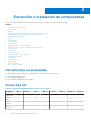 8
8
-
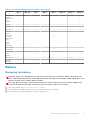 9
9
-
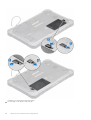 10
10
-
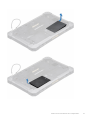 11
11
-
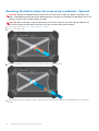 12
12
-
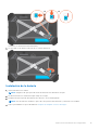 13
13
-
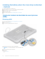 14
14
-
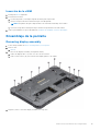 15
15
-
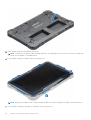 16
16
-
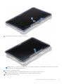 17
17
-
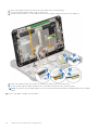 18
18
-
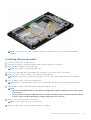 19
19
-
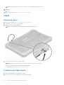 20
20
-
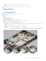 21
21
-
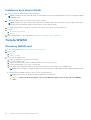 22
22
-
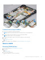 23
23
-
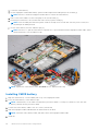 24
24
-
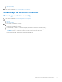 25
25
-
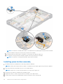 26
26
-
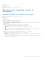 27
27
-
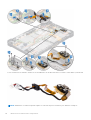 28
28
-
 29
29
-
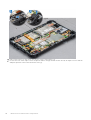 30
30
-
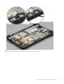 31
31
-
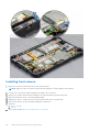 32
32
-
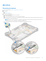 33
33
-
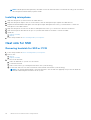 34
34
-
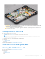 35
35
-
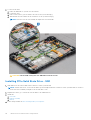 36
36
-
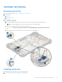 37
37
-
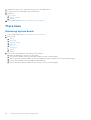 38
38
-
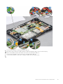 39
39
-
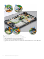 40
40
-
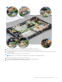 41
41
-
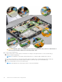 42
42
-
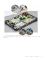 43
43
-
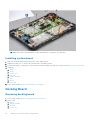 44
44
-
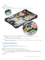 45
45
-
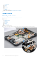 46
46
-
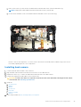 47
47
-
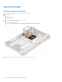 48
48
-
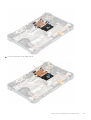 49
49
-
 50
50
-
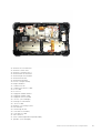 51
51
-
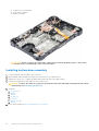 52
52
-
 53
53
-
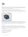 54
54
-
 55
55
-
 56
56
-
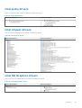 57
57
-
 58
58
-
 59
59
-
 60
60
-
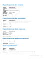 61
61
-
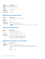 62
62
-
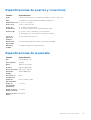 63
63
-
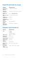 64
64
-
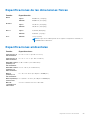 65
65
-
 66
66
-
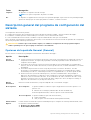 67
67
-
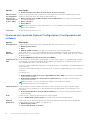 68
68
-
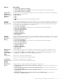 69
69
-
 70
70
-
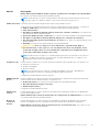 71
71
-
 72
72
-
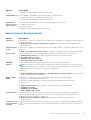 73
73
-
 74
74
-
 75
75
-
 76
76
-
 77
77
-
 78
78
-
 79
79
-
 80
80
-
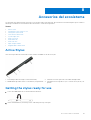 81
81
-
 82
82
-
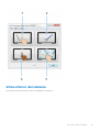 83
83
-
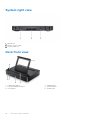 84
84
-
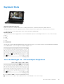 85
85
-
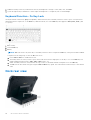 86
86
-
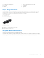 87
87
-
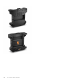 88
88


Dell Latitude 7212 Rugged Extreme El manual del propietario
- Tipo
- El manual del propietario
en otros idiomas
Artículos relacionados
-
Dell Latitude 12 Rugged Extreme 7212 El manual del propietario
-
Dell Latitude 10 El manual del propietario
-
-
Dell Precision 5510 El manual del propietario
-
Dell Precision 7550 El manual del propietario
-
Dell Precision 7750 El manual del propietario
-
Dell Latitude 5285 2-in-1 El manual del propietario
-
Dell Latitude 7285 2-in-1 El manual del propietario
-
Dell Precision M6600 El manual del propietario
-
Dell Vostro 5459 El manual del propietario
Otros documentos
-
Gateway NV47H Manual de usuario
-
LG 14T90R-G Manual de usuario
-
Alienware 17 R4 Manual de usuario
-
Getac RX10(52628719XXXX) Guía de inicio rápido
-
Gamber-Johnson Zebra ET5X 10" 2-in-1 Attachable Keyboard Guía de inicio rápido
-
Shuttle X50V9 53R-X50V93-2001 Guía del usuario
-
Asus HZ-1 Guía del usuario
-
 Tacens ACRM3 Ficha de datos
-
iogear GPEN200N Guía de inicio rápido
-
 Square SPC2 Contactless and chip reader Manual de usuario

