Watchguard Firebox M4600 Guía de inicio rápido
- Tipo
- Guía de inicio rápido

Guide de démarrage rapide
Kurzanleitung
Guía Rápida
Guia de início rápido
快速設定手冊
Quick Start Guide
Firebox
®
M4600
HW Model: CL4AE24
WatchGuard® Technologies, Inc.
Guida introduttiva

2 3
Computer
Internet
Eth 1
Eth 0
Activate Your Firebox
1. Go to www.watchguard.com/activate
2. Log in to your WatchGuard account, or create a new account*.
*If you create a new account, return to www.watchguard.com/activate after you nish the account creation
process.
Connect Your Firebox and Power it On
Make sure your computer is congured to use DHCP. When you connect to the Firebox, it will
assign an IP address on the 10.0.1.0/24 network.
Connect to the Web UI
1. Go to https://10.0.1.1:8080
2. You can safely ignore certicate warnings, because the Firebox uses a
self-signed certicate.
3. Log in with the user name admin and the passphrase readwrite.
4. Follow the directions in the Web Setup Wizard to create a basic conguration le for a
new Firebox. Click More Information if you have questions.
5. When the Wizard completes, log in to the Web UI with the admin user account and the
Admin passphrase you set during the Wizard.
6. Install the Firebox in your network.
After you run the Web Setup Wizard your Firebox has a basic conguration:
• Allows outbound FTP, Ping, DNS, TCP, and UDP connections
• Blocks all unrequested trac from the external network
• Inspects outgoing FTP, HTTP, and HTTPS trac
• Uses licensed security services to protect the trusted and optional networks
Next Steps
Congratulations! You have nished basic setup of your Firebox. You can use the Web UI to view and
edit your conguration and to manage and monitor your Firebox. Or, you can download and install
WatchGuard System Manager (WSM) and use Policy Manager and the WSM suite of management
and monitoring tools. Here are some recommendations to help you get started:
Verify your Internet connectivity
• With your Firebox installed in your network, make sure that your users can successfully
browse the Internet.
Get the latest software
To upgrade the Firebox OS:
1. Log in to Fireware Web UI.
2. Select System > Upgrade OS.
To get the latest version of WSM, WatchGuard Dimension, VPN clients,
and other software for your Firebox:
1. Go to www.watchguard.com/support and click Download Software.
2. Find the software downloads page for the Firebox M4600 and select the
software you want to install.
Explore the Features and Functions of Your Firebox
Browse the Web UI or the tools in WatchGuard System Manager and click Help on any page or dialog
box to learn more about the management, monitoring, and security features of your Firebox.
English

4 5
About the Firebox Status Lights
Indicators for RJ45 interfaces – Interfaces 0 - 7 have two indicators. The right indicator shows the
interface connection status. The left indicator shows interface activity.
Indicator Indicator color Interface Status
Connection (right) Yellow Link at 1000 Mbps
Green Link at 100 Mbps
Not lit Link at 10 Mbps or no link
Activity (left) Yellow, blinks Power on, network activity
Not lit Power o, no connections
Storage ( ) – When there is activity on the CFAST card or hard disk, the storage indicator is yellow.
Arm/Disarm ( ) – When the Firebox is armed and ready to pass trac, this indicator is green. When
the Firebox is powered on, but not ready to pass trac, this indicator is red.
Power ( ) – The power indicator on the left front of the Firebox is green when the Firebox is
powered on.
Power Button ( ) – The Power button on the front of the Firebox is lit to indicate power status. It is
green when the Firebox is powered on, and red when power is available, but the Firebox is powered
o. When the Power button is red, press this button to power on the Firebox. When the Power button
is green, press and hold it for ve seconds to power o the Firebox.
Install Interface Modules
You can install interface modules in slots A and B to add more interfaces to your Firebox. You must
install the interface modules before you can enable the interfaces in the Firebox conguration. The
Firebox M4600 supports these interface modules:
• WatchGuard Firebox M 8 Port 1Gb Copper Module
• WatchGuard Firebox M 8 Port SFP Fiber Module
• WatchGuard Firebox M 4 Port 10 Gb SFP+ Fiber Module
Important: You must power o the Firebox before you install or remove an interface module.
For details about available interface modules and instructions for interface module installation,
see the Firebox M4600 Hardware Guide available at: www.watchguard.com/help/documentation/
hardware.asp
Install Your Firebox
Your Firebox includes a rack mount kit. For instructions to install your Firebox in a network rack, see
page 6.
Reset the Firebox to Factory-Default Settings
If you ever need to, you can restore your Firebox to its factory-default settings. For example, if you do
not know the administrator account passphrase or you want to start over with a new conguration,
you can reset your Firebox. Make sure you back up your Firebox conguration before you reset your
Firebox in case you want to restore it in the future.
For information about how to reset your Firebox, see the Firebox M4600 Hardware Guide, available at:
www.watchguard.com/help/documentation/hardware.asp
English

6 7
Separate the inner rails from the outer rails
1. Extend the inner rail until it locks.
2. Press the tab, and pull the inner rail from the outer rail until they completely separate.
3. Repeat these steps to separate the second inner and outer rail.
Attach the inner rails and front mounting bracket to the Firebox
1. Locate the six shorter at head screws (A), and the front ear brackets and screws.
2. Use three screws provided with the front ear brackets to attach a bracket to the front of the
Firebox on one side.
3. Put the inner rail against one side of the Firebox. Make sure that the safety lock tab faces out,
and that the notched end of the rail is located toward the rear of the Firebox.
4. Align the screw holes in the rail with the holes on the sides of the Firebox.
5. Attach the inner rail to the Firebox with three of the shorter at head screws.
6. Repeat these steps to attach the other inner rail and front ear bracket to the other side of the
Firebox.
Rack Mount Installation Instructions
The Firebox M4600 rack mount system includes:
Rack rail kit
• 4 L-shaped brackets
• 2 sliding rails
• 8 short at head screws (A)
• 8 longer at head screws and 8 nuts (B)
• 12 at countersink screws and 12 conical washers (C)
• 2 front ear brackets and 6 small screws
Precautions
When you install the Firebox in a rack, consider these factors:
Elevated Operating Ambient Temperature
If you install the Firebox in a closed or multi-unit rack assembly, the operating ambient temperature
of the rack environment may be greater than room ambient. Make sure the ambient temperature of
the rack environment is within the certied operating range specied in the Hardware Guide.
Reduced Air Flow
When you install the Firebox in a rack, make sure that the amount of air ow required for safe
operation of the equipment is not compromised.
Mechanical Loading
When you mount the Firebox in the rack, avoid hazardous conditions caused by uneven mechanical
loading.
Circuit Overloading
Make sure you connect the Firebox to the power supply circuit in such a way that there is no
overloading of the circuits, and no impact on overcurrent protection and supply wiring.
Reliable Grounding
Make sure all rack-mounted equipment is correctly grounded. For example, make sure you use
power strips instead of direct connections to the branch circuit.
CAUTION: Do not use your slide/rail mounted Firebox as a shelf or work space.
English
Front ear bracket
Screws
Press tab to unlock inner rail
inner rail
(A) (B)
(C)

8 9
Attach the L-shaped brackets to the outer rails
The four L-shaped brackets secure the outer rails to the rack. You must attach the L-shaped
brackets to the outer rails rst.
1. Locate the eight at head screws and the eight nuts (B).
2. Use two at head screws and two nuts to connect an L-shaped bracket to the outer rail
through any two of the four holes at the end of the outer rail. Position each nut on the
outside of the bracket, and attach a screw from the inside of the outer rail.
3. Do not fully tighten the nuts yet.
4. Slide out the center of the outer rail to expose the screw holes at the other end of the rail.
5. Use two at head screws and two nuts to connect a second L-shaped bracket to the other
end of the outer rail through any two of the four holes at the end of the outer rail. Position
each nut on the outside of the bracket, and attach a screw from the inside of the outer rail.
The fully assembled outer rail looks like this:
6. Do not fully tighten the nuts yet because you will need to adjust the location of the rear
bracket to match the depth of your rack.
7. Repeat these steps to attach the other two L-shaped brackets to the other outer rail.
Attach the outer rails to the rack
1. Locate the countersink screws and conical washers (C).
2. Use two screws and conical washers to connect the front bracket on the outer rail to the front
post of the rack. Make sure that the sliding center rail is located toward the front of the rack and
faces the center.
3. Extend and adjust the rear bracket depth to match the depth of the rack.
4. Use two countersink screws and conical washers to connect the rear bracket to the rear post of
the rack.
5. Repeat these steps to attach the other rail to the other side of the rack. Make sure the sliding
center section of each rail is positioned at the same depth within the rack.
6. Tighten the nuts and screws that attach the L-shaped brackets to each of the rails. You can use a
wrench for this step.
Install the Firebox in the rack
1. Pull out the center rail on each side until the extension safety lock is locked.
2. Hold the Firebox with its front facing you. Lift the Firebox and carefully slide the inner rails on
each side of the chassis into the outer rail on each side of the rack.
3. Press the safety lock tabs on the inner rails, and slide the Firebox into the rack until the front
mounting brackets touch the front posts of the rack.
4. Use two of the countersink screws (C), without the washers, to attach the front mounting
brackets to the rack.
English

10 11
计算机
Internet
Eth 1
Eth 0
激活您的 Firebox
1. 访问 www.watchguard.com/activate
2. 登录您的 WatchGuard 帐户,或者创建一个新帐户*。
*如果创建新帐户,请在完成帐户创建过程之后返回到 www.watchguard.com/activate。
连接您的 Firebox 并开启电源
确保您的计算机配置为使用 DHCP。连接 Firebox 后,它将在 10.0.1.0/24 网络上分配一个 IP
地址。
连接到网页管理界面
1. 访问 https://10.0.1.1:8080
2. 您可以安全地忽略证书警告,因为 Firebox 使用自签名证书。
3. 使用用户名 admin 和密码 readwrite 登录。
4. 按照网络设置向导中的说明为新的 Firebox 创建一个基本的配置文件。
如有问题,请单击 More Information(更多信息)。
5. 在向导完成后,使用您在向导中设置的 admin 用户帐户和管理员密码登录网页管理界面。
6. 在您的网络中安装 Firebox。
运行网络设置向导后,您的 Firebox 将具备以下基本配置:
• 允许出站 FTP、Ping、DNS、TCP 和 UDP 连接
• 阻止来自外部网络的所有未请求的数据流
• 检测传出 FTP、HTTP 和 HTTPS 流量
• 使用许可的安全服务来保护受信任的网络和可选网络
后续步骤
恭喜!您已经完成了 Firebox 的基本设置。您可以使用网页管理界面查看和编辑配置,以及管
理和监控您的 Firebox。或者,您也可以下载并安装 WatchGuard 系统管理器(WSM),使用策
略管理器和 WSM 管理与监控工具套件。下面是帮助您入门的一些建议:
验证您的 Internet 连接
• 在网络中安装 Firebox 之后,确保您的用户可以成功浏览 Internet。
获取最新版本的软件
升级 Firebox 操作系统:
1. 登录 Fireware 网页管理界面。
2. 选择 System > Upgrade OS(系统 > 升级操作系统)。
获取最新版本的 WSM、WatchGuard Dimension、VPN 客户端
和其他 Firebox 软件:
1. 访问 www.watchguard.com/support 并单击 Download Software(下载软件)。
2. 找到 Firebox M4600 的软件下载页面并选择 想要安装的软件。
探索 Firebox 的特性和功能
浏览网页管理界面或 WatchGuard 系统管理器,单击任意页面或对话框的上的 Help(帮助),详
细了解 Firebox 的管理、监控和安全功能。
简体中文
简体中文

12 13
关于 Firebox 状态指示灯
RJ45 接口指示灯 - 接口 0 - 7 均有两个指示灯。右侧的指示灯显示接口连接状态。左侧的指示灯
显示接口活动。
指示灯 指示灯颜色 接口状态
连接(右侧) 黄色
链路速度为 1000 Mbps
绿色
链路速度为 100 Mbps
不亮
链路速度为 10 Mbps 或无链路
活动(左侧) 黄色,闪烁 已开启,有网络活动
不亮 已关闭,无连接
存储 ( ) – 当 CFAST 卡或硬盘上有活动时,存储指示灯显示为黄色。
防护/解除防护 ( ) - 当 Firebox 处于防护状态并可通过数据流时,此指示灯显示为绿色。当
Firebox 处于开启状态,但尚不能通过数据流时,此指示灯显示为红色。
电源 ( ) – 当 Firebox 处于开启状态时,位于 Firebox 左前方的电源指示灯显示为绿色。
电源按钮 ( ) – Firebox 正面的电源按钮用于指示电源状态。当 Firebox 处于开启状态时,电源
按钮显示为绿色;当有电源可用但 Firebox 处于关闭状态时,电源按钮显示为红色。当电源按钮
显示为红色时,按下此按钮可以打开 Firebox 的电源。当电源按钮显示为绿色时,按住此按钮并
持续 5 秒钟可以关闭 Firebox 的电源。
安装接口模块
您可以在插槽 A 和 B 中安装接口模块,以便为您的 Firebox 添加更多接口。您必须安装接口模
块,然后才能在 Firebox 配置中启用接口。Firebox M4600 支持以下接口模块:
• WatchGuard Firebox M 8 端口 1Gb 铜缆模块
• WatchGuard Firebox M 8 端口 SFP 光纤模块
• WatchGuard Firebox M 4 端口 10 Gb SFP+ 光纤模块
重要信息:在安装或移除接口模块前,您必须关闭
Firebox
的电源
。
关于可用接口模块的详细信息和接口模块的安装说明,请参阅 Firebox M4600
硬件指南
,网址
为:www.watchguard.com/help/documentation/hardware.asp
安装您的 Firebox
您的 Firebox 包含机架安装套件。关于在网络机架上安装 Firebox 的说明,请参见第 6 页。
将 Firebox 重置为出厂默认设置
如果需要,可以将 Firebox 重置为其出厂默认设置。例如,如果您不知道管理员帐户的密码或者
想要重新配置,可以重置 Firebox。在重置您的 Firebox 之前,请确保备份 Firebox 配置,以防您
以后想恢复这一配置。
关于如何重置 Firebox 的信息,请参阅 Firebox M4600
硬件指南
,网址为:
www.watchguard.com/help/documentation/hardware.asp
简体中文

14 15
Ordinateur
Internet
Eth 1
Eth 0
Activation de votre appliance Firebox
1. Rendez-vous à l'adresse www.watchguard.com/activate
2. Connectez-vous à votre compte WatchGuard ou créez un nouveau compte*.
* Si vous créez un nouveau compte, retournez à l'adresse www.watchguard.com/activate à la n
duprocessus de création du compte.
Branchement et mise sous tension de votre appliance Firebox
Assurez-vous que votre ordinateur est conguré pour utiliser le protocole DHCP. Lorsque vous
connectez votre appliance Firebox, elle attribue une adresseIP sur le réseau 10.0.1.0/24.
Connexion à l'interface utilisateur Web
1. Rendez-vous à l'adresse https://10.0.1.1:8080
2. Votre appliance Firebox utilisant un certicat auto-signé, vous pouvez, sans risque, ignorer
lesavertissements liés aux certicats.
3. Connectez-vous avec le nom d'utilisateur admin et le mot de passe readwrite.
4. Suivez les instructions de l'Assistant de conguration Web pour générer un chier de conguration
pour une nouvelle appliance Firebox. Si vous avez des questions, cliquez sur Plus d'informations.
5. Une fois que l'Assistant a terminé, connectez-vous à l'interface utilisateur Web avec le nom
d'utilisateur admin et le mot de passe Admin que vous avez dénis dans l'Assistant.
6. Installez l'appliance Firebox sur votre réseau.
Après avoir exécuté l'Assistant de conguration Web, votre appliance Firebox présente une
conguration de base:
• Autorisation des connexions sortantes FTP, Ping, DNS, TCP et UDP
• Blocage de tout le trac non demandé en provenance du réseau externe
• Inspection du trac sortant FTP, HTTP et HTTPS
• Utilisation de services de sécurité sous licence pour protéger les réseaux approuvés et en option
Étapes suivantes
Félicitations! Vous avez à présent terminé la conguration de base de votre appliance Firebox. Vous
pouvez utiliser l'interface utilisateur Web pour consulter et modier votre conguration, mais aussi
pour gérer et contrôler votre appliance. Autrement, vous pouvez télécharger et installer WatchGuard
System Manager (WSM) et utiliser Policy Manager et la suite WSM d'outils de gestion etde
surveillance. Voici quelques recommandations pour débuter:
Vérifiez votre connectivité Internet
• Une fois votre appliance Firebox installée sur votre réseau, assurez-vous que vos utilisateurs
peuvent naviguer correctement sur Internet.
Procurez-vous le logiciel le plus récent
Pour mettre à niveau le système d'exploitation de l'appliance Firebox:
1. Connectez-vous à l'interface utilisateur Web de Fireware.
2. Sélectionnez System > Upgrade OS (Système > Mise à niveau du système d'exploitation).
Pour obtenir la toute dernière version de WSM, de WatchGuard Dimension, des clients VPN
et d'autres logiciels pour votre appliance Firebox:
1. Rendez-vous à l'adresse www.watchguard.com/support et cliquez sur Download
Software (Téléchargements de logiciels).
2. Recherchez la page des téléchargements de logiciels pour l'appliance FireboxM4600
etsélectionnez le logiciel à installer.
Français

16 17
Examen des caractéristiques et fonctions
de votre appliance Firebox
Accédez à l'interface utilisateur Web ou aux outils de WatchGuard System Manager et cliquez sur
l'icône d'Aide d'une page ou d'une boîte de dialogue pour en savoir plus sur les fonctions de gestion,
de surveillance et de sécurité de votre appliance Firebox.
À propos des témoins d'état de votre appliance Firebox
Indicateurs des interfaces RJ45 : les interfaces0 à7 présentent deux indicateurs. Celui de droite
indique l'état de la connexion de l'interface. Celui de gauche indique l'activité de l'interface.
Indicateur Couleur de l'indicateur État de l'interface
Connexion (droit) Jaune Liaison à 1000Mbps
Vert Liaison à 100Mbps
Éteint Liaison à 10Mbps ou aucune liaison
Activité (gauche) Jaune, clignotant Sous tension, activité réseau
Éteint Hors tension, aucune connexion
Stockage (Stockage) ( ): lorsque la mémoire Flash ou le disque dur est actif, l'indicateur
destockage est jaune.
Activation/désactivation ( ): lorsque l'appliance Firebox est activée et prête à transmettre
dutrac, cet indicateur passe au vert. Lorsque l'appliance Firebox est sous tension mais qu'elle n'est
pas prête à transmettre du trac, cet indicateur est rouge.
Alimentation ( ): situé à l'avant gauche, l'indicateur d'alimentation est vert lorsque l'appliance
Firebox est sous tension.
Bouton d'alimentation ( ): ce bouton, situé à l'avant de l'appliance Firebox, s'allume pour
indiquer le statut de l'alimentation. Il est vert lorsque l'appliance Firebox est sous tension, et rouge
lorsque l'alimentation est disponible, mais que l'appliance est hors tension. Lorsque ce bouton est
rouge, appuyez dessus pour mettre l'appliance sous tension. Lorsque ce bouton est vert, maintenez-
le enfoncé pendant cinq secondes pour mettre l'appliance Firebox hors tension.
Installation des modules d'interface
Vous pouvez installer les modules d'interface dans les emplacementsA etB an d'ajouter des
interfaces supplémentaires à votre appliance Firebox. Les modules d'interface doivent être
installés avant de pouvoir activer les interfaces dans la conguration de l'appliance. L'appliance
FireboxM4600 prend en charge les modules d'interface suivants:
• Module en cuivre à 8ports (1Gb) de l'appliance WatchGuard FireboxM
• Module en bre SFP à 8ports de l'appliance WatchGuard FireboxM
• Module en bre SFP+ à 4ports (10Gb) de l'appliance WatchGuard FireboxM
Important: vous devez mettre l'appliance Firebox hors tension avant d'installer ou de retirer un module
d'interface.
Pour plus d'informations concernant les modules d'interface disponibles et des instructions pour
l'installation de modules d'interface, reportez-vous au Firebox M4600 Hardware Guide (Guide du matériel
FireboxM4600) disponible à l'adresse: www.watchguard.com/help/documentation/hardware.asp
Installation de votre appliance Firebox
Votre appliance Firebox comprend un kit de montage sur châssis. Pour obtenir des instructions
surl'installation de votre appliance Firebox dans une baie réseau, consultez la page6.
Rétablissement des paramètres d'usine
de l'appliance Firebox
En cas de besoin, vous pouvez réinitialiser votre appliance Firebox sur ses paramètres d'usine.
Par exemple, vous pouvez réinitialiser votre appliance si vous ne connaissez pas le mot de passe
du compte administrateur ou si vous souhaitez recommencer avec une nouvelle conguration.
Assurez-vous de sauvegarder la conguration de votre appliance Firebox avant de procéder
àlaréinitialisation, an de pouvoir la restaurer ultérieurement si nécessaire.
Français
Pour plus d'informations sur la réinitialisation de votre appliance Firebox, reportez-vous
auFirebox M4600 Hardware Guide (Guide du matériel FireboxM4600), disponible à l'adresse:
www.watchguard.com/help/documentation/hardware.asp

18 19
Computer
Internet
Eth 1
Eth 0
Firebox aktivieren
1. Rufen Sie die Website www.watchguard.com/activate auf.
2. Melden Sie sich bei Ihrem WatchGuard-Account an oder erstellen Sie ein neues Konto.*
*Falls Sie ein neues Konto erstellen, kehren Sie nach erfolgreichem Abschluss zur Seite www.watchguard.
com/activate zurück.
Firebox anschließen und einschalten
Stellen Sie sicher, dass Ihr Computer für die Verwendung von DHCP konguriert ist. Wenn Sie eine
Verbindung zu Ihrer Firebox herstellen, wird eine IP-Adresse im Netzwerk 10.0.1.0/24 zugewiesen.
Verbindung zum Web-Interface herstellen
1. Rufen Sie die Website https://10.0.1.1:8080 auf.
2. Eventuell angezeigte Zertikatswarnungen können Sie ignorieren, da die Firebox ein
selbstsigniertes Zertikat verwendet.
3. Melden Sie sich mit dem Benutzernamen admin und dem Kennwort readwrite an.
4. Folgen Sie den Anweisungen im Web-Setup-Assistenten, um eine Basiskongurationsdatei für eine
neue Firebox zu erstellen. Klicken Sie bei weiteren Fragen auf More Information.
5. Melden Sie sich nach Abschluss des Assistenten mit dem Benutzerkonto admin und dem Admin-
Kennwort, das Sie mit dem Assistenten festgelegt haben,
an der Web-Schnittstelle an.
6. Installieren Sie die Firebox in Ihrem Netzwerk.
Wenn Sie den Web-Setup-Assistenten ausgeführt haben, hat die Firebox eine Grundkonguration:
• Unterstützung von ausgehenden FTP-, Ping-, DNS-, TCP- und UDP-Verbindungen
• Blockierung von nicht angefordertem Datenverkehr aus dem externen Netzwerk
• Prüfung von ausgehendem FTP-, HTTP- und HTTPS-Datenverkehr
• Verwendung lizenzierter Sicherheitsdienste zum Schutz vertrauenswürdiger und optionaler
Netzwerke
Weitere Schritte
Herzlichen Glückwunsch! Sie haben das Basis-Setup für Ihre Firebox abgeschlossen. Über das Web-
Interface können Sie Ihre Konguration anzeigen lassen sowie bearbeiten und Ihre Firebox verwalten
und überwachen. Alternativ können Sie den WatchGuard System Manager (WSM) herunterladen und
installieren und den Policy Manager und die WSM-Suite mit Management- und Überwachungstools
verwenden. Tipps für den Start:
Internetverbindung überprüfen
• Stellen Sie sicher, dass Ihre Nutzer nach der Installation der Firebox im Netzwerk problemlos im
Internet navigieren können.
Neueste Software implementieren
So führen Sie ein Upgrade des Firebox-Betriebssystems durch:
1. Melden Sie sich beim Fireware Web UI an.
2. Wählen Sie die Option System > Upgrade OS aus.
So rufen Sie die neueste Version von WSM, WatchGuard Dimension, VPN-Clients
und anderer Software für die Firebox ab:
1. Rufen Sie die Website www.watchguard.com/support auf, und klicken Sie auf Download
Software.
2. Gehen Sie auf die Seite mit den Software-Downloads für die Firebox M4600, und wählen Sie
die zu installierende Software aus.
Merkmale und Funktionen der Firebox erkunden
Durchsuchen Sie das Web-Interface oder die Tools in WatchGuard System Manager und klicken Sie auf
einer beliebigen Seite oder in einem beliebigen Dialogfeld auf Help, um weitere Informationen zu den
Verwaltungs-, Überwachungs- und Sicherheitsmerkmalen Ihrer Firebox zu erhalten.
Deutsch

20 21
Informationen zu den Statusanzeigen der Firebox
Anzeigen für die RJ45-Schnittstellen – Die Schnittstellen 0–7 haben zwei Anzeigen. Die rechte
Anzeige signalisiert den Verbindungsstatus der Schnittstelle. Die linke Anzeige signalisiert die
Schnittstellenaktivität.
Anzeige Farbsignal Schnittstellenstatus
Verbindung (rechts) Gelb Verbindung mit 1.000 Mbit/s
Grün Verbindung mit 100 Mbit/s
Leuchtet nicht Verbindung mit 10 Mbit/s oder keine
Verbindung
Aktivität (links) Gelb, blinkt Eingeschaltet, Netzwerkaktivität
Leuchtet nicht Ausgeschaltet, keine Verbindung
Storage ( ) – Wenn auf der CFAST-Karte oder Festplatte Aktivität stattndet, leuchtet die
Speicheranzeige gelb.
Arm/Disarm ( ) – Wenn die Firebox aktiv und bereit ist, Daten zu übertragen, leuchtet diese Anzeige
grün. Wenn die Firebox eingeschaltet, jedoch nicht bereit ist, Daten zu übertragen, leuchtet diese Anzeige
rot.
Power ( ) – Diese Anzeige links auf der Vorderseite der Firebox leuchtet grün, wenn die Firebox
eingeschaltet ist.
Power-Taste ( ) – Die Power-Taste an der Vorderseite der Firebox leuchtet, um den Betriebszustand
anzuzeigen. Sie leuchtet grün, wenn die Firebox eingeschaltet ist, und rot, wenn die Firebox an das
Stromnetz angeschlossen, aber ausgeschaltet ist. Wenn die Power-Taste rot leuchtet, drücken Sie zum
Einschalten der Firebox kurz auf diese Taste. Wenn die Power-Taste grün leuchtet, halten Sie diese Taste
zum Ausschalten der Firebox fünf Sekunden lang gedrückt.
Schnittstellenmodule installieren
Sie können Schnittstellenmodule in den Steckplätzen A und B installieren, um der Firebox weitere
Schnittstellen hinzuzufügen. Sie müssen die Schnittstellenmodule installieren, bevor Sie die Schnittstellen
in der Firebox-Konguration aktivieren können. Die Firebox M4600 unterstützt die folgenden
Schnittstellenmodule:
• WatchGuard Firebox M 8 Port 1GB Copper Module
• WatchGuard Firebox M 8 Port SFP Fiber Module
• WatchGuard Firebox M 4 Port 10 Gbit/s SFP+ Fiber Module
Wichtig: Sie müssen die Firebox ausschalten, bevor Sie ein Schnittstellenmodul installieren oder entfernen.
Details zu verfügbaren Schnittstellenmodulen und Anweisungen zur Installation von
Schnittstellenmodulen nden Sie im Firebox M4600-Hardwarehandbuch unter folgender URL: www.
watchguard.com/help/documentation/hardware.asp
Firebox installieren
Die Firebox wird mit einem Rack-Montage-Kit geliefert. Anweisungen zum Installieren der Firebox in einem
Netzwerk-Rack nden Sie auf Seite6.
Zurücksetzen der Firebox auf die Standard-Werkseinstellungen
Falls erforderlich, lassen sich jederzeit die Werkseinstellungen Ihrer Firebox wiederherstellen. Sie können
das Gerät beispielsweise zurücksetzen, wenn Sie das Kennwort für das Administratorkonto nicht mehr
wissen oder wenn Sie ein Setup mit einer neuen Konguration durchführen möchten. Sichern Sie
jedoch unbedingt Ihre Konguration, bevor Sie die Firebox zurücksetzen, damit Sie sie künftig ggf.
wiederherstellen können.
Informationen zum Zurücksetzen der Firebox nden Sie im Firebox M4600-Hardwarehandbuch unter
folgender URL: www.watchguard.com/help/documentation/hardware.asp
Deutsch

22 23
Computer
Internet
Eth 1
Eth 0
Attivazione di Firebox
1. Vai su www.watchguard.com/activate
2. Accedi al tuo account WatchGuard, oppure creane uno nuovo*.
*Se crei un nuovo account, ritorna a www.watchguard.com/activate al termine della procedura di creazione
dell’account.
Collegamento e accensione di Firebox
Verica che il computer in uso sia congurato per utilizzare il protocollo DHCP. Quando installi il
tuo Firebox, questo assegnerà al computer un indirizzo IP nella sottorete 10.0.1.0/24.
Connessione all’interfaccia di gestione via Web
1. Vai all’indirizzo https://10.0.1.1:8080
2. Puoi ignorare tranquillamente qualsiasi avviso di certicato visualizzato perché Firebox utilizza
un certicato autormato.
3. Accedi con il nome utente admin e la passphrase readwrite.
4. Per creare un le di congurazione di base per il nuovo Firebox, segui le indicazioni contenute
nella procedura guidata per l’installazione basata sul Web. In caso di domande, fare clic su
Ulteriori informazioni.
5. Una volta completata la procedura guidata, accedi all’interfaccia di gestione via Web con
l’account utente admin e la passphrase Admin, impostata durante la procedura guidata.
6. Installa Firebox nella tua rete.
Dopo avere eseguito la procedura guidata Web, il tuo nuovo Firebox avrà una congurazione di base:
• Consente le connessioni in uscita FTP, Ping, DNS, TCP e UDP
• Blocca tutto il traco non richiesto dalla rete esterna
• Ispeziona il traco in uscita FTP, HTTP e HTTPS
• Utilizza i servizi di sicurezza concessi in licenza per proteggere le reti adabili e opzionali
Passaggi successivi
Congratulazioni! L’installazione di base di Firebox è completata. Per visualizzare e modicare la
congurazione in uso e per gestire e monitorare Firebox, utilizza l’interfaccia di gestione via Web.
Inalternativa, è possibile scaricare e installare WatchGuard System Manager (WSM) e utilizzare
PolicyManager e la suite di strumenti gestionali e di monitoraggio WSM. Di seguito alcuni consigli
utili per iniziare:
Verifica della connessione a Internet
• Dopo avere installato Firebox nella tua rete, verica che gli utenti possano navigare in
Internet senza problemi.
Aggiornamento del software
Per aggiornare il sistema operativo Firebox:
1. Accedi all’interfaccia utente Web Fireware.
2. Seleziona System > Upgrade OS.
Per ottenere l’ultima versione di WSM, WatchGuard Dimension, client VPN
e altro software per Firebox:
1. Vai su www.watchguard.com/support e fai clic su Download Software.
2. Cerca la pagina per scaricare il software di Firebox M4600 e seleziona
il software che desideri installare.
Esplorazione delle caratteristiche e delle funzionalità di Firebox
Per ulteriori informazioni sulle funzionalità di gestione, monitoraggio e sicurezza di Firebox, sfogliare
l’interfaccia utente basata sul web o gli strumenti di WatchGuard System Manager e fare clic su ? o su
qualsiasi altra pagina o nestra di dialogo.
Italiano

24 25
Informazioni sulle spie di stato di Firebox
Indicatori per le interfacce RJ45 – Le interfacce 0-7 hanno due indicatori. L’indicatore di destra
mostra lo stato di connessione dell’interfaccia. L’indicatore di sinistra mostra l’attività dell’interfaccia.
Indicatore Colore dell’indicatore Stato dell’interfaccia
Connessione (destra) Giallo Collegamento a 1000 Mbps
Verde Collegamento a 100 Mbps
Spento Collegamento a 10 Mbps,
onessuncollegamento
Attività (sinistra) Giallo, lampeggiante Accensione, attività della rete
Spento Spegnimento, nessuna connessione
Archiviazione ( ) – Quando la scheda CFAST o l’hard disk sono attivi, l’indicatore di archiviazione
ègiallo.
Attivazione/Disattivazione ( ) – Quando Firebox è attivo e pronto a consentire il traco, questo
indicatore è verde. Quando Firebox è acceso, ma non è ancora pronto a consentire il traco, questo
indicatore è rosso.
Alimentazione ( ) – L’indicatore dell’alimentazione anteriore sinistro è verde quando Firebox
èacceso.
Pulsante Alimentazione ( ) – Il pulsante Alimentazione sulla parte anteriore di Firebox si illumina
per indicare lo stato di alimentazione. Il pulsante è verde quando Firebox è acceso e rosso quando
l’alimentazione è collegata ma Firebox è ancora spento. Quando il pulsante Alimentazione è rosso,
premerlo per accendere Firebox. Quando il pulsante Alimentazione è verde, tenerlo premuto per
cinque secondi per spegnere Firebox.
Installazione dei moduli di interfaccia
È possibile installare dei moduli di interfaccia negli slot A e B per aggiungere ulteriori interfacce
aFirebox. È necessario installare i moduli di interfaccia prima di potere abilitare le interfacce nella
congurazione di Firebox. Firebox M4600 supporta i moduli di interfaccia indicati di seguito:
• Modulo in rame WatchGuard Firebox M 8 Porta 1Gb
• Modulo in bra WatchGuard Firebox M 8 Porta SFP
• Modulo in bra WatchGuard Firebox M 4 Porta 10 Gb SFP+
Importante: È necessario spegnere Firebox prima di installare o rimuovere qualsiasi modulo di interfaccia.
Per ulteriori dettagli sui moduli di interfaccia disponibili e le istruzioni di installazione, consultare
la Guida hardware di Firebox M4600 reperibile all’indirizzo: www.watchguard.com/help/
documentation/hardware.asp
Installazione di Firebox
Firebox include un kit di montaggio su rack. Per istruzioni sull’installazione di Firebox in un rack
direte, vedi pagina 6.
Ripristino delle impostazioni di fabbrica predefinite di Firebox
Se necessario, è possibile ripristinare le impostazioni di fabbrica di Firebox. Per esempio, è possibile
reimpostare Firebox se non si conosce la passphrase dell’account administrator o si desidera riavviare
con una nuova congurazione. Prima di ripristinare Firebox, assicurarsi di eseguire il backup della
congurazione di Firebox qualora si desideri ripristinarlo in futuro.
Per informazioni sul ripristino di Firebox, consultare la Guida hardware di Firebox M4600 reperibile
all’indirizzo: www.watchguard.com/help/documentation/hardware.asp
Italiano

26 27
コンピュータ
インターネット
Eth 1
Eth 0
Firebox を起動する
1. www.watchguard.com/activate
にアクセスします。
2.
登録済みの
WatchGuard
アカウントにログインするか、 新しいアカウントを作成します
*
。
*
新しいアカウントを作成する場合は、アカウント作成プロセスが完了してからもう一度
www.watchguard.com/activate
にアクセスしてください。
Firebox を接 続して 電 源を入れる
コンピュータが
DHCP
を使用するように設定されていることを確認します。
Firebox
への接続時に、
10.0.1.0/24
ネットワーク上の
IP
アドレスが割り当てられます。
Web UI に接続する
1. https://10.0.1.1:8080
にアクセスします。
2. Firebox
は自己署名証明書を使用するため、証明書に関する警告は無視して
かまいません。
3.
ユーザー名
admin
とパスフレーズ
readwrite
でログインします。
4. Web
セットアップ・ウィザードの手順に従って、新たな
Firebox
デバイスの基本設定ファイルを
作成します。詳しい手順を確認する場合は、
[More Information]
をクリックしてくだ さ い 。
5.
ウィザードが完了したら、ユーザー・アカウント
admin
と、ウィザードで設定した
管理用パスフレーズで
Web UI
にログインします。
6.
ネットワークに
Firebox
をインストールします。
日本語
Web
セットアップ・ウィザ ードを実 行 すると、
Firebox
の基本設定が完了します。
• アウトバウンド
FTP
、
Ping
、
DNS
、
TCP
、
UDP
接続を可能にする
• 外部ネットワークからのすべての要求されないトラフィックをブロック
• 外部に向けた
FTP
、
HTTP
、
HTTPS
トラフィックを検査
• 信頼できるネットワークとオプション
ネットワーク保護のため、ライセンス式セキュリティ
サービスを使用
次のステップ
おめでとうございます。これで
Firebox
の基本セットアップが完了しました。
Web UI
を使って、設定の閲覧と
編集、および
Firebox
の管理
/
監視が可能です。また、
WatchGuard System Manager
(
WSM
)をダウン
ロードしてインストールし、
Policy Manager
や
WSM
スイートに含まれる管理
/
監視ツールを利用することも
できます。それらの作業の手始めとして、いくつかの推奨事項を次に示します。
インターネット接続を確認する
• ネットワークにインストールした
Firebox
で、ユーザーがインターネットを正常に閲覧できることを
確認します。
最 新 のソフトウェア を入手 する
Firebox OS
をアップグレ ードする手順は 次 のとおりです。
1. Fireware Web UI
にログインします。
2. System > Upgrade OS
を選択します。
Firebox
に、最新版の
WSM
、
WatchGuard Dimension
、
VPN clients
、
その 他 のソフトウェアを入 手 するには
:
1. www.watchguard.com/support
にアクセスし、
Download Software
をクリックしま す。
2. Firebox M4600
向けのソフトウェア・ダウンロード・ページを探し、インストールするソフトウェ
アを選択します。
Firebox の機能について調べる
Firebox
の管理、監視、およびセキュリティの機能の詳細については、ウェブ
UI
または
WatchGuard
System Manager
で確認できます。それぞれのページやダイアログ・ボックスで
[Help]
をクリックしてくだ さ い 。
日本語

28 29
Firebox のステータス・ライトについて
RJ45
インターフェイスのインジケータ
–
インターフェイス
0
~
7
には、
2
つのインジケータがあります。右側
のインジケータはインターフェイスの接続ステータスを示し、左側のインジケータはインターフェイスのアクテ
ィビ ティを 示します。
インジケータ インジケータの色 インターフェイスのステータス
接続(右)
黄色
リンク速度
1000 Mbps
緑色
リンク速度
100 Mbps
消灯
リンク速度
10 Mbps
、また はリンクなし
アクティビ ティ(左 ) 黄色の点滅 電源オン、ネットワーク・アクティビティ
消灯 電源を切る、接続なし
Storage ( )
–
CFAST
カードまたはハードディスクのアクティビティがある場合は、このインジケータが黄色
く点 灯しま す。
Arm/Disarm ( )
–
Firebox
の電源が入った状態で、トラフィックを送受信する準備ができている場合は緑
色に点灯します。
Firebox
の電源が入っていても、トラフィックを送受信する準備ができていない場合は赤色
に点灯します。
Power ( )
–
Firebox
前面左側にあるインジケータは、
Firebox
の電源が入っている間、緑色に点灯します。
Power
ボタン
( )
–
Firebox
前面の
Power
ボタンは、電源が入っているかどうかを表示します。
Firebox
の電源が入っていれば緑色に、通電していても
Firebox
の電源が入っていなければ赤色に点灯します。赤色
の状態で
Power
ボタンを押せば、
Firebox
の電源が入ります。緑色の状態で
Power
ボタンを
5
秒間長押し
すると、電源が切れます。
日本語
インターフェイス・モジュールをインストールする
Firebox
にインターフェイスを追加するには、
A
と
B
のスロットにインストールできます。
Firebox
設定内でイ
ンターフェイスを使用するには、インターフェイス・モジュールをインストールする必要があります。
Firebox
M4600
が サ ポ ートしている モ ジュール
:
•
WatchGuard Firebox M 8 Port 1Gb Copper Module
•
WatchGuard Firebox M 8 Port SFP Fiber Module
•
WatchGuard Firebox M 4 Port 10 Gb SFP+ Fiber Module
重要
: Firebox
の電源を落としてから、インターフェイス・モジュールをインストール、またはアンインストール
してください。
利用可能なインターフェイス・モジュールとインストールの手順などの詳細は、
www.watchguard.com/
help/documentation/hardware.asp
内の
Firebox M4600 Hardware Guide
をご覧ください。
Firebox を設置する
Firebox
には、ラックマウント部品一式が同梱されています。
Firebox
をネットワーク・ラックに設置するには、
6
ページをご覧ください。
Fireboxの設定を工場出荷時の状態に戻す
必要に応じて、
Firebox
の設定を工場出荷時の状態に戻すことができます。たとえば、管理者アカウントのパ
スフレーズを忘れた場合や、新しい設定でセットアップをやり直したい場合に、
Firebox
をリセットすることが
できます。
Firebox
の設定をバックアップしてから、リセットするようにしてください。後で復元できなくなります。
Firebox
のリセット方法に関する情報は、
www.watchguard.com/help/documentation/hardware.asp
内の、
Firebox M4600 Hardware Guide
をご覧ください。
日本語

30 31
컴퓨터 인터넷
이더넷 1
이더넷 0
Firebox 활성화
1. www.watchguard.com/activate로 이동합니다.
2. WatchGuard 계정으로 로그인하거나 새 계정을 만듭니다*.
*새 계정을 만들 경우 계정 생성 과정을 마친 후 www.watchguard.com/activate로 돌아가십시오.
Firebox 연결 및 전원 켜기
컴퓨터가 DHCP를 사용하도록 설정되어 있는지 확인합니다. Firebox에 연결할 때 10.0.1.0/24
네트워크의 IP 주소가 자동으로 할당됩니다.
Web UI에 연결
1. https://10.0.1.1:8080으로 이동합니다.
2. Firebox에서 자체 서명된 인증서를 사용하기 때문에 인증서 경고는
안심하고 무시하시면 됩니다.
3. 사용자 이름 admin과 암호 readwrite를 사용하여 로그인합니다.
4. Web Setup Wizard의 지침을 따라 새 Firebox에 대한 기본 구성 파일을
만듭니다. 궁금한 사항이 있을 경우 More Information을 클릭합니다.
5. 마법사가 완료되면 사용자 계정 admin과 마법사를 진행하는 도중 설정한
Admin 암호를 사용하여 Web UI에 로그인합니다.
6. 네트워크에 Firebox를 설치합니다.
Web Setup Wizard를 실행한 후 Firebox에 적용되는 기본 구성은 다음과 같습니다.
• 아웃바운드 FTP, Ping, DNS, TCP 및 UDP 연결 허용
• 외부 네트워크에서 들어오는 요청되지 않은 트래픽 모두 차단
• 나가는 FTP, HTTP 및 HTTPS 트래픽 검사
• 라이선스가 있는 보안 서비스를 사용하여 신뢰할 수 있고 선택적인 네트워크를
보호합니다.
다음 단계
축하합니다! Firebox 기본 설정을 완료하였습니다. Web UI를 사용하여 구성을 보고 편집할 수
있으며 Firebox를 관리하고 모니터링할 수 있습니다. 또는 WatchGuard System Manager(WSM)를
다운로드한 후 설치하여 Policy Manager와 WSM 관리 및 모니터링 도구 제품군을 사용할 수도
있습니다. 시작할 때 도움이 되는 몇 가지 권장 사항은 다음과 같습니다.
인터넷 연결 상태 확인
• 네트워크에 설치된 Firebox에서 사용자가 성공적으로 인터넷을 탐색할 수 있는지
확인하십시오.
최신 소프트웨어 다운로드
Firebox OS를 업그레이드하려면 다음과 같이 하십시오.
1. Fireware Web UI에 로그인합니다.
2. System > Upgrade OS를 선택합니다.
최신 버전의 WSM, WatchGuard Dimension, VPN 클라이언트 및
기타 Firebox용 소프트웨어를 다운로드하려면 다음과 같이 하십시오.
1. www.watchguard.com/support로 이동하고 Download Software를 클릭합니다.
2. Firebox M4600의 소프트웨어 다운로드 페이지를 찾아 설치하고자 하는
소프트웨어를 선택합니다.
Firebox의 특징 및 기능 살펴보기
Web UI 또는 WatchGuard System Manager의 도구를 살펴보고 어떠한 페이지나 대화 상자에서든
Help를 클릭하면 Firebox의 관리, 모니터링 및 보안 기능에 대한 자세한 내용을 볼 수 있습니다.
한국어

32 33
Firebox 상태 표시등 정보
RJ45 인터페이스용 표시등 - 인터페이스 0 - 7에는 2개의 표시등이 있습니다. 오른쪽 표시등은
인터페이스 연결 상태를 표시합니다. 왼쪽 표시등은 인터페이스 활동을 표시합니다.
표시등 표시등 색상 인터페이스 상태
연결(오른쪽) 노란색 1000Mbps 링크 속도
녹색 100Mbps 링크 속도
켜져 있지 않음 10Mbps 링크 속도, 또는 링크가 없음
활동(왼쪽) 노란색, 깜박임 전원 켜짐, 네트워크 활동
켜져 있지 않음 전원 꺼짐, 연결 안 됨
Storage( ) - CFAST 카드나 하드 디스크에 활동이 있는 경우, 스토리지 표시등이 노란색으로
켜집니다.
Arm/Disarm( ) - Firebox가 작동 설정되어 트래픽을 전달할 준비가 된 경우, 이 표시등이
녹색으로 켜집니다. Firebox의 전원이 켜졌으나 트래픽을 전달할 준비가 되지 않은 경우, 이
표시등이 빨간색으로 켜집니다.
Power( ) - Firebox의 전원이 켜지면, Firebox 왼쪽 앞면의 전원 표시등이 녹색으로 켜집니다.
Power 버튼( ) - Firebox의 앞면에 있는 Power 버튼은 켜지는 방식에 따라 전원 상태를
나타냅니다. Firebox의 전원이 켜지면 녹색으로 켜지고 전원을 사용할 수 있지만 Firebox
의 전원이 꺼져 있으면 빨간색으로 켜집니다. Power 버튼이 빨간색인 경우, Firebox의 전원을
켜려면 이 버튼을 누릅니다. Power 버튼이 녹색인 경우, Firebox의 전원을 끄려면 이 버튼을 5초
동안 누릅니다.
인터페이스 모듈 설치
슬롯 A 및 슬롯 B에 인터페이스 모듈을 설치하여 Firebox에 인터페이스를 더 추가할 수
있습니다. Firebox 구성에서 인터페이스를 활성화하려면 먼저 인터페이스 모듈을 설치해야
합니다. Firebox M4600에서는 다음 인터페이스 모듈을 지원합니다.
• WatchGuard Firebox M 8포트 1Gb 코퍼 모듈
• WatchGuard Firebox M 8포트 SFP 파이버 모듈
• WatchGuard Firebox M 4포트 10Gb SFP+ 파이버 모듈
중요: 인터페이스 모듈을 설치하거나 제거하기 전에는 반드시 Firebox의 전원을 꺼야 합니다.
사용 가능한 인터페이스 모듈 및 인터페이스 모듈 설치 지침에 대한 자세한 내용은 Firebox
M4600 Hardware Guide(www.watchguard.com/help/documentation/hardware.asp)를
참조하십시오.
Firebox 설치
Firebox에는 랙 마운트 키트가 포함되어 있습니다. 네트워크 랙에 Firebox를 설치하기 위한
지침은 6페이지를 참조하십시오.
Firebox를 공장 초기 설정으로 리셋
필요할 경우 Firebox를 공장 초기 설정으로 되돌릴 수 있습니다. 예를 들어, 관리자 계정 암호를
모르거나 새로운 구성으로 다시 시작하고자 하는 경우 Firebox를 리셋할 수 있습니다. 미래에
다시 되돌리고 싶을 경우를 대비하여, Firebox를 리셋하기 전에 반드시 Firebox 구성을 백업해
두십시오.
Firebox를 리셋하는 방법에 대한 자세한 내용은 Firebox M4600 Hardware Guide(www.watchguard.
com/help/documentation/hardware.asp)를 참조하십시오.
한국어

34 35
Equipo
Internet
Eth 1
Eth 0
Active su Firebox
1. Visite www.watchguard.com/activate
2. Inicie sesión con su cuenta de WatchGuard o cree una cuenta nueva*.
*Si crea una cuenta nueva, regrese a www.watchguard.com/activate luego de nalizar el proceso.
Conecte su Firebox y Enciéndalo
Asegúrese de que su equipo esté congurado para usar DHCP. Cuando se conecte a su Firebox,
este le asignará una dirección IP en la red 10.0.1.0/24.
Conéctese a la Interfaz de Usuario Web
1. Visite https://10.0.1.1:8080
2. De manera segura, puede ignorar cualquier certicado de advertencia debido a que el Firebox
usa un certicado con rma automática.
3. Inicie sesión con el nombre de usuario admin y la frase de contraseña readwrite.
4. Siga las directivas en el asistente de instalación web para crear un archivo de conguración
básico para un Firebox nuevo. Haga clic en More information (Más información)
si tiene preguntas.
5. Cuando el asistente nalice, inicie sesión en la interfaz de usuario web con la cuenta de usuario
admin y la frase de contraseña de Admin que estableció durante el asistente.
6. Instale el Firebox en su red.
Después de ejecutar el asistente de instalación web, su Firebox tiene una conguración básica:
• Permite conexiones UDP, TCP, DNS, ping y FTP salientes.
• Bloquea todo el tráco no solicitado de la red externa
• Inspecciona tráco HTTPS, HTTP y FTP saliente.
• Usa servicios de seguridad con licencia para proteger las redes conables y opcionales.
Próximos pasos
¡Felicitaciones! Ha nalizado la instalación básica de su Firebox. Puede usar la interfaz de usuario
web para ver y editar su conguración, y para administrar y controlar su Firebox. O bien, puede
descargar e instalar WatchGuard System Manager (WSM) y usar la función Policy Manager y el
conjunto de herramientas de gestión y supervisión de WSM. A continuación, presentamos algunas
recomendaciones para ayudarlo a comenzar:
Verifique su Conexión a Internet
• Con su Firebox instalado en su red, asegúrese de que sus usuarios puedan navegar
correctamente en Internet.
Obtenga el Software más Reciente
Para actualizar el SO Firebox:
1. Inicie sesión en la interfaz de usuario web de Fireware.
2. Seleccione System (Sistema) > Upgrade OS (Actualizar SO).
Para obtener la versión más reciente de WSM, WatchGuard Dimension, clientes de VPN
y otro software para su Firebox:
1. Visite www.watchguard.com/support y haga clic en Download Software (Descargas
de software).
2. Encuentre la página de descargas de software para el Firebox M4600 y seleccione el
software que desee instalar.
Explore las Características y Funciones de su Firebox
Explore la interfaz de usuario web o las herramientas de WatchGuard System Manager y haga clic en
Help (Ayuda) en cualquier página o cuadro de diálogo para aprender más sobre las características
de seguridad, control y gestión de su Firebox.
Español

36 37
Acerca de las Luces de Estado de Firebox
Indicadores para interfaces RJ45: las interfaces 0 - 7 tienen dos indicadores. El indicador de
la derecha muestra el estado de conexión de la interfaz. El indicador de la izquierda muestra la
actividad de la interfaz.
Indicador Color del indicador Estado de interfaz
Conexión (derecha) Amarillo Enlace a 1000Mbps
Verde Enlace a 100Mbps
Sin iluminación Enlace a 10Mbps o sin enlace
Actividad (izquierda) Amarillo, parpadea Encendido, actividad de red
Sin iluminación Apagado, sin conexiones
Almacenamiento ( ): cuando haya actividad en la tarjeta CFAST o en el disco duro, el indicador de
almacenamiento se muestra amarillo.
Armar/Desarmar ( ): cuando el dispositivo Firebox está armado y listo para transmitir tráco, este
indicador se muestra verde. Cuando el Firebox está encendido, pero no está listo para transmitir
tráco, este indicador se muestra rojo.
Encendido ( ): el indicador de encendido ubicado en la parte frontal izquierda del Firebox se
muestra verde cuando el Firebox está encendido.
Botón de encendido y apagado ( ): el botón de encendido y apagado en la parte frontal del
Firebox se enciende para indicar el estado del encendido. Se muestra verde cuando el Firebox está
encendido, y rojo cuando el encendido está disponible, pero el Firebox está apagado. Cuando el
botón de encendido y apagado se muestra rojo, presiónelo para encender el Firebox. Cuando el
botón de encendido y apagado se muestra verde, presiónelo y manténgalo presionado durante
cinco segundos para apagar el Firebox.
Instale los Módulos de Interfaz
Puede instalar módulos de interfaz en las ranuras A y B para agregar más interfaces a su Firebox.
Usted debe instalar los módulos de la interfaz antes de poder habilitar las interfaces en la
conguración de Firebox. El modelo Firebox M4600 admite estos módulos de interfaz:
• Módulo de cobre WatchGuard Firebox M de 1Gb y 8puertos
• Módulo de bra SFP WatchGuard Firebox M de 8puertos
• Módulo de bra SFP+ WatchGuard Firebox M de 10Gb y 4puertos
Importante: Usted debe apagar Firebox antes de instalar o eliminar un módulo de interfaz.
Para obtener información detallada sobre los módulos de interfaz disponibles y las instrucciones de
instalación correspondientes, consulte la Guía de hardware de Firebox M4600 disponible en www.
watchguard.com/help/documentation/hardware.asp
Instale su Firebox
Su Firebox incluye un kit de montaje en rack. Para obtener instrucciones sobre cómo instalar su
Firebox en un rack de la red, consulte la página 6.
Restablecimiento del Firebox a la configuración
predeterminada de fábrica
Si alguna vez lo necesita, puede restaurar su Firebox a la conguración predeterminada de fábrica.
Por ejemplo, si no conoce la frase de contraseña de la cuenta de administrador o quiere comenzar
de nuevo con una nueva conguración, puede restablecer su Firebox. Asegúrese de haber realizado
una copia de seguridad de la conguración de su Firebox antes de restablecer Firebox en caso de que
desee restaurarla en el futuro.
Para obtener información sobre cómo restablecer su Firebox, consulte la Guía de hardware de Firebox
M4600, disponible en www.watchguard.com/help/documentation/hardware.asp
Español

38 39
Computador
Internet
Eth 1
Eth 0
Ative seu Firebox
1. Acesse www.watchguard.com/activate
2. Faça login na conta WatchGuard ou crie uma conta nova*.
*Se for criar uma conta nova, volte a www.watchguard.com/activate depois de concluído o processo de
criação de conta.
Conecte o Firebox e ligue-o
Certique-se de que o computador esteja congurado para usar DHCP. Ao conectar-se ao Firebox,
ele atribuirá um endereço IP na rede 10.0.1.0/24.
Conecte à interface de usuário da web
1. Acesse https://10.0.1.1:8080
2. É seguro ignorar os avisos de certicado porque o dispositivo usa um certicado autoassinado.
3. Faça login com o nome de usuário admin e a senha readwrite.
4. Siga as instruções no Assistente de Conguração da Web para criar um arquivo de conguração
básica para um
novo Firebox. Em caso de dúvidas, clique em Mais informações.
5. Ao concluir o assistente, faça login na interface de usuário da web com a conta de usuário
admin e a senha do Admin denida no Assistente.
6. Instale o Firebox na rede.
Depois de executar o Assistente de Conguração da Web, o Firebox tem uma conguração básica:
• Permite conexões de saída de FTP, Ping, DNS, TCP e UDP
• Bloqueia todo tráfego não solicitado da rede externa
• Inspeciona o tráfego de saída de FTP, HTTP e HTTPS
• Usa serviços de segurança licenciados para proteger as redes opcionais e conáveis
Próximas etapas
Parabéns! Você concluiu a conguração básica do Firebox. Use a interface de usuário da web para
editar as congurações e para gerenciar e monitorar o Firebox. Ou você pode fazer o download
e instalar o WatchGuard System Manager (WSM) e usar o Policy Manager e o conjunto WSM de
ferramentas de gerenciamento e monitoramento. Eis algumas recomendações para ajudar no início:
Verifique a conectividade com a internet
• Com o Firebox instalado na rede, certique-se de que os usuários consigam navegar
na internet.
Obtenha o software mais recente
Para atualizar o Firebox OS:
1. Faça login na interface de usuário da web do Fireware.
2. Selecione System > Upgrade OS (Sistema > Atualizar SO).
Para obter a versão mais recente do WSM, do WatchGuard Dimension, dos clientes VPN
e outros softwares para o Firebox:
1. Acesse www.watchguard.com/support e clique em Download Software
(Baixar software).
2. Localize a página de downloads de software do Firebox M4600 e selecione o software
que deseja instalar.
Explore os recursos e as funções do Firebox
Abra a interface de usuário da web ou as ferramentas no WatchGuard System Manager e clique
em Help (Ajuda) em qualquer página ou caixa de diálogo para saber mais sobre os recursos de
gerenciamento, monitoramento e segurança do Firebox.
Português

40 41
Sobre as luzes de estado do Firebox
Indicadores para interfaces RJ45 – As interfaces 0 - 7 têm dois indicadores. O indicador direito
mostra o estado de conexão da interface. O indicador esquerdo mostra a atividade da interface.
Indicador Cor do indicador Estado da interface
Conexão (direita) Amarelo Link a 1.000 Mbps
Verde Link a 100 Mbps
Apagado Link a 10 Mbps ou sem link
Atividade (esquerda) Amarelo, pisca Ligado, atividade de rede
Apagado Desligado, sem conexões
Storage (Armazenamento) ( ) – Quando há atividade no cartão CFAST ou no disco rígido, o
indicador de armazenamento ca amarelo.
Arm/Disarm (Armar/Desarmar) ( ) – Quando o Firebox está armado e pronto para passar tráfego,
esse indicador ca verde. Quando o Firebox está ligado, mas não está pronto para passar tráfego,
esse indicador ca vermelho.
Power (Ligado/Desligado) ( ) – O indicador ligado/desligado na frente à esquerda do Firebox ca
verde quando o Firebox está ligado.
Botão Power (Liga/Desliga) ( ) – O botão liga/desliga na frente do Firebox ca ligado para indicar
o status da alimentação. Ele ca verde quando o Firebox está ligado e vermelho quando há energia,
mas o Firebox está desligado. Quando o botão liga/desliga estiver vermelho, pressione-o brevemente
para ligar o Firebox. Quando o botão liga/desliga estiver verde, mantenha-o pressionado por cinco
segundos para desligar o Firebox.
Instalação dos módulos de interface
É possível instalar módulos de interface nos slots A e B para adicionar mais interfaces ao Firebox. É
preciso instalar os módulos de interface antes de ativar as interfaces na conguração do Firebox. O
Firebox M4600 é compatível com estes módulos de interface:
• Módulo de cobre WatchGuard Firebox M 8 Portas 1 Gb
• Módulo de bra WatchGuard Firebox M de 8 Portas SFP
• Módulo de bra WatchGuard Firebox M de 4 Portas 10 Gb SFP+
Importante: É preciso desligar o Firebox antes de instalar ou remover um módulo de interface.
Para obter detalhes sobre os módulos de interface disponíveis e as instruções para instalação
dos módulos de interface, consulte Guia de Hardware do Firebox M4600 disponível em: www.
watchguard.com/help/documentation/hardware.asp
Instalação do Firebox
O Firebox inclui um kit de montagem em rack. Para obter instruções de instalação do Firebox em um
rack de rede, consulte a página 6.
Redefina o Firebox com as configurações padrão de fábrica
Se for necessário, é possível restaurar as congurações padrão de fábrica do Firebox. Por exemplo, se
você não souber a senha da conta do administrador ou quiser reiniciar com uma nova conguração,
é possível redenir o Firebox. Certique-se de fazer backup da conguração do Firebox antes de
redeni-lo, caso deseje restaurá-lo no futuro.
Para obter informações sobre como redenir o Firebox, consulte o Guia de Hardware do Firebox
M4600, disponível em: www.watchguard.com/help/documentation/hardware.asp
Português

42 43
電腦 網際網路
Eth 1
Eth 0
啟用您的 Firebox
1. 前往 www.watchguard.com/activate
2. 登入您的 WatchGuard 帳戶,或建立新的帳戶*。
*若建立新的帳戶,請在帳戶建立程序完成後返回 www.watchguard.com/activate。
連接您的 Firebox 並開啟電源
請確定您的電腦已設定為使用 DHCP。連線到 Firebox 時,它將會指派 10.0.1.0/24 網路上的
IP 位址。
連線到 Web UI
1. 移至 https://10.0.1.1:8080
2. 您可以安全地忽略憑證警告,因為 Firebox 使用自我簽署憑證。
3. 利用使用者名稱 admin 與密碼 readwrite 登入。
4. 依照「Web 安裝精靈」中的指示,建立新 Firebox 的基本設定檔案。
若您有疑問,請按一下 [More Information] (詳細資訊)。
5. 當精靈完成時,請使用您在精靈執行期間設定的 admin 使用者帳戶與
Admin 密碼登入 Web UI。
6. 在您的網路中安裝 Firebox。
執行「Web 安裝精靈」之後,您的 Firebox 將會擁有基本設定:
• 允許對外的 FTP、Ping、DNS、TCP 及 UDP 連線
• 封鎖來自外部網路所有的流量
• 檢查 FTP 下載、HTTP 及 HTTPS 傳輸
• 使用授權的資訊安全服務以保護信任和選用的網路
接下來的步驟
恭喜!您已經完成 Firebox 的基本安裝。您可以使用 Web UI 檢視及編輯設定,並管理及監視您的
Firebox。或者,您可以下載並安裝 WatchGuard System Manager (WSM),並使用管理與監控工具
的 Policy Manager 以及 WSM 套件。以下是協助您開始使用的一些建議:
驗證您的網際網路連線
• 在網路中安裝 Firebox 之後,請確認您的使用者可以順利瀏覽網際網路。
取得最新的軟體
升級 Firebox OS:
1. 登入 Fireware Web UI。
2. 選取 [System] (系統) > [Upgrade OS] (升級 OS)。
若要取得最新版本的 WSM、WatchGuard Dimension、VPN 客戶端,
以及其他 Firebox 軟體:
1. 移至 www.watchguard.com/support 並按一下 [Download Software] (下載軟體)。
2. 尋找 Firebox M4600 的軟體下載頁面,並選取您要安裝的軟體。
探索 Firebox 的功能與作用
瀏覽 Web UI 或是 WatchGuard System Manager 中的工具,並按一下任何頁面或對話方塊上的
[Help] (說明),了解更多關於 Firebox 管理、監視與安全功能的詳細資訊。
繁體中文

44 45
關於 Firebox 狀態燈號
RJ45 介面的指示燈 – 介面 0 - 7 有兩個指示燈。右邊的指示燈會顯示介面連線狀態。左邊的指示
燈會顯示介面活動。
指示燈 指示燈色彩 介面狀態
連線 (右邊)
黃色
以 1000 Mbps 的速度連結
綠色
以 100 Mbps 的速度連結
未亮起
以 10 Mbps 的速度連結或無連結
活動 (左邊)
黃色,閃爍 電源開啟,網路活動
未亮起 電源關閉,無連線
Storage (儲存裝置) ( ) – 當 CFAST 卡或硬碟上有活動進行時,儲存裝置指示燈會是黃色。
Arm/Disarm (防護/解除防護) ( ) – 當 Firebox 已受到防護且準備好傳輸流量時,此指示燈會是
綠色。當 Firebox 電源已開啟,但尚未準備好傳輸流量,此指示燈會是紅色。
Power (電源) ( ) – 當 Firebox 電源已開啟,Firebox 左前方的電源指示燈會是綠色。
Power (電源) 按鈕 ( ) – Firebox 前方的 Power (電源) 按鈕會亮起以指出電源狀態。它在 Firebox
電源已開啟時會是綠色。在有提供電源,但 Firebox 已關閉時會是紅色。當 Power (電源) 按鈕為
紅色時,按下此按鈕可開啟 Firebox 電源。當 Power (電源) 按鈕為綠色時,將它按住不放五秒鐘
可關閉 Firebox 電源。
安裝介面模組
您可以在插槽 A 與 B 中安裝介面模組,以新增更多介面至您的 Firebox。在可以於 Firebox 設定中
啟用介面之前,您必須先安裝相對應的介面模組。Firebox M4600 支援下列介面模組:
• WatchGuard Firebox M 8 連接埠 1Gb 銅纜模組
• WatchGuard Firebox M 8 連接埠 SFP 光纖模組
• WatchGuard Firebox M 4 連接埠 10 Gb SPF+ 光纖模組
重要:在安裝或移除介面模組之前,請務必先將
Firebox
的電源關閉。
如需有關可用介面模組與介面模組安裝指示的詳細資料,請參閱 Firebox M4600
硬體手冊
,網址是:
www.watchguard.com/help/documentation/hardware.asp
安裝您的 Firebox
您的 Firebox 內含一組機架安裝組件。如需將 Firebox 安裝於網路機架中的指示,請參閱第 6 頁。
將 Firebox 重設為預設設定
若您需要,可以將 Firebox 還原為出廠預設值。例如,如果您不知道系統管理員帳戶密碼,或是
想以新設定重新開始,您可以重設 Firebox。請確定您在重設 Firebox 之前已備份您的 Firebox 設
定,以供日後還原之用。
如需有關如何重設 Firebox 的資訊,請參閱 Firebox M4600
硬體手冊
,網址是:
www.watchguard.com/help/documentation/hardware.asp
繁體中文

Certifications
46 47
Notices:
All WatchGuard products are designed and tested to meet strict safety requirements. These requirements
include product safety approvals and other global compliance standards. Please read the following
instructions carefully before operating the product, and refer to them as needed to ensure the continued
safe operation of your product. Additional information can be found in the Hardware Guide located on the
WatchGuard website: http://www.watchguard.com/help/documentation/hardware.asp
Product Safety Certification
The WatchGuard product is safety certied under the following standards:
• CAN/CSA C 22.2 No. 60950-1-07+A1:2011+A2:2014
• UL 60950-1:2007 R10.14
• IEC 60950-1:2005 (Second Edition) + Am 1:2009 + Am 2:2013
• EN 60950-1:2006+A11:2009+A1:2010+A12:2011+A2:2013
Safety Warning
• Do not place objects on the power cord.
• Do not obstruct the ventilation openings. These openings prevent overheating of the machine.
• Never push objects of any kind into slots or openings on this equipment. Making a contact with a
voltage point or shorting out a part may result in re or electrical shock.
• When removing or installing an appliance, follow the general installation safety instructions.
• You must disconnect the AC power cord from the Firebox before you remove the cover of the Firebox for
any reason.
• There is risk of explosion if the battery is replaced by an incorrect type. Dispose of used batteries
according to the manufacturer’s instructions.
Disclaimer
WatchGuard shall not be held liable if the end user alters, modies, or repairs any WatchGuard
hardware appliance.
Hinweise Zur Sicherheit
Alle WatchGuard Produkte werden entwickelt und getestet, um strenge Sicherheitsanforderungen
zu erfüllen. Diese Anforderungen umfassen Produktsicherheit Zulassungen und andere globale
Compliance- Standards. Bitte lesen Sie die folgenden Anweisungen sorgfältig, bevor Sie das Produkt,
und bezeichnen sie als notwendig, um den sicheren Betrieb des Geräts zu gewährleisten. Weitere
Informationen nden Sie in der elektronischen Hardware Guide.
Die WatchGuard Produkt ist Sicherheit unter den folgenden Normen zertiziert:
• CAN/CSA C 22.2 No. 60950-1-07+A1:2011+A2:2014
• UL 60950-1:2007 R10.14
• IEC 60950-1:2005 (Second Edition) + Am 1:2009 + Am 2:2013
• EN 60950-1:2006+A11:2009+A1:2010+A12:2011+A2:2013
Sicherheitshinweis
• Legen Sie keine Gegenstände auf das Netzkabel.
• Verdecken Sie nicht die Lüftungsönungen. Diese Önungen verhindern eine Überhitzungder Maschine.
• Stecken Sie niemals Gegenstände jeglicher Art in die Schlitze oder Önungen des Geräts stecken.
Der Kontakt mit einem spannungsführenden Punkt oder das Kurzschließen eines Bauteils kann zu
einem Brand oder elektrischen Schlag führen.
• Beim Entfernen oder Installieren eines Gerätes, nach den allgemeinen Installation Sicherheitshinweise.

Certifications
48 49
Aviso De Seguridad
Todos los productos WatchGuard están diseñados y probados para satisfacer estrictos requisitos de
seguridad. Estos requisitos incluyen la homologación de productos de seguridad y otras normas de
cumplimiento global. Por favor, lea atentamente las siguientes instrucciones antes de utilizar el producto, y
se reeren a ellos como sea necesario para garantizar el funcionamiento seguro y continuo de su producto.
Información adicional se puede encontrar en la Guía del usuario electrónica.
Certificación de seguridad del producto
El producto tiene certicación de seguridad WatchGuard bajo las siguientes normas:
• CAN/CSA C 22.2 No. 60950-1-07+A1:2011+A2:2014
• UL 60950-1:2007 R10.14
• IEC 60950-1:2005 (Second Edition) + Am 1:2009 + Am 2:2013
• EN 60950-1:2006+A11:2009+A1:2010+A12:2011+A2:2013
Advertencia de seguridad
• No coloque objetos sobre el cable de alimentación.
• No obstruya las aberturas de ventilación. Estas aberturas evitan el sobrecalentamiento de
la máquina.
• Nunca introduzca objetos de ningún tipo en las ranuras o aberturas del equipo. El contacto con
puntos de voltaje o el cortocircuito de una pieza podría provocar un incendio o una descarga eléctrica.
• Al extraer o instalar un electrodoméstico, siga las instrucciones generales de instalación
de seguridad.
CE Notice:
The CE symbol on your WatchGuard Technologies equipment indicates that it is in compliance with the
Electromagnetic Compatibility (EMC) directive and the Low Voltage Directive (LVD) of the European Union (EU).
Federal Communication Commission Interference Statement
This equipment has been tested and found to comply with the limits for a Class A digital Firebox,
pursuant to part 15 of the FCC Rules. These limits are designed to provide reasonable protection
against harmful interference when the equipment is operated in a commercial environment. This
equipment generates, uses, and can radiate radio frequency energy and, if not installed and used in
accordance with the instruction manual, may cause harmful interference to radio communications.
Operation of this equipment in a residential area is likely to cause harmful interference in which
case the user will be required to correct the interference at his own expense.)
This equipment complies with Part 15 of the FCC Rules. Operation is subject to the following two
conditions:
(1) This Firebox may not cause harmful interference, and
(2) This Firebox must accept any interference received, including interference that may cause
undesired operation.
RoHS Statement
The member states of the European Union approved directive 2002/95/EC, Restrictions of Hazardous
Substances (“RoHS directive”‘) that became valid on July 1, 2006. It states that all new electrical
and electronic equipment put on the market within the member states must not contain certain
hazardous materials. This Firebox complies with the European Union’s R0HS directive 2002/95/EC and
similar regulations that may be adopted by other countries for European Sales.

Certifications
50 51
WEEE Statement
WEEE is a general set of requirements dictated in the EU Directive 2002/96/EC. This Directive
mandated that member EU countries enact regulations governing the Waste of Electrical and
Electronic Equipment (WEEE). The Directive, and its individual transpositions into specic country
laws and legislation, is aimed at the reduction of WEEE through reuse, recovery, and recycling of WEEE.
WatchGuard is working in partnership with our European Union (EU) distribution partners to ensure
that our products are in compliance with the WEEE statutes, and that the recovery of our product per
the specic EU country legislative requirements is seamless for our product’s end users. If you have a
WatchGuard product that is at its end of life and needs to be disposed of, please contact WatchGuard
Customer Care Department at:
U.S. Customers: 877.232.3531 International Customers: +1.206.613.0456
WatchGuard is reasonably condent that our products do not contain any substances or hazardous
materials presently banned by any legislation, and do not present a risk due to hazardous materials.
WEEE recovery professionals should also note that these products do not have any materials that are
of particular high value in their individual form.
REACH
The new EU chemicals policy REACH (Registration, Evaluation, Authorization and restriction of
Chemicals) came into eect on June 1, 2007. REACH is Europe’s new chemicals legislation, which
is applicable in all 27 EU Member States as well as the EFTA European Economic Area (EEA).
REACH creates a new system for gathering information, assessing risks to human health and the
environment, and authorizing or restricting the marketing and use of chemicals produced or
supplied in the EEA. REACH has an impact on EEA producers and importers of nished products and
users of chemicals in the course of industrial or professional activities.
WatchGuard supports the overall REACH objective of improving the protection of human health
and the environment and will meet all applicable REACH requirements. WatchGuard is strongly
committed to working with our customers and supply chain to dene and implement the REACH
requirements and ensure a smooth transition to compliance.
One of the REACH requirements is that manufacturers and importers have the duty to register
substances they are producing or importing. In accordance with the regulations, the products of
WatchGuard do not need to be registered for the following reasons:
• WatchGuard does not import more than 1 metric ton per year of a substance as dened by REACH.
• WatchGuard products are non-chemical products that are not designed to release any substance under
normal and reasonably predictable application.
• Our products do not contain the listed substances at more than 0.1% by weight of the whole product/part.
Industry Canada statement:
This Firebox complies with RSS-210 of the Industry Canada Rules. Operation is subject to the following
two conditions: (1) This Firebox may not cause harmful interference, and (2) this Firebox must accept any
interference received, including interference that may cause undesired operation. CAN ICES- 3(A)/NMB-3(A)
Ce dispositif est conforme à la norme CNR-210 d’Industrie Canada applicable aux appareils radio exempts
de licence. Son fonctionnement est sujet aux deux conditions suivantes: (1) le dispositif ne doit pas
produire de brouillage préjudiciable, et (2) ce dispositif doit accepter tout brouillage reçu, y compris un
brouillage susceptible de provoquer un fonctionnement indésirable.
Japan VCCI Notice (Class A ITE)
This is a Class A product based on the standard of the Voluntary Control Council for interference by
information Technology Equipment (VCCI). If this equipment is used in a domestic environment,
radio disturbance may arise. When such trouble occurs, the user may be required to take corrective a
actions. この装置は、クラスA情報技術装置です。この装置を家庭環境で使用すると電波妨害を引き
起こすことがあります。この場合には使用者が適切な対策を講ずるよう要求されることがあります。
Taiwan Class A Notice:
警告使用者:這是A類產品,應使用並正確安裝。本產品可能會造成無線電干擾,在這種情況
下,用戶可能需要採取適當的措施。
警示 本電池如果更換不正確會有爆炸的危險,請勿自行更換電池
Mexico Notice:
La operación de este equipo está sujeta a las siguientes dos condiciones:
1) es posible que este equipo o dispositivo no cause interferencia perjudicial y
2) este equipo o dispositivo debe aceptar cualquier interferencia, incluyendo la que pueda causar su
propia operación no deseada.

Certifications
52 53
DECLARATION OF CONFORMITY
WatchGuardTechnologies,Inc.
505FifthAve.S.,Suite500
Seattle,WA981043892USA
WatchGuardTechnologiesInc.herebydeclaresthatthe
product(s)listedbelowconformtotheEuropeanUnion
directivesandstandardsidentifiedinthisdeclaration.
Product(s):
WatchGuardModels:FireboxM5600
HardwareModel: CL5AE32
EUDirective(s):
LowVoltage(2006/95/EC)
ElectromagneticCompatibility(2004/108/EC)
RoHS(2011/65/EC)
WEEEDirective2002/96/EC
REACHEC1907/2006
Standard(s):
Safety: EN609501:2006+A11:2009+A1+A12:2011+A2:2013
Emission: EN55022:2010/AC:2011ClassA
FCCPart15SubpartB:2014ClassA
ICES003:Issue52012ClassA
CISPR22:2008ClassA
VCCIV3/2015.04ClassAITE
AS/NZSCISPR22.2009+A1:2010ClassA
EN6100032:2014
EN6100033:2013
Immunity: EN55024:2010
EN6100042:2008
EN6100043:2006+A1:2007+A2:2010
EN6100044:2012
EN6100045:2014
EN6100046:2013
EN6100048:2009
EN61000411:2004
Signature:
FullName: LaurenceHuang
Position: ManufacturingProgramManager
Date: 1December2015

54 55
Limited Hardware Warranty
This Limited Hardware Warranty (the “Warranty”) applies to the enclosed hardware product, not including any
associated software, which is licensed pursuant to a separate end-user license agreement and warranty (the
“Product”). BY USING THE PRODUCT, YOU (either an individual or a single entity) AGREE TO THE TERMS HEREOF.
If you do not agree to these terms, please return this package, along with proof of purchase, to the authorized
dealer from which you purchased it for a full refund. WatchGuard Technologies, Inc. (“WatchGuard”) and you agree
as set forth below or on the reverse side of this card, as applicable.
1. LIMITED WARRANTY. WatchGuard warrants that upon delivery and for one (1) year thereafter (the “Warranty
Period”): (a) the Product will be free from material defects in materials and workmanship, and (b) the Product,
when properly installed and used for its intended purpose and in its intended operating environment, will
perform substantially in accordance with WatchGuard applicable specications.
This warranty does not apply to any Product that has been: (i) altered, repaired or modied by any party
other than WatchGuard except for the replacement or inclusion of specied components authorized in, and
performed in strict accordance with, documentation provided by WatchGuard; or (ii) damaged or destroyed
by force majeure events, accidents, power spikes or similar events or by any intentional, reckless or negligent
acts or omissions of any party. You may have additional warranties with respect to the Product from the
manufacturers of Product components. However, you agree not to look to WatchGuard for, and hereby release
WatchGuard from any liability for, performance of, enforcement of, or damages or other relief on account of,
any such warranties or any breach thereof.
2. REMEDIES. If any Product does not comply with the WatchGuard warranties set forth in Section 1 above,
WatchGuard will, following the receipt of the product you claim is defective and at its option, either (a) repair
the Product, or (b) replace the Product with a like or similar product; provided, that you will be responsible
for returning the Product and for all costs of shipping and handling. Repair or replacement of the Product
shall not extend the Warranty Period. Any Product, component, part or other item replaced by WatchGuard
becomes the property of WatchGuard. WatchGuard shall not be responsible for return of or damage to any
software, rmware, information or data contained in, stored on, or integrated with any returned Products.
3. DISCLAIMER AND RELEASE. THE WARRANTIES, OBLIGATIONS AND LIABILITIES OF WATCHGUARD, AND YOUR
REMEDIES, SET FORTH IN PARAGRAPHS 1 AND 2 ABOVE ARE EXCLUSIVE AND IN SUBSTITUTION FOR, AND YOU
HEREBY WAIVE, DISCLAIM AND RELEASE ANY AND ALL OTHER WARRANTIES, OBLIGATIONS AND LIABILITIES
OF WATCHGUARD AND ALL OTHER RIGHTS, CLAIMS AND REMEDIES YOU MAY HAVE AGAINST WATCHGUARD,
EXPRESS OR IMPLIED, ARISING BY LAW OR OTHERWISE, WITH RESPECT TO ANY NONCONFORMANCE OR
DEFECT IN THE PRODUCT (INCLUDING, BUT NOT LIMITED TO, ANY IMPLIED WARRANTY OF MERCHANTABILITY
OR FITNESS FOR A PARTICULAR PURPOSE, ANY IMPLIED WARRANTY ARISING FROM COURSE OF
PERFORMANCE, COURSE OF DEALING, OR USAGE OF TRADE, ANY WARRANTY OF NONINFRINGEMENT, ANY
WARRANTY OF UNINTERRUPTED OR ERROR-FREE OPERATION, ANY OBLIGATION, LIABILITY, RIGHT, CLAIM
OR REMEDY IN TORT, WHETHER OR NOT ARISING FROM THE NEGLIGENCE (WHETHER ACTIVE, PASSIVE OR
IMPUTED) OR FAULT OF WATCHGUARD OR FROM PRODUCT LIABILITY, STRICT LIABILITY OR OTHER THEORY,
AND ANY OBLIGATION, LIABILITY, RIGHT, CLAIM OR REMEDY FOR LOSS OR DAMAGE TO, OR CAUSED BY OR
CONTRIBUTED TO BY, THE PRODUCT).
4. LIMITATION AND LIABILITY. WATCHGUARD’S LIABILITY (WHETHER ARISING IN CONTRACT (INCLUDING
WARRANTY), TORT (INCLUDING ACTIVE, PASSIVE OR IMPUTED NEGLIGENCE AND STRICT LIABILITY AND FAULT)
OR OTHER THEORY) WITH REGARD TO ANY PRODUCT WILL IN NO EVENT EXCEED THE PURCHASE PRICE PAID
BY YOU FOR SUCH PRODUCT. THIS SHALL BE TRUE EVEN IN THE EVENT OF THE FAILURE OF ANY AGREED
REMEDY. IN NO EVENT WILL WATCHGUARD BE LIABLE TO YOU OR ANY THIRD PARTY (WHETHER ARISING IN
CONTRACT (INCLUDING WARRANTY), TORT (INCLUDING ACTIVE, PASSIVE OR IMPUTED NEGLIGENCE AND
STRICT LIABILITY AND FAULT) OR OTHER THEORY) FOR COST OF COVER OR FOR ANY INDIRECT, SPECIAL,
INCIDENTAL, OR CONSEQUENTIAL DAMAGES (INCLUDING WITHOUT LIMITATION LOSS OF PROFITS, BUSINESS,
OR DATA) ARISING OUT OF OR IN CONNECTION WITH THIS WARRANTY OR THE USE OF OR INABILITY TO USE
THE PRODUCT, EVEN IF WATCHGUARD HAS BEEN ADVISED OF THE POSSIBILITY OF SUCH DAMAGES. THIS
SHALL BE TRUE EVEN IN THE EVENT OF THE FAILURE OF ANY AGREED REMEDY.
5. MISCELLANEOUS PROVISIONS. This Warranty will be governed by the laws of the state of Washington,
U.S.A., without reference to its choice of law rules. The provisions of the 1980 United Nations Convention
on Contracts for the International Sales of Goods, as amended, shall not apply. You agree not to directly or
indirectly transfer the Product or use of the product or associated documentation to any country to which
such transfer would be prohibited by the U.S. Export laws and regulations. If any provision of this Warranty
is found to be invalid or unenforceable, then the remainder shall have full force and eect and the invalid
provision shall be modied or partially enforced to the maximum extent permitted by law to eectuate the
purpose of this Warranty. This is the entire agreement between WatchGuard and you relating to the Product,
and supersedes any prior purchase order, communications, advertising or representations concerning the
Product AND BY USING THE PRODUCT YOU AGREE TO THESE TERMS. IF THE PRODUCT IS BEING USED BY AN
ENTITY, THE INDIVIDUAL INDICATING AGREEMENT TO THESE TERMS BY USING THE PRODUCT REPRESENTS
AND WARRANTS THAT (A) SUCH INDIVIDUAL IS DULY AUTHORIZED TO ACCEPT THE WARRANTY ON BEHALF
OF THE ENTITY AND TO BIND THE ENTITY TO THE TERMS OF THIS WARRANTY; (B) THE ENTITY HAS THE FULL
POWER, CORPORATE OR OTHERWISE, TO ENTER INTO THE WARRANTY AND PERFORM ITS OBLIGATIONS
UNDER THE WARRANTY AND; (C) THE WARRANTY AND THE PERFORMANCE OF THE ENTITY’S OBLIGATIONS
UNDER THE WARRANTY DO NOT VIOLATE ANY THIRD-PARTY AGREEMENT TO WHICH THE ENTITY IS A PARTY.
No change or modication of the Warranty will be valid unless it is in writing and is signed by WatchGuard.

ADDRESS: 505 Fifth Avenue South, Suite 500, Seattle, WA 98104
WEB: www.watchguard.com • U.S. SALES: 1.800.734.9905 • INTERNATIONAL SALES: +1.206.613.0895
© 2017 WatchGuard Technologies, Inc. All rights reserved. WatchGuard, the WatchGuard Logo, Fireware,
and LiveSecurity are registered trademarks of WatchGuard Technologies, Inc. in the United States and/or
other countries. All other trademarks and tradenames are the property of their respective owners.
P.N. 352-M463-001 Rev C 042717
1.877.232.3531
(U.S. and Canada)
WATCHGUARD TECHNICAL SUPPORT
+1.206.613.0456
(all other countries)
www.watchguard.com/support
-
 1
1
-
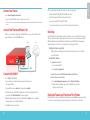 2
2
-
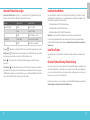 3
3
-
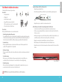 4
4
-
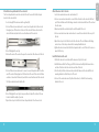 5
5
-
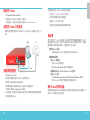 6
6
-
 7
7
-
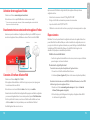 8
8
-
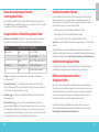 9
9
-
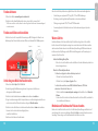 10
10
-
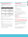 11
11
-
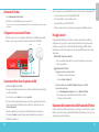 12
12
-
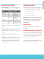 13
13
-
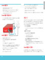 14
14
-
 15
15
-
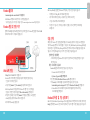 16
16
-
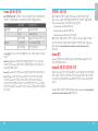 17
17
-
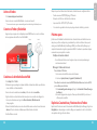 18
18
-
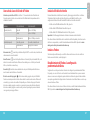 19
19
-
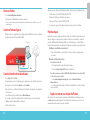 20
20
-
 21
21
-
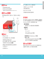 22
22
-
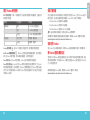 23
23
-
 24
24
-
 25
25
-
 26
26
-
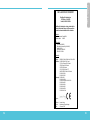 27
27
-
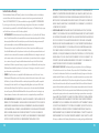 28
28
-
 29
29


Watchguard Firebox M4600 Guía de inicio rápido
- Tipo
- Guía de inicio rápido
En otros idiomas
Documentos relacionados
-
Watchguard Firebox T15/T15-W Guía de inicio rápido
-
-
-
-
-
-
-
-
-