La página se está cargando...

LOW PASS FILTER MOD.FA2-LP AND HIGH
PASS FILTER MOD.FA2-HP. CONNECTION
INSTRUCTION.
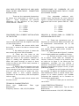
There are four assignable frequencies
by means of a mini-jumper, as shown in the
figure 1. These frequencies are selected
depending on the positions of the jumper
circuit FA2-LP / FA2-HP:
A = 100Hz
B = 125Hz
C = 150Hz
D = 200Hz
PROCEDURE FOR A CORRECT INSTALLATION
OF THE FILTER
A -All operations described herein
must be performed with the amplifier switched
off from mains power.
B -Remove the screws which hold
the cover, in order to be able to access inside
the device.
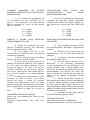
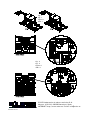
C -By looking at figure 2, locate the
area where the circuit will be installed.
D -There are four holes on the
chassis, where the circuit must be inserted.
Place the circuit in the position indicated in
figure 2, making the separators match the
holes and press strongly on each of them
(never do that on the circuit itself, because it
could be damaged!).
E -Extract the mini-jumpers from the
input circuit. If you wish to remove the filter
circuit anytime in the future, take into account
that you will also have to place the mini-
jumpers back in their original positions
(extremes of the connector), else the amplifier
will not work.
F -Plug the cable which comes with
the filter circuit.
TECHNICAL CHARACTERISTICS
Filters slop: 18dB/octave. Filter type
Butterworth.
Frequency selector: 100,125,150,200Hz.
INSTRUCCIONES DE CONEXIÓN DE L0S
FILTROS PASA BAJOS MOD. FA2-LP Y PASA
ALTOS MOD. FA2-HP.
Son asignables mediante mini-
jumper cuatro frecuencias tal como indica la
figura 1. Dichas frecuencias vienen dadas por
la posición del circuito puente FA2-LP / FA2-
HP:
A = 100Hz
B = 125Hz
C = 150Hz
D = 200Hz
PROCESO A SEGUIR PARA LA CORRECTA
INSTALACIÓN DEL FILTRO
A -Todas las operaciones que se
describen a continuación deben efectuarse con
el amplificador desconectado de la red
eléctrica.
B -Quitar previamente los tornillos
que sujetan la tapa para poder acceder al
interior del aparato.
C -Con ayuda de la figura 2, localizar
la zona donde deberá ser instalado el circuito.
D -Existen previstos cuatro orificios
en el chasis, donde debe ser insertado el
circuito. Colocar el mismo en la posición que
se indica en la figura 2, de forma que los
separadores coincidan con los orificios y
presionar fuertemente sobre cada uno de los
mismos, nunca sobre el propio circuito, ya que
podríamos dañarlo.
E -Extraer los mini-jumper del circuito
de entradas. Si alguna vez deseamos retirar el
filtro deberemos volver a colocar dichos mini-
jumper en la misma posición que estaban
(extremos del conector), de lo contrario no
funcionará el amplificador.
F -Colocar el cable que se suministra
con el filtro.
CARACTERÍSTICAS TÉCNICAS
Pendiente filtros: 18dB/octava. Tipo de filtro
Butterworth.
Selector de frecuencia: 100,125,150,200Hz.
La página se está cargando...

ECLER Laboratorio de electroacústica S.A.
Motors 166168, 08038 Barcelona, Spain
INTERNET http://www.ecler.es Email: info@ecler.es
50.0027.02.00
Fig. 1
Fig. 1
Figure 1
Abb. 1
Fig. 2
Fig. 2
Figure 2
Abb. 2
Transcripción de documentos
LOW PASS FILTER MOD.FA2-LP AND HIGH PASS FILTER MOD.FA2-HP. CONNECTION INSTRUCTION. INSTRUCCIONES DE CONEXIÓN DE L0S FILTROS PASA BAJOS MOD. FA2-LP Y PASA ALTOS MOD. FA2-HP. There are four assignable frequencies by means of a mini-jumper, as shown in the figure 1. These frequencies are selected depending on the positions of the jumper circuit FA2-LP / FA2-HP: Son asignables mediante minijumper cuatro frecuencias tal como indica la figura 1. Dichas frecuencias vienen dadas por la posición del circuito puente FA2-LP / FA2HP: A = 100Hz B = 125Hz C = 150Hz D = 200Hz A = 100Hz B = 125Hz C = 150Hz D = 200Hz PROCEDURE FOR A CORRECT INSTALLATION OF THE FILTER PROCESO A SEGUIR PARA LA CORRECTA INSTALACIÓN DEL FILTRO A -All operations described herein must be performed with the amplifier switched off from mains power. B -Remove the screws which hold the cover, in order to be able to access inside the device. C -By looking at figure 2, locate the area where the circuit will be installed. D -There are four holes on the chassis, where the circuit must be inserted. Place the circuit in the position indicated in figure 2, making the separators match the holes and press strongly on each of them (never do that on the circuit itself, because it could be damaged!). E -Extract the mini-jumpers from the input circuit. If you wish to remove the filter circuit anytime in the future, take into account that you will also have to place the minijumpers back in their original positions (extremes of the connector), else the amplifier will not work. F -Plug the cable which comes with the filter circuit. A -Todas las operaciones que se describen a continuación deben efectuarse con el amplificador desconectado de la red eléctrica. B -Quitar previamente los tornillos que sujetan la tapa para poder acceder al interior del aparato. C -Con ayuda de la figura 2, localizar la zona donde deberá ser instalado el circuito. D -Existen previstos cuatro orificios en el chasis, donde debe ser insertado el circuito. Colocar el mismo en la posición que se indica en la figura 2, de forma que los separadores coincidan con los orificios y presionar fuertemente sobre cada uno de los mismos, nunca sobre el propio circuito, ya que podríamos dañarlo. E -Extraer los mini-jumper del circuito de entradas. Si alguna vez deseamos retirar el filtro deberemos volver a colocar dichos minijumper en la misma posición que estaban (extremos del conector), de lo contrario no funcionará el amplificador. F -Colocar el cable que se suministra con el filtro. TECHNICAL CHARACTERISTICS Filters slop: 18dB/octave. Filter type Butterworth. Frequency selector: 100,125,150,200Hz. CARACTERÍSTICAS TÉCNICAS Pendiente filtros: 18dB/octava. Tipo de filtro Butterworth. Selector de frecuencia: 100,125,150,200Hz. Fig. 1 Fig. 1 Figure 1 Abb. 1 Fig. 2 Fig. 2 Figure 2 Abb. 2 ECLER Laboratorio de electroacústica S.A. Motors 166168, 08038 Barcelona, Spain INTERNET http://www.ecler.es Email: [email protected] 50.0027.02.00-
 1
1
-
 2
2
-
 3
3
-
 4
4


Ecler FA2-LP Manual de usuario
- Tipo
- Manual de usuario
- Este manual también es adecuado para
en otros idiomas
- français: Ecler FA2-LP Manuel utilisateur
- English: Ecler FA2-LP User manual
- Deutsch: Ecler FA2-LP Benutzerhandbuch
Artículos relacionados
Otros documentos
-
Nice Automation F210B El manual del propietario
-
-
-
-
-
CAME ZL19A El manual del propietario
-
CAME ZL19N El manual del propietario