
WARRANTY
WE WARRANT THE LANDSCAPE PRODUCTS FEATURED IN OUR LANDSCAPE LIGHTING CATALOG (WITH THE EXCEPTION OF LIGHT BULBS) FOR FIVE YEARS AGAINST DEFECTS IN MATERIALS AND WORKMANSHIP IF IT WAS PROPERLY
INSTALLED AND FAILED UNDER NORMAL OPERATING CONDITIONS, PROVIDED IT IS RETURNED TO THE POINT OF PURCHASE, WHERE IT WILL BE REPAIRED OR, AS IT MAY BE DETERMINED, TO REPLACE THE LANDSCAPE PRODUCT OR
PARTS USED ON THAT PRODUCT.
GARANTIA
NOSOTROS GARANTIZAMOS POR CINCO ANOS LOS PRODUCTOS PANORAMICOS QUE OFRECEMOS EN NUESTRO CATALOGO DE ILUMINACION PANORAMICA (CON EXCEPCION DE LAS BOMBILLAS), QUE ESTAN EXENTOS DE DEFECTOS
DE MATERIALES Y MANO DE OBRA, SI SE INSTALARON CORRECTAMIENTE Y FALLARON EN CONDICIONES DE OPERACION NORMAL, SIEMPRE QUE SE DEVUELVAN AL LUGAR DE COMPRA, DONDE SERAN REPARADOS O, SEGUN PUEDA
DETERMINARSE, SERAN CAMBIADOS LOS PRODUCTOS PANORAMICOS O LAS PIEZAS UTILIZADAS EN ESE PRODUCTO.
INSTRUCTIONS PERTAINING TO A RISK OF FIRE,OR INJURY TO PERSONS
IMPORTANT SAFETY INSTRUCTIONS
Lighted lamp is HOT!
WARNING — To reduce the risk of FIRE OR INJURY TO PERSONS.
1) Turn off / unplug and allow to cool before replacing lamp.
2) Lamp gets HOT quickly! Contact only switch / plug when turning on.
3) Do not touch hot lens or cowl.
4) Do not remain in light if skin feels warm. (Light is intense, it may cause “sunburn”.)
5) Do not look directly at lighted lamp.
6) Keep lamp away from materials that may burn.
7) Use only with wattage and lamp marked on fixture.
8) Do not touch the inner glass envelope of the lamp at any time. Use a soft cloth. Oil from skin may
damage lamp.
9) Do not operate the fixture with a damaged or missing lens.
SAFETY INSTRUCTIONS
READ THIS FIRST
KEEP THESE INSTRUCTIONS
This fixture is intended for installation in accordance with the National
Electric Code (NEC) and Local code specifications. Failure to adhere to
these codes and instructions may result in serious injury and/or property damage and will void
the warranty.
1) WARNING: This fixture is not to be installed within 10 feet (3M) of a pool, spa or fountain.
2) This fixture is to be used only with a power unit (transformer) rated a maximum of 300 W (25 AMPS)
15 volts.
3) According to the requirements of the National Electric Code (NEC), direct burial rated wire is to be buried
a minimum of 6” [152mm] beneath the surface of the ground.
NOTE: If additional Direct Burial wire is needed, contact your local Kichler landscape distributor.
•8GAwirecanbepurchasedinlengthof250’(76M),15503-BK.
•10GAwirecanbepurchasedinlengthof250’(76M),15504-BK.
•12GAwirecanbepurchasedinlengthsof100’(30M),15501-BK;250’(76M),15502-BK;500’
(152M),15505-BK;and1000’(304M),15506-BK.
4) Fixture shall not use a tungsten halogen lamp unless the fixture is marked for use with such lamps.
Date Issued: 215/08 IS-15773-US
SAVE THESE INSTRUCTIONS
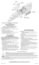
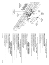
INSTALLATION AND ASSEMBLY IN BRICK WALL (SEE FIG. 1)
Before Starting:
A) Desired location for each fixture should be determined before construction of wall is started.
B) If access to back of wall is limited, cable/conduit should be run prior to construction.
1) Turn off power.
2) Assemble brackets to bottom of housing using washers and screws.
3) Knock off corner of brick on either side or below housing for cable/conduit entry and exit.
4) Screw supplied 1/2 NPT plugs into holes in housing not being used for wire passage.
5) Remove socket bracket from inside of housing.
6) Mortar housing into place noting the following items:
A) Supply wire may need to be run into housing at this time, if so pull supply wire through appropriate
hole in housing and secure cable/conduit to housing using a suitable connector.
B) Embed lower brackets in mortar.
C) Mortar housing into place as it if were a brick.
D)Allowmortartocurebeforewiringandre-assemblingbricklight.
7) Continue building wall, installing remaining housing as specified above.
NOTE: Before the coarse of brick over housing is laid, attach brackets to top of housing using washers
and screws.
CAUTION: When securing brackets, do not apply a lot of pressure or force. This may damage
uncured mortar.
8) Allow wall to cure.
9) Makewireconnections(connectorsnotprovided.)Thisxtureusesanon-polarizedsocket.Each
supply wire may be connected to either fixture wire.
10) Push socket bracket into housing and secure in place with screws.
11) Insert recommended lamps.
12) Assemble cover/lens to housing.
INSTALLATION AND ASSEMBLY IN WOOD WALL OR STAIR (SEE FIG. 2)
Before Starting:
A) Desired location for each fixture should be determined before construction of wall is started.
B) If access to back of wall or stair is limited, cable/conduit should be run prior to construction.
1) Turn off power.
2) Locate and cut opening, 2.75” (70mm) x 8.38” (213mm), at desired location in wall or stair tread.
3) Screw supplied 1/2 NPT plugs into holes in housing not being used for wire passage.
4) Remove bracket from inside of housing.
A) Supply wire may need to be run into housing at this time, if so pull supply wire through appropriate
hole in housing and secure cable/conduit to housing using a suitable connector.
5) Insert housing into opening. Attach (4) “L” brackets as shown using machine screws provided. Brackets
should clamp wall between housing and brackets.
A) Wood screws (not provided) may be used to fasten “L” brackets to wall if desired.
6) Finish wall or stair construction if necessary.
7) Makewireconnections(connectorsnotprovided.)Thisxtureusesanon-polarizedsocket.Each
supply wire may be connected to either fixture wire.
8) Push socket bracket into housing and secure in place with screws.
9) Assemble cover/lens to housing.
INSTRUCCIONESPERTINENTESAUNRIESGODEICENDIOOLESIONA
LAS PERSONAS
INSTRUCCIONES IMPORTANTES DE SEGURIDAD
¡La lámpara encendida es CALIENTE!
ADVERTENCIA — Para disminuir el riesgo de INCENDIO O LESION A LAS PERSONAS.
1) Apague / desenchufe y deje que se enfríe antes de cambiar la lámpara.
2) ¡La lámpara se CALIENTA rápidamente! Haga contacto del conmutador/enchufe sólo cuando encienda.
3) No toque la lente o la capucha caliente.
4) Nopermanezcaenlaluzsisientetibialapiel.(Laluzesintensa,puedecausar“quemadurasdesol”).
5) No mire directamente a la lámpara encendida.
6) Mantenga la lámpara alejada de los materiales que puedan encenderse.
7) Use solamente con el vatiaje y la lámpara marcados en el artefacto.
8) No toque el vidrio del interior de la lámpara en ningún momento. Use un paño suave. El aceite del
cuerpo puede dañar la lámpara.
9) No haga funcionar el artefacto con una lente dañada o faltante.
INSTRUCCIONES DE SEGURIDAD
Primero lea esto
Guarde estas instrucciones
Este artefacto se debe instalar de acuerdo con el Código Eléctrico Nacional (NEC, por sus siglas
en inglés) y con las especificaciones del código local. No cumplir con estos códigos e instruc-
ciones puede resultar en lesiones graves y/ o en daños a la propiedad y anulará la garantía.
1) ADVERTENCIAERTENCIA: Este artefacto no debe instalarse a menos de 10 pies (3 m) de una piscina
(alberca), spa o fuente.
2) Esteartefactodebeutilizarsesolamenteconunaunidaddepotencia(tranformador)concapacidad
nominal máxima de 300 vatios (25 amp.) 15 voltios.
3) De acuerdo con los requisitos del Código Eléctrico Nacional (NEC por sus siglas en inglés), el alambre
clasificado para soterrado directo se debe enterrar un mínimo de 6 pulgadas [152 mm.] debajo de la
superficie del terreno.
•Elalambrecalibre8puedecomprarseenlongitudde250’(76m.),15503-BK
•Elalambrecalibre10puedecomprarseenlongitudde250’(76m.),15504-BK
•Elalambrecalibre12puedecomprarseenlongitudesde75’(22m.),15550-BK;100’(30m.),
15501-BK;250’(76m.),15502-BK;500’(152m.),15505-BK;y1000’(304m.),15506-BK.
4) Elartefactonodebeutilizarseconlámparasdehalógeno,amenossqueelartefactoestémarcado
para usar con tales lámparas.
GUARDE ESTAS INSTRUCCIONES
INSTALACIÓN Y MONTAJE EN UNA PARED DE LADRILLO (VEA LA FIG. 1)
Antes de empezar:
A)Debedeterminarseellugardeseadoparacadaartefactoantesdeempezarlaconstruccióndela
pared.
B) Si el acceso a la parte posterior de la pared está limitado, el cable/conducto debe instalarse antes de
la construcción.
1) Apague la alimentación eléctrica.
2) Monte los apoyos en la parte inferior de la cubierta usando arandelas y tornillos.
3) Saque la esquina del ladrillo en cada lado o debajo de la cubierta para la entrada y salida del cable/
conducto.
4) Atornille los tapones de 1/2 NPT suministrados, en los agujeros de la cubierta que no se estén
usando para el paso del alambre.
5) Quite el apoyo del enchufe del interior de la cubierta.
6) Instale con mortero en el lugar teniendo en cuenta los siguientes puntos:
A)Puedesernecesarioqueelalambredealimentaciónseinstaleenlacubiertaenestemomento;
si es así, estire el alambre de alimentación a través del agujero apropiado en la cubierta y asegure
el cable/conducto a la cubierta usando un conector apropiado.
B) Encaje los apoyos inferiores en el mortero.
C) Instale con mortero la cubierta en el lugar como si fuera un ladrillo.
D)Dejequefragueelmorteroantesdealambraryvolveramontarlaluz.
7) Siga construyendo la pared, instalando la cubierta restante como se especifica más arriba.
NOTA: Antes de colocar la hilada de ladrillo sobre la cubierta, una los apoyos a la parte superior
de la cubierta usando arandelas y tornillos. PRECAUCIÓN: Al asegurar los apoyos, no aplique
muchapresiónofuerza.Estopuededañarelmorteronofraguado.
8) Deje que frague la pared.
9) Haga las conexiones de alambres (no se proporcionan conectores). Este artefacto usa un enchufe
nopolarizado.Cadaalambredealimentaciónpuedeconectarseacualquieradelosalambresdel
artefacto.
10) Empuje el apoyo del enchufe en la cubierta y asegure en el lugar con tornillos.
11) Instale las lámparas recomendadas.
12) Monte la tapa/lente a la cubierta.
INSTALACIÓN Y MONTAJE EN UNA PARED DE MADERA O ESCALERA (VEA LA FIG. 2)
Antes de empezar:
A)Debedeterminarseellugardeseadoparacadaartefactoantesdeempezarlaconstruccióndela
pared.
B) Si el acceso a la parte posterior de la pared o escalera es limitado, el cable / conducto se debe
instalar antes de la construcción.
1) Apague la alimentación eléctrica.
2) Localice y corte la abertura, 2.75” (70 mm.) x 8.38” (213 mm.), en el lugar deseado, en la pared o
en el peldaño de la escalera.
3) Atornille los tapones de 1/2 NPT suministrados, en los agujeros de la cubierta que no se estén
usando para el paso del alambre.
4) Quite el apoyo del enchufe del interior de la cubierta.
A)Puedesernecesarioqueelalambredealimentaciónseinstaleenlacubiertaenestemomento;
si es así, estire el alambre de alimentación a través del agujero apropiado en la cubierta y asegure
el cable/conducto a la cubierta usando un conector apropiado.
5) Insertelaenvueltaenlaabertura.Acople(4)soportes“L”comosemuestrautilizandolostornillos
para chapas que se proveen. Los soportes se deben grapar a la pared entre la envuelta y los soportes.
A) Tornillos para madera (no se proveen) se pueden usar para sujetar los soportes “L” a la pared, si
se desea.
6) Termine la construcción de la pared o escalera si es necesario.
7) Haga las conexiones de alambres (no se proporcionan conectores). Este artefacto usa un enchufe
nopolarizado.Cadaalambredealimentaciónpuedeconectarseacualquieradelosalambresdel
artefacto.
8) Empuje el apoyo del enchufe en la cubierta y asegure en el lugar con tornillo.
9) Monte la tapa/lente a la cubierta.
WASHER
ARANDELA
SCREW
TORNILLO
COVER/LENS
TAPA/LENTE
SOCKET BRACKET
APOYO DEL ENCHUFE
BRACKET
APOYO
SCREW
TORNILLO
HOUSING
CUBIERTA
FIG. 1 FIG. 2
(4) MACHINE SCREWS
(4) TORNILLOS PARA
CHAPAS
WOOD SCREWS
(NOT PROVIDED)
TORNILLOS PARA MADERA
(NO SE PROVEEN)
(4)‘L’BRACKET
(4) SOPORTES “L”
Transcripción de documentos
FIG. 1 SCREW TORNILLO FIG. 2 WASHER ARANDELA BRACKET APOYO HOUSING CUBIERTA (4) MACHINE SCREWS (4) TORNILLOS PARA CHAPAS WOOD SCREWS (NOT PROVIDED) TORNILLOS PARA MADERA (NO SE PROVEEN) COVER/LENS TAPA/LENTE (4) ‘L’ BRACKET (4) SOPORTES “L” SCREW TORNILLO SOCKET BRACKET APOYO DEL ENCHUFE INSTRUCCIONES PERTINENTES A UN RIESGO DE ICENDIO O LESION A LAS PERSONAS INSTRUCCIONES IMPORTANTES DE SEGURIDAD ¡La lámpara encendida es CALIENTE! INSTRUCTIONS PERTAINING TO A RISK OF FIRE,OR INJURY TO PERSONS IMPORTANT SAFETY INSTRUCTIONS Lighted lamp is HOT! WARNING — To reduce the risk of FIRE OR INJURY TO PERSONS. Turn off / unplug and allow to cool before replacing lamp. Lamp gets HOT quickly! Contact only switch / plug when turning on. Do not touch hot lens or cowl. Do not remain in light if skin feels warm. (Light is intense, it may cause “sunburn”.) Do not look directly at lighted lamp. Keep lamp away from materials that may burn. Use only with wattage and lamp marked on fixture. Do not touch the inner glass envelope of the lamp at any time. Use a soft cloth. Oil from skin may damage lamp. 9) Do not operate the fixture with a damaged or missing lens. 1) 2) 3) 4) 5) 6) 7) 8) SAFETY INSTRUCTIONS READ THIS FIRST KEEP THESE INSTRUCTIONS This fixture is intended for installation in accordance with the National Electric Code (NEC) and Local code specifications. Failure to adhere to these codes and instructions may result in serious injury and/or property damage and will void the warranty. 1) WARNING: This fixture is not to be installed within 10 feet (3M) of a pool, spa or fountain. 2) This fixture is to be used only with a power unit (transformer) rated a maximum of 300 W (25 AMPS) 15 volts. 3) According to the requirements of the National Electric Code (NEC), direct burial rated wire is to be buried a minimum of 6” [152mm] beneath the surface of the ground. NOTE: If additional Direct Burial wire is needed, contact your local Kichler landscape distributor. • 8 GA wire can be purchased in length of 250’ (76 M), 15503-BK. • 10 GA wire can be purchased in length of 250’ (76 M), 15504-BK. • 12 GA wire can be purchased in lengths of 100’ (30 M), 15501-BK; 250’ (76 M), 15502-BK; 500’ (152M), 15505-BK; and 1000’ (304 M), 15506-BK. 4) Fixture shall not use a tungsten halogen lamp unless the fixture is marked for use with such lamps. SAVE THESE INSTRUCTIONS INSTALLATION AND ASSEMBLY IN BRICK WALL (SEE FIG. 1) Before Starting: A) Desired location for each fixture should be determined before construction of wall is started. B) If access to back of wall is limited, cable/conduit should be run prior to construction. 1) Turn off power. 2) Assemble brackets to bottom of housing using washers and screws. 3) Knock off corner of brick on either side or below housing for cable/conduit entry and exit. 4) Screw supplied 1/2 NPT plugs into holes in housing not being used for wire passage. 5) Remove socket bracket from inside of housing. 6) Mortar housing into place noting the following items: A) Supply wire may need to be run into housing at this time, if so pull supply wire through appropriate hole in housing and secure cable/conduit to housing using a suitable connector. B) Embed lower brackets in mortar. C) Mortar housing into place as it if were a brick. D) Allow mortar to cure before wiring and re-assembling brick light. 7) Continue building wall, installing remaining housing as specified above. NOTE: Before the coarse of brick over housing is laid, attach brackets to top of housing using washers and screws. CAUTION: When securing brackets, do not apply a lot of pressure or force. This may damage uncured mortar. 8) Allow wall to cure. 9) Make wire connections (connectors not provided.) This fixture uses a non-polarized socket. Each supply wire may be connected to either fixture wire. 10) Push socket bracket into housing and secure in place with screws. 11) Insert recommended lamps. 12) Assemble cover/lens to housing. INSTALLATION AND ASSEMBLY IN WOOD WALL OR STAIR (SEE FIG. 2) Before Starting: A) Desired location for each fixture should be determined before construction of wall is started. B) If access to back of wall or stair is limited, cable/conduit should be run prior to construction. 1) Turn off power. 2) Locate and cut opening, 2.75” (70mm) x 8.38” (213mm), at desired location in wall or stair tread. 3) Screw supplied 1/2 NPT plugs into holes in housing not being used for wire passage. 4) Remove bracket from inside of housing. A) Supply wire may need to be run into housing at this time, if so pull supply wire through appropriate hole in housing and secure cable/conduit to housing using a suitable connector. 5) Insert housing into opening. Attach (4) “L” brackets as shown using machine screws provided. Brackets should clamp wall between housing and brackets. A) Wood screws (not provided) may be used to fasten “L” brackets to wall if desired. 6) Finish wall or stair construction if necessary. 7) Make wire connections (connectors not provided.) This fixture uses a non-polarized socket. Each supply wire may be connected to either fixture wire. 8) Push socket bracket into housing and secure in place with screws. 9) Assemble cover/lens to housing. ADVERTENCIA — Para disminuir el riesgo de INCENDIO O LESION A LAS PERSONAS. Apague / desenchufe y deje que se enfríe antes de cambiar la lámpara. ¡La lámpara se CALIENTA rápidamente! Haga contacto del conmutador/enchufe sólo cuando encienda. No toque la lente o la capucha caliente. No permanezca en la luz si siente tibia la piel. (La luz es intensa, puede causar “quemaduras de sol”). No mire directamente a la lámpara encendida. Mantenga la lámpara alejada de los materiales que puedan encenderse. Use solamente con el vatiaje y la lámpara marcados en el artefacto. No toque el vidrio del interior de la lámpara en ningún momento. Use un paño suave. El aceite del cuerpo puede dañar la lámpara. 9) No haga funcionar el artefacto con una lente dañada o faltante. 1) 2) 3) 4) 5) 6) 7) 8) INSTRUCCIONES DE SEGURIDAD Primero lea esto Guarde estas instrucciones Este artefacto se debe instalar de acuerdo con el Código Eléctrico Nacional (NEC, por sus siglas en inglés) y con las especificaciones del código local. No cumplir con estos códigos e instrucciones puede resultar en lesiones graves y/ o en daños a la propiedad y anulará la garantía. 1) Advertenciaertencia: Este artefacto no debe instalarse a menos de 10 pies (3 m) de una piscina (alberca), spa o fuente. 2) Este artefacto debe utilizarse solamente con una unidad de potencia (tranformador) con capacidad nominal máxima de 300 vatios (25 amp.) 15 voltios. 3) De acuerdo con los requisitos del Código Eléctrico Nacional (NEC por sus siglas en inglés), el alambre clasificado para soterrado directo se debe enterrar un mínimo de 6 pulgadas [152 mm.] debajo de la superficie del terreno. • El alambre calibre 8 puede comprarse en longitud de 250’ (76 m.), 15503-BK • El alambre calibre 10 puede comprarse en longitud de 250’ (76 m.), 15504-BK • El alambre calibre 12 puede comprarse en longitudes de 75’ (22 m.), 15550-BK; 100’ (30 m.), 15501-BK; 250’ (76 m.), 15502-BK; 500’ (152 m.), 15505-BK; y 1000’ (304 m.), 15506-BK. 4) El artefacto no debe utilizarse con lámparas de halógeno, a menoss que el artefacto esté marcado para usar con tales lámparas. GUARDE ESTAS INSTRUCCIONES INSTALACIÓN Y MONTAJE EN UNA PARED DE LADRILLO (VEA LA FIG. 1) Antes de empezar: A) Debe determinarse el lugar deseado para cada artefacto antes de empezar la construcción de la pared. B) Si el acceso a la parte posterior de la pared está limitado, el cable/conducto debe instalarse antes de la construcción. 1) Apague la alimentación eléctrica. 2) Monte los apoyos en la parte inferior de la cubierta usando arandelas y tornillos. 3) Saque la esquina del ladrillo en cada lado o debajo de la cubierta para la entrada y salida del cable/ conducto. 4) Atornille los tapones de 1/2 NPT suministrados, en los agujeros de la cubierta que no se estén usando para el paso del alambre. 5) Quite el apoyo del enchufe del interior de la cubierta. 6) Instale con mortero en el lugar teniendo en cuenta los siguientes puntos: A) Puede ser necesario que el alambre de alimentación se instale en la cubierta en este momento; si es así, estire el alambre de alimentación a través del agujero apropiado en la cubierta y asegure el cable/conducto a la cubierta usando un conector apropiado. B) Encaje los apoyos inferiores en el mortero. C) Instale con mortero la cubierta en el lugar como si fuera un ladrillo. D) Deje que frague el mortero antes de alambrar y volver a montar la luz. 7) Siga construyendo la pared, instalando la cubierta restante como se especifica más arriba. NOTA: Antes de colocar la hilada de ladrillo sobre la cubierta, una los apoyos a la parte superior de la cubierta usando arandelas y tornillos. PRECAUCIÓN: Al asegurar los apoyos, no aplique mucha presión o fuerza. Esto puede dañar el mortero no fraguado. 8) Deje que frague la pared. 9) Haga las conexiones de alambres (no se proporcionan conectores). Este artefacto usa un enchufe no polarizado. Cada alambre de alimentación puede conectarse a cualquiera de los alambres del artefacto. 10) Empuje el apoyo del enchufe en la cubierta y asegure en el lugar con tornillos. 11) Instale las lámparas recomendadas. 12) Monte la tapa/lente a la cubierta. INSTALACIÓN Y MONTAJE EN UNA PARED DE MADERA O ESCALERA (VEA LA FIG. 2) Antes de empezar: A) Debe determinarse el lugar deseado para cada artefacto antes de empezar la construcción de la pared. B) Si el acceso a la parte posterior de la pared o escalera es limitado, el cable / conducto se debe instalar antes de la construcción. 1) Apague la alimentación eléctrica. 2) Localice y corte la abertura, 2.75” (70 mm.) x 8.38” (213 mm.), en el lugar deseado, en la pared o en el peldaño de la escalera. 3) Atornille los tapones de 1/2 NPT suministrados, en los agujeros de la cubierta que no se estén usando para el paso del alambre. 4) Quite el apoyo del enchufe del interior de la cubierta. A) Puede ser necesario que el alambre de alimentación se instale en la cubierta en este momento; si es así, estire el alambre de alimentación a través del agujero apropiado en la cubierta y asegure el cable/conducto a la cubierta usando un conector apropiado. 5) Inserte la envuelta en la abertura. Acople (4) soportes “L” como se muestra utilizando los tornillos para chapas que se proveen. Los soportes se deben grapar a la pared entre la envuelta y los soportes. A) Tornillos para madera (no se proveen) se pueden usar para sujetar los soportes “L” a la pared, si se desea. 6) Termine la construcción de la pared o escalera si es necesario. 7) Haga las conexiones de alambres (no se proporcionan conectores). Este artefacto usa un enchufe no polarizado. Cada alambre de alimentación puede conectarse a cualquiera de los alambres del artefacto. 8) Empuje el apoyo del enchufe en la cubierta y asegure en el lugar con tornillo. 9) Monte la tapa/lente a la cubierta. WARRANTY WE WARRANT THE LANDSCAPE PRODUCTS FEATURED IN OUR LANDSCAPE LIGHTING CATALOG (WITH THE EXCEPTION OF LIGHT BULBS) FOR FIVE YEARS AGAINST DEFECTS IN MATERIALS AND WORKMANSHIP IF IT WAS PROPERLY INSTALLED AND FAILED UNDER NORMAL OPERATING CONDITIONS, PROVIDED IT IS RETURNED TO THE POINT OF PURCHASE, WHERE IT WILL BE REPAIRED OR, AS IT MAY BE DETERMINED, TO REPLACE THE LANDSCAPE PRODUCT OR PARTS USED ON THAT PRODUCT. GARANTIA NOSOTROS GARANTIZAMOS POR CINCO ANOS LOS PRODUCTOS PANORAMICOS QUE OFRECEMOS EN NUESTRO CATALOGO DE ILUMINACION PANORAMICA (CON EXCEPCION DE LAS BOMBILLAS), QUE ESTAN EXENTOS DE DEFECTOS DE MATERIALES Y MANO DE OBRA, SI SE INSTALARON CORRECTAMIENTE Y FALLARON EN CONDICIONES DE OPERACION NORMAL, SIEMPRE QUE SE DEVUELVAN AL LUGAR DE COMPRA, DONDE SERAN REPARADOS O, SEGUN PUEDA DETERMINARSE, SERAN CAMBIADOS LOS PRODUCTOS PANORAMICOS O LAS PIEZAS UTILIZADAS EN ESE PRODUCTO. Date Issued: 215/08 IS-15773-US-
 1
1
Kichler Lighting 15773AZT27R Manual de usuario
- Tipo
- Manual de usuario
- Este manual también es adecuado para
en otros idiomas
Artículos relacionados
-
 Kichler Lighting 15073AZT Manual de usuario
-
 Kichler Lighting 15073AZT Manual de usuario
-
 Kichler Lighting 15679BK Manual de usuario
-
Kichler Lighting 16102AZT27 Manual de usuario
-
 Kichler Lighting 16141CBR27 Manual de usuario
-
 Kichler Lighting 15488BK Manual de usuario
-
 Kichler Lighting 15495CBR Manual de usuario
-
 Kichler Lighting 15764WHT27R Manual de usuario
-
 Kichler Lighting 15064AZT Manual de usuario
-
Kichler Lighting 15788CBR Manual de usuario


