La página se está cargando...

SAFETY INSTRUCTIONS
READ THIS FIRST
KEEP THESE INSTRUCTIONS
This fixture is intended for installation in accordance with the
National Electric Code (NEC) and Local code specifications.
Failure to adhere to these codes and instructions may result in
serious injury and/or property damage and will void the warranty.
1) WARNING: This fixture is not to be installed within 10 feet (3M)
of a pool, spa or fountain.
2) This fixture is to be used only with a power unit (transformer)
rated a maximum of 300 W (25 AMPS) 15 volts.
3) The #18 ga. fixture wire is not intended for direct burial.
4) Direct burial rated wire is to be buried a minimum of 6"
(152mm) beneath the surface of the ground.
NOTE: If additional Direct Burial wire is needed, contact your
local Kichler
®
landscape distributor.
•8GAwirecanbepurchasedinlengthof250’(76M),15503-BK.
•10GAwirecanbepurchasedinlengthof250’(76M),
15504-BK.
•12GAwirecanbepurchasedinlengthsof100’(30M),
15501-BK;250’(76M),15502-BK;500’(152M),15505-BK;and
1000’(304M),15506-BK.
5) Fixture shall not use a tungsten halogen lamp unless the fixture
is marked for use with such lamps.
6) Wiring connections must be made with approved/listed wire
connection device(s) suitable for the application. Do not exceed
manufacturers’wiringcombinationspecicationsforsizeand
quantity of conductors.
7) IMPORTANT: This fixture is not to be installed in series.
8) WARNING: Fixtures may have sharp edges or components.
Use caution when assembling or disassembling fixture.
CAUTION
WHEN INSTALLING KICHLER LANDSCAPE LIGHTING (LINE VOLTAGE OR LOW
VOLTAGE), CARE SHOULD BE TAKEN TO KEEP CLEAR OF POTENTIALLY COM-
BUSTIBLE MATERIALS.
WHEN MAINTAINING THE FIXTURES, BE SURE TO REMOVE LEAVES, PINE
NEEDLES, GRASS CLIPPINGS, MULCH, OR ANY DEBRIS THAT HAS ACCUMU-
LATED ON THE LIGHT BULB, LENS, OR BODY OF THE FIXTURE.
ASSEMBLY AND INSTALLATION
1) Loosen set screw on either side of fixture face (do not remove
screws completely) and remove face from housing.
2) Using fixture housing as a template determine desired location
for fixture and mark position of mounting holes on mounting
surface.
3) Drill 3/32" (2 mm) pilot holes in mounting surface at positions
marked. If using a wireway hole also drill that at this time.
Suggestedsize1/4"(6mm).
4) Hardscape (cement, brick, concrete, stone) install: Select a
drill bit slightly smaller than the diameter of the screw (suggested
maxscrewsize3/16").Drillpilotholeinmountingsurfaceat
marked position.
5) Secure fixture housing to mounting surface using provided
screws.
6) Reassemble fixture face to fixture housing.
7) TURN OFF POWER.
8) Make wire connections using supplied Kichler
®
Pro Series Wire
Connectors following instructions included, or using other
approved wiring connection method (not supplied.)
INSTRUCCIONES DE SEGURIDAD
PRIMERO LEA ESTO
GUARDE ESTAS INSTRUCCIONES
Este artefacto se debe instalar de acuerdo con el Código
Eléctrico Nacional (NEC, por sus siglas en inglés) y con las
especificaciones del código local. No cumplir con estos códigos
e instrucciones puede resultar en lesiones graves y/ o en daños
a la propiedad y anulará la garantía.
1) ADVERTENCIAERTENCIA: Este artefacto no debe instalarse a
menos de 10 pies (3 m) de una piscina (alberca), spa o fuente.
2) Esteartefactodebeutilizarsesolamenteconunaunidadde
potencia (tranformador) con capacidad nominal máxima de 300
vatios (25 amp.) 15 voltios.
3) El alambre del artefacto calibre No. 18 no es para soterrado
directo.
4) El alambre clasificado para soterrado directo se debe enterrar
un mínimo de 6 pulgadas (152 mm) debajo de la superficie del
terreno.
NOTA: Si necesita alambre de soterrado directo adicional, co
muníquese con su distribuidor local Kichler® de productos de
jardinería ornamental.
•Elalambrecalibre8puedecomprarseenlongitudde250’(76m.),
15503-BK
•Elalambrecalibre10puedecomprarseenlongitudde250’
(76m.),15504-BK
Date Issued: 2/13/15 IS-15764R-US
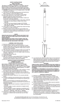
HOUSING
CUBIERTA PROTECTORA
FIXTURE FACE
CARA DEL ARTEFACTO
SCREW
TORNILLO
•Elalambrecalibre12puedecomprarseenlongitudesde75’
(22m.),15550-BK;100’(30m.),15501-BK;250’(76m.),15502-BK;
500’(152m.),15505-BK;y1000’(304m.),15506-BK.
5) Elartefactonodebeutilizarseconlámparasdehalógeno,a
menoss que el artefacto esté marcado para usar con tales
lámparas.
6) Las conexiones de cableado se deben hacer con las conexiones
del(los)dispositivos)deconexióndecableadoaprobados/de
lalista,adecuadosparalaaplicación.Noexcedalas
especicacionesdecombinacióndecableadodelfabricante
para el tamaño y cantidad de conductores.
7) IMPORTANTE: Este artefacto no debe ser instalado en serie.
8) ADVERTENCIA: Artefactos pueden tener bordes afilados o
componentes. Tenga cuidado al montar o desmontar artefacto.
PRECAUCION
CUANDO SE INSTALE SISTEMAS DE ALUMBRADO KICHLER PARA JARDINES (YA
SEA DE VOLTAJE DE LINEA O CON VOLTAJE BAJO) SE DEBE TENER CUIDADO DE
MAINTNERLOS ALEJADOS DE MATERIALES QUE PUEDAN SER COMBUSTIBLES
EN POTENCIA.
AL DAR SERVICIO DE MANTENIMIENTO A ESTOS SISTEMAS, ASEGURESE DE
DESPEJAR LAS HOJAS, CONOS DE PINO, RECORTES DEL PASTO, CUBIERTA DE
PAJA O CUALQUIER BASURA QUE SE HAYA ACUMULADO EN LA BOMBILLA DE
LUZ, EL LENTE O EL SOPORTE DE LA BOMBILLA.
MONTAJE E INSTALACIÓN
1) Afloje el tornillo opresor en cualquiera de los lados de la cara
del artefacto (no retire totalmente los tornillos) y retire la cara del
artefacto de la cubierta protectora.
2) Usandolacubiertaprotectoradelartefactocomopatrón,
determineellugardeseadodelartefactoymarquelaposición
de los agujeros de montaje en la superficie de montaje.
3) Perfore agujeros piloto de 3/32” (2 mm) en la superficie de
montajeenlasposicionesmarcadas.Siestáutilizandoun
agujero del canal de alambres también perfore ese en este
momento. Tamaño sugerido 1/4” (6 mm).
4) Instalaciónenlassuperciesduras(cemento,ladrillo,concreto,
piedra):Seleccioneunabrocadeperforaciónligeramentemás
pequeña que el diámetro del tornillo (3/16” – tamaño máximo
sugerido del tornillo). Perfore el agujero piloto en la superficie
demontajeenlaposiciónmarcada.
5) Sujete la cubierta protectora del artefacto a la superficie de
montaje usando los tornillos que se proveen.
6) Vuelva a montar la cara del artefacto a la cubierta protectora.
7) APAGUELAALIMENTACIÓNELÉCTRICA.
8) Haga las conexiones de cableado usando del conector de hilo (o
alambre) Kichler
®
Pro Series suministrado y siguiendo las
instruccionesdeincluidas,ousandootrométododeconexión
de cableado aprobado (no se suministra.) de cableado aprobado
(no se suministra.)
For warranty information please visit: http://www.landscapelighting.com/portal/warranty_page
Para informacion de ka garantia por favor visite: www.landscapelighting.com/portal/warranty_page
SET SCREW
TORNILLO OPRESOR
We’re here to help 866-558-5706
Hrs: M-F 9am to 5pm EST
/