La página se está cargando...

Instrucciones para la instalación,
el servicio y el mantenimiento
de los interruptores automáticos
abiertos de baja tensión
Installation, service and
maintenance instructions for
low voltage air circuit-breaker
Instrucciones para la instalación
y el servicio
Instructions for installation
and service
ABB SACE
ITSCB 601933/003 es-en 1-98
SACE Emax

N° Doc.
Doc. No.
Mod.
Rev.
M4379
SACE Emax
601933/003
Aparato
Apparatus
Dib.
Prep.
Titolo
Title
Aprobado
App.
Dep. Respon.
Resp. Dep.
Dep. Usuario
Take over dep.
Instrucciones para la instalación, el servicio y el
mantenimiento de los interruptores automáticos
abiertos de baja tensión
Installation, service and maintenance instructions
for low voltage air circuit-breaker
ABB SACE
Escala
Scale
Idioma
Lang.
es/en

N° Doc.
Doc. No.
Mod.
Rev.
M4379
SACE Emax
601933/003
Aparato
Apparatus
Escala
Scale
N° Pag.
Sh. No.
1/100
Index
1. Description page 4
1.1 General characteristics « 4
1.2 External front view of the circuit-breaker « 4
1.3 Circuit-breaker nameplate data « 4
1.4 Construction characteristics of the moving part « 5
1.5 Construction characteristics of the fixed part « 5
1.6 General characteristics of the microprocessor-based
releases « 6
2. Control on receipt « 7
3. Storage, lifting and weights « 7
4. Installation « 8
4.1 Installation ambient
«
8
4.2 Installation of fixed circuit-breaker « 8
4.3 Installation of the fixed part of withdrawable
circuit-breakers « 9
4.3.1 Preparation of the fixed part « 9
4.3.2 Installation « 10
4.4 Assembly of the flange on the compartment door « 10
5. Electrical connections « 11
5.1 Connections to the power circuit « 11
5.1.1 Terminals shapes « 11
5.1.2 Example of layout of the connection busbars
according to the type of teminals « 12
5.1.3 Assembly procedure for connection busbars « 13
5.2 Earthing « 14
5.3 Cabling the auxiliary circuits of the circuit-breaker « 14
5.3.1 Interfacing elements for fixed circuit-breaker « 14
5.3.2 Withdrawable circuit-breaker « 15
5.4 Conversion of the auxiliary contacts or position
contacts from normally closed (opening) to
normally open (closing) or vice versa « 16
6. Putting into service « 17
6.1 General procedures « 17
7. Instructions for use « 19
7.1 Operating and signalling parts « 19
7.2 Circuit-breaker closing and opening operations « 20
7.3 Racking-in and racking-out operations « 22
8. Maintenance « 25
8.1 Cautions « 25
8.2 Maintenance programme « 26
8.3 Maintenance operations « 26
8.3.1 Preliminary operations « 26
8.3.2 General inspection of the circuit-breaker
«
27
8.3.3 Checking contact wear « 28
8.3.4 Maintenance of the operating mechanism
«
28
9. Measures to be taken for any operating
anomalies « 30
10. Electrical accessories « 31
11. Overall dimensions and electrical circuit diagrams « 36
11.1 Dimensions « 36
11.2 Electrical circuit diagram « 45
12. PR111/LI-LSI-LSIG protection unit « 52
12.1 General « 52
12.2 Current sensors « 53
12.3 Protection functions « 53
12.3.1 Protection against overload with inverse
long time-delay (L) « 53
12.3.1.1 Selection of the threshold value (I1) « 53
12.3.1.2 Selection of the trip curve (t1) « 54
12.3.1.3 Example of setting « 54
12.3.2 Protection against short-circuit with short
time-delay (S) « 55
12.3.2.1 Selection of the threshold value (I2) « 55
Índice
1. Descripción pág. 4
1.1 Características generales del interruptor « 4
1.2 Vista frontal exterior del interruptor « 4
1.3 Datos nominales del interruptor « 4
1.4 Características de construcción de la parte móvil « 5
1.5 Características de construcción de la parte fija « 5
1.6 Características generales de los relés
con microprocesador « 6
2. Control durante la recepción « 7
3. Almacenaje, elevación y pesos « 7
4. Instalación « 8
4.1 Lugar de instalación « 8
4.2 Instalación del interruptor fijo « 8
4.3 Instalación de la parte fija del interruptor extraíble « 9
4.3.1 Preparación de la parte fija « 9
4.3.2 Instalación « 10
4.4 Instalación del marco en la puerta de la celda « 10
5. Conexiones eléctricas « 11
5.1 Conexiones al circuito de potencia « 11
5.1.1 Formas de los terminales « 11
5.1.2 Ejemplos de instalación de las barras de
conexión en función de los tipos de terminales « 12
5.1.3 Procedimientos para el montaje de las barras
de conexión « 13
5.2 Puesta a tierra « 14
5.3 Cableado de los circuitos auxiliares del interruptor « 14
5.3.1 Elementos de interfaz para interruptor fijo « 14
5.3.2 Interruptor extraíble « 15
5.4 Transformación de los contactos auxiliares o
de los contactos de posición de normalmente
cerrados (de apertura) a normalmente abiertos
(de cierre) o viceversa « 16
6. Puesta en servicio « 17
6.1 Procedimientos generales « 17
7. Normas de uso « 19
7.1 Órganos de maniobras y señalización « 19
7.2 Maniobras de cierre y de apertura del interruptor « 20
7.3 Maniobra de inserción y de extracción « 22
8. Mantenimiento « 25
8.1 Advertencias « 25
8.2 Programa de mantenimiento « 26
8.3 Operaciones de mantenimiento « 26
8.3.1 Operaciones preliminares « 26
8.3.2 Inspección general del interruptor « 27
8.3.3 Control del desgaste de los contactos « 28
8.3.4 Mantenimiento del mando « 28
9. Operaciones a efectuar en caso de posibles
anomalías de funcionamiento « 29
10. Accesorios elétricos « 31
11. Dimensiones generales y esquemas eléctricos « 36
11.1 Dimensiones generales « 36
11.2Esquemas eléctricos « 45
12. Unidad de protección PR111/LI - LSI - LSIG « 52
12.1Generalidades « 52
12.2 Sensores amperimétricos « 53
12.3 Funciones de protección « 53
12.3.1 Protección contra sobrecarga a tiempo largo
inverso (L) « 53
12.3.1.1 Selección del valor de umbral (I1) « 53
12.3.1.2Selección de la curva de actuación (t1) « 54
12.3.1.3 Ejemplo de programación « 54
12.3.2 Protección contra cortocircuito a tiempo
corto (S) « 55
12.3.2.1Selección del valor de umbral (I2) « 55

N° Doc.
Doc. No.
Mod.
Rev.
M4379
SACE Emax
601933/003
Aparato
Apparatus
Escala
Scale
N° Pag.
Sh. No.
2/100
12.3.2.2Selección del tipo de curva de actuación (t2) « 55
12.3.2.2.1 Curvas de actuación a tiempo corto inverso « 55
12.3.2.2.2 Curvas de actuación a tiempo independiente « 56
12.3.2.3Ejemplo de programación « 56
12.3.3 Protección contra cortocircuito instantáneo (I) « 57
12.3.3.1Selección del valor de umbral (I3) « 57
12.3.3.2Características del tiempo de actuación (t3) « 58
12.3.3.3Ejemplo de programación « 58
12.3.4 Protección contra defecto a tierra (G) « 58
12.3.4.1Selección del valor de umbral (I4) « 58
12.3.4.2Selección de la curva de actuación (t4) « 59
12.3.4.3Ejemplo de programación « 59
12.3.5 Protección de umbral fijo contra cortocircuito « 60
12.3.5.1 Selección del valor de umbral (Iinst) « 60
12.3.5.2Características del tiempo de actuación (tinst) « 61
12.4 Función de prueba de disparo « 61
12.5 Accesorios de la prueba de disparo TT1 « 61
12.6 Función del conector de prueba « 62
12.7 Marco del relé « 62
12.8 Curvas de actuación « 63
12.8.1 Curvas de actuación de la protección “L” « 63
12.8.2 Curvas de actuación de la protección “I” « 63
12.8.3 Curvas de actuación de la protección “S” « 64
12.8.4 Curvas de actuación de la protección “G” « 65
13. Unidad de protección SACE PR112/P-LSI-LSIG
y unidad de protección SACE PR112/PD - LSI
- LSIG « 66
13.1Generalidades « 66
13.2 Sensores amperimétricos « 66
13.2.1 Sensores amperimétricos de fase « 66
13.2.2 Transformador toroidal exterior
“Source Ground Return” « 67
13.3 Interfaz usuario « 67
13.3.1 Display y teclas función « 67
13.3.2 Señalizaciones ópticas « 69
13.3.3 Señalizaciones eléctricas « 69
13.3.4 Puesta a cero de las señalizaciones
ópticas y eléctricas « 69
13.3.5 Función de prueba « 70
13.3.6 Función Read / Edit « 71
13.3.7 Autodiagnóstico del microprocesador « 72
13.4Programación de los parámetros de funcionamiento « 72
13.4.1 Parámetros de configuración básica « 72
13.4.2 Parámetros de comunicación (sólo PR112/PD)
con protocolo INSUM « 77
13.4.3 Parámetros de protección « 78
13.4.4 Parámetros de medida « 82
13.4.5 Parámetros de control y información desde
la unidad SACE PR112/P « 82
13.4.6 Parámetros de control y información desde
la unidad SACE PR112/PD « 83
13.5 Mensajes de configuración equivocada y de alarma « 84
13.5.1 Configuraciones equivocadas « 84
13.5.2 Alarmas para funciones de protección en
temporización o intervenidas « 85
13.5.3 Alarmas generales desde la unidad
SACE PR112/P « 87
13.5.4 Alarmas generales desde la unidad
SACE PR112/D « 88
13.6 Funciones de protección « 88
13.6.1 Protección contra sobrecarga a
tiempo dependiente (L) « 89
13.6.1.1 Selección del valor de umbral (I1) « 89
13.6.1.2 Selección de la curva de actuación (t1) « 89
13.6.1.3 Memoria térmica “L” « 89
13.6.2 Protección contra cortocircuito a
tiempo corto (S) « 90
13.6.2.1 Selección del valor de umbral (I2) « 90
13.6.2.2 Selección del tipo de curva de actuación (t2) « 90
13.6.2.2.1 Curvas de actuación a tiempo corto inverso « 90
13.6.2.2.2 Curvas de actuación a tiempo corto
independiente « 90
13.6.2.3 Memoria térmica “S” « 90
13.6.2.4 Selectividad de zona “S” « 91
13.6.3 Protección contra cortocircuito instantáneo (I) « 91
13.6.3.1 Selección del valor de umbral (I3) « 91
12.3.2.2Selection of the type of trip curve (t2) « 55
12.3.2.2.1 Trip curves with inverse short time-delay « 55
12.3.2.2.2 Trip curves with definite time-delay « 56
12.3.2.3Example of setting « 56
12.3.3 Protection against instantaneous short-circuit (I)« 57
12.3.3.1Selection of the threshold value (I3) « 57
12.3.3.2Characteristics of the trip time (t3) « 58
12.3.3.3Example of setting « 58
12.3.4 Protection against earth fault (G) « 58
12.3.4.1Selection of the threshold value (I4)
«
58
12.3.4.2Selection of the trip curve (t4) « 59
12.3.4.3Example of setting
«
59
12.3.5 Fixed threshold protection against
short -circuit
«
60
12.3.5.1Selection of the threshold value (Iinst) « 60
12.3.5.2Trip time characteristics (tinst)
«
61
12.4 Trip test function
«
61
12.5 TT1 trip test release accessory
«
61
12.6 Test connector function
«
62
12.7 Release flange « 62
12.8 Trip curves « 63
12.8.1 Trip curves of protection “L” « 63
12.8.2 Trip curves of protection “I” « 63
12.8.3 Trip curves of protection “S” « 64
12.8.4 Trip curves of protection “G” « 65
13. SACE PR112/P-LSI-LSIG protection unit and
SACE PR112/PD-LSI-LSIG protection unit « 66
13.1 General « 66
13.2 Current sensors « 66
13.2.1 Phase current sensors « 66
13.2.2 “Source Ground Return” external toroidal
transformer « 67
13.3 User interface « 67
13.3.1 Display and function keys
«
67
13.3.2 Visual indications « 69
13.3.3 Electrical signals « 69
13.3.4 Resetting of optical and electrical signals « 69
13.3.5 Test functions
«
70
13.3.6 Read / Edit function « 71
13.3.7 Microprocessor self-diagnosis « 72
13.4 Setting the operating parameters « 72
13.4.1 Basic configuration parameters « 72
13.4.2 Communication parameters (only PR112/PD unit)
with INSUM protocol « 77
13.4.3 Protection parameters « 78
13.4.4 Measurement parameters « 82
13.4.5 Control parameters and information
from the PR112/P unit « 82
13.4.6 Control parameters and information from the
SACE PR112/D unit « 83
13.5 Messages for incorrect configuration and alarm « 84
13.5.1 Incorrect configurations « 84
13.5.2 Alarms for protection functions under timing
or tripped « 85
13.5.3 General alarms from SACE PR112/P unit « 87
13.5.4 General alarms from SACE PR112/D unit « 88
13.6 Protection functions « 88
13.6.1 Protection against overload with definite time (L) « 89
13.6.1.1 Selection of the threshold value (I1) « 89
13.6.1.2 Selection of the trip curve (t1) « 89
13.6.1.3 Thermal memory “L” « 89
13.6.2 Protection against short-circuit with short
time-delay (S) « 90
13.6.2.1 Selection of the threshold value (I2) « 90
13.6.2.2 Selection of the type of trip curve (t2) « 90
13.6.2.2.1 Trip curves with inverse short time-delay « 90
13.6.2.2.2 Trip curves with definite time-delay « 90
13.6.2.3 Thermal memory “S” « 90
13.6.2.4 Zone selectivity “S” « 91
13.6.3 Protection against instantaneous short-circuit (I)« 91
13.6.3.1 Selection of the threshold value (I3) « 91
13.6.3.2 Trip time characteristics (t3) « 91
13.6.4 Protection against earth fault (G) « 91
13.6.4.1 Selection of the threshold value (I4) « 92
13.6.4.2 Selection of the type of trip curve (t4) « 92
13.6.4.2.1 Trip curves with inverse short time-delay « 92
13.6.4.2.2 Trip curves with definite time-delay « 92
13.6.4.3 Source Ground Return protection function « 93

N° Doc.
Doc. No.
Mod.
Rev.
M4379
SACE Emax
601933/003
Aparato
Apparatus
Escala
Scale
N° Pag.
Sh. No.
3/100
13.6.3.2 Características del tiempo de actuación (t3) « 91
13.6.4 Protección contra defecto a tierra (G) « 91
13.6.4.1 Selección del valor de umbral (I4) « 92
13.6.4.2 Selección del tipo de curva de actuación (t4) « 92
13.6.4.2.1 Curvas de actuación a tiempo corto inverso « 92
13.6.4.2.2 Curvas de actuación a tiempo corto
independiente « 92
13.6.4.3 Función de protección Source Ground Return « 93
13.6.4.4 Selectividad de zona “G” « 93
13.6.5 Protección de umbral fijo contra
cortocircuito (linst) « 93
13.6.5.1 Selección del valor de umbral (Iinst) « 93
13.6.5.2 Características del tiempo de actuación (tinst) « 94
13.6.6 Protección contra sobretemperatura « 94
13.7 Alimentación auxiliar « 94
13.8 Tarjeta de diálogo (sólo PR112/PD) « 94
13.8.1 Generalidades « 94
13.8.2 Entradas binarias « 94
13.8.2.1 Entradas de adquisición del estado
del interruptor « 94
13.8.2.2 Entrada de la línea de comunicación « 94
13.8.2.3 Salidas de los mandos de apertura y cierre « 94
13.8.3 Señalizaciones visuales y programaciones local « 94
13.8.4 Función de diálogo (protocolo INSUM) « 95
13.8.4.1 Diálogo con el sistema centralizado « 95
13.8.4.1.1 Datos transmitidos « 95
13.8.4.1.2 Datos recibidos « 95
13.9 Marco relé « 96
13.10 Curvas de actuación « 97
13.10.1 Curvas de actuación de la protección “L” « 97
13.10.2 Curvas de actuación de la protección “I” « 97
13.10.3 Curvas de actuación de la protección “S” « 98
13.10.4 Curvas de actuación de la protección “G” « 99
13.11 Accesorios de alimentación SACE PR110/B « 100
13.12 Accesorios de prueba y configuración PR110/T « 100
13.6.4.4 Zone selectivity “G” « 93
13.6.5 Protection against instantaneous short-circuit
(Iinst) with fixed threshold « 93
13.6.5.1 Selection of the threshold value (Iinst) « 93
13.6.5.2 Trip time characteristics (tinst) « 94
13.6.6 Protection against overtemperature « 94
13.7 Auxiliary power supply « 94
13.8 Dialogue card (only PR112/PD) « 94
13.8.1 General « 94
13.8.2 Binary inputs « 94
13.8.2.1 Circuit-breaker state acquisition inputs « 94
13.8.2.2 Communication line input « 94
13.8.2.3 Opening and closing control outputs « 94
13.8.3 Visual indications and local settings « 94
13.8.4 Dialogue function (INSUM protocol) « 95
13.8.4.1 Dialogue with the centralised system « 95
13.8.4.1.1 Data transmitted « 95
13.8.4.1.2 Data received « 95
13.9 Release flange « 96
13.10 Trip curves « 97
13.10.1Trip curves of protection “L” « 97
13.10.2Trip curves of protection “I” « 97
13.10.3Trip curves of protection “S” « 98
13.10.4 Trip curves of protection “G” « 99
13.11 SACE PR110/B power supply accessory « 100
13.12 PR110/T test and configuration accessory « 100

N° Doc.
Doc. No.
Mod.
Rev.
M4379
SACE Emax
601933/003
Aparato
Apparatus
Escala
Scale
N° Pag.
Sh. No.
4/100
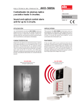
Interruptor fijo
Fixed circuit-breaker
Fig. 1
Fig. 2
1 Relé electrónico con microprocesador SACE PR111 o PR112
2 Marca de fábrica
3 Órganos de maniobras y de control del mando y señalizaciones de actuación
de los relés (para la descripción detallada véase el capítulo 7)
4 Etiqueta de características
1.3 Datos nominales del interruptor
1 Código de identificación del tipo de interruptor
2 Tensión nominal de servicio Ue
3 Corriente nominal Iu
4 Corriente admisible de corta duración (1s) Icw
5 Símbolo de actitud al seccionamiento
6 Poder de corte nominal extremo (Icu) y de servicio (Ics) en cortocircuito, según
la tensión nominal de servicio (Ue) y la frecuencia (50-60 Hz/corriente continua)
7 Símbolo de conformidad con las normas
8 Marca de conformidad con las directivas de la Unión Europea
1. Description
1.1 General characteristics
The SACE Emax series of circuit-breakers consists of a sheet steel
structure which houses the operating mechanism, the poles and the
auxiliary parts.
Each pole, insulated from the others, contains the breaking parts and
the current transformer relative to the corresponding phase.
The pole structure varies according to whether the circuit-breaker is
selective or current-limiting.
The fixed version circuit-breaker has its own terminals for connection
to the power circuit. In the withdrawable version, the circuit-breaker is
the moving part of the apparatus which is completed with a fixed part
fitted with terminals for connection to the installation power circuit.
Coupling between the moving part and the fixed part is made by means
of special pliers mounted in the fixed part.
1.2 External front view of the circuit-breaker
1 SACE PR111 or PR112 microprocessor-based electronic release
2 Trade-mark
3 Switching and control parts of the operating mechanism and release trip signals
(for a detailed description, see chapter 7)
4 Characteristics nameplate
1.3 Circuit-breaker nameplate data
1 Identification code for type of circuit-breaker
2 Rated service voltage Ue
3 Rated current Iu
4 Short-time withstand current (1s) Icw
5 Symbol for isolation behaviour
6 Rated ultimate (Icu) and service (Ics) breaking capacity under short-circuit,
according to the rated service voltage (Ue) and the frequency (50-60 Hz/direct
current)
7 Symbol of compliance with Standards
8 Mark for compliance with the Directives of the European Community
1. Descripción
1.1 Características generales del interruptor
Los interruptores de la serie SACE Emax están fabricados con una
estructura de chapa de acero que aloja el mando, los polos y los
órganos auxiliares. Cada polo, aislado de los otros, contiene las partes
de interrupción y el transformador de corriente para la correspondiente
fase.
La estructura de los polos es diferente según se trate de un interruptor
selectivo o limitador.
El interruptor en ejecución fija posee terminales propios para la
conexión al circuito de potencia; en ejecución extraíble, el interruptor
constituye la parte móvil del aparato que se completa con una parte fija
dotada con terminales para la conexión al circuito de potencia del
aparato. La parte móvil y la parte fija se acoplan mediante unas pinzas
montadas en la parte fija.
1.2 Vista frontal exterior del interruptor
1
2
3
4
1
2
3
4
1 2345
6
7
8

N° Doc.
Doc. No.
Mod.
Rev.
M4379
SACE Emax
601933/003
Aparato
Apparatus
Escala
Scale
N° Pag.
Sh. No.
5/100
1.4 Características de construcción de la parte móvil
1 Estructura portante de chapa de acero
2 Transformador de corriente para relé de protección
3 Caja aislante de soporte de los terminales
4 Terminales posteriores horizontales
5a Placas para contactos principales fijos
5b Placas para contactos rompearco fijos
6a Placas para contactos principales móviles
6b Placas para contactos rompearco móviles
7 Cámara de arco
8 Placa de bornes para la ejecución fija - Contactos deslizantes para la ejecución
extraíble
9 Relé de protección
10 Mando de cierre y de apertura del interruptor
11 Resortes de cierre
12 Motorreductor de carga de los resortes (bajo demanda)
13 Palanca para la carga manual de los resortes de cierre
14 Dispositivo de extracción (sólo para interruptor extraíble)
15 Relés de servicio (de cierre, de apertura, de mínima tensión) bajo demanda
1 Estructura portante de chapa de acero
2 Pinza de tierra (a: para todas las ejecuciones; b: para E4 y E6)
3 Obturadores de seguridad (grado de protección IP20)
4 Base aislante de soporte de los terminales
5 Terminales
6 Contactos de señalización insertado - seccionado en prueba - extraído (bajo
demanda)
7 Contactos deslizantes
8 Bloqueo por candados para obturadores de seguridad (bajo demanda)
9 Bloqueo antiintroducción para interruptores de calibre diferente
Fig. 3
Interruptor selectivo/
Selective circuit-breaker
Interruptor limitador/
Current-limiting circuit-breaker
1.5 Características de construcción de la parte fija
Fig. 4
1.4 Construction characteristics of the moving part
1.5 Construction characteristics of the fixed part
1 Supporting structure made of sheet steel
2 Earthing pliers (a: for all versions; b: for E4, E6)
3 Safety shutters (IP20 degree of protection)
4 Terminal support insulating base
5 Terminals
6 Contacts for signalling connected-isolated for test-disconnected (to order)
7 Sliding contacts
8 Padlock for safety shutters (to order)
9 Anti-insertion lock for circuit-breakers of different size
1 Supporting structure made of sheet steel
2 Current transformer for protection release
3 Terminal support insulating board
4 Horizontal rear terminals
5a Main fixed contact plates
5b Fixed arc-breaking contact plates
6a Main moving contact plates
6b Moving arc-breaking contact plates
7 Arcing chambers
8 Terminal box for fixed version - Sliding contacts for withdrawable version
9 Protection release
10 Circuit-breaker closing and opening operating mechanism
11 Closing springs
12 Spring charging gearmotor (to order)
13 Lever for manual closing spring charging
14 Racking-out device (only for withdrawable circuit-breaker)
15 Service releases (closing, opening, undervoltage), to order
3
2
4
5b
5a
6a
6b
1
7
8
15
9
12 13 14
15
12 13 14
12
3
2
4
5a
6a
1
7
8
9
2b
1
2a
3
4
5
6
7
8
11
12
10
10
11
9

N° Doc.
Doc. No.
Mod.
Rev.
M4379
SACE Emax
601933/003
Aparato
Apparatus
Escala
Scale
N° Pag.
Sh. No.
6/100
Conexiones mecánicas
Mechanical connections
Fig. 5
Conexiones eléctricas
Electrical connections
1.6 General characteristics of the microprocessor-based
releases
The SACE Emax series circuit-breakers can be fitted with SACE
PR111 or PR112 microprocessor-based releases.
The SACE PR111 releases carry out protection, local signalling, self-
monitoring and test functions.
In the configuration only equipped with the protection unit (PR112/P),
apart from the PR111 functions with a wider range of possibilities, the
SACE PR112 releases also carry out the remote signalling and
measurement functions, whereas in the configuration with the dialogue
unit (PR112/PD), they allow control of the circuit-breaker and program-
ming of the various functions from a centralised control system.
Both the releases normally receive their power supply from the current
transformers mounted in each pole. All the adjustment and control parts
available to the user are placed on the front of the release.
Installation in the circuit-breaker is simple: mechanical fixing is carried
out by means of four nuts, whereas some connectors are available for
the electrical connections whose references are indicated on the circuit
diagram.
XK1: connector for connection of PR111, PR112/P and
PR112/PD releases to the current sensors
XK2 and XK3: connectors for the auxiliary circuits of the PR112/P and
PR112/PD releases (for functions such as remote
signalling and circuits for zone selectivity)
X0: connector for the Y01 release which makes the circuit-
breaker open following protection release tripping.
Accessory units normally fitted and others supplied to order provide
the auxiliary power supply and allow tests to check release operation.
1.6 Características generales de los relés con microprocesa-
dor
Los interruptores de la serie SACE Emax pueden incorporar relés con
microprocesador del tipo SACE PR111 o PR112.
Los relés SACE PR111 desempeñan las funciones de protección,
señalización local, autocontrol y prueba.
Los relés SACE PR112 pueden presentar dos configuraciones según
las cuales desempeñarán funciones diferentes: con unidad de protec-
ción (PR112/P), además de las funciones del PR111, realizadas con
una mayor gama de posibilidades, también desempeñan las funciones
de señalizaciones a distancia y de medida; con la unidad de diálogo
(PR112/PD), los relés permiten controlar el interruptor y programar las
diferentes funciones desde un sistema de control centralizado.
Los dos relés se alimentan, en general, mediante los transformadores
de corriente montados en cada polo. Todos los órganos de regulación
y de control a disposición del usuario se encuentran en la parte frontal
del relé.
La instalación en el interruptor es muy simple: la sujeción mecánica se
realiza mediante cuatro tuercas mientras que, para las conexiones
eléctricas, hay unos conectores cuyas referencias se indican en el
esquema eléctrico.
XK1: conector para conectar los relés PR111, PR112/P y
PR112/PD a los sensores de corriente.
XK2 y XK3: conectores para los circuitos auxiliares de los relés
PR112/P y PR112/PD (para funciones como las señali-
zaciones a distancia y circuitos para la selectividad de
zona).
X0: conector para el relé Y01 que provoca la apertura del
interruptor tras la actuación del relé de protección..
Existen algunas unidades opcionales, en dotación o suministradas bajo
demanda, que permiten obtener la alimentación auxiliar y efectuar
pruebas de control del funcionamiento del relé.

N° Doc.
Doc. No.
Mod.
Rev.
M4379
SACE Emax
601933/003
Aparato
Apparatus
Escala
Scale
N° Pag.
Sh. No.
7/100
Fig. 6
Fig. 7
Fig. 8
2. Control on receipt
Examine the state of the material received to check that it corresponds
with what was ordered. If on unpacking - which must be carried out
carefully - any damage or irregularity is noted, notify this within 5 days
of receipt of the goods: notification must indicate the shipping note
number.
3. Storage, lifting and weights
Protected by an external wooden housing, the circuit-breaker is fixed
to the transport platform by means of screws or to the bottom of the
packing crate. If the circuit-breaker is to be stored for even short periods
before being put into service, after control on receipt it is advisable to
put it back into its relative container and cover it with a waterproof
tarpaulin.
Caution
– Use a dry, dustfree ambient for storage without any aggressive
chemical agents
– Place the circuit-breaker and any fixed part on a horizontal surface
not in direct contact with the floor, but on a suitable support (fig. 6)
– The maximum number of circuit-breakers which can be placed on
top of each other is shown in figure 7.
– Keep the circuit-breaker in the open position with the closing springs
discharged to prevent unwarranted stresses and risks of accidents
to personnel.
With regard to lifting, follow these instructions: the circuit-breakers must
be placed on a sturdy surface and preferably lifted using an appropriate
fork-lift truck. The use of ropes is, however, permitted: in this case the
lifting ropes must be hooked as shown in the figure (the lifting plates are
always supplied with the circuit-breaker).
Por lo que se refiere a la elevación, atenerse a las siguientes instruc-
ciones: los interruptores se tienen que colocar sobre una superficie de
apoyo robusta y se deben levantar mediante una carretilla elevadora
de capacidad adecuada. También se permite usar cuerdas; en este
caso, las cuerdas de elevación se tiene que sujetar de la manera
ilustrada en la figura (las placas de elevación se suministran siempre
con el interruptor).
2. Control durante la recepción
Examinar el estado del material que se ha recibido y comprobar que
corresponda al material pedido. Si durante el desembalaje, que se tiene
que efectuar con cuidado, se observan daños o irregularidades,
señalarlo al fabricante en un plazo máximo de 5 días a partir de la fecha
de entrega. En dicha comunicación debe indicarse el número del aviso
de la expedición.
3. Almacenaje, elevación y pesos
El interruptor, protegido con una envolvente externa de madera, se
encuentra sujeto mediante tornillos a la plataforma de transporte o al
fondo de la caja de embalaje.
Si, antes de la puesta en marcha, el interruptor tiene que permanecer
en el almacén, incluso por un breve periodo, una vez efectuado el
control durante la recepción, hay que volverlo a poner en su contenedor
y cubrirlo con una tela impermeable.
Atención
– Para almacenar los equipos, utilizar un lugar seco, sin polvo ni
agentes químicos agresivos.
– Colocar el interruptor y su parte fija en una superficie horizontal,
sobre una plataforma y nunca directamente en contacto con el suelo
(fig. 6).
– El número máximo de interruptores que se pueden apilar se indica
en la figura 7.
– Mantener el interruptor en posición de abierto y con los resortes de
cierre descargados para evitar solicitaciones inútiles y riesgos de
accidentes para el personal.

N° Doc.
Doc. No.
Mod.
Rev.
M4379
SACE Emax
601933/003
Aparato
Apparatus
Escala
Scale
N° Pag.
Sh. No.
8/100
Fig. 9
Tabla de los pesos de los interruptores
Nota
Los pesos indicados en la tabla se entienden para interruptores
selectivos y limitadores dotados de relés SACE PR111 o PR112 y de
los correspondientes transformadores de corriente, accesorios ex-
cluidos. La ejecución extraíble comprende la parte móvil con las
mismas condiciones que las descritas anteriormente y la parte fija con
terminales posteriores horizontales.
4. Instalación
4.1 Lugar de instalación
Instalar el interruptor en un lugar seco sin polvo ni sustancias corro-
sivas y de manera que no se encuentre sujeto a golpes ni vibraciones.
Si esto no es posible, efectuar el montaje con un cuadro de grado de
protección adecuado.
Para preparar el lugar de instalación, consultar el párrafo 11 “Dimen-
siones”, que proporciona información sobre los siguientes puntos:
– volúmenes mínimos de instalación de los interruptores y de las
ejecuciones derivadas
– distancias a respetar para los interruptores en celda
– dimensiones generales de los interruptores
– orificios de sujeción
– orificios de la puerta de la celda.
4.2 Instalación del interruptor fijo
Sujetar el interruptor a una superficie horizontal mediante los tornillos
(M10 x 12 min.).
Interruptor selectivo Ejecución fija Ejecución extraíble
Selective circuit-breaker Fixed version Withdrawable version
3 Polos / Poles 4 Polos / Poles 3 Polos / Poles 4 Polos / Poles
E1 42 50 65 80
E2 46 55 72 89
E3 68 80 100 125
E4 95 115 147 190
E6 140 170 210 260
Interruptor limitador
Current-limiting c.-breaker
E2L 45 53 70 87
E3L 67 79 100 120
Table of circuit-breaker weights
Note
The weights indicated in the table are intended for selective and current-
limiting circuit-breakers complete with SACE PR111 or PR112 re-
leases and relative current transformers, excluding the accessories.
The withdrawable version includes the moving part in the same
conditions as above and the fixed part with horizontal rear terminals.
4. Installation
4.1 Installation ambient
Install the circuit-breaker in a dry, dustfree, non-corrosive place so that
it is not subjected to impacts or vibrations. When this is not possible,
assemble inside a switchboard with a suitable degree of protection.
For preparation of the installation ambient, refer to paragraph 11:
“Dimensions”, which gives information about the following points:
– minimum installation volumes of the circuit-breakers and derived
versions
– clearances to be respected for circuit-breakers in compartments
– overall dimensions of the circuit-breakers
– fixing drilling holes
– drilling holes in the compartment door.
4.2 Installation of fixed circuit-breakers
Fix the circuit-breaker onto a horizontal surface by means of the screws
(min. M10 x 12)

N° Doc.
Doc. No.
Mod.
Rev.
M4379
SACE Emax
601933/003
Aparato
Apparatus
Escala
Scale
N° Pag.
Sh. No.
9/100
Fig. 10
Fig. 11
Ejemplo para E1B 08 según el esquema de la etiqueta
Example for E1B 08 according to the nameplate diagram
4.3 Installation of the fixed part of withdrawable circuit-breakers
4.3.1 Preparation of the fixed part
Assembly of anti-insertion lock
Before installing the fixed part, it is necessary to check that the anti-
insertion lock is present for circuit-breakers with electrical character-
istics different from those of the fixed part itself. Should the anti-insertion
lock have been supplied separately, mount it as follows:
– Find the assembly position of the stop bolts in relation to the circuit-
breaker to be housed in the fixed part on the adhesive nameplate (4)
– Insert the two hexagonal headed screws (1) as shown in the figure,
in the holes identified in the previous point
– Fix the two screws with the washers (2) and the hexagonal stop parts
(3).
Check that the anti-insertion lock corresponding to the one installed on
the fixed part is present on the circuit-breaker (moving part).
4.3 Instalación de la parte fija del interruptor extraíble
4.3.1 Preparación de la parte fija
Montaje del bloqueo antiintroducción
Antes de instalar la parte fija es necesario controlar la presencia del
bloqueo antiintroducción de los interruptores cuyas características
eléctricas son diferentes a las de la parte fija; cuando el bloqueo
antiintroducción se ha suministrado aparte hay que efectuar el montaje
según las instrucciones siguientes:
– Identificar, en la etiqueta autoadhesiva (4), la posición de montaje de
los tornillos de tope en relación con el interruptor que se tiene que
instalar en la parte fija.
– Introducir los dos tornillos de cabeza hexagonal (1) en los orificios
descritos en el punto precedente según se indica en la figura.
– Sujetar los dos tornillos con las tuercas (3) tras poner las arandelas
(2).
Controlar que en el interruptor (parte móvil) se encuentre presente el
bloqueo antiintroducción correspondiente al instalado en la parte fija.
1
4
2
3

N° Doc.
Doc. No.
Mod.
Rev.
M4379
SACE Emax
601933/003
Aparato
Apparatus
Escala
Scale
N° Pag.
Sh. No.
10/100
4.3.2 Instalación de la parte fija
Sujetar la parte fija mediante los tornillos (1), las arandelas (2) y las
tuercas (3) (M8x16) suministradas por ABB SACE. Si se utilizan
tornillos diferentes, controlar que la cabeza de los tornillos no sobre-
salga más de 5,5 mm de la base de la parte fija.
Fig. 12
Nota
(*) Sujeción central sólo para E4 - E6
4.4 Instalación del marco en la puerta de la celda
– Efectuar los orificios de la puerta de la celda previstos en el párrafo
11 “Dimensiones”.
– Aplicar el marco (1) en la parte delantera de la puerta de la celda y
sujetarla desde el interior mediante los tornillos autorroscantes (2).
Fig. 13
4.3.2 Installation of the fixed part
Fix the fixed part by means of the screws (1), washers (2) and nuts (3)
(M8 x 16), checking that the heads of the screws do not extend for more
than 5.5 mm from the base of the fixed part.
Note
(*) Central fixing only for E4 - E6
4.4 Assembly of the flange on the compartment door
– Drill the holes in the compartment door indicated in paragraph 11:
“Dimensions”.
– Apply the flange (1) onto the front of the compartment door, fixing it
from the inside with self-tapping screws (2).
1
2
1
2
3

N° Doc.
Doc. No.
Mod.
Rev.
M4379
SACE Emax
601933/003
Aparato
Apparatus
Escala
Scale
N° Pag.
Sh. No.
11/100
5. Conexiones eléctricas
5.1 Conexiones al circuito de potencia
5.1.1 Formas de los terminales
Interruptor fijo
Terminales posteriores horizontales
Horizontal rear terminals
Terminales anteriores
Front terminals
Terminales posteriores verticales
Vertical rear terminals
Fig. 14
Parte fija para interruptor extraíble
Terminales posteriores horizontales
Horizontal rear terminals
Fig. 15
Terminales posteriores verticales
Vertical rear terminals
Terminales planos
Flat terminals
Terminales anteriores
Front terminals
5. Electrical connections
5.1 Connections to the power circuit
5.1.1 Terminal shapes
Fixed circuit-breaker
Fixed part for withdrawable circuit-breaker

N° Doc.
Doc. No.
Mod.
Rev.
M4379
SACE Emax
601933/003
Aparato
Apparatus
Escala
Scale
N° Pag.
Sh. No.
12/100
5.1.2 Ejemplos de instalación de las barras de conexión en
función de los tipos de terminales
Las barras de conexión permiten conectar los terminales del interruptor
y las barras del cuadro.
Sus dimensiones deben ser estudiadas esmeradamente por el
proyectista del cuadro.
En este párrafo se describen algunos ejemplos de instalación en
función de la forma y de las dimensiones de los terminales del
interruptor.
Las dimensiones de los diferentes tipos de terminales son constantes
para cada tipo de interruptor: en general, como es aconsejable
aprovechar toda la superficie de contacto del terminal, la anchura de
la barra de conexión tiene que ser igual a la del terminal. Se pueden
obtener capacidades diferentes para las conexiones regulando el
espesor y el número de barras en paralelo. En algunos casos, es
posible reducir la anchura de las conexiones con respecto a la del
terminal tal como se ilustra en los ejemplos siguientes.
Interruptor fijo
Fixed circuit-breaker
Anchura (en mm) de los terminales y posibles anchuras de las barras de conexión
Width (in mm) of the terminals and possible widths of the connection busbars
Terminales posteriores horizontales Terminales posteriores verticales Terminales anteriores
Horizontal rear terminals Vertical rear terminals Front terminals
Anchura Anchura de las Anchura Anchura de las Anchura Anchura de las
del terminal posibles conexiones del terminal posibles conexiones del terminal posibles conexiones
Width of Width of the Width of Width of the Width of Width of the
the terminal possible connections the terminal possible connections the terminal possible connections
E1 60 (x1) 60 (x1-x2) 80 (x1) 60-80 (x1-x2) 60 (x1) 60 (x1-x2)
E2 60 (x1) 60 (x1-x2-x3) 80 (x2) 60-80(x1-x2-x3) 60 (x3) 60 (x2-x3)
E3 96 (x1) 100 (x1-x2-x3) 100 (x3) 80-100 (x2-x3-x4) 96 (x3) 100 (x2-x3)
E4 150 (x1) 120-150 (x1-x2-x3) 80 (x4) 60-80(x2-x4-x6) 150 (x3) 120-150 (x2-x3)
E6 222 (x1) 200-220 (x1-x2-x3) 100 (x6) 80-100 (x4-x6-x8) 222 (x3) 200-220 (x2-x3)
Interruptor extraíble
Withdrawable circuit-breaker
Anchura (en mm) de los terminales y posibles anchuras de las barras de conexión
Width (in mm) of the terminals and possible widths of the connection busbars
Terminales posteriores horizontales Terminales posteriores verticales Terminales anteriores Terminales planos
Horizontal rear terminals Vertical rear terminals Front terminals Flat terminals
Anchura Anchura de las Anchura Anchura de las Anchura Anchura de las Anchura Anchura de las
del terminal posibles conexiones del terminal posibles conexiones del terminal posibles conexiones del terminal posibles conexiones
Width of Width of the Width of Width of the Width of Width of the Width of Width of the
the terminal possible connections the terminal possible connections the terminal possible connections the terminal possible connections
E1 60 (x1) 60 (x1-x2) 80 (x1) 60-80 (x1-x2) 60 (x1) 60 (x1-x2) 60 (x1) 60 (x1)
E2 60 (x2) 60 (x1-x2-x3) 80 (x2) 60-80 (x1-x2-x3) 6 0 (x3) 60 (x1-x2-x3) 60 (x2) 60 (x1-x2-x3)
E3 96 (x2) 100 (x1-x2-x3) 100 (x3) 80-100 (x2-x3) 100 (x3) 80-100 (x2-x3) 96 (x2) 100 (x1-x2-x3)
E4 150 (x2) 120-150 (x1-x2-x3) 80 (x4) 60-80 (x2-x4-x6) 60 (x6) 60 (x2-x4-x6) 150 (x2) 60 (x2-x4-x6)
120-150 (x2-x3) 120-150 (x2)
E6 222 (x2) 200-220 (x1-x2-x3) 100 (x6) 80-100 (x4-x6) 100 (x6) 80-100 (x2-x4-x6) 222 (x2) 100 (x2-x4-x6)
200-220 (x2-x3) 200-220 (x1-x2)
Fig. 16
5.1.2 Examples of layout of the connection busbars according
to the type of terminals
The connection busbars allow connection between the circuit-breaker
terminals and the switchboard busbars.
Their sizing must be carefully studied by the switchboard design
engineer.
This paragraph shows some examples of possible constructions in
relation to the shape and size of the circuit-breaker terminals.
The various types of terminals have constant dimensions for each
circuit-breaker size: it is normally advisable to exploit the whole contact
surface of the terminal and therefore the width of the connection busbar
should be the same as that of the terminal. Different capacities for the
connections can be made by working on the thickness and on the
number of busbars in parallel. In some cases, reduction in the width of
the connection in relation to that of the terminal is allowed, as can be seen
in the following examples.

N° Doc.
Doc. No.
Mod.
Rev.
M4379
SACE Emax
601933/003
Aparato
Apparatus
Escala
Scale
N° Pag.
Sh. No.
13/100
Fig. 17
5.1.3 Procedimientos para el montaje de las barras de conexión
Controlar con la máxima atención las superficies de contacto de las
conexiones: tienen que estar bien limpias y sin rebabas, golpes o signos
de oxidación que, en cualquier caso, se tienen que eliminar con una lima
fina o con tela esmeril para evitar aumentos localizados de temperatura;
al término de la operación, limpiar los restos de grasa o polvo mediante
un trapo empapado con un disolvente adecuado.
Si se utilizan conexiones de cobre, se aconseja estañar las superficies
de contacto; en el caso de conexiones de aluminio, hay que aplicar una
ligera capa de vaselina en las superficies de contacto.
Las conexiones no tienen que ejercer esfuerzos en ninguna dirección
sobre los terminales.
Poner una arandela plana con diámetro suficiente para repartir la
presión de apriete sobre un área mayor y una arandela elástica.
Establecer el contacto entre la conexión y el terminal y apretar los
tornillos de sujeción hasta el tope.
Se aconseja utilizar siempre dos llaves (para no forzar excesivamente
las partes aislantes) y aplicar el par de apriete indicado en la figura 18.
Controlar el apriete transcurridas 24 horas.
Colocación del primer juego de anclaje de las barras en función
de la corriente de cortocircuito
Fijación al cuadro
Positioning the first anchoring division of the busbars according
to the short-circuit current
5.1.3 Assembly procedure for connection busbars
Carefully check the state of the contact surfaces of the connections:
these must be very clean and free of any burrs, dents or traces of
oxidation - which must be removed using a fine file or emery cloth to
prevent localised increases in temperature. On completion of the
operation, remove any traces of grease or dust using a cloth soaked
in suitable solvent.
When copper connections are used, it is advisable to tinplate the contact
surfaces. When aluminium connections are used, it is advisable to apply
a thin layer of vaseline over the contact surfaces.
The connections must not put any force on the terminals in any direction.
Always insert a flat washer of suitable diameter (to distribute the
tightening pressure over the largest area possible) and a spring
washer.
Establish the contact between the connection and terminal and tighten
the fixing screws fully.
Always use two spanners (so that the insulating parts are not stressed
unduly), applying the tightening torque indicated in the figure 18.
Check tightness after 24 hours.
Anchoring to the switchboard
PLANOS
FLAT
ANTERIORES
FRONT
P E1-E2 E3-E4-E6 E1-E6
HORIZONTALES
HORIZONTAL
250 150 –
VERTICALES
VERTICAL
250 150 –
ANTERIORES
FRONT
– – 250
PLANOS
FLAT
– – 250
VERTICALES
VERTICAL
HORIZONTALES
HORIZONTAL

N° Doc.
Doc. No.
Mod.
Rev.
M4379
SACE Emax
601933/003
Aparato
Apparatus
Escala
Scale
N° Pag.
Sh. No.
14/100
Interruptor fijo
Fixed circuit-breaker
Interruptor extraíble
Withdrawable circuit-breaker
Prisioneros M12 suministrados de serie para los terminales posteriores verticales
(E3 y E6).
Fig. 18
Fig. 19
5.2 Earthing
The fixed version circuit-breaker and the fixed part of the withdrawable
circuit-breaker have one or two terminals on the rear for connection to
earth, marked with the appropriate symbol, (fig. 9 and fig. 12).
Each terminal is complete with a bolt for fixing the connection.
A conductor with a cross-section in compliance with the Standards in
force must be used for the connection.
Before assembling the connection, clean and degrease the area around
the screw.
After assembly, tighten the bolt with a torque of 70 Nm.
5.3 Cabling the auxiliary circuits of the circuit-breaker
5.3.1 Interfacing elements for fixed circuit-breaker
A special terminal board fitted with screw terminals is provided for
connection of the auxiliary circuits.
The terminals are marked with alphanumerical identification codes as
per the electrical circuit diagram.
The terminal board is identified with the code XV on the electrical circuit
diagram.
The terminal board is accessed immediately when the compartment
door is opened.
5.2 Puesta a tierra
El interruptor en ejecución fija y la parte fija del interruptor extraíble están
dotados, en la parte posterior, de uno o dos terminales, indicados con
el símbolo correspondiente, para la conexión a tierra (fig. 9 y fig. 12).
Cada terminal posee un tornillo para la sujeción de la conexión.
Para la conexión se tiene que utilizar un conductor con una sección que
responda a las normativas vigentes.
Antes de montar la conexión, limpiar y desengrasar la zona alrededor
del tornillo.
Tras el montaje, apretar el tornillo con un par de 70 Nm.
5.3 Cableado de los circuitos auxiliares del interruptor
5.3.1 Elementos de interfaz para interruptor fijo
Para la conexión de los circuitos auxiliares se ha previsto una placa de
bornes con terminales de tornillo.
Los terminales se identifican con unos códigos alfanuméricos como el
esquema eléctrico.
La placa de bornes se identifica con el código XV en el esquema
eléctrico.
Al abrir la puerta de la celda se accede de inmediato a la placa de bornes.
XV
Tornillos M12 de alta resistencia
Par de apriete de los terminales principales 70 Nm
High resistance M12 screws
Tightening torque of the main terminals: 70 Nm
Fase/Phase Neutro/NeutralFase/Phase Neutro/Neutral
M12 included in the supply for vertical rear terminals (E3, E6)

N° Doc.
Doc. No.
Mod.
Rev.
M4379
SACE Emax
601933/003
Aparato
Apparatus
Escala
Scale
N° Pag.
Sh. No.
15/100
5.3.2 Interruptor extraíble
Para la conexión a los circuitos auxiliares de la parte móvil se encuentra
disponible, en la parte fija, un conector de contactos deslizantes (véase
figura), identificado con el código X en el esquema eléctrico.
Al abrir la puerta de la celda se accede de inmediato a los terminales
del conector fijo.
Además, para la conexión de los contactos de posición de la parte móvil
con respecto a la parte fija, se encuentra disponible una placa de
bornes, identificada con el código XF.
El conector y la placa de bornes están dotado con terminales de tornillo.
E1 - E2 - E3
5 contactos en posición
5 contacts in position
E4 - E6
10 contactos en posición
10 contacts in position
E1 - E2 - E3
Leyenda
1) Contactos deslizantes (X)
2) Placa de bornes para contactos de posición (XF)
3) Contactos de posición
Fig. 20
5.3.2 Withdrawable circuit-breaker
For connection of the moving part to the auxiliary circuits, a connector
with sliding contacts is available on the fixed part (see figure), identified
with the code X on the electrical circuit diagram.
The connector terminals are accessed immediately when the compart-
ment door is opened.
Moreover, a terminal board is available for connection of the position
contacts of the moving part in relation to the fixed part, identified by the
code XF.
Both connector and terminal boxhave screw terminals.
Caption
1) Sliding contacts (X)
2) Terminal box for position contacts (XF)
3) Position contacts
1
2
3
1
2
3
3
1
2

N° Doc.
Doc. No.
Mod.
Rev.
M4379
SACE Emax
601933/003
Aparato
Apparatus
Escala
Scale
N° Pag.
Sh. No.
16/100
5.4 Transformación de los contactos auxiliares o de los
contactos de posición de normalmente cerrados (de
apertura) a normalmente abiertos (de cierre) o viceversa
Los contactos se cablean en la fábrica como se ilustra en el esquema
eléctrico. Si es necesario modificar el estado, debido a exigencias de
la instalación, proceder de la manera siguiente.
a) Contactos auxiliares
Para acceder a los contactos auxiliares efectuar las siguientes ope-
raciones:
– quitar la protección frontal (3) del relé girando los bloqueos (1) tal
como se indica en la figura;
– tras desenroscar las tuercas laterales (2), quitar el relé de protección
(4) desde el frente del interruptor
Fig. 21
Los contactos auxiliares, siendo de dos vías (contactos en
conmutación), se pueden modificar de contactos de apertura a con-
tactos de cierre y viceversa; para ello, hay que desplazar simplemente
el conductor de salida de una a otra posición de la manera indicada en
la figura.
Fig. 22
(Contacto N.C.) (Contactos deslizantes)
(N.C. contact) (sliding contacts)
b) Contactos de posición
Para cambiar el estado del contacto de posición, proceder de la manera
descrita para los contactos auxiliares (véase fig. 21-22).
5.4 Conversion of the auxiliary contacts or position contacts
from normally closed (opening) to normally open (closing)
or vice versa
The contacts are cabled in the factory as shown in the electrical circuit
diagram. Should their state have to be modified due to installation
requirements, proceed as follows:
a) Auxiliary contacts
To access the auxiliary contacts, carry out the following operations:
– remove the front protection (3) of the release working on the locks
(1) as shown in the figure
– remove the protection release (4), by removing the lateral nuts (2)
and sliding it out from the front of the circuit-breaker.
As they are the two-way type (change-over contacts), the auxiliary
contacts can be modified from opening contacts to closing contacts and
vice versa simply by moving the output conductor from one position to
the other, as shown in the figure.
b) Position contacts
To change the state of the contact, proceed in the same way as for the
auxiliary contacts (see figs. 21-22).
1
3
4
2
(Contacto N.A.) (Placa de bornes)
(N.O. contact) (terminal box)

N° Doc.
Doc. No.
Mod.
Rev.
M4379
SACE Emax
601933/003
Aparato
Apparatus
Escala
Scale
N° Pag.
Sh. No.
17/100
6. Puesta en servicio
6.1 Procedimientos generales
– Controlar el apriete de las conexiones de potencia en los terminales
del interruptor.
– Efectuar todas las operaciones de preparación del relé (véase parte
B)
– Controlar que el valor de la tensión de alimentación de los circuitos
auxiliares se encuentre comprendido entre el 85 y el 110% de la
tensión nominal de las aplicaciones eléctricas
– Controlar que en el lugar de instalación se asegure un cambio de aire
suficiente para evitar sobretemperaturas.
– Efectuar los controles indicados en la siguiente tabla.
Objeto de la inspección
Item to be inspected
1 Mando manual
Manual operating mechanism
2 Motorreductor (si se ha previsto)
Gearmotor (if provided)
3 Relé de mínima tensión
(si se ha previsto)
Undervoltage release
(if provided)
Procedimiento
Procedure
Efectuar algunas maniobras de apertura y
cierre (véase el cap. 7).
ATENCIÓN
En presencia del relé de mínima tensión, el
interruptor sólo se puede cerrar tras haber
excitado eléctricamente el relé.
Carry out a few opening and closing operations
(see chap. 7).
CAUTION
When there is an undervoltage release, the
circuit-breaker can only be closed after elec-
trically energising the release itself.
Alimentar el motorreductor de carga de los
resortes con la tensión nominal correspon-
diente.
Efectuar algunas maniobras de cierre y aper-
tura.
Nota. Alimentar el relé de mínima tensión con
la relativa tensión nominal (si se ha previsto).
Supply the spring charging gearmotor at the
relative rated voltage.
Carry out a few closing and opening opera-
tions.
Note. Supply the undervoltage release at the
relative rated voltage (if provided)
Alimentar el relé de mínima tensión con la
tensión nominal correspondiente y efectuar la
maniobra de cierre del interruptor.
Quitar la tensión al relé.
Alimentar el relé de mínima tensión con la
tensión nominal correspondiente y efectuar la
maniobra de cierre del interruptor.
Supply the undervoltage release at the relative
rated voltage and carry out the circuit-breaker
closing operation.
Turn supply voltage to the release off.
Supply the undervoltage release at the relative
rated voltage and carry out the circuit-breaker
closing operation.
Control positivo
Successful check
La palanca de carga de los resortes se mueve
correctamente
The spring charging lever moves normally,
without any particular resistance.
Los resortes se cargan correctamente.
Las señalizaciones son correctas.
Una vez los resortes están cargados, el
motorreductor se para.
El motorreductor vuelve a cargar los resortes
tras cada maniobra de cierre.
The springs are charged normally.
The signals are normal.
When the springs are charged the gearmotor
stops.
The gearmotor recharges the springs after
each closing operation.
El interruptor se cierra correctamente; las
señalizaciones son correctas.
El interruptor se abre; la señalización cambia.
The circuit-breaker closes normally; the sig-
nals are normal.
The circuit-breaker opens; the signalling
changes over.
6. Putting into service
6.1 General procedures
– Check the tightness of the power connections to the circuit-breaker
terminals
– Carry out all the preparatory operations on the release (see part B)
– Check that the power supply voltage value of the auxiliary circuits is
between 85 and 110% of the rated voltage of the electrical applica-
tions
– Check that there is sufficient air exchange in the installation area to
prevent excessive temperatures
– Also carry out the checks given in the following table.

N° Doc.
Doc. No.
Mod.
Rev.
M4379
SACE Emax
601933/003
Aparato
Apparatus
Escala
Scale
N° Pag.
Sh. No.
18/100
Objeto de la inspección
Item to be inspected
4 Relé de apertura (si se ha previsto).
Shunt opening release (if provided)
5 Relé de cierre (si se ha previsto).
Shunt closing release (if provided)
6 Bloqueo del interruptor en posición de
abierto (a llave o por candados).
Lock for circuit-breaker in open position
(key or padlock)
7 Contactos auxiliares del interruptor.
Auxiliary circuit-breaker contacts
8 Contactos auxiliares de señalización inte-
rruptor insertado, seccionado en prueba,
extraído.
Auxiliary contacts for signalling circuit-
breaker connected, isolated for test,
disconnected.
9 Dispositivos de bloqueo del interruptor
insertado y extraído, dispositivos de
enclavamiento entre interruptores monta-
dos colateralmente o sobrepuestos (si se
han previsto).
Locking devices for circuit-breaker con-
nected and disconnected; interlocking de-
vices between circuit-breakers side by
side and on top of each other (if provided)
10 Para interruptores extraíbles: dispositivo
de inserción y extracción
For withdrawable circuit-breakers: racking
in and racking out device
Procedimiento
Procedure
Cerrar el interruptor.
Alimentar el relé de apertura con la tensión
nominal correspondiente
Close the circuit-breaker.
Supply the shunt opening release at the relative
rated voltage.
Abrir el interruptor.
Alimentar el relé de cierre con la tensión nomi-
nal.
Open the circuit-breaker.
Supply the shunt closing release at its rated
voltage.
Abrir el interruptor; girar la llave y extraerla de
su sede, intentar efectuar la maniobra de cierre
del interruptor.
Open the circuit-breaker; turn the key and
remove it. Attempt the circuit-breaker closing
operation.
Insertar los contactos auxiliares en los corres-
pondientes circuitos de señalización; efectuar
algunas maniobras de cierre y de apertura del
interruptor.
Insert the auxiliary contacts in appropriate
signalling circuits. Carry out a few circuit-
breaker closing and opening operations
Insertar los contactos auxiliares en los corres-
pondientes circuitos de señalización; colocar
el interruptor en posición de insertado,
seccionado en prueba y extraído.
Insert the auxiliary contacts in appropriate
signalling circuits. Then put the circuit-breaker
in the connected, isolated for test and discon-
nected position.
Efectuar las pruebas de funcionamiento.
Carry out the operating tests
Efectuar algunas maniobras de inserción y
extracción
Carryout a few racking in and racking out
operations
Control positivo
Successful check
El interruptor se abre correctamente; las seña-
lizaciones son correctas.
The circuit-breaker opens normally; the sig-
nals are normal.
El interruptor se cierra correctamente; las
señalizaciones son correctas.
The circuit-breaker closes normally; the sig-
nals are normal.
No se pueden efectuar el cierre manual ni el
eléctrico
Both manual and electrical closing are
prevented.
Las señalizaciones se efectúan correctamen-
te.
Signalling occurs normally
Las señalizaciones debidas a las correspon-
dientes maniobras se efectúan correctamen-
te.
The signals for the relative operations are
normal.
Los bloqueos funcionan correctamente.
The interlocks function correctly
.
Maniobra de inserción: el interruptor se inserta
correctamente. Las primeras vueltas de la
manivela no ofrecen una particular resistencia
Racking in operation: the circuit-breaker is
racked in normally. There is no particular
resistance during the first few turns of the
handle
.
.

N° Doc.
Doc. No.
Mod.
Rev.
M4379
SACE Emax
601933/003
Aparato
Apparatus
Escala
Scale
N° Pag.
Sh. No.
19/100
7. Normas de uso
7.1 Órganos de maniobras y señalización
1 Pulsador para la maniobra manual de apertura
2 Palanca para la carga manual de los resortes de cierre
3 Indicador mecánico de interruptor abierto “O” y cerrado “I”
4 Indicador mecánico de actuación del relé de protección (bajo
demanda)
5 Pulsador para la maniobra manual de cierre
6 Indicador de los resortes cargados - descargados
7 Cuentamaniobras (bajo demanda)
8 Bloqueo a llave de la maniobra de cierre (bajo demanda)
9 Indicador mecánico de interruptor insertado (connected),
seccionado en prueba (test connected ) y extraído (disconnected).
10 Sede para la palanca de inserción - extracción
11 Palanca de desbloqueo de la maniobra de inserción -extracción
12 Bloqueo a llave de la maniobra de inserción (bajo demanda)
13 Bloqueo por candados de la maniobra manual de cierre (bajo
demanda)
14 Bloqueo por candados de la maniobra de inserción - extracción
(bajo demanda)
Fig. 23
Interruptor fijo
Fixed circuit-breaker
Interruptor extraíble
Withdrawable circuit-breaker
7. Instructions for use
7.1 Operating and signalling parts
1 Pushbutton for the manual opening operation
2 Lever for manual charging of the closing springs
3 Mechanical indicator for circuit-breaker “O” open and “I” closed
4 Mechanical indicator for protection release trip (to order)
5 Pushbutton for the manual closing operation
6 Indicator for springs charged - discharged
7 Operation counter (to order)
8 Key lock on the closing operation (to order)
9 Mechanical indicator for circuit-breaker connected, isolated for
test, disconnected
10 Seat for the racking-in/racking-out lever
11 Racking-in/racking-out operation release lever
12 Key lock on the racking-in operation (to order)
13 Padlock on manual closing operation (to order)
14 Padlock on racking-in/racking-out operation (to order)
1
8
2
3
4
6
5
7
1
8
2
3
4
6
5
7
10
11
9
12
13
14

N° Doc.
Doc. No.
Mod.
Rev.
M4379
SACE Emax
601933/003
Aparato
Apparatus
Escala
Scale
N° Pag.
Sh. No.
20/100
Nota
En el frente del interruptor se puede instalar, bajo demanda, una
cobertura trasparente para obtener un grado de protección IP54; la
cobertura dispone de una llave de cierre.
Como alternativa a la cobertura trasparente, en los mandos de cierre
y de apertura manual se puede montar una protección que permita sólo
la maniobra de los pulsadores mediante la herramienta correspondien-
te.
Fig. 24
Fig. 25
7.2 Maniobras de cierre y de apertura del interruptor
La maniobra del interruptor puede ser manual o eléctrica
a) Maniobra manual de carga de los resortes de cierre
– Asegurarse de que el indicador (3) marque la posición “O” (interrup-
tor abierto).
– Asegurarse de que el indicador (6) se presente de color BLANCO
(resortes descargados).
– Activar repetidamente la palanca (2) hasta que el indicador (6)
cambia de color y se presenta de color AMARILLO.
Note
On request, a transparent cover can be installed on the front of the
circuit-breaker to increase the degree of protection to IP54. The cover
has a locking key.
As an alternative to the transparent cover, a protection which only
allows operation of the pushbuttons by means of a special tool can be
mounted on the manual closing and opening controls.
7.2 Circuit-breaker closing and opening operations
Circuit-breaker operation can be either manual or electrical.
a) Manual operation for charging the closing springs
– Make sure that the indicator (3) shows “O” (circuit-breaker open).
– Make sure that the indicator (6) is WHITE (springs discharged).
– Repeatedly work on lever (2) until the indicator (6) changes its colour
to YELLOW.
2
3
6

N° Doc.
Doc. No.
Mod.
Rev.
M4379
SACE Emax
601933/003
Aparato
Apparatus
Escala
Scale
N° Pag.
Sh. No.
21/100
b) Maniobra eléctrica de carga de los resortes de cierre
La maniobra eléctrica del interruptor es posible con los siguientes
accesorios (suministrados bajo demanda):
– motorreductor para la carga automática de los resortes de cierre;
– relé de cierre;
– relé de apertura.
El motorreductor recarga automáticamente los resortes tras cada
operación de cierre hasta que el indicador está de color amarillo (6, fig.
25). Si falta la tensión durante la carga, el motorreductor se para y
recarga automáticamente los resortes cuando vuelve la tensión. En
cualquier caso, siempre es posible completar la recarga de los resortes
en manual.
c) Cierre del interruptor
Esta operación sólo se puede efectuar con los resortes de cierre
cargados por completo.
Para el cierre manual, activar el pulsador (5) marcado con la letra “I”.
En presencia del relé de cierre, la maniobra se puede efectuar a
distancia mediante el circuito de control. El cierre se señala mediante
el correspondiente indicador (3) que muestra la letra “I”; además, el
indicador del estado de los resortes (6) se presenta de color BLANCO.
El mando, incluso con los resortes de cierre descargados, conserva
la energía suficiente para la maniobra de apertura. El motorreductor,
si se encuentra presente, inicia de inmediato la recarga automática de
los resortes.
En presencia del relé SACE PR112/PD (con unidad de diálogo), el cierre
se puede activar desde el sistema de control centralizado.
Fig. 26
d) Apertura del interruptor
Para la apertura manual, activar el pulsador “O” (1). En presencia del
relé de apertura, la maniobra se puede efectuar a distancia mediante
el circuito de control. La apertura se señala mediante el correspondien-
te indicador (3) que muestra la letra “O”.
En presencia del relé SACE PR112/PD (con unidad de diálogo), la
apertura se puede activar desde el sistema de control centralizado.
Fig. 27
b) Electrical operation for charging the closing springs
Electrical operation of the circuit-breaker is possible when the following
accessories are present (supplied to order):
– gearmotor for automatic charging of the closing springs
– shunt closing release
– shunt opening release.
The gearmotor automatically recharges the springs after each closing
operation until the yellow indicator appears (6, fig. 25). Should there be
a power cut during gearmotor charging, it stops and automatically
restarts spring charging when the power returns. It is, however, always
possible to complete the recharging operation manually.
c) Circuit-breaker closing
The operation can only be carried out with the closing springs fully
charged.
For manual closing, press pushbutton (5) marked with the letter “I”.
When there is a shunt closing release, the operation can be carried out
remotely by means of the special control circuit. Closure having taken
place is indicated by the special indicator (3) which goes to the “I”
position. Moreover, the indicator for the state of the springs (6) goes
to the WHITE position. Even with the closing springs discharged, the
operating mechanism has enough energy for the opening operation.
The gearmotor - if present - immediately starts the automatic spring
charging operation.
When there is a SACE PR112/PD release (fitted with a dialogue unit),
closing can be controlled from the centralised control system.
d) Circuit-breaker opening
For manual opening of the circuit-breaker, press pushbutton “O” (1).
When there is a shunt opening release, the operation can also be carried
out remotely by means of the special control circuit. Opening having
taken place is indicated by the appearance of the letter “O” in the
indicator (3).
When there is a SACE PR112/PD release (with a dialogue unit), opening
can be controlled from the centralised control system.
Pulsar
Push
Pulsar
Push
3
5
6
3
1

N° Doc.
Doc. No.
Mod.
Rev.
M4379
SACE Emax
601933/003
Aparato
Apparatus
Escala
Scale
N° Pag.
Sh. No.
22/100
7.3 Maniobra de inserción y de extracción
ADVERTENCIAS
a) Antes de efectuar cualquier maniobra de inserción o de extracción,
abrir el interruptor.
b) El interruptor (parte móvil) y parte fija están dotados con un bloqueo
que impide la introducción en la parte fija de interruptores con
corriente nominal diferente: el operador tiene que controlar, antes
de efectuar la maniobra de inserción, que el bloqueo antiintroducción
sea correcto para evitar solicitaciones inútiles.
c) Antes de la maniobra de inserción quitar el bloqueo por candados
de los obturadores de aislamiento de los terminales de secciona-
miento en la parte fija.
NOTA
El interruptor (parte móvil) puede presentar, con respecto a la parte
fija, diferentes posiciones identificadas de la manera siguiente:
– EXTRAÍDO: la parte móvil se encuentra insertada en la parte fija SIN
la conexión entre los terminales de potencia y SIN la conexión de los
contactos deslizantes para los circuitos auxiliares: en esta posición no
es posible efectuar ninguna maniobra eléctrica del interruptor; en el
frente, el indicador (9, fig. 23) señala DISCONNECTED y la puerta de
la celda del cuadro se puede cerrar.
– SECCIONADO EN PRUEBA: la parte móvil se encuentra insertada
en la parte fija SIN la conexión entre los terminales de potencia, pero
CON la conexión de los contactos deslizantes para los circuitos
auxiliares: en esta posición sólo se pueden efectuar las maniobras
para pruebas con el interruptor quitado. El indicador (9, fig. 23) señala
TEST ISOLATED.
– INSERTADO: la parte móvil se encuentra completamente insertada
en la parte fija CON la conexión entre los terminales de potencia y de
los contactos deslizantes para los circuitos auxiliares; el interruptor se
encuentra en condiciones de funcionamiento; el indicador (9, fig. 23)
señala CONNECTED.
Fig. 28
7.3 Racking-in and racking-out operations
CAUTION
a) Open the circuit-breaker before carrying out any racking-in or
racking-out operation.
b) The circuit-breaker (moving part) and fixed part are fitted with a lock
which prevent insertion of the fixed part of circuit-breakers with
different rated current: the congruency of the anti-insertion lock
must be checked by the operator before carrying out the racking-
in operation to prevent unwarranted stresses.
c) Before the racking-in operation, remove any padlocks from the
segregation shutters of the isolating terminals on the fixed part.
NOTE
The circuit-breaker (moving part) can take up different positions in
relation to the fixed part, identified as follows:
– RACKED-OUT: the moving part is connected in the fixed part
WITHOUT connection between the power terminals and WITHOUT
coupling of the sliding contacts for the auxiliary circuits: in this position
all circuit-breaker electrical operations are prevented. On the front,
the indicator (9, fig. 23) indicates DISCONNECTED; the switchboard
compartment door can be closed.
– TEST DISCONNECTED: the moving part is racked into the fixed part
WITHOUT connection between the power terminals, but WITH
coupling of the sliding contacts for the auxiliary circuits. In this position
the circuit-breaker can be operated for the no-load tests. The
indicator (9, fig. 23) indicates TEST ISOLATED.
– RACKED-IN: the moving part is completely racked into the fixed part
WITH connection of both the power terminals and the sliding contacts
for the auxiliary circuits. The circuit-breaker is in operating condi-
tions. The indicator (9, fig. 23) indicates CONNECTED.
Pulsar
Push
A
B
C

N° Doc.
Doc. No.
Mod.
Rev.
M4379
SACE Emax
601933/003
Aparato
Apparatus
Escala
Scale
N° Pag.
Sh. No.
23/100
a) Posicionamiento de la parte móvil en la parte fija en posición
de EXTRAÍDO
Levantar la parte móvil de la manera indicada en el párrafo (3) e
introducirla en las guías de la parte fija, inclinándola de la manera
indicada en la figura.
Fig. 29
La maniobra de inserción manual tiene que permitir el desplazamiento
de la solapa (D) de las guías del interruptor bajo los bloques (E) de la
parte fija. Quitar los dispositivos de elevación.
La posición alcanzada es estable y permite inspeccionar el interruptor.
Empujar hasta el fondo la parte móvil hasta que se detenga en la parte
fija.
Cerrar la puerta de la celda.
a) Positioning the moving part in the fixed part in the RACKED-
OUT position
Lift the moving part as shown in paragraph (3) and insert it in the guides
of the fixed part, angling it as shown in the figure.
The manual racking-in operation must allow the limb (E) of the circuit-
breaker guides to slide under the small blocks (D) of the fixed part.
Remove the lifting devices.
The position reached is stable and allows any inspection operations of
the circuit-breaker.
Push the moving part as far as it will go until it stops in the fixed part.
Close the compartment door.

N° Doc.
Doc. No.
Mod.
Rev.
M4379
SACE Emax
601933/003
Aparato
Apparatus
Escala
Scale
N° Pag.
Sh. No.
24/100
b ) Paso de la posición de EXTRAÍDO a la posición de SECCIONADO
EN PRUEBA
Asegurarse de que el indicador (9) se encuentre en la posición
DISCONNECTED.
Asegurarse de que el bloqueo a llave (12) y por candados (14) para
la maniobra de inserción se encuentre desactivado.
Asegurarse de que el interruptor se encuentre abierto.
Empujar a fondo la parte móvil en la parte fija.
Bajar la palanca de desbloqueo (11).
Introducir la manivela en el correspondiente acoplamiento (10).
Girar la manivela hasta que el indicador (9) señale TEST ISOLATED.
Durante las primeras vueltas, la manivela no ha de ofrecer una
particular resistencia a la rotación.
Si es necesario efectuar las maniobras con el interruptor quitado, hay
que sacar la manivela.
Fig. 30
Fig. 31
c) Paso de la posición de SECCIONADO EN PRUEBA a la posi-
ción de INSERTADO
Asegurarse de que el interruptor se encuentre abierto.
Bajar la palanca de desbloqueo (11).
Introducir la manivela en el correspondiente acoplamiento (10).
Girar la manivela hasta que el indicador (9) señale CONNECTED.
Quitar la manivela para poder cerrar el interruptor.
b) Passing from the RACKED-OUT position to the TEST ISO-
LATED position
Make sure that the indicator (9) is in the DISCONNECTED position.
Make sure that the key lock (12) and padlock (14) for the racking-in
operation is removed.
Make sure that the circuit-breaker is open.
Push the moving part into the fixed part fully.
Lower the release lever (11).
Insert the handle in its coupling (10).
Proceed to rotate the handle until the indication TEST ISOLATED
appears on the indicator (9).
During the first turns, the handle must not encounter any particular
resistance to rotation.
If it is necessary to carry out no-load operations of the circuit-breaker,
the handle must be removed.
d) Passing from the CONNECTED position to the TEST ISO-
LATED position, to the DISCONNECTED position.
Repeat the racking in operations except with rotation of the handle in
an anticlockwise direction. Open door in disconnected position.
c) Passing from the TEST ISOLATED position to the CON-
NECTED position
Make sure that the circuit-breaker is open.
Lower the release lever (11).
Insert the handle in its coupling (10).
Proceed to rotate the handle until the indication CONNECTED appears
on the indicator (9).
Remove the handle in order to close the circuit-breaker.
d) Paso de la posición de INSERTADO, a la posición de
SECCIONADO EN PRUEBA, a la posición de EXTRAÍDO.
Repetir las maniobras de inserción, girando la manivela hacia la
izquierda. Abrir la tapa en posición de extraído.
12
14 10 9
11 10 9
11

N° Doc.
Doc. No.
Mod.
Rev.
M4379
SACE Emax
601933/003
Aparato
Apparatus
Escala
Scale
N° Pag.
Sh. No.
25/100
Interruptor Duración mecánica Duración eléctrica
Circuit-breaker Mechanical life Electrical life
N° de maniobras Frecuencia N° de maniobras Frecuencia
(maniobras/hora) (440 V ~) (maniobras/hora)
No. of operations Frequency No. of operations Frequency
(operations/hour) (440 V ~) (operations/hour)
E1B 800 25000 60 10000 30
1250 25000 60 10000 30
E2B-N 1250 25000 60 15000 30
1600 25000 60 12000 30
2000 25000 60 10000 30
E2L 1250 20000 60 4000 20
1600 20000 60 3000 20
E3N-S-H 1250 20000 60 12000 20
1600 20000 60 10000 20
2000 20000 60 9000 20
2500 20000 60 8000 20
3200 20000 60 6000 20
E3L 2000 15000 60 2000 20
2500 15000 60 1800 20
E4S-H 3200 15000 60 7000 10
4000 15000 60 5000 10
E6H-V 3200 12000 60 5000 10
4000 12000 60 4000 10
5000 12000 60 3000 10
6300 12000 60 2000 10
8. Maintenance
8.1 Cautions
Before any maintenance operation, the following procedures must be
carried out:
– open the circuit-breaker and check that the operating mechanism
springs are discharged
– for withdrawable circuit-breakers, work with the circuit-breaker
withdrawn from the fixed part
– for interventions on fixed version circuit-breakers or on fixed parts
of withdrawable circuit-breakers, turn the power supply to the power
circuit and the auxiliary circuits off. Also visibly earth the terminals on
both the supply and load side.
The circuit-breakers require minimum maintenance during normal
service.
The paragraph below shows the maintenance programme table,
indicating the relative time intervals between interventions. In particular,
with regard to these time intervals, it is advisable to follow what is
specified in the table, at least for the first year of service.
On the basis of the results obtained during the periodic checks,
establish the best dates for maintenance operations.
It is also advisable to refer to the following rules:
– the circuit-breakers which only operate rarely, or which remain either
closed or open for long periods, must be activated from time to time
to prevent them sticking.
– during service, visually inspect the circuit-breaker from the outside
to detect any dust, dirt or damage of any kind. For circuit-breakers
with SACE PR112/P releases, check the percentage of wear on the
contacts.
– For circuit-breakers with SACE PR111 releases, installation of the
mechanical operation counter is recommended (supplied to order).
The SACE PR112 release allows display at any time of the number
of operations carried out by the circuit-breaker in service on the
special display. This release also makes various useful information
available for control of the state of the circuit-breaker (see part B).
When regular maintenance is carried out, SACE Emax circuit-breakers
- with or without gearmotor - can withstand the following operating
cycles without replacement of parts:
8. Mantenimiento
8.1 Advertencias
Antes de efectuar cualquier operación de mantenimiento es necesario:
– abrir el interruptor y controlar que los resortes del mando estén
descargados;
– en el caso de interruptor extraíble, trabajar con el interruptor extraído
desde la parte fija;
– para intervenciones en los interruptores en ejecución fija o en partes
fijas de interruptores seccionables, quitar tensión al circuito de
potencia y a los circuitos auxiliares; además, hay que conectar a
tierra de manera bien visible los terminales, desde el lado de
alimentación y desde el de carga.
Durante el servicio normal, los interruptores requieren un mantenimien-
to reducido.
En el párrafo siguiente se ilustra la tabla del programa de mantenimiento
y la correspondiente periodicidad. En particular, por lo que se refiere
a la periodicidad de las intervenciones, se aconseja atenerse, durante
el primer año de servicio como mínimo, a cuanto descrito en la tabla.
En función de los resultados obtenidos durante los controles periódi-
cos, establecer los intervalos más adecuados para las operaciones de
mantenimiento.
Además, se aconseja tener en cuenta lo siguiente:
– los interruptores que efectúan pocas maniobras o que, en cualquier
caso, permanecen cerrados o abiertos durante largos periodos, se
tienen que accionar de vez en cuando para evitar agarrotamientos;
– durante el servicio, controlar visualmente la parte exterior del
interruptor para detectar la presencia de polvo, suciedad o daños de
cualquier género. Para interruptores con relés SACE PR112/P,
controlar el porcentaje de desgaste de los contactos;
– para los interruptores con relés SACE PR111, se aconseja instalar
el cuentamaniobras mecánico (suministrado bajo demanda); el relé
SACE PR112 permite ver, en cada momento, el número de manio-
bras efectuadas por el interruptor en servicio en el correspondiente
display; este último relé suministra diferente información útil para el
control del estado del interruptor (véase parte B).
Los interruptores SACE Emax, con o sin motorreductor, pueden
soportar los siguientes ciclos de maniobra sin tener que sustituir las
piezas, pero con un mantenimiento regular.

N° Doc.
Doc. No.
Mod.
Rev.
M4379
SACE Emax
601933/003
Aparato
Apparatus
Escala
Scale
N° Pag.
Sh. No.
26/100
8.2 Programa de mantenimiento
Fig. 32
Operaciones de mantenimiento Periodicidad
Maintenance operations Intervals
Instalaciones en lugares normales Instalaciones en lugares con polvo o contaminados
Installations in normal ambients Installations in dusty or polluted ambients
Inspección general (véase par. 8.3.2) Un año o tras una actuación en corto- Seis meses o tras una actuación en cortocircuito
circuito
General inspection (see para. 8.3.2.) One year or after a trip under short-circuit Six months or after a trip under short-circuit
Control visual exterior e inspección de la Un año Seis meses
sección de potencia
External visual check and inspection One year Six months
of the power section
Mantenimiento del mando (par. 8.3.4) Un año o 10000 maniobras Seis meses o 10000 maniobras
Maintenance of the operating One year or 10000 operations Six months or 10,000 operations
mechanism (par. 8.3.4)
Control de actuación del relé Un año Seis meses
(véase apartado B del manual)
Check of release trip
One year Six months
(see part B of the manual)
8.3 Operaciones de mantenimiento
8.3.1 Operaciones preliminares
– Quitar el marco (1) del relé girando los tornillos (2) de la manera
indicada en la figura.
– Quitar la protección frontal (3) tras desenroscar los 4 tornillos (4).
– Quitar uno o los dos escudos laterales (5) tras desenroscar los
tornillos frontales (6) y laterales (7).
– Quitar las cámaras de arco (8) tras desenroscar los tornillos (9).
8.2 Maintenance programme
8.3 Maintenance operations
8.3.1 Preliminary operations
– Remove flange (1) of the release by rotating the screws (2) as shown
in the figure
– Remove front cap (3) by removing the four screws (4)
– Remove one or both the lateral shields (5) by removing the front (6)
and side (7) screws.
– Remove arcing chambers (8) by removing screws (9).
9
8
7
5
6
2
1
4
3
2
1
4 3
6
5
7
9
8

N° Doc.
Doc. No.
Mod.
Rev.
M4379
SACE Emax
601933/003
Aparato
Apparatus
Escala
Scale
N° Pag.
Sh. No.
27/100
8.3.2 Inspección general del interruptor
Parte sujeta a inspección
Item inspected
1 Mando/Accesorios eléctricos
Operating mechanism
2 Contactos rompearco y principales
Arc-breaking and main contacts
3 Cámaras de arco
Arcing chambers
4 Circuito principal - Barras - Contactos de
seccionamiento
Main circuit - Busbars - Isolating contacts
5 Pinzas de puesta a tierra (sólo para interruptor
extraíble)
Earthing pliers (only for withdrawable circuit-breaker)
6 Conexión a tierra (sólo para interruptor fijo)
Earthing connection (only for fixed circuit-breaker)
7 Tensión de alimentación de los circuitos auxiliares
Power supply voltage of the auxiliary circuits
8 Órganos de maniobras y control
Switching and control parts
Inconveniente detectado
Problem encountered
– Presencia de polvo en los órganos interiores
– Resortes deformados u oxidados
– Anillos de seguridad fuera de sede, tuercas o
tornillos aflojados
– Hilos y cintas desprendidas
– Presence of dust on the internal parts
– Deformed or oxidised springs
– Safety rings out of place, nuts or screws loose
– Detached wires and straps
– Marcas de desgaste
– Regulaciones incorrectas (para las modalidades de
control de las regulaciones, véase el párrafo 8.3.3)
– Traces of wear
–
Incorrect adjustments (see para. 8.3.3 for methods
for checking adjustments)
– Presencia de humo o polvo
– Presencia de grietas en la estructura exterior de
plástico
– Excesiva diferencia de desgaste entre la primera y
la última placa de extinción del arco
– Presence of fumes or dust
– Presence of cracks in the external plastic structure
– Excessive difference in wear between the first and
last arc extinction plate
– Presencia de polvo o suciedad en las partes
aislantes
– Anillos de seguridad fuera de sede, tuercas o
tornillos aflojados
– Deformaciones o grietas en las partes aislantes
– Contactos de seccionamiento oxidados (sólo para
interruptor extraíble)
– Signos de desgaste o recalentamiento o tornillos
aflojados en las conexiones con los terminales del
interruptor (sólo para interruptor fijo)
– Presence of dust or dirt on the insulating parts
– Safety rings out of place, screws or nuts loose
– Deformation or cracks in the insulating parts
– Oxidised isolating contacts (only for withdrawable
circuit-breaker)
– Signs of wear or overheating or screws loose on
the connections to the circuit-breaker terminals
(only for fixed circuit-breaker)
Presencia de oxidación o tuercas aflojadas
Presence of oxidation or loose nuts
Presencia de oxidación y/o tuercas aflojadas
Presence of oxidation and/or loose nut
Controlar la tensión de alimentación de los accesorios
eléctricos del mando
Check the power supply voltage of the electrical
accessories of the operating mechanism
Las pruebas de funcionamiento, que se deben efectuar
de la manera indicada en el párrafo 6.1, han detectado
averías en los componentes.
Operating tests - which must be carried out as indicated
in para. 6.1 have shown up faults in the components
Solución
Solution
– Limpiar con un pincel o con un trapo seco
– Sustituir los resortes averiados
– Colocar en su sede los anillos y apretar los tornillos
y tuercas de manera adecuada
– Sustituir las cintas y conectar correctamente los
hilos desprendidos
– Clean with dry brushes or rags
– Replace the damaged springs
– Put the rings back in place and tighten nuts and
screws properly
– Replace the straps and connect the detached wires
correctly
– Limar los contactos con papel de lija
–
Smooth the contacts with emery cloth
–
Limpiar con aire comprimido y eliminar el humo y los
residuos con un cepillo
– Sustituir la cámara de arco
– Sustituir la cámara de arco
– Remove using compressed air and remove and
fumes and waste materials with a brush
– Replace the arcing chamber
– Replace the arcing chamber
– Limpiar con un pincel o con un trapo seco
– Colocar en su sede los anillos y apretar los tornillos
y tuercas de manera adecuada
– Solicitar información a ABB SACE para sustituir las
partes dañadas
– Quitar las pantallas y limpiar con un trapo basto
empapado con un disolvente adecuado y lubricar
moderadamente con grasa neutra
– Apretar los tornillos de forma correcta
– Clean with dry brushes or rags
–
Put the rings back in place and tighten nuts and
screws properly
–
Ask ABB SACE for replacement of the damaged
parts
–
Remove the shutters and clean with a rough cloth
soaked in suitable solvent and lubricate adequately
with neutral grease
– Tighten the screws appropriately
– Limpiar con un trapo basto empapado con un
disolvente adecuado y lubricar moderadamente con
grasa neutra; apretar a fondo las tuercas
– Clean with a rough cloth soaked in suitable solvent
and lubricate adequately with neutral grease; tighten
the nuts fully
Limpiar con un trapo basto empapado con un disolvente
adecuado, apretar hasta el fondo la conexión de tierra
y untar con grasa neutra
Clean with a rough cloth soaked in suitable solvent, fully
tighten the earthing connection and cover with neutral
grease
Los relés y los dispositivos de bloqueo tienen que
funcionar correctamente para valores comprendidos
entre el 85% y el 110% de la correspondiente tensión
nominal
The releases and locking devices must operate normally
for values between 85% and 110% of the relative rated
voltage
Sustituir las partes averiadas o que funcionen defec-
tuosamente (si es necesario, solicitar información a
ABB SACE).
Replace the faulty parts or those operating incorrectly
(if necessary, ask ABB SACE).
8.3.2 General inspection of the circuit-breaker

N° Doc.
Doc. No.
Mod.
Rev.
M4379
SACE Emax
601933/003
Aparato
Apparatus
Escala
Scale
N° Pag.
Sh. No.
28/100
8.3.3 Control del desgaste de los contactos
– Quitar la cámara de arco.
– Cerrar el interruptor.
– Controlar mediante el correspondiente calibre de espesores que la
distancia “A” se encuentre dentro de los límites indicados.
Fig. 33
8.3.4 Mantenimiento del mando
– Efectuar los controles e intervenciones descritas en el punto 1 de la
tabla ilustrada en el párrafo 8.3.2.
– Lubricar, con grasa MU-EP1 (AGIP) o similar, los soportes del eje
de maniobra, comprendidos los de las partes laterales del interruptor.
– Lubricar los ejes y los ganchos de apertura y cierre con grasa 5 RX
MOLY (OLEOTECNICA) o similar (fig. 34).
Fig. 34
8.3.3 Checking contact wear
– Remove the arcing chamber
– Close the circuit-breaker
– With a suitable thickness gauge, check that distance “A” is within the
limits shown.
8.3.4 Maintenance of the operating mechanism
– Carry out the checks and interventions listed under point 1 of the table
in paragraph 8.3.2
– Lubricate the operating shaft supports, including those of the sides
of the circuit-breaker with MU-EP1 (AGIP) or similar grease
– Lubricate the small shafts and opening closing hooks with 5 RX MOLY
(OLEOTECNICA) or similar grease (fig. 34).
Interruptor
Circuit-breaker
E1 - E2 - E3 1, 6 - 1,9
E4 - E5 1,3 - 1,6
A

N° Doc.
Doc. No.
Mod.
Rev.
M4379
SACE Emax
601933/003
Aparato
Apparatus
Escala
Scale
N° Pag.
Sh. No.
29/100
9. Operaciones a efectuar en caso de posibles anomalías de funcionamiento
La alimentación a los casquillos TEST (15 V cc) del relé SACE PR111 no abre el interruptor
La presión del pulsador TEST en el relé SACE PR212 no provoca la apertura del interruptor
Actuación de la señalización µP Fault en el relé SACE PR212
Encendido de los leds WARNING o EMERGENCY en el relé SACE PR112
Bobinas de relés interrumpidas o quemadas, bobinado del motorreductor interrumpido
El relé de apertura o de cierre no se excita suficientemente
El relé de apertura o de cierre permanece excitado
La parte móvil no se introduce en la parte fija
La parte móvil no se extrae de la parte fija
El interruptor no se cierra
El interruptor no se abre
Anomalías
Controles y soluciones
Controlar y restablecer la posición del conector XO
Sustituir el relé de apertura YO1
Poner fuera de servicio el interruptor y controlar el relé con el
aparato de prueba.
Intervenir en relación a la causa: en particular, si el desgaste
de los contactos es superior al 80% (led WARNING encendido),
el interruptor puede permanecer en servicio pero las piezas de
interrupción se tienen que sustituir en poco tiempo. Si el
desgaste de los contactos alcanza el 100%, el interruptor se
tiene que poner fuera de servicio inmediatamente. Para la
sustitución de las piezas de interrupción, solicitar más informa-
ción a ABB SACE.
Activar el pulsador mecánico de señalización de la actuación
de las proteccionesi
Controlar el estado de los contactos en serie al circuito del relé
Medir la tensión: no debe ser inferior al 85% de la nominal
Controlar la tensión de la etiqueta de los relés
Controlar las conexiones, fusibles, enclavamientos, interrup-
tores de protección y contactos de consentimiento
Controlar el apriete de los tornillos de los hilos
Controlar los conexiones consultando el correspondiente es-
quema funcional
Sustituir las bobinas
Efectuar las maniobras a mano; si la avería permanece, solicitar
más información a ABB SACE
Introducir y girar la llave
Completar la maniobra
Controlar el correspondiente circuito de alimentación
Controlar el circuito de alimentación
Véase el párrafo 7.3
•
•
•
•
•••
•
•
•
••••
••
•
•••
•
••
•••
•
•
Causas posibles
Conector XO no insertado correctamente
Bobina del relé de apertura YO1 interrumpida
Avería en los circuitos electrónicos del relé con
microprocesador
Las posibles causas de actuación se describen en el
apartado B del manual
Protecciones no restablecidas
Contactos de mando o consensos bloqueados en cierre
Tensión de alimentación de los circuitos auxiliares demasia-
da baja
Tensión de alimentación diferente a la indicada en la etiqueta
de estos relés
Circuito de maniobra defectuoso
Tornillos de apriete de los hilos aflojados
Conexiones eléctricas equivocadas en el circuito de alimen-
tación
Bobinas de los relés interrumpidas
Mando bloqueado
Llave no insertada en el bloqueo a llave del mando
Interruptor en posición intermedia entre insertado y extraído
Relé de mínima tensión no excitado
Relé de apertura que permanece excitado
Maniobra de inserción o de extracción no efectuada correc-
tamente
••
•
•
•
•
•
••

N° Doc.
Doc. No.
Mod.
Rev.
M4379
SACE Emax
601933/003
Aparato
Apparatus
Escala
Scale
N° Pag.
Sh. No.
30/100
9. Measures to be taken for any operating anomalies
The power supply to the TEST bushes (15V dc) of the SACE PR111 release does not open the
circuit-breaker
Pressure on the TEST pushbutton of the SACE PR112 release does not make the circuit-
breaker open
Intervention of the
µ
P Fault indication on the SACE PR112 release
Lighting up of the WARNING or EMERGENCY LED on the SACE PR112 release
Release coils interrupted or burnt out, gearmotor winding interrupted
The shunt opening or closing release does not energise sufficiently
The shunt opening or closing release remains energised
The moving part does not rack into the fixed part
The moving part does not rack out of the fixed part
The circuit-breaker does not close
The circuit-breaker does not open
Checks and solutions
Check and position connector XO correctly
Replace the YO1 shunt opening release
Put the circuit-breaker out of service and check the release with
the testing apparatus
Intervene in relation to the cause: in particular, if contact wear
exceeds 80% (WARNING LED on), the circuit-breaker can
remain in service but replacement of the breaking parts must
be programmed within a short time. If contact wear reaches
100%, the circuit-breaker must be put out of service immedi-
ately. For replacement operations of the breaking parts, ask
ABB SACE.
Press the mechanical pushbutton for signalling protection
intervention
Check the state of the contacts in series with the release circuit
Measure the voltage: it must not be less than 85% of the rated
voltage
Check the rating plate voltage of the releases
Check connections, fuses, interlocks, protection circuit-break-
ers and consent contacts
Check tightening of the screws which connect the wires
Check the connections with the relative key diagram
Replace the coils
Operate manually; if the fault persists, ask ABB SACE
Insert the key and turn it
Complete the operation
Check the relative power supply circuit
Check the power supply circuit
See paragraph 7.3
••
•
•
•
••
•
•
•
••••
••
•
•••
•
••
•••
•
•
Possible causes
XO connector not connected correctly
Coil of the YO1 shunt opening release interrupted
Fault in the electronic circuits of the microprocessor-based
release
The possible causes for intervention are listed in part B of
the manual
Protections not recovered
Control or consent contacts locked in closure
Power supply voltage of the auxiliary circuits too low
Power supply voltage different from the one indicated on the
rating plate of these releases
Switching circuit faulty
Wire tightening screws loose
Incorrect electrical connections in the power supply circuit
Release coils interrupted
Operating mechanism blocked
Key not inserted in the operating mechanism Key lock
Circuit-breaker in intermediate position between connected
and withdrawn
Undervoltage release not energised
Shunt opening release remains energised
Racking-in or racking-out operation not carried out correctly
••
•
Anomalies
•
•
•
•
••

N° Doc.
Doc. No.
Mod.
Rev.
M4379
SACE Emax
601933/003
Aparato
Apparatus
Escala
Scale
N° Pag.
Sh. No.
31/100
Alimentación (Un) 24 V
30 V
48 V
60 V
110-115 V
120-127 V
220-230 V
240-250 V
380-400 V (50-60Hz)
440 V (50-60Hz)
Límite de funcionamiento (YO) : 70…110 Un
(Normas CEI EN 60947-2) (YC) : 85…110 Un
Potencia al arranque (Ps) DC = 200 W
Duración del arranque ~100 ms AC = 200 VA
Potencia de mantenimiento(Pc) DC = 5 W
AC = 5 VA
Tiempo de apertura (YO) (máx) 60 ms
Tiempo de cierre (YC) (máx) 80 ms
Tensión de aislamiento 2500 V 50 Hz (por 1 min)
10. Accesorios eléctricos
Relé de apertura y cierre (YO/YC)
Permite el mando de apertura o cierre a distancia del aparato. Dadas
las características del mando del interruptor, siempre es posible
efectuar la apertura (con interruptor cerrado), mientras que el cierre
sólo se efectúa cuando los resortes de cierre están cargados. El relé
puede funcionar con corriente continua y alterna.
Este relé realiza un servicio instantáneo (*), pero puede ser alimentado
permanentemente (**).
En el uso como relé de cierre alimentado permanentemente, para
volver a efectuar el cierre del interruptor, tras abrirlo, es necesario
desexcitar momentáneamente el relé de cierre (el mando del interruptor
está dotado con el dispositivo de antibombeo).
(*) En caso de servicio instantáneo la duración mínima del impulso de corriente
tiene que ser de 100 ms.
(**) En caso de alimentación permanente en el relé de apertura, hay que esperar,
como mínimo, 30 ms antes de dar el mando al relé de cierre.
Figura de referencia en los esquemas eléctricos YO 4 - 5 YC 2 3
Alimentación (Un) 24 V
30 V
48 V
60 V
110-115 V
120-127 V
220-230 V
240-250 V
380-400 V (50-60Hz)
440 V (50-60Hz)
Límites de funcionamiento (Normas CEI EN 60947-2)
Relé de mínima tensión (YU)
El relé de mínima tensión realiza la apertura del interruptor en caso de
una sensible disminución o falta de tensión de alimentación del mismo.
Se puede utilizar para el disparo a distancia (mediante pulsadores de
tipo normalmente cerrado), bloqueo al cierre o para controlar la tensión
en los circuitos primarios y secundarios. La alimentación del relé se
deriva, por lo tanto, antes del interruptor o de fuentes independientes.
Sólo se permite el cierre del interruptor con el relé alimentado (el bloqueo
del cierre se efectuará automáticamente). El relé puede funcionar con
corriente continua y alterna.
10. Electrical accessories
Opening/closing release (YO/YC)
Enables remote control opening or closing of the switchgear . Given the
characteristics of the circuit-breaker operating mechanism, opening
(with the circuit-breaker closed) is always possible, while closing is only
possible when the closing springs are charged. The release can
operate with direct current or alternating current.
This release provides instantaneous operation (*), but can be powered
permanently (**).
When used as a permanently powered closing release, it is necessary
to momentarily de-energise the closing release in order to close the
circuit-breaker again after opening (the circuit-breaker’s operating
mechanism features an anti-pumping device).
(*) The minimum current duration time in instantaneous duty must be 100 ms.
(**) If the opening release is permanently connected to the power supply, wait at
least 30 ms before sending the command to the closing release.
Reference figure in circuit diagrams:YO 4 - 5 - YC 2 3
Undervoltage release (YU)
The undervoltage release opens the circuit-breaker in the event of a
significant drop in the power supply voltage or a power supply failure.
It can be used for remote release (using normally closed pushbuttons),
obtaining a lock on closing for monitoring the voltage of the primary and
secondary circuits. The power supply for the release is therefore
obtained upstream of the circuit-breaker or from an independent
source. The circuit-breaker may only be closed with the release
powered (the closing lock is obtained mechanically). The release can
operate both with direct current and alternating current.
Power supply (Un) 24 V
30 V
48 V
60 V
110-115 V
120-127 V
220-230 V
240-250 V
380-400 V (50-60Hz)
440 V (50-60Hz)
Operating limits (YO) : 70…110 Un
(CEI EN 60947-2 Standards)
(YC) : 85…110 Un
Inrush power consumption(Ps) DC = 200 W
Inrush time ~100 ms AC = 200 VA
Continuous power consumption (Pc) DC = 5 W
AC = 5 VA
Opening time (YO) (max) 60 ms
Closing time (YC) (max) 80 ms
Insulation voltage 2500 V 50 Hz (per 1 min)
Power supply (Un) 24 V
30 V
48 V
60 V
110-115 V
120-127 V
220-230 V
240-250 V
380-400 V (50-60Hz)
440 V (50-60Hz)
Operating limits (Standars CEI EN 60947-2)

N° Doc.
Doc. No.
Mod.
Rev.
M4379
SACE Emax
601933/003
Aparato
Apparatus
Escala
Scale
N° Pag.
Sh. No.
32/100
Potencia al arranque (Ps): DC = 200 W
AC = 200 VA
Potencia de mantenimiento (Pc): DC = 5 W
AC = 5 VA
Tiempo de apertura (YU): 30 ms
Tensión de aislamiento 2500 V 50 Hz
(por 1 min.)
Alimentación 24-30 V
48-60 V
100-130 V
220-250 V
Límite de funcionamiento: 85…110 Un (Normas CEI EN 60947-2)
Potencia al arranque (Ps): DC = 500 W
AC = 500 VA
Potencia nominal (Pn): DC = 200 W
AC = 200 VA
Duración del arranque 0,2 s
Tiempo de carga: 4-5 s
Tensión de aislamiento: 2500 V 50 Hz (por 1 min)
Figura de referencia en los esquemas eléctricos: YU + D 7
Motorreductor para la carga automática de los resortes de
cierre (M)
Realiza la carga automática de los resortes de cierre del mando del
interruptor. Tras el cierre del interruptor, el motorreductor efectúa
rápidamente la carga de los resortes de cierre.
Cuando se produce una falta de alimentación o durante los trabajos de
mantenimiento, los resortes de cierre se pueden cargar manualmente
(mediante la correspondiente palanca de mando)
Alimentación (D): 24-30 V
48 V
60 V
110-115 V
220-250 V
Tiempo de apertura regulable (YU+D): 0,5-1-1,5-2-3 s
Siempre se suministra con contacto de final de carrera y con
microinterruptor para la señalización de resortes de cierre cargados
(véase accesorio 5d).
Figura de referencia en los esquemas eléctricos: M
It can be fitted with a contact for signalling the undervoltage release is
energised (C.aux YU) (see accessory 5d)
Reference figure in circuit diagrams:YU 6
Time-lag device for undervoltage release (D)
The undervoltage release can be combined with an electronic time-lag
device for installation outside the circuit-breaker, enabling delayed
operation of the release with adjustable preset times. Use of the delayed
undervoltage release is recommended to prevent tripping when the
power supply network for the release may be subject to brief voltage
drops or power supply failures. Closing of the circuit-breaker is inhibited
when it is not powered.
The time-lag device is designed to operate in conjunction with the
undervoltage release with the same voltage as the time-lag device.
The characteristics of the time-lag device are as follows:
The circuit-breaker is opened with release power supply voltages equal
to 35-70% Un.
The circuit-breaker can be closed with a release power supply voltage
equal to 85-110% Un.
Inrush power consumption (Ps): DC = 200 W
AC = 200 VA
Continuous power DC = 5 W
consumption (Pc):
AC = 5 VA
Opening time (YU): 30 ms
Insulation voltage: 2500 V 50 Hz
(for 1 min)
Reference figure in circuit diagrams: YU+D7
Gearmotor for automatic charging of closing springs (M)
Enables automatic charging of the circuit-breaker operating mecha-
nism’s closing springs. The gearmotor loads the closing springs again
immediately after the circuit-breaker has closed.
The closing springs can, however, be charged manually (using the
related operating mechanism lever) in the event of a power supply
failure or during maintenance work.
It is always supplied with a limit contact and microswitch for signalling
that the closing springs are charged (see accessory 5d).
Reference figure in circuit diagrams: M
La apertura del interruptor se efectúa con valores de tensión de
alimentación del relé iguales al 35-70% Un.
El cierre del interruptor es posible con tensiones de alimentación del relé
iguales al 85 - 110% Un.
Se puede dotar con contacto de señalización del relé de mínima tensión
excitado (C. aux YU) (véase accesorio 5d)
Figura de referencia en los esquemas eléctricos: YU 6
Retardador para el relé de mínima tensión (D)
El relé de mínima tensión se puede combinar con un retardador
electrónico que se debe montar exteriormente con respecto al interrup-
tor. Este retardador permite el retardo de la actuación del relé con
tiempos preestablecidos y regulables. El uso del relé de mínima tensión
retardado es adecuado para evitar intervenciones, cuando la red de
alimentación del relé puede estar sometida a interrupciones o disminu-
ciones de tensión de corta duración . Cuando no está alimentado, el
cierre del interruptor está deshabilitado
El retardador se tiene que combinar con un relé de mínima tensión con
la misma tensión.
Las características del retardador son:
Power supply (D): 24-30 V
48 V
60 V
110-115 V
220-250 V
Adjustable opening time (YU+D): 0,5-1-1,5-2-3 s
Power supply 24-30 V
48-60 V
100-130 V
220-250 V
Operating limits: 85…110 Un (Standards CEI EN 60947-2)
Inrush power DC = 500 W
consumption (Ps):
AC = 500 VA
Rated power (Pn): DC = 200 W
AC = 200 VA
Inrush time 0,2 s
Charging time: 4-5 s
Insulation voltage: 2500 V 50 Hz (for 1 min)

N° Doc.
Doc. No.
Mod.
Rev.
M4379
SACE Emax
601933/003
Aparato
Apparatus
Escala
Scale
N° Pag.
Sh. No.
33/100
Señalización mecánica y eléctrica de actuación de los relés
de máxima corriente
Se encuentran disponibles las siguientes señalizaciones tras la actua-
ción del relé de máxima corriente:
a) Señalización mecánica de actuación de los relés de máxima
corriente
Permite la señalización visible en el mando, en caso de interruptor
abierto tras la actuación de los relés de máxima corriente, mediante el
avance del pulsador de actuación de los relés. El interruptor sólo se
puede cerrar si se rearma el pulsador hasta la posición normal.
b) Señalización eléctrica y mecánica de actuación de los relés de
máxima corriente
Permite la señalización visible en el mando (mecánica) y a distancia
(eléctrica mediante conmutador) de interruptor abierto tras la actuación
de los relés de máxima corriente. Para el rearme del interruptor, es
necesario rearmar el pulsador de la indicación mecánica.
El relé SACE PR112 se suministra dotado con contacto de señalización
interior de sobrecorriente.
Figura de referencia en los esquemas eléctricos: S51 12
Contactos auxiliares
Se encuentran disponibles contactos auxiliares instalados en el inte-
rruptor que permiten la señalización del estado del interruptor.
Un In max T
125 Vdc 0.3 A 10 ms
250 Vdc 0.15 A
Un In max cosϕ
250 Vac 5 A 0.3
The versions available are as follows:
a) Electrical signalling of circuit-breaker open/closed
It is possible to have electrical signalling of the state (open/closed) of
the circuit-breaker using 4 or 10 auxiliary contacts.
The auxiliary contacts have the following configurations:
– 4 open/closed contacts (2 normally open + 2 normally closed)
– 10 open/closed contacts (5 normally open + 5 normally closed); not
available when the SACE PR112 overcurrent release is required.
A set of 15 additional open/closed contacts for installation outside the
circuit-breaker is also available. The basic configuration described
above may be modified by the user for normally open or normally closed
indication by repositioning the faston connector on the microswitch.
Reference figure in circuit diagrams: Q/1÷10 21 22
b) Electrical signalling of circuit-breaker connected/test iso-
lated/disconnected
In addition to mechanical indication of the circuit-breaker position, it is
also possible to obtain electrical signalling using 5 or 10 auxiliary
contacts which are installed on the fixed part.
Only available for withdrawable circuit-breakers - for installation on the
fixed part.
The auxiliary contacts can have the following configurations:
– 5 contacts; set comprising 2 contacts for signalling connected, 2
contacts for signalling disconnected and 1 contact for signalling test
position (main jaw-type contacts isolated, but sliding contacts in-
serted).
– 10 contacts; set comprising 4 contacts for signalling connected, 4
contacts for signalling disconnected and 2 contacts for signalling test
position (main jaw-type contacts isolated, but sliding contacts in-
serted).
Reference figure in diagrams:
S75I 31 - 32
S75T 31 - 32
S75E 31 - 32
Mechanical indication and electrical signalling of overcurrent
releases tripped
The following indications are available after the overcurrent release
has tripped:
a) Mechanical indication of overcurrent releases tripped
Where the circuit-breaker is open following operation of the overcurrent
release, this can be indicated on the operating mechanism, moving the
releases tripped pushbutton out. The circuit-breaker can only be
closed again by resetting the pushbutton in its normal position.
b) Electrical signalling and mechanical indication of overcurrent
releases tripped
Enables indication on the operating mechanism (mechanical) and
remote indication (electrical using change-over contact) that the
circuit-breaker is open following the operation of the overcurrent
releases. The mechanical indication pushbutton must be rearmed to
reset the circuit-breaker.
The SACE PR112 is already supplied with an internal overcurrent
signalling contact.
Reference figure in circuit diagrams: S51 12
Auxiliary contacts
Auxiliary contacts are available, installed on the circuit-breaker, which
enable the state of the circuit-breaker to be signalled.
Un In max T
125 Vdc .3 A 10 ms
250 Vdc 0.15 A
Un In max cos
ϕ
250 Vac 5 A 0.3
Las ejecuciones disponibles son:
a) Señalización eléctrica del interruptor abierto/cerrado
Es posible obtener la señalización eléctrica del estado (abierto/cerra-
do) del interruptor 4 o 10 contactos auxiliares.
Los contactos auxiliares asumen las siguientes configuraciones:
– 4 contactos abierto/cerrado (2 normalmente abiertos + 2 normal-
mente cerrados)
– 10 contactos abierto/cerrado (5 normalmente abiertos + 5 normal-
mente cerrados); no se encuentran disponibles cuando se requiere
el relé de máxima corriente SACE PR112.
Además, se encuentra disponible un grupo de 15 contactos abierto/
cerrado suplementarios que se pueden montar exteriormente al
interruptor. La configuración básica anteriormente descrita puede ser
modificada por el usuario para indicaciones normalmente abierto o
normalmente cerrado mediante la colocación del conector faston en el
microinterruptor
Figura de referencia en los esquemas eléctricos: Q/1÷10 21 22
b) Señalización eléctrica interruptor insertado / sec. prueba /
seccionado
Además de la señalización mecánica de la posición del interruptor, es
posible obtener la señalización eléctrica mediante 5 o 10 contactos
auxiliares que se instalan en la parte fija.
Sólo se encuentra disponible para interruptor en versión extraíble que
se tiene que instalar en la parte fija.
Los contactos auxiliares asumen las siguientes configuraciones:
– 5 contactos; grupo formado por 2 contactos de señalización inser-
tado, 2 contactos de señalización extraído y 1 contacto de señali-
zación posición de test (pinzas principales seccionadas, pero
contactos deslizantes insertados)
– 10 contactos; grupo formado por 4 contactos de señalización
insertado, 4 contactos de señalización extraído y 2 contactos de
señalización posición de test (pinzas principales seccionadas, pero
contactos deslizantes insertados)
Figura de referencia en los esquemas eléctricos:
S75I 31 - 32
S75T 31 - 32
S75E 31 - 32

N° Doc.
Doc. No.
Mod.
Rev.
M4379
SACE Emax
601933/003
Aparato
Apparatus
Escala
Scale
N° Pag.
Sh. No.
34/100
c) Contacto de señalización resortes de cierre cargados
Está formado por un microinterruptor que permite señalar a distancia
el estado de los resortes de cierre del mando del interruptor (siempre
se suministra con el motorreductor de carga de los resortes).
Figura de referencia en los esquemas eléctricos: S33 M/2 11
d) Contacto de señalización del relé de mínima tensión excitado
(C. aux YU)
Los relés de mínima tensión se pueden dotar con un contacto (a elegir
normalmente entre cerrado o abierto) de señalización de mínima
tensión excitada para señalar a distancia el estado del relé de mínima
tensión.
Figura de referencia en los esquemas eléctricos: 12
Transformador amperométrico para el conductor neutro
exterior al interruptor
Sólo para interruptores tripolares. Permite realizar la protección del
neutro mediante la conexión al relé de máxima corriente (se suministra
a pedido).
Figura de referencia en los esquemas eléctricos:
TI/N 51 -52
UI/N 51 -52
Bloqueos mecánicos
Cuentamaniobras mecánico
Se encuentra conectado al mando mediante simples bielismos; señala
el número de maniobras mecánicas del interruptor. La indicación es
visible desde el exterior en la parte frontal del interruptor.
Bloqueos mecánicos
a) Bloqueos en posición de abierto
Se encuentran disponibles diferentes mecanismos que permiten blo-
quear el interruptor en posición abierta.
Estos dispositivos pueden ser activados mediante:
– Llave: una cerradura especial circular con llaves diferentes (para
un único interruptor) o con llaves iguales (para más interruptores).
En este último caso se encuentran disponibles hasta cuatro
numeraciones diferentes de llaves.
– Candado: hasta 3 candados (no suministrados) - Ø 4 mm.
b) Bloqueo del interruptor en posición insertado -seccionado en
prueba - seccionado
Este dispositivo puede ser activado mediante una especial cerradura
circular con llaves diferentes (para un único interruptor) o con llaves
iguales (para varios interruptores hasta cuatro diferentes numeracio-
nes de llaves) y por candados (hasta 3 candados, no suministrados
- Ø 4 mm)
Disponible sólo para interruptor en versión extraíble que se tiene que
instalar en la parte móvil.
c) Accesorios para bloqueo en posición de seccionado –
seccionado en prueba
En combinación con el bloqueo del interruptor en posición insertado,
seccionado – seccionado en prueba, sólo permite el bloqueo en las
posiciones de seccionado o seccionado en prueba.
Disponible solamente para interruptores en versión extraíble por
instalar en la parte móvil.
d) Accesorios para el bloqueo de las pantallas mediante canda-
dos
Permiten bloquear mediante candados las pantallas (instaladas en la
parte fija) en posición cerrada.
Disponible solamente para interruptores en versión extraíble por
instalar en la parte fija.
e) Bloqueo mecánico de la puerta de la celda
No permite la apertura de la puerta de la celda con el interruptor cerrado
(e interruptor insertado para interruptor extraíble) y bloquea el cierre
del interruptor con la puerta de la celda abierta.
c) Contact for signalling closing springs charged
Comprises a microswitch which enables remote indication of the state
of the circuit-breaker operating mechanism’s closing springs.
(Supplied as standard with spring-charging gearmotor).
Reference figure in circuit diagrams S33 M/2 -11
d) Contact signalling undervoltage release energised (C.aux YU)
The undervoltage releases can be fitted with a contact (normally closed
or open as preferred) for signalling undervoltage energised to provide
remote indication of the state of the undervoltage release.
Reference figure in circuit diagrams: 12
Current transformer for neutral conductor outside circuit-
breaker
For three-pole circuit-breakers only. Allows neutral protection using the
connection to the overcurrent release. (Supplied to order).
Reference figure in circuit diagrams:
T1/N 51 -52
UI/N 51 -52
Mechanical accessories
Mechanical operation counter
Connected to the operating mechanism using a simple lever mecha-
nism. Indicates the number of mechanical operations of the circuit-
breaker. The indication is visible from outside on the front of the circuit-
breaker.
Mechanical locks
a) Lock for open position
Several different mechanisms are available which enable one to lock
the circuit-breaker in its open position.
These devices can be controlled by:
– Key: a special circular lock with different keys (for a single circuit-
breaker) or the same keys (for several circuit-breakers). In the latter
case, up to four different key numbers are available.
– Padlocks: up to 3 padlocks (not supplied): Ø 4 mm.
b) Circuit-breaker lock for locking in connected / test isolated /
disconnected position
This device can be controlled by a special circular lock with different
keys (for a single circuit-breaker) or the same keys (for several circuit-
breakers - up to four different key numbers available) and padlocks (up
to 3 padlocks, not supplied - Ø 4 mm).
Only available for withdrawable circuit-breakers - for installation on the
moving part.
c) Accessories for locking in disconnected / test isolated posi-
tion
In addition to the circuit-breaker lock for locking in the connected /
disconnected test isolated position, allows the circuit-breaker to be
locked in the disconnectedor test isolated positions only.
Only available for withdrawable circuit-breakers - for installation on the
moving part.
d) Accessories for shutter padlock device
Allow the shutters (installed on the fixed part) to be padlocked in their
closed position.
Only available for withdrawable circuit-breakers - for installation on the
fixed part.
e) Mechanical lock for compartment door.
Stops the compartment door from being opened when the circuit-
breaker is closed (when the circuit-breaker is racked in on withdrawa-
ble circuit-breakers) and locks closing of the circuit-breaker when the
compartment door is open.

N° Doc.
Doc. No.
Mod.
Rev.
M4379
SACE Emax
601933/003
Aparato
Apparatus
Escala
Scale
N° Pag.
Sh. No.
35/100
Protecciones transparentes
a) Protección para pulsadores de apertura y cierre
Estas protecciones (que se pueden bloquear por candados) aplicadas
en los pulsadores de apertura y cierre, deshabilitan las correspondien-
tes maniobras del interruptor a menos que se use una herramienta
especial.
b) Protección puerta IP54
Se ha realizado mediante una protección de plástico transparente que
protege completamente la parte frontal del interruptor y permite alcan-
zar el grado de protección IP54. Montado en bisagras, dispone de un
bloqueo mediante llave.
Enclavamiento entre interruptores
Este mecanismo realiza el enclavamiento mecánico entre dos o tres
interruptores (incluso de modelo diferente y en cualquier ejecución fija/
extraíble) mediante el cable flexible. Con el enclavamiento mecánico
se suministra el esquema eléctrico para la conmutación eléctrica
mediante relé (a cargo del cliente). La instalación de los interruptores
puede ser vertical u horizontal.
Se encuentran disponibles 4 tipos de enclavamientos:
tipo A: entre 2 interruptores (grupo de alimentación + emergencia)
tipo B: entre 3 interruptores (grupo 2 alimentaciones + emergencia)
tipo C: entre 3 interruptores (grupo 2 alimentaciones + acoplador)
tipo D: entre 3 interruptores (grupo 3 alimentaciones / un solo interrup-
tor cerrado)
Piezas de recambio
– Escudos y protecciones frontales
– Solenoide de apertura para el relé de máxima corriente SACE PR111
- PR112
– Cámara de arco
– Resortes de cierre
– Contacto de seccionamiento con pinza para parte fija del interruptor
extraíble
– Contacto deslizante a tierra
– Pantallas para parte fija
– Polo completo
– Dispositivo de mando
– Cables de conexión entre relés y transformadores de corriente.
Transparent protections
a) Protection for opening and closing pushbuttons
These protections (which can be secured with padlocks) are fitted over
the opening and closing pushbuttons, preventing the related circuit-
breaker operations unless a special tool is used.
b) IP54 door protection
This is a transparent plastic protective cover which completely protects
the front panel of the circuit-breaker allowing, protection class IP54 to
be achieved. Mounted on hinges and fitted with a key lock.
Interlock across circuit-breakers
This mechanism creates a mechanical interlock across two or three
circuit-breakers (even different models and different versions - fixed
/ withdrawable) using a flexible cable. The circuit diagram for electrical
switching using a relay (for installation by the customer) is supplied with
the mechanical interlock. The circuit-breakers can be installed verti-
cally or horizontally.
Four types of interlocks are available:
type A: across 2 circuit-breakers (power supply + emergency power
supply)
type B: across 3 circuit-breakers (2 power supplies + emergency
power supply)
type C:across 3 circuit-breakers (2 power supplies + bus-tie)
type D:across 3 circuit-breakers (3 power supplies / one single closed
circuit-breaker)
Spare parts
– Front metal shields and escutcheon plate
– Opening solenoid for overcurrent release SACE PR111 - PR112
– Arcing chamber
– Closing springs
– Jaw-type isolating contact for fixed part of withdrawable circuit-
breaker
– Sliding earthing contact
– Shutters for fixed part
– Complete pole
– Control device
– Cables for connecting releases and current transformers to one
another

N° Doc.
Doc. No.
Mod.
Rev.
M4379
SACE Emax
601933/003
Aparato
Apparatus
Escala
Scale
N° Pag.
Sh. No.
36/100
386
386
530
656
908
E1
E2
E3
E4
E6
ABCDE
10
26
26
20
20
296
296
404
566
782
148
148
202
238
328
148
148
202
328
454
F
130
114
114
160
160
G
117.5
117.5
117.5
97.5
97.5
418
A
B
Y
Y
C
D
A
80
379
E
E
XX
440 Min.
192.5
16.5
177
33
49
89
50
10
13
5
F
G
E3
N
541
415
348
474
126 126 126
96
35
18
33
242252
E4
18
600
577
667
Y
510
N
33
242252
60
135 180 180
66
180 180
35
1
2
4
3
2
4
3
3
4
Y
E1/E2
397
307
Y
242252
33
18
35
90 9090
60
240
330
N
1
2
4
3
150
M10
M10
M10
E6
33
242252
66
18
852
919
252
222
252189
96
18
Y
793
252
222
252
N
Y
726
35 35
35 35 56 35 35
66
M10
1
2
3
Max
Min
45
Max +40
63
Max +40
Max +40
Max +40
45
63
1
3 POL
4 POL
3 POL
4 POL
4 POL
3 POL
3 POL
4 POL
3 POL
4 POL
3 POL
4 POL
4 POL
3 POL
4 POL
3 POL
11. Dimensiones generales y esquemas eléctricos
11.1 Dimensiones generales
Interruptor fijo
Ejecución básica con terminales posteriores horizontales
11. Overall dimensions and electrical circuit
diagrams
11.1 Dimensions
Fixed circuit-breaker
Basic versaion with horizontal rear terminals
Leyenda /
Caption
1 Hilo interior puerta celda
Inside edge of compartment door
2 Segregación (donde se haya previsto)
Segregation (when provided)
3 Sujeción interruptor orificio M10 (utilizar tornillos M10)
M10 mounting holes for circuit-breaker
(use M10 screws)
4 1 tornillo M12 (E1, E2, E3) o 2 tornillos M12 (E4, E6)
para puesta a tierra (comprendidos en el suministro)
1 x M12 screw (E1, E2, E3) or 2 x M12 screws
(E4, E6) for earthing (supplied as standard)
5 Parte aislante o metálica aislada
Insulating wall or insulated metal wall
Vista A -
View A
Fig. 35
Vista A -
View A
Vista A -
View A
Vista A -
View A

N° Doc.
Doc. No.
Mod.
Rev.
M4379
SACE Emax
601933/003
Aparato
Apparatus
Escala
Scale
N° Pag.
Sh. No.
37/100
Ejecución básica con terminales posteriores verticales (sobre demanda)
E1
166
104.5
80
35
50 48
20
166
104.5
80
35
50 48
20
E2/E4
166
104.5
100
35
50 48
20
E3/E6
E1
A
E2
E4
E3
E6
A A
90
90
10
N N
90
90
10 1010
126
126
12 1212
N
N
N
126
12 1212
252
189
90
10 1010
180
135
10 10
10 10
Version with vertical rear terminals (to order)
Prisioneros M12 compren-
didos en el suministro
M12 screw studs
supplied as standard
Fig. 36
Vista A -
View A
Vista A -
View A
Vista A -
View A
Vista A -
View A
Vista A -
View A

N° Doc.
Doc. No.
Mod.
Rev.
M4379
SACE Emax
601933/003
Aparato
Apparatus
Escala
Scale
N° Pag.
Sh. No.
38/100
E1
460
42.5
10
68
E2
460
42.5
88
20
E3
90 90
35 60
20
N
90 90
35 60
20
N
126
35 96
20
N
126
N
135
35 60
20
180
150
E4
E6
N
189
56 96
20
252
35
222
10
10
20
460
42.5
88
20
10
10
20
460
42.5
88
20
10
10
20
460
42.5
88
20
10
10
20
Interruptor fijo
Ejecución con terminales anteriores (sobre demanda)
Fixed circuit-breaker
Version with front terminals (to order)
Fig. 37

N° Doc.
Doc. No.
Mod.
Rev.
M4379
SACE Emax
601933/003
Aparato
Apparatus
Escala
Scale
N° Pag.
Sh. No.
39/100
400
400
500
700
1000
E1
E2
E3
E4
E6
AB
490
490
630
790
1130
242 Min
282 Max
500
A
B
20 30
34
38.5
40
110
XX
Y
Y
R
100 100
306
316
374 384
150
168.5
100
100
100
339
110
73.5
3 POL
4 POL
Interruptor fijo
Fixed circuit-breaker
Taladrado de la puerta de la celda
Holes in compartment door
Dimensión de la celda
Dimensions of compartment
Profundidad
Depth
2 orificios para la
protección IP54
No. 2 holes for
IP54 protection
Descargas para el paso de los cables flexibles para enclavamientos mecánicos
Holes for passing through flexible cables for mechanical interlocks
Fig. 38

N° Doc.
Doc. No.
Mod.
Rev.
M4379
SACE Emax
601933/003
Aparato
Apparatus
Escala
Scale
N° Pag.
Sh. No.
40/100
414
414
558
684
936
E1
E2
E3
E4
E6
ABCD
E
10
8
8
8
8
324
324
432
594
810
162
162
216
252
342
162
162
216
342
468
461
Y
Y
A
5
A
B
C
D
6
E
X
E
140
465
X
240 4956
199.5
465
Min
34 13
3
124.5
380
393.5
33
15
687
180180135
N
597
Y
180
150 3535 35
200 200
528
618
245 245
E4E1/E2
327
Y
90 90
60 35
90 9090
N
417
380
393.5
33
15
138
220
174
129
939
380
393.5
33
15
E6
813
222
252 252
35 35 56 35 35
310 310
744
252 252189
96
N
870
370 370
Y
N
E3
435
126 126
96
35 35
561
126
126
126
370
240
183
309
380
393.5
33
15
Y
2
4
1
3
2
4
1
3
2
4
1
3
2
4
1
60
96 150
60
3
222
E
X
140
465
X
240 4956
199.5
465
Min
124.5
E2, E3, E4, E6
E1
E
E
10
10
5,5 Max
45
63
45
63
3 POL
4 POL
3 POL
4 POL
4 POL
3 POL
3 POL
4 POL
4 POL
3 POL
3 POL
4 POL
Interruptor extraíble
Ejecución básica con terminales posteriores horizontales
Withdrawable circuit-breaker
Basic version with horizontal rear terminals
Legenda /
Caption
1 Hilo interior puerta celda
Inside edge of compartment door
2 Segregación (donde se haya previsto)
Segregation (when provided)
3 Sujeción parte fija orificio Ø 10 (utilizar tornillos M8)
10
Ø mounting holes for fixed part(use M8 screws)
4 1 tornillo M12 (E1, E2, E3) o 2 tornillos M12 (E4, E6)
para puesta a tierra (comprendidos en el suministro)
1 x M12 screw (E1, E2, E3) or 2 x M12 screws
(E4, E6) for earthing (supplied as standard)
5 Carrera desde insertado a prueba hasta seccionado
Travel from test connected to disconnected
Fig. 39
Vista A -
View A
Vista A -
View A
Vista A -
View A
Vista A -
View A

N° Doc.
Doc. No.
Mod.
Rev.
M4379
SACE Emax
601933/003
Aparato
Apparatus
Escala
Scale
N° Pag.
Sh. No.
41/100
E1 E2/E4 E3/E6
E1
A
E2
E4
E3
E6
A
A
114
80
35
50 3
20
114
80
35
50 3
20
50 3
134
100
35
20
127.5
137.5137.5
N
90
90
10
90
90
10
10
10
N
90
90
10
10
10
N
180
135
N
252
189
12
N
12
12
126
10
10
126
126
12 1212
10 10
Prisioneros M12 comprendi-
dos en el suministro
M12 screw studs
supplied as standard
Interruptor extraíble
Ejecución con terminales posteriores verticales (sobre demanda)
Withdrawable circuit-breaker
Version with vertical rear terminals (to order)
Fig. 40
Vista A
View A
Vista A
View A
Vista A
View A

N° Doc.
Doc. No.
Mod.
Rev.
M4379
SACE Emax
601933/003
Aparato
Apparatus
Escala
Scale
N° Pag.
Sh. No.
42/100
Interruptor extraíble
Ejecución con terminales anteriores (sobre demanda)
Withdrawable circuit-breaker
Version with front terminals (to order)
Fig. 41
N
E1
E6
460
35.5
10
71
E3
E2
E4
N
90 90
35 60
20
N
90 90
35 60
20
126 126
35
100
20
N N
35
180 135
60
20
6060
70
126 126
35
100
20
35
252 189
460
35.5
91
20
10
10
20
460
35.5
91
20
10
10
20
460
35.5
91
20
10
10
20
460
35.5
91
20
10
10
20

N° Doc.
Doc. No.
Mod.
Rev.
M4379
SACE Emax
601933/003
Aparato
Apparatus
Escala
Scale
N° Pag.
Sh. No.
43/100
Interruptor extraíble
Ejecución con terminales planos (sobre demanda)
Withdrawable circuit-breaker
Version with flat terminals (to order)
Fig. 42
E1
A
N
M12
114
137.5
3
90
90
35
E6
N
252
189
35
35
56
96
222
E3
N
126
126
35
35
96
E4
N
180
135
35
35
35
150
60
60
E2
N
90
90
35
60
A
M12
114
137.5
3
45
62
E1 E2÷E6
Vista A
View A
Vista A
View A
Vista A
View A
Vista A
View A
Vista A
View A

N° Doc.
Doc. No.
Mod.
Rev.
M4379
SACE Emax
601933/003
Aparato
Apparatus
Escala
Scale
N° Pag.
Sh. No.
44/100
Interruptor extraíble
Withdrawable circuit-breaker
Taladrado de la puerta de la celda
Holes in compartment door
Dimensión de la celda
Dimensions of compartment
Descargas para el paso de los cables flexibles para enclavamientos mecánicos
Holes for passing through flexible cables for mechanical interlocks
Fig. 43
400
400
500
700
1000
E1
E2
E3
E4
E6
AB
490
490
630
790
1130
380
500
A
B
35
50
50
40
110
35
XX
Y
Y
R
100 100
306
316
374 384
150
168.5
100
100
100
339
3 POL
4 POL
Profundidad
Depth
2 orificios para
la protección IP54
No. 2 holes for
IP54 protection

N° Doc.
Doc. No.
Mod.
Rev.
M4379
SACE Emax
601933/003
Aparato
Apparatus
Escala
Scale
N° Pag.
Sh. No.
45/100
11.2 Esquemas eléctricos
Estado de funcionamiento representado
El esquema está representado en las siguientes condiciones:
• interruptor en ejecución extraíble, abierto e insertado
• circuitos sin tensión
• relés sin actuar
• mando a motor con resortes cargados.
Ejecuciones
El esquema representa un interruptor en ejecución extraíble pero
también es válido para los interruptores en ejecución fija.
Ejecución fija
Los circuitos de mando se encuentran comprendidos entre los bornes
XV (el conector X no se suministra).
Con esta ejecución no se pueden suministrar las aplicaciones indica-
das en las figuras , y .
Ejecución extraíble
Los circuitos de mando se encuentran comprendidos entre los polos
del conector X (la placa de bornes XV no se suministra).
Con esta ejecución no se puede suministrar la aplicación indicada en
la figura .
Ejecución sin relé de máxima corriente
Con esta ejecución no se pueden suministrar las aplicaciones indica-
das en las figuras , , , , , y .
Ejecución con relé con microprocesador PR111 o PR112/P
Los relés de máxima corriente PR111 y PR112/P están dotados con
una sola unidad de protección.
Con esta ejecución no se pueden suministrar las aplicaciones indica-
das en las figuras , , , y .
Ejecución con relé con microprocesador PR112/PD
El relé de máxima corriente PR112/PD está dotado con unidades de
protección y diálogo.
Con esta ejecución no se puede suministrar la aplicación indicada en
la figura .
11.2 Electrical circuit diagram
Operating state shown
The circuit diagrams are for the following conditions:
• withdrawable version of circuit-breaker, open and racked in
• circuits de-energised
• releases not tripped
• motor operating mechanism with springs charged.
Versions
The circuit diagrams show withdrawable circuit-breakers but are also
valid for fixed circuit-breakers.
Fixed version
The control circuits are between the terminals XV (the connector X is
not supplied).
With this version, the applications indicated in circuit diagrams , ,
cannot be provided.
Withdrawable version
The control circuits are between the poles of the connector X (the
terminal blox XV is not supplied).
With this version, the application indicated in circuit diagram cannot
be provided.
Version without overcurrent release
With this version, the applications indicated in circuit diagrams , ,
, , , , cannot be provided.
Version with PR111 or PR112/P microprocessor-based release
The PR111 and PR112/P releases are fitted with the protection unit only.
With this version, the applications indicated in circuit diagrams , ,
, , cannot be provided.
Version with PR112/PD microprocessor-based release
The PR112/PD overcurrent release is fitted with the protection and
dialogue unit.
With this version, the accessory shown in circuit diagram , cannot
be fitted.
Fig. 44
NL1L2L3
Q
TI/L1
TI/L2
TI/L3
TI/N
UI/L1
UI/L2
UI/L3
UI/N
T11
T12
T21
T22
T31
T32
T41
T42
T11
T12
T21
T22
T31
T32
T41
T42
T13
T14
T23
T24
T33
T34
T43
T44
T13
T14
T23
T24
T33
T34
T43
T44
T5
T6
T5
T6
T5
T6
T5
T6
XK1
K51
1
XO
1
22
XO
Y01
EE
XK1
XV
X
E
E
XK1
XK2XVX
PR112/PD
PR111
PR112/P
N L1 L2 L3
Q
(*G)
Interruptor de maniobra -
seccionador tripolar y
tetrapolar
Three-pole or four-pole
switch-disconnector
Interruptor tripolar o tetrapolar
con relé con microprocesador
PR111, PR112/P o PR112/PD
Three-pole or four-pole circuit-breaker with
SACE PR111, PR112/P or PR112/PD
microprocessor-based release

N° Doc.
Doc. No.
Mod.
Rev.
M4379
SACE Emax
601933/003
Aparato
Apparatus
Escala
Scale
N° Pag.
Sh. No.
46/100
IEC 617 02-08-05
IEC 617 02-12-01
IEC 617 02-13-01
IEC 617 02-13-04
IEC 617 02-13-05
IEC 617 02-15-05
IEC 617 02-17-06 / 02-17-07
IEC 617 03-01-07 / 03-01-09
IEC 617 03-01-08
IEC 617 03-02-01
IEC 617 03-02-02
IEC 617 03-03-05
IEC 617 06-04-01
IEC 617 06-13-11
M
IEC 617 07-02-01
IEC 617 07-02-03
IEC 617 07-08-01
IEC 617 07-08-02
–
IEC 617 07-13-05 / 07-01-03 / 07-01-05
IEC 617 07-13-08
IEC 617 07-15-01
IEC 617 07-16-01
IEC 617 07-16-01
IEC 617 07-16-01
IEC 617 07-16-01
IEC 617 07-16-01
IEC 617 09-09-09
Delay
Mechanical connection
Mechanical control
Rotating control
Pushbutton control
Equipotentiality
Galvanically separated
converter
Conductors in shielded
cable
Stranded conductors or
cables
(e.g.: 3 conductors)
Conductor connections
Terminal or clamp
Socket and plug
(female and male)
Motor
(general symbol)
Current transformer
Make contact
Break contact
Make position contact
(limit switch)
Break position contact
(limit switch)
Change-over position contact
with momentary interruption
(limit switch)
Automatic-opening circuit-
breaker-isolator
Switch-disconnector
Control coil
(general symbol)
Instantaneous overcurrent
release
Overcurrent release with
adjustable short time-delay
trip
Overcurrent release with
inverse short time-delay trip
Overcurrent release with
inverse long time-delay trip
Earth fault overcurrent release
with inverse short time-delay
trip
Current sensor
Fig. 45
Signos gráficos para esquemas eléctricos (normas IEC 617 y CEI 3-14... 3-26)
Circuit diagram symbols (IEC 617 and CEI 3-14...3-26 Standards)
IEC 617 02-08-05
IEC 617 02-12-01
IEC 617 02-13-01
IEC 617 02-13-04
IEC 617 02-13-05
IEC 617 02-15-05
IEC 617 02-17-06 / 02-17-07
IEC 617 03-01-07 / 03-01-09
IEC 617 03-01-08
IEC 617 03-02-01
IEC 617 03-02-02
IEC 617 03-03-05
IEC 617 06-04-01
IEC 617 06-13-11
M
IEC 617 07-02-01
IEC 617 07-02-03
IEC 617 07-08-01
IEC 617 07-08-02
–
IEC 617 07-13-05 / 07-01-03 / 07-01-05
IEC 617 07-13-08
IEC 617 07-15-01
IEC 617 07-16-01
IEC 617 07-16-01
IEC 617 07-16-01
IEC 617 07-16-01
IEC 617 07-16-01
IEC 617 09-09-09
Temporización
Conexión mecánica
Mando mecánico
Mando giratorio
Mando a pulsador
Equipotencialidad
Convertidor
separado
galvánicamente
Conductores con cable
protegido
(ejemplo: 3 conductores)
Conductores o cables tren-
zados
(ejemplo: 3 conductores)
Conexiones de
conductores
Terminal o borne
Conector hembra y macho
Motor
(símbolo general)
Transformador de corriente
Contacto de cierre
Contacto de apertura
Contacto de posición
de cierre
(fin de carrera)
Contacto de posición
de apertura
(fin de carrera)
Contacto de posición de
intercambio con interrupción
momentánea (fin de carrera)
Interruptor de potencia
seccionador de apertura
automática
Interruptor de maniobra-
seccionador
Bobina de mando
(símbolo general)
Relé de máxima corriente
instantánea
Relé de máxima corriente
con retardo de tiempo corto
regulable
Relé de máxima corriente
con retardo de tiempo corto
inverso
Relé de máxima corriente
con retardo de tiempo largo
inverso
Relé de máxima corriente por
defecto a tierra con tiempo
corto inverso
Sensor de corriente

N° Doc.
Doc. No.
Mod.
Rev.
M4379
SACE Emax
601933/003
Aparato
Apparatus
Escala
Scale
N° Pag.
Sh. No.
47/100
(*) Véase nota indicada por la letra en la pág. 50
(*) See note indicated by letter on page 50
(*) Véase nota indicada por la letra en la pág. 50
(*) See note indicated by letter on page 50
M
U1
U1
U1
X1 1
S33M/1
X1 2
U2
U2
U2
1
C1
C1
C1
X3 1
X3 2
C2
C2
C2
SC
C1
C1
C1
X3 1
X3 2
C2
C2
C2
SC
C3
XK2
C3
S43
C3
C3
K51
XK2
C1
YC
2 3 4 5
C11
C11
C11
X4 1
X4 2
C12
C12
C12
SO
C11
C11
C11
X4 1
X4 2
C12
C12
C12
SO
C13
XK3 14
S43
C13
C13
K51
XK3 16
YO
6 7
D1
D1
D1
X5 1
X5 2
D2
D2
D2
SO SO
D1
D1
D1
X5 1
X5 2
D2
D2
D2
D
YC
YC
YO YO YU YU
2
3
6
7
1
(*B) (*B)
4
5
13
13
13
Q/1
14
14
14
11
11
11
Q/2
12
12
12
23
23
23
Q/3
24
24
24
21
21
21
Q/4
22
22
22
33
33
33
Q/5
34
34
34
31
31
31
Q/6
32
32
32
43
43
43
Q/7
44
44
44
41
41
41
Q/8
42
42
42
53
53
53
Q/9
54
54
54
51
51
51
Q/10
52
52
52
21131211
37
37
37
X2 1
X2 2
38
38
38
S33M/2
YU
D13
D13
D13
X6 1
X6 2
D14
D14
D14
96
96
98
96
96
98
X7 2 3
S51
X7 1
95
95
95
22
12
13
11
(*B)
21
22
External
circuit
Conn. (X)
Term. (XV)
Conn. (X)
Term. (XV)
External
circuit
Internal
circuit
External
circuit
Conn. (X)
Term. (XV)
Conn. (X)
Term. (XV)
External
circuit
Internal
circuit
Motor para la
carga de los
resortes de
cierre
Motor for
charging
closing
springs
Relé de cierre
Closing
release
Relé de cierre con
mando de la unidad
de diálogo
Closing release
with control of
dialogue unit
Relé de
apertura
Opening
release
Relé de apertura
con mando de la
unidad de
diálogo
Opening release
with control of
dialogue unit
Relé de mínima
tensión
instantáneo
Instantaneous
undervoltage
release
Relé de mínima
tensión con
retardador
electrónico
Undervoltage
release with
electronic time-
lag device
Señalización
resortes
cargados
Signalling
springs
charged
Señalización relé
de mínima tensión
excitado
Signalling
undervoltage
release
energised
Señalización interrup-
tor abierto debido a la
actuación del relé de
máxima corriente
Signaling circuit-
breaker open due
to tripping of
overcurrent release
Primer grupo de contactos
auxiliares del interruptor
First set of auxiliary
circuit-breakers
contacts
Segundo grupo de contactos
auxiliares del interruptor
Second set of auxiliary
circuit-breakers
contacts
Circuitos de mando
Control circuits
Contactos de
señalización
Signalling
contacts

N° Doc.
Doc. No.
Mod.
Rev.
M4379
SACE Emax
601933/003
Aparato
Apparatus
Escala
Scale
N° Pag.
Sh. No.
48/100
31
154
154
42
1
S75I/3
151
151
162
162
42
1
S75I/4
161
161
174
174
24
1
S75T/2
171
171
184
184
24
1
S75E/3
181
181
192
192
24
1
S75E/4
191
191
104
104
42
1
S75I/1
101
101
112
112
42
1
S75I/2
111
111
124
124
24
1
S75T/1
121
121
134
134
24
1
S75E/1
131
131
142
142
24
1
S75E/2
141
141
32
31 32
41
K1
K1
K1
XK2 8
K2
K2
K2
XK2 9
Uaux.
24V
K3
K3
K3K4
K4
K4
XK3 22
K51
µP
24XK3
K5
K5
K5K6
K6
K6
XK3 18
K51
pL
20XK3
K7
K7
K5K8
K8
K8
XK3 2
K51
Y01
30XK3
K9
K9
K9K11
K11
K11
XK2 16
K51
Zin
7XK2
K51
Zout
K10
K10
K10
XK2 15
K51
PR112/P
W3
W3
W3
10XK2
(A)(B)( )
W2
W4
W4
W4
19XK2
CC2
CC2
CC2
1XK2
41
(*F)
External
circuit
Conn. (X)
Term. (XV)
Term. (XV)
External
circuit
Internal
circuit
Conn. (X)
External
circuit
Fixed part
terminal box
External
circuit
Fixed part circuit
Fixed part
terminal box
Primer grupo de contactos de
señalización del interruptor
(insertado, prueba, removido)
First set of circuit-breakers
signalling contacts (connected,
test position, disconnected)
Segundo grupo de contactos de
señalización del interruptor
(insertado, extraído, removido)
Second set of circuit-breakers
signalling contacts (connected,
test position, disconnected)
Circuitos auxiliares
del relé PR112/P
Auxiliary circuits of
PR112/P release
Contactos de
señalización
Signalling
contacts
Unidad de protección
PR112/P
PR112/P protection
unit

N° Doc.
Doc. No.
Mod.
Rev.
M4379
SACE Emax
601933/003
Aparato
Apparatus
Escala
Scale
N° Pag.
Sh. No.
49/100
(*) Véase nota indicada por la letra en la pág. 50
(*) See note indicated by letter on page 50
(*) Véase nota indicada por la letra en la pág. 50
(*) See note indicated by letter on page 50
42
K1
K1
K1
XK2 8
K2
K2
K2
XK2 9
Uaux.
24V
K3
K3
K3K4
K4
K4
XK3 22
K51
µP
24XK3
K5
K5
K5K6
K6
K6
XK3 18
K51
pL
20XK3
K7
K7
K5K8
K8
K8
XK3 2
K51
Y01
7XK3
K9
K9
K9K11
K11
K11
XK2 16
K51
Zin
17XK2
K51
Zout
K10
K10
K10
XK2 15
K51
PR112/PD
K12
K12
K12W1
W1
W1
XK2 6
17XK2
K13
K13
K13W2
W2
W2
XK2 13
5XK2
K14
K14
K14CC1
CC1
CC1
XK2 11
4XK2
K15
K15
K15W3
W3
W3
XK2 12
10XK2
(A)(B)( )
W1
(A)(B)( )
W2
K16
K16
K16W4
W4
W4
XK2 14
19XK2
CC2
CC2
CC2
1XK2
S33M
2
S75IQQ
42
(*D)
(*E)
(*F)
E
E
104 112 124 134 142
101 111 121 131 141
T43
T44
T1
T41
T42
T1
T2
T2
101
111
121
131
141
1111 1
104
112
124
134
142
42 42 24 4242
S75I/1 S75I/2 S75T/2 S75E/1 S75E/2
T4T3
T3
T4
T43
T44
T1
T41
T42
T1
T2
T2
(*C
L1 L2 L3
Q
TI/L1
TI/L2
TI/L3
UI/L1
UI/L2
UI/L3
T11
T12
T21
T22
T31
T32
T11
T12
T21
T22
T31
T32
T14
T23
T24
T33
T34
T5
T5
XK1
K51
1
XO
1
22
XO
Y01
XK1
PR112/P
PR111
XK
T13
EE
XV
X
XK1XV
X
T
T
T5
T6
T5
T6
T5
T6
T14
T23
T24
T33
T34
T13
T41
T42
T44
T43
T41
T42
T44
T43
N
PE
TI/N
UI/N
51
52
PR112/PD
(*G)
T4T3
T3
T4
External
circuit
Conn. (X)
Term. (XV)
Term. (XV)
External
circuit
Internal
circuit
Conn. (X)
Circuitos auxiliares del relé
PR112/PD
Auxiliary circuits of
PR112/PD release
Interruptor en
ejecución extraíble
Withdrawable
version of
circuit-breaker
Interruptor en
ejecución fija
Fixed version
of circuit-breaker
External
circuit
Fixed part
terminal box
External
circuit
Internal
circuit
Fixed part
terminal box
Fixed part
circuit
External
circuit
Connect.
Terminal
Connect.
Terminal
Unidad de diálogo PR112/PD
PR112/PD
d
ialogue unit
Interruptor tripolar con relé SACE PR111,
PR112/P o PR112/PD y transformador de
corriente en conductor neutro exterior
Three-pole circuit-breaker with SACE PR111,
PR112/P or PR112/PD release and current
transformer on external neutral conductor

N° Doc.
Doc. No.
Mod.
Rev.
M4379
SACE Emax
601933/003
Aparato
Apparatus
Escala
Scale
N° Pag.
Sh. No.
50/100
Leyenda
D = Retardador electrónico del relé de mínima tensión,
fuera del interruptor
K51 = Relé con microprocesador de máxima corriente tipo
PR111, PR112/P o PR112/PD con las siguientes
funciones de protección:
– L contra sobrecarga con tiempo de actuación largo
inverso - regulación I1
– contra cortocircuito con tiempo de actuación corto
inverso o independiente - regulación I2
–I contra cortocircuito con tiempo de actuación
instantáneo - regulación I3
– G contra defecto a tierra con tiempo de actuación
corto inverso - regulación I4
K51/YC = Mando de cierre desde relé con microprocesador
PR112/P y PR112/PD
K51/YO = Mando de apertura desde relé con microprocesador
PR112/P y PR112/PD
K51/YO1 = Señalización eléctrica de alarma por relé YO1 actuado
(prevista sólo para relés PR112/P y PR112/PD)
K51/Zin = Selectividad de zona: entrada (prevista sólo para relés
PR112/P y PR112/PD)
K51/Zout = Selectividad de zona: salida (prevista sólo para relés
PR112/P y PR112/PD)
K51/pL = Señalización eléctrica de función de protección L en
zona de prealarma (prevista sólo para relés PR112/P
y PR112/PD)
K51/P = Señalización eléctrica de alarma por anomalías de
funcionamiento del microprocesador (prevista sólo
para relés PR112/P y PR112/PD)
M = Motor para la carga de los resortes de cierre
Q = Interruptor
Q/110 = Contactos auxiliares del interruptor
S33M/1 = Contacto de fin de carrera del motor de carga de los
resortes
S33M/2 = Contacto para la señalización eléctrica de los resortes
cargados
S43 = Conmutador de predisposición al mando a distancia/
local
S51 = Contacto para la señalización eléctrica de interruptor
abierto por actuación del relé de máxima corriente. El
interruptor sólo se puede cerrar tras accionar el pulsador
de rearme
S75I/1…4 = Contactos para la señalización eléctrica del interruptor
en posición de insertado (previstos sólo en los
interruptores con ejecución extraíble)
S75T/1…4 = Contactos para la señalización eléctrica del interruptor
en posición de prueba (previstos sólo en los interruptores
con ejecución extraíble)
S75E/1…4 = Contactos para la señalización eléctrica del interruptor
en posición de extraído (previstos sólo en los
interruptores con ejecución extraíble)
SC = Pulsador o contacto para el cierre del interruptor
SO = Pulsador o contacto para la apertura del interruptor
TI/L1 = Transformador de corriente localizado en la fase L1
TI/L2 = Transformador de corriente localizado en la fase L2
TI/L3 = Transformador de corriente localizado en la fase L3
TI/N = Transformador de corriente localizado en el neutro
TI/O = Transformador de corriente homopolar, fuera del
interruptor (previsto sólo con relé PR112/P y PR112/
PD)
UI/L1 = Sensor de corriente (bobina Rogowski) localizado en
la fase L1
UI/L2 = Sensor de corriente (bobina Rogowski) localizado en
la fase L2
UI/L3 = Sensor de corriente (bobina Rogowski) localizado en
la fase L3
UI/N = Sensor de corriente (bobina Rogowski) localizado en
el neutro
Uaux. = Tensión de alimentación auxiliar, separada galvánica-
mente, para alimentar los circuitos auxiliares del relé
PR112/P y PR112/PD. Dicha alimentación es necesa-
ria para las funciones de diálogo y, cuando falta la
alimentación de los transformadores de corriente para
la señalización. Al contrario, no es necesaria para las
protecciones ya que se alimentan directamente me-
diante los transformadores de corriente
Caption
D = Electronic time-lag device for undervoltage release,
outside circuit-breaker
K51 = PR111, PR112/P or PR112/PD microprocessor-based
overcurrent release with the following protection func-
tions:
– L overload protection with inverse long time-delay
trip - setting I1
– S short-circuit protection with inverse or definite
short time-delay trip - setting I2
– I short-circuit protection with instantaneous time-
delay trip - setting I3
– G earth-fault protection with inverse or definite
short time-delay trip - setting I4
K51/YC = Closing control from PR112/P and PR112/PD micro-
processor-based release
K51/YO = Opening control from PR112/P and PR112/PD micro-
processor-based release
K51/YO1 = Electrical signalling of alarm due to tripping of release
YO1 (for PR112/P and PR112/PD releases only)
K51/Zin = Zone selectivity: input (with PR112/P and PR112/PD
releases only)
K51/Zout = Zone selectivity: output (with PR112/P and PR112/PD
releases only)
K51/pL = Electrical signalling of protection function L in pre-
alarm zone (with PR112/P and PR112/PD releases
only)
K51/P = Electrical signalling of alarm due to microprocessor
operating faults (with PR112/P and PR112/PD re-
leases only)
M = Motor for charging the closing springs
Q = Circuit-breaker
Q/110 = Auxiliary contacts of the circuit-breaker
S33M/1 = Limit contact of spring-charging motor
S33M/2 = Contact for electrical signalling of springs charged
S43 = Change-over contact for setting remote/local con-
trol
S51 = Contact for electrical signalling of circuit-breaker
open due to tripping of the overcurrent release. The
circuit-breaker can only be closed after the reset
pushbutton has been pressed
S75I/1…4 = Contacts for electrical signalling of circuit-breaker in
connected position (for withdrawable circuit-break-
ers only)
S75T/1…4 = Contacts for electrical signalling of circuit-breaker
in test position (for withdrawable circuit-breakers
only)
S75E/1…4 = Contacts for electrical signalling of circuit-breaker in
disconnected position (for withdrawable circuit-break-
ers only)
SC = Pushbutton or contact for closing the circuit-breaker
SO = Pushbutton or contact for opening the circuit-breaker
TI/L1 = Current transformer located on phase L1
TI/L2 = Current transformer located on phase L2
TI/L3 = Current transformer located on phase L3
TI/N = Current transformer located on neutral
TI/O = Homopolar current transformer, outside circuit-
breaker (with PR112/P and PR112/PD releases only)
UI/L1 = Current sensor (Rogowski coil) located on phase L1
UI/L2 = Current sensor (Rogowski coil) located on phase L2
UI/L3 = Current sensor (Rogowski coil) located on phase L3
UI/N = Current sensor (Rogowski coil) located on neu-
tral
Uaux. = Galvanically-separated auxiliary power supply for the
auxiliary circuits of PR112/P and PR112/PD releases.
This power supply is required for the dialogue func-
tions and, when there is no power to the current
transformers, for signalling. Conversely, it is not
required for the protection devices, which are pow-
ered directly using the current transformers.

N° Doc.
Doc. No.
Mod.
Rev.
M4379
SACE Emax
601933/003
Aparato
Apparatus
Escala
Scale
N° Pag.
Sh. No.
51/100
W1 = Interfaz serial con el sistema de control (bus exterior):
interfaz EIA RS485 (véase nota E)
W2 = Interfaz serial con los accesorios del relé PR112/P y
PR112/PD (bus interior)
X1...X7 = Conectores para las aplicaciones del interruptor
XK1 = Conector para los circuitos de potencia de los relés
PR111, PR112/P y PR112/PD
XK2 = Conector para los circuitos auxiliares de los relés
PR112/P y PR112/PD
XO = Conector para el relé YO1
YC = Relé de cierre
YO = Relé de apertura
YO1 = Relé de apertura para máxima corriente
YU = Relé de mínima tensión (véase nota B)
Incompatibilidad
No se pueden suministrar simultáneamente en el mismo interruptor los
circuitos indicados con las siguientes figuras:
Notas
A) El interruptor sólo está dotado con las aplicaciones especificadas
en la confirmación de pedido de ABB SACE.
B) El relé de mínima tensión se suministra para la alimentación
derivada antes del interruptor o de una fuente independiente: se
permite el cierre del interruptor sólo con el relé excitado (el bloqueo
del cierre se efectúa mecánicamente).
En el caso de que exista la misma alimentación para los relés de
cierre y de mínima tensión y se desee el cierre automático del
interruptor cuando vuelva la tensión auxiliar, es necesario intro-
ducir un retardo de 30 milésimas de segundo entre el instante de
consentimiento del relé de mínima tensión y la excitación del relé
de cierre. Esto se puede realizar mediante un circuito exterior al
interruptor que comprenda un contacto de cierre permanente, el
contacto indicado en la figura y un relé retardador.
C) En el caso de interruptor en ejecución fija con transformador de
corriente en conducciones de neutro exterior al interruptor,
cuando se desea remover el interruptor es necesario cortocircuitar
los bornes de transformador TI/N.
D) Conectar el contacto S33M/2 indicado en la figura , uno de los
contactos de cierre y uno de los contactos de apertura del
interruptor indicados en la fig. y uno de los contactos S75I
indicados en la fig. o de la manera ilustrada en la fig. .
En el caso de interruptor en ejecución fija, conectar el borne XV-
K14 directamente al borne XV-K16 (el contacto S75I no existe).
E) Para la conexión de la línea serial EIA RS485 consultar los
documentos siguientes:
– ejemplos de distribución de la comunicación serial EIA RS485
= 401517
– prescripciones para la instalación del cable para la comunica-
ción serial EIA RS485 = 601823.
F) La tensión auxiliar Uaux. es necesaria para garantizar que las
siguientes funciones de los relés SACE PR112/P trabajen correc-
tamente incluso en ausencia de autoalimentación (corrientes
primarias inferiores a 0,35 In)
– medida de la corriente
– protección contra defecto a tierra y señalizaciones correspon-
dientes
– señalizaciones K51/µp y K51/pL.
La tensión auxiliar Uaux. siempre es necesaria para garantizar
el funcionamiento correcto del diálogo (sólo para relé SACE
PR112/PD).
La presencia de corriente primaria ≥ 0,35 In en al menos una fase,
provista con transformador de corriente, garantiza el funciona-
miento correcto de todas las funciones de protección y medida.
G) Con los relés SACE PR112/P y PR112/PD se encuentra dispo-
nible la protección contra defecto a tierra mediante transformador
de corriente ubicado en el centro estrella del transformador.
Incompatibility
The circuits shown in the following figures cannot be provided on the
same circuit-breaker at the same time:
Notes
A) The circuit-breaker is only fitted with the applications specified in
the ABB SACE confirmation of order.
B) The undervoltage release is supplied for operation using a power
supply obtained upstream of the circuit-breaker or from an
independent source. The circuit-breaker can only close when the
release is energised (there is a mechanical lock on closing).
If the same power supply is used for the closing and undervoltage
releases and one wants automatic closing of the circuit-breaker
upon restoration of the auxiliary power supply, it is necessary to
insert a 30 millisecond delay between the undervoltage relay
accept signal and energising of the closing release. This can be
obtained using a circuit outside the circuit-breaker which
comprises a permanently closed contact, the contact indicated
in figure
and a time-delay relay.
C) For fixed circuit-breakers with current transformers on the
neutral conductors outside the circuit-breakers, the terminals of
transformer TI/N must be short-circuited when one wants to
remove the circuit-breaker.
D) Connect contact S33M/2 shown in circuit diagrams
, one of the
make contacts and one of the break contacts of the circuit-
breaker shown in circuit diagrams
and one of the S75I contacts
shown in circuit diagrams
or
as shown in circuit diagrams
.
On fixed circuit-breakers, connect terminal XV-K14 directly
to terminal XV-K16 (contact S75I does not exist).
E) See the following documents on how to connect the EIA RS485
serial line:
– examples of EIA RS485 serial communication distribution =
401517
– prescriptions for laying EIA RS485 serial communication
cable = 601823.
F) Auxiliary voltage Uaux. is necessary to guarantee that the
following functions of SACE PR112/P releases will operate
correctly even without self-supply (primary currents lower than
0.35 In):
– current measurement
– protection against earth fault and relevant signalling
– K51/µp and K51/pL signalling.
The auxiliary voltage Uaux. is always necessary to guarantee
correct working of the dialogue unit (for SACE PR112/PD release
only).
La presencia de corriente primaria
≥
0,35 In en al menos una fase,
provista con transformador de corriente, garantiza el
funcionamiento correcto de todas las funciones de protección y
medida.
G) With SACE PR112/P and PR112/PD releases the protection
against earth fault through current transformer placed on the star
center of the transformer is also available.
W1 = Serial interface with the control system (external
bus): EIA RS485 interface (see note E)
W2 = Serial interface with the accessories of the PR112/
P and PR112/PD release (internal bus)
X1...X7 = Connectors for circuit-breaker applications
XK1 = Connector for the power circuits of PR111, PR112/
P and PR112/PD releases
XK2 = Connector for the auxiliary circuits of PR112/P and
PR112/PD releases
XO = Connector for release YO1
YC = Shunt closing release
YO = Shunt opening release
YO1 = Overcurrent shunt opening release
YU = Undervoltage release (see note B)

N° Doc.
Doc. No.
Mod.
Rev.
M4379
SACE Emax
601933/003
Aparato
Apparatus
Escala
Scale
N° Pag.
Sh. No.
52/100
12. Unidad de protección PR111/LI - LSI - LSIG
12.1 Generalidades
La unidad SACE PR111/P realiza las siguiente funciones de protección:
L – protección contra sobrecarga a tiempo largo inverso
S – protección contra cortocircuito a tiempo corto
I – protección contra cortocircuito instantáneo
G – protección contra defecto a tierra
Iinst – protección rápida contra cortocircuito instantáneo
Las unidades SACE PR111 disponibles para el usuario son:
PR111/L+I+Iinst
12. PR111/LI - LSI - LSIG protection unit
12.1 General
The SACE PR111/P unit carries out the following protection functions:
L – protection against overload with inverse long time-delay
S – protection against short-time short-circuit
I – protection against instantaneous short-circuit
G – protection against earth fault
Iinst – rapid protection against instantaneous short-circuit
The SACE PR111 units available to the user are:
In=
I
TEST
L
I
1
=
t
1
x
I
n
ABCD
0.4
0.5 0.6 0.7 0.8 0.9 0.95 1
I
3
=
x
I
n
1.5
24681012
OFF
I
=
6
I
1
Nr.=
15 Vdc
+
InN = In/2
L
I
t
t1
I
I
3
I
1
3s
6s
12s
18s
SACE PR111/P
SI
TEST
L
I1=
t1
OFF
12346810
ABCD
x In
ABCD
0.4
0.5 0.6 0.7 0.8 0.9 0.95 1
I2=
x In
I3=
x In
1.5
24681012
OFF
I=6I1
I=8In
I>I2
t2
Nr.=
15 Vdc
+
InN = In/2
L
S
I
t
t1
t2
InI3I2I1
In=
0.05s
0.10s
0.25s
0.5s
3s
6s
12s
18s
SACE PR111
SI G
TEST
L
I1=
t1
OFF
12346810
ABCD
x In
ABCD ABCD
0.4
0.5 0.6 0.7 0.8 0.9 0.95 1
I2=
x In
I3=
x In
I4=
x In
1.5
24681012
OFF
0.2 0.3 0.4 0.6 0.8 0.9 1
OFF
I=6I1
I=8In
I>I2
t2 t4
Nr.=
15 Vdc
+
InN = In/2
In=
t
t4
I
I4
SACE PR111
0.1s
0.2s
0.4s
0.8s
0.05s
0.10s
0.25s
0.5s
3s
6s
12s
18s
The protections can be made either in three-phase or three-phase with
neutral mode, depending on the type of circuit-breaker used (three-pole,
four-pole or three-pole with external neutral).
The unit is self-powered and ensures correct operation of the protection
functions when there is a current higher than or equal to 18% of the rated
phase current transformer value (CT).
The protection release assembly consists of the following:
– 3 or 4 current transformers (CT)
– SACE PR111 protection unit
– an opening solenoid (OS) of the overcurrent release which acts directly
on the circuit-breaker operating mechanism.
Las protecciones se pueden efectuar de manera trifásica o trifásica con
neutro en función del tipo de interruptor utilizado (tripolar, tetrapolar o
tripolar con neutro exterior).
La unidad está autoalimentada y garantiza el funcionamiento correcto de
las funciones de protección en presencia de una corriente mayor o igual
al 18% del valor nominal del transformador amperimétrico de fase (TA).
El grupo relé de protección está formado por:
– 3 o 4 transformadores de corriente (TA)
– unidad de protección SACE PR111
– un solenoide de apertura (SA) del relé de sobreintensidad que actúa
directamente en el mando del interruptor.
PR111/L+S+I+G+Iinst
PR111/L+S+I+Iinst
Fig. 47

N° Doc.
Doc. No.
Mod.
Rev.
M4379
SACE Emax
601933/003
Aparato
Apparatus
Escala
Scale
N° Pag.
Sh. No.
53/100
12.2 Current sensors
The current sensors are mounted on each phase and give the following
signals:
a) Current signal which guarantees the energy necessary for correct
operation of the protection
b) Current signal required proportional to the phase currents.
The current sensors are characterised by the following rated values:
Rated primary current 250A, 400A, 800A, 1250A, 1600A,
2000A, 2500A, 3200A, 4000A, 5000A
and 6300A
Service frequency 45 - 66 Hz
12.3 Protection functions
In its most complete configuration, the SACE PR111 protection unit
carries out five independent protection functions, of which three (S, I and
G) can be excluded. In particular:
– protection against overload with inverse long time-delay “L”
– protection against short-circuit with inverse or definite short time-delay
“S”
– protection against instantaneous short-circuit “I”
– protection against earth fault “G”
– rapid protection against instantaneous short-circuit “Iinst”
The protection allows processing of the current signal as follows:
– with true effective value up to a current of 2 x In and with a peak factor
≤
3 for the protection function “L”
– with peak value for currents
≥
2 x In and for the protection functions “S”
and “I”
– with peak value for the function “Iinst”
– with average value for the protection against earth fault “G”.
The protection allows processing of the neutral pole current signal as
follows:
– at 50% of the value of the phases (release normally supplied by ABB
SACE)
– at 100% of the value of the phases (version available on request).
12.3.1 Protection against overload with inverse long time-delay (L)
The threshold value of this protection is indicated by I1, whereas the
relative trip time is indicated by t1. This function has 4 protection curves
with inverse long time-delay.
A luminous LED indicator is provided on the front of the unit (fig. 48
ref. B) which lights up during an overload; it turns off when the overload
is over or with the protection tripped.
In the latter case, the circuit-breaker opens by means of the opening
solenoid (OS).
12.3.1.1 Selection of the threshold value (I1)
Setting the L threshold is carried out by working on the 3 dip-switches
shown in fig. 48 ref. A.
The selection made represents the fraction of In corresponding to I1. The
threshold tolerance is in compliance with the 947-2 standard. The
protection cannot be excluded.
8 threshold values are available, defined and set as follows:
12.2 Sensores amperimétricos
Los sensores amperimétricos se encuentran montados en cada fase
y suministran las siguientes señales:
a) Señal amperimétrica que garantiza la energía necesaria para el
funcionamiento correcto de la protección.
b) Señal amperimétrica necesaria proporcional a la corriente de fase.
Los sensores amperimétricos se caracterizan por los siguientes valores
nominales:
Corriente nominal primaria 250A, 400A, 800A, 1250A, 1600A,
2000A, 2500A, 3200A, 4000A, 5000A
y 6300A
Frecuencia de trabajo 45 - 66 Hz
12.3 Funciones de protección
La unidad de protección SACE PR111 ejerce, en la configuración más
completa, cinco funciones de protección independientes de las cuales
tres (S, I y G) se pueden excluir. En particular:
– Protección contra sobrecarga a tiempo largo inverso “L”
– Protección contra cortocircuito a tiempo corto inverso o independiente
“S”
– Protección contra cortocircuito instantáneo “I”
– Protección contra defecto a tierra “G”
– Protección de umbral fijo contra cortocircuito “linst”
La protección permite elaborar la señal amperimétrica de la manera
siguiente:
– con verdadero valor eficaz hasta una corriente de 2 x In y con un factor
de cresta ≤ 3 para las funciones de protección “L”.
– con valor de cresta para corrientes ≥ 2 x In y para las funciones de
protección “S” e “I”.
– con valor de cresta para la función “linst”
– con valor medio para la función de protección contra defecto a tierra
“G”.
La protección permite elaborar la señal amperimétrica del polo neutro de
la siguiente manera:
– al 50% del valor de las fases (relé normalmente suministrado por ABB
SACE)
– al 100% del valor de las fases (ejecución disponible bajo demanda).
12.3.1 Protección contra sobrecarga a tiempo largo inverso (L)
El valor de umbral de esta protección se indica con I1, mientras que el
tiempo correspondiente de actuación se indica con t1. Esta función
dispone de 4 curvas de protección a tiempo largo inverso.
En el frente de la unidad se ha previsto una indicación luminosa, mediante
LED (fig. 48 ref. B), que se enciende durante una sobrecarga y se apaga
cuando la sobrecarga desaparece o interviene la protección.
En este último caso, el interruptor se abre mediante el solenoide de
apertura (SA).
12.3.1.1 Selección del valor de umbral (I1)
El umbral L se programa mediante los 3 dip-switch indicados en la fig. 48
ref. A.
La selección efectuada representa la fracción de In correspondiente a I1.
La tolerancia en el umbral es conforme con la norma 947-2.
La protección no se puede excluir.
Se encuentran disponibles 8 valores de umbral que se pueden definir y
programar de la siguiente manera:
0.4 x In
0.5 x In
0.6 x In
0.7 x In
0.8 x In
0.9 x In
0.95 x In
1.0 x In
0.4 ... 0.9 x In with steps of 0.1 x In
0.9 ... 1.0 x In with steps of 0.05 x In
0.4 ... 0.9 x In con paso de 0.1 x In
0.9 ... 1.0 x In con paso de 0.05 x In

N° Doc.
Doc. No.
Mod.
Rev.
M4379
SACE Emax
601933/003
Aparato
Apparatus
Escala
Scale
N° Pag.
Sh. No.
54/100
I1 = 0.5 x In t1 = Curva /
Curve
“C”
I1
Valor teórico I/In /
Theoretical /In value
= 925 / 2000 = 0.4625
El valor práctico que se debe programar es I1 /
The practical value to set is
I1 = 0.5
Is = (5 x I) / (I1 x In) = (5 x 925) / (0.5 x 2000 ) = 4.625
Curva /
Curve
A: I²t = 6I1 x 6I1 x 3 = 108 I1²
Curva /
Curve
B: I²t = 6I1 x 6I1 x 6 = 216I1²
Curva /
Curve
C: I²t = 6I1 x 6I1 x 12 = 432 I1²
Curva /
Curve
D: I²t = 6I1 x 6I1 x 18 = 648I1²
Curva/
Curve
a) Se calcula la relación entre la corriente de circulación y la corriente
nominal del TA que define la fracción de In teórica:
b) Se calcula (Is) la relación entre la corriente de sobrecarga y el valor de
corriente I1 programado que define el múltiplo de I1:
c) Sucesivamente, es necesario buscar la curva dentro de la cual, con
una sobrecarga de 4.625 x I1, el tiempo de actuación no supere los
25s.
Utilizando la fórmula I²t = Cost se calculan los valores de las
constantes de las curvas A, B, C y D (véase párrafo 12.8):
a) The relationship between the circulating current and the rated current
of the CT is calculated, which defines the fraction of theoretical:
b) The relationship (Is) between the overload current and the current
value I1 set, which defines the multiple of I1:
c) It is now necessary to look for the curve within which, with an overload
of 4.625 x I1, the trip time is not longer than 25s.
Using the I²t relationship = Const, we calculate the values of the
constants of the curves A, B, C and D (see para. 12.8):
Now we calculate the real trip time according to the selected curve:
Luego, se calcula el tiempo real de actuación en función de la curva
seleccionada:
De esta manera se deduce que la curva que se debe programar es la
“C “ya que es la que mejor cumple con los requisitos. La programación
será la siguiente:
The curve to be set is definitely the “C” one as it best fulfils our
requirements. The protection setting will therefore be as follows:
Curva /
Curve
A: t1 = 108 I1² / (IsI1 x IsI1 ) = 108 /(4.625 x 4.625) = 5.0 s
Curva /
Curve
B: t1 = 216I1² / (IsI1 x IsI1 ) = 216 /(4.625 x 4.625) = 10.1s
Curva /
Curve
C: t1 = 432 I1² / (IsI1 x IsI1 ) = 432/(4.625 x 4.625) = 20.2s
Curva /
Curve
D: t1 = 648I1² / (IsI1 x IsI1 ) = 648/(4.625 x 4.625) = 30.3s
Curva A ⇒ tiempo de actuación 3s a 6 x In
Curve A
⇒
trip time 3s at 6 x I1
Curva B ⇒ tiempo de actuación 6s a 6 x I1
Curve B
⇒
trip time 6s at 6 x I1
Curva C ⇒ tiempo de actuación 12s a 6 x I1
Curve C
⇒
trip time 12s at 6 x I1
Curva D ⇒ tiempo de actuación 18s a 6 x I1
Curve D
⇒
trip time 18s at 6 x I1
Curva/
Curve
A
Curva/
Curve
B
Curva/
Curve
C
Curva/
Curve
D
12.3.1.2 Selection of the trip curve (t1)
4 different trip curves can be selected by using the dip-switches indicated
in fig. 48 ref. R.
These curves are defined by the function I²t = defined Const (*) of the
values:
The trip time tolerance is ± 10% up to 2 x In and ± 20% over 2 x In.
(*) The minimum value of this trip is 750 ms regardless of the type of curve
set (self-protection).
The table below shows the possible settings:
La tolerancia en los tiempos de actuación es ± 10% hasta 2 x In y ± 20%
para más de 2 x In.
(*) El valor mínimo de dicha actuación es de 750ms independiente del
tipo de curva programada (autoprotección).
En la siguiente tabla se indican las programaciones posibles:
12.3.1.2 Selección de la curva de actuación (t1)
Se pueden seleccionar 4 curvas de actuación diferentes configurando los
dip-switch indicados en la fig. 48 ref. R .
Dichas curvas se definen mediante la función I²t = Cost (*) determinada
por los valores:
12.3.1.3. Ejemplo de programación
A continuación se ilustra un ejemplo de programación de la protección
a tiempo largo inverso (L).
Se desea efectuar una protección con las siguientes características:
Un interruptor SACE Emax con TA de 2000A y una corriente nominal
de circulación de 925A.
Se desea proteger la carga de esta manera:
– en un tiempo de 25s con una sobrecarga 5 veces superior a la corriente
de circulación.
12.3.1.3 Example of setting
An example of inverse long time-delay (L) setting of the protection is
given.
A protection with the following characteristics is to be made:
A SACE Emax circuit-breaker mounts 2000A CTs and the circulating
service current is 925A.
The load is to be protected as follows:
– within a time of 25s with an overload 5 times the circulating current

N° Doc.
Doc. No.
Mod.
Rev.
M4379
SACE Emax
601933/003
Aparato
Apparatus
Escala
Scale
N° Pag.
Sh. No.
55/100
1...4 x In con paso de 1 x In 4 ... 10 x In con paso de 2 x In
1 ... 4 x In with steps of 1 x In 4 ... 10 x In with steps of 2 x In
3 x In 10 x In
2 x In 8 x In
1 x In 6 x In
OFF 4 x In
12.3.2 Protección contra cortocircuito a tiempo corto (S)
El valor de umbral de esta protección se indica con I2, mientras que el
correspondiente tiempo de actuación se indica con t2. Esta función
dispone de 8 curvas de protección de las cuales 4 a tiempo corto inverso
y 4 a tiempo corto independiente.
En el frente de la unidad se ha previsto una indicación luminosa, mediante
LED (fig. 48 ref. E), que se enciende durante una sobrecarga y se apaga
cuando la sobrecarga desaparece o interviene la protección.
En este último caso, el interruptor se abre mediante el solenoide de
apertura (SA).
12.3.2.1 Selección del valor de umbral (I2)
El umbral S se programa mediante los 3 dip-switch indicados en la fig. 48
ref. Q .
La selección efectuada representa el múltiplo de In correspondiente a I2.
La tolerancia en el umbral de actuación es ± 20%.
La protección se puede excluir.
Se encuentran disponibles 7 valores de umbral, definidos de la siguiente
manera:
12.3.2 Protection against short-circuit with short time-delay (S)
The threshold value of this protection is indicated by I2, whereas the
relative trip time is indicated by t2. This function has 8 protection curves
of which 4 with inverse short time-delay and 4 with definite short time-
delay.
A luminous LED indicator is provided on the front of the unit (fig. 48
ref. E) which lights up during an overload; it turns off when the overload
is over or with the protection tripped.
In the latter case, the circuit-breaker opens by means of the opening
solenoid (OS).
12.3.2.1 Selection of the threshold value (I2)
Setting the S threshold is carried out by working on the 3 dip-switches
indicated in fig. 48 ref. Q.
The selection made represents the multiple of In corresponding to I2.
The trip threshold tolerance is ± 20%.
The protection can be excluded.
7 threshold values are available, defined as follows:
The following table shows the possible settings:
En la siguiente tabla se indican las programaciones posibles:
Curva A ⇒ tiempo de actuación 0.05s a 8 x In (tiempo mínimo de actuación = 20 ms)
Curve A
⇒
trip time 0.05s at 8 x In (minimum trip time = 20 ms)
Curva B ⇒ tiempo de actuación 0.1s a 8 x In (tiempo mínimo de actuación = 30ms)
Curve B
⇒
trip time 0.1s at 8 x In (minimum trip time = 30 ms)
Curva C ⇒ tiempo de actuación 0.25s a 8 x In (tiempo mínimo de actuación = 80ms)
Curve C
⇒
trip time 0.25s at 8 x In (minimum trip time = 80 ms)
Curva D ⇒ tiempo de actuación 0.5s a 8 x In (tiempo mínimo de actuación = 150ms)
Curve D
⇒
trip time 0.5s at 8 x In (minimum trip time = 150 ms)
I
2
t
I
2
t
I
2
t
Curva/
Curve
C
I
2
t
Curva/
Curve
D
Curva/
Curve
A
Curva/
Curve
B
12.3.2.2 Selección del tipo de curva de actuación (t2)
Se pueden seleccionar 2 tipos de características de actuación mediante
el dip-switch indicado en fig. 48 ref. P :
– a tiempo corto inverso (I²t ON)
– a tiempo corto independiente (I²t OFF)
Cada tipo dispone de 4 curvas seleccionables mediante los dip-switch
indicados en la fig. 48 ref. Q .
La tolerancia de los tiempos de actuación es ± 20%.
12.3.2.2.1 Curvas de actuación a tiempo corto inverso
Se encuentran disponibles 4 curvas a tiempo corto inverso definidas por
la función I²t = Cost:
12.3.2.2 Selection of the type of trip curve (t2)
2 types of trip characteristics can be chosen by selecting the dip-switches
indicated in fig. 48 ref. P:
– with inverse short time-delay (I²t ON)
– with definite short time-delay (I²t OFF)
Each type has 4 curves which can be selected by means of the dip-
switches indicated in fig. 48 ref. Q.
The trip time tolerance is ± 20%.
12.3.2.2.1 Trip curves with inverse short time-delay
4 inverse short time-delay curves are available defined by the I²t function
= Const:
En la siguiente tabla se indican las programaciones posibles:
The table below shows the possible settings:

N° Doc.
Doc. No.
Mod.
Rev.
M4379
SACE Emax
601933/003
Aparato
Apparatus
Escala
Scale
N° Pag.
Sh. No.
56/100
Curva /
Curve
A: I²t = 8In x 8In x 0.05 = 3.2In²
Curva /
Curve
B: I²t = 8In x 8In x 0.1 = 6.4In²
Curva /
Curve
C: I²t = 8In x 8In x 0.25 = 16In²
Curva /
Curve
D: I²t = 8In x 8In x 0.5 = 32In²
I2
4 x In
I
2
t
Curva /
Curve
D = 500 ms I²t = OFF
Calculation of the threshold I1 and of trip curve t1
See setting example 12.3.1.3.
Calculation of threshold I2 and trip curve t2
a) The relationship between the overload current and the rated current of
the CT is calculated, which defines the value of I2 to be set:
I2 = (9 x I) / In = (9 x 925) / 2000 = 4.1625
El valor práctico que se debe programar es /
The practical value to set is
I2 = 4
b) Luego se puede seleccionar una curva de actuación a tiempo corto
independiente (I²t = OFF) o una curva de actuación a tiempo corto
inverso (I²t = ON).
b1) En el 1er caso la selección será:
b) At this point, either a curve with definite short time-delay (I²t=OFF) or
a curve with inverse short time-delay (I²t=ON) can be selected
b1) In the 1st case, selection will fall on:
With this setting, every time the overload current exceeds the I2
threshold equal to 8000A, the protection will trip within a time of
500ms.
Con esta programación, cada vez que la corriente de sobrecarga
supere el umbral de I2 igual a 8000A, la protección intervendrá en un
plazo de 500ms.
b2) En el 2° caso es necesario calcular el tiempo de actuación de la
función I²t = Cost.
Las constantes de las curvas A, B, C y D (véase par 12.3.2.2.1) son:
b2) In the 2nd case, it will be necessary to calculate the trip time of the
I²t function = Cost.
The constants of curves A, B, C and D (see para. 12.3.2.2.1) are:
Curva/
Curve
D
Cálculo del umbral I1 y de la curva de actuación t1
Véase el ejemplo de programación del párrafo 12.3.1.3.
Cálculo del umbral I2 y de la curva de actuación t2
a) Se calcula la relación entre la corriente de sobrecarga y la corriente
nominal del TA que define el valor de I2 que se debe programar:
I
2
t
I
2
t
I
2
t
I
2
t
Curva/
Curve
C
Curva/
Curve
D
Curva/
Curve
A
Curva/
Curve
B
12.3.2.2.2 Curvas de actuación a tiempo independiente
Se encuentran disponibles 4 curvas a tiempo corto independiente:
12.3.2.2.2 Trip curves with definite time-delay
4 definite short time-delay curves are available:
Curva A ⇒ tiempo de actuación 0.05s
Curve A
⇒
trip time 0.05s
Curva B ⇒ tiempo de actuación 0.1s
Curve B
⇒
trip time 0.1s
Curva C ⇒ tiempo de actuación 0.25s
Curve C
⇒
trip time 0.25s
Curva D ⇒ tiempo de actuación 0.5s
Curve D
⇒
trip time 0.5s
En la siguiente tabla se indican las programaciones posibles:
The table below shows the possible settings:
12.3.2.3 Ejemplo de programación
A continuación se ilustra un ejemplo de programación de la protección
contra cortocircuito a tiempo corto inverso (S) tomando como referencia
el ejemplo de programación 12.3.1.3.
Se desea efectuar una protección con las siguientes características:
Un interruptor SACE Emaxcon TA de 2000A y una corriente nominal
de circulación de 925A.
Se desea proteger la carga de la manera siguiente:
– en un tiempo de 25s con una sobrecarga 5 veces superior a la corriente
de circulación
– en un tiempo de 500ms con una sobrecarga 9 veces superior a la
corriente de circulación
12.3.2.3 Example of setting
An example of setting the protection against short-circuit with inverse
short time-delay (S), taking a cue from the setting example 12.3.1.3 is
given.
A protection with the following characteristics is to be made:
A SACE Emax circuit-breaker mounts 2000A CTs and the rated
circulating current in 925A.
The load is to be protected as follows:
– within a time of 25s with an overload 5 times the circulating current
– within a time of 500 ms with an overload 9 times the circulating current

N° Doc.
Doc. No.
Mod.
Rev.
M4379
SACE Emax
601933/003
Aparato
Apparatus
Escala
Scale
N° Pag.
Sh. No.
57/100
Curva /
Curve
A: t2 = 3.2In² / (IsIn x IsIn) = 3.2 /(4 x 4) = 200ms
Curva /
Curve
B: t2 = 6.4In² / (IsIn x IsIn) = 6.4 /(4 x 4) = 400ms
Curva /
Curve
C: t2 = 16In² / (IsIn x IsIn) = 16 /(4 x 4) = 1s
Curva /
Curve
D: t2 = 32In² / (IsIn x IsIn) = 32 /(4 x 4) = 2s
Curva /
Curve
A: t2 = 3.2In² / (IsIn x IsIn) = 3.2 /(4.165 x 4.165) = 184ms
Curva /
Curve
B: t2 = 6.4In² / (IsIn x IsIn) = 6.4/(4.165 x 4.165) = 369ms
Curva /
Curve
C: t2 = 16In² / (IsIn x IsIn) = 16 /(4.165 x 4.165) = 922ms
Curva /
Curve
D: t2 = 32In² / (IsIn x IsIn) = 32 /(4.165 x 4.165) = 1844ms
I2
4 x In
Sucesivamente se debe calcular el tiempo real de actuación con
corriente de cortocircuito igual a 4 x In = 8000A:
Now we calculate the real trip time with short-circuit current equal to
4 x In = 8000A:
Now we check the relative trip time with the effective short-circuit
requested (4.165 x In) equal to 8325A:
Controlar el tiempo real de actuación con el cortocircuito efectivo
solicitado (4.165 x In) igual a 8325A:
The curve to be set is definitely the “B”. With this choice, the trip time
is about 26% less than the previous setting (point b1).
I
2
t
Curva/
Curve
La curva que seguramente se tendrá que programar es la “B”; con esta
selección el tiempo de actuación es aproximadamente un 26%
inferior a la programación precedente (punto b1).
4 x In 12 x In
2 x In 10 x In
1.5 x In 8 x In
OFF 6 x In
1.5 ... 2 x In con paso de 0.5 x In 2 ... 12 x In con paso de 2 x In
1.5 ... 2 x In with steps of 0.5 x In 2 ... 12 x In with steps of 2 x In
12.3.3 Protección contra cortocircuito instantáneo (I)
El valor de umbral de esta protección se indica con I3, mientras que el
correspondiente tiempo de actuación se indica con t3.
Esta función dispone de una única curva de protección a tiempo fijo.
Cuando la protección interviene el interruptor se abre mediante el
solenoide de apertura (SA).
12.3.3.1 Selección del valor de umbral (I3)
El umbral I se programa mediante los 3 dip-switch indicados en la
fig. 48 ref. F. La selección efectuada representa el múltiplo de In
correspondiente a I3. La tolerancia en el umbral de actuación es ±20%.
La protección se puede excluir.
Se encuentran disponibles 7 valores de umbral, definidos de la siguiente
manera:
En la siguiente tabla se indican las programaciones posibles:
12.3.3 Protection against instantaneous short-circuit (I)
The threshold value of this protection is indicated by I3, whereas the
relative trip time is indicated by t3.
This function has a single protection curve with fixed time. When the
protection trips, the circuit-breaker opens by means of the opening
solenoid (OS).
12.3.3.1 Selection of the threshold value (I3)
Setting the I threshold is carried out by using the 3 dip-switches shown in
fig. 48 ref. F.
The selection made represents the multiple of In corresponding with I3.
The trip threshold tolerance is ±20%. The protection can be excluded.
7 threshold values are available, defined as follows:
The following table shows the possible settings:

N° Doc.
Doc. No.
Mod.
Rev.
M4379
SACE Emax
601933/003
Aparato
Apparatus
Escala
Scale
N° Pag.
Sh. No.
58/100
0.4 x In 1.0 x In
0.3 x In 0.9 x In
0.2 x In 0.8 x In
OFF 0.6 x In
12.3.4 Protection against earth fault with inverse short time-delay
(G)
The threshold value of this protection is indicated by I4, whereas the
relative trip time is indicated by t4:
This function makes 4 protection curves with inverse short time-delay
available.
When the protection trips, the circuit-breaker opens by means of the
opening solenoid (OS).
12.3.4.1 Selection of the threshold value (I4)
Setting of threshold G is made by using the 3 dip-switches indicated in
fig. 48 ref. G.
The selection made represents the fraction of In corresponding to I4.
The threshold tolerance is ±20%. The protection can be excluded.
N.B.: When the earth fault overload value exceeds 4 x In, the “G” function
excludes itself as in this case the other protections trip as the fault is
considered a phase fault.
7 threshold values are available, defined as follows:
0.2 ... 0.4 x In with steps of 0.1 x In
0.4 ... 0.8 x In with steps of 0.2 x In
0.8 ... 1.0 x In with steps of 0.1 x In
The following table shows the possible settings:
I3
6 x In
El umbral que se debe programar es de:
12.3.4 Protección contra defecto a tierra corto inverso (G)
El valor de umbral de esta protección se indica con I4, mientras que el
correspondiente tiempo de actuación se indica con t4.
Esta función dispone de 4 curvas de protección a tiempo corto inverso.
Cuando la protección interviene, el interruptor se abre mediante el
solenoide de apertura (SA).
12.3.4.1 Selección del valor de umbral (I4)
El umbral G se programa mediante los 3 dip-switch indicados en la fig.
48 ref. G.
La selección efectuada representa la fracción de In correspondiente a I4.
La tolerancia en el umbral de actuación es ± 20%. La protección se puede
excluir.
N.B.: Cuando el valor de la sobrecarga de defecto a tierra es superior a
4 x In, la función “G” se autoexcluye ya que en este caso intervienen las
otras protecciones debido a que el defecto se considera de fase.
Se encuentran disponibles 7 valores de umbral, definidos de la manera
siguiente:
0.2 ... 0.4 x In con paso de 0.1 x In
0.4 ... 0.8 x In con paso de 0.2 x In
0.8 .... 1.0 x In con paso de 0.1 x In
En la siguiente tabla se indican las programaciones posibles:
12.3.3.2 Características del tiempo de actuación (t3)
La protección contra cortocircuito instantáneo posee un tiempo de
actuación nominal de 35ms con una tolerancia de ± 20%.
12.3.3.3 Ejemplo de programación
A continuación se ilustra un ejemplo de programación de la protección
contra cortocircuito instantáneo (I) tomando como referencia el ejemplo
de programación 12.3.2.3.
Se desea efectuar una protección con las siguientes características:
Un interruptor SACE Emax con TA de 2000A y una corriente nominal
de circulación de 925A.
Se desea proteger la carga de la manera siguiente:
– en un tiempo de 25s con una sobrecarga 5 veces superior a la corriente
de circulación
– en un tiempo de 500ms con una sobrecarga 9 veces superior a la
corriente de circulación
– en un tiempo de 35ms con una sobrecarga 13 veces superior a la
corriente de circulación.
Cálculo del umbral I1 y de la curva de actuación t1
Véase el ejemplo de programación del párrafo 12.3.1.3.
Cálculo del umbral I2 y de la curva de actuación t2
Véase el ejemplo de programación del párrafo 12.3.2.3.
Cálculo del umbral I3
Se calcula la relación entre la corriente de sobrecarga y la corriente
nominal del TA que define el valor de I3 que se debe programar:
I3 = (13 x I) / In = (13 x 925) / 2000 = 6.0125
El valor práctico que se debe programar es I3 = 6
12.3.3.2 Characteristics of the trip time (t3)
The protection against instantaneous short-circuit has a rated trip time
of 35 ms with a tolerance of ±20%.
12.3.3.3 Example of setting
An example of setting the protection against instantaneous short-circuit
(I), taking a cue from the setting example 12.3.2.3 is given.
A protection with the following characteristics is to be made:
A SACE Emax circuit-breaker mounts 2000A CTs and the rated
circulating current in 925A.
The load is to be protected as follows:
– within a time of 25s with an overload 5 times the circulating current
– within a time of 500ms with an overload 9 times the circulating current
– within a time of 35ms with an overload 13 times the circulating current.
Calculation of the threshold I1 and of trip curve t1
See setting example 12.3.1.3.
Calculation of threshold I2 and trip curve t2
See setting example 12.3.2.3.
Calculation of threshold I3
The relationship between the overload current and the rated current of the
CT is calculated, which defines the value of I3 to be set:
The practical value to set is I3 = 6
I3 = (13 x I) / In = (13 x 925) / 2000 = 6.0125
The pratical value to set is I3 = 6
The threshold to be set is therefore:

N° Doc.
Doc. No.
Mod.
Rev.
M4379
SACE Emax
601933/003
Aparato
Apparatus
Escala
Scale
N° Pag.
Sh. No.
59/100
12.3.4.2 Selección de la curva de actuación (t4)
Se pueden seleccionar 4 curvas de actuación diferentes mediante los dip-
switch indicados en la fig. 48 ref. L.
Dichas curvas se definen:
– Curva A - tiempo de actuación 100ms con sobrecarga mínima de
3.25 x I4
- con sobrecarga inferior a 3.25 x I4 la curva es I²t = Cost
(100ms a 3.25 x I4)
– Curva B - tiempo de actuación 200ms con sobrecarga mínima de
2.25 x I4
- con sobrecarga inferior a 2.25 x I4 la curva es I²t = Cost
(200ms a 2.25 x I4)
– Curva C - tiempo de actuación 400ms con sobrecarga mínima de 1.6
x I4
- con sobrecarga inferior a 1.6 x I4 la curva es I²t = Cost
(400ms a 1.6 x I4)
– Curva D - tiempo de actuación 800ms con sobrecarga mínima de
1.25 x I4
- con sobrecarga inferior a 1.25 x I4 la curva es I²t = Cost
(800ms a 1.25 x I4)
La tolerancia en los tiempos de actuación es ± 20%.
En la siguiente tabla se indican las programaciones posibles:
12.3.4.2 Selection of the trip curve (t4)
4 different trip curves can be selected by using the dip-switches indicated
in fig. 48 ref. L.
These curves are defined as follows:
– Curve A - trip time 100ms with minimum overload of 3.25 x I4
- with overload less than 3.25 x I4 the curve is I²t = Const
(100ms at 3.25 x I4)
– Curve B - trip time 200ms with minimum overload of 2.25 x I4
- with overload less than 2.25 x I4 the curve is I²t = Const
(200ms at 2.25 x I4)
– Curve C - trip time 400ms with minimum overload of 1.6 x I4
- with overload less than 1.6 x I4 the curve is I²t = Const
(400ms at 1.6 x I4)
– Curve D - trip time 800ms with minimum overload of 1.25 x I4
- with overload less than 1.25 x I4 the curve is I²t = Const
(800ms at 1.25 x I4)
The trip time tolerance is ±20%.
The following table shows the possible settings:
Curva/
Curve
A
Curva/
Curve
B
Curva/
Curve
C
Curva/
Curve
D
I = 0.9 x IU = 0.9 x 925 = 832.5A SG = I / In = 832.5 / 2000 = 0.41625
El valor práctico que se debe programar es /
Practical value to be set is
SG = 0.4
12.3.4.3 Ejemplo de programación
A continuación se ilustra un ejemplo de programación de la protección
contra defecto a tierra (G) tomando como referencia el ejemplo de
programación 12.3.3.3.
Se desea efectuar una protección con las siguientes características:
Un interruptor SACE Emax con TA de 2000A y una corriente nominal
de circulación de 925A.
Se desea proteger la carga de la manera siguiente:
– en un tiempo de 25s con una sobrecarga 5 veces superior a la corriente
de circulación
– en un tiempo de 500ms con una sobrecarga 9 veces superior a la
corriente de circulación
– en un tiempo de 35ms con una sobrecarga 13 veces superior a la
corriente de circulación
– en un tiempo de 350 ms con sobrecarga de defecto a tierra alcanza un
valor 0.9 veces superior a la corriente de circulación
Cálculo del umbral I1 y de la curva de actuación t1
Véase el ejemplo de programación del párrafo 12.3.1.3.
Cálculo del umbral I2 y de la curva de actuación t2
Véase el ejemplo de programación del párrafo 12.3.2.3.
Cálculo del umbral I3
Véase el ejemplo de programación del párrafo 12.3.3.3.
Cálculo del umbral I4 y de la curva de actuación t4
a) Se calcula la relación entre la corriente de sobrecarga y la corriente
nominal del TA que define el valor del umbral “G” (SG) que se debe
programar:
12.3.4.3 Example of setting
An example of setting the protection against earth fault (G) taking a cue
from setting example 12.3.3.3 is given.
A protection with the following characteristics is to be made:
A SACE Emax circuit-breaker mounts 2000A CTs and the rated
circulating current in 925A.
The load is to be protected as follows:
– within a time of 25s with an overload 5 times the circulating current
– within a time of 500ms with an overload 9 times the circulating current
– within a time of 35ms with an overload 13 times the circulating current.
– within a time of 350ms with earth fault overload, it reaches the value of
0.9 times the circulating current.
Calculation of the threshold I1 and of trip curve t1
See setting example 12.3.1.3.
Calculation of threshold I2 and trip curve t2
See setting example 12.3.2.3.
Calculation of threshold I3
See setting example 12.3.3.3.
Calculation of threshold I4 and trip curve t4
a) The relationship between the overload current and the rated current of
the CT is calculated which defines the value of threshold “G” (SG) to
be set:

N° Doc.
Doc. No.
Mod.
Rev.
M4379
SACE Emax
601933/003
Aparato
Apparatus
Escala
Scale
N° Pag.
Sh. No.
60/100
Curva B ⇒ tiempo de actuación 200ms a 2.25 x I4
Curve B
⇒
trip time 200ms at 2.25 x I4
I²t = (2.25 x I4) x (2.25 x I4) x 0.2 = 1.0125 x I4²
(I²t) x I4
2
1.0125
I = = x I4 = 1.7 x I4
t4 0.35
I4 = I / 1.7 = 832.5 / 1.7 = 489.7A
b) Lamentablemente, el tiempo de actuación mínimo independientemen-
te del tipo de curva seleccionada es de unos 900ms con una
sobrecarga real de 0.41625 x In.
Esta cantidad no es aceptable y, por lo tanto, es necesario programar
un umbral más bajo.
Ya que se tiene que seleccionar un tiempo inferior a 350ms es
necesario programar al menos la curva de actuación tipo “B” (esta
curva permite un tiempo de actuación constante de 200ms para
sobrecargas superiores a 2.25 x I4).
Según la fórmula I²t = Cost:
Calcular la constante K de la curva B a característica I²t = Constante
Por lo tanto con t4 = 350ms se obtendrá un múltiplo de corriente:
Imponer, a la corriente, el valor de sobrecarga requerido de 832.5A y
encontrar el nuevo umbral:
Por lo tanto, el nuevo umbral (SG1) que se debe programar será:
SG1 = I4 / In = 489.7 / 2000 = 0.24 con lo que el valor práctico que se
tiene que programar será SG1 = 0.2
b) Unfortunately the minimum trip time regardless of the type of curve
selected is about 900ms with a real overload of 0.41625 x In.
This is not acceptable and it is therefore necessary to set a lower
threshold.
Since a time not exceeding 350ms must be selected, it is necessary
to set the “B” type trip curve at least (this curve allows a constant trip
time of 200ms for overloads exceeding 2.25 x I4).
From the I²t = Const relationship:
Calculate the constant K of the curve B with I²t characteristic =
Constant
Therefore with t4 = 350ms there will be the following current multiple:
Now the current is set at the overload value required of 832.5A and the new
threshold is achieved:
Therefore the new threshold (SG1) to be set will be:
SG1 = I4 / In = 489.7 / 2000 = 0.24 so the practical value to set is SG1
= 0.2
La programación de la función G es la siguiente:
I4
0.2 x In
E1 E2 E2L E3 E3L E4 E6
The setting of function G is as follows:
Curva/
Curve
B
12.3.5 Protección de umbral fijo contra cortocircuito
Esta función dispone de una única curva de protección a tiempo fijo.
Cuando la protección interviene, el interruptor se abre mediante el
solenoide de apertura (SA)
12.3.5.1 Selección del valor de umbral (Iinst)
La protección linst se programa mediante los 10 dip-switch indicados
en la fig. 48 ref. C.
Dicha selección, que sólo puede efectuar ABB SACE, representa
el valor de corriente correspondiente a Iinst.
La protección se personaliza en función del tipo de interruptor.
La tolerancia en el umbral es del ±5% con un factor de potencia (cosϕ)
comprendido entre 0.21 y 0.28 (según las normas IEC 947-1-2).
Se encuentran disponibles 7 valores de umbral para los siguientes
interruptores:
12.3.5 Fixed threshold protection against short-circuit
This function has a single protection curve with fixed time.
When the protection trips, the circuit-breaker opens by means of the
opening solenoid (OS).
12.3.5.1 Selection of the threshold value (Iinst)
The Iinst protection setting is made by using the 10 dip-switches indicated
in fig. 48 ref. C.
The selection is only made by ABB SACE and represents the current
value corresponding to Iinst.
The protection is personalised according to the type of circuit-breaker-
The threshold tolerance is ±5% with power factor (cos
ϕ
) between 0.21 and
0.28 inclusive (in compliance with IEC 947-1-2 standards).
7 threshold values are available for the following circuit-breakers:

N° Doc.
Doc. No.
Mod.
Rev.
M4379
SACE Emax
601933/003
Aparato
Apparatus
Escala
Scale
N° Pag.
Sh. No.
61/100
Dip-switch 12345678910
E2L
E3L
E1
E2
E3
E4
E6
En la siguiente tabla se indican las programaciones posibles:
The table below shows the possible settings:
12.3.5.2 Características del tiempo de actuación (tinst)
La protección de umbral fijo contra cortocircuito posee un tiempo de
actuación nominal de 5ms.
12.4 Función de prueba de disparo
Es posible probar el solenoide de apertura (SA) aplicando una tensión de
15Vcc ± 2V durante 3s a los casquillos TEST del la unidad de protección
SACE PR111 indicadas en la fig. 48 ref. H.
Esta prueba también permite controlar la funcionalidad del microprocesa-
dor ya que el mando al solenoide de apertura proviene de éste.
El resultado positivo de la prueba coincide con la apertura del interruptor.
Esta prueba se puede efectuar utilizando el dispositivo TT1.
12.5 Accesorio de la prueba de disparo TT1
Este accesorio efectúa, cuando se encuentra conectado a los casquillos
TEST de la unidad SACE PR111(fig. 48 ref. H), la prueba del relé de
apertura. La unidad es de bolsillo y, como está dotada con una batería de
12V, no requiere ningún tipo de tensión de alimentación exterior.
El aparato se presenta con dos pulsadores (uno de PRESET y el otro de
TRIP) y una indicación mediante LED.
El contenedor presenta un espacio donde se instala el grupo palpador de
conexión a la unidad de protección SACE PR111.
El accesorio funciona de manera secuencial:
– Activar el pulsador PRESET y esperar hasta que el led READY se
encienda.
– Colocar el accesorio con el grupo palpador insertado en la unidad de
protección.
– Activar al cabo de 30 s de la operación de PRESET el pulsador TRIP.
Si el LED READY no se enciende, significa que la batería está descargada
o el circuito está averiado.
12.3.5.2 Trip time characteristics (tinst)
The fixed threshold protection against short-circuit has a rated trip time of
5ms.
12.4 Trip test function
Testing the opening solenoid (OS) can be carried out by applying a voltage
of 15Vdc ± 2V for 3s to the TEST bushes of the SACE PR111 protection
unit indicated in fig. 48 ref. H.
This test also allows checking of the microprocessor function as the
control to the opening solenoid comes from this.
Positive outcome of the test coincides with circuit-breaker opening.
This test can be carried out using the TT1 device.
12.5 TT1 trip test release accessory
This accessory - when connected to the TEST bushes of the SACE
PR111 unit (fig. 48 ref. H) - carries out the test on the shunt opening
release.
The unit is portable and fitted with a 12V battery and does not therefore
require an external power supply.
The item has two pushbuttons (one for PRESET and the other for TRIP)
and LED indication.
The container is a housing with the tracer point group which makes the
connection with the SACE PR111 protection unit.
The accessory operates in sequential mode:
– Press the PRESET button and wait for the READY LED to light up
– Position the accessory with the tracer point group inserted in the
protection unit
– Press the TRIP button within 30s of the PRESET operation.
If the READY LED does not light up it means that the battery is flat or the
circuit is faulty.

N° Doc.
Doc. No.
Mod.
Rev.
M4379
SACE Emax
601933/003
Aparato
Apparatus
Escala
Scale
N° Pag.
Sh. No.
62/100
12.6 Test connector function
A complete test of the protection can be carried out by using the special
SACE EmaxTEST SET, applying it to the TEST connector (fig. 48 ref.
I). With this unit the test described in para. 4 can be carried out and it
is not therefore necessary to have the two test units at the same time.
With this unit all the release functions are checked, and in particular:
– It supplies a single signal to the L1, L2, L3 and NE phases for testing
the L, S and I protection functions
– It supplies an auxiliary power supply voltage
– It supplies a signal for testing the G protection function
– It supplies a signal for testing the rapid Iinst protection function
– It supplies a signal for inhibition of the opening solenoid OS opening
control
– It supplies a signal for testing the OS release
– It reads the active states of the L, S, I and G protection functions
– It reads the active state of the opening solenoid OS opening control
– It reads the active state of the threshold set of the rapid protection
against Iinst short-circuit
– It reads the state of operation of the microcontroller
– It reads the digital voltage level of the electronic circuit
12.7 Release flange
12.6 Función del conector de prueba
Es posible efectuar una prueba completa de la protección utilizando el
aparato correspondiente SACE Emax TEST SET aplicado al conector
TEST (fig. 48 ref. I). Con esta unidad se puede efectuar la prueba descrita
en el párrafo 4 y, por lo tanto, no es necesario disponer simultáneamente
de las dos unidades de prueba.
Con esta unidad se controlan todas las funciones del relé en particular:
– Suministra una señal única a las fases L1, L2, L3 y NE para la prueba
de las funciones de protección L, S e I
– Suministra una tensión de alimentación auxiliar
– Suministra una señal para la prueba de la función de protección G
– Suministra una señal para la prueba de la función de protección rápida
Iinst
– Suministra una señal para la inhibición del mando de apertura del
solenoide de apertura SA
– Suministra una señal para la prueba del relé SA
– Lee los estados activos de las funciones de protección L, S, I y G
– Lee el estado activo del mando de apertura del solenoide de apertura
SA
– Lee el estado activo de la programación del umbral de la protección
rápida contra cortocircuito Iinst
– Lee el estado de funcionamiento del microprocesador
– Lee el nivel de tensión digital del circuito electrónico
12.7 Marco del relé
Fig. 48
Leyenda
A Dip-switch para programar la función de protección “L”
B LED de señalización de la función de protección “L” con temporización
C Dip-switch para programar la función de protección “Iinst”
D Dip-switch para programar la función de protección “S”
E LED de señalización de la función de protección “S” con temporización
F Dip-switch para programar la función de protección “I”
G Dip-switch para programar la función de protección “G”
H Casquillos para efectuar la prueba del solenoide de apertura con
desmagnetización
I Conector para efectuar la prueba completa de la unidad de protección
SACE PR111
L Dip-switch para programar la curva de actuación “t4”
M Etiqueta con el número de serie de la unidad de protección SACE PR111
N Etiqueta que indica la protección del polo neutro al 50% o al 100%
O Etiqueta “In” calibre TA
P Dip-switch para programar el tipo de curva con tiempo dependiente o
independiente
Q Dip-switch para programar la curva de actuación “t2”
R Dip-switch para programar la curva de actuación “t1”
Caption
A Dip-switch for setting the “L” protection function
B LED for signalling “L” protection function under timing
C Dip-switch for setting the “S” protection function
D Dip-switch for setting the “S” protection function
E LED for signalling “S” protection function under timing
F Dip-switch for setting the “I” protection function
G Dip-switch for setting the “G” protection function
H Bushes for carrying out the demagnetising opening solenoid test
I Connector for carrying out the complete test of the SACE PR111 protection
unit
L Dip-switch for setting the “t4” trip curve
M SACE PR111 protection unit serial number plate
N Plate indicating the neutral pole protection at 50% or at100%
O CT “In” rating plate
P Dip-switch for setting the type of curve with definite or inverse time-delay
Q Dip-switch for setting the “t2” trip curve
R Dip-switch for setting the “t1” trip curve
SI G
TEST
L
I1=
t1
OFF
12346810
ABCD
x In
ABCD ABCD
0.4
0.5 0.6 0.7 0.8 0.9 0.95 1
I2=
x In
I3=
x In
I4=
x In
1.5
24681012
OFF
0.2 0.3 0.4 0.6 0.8 0.9 1
OFF
I=6I1
I=8In
I>I2
t2 t4
Nr.=
15 Vdc
+
InN = In/2
In=
t
t4
I
I4
SACE PR111
0.1s
0.2s
0.4s
0.8s
0.05s
0.10s
0.25s
0.5s
3s
6s
12s
18s
A B C
I
D
OM LR Q N
GE
H
F
P

N° Doc.
Doc. No.
Mod.
Rev.
M4379
SACE Emax
601933/003
Aparato
Apparatus
Escala
Scale
N° Pag.
Sh. No.
63/100
12.8 Curvas de actuación
12.8.1 Curvas de actuación de la protección “L”
12.8 Trip curves
12.8.1 Trip curves of protection “L”
12.8.2 Curvas de actuación de la protección “I”
12.8.2 Trip curves of protection “I”
1Õ
2Õ
5Õ
10Õ
20Õ
30Õ
0,01
0,02
0,04
0,06
0,1
0,2
0,4
20
t[s]
0,6
1
2
4
6
10
20
40
60
10
2
2
4
6
10
3
x I
n
0,1 0,2 0,3 0,4 0,5 0,6 0,70,80,91
2
1,2 1,5 3 4 5 6 7 8 9 10 12 15 20 25
D
C
B
A
0,9
0,7
0,6
0,5
0,8
0,4
1
L
A
B
C
D
0,95
1Õ
2Õ
5Õ
10Õ
20Õ
30Õ
0,01
0,02
0,04
0,06
0,1
0,2
0,4
20
t[s]
0,6
1
2
4
6
10
20
40
60
10
2
2
4
6
10
3
x I
n
0,1 0,2 0,3 0,4 0,5 0,6 0,70,80,91
2
1,2 1,5 3 4 5 6 7 8 9 10 12 15 20 25
1,5 2 4
6
8 10 12
I
Tolerancia en los umbra-
les de actuación
L = ± disparo entre 1,05
y 1,3 I1 (según las
normas IEC 947-2)
I = ± 20%
Trip threshold tolerance
L = Release between
1.05 and 1.3 I1 (in
conformity with IEC
947-2 standards)
I = ± 20%
Tolerancia en los tiem-
pos de actuación
L = ± 10% (20% para I>2
x In)
I = ± 20%
Trip time tolerances
L = ± 10% (20% per I>2 x
In)
I = ± 20%
Leyenda
In= Corriente nominal de
los transformadores
de corriente
t = tiempo de actuación
Caption
In= Rated current of cur-
rent transformers
t = trip time

N° Doc.
Doc. No.
Mod.
Rev.
M4379
SACE Emax
601933/003
Aparato
Apparatus
Escala
Scale
N° Pag.
Sh. No.
64/100
12.8.3 Curvas de actuación de la protección “S”
12.8.3 Trip curves of protection “S”
1Õ
2Õ
5Õ
10Õ
20Õ
30Õ
0,01
0,02
0,04
0,06
0,1
0,2
0,4
20
t[s]
0,6
1
2
4
6
10
20
40
60
10
2
2
4
6
10
3
x I
n
0,1 0,2 0,3 0,4 0,5 0,6 0,70,80,91
2
1,2 1,5 3 4 5 6 7 8 9 10 12 15 20 25
I
2
t
ON
1
2 3 4 6 8 10
D
C
B
A
S
t=
K
I
2
1Õ
2Õ
5Õ
10Õ
20Õ
30Õ
0,01
0,02
0,04
0,06
0,1
0,2
0,4
20
t[s]
0,6
1
2
4
6
10
20
40
60
10
2
2
4
6
10
3
x I
n
0,1 0,2 0,3 0,4 0,5 0,6 0,70,80,91
2
1,2 1,5 3 4 5 6 7 8 9 10 12 15 20 25
I
OFF
1
2
3 4 6 8 10
D
C
B
A
S
t=K
Tolerancia en los umbra-
les de actuación
S = ± 10%
Trip threshold tolerance
S = ± 10%
Tolerancia en los tiem-
pos de actuación
S = ± 20%
Trip time tolerances
S = ± 20%
Leyenda
In= Corriente nominal de
los transformadores
de corriente
t = tiempo de actuación
Caption
In= Rated current of cur-
rent transformers
t = trip time

N° Doc.
Doc. No.
Mod.
Rev.
M4379
SACE Emax
601933/003
Aparato
Apparatus
Escala
Scale
N° Pag.
Sh. No.
65/100
12.8.4 Curvas de actuación de la protección “G”
12.8.4 Trip curves of protection “G”
1Õ
2Õ
5Õ
10Õ
20Õ
30Õ
0,01
0,02
0,04
0,06
0,1
0,2
0,4
20
t[s]
0,6
1
2
4
6
10
20
40
60
10
2
2
4
6
10
3
x I
n
0,1 0,2 0,3 0,4 0,5 0,6 0,70,80,91
2
1,2 1,5 3 4 5 6 7 8 9 10 12 15 20 25
0,2 0,3 0,4 0,6 0,8
0,9
1
D
C
B
A
G
Tolerancia en los umbra-
les de actuación
G = ± 20%
Trip threshold tolerance
G = ± 20%
Tolerancia en los tiem-
pos de actuación
G = ± 20%
Trip time tolerances
G = ± 20%
Leyenda
In= Corriente nominal de
los transformadores
de corriente
t = tiempo de actuación
Caption
In= Rated current of cur-
rent transformers
t = trip time

N° Doc.
Doc. No.
Mod.
Rev.
M4379
SACE Emax
601933/003
Aparato
Apparatus
Escala
Scale
N° Pag.
Sh. No.
66/100
PR112/P (LSI) PR112/P (LSIG) PR112/PD (LSI) PR112/PD (LSIG)
13. Unidad de protección SACE PR112/P - LSI -
LSIG y unidad de protección SACE PR112/PD -
LSI - LSIG
13.1 Generalidades
La unidad SACE PR112 ejerce las funciones de protección, medida,
autocontrol, señalización, prueba, control del interruptor, comuni-
cación y memorización para interruptores de baja tensión tipo SACE
Emax.
En particular, desempeña las siguientes funciones de protección:
L - protección contra sobrecarga a tiempo dependiente
S - protección contra cortocircuito a tiempo corto
I - protección contra cortocircuito instantáneo
G - protección contra defecto a tierra
Iinst - protección de umbral fijo contra cortocircuito
Las unidades SACE PR112 disponibles para el usuario son:
13. SACE PR112/P - LSI - LSIG protection unit and
SACE PR112/PD - LSI - LSIG protection unit
13.1 General
The SACE PR112 unit carries out the protection, measurement, self-
monitoring, signalling, test, circuit-breaker control, communication
and memorisation functions for SACE Emax low voltage circuit-
breakers.
In particular, it carries out the following protection functions:
L - protection against overload with definite time-delay
S - protection against short-circuit with short time-delay
I - protection against instantaneous short-circuit
G - protection against earth fault
Iinst - protection against instantaneous short-circuit with fixed thresh-
old
The SACE PR112 units available to the user are:
Las protecciones se pueden efectuar de manera trifásica o trifásica
con neutro en función del tipo de interruptor utilizado (tripolar, tetrapolar
o tripolar con neutro exterior).
La unidad está autoalimentada y garantiza el funcionamiento correcto
de las funciones de protección en presencia de una corriente mayor
o igual al 35% del valor nominal del transformador amperimétrico de
fase (TA) en caso de funcionamiento monofásico o con una corriente
mayor o igual al 20% en caso de funcionamiento bifásico.
La unidad ha sido realizada con tecnología digital con microprocesador
y comunica con el usuario mediante un display alfanumérico y teclado
de mando de membrana
El grupo relé de protección está formado por:
– 3 o 4 sensores amperimétricos
– unidad de protección SACE PR112
– un solenoide de apertura (SA) del relé de sobreintensidad que actúa
directamente en el mando del interruptor.
13.2 Sensores amperimétricos
13.2.1 Sensores amperimétricos de fase
Los sensores amperimétricos se encuentran instalados en cada fase
y suministran las siguientes señales:
a) Señal amperimétrica que garantiza la energía necesaria para el
funcionamiento correcto de la protección
b) Señal amperimétrica proporcional a la corriente de fase
Los sensores amperimétricos se caracterizan por los siguientes
valores nominales:
Corriente nominal primaria 250A, 400A, 800A, 1250A, 1600A,
2000A, 2500A, 3200A, 4000A, 5000A
y 6300A
Frecuencia de trabajo 45 - 66 Hz
The protections can be made either in the three-phase or three-phase with
neutral mode according to the type of circuit-breaker used (three-pole,
four-pole or four-pole with external neutral).
The unit is self-powered and ensures correct operation of the protection
functions when there is a current higher or equal to 35% of the rated phase
current transformer value (CT) in the case of single-phase operation or
when there is a current higher than or equal to 20% in the case of two-phase
operation.
The unit is constructed using digital microprocessor-based technology
and is interfaced to the user with an alphanumerical display and membrane
control keyboard.
The protection release assembly consists of the following:
– 3/4 current sensors
– SACE PR112 protection unit
– an opening solenoid (OS) of the overcurrent release which acts directly
on the circuit-breaker operating mechanism.
13.2 Current sensors
13.2.1 Phase current sensors
The current sensors are mounted on each phase and give the following
signals:
a) current signal which ensures the energy required for correct operation
of the protection
b) current signal proportional to the phase current
The current sensors are characterised by the following rated values:
Rated primary current 250A, 400A, 800A, 1250A, 1600A,
2000A, 2500A, 3200A, 4000A, 5000A
and 6300A
Operating frequency 45 - 66 Hz
SACE PR112/PD
READ
EDIT
Nr.=
ESC
TEST
EMERGENCY
WARNING
InN = In/2
In=
Vaux
Fault
L
S
I
G
TEST
RESET
˜
Rx Tx
Fig. 49

N° Doc.
Doc. No.
Mod.
Rev.
M4379
SACE Emax
601933/003
Aparato
Apparatus
Escala
Scale
N° Pag.
Sh. No.
67/100
CURRENT
L1:xxxxxA L2:yyyyyA
L3:zzzzzA Ne:kkkkkA
(*) Ground:wwwwwA
(*) Indicación visualizada sólo en caso de relé PR112/LSIG (P o PD).
(*) Indication only displayed in the case of SACE PR112/LSIG (P or PD) relay.
1. Config./Program
2. Test
3. Ammeter
4. Other functions
Should the operator want to carry out read-out or data configuration
operations, it is only necessary to press the ESC (Escape) key or
↵
(enter)
and the page with the main menu is displayed:
Now with the
↑
(up arrow),
↓
(down arrow),
↵
(enter) and ESC (Escape) keys
it is possible to move around inside the main menu and access all the
pages relative to configurations and parametrisations.Using the following
map, all the pages obtainable are displayed (in the SACE PR112/PD
version) and the movements to be made on the keyboard, with the key in
the READ position (for data readout only) or with the key in the EDIT
position (for setting protection parameters).
In the latter case, the variables described by the letters xxx, yyy, kkk, zzz
and www can be compiled using the
↑
or
↓
keys and confirmed with the
↵
key.
Should it be necessary to repeat programming of a parameter which has
just been configured, simply press the ESC key once and the cursor of the
display will go back to the first line of the same page selected, otherwise
press ESC twice to return to the main menu.
N.B.: When the page displayed is the main menu or other sub-menus,
two different operating modes can be obtained depending on the
position of the key:
Key in the READ position:
after about 20 seconds, the page relative to the currents will
automatically be displayed.
Key in the EDIT position:
the page displayed will always be the one selected.
13.2.2 Transformador toroidal exterior “Source Ground Return”
Este transformador toroidal se instala en el centro estrella de la máquina
que se debe controlar (motor, generador, transformador, etc.) y realiza la
protección “Source Ground Return”.
Es obligatorio que el centro de la estrella esté conectado a tierra y que el
mismo no se utilice como conductor de neutro (como en el sistema TNC)
realizando una protección según el sistema TT. Para habilitar la función
es necesario efectuar una configuración precisa desde la parte delantera
de la unidad (véase par. 13.4.1).
Los transformadores toroidales (especiales que sólo suministra ABB
SACE) se caracterizan por los siguientes valores nominales:
Corriente nominal primaria 100A, 250A, 400A y 800A
Frecuencia de trabajo 45 - 66 Hz
13.3 Interfaz usuario
Esta unidad introduce un nuevo sistema de diálogo con el usuario ya que
las configuraciones de las funciones de protección, control, medida y
comunicación se han efectuado mediante un menú guiado mostrado en
un display y con el uso de algunas teclas.
13.3.1 Display y teclas función
La unidad utiliza un display LCD alfanumérico de 4 líneas de 20 caracteres
cada una y está retroiluminado cuando se encuentra presente la tensión
auxiliar. El display se activa a partir de una corriente primaria monofásica
igual a 0.35 x In monofásica o 0.2 x In bifásica.
Cada vez que se activa la unidad, el display muestra la página siguiente:
13.2.2 “Source Ground Return” external toroidal transformer
This toroidal transformer is placed on the centre star of the machine to
be controlled (motor, generator, transformer, etc.) which carries out the
“Source Ground Return” protection.
It is obviously compulsory for the star centre to be connected openly to
earth and that it not be used as a neutral conductor as well (as in the TNC
system), making up a protection according to the TT system. To enable
the function, it is necessary to carry out a precise configuration from the
front of the unit (see para. 13.4.1).
The toroidal transformers (special and only supplied by ABB SACE) are
characterised by the following rated values:
Rated primary current 100A, 250A, 400A and 800A
Operating frequency 45 - 66 Hz
13.3 User interface
This unit introduces a new interfacing system with the user since the
configurations of the protection, control, measurement and communica-
tion functions are made by means of a guided menu shown by a display
and with the use of some keys.
13.3.1 Display and function keys
The unit uses an alphanumerical LCD display with 4 lines of 20
characters each and is illuminated from the rear when the auxiliary
supply is on.
The display is active when there is a primary single-phase current of 0.35
x In single-phase or 0.2 x In two-phase.
Each time the unit is activated, the display shows the following page:
En el caso de que el operador desee efectuar operaciones de lectura o de
configuración de datos basta pulsar la tecla ESC (escape) o
↵
(envío) y
se mostrará automáticamente la página correspondiente al menú princi-
pal:
Mediante las teclas
↑
(flecha hacia arriba),
↓
(flecha hacia abajo ),
↵
(envío) y ESC (escape) es posible moverse en el interior del menú
principal y ver todas las páginas correspondientes a las configuraciones
y parámetros. Con el esquema siguiente se pueden observar todas las
páginas que se pueden obtener (en la ejecución SACE PR112/PD) y los
movimientos que se deben efectuar con el teclado, con la llave en
posición READ (sólo para la lectura de los datos) o con la llave en posición
EDIT (para la programación de los parámetros de protección).
En este último caso, las variables descritas por las letras xxx, yyy, kkk,
zzz y www se pueden rellenar utilizando las teclas
↑
o
↓
y confirmar con
la tecla
↵
.
En el caso de que sea necesario repetir la programación de un parámetro
apenas configurado, basta pulsar la tecla ESC una sola vez y el cursor
del display se colocará en la primera línea de la página seleccionada; para
volver al menú principal, es necesario pulsar dos veces la tecla ESC.
N.B.: Si la página visualizada es la página del menú principal o de otros
submenús, se pueden obtener dos funciones diferentes según la
posición de la llave.
Llave en posición READ:
Tras aproximadamente 20 segundos se visualiza automáticamen-
te la página correspondiente a las corrientes.
Llave en posición EDIT:
La página visualizada es siempre la seleccionada.

N° Doc.
Doc. No.
Mod.
Rev.
M4379
SACE Emax
601933/003
Aparato
Apparatus
Escala
Scale
N° Pag.
Sh. No.
68/100
CURRENT
L1:xxxxxA L2:yyyyyA
L3:zzzzzA Ne:kkkkkA
Ground:wwwwwA
1. Config./Program
2. Test
3. Ammeter
4. Other functions
1. Unit Configurat.
2. Parameters Progr.
3. Informations
PR112 Tests
Trip Test : xxx
Auto Test : yyy
1. CB Operations
2. Network Configur.
3. Dialogue Info.
Language : xxxx.
Min. Unbal. : x.x In
OverT Trip : yyy
PR110/K unit : zzz
CB Operations
CB Status is : xxxxx
CB Opening : yyy
CB Closing : zzz
PR112/P
Hw Release: x.x
Sw Release: y.y
Tor. selec. : xxx
Ext.tor. In : kkkkA
CB:Exyzzz,Icu : kkk KA
CS In : zzzz A
L PROTECTION:t=k/i∧2
I1: x.xx In → kkkkkA
t1: zzz s at 3I1
Thermal memory: www
PR112/D
Hw Release: x.x
Sw Release: y.y
D CONFIGURATION
Operating Mode : kkk
Wait Rem->Loc : zzz
S PROTECTION:t=xxxxx
I2: y.y In → yyyyyA
t2: k.k s at 10 In
Thermal memory: www
INSUM Network Conf.
Baud rate : xxxxx
Parity bit : yy
Address : zz
N° Open:zzzzz J Prot
L1: xxxxxA L2: yyyyyA
L3: zzzzzA Ne: kkkkkA
Wear:sss% Gr.: wwwwww
I PROTECTION: t=k
I3: x.x In → xxxxxA
t3: Instantaneous
Accept prg: <ENTER>
Undo prg: <ESCAPE>
?
(*)
G PROTECTION: xxxxxx
I4: y.yy In → zzzzA
t4: z.z s at In
G-S ZONE SEL.: wwwww
ESC = vuelve al menú principal, ↵ = vuelve al amperímetro
ESC = go to main menu,
↵
= go to ammeter
Con llave en posición EDIT:
– las páginas seleccionables son las mismas pero con la diferencia que
las variables xxx, yyy, kkk, zzz y www se pueden rellenar utilizando las
flechas ↑ y ↓ y confirmando con la tecla ↵ ;
– al término de cada secuencia de programación, antes de volver al menú
principal, se visualiza una página que solicita al usuario la confirmación
o la cancelación de los datos apenas programados (*).
With the key in the EDIT position:
– the pages which can be selected are the same, except that the
variables xxx, yyy, kkk, zzz and www can be compiled using the
↑
and
↓
arrows and confirming with the
↵
key;
– at the end of each programming sequence, before returning to the main
menu, a page is displayed which asks the user to confirm or refuse the
data just entered (*).
↵ ↓,↵ ↓,↓,↓,↵
↓,↓,↵
↵
↓,↓,↵
↵
↵
↵
↵
↵
↓,↵
↓,↓,↵
↵
↵
↵
ESC
ESC
ESC ESC ESC
ESC
ESC
ESC
ESC
ESC or

N° Doc.
Doc. No.
Mod.
Rev.
M4379
SACE Emax
601933/003
Aparato
Apparatus
Escala
Scale
N° Pag.
Sh. No.
69/100
13.3.2 Señalizaciones ópticas
La unidad presenta en la parte delantera una serie de indicaciones:
mecánicas y luminosas mediante led. Estas señalizaciones se activan
durante una de las siguientes condiciones:
LED “Vaux”: Indica la presencia de alimentación auxiliar.
LED “
µµ
µµ
µP Fault”: Indica que el microprocesador de la unidad de
protección presenta una avería temporánea (activación limita-
da en el tiempo) o definitiva (activación ilimitada).
LED “Communication Net”: Indica la actividad de comunicación de
datos entre la unidad de comunicación (sólo PR112/PD) y la
unidad de supervisión remota.
LED “Communication
µµ
µµ
µP Fault”: Indica que el microprocesador de
la unidad de comunicación (sólo PR112/PD) posee una avería
temporánea (activación limitada en el tiempo) o definitiva
(activación ilimitada).
LED “WARNING”: Se enciende en caso de prealarma y cuando hay
una de las siguientes condiciones:
– Presencia de una o más fases con valor de corriente
superior a 0.9I1 con indicación en el display de las corrientes
de fase
– Presencia, entre dos fases como mínimo, de un desequilibro
superior al valor programado
– Se ha superado el primer umbral de temperatura T=70 °C
– Desgaste de los contactos superior al 80% pero inferior al
100%
– Presencia de una forma de onda deforme con factor de forma
> 2
LED “EMERGENCY”: Se enciende en caso de peligro y cuando hay
una de las siguientes condiciones:
– Temporización en curso para las funciones de protección L,
S y G con indicaciones en el display de las corrientes de fase
– Se ha superado el segundo umbral de temperatura T=85 °C
– Desgaste de los contactos igual al 100%
5 banderas magnéticas: Indican que se ha producido la actuación de
la protección para las funciones L, S, I, G y para la
sobretemperatura límite (T=85 °C) girando hasta la posición
amarilla.
13.3.3 Señalizaciones eléctricas
La unidad está dotada en su interior con 3 relés de señalización que
ponen a disposición 3 contactos sin potencial:
Contacto de prealarma de sobrecarga: El contacto se cierra en
presencia, como mínimo, de una fase con corriente superior
a 0.9I1. Este contacto sólo se habilita en presencia de tensión
auxiliar.
Contacto de protección intervenida: El contacto se cierra cuando
ha intervenido una de las protecciones L, S, I, G y Temperatura
límite.
Contacto de microprocesador averiado: El contacto se cierra con
un retraso, con respecto al defecto, de aproximadamente 1..2
s e indica la presencia de un defecto temporáneo o permanente
al microprocesador de la unidad de protección.
Este contacto sólo se habilita en presencia de alimentación
auxiliar.
13.3.4 Puesta a cero de las señalizaciones ópticas y eléctricas
En este párrafo se describen las modalidades necesarias para obtener
la puesta a cero (apagado) de las indicaciones luminosas mediante led
y las eléctricas (apertura) de los contactos de los relés.
LED “Vaux”: Indica la ausencia de alimentación auxiliar
LED “
µµ
µµ
µP Fault”: Indica que el microprocesador de la unidad de
protección funciona correctamente
LED “Communication Net”: Indica la no transmisión de datos entre
la unidad de comunicación (sólo PR112/PD) y la unidad de
supervisión remota
LED “Communication
µµ
µµ
µP Fault”: Indica que el microprocesador de
la unidad de comunicación (sólo PR112/PD) funciona correc-
tamente.
13.3.2 Visual indications
The unit has a series of indications on the front: mechanical and
luminous LEDs.
These signals are activated in one of the following conditions:
“Vaux” LED: this indicates that the auxiliary power supply is present.
“
µµ
µµ
µ
PFault” LED: this indicates that there is a temporary (limited lighting
up) or permanent (unlimited lighting up) fault in the protection unit
microprocessor.
“Communication Net” LED: this indicates the communication activ-
ity of data between the dialogue unit (only PR112/PD) and the
remote supervisory unit.
“Communication
µµ
µµ
µ
P Fault” LED: this indicates the microprocessor
of the dialogue unit (only PR112/PD) has a temporary (limited
lighting up) or permanent (unlimited lighting up) fault.
“WARNING” LED: this only lights up in case of prealarm and during
one of the following events:
– presence of one or more phases with current value higher
than 0.9 I1 with indication on the display of the phase currents
– presence, between at least two phases, of imbalance higher
than the value set
– the first temperature threshold exceeded T = 70 °C
– contact wear exceeding 80% but less than 100%
– presence of a distorted wave form with shape factor > 2.
“EMERGENCY” LED: this lights up when there is danger and during
one of the following events:
– timing under way for protection functions L, S and G with
indication on the display of the phase currents
– the second temperature threshold exceeded T = 85 °C
– contact wear of 100%.
5 magnetic flags: these signal that the protection for functions L, S,
I and G has tripped and that the overtemperature has been
reached (T=85 °C), by turning to the yellow position.
13.3.3 Electrical signals
Inside, the unit is fitted with 3 signalling relays which make the same
number of contacts without potential available:
Overload prealarm contact: the contact closes when at least one
phase has current higher than 0.9 I1. This contact is only
enabled when there is an auxiliary power supply.
Contact for protection tripped: the contact closes when one of the
protections L, S, I, or G has tripped and the maximum tempera-
ture has been reached.
Contact for microprocessor fault: the contact closes with a delay -
in relation to the fault - of about 1.2 secs. and indicates the
presence of a temporary or permanent fault in the protection unit
microprocessor.
This contact is only enabled when there is an auxiliary power
supply.
13.3.4 Resetting of the optical and electrical signals
This paragraph describes how to reset (turn off) the luminous LED
indications and the electrical (opening) indications of the relay contacts.
“Vaux” LED: this indicates that the auxiliary power supply is absent.
“
µµ
µµ
µ
P Fault” LED: this indicates that the protection unit microprocessor
is operating normally.
“Communication Net” LED: this indicates there is no data transmis-
sion between the dialogue unit (only PR112/PD) and the remote
supervisory unit.
“Communication
µµ
µµ
µ
P Fault” LED: this indicates the microprocessor
of the dialogue unit (only PR112/PD) is operating normally.

N° Doc.
Doc. No.
Mod.
Rev.
M4379
SACE Emax
601933/003
Aparato
Apparatus
Escala
Scale
N° Pag.
Sh. No.
70/100
“WARNING” LED: this is off during one of the following events:
– absence of one or more phases with current value higher than
0.9 I1
– absence, between the phases, of imbalance higher than the
value set
– temperature below the first threshold (T < 70 °C)
– contact wear less than 80%
– presence of a wave form with distortion less than form factor
2.
“EMERGENCY” LED: this is off during one of the following events:
– protection functions L, S and G not under timing
– temperature below the second threshold (T < 85 °C)
– contact wear less than 100%.
5 magnetic flags: these signal that no protection has tripped and that all
the magnetic indicators are turned to the black position. To obtain
this conditions, the RESET (*) button to the side of the magnetic
indicators must be pressed.
Overload prealarm contact: the contact is open when all the phases
have current less than 0.9 I1 (automatic reset).
This contact is only enabled when there is an auxiliary power
supply.
Contact for protection tripped: the contact is open when none of the
protections L, S, I, or G has tripped or the maximum temperature
(T = 85 °C) reached; otherwise, after the vent, press the RESET
button (*).
Contact for microprocessor fault: the contact is open when the
protection unit microprocessor operates normally.
This contact is only enabled when there is an auxiliary power
supply.
(*) This button is effective when there is self-powering or auxiliary power.
In the case when the above indications are to be reset without the help
of an external power supply, with the circuit-breaker open or closed,
but with circulating current less than 0.35 In, this is possible within 6
hours at T=25 °C of when the above conditions occurred, otherwise
the SACE PR110/B additional power supply unit must be applied to
the TEST connector.
N.B.: The internal RESET circuits are only enabled, with self-powering,
10 s after circuit-breaker closing. This means that if the time between
circuit-breaker reclosure and subsequent opening is less than this time
interval, it becomes necessary to use the SACE PR110/B additional
power supply unit.
13.3.5 Test functions
The SACE PR112 unit is able to monitor correct operation of the following:
Microprocessor and opening solenoid (OS):
– after enablement on the command menu, by pressing the TEST button
on the front of the unit it is possible to monitor correct operation of the
microprocessor and of the opening solenoid.
In fact, this operation allows an opening command to be sent by the
microprocessor to the release actuator (OS), which opens the circuit-
breaker controlled. This button is effective in the case of operation in
the presence of self-powering or auxiliary power supply. Should the
above indications need to be reset with the circuit-breaker open or
closed, but with circulating current less than 0.35 In, this is possible by
applying the SACE PR110/B additional power supply unit to the TEST
connector.
Protection functions and logic control:
– by means of the multipin TEST connector, it is possible to apply a
SACE PR110/T test unit, which allows all the release functions to be
controlled:
– it gives a single signal on phases L1, L2, L3 and Ne for testing
protection functions L, S and I
– it provides an auxiliary power supply voltage
– it gives a signal for testing protection function “G” (both correct
operation of the internal and external toroid management is possible)
– it gives a signal for testing the protection function against Iinst short-
circuit with fixed threshold
– it gives a signal to inhibit the opening control to the opening solenoid
(OS)
LED “WARNING”: Está apagado cuando se presenta una de las
siguientes condiciones
– Ausencia de una o más fases con valor de corriente superior
a 0.9I1
– Ausencia, entre las fases, de un desequilibrio superior al valor
programado
– Temperatura inferior al primer umbral (T < 70 °C)
– Desgaste de los contactos inferior al 80%
– Presencia de una forma de onda con deformación inferior al
factor de forma 2
LED “EMERGENCY”: Está apagado cuando se presenta una de las
siguientes condiciones:
– Funciones de protección L, S y G no temporizadas
– Temperatura inferior al segundo umbral (T < 85 °C)
– Desgaste de los contactos inferior al 100%
5 banderas magnéticas: Indican que no ha intervenido ninguna protec-
ción y todos los indicadores magnéticos se encuentran en
posición negra. Para obtener esta condición es necesario activar
el pulsador RESET (*) situado al lado de los indicadores magné-
ticos.
Contacto de prealarma de sobrecarga: El contacto está abierto en
presencia de todas las fases con corriente inferior a 0.9I1 (reset
automático).
Este contacto sólo se habilita en presencia de alimentación auxiliar.
Contacto de protección intervenida: El contacto está abierto cuando
ninguna protección L, S, I, G y Temperatura límite (T=85 °C) han
intervenido, en caso contrario activar el pulsador RESET (*) tras
la intervención.
Contacto de microprocesador averiado: El contacto se encuentra
abierto si el microprocesador de la unidad de protección funciona
correctamente. Este contacto sólo se encuentra habilitado en
presencia de alimentación auxiliar.
(*) Este pulsador es eficaz en presencia de autoalimentación o de
alimentación auxiliar. En el caso de que se desee poner a cero dichas
indicaciones con interruptor abierto o cerrado pero con corriente de
circulación inferior a 0,35In es posible, sin la ayuda de alimentación
exterior, en el plazo de 6h a T=25 °C en el que se han producido dichas
condiciones, en caso contrario es necesario aplicar al conector TEST
la unidad de alimentación suplementaria SACE PR110/B.
N.B.: Los circuitos interiores de RESET se encuentran habilitados, en
autoalimentación, sólo transcurridos 10 s a partir del cierre del interrup-
tor; esto significa que si el tiempo entre el cierre del interruptor y la
apertura sucesiva es inferior a dicho intervalo, es necesario utilizar la
unidad de alimentación suplementaria SACE PR110/B.
13.3.5 Funciones de prueba
La unidad de PR112 puede controlar el funcionamiento correcto de:
Microprocesador y solenoide de apertura (SA):
– Si se activa el pulsador TEST, tras habilitar el menú mandos situado
en la parte delantera de la unidad, es posible controlar el funcionamien-
to correcto del microprocesador y del solenoide de apertura.
De hecho, esta operación permite enviar, por parte del microprocesa-
dor, un mando de apertura al actuador de disparo (SA) el cual abre el
interruptor controlado. Dicho pulsador es eficaz en presencia de
autoalimentación o de alimentación auxiliar. Si se desea poner a cero
dichas indicaciones con el interruptor abierto o cerrado, pero con
corriente de circulación inferior a 0.35In, es posible aplicar la unidad de
alimentación suplementaria SACE PR110/B al conector TEST.
Funciones de protección y control lógicas:
– Mediante el conector multipúas de TEST es posible aplicar una unidad
de prueba SACE PR110/T que controlar todas las funciones del relé:
– Suministra una señal única a las fases L1, L2, L3 y Ne para la prueba
de las funciones de protección L, S e I.
– Suministra una tensión de alimentación auxiliar
– Suministra una señal para la prueba de la función de protección “G”
(es posible controlar el funcionamiento correcto del circuito de
gestión del toroidal interior y del exterior)
– Suministra una señal para la prueba de la función de umbral fijo
contra cortocircuito Iinst
– Suministra una señal para la inhibición del mando de apertura del
solenoide de apertura (SA)

N° Doc.
Doc. No.
Mod.
Rev.
M4379
SACE Emax
601933/003
Aparato
Apparatus
Escala
Scale
N° Pag.
Sh. No.
71/100
– it reads the active states of protection functions L, S, I and G
– it reads the active state of the opening control of the opening solenoid
(OS)
– it reads the setting level of the protection threshold with fixed
threshold against Iinst short-circuit
– it reads the state of operation of the microprocessor (Watch dog)
– it reads the digital voltage level of the electronic circuit
– it control snormal operation of the serial communication circuit of the
protection (*)
– it controls normal operation of the serial communication circuit of the
dialogue unit (*).
(*) In these cases a special HAND TERMINAL type unit is supplied, with
which it is possible to carry out parametrisations/configurations
without working on the front of the relay.
13.3.6 Read / Edit function
There is a removable key with two positions on the front of the relay.
This allows enabling for consultation of the parameters set only (READ
mode), or it also allows modification of the configurations set (EDIT
mode).
This particular function allows a configuration procedure to be carried out
under extremely safe conditions. In fact, only the users enabled to change
these configurations (called SUPERUSERS) possess the key (which can
only be removed in the READ position), whereas all the others (called
USERS) are only enabled to consult the parameters set.
In particular, the functions allowed according to the position of the key are
as follows:
Key lock in READ (USER) position:
– with local configuration:
– consultation of the current measurements
– consultation of the configuration parameters of the P or PD unit
– consultation of the protection parameters
– consultation of the protection unit information
– with remote configuration (with dialogue unit):
– as per local configuration
Key lock in EDIT (SUPERUSER) position:
– with local configuration:
– consultation of the current measurements
– consultation of the configuration parameters of the unit
– consultation of the parameters
– consultation of the protection unit information
– configuration of the unit
– programming of the parameters regarding the protections
– enabling of the “TEST” button
– circuit-breaker closing and opening
– with remote configuration (with dialogue unit) (*):
– consultation of the current measurements
– consultation of the configuration parameters of the unit
– consultation of the parameters
– consultation of the protection unit information
– request to the central unit for enablement of operation locally.
(*) Actions which can be undertaken by the operator working directly on
the relay when it is in remote configuration.
From remote it is, in any case, possible to carry out the same actions
which are made available by acting directly on the relay when it is in
local configuration.
– Lee los estados activos de las funciones de protección L, S, I y G
– Lee el estado activo del mando de apertura del solenoide de
apertura (SA)
– Lee el nivel de programación del umbral de la protección de umbral
fijo contra cortocircuito Iinst
– Lee el estado de funcionamiento del microprocesador (Watch dog)
– Lee el nivel de tensión digital del circuito electrónico
– Controla el funcionamiento correcto del circuito de comunicación
serial de la protección(*)
– Controla el funcionamiento correcto del circuito de comunicación
serial del diálogo (*)
(*) En estos casos se suministra una unidad especial tipo HAND
TERMINAL con la que es posible programar los parámetros y las
configuraciones sin actuar en la parte delantera del relé.
13.3.6 Función Read / Edit
En la parte delantera del relé se ha previsto una llave extraíble de dos
posiciones que permite la habilitación para consultar solamente los
parámetros programados (modalidad READ) o permite también modificar
las configuraciones efectuadas (modalidad EDIT).
Esta función especial permite efectuar la configuración en condiciones
muy seguras ya que sólo los usuarios habilitados al cambio de dichas
configuraciones (llamados SUPERUSER) poseen la llave (que sólo se
puede extraer en la posición READ) mientras todos los otros (llamados
USER) sólo están habilitados para consultar los parámetros programa-
dos.
En particular, las funciones posibles, según la posición de la llave, son:
Bloqueo con llave en posición READ (USER):
– En configuración local:
– Consulta de las medidas de corriente
– Consulta de los parámetros de configuración de la unidad P o
PD
– Consulta de los parámetros de protección
– Consulta de la información de la unidad de protección
– En configuración remota (con unidad de diálogo):
– Como en la configuración local
Bloqueo con llave en posición EDIT (SUPERUSER):
– En configuración local:
– Consulta de las medidas de corriente
– Consulta de los parámetros de configuración de la unidad
– Consulta de los parámetros
– Consulta de la información de la unidad de protección
– Configuración de la unidad
– Programación de los parámetros correspondientes a las pro-
tecciones
– Habilitación del pulsador “TEST”
– Cierre y apertura del interruptor
– En configuración remota (con unidad de diálogo) (*):
– Consulta de las medidas de corriente
– Consulta de los parámetros de configuración de la unidad
– Consulta de los parámetros
– Consulta de la información de la unidad de protección
– Solicitud a la unidad central para la habilitación al funciona-
miento en local
(*) Funciones que el operador puede efectuar directamente en el relé
cuando se encuentra en configuración remota.
Desde remoto es posible efectuar las mismas funciones disponibles
actuando directamente en el relé cuando el mismo se encuentra en
configuración local.

N° Doc.
Doc. No.
Mod.
Rev.
M4379
SACE Emax
601933/003
Aparato
Apparatus
Escala
Scale
N° Pag.
Sh. No.
72/100
Language : xxxx.
Min Unbal. : xxx
OverT Trip : yyy
PR110/K unit: zzz
Inglés / English = Engl.
Language : xxxx.
Min Unbal. : xxx
OverT Trip : yyy
PR110/K unit: zzz
Language : xxxx.
Min Unbal. : xxx
OverT Trip : yyy
PR110/K unit: zzz
13.3.7 Autodiagnóstico del microprocesador
En el interior de la unidad SACE PR112 existe un circuito electrónico
que controla el funcionamiento del microprocesador de la unidad de
protección en tiempo real (para la unidad PR112/PD se ha previsto un
circuito electrónico suplementario para el control del microprocesador
de la unidad de comunicación). En caso de mal funcionamiento
temporal o continuo se activan dos señales:
– En autoalimentación (con o sin tensión auxiliar) encendido del led “µP
Fault” (si está la unidad PR112/PD se enciende también el led
“Communication µP Fault” de la unidad de comunicación).
– Sólo con alimentación auxiliar, cierre del contacto eléctrico “µP Fault”
(este contacto sólo se cierra debido a una anomalía causada por el
microprocesador de la unidad de protección).
13.4. Programación de los parámetros de funcionamiento
Este capítulo muestra cuáles son y cómo efectuar todas las configuracio-
nes útiles para la puesta en servicio correcta del interruptor SACE
Emax con la unidad SACE PR112 a bordo.
N.B.: Si la unidad PR112 se encuentra en una situación de alarma no es
posible programar ningún parámetro.
13.4.1 Parámetros de configuración básica
La configuración básica de la unidad se tiene que efectuar en modalidad
EDIT.
Siguiendo las instrucciones indicadas en el par. 13.3.1 “Display y teclas
de función” en el display aparece la siguiente pantalla:
13.3.7 Microprocessor self-diagnosis
There is an electronic circuit inside the SACE PR112 unit which carries
out control of the protection unit microprocessor operation in real time (for
the PR112/PD unit, an additional electronic circuit is provided for control
of the communication unit microprocessor). Should there be temporary or
continual malfunction, the following two signals are activated:
– under self-powering (with or without auxiliary voltage), the “
µ
P Fault”
LED lights up (if there is a PR112/PD unit, the “Communication
µ
P
Fault” LED of the communication unit also lights up)
– only with auxiliary power supply, closure of the electrical “mP Fault”
contact (this contact only closes due to an anomaly which can be
attributed to the protection unit microprocessor).
13.4 Setting the operating parameters
This chapter shows which configurations are useful for correct putting
into service of the SACE Emax circuit-breaker with the SACE PR112
unit on board and how to carry them out.
N.B.: If the PR112 unit is under an alarm situation, no parametrisation
can be carried out.
13.4.1 Basic configuration parameters
The basic configuration of the unit must be carried out in the EDIT mode.
Following the instructions given in para. 13.3.1 “Display and function
keys”, the following page is viewed on the display:
with the help of the
↑
and
↓
keys, select the language for displaying the
messages:
Seleccionar, con la ayuda de las teclas↑ y ↓, el idioma deseado para ver
los mensajes:
Confirmar con la tecla ↵ que también permite pasar a la selección
sucesiva.
Seleccionar, con la ayuda de las teclas ↑ y ↓, el valor mínimo de
desequilibrio de las corrientes entre las fases que provoca el encendido
del led “WARNING”. Las selecciones permitidas son:
Confirm with the
↵
key which also allows you to pass on to the next
selection.
With the help of the
↑
and
↓
keys, select the minimum imbalance value
of the currents between the phases which makes the “WARNING” LED
light up. The selections permitted are:
Confirmar con la tecla ↵ que también permite pasar a la selección
sucesiva.
del 10% al 90% con un paso del 10% o OFF
from 10% to 90% with steps of 10% or OFF
Confirm with the
↵
key which also allows you to pass on to the next
selection.

N° Doc.
Doc. No.
Mod.
Rev.
M4379
SACE Emax
601933/003
Aparato
Apparatus
Escala
Scale
N° Pag.
Sh. No.
73/100
Tor. select. : www
Ext.Tor. In : kkkk A
CB:Exyzzz Icu : kkk KA
CS In : zzzz A
Tor. select. : www
Ext.Tor. In : kkkk A
CB:Exyzzz Icu : kkk KA
CS In : zzzz A
100A 250A 400A 800A
Tor. select. : ww
Ext.Tor. In : kkkk A
CB:Exyzzz Icu : kkk KA
CS In : zzzz A
Seleccionar, con la ayuda de las teclas ↑ y ↓, la habilitación (On) o
deshabilitación (Off) de la apertura del interruptor en caso de
sobretemperatura del segundo umbral (T = 85 °C).
Esta función, si se encuentra habilitada, proporciona un sistema de
autoprotección de la unidad SACE PR112 en caso de temperaturas
interiores elevadas.
Confirmar con la tecla ↵ que también permite pasar a la selección
sucesiva.
With the help of the
↑
and
↓
keys, select enabling (ON) or disabling (Off)
of circuit-breaker opening in case of temperature exceeding the second
threshold (T = 85 °C).
If enabled, this function provides a self-protection system for the SACE
PR112 unit in case of high internal temperatures.
Confirm with the
↵
key which also allows you to pass on to the next
selection.
With the help of the
↑
and
↓
keys, select the type of protection against earth
fault: select Int if you want to protect the installations with the help of the
internal toroid, otherwise Ext to protect it with the help of the external
toroid, to make the “Source Ground Return” protection function.
N.B.: This selection is only displayed in the SACE PR112/LSIG
version.
Confirm with the
↵
key which also allows you to pass on to the next
selection.
Seleccionar, con la ayuda de las teclas ↑ y ↓, el calibre de la corriente
nominal del transformador toroidal exterior para la función “Source Ground
Return”. Las selecciones permitidas son:
N.B.: Esta selección sólo se visualiza en la versión SACE PR112/
LSIG.
Confirmar con la tecla ↵ que también permite pasar a la selección
sucesiva.
With the help of the
↑
and
↓
keys, select the tsize of the rated current of
the external toroid transformer for the “Source Ground Return” function.
The following selections are permitted:
N.B.: This selection is only displayed in the SACE PR112/LSIG
version.
Confirm with the
↵
key which also allows you to pass on to the next
selection.
With the help of the
↑
and
↓
keys, select the type of SACE Emax circuit-
breaker (code and rated current) on which the SACE PR112 unit is
mounted.
Seleccionar, con la ayuda de las teclas ↑ y ↓, el tipo de protección contra
defecto a tierra: seleccionar Int si se desea proteger el equipo con la ayuda
del toroidal interior; seleccionar Ext si se desea proteger el equipo con la
ayuda del toroidal exterior efectuando la función de protección ”Source
Ground Return”.
N.B.: Esta selección sólo se visualiza en la versión SACE PR112/
LSIG.
Confirmar con la tecla ↵ que también permite pasar a la selección
sucesiva.
Seleccionar, con la ayuda de las teclas ↑ y ↓, el tipo de interruptor SACE
Emax (código y corriente nominal) sobre el cual se ha instalado la
unidad SACE PR112.

N° Doc.
Doc. No.
Mod.
Rev.
M4379
SACE Emax
601933/003
Aparato
Apparatus
Escala
Scale
N° Pag.
Sh. No.
74/100
Interruptor
→→
→→
→ E1 E2 E3 E4 E6
Circuit-breaker
↓↓
↓↓
↓
B 800 1600
B 1250 2000
N 1250
N 1600 2500
N 2000 3200
S 1250 4000
S 1600
S 2000
S 2500
S 3200
H 1250 3200 5000
H 1600 4000 6300
H 2000
H 2500
H 3200
L 1250 2000
L 1600 2500
V 3200
V 4000
V 5000
V 6300
Tor. select. : ww
Ext.Tor. In : kkkk A
CB:Exyzzz Icu : kkk KA
CS In : zzzz A
40KA (B) 65KA (N) 75KA (S) 100KA (H) 130 KA (L) 150KA (V)
Tor. select. : www
Ext.Tor. In : kkkk A
CB:Exyzzz Icu : kkk KA
CS In : zzzz A
250A 400A 800A 1250A 1600A 2000A 2500A 3200A 4000A 5000A 6300A
The following selections are permitted:
Las selecciones permitidas son:
Además se visualiza, de manera automática, el valor del poder de corte
Icu del interruptor SACE Emax controlado.
The value of the breaking capacity Icu of the SACE Emax circuit-
breaker controlled is also displayed automatically.
The possible displays are:
Confirmar con la tecla ↵ que también permite pasar a la selección
sucesiva.
Confirm with the
↵
key which also allows you to pass on to the next
selection.
Seleccionar, con la ayuda de las teclas ↑ y ↓, el calibre de la corriente
nominal de los sensores de corriente (CS) instalados en el interruptor.
Esta selección tiene que ser correcta ya que, en caso contrario, todas las
medidas resultarán falsas.
Las selecciones permitidas son:
Por lo tanto, es necesario insertar correctamente los parámetros reque-
ridos y confirmar con la tecla ↵ que también permite pasar a la selección
sucesiva.
N.B.: Si se programan parámetros en una unidad SACE PR112/PD,
la página visualizada es la siguiente; en caso contrario (si la unidad
es PR112/P) se visualizará la página sucesiva.
With the help of the
↑
and
↓
keys, select the value of the rated current of
the current sensors (CS) mounted on the circuit-breaker. This selection
must be absolutely correct, otherwise all the measurements are distorted.
The following selections are permitted:
It is then necessary to insert the parameters required correctly and to
confirm them with the
↵
key which also allows you to pass on to the next
selection.
N.B. If you are parametrising on a SACE PR112/PD unit, the page
displayed is the following one, otherwise (if the unit is PR112/P) the
subsequent page is displayed.
Las posibles visualizaciones son:

N° Doc.
Doc. No.
Mod.
Rev.
M4379
SACE Emax
601933/003
Aparato
Apparatus
Escala
Scale
N° Pag.
Sh. No.
75/100
D configuration
Operating Mode: kkk
Wait Rem->Loc : Off
D configuration
Operating Mode: kkk
Wait Rem->Loc : On
Accept prg: <ENTER>
Undo prg: <ESCAPE>
?
Accept prg: <ENTER>
Undo prg: <ESCAPE>
?
NOT stored
Accept prg: <ENTER>
Undo prg: <ESCAPE>
?
stored
o
or
Accept prg: <ENTER>
Undo prg: <ESCAPE>
?
Waiting REMOTE ans.
Programming this page follows different criteria according to the param-
eters which have been memorised previously, since the SACE PR112/PD
unit is either given a role of dependency or not for carrying out its own
actions (parametrisations...) in relation to a remote supervisory unit by
means of this page:
– if “Wait Rem
→
Loc=Off”, the setting variation from “Operating
Mode=Loc” to “Operating Mode=Rem” and vice versa is accepted
unconditionally:
– si “Wait Rem → Loc=On”, la variación de programación de “Operating
Mode=Loc.” a “Operating Mode=Rem.” se acepta incondicionalmente;
– si “Wait Rem → Loc=On”, la variación de programación de “Operating
Mode=Rem.” a “Operating Mode=Loc.” se encuentra sujeta a la
respuesta favorable o no, procedente del sistema de supervisión
remoto:
Seleccionar, con la ayuda de las teclas ↑ o ↓, el modo de funcionamiento
de la unidad en REMOTO (Rem) o LOCAL (Loc).
Confirmar con la tecla ↵ que permite pasar a la selección sucesiva.
Confirmar nuevamente con la tecla ↵ que permite pasar a la página
sucesiva:
– if “Wait Rem
→
Loc=On”, the setting variation from “Operating Mode=Loc”
to “Operating Mode=Rem” is accepted unconditionally;
– if “Wait Rem
→
Loc=On”, the setting variation from “Operating
Mode=Rem” to “Operating Mode=Loc” is subject to the favourable or
unfavourable reply from the remote supervisory system:
Aceptar la nueva configuración (Accept prg) pulsando la tecla ↵ o
cancelarla y mantener la vieja configuración (Undo prg)pulsando la tecla
ESC. En la pantalla aparece:
Accept the new configuration (Accept prg) by pressing the
↵
key or refuse
it and therefore keep the old configuration (Undo prg) by pressing the ESC
key and so the following will appear:
These pages shows whether data memorisation has been successful or
not.
In the latter case, the SACE PR112 unit will use the last valid configuration
set.
During the time interval between sending a request to modify parameters
to the remote unit and the reply, the following page is displayed:
La programación de esta página sigue unos criterios diferentes en función
de los parámetros que se han memorizado precedentemente ya que a
través de esta página se atribuye a la unidad SACE PR112/PD un papel
de dependencia o independencia durante la actuación de las propia
acciones (programación de los parámetros...) con respecto a una
unidad de supervisión remota:
– si “Wait Rem → Loc=Off”, la variación de programación de “Operating
Mode=Loc.” a “Operating Mode=Rem.” y viceversa se acepta
incondicionalmente:
Estas páginas indican si la memorización de los datos ha llegado a
término correctamente o no.
En este último caso, la unidad SACE PR112 utilizará la última configu-
ración válida programada.
Durante el intervalo de tiempo que transcurre entre el envío de una
solicitud de modificación de los parámetros a la unidad remota y la llegada
de la respuesta se visualiza la siguiente página:
With the help of the
↑
and
↓
keys, select the operating mode of the unit
on REMOTE (Rem) or LOCAL (Loc.).
Confirm with the
↵
key which also allows you to pass on to the next
selection.
Confirm with the
↵
key again, which also allows you to pass on to the next
page:

N° Doc.
Doc. No.
Mod.
Rev.
M4379
SACE Emax
601933/003
Aparato
Apparatus
Escala
Scale
N° Pag.
Sh. No.
76/100
Accept prg: <ENTER>
Undo prg: <ESCAPE>
?
Answer: NO LOCAL
Accept prg: <ENTER>
Undo prg: <ESCAPE>
?
Answer: LOCAL OK
o
or
D configuration
Operating Mode: Loc.
Wait Rem->Loc : zzz
N°Open:zzzzz J Prot
L1:xxxxxA L2:yyyyyyA
L3:zzzzzA Ne:kkkkkkA
Wear:sss% Gr.:wwwwwA
Accept prg: <ENTER>
Undo prg: <ESCAPE>
?
NO Answer: LOCAL OK
Mediante dos mensajes diferentes el sistema de supervisión remoto
comunicará el resultado de la solicitud de modificación. En caso negativo
se mantendrá el parámetro programado antes de la solicitud.
– si la unidad SACE PR112/PD no obtiene ninguna respuesta del sistema
de supervisión remoto, en un plazo preestablecido, actualizar el
parámetro programado comunicando el mensaje:
By means of two different messages the remote supervisory system will
communicate the outcome of the request for modification. If this is
negative, the parameter set before the request will be kept.
– para poder pasar de “Wait Rem → Loc=On” a “Wait Rem → Loc=Off”
es necesario que se haya programado el “Operating Mode =Loc.” ya
que no es posible solicitar la modificación de un parámetro, actuando
directamente en el relé, cuando el mismo se encuentra programado
para determinar los parámetros, los mandos ... desde remoto.
– if the SACE PR112/PD unit does not obtain a response from the remote
supervisory system, within a predefined time, it proceeds to update the
parameter set, communicating the following message:
– to be able to pass from “Wait Rem
→
Loc=On” to “Wait Rem
→
Loc=Off”, the “Operating Mode=Loc” must first have been set since it
would obviously not be possible to request modification of a parameter,
working directly on the relay, when this has been set to carry out
parametrisations, controls ... remotely.
With the help of the
↑
and
↓
keys, select activation or non-activation (On/
Off) of the function of waiting for consent from the central remote control
unit to enable changeover from REMOTE to LOCAL operation.
Confirm with the
↵
key which also allows you to pass on to the next
selection.
N.B. Since this is the last parameter to be set in the programming
sequence, the page will be displayed with the request for memorisa-
tion or cancellation of the modifications made, displayed above for
convenience.
Display of this page is only permitted with the Key in the READ position
and shows all the information regarding circuit-breaker opening caused by
tripping of the SACE PR112 protection. In particular:
a) the following appears on the first line: the number of circuit-breaker
openings due to tripping of one of the protections (PR112/P) or the
overall number of mechanical operations, sum of the openings due to
tripping of the protections plus the normal opening-closing operations
of the circuit-breaker (PR112/PD) and indication of the last trip of one
of the L, S, I, G or overtemperature protections (para. 13.6.6)
b) The circulating currents of the four poles at the time of circuit-breaker
opening appear on the second and third line
c) the percentage of contact wear and the earth current at the time of the
last trip of one of the L, S, I G or T protections appear on the fourth line.
N.B.: This page is updated and displayed by the SACE PR112 unit only
when and if the auxiliary voltage is present. In the case of self-powering
only, at the moment one of the protection functions trips, the relay DOES
NOT MEMORISE any trip data and the contact wear data is not updated.
Seleccionar, con la ayuda de las teclas ↑ y ↓, la activación o no (On/Off),
de la función de espera del consenso de la unidad central de telecontrol
para habilitar el paso de funcionamiento REMOTO a LOCAL.
Confirmar con la tecla ↵ que permite pasar a la página sucesiva.
N.B. Dado que este es el último parámetro de la secuencia de
programación que se debe programar se visualiza la página de
solicitud de memorización o de cancelación de las modificaciones
efectuadas representadas anteriormente por comodidad.
La visualización de esta página sólo se permite con la llave en posición
READ y muestra toda la información correspondientes a la apertura del
interruptor causada por la intervención de la protección SACE PR112; en
particular:
a) En la primera línea aparecen: el número de aperturas del interruptor
debidas a la actuación de una de las protecciones (PR112/P) o el
número total de las maniobras mecánicas, suma de las aperturas
debidas a la actuación de las protecciones más las operaciones
normales de apertura-cierre del interruptor (PR112/PD) y la indicación
de la ultima actuación de una de las protecciones L, S, I, G o
sobretemperatura (par. 13.6.6).
b) En la segunda y tercera línea aparecen las corrientes de los cuatro
polos de circulación durante el momento de apertura del interruptor.
c) En la cuarta línea aparecen el porcentaje de desgaste de los contactos
y la corriente de tierra en el momento de la última actuación de una de
las protecciones L, S, I, G o T.
N.B.: La unidad SACE PR112 sólo actualiza y visualiza esta página en
presencia de tensión auxiliar. En caso de sola autoalimentación, durante
la intervención de las funciones de protección, el relé NO MEMORIZA
ningún dato de actuación y no actualiza el dato de desgaste de los
contactos.

N° Doc.
Doc. No.
Mod.
Rev.
M4379
SACE Emax
601933/003
Aparato
Apparatus
Escala
Scale
N° Pag.
Sh. No.
77/100
Language = Engl. Min unbal. = Off Over Trip = Off CS In = 250A
Tor. select. = INT C.B. Type = E1B800 C.B.Icu = 40KA
Parity Bit = YES Parity Bit = NO
INSUM Network Conf.
Baud Rate : xxxxx
Parity Bit : yyy
Address : yy
INSUM Network Conf.
Baud Rate : xxxxx
Parity Bit : yyy
Address : yy
INSUM Network Conf.
Baud Rate : xxxxx
Parity Bit : yyy
Address : yy
Consult para. 13.3.1 “Display and function keys” to reach the desired
menu.
The basic configuration programmed by ABB SACE is as follows:
With the key in the READ position, it is possible to consult all the data
previously configured, but not to modify it. Moreover, to reach all the
pages permitted by the menu, simply press the
↵
key or the ESC key
to return to the main menu. To speed up data setting, it is advisable to
put the key in the READ position and press the
↵
key until the page you
want is reached and then pass into the EDIT mode. Should data be
incorrectly configured, it is also possible to press the ESC key and start
again with new parametrisation, still on the same page.
13.4.2 Communication parameters (only for PR112/PD unit) with
INSUM protocol
The configuration of the communication parameters of the units must
be carried out in the EDIT mode and is only possible locally (on PR112
unit) and not from Remote (centralised supervision system).
N.B.: This paragraph allows the user to program the communication
parameters of the SACE PR112/PD unit. At this time only the data
programming methods and which values can be set are given - for all
the other information regarding the technical characteristics of these
parameters, please see chap. 13.8 and its descriptive paragraphs.
Following the instructions given in para. 13.3.1 “Display and function
keys”, show the following page on the display:
Consultar el par. 13.3.1 “Display y teclas de función” para alcanzar el
menú deseado.
La configuración básica programada por ABB SACE es la siguiente:
Con la llave en posición READ es posible consultar todos los datos
configurados precedentemente pero no se pueden modificar; además,
para alcanzar todas las páginas permitidas por el menú basta pulsar
la tecla ↵ o la tecla ESC para volver al menú principal.
Para facilitar la programación de los datos se aconseja poner la llave
en posición READ y pulsar la tecla ↵ hasta llegar a la página deseada
y, sucesivamente, pasar a la modalidad EDIT; en caso de configuración
equivocada de un dato, es posible pulsar la tecla ESC y efectuar una
nueva programación de parámetros siempre en la misma página.
13.4.2 Parámetros de comunicación (sólo para unidad PR112/
PD) con protocolo INSUM
La configuración de los parámetros de comunicación de la unidad se
tiene que efectuar en modalidad EDIT y sólo es posible localmente (en
unidad PR112) y no se puede efectuar desde Remoto (sistema
centralizado de supervisión).
N.B.: Este párrafo permite al usuario programar los parámetros de
comunicación de la unidad SACE PR112/PD. A continuación se indican
solamente las modalidades de programación de los datos y qué valores
se pueden programar, para cualquier otra información correspondien-
te a las características técnicas de dichos parámetros consultar el cap.
13.8 y párrafos correspondientes.
Siguiendo las instrucciones descritas en el par. 13.3.1 “Display y teclas
de función” visualizar en el display la siguiente pantalla:
Seleccionar, con la ayuda de las teclas ↑ y ↓
, a qué velocidad (Baud rate)
de transmisión en serie se tiene que configurar la unidad de manera que
el sistema de supervisión la reconozca. (Tiene que comunicar a la misma
velocidad). Las selecciones permitidas son:
2400 4800 9600 19200
Confirmar con la tecla ↵ que también permite pasar a la selección
sucesiva.
With the help of the
↑
and
↓
keys, select the speed (Baud rate) of serial
transmission at which the unit must be configured to be recognised by the
supervisory system. (They must dialogue at the same rate). The following
selections are possible:
Confirm with the
↵
key which also allows you to pass on to the next
selection.
Seleccionar, con la ayuda de las teclas ↑ y ↓
, el tipo de protocolo INSUM
con el cual se tiene que configurar la unidad de manera que el sistema de
supervisión la pueda reconocer.
With the help of the
↑
and
↓
keys, select the type of INSUM protocol the
unit is to be configured with to be recognised by the supervisory system:
Confirm with the
↵
key which also allows you to pass on to the next
selection.
Confirmar con la tecla ↵ que permite pasar a la página sucesiva:

N° Doc.
Doc. No.
Mod.
Rev.
M4379
SACE Emax
601933/003
Aparato
Apparatus
Escala
Scale
N° Pag.
Sh. No.
78/100
Accept prg: <ENTER>
Undo prg: <ESCAPE>
?
Accept prg: <ENTER>
Undo prg: <ESCAPE>
?
NOT stored
Accept prg: <ENTER>
Undo prg: <ESCAPE>
?
stored
o
or
Bit/s = 9600 Add = 1 Parity bit = Yes Operating Mode = Loc. Wait Rem->Loc = Off
L PROTECTION:t=k/i∧2
I1: x.xxIn → yyyyA
t1: zzz s at 3I1
Thermal Memory: kkk
Seleccionar, con la ayuda de las teclas ↑ y ↓, a qué dirección numérica
(de 1 a 32) se tiene que configurar la unidad de manera que el sistema de
supervisión la pueda reconocer.
Confirmar con la tecla ↵ que permite pasar a la página sucesiva:
With the help of the
↑
and
↓
keys, select the numerical address (from 1 to
32) the unit is to be configured with to be recognised by the supervisory
system.
Confirm with the
↵
key which also allows you to pass on to the next
selection.
Accept the new configuration (Accept prg) by pressing the
↵
key or refuse
it and therefore keep the previous configuration (Undo prg) by pressing
the ESC key. The following will therefore appear:
This screen indicates whether data memorisation has taken place
correctly or not.
If not, the PR112 unit uses the last valid configuration set.
Press the
↵
key to return to the ammeter, ESC to return to the main menu
or wait 5 seconds to return to the ammeter if you are on the STORED page
or to return to the main menu if you are on the NOT STORED page.
Consult para. 13.3.1 “Display and function Keys” to reach the desired
menu.
The basic configuration programmed by ABB SACE is as follows:
Con la llave en posición READ es posible consultar todos los datos
configurados precedentemente pero no se pueden modificar; además,
para alcanzar todas las páginas permitidas por el menú basta pulsar la
tecla ↵ o la tecla ESC para volver al menú principal.
Para facilitar la programación de los datos se aconseja poner la llave en
posición READ y pulsar la tecla ↵ hasta llegar a la página deseada y,
sucesivamente, pasar a la modalidad EDIT; en caso de configuración
equivocada de un dato, es posible pulsar la tecla ESC y efectuar una
nueva programación de parámetros siempre en la misma página.
13.4.3 Parámetros de protección
La configuración básica de la unidad se tiene que efectuar en modalidad
EDIT.
N.B.: Este párrafo permite al usuario programar las funciones
implementadas en la unidad PR112. A continuación se indican solamente
las modalidades de programación de los datos y qué valores se pueden
programar, para cualquier otra información correspondiente a las carac-
terísticas técnicas de las funciones de protección consultar el cap. 5 y
párrafos correspondientes.
Siguiendo las instrucciones descritas en el par. 13.3.1 “Display y teclas
de función” visualizar en el display la siguiente pantalla:
With the key in the READ position, it is possible to consult all the data
previously configured, but not to modify it. Moreover, to reach all the pages
permitted by the menu, simply press the
↵
key or the ESC key to return
to the main menu.
To speed up data setting, it is advisable to put the key in the READ position
and press the
↵
key until the page you want is reached and then pass into
the EDIT mode. Should data be incorrectly configured, it is also possible
to press the ESC key and start again with new parametrisation, still on
the same page.
13.4.3 Protection parameters
The basic configuration of the unit must be carried out in EDIT mode.
N.B.: This paragraph allows the user to program the protection functions
implemented in the PR112 unit. At this time only the data programming
methods and which values can be set are given - for all the other
information regarding the technical characteristics of these parameters,
please see chap. 5 and its descriptive paragraphs.
Following the instructions given in para. 13.3.1 “Display and function
keys”, show the following page on the display:
Seleccionar, con la ayuda de las teclas ↑ y ↓, qué valor de umbral I1 se
tiene que programar. Los valores permitidos son:
With the help of the
↑
and
↓
keys, select the threshold value I1 to be set.
The possible values are:
de 0.40 a 1.00 con paso de 0.01
from 0.40 to 1.00 with steps of 0.01
Aceptar la nueva configuración (Accept prg) mediante la tecla ↵ o
cancelarla y mantener la vieja configuración (Undo prg) pulsando la tecla
ESC. En el display se visualiza:
Estas pantallas indican si la memorización de los datos se ha efectuado
correctamente o no.
En este último caso la unidad PR112 utilizará la última configuración
válida programada.
Pulsar la tecla ↵ para volver al amperímetro, ESC para volver al menú
superior o esperar 5 s para volver al amperímetro si se encuentra en la
página STORED o para volver al menú superior si se encuentra en la
página NOT STORED.
Consultar el par. 13.3.1 “Display y teclas de función” para alcanzar el
menú deseado.
La configuración básica programada por ABB SACE es la siguiente:

N° Doc.
Doc. No.
Mod.
Rev.
M4379
SACE Emax
601933/003
Aparato
Apparatus
Escala
Scale
N° Pag.
Sh. No.
79/100
L PROTECTION:t=k/i∧2
I1: x.xxIn → yyyyA
t1: zzz s at 3I1
Thermal Memory: kkk
3 6 12 24 36 48 72 108 144
L PROTECTION:t=k/i∧2
I1: x.xxIn → yyyyA
t1: zzz s at 3I1
Thermal Memory: kkk
S PROTECTION: xxxxxx
I2: y.y In → zzzzzA
t2: k.k s at 10In
Thermal Memory: kkk
S PROTECTION: t=k
I2k:y.y In
→ zzzzzA
t2k:k.k s
S PROTECTION: t=k/i∧2
I2: y.y In
→ zzzzzA
t2: k.k s at 10In
Thermal Memory: www
de 0.6 a 1.0 con paso de 0.2 de 1.0 a 10.0 con paso de 0.5 y Off
from 0.6 to 1.0 with steps of 0.2 from 0.1 to 10.0 with steps of 0.5 and Off
S PROTECTION: t=k
I2k:y.y In → zzzzzA
t2k:k.k s at 10In
S PROTECTION: t=k/i∧2
I2: y.y In → zzzzzA
t2: k.k s at 10In
Thermal Memory: www
t2k → 0.0 0.05 0.07 0.1 0.14 0.2 0.21 0.25 0.28 0.3 0.35 0.4 0.5 0.6 0.7 0.75
t2
→ — 0.0.5 0.07 0.1 0.14 0.2 0.21 0.25 0.28 0.3 0.35 0.4 0.5 0.6 0.7 0.75
The cursor on the display is ready for the next selection
El cursor del display se encuentra listo para la selección sucesiva.
Seleccionar, con la ayuda de las teclas ↑ y ↓, qué curva de actuación t1
programar.
Los valores permitidos son:
Confirmar con la tecla ↵ que también permite pasar a la selección
sucesiva.
With the help of the
↑
and
↓
keys, select the t1 trip curve to be set.
The possible values are:
Seleccionar, con la ayuda de las teclas ↑ y ↓, si habilitar (On) o
deshabilitar (Off) el funcionamiento de la protección L con memoria
térmica.
Confirmar con la tecla ↵ que también permite pasar a la selección
sucesiva.
Confirm with the
↵
key which also allows you to pass on to the next
selection.
Seleccionar, con la ayuda de las teclas ↑ y ↓, el tipo de protección contra
cortocircuito selectivo S eligiendo entre la protección de tiempo indepen-
diente (t=k) o de tiempo corto inverso (t=k/i∧2); en función de la selección
efectuada, aparecerán las siguientes páginas:
La página se encuentra disponible en dos versiones en función del tipo de
protección seleccionada
With the help of the
↑
and
↓
keys, select whether to enable (On) or disable
(Off) operation of the L protection with thermal memory.
Confirm with the
↵
key which also allows you to pass on to the next
selection.
With the help of the
↑
and
↓
keys, select the type of protection against
selective short-circuit S, choosing between protection with definite time-
delay (t=k) or inverse short time-delay (t=k/i
∧
2) and, depending on the
selection made, the following pages will appear:
The page is available in two versions according to the type of protection
selected
Seleccionar, con la ayuda de las teclas ↑ y ↓, qué valor de umbral I2 y
I2k se tiene que programar. Los valores permitidos son:
With the help of the
↑
and
↓
keys, select the threshold value I2 and I2k to
be set. The possible values are:
Confirm with the
↵
key. The display cursor is ready for the next selection.
The page is available in two versions according to the type of protection
selected
Seleccionar, con la ayuda de las teclas ↑ y ↓, qué curva de actuación t2
y t2k se tiene que programar. Los valores permitidos son:
With the help of the
↑
and
↓
keys, select the trip curve t2 and t2k to be set.
The possible values are:
Confirmar con la tecla ↵. El cursor del display se encuentra listo para la
próxima selección.
La página se encuentra disponible en dos versiones en función del tipo de
protección seleccionada

N° Doc.
Doc. No.
Mod.
Rev.
M4379
SACE Emax
601933/003
Aparato
Apparatus
Escala
Scale
N° Pag.
Sh. No.
80/100
S PROTECTION:t=k/i∧z
I2: y.yIn → zzzzzA
t2: k.k s at 10 In
Thermal Memory: www
I PROTECTION: t=k
I3: x.x In → zzzzzA
t3: Instantaneous
de 1.5 a 2.0 con paso de 0.5 de 2.0 a 15.0 con paso de 1.0 y Off
from 1.5 to 2.0 with steps of 0.5 from 2.0 to 15.0 with steps of 1.0 and Off
G PROTECTION: xxxxxx
I4j: y.yyIn→ zzzzzA
t4j: z.z s at In
G-S ZONE SEL.: www
Zone Selectivity
S ZONE Selec.:www
G PROTECTION: xxxxxx
I4j: y.yyIn→ zzzzzA
t4j: z.z s at In
G-S ZONE SEL.: www
Zone Selectivity
S ZONE Selec.:www<-PR112/LSIG PR112/LSI->
de 2.0 a 1.0 con paso de 0.02 y Off
from 0.2 to 1.0 with steps of 0.02 and Off
G PROTECTION: xxxxxx
I4j: y.yyIn→ zzzzA
t4j: z.z s at In
G-S ZONE SEL.: www
Zone Selectivity
S ZONE Selec.:www
<-PR112/LSIG PR112/LSI->
<-PR112/LSIG PR112/LSI->
Confirm with the
↵
key which also allows you to pass on to the next
selection.
With the help of the
↑
and
↓
keys, select whether to enable (On) or disable
(Off) operation of the S protection with thermal memory. (This function is
only enabled with PROTECTION S: t=k/i
∧
2).
Confirm with the
↵
key which also allows you to pass on to the next
selection.
With the help of the
↑
and
↓
keys, select the threshold value I3 to be set.
The possible values are:
Confirmar con la tecla ↵. Controlar el paso a la página sucesiva.
La página se encuentra disponible en dos versiones en función del tipo del
relé:
Seleccionar, con la ayuda de las teclas ↑ y ↓, qué valor de umbral I3 se
tiene que programar. Los valores permitidos son::
Seleccionar, con la ayuda de las teclas ↑ y ↓, si habilitar (On) o
deshabilitar (Off) el funcionamiento de la protección S con memoria
térmica. (Esta función sólo está habilitada con S PROTECTION: t=k/
i∧2).
Confirmar con la tecla ↵ que permite pasar a la página sucesiva:
Confirm with the
↵
key. Check that the next page is displayed.
The page is available in two versions according to the type of relay
selected
Seleccionar, con la ayuda de las teclas ↑ y ↓, qué valor de umbral I4k o
I4 se tiene que programar. Los valores permitidos son:
Confirmar con la tecla ↵ y controlar que al lado de la selección del umbral
I4, se visualice automáticamente el valor del mismo expresado en
Amperios.
El cursor del display se encuentra listo para la selección sucesiva
With the help of the
↑
and
↓
keys, select the type of protection against earth
fault G, choosing between protection with definite time-delay (t4k=k) or
inverse short time-delay (t4=k/i
∧
2).
Confirm with the
↵
key which also allows you to pass on to the next
selection.
The page is available in two versions according to the type of relay
selected
With the help of the
↑
and
↓
keys, select the threshold value I4k or I4 to
be set. The possible values are:
Confirm with the
↵
key and check that the value in Amperes of the I4
threshold automatically appears beside selection of the I4 threshold.
The display cursor is ready for the next selection.
Seleccionar, con la ayuda de las teclas ↑ y ↓, el tipo de protección contra
defecto a tierra G, eligiendo entre la protección a tiempo independiente
(t4k=k) o de tiempo corto inverso (t4=k/i∧2)
Confirmar con la tecla ↵ que también permite pasar a la selección
sucesiva
La página se encuentra disponible en dos versiones en función del tipo del
relé:
Confirmar con la tecla ↵ que también permite pasar a la selección
sucesiva.

N° Doc.
Doc. No.
Mod.
Rev.
M4379
SACE Emax
601933/003
Aparato
Apparatus
Escala
Scale
N° Pag.
Sh. No.
81/100
de 0.1 a 1.0 con paso de 0.1
from 0.1 to 1.0 with steps of 0.1
G PROTECTION: xxxxxx
I4j: y.yyIn→ zzzzA
t4j: z.z s at In
G-S ZONE SEL.: www
Zone Selectivity
S ZONE Selec.:www
<-PR112/LSIG PR112/LSI->
Accept prg: <ENTER>
Undo prg: <ESCAPE>
?
Accept prg: <ENTER>
Undo prg: <ESCAPE>
?
stored
Accept prg: <ENTER>
Undo prg: <ESCAPE>
?
NOT stored
o
or
L PROTECTION: t = k/i∧2 I1 = 1In t1 = 48s Thermal memory = Off
S PROTECTION: t = k I2 = 8In t2 = 0.4 Thermal memory = Off
I PROTECTION: t = k I3 = Off
G PROTECTION: t = k I4 = Off t4 = 0.1 G-S ZONE SELEC. = Off
With the help of the
↑
and
↓
keys, select the trip curve t4k or t4 to be set.
The possible values are:
Confirmar con la tecla ↵ que también permite pasar a la selección
sucesiva.
La página se encuentra disponible en dos versiones en función del tipo de
relé:
Seleccionar, con la ayuda de las teclas ↑ y ↓, qué curva de actuación t4k
o t4 se tiene que programar. Los valores permitidos son:
Confirm with the
↵
key which also allows you to pass on to the next
selection.
The page is available in two versions according to the type of relay:
Seleccionar, con la ayuda de las teclas ↑ y ↓, si activar o desactivar la
función de selectividad de zona para las protecciones S o G; se
encuentran disponibles estas selecciones
PR112/LSIG Off, On S, o On G
PR112/LSI Off o On S
N.B.: Esta función sólo se encuentra disponible con tensión auxiliar
presente.
Confirmar con la tecla ↵ que permite pasar a la página sucesiva:
With the help of the
↑
and
↓
keys, select whether to enable or disable the
function of zone selectivity for the S or G protections. The following
selections are possible:
PR112/LSIG Off, On S, or On G
PR112/LSI Off or On S
N.B.: This function is only available with auxiliary voltage present.
Confirm with the
↵
key which also allows you to pass on to the next
selection.
Aceptar la nueva configuración (Accept prg) pulsando la tecla ↵ o
cancelarla y mantener la vieja configuración (Undo prg) pulsando la tecla
ESC. En la pantalla aparece:
Accept the new configuration (Accept prg) by pressing the
↵
key or
refuse it and therefore keep the previous configuration (Undo prg) by
pressing the ESC key. The following will therefore appear:
Estas páginas indican si la memorización de los datos ha llegado a
término correctamente o no.
En este último caso, la unidad PR112 utilizará la última configuración
válida programada.
Consultar el par. 13.3.1 “Display y teclas de función” para alcanzar el
menú deseado.
La configuración básica programada por ABB SACE es la siguiente:
This screen indicates whether data memorisation has taken place
correctly or not.
If not, the PR112 unit uses the last valid configuration set.
Consult para. 13.3.1 “Display and function keys” to reach the desired
menu.
The basic configuration programmed by ABB SACE is as follows:
With the key in the READ position, it is possible to consult all the data
previously configured, but not to modify it. Moreover, to reach all the pages
permitted by the menu, simply press the
↵
key or the ESC key to return
to the main menu. Moreover, should data be incorrectly configured, it is
also possible to press the ESC key and start again with new parametrisation,
still on the same page.
To speed up data setting, it is advisable to put the key in the READ
position and press the
↵
key until the page you want is reached and
then pass into the EDIT mode.
Con la llave en posición READ es posible consultar todos los datos
configurados precedentemente pero no se pueden modificar; además,
para alcanzar todas las páginas permitidas por el menú basta pulsar la
tecla ↵ o la tecla ESC para volver al menú principal; además, en caso de
configuración equivocada de un dato es posible pulsar la tecla ESC y
efectuar una nueva programación de parámetros siempre en la misma
página.
Para facilitar la programación de los datos se aconseja poner la llave
en posición READ y pulsar la tecla
↵↵
↵↵
↵ hasta llegar a la página deseada
y, sucesivamente, pasar a la modalidad EDIT.

N° Doc.
Doc. No.
Mod.
Rev.
M4379
SACE Emax
601933/003
Aparato
Apparatus
Escala
Scale
N° Pag.
Sh. No.
82/100
de /
from
0.03...0.3 In → y/and ± 15 %
de /
from
0.3 ... 1.2 In → y/and ± 3 %
de /
from
1.2 ... 6.0 In → y/and ± 5 %
de /
from
6.0...16.0 In → y/and ± 15 %
CURRENT
L1:xxxxxA L2:yyyyyyA
L3:zzzzzA Ne:kkkkkkA
(*)Ground:wwwwwwA
PR112 Tests
Trip Test : xxx
Auto Test : yyy
PR112 Tests
Trip Test : xxx
Auto Test : yyy
13.4.4 Measurement parameters
The current measuring function (ammeter) is present on all the versions
of the SACE PR112 unit.
The screen allows display of the currents of the three phases, of the
neutral and of earth fault. The latter current value takes on two different
meanings depending on whether the external toroidal transformer for the
“Source Ground Return” function or the internal toroidal “Ground Fault”
transformer is connected.
The ammeter operates both as self-powered and with auxiliary voltage.
Should the relay be self-powered, the display will start to read a current
when this is turned on (about 0.3 In), whereas with auxiliary voltage, the
readout of the current is made starting from 0.03 In with a readout precision
as per the following table:
En presencia de señalizaciones de alarma o de prealarma y en ausencia
de consultas por parte del usuario, el display indicará las corrientes de
circulación en el interruptor.
When there are alarm or prealarm signals and when there are no
consultations by the user, the display will indicate the currents circulating
in the circuit-breaker.
(*) La indicación de la corriente ground se encuentra disponible hasta
un valor de corriente igual a 4*In; para valores superiores la
protección contra defecto a tierra se inhibe y el display indicará
Ground: N.d.
Para volver al menú principal pulsar la tecla ESC.
13.4.5 Parámetros de control y información desde la unidad
SACE PR112/P
Este párrafo describe las configuraciones de habilitación o deshabilitación
de algunos parámetros de control y mando con relé SACE PR112/P.
La configuración de dichos parámetros tiene que efectuarse en modalidad
EDIT.
Siguiendo las instrucciones descritas en el par. 13.3.1 “Display y teclas
de función” visualizar en el display:
Seleccionar, con la ayuda de las teclas ↑ y ↓, si habilitar (On) o
deshabilitar (Off) el pulsador de TEST frontal que, una vez activado,
permite la apertura del interruptor mediante el solenoide de apertura. Al
término de la prueba la función pasa automáticamente a Off y permite el
acceso a la selección sucesiva pulsando la tecla
↵
.
With the help of the
↑
and
↓
keys, select whether to enable (On) or disable
(Off) the front TEST button which once pressed allows circuit-breaker
opening by means of the opening solenoid. At the end of the test the
function automatically return to Off and allows the next selection to be
made by pressing the
↵
key.
With the help of the
↑
and
↓
keys, select whether to enable (On) the self-
test of the optical and electrical signals (see para. 13.3.2).
Confirmation with the
↵
key allows the self-test to be carried out and
passing on to the next selection, whereas at the end of the test the function
automatically returns to Off.
N.B. This test function is allowed fully with auxiliary voltage present, and
partially ( the “
µ
P Fault” and “Prealarm” relays are not changed over) in the
case of self-powering with at least one single-phase current of 0.5 In. To
interrupt the test at any time, simply press the TEST button for longer than
3 seconds.
Seleccionar, con la ayuda de las teclas ↑ y ↓, si efectuar (On) el autotest
de las señalizaciones ópticas y eléctricas (véase par. 13.3.2).
La confirmación mediante la tecla ↵ permite ejecutar la prueba autotest
y el paso a la selección sucesiva mientras que, al término de la prueba,
la función pasa automáticamente a Off.
N.B.: Esta función de prueba se permite de manera integral con tensión
auxiliar presente y de manera parcial (no se conmutan los relés “µP Fault”
y “Prealarm”) en el caso de autoalimentación con al menos una corriente
monofásica de 0.5In. Para interrumpir la prueba en cualquier momento
basta pulsar la tecla TEST durante más de 3 s.
(*) Indication of the ground current is available up to a current value of 4*In.
For higher values, the earth fault protection is inhibited and the display
will show Ground: N.d.
To return to the main menu, press the ESC key.
13.4.5 Control parameters and information from the PR112/P
unit
This paragraph describes the enabling or disabling configurations and
control with SACE PR112/P relay.
The configuration of these parameters must be carried out in the EDIT
mode.
Following the instructions given in para. 13.3.1 “Display and function keys”
show the following on the display:
13.4.4 Parámetros de medida
La función de medida de las corrientes (amperímetro) se encuentra
presente en todas las versiones de la unidad SACE PR112.
El display permite visualizar las corrientes de las tres fases, del neutro y
de defecto a tierra. Este último valor de corriente asume dos significados
diferentes en función de si se ha insertado el transformador toroidal
exterior para la función “Source Ground Return” o el transformador toroidal
interior “Ground Fault” .
El amperímetro funciona en autoalimentación y con tensión auxiliar.
En el caso de que el relé se encuentre autoalimentado, el display
empezará a leer una corriente en correspondencia con la activación del
mismo (aproximadamente 0.3 In) mientras que en presencia de tensión
auxiliar la corriente se lee a partir de 0.03 In con una precisión lectura
indicada en la siguiente tabla:

N° Doc.
Doc. No.
Mod.
Rev.
M4379
SACE Emax
601933/003
Aparato
Apparatus
Escala
Scale
N° Pag.
Sh. No.
83/100
PR112/P
Hw Release : xx.x
Sw Release : yy.y
CB Operations
CB Status is : xxxxx
C.B. Closing : zzz
C.B. Opening : www
CB Operations
CB Status is : xxxxx
C.B. Closing : zzz
C.B. Opening : www
CB Operations
CB Status is : xxxxx
C.B. Closing : zzz
C.B. Opening : www
Consultation of the information from the unit must be carried out in the
READ mode.
Following the instructions given in para. 13.3.1 “Display and function keys”
show the following on the display:
La información procedente de la unidad se tiene que consultar en
modalidad READ.
Siguiendo las instrucciones descritas en el par. 13.3.1 «Display y teclas
de función» visualizar en el display:
Esta página muestra cuál es la versión Hardware y Software (
togliere
“de la tarjeta”) del relé SACE PR112 en cuestión.
Cada vez que se tenga que comunicar a ABB SACE cualquier tipo de
problema, se tiene que citar obligatoriamente la versión Hw y Sw de
la unidad SACE PR112.
Terminada la consulta, pulsar la tecla ESC para volver al menú principal.
13.4.6 Parámetros de control y información desde la unidad
SACE PR112/PD
Este parágrafo describe las configuraciones de habilitación o
deshabilitación de algunos parámetros de control y mando con el relé
SACE PR112/PD.
Dichos parámetros se tienen que configurar en modalidad EDIT.
Estas funciones sólo se encuentran habilitadas si se encuentra
presente la unidad de diálogo SACE PR112/PD.
Los mandos de apertura y cierre se encuentran habilitados si se han
efectuado todas las configuraciones en local; si el interruptor se
encuentra en configuración remota, estas funciones no se encuen-
tran disponibles; véase par. 13.4.2 para colocar la unidad en local.
Siguiendo las instrucciones descritas en el par. 13.3.1 «Display y teclas
función» visualizar en el display:
This page shows which Hardware and Software version of the SACE
PR112 relay is present.
Any time it is necessary to inform ABB SACE of any operating problems
of the unit, it is advisable to quote the Hw and Sw version of the SACE
PR112 unit.
On completion of consultation, press the ESC key to return to the main
menu.
13.4.6 Control parameters and information from the SACE PR112/
PD unit
This paragraph describes the enabling or disabling configuration of
some control and operating parameters with SACE PR112/PD relay.
Configuration of these parameters must be carried out in the EDIT mode.
These functions are only enabled if the SACE PR112/PD dialogue
unit is present.
The opening and closing controls are enabled if all the configura-
tions have been carried out locally. If the circuit-breaker is in remote
configuration, these functions are not available. See para. 13.4.2 to
put the unit into local.
Following the instructions given in para. 13.3.1 “Display and function
keys” show the following on the display:
Esta es la información en tiempo real del estado del interruptor si está
cerrado (Close) o abierto (Open).
Este parámetro sólo es para consulta.
Seleccionar, con la ayuda de las teclas ↑ y ↓, si efectuar (On) el cierre
del interruptor desde local.
La confirmación con la tecla ↵ permite la ejecución del mando que, tras
la actuación, vuelve automáticamente a Off y permite el paso a la
selección sucesiva.
This is information in real time of the state of the circuit-breaker whether
it is closed or open.
This parameter is only for consultation.
With the help of the
↑
and
↓
keys, select whether to carry out (On) the
circuit-breaker closing operation locally.
Confirmation with the
↵
key allows the control to be carried out, after which
it automatically returns to Off and allows the next selection.
Seleccionar, con la ayuda de las teclas ↑ y ↓, si efectuar (On) la apertura
del interruptor desde local.
La confirmación con la tecla ↵ permite la ejecución del mando que, tras
la actuación, vuelve automáticamente a Off y permite el paso a la
selección sucesiva.
With the help of the
↑
and
↓
keys, select whether to carry out (On) the
circuit-breaker opening operation locally.
Confirmation with the
↵
key allows the control to be carried out, after which
it automatically returns to Off and allows the next selection.

N° Doc.
Doc. No.
Mod.
Rev.
M4379
SACE Emax
601933/003
Aparato
Apparatus
Escala
Scale
N° Pag.
Sh. No.
84/100
PR112/P
Hw Release : xx.x
Sw Release : yy.y
Wrong CS for this CB
Error: I2<I1
Error: I3<I2
Consultation of the information from the unit must be carried out in the
READ mode.
Following the instructions given in para. 13.3.1 “Display and function keys”
show the following on the display:
La consulta de la información procedente de la unidad se tiene que
efectuar en modalidad READ.
Siguiendo las instrucciones descritas en el par. 13.3.1 “Display y teclas
de función” visualizar en el display:
Esta página muestra cuál es la versión Hardware y Software de la tarjeta
del relé SACE PR112 en cuestión.
Cada vez que se tenga que comunicar a ABB SACE cualquier tipo de
problema, se tiene que citar obligatoriamente la versión Hw y Sw de la
unidad SACE PR112.
Terminada la fase de consulta, pulsar la tecla ESC para volver al menú
principal.
13.5 Mensajes de configuración equivocada y de alarma
En este capítulo se describen todos los mensajes que se pueden
visualizar en el display inherentes a las configuraciones equivocadas y a
las alarmas genéricas o derivantes de las funciones de protección.
13.5.1 Configuraciones equivocadas
Durante la fase de programación de los parámetros de funcionamiento
de la unidad SACE PR112 (cap. 13.4) es posible que el usuario efectúe
una configuración correcta para cada función pero que las mimas no
sean compatibles entre sí.
Dichos mensajes se visualizan al término de la programación del
parámetro en correspondencia con un valor no permitido. La duración del
mensaje es aproximadamente de 5 sec. Sucesivamente el display
volverá a la página correspondiente al parámetro equivocado y el usuario
tendrá que seleccionar un parámetro correcto.
Los mensajes que se pueden visualizar son:
a)
Esta página indica un calibre de CS que no se puede instalar (por ejemplo,
E1 6300) en el interruptor ya que el valor de CS se compara automáticamente
con el tipo de interruptor seleccionado.
b)
This page shows which Hardware and Software version of the SACE
PR112 relay is present.
Should it be necessary to inform ABB SACE of any operating problems
with the unit, it is advisable to state the Hw and Sw version of the SACE
PR112 unit.
On completion of consultation, press the ESC key to return to the main
menu.
13.5 Messages for incorrect configuration and alarm
This chapter describes all the messages displayed on the screen
regarding incorrect configurations and general alarms or those derived
from the protection functions.
13.5.1 Incorrect configurations
During the operating parameter setting phase of the SACE PR112 unit
(chap. 13.4), the user may carry out a correct configuration for each single
protection function, but these may not be compatible with each other.
The displays of the above messages are given on completion of the
parameter setting when a value is not allowed. The message lasts about
5 seconds. The display then returns to the page regarding the incorrect
parameter and the user must select a correct parameter.
The messages which can be displayed are:
This page indicates a CS size which cannot be installed (e.g. E1 6300) on
the circuit-breaker as the CS value is automatically compared with the
type of circuit-breaker selected.
Esta página indica que el umbral (I2) de actuación de la función de
protección de tiempo corto S es mayor que el del umbral (I3) de la función
de protección contra cortocircuito instantáneo I.
Para solucionar el problema hay que programar el umbral de manera que
los valores sean I3 > I2.
Esta página indica que el umbral (I1) de actuación de la función de
protección de tiempo largo L es mayor que el umbral (I2) de la función de
protección contra cortocircuito selectivo S.
Para solucionar el problema hay que programar el umbral de manera que
los valores sean I2 > I1.
c)
This page indicates that the trip threshold (I2) of the protection function
with short time-delay S is higher than the threshold (I3) of the protection
function against instantaneous short-circuit I.
To solve the problem, the threshold must be set so that the values are I3
> I2.
This page indicates that the trip threshold (I1) of the protection function
with long time-delay L is higher than the threshold (I2) of the protection
function against selective short-circuit S.
To solve the problem, the threshold must be set so that the values are I2
> I1.

N° Doc.
Doc. No.
Mod.
Rev.
M4379
SACE Emax
601933/003
Aparato
Apparatus
Escala
Scale
N° Pag.
Sh. No.
85/100
PREALARM L
L1:xxxxxA L2:yyyyyA
L3:zzzzzA Ne:kkkkkA
Ground:wwwwwA
L PROTECTION TIMING
L1:xxxxxA L2:yyyyyA
L3:zzzzzA Ne:kkkkkA
Ground:wwwwwA
S PROTECTION TIMING
L1:xxxxxA L2:yyyyyA
L3:zzzzzA Ne:kkkkkA
Ground:wwwwwA
Para la indicación de PREALARM L se permite la modificación eventual
de las configuraciones de protección y en general para todas las
condiciones de Warning y desgaste contactos =100%.
Los mensajes que se pueden visualizar son:
a)
Esta alarma indica que la corriente de circulación en al menos una fase
es superior al 90% del valor de corriente del umbral de protección L
programado. Se recuerda que este estado no presupone una sobrecarga
sino una condición cercana a una posible sobrecarga
b)
With the PREALARM L indication, any modification of the protection
configurations is allowed and, in general, for all the Warning and Contact
wear = 100% conditions.
The messages which can be displayed are:
This alarm indicates that the circulating current on at least one phase is
higher than 90% of the current value of the L protection threshold set.
Remember that this state does not mean an overload, but only a condition
of proximity to a possible overload.
Esta alarma indica que la corriente de circulación en al menos una fase
es superior al valor de corriente del umbral de protección L programado y
que la unidad se está temporizando debido a esta sobrecarga.
c)
This alarm indicates that the circulating current on at least one phase is
higher than the current value of the L protection threshold set and that the
unit is under timing due to this overload.
o
or
ERROR: S ZONE SEL. ERROR: G ZONE SEL.
ERROR: V AUX Off
Esta página indica que se ha programado la función de selectividad de
zona para las protecciones S o G con las respectivas protecciones
configuradas con curvas de actuación a tiempo corto inverso.
Para solucionar el problema hay que programar la función de protección
S o G en t = k o desactivar la selectividad de zona G-S ZONE SELEC.:
Off (véase par.13.4.3).
e)
This page indicates that the zone selectivity function is set for protections
S or G with the relative protections configured with trip curves with inverse
short time-delay.
To solve the problem, protection function S or G must be set in t = k or
the zone selectivity disconnected G-S ZONE SELEC.: Off (see para.
13.4.3).
This alarm indicates that the unit is configured to operate with the unit and/
or with S or G zone selectivity but the auxiliary power supply is not
present.
13.5.2 Alarms for protection functions under timing or tripped
All the alarms set off by an anomaly in the operating conditions of the
controlled and protected installation are described in this paragraph. The
message is displayed on the first line of the page of currents in place of
the writing Current and the values of the currents at that time on the other
lines.
When there are several alarms, their signals are automatically shown on
the display in cycles or the relative alarm can be blocked by pressing the
↵
key and displaying the others by pressing the
↓
key. Press the
↵
again
to release.
N.B.: When these alarms are signalled a special software interlock
prevents any modification of the protection configurations even with the
key in the EDIT position.
d)
Esta alarma indica che la unidad ha sido configurada para funcionar con
la unidad SACE PR 110/K y/o con selectividad de zona S o G pero no se
encuentra presente la alimentación auxiliar.
13.5.2 Alarmas para funciones de protección en temporización o
intervenidas
En este párrafo se describen todas las alarmas provocadas por una
anomalía debida a las condiciones de funcionamiento de la instalación
controlada y protegida. El mensaje se visualiza en la primera línea de la
página de las corrientes en el lugar de la palabra Current y en las demás
líneas los valores de las corrientes en ese momento.
En caso de presencia de varias alarmas, las señalizaciones de las
mismas se visualizan automáticamente en el display de manera cíclica
o es posible bloquear la alarma en cuestión pulsando la tecla ↵ y visualizar
las otras pulsando la tecla
↓
; volver a pulsar la tecla ↵ para desbloquear.
N.B.: En presencia de señalización de estas alarmas un interbloqueo
software impide, incluso con la llave en posición EDIT, la modificación de
las configuraciones de protección.

N° Doc.
Doc. No.
Mod.
Rev.
M4379
SACE Emax
601933/003
Aparato
Apparatus
Escala
Scale
N° Pag.
Sh. No.
86/100
G PROTECTION TIMING
L1:xxxxxA L2:yyyyyA
L3:zzzzzA Ne:kkkkkA
Ground:wwwwwA
N°Open:zzzzz J Prot
L1:xxxxxA L2:yyyyyA
L3:zzzzzA Ne:kkkkkA
Wear:sss% Gr.:wwwwwA
This alarm indicates that the circulating current on at least one phase is
higher than the current value of the S protection threshold set and that the
unit is under timing due to this overload.
This alarm indicates that the circulating current on at least one phase is
higher than the current value of the G protection threshold set and that the
unit is under timing due to this overload.
Esta página muestra toda la información correspondientes a la apertura
del interruptor debida a la intervención de la protección SACE PR112 y no
se puede configurar; en particular:
e1) En la primera línea aparecen: el número de aperturas del interruptor
debidas a la actuación de una de las protecciones (PR112/P) o el
número total de las maniobras mecánicas, suma de las aperturas
debidas a la actuación de las protecciones más las operaciones
normales de apertura-cierre del interruptor (PR112/PD) y la indicación
del última actuación de una de las protecciones L, S, I, G.
e2) En la segunda y tercera línea aparecen las corrientes de los cuatro
polos durante la última actuación de una de las protecciones L, S, I,
G o de sobretemperatura.
e3) En la cuarta línea aparecen el porcentaje de desgaste de los
contactos y la corriente de tierra en el momento de la última actuación
de una de las protecciones L, S, I, G o de sobretemperatura.
N.B.: La unidad SACE PR112 sólo actualiza y visualiza esta página
en presencia de tensión auxiliar. En caso de sola autoalimentación,
durante la intervención de las funciones de protección, el relé NO
MEMORIZA ningún dato de actuación y no actualiza el dato de
desgaste de los contactos.
Cada vez que el interruptor se abre debido a una alarma, las mismas
señalizaciones se pueden eliminar pulsando la tecla ↵ o ESC mientras
con la tecla frontal RESET se restablecen los indicadores magnéticos y
el relé de señalización de protección intervenida.
This page shows all the information regarding circuit-breaker opening due
to tripping of the SACE PR112 protection and cannot be configured. In
particular:
e1) the following appears on the first line: the number of circuit-breaker
openings due to tripping of one of the protections (PR112/P) or the
overall number of mechanical operations, sum of the openings due to
tripping of the protections plus the normal opening-closing operations
of the circuit-breaker (PR112/PD) and indication of the last trip of one
of the L, S, I, G or T protections.
e2) the currents of the four poles at the time of the last trip of one of the
L, S, I, G or overtemperature protections appear on the second and
third line.
e3) the percentage of contact wear and the ground current at the time of
the last trip of one of the L, S, I, G or overtemperature protections
appear on the fourth line.
N.B.: This page is updated and displayed by the SACE PR112 unit
only when the auxiliary voltage is present. In the case of self-
powering only, at the time of tripping of the protection functions, the
relay DOES NOT MEMORISE any trip data and does not update the
contact wear data.
Every time the circuit-breaker opens due to an alarm, the signals
themselves can be cancelled by pressing the
↵
key or ESC whereas the
magnetic indicators and the relays signalling tripped protection are reset
using the front RESET button.
Esta alarma indica que la corriente de circulación en al menos una fase
es superior al valor de corriente del umbral de protección S programado
y que la unidad se está temporizando debido a esta sobrecarga.
d)
Esta alarma indica que la corriente de circulación en al menos una fase
es superior al valor de corriente del umbral de protección G programado
y que la unidad se está temporizando debido a esta sobrecarga.
e)

N° Doc.
Doc. No.
Mod.
Rev.
M4379
SACE Emax
601933/003
Aparato
Apparatus
Escala
Scale
N° Pag.
Sh. No.
87/100
V.AUX Off: X Sel.Off
L1:xxxxxA L2:yyyyyA
L3:zzzzzA Ne:kkkkkA
Ground:wwwwwA
UNBALANCED PHASES
L1:xxxxxA L2:yyyyyA
L3:zzzzzA Ne:kkkkkA
Ground:wwwwwA
OVER TEMPERATURE 70°
L1:xxxxxA L2:yyyyyA
L3:zzzzzA Ne:kkkkkA
Ground:wwwwwA
OVER TEMPERATURE 85°
L1:xxxxxA L2:yyyyyA
L3:zzzzzA Ne:kkkkkA
Ground:wwwwwA
HARMONIC DISTORTION
L1:xxxxxA L2:yyyyyA
L3:zzzzzA Ne:kkkkkA
Ground:wwwwwA
INTERNAL BUS FAULT
L1:xxxxxA L2:yyyyyA
L3:zzzzzA Ne:kkkkkA
Ground:wwwwwA
13.5.3 General alarms from SACE PR112/P unit
All the alarms set off by an anomaly in the operating conditions of the
controlled installation and by operation of the P protection are described
in this paragraph.
The message is displayed on the first line of the page of currents in place
of the writing Current and the values of the currents at that time on the other
lines.
When there are several alarms, their signals are automatically shown on
the display in cycles or the relative alarm can be blocked by pressing the
↵
key and displaying the others by pressing the
↓
key.
N.B.: The presence of these alarms does not prevent any modification of
the protection configurations with the key in the EDIT position.
The messages which can be displayed are:
Esta alarma indica la presencia de un desequilibrio entre dos fases
superior, como mínimo, al valor programado.
b)
This alarm indicates an imbalance between at least two phases higher
than the value set.
Esta alarma indica que la temperatura interior del relé es superior a
70 °C.
c)
Esta alarma indica que la temperatura interna del relé es superior a
85 °C.
d)
This alarm indicates that the temperature inside the relay is higher than
70 °C.
This alarm indicates that the temperature inside the relay is higher than
85 °C.
Esta alarma indica que el bus de comunicación en serie entre la unidad
de protección P y la unidad de comunicación D o de la unidad de
señalización SACE PR110/T está averiado.
f)
Esta alarma indica que la corriente de circulación del interruptor es
deforme.
La deformación se visualiza cuando la relación entre el valor de cresta y
el valor eficaz de la forma de onda es superior a 2.
e)
This alarm indicates that the current circulating in the circuit-breaker is
distorted.
The distortion is displayed when the ratio between the peak value and the
effective value of the wave form is higher than 2.
This alarm indicates that the serial communication bus between the
protection unit P and the communication unit D or the SACE PR110/T
signalling unit, is faulty.
13.5.3 Alarmas generales desde la unidad SACE PR112/P
En este párrafo se describen todas las alarmas provocadas por anomalías
en las condiciones de funcionamiento de la instalación controlada y del
funcionamiento de la protección P.
El mensaje se visualiza en la primera línea de la página de las corrientes
en el lugar de la palabra Current y en las demás líneas los valores de las
corrientes en ese momento.
En caso de presencia de varias alarmas las señalizaciones de las mismas
se visualizan en el display de manera cíclica; también es posible bloquear
la alarma en cuestión pulsando la tecla ↵ y visualizar las otras pulsando
la tecla ↓.
N.B.: La presencia de estas alarmas no impide la modificación de las
configuraciones de protección con la llave en posición EDIT.
Los mensajes que se pueden visualizar son:
a)

N° Doc.
Doc. No.
Mod.
Rev.
M4379
SACE Emax
601933/003
Aparato
Apparatus
Escala
Scale
N° Pag.
Sh. No.
88/100
V.AUX Off: Dial.Off
L1:xxxxxA L2:yyyyyA
L3:zzzzzA Ne:kkkkkA
Ground:wwwwwA
LINK ERROR
L1:xxxxxA L2:yyyyyA
L3:zzzzzA Ne:kkkkkA
Ground:wwwwwA
Factor de cresta Corriente en el interruptor
Peak factor Current in the circuit-breaker
2,82 I < 3 x In
2,12 3 x In ≤ I ≤ 4 x In
1,42 I > 4 x In
Esta alarma indica que la unidad ha sido configurada para funcionar con
selectividad de zona S o G pero se ha quitado la alimentación auxiliar.
g)
This alarm indicates that the unit is configured to operate with S or G zone
selectivity but the auxiliary power supply has been removed.
Esta alarma indica que la unidad ha sido configurada para funcionar con
la unidad de comunicación pero se ha quitado la alimentación auxiliar.
Dichos mensajes sólo desaparecen cuando se ha eliminado la causa que
los ha provocado.
13.5.4 Alarmas generales desde la unidad SACE PR112/D
En este párrafo se describe la alarma provocado por una anomalía en las
condiciones de funcionamiento de la unidad de comunicación D.
El mensaje se visualiza en la primera línea de la página de las corrientes
en el lugar de la palabra Current y en las demás líneas los valores de las
corrientes en ese momento.
En caso de presencia de varias alarmas (procedentes de la unidad P
además de las procedentes de la unidad D) las señalizaciones de las
mismas se visualizan en el display de manera cíclica; también es posible
bloquear la alarma en cuestión pulsando la tecla ↵ y visualizar las otras
pulsando la tecla ↑ o ↓.
N.B.: La presencia de estas alarmas no impide la modificación de las
configuraciones de protección con la llave en posición EDIT.
a)
This alarm indicates that the unit is configured to operate with the
communication unit but the auxiliary power supply has been removed.
The above messages are only reset when the cause for the signal itself
has been dealt with.
13.5.4 General alarms from the SACE PR112/D unit
This paragraph describes the alarm set off by anomalies due to operating
conditions of the dialogue unit D.
The message is displayed on the first line of the pages of the current in
place of the writing Current and the values of the currents at that moment
are displayed on the remaining lines.
If several alarms are present (coming from unit P as well as those from
unit D), their signals will be shown on the display cyclically or the alarm
involved can be blocked by pressing the
↵
key and to display the others
by pressing the
↑
or
↓
keys.
N.B. The presence of this alarm does not prevent modification of the
protection configurations with the key in the EDIT position.
This alarm indicates that the auxiliary contacts signalling circuit-breaker
open and closed are faulty or badly cabled.
This message is only reset when the cause of the signal has been found
and dealt with.
13.6 Protection functions
The SACE PR112 protection unit - in its most complete configuration -
carries out five independent protection functions, of which three (S, I and
G) can be excluded. In particular:
– protection against overload with definite time-delay “L”
– protection against short-circuit with adjustable time-delay “S”
– protection against instantaneous short-circuit “I”
– protection against earth fault with adjustable time-delay “G”
– protection against instantaneous short-circuit “Iinst” with fixed thresh-
old
The SACE PR112 release processes the effective value of the wave form
determined by the current transformers. The peak factor considered
acceptable varies according to the current value in the circuit-breaker as
per the following table:
Esta alarma indica que los contactos auxiliares de señalización del
interruptor abierto y cerrado están averiados o mal cableados.
Dicho mensaje sólo desaparece cuando se ha eliminado la causa que lo
ha provocado.
13.6 Funciones de protección
La unidad de protección SACE PR112 desempeña, en la configuración
más completa, cinco funciones de protección independientes tres de las
cuales (S, I y G) se pueden excluir. En particular:
– Protección contra sobrecarga a tiempo dependiente “L”
– Protección contra cortocircuito a tiempo con retraso regulable “S”
– Protección contra cortocircuito instantáneo “I”
– Protección contra defecto a tierra a tiempo con retraso regulable “G”
– Protección de umbral fijo contra cortocircuito (linst)
El relé SACE PR112 elabora el valor eficaz de las formas de onda
detectadas por los transformadores amperimétricos. El factor de
cresta que se considera aceptable varía en función del valor de
corriente en el interruptor según la siguiente tabla:

N° Doc.
Doc. No.
Mod.
Rev.
M4379
SACE Emax
601933/003
Aparato
Apparatus
Escala
Scale
N° Pag.
Sh. No.
89/100
Si la forma de onda posee un factor de cresta superior, el error de
elaboración introducido será mayor cuanto mayor es la diferencia de los
valores de cresta declarados.
La función de protección “L” efectúa la elaboración en función del
verdadero valor eficaz de las corrientes secundarias de los TA mientras
que, para las otras protecciones, la elaboración se efectúa teniendo en
cuenta el valor de cresta dividido entre √2: se considera, por lo tanto, la
forma de onda sinusoidal; debido a razones de incompatibilidad entre el
tiempo de disparo y el tiempo de cálculo del valor eficaz.Se recuerda que
la unidad indica con una señal de “WARNING” y de “HARMONIC
DISTORTION” que se ha superado un factor de cresta superior a 2 (se
recuerda que la normativa 947-2 anexo “F” prevé que la unidad de
protección funcione correctamente con un factor de cresta ≤ 2.1)
La protección permite la elaboración de la señal amperimétrica del polo
neutro de la siguiente manera:
– al 50% del valor de las fases (relé normalmente suministrado por ABB
SACE)
– al 100% del valor de las fases (ejecución disponible bajo demanda)
13.6.1 Protección contra sobrecarga a tiempo dependiente (L)
El valor de umbral de esta protección se indica con I1, mientras que el
tiempo correspondiente de actuación se indica con t1.
La unidad SACE PR112 considera como sobrecarga un valor de corriente
mayor o igual al 115% de I1. En el display de la unidad se ha previsto una
indicación que se activa durante una sobrecarga y se desactiva cuando
desaparece la sobrecarga o cuando ha intervenido la protección. En este
último caso, en presencia de alimentación auxiliar, el display indica todos
los datos correspondientes a la apertura del interruptor (véase par.
13.5.2).
Además, el interruptor se abre mediante el solenoide de apertura (SA) y,
simultáneamente, se cierra un contacto eléctrico de protección interveni-
da (SRE).
13.6.1.1 Selección del valor de umbral (I1)
El umbral L se programa mediante el teclado (véase par 13.4.3).
La selección efectuada representa la fracción de In correspondiente a I1.
La tolerancia del umbral es conforme con la norma 947-2. La protección
no se puede excluir.
Se encuentran disponibles 61 valores de umbral que se pueden definir y
programar de la manera siguiente:
Should the wave form have a higher peak factor, the processing error
entered will be higher by the same difference in peak values declared.
The protection function “L” carries out the relative processing on the basis
of the true effective value of the secondary currents of the CTs, whereas
for the other protections processing is carried out taking into account the
peak value divided
√
2: the sinusoidal wave form is therefore considered.
This is due to incompatibility between the trip time and the time for
calculating the effective value.
It must also be remembered that the unit signals a “WARNING” and
“HARMONIC DISTORTION” indication when a peak factor higher than 2
is exceeded (the 947-2 annex “F” standard sets down that the protection
unit should function normally with a peak factor
≤
2.1).
The protection allows processing of the current signal of the neutral pole
as follows:
– at 50% of the value of the phases (relay usually supplied by ABB SACE)
– at 100% of the value of the phases (version available to order)
13.6.1 Protection against overload with definite time (L)
The threshold value of this protection is indicated by I1, whereas the
relative trip time is indicated by t1.
The SACE PR112 unit considers a current value greater than or equal to
115% of I1 an overload. There is an indication on the display which is
activated during an overload and is deactivated when the overload is
finished or when the protection trips. In the latter case, when there is an
auxiliary power supply, the display will indicate all the data relative to
circuit-breaker opening (see para. 13.5.2).
Moreover, the circuit-breaker opens by means of the opening solenoid
(OS) and an electrical protection tripped contact (SRE) simultaneously
closes.
13.6.1.1 Selection of the threshold value (I1)
Setting the threshold L is carried out using the keyboard (see para. 13.4.3).
The selection made represents the fraction of In corresponding to I1. The
threshold tolerance is in compliance with the 947-2 standard. The
protection cannot be excluded.
61 threshold values are available, defined and set as follows:
13.6.1.2 Selección de la curva de actuación (t1)
Se pueden seleccionar 9 tipos de curvas de actuación diferentes
programando los valores mediante el teclado (véase par 13.4.3).
Dichas curvas se definen mediante la función I²t = Cost (*) determinada
por los valores:
Curva n. 1 → tiempo de actuación 3s a 3 x I1
Curva n. 2 → tiempo de actuación 6s a 3 x I1
Curva n. 3 → tiempo de actuación 12s a 3 x I1
Curva n. 4 → tiempo de actuación 24s a 3 x I1
Curva n. 5 → tiempo de actuación 36s a 3 x I1
Curva n. 6 → tiempo de actuación 48s a 3 x I1
Curva n. 7 → tiempo de actuación 72s a 3 x I1
Curva n. 8 → tiempo de actuación 108s a 3 x I1
Curva n. 9 → tiempo de actuación 144s a 3 x I1
La tolerancia en los tiempos de actuación se encuentra comprendida
entre ± 10 % para I < 6In y ± 20 % para I > 6In.
(*) El valor mínimo de dicha actuación es de 750ms independiente de tipo
de curva programada (autoprotección).
13.6.1.3 Memoria térmica “L”
Es posible configurar, mediante teclado, si activar (On) o desactivar (Off)
la memoria térmica que se basa en el parámetro tL que es el tiempo de
actuación de la curva seleccionada a 1.25 x I1.
El tiempo de actuación del relé es el 100% del seleccionado tras haber
transcurrido un tiempo de 3xtL desde la última sobrecarga o desde la
última actuación.
El SACE PR112 está dotado con dos instrumentos para poder efectuar
esta memoria térmica; el primero sólo trabaja cuando el relé se encuentra
alimentado (recuerda las sobrecargas cuya duración no han provocado la
intervención del relé) mientras que el segundo trabaja incluso cuando el
relé no se encuentra alimentado (reduce los tiempos de actuación en caso
de cierre inmediato).
13.6.1.2 Selection of the trip curve (t1)
9 different trip curves can be selected, setting the values by using the
keyboard (see para. 13.4.3).
These curves are defined by the function I²t= Const (*) defined by the
values:
Curve no. 1
→
trip time 3s at 3 x I1
Curve no. 2
→
trip time 6s at 3 x I1
Curve no. 3
→
trip time 12s at 3 x I1
Curve no. 4
→
trip time 24s at 3 x I1
Curve no. 5
→
trip time 36s at 3 x I1
Curve no. 6
→
trip time 48s at 3 x I1
Curve no. 7
→
trip time 72s at 3 x I1
Curve no. 8
→
trip time 108s at 3 x I1
Curve no. 9
→
trip time 144s at 3 x I1
The trip time tolerance is between ± 10% for I < 6 In and ± 20% for I >
6 In.
(*) The minimum value of this trip is 750ms regardless of the type of curve
set (self-protection).
13.6.1.3 Thermal memory “L”
By means of the keyboard, it is possible to configure whether to connect
(On) or disconnect (Off) the thermal memory which is based on the
parameter tL which is the trip time of the curve selected at 1.25 x I1.
The release trip time is definitely 100% of the one selected after a time
of 3xtL has passed after the last overload or the last trip.
The SACE PR112 unit is fitted with two instruments to make up this
thermal memory. The first only operates when the release is supplied
(remember that overloads which do not last long enough to make the
release trip), whereas the second operates even when the release is not
supplied (it reduces any trip times in case of immediate reclosing).
de 0.40 ... 1.00 x In con paso de 0.01 x In
from 0.40 ... 1.00 x In with steps of 0.01 In

N° Doc.
Doc. No.
Mod.
Rev.
M4379
SACE Emax
601933/003
Aparato
Apparatus
Escala
Scale
N° Pag.
Sh. No.
90/100
It is the SACE PR112 release which automatically decides which of the
two to use depending on the various situations.
13.6.2 Protection against short-circuit with short time-delay (S)
The threshold value of this protection is indicated by I2, whereas the
relative trip time is indicated by t2.
There is an indication on the display which is activated during an overload
and is deactivated when the overload is finished or when the protection
trips. In the latter case, when there is an auxiliary power supply, the display
will indicate all the data relative to circuit-breaker opening (see para.
13.5.2).
Moreover, the circuit-breaker opens by means of the opening solenoid
(OS) and an electrical protection tripped contact (SRE) simultaneously
closes.
13.6.2.1 Selection of the threshold value (I2)
The threshold S is set by using the keyboard (see para. 13.4.3).
The selection made represents the multiple of In corresponding to I2.
The trip threshold tolerance is ± 10%.
The protection can be excluded.
21 threshold values are available, defined as follows
El relé SACE PR112 decide, automáticamente, cuál de las dos tiene que
utilizar en función de las diferentes situaciones.
13.6.2 Protección contra cortocircuito a tiempo corto (S)
El valor de umbral de esta protección se indica con I2, mientras que el
correspondiente tiempo de actuación se indica con t2.
En el display de la unidad se ha previsto una indicación que se activa
durante una sobrecarga y se desactiva cuando desaparece la sobrecarga
o cuando ha intervenido la protección. En este último caso, en presencia
de alimentación auxiliar, el display indica todos los datos correspondien-
tes a la apertura del interruptor (véase par. 13.5.2).
Además, el interruptor se abre mediante el solenoide de apertura (SA) y
simultáneamente se cierra un contacto eléctrico de protección intervenida
(SRE).
13.6.2.1 Selección del valor de umbral (I2)
El umbral S se programa mediante el teclado (véase par 13.4.3).
La selección efectuada representa el múltiplo de In correspondiente a I2.
La tolerancia en el umbral de actuación es ± 10%.
La protección se puede excluir.
Se encuentran disponibles 21 valores de umbral, definidos de la siguiente
manera:
0.6 ... 1.0 x In con paso de 0.2 x In y 1.0 ... 10 x In con paso de 0.5 x In
0.6 ... 1.0 x In with steps of 0.2 In and 1.0 ... 10 x In with steps of 0.5 x In
13.6.2.2 Selección del tipo de curva de actuación (t2)
Esta función dispone de 21 curvas de protección de las cuales 10 a
tiempo corto inverso y 11 a tiempo corto independiente. Se pueden
seleccionar mediante el teclado (véase par. 13.4.3).
La tolerancia en los tiempos de actuación es ±20 %.
13.6.2.2.1 Curvas de actuación a tiempo corto inverso
Se encuentran disponibles 8 curvas a tiempo corto inverso definidas por
la función t = k/I∧2.
Curva n. 1 → tiempo mínimo de actuación 0.1s a 10 x In
Curva n. 2 → tiempo mínimo de actuación 0.2s a 10 x In
Curva n. 3 → tiempo mínimo de actuación 0.3s a 10 x In
Curva n. 4 → tiempo mínimo de actuación 0.4s a 10 x In
Curva n. 5 → tiempo mínimo de actuación 0.5s a 10 x In
Curva n .6 → tiempo mínimo de actuación 0.6s a 10 x In
Curva n. 7 → tiempo mínimo de actuación 0.7s a 10 x In
Curva n. 8 → tiempo mínimo de actuación 0.75s a 10 x In
13.6.2.2.2 Curvas de actuación a tiempo independiente
Se encuentran disponibles 9 curvas a tiempo corto independiente t = k:
Curva n. 1 → tiempo de actuación 0.0
Curva n. 2 → tiempo de actuación 0.1s
Curva n. 3 → tiempo de actuación 0.2s
Curva n. 4 → tiempo de actuación 0.3s
Curva n. 5 → tiempo de actuación 0.4s
Curva n. 6 → tiempo de actuación 0.5s
Curva n. 7 → tiempo de actuación 0.6s
Curva n. 8 → tiempo de actuación 0.7s
Curva n. 9 → tiempo de actuación 0.75s
13.6.2.3 Memoria térmica “S”
Si se selecciona la curva a tiempo dependiente es posible configurar,
mediante el teclado , si activar (On) o desactivar (Off) la memoria térmica
que se basa en el parámetro tS que es el tiempo de actuación de la curva
seleccionada a 1.5 x In.
El tiempo de actuación del relé es el 100% del seleccionado tras haber
transcurrido un tiempo de 3xτs desde la última sobrecarga o desde la
última actuación.
El SACE PR112 está dotado con dos instrumentos para poder efectuar
esta memoria térmica; el primero sólo trabaja cuando el relé se encuentra
alimentado (recuerda las sobrecargas cuya duración no han provocado la
intervención del relé) mientras que el segundo trabaja incluso cuando el
relé no se encuentra alimentado (reduce los tiempos de actuación en caso
de cierre inmediato).
13.6.2.2 Selection of the type of trip curve (t2)
This function has 21 protection curve of which 10 with inverse short
time-delay and 11 with definite short time-delay. They can be selected
by using the keyboard (see para. 13.4.3).
The trip time tolerance is ± 20%.
13.6.2.2.1 Trip curves with inverse short time-delay
8 inverse short time-delay curves are available defined by the function t
= k/I
∧
2.
Curve no. 1
→
minimum trip time 0.1s at 10 x In
Curve no. 2
→
minimum trip time 0.2s at 10 x In
Curve no. 3
→
minimum trip time 0.3s at 10 x In
Curve no. 4
→
minimum trip time 0.4s at 10 x In
Curve no. 5
→
minimum trip time 0.5s at 10 x In
Curve no. 6
→
minimum trip time 0.6s at 10 x In
Curve no. 7
→
minimum trip time 0.7s at 10 x In
Curve no. 8
→
minimum trip time 0.75s at 10 x In
13.6.2.2.2 Trip curves with definite time-delay
9 curves with definite short time-delay t = k are available
Curve no. 1
→
trip time 0.0s
Curve no. 2
→
trip time 0.1s
Curve no. 3
→
trip time 0.2s
Curve no. 4
→
trip time 0.3s
Curve no. 5
→
trip time 0.4s
Curve no. 6
→
trip time 0.5s
Curve no. 7
→
trip time 0.6s
Curve no. 8
→
trip time 0.7s
Curve no. 9
→
trip time 0.75s
13.6.2.3 Thermal memory “S”
If the definite time curve is selected, by means of the keyboard it is
possible to configure whether to connect (On) or disconnect (Off) the
thermal memory which is based on the tS parameter which is the trip time
of the curve selected at 1.5 x In.
The release trip time is definitely 100% of the one selected after a time
of
3xτs
has passed after the last overload or the last trip.
The SACE PR112 unit is fitted with two instruments to make up this
thermal memory. The first only operates when the release is supplied
(remember that overloads which do not last long enough to make the
release trip), whereas the second operates even when the release is not
supplied (it reduces any trip times in case of immediate reclosing).

N° Doc.
Doc. No.
Mod.
Rev.
M4379
SACE Emax
601933/003
Aparato
Apparatus
Escala
Scale
N° Pag.
Sh. No.
91/100
1.5 ... 2 x In con paso de 0.5 x In 2 ... 15 x In con paso de 1 x In
1.5 ... 2 x In with steps of 0.5 x In 2 ... 15 x In with steps of 1 x In
It is the SACE PR112 release which automatically decides which of the
two to use depending on the various situations.
13.6.2.4 Zone selectivity “S”
By means of the Keyboard, it is possible to configure whether to connect
(On) or disconnect (Off) the zone selectivity function”S”. This is carried
out by connecting all the zone selectivity outputs of the releases belonging
to the same zone together and taking this signal to the input of zone
selectivity of the release immediately to the supply side.
If the cabling operation has been carried out correctly, all the zone
selectivity inputs of the last circuit-breakers in the chain must be empty
and all the outputs of the circuit-breaker at the head of each chain.
Zone selectivity is ignored even when correctly cabled and set when the
protection “S” is set with curves with inverse short time-delay (t=k/i
∧
2).
N.B.: The cabling of zone selectivity “S” is an alternative to the “G” one
and operation is only ensured when there is auxiliary power supply.
13.6.3 Protection against instantaneous short-circuit (I)
The threshold value of this protection is indicated by I3, whereas the
relative trip time is indicated by t3.
There is an indication on the display which is activated during an overload
and is deactivated when the overload is finished or when the protection
trips. In the latter case, when there is an auxiliary power supply, the display
will indicate all the data relative to circuit-breaker opening (see para.
13.5.2).
Moreover, the circuit-breaker opens by means of the opening solenoid
(OS) and an electrical protection tripped contact (SRE) simultaneously
closes.
13.6.3.1 Selection of the threshold value (I3)
Setting threshold L is carried out using the keyboard (see para. 13.4.3).
The selection made represents the multiple of In corresponding to I3. The
trip threshold tolerance is ± 15%. The protection can be excluded.
15 threshold values are available, defined as follows:
El relé SACE PR112 decide, automáticamente, cuál de las dos tiene que
utilizar en función de las diferentes situaciones.
13.6.2.4 Selectividad de zona “S”
Es posible configurar, mediante el teclado, si activar (On) o desactivar
(Off) la función de selectividad de zona “S”. Esta operación se efectúa
conectando entre sí todas las salidas de selectividad de zona de los relés
pertenecientes a la misma zona y llevando esta señal a la entrada de
selectividad de zona del relé situado inmediatamente aguas arriba.
Si la operación de cableado se ha efectuado correctamente tienen que
quedar vacías todas las entradas de selectividad de zona de los últimos
interruptores de la cadena y todas las salidas de los interruptores al inicio
de cada cadena.
La selectividad de zona se ignora incluso si se ha cableado y programado
correctamente, en el caso en el que la protección “S” se haya programado
con curvas a tiempo corto inverso (t=k/i∧2).
N.B.: El cableado de la selectividad de zona “S” es alternativo al de “G”
y el funcionamiento se garantiza sólo en presencia de tensión auxiliar.
13.6.3 Protección contra cortocircuito instantáneo (I)
El valor de umbral de esta protección se indica con I3, mientras que el
tiempo correspondiente de actuación se indica con t3.
En el display de la unidad se ha previsto una indicación que se activa
durante una sobrecarga, la misma se desactiva cuando desaparece la
sobrecarga o cuando ha intervenido la protección. En este último caso,
en presencia de alimentación auxiliar, el display indica todos los datos
correspondientes a la apertura del interruptor (véase par. 13.5.2).
Además, el interruptor se abre mediante el solenoide de apertura (SA) y
simultáneamente se cierra un contacto eléctrico de protección intervenida
(SRE).
13.6.3.1 Selección del valor de umbral (I3)
El umbral se programa mediante teclado (véase par 13.4.3).
La selección efectuada representa el múltiplo de In correspondiente a I3.
La tolerancia en el umbral de actuación es ±15%. La protección se puede
excluir.
Se encuentran disponibles 15 valores de umbral, definidos de la siguiente
manera:
13.6.3.2 Características del tiempo de actuación (t3)
La protección contra cortocircuito instantáneo posee un tiempo de
actuación nominal de 40ms con una tolerancia de ± 20%.
13.6.4 Protección contra defecto a tierra (G)
La unidad SACE PR112 puede suministrar dos tipos diferentes de
protección contra defecto a tierra.
a) La primera se realiza mediante el paso de todas las corrientes
secundarias (procedentes de los TA) al interior de un transformador
toroidal (contenido en la misma unidad) que induce, en su bobinado
secundario, una corriente proporcional a la corriente de defecto del
circuito primario.
La corriente de defecto se define mediante la siguiente fórmula:
Ig I I I In=+++123
(Suma vectorial de todas las corrientes de fase y neutro)
En el caso de que los circuitos no presenten ningún defecto, el módulo
de la suma de dichas corrientes es siempre 0; al contrario, el valor de
la corriente de defecto asumirá un valor cada vez más grande en
función de la entidad del defecto..
b) La segunda se realiza cuando se necesita controlar el funcionamiento
de una máquina (transformador, generador, motor etc.) que posea los
bobinados configurados a estrella.
13.6.3.2 Trip time characteristics (t3)
The protection against instantaneous short-circuit has a rated trip time of
40 ms with a tolerance of ± 20%.
13.6.4 Protection against earth fault (G)
The SACE PR112 unit is able to supply two different types of protection
against earth fault.
a) The first is made by means of the passage of all the secondary currents
(coming from the CTs) to the inside of a toroidal transformer (contained
in the unit itself) which induces a current proportional to the primary
circuit fault current on its secondary winding.
The fault current is defined by the following formula:
Ig
I
I
I
In
=+++
1
2
3
(Vectorial sum of all the phase and neutral currents)
When there is no fault in the circuit, the module of the sum of these
currents is always 0. Vice versa, the value of the fault current will take
on an increasingly high value depending on the size of the fault.
b) The second is made when there is the need to control operation of a
machine (transformer, generator or motor, etc.) which has windings
configured in a star.

N° Doc.
Doc. No.
Mod.
Rev.
M4379
SACE Emax
601933/003
Aparato
Apparatus
Escala
Scale
N° Pag.
Sh. No.
92/100
0.20 ... 1.00 x In con paso de 0.02
0.20 ... 1.00 x In with steps of 0.02 In
N.B.: En autoalimentación monofásica, la protección G sólo se
encuentra activa si la corriente primaria es superior a 0.4 x In.
Cuando el valor de la sobrecarga de defecto a tierra es superior a 4
x In, la función “G” se autoexcluye ya que en este caso intervienen
las otras protecciones debido a que el defecto se considera de fase..
13.6.4.2 Selección del tipo de curva de actuación (t4)
Esta función dispone de 20 curvas de protección de las cuales 10 a tiempo
corto inverso y 10 a tiempo corto independiente. Estas se pueden
seleccionar durante la fase de configuración de los parámetros de
protección (véase par. 13.4.3).
La tolerancia en los tiempos de actuación es ±20%.
13.6.4.2.1 Curvas de actuación a tiempo corto inverso
Se encuentran disponibles 10 curvas a tiempo corto inverso definidas por
la función I²t = Cost:
Curva n. 1 → tiempo mínimo de actuación 0.1s a 4 x In
Curva n. 2 → tiempo mínimo de actuación 0.2s a 4 x In
Curva n. 3 → tiempo mínimo de actuación 0.3s a 4 x In
Curva n. 4 → tiempo mínimo de actuación 0.4s a 4 x In
Curva n. 5 → tiempo mínimo de actuación 0.5s a 4 x In
Curva n. 6 → tiempo mínimo de actuación 0.6s a 4 x In
Curva n. 7 → tiempo mínimo de actuación 0.7s a 4 x In
Curva n. 8 → tiempo mínimo de actuación 0.8s a 4 x In
Curva n. 9 → tiempo mínimo de actuación 0.9s a 4 x In
Curva n. 10 → tiempo mínimo de actuación 1.0s a 4 x In
13.6.4.2.2 Curvas de actuación a tiempo independiente
Se encuentran disponibles 10 curvas de actuación a tiempo corto
independiente:
Curva n. 1 → tiempo de actuación 0.1s
Curva n. 2 → tiempo de actuación 0.2s
Curva n. 3 → tiempo de actuación 0.3s
Curva n. 4 → tiempo de actuación 0.4s
Curva n. 5 → tiempo de actuación 0.5s
Curva n. 6 → tiempo de actuación 0.6s
Curva n. 7 → tiempo de actuación 0.7s
Curva n. 8 → tiempo de actuación 0.8s
Curva n. 9 → tiempo de actuación 0.9s
Curva n. 10 → tiempo de actuación 1.0s
N.B.: with single-phase self-powering, protection G is only active if
the primary current is higher than 0.4 x In.
When the earth fault overload is higher than 4 x In, function “G”
excludes itself, since in this case the other protections intervene
because the fault is considered to be a phase fault.
13.6.4.2 Selection of the type of trip curve (t4)
This function has 20 protection curves of which 10 with inverse short
time-delay and 10 with definite short time-delay. They can be selected
during the protection parameter configuration phase (see para. 13.4.3).
The trip time tolerance is ± 20%.
13.6.4.2.1 Trip curves with inverse short time-delay
10 curves with inverse short time-delay are available defined by the
function I²t = Const:
Curve no. 1
→
minimum trip time 0.1s at 4 x In
Curve no. 2
→
minimum trip time 0.2s at 4 x In
Curve no. 3
→
minimum trip time 0.3s at 4 x In
Curve no. 4
→
minimum trip time 0.4s at 4 x In
Curve no. 5
→
minimum trip time 0.5s at 4 x In
Curve no. 6
→
minimum trip time 0.6s at 4 x In
Curve no. 7
→
minimum trip time 0.7s at 4 x In
Curve no. 8
→
minimum trip time 0.8s at 4 x In
Curve no. 9
→
minimum trip time 0.9s at 4 x In
Curve no. 10
→
minimum trip time 1.0s at 4 x In
13.6.4.2.2 Trip curves with definite time-delay
10 curves with definite short time-delay are available:
Curve no. 1
→
trip time 0.1s
Curve no. 2
→
trip time 0.2s
Curve no. 3
→
trip time 0.3s
Curve no. 4
→
trip time 0.4s
Curve no. 5
→
trip time 0.5s
Curve no. 6
→
trip time 0.6s
Curve no. 7
→
trip time 0.7s
Curve no. 8
→
trip time 0.8s
Curve no. 9
→
trip time 0.9s
Curve no. 10
→
trip time 1.0s
The protection is made by physically positioning an external toroidal
transformer on the cable connected from the star centre of the machine
to the earthing connection point.
The current induced on the toroid winding is proportional to the fault
current which, in this case, passes exclusively inside the above-
mentioned toroid.
The threshold value of this protection is indicated by I4, whereas the
relative trip time is indicated by t4.
There is an indication on the display which is activated during an overload
and is deactivated when the overload is finished or when the protection
trips. In the latter case, when there is an auxiliary power supply, the display
will indicate all the data relative to circuit-breaker opening (see para.
13.5.2).
Moreover, the circuit-breaker opens by means of the opening solenoid
(OS) and an electrical protection tripped contact (SRE) simultaneously
closes.
13.6.4.1 Selection of the threshold value (I4)
The threshold G is set by using the keyboard (see para. 13.4.3).
The selection made represents the multiple of In corresponding to I4.
The trip threshold tolerance is ± 15%.
The protection can be excluded.
41 threshold values are available, defined as follows
La protección se obtiene colocando físicamente un transformador
toroidal exterior en el cable conectado desde el centro de la estrella de
la máquina hasta punto de conexión a tierra.
La corriente inducida en el bobinado del toroidal es proporcional a la
corriente de defecto que, en este caso, pasa exclusivamente por dicho
toroidal.
El valor de umbral de esta protección se indica con I4, mientras que el
correspondiente tiempo de actuación se indica con t4.
En el display de la unidad se ha previsto una indicación que se activa
durante una sobrecarga y se desactiva cuando desaparece la sobrecarga
o cuando ha intervenido la protección. En este último caso, en presencia
de alimentación auxiliar, el display indica todos los datos correspondien-
tes a la apertura del interruptor (véase par. 13.5.2).
Además, el interruptor se abre mediante el solenoide de apertura (SA) y
simultáneamente se cierra un contacto eléctrico de protección intervenida
(SRE).
13.6.4.1 Selección del valor de umbral (I4)
El umbral G se programa mediante teclado (véase par. 13.4.3).
La selección efectuada representa la fracción de In correspondiente a I4.
La tolerancia en el umbral de actuación es ± 15%.
La protección se puede excluir.
Se encuentran disponibles 41 valores de umbral, definidos de la siguiente
manera::

N° Doc.
Doc. No.
Mod.
Rev.
M4379
SACE Emax
601933/003
Aparato
Apparatus
Escala
Scale
N° Pag.
Sh. No.
93/100
E1 E2 E2L E3 E3L E4 E6
Dip-switch 12345678910
E2L
E3L
E1
E2
E3
E4
E6
En la siguiente tabla se indican las programaciones posibles:
The following table shows the possible settings:
13.6.4.3 Función de protección “Source Ground Return”
Como descrito en el par. 13.6.4 dicha función sólo se puede implementar
cambiando la configuración de la unidad P (véase par. 13.4.1).
13.6.4.4 Selectividad de zona “G”
Es posible configurar, mediante el teclado, si activar (On) o desactivar
(Off) la función de selectividad de zona “G”. Esta operación se efectúa
conectando entre sí todas las salidas de selectividad de zona de los relés
pertenecientes a la misma zona y llevando esta señal a la entrada de
selectividad de la zona del relé situadas inmediatamente aguas arriba. Si
la operación de cableado se ha efectuado correctamente tienen que
quedar vacías todas las entradas de selectividad de zona de los últimos
interruptores de la cadena y todas las salidas de los interruptores al inicio
de cada cadena.
La selectividad de zona se ignora incluso si se ha cableado y programado
correctamente; en el caso de que la protección “G” se haya programado
con curvas a tiempo corto inverso(t=k/i∧2).
N.B.: El cableado de la selectividad de zona “G” es alternativo al de “S”
y el funcionamiento se garantiza sólo en presencia de tensión auxiliar
13.6.5 Protección de umbral fijo contra cortocircuito (linst)
El valor de umbral de esta protección se indica con Iinst, mientras que
el tiempo de actuación correspondiente se indica con tinst.
Esta función dispone de una única curva de protección a tiempo fijo.
Cuando la protección interviene, el interruptor se abre mediante el
solenoide de apertura (SA).
13.6.5.1 Selección del valor de umbral (Iinst)
El umbral se programa mediante los 10 dip-switches.
Esta selección, que sólo puede efectuar ABB SACE, representa el valor
de corriente correspondiente a Iinst.
La tolerancia en el umbral es del ±5% con un factor de potencia (cosϕ)
comprendido entre 0.21 y 0.28 (según las normas IEC 947-1-2).
La protección no se puede excluir.
La protección se personaliza en función del tipo de interruptor.
13.6.4.3 “Source Ground Return” protection function
As already described in para. 13.6.4, the above protection function can
only be implemented by changing the configuration of the P unit (see para.
13.4.1).
13.6.4.4 Zone selectivity “G”
By means of the keyboard, it is possible to configure whether to connect
(On) or disconnect (Off) the zone selectivity function “G”. This is carried
out by connecting all the zone selectivity outputs of the releases belonging
to the same zone together and taking this signal to the input of zone
selectivity of the release immediately to the supply side. If the cabling
operation has been carried out correctly, all the zone selectivity inputs of
the last circuit-breakers in the chain must be empty and all the outputs of
the circuit-breaker at the head of each chain (see figure).
Zone selectivity is ignored even when correctly cabled and set when
protection “G” is set with curves with inverse short time-delay (t=k/i
∧
2).
N.B.: Cabling of zone selectivity “G” is an alternative to the “S” one and
operation is only ensured when there is auxiliary voltage.
13.6.5 Protection against instantaneous short-circuit (Iinst) with
fixed threshold
The threshold value of this protection is indicated by Iinst, whereas the
relative trip time is indicated by tinst.
This function has a single protection curve with fixed time.
When the protection trips the circuit-breaker opens by means of the
opening solenoid (OS).
13.6.5.1 Selection of the threshold value (Iinst)
The Iinst threshold is set by using the 10 dip-switches.
The selection, which can only be made by ABB SACE, represents the
current value corresponding to Iinst.
The threshold tolerance is ± 5% with power factor (cos
ϕ
) between 0.21
and 0.28 (in compliance with IEC 947-1-2 standards).
The protection cannot be excluded.
The protection must be personalised according to the type of circuit-
breaker.

N° Doc.
Doc. No.
Mod.
Rev.
M4379
SACE Emax
601933/003
Aparato
Apparatus
Escala
Scale
N° Pag.
Sh. No.
94/100
13.6.5.2 Características del tiempo de actuación (tinst)
La protección de umbral fijo contra cortocircuito posee un tiempo de
actuación nominal de 5ms con una tolerancia de ± 5 %.
13.6.6 Protección contra sobretemperatura
En el interior de la unidad SACE PR112 se ha instalado un sensor que
controla en tiempo real la temperatura en el interior de la unidad. Esto
permite señalar al usuario la presencia de temperaturas anómalas que
pueden provocar malos funcionamientos temporáneos o continuados
del microprocesador.
El usuario posee las siguientes señalizaciones o mandos:
– Encendido del led “WARNING” cuando la temperatura es superior
a 70 °C (temperatura a la que el microprocesador aún puede
funcionar correctamente)
– Encendido del led “EMERGENCY” cuando la temperatura es supe-
rior a 85 °C (temperatura a partir de la cual el microprocesador no
garantiza un funcionamiento correcto)
– Encendido del led “EMERGENCY” y apertura del interruptor (si se
ha configurado la función “OverT. Trip: ON”) con rotación de la señal
magnética biestable “q“ y del contacto “SRE”.
13.7 Alimentación auxiliar
La unidad funciona correctamente en autoalimentación, es decir, garan-
tizando la configuración y la protección del interruptor controlado pero
suministrando alimentación auxiliar de 18 a 36Vcc o de 18 a 25Vca;
también es posible utilizar la unidad incluso con el interruptor abierto o
cerrado pero con corriente inferior al 35%In en monofásico.
Además el display se retroilumina permitiendo una lectura de los datos
incluso en caso de oscuridad.
13.8 Tarjeta de diálogo (sólo SACE PR112/PD)
13.8.1 Generalidades
La unidad de diálogo es una tarjeta instalada en el interior del relé de
protección PR112.
Esta configuración hardware se indica con el nombre SACE PR112/PD.
Mediante la interfaz en serie RS485 según el protocolo ABB INSUM se
permite la comunicación con unidades centrales de gestión de la
instalación (Work station u ordenador personal).
Para el funcionamiento de la unidad se requiere una alimentación auxiliar.
13.8.2 Entradas binarias
13.8.2.1 Entradas de adquisición del estado del interruptor
Mediante estas entradas es posible efectuar la adquisición de las
señalizaciones correspondientes al estado del interruptor.
En particular, se encuentran a disposición:
a) Entrada para adquirir el estado del interruptor ABIERTO
b) Entrada para adquirir el estado del interruptor CERRADO
c) Entrada para adquirir el estado del interruptor INSERTADO - REMO-
VIDO
d) Entrada para adquirir el estado de los resortes del mando DESCAR-
GADOS - CARGADOS
13.8.2.2 Entrada de la línea de comunicación
Mediante esta entrada es posible conectar la unidad SACE PR112/PD a
un sistema centralizado (SCC).
La línea de comunicación en serie es del tipo EIA RS485.
13.8.2.3 Salidas de los mandos de apertura y cierre
En la unidad SACE PR112/PD se han previsto dos contactos de potencia
que permiten el cierre o la apertura del interruptor a distancia (Control
Remoto) y local (Control local).
13.8.3 Señalizaciones visuales y programaciones locales
Para obtener información sobre las diferentes señalizaciones concernien-
tes a la unidad de diálogo y para efectuar operaciones de configuración se
aconseja consultar los capítulos. “13.3 Interfaz usuario”, “13.4.2 Parámetros
de comunicación” y “13.5.4 Alarmas generales desde SACE PR112/D”.
13.6.5.2 Trip time characteristics (tinst)
The protection against instantaneous short-circuit with fixed threshold
has a rated trip time of ms with a tolerance of ± 5%.
13.6.6 Protection against overtemperature
There is a sensor inside the SACE PR112 unit which monitors the
temperature inside the unit in real time. This allows a signal to be sent to
the user regarding abnormal temperatures which could cause temporary
or continuous malfunction of the microprocessor.
The following signals or controls are available to the user:
– lighting up of the “WARNING” LED when the temperature is higher than
70 °C (temperature at which the microprocessor is still able to operate
correctly)
– lighting up of the “EMERGENCY” LED when the temperature is higher
than 85 °C (temperature above which the microprocessor cannot
ensure correct operation)
– lighting up of the “EMERGENCY” LED and simultaneous opening of
the circuit-breaker (if the “OverT. Trip: ON” function is configured)
with rotation of the bistable magnetic indication “q” and of the “SRE”
contact.
13.7 Auxiliary power supply
The unit is normally self-powered, thereby guaranteeing configuration
and protection of the controlled circuit-breaker, but by supplying an
auxiliary power supply from 18 to 36Vdc or from 18 to 25Vac, it is
possible to use the unit even with the circuit-breaker open or closed but
with current under 35% In in single-phase.
Moreover, the display is illuminated from the rear allowing readout of the
data even in the dark.
13.8 Dialogue card (only SACE PR112/PD)
13.8.1 General
The dialogue unit is a card placed inside the PR112 protection release.
This hardware configuration is identified by the name SACE PR112/PD.
Communication with central installation management units (Work Sta-
tions or Personal Computers) is possible through the serial RS485
interface according to the ABB INSUM protocol.
An auxiliary power supply is required to operate the unit.
13.8.2 Binary inputs
13.8.2.1 Circuit-breaker state acquisition inputs
By means of these inputs it is possible to acquire signals regarding the
state of the circuit-breaker.
The following are available in particular:
a) input to acquire the state of circuit-breaker OPEN
b) input to acquire the state of circuit-breaker CLOSED
c) input to acquire the state of circuit-breaker CONNECTED-DISCON-
NECTED
d) input to acquire the state of operating mechanism springs DIS-
CHARGED-CHARGED.
13.8.2.2 Communication line input
This input makes it possible to connect the SACE PR112/PD unit to a
centralised control system (CCS).
The serial communication line is of the EIA RS485 type.
13.8.2.3 Opening and closing control outputs
The SACE PR112/PD unit is provided with two power contacts which allow
circuit-breaker closing or opening both with Remote Control and with Local
control.
13.8.3 Visual indications and local settings
For information regarding the various signals coming from the dialogue
unit and to carry out the configuration operations, please see chaps.: “13.3
User interface”, “13.4.2 Communication parameters” and “13.5.4 General
alarms from SACE PR112/PD”.

N° Doc.
Doc. No.
Mod.
Rev.
M4379
SACE Emax
601933/003
Aparato
Apparatus
Escala
Scale
N° Pag.
Sh. No.
95/100
13.8.4 Función de diálogo (protocolo INSUM)
13.8.4.1 Diálogo con el sistema centralizado
La unidad SACE PR112/PD permite dialogar con un sistema de control
centralizado.
La interfaz en serie utilizada es de tipo EIA RS485 y, en consecuencia
las conexiones se tienen que efectuar respetando las reglas impuestas
por dicho estándar.
Para ello, consultar los documentos:
401516 Ejemplo de distribución de la comunicación en serie tipo EIA
RS485
601823 Prescripciones para la instalación del cable de comunicación
en serie tipo EIA RS485
El protocolo utilizado es ABB INSUM descrito en el documento TN6567.
El estándar RS485 define un sistema de comunicación en serie
diferencial multipoint en anillo de corriente que puede aceptar un Master
y hasta 32 Slave. En esta configuración el Master es la unidad central
de instalación mientras que los Slave son los interruptores SACE Emax
dotados con diálogo; por lo tanto, una unidad central puede controlar
hasta 32 interruptores. Cada slave (PR112/PD) se tiene que reconocer
a través de una dirección diferente. No es posible que varias unidades
tengan una misma dirección. La unidad SACE PR112/PD puede
comunicar con diferentes velocidades de transmisión desde un mínimo
de 2400 Baud (bit/s) hasta un máximo de 19200 Baud pero las unidades
que dialogan con el mismo Master tienen que estar programadas a la
misma velocidad de transmisión.
Para una identificación correcta del interruptor controlado es necesario
programar los datos correspondientes al tipo de interruptor y al calibre
de los transformadores amperimétricos; además, es posible inhibir los
mandos para el cierre y la apertura del interruptor a distancia.
En caso de error durante la comunicación en serie, la unidad de
protección SACE PR112/LSIG actúa en función de los últimos
parámetros programados. Lo mismo ocurre en caso de defecto de la
unidad de diálogo o cuando falta alimentación auxiliar.
13.8.4.1.1Datos transmitidos
La unidad PR112/PD puede transmitir la siguiente información:
a) Parámetros de protección programados
b) Programación de la protección de neutro (50% o 100%)
c) Programación de la configuración (LSI / LSIG) y (Tor. Int / Ext)
d) Corrientes de fase, neutro y tierra
e) Estado del interruptor Abierto - Cerrado
f) Estado del interruptor Insertado - Removido
g) Estado de los resortes del mando Descargados - Cargados
h) Suma de las corrientes interrumpidas (desgaste de los contactos)
i) Número de maniobras mecánicas del interruptor
l) Última corriente interrumpida
m)Estado de las funciones de protección:
1) Prealarma función L L (I > 0.9 x I1)
2) Sobrecarga función L
3) Sobrecarga función S
4) Sobrecarga función I
5) Sobrecarga función G
6) Sobretemperatura
7) Disparo relé
8) Comunicación correcta en el Bus interior
9) Estado de funcionamiento normal o de programación de los
parámetros
n) Calibre de los transformadores amperimétricos
o) Programación “Local - Remoto” y “wait Rem. - Loc.”
13.8.4.1.2Datos recibidos
La unidad PR112/PD puede recibir del sistema de control centralizado
los siguientes datos:
a) Todos los parámetros de las funciones de protección
b) Mandos de apertura y cierre del interruptor
c) (*)Puesta a cero para la actuación de la función de protección “L”
y “T”
(*) N.B.: Desde el sistema de control remoto no es posible efectuar la
puesta a cero de las funciones de protección S, I y G; esta operación
sólo se permite localmente. Además, tras una actuación de las
funciones de protección. no se permite ninguna operación de apertura
y cierre a distancia y local hasta que no se efectúe una operación de
puesta a cero.
13.8.4 Dialogue function (INSUM protocol)
13.8.4.1 Dialogue with the centralised system
The SACEPR112/PD unit allows dialogue with a centralised control
system.
The serial interface used is the EIA RS485 type and therefore the
connections must be made following the rules imposed by this standard.
With regard to this, please see the following documents:
401516 Example of distribution of serial communication type EIA
RS485
601823 Regulations for laying the serial EIA RS485 type communica-
tion cable
The protocol used is ABB INSUM, described in document TN6567. The
RS485 standard defines a differential, multipoint serial communication
in a current ring which can accept a Master and up to 32 Slaves. In this
configuration, the Master is the central installation unit, whereas the
Slaves are the SACE Emax circuit-breakers fitted with dialogue unit.
Consequently, a central unit can manage up to 32 circuit-breakers.
Each Slave (PR112/PD) must be identified by means of a distinct
address. More than one unit with the same address is not allowed. The
SACE PR112/PD unit can communicate with different transmission
rates, from a minimum of 2400 Baud (bit/s) up to a maximum of 19200
Baud, but the units which have the same Master must all be set at the
same transmission speed.
For correct identification of the circuit-breaker controlled, it is neces-
sary to set the data relative to the type of circuit-breaker and the rating
of the current transformers. It is also possible to inhibit the circuit-
breaker closing and opening controls remotely.
In case of an error in the serial communication, the SACE PR112/LSIG
protection unit operates according to the last parameters set. The same
happens in the case of a fault in the dialogue unit or when the auxiliary
power supply is absent.
13.8.4.1.1Data transmitted
The PR112/PD unit is able to transmit the following information:
a) protection parameters set
b) the neutral protection setting (50% or 100%)
c) the configuration setting (LSI / LSIG) and (Tor.Int / Ext)
d) phase, neutral and earth currents
e) state of the circuit-breaker Open - Closed
f) state of the circuit-breaker Connected - Disconnected
g) state of the operating mechanism springs Discharged - Charged
h) sum of the interrupted currents (contact wear)
i) number of circuit-breaker mechanical operations
l) last interrupted current
m)state of the protection functions:
1) prealarm of function L (I > 0.9 x I1)
2) overload of function L
3) overload of function S
4) overload of function I
5) overload of function G
6) overtemperature
7) relay tripped
8) correct communication on the internal Bus
9) state of normal operation of parametrisation
n) rating of the current transformers
o) “Local - Remote” and “Wait Rem. - Loc.” setting
13.8.4.1.2Data received
The SACE PR112/PD unit can receive the following data from the
centralised control system:
a) All the protection function parameters
b) Circuit-breaker opening and closing controls
c) (*)Reset for “L” and “T” protection function tripping
(*) N.B.: It is not possible to carry out the reset from the remote control
system for tripping of protection functions S, I and G. This is only
possible locally. Moreover, after a trip of the protection functions, no
remote or local opening and closing operation is possible until a Reset
operation has been carried out.

N° Doc.
Doc. No.
Mod.
Rev.
M4379
SACE Emax
601933/003
Aparato
Apparatus
Escala
Scale
N° Pag.
Sh. No.
96/100
13.9 Marco relé
Leyenda del frente de la unidad PR112/P y PR112/PD:
A Led “µP Fault”: indica el funcionamiento incorrecto del microprocesador
de la unidad de protección
B Led “Vaux”; indica la presencia de tensión auxiliar
C Led “Communication µP Fault”: indica el funcionamiento incorrecto del
microprocesador de la unidad de comunicación (sólo PR112/PD)
D Led “Communication Net”: indica el bus de comunicación serial activo
(sólo PR112/PD)
E Led “WARNING”: indica la presencia de una situación de prealarma
F Led “EMERGENCY”: indica la presencia de una situación de peligro
G Display alfanumérico de cristales líquidos con retroiluminación (20
x 4 car.)
H Pulsador de movimiento para el cursor (UP)
I Pulsador de movimiento para el cursor (DOWN)
L Conector de TEST para la aplicación de los accesorios PR110/B o
PR110/T
M Pulsador de consenso para la introducción de datos o cambio de
página (RETURN)
N Pulsador de salida de los submenús o de anulación (ESCAPE)
O Pulsador para efectuar el disparo del solenoide de apertura (TEST)
P Señalización magnética biestable: indica la intervención de la
protección contra defecto a tierra “G”
Q Señalización magnética biestable: indica la intervención de la
protección de cortocircuito instant. “I”
R Señalización magnética biestable: indica la intervención de la
protección de cortocircuito select. “S”
S Señalización magnética biestable: indica la intervención de la
protección de sobrecarga “L”
T Señalización magnética biestable: indica la intervención de la
protección de sobretemperatura “q”
U Pulsador para efectuar la puesta a cero de las señalizaciones
magnéticas biestables y de los contactos de los relé
V Llave para la selección del funcionamiento de sola lectura READ o
también para programación . EDIT
13.9 Release flange
Caption of the front of the SACE PR112/P and PR112/PD unit:
A “
µ
P Fault” LED indicating that the protection unit microprocessor is
not operating correctly.
B “Vaux” LED indicating that the auxiliary power supply is present
C “Communication
µ
P Fault” LED indicating that the microprocessor of
the dialogue unit (only PR112/PD) is not operating correctly.
D “Communication Net” LED indicating that the serial communication
bus is active (only PR112/PD)
E “WARNING” LED indicating a prealarm situation
F “EMERGENCY” LED indicating a dangerous situation is present
G LCD alphanumerical display with rear illumination (20 x 4 char.)
H Movement button for the cursor (UP)
I Movement button for the cursor (DOWN)
L TEST connector for application of the PR110/B or PR110/T accesso-
ries
M Consent button for entering data or changing page (RETURN)
N Submenu exit or cancel button (ESCAPE)
O Button for carrying out opening solenoid release (TEST)
P Bistable magnetic indication of ground fault protection “G” tripped
Q Bistable magnetic indication of instant. “I” short-circuit protection
tripped
R Bistable magnetic indication of select. “S” short-circuit protection
tripped
S Bistable magnetic indication of overload “L” protection tripped
T Bistable magnetic indication of overtemperature “q” protection tripped
U Button for carrying out resetting of the bistable magnetic indications
and the relay contacts
V Key for selection of operation only in READ or also in EDIT program.
SACE PR112/PD
READ
EDIT
Nr.=
ESC
TEST
EMERGENCY
WARNING
InN = In/2
In=
Vaux
Fault
L
S
I
G
TEST
RESET
˜
Rx Tx
Fig. 50
A B C D E F
U T S O N MR Q P
H I LG
V

N° Doc.
Doc. No.
Mod.
Rev.
M4379
SACE Emax
601933/003
Aparato
Apparatus
Escala
Scale
N° Pag.
Sh. No.
97/100
13.10 Curvas de actuación
13.10.1 Curvas de actuación de la protección “L”
13.10Trip curves
13.10.1 Trip curves of protection “L”
1Õ
2Õ
5Õ
10Õ
20Õ
30Õ
0,01
0,02
0,04
0,06
0,1
0,2
0,4
0,6
1
2
4
6
10
20
40
60
10
2
2
4
6
10
3
20
t[s]
0,1 0,2 0,3 0,4 0,5 0,6 0,70,80,91
2
x I
n
1,2 1,5 3 4 5 6 7 8 9 10 12 15 20
0,4 1
L
13.10.2 Curvas de actuación de la protección “I”
13.10.2 Trip curves of protection “I”
1Õ
2Õ
5Õ
10Õ
20Õ
30Õ
0,01
0,02
0,04
0,06
0,1
0,2
0,4
0,6
1
2
4
6
10
20
40
60
10
2
2
4
6
10
3
20
t[s]
0,1 0,2 0,3 0,4 0,5 0,6 0,70,80,91
2
x I
n
1,2 1,5 3 4 5 6 7 8 9 10 12 15 20
I
1,5 2 3 4 5
6
7
10
12
15
8
Tolerancia en los umbra-
les de actuación
L = ± disparo entre 1,05
y 1,3 I1 (según las
normas IEC 947-2)
I = ± 15%
Trip threshold tolerance
L = Release between
1.05 and 1.3 I1 (in
conformity with IEC
947-2 standards)
I = ± 15%
Tolerancia en los tiem-
pos de actuación
L = ± 10% (20% para I>2
x In)
I = ± 20%
Trip time tolerance
L = ± 10% (20% per I>2 x
In)
I = ± 20%
Leyenda
In= Corriente nominal de
los transformadores
de corriente
t = tiempo de actuación
Caption
In= Rated current or cur-
rent transformers
t = trip time

N° Doc.
Doc. No.
Mod.
Rev.
M4379
SACE Emax
601933/003
Aparato
Apparatus
Escala
Scale
N° Pag.
Sh. No.
98/100
13.10.3 Curvas de actuación de la protección “S”
13.10.3 Trip curves of protection “S”
1Õ
2Õ
5Õ
10Õ
20Õ
30Õ
0,01
0,02
0,04
0,06
0,1
0,2
0,4
0,6
1
2
4
6
10
20
40
60
10
2
2
4
6
10
3
20
t[s]
0,1 0,2 0,3 0,4 0,5 0,6 0,70,80,91
2
x I
n
1,2 1,5 3 4 5 6 7 8 9 10 12 15 20
t=k/I
0,5
1,5 2 3 4 5
6 7
10
8
1Õ
2Õ
5Õ
10Õ
20Õ
30Õ
0,01
0,02
0,04
0,06
0,1
0,2
0,4
0,6
1
2
4
6
10
20
40
60
10
2
2
4
6
10
3
20
t[s]
0,1 0,2 0,3 0,4 0,5 0,6 0,70,80,91
2
x I
n
1,2 1,5 3 4 5 6 7 8 9 10 12 15 20
t=k
S
1,5 2 3 4 5
6 7
10
8
0,5
Tolerancia en los umbra-
les de actuación
S = ± 10%
Trip threshold tolerance
S = ± 10%
Tolerancia en los tiem-
pos de actuación
S = ± 20%
Trip time tolerance
S = ± 20%
Leyenda
In= Corriente nominal de
los transformadores
de corriente
t = tiempo de actuación
Caption
In= Rated current or cur-
rent transformers
t = trip time

N° Doc.
Doc. No.
Mod.
Rev.
M4379
SACE Emax
601933/003
Aparato
Apparatus
Escala
Scale
N° Pag.
Sh. No.
99/100
13.10.4 Curvas de actuación de la protección “G” 1
3.10.4 Trip curves of protection “G”
1Õ
2Õ
5Õ
10Õ
20Õ
30Õ
0,01
0,02
0,04
0,06
0,1
0,2
0,4
0,6
1
2
4
6
10
20
40
60
10
2
2
4
6
10
3
20
t[s]
0,1 0,2 0,3 0,4 0,5 0,6 0,70,80,91
2
x I
n
1,2 1,5 3 4 5 6 7 8 9 10 12 15 20
Tolerancia en los umbra-
les de actuación
G = ± 15%
Trip threshold tolerance
G = ± 15%
Tolerancia en los tiem-
pos de actuación
G = ± 20%
Trip time tolerance
G = ± 20%
Leyenda
In= Corriente nominal de
los transformadores
de corriente
t = tiempo de actuación
Caption
In= Rated current or cur-
rent transformers
t = trip time

N° Doc.
Doc. No.
Mod.
Rev.
M4379
SACE Emax
601933/003
Aparato
Apparatus
Escala
Scale
N° Pag.
Sh. No.
100/100
13.11Accesorios de alimentación SACE PR110/B
Con este accesorio, siempre en dotación, es posible leer y configurar
los parámetros de la unidad PR112 sea cual sea el estado del interruptor
(abierto, cerrado, en posición de prueba o insertado, con/sin alimentación
auxiliar).
En su interior se encuentra un circuito electrónico que permite la
alimentación de la unidad durante aproximadamente 3 horas continuas
para efectuar las operaciones de lectura y configuración de los datos
La autonomía disminuye, proporcionalmente al uso, si el accesorio SACE
PR110/B también se utiliza para efectuar las funciones del menú
«COMMAND» [Trip test, Auto test, CB closing (*) CB opening (*)].
(*) sólo con tarjeta de diálogo presente.
13.12Accesorios de prueba y configuración PR110/T
Es posible efectuar una prueba completa de la protección con la ayuda del
aparato correspondiente PR110/T aplicándolo al conector TEST.
Con esta unidad se controla completamente el funcionamiento del relé en
particular:
– Suministra una señal única a las fases L1, L2, L3 y Ne para probar las
funciones de protección L, S e I
– Suministra una tensión de alimentación auxiliar
– Suministra una señal para probar la función de protección G con toroidal
interno
– Suministra una señal para probar la función de protección G con toroidal
exterior
– Suministra una señal para la inhibición del mando de apertura del
solenoide de apertura SA
– Lee los estados activos de las funciones de protección L, S, I y G
– Lee el estado activo del mando de apertura del solenoide de apertura
SA
– Lee el estado activo del umbral seleccionado de la protección contra
cortocircuito Iinst
– Lee el estado de funcionamiento del microprocesador
– Lee el nivel de tensión digital del circuito electrónico
– Permite la lectura y la programación de los parámetros de los datos
– Permite el control y la inserción de los datos mediante el uso del BUS
interior (HAND TERMINAL)
– Permite el control y la inserción de los datos mediante el uso del BUS
exterior (HAND TERMINAL)
13.11SACE PR110/B power supply accessory
With this accessory, which is always supplied, the parameters of the
PR112 unit can be read and configured, whatever the state of the circuit-
breaker (open-closed, in the test or connected position, with/without
auxiliary power supply).
Inside it there is an electronic circuit which allows power supply to the unit
for about 3 hours continuously to carry out only the data readout and
configuration operations.
Its autonomy decreases in proportion to its use. If the SACE PR110/B
accessory is also used to carry out the “COMMAND” menu functions [Trip
test, Auto test, CB closing (*), CB opening (*)].
(*) only when the dialogue card is present.
13.12 PR110/T test and configuration accessory
A complete test of the protection can be carried out using the special
PR110/T apparatus by applying it to the TEST connector.
All operation of the release is controlled with this unit, and in particular:
– It gives a single signal on phases L1, L2, L3 and Ne for test of protection
functions L, S and I
– It supplies an auxiliary power supply voltage
– It gives a signal for test of protection function G with internal toroid
– It gives a signal for test of protection function G with external toroid
– It gives a signal for inhibition of the opening solenoid OS opening control
– It reads the active states of the L, S, I and G protection functions
– It reads the active state of the opening solenoid OS opening control
– It reads the active state of the threshold selected for the protection
against Iinst short-circuit
– It reads the state of operation of the microcontroller
– It reads the level of digital voltage in the electronic circuit
– It allows data readout and parametrisation
– It allows data control and entry by means of the internal BUS (HAND
TERMINAL)
– It allows data control and entry by means of the external BUS (HAND
TERMINAL).

ABB SACE SPA
Head Office: Via Baioni, 35
24123 Bergamo - Italy
Tel.: +39 (0) 35 395111
Telex: 301627 ABBSAC I
Telefax: +39 (0) 35 395306-395433
ITSCB 601933/003 es-en 1-98
Obtained from:
/