ABB RGU-10 Electronic Earth-leakage Protection Relay Instrucciones de operación
- Categoría
- Medir, probar
- Tipo
- Instrucciones de operación
Este manual también es adecuado para

Código
code
Tipo
Type
Sensibilidad (A)
Sensivity
Retardo disparo (s)
Tripping delay
Comunicaciones
Communications
P11941
RGU - 10
0,03-0,1-0,3-0,5-1-3
por ajuste directo
by direct setting
5-10-30 por/ SETUPby
INS-SEL-0,02-0,1-0,2-0,3-0,4-0,5-0,75-1
por ajuste directo / by direct setting
3-5-10 por/ SETUPby
No disponible
Not available
P 1 X X X X 0 0 X
Código
Code
Código interno
Internal code
Tensión de
alimentación
Power supply
Tensión de
alimentación
Power
supply
230 V c.a.230 V c.a.
110 V c.a.110
V c.a.
0
1
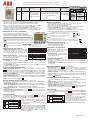
Relé de protección diferencial electrónico RGU-10
RGU-10 Electronic Earth-leakage Protection Relay
Por ejemplo RGU-10 alimentado a 110 V c.a / .For instance RGU-10 110 V a.c..supplied by
DESCRIPCIÓN GENERAL
DESCRIPCIÓN DE LOS LED Y PULSADORES.
- Dispositivo con 2 relés programables independientes, canal principal y canal de prealarma.
- Dispone de 2 salidas. Disparo de relé principal y la de señalización por prealarma.
- Dispone de 1 entrada libre de potencial para realizar un Disparo/Rearme exterior.
- Montaje en Carril DIN 46277 (EN 50022) o en panel 72x72 mediante accesorio (M5ZZF1)
- Asociado a transformador de corriente diferencial externo serie / .
- Comprueba conexión con transformador exterior mediante test inductivo.
- La detección y medida de la fuga se realiza calculando su verdadero valor eficaz (TRMS).
- Visualización por display de los valores de ajuste y de la corriente de uga instantánea.
- Indicación del estado del equipo mediante display y 2 LED.
- Ajuste y programación del equipo mediante 5 pulsadores.
- Operaciones de TEST y RESET del equipo mediante 2 pulsadores.
WG WGS
WG/WGS
-
.
INDICACIONES POR LED Y DISPLAY.
RECONEXIÓN DEL EQUIPO.
AJUSTES PARÁMETROS RELÉ PRINCIPAL
AJUSTES PARÁMETROS RELÉ PREALARMA
AJUSTES POR SETUP
- Señaliza por un cambio
de estado de color verde a rojo, tanto del LED como
del display. Se visualizan los mensajes o valores
concernientes al tipo evento que lo produce.
. Cuando la corriente
de fuga supera el umbral de prealarma programado
solo se enciende el LED amarillo.
- POR . Para volver al estado inicial del equipo se tiene que realizar un manual
o una señal de rearme externa. Por disparo forzado por señal externa, sólo se puede rearmar
por señal externa de rearme.
- POR . Para anular este estado se tiene que realizar un manual si está
configurado en modo no automático.
, . Al pulsar la tecla aparece en pantalla el mensaje
y dos valores. El más pequeño indica el valor actual configurado y en el más grande los
valores a configurar que debemos ir visualizando pulsando . Visualizado el valor escogido
se espera a que el equipo valide el valor como configurado mostrando el mensaje de SAVE.
. Al pulsar la tecla realizamos la operación con el mismo
modus operandi que el anterior ajuste.
. Al pulsar esta tecla seleccionamos el tipo de seguridad que
queremos variando la polaridad de los contactos de disparo. (Std) Standard, no aparece nada en
el display. (+) Positiva, aparece el símbolo
Para entrar en el canal de prealarma se realiza una pulsación corta en
seleccionamos el retardo de tiempo en dar la señal de prealarma.
seleccionamos el umbral de prealarma del equipo. Referidos
en%alasensibilidad escogida en el canal principal (OFF-50-60-70-80-MAIN).
Seleccionamos la polaridad de la salida de señalización de
la prealarma.
. Al activar el equipo realiza un reset de la
prealarma de forma automática cuando la corriente de fuga vuelva a estar por debajo del umbral
de prealarma programado.
Por pulsación larga en En este modo de
funcionamiento mediante los pulsadores y nos iremos desplazándo y variando valores
de configuración del equipo por los diferentes submenús de programación.
DISPARO RELÉ PRINCIPAL.
SEÑALIZACIÓN PREALARMA
DISPARO RESET
PREALARMA RESET
- AJUSTE DEL RETARDO DE DISPARO
- AJUSTE DE LA SENSIBILIDAD,
- AJUSTE DE SEGURIDAD, std/+
- AJUSTE DEL RETARDO,
- AJUSTE DE LA SENSIBILIDAD,
- AJUSTE DE POLARIDAD, std/+ .
- AJUSTE DE RESET DE PREALARMA, Auto
PROG
( , y std/+ )
( , , std/+ y Auto)
tI
tI
dd
dd
tt
I
dd
d
I
t
I
d
d
d
, activando el
mensaje de en el display.
activamos el menú de programación .
Alarm
PROG
PROG
- LED VERDE: Equipo encendido /
- LED ROJO: Disparo por fuga /
- LED AMARILLO: Prealarma /
- PULSADOR RESET /
- PULSADOR TEST /
GREEN LED: Equipment on
RED LED: Leakage trip
YELLOW LED: Prealarm
RESET BUTTON
TEST BUTTON
Causa del disparo
Mensaje display
Test
Señal remota ON/OFF
Corriente de fuga
TESt
EXT
valor instantáneo
PROG
REC
PROG
+
Pulsador
Pulsador PROG
RGU-10C
Con el pulsador navegamos por los
submenús y con el pulsador vamos visualizando
los valores a escoger. Para validar el valor tenemos
que pulsar .
El equipo configura el valor visualizando “ ”
por display y sale fuera del modo de programación. Si
transcurre un cierto tiempo con el teclado inactivo
el equipo automáticamente sale del modo de
programación visualizando “ ” por display sin
cambiar la configuración.
SAVE
EXIT
PROG
PROG
Otros MENSAJES por display
SAVE
EXIT
OVR
ERRt Mala conexión con el toroidal
Valida valores de configuración.
Sale fuera modo programación.
Lectura del valor fuera de escala.
FREC
LIM
Pulsador
50 Hz
60 Hz
10 s, 30 A
1s, 3A
P11941001
GENERAL
SETUP
-
.
-
.
-.
.
-BY .
l.
-BY .
.
-,.
t
.
SAVE.
..
.
.
.
.S
(OFF-50-60-70-80-MAIN).
.S .
.A
.
A
.
.
-
.
TRIP
PREALARM
-,
- , std/+
-,
-,
- , std/+
- , Auto
( , and std/+ )
( , , std/+ and Auto)
tI
tI
dd
dd
t
II
d
d
dd
d
d
.
t
I
DESCRIPTION
DESCRIPTION LED AND BUTTONS
INDICATION BY LED AND DISPLAY
RECLOSING THE EQUIPMENT
MAIN RELAY PARAMETER SETTING
PREALARM RELAY SETTING PARAMETERS
SETTINGS
Device with 2 independent, programmable relays, one main relay one prealarm.
- It has 2 outputs. Main trip relay and prealarm signal relay.
- It has 1 potential free input for external ON/OFF.
- Mounting in DIN rail 46277 (EN 50022) or PANEL 72x72 by means accesories M5ZFF1.
- Associated to a Series external, toroidal current transformer.
- It verifies connection with external transformer by inductive tests.
- Leakage detection and measurement is via calculating its true effective value (TRMS).
- Displays setting values and instant current different to its associated units
Shows equipment status via a display and 2 LED's.
- 5 button equipment setup and setting.
- 2 button equipment TEST and RESET
LED and display signals a
change of status by changing from green to red.
Display event type messages or values
The yellow LED only
comes on when current leakage exceeds the
preset prealarm threshold
A manual , or remote ON is required to return to the equipment's initial
status. When the trip is caused by the remote OFF signal, it can only be re-armed by the
remote ON signa
A manual has to be performed if it is in non-automatic mode to
cancel this status
The message and two values appear on the screen after
pressing the button. The lowest value indicates the current set value and the highest is the
values to be configured which are displayed by pressing The selected value to be saved
is displayed by showing the message
The same operation as above setting is carried out by pressing
The required safety type through changing the trip contact polarity
is selected by pressing this button. (Std) Standard nothing appears on the display and (+)
Positive, the symbol appears
A short press on enters the prealarm channel activating the message on the
display
. Select the time delay for giving the prealarm signal
elect the equipment's prealarm threshold. Selected sensitivity
stated as % in the main channel
elect the prealarm output signal polarity
ctivating , the equipment automatically
resets the prealarm when the leakage current drops below the preset alarm threshold
long press on activates the setting menu . Using the and buttons
in this operating mode moves and changes the preset equipment values in the different
setting submenus
WG/WGS
WG/WGS
MAIN TRIP RELAY
PREALARM SIGNAL.
RESET
RESET
SETTING TRIP DELAY
SENSITIVITY SETTING
SAFETY SETTING
PROG Alarm
DELAY SETTING
SENSITIVITY SETTING
POLARITY SETTING
SETTING OF RESET OF PREALARM
PROG PROG
Cause of trip
Message display
Test
Remote signal ON/OFF
Current leakage
TESt
EXT
instant value
PROG
REC
PROG
+
button
PROG button
RGU-10C
.
Press
“ ” por
.
“” .
SAVE
EXIT
With the button the submenus are browsed
and with the button the values to be selected
are displayed
to enter the value. The equipment
configures the value by displaying on
the display and then exits Setting Mode
If the keypad remains inactive for a certain time,
the equipment automatically exits Setting Mode
and displays without changing the setting
PROG
PROG
Other display MESSAGES
Mensaje en el display
SAVE
EXIT
OVR
ERRt
Enters setting values
Exits setting mode
Current leakage reading off scale
Poor toroidal connection
FREQ
LIM
button
50 Hz
60 Hz
10 s, 30 A
1s, 3A
-AJUSTE RETARDO /
-AJUSTE SENSIBILIDAD /
-AJUSTE SEGURIDAD /
- -AJUSTE RESET PREALARMA/
DELAY SETTING
- / SETUP ROTATION
SENSITIVITY SETTING
SAFETY SETTING
RESET PREALARM SETTING
ROTACIÓN MENÚ SETUP
SELECCIÓN VALORES EN PROGRAMACIÓN / VALUES SELECTION SETTING
- PROGRAMACIÓN POR SETUP /
- PROGRAMACIÓN PREALARMA /
SETTING BY SETUP PROGRAMMING
SETTING BY PREALARM PROGRAMMING
AUTO
Id
M98200912-20-08B

Relé de protección diferencial electrónico Series RGU-10
Electronic earth-leakage protection Relay RGU-10 Series
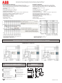
ESQUEMAS DE CONEXIÓN / CONNECTION DIAGRAM RGU-10 + WG/WGS
CONTACTOS DISPARO
/ TRIPPING CONTACTS
SALIDA NA /
SALIDA NC /
SALIDA COMÚN /
OUTPUT NO
OUTPUT NC
COMMON OUTPUT
13
14
15
CONTACTOS PREALARMA
/ PREALARM CONTACTS
SALIDA COMÚN /
SALIDA NC /
SALIDA NA /
COMMON OUTPUT
OUTPUT NC
OUTPUT NO
4
5
6
TRANSFORMADOR DIFERENCIAL
/ CORE BALANCE
ENTRADA 1S2 /
ENTRADA 1S1 /
INPUT 1S2
INPUT 1S1
8
9
ENTRADA DISPARO/REARME EXTERNA
EXTERNAL TRIP/RECLOSE
ENTRADA TENSIÓN / INPUT VOLTAGE
1
2
MARCADO DE BORNES /TERMINAL
CONNECTIONS DESIGNATIONS
DIMENSIONES
DIMENSIONS
10
ALIMENTACIÓN / POWER SUPPLY
ALIMENTACIÓN / (A1)
ALIMENTACIÓN / (A2)
SUPPLY
SUPPLY
11
45
52,5
43,5
85
67,9
Fijación carril DIN 46277 (EN 50022)
CARACTERÍSTICAS TÉCNICAS
- Tipo de relé: Electrónico, clase A. Filtrado de corriente de alta frecuencia.
- Tipo de reconexión: Manual, mediante pulsador de RESET o corte de alimentación.
- Tensión de alimentación nominal: 230 ó 110 V c.a. (+/- 20%) 50/60 Hz, 6 V·A
- Temperatura de trabajo: -10 / +50 ºC
- Conexionado:
Sección cable permitida: 0,127 - 2,082 mm
Par de apriete recomendado: 0,5-0,6 N.m
Longitud de cable a desaislar: 7 mm
Destornilladores recomendado: Varilla: 0,4 x 2,5 x 80 mm, longitud 160 mm
- Características contactos conmutados de salida 13-14-15 y 4-5-6:
Corriente Nominal/Máxima corriente instantánea: 6/10 A c.a.
Tensión Nominal: 230V c.a.
Carga Nominal en AC: 2 500 V·A
Contactos protegidos por varistor.
2
- Características entrada de disparo/rearme externo 1-2
Entrada mediante optoacoplador
Tensión máxima : 230 V c.a. ; 0,7 W
TECHNICAL FEATURES
Relay type: Electronic class A. High frequency current filtering.
- Reclosing type: Manual via RESET button or by cutting power supply.
- Rated power supply voltage
Operating temperature
Connections
Recommended tightening torque: 0.5-0.6 Nm
Length of cable to strip: 7 mm
Recommended screwdrivers length
Switch Output contact features
Rated current/Maximum instant current
Rated voltage/Maximum switching voltage
Rated load in
Permissible cable section:
- Tipo
: 230 or 110 Va.c. (+/- 20%) 50/60 Hz, 6 VA
- : -10ºC / 50ºC
-:
: Bar 0.4 x 2.5 x 80 mm, 160 mm
- 13-14-15 and 4-5-6
: 6/10 A a.c.
: 250/230 V a.c.
AC: 2,500 V·A
Contacts protected by varistor
0,127 - 2,082 mm
2
ALIMENTACIÓN C.A. / SUPPLY A.C.
- Trip/reclose input features external 1-2
Input using Optocoupler
Maximum voltage: 230 V a.c.; 0,7 W
Poder de corte para cargas DC:
Corriente máxima de apertura. (Ver gráfico adjunto)
Vida útil eléctrica para cargas AC: Nº de ciclos.
(Ver gráfico adjunto)
Electrical useful life for AC loads o. of cycles.
(See graph
:N
)
Maximun DC Load Breaking Capacity:
Maximum opening current. (See graph)
- Características varistor
Tensión máxima : 275 V c.a
- Features varistors
Maximum operating voltage: 275 V a.c.
M98200912-20-08B

mS
mA
mA
PROG
mS
mA
mA
PROG
mS
mA
mA
PROG
mS
mA
mA
PROG
mS
mA
mA
PROG
mS
mA
mA
PROG
t
d
t
d
PROG
PROG
PROG
PROG
t
d
t
d
t
d
t
d
PROG
PROG
Relé de protección diferencial electrónico Series RGU-10
Electronic earth-leakage protection Relay RGU-10 Series
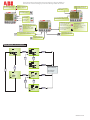
MENU SETUP / SETUP MENU
AUTO
AJUSTE SENSIBILIDAD/ SENSIVITY SETTING
POLARIDAD CONTACTOS
CONTACTS POLARITIES
AJUSTE RESET PREALARMA
SETTING RESET PREALARM
PROGRAMACIÓN POR SETUP
- Comunicaciones (RGU-10C)
- Frecuencia 50/60 Hz
- Escala Valores Corriente y tiempo.
PROGRAMACIÓN PREALARMA
- Corriente de ajuste (%I N).
- Retardo al disparo
D
0,03-0,1-0,3-0,5-1-3-5-10-30 A
ROTACIÓN MENÚ SETUP
ROTATIONAL BUTTON SETUP
AJUSTE RETARDO/DELAY SETTING
0,02-0,1-0,2-0,3-0,4-0,75-1-3-5-10 s
Curva Inversa INS-SEL
Id
LED VERDE: Equipo encendido
LED ROJO: Disparo por fuga
LED AMARILLO: Prealarma
YELLOW LED: Prealarm
PULSADOR RESET
PULSADOR TEST
BUTTON RESET
BUTTON TEST
CORRIENTE DE AJUSTE, I ND
TRIPPING CURRENT TRESHOLD
TIEMPO DE AJUSTE, td
DELAY TIME
VALOR INSTANTÁNEO DE FUGA
INSTANT LEAKAGE CURRENT VALUE
GREEN LED: Equipment ON
RED LED: Leakage trip
SETUP SETTINGS
- Communications (RGU-10C)
- Frecuency 50/60 Hz
- Range values current / time delay.
PREALARM SETTINGS
- Current adjustment (%I N).
- Delay time
D
GUARDA CAMBIOS
SALIR SETUP
SAVE CHANGES
EXIT SETUP
M98200912-20-08B
-
 1
1
-
 2
2
-
 3
3


ABB RGU-10 Electronic Earth-leakage Protection Relay Instrucciones de operación
- Categoría
- Medir, probar
- Tipo
- Instrucciones de operación
- Este manual también es adecuado para
en otros idiomas
Artículos relacionados
Otros documentos
-
Hager HR534 Manual de usuario
-
Wacker Neuson G240 Manual de usuario
-
Socomec RESYS M40 Instrucciones de operación
-
-
Wacker Neuson G150 Manual de usuario
-
-
-
-
-