Siemens SJD6-B Manual de usuario
- Categoría
- Accesorios para motocicletas
- Tipo
- Manual de usuario

s
1 / 10
Installation Instructions / Instructivo de Instalación / Instructions d'installation
Item: Sentron Series Sensitrip IV Solid State
Molded Case Circuit Breaker
For Use With: JD Frame Types SJD6-B, SHJD6-B, SCJD6-B
LD Frame Types SLD6-B, SHLD6-B, SCLD6-B
Use only with Siemens certified Components.
Utilizar únicamente con componentes certificados de Siemens.
À utiliser uniquement avec les composantes certifiées Siemens.
Turn off and lock out all power supplying this equipment
before working on this device.
Replace all covers before power supplying this device is
turned on.
Mettre hors tension et cadenasser verrouiller l’alimentation
avant d’intervenir sur cet appareil.
Remettre tous les couvercles en place avant de remettre
cet appareil sous tension.
Tensión peligrosa.
Puede causar la muerte o lesiones graves. Tension dangereuse.
Provoquera la mort ou des blessures graves.
Hazardous Voltage
Will cause death or serious injury Desenergice totalmente el equipo antes de instalar o darle
servicio.
Reemplace todas las barreras y cubiertas antes de
energizar el interruptor.
NOTE - These instructions do not purport to cover all details or variations in equipment, or to provide for every possible
contingency to be met in connection with installation, operation or maintenance. Should further information be desired or
should particular problems arise, which are not covered sufficiently for the purchaser’s purposes, the matter should be
referred to the local Siemens sales office. The contents of this instruction manual shall not become part of or modify any prior
or existing agreement, commitment or relationship. The sales contract contains the entire obligation of Siemens. The
warranty contained in the contract between the parties is the sole warranty of Siemens. Any statements contained herein do
not create new warranties or modify the existing warranty.
Trademarks - Unless otherwise noted, all names identified by ® are registered trademarks of Siemens AG or Siemens
Industry, Inc. The remaining trademarks in this publication may be trademarks whose use by third parties for their own
purposes could violate the rights of the owner.
NOTA - Estas instrucciones no pretenden incluir todos los detalles o variaciones de los equipos ni indicar cada posible
contingencia que pudiese encontrar en relación con la instalación, el funcionamiento o el mantenimiento. Si desea más
información o si surgen problemas en particular, que no estén explicados suficientemente para fines del comprador, el
asunto se debe referir a la oficina de ventas local de Siemens. El contenido de este manual de instrucciones no debe
formar parte ni modificar una relación, acuerdo o compromiso o previo o existente. El contrato de venta contiene toda la
obligación por parte de Siemens. La garantía contenida en el contrato establecido entre las partes es la única garantía de
Siemens. Las declaraciones contenidas en el presente documento no crean nuevas garantías ni modifican la que está en
vigor.
Marcas comerciales - A menos que se indique lo contrario, todos los nombres identificados con ® son marcas
comerciales registradas de Siemens AG o Siemens Industry, Inc. Las marcas comerciales restantes que aparecen en esta
publicación pueden ser marcas comerciales cuyo uso por parte de terceros para sus propios fines podría violar los
derechos del propietario.
REMARQUE - Ces instructions ne prétendent pas couvrir tous les détails ou les variations de l'équipement, ni prévoir
chaque éventualité pouvant être rencontrée lors de la connexion, l'exploitation ou l’entretien. Si plus d’information est
désirée ou si des problèmes particuliers surviennent, qui ne sont pas couverts suffisamment aux fins de l'acheteur, il faut
adresser ces questions au bureau local de Siemens. Le contenu de ce manuel d'instruction ne fera pas partie de tout
accord, engagement ou relation préalable ou existant et ne le modifiera pas. Le contrat de vente contient l'obligation
intégrale de Siemens. La garantie contenue dans le contrat entre les parties est la garantie unique offerte par Siemens.
Toute autre déclaration contenue aux présentes ne crée pas de nouvelles garanties et ne modifie pas la garantie existante.
Marques de commerce – Sauf indication contraire, tous les noms identifiés par MD sont des marques déposées de
Siemens AG ou de Siemens Industry, Inc. Les autres marques dans cette publication peuvent être des marques dont
l'utilisation par des tiers à leurs propres fins pourrait violer les droits du propriétaire.
5/16“
R813152A01

INTRODUCTION
The JD and LD Frame circuit breaker line
includes types SJD6-B, SHJD6-B,
SCJD6-B, SLD6-B, SHLD6-B, and
SCLD6-B circuit breaker types. These circuit breakers are
listed under UL489 and rated for operating voltages up to
600 VAC, 50/60 Hz.
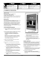
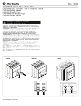
INSTALLATION
The JD and LD Frame circuit breakers (See Fig. 1) are for
use in individual enclosures, panelboards, or other
approved equipment. The installation procedure consists
of inspecting, attaching required accessories, mounting
the circuit breaker and connecting and torquing the line
and load wire connectors. Mounting hardware and
unmounted wire connectors (where required) are available
as separate catalog items.
CIRCUIT BREAKER PREPARATION
A. Before installing or servicing the breaker, turn off and
lock out all power to prevent incidental or accidental
contact.
B. Make sure that the device is suitable for the installation
by comparing nameplate ratings with system
requirements. Inspect the circuit breaker for
completeness and check for any damage before
mounting.
NOTE: Accessory installation should be completed
before the circuit breaker is mounted and connected.
(See installation instructions supplied with the
accessory before proceeding.)
C. Depress the red trip button (See Fig 4) or turn the
breaker off before installation.
D. To mount the circuit breaker, perform the following
steps:
1. For enclosures, panelboards and switchboards
manufactured by Siemens Industry, Inc., follow the
instructions provided with the equipment.
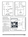
2. For applications where mounting is on a flat
surface of the equipment, drill and tap mounting
bolt holes as shown in Fig. 2. For escutcheon cut
out refer to Fig. 3.
3. Ensure that any internal accessory terminals can
be properly connected with the circuit breaker in
the mounted position.
4. Position the circuit breaker in the mounting
location, install the mounting hardware and tighten
securely.
Installation Instructions
2 / 10
Turn off and lock out all power supplying this equipment
before working on this device.
Replace all covers before power supplying this device is
turned on.
Mettre hors tension et cadenasser verrouiller l’alimentation
avant d’intervenir sur cet appareil.
Remettre tous les couvercles en place avant de remettre
cet appareil sous tension.
Tensión peligrosa.
Puede causar la muerte o lesiones graves. Tension dangereuse.
Provoquera la mort ou des blessures graves.
Hazardous Voltage
Will cause death or serious injury Desenergice totalmente el equipo antes de instalar o darle
servicio.
Reemplace todas las barreras y cubiertas antes de
energizar el interruptor.
R81315201
5. Connect the line and load terminals and
torque using the values shown on the circuit
breaker nameplate.
6. Connect all accessory terminals, if present.
7. Check all mounting hardware for secureness.
Check wire connectors for correct torque
requirements per the rating label on the front of
the breaker.
MANUAL OPERATION
Manual operation of the circuit breaker is controlled by the
circuit breaker handle and the PUSH-TO-TRIP button.
The circuit breaker handle has three indicating positions,
two of which are molded into the handle to indicate ON
and OFF. The third position indicates a TRIP position and
is between the ON and OFF positions. (See Fig. 4)
A. Circuit Breaker Reset
After tripping, the circuit breaker is reset by moving the
circuit breaker handle to the reset position and then
moving the handle to the ON position.
B. The PUSH-TO-TRIP Button
The PUSH-TO-TRIP button checks the tripping
function and is used to manually exercise the tripping
mechanism.
Fig. 1: JD, LD Frame

3 / 10
ELECTRONIC OPERATION
All circuit breaker devices have
adjustable Continuous Current and
Instantaneous Overcurrent protection.
Optional features include Short Time
Overcurrent and Ground Fault protection.
Breaker functionality is denoted in the
catalog number suffixes. There are four
types of configurations LI, LSI, LIG and
LSIG.
L = Continuous Current (Ir) and Long
Time Delay (tld)
I = Instantaneous Pickup (Ii)
S = Short Time Pickup (Isd) and Short
Time Delay (tsd)
G = Ground Fault Pickup and Ground
Fault Delay (tg)
The setting dials on the face of the
electronic trip unit are rotary switches
that must be properly set to mechanical
detent (click stop) positions. Dial settings
not set to the detent position will cause
the setting to be either value between the
dial setting and, consequently, may result
in unintentional or nuisance tripping.
There are ten (10) positions on each
rotary switch and the circuit breaker is
shipped with all settings in the minimum
settings.
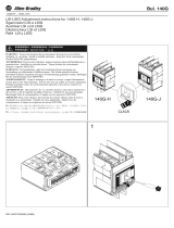
Fig. 2: Mounting template Fig. 3: Escutcheon Cut Out
Fig. 4: Handle and Push to Trip Button
R81315201
PUSH-TO-TRIP BUTTON

Turn off and lock out all power supplying this equipment
before working on this device.
Replace all covers before power supplying this device is
turned on.
Mettre hors tension et cadenasser verrouiller l’alimentation
avant d’intervenir sur cet appareil.
Remettre tous les couvercles en place avant de remettre
cet appareil sous tension.
Tensión peligrosa.
Puede causar la muerte o lesiones graves. Tension dangereuse.
Provoquera la mort ou des blessures graves.
Hazardous Voltage
Will cause death or serious injury Desenergice totalmente el equipo antes de instalar o darle
servicio.
Reemplace todas las barreras y cubiertas antes de
energizar el interruptor.
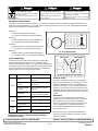
4 / 10
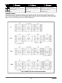
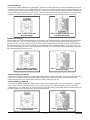
Continuous Current (Ir)
All model types have an adjustable Continuous Current dial setting. The first dial is always used to adjust the Continuous
Current setting of the circuit breaker and the markings are displayed in Amps. The Long Time Pickup (Ild) setting is set to Irx
1.15. LI and LIG configurations have ten (10) adjustable settings and the LSI and LSIG configurations have five (5) adjustable
settings. See Fig. 5 for an example of the four LD 600A configurations.
LI
LSI
LIG
LSIG
Fig. 5: LD 600A LI, LSI, LIG & LSIG trip unit dial settings
R81315201

5 / 10
Long Time Delay (tld)
All model types have an adjustable Long Time Delay. The Long Time Delay times are an I2t function calibrated at 6 times the
Continuous Current setting. For LI and LIG breakers (see Fig. 6), there are ten (10) Long Time Delay settings that range from
2.5 to 30 seconds. For LSI and LSIG breakers (see Fig. 7), there are two Long Time Delay settings which are selected based
on the Continuous Current setting. As shown in Fig. 7, the Continuous Current settings on the left selects a Long Time Delay
setting of 10 seconds and the Continuous Current settings on the right select a Long time Delay setting of 20 seconds.
Fig. 6: LI and LIG Long Time
Delay dial settings Fig. 7: LD 600A LSI and LSIG Long
Time Delay dial settings
Instantaneous Pickup (Ii)
All model types have an adjustable Instantaneous Pickup setting. This adjustment sets the Instantaneous Overcurrent Pickup
of the circuit breaker. For LI, LSI, and LIG breakers (see Fig. 8), there are ten (10) Instantaneous Pickup settings that are
displayed in Amps. For LSIG breakers (see Fig. 9), there are two Instantaneous Pickup settings which are selected based on
the Short Time Pickup setting. These two settings are a multiple of the maximum Frame Rating (In). As shown in Fig. 9, the
Short Time Pickup settings on the left select an Instantaneous Pickup of 5 x Inand the Short Time Pickup settings on the right
select an Instantaneous Pickup of 10.5 x In.
Fig. 8: LD 600A LI, LSI and LIG
Instantaneous Pickup dial settings Fig. 9: LD 600A LSIG Instantaneous
Pickup dial settings
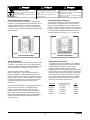
Short Time Pickup (Isd) (Optional)
Circuit breakers with the LSI and LSIG catalog number suffixes have an adjustment to set the Short Time Pickup. Short Time
Pickup is an overcurrent protection setting with intentional tripping delay. There are ten (10) Short Time Pickup current
settings that range from 1.5 to 10 times the Continuous Current (lr) setting (see Fig. 10).
Short Time Delay (tsd) (Optional)
Circuit breakers with the LSI and LSIG catalog number suffixes have an adjustment to set the Short Time Delay. Short Time
Delay is either a fixed or I2t time delay function. The I2t function is based on a calibration point of 8 times the Continuous
Current Setting (lr). As shown in Fig. 11, the five (5) settings on the left select the fixed (FIXED) Short Time Delay settings and
the five (5) settings on the right select the I2t Short Time Delay settings.
Fig. 10: LSI and LSIG Short Time
Pickup dial settings Fig. 11: LSI and LSIG Short Time
Delay dial settings
R81315201

Turn off and lock out all power supplying this equipment
before working on this device.
Replace all covers before power supplying this device is
turned on.
Mettre hors tension et cadenasser verrouiller l’alimentation
avant d’intervenir sur cet appareil.
Remettre tous les couvercles en place avant de remettre
cet appareil sous tension.
Tensión peligrosa.
Puede causar la muerte o lesiones graves. Tension dangereuse.
Provoquera la mort ou des blessures graves.
Hazardous Voltage
Will cause death or serious injury Desenergice totalmente el equipo antes de instalar o darle
servicio.
Reemplace todas las barreras y cubiertas antes de
energizar el interruptor.
6 / 10
Ground Fault Pickup (lg) (Optional)
Circuit breakers with the LIG and LSIG catalog number
suffixes have integral equipment ground fault protection in
compliance with UL1053. The Ground Fault Pickup (Ig)
setting is displayed in Amps. As shown in Fig. 12, there
are three (3) Ground Fault Pickup settings available: 240A,
360A and 600A.
Ground Fault Delay (tg) (Optional)
Circuit breakers with the LIG and LSIG catalog number
suffixes, have an adjustment to set the Ground Fault
Delay. Ground Fault Delay is an I2t time delay function
based on a calibration point of 3 times the Ground Fault
Pickup (Ig) setting. As shown in Fig. 13, there are four (4)
Ground Fault Delay settings selectable based on the
Ground Fault Pickup (Ig) setting: .1s, .2s, .3s and .32s.
Fig. 12: LD 600A LIG and LSIG Ground
Fault Pickup dial settings Fig. 13: LD 600A LIG and LSIG Ground
Fault Delay dial settings
Ground Fault Method
The integral ground fault protection option has two modes
of operation. The mode is set by a DIP switch under the
trip unit cover with the settings defined as RESIDUAL and
GROUND RETURN. See Fig. 17 for switch location.
These two modes function as follows:
RESIDUAL METHOD – This is the default position to
which the breaker is set when shipped from the factory.
With the switch in this position the circuit breaker may be
used on 3 phase 3 wire or, with the addition of an external
neutral sensing transformer, on 3 phase 4 wire systems.
See Neutral Sensing Transformer section for more
information.
GROUND RETURN METHOD – This setting may only be
used for service disconnects or separately derived
systems. With the switch in this position, the circuit
breaker may be used on 3 phase 3 wire and 3 phase 4
wire systems. An external sensing transformer, which is
installed on the main bonding jumper, is required for this
method. See Neutral Sensing Transformer section for
more information.
Neutral Sensing Transformer
An external transformer is required for circuit breakers
equipped with ground fault protection when operating
in the RESIDUAL METHOD on 3 phase 4 wire
systems and when operating in the GROUND
RETURN METHOD on any system. The sensors listed
below must be used for these applications. The sensor
catalog number must be matched to the circuit breaker
Frame Rating (ln) as shown in the table. Please note
that sensors used with other breaker types cannot be
used with the SJD/SLD circuit breakers. Installation
instructions are included with the sensors.
Catalog No. Max Ampere Rating Color
N02SJD 200 Amps GREEN
N03SJD 300 Amps GREEN
N04SLD 400 Amps GREEN
N05SLD 500 Amps GREEN
N06SLD 600 Amps GREEN
R81315201

7 / 10
Maintenance Mode
The National Electrical Code (NFPA 70) mandates that all circuit breakers 1200A and larger be equipped with means to
reduce the arc flash energy while a worker is within the circuit breaker arc-flash boundary as defined in NFPA 70E-2012,
Standard for Electrical Safety in the Workplace. The Sentron Series Sensitrip IV circuit breakers with “6A” included in the
catalog number meet this requirement by use of a Maintenance Mode (MM) setting.
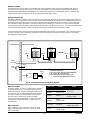
MM Operating Principle
The MM is initiated by maintenance personnel pressing a normally open (NO) latching “maintenance switch” either before or
upon entering a room to perform service. The first circuit breaker interprets the closed contact as a digital input command and
immediately enables the MM setting of 2xInwith no intentional delay and illuminates its local blue LED. The circuit breaker
then activates its output signal which is connected to the next circuit breaker in a series chain. The second circuit breaker
receives the input and immediately enables its MM and illuminates its local blue LED, and so on. The last circuit breaker in the
system activates the “maintenance light” as indication that all the circuit breakers in the system are in MM.
All circuit breakers that receive the input signal shall maintain MM, even with loss of control power, until a valid OFF signal is
received. The OFF signal is initiated by maintenance personnel opening the “maintenance switch” with the control power
maintained for at least 1 second.
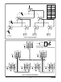
Fig. 14: Example Maintenance Mode Wiring Diagram
MM Technical Data
An external 24VDC, UL Class 2, power supply is required
to implement this feature. On the right side of the circuit
breaker are six multi-colored, 2-foot length, 18 AWG wires
for connection. It is recommended that the interconnection
wiring be 12-18 AWG, shielded, twisted-pair and 1000-
feet (300-meters). Refer to Fig. 14 for an example
maintenance mode wiring diagram. In this example, the
recommended components listed can support up to 25
circuit breakers.
MM Configuration
MM is enabled by a DIP switch under the trip unit cover
and the default setting is set to MM. See Fig. 17 for DIP
switch configuration.
Wire Color Function Rating
RED 24VDC LINE 24VDC ±20%
20mA max.
BLACK 24VDC COM
WHITE INPUT+ 24VDC
5mA typ. sinked
BROWN INPUT-
(24VDC COM)
YELLOW OUTPUT+ 24VDC
100mA max. sourced
BLUE OUTPUT-
(24VDC COM)
R81315201
BLACK
WHITE
BROWN
YELLOW
BLUE
RED
CIRCUIT
BREAKER
#1
SWITCHGEAR ROOMCONTROL ROOM
24VDC
Switch
BLACK
WHITE
BROWN
YELLOW
BLUE
RED
CIRCUIT
BREAKER
#2
24VDC
BLACK
WHITE
BROWN
YELLOW
BLUE
RED
CIRCUIT
BREAKER
#n
24VDC
24VDC
Light
AC/DC
Power
Supply
24VDC
120V
Recommended Components:
AC/DC Power Supply - Siemens, 6EP3331-6SB00-0AY0
Light - Siemens, 3SU1102-6AA50-1AA0
Switch - Siemens, 3SU1100-4BF11-1BA0 (keyed)
Siemens, 3SU1100-2BF60-1BA0 (non-keyed)
Maint.
Maint.

Turn off and lock out all power supplying this equipment
before working on this device.
Replace all covers before power supplying this device is
turned on.
Mettre hors tension et cadenasser verrouiller l’alimentation
avant d’intervenir sur cet appareil.
Remettre tous les couvercles en place avant de remettre
cet appareil sous tension.
Tensión peligrosa.
Puede causar la muerte o lesiones graves. Tension dangereuse.
Provoquera la mort ou des blessures graves.
Hazardous Voltage
Will cause death or serious injury Desenergice totalmente el equipo antes de instalar o darle
servicio.
Reemplace todas las barreras y cubiertas antes de
energizar el interruptor.
8 / 10
Zone Selective Interlocking (Optional)
Sentron Series Sensitrip IV circuit breakers with “6A” included in the catalog number support Zone Selective Interlocking (ZSI).
ZSI is a method which allows two or more circuit breakers to communicate with each other so that a short circuit or ground
fault will be cleared by the breaker closest to the fault with a minimum time delay. The primary goal of ZSI is to limit stress on
the distribution system by clearing a fault in the shortest time without sacrificing coordination. The benefits of ZSI are lower
potential costs of system damage due to the reduced time to clear faults and increased uptime because coordination is not
sacrificed.
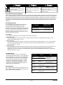
ZSI Example
Fig. 15 shows an example of a ZSI system with set Short Time Delay times.
Short-circuit at SC1:
Only CB1 establishes that a short-circuit has occurred and does not receive a restraint signal from CB2. For this
reason, CB1 trips after tsd(ZSI) = 50 ms
Short-circuit at SC2:
CB1 and CB2 establish that a short-circuit has occurred. CB2 issues a restraint signal to CB1. The tsd for CB1 will be
set to its programmed setting of 300ms. CB2 does not receive a restraint signal from CB4 or CB5. For this reason,
CB2 trips after tsd(ZSI) = 50 ms
Short-circuit at SC3:
CB1, CB2 and CB4 establish that a short-circuit has occurred. CB4 issues a restraint signal to CB2 and CB2 issues a
restraint signal to CB1. The tsd for CB1 and CB2 will be set to their programmed setting of 300ms and 200ms,
respectively. CB4 does not receive a restraint signal since it is the last circuit breaker in the system. For this reason,
CB4 trips after tsd(ZSI) = 50 ms
FUNCTION NON-RESTRAINT
TRIPPING TIME
Short Time Delay tsd(ZSI) = 50ms
Ground Fault Delay tg(ZSI)= 100ms
ZSI Operating Principle
In a distribution system comprised of several levels,
each circuit breaker affected by a short-circuit
communicates with the circuit breaker directly
downstream, to ascertain whether the short-circuit also
occurred. All downstream circuit breakers experiencing
the short-circuit provide a restraint signal to all circuit
breakers upstream so that the circuit breaker closest to
the short-circuit clears the fault.
ZSI Technical Data
An external 24VDC, UL Class 2, power supply is
required to implement this feature. On the right side of
the circuit breaker are six multi-colored, 2-foot length,
18 AWG wires for connection. It is recommended that
the interconnection wiring be 12-18 AWG, shielded,
twisted-pair and 1000-feet (300-meters). Refer to
Fig. 16 for an example ZSI wiring diagram. In this
example, the recommended components listed can
support up to 50 circuit breakers.
ZSI Configuration
ZSI is enabled by a DIP switch under the trip unit cover
and the default setting is set to Maintenance Mode. See
Fig. 17 for DIP switch configuration.
Wire Color Function Rating
RED 24VDC LINE 24VDC ±20%
20mA max.
BLACK 24VDC COM
WHITE INPUT+ 24VDC
5mA typ. sinked
BROWN INPUT-
(24VDC COM)
YELLOW OUTPUT+ 24VDC
100mA max. sourced
BLUE OUTPUT-
(24VDC COM)
R81315201

AC/DC
Power
Supply
24VDC
120V
Recommended Components:
AC/DC Power Supply - Siemens, 6EP3331-6SB00-0AY0
9 / 10
CB1 OUT
IN
CB2 OUT
IN CB3 OUT
IN
CB4 OUT
IN CB5 OUT
IN CB7 OUT
IN
CB6 OUT
IN
LOAD LOAD LOAD LOAD
SC1
SC2
SC3
Fig. 15: Example ZSI System
BLACK
WHITE
BROWN
YELLOW
BLUE
RED
CB1
24VDC
BLACK
WHITE
BROWN
YELLOW
BLUE
RED
CB7
24VDC
BLACK
WHITE
BROWN
YELLOW
BLUE
RED
CB4
24VDC
BLACK
WHITE
BROWN
YELLOW
BLUE
RED
CB5
24VDC
BLACK
WHITE
BROWN
YELLOW
BLUE
RED
CB6
24VDC
BLACK
WHITE
BROWN
YELLOW
BLUE
RED
CB2
24VDC
BLACK
WHITE
BROWN
YELLOW
BLUE
RED
CB3
24VDC
Fig. 16: Example ZSI Wiring Diagram
Circuit
Breaker tsd
(msec)
CB1 300
CB2 200
CB3 200
CB4 100
CB5 100
CB6 100
CB7 100
R81315201

Technical Support: Toll Free: 1-800-241-4453 Internet: www.usa.siemens.com/powerdistribution
Subject to change without prior notice
Siemens Industry, Inc., Norcross, GA 30092 © Siemens Industry Inc. 2018
Turn off and lock out all power supplying this equipment
before working on this device.
Replace all covers before power supplying this device is
turned on.
Mettre hors tension et cadenasser verrouiller l’alimentation
avant d’intervenir sur cet appareil.
Remettre tous les couvercles en place avant de remettre
cet appareil sous tension.
Tensión peligrosa.
Puede causar la muerte o lesiones graves. Tension dangereuse.
Provoquera la mort ou des blessures graves.
Hazardous Voltage
Will cause death or serious injury Desenergice totalmente el equipo antes de instalar o darle
servicio.
Reemplace todas las barreras y cubiertas antes de
energizar el interruptor.
R81315201
10 / 10
1National Electrical Code® is a Registered Trademark of the National
Fire Protection Association.
DIP SWITCH CONFIGURATION
On the front of the Sensitrip IV trip unit there is a 4 position configuration switch for configuring the Maintenance Mode, ZSI
Mode and Ground Fault Method. Use a small pocket screwdriver to open the access cover. The shipping default of this DIP
switch is with all positions in the DOWN position.
Switch #1:
DOWN = Selects Maintenance Mode
UP = Selects Zone Selective Interlocking Mode
Switch #2:
DOWN = Disables Short Time Zone Interlocking
UP = Enables Short Time Zone Interlocking
Switch #3:
DOWN = Disables Ground Fault Zone Interlocking
UP = Enables Ground Fault Zone Interlocking
Switch #4:
DOWN = Selects Ground Fault Residual Method
UP = Selects Ground Fault Ground Return Method
Electronic Testing
Sensitrip IV solid state molded case circuit breakers
may be tested for electronic functionality by the use of
ELTPHB or EPSP18V test sets, available from local
Siemens sales offices. See Fig. 18 for location of test
connector. NOTE: Time current characteristic curves
and information on factory installed accessories can be
obtained from local Siemens sales offices or Siemens
Online.
Maintenance
JD and LD frame circuit breakers are designed to
provide years of maintenance free service. However,
some industrial users may choose to establish an
inspection and maintenance procedure to be carried
out on a regular basis. For detailed information,
consult applicable NEMA publication or your local
Siemens sales office.
NOTE: Do not spray or allow any petroleum based
chemicals, solvents or paints to contact the molded
parts or nameplates.
UP
DOWN
Fig. 17: Configuration Switch
STATUS INDICATORS
On the front of the Sensitrip IV trip unit there are 3 LED status
indicators that display the status of the circuit breaker: Active,
Overload and Maintenance Mode. The Active and Overload LEDs
are available on all circuit breaker types and the Maintenance Mode
LED is only available on circuit breakers with “6A” included in the
catalog number. See Fig. 18 for location of LEDs.
Fig. 18: Status Indicators and Test Connector
Test Connector Status Indicators
LED State Trip Unit State
Active
OFF Ok. Ipri < min Ipri to power
trip unit
Flashing GREEN
(1 Hz) Ok. Trip unit fully
operational.
Flashing GREEN
(>>1Hz) Ok. Ipri < min Ipri to power
trip unit
Static RED Trip unit in error state.
Contact technical support.
Overload
OFF Ok
Flashing AMBER Trip pending Ipri > Ir
Static Amber Trip pending Ipri > Ir* 115%
Maint.
Mode
OFF Maintenance mode OFF
Static BLUE Maintenance mode ON
-
 1
1
-
 2
2
-
 3
3
-
 4
4
-
 5
5
-
 6
6
-
 7
7
-
 8
8
-
 9
9
-
 10
10


Siemens SJD6-B Manual de usuario
- Categoría
- Accesorios para motocicletas
- Tipo
- Manual de usuario
En otros idiomas
- français: Siemens SJD6-B Manuel utilisateur
- English: Siemens SJD6-B User manual
Documentos relacionados
Otros documentos
-
ABB SACE Emax Instructions For Installation And Service
-
GE EntelliGuard G Installation, Operation and Maintenance Manual
-
 Rockwell Automation Allen-Bradley 140G-N Getting Started
-
 Allen-Bradley 140G-J Guía de inicio rápido
-
 Allen-Bradley 140G Series Adjustment Instructions
-
Miller 117.205710 Manual de usuario
-


