
Drill Bits: 1/2”
Wrenches: 7/8”
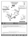
Installation Instructions
CHRYSLER SEBRING
CONVERTIBLE
Part Numbers:
77092
24711
60850
Hitch Shown In Proper Position
Wiring Access Location: PC3, PC4
Equipment Required:
1. FISHWIRE BLOCK AND CARRIAGE BOLT THROUGH ACCESS HOLE AT TOP OF FRAME RAIL AND INTO EXISTING HOLES.
2. RAISE HITCH INTO POSITION AND SECURE WITH CONICAL TOOTHED WASHERS AND NUTS.
3. USING FORWARDMOST SLOT IN HITCH AS A TEMPLATE, DRILL 1/2” HOLE INTO FRAME RAIL, EACH SIDE.
4. FISHWIRE REMAINING BLOCKS AND CARRIAGE BOLTS INTO THE HOLES DRILLED IN STEP3. SECURE WITH CONICAL TOOTHED
WASHERS AND NUTS.
z 2006,2007,2015 Cequent Towing Products – Printed in Mexico
Sheet 1 of 3 N24711 10-19-15 Rev. D
1
11
1
Qty. (4) Bolt, Carriage 1/2-13 x 1.75
3
33
3
Qty. (4) Washer, Conical Toothed
2
22
2
Qty. (4) Block, 0.25 x 1.50 x 2.00
4
44
4
Qty. (4) Nut, 1/2-13
Tighten all 1/2-13 fasteners with torque wrench to 75 Lb.-Ft.
Note: check hitch frequently, making sure all fasteners and ball are properly tightened. If hitch is removed, plug all holes in trunk pan or other body panels to
prevent entry of water and exhaust fumes. A hitch or ball which has been damaged should be removed and replaced. Observe safety precautions when working
beneath a vehicle and wear eye protection. Do not cut access or attachment holes with a torch.
This product complies with safety specifications and requirements for connecting devices and towing systems of the state of New York, V.E.S.C. Regulation V-5
and SAE J684.
2000 LB (908 Kg) Max Gross Trailer Weight
200 LB (90.8 Kg) Max Tongue Weight
Do Not Exceed Lower of Towing Vehicle
Manufacturer’s Rating or
Drawbar must be used in the
RISE position only.
Drawbar Kit:
3592
Fastener Kit: F24711
Form F206 Rev A 5605
FRAME RAIL
EXISTING HOLE
IN FRAME RAIL
EACH SIDE
DRILL HOLE
IN FRAME RAIL
EACH SIDE
ACCES HOLE AT
TOP OF FRAME RAIL
ACCES HOLE AT
TOP OF FRAME RAIL
FRAME
DRILLED HOLE
EXAMPLE OF FISHWIRE PROCEDURE
KINK FISHWIRE
TO KEEP BLOCK
INDEPENDENT OF BOLT
EXISTING
HOLE
1
11
12
22
23
33
34
44
4
(Sold separately)

Mèche : 1/2 po
Clé : 7/8 po
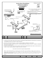
Instructions d’installation
CHRYSLER SEBRING
CONVERTIBLE
Numéros de pièces :
77092
24711
60850
Attelage montré dans la position
appropriée
Points d’accès au câblage : PC3, PC4
Équipement requis :
1. À L’AIDE D’UN FIL DE TIRAGE, FAIRE PASSER UN BLOC ET UN BOULON DE CARROSSERIE DANS LE TROU D’ACCÈS SUR LE DESSUS
DU LONGERON DE CHÂSSIS, PUIS DANS LES TROUS EXISTANTS .
2. SOULEVER L’ATTELAGE EN POSITION, PUIS FIXER À L’AIDE DES RONDELLES CONIQUES ET DES ÉCROUS.
3. EN UTILISANT LA FENTE À L’EXTRÊME AVANT DE L’ATTELAGE COMME GABARIT, PERCER UN TROU DE 1/2 PO DANS LE LONGERON
DE CHÂSSIS, DE CHAQUE CÔTÉ.
4. À L’AIDE D’UN FIL DE TIRAGE, FAIRE PASSER LES BLOCS ET BOULONS DE CARROSSERIE RESTANTS DANS LES TROUS PERCÉS À
L’ÉTAPE 3. FIXER À L’AIDE DE RONDELLES CONIQUES DENTÉES ET D'ÉCROUS .
z 2006,2007, 2015 Cequent Towing Products - Imprimé au Mexique Feuille 2 de 3 N24711 10-19-15 Rev. D
1
11
1
Qté (4) Boulon de carrosserie 1/2-13 x 1.75
3
33
3
Qté (4) Rondelle conique dentée
2
22
2
Qté (4) Bloc 0.25 x 1.50 x 2.00
4
44
4
Qté (4) Écrou 1/2-13
Serrer toute la visserie 1/2-13 au couple de 75 lb-pi (102 N*M).
Remarque : Vérifier l’attelage fréquemment, en s’assurant que toute la visserie et la bille sont serrées adéquatement. Si l’attelage est enlevé, boucher tous les
trous percés dans le coffre ou la carrosserie afin de prévenir l’infiltration d’eau ou de gaz d’échappement. Un attelage ou bille endommagés doivent être enlevés
et remplacés. Observer les mesures de sécurité appropriées en travaillant sous le véhicule et porter des lunettes de protection. Ne jamais utiliser une torche pour
découper un accès ou un trou de fixation.
Ce produit est conforme aux normes V-5 et SAE J684 de la V.E.S.C. (État de New York) concernant les spécifications en matière de sécurité des systèmes
d’attelage.
2 000 lb (908 kg) Poids brut max. de la remorque
200 lb (90,8 kg) Poids max. au timon
Ne pas excéder les spécifications du fabricant
de véhicules de remorquage, ou
La barre de remorquage doit
être utilisée dans la position
ÉLEVÉE seulement.
Ensemble de barre
de remorquage :
3592
Visserie : F24711
Form F206 Rev A 5605
LONGERON DE CHÂSSIS
TROU EXISTANT DANS LE LONGERON DE
CHAQUE CÔTÉ
PERCER UN TROU
DANS LE LONGERON
DE CHAQUE CÔTÉ
TROU D’ACCÈS SUR
LE DESSUS
DU LONGERON
TROU D’ACCÈS SUR
LE DESSUS DU LONGERON
LONGERON
TROU PERCÉ
EXEMPLE DU PASSAGE DU FIL DE TIRAGE
ENTORTILLER LE FIL DE TIRAGE
POUR TENIR LE BLOC À L'`ÉCART DU BOULON
TROU EXISTANT
1
11
12
22
23
33
34
44
4
(Vendu séparément)

Brocas de taladro: 1/2”
Llaves: 7/8”
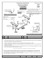
Instrucciones de instalación
CHRYSLER SEBRING
CONVERTIBLE
Números de partes:
77092
24711
60850
El enganche se muestra en la posición correcta
Ubicación del acceso al cableado:
PC3, PC4
Equipo necesario:
1. INSERTE CON ALAMBRE EL BLOQUE Y EL PERNO DE CARRUAJE A TRAVÉS DEL ORIFICIO DE ACCESO EN LA PARTE SUPERIOR DEL
LARGUERO DEL BASTIDOR Y EN LOS ORIFICIOS EXISTENTES.
2. LEVANTE EL ENGANCHE A SU POSICIÓN Y ASEGURE CON ARANDELAS CÓNICAS DENTADAS Y TUERCAS.
3. USANDO LA RANURA MÁS DELANTERA EN EL ENGANCHE COMO PLANTILLA, PERFORE UN ORIFICIO DE 1/2” EN EL LARGUERO DEL
BASTIDOR, EN CADA LADO.
4. INSERTE CON ALAMBRE LOS BLOQUES RESTANTES Y LOS PERNOS DE CARRUAJE EN LOS ORIFICIOS PERFORADOS EN EL PASO 3.
ASEGURE CON ARANDELAS CÓNICAS DENTADAS Y TUERCAS.
z 2006,2007,2015 Cequent Towing Products - Impreso en México
Hoja 3 de 3 N24711 10-19-15 Rev. D
1
11
1
Cant. (4) Perno de carruaje 1/2-13 x 1.75
3
33
3
Cant. (4) Arandela, cónica dentada
2
22
2
Cant. (4) Bloque, 0.25 x 1.50 x 2.00
4
44
4
Cant. (4) Tuerca, 1/2-13
Apriete todos los tornillos 1/2-13 con una llave de torsión a 75 Lb.-pies (102 N*M).
Nota: Revise el enganche con frecuencia, verificando que todos los tornillos y la bola estén correctamente apretados. Si se quita el enganche
tape todos los orificios en el colector del baúl u otros paneles de la carrocería para evitar la entrada del agua y los gases del escape. Se debe
retirar y reemplazar un enganche o bola que se haya dañado. Observe las precauciones de seguridad al trabajar por debajo del vehículo y use
protección visual. No corte los orificios de acceso o accesorios con soplete.
Este producto cumple con las especificaciones y requisitos de seguridad para conectar dispositivos y sistemas de remolque del estado de Nueva
York, V.E.S.C. Regulación V-5 y SAE J684
2000 LB (908 Kg) Peso bruto máximo del remolque
200 LB (90.8 Kg) Peso máximo de la horquilla
No supere el valor inferior entre la calificación del
fabricante del vehículo del remolque o
La barra de tracción se debe
usar en la posición
LEVANTADA únicamente
Kit de barra de tracción:
3592
Kit de tornillos: F24711
Form F206 Rev A 5605
LARGUERO
DEL BASTIDOR
ORIFICIO EXISTENTE
EN LARGUERO DEL
BASTIDOR EN CADA
COSTADO
PERFORE EL ORIFICIO
EN CADA LADO DEL
LARGUERO DEL BASTIDOR
ORIFICIO DE ACCESO
EN LA PARTE SUPERIOR
DEL LARGUERO
DEL BASTIDOR
ORIFICIO DE ACCESO EN LA
PARTE SUPERIOR DEL
LARGUERO DEL BASTIDOR
BASTIDOR
ORIFICIO PERFORADO
EJEMPLO DEL PROCEDIMEONTO DE INSERSION CON ALAMBRE
TUERZA EL ALAMBRE
PARA MANTENER EL BLOQUE
INDEPENDIENTE DEL PERNO
ORIFICIO
EXISTENTE
1
11
12
22
23
33
34
44
4
(Se vende por separado)
Transcripción de documentos
Installation Instructions Part Numbers: 24711 77092 60850 CHRYSLER SEBRING CONVERTIBLE (Sold separately) Drawbar Kit: 3592 Do Not Exceed Lower of Towing Vehicle Manufacturer’s Rating or Drawbar must be used in the RISE position only. 2000 LB (908 Kg) Max Gross Trailer Weight 200 LB (90.8 Kg) Max Tongue Weight Wiring Access Location: PC3, PC4 Hitch Shown In Proper Position Equipment Required: FRAME RAIL Fastener Kit: F24711 Wrenches: 7/8” EXISTING HOLE Drill Bits: 1/2” IN FRAME RAIL EACH SIDE ACCES HOLE AT TOP OF FRAME RAIL ACCES HOLE AT TOP OF FRAME RAIL DRILL HOLE IN FRAME RAIL EACH SIDE FRAME DRILLED HOLE KINK FISHWIRE TO KEEP BLOCK INDEPENDENT OF BOLT 1234 EXISTING HOLE EXAMPLE OF FISHWIRE PROCEDURE 1 2 1. 2. 3. 4. Qty. (4) Bolt, Carriage 1/2-13 x 1.75 Qty. (4) Block, 0.25 x 1.50 x 2.00 3 4 Qty. (4) Washer, Conical Toothed Qty. (4) Nut, 1/2-13 FISHWIRE BLOCK AND CARRIAGE BOLT THROUGH ACCESS HOLE AT TOP OF FRAME RAIL AND INTO EXISTING HOLES. RAISE HITCH INTO POSITION AND SECURE WITH CONICAL TOOTHED WASHERS AND NUTS. USING FORWARDMOST SLOT IN HITCH AS A TEMPLATE, DRILL 1/2” HOLE INTO FRAME RAIL, EACH SIDE. FISHWIRE REMAINING BLOCKS AND CARRIAGE BOLTS INTO THE HOLES DRILLED IN STEP3. SECURE WITH CONICAL TOOTHED WASHERS AND NUTS. Tighten all 1/2-13 fasteners with torque wrench to 75 Lb.-Ft. Note: check hitch frequently, making sure all fasteners and ball are properly tightened. If hitch is removed, plug all holes in trunk pan or other body panels to prevent entry of water and exhaust fumes. A hitch or ball which has been damaged should be removed and replaced. Observe safety precautions when working beneath a vehicle and wear eye protection. Do not cut access or attachment holes with a torch. This product complies with safety specifications and requirements for connecting devices and towing systems of the state of New York, V.E.S.C. Regulation V-5 and SAE J684. z 2006,2007,2015 Cequent Towing Products – Printed in Mexico Sheet 1 of 3 N24711 10-19-15 Rev. D Form F206 Rev A 5605 Instructions d’installation Numéros de pièces : 24711 77092 60850 CHRYSLER SEBRING CONVERTIBLE (Vendu séparément) Ensemble de barre de remorquage : 3592 La barre de remorquage doit être utilisée dans la position ÉLEVÉE seulement. Ne pas excéder les spécifications du fabricant de véhicules de remorquage, ou 2 000 lb (908 kg) Poids brut max. de la remorque 200 lb (90,8 kg) Poids max. au timon Points d’accès au câblage : PC3, PC4 Attelage montré dans la position appropriée Équipement requis : LONGERON DE CHÂSSIS Visserie : F24711 Clé : 7/8 po TROU EXISTANT DANS LE LONGERON DE Mèche : 1/2 po CHAQUE CÔTÉ TROU D’ACCÈS SUR LE DESSUS DU LONGERON TROU D’ACCÈS SUR LE DESSUS DU LONGERON PERCER UN TROU DANS LE LONGERON DE CHAQUE CÔTÉ LONGERON TROU PERCÉ TROU EXISTANT ENTORTILLER LE FIL DE TIRAGE POUR TENIR LE BLOC À L'`ÉCART DU BOULON 1234 EXEMPLE DU PASSAGE DU FIL DE TIRAGE 1 2 Qté (4) Boulon de carrosserie 1/2-13 x 1.75 Qté (4) Bloc 0.25 x 1.50 x 2.00 3 4 Qté (4) Rondelle conique dentée Qté (4) Écrou 1/2-13 1. À L’AIDE D’UN FIL DE TIRAGE, FAIRE PASSER UN BLOC ET UN BOULON DE CARROSSERIE DANS LE TROU D’ACCÈS SUR LE DESSUS DU LONGERON DE CHÂSSIS, PUIS DANS LES TROUS EXISTANTS . 2. SOULEVER L’ATTELAGE EN POSITION, PUIS FIXER À L’AIDE DES RONDELLES CONIQUES ET DES ÉCROUS. 3. EN UTILISANT LA FENTE À L’EXTRÊME AVANT DE L’ATTELAGE COMME GABARIT, PERCER UN TROU DE 1/2 PO DANS LE LONGERON DE CHÂSSIS, DE CHAQUE CÔTÉ. 4. À L’AIDE D’UN FIL DE TIRAGE, FAIRE PASSER LES BLOCS ET BOULONS DE CARROSSERIE RESTANTS DANS LES TROUS PERCÉS À L’ÉTAPE 3. FIXER À L’AIDE DE RONDELLES CONIQUES DENTÉES ET D'ÉCROUS . Serrer toute la visserie 1/2-13 au couple de 75 lb-pi (102 N*M). Remarque : Vérifier l’attelage fréquemment, en s’assurant que toute la visserie et la bille sont serrées adéquatement. Si l’attelage est enlevé, boucher tous les trous percés dans le coffre ou la carrosserie afin de prévenir l’infiltration d’eau ou de gaz d’échappement. Un attelage ou bille endommagés doivent être enlevés et remplacés. Observer les mesures de sécurité appropriées en travaillant sous le véhicule et porter des lunettes de protection. Ne jamais utiliser une torche pour découper un accès ou un trou de fixation. Ce produit est conforme aux normes V-5 et SAE J684 de la V.E.S.C. (État de New York) concernant les spécifications en matière de sécurité des systèmes d’attelage. z 2006,2007, 2015 Cequent Towing Products - Imprimé au Mexique Feuille 2 de 3 N24711 10-19-15 Rev. D Form F206 Rev A 5605 Instrucciones de instalación Números de partes: CHRYSLER SEBRING CONVERTIBLE 24711 77092 60850 (Se vende por separado) Kit de barra de tracción: 3592 No supere el valor inferior entre la calificación del fabricante del vehículo del remolque o La barra de tracción se debe 2000 LB (908 Kg) Peso bruto máximo del remolque usar en la posición LEVANTADA únicamente 200 LB (90.8 Kg) Peso máximo de la horquilla Ubicación del acceso al cableado: PC3, PC4 El enganche se muestra en la posición correcta Equipo necesario: Kit de tornillos: F24711 Llaves: 7/8” Brocas de taladro: 1/2” ORIFICIO EXISTENTE EN LARGUERO DEL BASTIDOR EN CADA COSTADO LARGUERO DEL BASTIDOR ORIFICIO DE ACCESO EN LA PARTE SUPERIOR DEL LARGUERO DEL BASTIDOR ORIFICIO DE ACCESO EN LA PARTE SUPERIOR DEL LARGUERO DEL BASTIDOR PERFORE EL ORIFICIO EN CADA LADO DEL LARGUERO DEL BASTIDOR BASTIDOR ORIFICIO EXISTENTE ORIFICIO PERFORADO TUERZA EL ALAMBRE PARA MANTENER EL BLOQUE INDEPENDIENTE DEL PERNO 1234 EJEMPLO DEL PROCEDIMEONTO DE INSERSION CON ALAMBRE 1 2 Cant. (4) Perno de carruaje 1/2-13 x 1.75 Cant. (4) Bloque, 0.25 x 1.50 x 2.00 3 4 Cant. (4) Arandela, cónica dentada Cant. (4) Tuerca, 1/2-13 1. INSERTE CON ALAMBRE EL BLOQUE Y EL PERNO DE CARRUAJE A TRAVÉS DEL ORIFICIO DE ACCESO EN LA PARTE SUPERIOR DEL LARGUERO DEL BASTIDOR Y EN LOS ORIFICIOS EXISTENTES. 2. LEVANTE EL ENGANCHE A SU POSICIÓN Y ASEGURE CON ARANDELAS CÓNICAS DENTADAS Y TUERCAS. 3. USANDO LA RANURA MÁS DELANTERA EN EL ENGANCHE COMO PLANTILLA, PERFORE UN ORIFICIO DE 1/2” EN EL LARGUERO DEL BASTIDOR, EN CADA LADO. 4. INSERTE CON ALAMBRE LOS BLOQUES RESTANTES Y LOS PERNOS DE CARRUAJE EN LOS ORIFICIOS PERFORADOS EN EL PASO 3. ASEGURE CON ARANDELAS CÓNICAS DENTADAS Y TUERCAS. Apriete todos los tornillos 1/2-13 con una llave de torsión a 75 Lb.-pies (102 N*M). Nota: Revise el enganche con frecuencia, verificando que todos los tornillos y la bola estén correctamente apretados. Si se quita el enganche tape todos los orificios en el colector del baúl u otros paneles de la carrocería para evitar la entrada del agua y los gases del escape. Se debe retirar y reemplazar un enganche o bola que se haya dañado. Observe las precauciones de seguridad al trabajar por debajo del vehículo y use protección visual. No corte los orificios de acceso o accesorios con soplete. Este producto cumple con las especificaciones y requisitos de seguridad para conectar dispositivos y sistemas de remolque del estado de Nueva York, V.E.S.C. Regulación V-5 y SAE J684 z 2006,2007,2015 Cequent Towing Products - Impreso en México Hoja 3 de 3 N24711 10-19-15 Rev. D Form F206 Rev A 5605-
 1
1
-
 2
2
-
 3
3


en otros idiomas
- français: Draw-Tite 24711† Guide d'installation
- English: Draw-Tite 24711† Installation guide
- Deutsch: Draw-Tite 24711† Installationsanleitung
Artículos relacionados
-
Draw-Tite 24826 Guía de instalación
-
-
-
-
-
-
-
-
-