Alemlube 506 Reels Service Guide
- Categoría
- Rociador de pintura
- Tipo
- Service Guide

WARNING / ATENCIÓN
1
1
R.02/09 850 812
Samoa Industrial, S.A. · Box 103 Alto Pumarín · 33211 Gijón - Asturias Spain · Tel.: +34 985 381 488 · Fax.: + 34 985 384 163
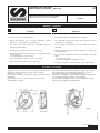
Description / Descripción
Ref.:
506 XXX
Open hose reel for air, water (cold or hot; high or low pressure),
antifreeze, vacuum, lubricants, grease and other fluids
depending on model.
Hose can be extended to the desired length and latched with a
mechanism.
By pulling the hose, the latch is released and the hose is
automatically rewinded.
WARNING
• This equipment is for professional use only.
•Do not the hose to coil unatended.
•Ensure that pressure does not exceed maximun working
pressure of lowest rated system component.
• Use fluids and solvents that are compatible with the
equipment wetted parts.
• Release pressure inside the reel before servicing.
• The spring is always under great tension. To reduce the risk of
serious injury:
- Do not attempt to remove spring.
- Do not attempt to replace or service the spring.
• Fluids under pressure can cause serious injury.
ATENCIÓN
• Este equipo es para uso profesional.
•Acompañar siempre la recogida de la manguera.
•No sobrepasar la presión de trabajo del componente menos
resistente de la instalación.
• Usar con fluidos compatibles con los materiales de las partes
húmedas.
• Eliminar la presión interior del fluido durante las operaciones
de mantenimiento.
•El resorte está siempre bajo tensión. Para reducir el riesgo de
daño:
- No eliminar el resorte.
- No intentar cambiar ni manipular el resorte.
• Los fluidos sometidos a presión puden causar graves daños.
GGBB
Enrollador de manguera abierto para aire, agua (fría o caliente;
alta o baja presión), anticongelante, aplicaciones de vacío,
detergentes, lubricantes o grasa según modelos.
Al tirar de la manguera, esta se desenrolla pudiendo bloquearse
a la longitud deseada por acción de un trinquete.
Para recoger la manguera, basta con tirar ligeramente de ella
para que sea recogida automaticamente.
Spare parts and technical service guide
Guía de servicio técnico y recambios
ALUMINIUM REEL 506 SERIES
ENROLLADOR DE ALUMINIO - SERIES 506
2009_03_27-11:10
Fig. 1
EE

2
2850 812 R.02/09
Samoa Industrial, S.A. · Box 103 Alto Pumarín · 33211 Gijón - Asturias Spain · Tel.: +34 985 381 488 · Fax.: + 34 985 384 163
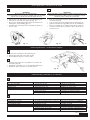
Installation / Instalación
2009_03_27-11:10
El enrollador puede instalarse directamente sobre la superficie
de montaje, una base de fijación (fig.A) o un soporte pivotante
(fig. B). El brazo de salida tiene varias posiciones para un
adecuado funcionamiento.
•PERPENDICULAR REELING
Para montaje en techo o sobre pared por debajo de 2.5
metros (8 pies) (ver figura 2).
•SIDE REELING
Para montaje sobre suelo , columna, foso, depósito,
banco… (ver figura 3).
•TANGENTIAL REELING
Para montaje sobre pared por encima de 2.5 metros (8
pies). También adecuado para montaje sobre unidades
móviles. (ver figura 4).
Para mover el brazo de salida, el procedimiento es el siguiente:
1. Fijar el disco del enrollador con un sargento (fig C).
2. Quitar el tope manguera.
3. Aflojar los tornillos del brazo superior (fig 5).
4. Colocar el brazo del enrollador en la posición deseada y apretar
los tornillos.
5. Introducir la manguera por la salida de manguera y colocar el
tope manguera de nuevo.
6. Quitar el sargento para liberar el disco del enrollador.
EE
Fig. 2 Fig. 3 Fig. 4
Fig. A Fig. B
Fig. C Fig. 5
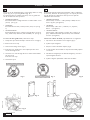
Hose reel can be installed directly on the fixing surface or using
a plate (Fig. A) or a pivoting bracket (Fig. B).
For achieving the reel optimal operation; its hose guide arm
can be mounted in these positions:
•PERPENDICULAR REELING
Recommended for ceiling and wall or column under 2.5 m
(8 feet) (see fig. 2).
•SIDE REELING
Recommended for wall, column, bench, tank, etc (see fig
3).
•TANGENTIAL REELING
Recommended for wall or column at a height above 2.5 m (8
feet), mobile units, lube truck, tank assemblies, etc. (see fig. 4).
To move the hose guide arm, follow these steps:
1. Clamp the spool with c-clamp to lock the hose reel (fig C)
2. Remove the hose-stop.
3. Unscrew the fixing screws (fig 5)
4. Place the hose guide arm in the required position and
screw the fixing screws.
5. Insert the hose reel through the hose outlet and assemble
the hose-stop.
Place the hose-stop.
6. Unlock the spool.
GGBB

Hose installation / Instalación de la manguera
3
3
R.02/09 850 812
Samoa Industrial, S.A. · Box 103 Alto Pumarín · 33211 Gijón - Asturias Spain · Tel.: +34 985 381 488 · Fax.: + 34 985 384 163
2009_03_27-11:10
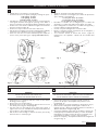
• Clamp the hose reel firmly to a work bench
• Pretension the hose reel power spring by rotating the spool:
10m spring: 16 turns
15m spring: 19 turns
15m HD spring: 21 turns
• Introduce the hose end to fix to the hose reel through the
outlet guide and then through the opening in the drum of
the spool. Pull the hose through the drum towards the swivel
•Fix the hose to the swivel as indicated in figure 8a and fix the
U bolt as shown in figure 8b
•Fix the hose stop to the free end of the outlet hose
• Pull out the hose slightly to free the spool latch and then gradually
release the hose to allow the hose reel to windup the hose.
• If the hose reel does not rewind satisfactorily then adjust the
tension of the power spring (see “Spring load adjustment”).
• Sujetar el enrollador a una base firmemente.
• Aplicar, al enrolldor sin manguera, las vueltas de pretensión
que se indican a continuación.
resorte para 10 m: 16 vueltas
resorte para 15 m: 19 vueltas
resorte para 15 m HD: 21 vueltas
• Introducir el extremo de la manguera por la salida del
enrollador y el orificio del tambor hasta llegar a la rótula.
•Fijar la manguera a la rótula como se indica en la Figura 8a y
colocar el abarcón según la figura 8b.
• Colocar el tope de manguera en el extremo libre.
• Liberar el trinquete tirando ligeramente de la manguera y
dejar que enrolle suavemente.
• Si es necesario ajustar la tensión del resorte, seguir las
instrucciones del apartado “Ajuste de la tensión del
resorte”.
EE
Fig. 8a Fig. 8b Fig. 9
Fig. 6
GGBB
Fig. 7
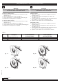
WARNING
BEFORE REMOVING THE HOSE, CLOSE THE NEAREST SHUT OFF VALVE TO
THE REEL AND OPEN THE FLUID CONTROL GUN
TO RELEASE THE PRESSURE INSIDE THE HOSE.
•Unwind the hose completely and then search for the ratchet
blocking position (Fig 6).
•Remove the hose stopper (Fig 7)
• Disconnect the hose as seen (Fig 8a). Release the hose from
the disk by removing the clamp (Fig 8b).
• Pass the new hose through the hose outlet and connect it
again to the hose reel. Assemble the clamp and assemble the
hose stopper to the required length.
• Pull the hose hard enough to release the latch, and slowly
allow the hose to retract (Fig 9).
ATENCIÓN
ANTES DE RETIRAR LA MANGUERA, CERRAR LA LLAVE DE SERVICIO
MÁS CERCANA AL ENROLLADOR Y ABRIR LA PISTOLA DE SUMINISTRO
A FIN DE LIBERAR EL FLUIDO A PRESIÓN DE LA MANGUERA.
•Desenrollar totalmente la manguera usada y buscar la
posicion de bloqueo del trinquete más proxima a esta
longitud (fig. 6).
•Aflojar entonces el tope de manguera y desmontelo (fig. 7).
• Desconectar la manguera usada según se indica en la
imagen (fig. 8a) y liberar la manguera del disco retirando el
abarcón de fijacion manguera (fig. 8b).
• Conectar la manguera nueva; para ello ntroducir el extremo de
la manguera por la salida del enrollador y el orificio del tambor
hasta llegar a la rótula y conectar de nuevo al enrollado y fijar
correctamente el abarcón. Colocar el tope manguera.
•Liberar el trinquete y acompañar lentamente la manguera al
recogerse (fig. 9).
EEGGBB
Hose replacement / Sustitución de la manguera

4
4850 812 R.02/09
Samoa Industrial, S.A. · Box 103 Alto Pumarín · 33211 Gijón - Asturias Spain · Tel.: +34 985 381 488 · Fax.: + 34 985 384 163
2009_03_27-11:10
Fig. 11
Tabla 1
Fig. 12
Fig. 13 Fig. 14
Spring load adjustment / Ajuste de la tensión del resorte
Part. No. / Description/ STANDARD pretension turns / MAX. pretension turns /
Cód. Descripción Vueltas NOMINALES Vueltas MÁXIMAS
pretensión trabajo pretensión de trabajo
850310 Standard spring (10 m) 5 9
850311 Severe spring (15m HD) 5 10
850313 High spring (15 m) 7 7
To increase spring tension
1. Pull the hose out 10 feet (3meters) and let the hose get
latched (Fig. 11).
2.Wind the hanging hose in the reel (Fig 13).
3. Gently pull the hose, it is automatically winded (Fig 14).
4. Repeat if more spring tension is required.
To decrease spring tension
1. Pull the hose out 10 feet (3 meters) and let the hose get
latched (Fig. 11).
2. Unwind one wrap and pull the hose (Fig 12).
3. Gently pull the hose, the hose is automatically winded (Fig 14).
4. Repeat if less spring tension is required.
WARNING
DO NOT PUT MANY LOOPS ONTO THE REEL, EXCESIVE STRAIN ON THE
HOSE AND REEL SPRING COULD DAMAGE THE REEL
GGBBEE
Para dar tensión
1. Extraer unos 10 pies (3 metros) de manguera y trincar la
manguera (fig. 11).
2.Introducir una vuelta de la manguera, en el disco del
enrollador (fig. 13).
3. Tirar suavemente de la manguera hasta que quede liberada
del trinquete y se recoja por si misma (fig. 14).
4. Repetir los pasos anteriores si necesita más tensión.
Para quitar tensión
1. Extraer unos 10 pies (3 metros) de manguera y trincar la
manguera (fig. 11).
2.Quitar una vuelta de manguera del interior del disco del
enrollador (fig. 12).
3. Tirar suavemente de la manguera hasta que quede liberada
del trinquete y se recoja por si misma (fig. 14).
4. Repetir los pasos anteriores si necesita menos tensión.
ATENCIÓN
NOAÑADIR DEMASIADAS VUELTAS AL ENROLLADOR. UNA TENSIÓN EXCESIVA
PODRÍA DAÑAR EL MUELLE Y LA MANGUERA.

5
5
R.02/09 850 812
Samoa Industrial, S.A. · Box 103 Alto Pumarín · 33211 Gijón - Asturias Spain · Tel.: +34 985 381 488 · Fax.: + 34 985 384 163
2009_03_27-11:10
Swivel replacement / Sustitución de la rótula
WARNING
BEFORE REMOVING THE DAMAGED SWIVEL,
CLOSE THE NEAREST SHUT OFF VALVE TO THE REEL AND OPEN THE FLUID
CONTROL GUN TO RELEASE THE PRESSURE INSIDE THE HOSE
• Pull the hose out and let the hose get latched (Fig. 15).
• Unscrew the nuts with two spanners (Fig. 16).
• Remove the circlip and pull the swivel. Be careful not to
damage the swivel O-Ring (Fig. 17).
• Assemble the new swivel and re-assemble the pieces in
reverse order.
ATENCIÓN
ANTES DE RETIRAR LA RÓTULA DAÑADA, CERRAR LA LLAVE DE SERVICIO MÁS
CERCANA AL ENROLLADOR Y ABRIR LA PISTOLA DE SUMINISTRO A FIN DE
LIBERAR EL FLUIDO A PRESIÓN DE LA MANGUERA
• Tirar de la manguera hasta que quede trincada en el
enrollador (Fig. 15).
• Con dos llaves, aflojar la manguera de la rótula (Fig 16).
• Quitar la arandela de seguridad y tirar de la rótula hacia
fuera con cuidado de no dañar la junta interior (Fig 17).
• Colocar la nueva rótula y realizar los pasos anteriores en
sentido inverso.
EEGGBB
GGBB
Troubleshooting/ Anomalías y sus soluciones
Symptom
Hose does not wind
Leaking hose reel
Leaking swivel
Hose does not go out as much as required.
Hose reel does latch
Possible Causes
Spring has low load
Hose with pore or broken hose
Damaged swivel rings
Spring has too much load
Damaged ratchet
Ratchet not fitted
Damaged spring ratchet
Solution
Adjust the spring load
Replace the hose
Replace the swivel rings
Adjust the spring load
Replace the ratchet
Assembly the ratchet properly
Change the ratchet spring
EE
Síntoma
El enrollador no recoge
La manguera pierde fluido
La rótula pierde fluido
La manguera no sale todo lo que debería
El enrollador no trinca
Posibles causas
El muelle ha perdido tensión o se ha roto.
Manguera con poro o rota
Rótula deteriorada
Demasiada tensión en el resorte
Trinquete deteriorado
Trinquete fuera de su lugar
Muelle trinquete deteriorado
Solución
Dar tensión al resorte o reemplazarlo.
Cambiar la manguera
Cambiar la rótula
Quitar tensión al resorte
Cambiar el trinquete
Colocar el trinquete adecuadamente
Sustituir el muelle del trinquete
Fig. 15 Fig. 16 Fig. 17
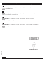
Ratchet Replacement / Sustitución de trinquete
• Remove the nut that fixes the latch (Fig 18).
•Replace the latch and/or the latch spring.
• Re-assemble the pieces in reverse order.
• Quitar la tuerca que une el trinquete con el brazo del
enrollador (Fig 18).
• Remplazar el trinquete y/o resorte trinquete defectuoso.
• Realizar los pasos anteriores en sentido inverso.
GGBB
EE
Fig. 18

6
6850 812 R.02/09
Samoa Industrial, S.A. · Box 103 Alto Pumarín · 33211 Gijón - Asturias Spain · Tel.: +34 985 381 488 · Fax.: + 34 985 384 163
2009_03_27-11:10
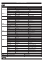
Parts list / Lista de recambios
GGBBEE
Kit number Part. No incl./Cód. incl. Description Descripción
526010 Oil, vacuum and cold water swivel kit / Kit rótula aceite, vacío y agua
750425 Body swivel Rótula
945593 Fitting R 1/2” - 1/2” - MM Adaptador R 1/2” - 1/2” - MM
946032 (x2) O-ring NBR Junta tórica NBR
526011 Grease swivel kit / Kit rótula grasa
750430 Body swivel Rótula
946012 (x2) O-ring NBR Junta tórica
945676 Fitting 3/8 NPT-3/8 BSP - MM Adaptador 3/8 NPT-3/8 BSP - MM
946307 (x2) Back-up ring Junta tórica
526012 High pressure hot water swivel kit / Kit rótula agua caliente alta presión
750425 Body swivel Rótula
945593 Fitting R 1/2” - 1/2” - MM Adaptador R 1/2” - 1/2” - MM
946146 (x2) O-ring EPDM Junta tórica EPDM
526013 Kit rótula limpiaparabrisas / Windscreen washer swivel kit
750425 Swivel Rótula
945703 Fitting R 1/2” - 1/2” NPT-BSP DISI-316 Adaptador R 1/2” - 1/2” NPT-BSP DISI-316
946145 (x2) O-ring Viton Junta tórica Viton
526020 Kit trinquete / Ratchet kit
850312 Ratchet spring Resorte trinquete
850441 Ratchet Axle Eje trinquete
850611 Ratchet Trinquete
941107 Nut Tuerca autoblocante
942061 Washer Arandela
526021 Hose outlet kit / Kit salida
850616 (x6) Hose roller Rodillo salida manguera
750428 (x6) Roller axle Eje salida manguera
940921 (x6) Screw Tornillo
526001 Hose-stop and U-bolt kit / Kit tope manguera y abarcón (aire, agua y grasa 3/8”, aceite 1/2”)
944816 U-bolt Abarcón
941126 Nut Tuerca autoblocante
852601 Hose-stop Bicono
940610 Screw Tornillo
941105 Nut Tuerca autoblocante
526002 Hose-stop and U-bolt kit / Kit tope manguera y abarcón (aire, agua, limpiaparabrisas y adblue 1/2”)
944816 U-bolt Abarcón
941126 Nut Tuerca autoblocante
852602 Hose-stop Bicono
940610 Screw Tornillo
941105 Nut Tuerca autoblocante
526004 Hose-stop and U-bolt kit / Kit tope manguera y abarcón (agua caliente 3/8” y grasa 1/4”)
944810 U-bolt Abarcón
941126 Nut Tuerca autoblocante
852600 Hose-stop Bicono
940610 Screw Tornillo
941105 Nut Tuerca autoblocante
526022 Spool and grease reel shaft kit / Kit disco y eje para grasa
850615 Washer Arandela tope disco
850613 Spool Disco enrollador completo
750429 High pressure shaft Eje para grasa
950510 (x2) Ball bearing Rodamiento
850617 Spacer Espaciador rodamientos
850614 Spring cover Tapa resorte
940522 (x6) Screw Tornillo cierre tapa resorte
850442 Spring washer Arandela resorte
526023 Spool and fluid reel shaft kit / Kit disco y eje para fluidos
850615 Washer Arandela tope disco
850613 Spool Disco enrollador completo
750424 Low-medium pressure shaft Eje para fuido
950510 (x2) Ball bearing Rodamiento
850617 Bushing Espaciador rodamientos
850614 Spring cover Tapa resorte
940522 (x6) Screw Tornillo cierre tapa resorte
850442 Spring washer Arandela resorte
Part. No / Cód. Description Descripción
850310 Standard spring (10 m) Resorte 10 m
850311 Severe spring (15 m HSD) Resorte 15 m HD
850313 High spring (15 m) Resorte 15 m

7
7
R.02/09 850 812
Samoa Industrial, S.A. · Box 103 Alto Pumarín · 33211 Gijón - Asturias Spain · Tel.: +34 985 381 488 · Fax.: + 34 985 384 163
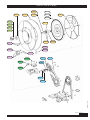
Parts list / Lista de recambios
2009_03_27-11:10
944810
944816
941105
941126
852601
940610
850615 850613
950510 850442
850617
750424
750429
850311
850310
850313
850614
850441
850312
942061
941107
850611
526012
526010
523011
526013
750428
850616
940921

8
8850 812 R.02/09
Samoa Industrial, S.A. · Box 103 Alto Pumarín · 33211 Gijón - Asturias Spain · Tel.: +34 985 381 488 · Fax.: + 34 985 384 163
2009_03_27-11:10
EC conformity declaration/ Declaración CE de conformidad/
Déclaration CE de conformité /EG-Konformitätserklärung
For SAMOA INDUSTRIAL, S.A.
Por SAMOA INDUSTRIAL, S.A.
Pour SAMOA INDUSTRIAL, S.A.
für SAMOA INDUSTRIAL, S.A.
Pedro E. Prallong Alvarez
Production Director
Director de Producción
Directeur de Production
Produktionsleiter
GGBB
SAMOA INDUSTRIAL, S.A., Alto de Pumarín, s/n, 33211 – Gijón – Spain, declares that the product(s):
506 XXX
conform(s) with the EU Directive(s):
98/37/EC.
EE
SAMOA INDUSTRIAL, S.A., Alto de Pumarín, s/n, 33211 – Gijón – España, declara que el(los) producto(s):
506 XXX
cumple(n) con la(s) Directiva(s) de la Unión Europea:
98/37/CE.
FF
SAMOA INDUSTRIAL, S.A., Alto de Pumarín, s/n, 33211 – Gijón – Espagne, déclare que le(s) produit(s):
506 XXX
est(sont) conforme(s) au(x) Directive(s) de l’Union Européenne:
98/37/CE.
DD
SAMOA INDUSTRIAL, S.A., Alto de Pumarín, s/n, 33211 – Gijón – Spanien, bestätigt hiermit, dass das(die) Produkt(e):
506 XXX
der(die) EG-Richtlinie(n):
98/37/EG
entspricht.
-
 1
1
-
 2
2
-
 3
3
-
 4
4
-
 5
5
-
 6
6
-
 7
7
-
 8
8


Alemlube 506 Reels Service Guide
- Categoría
- Rociador de pintura
- Tipo
- Service Guide
en otros idiomas
- English: Alemlube 506 Reels Service guide
Artículos relacionados
-
Alemlube 504 reels El manual del propietario
-
-
-
-
-
-
-
-
-