Need help? Visit Sauder.com to view video assembly tips or chat with a live rep.
Prefer the phone? Call 1-800-523-3987.
Share your journey!
sauder.com
NOTE: THIS INSTRUCTION
BOOKLET CONTAINS IMPORTANT
SAFETY INFORMATION.
PLEASE READ AND KEEP FOR
FUTURE REFERENCE.
Enlish p 1-36
Français p 37-40
Español p 41-44
Lot # 390205 04/13/16
Purchased: __________________
Be sure to ive us a rin before
makin any returns. 1-800-523-3987
Corner Desk
Harbor View Collection | Model 403793
For all your
newfanled gadgetry.

Table of Contents Assembly Tools Required
Part Identifi cation
Hardware Identifi cation
Assembly Steps
Français
Español
Safety
Warranty
Hammer
Not actual size
No. 2 Phillips Screwdriver
Tip Shown Actual Size
A DOOR RIGHT END (1)
B DOOR LEFT END (1)
C DRAWER RIGHT END (1)
D DRAWER LEFT END (1)
E RIGHT UPRIGHT (1)
F LEFT UPRIGHT (1)
G3 TOP (1)
H2 SMALL TOP (1)
I MODESTY PANEL (2)
J BOTTOM (1)
K BACK (2)
L BRACE (2)
M DOOR (1)
N DRAWER FRONT (1)
S2 KEYBOARD UPRIGHT (2)
T KEYBOARD SHELF (1)
U SMALL DRAWER FRONT (2)
X BASE (2)
AA RIGHT MOLDING (1)
BB LEFT MOLDING (1)
D24 SMALL DRAWER RIGHT SIDE (2)
D25 SMALL DRAWER LEFT SIDE (2)
D28 DRAWER RIGHT SIDE (1)
D29 DRAWER LEFT SIDE (1)
D78 DRAWER BACK (1)
D109 SMALL DRAWER BACK (2)
D707 DRAWER BOTTOM (1)
D716 SMALL DRAWER BOTTOM (2)
2-3
4-5
6-36
37-40
41-44
45-46
47
Now you know
our ABCs.
Part Identifi cation
å While not all parts are labeled, some of the parts will have a label or an inked letter on the ede
to help distinuish similar parts from each other. Use this part identifi cation to help identify similar parts.
403793 www.sauder.com/servicesPae 2
Electric drill with 1/8" bit
(ONLY in indicated step)

Part Identifi cation
403793www.sauder.com/services
Pae 3
A
B
C
D
E
F
G3
H2
I
J
K
L
M
S2
T
X
AA
BB
I
K
S2
X
L
D716
D707
D29
D28
D78
D109
D25
D24
U
N
D716
D109
D25
D24
U

Hardware Identifi cation
å Screws are shown actual size. You may receive extra hardware with your unit.
403793 www.sauder.com/servicesPae 4
FILE GLIDE - 2
15B
GG
LONG RIGHT
CABINET RAIL - 1
HH
LONG LEFT
CABINET RAIL - 1
JJ
LONG LEFT
DRAWER SLIDE - 1
II
LONG RIGHT
DRAWER SLIDE - 1
FILE ROD - 2
SS
35DA
CABINET RIGHT - 2
35DD
DRAWER LEFT - 2
35DC
DRAWER RIGHT - 2
35DB
CABINET LEFT - 2
PLATE - 2
TT
KNOB - 4
WW
HIDDEN CAM - 18
PP2
CAM DOWEL - 18
QQ2
HIDDEN CONNECTOR - 4
OO
UU
HINGE - 2
40AW
CABINET RIGHT - 1
40AX
CABINET LEFT - 1
40AY
DRAWER RIGHT - 1
40AZ
DRAWER LEFT - 1

Hardware Identifi cation
å Screws are shown actual size. You may receive extra hardware with your unit.
403793www.sauder.com/services
Pae 5
FELT DISC CARD - 1
FFF
CORD CLIP - 5
AAA
ANGLE BRACKET - 10
BBB
METAL PIN - 4
DDD EEE
SLIDE CAM - 6
BLACK 1-1/8" PAN HEAD SCREW - 14
HHH
BLACK 9/16" LARGE HEAD SCREW - 36
JJJ
CONNECTOR SCREW - 4
NNN
BLACK 1-7/8" FLAT HEAD SCREW - 6
GGG
III
BROWN 1" FLAT HEAD SCREW - 4
LLL
GOLD 5/16" FLAT HEAD SCREW - 28
BLACK 1/2" FLAT HEAD SCREW - 4
MMM
NAIL - 30
OOO
GROMMET CAP - 1
1P
GROMMET - 1
10P
METAL BRACKET - 4
2G
30S
BLACK 1-9/16" FLAT HEAD SCREW - 12

403793 www.sauder.com/servicesPae 6
å
IMPORTANT: Follow the video to the riht for this option.
å
IMPORTANT: Follow the video to the riht for this option.
DOOR ON RIGHT AND
DRAWERS ON LEFT
DOOR ON LEFT AND
DRAWERS ON RIGHT
Scan this QR code or go to this address:
http://qr.sauder.com/?ID=1474
to watch a video on how to assemble your unit.
Scan this QR code or go to this address:
http://qr.sauder.com/?ID=1475
to watch a video on how to assemble your unit.

Look for this icon. It means a
video assembly tip is available at
www.sauder.com/services/tips
Step 1
å
Assemble your unit on a carpeted fl oor or on the empty
carton to avoid scratchin your unit or the fl oor.
å
Use your hammer to tap four HIDDEN CONNECTORS (OO)
with SCREWS into the KEYBOARD UPRIGHTS (S2).
Step 2
å
Insert a CONNECTOR SCREW (NNN) into each
HIDDEN CONNECTOR (OO).
NNN
OO
OO
STOP
If you purchased
the 403785
Hutch, assemble
that unit fi rst.
S2
S2
403793www.sauder.com/services
Pae 7

Step
å
Push eihteen HIDDEN CAMS (PP2) into the ENDS (A, B, C,
and D), UPRIGHTS (E and F), BOTTOM (J), and BRACES (L).
Then, insert the metal end of a CAM DOWEL (QQ2) into each
HIDDEN CAM.
Step 3
403793 www.sauder.com/servicesPae 8
Arrow
PP2
QQ2
(18 used)
Arrow
PP2
QQ2
Insert the metal end of the CAM
DOWEL into the HIDDEN CAM.
Arrow
Do not tihten the HIDDEN CAMS in this step.
C
D
E
F
J
A
B
L
L

Step Step 4
35DA
35DA
35DB
35DB
å
Fasten the CABINET RIGHTS (35DA) and CABINET
LEFTS (35DB) to the DRAWER ENDS (C and D). Use
eiht GOLD 5/16" FLAT HEAD SCREWS (LLL) throuh
holes #1 and #3.
å
Fasten the LONG CABINET RAILS (GG and HH) to the
DRAWER ENDS (C and D). Use four GOLD 5/16" FLAT
HEAD SCREWS (LLL) throuh holes #1 and #3.
å
NOTE: The LONG CABINET RAILS (GG and HH) are
marked "CABINET RIGHT" and "CABINET LEFT" for
easy identifi cation.
GOLD 5/16" FLAT HEAD SCREW
(12 used in this step)
LLL
Roller end
1
3
2
1
3
2
C
D
Surface with
HIDDEN CAMS
Surface with
HIDDEN CAMS
1
3
2
1
3
2
4
Roller end
1
3
2
1
3
2
4
HH
GG
Remember:
Rihty tihty.
Lefty loosey.
403793www.sauder.com/services
Pae 9

Step
403793 www.sauder.com/servicesPae 10
Step 5
GOLD 5/16" FLAT HEAD SCREW
(4 used for the CABINET RAILS)
LLL
S2
Surface with
HIDDEN CONNECTORS
Roller end
Roller end
40AW
40AW
40AX
40AX
å
Fasten a CABINET RIGHT (40AW) and a CABINET LEFT (40AX) to the
KEYBOARD UPRIGHTS (S2). Use four GOLD 5/16" FLAT HEAD SCREWS (LLL).
å
NOTE: The CABINET RAILS are marked "CABINET RIGHT" and "CABINET
LEFT" for easy identifi cation.
å
NOTE: Be sure to use the exact holes shown.
å
Fasten the METAL BRACKETS (2G) to the KEYBOARD UPRIGHTS (S2). Use
four BLACK 9/16" LARGE HEAD SCREWS (JJJ).
å
NOTE: Be sure the edes of the METAL BRACKETS are even with the edes of
the KEYBOARD UPRIGHTS.
S2
Surface with
HIDDEN CONNECTORS
BLACK 9/16" LARGE HEAD SCREW
(4 used for the METAL BRACKETS)
JJJ
2G
2G
2G
2G

å
Fasten the LEFT UPRIGHT (F) to the RIGHT UPRIGHT (E).
Use two BLACK 1-7/8" FLAT HEAD SCREWS (GGG).
Step 6
403793www.sauder.com/services
Pae 11
E
F
Surface with
HIDDEN CAM
Surface with
HIDDEN CAM
BLACK 1-7/8" FLAT HEAD SCREW
(2 used in this step)
GGG
Ede with CAM DOWEL
Do not stand the unit upriht without the
BACK fastened. The unit may collapse.
Caution

Step
å
Insert four METAL PINS (DDD) into the ENDS (C and D).
å
Fasten the ENDS (C and D) to the BRACES (L). Tihten
four HIDDEN CAMS.
å
NOTE: Be sure the METAL PINS in the ENDS insert into
the holes in the BRACES.
Step 7
403793 www.sauder.com/servicesPae 12
Start Tighten
Arrow
Minimum
190 derees
Caution
Risk of damae or
injury. HIDDEN CAMS
must be completely
tihtened. HIDDEN
CAMS that are not
completely tihtened
may loosen, and parts
may separate. To
completely tihten:
Arrow
Maximum
210 derees
C
D
L
L
Surface with
HIDDEN CAMS
Surface with
HIDDEN CAMS
Surface without
HIDDEN CAMS
Surface with
HIDDEN
CAMS
DDD
(4 used)
These holes must be here.
Ede with CAM DOWELS

Step
403793www.sauder.com/services
Pae 13
å
Fasten four ANGLE BRACKETS (BBB) to the DRAWER
ENDS (C and D) and BRACE (L). Use four BLACK 9/16"
LARGE HEAD SCREWS (JJJ).
å
NOTE: Be sure the edes of the ANGLE BRACKETS are
even with the edes of the ENDS and BRACE.
å
Fasten the BASE (X) to the DRAWER ENDS (C and D)
and BRACE (L). Use four BLACK 9/16" LARGE
HEAD SCREWS (JJJ).
Step 8
BLACK 9/16" LARGE HEAD SCREW
(8 used in this step)
JJJ
C
D
L
X
BBB
BBB
BBB
(4 used)

Step
å
Fasten the DOOR ENDS (A and B) to the BOTTOM (J).
Tihten four HIDDEN CAMS.
Step 9
403793 www.sauder.com/servicesPae 14
Arrow
Minimum
190 derees
Maximum
210 derees
A
B
J
Surface with
HIDDEN CAMS
Surface without
HIDDEN CAMS
Surface with
HIDDEN CAMS
These holes must be here.
Ede with CAM DOWELS

Step
403793www.sauder.com/services
Pae 15
å
Fasten four ANGLE BRACKETS (BBB) to the DOOR
ENDS (A and B) and BOTTOM (J). Use four BLACK 9/16"
LARGE HEAD SCREWS (JJJ).
å
NOTE: Be sure the edes of the ANGLE BRACKETS are
even with the edes of the ENDS and BOTTOM.
å
Fasten the BASE (X) to the DOOR ENDS (A and B)
and BOTTOM (J). Use four BLACK 9/16" LARGE
HEAD SCREWS (JJJ).
Step 10
BLACK 9/16" LARGE HEAD SCREW
(8 used in this step)
JJJ
BBB
BBB
BBB
(4 used)
A
B
J
X

Step
å
Carefully turn your unit over onto its front edes. Lay the
BACKS (K) over your unit.
å
Make equal marins alon all four edes of the
BACKS (K). Push on opposite corners of your unit if
needed to make it "square".
å
Fasten the BACKS (K) to your unit usin the NAILS.
å
NOTE: Perforations have been provided for access
throuh the BACK. Carefully cut out the rectanle in the
BACK for proper ventilation of your CPU.
Step 11
403793 www.sauder.com/servicesPae 16
Finished
surface
NAIL
(30 used in this step)
OOO
Finished
surface
K
K
A
B
C
D
Ede without holes
Ede without holes
Do not stand the unit upriht without the
BACK fastened. The unit may collapse.
Caution

Step
403793www.sauder.com/services
Pae 17
Step 12
H2
H2
G3
G3
C
D
B
C
A
A
D
DOOR ON RIGHT AND
DRAWERS ON LEFT
DOOR ON LEFT AND
DRAWERS ON RIGHT
å
IMPORTANT: You have the choice of assemblin the unit
two ways. If you want the drawers on the riht and the
DOOR on the left side of the desk, fasten the DRAWER
ENDS (C and D) to the SMALL TOP (H2) and the ENDS (A
and B) to the TOP (G3).
å
If you want the drawers on the left and the DOOR on the
riht side of the desk, fasten the ENDS (A and B) to the
SMALL TOP (H2) and the ENDS (C and D) to the TOP (G3)
as shown in the lower diaram.
å
NOTE: The followin steps in this book show the fi rst option
with the DOOR on the left and drawers on the riht.
B

å
Fasten the DOOR ENDS (A and B) to the TOP (G3).
Tihten four HIDDEN CAMS.
Step 13
403793 www.sauder.com/servicesPae 18
Arrow
Minimum
190 derees
Maximum
210 derees
A
B
G3
The lare hole
must be here.
Surface with more holes
Rounded ede
X

å
Fasten the LEFT MOLDING (BB) to the TOP (G3). Use
three BLACK 1-1/8" PAN HEAD SCREWS (HHH).
å
Fasten the UPRIGHTS (E and F) to the TOP (G3). Tihten
two HIDDEN CAMS.
Step 14
403793www.sauder.com/services
Pae 19
Arrow
Minimum
190 derees
Maximum
210 derees
G3
E
F
BB
Surface with
HIDDEN CAM
Surface with
HIDDEN CAM
BLACK 1-1/8" PAN HEAD SCREW
(3 used in this step)
HHH

å
Use a drill and a 1/8" drill bit to complete the two holes in the
DOOR RIGHT END (A).
å
Fasten the MODESTY PANEL (I) to the LEFT UPRIGHT (F).
Use two BLACK 1-1/8" PAN HEAD SCREWS (HHH).
å
Fasten the MODESTY PANEL (I) to the DOOR RIGHT END (A).
Use two BLACK 1-7/8" FLAT HEAD SCREWS (GGG).
Step 15
403793 www.sauder.com/servicesPae 20
BLACK 1-7/8" FLAT HEAD SCREW
(2 used for the MODESTY PANEL)
GGG
F
I
A
BLACK 1-1/8" PAN HEAD SCREW
(2 used for the LEFT UPRIGHT)
HHH
Use a 1/8" drill bit in the RIGHT END (A).
Cut-out

å
Fasten the TIE PLATES (TT) to the TOP (G3). Use four
BLACK 9/16" LARGE HEAD SCREWS (JJJ).
å
Fasten an ANGLE BRACKET (BBB) to the TOP (G3) and
MODESTY PANEL (I). Use two BLACK 9/16" LARGE
HEAD SCREWS (JJJ).
å
Turn three CORD CLIPS (AAA) into the TOP (G3).
å
NOTE: The CORD CLIPS are used to hold your keyboard
cord aainst the TOP.
Step 16
403793www.sauder.com/services
Pae 21
Now miht be a
ood time to refresh
your drink.
BLACK 9/16" LARGE HEAD SCREW
(6 used in this step)
JJJ
BBB
TT
I
G3
AAA
AAA

å
Fasten the DRAWER ENDS (C and D) to the SMALL
TOP (H2). Tihten four HIDDEN CAMS.
Step 17
403793 www.sauder.com/servicesPae 22
Arrow
Minimum
190 derees
Maximum
210 derees
H2
Surface with holes
Rounded ede
C
D
X

å
Use a drill and a 1/8" drill bit to complete the two holes in
the DRAWER LEFT END (D).
å
Fasten the other MODESTY PANEL (I) to the
DRAWER LEFT END (D). Use two BLACK 1-7/8" FLAT
HEAD SCREWS (GGG).
å
Fasten an ANGLE BRACKET (BBB) to the SMALL TOP (H2)
and MODESTY PANEL (I). Use two BLACK 9/16" LARGE
HEAD SCREWS (JJJ).
Step 18
403793www.sauder.com/services
Pae 23
H2
I
D
Use a 1/8" drill bit in the LEFT END (D).
BLACK 9/16" LARGE HEAD SCREW
(2 used for the ANGLE BRACKET)
JJJ
BBB
BLACK 1-7/8" FLAT HEAD SCREW
(2 used for the MODESTY PANEL)
GGG

å
Fasten the RIGHT MOLDING (AA) to the SMALL TOP (H2).
Use three BLACK 1-1/8" PAN HEAD SCREWS (HHH).
å
Turn a CORD CLIP (AAA) into the TOP (H2).
å
NOTE: The CORD CLIP is used to hold your keyboard cord
aainst the TOP.
Step 19
403793 www.sauder.com/servicesPae 24
H2
I
BLACK 1-1/8" PAN HEAD SCREW
(3 used in this step)
HHH
AA
AAA

å
Carefully stand your unit upriht.
å
Fasten the MODESTY PANEL (I) to the RIGHT UPRIGHT (E).
Use two BLACK 1-1/8" PAN HEAD SCREWS (HHH).
å
Fasten the SMALL TOP (H2) to the TOP (G3). Use four
BLACK 9/16" LARGE HEAD SCREWS (JJJ) throuh the TIE
PLATES on the TOP and into the SMALL TOP.
Step 20
403793www.sauder.com/services
Pae 25
H2
G3
I
E
BLACK 1-1/8" PAN HEAD SCREW
(2 used for the RIGHT UPRIGHT)
HHH
BLACK 9/16" LARGE HEAD SCREW
(4 used for the SMALL TOP)
JJJ
Pro Tip: Lift with your
les. And, you know,
your arms.

Step 21
403793 www.sauder.com/servicesPae 26
å
Fasten two HINGES (UU) to the DOOR (M). Use four
BLACK 1/2" FLAT HEAD SCREWS (MMM).
UU
BLACK 1/2" FLAT HEAD SCREW
(4 used in this step)
MMM
M

Step 22
403793www.sauder.com/services
Pae 27
å
Before fastenin the DOOR to your unit, be sure the
mountin screw is aainst the stops as shown in the riht
diaram. If it isn't, loosen the mountin screw to slide it
aainst the stops. Then tihten the mountin screw.
å
Fasten the DOOR (M) to the LEFT END (B) as shown in
the lower diaram. Use the screws in the HINGES. You
should start each SCREW a few turns before completely
tihtenin any of them.
å
Fasten a KNOB (WW) to the DOOR (M). Use a BLACK
1-1/8" PAN HEAD SCREW (HHH).
å
Peel the FELT DISC from the FELT DISC CARD (FFF).
Stick a FELT DISC on the DOOR where it comes in
contact with the RIGHT END (A).
å
See the next step for DOOR adjustments.
Mountin
screw
Stop
Hine
M
B
A
BLACK 1-1/8" PAN HEAD SCREW
(1 used for the KNOB)
HHH
FFF
WW
FFF

Step 23
403793 www.sauder.com/servicesPae 28
å
Refer to the enlared diaram to identify the parts on
the HINGES.
å
The DOORS may need some adjustments. Follow the text below
to make needed adjustments.
å
DOOR ADJUSTMENTS:
To adjust the DOORS from side to side (horizontal), turn the
adjustin screw in or out.
å
To adjust the DOORS up and down (vertical), loosen both
vertical adjustment screws. Move the DOORS up or down to the
desired location. Tihten the screws after makin adjustments.
å
To adjust the DOORS in or out (depth), loosen the mountin
screw one turn and move the DOORS in or out, as needed.
Tihten the mountin screw after makin adjustments.
Adjustin screw (horizontal)
Mountin screw (depth)
(vertical adjustment)

Step 24
403793www.sauder.com/services
Pae 29
å
Fasten a DRAWER RIGHT (40AY) and a DRAWER
LEFT (40AZ) to the KEYBOARD SHELF (T). Use four
BROWN 1" FLAT HEAD SCREWS (III).
å
NOTE: The DRAWER SLIDES are marked "DRAWER
RIGHT" and "DRAWER LEFT" for easy identifi cation.
å
Turn a CORD CLIP (AAA) into the KEYBOARD SHELF (T).
å
NOTE: The CORD CLIP is used to hold your keyboard
cord aainst the TOP.
AAA
Roller end
Roller end
T
Finished ede
Finished surface
40AZ
40AZ
40AY
40AY
BROWN 1" FLAT HEAD SCREW
(4 used in this step)
III

å
NOTE: The KEYBOARD SHELF can be attached to the riht side, left side, or the
center of your desk. If you want your SHELF on the riht, fasten the KEYBOARD
UPRIGHTS (S2) to the SMALL TOP (H2). If you want your SHELF in the center,
fasten the KEYBOARD UPRIGHTS (at an anle) to both TOPS (G3 and H2). The
diaram below is showin the option of the SHELF on the left side.
å
Fasten the KEYBOARD UPRIGHTS (S2) to the TOP (G3). Tihten four HIDDEN
CONNECTORS and use four BLACK 9/16" LARGE HEAD SCREWS (JJJ).
Step 25
403793 www.sauder.com/servicesPae 30
How to use the HIDDEN CONNECTOR
To fasten two parts together using the
HIDDEN CONNECTORS, insert your
screwdriver, at an angle, into the slot in the
HIDDEN CONNECTOR. While pushing the
screw into the hole of the adjoining part,
turn the screwdriver clockwise to tighten.
G3
H2
S2
BLACK 9/16" LARGE HEAD SCREW
(4 used for the METAL BRACKETS)
JJJ

Step 27
403793www.sauder.com/services
Pae 31
VIEW THE T-LOCK BOX VIDEO
å
Fasten the DRAWER BACK (D78) to the DRAWER SIDES (D28
and D29). Use four BLACK 1-9/16" FLAT HEAD SCREWS (30S).
å
NOTE: Be sure the DRAWER BOTTOM (D707) inserts into the
roove of the DRAWER BACK (D78).
å
Repeat this step for the small drawers usin parts U, D24, D25,
D109, and D716.
12
3
å
Insert the DRAWER SIDES (D28 and D29) at an anle
into the slot at each end of the DRAWER FRONT (N).
å
Slide the DRAWER BOTTOM (D707) into the rooves in the
DRAWER SIDES (D28 and D29) and DRAWER FRONT (N).
The tabs should insert freely
into the slots. Gently tilt the
DRAWER SIDES side to side
until the tabs slip into the slots.
Groove
Be sure the DRAWER
BOTTOM inserts into the
DRAWER FRONT roove.
D28
D29
D707
D707
D28
D29
D78
D29
N
N
Unfi nished
surface
With the palm of
your hand, tap the
DRAWER BOTTOM
down into the roove.
D28
Step 26
Start each screw a few turns before
completely tihtenin any of them.
BLACK 1-9/16" FLAT HEAD SCREW
(12 used in this step)
30S

å
Insert a SLIDE CAM (EEE) into each DRAWER SIDE (D28 and D29).
å
Fasten the SLIDES (II and JJ) to the DRAWER SIDES (D28 and D29).
Use four GOLD 5/16" FLAT HEAD SCREWS (LLL) throuh
holes #1 and #3.
å
NOTE: The DRAWER SLIDES are marked "DRAWER RIGHT" and
"DRAWER LEFT" for easy identifi cation.
å
NOTE: The screw head in the CAM must be visible throuh the
slotted hole in the SLIDE.
å
Repeat this step for the small drawers usin DRAWER
RIGHTS (35DC) and DRAWER LEFTS (35DD).
Step 27
403793 www.sauder.com/servicesPae 32
II
JJ
Screw head - turn CAM to line up holes in
the SLIDES with holes in DRAWER SIDES
1
2
3
EEE
EEE
1
2
3
Roller end
Roller end
D28
D29
GOLD 5/16" FLAT HEAD SCREW
(12 used in this step)
LLL
(4 screws per drawer)

å
Push a FILE GLIDE (15B) onto the DRAWER RIGHT SIDE (D28).
å
Slide the FILE RODS (SS) into the FILE GLIDE (15B) on the
DRAWER RIGHT SIDE.
å
Slide another FILE GLIDE (15B) onto the other end of the FILE
RODS (SS), then press this FILE GLIDE over the DRAWER
LEFT SIDE (D29).
Step 28
403793www.sauder.com/services
Pae 33
15B
15B
SS
Insert the FILE RODS into the holes of your choice
in the FILE GLIDES, dependin on your fi le sizes.
D28
D29

å
Fasten a KNOB (WW) to the DRAWER FRONT (N). Use a
BLACK 1-1/8" PAN HEAD SCREW (HHH).
å
Repeat this step for the small drawers.
Step 29
403793 www.sauder.com/servicesPae 34
Almost time to
celebrate! With a nap.
WW
BLACK 1-1/8" PAN HEAD SCREW
(3 used in this step)
HHH
N

å
Push a GROMMET CAP (1P) and GROMMET (10P) into
the lare hole in the TOP (G3).
å
To insert the drawers into your unit, tip the front of the
drawer down and drop the rollers on the drawer behind
the rollers on the unit. Lift the front of the drawer up
and slide it into the unit. Repeat this step to insert the
KEYBOARD SHELF.
Step 30
403793www.sauder.com/services
Pae 35
1P
10P
G3
60 lbs.
25 lbs.
40 lbs.
30 lbs.
10 lbs.
50 lbs.

Step 31
403793 www.sauder.com/servicesPae 36
å
To make adjustments to the drawers, loosen SCREW #3 in the SLIDES a 1/4 turn, then turn the CAM clockwise or
counter-clockwise. Notice how the drawer raises or lowers as you turn the CAM. The hiher the screw in the oblon hole,
the hiher your drawer front will be. The lower the screw, the lower the drawer front. By adjustin the drawers this way, it
will help the DRAWER FRONTS line up better when closed. Tihten the SCREW when fi nished with adjustments.
å
NOTE: Please read the back paes of the instruction booklet for important safety information.
å
This completes assembly. Clean with your favorite furniture polish or a damp cloth. Wipe dry.
The hiher the screw in the oblon hole,
the hiher your drawer front will be. The
lower the screw, the lower the drawer front.
Loosen screw #3 a 1/4 turn, turn the cam a 1/4 turn
maximum in both the clockwise and counter-clockwise
directions to make adjustments, and then tihten screw #3.
Cam
And to celebrate, why not share your success story?

A l’usae exclusif du
Canada Noter la date
d’achat de cet élément
et conserver le livret
pour future référence.
Pour contacter Sauder
en ce qui concerne cet
élément, faire référence
au numéro de lot et
numéro de modèle en
appelant notre numéro
sans frais.
Lot nº : ____________
Date de
l’achat: ____________
LISTE DE PIÈCES
REFERENCE DESCRIPTION QUANTITÉ
LISTE DE PIÈCES
REFERENCE DESCRIPTION QUANTITÉ
NOUS SOMMES LA POUR VOUS AIDER!
Nous faisons de notre mieux pour nous assurer que votre meuble
arrive dans d’excellentes conditions. Nos représentants du service
Clientèle sont aimables et prêts à vous aider au cas où une pièce
aurait été endommaée ou manquerait (ou si vous aviez besoin
d’aide pour l’assemblae). NE RAMENEZ PAS LE MEUBLE AU
MAGASIN. Au Canada, composez ce numéro d’appel ratuit:
1-800-523-3987
Du lundi au vendredi, de 9 heures du matin à
5:30 heures du soir (horaire Côte Est)
(sauf jours fériés)
Si une pièce a besoin d’être remplacée, la pièce de remplacement
sera envoyée dans les 48 heures. (Sauf week-ends et jours fériés)
Utilisez les instructions d’assemblae en français avec les
schémas étape par étape du manuel d’instruction en anlais.
Chaque étape en français correspond à la même étape
en anlais. La pièce devant être attachée à l’élément est
représentée en ris sur les schémas de chaque étape pour plus
de précision. Comparer la “Liste de pièces” ci-dessous avec
la “PART IDENTIFICATION” du manuel en anlais pour vous
familiariser avec les pièces avant l’assemblae.
REMARQUE : CE MANUEL D’INSTRUCTIONS CONTIENT
D’IMPORTANTES INFORMATIONS RELATIVES À LA SÉCURITÉ.
À LIRE ET CONSERVER POUR TOUTE RÉFÉRENCE FUTURE.
35DA
ÉLÉMENT DROITE......................................................2
35DB
ÉLÉMENT GAUCHE ..................................................2
35DC
TIROIR DROIT ................................................................2
35DD
TIROIR GAUCHE ..........................................................2
40AW
ÉLÉMENT DROITE.......................................................1
40AX
ÉLÉMENT GAUCHE ...................................................1
40AY
TIROIR DROIT .................................................................1
40AZ
TIROIR GAUCHE ...........................................................1
OO CONNECTEUR ESCAMOTABLE .....................4
PP2
EXCENTRIQUE ESCAMOTABLE ..................18
QQ2
CHEVILLE D'EXCENTRIQUE ........................... 18
15B ARMATURE POUR DOSSIERS .........................2
SS TIGE DE DOSSIER ......................................................2
TT PLAQUE ..............................................................................2
UU CHARNIÈRE .....................................................................2
WW BOUTON ............................................................................4
2G CONSOLE EN MÉTAL .............................................4
1P COUVERCLE DE PASSE-CÂBLES .................1
10P PASSE-CÂBLES ............................................................1
AAA
CLIP POUR CORDONS ..........................................5
BBB
CONSOLE À ÉQUERRE ......................................10
DDD
GOUPILLE EN MÉTAL .............................................4
EEE
EXCENTRIQUE DE COULISSE .........................6
FFF
FICHE DE TAMPONS EN FEUTRE..................1
GGG
VIS TÊTE PLATE 48 mm NOIRE .....................6
HHH
VIS TÊTE GOUTTE DE SUIF
28 mm NOIRE .............................................................14
III VIS TÊTE PLATE 25 mm MARRON .............4
JJJ VIS TÊTE LARGE 14 mm NOIRE .................36
LLL VIS TÊTE PLATE 8 mm DORÉE ..................28
MMM
VIS TÊTE PLATE 13 mm NOIRE ......................4
NNN
VIS DE CONNECTEUR ............................................4
OOO
CLOU ................................................................................30
30S VIS TÊTE PLATE 40 mm NOIRE ..................12
A EXTRÉMITÉ DROITE DE PORTE ......................1
B EXTRÉMITÉ GAUCHE DE PORTE ...................1
C EXTRÉMITÉ DROITE DE TIROIR .......................1
D EXTRÉMITÉ GAUCHE DE TIROIR ...................1
E MONTANT DROIT ........................................................1
F MONTANT GAUCHE .................................................1
G3 DESSUS ...............................................................................1
H2 PETIT DESSUS ...............................................................1
I VOILE DE FOND ..........................................................2
J DESSOUS ...........................................................................1
K ARRIÈRE .............................................................................2
L ENTRETOISE...................................................................2
M PORTE ...................................................................................1
N DEVANT DE TIROIR ....................................................1
S2
MONTANT DE LA TABLETTE DE CLAVIER .......2
T TABLETTE DE CLAVIER ..........................................1
U DEVANT DE PETIT TIROIR ..................................2
X BASE .....................................................................................2
AA MOULURE DROITE .....................................................1
BB MOULURE GAUCHE .................................................1
D24 CÔTÉ DROIT DE PETIT TIROIR .......................2
D25 CÔTÉ GAUCHE DE PETIT TIROIR.................2
D28 CÔTÉ DROIT DE TIROIR ........................................1
D29 CÔTÉ GAUCHE DE TIROIR ..................................1
D78 ARRIÈRE DE TIROIR ...................................................1
D109
ARRIÈRE DE PETIT TIROIR ..................................2
D707
FOND DE TIROIR ..........................................................1
D716
FOND DE PETIT TIROIR ........................................2
GG
GLISSIÈRE DROITE D'ÉLÉMENT LONGUE ......... 1
HH GLISSIÈRE GAUCHE D'ÉLÉMENT LONGUE ..... 1
II
COULISSE DROITE DE TIROIR LONGUE ............ 1
JJ
COULISSE GAUCHE DE TIROIR LONGU
E ........ 1
Bureau d’anleModèle 403793
403793www.sauder.com/services
Pae 37

ÉTAPE 9
Fixer les EXTRÉMITÉS DE PORTE (A et B) au DESSOUS (J). Serrer quatre
EXCENTRIQUES ESCAMOTABLES.
ÉTAPE 8
Fixer quatre CONSOLES À ÉQUERRE (BBB) aux EXTRÉMITÉS DE TIROIR (C et D)
et à l'ENTRETOISE (L). Utiliser quatre VIS TÊTE LARGE 14 mm NOIRES (JJJ).
REMARQUE : S'assurer que les chants des CONSOLES À ÉQUERRE sont à fl eur
des chants des EXTRÉMITÉS et l'ENTRETOISE.
Fixer le SOCLE (X) aux EXTRÉMITÉS DE TIROIR (C et D) et à l'ENTRETOISE (L).
Utiliser quatre VIS TÊTE LARGE 14 mm NOIRES (JJJ).
ÉTAPE 5
Fixer les GLISSIÈRES D'ÉLÉMENT (40AW et 40AX) aux MONTANTS DE TABLETTE
DE CLAVIER (S2). Utiliser quatre VIS TÊTE PLATE 8 mm DORÉES (LLL).
REMARQUE : Les GLISSIÈRES D'ÉLÉMENT ont une inscription "CABINET RIGHT"
(droite) et "CABINET LEFT" (auche) pour faciliter leur identifi cation.
REMARQUE : S’assurer de utiliser les trous exacts indiqués.
Fixer les CONSOLES EN MÉTAL (2G) sur les
MONTANTS DE TABLETTE DE
CLAVIER
(S2). Utiliser quatre VIS TÊTE LARGE 14 mm NOIRES (JJJ).
REMARQUE : S'assurer que les chants des CONSOLES EN MÉTAL sont à fl eur
des chants des
MONTANTS DE TABLETTE DE CLAVIER
.
ÉTAPE 4
Fixer les ÉLÉMENTS DROITES (35DA) et les ÉLÉMENTS
GAUCHES (35DB) aux EXTRÉMITÉS DE TIROIR (C et D). Utiliser huit VIS TÊTE
PLATE 8 mm DORÉES (LLL) à travers les trous nº 1 et nº 3.
Fixer les GLISSIÈRES D'ÉLÉMENT LONGUES (GG et HH) aux
EXTRÉMITÉS DE TIROIR (C et D). Utiliser quatre VIS TÊTE PLATE 8 mm
DORÉES (LLL) à travers les trous nº 1 et nº 3.
REMARQUE : Les GLISSIÈRES D'ÉLÉMENT LONGUES (GG et HH) ont une
inscription « CABINET RIGHT » (droite) et « CABINET LEFT » (auche)
ÉTAPE 3
Ne pas serrer les EXCENTRIQUES ESCAMOTABLES dans cette étape.
Enfoncer dix-huit EXCENTRIQUES ESCAMOTABLES (PP2) dans les
EXTRÉMITÉS (A, B, C et D), les MONTANTS (E et F), le DESSOUS (J) et les
ENTRETOISES (L). Ensuite, insérer l'extrémité en métal de la CHEVILLE
D'EXCENTRIQUE (QQ2) dans chaque EXCENTRIQUE ESCAMOTABLE.
ÉTAPE 2
Assembler l'élément sur un sol à moquette ou sur le carton vide pour
éviter d'endommaer l'élément ou le sol.
À l'aide de un marteau, enfoncer quatre CONNECTEURS ESCAMOTABLES (OO)
avec VIS dans les MONTANTS DE TABLETTE DE CLAVIER (S2).
ÉTAPE 1
Insérer une VIS DE CONNECTEUR (NNN) dans chaque
CONNECTEUR ESCAMOTABLE (OO).
403793 www.sauder.com/servicesPae 38
ÉTAPE 10
Fixer quatre CONSOLES À ÉQUERRE (BBB) aux EXTRÉMITÉS DE PORTE (A et B)
et au DESSOUS (J). Utiliser quatre VIS TÊTE LARGE 14 mm NOIRES (JJJ).
REMARQUE : S'assurer que les chants des CONSOLES À ÉQUERRE sont à fl eur
des chants des EXTRÉMITÉS et du DESSOUS.
Fixer le SOCLE (X) aux EXTRÉMITÉS DE PORTE (A et B) et au DESSOUS (J).
Utiliser quatre VIS TÊTE LARGE 14 mm NOIRES (JJJ).
ÉTAPE 6
Attention: Ne pas relever l'élément dans sa position verticale avant d'avoir
fi xé l’ARRIÈRE. L'élément risque de s'e ondrer.
Fixer le MONTANT GAUCHE (F) sur le MONTANT DROIT (E). Utiliser
deux VIS TÊTE PLATE 48 mm NOIRES (GGG).
ÉTAPE 11
Attention: Ne pas relever l'élément dans sa position verticale avant d'avoir
fi xé l’ARRIÈRE. L'élément risque de s'e ondrer.
Avec précaution, retourner l'élément sur ses chants avant. Placer les ARRIÈRES (K) sur l'élément.
Veiller à avoir des mares éales le lon des quatre chants des ARRIÈRES (K). Si besoin
est, enfoncer sur les coins opposés de l'élément pour s'assurer d'être « d'équerre ».
Fixer les ARRIÈRES (K) à l'élément à l'aide des CLOUS.
REMARQUE : Des lines perforées ont été prévues pour accéder facilement à l'ARRIÈRE.
Découper, avec précaution, le rectanle dans l'ARRIÈRE pour la ventilation appropriée du CPU.
ÉTAPE 7 (SUITE)
REMARQUE : S'assurer de bien insérer les GOUPILLES EN MÉTAL situées sur les
EXTRÉMITÉS dans les trous des ENTRETOISES.
Attention: Risque des déâts ou blessures. Les Excentriques Escamotables
doivent être serrés à bloc. Les Excentriques Escamotables que ne sont pas
serrées à bloc peuvent desserrer et les pièces peuvent séparer. Pour serrer
à bloc, faire tourner l'excentrique escamotable de 210 derés.
ÉTAPE 7
Insérer quatre GOUPILLES EN MÉTAL (DDD) dans les EXTRÉMITÉS (C et D).
Fixer les EXTRÉMITÉS (C et D) aux ENTRETOISES (L). Serrer quatre
EXCENTRIQUES ESCAMOTABLES.
ÉTAPE 12
IMPORTANT : On peut choisir entre deux méthodes d'assemblae pour
l'élément. Pour les tiroirs sur la droite du bureau et la PORTE sur la
auche du bureau, fi xer les EXTRÉMITÉS DE TIROIR (C et D) au PETIT
DESSUS (H2) et les EXTRÉMITÉS (A et B) au DESSUS (G3).
Pour les tiroirs sur la auche du bureau et la PORTE sur la droite du bureau, fi xer
les EXTRÉMITÉS (A et B) au PETIT DESSUS (H2) et les EXTRÉMITÉS (C et D)
au DESSUS (G3) comme l’indique le schéma inférieur.
REMARQUE : Les étapes suivantes de ce manuel montrent la première
option avec la PORTE sur la auche et les tiroirs sur la droite.

ÉTAPE 22
Relever, avec précaution, l'élément dans sa position verticale.
Avant de fi xer la PORTE à l’unité, s’assurer que la vis de montae se trouve contre les
butées comme l’indique le schéma de droite. Si ce n’est pas le cas, desserrer la vis de
montae pour la faire lisser contre les butées. Serrer ensuite la vis de montae.
Fixer la PORTE (M) à l’EXTRÉMITÉ GAUCHE (B) comme l'indique le schéma
inférieur. Utiliser les vis fournies avec les CHARNIÈRES. Il est préférable de donner
quelques tours de tournevis à chaque VIS avant de les serrer toutes à bloc.
Fixer un BOUTON (WW) à la PORTE (M). Utiliser une VIS TÊTE GOUTTE
DE SUIF 28 mm NOIRE (HHH).
Décoller le TAMPON EN FEUTRE de la FICHE DE TAMPONS EN FEUTRE (FFF).
Coller un TAMPON EN FEUTRE sur la PORTE à l’endroit où celle-ci entre en
contact avec l'EXTRÉMITÉ DROITE (A).
Voir l'étape suivante pour rélaes des PORTES.
ÉTAPE 21
Fixer deux CHARNIÈRES (UU) à la PORTE (M). Utiliser quatre VIS TÊTE
PLATE 13 mm NOIRES (MMM).
ÉTAPE 20
Relever, avec précaution, l'élément dans sa position verticale.
Fixer le VOILE DE FOND (I) au MONTANT DROIT (E). Utiliser deux VIS
TÊTE GOUTTE DE SUIF 28 mm NOIRES (HHH).
Fixer le PETIT DESSUS (H2) sur le DESSUS (G3). Utiliser quatre VIS
TÊTE LARGE 14 mm NOIRES (JJJ) à travers les PLAQUES D’ATTACHE
sur le DESSUS et dans le PETIT DESSUS.
ÉTAPE 16
Fixer les PLAQUES D’ATTACHE (TT) au DESSUS (G3). Utiliser quatre VIS
NOIRES TÊTE LARGE 14 mm (JJJ).
Fixer une CONSOLE À ÉQUERRE (BBB) sur le DESSUS (G3) et le VOILE
DE FOND (I). Utiliser deux VIS TÊTE LARGE 14 mm NOIRES (JJJ).
Serrer trois CLIPS DE CORDONS (AAA) dans le DESSUS (G3).
REMARQUE : Les CLIPS DE CORDON sont utilisés pour maintenir le
cordon de clavier contre le DESSUS.
ÉTAPE 15
Utiliser une perceuse et un foret de 3 mm pour fi nir de percer complètement
les deux trous de l'EXTRÉMITÉ DROITE DE PORTE (A).
Fixer le VOILE DE FOND (I) sur le MONTANT GAUCHE (F). Utiliser deux
VIS TÊTE GOUTTE DE SUIF 28 mm NOIRES (HHH).
Fixer le VOILE DE FOND (I) à l'EXTRÉMITÉ DROITE DE PORTE (A). Utiliser
deux VIS TÊTE PLATE 48 mm NOIRES (GGG).
ÉTAPE 14
Fixer la MOULURE GAUCHE (BB) au DESSUS (G3). Utiliser trois VIS
TÊTE GOUTTE DE SUIF 28 mm NOIRES (HHH).
Fixer les MONTANTS (E et F) au DESSUS (G3). Serrer deux
EXCENTRIQUES ESCAMOTABLES.
ÉTAPE 13
Fixer les EXTRÉMITÉS DE PORTE (A et B) au DESSUS (G3). Serrer quatre
EXCENTRIQUES ESCAMOTABLES.
403793www.sauder.com/services
Pae 39
ÉTAPE 17
Fixer les EXTRÉMITÉS DE TIROIR (C et D) au PETIT DESSUS (H2). Serrer
quatre EXCENTRIQUES ESCAMOTABLES.
ÉTAPE 18
Utiliser une perceuse et un foret de 3 mm pour fi nir de percer complètement les
deux trous de l'EXTRÉMITÉ GAUCHE DE PORTE (D).
Fixer l'autre VOILE DE FOND (I) à l’EXTRÉMITÉ GAUCHE DE TIROIR (D).
Utiliser deux VIS TÊTE PLATE 48 mm NOIRES (GGG).
Fixer une CONSOLE À ÉQUERRE (BBB) sur le PETIT DESSUS (H2) et le VOILE
DE FOND (I). Utiliser deux VIS TÊTE LARGE 14 mm NOIRES (JJJ).
ÉTAPE 19
Fixer la MOULURE DROITE (AA) au PETIT DESSUS (H2). Utiliser trois
VIS TÊTE GOUTTE DE SUIF 28 mm NOIRES (HHH).
Serrer un CLIP DE CORDONS (AAA) dans le DESSUS (H2).
REMARQUE : Le CLIP DE CORDON est utilisé pour maintenir le cordon
de clavier contre le DESSUS.
ÉTAPE 23
Consulter le schéma arandi pour identifi er les pièces des CHARNIÈRES.
Il faut peut-être ajuster les PORTES. Suivre les indications ci-dessous
pour ajuster.
RÉGLAGES DES PORTES :
Pour ajuster les PORTES latéralement (horizontalement), tourner la vis de rélae
vers l'intérieur ou vers l'extérieur.
Pour ajuster les PORTES de haut en bas (verticalement), desserrer les
deux vis de rélae. Déplacer les PORTES verticalement à l'emplacement
désiré. Serrer les vis après avoir ajusté.
Pour ajuster les PORTES vers l'intérieur où vers l'extérieur (profondeur), desserrer
la vis de montae un tour et déplacer les PORTES vers l'intérieur ou vers
l'extérieur. Serrer la vis de montae après avoir

ÉTAPE 29
Fixer un BOUTON (WW) au DEVANT DE TIROIR (N). Utiliser une VIS
TÊTE GOUTTE DE SUIF 28 mm NOIRE (HHH).
Répéter cette étape pour l'autre tiroirs.
ÉTAPE 28
Enfoncer une ARMATURE POUR DOSSIERS (15B) sur le CÔTÉ DROIT
DE TIROIR (D28).
Enfi ler les GUIDES POUR DOSSIERS (SS) dans l'ARMATURE POUR
DOSSIERS (15B) située sur le CÔTÉ DROIT DE TIROIR.
Enfi ler une autre ARMATURE POUR DOSSIERS (15B) sur l'autre extrémité
des GUIDES POUR DOSSIERS (SS) et appuyer cette ARMATURE POUR
DOSSIERS sur le CÔTÉ GAUCHE DE TIROIR (D29).
ÉTAPE 25
REMARQUE : La TABLETTE DE CLAVIER peut être fi xée sur la droite, sur
la auche ou sur centre du bureau. Pour fi xer la TABLETTE à la droite, fi xer
les MONTANTS DE TABLETTE DE CLAVIER (S2) au PETIT DESSUS (H2).
Pour que la TABLETTE soit au centre, fi xer les MONTANTS DE TABLETTE
DE CLAVIER (en biais) sur les deux DESSUS (G3 et H2). Le schéma ci-
dessous illustre le placement en option de la TABLETTE sur le côté auche.
Fixer les MONTANTS DE TABLETTE DE CLAVIER (S2) au DESSUS (G3).
Serrer quatre CONNECTEURS ESCAMOTABLES et utiliser quatre VIS TÊTE
LARGE 14 mm NOIRES (JJJ).
Utilisation des CONNECTEURS ESCAMOTABLES:
Pour attacher deux pièces ensemble à l'aide des CONNECTEURS
ESCAMOTABLES, il su t d'insérer la pointe d'un tournevis en biseau dans la fente
du CONNECTEUR ESCAMOTABLE. Tout en enfonçant la vis dans le trou dans la
planche adjacente, tourner le tournevis, en biseau, dans le sens des aiuilles d'une
montre pour serrer à bloc.
ÉTAPE 24
Fixer les COULISSES (40AY et 40AZ) à la TABLETTE DE CLAVIER (T).
Utiliser quatre VIS TÊTE PLATE 25 mm MARRON (III).
REMARQUE : Les COULISSES DE TIROIR ont une inscription "DRAWER RIGHT"
(droite) et une inscription "DRAWER LEFT" (auche) pour faciliter leur identifi cation.
Serrer un CLIP DE CORDON (AAA) dans la TABLETTE DE CLAVIER (T).
REMARQUE : Le CLIP DE CORDON est utilisé pour maintenir le cordon
de clavier contre le DESSUS.
403793 www.sauder.com/servicesPae 40
ÉTAPE 30
Insérer un COUVERCLE DE PASSE-CÂBLES (1P) et PASSE-CÂBLES (10P)
dans le ros trou du DESSUS (G3).
Pour insérer les tiroirs dans l'élément, abaisser le devant du tiroir et faire passer
les roulettes situées sur le tiroir derrière les roulettes situées sur l'élément. Relever
le devant du tiroir et l'enfi ler dans l'élément.
ÉTAPE 31
Pour ajuster les tiroirs, desserrer la VIS nº 3 dans les COULISSES un
quart de tour et tourner ensuite la CAME dans le sens des aiuilles d'une
montre ou dans le sens contraire. Noter que le tiroir monte ou descend
lorsque l'on tourne la CAME. Plus la vis dans le trou oblon est haute,
plus le devant de tiroir sera haut. Plus la vis est basse, plus le devant de
tiroir sera bas. Ajuster les tiroirs de cette manière permet aux DEVANTS
DE TIROIR d'être mieux alinés une fois fermés. Resserrer la VIS après
d'avoir ajusté.
REMARQUE : Prière de lire les informations importantes sur la sécurité
fi urant sur les paes arrière du manuel d’instructions.
Ceci complète l'assemblae. Nettoyer à l’aide d’une encaustique pour
meubles ou d’un chi on humide. Essuyer.
ÉTAPE 26
1 Insérer les CÔTÉS DE TIROIR (D28 et D29) en biseau dans la fente
dans chaque extrémité du DEVANT DE TIROIR (N).
2 Enfi ler le FOND DE TIROIR (D707) dans les rainures des CÔTÉS DE
TIROIR (D28 et D29) et du DEVANT DE TIROIR (N).
3 Fixer l'ARRIÈRE DE TIROIR (D78) aux CÔTÉS DE TIROIR (D28 et D29).
Utiliser quatre VIS TÊTE PLATE 40 mm NOIRES (30S).
REMARQUE : S'assurer que le FOND DE TIROIR (D707) s'encastre dans
la rainure de l'ARRIÈRE DE TIROIR (D78).
Répéter cette étape pour l'autre tiroirs. Utiliser U, D24, D25, D109 et D716.
ÉTAPE 27
Insérer une EXCENTRIQUE DE COULISSE (EEE) dans chaque CÔTÉ
DE TIROIR (D28 et D29).
Fixer les COULISSES (II et JJ) aux CÔTÉS DE TIROIR (D28 et D29). Utiliser
quatre VIS TÊTE PLATE 8 mm DORÉES (LLL) à travers les trous nº 1 et nº 3.
REMARQUE : Les COULISSES DE TIROIR ont une inscription "DRAWER
RIGHT" (droite) et une inscription "DRAWER LEFT" (auche) pour faciliter
leur identifi cation.
REMARQUE : La tête de vis dans l'EXCENTRIQUE doit être visible à
travers le trou fendu dans la COULISSE.
Répéter cette étape pour les petits tiroirs en utilisant les TIROIRS DROITS (35DC)
et les TIROIRS GAUCHES (35DD).

A l’usae exclusif du
Canada Noter la date
d’achat de cet élément
et conserver le livret
pour future référence.
Pour contacter Sauder
en ce qui concerne cet
élément, faire référence
au numéro de lot et
numéro de modèle en
appelant notre numéro
sans frais.
Lot nº : ____________
Date de
l’achat: ____________
LISTA DE PARTES
ITEM DESCRIPCIÓN CANTIDAD
ESTAMOS AQUI PARA AYUDAR!
Tratamos de aseurar que su mueble llea en condición excelente.
Nuestros representantes de Servicio al Cliente son amables y
listos para ayudarle con servicio rápido y efi ciente si una parte
está defectuosa o ausente (o si necesita ayuda con el ensamblaje).
NO DEVUELVA LA UNIDAD A LA TIENDA. Llame este número sin
caro:
1-800-523-3987
Lunes a viernes, 9:00 a.m. - 5:30 p.m.
Hora ofi cial del Este
(excepto días festivos)
Si requiere un repuesto de una parte, será enviado dentro de
48 horas (excepto los fi nes de semana y días festivos)
Use estas instrucciones de ensamblaje en español junto con las
fi uras paso-a-paso provistas en el folleto inlés. Cada paso
en español corresponde al mismo paso en inlés. Se destacan
las fi uras de cada paso con una tonalidad oscura para mostrar
precisamente cual parte se debe montar a la unidad. Compare
la “Lista de Part” abajo con la “Part Identifi cation” en el folleto en
inlés para familiarizarse con Las partes de ensamblaje.
NOTA: ESTE FOLLETO DE INSTRUCCIONES CONTIENE
INFORMACIÓN IMPORTANTE SOBRE LA SEGURIDAD. POR
FAVOR LEA Y GUÁRDELO PARA REFERENCIA EN EL FUTURO.
LISTA DE PARTES
ITEM DESCRIPCIÓN CANTIDAD
40AW GABINETE DERECHO ......................................................... 1
40AX GABINETE IZQUIERDO ......................................................1
40AY CAJÓN DERECHO ................................................................. 1
40AZ CAJÓN IZQUIERDO ..............................................................1
OO CONECTOR INVISIBLE .....................................................4
PP2 EXCÉNTRICO ESCONDIDO ........................................18
QQ2 PASADOR DE EXCÉNTRICO .......................................18
15B CORRIMIENTO DE ARCHIVERO................................2
SS VARILLA DE ARCHIVERO ...............................................2
TT PLACA .............................................................................................2
UU BISAGRA .......................................................................................2
WW POMO .............................................................................................4
2G SOPORTE DE METAL .........................................................4
1P CUBIERTA DE OJAL .............................................................. 1
10P OJAL ..................................................................................................1
AAA GRAPA DE CABLE .................................................................5
BBB SOPORTE ANGULAR .......................................................10
DDD ESPIGA DE METAL ...............................................................4
EEE EXCÉNTRICO DE CORREDERA ..................................6
FFF TARJETA CON TOPES DE FIELTRO .........................1
GGG TORNILLO NEGRO DE CABEZA
PERDIDA de 48 mm ............................................................6
HHH TORNILLO NEGRO DE CABEZA
REDONDA de 28 mm .......................................................14
III TORNILLO MARRÓN DE CABEZA
PERDIDA de 25 mm ............................................................4
JJJ TORNILLO NEGRO DE CABEZA
GRANDE de 14 mm ...........................................................36
LLL TORNILLO DORADO DE CABEZA
PERDIDA de 8 mm .............................................................28
MMM TORNILLO NEGRO DE CABEZA
PERDIDA de 13 mm .............................................................4
NNN TORNILLO CONECTOR ....................................................4
OOO CLAVO ........................................................................................30
30S TORNILLO NEGRO DE CABEZA
PERDIDA de 40 mm ..........................................................12
A EXTREMO DERECHO DE PUERTA ......................................... 1
B EXTREMO IZQUIERDO DE PUERTA ..................................... 1
C EXTREMO DERECHO DE CAJÓN ..........................................1
D EXTREMO IZQUIERDO DE CAJÓN ....................................... 1
E PARAL DERECHO................................................................................1
F PARAL IZQUIERDO ............................................................................1
G3 PANEL SUPERIOR ...............................................................................1
H2 PANEL SUPERIOR PEQUEÑO ...................................................1
I VELO DE FONDO................................................................................2
J FONDO ........................................................................................................1
K DORSO ........................................................................................................2
L RIOSTRA ....................................................................................................2
M PUERTA ........................................................................................................1
N CARA DE CAJÓN................................................................................. 1
S2 PARAL DE TECLADO ......................................................................2
T ESTANTE DE TECLADO .................................................................1
U CARA DE CAJÓN PEQUEÑO....................................................2
X BASE .............................................................................................................2
AA MOLDURA DERECHA ......................................................................1
BB MOLDURA IZQUIERDA ...................................................................1
D24 LADO DERECHO DE CAJÓN PEQUEÑO ........................2
D25 LADO IZQUIERDO DE CAJÓN PEQUEÑO .....................2
D28 LADO DERECHO DE CAJÓN .....................................................1
D29 LADO IZQUIERDO DE CAJÓN .................................................. 1
D78 DORSO DE CAJÓN ............................................................................ 1
D109 DORSO DE CAJÓN PEQUEÑO ...............................................2
D707 FONDO DE CAJÓN ............................................................................1
D716 FONDO DE CAJÓN PEQUEÑO ...............................................2
GG RIEL LARGO DERECHO DE GABINETE ................ 1
HH RIEL LARGO IZQUIERDO DE GABINETE ............. 1
II CORREDERA LARGA DERECHA DE CAJÓN ... 1
JJ CORREDERA LARGA IZQUIERDA DE CAJÓN 1
35DA GABINETE DERECHO ........................................................2
35DB GABINETE IZQUIERDO .....................................................2
35DC CAJÓN DERECHO ................................................................2
35DD CAJÓN IZQUIERDO .............................................................2
Escritorio RinconeroModelo 403793
403793www.sauder.com/services
Pae 41

PASO 10
Fije cuatro SOPORTES ANGULARES (BBB) a los EXTREMOS DE PUERTA (A y B)
y al FONDO (J). Utilice cuatro TORNILLOS NEGROS DE CABEZA GRANDE
de 4 mm (JJJ).
NOTA: Aseúrese de que los bordes de los SOPORTES ANGULARES
estén nivelados con los bordes de los EXTREMOS y del FONDO.
Fije la BASE (X) a los EXTREMOS DE PUERTA (A y B) y al FONDO (J).
Utilice cuatro TORNILLOS NEGROS DE CABEZA GRANDE de 14 mm (JJJ).
PASO 9
Fije los EXTREMOS DE PUERTA (A y B) al FONDO (J). Apriete cuatro
EXCÉNTRICOS ESCONDIDOS.
PASO 8
Fije cuatro SOPORTES ANGULARES (BBB) a los EXTREMOS DE CAJÓN (C y D)
y a la RIOSTRA (L). Utilice cuatro TORNILLOS NEGROS DE CABEZA GRANDE
de 14 mm (JJJ).
NOTA: Aseúrese que los bordes de los SOPORTES ANGULARES estén
nivelados con los bordes de los EXTREMOS y de la RIOSTRA.
Fije la BASE (X) a los EXTREMOS DE CAJÓN (C y D) y a la RIOSTRA (L).
Utilice cuatro TORNILLOS NEGROS DE CABEZA GRANDE de 14 mm (JJJ).
PASO 5
Fije los RIELES DE GABINETE (40AW y 40AX) a los PARALES DE
ESTANTE DE TECLADO (S2). Utilice cuatro TORNILLOS DORADOS DE
CABEZA PERDIDA de 8 mm (LLL).
NOTA: Los RIELES DE GABINETE tienen la inscripción "CABINET
RIGHT" (derecho) y la inscripción "CABINET LEFT" (izquierdo) para
identifi carlos fácilmente.
NOTA: Aseúrese de utilizar los aujeros correspondientes indicados.
Fije los SOPORTES DE METAL (2G) a los PARALES DE ESTANTE
DE TECLADO (S2). Utilice cuatro TORNILLOS NEGROS DE CABEZA
GRANDE de 14 mm (JJJ).
NOTA: Aseúrese de que los bordes de los SOPORTES DE METAL estén
nivelados con los bordes de los PARALES DE ESTANTE DE TECLADO.
PASO 4
Fije los GABINETES DERECHOS (35DA) y los GABINETES IZQUIERDOS (35DB)
a los EXTREMOS DE CAJÓN (C y D). Utilice ocho TORNILLOS DORADOS DE
CABEZA PERDIDA de 8 mm (LLL) a través de los aujeros No. 1 y No. 3.
Fije los RIELES LARGOS DE GABINETE (GG y HH) a los EXTREMOS
DE CAJÓN (C y D). Utilice cuatro TORNILLOS DORADOS DE CABEZA
PERDIDA de 8 mm (LLL) a través de los aujeros No. 1 y No. 3.
NOTA: Los RIELES LARGOS DE GABINETE (GG y HH) tienen la
inscripción "CABINET RIGHT" (derecho) y la inscripción "CABINET LEFT"
(izquierdo) para identifi carlos fácilmente.
PASO 3
No apriete los EXCÉNTRICOS ESCONDIDOS en este paso.
Empuje veintidós EXCÉNTRICOS ESCONDIDOS (PP2) en los
EXTREMOS (A, B, C y D), los PARALES (E y F), el FONDO (J) y las
RIOSTRAS (L). A continuación, inserte el extremo de metal de un
PASADOR DE EXCÉNTRICO (QQ2) en cada EXCÉNTRICO ESCONDIDO.
PASO 2
Ensamble la unidad sobre un piso alfombrado o sobre el cartón vacío
para evitar rayar la unidad o el piso.
Utilice un martillo para olpear lieramente cuatro CONECTORES
ESCONDIDOS (OO) con TORNILLOS dentro de los PARALES DE
ESTANTE DE TECLADO (S2).
PASO 1
Inserte un TORNILLO CONECTOR (NNN) dentro de cada
CONECTOR INVISIBLE (OO).
403793 www.sauder.com/servicesPae 42
PASO 6
Precaución: No coloque la unidad en posición vertical hasta que se fi je el
DORSO. La unidad podría caerse.
Fije el PARAL IZQUIERDO (F) al PARAL DERECHO (E). Utilice dos
TORNILLOS NEGROS DE CABEZA PERDIDA de 48 mm (GGG).
PASO 11
Precaución: No coloque la unidad en posición vertical hasta que se fi je el DORSO.
La unidad podría caerse.
Cuidadosamente voltee la unidad para que repose sobre los bordes delanteros.
Coloque los DORSOS (K) sobre la unidad.
Los márenes a lo laro de todos los cuatro bordes de los DORSOS (K) deben
estar uniformes. Empuje sobre las esquinas opuestas de la unidad si es requerido
para hacerla "cuadrada."
Fije los DORSOS (K) a la unidad utilizando los CLAVOS.
NOTA : Hay perforaciones provistas para el acceso a través del DORSO.
Cuidadosamente corte el rectánulo del DORSO para la ventilación adecuada de la CPU.
PASO 7 (CONTINUACIÓN)
NOTA: Aseúrese de insertar las ESPIGAS DE METAL sujetadas a los
EXTREMOS en los aujeros de las RIOSTRAS.
Precaución: Rieso de daños o heridas. Los Excéntricos Escondidos deben
apretarse completamente. Los Excéntricos Escondidos que no se aprieten
completamente se afl ojarán y las partes pueden separarse. Para apretar
completamente, atornille el excéntrico escondido 210 rados.
PASO 7
Inserte cuatro ESPIGAS DE METAL (DDD) en los EXTREMOS (C y D).
Fije los EXTREMOS (C y D) a las RIOSTRAS (L). Apriete cuatro
EXCÉNTRICOS ESCONDIDOS.
PASO 12
IMPORTANTE: Se ofrecen dos opciones para el ensamblaje de esta unidad.
Para fi jar los cajones al lado derecho del escritorio y la PUERTA al lado izquierdo
del escritorio, fi je los EXTREMOS DE CAJÓN (C y D) al PANEL SUPERIOR
PEQUEÑO (H2) y los EXTREMOS (A y B) al PANEL SUPERIOR (G3)
.
Para fi jar los cajones al lado izquierdo del escritorio y la PUERTA al lado
derecho del escritorio, fi je los EXTREMOS (A y B) al PANEL SUPERIOR
PEQUEÑO (H2) y los EXTREMOS (C y D) al PANEL SUPERIOR (G3)
como se muestra en el diarama inferior.
NOTA: Los pasos siuientes en este libro mostrarán la primera opción
con la PUERTA fi jado al lado izquierdo y los cajones al lado derecho.

PASO 23
Consulte el diarama ampliado para identifi car las piezas de
las BISAGRAS.
Las PUERTAS pueden requerir de ajustes. Sia el texto abajo para hacer
los ajustes necesarios.
AJUSTE DE LA PUERTA:
Para ajustar las PUERTAS de un lado al otro (horizontalmente), ire el
tornillo de ajuste hacia el interior o hacia el exterior.
Para ajustar las PUERTAS hacia arriba o hacia abajo (vertical), afl oje los
dos tornillos de ajuste. Mueva las PUERTAS hacia arriba o hacia abajo a la
ubicación deseada. Apriete los tornillos después de hacer los ajustes.
Para ajustar las PUERTAS hacia atrás o hacia adelante (profundidad),
afl oje el tornillo de montaje una vuelta y mueva las PUERTAS hacia el
interior o hacia el exterior seún sea necesario. Apriete el tornillo de
montaje después de hacer los ajustes.
PASO 22
Cuidadosamente pona la unidad en posición vertical.
Antes de ajustar la PUERTA a su unidad, aseúrese de que el tornillo de
montaje se encuentre contra los topes como se muestra en el diarama
derecho. Si no lo está, afl oje el tornillo de montaje para que se deslice
contra los topes. Lueo, apriete el tornillo de montaje.
Fije la PUERTA (M) al EXTREMO IZQUIERDO (B) como se muestra en el
diarama inferior. Utilice los tornillos provistos de las BISAGRAS. Debe apretar
cada TORNILLO unas vueltas antes de apretar cualquier tornillo fi rmemente.
Fije un POMO (WW) a la PUERTA (M). Utilice un TORNILLO NEGRO DE
CABEZA REDONDA de 28 mm (HHH).
Separe el TOPE DE FIELTRO de la TARJETA CON TOPES DE FIELTRO (FFF).
Aplique un TOPE DE FIELTRO sobre la PUERTA por donde hace contacto
con el EXTREMO DERECHO (A).
Consulte el próximo paso para ajustar la PUERTA.
PASO 21
Fije dos BISAGRAS (UU) a la PUERTA (M). Utilice cuatro TORNILLOS
NEGROS DE CABEZA PERDIDA de 13 mm (MMM).
PASO 20
Cuidadosamente pona la unidad en posición vertical.
Fije el VELO DE FONDO (I) al PARAL DERECHO (E). Utilice dos
TORNILLOS NEGROS DE CABEZA REDONDA de 28 mm (HHH).
Fije el PANEL SUPERIOR PEQUEÑO (H2) al PANEL SUPERIOR (G3).
Utilice cuatro TORNILLOS NEGROS DE CABEZA GRANDE de
14 mm (JJJ) a través de las PLACAS DE CONEXIÓN en el PANEL
SUPERIOR y que en el PANEL SUPERIOR PEQUEÑO.
PASO 19
Fije la MOLDURA DERECHA (AA) al PANEL SUPERIOR PEQUEÑO (H2).
Utilice tres TORNILLOS NEGROS DE CABEZA REDONDA de 28 mm (HHH).
Atornille una GRAPA DE CABLE (AAA) en el PANEL SUPERIOR (H2).
NOTA: Se utiliza la GRAPA DE CABLE para mantener los cordones de
teclado contra el PANEL SUPERIOR.
PASO 16
Fije las PLACAS DE CONEXIÓN (TT) al PANEL SUPERIOR (G3). Utilice
cuatro TORNILLOS NEGROS DE CABEZA GRANDE de 14 mm (JJJ).
Fije un SOPORTE ANGULAR (BBB) al PANEL SUPERIOR (G3) y al VELO
DE FONDO (I). Utilice dos TORNILLOS NEGROS DE CABEZA GRANDE
de 14 mm (JJJ).
Atornille tres GRAPAS DE CABLE (AAA) en el PANEL SUPERIOR (G3).
NOTA: Se utilizan las GRAPAS DE CABLE para mantener los cordones de
teclado contra el PANEL SUPERIOR.
PASO 15
Use un taladro y una broca de 3 mm para terminar de perforar los dos
aujeros en el EXTREMO DERECHO DE PUERTA (A).
Fije el VELO DE FONDO (I) al PARAL IZQUIERDO (F). Utilice dos
TORNILLOS NEGROS DE CABEZA REDONDA de 28 mm (HHH).
Fije el VELO DE FONDO (I) al EXTREMO DERECHO DE PUERTA (A). Utilice
dos TORNILLOS NEGROS DE CABEZA PERDIDA de 48 mm (GGG).
PASO 14
Fije la MOLDURA IZQUIERDA (BB) al PANEL SUPERIOR (G3). Utilice tres
TORNILLOS NEGROS DE CABEZA REDONDA de 28 mm (HHH).
Fije los PARALES (E y F) al PANEL SUPERIOR (G3). Apriete dos
EXCÉNTRICOS ESCONDIDOS.
PASO 13
Fije los EXTREMOS DE PUERTA (A y B) al PANEL SUPERIOR (G3).
Apriete cuatro EXCÉNTRICOS ESCONDIDOS.
403793www.sauder.com/services
Pae 43
PASO 17
Fije los EXTREMOS DE CAJÓN (C y D) al PANEL SUPERIOR (H2). Apriete
cuatro EXCÉNTRICOS ESCONDIDOS.
PASO 18
Use un taladro y una broca de 3 mm para terminar de perforar los dos
aujeros en el EXTREMO IZQUIERDO DE CAJÓN (D).
Fije el otro VELO DE FONDO (I) al EXTREMO IZQUIERDO DE CAJÓN (D).
Utilice dos TORNILLOS NEGROS DE CABEZA PERDIDA de 48 mm (GGG).
Fije un SOPORTE ANGULAR (BBB) al PANEL SUPERIOR PEQUEÑO (H2)
y al VELO DE FONDO (I). Utilice dos TORNILLOS NEGROS DE CABEZA
GRANDE de 14 mm (JJJ).

PASO 29
Fije un POMO (WW) a la CARA DE CAJÓN (N). Utilice un TORNILLO
NEGRO DE CABEZA REDONDA de 28 mm (HHH).
Repita este paso para el otro cajóns.
PASO 28
Empuje un CORRIMIENTO DE ARCHIVERO (15B) sobre el LADO
DERECHO DE CAJÓN (D28).
Deslice las VARILLAS DE ARCHIVERO (SS) dentro del CORRIMIENTO
DE ARCHIVERO (15B) sujetada al LADO DERECHO DE CAJÓN.
Deslice otro CORRIMIENTO DE ARCHIVERO (15B) sobre el otro extremo
de las VARILLAS DE ARCHIVERO (SS) y presione este CORRIMIENTO
DE ARCHIVERO sobre el LADO IZQUIERDO DE CAJÓN (D29).
PASO 27
Inserte un EXCÉNTRICO DE CORREDERA (EEE) dentro de cada LADO
DE CAJÓN (D28 y D29).
Fije las CORREDERAS (II y JJ) a los LADOS DE CAJÓN (D28 y D29).
Utilice cuatro TORNILLOS DORADOS DE CABEZA PERDIDA
de 8 mm (LLL) a través de los aujeros No. 1 y No. 3.
NOTA: Las CORREDERAS DE CAJÓN tienen una inscripción "DRAWER
RIGHT" (derecha) y una inscripción "DRAWER LEFT" (izquierda) para
identifi carlas fácilmente.
NOTA: La cabeza de tornillo del EXCÉNTRICO debe ser visible a través
del aujero alarado de la CORREDERA.
Repita este paso para los cajones pequeños utilizando los CAJONES
PASO 26
1 Inserte los LADOS DE CAJÓN (D28 y D29) en ánulo en el
encaje en cada extremo de la CARA DE CAJÓN (N).
2 Deslice el FONDO DE CAJÓN (D707) en las ranuras de los
LADOS DE CAJÓN (D28 y D29) y de la CARA DE CAJÓN (N).
3 Fije el DORSO DE CAJÓN (D78) a los LADOS DE CAJÓN (D28
y D29). Utilice cuatro TORNILLOS NEGROS DE CABEZA PERDIDA
de 40 mm (30S).
NOTA: Aseúrese de que el FONDO DE CAJÓN (D707) ajuste en
la ranura del DORSO DE CAJÓN (D78).
Repita este paso para el otro cajóns. Utilice U, D24, D25, D109 y D716.
PASO 25
NOTA: El ESTANTE DE TECLADO puede fi jarse al lado derecho, al lado
izquierdo o al centro del escritorio. Para colocar el ESTANTE al lado
derecho, fi je los PARALES DE ESTANTE DE TECLADO (S2) al PANEL
SUPERIOR PEQUEÑO (H2). Si usted desea su ESTANTE en el centro, fi je
los PARALES DE ESTANTE DE TECLADO (en ánulo) a ambos PANELES
SUPERIORES (G3 y H2). El diarama siuiente muestra la opción del
ESTANTE en el lado izquierdo.
Fije los PARALES DE ESTANTE DE TECLADO (S2) al PANEL
SUPERIOR (G3). Apriete cuatro CONECTORES INVISIBLES y utilice
cuatro TORNILLOS NEGROS DE CABEZA GRANDE de 14 mm (JJJ).
Cómo utilizar los CONECTORES INVISIBLES:
Para juntar dos partes usando los CONECTORES INVISIBLES, inserte su
destornillador, en ánulo, dentro del encaje del CONECTOR INVISIBLE.
Mientras empuje el tornillo dentro del aujero del tablero adjunto, ire el
destornillador hacia la derecha para apretar.
PASO 24
Fije las CORREDERAS (40AY y 40AZ) al ESTANTE DE TECLADO (T). Utilice
cuatro TORNILLOS MARRONES DE CABEZA PERDIDA de 25 mm (III).
NOTA: Las CORREDERAS DE CAJÓN tienen una inscripción "DRAWER
RIGHT" (derecha) y una inscripción "DRAWER LEFT" (izquierda) para
identifi carlas fácilmente.
Atornille una GRAPA DE CABLE (AAA) en el ESTANTE DE TECLADO (T).
NOTA: Se utiliza la GRAPA DE CABLE para mantener los cordones de
teclado contra el PANEL SUPERIOR.
403793 www.sauder.com/servicesPae 44
PASO 30
Empuje una CUBIERTA DE OJAL (1P) y un OJAL (10P) dentro del aujero
rande del PANEL SUPERIOR (G3).
Para insertar los cajones dentro de la unidad, incline la parte delantera
del cajón y deje que los rodillos del cajón caian detrás de los rodillos de
la unidad. Levante la parte delantera del cajón y deslícelo dentro de la
unidad. Repita este paso para insertar el ESTANTE DE TECLADO.
PASO 31
Para ajustar los cajones, afl oje el TORNILLO No. 3 de las CORREDERAS
una cuarta vuelta y después ire la leva hacia la derecha o hacia la
izquierda. Observe que el cajón sube o baja al irar la LEVA. Entre más
alto esté el tornillo en el aujero oblono, más alto estará el frente del
cajón. Entre más bajo esté el tornillo, el frente del cajón estará más bajo.
Al ajustar los cajones de esta manera, mejorará la alineación de las
CARAS DE CAJÓN una vez cerrada. Apriete los TORNILLOS después de
hacer los ajustes.
NOTA: Por favor, lea las páinas de atrás del folleto de instrucciones en
cuanto a importante información de seuridad.
Esto completa el ensamblaje. Limpie con su pulimento para muebles
preferido o un paño húmedo. Seque con un paño.

WARNING
Please use your furniture correctly and safely. Improper use can cause safety hazards,
or damae to your furniture or household items. Carefully read the following chart.
Look out for: What can happen: How to avoid the problem:
• Overloaded shelves and drawers.
• Improper loadin can cause the product
to be top-heavy.
• Risk of injury.
• Top-heavy furniture can tip over.
• Overloaded shelves and drawers can
break.
• Never exceed the weiht limits shown in
the instructions.
• Work from bottom to top when loadin
shelves and drawers. Place the heavier
items on the lower shelves or in lower
drawers.
• Improperly movin furniture that is not
desined and equipped with casters.
• Furniture can tip over or break if
improperly moved.
• Physical injury. Furniture can be very
heavy.
• Breakae of tops - particularly with
double pedestal furniture (drawers at both
ends).
• Unload shelves and drawers from top to
bottom before movin the unit.
• Do not push furniture, especially on a
carpeted fl oor. Have a friend help you lift
the item and set it in place.
• Provide support to the center section of
the top when liftin the furniture.
• Placin TVs on furniture items that are
not desined to support a television is
hazardous.
• Risk of injury or death. TVs can be very
heavy. Plus the weiht and location of the
picture tube tends to make TVs unbalanced
and prone to tippin forward.
• This product is not desined to support a
television.
AVERTISSEMENT
Prière d’utiliser le mobilier à bon escient et avec prudence. Une mauvaise utilisation peut être à l’oriine de risques
d’accident ou peut endommaer le mobilier et les articles ménaers. Lire attentivement le tableau suivant.
À surveiller : Daner éventuel : Solution :
• Tablettes et tiroirs surcharés.
• En cas de charement inadéquat
l’élément peut être lourd du haut.
• Risque de blessure.
• Du mobilier mal équilibré risque de se
renverser.
• Tablettes et tiroirs surcharés risquent de
casser.
• Ne jamais excéder les limites de poids
indiquées dans les instructions.
• Pour charer les tablettes et tiroirs,
commencer par remplir celui du bas pour
fi nir par celui du haut. Placer les articles
plus lourds sur les tablettes inférieures ou
dans les tiroirs inférieurs.
• Déplacement inadéquat d’un mobilier qui
n’est pas conçu pour avoir des roulettes et
n’en est pas équipé..
• Le mobilier risque de se renverser ou de
casser en cas de déplacement inadéquat.
• Blessure physique. Le mobilier peut être
très lourd.
• Défaillance des dessus surtout avec les
éléments de double piédestaux (tiroirs en
chaque extrémité).
• Décharer les tablettes et tiroirs en
commençant par celui du haut avant de
déplacer l’élément.
• Ne pas pousser le meuble, surtout sur
la moquette. Se faire aider par une autre
personne pour soulever l'élément et le
mettre en place.
• Supporter la section centrale du dessus
lorsque l’on soulève le meuble.
• Il est danereux de placer des téléviseurs
sur des meubles que ne sont pas prévus à
cet e et.
• Risque de blessures raves, voire mortelles.
Les téléviseurs peuvent être particulièrement
lourds. De plus, le poids et l’emplacement
du tube imae ont tendance à rendre les
téléviseurs instables et enclins à tomber vers
l’avant.
• Ce produit n’est pas destiné à supporter
un téléviseur.
403793www.sauder.com/services
Pae 45

ADVERTENCIA
Por favor use el mobiliario correcta y seuramente. El mal uso puede causar riesos de seuridad
o daño a las unidades o artículos domésticos. Cuidadosamente lea la tabla a continuación.
Esté alerto de: Puede ocurrir: Evitar el problema:
• Estantes y cajones sobrecarados
• Carar el producto de manera inadecuada
puede causar la inestabilidad.
• Rieso de lesiones.
• El mobiliario inestable puede volcarse.
• Estantes y cajones sobrecarados pueden
romperse.
• Nunca exceder los límites de peso
indicados en las instrucciones.
• Carue los estantes y cajones a partir de
la base y trabaje hacia arriba. Coloque los
artículos más pesados sobre los estantes
inferiores o en los cajones inferiores.
• Mover incorrectamente el mobiliario que
no está diseñado y provisto con ruedecitas.
• La inclinación o rotura del mobiliario es
posible si se mueve de manera inadecuada.
• Lesión física. El mobiliario puede ser muy
pesado.
• Rotura de las superfi cies especialmente
las unidades con dos pedestales (con
cajones en cada extremo).
• Descarue los estantes y cajones desde
arriba hacia abajo antes de mover la unidad.
• No empuje la unidad, especialmente sobre
un piso alfombrado. Pide la ayuda de otra
persona para levantar la unidad y colocarla
en luar
• Soporte la sección central del panel
superior cuando levanta el mueble.
• Es peliroso colocar los televisores
sobre unidades de mobiliario que no están
diseñadas para soportar un televisor.
• Rieso de lesiones o muerte. Los
televisores pueden ser muy pesados.
Además, el peso y la ubicación del tubo de
imaen tienden a causar la inestabilidad
de televisores y propensa a volcarse hacia
adelante.
• Este producto no está diseñado para
soportar un televisor.
403793 www.sauder.com/servicesPae 46

403793www.sauder.com/services
Pae 47
1. Sauder Woodworkin Co. (Sauder®) provee cobertura de arantía limitada al
comprador oriinal de este producto por un período de cinco años, a partir de la fecha
de compra, contra defectos en los materiales o de mano de obra en los componentes
de muebles Sauder. Como es utilizado en esta Garantía, “defecto” sinifi ca
imperfecciones en los componentes que de manera fundamental afecta la utilidad del
producto. Esta Garantía le permite a usted ciertos derechos leales, y usted también
podría poseer otros derechos adicionales, los cuales varían de estado a estado.
2. No hay cobertura de arantía para defectos o estados que resulten del
incumplimiento en seuir las instrucciones, la información o las advertencias sobre el
ensamblaje del producto; del uso incorrecto o maltrato, del daño intencional, incendio,
inundación, cambio o modifi cación del producto; o de la utilización del producto de
manera contradictoria con el uso para el cual fue fabricado, ni por ninún estado que
resulte del mantenimiento, limpieza o cuidado incorrecto o inadecuado. Tampoco no
hay cobertura de arantía para los productos rentados o para cualesquiera productos
comprados “de uso” o “como está”, en una venta de bienes embarados o en una
venta por salirse del neocio, o comprados a un liquidador.
3. Como un recurso exclusivo bajo esta Garantía, Sauder (sólo a su opción) reparará,
reemplazará o reembolsará el valor de cualquier componente defectuoso de mueble.
Sauder puede requerir una confi rmación independiente de un defecto reclamado y una
prueba de compra. Las piezas de repuesto serán arantizadas solamente por el período
de tiempo que queda de la Garantía oriinal. SAUDER NO TENDRÁ RESPONSABILIDAD
por NINGÚN DAÑO INCIDENTAL O CONSECUENTE DE NINGÚN TIPO y todos dichos
daños SE EXCLUYEN DE ESTA GARANTÍA, tales como pérdida de uso, desensamblaje,
transportación, trabajo o daño a la propiedad en o cerca del producto. Alunos estados
no permiten la exclusión o limitación de daños incidentales o consecuentes, en tales
instancias la limitación o exclusión antes mencionada podría no ser aplicable a usted.
4. Esta Garantía sólo es aplicable a defectos arantizados que primeramente surjan
y se informen a Sauder dentro del período de cobertura de arantía. La Garantía
no puede ser transferida a propietarios o usuarios subsiuientes del producto, y
ésta será inmediatamente invalidada en el caso que el producto sea revendido,
transferido, arrendado o rentado a cualquier tercero u otra persona que no sea el
comprador oriinal.
5. NO HAY OTRA GARANTÍA APLICABLE A ESTE PRODUCTO. Bajo las leyes
de ciertos estados, pueden no haber arantías implícitas de Sauder y se hace
renuncia de responsabilidad de todas las arantías implícitas donde lo permita la
ley, INCLUYENDO CUALQUIER GARANTÍA IMPLÍCITA DE MERCANTIBILIDAD O
DE APTITUD PARA UN PROPÓSITO EN PARTICULAR. EN LA MEDIDA CUALQUIER
GARANTÍA IMPLÍCITA ES APLICABLE, CUALESQUIERA GARANTÍAS IMPLÍCITAS,
INCLUYENDO AQUELLA DE MERCANTIBILIDAD O DE APTITUD PARA UN
PROPÓSITO EN PARTICULAR, SE LIMITAN EN DURACIÓN HASTA LA DURACIÓN
DE ESTA GARANTÍA IMPLÍCITA o hasta el periodo mínimo permitido por la ley,
la que sea más corta. Alunos estados no permiten limitaciones en cuanto a la
duración de una arantía implícita, por eso la limitación arriba citada pueda no ser
aplicable a usted.
6. Para solicitud de información o reclamación de Garantía, por favor, visite nuestro
sitio Web www.sauder.com. Usted también puede contactar a Sauder llamando al
1.800.523.3987. Sauder puede solicitar que las reclamaciones sean presentadas por
escrito a: Sauder Woodworkin Co., 502 Middle Street, Archbold, OH 43502 USA.
Por favor incluya su recibo de venta u otra prueba de compra y una descripción
detallada del defecto del producto.
GARANTÍA LIMITADA DE 5 AÑOS
1. Sauder Woodworkin Co. (Sauder®) o re une couverture de arantie limitée à l'acheteur
initial du présent produit pendant une période de cinq ans à compter de la date d'achat
contre tout défaut de matériaux ou de fabrication des composantes de mobilier Sauder.
Le mot « défaut », tel qu’il est utilisé sous les termes de la présente arantie, comprend
les imperfections des pièces qui empêchent substantiellement l’utilisation du produit. La
présente arantie vous donne des droits léaux spécifi ques et il est possible que vous
ayez des droits supplémentaires variant d’État en État ou de province en province.
2. La présente arantie ne saurait couvrir les défauts ou conditions qui surviendraient
à la suite du non respect des instructions, informations ou mises en arde de
montae, d’une mauvaise utilisation ou d’un abus, d’un dommae intentionnel, d’un
incendie, d’une inondation, d’une altération ou modifi cation du produit, d’une utilisation
du produit allant à l’encontre de son usae prévu, ni aucune condition résultant d'une
maintenance, d'un nettoyae ou d'un entretien inappropriés ou inadéquats. De plus,
il n'existe aucune arantie pour les produits loués ou tous les produits achetés «
d'occasion » ou « en l'état », dans le cadre d'une vente aux enchères ou de solde
pour cessation de commerce, ou auprès d'un liquidateur.
3. En tant que recours exclusif en vertu de la présente arantie, Sauder réparera,
remplacera ou rembourser (sur sa seule décision) la valeur de toute composante de
mobilier défectueuse. Sauder peut exier une confi rmation indépendante du défaut
revendiqué ainsi qu'une preuve d'achat. Les pièces de rechane seront aranties
uniquement pendant la période restante de la arantie oriinale. SAUDER NE SERA EN
AUCUN CAS RESPONSABLE de TOUT DOMMAGE ACCESSOIRE OU CONSÉCUTIF
DE TOUTE SORTE et lesdits dommaes sont EXCLUS DE LA PRÉSENTE GARANTIE,
à savoir perte d'utilisation, démontae, transport, main d'œuvre ou dommaes
matériels sur ou à proximité du produit. Certains États ou provinces ne permettant pas
l’exclusion ou la limite aux responsabilités pour dommaes accidentels ou consécutifs,
la limite ou l’exclusion ci -dessus peut ne pas être applicable.
4. La présente arantie ne s'applique qu'aux défauts arantis qui se produisent pour
la première fois et qui sont sinalés à Sauder dans les limites de couverture de la
arantie. La arantie ne peut pas être transférée à des propriétaires ou utilisateurs
subséquents du produit, et sera immédiatement invalidée dans le cas où le produit
est revendu, transféré, loué sous bail ou loué à une tierce partie ou personne autre
que l’acheteur oriinal.
5. IL N'EXISTE AUCUNE AUTRE GARANTIE EN VIGUEUR POUR LE PRÉSENT
PRODUIT. En vertu des lois de certains États ou provinces, il ne peut y avoir
de aranties implicites de la part de Sauder et toutes les aranties implicites,
Y COMPRIS TOUTE GARANTIE IMPLICITE DE COMMERCIABILITÉ OU
D'ADAPTATION À UN USAGE PARTICULIER sont déclinées partout où la
loi l'autorise. DANS LA MESURE OÙ TOUTE GARANTIE IMPLICITE EST
APPLICABLE, TOUTE GARANTIE IMPLICITE, Y COMPRIS TOUTE GARANTIE
DE COMMERCIABILITÉ OU D'ADAPTATION À UN USAGE PARTICULIER, EST
LIMITÉE À LA DURÉE DE LA PRÉSENTE GARANTIE EXPRESSE ou à la période
minimum autorisée par la loi, la période la plus courte étant retenue. Certains États
ne permettant pas que des limites soient imposées quant à la durée d’une arantie
implicite, la limite ci-dessus peut donc ne pas être applicable.
6. Pour toute question concernant la arantie ou toute demande de réclamation,
consulter le site Web www.sauder.com. Il est éalement possible de contacter Sauder
en composant le 1.800.523.3987. Sauder peut exier de soumettre les demandes de
réclamation sous arantie par écrit à : Sauder Woodworkin Co., 502 Middle Street,
Archbold, OH 43502 USA. Veuillez joindre votre ticket de caisse ou toute autre
preuve d’achat ainsi qu’une description spécifi que du défaut de produit.
GARANTIE LIMITÉE DE 5 ANS
1. Sauder Woodworkin Co. (Sauder®) provides limited warranty coverae to the
oriinal purchaser of this product for a period of fi ve years from the date of purchase
aainst defects in materials or workmanship of Sauder furniture components.
As used in this Warranty, “defect” means imperfections in components which
substantially impair the utility of the product. This Warranty ives you specifi c leal
rihts, and you may also have other rihts which vary from state to state.
2. There is no warranty coverae for defects or conditions that result from the failure
to follow product assembly instructions, information or warnins, misuse or abuse,
intentional damae, fi re, fl ood, alteration or modifi cation of the product, or use of the
product in a manner inconsistent with its intended use, nor any condition resultin
from incorrect or inadequate maintenance, cleanin, or care. There is also no
warranty coverae for rented products or any products purchased “used” or “as is”, at
a distress or oin-out-of business sale, or from a liquidator.
3. As the exclusive remedy under this Warranty, Sauder will (at its sole option) repair,
replace or refund the value of any defective furniture component. Sauder may require
independent confi rmation of the claimed defect and proof of purchase. Replacement
parts will be warranted for only the remainin period of the oriinal Warranty. SAUDER
SHALL HAVE NO LIABILITY for ANY INCIDENTAL OR CONSEQUENTIAL DAMAGES
OF ANY KIND and all such damaes are EXCLUDED FROM THIS WARRANTY, such
as loss of use, disassembly, transportation, labor or damae to property on or near
the product. Some states do not allow the exclusion or limitation of incidental or
consequential damaes, so the above limitation or exclusion may not apply to you.
4. This Warranty applies only to warranted defects that fi rst arise and are reported to
Sauder within the warranty coverae period. The Warranty cannot be transferred to
subsequent owners or users of the product, and it shall be immediately void in the
event the product is resold, transferred, leased or rented to any third party or person
other than the oriinal purchaser.
5. THERE ARE NO OTHER WARRANTIES APPLICABLE TO THIS PRODUCT. Under
the laws of certain states, there may be no implied warranties from Sauder and all
implied warranties, INCLUDING ANY IMPLIED WARRANTY OF MERCHANTABILITY
OR FITNESS FOR A PARTICULAR PURPOSE are disclaimed where allowed by law.
TO THE EXTENT ANY IMPLIED WARRANTIES ARE APPLICABLE, ANY IMPLIED
WARRANTIES, INCLUDING ANY IMPLIED WARRANTY OF MERCHANTABILITY OR
FITNESS FOR A PARTICULAR PURPOSE, ARE LIMITED IN DURATION TO THE
DURATION OF THIS EXPRESS WARRANTY or the minimum period allowed by law,
whichever is shorter. Some states do not allow limitations on how lon an implied
Warranty lasts, so the above limitation may not apply to you.
6. For Warranty inquiries or claims, please visit our website www.sauder.com. You
can also contact Sauder at 1.800.523.3987. Sauder may require Warranty claims to
be submitted in writin to: Sauder Woodworkin Co., 502 Middle Street, Archbold,
OH 43502 USA. Please include your sales receipt or other proof of purchase and a
specifi c description of the product defect.
5-YEAR LIMITED WARRANTY

Register your new
product online
For immediate service, our website is available
24 hours per day, seven days per week, to order
replacement parts, access assembly tips, reister your
product and view Sauder products. www.sauder.com
Customer Services in United States and Canada
Monday throuh Friday – 9 a.m. to 5:30 p.m. ET
(except holidays) 1-800-523-3987
Dear Valued Customer:
Thanks so much for choosin Sauder® furniture. I hope the
purchase and assembly process was a positive experience
and you feel ood about the furniture you just built. If you
need assistance or want to learn more, please contact our
award-winnin, Ohio-based customer service team at
800-523-3987 or Sauder.com.
My randfather, Erie Sauder, founded the company in 1934
and later invented and patented the fi rst commercially
successful ready-to-assemble tables. We strive to hold true
to his core values of innovation, interity, servanthood and
stewardship.
Sauder products are made with environmentally
responsible materials and world-class manufacturin
processes. Our 2,000+ dedicated employees in Archbold,
Ohio, alon with our lobal manufacturin partners, are
committed to providin you furniture with reat value, style
and quality.
From our family to you. Enjoy!
Kevin J. Sauder
President/CEO
So, how did it go?
Set a world record for speed?
Feelin ood about yourself?
Nice. Get social with it on any
of these quality share sites.
General Conformity Certifi cate
1. This certifi cate applies to the Sauder Woodworkin
Product identifi ed by this Instruction Book.
2. This certifi cate applies to compliance of this
product with the CPSC Ban on Lead-Containin
Paint (16 CFR 1303).
3. This product is manufactured by:
Sauder Woodworkin Company
502 Middle St.
Archbold, OH 43502
419-446-2711
4. Date of Manufacture: __________________________
And don’t foret to rate and
review your piece at Sauder.com
in the product detail pae.
March 2017
Transcripción de documentos
sauder.com For all your newfangled gadgetry. Corner Desk Harbor View Collection | Model 403793 NOTE: THIS INSTRUCTION BOOKLET CONTAINS IMPORTANT SAFETY INFORMATION. Need help? Visit Sauder.com to view video assembly tips or chat with a live rep. Prefer the phone? Call 1-800-523-3987. Share your journey! PLEASE READ AND KEEP FOR FUTURE REFERENCE. English pg 1-36 Français pg 37-40 Español pg 41-44 Lot # 390205 04/13/16 Purchased: __________________ Be sure to give us a ring before making any returns. 1-800-523-3987 Table of Contents Part Identification Assembly Tools Required 2-3 Hardware Identification Assembly Steps No. 2 Phillips Screwdriver Tip Shown Actual Size 4-5 6-36 Hammer Français 37-40 Español 41-44 Safety 45-46 Warranty Not actual size Electric drill with 1/8" bit (ONLY in indicated step) 47 Now you know our ABCs. Part Identification å While not all parts are labeled, some of the parts will have a label or an inked letter on the edge to help distinguish similar parts from each other. Use this part identification to help identify similar parts. Page 2 A DOOR RIGHT END (1) S2 KEYBOARD UPRIGHT (2) B DOOR LEFT END (1) T KEYBOARD SHELF (1) C DRAWER RIGHT END (1) U SMALL DRAWER FRONT (2) D DRAWER LEFT END (1) X BASE (2) E RIGHT UPRIGHT (1) AA RIGHT MOLDING (1) F LEFT UPRIGHT (1) BB LEFT MOLDING (1) G3 TOP (1) D24 SMALL DRAWER RIGHT SIDE (2) H2 SMALL TOP (1) D25 SMALL DRAWER LEFT SIDE (2) I MODESTY PANEL (2) D28 DRAWER RIGHT SIDE (1) J BOTTOM (1) D29 DRAWER LEFT SIDE (1) K BACK (2) D78 DRAWER BACK (1) L BRACE (2) D109 SMALL DRAWER BACK (2) M DOOR (1) D707 DRAWER BOTTOM (1) N DRAWER FRONT (1) D716 SMALL DRAWER BOTTOM (2) 403793 www.sauder.com/services Part Identification G3 H2 AA BB E I I F K S2 K S2 T A D L B J C L X X M D25 D109 D716 U D25 D24 D707 D716 U www.sauder.com/services D78 D29 D109 D28 D24 N 403793 Page 3 Hardware Identification å Screws are shown actual size. You may receive extra hardware with your unit. GG LONG RIGHT CABINET RAIL - 1 35DA CABINET RIGHT - 2 HH 35DB CABINET LEFT - 2 40AW CABINET RIGHT - 1 OO HIDDEN CONNECTOR - 4 SS FILE ROD - 2 Page 4 LONG LEFT CABINET RAIL - 1 40AX CABINET LEFT - 1 PP2 HIDDEN CAM - 18 TT II LONG RIGHT DRAWER SLIDE - 1 JJ LONG LEFT DRAWER SLIDE - 1 35DC DRAWER RIGHT - 2 35DD DRAWER LEFT - 2 40AY DRAWER RIGHT - 1 40AZ DRAWER LEFT - 1 QQ2 CAM DOWEL - 18 PLATE - 2 UU HINGE - 2 403793 15B FILE GLIDE - 2 WW KNOB - 4 www.sauder.com/services Hardware Identification å Screws are shown actual size. You may receive extra hardware with your unit. 2G METAL BRACKET - 4 BBB ANGLE BRACKET - 10 1P GROMMET CAP - 1 DDD METAL PIN - 4 10P GROMMET - 1 AAA CORD CLIP - 5 EEE SLIDE CAM - 6 FFF FELT DISC CARD - 1 GGG BLACK 1-7/8" FLAT HEAD SCREW - 6 III HHH BLACK 1-1/8" PAN HEAD SCREW - 14 JJJ BLACK 9/16" LARGE HEAD SCREW - 36 BROWN 1" FLAT HEAD SCREW - 4 LLL GOLD 5/16" FLAT HEAD SCREW - 28 MMM NNN CONNECTOR SCREW - 4 OOO NAIL - 30 BLACK 1/2" FLAT HEAD SCREW - 4 30S BLACK 1-9/16" FLAT HEAD SCREW - 12 www.sauder.com/services 403793 Page 5 å IMPORTANT: Follow the video to the right for this option. Scan this QR code or go to this address: http://qr.sauder.com/?ID=1474 to watch a video on how to assemble your unit. DOOR ON LEFT AND DRAWERS ON RIGHT å IMPORTANT: Follow the video to the right for this option. Scan this QR code or go to this address: http://qr.sauder.com/?ID=1475 to watch a video on how to assemble your unit. DOOR ON RIGHT AND DRAWERS ON LEFT Page 6 403793 www.sauder.com/services Look for this icon. It means a video assembly tip is available at www.sauder.com/services/tips Step 1 å Insert a CONNECTOR SCREW (NNN) into each HIDDEN CONNECTOR (OO). OO NNN Step 2 å Assemble your unit on a carpeted floor or on the empty carton to avoid scratching your unit or the floor. å Use your hammer to tap four HIDDEN CONNECTORS (OO) with SCREWS into the KEYBOARD UPRIGHTS (S2). STOP If you purchased the 403785 Hutch, assemble that unit first. OO S2 S2 www.sauder.com/services 403793 Page 7 Step 3 å Push eighteen HIDDEN CAMS (PP2) into the ENDS (A, B, C, and D), UPRIGHTS (E and F), BOTTOM (J), and BRACES (L). Then, insert the metal end of a CAM DOWEL (QQ2) into each HIDDEN CAM. Do not tighten the HIDDEN CAMS in this step. Arrow QQ2 (18 used) D PP2 C L B L J A F Arrow E Arrow Insert the metal end of the CAM DOWEL into the HIDDEN CAM. PP2 QQ2 Page 8 403793 www.sauder.com/services Step 4 å Fasten the CABINET RIGHTS (35DA) and CABINET LEFTS (35DB) to the DRAWER ENDS (C and D). Use eight GOLD 5/16" FLAT HEAD SCREWS (LLL) through holes #1 and #3. å Fasten the LONG CABINET RAILS (GG and HH) to the DRAWER ENDS (C and D). Use four GOLD 5/16" FLAT HEAD SCREWS (LLL) through holes #1 and #3. å NOTE: The LONG CABINET RAILS (GG and HH) are marked "CABINET RIGHT" and "CABINET LEFT" for easy identification. 3 Remember: Righty tighty. Lefty loosey. A D 5 Roller end 1 2 1 3 2 3 1 2 3 3 GG 4 2 C 1 3 2 4 1 S HI urfa DD ce EN wi CA th M S 3 B 5D 3 2 HH 1 Roller end www.sauder.com/services S HI urfa DD ce EN wi CA th M S D 403793 LLL GOLD 5/16" FLAT HEAD SCREW (12 used in this step) Page 9 Step 5 å Fasten a CABINET RIGHT (40AW) and a CABINET LEFT (40AX) to the KEYBOARD UPRIGHTS (S2). Use four GOLD 5/16" FLAT HEAD SCREWS (LLL). å NOTE: The CABINET RAILS are marked "CABINET RIGHT" and "CABINET LEFT" for easy identification. å å NOTE: Be sure to use the exact holes shown. å NOTE: Be sure the edges of the METAL BRACKETS are even with the edges of the KEYBOARD UPRIGHTS. Fasten the METAL BRACKETS (2G) to the KEYBOARD UPRIGHTS (S2). Use four BLACK 9/16" LARGE HEAD SCREWS (JJJ). LLL 4 X A 0 GOLD 5/16" FLAT HEAD SCREW (4 used for the CABINET RAILS) Roller end Roller end A 40 JJJ S HI urfa DD ce EN wi CO th NN EC S2 RS 2G TO 2G S HI urfa DD ce EN wi CO th NN EC TO S2 W RS 2G 2G BLACK 9/16" LARGE HEAD SCREW (4 used for the METAL BRACKETS) Page 10 403793 www.sauder.com/services Step 6 å Fasten the LEFT UPRIGHT (F) to the RIGHT UPRIGHT (E). Use two BLACK 1-7/8" FLAT HEAD SCREWS (GGG). Caution Do not stand the unit upright without the BACK fastened. The unit may collapse. GGG BLACK 1-7/8" FLAT HEAD SCREW (2 used in this step) Edge with CAM DOWEL E Sur HIDface w DEN ith CA M S HI urfa DD ce EN wi CA th M F www.sauder.com/services 403793 Page 11 Step 7 å å Insert four METAL PINS (DDD) into the ENDS (C and D). å NOTE: Be sure the METAL PINS in the ENDS insert into the holes in the BRACES. Fasten the ENDS (C and D) to the BRACES (L). Tighten four HIDDEN CAMS. These holes must be here. Edge with CAM DOWELS D with e c fa Sur DEN HID S M CA L Su r HIDface w DEN ith CA MS C L (4 used) Caution Risk of damage or injury. HIDDEN CAMS must be completely tightened. HIDDEN CAMS that are not completely tightened may loosen, and parts may separate. To completely tighten: Page 12 ut itho S w e fac AM Sur DEN C HID Sur HIDface w DEN ith CA MS DDD Start Tighten Arrow Maximum 210 degrees Arrow Minimum 190 degrees 403793 www.sauder.com/services Step 8 å Fasten four ANGLE BRACKETS (BBB) to the DRAWER ENDS (C and D) and BRACE (L). Use four BLACK 9/16" LARGE HEAD SCREWS (JJJ). å NOTE: Be sure the edges of the ANGLE BRACKETS are even with the edges of the ENDS and BRACE. å Fasten the BASE (X) to the DRAWER ENDS (C and D) and BRACE (L). Use four BLACK 9/16" LARGE HEAD SCREWS (JJJ). X L D C BBB BBB JJJ (4 used) BLACK 9/16" LARGE HEAD SCREW (8 used in this step) BBB www.sauder.com/services 403793 Page 13 Step 9 å Fasten the DOOR ENDS (A and B) to the BOTTOM (J). Tighten four HIDDEN CAMS. Maximum 210 degrees Arrow Minimum 190 degrees These holes must be here. Edge with CAM DOWELS B ith e w AMS c a f Sur DEN C HID J Sur HIDface w DEN ith CA MS Page 14 A ut itho S w e fac AM Sur DEN C HID 403793 www.sauder.com/services Step 10 å Fasten four ANGLE BRACKETS (BBB) to the DOOR ENDS (A and B) and BOTTOM (J). Use four BLACK 9/16" LARGE HEAD SCREWS (JJJ). å NOTE: Be sure the edges of the ANGLE BRACKETS are even with the edges of the ENDS and BOTTOM. å Fasten the BASE (X) to the DOOR ENDS (A and B) and BOTTOM (J). Use four BLACK 9/16" LARGE HEAD SCREWS (JJJ). X B A J BBB BBB JJJ (4 used) BLACK 9/16" LARGE HEAD SCREW (8 used in this step) BBB www.sauder.com/services 403793 Page 15 Step 11 å Carefully turn your unit over onto its front edges. Lay the BACKS (K) over your unit. å Make equal margins along all four edges of the BACKS (K). Push on opposite corners of your unit if needed to make it "square". å å Fasten the BACKS (K) to your unit using the NAILS. Caution Do not stand the unit upright without the BACK fastened. The unit may collapse. NOTE: Perforations have been provided for access through the BACK. Carefully cut out the rectangle in the BACK for proper ventilation of your CPU. Edge without holes OOO NAIL (30 used in this step) K ed ish ce rfa su n Fi Edge without holes A B ed sh ni ce Fi rfa su K C D Page 16 403793 www.sauder.com/services Step 12 å IMPORTANT: You have the choice of assembling the unit two ways. If you want the drawers on the right and the DOOR on the left side of the desk, fasten the DRAWER ENDS (C and D) to the SMALL TOP (H2) and the ENDS (A and B) to the TOP (G3). å If you want the drawers on the left and the DOOR on the right side of the desk, fasten the ENDS (A and B) to the SMALL TOP (H2) and the ENDS (C and D) to the TOP (G3) as shown in the lower diagram. å NOTE: The following steps in this book show the first option with the DOOR on the left and drawers on the right. G3 H2 DOOR ON LEFT AND DRAWERS ON RIGHT D A C B G3 H2 C DOOR ON RIGHT AND DRAWERS ON LEFT B D www.sauder.com/services A 403793 Page 17 Step 13 å Fasten the DOOR ENDS (A and B) to the TOP (G3). Tighten four HIDDEN CAMS. Maximum 210 degrees Arrow Minimum 190 degrees The large hole must be here. X A G3 ce rfa Su B th wi e or m s le ho Rounded edge Page 18 403793 www.sauder.com/services Step 14 å Fasten the LEFT MOLDING (BB) to the TOP (G3). Use three BLACK 1-1/8" PAN HEAD SCREWS (HHH). å Fasten the UPRIGHTS (E and F) to the TOP (G3). Tighten two HIDDEN CAMS. Maximum 210 degrees Arrow Minimum 190 degrees E F ith Surfac w H e fac CAM IDDEe with r u N S DE NC AM HID HHH BLACK 1-1/8" PAN HEAD SCREW (3 used in this step) G3 BB www.sauder.com/services 403793 Page 19 Step 15 å Use a drill and a 1/8" drill bit to complete the two holes in the DOOR RIGHT END (A). å Fasten the MODESTY PANEL (I) to the LEFT UPRIGHT (F). Use two BLACK 1-1/8" PAN HEAD SCREWS (HHH). å Fasten the MODESTY PANEL (I) to the DOOR RIGHT END (A). Use two BLACK 1-7/8" FLAT HEAD SCREWS (GGG). F I A HHH BLACK 1-1/8" PAN HEAD SCREW (2 used for the LEFT UPRIGHT) Cut-out Use a 1/8" drill bit in the RIGHT END (A). GGG BLACK 1-7/8" FLAT HEAD SCREW (2 used for the MODESTY PANEL) Page 20 403793 www.sauder.com/services Step 16 å Fasten the TIE PLATES (TT) to the TOP (G3). Use four BLACK 9/16" LARGE HEAD SCREWS (JJJ). å Fasten an ANGLE BRACKET (BBB) to the TOP (G3) and MODESTY PANEL (I). Use two BLACK 9/16" LARGE HEAD SCREWS (JJJ). å å Turn three CORD CLIPS (AAA) into the TOP (G3). Now might be a good time to refresh your drink. NOTE: The CORD CLIPS are used to hold your keyboard cord against the TOP. AAA AAA I G3 TT JJJ BLACK 9/16" LARGE HEAD SCREW (6 used in this step) BBB www.sauder.com/services 403793 Page 21 Step 17 å Fasten the DRAWER ENDS (C and D) to the SMALL TOP (H2). Tighten four HIDDEN CAMS. Maximum 210 degrees Arrow Minimum 190 degrees X C D ce rfa Su s le ho Page 22 th wi Rounded edge H2 403793 www.sauder.com/services Step 18 å Use a drill and a 1/8" drill bit to complete the two holes in the DRAWER LEFT END (D). å Fasten the other MODESTY PANEL (I) to the DRAWER LEFT END (D). Use two BLACK 1-7/8" FLAT HEAD SCREWS (GGG). å Fasten an ANGLE BRACKET (BBB) to the SMALL TOP (H2) and MODESTY PANEL (I). Use two BLACK 9/16" LARGE HEAD SCREWS (JJJ). Use a 1/8" drill bit in the LEFT END (D). GGG BLACK 1-7/8" FLAT HEAD SCREW (2 used for the MODESTY PANEL) BBB D I H2 JJJ BLACK 9/16" LARGE HEAD SCREW (2 used for the ANGLE BRACKET) www.sauder.com/services 403793 Page 23 Step 19 å Fasten the RIGHT MOLDING (AA) to the SMALL TOP (H2). Use three BLACK 1-1/8" PAN HEAD SCREWS (HHH). å å Turn a CORD CLIP (AAA) into the TOP (H2). NOTE: The CORD CLIP is used to hold your keyboard cord against the TOP. HHH BLACK 1-1/8" PAN HEAD SCREW (3 used in this step) AAA H2 I AA Page 24 403793 www.sauder.com/services Step 20 å å Carefully stand your unit upright. å Fasten the SMALL TOP (H2) to the TOP (G3). Use four BLACK 9/16" LARGE HEAD SCREWS (JJJ) through the TIE PLATES on the TOP and into the SMALL TOP. Pro Tip: Lift with your legs. And, you know, your arms. Fasten the MODESTY PANEL (I) to the RIGHT UPRIGHT (E). Use two BLACK 1-1/8" PAN HEAD SCREWS (HHH). JJJ BLACK 9/16" LARGE HEAD SCREW (4 used for the SMALL TOP) G3 E H2 I HHH BLACK 1-1/8" PAN HEAD SCREW (2 used for the RIGHT UPRIGHT) www.sauder.com/services 403793 Page 25 Step 21 å Fasten two HINGES (UU) to the DOOR (M). Use four BLACK 1/2" FLAT HEAD SCREWS (MMM). MMM BLACK 1/2" FLAT HEAD SCREW (4 used in this step) UU M Page 26 403793 www.sauder.com/services Step 22 å Before fastening the DOOR to your unit, be sure the mounting screw is against the stops as shown in the right diagram. If it isn't, loosen the mounting screw to slide it against the stops. Then tighten the mounting screw. å Fasten the DOOR (M) to the LEFT END (B) as shown in the lower diagram. Use the screws in the HINGES. You should start each SCREW a few turns before completely tightening any of them. å Fasten a KNOB (WW) to the DOOR (M). Use a BLACK 1-1/8" PAN HEAD SCREW (HHH). å Peel the FELT DISC from the FELT DISC CARD (FFF). Stick a FELT DISC on the DOOR where it comes in contact with the RIGHT END (A). å See the next step for DOOR adjustments. Stop Mounting screw Hinge FFF WW B M A FFF HHH BLACK 1-1/8" PAN HEAD SCREW (1 used for the KNOB) www.sauder.com/services 403793 Page 27 Step 23 å Refer to the enlarged diagram to identify the parts on the HINGES. å The DOORS may need some adjustments. Follow the text below to make needed adjustments. å DOOR ADJUSTMENTS: To adjust the DOORS from side to side (horizontal), turn the adjusting screw in or out. å To adjust the DOORS up and down (vertical), loosen both vertical adjustment screws. Move the DOORS up or down to the desired location. Tighten the screws after making adjustments. å To adjust the DOORS in or out (depth), loosen the mounting screw one turn and move the DOORS in or out, as needed. Tighten the mounting screw after making adjustments. Adjusting screw (horizontal) Mounting screw (depth) (vertical adjustment) Page 28 403793 www.sauder.com/services Step 24 å Fasten a DRAWER RIGHT (40AY) and a DRAWER LEFT (40AZ) to the KEYBOARD SHELF (T). Use four BROWN 1" FLAT HEAD SCREWS (III). å NOTE: The DRAWER SLIDES are marked "DRAWER RIGHT" and "DRAWER LEFT" for easy identification. å å Turn a CORD CLIP (AAA) into the KEYBOARD SHELF (T). NOTE: The CORD CLIP is used to hold your keyboard cord against the TOP. Roller end A 40 Z AAA ed h is n Fi T Roller end e ac rf su Finished edge 4 Y A 0 III BROWN 1" FLAT HEAD SCREW (4 used in this step) www.sauder.com/services 403793 Page 29 Step 25 å NOTE: The KEYBOARD SHELF can be attached to the right side, left side, or the center of your desk. If you want your SHELF on the right, fasten the KEYBOARD UPRIGHTS (S2) to the SMALL TOP (H2). If you want your SHELF in the center, fasten the KEYBOARD UPRIGHTS (at an angle) to both TOPS (G3 and H2). The diagram below is showing the option of the SHELF on the left side. å Fasten the KEYBOARD UPRIGHTS (S2) to the TOP (G3). Tighten four HIDDEN CONNECTORS and use four BLACK 9/16" LARGE HEAD SCREWS (JJJ). How to use the HIDDEN CONNECTOR To fasten two parts together using the HIDDEN CONNECTORS, insert your screwdriver, at an angle, into the slot in the HIDDEN CONNECTOR. While pushing the screw into the hole of the adjoining part, turn the screwdriver clockwise to tighten. JJJ BLACK 9/16" LARGE HEAD SCREW (4 used for the METAL BRACKETS) G3 H2 S2 Page 30 403793 www.sauder.com/services Step 26 27 VIEW THE T-LOCK BOX VIDEO 1 2 The tabs should insert freely into the slots. Gently tilt the DRAWER SIDES side to side until the tabs slip into the slots. With the palm of your hand, tap the DRAWER BOTTOM down into the groove. Un fi su nish rfa ed ce D707 D28 D28 D29 D29 N N Be sure the DRAWER BOTTOM inserts into the DRAWER FRONT groove. Groove å Insert the DRAWER SIDES (D28 and D29) at an angle into the slot at each end of the DRAWER FRONT (N). å Slide the DRAWER BOTTOM (D707) into the grooves in the DRAWER SIDES (D28 and D29) and DRAWER FRONT (N). 3 Start each screw a few turns before completely tightening any of them. 30S D78 BLACK 1-9/16" FLAT HEAD SCREW (12 used in this step) D28 D707 D29 å Fasten the DRAWER BACK (D78) to the DRAWER SIDES (D28 and D29). Use four BLACK 1-9/16" FLAT HEAD SCREWS (30S). å NOTE: Be sure the DRAWER BOTTOM (D707) inserts into the groove of the DRAWER BACK (D78). å Repeat this step for the small drawers using parts U, D24, D25, D109, and D716. www.sauder.com/services 403793 Page 31 Step 27 å å Insert a SLIDE CAM (EEE) into each DRAWER SIDE (D28 and D29). å NOTE: The DRAWER SLIDES are marked "DRAWER RIGHT" and "DRAWER LEFT" for easy identification. å NOTE: The screw head in the CAM must be visible through the slotted hole in the SLIDE. å Repeat this step for the small drawers using DRAWER RIGHTS (35DC) and DRAWER LEFTS (35DD). Fasten the SLIDES (II and JJ) to the DRAWER SIDES (D28 and D29). Use four GOLD 5/16" FLAT HEAD SCREWS (LLL) through holes #1 and #3. Roller end 1 Screw head - turn CAM to line up holes in the SLIDES with holes in DRAWER SIDES EEE JJ EEE 3 2 D29 Roller end D28 1 II 3 2 (4 screws per drawer) LLL GOLD 5/16" FLAT HEAD SCREW (12 used in this step) Page 32 403793 www.sauder.com/services Step 28 å å Push a FILE GLIDE (15B) onto the DRAWER RIGHT SIDE (D28). å Slide another FILE GLIDE (15B) onto the other end of the FILE RODS (SS), then press this FILE GLIDE over the DRAWER LEFT SIDE (D29). Slide the FILE RODS (SS) into the FILE GLIDE (15B) on the DRAWER RIGHT SIDE. Insert the FILE RODS into the holes of your choice in the FILE GLIDES, depending on your file sizes. SS 15B D29 15B D28 www.sauder.com/services 403793 Page 33 Step 29 å Fasten a KNOB (WW) to the DRAWER FRONT (N). Use a BLACK 1-1/8" PAN HEAD SCREW (HHH). å Repeat this step for the small drawers. Almost time to celebrate! With a nap. HHH BLACK 1-1/8" PAN HEAD SCREW (3 used in this step) N WW Page 34 403793 www.sauder.com/services Step 30 å Push a GROMMET CAP (1P) and GROMMET (10P) into the large hole in the TOP (G3). å To insert the drawers into your unit, tip the front of the drawer down and drop the rollers on the drawer behind the rollers on the unit. Lift the front of the drawer up and slide it into the unit. Repeat this step to insert the KEYBOARD SHELF. 1P 10P G3 60 lbs. 40 lbs. 25 lbs. 10 lbs. 50 lbs. 30 lbs. www.sauder.com/services 403793 Page 35 Step 31 å To make adjustments to the drawers, loosen SCREW #3 in the SLIDES a 1/4 turn, then turn the CAM clockwise or counter-clockwise. Notice how the drawer raises or lowers as you turn the CAM. The higher the screw in the oblong hole, the higher your drawer front will be. The lower the screw, the lower the drawer front. By adjusting the drawers this way, it will help the DRAWER FRONTS line up better when closed. Tighten the SCREW when finished with adjustments. å å NOTE: Please read the back pages of the instruction booklet for important safety information. This completes assembly. Clean with your favorite furniture polish or a damp cloth. Wipe dry. And to celebrate, why not share your success story? Loosen screw #3 a 1/4 turn, turn the cam a 1/4 turn maximum in both the clockwise and counter-clockwise directions to make adjustments, and then tighten screw #3. The higher the screw in the oblong hole, the higher your drawer front will be. The lower the screw, the lower the drawer front. Page 36 Cam 403793 www.sauder.com/services Modèle 403793 Utilisez les instructions d’assemblage en français avec les schémas étape par étape du manuel d’instruction en anglais. Chaque étape en français correspond à la même étape en anglais. La pièce devant être attachée à l’élément est représentée en gris sur les schémas de chaque étape pour plus de précision. Comparer la “Liste de pièces” ci-dessous avec la “PART IDENTIFICATION” du manuel en anglais pour vous familiariser avec les pièces avant l’assemblage. REMARQUE : CE MANUEL D’INSTRUCTIONS CONTIENT D’IMPORTANTES INFORMATIONS RELATIVES À LA SÉCURITÉ. À LIRE ET CONSERVER POUR TOUTE RÉFÉRENCE FUTURE. A l’usage exclusif du Canada Noter la date d’achat de cet élément et conserver le livret pour future référence. Pour contacter Sauder en ce qui concerne cet élément, faire référence au numéro de lot et numéro de modèle en appelant notre numéro sans frais. Lot nº : ____________ Date de l’achat: ____________ www.sauder.com/services NOUS SOMMES LA POUR VOUS AIDER! Nous faisons de notre mieux pour nous assurer que votre meuble arrive dans d’excellentes conditions. Nos représentants du service Clientèle sont aimables et prêts à vous aider au cas où une pièce aurait été endommagée ou manquerait (ou si vous aviez besoin d’aide pour l’assemblage). NE RAMENEZ PAS LE MEUBLE AU MAGASIN. Au Canada, composez ce numéro d’appel gratuit: 1-800-523-3987 Du lundi au vendredi, de 9 heures du matin à 5:30 heures du soir (horaire Côte Est) (sauf jours fériés) Si une pièce a besoin d’être remplacée, la pièce de remplacement sera envoyée dans les 48 heures. (Sauf week-ends et jours fériés) LISTE DE PIÈCES REFERENCE DESCRIPTION Bureau d’angle QUANTITÉ A B C D E F G3 H2 I J K L M N S2 T U X AA BB D24 D25 D28 D29 D78 D109 D707 D716 EXTRÉMITÉ DROITE DE PORTE ......................1 EXTRÉMITÉ GAUCHE DE PORTE ...................1 EXTRÉMITÉ DROITE DE TIROIR.......................1 EXTRÉMITÉ GAUCHE DE TIROIR ...................1 MONTANT DROIT........................................................1 MONTANT GAUCHE .................................................1 DESSUS ...............................................................................1 PETIT DESSUS ...............................................................1 VOILE DE FOND ..........................................................2 DESSOUS...........................................................................1 ARRIÈRE .............................................................................2 ENTRETOISE...................................................................2 PORTE...................................................................................1 DEVANT DE TIROIR....................................................1 MONTANT DE LA TABLETTE DE CLAVIER .......2 TABLETTE DE CLAVIER ..........................................1 DEVANT DE PETIT TIROIR ..................................2 BASE .....................................................................................2 MOULURE DROITE.....................................................1 MOULURE GAUCHE .................................................1 CÔTÉ DROIT DE PETIT TIROIR .......................2 CÔTÉ GAUCHE DE PETIT TIROIR.................2 CÔTÉ DROIT DE TIROIR ........................................1 CÔTÉ GAUCHE DE TIROIR ..................................1 ARRIÈRE DE TIROIR ...................................................1 ARRIÈRE DE PETIT TIROIR..................................2 FOND DE TIROIR..........................................................1 FOND DE PETIT TIROIR ........................................2 GG HH II JJ GLISSIÈRE DROITE D'ÉLÉMENT LONGUE......... 1 GLISSIÈRE GAUCHE D'ÉLÉMENT LONGUE ..... 1 COULISSE DROITE DE TIROIR LONGUE ............ 1 COULISSE GAUCHE DE TIROIR LONGUE ........1 403793 LISTE DE PIÈCES REFERENCE DESCRIPTION QUANTITÉ 35DA ÉLÉMENT DROITE......................................................2 35DB ÉLÉMENT GAUCHE ..................................................2 35DC TIROIR DROIT ................................................................2 35DD TIROIR GAUCHE..........................................................2 40AW ÉLÉMENT DROITE.......................................................1 40AX ÉLÉMENT GAUCHE ...................................................1 40AY TIROIR DROIT .................................................................1 40AZ TIROIR GAUCHE...........................................................1 OO CONNECTEUR ESCAMOTABLE .....................4 PP2 EXCENTRIQUE ESCAMOTABLE .................. 18 QQ2 CHEVILLE D'EXCENTRIQUE ........................... 18 15B ARMATURE POUR DOSSIERS .........................2 SS TIGE DE DOSSIER ......................................................2 TT PLAQUE ..............................................................................2 UU CHARNIÈRE .....................................................................2 WW BOUTON ............................................................................4 2G CONSOLE EN MÉTAL .............................................4 1P COUVERCLE DE PASSE-CÂBLES .................1 10P PASSE-CÂBLES ............................................................1 AAA CLIP POUR CORDONS ..........................................5 BBB CONSOLE À ÉQUERRE ......................................10 DDD GOUPILLE EN MÉTAL .............................................4 EEE EXCENTRIQUE DE COULISSE .........................6 FFF FICHE DE TAMPONS EN FEUTRE..................1 GGG VIS TÊTE PLATE 48 mm NOIRE.....................6 HHH VIS TÊTE GOUTTE DE SUIF 28 mm NOIRE .............................................................14 III VIS TÊTE PLATE 25 mm MARRON .............4 JJJ VIS TÊTE LARGE 14 mm NOIRE.................36 LLL VIS TÊTE PLATE 8 mm DORÉE .................. 28 MMM VIS TÊTE PLATE 13 mm NOIRE ......................4 NNN VIS DE CONNECTEUR............................................4 OOO CLOU ................................................................................30 30S VIS TÊTE PLATE 40 mm NOIRE ..................12 Page 37 ÉTAPE 1 ÉTAPE 7 (SUITE) Insérer une VIS DE CONNECTEUR (NNN) dans chaque CONNECTEUR ESCAMOTABLE (OO). REMARQUE : S'assurer de bien insérer les GOUPILLES EN MÉTAL situées sur les EXTRÉMITÉS dans les trous des ENTRETOISES. ÉTAPE 2 Attention: Risque des dégâts ou blessures. Les Excentriques Escamotables doivent être serrés à bloc. Les Excentriques Escamotables que ne sont pas serrées à bloc peuvent desserrer et les pièces peuvent séparer. Pour serrer à bloc, faire tourner l'excentrique escamotable de 210 degrés. Assembler l'élément sur un sol à moquette ou sur le carton vide pour éviter d'endommager l'élément ou le sol. ÉTAPE 8 À l'aide de un marteau, enfoncer quatre CONNECTEURS ESCAMOTABLES (OO) avec VIS dans les MONTANTS DE TABLETTE DE CLAVIER (S2). Fixer quatre CONSOLES À ÉQUERRE (BBB) aux EXTRÉMITÉS DE TIROIR (C et D) et à l'ENTRETOISE (L). Utiliser quatre VIS TÊTE LARGE 14 mm NOIRES (JJJ). ÉTAPE 3 REMARQUE : S'assurer que les chants des CONSOLES À ÉQUERRE sont à fleur des chants des EXTRÉMITÉS et l'ENTRETOISE. Ne pas serrer les EXCENTRIQUES ESCAMOTABLES dans cette étape. Enfoncer dix-huit EXCENTRIQUES ESCAMOTABLES (PP2) dans les EXTRÉMITÉS (A, B, C et D), les MONTANTS (E et F), le DESSOUS (J) et les ENTRETOISES (L). Ensuite, insérer l'extrémité en métal de la CHEVILLE D'EXCENTRIQUE (QQ2) dans chaque EXCENTRIQUE ESCAMOTABLE. Fixer le SOCLE (X) aux EXTRÉMITÉS DE TIROIR (C et D) et à l'ENTRETOISE (L). Utiliser quatre VIS TÊTE LARGE 14 mm NOIRES (JJJ). ÉTAPE 4 Fixer les EXTRÉMITÉS DE PORTE (A et B) au DESSOUS (J). Serrer quatre EXCENTRIQUES ESCAMOTABLES. Fixer les ÉLÉMENTS DROITES (35DA) et les ÉLÉMENTS GAUCHES (35DB) aux EXTRÉMITÉS DE TIROIR (C et D). Utiliser huit VIS TÊTE PLATE 8 mm DORÉES (LLL) à travers les trous nº 1 et nº 3. ÉTAPE 10 ÉTAPE 9 Fixer quatre CONSOLES À ÉQUERRE (BBB) aux EXTRÉMITÉS DE PORTE (A et B) et au DESSOUS (J). Utiliser quatre VIS TÊTE LARGE 14 mm NOIRES (JJJ). Fixer les GLISSIÈRES D'ÉLÉMENT LONGUES (GG et HH) aux EXTRÉMITÉS DE TIROIR (C et D). Utiliser quatre VIS TÊTE PLATE 8 mm DORÉES (LLL) à travers les trous nº 1 et nº 3. REMARQUE : S'assurer que les chants des CONSOLES À ÉQUERRE sont à fleur des chants des EXTRÉMITÉS et du DESSOUS. REMARQUE : Les GLISSIÈRES D'ÉLÉMENT LONGUES (GG et HH) ont une inscription « CABINET RIGHT » (droite) et « CABINET LEFT » (gauche) Fixer le SOCLE (X) aux EXTRÉMITÉS DE PORTE (A et B) et au DESSOUS (J). Utiliser quatre VIS TÊTE LARGE 14 mm NOIRES (JJJ). ÉTAPE 5 ÉTAPE 11 Fixer les GLISSIÈRES D'ÉLÉMENT (40AW et 40AX) aux MONTANTS DE TABLETTE DE CLAVIER (S2). Utiliser quatre VIS TÊTE PLATE 8 mm DORÉES (LLL). REMARQUE : Les GLISSIÈRES D'ÉLÉMENT ont une inscription "CABINET RIGHT" (droite) et "CABINET LEFT" (gauche) pour faciliter leur identification. REMARQUE : S’assurer de utiliser les trous exacts indiqués. Attention: Ne pas relever l'élément dans sa position verticale avant d'avoir fixé l’ARRIÈRE. L'élément risque de s'effondrer. Avec précaution, retourner l'élément sur ses chants avant. Placer les ARRIÈRES (K) sur l'élément. Veiller à avoir des marges égales le long des quatre chants des ARRIÈRES (K). Si besoin est, enfoncer sur les coins opposés de l'élément pour s'assurer d'être « d'équerre ». Fixer les CONSOLES EN MÉTAL (2G) sur les MONTANTS DE TABLETTE DE CLAVIER (S2). Utiliser quatre VIS TÊTE LARGE 14 mm NOIRES (JJJ). Fixer les ARRIÈRES (K) à l'élément à l'aide des CLOUS. REMARQUE : S'assurer que les chants des CONSOLES EN MÉTAL sont à fleur des chants des MONTANTS DE TABLETTE DE CLAVIER. REMARQUE : Des lignes perforées ont été prévues pour accéder facilement à l'ARRIÈRE. Découper, avec précaution, le rectangle dans l'ARRIÈRE pour la ventilation appropriée du CPU. ÉTAPE 6 ÉTAPE 12 Attention: Ne pas relever l'élément dans sa position verticale avant d'avoir fixé l’ARRIÈRE. L'élément risque de s'effondrer. Fixer le MONTANT GAUCHE (F) sur le MONTANT DROIT (E). Utiliser deux VIS TÊTE PLATE 48 mm NOIRES (GGG). IMPORTANT : On peut choisir entre deux méthodes d'assemblage pour l'élément. Pour les tiroirs sur la droite du bureau et la PORTE sur la gauche du bureau, fixer les EXTRÉMITÉS DE TIROIR (C et D) au PETIT DESSUS (H2) et les EXTRÉMITÉS (A et B) au DESSUS (G3). ÉTAPE 7 Pour les tiroirs sur la gauche du bureau et la PORTE sur la droite du bureau, fixer les EXTRÉMITÉS (A et B) au PETIT DESSUS (H2) et les EXTRÉMITÉS (C et D) au DESSUS (G3) comme l’indique le schéma inférieur. Insérer quatre GOUPILLES EN MÉTAL (DDD) dans les EXTRÉMITÉS (C et D). Fixer les EXTRÉMITÉS (C et D) aux ENTRETOISES (L). Serrer quatre EXCENTRIQUES ESCAMOTABLES. Page 38 REMARQUE : Les étapes suivantes de ce manuel montrent la première option avec la PORTE sur la gauche et les tiroirs sur la droite. 403793 www.sauder.com/services ÉTAPE 13 ÉTAPE 20 Fixer les EXTRÉMITÉS DE PORTE (A et B) au DESSUS (G3). Serrer quatre EXCENTRIQUES ESCAMOTABLES. Relever, avec précaution, l'élément dans sa position verticale. ÉTAPE 14 Fixer le PETIT DESSUS (H2) sur le DESSUS (G3). Utiliser quatre VIS TÊTE LARGE 14 mm NOIRES (JJJ) à travers les PLAQUES D’ATTACHE sur le DESSUS et dans le PETIT DESSUS. Fixer la MOULURE GAUCHE (BB) au DESSUS (G3). Utiliser trois VIS TÊTE GOUTTE DE SUIF 28 mm NOIRES (HHH). Fixer les MONTANTS (E et F) au DESSUS (G3). Serrer deux EXCENTRIQUES ESCAMOTABLES. ÉTAPE 15 Fixer le VOILE DE FOND (I) au MONTANT DROIT (E). Utiliser deux VIS TÊTE GOUTTE DE SUIF 28 mm NOIRES (HHH). ÉTAPE 21 Fixer deux CHARNIÈRES (UU) à la PORTE (M). Utiliser quatre VIS TÊTE PLATE 13 mm NOIRES (MMM). Utiliser une perceuse et un foret de 3 mm pour finir de percer complètement les deux trous de l'EXTRÉMITÉ DROITE DE PORTE (A). ÉTAPE 22 Fixer le VOILE DE FOND (I) sur le MONTANT GAUCHE (F). Utiliser deux VIS TÊTE GOUTTE DE SUIF 28 mm NOIRES (HHH). Relever, avec précaution, l'élément dans sa position verticale. Fixer le VOILE DE FOND (I) à l'EXTRÉMITÉ DROITE DE PORTE (A). Utiliser deux VIS TÊTE PLATE 48 mm NOIRES (GGG). Avant de fixer la PORTE à l’unité, s’assurer que la vis de montage se trouve contre les butées comme l’indique le schéma de droite. Si ce n’est pas le cas, desserrer la vis de montage pour la faire glisser contre les butées. Serrer ensuite la vis de montage. ÉTAPE 16 Fixer la PORTE (M) à l’EXTRÉMITÉ GAUCHE (B) comme l'indique le schéma inférieur. Utiliser les vis fournies avec les CHARNIÈRES. Il est préférable de donner quelques tours de tournevis à chaque VIS avant de les serrer toutes à bloc. Fixer les PLAQUES D’ATTACHE (TT) au DESSUS (G3). Utiliser quatre VIS NOIRES TÊTE LARGE 14 mm (JJJ). Fixer un BOUTON (WW) à la PORTE (M). Utiliser une VIS TÊTE GOUTTE DE SUIF 28 mm NOIRE (HHH). Fixer une CONSOLE À ÉQUERRE (BBB) sur le DESSUS (G3) et le VOILE DE FOND (I). Utiliser deux VIS TÊTE LARGE 14 mm NOIRES (JJJ). Décoller le TAMPON EN FEUTRE de la FICHE DE TAMPONS EN FEUTRE (FFF). Coller un TAMPON EN FEUTRE sur la PORTE à l’endroit où celle-ci entre en contact avec l'EXTRÉMITÉ DROITE (A). Serrer trois CLIPS DE CORDONS (AAA) dans le DESSUS (G3). REMARQUE : Les CLIPS DE CORDON sont utilisés pour maintenir le cordon de clavier contre le DESSUS. ÉTAPE 17 Voir l'étape suivante pour réglages des PORTES. ÉTAPE 23 Consulter le schéma agrandi pour identifier les pièces des CHARNIÈRES. Fixer les EXTRÉMITÉS DE TIROIR (C et D) au PETIT DESSUS (H2). Serrer quatre EXCENTRIQUES ESCAMOTABLES. Il faut peut-être ajuster les PORTES. Suivre les indications ci-dessous pour ajuster. ÉTAPE 18 RÉGLAGES DES PORTES : Pour ajuster les PORTES latéralement (horizontalement), tourner la vis de réglage vers l'intérieur ou vers l'extérieur. Utiliser une perceuse et un foret de 3 mm pour finir de percer complètement les deux trous de l'EXTRÉMITÉ GAUCHE DE PORTE (D). Fixer l'autre VOILE DE FOND (I) à l’EXTRÉMITÉ GAUCHE DE TIROIR (D). Utiliser deux VIS TÊTE PLATE 48 mm NOIRES (GGG). Fixer une CONSOLE À ÉQUERRE (BBB) sur le PETIT DESSUS (H2) et le VOILE DE FOND (I). Utiliser deux VIS TÊTE LARGE 14 mm NOIRES (JJJ). Pour ajuster les PORTES de haut en bas (verticalement), desserrer les deux vis de réglage. Déplacer les PORTES verticalement à l'emplacement désiré. Serrer les vis après avoir ajusté. Pour ajuster les PORTES vers l'intérieur où vers l'extérieur (profondeur), desserrer la vis de montage un tour et déplacer les PORTES vers l'intérieur ou vers l'extérieur. Serrer la vis de montage après avoir ÉTAPE 19 Fixer la MOULURE DROITE (AA) au PETIT DESSUS (H2). Utiliser trois VIS TÊTE GOUTTE DE SUIF 28 mm NOIRES (HHH). Serrer un CLIP DE CORDONS (AAA) dans le DESSUS (H2). REMARQUE : Le CLIP DE CORDON est utilisé pour maintenir le cordon de clavier contre le DESSUS. www.sauder.com/services 403793 Page 39 ÉTAPE 24 ÉTAPE 28 Fixer les COULISSES (40AY et 40AZ) à la TABLETTE DE CLAVIER (T). Utiliser quatre VIS TÊTE PLATE 25 mm MARRON (III). Enfoncer une ARMATURE POUR DOSSIERS (15B) sur le CÔTÉ DROIT DE TIROIR (D28). REMARQUE : Les COULISSES DE TIROIR ont une inscription "DRAWER RIGHT" (droite) et une inscription "DRAWER LEFT" (gauche) pour faciliter leur identification. Enfiler les GUIDES POUR DOSSIERS (SS) dans l'ARMATURE POUR DOSSIERS (15B) située sur le CÔTÉ DROIT DE TIROIR. Serrer un CLIP DE CORDON (AAA) dans la TABLETTE DE CLAVIER (T). Enfiler une autre ARMATURE POUR DOSSIERS (15B) sur l'autre extrémité des GUIDES POUR DOSSIERS (SS) et appuyer cette ARMATURE POUR DOSSIERS sur le CÔTÉ GAUCHE DE TIROIR (D29). REMARQUE : Le CLIP DE CORDON est utilisé pour maintenir le cordon de clavier contre le DESSUS. ÉTAPE 29 ÉTAPE 25 REMARQUE : La TABLETTE DE CLAVIER peut être fixée sur la droite, sur la gauche ou sur centre du bureau. Pour fixer la TABLETTE à la droite, fixer les MONTANTS DE TABLETTE DE CLAVIER (S2) au PETIT DESSUS (H2). Pour que la TABLETTE soit au centre, fixer les MONTANTS DE TABLETTE DE CLAVIER (en biais) sur les deux DESSUS (G3 et H2). Le schéma cidessous illustre le placement en option de la TABLETTE sur le côté gauche. Fixer les MONTANTS DE TABLETTE DE CLAVIER (S2) au DESSUS (G3). Serrer quatre CONNECTEURS ESCAMOTABLES et utiliser quatre VIS TÊTE LARGE 14 mm NOIRES (JJJ). Fixer un BOUTON (WW) au DEVANT DE TIROIR (N). Utiliser une VIS TÊTE GOUTTE DE SUIF 28 mm NOIRE (HHH). Répéter cette étape pour l'autre tiroirs. ÉTAPE 30 Insérer un COUVERCLE DE PASSE-CÂBLES (1P) et PASSE-CÂBLES (10P) dans le gros trou du DESSUS (G3). Utilisation des CONNECTEURS ESCAMOTABLES: Pour attacher deux pièces ensemble à l'aide des CONNECTEURS ESCAMOTABLES, il suffit d'insérer la pointe d'un tournevis en biseau dans la fente du CONNECTEUR ESCAMOTABLE. Tout en enfonçant la vis dans le trou dans la planche adjacente, tourner le tournevis, en biseau, dans le sens des aiguilles d'une montre pour serrer à bloc. Pour insérer les tiroirs dans l'élément, abaisser le devant du tiroir et faire passer les roulettes situées sur le tiroir derrière les roulettes situées sur l'élément. Relever le devant du tiroir et l'enfiler dans l'élément. ÉTAPE 31 2 Enfiler le FOND DE TIROIR (D707) dans les rainures des CÔTÉS DE TIROIR (D28 et D29) et du DEVANT DE TIROIR (N). Pour ajuster les tiroirs, desserrer la VIS nº 3 dans les COULISSES un quart de tour et tourner ensuite la CAME dans le sens des aiguilles d'une montre ou dans le sens contraire. Noter que le tiroir monte ou descend lorsque l'on tourne la CAME. Plus la vis dans le trou oblong est haute, plus le devant de tiroir sera haut. Plus la vis est basse, plus le devant de tiroir sera bas. Ajuster les tiroirs de cette manière permet aux DEVANTS DE TIROIR d'être mieux alignés une fois fermés. Resserrer la VIS après d'avoir ajusté. 3 Fixer l'ARRIÈRE DE TIROIR (D78) aux CÔTÉS DE TIROIR (D28 et D29). Utiliser quatre VIS TÊTE PLATE 40 mm NOIRES (30S). REMARQUE : Prière de lire les informations importantes sur la sécurité figurant sur les pages arrière du manuel d’instructions. REMARQUE : S'assurer que le FOND DE TIROIR (D707) s'encastre dans la rainure de l'ARRIÈRE DE TIROIR (D78). Ceci complète l'assemblage. Nettoyer à l’aide d’une encaustique pour meubles ou d’un chiffon humide. Essuyer. ÉTAPE 26 1 Insérer les CÔTÉS DE TIROIR (D28 et D29) en biseau dans la fente dans chaque extrémité du DEVANT DE TIROIR (N). Répéter cette étape pour l'autre tiroirs. Utiliser U, D24, D25, D109 et D716. ÉTAPE 27 Insérer une EXCENTRIQUE DE COULISSE (EEE) dans chaque CÔTÉ DE TIROIR (D28 et D29). Fixer les COULISSES (II et JJ) aux CÔTÉS DE TIROIR (D28 et D29). Utiliser quatre VIS TÊTE PLATE 8 mm DORÉES (LLL) à travers les trous nº 1 et nº 3. REMARQUE : Les COULISSES DE TIROIR ont une inscription "DRAWER RIGHT" (droite) et une inscription "DRAWER LEFT" (gauche) pour faciliter leur identification. REMARQUE : La tête de vis dans l'EXCENTRIQUE doit être visible à travers le trou fendu dans la COULISSE. Répéter cette étape pour les petits tiroirs en utilisant les TIROIRS DROITS (35DC) et les TIROIRS GAUCHES (35DD). Page 40 403793 www.sauder.com/services Modelo 403793 Use estas instrucciones de ensamblaje en español junto con las figuras paso-a-paso provistas en el folleto inglés. Cada paso en español corresponde al mismo paso en inglés. Se destacan las figuras de cada paso con una tonalidad oscura para mostrar precisamente cual parte se debe montar a la unidad. Compare la “Lista de Part” abajo con la “Part Identification” en el folleto en inglés para familiarizarse con Las partes de ensamblaje. Escritorio Rinconero ESTAMOS AQUI PARA AYUDAR! Tratamos de asegurar que su mueble llega en condición excelente. Nuestros representantes de Servicio al Cliente son amables y listos para ayudarle con servicio rápido y eficiente si una parte está defectuosa o ausente (o si necesita ayuda con el ensamblaje). NO DEVUELVA LA UNIDAD A LA TIENDA. Llame este número sin cargo: 1-800-523-3987 NOTA: ESTE FOLLETO DE INSTRUCCIONES CONTIENE INFORMACIÓN IMPORTANTE SOBRE LA SEGURIDAD. POR FAVOR LEA Y GUÁRDELO PARA REFERENCIA EN EL FUTURO. Lunes a viernes, 9:00 a.m. - 5:30 p.m. Hora oficial del Este (excepto días festivos) Si requiere un repuesto de una parte, será enviado dentro de 48 horas (excepto los fines de semana y días festivos) A l’usage exclusif du Canada Noter la date d’achat de cet élément et conserver le livret pour future référence. Pour contacter Sauder en ce qui concerne cet élément, faire référence au numéro de lot et numéro de modèle en appelant notre numéro sans frais. Lot nº : ____________ Date de l’achat: ____________ www.sauder.com/services LISTA DE PARTES ITEM DESCRIPCIÓN CANTIDAD A B C D E F G3 H2 I J K L M N S2 T U X AA BB D24 D25 D28 D29 D78 D109 D707 D716 EXTREMO DERECHO DE PUERTA......................................... 1 EXTREMO IZQUIERDO DE PUERTA ..................................... 1 EXTREMO DERECHO DE CAJÓN .......................................... 1 EXTREMO IZQUIERDO DE CAJÓN ....................................... 1 PARAL DERECHO................................................................................ 1 PARAL IZQUIERDO ............................................................................ 1 PANEL SUPERIOR ............................................................................... 1 PANEL SUPERIOR PEQUEÑO ................................................... 1 VELO DE FONDO................................................................................2 FONDO ........................................................................................................ 1 DORSO........................................................................................................2 RIOSTRA ....................................................................................................2 PUERTA........................................................................................................ 1 CARA DE CAJÓN................................................................................. 1 PARAL DE TECLADO ......................................................................2 ESTANTE DE TECLADO ................................................................. 1 CARA DE CAJÓN PEQUEÑO....................................................2 BASE .............................................................................................................2 MOLDURA DERECHA ...................................................................... 1 MOLDURA IZQUIERDA ................................................................... 1 LADO DERECHO DE CAJÓN PEQUEÑO ........................2 LADO IZQUIERDO DE CAJÓN PEQUEÑO.....................2 LADO DERECHO DE CAJÓN ..................................................... 1 LADO IZQUIERDO DE CAJÓN.................................................. 1 DORSO DE CAJÓN ............................................................................ 1 DORSO DE CAJÓN PEQUEÑO ...............................................2 FONDO DE CAJÓN............................................................................ 1 FONDO DE CAJÓN PEQUEÑO ...............................................2 GG HH II JJ 35DA 35DB 35DC 35DD RIEL LARGO DERECHO DE GABINETE ................ 1 RIEL LARGO IZQUIERDO DE GABINETE............. 1 CORREDERA LARGA DERECHA DE CAJÓN ... 1 CORREDERA LARGA IZQUIERDA DE CAJÓN 1 GABINETE DERECHO ........................................................ 2 GABINETE IZQUIERDO ..................................................... 2 CAJÓN DERECHO ................................................................ 2 CAJÓN IZQUIERDO ............................................................. 2 403793 LISTA DE PARTES ITEM DESCRIPCIÓN CANTIDAD 40AW GABINETE DERECHO ......................................................... 1 40AX GABINETE IZQUIERDO ...................................................... 1 40AY CAJÓN DERECHO ................................................................. 1 40AZ CAJÓN IZQUIERDO .............................................................. 1 OO CONECTOR INVISIBLE ..................................................... 4 PP2 EXCÉNTRICO ESCONDIDO ........................................18 QQ2 PASADOR DE EXCÉNTRICO.......................................18 15B CORRIMIENTO DE ARCHIVERO................................ 2 SS VARILLA DE ARCHIVERO ............................................... 2 TT PLACA............................................................................................. 2 UU BISAGRA ....................................................................................... 2 WW POMO ............................................................................................. 4 2G SOPORTE DE METAL ......................................................... 4 1P CUBIERTA DE OJAL .............................................................. 1 10P OJAL .................................................................................................. 1 AAA GRAPA DE CABLE.................................................................5 BBB SOPORTE ANGULAR .......................................................10 DDD ESPIGA DE METAL ............................................................... 4 EEE EXCÉNTRICO DE CORREDERA..................................6 FFF TARJETA CON TOPES DE FIELTRO ......................... 1 GGG TORNILLO NEGRO DE CABEZA PERDIDA de 48 mm ............................................................6 HHH TORNILLO NEGRO DE CABEZA REDONDA de 28 mm.......................................................14 III TORNILLO MARRÓN DE CABEZA PERDIDA de 25 mm ............................................................ 4 JJJ TORNILLO NEGRO DE CABEZA GRANDE de 14 mm ...........................................................36 LLL TORNILLO DORADO DE CABEZA PERDIDA de 8 mm.............................................................28 MMM TORNILLO NEGRO DE CABEZA PERDIDA de 13 mm ............................................................. 4 NNN TORNILLO CONECTOR .................................................... 4 OOO CLAVO ........................................................................................ 30 30S TORNILLO NEGRO DE CABEZA PERDIDA de 40 mm ..........................................................12 Page 41 PASO 1 PASO 7 (CONTINUACIÓN) Inserte un TORNILLO CONECTOR (NNN) dentro de cada CONECTOR INVISIBLE (OO). NOTA: Asegúrese de insertar las ESPIGAS DE METAL sujetadas a los EXTREMOS en los agujeros de las RIOSTRAS. Precaución: Riesgo de daños o heridas. Los Excéntricos Escondidos deben apretarse completamente. Los Excéntricos Escondidos que no se aprieten completamente se aflojarán y las partes pueden separarse. Para apretar completamente, atornille el excéntrico escondido 210 grados. PASO 2 Ensamble la unidad sobre un piso alfombrado o sobre el cartón vacío para evitar rayar la unidad o el piso. Utilice un martillo para golpear ligeramente cuatro CONECTORES ESCONDIDOS (OO) con TORNILLOS dentro de los PARALES DE ESTANTE DE TECLADO (S2). PASO 3 No apriete los EXCÉNTRICOS ESCONDIDOS en este paso. Empuje veintidós EXCÉNTRICOS ESCONDIDOS (PP2) en los EXTREMOS (A, B, C y D), los PARALES (E y F), el FONDO (J) y las RIOSTRAS (L). A continuación, inserte el extremo de metal de un PASADOR DE EXCÉNTRICO (QQ2) en cada EXCÉNTRICO ESCONDIDO. PASO 4 Fije los GABINETES DERECHOS (35DA) y los GABINETES IZQUIERDOS (35DB) a los EXTREMOS DE CAJÓN (C y D). Utilice ocho TORNILLOS DORADOS DE CABEZA PERDIDA de 8 mm (LLL) a través de los agujeros No. 1 y No. 3. Fije los RIELES LARGOS DE GABINETE (GG y HH) a los EXTREMOS DE CAJÓN (C y D). Utilice cuatro TORNILLOS DORADOS DE CABEZA PERDIDA de 8 mm (LLL) a través de los agujeros No. 1 y No. 3. NOTA: Los RIELES LARGOS DE GABINETE (GG y HH) tienen la inscripción "CABINET RIGHT" (derecho) y la inscripción "CABINET LEFT" (izquierdo) para identificarlos fácilmente. PASO 5 Fije los RIELES DE GABINETE (40AW y 40AX) a los PARALES DE ESTANTE DE TECLADO (S2). Utilice cuatro TORNILLOS DORADOS DE CABEZA PERDIDA de 8 mm (LLL). NOTA: Los RIELES DE GABINETE tienen la inscripción "CABINET RIGHT" (derecho) y la inscripción "CABINET LEFT" (izquierdo) para identificarlos fácilmente. NOTA: Asegúrese de utilizar los agujeros correspondientes indicados. Fije los SOPORTES DE METAL (2G) a los PARALES DE ESTANTE DE TECLADO (S2). Utilice cuatro TORNILLOS NEGROS DE CABEZA GRANDE de 14 mm (JJJ). NOTA: Asegúrese de que los bordes de los SOPORTES DE METAL estén nivelados con los bordes de los PARALES DE ESTANTE DE TECLADO. PASO 6 Precaución: No coloque la unidad en posición vertical hasta que se fije el DORSO. La unidad podría caerse. Fije el PARAL IZQUIERDO (F) al PARAL DERECHO (E). Utilice dos TORNILLOS NEGROS DE CABEZA PERDIDA de 48 mm (GGG). PASO 7 Inserte cuatro ESPIGAS DE METAL (DDD) en los EXTREMOS (C y D). Fije los EXTREMOS (C y D) a las RIOSTRAS (L). Apriete cuatro EXCÉNTRICOS ESCONDIDOS. Page 42 PASO 8 Fije cuatro SOPORTES ANGULARES (BBB) a los EXTREMOS DE CAJÓN (C y D) y a la RIOSTRA (L). Utilice cuatro TORNILLOS NEGROS DE CABEZA GRANDE de 14 mm (JJJ). NOTA: Asegúrese que los bordes de los SOPORTES ANGULARES estén nivelados con los bordes de los EXTREMOS y de la RIOSTRA. Fije la BASE (X) a los EXTREMOS DE CAJÓN (C y D) y a la RIOSTRA (L). Utilice cuatro TORNILLOS NEGROS DE CABEZA GRANDE de 14 mm (JJJ). PASO 9 Fije los EXTREMOS DE PUERTA (A y B) al FONDO (J). Apriete cuatro EXCÉNTRICOS ESCONDIDOS. PASO 10 Fije cuatro SOPORTES ANGULARES (BBB) a los EXTREMOS DE PUERTA (A y B) y al FONDO (J). Utilice cuatro TORNILLOS NEGROS DE CABEZA GRANDE de 4 mm (JJJ). NOTA: Asegúrese de que los bordes de los SOPORTES ANGULARES estén nivelados con los bordes de los EXTREMOS y del FONDO. Fije la BASE (X) a los EXTREMOS DE PUERTA (A y B) y al FONDO (J). Utilice cuatro TORNILLOS NEGROS DE CABEZA GRANDE de 14 mm (JJJ). PASO 11 Precaución: No coloque la unidad en posición vertical hasta que se fije el DORSO. La unidad podría caerse. Cuidadosamente voltee la unidad para que repose sobre los bordes delanteros. Coloque los DORSOS (K) sobre la unidad. Los márgenes a lo largo de todos los cuatro bordes de los DORSOS (K) deben estar uniformes. Empuje sobre las esquinas opuestas de la unidad si es requerido para hacerla "cuadrada." Fije los DORSOS (K) a la unidad utilizando los CLAVOS. NOTA : Hay perforaciones provistas para el acceso a través del DORSO. Cuidadosamente corte el rectángulo del DORSO para la ventilación adecuada de la CPU. PASO 12 IMPORTANTE: Se ofrecen dos opciones para el ensamblaje de esta unidad. Para fijar los cajones al lado derecho del escritorio y la PUERTA al lado izquierdo del escritorio, fije los EXTREMOS DE CAJÓN (C y D) al PANEL SUPERIOR PEQUEÑO (H2) y los EXTREMOS (A y B) al PANEL SUPERIOR (G3). Para fijar los cajones al lado izquierdo del escritorio y la PUERTA al lado derecho del escritorio, fije los EXTREMOS (A y B) al PANEL SUPERIOR PEQUEÑO (H2) y los EXTREMOS (C y D) al PANEL SUPERIOR (G3) como se muestra en el diagrama inferior. NOTA: Los pasos siguientes en este libro mostrarán la primera opción con la PUERTA fijado al lado izquierdo y los cajones al lado derecho. 403793 www.sauder.com/services PASO 13 PASO 20 Fije los EXTREMOS DE PUERTA (A y B) al PANEL SUPERIOR (G3). Apriete cuatro EXCÉNTRICOS ESCONDIDOS. Cuidadosamente ponga la unidad en posición vertical. Fije el VELO DE FONDO (I) al PARAL DERECHO (E). Utilice dos TORNILLOS NEGROS DE CABEZA REDONDA de 28 mm (HHH). Fije el PANEL SUPERIOR PEQUEÑO (H2) al PANEL SUPERIOR (G3). Utilice cuatro TORNILLOS NEGROS DE CABEZA GRANDE de 14 mm (JJJ) a través de las PLACAS DE CONEXIÓN en el PANEL SUPERIOR y que en el PANEL SUPERIOR PEQUEÑO. PASO 14 Fije la MOLDURA IZQUIERDA (BB) al PANEL SUPERIOR (G3). Utilice tres TORNILLOS NEGROS DE CABEZA REDONDA de 28 mm (HHH). Fije los PARALES (E y F) al PANEL SUPERIOR (G3). Apriete dos EXCÉNTRICOS ESCONDIDOS. PASO 15 Use un taladro y una broca de 3 mm para terminar de perforar los dos agujeros en el EXTREMO DERECHO DE PUERTA (A). Fije el VELO DE FONDO (I) al PARAL IZQUIERDO (F). Utilice dos TORNILLOS NEGROS DE CABEZA REDONDA de 28 mm (HHH). Fije el VELO DE FONDO (I) al EXTREMO DERECHO DE PUERTA (A). Utilice dos TORNILLOS NEGROS DE CABEZA PERDIDA de 48 mm (GGG). PASO 16 Fije las PLACAS DE CONEXIÓN (TT) al PANEL SUPERIOR (G3). Utilice cuatro TORNILLOS NEGROS DE CABEZA GRANDE de 14 mm (JJJ). Fije un SOPORTE ANGULAR (BBB) al PANEL SUPERIOR (G3) y al VELO DE FONDO (I). Utilice dos TORNILLOS NEGROS DE CABEZA GRANDE de 14 mm (JJJ). Atornille tres GRAPAS DE CABLE (AAA) en el PANEL SUPERIOR (G3). NOTA: Se utilizan las GRAPAS DE CABLE para mantener los cordones de teclado contra el PANEL SUPERIOR. PASO 21 Fije dos BISAGRAS (UU) a la PUERTA (M). Utilice cuatro TORNILLOS NEGROS DE CABEZA PERDIDA de 13 mm (MMM). PASO 22 Cuidadosamente ponga la unidad en posición vertical. Antes de ajustar la PUERTA a su unidad, asegúrese de que el tornillo de montaje se encuentre contra los topes como se muestra en el diagrama derecho. Si no lo está, afloje el tornillo de montaje para que se deslice contra los topes. Luego, apriete el tornillo de montaje. Fije la PUERTA (M) al EXTREMO IZQUIERDO (B) como se muestra en el diagrama inferior. Utilice los tornillos provistos de las BISAGRAS. Debe apretar cada TORNILLO unas vueltas antes de apretar cualquier tornillo firmemente. Fije un POMO (WW) a la PUERTA (M). Utilice un TORNILLO NEGRO DE CABEZA REDONDA de 28 mm (HHH). Separe el TOPE DE FIELTRO de la TARJETA CON TOPES DE FIELTRO (FFF). Aplique un TOPE DE FIELTRO sobre la PUERTA por donde hace contacto con el EXTREMO DERECHO (A). Consulte el próximo paso para ajustar la PUERTA. PASO 17 PASO 23 Fije los EXTREMOS DE CAJÓN (C y D) al PANEL SUPERIOR (H2). Apriete cuatro EXCÉNTRICOS ESCONDIDOS. Consulte el diagrama ampliado para identificar las piezas de las BISAGRAS. Las PUERTAS pueden requerir de ajustes. Siga el texto abajo para hacer los ajustes necesarios. AJUSTE DE LA PUERTA: Para ajustar las PUERTAS de un lado al otro (horizontalmente), gire el tornillo de ajuste hacia el interior o hacia el exterior. Para ajustar las PUERTAS hacia arriba o hacia abajo (vertical), afloje los dos tornillos de ajuste. Mueva las PUERTAS hacia arriba o hacia abajo a la ubicación deseada. Apriete los tornillos después de hacer los ajustes. Para ajustar las PUERTAS hacia atrás o hacia adelante (profundidad), afloje el tornillo de montaje una vuelta y mueva las PUERTAS hacia el interior o hacia el exterior según sea necesario. Apriete el tornillo de montaje después de hacer los ajustes. PASO 18 Use un taladro y una broca de 3 mm para terminar de perforar los dos agujeros en el EXTREMO IZQUIERDO DE CAJÓN (D). Fije el otro VELO DE FONDO (I) al EXTREMO IZQUIERDO DE CAJÓN (D). Utilice dos TORNILLOS NEGROS DE CABEZA PERDIDA de 48 mm (GGG). Fije un SOPORTE ANGULAR (BBB) al PANEL SUPERIOR PEQUEÑO (H2) y al VELO DE FONDO (I). Utilice dos TORNILLOS NEGROS DE CABEZA GRANDE de 14 mm (JJJ). PASO 19 Fije la MOLDURA DERECHA (AA) al PANEL SUPERIOR PEQUEÑO (H2). Utilice tres TORNILLOS NEGROS DE CABEZA REDONDA de 28 mm (HHH). Atornille una GRAPA DE CABLE (AAA) en el PANEL SUPERIOR (H2). NOTA: Se utiliza la GRAPA DE CABLE para mantener los cordones de teclado contra el PANEL SUPERIOR. www.sauder.com/services 403793 Page 43 PASO 24 PASO 28 Fije las CORREDERAS (40AY y 40AZ) al ESTANTE DE TECLADO (T). Utilice cuatro TORNILLOS MARRONES DE CABEZA PERDIDA de 25 mm (III). NOTA: Las CORREDERAS DE CAJÓN tienen una inscripción "DRAWER RIGHT" (derecha) y una inscripción "DRAWER LEFT" (izquierda) para identificarlas fácilmente. Atornille una GRAPA DE CABLE (AAA) en el ESTANTE DE TECLADO (T). NOTA: Se utiliza la GRAPA DE CABLE para mantener los cordones de teclado contra el PANEL SUPERIOR. Empuje un CORRIMIENTO DE ARCHIVERO (15B) sobre el LADO DERECHO DE CAJÓN (D28). Deslice las VARILLAS DE ARCHIVERO (SS) dentro del CORRIMIENTO DE ARCHIVERO (15B) sujetada al LADO DERECHO DE CAJÓN. Deslice otro CORRIMIENTO DE ARCHIVERO (15B) sobre el otro extremo de las VARILLAS DE ARCHIVERO (SS) y presione este CORRIMIENTO DE ARCHIVERO sobre el LADO IZQUIERDO DE CAJÓN (D29). PASO 25 NOTA: El ESTANTE DE TECLADO puede fijarse al lado derecho, al lado izquierdo o al centro del escritorio. Para colocar el ESTANTE al lado derecho, fije los PARALES DE ESTANTE DE TECLADO (S2) al PANEL SUPERIOR PEQUEÑO (H2). Si usted desea su ESTANTE en el centro, fije los PARALES DE ESTANTE DE TECLADO (en ángulo) a ambos PANELES SUPERIORES (G3 y H2). El diagrama siguiente muestra la opción del ESTANTE en el lado izquierdo. Fije los PARALES DE ESTANTE DE TECLADO (S2) al PANEL SUPERIOR (G3). Apriete cuatro CONECTORES INVISIBLES y utilice cuatro TORNILLOS NEGROS DE CABEZA GRANDE de 14 mm (JJJ). Cómo utilizar los CONECTORES INVISIBLES: Para juntar dos partes usando los CONECTORES INVISIBLES, inserte su destornillador, en ángulo, dentro del encaje del CONECTOR INVISIBLE. Mientras empuje el tornillo dentro del agujero del tablero adjunto, gire el destornillador hacia la derecha para apretar. PASO 26 1 Inserte los LADOS DE CAJÓN (D28 y D29) en ángulo en el encaje en cada extremo de la CARA DE CAJÓN (N). 2 Deslice el FONDO DE CAJÓN (D707) en las ranuras de los LADOS DE CAJÓN (D28 y D29) y de la CARA DE CAJÓN (N). 3 Fije el DORSO DE CAJÓN (D78) a los LADOS DE CAJÓN (D28 y D29). Utilice cuatro TORNILLOS NEGROS DE CABEZA PERDIDA de 40 mm (30S). PASO 29 Fije un POMO (WW) a la CARA DE CAJÓN (N). Utilice un TORNILLO NEGRO DE CABEZA REDONDA de 28 mm (HHH). Repita este paso para el otro cajóns. PASO 30 Empuje una CUBIERTA DE OJAL (1P) y un OJAL (10P) dentro del agujero grande del PANEL SUPERIOR (G3). Para insertar los cajones dentro de la unidad, incline la parte delantera del cajón y deje que los rodillos del cajón caigan detrás de los rodillos de la unidad. Levante la parte delantera del cajón y deslícelo dentro de la unidad. Repita este paso para insertar el ESTANTE DE TECLADO. PASO 31 Para ajustar los cajones, afloje el TORNILLO No. 3 de las CORREDERAS una cuarta vuelta y después gire la leva hacia la derecha o hacia la izquierda. Observe que el cajón sube o baja al girar la LEVA. Entre más alto esté el tornillo en el agujero oblongo, más alto estará el frente del cajón. Entre más bajo esté el tornillo, el frente del cajón estará más bajo. Al ajustar los cajones de esta manera, mejorará la alineación de las CARAS DE CAJÓN una vez cerrada. Apriete los TORNILLOS después de hacer los ajustes. NOTA: Por favor, lea las páginas de atrás del folleto de instrucciones en cuanto a importante información de seguridad. Esto completa el ensamblaje. Limpie con su pulimento para muebles preferido o un paño húmedo. Seque con un paño. NOTA: Asegúrese de que el FONDO DE CAJÓN (D707) ajuste en la ranura del DORSO DE CAJÓN (D78). Repita este paso para el otro cajóns. Utilice U, D24, D25, D109 y D716. PASO 27 Inserte un EXCÉNTRICO DE CORREDERA (EEE) dentro de cada LADO DE CAJÓN (D28 y D29). Fije las CORREDERAS (II y JJ) a los LADOS DE CAJÓN (D28 y D29). Utilice cuatro TORNILLOS DORADOS DE CABEZA PERDIDA de 8 mm (LLL) a través de los agujeros No. 1 y No. 3. NOTA: Las CORREDERAS DE CAJÓN tienen una inscripción "DRAWER RIGHT" (derecha) y una inscripción "DRAWER LEFT" (izquierda) para identificarlas fácilmente. NOTA: La cabeza de tornillo del EXCÉNTRICO debe ser visible a través del agujero alargado de la CORREDERA. Repita este paso para los cajones pequeños utilizando los CAJONES Page 44 403793 www.sauder.com/services WARNING Please use your furniture correctly and safely. Improper use can cause safety hazards, or damage to your furniture or household items. Carefully read the following chart. Look out for: What can happen: How to avoid the problem: • Overloaded shelves and drawers. • Improper loading can cause the product to be top-heavy. • Risk of injury. • Top-heavy furniture can tip over. • Overloaded shelves and drawers can break. • Never exceed the weight limits shown in the instructions. • Work from bottom to top when loading shelves and drawers. Place the heavier items on the lower shelves or in lower drawers. • Improperly moving furniture that is not designed and equipped with casters. • Furniture can tip over or break if improperly moved. • Physical injury. Furniture can be very heavy. • Breakage of tops - particularly with double pedestal furniture (drawers at both ends). • Unload shelves and drawers from top to bottom before moving the unit. • Do not push furniture, especially on a carpeted floor. Have a friend help you lift the item and set it in place. • Provide support to the center section of the top when lifting the furniture. • Placing TVs on furniture items that are not designed to support a television is hazardous. • Risk of injury or death. TVs can be very • This product is not designed to support a heavy. Plus the weight and location of the television. picture tube tends to make TVs unbalanced and prone to tipping forward. AVERTISSEMENT Prière d’utiliser le mobilier à bon escient et avec prudence. Une mauvaise utilisation peut être à l’origine de risques d’accident ou peut endommager le mobilier et les articles ménagers. Lire attentivement le tableau suivant. À surveiller : Danger éventuel : Solution : • Tablettes et tiroirs surchargés. • En cas de chargement inadéquat l’élément peut être lourd du haut. • Risque de blessure. • Du mobilier mal équilibré risque de se renverser. • Tablettes et tiroirs surchargés risquent de casser. • Ne jamais excéder les limites de poids indiquées dans les instructions. • Pour charger les tablettes et tiroirs, commencer par remplir celui du bas pour finir par celui du haut. Placer les articles plus lourds sur les tablettes inférieures ou dans les tiroirs inférieurs. • Déplacement inadéquat d’un mobilier qui n’est pas conçu pour avoir des roulettes et n’en est pas équipé.. • Le mobilier risque de se renverser ou de casser en cas de déplacement inadéquat. • Blessure physique. Le mobilier peut être très lourd. • Défaillance des dessus surtout avec les éléments de double piédestaux (tiroirs en chaque extrémité). • Décharger les tablettes et tiroirs en commençant par celui du haut avant de déplacer l’élément. • Ne pas pousser le meuble, surtout sur la moquette. Se faire aider par une autre personne pour soulever l'élément et le mettre en place. • Supporter la section centrale du dessus lorsque l’on soulève le meuble. • Il est dangereux de placer des téléviseurs sur des meubles que ne sont pas prévus à cet effet. • Risque de blessures graves, voire mortelles. Les téléviseurs peuvent être particulièrement lourds. De plus, le poids et l’emplacement du tube image ont tendance à rendre les téléviseurs instables et enclins à tomber vers l’avant. • Ce produit n’est pas destiné à supporter un téléviseur. www.sauder.com/services 403793 Page 45 ADVERTENCIA Por favor use el mobiliario correcta y seguramente. El mal uso puede causar riesgos de seguridad o daño a las unidades o artículos domésticos. Cuidadosamente lea la tabla a continuación. Esté alerto de: Puede ocurrir: Evitar el problema: • Estantes y cajones sobrecargados • Riesgo de lesiones. • Cargar el producto de manera inadecuada • El mobiliario inestable puede volcarse. puede causar la inestabilidad. • Estantes y cajones sobrecargados pueden romperse. • Nunca exceder los límites de peso indicados en las instrucciones. • Cargue los estantes y cajones a partir de la base y trabaje hacia arriba. Coloque los artículos más pesados sobre los estantes inferiores o en los cajones inferiores. • Mover incorrectamente el mobiliario que no está diseñado y provisto con ruedecitas. • La inclinación o rotura del mobiliario es posible si se mueve de manera inadecuada. • Lesión física. El mobiliario puede ser muy pesado. • Rotura de las superficies especialmente las unidades con dos pedestales (con cajones en cada extremo). • Descargue los estantes y cajones desde arriba hacia abajo antes de mover la unidad. • No empuje la unidad, especialmente sobre un piso alfombrado. Pide la ayuda de otra persona para levantar la unidad y colocarla en lugar • Soporte la sección central del panel superior cuando levanta el mueble. • Es peligroso colocar los televisores sobre unidades de mobiliario que no están diseñadas para soportar un televisor. • Riesgo de lesiones o muerte. Los televisores pueden ser muy pesados. Además, el peso y la ubicación del tubo de imagen tienden a causar la inestabilidad de televisores y propensa a volcarse hacia adelante. • Este producto no está diseñado para soportar un televisor. Page 46 403793 www.sauder.com/services 5-YEAR LIMITED WARRANTY 1. Sauder Woodworking Co. (Sauder®) provides limited warranty coverage to the original purchaser of this product for a period of five years from the date of purchase against defects in materials or workmanship of Sauder furniture components. As used in this Warranty, “defect” means imperfections in components which substantially impair the utility of the product. This Warranty gives you specific legal rights, and you may also have other rights which vary from state to state. 2. There is no warranty coverage for defects or conditions that result from the failure to follow product assembly instructions, information or warnings, misuse or abuse, intentional damage, fire, flood, alteration or modification of the product, or use of the product in a manner inconsistent with its intended use, nor any condition resulting from incorrect or inadequate maintenance, cleaning, or care. There is also no warranty coverage for rented products or any products purchased “used” or “as is”, at a distress or going-out-of business sale, or from a liquidator. 3. As the exclusive remedy under this Warranty, Sauder will (at its sole option) repair, replace or refund the value of any defective furniture component. Sauder may require independent confirmation of the claimed defect and proof of purchase. Replacement parts will be warranted for only the remaining period of the original Warranty. SAUDER SHALL HAVE NO LIABILITY for ANY INCIDENTAL OR CONSEQUENTIAL DAMAGES OF ANY KIND and all such damages are EXCLUDED FROM THIS WARRANTY, such as loss of use, disassembly, transportation, labor or damage to property on or near the product. Some states do not allow the exclusion or limitation of incidental or consequential damages, so the above limitation or exclusion may not apply to you. 4. This Warranty applies only to warranted defects that first arise and are reported to Sauder within the warranty coverage period. The Warranty cannot be transferred to subsequent owners or users of the product, and it shall be immediately void in the event the product is resold, transferred, leased or rented to any third party or person other than the original purchaser. 5. THERE ARE NO OTHER WARRANTIES APPLICABLE TO THIS PRODUCT. Under the laws of certain states, there may be no implied warranties from Sauder and all implied warranties, INCLUDING ANY IMPLIED WARRANTY OF MERCHANTABILITY OR FITNESS FOR A PARTICULAR PURPOSE are disclaimed where allowed by law. TO THE EXTENT ANY IMPLIED WARRANTIES ARE APPLICABLE, ANY IMPLIED WARRANTIES, INCLUDING ANY IMPLIED WARRANTY OF MERCHANTABILITY OR FITNESS FOR A PARTICULAR PURPOSE, ARE LIMITED IN DURATION TO THE DURATION OF THIS EXPRESS WARRANTY or the minimum period allowed by law, whichever is shorter. Some states do not allow limitations on how long an implied Warranty lasts, so the above limitation may not apply to you. 6. For Warranty inquiries or claims, please visit our website www.sauder.com. You can also contact Sauder at 1.800.523.3987. Sauder may require Warranty claims to be submitted in writing to: Sauder Woodworking Co., 502 Middle Street, Archbold, OH 43502 USA. Please include your sales receipt or other proof of purchase and a specific description of the product defect. GARANTIE LIMITÉE DE 5 ANS 1. Sauder Woodworking Co. (Sauder®) offre une couverture de garantie limitée à l'acheteur initial du présent produit pendant une période de cinq ans à compter de la date d'achat contre tout défaut de matériaux ou de fabrication des composantes de mobilier Sauder. Le mot « défaut », tel qu’il est utilisé sous les termes de la présente garantie, comprend les imperfections des pièces qui empêchent substantiellement l’utilisation du produit. La présente garantie vous donne des droits légaux spécifiques et il est possible que vous ayez des droits supplémentaires variant d’État en État ou de province en province. 2. La présente garantie ne saurait couvrir les défauts ou conditions qui surviendraient à la suite du non respect des instructions, informations ou mises en garde de montage, d’une mauvaise utilisation ou d’un abus, d’un dommage intentionnel, d’un incendie, d’une inondation, d’une altération ou modification du produit, d’une utilisation du produit allant à l’encontre de son usage prévu, ni aucune condition résultant d'une maintenance, d'un nettoyage ou d'un entretien inappropriés ou inadéquats. De plus, il n'existe aucune garantie pour les produits loués ou tous les produits achetés « d'occasion » ou « en l'état », dans le cadre d'une vente aux enchères ou de solde pour cessation de commerce, ou auprès d'un liquidateur. 3. En tant que recours exclusif en vertu de la présente garantie, Sauder réparera, remplacera ou rembourser (sur sa seule décision) la valeur de toute composante de mobilier défectueuse. Sauder peut exiger une confirmation indépendante du défaut revendiqué ainsi qu'une preuve d'achat. Les pièces de rechange seront garanties uniquement pendant la période restante de la garantie originale. SAUDER NE SERA EN AUCUN CAS RESPONSABLE de TOUT DOMMAGE ACCESSOIRE OU CONSÉCUTIF DE TOUTE SORTE et lesdits dommages sont EXCLUS DE LA PRÉSENTE GARANTIE, à savoir perte d'utilisation, démontage, transport, main d'œuvre ou dommages matériels sur ou à proximité du produit. Certains États ou provinces ne permettant pas l’exclusion ou la limite aux responsabilités pour dommages accidentels ou consécutifs, la limite ou l’exclusion ci -dessus peut ne pas être applicable. 4. La présente garantie ne s'applique qu'aux défauts garantis qui se produisent pour la première fois et qui sont signalés à Sauder dans les limites de couverture de la garantie. La garantie ne peut pas être transférée à des propriétaires ou utilisateurs subséquents du produit, et sera immédiatement invalidée dans le cas où le produit est revendu, transféré, loué sous bail ou loué à une tierce partie ou personne autre que l’acheteur original. 5. IL N'EXISTE AUCUNE AUTRE GARANTIE EN VIGUEUR POUR LE PRÉSENT PRODUIT. En vertu des lois de certains États ou provinces, il ne peut y avoir de garanties implicites de la part de Sauder et toutes les garanties implicites, Y COMPRIS TOUTE GARANTIE IMPLICITE DE COMMERCIABILITÉ OU D'ADAPTATION À UN USAGE PARTICULIER sont déclinées partout où la loi l'autorise. DANS LA MESURE OÙ TOUTE GARANTIE IMPLICITE EST APPLICABLE, TOUTE GARANTIE IMPLICITE, Y COMPRIS TOUTE GARANTIE DE COMMERCIABILITÉ OU D'ADAPTATION À UN USAGE PARTICULIER, EST LIMITÉE À LA DURÉE DE LA PRÉSENTE GARANTIE EXPRESSE ou à la période minimum autorisée par la loi, la période la plus courte étant retenue. Certains États ne permettant pas que des limites soient imposées quant à la durée d’une garantie implicite, la limite ci-dessus peut donc ne pas être applicable. 6. Pour toute question concernant la garantie ou toute demande de réclamation, consulter le site Web www.sauder.com. Il est également possible de contacter Sauder en composant le 1.800.523.3987. Sauder peut exiger de soumettre les demandes de réclamation sous garantie par écrit à : Sauder Woodworking Co., 502 Middle Street, Archbold, OH 43502 USA. Veuillez joindre votre ticket de caisse ou toute autre preuve d’achat ainsi qu’une description spécifique du défaut de produit. GARANTÍA LIMITADA DE 5 AÑOS 1. Sauder Woodworking Co. (Sauder®) provee cobertura de garantía limitada al comprador original de este producto por un período de cinco años, a partir de la fecha de compra, contra defectos en los materiales o de mano de obra en los componentes de muebles Sauder. Como es utilizado en esta Garantía, “defecto” significa imperfecciones en los componentes que de manera fundamental afecta la utilidad del producto. Esta Garantía le permite a usted ciertos derechos legales, y usted también podría poseer otros derechos adicionales, los cuales varían de estado a estado. 2. No hay cobertura de garantía para defectos o estados que resulten del incumplimiento en seguir las instrucciones, la información o las advertencias sobre el ensamblaje del producto; del uso incorrecto o maltrato, del daño intencional, incendio, inundación, cambio o modificación del producto; o de la utilización del producto de manera contradictoria con el uso para el cual fue fabricado, ni por ningún estado que resulte del mantenimiento, limpieza o cuidado incorrecto o inadecuado. Tampoco no hay cobertura de garantía para los productos rentados o para cualesquiera productos comprados “de uso” o “como está”, en una venta de bienes embargados o en una venta por salirse del negocio, o comprados a un liquidador. 3. Como un recurso exclusivo bajo esta Garantía, Sauder (sólo a su opción) reparará, reemplazará o reembolsará el valor de cualquier componente defectuoso de mueble. Sauder puede requerir una confirmación independiente de un defecto reclamado y una prueba de compra. Las piezas de repuesto serán garantizadas solamente por el período de tiempo que queda de la Garantía original. SAUDER NO TENDRÁ RESPONSABILIDAD por NINGÚN DAÑO INCIDENTAL O CONSECUENTE DE NINGÚN TIPO y todos dichos daños SE EXCLUYEN DE ESTA GARANTÍA, tales como pérdida de uso, desensamblaje, transportación, trabajo o daño a la propiedad en o cerca del producto. Algunos estados no permiten la exclusión o limitación de daños incidentales o consecuentes, en tales instancias la limitación o exclusión antes mencionada podría no ser aplicable a usted. www.sauder.com/services 4. Esta Garantía sólo es aplicable a defectos garantizados que primeramente surjan y se informen a Sauder dentro del período de cobertura de garantía. La Garantía no puede ser transferida a propietarios o usuarios subsiguientes del producto, y ésta será inmediatamente invalidada en el caso que el producto sea revendido, transferido, arrendado o rentado a cualquier tercero u otra persona que no sea el comprador original. 5. NO HAY OTRA GARANTÍA APLICABLE A ESTE PRODUCTO. Bajo las leyes de ciertos estados, pueden no haber garantías implícitas de Sauder y se hace renuncia de responsabilidad de todas las garantías implícitas donde lo permita la ley, INCLUYENDO CUALQUIER GARANTÍA IMPLÍCITA DE MERCANTIBILIDAD O DE APTITUD PARA UN PROPÓSITO EN PARTICULAR. EN LA MEDIDA CUALQUIER GARANTÍA IMPLÍCITA ES APLICABLE, CUALESQUIERA GARANTÍAS IMPLÍCITAS, INCLUYENDO AQUELLA DE MERCANTIBILIDAD O DE APTITUD PARA UN PROPÓSITO EN PARTICULAR, SE LIMITAN EN DURACIÓN HASTA LA DURACIÓN DE ESTA GARANTÍA IMPLÍCITA o hasta el periodo mínimo permitido por la ley, la que sea más corta. Algunos estados no permiten limitaciones en cuanto a la duración de una garantía implícita, por eso la limitación arriba citada pueda no ser aplicable a usted. 6. Para solicitud de información o reclamación de Garantía, por favor, visite nuestro sitio Web www.sauder.com. Usted también puede contactar a Sauder llamando al 1.800.523.3987. Sauder puede solicitar que las reclamaciones sean presentadas por escrito a: Sauder Woodworking Co., 502 Middle Street, Archbold, OH 43502 USA. Por favor incluya su recibo de venta u otra prueba de compra y una descripción detallada del defecto del producto. 403793 Page 47 Dear Valued Customer: So, how did it go? Thanks so much for choosing Sauder® furniture. I hope the purchase and assembly process was a positive experience and you feel good about the furniture you just built. If you need assistance or want to learn more, please contact our award-winning, Ohio-based customer service team at 800-523-3987 or Sauder.com. Set a world record for speed? Feeling good about yourself? Nice. Get social with it on any of these quality share sites. My grandfather, Erie Sauder, founded the company in 1934 and later invented and patented the first commercially successful ready-to-assemble tables. We strive to hold true to his core values of innovation, integrity, servanthood and stewardship. And don’t forget to rate and review your piece at Sauder.com in the product detail page. Sauder products are made with environmentally responsible materials and world-class manufacturing processes. Our 2,000+ dedicated employees in Archbold, Ohio, along with our global manufacturing partners, are committed to providing you furniture with great value, style and quality. From our family to you. Enjoy! Kevin J. Sauder President/CEO Register your new product online For immediate service, our website is available 24 hours per day, seven days per week, to order replacement parts, access assembly tips, register your product and view Sauder products. www.sauder.com Customer Services in United States and Canada Monday through Friday – 9 a.m. to 5:30 p.m. ET (except holidays) 1-800-523-3987 General Conformity Certificate 1. This certificate applies to the Sauder Woodworking Product identified by this Instruction Book. 2. This certificate applies to compliance of this product with the CPSC Ban on Lead-Containing Paint (16 CFR 1303). 3. This product is manufactured by: Sauder Woodworking Company 502 Middle St. Archbold, OH 43502 419-446-2711 March 2017 4. Date of Manufacture: __________________________-
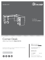 1
1
-
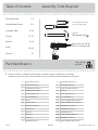 2
2
-
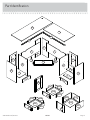 3
3
-
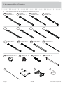 4
4
-
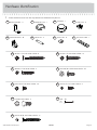 5
5
-
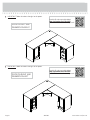 6
6
-
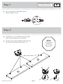 7
7
-
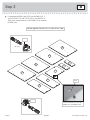 8
8
-
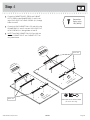 9
9
-
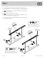 10
10
-
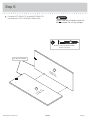 11
11
-
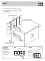 12
12
-
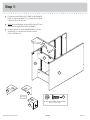 13
13
-
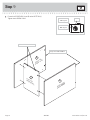 14
14
-
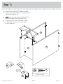 15
15
-
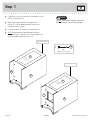 16
16
-
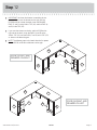 17
17
-
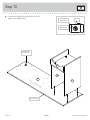 18
18
-
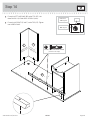 19
19
-
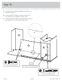 20
20
-
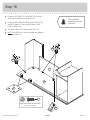 21
21
-
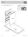 22
22
-
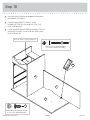 23
23
-
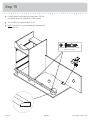 24
24
-
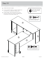 25
25
-
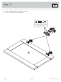 26
26
-
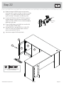 27
27
-
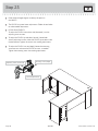 28
28
-
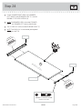 29
29
-
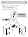 30
30
-
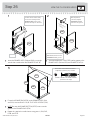 31
31
-
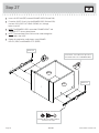 32
32
-
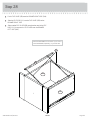 33
33
-
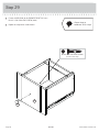 34
34
-
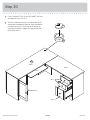 35
35
-
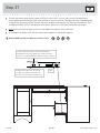 36
36
-
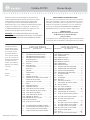 37
37
-
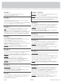 38
38
-
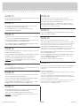 39
39
-
 40
40
-
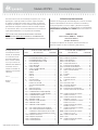 41
41
-
 42
42
-
 43
43
-
 44
44
-
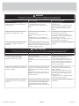 45
45
-
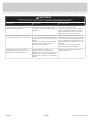 46
46
-
 47
47
-
 48
48


Sauder Harbor View 403793 Assembly Manual
- Tipo
- Assembly Manual
- Este manual también es adecuado para
en otros idiomas
- français: Sauder Harbor View 403793
- English: Sauder Harbor View 403793
Artículos relacionados
-
Sauder Harbor View 417586 Manual de usuario
-
-
-
-
-
-
-
-
-