
USER'S MANUAL AND OPERATING INSTRUCTIONS
READ INSTRUCTIONS CAREFULLY:
Read and follow all instructions. Place
instructions in a safe place for future ref-
erence. Do not allow anyone who has
not read these instructions to assemble,
light, adjust or operate the heater.
PORTABLE PROPANE HEATER FOR
RECREATIONAL,
COMMERCIAL AND
EMERGENCY INDOOR USE
FOR US SALE EXCEPT
MASSACHUSETTS
Patent Pending
– Do not store or use gasoline or other flammable vapors and liquids in the vicinity of this or any
other appliance.
– An LP cylinder not connected for use shall not be stored in the vicinity of this or any other
appliance.
– WHAT TO DO IF YOU SMELL GAS
• Do not try to light appliance.
• Extinguish any open flame.
• Shut off gas to appliance.
– Service must be performed by a qualified service agency.
This is an unvented gas-red portable heater. It uses air (oxygen) from the area in which
it is used.
Adequate combustion and ventilation air must be provided. Refer to page 4.
Model #
HEAT AROUND 360
RADIANT HEATER
1
IMHA360 - KCN
WARNING:
If the information in this manual is not followed exactly, a re or
explosion may result causing property damage, personal injury or
loss of life.
HA1360RH
HA1360R
HA1360BK
HA2360R
For Manual
For Product
Registration
Questions, problems, missing parts? Before returning to your retailer, call our customer
service department at 877-447-4768 8:30 a.m. – 4:30 pm CST, Monday – Friday
or email us at [email protected]
www.ghpgroupinc.com
CONSUMER: Retain this manual for future reference.
US
CSA 4.98 US, GAS-FIRED PORTABLE HEATERS
FOR RECREATIONAL AND COMMERCIAL USE
HA2360BK
HA1360C
HA2360C

NEVER LEAVE THE HEATER
UNATTENDED WHILE BURNING!
2
Service / Parts Ordering Information ....................................................................................1
General Safety Instructions ..................................................................................................2
General Information .............................................................................................................3
Tank Installation Instructions ................................................................................................5
Operating with Disposable Propane Cylinders ......................................................................5
Operating With Hose Connected to Remote Cylinder. ...........................................................5
Lighting Operation Instructions..............................................................................................6
Maintenance ........................................................................................................................8
Troubleshooting ...................................................................................................................9
Parts List ...........................................................................................................................11
Warranty.............................................................................................................................13
TABLE OF CONTENTS
WARNING:
Every time hose or tank is connected to unit, connection
must be checked for leaks in one or more ways: Apply
soapy water to connection, look for bubbles, listen for
hiss of escaping gas, feel for extreme cold, smell for
rotten egg odor. Do not use if leaking!
Any changes to this heater or its controls can be
dangerous.
Some people-pregnant women, persons with heart
or lung disease, anemia, those under the inuence of
alcohol, those at high altitudes - are more affected by
carbon monoxide than others.
If the recreational or commercial enclosure does not
have a window or roof vent that is open, DO NOT USE
THIS HEATER inside.
WARNING:
WARNING:
WARNING:
Early signs of carbon monoxide poisoning resemble the
u, with headache, dizziness and/or nausea. If you have
these signs, heater may not be working properly.
Get fresh air at once! Have heater serviced.
WARNING:
This product and the fuels used to operate this product (liquid propane), and the products of combustion of such fuels, can
expose you to chemicals including benzene, which is known to the State of California to cause cancer and reproductive harm.
For more information go to www.p65Warnings.ca.gov
WARNING:

NEVER LEAVE THE HEATER
UNATTENDED WHILE BURNING!
3
GENERAL INFORMATION:
• This heater is safe for indoor use in small recreational enclosures, having means for providing combustion air and ventilation, such
as enclosed porches, cabins, shing huts, trailers, tent trailers, tents, truck caps and vans. It may be used for emergency indoor
heating when connected to a disposable 1 lb. propane cylinder and for indoor use in commercial enclosures, having means
for providing combustion air and ventilation, such as construction trailers or temporary work enclosures.
• When the heater is cold or at room temperature, it will take a few minutes for the burner to turn bright orange. This is normal
and the heater is working properly. Also, during the initial lighting, the oil used during manufacturing process needs to burn off. This can
take up to 60 minutes of continuous burning. Some odor and yellow ames may occur during this time but will diminish after the burn-in
period.
• After a few hours of operation the upper burner plate will discolor due to the heat of normal operation. This is normal and does not
affect the safe operation of the unit.
• It is recommended not to use the heater in windy conditions. The heater may utter reducing the effectiveness of the
appliance and could have excessive pilot outages.
• When the unit is lit, there should be about a quarter inch border that will not turn bright orange. This is normal.
• When operating the heater at altitudes over 7,000 FT. above sea level, the unit may not burn as bright as in lower altitudes.
This is normal. At higher altitudes, the heater may shut-off. If this happens, provide fresh air, wait 5 minutes and re-light.
Due to local atmospheric conditions heater may not re-light.
• When moving heater when lit or bumping heater setting it down, tip over switch may shut off heater. If this happens,
re-light.
• Operating time will vary depending on the heater setting and the supply cylinder size. See chart and "Cold Weather
Operations" section.
• NOTE: This HEATER MAY BE OPERATED WITH (1) OR (2) DISPOSABLE 1 LB. PROPANE CYLINDERS OR WITH (1)
REMOTE REFILLABLE PROPANE CYLINDER MAX. 20 LBS USING BOTH (1) Dyna-Glo Model # HAKITDG 12’ Extension
Hose and (1) Dyna-Glo Model # HAKITDG Fuel Filter (Sold Separately)
COLD WEATHER OPERATION:
• Cold weather is generally dened as ambient temperatures below 32 degrees F.
• 1 lb. propane cylinders have difculty producing sufcient gas at lower temperatures and can “freeze-up”, reducing the time of
operation by as much as 50-70%. For this reason, it is recommended to use only 20 lb. propane tanks under these conditions.
• If a 1 lb. tank is used in cold weather, such as in an ice shing hut, following are some operating suggestions;
1. Expect operating times to be signicantly reduced.
2. Never use only a single 1 lb. tank on the Heat Around Elite unit, Model HA2360.
3. Never set the heater directly on the ice. Set the heater on a rigid piece of ame retardant insulation and make sure the
ventilation slots on the bottom of the heater are not obstructed.
4. Elevate the heater slightly above the ground level. Insure the unit is level and secure and cannot be knocked over.
5. Keep the tank access door open. This provides some additional heat to warm the 1 lb. cylinder.
6. Adequate ventilation and combustion air must be provided.
7. Maintain all clearances as specied on Page 4.
Carefully watch the Heater for signs of the 1 lb. cylinder "freezing-up". If the lower portion of the burner starts to turn from
orange to blue and begins sputtering immediately shut off the heater and remove it from any enclosure.
WARNING:

NEVER LEAVE THE HEATER
UNATTENDED WHILE BURNING!
4
GENERAL SAFETY INSTRUCTIONS
• Do not use non-approved attachments on this heater.
• Due to high temperatures, the appliance should be located out of trafc and away from combustible materials.
• Children and adults should be alerted to the hazard of high surface temperatures and should stay away to avoid burns
or clothing ignition.
• Young children should be carefully supervised when they are near the appliance.
• Do not place clothing or other ammable material on or near the appliance.
• Do not operate heater in any moving vehicle.
• This heater can also be used in a recreational or commercial enclosure with a window or roof vent. It may also be used outdoors.
• This heater requires a vent area of 18 square inches (example 4 1/4" x 4 1/4" opening) minimum for adequate ventilation during
operation. Do not use other fuel burning appliances inside.
• GAS PRESSURE AT HEATER IS REGULATED AND FIXED AT 11" W.C. WHEN USING A REMOTE HOSE CONNECTION TO HEATER
REGULATOR(S), DO NOT REGULATE OR REDUCE PROPANE TANK SUPPLY PRESSURE TO HEATER.
• REGULATOR(S) IN HEATER MUST ALWAYS BE IN PLACE DURING OPERATION.
• Any safety screen or guard removed for servicing the appliance must be replaced prior to operating the heater.
• The appliance should be inspected before each use. Frequent cleaning may be required. The control compartments,
burner(s) and circulating air passageways of the appliance must be kept clean, see MAINTENANCE.
• DO NOT use this heater if any part has been under water. Immediately call a qualied service technician to inspect
the heater and to replace any part of the control system and any gas control, which has been under water.
• When used without adequate combustion and ventilation air, this heater may give off excessive CARBON MONOXIDE,
an odorless, poisonous gas.
• Some people - pregnant women, persons with heart or lung disease, anemia, those under the inuence of alcohol, those at
high altitudes - are more affected by carbon monoxide than others.
• Cylinders must be disconnected when the heater is not in use.
• When heater is placed on the ground, make sure the ground is level and keep any objects at least 15"' from the edge
of the heater. THIS HEATER IS EQUIPPED WITH A TIP OVER SWITCH THAT WILL SHUT THE HEATER OFF IF
THE HEATER TIPS OVER HOWEVER, DO NOT LEAVE HEATER UNATTENDED OR WHERE CHILDREN MAY
CAUSE THE HEATER TO TIP OVER. NEVER OPERATE THE HEATER WHILE SLEEPING!
• Keep remote 20 lb. rellable cylinders at least 6 ft. away from heater at all times.
GENERAL SAFETY INSTRUCTIONS
THIS IS A HEATING APPLIANCE. DO NOT OPERATE THIS APPLIANCE WITHOUT THE WIRE GUARD INSTALLED. DO NOT
ATTEMPT TO WARM OR COOK FOOD ON THIS HEATER.
MODEL NO..
HA1360RH / HA1360R / HA1360BK / HA1360C / HA2360R / HA2360BK/HA2360C
GAS TYPE .................................................................................................PROPANE
INPUT BTU/HR. .......................................................HA1360 Series - 7,500 - 10,000
.................................................................................HA2360 Series - 13,500 - 18,000
MAX. SUPPLY PRESSURE......................................................BOTTLE PRESSURE
CLEARANCE TO COMBUSTIBLES (FROM EDGE OF GUARD)
TOP ...............................................................................................................17 inches
FRONT ............................................................................................................15 inche
SIDES ..............................................................................................................15 inche
REAR .............................................................................................................15 inches
SPECIFICATIONS
CAUTION:
• Some linoleum surfaces may discolor if heater
is placed directly on these oor coverings.
• When operating the heater at altitudes
over 7,000 FT above sea level the heater
may shut off. (Please read the GENERAL
INFORMATION)
Cylinder Size
Operating Time
HeatAround360 HeatAround 360 Elite
One 1 lb. cylinder 2.7 hrs (high) - 3.2 hrs (low) NOT RECOMMENDED
Two 1 lb. cylinders N/A 3 hrs (high) - 3.5 hrs (low)
One 20 lb. cylinder 45 hrs (high) - 58 hrs (low) 25 hrs (high) - 32 hrs (low)

NEVER LEAVE THE HEATER
UNATTENDED WHILE BURNING!
5
TANK INSTALLATION INSTRUCTIONS
Tank Installation for DOT Certied 1 lb. Propane Cylinder(s) (Fig. 1)
• Open easy access tank compartment door(s).
• Locate regulator and swivel it upward by hand to provide better access for cylinder
• Attach cylinder(s) to swivel mount by gently turning clockwise until it is hand tight. Do not overtighten. Do not use tools to tighten.
• Check for gas leaks by using a 50% soap-water solution at the joint of the regulator and cylinder.
Tank Installation for 20 lb. Propane Cylinder (Fig. 1a)
• Open easy access tank compartment door(s).
• Locate regulator and swivel it upward by hand to provide better access for hose end adapter.
• Attach Fuel Filter, Model HAKITDG to swivel mount by gently turning clockwise until it is hand tight. Do not over tighten. Do not use tools
to tighten.
• Attach GHP hose end adapter (No. HAKITDG ) to fuel lter by gently turning clockwise until it is hand tight. Do not overtighten.
Do not use tools to tighten.
• Check for gas leaks by using a 50% soap-water solution at the joint of the regulator and hose end adapter.
Fig. 1 - 1 lb. Cylinder Tank Installation
1 lb. DOT Approved
Cylinder Tank
Regulator
Access Door
Fig. 1 - 1 lb. Cylinder Tank Installation
Fig. 1a - Remote Tank Installation
EMERGENCY INDOOR USE
• Adequate combustion and ventilation air must be provided when the appliance is in use. Refer to General Safety Instructions on
Page 4 for additional information.
• Only disposable 1 lb. cylinders, marked as PROPANE can be used with this heater.
• NEVER bring a rellable propane cylinder indoors. A re or explosion can occur causing property damage, serious injury, or death.
ADDITIONAL INFORMATION REGARDING OPTIONAL ACCESSORIES TO CONNECT A
20 LB LP TANK
• Please note: this heater may be operated with (1) remote rellable propane cylinder max. 20 Lbs.
• Any CSA certied hose with a CGA 600 tting and excess ow device, that is appropriate for this application, may be used to
connect a 20 lb. propane tank.
• Non-certied or handmade hoses and adapters may not be used to connect a 20 lb. propane tank.
• The use of a fuel lter is also recommended but not mandatory. The fuel lter can reduce potential contaminants from the 20 lb. LP
tank/hose and extend the life of the heater.
• We recommend using the Dyna-Glo 20 lb. tank connection kit model# HAKITDG, which includes (1) 12’ extension hose and (1) fuel
lter (sold separately).
Carefully close the Door while
positioning the remote hose
through the access slot.
Fuel Filter & Hose Kit
# HAKITDG
Access Door
Regulator

6
Fig. -Lighting Instructions
Control Knob
OFF Position
Pilot Position
HIGH Position
LOW Position
Knob Indicator Mark
LIGHTING / OPERATING INSTRUCTIONS
FOR USE WITH HOSE(S) CONNECTED TO A
REMOTE CYLINDER, MAXIMUM SIZE 20 LBS:
• This Heater may be used in a Recreational Enclosure or
Temporary Construction Work Enclosure with a Remote
Rellable Propane Cylinder ONLY when the Cylinder is
Located Outdoors and the Heater is Used with GHP
Hose No. HAKITDG.
• GHP Hose No. HAKITDG includes a hand-tightening tank
connector and a #600 hose connector tting.
• WARNING: NEVER bring a rellable propane cylinder indoors.
A re or explosion can occur causing property damage, serious
injury or death!
• Inspect the hose before each use of the heater. If there is
excessive abrasion or wear, or the hose is cut, replace prior to
using the heater with Dyna-Glo HAKITDG.
• The propane cylinder must include a listed overlling protection
device as well as a collar to protect the cylinder valve.
• Heater must be in an upright position during operation.
• Screw hose connector into tank swivel on heater and screw
opposite end of hose into LP gas tank valve. Tighten all hose
connections. DO NOT use thread sealant on any of these
connections.
• Open valve at LP-gas supply cylinder.
• Check all hose connections for leaks with soapy water at the
threaded connection where the hose connector screws into the
regulator and at LP-gas supply cylinder. SEE WARNING! ON
ATTACHED HANG TAGS.
LIGHTING, OPERATION, AND
SHUTDOWN INSTRUCTIONS
1. Make sure the control knob is in the OFF position. " "
2. Open the access door and install the propane fuel source;
a. Install a DOT certied 1 lb. propane cylinder.
b. Install the GHP hose connector model # HAKITDG.
Check for gas leaks by using a 50% soap-water solution at
the joint of the regulator and cylinder.
3. Depress and turn the control knob to the pilot position "
".
a. If fueled by a 1 lb. propane cylinder, hold for 30 seconds.
b. If fueled by a 20 lb. propane cylinder, hold for 4-5 minutes.
Push and turn knob back to the off position. From the OFF “O” position,
push and turn counter clockwise to the PILOT position. "
". The Igniter
will spark each time this step is performed. Repeat until the pilot ame
lights.
4. Continue holding the knob down in the PILOT position
for 30 seconds or until pilot ame holds.
5. Release the knob. The knob should return to the fully
extended position and the pilot should remain lit.
6. Turn on the burner by depressing the knob slightly and
gently turn the knob to the HI position "
".
7. Adjust heat output by turning the knob between HI and
LOW position "
".
8. To shut down the heater turn the knob clockwise to the OFF
position and remove the gas cylinder or close the propane
tank shut off valve and allow the heater to burn off the gas in
the hose, then turn the heater knob to the OFF position.
CAUTION
Do not try to adjust heating levels by using the propane tank shutoff valve.
After turning heater off the guard will remain hot. Allow the heater to cool
down before storing the heater.
Do not operate, store, connect or remove cylinder/hose connection near
ammable items or ignition sources.
NEVER LEAVE THE HEATER
UNATTENDED WHILE BURNING!
Fig. 2 - Lighting Instruction
WIND
DIRECTION
PILOT
POSITION
Fig. 3 - Lighting in Windy Areas
LIGHTING IN WINDY AREAS
1. Position the heater such that the Pilot is opposite the direction that
the wind is coming from.
2. Position your body behind the heater such that your body blocks the
wind while you are following the instructions for lighting the unit.

7
IMPORTANT NOTICE
REGARDING THIRD PARTY ATTACHMENTS TO ALL
DYNA-GLO HEATAROUND360 MODELS
GHP Group, Inc. is a leading manufacturing company specializing in portable heating products. Our products can be found at most
major home centers, hardware stores and internet retailers across North America. In 2016, GHP introduced the HeatAround360 and
HeatAround360 Elite portable heaters into the market. These heaters, which are sold under the Dyna-Glo brand feature an Oxygen
Depletion Sensor (“ODS”), which shuts off the heater if the oxygen in the room gets below a certain point and a tip-over safety switch
that turns it off in the event of it being knocked on its side. These features allow the heater to be safely used during numerous indoor
and outdoor activities.
GHP recognizes the many different third party attachments for the HeatAround360 and is aware of their intended purpose of using
the HeatAround360 to heat or cook food. GHP strongly encourages that these third party attachments NOT be used as they are nei-
ther certied, nor safe to be used to warm or cook food of any kind. HeatAround360 Heaters are not certied as a cooker and are not
designed to operate in this manner. GHP explicitly prohibits the use of any type of non-approved attachments with its HeatAround360
heaters.
This product is a heater. It is certied to CSA International Requirement Section CSA 4.98 U.S.
"Gas Fired Portable Heaters for Recreational or Commercial Use." This product is NEVER to be used for the cooking or warming of
foods as doing so can interfere with the safety systems of the heater, which may result in a re, explosion, the production of deadly
carbon monoxide, and personal injury or death to you or others. NEVER use hand-made or third party accessories or attachments
with this heater; this is extremely dangerous and may result in personal injury or.death to you or others
WARRANTY LANGUAGE
GHP Group, Inc. warrants its heaters and accessories to be free from defects in material and workmanship for a period of 1 year from
date of purchase. GHP Group, Inc. will repair or replace this product free of charge if it has been proven to be defective within the
1-year period and is returned at customer expense with proof of purchase to GHP Group, Inc. within the warranty period. DISCLAIM-
ER: This warranty does not cover any product that: a) has been subject to misuse or neglect; b) has been used in a manner inconsis-
tent with the warnings and instructions contained in the owner’s manual, including but not limited to using a heater for the cooking or
warming of foods; or c) has been used with hand-made or third party accessories or attachments.
GHP prohibits the HeatAround360 heaters from being used for cooking or warming foods. Third party attachments intended to
change the intended operation of the HeatAround360 are prohibited for use as they could cause serious harm to consumers. Using
such products with GHP heaters will immediately void the product warranty. GHP values the safety of its consumers above all else
and appreciates your continual trust in all GHP products. Please feel free to contact us at [email protected] with
any questions.
• CAUTION: After turning heater off, wire guard will remain hot.
Allow to thoroughly cool before moving or storing.
• CAUTION: When not in use, the gas must be turned off at the LPgas supply cylinder. As stated before allow heater to use up
propane in supply line until heater shuts off. When the LP-gas supply cylinder is not disconnected from the heater, the heater
and the cylinder must be stored outdoors, in a well ventilated space, out of reach of children, and must not be stored in a
building, garage or any other enclosed area. Disconnect all cylinders when heater is not in use.
• CAUTION: Indoor storage of the heater is permissible only if the cylinder is disconnected and removed from the heater. Cylinders
must be stored outdoors out of the reach of children and must not be stored in a building, garage or any other enclosed area.
Both the 1 lb. and 20 lb. cylinders must be in an upright position during use to insure proper vapor withdraw.
1 lb. cylinders must be Dept. of Transportation (DOT) constructed and approved and have an outlet connection compatible with a
CGA 600 tting.
NEVER LEAVE THE HEATER
UNATTENDED WHILE BURNING!
WARNING:

MAINTENANCE:
Always keep the heater area clear and free from combustible
materials, gasoline and other ammable vapors and liquids.
Keep the vent areas (slots in the bottom and the top at the front
of heater) clear at all times so combustion is ventilation air is not
obstructed. Visually inspect the pilot ame and burner periodical-
ly during use so combustion and ventilation air is not obstruct-
ed. The pilot ame should be blue in color (not yellow) and will
extend beyond the thermocouple. The ame will surround the
thermocouple just below the tip, see Figure 4. A slight yellow
ame may occur where the pilot ame and main burner ame
meet. The burner(s) should be bright orange (with a slight blue
color around the border, a red-orange haze that is visible on
the burner is acceptable) and without a noticeable ame. A blue
ame that rolls out at the top indicates an accumulation of dust,
lint or spider webs inside the main burner assembly. If the pilot
is yellow or the burner has a noticeable ame, cleaning may be
required. Use the following procedure to inspect main burner
assembly. It is necessary to periodically check the burner(s)
orice and burner venturi tube to make sure they are clear of
insects/nests or spider webs that may accumulate over time. It is
strongly recommended that these maintenance instructions be
performed annually. A clogged tube can lead to a re.
1 Allow heater to thoroughly cool before performing
any maintenance.
2 Remove disposable 1 lb. cylinder(s) from heater or turn OFF
gas supply at remote cylinder valve, and disconnect
hose from heater.
3 Remove wire guard from heater by gently removing the four
screws attaching the wire guard.
4 And then remove the (3) acorn nuts and gently remove the
burner assembly exposing the burner venturi and pilot
assembly
5 Inspect interior of casing assembly for accumulation
of dust, lint or spider webs. If necessary, clean interior
of casing assembly with a vacuum cleaner or apply air
pressure. Do not damage any components within casing
assembly when you are cleaning.
6. Inspect and clean main burner orice located at bottom
of burner venturi tube, by using a vacuum or apply air
pressure at orice opening.
7 Inspect and clean pilot (mounted to bracket) by using a
vacuum or apply air pressure through the holes in the pilot
indicated by the arrows in Figure 5.
WARNING: Never use needles, wires, or similar cylindrical
objects to clean the pilot to avoid damaging the calibrated
orice that controls the gas ow.
8 Apply air pressure into burner assembly to remove
dust, lint or spider webs.
9 Reinstall burner assembly and wire guard.
8
Pilot Flame
Pilot Air Hole
Burner Assembly
Venturi Tube
NEVER LEAVE THE HEATER
UNATTENDED WHILE BURNING!
Fig. 4 - Burner Orice Location
Fig. 5 - Pilot Assembly
Fig. 6 - Burner Assembly
A
Burner Assembly
Control
Knob
Gas Train
Assembly
Burner Orice
Wire Guard
Plastic Base Assembly
ODS Pilot Assembly
Upper Hinge
Lower Hinge
Door

TROUBLESHOOTING
WARNING: If you smell gas:
• Shut off gas supply.
• Do not try to light any appliance.
• Do not touch any electrical switch; do not use any phone in your building.
• Immediately call your gas supplier from a neighbor’s phone. Follow the gas supplier’s instructions.
• If you cannot reach your gas supplier, call the re department.
IMPORTANT: Operating heater where impurities in air exist may create odors. Cleaning supplies, paint, paint
remover, cigarette smoke, cements and glues, new carpet or textiles, etc., create fumes. These fumes may mix
with combustion air and create odors.
WARNING: Turn off and let cool before servicing. Only a qualied service person should service
and repair heater.
CAUTION: Never use a wire, needle, or similar object to clean ODS/pilot. This can damage ODS/ pilot unit.
PROBLEM POSSIBLE CAUSE CORRECTIVE ACTION
When ignitor knob is
turned, there is no
spark at ODS/pilot.
1. Ignitor electrode is
positioned wrong.
2. Ignitor electrode is broken.
3. Ignitor electrode is not
connected to ignitor cable.
4. Ignitor cable is pinched or
wet.
5. Damaged ignitor cable.
1. Replace electrode.
2. Replace electrode.
3. Replace ignitor cable
4. Free ignitor cable if pinched by any met-
al or tubing. Keep ignitor cable dry.
5. Replace ignitor cable.
When ignitor knob
is turned, there
is a spark at ODS/
pilot but no ignition.
1. Tank shutoff valve is
closed.
2. Control knob not fully
pressed in while pressing
ignitor button.
3. Air in gas lines when
installed.
4. ODS / pilot is clogged.
5. Control knob not in PILOT
position.
6. Depleted gas supply (propane)
1. Turn on gas supply valve.
2. Fully press in control knob while
pressing ignitor button.
3. Continue holding down control knob.
Repeat igniting operation until air is
removed.
4. Clean ODS/pilot (see Care and
Maintenance, page 8) or replace
ODS/pilot assembly.
5. Turn control knob to PILOT position.
6. Purchase new tank or rell 20 lb tank.
ODS/pilot lights
but ame goes out
when control knob is
released.
1. Control knob is not fully
pressed in.
2. Control knob is not pressed
in long enough.
3. Equipment shutoff valve is
not fully open.
4. Thermocouple connection is
loose.
5. Thermocouple damaged.
6. Control valve damaged.
1. Press in control knob fully.
2. After ODS/pilot lights, keep control
knob pressed in 30 seconds.
3. Fully open equipment shutoff valve.
4. Hand tighten until snug, and then
tighten ¼ turn more.
5. Replace thermocouple.
6. Contact customer service.
Burner(s) does not
light afterODS/pilot
is lit.
1. Burner orice is clogged.
2. Burner orice diameter is
too small.
3. Inlet gas pressure is too low.
1. Clean burner orice (see Care and
Maintenance, page 8) or contact
customer service.
2. Contact customer service.
3. Change tanks.
NEVER LEAVE THE HEATER
UNATTENDED WHILE BURNING!
9
TROUBLESHOOTING

PROBLEM POSSIBLE CAUSE CORRECTIVE ACTION
Burner backring
during combustion.
1. Burner orice is clogged or
damaged.
2. Burner is damaged.
3. Gas regulator is damaged.
1. Clean burner orice (see Care and
Maintenance, page 8 or contact
customer service.
2. Contact dealer or customer service.
3. Replace gas regulator.
High yellow ame
during burner
combustion
1. Not enough air.
2. Gas regulator is defective.
3. Outside temperature is too
low.
1. Check burner for dirt and debris. If found,
clean burner (see Care and Maintenance,
page 8).
2. Replace gas regulator.
3. Buy new tank or rell 20lb tank.
Gas odor during
combustion.
1. Foreign matter between
control valve and burner.
2. Gas leak. (See Warning
Statement on page 2).
1. Take apart gas tubing and remove foreign
matter.
2. Locate and correct all leaks.
Heater produces a
clicking/ticking noise
just after burner is lit
or shut off.
1. Metal is expanding while
heating or contracting
while cooling.
1. This is common with most heaters. If
noise is excessive, contact qualied
service technician.
Heater shuts off in
use (ODS operates).
1. Not enough fresh air is
available.
2. Low line pressure.
3. ODS/pilot is partially
clogged.
1. Open window and/or door for
ventilation.
2. Contact local gas supplier.
3. Clean ODS/pilot (see Care and
Maintenance, page 8).
Gas odor exists
even when control
knob is in OFF posi-
tion.
1. Gas leak. See Warning
Statement on page 2.
2. Control valve is
defective.
1. Locate and correct all leaks (see
“Checking Gas Connections” page 4).
2. Contact customer service.
Moisture/conden-
sation noticed on
windows.
1. Not enough combustion/
ventilation air.
1. Refer to “Air for Combustion and
Ventilation” requirements, page 4.
Slight smoke or odor
during initial opera-
tion
1. Residues from
manufacturing process.
1. Problem will stop after a few hours of
operation.
NEVER LEAVE THE HEATER
UNATTENDED WHILE BURNING!
10
TROUBLESHOOTING

PARTS LIST
ITEM QTY HA1360RH HA1360R HA1360BK HA1360C DESCRIPTION
1 1
HA1360-04 HA1360-04 HA1360-04 HA1360-04 Wire Guard
2 1
HA1360-GTA HA1360-GTA HA1360-GTA HA1360-GTA Gas Train Assembly
3 1
KW-16B KW-16B KW-16B KW-16B Tip Switch
4 1
HA360-23 HA360-23 HA360-23 HA360-23 Control Knob
5 1
HA1360-PBA-RD HA1360-PBA-RD HA1360-PBA-B HA1360-PBA-C Plastic Base Assembly
6 1
HA1360-15-RD HA1360-15-RD HA1360-15-B HA1360-15-C Access Door
7 1
HA1360-01 HA1360-01 HA1360-10 HA1360-10 Burner Assembly
8 N/A
HA360-HK HA360-HK HA360-HK HA360-HK
Hardware Kit (Includes all
hardware to assemble unit)
9-1 1
HA1360-21 HA1360-21 HA1360-21 HA1360-21 Hinge Assembly, upper
9-2 1
HA1360-22 HA1360-22 HA1360-22 HA1360-22 Hinge Assembly, lower
10 1
HA1360-08 HA1360-08 HA1360-08 HA1360-08 LP ODS Pilot Assy.
11 1
HA360-08-01 HA360-08-01 HA360-08-01 HA360-08-01 Thermocouple
12 1
HAC360-1 N/A N/A N/A Carrying Case
PARTS LIST
DESCRIPTIONBK10360-ORBK10360-RDQTY
ITEM
Wire Guard
BK10360-04BK10360-04
11
Gas Train Assembly
BK10360-GTABK10360-GTA
1
2
Tip Switch
TT15C-07TT15C-07
1
3
Control Knob
BK360-23BK360-23
14
Plastic Base Assembly
BK10360-PBA-ORBK10360-PBA-RD
15
Access Door
BK10360-15-ORBK10360-15-RD
16
Burner Assembly
BK10360-10BK10360-011
7
Hardware Kit (Includes all hardware
to assemble unit)
BK360-HKBK360-HK
NA
8
Hinge Assembly, upper
BK10360-21BK10360-21
1
9-1
Hinge Assembly, lower
BK10360-22BK10360-22
1
9-2
LP ODS Pilot Assy.
1
10
Thermocouple
111
1
7
2
4
10
11
6
9-2
5
3
8
9-1
11
NEVER LEAVE THE HEATER
UNATTENDED WHILE BURNING!
12

PARTS LIST
ITEM QTY HA2360R HA2360BK HA2360C DESCRIPTION
1 1
HA2360-01 HA2360-01 HA2360-01 Burner Assembly
2 1
HA2360-GTA HA2360-GTA HA2360-GTA Gas Train Assembly
3 N/A
HA360-HK HA360-HK HA360-HK Hardware Kit
4 1
HA2360-04 HA2360-04 HA2360-04 Wire Guard
5 1
HA360-23 HA360-23 HA360-23 Control Knob
6 1
HA2360-PBA-RD HA2360-PBA-B HA2360-PBA-C Plastic Base Assembly
7 2
HA2360-15-RD HA2360-15-B HA2360-15-C Door
8 1
KW-16B KW-16B KW-16B Tip Switch
9-1 2
HA2360-21 HA2360-21 HA2360-21 Door Hinge, Upper
9-2 2
HA2360-22 HA2360-22 HA2360-22 Door Hinge, Lower
10 1
HA2360-08 HA2360-08 HA2360-08 LP ODS Pilot Assy.
11 1
HA360-08-01 HA360-08-01 HA360-08-01 Thermocouple
12
NEVER LEAVE THE HEATER
UNATTENDED WHILE BURNING!
4
1
3
8
5
9-1
9-2 7
6
2
10
11

WARRANTY
LIMITED WARRANTY:
DUTIES OF THE OWNER:
This heating appliance must be operated in accordance with the written instructions furnished with this heater. This warranty shall not excuse
the owner from properly maintaining this heater in accordance with the written instructions furnished with this heater. A bill of sale, canceled
check or payment record must be kept to verify purchase date and establish warranty period. Original carton should be kept in case of warranty
return of unit.
WHAT IS NOT COVERED:
1. Damage resulting from use of improper fuel.
2. Damage caused by misuse or use contrary to the owners manual and safety guidelines.
3. Damage caused by a lack of normal maintenance.
4. Fuses
5. Use of non-standard parts or accessories.
6. Damage caused in transit. Freight charges on warranty parts or heaters to and from the factory shall be the responsibility of the owner.
This warranty does not imply or assume any responsibility for consequential damages that may result fr
om the use, misuse, or the lack of
routine maintenance of this heating appliance. A cleaning fee and the cost of parts may be charged for appliance failures resulting from lack of
maintenance. This warranty does not cover claims which do not involve defective workmanship or materials. FAILURE TO PERFORM
GENERAL MAINTENANCE (INCLUDING CLEANING) WILL VOID THIS WARRANTY.
THIS LIMITED WARRANTY IS GIVEN TO THE PURCHASER IN LIEU OF ALL OTHER WARRANTIES, EXPRESSED OR IMPLIED,
I
NCLUDING BUT NOT LIMITED TO THE WARRANTIES OF MERCHANTABILITY OF FITNESS FOR A PARTICULAR PURPOSE. THE
REMEDY PROVIDED IN THIS WARRANTY IS EXCLUSIVE AND IS GRANTED IN LIEU OF ALL OTHER REMEDIES. IN NO EVENT WILL
GHP GROUP, INC. BE LIABLE FOR INCIDENTAL OR CONSEQUENTIAL DAMAGES.
Some states do not allow limitations on how long an implied warranty lasts, so the above limitation may not apply to you. Some states do not
allow the exclusion or limitation of incidental or consequential damages so the above limitation or exclusion may not apply to y
ou.
CLAIMS HANDLED AS FOLLOWS:
1. Contact your retailer and explain the problem.
2. If the retailer is unable to resolve the problem, contact ourCustomer Service Dept. detailing the heater model, the problem, and proof
of date of purchase.
3. A representative will contact you. DO NOT RETURN THE HEATER TO GHP GROUP,INC. unless instructed by our Representative.
This warranty gives you specific legal rights and you may also have other rights which vary from state to state.
TO REGISTER THE WARRANTY ON YOUR HEATER, PLEASE FILL OUT THIS CARD COMPLETELY
AND MAIL WI
THIN 14 DAYS FROM DATE OF PURCHASE OR REGISTER ON-LINE AT www.ghpgroupinc.com
NAME: ______________________________________ PHONE: ( ) __________________ EMAIL: ____________________________
ADDRESS: _________________________________ CITY: ______________________________ STATE: __________ ZIP: ____________
MODEL: ____________________ SERIAL #: _______________________________________ DATE PURCHASED: __________________
DEALER PURCHASED FROM: ____________________________________________ TYPE OF STORE: __________________________
CITY & STATE WHERE PURCHASED: ______________________________________________ PRICE PAID: _______________________
Please Take a Minute To Give Us Your Answers To The Following Questions.
All Responses Are Used Solely For Market Research And Are Held In Strict Confidence.
Who primarily decided this purchase?
Male Female 18-24 25-39 40-59 60 and over
Purpose of Purchase? _______________________________________________________________________________________________
Do you own any other portable heaters?
Yes No If yes, type____________________________brand_____________________
How do you intend to use your new heater?
Construction Site Farm Warehouse/Commercial Garage/Outbuilding Other
How did you become aware of this heater?
In-Store Display Newspaper Ad Magazine Ad Friend/Relative
TV Commercial Store Salesperson
Other ___________________________
What made you select this heater?
Style Size/Portability Price Package Brand Other ___________________
Do you:
own rent Would you recommend this heater to a friend? Yes No
Please give us your comments:________________________________________________________________________________________
THANK YOU FOR COMPLETING THIS FORM!
Information will be held confidential.
This limited warranty is extended to the original retail purchaser of this Forced Air/Convection/Radiant Heater and warrants against any defect
in materials and workmanship for a period of one (1) year from the date of retail sale (lifetime warranty for the brass nozzle burner only). GHP
Group, Inc., at it’s option, will either provide replacement parts or replace or repair the unit, when properly returned to the retailer where
purchased or one of our service centers as directed by GHP Group, Inc., within one (1) year of retail purchase. (Shipping costs, labour costs,
etc. are the responsibility of the purchaser.)

WARRANTY REGISTRATION
IMPORTANT: We urge you to fill out your warranty registration card within fourteen (14)
days of date of purchase. You can also register your warranty on the internet at
www.ghpgroupinc.com. Complete the entire serial number. Retain this portion of the card
for your records.
SAVE THIS CARD!
Place
Postage
Stamp
Here
GHP Group, Inc.
8280 Austin Avenue
Morton Grove, IL 60053-3207
GHP Group, Inc.
8280 Austin Ave.
Morton Grove, IL 60053-3207
Tel: (877) 447-4768
www.ghpgroupinc.com
8280 Austin Avenue
Mo rton G r ove , IL.
6 0 053-3207
Tel: ( 847 ) 324 - 5900
Fax: ( 847 ) 324 - 5901
Toll Free (877) GHP Group
( 8 7 7 ) 4 4 7 - 4 7 6 8
www.ghpgroupinc.com
GHP
GHP Group, Inc.
6440 W Howard St
Niles, IL 60714-3302
Tel: (877) 447-4768
www.ghpgroupinc.com
GHP Group, Inc.
6440 W Howard St
Niles, IL 60714-3302

15
MANUAL DEL USUARIO E INSTRUCCIONES DE FUNCIONAMIENTO
LEA ATENTAMENTE LAS INSTRUCCIONES:
Lea y respete todas las instrucciones.
Guarde las instrucciones en un lugar
seguro para consultarlas en el futuro.
No permita que nadie ensamble,
encienda, ajuste ni utilice el calefactor
sin leer estas instrucciones.
CALEFACTOR PORTÁTIL A PROPANO
PARA USO EN INTERIORES,
RECREATIVO, COMERCIAL Y DE
EMERGENCIA
PARA VENTA EN EE. UU. EXCEPTO EN
MASSACHUSETTS
Patente en trámite
– No guarde ni utilice gasolina u otros vapores y líquidos inamables cerca de
este artefacto ni de ningún otro.
–
Cuando los cilindros de gas propano líquido no estén conectados,
no deben quedar guardados cerca de este artefacto ni de ningún otro.
– QUÉ HACER SI SIENTE OLOR A GAS
• No intente encender el artefacto.
• Apague toda llama abierta.
• Cierre la conexión de gas que va al artefacto.
– Las reparaciones deben ser realizadas por una
agencia de servicio calicada.
Este es un calefactor portátil a gas sin salida al exterior. Utiliza el aire (oxígeno) del área en que
se utiliza.
Se debe proporcionar cantidad adecuada de aire de combustión y ventilación. Consulte la página 18.
N.° de modelo
CALEFACTOR RADIANTE
HEAT AROUND 360
ADVERTENCIA:
Si la información de este manual no se respeta con exactitud, se
podría ocasionar una descarga eléctrica o un incendio, lo que podría
provocar daños materiales y lesiones personales, incluso la muerte.
HA1360RH
HA1360R
HA1360BK
HA2360R
HA2360BK
Para manual
Para registro
del producto
¿Dudas, problemas, piezas faltantes? Antes de volver a la tienda, llame a nuestro
departamento de servicio al cliente al 877-447-4768 de lunes a viernes de 8:30 a 16:30 (hora central estándar)
o escriba a [email protected]
www.ghpgroupinc.com
CONSUMIDOR: conserve este manual para consultarlo cuando sea necesario.
US
CERTIFICACIÓN CSA 4.98 DE EE. UU.,
CALEFACTORES PORTÁTILES A GAS
PARA USO COMERCIAL Y RECREATIVO
IMHA360 - KCN
HA1360C
HA2360C
HA1360C
HA2360C

16
NUNCA DEJE DESATENDIDO EL CALEFACTOR
MIENTRAS ESTÁ ENCENDIDO.
Información sobre reparación/solicitud de piezas .............................................................................. 15
Instrucciones generales sobre seguridad ........................................................................................... 16
Información general ............................................................................................................................ 17
Instrucciones de instalación del tanque .............................................................................................. 19
Funcionamiento con cilindros de gas propano desechables .............................................................. 19
Funcionamiento con manguera conectada a cilindro remoto. ............................................................ 19
Instrucciones de funcionamiento del encendido ................................................................................ 20
Mantenimiento .................................................................................................................................... 22
Solución de problemas ....................................................................................................................... 23
Lista de piezas .................................................................................................................................... 25
Garantía............................................................................................................................................... 27
CONTENIDO
Cada vez que se conecta la manguera o el tanque a la
unidad, se debe vericar que la conexión no tenga fugas.
Para esto: Aplique agua jabonosa en la conexión, observe si
hay burbujas, escuche si hay un silbido de escape de gas,
palpe para comprobar si está muy frío y verique que no haya
olor a huevo podrido. ¡No utilice el artefacto si hay fugas!
Realizar cambios en el calefactor o en sus controles puede
ser peligroso.
Algunas personas ―embarazadas, personas con
enfermedades cardíacas o pulmonares, anémicas, las que
están bajo los efectos del alcohol o las que están a alturas
elevadas― se ven más afectadas por el monóxido de
carbono que otras.
Si se trata de un espacio cerrado recreativo o comercial sin
ventana ni ventilación en el techo que esté abierta,
NO UTILICE ESTE CALEFACTOR en el interior.
Los signos tempranos de intoxicación por monóxido de
carbono se asemejan a los de la gripe, con dolores de
cabeza, mareos y/o náuseas. Si presenta estos signos, es
posible que el calefactor no esté funcionando correctamente.
¡Tome aire fresco inmediatamente! Haga reparar el calefactor.
ADVERTENCIA:
ADVERTENCIA: ADVERTENCIA:
ADVERTENCIA:ADVERTENCIA:
Este producto y los combustibles utilizados para poner en funcionamiento este producto (propano líquido), y los productos
de la combustión de tales combustibles, pueden exponerlo a sustancias químicas como el benceno que, según el estado de
California puede provocar cáncer y daños reproductivos.
Para obtener más información, visite www.p65Warnings.ca.gov
ADVERTENCIA:

17
NUNCA DEJE DESATENDIDO EL CALEFACTOR
MIENTRAS ESTÁ ENCENDIDO.
INFORMACIÓN GENERAL:
• Este calefactor es seguro para ser utilizado en el interior de espacios cerrados pequeños de uso recreativo que tengan
medios para proporcionar aire de combustión y ventilación, como galerías cerradas, cabinas, cabañas de pescadores,
remolques, tienda-remolques, tiendas de campaña, capotas de camionetas y furgonetas. Se puede utilizar como calefacción
de emergencia para interiores si se conecta a un cilindro de gas propano de 1 lb desechable y también en espacios
cerrados comerciales que tengan medios para proporcionar aire de combustión y ventilación, como casillas de obrador o
compartimentos para trabajos temporarios.
• Cuando el calefactor está frío o a temperatura ambiente, demorará unos minutos para que el quemador se torne de
color naranja brillante. Esto es normal y signica que el calefactor está funcionando correctamente. Además, durante el
procedimiento de encendido inicial, el aceite utilizado en el proceso de fabricación debe quemarse. Observará un quemado
continuo que puede llevar hasta 60 minutos, y tal vez perciba cierto olor y observe llamas de color amarillo. Esto disminuirá
una vez nalizado el quemado del aceite.
• Después de unas horas de funcionamiento, la placa superior del quemador se descolorará debido al calor del funcionamiento
normal. Esto es normal y no afecta al funcionamiento seguro de la unidad.
• No se recomienda el uso del calefactor cuando hay mucho viento. Se pueden agitar las llamas del calentador, lo que reduce la
ecacia del artefacto y podría ocasionar excesivos apagados del piloto.
• Cuando la unidad esté encendida, habrá un borde de aproximadamente un cuarto de pulgada que no se tornará de color
naranja brillante. Esto es normal.
• Cuando el calefactor funciona a alturas superiores a los 7000 pies sobre el nivel del mar, es posible que la unidad no queme
con tanta intensidad como en alturas inferiores. Esto es normal. A alturas más elevadas, el calefactor podría apagarse. Si esto
sucede, procure que haya aire fresco, espere 5 minutos y vuelva a encenderlo. Debido a las condiciones atmosféricas locales,
es posible que el calefactor no se vuelva a encender.
• Si mueve el calefactor cuando está encendido o si, al colocarlo en el suelo, lo golpea, es posible que el interruptor de vuelco
haga que se apague el calefactor. Si esto sucede, vuelva a encenderlo.
• El tiempo de funcionamiento variará según el lugar y el tamaño del cilindro. Consulte el gráco y la sección "Funcionamiento
en clima frío".
• NOTA: ESTE CALEFACTOR PUEDE FUNCIONAR CON (1) O (2) CILINDROS DE GAS PROPANO DESECHABLES DE
1 LB O CON (1) CILINDRO DE GAS PROPANO RECARGABLE REMOTO DE 20 LB COMO MÁXIMO UTILIZANDO (1)
manguera de extensión de 12’ Dyna-Glo modelo n.º HAKITDG y (1) ltro de combustible Dyna-Glo modelo n.º HAKITDG
(se venden por separado)
FUNCIONAMIENTO EN CLIMA FRÍO:
• Por lo general, el clima frío se dene como temperaturas ambiente inferiores a 32 °F.
• Los cilindros de gas propano de 1 lb tienen dicultad para producir suciente gas a bajas temperaturas y se pueden congelar,
lo que reduce el tiempo de funcionamiento entre un 50 % y un 70 %. Por esta razón, se recomienda utilizar únicamente
tanques de gas propano de 20 lb bajo estas condiciones.
• Si se utiliza un tanque de 1 lb en climas fríos, por ejemplo, en una cabaña para pescadores escarchada, tenga en cuenta las
siguientes sugerencias:
1. Los tiempos de funcionamiento se reducirán considerablemente.
2. Nunca utilice un solo tanque de 1 lb en la unidad Heat Around Elite, modelo HA2360.
3. Nunca coloque el calefactor directamente sobre el hielo. Coloque el calefactor sobre una pieza de material aislante
rígido resistente a las llamas y asegúrese de que las ranuras de ventilación de la parte inferior del calefactor no estén
obstruidas.
4. Levante ligeramente el calefactor sobre el nivel del suelo. Asegúrese de que la unidad esté nivelada y rme y no se
pueda volcar.
5. Mantenga abierta la puerta de acceso del tanque. Esto proporciona calor adicional para calentar el cilindro de 1 lb.
6. Se debe proporcionar cantidad adecuada de aire de ventilación y combustión.
7. Mantenga todas las distancias según se especican en la página 18.
Observe cuidadosamente el calefactor para vericar que no haya signos de congelamiento del cilindro de 1 lb. Si la parte in-
ferior del quemador comienza a tornarse de naranja a azul y comienza a chisporrotear, apague inmediatamente el calefactor
y retírelo del espacio cerrado.
ADVERTENCIA:

18
NUNCA DEJE DESATENDIDO EL CALEFACTOR
MIENTRAS ESTÁ ENCENDIDO.
• No utilice accesorios no aprobados en este calefactor.
• Debido a las altas temperaturas, el artefacto se debe colocar fuera del tráco y apartado de materiales combustibles.
• Tanto los niños como los adultos deben estar al tanto de los peligros de las altas temperaturas y mantenerse alejados para
evitar quemaduras o riesgo de que se les prenda fuego la ropa.
• Cuando haya niños cerca del lugar donde se encuentra el artefacto, se los deberá supervisar atentamente.
• Nunca coloque ropa u otro material inamable sobre el artefacto o cerca de este.
• No ponga en funcionamiento el calefactor sobre un vehículo en movimiento.
• Este calefactor también se puede utilizar en un espacio cerrado de uso recreativo o comercial que tenga una ventana o una
ventilación en el techo. También se puede utilizar en exteriores.
• Este calefactor requiere un área de ventilación mínima de 18 pulgadas cuadradas (por ejemplo, una abertura de 4 1/4" × 4 1/4") para
que la ventilación sea adecuada durante el funcionamiento. No utilice otros artefactos que queman combustible en el interior.
• LA PRESIÓN DE GAS DEL CALEFACTOR SE REGULA Y SE FIJA EN 11" DE COLUMNA DE AGUA. AL UTILIZAR UNA CONEXIÓN
DE MANGUERA REMOTA A LOS REGULADORES DEL CALEFACTOR, NO REGULE NI REDUZCA LA PRESIÓN DE SUMINISTRO
DEL TANQUE DE GAS PROPANO AL CALEFACTOR.
• LOS REGULADORES DEL CALEFACTOR SIEMPRE DEBEN ESTAR EN SU LUGAR DURANTE EL FUNCIONAMIENTO.
• Antes de poner en funcionamiento el calefactor, vuelva a colocar todas las protecciones o pantallas de seguridad que hayan
sido retiradas para realizar la reparación del artefacto.
• El artefacto debe ser inspeccionado antes de cada uso. Posiblemente se requiera una limpieza frecuente. Los
compartimentos de control, los quemadores y los conductos de aire circulante deben mantenerse limpios; consulte la
sección MANTENIMIENTO.
• NO utilice este calefactor si se ha mojado alguna de las piezas. Llame inmediatamente a un técnico calicado para que inspeccione el
calefactor y reemplace las piezas del sistema de control y los controles de gas que se hayan mojado.
• Si se lo utiliza sin un ujo adecuado de aire de combustión y ventilación, el calefactor puede emitir una cantidad excesiva de
MONÓXIDO DE CARBONO, un gas tóxico que no produce olor.
• Algunas personas ―embarazadas, personas con enfermedades cardíacas o pulmonares, anémicas, las que están bajo los efectos
del alcohol o las que están a alturas elevadas― se ven más afectadas por el monóxido de carbono que otras.
• Los cilindros se deben desconectar cuando el calefactor está fuera de uso.
• Cuando el calefactor se coloque sobre el suelo, asegúrese de que el suelo esté nivelado y mantenga cualquier objeto a una distancia
mínima de 15" desde el borde del calefactor. ESTE CALEFACTOR ESTÁ EQUIPADO CON UN INTERRUPTOR DE VUELCO QUE
APAGA EL ARTEFACTO SI SE VUELCA. NO OBSTANTE, NUNCA DEJE EL CALEFACTOR DESATENDIDO O EN UN LUGAR
DONDE LOS NIÑOS PUEDAN VOLCARLO. ¡NUNCA DEJE EN FUNCIONAMIENTO EL CALEFACTOR MIENTRAS DUERME!
• Mantenga los cilindros recargables remotos de 20 lb. por lo menos a 6 pies del calentador en todo momento.
INSTRUCCIONES GENERALES SOBRE SEGURIDAD
ESTE ES UN ARTEFACTO DE CALEFACCIÓN. NO PONGA EN FUNCIONAMIENTO ESTE ARTEFACTO SI LA REJILLA DE
PROTECCIÓN NO ESTÁ INSTALADA. NO INTENTE CALENTAR NI COCINAR ALIMENTOS SOBRE ESTE CALEFACTOR.
N.º DE MODELO
HA1360RH / HA1360R / HA1360BK / HA1360C / HA2360R / HA2360BK / HA2360C
TIPO DE GAS .........................................................................................................PROPANO
ENTRADA BTU/H.....................................................................Serie HA1360 - 7500 - 10 000
................................................................................................Serie HA2360 - 13 500 - 18 000
PRESIÓN MÁX. DE SUMINISTRO........................................................PRESIÓN DEL TUBO
DISTANCIA A COMBUSTIBLES (DESDE EL BORDE DE PROTECCIÓN)
SUPERIOR ...........................................................................................................17 pulgadas
FRONTAL .............................................................................................................15 pulgadas
LATERALES .........................................................................................................15 pulgadas
TRASERA .............................................................................................................15 pulgadas
ESPECIFICACIONES
PRECAUCIÓN:
• Las supercies de linóleo se pueden decolorar
si el calefactor se coloca directamente sobre el
revestimiento.
• Cuando el calefactor funciona a alturas
superiores a los 7000 pies sobre el nivel
del mar, es posible que se apague. (Lea la
INFORMACIÓN GENERAL).
Tamaño del cilindro
Tiempo de funcionamiento
HeatAround360 HeatAround 360 Elite
Un cilindro de 1 lb 2.7 h (alto) - 3.2 h (bajo) NO RECOMENDADO
Dos cilindros de 1 lb N/A 3 h (alto) - 3.5 h (bajo)
Un cilindro de 20 lb 45 h (alto) - 58 h (bajo) 25 h (alto) - 32 h (bajo)

19
NUNCA DEJE DESATENDIDO EL CALEFACTOR
MIENTRAS ESTÁ ENCENDIDO.
INSTRUCCIONES DE INSTALACIÓN DEL TANQUE
Instalación del tanque para cilindros de gas propano de 1 lb con certicación del Departamento de Transporte (DOT) (Fig. 1)
• Abra las puertas de fácil acceso del compartimento del tanque.
• Localice el regulador y gírelo hacia arriba con la mano de manera que tenga mejor acceso para el cilindro.
• Conecte los cilindros en el montaje giratorio girando suavemente en sentido de las agujas del reloj hasta que quede ajustado. No
ajuste demasiado. No utilice herramientas para ajustar.
• Coloque una solución de agua con 50 % de jabón en la junta entre el regulador y el cilindro para detectar fugas de gas.
Instalación del tanque para cilindros de gas propano de 20 lb (Fig. 1a)
• Abra las puertas de fácil acceso del compartimento del tanque.
• Localice el regulador y gírelo hacia arriba con la mano de manera que tenga mejor acceso para el adaptador del extremo de la
manguera.
• Conecte el ltro de combustible modelo HAKITDG en el montaje giratorio girando suavemente en sentido de las agujas del reloj
hasta que quede ajustado. No lo ajuste demasiado. No utilice herramientas para ajustar.
• Conecte el adaptador del extremo de la manguera GHP (n.º HAKITDG) al ltro de combustible girando suavemente en sentido de
las agujas del reloj hasta que quede ajustado. No ajuste demasiado. No utilice herramientas para ajustar.
• Coloque una solución de agua con 50 % de jabón en la junta entre el regulador y el adaptador del extremo de la manguera para
detectar fugas de gas.
Fig. 1 - Instalación del tanque del cilindro de 1 lb
Fig. 1 - 1 lb. Cylinder Tank Installation
Regulador
Puerta de acceso
Tanque del cilindro
de 1 lb aprobado
por DOT
C
M
Y
CM
MY
CY
CMY
K
1 lb Cylinder Installation.pdf 1 3/9/17 10:25 AM
Fig. 1a - Instalación del tanque remoto
PARA USO EN INTERIORES Y DE EMERGENCIA
• Cuando el artefacto está en uso, se debe proporcionar cantidad adecuada de aire de combustión y ventilación. Para obtener más
información, consulte las Instrucciones generales sobre seguridad en la página 18.
• En este calefactor solo se pueden utilizar cilindros de 1 lb. marcados con la leyenda PROPANO.
• NUNCA use un cilindro de gas propano recargable en lugares cerrados. Podría producirse un incendio o una explosión, con daños
materiales y lesiones graves o mortales.
Carefully close the Door while
positioning the remote hose
through the access slot.
Fuel Filter & Hose Kit
# HAKITDG
Access Door
Regulator
INFORMACIÓN ADICIONAL SOBRE ACCESORIOS
OPCIONALES PARA CONECTAR UN TANQUE DE GAS PROPANO DE 20 LB
• Atención: este calefactor puede funcionar con (1) tanque de gas propano recargable remoto de 20 lb. como máximo.
• Para conectar el tanque de gas propano de 20 lb. se puede utilizar cualquier manguera certicada por CSA que tenga un acceso-
rio CGA 600 y un dispositivo de exceso de ujo, y que sea adecuada para esta aplicación.
• No se recomienda utilizar mangueras ni adaptadores no certicados o confeccionados a mano para conectar el tanque de gas
propano de 20 lb.
• El uso de un ltro de combustible es recomendable, pero no obligatorio. El ltro de combustible puede reducir los potenciales
contaminantes de la manguera o del tanque de gas propano de 20 lb. y prolongar la vida útil del calefactor.
• Se recomienda usar el kit de conexión del tanque de gas propano de 20 lb. Dyna-Glo, modelo n.° HAKITDG, que incluye (1)
manguera de extensión de 12’ y (1) ltro de combustible (se vende por separado).
Regulador
Puerta de
acceso
Filtro de combustible
recomendado
modelo HAKITDG
Cierre la puerta con
cuidado mientras coloca
la manguera remota por
la ranura de acceso.

20
NUNCA DEJE DESATENDIDO EL CALEFACTOR
MIENTRAS ESTÁ ENCENDIDO.
Posición Piloto
Posición ALTO
Posición BAJO
Marca del indicador
de la perilla
Posición APAGADO
Perilla de control
INSTRUCCIONES DE ENCENDIDO/
FUNCIONAMIENTO CON MANGUERAS
CONECTADAS A UN CILINDRO REMOTO,
TAMAÑO MÁXIMO DE 20 LB
• Este calefactor se puede utilizar, en un espacio cerrado de uso recreativo
o en un espacio cerrado destinado al trabajo temporario de constructores,
con un cilindro de gas propano recargable remoto ÚNICAMENTE cuando el
cilindro se encuentra en el exterior y el calefactor se utiliza con una manguera
GHP n.º HAKITDG.
• La manguera de GHP n.º HAKITDG incluye un conector de tanque que se
ajusta con la mano y un accesorio conector de manguera n.º 600.
• ADVERTENCIA: NUNCA use un cilindro de gas propano recargable en
lugares cerrados. Podría producirse un incendio o una explosión, con daños
materiales y lesiones graves o mortales.
• Inspeccione la manguera antes de cada uso. Si hay demasiada abrasión o
está demasiado gastada, reemplácela antes de usar el calefactor con
Dyna-Glo HAKITDG.
• El cilindro de gas propano debe incluir un dispositivo de protección contra
sobrellenado registrado y un collarín para proteger la válvula del cilindro.
• El calefactor debe estar en posición vertical durante el funcionamiento.
• Atornille el conector de la manguera en el montaje giratorio del tanque del
calefactor y atornille el extremo opuesto de la manguera en la válvula del
tanque de gas propano líquido. Ajuste todas las conexiones de la manguera.
NO utilice sellador de roscas en ninguna de estas conexiones.
• Abra la válvula del cilindro de suministro de gas propano líquido.
• Verique todas las conexiones de la manguera para detectar fugas colocando
agua jabonosa en la conexión roscada, donde el conector de la manguera se
atornilla al regulador y al cilindro de suministro de gas propano líquido.
LEA LAS ADVERTENCIAS DE LAS ETIQUETAS COLGANTES.
INSTRUCCIONES DE ENCENDIDO,
FUNCIONAMIENTO Y APAGADO
1. Asegúrese de que la perilla de control esté en la posición de APAGADO " ".
2. Abra la puerta de acceso e instale la fuente de combustible propano:
a. Instale un cilindro de gas propano de 1 lb con certicación del
Departamento de Transporte (DOT).
b. Instale el conector de manguera GHP modelo n.º HAKITDG.
Coloque una solución de agua con 50 % de jabón en la junta entre el
regulador y el cilindro para detectar fugas de gas.
3. Oprima y gire la perilla de control hasta la posición piloto "
".
a. Si está alimentado por un tanque de gas propano de 1 lb, manténgala
oprimida por 30 segundos.
b. Si está alimentado por un tanque de gas propano de 20 lb, manténgala
oprimi da por 4 a 5 minutos
Presione la perilla y gírela hasta la posición de apagado
Desde la posición APAGADO "O", presiónela y gírela en sentido contrario a las
agujas del reloj hasta la posición PILOTO.
4. Mantenga presionada la perilla en la posición PILOTO durante 30 segun
dos o hasta asegurarse de que la llama piloto permanece encendida.
5. Suelte la perilla. Esta debería regresar a la posición completamente
extendida y el piloto debería permanecer encendido.
6. Encienda el quemador presionando levemente la perilla y girándola con
suavidad hasta colocarla en la posición ALTO "
".
7. Regule la salida de calor girando la perilla entre la posición ALTO y BAJO " ".
8. Para apagar el calefactor, gire la perilla en sentido de las agujas del reloj
hasta la posición de APAGADO, retire el cilindro de gas o cierre la válvula
del tanque de gas propano para que el calefactor pueda quemar el gas en la
manguera y luego gire la perilla del calefactor hasta la posición APAGADO.
PRECAUCIÓN
No intente regular la temperatura con la válvula de paso del tanque de gas
propano. Una vez que se apague el calefactor, la protección seguirá estando
caliente. Deje que el calefactor se enfríe antes de guardarlo.
No utilice, guarde, conecte ni retire la conexión de la manguera/cilindro cerca
de elementos inamables o fuentes de ignición.
Fig. 2 - Instrucciones de encendido
Fig. 3 - Encendido en áreas ventosas
ENCENDIDO EN ÁREAS VENTOSAS
1. Coloque el calefactor de manera que el piloto quede en dirección
opuesta al viento.
2. Colóquese detrás del calefactor de manera que su cuerpo bloquee
el viento y siga las instrucciones para encender la unidad.
WIND
DIRECTION
PILOT
POSITION
DIRRECIÓN
DEL VIENTO
POSICIÓN PILOTO

21
NUNCA DEJE DESATENDIDO EL CALEFACTOR
MIENTRAS ESTÁ ENCENDIDO.
AVISO IMPORTANTE
SOBRE EL USO DE ACCESORIOS DE TERCEROS EN TODOS LOS
MODELOS DYNA-GLO HEATAROUND360
GHP Group, Inc. es una importante empresa que se especializa en productos de calefacción portátiles. Nuestros productos se
pueden encontrar en la mayoría de las principales tiendas de artículos para el hogar, ferreterías y comercios de venta minorista por
Internet de Norteamérica. En 2016, GHP lanzó al mercado los calefactores portátiles HeatAround360 y HeatAround360 Elite. Estos
calefactores, que se venden bajo la marca Dyna-Glo, incluyen un sensor de agotamiento de oxígeno (ODS), que apaga el calefactor
si el oxígeno de la habitación disminuye a un cierto punto, y un interruptor de vuelco que apaga el calefactor cuando se vuelca. Estas
características permiten que el calefactor se pueda utilizar de forma segura durante distintas actividades en interiores y al aire libre.
GHP reconoce que existen muchos accesorios de terceros para el calefactor HeatAround360 y que el objetivo de estos accesorios
es utilizar el calefactor HeatAround360 para calentar o cocinar alimentos. GHP recomienda rmemente NO utilizar estos accesorios
de terceros ya que no están certicados y no son seguros para calentar o cocinar alimentos de ningún tipo. Los calefactores
HeatAround360 no están certicados como artefactos de cocina y no están diseñados para funcionar como tales. GHP prohíbe
explícitamente el uso de cualquier tipo de accesorio no aprobado en sus calefactores HeatAround360.
Este producto es un calefactor. Está certicado según la sección de requisitos internacionales CSA 4.98 de EE. UU.
"Calefactores portátiles a gas para uso recreativo o comercial". Este producto NUNCA se debe utilizar para cocinar o calentar
alimentos, ya que esto puede interferir en los sistemas de seguridad del calefactor, lo que podría provocar un incendio, una
explosión, la producción de monóxido de carbono mortal y lesiones personales o mortales a usted o a otras personas. NUNCA utilice
accesorios ni dispositivos de terceros ni hechos a mano en este calefactor; es muy peligroso y podría ocasionar lesiones personales
o mortales a usted o a otras personas.
INFORMACIÓN DE GARANTÍA
GHP Group, Inc. garantiza que sus calefactores y accesorios están libres de defectos en materiales y mano de obra durante un
período de 1 año a partir de la fecha de compra. GHP Group, Inc. reparará o reemplazará este producto sin cargo si se prueba que
el defecto se produjo dentro del período de 1 año y el cliente devuelve el producto a GHP Group, Inc. junto con el comprobante
de compra dentro del período de garantía y asumiendo los costos de envío. DESCARGO DE RESPONSABILIDAD: Esta garantía
no cubre ningún producto que: a) se haya sometido a uso indebido o negligencia; b) no se haya utilizado de acuerdo con las
advertencias e instrucciones de este manual, incluido, entre otros, el uso del calefactor para cocinar o calentar alimentos o c) se lo
haya utilizado con accesorios o dispositivos de terceros o hechos a mano.
GHP prohíbe que los calefactores HeatAround360 se utilicen para cocinar o calentar alimentos. El uso de accesorios de terceros
diseñados para cambiar el funcionamiento del HeatAround360 está prohibido ya que podría causar daños graves a los usuarios.
El uso de estos productos con los calefactores de GHP anulará instantáneamente la garantía. GHP valora la seguridad de los
usuarios sobre todo lo demás y aprecia su conanza continua en todos los productos de GHP. Si tiene alguna pregunta, no dude en
comunicarse con nosotros a [email protected].
• PRECAUCIÓN: Una vez que se apague el calefactor, la rejilla de protección seguirá estando caliente.
Deje que se enfríe completamente antes de mover o guardar el calefactor.
• PRECAUCIÓN: Cuando no esté en uso, se debe cerrar el gas en el cilindro de suministro de gas propano líquido. Como
se indicó anteriormente, deje que el calefactor utilice todo el gas propano de la tubería de suministro hasta que el calefactor se
apague. Cuando el cilindro de suministro de gas propano líquido no está conectado en el calefactor, el calefactor y el cilindro se
deben guardar al aire libre, en un espacio bien ventilado, fuera del alcance de los niños, y no se debe guardar dentro de un edicio,
garaje ni ningún otro lugar cerrado. Desconecte todos los cilindros cuando el calefactor no esté en uso.
• PRECAUCIÓN: El calefactor se puede guardar en un espacio interior siempre que se haya desconectado y extraído el cilindro.
Los cilindros se deben guardar al aire libre, fuera del alcance de los niños; no se deben guardar dentro de un edicio, garaje ni
ningún otro lugar cerrado.
Los cilindros de 1 lb y 20 lb deben estar en posición vertical durante el uso para garantizar que el vapor se extraiga correctamente.
Los cilindros de 1 lb deben estar fabricados y aprobados por el Departamento de Transporte (DOT) y deben tener una conexión de
salida compatible con el accesorio CGA 600.
ADVERTENCIA:

22
NUNCA DEJE DESATENDIDO EL CALEFACTOR
MIENTRAS ESTÁ ENCENDIDO.
MANTENIMIENTO:
Siempre asegúrese de que no haya material combustible,
gasolina ni otros vapores y líquidos inamables en el lugar
donde se encuentra el calefactor. Mantenga en todo momento
despejadas las áreas de ventilación (ranuras en la parte
inferior y superior, en el frente del calefactor) de manera que
la combustión y el aire de ventilación no estén obstruidos.
Con frecuencia, inspeccione visualmente la llama piloto y el
quemador durante el uso para vericar que la combustión y
el aire de ventilación no estén obstruidos. La llama del piloto
debe ser de color azul (no amarillo) y se debe extender más
allá de la termocupla. La llama rodeará la termocupla debajo
de la punta; consulte la Figura 4. Se puede producir una llama
de color levemente amarillo cuando la llama del piloto se cruza
con la llama del quemador principal. Los quemadores deben
ser de color naranja brillante (con un color levemente azul en
torno al borde; una sombra de color naranja rojizo visible en
el quemador es aceptable) y sin una llama perceptible. Una
llama azul que se despliega en la parte superior indica una
acumulación de polvo, pelusas o telarañas adentro del conjunto
del quemador principal. Si el piloto es amarillo o el quemador
tiene una llama perceptible, posiblemente se requiera una
limpieza. Utilice el siguiente procedimiento para inspeccionar
el conjunto del quemador principal. Si es necesario revise
periódicamente el oricio y el tubo de Venturi del quemador para
asegurarse de que estén limpios y no tengan insectos, nidos o
telarañas que se suelen acumular con el tiempo. Se recomienda
especialmente que estas instrucciones de mantenimiento se
realicen una vez por año. Un tubo obstruido puede ocasionar un
incendio.
1. Deje que el calefactor se enfríe completamente antes de
realizar cualquier tarea de mantenimiento.
2. Extraiga los cilindros de 1 lb del calefactor o cierre el
suministro de gas en la válvula del cilindro remoto y
desconecte la manguera del calefactor.
3. Retire la rejilla de protección del calefactor extrayendo con
cuidado los cuatro tornillos que sujetan la rejilla.
4. Extraiga las (3) tuercas ciegas y retire con cuidado el
conjunto del quemador exponiendo el conjunto del piloto y el
tubo de Venturi.
5. Inspeccione que no haya polvo, pelusas ni telarañas
acumulados en el interior del conjunto de la carcasa. Si es
necesario, limpie el interior del conjunto de la carcasa con
una aspiradora o aplique presión de aire. Tenga cuidado
de no dañar ningún componente del conjunto de la carcasa
durante la limpieza.
6.
Inspeccione y limpie el oricio del quemador principal en la
parte inferior del tubo de Venturi del quemador utilizando una
aspiradora o aplicando presión de aire en la abertura del oricio.
7. Inspeccione y limpie el piloto (montado en el soporte)
utilizando una aspiradora o aplicando presión de aire a través
de los oricios del piloto, que se indican con echas en la
gura 5.
ADVERTENCIA: Nunca utilice agujas, alambres ni otros
objetos cilíndricos similares para limpiar el piloto ya que podría
dañar el oricio calibrado que controla el ujo de gas.
8. Aplique presión de aire en el conjunto del quemador para
quitar el polvo, las pelusas o las telarañas.
9.
Vuelva a instalar el conjunto del quemador y la rejilla de protección.
Llama del piloto
Orificio de aire del piloto
Tubo de Venturi
Fig. 4 - Ubicación del oricio del quemador
Fig. 5 - Conjunto del piloto
Fig. 6 - Conjunto del quemador
A
Conjunto del
quemador
Perilla de
control
Conjunto del sistema de
interconexión de gas
Oricio del
quemador
Rejilla de protección
Conjunto de la base de
plástico
Conj. del piloto ODS
Conjunto de
bisagras,
superior
Conjunto de
bisagras,
inferior
Puerta

23
NUNCA DEJE DESATENDIDO EL CALEFACTOR
MIENTRAS ESTÁ ENCENDIDO.
SOLUCIÓN DE PROBLEMAS
ADVERTENCIA: Si percibe olor a gas:
• Cierre el suministro de gas.
• No intente encender el artefacto.
• No toque ningún interruptor eléctrico; no utilice ningún teléfono del edicio.
• Llame inmediatamente al proveedor de gas desde el teléfono de un vecino. Siga las instrucciones del proveedor de gas.
• Si no puede comunicarse con el proveedor de gas, llame al departamento de bomberos.
IMPORTANTE: Poner en funcionamiento el calefactor cuando hay impurezas en el aire podría causar olores. Los elementos de
limpieza, las pinturas, los removedores de pintura, el humo del cigarrillo, el cemento y los pegamentos, las alfombras o telas nuevas,
etc. generan humos. Estos humos se pueden mezclar con el aire de combustión y crear olores.
ADVERTENCIA: Apague el calefactor y déjelo enfriar antes de repararlo. Solamente un técnico capacitado debe realizar el
mantenimiento y la reparación del calefactor.
PRECAUCIÓN: Nunca utilice un alambre, una aguja ni un objeto similar para limpiar el ODS/piloto. Esto puede dañar la unidad del
ODS/piloto.
PROBLEMA POSIBLE CAUSA ACCIÓN CORRECTIVA
Cuando se gira la
perilla del dispositivo
de encendido, no hay
chispas en el ODS/
piloto.
1. El electrodo del dispositivo de
encendido está mal ubicado.
2. El electrodo del dispositivo de
encendido está roto.
3. El electrodo del dispositivo de
encendido no está conectado al
cable del dispositivo.
4. El cable del dispositivo de
encendido está aplastado o
húmedo.
5. El cable del dispositivo de
encendido está dañado.
1. Reemplace el electrodo.
2. Reemplace el electrodo.
3. Reemplace el cable del dispositivo de encendido.
4.
Libere el cable del dispositivo de encendido si
está aplastado debajo de un metal o una tubería.
Mantenga seco el cable del dispositivo de encendido.
5. Reemplace el cable del dispositivo de encendido.
Cuando se gira la
perilla del dispositivo
de encendido, hay una
chispa en el ODS/piloto,
pero no se enciende.
1. La válvula de cierre del tanque está
cerrada.
2. La perilla de control no se presiona
completamente al pulsar el botón
del dispositivo de encendido.
3. Quedó aire en la tubería de gas
cuando se instaló.
4. El ODS/piloto está obstruido.
5. La perilla de control no está en la
posición PILOTO.
6. El suministro de gas (propano) está
agotado.
1. Abra la válvula de suministro de gas.
2. Presione completamente la perilla de control al
pulsar el botón del dispositivo de encendido.
3. Mantenga presionada la perilla de control. Repita
el procedimiento de encendido hasta que se
elimine el aire.
4.
Limpie el ODS/piloto (consulte Cuidado y mantenimiento,
página 22) o reemplace el conjunto del ODS/piloto.
5. Gire la perilla de control a la posición PILOTO.
6. Compre un tanque nuevo o recargue el tanque
de 20 lb.
El ODS/piloto se
enciende, pero la llama
se apaga cuando se
suelta la perilla de
control.
1. La perilla de control no está bien
presionada.
2. La perilla de control no se mantiene
presionada lo suciente.
3. La válvula de cierre del equipo no
está completamente abierta.
4. La conexión de la termocupla está
oja.
5. La termocupla está dañada.
6. La válvula de control está dañada.
1. Presione completamente la perilla de control.
2.
Una vez que el ODS/piloto se encienda, mantenga
presionada la perilla de control durante 30 segundos.
3. Abra completamente la válvula de cierre del
equipo.
4. Ajuste con la mano hasta que quede bien
apretada y luego ajuste ¼ giro más.
5. Reemplace la termocupla.
6. Comuníquese con el servicio al cliente.
Los quemadores no se
encienden después de
encender el ODS/piloto.
1. El oricio del quemador está
obstruido.
2. El diámetro del oricio del quemador
es demasiado pequeño.
3. La presión del gas de entrada es
demasiado baja.
1. Limpie el oricio del quemador (consulte Cuidado
y mantenimiento, página 22) o comuníquese con
el servicio al cliente.
2. Comuníquese con el servicio al cliente.
3. Cambie los tanques.
SOLUCIÓN DE PROBLEMAS

24
NUNCA DEJE DESATENDIDO EL CALEFACTOR
MIENTRAS ESTÁ ENCENDIDO.
PROBLEMA POSIBLE CAUSA ACCIÓN CORRECTIVA
El quemador hace
explosiones durante la
combustión.
1. El oricio del quemador está
obstruido o dañado.
2. El quemador está dañado.
3. El regulador de gas está dañado.
1. Limpie el oricio del quemador (consulte Cuidado
y mantenimiento, página 22) o comuníquese con
el servicio al cliente.
2. Comuníquese con el distribuidor o el servicio al
cliente.
3. Reemplace el regulador de gas.
La llama es alta y
amarilla durante
la combustión del
quemador.
1. No hay suciente aire.
2.
El regulador de gas tiene un defecto.
3. La temperatura del exterior es
demasiado baja.
1. Verique que no haya suciedad ni desechos en
el quemador. En este caso, limpie el quemador
(consulte Cuidado y mantenimiento, página 22).
2. Reemplace el regulador de gas.
3. Compre un tanque nuevo o recargue el tanque
de 20 lb.
Hay olor a gas durante la
combustión.
1. Hay una materia extraña entre la
válvula de control y el quemador.
2. Hay fuga de gas. (Consulte la
advertencia de la página 16).
1. Desmonte la tubería de gas y extraiga la materia
extraña.
2. Localice y corrija todas las fugas.
El calentador produce
un ruido de chasquido
inmediatamente después
de encender o apagar el
quemador.
1. El metal se expande al calentarse y
se contrae al enfriarse.
1. Esto es común en la mayoría de los calefactores.
Si el ruido es excesivo, comuníquese con un
técnico capacitado.
El calentador se apaga
cuando está en uso (se
activa el ODS).
1. No hay suciente aire fresco.
2. La presión en la tubería es baja.
3. El ODS/piloto está parcialmente
obstruido.
1. Abra una ventana y/o una puerta para que haya
ventilación.
2. Comuníquese con el proveedor de gas local.
3. Limpie el ODS/piloto (consulte Cuidado y
mantenimiento, página 22).
Hay olor a gas aunque la
perilla de control está en
posición APAGADO.
1. Hay fuga de gas. Consulte la
advertencia de la página 30.
2. La válvula de control está dañada.
1.
Localice y corrija todas las fugas (consulte
“Vericación de las conexiones de gas”, página 18).
2. Comuníquese con el servicio al cliente.
Se observa humedad/
condensación en las
ventanas.
1. No hay suciente aire de
combustión/ventilación.
1. Consulte los requisitos de “Aire para combustión
y ventilación”, página 18.
Hay un poco de humo u
olor cuando se enciende
por primera vez.
1. Residuos del proceso de
fabricación.
1. El problema se solucionará después de unas
horas de funcionamiento.
SOLUCIÓN DE PROBLEMAS

25
NUNCA DEJE DESATENDIDO EL CALEFACTOR
MIENTRAS ESTÁ ENCENDIDO.
LISTA DE PIEZAS
ARTÍCULO CANT. HA1360RH HA1360R HA1360BK HA1360C DESCRIPCIÓN
1 1
HA1360-04 HA1360-04 HA1360-04 HA1360-04 Rejilla de protección
2 1
HA1360-GTA HA1360-GTA HA1360-GTA HA1360-GTA
Conjunto del sistema de
interconexión de gas
3 1
KW-16B KW-16B KW-16B KW-16B Interruptor de vuelco
4 1
HA360-23 HA360-23 HA360-23 HA360-23 Perilla de control
5 1
HA1360-PBA-RD HA1360-PBA-RD HA1360-PBA-B HA1360-PBA-C Conjunto de la base de plástico
6 1
HA1360-15-RD HA1360-15-RD HA1360-15-B HA1360-15-C Puerta de acceso
7 1
HA1360-01 HA1360-01 HA1360-10 HA1360-10 Conjunto del quemador
8 N/A
HA360-HK HA360-HK HA360-HK HA360-HK
Kit de tornillería para
instalación (incluye la tornillería
para ensamblar la unidad)
9-1 1
HA1360-21 HA1360-21 HA1360-21 HA1360-21 Conjunto de bisagras, superior
9-2 1
HA1360-22 HA1360-22 HA1360-22 HA1360-22 Conjunto de bisagras, inferior
10 1
HA1360-08 HA1360-08 HA1360-08 HA1360-08
Conj. del piloto/ODS para
propano líquido
11 1
HA360-08-01 HA360-08-01 HA360-08-01 HA360-08-01 Termocupla
12 1
HAC360-1 N/A N/A N/A Caja de acarreo
PARTS LIST
DESCRIPTIONBK10360-ORBK10360-RDQTY
ITEM
Wire Guard
BK10360-04BK10360-04
11
Gas Train Assembly
BK10360-GTABK10360-GTA
1
2
Tip Switch
TT15C-07TT15C-07
1
3
Control Knob
BK360-23BK360-23
14
Plastic Base Assembly
BK10360-PBA-ORBK10360-PBA-RD
15
Access Door
BK10360-15-ORBK10360-15-RD
16
Burner Assembly
BK10360-10BK10360-011
7
Hardware Kit (Includes all hardware
to assemble unit)
BK360-HKBK360-HK
NA
8
Hinge Assembly, upper
BK10360-21BK10360-21
1
9-1
Hinge Assembly, lower
BK10360-22BK10360-22
1
9-2
LP ODS Pilot Assy.
1
10
Thermocouple
111
1
7
2
4
10
11
6
9-2
5
3
8
9-1
12

26
NUNCA DEJE DESATENDIDO EL CALEFACTOR
MIENTRAS ESTÁ ENCENDIDO.
LISTA DE PIEZAS
ARTÍCULO CANT. HA2360R HA2360BK HA2360C DESCRIPCIÓN
1 1
HA2360-01 HA2360-01 HA2360-01 Conjunto del quemador
2 1
HA2360-GTA HA2360-GTA HA2360-GTA Conjunto del sistema de
interconexión de gas
3 N/A
HA360-HK HA360-HK HA360-HK Kit de tornillería para instalación
4 1
HA2360-04 HA2360-04 HA2360-04 Rejilla de protección
5 1
HA360-23 HA360-23 HA360-23 Perilla de control
6 1
HA2360-PBA-RD HA2360-PBA-B HA2360-PBA-C Conjunto de la base de plástico
7 2
HA2360-15-RD HA2360-15-B HA2360-15-C Puerta
8 1
KW-16B KW-16B KW-16B Interruptor de vuelco
9-1 2
HA2360-21 HA2360-21 HA2360-21 Bisagra de la puerta, superior
9-2 2
HA2360-22 HA2360-22 HA2360-22 Bisagra de la puerta, inferior
10 1
HA2360-08 HA2360-08 HA2360-08
Conj. del piloto/ODS para
propano líquido
11 1
HA360-08-01 HA360-08-01 HA360-08-01 Termocupla
4
1
3
8
5
9-1
9-2 7
6
2
10
11

27
GARANTÍA
GARANTÍA LIMITADA:
Esta garantía limitada se extiende al comprador minorista original de este calefactor de aire forzado/convección/radiante, que está garantizado contra defectos
de materiales y mano de obra por un período de un (1) año a partir de la fecha de la venta minorista (garantía de por vida solo para el quemador con boquilla de
bronce). GHP Group, Inc., a su discreción, proporcionará las piezas de repuesto o reparará la unidad, cuando esta sea devuelta a la tienda minorista donde se
compró o a uno de nuestros centros de servicio, según lo indique GHP Group, Inc., dentro de un período de un (1) año a partir de la compra minorista. (Los costos
de envío, los costos de mano de obra, etc. son responsabilidad del comprador).
OBLIGACIONES DEL PROPIETARIO:
Este artefacto de calefacción se debe utilizar de acuerdo con las instrucciones escritas incluidas con el calefactor. Esta garantía no eximirá al propietario del
mantenimiento adecuado del calefactor de acuerdo con las instrucciones escritas incluidas con el calefactor. Se debe conservar la factura de compra, el cheque
cobrado o el registro de pago para vericar la fecha de compra y establecer el período de la garantía. Se debe conservar la caja original en caso de que se desee
devolver la unidad en garantía.
QUÉ NO CUBRE:
1. Daños ocasionados por el uso del combustible incorrecto.
2. Daños ocasionados por el uso indebido o contrario al manual del propietario y a las pautas de seguridad.
3. Daños ocasionados por la falta de mantenimiento normal.
4. Fusibles
5. Uso de piezas o accesorios no estándar.
6. Daños ocasionados en el traslado. Los cargos de ete para las piezas o los calefactores en garantía trasladados hacia o desde la fábrica serán
responsabilidad del propietario.
Esta garantía no implica ni asume ninguna responsabilidad de daños indirectos que se podrían ocasionar por el uso, el uso indebido o la falta de mantenimiento
habitual de este artefacto de calefacción. Se podría cobrar una tarifa por limpieza y el costo de las piezas en caso de que las fallas del artefacto se ocasionaran
por falta de mantenimiento. Esta garantía no cubre reclamos que no estén relacionados con la mano de obra o materiales defectuosos. SI NO SE REALIZA
MANTENIMIENTO GENERAL (INCLUIDA LA LIMPIEZA), LA GARANTÍA QUEDARÁ ANULADA.
ESTA GARANTÍA LIMITADA SE OTORGA AL COMPRADOR EN REEMPLAZO DE TODAS LAS OTRAS GARANTÍAS, EXPRESAS O IMPLÍCITAS, INCLUIDAS,
ENTRE OTRAS, LAS GARANTÍAS DE COMERCIABILIDAD E IDONEIDAD PARA UN FIN DETERMINADO. EL RECURSO PROPORCIONADO EN ESTA
GARANTÍA ES EXCLUSIVO Y SE OTORGA EN REEMPLAZO DE TODOS LOS OTROS RECURSOS. EN NINGÚN CASO, GHP GROUP, INC. SERÁ
RESPONSABLE DE NINGÚN DAÑO INCIDENTAL O INDIRECTO.
Algunos estados no permiten limitaciones por el tiempo que dura una garantía implícita. Por lo tanto, es posible que la limitación mencionada no se aplique en su
caso. Algunos estados no permiten la exclusión o limitación de daños incidentales o indirectos. Por lo tanto, es posible que la limitación o exclusión mencionada no
se aplique en su caso.
LOS RECLAMOS SE APLICAN DE LA SIGUIENTE MANERA:
1. Comuníquese con la tienda y explique el problema.
2. Si en la tienda no pueden resolver el problema, comuníquese con nuestro Departamento de servicio al cliente detallando el modelo del calefactor, el problema
y el comprobante de la fecha de compra.
3. Un representante se podrá en contacto con usted. NO DEVUELVA EL CALEFACTOR A GHP GROUP, INC. a menos que se lo haya indicado el representante.
Esta garantía otorga derechos legales especícos, y podría haber otros derechos aplicables según el estado.
PARA REGISTRAR LA GARANTÍA DE SU CALEFACTOR, COMPLETE ESTA TARJETA
Y ENVÍELA POR CORREO DENTRO DE LOS 14 DÍAS A PARTIR DE LA FECHA DE COMPRA O REGÍSTRELA EN LÍNEA EN www.ghpgroupinc.com.
NOMBRE: TELÉFONO: CORREO ELECTRÓNICO:
DIRECCIÓN: CIUDAD: ESTADO: CÓDIGO POSTAL:
MODELO: N.º DE SERIE: FECHA DE COMPRA:
DISTRIBUIDOR DONDE REALIZÓ LA COMPRA: TIPO DE TIENDA:
CIUDAD Y ESTADO DONDE REALIZÓ LA COMPRA: PRECIO ABONADO:
Tómese un minuto para responder las siguientes preguntas.
Todas las respuestas se utilizan exclusivamente para investigación de mercado y se mantiene estrictamente la confi dencialidad de la información.
¿Quién decidió principalmente esta compra? Masculino Femenino 18-24 25-39 40-59 60 o más
¿Objetivo de la compra?
¿Posee alguno de los otros calefactores portátiles? Sí No Si la respuesta es a rmativa, tipo marca
¿Cómo pretende utilizar su calefactor nuevo? Obra en construcción Finca Almacén/comercio Garaje/edi cación anexa Otro
¿Cómo se enteró de este calefactor? En la vidriera de una tienda Anuncio publicitario en un periódico Anuncio publicitario en una revista
Amigo/familiar Comercial en televisión Vendedor de una tienda Otro
¿Por qué eligió este calefactor? Estilo Tamaño/Portabilidad Precio Embalaje Marca Otro
¿Usted: es propietario? alquila? ¿Recomendaría este calefactor a un amigo? Sí No
Déjenos sus comentarios:
GRACIAS POR COMPLETAR ESTE FORMULARIO.
Se mantendrá la con dencialidad de la información.

28
REGISTRO DE LA GARANTÍA
GHP Group, Inc.
8280 Austin Avenue
Morton Grove, IL 60053-3207
GHP Group, Inc.
8280 Austin Ave.
Morton Grove, IL 60053-3207
Tel: (877) 447-4768
www.ghpgroupinc.com
IMPORTANTE: Lo instamos a que complete la tarjeta de registro de la garantía dentro de los
catorce (14) días de la fecha de compra. También puede registrar la garantía por Internet en
www.ghpgroupinc.com. Complete el número de serie. Conserve esta parte de la tarjeta para
su constancia.
¡GUARDE ESTA TARJETA!
Coloque aquí
el sello postal
GHP Group, Inc.
6440 W Howard St
Niles, IL 60714-3302
GHP Group, Inc.
6440 W Howard St
Niles, IL 60714-3302
Tel: 1 (877) 447-4768
www.ghpgroupinc.com
-
 1
1
-
 2
2
-
 3
3
-
 4
4
-
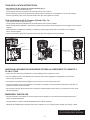 5
5
-
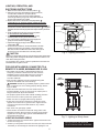 6
6
-
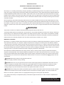 7
7
-
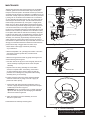 8
8
-
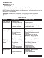 9
9
-
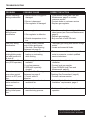 10
10
-
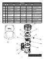 11
11
-
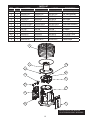 12
12
-
 13
13
-
 14
14
-
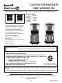 15
15
-
 16
16
-
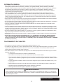 17
17
-
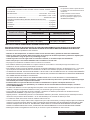 18
18
-
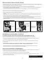 19
19
-
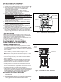 20
20
-
 21
21
-
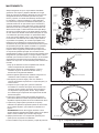 22
22
-
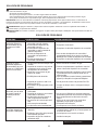 23
23
-
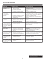 24
24
-
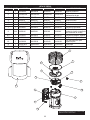 25
25
-
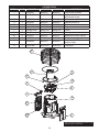 26
26
-
 27
27
-
 28
28


en otros idiomas
- English: Dyna-Glo HA1360BK User manual
Artículos relacionados
-
 Dyna-Glo Delux GG18G Manual de usuario
-
Dyna-Glo IBF10PMDG Guía de instalación
-
-
-
Dyna-Glo Delux RA125DGD El manual del propietario
-
-
-

Otros documentos
-
Comfort Glow GCH480 Manual de usuario
-
Mr. Heater MH18B Manual de usuario
-
-
-
Mr Heater 2 x MH-F232000 Manual de usuario
-
-
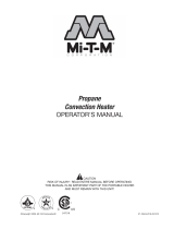 Mi-T-M Propane Convection Heater Manual de usuario
-
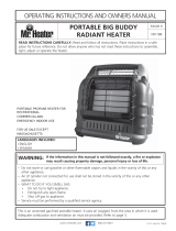 Tough Buddy MH18B Instrucciones de operación
-
-

