
24816
Installation Instructions
Mazda 3
including Speed 3
Part Numbers:
77188
60201
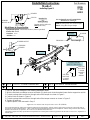
Hitch Shown In Proper Position
Wiring Access Location: PC3, PC4
Equipment Required: Flat blade Screwdriver, Fishwire (provided).
Wrenches: 11/16”
Drill Bits: 1/2”
z 2006, 2007, 2008, 2009, 2015 Cequent Performance Products – Printed in Mexico
Sheet 1 of 3 24816N 10-09-15 Rev C
j
Qty. (4) 7/16”-14 X 1-1/4” GRADE 5 CARRIAGE BOLT
l
Qty. (4) 7/16” CONICAL TOOTHED WASHER
k
Qty. (4) BLOCK 1/4” X 1” X 3”
m
Qty. (4) 7/16”-14 HEX NUT
Tighten all 7/16” fasteners with torque wrench to 50 Lb.-Ft. (68 N*M)
Note: check hitch frequently, making sure all fasteners and ball are properly tightened. If hitch is removed, plug all holes in trunk pan or other body panels to
prevent entry of water and exhaust fumes. A hitch or ball which has been damaged should be removed and replaced. Observe safety precautions when working
beneath a vehicle and wear eye protection. Do not cut access or attachment holes with a torch.
This product complies with safety specifications and requirements for connecting devices and towing systems of the state of New York, V.E.S.C. Regulation V-5
and SAE J684.
2000 LB (908 kg) Max Gross Trailer Weight
200 LB (91 kg) Max Tongue Weight
Do Not Exceed Lower of Towing Vehicle
Manufacturer’s Rating or
Drawbar must be used in the
RISE position only.
Drawbar Kit:
3592
Fastener Kit: 24816F
Form F206 Rev A 5605
1. Use 1/2” drill bit to enlarge the four existing attachment holes.
2. With the flat blade screwdriver remove and retain (2) plastic push rivets that attach lower fascia supports to vehicle.
3. Fishwire carriage bolts and blocks through ends of the bumper as shown in Figure 1.
4. Position hitch as shown in Figure 2.
5. Fishwire carriage bolts and blocks through ends of the bumper mounts as shown in Figure 2.
6. Tighten all fasteners.
7. Replace plastic rivets removed in Step 2.
j
l
m
k
j
l
m
k
j
l
m
k
j
l
m
k
BUMPER
FISHWIRE
FIGURE 1.
BUMPER MOUNT
FISHWIRE
BUMPER
BUMPER
FASCIA
BUMPER
MOUNT
USE THIS
SLOT FOR
4 - DOOR
MODELS
USE THIS
SLOT FOR
5 - DOOR
MODELS
AND
SPEED 3
BUMPER MOUNT
BRACKET ENLARGED
FIGURE 2.
FIGURE 3.
(Sold separately)

60201
Instructions d’installation
MAZDA 3
y compris Speed 3.
Numéros de pièces :
77188
24816
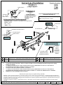
Attelage montré dans la position appropriée
Points d’accès au câblage : PC3, PC4
Équipement requis : Tournevis à lame plate, fil de tirage (fourni).
Clé : 11/16 po
Mèche : 1/2 po
z 2006, 2007, 2008, 2009, 2015 Cequent Performance Products – Imprimé au Mexique
Feuille 2 de 3 24816N 10-09-15 Rev C
j
Qté (4) 7/16-14 X 1.25 BOULON DE CARROSSERIE CATÉGORIE 5
l
Qté (4) RONDELLE CONIQUE DENTÉE 7/16 PO
k
Qté (4) BLOC 1/4 X 1 X 3
m
Qté (4) ÉCROU 7/16-14
Serrer toute la visserie 7/16 po au couple de 50 lb-pi. (68 N*M)
Remarque : Vérifier l’attelage fréquemment, en s’assurant que toute la visserie et la bille sont serrées adéquatement. Si l’attelage est enlevé, boucher tous les
trous percés dans le coffre ou la carrosserie afin de prévenir l’infiltration d’eau ou de gaz d’échappement. Un attelage ou bille endommagés doivent être enlevés
et remplacés. Observer les mesures de sécurité appropriées en travaillant sous le véhicule et porter des lunettes de protection. Ne jamais utiliser une torche pour
découper un accès ou un trou de fixation.
Ce produit est conforme aux normes V-5 et SAE J684 de la V.E.S.C. (État de New York) concernant les spécifications en matière de sécurité des systèmes
d’attelage.
2 000 lb (908 kg) Poids brut max. de la remorque
200 lb (90 kg) Poids max. au timon
Ne pas excéder les spécifications du fabricant de
véhicules de remorquage, ou
La barre de remorquage doit
être utilisée dans la position
ÉLEVÉE seulement.
Ensemble de barre de
remorquage :
3592
Visserie : 24816F
Form F206 Rev A 5605
1. UTILISER UNE MÈCHE DE 1/2 PO POUR AGRANDIR LES QUATRE TROUS DE FIXATION EXISTANTS.
2. À l'aide du tournevis à lame plate, enlever et conserver les deux (2) rivets en plastique qui fixent les supports de carénage
inférieurs au véhicule.
3. À L’AIDE D’UN FIL DE TIRAGE, FAIRE PASSER LES BOULONS DE CARROSSERIE ET LES BLOCS À TRAVERS LES
EXTRÉMITÉS DU PARE-CHOCS, COMME ILLUSTRÉ À LA FIGURE 1.
4. PLACER L’ATTELAGE COMME ILLUSTRÉ À LA FIGURE 2.
5. À L’AIDE D’UN FIL DE TIRAGE, FAIRE PASSER LES BOULONS DE CARROSSERIE ET LES BLOCS À TRAVERS LES
EXTRÉMITÉS DES SUPPORTS DE PARE-CHOCS COMME ILLUSTRÉ À LA FIGURE 2 ET SERRER TOUTE LA VISSERIE.
6. Remplacer les rivets en plastique enlevés à l’étape 2.
PARE-CHOCS
FIL DE TIRAGE
SUPPORT DE PARE-CHOCS
FIL DE TIRAGE
PARE-CHOCS
PARE-CHOCS
CARÉNAGE
SUPPORT
DE
PARE-CHOCS
j
l
m
k
j
l
m
k
j
l
m
k
j
l
m
k
FIGURE 1.
UTILISER CETTE
FENTE POUR LES
MODÈLES 4 PORTES
UTILISER
CETTE
FENTE
POUR LES
MODÈLES 5
PORTES ET
SPEED 3
LE SUPPORT MONTÉ SUR
PARE-CHOCS EST AGRANDI
FIGURE 2.
FIGURE 3.
(Vendu séparément)

60201
Instrucciones de instalación
MAZDA 3
Incluye Velocidad 3
Números de partes:
77188
24816
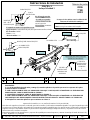
El enganche se muestra en la posición correcta
Ubicación del acceso al cableado: PC3, PC4
Equipo necesario: Destornillador de pala, cable para insertar tornillos (incluido).
Llaves: 11/16”
Brocas de taladro: 1/2”
z 2006, 2007, 2008, 2009, 2015 Cequent Performance Products – Impreso en México
Hoja 3 de 3 24816N 10-09-15 Rev C
j
Cant. (4) 7/16-14 X 1.25 PERNO DE CARRUAJE GRADO 5
l
Cant.(4) ARANDELA CÓNICA DENTADA 7/16”
k
Cant. (4) BLOQUE 1/4 X 1 X 3
m
Cant.(4) TUERCA 7/16-14
Apriete todos los tornillos 7/16” con una llave de torsión a 50 Lb.-pies (68 N*M)
Nota: Revise el enganche con frecuencia, verificando que todos los tornillos y la bola estén correctamente apretados. Si se quita el enganche tape todos
los orificios en el colector del baúl u otros paneles de la carrocería para evitar la entrada del agua y los gases del escape. Se debe retirar y reemplazar un
enganche o bola que se haya dañado. Observe las precauciones de seguridad al trabajar por debajo del vehículo y use protección visual. No corte los
orificios de acceso o accesorios con soplete.
Este producto cumple con las especificaciones y requisitos de seguridad para conectar dispositivos y sistemas de remolque del estado de Nueva York,
V.E.S.C. Regulación V-5 y SAE J684
2000 LB (908 kg) Peso bruto máximo del remolque
200 LB (91 kg) Peso máximo de la horquilla
No supere el valor inferior entre la calificación del
fabricante del vehículo del remolque o
La barra de tracción se debe
usar en la posición
LEVANTADA únicamente.
Kit de barra de tracción:
3592
Kit de tornillos: 24816F
Form F206 Rev A 5605
1. USE UNA BROCA DE TALADRO DE 1/2” PULGADA PARA AGRANDAR LOS CUATRO ORIFICIOS DE UNIÓN
EXISTENTES.
2. Con el destornillador de pala retire y retenga (2) remaches plásticos de presión que unen los soportes de la placa
protectora inferior al vehículo.
3. GUÍE CON EL ALAMBRE GUÍA LOS PERNOS DE CARRUAJE Y LOS BLQOUES A TRAVÉS DE LOS EXTREMOS DEL
PARACHOQUES COMO SE MUESTRA EN LA FIGURA 1.
4. COLOQUE EL ENGANCHE COMO SE MUESTRA EN LA FIGURA 2.
5. GUÍE CON EL ALAMBRE GUÍA LOS PERNOS DE CARRUAJE Y LOS BLOQUES A TRAVÉS DE LOS EXTREMOS DE
LOS MONTAJES DEL PARACHOQUES COMO SE MUESTRA EN LA FIGURA 2 Y APRIETE TODOS LOS TORNILLOS.
6. Reemplace los remaches plásticos que se retiraron en el Paso 2.
PARACHOQUES
ALAMBRE GUÍA
MONTAJE DEL PARACHOQUES
ALAMBRE GUÍA
PARACHOQUES
PARACHOQUES
PLACA
PROTECTORA
MONTAJE
DEL
PARACHOQUES
j
l
m
k
j
l
m
k
j
l
m
k
j
l
m
k
FIGURA 1.
USE ESTA
RANURA PARA
MODELOS DE
4 PUERTAS
USE ESTA
RANURA PARA
MODELOS DE
5 PUERTAS
Y
3 VELOCIDADES
MONTAJE DEL PARACHOQUES
SOPORTE AGRANDADO
FIGURA 2.
FIGURA 3.
(Se vende por separado)
Transcripción de documentos
Installation Instructions Part Numbers: Mazda 3 24816 77188 60201 including Speed 3 BUMPER FASCIA BUMPER MOUNT Hitch Shown In Proper Position Drawbar Kit: 3592 (Sold separately) Do Not Exceed Lower of Towing Vehicle Manufacturer’s Rating or Drawbar must be used in the RISE position only. 2000 LB (908 kg) Max Gross Trailer Weight 200 LB (91 kg) Max Tongue Weight Wiring Access Location: PC3, PC4 Equipment Required: Flat blade Screwdriver, Fishwire (provided). Fastener Kit: 24816F Wrenches: 11/16” Drill Bits: 1/2” FIGURE 1. BUMPER FISHWIRE BUMPER MOUNT j k l m FISHWIRE BUMPER j k l m FIGURE 2. FIGURE 3. j k l m BUMPER MOUNT BRACKET ENLARGED j k l m j k USE THIS SLOT FOR 5 - DOOR MODELS AND SPEED 3 USE THIS SLOT FOR 4 - DOOR MODELS Qty. (4) 7/16”-14 X 1-1/4” GRADE 5 CARRIAGE BOLT Qty. (4) BLOCK 1/4” X 1” X 3” l m Qty. (4) 7/16” CONICAL TOOTHED WASHER Qty. (4) 7/16”-14 HEX NUT 1. Use 1/2” drill bit to enlarge the four existing attachment holes. 2. With the flat blade screwdriver remove and retain (2) plastic push rivets that attach lower fascia supports to vehicle. 3. Fishwire carriage bolts and blocks through ends of the bumper as shown in Figure 1. 4. Position hitch as shown in Figure 2. 5. Fishwire carriage bolts and blocks through ends of the bumper mounts as shown in Figure 2. 6. Tighten all fasteners. 7. Replace plastic rivets removed in Step 2. Tighten all 7/16” fasteners with torque wrench to 50 Lb.-Ft. (68 N*M) Note: check hitch frequently, making sure all fasteners and ball are properly tightened. If hitch is removed, plug all holes in trunk pan or other body panels to prevent entry of water and exhaust fumes. A hitch or ball which has been damaged should be removed and replaced. Observe safety precautions when working beneath a vehicle and wear eye protection. Do not cut access or attachment holes with a torch. This product complies with safety specifications and requirements for connecting devices and towing systems of the state of New York, V.E.S.C. Regulation V-5 and SAE J684. z 2006, 2007, 2008, 2009, 2015 Cequent Performance Products – Printed in Mexico Sheet 1 of 3 24816N 10-09-15 Rev C Form F206 Rev A 5605 Instructions d’installation Numéros de pièces : MAZDA 3 y compris Speed 3. PARE-CHOCS CARÉNAGE SUPPORT DE PARE-CHOCS 24816 77188 60201 Ensemble de barre de remorquage : 3592 (Vendu séparément) La barre de remorquage doit être utilisée dans la position ÉLEVÉE seulement. Ne pas excéder les spécifications du fabricant de véhicules de remorquage, ou 2 000 lb (908 kg) Poids brut max. de la remorque 200 lb (90 kg) Poids max. au timon Attelage montrédans la position appropriée Points d’accès au câblage : PC3, PC4 Équipement requis : Tournevis à lame plate, fil de tirage (fourni). Visserie : 24816F Clé: 11/16 po Mèche : 1/2 po FIGURE 1. PARE-CHOCS FIL DE TIRAGE SUPPORT DE PARE-CHOCS j k l m FIL DE TIRAGE PARE-CHOCS j k l m FIGURE 2. FIGURE 3. j k l m LE SUPPORT MONTÉ SUR PARE-CHOCS EST AGRANDI j k l m j k UTILISER CETTE FENTE POUR LES MODÈLES 4 PORTES Qté (4) 7/16-14 X 1.25 BOULON DE CARROSSERIE CATÉGORIE 5 Qté (4) BLOC 1/4 X 1 X 3 l m UTILISER CETTE FENTE POUR LES MODÈLES 5 PORTES ET SPEED 3 Qté (4) RONDELLE CONIQUE DENTÉE 7/16 PO Qté (4) ÉCROU 7/16-14 1. UTILISER UNE MÈCHE DE 1/2 PO POUR AGRANDIR LES QUATRE TROUS DE FIXATION EXISTANTS. 2. À l'aide du tournevis àlame plate, enlever et conserver les deux (2) rivets en plastique qui fixent les supports de carénage inférieurs au véhicule. 3. À L’AIDE D’UN FIL DE TIRAGE, FAIRE PASSER LES BOULONS DE CARROSSERIE ET LES BLOCS À TRAVERS LES EXTRÉMITÉS DU PARE-CHOCS, COMME ILLUSTRÉ À LA FIGURE 1. PLACER L’ATTELAGE COMME ILLUSTRÉ À LA FIGURE 2. À L’AIDE D’UN FIL DE TIRAGE, FAIRE PASSER LES BOULONS DE CARROSSERIE ET LES BLOCS À TRAVERS LES EXTRÉMITÉS DES SUPPORTS DE PARE-CHOCS COMME ILLUSTRÉ À LA FIGURE 2 ET SERRER TOUTE LA VISSERIE. 4. 5. 6. Remplacer les rivets en plastique enlevés à l’étape 2. Serrer toute la visserie 7/16 po au couple de 50 lb-pi. (68 N*M) Remarque : Vérifier l’attelage fréquemment, en s’assurant que toute la visserie et la bille sont serrées adéquatement. Si l’attelage est enlevé, boucher tous les trous percés dans le coffre ou la carrosserie afin de prévenir l’infiltration d’eau ou de gaz d’échappement. Un attelage ou bille endommagés doivent être enlevés et remplacés. Observer les mesures de sécuritéappropriées en travaillant sous le véhicule et porter des lunettes de protection. Ne jamais utiliser une torche pour découper un accès ou un trou de fixation. Ce produit est conforme aux normes V-5 et SAE J684 de la V.E.S.C. (État de New York) concernant les spécifications en matière de sécuritédes systèmes d’attelage. z 2006, 2007, 2008, 2009, 2015 Cequent Performance Products – Imprimé au Mexique Feuille 2 de 3 24816N 10-09-15 Rev C Instrucciones de instalación Números de partes: MAZDA 3 24816 77188 60201 Incluye Velocidad 3 PARACHOQUES PLACA PROTECTORA Kit de barra de tracción: 3592 (Se vende por separado) La barra de tracción se debe usar en la posición LEVANTADA únicamente. MONTAJE DEL PARACHOQUES El enganche se muestra en la posición correcta Equipo necesario: Destornillador de pala, cable para insertar tornillos (incluido). Kit de tornillos: 24816F Llaves: 11/16” Brocas de taladro: 1/2” No supere el valor inferior entre la calificación del fabricante del vehículo del remolque o 2000 LB (908 kg) Peso bruto máximo del remolque 200 LB (91 kg) Peso máximo de la horquilla Ubicación del acceso al cableado: PC3, PC4 FIGURA 1. PARACHOQUES ALAMBRE GUÍA MONTAJE DEL PARACHOQUES j k l m ALAMBRE GUÍA PARACHOQUES j k l m FIGURA 2. FIGURA 3. MONTAJE DEL PARACHOQUES SOPORTE AGRANDADO j k l m USE ESTA RANURA PARA MODELOS DE 5 PUERTAS Y 3 VELOCIDADES USE ESTA RANURA PARA MODELOS DE 4 PUERTAS j k l m j Cant. (4) 7/16-14 X 1.25 PERNO DE CARRUAJE GRADO 5 l Cant.(4) ARANDELA CÓNICA DENTADA 7/16” k Cant. (4) BLOQUE 1/4 X 1 X 3 m Cant.(4) TUERCA 7/16-14 1. USE UNA BROCA DE TALADRO DE 1/2” PULGADA PARA AGRANDAR LOS CUATRO ORIFICIOS DE UNIÓN EXISTENTES. 2. Con el destornillador de pala retire y retenga (2) remaches plásticos de presión que unen los soportes de la placa protectora inferior al vehículo. 3. GUÍE CON EL ALAMBRE GUÍA LOS PERNOS DE CARRUAJE Y LOS BLQOUES A TRAVÉS DE LOS EXTREMOS DEL PARACHOQUES COMO SE MUESTRA EN LA FIGURA 1. 4. COLOQUE EL ENGANCHE COMO SE MUESTRA EN LA FIGURA 2. 5. GUÍE CON EL ALAMBRE GUÍA LOS PERNOS DE CARRUAJE Y LOS BLOQUES A TRAVÉS DE LOS EXTREMOS DE LOS MONTAJES DEL PARACHOQUES COMO SE MUESTRA EN LA FIGURA 2 Y APRIETE TODOS LOS TORNILLOS. 6. Reemplace los remaches plásticos que se retiraron en el Paso 2. Apriete todos los tornillos 7/16” con una llave de torsión a 50 Lb.-pies (68 N*M) Nota: Revise el enganche con frecuencia, verificando que todos los tornillos y la bola estén correctamente apretados. Si se quita el enganche tape todos los orificios en el colector del baúl u otros paneles de la carrocería para evitar la entrada del agua y los gases del escape. Se debe retirar y reemplazar un enganche o bola que se haya dañado. Observe las precauciones de seguridad al trabajar por debajo del vehículo y use protección visual. No corte los orificios de acceso o accesorios con soplete. Este producto cumple con las especificaciones y requisitos de seguridad para conectar dispositivos y sistemas de remolque del estado de Nueva York, V.E.S.C. Regulación V-5 y SAE J684 z 2006, 2007, 2008, 2009, 2015 Cequent Performance Products – Impreso en México Hoja 3 de 3 24816N 10-09-15 Rev C-
 1
1
-
 2
2
-
 3
3


en otros idiomas
- français: Draw-Tite 24816 Guide d'installation
- English: Draw-Tite 24816 Installation guide
Artículos relacionados
-
Draw-Tite 24773 Guía de instalación
-
-
-
-
-
-
-
-
-