Keystone KSTAW25C Instrucciones de operación
- Tipo
- Instrucciones de operación

WINDOW/WALL TYPE
ROOM AIR CONDITIONER
-
Before using your air conditioner, please read
this manual carefully and keep it for future reference.
Sleep
Check
Filter
Follow
Me
Auto
On/off
Fan
High
Med
Low
Energy
Saver
on
off
Timer
Auto
Fan
Cool
Dry
Mode
TEMP/TIMER
TEMP/TIMER
Heat
TABLE OF CONTENTS
Installation Instructions
................................................12
4-11
Normal Sounds
.................................
......................................
Important Safety Instructions ..........................1-3
Troubleshooting Tip 15-16
.....................................
Air Conditioner Features 12-14
.............................
Care and Cleaning 14-15
Model: KSTAW15C
KSTAW18C
KSTAW25C


Producto

1 866 646 4332
1 866 646 4332
MIDEA AMERICA CORPORATION
PRODUCT REGISTRATION CENTER
11800 NW 100 ROAD STE 4
MEDLEY FL 33178-1037

IMPORTANT SAFETY INSTRUCTIONS
Inside you will find many helpful hints on how to use and maintain your air conditioner
properly. Just a little preventive care on your part can save you a great deal of time
and money over the life of your air conditioner. You'll find many answers to common
problems in the chart of troubleshooting tips. If you review our chart of Troubleshooting
Tips first, you may not need to call for service at all.
To prevent injury to the user or other people and property damage, the following
instructions must be followed. Incorrect operation due to ignoring of instructions may
cause harm or damage. The seriousness is classified by the following indications.
This symbol indicates the possibility of death or serious injury.
Always do this.
Never do this.
CAUTION
This symbol indicates the possibility of injury or damage to property.
WARNING
WARNING
Plug in power plug
properly.
Do not modify power cord length or share the
outlet with other appliances.
Always ensure effective
grounding.
Unplug the unit if strange
sounds, smell, or smoke
comes from it.
Keep firearms away.
Ventilate room before operating air conditioner if there is
a gas leakage from another appliance.
Otherwise, it may cause electric
shock or fire due to excess heat
generation.
It may cause electric shock or fire due to heat generation.
Incorrect grounding may cause
electric shock.
It may cause fire and electric
shock.
It may cause fire.
It may cause explosion, fire and, burns.
It may cause electric shock or fire
due to heat generation.
It may cause electric shock.
It may cause failure of machine
or electric shock.
It may cause fire and electric
shock.
It may cause fire and electric
shock.
It may cause electric shock or fire.
If the power cord is damaged, it must be replaced by the
manufacturer or an authorised service centre or a similarly
qualified per son in order to avoid a hazard.
This could damage your health.
Incorrect installation may cause
fire and electric shock.
It may cause electric shock.
It may cause an explosion or fire.
It may cause failure and electric shock.
Do not operate or stop the
unit by inserting or pulling
out the power plug.
Do not operate with wet
hands or in damp
environment.
Do not allow water to run
into electric parts.
Do not use the socket if it is
loose or damaged.
Do not use the power cord
close to heating appliances.
Do not damage or use an unspecified power
cord.
Do not direct airflow at room occupants only.Always install circuit
breaker and a dedicated
power circuit.
Do not open the unit during operation.
Do not use the power cord near flammable gas
or combustibles, such as gasoline, benzene,
thinner, etc.
Do not disassemble or modify unit.
!
!
!
!
!
!
!
!
READ THIS MANUAL
1

When the air filter is to be
removed, do not touch the metal
parts of the unit.
It may cause an injury.
Do not clean unit when power is on
as it may c ause fi re an d el ectric sh ock,
it may cause an injury.
Operation with windows opened
may cause wetting of indoor and
soaking of household furniture.
When the unit is to be cleaned,
switch off, and turn off the circuit
breaker.
Use caution when unpacking and
installing. Sharp edges could cause injury.
Do not clean the air conditioner
with water.
Water may enter the unit and
degrade the insulation. It may
cause an electric shock.
This could injure the pet or plant.
It may cause electric shock and
damage.
Do not put a pet or house plant
where it will be exposed to direct
air flow.
Ventilate the room well when
used together with a stove, etc.
An oxygen shortage may occur.
Do not use this air conditioner to
preserve precision devices, food,
pets, plants, and art objects.It may
cause deterioration of quality, etc.
It may cause failure of product or
fire.
Do not use for special purposes.
If water enters the unit, turn the unit off at the power
outlet and switch off the circuit breaker. Isolate
supply by taking the power-plug out and contact a
qualified service technician.
!
!
!
!
It may cause failure of appliance
or accident.
Appearance may be deteriorated
due to change of product color or
scratching of its surface.
If bracket is damaged, there is
concern of damage due to falling
of unit.
There is danger of fire or electric
shock.
Operation without filters maycause
failure.
It contains contaminants and
could make you sick.
Stop operation and close the
window in storm or hurricane.
!
Do not use strong detergent
such as wax or thinner but use
a soft cloth.
Ensure that the installation bracket of the
outdoor appliance is not damaged due
to prolonged exposure.
Hold the plug by the head of the
power plug when taking it out.
!
Turn off the main power
switch when not using the
unit for a long time.
!
!
!
Always insert the filters securely.
Clean filter once every t wo w eeks.
!
Do not place heavy object on the power
cord and ensure that the cord is not
compressed.
Do not drink water drained
from air conditioner.
This appliance is not intended for use by persons
(including children) with reduced physical ,sensory
or mental capabilities or lack of experience and
knowledge, unless t hey h aveb eengi ven su pervision
or instruction concerning use of the appliance by
a person responsible for their safety.
Children should be supervised to ensure that they
do not play with the appliance.
If the supply cord is damaged, it must be replaced
by the manufacturer, its service agent or similarly
qualified persons in order to avoid a hazard.
CAUTION
2
CAUTION
Do not place obstacles around
air-inlets or inside of air-outlet.
The appliance shall be installed in accordance
with national wiring regulations.
Do not operate your air conditioner in a wet room
such as a bathroom or laundry room.
The appliance with electric heater shall have at
l east 1 m eter s pace to th e co mbustible materials.
Contact the authorised service technician for
repair or maintenance of this unit.
Contact the authorised installer for installation
of this unit.
IMPORTANT SAFETY INSTRUCTIONS

Do not, under any
circumstances, cut,
remove, or bypass
the grounding prong.
Power supply cord
with 3-prong grounding plug
and current detection device
Grounding type wall
receptacle
WARNING
NOTE:
The power supply cord with this air
conditioner contains a current detection
device designed to reduce the risk of fire.
Please refer to the section Operation
of Current Device for details.In the event
that the power supply cord is damaged,
it cannot be repaired-it must be replaced
with a c ord f rom t he P roductM anufacturer.
Avoid fire hazard or electric shock. Do not
use an extension cord or an adaptor plug.
Do not remove any prong from the power
cord.
WARNING
For Your Safety
WARNING
Prevent Accidents
WARNING
Electrical Information
Do not store or use gasoline or other flammable vapors and liquids in the vicinity
of this or any other appliance.
Operation of Current Device
(Applicable to the unit adopts current detection
device only )
The power supply cord contains a current device that senses
damage to the power cord. To test your power supply cord do
the following:
1. Plug in the Air Conditioner.
2. The power supply cord will have TWO buttons on the plug
head. Press the TEST button, you will notice a click as the
RESET button pops out.
3. Press the RESET button, again you will notice a click as
the button engages.
4. The power supply cord is now supplying electricity to the
unit. (On some products this it also indicated by a light on
the plug head.)
3
To reduce the risk of fire, electrical shock, or injury to persons when using your
air conditioner, follow basic precautions, including the following:
Be sure the electrical service is adequate for the model you have chosen. This
information can be found on the serial plate, which is located on the side of the
the cabinet and behind the grille.
If the air conditioner i s t o b e in stalled in a w indow, yo u w ill pr obably w ant to cl ean
both sides of the g lass f irst. I f th e w indow is a tri ple-track ty pe w ith a sc reen pa nel
included, remove the screen completely before installation.
Be sure the air c onditioner h as b een s ecurely a nd c orrectly in stalled a ccording to
the installation instructions in this manual. Save this manual for possible future
use in removing or installing this unit.
When handling the air conditioner, be careful to avoid cuts f rom s harp m etal f ins
on front and rear coils.
The complete electical rating of your new room air conditioner is stated on the
serial plate. Refer to the rating when checking the electrical requirements.
Be sure the air conditioner is properly grounded. To minimize shock and fire
hazards, proper grounding is important. The power cord is equipped with a
three-prong grounding plug for protection against shock hazards.
Your air conditioner must be used in a properly grounded wall receptacle. If the
wall receptacle you intend to use is not adequately grounded or protected by a
time delay fuse or circuit breaker, have a qualified electrician install the proper
receptacle. Ensure the receptacle is accessible after the unit installation.
Do not run air conditioner without side protective cover in place.This could
result in mechanical damage within the air conditioner.
Do not use an extension cord or an adapter plug.
IMPORTANT SAFETY INSTRUCTIONS
Do not use this device to turn the unit on or off.
Always make sure the RESET button is pushed in for
correct operation.
The power supply must be replaced if it fails reset when
either the TEST button is pushed, or it cannot be reset. A
new one can be obtained from the product manufacturer.
If power supply cord is damaged, it cannot be repaired. It
MUST be replaced by one obtained from the product
manufacturer.
NOTE:
NOTE:This air conditioner is designed to be operated
under condition as follows:
Cooling
operation
Outdoor temp:
Indoor temp:
Heating
operation
Outdoor temp:
O
O
23-76 F/ C-5-24
Indoor temp:
O
32-80 F/
O
0-27 C
O O O O
64-109 F/18-43 C (64-125 F/18-52 C
for special tropical models)
O
62-90 F/
O
17-32 C
Note: Performance may be reduced outside of these
operating temperatures.

4
INSTALLATION INSTRUCTIONS
Read these instructions completely
and carefully.
IMPORTANT- Save these
instructions for local inspector s use.
IMPORTANT- Observe all
governing codes and ordianaces.
Note to Consumer- Keep these
instructions for futrue reference.
Note to Installer- Be sure to leave these
instructions with the Consumer.
Completion time- Approximately 1 hour.
Skill level- Installatio of this appliance
requires basic mechanical skills.
We recommend that two people install
this product.
Proper installation is the responsibility
of the installer.
Product failure due to improper installation
is not covered under the Warranty.
You MUST use all supplied parts and use
proper installation procedures as described
in these instructions when installing this air
conditioner.
BEFORE YOU BEGIN
Do not, under any circumstances, cut or
remove the third (ground) prong from the
power cord.
CAUTION
Do not change the plug on the power cord
of the air conditioner.
Aluminum house wiring may present special
problems- consult a qualified electircian.
When handling unit, be careful to avoid cuts from
sharp metal edges and aluminum fins on front and
rear coils.
Save Carton and these Installation Instructions
for future reference. The carton is the best way
to store unit during winter, or when not in use.
NOTE:
Preliminary Instructions
Do the following before starting to install unit.
See illustrations below.
Check dimensions of your unit to determine
model type:
Unit Height: 18 5/8 17 5/8
Unit Width:
Min. Window Opening:
Min. Window Width:
Max. Window Width:
26 23
1
2
/
5
8
/
19 18
1
2
/
31 28
42 40
1
2
/
1. Check window opening size-- the mounting
parts furnished with this air conditioner are
made to install in a wooden sill double-hung
window. The standard parts are for window
dimensions listed above. Open sash to a mini-
mum of 19 inches(483mm). See Fig.D.
SASH
/2 MIN.
1
19 MIN.
Storm Window Frame or
Other Obstruction
Storm Window
Frame or Other
Obstruction
Board
Thickness
As Required,
Along Entire
Stool. Fasten
With Two Nails
Or Screws.
Fig.D
Fig.E
/2 MIN.
1
/2 MIN.
1
19 MIN.
SASH
Window Sash Seal
Safety Lock and
3 /4 (or1/2 ) Long
Hex Head Screw
Top Angle
Foam Gasket
Washer Head
Locking screw
Frame
Assembly
(Left)
Side Retainer
Bottom rail
seal to Unit
1 /2 Long
Screw and
Locknuts
Locknut
3 /4 Long
Flat Head
Bolt
Sill Angle
Bracket
Window Support
Bracket
Frame
Assembly
(Right)
1
/
2
2.Check condition of window-- all wood parts of
window must be in good shape and able to firmly
hold the needed screws. If not, make repairs
before installing unit.

5
INSTALLATION INSTRUCTIONS
3. Check your storm windows-- if your storm
window frame does not allow the clearance
required, correct by adding a piece of wood as
shown in Fig. E,or by removing storm window
while room air conditioner is being installed.
4 .Check for anything that could block airflow--
check area outside of window for things such as
shrubs, trees, or awnings. Inside, be sure
furniture, drapes, or blinds will not stop proper
airflow.
5.Check the available electrical service- Power
supply must be the same as that shown on the
unit serial nameplate. Power cord is 48 inches
long. Be sure you have an outlet near.
6.Carefully unpack air conditioner- Remove all
packing material. Protect floor or carpet from
damage. Two people should be used to move
and install unit.
Preliminary Instructions
Tools Required
A large flat blade screwdriver;Tape measure
Adjustable wrench or pliers;Pencil;Level
Socket wrenches;Phillips Screwdriver
Hardware(Packed with the unit)
7/16 inch Locking
screw and Flat
washer for window
panels
3 / 4 (or 1/2)inch
Long Hex-head
Screw
Safety Lock
1 / 2 inch Long
screw and Locknut
3 / 4 inch Long
Flat Head Bolt
and Locknut
Sill Angle
Bracket
Long hex-head
locking screw
for top angle,
side retainer
5 /16 inch Long
2 ea.
7
1
4ea.
2ea.
2
10
Foam insert
2
Window sash
seal foam
1
A.Window Mounting
1
Remove Chassis
1. Pull down front grille and remove filter.
(See Fig.1).
2. Lift front grille upwards and place to one side.
3. Locate the four front screws and remove.
These screws will be needed to re-install
the front panel (see Fig.2).
7. Remove shipping screws from top of unit and
also on the side by the base if installed
(see Fig.5).
8. Hold the cabinet while pulling on the base pan
handle, and carefully remove the unit.
9. Add two foam inserts to holes in top of cabinet
where shipping screws were removed from
(see Fig.6).
4. Push metal cabinet side to release plastic tabs
on each side of front panel (see Fig.3).
5. Gently lift front panel off unit(see Fig.3A).
6. Disconnect the connector plug of the display
panel from the unit and place front panel to one
side(see Fig.4).
Front Grille
Fig.1 Fig.2
Fig.3
Fig.3A
Front Panel
Fig.4
shipping
screws
Fig.5 Fig.6
R1 hardware
2
(10 *3/4 *1/12 )
NOET: R1 hardware and Weather stripping is only
for Energy star models.
Weather stripping
5

6
INSTALLATION INSTRUCTIONS
10. Your unit may come with internal packaging.
This packaging must be removed prior to
installing the air conditioner back into the
cabinet.(see Fig.7).
2
Install Top Angle and
Side Bracket
1. Attach foam gasket to top angle
above holes as shown in Fig.6.
2. Install top angle and side retainers
to cabinet as shown in Fig.8 (10 sc-
rews).
3
Assemble Window Filler Panels
1. Place cabinet on floor, a bench, or
a table.
2. Slide I section of window filler panel
into side retainer on the side of the
cabinet (see Fig.9 & Fig.10).
Do both sides.
,,
,,
Plastic
Frame
Window Filler
Panel
Side Retainer
Fig.9
5 1
6 long
hex-h
e
a
d
/
Shipping Packaging
Plastic tie
Fig.7
Fig.8
3. Insert top and bottom legs of window
filler panel frame into channel in the
top angle and bottom rail. Do both
sides.
4. Insert washer head locking 7/16" screws
(2) into holes in top leg of filler panel
frame (see step 6). Do not totally tigh-
ten. Allow leg to slide freely. Screws
will be tightened after section 6.
4
Place Cabinet in
1.Open window and mark center of window stool as
shown(Fig.11).
2. Place cabinet in window with bottom stool angle
firmly seated over window stool as shown. Bring
window down temporarily behind top angle to
hold cabinet in place(Fig.12).
Stool
Stool
Angle
Top
View
Air Conditioner
Cabinet
Plastic
Frame
"Ⅰ" Section
Window
Filler
Panel
Locking
Screw
Hole
Fig.10
Fig.11
Fig.12
3. Shift cabinet left or right as needed to line up
center of cabinet on center line marked on stool.
4. Fasten cabinet to window stool with 2 screws
into holes(You may wish to pre-drill pilot holes).
5. Add bottom rail seal over screws to window stool.

7
INSTALLATION INSTRUCTIONS
5
Install Support Bracket
1. Hold each support bracket flush against
outside of sill, and tight to bottom of cabinet
as shown in Fig.15A. Mark brackets at top level
of sill, and remove.
2. Assemble sill angle bracket to support
brackets at the marked position(Fig.15B).
Hand tighten, but allow for any changes later.
Bottom
Rail Seal
1 2 Long Screws
And Locknuts
Left
Right
Sill Angle
Bracket
Flat Head
Bolt
2 Each Required For
Each Support Bracket
Locknut
3 4 (or1 )Long
Hex-head Screw
/2
Fig.13
Fig.15A
Mark
Fig.15B
3. Close window behind top angle.
6
Extend Window Filler Panels
1. Carefully raise window to expose filler panel
locking screws. Loosen screws so filler panels
slide easily.
2. Extend panels to fill window opening completely.
Tighten locking screws on top(Fig.17).
3. Install support brackets(with sill angle
brackets attached) to correct hole in
bottom of cabinet as shown in Fig.16.
4. Tighten all 6 bolts securely.
1 2 Long Screws
and Locknuts
L
o
cking Sc
re
w
7/16"Locking Screw
and Washer
Fig.16
Fig.17
FIG.14
5
Side Louvers
Window Sash
Window Sill
Sill
Angle Bracket
1 5
About1 / to1 /
4 8
Measure from
the cabinet edge.
NOTE: Check that air conditioner is tilted back about
1 5 O O
1 / to 1 / (tilted about 3 t o 4 downward t o th e o utside).
4 8
After proper installation, condensate should not drain
from the overflow drain h ole d uring n ormalu se,c orrect
the slope otherwise (Fig.14).

Fig.17A
8
INSTALLATION INSTRUCTIONS
4. Attach the top angle to window frame: Use a 3/32
drill bit to drill one hole through the hole in the
middle of top angle into the window frame, and
drive one 3/ 4 (or 1/ 2 ) HEX-HEAD locking screw
through hole in the middle of top angle into the
window frame as shown (Fig.17A).
7
Attach Window Filler Panels to
Window Frame
1. Extend the window filler panels out against the
window frame.
2. Use a 1/8" drill bit to drill a starter hole through the
hole in the top leg of each window filler panel and
into the window sash (Fig. 18A and Fig. 18B).
Connect with one 3/ 4 (or 1/ 2") long hex head
screw.
8
1. Trim sash seal to fit window width. Insert into
space between upper and lower sashes(Fig.18).
Window Sash Seal
Fig.18
Install Window
Safety Lock
Sash Seal and
9
Install Chassis into Cabinet
and Install Front to Unit
1. Lift air conditioner and carefully slide into
cabinet leaving 6 inches protruding.
2. DO NOT push on controls or finned coils.
3. Be sure chassis is firmly seated towards rear
of cabinet.
4. Installation of front is the reverse of removal
outlined in Section 1.
INSTALL R1 HARDWARE (only be
applicable to Energy star models )
In order to minimize air leaks and ensure optimal
insulation, it is necessary to install the included R1
hardware to the side curtain. Follow the instructions
below.
Step 1. After the unit is installed to the window,
measure the inner width of the side curtain as shown
(Fig.20).
10
Fig.18A
A.3/ 4 (or 1/2 ) long hex head screw
B. Left-hand Window Filler
Panel Top Leg
C. Window channel
Fig.18B
A.3/ 4 (or1/2 ) long hex head screw
3/ 4 (or 1/ 2 ) long
HEX-HEAD
SCREW
Safety Lock
3 4 (or1 )Long
Hex-head Screws
/2
Fig.19
2. Attach right angle safety lock (Fig.19).
Step 2. Remark a line on the provide R1 insulation
panel according to a length 1/8 (3mm) less than the
measured width in step 1, then cut the R1 insulation
panel along the line (Fig.12).

Measure the inner width
of the side curtain
1
2
3
4
5
6
7
8
9
10
11
12
13
14
15
16
17
1
2
3
4
5
6
Fig.20
or
Fig.21
Step 4. Repeat on the other side.
Fig.22
INSTALLATION INSTRUCTIONS
9
Step 3. Slide the R1 insulation panel into the side
curtain, the side with pattern should facing the indoor
side.(Fig.22).
INSTALL WEATHER STRIPPING (only
be applicable to Energy star models )
11
In order to minimize air leaks between the room air
conditoner and the window opening, trim the weather
sttipping with a proper length, peel off the protective
backing and plug any gaps if needed (Fig.23).
Fig.23

10
INSTALLATION INSTRUCTIONS
NAIL SPACERS
TO STUDS
LEVEL
Fig.3
NOTE: If wall thickness is 8-1/2 or more, add
aluminum flashing over bottom of frame opening
to assure no water can enter area between inner
and outer wall.
Caulkas
Required
Aluminum Flashing
Over Bottom Of Frame
Over
8-1/2
Fig.4
4. Build a wooden frame with the INSIDE dimen-
sions of your model listed above. (Measure
twice remember). Frame depth should be the
same as wall thickness. Fill in the space from
the opening to the studs with wood spacers,
as shown.
5. Nail frame to spacers to spacers with front
flush with drywall.
Inside Frame Height: 18-7/8"(47.9cm) or18" (45.7cm)
Inside Frame Width: 26-3/4"(67.9cm) or 23-7/8"(60.6cm)
Fg.2
Frame
Height
Inside
Frame
Y
Inside
Width
Up to 8-1/2"
B.Thru-The-Wall Installation
1
Select Wall Location
The air conditioner has a slide-out chassis, so
that it can be installed through an outside wall
as specified below:
Max. Wall thickness: 12 or 10
IMPORTANT: Side louvers must never be blocked.
NOTE: All parts needed for Thru-The-Wall Install-
tion are provided, except a wood frame, shims,
and 10 wood screws(#10-1 long minimum).
Select a wall surface that:
1. does not support major structural loads such
as the frame construction at ends of windows,
and under truss-bearing points, etc.
NOTE: Consult local building codes prior to
installation, or a qualified carpenter.
2
Prepare Wall
1. Prepare wall in frame construction (including
brick and stucco veneer). Working from inside
the room, find wall stud nearest the center of
area where air conditioner will be installed
(by sounding wall, or by magnetically finding
nails).
2. Cut or knock out a hole on each side of center stud.
3. Measure between inside edges of every other
stud as shown in Fig.1.
Fig.1
3-3/8" MIN
(8.6 cm)
Carefully measure and cut an opening with the
following dimensions depending on your model.
See Fig.1 and Fig.2.
WIDTH X = inside model width plus twice the
thickness of framing material used.
HEIGHT Y =inside model height plus twice the
thickness of framing material used.
2. does not have plumbing or wiring inside.
3. is near existing electrical outlets, or where
another outlet can be installed.
4. faces, and is not blocked to the area to be
cooled.
5. allows unblocked airflow from rear sides and
end(outside) of installed air conditioner.

11
INSTALLATION INSTRUCTIONS
6. Install chassis into cabinet by following all
steps in Step 8 of Window Mounting.
1. Cut or build a wall opening in the masonry wall
similar to the frame construction (refer to Step
2 of Thru-the-wall Installation for a wall
thickness greater than 8-1/2 ).
2. Secure cabinet in place using masonry nails,
or the right masonry anchor screws. (Another
way to do this is to build an in-between frame
of 2x4 s as shown in the Step 2 Prepare Wall
illustrations-but make it double framed on
either side, and install between masonry wall
opening and cabinet. Frame must be securely
anchored to masonry wall opening). This way
gives very good louver clearance on either
side of cabinet.
3. Install a lintel to support masonry wall above
cabinet. Existing holes in cabinet can be used
and/ or additional holes can be drilled to fasten
cabinet at various positions. Be sure that side
louver clearance is in accordance with Step 1
above.
4. Install exterior cabinet support brackets as
shown in Step 2 of Thru-the-wall installation.
Caulk or flash if needed, to provide a wether-
tight seal around top and sides of cabinet.
5. To complete installation, apply wood trim
molding around room side projection of cabinet.
C.Masonry Construction
,
5. Screw or nail cabinet wooden frame using
shims if frame is oversized, to eliminate
distortion. See Fig.8.Remember to maintain
proper slop as described in Step 3.
Fig.8
OPTIONAL: Caulking and installation of trim on
interior wall may be done. You can buy wood from
your local number or hardware supply. On the
outside, caulk openings around top and sides of
cabinet, and all sides of wood sleeve to the opening.
NOTE: See Step 5, Item 3 of Window Mounting
Instructions for bottom rail seal location.
3
Prepare and Install Cabinet
1. Slide chassis from cabinet. Refer back to Step
one of Window Mounting.
2. Place cabinet into opening with bottom rail
resting firmly on bottom board of wooden
frame.
3. Position cabinet to achieve proper slope for
water removal.(See Fig.5 below.)
4. Secure bottom rail to wood frame with two large
wood screws 1 (2.5cm) long using the two holes
in the bottom of the channel resting on frame.
(See Fig.6 ).
Fig.5
Side Louvers
1 Long Wood
Screw
Fig.6
Refer to Step 5 of Window Mounting for assembly
of support brackets. A wooden strip nailed to the
outside wall should be used in conjunction with
sill support angle brackets.
Support bracket
Sill angle bracket
Fig.7
NOTE: Check that air conditioner is tilted back about
1 5 O O
1 / to 1 / (tilted about 3 t o 4 downward t o th e o utside).
4 8
After proper installation, condensate should not drain
from the overflow drain h ole d uring n ormalu se,c orrect
the slope otherwise (Fig.14).
1 5
About1 / to 1 /
4 8
Measure from
the cabinet edge.

NORMAL SOUNDS
All the illustrations in this manual are for explanation purpose only. Your air
conditioner may be slightly different. The actual shape shall prevail.
NOTE:
AIR CONDITIONER FEATURES
Before you begin, thoroughly familiarize yourself with the control panel as shown below and all its
functions, then follow the symbol for the functions you desire. The unit can be controlled by the unit
control alone or with the remote.
ELECTRONIC CONTROL OPERATING INSTRUCTIONS
12
TO TURN UNIT ON OR OFF:
Press ON/OFF button to t urn u nit o n o r o ff.
NOTE:Th e unit wi l l i niti a te a utomatically the Energy
Saver function under C ool, Dry, Auto(only Au to-Cooling
and Auto-Fan) modes.
TO CHANGE TEMPERATURE SETTING:
Press / UP/DOWN button to change
temperature setting.
NOTE:Press or hold either UP( ) or DOWN ( ) button
until the desired temperature is seen on the display.
This temperature will be automatically maintained
O O O O
anywhere between 62 F(17 C) and 86 F(30 C). If
you want the display to read the actual room
temperature, see To Operate on Fan Only section.
CLEAN AIR FEATURE: (on some models)
Press Clean Air button,the ion generator is
energized and will help to removep ollenan d imp urities
from the air, and trap them in the filter.
Sleep
Check
Filter
Follow
Me
Auto
On/Off
Fan
High
Med
Low
Energy
Saver
On
Off
Timer
Auto
Fan
Cool
Dry
Mode
TEMP/TIMER
TEMP/TIMER
Sleep
Check
Filter
Auto
On/Off
Fan
High
Med
Low
Energy
Saver
On
Off
Timer
Auto
Fan
Cool
Dry
Mode
TEMP/TIMER
TEMP/TIMER
Heat
(Cooling Only Models)
(Electric Heating models)
Follow
Me
Clean
Air
Sound of Rushing Air
At the front of the unit, you may
hear the sound of rushing air
being moved by the fan
High Pitched Chatter
High efficiency compressors
may have a high pitched chatter
during the cooling cycle.
Gurgle/Hiss
Gurgling or hissing noise may
be heard due to refrigerant
passing through evaporator
during normal operation.
Pinging or Switching
Droplets of water hitting condenser
during normal operation may cause
pinging or switching sounds.
Vibration
Unit may vibrate and make noise
because of poor wall or window
construction or incorrect installation.
Sleep
Check
Filter
Follow
Me
Auto
On/off
Fan
High
Med
Low
Energy
Saver
on
off
Timer
Auto
Fan
Cool
Dry
Mode
TEMP/TIMER
TEMP/TIMER
Heat

13
AIR CONDITIONER FEATURES
TO ADJUST FAN SPEEDS:
Press to select the Fan Speed in four steps-Auto,
Low, Med or High. Each time the button is pressed,
the fan speed mode is shifted.For some models, the
fan speed can not be adjusted under HEAT mode.
On Dry mode,the fan speed is controlled at Low
automatically.
TO SELECT THE OPERATING MODE:
To choose operating mode, press Mode button.Each
time you press the button, a mode is selected in a
sequence that goes from Auto, Cool, Dry ,heat(cooling
only models without)and Fan. The indicator light beside
will be illuminated and remained on once the mode is
selected.
To operate on Auto feature:
In this mode, the fan speed cannot be adjusted, it starts
automatically at a speed according to the room
temperature.
To operate on Fan Only:
Use this function only when cooling is not desired,such
as for room air circulation or to exhaust stale air(on
some models). (Remember to open the vent during this
function, but keep it closed during cooling for maximum
cooling efficiency.) You can choose any fan speed you
prefer.
During this function, the display will show the actual
room temperature, not the set temperature as in the
cooling mode.
To operate on Dry mode:
In this mode, the air conditioner will generally operate
in the form of a dehumidifier. Since the conditioned
space is a closed or sealed area, some degree of
cooling will continue.
When you set the air conditioner in AUTO mode, it will
automatically select cooling, heating(cooling only models
without), or fan only operation depending on what
temperature you have selected and the room temperature.
The air conditioner will control room temperature
automatically round the temperature point set by you.
In Fan only mode ,the temperature is not adjusted.
The unit will initiate automatically the Energy Saver
function under Cool, Dry, Auto(only Auto-Cooling and
Auto-Fan) modes.
SLEEP FEATURE:
Press Sleep button to initiate the sleep mode. In
this mode the selected temperature will increase
O O
(cooling) or decrease (heating) by 2 F/1(or 2) C 30
minutes after the mode is s elected. T he t emperature
will then increase (cooling) or decrease (heating) b y
O O
another 2 F/1(or 2) C after an additional 30 minutes.
T his n ew t emperature w ill be m aintained f or 6 h ours
before i t r eturns to th e originally se lected tem perature.
This ends the Sleep mode and the u nit w ill c ontinue
t o o perate as originally programmed. The Sleep
mode program can be cancelled at any time during
operation by pressing the Sleep button again.
Press Check filter button to initiate theis feature.
This feature is a reminder to clean the Air Filter for
more efficient operation. The LED(light) will illumi-
nate after 250 hours of operation. To reset after
cleaning the filter, press the Check Filter button and
the light will go off.
CHECK FILTER FEATURE:
ENERGY SAVER FEATURE:
Press Energy saver button to initiate this function.
This function is available on COOL, DRY, AUTO
(only AUTO-COOLING and AUTO-FAN) modes.The
fan will continue to run for 3 minutes after the
compressor shuts off.The fan then cycles on for 2
minutes at 10 minute intervals until the room
temperature is above the set temperature, at which
time the compressor turns back on and Cooling
Starts.
FOLLOW ME FEATURE:(on some models)
This feature can be activated from the remote
control ONLY. The remote control serves as
a remote thermostat allowing for the precise
temperature control at its location.
To activate the Follow Me feature, point the remote
control towards the unit and press the Follow Me
button. The remote display is actual temperature at
its location. The remote control will send this signal
to the air conditioner every 3 minutes interval until
press the Follow Me button again.If the unit does not
receive the Follow Me signal during any 7 minutes
interval, the unit will beep to indicate the Follow Me
mode has ended.
When the unit is on or off, first press Timer button, the
TIMER ON indicator light illuminates. It indicates the Auto
Start program is initiated.
When the time of TIMER ON is displayed ,press the Timer
button again, the TIMER OFF indicator light illuminates.
It indicates the Auto Stop program is initiated.
Press or hold the UP or DOWN button to change the Auto
time by 0.5 hour increments, up to 10 hours,then at 1 hour
increments up to 24 hours.The control will count down the
time remaining until start.
The selected time will register in 5 seconds, and the system
will automatically revert back to display the previous
temperature setting or room temperature when the unit is
on.(when the unit is off,there is no display.)
Turning the unit ON or OFF at any time or adjusting the
timer setting to 0.0 will cancel the Auto Start/Stop timed
program.
TIMER: AUTO START/STOP FEATURE:
Light flashing
Follow
Me

AIR CONDITIONER FEATURES
O O
Shows the set temperature in " C" or " F" and the
Auto-timer settings.While on Fan only mode,it shows
the room temperature.
DISPLAYS:
-Evaporator temperature sensor error-Unplug the
unit and plug it back in.If error repeats, call for
service.
NOTE: " " is displayed as shown in the left picture.
HS -Electric heating sensor error-Unplug the unit and
plug it back in.If error repeats, call for service.
Error codes:
AS-Room temperature sensor error-Unplug the unit
and plug it back in.If error repeats, call for service.
NOTE:In Fan only mode,it will display" LO" or " HI" .
If the unit breaks off unexpectedly due to the power
cut, it will restart with the previous function setting
automatically when the power resumes.
DISPLAYS:
NOTE:
Air Directional Louvers
ADDITIONAL THINGS YOU SHOULD KNOW
Now that you have mastered the operating procedure,
here are more features in your control that you should
become familiar with.
The Cool circuit has an automatic 3 minute time
delayed start if the unit is turned off and on quickly.
This prevents overheating of the compressor and
possible circuit breaker tripping.The fan will
continue to run during this time.
The control is capable of displaying temperature in
degrees Fahrenheit or degrees Celsius. To convert
from one to the other, press and hold the Left and
Right Temp/Timer buttons at the same time, for 3
seconds.
Fresh Air Vent Control
Fig. A (VENT CLOSED) Fig. B (VENT OPEN)
Fig. C (VENT & EXHAUST
OPEN)
The Fresh Air Vent allows
the air conditioner to:
1. Recirculate inside
air - Vent Closed
(See Fig.A)
2. Draw fresh air into the
room- Vent Open
(see Fig.B)
3. Exchange air from the
room and draws fresh
air into the room - Vent
and Exhaust Open
(see Fig.C)
CARE AND CLEANING
CAUTION
Clean your air conditioner occasionally to keep it looking
new. Be sure to unplug the unit before cleaning to
prevent chock or fire hazards.
Air Filter Cleaning
The air filter should be checked at least once a month to see
if cleaning is necessary. Trapped particles in the filter can
build up and cause an accumulation of frost on the cooling
coils.
14
Displays
Air Directional Louvers
The 4-way air directional louvers allow you to
direct the air flow Up or Down(on some models)
and Left or Right throughout the room as needed.
To adjust the air directional louvers side-to -side,
use the center handles as you move it side-to-side.
Air Direction(4- way)

CARE AND CLEANING
Air Filter Cleaning
。 。
Note: Never use hot water over 40 C(104 F) to cl ean th e
a i r fil ter. Never attempt to operate the unit without the air
filter.
Winter Storage
If you plan to store the air conditioner during the winter,
remove it carefully from the window according to the
installation instructions. Cover it with plastic or return it to
the original carton.
Cabinet Cleaning
Be sure to unplug the air conditioner to prevent shock or fire
hazard. The cabinet and front may be dusted with an oil-free
cloth or washed with a cloth dampened in a solution of warm
water and mild liquid dishwashing detergent. Rinse thoroughly
and wipe dry.
Never use harsh cleaners, wax or polish on the cabinet front.
Be sure to wring excess water from the cloth before wiping
around the controls. Excess water in or around the controls
may cause damage to the air conditioner.
Plug in air conditioner.
TROUBLESHOOTING TIPS
Before calling for service, review this list. It may save your time and expense. This list includes common
occurrences that are not the result of defective workman-ship or materials in this appliance.
Solution
Air conditioner
does not start
Wall plug disconnected. Push plug firmly into wall outlet.
House fuse blown or circuit breaker tripped. Replace fuse with time delay type or
reset circuit breaker.
Plug Current Device Tripped. Press the RESET button.
Problem
Air from unit does
not feel cold
enough
Set to a Lower temperature.
O O
Room temperature below 62 F(17 C ). Cooling may not occur until room temperature
O O
rises above 62 F(17 C).
Thermostat set too cold for night-time cooling. To defrost the coil, set to FAN ONLY
mode. Then, set temperature to a Higher setting.
Temperature sensing behind air filter element touching cold coil. Keep it from the cold
coil.
Air filter may be dirty. Clean filter. Refer to Care and Cleaning section. To defrost,
set to FAN ONLY mode.
Power is OFF. Turn power ON.
Air conditioner
cooling, but room
is too warm- ice
forming on cooling
coil behind
decorative front.
O O
Outdoor temperature below 64 F(18 C). To defrost the coil, set FAN ONLY mode.
Compressor stopped when changing modes. Wait for 3 minutes after set to the COOL
mode.
15
Push the vent handle to the Vent Closed position
(where applicable). Open the front panel.
Take the filter by the center and pull up and out.
Wash the filter u sing l iquid d ishwashing d etergent a nd w arm
water. Rinse filter thoroughly. Gently shake excess water
from the filter. Be sure the filter is thoroughly dry before
replacing. Or, instead of washing you may vacuum the filter
clean.

TROUBLESHOOTING TIPS
Solution
Problem
Dirty air filter- air restricted. Clean air filter. Refer to Care and Cleaning section.
Unit recently turned on in hot room. Allow additional time to remove Stored heat from
walls, ceiling, floor and furniture.
Air conditioner
cooling, but room
is too warm- NO
ice forming on
cooling coil behind
decorative front.
Temperature is set too High, set temperature to a Lower setting.
Air directional louvers positioned improperly. Position louvers for better air distribution.
Front of units is blocked by drapes, blinds, furniture, etc. - restricts air distribution.
Clear blockage in front of unit.
Doors, windows, registers, etc. Open- cold air escapes. Close doors, windows, registers.
Air conditioner turns on
and off rapidly
Noise when unit is
cooling
Water dripping
INSIDE when
unit is cooling.
Improper installation. Tilt air conditioner slightly to the outside to allow water drainage.
Refer to installation instructions - check with installer.
Dirty air filter- air restricted. Clean air filter.
Air movement sound. This is normal . If too loud, set to a slower FAN setting.
Outside temperature extremely hot. Set FAN speed to a Higher setting to bring air past
cooling coils more frequently.
Window vibration - poor installation. Refer to installation instructions or check with installer.
Water dripping
OUTSIDE when
unit is cooling.
Remote Sensing
Deactivating
Prematurely
(some models)
Remote control not located within range. Place remote control within 20 feet & 180 ,
radius of the front of the unit.
Remote control signal obstructed. Remove obstruction.
Room too cold
Set temperature too low. Increase set temperature.
Unit removing large quantity of moisture from humid room. This is normal during
excessively humid days.
16


The design and specifications are subject to change without prior notice for product
improvement. Consult with the sales agency or manufacturer for details.

Sleep
Check
Filter
Follow
Me
Auto
On/off
Fan
High
Med
Low
Energy
Saver
on
off
Timer
Auto
Fan
Cool
Dry
Mode
TEMP/TIMER
TEMP/TIMER
Heat
Model: KSTAW15C
KSTAW18C
KSTAW25C
TABLA DE CONTENIDO
Soluciones para instalación
.............................4-17
Normales Sonidos.
...........................................18
Instrucciones importantes de seguridad
..............1-3
Consejo de solución para problemas
.............21-22
Rasgo de aire acondicionado
........................18-20
Cuidado y limpio
.........................................20-21
Plazo De Garantía
...........................................23

INSTRUCCIONES IMPORTANTES DE LA SEGURIDAD
Dentro de este manual podría encontrar muchos consejos ayudables diciendo cómo usa
y mantener su aire acondicionado correctamente.le cuesta un poco cuidado antes, le
ahorrará mucho tiempo y dinero en su aire acondicionado.Puede encontrar muchas
respuestas a los problemas communes en el cuadro de las soluciones de problemas.
Si lea nuestro cuadro de las soluciones de problemas primero, quizá no será necesario
llamar por servicio.
Para evitar los daños a los usuarios u otra persona, deben seguir las instrucciones
siguientes. Las operaciones incorrectas por la ignora de las instrucciones puede causar
lesiones o daños. El grado de seriedad está clasificado por lo que indica siguiente.
Este símbolo indica la posibilidad de muerto o lesiones graves.
Siempre hacerlo.
Nunca lo hace.
CAUTION
Este símbolo indica la posibilidad de lesiones o daños a la propiedad.
WARNING
WARNING
Encúfalo en el enchufe
adecuadamente
No modifique la longitude del cable eléctrica
ni compartiri el enchufe con otros aparatos.
Siempre asegúrese que
está puesto a una tierra
eficaz.
Si emite sonido, olor o
humo extraño ,
desenchuúfelo.
Mantener las armas de
fuego lejos.
Ventile la habitación antes de operar el aire acondicionado
si hay una fuga de gas desde otros aparatos.
Si no, podría causar una
descarga eléctrica o incendio
por la generación del calor.
Podría causar una descarga eléctrica o incendio por la
generación del calor.
La tierra incorrecto podría causar
una descarga eléctrica.
Podría causar incendio u
descarga eléctrica.
Podría causar incendio.
Podría causar una explosion, incendio y quemaduras.
Podría causar una descarga
eléctrica por la generación del
calor
Podría causar una descarga
eléctrica.
Podría causar un fallo de esta
máquina o una descarga eléctrica.
Podría causar incendio u
descarga eléctrica.
Podría causar incendio y una
descarga eléctrica.
Podría causar descarga eléctrica o incendio.
Si el cable eléctrico está dañado, para evitar el peligro,
debe reemplazarlo por un fabricante o un servicio autorizado
o unidad con cualificación similar.
Podría hacer daños a su salud.
La instalación incorrecta podría
causar incendio o descarga
eléctrica.
Podría causar descarga eléctrica.
Podría causar una explosión o incendio.
Podría causar fallo y descarga eléctrica.
No la enciende o apaga la unidad
con la manera de meter o tirar su
calbe en la encufa.
No lo maneje con las manos
mojados o en un ambiente
húmedo.
No permite entrar el agua
en las piezas eléctricas.
No lo usa el enchufe si
está suelto o dañado.
No lo use el cable electrico
que está cerca de los
apraratos de calefacciones.
No lo hace daño o usar un cable eléctrico
sospechoso.
No dirije el flujo del aire solamente a un
ocupante de la habitación.
Siempre instala el
interruptor y un circuito
de potencia dedicado.
No la abre la unidad durante su operación.
No lo usa el cable electrico cerca de gas
inflammable o combustibles, como gasolina,
benceno, disolvente, etc.
No desmonte ni modifique la unidad.
!
!
!
!
!
!
!
!
Lea este manual
1

Cuando el filtro del aire está
eliminado, no la toca las partes
metálicas de la unidad.
Podría causar una lesion.
La operación con la ventana
abierta podría causar
humedecimiento y remojo de
muebles dentro de la casa.
Cuando la unidad se va a limpiar,
apague y desconecte el disyuntor.
Tenga cuidado al desembalar e instalarlo.
Su bordes afilados podrían provocar
lesiones.
No lo limpie el aire
acondicionado con agua.
Podría hacer daño a su mascot o
planta.
Podría causar descarga eléctrica
y daños.
No lo guarda una mascot o planta
donde sera expuesto al flujo del
aire directo.
Ventile bien la habitación
cuando se utilize junto con
una estufa, etc.
Podría ocurrir la escasez de
oxígeno.
No lo use este aire acondicionado a
conservar dispositivos de precision,
alimentos, mascotas, plantas y
objectos artístas.Podría causar
deterioro de su calidad, etc.
Podría causar fallo del product o
incendio.
No lo usa para fines especiales.
Si entra agua en la unidad, apágue la energía fuera
y apague el disyuntor.Aisla el suministro mediante
la tira de su calbe energetic y contactelo a un
servicio técnico cualificado.
!
!
!
!
Podría causar fallos de aplicación
o accidente.
La apariencia podría deteriorarse
por el cambio del color del producto
u arañazos en su superficie.
Si el soporte está dañado,. podría
producir daños por el fallo de la
unidad.
Podría causar fallos de aplicación
o accidente.
La operación sin filtro podría
causar fallo.
Contiene producer contaminación
y podría hacerle enfermo.
El agua podría entrar en la unidad
y disminuir la aislación. Podría
causar una descarga eléctrica.
No la limpie la unidad cuando está
encendido porque podría causar
incendio y una descarga eléctrica,
lo cual produciría lesiones.
Detenga el funcionameinto y
cierre la ventana en la tormenta
o huracán.
!
No utilice detergente fuerte
como cera o algo más delgado,
sino usa un paño suave.
Asegúrese de que el soporte de la
instalación del aparato al aire libre no está
dañado por una exposición prolongada.
Sujete la clavija por la cabeza
de la clavija de alimentación
cuando la saque.
!
Apaque el interruptor principal de
la alimentación cuando la unidad
ni hace ruido un largo tiempo.
!
!
!
Siempres inserte el filtro
correctamente.Limpie el filtro
una vez cada dos semanas.
!
No coloque objetos pesados sobre el
cable electrico y aseguúrese que el
cable no está comprimido.
No beba el agua drenada del
aire acondicionado.
Este aparato no está diseñado para ser utilizado
por las personas(incluso los niños)con capacidad
reducida o falta de experiencia o los conocimientos
físicos, sensoriales o mentales ,a menos que sean
enseñado o instruidos el uso del aparato por la
gente responsible se su seguridad.
Los niños deben ser supervisados para asegurar
que no lo jueguen con el aparato.
Si el cable electrico está dañado, debe ser
reemplazado por un fabricante , agente de
servicio o personas cualificados para evitar peligro.
CAUTION
2
CAUTION
No coloque obstáculos en
alrededor de la entrada de
aire o dentro de la salida del aire.
El aparato debe ser instalado de acuerdo con
reglas escritas nacionales.
No lo utilice el aire acondicionado en una
habitación mojada somo el baño o lavandería.
Eeste aparato con su calentador electrico deben
tener al menos 1 metro lejos a los materials
combustibles.
Póngase en contacto con el servicio técnico
autorizado para la reparación o mantenimiento
de esta unidad.
Póngase en contacto con el instalador autorizado
para la instalación de esta unidad.
INSTRUCCIONES IMPORTANTES DE LA SEGURIDAD

Nunca, en ningún
caso, corte, remueve
ni pasar por la
conexión a la tierra.
El cable de energía con conexión a
tierra de 3 patas y un dispositivo de
detección de corriente.
Varada Tipo Pared
Receptáculo
WARNING
NOTA:
El cable de energía con el aire acondicionado
contienen un dispositivo de detección de
corriente, lo cual está diseñado para reducir
el riesgo de incendio.Por favor consulte la
sección de Operación del dispositivo de
Corriente los detalles.En el caso que el
cable de energía está dañado, no puede
ser reparado, debe reemplazarlo por un
cable del Fabricante del Producto.
Evita el incendio o descarga eléctrica.No
utilice cable de extención ni enchufe
adoptado.No remueve ninguna clavaja
del cable de energía.
WARNING
Para su seguridad
WARNING
Evitar accidentes
WARNING
Información Eléctrica
No guarda o usar gasolina u otros vapors y líquidos inflammables en la
proximidad de este o cualquier otro electrodoméstico.
Operación de Dispositivos de
Corriente (Sólo applicable a la unidad que
adopta dispositivo de detección de corriente)
El cable de energía contiene un despositivo que detecta
daños en el cable electrico.Para comprobar su cable
electrico sigue los siguientes:
1. Enchufe el aire acondicionado.
2. El cable de suministro de corriente tundra dos botones
en el enchufe.Pluse el botón de TEST, le darás cuanta
de un clic cuando el botón TEST salta.
3. Pulse el botón RESET, vuelve a ver un clic cuando tl
botón activa.
4. El cable de suministro de corriente ahora suministra la
electricidad a la unidad.(En algunos productos este
también está indicado por una luz en la cabeza del
enchufe.)
3
Para reducer el riesgo de incendio, descarga eléctrica o lesiones a la gente cuando
usted usa el aire acondicionado, siga las precauciones básicas, incluyendo las
siguientes:
Asegúrese de que sel servicio electrico sea adecuado para el modelo elegido.
Esta información podría ser encontrado en este serie de places, los cuales están
situado en un lado del armario y detrás de la rejilla.
Si el aire acondicionado va a ser instalado en una ventana, quizá quiere limpiar
ambos lados de los vidrios primero.Si la ventana es un tipo de triple pista con un
panel de pantalla incluído, remueva la pantalla completamente antes de la instalación.
Asegúrese de que el aire acondicionado está instalado a una manera segura y
correcta según las instrucciones de intalación en este manual. Guarda este manual
para quitar lo intalarlo en el future.
Al manipular el aire acondicionado, tenga cuidado para evitar cortes de las aletas
metálicas afiladas en los serpentines frontales y traseros.
Las especificaciones eléctricas completas de su nuevo aire acondicionado de la
habitación está indicada en el serie de placa.Consulte a las especificaciones
cuando comproba los requisites eléctricos:
Asegúrese de que al aire acondiconado está puesto bien.Para minimizar los
riesgos de choque electrico e incendio, es muy important ponerlo bien.El cable
de energía está equipado conun enchufe de 3 clavijas conectado a la tierra
para protección contra posibles descargas eléctricas.
Su aire acondicionado debe ser utilizado en una manera correcta puesta en la
teirra.Si el tomacorriente que pretende usar no está adecuadamente conectado
a tierra o protegido por un fusible de retard o un interruptor de cirtuito, pida a un
electricista calificado que instale el tomacorriente adecuado.Asegúrese de que
el recipient sea accessible despúes de la instalación de la unidad.
No funciona el aire acondicionado sin cubierta protectora lateral.Este podría
resultar daño mecánico dentro del aire acondicionado.
No utilice un cable de extension ni un adaptador.
INSTRUCCIONES IMPORTANTES DE LA SEGURIDAD
No ultilice este dispositivo a encender o apagar la unidad.
Siempre asegúrese de que el botón RESET está
presionado bajo una operación correcta.
La fuente de corriente debe ser reemplazado si falle a
restablecerlo ni con el botón TEST o RESET.Se puede
obtener un nuevo del fabricante del producto. Si el cable
de energia está dañado, no puede ser reparado.
DEBE ser reemplazado por uno obtenido del fabricante
del producto.
NOTA:
NOTA:Este aire acondicionado es diseñado para
funcionar bajo las siguientes condiciones:
Funcionamiento
de enfriamiento
Temperatura fuera:
Funcionamiento
de calefacción
O
O
23-76 F/ C-5-2
O
32-80 F/
O
0-27 C
O O O O
64-109 F/18-43 C (64-125 F/18-52 C
Para los modelos tropicales especiales)
O
62-90 F/
O
17-32 C
Nota: Su rendimiento podría reducir fuera de estas
temperaturas operativas.
Temperatura interior:
Temperatura fuera:
Temperatura interior:

4
INSTRUCCIONES DE INSTALACIÓN
Lea esta instrucción completamente y con
mucho cuidado.
IMPORTANTE- Guarda esta instrucción
en un lugar del insperctor o el usuario.
IMPORTANTE- Consulte todos los
códigos y ordenanzas vigentes.
Nota para el cliente- Guarda la
instrucción para el uso futuro.
Nota para instalar- Asegúrese de dejar
las instrucciones al cliente.
Plazo de ejecución- Approximadamente
1 horas.
Nivel de habilidad- Para instalarla require
una habilidad básica mecánica.
Le recomendamos que dos personas lo instalen..
Una instalación correcta es la responsabilidad
del instalador.
El fallo del product por una instalación
incorrect no está incluído en la garantía.
DEBE usar todas las partes suministradas y
los productos de instalación correctamente
según la descripción en la instruccióncuando
instala esta aire acondicionado.
ANTES DE EMPEZAR
No bajo ninguna circunstancia corte o remueva la
tercera púa (tierra) del cable de alimentación.
No cambie el enchufe del cable de alimentación del
aparato de aire acondicionado.
Cableado doméstico de aluminio podría presentar
problemas especiales consultar a electircian calificado.
Al manipular la unidad, tenga cuidado de evitar cortes
de bordes metálicos afilados y aletas de aluminio en
las bobinas frontal y posterior.
ADVERTENCIA
Guardar cartón y estas instrucciones de instalación para
referencia futura. La caja de cartón es la mejor manera de
almacenar la unidad durante el invierno, o cuando no esté
en uso.
NOTA:
Instrucciones preliminares
Haga lo siguiente antes de instalar la unidad.
Vea las siguientes ilustraciones.
Revise las dimensiones de la unidad para
determinar el tipo de modelo:
Altura de la unidad:
Ancho de la unidad:
Apertura mín. de la ventana:
Ancho mín. de la ventana:
Ancho máx. de la ventana:
1. Revise el tamaño de la apertura de la ventana:
las piezas de montaje proporcionadas con este
acondicionador de aire sirven para instalarlo en una
ventana de guillotina doble con umbral de madera.
Las piezas estándares son para las dimensiones de
ventana detalladas anteriormente. Abra la hoja a un
mínimo de 19 pulgadas (483 mm). Consulte la Fig. D.
2. Revise el estado de la ventana: todas las partes de
la ventana deben estar en buen estado y para soportar
firmemente los tornillos necesarios. Caso contrario,
realice reparaciones antes de instalar la unidad.
HOJA
1/2" (1,3 cm)
MÍN.
19" (48,3 cm)
MÍN.
Bastidor de tormentera u
otra obstrucción
Bastidor de
tormentera u
otra obstrucción
Espesor de
placa según lo
requerido, junto
con toda la
base. Sujete
con dos clavos
o tornillos.
Fig. D
Fig. E
1/2" (1,3 cm)
MÍN.
1/2" (1,3 cm)
MÍN.
19" (48,3 cm) MÍN.
HOJA
Sello de hoja
de ventana
Cierre de seguridad
y tornillo largo de
cabeza hexagonal
3/4" (o 1/2")
Ángulo superior
Junta de espuma
Tornillo de
cierre con
cabeza con
arandela
Bastidor de
montaje
(izquierdo)
Sujetador lateral
Sello de riel
inferior a unidad
Tornillo largo de
1/2" y tuercas
de seguridad
Tuerca de seguridad
Tornillo largo
de cabeza
plana de 3/4"
Soporte de ángulo
de umbral
Soporte de sujeción
de ventana
Bastidor de
montaje
(derecho)
18 5/8" (47,3 cm) 17 5/8" (44,8 cm)
5
26 ½"(67,3 cm) 23 / " (60 cm)
8
19 ½" (49,5 cm) 18 ½" (47 cm)
31" (78,8 cm) 28" (71,1 cm)
42" (106,7 cm) 40 ½" (102,9 cm)

5
INSTRUCCIONES DE INSTALACIÓN
3. Revise sus tormenteras: si su bastidor de tormentera
no tiene el espacio necesario, corrija agregando una
madera como se muestra en la Fig. E o quite la
tormentera al instalar el acondicionador de aire.
4. Revise que nada bloquee el flujo de aire: revise que
no haya cosas como arbustos, árboles o toldos en la
parte exterior de la ventana. En el interior, asegúrese de
que no haya muebles, cortinas ni persianas que
interrumpan el flujo de aire adecuado.
5. Revise el servicio eléctrico disponible: la fuente de
alimentación debe ser la misma que la que se muestra
en la placa de serie de la unidad. El cable de
alimentación tiene 48" (1,21 m) de largo. Asegúrese de
que haya un enchufe cerca.
6. Desempaque el acondicionador de aire con cuidado:
quite todo material de empaque. Proteja el piso o la
alfombra de daños. Se recomienda que dos personas
muevan e instalen la unidad.
Instrucciones preliminares
Herramientas necesarias
Un destornillador plano grande, cinta métrica, llave
inglesa o pinzas, lápiz, llaves fijas, destornillador Philips
Accesorio (incluido con la unidad)
Tornillo de cierre de
7/16" y arandela plana
para paneles de
ventana
Tornillo largo de
cabeza hexagonal
de 3/4" o (1/2")
Cierre de seguridad
Tornillo largo de 1/2" y
tuerca de seguridad
Tornillo largo de
cabeza plana de 3/4"
y tuerca de seguridad
Soporte de ángulo
de umbral
Tornillo largo de cierre
con cabeza hexagonal
para ángulo superior,
sujetador lateral de 5/16"
de largo
2 c/u
7
1
4 c/u
2 c/u
2
10
Inserto de espuma
2
Espuma aislante en
hoja de ventana
1
A. Montaje en ventana
1
Retirar chasis
1. Baje la parrilla delantera y retire el filtro. (Consulte la Fig. 1).
2. Levante la parrilla delantera y colóquela a un costado.
3. Busque los cuatro tornillos delanteros y retírelos. Estos
tornillos serán necesarios para volver a colocar el panel
delantero (consulte la Fig. 2).
7. Quite los tornillos de envío de la parte superior de la
unidad y los de los lados si tuviera (consulte la Fig. 5).
8. Sostenga con cuidado el gabinete al tirar de la manija
de la base para retirar la unidad.
9. Agregue dos insertos de espuma en los orificios
superiores del gabinete donde se quitaron los tornillos
de envío (consulte la Fig. 6).
4. Presione el lado metálico del gabinete para liberar las
lengüetas plásticas de cada lado del panel delantero
(consulte la Fig. 3).
5. Levante con cuidado el panel delantero de la unidad
(consulte la Fig. 3A).
6. Desconecte el enchufe del visor de la unidad y coloque el
panel delantero a un costado (consulte la Fig. 4).
Parrilla delantera
Fig. 1 Fig. 2
Fig. 3
Fig. 3A
Panel delantero
Fig. 4
tornillos
de envío
Fig. 5 Fig. 6
Accesorio R1
2
(10"*3/4"*1/12" -
254 mm x 19,1 mm x 2,11 mm)
NOTA: El accesorio R1 y el burlete solo son para
modelos Energy Star.
Burlete
5

6
INSTRUCCIONES DE INSTALACIÓN
10. Su unidad puede venir con empaque interno.
Este empaque debe retirarse antes de instalar el
acondicionador de aire en el gabinete. (Consulte
la Fig. 7).
2
Instalar ángulo superior y soporte
lateral
1. Coloque la junta de espuma en el ángulo superior
sobre los orificios como se muestra en la Fig. 6.
2. Instale el ángulo superior y los sujetadores
laterales en el gabinete como se muestra en la
Fig. 8 (10 tornillos).
3
Montar paneles de relleno de ventana
1. Coloque el gabinete en el piso, en un banco
o una mesa.
2. Deslice la sección "I" del panel de relleno de
ventana en el sujetador lateral en el costado
del gabinete (consulte la Fig. 9 y Fig. 10).
Haga esto en ambos lados.
Bastidor plástico
Panel de relleno de ventana
Sujetador lateral
Fig. 9
T
ornillo largo de
cabeza hexagonal
de 5/16"
Empaque de envío
Acoplamiento plástico
Fig. 7
Fig. 8
3. Inserte las patas superior e inferior del bastidor de
panel de relleno de ventana en el canal del ángulo
superior y el riel inferior. Haga esto en ambos lados.
4. Inserte los tornillos de cierre de 7/16" con cabeza
con arandela (2) en los orificios de la pata superior
del bastidor de panel de relleno (consulte el paso 6).
No ajuste por completo. Permita que la pata se
deslice libre. Los tornillos se ajustarán después de la
sección 6.
4
Colocar gabinete
1. Abra la ventana y marque el centro de la base según
se muestra (Fig. 11).
2. Coloque el gabinete en la ventana con el ángulo de
base inferior bien apoyado según se muestra. Baje la
ventana temporalmente detrás del ángulo superior
para sostener al gabinete fijo (Fig. 12).
Base
Ángulo de base
Vista superior
Gabinete del
acondicionador de aire
Bastidor plástico
Sección "I"
Panel de relleno
de ventana
Orificio del
tornillo de cierre
Fig. 10
Fig. 11
Fig. 12
3. Mueva el gabinete a derecha o izquierda según sea necesario
para centrar el gabinete con la línea central marcada en la base.
4. Sujete el gabinete a la base de la ventana con 2 tornillos (puede
marcar los orificios guía previamente).
5. Coloque el sello de riel inferior con tornillos en la base de la
ventana.

7
INSTRUCCIONES DE INSTALACIÓN
5
Instalar soporte de sujeción
1. Sujete cada soporte de sujeción nivelado con la parte
exterior del umbral y ajuste la parte inferior del
gabinete como se muestra en la Fig. 15A. Marque los
soportes en la parte superior del umbral y retírelos.
2. Monte el soporte de ángulo de umbral para sujetar los
soportes en la posición marcada (Fig. 15B). Ajuste a
mano para permitir cambios posteriores.
Sello de
riel inferior
1 Tornillos largos de 2"
y tuercas de seguridad
Izquierdo
Derecho
Soporte de ángulo
de umbral
Tornillo de cabeza plana
2 Por soporte de sujeción
Tuerca de
seguridad
Tornillo largo de cabeza
hexagonal de 3/4" (o 1/2")
Fig. 13
Fig. 15A
Marca
Fig. 15B
6
Extender paneles de relleno de ventana
1. Levante la ventana con cuidado para exponer los tornillos
de cierre del panel de relleno. Afloje los tornillos para que
los paneles de relleno se deslicen fácilmente.
2. Extienda los paneles para llenar la apertura de la ventana
por completo. Ajuste los tornillos de cierre en la parte
superior (Fig. 17).
3. Cierre la ventana detrás del ángulo superior.
3. Instale los soportes de sujeción (con soportes de
ángulo de umbral colocados) en el orificio correcto
en la parte inferior del gabinete como se muestra
en la Fig. 16.
4. Ajuste los 6 tornillos firmemente.
Tornillos largos de
1/2" y tuercas de
seguridad
Tornillo de cierre
Tornillo de cierre de
7/16" y arandela
Fig. 16
Fig. 17
Fig. 145
Rejillas laterales
Hoja de ventana
Umbral de ventana
Soporte de ángulo de umbral
Aprox. 1 " (3,2 cm)
5
a 1 / " (4,1 cm)
8
1
/
4
Mida desde
el borde del
gabinete.
NOTA:
1 5
inclinado hacia atrás 1 / " (3,2 cm) a 1 / " (4,1 cm),
4 8
inclinado unos 3° a 4° hacia abajo y afuera). Después de
la instalación correcta, si la condensación no drena por el
orificio de drenaje de derrame en el uso normal, corrija la
inclinación (Fig. 14).
Revise que el acondicionador de aire esté

Fig. 17A
8
INSTRUCCIONES DE INSTALACIÓN
4. Coloque el ángulo superior en el bastidor de ventana:
Utilice un taladro de 3/32" para perforar un orificio
guía en el medio del ángulo superior en el bastidor de
ventana, y coloque un tornillo de cierre de CABEZA
HEXAGONAL de 3/4" (o 1/2") en el orificio del medio
del ángulo superior y en el bastidor de ventana como
se muestra (Fig. 17A).
7
Colocar paneles de relleno de
ventana en bastidor de ventana
1. Extienda los paneles de relleno de ventana contra el
bastidor de la ventana.
2. Utilice un taladro de 1/8" para perforar un orificio guía
en el orificio de la pata superior de cada panel de
relleno de ventana y en la hoja de ventana (Fig. 18A y
Fig. 18B). Conecte con un tornillo largo de cabeza
hexagonal de 3/4" (o 1/2").
8
1. Corte el sello de hoja para encajar con el ancho de
ventana. Inserte en el espacio entre las hojas
superiores e inferiores (Fig. 18).
Sello de hoja de ventana
Fig. 18
Instalar sello de hoja de
ventana y cierre de seguridad
9
Instalar chasis en gabinete e instalar
parte delantera en unidad
1. Levante el acondicionador de aire y deslícelo con
cuidado en el gabinete dejando que sobresalga 6"
(15 cm).
2. NO presione los controles ni las bobinas con aletas.
3. Asegúrese de que el chasis esté bien apoyado en la
parte posterior del gabinete.
4. La instalación de la parte delantera es opuesta a la
extracción detallada en la Sección I.
INSTALAR ACCESORIO R1 (solo se
aplica a modelos Energy Star)
Para minimizar las filtraciones de aire y garantizar el
aislamiento óptimo, es necesario instalar el accesorio
R1 incluido en la cortina lateral. Siga las instrucciones
a continuación.
Paso 1. Después de instalar la unidad en la ventana,
mida el ancho interno de la cortina lateral como se
muestra (Fig. 20).
Paso 2. Remarque una línea en el panel de
aislamiento R1 según un largo de 1/8" (3 mm) menor
que el ancho medido en el paso 1, luego corte el panel
de aislamiento R1 por la línea (Fig. 12).
10
Fig. 18A
A. Tornillo largo de cabeza hexagonal de 3/4" (o 1/2")
B. Pata superior izquierda del panel de relleno de ventana
C. Canal de ventana
Fig.18B
A. Tornillo largo de cabeza hexagonal de 3/4" (o 1/2")
TORNILLO DE
CABEZA
HEXAGONAL largo
de 3/4" (o 1/2")
Cierre de seguridad
Tornillos largos de
cabeza hexagonal
de 3/4" (o 1/2")
Fig. 19
2. Coloque el cierre de seguridad en ángulo recto
(Fig. 19).
Hoja de ventana
burletes

Medida del ancho interno
de la cortina lateral
1
2
3
4
5
6
7
8
9
10
11
12
13
14
15
16
17
1
2
3
4
5
6
Fig. 20
o
Fig. 21
Paso 4. Repita en el otro lado.
Fig. 22
INSTRUCCIONES DE INSTALACIÓN
9
Paso 3. Deslice el panel de aislamiento R1 en la cortina
lateral, el lado con forma debe ir hacia adentro (Fig. 22).
INSTALAR BURLETE (solo se aplica a
modelos Energy Star)
11
Para minimizar las filtraciones de aire entre el
acondicionador de aire y la apertura de la ventana,
recorte el burlete con la longitud correcta, quite la parte
trasera y tape huecos si es necesario (Fig. 23).
Fig. 23

10
INSTRUCCIONES DE INSTALACIÓN
CLAVAR ESPACIADORES A
ENTRAMADOS
NIVEL
Fig. 3
NOTA: Si el espesor de la pared es de 8-1/2"
(21,6 cm) o más, agregue babetas de aluminio sobre
la parte inferior de la apertura del bastidor para
asegurarse de que no entre agua entre la pared
interior y exterior.
Babetas de aluminio sobre
la parte inferior del bastidor
Más de 8-1/2"
(21,6 cm)
Fig. 4
4. Arme un bastidor de madera DENTRO de las
dimensiones del modelo detallado arriba. (Recuerde
medir dos veces). La profundidad del bastidor debe
ser la misma que el espesor de la pared. Rellene el
espacio de la abertura a los entramados con
espaciadores de madera, según se muestra.
5. Clave el bastidor a los espaciadores nivelados con
la parte delantera del panel de yeso.
Alto de bastidor interior 18-7/8" (47,9 cm) o 18" (45,7 cm)
Ancho de bastidor interior: 26-3/4" (67,9 cm) o 23-7/8"
(60,6 cm)
Fig.2
Ancho
de bastidor
interior
Y
Alto de
bastidor
interior
Hasta 8-1/2" (21,6 cm)
B. Instalación a través de la pared
1
Seleccionar pared de instalación
El acondicionador de aire tiene un chasis deslizable para
poder instalarlo en una pared exterior según se especifica a
continuación:
Espesor máx. de pared: 10" (25,4 cm) o 12" (30,5 cm)
IMPORTANTE: Las rejillas laterales no se deben bloquear
nunca.
NOTA: Se incluyen todas las piezas necesarias para la
instalación a través de la pared, excepto el bastidor de
madera, calces y 10 tornillos para madera (10 de 1" [2,5 cm]
de largo como mínimo). Seleccione una superficie de pared
que cumpla con lo siguiente:
1. No debe soportar cargas estructurales importantes, como
la estructura de armazón en extremos de ventanas ni
puntos debajo de vigas, etc.
2. No debe haber caños ni cables dentro.
3. Debe estar cerca de enchufes eléctricos o donde se
puedan instalar.
4. Debe estar de frente y no bloqueando el área a refrigerar.
5. Debe permitir que fluya el aire sin obstáculos en la parte
posterior y trasera (exterior) del acondicionador de aire
instalado.
NOTA: Consulte los reglamentos de construcción
o a un carpintero calificado antes de la instalación.
2
Preparar pared
1. Prepare la pared de estructura de armazón (con
ladrillo y chapa de estuco). desde adentro de la
habitación, busque el entramado más cercano al
área donde se instalará el acondicionador de aire
(golpeando la pared o buscando clavos
magnéticamente).
2. Corte o haga un orificio a cada lado del entramado
del medio.
3. Mida con los bordes internos de los entramados
como se muestra en la Fig. 1.
Fig. 1
3-3/8"
(8,6 cm) MÍN.
Mida y corte una apertura con cuidado siguiendo las
dimensiones según el modelo. Consulte la Fig. 1 y Fig. 2.
ANCHO "X" = ancho de modelo interior más el doble del
espesor del material de bastidor usado.
ALTO "Y" = alto de modelo interior más el doble del
espesor del material de bastidor usado.
Sellador según
necesario

11
INSTRUCCIONES DE INSTALACIÓN
6. Instale el chasis en el gabinete siguiendo todos los
pasos del Paso 8 de Montaje en ventana.
1. Corte o arme una apertura en la pared de
mampostería similar a la construcción del bastidor
(consulte el Paso 2 de la instalación a través de la
pared para un espesor de pared superior a 8-1/2").
2. Asegure el gabinete con clavos para mampostería o
con los tornillos de anclaje de mampostería
adecuados. (Otra forma de hacer esto es armar un
bastidor intermedio de 2x4 como se muestra en las
ilustraciones del Paso 2 Preparar pared, pero hacerle
un bastidor doble en cada lado e instalar entre la
apertura de la pared de mampostería y el gabinete.
El bastidor debe anclarse de forma segura a la
apertura de la pared de mampostería). Esto permite
tener buen espacio para las rejillas a cada lado del
gabinete.
3. Instale un dintel para sostener la pared de
mampostería sobre el gabinete. Pueden usarse los
orificios existentes del gabinete o pueden perforarse
nuevos para sujetar el gabinete en distintas
posiciones. Asegúrese de que el espacio de la rejillas
laterales cumplan con el Paso 1 anterior.
4. Instale soportes de sujeción del gabinete exterior
como se muestre en el Paso 2 de la instalación a
través de la pared. Selle o coloque babetas según sea
necesario para generar un sello impermeable en las
partes superior y lateral del gabinete.
5. Para completar la instalación, aplique molduras de
madera en las proyecciones laterales del gabinete.
C. Construcción de mampostería
,
5. Atornille o clave el bastidor de madera del gabinete
con calces si el bastidor es más grande para eliminar
distorsión. Consulte la Fig. 8. Recuerde mantener la
inclinación adecuada según se describe en el Paso 3.
Fig. 8
OPCIONAL: Se pueden sellar o instalar molduras en la
pared interior. Puede comprar madera en su local o
ferretería. En la parte exterior, selle las aperturas en las
partes superior y laterales del gabinete y en todos los
lados de la madera de la apertura.
NOTA: Consulte el Paso 5, Elemento 3 de las
instrucciones de montaje en ventana para la ubicación
del sello de riel inferior.
3
Preparar e instalar gabinete
1. Deslice el chasis del gabinete. Consulte el paso uno
de Montaje en ventana.
2. Coloque el gabinete en la apertura con el riel inferior
apoyado sobre la placa inferior del bastidor de
madera.
3. Coloque el gabinete de manera correcta con la
inclinación para extracción de agua. (Consulte la Fig. 5).
4. Asegure el riel inferior al bastidor de madera con dos
tornillos largos para madera de 1" (2,5 cm) en los dos
orificios en la parte inferior del canal sobre el bastidor.
(Consulte la Fig. 6).
Fig. 5
Rejillas laterales
Tornillo largo para madera de 1"
Fig. 6
Consulte el Paso 5 de Montaje en ventana para montar
los soportes de sujeción. Debe usarse un listón de
madera clavado en la pared exterior junto con soportes
de sujeción de ángulo de umbral.
Soporte de sujeción
Soporte de ángulo
de umbral
Fig. 7
NOTA: Revise que el acondicionador de aire esté
1 5
inclinado hacia atrás 1 / " (3,2 cm) a 1 / " (4,1 cm),
4 8
inclinado unos 3° a 4° hacia abajo y afuera). Después de
la instalación correcta, si la condensación no drena por el
orificio de drenaje de derrame en el uso normal, corrija la
inclinación (Fig. 14).
Aprox. 1 " (3,2 cm)
5
a 1 / " (4,1 cm)
8
1
/
4
Mida desde el borde
del gabinete.

NORMALES SONIDOS
Todas las ilustraciones de este manual son para fines de explicación solamente.
Su aire acondicionador puede ser ligeramente diferente. La forma real prevalecerá.
NOTA:
CARACTERÍSTICAS DE AIRE ACONDICIONADO
Antes de empezar, debe familiarizarse completamente con el panel de control como se muestra a
continuación y todas sus funciones, a continuación, siga el símbolo de las funciones que usted desea.
La unidad puede ser controlada por la unidad de control solo o con el mando a distancia.
INSTRUCCIONES DE OPERACIÓN DE CONTROL ELECTRÓNICO
PARA ENCENDER UNIDADON OR OFF:
Presar ON/OFF botón para encender la
unidad de encendido o apagado.
NOTA: La unidad iniciará automáticamente la función
de ahorro de energía bajo fresco, seco y Auto (sólo
automático Refrigeración y Auto-Fan) modos.
Sonido de ráfagas de aire
En la parte delantera de la unidad,
es posible queescuchar el sonido
de ráfagas de aire
Traqueteo agudo
Alta eficiencia del compresor s
ma y tiene un traqueteo agudo
durante el ciclo de ing cool.
Gurgle / silbido
"
ser oído debido a refrigerante
pas cantar a través del evaporador
durante el funcionamiento normal.
Gorgoteo o siseo" puede
Hacer ping o conmutación
Las gotas de agua que caen sobre el
condensador durante el funcionamiento
normal puede causarping o cambiar los
sonidos.
vibración
La unidad puede vibrar y hacer ruido
debido a la mala pared o ventana
construcción o instalación incorrecta
(Modelos sólo fríos)
Para cambiar Instalación de temperatura:
Presar UP/DOWN button para cambiar
Instalación de temperatura.
NOTA: Pulse o mantenga presionado el botón ARRIBA
( ) o ABAJO ( ) hasta que la temperatura deseada se
ve en la pantalla. Esta temperatura se mantiene de
O O
forma automática en cualquier lugar entre 62 F(17 C)
O O
y 86 F(30 C). Si desea que la pantalla para leer la
temperatura actual, consulte Para operar en la sección
Sólo Fan.
1
Sleep
Check
Filter
Follow
Me
Auto
On/off
Fan
High
Med
Low
Energy
Saver
on
off
Timer
Auto
Fan
Cool
Dry
Mode
TEMP/TIMER
TEMP/TIMER
Heat
Sleep
Check
Filter
Follow
Me
Auto
On/Off
Fan
High
Med
Low
Energy
Saver
On
Off
Timer
Auto
Fan
Cool
Dry
Mode
TEMP/TIMER
TEMP/TIMER
Sleep
Check
Filter
Auto
On/Off
Fan
High
Med
Low
Energy
Saver
On
Off
Timer
Auto
Fan
Cool
Dry
Mode
TEMP/TIMER
TEMP/TIMER
Heat
(Cooling Only Models)
Follow
Me
Clean
Air
2

CARACTERÍSTICAS DE AIRE ACONDICIONADO
PARA AJUSTAR VELOCIDAD DE FAN:
Pulse para seleccionar la velocidad del ventilador
en cuatro copas-Auto, Bajo, Medio o Alto. Cada vez
que se pulsa el botón, el modo de velocidad del
ventilador es shifted.For algunos modelos, la
velocidad del ventilador no se puede ajustar en el
modo CALOR. En el modo seco, la velocidad del
ventilador se controla a baja automáticamente.
PARA SELECCIONAR MODELO DE OPERACIÓN:
Para elegir el modo de funcionamiento, pulse Modo
botón.Cada vez que pulse el botón, se selecciona un
modo en una secuencia que va de Auto, Refrescar,
Secar, el calor (modelos sólo frío y sin) y ventilador.
La luz indicadora lado se ilumina y se mantuvo en una
vez que se selecciona el modo.
Para operar en función Auto:
En este modo, la velocidad del ventilador no se puede
ajustar, se inicia de forma automática a una velocidad
de acuerdo con la temperatura ambiente.
Para operar el ventilador Sólo:
Utilice esta función sólo cuando no se está enfriando,
como la circulación de aire ambiente o aire manido del
escape (en algunos modelos). (Recuerde abrir el
respiradero durante esta función, pero mantenerlo
cerrado durante el enfriamiento para la máxima
eficiencia de enfriamiento.) Usted puede elegir
cualquier velocidad del ventilador que prefiera.
En esta función, la pantalla mostrará la temperatura
ambiente actual, no la temperatura de ajuste como en
el modo de refrigeración
Para operar en modelo de Secar:
En este modo, el acondicionador de aire, generalmente,
operar en la forma de un deshumidificador. Dado que el
espacio acondicionado es un sistema cerrado o sellado
están, cierto grado de enfriamiento continuará.
Cuando se programa el aire acondicionado en el modo AUTO,
se seleccionará automáticamente, calefacción (modelos sólo
frío fuera), o sólo ventilador de refrigeración en función de lo
que la temperatura seleccionada y la temperatura ambiente.
El aire acondicionado controla automáticamente la temperatura
ambiente alrededor de la temperatura programada por usted.
En el modo de sólo ventilador, la temperatura no está ajustado
La unidad iniciará automáticamente la función de
ahorro de energía bajo fresco, seco y Auto (sólo
automático Refrigeración y Auto-Fan) modos.
RASGO DE DESCANSO:
Pulse el botón descanso para iniciar el modo de reposo.
En este modo la temperatura seleccionada aumentará
O O
(enfriamiento) o disminuir (calefacción) por 2 F/1(or 2) C 30
minutos después de que el modo está seleccionado. La
temperatura entonces aumentará (enfriamiento) o disminuir
O O
(calefacción) por otro 2 F/1(or 2) C después de un período
adicional de 30 minutos. Esta nueva temperatura se
mantuvo durante 6 horas antes de que vuelva a la
temperatura seleccionada originalmente. Esto termina el
modo de sueño y la unidad seguirá funcionando según lo
programado originalmente. El programa de modo de reposo
se puede cancelar en cualquier momento durante la
operación pulsando de nuevo el botón de reposo.
Presione botón Comprobar filtro para iniciar esta
función. Esta función es un recordatorio para limpiar
el filtro de aire para un funcionamiento más eficiente.
El LED (luz) se iluminará después de 250 horas de
funcionamiento. Para reestablecer después de
limpiar el filtro, presione el botón Comprobar filtro y
la luz se apagará.
RASGO DE FILTRO DE CHEQUE:
RASGO DE AHORRO DE ENERGÍA:
Pulse el botón de ahorro de energía para iniciar esta
función. Esta función está disponible en fresco, seco y
AUTO (sólo AUTO-REFRIGERACIÓN Y AUTO-FAN)
modelos.El ventilador continuará funcionando durante
3 minutos después de que el compresor se apaga.El
entonces ciclos durante 2 minutos a intervalos de 10
minutos hasta que la temperatura ambiente está por
encima de la temperatura del sistema, momento en el
cual el compresor se vuelve a encender y comienza a
refrigerar.
SIGA REPORTAJE:(en algunos modelos)
luz parpadeando
TEsta función se puede activar desde el mando
a distancia controlar SOLAMENTE. El mando a
distancia sirve como un termostato de control
remoto que permite el preciso control de la
temperatura en su ubicación.
Para activar la función Sígueme, apunte el control remoto
el control hacia la unidad y pulse el Follow Me
botón. La pantalla remota es la temperatura real en su
ubicación. El mando a distancia envía esta señal al
acondicionador de aire cada intervalo de 3 minutos hasta
que pulse el botón Follow Me de nuevo. Si la unidad no
recibe la señal e M seguimiento durante cualquier intervalo
de 7 minutos, la unidad emitirá un sonido para indicar el
modo de Follow Me ha terminado.
Cuando enciende la unidad, primero presiona el botón reloj,
el indicador TIMER ON luz ilumina.Este indica que el
programa de Auto Empezar está iniciado.
Cuando se muestra el tiempo de temporizador, presione el
botón del temporizador de nuevo, el OFF TIMER luz
indicadora se ilumina. Se indica que se inició el programa
de parada automática..
Pulse o mantenga pulsado el botón ARRIBA o ABAJO para
cambiar el tiempo de Auto por incrementos de 0,5 horas,
hasta 10 horas, y luego a intervalos de 1 hora hasta 24
horas.El control de la cuenta regresiva del tiempo restante
hasta el inicio.
El tiempo seleccionado se registrará en 5 segundos, y el
sistema volverá automáticamente a mostrar la configuración
de la temperatura anterior oa temperatura ambiente cuando
la unidad está encendida. (Cuando la unidad está apagada,
la pantalla está apagada.)
Encendido de la unidad o desactivar en cualquier momento
o el ajuste de la configuración del temporizador de 0.0, se
cancelará la función Auto Start / Stop programa asignado.
TIEMPO: RASGO DE AUTO INICIO/CESO :
1
Follow
Me
3

CARACTERÍSTICAS DE AIRE ACONDICIONADO
Pantallas
O O
Muestra la temperatura programada en " C" o " F" y
la instalación.Cuando Auto-temporizador en modo de
sólo ventilador, muestra la temperatura de ambiente.
PANTALLAS:
-Sensor de temperatura del evaporador de errores
desenchufe la unidad y vuelva a enchufarlo in.If se
repite el error, llame al servicio técnico.
NOTA: "●"en la pantalla como se muestra en la
imagen de la izquierda.
HS -sensor eléctrico calefacción errores Desenchufe la
unidad y conéctelo de nuevo in.If error se repite,
llame al servicio técnico.
Códigos de error:
AS-sensor de temperatura ambiente de errores
Desenchufe la unidad y vuelva a conectarla in.If
error se repite, llame al servicio técnico.
NOTA: En el modo sólo ventilador, se mostrará
"LO" o "HI".
Si la unidad se interrumpe de forma inesperada
debido al corte de suministro eléctrico, se reiniciará
con la configuración de la función anterior de manera
automática cuando se restablece el suministro
eléctrico.
PANTALLSA:
NOTAS:
Ahora que ya domina los procedimientos de
operación, aquí tiene más funciones en su control
que usted debe estar familiarizado.
El circuito de frío tiene un tiempo de 3 minutos de
inicio automático demorado si la unidad se apaga
y se enciende rápidamente. Esto evita el sobrecale
ntamiento del compresor y el posible interruptor
tripping.The ventilador continuará funcionando
durante este tiempo.
El control es capaz de mostrar la temperatura en
grados Fahrenheit o grados Celsius. Para pasar
de una a otra, mantenga pulsada la Izquierda y
Derecha Temporal / botones del temporizador al
mismo tiempo durante 3 segundos.
Limbia de filtro de aire
El filtro de aire debe ser revisado al menos una vez al mes
para ver si es necesario limpiar. Las partículas atrapadas
en el filtro pueden acumularse y causar una acumulación
de escarcha en los serpentines de enfriamiento.
Dirección de aire(4- vía)
centro maneja Air direccional rejillas de control de flujo
de aire dirección.Tu acondicionador de aire tiene la 4-
vía sistema direccional descrito persianas siguientes.
Le permitirá dirigir el flujo de aire hacia arriba o
horizontal, y la izquierda o hacia la derecha por toda la
habitación como necesita.Use el centro asas para
ajustar la dirección de rejillas de lado a lado del aire
hasta que la dirección izquierda o derecha deseado es
obtained.Pivot persianas horizontales con los dedos
hasta que la desea! o dirección horizontal es obtained.
Hay una de las 4 posibles orientaciones direccionales
de aire disponible con este sistema
COSAS ADICIONALES QUE DEBES SABER
Aire rejillas direccionales
CUIDADO Y LIMPIA
Aire rejillas direccionales
14
Control de ventilación de aire fresco
Fig. A
(VENTILACIÓN
CERRADA)
Fig. B
(VENTILACIÓN
ABIERTA)
Fig. C
(VENTILACIÓN Y
ESCAPE ABIERTA)
La ventilación de aire
fresco permite el aire
acondicionado para
1. Recircular el aire interior-
ventilación cerrar(Fig.A)
2. Toma aire fresco en la
habitación- ventilación
abierta(Fig.B)
3. Intercambia el aire de la
habitación y saca aire
fresco a la habitación-
Ventilación y escape
abierta(Fig. C)

MANTENIMIENTO Y LIMPIEZA
La Limpieza del Filtro de Aire
Empuje la palanca de ventilación en la posición de Cerrada
Vent (en su caso). Abra el panel frontal.
Tomar el filtro por el centro y tire hacia arriba y hacia fuera.
Lave el filtro con un liquid detergente para lavar los platos,
en agua caliente..En juague el filtro.Suavemente sacuda el
exceso de agua del filtro.Asegúrese de que el filtro está seco
antes de volver.Si no, en lugar de lavar, podría aspirar el filtro.
O O
Nota: Nunca usar el agua más caliente que 40 C (104 F H)
a limpiar el filtro de aire.Nunca trata de operar la unidad sin
el filtro.
Almacenamiento en en Invierno
Si va a almacenar el aire acondicionado durante el invierno,
eliminelo de la ventana con mucho cuidado según las
instrucciones de la instalación.Cubralo con plástico o
vuelvalo en la caja.
La Limpieza del Gabinete
Asegúrese de desconectar el AC para protegerlo de descarga
eléctrica o incendio.El gabinete y su frontera pueden ser
limpiado por un paño libre de aceite o un paño humedecido
en agua caliente con liquid detergente para limpiar los platos.
Enjuaquelo bien y séquelo.
Nunca use limpiadores abrasives, ceras ni pulimento en el
frente del gabinete.
Asegúrese de quitar el agua en el paño antes de limpiar los
controles.El exceso de agua dentro o alrededor del control
podría causar daños al AC.
Enchufe el aparato.
SOLUCIONES DE PROBLEMAS
Antes de llamar al servicio, revisa esta lista.Le podría ahorrar tiempo y molestia.Esta lista incluye las ocurrencias
communes, los cuales no son resultado por un defecto del hechura o los materiales de la fábrica.
Solución
El aire acondicionado
no funciona
Enchufe de pared desconectado.Presione el enchufe con mucha esfuerza en la toma de corriente.
El fusible domestico estropeado o disyuntor abierto.Reemplace fusible por un retardante
o volver a encender el disyuntor.
Se desconecta el dispositivo de corriente.Presiona el botón RESET.
Problema
El aire de la unidad no
es tan fría
Ajuste a una temperatura más baja.
O O
La temperatura de la habitación está bajo 62 F(17 C ). No empieza a enfriar hasta la
O O
tempetura llega más que 62 F(17 C).
Los elemtos del sensor de la temperatura detrás del filtro toca la bobina fría.Déjalo lejos
de la bobina fría.
El filtro de aire podría ser sucio.Limpie el filtro.Consulte la sección del Mantenimiento y
Limpieza. Para descongelarlo, cambie al modo FAN ONLY.
Se apague. Enciendalo.
El aire acondicionado
enfria, pero la habitación
hace calor – forma hielo
en la bobina fría detrás
el frente decorativo
O O
La temperatura fuera está bajo 64 F(18 C). Para descongelar la bobina de O O,
cambie al modo FAN ONLY.
El compresro para cuando cambia el modo.Espere 3 minutos despúes de elegir el
modo Frío.
El termostato ha ajustado demasiado frío durante su funcionamiento de la noche.Para
descongelarla, cambie al modo FAN ONLY. Despúes, elige la una temperatura más alta.
ADVERTENCIA
Limpie su aparato de aire acondicionado para mantener
su aspecto nuevo. Asegúrese de desconectar la
unidad antes de limpiarla para evitar descargas
eléctricas o riesgo de incendios.
15

SOLUCIONES DE PROBLEMAS
Solución
Problema
Un seco filtro de air- aire limitado. Limpie el filtro. Consulte a la sección del Mantenimiento
y limpieza.
La uniadad funciona en una habitación caliente recientemente. Perimitalo un plazo de tiempo
adicional para eliminar los calores guardados por los paredes, el techo, el suelo o los muebles.
El aire acondicionado
enfria, pero la habitación
hace mucho calor – no
forma hielo en la bobina
fría detrás el frente
decorativo
Ha elegido una temperatura tan alta, elige una temperatura baja.
Ha puesto la rejillas direccionales incorrectamente.. Ponga la rejilla en un lugar con
mejor distribución del aire.
La frontera de la unidad está cubierta con cortinas, persianas, muebles, etc. – distribución
de aire limitado.
Elimine la obstrucción en la frontera de la unidad.
Se escape el aire frío por las puertas, ventanas, rejillas, etc.Cierre la puerta, ventana o rejilla.
El aire acondicionado
se enciende y apaga
rápidamente
Hace ruido cuando la
unidad enfria
Un seco filtro de aire- aire limitado. Limpie el filtro.
El sonido del movimiento del aire Es normal .Si hace tanto ruido, cambie a una opción
de FAN más baja.
La temperatura fuera es demasiado alto. Elige la velocidad del FAN a una opción más
alto para traer más aires pasando por la babina fría.
La vibración de la ventana – mala instalación. Consulte las instrucciones de instalación
o consulte al instalador.
El agua que gotea
INTERIOR cuando
unidad está enfriando.
La instalación incorrecta. Inclina acondicionador de aire ligeramente hacia el exterior
para permitir el drenaje del agua.Consulte las instrucciones de instalación - consulte con
el instalador.
El agua que gotea
EXTERIOR cuando
unidad está enfriando.
Unidad eliminar gran cantidad de humedad del ambiente húmedo. Esto es normal durante
días excesivamente húmedos.
Teledetección
desactivación
Antes de tiempo
(algunos modelos)
El control remoto no encuentra dentro del alcance. Coloque el control remoto dentro de
20 pies & 180º,radio de la parte frontal de la unidad.
Señal de control remoto obstruido. Retire la obstrucción.
Habitación demasiado
fría
Ajuste la temperatura demasiado baja. Aumente la temperatura de la unidad.
16

Su producto está protegido por esta garantía:
Reparaciones bajo garantía deben ser obtenidos de Centro de Servicios al Consumidor de Midea
o con un administrador de Midea.
PERIODO DE
GARANTIA
MIDEA , A TRAVES DE SU
CENTRO DE SERVICIO
AUTORIZADO, VA A
EL CONSUMIDOR VA A SER
RESPONSABLE PARA
GARANTIA
COMPLETA DE UNO
AÑOS
años a partir de
la
fecha de compra
original
Pago de la totalidad de los
costos de reparación o
reemplazo de las partes de
este dispositivo que se
comprueba defectuosos en
materiales o mano de obra.
Los costos de las llamadas de
servicio que se encuentra
bajo RESPONSABILIDADES DEL
CONSUMIDOR NORMALES
GARANTIA LIMITADA
DE 2DO A 5TO AÑOS
(sistema sellado)
Año a partir de la fecha
de compra original
Reparar o reemplazar
cualquier parte en la
Sistema Sellado de
refrigeración (compresor, el
condensador, el evaporador
y el tubo)se comprueban
defectuosos en materiales
de la mano de obra.
Diagnóstico, retirada
y
reinstalación necesarioS delos
costos de los servicios que no sean
con respecto al sistema de
refrigeración Sellado
Repuestos de Midea se utilizarán y se justifican únicamente por el período restante de la garantía
original
Responsabilidades de los consumidores NORMALES
Esta garantía se aplica sólo a los productos de uso doméstico ordinario, y el consumidor es el
responsable de los temas que figuran a continuación;
1. El uso adecuado del dispositivo, de conformidad con las instrucciones provistas con el producto.
2. Correcta instalación por un profesional de servicio autorizado, de conformidad con las instrucciones
provistas con el dispositivo, y de conformidad con todos los plomería local , electricidad y / o códigos
de gas.
3. Una buena conexión a tierra a una fuente de alimentación de voltaje suficiente, de sustitución de
fusibles quemados, la reparación de los defectos sueltos o las conexiones de cableado en casa.
4. Los gastos para hacer que el dispositivo llegue al centro de la prestación de servicios.
5. Los daños a perfeccionar después de la instalación.
Uno
Segundo hasta quinto
GARANTIA DE AIR ACONDICIONADO
17

1-866-646-4332.
GARANTIA DE AIR ACONDICIONADO
18


El diseño y especificación se publican sin previo aviso de las mejoras del producto.
Consulte a la agencia de ventas o el fabricante sobre más informaciones.
-
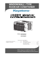 1
1
-
 2
2
-
 3
3
-
 4
4
-
 5
5
-
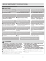 6
6
-
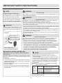 7
7
-
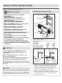 8
8
-
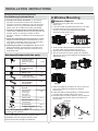 9
9
-
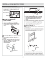 10
10
-
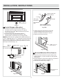 11
11
-
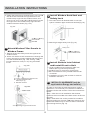 12
12
-
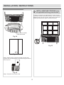 13
13
-
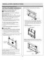 14
14
-
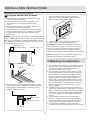 15
15
-
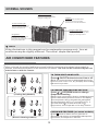 16
16
-
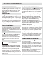 17
17
-
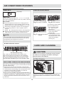 18
18
-
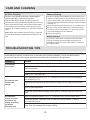 19
19
-
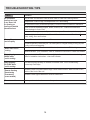 20
20
-
 21
21
-
 22
22
-
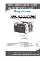 23
23
-
 24
24
-
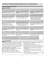 25
25
-
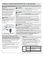 26
26
-
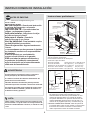 27
27
-
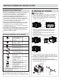 28
28
-
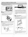 29
29
-
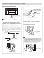 30
30
-
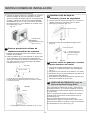 31
31
-
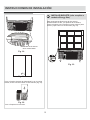 32
32
-
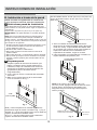 33
33
-
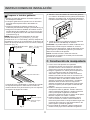 34
34
-
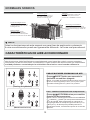 35
35
-
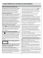 36
36
-
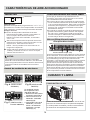 37
37
-
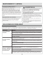 38
38
-
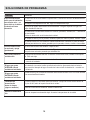 39
39
-
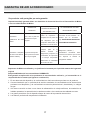 40
40
-
 41
41
-
 42
42
-
 43
43
-
 44
44


Keystone KSTAW25C Instrucciones de operación
- Tipo
- Instrucciones de operación
en otros idiomas
Artículos relacionados
-
Keystone KSTAW12B El manual del propietario
-
-
-
Keystone KSTAW10A Manual de usuario
-
-
-
-
Otros documentos
-
COMFORT-AIRE RADS-51Q Installation, Operation & Maintenance Manual
-
Whirlpool ACE184XR0 Manual de usuario
-
 Frost King AC14H Guía de instalación
-
Kenmore 25370125003 Guía de instalación
-
Kenmore 25372175200 Guía de instalación
-
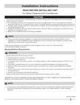 Kenmore Elite 25376063312 Guía de instalación
-
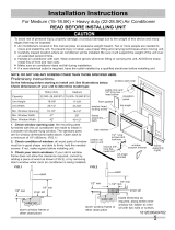 Kenmore Elite 25377150610 Guía de instalación
-
-
Frigidaire FFRA2822U2 Instrucciones de operación
-
Frigidaire FFRE2233S2 Guía de instalación


