FLOW INDICATOR INSTALLATION INSTRUCTIONS
Turn off water system, disable all pumps, and depressurize the system before performing installation. The use of proper
personal protective equipment is mandatory when working on or near chemical metering pumps. Adhere to all safety precautions in the pump
manual. Pump manuals are available at www.stenner.com.
TO BE INSTALLED AND MAINTAINED BY PROPERLY TRAINED PROFESSIONAL INSTALLER ONLY. READ MANUAL &
LABELS FOR ALL SAFETY INFORMATION & INSTRUCTIONS.
WARNING
CAUTION
Jacksonville, Florida USA www.stenner.com
© Stenner Pump Company All Rights Reserved
This information is not intended for specific application purposes. Stenner Pump Company reserves the right to make changes to prices, products, and
specifications at any time without prior notice.
STENNER PUMP COMPANY
INSFI 092220
NOTE: Beveled ends of ferrules face male threads.
PARTS AND MATERIALS
1Body: PVC (Polyvinyl Chloride)
1Ball: PTFE (Polytetrafluoroethylene)
1O-ring: FKM (Fluorocarbon)
2Ferrules: PE (Polyethylene)
1Bracket: Polycarbonate
2Connecting Nuts
1/4" or 6 mm EUROPE: PVC (Polyvinyl Chloride)
3/8": PP (Polypropylene)
2Adapters: PVC (Polyvinyl Chloride)
NOTE: User is responsible for confirming chemical
compatibility with flow indicator materials of construction.
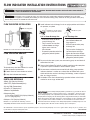
➊Install indicator in the discharge line in an upright position and visible to
the operator, see photo.
.
➋Re-pressurize the water system, turn the metering pump on and check all
connections for leaks.
➌Observe flow indicator. The ball will rise briefly each time a roller completes
a cycle and a pulse of solution is metered into the system.
➍No movement or reduced movement of the ball during pump operation
indicates that there is no flow or a reduced flow of solution into system
which could be the result of a discharge line blockage, a worn or ruptured
tube, or a clogged strainer.
➎Air bubbles in the flow indicator during operation indicate a leak in the
suction line or an empty solution tank.
Limited Warranty: Stenner Pump Company will for a period of one (1) year from the date of
purchase (proof of purchase required) repair or replace – at our option – all defective parts.
Stenner Pump Company is not responsible for any removal or installation costs. Stenner Pump
Company will incur shipping costs for warranty products shipped from our factory in Jacksonville,
Florida. Any tampering with major components, chemical damage, weather conditions, power
surges, or products not used with reasonable care and maintained in accordance with the
instructions will void the warranty. Stenner Pump Company limits its liability solely to the cost
of the original product. We make no other warranty expressed or implied.
DO NOT use thread sealant
tape on pump tube threads.
DO NOT use pliers.
FLOW INDICATOR BRACKET
The bracket keeps the flow indicator in a vertical
position for optimal performance.
➊Attach screws to secure bracket to surface.
➋Snap flow indicator onto bracket.
FLOW INDICATOR INSTALLATION
Discharge Line
1/4" or 6 mm Discharge Line
• Slide nut & ferrule on to the
pump discharge line.
• Fully insert the line into flow
indicator bottom and finger
tighten nut & ferrule to
flow indicator.
• Repeat this procedure on the line
going to the point of injection.
3/8" Discharge Line
• Install 3/8" adapter to the
flow indicator bottom and
finger tighten it.
• Slide the nut on to the pump
discharge line.
• Fully insert the discharge line
into the adapter and finger
tighten the nut to the adapter.
• Repeat this procedure on the line
going to the point of injection.

NOTA: Insertar los casquillos con el extremo en punta
hacia el indicador de flujo.
INSTALACIÓN DEL INDICADOR DE FLUJO
PARTES Y MATERIALES
DE CONSTRUCCIÓN
1Cuerpo del indicador: PVC (Cloruro de polivinilo)
1Bolita: PTFE (Politetrafluoroetileno)
1Anillo de Sellado: FKM (Fluorocarbono)
2Casquillos: PE (Polietileno)
1Soporte: Policarbonato
2Tuercas
1/4" o 6 mm EUROPA: PVC (Cloruro de polivinilo)
3/8": PP (Polipropileno)
2Adaptadores: PVC (Cloruro de polivinilo)
NOTA: El usuario es responsable de confirmar la
compatibilidad de químicos con los materiales de
construcción del Indicador de Flujo.
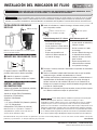
➊Instale el indicador en el tubo de descarga; de forma vertical y visible
para el operador, vea foto.
.
➋Presurice el sistema, encienda el dosificador e inspeccione las conexiones
por pérdidas.
➌Observe el indicador. La bolita subirá levemente cada vez que los rodillos
completen un giro y solución sea bombeada en el sistema.
➍Si no hay movimiento o el movimiento de la bolita es reducido durante el
funcionamiento del dosificador, esto significa que no hay descarga de
fluído o la misma ha sido reducida. Esto puede ser el resultado de un
bloqueo en el punto de descarga, un tubo de bombeo desgastado o roto,
o un filtro de succión tapado.
➎Burbujas en el indicador de flujo son causadas por una pérdida o ruptura
en el tubo de succión o un tanque de químico vacío.
NO use cinta de rosca en
las conexiones del tubo.
NO utilice pinzas.
SOPORTE DEL INDICADOR DE FLUJO
El soporte mantiene el indicador de flujo en
posición vertical para su óptima operación.
➊Atornille el soporte a la superficie.
➋Coloque el indicador de flujo en el soporte.
INSTALACIÓN DEL INDICADOR
DE FLUJO
Tubo de descarga de 1/4" o 6 mm
• Deslice la tuerca y el casquillo
en el tubo de descarga.
• Inserte el tubo en la parte inferior
del indicador y enrosque la tuerca
a mano.
• Repita esta operación en el
extremo del tubo a conectar en
el punto de descarga.
Tubo de descarga
Tubo de descarga de 3/8"
• Instale el adaptador de 3/8 en
la parte inferior del indicador y
enrosque a mano.
• Deslice la tuerca en el tubo
de descarga.
• Inserte el tubo de descarga en
el adaptador hasta el tope y
enrosque la tuerca al mismo,
ajuste a mano.
• Repita esta operación en el
extremo del tubo a conectar
en el punto de descarga.
Jacksonville, Florida USA www.stenner.com
© Stenner Pump Company Derechos Reservados
Esta información no está prevista con fines de aplicaciones específicas. Stenner Pump Company se reserva el derecho de efectuar cambios en los precios,
productos y especificaciones, en cualquier momento y sin previo aviso.
STENNER PUMP COMPANY
INSFI 092220
Garantía Limitada: Stenner Pump Company cambiará o reparará (nuestra opción) todo
producto defectuoso por un año desde el momento de compra (se requiere
comprobante/recibo de compra). Stenner no es responsable por los costos de cambio y
reemplazo de partes. Stenner se hará cargo del costo de envío de los productos bajo
garantía desde nuestra fábrica en Jacksonville, Florida, USA. Cualquier manipulación de los
componentes, daño químico, conexiones mal hechas, daño por razones climáticas, variaciones
de voltaje, maltrato o el no seguimiento de las instrucciones de uso y mantenimiento indicadas
en este manual, anularán la garantía del producto. Stenner limita su responsabilidad solamente
por el costo del producto original. No otorgamos ninguna otra garantía expresada o implicada.
Previo a la instalación, cierre el sistema de agua y permita la descarga de la presión existente en el mismo. El uso de un equipo
de protección es obligatorio cuando se realizan trabajos cerca o en un dosificador de químico. Cumpla con todas las advertencias de seguridad
indicadas en el manual de instalación del dosificador. Manuales del dosificador están disponibles en nuestro sitio de internet: www.stenner.com.
INSTALACIÓN DEBE SER REALIZADA Y MANTENIDA POR PROFESIONALES DEBIDAMENTE ENTRENADOS. LEA EL
MANUAL Y LAS ETIQUETAS PARA OBTENER LAS INSTRUCCIONES Y LA INFORMACIÓN DE SEGURIDAD.
PRECAUCIÓN
ADVERTENCIA
-
 1
1
-
 2
2