Kenmore PG-40406S0L El manual del propietario
- Categoría
- Barbacoas
- Tipo
- El manual del propietario
Este manual también es adecuado para

Use & Care Guide
Manual de Uso y Cuidado
English / Español
Kenmore®
Liquid Propane Gas Grill
Parrilla a gas de propane liquido
Model/Modélo: PG-40406S0L
P/N 40600050A
®

enDANGER: Indicates an imminently hazardous situation
which, if not avoided, will result in death or serious injury.
WARNING: Indicates an potentially hazardous situation
which, if not avoided, could result in death or serious injury.
DANGER
If you smell gas:
1. Shut off gas to the appliance.
2. Extinguish any open flame.
3. Open lid.
4. If odor continues, keep away from the
appliance and immediately call your gas
supplier or your fire department.
WARNING
1.
Do not store or use gasoline or other
flammable liquids or vapors in the vicinity of
this or any other appliance.
2. An LP cylinder not connected for use shall not
be stored in the vicinity of this or any other
appliance.
Safety Symbols
The symbols and boxes shown below explain what each heading
means. Read and follow all of the messages found throughout
the manual.
Product Record
IMPORTANT: Fill out the product record information below.
DANGER
Model Number
Serial Number
See rating label on grill for serial number.
WARNING
Date Purchased
CAUTION
CAUTION
For residential use only. Do not use for commercial
cooking.
2
CAUTION: Indicates a potentially hazardous situation or
unsafe practice which, if not avoided, may result in minor or
moderate injury.
Installation Safety Precautions
• Please read this User’s Manual in its entirety before using
the grill.
• Failure to follow the provided instruction can result in
seriously bodily injury and/or property damage.
• Some parts of this grill may have sharp edges. Please
wear suitable protective gloves.
• Use grill, as purchased, only with LP (propane) gas and the
regulator/valve assembly supplied.
• Grill installation must conform with local codes, or in their
absence of local codes, with either the National Fuel Gas
Code, ANSI Z223.1/ NFPA 54, Natural Gas and Propane
Installation Code, CSA B149.1, or Propane Storage and
Handling Code, B149.2, or the Standard for Recreational
Vehicles, ANSI A 119.2/NFPA 1192, and CSA Z240 RV
Series, Recreational Vehicle Code, as applicable.
• All electrical accessories (such as rotisserie) must be
electrically grounded in accordance with local codes, or
National Electrical Code, ANSI / NFPA 70 or Canadian
Electrical Code, CSA C22.1. Keep any electrical cords
and/or fuel supply hoses away from any hot surfaces.
• This grill is safety certified for use in the United States
and/or Canada only. Do not modify for use in any other
location. Modification will result in a safety hazard.
IMPORTANT: This grill is intended for outdoor use only and is
not intended to be installed in or on recreational vehicles or
boats.
NOTE TO INSTALLER: Leave this User’s Manual with the
customer after delivery and/or installation.
NOTE TO CONSUMER: Leave this User’s Manual in a
convenient place for future reference.
Please Contact Permasteel Customer Service For Help
& Parts
If you have questions or need assistance during assembly,
Please call 1-888-287-0735. M – F 8:00 – 5:00 Pacific
You will be speaking to a Representative of the grill
manufacturer.

Installation Safety Precautions . . .
Safety Symbols . . .
Kenmore Grill Warranty . . .
Use and Care . . .
Parts List . . .
Parts Diagram . . .
Before Assembly . . .
Assembly . . .
Troubleshooting . . .
. . 2
. . 2
. 2
. . 2
. . 2
. . 4
. . . 5-11
. . . 12
. . 13
. . . 14-17
. 18-28
. 29-31
WARRANTY
WARRANTY
WARNIG
For Your Safety . . .
Grill Service Center. . .
Product Record Information . . .
TABLE OF CONTENTS
3
WARNING
CALIFORNIA PROPOSITION 65
This product contains chemicals, including lead and lead
compounds in brass fittings. It also produces combustion
by-products when used. These substances are known to
the State of California to cause cancer, birth defects or
other reproductive harm.
Wash your hands after handling this product.

KENMORE LIMITED WARRANTY
WITH PROOF OF SALE: the following warranty coverage applies when this appliance is correctly installed, operated and
maintained according to all supplied instructions. Note: Consumer is responsible for Shipping & handling of all warranty
replacement parts.
FOR ONE YEAR: from the date of sale this grill is warranted against defects in material or workmanship, consumer will receive
free replacement parts with proof of purchase, consumer is responsible for S&H cost.
FOR FIVE YEARS: from the date of sale, any stainless-steel burner that rusts through or burns through will be replaced, proof
of purchase must be provided, consumer is responsible for Shipping & Handling cost.
All warranty coverage excludes ignitor batteries and grill part paint loss, discoloration or surface rusting, which are either
expendable parts that can wear out from normal use within the warranty period, or are conditions that can be the result of
normal use, accident or improper maintenance.
All warranty coverage is void if this appliance is ever used for other than private household purposes.
For warranty coverage details to obtain replacement parts, visit the web page: www.permasteel.net
This warranty covers ONLY defects in material and workmanship, and will NOT pay for:
1. Expendable items that can wear out from normal use within the warranty period, including but not limited to batteries,
screw-in base light bulbs and surface coatings or finishes.
2. A service technician to clean or maintain this appliance, or to instruct the user in correct appliance installation, operation
and maintenance.
3. Service calls to correct appliance installation not performed by Sears authorized service agents, or to repair problems with
house fuses, circuit breakers, house wiring, and plumbing or gas supply systems resulting from such installation.
4. Damage to or failure of this appliance resulting from installation not performed by Sears authorized service agents,
including installation that was not in accord with electrical, gas or plumbing codes.
5. Damage to or failure of this appliance, including discoloration or surface rust, if it is not correctly operated and
maintained according to all supplied instructions.
6. Damage to or failure of this appliance, including discoloration or surface rust, resulting from accident, alteration, abuse,
misuse or use for other than its intended purpose.
7. Damage to or failure of this appliance, including discoloration or surface rust, caused by the use of detergents, cleaners,
chemicals or utensils other than those recommended in all instructions supplied with the product.
8. Damage to or failure of this appliance resulting from natural or other catastrophe, such as flood, fire or storm.
9. Damage to or failure of parts or systems resulting from unauthorized modifications made to this appliance.
10. Service to an appliance if the model and serial plate is missing, altered, or cannot easily be determined to have the
appropriate certification logo.
Disclaimer of implied warranties; limitation of remedies
Customer’s sole and exclusive remedy under this limited warranty shall be product repair or replacement as provided herein.
Implied warranties, including warranties of merchantability or fitness for a particular purpose, are limited to two years on the
appliance, five years on heat diffusers, fifteen years on burners, and twenty-five years on sidewalls, lid shroud and grates, or
the shortest period allowed by law. Seller shall not be liable for incidental or consequential damages. Some states and
provinces do not allow the exclusion or limitation of incidental or consequential damages, or limitation on the duration of
implied warranties of merchantability or fitness, so these exclusions or limitations may not apply to you.
This warranty gives you specific legal rights, and you may also have other rights which vary from state to state.

• Never fill a cylinder beyond 80% full.
• If the information in the two points above is not
followed exactly, a fire causing death or serious
injury may occur.
• An overfilled or improperly stored cylinder is a
hazard due to possible gas release from the safety
relief valve. This could cause an intense fire with
risk of property damage, serious injury or death.
• If you see, smell or hear gas escaping,
immediately get away from the LP cylinder and
appliance and call your fire department.
LP Cylinder
USE AND CARE
• The LP cylinder used with your grill must meet the following
requirements:
• Use LP cylinders only with these required measurements: 12"
(30.5cm) (diameter) x 18" (45.7 cm) (tall) with 20 lb. (9 kg.)
Capacity maximum.
• LP cylinders must be constructed and marked in accordance
with specifications for LP cylinders of the U.S. Department of
Transportation (DOT) or for Canada, CAN/CSA-B339,
cylinders, spheres and tubes for transportation of dangerous
goods. Transport Canada (TC). See LP cylinder collar for
marking.
• LP cylinder valve must have:
• Type 1 outlet compatible with
regulator or grill.
• Safety relief valve.
• UL listed Overfill Protection
Device (OPD). This OPD safety
feature is identified by a unique triangular hand wheel. Use
only LP cylinders equipped with this type of valve.
• LP cylinder must be arranged for vapor withdrawal and
include collar to protect LP cylinder valve. Always keep LP
cylinders in upright position during use, transit or storage.
OPD Hand Wheel
• NEVER store a spare LP cylinder under or near the
appliance or in an enclosed area.
LP cylinder in upright position for vapor withdrawal
LP (Liquefied Petroleum Gas)
LP Tank Removal, Transport And Storage
• Turn OFF all control knobs and LP tank valve. Turn coupling nut
counterclockwise by hand only - do not use tools to
disconnect. Lift LP tank wire upward off of LP tank collar, then lift
LP tank up and off of support bracket. Install safety cap onto LP
tank valve. Always use cap and strap supplied with valve.
Failure to use safety cap as directed may result in serious
personal injury and/or property damage.
LP Tank Valve
• LP gas is nontoxic, odorless and colorless when produced. For
Your Safety, LP gas has been given an odor (similar to rotten
cabbage) so that it can be smelled.
• LP gas is highly flammable and may ignite unexpectedly when
mixed with air.
LP Cylinder Filling
• Use only licensed and experienced dealers.
• LP dealer must purge new cylinder before filling.
• Dealer should NEVER fill LP cylinder more than 80% of LP
cylinder volume. Volume of propane in cylinder will vary by
temperature.
• A frosty regulator indicates gas overfill. Immediately close LP
cylinder valve and call local LP gas dealer for assistance.
• Do not release liquid propane (LP) gas into the atmosphere. This
is a hazardous practice.
• To remove gas from LP cylinder, contact an LP dealer or call a
local fire department for assistance. Check the telephone
directory under “Gas Companies” for nearest certified LP
dealers.
Safety Cap
Retainer Strap
• A disconnected LP tank in storage or being transported must
have a safety cap installed (as shown). Do not store an LP tank
in enclosed spaces such as a carport, garage, porch, covered
patio or other building. Never leave an LP tank inside a vehicle
which may become overheated by the sun.
• Do not store an LP tank in an area where children play.
DANGER
5

LP Tank Exchange
• Many retailers that sell grills offer you the option of replacing
your empty LP tank through an exchange service. Use only those
reputable exchange companies that inspect, precision fill, test
and certify their cylinders. Exchange your tank only for an OPD
safety feature-equipped tank as described in the "LP Tank"
section of this manual.
• Always keep new and exchanged LP tanks in upright position
during use, transit or storage.
• Leak test new and exchanged LP tanks BEFORE connecting to
grill.
Connecting Regulator To The LP Tank
1. LP tank must be properly secured onto grill. (Refer to
assembly section.)
2. Turn all control knobs to the OFF position.
3. Turn LP tank OFF by turning OPD hand wheel clockwise to a
full stop.
4. Remove the protective cap from LP tank valve. Always use
cap and strap supplied with valve.
ck
LP Tank Leak Test
For your safety
OPD Hand Wheel
Type 1 outlet with
thread on outside
Safety Relief Valve
Strap and Cap
• Leak test must be repeated each time LP tank is exchanged or
refilled.
• Do not smoke during leak test.
• Do not use an open flame to check for gas leaks.
• Grill must be leak tested outdoors in a well-ventilated area,
away from ignition sources such as gas fired or electrical
appliances. During leak test, keep grill away from open flames
or sparks.
• Use a clean paintbrush and a 50/50 mild soap and water
solution. Brush soapy solution onto areas indicated by arrows
in figure below. Leaks are indicated by growing bubbles.
Do not insert a POL transport plug
(plastic part with external threads
into the type 1 valve outlet. It will
defeat the Safety Relief Valve
feature.
WARNING
If “growing” bubbles appear do not use or move the LP
tank. Contact an LP gas supplier or your fire department!
5. Hold regulator and insert nipple into LP
tank valve. Hand-tighten the coupling
nut, holding regulator in a straight line
with LP tank valve so as not to crossth-
thread the connection.
Nipple has to be
centered into the LP
tank valve.
▲Do not use household cleaning agents. Damage to the gas
train components (valve/hose/regulator) can result.
6

Leak Testing Valves, Hose and Regulator
1. Turn all grill control knobs to OFF.
2. Be sure regulator is tightly connected to LP tank.
3. Completely open LP tank valve by turning OPD hand wheel
counterclockwise. If you hear a rushing sound, turn gas off
immediately. There is a major leak at the connection. Correct
before proceeding by calling Permasteel for replacement
parts at 1-888-287-0735,
M – F 8:00 – 5:00 PACIFIC
4 .Brush soapy solution onto areas where bubbles are shown in
picture below:
Hold coupling nut and regulator
as shown for proper connection
▲
to LP tank valve.
Never remove threaded
orifice at end of valve.
6. Turn the coupling nut clockwise and tighten to a full stop. The
regulator will seal on the back-check feature in the LP tank
valve, resulting in some resistance. An additional one-half to
three-quarters turn is required to complete the connection.
Tighten by hand only - do not use tools.
NOTE:
If you cannot complete the connection, disconnect regulator
and repeat steps 5 and 6. If you are still unable to complete the
connection, do not use this regulator!
Call 1-888-287-0735 for an identical replacement part.
DANGER
• Do not insert any tool or foreign object into the valve
outlet or safety relief valve. You may damage the valve
and cause a leak. Leaking propane may result in
explosion, fire, severe personal injury, or death.
5. If “growing” bubbles appear, there is a leak. Close LP tank
valve immediately and retighten connections. If leaks cannot be
stopped do not try to repair. Call for replacement
parts at 1-888-287-0735.
6. Always close LP tank valve after performing leak test by
turning hand wheel clockwise.
WARNING
•
Outdoor gas appliance is not intended to be installed
in or on a boat.
•
Outdoor gas appliance is not intended to be installed
in or on an RV.
•
Never attempt to attach this grill to the self-contained
LP gas system of a camper trailer or motor home.
•
Do not use grill until leak-tested.
•
If a leak is detected at any time, STOP and call the fire
department.
• If you cannot stop a gas leak, immediately close
LP cylinder valve and call LP gas supplier or your fire
department !
7

▲Do not lean over grill while lighting.
1. Open lid during lighting.
2. Turn on valve from source or tank.
3. To ignite, turn Ignition Burner knob to HI.
4. Push and hold electronic ignition button.
5. If ignition does not occur in 5 seconds, turn the burner
controls OFF, wait 5 minutes, and repeat the lighting
procedure.
6. To ignite other main burners after ignition burner is lit,turn a
control knob that is adjacent to a lit burner to Hi.
Ignite far left burner last.
7. To ignite the Side Burner, follow steps 3-5 using the Side
Burner knob.
If igniter does not work, follow Match Lighting instructions.
Main Burner Igniter Lighting
Safety Tips
WARNING
For Safe Use of Your Grill and to Avoid Serious
Injury:
• Do not let children operate or play near grill.
• Keep grill area clear and free from materials that
burn.
• Do not block holes in sides or back of grill.
• Use grill only in well-ventilated space. NEVER use
in enclosed space such as carport, garage, porch,
covered patio, or under an overhead structure of
any kind.
• Do not use charcoal or ceramic briquets in a gas
grill.
• Use grill at least 3 ft. from any wall or surface.
Maintain 10 ft. clearance to objects that can catch
fire, or to sources of ignition etc.
▲ Before opening LP cylinder valve, check the coupling nut for
tightness.
▲ When grill is not in use, turn off all control knobs and LP cylinder
valve.
▲ Never move grill while in operation or still hot.
▲ Use long-handled barbecue utensils and oven mitts to avoid burns
and splatters.
▲ Maximum load for sideburner and side shelf is 10 lbs.
▲ The drip tray must be inserted into grill and emptied after each use
Do not remove drip tray until grill has completely cooled.
▲ Clean grill often, preferably after each cookout. If a bristle brush is
used to clean any of the grill cooking surfaces, ensure no loose
bristles remain on cooking surfaces prior to grilling. It is not
recommended to clean cooking surfaces while grill is hot.
▲ If you notice drip or other hot material dripping from grill,
determine the cause, correct it, then clean and inspect valve. Keep
ventilation openings in cylinder enclosure (grill cart) free and clear
of debris.
▲ Do not store objects or materials inside the grill cart enclosure that
would block the flow of combustion air to the underside of either
the control panel or the firebox bowl.
▲ The regulator may make a humming or whistling noise during
operation. This will not affect safety or use of grill.
▲ If you have a grill problem see the "Troubleshooting Section".
▲ If the regulator frosts, turn off grill and LP cylinder valve
immediately. This indicates a problem with the cylinder and it
should not be used on any product. Return to supplier!
CAUTION
• Putting out drip fires by closing the lid is not possible. Grills
are well ventilated for safety reasons.
• Do not use water on a drip fire. Personal injury may result.
If a drip fire develops, turn knobs and LP cylinder off.
• Do not leave grill unattended while preheating or burning
off food residue on HI. If grill has not been regularly
cleaned, a drip fire can occur that may damage the
product.
• Apartment Dwellers:
Check with management to learn the requirements
and fire codes for using an LP gas grill in your
apartment complex. If allowed, use outside on the
ground floor with a three (3) foot clearance from
walls or rails. Do not use on or under balconies.
• NEVER attempt to light burner with lid closed. A
buildup of non-ignited gas inside a closed grill is
hazardous.
• Never operate grill with LP cylinder out of correct
position specified in assembly instructions.
• Always close LP cylinder valve and remove
coupling nut before moving LP cylinder from
specified operation position.
8

Turning Grill Off
• Turn all knobs to OFF position. Turn LP cylinder off by turning
Igniter Check
• Turn gas off at LP cylinder. Press and hold electronic igniter
button. "Clicking" should be heard and spark seen each time
between collector box or burner and electrode. See
"Troubleshooting" if no click or spark.
Valve Check
• Important: Make sure gas is off at LP cylinder before checking valves.
Knobs lock in OFF position. To check valves, first push in knobs and
release, knobs should spring back. If knobs do not spring back,
replace valve assembly before using grill. Turn knobs to LOW
position then turn back to OFF position. Valves should turn smoothly.
Hose Check
• Before each use, check to see if hoses are cut or worn. Replace
damaged hoses before using grill. Use only valve/hose/regulator as
specified in the parts list of this Use & Care Guide.
Burner Flame Check
• Remove cooking grates and heat diffusers. Light burners, turn
knobs from HI to LO. You should see a smaller flame in
LO position than seen on HI. Perform burner flame check
on sideburner, also. Always check flame prior to each use. If
only low flame is seen refer to "Sudden flame drop or low flame" in
the Troubleshooting Section.
WARNING
Match Lighting
▲Do not lean over grill while lighting.
1. Open lid during lighting.
2. Place match into match holder (hanging on right back leg).
Light match, place into lighting hole on left side of firebox.
3. Turn right knob to HI position. Be sure burner lights and stay lit.
4. Light other burners follow with step 3.
Sideburner Match Lighting
1. Open sideburner lid. Turn on gas at LP cylinder.
2. Place lit match near burner.
3. Turn sideburner knob to HI. Be sure burner lights and stays lit.
Turn controls and gas source or tank OFF when not
in use.
CAUTION
HIGH
LOW
If ignition does not occur in 5 seconds, turn the
burner controls OFF, wait 5 minutes and repeat the
lighting procedure. If the burner does not ignite with
the valve open, gas will continue to flow out of the
burner and could ignite with risk of injury.
.
9
HI
LO
Cast Iron Grate Seasoning (if applicable)
First Use – Before first use, season cast iron grates as follows: Rinse
cast iron grates with hot water. Do not use soap. Dry grates
thoroughly with a cloth towel. Coat grates with vegetable oil or
non-stick cooking spray. Place grates in grill. Start grill and slowly
raise temperature to 350° - 400° F. Heat grates for one hour. Turn
off grill and allow grates to cool completely before using to cook.
Cleaning – Do not use soap when cleaning grates. Clean grates with
a stiff brush and hot water. Dry grates thoroughly with a cloth towel.
Re-seasoning – Re-season grates when rust spots appear on grate
surface. When re-seasoning grates, soap may be used with hot
water to clean grates. After cleaning, dry grates thoroughly with a
cloth towel. Coat grates with vegetable oil or non-stick cooking
spray. Place grates in grill. Start grill and slowly raise temperature
to 350° - 400° F. Heat grates for one hour. Turn off grill and allow
grates to cool completely before using again.
General Grill Cleaning
• Do not mistake brown or black accumulation of drip and smoke
for paint. Interiors of gas grills are not painted at the factory (and
should never be painted). Apply a strong solution of detergent
and water or use a grill cleaner with scrub brush on insides of
grill lid and bottom. Rinse and allow to completely air dry. Do not
apply a caustic grill/oven cleaner to painted surfaces.
• Porcelain surfaces: Because of glass-like composition, most
residue can be wiped away with baking soda/water solution or
specially formulated cleaner. Use nonabrasive scouring powder
for stubborn stains.

Cleaning the Burner Assembly
CAUTION
Follow these instructions to clean and/or replace parts of burner
assembly or if you have trouble igniting grill.
1. Turn gas off at control knobs and LP cylinder.
2. Remove cooking grates and heat diffusers.
3. Remove cotter pin from rear of burners.
See Fig. A next page.
4. Carefully lift each burner up and away from valve openings.
We suggest three ways to clean the burner tubes. Use the one
easiest for you.
(A) Bend a stiff wire (a light weight coat hanger works well)
into a small hook. Run the hook through each burner
tube several times.
(B) Use a narrow bottle brush with a flexible handle (do not use
a brass wire brush), run the brush through each burner tube
several times.
(C) Wear eye protection: Use an air hose to force air into
the burner tube and out the burner ports. Check each
port to make sure air comes out each hole.
5. Wire brush entire outer surface of burner to remove
food residue and dirt.
6. Clean any blocked ports with a stiff wire such as an
open paper clip.
7. Check burner for damage, due to normal wear and
corrosion some holes may become enlarged. If any large
cracks or holes are found replace burner.
Spiders or small insects have been known to create “flashback”
problems. The spiders spin webs, build nests and lay eggs in the grill’s
venturi tube(s) obstructing the flow of gas to the burner. The
backed-up gas can ignite in the venturi behind the control panel. This
is known as a flashback and it can damage your grill and even cause
injury.
To prevent flashbacks and ensure good performance the burner and
venturi assembly should be removed from the grill and cleaned
before use whenever the grill has been idle for an extended period.
VERY IMPORTANT: Burner tubes must reengage valve
openings. See illustrations below.
8. Carefully replace burners.
9. Attach burners to brackets with cotter pin. See Fig. B next
page.
10. Replace heat diffusers and cooking grates.
Storing Your Grill
•Clean cooking grates.
•Store in dry location.
•When LP cylinder is connected to grill, store outdoors in a
well-ventilated space and out of reach of children.
•Cover grill if stored outdoors. Choose from a variety of grill
covers offered by manufacturer once available.
•Store grill indoors ONLY if LP cylinder is turned off and
Disconnected, remove from grill and stored outdoors.
• When removing grill from storage, follow “Cleaning the Burner
A
s
sembl
y
” instructions before starting grill.
SPIDER ALERT!
If you notice that your grill is getting hard to light or that the
flame isn’t as strong as it should be, take the time to check and
clean the venturi’s.
IMPORTANT: Always ensure that the venturi burner tubes
are clean. A venturi burner tube has a narrow area in
which spiders tend to build nests.
10
• Painted surfaces: Wash with mild detergent or nonabrasive
cleaner and warm soapy water. Wipe dry with a soft
nonabrasive cloth.
• Stainless steel surfaces: To maintain your grill’s high quality
appearance, wash with mild detergent and warm soapy water
and wipe dry with a soft cloth after each use. Baked-on drip
deposits may require the use of an abrasive plastic cleaning
pad. Use only in direction of brushed finish to avoid damage. Do
not use abrasive pad on areas with graphics.
• Cooking surfaces: If a bristle brush is used to clean any of the grill
cooking surfaces, ensure no loose bristles remain on cooking
surfaces prior to grilling. It is not recommended to clean cooking
surfaces while grill is hot.
•Drip Tray and Cup: Regularly clean the drip drippings from the
Drip Tray and Drip Cup. When the grill has completely cooled
down after use, remove the cup from the tray and slide the tray
out of the grill. Clean the drip drippings from the cup and tray
surfaces by washing with mild detergent or nonabrasive cleaner
and warm soapy water. Wipe dry with a soft nonabrasive cloth.
Slide the tray back into the grill and replace the cup back into
the tra
y
before usin
g
the
g
rill a
g
ain.

Indirect Cooking
Poultry and large cuts of meat cook slowly to perfection on the grill
by indirect heat. Place food over unlit burner(s); the heat from lit
burners circulates gently throughout the grill, cooking meat or
poultry without the touch of a direct flame. This method greatly
reduces flare-ups when cooking extra fatty cuts because there is no
direct flame to ignite the fats and juices that drip during cooking.
Food Safety
Food safety is a very important part of enjoying the outdoor
cooking experience. To keep food safe from harmful bacteria,
follow these four basic steps:
Clean: Wash hands, utensils, and surfaces with hot soapy water
before and after handling raw meat and poultry.
Separate: Separate raw meats and poultry from ready-to-eat
foods to avoid cross contamination. Use a clean platter and
utensils when removing cooked foods.
Cook: Cook meat and poultry thoroughly to kill bacteria. Use a
thermometer to ensure proper internal food temperatures.
Chill: Refrigerate prepared foods and leftovers promptly. For
more information call: USDA Meat and Poultry Hotline at
1-800-535-4555 (In Washington, DC (202) 720-3333, 10:00 am
4:00 pm EST).
1 Burner Cooking
Cook with direct or indirect heat.
Best for smaller meals or foods.
Consumes less fuel.
Indirect Cooking Instructions
• Always cook with the lid closed.
• Due to weather conditions, cooking times may vary. During
cold and windy conditions the temperature setting may
need to be increased to insure sufficient cooking
temperature.
• Place food over over unlit burner(s).
How To Tell If Meat Is Grilled Thoroughly
• Meat and poultry cooked on a grill often browns very fast
on the outside. Use a meat thermometer to be sure food has
reached a safe internal temperature, and cut into food to
check for visual signs of doneness.
• Whole poultry should reach 180° F; breasts, 170° F. Juices
should run clear and flesh should not be pink.
• Hamburgers made of any ground meat or poultry should
reach 160° F, and be brown in the middle with no pink juices
Beef, veal and lamb steaks, roasts and chops can be
cooked to 145° F. All cuts of pork should reach 160° F.
• NEVER partially grill meat or poultry and finish cooking
later. Cook food completely to destroy harmful bacteria.
• When reheating takeout foods or fully cooked meats like
hot dogs, grill to 165° F, or until steaming hot.
2 Burner Cooking
Great indirect cooking on low.
Produces slow, even heating.
Ideal for slow roasting and baking.
WARNING: To ensure that it is safe to eat, food must be cooked
to the minimum internal temperatures listed in the table below.
USDA* Safe Minimum Internal Temperatures
Fish 145°F
Pork
160°F
Egg Dishes
160°F
Steaks and Roasts of Beef,
Veal or Lamb
145°F
Ground Beef, Veal or Lamb 160°F
Whole Poultry (Turkey,
Chicken, Duck, etc.)
165°F
Ground or Pieces Poultry
165°F
(Chicken Breast, etc.)
*United States Department of Agriculture
11
USDA* Recommended Safe Minimum Internal Temperatures
Beef, Veal, Lamb and Pork – Whole Cuts** 145° F
Fish 145° F
Beef, Veal, Lamb and Pork – Ground 160° F
Egg Dishes 160° F
Turkey, Chicken & Duck – Whole, Pieces &
Ground
165° F
* United States Department of Agriculture
**Allow meat to rest three minutes before carving or consuming.
A B

PARTS LIST
Key
Qty Description
12
42 3
HEAT DIFFUSERS
2
1
43 3
COOKING GRATE
31
44 1
SWING AWAY GRATE
41
45 1 CLIP, F/ GREASE CUP
51
46 1
GREASE CUP
6
2
47 1
TANK THUMBSCREW
71
81
91
10 1
11 1
Not Pictured
12 1
1
HARDWARE PACK
13 1
1
PRODUCT MANUAL, ENGLISH
14 1
1
PRODUCT MANUAL, SPANISH
15 1
16 1
17 2
18 2
19 1
20 1
21 1
22 3
23 1
24 2
25 1
26 1
27 1
28 1
29 4
30 4
31 1
32 1
33 1
34 1
1
36 1
37 1
38 1
39 1
40
1
41 1
12
Not Pictured
Hardware Pack 1 41100316
Manual 1 40100219
If you are missing hardware or have
damaged parts after unpacking grill,
call 1-888-287-0735 M – F 8:00 – 5:00 PACIFIC
for replacement.
To order replacement parts after using grill,
call 1-888-287-0735, M – F 8:00 – 5:00 PACIFIC
Key Description Qty Part Number Key Description Qty Part Number
1 Side Burner Lid 1 40800065 31 Bottom Shelf 1 52200073
2 Side Burner Grid 1 40800119 32 Front Panel 2 40600062
3 Rotate Rod, Side Burner Lid 2 40800118 33 Side Lower Rail 2 52200064
4 Side Burner Base 1 52200052 34 Side Upper Rail 2 52200061
5 Side Burner 1 40600031 35 Tank Baffle 1 40800090
6 Igniter Wire, Side Burner 1 52200054 36 Drip Cup 1 40800026
7 Igniter Wire, Main Burner 1 52200053 37 Drip Cup Clip 1 40800131
8 Right Side Shelf 1 40900145 38 Drip Tray 1 40600014
9 FireBox 1 40600004 39 Right Drip Tray Support 1 40600027
10 Electronic Ignition Module 1 40600030 40 Left Drip Tray Support 1 40600026
11 Fascia, Right Shelf 1 41100023 41 Back Rail 1 52200074
12 Control Panel 1 40100022 42 Fascia, Left Side Shelf 1 40900040
13 Gas Valve, Main Burner 4 40900205 43 Left Side Shelf 1 40900143
14 Manifold, Main Burner 1 40300037 44 Side Shelf Support Angle Bar 2 40900109
15 Side Burner Hose 1 40900210 45 Flame Carry Over Tube 3 40300019
16 Gas Valve, Side Burner 1 10900209 46 Cooking Grate 2 40100101
17 Bezel, Control Knob 5 40900036 47
Silicone Rubber Bumper,
Firebox
2 50300205
18 Control Knob 5 40900206 48 Silicone Rubber Bumper, Lid 2 40700103
19 Regulator 1 408D00115 49 Warming Rack 1 40300104
20 Axle Rod 1 408D00125 50 Lid Handle 1 40900012
21 Match Holder Chain 1 120006 51 Bezel, Lid Handle 2 40900013
22 Cotter Pin 10 110050 52 Temperature Gauge 1 40900218
23 Hose Fixed Pin 1 40800134 53 Logo 1 40800106
24 Leg Extender 2 40800127 54 Lid 1 50500004
25 Caster 2 40800124 55 Heat Diffuser 4 40800023
26 Right Back Leg 1 40600025 56 Rotated Rod, Lid 2 50300207
27 Right Front Leg 1 40600024 57 Flat Washer 3 110018
28 Left Front Leg 1 40600021 58 Hex Nut 3 110011
29 Left Back Leg 1 40600022 59 Burner 1 40600013
30 Tank Holder 1 40800130 60 Main Burner 3 40600012
Not Pictured
Hardware Pack 1 40600049
Manual 1 40600050A
PARTS LIST

13
PARTS DIAGRAM
1
2
3
4
5
6
8
10
11
12
13
14
15
16
17
18
19
20
21
22
23
24
25
31
26272829
30
32
33
34
35
36
37
38
39
40
41
42
43
44
45
46
47
48
49
50
51
52
53
54
55
56
57
58
59
60
7
9

14
BEFORE ASSEMBLY
NOTICE: Once you have unpacked the grill according to the STOP SHEET
instructions, check all grill parts against the pictures on this and the following
two pages. If any parts are missing or damaged, call 1-888-287-0735, M – F
8:00 – 5:00 PACIFIC.

15
BEFORE ASSEMBLY

BEFORE ASSEMBLY
16

17
ASSEMBLY
CAREFULLY READ AND PERFORM ALL ASSEMBLY INSTRUCTIONS ON THE FOLLOWING PAGES.
Tools Required:
Adjustable wrench (not provided)
Screwdriver (not provided)
7/16” Combination wrench (not provided)
The following hardware is provided in blister pack for convenient use.
M4X10 screw
Qty: 54 pcs
AA Battery
Qty: 1 pc
M5X10 screw
Qty: 4 pcs
M5 flat washer
Qty: 4 pcs
M6X13 screw
Qty: 16 pcs
M6 compression washer
Qty: 4 pcs

1
2
Left Frame
□ Install (4)M4×10 Screws as shown to the leg marked “5A”. Do not fully tighten the screws at this
time. Leave 1/8-inch gap below screw head for rail attachment. (A)
□ Attach one end of a Side Upper Rail “6A” to the leg, tighten the screws and install and tighten
another (1)M4×10 Screw.(C)
□ Attach one end of a Side Lower Rail “6B” to the leg and tighten the screws. (C)
□ Install (4)M4×10 Screws as shown to the leg marked “5B”. Do not fully tighten the screws at this
time. Leave 1/8-inch gap below screw head for rail attachment. (B)
□ Attach the other end of Side Upper Rail and Side Lower Rail to the “5B” Leg and tighten the
screws. Install and tighten another (1)M4X10 Screw to the Side Upper Rail. (D)
M4x10 screws Qty: 10 pcs
A
B
C
D
18

19
Right Frame
□ Install (4)M4×10 Screws as shown to the leg marked “5C”. Do not fully tighten the screws at this
time. Leave 1/8-inch gap below screw head for rail attachment. (A)
□ Attach one end of a Side Upper Rail “6A” to the leg, tighten the screws and install and tighten another
(1)M4×10 Screw.(C)
□ Attach one end of a Side Lower Rail “6B” to the leg and tighten the screws. (C)
□ Install (4)M4×10 Screws as shown to the leg marked “5D”. Do not fully tighten the screws at this
time. Leave 1/8-inch gap below screw head for rail attachment. (B)
□ Attach the other end of Side Upper Rail and Side Lower Rail to the “5D” Leg and tighten the screws.
Install and tighten another (1)M4X10 Screw to the Side Upper Rail. (D)
M4x10 screws Qty: 10 pcs
A
B
C
D

M4x10 screws Qty: 14 pcs
Left Frame
A
B
Bottom Shelf
□ Install (4)M4×10 Screws as shown to Right Frame. Do not fully tighten the screws at this time.
Leave 1/8-inch gap below screw head for panel attachment. (A)
□ Install (4) M4X10 screws as shown to Left Frame. Do not fully tighten screws at this time. Leave
1/8-inch gap below screw head for panel attachment. (B)
□ Attach Bottom Shelf to Right Frame with (3) M4X10 screws. Do not yet fully tighten these screws.
(A)
□ Attach Bottom Shelf to Left Frame with (3) M4X10 screws. Do not yet fully tighten these screws. (B)
Bottom Shelf
Right Frame
20

M4x10 screws Qty: 4 pcs
Front Panel
□ Attach the two front panel sections together into a single front panel with (1) M4X10 screw as shown.
□ Attach the front panel to the cart by slipping the four panel holes on each side over and down onto the
four protruding screw heads on the left and right frames. Leave the top screw loose on each side, and
fully tighten the other three screws on each side.
□ Slide one end of the Right Drip Tray Support Bar “7A” under the front Right Frame top screw. Fully
tighten the screw. Fully tighten other end of bar to the rear Right Frame with (1)M4×10 Screw. (C)
□ Slide one end of the Left Drip Tray Support Bar “7B” under the front Left Frame top screw. Fully tighten
the screw. Fully tighten other end of bar to the rear Left Frame with (1)M4×10 Screws as shown. Install
and fully tighten (1) M4X10 screw through the middle screw hole on the bottom of the front panel into
the bottom shelf. (D)
21
A
B
C
D

D
9
B
A
M6X13 screw Qty: 4 pcs M4X10 screw Qty: 2 pcs
Wheels to Cart
□ Turn cart upside down and attach Legs to Bottom Shelf with (4) M6X13 screws as shown. (A)
□ Tap both Leg Extenders onto Left Legs. (B)
□ Remove hitch pin, nut and washer from axle rod. Insert axle rod through Wheels and Right Leg Frame.
Reattach washer, nut and hitch pin. (C)
Note: The convex side of the wheel must face to the cart, and the concave side must face outward.
□ Stand cart right side up and fully tighten the (6) M4X10 bottom shelf screws. (D) Attach Tank Baffle as
shown with (2) M4X10 screws. (D)
B
C
22

A
23
Grill Head to Cart
□ This step requires two people to lift and position grill head onto cart.
□ Remove the tie wraps and packaging material from regulator hose, side burner valve and igniter
wire. Pull hose and igniter wire out to side of grill head.
□ Carefully lower the grill head onto the cart. Make sure the regulator hose and igniter wire are
hanging outside the cart.
□ Line up control panel so that it is flush with front panels. Attach head to cart with (4) M6X13 screws.
M6X13 screw Qty: 4 pcs

Left Side Shelf
□ Attach fascia to left side shelf with (2) M5x10 screws and M5 flat washers. (A)
□ Attach Side Shelf Support Angle Bar with (4) M4x10 screws.(B)
□ Align the Side Fascia and Control Panel.
□ Attach shelf to firebox as follows:
- From inside to outside of firebox with (2) M6x13 screws and M6 compression washers. (C)
- From outside to inside of firebox with (2) M6x13 screws. (D)
□ Attach fascia to control panel with (1) M4x10 screw. (D)
M5 flat washer
Qty: 2 pcs
M6 compression washer
Qty: 2 pcs
M4X10 screw Qty: 5 pcs
M6X13 screws Qty: 4 pcs
M5X10 screw Qty: 2 pcs
A
B
C
D
24

B
NOTES
25
Right Side Shelf
□ Remove side burner grate from side burner before assembling and attaching the right side shelf,
□ Attach fascia to right side shelf with (2) M5x10 screws and M5 flat washers.(A)
□ Attach Side Shelf Support Angle Bar with (4) M4x10 screws.(B)
□ Hang right side shelf onto the brackets on right side of firebox.
□ Attach shelf to firebox as follows:
- From inside to outside of firebox with (2) M6x13 screws and M6 compression washers.(C)
- From outside to inside of firebox with (2) M6x13 screws. (D)
□ Attach fascia to control panel with (1) M4x10 screw. (D)
A
M5X10 screw Qty: 2 pcs
M5 flat washer
Qty: 2 pcs
M6 compression washer
Qty: 2 pcs
M4X10 screw Qty: 5 pc
M6X13 screws Qty: 4 pcs
C D

26
Side burner
□ Loosen side burner in side shelf. (B ). To loosen, unscrew and remove two front screws and washers
holding sideburner in place. (A). Note: Do not loosen electrode screw.
□ Remove the 2 pre-installed screws from the valve stem and set them aside. (C)
□ Insert valve stem through hole in fascia. (D). Install previously removed 2 screws .Note:
Leave a
1/8-inch gap below the screw heads for bezel attachment. (E).
□ Attach bezel to fascia and valve face with the installed screws. Make sure the black mark is facing
up.(F). Tighten the 2 screws.(G)
□ Place sideburner tube over the valve, making sure that valve is inside sideburner tube. (H)
□ Push control knob onto sideburner valve stem. (I)
□ Reattach sideburner to sideburner shelf with the 2 previously removed screws. Replace sideburner
grate. (J)
□ Connect both igniter wires to the igniter module on the inside of the right fascia. To connect, push
igniter wire tips onto pins in igniter module.(K)
□ Unscrew igniter cap from control panel. Insert (1) AA battery (provided in blister pack) into battery
slot with positive end (+) facing outward. Screw igniter cap back onto panel. (L)
A
BC
D E
F
G H
I
J K L

27
Heat Diffusers, Cooking Grates and Warming Rack
□ Place Heat Diffusers over burners. Diffusers will fit in firebox in either direction.
□ Place Cooking Grates onto grate rests at front and rear of Firebox.
□ Insert warming rack into brackets at top of Firebox with Curved edge to front as shown.

Drip Tray, Drip Cup and LP Tank
□ Attach Back Rail to the Cart and Grill Head with (4)M4×10 Screws as shown.(A)
□ Remove the cotter key and retention pin from the hose bracket on cart right leg. Insert hose
into bracket and replace cotter and pin.
□ Hang Drip Cup Clip from bottom of drip tray, and insert Drip Tray into bottom of Firebox from
back of cart. Fit Drip Cup into Drip Cup Clip. Insert Match Holder Chain into hole in Front Left
Leg. (B)
□ Place LP tank into hole in bottom shelf with tank collar opening facing to side as shown.(C)
M4X10 screw Qty: 4 pcs
A
B
C
28

29
EMERGENCIES: If a gas leak cannot be stopped, or a fire occurs due to gas leakage, call the fire department.
Gas leaking from
cracked/cut/burned hose.
Gas leaking from LP
cylinder.
Gas leaking from LP
cylinder valve.
Gas leaking between LP
cylinder and regulator
connection.
Fire coming through
control panel.
Drip fire or continuous
excessive flames above
cooking surface.
• Damaged hose.
• Mechanical failure due to rusting or
mishandling.
• Failure of cylinder valve from mishandling
or mechanical failure.
• Improper installation, connection not
tight, failure of rubber seal.
• Fire in burner tube section of burner due
to blockage.
• Too much Drip buildup in burner area.
•Turn off gas at LP cylinder or at source on natural gas systems. If the
hose is cracked or cut but not burned, simply replace valve / hose /
regulator. If the hose is burned, the cause could be other than a faulty
valve/hose/regulator. Discontinue use of grill until a plumber or gas
technician has investigated and corrected the problem.
• Replace LP cylinder.
• Turn off LP cylinder valve. Return LP cylinder to gas supplier.
•Turn off LP cylinder valve. Remove regulator from cylinder and visually
inspect rubber seal for damage. See LP Cylinder Leak Test and
Connecting Regulator to the LP Cylinder.
•Turn off control knobs and LP cylinder valve. Leave lid open to allow
flames to die down. After fire is out and grill is cold, remove burner
and inspect for spider nests or rust. See Spider Alert and Cleaning the
Burner Assembly sections of this Use & Care Guide.
• Turn off control knobs and LP cylinder valve. Leave lid open to allow
flames to die down. After cooling, clean food particles and excess
Drip from inside firebox area, Drip tray, and other surfaces.
Troubleshooting
Problem Possible Cause
Prevention/Solution
GAS ISSUES:
Burner(s) will not light
using ignitor.
(See Electronic Ignition
Troubleshooting also)
Continued on next
page.
• Trying to light wrong burner.
• Burner not engaged with control valve.
• Obstruction in burner.
• No gas flow.
• Vapor lock at coupling nut to LP cylinder.
• Coupling nut and LP cylinder valve not
fully connected.
• Electrode cracked or broken; “sparks at
crack.
• Electrode tip not in proper position.
• Wire and/or electrode covered with
cooking residue.
• Wires are loose or disconnected.
• Wires are shorting (sparking) between
ignitor and electrode.
• Dead battery.
• See instructions on control panel and in Use and Care section.
• Make sure valves are positioned inside of burner tubes.
• Ensure burner tubes are not obstructed with spider webs or other
matter. See cleaning section of Use and Care.
• Make sure LP cylinder is not empty. If LP cylinder is not empty,
refer to “Sudden drop in gas flow.”
• Turn off knobs and disconnect coupling nut from LP cylinder.
Reconnect and retry.
• Turn the coupling nut approximately one-half to three-quarters
additional turn until solid stop. Tighten by hand only - do not use
tools.
• Replace electrode(s).
Main Burners:
• Tip of electrode should be pointing toward gas port opening on
burner. The distance should be 1/8” to 1/4”. Adjust if necessary.
Sideburner
• Tip of electrode should be pointing toward gas port opening on
burner. the distance should be 1/8” to 3/16”. Adjust if necessary.
• Clean wire and/or electrode with rubbing alcohol and clean swab.
• Reconnect wires or replace electrode/wire assembly.
• Replace ignitor wire/electrode assembly.
• Replace with a new AA-size alkaline battery.
ELECTRICAL ISSUES:

Problem
Burner(s) will not light
using ignitor.
(See Electronic Ignition
Troubleshooting also)
Pro
Burner(s) will not match
light.
Sudden drop in gas
flow or low flame.
Flames blow out.
Flare-up.
Persistent Drip fire.
• See “GAS ISSUES:” on previous page.
• Match will not reach.
• Improper method of match-lighting.
• High or gusting winds.
• Low on LP gas.
• Excess flow valve tripped.
• Drip buildup.
• Excessive fat in meat.
• Excessive cooking temperature.
• Drip trapped by food buildup around
burner system.
• Burner and/or burner tubes are blocked.
Prevention/Solution
• See Section I of Electronic Ignition System.
• See Section II of Electronic Ignition System.
• See Section III of Electronic Ignition System.
• Check for gas in LP cylinder.
•Turn off knobs, wait 30 seconds and light grill. If flames are still low,
turn off knobs and LP cylinder valve. Disconnect regulator.
Reconnect regulator and leak-test. Turn on LP cylinder valve, wait
30 seconds and then light grill.
•Turn off knobs and LP cylinder valve. Disconnect coupling nut from
cylinder. Reconnect and retry.
•Turn knobs to OFF. Turn gas off at LP cylinder. Leave lid in position
and let fire burn out. After grill cools, remove and clean all parts.
• Turn knobs to OFF. Clean burner and/or burner tubes. See burner
cleaning section of Use and Care.
• The worn nozzles don’t have enough “bite” to engage the valve.
Try a second LP dealer.
Troubleshooting (continued)
Possible Cause
ELECTRONIC IGNITION:
• No spark, no ignition noise.
• No spark, some ignition noise.
• Sparks, but not at electrode or at full
strength.
• Use long-stem match (fireplace match).
• See “Match-Lighting” section of Use and Care.
• Clean burners and inside of grill/firebox.
• Trim fat from meat before grilling.
• Adjust (lower) temperature accordingly.
• Clean carry-over tube(s) with wire brush.
One burner does not
light from other
burner(s).
• Drip buildup or food particles in end(s) of
carryover tube(s).
Flashback…
(fire in burner tube(s)).
Unable to fill LP
cylinder.
• Out of gas.
• Excess flow valve tripped.
• Vapor lock at coupling nut/LP cylinder
connection.
• Some dealers have older fill nozzles
with worn threads.
• Turn front of grill to face wind or increase flame height.
• Refill LP cylinder.
• Refer to “Sudden drop in gas flow” above.
30

• Output lead connections
not connected.
31
Troubleshooting - Electronic Ignition
Problem (Ignition)
SECTION I
No sparks appear at
any electrodes when
control knob turned to
; no noise can be
heard from spark
module.
Possible Cause
• Battery not installed
properly.
• Dead battery.
• Button assembly not
installed properly.
• Faulty spark module.
• Check battery orientation.
• Has battery been used
previously?
• Check to insure threads are
properly engaged. Button
should travel up and down
without binding.
• If no sparks are generated
with new batter
y
and
g
ood wire
connections, module is faulty.
Preventio
• Install battery (make sure that “+” and “-”
connectors are oriented correctly, with “+” end up
and “-” end down.)
• Replace battery with new AA-size alkaline battery.
• Unscrew button cap assembly and reinstall, making
sure threads are aligned and engaged fully.
• Replace spark module assembly.
SECTION II
No sparks appear at
any electrodes when
control knob turned to
; noise can be
heard from spark
module.
•
A
re output connections
on and tight?
• Remove and reconnect all output connections a
t
module and electrodes.
SECTION III
Sparks are present
but not at all
electrodes and/or not
at full strength
• Output lead connections
not connected.
• Electrical arc between
output wires and grill
frame.
• Weak battery.
• Electrodes are wet.
• Electrodes cracked or
Broken; “sparks at crack”
• Are output connections on
and tight?
• If possible, observe grill in
Dark location.Operate i
g
nition
system and look for arcing
between output wires and
g
rill
frame.
• All sparks present but weak
or at slow rate.
• Has moisture accumulated
on electrode and/or in burner
ports?
• Inspect electrodes for cracks.
• Remove and reconnect all output connections at
module and electrodes.
• If sparks are observed other than from burner(s),
wire insulation may be damaged. Replace wires.
• Replace battery with a new AA-size alkaline
battery.
• Use paper towel to remove moisture.
• Replace cracked or broken electrodes.

PELIGRO: Indica una situación inminentemente peligrosa
que, si no se evita, resultará en muerte o lesiones graves.
ADVERTENCIA: Indica una situación potencialmente peligrosa que, si
no se evita, podría resultar en lesiones graves o la muerte.
PELIGRO
Si siente olor a gas:
1. Cierre el paso de gas al aparato.
2. Apague toda llama al descubierto.
3. Abra la tapa.
4. Si persiste el olor, aléjese del aparato y llame
inmediatamente al proveedor local de gas o a los
bomberos.
ADVERTENCIA
1. No guarde ni use gasolina ni otros líquidos o gases
inflamables cerca de éste ni de cualquier otro
aparato.
2. No guarde un tanque de gas propano, que no esté
conectado, cerca de éste ni de cualquier otro
aparato.
Póngase en contacto con el servicio de atención al
cliente de Permasteel para obtener ayuda y piezas
Si tiene preguntas o necesita asistencia durante el montaje,
Por favor llame al 1-888-287-0735. M - F 8:00 - 5:00 Pacífico
Usted estará hablando con un Representante del fabricante de
la parrilla.
Inscripción del producto
IMPORTANTE: Llene la siguiente información.
PELIGRO
Número de modelo
Número de serie
El número de serie se encuentra en la etiqueta
de especificaciones de la parrilla.
ADVERTENCIA
Fecha de compra
CAUTION
CAUTION
Sólo para uso residencial. No utilice para la cocina
comercial.
32
CAUCIÓN: Indica una situación potencialmente peligrosa
o una practica insegura que, si no se evita, podría resultar
en lesiones menores o moderadas.
Precauciones de instalación
• Por favor lea este Manual del usuario en su totalidad
antes de usar la parrilla.
• El incumplimiento de la instrucción proporcionada puede
resultar en lesiones graves o daños a la propiedad.
• Algunas partes de esta parrilla pueden tener bordes
afilados. Por favor, utilice guantes de protección
adecuados.
• Parrilla de uso, como compró, únicamente con propano
gas y theregulator/válvula suministrada.
• Parrilla de instalación debe cumplir con los códigos locales
o en su ausencia de códigos locales, ya sea con el código
nacional de Gas combustible, ANSI Z223.1 / NFPA 54,
Gas Natural y propano instalación código, CSA B149.1, o
almacenaje de propano y código de manipulación, B149.2
o la norma para vehículos recreativos, ANSI una
119.2/NFPA 1192 y CSA Z240 RV Series, código de
vehículo recreativo, según sea el caso.
• Todos los accesorios eléctricos (como soporte) deben ser
eléctricamente puesta a tierra según los códigos locales, o
el código eléctrico nacional, ANSI / NFPA 70 o código
eléctrico canadiense CSA C22.1. Mantenga cualquier
cables eléctricos o mangueras de suministro de combustible
de cualquier superficie caliente. • Esta parrilla es seguridad
certificado para su uso en los Estados Unidos y Canadá
solamente. No modifique para el uso en cualquier otro
lugar. Modificación dará lugar a un riesgo de seguridad.
IMPORTANT: Esta parrilla está diseñada para uso al aire
libre solamente y no pretende instalarse en o en remolques o
barcos.
NOTE TO INSTALLER: Deje este Manual con el cliente
después de la entrega o instalación.
NOTE TO CONSUMER: Deje este Manual en un lugar
conveniente para referencia futura.
Símbolos de seguridad
Los símbolos y las cajas que se muestra a continuación
explicaron lo que significa cada línea. Lea y siga todos los
mensajes que se encuentran en el manual de.

Antes De La Asamblea . . .
. 48-58
ÍNDICE DE MATERIAS
Por su propia seguridad . . .
. . 32
Centro de servicio para parrillas.. . .
. . 32
Información de inscripción de la garantía . . .
. 32
Símbolos de seguridad. . .
. . 32
Medidas de seguridad para la instalación . . .
. . 32
Garantía para la parrilla Kenmore . . .
. .34
Uso y mantenimiento . . .
. . . 35-41
Lista de piezas . . .
. . . 42
Vista esquemática de las piezas . . .
. . 43
Armado . . .
. . . 44-47
Resolución de problemas . . .
. 59-61
Lávese las manos después de manipular este
.
PROPOSICIÓN DE CALIFORNIA 65
1. subproductos de combustión producidos al usar este
producto contienen sustancias químicas conocidas por el
estado de California causan cáncer, defectos congénitos
y otros daños reproductivos.
2. este producto contiene productos químicos, incluidos
compuestos de plomo y plomo en latón. También
produce subproductos de la combustión cuando se utiliza.
Estas sustancias son conocidas en el estado de California
causan cáncer, defectos congénitos u otros daños
reproductivos.
ADVERTENCIA
33

GARANTÍA LIMITADA DE KENMORE
CON PRUEBA DE VENTA: la siguiente cobertura de garantía se aplica cuando este electrodoméstico se instala, opera y
mantiene correctamente de acuerdo con todas las instrucciones provistas. Nota: El consumidor es responsable del envío y
manejo de todas las piezas de repuesto bajo garantía.
POR UN AÑO: a partir de la fecha de venta, esta parrilla está garantizada contra defectos de materiales o mano de obra, el
consumidor recibirá piezas de repuesto gratuitas junto con un comprobante de compra, el consumidor es responsable del
costo de envío y manipulación.
POR CINCO AÑOS: a partir de la fecha de venta, se reemplazará cualquier quemador de acero inoxidable que se oxide o se
queme, se debe presentar un comprobante de compra y el consumidor es responsable del costo de envío y manipulación.
Toda la cobertura de la garantía excluye la pérdida de pintura, decoloración o oxidación de la superficie de la parrilla, que
son piezas desechables que pueden desgastarse por el uso normal dentro del período de garantía o son condiciones que
pueden ser el resultado de un uso normal, accidente o mantenimiento incorrecto .
Toda la cobertura de la garantía quedará anulada si este electrodoméstico se utiliza alguna vez para fines ajenos al hogar.
Para obtener detalles sobre la cobertura de la garantía para obtener piezas de repuesto, visite la página web:
www.permasteel.net
Esta garantía cubre ÚNICAMENTE defectos de materiales y mano de obra, y NO pagará por:
1. Artículos consumibles que pueden desgastarse por el uso normal dentro del período de garantía, incluidas, entre otras,
baterías, bombillas de luz con base atornillable y revestimientos o acabados de la superficie.
2. Un técnico de servicio para limpiar o mantener este dispositivo, o para instruir al usuario sobre la correcta instalación,
operación y mantenimiento del dispositivo.
3. Llamadas de servicio para corregir la instalación del artefacto no realizada por los agentes de servicio autorizados de
Sears, o para reparar problemas con fusibles domésticos, interruptores automáticos, cableado de viviendas y sistemas de
plomería o suministro de gas resultantes de dicha instalación.
4. Daño o falla de este electrodoméstico como resultado de la instalación no realizada por los agentes de servicio autorizados
de Sears, incluida la instalación que no estaba de acuerdo con los códigos eléctricos, de gas o de plomería.
5. Daños o fallas de este artefacto, incluida la decoloración o el óxido de la superficie, si no se opera y mantiene
correctamente de acuerdo con todas las instrucciones provistas.
6. Daños o fallas de este artefacto, incluida la decoloración o la corrosión superficial, como resultado de un accidente,
alteración, abuso, uso indebido o uso distinto del previsto.
7. Daños o fallas de este artefacto, incluida la decoloración o la oxidación de la superficie, causados por el uso de
detergentes, limpiadores, productos químicos o utensilios distintos de los recomendados en todas las instrucciones
suministradas con el producto.
8. Daños o fallas de este electrodoméstico como resultado de catástrofes naturales o de otro tipo, como inundaciones,
incendios o tormentas.
9. Daño o falla de partes o sistemas como resultado de modificaciones no autorizadas hechas a este electrodoméstico.
10. Servicio a un electrodoméstico si el modelo y la placa de serie faltan, están alterados o no se puede determinar fácilmente
que tengan el logotipo de certificación apropiado.
Descargo de responsabilidad de las garantías implícitas; limitación de remedios
El único y exclusivo remedio del cliente bajo esta garantía limitada será la reparación o el reemplazo del producto según lo
dispuesto en este documento. Las garantías implícitas, incluidas las garantías de comerciabilidad o idoneidad para un fin
determinado, están limitadas a dos años en el electrodoméstico, cinco años a difusores de calor, quince años a quemadores y
veinticinco años en paredes laterales, tapadera y parrillas, o el más corto Período permitido por la ley. El vendedor no será
responsable por daños incidentales o consecuentes. Algunos estados y provincias no permiten la exclusión o limitación de
daños incidentales o consecuentes, o la limitación de la duración de las garantías implícitas de comerciabilidad o adecuación,
por lo que estas exclusiones o limitaciones pueden no aplicarse en su caso.
Esta garantía le otorga derechos legales específicos, y también puede tener otros derechos que varían de estado a estado.

Tanque de gas propano
UOS Y MANTENIMIENTO
• El cilindro de gas LP con la parrilla debe cumplir los siguientes
requisitos:
• Utilice cilindros de propano licuado solo con estas medidas
requiere: 12"(30,5 cm) (diámetro) x 18" (45.7 cm) (alto) con 20
libras (9 kg.) Capacidad máxima.
• Cilindros de propano licuado deben ser y de acuerdo con las
especificaciones para cilindros de propano del Departamento de
transporte de Estados Unidos (DOT) o de Canadá, CAN/CSA-B339
cilindros, esferas y tubos para el transporte de mercancías
peligrosas. Transporte Canadá (TC). Ver collar del tanque LP para
la marca.
• Válvula de cilindro de gas LP debe tener:
• Enchufe del tipo 1 compatible con el
regulador o la parrilla.
• Válvula de descarga de seguridad.
• La UL enumerada sobrellena Protection
Device (OPD). Esta característica de
la seguridad de OPD es identificada
por un manubrio triangular único. Utilice solamente los cilindros del
LP equipados de este tipo de válvula.
• El cilindro del LP debe ser arreglado para el retiro del vapor e
incluir el collar para proteger la válvula del cilindro del LP. Mantenga
siempre los cilindros del LP la posición vertical durante uso, tránsito o
almacenaje.
OPD Hand Wheel
• NUNCA guarde un cilindro de gas de repuesto debajo o
cerca del aparato o en un areacerrada.
Cilindro del LP en la posición vertical para el retiro del vapor
El gas propano (GLP)
Remoción, transporte y almacenamiento del tanque de
gas propano
• Apague todas las perillas de control y válvula de tanque de gas LP.
Antihorario, la tuerca de acoplamiento con la mano solamente - no
use herramientas para desconectar. Levante el tanque de LP alambre
hacia arriba del cuello de tanque de LP, luego levante el tanque de
gas LP y de soporte. Instale la tapa de seguridad en la válvula del
tanque de gas LP. Use siempre correa provista de válvula y tapa.
No usar el tapón de seguridad según las instrucciones puede resultar en
lesiones personales graves y/o daños a la propiedad.
LP Tank Valve
• El gas del LP es no tóxico, inodoro y descolorido cuando está
producido. Para su seguridad, el gas del LP se ha dado un olor
(similar a la col putrefacta) para poderla oler.
• El gas del LP es altamente inflamable y puede encender
inesperado cuando está mezclado con aire.
Carga de los tanques de gas propano
• Utilice solamente los distribuidores licenciados y
experimentados.
• El distribuidor del LP debe purgar el cilindro nuevo antes de
llenar.
• El distribuidor debe NUNCA llenar el cilindro más el de 80%
del LP del volumen del cilindro del LP. El volumen de propano en
cilindro variará por temperatura.
•
Un regulador escarchado indica que el gas sobrellena. La
válvula inmediatamente cercana y la llamada LP local del
cilindro del LP proveen de gas a distribuidor para la ayuda.
•No lance el gas líquido del propano (LP) en la atmósfera. Esto
es una práctica peligrosa.
• Para quitar el gas del cilindro del LP, entre en contacto con a
distribuidor del LP o llame un cuerpo de bomberos local para la
ayuda. Compruebe la guía de telefonos bajo “compañías del
gas” para saber si hay distribuidores certificados más cercanos
del LP.
Safety Cap
Retainer Strap
• Un tanque de gas LP desconectado en almacenamiento o
transporte debe tener una tapa de seguridad instalada (como
se muestra). No almacene un tanque de gas LP en espacios
cerrados como una cochera, garaje, porche, patio cubierto u
otro edificio. Nunca deje un tanque de gas LP dentro de un
vehículo que puede ser recalentado por el sol.
• No almacene un tanque de gas LP en un área donde los niños
j
uegan.
• Nunca llene un cilindro más allá del 80% completo.
• Si la información en los dos puntos anteriores no se
siguen exactamente, un incendio causando la muerte o
pueden producir lesiones graves.
• Un cilindro de un llenado excesivo o mal almacenado
es un peligro debido a la liberación de gas posible de la
válvula de seguridad. Esto podría causar un fuego
intenso con riesgo de daños a la propiedad, lesiones
graves o la muerte.
• Si usted observa, huele o escucha gas escapar, alejarse
del cilindro de gas LP y el artefacto inmediatamente y
llame a los bomberos.
05349-40500318•35
35
35

Cambio del tanque de gas
• Muchos comerciantes minoristas que venden parrillas, le
ofrecen la opción de cambiar su tanque de gas vacío
mediante un servicio de recambio. Emplee únicamente
empresas de recambio de buena reputación, que
inspeccionen, carguen con
precisión, verifiquen y certifiquen sus cilindros. Cambie su
tanque sólo por otros tanques equipados con el
dispositivo de seguridad volumétrica que se describe en la
sección de
Tanques de gas
de este manual.
• Siempre mantenga los tanques de gas, nuevos y de repuesto,
en posición vertical durante su uso, su transporte o su
almacenamiento.
• Verifique que los tanques de gas, nuevos o de recambio,
no tengan fugas ANTES de conectarlos a la parrilla.
Como conectar el regulador al tanque de gas propano
1. El tanque del LP se debe asegurar correctamente sobre parrilla.
(Refiera a la sección de la asamblea.)
2. Dé vuelta a todas las perillas de control a la posición de reposo.
3. Dé vuelta al tanque del LP APAGADO dando vuelta al manubrio
de OPD a la derecha a una parada completa.
4. Quite la tapa protectora de la válvula del tanque del LP. Utilice
siempre el casquillo y la correa proveídos de la válvula.
ck
Prueba para detectar fugas del tanque de gas propano
Por su propia su seguridad
OPD Hand Wheel
Salida tipo 1, con
rosca exterior
Válvula de seguridad
Tira y tapa
•
La prueba de escape debe ser repetida cada vez que se
intercambia o se rellena el tanque del LP.
•
No fume durante prueba de escape.
• No utilice una llama abierta a la comprobación para
escapes del gas.
• La parrilla debe ser escape probado al aire libre en un área
bien-ventilada, lejos de fuentes de ignición tales como
aplicaciones de gas o eléctricas. Durante prueba de escape,
parrilla de la subsistencia lejos de las llamas abiertas o
chispas.
•
Utilice una brocha limpia y solución una 50/50 suave del
jabón y del agua. Cepille la solución jabonosa sobre las
áreas indicadas por las flechas en figura abajo. Los escapes
son indicados creciendo burbu
j
as.
No use un tapón POL para
transporte (la pieza de plástico con
roscas en el exterior). Anulará la
característica de seguridad de la
válvula.
ADVERTENCIA
Si aparecen burbujas que aumentan de tamaño, no use ni mueva el tanque de
gas. ¡Comuníquese con el proveedor de gas propano o con losbomberos!
5. Sostenga el regulador e inserte el
manguito de unión en la válvula del
tanque de gas. Apriete a mano la
tuerca de unión, mientras sostiene el
regulador en línea recta con la válvula
del tanque, para no saltar ninguna
rosca de la conexión.
El manguito de unión
debe quedar centrado
en la válvula del tanque
de gas.
▲No use productos de limpieza del hogar. Esto puede dañar
los componentes del circuito de gas.
36

37
Prueba para detectar fugas de las válvulas, las
mangueras y el regulador
1. Gire todas las perillas de control de la parrilla a la posición
deAPAGADO.
2. Cerciórese de que el regulador esté bien conectado al tanque
de gas.
3. Abra por completo la válvula del tanque, girando la manilla en
sentido contrario a las agujas del reloj. Si escucha un
sonido
de
ráfaga,
cierre de inmediato el paso de gas. La conexión
tiene una fuga considerable. Corrija esta situación antes de
continuar 1-888-287-0735.
4. Aplique solución jabonosa con la brocha, en las áreas
marcadas con un círculo en la ilustración que sigue.
Sostenga la tuerca de unión y el
regulador, como se ilustra, para
conectarlos bien a la válvula del
tanque.
▲
▲Nunca retire el orificio roscado
del extremo de la válvula.
6. Gire la tuerca de unión en el sentido de las agujas del reloj,
apretándola hasta que no se mueva más. El regulador
formará un sello en el dispositivo de seguridad de la válvula
del tanque, lo que creará cierta resistencia. Se deberá hacer
girar la tuerca entre un cuarto y tres cuartos de vuelta
adicionales, para completar la conexión. Apriétela a mano
únicamente -- no use herramientas.
NOTA:
Si no puede completar la conexión, desconecte el regulador y
repita los pasos 5 y 6. Si a pesar de haberlo hecho, todavía no
puede completar la conexión, ¡no use este regulador
1-888-287-0735 M - F 8:00 - 5:00 Pacífico.
PELIGRO
• No introduzca ninguna herramienta ni ningún objeto
extraño en la salida de la válvula ni en la válvula de
seguridad. Puede dañarla y causar una fuga. Las fugas de gas
propano pueden causar explosiones,incendios, lesiones
graves o la muerte.
5. Si aparecen burbujas que aumentan de tamaño, existe
una fuga. Cierre de inmediato la válvula del tanque de gas
y vuelva a apretar las conexiones. Si no puede eliminar
las fugas, no intente repararlas. Solicite una pieza de repuesto.
Encargue las piezas nuevas indicando el número de serie, de
modelo y el nombre de las piezas que requiera (vea la lista de
piezas), llamando al centro de servicio para parrillas al
1-888-287-0735.
6. Después de hacer una prueba para detectar fugas, cierre
siempre la válvula del tanque de gas, girando la manilla en el
sentido de las agujas del reloj.
ADVERTENCIA
• El aparato a gas para uso al aire libre no ha sido
diseñado para ser instalado en embarcaciones.
• El aparato a gas para uso al aire libre no ha sido
diseñado para ser instalado en vehículos de recreo.
• Nunca trate de conectar esta parrilla al sistema de gas
propano independiente de un remolque de recreo o de
una casa rodante.
• No use la parrilla sin antes haber verificado que no
tenga fugas.
• En caso de detectar una fuga en cualquier momento,
DETÉNGASE y llame a los bomberos.
• Si no puede detener una fuga de gas, ¡cierre de
inmediato
la válvula del tanque de gas y llame al
distribuidor o a los bomberos!

Consejos de seguridad
ADVERTENCIA
Para usar su parrilla en forma segura y para evitar
lesiones graves:
• No deje que los niños usen la parrilla ni que jueguen
cerca de la misma.
• Mantenga el área de la parrilla limpia y sin materiales
combustibles.
• No obstruya los agujeros laterales ni los de la parte
posterior de la parrilla.
• Revise periódicamente las llamas del quemador.
• Use la parrilla sólo en lugares bien ventilados. NUNCA la
use en lugares cerrados tales como cocheras, garajes,
porches, patios techados o debajo de superficies de
ningún tipo.
• No use carbón ni briquetas de cerámica en una parrilla a
gas.
(Salvo que las briquetas vengan con su parrilla.)
• Use la parrilla al menos a 3 pies de distancia de cualquier
pared o superficie. Deje un espacio de 10 pies entre la
parrilla y los objetos que puedan incendiarse o que sean
fuentes de ignición, tal como las llamas de encendido de
calentadores de agua, electrodomésticos conectados,
▲ Verifique que la tuerca de unión esté bien apretada antes de
abrir la válvula del tanque de gas.
▲ Cuando no use la parrilla, cierre todas las perillas de control
y la válvula del tanque de gas.
▲ Si la aplicación al aire libre del gas que cocina no es adentro uso, el gas se
debe dar vuelta apagado en el cilindro de la fuente. El almacenaje de una
aplicación al aire libre del gas que cocina dentro es permitido solamente si
el cilindro se desconecta y se quita de la aplicación.
▲ Nunca mueva la parrilla cuando la esté usando o mientras esté caliente.
▲ Use utensilios para parrilla de mango largo y guantes para hornear, para
evitar quemaduras y salpicaduras.
▲ El peso máximo que soportan los estantes laterales es 10 lb.
▲ La lata para la grasa debe estar colocada en su presilla, y se debe vaciar
cada vez, después de usarla. No retire la lata para la grasa hasta que la
parrilla se haya enfriado por completo.
▲ Limpie la parrilla con frecuencia; de preferencia cada vez después de usarla.
Si utiliza un cepillo de cerdas para limpiar las superficies para cocinar, antes
de usar la parrilla verifique que no queden cerdas sueltas sobre éstas. Se
recomienda no limpiar las superficies para cocinar cuando la parrilla esté
aún caliente.
▲ Si observa que de la parrilla caen gotas de grasa u otras sustancias calientes
a la válvula, la manguera o el regulador, cierre inmediatamente el paso de
gas. Establezca la causa, corrija el problema, limpie e inspeccione la válvula,
la manguera y el regulador, antes de proseguir. Haga una prueba para
detectar fugas.
▲ El regulador puede emitir un sonido zumbante o sibilante durante su uso. Esto
no afectará la seguridad ni el uso de la parrilla.
▲ Utilice solamente el regulador de presión y el montaje de manguera provistos
de esta parrilla. El regulador de presión del reemplazo y los montajes de
manguera deben ser especificados o provisto cerca.
▲ Si tiene un problema con la parrilla, lea la sección de
Resolución de
bl
CAUTION
• No es posible apagar los fuegos provocados por la grasa
cerrandola tapa. Por razones de seguridad, las parrillas tienen
aberturas de ventilación.
• No use agua para apagar los fuegos provocados por la grasa. Esto
puede ocasionar lesiones. Si surge un fuego provocado por la grasa,
cierre las perillas y el tanque de gas.
• No deje desatendida la parrilla cuando la esté precalentando o
usando la alta temperatura para quemar los residuos de comida. Si
no se ha limpiado. periódicamente la parrilla, se puede presentar un
fuego provocado por la grasa, que puede dañar al producto.
Como usar el encendedor
▲Do not lean over grill while lighting.
1. Abra la tapa durante la iluminación.
2. Abra la válvula de gas en el tanque..
3. Empuje y gire cualquier perilla principal de control del quemador
a HI. Y tiene en. Se escuchará un sonido de clic de los
electrodos de todos los quemadores.
4. Si NO se enciende en 5 segundos, gire la perilla de control del
quemador, espere 5 minutos y repita el proceso de encendido
5. Para encender otro quemador principal, repita el paso 3.
6. Para encender el quemador abrasador, siga los pasos 2-4 usando
el mando del quemador abrasador.
Si el encendedor no funciona, siga las instrucciones de ajuste de la
iluminación
• Para personas que viven en apartamentos:
Pídale al administrador que le indique los requisitos y los
códigos contra incendios que corresponden al uso de
parrillas de gas propano en un edificio de apartamentos. Si
se le permite usarla, hágalo al aire libre, en la planta baja,
dejando un espacio libre de tres (3) pies entre la parrilla y
las paredes o las barandillas.No la use en balcones o debajo
de los mismos.
• NUNCA trate de encender el quemador con la tapa
cerrada. Las acumulaciones de gas no encendido en las
parrillas tapadas son peligrosas.
• Nunca use la parrilla si el tanque de gas no está en la
posición correcta que se especifica en las instrucciones de
ensamblado.
• Siempre cierre la válvula del tanque de gas y retire la
tuerca de unión antes de mover el tanque del sitio específico
de uso.
38

ADVERTENCIA
39
Como apagar la parrilla
• Gire todas las perillas de control a la posición de APAGADO(OFF).
Control del encendedor
• Cierre el paso de gas desde el tanque. Presione el botón del
encendedor rápidamente. Deberá oír un chasquido y ver chispas cada
vez, entre la caja de recolección o el quemador y el electrodo. En caso
de no oír chasquidos ni ver chispas, lea la sección de
Resolución de
problemas
Control de la válvula
• Importante: Cerciórese de haber cerrado el paso de gas desde el
tanque antes de revisar las válvulas. Las perillas se traban al llegar a la
posición de APAGADO (OFF). Para revisar las válvulas, primero presione
las perillas y luego suéltelas; las perillas deben regresar a su posición
original. De lo contrario, cambie la unidad de la válvula antes de usar la
parrilla. Gire las perillas a la graduación BAJA y luego regréselas a la
posición de APAGADO. Las válvulas deben girar suavemente.
Control de la manguera
• Antes de cada uso, verifique que las mangueras no tengan cortes ni estén
desgastadas. Cambie dañadas antes de usar la parrilla. Use sólo la
válvula / la manguera / el regulador especificado por el fabricante.
Limpieza general de la parrilla
• No confunda la acumulación de grasa y de humo, de color marrón o
negro, con la pintura. La parte interna de las parrillas a gas no viene
pintada de fábrica (y no se debe pintar nunca). Aplique una solución
concentrada de detergente y de agua, o use un limpiador para parrillas
con un cepillo de cerdas resistentes, cepillando la parte interna de la tapa
de la parrilla y el fondo de la misma. Enjuáguelos y deje que se sequen
completamente al aire. No aplique limpiadores cáusticos
para parrillas / limpiadores de hornos a las superficies pint
adas.
Encendido con fósforos
▲No se incline sobre la parrilla cuando la esté encendiendo.
1. Abra la tapa durante el encendido.
2. Coloque un fósforo encendido en el portafósforos, y luego en
el orificio de encendido con fósforos ubicado en la parte
inferior del lado de la parrilla, (como se ilustra más abajo).
3. Oprima y gire la perilla del QUEMADOR DE ENCENDIDO a
laposición de ALTA. Verifique que el quemadorse encienda y que
permanezca encendido.
4. Para encender el quemador del lado derecho, gire la perilla
Encendido con fósfors de quemador lateral
1.Abra la tapa o la cubierta del quemador lateral durante el
encendido.
2.Abra el gas en el tanque o en la fuente de suministro.
3. Oprima y gire la perilla de control del quemador lateral a la
graduación de llama ALTA.
HI
LO
Cast Iron Grate Condimento (si procede)
Primer Uso - Antes del primer uso, la temporada de rejillas de hierro
fundido de la siguiente manera: Limpiar las rejillas de hierro fundido con
agua caliente. No use jabón. Rejillas Seque bien con una toalla de tela.
Rejillas Coat con aceite vegetal o aerosol antiadherente para cocinar.
Coloque las rejillas en la parrilla. Comience parrilla y levante
lentamente la temperatura a 350 ° - 400 ° F. rejillas de calor durante
una hora. Apague la parrilla y las rejillas permiten que se enfríen
completamente antes de usar para cocinar.
Limpieza - No utilice jabón para limpiar las parrillas. Rejillas limpias con
un cepillo duro caliente. Rejillas Seque bien con una toalla de tela.
Re-condimento - Re-temporada rejas cuando manchas de óxido
aparecen en la superficie de la rejilla. Cuando las rejillas de volver a
sazonar, jabón puede usarse con agua caliente para limpiar las
parrillas. Después de la toalla de tela. Rejillas Coat con aceite vegetal
o aerosol antiadherente para cocinar. Coloque las rejillas en la parrilla.
Comience parrilla y levante lentamente la temperatura a 350 ° - 400 °
F. rejillas de calor durante una hora. Apague las rejillas permiten que se
enfríen completamente antes de usar de nuevo.
Control de la llama del quemador
• Retire las parrillas de cocción y los reguladores de llama. Encienda los
quemadores aduación ALTA (HI) a la graduación BAJA (LO). Deberá ver
una llama más reducida en la graduacaduación alta. Controle siempre las
llamas antes de cada uso. Si sólo se observan llamas bajas, lea lo
referente a la
Caída repentina de las llamas o llamas bajas
en la sección
de
Resolución de
p
roblema
s
.

Cómo limpiar la unidad del quemador
CAUTION
Siga estas instrucciones para limpiar o cambiar piezas de la unidad del
quemador, o si tiene problemas para encender la parrilla.
1. Cierre el paso de gas en las perillas de control y desde el
tanque de gas.
2. Retire las parrillas de cocción y Termodisipador.
3. Retire los tornillos y los tubos de arrastre de la parte posterior de
los quemadores.
4. Retire los tornillos y las arandelas para desconectar el quemadordel
soporte de la cámara de combustión.
SPIDER ALERT!
.
(A) Doble un alambre rígido (un gancho de alambre para ropa
sirve bien) para formar un gancho pequeño. Pase varias veces
el gancho a través del tubo de cada quemador.
(B) Use un cepillo delgado de botella, de mango flexible (no
use un cepillo de alambre de latón), páselo varias veces a
través del tubo de cada quemador.
(C) Use protectores para la vista: Con una manguera neumática
fuerce el paso del aire a través del tubo y de los puertos del
quemador. Examine cada puerto para verificar que el aire
5. Levante y retire cuidadosamente cada quemador de las aberturas
de la válvula.
6. Cepille con un cepillo de alambre toda la superficie exterior del
quemador para eliminar los residuos de comida y la suciedad.
7. Limpie todo puerto que esté atascado con un alambre rígido, tal
como un sujetapapeles.
Las arañas y los insectos pequeños han producido
“fogonazos”. Las arañas tejen sus telas, hacen sus nidos y
ponen sus huevos en los tubos Venturi de las parrillas, que
obstruyen el paso del gas al quemador. El gas que se
acumula dentro de los tubos Venturi, ubicados en la parte
posterior del tablero de control, se puede encender. A esto
se le llama "fogonazo", y puede dañar su parrilla e, incluso,
puede producir lesiones.
Para evitar los fogonazos y garantizar el buen
funcionamiento, retire la unidad del quemador y del tubo
Venturi y límpielos antes de usar la parrilla, si no la ha usado
durante un tiempo prolongado.
VERY IMPORTANT: Burner tubes must reengage valve
openings. See illustrations below.
8. Substituya cuidadosamente las hornillas.
9. Una las hornillas a los soportes con la chaveta.
10. Coloque los tubos de la adherencia al cilindro de nuevo y únalos a
lashornillas. Substituya los difusores del calor y las rejillas el cocinar.
Cómo guardar su parrilla
• Limpie las parrillas de cocción.
• Guárdela en un lugar seco.
• Cuando el tanque de gas esté conectado a la parrilla, guárdela
al aire libre, en un lugar bien ventilado y fuera del alcance de los
niños.
• Cubra la parrilla si la guarda al aire libre. El fabricante tiene a
su disposición una variedad de cubiertas para parrillas.
• SOLO guarde la parrilla bajo techo si se ha cerrado el paso y
desconectado el tanque de gas, retirándolo de la parrilla y
guardándolo al aire libre.
Si usted nota que le es más difícil encender la parrilla o que
la llama es más débil de lo normal, examine y limpie los
tubosVenturi.
clean the venturi’s.
IMPORTANT: Always ensure that the venturi burner tubes
are clean. A venturi burner tube has a narrow area in
which spiders tend to build nests.
40
• Piezas plásticas: Lávelas con agua jabonosa tibia y séquelascon
un paño
• Superficies de porcelana: Debido a su composición vítrea, la
mayoría de los residuos se puede eliminar con un paño
empapado en una solución de bicarbonato de soda y agua, o
con un limpiador especialmente formulado. Use un polvo
limpiador no abrasivo para las manchas difíciles de eliminar.
• Superficies pintadas: Lávelas con un detergente suave o un
limpiador no abrasivo y agua tibia jabonosa. Séquelas con un
paño suave, no abrasivo.
• Superficies para cocinar: Si utiliza un cepillo de cerdas para
limpiar las superficies para cocinar, antes de usar la parrilla
verifique que no queden cerdas sueltas sobre éstas. Se
recomienda no limpiar las superficies para cocinar cuando la
parrilla esté aún caliente.

Cocción indirecta
Las aves de corral y los cortes grandes de la carne cocinan
lentamente a la perfección en la parrilla por calor indirecto. Coloque
el alimento sobre las hornillas del unlit; el calor de encendió las
hornillas circula suavemente a través de la parrilla, cocinando la carne
o aves de corral sin el tacto de una llama directa.
Este método
reduce grandemente llamaradas al cocinar cortes grasos
adicionales porque no hay llama directa para encender las grasas
Cocción:
Cocine bien las carnes y las piezas de ave, para matar las bacterias.
Use un termómetro para verificar que los alimentos alcancen la
temperatura interna adecuada.
Limpio: Lave las manos, los utensilios, y las superficies con agua
j
abonosa caliente antes y después que maneja la carne y aves de
corral crudas.
Separado: Carnes y aves de corral crudas separadas de los alimentos
preparados para evitar la contaminación cruzada. Utilice un disco
limpio y los utensilios al quitar los alimentos cocinados.
Cocinero: Cocine la carne y las aves de corral a fondo para matar a
bacterias. Utilice un termómetro para asegurar temperaturas internas
apropiadas del alimento.
Frialdad: Refrigere los alimentos y las sobras preparadospuntualmente
Para más llamada de la información: Carne del USDA y teléfono
directo de las aves de corral en 1-800-535-4555 (en Washington, C.C.
(202) 720-3333, 10:004:00 P.M. EST).
1 Burner Cooking
Cocinero con calor directo o indirecto.
Lo más mejor posible para comidas o alimentos más
pequeños. Consume menos combustible.
Instrucciones de cocción indirectas
• Siempre cocinero con la tapa cerrada.
• Debido a las condiciones atmosféricas, tiempos de cocción puede
variar. Durantecondiciones frías y ventosas el ajuste de la
temperatura puede necesitar ser aumentado para asegurar suficiente
temperatura que cocina..
• Coloque las hornillas del unlit del excedente del alimento encima.
Cómo decir si la carne se asa a la parilla a fondo
• La carne y las aves de corral cocinaron en una parrilla
broncea a menudo muy rápidamente en el exterior. Utilice
un termómetro de la carne para ser seguro que el alimento
ha alcanzado una temperatura interna segura, y el corte en
el alimento para comprobar para saber si hay muestras
visuales del doneness.
• Las aves de corral enteras deben alcanzar 180° F; pechos,
170° F. Los jugos deben funcionar claramente y la carne no
debe ser rosada.
• Las hamburguesas hechas de cualquier carne de tierra o
ave de corral deben alcanzar 160° F, y sean marrones en el
centro sin los jugos rosados. La carne de vaca, los filetes de
la ternera y del cordero, las carnes asadas y las tajadas se
pueden cocinar a 145° F. Todos los cortes del cerdo deben
alcanzar 160° F.
• Ase a la parilla NUNCA parcialmente la carne o las aves
de corral y acabe el cocinar más adelante. Alimento del
cocinero totalmente para destruir bacterias dañosas.
• Cuando los alimentos para llevar reheating o las carnes
completamente cocinadas tienen gusto de perros calientes,
ase a la parilla a 165° F, o hasta cocer al vapor caliente.
2 Burner Cooking
El gran cocinar indirecto en punto bajo.
Produce lento, incluso calentando.
Ideal para la asación y cocer al horno lentos.
WARNING: Para asegurarse de que sea seguro comer, el
alimento se debe cocinar a las temperaturas internas mínimas
enumeradas en la tabla abajo.
Steaks and Roasts of Beef,
Veal or Lamb
145°F
Ground Beef, Veal or Lamb 160°F
Whole Poultry (Turkey,
Chicken, Duck, etc.)
165°F
Ground or Pieces Poultry
165°F
(Chicken Breast, etc.)
*United States Department of Agriculture
41
USDA* Recommended Safe Minimum Internal Temperatures
Beef, Veal, Lamb and Pork – Whole Cuts** 145° F
Fish 145° F
Beef, Veal, Lamb and Pork – Ground 160° F
Egg Dishes 160° F
Turkey, Chicken & Duck – Whole, Pieces &
Ground
165° F
* Ministerio de Agricultura de Estados Unidos
**
Permita que la carne recline tres minutos antes de tallar o de
consumir.
A
B

42
Si le falta el hardware o que han deteriorado
las partes después de desempaquetar parrilla,
llame al 1-888-287-0735, M - F 8:00 - 5:00
Pacífico, para su sustitución.
Si falta o está dañada alguna pieza, llame
al1-888-287-0735, M - F 8:00 - 5:00 Pacífico,
para su reposición.
Key Description Qty
Part
Number
Key Description Qty
Part
Number
1
Tapa del quemador lateral
1 40800065 31
Estante inferior
1 52200073
2
Rejilla del quemador lateral
1 40800119 32
Panel frontal
2 40600062
3
Rodar la varilla, tapa lateral de la
hornilla
2 40800118 33
Carril inferior lateral
2 52200064
4
Base del quemador lateral
1 52200052 34
Carril superior lateral
2 52200061
5
Quemador lateral
1 40600031 35
Deflector del tanque
1 40800090
6
Cable del encendedor, quemador
lateral
1 52200054 36
Taza de goteo
1 40800026
7
Cable del encendedor, quemador
principal
1 52200053 37
Clip de la copa de goteo
1 40800131
8
Estantería lateral derecha
1 40900145 38
Bandeja de goteo
1 40600014
9
FireBox
1 40600004 39
Soporte adecuado de la bandeja de goteo
1 40600027
10
Módulo de encendido electrónico
1 40600030 40
Bandeja de goteo izquierda
1 40600026
11
Fascia, estante derecho
1 41100023 41
Tren trasero
1 52200074
12
Panel de control
1 40100022 42
Fascia, estantería lateral izquierda
1 40900040
13
Válvula de gas, quemador
principal
4 40900205 43
Estantería lateral izquierda
1 40900143
14
Manifold, quemador principal
1 40300037 44
Barra de ángulo de apoyo de la
plataforma lateral
2 40900109
15
Manguera de quemador lateral
1 40900210 45
Tubo de transporte de llama
3 40300019
16
Válvula de gas, quemador lateral
1 10900209 46
Rejilla de cocina
2 40100101
17
Bisel, perilla de control
5 40900036 47
Parachoques de goma de silicona, Firebox
2 50300205
18
Perilla de control
5 40900206 48
Parachoques de goma de silicona, Tapa
2 40700103
19
Regulador
1 408D00115 49
Calentador
1 40300104
20
Barra de eje
1 408D00125 50
Mango de tapa
1 40900012
21
Cadena del titular del partido
1 120006 51
Bisel, mango de tapa
2 40900013
22
Pasador
10 110050 52
Indicador de temperatura
1 40900218
23
Manguera fija
1 40800134 53
Logo
1 40800106
24
Extensor de la pierna
2 40800127 54
Tapa
1 50500004
25
Castor
2 40800124 55
Difusor de calor
4 40800023
26
Pierna trasera derecha
1 40600025 56
Varilla girada, tapa
2 50300207
27
Pierna Delantera Derecha
1 40600024 57
Arandela plana
3 110018
28
Pierna Delantera Izquierda
1 40600021 58
Tuerca hexagonal
3 110011
29
Pierna trasera izquierda
1 40600022 59
Quemador
1 40600013
30
Titular del tanque
1 40800130 60
Quemador principal
3 40600012
Not Pictured
Hardware Pack 1 40600049
Manual 1 40600050A
LISTA DE PARTES

S DIAGRAM
43
1
2
3
4
5
6
8
10
11
12
13
14
15
16
17
18
19
20
21
22
23
24
25
31
26272829
30
32
33
34
35
36
37
38
39
40
41
42
43
44
45
46
47
48
49
50
51
52
53
54
55
56
57
58
59
60
7
9

44
BEFORE ASSEMBLY
AVISO: Una vez que usted haya desempaquetado la parrilla según las
instrucciones de la HOJA de la PARADA, compruebe todas las piezas de la parrilla
contra los cuadros en esto y las dos páginas siguientes. Si usted parte es que falta
o dañado, la llamada 1-888-287-0735. M - F 8:00 - 5:00 Pacífico

45
BEFORE ASSEMBLY

46
BEFORE ASSEMBLY

ASSEMBLY
LEA Y REALICE CUIDADOSAMENTE TODAS LAS INSTRUCCIONES DE ASAMBLEA EN LAS PÁGINAS
SIGUIENTES.
Las herramientas requirieron:
El destornillador de la llave ajustable no proporcionada
no proporcionado
7/16” la llave combinada (no proporcionada)
el hardware siguiente se proporciona en el paquete de ampolla para el uso conveniente.
47
M4X10 tornillo
Qty: 54 pcs
AA Batería
Qty: 1 pc
M5X10 tornillo
Qty: 4 pcs
M5 arandela plana
Qty: 4 pcs
M6X13 tornillo
Qty: 16 pcs
M6 Arandela de compresión
Qty: 4 pcs

1
2
Marco izquierdo
□ Instale (4) M4 × 10 Tornillos como se muestra en la pata marcada "5A". No apriete completamente
los tornillos en este momento. Deje un hueco de 1/8 pulgada debajo de la cabeza del tornillo para fijar el
riel. (A)
□ Conecte un extremo de un riel superior lateral "6A" a la pata, apriete los tornillos e instale y apriete otro
(1) tornillo M4 × 10. (C)
□ Conecte un extremo de un riel inferior lateral "6B" a la pata y apriete los tornillos. (C)
□ Instale (4) M4 × 10 Tornillos como se muestra en la pata marcada "5B". No apriete completamente los
tornillos en este momento. Deje un hueco de 1/8 pulgada debajo de la cabeza del tornillo para fijar el
riel. (B)
□ Fije el otro extremo del riel superior lateral y del riel inferior lateral a la pata "5B" y apriete los tornillos.
Instale y apriete otro (1) tornillo M4X10 al riel superior lateral.
(D)
M4x10 tornillos Qty: 10 pcs
A
B
C
D
48

49
Marco derecho
□ Instale (4) M4 × 10 Tornillos como se muestra en la pata marcada "5C". No apriete completamente
los tornillos en este momento. Deje un hueco de 1/8 pulgada debajo de la cabeza del tornillo para
fijar el riel. (A)
□ Conecte un extremo de un riel superior lateral "6A" a la pata, apriete los tornillos e instale y apriete
otro (1) tornillo M4 × 10. (C)
□ Conecte un extremo de un riel inferior lateral "6B" a la pata y apriete los tornillos. (C)
□ Instale (4) M4 × 10 Tornillos como se muestra en la pata marcada "5D". No apriete completamente
los tornillos en este momento. Deje un hueco de 1/8 pulgada debajo de la cabeza del tornillo para
fijar el riel. (B)
□ Fije el otro extremo del riel superior lateral y del riel inferior lateral a la pata "5D" y apriete los
tornillos. Instale y apriete otro (1) tornillo M4X10 al riel superior lateral. (D)
M4x10 tornillos Qty: 10 pcs
A
B
C
D

M4x10 tornillos Qty: 14 pcs
Marco izquierdo
A
B
Estante inferior
□ Instale (4) tornillos M4 × 10 como se muestra en el marco derecho. No apriete completamente
los tornillos en este momento. Deje un hueco de 1/8 pulgada debajo de la cabeza del tornillo para
fijar el panel. (A)
□ Instale (4) tornillos M4X10 como se muestra en el marco izquierdo. No apriete completamente los
tornillos en este momento. Deje un hueco de 1/8 pulgada debajo de la cabeza del tornillo para fijar el
panel. (B)
□ Fije el estante inferior al marco derecho con (3) tornillos M4X10. No apriete completamente estos
tornillos. (A)
□ Fije el estante inferior al bastidor izquierdo con (3) tornillos M4X10. No apriete completamente
estos tornillos.
□ Fije el estante inferior al bastidor izquierdo con (3) tornillos M4X10. No apriete completamente
estos tornillos. (B)
Estante inferior
Marco derecho
50

M4x10 tornillos Qty: 4 pcs
Panel frontal
□ Fije las dos secciones del panel frontal en un único panel frontal con (1) tornillo M4X10 como se
muestra.
□ Fije el panel frontal al carro deslizando los cuatro orificios del panel de cada lado hacia arriba y hacia
abajo sobre las cuatro cabezas de tornillo que sobresalen en los marcos izquierdo y derecho. Deje el
tornillo superior suelto en cada lado y apriete completamente los otros tres tornillos de cada lado.
□ Deslice uno de los extremos de la barra de apoyo de la bandeja de goteo derecha "7A" debajo del
tornillo superior del marco derecho delantero. Apriete completamente el tornillo. Apriete
completamente el otro extremo de la barra hacia la parte trasera del marco derecho con (1) tornillo
M4 × 10. (C)
□ Deslice un extremo de la barra de apoyo de la bandeja de goteo izquierda "7B" debajo del tornillo
superior delantero izquierdo del marco. Apriete completamente el tornillo. Apriete completamente el
otro extremo de la barra hacia la parte trasera del marco izquierdo con (1) tornillos M4 × 10 como se
muestra. Instale y apriete completamente (1) el tornillo M4X10 a través del orificio medio del tornillo en
la parte inferior del panel frontal en el estante inferior. (D)
51
A
B
C
D

D
9
B
A
A
M6X13 tornillos Qty: 4 pcs M4X10 tornillos Qty: 2 pcs
Ruedas al carrito
□ Coloque el carro boca abajo y coloque las patas en la plataforma inferior con (4) tornillos M6X13
como se muestra. (A)
□ Toque ambos Extensores de Pierna en las Piernas Izquierdas. (B)
□ Retire el pasador de enganche, la tuerca y la arandela de la varilla del eje. Inserte la barra del eje a
través de las ruedas y el marco de la pierna derecha. Vuelva a colocar la arandela, la tuerca y el
pasador de enganche. (C)
Nota: El lado convexo de la rueda debe hacer frente al carro, y el lado cóncavo debe mirar hacia
fuera.
□ Coloque el carro derecho hacia arriba y apriete completamente los (6) tornillos del estante inferior
M4X10. (D) Fije el deflector del tanque como se muestra con (2) tornillos M4X10. (D)
B
C
52

53
Grill Head to Cart
□ Este paso requiere dos personas para levantar y colocar la cabeza de la parrilla en el carro.
□ Retire las abrazaderas y el material de embalaje de la manguera del regulador, la válvula del
quemador lateral y el cable del encendedor. Tire de la manguera y el cable del encendedor
hacia afuera al lado de la cabeza de la parrilla.
□ Baje con cuidado la cabeza de la parrilla en el carro. Asegúrese de que la manguera del
regulador y el cable del encendedor estén colgando fuera del carro.
□ Alinee el panel de control para que quede alineado con los paneles frontales. Fije la cabeza al
carro con (4) tornillos M6X13.
M6X13 tornillos Qty: 4 pcs

Estantería lateral izquierda
□ Fijar el tablero al estante izquierdo con (2) tornillos M5x10 y arandelas planas M5. (A)
□ Fije la barra de ángulo de soporte del estante lateral con (4) tornillos M4x10 (B)
□ Alinee la Faja lateral y el Panel de control.
□ Fije el estante a la cámara de combustión de la siguiente manera:
- Del interior al exterior de la cámara de combustión con (2) tornillos M6x13 y arandelas de
compresión M6. (C)
- Del exterior al interior de la cámara de combustión con (2) tornillos M6x13. (D)
□ Fijar el tablero del panel de control con (1) tornillo M4x10. (D)
M5 arandela plana
Qty: 2 pcs
M6 Arandela de compresión
Qty: 2 pcs
M4X10 tornillos Qty: 5
M6X13 tornillos Qty: 4
pcs
M5X10 tornillos Qty: 2
A
B
C
D
54

B
NOTES
55
Estantería lateral derecha
□ Retire la rejilla del quemador lateral del quemador lateral antes de montar y colocar el estante
lateral derecho,
□ Fijar el tablero en el estante del lado derecho con (2) tornillos M5x10 y arandelas planas M5. (A)
□ Fije la barra de ángulo de soporte del estante lateral con (4) tornillos M4x10 (B)
□ Colgar el estante del lado derecho en los soportes del lado derecho de la cámara de combustión.
□ Fije el estante a la cámara de combustión de la siguiente manera:
-Del interior al exterior de la caja de combustión con (2) tornillos M6x13 y arandelas de compresión
M6. (C)
- Del exterior al interior de la cámara de combustión con (2) tornillos M6x13. (RE)
□ Fijar el tablero del panel de control con (1) tornillo M4x10. (D)
A
M5X10 tornillos Qty: 2 pcs
M5 arandela plana
Qty: 2 pcs
M6 Arandela de compresión
Qty: 2 pcs
M4X10 tornillos Qty: 5 pc
M6X13 tornillos Qty: 4 pcs
C D

56
Quemador lateral
□ Afloje el quemador lateral en el estante lateral. (B). Para aflojar, desenrosque y quite los dos tornillos
delanteros y las arandelas que sostienen el quemador lateral en su lugar. (UN). Nota: No afloje el
tornillo del electrodo.
□ Quite los 2 tornillos preinstalados del vástago de la válvula y déjelos a un lado. (DO)
□ Inserte el vástago de la válvula en el orificio de la faja. (RE). Instale los 2 tornillos previamente
retirados. Nota: Deje un hueco de 1/8 de pulgada debajo de las cabezas de los tornillos para fijar el
bisel. (MI).
□ Fije el bisel a la tapa de la fascia y la válvula con los tornillos instalados. Asegúrese de que la marca
negra esté hacia arriba. (F). Apriete los 2 tornillos (G)
□ Coloque el tubo del quemador lateral sobre la válvula, asegurándose de que la válvula esté dentro
del tubo del quemador lateral. (MARIDO)
□ Empuje la perilla de control en el vástago de la válvula del quemador lateral. (YO)
□ Vuelva a conectar el quemador lateral al estante del quemador lateral con los 2 tornillos previamente
retirados. Reemplace la rejilla del quemador lateral. (J)
□ Conecte los dos cables del encendedor al módulo del encendedor en el interior de la fascia derecha.
Para conectar, empuje las puntas de los cables del encendedor en los pasadores del módulo del
encendedor (K).
□ Desenrosque la tapa del encendedor del panel de control. Inserte (1) una pila AA (suministrada en el
blister) en la ranura de la batería con el extremo positivo (+) mirando hacia fuera. Enrosque la tapa
del encendedor en el panel. (L)dulo del encendedor (K).
□ Desenrosque la tapa del encendedor del panel de control. Inserte (1) una pila AA (suministrada en el
blister) en la ranura de la batería con el extremo positivo (+) mirando hacia fuera. Enrosque la tapa
del encendedor en el
p
anel.
(
L
)
A
BC
D E
F
G H I
J
K
L

57
Difusores de calor, rejillas de cocción y estante de calentamiento
□ Coloque los difusores de calor sobre los quemadores. Los difusores encajarán en la cámara de
combustión en cualquier dirección.
Coloque las rejillas de cocción sobre las rejillas de la parrilla delantera y trasera de la caja de
combustión.

Bandeja de goteo, Copa de goteo y tanque de LP
□ Fije el riel trasero al carro y la cabeza de la parrilla con (4) tornillos M4 × 10 como se
muestra (A)
□ Retire la chaveta y el pasador de retención del soporte de la manguera en la pata derecha del
carro. Inserte la manguera en el soporte y reemplace la chaveta y el pasador.
□ Colgar el clip de la copa de goteo desde la parte inferior de la bandeja de goteo e insertar la
bandeja de goteo en la parte inferior de la caja de fuego de la parte posterior del carro.
Coloque la taza de goteo en el clip de la taza de goteo. Inserte la cadena del sujetador de
coincidencia en el orificio en la pata delantera izquierda. (B)
□ Coloque el tanque de LP en el orificio en el estante inferior con la abertura del collar del
tanque mirando hacia el lado como se muestra (C)
M4X10 tornillos Qty: 4
A
B
C
58

59
EMERGENCIES: If a gas leak cannot be stopped, or a fire occurs due to gas leakage, call the fire department.
Gas leaking from
cracked/cut/burned hose.
Gas leaking from LP
cylinder.
Gas leaking from LP
cylinder valve.
Gas leaking between LP
cylinder and regulator
connection.
Fire coming through
control panel.
Drip fire or continuous
excessive flames above
cooking surface.
• Damaged hose.
• Mechanical failure due to rusting or
mishandling.
• Failure of cylinder valve from mishandling
or mechanical failure.
• Improper installation, connection not
tight, failure of rubber seal.
• Fire in burner tube section of burner due
to blockage.
• Too much Drip buildup in burner area.
•Turn off gas at LP cylinder or at source on natural gas systems. If the
hose is cracked or cut but not burned, simply replace valve / hose /
regulator. If the hose is burned, the cause could be other than a faulty
valve/hose/regulator. Discontinue use of grill until a plumber or gas
technician has investigated and corrected the problem.
• Replace LP cylinder.
• Turn off LP cylinder valve. Return LP cylinder to gas supplier.
•Turn off LP cylinder valve. Remove regulator from cylinder and visually
inspect rubber seal for damage. See LP Cylinder Leak Test and
Connecting Regulator to the LP Cylinder.
•Turn off control knobs and LP cylinder valve. Leave lid open to allow
flames to die down. After fire is out and grill is cold, remove burner
and inspect for spider nests or rust. See Spider Alert and Cleaning the
Burner Assembly sections of this Use & Care Guide.
• Turn off control knobs and LP cylinder valve. Leave lid open to allow
flames to die down. After cooling, clean food particles and excess
Drip from inside firebox area, Drip tray, and other surfaces.
Troubleshooting
Problem Possible Cause
Prevention/Solution
GAS ISSUES:
Burner(s) will not light
using ignitor.
(See Electronic Ignition
Troubleshooting also)
Continued on next
page.
• Trying to light wrong burner.
• Burner not engaged with control valve.
• Obstruction in burner.
• No gas flow.
• Vapor lock at coupling nut to LP cylinder.
• Coupling nut and LP cylinder valve not
fully connected.
• Electrode cracked or broken; “sparks at
crack.
• Electrode tip not in proper position.
• Wire and/or electrode covered with
cooking residue.
• Wires are loose or disconnected.
• Wires are shorting (sparking) between
ignitor and electrode.
• Dead battery.
• See instructions on control panel and in Use and Care section.
• Make sure valves are positioned inside of burner tubes.
• Ensure burner tubes are not obstructed with spider webs or other
matter. See cleaning section of Use and Care.
• Make sure LP cylinder is not empty. If LP cylinder is not empty,
refer to “Sudden drop in gas flow.”
• Turn off knobs and disconnect coupling nut from LP cylinder.
Reconnect and retry.
• Turn the coupling nut approximately one-half to three-quarters
additional turn until solid stop. Tighten by hand only - do not use
tools.
• Replace electrode(s).
Main Burners:
• Tip of electrode should be pointing toward gas port opening on
burner. The distance should be 1/8” to 1/4”. Adjust if necessary.
Sideburner
• Tip of electrode should be pointing toward gas port opening on
burner. the distance should be 1/8” to 3/16”. Adjust if necessary.
• Clean wire and/or electrode with rubbing alcohol and clean swab.
• Reconnect wires or replace electrode/wire assembly.
• Replace ignitor wire/electrode assembly.
• Replace with a new AA-size alkaline battery.
ELECTRICAL ISSUES:

Problem
Burner(s) will not light
using ignitor.
(See Electronic Ignition
Troubleshooting also)
Pro
Burner(s) will not match
light.
Sudden drop in gas
flow or low flame.
Flames blow out.
Flare-up.
Persistent Drip fire.
• See “GAS ISSUES:” on previous page.
• Match will not reach.
• Improper method of match-lighting.
• High or gusting winds.
• Low on LP gas.
• Excess flow valve tripped.
• Drip buildup.
• Excessive fat in meat.
• Excessive cooking temperature.
• Drip trapped by food buildup around
burner system.
• Burner and/or burner tubes are blocked.
Prevention/Solution
• See Section I of Electronic Ignition System.
• See Section II of Electronic Ignition System.
• See Section III of Electronic Ignition System.
• Check for gas in LP cylinder.
•Turn off knobs, wait 30 seconds and light grill. If flames are still low,
turn off knobs and LP cylinder valve. Disconnect regulator.
Reconnect regulator and leak-test. Turn on LP cylinder valve, wait
30 seconds and then light grill.
•Turn off knobs and LP cylinder valve. Disconnect coupling nut from
cylinder. Reconnect and retry.
•Turn knobs to OFF. Turn gas off at LP cylinder. Leave lid in position
and let fire burn out. After grill cools, remove and clean all parts.
• Turn knobs to OFF. Clean burner and/or burner tubes. See burner
cleaning section of Use and Care.
• The worn nozzles don’t have enough “bite” to engage the valve.
Try a second LP dealer.
Troubleshooting (continued)
Possible Cause
ELECTRONIC IGNITION:
• No spark, no ignition noise.
• No spark, some ignition noise.
• Sparks, but not at electrode or at full
strength.
• Use long-stem match (fireplace match).
• See “Match-Lighting” section of Use and Care.
• Clean burners and inside of grill/firebox.
• Trim fat from meat before grilling.
• Adjust (lower) temperature accordingly.
• Clean carry-over tube(s) with wire brush.
One burner does not
light from other
burner(s).
• Drip buildup or food particles in end(s) of
carryover tube(s).
Flashback…
(fire in burner tube(s)).
Unable to fill LP
cylinder.
• Out of gas.
• Excess flow valve tripped.
• Vapor lock at coupling nut/LP cylinder
connection.
• Some dealers have older fill nozzles
with worn threads.
• Turn front of grill to face wind or increase flame height.
• Refill LP cylinder.
• Refer to “Sudden drop in gas flow” above.
60

• Output lead connections
not connected.
61
Troubleshooting - Electronic Ignition
Problem (Ignition)
SECTION I
No sparks appear at
any electrodes when
control knob turned to
; no noise can be
heard from spark
module.
Possible Cause
• Battery not installed
properly.
• Dead battery.
• Button assembly not
installed properly.
• Faulty spark module.
• Check battery orientation.
• Has battery been used
previously?
• Check to insure threads are
properly engaged. Button
should travel up and down
without binding.
• If no sparks are generated
with new batter
y
and
g
ood wire
connections, module is faulty.
Preventio
• Install battery (make sure that “+” and “-”
connectors are oriented correctly, with “+” end up
and “-” end down.)
• Replace battery with new AA-size alkaline battery.
• Untornillo button cap assembl
y
and reinstall, makin
g
sure threads are aligned and engaged fully.
• Replace spark module assembly.
SECTION II
No sparks appear at
any electrodes when
control knob turned to
; noise can be
heard from spark
module.
•
A
re output connections
on and tight?
• Remove and reconnect all output connections a
t
module and electrodes.
SECTION III
Sparks are present
but not at all
electrodes and/or not
at full strength
• Output lead connections
not connected.
• Electrical arc between
output wires and grill
frame.
• Weak battery.
• Electrodes are wet.
• Electrodes cracked or
Broken; “sparks at crack”
• Are output connections on
and tight?
• If possible, observe grill in
Dark location.Operate i
g
nition
system and look for arcing
between output wires and
g
rill
frame.
• All sparks present but weak
or at slow rate.
• Has moisture accumulated
on electrode and/or in burner
ports?
• Inspect electrodes for cracks.
• Remove and reconnect all output connections at
module and electrodes.
• If sparks are observed other than from burner(s),
wire insulation may be damaged. Replace wires.
• Replace battery with a new AA-size alkaline
battery.
• Use paper towel to remove moisture.
• Replace cracked or broken electrodes.
-
 1
1
-
 2
2
-
 3
3
-
 4
4
-
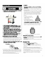 5
5
-
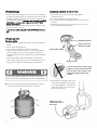 6
6
-
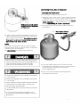 7
7
-
 8
8
-
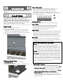 9
9
-
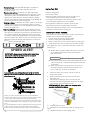 10
10
-
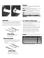 11
11
-
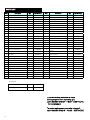 12
12
-
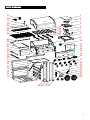 13
13
-
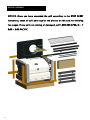 14
14
-
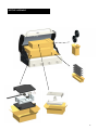 15
15
-
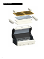 16
16
-
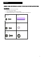 17
17
-
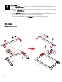 18
18
-
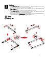 19
19
-
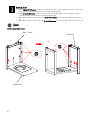 20
20
-
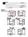 21
21
-
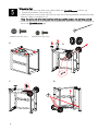 22
22
-
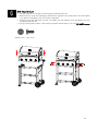 23
23
-
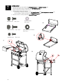 24
24
-
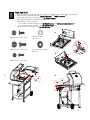 25
25
-
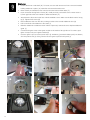 26
26
-
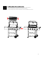 27
27
-
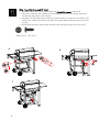 28
28
-
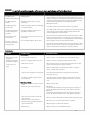 29
29
-
 30
30
-
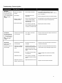 31
31
-
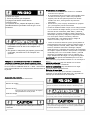 32
32
-
 33
33
-
 34
34
-
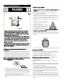 35
35
-
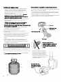 36
36
-
 37
37
-
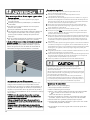 38
38
-
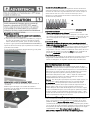 39
39
-
 40
40
-
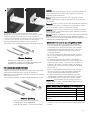 41
41
-
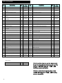 42
42
-
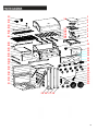 43
43
-
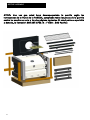 44
44
-
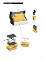 45
45
-
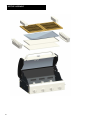 46
46
-
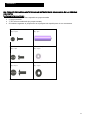 47
47
-
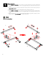 48
48
-
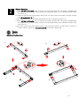 49
49
-
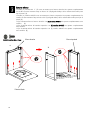 50
50
-
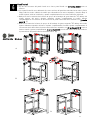 51
51
-
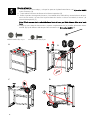 52
52
-
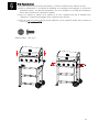 53
53
-
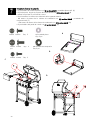 54
54
-
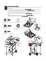 55
55
-
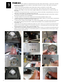 56
56
-
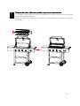 57
57
-
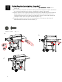 58
58
-
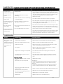 59
59
-
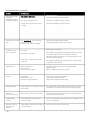 60
60
-
 61
61


Kenmore PG-40406S0L El manual del propietario
- Categoría
- Barbacoas
- Tipo
- El manual del propietario
- Este manual también es adecuado para
en otros idiomas
- English: Kenmore PG-40406S0L Owner's manual
Artículos relacionados
-
Kenmore PG-40406S0L Manual de usuario
-
Kenmore PG-40611S0L Manual de usuario
-
-
-
-
-
-
-
-
 Kenmore Elite PG-40308OOLC-1S El manual del propietario