Infinity Drain LTD5 BA SS Guía de instalación
- Tipo
- Guía de instalación

Center Drain Series
Installation Instructions
The Center Drain Series are intended for use with the following waterproong methods:
°
Hot Mop
°
Copper Pan
°
CPE Rubber Liner (Chloraloy
®
)
°
PVC Liner
°
Lead Pan
°
Fiberglass
Dimension are subject to Manufacturers tolerance and change without notice. We can assume no responsibility for
use of superseded or void data.
Las dimensiones están sujetos a la tolerancia del fabricante y cambio sin previo aviso. No podemos asumir ninguna
responsabilidad por el uso de datos a sustituir los nulos.
Infinity Drain • 145 Dixon Avenue, Amityville, New York 11701
Phone 516.767.6786 • Fax 516.740.3066 • www.InfinityDrain.com
Made in the U.S.A.
Squares
Criss-Cross
Wedge Wire
WD 4
WD 5
LW 5
L5-2
LW5-2
LTD 5
LT5-2
LTD5-2
RTD 15
RTD 15-2
RTD 15-3
TD 15
TD 15-2
TD 15-3
TD 20
TD 20-2
TD 20-3
Moor
MD 4
MD 5
Link
KD 4
KD 5
Weave
VD 4
VD 5
Lines
ND 4
ND 5
QD 4
QD 5
XD 4
XD 5

2
Series Components:
LTD 5 Series
LT5-2 SS 5" x 5" Strainer Only with Satin Stainless Finish
LT5-2 PS 5" x 5" Strainer Only with Polished Stainless Finish
CDI 22 Clamp Down Drain Cast Iron
CDA 22 Clamp Down Drain ABS
CDP 22 Clamp Down Drain PVC
LW 5 Series
L5-2 SS 5" x 5" Strainer Only - Satin Stainless Finish
L5-2 PS 5" x 5" Strainer Only - Polished Stainless Finish
L5-2 ORB 5" x 5" Strainer Only - Lifetime Oil Rubbed Bronze Finish
CDI 22 Clamp Down Drain Cast Iron
CDA 22 Clamp Down Drain ABS
CDP 22 Clamp Down Drain PVC
RTD 15 Series
RT 15A 5" Round Tile Drain Strainer
CDI 42 4" Throat x 2" Outlet Clamp Down Drain Cast Iron
CDI 43 4" Throat x 3" Outlet Clamp Down Drain Cast Iron
CDA 42 4" Throat x 2" Outlet Clamp Down Drain ABS
CDA 43 4" Throat x 3" Outlet Clamp Down Drain ABS
CDP 42 4" Throat x 2" Outlet Clamp Down Drain PVC
CDP 43 4" Throat x 3" Outlet Clamp Down Drain PVC
TD 15 Series
T15 A SS 5" x 5" Strainer Only - Satin Stainless Finish
T15 A PS 5" x 5" Strainer Only - Polished Stainless Finish
CDI 42 4" Throat x 2" Outlet Clamp Down Drain Cast Iron
CDI 43 4" Throat x 3" Outlet Clamp Down Drain Cast Iron
CDA 42 4" Throat x 2" Outlet Clamp Down Drain ABS
CDA 43 4" Throat x 3" Outlet Clamp Down Drain ABS
CDP 42 4" Throat x 2" Outlet Clamp Down Drain PVC
CDP 43 4" Throat x 3" Outlet Clamp Down Drain PVC
TKEY Lift Out Key
HS 4 4" Hair Strainer Stainless Steel Throat
TD 20 Series
T20 A SS 8" x 8" Strainer Only - Satin Stainless Finish
T20 A PS 8" x 8" Strainer Only - Polished Stainless Finish
CDI 42 4" Throat x 2" Outlet Clamp Down Drain Cast Iron
CDI 43 4" Throat x 3" Outlet Clamp Down Drain Cast Iron
CDA 42 4" Throat x 2" Outlet Clamp Down Drain ABS
CDA 43 4" Throat x 3" Outlet Clamp Down Drain ABS
CDP 42 4" Throat x 2" Outlet Clamp Down Drain PVC
CDP 43 4" Throat x 3" Outlet Clamp Down Drain PVC
TKEY Lift Out Key
HS 4 4" Hair Strainer
Optional Components: (Not Included)
UCP 2 Universal 2" Clamping Plate
UCP 4 Universal 4" Clamping Plate
ERB Eccentric Reducing Bushing 4"x2"
Note: Installer must verify all rough-in
dimensions prior to installation and consult
local and national codes. Conformity and
compliance to local and national codes are
the responsibility of the installer.
Tenga en cuenta: Instalador debe
comprobar todas las dimensiones en las
partes previa a la instalación y consultar
localmente y nacionalmente los códigos. La
conformidad y el cumplimiento de códigos
local y nacional es responsabilidad del
instalador.

3
Section A-A
TD 15
Section A-A
RTD 15
Section A-A
TD 20
1
1
4"
3
7
8
"
3
16
"
C
2
1
2
"
6
7
16
"
SECTION 1-1
Section A-A
4” x 4” Center Drain
1
1
5"
2
1
2
"
6
7
16
"
4
7
8
"
5
8
"
3
16
"
SECTION 1-1
Section A-A
5” x 5” Center Drain
Section A-A
LW 5
Section A-A
LTD 5

4
KEY
(A) Strainer
(B) Throat
Waterproong Membrane
(C) Clamp Down Drain Assembly
CDI22/CDA22/CDP22/
CDI42/CDA42/CDP42/
CDI43/CDA43/CDP43
(C1)
(C2)
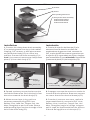
Installation
1. Connect the clamp down drain assembly
(C) to existing waste line via no-hub rubber
coupling, PVC cement, or ABS pipe cement
and allow drain body (C2) to recess into
suboor. Ensure that drain assembly (C) is
level. Unscrew and remove top clamp down
plate (C1) from drain body (C2).
Instalación
1. Conecte la sujeción del drenaje (C) a la
existente línea de desecho a través del
acoplamiento de goma no-hub, cemento de
PVC, o tubo de ABS de cemento y permita que
la sujeción (C2) a que rebaje en el piso. Asegure
que la asamblea (C) este anivelado. Destornillar
y remueva la placa (C1) de la sujeción (C2).
2. Spread a primary mortar bed across the
intended shower area. Pitch this bed in four
directions towards the drain body (C2).
2. Propagar una capa de mortero a través de
la zona de ducha prevista. Bree este mortero
en cuatro direcciones hacia el drenaje (C2).
3. When mortar layer is dry, perform
necessary waterproong (PVC Liner,
Rubber Liner, Lead Pan, Copper Pan, Hot
Mop, Fiberglass) as per local code. Ensure
waterproong layer reaches the edge of the
hole in the drain body (C2).
3. Cuando el mortero este seco, realice la
impermeabilización necesaria (PVC Liner,
Rubber Liner, Lead Pan, Cooper Pan, Hot
Mop, Fiberglass) según el código. Asegure
que la capa de impermeabilización alcance
el borde del agujero en el drenaje (C2).
(C1)
(C2)
(C) Clamp Down
Drain Assembly
Rubber
Coupling*
Waste Line
Suboor
1
(C) Clamp Down
Drain Assembly
Waterproong Membrane
Primary Motar Bed
3
*Not provided by Innity Drain kits

5
5. Using desired oor material, mark the
thickness of the material along the outside
of the throat (B), so that it will nish 1/16”
above the channel. Lay gravel or other porous
substrate over weep holes of the top clamp
down plate (C1). Spread a nal mortar bed up
to the marked thickness, less the thickness of
thinset. Pitch this bed in all directions toward
the center drain. Once dry, apply a bead
of silicone caulk around the throat (B). Lay
thinset and nishing material. Have material
nish to the edge of the throat (B). DO NOT
allow nishing material to nish on top of the
stainless steel channel edge.
5. Usando el material deseado, marque el
espesor del material a lo largo de la parte
afuera del cuello (B), para que termine
1/16” arriba del canal. Coloque grava u otro
sustrato poroso sobre los oricios de drenaje
(C1). Propagar un motero hasta el espesor
marcado, menos del espesor del thinset. Bree
esto en cuatro direcciones hacia el centro
drenaje. Una vez que este seco, aplique un
cordón de silicona alrededor de cuello (B).
Coloque thinset y material terminado al
borde superior del cuello (B). NO PERMITA
que el material terminado termine enzima del
canal de acero inoxidable.
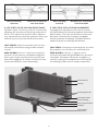
4. Reattach the top clamp down plate (C1)
to the clamp down drain body (C2) over the
waterproong layer using bolts. Thread the
throat (B) of the drain into top clamp down
plate (C1). Adjust to the desired height. Turn
clockwise to lower, counter-clockwise to
raise. When determining desired height,
include thickness of mortar, thinset and
nishing material.
4. Vuelva a colocar la parte superior de la
placa (C1) al drenaje (C2) sobre la capa de
impermeabilización usando tornillos. Rosca
el cuello (B) del drenaje en la placa del
drenaje (C1). Ajústelo a la longitud deseada.
Gire hacia la derecha para bajar, hacia la
izquierda para aumentar. Al determinar
la altura deseada, incluía el espesor del
mortero, thinset y el material terminado.
(C) Clamp Down
Drain Assembly
Waterproong
Membrane
Primary Motar Bed
(B) Throat
(C1)
(C2)
Model Overall Minimum Height Overall Maximum Height*
LTD 5 1 ⅛” 2 ¼”
RTD 15 ¹³⁄
¹⁶
” 1 ⁷⁄
¹⁶
”
TD 15 1 ⁵⁄
¹⁶
” 2 ¹⁄
¹⁶
”
TD 20 1 ⁵⁄
¹⁶
” 2 ¹⁄
¹⁶
”
WW 5 ¾” 1 ¾”
LW 5 ⁷⁄
¹⁶
” 1 ⁷⁄
¹⁶
”
Center Drain ⅝” 1 ⅝”
Center Drain - High Flow ⅝” 1 ⅝”

6
6. LTD 5/RTD 15/TD15/TD20 SERIES ONLY:
Spread a layer of mortar into the strainer (A),
allowing for thinset and nishing material to
nish 1/16” above the metal frame. Allow to
dry, spread thinset and lay material. Place top
strainer (A) into the throat (B) of the drain.
LW 5 SERIES: Place the strainer (A) into the
throat (B) and fasten using screws at each
corner.
MUD GUARD: Drill a 1” hole in the marked
location of the factory installed mudguard.
Place your nger into the hole and pull out.
Place the magnetic G-Series strainer (A) into
the throat (B) (Each sold separately)
6. LTD 5/RTD 15/TD15/TD20 SOLAMENTE:
Propagar una capa de mortero en el strainer
(A), permitiendo el thinset y material terminado
que termine 1/16” por encima de la estructura
de metal. Permita que se seque, propagar
thinset y tender el material. Coloque la parte
superior (A) en el cuello (B) del drenaje.
LW 5 SERIE: Coloque el strainer(A) en el cuello
(B) y sujetar con tornillos en cada esquina.
MUD GUARD: Perfore 1” agujero en la
locación marcada del guardabarros que está
instalado. Coloque su dedo en el agujero y
retírelo. Coloque el magnético G-serie (A) en
el cuello (B) (Cada uno se vende separado)
Primary Mortar Bed
Suboor
Clamp Down
Floor Drain
Waterproong
Final Mortar Bed
Finishing Material
Backer Board
Thinset
Before nishing
material
Antes que el material
esté terminado
After nishing
material
Después que el material
esté terminado
-
 1
1
-
 2
2
-
 3
3
-
 4
4
-
 5
5
-
 6
6


Infinity Drain LTD5 BA SS Guía de instalación
- Tipo
- Guía de instalación
en otros idiomas
Artículos relacionados
-
Infinity Drain STIF AS 6540 SS Guía de instalación
-
Infinity Drain S-LAG 6536 BK Guía de instalación
-
Infinity Drain D 3860 SS Instrucciones de operación
-
Infinity Drain XS 4 ORB Instrucciones de operación
-
Infinity Drain FXSG 6548 SS Guía de instalación
-
Infinity Drain UTIF-A 36 SS Guía de instalación
-
Infinity Drain FFAS 6536 SS Guía de instalación
-
Infinity Drain FFDG Instrucciones de operación