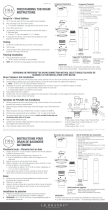
Infinity Drain STIF AS 6540 SS Guía de instalación
- Tipo
- Guía de instalación

Stainless Steel Channel
Site Sizable Series
Installation Instructions
The Site Sizeable Series intended for use with traditional waterproong methods:
°
Hot Mop
°
Copper Pan
°
Rubber Liner (Chloraloy®)
°
PVC Liner
°
Lead Pan
°
Fiberglass
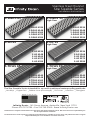
S-TIFAS 9940
S-TIFAS 9948
S-TIFAS 9960
S-TIFAS 9980
S-TIFAS 9996
S-TIFAS 99
High Flow
S-DGAS 6536
S-DGAS 6548
S-DGAS 6560
S-DGAS 6572
S-DGAS 6596
S-DGAS 65
S-TIFAS 6540
S-TIFAS 6548
S-TIFAS 6560
S-TIFAS 6580
S-TIFAS 6596
S-TIFAS 65
S-DGAS 9936
S-DGAS 9948
S-DGAS 9960
S-DGAS 9972
S-DGAS 9996
S-DGAS 99
High Flow
S-AS 9936
S-AS 9948
S-AS 9960
S-AS 9972
S-AS 9996
S-AS 99
High Flow
S-AS 6536
S-AS 6548
S-AS 6560
S-AS 6572
S-AS 6596
S-AS 65
Infinity Drain • 145 Dixon Avenue, Amityville, New York 11701
Phone 516.767.6786 • Fax 516.740.3066 • www.InfinityDrain.com
Dimension are subject to Manufacturers tolerance and change without notice. We can assume no responsibility for
use of superseded or void data.
Las dimensiones están sujetos a la tolerancia del fabricante y cambio sin previo aviso. No podemos asumir ninguna
responsabilidad por el uso de datos a sustituir los nulos.
Made in the U.S.A.

2
Series Components:
Note: Installer must verify all
rough-in dimensions prior to
installation and consult local
and national codes. Confor-
mity and compliance to local
and national codes are the
responsibility of the installer.
Tenga en cuenta: Instalador
debe comprobar todas las
dimensiones en las partes pre-
via a la instalación y consultar
localmente y nacionalmente
los códigos. La conformidad
y el cumplimiento de códigos
local y nacional es responsabi-
lidad del instalador.
*Not provided by Innity Drain kits
S-AS 65 Series
SA 6536 36″ SS Grate
SA 6548 48″ SS Grate
SA 6560 60″ SS Grate
LC 6528 28″ SS Closed Ended Channel
LC 6540 40″ SS Closed Ended Channel
LC 6552 52″ SS Closed Ended Channel
LC 6564 64″ SS Closed Ended Channel
LC 6588 88″ SS Closed Ended Channel
LF 65 8″ SS Outlet Section
GJS 65 SS Joiner Strip
TNAS SS Threaded Nipple
ZSIKA Sikaflex 1a Construction Sealant
HS 2 2" Hair Strainer
S-AS 99 Series
SA 6536 36″ SS Grate
SA 6548 48″ SS Grate
SA 6560 60″ SS Grate
LC 6528 28″ SS Closed Ended Channel
LC 6540 40″ SS Closed Ended Channel
LC 6552 52″ SS Closed Ended Channel
LC 6564 64″ SS Closed Ended Channel
LC 6588 88″ SS Closed Ended Channel
LF 99 8″ SS Outlet Section
GJS 65 SS Joiner Strip
ZSIKA Sikaflex 1a Construction Sealant
CDI43W Cast Iron Drain Body
HS 2 2" Hair Strainer
S-DGAS 65 Series
DA 6536 36″ SS Grate
DA 6548 48″ SS Grate
DA 6560 60″ SS Grate
LC 6528 28″ SS Closed Ended Channel
LC 6540 40″ SS Closed Ended Channel
LC 6552 52″ SS Closed Ended Channel
LC 6564 64″ SS Closed Ended Channel
LC 6588 88″ SS Closed Ended Channel
LF 65 8″ SS Outlet Section
GJS 65 SS Joiner Strip
TNAS SS Threaded Nipple
ZSIKA Sikaflex 1a Construction Sealant
HS 2 2" Hair Strainer
S-DGAS 99 Series
DA 6536 36″ SS Grate
DA 6548 48″ SS Grate
DA 6560 60″ SS Grate
LC 6528 28″ SS Closed Ended Channel
LC 6540 40″ SS Closed Ended Channel
LC 6552 52″ SS Closed Ended Channel
LC 6564 64″ SS Closed Ended Channel
LC 6588 88″ SS Closed Ended Channel
LF 99 8″ SS Outlet Section
GJS 65 SS Joiner Strip
ZSIKA Sikaflex 1a Construction Sealant
CDI43W Cast Iron Drain Body
HS 2 2" Hair Strainer
S-TIFAS 65 Series
TA 6540 40″ SS Grate
TA 6548 48″ SS Grate
TA 6560 60″ SS Grate
HC 6532 32″ SS Closed Ended Channel
HC 6540 40″ SS Closed Ended Channel
HC 6552 52″ SS Closed Ended Channel
HC 6572 72″ SS Closed Ended Channel
HC 6588 88″ SS Closed Ended Channel
HF 65 8" SS Outlet Section
TJS 65 SS Joiner Strip
TNAS SS Threaded Nipple
HS 2 2" Hair Strainer
TIF PL TIF Plates
TKEY Lift Out Key
ZSIKA Sikaflex 1a Construction Sealant
S-TIFAS 99 Series
TA 6540 40″ SS Grate
TA 6548 48″ SS Grate
TA 6560 60″ SS Grate
HC 6532 32″ SS Closed Ended Channel
HC 6540 40″ SS Closed Ended Channel
HC 6552 52″ SS Closed Ended Channel
HC 6572 72″ SS Closed Ended Channel
HC 6588 88″ SS Closed Ended Channel
HF 99 8″ SS Outlet Section
TJS 65 SS Joiner Strip
TIF PL TIF Plates
TKEY Lift Out Key
ZSIKA Sikaflex 1a Construction Sealant
CDI43W Cast Iron Drain Body
SS = Stainless Steel
(A) Top Grate –
SA65/DA65/TA65
(B) Stainless Steel Channel –
LC65/HC65
(C) Outlet Section –
LF65/HF65/LF99/HF99
(D) Joiner Strips - GJS65/TJS65
(E) Threaded Nipple - TNAS
Weep Holes
Waterproong Membrane
(F) 2” Throat Clamp Down
Drain Body* (Two Pieces)
4” Throat Clamp Down
Drain Body for S-AS99/
S-DGAS99/S-TIFAS99
(F1)
(F2)
KEY

3
S-DGAS65/S-AS65/S-TIFAS65 kits: DO NOT
include the mechanically fastening clamp down
drain due to the variance of material by local
code. This is a residential drain that is available
through Innity Drain or your local plumbing
supply from various manufacturers (i.e. Oatey®,
Sioux Chief™, JSC™, PROFLO™, Matco-Norca™).
S-DGAS99/S-AS99/S-TIFAS99 kits are
provided with a (CDI43W) Cast Iron
mechanically fastening clamp down drain
body. This item can be substituted for an ABS
or PVC drain body (CDA 43/CDP 43).
S-DGAS65/S-AS65/S-TIFAS65 kits: NO
INCLUYE la sujeción mecánica del drenaje
por la razón que varía el material de código
local. Este drenaje es residencial que está
disponible a través de Innity Drain o su
local suministro de plomería de diversos
fabricantes. (i.e. Oatey®, Sioux Chief™, JSC™,
PROFLO™, Matco-Norca™).
S-DGAS99/S-AS99/S-TIFAS99 kits son proveído
con (CDI 43 W) drenaje en hierro fundido. Este
artículo puede ser sustituto en ABS en plástico, o
PVC. (CDA 42/CDP 42/CDA 43/CDP 43).
Available Clamp Down Drains:
CDI 22 Clamp Down Drain Cast Iron
CDA 42 Clamp Down Drain, ABS,
4” Throat, 2’ No Hub Outlet
CDP 22 Clamp Down Drain PVC
CDI 43 Clamp Down Drain, Cast Iron,
4” Throat, 3” No Hub Outlet
CDA 22 Clamp Down Drain ABS
CDP 43 Clamp Down Drain, PVC,
4” Throat, 3” No Hub Outlet
CDI 42 Clamp Down Drain, Cast Iron,
4” Throat, 2” No Hub Outlet
CDA 43 Clamp Down Drain, ABS,
4” Throat, 3” No Hub Outlet
CDP 42 Clamp Down Drain, PVC,
4” Throat, 2” No Hub Outlet
CDI43W Clamp Down Drain,
Cast Iron with threaded ring
Optional Components: (Not Included)
SLA 65 Stainless Steel 90° Angle
Joiner for LC/SC Channel
ERB Eccentric Reducer
Bushing 4”x2”
SE 65 2” Stainless Steel
End Section
TNRN Stainless Steel Threaded
Nipple Extension
TE 65 2” Stainless Steel
End Section
SC 6548 48" Stainless Open
Ended Channel
UCP 2 Universal 2” Clamping Plate
TC 6548 48" Stainless Open
Ended Channel
SC 6596 96" Stainless Open
Ended Channel
UCP 4 Universal 4” Clamping Plate
TC 6596 96" Stainless Open
Ended Channel
SHA 65 Stainless Steel 90° Joiner
for HC/TC Channel
2” clamp down drain
not included in kit
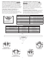
Section A-A
S-TIFAS 65
Section A-A
S-DGAS 65, S-AS 65
Section A-A
S-DGAS 99, S-AS 99
Section A-A
S-TIFAS 99
1"
2⅞"
1³⁄
¹⁶
"
2½"
6½"
2"
1"
2⅞"
1⁷⁄
¹⁶
"
4¹⁄
¹⁶
"
8"
3"
1⅝"
2⅞"
2"
1¹¹⁄
¹⁶
"
2½"
6½"
2"
¾"
1⅝"
2⅞"
2"
2"
4"
8"
3"
¾"

4
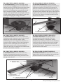
OPTIONAL PROCEDURE:
When drain install is required to be ush
against the nished wall, build out wall with
backer board over round clamp down drain
body (F) to compensate for the drain radius.
PROCEDIMIENTO OPCIONAL:
Cuando el drenaje sea instalado, se requiere
que esté completamente a la pared,
construir la pared con múltiples de placas
de cemento sobre el redondo drenaje (F)
para compensar el radial del drenaje.
2. If clamp down drain body (F) is not
installed. Attach (F) to existing waste line
and allow drain to recess into suboor.
Ensure that drain body (F) is level.
Unscrew and remove top clamp down plate
from drain body
3. Spread a primary mortar bed across the
intended shower area. Pitch this bed in four
directions towards the drain body (F).
4. When mortar layer is dry, perform
necessary waterproong (PVC Liner, CPE
Rubber Liner/Chloraloy™, Lead Pan, Copper
Pan, Hot Mop, Fiberglass) as per local code.
Ensure waterproong layer reaches the edge
of the hole in the drain body (F).
5. Calculate desired nished wall to wall
length, keeping in mind wall tile thickness
and 8”± ¼” for the outlet section (C). When
utilizing full assembly length: using a band
saw, shop saw, or a hack saw with a 32
tooth blade, cut the channel along its length
where the outlet section (C) is to be placed.
When using less than full assembly length,
remove equal amounts (half of total excess
to be removed) from each open end of
channel (B1). Gently le back rough edges.
(i.e. If 6 inches of total excess channel length
is to be removed. Remove 3 inches from
each open end of channel).
2. Si el drenaje (F) no está instalado.
Adjuntar el drenaje (F) a la línea de residuos
existentes y permite el drenaje a que recese
en el piso. Asegura, que el drenaje (F) este
nivelado. Destornilla y remueve la placa de
sujeción de arriba.
3. Esparcir una primaria de capa de mortero
a través del destino o zona del baño. Lanzar
la capa de mortero en cuatro direcciones
hacia el drenaje (F).
4. Cuando la capa de mortero este seca,
realice la impermeabilización necesaria
(Forro del PVC, cobre, panal de vidrio)
según el código local. Asegura que la capa
de impermeabilización alcance al borde del
agujero en el drenaje (F).
5. Calcular deseada terminación de pared a
pared, teniendo en cuenta que el espesor de
la pared 8”± ¼” para la sección de salida (C).
Cuando utilice la longitud del ensamblaje
complete: usando una sierra de cinta, arco de
sierra, con 32 por pulgada de cuchilla, corte el
canal a lo largo de donde necesita la sección
de salida (C) ser colocado. Cuando se utiliza
el uso de menos de la longitud, eliminé
cantidad iguales (Mitad del exceso total que
se retira) en cada parte nal del canal (B1).
Suavemente lime de nuevo en las orillas.
(i.e. Si 6 pulgadas en total exceso tiene que ser
eliminado. Elimine 3 pulgadas de cada parte
abierta en el canal, (B1).
Installation
1. Determine the location of the drain outlet
location. Typically linear drains should span a
dimension from wall to wall, against a wall or
at a shower entrance.
Instalación
1. Determine la ubicación del emplazamiento
del drenaje. Típicamente el drenaje lineal
atraviesa una dimensión de pared a pared,
contra la pared, o en una entrada de un baño.
OPTIONAL PROCEDURE / PROCEDIMIENTO OPCIONAL
Waterproong
Membrane
D
ouble Layer Backer
Board
(F) 2” Throat Clamp Down Drain Body*
(Two Pieces)
(F1)
(F2)

5
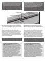
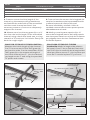
6. Clean all parts using denatured alcohol.
On a at surface, place each cut end of the
stainless channel ush against each end
of the outlet section (C). Using provided
Sikaex 1a construction sealant place the
joiner strips (D) from the underside of
the seam to join the channel pieces to the
outlet section (C). Remove any Sikaex
spillover with a clean cloth dampened with
denatured alcohol. Allow to dry at least 8
hours before handling.
6. Limpie todas las partes usando alcohol
desnaturalizado. Sobre una supercie plana,
coloque cada parte nal del canal de acero ras
contra cada lado nal de la sección de salida
(C). Usando Sikaex sellador de construcción
que es incluido, coloque la tiras/joiner strips
(D) desde la parte inferior del cordón para
unirse a la piezas del canal a la sección de
salida (C). Elimine cualquier desbordamiento
de Sikaex con un paño limpio humedecido
con alcohol desnaturalizado. Permitir que se
seque durante la noche antes de manejarlo.
Note: (1) Length indicated on kits are total
lengths. 8” outlet section and full stainless
channel lengths combine to create a total
length that is specied in kit description.
(2) 96”, 72”, and 80” kits include enough
stainless steel channel to allow use of ONE
outlet. (This is not recommended)
TENGA EN CUENTA: (1) Total longitud
indicada en el ensamblaje son 8” sección de
salida y la longitud del canal de acero crea
una combinación de longitud total que es
especicado en la descripción del kit.
(2) 96”, 80”, and 72” kits inclyen suciente
canal de acero para permitir el uso de una
sección/outlet. (Esto no es recomendable)
Note: Sikaex construction sealant
continues to cure for 7 days.
TENGA EN CUENTA: Sikaex sellador de
construcción requiere 7 días para curación
completa.
7a. ONLY FOR S-AS65/S-DGAS65/S-
TIFAS 65 Install: Reattach the top clamp
down plate (F1) to the drain body over the
waterproong layer using bolts. Screw
threaded nipple (E) into top clamp down
plate (F1) of the drain body. Adjust to the
desired height to allow assembly to end
1/16” below the intended nished tile
height. Turn clockwise to lower, counter-
clockwise to raise. (Combined height of
threaded nipple (E) and stainless steel
channel assembly (B,C,&D) must be 1/16” less
than the combined height of mortar, thinset,
AND tile/oor material).
7a. SOLO PARA S-AS65/S-DGAS65/S-
TIFAS 65 Instalación: Reconecte la placa
de sujeción de arriba del drenaje (D2) sobre
las capas de impermeabilización utilizando
tornillo. Enrosque el niple roscado (E) adentro
de la placa del drenaje. Ajustar la altura
deseada para permitir la pieza que termine
1/16” debajo del acabado destino. Gire hacia
la derecha para bajar, hacia la izquierda para
aumentar. (La altura combinada del (niple
roscado (E) y la pieza del canal de acero (B, C, &
D) debe ser 1/16” menos de la combinación de
la altura de mortero, thinset, material de tile/
material de suelo de baldosas.)
(B) Stainless Steel
Channel – LC65/HC65
(B1) Open End of Channel
Sikaex Construction
Sealant
(D) Joiner Strips
GJS65/TJS65
(C) Outlet Section
LF65/HF65/LF99/HF99

6
7b. SOLO PARA S-AS99/S-DGAS99/
S-TIFAS99 Instalación: Rosca la parte
superior de la place del drenaje solamente
a la parte suelta (LF99/HF99) y ajuste la
placa a la altura deseada para permitir la
sección de salida que termine 1/16” debajo
del destinado material de altura. Reconecte
la placa de sujeción de arriba del drenaje
(F) sobre las capas de impermeabilización
utilizando tornillo.
7b. ONLY FOR S-AS99/S-DGAS99/
S-TIFAS99 Install: Thread the top clamp
down plate (F1) only on to the detached
outlet section (LF99/HF99) and adjust plate
to desired height to allow outlet section
to end 1/16” below the intended nished
oor material height. Reattach the top
clamp down plate and assembled channel
to the clamp down drain body (F) over the
waterproong layer using the bolts.
8a. ONLY FOR S-AS65/S-DGAS65/
S-TIFAS65 Install: Test t the combined
stainless steel channel onto the threaded
nipple (E) and conrm height. After
conrming correct height use Sikaex 1a
construction sealant to join the threaded
nipple to the underside of the outlet in
the outlet section (C) of the assembled
channel. Be sure to support the underside
of the assembled channel.
8a. SOLO PARA S-AS65/S-DGAS65/S-
TIFAS65 Instalación: Pruebe y ajuste
la combinación del canal de acero en
el niple roscado (E) Y conrmar altura.
Después de conrmar la altura use Sikaex
construcción de sellador para unir la niple
roscado a parte inferior de la sección de
salida (C) del canal. Asegúrese a soportar la
parte inferior del canal.
8b. ONLY FOR S-AS99/S-DGAS99/
S-TIFAS99 Install: Conrm the correct
height of assembled outlet section and
channel that was previously joined to the
clamp down drain.
8b. SOLO PARA S-AS99/S-DGAS99/S-
TIFAS99 Instalación: Conrmar la correcta
altura de la sección de salida y del canal que
anteriormente fue unida al drenaje.
(F) Clamp Down Drain Body*
(Two Pieces)
Waterproong
Membrane
Mortar Bed
Suboor
(F1)
(F2)
7a
(E) Threaded
Nipple - TNAS
(F2)
(C) Outlet Section
(B) Stainless Steel Channel
(F) 4” Throat Clamp Down
Drain Body* (Two Pieces)
(F1)
7b
(F) 2” Throat Clamp Down
Drain Body* (Two Pieces)
Waterproong
Membrane
Mortar Bed
Suboor
(F1)
(F2)
(B) Stainless Steel
Channel – LC65/HC65
Shims
(C) Outlet Section
LF65/LF99/HF65/HF99
*Not provided by Innity Drain kits

7
10. Measure and cut the top grate (A) to a ⅛”
less than the inside length of the assembled
channel using a hack saw, band saw, or shop
saw with a 32 tooth per inch blade. Gently le
back the rough edges.
9. Create a mortar bed the length of the
channel on the waterproong membrane
and backll the underside of the assembled
stainless steel channel and level. Use
necessary amount of mortar to adequately
support the channel.
9. Crear un base de mortero de la longitud del
canal en la membrana de impermeabilización
y rellene la parte de inferior del canal
de acero inoxidable y nivélelo. Utilice la
cantidad necesaria de mortero para soportar
adecuadamente el canal.
10. Medir y cortar la parte superior (A) a ⅛”
menos de la longitud interior del canal usando
una sierra para metal con un hoja de 32 dientes
por pulgada, sierra de cinta. Suavemente lima
los bordes ásperos.
ONLY FOR S-TIFAS65/S-TIFAS99 INSTALL:
Measure the inside length of the channel.
Cut 5” from one end of the TA65 grate (A)
and set this aside. Cut the remainder of the
TA65 grate (A) to the measured length of
the inside channel less 5”. Join the desired
cut length to the 5” end using the provided
TIF plates and screws.
SOLO PARA S-TIFAS65/S-TIFAS99
Instalación: Medir la longitud de adentro
del canal. Corte 5” de un lado del nal de la
reja TA 65 (A) a la medición de la longitud del
canal por dentro menos 5”. Unir la parte que
corto de 5” usando la placa TIF y enrosca.
Note:
Model Overall Minimum Height Overall Maximum Height
S-DGAS 65/S-AS 65 1 3⁄16” 2 3⁄16”
S-DGAS 99/S-AS 99 1 7⁄ 16” 2 7⁄ 16”
S-TIFAS 65 1 11⁄16” 2 11⁄16”
S-TIFAS 99 2” 3”
32 Tooth per Inch
Blade Hacksaw
(A) Tile Insert
Frame – TA65
5 Inches
1
(A) Tile Insert Frame – TA65
TIF Plates
3
TIF Screws
32 Tooth per Inch
Blade Hacksaw
(A) Tile Insert Frame – TA65
Desired Length
2
(A) Tile Insert Frame – TA65
5 Inches
4
TIF Plates
TIF Screws

8
12. ONLY FOR S-TIFAS 65 INSTALL:
Spread a layer of mortar into the Tile
Insert Frame (TA65), allowing for thinset
and material to finish 1/16” above the
metal frame. Allow to dry, spread thinset
and finishing material.
12. SOLO PARA S-TIFAS 65 INSTALACION:
Extender una capa de mortero en Tile
Insert Frame (TA65), permitiendo el thinset
y material que termine 1/16” arriba del
marco de metal. Permita que se seque,
extienda thinset y material terminado.
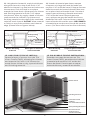
11. Using desired material, mark the thickness
along the channel so that it will nish 1/16”
above the channel. Lay nal mortar bed across
the wet area. Pitch this bed in one plane
toward the linear drain. Allow space for thinset
and nishing material to nish 1/16” above
the channel. After dry, apply a bead of silicone
caulk around the channel. Lay thinset and
nishing material to the edge of the combined
stainless steel channel. DO NOT allow material
to nish on top of the stainless steel channel
edge. (Please refer to gures below)
11. Usando el material que desea, marque
el espesor a lo largo del canal de modo que
termine 1/16” arriba del canal. Coloque mortero
denitivo través de la zona húmeda. Brea esto
en un plano hacia el drenaje lineal. Permita el
espacio para el thinset y material terminado
1/16” arriba del canal. Después que este
seco, aplique una gota de masilla de silicona
alrededor del canal. Colocar thinset y material
hasta el borde del canal de acero. NO PERMITA
el material que termine en el borde del canal de
acero. (Por favor referirse a las cifras inferiores)
Waterproong Membrane
Stainless Steel
Channel Assembly
Final Mortar Bed
Threaded Outlet
Pre-Pitched Mortar Bed
Suboor
Finishing Material
Backer Board
Caulking
Mortar Bed
Mortar Bed
Sub-oor
Waterproong
Membrane
Finishing Material
Assure that grate is lower
than installed tile
Mortar Bed
Mortar Bed
Sub-oor
Waterproong
Membrane
Before nishing
material
Antes que el material
esté terminado
After nishing
material
Después que el material
esté terminado
-
 1
1
-
 2
2
-
 3
3
-
 4
4
-
 5
5
-
 6
6
-
 7
7
-
 8
8


Infinity Drain STIF AS 6540 SS Guía de instalación
- Tipo
- Guía de instalación
en otros idiomas
Artículos relacionados
-
Infinity Drain FXSG 6548 SS Guía de instalación
-
Infinity Drain LTD5 BA SS Guía de instalación
-
Infinity Drain S-LAG 6536 BK Guía de instalación
-
Infinity Drain D 3860 SS Instrucciones de operación
-
Infinity Drain UTIF-A 36 SS Guía de instalación
-
Infinity Drain FFDG Instrucciones de operación
-
Infinity Drain T 42-SS Instrucciones de operación
-
Otros documentos
-
Oatey 33533 Instrucciones de operación
-
-
Sika 90959 Guía de instalación
-
 Sikaflex 90959 Guía de instalación
-
 PACE supply FTD5135 Instrucciones de operación
-
 Sikaflex 106711 Guía de instalación
-
Sika 91065 Guía de instalación
-
Oatey DLS2400 Guía de instalación
-
wedi US3000002 Especificación
-
 Mark E Industries 669555004019 Guía del usuario


