Infinity Drain UTIF-A 36 SS Guía de instalación
- Tipo
- Guía de instalación

Universal Innity Drain
USQ | U-TIF
Installation Guide
®
SCAN TO WATCH
INSTALLATION VIDEOS ONLINE
youtube.com/IDInfinityDrain

2
2
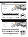
KEY
(A) Top Grate –
A38/D38/A65/TA65/A100
(B) PVC Channel –
G38/G65/G100
(C) Stop End – E38/E65/E100
(D) Outlet Section – S32/S65
(Not Applicable for AG100)
(E) Threaded Nipple - S50
(F65 – non-threaded
nipple, for no-hub
installation)
Weep Holes
Waterproong Membrane
(F) 2” Throat Clamp Down
Drain Body*
(Two Pieces)
(F1)
(F2)
S-AG 38 Series
A 3836 36″StainlessSteelGrate
A 3848 48″StainlessSteelGrate
A 3860 60″StainlessSteelGrate
G 3836 36″PVCChannel
G 3848 48″PVCChannel
G 3860 60″PVCChannel
G 3896 96″PVCChannel
E 38 PVC Stop End
S 32 PVC Outlet Section
S 50 PVC Threaded Outlet
S-DG 65 Series
D 6548 48″StainlessSteelGrate
D 6560 60″StainlessSteelGrate
G 6548 48″PVCChannel
G 6560 60″PVCChannel
G 6596 96″PVCChannel
E 65 PVC Stop End
S 50 PVC Threaded Outlet
S 65 PVC Outlet Section
S-AG 100 Series
A 1004848″StainlessSteelGrate
G 1004848″PVCChannel
G 1009696″PVCChannel
E 100 PVC Stop End
S 50 PVC Threaded Outlet
S-DG 38 Series
D 3848 48″StainlessSteelGrate
D 3860 60″StainlessSteelGrate
G 3848 48″PVCChannel
G 3860 60″PVCChannel
G 3896 96″PVCChannel
E 38 PVC Stop End
S 32 PVC Outlet Section
S 50 PVC Threaded Outlet
S-AG 65 Series
A 6536 36″StainlessSteelGrate
A 6548 48″StainlessSteelGrate
A 6560 60″StainlessSteelGrate
G 6536 36″PVCChannel
G 6548 48″PVCChannel
G 6560 60″PVCChannel
G 6596 96″PVCChannel
E 65 PVC Stop End
S 50 PVC Threaded Outlet
S 65 PVC Outlet Section
S-TIF 65 Series
TA 654040″StainlessSteelGrate
TA 654848″StainlessSteelGrate
TA 656060″StainlessSteelGrate
G 6540 40″PVCChannel
G 6548 48″PVCChannel
G 6560 60″PVCChannel
G 6580 80″PVCChannel
G 6596 96″PVCChannel
E 65 PVC Stop End
S 50 PVC Threaded Nipple
TIF PL TIF Plates
TKEY Lift Out Key
S 65 PVC Outlet Section
Series Components:
Note: Installer must verify
all rough-in dimensions
prior to installation and
consult local and national
codes. Conformity and com-
pliance to local and national
codes are the responsibility
of the installer.
Tenga en cuenta: Instala-
dor debe comprobar todas
las dimensiones en las par-
tes previa a la instalación
y consultar localmente y
nacionalmente los códigos.
La conformidad y el cum-
plimiento de códigos local
y nacional es responsabili-
dad del instalador.
*Not provided by Innity Drain kits
2
KEY
(A) Top Grate –
A38/D38/A65/TA65/A100
(B) PVC Channel –
G38/G65/G100
(C) Stop End – E38/E65/E100
(D) Outlet Section – S32/S65
(Not Applicable for AG100)
(E) Threaded Nipple - S50
(F65 – non-threaded
nipple, for no-hub
installation)
Weep Holes
Waterproong Membrane
(F) 2” Throat Clamp Down
Drain Body*
(Two Pieces)
(F1)
(F2)
S-AG 38 Series
A 3836 36″StainlessSteelGrate
A 3848 48″StainlessSteelGrate
A 3860 60″StainlessSteelGrate
G 3836 36″PVCChannel
G 3848 48″PVCChannel
G 3860 60″PVCChannel
G 3896 96″PVCChannel
E 38 PVC Stop End
S 32 PVC Outlet Section
S 50 PVC Threaded Outlet
S-DG 65 Series
D 6548 48″StainlessSteelGrate
D 6560 60″StainlessSteelGrate
G 6548 48″PVCChannel
G 6560 60″PVCChannel
G 6596 96″PVCChannel
E 65 PVC Stop End
S 50 PVC Threaded Outlet
S 65 PVC Outlet Section
S-AG 100 Series
A 1004848″StainlessSteelGrate
G 1004848″PVCChannel
G 1009696″PVCChannel
E 100 PVC Stop End
S 50 PVC Threaded Outlet
S-DG 38 Series
D 3848 48″StainlessSteelGrate
D 3860 60″StainlessSteelGrate
G 3848 48″PVCChannel
G 3860 60″PVCChannel
G 3896 96″PVCChannel
E 38 PVC Stop End
S 32 PVC Outlet Section
S 50 PVC Threaded Outlet
S-AG 65 Series
A 6536 36″StainlessSteelGrate
A 6548 48″StainlessSteelGrate
A 6560 60″StainlessSteelGrate
G 6536 36″PVCChannel
G 6548 48″PVCChannel
G 6560 60″PVCChannel
G 6596 96″PVCChannel
E 65 PVC Stop End
S 50 PVC Threaded Outlet
S 65 PVC Outlet Section
S-TIF 65 Series
TA 654040″StainlessSteelGrate
TA 654848″StainlessSteelGrate
TA 656060″StainlessSteelGrate
G 6540 40″PVCChannel
G 6548 48″PVCChannel
G 6560 60″PVCChannel
G 6580 80″PVCChannel
G 6596 96″PVCChannel
E 65 PVC Stop End
S 50 PVC Threaded Nipple
TIF PL TIF Plates
TKEY Lift Out Key
S 65 PVC Outlet Section
Series Components:
Note: Installer must verify
all rough-in dimensions
prior to installation and
consult local and national
codes. Conformity and com-
pliance to local and national
codes are the responsibility
of the installer.
Tenga en cuenta:
Instala-
dor debe comprobar todas
las dimensiones en las par-
tes previa a la instalación
y consultar localmente y
nacionalmente los códigos.
La conformidad y el cum-
plimiento de códigos local
y nacional es responsabili-
dad del instalador.
*Not provided by Innity Drain kits
INSTALLATION INSTRUCTIONS (Instalación)
Dimension are subject to Manufacturers tolerance and change without notice. We
can assume no responsibility for use of superseded or void data.
Las dimensiones están sujetos a la tolerancia del fabricante y cambio sin previo
aviso. No podemos asumir ninguna responsabilidad por el uso de datos a sustituir
los nulos.
®
Page 2 of 3
Innity Drain
145 Dixon Avenue
Amityville, NY 11701
Phone: 516.767.6786
Fax: 516.740.3066
www.innitydrain.com
NOTE: Installer must verify all rough-in
dimensions prior to installation and consult
local and national codes. Conformity and com-
pliance to local and national codes are the
responsibility of the installer.
Model
Number
Complete Kit Contents
A
(Maximum Overall Length)
B
(Maximum Grate Length)
USQ 24-A
USQ 24-P
1 - QA 6524 Perforated Squares Pattern Grate
1 - UC 24 Channel
2 - CC 24 Clamping Collars
1 - HS 2 Hair Strainer
1 - AKEY Lift Out Key
27” 23 7/8”
USQ 30-A
USQ 30-P
1 - QA 6530 Perforated Squares Pattern Grate
1 - UC 30 Channel
2 - CC 30 Clamping Collars
1 - HS 2 Hair Strainer
1 - AKEY Lift Out Key
33” 29 7/8”
USQ 32-A
USQ 32-P
1 - QA 6532 Perforated Squares Pattern Grate
1 - UC 32 Channel
2 - CC 32 Clamping Collars
1 - HS 2 Hair Strainer
1 - AKEY Lift Out Key
35” 31 7/8”
USQ 36-A
USQ 36-P
1 - QA 6536 Perforated Squares Pattern Grate
1 - UC 36 Channel
2 - CC 36 Clamping Collars
1 - HS 2 Hair Strainer
1 - AKEY Lift Out Key
39” 35 7/8”
Dimensions are subject to manufacturer’s tolerance and change without notice. We can assume no responsibility for use of superceded or void data.
FM550-05-20
A
B
1
1
SECTION 1-1
QA 65
PERFORATED SQUARE PATTERN GRATE
UNIVERSAL CHANNEL
STAINLESS STEEL
CLAMPING COLLAR
#10-32 STAINLESS
STEEL SCREWS
HS2
HAIR STRAINER
1/4"-20 STAINLESS STEEL
LEVELING SCREW
B
B
3
1
16
"
2
5
16
"
2
3
4
"
13
16
"
1
2
"
1
4
"
7
16
"
5
1
2
"
2
7
16
"
SECTION 1-1
SECTION 1-1
A
B
1
1
SECTION 1-1
QA 65 PERFORATED SQUARE PATTERN GRATE
UNIVERSAL CHANNEL
STAINLESS STEEL
CLAMPING COLLAR
#10-32 STAINLESS
STEEL SCREWS
HS2
HAIR STRAINER
1/4"-20 STAINLESS STEEL
LEVELING SCREW
□
□
□
□
A
B
1
1
SECTION 1-1
QA 65
PERFORATED SQUARE PATTERN GRATE
UNIVERSAL CHANNEL
STAINLESS STEEL
CLAMPING COLLAR
#10-32 STAINLESS
STEEL SCREWS
HS2
HAIR STRAINER
1/4"-20 STAINLESS STEEL
LEVELING SCREW
Channel Material Options:
▪ A = ABS
▪
P = PVC
Finishes
□ Satin Stainless □ Polished Stainless

3
INSTALLATION INSTRUCTIONS (Instalación)
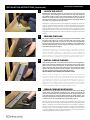
Waterproong
Waterproong technique will determine how you will install the linear drain. If using a traditional type of waterproong, the professional will
typically build a shower pan (wet waterproofed area) with PVC, Vinyl, or Noble Chlo material, follow the instructions shown on pages 4 to 7.
If using a bonded type of waterproong such as liquid membrane or fabric sheet, follow the instructions shown on pages 8 to 11.
USING LIQUID/FABRIC WATERPROOFING (BONDED): Instructions shown on pages 8-11
USING TRADITIONAL WATERPROOFING: Instructions shown on pages 4-7
Liquid
Roll or paint-on liquid
membrane that can be
applied on oors, walls,
and ceilings and bonds
directly to the drain
ange. The total install
time is shorter than
traditional waterproong
methods and typically
saves 2 to 3 days.
PVC Membrane/Vinyl Liner
(Polyvinyl Chloride)
A plastic sheet available at
most plumbing suppliers and
sold in rolls of 4’, 5’ and 6’. The
membrane is layered between
mortar beds and the corners
are folded to create the
shower pan liner.
Fabric Sheet
Sheet membrane that bonds
directly to the drain ange
with an adhesive is sold by
most tile suppliers. Corners
(in and out) are available to
avoid folding. If the shower
pan area is larger than the
roll dimensions, it must be
seamed or joined together.
Tile can bond directly to
waterproong.
CPE Membrane
(Chlorinated Polyethylene)
A rubber sheet available at
most plumbing suppliers
and sold in rolls of 4’, 5’ and
6’. The membrane is layered
between mortar beds and
corners are folded to create
the shower pan liner.

4
INSTALLATION INSTRUCTIONS (Instalación)
TRADITIONAL WATERPROOFING
®
USQ Series
Universal Innity Drain™
▪ USQ 24 - 24” Complete Kit
▪ USQ 30 - 30” Complete Kit
▪ USQ 32 - 32” Complete Kit
▪ USQ 36 - 36” Complete Kit
▪ USQ 42 - 42” Complete Kit
▪ USQ 48 - 48” Complete Kit
▪ USQ 54 - 54” Complete Kit
▪ USQ 60 - 60” Complete Kit
Features
▪ Pre-pitched channel available in ABS or PVC
▪ 18 Gauge 304L clamping collar and removable decorative grate
▪ Compatible with Traditional OR Contemporary Waterproong
▫ Traditional Waterproong: PVC Liner, Rubber Liner, or Fiberglass
▫ Contemporary Waterproong: liquid applied or fabric membrane
▪ Two clamping collar heights available (1/2” or 1”)
▪ Clamping collar can be used facing up or down
▪ Flow rate - 9 gpm per outlet
▫ Flow rate measured at outlet only. Measurement does not account
for water in channel or sheeting on shower oor.
Installation with Traditional Waterprooong
Care & Maintenance
USQ Series stainless steel linear grates are made of 304L stainless steel. This material is non-porous, hygienic, rust-free and extremely durable. Bar Keepers Friend®
and Soft Scrub® are commonly available products that can be used to protect and clean your Satin Stainless drain cover. For stains that have been left for an exces-
sive amount of time, stronger cleaning agents such as Steel Brite® may be needed. For Polished Stainless and other nishes we recommend a mild soap and a soft
cloth for cleaning. DO NOT use any abrasive cleaners, scrub pads or allow household cleaning agents, such as bleach, to sit on the drain cover for a long period of
time. Stainless steel does not rust. External factors, such as contamination from other highly ferrous metals, built up road salt, sea salt, or chlorine may have caused
”surface” rust which can be removed using Barkeepers Friend®, Soft Scrub®, or Steel Brite® . Always follow the directions on the bottle. Follow proper maintenance
procedures to prevent excessive surface rust. In areas of frequent exposure to salt, chlorine, and other chemical compounds, maintenance of the stainless grates
should be performed at least 2-3 times per year.
Page 1 of 3
Dimensions are subject to manufacturer’s tolerance and change without notice. We can assume no responsibility for use of superceded or void data.
FM550-05-20
Innity Drain
145 Dixon Avenue
Amityville, NY 11701
Phone: 516.767.6786
Fax: 516.740.3066
www.innitydrain.com
NOTE: Installer must verify all rough-in
dimensions prior to installation and consult
local and national codes. Conformity and com-
pliance to local and national codes are the
responsibility of the installer.
Installation with Contemporary Waterprooong
A
B
C
D
E
F
G
H
I
J
A
B
C
D
E
F
G
H
I
A
B
C
D
E
F
G
H
I
J
- UC 65 Universal Channel
- QA 65 Decorative Grate
- CC Clamping Collar (1/2” or 1” High)
- Backerboard
- Suboor
- Primary Mortar Bed
- Waterproong Membrane
- Secondary Mortar Bed
- Thinset
- Tile/Stone
A
B
C
D
E
F
G
H
I
- UC 65 Universal Channel
- QA 65 Decorative Grate
- CC Clamping Collar (1/2” or 1” High)
- Backerboard
- Suboor
- Primary Mortar Bed
- Liquid or Fabric Membrane
- Thinset
- Tile/Stone
®
Page 2 of 3
Innity Drain
145 Dixon Avenue
Amityville, NY 11701
Phone: 516.767.6786
Fax: 516.740.3066
www.innitydrain.com
NOTE: Installer must verify all rough-in
dimensions prior to installation and consult
local and national codes. Conformity and com-
pliance to local and national codes are the
responsibility of the installer.
Model
Number
Complete Kit Contents
A
(Maximum Overall Length)
B
(Maximum Grate Length)
USQ 24-A
USQ 24-P
1 - QA 6524 Perforated Squares Pattern Grate
1 - UC 24 Channel
2 - CC 24 Clamping Collars
1 - HS 2 Hair Strainer
1 - AKEY Lift Out Key
27” 23 7/8”
USQ 30-A
USQ 30-P
1 - QA 6530 Perforated Squares Pattern Grate
1 - UC 30 Channel
2 - CC 30 Clamping Collars
1 - HS 2 Hair Strainer
1 - AKEY Lift Out Key
33” 29 7/8”
USQ 32-A
USQ 32-P
1 - QA 6532 Perforated Squares Pattern Grate
1 - UC 32 Channel
2 - CC 32 Clamping Collars
1 - HS 2 Hair Strainer
1 - AKEY Lift Out Key
35” 31 7/8”
USQ 36-A
USQ 36-P
1 - QA 6536 Perforated Squares Pattern Grate
1 - UC 36 Channel
2 - CC 36 Clamping Collars
1 - HS 2 Hair Strainer
1 - AKEY Lift Out Key
39” 35 7/8”
Dimensions are subject to manufacturer’s tolerance and change without notice. We can assume no responsibility for use of superceded or void data.
FM550-05-20
A
B
1
1
SECTION 1-1
QA 65
PERFORATED SQUARE PATTERN GRATE
UNIVERSAL CHANNEL
STAINLESS STEEL
CLAMPING COLLAR
#10-32 STAINLESS
STEEL SCREWS
HS2
HAIR STRAINER
1/4"-20 STAINLESS STEEL
LEVELING SCREW
B
B
3
1
16
"
2
5
16
"
2
3
4
"
13
16
"
1
2
"
1
4
"
7
16
"
5
1
2
"
2
7
16
"
SECTION 1-1
SECTION 1-1
A
B
1
1
SECTION 1-1
QA 65 PERFORATED SQUARE PATTERN GRATE
UNIVERSAL CHANNEL
STAINLESS STEEL
CLAMPING COLLAR
#10-32 STAINLESS
STEEL SCREWS
HS2
HAIR STRAINER
1/4"-20 STAINLESS STEEL
LEVELING SCREW
□
□
□
□
A
B
1
1
SECTION 1-1
QA 65
PERFORATED SQUARE PATTERN GRATE
UNIVERSAL CHANNEL
STAINLESS STEEL
CLAMPING COLLAR
#10-32 STAINLESS
STEEL SCREWS
HS2
HAIR STRAINER
1/4"-20 STAINLESS STEEL
LEVELING SCREW
Channel Material Options:
▪ A = ABS
▪ P = PVC
Finishes
□ Satin Stainless □ Polished Stainless
®
Page 2 of 3
Innity Drain
145 Dixon Avenue
Amityville, NY 11701
Phone: 516.767.6786
Fax: 516.740.3066
www.innitydrain.com
NOTE: Installer must verify all rough-in
dimensions prior to installation and consult
local and national codes. Conformity and com-
pliance to local and national codes are the
responsibility of the installer.
Model
Number
Complete Kit Contents
A
(Maximum Overall Length)
B
(Maximum Grate Length)
UTIF 24-A
UTIF 24-P
1 - NA 6524 Tile Insert Frame
1 - UC 24 Channel
2 - CC 24 Clamping Collars
1 - HS 2 Hair Strainer
1 - AKEY Lift Out Key
27” 23 7/8”
UTIF 30-A
UTIF 30-P
1 - NA 6530 Tile Insert Frame
1 - UC 30 Channel
2 - CC 30 Clamping Collars
1 - HS 2 Hair Strainer
1 - AKEY Lift Out Key
33” 29 7/8”
UTIF 32-A
UTIF 32-P
1 - NA 6532 Tile Insert Frame
1 - UC 32 Channel
2 - CC 32 Clamping Collars
1 - HS 2 Hair Strainer
1 - AKEY Lift Out Key
35” 31 7/8”
UTIF 36-A
UTIF 36-P
1 - NA 6536 Tile Insert Frame
1 - UC 36 Channel
2 - CC 36 Clamping Collars
1 - HS 2 Hair Strainer
1 - AKEY Lift Out Key
39” 35 7/8”
Dimensions are subject to manufacturer’s tolerance and change without notice. We can assume no responsibility for use of superceded or void data.
FM551-05-20
A
B
1
1
SECTION 1-1
NA 65
TILE INSERT FRAME
UNIVERSAL CHANNEL
STAINLESS STEEL
CLAMPING COLLAR
#10-32 STAINLESS
STEEL SCREWS
HS2
HAIR STRAINER
1/4"-20 STAINLESS STEEL
LEVELING SCREW
B
B
3
1
16
"
2
5
16
"
2
1
8
"
2
3
4
"
13
16
"
1
2
"
1
4
"
7
16
"
5
1
2
"
SECTION 1-1
A
B
1
1
SECTION 1-1
NA 65
TILE INSERT FRAME
UNIVERSAL CHANNEL
STAINLESS STEEL
CLAMPING COLLAR
#10-32 STAINLESS
STEEL SCREWS
HS2
HAIR STRAINER
1/4"-20 STAINLESS STEEL
LEVELING SCREW
□
□
□
□
A
B
1
1
SECTION 1-1
NA 65
TILE INSERT FRAME
UNIVERSAL CHANNEL
STAINLESS STEEL
CLAMPING COLLAR
#10-32 STAINLESS
STEEL SCREWS
HS2
HAIR STRAINER
1/4"-20 STAINLESS STEEL
LEVELING SCREW
Channel Material Options:
▪ A = ABS
▪ P = PVC
®
Page 1 of 3
Dimensions are subject to manufacturer’s tolerance and change without notice. We can assume no responsibility for use of superceded or void data.
FM551-05-20
Innity Drain
145 Dixon Avenue
Amityville, NY 11701
Phone: 516.767.6786
Fax: 516.740.3066
www.innitydrain.com
NOTE: Installer must verify all rough-in
dimensions prior to installation and consult
local and national codes. Conformity and com-
pliance to local and national codes are the
responsibility of the installer.
UTIF Series
Universal Innity Drain™
▪ UTIF 24 - 24” Complete Kit
▪ UTIF 30 - 30” Complete Kit
▪ UTIF 32 - 32” Complete Kit
▪ UTIF 36 - 36” Complete Kit
▪ UTIF 42 - 42” Complete Kit
▪ UTIF 48 - 48” Complete Kit
▪ UTIF 54 - 54” Complete Kit
▪ UTIF 60 - 60” Complete Kit
Features
▪ Pre-pitched channel available in ABS or PVC
▪ 18 Gauge 304L clamping collar and removable decorative tile insert frame
▪ Compatible with Traditional OR Contemporary Waterproong
▫ Traditional Waterproong: PVC Liner, Rubber Liner, or Fiberglass
▫ Contemporary Waterproong: liquid applied or fabric membrane
▪ Two clamping collar heights available (1/2” or 1”)
▪ Clamping collar can be used facing up or down
▪ Flow rate - 9 gpm per outlet
▫ Flow rate measured at outlet only. Measurement does not account
for water in channel or sheeting on shower oor.
Installation with Traditional Waterprooong
Care & Maintenance
UTIF Series stainless steel linear grates are made of 304L stainless steel. This material is non-porous, hygienic, rust-free and extremely durable. Bar Keepers Friend®
and Soft Scrub® are commonly available products that can be used to protect and clean your Satin Stainless drain cover. For stains that have been left for an exces-
sive amount of time, stronger cleaning agents such as Steel Brite® may be needed. For Polished Stainless and other nishes we recommend a mild soap and a soft
cloth for cleaning. DO NOT use any abrasive cleaners, scrub pads or allow household cleaning agents, such as bleach, to sit on the drain cover for a long period of
time. Stainless steel does not rust. External factors, such as contamination from other highly ferrous metals, built up road salt, sea salt, or chlorine may have caused
”surface” rust which can be removed using Barkeepers Friend®, Soft Scrub®, or Steel Brite® . Always follow the directions on the bottle. Follow proper maintenance
procedures to prevent excessive surface rust. In areas of frequent exposure to salt, chlorine, and other chemical compounds, maintenance of the stainless grates
should be performed at least 2-3 times per year.
Installation with Contemporary Waterprooong
A
B
C
D
E
F
G
H
I
J
A
B
C
D
E
F
G
H
I
A
B
C
D
E
F
G
H
I
J
- UC 65 Universal Channel
- NA 65 Tile Insert Frame
- CC Clamping Collar (1/2” or 1” High)
- Backerboard
- Suboor
- Primary Mortar Bed
- Waterproong Membrane
- Secondary Mortar Bed
- Thinset
- Tile/Stone
A
B
C
D
E
F
G
H
I
- UC 65 Universal Channel
- NA 65 Tile Insert Frame
- CC Clamping Collar (1/2” or 1” High)
- Backerboard
- Suboor
- Primary Mortar Bed
- Liquid or Fabric Membrane
- Thinset
- Tile/Stone
USQ - Details
UTIF - Details

5
INSTALLATION INSTRUCTIONS (Instalación)
TRADITIONAL WATERPROOFING
Establish the intended position for the linear drain by measuring the
desired space and marking the center location for the drain outlet on
the suboor. Make a hole at the marked location through or into the
suboor for the drain outlet using a 3-1/2 inch hole saw. This drain can
be connected to a 2 inch or 3 inch nominal pipe. A 2” pipe will t inside of
the outlet. A 3” pipe will t over the outlet.
Establezca la posición prevista para el desagüe lineal midiendo el espacio de-
seado y marcando la ubicación central de la salida del desagüe en el subsuelo.
Haga un agujero en el lugar marcado a través o dentro del subsuelo para la
salida del desagüe usando una sierra perforadora de 3-1/2 pulgadas. Este de-
sagüe puede conectarse a una tubería nominal de 2 o 3 pulgadas. Un tubo de
2 pulgadas encajará dentro de la salida. Un tubo de 3” encajará por encima de
la salida.
For wooden suboor, lay water-resistant paper over the suboor, staple
into place and make a cut out for the outlet hole. Then lay wire lath,
staple into place and make a cut out for the outlet hole in preparation
for the primary mortar bed. For a concrete suboor, ensure the surface
cleaned and prepared as needed using primers and/or abrasives to ac-
cept additional mortar bed layers.
Para subsuelos de madera, coloque papel resistente al agua sobre el subsuelo,
engrápelo en su lugar y haga un corte para el agujero de salida. Luego coloque
una malla de alambre, engrápela en su lugar y haga un corte para el agujero de
salida en preparación para la base de mortero primario. Para un subsuelo de
concreto, asegúrese de que la supercie se limpie y se prepare según sea nece-
sario usando primers y/o abrasivos para aceptar capas adicionales de mortero.
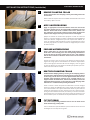
1 LOCATE THE OUTLET
2 PREPARE SUBFLOOR
Place the drain channel into position and ensure it is level using the lev-
eling screws under the channel. Turn each leveling screw counter-clock-
wise to raise the drain and clockwise to lower. Ensure the drain is par-
allel to the wall. Then connect the waste line to the outlet of the drain
channel using the appropriate primer and glue. Ensure that the clamp-
ing collar is screwed into the Universal Drain channel.
DO NOT REMOVE THE CLAMPING COLLAR UNTIL STEP 5.
Coloque el canal de desagüe en su posición y asegúrese de que esté nivela-
do con los tornillos de nivelación que están debajo del canal. Gire cada tornillo
nivelador en sentido contrario a las manecillas del reloj para subir el desagüe y
en el sentido de las manecillas del reloj para bajarlo. Asegúrese de que el de-
sagüe esté paralelo a la pared. A continuación, conecte la tubería de desagüe a
la salida del canal de desagüe utilizando el abrasivo y el pegamento adecuados.
Asegúrese de que el anillo de sujeción esté atornillado en el canal de desagüe
universal. NO RETIRE EL ANILLO DE SUJECIÓN HASTA EL PASO 5.
3 INSTALL LINEAR CHANNEL
Spread a layer of dry pack mortar around the drain and up to the ange
of the linear drain channel ensuring all areas under and around the
channel are back lled. Then spread mortar across the intended shower
area while keeping a consistent pitch towards the drain channel. Con-
sult your local code for the appropriate degree of pitch. Allow this prima-
ry mortar bed to dry completely before proceeding to step 5.
Extienda una capa de mortero de relleno seco alrededor del desagüe y has-
ta la orilla del canal de desagüe lineal, asegurándose de que todas las áreas
debajo y alrededor del canal estén rellenadas. A continuación, extienda el
mortero a través de la zona de lavado prevista, manteniendo una pendiente
constante hacia el canal de desagüe. Consulte su código local para conocer
el grado de pendiente adecuado. Deje que esta base de mortero primario se
seque completamente antes de proceder al paso 5
4 SPREAD PRIMARY MORTAR BED

6
INSTALLATION INSTRUCTIONS (Instalación)
Remove the stainless steel clamping collar by unscrewing each screw
and set aside.
Retire el anillo de sujeción de acero inoxidable destornillando cada uno de
los tornillos y déjelo a un lado.
Apply an appropriate construction adhesive across the mortar bed
and drain channel and lay the waterproong membrane over this
adhesive. Ensure each corner is folded in each corner, without cuts.
The membrane must extend at least 4-6 inches above the oor and
stapled at that height. Consult your local code for exact heights.
Aplique un adhesivo de construcción apropiado a través de la base de
mortero y el canal de desagüe y coloque la membrana impermeabilizante
sobre este adhesivo. Asegúrate de que cada esquina esté doblada, sin
cortes. La membrana debe extenderse al menos 4-6 pulgadas por encima
del suelo y engrapada a esa altura. Consulte su código local para conocer
las alturas exactas.
Using a utility knife, cut a slit over the middle of the opening of the
linear drain. Then carefully pierce the waterproong membrane at
each screw hole of the drain channel and cut out a 3/16” diameter
hole at each screw hole to allow the #10-32 screw to be screwed into
the channel.
Usando una navaja, corte una ranura en el medio de la abertura del de-
sagüe lineal. Luego perfore cuidadosamente la membrana impermeabili-
zante en cada agujero de tornillo del canal de desagüe y corte un agujero
de 3/16” de diámetro en cada agujero de tornillo para permitir que el tor-
nillo #10-32 se atornille en el canal.
Reattached the clamping collar by screwing on the clamping collar to
the linear drain channel with the hem edge facing up using the #10-32
screws using a screw driver. Do not over tighten. NOTE: There are two
clamping collars provided in each kit, one ½” in height and one 1” in
height. Conrm the nished tile, thinset and secondary mortar bed
thicknesses before choosing. In most cases the 1” high clamping collar
will work for a traditional waterproong installation.
Vuelva a colocar el anillo de sujeción atornillándolo al canal de desagüe
lineal con el borde del dobladillo hacia arriba usando los tornillos #10-32
con un destornillador. No lo apriete demasiado. NOTA: Hay dos anillos de
sujeción en cada paquete, uno de ½” de altura y otro de 1” de altura. Conr-
ma el grosor de la baldosa terminada, el cemento y el mortero secundario
antes de elegir una. En la mayoría de los casos el anillo de sujeción de 1” de
altura funcionará para una instalación de impermeabilización tradicional.
Cut out the waterproong membrane that is over the inside of the
drain channel using a utility knife.
Cortar la membrana impermeabilizante que está sobre el interior del canal
de desagüe con una navaja de uso genera.
5 REMOVE CLAMPING COLLAR
6 APPLY WATERPROOFING
7 PREPARE WATERPROOFING
8 REATTACH CLAMPING COLLAR
9 CUT OUT DRAIN
TRADITIONAL WATERPROOFING

7
Mark the thickness of the nishing material plus thinset from the top
of the clamping collar along the outside of the collar. This will serve as a
guide for the second layer of mortar. Spread pea gravel around the weep
holes of the collar to prevent blockage. Then spread a layer of dry pack
mortar up to the mark made on the clamping collar and across the in-
tended shower area while keeping a consistent pitch towards the drain
channel. Consult your local code for the appropriate degree of pitch. Al-
low this secondary mortar bed to dry before continuing to step 11.
Marque el grosor del material de acabado más el engrosamiento desde la
parte superior del anillo de sujeción a lo largo de la parte exterior del anil-
lo. Esto servirá como guía para la segunda capa de mortero. Extienda grava
alrededor de los agujeros de desagüe del anillo para evitar obstrucciones. A
continuación, extienda una capa de mortero seco hasta la marca hecha en el
anillo de sujeción y a través de la zona de lavado prevista, manteniendo una
pendiente constante hacia el canal de desagüe. Consulte su código local para
conocer el grado de pendiente adecuado. Deje que esta capa de mortero
secundario se seque antes de continuar con el paso 11.
Install backerboard directly to the framing and over the waterproong
membrane that runs up the wall and. Ensure the backerboard does NOT
make contact with the mortar bed on the shower oor. Be sure not to
place any screws below the line at which waterproong membrane ends
on the framing.
Instale la placa de base directamente en el marco y sobre la membrana imper-
meabilizante que sube por la pared y asegúrese de que la placa de base NO
entre en contacto con la capa de mortero del piso de retención. Asegúrese
de no colocar ningún tornillo por debajo de la línea en la que termina la mem-
brana impermeabilizante en el marco.
Conrm that the height of the tile and thinset will be accommodated
with the clamping that is on the channel. Apply thinset mortar to the
oor using the appropriate trowel then lay oor tile into the thinset.
After the oor tile and thinset is dry, apply thinset mortar to the vertical
walls and set the wall tile into thinset. Once the wall tile and thinset is
dry grout all tile joints.
Conrme que la altura de la baldosa y del conjunto se acomodará con la
abrazadera que está en el canal. Aplique el mortero de capa delgada al suelo
con la paleta adecuada y luego coloque la baldosa. Después de que la baldosa
y la capa delgada estén secas, aplique el mortero de capa delgada a las pare-
des verticales y coloque la baldosa. Una vez que la baldosa de la pared y la
capa delgada estén secas, rellene todas las juntas de las baldosas.
For the U-TIF Model, apply thinset mortar directly into the stainless steel
tile insert frame using the appropriate trowel. Then place the nishing
material into the thinset mortar. Allow the thinset to dry then grout.
Para el modelo U-TIF, aplique el mortero de capa delgada directamente en
el marco de inserción de baldosas de acero inoxidable utilizando la paleta
adecuada. A continuación, coloque el material de acabado en el mortero de
capa delgada. Deje que el mortero de capa delgada se seque y luego aplique
la boquilla.
Place the decorative grate or tile insert into the channel and adjust the
leveling feet so that the grate sits ush with the nish oor.
Coloque la rejilla decorativa o el azulejo en el canal y ajuste las bases de nive-
lación de manera que la rejilla quede a ras del suelo acabado.
INSTALLATION INSTRUCTIONS (Instalación)
10 INSTALL BACKERBOARD
11 SPREAD SECONDARY MORTAR BED
12 INSTALL TILE
13 TILE THE INSERT FRAME
14 INSTALL LINEAR DRAIN GRATE
TRADITIONAL WATERPROOFING

8
INSTALLATION INSTRUCTIONS (Instalación)
®
USQ Series
Universal Innity Drain™
▪ USQ 24 - 24” Complete Kit
▪ USQ 30 - 30” Complete Kit
▪ USQ 32 - 32” Complete Kit
▪ USQ 36 - 36” Complete Kit
▪ USQ 42 - 42” Complete Kit
▪ USQ 48 - 48” Complete Kit
▪ USQ 54 - 54” Complete Kit
▪ USQ 60 - 60” Complete Kit
Features
▪ Pre-pitched channel available in ABS or PVC
▪ 18 Gauge 304L clamping collar and removable decorative grate
▪ Compatible with Traditional OR Contemporary Waterproong
▫ Traditional Waterproong: PVC Liner, Rubber Liner, or Fiberglass
▫ Contemporary Waterproong: liquid applied or fabric membrane
▪ Two clamping collar heights available (1/2” or 1”)
▪ Clamping collar can be used facing up or down
▪ Flow rate - 9 gpm per outlet
▫ Flow rate measured at outlet only. Measurement does not account
for water in channel or sheeting on shower oor.
Installation with Traditional Waterprooong
Care & Maintenance
USQ Series stainless steel linear grates are made of 304L stainless steel. This material is non-porous, hygienic, rust-free and extremely durable. Bar Keepers Friend®
and Soft Scrub® are commonly available products that can be used to protect and clean your Satin Stainless drain cover. For stains that have been left for an exces-
sive amount of time, stronger cleaning agents such as Steel Brite® may be needed. For Polished Stainless and other nishes we recommend a mild soap and a soft
cloth for cleaning. DO NOT use any abrasive cleaners, scrub pads or allow household cleaning agents, such as bleach, to sit on the drain cover for a long period of
time. Stainless steel does not rust. External factors, such as contamination from other highly ferrous metals, built up road salt, sea salt, or chlorine may have caused
”surface” rust which can be removed using Barkeepers Friend®, Soft Scrub®, or Steel Brite® . Always follow the directions on the bottle. Follow proper maintenance
procedures to prevent excessive surface rust. In areas of frequent exposure to salt, chlorine, and other chemical compounds, maintenance of the stainless grates
should be performed at least 2-3 times per year.
Page 1 of 3
Dimensions are subject to manufacturer’s tolerance and change without notice. We can assume no responsibility for use of superceded or void data.
FM550-05-20
Innity Drain
145 Dixon Avenue
Amityville, NY 11701
Phone: 516.767.6786
Fax: 516.740.3066
www.innitydrain.com
NOTE: Installer must verify all rough-in
dimensions prior to installation and consult
local and national codes. Conformity and com-
pliance to local and national codes are the
responsibility of the installer.
Installation with Contemporary Waterprooong
A
B
C
D
E
F
G
H
I
J
A
B
C
D
E
F
G
H
I
A
B
C
D
E
F
G
H
I
J
- UC 65 Universal Channel
- QA 65 Decorative Grate
- CC Clamping Collar (1/2” or 1” High)
- Backerboard
- Suboor
- Primary Mortar Bed
- Waterproong Membrane
- Secondary Mortar Bed
- Thinset
- Tile/Stone
A
B
C
D
E
F
G
H
I
- UC 65 Universal Channel
- QA 65 Decorative Grate
- CC Clamping Collar (1/2” or 1” High)
- Backerboard
- Suboor
- Primary Mortar Bed
- Liquid or Fabric Membrane
- Thinset
- Tile/Stone
®
Page 2 of 3
Innity Drain
145 Dixon Avenue
Amityville, NY 11701
Phone: 516.767.6786
Fax: 516.740.3066
www.innitydrain.com
NOTE: Installer must verify all rough-in
dimensions prior to installation and consult
local and national codes. Conformity and com-
pliance to local and national codes are the
responsibility of the installer.
Model
Number
Complete Kit Contents
A
(Maximum Overall Length)
B
(Maximum Grate Length)
USQ 24-A
USQ 24-P
1 - QA 6524 Perforated Squares Pattern Grate
1 - UC 24 Channel
2 - CC 24 Clamping Collars
1 - HS 2 Hair Strainer
1 - AKEY Lift Out Key
27” 23 7/8”
USQ 30-A
USQ 30-P
1 - QA 6530 Perforated Squares Pattern Grate
1 - UC 30 Channel
2 - CC 30 Clamping Collars
1 - HS 2 Hair Strainer
1 - AKEY Lift Out Key
33” 29 7/8”
USQ 32-A
USQ 32-P
1 - QA 6532 Perforated Squares Pattern Grate
1 - UC 32 Channel
2 - CC 32 Clamping Collars
1 - HS 2 Hair Strainer
1 - AKEY Lift Out Key
35” 31 7/8”
USQ 36-A
USQ 36-P
1 - QA 6536 Perforated Squares Pattern Grate
1 - UC 36 Channel
2 - CC 36 Clamping Collars
1 - HS 2 Hair Strainer
1 - AKEY Lift Out Key
39” 35 7/8”
Dimensions are subject to manufacturer’s tolerance and change without notice. We can assume no responsibility for use of superceded or void data.
FM550-05-20
A
B
1
1
SECTION 1-1
QA 65
PERFORATED SQUARE PATTERN GRATE
UNIVERSAL CHANNEL
STAINLESS STEEL
CLAMPING COLLAR
#10-32 STAINLESS
STEEL SCREWS
HS2
HAIR STRAINER
1/4"-20 STAINLESS STEEL
LEVELING SCREW
B
B
3
1
16
"
2
5
16
"
2
3
4
"
13
16
"
1
2
"
1
4
"
7
16
"
5
1
2
"
2
7
16
"
SECTION 1-1
SECTION 1-1
A
B
1
1
SECTION 1-1
QA 65 PERFORATED SQUARE PATTERN GRATE
UNIVERSAL CHANNEL
STAINLESS STEEL
CLAMPING COLLAR
#10-32 STAINLESS
STEEL SCREWS
HS2
HAIR STRAINER
1/4"-20 STAINLESS STEEL
LEVELING SCREW
□
□
□
□
A
B
1
1
SECTION 1-1
QA 65
PERFORATED SQUARE PATTERN GRATE
UNIVERSAL CHANNEL
STAINLESS STEEL
CLAMPING COLLAR
#10-32 STAINLESS
STEEL SCREWS
HS2
HAIR STRAINER
1/4"-20 STAINLESS STEEL
LEVELING SCREW
Channel Material Options:
▪ A = ABS
▪ P = PVC
Finishes
□ Satin Stainless □ Polished Stainless
®
Page 2 of 3
Innity Drain
145 Dixon Avenue
Amityville, NY 11701
Phone: 516.767.6786
Fax: 516.740.3066
www.innitydrain.com
NOTE: Installer must verify all rough-in
dimensions prior to installation and consult
local and national codes. Conformity and com-
pliance to local and national codes are the
responsibility of the installer.
Model
Number
Complete Kit Contents
A
(Maximum Overall Length)
B
(Maximum Grate Length)
UTIF 24-A
UTIF 24-P
1 - NA 6524 Tile Insert Frame
1 - UC 24 Channel
2 - CC 24 Clamping Collars
1 - HS 2 Hair Strainer
1 - AKEY Lift Out Key
27” 23 7/8”
UTIF 30-A
UTIF 30-P
1 - NA 6530 Tile Insert Frame
1 - UC 30 Channel
2 - CC 30 Clamping Collars
1 - HS 2 Hair Strainer
1 - AKEY Lift Out Key
33” 29 7/8”
UTIF 32-A
UTIF 32-P
1 - NA 6532 Tile Insert Frame
1 - UC 32 Channel
2 - CC 32 Clamping Collars
1 - HS 2 Hair Strainer
1 - AKEY Lift Out Key
35” 31 7/8”
UTIF 36-A
UTIF 36-P
1 - NA 6536 Tile Insert Frame
1 - UC 36 Channel
2 - CC 36 Clamping Collars
1 - HS 2 Hair Strainer
1 - AKEY Lift Out Key
39” 35 7/8”
Dimensions are subject to manufacturer’s tolerance and change without notice. We can assume no responsibility for use of superceded or void data.
FM551-05-20
A
B
1
1
SECTION 1-1
NA 65
TILE INSERT FRAME
UNIVERSAL CHANNEL
STAINLESS STEEL
CLAMPING COLLAR
#10-32 STAINLESS
STEEL SCREWS
HS2
HAIR STRAINER
1/4"-20 STAINLESS STEEL
LEVELING SCREW
B
B
3
1
16
"
2
5
16
"
2
1
8
"
2
3
4
"
13
16
"
1
2
"
1
4
"
7
16
"
5
1
2
"
SECTION 1-1
A
B
1
1
SECTION 1-1
NA 65
TILE INSERT FRAME
UNIVERSAL CHANNEL
STAINLESS STEEL
CLAMPING COLLAR
#10-32 STAINLESS
STEEL SCREWS
HS2
HAIR STRAINER
1/4"-20 STAINLESS STEEL
LEVELING SCREW
□
□
□
□
A
B
1
1
SECTION 1-1
NA 65
TILE INSERT FRAME
UNIVERSAL CHANNEL
STAINLESS STEEL
CLAMPING COLLAR
#10-32 STAINLESS
STEEL SCREWS
HS2
HAIR STRAINER
1/4"-20 STAINLESS STEEL
LEVELING SCREW
Channel Material Options:
▪ A = ABS
▪ P = PVC
®
Page 1 of 3
Dimensions are subject to manufacturer’s tolerance and change without notice. We can assume no responsibility for use of superceded or void data.
FM551-05-20
Innity Drain
145 Dixon Avenue
Amityville, NY 11701
Phone: 516.767.6786
Fax: 516.740.3066
www.innitydrain.com
NOTE: Installer must verify all rough-in
dimensions prior to installation and consult
local and national codes. Conformity and com-
pliance to local and national codes are the
responsibility of the installer.
UTIF Series
Universal Innity Drain™
▪ UTIF 24 - 24” Complete Kit
▪ UTIF 30 - 30” Complete Kit
▪ UTIF 32 - 32” Complete Kit
▪ UTIF 36 - 36” Complete Kit
▪ UTIF 42 - 42” Complete Kit
▪ UTIF 48 - 48” Complete Kit
▪ UTIF 54 - 54” Complete Kit
▪ UTIF 60 - 60” Complete Kit
Features
▪ Pre-pitched channel available in ABS or PVC
▪ 18 Gauge 304L clamping collar and removable decorative tile insert frame
▪ Compatible with Traditional OR Contemporary Waterproong
▫ Traditional Waterproong: PVC Liner, Rubber Liner, or Fiberglass
▫ Contemporary Waterproong: liquid applied or fabric membrane
▪ Two clamping collar heights available (1/2” or 1”)
▪ Clamping collar can be used facing up or down
▪ Flow rate - 9 gpm per outlet
▫ Flow rate measured at outlet only. Measurement does not account
for water in channel or sheeting on shower oor.
Installation with Traditional Waterprooong
Care & Maintenance
UTIF Series stainless steel linear grates are made of 304L stainless steel. This material is non-porous, hygienic, rust-free and extremely durable. Bar Keepers Friend®
and Soft Scrub® are commonly available products that can be used to protect and clean your Satin Stainless drain cover. For stains that have been left for an exces-
sive amount of time, stronger cleaning agents such as Steel Brite® may be needed. For Polished Stainless and other nishes we recommend a mild soap and a soft
cloth for cleaning. DO NOT use any abrasive cleaners, scrub pads or allow household cleaning agents, such as bleach, to sit on the drain cover for a long period of
time. Stainless steel does not rust. External factors, such as contamination from other highly ferrous metals, built up road salt, sea salt, or chlorine may have caused
”surface” rust which can be removed using Barkeepers Friend®, Soft Scrub®, or Steel Brite® . Always follow the directions on the bottle. Follow proper maintenance
procedures to prevent excessive surface rust. In areas of frequent exposure to salt, chlorine, and other chemical compounds, maintenance of the stainless grates
should be performed at least 2-3 times per year.
Installation with Contemporary Waterprooong
A
B
C
D
E
F
G
H
I
J
A
B
C
D
E
F
G
H
I
A
B
C
D
E
F
G
H
I
J
- UC 65 Universal Channel
- NA 65 Tile Insert Frame
- CC Clamping Collar (1/2” or 1” High)
- Backerboard
- Suboor
- Primary Mortar Bed
- Waterproong Membrane
- Secondary Mortar Bed
- Thinset
- Tile/Stone
A
B
C
D
E
F
G
H
I
- UC 65 Universal Channel
- NA 65 Tile Insert Frame
- CC Clamping Collar (1/2” or 1” High)
- Backerboard
- Suboor
- Primary Mortar Bed
- Liquid or Fabric Membrane
- Thinset
- Tile/Stone
USQ - Details
UTIF - Details
LIQUID/FABRIC WATERPROOFING

9
INSTALLATION INSTRUCTIONS (Instalación)
Establish the intended position for the linear drain by measuring the
desired space and marking the center location for the drain outlet on
the suboor. Make a hole at the marked location through or into the
suboor for the drain outlet using a 3-1/2 inch hole saw. This drain can
be connected to a 2 inch or 3 inch nominal pipe. A 2” pipe will t inside of
the outlet. A 3” pipe will t over the outlet.
Establezca la posición prevista para el desagüe lineal midiendo el espacio de-
seado y marcando la ubicación central de la salida del desagüe en el subsuelo.
Haga un agujero en el lugar marcado a través o dentro del subsuelo para la
salida del desagüe usando una sierra perforadora de 3-1/2 pulgadas. Este de-
sagüe puede conectarse a una tubería nominal de 2 o 3 pulgadas. Un tubo de
2 pulgadas encajará dentro de la salida. Un tubo de 3” encajará por encima de
la salida.
For wooden suboor, lay water-resistant paper over the suboor, staple
into place and make a cut out for the outlet hole. Then lay wire lath,
staple into place and make a cut out for the outlet hole in preparation
for the primary mortar bed. For a concrete suboor, ensure the surface
cleaned and prepared as needed using primers and/or abrasives to ac-
cept additional mortar bed layers.
Para subsuelos de madera, coloque papel resistente al agua sobre el subsuelo,
engrápelo en su lugar y haga un corte para el agujero de salida. Luego coloque
una malla de alambre, engrápela en su lugar y haga un corte para el agujero de
salida en preparación para la base de mortero primario. Para un subsuelo de
concreto, asegúrese de que la supercie se limpie y se prepare según sea nece-
sario usando primers y/o abrasivos para aceptar capas adicionales de mortero.
1 LOCATE THE OUTLET
2 PREPARE SUBFLOOR
Place the drain channel into position and ensure it is level using the lev-
eling screws under the channel. Turn each leveling screw counter-clock-
wise to raise the drain and clockwise to lower. Ensure the drain is par-
allel to the wall. Then connect the waste line to the outlet of the drain
channel using the appropriate primer and glue. Ensure that the clamp-
ing collar is screwed into the Universal Drain channel.
DO NOT REMOVE THE CLAMPING COLLAR UNTIL STEP 5.
Coloque el canal de desagüe en su posición y asegúrese de que esté nivela-
do con los tornillos de nivelación que están debajo del canal. Gire cada tornillo
nivelador en sentido contrario a las manecillas del reloj para subir el desagüe y
en el sentido de las manecillas del reloj para bajarlo. Asegúrese de que el de-
sagüe esté paralelo a la pared. A continuación, conecte la tubería de desagüe a
la salida del canal de desagüe utilizando el abrasivo y el pegamento adecuados.
Asegúrese de que el anillo de sujeción esté atornillado en el canal de desagüe
universal. NO RETIRE EL ANILLO DE SUJECIÓN HASTA EL PASO 5.
3 INSTALL LINEAR CHANNEL
Spread a layer of dry pack mortar around the drain and up to the ange
of the linear drain channel ensuring all areas under and around the
channel are back lled. Then spread mortar across the intended shower
area while keeping a consistent pitch towards the drain channel. Con-
sult your local code for the appropriate degree of pitch. Allow this prima-
ry mortar bed to dry completely before proceeding to step 5.
Extienda una capa de mortero de relleno seco alrededor del desagüe y has-
ta la orilla del canal de desagüe lineal, asegurándose de que todas las áreas
debajo y alrededor del canal estén rellenadas. A continuación, extienda el
mortero a través de la zona de lavado prevista, manteniendo una pendiente
constante hacia el canal de desagüe. Consulte su código local para conocer
el grado de pendiente adecuado. Deje que esta base de mortero primario se
seque completamente antes de proceder al paso 5
4 SPREAD PRIMARY MORTAR BED
LIQUID/FABRIC WATERPROOFING

10
INSTALLATION INSTRUCTIONS (Instalación)
Remove the stainless steel clamping collar by unscrewing each screw
and set aside.
Retire el anillo de sujeción de acero inoxidable destornillando cada uno de
los tornillos y déjelo a un lado.
Install backerboard directly to the framing and ensure that the back-
er board makes contact with the primary mortar bed oor.
Instale la placa de soporte directamente en el marco y asegúrese de que la
placa de soporte haga contacto con el piso de la base de mortero primario.
For Fabric Waterproong : Lay the waterproong membrane over the
shower area and drain. Mark the screw hole locations of the channel
onto the membrane. Using a utility knife, carefully pierce the water-
proong membrane at each screw hole of the drain channel and cut
out a 3/16” diameter hole for each screw. Apply thinset mortar or an
adhesive recommended by the waterproong manufacturer over the
mortar bed. Then apply the appropriate adhesive that is provided by
the waterproong manufacturer on the anges of the drain channel.
Lay the waterproong membrane over the adhesive on the channel
and mortar bed. Press the membrane into the adhesive and remove
excess thinset from under the waterproong membrane in accor-
dance with the manufacturer’s instructions.
Para la impermeabilización textil: Coloque la membrana impermeabili-
zante sobre el área de lavado y el desagüe. Marque la ubicación de los
agujeros de los tornillos del canal sobre la membrana. Usando una nava-
ja utilitaria, perfore cuidadosamente la membrana impermeabilizante en
cada agujero de tornillo del canal de desagüe y corte un agujero de 3/16”
de diámetro para cada tornillo. Aplique un mortero no o un adhesivo
recomendado por el fabricante de la impermeabilización sobre la base de
mortero. A continuación, aplique el adhesivo apropiado que proporciona el
fabricante de la impermeabilización en las pestañas del canal de desagüe.
Coloque la membrana impermeabilizante sobre el adhesivo en el canal y la
base de mortero. Presione la membrana en el adhesivo y retire el exceso
de adhesivo de debajo de la membrana impermeabilizante de acuerdo con
las instrucciones del fabricante.
For Liquid Waterproong: Paint or spread the waterproong on the
anges of the drain channel in all corners, curb and over the mortar
bed. Apply any reinforcement tape over any seams as per the man-
ufacturer’s instructions. Once dry ensure that all screw holes are
cleared.
Para la impermeabilización de líquidos: Pintar o extender la impermeabili-
zación en las pestañas del canal de desagüe en todas las esquinas, borde
y sobre la base de mortero. Aplique cualquier tipo de cinta adhesiva de
refuerzo sobre las juntas, según las instrucciones del fabricante. Una vez
seco, asegúrese de que todos los agujeros de los tornillos estén despeja-
dos.
5 REMOVE CLAMPING COLLAR
6 INSTALL BACKERBOARD
7 WATERPROOF
LIQUID/FABRIC WATERPROOFING

11
Screw on the clamping collar to the linear drain channel using the #10-
32. Do not over tighten. If using a fabric waterproong, cut out the wa-
terproong membrane that is over the inside of the drain channel using
a utility knife.
Atornille el anillo de sujeción al canal de desagüe lineal con el #10-32. No lo
apriete demasiado. Si utiliza un impermeabilizante textil, corte la membrana
impermeabilizante que está sobre el interior del canal de desagüe utilizando
una navaja de uso general.
Conrm that the height of the tile and thinset will be accommodated
with the clamping that is on the channel. Apply thinset mortar directly
over the waterproong using the appropriate trowel then lay oor tile
into the thinset. Ensure the nished oor is ush with the top of the
clamping collar, unless using the clamping collar with the tile edge fac-
ing downwards. After the oor tile is dry, apply thinset mortar to the
vertical walls and set the wall tile into thinset. Once the thinset is dry
grout all tile joints.
Conrme que la altura de la baldosa y la capa delgada se acomodará con la
abrazadera que está en el canal. Aplique el mortero de capa delgada direct-
amente sobre la impermeabilización con una paleta apropiada y luego colo-
que la baldosa. Asegúrese de que el suelo terminado esté a ras con la parte
superior del anillo de sujeción, a menos que utilice el anillo de sujeción con el
borde de la baldosa hacia abajo. Una vez que la baldosa esté seca, aplique el
mortero de aplicación delgada a las paredes verticales y coloque la baldosa.
Una vez que el mortero esté seco, rellene todas las juntas de las baldosas.
For the U-TIF Model, apply thinset mortar directly into the stainless steel
tile insert frame using the appropriate trowel. Then place the nishing
material into the thinset mortar. Allow the thinset to dry then grout.
Para el modelo U-TIF, aplique el mortero de aplicación delgada directamente
en el marco de inserción de baldosas de acero inoxidable utilizando la paleta
adecuada. A continuación, coloque el material de acabado en el mortero de
aplicación delgada. Deje que el mortero se seque y luego aplique la boquilla.
Place the decorative grate or tile insert into the channel and adjust the
leveling feet so that the grate sits ush with the nish oor
Coloque la rejilla decorativa o el azulejo en el canal y ajuste las bases de nive-
lación de manera que la rejilla quede a ras del suelo.
INSTALLATION INSTRUCTIONS (Instalación)
10 INSTALL TILE
11 TILE THE INSERT FRAME
12 INSTALL LINEAR DRAIN GRATE
Continue applying the fabric or liquid applied waterproong membrane
to the shower walls and seal any seams as per the manufacturer’s in-
structions.
Continúe aplicando tela o membrana impermeabilizante líquida a las paredes
del lavado y selle cualquier junta según las instrucciones del fabricante.
9 CONTINUE WATERPROOFING
8 REATTACH CLAMPING COLLAR
NOTE: There are two clamping collars provided in each kit, one ½” in height that can used with the tile edge facing up-
wards or downwards and one 1”in height. Conrm the nished tile, thinset thickness before choosing. In most cases the
1/2” high clamping collar will work for a liquid or fabric waterproong installation.
NOTA: Se proporcionan dos anillos de sujeción en cada paquete, uno de ½” de altura que puede usarse con el borde de la baldosa
hacia arriba o hacia abajo y uno de 1” de altura. Conrme la baldosa terminada, el espesor del conjunto antes de elegir uno. En la
mayoría de los casos el anillo de sujeción de 1/2” de altura funcionará para una instalación de impermeabilización líquida o textil.
LIQUID/FABRIC WATERPROOFING

PRODUCT INFORMATION
See innitydrain.com for the most
up-to-date product information.
INFINITY DRAIN
facebook.com/InnityDrain
youtube.com/IDInnityDrain
pinterest.com/InnityDrain
FM528-08-20
145 Dixon Avenue, Amityville, New York 11701
Phone 516.767.6786 ~ Fax 516.740.3066
www.innitydrain.com
MADE IN THE USA
SCAN TO WATCH
INSTALLATION VIDEOS ONLINE
youtube.com/IDInnityDrain
-
 1
1
-
 2
2
-
 3
3
-
 4
4
-
 5
5
-
 6
6
-
 7
7
-
 8
8
-
 9
9
-
 10
10
-
 11
11
-
 12
12


Infinity Drain UTIF-A 36 SS Guía de instalación
- Tipo
- Guía de instalación
en otros idiomas
Artículos relacionados
-
Infinity Drain STIF AS 6540 SS Guía de instalación
-
Infinity Drain S-LAG 6536 BK Guía de instalación
-
Infinity Drain D 3860 SS Instrucciones de operación
-
Infinity Drain FXSG 6548 SS Guía de instalación
-
Infinity Drain FFDG Instrucciones de operación
-
Infinity Drain LTD5 BA SS Guía de instalación
-
Infinity Drain T 42-SS Instrucciones de operación
-