Infinity Drain D 3860 SS Instrucciones de operación
- Tipo
- Instrucciones de operación
La página se está cargando...
La página se está cargando...

3
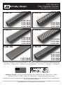
S-AG38/S-DG38/S-AG65/S-DG65/S-AG100/S-
TIF65 kits DO NOT include a mechanically
fastening clamp down drain due to the disparity
of material of each consumer’s existing plumbing.
This is a standard item that is available through
Innity Drain or your local plumbing supply from
various manufacturers (Oatey®, Sioux Chief™,
JSC™, PROFLO™, Matco-Norca™).
S-AG 38/S-DG38/S-AG65/S-DG65/S-AG100/
S-TIF65 NO INCLUYE la sujeción mecánica
del drenaje por la razón que varía el material
de código local. Este drenaje es residencial
que está disponible a través de Innity Drain
o su local suministro de plomería de diversos
fabricantes. (i.e. Oatey®, Sioux Chief™, JSC™,
PROFLO™, Matco-Norca™).
2” clamp down drain
not included in kit
Add Clamp Down Drain:
CDA 22 Clamp Down Drain ABS
CDI 22 Clamp Down Drain Cast Iron
CDP 22 Clamp Down Drain PVC
Optional Components: (Not Included)
F 65 PVC Non-Threaded Outlet GAM 65 PVC 90° Angle Joiner TNRN-P PVC Threaded Nipple
F 100 PVC Non-Threaded Outlet G38108 108” PVC Channel UCP 2 Universal 2” Clamping Plate
GJC 38 PVC Straight Joiner Strip G65108 108” PVC Channel UCP 4 Universal 4” Clamping Plate
GAM 38 PVC 90° Angle Joiner GJ 100 PVC Straight Joiner Strip ERB Eccentric Reducer Bushing 4”x2”
GJC 65 PVC Straight Joiner Strip GA 100 PVC 90° Angle Joiner
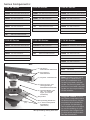
Section A-A
S-AG 38, S-DG 38
1⅝"
1⅞"
1¹³⁄ ¹⁶"
2½"
6½"
2"
Section A-A
S-TIF 65
1¾"
¾"
2⅞"
1⁹⁄ ¹⁶"
2½"
6½"
2"
Section A-A
S-AG 65, S-DG 65
2½"
2⅞"
6½"
2"
1¹¹⁄ ¹⁶"
1⅝"
1¾"
4³⁄¹⁶"
¹³⁄ ¹⁶"
2½"
6½"
2"
Section A-A
S-AG 100
All drains can be
adjusted upward
for an additional
1” in height.

4
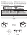
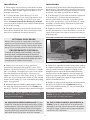
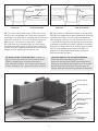
OPTIONAL PROCEDURE:
When drain install is required to be ush
against the nished wall, build out wall with
backer board over round clamp down drain
body (F) to compensate for the drain radius.
PROCEDIMIENTO OPCIONAL:
Cuando el drenaje sea instalado, se requi-
ere que esté completamente a la pared,
construir la pared con múltiples paneles de
cemento sobre el redondo drenaje (F) para
compensar el radial del drenaje.
Installation
1. Determine the location of the drain outlet
location. Typically linear drains span a dimen-
sion from wall to wall, against a wall or at a
shower entrance.
2. If clamp down drain body (F) is not
installed. Attach (F) to existing waste line
and allow drain body to recess into sub-
floor. Ensure that drain body (F) is level.
Unscrew and remove top clamp down plate
from drain body.
3. Spread a primary mortar bed across the
intended shower area. Pitch this bed in four
directions towards the drain body (F).
4. When mortar layer is dry, perform
necessary waterproong (PVC Liner, CPE
Rubber Liner/Chloraloy™, Lead Pan, Copper
Pan, Hot Mop, Fiberglass) as per local code.
Ensure waterproong layer reaches the
edge of the hole in the drain body (F). Reat-
tach the top clamp down plate to the clamp
down drain body (F) over the waterproong
layer using bolts.
5. Measure desired wall to wall length, allow
for wall tile thickness and 3/16” for both stop
ends (C). Cut PVC channel (B) to desired length.
Instalación
1. Determine la ubicación del emplazamiento
del drenaje. Típicamente el drenaje lineal atra-
viesa una dimensión de pared a pared, contra
la pared, o en una entrada de un baño.
2. Si el drenaje (F) no está instalado. Adjuntar
el drenaje (F) a la línea de residuos exis-
tentes y permite el drenaje a que descanse
en el piso. Asegúrese, que el drenaje (F) este
nivelado. Destornilla y remueve la placa de
sujeción de arriba.
3. Esparcir una primaria de capa de mortero a
través del destino o zona del baño. Lanzar la
capa de mortero en cuatro direcciones hacia
el drenaje (F).
4. Cuando la capa de mortero este seca, realice
la impermeabilización necesaria (Forro del PVC,
cobre, panal de vidrio) según el código local.
Asegura que la capa de impermeabilización
alcance al borde del agujero en el drenaje (F).
Vuelva a colocar la placa de sujeción de arriba
al drenaje (F) sobre las capa de impermeabili-
zación usando tonillos.
5. Medir la longitud deseada a pared a pared,
permitir el espesor de la baldosa pared y
3/16” por ambas partes (C). Corte canal (B) a
la desead longitud.
TENER EN CUENTA SOLO PARA S-AG38/S-
DG38: Tener en cuenta en los dos 7/16”
sección (D) a lo largo del canal.
NOTE ONLY FOR S-AG38/S-DG38 Series:
Account for the 2-7/16” outlet section (D)
along channel length.
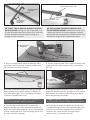
6a. ONLY FOR S-AG38/S-DG38 Install: Cut the
sized PVC channel at the desired location of the
outlet section. Insert the open ends of the PVC
channel (B) into the slotted ends of the outlet
section (D) Dry t components before axing.
Ax with clear PVC primer and PVC cement.
6a. SOLO PARA S-AG38/S-DG38 INSTALA-
CION: Corte el canal de PVC a la ubicación
deseada a donde va ser la sección de salida
de agua. Pegar la parte (D) a la parte (B) del
canal con PVC cemento.
Waterproong
Membrane
Double Layer Backer Board
(F) 2” Throat Clamp Down
Drain Body* (Two Pieces)
(F1)
(F2)
*Not provided by Innity Drain kits
OPTIONAL PROCEDURE / PROCEDIMIENTO OPCIONAL

5
6b. ONLY FOR S-AG65/S-DG65/S-TIF65/S-
AG100 Install: Using a 2-1/4” hole saw, cut
a hole through the base of the PVC channel
at the desired outlet location along the
length of the channel.
6b. SOLO PARA S-AG65/S-DG65/S-TIF/S-
AG100 INSTALACION: Usando un 2-1/4” sier-
ra de perforación, corte un agujero a través
de la base del canal de PVC a la ubicación que
desea a lo largo de la longitud del canal.
Cordless Drill with
2¼” Hole Saw
(B) PVC Channel –
G38/G100
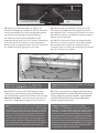
7. Dry t components before axing. Ax
the stop ends (C) to the channel using clear
PVC primer and PVC cement.
7. Poner una tapa de PVC a cada esquina del
canal usando imprimación PVC y cemento
de PVC.
(B) PVC Channel – G38/G65/G100
(C) Stop End – E38/E65/E100
Note: Do NOT ax channel or outlet sec-
tion to threaded nipple until step 9.
Tenga en cuenta: No pege el canal a la sec-
ción de salida al niple roscado hasta el paso 9.
8. Screw threaded nipple (E) into top clamp
down plate of the drain body (F). Adjust to
the desired height. Turn clockwise to lower,
counter-clockwise to raise.
8. Enroscar niple roscado (E) en la sujeción
superior del drenaje (F). Adaptarla a la altura
que desea. Gire hacia la derecha para bajar,
hacia izquierda para subir.
9. Test t the combined PVC channel for
desired height onto the threaded nipple (E).
Ax the threaded nipple (E) to the underside
of the combined PVC channel using clear PVC
primer and PVC cement.
9. Pruebe y ajuste a la combinación de PVC
a la desea longitud en el threaded nipple (E).
Colocar el threaded nipple (E) en la parte
inferior del canal de PVC usando impri-
mación PVC y cemento de PVC.
(E) Threaded
Nipple - S50
(F) 2” Throat Clamp Down
Drain Body* (Two Pieces)
Waterproong
Membrane
Mortar Bed
Suboor
(F1)
(F2)
(B) PVC Channel – G38
Desired Outlet
Location
32 Tooth per
Inch Blade
Hacksaw
(D) Outlet Section – S32
(B) PVC Channel – G38

6
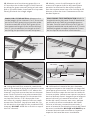
Note: Minimum height: 1⅝” Maximum
height with standard nipple (S50): 2¾”
Tenga en Cuenta: Altura Mínima: 1⅝” Altura
Máxima con niple: (S50): 2¾”
PVC Channel Assembly
Waterproong MembraneMortar BedSuboor
Shims
Lumber
Tile
Backer Board
10. After dry, measure and cut a piece of
lumber to length and width of the PVC channel.
Insert the lumber into the channel during mor-
tar and tiling to prevent channel exing.
11. Measure the distance between the
waterproong and set PVC Channel assembly.
Cut two pieces of lumber to the measured
dimensions and place under the PVC Channel
for support while laying mortar bed.
10. Después que se seque, medir y cortar
una pieza de madera a la longitud y ancho
del canal de PVC. Insertar la madera en canal
durante el mortero y baldosas para prevenir
que el canal se doble.
11. Medir la distancia entre la impermeabi-
lización y colocar el canal. Corte dos piezas
de madera para medir las dimensiones y
coloque bajo el canal para soportar, mientras
que el mortero se instala.
12. Create a mortar bed the length of the
channel on the waterproong membrane
and backll the underside of the channel and
ensure it is level. Use necessary amount of
mortar to adequately support the channel.
12. Crear un mortero a la longitud del canal en la
impermeabilización y rellena la parte inferior del
canal y asegura que este nivelado. Usa cantidad
necesaria de mortero para apoyar adecuada-
mente el soporte del canal.
Note: Site Sizable models are designed with
a nished neutral internal pitch. With proper
ventilation of waste line plumbing, the uid
of the charged channel will nd any point of
exit by force of gravity. Negative pressure
below the drain level will create a vacuum
to aid in the siphoning action through the
drain outlet. Based on Manning’s Equation
the designed depth of the channel has been
optimized for the specied ow capacity.
Tenga en cuenta: Nuestro Site-Sizable
modelos son diseñado con un tono interno
neutral, con adecuada ventilación de la línea de
residuos, el uido de la carga del canal encon-
trara todos los puntos de salida por la fuerza
de la gravedad, la presión negativa por debajo
del drenaje creara un vacío para ayudar en la
acción de sifón a través del agujero del drenaje.
Basada en la ecuación de Manning’s la longitud
deseada del canal ha sido optimizada para la
capacidad de ujo especicada.
*Not provided by Innity Drain kits
(E) Threaded Nipple -
S50
PVC Channel Assembly
(F) 2” Throat Clamp Down
Drain Body*(Two Pieces)
(F1)
(F2)

7
32 Tooth per Inch
Blade Hacksaw
(A) Top Grate – TA65
5 Inches
32 Tooth per Inch
Blade Hacksaw
(A) Top Grate – TA65
Desired Length
2
ONLY FOR S-TIF65 INSTALL: Measure the
inside length of the channel. Cut 5” from one
end of the TA65 grate (A) and set this aside.
Cut the remainder of the TA65 grate (A) to
the measured length of the inside channel
less 5”. Join the desired cut length to the 5”
end using the provided screws and plates.
SOLO PARA S-TIF65 INSTALACION: Medir la
longitud interior del canal. Corte 5” desde una
punta de la reja TA65 (A) y establezca esto a
un lado. Corte el resto de la reja TA 65 (A) a la
longitud medida del canal menos de 5”. Una la
desead longitud cortada a la pieza de 5”usan-
do los clips de los tornillos suministrados.
1
(A) Top Grate – TA65
5 Inches
4
TIF Plates
TIF Screws
(A) Top Grate – TA65
TIF Plates
3
TIF Screws
14. Using desired oor material, mark thick-
ness of the material along the channel so that
nishing material will nish 1/16” above the
channel. Lay nal mortar bed across the wet
area. Pitch this bed in one plane toward the
linear drain. Allow space for thinset and tile
so that tile nishes 1/16” above the chan-
nel. After dry, apply a bead of silicone caulk
around the channel. Lay thinset and tile, n-
ish tile work to the edge of the combined PVC
channel. DO NOT allow tile to nish on top of
the PVC channel.
14. Utilizando el material de piso deseado,
marque el espesor del material a lo largo del
canal para que termine 1/16” arriba del canal.
Sentar la última capa de mortero a través de
la zona mojada. Lanzar esta capa en un plano
hacia el drenaje lineal. Asegura que el espacio
para el thinset y el material terminen 1/16”
arriba del canal. Una vez este seco, aplique
un cordón de silicona alrededor del canal.
Colocar el thinset y material terminado, y
tener el material terminado al borde del canal
de acero inoxidable. NO DEJE o PERMITA que
el material terminado termine en la parte
superior del canal de acero inoxidable.
13. Measure and cut the top grate (A) to a
⅛” less than the inside length of the channel
(to allow for grate removal) using a hack saw
with a 32 tooth blade, band saw or shop saw.
Gently le back the rough edges.
13. Medir y corte la rejilla superior (A) ⅛”
menos de la parte interior del canal (para
permitir la eliminación de rejilla) usando
una sierra para metal con una cuchilla de 32
dientes, sierra de cinta. Suavemente le los
bordes ásperos.

8
15. To cover the visible edge of the PVC chan-
nel (B), use sandpaper to rough the channel’s
top edge. Use a bead of a epoxy based silicone
that this similar in color to the nishing grout.
OR Use a 1:1 mixture of clear PVC cement
and desired dry unsanded grout, and apply
immediately along the visible edge. Clear PVC
primer solvent should be used on the channel
edges before applying PVC/grout mix.
15. Para cubrir los bordes visibles en el canal de
PVC (B), use papel de lija para desbastar el borde
superior del canal. Use un cordón de base de
silicona epoxi, similar al color del mortero O use
1:1 mezcla de imprimación de PVC transparente
y deseada boquilla sin arena y aplique inmediat-
amente a lo largo del borde visible, imprimación
de PVC transparente solvente tiene que ser
usado en el borde del canal antes de aplicar
PVC/mezcla de mortero.
16.ONLY FOR S-TIF65 INSTALL: Spread a
layer of mortar into the Tile Insert Frame
(TA65), allowing for thinset and tile so
that the tile nishes 1/16” above the metal
frame. Allow to dry, spread thinset and tile.
16.SOLO PARA S-TIF 65 INSTALACION:
Extender una capa de mortero en la
inserción en la parte (TA65), permitiendo el
thinset y el material terminado a 1/16” arriba
de la estructura de metal. Permitir que se
seque, difundir el thinset y tender el material.
Tile
Waterproong
Membrane
PVC Channel
Assembly
Final Mortar Bed
Finished Grate
Threaded Outlet
Primary Pre-Pitched
Mortar Bed
Suboor
Backer Board
Before nishing
material
Antes que el material
esté terminado
After nishing
material
Después que el material
esté terminado
Caulking
Tile
Assure that grate is
lower than installed tile
Mortar Bed
Mortar Bed
Sub-oor
Waterproong
Membrane
Transcripción de documentos
S-AG38/S-DG38/S-AG65/S-DG65/S-AG100/STIF65 kits DO NOT include a mechanically fastening clamp down drain due to the disparity of material of each consumer’s existing plumbing. This is a standard item that is available through Infinity Drain or your local plumbing supply from various manufacturers (Oatey®, Sioux Chief™, JSC™, PROFLO™, Matco-Norca™). S-AG 38/S-DG38/S-AG65/S-DG65/S-AG100/ S-TIF65 NO INCLUYE la sujeción mecánica del drenaje por la razón que varía el material de código local. Este drenaje es residencial que está disponible a través de Infinity Drain o su local suministro de plomería de diversos fabricantes. (i.e. Oatey®, Sioux Chief™, JSC™, PROFLO™, Matco-Norca™). Add Clamp Down Drain: CDA 22 Clamp Down Drain ABS CDI 22 Clamp Down Drain Cast Iron CDP 22 Clamp Down Drain PVC 2” clamp down drain not included in kit Optional Components: (Not Included) F 65 PVC Non-Threaded Outlet GAM 65 PVC 90° Angle Joiner TNRN-P PVC Threaded Nipple F 100 PVC Non-Threaded Outlet G38108 108” PVC Channel UCP 2 Universal 2” Clamping Plate UCP 4 Universal 4” Clamping Plate GJC 38 PVC Straight Joiner Strip G65108 108” PVC Channel GAM 38 PVC 90° Angle Joiner GJ 100 PVC Straight Joiner Strip ERB GJC 65 PVC Straight Joiner Strip GA 100 PVC 90° Angle Joiner Eccentric Reducer Bushing 4”x2” 1¹³⁄ ¹⁶" 2⅞" 1⅝" 1⅞" 1¹¹⁄ ¹⁶" 1⅝" 2½" 2½" All drains can be adjusted upward for an additional 1” in height. 2" 6½" Section A-A S-AG 38, S-DG 38 4³⁄ ¹⁶" 2⅞" 2" ¾" 1¾" 1⁹⁄ ¹⁶" 2" 6½" Section A-A S-AG 65, S-DG 65 1¾" ¹³⁄ ¹⁶" 2½" 2½" 2" 6½" Section A-A S-TIF 65 6½" Section A-A S-AG 100 3 Installation Instalación 1. Determine the location of the drain outlet location. Typically linear drains span a dimension from wall to wall, against a wall or at a shower entrance. 1. Determine la ubicación del emplazamiento del drenaje. Típicamente el drenaje lineal atraviesa una dimensión de pared a pared, contra la pared, o en una entrada de un baño. 2. If clamp down drain body (F) is not installed. Attach (F) to existing waste line and allow drain body to recess into subfloor. Ensure that drain body (F) is level. Unscrew and remove top clamp down plate from drain body. 2. Si el drenaje (F) no está instalado. Adjuntar el drenaje (F) a la línea de residuos existentes y permite el drenaje a que descanse en el piso. Asegúrese, que el drenaje (F) este nivelado. Destornilla y remueve la placa de sujeción de arriba. 3. Spread a primary mortar bed across the intended shower area. Pitch this bed in four directions towards the drain body (F). 3. Esparcir una primaria de capa de mortero a través del destino o zona del baño. Lanzar la capa de mortero en cuatro direcciones hacia el drenaje (F). OPTIONAL PROCEDURE / PROCEDIMIENTO OPCIONAL OPTIONAL PROCEDURE: Waterproofing Membrane When drain install is required to be flush against the finished wall, build out wall with backer board over round clamp down drain body (F) to compensate for the drain radius. PROCEDIMIENTO OPCIONAL: Cuando el drenaje sea instalado, se requiere que esté completamente a la pared, construir la pared con múltiples paneles de cemento sobre el redondo drenaje (F) para compensar el radial del drenaje. Double Layer Backer Board (F1) (F) 2” Throat Clamp Down (F2) Drain Body* (Two Pieces) *Not provided by Infinity Drain kits 4. When mortar layer is dry, perform necessary waterproofing (PVC Liner, CPE Rubber Liner/Chloraloy™, Lead Pan, Copper Pan, Hot Mop, Fiberglass) as per local code. Ensure waterproofing layer reaches the edge of the hole in the drain body (F). Reattach the top clamp down plate to the clamp down drain body (F) over the waterproofing layer using bolts. 4. Cuando la capa de mortero este seca, realice la impermeabilización necesaria (Forro del PVC, cobre, panal de vidrio) según el código local. Asegura que la capa de impermeabilización alcance al borde del agujero en el drenaje (F). Vuelva a colocar la placa de sujeción de arriba al drenaje (F) sobre las capa de impermeabilización usando tonillos. 5. Medir la longitud deseada a pared a pared, permitir el espesor de la baldosa pared y 3/16” por ambas partes (C). Corte canal (B) a la desead longitud. 5. Measure desired wall to wall length, allow for wall tile thickness and 3/16” for both stop ends (C). Cut PVC channel (B) to desired length. NOTE ONLY FOR S-AG38/S-DG38 Series: Account for the 2-7/16” outlet section (D) along channel length. TENER EN CUENTA SOLO PARA S-AG38/SDG38: Tener en cuenta en los dos 7/16” sección (D) a lo largo del canal. 6a. ONLY FOR S-AG38/S-DG38 Install: Cut the sized PVC channel at the desired location of the outlet section. Insert the open ends of the PVC channel (B) into the slotted ends of the outlet section (D) Dry fit components before affixing. Affix with clear PVC primer and PVC cement. 6a. SOLO PARA S-AG38/S-DG38 INSTALACION: Corte el canal de PVC a la ubicación deseada a donde va ser la sección de salida de agua. Pegar la parte (D) a la parte (B) del canal con PVC cemento. 4 (B) PVC Channel – G38 (D) Outlet Section – S32 Desired Outlet Location 32 Tooth per Inch Blade Hacksaw (B) PVC Channel – G38 6b. ONLY FOR S-AG65/S-DG65/S-TIF65/SAG100 Install: Using a 2-1/4” hole saw, cut a hole through the base of the PVC channel at the desired outlet location along the length of the channel. 6b. SOLO PARA S-AG65/S-DG65/S-TIF/SAG100 INSTALACION: Usando un 2-1/4” sierra de perforación, corte un agujero a través de la base del canal de PVC a la ubicación que desea a lo largo de la longitud del canal. (B) PVC Channel – G38/G100 Cordless Drill with 2¼” Hole Saw 7. Dry fit components before affixing. Affix the stop ends (C) to the channel using clear PVC primer and PVC cement. 7. Poner una tapa de PVC a cada esquina del canal usando imprimación PVC y cemento de PVC. (B) PVC Channel – G38/G65/G100 Waterproofing Membrane (E) Threaded Nipple - S50 (C) Stop End – E38/E65/E100 (F1) (F2) (F) 2” Throat Clamp Down Drain Body* (Two Pieces) Mortar Bed Subfloor 8. Screw threaded nipple (E) into top clamp down plate of the drain body (F). Adjust to the desired height. Turn clockwise to lower, counter-clockwise to raise. 8. Enroscar niple roscado (E) en la sujeción superior del drenaje (F). Adaptarla a la altura que desea. Gire hacia la derecha para bajar, hacia izquierda para subir. Note: Do NOT affix channel or outlet section to threaded nipple until step 9. Tenga en cuenta: No pege el canal a la sección de salida al niple roscado hasta el paso 9. 9. Test fit the combined PVC channel for desired height onto the threaded nipple (E). Affix the threaded nipple (E) to the underside of the combined PVC channel using clear PVC primer and PVC cement. 9. Pruebe y ajuste a la combinación de PVC a la desea longitud en el threaded nipple (E). Colocar el threaded nipple (E) en la parte inferior del canal de PVC usando imprimación PVC y cemento de PVC. 5 PVC Channel Assembly (F1) (F) 2” Throat Clamp Down Drain Body*(Two Pieces) (E) Threaded Nipple S50 (F2) *Not provided by Infinity Drain kits 10. After dry, measure and cut a piece of lumber to length and width of the PVC channel. Insert the lumber into the channel during mortar and tiling to prevent channel flexing. 10. Después que se seque, medir y cortar una pieza de madera a la longitud y ancho del canal de PVC. Insertar la madera en canal durante el mortero y baldosas para prevenir que el canal se doble. 11. Measure the distance between the waterproofing and set PVC Channel assembly. Cut two pieces of lumber to the measured dimensions and place under the PVC Channel for support while laying mortar bed. 11. Medir la distancia entre la impermeabilización y colocar el canal. Corte dos piezas de madera para medir las dimensiones y coloque bajo el canal para soportar, mientras que el mortero se instala. PVC Channel Assembly Lumber Tile Shims Backer Board Subfloor Mortar Bed Note: Minimum height: 1⅝” Maximum height with standard nipple (S50): 2¾” Waterproofing Membrane Tenga en Cuenta: Altura Mínima: 1⅝” Altura Máxima con niple: (S50): 2¾” 12. Create a mortar bed the length of the channel on the waterproofing membrane and backfill the underside of the channel and ensure it is level. Use necessary amount of mortar to adequately support the channel. 12. Crear un mortero a la longitud del canal en la impermeabilización y rellena la parte inferior del canal y asegura que este nivelado. Usa cantidad necesaria de mortero para apoyar adecuadamente el soporte del canal. Note: Site Sizable models are designed with a finished neutral internal pitch. With proper ventilation of waste line plumbing, the fluid of the charged channel will find any point of exit by force of gravity. Negative pressure below the drain level will create a vacuum to aid in the siphoning action through the drain outlet. Based on Manning’s Equation the designed depth of the channel has been optimized for the specified flow capacity. 6 Tenga en cuenta: Nuestro Site-Sizable modelos son diseñado con un tono interno neutral, con adecuada ventilación de la línea de residuos, el fluido de la carga del canal encontrara todos los puntos de salida por la fuerza de la gravedad, la presión negativa por debajo del drenaje creara un vacío para ayudar en la acción de sifón a través del agujero del drenaje. Basada en la ecuación de Manning’s la longitud deseada del canal ha sido optimizada para la capacidad de flujo especificada. 13. Measure and cut the top grate (A) to a ⅛” less than the inside length of the channel (to allow for grate removal) using a hack saw with a 32 tooth blade, band saw or shop saw. Gently file back the rough edges. 13. Medir y corte la rejilla superior (A) ⅛” menos de la parte interior del canal (para permitir la eliminación de rejilla) usando una sierra para metal con una cuchilla de 32 dientes, sierra de cinta. Suavemente file los bordes ásperos. ONLY FOR S-TIF65 INSTALL: Measure the inside length of the channel. Cut 5” from one end of the TA65 grate (A) and set this aside. Cut the remainder of the TA65 grate (A) to the measured length of the inside channel less 5”. Join the desired cut length to the 5” end using the provided screws and plates. SOLO PARA S-TIF65 INSTALACION: Medir la longitud interior del canal. Corte 5” desde una punta de la reja TA65 (A) y establezca esto a un lado. Corte el resto de la reja TA 65 (A) a la longitud medida del canal menos de 5”. Una la desead longitud cortada a la pieza de 5”usando los clips de los tornillos suministrados. 1 (A) Top Grate – TA65 2 (A) Top Grate – TA65 32 Tooth per Inch Blade Hacksaw Desired Length 5 Inches 32 Tooth per Inch Blade Hacksaw TIF Plates 4 3 TIF Screws TIF Plates TIF Screws 5 Inches (A) Top Grate – TA65 (A) Top Grate – TA65 14. Using desired floor material, mark thickness of the material along the channel so that finishing material will finish 1/16” above the channel. Lay final mortar bed across the wet area. Pitch this bed in one plane toward the linear drain. Allow space for thinset and tile so that tile finishes 1/16” above the channel. After dry, apply a bead of silicone caulk around the channel. Lay thinset and tile, finish tile work to the edge of the combined PVC channel. DO NOT allow tile to finish on top of the PVC channel. 14. Utilizando el material de piso deseado, marque el espesor del material a lo largo del canal para que termine 1/16” arriba del canal. Sentar la última capa de mortero a través de la zona mojada. Lanzar esta capa en un plano hacia el drenaje lineal. Asegura que el espacio para el thinset y el material terminen 1/16” arriba del canal. Una vez este seco, aplique un cordón de silicona alrededor del canal. Colocar el thinset y material terminado, y tener el material terminado al borde del canal de acero inoxidable. NO DEJE o PERMITA que el material terminado termine en la parte superior del canal de acero inoxidable. 7 Assure that grate is lower than installed tile Caulking Mortar Bed Waterproofing Membrane Tile Mortar Bed Sub-floor Before finishing material Antes que el material esté terminado After finishing material Después que el material esté terminado 15. To cover the visible edge of the PVC channel (B), use sandpaper to rough the channel’s top edge. Use a bead of a epoxy based silicone that this similar in color to the finishing grout. OR Use a 1:1 mixture of clear PVC cement and desired dry unsanded grout, and apply immediately along the visible edge. Clear PVC primer solvent should be used on the channel edges before applying PVC/grout mix. 15. Para cubrir los bordes visibles en el canal de PVC (B), use papel de lija para desbastar el borde superior del canal. Use un cordón de base de silicona epoxi, similar al color del mortero O use 1:1 mezcla de imprimación de PVC transparente y deseada boquilla sin arena y aplique inmediatamente a lo largo del borde visible, imprimación de PVC transparente solvente tiene que ser usado en el borde del canal antes de aplicar PVC/mezcla de mortero. 16.ONLY FOR S-TIF65 INSTALL: Spread a layer of mortar into the Tile Insert Frame (TA65), allowing for thinset and tile so that the tile finishes 1/16” above the metal frame. Allow to dry, spread thinset and tile. 16.SOLO PARA S-TIF 65 INSTALACION: Extender una capa de mortero en la inserción en la parte (TA65), permitiendo el thinset y el material terminado a 1/16” arriba de la estructura de metal. Permitir que se seque, difundir el thinset y tender el material. Backer Board Finished Grate Tile Final Mortar Bed Primary Pre-Pitched Mortar Bed Waterproofing Membrane Subfloor Threaded Outlet PVC Channel Assembly 8-
 1
1
-
 2
2
-
 3
3
-
 4
4
-
 5
5
-
 6
6
-
 7
7
-
 8
8


Infinity Drain D 3860 SS Instrucciones de operación
- Tipo
- Instrucciones de operación
en otros idiomas
Artículos relacionados
-
Infinity Drain S-LAG 6536 BK Guía de instalación
-
Infinity Drain FXSG 6548 SS Guía de instalación
-
Infinity Drain STIF AS 6540 SS Guía de instalación
-
Infinity Drain LTD5 BA SS Guía de instalación
-
Infinity Drain T 42-SS Instrucciones de operación
-
Infinity Drain UTIF-A 36 SS Guía de instalación
-
-
Infinity Drain FFAS 6536 SS Guía de instalación
-
Infinity Drain FFDG Instrucciones de operación