
Quality Products
for the way you live
Intended for use with children 6-24 months
INSTRUCTIONS FOR MODELS
8620 / 8629 / 8715 / 8717 / 8718 / 8719
IMPORTANT: PLEASE KEEP FOR FUTURE REFERENCE!
For helpful tips and instructions, please visit our website: www.northstatesind.com or
contact our Customer Care department via email: CustomerService@northstatesind.com
Phone: (763) 486-1756 or Toll Free: (800) 848-8421
PN 25592
Rev 09/2019

Page 2
User instructions . . . . . . . . . . . . . . . . .page 2
Instrucciones para el usuario. . . . . .página 6......
To ensure safe operation additional or replacement parts should be obtained only from North States or
its authorized distributors. Contact information appears on the cover of these instructions.
Replacement parts can be ordered at www.northstatesind.com
Any damage to property during installation of your safety gate is the sole responsibility of the end user.
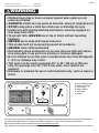
WARNING
• Children have died or been seriously injured when gates are not
securely installed.
• ALWAYS install and use gates as directed, using all required parts.
• STOP using when a child can climb over or dislodge the gate.
• Install only with locking/latching mechanism securely engaged on
side away from child.
• To prevent falls, NEVER use at top of stairs without mounting
hardware.
• NEVER use to keep child away from pool.
• This product will not necessarily prevent all accidents.
• NEVER leave child unattended.
• Periodically check all fasteners to be sure they are tight and secure,
stop using gate if any parts are missing or become damaged.
• Do not attempt to use this gate in temperatures less than 40 degrees
F (4˚C) or damage may result.
• This gate is to be used in openings 26” to 42” (66 cm to 106 cm)
only. On openings over 40” (101.6 cm) wide, door sockets are
required.
• Hardware is included for use in solid materials only, such as wood or
metal.
Your safety gate contains the following:
A. Preassembled gate
B. Casement hinge
C. Gate hinge
D. Door sockets
E. Tape pads
F. Screws
x2
x1
B
x8
F
C
A
D E
x4

Page 3
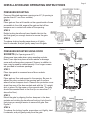
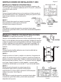
INSTALLATION AND OPERATING INSTRUCTIONS
Figure 2
PRESSURE MOUNTING
Pressure Mounted maximum opening size 40” (if opening is
greater than 40” use Door sockets).
STEP 1
Place gate on floor with handle on the opposite side of area
accessible to the child, expand the gate so that all four
bumpers are in contact with sides of the opening.
STEP 2
Rotate locking handle and insert handle tab into the
slot that gives you enough tension to secure the gate.
STEP 3
To release locking handle press down on it lightly,
twist it outwards, and pull gently away from the gate.
PRESSURE MOUNTED USING DOOR
SOCKETS
(On Openings over 40”)
Always use tape pads when using mounting sockets.
Note: Foam tape may leave a foam residue or damage
some wall surfaces when removed. Screws, in addition to
tape, may be used for added security. Four longer screws
are provided in hardware package.
STEP 1
Place tape pads in recessed area of door sockets.
STEP 2
Place gate on floor and expand in the opening. Be sure to
adhere the door sockets to the opening wall or surface
where the four bumpers touch. Remove the protective cover
sheet from one of the door sockets and with the “U” upright,
stick in place. Do the same on the opposite side. The gate
should be mounted flush to the floor (or no more than 1
1
/
2
”
above the floor).
STEP 3
Mount the gate by aligning the four bumpers in the door
sockets and rotating the handle and locking it into the slot
that gives you enough tension to secure the gate. See
Figure 2.
STEP 4
To release the locking handle, press down on it lightly, twist
it outwards, and pull gently away from the gate.
Figure 1
Figure 3
Figure 4
Figure 5
Figure 6

Page 4
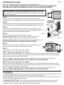
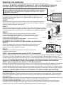
STEP 1
Hold the gate so the locking handle is on the opposite side of the area
accessible to the child and determine on which side you want the gate hinges.
STEP 2
Slide both gate hinges onto the hinge side of the gate and fasten lower hinge
with smaller screw provided (do not fasten top at this time). See Figure 8.
STEP 3
Fasten both the casement hinges to the doorway using the longer screws
provided. Mount upper casement hinge with hinge facing down, mount lower
casement hinge with hinge facing up. See Figure 9.
STEP 4
Determine the direction you desire the gate to swing.
Gate to swing towards you—place bottom gate hinge onto bottom
casement hinge using the hole in the hinge that is closest to you.
Gate to swing from you—Use the hole in the gate hinge furthest from you.
DO NOT ALLOW GATE TO SWING OVER THE STAIRS.
STEP 5
Slide the gate hinge on the top of the gate up to the casement hinge and
fasten the top gate hinge with the small screw provided.
STEP 6
Place tape pads in recessed area of door sockets.
HARDWARE MOUNTED
Used where additional security is required (top of the stairs etc.).
Warning: DO NOT MOUNT HINGES INTO SHEETROCK OR PLASTER. HARDWARE IS
INCLUDED FOR USE IN SOLID MATERIALS ONLY, SUCH AS WOOD OR METAL.
Figure 7
OPERATION
To close the gate: Expand gate so the 2 bumpers fit in the sockets. Rotate locking handle and insert handle
tab into the slot that gives you enough tension to secure the gate.(see figure 2)
To open the gate: Lightly press down on the locking handle, twist handle outward and pull gently away from
the gate. Slide gate together and swing open.
CLEANING INSTRUCTIONS: Wash with warm water using mild liquid soap. Use a soft cloth to avoid
scratching the gate. Rinse with clear water and wipe dry with a soft cloth. NOTE: Never use solvents,
chemicals, scouring powders and sharp tools when cleaning the gate.
STEP 7 (for bumper spacing 21 3/8" apart)
Remove protective cover sheet from one of the sockets, with U upright. Measuring from the bottom of the
socket, place on a flat, even surface 3” above the floor. Mount second socket 23” from the floor (measured
from the bottom of the sockets). See Figure 10.
Screws, in addition to tape pads, may be used for added security. Use two longer screws provided.
Warning: SCREWS ARE REQUIRED IF GATE IS INSTALLED OVER THE STAIRS.
STEP 7 (for bumper spacing 17 3/8" apart)
Remove protective cover sheet from one of the sockets, with U upright. Measuring from the bottom of the
socket, place on a flat, even surface 5” above the floor. Mount second socket 21” from the floor (measured
from the bottom of the sockets). See Figure 10.
Screws, in addition to tape pads, may be used for added security. Use two longer screws provided.
Warning: SCREWS ARE REQUIRED IF GATE IS INSTALLED OVER THE STAIRS.
BEFORE BEGINNING YOU MUST DETERMINE WHICH VERSION OF GATE YOU
HAVE BY MEASURING THE BUMPER SPACING ON YOUR GATE. SEE FIGURE 7.
If this measures 21 3/8", follow dimension and figures A. If it measures 17 3/8", follow
dimensions and figures B.
A = 21 3/8"
B = 17 3/8"
Figure 8
Figure 9
23
A = 23"
B = 21"
A = 3"
B = 5"
Figure 10
SLIDE GATE HINGE
PAST MOUNTING HOLE
WITH TAB ORIENTATED
AS SHOWN (DO NOT
FASTEN AT THIS TIME)
DRILL
1
/
16
" (1.59mm)
PILOT HOLES
MOUNT IN THIS
HOLE FOR GATE
TO SWING
TOWARD YOU
MOUNT IN THIS
HOLE FOR GATE
TO SWING AWAY
A = 23 3/8"
B = 21 3/8"
A = 4 1/2"
B = 6 1/2"
A = 3 3/4"
B = 5 3/4"
A = 22 5/8"
B = 20 5/8"

Productos de calidad
para su estilo de vida
Diseñado para usarse con niños de 6 a 24 meses de edad
INSTRUCCIONES PARA TODOS LOS MODELOS
8620 / 8629 / 8715 / 8717 / 8718 / 8719
IMPORTANTE: ¡CONSERVE COMO REFERENCIA FUTURA!
Para obtener consejos útiles e instrucciones, visite nuestro sitio web:
www.northstatesind.com, o Comuníquese con nuestro Departamento de Atención al Cliente
por correo electrónico: CustomerService@northstatesind.com
Teléfono: +1 (763) 486-1756 o número gratuito: (800) 848-8421

User instructions . . . . . . . . . . . . . . . . .page 2
Instrucciones para el usuario. . . . . .página 6......
x2
x1
B
x8
F
C
A
D E
x4
Página 6
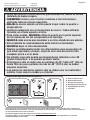
ADVERTENCIA
•
Niños han muerto o sufrido lesiones graves porque un recinto no estaba
instalada de manera segura.
•
SIEMPRE instale y use el recinto conforme a las instrucciones,
utilizando todas las piezas requeridas.
• DEJE de usarla cuando un niño puede trepar sobre la puerta o
desprenderla.
• Instálela solamente con el mecanismo de cierre / traba activado
firmente en el lado opuesto al niño.
• Para evitar caídas, NUNCA utilice la puerta en la parte superior
de las escaleras sin los componentes de montaje.
•
NUNCA debe usarse para mantener a un niño alejado de una piscina.
• Este producto no necesariamente evita todos los accidentes.
• NUNCA dejar al niño desatendido.
• Revisar periódicamente todos los afianzadores para asegurarse de
que estén apretados y firmes, dejar de usar esta barrera si falta
cualquier pieza o si se daña.
• No intentar usar esta puerta con temperaturas inferiores a los 40
grados Fahrenheit, o se pueden producir daños.
• Esta barrera sólo se debe usar en portales de 26” hasta 42” (66 cm
hasta 106 cm) para portales de mas de 40” (101.6 cm) se deben
emplear cojinetes.
• Las piezas de instalción ajuntas sólo se deben usar en materiales
solidos, tales como la madera o el metal.
A. Puerta prearmada
B. Bisagra del marco
C. Bisagra de la puerta
D. Receptáculos de puerta
E. Almohadillas de cinta
F. Tornillios
Para asegurar el funcionamiento seguro, las piezas adicionales o de repuesto deben obtenerse
únicamente de North States o de sus distribuidores autorizados. La información de contacto aparece
en la portada de estas instrucciones.
Se pueden pedir piezas de repuesto en www.northstatesind.com
Cualquier daño a la propiedad durante la instalación de su puerta de seguridad es exclusiva
responsabilidad usario fínal.
Su puerta de seguridad incluye lo siguiente:

Página 7
INSTRUCCIONES DE INSTALACIÓN Y USO
MONTAJE A PRESION CONVENCIONAL
El tamaño máximo de la abertura para el montaje a presión es de
101.6 cm (40)” (si la abertura mide más de 101.6 cm (40”), utilice los
receptáculos para puerta).
PASO 1
Coloque la puerta sobre el piso con la manija en el lado opuesto al
área accesible para el niño y extienda la puerta para que los cuatro
topes tengan contacto con los lados de la
abertura.
PASO 2
Gire la manija de enganche e inserte la lengüeta
de la manija en la ranura que le dé tensión
suficiente para asegurar la puerta.
PASO 3
Para liberar la manija de enganche, presiónela hacia abajo
suavemente, gírela hacia fuera y tire de ella suavemente alejándola
de la puerta.
Figura 2
Figura 1
Figura 6
MONTAJE A PRESIÓN CON RECEPTÁCULOS PARA
PUERTA
(en aberturas de más de 101.6 cm (40”))
Siempre use almohadillas adhesivas al utilizar receptáculos de montaje.
Nota: La cinta adhesiva de espuma puede dejar residuos de espuma
o dañar la superficie de ciertas paredes al retirarse. Pueden usarse
tornillos, además de la cinta adhesiva, para mayor seguridad. Se
proveen cuatro tornillos largos en el paquete de componentes de
sujeción.
PASO 1
Coloque las almohadillas adhesivas en el área hundida de los
receptáculos para puerta.
PASO 2
Ponga la puerta en el suelo y amplíe en la abertura. Asegúrese de
adherir los zócalos de la puerta a la pared o superficie de apertura
donde se tocan los cuatro topes. Retire la cubierta protectora de uno
de los zócalos de la puerta y con la “U” en posición vertical, péguelo
en el lugar. Haga lo mismo en el lado opuesto. La puerta debe
montarse al ras del suelo (o no más de 1
1
/
2
" por encima del suelo).
PASO 3
Monte la puerta alineando los cuatro topes de los
receptáculos para puerta y girando la manija para
engancharla en la ranura que le dé tensión suficiente para
asegurar la puerta. Vea la figura 2.
PASO 4
Para liberar la manija de enganche, presiónela hacia abajo
suavemente, gírela hacia fuera y tire de ella suavemente
alejándola de la puerta.
Figura 4
Figura 5
Figura 3

Figura 9
Figura 8
PASO 1
Sostenga la puerta de manera que la manija de enganche quede en el lado
opuesto al área accesible para el niño y determine de qué lado quiere las
bisagras para puerta.
PASO 2
Deslice las dos bisagras para puerta sobre el lado con bisagras de la puerta y
sujete la bisagra inferior con el tornillo pequeño provisto (no sujete la bisagra
superior en este momento). Vea Figura 8.
PASO 3
Sujete ambas bisagras para marco al marco de la puerta, utilizando los tornillos
largos provistos. Monte la bisagra para marco superior con la bisagra hacia abajo
y monte la bisagra para marco inferior con la bisagra hacia arriba. Vea Figura 9.
PASO 4
Determine la dirección en la que quiere que se abra la puerta.
La puerta se abrirá hacia usted:—coloque la bisagra para puerta
inferior en la bisagra para marco inferior utilizando el orificio de la
bisagra más cercano a usted.
La puerta se abrirá alejándose de usted: —use el orificio en la
bisagra para puerta más lejano de usted.
NO PERMITA QUE LA PUERTA SE ABRA SOBRE LAS ESCALERAS.
PASO 5
Deslice la bisagra para puerta en la parte superior de la puerta hacia
arriba hasta la bisagra para marco y sujete la bisagra para puerta
superior con el tornillo pequeño provisto.
PASO 6
Coloque las almohadillas adhesivas en el área hundida de los
receptáculos para puerta.
PASO 7 (para el espacio entre tope de 21 3/8" de separación)
Retire la cubierta protectora de uno de los zócalos, con la U en posición vertical. Medición desde la parte inferior
de la toma, colocar en una superficie plana, incluso 3" por encima del suelo. Monte el segundo zócalo a 23"
(medidos desde la parte inferior de los zócalos) por encima del zócalo inferior. Vea la Figura 10. Pueden usarse
tornillos, además de las almohadillas adhesivas, para mayor seguridad. Use dos de los tornillos largos provistos.
Advertencia: SE REQUIEREN TORNILLOS SI SE INSTALA LA PUERTA SOBRE LAS ESCALERAS.
PASO 7 (para el espacio entre tope de 17 3/8" de separación)
Retire la cubierta protectora de uno de los zócalos, con la U en posición vertical. Medición desde la parte inferior
de la toma, colocar en una superficie plana, incluso 5" por encima del suelo. Monte el segundo zócalo a 21"
(medidos desde la parte inferior de los zócalos) por encima del zócalo inferior. Vea la Figura 10. Pueden usarse
tornillos, además de las almohadillas adhesivas, para mayor seguridad. Use dos de los tornillos largos provistos.
Advertencia: SE REQUIEREN TORNILLOS SI SE INSTALA LA PUERTA SOBRE LAS ESCALERAS.
OPERACIÓN
Para cerrar la puerta: Extienda la puerta para que los 2 topes entren en los receptáculos. Gire la manija de
enganche e inserte la lengüeta de la manija en la ranura que le dé tensión suficiente para asegurar la puerta
(vea la figura 2).
Para abrir la puerta: Presione la manija de enganche suavemente hacia abajo, gire la manija hacia fuera y tire
de ella suavemente alejándola de la puerta. Deslice la puerta para contraerla y ábrala.
INSTRUCCIONES DE LIMPIEZA: Lave con agua tibia y jabón líquido suave. Use un paño suave para no
rasguñar la puerta. Enjuague con agua limpia y seque con un paño suave. NOTA: Nunca utilice solventes,
sustancias químicas, polvos abrasivos ni herramientas filosas al limpiar la puerta.
Página 8
ANTES DE COMENZAR, DEBE DETERMINAR QUÉ VERSIÓN DE LA PUERTA
POSEE AL MEDIR EL ESPACIADO DEL TOPE EN SU PUERTA. VEA LA FIGURA 7.
Si esto mide 21 3/8", siga la dimensión y las figuras A. Si mide 17 3/8", siga las
dimensiones y las figuras B.
Figura 7
A = 21 3/8"
B = 17 3/8"
MONTAJE CON HERRAJES
Se utiliza cuando se requiere seguridad adicional (a la cabeza de las escaleras, etc.).
Advertencia: NO MONTE LAS BISAGRAS EN TABLAROCA O YESO. LOS COMPONENTES DE SUJECIÓN
INCLUIDOS SON SOLO PARA USARSE EN MATERIALES SÓLIDOS, TALES COMO MADERA O METAL.
Deslice la bisagra pasado el agujero
de montaje con la lengüeta orientada
como se muestra (no la asegure
en este momento).
Perfore los agujeros guía
de
1
/16"
(1.59mm).
Monte en este agujero
para que la puerta se
abra hacia usted.
Monte en este agujero
para que la puerta se abra
alejandose de usted.
A = 23 3/8"
B = 21 3/8"
A = 22 5/8"
B = 20 5/8"
A = 4 1/2"
B = 6 1/2"
A = 3 3/4"
B = 5 3/4"
Figura 10
23
A = 23"
B = 21"
A = 3"
B = 5"
-
 1
1
-
 2
2
-
 3
3
-
 4
4
-
 5
5
-
 6
6
-
 7
7
-
 8
8


NORTH STATES 8717 Instructions Manual
- Tipo
- Instructions Manual
- Este manual también es adecuado para
en otros idiomas
- English: NORTH STATES 8717
Artículos relacionados
-
 NORTH STATES 4916 Instructions Manual
-
 NORTH STATES 8750 Instructions Manual
-
 NORTH STATES 8750 Superyard Colorplay Ultimate Instrucciones de operación
-
 NORTH STATES 8800 Manual de usuario
-
 NORTH STATES 5455 MyPet Wide Walk Thru EasyPass Pet Gate Manual de usuario
-
 NORTH STATES 5446 Wide Deco EasyPass Pet Gate Manual de usuario
-
NORTH STATES 5455 MyPet Wide Walk Thru EasyPass Pet Gate Manual de usuario
-
 NORTH STATES 5446 Manual de usuario
-
 NORTH STATES 8766 Instructions Manual


Otros documentos
-
 North States Pet 8871 Guía de instalación
-
 North States MyPet 8679 Manual de usuario
-
TODDLEROO 4600 Manual de usuario
-
 North States MyPet 8701 Manual de usuario
-
 North States MyPet 8805 Manual de usuario
-
 North States MyPet 4944 Manual de usuario
-
Munchkin Auto Close Modern Manual de usuario
-
-
Evenflo Secure Step Manual de usuario
-
 Kidco G20d Safeway Guía del usuario


