Quality Products
for the way you live
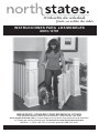
INSTRUCTIONS FOR MODELS
8693 / 8701
IMPORTANT: PLEASE KEEP FOR FUTURE REFERENCE!
For helpful tips and instructions, please visit our website: www.northstatesind.com or
contact our Customer Care department via email: CustomerService@northstatesind.com
Phone: (763) 486-1754 or Toll Free: (800) 848-8421
PN 26462
Re v 11/ 2023

Page 2
User instructions . . . . . . . . . . . . . . . . .page 2
Instrucciones para el usuario. . . . . .página 6
......... ......... .........
To ensure safe operation additional or replacement parts should be obtained only from North States or
its authorized distributors. Contact information appears on the cover of these instructions. Replacement
parts can be ordered at www.northstatesind.com. Any damage to property during installation/removal
and or operation of your safety gate is the sole responsibility of the end user.
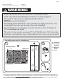
Your safety gate contains the following:
A. Gate Frame
B. Installation
Template
C. Mounting
Sockets
D. Screws
x16
x4
x1
A
C
D
• STOP using when a pet can climb over or dislodge the gate.
• Install only with locking/latching mechanism securely engaged.
• This product will not necessarily prevent all accidents.
• NEVER leave pet unattended.
• Periodically check all fasteners to be sure they are tight and secure, stop
using gate if any parts are missing or become damaged.
• Do not attempt to use this gate in temperatures less than 40 degrees F
(4˚C) or damage may result.
• This gate is to be used in openings 27” to 41” (68.58 cm to 104.14 cm) only.
• Hardware is included for use in solid materials only, such as wood or metal.
WARNING
RELEASE HANDLE
RH HINGE POSTS
LOCKING PEGS
B

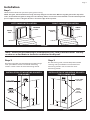
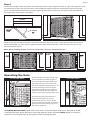
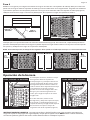
Installation
Step 1
Determine the direction you want your gate to swing.
NOTE: The gate, when installed correctly, will only swing in one direction. When using this gate at the top of the
stairs, do not allow the gate to swing over the stairway. Please ensure the release handle is on the side away from
pet. See Figure 1. Recess the gate at least 1" from the edge of the top stair.
Step 2
On the hinge side, use the template marked "hinge
side" provided to secure two of the mounting
sockets. Use 4 screws for each mounting socket.
Step 3
On the locking side, use the template marked
"locking side" provided to secure two of the
mounting sockets. Use 4 screws for each
mounting socket.
LEFT SWING INSTALLATION RIGHT SWING INSTALLATION
FIGURE 1
NOTE: Ensure you are mounting to solid materials only, such as wood or metal. You may
need to use a stud nder to locate the stud behind the drywall.
20
1
/
2
"
4
1
/
2
"
OR WALL
BOTTOM
FIGURE 2
INSTALLATION OF MOUNTING SOCKETS
FOR HINGES
FIGURE 3
22"
3"
DOOR JAMB
OR WALL
EQUAL
DISTANCE
TOP &
BOTTOM
INSTALLATION OF MOUNTING SOCKETS
FOR LOCKING SIDE
Page 3
LOCKING
SIDE
HINGE
SIDE
HINGE
SIDE
LOCKING
SIDE

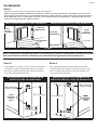
Step 4
To attach the hinge side of the gate to the mounting sockets, refer to Figure 4. Note, to align the hinge posts over
the mounting sockets, the gate must be at a 45-90 degree angle to the plane of the opening. Once the hinge
posts are aligned over the mounting sockets (Figure 5), set the gate into place. The gate can be removed from
the opening by reversing this procedure.
STAIRS
SIDE AT LEAST
FIGURE 4 FIGURE 5
SIDE
HANDLE
SIDE
HANDLE
FIGURE 6
Check to see that the release handle is positioned properly (Figure 6). If not, simply depress the locking tabs to
release the handle, this may require slight force. Move the handle to the top side of the gate and snap it into
place on the locking tabs.
NOTE: When installing the gate, the release handle must be on the side away from pet.
Operating the Gate
TO CLOSE GATE
FIGURE 7
TO OPEN GATE
FIGURE 8
To lock the gate, align the locking pegs
over the mounting sockets (Figure 7)
and set the gate into place. Make sure
that each time you use the gate, both
the top and bottom locking pegs are set
into the mounting sockets. Test your
installation by pulling up on both the
hinge and locking sides of the gate to
make sure you can’t dislodge either side.
To unlock the gate, pull back on the
release handle (and the panel it is
attached to) until the release handle
clears the mounting socket. Then lift the
gate panel until the locking pegs clear
the sockets (Figure 8).
CLEANING INSTRUCTIONS: Wash with warm water using mild liquid soap. Use a soft cloth to avoid
scratching the gate. Rinse with clear water and wipe dry with a soft cloth. NOTE: Never use solvents,
chemicals, scouring powders or sharp tools when cleaning the gate.
Page 4

Productos de calidad
para su estilo de vida
INSTRUCCIONES PAR A LOS MODELES
8693 / 8701
IMPORTANTE: ¡CONSERVE COMO REFERENCIA FUTURA!
Para obtener consejos útiles e instrucciones, visite nuestro sitio web:
www.northstatesind.com, o Comuníquese con nuestro Departamento de Atención
al Cliente por correo electrónico: CustomerService@northstatesind.com
Teléfono: +1 (763) 486-1754 o número gratuito: (800) 848-8421

Página 6
User instructions . . . . . . . . . . . . . . . . .page 2
Instrucciones para el usuario. . . . . .página 6
........... ............ ............
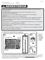
ADVERTENCIA
Para asegurar el funcionamiento seguro, las piezas adicionales o de repuesto deben obtenerse únicamente
de North States o de sus distribuidores autorizados. La información de contacto aparece en la portada de
estas instrucciones. Se pueden pedir piezas de repuesto en www.northstatesind.com Cualquier daño a la
propiedad durante la instalación/desmontaje o el funcionamiento de su puerta de seguridad es
responsabilidad exclusiva del usuario nal.
Su puerta de seguridad incluye lo siguiente:
A. Marco de la
puerta
B. Plantilla de
instalación
C. Cojinete de
montaje
D. Tornillos
x16
x4
x1
A
C
D
• DEJE DE USARLA cuando un mascota pueda trepar sobre la puerta o
desprenderla.
• Instálela únicamente con el mecanismo de bloqueo y cierre
debidamente enganchado.
• Este producto no necesariamente evitará todos los accidentes.
• NUNCA deje a un mascota sin supervisión.
• Revisar periódicamente todos los aanzadores para asegurarse de que
estén apretados y rmes, dejar de usar esta barrera si falta cualquier
pieza o si se daña.
• No intentar usar esta puerta con temperaturas inferiores a los 40 grados
Fahrenheit, o se pueden producir daños.
• Esta barrera sólo se debe usar en portales de 27” hasta 41” (68.58 cm
hasta 104.14 cm).
• Las piezas de instalción ajuntas sólo se deben usar en materiales solidos,
tales como la madera o el metal.
ASA DE DESENGANCHE
RH POSTES DE
LA BISAGRA
CLAVIJAS DE
ENGANCHE
B

Instalación
Paso 1
Determine la dirección en la que desea que se abra la puerta.
NOTA: La puerta, cuando se instala correctamente, se abrirá en una sola dirección. Al utilizar esta puerta en la
parte superior de las escaleras, no permita que la puerta se abra sobre las escaleras. Asegúrese de que la manija
de desenganche esté en el lado opuesto al que se encuentra la mascota. Vea Figura 1. Aleje la puerta, al menos,
2.54 cm (1") del borde de la escalera superior.
Paso 2
En el lado de las bisagras, utilice la plantilla marcada
"lado de las bisagras" proporcionada para asegurar
dos de los casquillos de montaje. Utilice 4 tornillos
para cada casquillo de montaje.
Paso 3
En el lado de bloqueo, utilice la plantilla marcada
"lado de bloqueo" proporcionada para asegurar dos
de los casquillos de montaje. Utilice 4 tornillos para
cada casquillo de montaje.
NOTA: Asegúrese de montar únicamente en materiales sólidos, como madera o metal. Es posible
que necesite utilizar un buscador de vigas para ubicar la viga detrás del panel de yeso.
Página 7
SIDE
SIDE
ESCALERAS
INSTALACION HACIA EL LADO IZQUIERDO
SIDE
SIDE
INSTALACION HACIA EL LADO DERECHO
ESCALERAS
FIGURA 1
LADO
DE LA
BISAGRA
LADO
DE LA
BISAGRA
LADO DE
ENGANCHE
LADO DE
ENGANCHE
20
1
/
2
"
4
1
/
2
"
OR WALL
BOTTOM
FIGURA 2
22"
3"
DOOR J
AMB
OR WALL
EQUAL
DISTANCE
TOP &
BOTTOM
FIGURA 3
INSTALACION DE LOS COJINETES DE
MONTAJE PARA LAS BISAGRAS
INSTALACION DE LOS COJINETES DE
MONTAJE PARA EL LADO DE ENGANCHE
Marco interior de
la puerta o pared
Marco interior de
la puerta o pared
IGUAL
DISTANCIA
ARRIBA Y
ABAJO
IGUAL
DISTANCIA
ARRIBA Y
ABAJO
201/2" = 51.25 cm
22" = 55.88 cm
41/2" = 11.25 cm
3" = 7.62cm

Paso 4
Reérase a la Figura 4 para asegurar el lado de las bisagras de la barrera a los cojinetes de montaje. Nota para alinear los
postes de las bisagras sobre los cojinetes de montaje, la barrera debe estar en un ángulo de 45 - 90 grados con referencia
al plano de la apertura. Una vez que los postes de las bisagras están alineados sobre los cojinetes de montaje (Figura 5)
coloque la barrera en su lugar. La barrera se puede quitar de la apertura al seguir este proceso en reversa.
Verique que la manija de liberación esté colocada correctamente (Figura 6). De lo contrario, simplemente presione las
pestañas de bloqueo para liberar el mango; esto puede requerir una ligera fuerza. Mueva la manija hacia el lado superior
de la puerta y colóquela en su lugar en las pestañas de bloqueo.
NOTA: Al instalar la puerta, la manija de desenganche debe quedar en el lado opuesto al que se encuentra la mascota.
Operación de la barrera
Para bloquear la barrera, alinee las clavijas
de enganche sobre los cojinetes de
montaje (Figura 7) y coloque la barrera en
su lugar. Asegúrese de que tanto la clavija
de enganche superior como la inferior se
colocan dentro de los cojinetes de montaje
cada vez que usa la barrera. Ponga a
prueba su instalación empujando las dos
bisagras y los lados de enganche hacia
arriba, para asegurarse que no se soltará
ningún lado.
Para abrir la barrera, tire del asa de
desenganche, y del panel al que está sujeta,
hasta que el asa de desenganche pasa el
cojinete de montaje. Luego levante el panel
de la barrera hasta que las clavijas de
enganche salen de los cojinetes (Figura 8).
INSTRUCCIONES DE LIMPIEZA: Lave con agua tibia y jabón líquido suave. Use un paño suave para no
rasguñar la puerta. Enjuague con agua limpia y seque con un paño suave. NOTA: Nunca utilice solventes,
sustancias químicas, polvos abrasivos ni herramientas losas al limpiar la puerta.
Página 8
STAIRS
SIDE AT LEAST
FIGURA 4 FIGURA 5
ESCALERAS
LADO DE LA
BISAGRA POR LO
MENOS 45˚
SIDE
HANDLE
SIDE
HANDLE
FIGURA 6
LADO
DE LA
BISAGRA
LADO
DE LA
BISAGRA
ASA DE DESENGANCHE
PARA ABRIR LA BARRERA
FIGURA 8
PARA CERRAR LA BARRERA
FIGURA 7
-
 1
1
-
 2
2
-
 3
3
-
 4
4
-
 5
5
-
 6
6
-
 7
7
-
 8
8


North States MyPet 8701 Manual de usuario
- Tipo
- Manual de usuario
- Este manual también es adecuado para
en otros idiomas
- English: North States MyPet 8701 User manual
Artículos relacionados
-
 North States MyPet 8679 Manual de usuario
-
 North States MyPet 8805 Manual de usuario
-
 North States MyPet 4944 Manual de usuario
-
 North States MyPet 4955 Manual de usuario
-
 North States MyPet 5274 Manual de usuario
-
 North States MyPet 5435 Manual de usuario
-
NORTH STATES 5455 MyPet Wide Walk Thru EasyPass Pet Gate Manual de usuario