Siemens GPC166.1P Damper Actuator Manual de usuario
- Tipo
- Manual de usuario

Installation Instructions
Notice d’installation
Instrucciones de montaje
Document No. 129-585
March 20, 2019
OpenAir® GPC Series, Spring Return, 35 lb-in (4 Nm)
Rotary Electronic Damper Actuators
Déclencheurs électroniques rotatoires d'amortisseur
Actuadores electrónicos rotatorios del apagador
Contents
Contenu
Contenido
Item Number: 129-585, Rev. DA Page 1 of 8
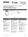
a. Actuator
b. Mounting bracket
c. Mounting screws
d. 3 mm hex key
Figure 1.
Hints/Warnings
Conseils/Mise en garde
Indicaciones/Consejos
Store these instructions with the
actuator or with the plant
documentation.
Warning
Do not open the actuator!
Only authorized personnel are to
connect actuators.
Do not expose the actuator's
connecting cables to water or
lay the cables in water.
Device of protection
class II (protective
insulation)
Device of protection
class III (protective
insulation)
Wiring and commissioning, see
Technical Instructions 155-782.
Cette notice est à conserver avec
le servomoteur ou avec la
documentation de l’installation.
Avertissement !
Ne pas ouvrir le servomoteur!
Le branchement des servomoteurs
ne doit être effectué que par un
personnel qualifié.
Les câbles de raccordement du
servomoteur ne doivent en
aucun cas entrer en contact
avec l'eau.
Classe d'isolation II
(isolation de protection)
Classe d'isolation III
(isolation de protection)
Câblage et mise en service :
se référer aux instructions
techniques du servomoteur,
document n°155-782.
Conserve estas instrucciones con el
actuador o con la documentación de
la instalación!
Precaución
No abra el accionador!
Sólo el personal autorizado puede
conectar los actuadores.
No exponer los cables de conexión
del actuador al agua ni dejarlos en
contacto con ésta.
Equipo con tipo de
protección II (aislamiento
protegido)
Equipo con tipo de
protección III (aislamiento
protegido)
Cableado y puesta en marcha
Ver la documentación técnica
155-782 del actuador.

Document No. 129-585
Installation Instructions
March 20, 2019
Page 2 of 8 Siemens Industry, Inc.
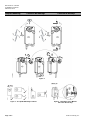
Adapter Mounting
Positions de montage
Posición de montaje
Figure 2.
Figure 3. Acceptable Mounting Positions. Figure 4. DIP Switch Cover Must be
Closed for IP54 Listing.

Document No. 129-585
Installation Instructions
March 20, 2019
Siemens Industry, Inc. Page 3 of 8
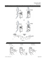
Shaft Mounting
Montage sur l’axe des volets
Montaje sobre el eje
Figure 5.
Manual Override
Positionnement manuel
Reposición manual
• winding • locking • releasing
• positionner • verrouiller • déverrouiller
• posicionar • enganchar • desenganchar

Document No. 129-585
Installation Instructions
March 20, 2019
Page 4 of 8 Siemens Industry, Inc.
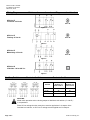
Wiring Diagrams
Schémas de raccordement
Diagramas de cableado
GPC12x.1P
2-Position: 24 Vac/dc
Figure 6.
Class III
GPC13x.1P
Floating: 24 Vac/dc
Figure 7.
Class III
GPC16x.1P
Modulating: 24 Vac/dc
Figure 8.
Class III
GPC32x.1U
2-Position: 100 to 240 Vac
Figure 9.
Auxiliary Switches Contacts Auxiliaires Contacto Auxiliar
Actuator
Position
Switch A
Common S1
Connected to
Switch B
Common S4
Connected to
0° to 5°
S3
S6
5° to 85°
S2
S6
85° to 90°
S2
S5
CAUTION:
Mixed switch operation to the switching outputs of both dual end switches (5° and 85°)
is not permitted.
Either AC line voltage from the same phase must be applied to all six outputs of the
fixed dual end switches, or UL-Class 2 voltage must be applied to all six outputs.

Document No. 129-585
Installation Instructions
March 20, 2019
Siemens Industry, Inc. Page 5 of 8
DIP Switches Communtateur DIP DIP Contacto
NOTE: The black position indicates the active switch setting.
Description
Label
Description
Function
2 to 10 Vdc
0 to 10 Vdc
Control signal selection
Not In Use
Inverse Acting
Direct-Acting
Input signal inversion
Figure 10. DIP Switches.
Control Signal
Selection
Selects the control and feedback signals
Input Signal Inversion
Allows inverting the control input signal
The arrow direction indicates opening or closing (closing or opening) when operating
an actuator with a given control signal.
= Direct acting (Factory setting)
Input signal 0 Vdc ► fail-safe position
= Inverse acting
Input signal 10 Vdc ► fail-safe position
Wire Designations Désignations de fil Designaciones del alambre
Table 1.
Connecting
Standard
Symbol
Function
Color
Color
Symbol
24 Vac/dc
Actuator
1
Supply (SP)
Red
RD
2
System Neutral
Black
BK
6
Control signal clockwise
Violet
VT
7
Control signal counterclockwise
Orange
OG
8
Input Signal: 0 (2) to 10 Vdc or 10 to 0 (2) Vdc
(GPC16x)
Gray
GY
9
Position Output: 0 (2) to 10 Vdc or 10 to 0 (2) Vdc
(GPC16x)
Pink
PK
120 Vac
3
Supply
Black
BK
4
Neutral
White
WH
Auxiliary
Switches
1
Switch A − Common
S1
Gray/red
2
Switch A − N.O.
S2
Gray/blue
3
Switch A − N.C.
S3
Gray/pink
4
Switch B − Common
S4
Black/red
5
Switch B − N.O.
S5
Black/blue
6
Switch B − N.C.
S6
Black/pink

Document No. 129-585
Installation Instructions
March 20, 2019
Page 6 of 8 Siemens Industry, Inc.
Wire Designations Désignations de fil Designaciones del alambre
Table 2.
Câbles de
raccordement
Symbole
Standard
Fonction
Couleur
Étiquette
Servomoteur
24 V~/-
1
Alimentation (SP)
Rouge
RD
2
Neutre (SN)
Noir
BK
6
Signal de commande – sens des aiguilles
Violet
VT
7
Signal de commande – sens contraire des aiguilles
Orange
OG
8
Signal de commande 0…10 V- ou 2…10 V- ou
10…0 V- ou 10…2 V- (GPC16x)
Gris
GY
9
Sortie 0…10 V- ou 2-10 V- ou 10…0 V- ou 10 … 2 V-
(GPC16x) pour indicateur de position
Rose
PK
Servomoteurs
120 V~
3
Secteur
Noir
BK
4
Neutre
Blanc
WH
Auxiliary
Switches
1
Switch A − Common
S1
Gris/rouge
2
Switch A − N.O.
S2
Gris/bleu
3
Switch A − N.C.
S3
Gris/rose
4
Switch B − Common
S4
Noir/rouge
5
Switch B − N.O.
S5
Noir/bleu
6
Switch B − N.C.
S6
Noir/rose
Table 3.
Conexión
Símbolo
estándar
Función
Color
Color
Abreviatura
Accionador
24V ca/cc
1
Suministro de corriente (SP)
Rojo
RD
2
Sistema neutral
Negro
BK
6
Señal de control-sentido de las agujas del rejol
Violeta
VT
7
Señal de control - sentido contrario a las agujas del
reloj
Naranja
OG
8
Señal de entrada 0 a 10V o 2 a 10V o 10 a 0V o 10 a
2V (GPC16x)
Gris
GY
9
Salida de 0 a 10V o 2 a 10V o 10 a 0V o 10 a 2V cc
(GQD15x) para indicador de posición
Rosado
PK
Accionador
120V ca
3
Línea
Negro
BK
4
Neutro
Blanco
WH
Conmutadores
Auxiliares
1
Switch A − Común
S1
Gris/rojo
2
Switch A − N.O.
S2
Gris/azul
3
Switch A − N.C.
S3
Gris/rosado
4
Switch B − Común
S4
Negro/rojo
5
Switch B − N.O.
S5
Negro/azul
6
Switch B − N.C.
S6
Negro/rosado

Document No. 129-585
Installation Instructions
March 20, 2019
Siemens Industry, Inc. Page 7 of 8
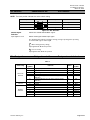
Retrofit Wiring
Modulating Control
(2 to 10 Vdc)
Function
Siemens
GPC Series
Belimo
LF Series
Honeywell
MS7505 Series
Johnson
M9203 Series
Color
Number
Color
Number
Terminal
Only
Number
Color
Number
Supply (24V)
Red
1
Red
2
1
Red
2
Common
Black
2
Black
1
2
Black
1
0(2) to 10 Vdc Input
Gray
8
White
3
3
Gray
3
0(2) to 10 Vdc Feedback
Pink
9
Orange
5
5
Orange
4
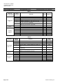
2-Position Control
(24 Vac/Vdc)
Function
Siemens
GPC Series
Belimo
LF Series
Honeywell
MS8105 Series
Johnson
M9203 Series
Color
Number
Color
Number
Terminal
Only
Number
Color
Number
Supply (24V)
Red
1
Red
2
1
Red
2
Common
Black
2
Black
1
2
Black
1
2-Position Control
(120 Vac)
Function
Siemens
GPC Series
Belimo
LF Series
Honeywell
MS4105 Series
Johnson
M9203 Series
Color
Number
Color
Number
Terminal
Only
Number
Color
Number
Line (120V)
Black
3
Black
2
1
Black
2
Neutral
White
4
White
1
2
White
1
Postcâblage
Commande
progressive
(2…10 V-)
Siemens
Série GPC
Belimo
Série LF
Honeywell
Série MS7505
Johnson
Série M9203
Couleur
Numéro
Couleur
Numéro
Terminal
seulement
Numéro
Couleur
Numéro
Alimentation (24 V)
Rouge
1
Rouge
2
1
Rouge
2
Commun
Noir
2
Noir
1
2
Noir
1
Entrée 0(2)…10 V-
Gris
8
Blanc
3
3
Gris
3
Retroaction 0(2)…10 V-
Rose
9
Orange
5
5
Orange
4
Commande TOR
(24 Vac/Vdc)
Siemens
Série GPC
Belimo
Série LF
Honeywell
Série MS8105
Johnson
Série M9203
Couleur
Numéro
Couleur
Numéro
Terminal
seulement
Numéro
Couleur
Numéro
Alimentation (24 V)
Rouge
1
Rouge
2
1
Rouge
2
Commun
Noir
2
Noir
1
2
Noir
1
Commande TOR
(120 Vac)
Siemens
Série GPC
Belimo
Série LF
Honeywell
Série MS4105
Johnson
Série M9203
Couleur
Numéro
Couleur
Numéro
Terminal
seulement
Numéro
Couleur
Numéro
Alimentation (120 V)
Noir
3
Noir
2
1
Noir
2
Neutre
Blanc
4
Blanc
1
2
Blanc
1

Document No. 129-585
Installation Instructions
March 20, 2019
Information in this publication is based on current specifications. The company reserves the right to make changes in specifications and models as design
improvements are introduced. OpenAir is a registered trademark of Siemens Schweiz, AG. Other product or company names mentioned herein may be the
trademarks of their respective owners. © 2019 Siemens Industry, Inc.
Les informations contenues dans ce document sont basées sur les caractéristiques les plus récentes. Nous nous réservons le droit de modifier ces caractéristiques,
de même que les modèles, à mesure que des évolutions techniques sont introduites. OpenAir est une marque de Siemens Schweiz, AG. Tout autre nom de produit
ou de société mentionné dans ce document peut être la marque de son propriétaire respectif.
© 2019 Siemens Industry, Inc.
Este documento ha sido preparado en base a especificaciones actuales. La compañía se reserva el derecho de modificar las especificaciones, así como los
modelos, a medida que se incorporen nuevas mejoras técnicas. OpenAir es marca de Siemens Schweiz, AG. Los nombres de otros productos o compañías aquí
mencionados serán las marcas de sus respectivos propietarios. © 2019 Siemens Industry, Inc.
Siemens Industry, Inc.
Building Technologies Division
1000 Deerfield Parkway
Buffalo Grove, IL 60089-4513
USA
Tel. +1-847-215-1000
Your feedback is important to us. If you have
comments about this document, please send them
to sbt_technical.editor.us.sbt@siemens.com
Document No. 129-585
Printed in the USA
Page 8 of 8
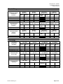
Alambrado de retrofit
Control modulador
(2 to 10 Vdc) Fonción
Siemens
GPC Serie
Belimo
LF Serie
Honeywell
MS7505 Serie
Johnson
M9203 Serie
Color
Número
Color
Número
Terminal Solo
Número
Color
Número
Alimento (24V)
Rojo
1
Rojo
2
1
Rojo
2
Común
Negro
2
Negro
1
2
Negro
1
0(2) to 10 Vdc Entrada
Gris
8
Blanco
3
3
Gris
3
0(2) to 10 Vdc
Realimentacion
Rosado
9
Naranja
5
5
Naranja
4
Control de 2
posiciones
(24 Vac/Vdc) Fonción
Siemens
GPC Serie
Belimo
LF Serie
Honeywell
MS8105 Serie
Johnson
M9203 Serie
Color
Número
Color
Número
Terminal Solo
Número
Color
Número
Alimento (24V)
Rojo
1
Rojo
2
1
Rojo
2
Común
Negro
2
Negro
1
2
Negro
1
Control de 2
posiciones
(120 Vac) Fonción
Siemens
GPC Serie
Belimo
LF Serie
Honeywell
MS4105 Serie
Johnson
M9203 Serie
Color
Número
Color
Número
Terminal Solo
Número
Color
Número
Linea (120V)
Negro
3
Negro
2
1
Negro
2
Neutro
Blanco
4
Blanco
1
2
Blanco
1
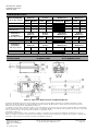
Dimensions
in Inches (mm)
Dimensions
en pouces (mm)
Dimensiones
en las pulgadas (mm)
Figure 11. GPC Series Damper Actuator and Mounting Bracket.
-
 1
1
-
 2
2
-
 3
3
-
 4
4
-
 5
5
-
 6
6
-
 7
7
-
 8
8


