Genius Blizzard 400C 800C Instrucciones de operación
- Tipo
- Instrucciones de operación

BLIZZARD 400 C ENC
BLIZZARD 800 C ENC

BLIZZARD 400-800 C ENC 2 532104 - Rev.B
Sede legale: FAAC S.p.A. Soc. Unipersonale
Via Calari, 10 - 40069 Zola Predosa BOLOGNA - ITALY
Tel. +39 051 61724 - Fax +39 051 09 57 820
www.geniusg.com
© Copyright FAAC S.p.A. 2018. Tüm hakları saklıdır.
Bu kılavuzun hiçbir bölümü önceden FAAC S.p.A.‘nın yazılı izni olmaksızın çoğaltılamaz,
depolanamaz, üçüncü taraflara dağıtılamaz ve elektronik, mekanik veya fotokopi
aracılığıyla herhangi bir formatta hiçbir şekilde çoğaltılamaz.
Tüm isimler ve ticari markalar söz konusu üreticinin mülkiyetidir.
Müşteriler sadece kendi kullanımları için kopya yoluyla çoğaltma yapabilirler.
Bu kılavuz 2018 yılında yayınlanmıştır.
© Copyright FAAC S.p.A. dal 2018. Tutti i diritti riservati.
Nessuna parte di questo manuale può essere riprodotta, archiviata, distribuita a terzi
né altrimenti copiata, in qualsiasi formato e con qualsiasi mezzo, sia esso elettronico,
meccanico o tramite fotocopia, senza il preventivo consenso scritto di FAAC S.p.A.
Tutti i nomi e i marchi citati sono di proprietà dei rispettivi fabbricanti.
I clienti possono effettuare copie per esclusivo utilizzo proprio.
Questo manuale è stato pubblicato nel 2018.
© Copyright FAAC S.p.A. from 2018. All rights reserved.
No part of this manual may be reproduced, archived, distributed to third parties nor
copied in any other way, in any format and with any means, be it electronic, mechanical
or by photocopying, without prior written authorisation by FAAC S.p.A.
All names and trademarks mentioned are the property of their respective manufac-
turers.
Customers may make copies exclusively for their own use.
This manual was published in 2018.
© Copyright FAAC S.p.A. depuis 2018. Tous droits réservés.
Aucune partie de ce manuel ne peut être reproduite, archivée ou distribuée à des tiers
ni copiée, sous tout format et avec tout moyen, qu’il soit électronique, mécanique ou
par photocopie, sans le consentement écrit préalable de FAAC S.p.A.
Tous les noms et les marques cités sont la propriété de leurs fabricants respectifs.
Les clients peuvent faire des copies pour leur usage exclusif.
Ce manuel a été publié en 2018.
© Copyright FAAC S.p.A. del 2018. Todos los derechos están reservados.
No puede reproducirse, archivarse, distribuirse a terceros ni copiarse de ningún modo,
ninguna parte de este manual, con medios mecánicos o mediante fotocopia, sin el
permiso previo por escrito de FAAC S.p.A.
Todos los nombre y las marcas citadas son de propiedad de los respectivos fabricantes.
Los clientes pueden realizar copias para su uso exclusivo.
Este manual se ha publicado en 2018.
© Copyright FAAC S.p.A. dal 2018. .
, , ,
, ,
, , ,
, .FAAC S.p.A.
.
.
2018

BLIZZARD 400-800 C ENC 3 532104 - Rev.B
Istruzioni originali
ITALIANO
SOMMARIO
1. INTRODUZIONE AL MANUALE ISTRUZIONI .................. 5
1.1 Significato dei simboli utilizzati ................................. 5
2. RACCOMANDAZIONI PER LA SICUREZZA .................... 6
2.1 Sicurezza dell’installatore ........................................ 6
2.2 Trasporto e stoccaggio ........................................... 6
2.3 Disimballo e movimentazione .................................. 7
2.4 Smaltimento del prodotto ....................................... 7
3. BLIZZARD 400-800 C ENC ........................................ 7
3.1 Utilizzo previsto ................................................... 7
3.2 Limiti di utilizzo ................................................... 7
3.3 Utilizzo non consentito .......................................... 7
3.4 Utilizzo in emergenza ............................................ 8
3.5 Segnalazioni sul prodotto ....................................... 8
3.6 Identificazione del prodotto ..................................... 8
3.7 Caratteristiche tecniche .......................................... 8
3.8 Identificazione dei componenti ................................. 9
3.9 Dimensioni di ingombro ......................................... 9
4. REQUISITI INSTALLATIVI ....................................... 10
4.1 Requisiti meccanici ..............................................10
4.2 Impianto elettrico ...............................................10
4.3 Impianto tipo ....................................................11
5. INSTALLAZIONE ................................................. 11
5.1 Attrezzi necessari ................................................11
5.2 Quote d’installazione ............................................ 12
5.3 Piastra di fondazione ............................................13
5.4 Fissaggio del motoriduttore ....................................14
5.5 Funzionamento manuale .......................................14
5.6 Montaggio della cremagliera...................................15
5.7 Regolazioni e verifiche ..........................................17
6. SCHEDA SPRINT M24 ........................................... 18
6.1 Collegamenti .....................................................19
7. AVVIAMENTO ................................................... 22
7.1 Alimentazione e messa a terra .................................22
7.2 Verifica dei Led ...................................................22
7.3 Installazione dei finecorsa ......................................23
7.4 Programmazione ................................................23
7.5 Logiche di funzionamento ......................................26
7.6 Dispositivi Bus....................................................27
7.7 Verifica del senso di marcia .....................................27
7.8 Setup ..............................................................28
8. OPERAZIONI FINALI ............................................ 28
9. ACCESSORI ........................................................ 29
9.1 Modulo radio RQFZ ..............................................29
9.2 Kit batteria ........................................................30
10. MASTER-SLAVE ................................................. 30
11. MANUTENZIONE ............................................... 31
11.1 Manutenzione ordinaria .......................................31
12. ISTRUZIONI D’USO ............................................ 32
12.1 Raccomandazioni per la sicurezza ............................ 32
12.2 Segnalazioni sul prodotto .....................................32
12.3 Utilizzo in emergenza .......................................... 32
12.4 Funzionamento manuale .....................................32
TABELLE
1 Simboli: note e avvertenze sulle istruzioni ........................... 5
2 Simboli: indicazioni per la sicurezza (EN ISO 7010) ................... 5
3 Simboli: dispositivi di Protezione Individuale ........................ 5
4 Simboli: segnalazioni sull’imballo. .................................. 6
5 Dati tecnici........................................................ 8
6 Componenti ...................................................... 9
7 Accessori di installazione ........................................... 9
8 Simboli: attrezzi di lavoro ........................................ 11
9 Dati tecnici...................................................... 18
10 Alimentazione di rete ............................................ 22
11 Verifica dei Led .................................................. 22
12 Programmazione Base ........................................... 24
13 Programmazione Avanzata....................................... 25
14
Manutenzione ordinaria ......................................... 31

BLIZZARD 400-800 C ENC 4 532104 - Rev.B
Istruzioni originali
ITALIANO
DICHIARAZIONE DI CONFORMITÀ UE
Il Fabbricante
Ragione sociale: FAAC S.p.A. Soc. Unipersonale
Indirizzo: Via Calari, 10 - 40069 Zola Predosa BOLOGNA - ITALIA
con la presente dichiara sotto la propria esclusiva responsabilità che i seguenti
prodotti:
Descrizione: Motoriduttore per cancelli scorrevoli
Modelli: BLIZZARD 400 C ENC, BLIZZARD 800 C ENC
rispettano le seguenti legislazioni comunitarie applicabili:
2014/30/EU
2011/65/EU
Inoltre sono state applicate le seguenti norme armonizzate:
EN 61000-6-2:2005
EN 61000-6-3:2007 + A1:2011
Bologna, 05-12-2018 CEO
A. Marcellan
DICHIARAZIONE DI INCORPORAZIONE DI QUASI
MACCHINE
(2006/42/EC ALL.II P.1, LETT. B)
Fabbricante e persona atta a costituire la documentazione tecnica pertinente
Ragione sociale: FAAC S.p.A. Soc. Unipersonale
Indirizzo: Via Calari, 10 - 40069 Zola Predosa BOLOGNA - ITALIA
con la presente dichiara che per la quasi macchina:
Descrizione: Motoriduttori per cancelli scorrevoli
Modello: BLIZZARD 400 C ENC, BLIZZARD 800 C ENC
i requisiti essenziali della Direttiva Macchine 2006/42/EC (comprese tutte le mo-
difiche applicabili) applicati e soddisfatti sono:
1.1.2, 1.1.3, 1.1.5, 1.1.6, 1.2.1, 1.2.3, 1.2.5, 1.2.6, 1.3.1,
1.3.2, 1.3.4, 1.3.6, 1.3.9, 1.4.1, 1.4.2.1, 1.5.1, 1.5.2, 1.5.5,
1.5.6, 1.5.7, 1.5.8, 1.5.10, 1.5.11, 1.6.1, 1.6.4, 1.7.1,
1.7.2, 1.7.3, 1.7.4.2, 1.7.4.3
e che la documentazione tecnica pertinente è stata compilata in conformità alla
parte B dell’allegato VII.
Inoltre sono state applicate le seguenti norme armonizzate:
EN60335-1:2012 + A11:2014
EN60335-2-103:2015
EN 12100:2010
EN 13849-1:2015 CAT 2 PL “C”
EN 13849-2:2012
Si impegna inoltre a trasmettere per posta o per via elettronica informazioni per-
tinenti sulla quasi-macchina in risposta ad una richiesta adeguatamente motivata
delle autorità nazionali.
Infine dichiara che la quasi macchina sopra individuata non deve essere messa in
servizio finché la macchina finale in cui deve essere incorporata non è stata dichiarata
conforme alle disposizioni della suddetta Direttiva Macchine 2006/42/EC.
Bologna, 05-12-2018 CEO
A. Marcellan

BLIZZARD 400-800 C ENC 5 532104 - Rev.B
Istruzioni originali
ITALIANO
1. INTRODUZIONE AL MANUALE ISTRUZIONI
RICICLAGGIO e SMALTIMENTO - I materiali di costruzione, le batterie e i com-
ponenti elettronici non devono essere smaltiti con i rifiuti domestici. Devono
essere consegnati ai centri autorizzati di smaltimento e riciclaggio.
FIGURA Es: 1-3 rimanda a Figura 1 -particolare 3.
TABELLA Es: 1 rimanda a Tabella 1.
§
CAPITOLO/PARAGRAFO Es: §1.1 rimanda al Paragrafo 1.1.
1.1 SIGNIFICATO DEI SIMBOLI UTILIZZATI
1 Simboli: note e avvertenze sulle istruzioni
F
ATTENZIONE RISCHIO DI FOLGORAZIONE - L’operazione o la fase descritta deve
essere eseguita nel rispetto delle istruzioni fornite e delle norme di sicurezza.
!
ATTENZIONE RISCHIO DI LESIONI PERSONALI O DI DANNEGGIAMENTI ALLE
PARTI - L’operazione o la fase descritta deve essere eseguita nel rispetto delle
istruzioni fornite e delle norme di sicurezza.
AVVERTENZA - Dettagli e specifiche da rispettare al fine di assicurare il corretto
funzionamento del sistema.
3 Simboli: dispositivi di Protezione Individuale
I dispositivi di protezione individuale devono essere indossati per proteggere da
eventuali rischi (es. schiacciamento, taglio, cesoiamento...):
Obbligo di indossare maschera/occhiali idonei alla protezione degli occhi
dal rischio di schegge conseguente all’utilizzo del trapano o della saldatrice.
Obbligo di indossare guanti da lavoro.
Obbligo di indossare calzature antinfortunistiche.
Questo manuale fornisce le procedure corrette e le prescrizioni per
l’installazione e il mantenimento di BLIZZARD 400-800 C ENC in
condizioni di sicurezza.
La redazione del manuale considera i risultati della valutazione dei
rischi condotta da FAAC S.p.A. sull’intero ciclo di vita del prodotto, al
fine di attuare un’efficace riduzione dei rischi.
Sono state considerate le fasi del ciclo di vita del prodotto:
- ricevimento/movimentazione fornitura
- assemblaggio e installazione
- messa a punto e messa in servizio
- funzionamento
- manutenzione/risoluzione eventuali avarie
- smaltimento a fine vita del prodotto
Sono stati considerati i rischi derivanti dall’installazione e dall’utilizzo
del prodotto:
- rischi per l’installatore/manutentore (personale tecnico)
- rischi per l’utilizzatore dell’automazione
- rischi per l’integrità del prodotto (danneggiamenti)
In Europa l’automazione di un cancello rientra nell’ambito di applica-
zione della Direttiva Macchine 2006/42/EC e relative norme armoniz-
zate. Colui che automatizza un cancello (nuovo o esistente) diventa
Costruttore della Macchina. Per legge è quindi obbligatorio, tra le
altre cose, svolgere la valutazione dei rischi della macchina (cancello
automatizzato nel suo complesso) e adottare misure di protezione
per soddisfare i requisiti essenziali di sicurezza previsti nell’Allegato
I della Direttiva Macchine.
FAAC S.p.A. raccomanda sempre il completo rispetto della norma
EN 12453, in particolare l’adozione dei criteri e dei dispositivi di sicu-
rezza indicati, senza nessuna esclusione, compreso il funzionamento
a uomo presente.
Questo manuale contiene – a titolo puramente esemplificativo e non
esaustivo – anche informazioni e linee guida di carattere generale,
volte ad agevolare, a tutti gli effetti, il Costruttore della Macchina
nelle attività connesse alla valutazione dei rischi e alla redazione
delle istruzioni d’uso e manutenzione della macchina. Resta espres-
samente inteso che FAAC S.p.A. non assume alcuna responsabilità
in relazione all’attendibilità e/o esaustività delle suddette indicazio-
ni. Pertanto, il costruttore della macchina dovrà, sulla base del reale
stato dei luoghi e delle strutture ove si intende installare il prodotto
BLIZZARD 400-800 C ENC, compiere tutte le attività prescritte dalla
Direttiva Macchine e dalle relative norme armonizzate prima della
messa in servizio della macchina. Tali attività comprendono la
valutazione di tutti i rischi connessi alla macchina e la conseguente
adozione di tutte le misure di protezione volte a soddisfare i requisiti
essenziali di sicurezza.
Questo manuale riporta riferimenti alle norme europee. L’automa-
zione di un cancello deve avvenire nel pieno rispetto di leggi, norme
e regolamenti locali del Paese in cui si effettua l’installazione.
Se non diversamente specificato, le misure riportate nelle istruzioni
sono in mm.
2 Simboli: indicazioni per la sicurezza (EN ISO 7010)
PERICOLO GENERICO
Rischio di lesioni personali o di danneggiamenti alle parti.
RISCHIO DI FOLGORAZIONE
Rischio di folgorazione per la presenza di parti sotto tensione elettrica.
RISCHIO DI SCHIACCIAMENTO, DISTURBI MUSCOLOSCHELETRICI
Rischio di schiacciamento muscolo-scheletrico - Rischio di lesioni personali
in caso di sollevamento manuale di carichi pesanti.
RISCHIO DI BRUCIATURA O SCOTTATURA
Rischio di bruciatura o scottatura per la presenza di parti ad elevata
temperatura.
RISCHIO DI SCHIACCIAMENTO
Rischio di schiacciamento mani/piedi per la presenza di parti pesanti.
RISCHIO DI TAGLIO/AMPUTAZIONE/PERFORAZIONE
Rischio di taglio per la presenza di parti affilate o per l’utilizzo di utensili
appuntiti (trapano).
RISCHIO DI CESOIAMENTO
Rischio di cesoiamento per effetto di parti mobili.
RISCHIO DI URTO/SCHIACCIAMENTO
Rischio di urto o schiacciamento per effetto di parti mobili.
RISCHIO URTO CARRELLI ELEVATORI
Rischio di collisione/urto con carrelli elevatori.

BLIZZARD 400-800 C ENC 6 532104 - Rev.B
Istruzioni originali
ITALIANO
2. RACCOMANDAZIONI PER LA SICUREZZA
2.1 SICUREZZA DELL’INSTALLATORE
2.2 TRASPORTO E STOCCAGGIO
4 Simboli: segnalazioni sull’imballo.
Leggere le istruzioni.
Maneggiare con attenzione. Presenza di parti fragili.
Indicazione alto.
Tenere al riparo da acqua e umidità.
3
Numero massimo di colli sovrapponibili.
Marcatura CE.
FORNITURA SU PALLET
RISCHI
DISPOSITIVI di PROTEZIONE INDIVIDUALE
!
Durante la movimentazione, rispettare
le indicazioni sull’imballo.
Utilizzare il carrello elevatore o tran-
spallet nel rispetto delle regole di
sicurezza per evitare rischi di colli-
sione/urto.
!
Durante la movimentazione, rispettare
le indicazioni sull’imballo.
CONFEZIONE SINGOLA
RISCHI
DISPOSITIVI di PROTEZIONE INDIVIDUALE
STOCCAGGIO
Conservare il prodotto nel proprio imballo originale, in ambienti chiu-
si, asciutti, al riparo dal sole e privi di polvere e sostanze aggressive.
Proteggere da sollecitazioni meccaniche. In caso di stoccaggio oltre
3 mesi, controllare periodicamente le condizioni dei componenti e
dell’imballo.
- Temperatura di stoccaggio: da 5 °C a 30 °C.
- Percentuale di umidità: da 30% a 70%.
Questo prodotto è immesso sul mercato come “quasi macchina”
quindi non può essere messo in servizio finché la macchina in cui
viene incorporato, non è stata identificata e dichiarata conforme alla
Direttiva Macchine 2006/42/EC dal proprio Costruttore.
!
Un’errata installazione e/o un errato uso del prodotto, possono portare
gravi danni alle persone. Leggere e rispettare tutte le istruzioni prima
di iniziare qualsiasi attività sul prodotto. Conservare le istruzioni per
riferimenti futuri.
Eseguire l’installazione e le altre attività rispettando le sequenze fornite
nel manuale istruzioni.
Rispettare sempre tutte le prescrizioni fornite nelle istruzioni e nelle
tabelle di avvertenze poste all’inizio dei paragrafi. Rispettare sempre
le raccomandazioni di sicurezza.
Solo l’installatore e/o manutentore è autorizzato ad intervenire sui
componenti dell’automazione. Non eseguire alcuna modifica ai
componenti originali.
Delimitare il cantiere di lavoro (anche temporaneo) e vietare l’accesso/
passaggio. Per i paesi CE rispettare la normativa di recepimento alla
Direttiva Cantieri europea 92/57/EC.
L’installatore è responsabile dell’installazione/collaudo dell’automa-
zione e della redazione del Registro dell’impianto.
L’installatore deve dimostrare o dichiarare di possedere l’idoneità
tecnico-professionale per svolgere le attività di installazione, collaudo,
manutenzione secondo quanto richiesto nelle presenti istruzioni.
L’attività di installazione richiede particolari condizioni di lavoro per
ridurre al minimo i rischi di incidenti e gravi danni. Inoltre devono
essere prese le opportune precauzioni per prevenire rischi di lesioni
alle persone o danni.
!
L’installatore deve essere in buone condizioni psicofisiche, consapevole e
responsabile dei pericoli che si possono generare utilizzando il prodotto.
L’area di lavoro deve essere tenuta in ordine e non deve essere abban-
donata incustodita.
Non indossare abiti o accessori (sciarpe, bracciali...) che potrebbero
impigliarsi nelle parti in movimento.
Indossare sempre i dispositivi di protezione individuale indicati per il
tipo di attività da svolgere.
È necessario un livello di illuminazione dell’ambiente di lavoro pari
ad almeno 200 lux.
Utilizzare macchinari e attrezzi marcati CE, rispettando le istruzioni del
fabbricante. Utilizzare strumenti di lavoro in buono stato.
Utilizzare i mezzi di trasporto e sollevamento raccomandati nel manuale
istruzioni.
Utilizzare scale portatili a norma di sicurezza, di appropriate dimen-
sioni, provviste di dispositivi antisdrucciolevoli alle estremità inferiori
e superiori, provviste di ganci di trattenuta.

BLIZZARD 400-800 C ENC 7 532104 - Rev.B
Istruzioni originali
ITALIANO
3.1 UTILIZZO PREVISTO
I motoriduttori GENIUS serie BLIZZARD 400-800 C ENC sono proget-
tati per muovere cancelli scorrevoli a movimento orizzontale ad uso
residenziale/condominiale.
Deve essere installato un solo motoriduttore per ogni anta. Il mo-
vimento deve essere trasmesso al cancello mediante cremagliera.
Gli impianti realizzati con BLIZZARD 400-800 C ENC devono essere
destinati al transito veicolare e/o pedonale.
Per muovere il cancello manualmente, attenersi alle istruzioni del § 5.5.
!
Qualsiasi altro utilizzo non espressamente indicato è vietato e potrebbe
pregiudicare l’integrità del prodotto e/o rappresentare fonte di pericolo.
3.2 LIMITI DI UTILIZZO
2.3 DISIMBALLO E MOVIMENTAZIONE
RISCHI
DISPOSITIVI di PROTEZIONE INDIVIDUALE
1. Aprire la confezione.
2. Estrarre i finecorsa magnetici e gli altri accessori
3. Estrarre il motoriduttore.
4. Svitare le due viti che fissano il carter e sfilare il carter.
Verificare che tutti i componenti della fornitura siano presenti e integri
2.
Dopo aver smontato il prodotto, eseguire lo smaltimento nel rispetto
delle Norme vigenti in materia di smaltimento dei materiali.
Componenti e materiali costruttivi, batterie e componenti elettronici
non devono essere smaltiti con i rifiuti domestici, ma consegnati ai
centri autorizzati di smaltimento e riciclaggio.
3. BLIZZARD 400800 C ENC
2.4 SMALTIMENTO DEL PRODOTTO
3.3 UTILIZZO NON CONSENTITO
- È vietato un impiego diverso dall’utilizzo previsto.
- È vietato installare l’automazione al di fuori dei limiti prescritti
dai Dati tecnici e dai Requisiti installativi.
- È vietato utilizzare BLIZZARD 400-800 C ENC in una configurazio-
ne costruttiva diversa da quella prevista dal fabbricante.
- È vietato modificare qualsiasi componente del prodotto.
- È vietato installare l’automazione sulle vie di fuga.
- È vietato installare l’automazione per realizzare porte per la
protezione al fumo e/o al fuoco (porte tagliafuoco).
- È vietato installare l’automazione in luoghi a rischio di esplosione
e/o incendio: la presenza di gas o fumi infiammabili costituisce
un grave pericolo per la sicurezza.
- È vietato alimentare l’impianto con fonti di energia diverse da
quelle prescritte.
- È vietato integrare sistemi e/o attrezzature commerciali non pre-
visti, o utilizzarli per usi non consentiti dai rispettivi fabbricanti.
- Non esporre il motoriduttore a getti d’acqua diretti di qualsiasi
tipo e dimensione.
- Non esporre il motoriduttore ad agenti chimici o ambientali
aggressivi.
- È vietato utilizzare e/o installare accessori che non siano stati
espressamente approvati da FAAC S.p.A.
- È vietato utilizzare l’automazione prima di aver effettuato la
messa in servizio.
- È vietato utilizzare l’automazione in presenza di guasti/manomis-
sioni che potrebbero comprometterne la sicurezza.
- È vietato utilizzare l’automazione con le protezioni mobili e/o
fisse manomesse o rimosse.
- Non utilizzare l’automazione quando l’area d’azione non è libera
da persone, animali, oggetti.
- Non transitare e/o sostare nell’area d’azione dell’automazione
durante il movimento.
- Non opporsi al movimento dell’automazione.
- Non arrampicarsi, aggrapparsi all’anta o farsi trainare. Non salire
sul motoriduttore.
- Non consentire ai bambini di avvicinarsi o giocare in prossimità
dell’area d’azione dell’automazione.
- Non consentire l’utilizzo dei dispositivi di comando a chiunque
non espressamente autorizzato e istruito.
- Non consentire l’utilizzo dei dispositivi di comando a bambini o
persone con ridotte capacità psicofisiche, se non sotto la super-
visione di un adulto responsabile della loro sicurezza.
!
Durante la movimentazione manuale, accompagnare lentamente l’anta
per tutta la corsa, non lanciare l’anta in corsa libera.
5. Smaltire i materiali di imballaggio.
!
I materiali dell’imballaggio (plastica, polistirolo, ecc.) non devono esse-
re lasciati alla portata dei bambini in quanto potenziali fonti di pericolo.
Al termine dell’utilizzo, gettare gli imballi nei contenitori appropriati
in conformità alle norme di smaltimento rifiuti.
La forza massima di movimentazione manuale dell’anta lungo tutta la
corsa deve essere 225 N in aree residenziali e 260 N in aree industriali/
commerciali.
La forza massima necessaria per iniziare il movimento deve essere
inferiore alla forza massima di spinta dell’operatore indicata nei dati
tecnici.
L’anta deve rientrare nei limiti di dimensioni, peso e frequenza d’uti-
lizzo indicati nei dati tecnici.
La presenza di fenomeni ambientali, anche occasionali, come ghiaccio,
neve, forte vento, potrebbe compromettere il corretto funzionamento
dell’automazione e l’integrità dei componenti e diventare potenziale
fonte di pericolo (si veda § Utilizzo in emergenza).
BLIZZARD 400-800 C ENC non è progettato come sistema di prote-
zione contro l’intrusione.
In presenza di una porta pedonale integrata nell’anta del cancello,
il movimento motorizzato deve essere impedito quando la porta
pedonale non è in posizione sicura.
L’installazione deve essere visibile nelle ore diurne e notturne. In caso
contrario, occorre predisporre adeguate soluzioni per rendere visibili
gli elementi fissi e mobili .
La realizzazione dell’automazione richiede l’installazione dei disposi-
tivi di sicurezza necessari, individuati dall’installatore mediante una
corretta valutazione dei rischi sul sito di installazione.

BLIZZARD 400-800 C ENC 8 532104 - Rev.B
••••••
•••
••••••
•••
••••
••••
••••
MM/YY PROG
••••
FAAC S.p.A. Soc. Unipersonale
Via Calari, 10 - 40069 Zola Predosa BOLOGNA
Italy
1
Istruzioni originali
ITALIANO
3.7 CARATTERISTICHE TECNICHE
Motoriduttore elettromeccanico con lubrificazione a grasso, fornito
di pignone per cremagliera.
Sistema irreversibile Per muovere il cancello manualmente è neces-
sario utilizzare il dispositivo di sblocco integrato.
Scheda SPRINT M24 La scheda elettronicaè a bordo, è dotata di display,
pulsanti di programmazione e copertura plastica di protezione.
Encoder incrementale L’encoder integrato nel motore elettrico deter-
mina la posizione dell’anta e la velocità di spostamento.
Rilevamento ostacolo Mediante l’encoder e la corrente erogata al
motore, la scheda elettronica rileva la presenza di un ostacolo. Il rile-
vamento di un ostacolo in apertura o in chiusura provoca l’inversione
di marcia parziale o totale dell'automazione.
Limitazione della forza La forza massima esercitata dal motoriduttore
è regolata dalla scheda elettronica.
Velocità regolabile È possibile regolare separatamente la velocità di
apertura e di chiusura del cancello.
Finecorsa magnetici Da fissare sulla cremagliera per determinare le
posizioni di arresto in apertura e in chiusura.
Rallentamenti a finecorsa Rallentamento elettronico regolabile in
prossimità delle posizioni di aperto e chiuso.
Bus G-Way È possibile collegare gli accessori Bus G-Way alla scheda
elettronica.
Master-Slave È possibile muovere due ante ad apertura contrappo-
sta. A tale scopo è necessario installare due BLIZZARD 400-800 C ENC
in configurazione MASTER-SLAVE: il primo (chiamato MASTER) con-
trolla il secondo (chiamato SLAVE).
Radio Il sistema di decodifica radio integrato alla scheda elettronica
permette di memorizzare fino a 256 codici radio GENIUS RC e JLC. A
tale scopo è necessario acquistare il modulo radio opzionale RQFZ.
Kit batteria È possibile collegare un kit batteria GENIUS opzionale, per
azionare il cancello in mancanza di alimentazione di rete.
I kit batteria con revisione 1 non sono compatibili: la revisione deve
essere 1A o superiore. Verificare la revisione sull'etichetta della scheda
del kit batteria.
3.4 UTILIZZO IN EMERGENZA
3.6 IDENTIFICAZIONE DEL PRODOTTO
5 Dati tecnici
BLIZZARD 400 C ENC BLIZZARD 800 C ENC
Tensione di alimentazione di rete 210-250 V~ 50/60 Hz 105-125 V~ 50/60 Hz 210-250 V~ 50/60 Hz 105-125 V~ 50/60 Hz
Motore elettrico Motore a spazzole 24 V
"
Motore a spazzole 24 V
"
Motore a spazzole 24 V
"
Motore a spazzole 24 V
"
Potenza max 150 W 150 W 150 W 150 W
Potenza stand-by senza accessori 5 W5 W5 W5 W
Forza di spinta max 310 N 310 N 410 N 410 N
Pignone Z16 Modulo 4 Z16 Modulo 4 Z16 Modulo 4 Z16 Modulo 4
Larghezza max anta 15 m 15 m 15 m 15 m
Peso max anta 400 kg 400 kg 800 kg 800 kg
Velocità max anta 12 m/min 12 m/min 12 m/min 12 m/min
Spazio di arresto 35 mm 35 mm - -
Temperatura ambiente di esercizio -20 °C +55 °C -20 °C +55 °C -20 °C +55 °C -20 °C...+55 °C
Tipo di utilizzo Residenziale/Condominiale Residenziale/Condominiale Residenziale/Condominiale Residenziale/Condominiale
Tempo di utilizzo continuo (ROT) continuo continuo continuo continuo
Grado di protezione IP44 IP44 IP44 IP44
Dimensioni (LxPxH) 297x170x256 297x170x256 297x170x256 297x170x256
Peso motoriduttore 7 kg 7 kg 7 kg 7 kg
Scheda elettronica SPRINT M24 SPRINT M24 115V SPRINT M24 SPRINT M24 115V
3.5 SEGNALAZIONI SUL PRODOTTO
Rischio di intrappolamento delle dita e delle mani tra cremagliera,
pignone e carter (2).
Codice di vendita
Denominazione del prodotto
NUMERO IDENTIFICATIVO
Mese/Anno di produzione
+ Numero progressivo nel
mese di produzione.
Esempio:
0115 0001
In qualunque situazione di anomalia, emergenza o avaria, inter-
rompere l’alimentazione elettrica dell’automazione e scollegare le
batterie d’emergenza, se presenti. Se sussistono le condizioni per
una movimentazione manuale dell’anta in sicurezza, utilizzare il
FUNZIONAMENTO MANUALE, altrimenti mantenere l’automazione
fuori servizio fino al ripristino/riparazione.
In caso di avaria, il ripristino/riparazione dell’automazione deve essere
effettuato esclusivamente dall’installatore/manutentore.

BLIZZARD 400-800 C ENC 9 532104 - Rev.B
2
4
10876
5
9
21
3
1
2
3
4
5
3
297
170
256
4
5
Istruzioni originali
ITALIANO
3.8 IDENTIFICAZIONE DEI COMPONENTI
6 Componenti
1 Carter e simbolo di pericolo
2 Minuteria
3 Motore elettrico con encoder integrato
4 Scheda elettronica SPRINT M24
5 Finecorsa magnetici
6 Dispositivo di sblocco
7 Vano kit batteria
8 Presa di terra
9 Fascette per cavo di alimentazione
10 Pignone Z16 Modulo 4
7 Accessori di installazione
1 Piastra di fondazione con viteria
2 Cremagliera in acciaio
3 Distanziali per cremagliera in acciaio (ad avvitare o a saldare)
4 Cremagliera in nylon
5 Viteria per cremagliera in nylon
ACCESSORI DI INSTALLAZIONE NON FORNITI
3.9 DIMENSIONI DI INGOMBRO

BLIZZARD 400-800 C ENC 10 532104 - Rev.B
Istruzioni originali
ITALIANO
4. REQUISITI INSTALLATIVI
4.2 IMPIANTO ELETTRICO
4.1 REQUISITI MECCANICI
In caso di impianto con due ante ad apertura contrapposta è ne-
cessario installare due BLIZZARD 400-800 C ENC in configurazione
MASTER-SLAVE. Leggere il § 10 prima di iniziare l'installazione.
F
Prima di qualsiasi intervento, interrompere l’alimentazione elettrica
di rete. Se il sezionatore non è a vista, applicarvi un cartello di
“ATTENZIONE - Manutenzione in corso”.
!
L’impianto elettrico deve essere conforme alle norme vigenti nel Paese
di installazione.
Utilizzare componenti e materiali marcati CE conformi alla Direttiva
Bassa Tensione 2014/35/EU e alla Direttiva EMC 2014/30/EU.
La rete di alimentazione elettrica dell’automazione deve essere
provvista di un interruttore magnetotermico onnipolare con soglia di
intervento adeguata e distanza d’apertura dei contatti uguale o supe-
riore a 3 mm, con finalità di sezionamento conforme alle norme vigenti.
La rete di alimentazione elettrica dell’automazione deve essere prov-
vista di un interruttore differenziale con soglia da 0.03 A.
Le masse metalliche della struttura devono essere messe a terra.
Verificare che l’impianto di messa a terra sia realizzato in conformità
alle norme vigenti nel Paese di installazione.
I cavi elettrici dell’impianto dell’automazione devono essere di dimen-
sione e classe di isolamento conforme alle norme vigenti, posati in
adeguati tubi rigidi o flessibili, esterni o sottotraccia.
Utilizzare tubi separati per i cavi a tensione di rete e per i cavi di colle-
gamento dei dispositivi di comando/accessori a 12-24 V.
In caso di configurazione Master-Slave è necessario posare un tubo per
i cavi di collegamento tra le schede elettroniche.
Verificare, consultando il piano cavi sottotraccia, che non siano presenti
cavi elettrici in prossimità di scavi e forature, per evitare il rischio di
folgorazione.
Verificare che non siano presenti tubature in prossimità di scavi e
forature.
I raccordi dei tubi e i passacavi devono impedire l’ingresso di umidità,
insetti e piccoli animali.
Proteggere le giunzioni di prolunga utilizzando scatole di derivazione
con grado di protezione IP 67 o superiore.
La lunghezza totale dei cavi BUS non deve superare 100 m.
È consigliato installare, in posizione visibile, un lampeggiatore di
segnalazione del movimento.
Gli accessori di comando devono essere posizionati in zone sempre ac-
cessibili e non pericolose per l’utilizzatore. È consigliato posizionare gli
accessori di comando entro il campo visivo dell’automazione. Questo
è d’obbligo in caso di comando a uomo presente.
Se si installa un pulsante di arresto di emergenza, deve essere conforme
alla norma EN13850.
Rispettare le seguenti altezze da terra:
- accessori di comando = minimo 150 cm
- pulsanti di emergenza = massimo 120 cm
Se i comandi manuali sono destinati all’uso da parte di disabili o infermi,
evidenziarli con adeguati pittogrammi e verificare che siano accessibili
anche a questi utilizzatori.
Gli elementi costruttivi meccanici devono essere in accordo con quan-
to stabilito dalla Norma EN 12604. Prima di installare l’automazione,
accertare l’idoneità dei requisiti meccanici ed effettuare gli interventi
necessari per ottenerla.
I requisiti meccanici indispensabili sono:
!
Terreno solido per sostenere il peso del cancello, delle strutture presenti
e del motoriduttore. Pavimentazione piana e orizzontale nell’area di
movimento dell’anta. Nella zona di installazione deve essere esclusa
la possibilità di accumulo d’acqua.
Struttura (colonne, guide, fermi meccanici, anta, contrappesi) solida,
stabile e senza pericoli di distacco o cedimento (considerare il peso
dell’anta, le forze sviluppate dal motoriduttore e l’azione del ven-
to). Effettuare se necessario il calcolo strutturale.
Assenza di segni di corrosione o fessurazioni nella struttura.
Anta perfettamente verticale in tutte le posizioni della corsa, con
movimento regolare e uniforme, senza attriti. Linea di scorrimento
dell’anta perfettamente orizzontale (l’anta non deve avere tendenza
ad aprire o chiudere spontaneamente quando è lasciata libera).
Presenza di adeguati dispositivi anticaduta per l’anta.
Presenza sull’anta di una superficie robusta e ampia a sufficienza per
il fissaggio della cremagliera.
Guide di scorrimento in buono stato, rettilinee, senza nessuna
deformazione, solidamente fissate e prive di ostacoli per tutta la
lunghezza. Le ruote di guida devono avere un diametro adeguato
al peso e alla lunghezza dell’anta e profilo coincidente con la guida di
scorrimento. Il numero e la posizione delle ruote devono garantire
un’adeguata e costante distribuzione del peso.
Solido sistema di guida dell’anta sospesa in caso di cancello cantilever.
Presenza di una guida di contenimento superiore che impedisca oscil-
lazioni verticali dell’anta. L’anta non deve in nessun caso uscire dalle
proprie guide e cadere. Ruote, rullini e cuscinetti in buono stato,
lubrificati, privi di giochi o attriti.
Presenza di arresti meccanici esterni in apertura e chiusura per limi-
tare la corsa dell’anta. Gli arresti devono essere opportunamente
dimensionati e solidamente fissati per resistere ad un eventuale
impatto dell’anta anche in caso di utilizzo improprio (anta lanciata
manualmente in corsa libera). Gli arresti meccanici devono essere
posizionati a 50 mm oltre le posizioni di arresto dell’anta e garantire la
permanenza dell’anta all’interno della guida di scorrimento.
Le soglie e le sporgenze dalla pavimentazione devono essere oppor-
tunamente modellate o segnalate per escludere rischi di inciampo o
scivolamento.
Per la realizzazione di eventuali spire di rilevazione, fare riferimento
alle specifiche istruzioni.
Presenza di un franco di sicurezza fra la parete (o altro elemento fisso)
e la parte più sporgente dell’anta aperta, adeguato alla protezione
dal rischio di schiacciamento/intrappolamento delle persone. In
alternativa verificare che la forza in apertura rientri nei limiti massimi
consentiti dalla norma in vigore.
Presenza di franchi di sicurezza fra le parti fisse e quelle mobili, adeguati
alla protezione dal rischio di convogliamento delle mani. In alter-
nativa applicare protezioni che impediscano l’introduzione delle dita.
Presenza di un franco di sicurezza fra il pavimento e il bordo inferiore
dell’anta in tutta la sua corsa, adeguato alla protezione dal rischio di
convogliamento e schiacciamento dei piedi sotto le ruote. In alter-
nativa applicare protezioni che impediscano l’introduzione del piede.
Assenza di bordi taglienti e parti sporgenti, per evitare i rischi di taglio e
uncinamento. In alternativa eliminare o proteggere opportunamente
i bordi taglienti e le parti sporgenti.
Assenza di feritoie sia sull’anta scorrevole che sulla recinzione per
evitare il rischio di cesoiamento di parti del corpo. In alternativa
applicare alle feritoie una griglia di protezione. La dimensione delle
maglie deve impedire l’introduzione della parte del corpo da proteggere
in relazione alla distanza tra la parte mobile e quella fissa.
Per la definizione degli spazi minimi per evitare lo schiacciamento di
parti del corpo, fare riferimento alla Norma EN 349. Per la definizione
delle distanze di sicurezza per impedire il raggiungimento di zone
pericolose, fare riferimento alla Norma EN ISO 13857.
Se l’area di installazione presenta possibilità di urti da parte di au-
tomezzi, prevedere adeguate strutture protettive a salvaguardia del
motoriduttore.

BLIZZARD 400-800 C ENC 11 532104 - Rev.B
1
2
3
1
4
5
6
7
8
5
Istruzioni originali
ITALIANO
5. INSTALLAZIONE
5.1 ATTREZZI NECESSARI
!
Operare con utensili e attrezzature appropriati e in ambiente di lavoro
conforme alle Normative vigenti.
8 Simboli: attrezzi di lavoro
17 - 13 - 10 - 8
CHIAVE ESAGONALE della misure indicate
x.x Nm
STRUMENTO con REGOLAZIONE di COPPIA - se necessario per la sicurezza,
viene indicato un utensile con regolazione di coppia e il valore di COPPIA
DI SERRAGGIO. Es.: CHIAVE ESAGONALE 6 regolata a 2.5 Nm
6
2.5 Nm
FORBICI DA ELETTRICISTA
6.5 - 5.5 - 3.6
PUNTA DA TRAPANO PER METALLO delle misure indicate
M8
MASCHIATORE delle misure indicate (per cremagliera in acciaio ad avvitare)
LIVELLA
1 Alimentazione di rete 3G1.5mm
2
2 Interruttore magnetotermico
3 Scatola di derivazione
4 Motoriduttore Blizzard
5 TX fotocellula Bus G-Way
6 RX fotocellula Bus G-Way
7 Pulsante a chiave
8 Lampeggiatore
4.3 IMPIANTO TIPO
L’impianto tipo è una rappresentazione puramente esemplificativa e non esaustiva di applicazione di BLIZZARD 400-800 C ENC.
METRO
MORSETTO A VITE
SALDATRICE (per cremagliera in acciaio a saldare)
FLESSIBILE
012 3456
CALIBRO
PINZA SPELAFILI E PER CAPICORDA
2.5
CACCIAVITE PIATTO delle misure indicate
2.5
CACCIAVITE A STELLA delle misure indicate
T20 - T15
CHIAVE TORX delle misure indicate (scheda elettronica)

BLIZZARD 400-800 C ENC 12 532104 - Rev.B
8
83
260
ø29
36 49
53
15
9
8-18
90°
0-50
50
7
90°
0-50
95
288
132
50
6
288
132
Istruzioni originali
ITALIANO
POSIZIONAMENTO DELLA CREMAGLIERA IN NYLON
Piano di fondazione
Cremagliera in nylon
5.2 QUOTE D’INSTALLAZIONE
POSIZIONAMENTO DELLA PIASTRA DI FONDAZIONE
Apertura verso destra Apertura verso sinistra
INTERASSI

BLIZZARD 400-800 C ENC 13 532104 - Rev.B
10
14
90
8-18
30
11
2x17
012 3456
12
50
328
172
1
Istruzioni originali
ITALIANO
Piano di fondazione
Cremagliera in acciaio
5.3 PIASTRA DI FONDAZIONE
RISCHI
DISPOSITIVI di PROTEZIONE INDIVIDUALE
Prima di procedere verificare la presenza dei tubi passacavi necessari
(§ 4.3).
La piastra di fondazione e la relativa viteria sono accessori non inclusi
nella fornitura.
1. Assemblare la piastra di fondazione come in 11; serrare i dadi
e i controdadi di misura M10 in dotazione, utilizzando due chiavi
esagonali.
2. Realizzare un plinto facendo riferimento al § 5.2 e alla 12.
3. Fare uscire i tubi passacavi dal foro (12-1) e murare la piastra
di fondazione.
Non sommergere la piastra nel cemento.
4. Mediante l’uso di una livella, verificare l’orizzontalità ed effettuare
le eventuali azioni correttive prima che il cemento si solidifichi
(12).
POSIZIONAMENTO DELLA CREMAGLIERA IN ACCIAIO

BLIZZARD 400-800 C ENC 14 532104 - Rev.B
12
15
13
3 1
2
18
14
2x17
1
2
012 3456
Istruzioni originali
ITALIANO
5.4 FISSAGGIO DEL MOTORIDUTTORE
RISCHI
DISPOSITIVI di PROTEZIONE INDIVIDUALE
!
Sollevare il motoriduttore prendendolo per la base.
Prima di procedere attendere che il cemento sia solidificato.
1. Passare i cavi attraverso i due fori presenti sul motoriduttore
(13-1).
2. Posizionare il motoriduttore facendo combaciare le asole e le viti
della piastra (13-2).
3. Passare i cavi attraverso i passacavi plastici in dotazione; innestare
i passacavi nei fori (13-3).
!
Se uno dei due fori non viene usato per passare i cavi, innestare il
passacavo plastico integro.
4. Portare la base del motoriduttore a 18mm dalla piastra di fonda-
zione, agendo sui quattro dadi di appoggio (14-1).
5. Montare quattro rondelle e quattro controdadi di misura M10, in
dotazione alla piastra di fondazione, come in 14-2.
6. Rispettare una distanza di 13.5mm tra pignone e anta
(§ 5.2).
7. Mediante l’uso di una livella, verificare l’orizzontalità del motori-
duttore (14): operare gli eventuali aggiustamenti agendo sui
dadi di appoggio (14-1).
8. Serrare provvisoriamente i quattro controdadi, usando due chiavi
esagonali (14-1-2).
5.5 FUNZIONAMENTO MANUALE
!
Togliere tensione all’impianto e assicurarsi che l’automazione sia ferma
prima di effettuare le operazioni di movimentazione manuale e di
ripristino del funzionamento automatico.
È disponibile la serratura con chiave personalizzata come accessorio
opzionale.
SBLOCCO MANUALE
1. Aprire il tappo plastico sul dispositivo di sblocco (15-1).
2. Girare la serratura in senso orario, usando una moneta o la chiave
personalizzata (15-1).
3. Girare la manopola in senso orario (15-2).
RIPRISTINO DEL FUNZIONAMENTO AUTOMATICO
1. Girare la manopola in senso antiorario.
2. Girare la serratura in senso antiorario.
3. Muovere manualmente il cancello fino all’ingranamento del
sistema meccanico.

BLIZZARD 400-800 C ENC 15 532104 - Rev.B
13
1
16
18
19
1
17
Istruzioni originali
ITALIANO
5.6 MONTAGGIO DELLA CREMAGLIERA
RISCHI
DISPOSITIVI di PROTEZIONE INDIVIDUALE
!
- Non saldare MAI i distanziali sulle cremagliere.
- Non saldare MAI tra loro gli elementi della cremagliera.
- Non usare MAI grassi o altri lubrificanti sulle cremagliere.
Il montaggio della cremagliera richiede di spostare l’anta manual-
mente a più riprese.
CREMAGLIERA IN ACCIAIO FISSAGGIO A SALDARE
!
Le saldature devono essere realizzate a regola d’arte. Una cattiva
esecuzione compromette la sicurezza.
1. Preparare tutti gli elementi di cremagliera necessari per la lun-
ghezza dell’anta (16):
- avvitare 3 distanziali su ogni elemento di cremagliera
- posizionare i distanziali a contatto con la parte superiore delle
asole, questo consente eventuali aggiustamenti in caso di ab-
bassamento della guida (16-1)
- se è necessario accorciare un elemento di cremagliera, tagliarlo
con un flessibile al di là dell’asola (19).
2. Aprire l’anta manualmente.
3. Appoggiare sul pignone un elemento di cremagliera. Verificare
l’orizzontalità con una livella e bloccare sull’anta con un morsetto
a vite (17).
4. Saldare il primo distanziale all’anta (17-1), poi muovere l’anta
con la cremagliera in appoggio sul pignone. Verificare l’orizzon-
talità e saldare gli altri distanziali.
!
Proteggere il motoriduttore da eventuali schizzi di saldatura. MAI
applicare la massa della saldatrice al motoriduttore.
5. Muovere l’anta. Appoggiare sul pignone il successivo elemento di
cremagliera e metterlo a contatto con quello precedente.
- Mettere in fase le dentature in appoggio su un elemento di
cremagliera e assemblare provvisoriamente mediante morsetti
a vite (18).
6. Verificare l’orizzontalità con una livella. Saldare i distanziali (come
al passo 4). Rimuovere i morsetti a vite.
7. Ripetere dal passo 5 per tutti gli elementi di cremagliera.

BLIZZARD 400-800 C ENC 16 532104 - Rev.B
6.5
13
M8
21
6.5
13
M8
22
1
2
5.5 10
23
1
2
20
Istruzioni originali
ITALIANO
CREMAGLIERA IN ACCIAIO FISSAGGIO A VITE
Gli accessori di installazione della cremagliera contengono viti per ante
in alluminio o acciaio. In caso di materiali diversi usare viti specifiche.
1. Aprire l’anta manualmente.
2. Appoggiare sul pignone un elemento di cremagliera.
3. Interporre un distanziale tra la cremagliera e l’anta. Verificare
l’orizzontalità con una livella. Segnare il punto di foratura sull’an-
ta (20).
- Posizionare il distanziale a contatto con la parte superiore delle
asole, questo consente eventuali aggiustamenti in caso di ab-
bassamento della guida (20-1).
4. Forare e filettare il foro (20).
5. Fissare con vite e rondella (20).
6. Muovere l’anta con la cremagliera in appoggio sul pignone. Ri-
petere i passi 3…5 per gli altri punti di fissaggio.
7. Muovere l’anta. Appoggiare sul pignone il successivo elemento
di cremagliera, a contatto con quello precedente.
- Mettere in fase le dentature, in appoggio su un elemento di
cremagliera e assemblare provvisoriamente mediante morsetti
a vite (21).
8. Ripetere i passi 3…6 per gli altri punti di fissaggio. Rimuovere i
morsetti a vite.
9. Ripetere dal passo 7 per tutti gli elementi di cremagliera necessari
per la lunghezza dell’anta.
- Se è necessario accorciare un elemento di cremagliera, tagliarlo
con un flessibile al di là dell’asola (22).
CREMAGLIERA IN NYLON
1. Appoggiare un elemento di cremagliera sul pignone (23).
2. Mediante l’uso di una livella e di un morsetto a vite, fissare l’ele-
mento all’anta verificandone l’orizzontalità (23).
3. Forare al centro delle asole (23-1). Fissare con viti e rondelle
adeguate.
!
Utilizzare viti di fissaggio specifiche in base al materiale di costruzione
dell’anta. In fornitura separata, sono disponibili viti autofilettanti per
alluminio o acciaio e rondelle (23-2).

BLIZZARD 400-800 C ENC 17 532104 - Rev.B
24
5.5
10
1
2
17
012 3456
40
Nm
27
1.5
1
2
26
25
Istruzioni originali
ITALIANO
4. Muovere l’anta manualmente. Assemblare il successivo elemento
a incastro nell’estremità del precedente e appoggiarlo sul pigno-
ne (24). Verificare l’orizzontalità con una livella.
5. Forare al centro delle asole. Fissare con le viti e rondelle adeguate.
6. Ripetere i passi per tutti gli elementi di cremagliera necessari per
la lunghezza dell’anta.
- Se è necessario accorciare un elemento, tagliarlo con un flessibile
al di là dell’asola (25).
5.7 REGOLAZIONI E VERIFICHE
RISCHI
DISPOSITIVI di PROTEZIONE INDIVIDUALE
Le operazioni descritte in questo paragrafo sono fondamentali per
l’integrità e il funzionamento del motoriduttore.
1. Terminato il montaggio della cremagliera abbassare il motoridut-
tore di 1.5mm (26-1), agendo sui quattro dadi di appoggio
(27-1).
2. Verificare l’orizzontalità del motoriduttore mediante una livella
(27).
3. Serrare i quattro controdadi superiori ad una coppia minima di
40Nm (27-2), utilizzando una chiave esagonale semplice ed
una dinamometrica.
4. Muovere manualmente il cancello e verificare che:
- lungo la corsa ci sia 1.5 mm di distanza tra le dentature di cre-
magliera e pignone;
- lungo la corsa la cremagliera rimanga dentro al pignone
(26-2);
- anta e motoriduttore non interferiscano in nessun punto;
- non vi siano attriti.

BLIZZARD 400-800 C ENC 18 532104 - Rev.B
8.8.
M
{
{
8.8.
-
-
+
N
L
PE
24 V
500 mA max
24 V
/15 W max
230 V~
115 V~ *
OPEN A
OPEN B
STOP
BUS
BUS
LAMP
LAMP
W.L. -
W.L. +
OUT -
+24V
MOT
MOT
123456
DISPLAY
J4
J6
J7
IC14
DL10
DL9
DL8
DL2
DL7
DL3
DL5
+ - F
DL1
J10
F1
J17
DL6
DL4
J9 J15 J13
J18
J2
28
Istruzioni originali
ITALIANO
6. SCHEDA SPRINT M24
LEGENDA:
J2 Morsettiera per alimentazione di rete
J4 Morsettiera per Bus G-Way
J6 Morsettiera per accessori
J7 Connettore per modulo radio GENIUS RQFZ
J9 Morsettiera per lampeggiatore
J10 Connettore per kit batteria GENIUS
J13 Morsettiera per uscita
OUT
J15 Morsettiera per uscita W.L.
J17 Connettore per
encoder
J18 Morsettiera per motore
IC14 Sensore di finecorsa
F1 Fusibile per alimentazione di rete
LEGENDA:
DL1 Led di segnalazione di dispositivo Bus G-Way attivo - “
BUS”
DL2 Led di diagnostica del Bus G-Way - “
BUS MON.”
DL3 Led di segnalazione
RADIO1
DL4 Led di segnalazione RADIO2
DL5 Led di segnalazione memoria radio piena
DL6 Led di stato FCC
DL7 Led di stato FCA
DL8 Led di stato
STOP
DL9 Led di stato OPEN B
DL10 Led di stato OPEN A
+
Pulsante
+
-
Pulsante
-
F
Pulsante
F
9 Dati tecnici
SPRINT M24 SPRINT M24 115V
Tensione di alimentazione di rete 210-250 V~ 50/60 Hz 105-125 V~ 50/60 Hz
Fusibile F1 2.5 A T 5 A T
Potenza max 150 W 150 W
Carico max accessori 24 V
"
500 mA 500 mA
Temperatura ambiente di esercizio -20 °C +55 °C -20 °C +55 °C
Lampeggiatore 24 V
"
- 15 W 24 V
"
- 15 W
* L’alimentazione di rete può
essere 230 V~ o 115 V~, secondo il
modello di scheda.

BLIZZARD 400-800 C ENC 19 532104 - Rev.B
29
123456
OPEN A
OPEN B
STOP
-
-
+
2.5
J6
24 V
15 W max
LAMP
LAMP
2.5
J9
24 V
100mA max
W.L. -
W.L. +
2.5
J15
24 V
100mA max
OUT -
+24V
2.5
J13
30
31
32
33
Istruzioni originali
ITALIANO
6.1 COLLEGAMENTI
In caso di configurazione MASTER-SLAVE leggere prima il § 10.
Rispettare il carico max delle uscite.
MORSETTIERA PER ACCESSORI (30).
Più contatti N.O. sullo stesso ingresso devono essere collegati in pa-
rallelo. Più contatti
N.C. sullo stesso ingresso devono essere collegati
in serie (29).
INGRESSI:
1
OPEN A Contatto N.O.: se attivo comanda l’apertura totale del cancello.
2
OPEN B Contatto N.O.: se attivo comanda l’apertura parziale del cancello.
Configurabile in Programmazione Avanzata (
Ob) come:
SAFE - Contatto N.C. per coste in apertura.
CLOSE - Contatto N.O.: se attivo comanda la chiusura del cancello.
In caso di logica b o C è obbligatorio configurare
l’ingresso
OPEN B come CLOSE in Programmazione
Avanzata (
Ob = 02).
3
STOP Contatto N.C. di arresto.
Configurabile in Programmazione Avanzata (
SP) come:
SAFE - Contatto N.C. per coste in chiusura.
USCITE:
4-5
-
Negativo accessori (500 mA max).
6
+
Positivo accessori 24 V
"
(500 mA max).
Esempio di contatti
N.O. in parallelo
Esempio di contatti
N.C. in serie
MORSETTIERA PER LAMPEGGIATORE (31)
Il lampeggiatore, se collegato alla scheda, segnala che l’automazione
è in movimento.
Morsettiera per il collegamento del lampeggiatore 24 V
"
.
Carico max: 15 W.
MORSETTIERA PER USCITA W.L. (32)
Uscita configurabile in Programmazione Avanzata (
OL), come lam-
pada spia o temporizzata.
Quando è attiva fornisce 24 V
"
.
Carico max: 100 mA.
MORSETTIERA PER USCITA
OUT (33)
Uscita configurabile in Programmazione Avanzata. La condizione di
attivazione è impostabile nella funzione
O1.
Quando è attiva fornisce 24 V
"
.
Carico max: 100 mA.

BLIZZARD 400-800 C ENC 20 532104 - Rev.B
J17
J10
J7
2.5
J4
M
MOT
MOT
2.5
J18
34
35
36
37
38
Istruzioni originali
ITALIANO
MORSETTIERA PER MOTORE (34)
Morsettiera per il collegamento del motore elettrico.
II cavo del motore elettrico viene collegato in fabbrica.
CONNETTORE PER ENCODER (35)
Connettore per il collegamento dell’
encoder.
II cavo dell’
encoder viene collegato in fabbrica.
Per il funzionamento dell’automazione l’encoder deve essere sempre
collegato.
CONNETTORE PER KIT BATTERIA (36)
Connettore per il collegamento del kit batteria GENIUS (accessorio
opzionale).
I kit batteria con revisione 1 non sono compatibili: la revisione deve
essere 1A o superiore. Verificare la revisione sull'etichetta della scheda
del kit batteria.
CONNETTORE PER MODULO RADIO RQFZ (37)
Connettore per l’innesto del modulo radio GENIUS RQFZ (accessorio
opzionale). Innestare il modulo quando la scheda è spenta.
FOTOCELLULE E COSTE BUS
La scheda SPRINT M24 permette l’installazione di fotocellule e di
coste
Bus.
Collegare i dispositivi
Bus in parallelo al morsetto J4 della SPRINT M24
(38). Il collegamento delle fotocellule e delle coste
Bus non ha
polarità.
La lunghezza massima consentita dei cavi Bus G-Way è 100 m.
In Programmazione Avanzata è possibile modificare il funzionamento
standard delle fotocellule e dell'inversione da ostacolo (
Ph, OP, IP).
TIPOLOGIA FUNZIONAMENTO STANDARD
Fotocellule in
chiusura
Attive in fase di chiusura Se impegnate, invertono il movimento
in apertura
Fotocellule in
apertura
Attive in fase di apertura Se impegnate, interrompono il movimen-
to e al disimpegno invertono in chiusura
Fotocellule
in apertura e
chiusura
Attive sia in fase di aper-
tura che di chiusura
Se impegnate, interrompono il movimen-
to e al disimpegno invertono
Fotocellule
come datori di
impulso
Sempre attive Se impegnate, inviano un comando di
OPEN
Coste Bus in
chiusura
Attive in fase di chiusura Al riconoscimento di un ostacolo inver-
tono il movimento fino alla posizione di
aperto. Al secondo ostacolo consecutivo il
cancello si ferma(
St = 02).
Coste
Bus in
apertura
Attive in fase di apertura Al riconoscimento di un ostacolo inver-
tono il movimento fino alla posizione di
chiuso

BLIZZARD 400-800 C ENC 21 532104 - Rev.B
12
ON
34 12
ON
34
1
RX
TX
-
OPEN B
123456
-
STOP
123456
OPEN B
123456
OUT -
STOP
OUT -
123456
2.5
J6
J6
J6
J6
1
2
3
4
J13
J13
39
40
Istruzioni originali
ITALIANO
Indirizzamento dei dispositivi Bus
Posizionare i DIP switch (indirizzo) per identificare la coppia trasmit-
tente-ricevente e assegnare il tipo di funzionamento (39-1).
In una coppia di fotocellule, la trasmittente e la ricevente devono
avere lo stesso indirizzo, ma non ci devono essere due o più coppie di
fotocellule con lo stesso indirizzo.
Scegliere le combinazioni dalla seguente tabella:
DIP1 DIP2 DIP3 DIP4 MODALITÀ DI FUNZIONAMENTO
OFF OFF OFF OFF
APERTURA (max 5 coppie)
OFF OFF OFF ON
OFF OFF ON OFF
OFF OFF ON ON
OFF ON ON ON
ON OFF OFF OFF
CHIUSURA (max 6 coppie)
ON OFF OFF ON
ON OFF ON OFF
ON OFF ON ON
ON ON OFF OFF
ON ON ON OFF
OFF ON OFF OFF
APERTURA e CHIUSURA
(max 2 coppie)
OFF ON OFF ON
ON ON ON ON COMANDO
OPEN (1 coppia)
COSTE A CONTATTO N.C.
La scheda SPRINT M24 permette il collegamento di coste a contatto
N.C. A tale scopo è necessario configurare come SAFE uno degli
ingressi
OPEN B e/o STOP in Programmazione Avanzata (Ob, SP).
In Programmazione Avanzata è possibile modificare il funzionamento
dell'inversione da ostacolo (
IP).
Attraverso l’uscita
OUT è possibile effettuare un test di Fail-Safe sulle
coste a contatto N.C.: se il test fallisce la scheda elettronica non comanda
il movimento.
In presenza di più coste, collegare i contatti
N.C. in serie.
TIPOLOGIA FUNZIONAMENTO STANDARD
Coste a
contatto in
chiusura
Attive in fase di chiusura Al riconoscimento di un ostacolo inver-
tono il movimento fino alla posizione di
aperto. Al secondo ostacolo consecutivo il
cancello si ferma(
St = 02).
Coste a
contatto in
apertura
Attive in fase di apertura Al riconoscimento di un ostacolo inver-
tono il movimento fino alla posizione di
chiuso
INGRESSO
OPEN B CONFIGURATO COME COSTA IN APERTURA
In caso di logica b o C non è consentito collegare le coste all’ingresso
OPEN B.
In caso di logica
A collegare le coste dopo aver configurato l’ingresso
OPEN B in Programmazione Avanzata.
COLLEGAMENTI PROGRAMMAZIONE AVANZATA
SENZA TEST DI
FAIL-SAFE
40-1
Ob = 01
O1 ≠ 01
CON TEST DI FAIL-SAFE
40-3
Ob = 01
O1 = 01
INGRESSO STOP CONFIGURATO COME COSTA IN CHIUSURA
COLLEGAMENTI PROGRAMMAZIONE AVANZATA
SENZA TEST DI
FAIL-SAFE
40-2
SP = 01
O1 ≠ 01
CON TEST DI FAIL-SAFE
40-4
SP = 01
O1 = 01

BLIZZARD 400-800 C ENC 22 532104 - Rev.B
8 2.5
2
3
N
L
PE
4
1
41
J2
42
1
2
Istruzioni originali
ITALIANO
!
Durante il funzionamento esiste un rischio di intrappolamento delle
dita e delle mani tra cremagliera, pignone e carter.
7.1 ALIMENTAZIONE E MESSA A TERRA
RISCHI
F
Togliere tensione all’impianto prima di effettuare i collegamenti e prima
di rimuovere la copertura plastica dalla scheda elettronica. Assicurarsi di
aver rimontato la copertura plastica prima di alimentare il sistema. Non
rimuovere il filo di terra collegato alla scheda elettronica (41-1).
1. Crimpare il filo di terra dell'alimentazione di rete, utilizzando il
capocorda in dotazione (41-2).
2. Montare il capocorda, la rondella e il dado di misura M5 in dotazio-
ne sulla presa di terra del motoriduttore (41-3). Serrare il dado.
3. Collegare i fili di fase e neutro rispettivamente ai morsetti L ed N
di J2 (41-4).
7. AVVIAMENTO
10Alimentazione di rete
PE Terra: non rimuovere il filo collegato.
N Neutro
L Fase
4. Vincolare il cavo di alimentazione di rete nella fascetta dedicata
(42-1).
5. Vincolare gli altri cavi nella fascetta dedicata (42-2).
6. Dare tensione all’impianto.
Alla prima accensione, il display della scheda visualizza la versione
firmware e poi la sigla
S0 lampeggiante: ciò significa che è necessario
eseguire una procedura di
Setup.
7.2 VERIFICA DEI LED
1. Portare manualmente il cancello a metà corsa.
2. Verificare che lo stato dei led sia quello illustrato in 11. In caso
contrario controllare i collegamenti.
11 Verifica dei Led
STATO SIGNIFICATO
DL1
BUS § 7.6 Led di segnalazione "dispositivo Bus attivo"
DL2
BUS MON. § 7.6 Led di diagnostica del Bus
DL3 RADIO1
Primo canale radio non attivo
DL4
RADIO2
Secondo canale radio non attivo
DL5
ERROR
Memoria radio disponibile
DL6 FCC
Finecorsa di chiusura disimpegnato
DL7 FCA
Finecorsa di apertura disimpegnato
DL8
STOP
STOP o CLOSE non attivo
DL9
OPEN B
1)
2)
1)
OPEN B o CLOSE non attivo
2)
SAFE non attivo
DL10
OPEN A
Comando di apertura totale non attivo
Legenda:
= Led spento
= Led acceso

BLIZZARD 400-800 C ENC 23 532104 - Rev.B
2.5
1
2
44
1
2
2.5
43
2.5
Istruzioni originali
ITALIANO
7.3 INSTALLAZIONE DEI FINECORSA
RISCHI
DISPOSITIVI di PROTEZIONE INDIVIDUALE
1. Assemblare i due magneti come indicato nel foglio allegato.
2. Portare manualmente il cancello nel punto di chiusura.
3. Posizionare il finecorsa magnetico di chiusura sulla cremagliera
(43-1), cercando il punto in cui il led FCC si spegne.
4. Arretrare il cancello e serrare il magnete sulla cremagliera con le
due viti in dotazione (43-2).
5. Riportare manualmente il cancello nel punto di chiusura e verifi-
care che il led FCC si spenga.
6. Portare manualmente il cancello nel punto di apertura.
7. Posizionare il finecorsa magnetico di apertura sulla cremagliera
(44-1), cercando il punto in cui il led FCA si spegne.
8. Arretrare il cancello e serrare il magnete sulla cremagliera con le
due viti in dotazione (44-2).
9. Riportare manualmente il cancello nel punto di apertura e verifi-
care che il led FCA si spenga.
7.4 PROGRAMMAZIONE
La scheda elettronica contiene due menu di Programmazione: Base
e Avanzata.
Per memorizzare le modifiche alla programmazione è necessario
scorrere i menu fino alla funzione
St, lasciando invariato il valore Y.
Se l’alimentazione di rete dovesse cadere prima della memorizzazione,
tutte le modifiche effettuate saranno perse.
Per ripristinare i valori di default, impostare la funzione
dF=Y e
memorizzare le modifiche (
St=Y).
PROGRAMMAZIONE BASE
1. Per accedere al menu, premere e mantenere premuto il pulsante
F
: il display visualizza la prima funzione (dF).
Il display continua a visualizzare il nome della funzione mentre il
pulsante
F
rimane premuto.
2. Rilasciare il pulsante
F
: il display visualizza il valore della funzione.
3. Premere i pulsanti
+
o
-
per modificare il valore della funzione.
4. Premere e mantenere premuto il pulsante
F
per passare alla
funzione successiva.
PROGRAMMAZIONE AVANZATA
1. Per accedere al menu, premere e mantenere premuto il pulsante
F e successivamente premere il pulsante
+
: il display visualizza la
prima funzione (
PF).
2. Rilasciare il pulsante
+
, mantenendo premuto il pulsante
F
.
Il display continua a visualizzare il nome della funzione mentre il
pulsante
F
rimane premuto.
3. Rilasciare il pulsante
F
: il display visualizza il valore della funzione.
4. Premere i pulsanti
+
o
-
per modificare il valore della funzione.
5. Premere e mantenere premuto il pulsante
F
per passare alla
funzione successiva.

BLIZZARD 400-800 C ENC 24 532104 - Rev.B
Istruzioni originali
ITALIANO
12 Programmazione Base
PROGRAMMAZIONE BASE Default
dF
DEFAULT:
Y indica che tutti i valori impostati corrispondono ai default.
no indica che uno o più valori impostati sono diversi dai default.
Selezionare
Y se si desidera ripristinare la configurazione di default.
Y
Ct
CONFIGURAZIONE MASTER-SLAVE (§ 10):
MA = scheda in modalità MASTER;
SL = scheda in modalità SLAVE.
Se la scheda è in modalità SLAVE non saranno visua-
lizzate alcune funzioni:
LO, PA, Pb, bu, PF, Ph,
OP, t, IP, t1, Ob, SP.
MA
LO
LOGICHE DI FUNZIONAMENTO (§ .):
E = Semiautomatica;
EP = Semiautomatica Passo-Passo;
A = Automatica;
AP = Automatica Passo-Passo;
S = Automatica Sicurezza;
b = Semiautomatica B;
C = Uomo Presente.
E
PA
TEMPO DI PAUSA A
(visualizzato solo con logiche automatiche)
È il tempo di pausa in apertura totale.
Regolabile da
00 a 59 s, a passi di 1 s.
Superato il valore 59, la visualizzazione passa a indicare minuti e
decine di secondi (separati da un punto) con regolazione a passi
di 10 s, fino al massimo di 9 min e 50 s.
Es: se il display visualizza 2.5, il tempo è 2 min
e 50 s.
20
Pb
TEMPO DI PAUSA B
(visualizzato solo con logiche automatiche)
È il tempo di pausa in apertura parziale.
Regolabile da
00 a 59 s, a passi di 1 s.
Superato il valore 59, la visualizzazione passa a indicare minuti e
decine di secondi (separati da un punto) con regolazione a passi
di 10 s, fino al massimo di 9 min e 50 s.
Es: se il display visualizza 2.5, il tempo è 2 min
e 50 s.
20
FO
FORZA MOTORE:
01 = forza minima;
50 = forza minima.
50
So
VELOCITÀ APERTURA:
01 = velocità minima
10 = velocità massima
08
Sc
VELOCITÀ CHIUSURA:
Regola la velocità di chiusura del motore.
01 = velocità minima
10 = velocità massima
08
ro
RALLENTAMENTO IN APERTURA:
Imposta lo spazio di rallentamento pre-finecorsa di apertura in cm.
00 = spazio di rallentamento minimo
99 = spazio di rallentamento massimo.
50
rc
RALLENTAMENTO IN CHIUSURA:
Imposta lo spazio di rallentamento pre-finecorsa di chiusura in cm.
00 = spazio di rallentamento minimo
99 = spazio di rallentamento massimo
50
PROGRAMMAZIONE BASE Default
bu
ISCRIZIONE DEI DISPOSITIVI BUS:
Leggere il § 7.6.
--
M1
AZIONAMENTO DEL MOTORE A UOMO PRESENTE:
Leggere il § 7.7.
Mt
tL
SETUP:
Leggere il § 7.8.
St
STATO DELL’AUTOMAZIONE:
Y Per salvare e uscire dalla programmazione.
no Per uscire dalla programmazione senza salvare.
Premere il pulsante
F
per conferma; al termine il display torna a
visualizzare lo stato dell’automazione:
00 = Chiuso;
01 = Aperto;
02 = Fermo poi apre;
03 = Fermo poi chiude;
04 = In pausa;
05 = In apertura;
06 = In chiusura;
09 = Prelampeggio poi apre;
10 = Prelampeggio poi chiude;
14 = Ostacolo in apertura;
15 = Ostacolo in chiusura.
Y

BLIZZARD 400-800 C ENC 25 532104 - Rev.B
Istruzioni originali
ITALIANO
13 Programmazione Avanzata
PROGRAMMAZIONE AVANZATA Default
PF
PRELAMPEGGIO:
OC = Imposta un prelampeggio di 3 s sull’uscita LAMP, prima di
ogni movimentazione;
no = Prelampeggio sull’uscita LAMP disabilitato.
no
Ph
FOTOCELLULE IN CHIUSURA:
Imposta il funzionamento delle fotocellule in chiusura.
Y = Arresto e inversione in apertura al disimpegno;
no = Inversione immediata in apertura.
no
OP
FOTOCELLULE IN APERTURA:
Imposta il funzionamento delle fotocellule in apertura.
Y = Inversione immediata in chiusura;
no = Arresto e inversione al disimpegno.
no
PO
APERTURA PARZIALE:
Imposta l’ampiezza dell’apertura parziale (
OPEN B). È regolabile
dal 00 al 99% dell’apertura totale.
50
t
TEMPO DI TIME-OUT:
Imposta il tempo massimo di lavoro del motoriduttore. Regolabile
da
20 s a 59 s, a passi di 1 s. E da 1.0 min a 9.5 (9 min e 50 s),
a passi di 10 s. Impostare un tempo maggiore ad un ciclo completo
di apertura e chiusura.
ES:
2.5=2 min e 50 s.
9.5
Sr
VELOCITÀ DI RALLENTAMENTO:
Lo = velocità rallentamento standard.
Hi = velocità di rallentamento alta.
Lo
IP
MODALITÀ DI INVERSIONE DA OSTACOLO:
Y = Imposta l’inversione parziale dopo il riconoscimento di un
ostacolo, da
encoder o da costa;
no = Imposta l’inversione totale dopo il riconoscimento di un
ostacolo, da
encoder o da costa.
no
OL
USCITA W.L.:
00 = Lampada spia, attiva in fase di apertura, aperto e aperto in
pausa; lampeggiante in fase di chiusura; disattiva a cancello chiuso;
01 = Luce di cortesia, attiva per il movimento di apertura e per
ulteriori 90 s.
00
O1
USCITA OUT:
00 = Sempre attiva;
01 = Test di Fail-Safe su ingresso SAFE;
05 = Cancello aperto o aperto in pausa;
06 = Cancello chiuso;
07 = Cancello in movimento;
09 = Cancello in apertura;
10 = Cancello in chiusura;
12 = Sicurezza attiva;
13 = Semaforo: uscita attiva a cancello aperto e aperto in pausa;
uscita disattiva in prelampeggio, in movimento e a cancello chiuso;
14 = Temporizzata attivabile dal secondo canale radio (vedere
funzione successiva
tl);
15 = Passo passo comandata dal secondo canale radio;
19 = Funzionamento a batteria.
00
tl
TEMPORIZZAZIONE USCITA OUT:
Imposta il tempo di attivazione dell’uscita
OUT in modalità tem-
porizzata attivabile dal secondo canale radio (
14). Regolabile da
01 min a 99 min, a passi di 1 min.
02
Ob
FUNZIONAMENTO INGRESSO OPEN B:
00 = OPEN B - comando di apertura parziale.
01 = SAFE - contatto per coste in apertura.
02 = CLOSE - comando di chiusura.
00
PROGRAMMAZIONE AVANZATA Default
SP
FUNZIONAMENTO INGRESSO STOP:
00 = STOP - comando di arresto dell’automazione.
01 = SAFE - contatto per coste in chiusura.
00
St
STATO DELL’AUTOMAZIONE:
Y per salvare e uscire dalla programmazione
no per uscire dalla programmazione senza salvare
Premere il pulsante
F
per conferma; al termine il display torna a
visualizzare lo stato dell’automazione:
00 = Chiuso;
01 = Aperto;
02 = Fermo poi apre;
03 = Fermo poi chiude;
04 = In pausa;
05 = In apertura;
06 = In chiusura;
09 = Prelampeggio poi apre;
10 = Prelampeggio poi chiude;
14 = Ostacolo in apertura;
15 = Ostacolo in chiusura.
Y

BLIZZARD 400-800 C ENC 26 532104 - Rev.B
Istruzioni originali
ITALIANO
7.5 LOGICHE DI FUNZIONAMENTO
Per comandare il cancello attraverso un dispositivo temporizzatore è
necessario impostare la logica
A. In caso di mancanza improvvisa
dell’alimentazione di rete e in seguito al suo ripristino, tale logica
permette di riconoscere lo stato attuale del temporizzatore.
In tutte le logiche il comando di
STOP è prioritario e blocca il funzio-
namento dell’automazione.
E SEMIAUTOMATICA
La logica
E richiede l’utilizzo di un solo comando:
- OPEN quando il cancello è chiuso comanda l’apertura.
- OPEN durante l'apertura ferma il cancello. Il successivo coman-
do di
OPEN comanda la chiusura.
- OPEN
quando il cancello è aperto comanda la chiusura.
- OPEN durante la chiusura comanda l'apertura.
Un ingresso configurato come CLOSE comanda sempre la chiusura.
EP SEMIAUTOMATICA PASSOPASSO
La logica
EP richiede l’utilizzo di un solo comando:
- OPEN quando il cancello è chiuso comanda l’apertura.
- OPEN durante l'apertura ferma il cancello. Il successivo coman-
do di
OPEN comanda la chiusura.
- OPEN
quando il cancello è aperto comanda la chiusura.
- OPEN durante la chiusura ferma il cancello. Il successivo co-
mando di
OPEN comanda l'apertura.
Un ingresso configurato come CLOSE comanda sempre la chiusura.
A AUTOMATICA
La logica
A richiede l’utilizzo di un solo comando:
- OPEN quando il cancello è chiuso comanda l’apertura. Dopo il
tempo di pausa il cancello richiude automaticamente.
- OPEN quando il cancello è aperto in pausa ricarica il tempo di
pausa.
OPEN mantenuto durante il tempo di pausa previene
la chiusura automatica: il rilascio del comando di OPEN riavvia il
conteggio del tempo di pausa.
- Le FOTOCELLULE IN CHIUSURA quando il cancello è aperto in
pausa ricaricano il tempo di pausa.
- OPEN durante l’apertura viene ignorato.
- OPEN durante la chiusura fa riaprire.
Un ingresso configurato come CLOSE comanda sempre la chiusura.
AP AUTOMATICA PASSOPASSO
La logica
AP richiede l’utilizzo di un solo comando:
- OPEN quando il cancello è chiuso comanda l’apertura. Dopo il
tempo di pausa il cancello richiude automaticamente.
- OPEN quando il cancello è aperto in pausa ferma il cancello nello
stato di aperto: la chiusura automatica è disabilitata.
- Le FOTOCELLULE IN CHIUSURA quando il cancello è aperto in
pausa ricaricano il tempo di pausa.
- OPEN durante l'apertura ferma il cancello. Il successivo coman-
do di
OPEN comanda la chiusura.
- OPEN durante la chiusura fa riaprire.
Un ingresso configurato come CLOSE comanda sempre la chiusura.
S AUTOMATICA SICUREZZA
La logica
S richiede l’utilizzo di un solo comando:
- OPEN quando il cancello è chiuso comanda l’apertura. Dopo il
tempo di pausa il cancello richiude automaticamente.
- OPEN quando il cancello è aperto in pausa comanda la chiusura.
- Le FOTOCELLULE IN CHIUSURA quando il cancello è aperto in
pausa comandano la chiusura al loro disimpegno.
- OPEN durante l’apertura fa chiudere.
- OPEN durante la chiusura fa riaprire.
Un ingresso configurato come CLOSE comanda sempre la chiusura.
b SEMIAUTOMATICA B
La logica
b richiede l’utilizzo dei comandi OPEN e CLOSE:
In caso di logica b è obbligatorio configurare l’ingresso OPEN B come
CLOSE in Programmazione Avanzata (Ob = 02). Non è consentito
comandare il cancello utilizzando il ricevitore radio integrato.
- OPEN quando il cancello è chiuso comanda l’apertura.
- CLOSE quando il cancello è aperto comanda la chiusura.
- CLOSE durante l’apertura fa richiudere.
- OPEN durante la chiusura fa riaprire.
C UOMO PRESENTE
La logica
C richiede l’utilizzo dei comandi OPEN e CLOSE mantenuti.
!
L’attivazione del comando deve essere volontaria e il cancello deve
essere a vista.
La velocità del cancello deve essere inferiore a 0.5 m/s.
In caso di logica C è obbligatorio configurare l’ingresso OPEN B come
CLOSE in Programmazione Avanzata (Ob = 02). Non è consentito
comandare il cancello utilizzando il ricevitore radio integrato.
- OPEN mantenuto comanda l’apertura.
- CLOSE mantenuto comanda la chiusura.
- Le FOTOCELLULE IN CHIUSURA durante la chiusura fermano il
cancello.
- Le FOTOCELLULE IN APERTURA durante l'apertura fermano il
cancello.

BLIZZARD 400-800 C ENC 27 532104 - Rev.B
M
MOT
MOT
2.5
J18
45
Istruzioni originali
ITALIANO
7.6 DISPOSITIVI BUS
È consentito iscrivere e verificare lo stato dei dispositivi Bus solo su
SPRINT M24 programmate come
MASTER (§ 10).
ISCRIZIONE DEI DISPOSITIVI BUS
Quando è necessaria l’iscrizione:
- Al primo avviamento dell’automazione o dopo la sostituzione
della scheda.
- In seguito a qualunque variazione (aggiunta, sostituzione o
rimozione) dei dispositivi
Bus.
Come eseguire l’iscrizione:
1. Verificare il corretto collegamento ed indirizzamento dei dispositivi
Bus § 6.1
2. Entrare nella funzione
bu in Programmazione Base.
3. Premere e tenere premuti i pulsanti
+
e
-
fino a visualizzare Y sul
display. L’iscrizione è completata.
4. Rilasciare i pulsanti
+
e
-
. Il display visualizza lo stato dei dispo-
sitivi
Bus.
VERIFICA DEI DISPOSITIVI BUS ISCRITTI
1. Entrare nella funzione
bu in Programmazione Base.
2. Il display visualizza lo stato dei dispositivi Bus. Verificare ciascun
dispositivo
Bus secondo la tabella seguente.
CONDIZIONE DISPLAY
Nessun dispositivo iscritto
Nessun dispositivo impegnato
Fotocellule in apertura impegnate
Fotocellule in chiusura impegnate
Fotocellule in apertura e chiusura
impegnate
Fotocellula usata come OPEN
impegnata
Linea Bus in cortocircuito
Linea Bus in errore
3. Verificare lo stato dei led relativi al Bus secondo la tabella seguente.
STATO SIGNIFICATO
DL1
BUS
Almeno un dispositivo
Bus impegnato/attivo
DL1
BUS
Nessun dispositivo
Bus impegnato/attivo
DL2
BUS MON.
Bus OK
DL2
BUS MON.
Bus in cortocircuito: verificare i collegamenti
DL2
BUS MON.
Bus in conflitto: più dispositivi o più coppie di
fotocellule
Bus con lo stesso indirizzo. È necessario
impostare un indirizzo diverso per ogni dispositivo
o coppia di fotocellule.
Legenda:
= Led spento
= Led acceso
= Lampeggio lento (1 flash ogni 2.5 s)
= Lampeggio veloce (1 flash ogni 0,5 s)
7.7 VERIFICA DEL SENSO DI MARCIA
Le operazioni descritte in questo paragrafo sono fondamentali per il
corretto funzionamento dell'automazione. In caso di configurazione
MASTER-SLAVE è necessario verificare il senso di marcia su entrambi i
BLIZZARD 400-800 C ENC.
1. Portare il cancello a metà corsa seguendo le istruzioni del § 5.5.
Ripristinare il funzionamento automatico.
2. Entrare nella funzione
M1 in Programmazione Base. Il display
visualizza
--.
3. Premere e tenere premuto il pulsante
+
. Il display visualizza oP
e il cancello apre. Il punto lampeggiante tra le due lettere indica
il corretto funzionamento dell’
encoder.
4. Premere e tenere premuto il pulsante -. Il display visualizza
cL e
lil cancello chiude. Il punto lampeggiante tra le due lettere indica
il corretto funzionamento dell’
encoder.
5. Se le condizioni dei punti 3 e 4 non sono rispettate è necessario
invertire i fili del motore elettrico (45).

BLIZZARD 400-800 C ENC 28 532104 - Rev.B
8
46
Istruzioni originali
ITALIANO
7.8 SETUP
!
Durante il Setup le fotocellule e le coste sono disattivate; impedire
qualsiasi transito nella zona di movimentazione del cancello.
La sigla S0 lampeggiante a display segnala che è necessario eseguire
il
Setup.
Durante il
Setup vegono iscritti i dispositivi Bus collegati.
Il
Setup può essere interrotto attivando un comando di STOP.
In caso di Configurazione
MASTER-SLAVE eseguire il Setup dopo aver
letto il § 10.
1. Portare il cancello a metà corsa seguendo le istruzioni del § 5.5.
Ripristinare il funzionamento automatico.
2. Entrare nella funzione
tL di Programmazione Base.
3. Premere e tenere premuti i pulsanti
+
e
-
finchè il cancello inizia
un movimento di chiusura.
4. Rilasciare i pulsanti
+
e
-
. La procedura di Setup continuerà au-
tonomamente. Verificare le seguenti condizioni:
DISPLAY FASI
S1
Movimento di chiusura del cancello
S2
Finecorsa di chiusura impegnato.
S3
Movimento di apertura del cancello.
S4
Finecorsa di apertura impegato.
01
Procedura di Setup terminata. Cancello aperto.
8. OPERAZIONI FINALI
RISCHI
DISPOSITIVI di PROTEZIONE INDIVIDUALE
1. Verificare che le forze generate dall’anta rientrino nei limiti ammes-
si dalla normativa. Utilizzare un misuratore di curva d’impatto in
conformità alle norme EN 12453. Per i paesi extra UE, in assenza
di una normativa locale specifica, la forza deve essere inferiore a
150 N statici.
2. Verificare che la forza massima di movimentazione manuale
dell’anta sia minore di 150 N.
3. Evidenziare con adeguata segnalazione le zone in cui, malgrado
siano state adottate tutte le misure di protezione, permangono
rischi residui.
4. Apporre sul cancello, in posizione visibile, il cartello di “PERICOLO
MOVIMENTAZIONE AUTOMATICA”.
5. Apporre la marcatura CE sul cancello.
6. Compilare la Dichiarazione CE di conformità della macchina e il
Registro dell’impianto.
7. Consegnare al proprietario/conduttore dell’automazione la Dichia-
razione CE, il Registro dell’impianto con il piano di manutenzione
e le istruzioni d’uso dell’automazione.
MONTAGGIO DEL CARTER
!
Montare il carter 46: utilizzare le viti M5X12 a testa esagonale o
a brugola in dotazione.

BLIZZARD 400-800 C ENC 29 532104 - Rev.B
47
Istruzioni originali
ITALIANO
9.1 MODULO RADIO RQFZ
La scheda elettronica SPRINT M24 è dotata di un sistema di decodifica
bicanale integrato. Tramite il modulo RQFZ è possibile memorizzare i
radiocomandi GENIUS RC e JLC: le due codifiche possono coesistere. Il
numero massimo di codici memorizzabili è 256. Verificare che radio-
comandi e modulo RQFZ abbiano la stessa frequenza di trasmissione.
Il primo canale (
RADIO1) comanda un'apertura totale, mentre il secondo
canale (
RADIO2) comanda un'apertura parziale.
Non è consentito comandare una chiusura con il radiocomando.
La memorizzazione va eseguita con il radiocomando ad una distanza
di circa un metro dal modulo RQFZ.
1. Togliere tensione all’impianto.
2. Innestare il modulo radio RQFZ nel connettore J7, facendo atten-
zione al senso di inserimento (47).
3. Memorizzare i radiocomandi.
MEMORIZZAZIONE DEI RADIOCOMANDI JLC
Primo radiocomando:
1. Premere e mantenere premuto il pulsante
+
della scheda elet-
tronica per programmare
RADIO1 o
-
per programmare RADIO2.
Dopo circa 5 s il led corrispondente (
RADIO1 o RADIO2) inizia a
lampeggiare lentamente per circa 20 s. Rilasciare il pulsante.
2. Premere e mantenere premuti contemporaneamente i pulsanti
P1 e P2 del radiocomando JLC. Il led del radiocomando inizia a
lampeggiare. Rilasciare entrambi i pulsanti.
3. Mentre il led
RADIO1 o RADIO2 e il led del radiocomando lam-
peggiano, premere e mantenere premuto il pulsante desiderato
sul radiocomando. Il led del radiocomando si accende a luce fissa.
4. Il led
RADIO1 o RADIO2 si accende a luce fissa per 1 s per poi
spegnersi, indicando l’avvenuta memorizzazione. Rilasciare il
pulsante del radiocomando.
5. Premere per 2 volte in successione il pulsante del radiocomando
memorizzato per completare la memorizzazione. L’automazione
effettuerà un’apertura.
Altri radiocomandi:
1. Premere e mantenere premuti contemporaneamente i pulsanti P1
e P2 del radiocomando già memorizzato. Il led del radiocomando
inizierà a lampeggiare. Rilasciare entrambi i pulsanti.
2. Mentre il led del radiocomando lampeggia, premere e mantenere
premuto il pulsante già memorizzato e tenerlo premuto. Il led del
radiocomando si accende a luce fissa.
3. Avvicinare il radiocomando da memorizzare a quello già memoriz-
zato. Premere e mantenere premuto il pulsante del radiocomando
da memorizzare. Il led del radiocomando da memorizzare lampeg-
gia due volte, indicando l’avvenuta memorizzazione.
4. Premere per 2 volte in successione il pulsante del radiocomando
memorizzato per completare la memorizzazione. L’automazione
effettuerà un’apertura.
MEMORIZZAZIONE DEI RADIOCOMANDI RC
1. Premere e mantenere premuto il pulsante
+
della scheda elet-
tronica per programmare
RADIO1 o
-
per programmare RADIO2.
Dopo circa 5 s il led corrispondente (
RADIO1 o RADIO2) inizia a
lampeggiare lentamente per circa 20 s. Rilasciare il pulsante.
2. Mentre il led
RADIO1 o RADIO2 lampeggia, premere il pulsante
desiderato del radiocomando RC.
3. Il led
RADIO1 o RADIO2 si accende a luce fissa per 1 s per poi spe-
gnersi, indicando l’avvenuta memorizzazione. Successivamente
riprendere a lampeggiare per altri 20 s, durante i quali è possibile
memorizzare un altro radiocomando.
9. ACCESSORI
MEMORIZZAZIONE REMOTA DEI RADIOCOMANDI RC
È possibile memorizzare altri radiocomandi RC in modo remoto, senza
intervenire direttamente sulla scheda, utilizzando un radiocomando
precedentemente memorizzato.
1. Procurarsi un radiocomando già memorizzato e portarsi nelle
vicinanze della scheda.
2. Premere e mantenere premuti contemporaneamente i pulsanti
P1 e P2 del radiocomando Il led del radiocomando inizia a lam-
peggiare. Rilasciare entrambi i pulsanti.
3. Entro 5 s premere il pulsante precedentemente memorizzato del
radiocomando per attivare la fase di apprendimento sul relativo
canale (
RADIO1 o RADIO2).
4. Il led
RADIO1 o RADIO2 lampeggia per 20 s entro i quali si deve
premere il pulsante desiderato dell’altro radiocomando.
5. ll led
RADIO1 o RADIO2 si accende a luce fissa per 1 s per poi spe-
gnersi, indicando l’avvenuta memorizzazione. Successivamente
riprendere a lampeggiare per altri 20 s, durante i quali è possibile
memorizzare un altro radiocomando.
CANCELLAZIONE DEI RADIOCOMANDI
!
Questa procedura è irreversibile e cancella tutti i codici dei radiocomandi
memorizzati su entrambi i canali. La procedura di cancellazione è
consentita solo in condizione di visualizzazione dello stato del cancello.
1. Premere e tenere premuto il pulsante
-
.
- Dopo circa 5 s di pressione il led
RADIO2 inizia a lampeggiare
lentamente; dopo altri 5 secondi di lampeggio lento e pressione
mantenuta i led
RADIO1 e RADIO2 iniziano a lampeggiare più
velocemente.
- Al termine del lampeggio veloce i led
RADIO1 e RADIO2 si ac-
cendono fissi a conferma dell’avvenuta cancellazione di tutti i
codici radio.
2. Rilasciare il pulsante
-
.

BLIZZARD 400-800 C ENC 30 532104 - Rev.B
-
-
+
OPEN A
OPEN B
STOP
BUS
BUS
123456
-
-
+
OPEN A
OPEN B
STOP
BUS
BUS
123456
N
L
PE
L
N
N
L
PE
L
N
1122
SPRINT M24 MASTER SPRINT M24 SLAVE
J6
J2J4
J6
J2J4
49
48
Istruzioni originali
ITALIANO
9.2 KIT BATTERIA
!
Scollegare il kit batteria in caso di messa fuori servizio dell’automazione.
I kit batteria con revisione 1 non sono compatibili: la revisione deve
essere 1A o superiore. Verificare la revisione sull'etichetta della scheda
del kit batteria.
Ricaricare il kit batteria collegandola alla SPRINT M24, prima dell’av-
viamento dell’impianto. Il ciclo di carica completa del kit batteria
è di 72 ore.
Il kit batteria garantisce l’alimentazione dell’automazione in caso di
interruzione della tensione di alimentazione di rete. Il numero di
cicli eseguibili a batteria dipende dalle condizioni dell’automazione
(stato di carica della batteria, tempo trascorso dall’interruzione della
tensione di rete, temperatura ambiente, struttura del cancello, ecc).
1. Togliere tensione all'impianto.
2. Posizionare la batteria nella sede dedicata (48).
3. Collegare il kit batteria al connettore J10 della scheda elettronica.
4. Dare tensione all'impianto.
10. MASTERSLAVE
In caso di impianto con due ante ad apertura contrapposta è ne-
cessario installare due BLIZZARD 400-800 C ENC. Il primo (chiamato
MASTER) controlla il secondo (chiamato SLAVE). La scelta di MASTER
e SLAVE è compito dell'installatore.
F
Togliere tensione all’impianto prima di effettuare i collegamenti.
1. Installare un motoriduttore per ogni anta (§ 5).
2. Collegare tutti gli accessori al
MASTER (§ 6). L'unico accessorio
che può essere collegato allo
SLAVE è il lampeggiatore.
3. Stendere una coppia di fili per collegare fra loro
MASTER e SLAVE
via Bus. Momentaneamente non collegare MASTER e SLAVE
via Bus.
4. Eseguire l'Avviamento ed il Setup del
MASTER e dello SLAVE indi-
pendentemente (§ 7).
5. Impostare sul
MASTER la funzione Ct = MA.
6. Impostare sullo
SLAVE la funzione Ct = SL.
7. Collegare tra loro
MASTER e SLAVE via Bus. Rispettare la polarità
indicata in 49.
8. Eseguire le operazioni finali (§ 8).
In caso di guasto, dopo aver sostituito una scheda elettronica:
- Impostare la funzione
Ct con linea Bus scollegata
- Collegare tra loro
MASTER e SLAVE via Bus. Rispettare la polarità
indicata in 49
- Eseguire il
Setup dal MASTER: in questo modo viene eseguito anche
il
Setup dello SLAVE.

BLIZZARD 400-800 C ENC 31 532104 - Rev.B
Istruzioni originali
ITALIANO
11. MANUTENZIONE
RISCHI
DISPOSITIVI di PROTEZIONE INDIVIDUALE
11.1 MANUTENZIONE ORDINARIA
La tabella14 Manutenzione ordinaria elenca, a titolo puramente
indicativo e da intendersi come linee guida non esaustive, le ope-
razioni periodiche per mantenere l’automazione in condizioni di
efficienza e sicurezza. È responsabilità dell’installatore/costruttore
della macchina definire il piano di manutenzione dell’automazione,
integrando l’elenco o modificando gli intervalli di manutenzione in
base alle caratteristiche della macchina.
Verificare la cremagliera: linearità, assenza di usura, corretta distanza dal pignone
per tutta la lunghezza e corretto fissaggio al cancello.
12
Cancello cantilever: verificare la solidità del sistema di guida dell’anta sospesa e
dell’eventuale contrappeso.
12
Verificare la guida di contenimento e la colonna antiribaltamento: fissaggio
e integrità.
12
Pulizia generale dell’area di manovra del cancello. 12
Motoriduttore
Verificare l’integrità e il corretto fissaggio. 12
Verificare il corretto calettamento e serraggio del pignone sull’albero. 12
Verificare la protezione salva mano attorno al pignone: presenza e integrità. 12
Verificare l’irreversibilità. 12
Verificare l’assenza di perdite di olio. 12
Verificare l’integrità dei cavi, dei pressacavi e delle scatole di derivazione. 12
Apparecchiature elettroniche
Verificare l’integrità dei cavi di alimentazione e collegamento, dei pressacavi e
delle scatole di derivazione.
12
Verificare l’integrità dei connettori e dei cablaggi. 12
Verificare l’assenza di tracce di surriscaldamenti, bruciature, ecc. sui componenti
elettronici.
12
Verificare l’integrità delle connessioni di terra. 12
Verificare il corretto funzionamento dell’interruttore magnetotermico e dell’in-
terruttore differenziale.
12
Verificare l’integrità e il corretto funzionamento dei finecorsa. 12
Dispositivi di comando
Verificare l’integrità e il corretto funzionamento dei dispositivi installati e dei
radiocomandi.
12
Bordi sensibili
Verificare: integrità, fissaggio e corretto funzionamento. 6
Bordi deformabili
Verificare: integrità e fissaggio. 12
Fotocellule
Verificare: integrità, fissaggio e corretto funzionamento. 6
Verificare le colonnette: integrità, fissaggio, assenza di deformazioni, ecc. 6
Lampeggiatore
Verificare: integrità, fissaggio e corretto funzionamento. 12
Elettroserrature
Verificare: integrità, fissaggio e corretto funzionamento. 12
Pulire le sedi di innesto. 12
Controllo accessi
Verificare la corretta apertura del cancello solo con riconoscimento utente
autorizzato.
12
Automazione completa
Verificare il corretto funzionamento dell’automazione, secondo la logica impo-
stata, utilizzando i vari dispositivi di comando.
12
Verificare il corretto movimento del cancello, fluido e regolare privo di rumorosità
anomale.
12
Verificare la corretta velocità in apertura e chiusura, il rispetto dei rallentamenti
e delle posizioni di arresto previste.
12
Verificare il corretto funzionamento dello sblocco manuale: quando è azionato
lo sblocco deve essere possibile movimentare il cancello solo manualmente, ma
non elettricamente.
6
Verificare la presenza dei tappi delle serrature.
Verificare che la forza massima di movimentazione manuale dell’anta sia minore
di 225 N in aree residenziali e 260 N in aree industriali o commerciali.
6
Verificare il corretto funzionamento dei bordi sensibili al rilevamento di un
ostacolo.
6
Verificare il corretto funzionamento dell’encoder al rilevamento di un ostacolo. 6
Verificare il corretto funzionamento di ogni coppia di fotocellule. 6
Verificare l’assenza di interferenze ottico/luminose fra le coppie di fotocellule. 6
Verifica della curva di limitazione delle forze (norma EN 12453). 6
Verificare la presenza, integrità e leggibilità di tutte le segnalazioni necessarie:
rischi residui, uso esclusivo, ecc.
12
Verificare la presenza, integrità e leggibilità della marcatura CE del cancello e del
cartello di segnalazione di PERICOLO MOVIMENTAZIONE AUTOMATICA.
12
F
Prima di qualsiasi intervento di manutenzione, interrompere l’alimen-
tazione elettrica di rete. Se il sezionatore non è a vista, applicarvi
un cartello di “ATTENZIONE - Manutenzione in corso”. Ripristinare
l’alimentazione elettrica al termine della manutenzione e dopo aver
eseguito il riordino dell’area.
!
La manutenzione deve essere eseguita dall’installatore/manutentore.
Rispettare tutte le istruzioni e le raccomandazioni per la sicurezza
fornite in questo manuale.
Delimitare il cantiere di lavoro e vietare l’accesso/passaggio. Non
abbandonare il cantiere incustodito.
La zona di lavoro deve essere tenuta in ordine e deve essere sgombrata
al termine della manutenzione.
Prima di iniziare le attività, attendere che i componenti soggetti a
riscaldamento si siano raffreddati.
Non eseguire alcuna modifica ai componenti originali.
FAAC S.p.A. declina ogni responsabilità per danni derivati da compo-
nenti modificati o manomessi.
La garanzia decade in caso di manomissione dei componenti.
Per le sostituzioni utilizzare esclusivamente ricambi originali GENIUS.
14 Manutenzione ordinaria
Operazioni Frequenza
Strutture
Verificare il plinto, le strutture e le parti di edificio/recinzione adiacenti all’auto-
mazione: assenza di danneggiamenti, fessurazioni, fratture, cedimenti.
12
Verificare l’area di movimentazione del cancello: assenza di ostacoli, assenza di
oggetti/depositi che riducano i franchi di sicurezza.
12
Verificare l’assenza di feritoie sulla recinzione perimetrale e l’integrità delle
eventuali griglie di protezione nella zona di sovrapposizione con l’anta mobile.
12
Verificare l’assenza di punti di uncinamento o spuntoni pericolosi. 12
Cancello
Verificare il cancello: integrità, assenza di deformazioni e ruggine, ecc. 12
Verificare l’assenza di feritoie sull’anta e l’integrità delle eventuali griglie di
protezione.
12
Verificare il corretto serraggio di viti e bulloni. 12
Verificare l’usura e la rettilineità della guida di scorrimento. 12
Verificare il buono stato dei cuscinetti e l’assenza di attriti. 12
Verificare gli arresti meccanici: fissaggio e solidità. La verifica va effettuata su
entrambi i lati, simulando eventuali colpi che potrebbero subire durante l’uso.
12
Verificare le ruote: integrità, corretto fissaggio, assenza di deformazioni, usura
e ruggine.
12

BLIZZARD 400-800 C ENC 32 532104 - Rev.B
12
50
Istruzioni originali
ITALIANO
12. ISTRUZIONI D’USO
12.4 FUNZIONAMENTO MANUALE
!
Prima di effettuare la Manovra di sblocco, interrompere l’alimentazione
elettrica dell’automazione.
Durante la movimentazione manuale, accompagnare lentamente l’anta
per tutta la corsa. Non lanciare l’anta in corsa libera.
Non lasciare il cancello sbloccato: dopo aver eseguito la movimenta-
zione manuale, effettuare il Ripristino del funzionamento automatico.
MANOVRA DI SBLOCCO
1. Aprire il tappo plastico sul dispositivo di sblocco (50-1).
2. Girare la serratura in senso orario, usando una moneta o la chiave
personalizzata (50-1).
3. Girare la manopola in senso orario (50-2).
RIPRISTINO DEL FUNZIONAMENTO AUTOMATICO
1. Girare la manopola in senso antiorario.
2. Girare la serratura in senso antiorario.
3. Muovere manualmente il cancello fino all’ingranamento del
sistema meccanico.
La presenza di fenomeni ambientali, anche occasionali, come ghiac-
cio, neve, forte vento, potrebbe compromettere il corretto funzio-
namento dell’automazione, l’integrità dei componenti e diventare
potenziale fonte di pericolo.
12.1 RACCOMANDAZIONI PER LA SICUREZZA
Gli impianti realizzati con motoriduttori GENIUS serie
BLIZZARD 400-800 C ENC sono destinati al transito veicolare.
L’utilizzatore deve essere in buone condizioni psicofisiche, consape-
vole e responsabile dei pericoli che si possono generare utilizzando
il prodotto.
!
- Non transitare e/o sostare nell’area d’azione dell’automazione durante
il movimento.
- Non utilizzare l’automazione quando l’area d’azione non è libera da
persone, animali, oggetti.
- Non consentire ai bambini di avvicinarsi o giocare in prossimità
dell’area d’azione dell’automazione.
- Non opporsi al movimento dell’automazione.
- Non arrampicarsi, aggrapparsi all’anta o farsi trainare. Non salire o
sedersi sul motoriduttore.
- Non consentire l’utilizzo dei dispositivi di comando a chiunque non
espressamente autorizzato e istruito.
- Non consentire l’utilizzo dei dispositivi di comando a bambini o
persone con ridotte capacità psicofisiche, se non sotto la supervisione
di un adulto responsabile della loro sicurezza.
- Non utilizzare l’automazione con le protezioni mobili e/o fisse ma-
nomesse o rimosse.
- Non utilizzare l’automazione in presenza di guasti/manomissioni che
potrebbero comprometterne la sicurezza.
- Non esporre l’automazione ad agenti chimici o ambientali aggressivi;
non esporre il motoriduttore a getti d’acqua diretti di qualsiasi tipologia
e dimensione.
- Non esporre l’automazione a gas o fumi infiammabili.
- Non eseguire alcun intervento sui componenti dell’automazione.
12.2 SEGNALAZIONI SUL PRODOTTO
Rischio di intrappolamento delle dita e delle mani tra cremagliera,
pignone e carter (§ 3.8-2).
12.3 UTILIZZO IN EMERGENZA
In qualunque situazione di anomalia, emergenza o avaria, inter-
rompere l’alimentazione elettrica dell’automazione e scollegare le
batterie d’emergenza, se presenti. Se sussistono le condizioni per
una movimentazione manuale dell’anta in sicurezza, utilizzare il
FUNZIONAMENTO MANUALE, altrimenti mantenere l’automazione
fuori servizio fino al ripristino/riparazione.
In caso di avaria, il ripristino/riparazione dell’automazione deve essere
effettuato esclusivamente dall’installatore/manutentore.

BLIZZARD 400-800 C ENC 3 532104 - Rev.B
Translation of the original instructions
ENGLISH
CONTENTS
1. INTRODUCTION TO THIS INSTRUCTION MANUAL .......... 5
1.1 Meaning of the symbols used ................................... 5
2. SAFETY RECOMMENDATIONS .................................. 6
2.1 Installer safety .................................................... 6
2.2 Transport and storage ............................................ 6
2.3 Unpacking and handling ........................................ 7
2.4 Disposal of the product .......................................... 7
3. BLIZZARD 400-800 C ENC ........................................ 7
3.1 Intended use ...................................................... 7
3.2 Limitations of use ................................................ 7
3.3 Unauthorised use ................................................. 7
3.4 Emergency Use ................................................... 8
3.5 Product warnings ................................................. 8
3.6 Product identification ............................................ 8
3.7 Technical specifications .......................................... 8
3.8 Component identification ....................................... 9
3.9 Dimensional drawing ............................................ 9
4. INSTALLATION REQUIREMENTS .............................. 10
4.1 Mechanical requirements .......................................10
4.2 Electrical system .................................................10
4.3 Example system..................................................11
5. INSTALLATION ................................................... 11
5.1 Tools required ....................................................11
5.2 Installation dimensions .........................................12
5.3 Foundation plate ................................................13
5.4 Fastening the gearmotor .......................................14
5.5 Manual operation................................................14
5.6 Installing the Rack ...............................................15
5.7 Adjustments and checks ........................................17
6. SPRINT M24 BOARD ............................................ 18
6.1 Connections ......................................................19
7. START-UP ........................................................ 22
7.1 Power supply and earthing .....................................22
7.2 LEDs check .......................................................22
7.3 Installation of the limit switches ...............................23
7.4 Programming ....................................................23
7.5 Operating logics .................................................26
7.6 Bus devices .......................................................27
7.7 Direction of movement check ..................................27
7.8 Set-up .............................................................28
8. FINAL OPERATIONS ............................................. 28
9. ACCESSORIES ..................................................... 29
9.1 RQFZ radio module .............................................29
9.2 Battery kit ........................................................30
10. MASTER-SLAVE ................................................. 30
11. MAINTENANCE ................................................. 31
11.1 Routine maintenance ..........................................31
12. INSTRUCTIONS FOR USE ..................................... 32
12.1 Safety recommendations......................................32
12.2 Product warnings ..............................................32
12.3 Emergency use .................................................32
12.4 Manual operation ..............................................32
TABLES
1 Symbols: notes and warnings on the instructions .................... 5
2 Symbols: safety signs and symbols (EN ISO 7010) .................... 5
3 Symbols: personal protective equipment ............................ 5
4 Symbols: warnings on packaging. .................................. 6
5 Technical data ..................................................... 8
6 Components ...................................................... 9
7 Installation accessories ............................................ 9
8 Symbols: work tools ............................................. 11
9 Technical data ................................................... 18
10 Mains power supply ............................................. 22
11 LEDs check ...................................................... 22
12 Basic Programming .............................................. 24
13 Advanced Programming ......................................... 25
14
Scheduled maintenance ......................................... 31

BLIZZARD 400-800 C ENC 4 532104 - Rev.B
Translation of the original instructions
ENGLISH
DECLARATION OF INCORPORATION FOR PARTLY
COMPLETED MACHINERY
(2006/42/EC ANNEX II P.1, B)
Manufacturer and person authorised to draft the applicable technical documentation
Company name: FAAC S.p.A. Soc. Unipersonale
Address: Via Calari, 10 - 40069 Zola Predosa BOLOGNA - ITALY
Hereby declares that the partly completed machinery:
Description: Gear motor for sliding gates
Model: BLIZZARD 400 C ENC; BLIZZARD 800 C ENC.
the following essential requirements of the Machinery Directive 2006/42/EC
(including all applicable amendments) have been applied and fulfilled:
1.1.2, 1.1.3, 1.1.5, 1.1.6, 1.2.1, 1.2.3, 1.2.5, 1.2.6, 1.3.1,
1.3.2, 1.3.4, 1.3.6, 1.3.9, 1.4.1, 1.4.2.1, 1.5.1, 1.5.2,
1.5.5, 1.5.6, 1.5.7, 1.5.8, 1.5.10, 1.5.11, 1.6.1, 1.6.4,
1.7.1, 1.7.2, 1.7.3, 1.7.4.2, 1.7.4.3
and that the relevant technical documentation has been compiled in compliance
with part B of Annex VII.
Furthermore, the following harmonised standards have been applied:
EN60335-1:2012 + A11:2014
EN60335-2-103:2015
EN 12100:2010
EN 13849-1:2015 CAT 2 PL “C”
EN 13849-2:2012
Undertakes to transmit by mail or by e-mail, in response to a reasoned request by
the national authorities, relevant information on the partly completed machinery.
It is also declared that the partly completed machinery identified above may not be com-
missioned until the final machine - into which it will be incorporated - has been declared
complaint with the provisions of the above mentioned Machine Directive 2006/42/EC.
Bologna, Italy, 05-12-2018 CEO
A. Marcellan
EU DECLARATION OF CONFORMITY
The Manufacturer
Company name: FAAC S.p.A. Soc. Unipersonale
Address: Via Calari, 10 - 40069 Zola Predosa BOLOGNA - ITALY
hereby declares under his sole responsibility that the following product:
Description: Gear motor for sliding gates
Model: BLIZZARD 400 C ENC; BLIZZARD 800 C ENC.
Complies with the following relevant Union harmonization legislations:
2014/30/EU
2011/65/EU
Furthermore, the following harmonised standards have been applied:
EN61000-6-2:2005
EN61000-6-3:2007 + A1:2011
Bologna, Italy, 05-12-2018 CEO
A. Marcellan

BLIZZARD 400-800 C ENC 5 532104 - Rev.B
Translation of the original instructions
ENGLISH
1. INTRODUCTION TO THIS INSTRUCTION MANUAL
RECYCLING AND DISPOSAL - The materials used in manufacturing, the batteries
and any electronic components must not be sent to landfill. They must be taken
to authorised recycling and disposal centres.
FIGURE E.g.: 1-3 see Figure 1 - detail 3.
TABLE E.g.: 1 see Table 1.
§
CHAPTER/SECTION E.g.: §1.1 see section 1.1.
1.1 MEANING OF THE SYMBOLS USED
1 Symbols: notes and warnings on the instructions
F
WARNING ELECTRIC SHOCK HAZARD - The operation or stage described
must be performed following the supplied instructions and applicable safety
regulations.
!
WARNING, PERSONAL INJURY HAZARD OR RISK OF DAMAGE TO COMPO
NENTS - The procedure or step described must be carried out following the
instructions provided and according to the applicable safety regulations.
WARNING - Details and specifications which must be respected in order to
ensure that the system operates correctly.
3 Symbols: personal protective equipment
Personal protective equipment must be worn to protect against hazards (e.g. crushing,
cutting, shearing etc.):
Obligation to wear mask/goggles to protect the eyes from the risk of frag-
ments due to the use of drill or welder.
Obligation to wear work gloves.
Obligation to wear safety footwear.
This manual provides the correct procedures and requirements
for installing BLIZZARD 400-800 C ENC and maintaining it in a safe
condition.
When drafting the manual, the results of the risk assessment con-
ducted by FAAC S.p.A. on the entire product life cycle have been taken
into account in order to implement effective risk reduction measures.
The following stages of the life cycle of the product have been con-
sidered:
- Delivery/handling
- Assembly and installation
- Set-up and commissioning
- Operation
- Maintenance/troubleshooting
- Disposal at the end of the product’s life cycle
Risks arising from installation and using the product have been taken
into consideration; these include:
- Risks for the installation/maintenance technician (technical
personnel)
- Risks for the user of the automation system
- Risks to product integrity (damage)
In Europe, the automation of a gate falls under the Machinery Directive
2006/42/EC and the corresponding harmonised standards. Anyone
automating a gate (new or existing) is classified as the Manufacturer
of the Machine. They are therefore required by law, among other
things, to carry out a risk analysis of the machine (automatic gate in
its entirety) and take protective measures to fulfil the essential safety
requirements specified in Annex I of the Machinery Directive.
FAAC S.p.A. recommends that you always comply with the EN 12453
standard and in particular that you adopt the safety criteria and de-
vices indicated, without exception, including the dead-man function.
This manual also contains general information and guidelines,
which are purely illustrative and not exhaustive, in order to facilitate
the activities carried out by the Manufacturer of the Machine in all
respects with regard to carrying out the risk analysis and drafting
the instructions for use and maintenance of the machine. It should
be clearly understood that FAAC S.p.A. accepts no liability for the
reliability and/ or completeness of the above instructions. As such,
the manufacturer of the machine must carry out all the activities
required by the Machinery Directive and the corresponding harmo-
nised standards on the basis of the actual condition of the locations
and structures where the product BLIZZARD 400-800 C ENC will
be installed, prior to commissioning the machine. These activities
include the analysis of all the risks associated with the machine and
subsequent implementation of all safety measures intended to fulfil
the essential safety requirements.
This manual contains references to European standards. The au-
tomation of a gate must fully comply with any laws, standards and
regulations applicable in the country where installation will take place.
Unless otherwise specified, the measurements provided in the instruc-
tions are in mm.
2 Symbols: safety signs and symbols (EN ISO 7010)
GENERIC HAZARD
Personal injury hazard or risk of damage to components.
ELECTROCUTION HAZARD
Risk of electric shock from live parts.
CRUSHING HAZARD, DANGER TO THE MUSCULOSKELETAL SYSTEM
Risk of musculoskeletal crushing - Personal injury hazard when manually
lifting heavy loads.
BURNING OR SCALDING HAZARD
Risk of burns due to the presence of high-temperature parts.
CRUSHING HAZARD
Risk of crushing to the hands/feet due to the presence of heavy parts.
CUTTING/AMPUTATION/PIERCING HAZARD
Cutting hazard due to the presence of sharp components or the use of
pointed/sharp tools (drill).
SHEARING HAZARD
Risk of shearing from moving parts.
RISK OF IMPACT/CRUSHING
Risk of impact or crushing due to moving parts.
COLLISION WITH FORKLIFT TRUCKS HAZARD
Risk of collision/impact with forklift trucks.

BLIZZARD 400-800 C ENC 6 532104 - Rev.B
Translation of the original instructions
ENGLISH
2. SAFETY RECOMMENDATIONS
2.1 INSTALLER SAFETY
2.2 TRANSPORT AND STORAGE
4 Symbols: warnings on packaging.
Read the instructions.
Handle with care. Presence of fragile parts.
Up indication.
Keep away from water and moisture.
3
Maximum number of stacked packages.
CE marking.
PALLETISED SUPPLY
RISKS
PERSONAL PROTECTIVE EQUIPMENT
!
Follow the instructions on the packag-
ing during handling.
Use a forklift or pallet truck, following
safety regulations to avoid the risk of
impacts or collisions.
!
Follow the instructions on the packag-
ing during handling.
SINGLE PACKAGE
RISKS
PERSONAL PROTECTIVE EQUIPMENT
STORAGE
Store the product in its original packaging, in closed and dry premises,
protected from the sun and free from dust and aggressive substances.
Protect from mechanical stress. If stored for more than 3 months,
regularly check the condition of the components and the packaging.
- Storage temperature: 5°C to 30°C.
- Percentage of humidity: 30% to 70%.
This product is placed onto the market as “partly completed machin-
ery”, therefore it cannot be commissioned until the machine in which
it will be incorporated has been identified and declared to conform
to the Machinery Directive 2006/42/EC by the actual Manufacturer.
!
Incorrect installation and/or incorrect use of the product might cause
serious harm to people. Read and comply with all the instructions
before starting any activity on the product. Keep these instructions
for future reference.
Perform installation and other activities adhering to the sequences
provided in the instructions manual.
Always comply with all the requirements contained in the instructions
and warning tables at the beginning of the paragraphs. Always
comply with the safety recommendations.
Only the installer and/or maintenance technician is authorised to
work on the automation components. Do not modify the original
components in any way.
Close off the work site (even temporarily) and prevent access/tran-
sit. EC countries must comply with the legislation that transposes
the European Construction Site Directive 92/57/EC.
The installer is responsible for the installation/testing of the automa-
tion and for completing the Register of the system.
The installer must prove or declare to possess technical and profes-
sional proficiency to perform installation, testing and maintenance
activities according to the requirements in these instructions.
Installation activities require special work conditions to reduce to the
minimum the risks of accidents and serious damage. Furthermore,
the suitable precautions must be taken to prevent risks of injury to
persons or damage.
!
The installer must be in good physical and mental condition, aware
of and responsible for the hazards that may be generated when using
the product.
The work area must be kept tidy and must not be left unattended.
Do not wear clothes or accessories (scarves, bracelets, etc.) that may
get caught in moving parts.
Always wear the personal protective equipment recommended for the
type of activity to be carried out.
The required level of workplace lighting must be equal to at least
200 lux.
Operate CE marked machinery and equipment in compliance with
the manufacturer's instructions. Use work instruments in good
conditions.
Use the transport and lifting equipment recommended in the instruc-
tions manual.
Use safety-compliant portable ladders of adequate size, fitted with
anti-slip devices at the top and bottom, equipped with retainer hooks.

BLIZZARD 400-800 C ENC 7 532104 - Rev.B
Translation of the original instructions
ENGLISH
3.1 INTENDED USE
The GENIUS series BLIZZARD 400-800 C ENC gearmotors are designed
to move horizontal sliding gates for residential buildings/apartment
complexes.
Only one gearmotor must be installed for each leaf. The gate must
be moved via a rack.
Installations using the BLIZZARD 400-800 C ENC must be used for
vehicular and/or pedestrian traffic.
To operate the gate manually, follow the instructions in § 5.5.
!
Any other use that is not expressly specified in these instructions is
prohibited and could affect the integrity of the product and/or represent
a source of danger.
2.3 UNPACKING AND HANDLING
RISKS
PERSONAL PROTECTIVE EQUIPMENT
1. Open the package.
2. Remove the magnetic limit switches and the other accessories.
3. Remove the gearmotor.
4. Unscrew the two screws that secure the cover and remove the
cover.
Check that all components are present and intact 2.
After having dismantled the product, dispose of it in compliance with
the current waste disposal regulations.
Components and structural materials, batteries and electronic compo-
nents must not be disposed of together with household waste. They
must be taken to authorised disposal and recycling centres.
3. BLIZZARD 400800 C ENC
2.4 DISPOSAL OF THE PRODUCT
3.3 UNAUTHORISED USE
5. Dispose of the packaging materials.
!
The packaging materials (plastic, polystyrene, etc.) must not be left
within reach of children as they are potential sources of danger.
Discard the packaging after use in the appropriate containers in compli-
ance with waste disposal regulations.
3.2 LIMITATIONS OF USE
- Uses other than the intended use are prohibited.
- It is prohibited to install the automation system outside of the
limits specified in the Technical Data and Installation Require-
ments sections.
- It is forbidden to use BLIZZARD 400-800 C ENC in a constructional
configuration other than the one provided by the manufacturer.
- No component part of the product may be modified.
- It is prohibited to install the automation system on escape routes.
- It is prohibited to install the automation system to create fire
doors.
- It is prohibited to install the automation system in environments
in which there is a risk of explosion and/or fire: the presence of
flammable gases or fumes is a serious safety hazard.
- It is prohibited to power the system with energy sources other
than those specified.
- It is prohibited to integrate commercial systems and/or
equipment other than those specified, or use them for purposes
not intended and authorised by their respective manufacturers.
- Do not allow water jets of any type or size to come into direct
contact with the gear motor.
- Do not expose the gear motor to corrosive chemicals or atmo-
spheric agents.
- It is prohibited to use and/or install accessories which have not
been specifically approved by FAAC S.p.A.
- It is prohibited to use the automation system before performing
commissioning.
- It is prohibited to use the automation system in the presence of
faults which could compromise safety.
- It is prohibited to use the automation system with the fixed and/
or mobile guards removed or altered.
- Do not use the automation system unless the area of operation
is free of persons, animals or objects.
- Do not enter/remain in the area of operation of the automation
system while it is moving.
- Do not try to prevent the movement of the automation system.
- Do not climb on, hold onto or let yourself be pulled by the
leaf. Do not climb onto the gear motor.
- Do not allow children to approach or play in the area of operation
of the automation system.
- Do not allow the control devices to be used by anyone who is
not specifically authorised and trained to do so.
- Do not allow the control devices to be used by children or persons
with mental and physical deficiencies unless they are supervised
by an adult who is responsible for their safety.
!
During manual operation, gently guide the leaf the whole way, do not
push it and let it slide freely.
The maximum force required to move the leaf by hand over its entire
length of travel must be 225 N for residential areas and 260 N for
industrial or commercial areas.
The maximum force required to start the movement must be less
than the maximum thrust force of the operator indicated in the
technical data.
The leaf must fall within the dimensional and weight limits indicated
in the technical data.
The presence of weather conditions such as snow, ice and strong wind,
even occasional, could affect the correct operation of the automation,
the integrity of the components and be a potential source of danger
(see § Emergency use).
BLIZZARD 400-800 C ENC is not designed to be a security (break-in
protection) system.
If there is a pedestrian access gate integrated in the leaf of the gate,
the motorised movement must be disabled when the pedestrian gate
is not in a safe position.
The installation must be visible during the day and at night. If it is
not, appropriate solutions must be provided to make the fixed and
moving parts visible .
Implementing the automation requires the installation of the neces-
sary safety devices, identified by the installer through an appropriate
risk assessment of the installation site.

BLIZZARD 400-800 C ENC 8 532104 - Rev.B
••••••
•••
••••••
•••
••••
••••
••••
MM/YY PROG
••••
FAAC S.p.A. Soc. Unipersonale
Via Calari, 10 - 40069 Zola Predosa BOLOGNA
Italy
1
Translation of the original instructions
ENGLISH
3.7 TECHNICAL SPECIFICATIONS
Electromechanical grease-lubricated gearmotor, supplied with a
pinion for the rack.
Irreversible system The integrated release device has to be used in
order to move the gate manually.
SPRINT M24 board The built-in electronic board is equipped with a
display, programming buttons and a protective plastic cover.
Incremental encoder The encoder integrated in the electric motor
determines the position of the leaf and the speed of movement.
Obstacle detection The electronic board detects the presence of an
obstacle via the encoder and the current supplied to the motor. The
automation reverses partially or totally if an obstacle is detected
during opening or closing.
Force limitation The maximum force exerted by the gearmotor is
regulated by the electronic board.
Adjustable speed The opening and closing speeds of the gate can be
regulated independently.
Magnetic limit switches To be fixed to the rack to set the opening and
closing stop positions.
End of travel slowdown Adjustable electronic slowdown near to the
open and closed positions.
Bus G-Way Bus G-Way accessories can be connected to the electronic
board.
Master-Slave It is possible to operate two opposite opening lea-
ves. To do this, two BLIZZARD 400-800 C ENC units have to be
installed in a MASTER-SLAVE configuration: the first (referred to as
the MASTER) controls the second (referred to as the SLAVE).
Radio The radio decoding system integrated in the electronic board
allows up to 256 GENIUS RC and JLC radio codes to be stored. To do
this, you have to purchase the optional RQFZ radio module.
Battery kit An optional GENIUS battery kit can be connected in order
to operate the gate if there is a mains power supply failure.
Revision 1 battery kits are not compatible: the revision number must
be 1A or higher. Check the revision number on the label of the battery
kit board.
3.4 EMERGENCY USE
3.6 PRODUCT IDENTIFICATION
5 Technical data
BLIZZARD 400 C ENC BLIZZARD 800 C ENC
Power supply voltage 210-250 V~ 50/60 Hz 105-125 V~ 50/60 Hz 210-250 V~ 50/60 Hz 105-125 V~ 50/60 Hz
Electric motor Brush motor 24 V
"
Brush motor 24 V
"
Brush motor 24 V
"
Brush motor 24 V
"
Max power 150 W 150 W 150 W 150 W
Stand-by power without accessories 5 W5 W5 W5 W
Max thrust force 310 N 310 N 410 N 410 N
Pinion Z16 Module 4 Z16 Module 4 Z16 Module 4 Z16 Module 4
Max leaf length 15 m 15 m 15 m 15 m
Max leaf weight 400 kg 400 kg 800 kg 800 kg
Max leaf speed 12 m/min 12 m/min 12 m/min 12 m/min
Stopping space 35 mm 35 mm - -
Ambient operating temperature -20 °C - +55 °C -20 °C - +55 °C -20 °C - +55 °C -20 °C - +55 °C
Type of use Residential buildings/
Apartment complexes
Residential buildings/
Apartment complexes
Residential buildings/
Apartment complexes
Residential buildings/
Apartment complexes
Continuous use time (ROT) continuous continuous continuous continuous
Protection rating IP44 IP44 IP44 IP44
Dimensions (LxDxH) 297x170x256 297x170x256 297x170x256 297x170x256
Gearmotor weight 7 kg 7 kg 7 kg 7 kg
Electronic board SPRINT M24 SPRINT M24 115V SPRINT M24 SPRINT M24 115V
3.5 PRODUCT WARNINGS
Risk of fingers and hands being trapped between the rack, pinion and
casing (2).
Sale code
Product name
IDENTIFICATION NUMBER
Month/year of production +
progressive number for the
month of production
Example:
0115 0001
In emergencies or if there is a fault, turn off the power supply to the
automation and disconnect the buffer batteries if there are any. If
the leaf can be moved safely by hand, use the MANUAL OPERATION
mode; otherwise place the automation out of service until it has been
reset/repaired.
In the case of a breakdown, the automation must be reset/repaired
exclusively by the installer/maintenance technician.

BLIZZARD 400-800 C ENC 9 532104 - Rev.B
2
4
10876
5
9
21
3
1
2
3
4
5
3
297
170
256
4
5
Translation of the original instructions
ENGLISH
3.8 COMPONENT IDENTIFICATION
6 Components
1 Casing and danger symbol
2 Hardware/accessories
3 Electric motor with integrated encoder
4 Electronic board SPRINT M24
5 Magnetic limit switches
6 Release device
7 Battery kit compartment
8 Earth connection
9 Power cable clamps
10 Z16 module 4 pinion
7 Installation accessories
1 Foundation plate with mounting hardware
2 Steel rack
3 Spacers for steel rack (to be screwed or welded)
4 Nylon rack
5 Mounting hardware for nylon rack
INSTALLATION ACCESSORIES WHICH ARE NOT SUPPLIED
3.9 DIMENSIONAL DRAWING

BLIZZARD 400-800 C ENC 10 532104 - Rev.B
Translation of the original instructions
ENGLISH
4. INSTALLATION REQUIREMENTS
4.2 ELECTRICAL SYSTEM
4.1 MECHANICAL REQUIREMENTS
If installing systems that have two opposite opening leaves, two
BLIZZARD 400-800 C ENC must be installed in a
MASTER-SLAVE con-
figuration. See § 10 before starting to install the product.
F
Always shut off the power supply before performing any work. If
the disconnect switch is not in view, apply a warning sign stating
“WARNING - Maintenance in Progress”.
!
The electrical system must comply with applicable legislation in the
country of installation.
Use components and materials with CE marking which are compliant
with the Low Voltage Directive 2014/35/EU and EMC Directive
2014/30/EU.
The power supply line for the automation must be fitted with a multi-
pole circuit breaker, with a suitable tripping threshold, a contact ope-
ning distance of at least 3 mm and a breaking capacity that complies
with current regulations.
The power supply for the automation must be fitted with a 30 mA
differential switch.
The metal parts of the structure must be earthed.
Check that the protective earthing system complies with applicable
regulations in the country of installation.
The electrical cables of the automation system must be of a size and
insulation class that is compliant with current legislation and laid in
appropriate rigid or flexible conduits, either above or below ground.
Use separate conduits for the power supply and the 12-24 V control
devices / accessories cables.
In the case of a Master-Slave configuration, a cable conduit has to be
installed for the cables that connect the two electronic boards.
Check buried cable plans to ensure that there are no other electrical
cables in proximity to the planned digging/drilling locations to prevent
the risk of electrocution.
Check that there are no pipes in the vicinity as well.
The conduit fittings and the cable glands must prevent the entry of
moisture, insects and small animals.
Protect extension connections using junction boxes with an IP 67
protection rating or higher.
The overall length of the BUS cables must not exceed 100 m.
It is recommended to install a flashing light in a visible position to
indicate when it is moving.
The control accessories must be positioned in areas that are always ac-
cessible and not dangerous for the user. It is recommended to position
the control accessories within the field of view of the automation. This
is mandatory in the case of hold-to-run controls.
If an emergency stop button has been installed, it must be EN13850
compliant.
Comply with the following heights from the ground:
- control accessories = minimum 150 cm
- emergency buttons = maximum 120 cm
If the manual controls are intended to be used by disabled or infirm
persons, highlight them with suitable pictograms and make sure that
these users are able to access them.
The mechanical structural components must comply with the require-
ments of EN 12604. Before installing the automation, the suitability
of the mechanical requirements must be established and any work
that is necessary in order to meet them carried out.
The essential mechanical requirements are as follows:
!
Solid ground to support the weight of the gate, the structures present
and the gearmotor. Flat, horizontal paving in the area of movement
of the leaf. There must be no chance of water accumulating in the
installation area.
The structure (columns, guides, mechanical stops, leaf and
counterweights) must be solid and there must be no risk of detachment
or collapse (considering the weight of the leaf and the forces applied
by the gearmotor and wind action). Perform structural calculations
where necessary.
The structure must show no signs of corrosion or cracking.
The leaf must remain vertical throughout the entire length of travel,
with a regular, smooth and uniform movement. The path along which
the leaf slides must be perfectly horizontal (the leaf must not have a
tendency to open or close spontaneously when it is released).
Appropriate devices must be installed to prevent the leaf from falling.
There should be a solid surface on the leaf sufficiently large to attach
the rack to.
The sliding guides must be in good condition; they must be straight
and not deformed, they must be fastened securely and there must be
no obstacles along their entire length. The diameter of the guide
wheels must be appropriate for the weight and length of the leaf and
their profile section must coincide with that of the sliding guide. The
number and position of the wheels must ensure an adequate and
constant distribution of the weight.
A solid guide system for the suspended leaf in the case of a cantilever
gate.
Presence of upper containing guide to prevent vertical oscillation of
the leaf. The leaf must not under any circumstances come out from
its guides and fall. Wheels, rollers and bearings in good condition,
lubricated and free from play or friction.
Presence of external mechanical limit stops to limit the travel of the
leaf when opening and closing. The stops must be suitably sized and
solidly fastened so that they resist any impact of the leaf in the event of
improper use (leaf pushed and left to slide freely). The mechanical
limit stops must be positioned at 50 mm beyond the stop position of
the leaf, and must ensure that the leaf remains inside its sliding guides.
The thresholds and protrusions of the paving must be appropriately
shaped in order to prevent the risk of sliding or slipping.
For the creation of detection loops, refer to the specific instructions.
Presence of a safety area between the wall (or other fixed element)
and the furthest protruding part of the open leaf, to protect against
the risk of persons becoming trapped/crushed. Alternatively, check
that the opening force required falls within the maximum permissible
limits according to applicable standards and legislation.
Presence of safety areas between the fixed and moving parts, to protect
against the risk of hands being trapped. Alternatively, apply protec-
tive elements that prevent fingers from being introduced.
Presence of a safety area between the paving and lower edge of the
leaf, along its entire path, providing protection from the risk of feet
becoming caught in and crushed beneath the wheels. Alternatively,
apply protective elements preventing the introduction of feet.
No sharp edges or protruding parts should be present to ensure there are
no cutting, hooking or perforation hazards. Alternatively, eliminate
or protect any sharp edges and protruding parts.
No slots or openings should be present on the sliding leaf or the fencing
to prevent the creation of a shearing hazard. Alternatively, apply
protective mesh to any such openings. The mesh should be sufficien-
tly fine to prevent introduction of body parts requiring protection, in
relation to the distance between the fixed and moving parts.
For the minimum dimensions to prevent crushing/shearing of body
parts, refer to EN 349. For the safety distances required to prevent
danger zones being reached, refer to ISO 13857.
If the area of installation gives rise to the risk of impact by vehicles,
provide an appropriate protective structure to protect the gearmotor.

BLIZZARD 400-800 C ENC 11 532104 - Rev.B
1
2
3
1
4
5
6
7
8
5
Translation of the original instructions
ENGLISH
5. INSTALLATION
5.1 TOOLS REQUIRED
!
Use appropriate tools and equipment in working environments which
comply with applicable legislation.
8 Symbols: work tools
17 - 13 - 10 - 8
HEX SPANNER of size indicated
x.x Nm
TORQUE WRENCH - if necessary for safety, a torque wrench and the
TIGHTENING TORQUE will be specified E.g.: HEX WRENCH 6 set at 2.5 Nm
6
2.5 Nm
ELECTRICIAN'S SCISSORS
6.5 - 5.5 - 3.6
HSS DRILL BIT of specified sizes
M8
THREAD CUTTER of specified sizes (for steel rack to be screwed on)
LEVEL
1 Mains power supply 3 x 1.5mm
2
2 Circuit breaker
3 Junction box
4 Blizzard gearmotor
5 Bus G-Way TX photocell
6 Bus G-Way RX photocell
7 Key switch
8 Flashing light
4.3 EXAMPLE SYSTEM
The example is purely an illustration and is only one of the possible applications of the BLIZZARD 400-800 C ENC.
TAPE MEASURE
SCREW CLAMP
WELDER (for steel rack to be welded on)
ANGLE GRINDER
012 3456
CALLIPER
WIRE STRIPPER/TERMINAL CRIMPER
2.5
FLAT SCREWDRIVER of the size(s) indicated
2.5
PHILLIPS SCREWDRIVER of the size(s) indicated
T20 - T15
TORX SCREWDRIVER of the size(s) indicated (electronic board)

BLIZZARD 400-800 C ENC 12 532104 - Rev.B
8
83
260
ø29
36 49
53
15
9
8-18
90°
0-50
50
7
90°
0-50
95
288
132
50
6
288
132
Translation of the original instructions
ENGLISH
POSITIONING THE NYLON RACK
Foundation
Nylon rack
5.2 INSTALLATION DIMENSIONS
POSITIONING THE FOUNDATION PLATE
Opening to the right Opening to the left
CENTRELINE DISTANCES

BLIZZARD 400-800 C ENC 13 532104 - Rev.B
10
14
90
8-18
30
11
2x17
012 3456
12
50
328
172
1
Translation of the original instructions
ENGLISH
Foundation
Steel rack
5.3 FOUNDATION PLATE
RISKS
PERSONAL PROTECTIVE EQUIPMENT
Before proceeding, check that the necessary cable glands have been
installed (§ 4.3).
The foundation plate and corresponding hardware are accessories
which are not included.
1. Assemble the foundation plate as shown in 11; tighten the M10
nuts and lock nuts supplied, using two hex spanners.
2. Make a plinth, with reference to § 5.2 and 12.
3. Pass the cable glands through the hole (12-1) and install the
foundation plate.
Do not bury the foundation plate in the concrete.
4. Use a spirit level, check that the plinth is horizontal and make any
adjustments before the concrete sets (12).
POSITIONING THE STEEL RACK

BLIZZARD 400-800 C ENC 14 532104 - Rev.B
12
15
13
3 1
2
18
14
2x17
1
2
012 3456
Translation of the original instructions
ENGLISH
5.4 FASTENING THE GEARMOTOR
RISKS
PERSONAL PROTECTIVE EQUIPMENT
!
Lift the gearmotor, holding it by the base.
Wait for the concrete to set completely before proceeding.
1. Pass the cables through the two holes on the gearmotor (13-1).
2. Position the gearmotor, lining up the slots and the screws on the
plate (13-2).
3. Pass the cables through the plastic cable glands provided, then
insert the cable glands in the holes (13-3).
!
If one of the two holes will not have cables running through it, insert
the plastic cable gland whole.
4. Position the base of the gearmotor 18mm from the foundation
plate by adjusting the four support nuts (14-1).
5. Fit four M10 lock nuts and four washers, supplied together with
the foundation plate, as shown in 14-2.
6. Make sure there is a distance of 13.5mm between the pinion and the leaf
(§ 5.2).
7. Use a spirit level to check that the gearmotor is horizontal (14):
make any adjustments by regulating the support nuts (14-1).
8. Provisionally tighten the four lock nuts using two hex spanners
(14-1-2).
5.5 MANUAL OPERATION
!
Shut off the power to the system and ensure that the automation
system is stopped before performing manual movement operations
and restoring automatic operation.
A lock with personalised key is available as an optional accessory.
MANUAL RELEASE
1. Open the plastic cap on the release device (15-1).
2. Turn the lock clockwise using a coin or the personalised key
(15-1).
3. Turn the knob clockwise (15-2).
RESTORING AUTOMATIC OPERATION
1. Turn the knob anticlockwise.
2. Turn the lock anticlockwise.
3. Manually move the gate until the mechanical system engages.

BLIZZARD 400-800 C ENC 15 532104 - Rev.B
13
1
16
18
19
1
17
Translation of the original instructions
ENGLISH
5.6 INSTALLING THE RACK
RISKS
PERSONAL PROTECTIVE EQUIPMENT
!
- DO NOT weld the spacers onto the racks.
- DO NOT weld the elements of the rack together.
- DO NOT apply grease or other lubricants to the racks.
Mounting the rack involves moving the leaf manually several times.
STEEL RACK WELDON FASTENINGS
!
Welding must be carried out in a workmanlike manner. Safety may
be affected if it is carried out badly.
1. Prepare all the elements of the rack that are required for the length
of the leaf (16):
- screw 3 spacers onto each element of the rack
- position the spacers so that they touch the top of the slots,
this will allow future adjustments if the guide were to move
downwards (16-1)
- if an element of the rack needs to be shortened, cut it using an
angle grinder away from the slot (19).
2. Open the leaf manually.
3. Rest an element of the rack on the pinion. Make sure that it is
level using a spirit level and fasten it to the leaf using a screw
clamp (17).
4. Weld the first spacer to the leaf (17-1), then move the leaf with
the rack resting on the pinion. Make sure that it is horizontal and
weld on the other spacers.
!
Protect the gearmotor from weld spatter. DO NOT connect the earth
of the welder to the gearmotor.
5. Move the leaf. Rest the next element of the rack on the pinion so
that it touches the previous element.
- Line up the teeth by resting them on an element of the rack and
assemble temporarily using screw clamps (18).
6. Make sure that it is horizontal using a spirit level. Weld the spacers
(as in step 4). Remove the screw clamps.
7. Repeat from step 5 for all elements of the rack.

BLIZZARD 400-800 C ENC 16 532104 - Rev.B
6.5
13
M8
21
6.5
13
M8
22
1
2
5.5 10
23
1
2
20
Translation of the original instructions
ENGLISH
STEEL RACK SCREWON FASTENINGS
The rack installation accessories contain screws for aluminium or steel
leaves. Use specific screws for other materials.
1. Open the leaf manually.
2. Rest an element of the rack on the pinion.
3. Place a spacer between the rack and the leaf. Make sure that it
is horizontal using a spirit level. Mark the hole to be drilled on
the leaf (20).
- Position the spacers so that they touch the top of the slots, this will
allow future adjustments if the guide were to move downwards
(20-1).
4. Drill the hole and make a thread in it (20).
5. Fasten using the screw and washer (20).
6. Move the leaf with the rack resting on the pinion. Repeat steps 3
... 5 for the other fixing points.
7. Move the leaf. Rest the next element of the rack on the pinion so
that it is touching the previous element.
- Line up the teeth by resting them on an element of the rack and
assemble temporarily using screw clamps (21).
8. Repeat steps 3 ... 6 for the other fixing points. Remove the screw
clamps.
9. Repeat from step 7 for all elements of the rack that are required
for the length of the leaf.
- If an element of the rack needs to be shortened, cut it with an
angle grinder away from the slot (22).
NYLON RACK
1. Rest a rack section on the pinion (23).
2. Use a screw clamp to fasten the assembly to the leaf, then use a
spirit level to check it is level (23).
3. Drill holes at the centre of the slots (23-1). Fasten using suita-
ble screws and washers.
!
Use fixing screws that are specific for the material from which the leaf
is made. Self-tapping screws and washers are available for aluminium
or steel and should be ordered separately (23-2).

BLIZZARD 400-800 C ENC 17 532104 - Rev.B
24
5.5
10
1
2
17
012 3456
40
Nm
27
1.5
1
2
26
25
Translation of the original instructions
ENGLISH
!
Move the leaf manually. Assemble the next interlocking
element at the end of the previous one and rest it on the
pinion (24). Make sure that it is horizontal using a
spirit level.
4. Drill holes at the centre of the slots. Fasten using suitable screws
and washers.
5. Repeat steps for all elements of the rack that are required for the
length of the leaf.
- If an element needs to be shortened, cut it with an angle grinder
away from the slot (25).
5.7 ADJUSTMENTS AND CHECKS
RISKS
PERSONAL PROTECTIVE EQUIPMENT
The operations described in this section are fundamentally important
to the integrity and operation of the gearmotor.
1. When you have installed the rack, lower the gearmotor
by 1.5mm (26-1), by adjusting the four support nuts
(27-1).
2. Check that the gearmotor is level using a spirit level (27).
3. Tighten the four upper lock nuts to a minimum torque of 40Nm
(27-2), using a hex spanner and a torque wrench.
4. Move the gate by hand and check that:
- There is 1.5 mm between the teeth of the rack and pinion along
the travel
- The rack remains engaged with the pinion along its travel
(26-2)
- The leaf and gearmotor do not touch at any point
- There is no friction.

BLIZZARD 400-800 C ENC 18 532104 - Rev.B
8.8.
M
{
{
8.8.
-
-
+
N
L
PE
24 V
500 mA max
24 V
/15 W max
230 V~
115 V~ *
OPEN A
OPEN B
STOP
BUS
BUS
LAMP
LAMP
W.L. -
W.L. +
OUT -
+24V
MOT
MOT
123456
DISPLAY
J4
J6
J7
IC14
DL10
DL9
DL8
DL2
DL7
DL3
DL5
+ - F
DL1
J10
F1
J17
DL6
DL4
J9 J15 J13
J18
J2
28
Translation of the original instructions
ENGLISH
6. SPRINT M24 BOARD
KEY:
J2 Power supply terminal board
J4 Terminal board for Bus G-Way
J6 Terminal board for accessories
J7 Connector for GENIUS RQFZ radio module
J9 Terminal board for flashing light
J10 Connector for GENIUS battery kit
J13 Terminal board for output
OUT
J15 Terminal board for output W.L.
J17 Connector for
encoder
J18 Terminal board for motor
IC14 Limit switch sensor
F1 Mains power supply fuse
KEY:
DL1 Signalling LED Bus G-Way device active - “
BUS”
DL2 Diagnostic LED Bus G-Way - “
BUS MON.”
DL3 Signalling LED
RADIO1
DL4 Signalling LED RADIO2
DL5 Signalling LED - radio memory full
DL6 Status LED FCC (Closing limit switch)
DL7 Status LED FCA (Opening limit switch)
DL8 Status LED
STOP
DL9 Status LED OPEN B
DL10 Status LED OPEN A
+ +
button
- -
button
F F
button
9 Technical data
SPRINT M24 SPRINT M24 115V
Power supply voltage 210-250 V~ 50/60 Hz 105-125 V~ 50/60 Hz
Fuse F1 2.5 A T 5 A T
Max power 150 W 150 W
Max accessories load 24 V
"
500 mA 500 mA
Ambient operating temperature -20 °C - +55 °C -20 °C - +55 °C
Flashing light 24 V
"
- 15 W 24 V
"
- 15 W
* The mains power supply can be
230 V~ or 115 V~, depending on
the model of the board.

BLIZZARD 400-800 C ENC 19 532104 - Rev.B
29
123456
OPEN A
OPEN B
STOP
-
-
+
2.5
J6
24 V
15 W max
LAMP
LAMP
2.5
J9
24 V
100mA max
W.L. -
W.L. +
2.5
J15
24 V
100mA max
OUT -
+24V
2.5
J13
30
31
32
33
Translation of the original instructions
ENGLISH
6.1 CONNECTIONS
If using a MASTER-SLAVE configuration, first read § 10.
Do not exceed the maximum load of the outputs.
TERMINAL BOARD FOR ACCESSORIES (30).
Multiple N.O. contacts on the same input must be connected in paral-
lel. Multiple
N.C. contacts on the same input must be connected in
series (29).
INPUTS:
1
OPEN A N.O. contact: if active, commands the total opening of the gate.
2
OPEN B N.O. contact: if active, commands the partial opening of the gate.
Can be configured in Advanced Programming (
Ob) as:
SAFE - N.C. contact for opening edges.
CLOSE - N.O. contact: if active, commands the closing of the gate.
If logic b or C are used, the input OPEN B must be
configured as
CLOSE in Advanced programming
(
Ob = 02).
3
STOP N.C. stop contact.
Can be configured in Advanced Programming (
SP) as:
SAFE - N.C. contact for closing edges.
OUTPUTS:
4-5
-
Accessories negative (500 mA max).
6
+
Accessories positive 24 V
"
(500 mA max).
Example of
N.O. contacts connected in parallel
Example of
N.C. contacts connected in series
TERMINAL BOARD FOR FLASHING LIGHT (31)
The flashing light, if connected to the board, indicates that the auto-
mation is moving.
Terminal board for connecting the flashing light 24 V
"
.
Max load: 15 W.
TERMINAL BOARD FOR OUTPUT W.L. (32)
Output can be configured as a LED or as a timed output in Advanced
Programming (
OL).
When active, it supplies 24 V
"
.
Max load: 100 mA.
TERMINAL BOARD FOR OUTPUT
OUT (33)
Output can be configured in Advanced Programming. The condition
under which it is activated is set in function
O1.
When active, it supplies 24 V
"
.
Max load: 100 mA.

BLIZZARD 400-800 C ENC 20 532104 - Rev.B
J17
J10
J7
2.5
J4
M
MOT
MOT
2.5
J18
34
35
36
37
38
Translation of the original instructions
ENGLISH
MOTOR TERMINAL BOARD (34)
Terminal board for connecting the electric motor.
The cable of the electric motor is connected at the factory.
ENCODER CONNECTOR (35)
Connector for connecting the
encoder.
The
encoder cable is connected at the factory.
The encoder must always be connected in order for the automation
to operate.
BATTERY KIT CONNECTOR (36)
Connector for connecting the GENIUS battery kit (optional accessory).
Battery kits with revision 1 are not compatible: the revision number
must be A1 or higher. Check the revision number on the label of the
battery kit board.
RQFZ RADIO MODULE CONNECTOR (37)
Rapid connector for plugging in the GENIUS RQFZ radio module
(optional accessory). Plug in the module only when the board is not
powered.
BUS PHOTOCELLS AND SAFETY EDGES
The SPRINT M24 board enables
Bus photocells and safety edges to
be installed.
Connect the
Bus devices in parallel to terminal J4 of the SPRINT M24
board (38). The
Bus photocells and safety edges connection has
no polarity.
The maximum permitted length for Bus G-Way cables is 100 m.
The standard mode of operation of the photocells and reverse on obsta-
cle function can be modified in Advanced Programming (
Ph, OP, IP).
TYPE STANDARD MODE OF OPERATION
Closing photo-
cells
Active during closing If engaged, reverse the movement during
opening
Opening
photocells
Active during opening If engaged, stop the gate and when
disengaged, reverse the movement
during closing
Opening
and closing
photocells
Active during both open-
ing and closing
If engaged, stop and when disengaged,
reverse the movement
Photocells
used as pulse
generators
Always active If engaged, send an
OPEN command
Bus closing
edges
Active during closing When an obstacle is detected, they re-
verse the movement until the open posi-
tion is reached. At the second consecutive
obstacle the gate stops(
St = 02).
Bus opening
edges
Active during opening When an obstacle is detected, they
reverse the movement until the closed
position is reached.

BLIZZARD 400-800 C ENC 21 532104 - Rev.B
12
ON
34 12
ON
34
1
RX
TX
-
OPEN B
123456
-
STOP
123456
OPEN B
123456
OUT -
STOP
OUT -
123456
2.5
J6
J6
J6
J6
1
2
3
4
J13
J13
39
40
Translation of the original instructions
ENGLISH
Addressing the Bus devices
Position the DIP switches (address) to identify the transmitter-receiver
pair and assign the type of operation (39-1).
The transmitter and receiver of a pair of photocells must have the same
address, but there must never be two or more pairs of photocells with
the same address.
Choose the combinations from the following table:
DIP1 DIP2 DIP3 DIP4 OPERATING MODE
OFF OFF OFF OFF
OPENING (max 5 pairs)
OFF OFF OFF ON
OFF OFF ON OFF
OFF OFF ON ON
OFF ON ON ON
ON OFF OFF OFF
CLOSING (max 6 pairs)
ON OFF OFF ON
ON OFF ON OFF
ON OFF ON ON
ON ON OFF OFF
ON ON ON OFF
OFF ON OFF OFF
OPENING and CLOSING
(max 2 pairs)
OFF ON OFF ON
ON ON ON ON
OPEN COMMAND (1 pair)
N.C. CONTACT SAFETY EDGES
The SPRINT M24 board enables
N.C. contact safety edges to be con-
nected. To do this, one of the inputs,
OPEN B and/or STOP, must be
configured as
SAFE in Advanced Programming (Ob, SP).
It is possible to modify the way the reverse on obstacle function works
in Advanced Programming (
IP).
A
Fail-Safe test can be carried out on N.C. contact safety edges via the
OUT output. If the test fails, the electronic board does not command
the movement.
If there are multiple safety edges, connect the
N.C. contacts in series.
TYPE STANDARD MODE OF OPERATION
Closing
contact safety
edges
Active during closing When an obstacle is detected, they re-
verse the movement until the open posi-
tion is reached. At the second consecutive
obstacle the gate stops(
St = 02).
Opening
contact safety
edges
Active during opening When an obstacle is detected, they
reverse the movement until the closed
position is reached.
INPUT
OPEN B CONFIGURED AS OPENING SAFETY EDGE
If logic b or C are used, it is not permitted to connect the safety edges
to input
OPEN B.
If logic
A is used, connect the safety edges after having configured
input
OPEN B in Advanced Programming
CONNECTIONS ADVANCED PROGRAMMING
WITHOUT
FAIL-SAFE
TEST
40-1
Ob = 01
O1 ≠ 01
WITH FAIL-SAFE TEST
40-3
Ob = 01
O1 = 01
INPUT STOP CONFIGURED AS CLOSING SAFETY EDGE
CONNECTIONS ADVANCED PROGRAMMING
WITHOUT
FAIL-SAFE
TEST
40-2
SP = 01
O1 ≠ 01
WITH FAIL-SAFE TEST
40-4
SP = 01
O1 = 01

BLIZZARD 400-800 C ENC 22 532104 - Rev.B
8 2.5
2
3
N
L
PE
4
1
41
J2
42
1
2
Translation of the original instructions
ENGLISH
!
During operation there is a risk of fingers and hands being trapped
between the rack, pinion and cover.
7.1 POWER SUPPLY AND EARTHING
RISKS
F
Disconnect power to the system before making the connections and
before removing the plastic cover of the electronic board. Before
switching power on, make sure that you have replaced the plastic
cover. Do not remove the earth wire that is connected to the electronic
board (41-1).
1. Crimp the earth wire of the power cable to the cable lug provided.
(41-2).
2. Install the cable lug, M5 washer and nut on the gearmotor earth
connection (41-3). Tighten the nut.
3. Connect the phase wires and neutral to terminals L and N respec-
tively of J2 (41-4).
7. STARTUP
10Mains power supply
PE Earth: do not remove the wire.
N Neutral
L Phase
4. Secure the mains power cable using the appropriate clamp
(42-1).
5. Secure the other cables in the appropriate clamp (42-2).
6. Switch on power to the system.
When first switched on, the board display shows the firmware version
and then the
S0 code flashes: this means that the Setup procedure
must be carried out.
7.2 LEDS CHECK
1. Move the gate to its half-travel position.
2. Check that the status of the LEDS is the same as that shown in
11. If it is not, check the connections.
11 LEDs check
STATUS MEANING
DL1
BUS § 7.6 “Bus device active” signalling LED
DL2
BUS MON. § 7.6 Bus diagnostics LED
DL3
RADIO1
First radio channel not active
DL4
RADIO2
Second radio channel not active
DL5
ERROR
Radio memory available
DL6 FCC
Closing limit switch disengaged
DL7 FCA
Opening limit switch disengaged
DL8
STOP
STOP or CLOSE not active
DL9
OPEN B
1)
2)
1)
OPEN B or CLOSE not active
2)
SAFE not active
DL10
OPEN A
Total opening command not active
Key:
= LED off
= LED on

BLIZZARD 400-800 C ENC 23 532104 - Rev.B
2.5
1
2
44
1
2
2.5
43
2.5
Translation of the original instructions
ENGLISH
7.3 INSTALLATION OF THE LIMIT SWITCHES
RISKS
PERSONAL PROTECTIVE EQUIPMENT
1. Assemble the two magnets as indicated in the attached sheet.
2. Move the gate to the closed position by hand.
3. Position the closing magnetic limit switch on the rack (43-1)
and look for the point at which the FCC LED turns off.
4. Move the gate backwards and fasten the magnet to the rack using
the two screws provided (43-2).
5. Move the gate to the closed position by hand and make sure that
the FCC LED turns off.
6. Move the gate to the open position by hand.
7. Position the opening magnetic limit switch on the rack (44-1)
and look for the point at which the FCA LED turns off.
8. Move the gate backwards and fasten the magnet to the rack
(44-2).
9. Move the gate to the open position by hand and make sure that
the FCA LED turns off.
7.4 PROGRAMMING
The electronic board contains two Programming menus: Basic and
Advanced.
To save the modifications made to the programming, scroll through the
menu until you reach the
St function leaving value Y unchanged
If the mains power supply fails before the modifications are saved, all
the modifications will be lost.
To reset the default values, set function
dF=Y and save the modifica-
tions (
St=Y).
BASIC PROGRAMMING
1. To access the menu, press and hold down button
F
: the display
shows the first function (
dF).
The display continues to show the name of the function as long as
button
F
remains pressed.
2. Release button
F
: the display shows the value of the function.
3. Press the
+
or
-
buttons to modify the value of the function.
4. Press and hold down button
F
to go to the next function.
ADVANCED PROGRAMMING
1. To access the menu, press and hold down button F and then press
the
+
button: the display shows the first function (PF).
2. Release the
+
button whilst keeping button
F
pressed.
The display continues to show the name of the function as long as
button
F
remains pressed.
3. Release button
F
: the display shows the value of the function.
4. Press the
+
or
-
buttons to modify the value of the function.
5. Press and hold down button
F
to go to the next function.

BLIZZARD 400-800 C ENC 24 532104 - Rev.B
Translation of the original instructions
ENGLISH
12 Basic Programming
BASIC PROGRAMMING Default
dF
DEFAULT:
Y indicates that all the set values correspond to the defaults.
no indicates that one or more set values are different from the
defaults.
Select
Y if you wish to restore the default configuration.
Y
Ct
MASTER-SLAVE CONFIGURATION (§ 10):
MA = board in MASTER mode:
SL = board in SLAVE mode:
If the board is in SLAVE mode, some functions will
not be displayed:
LO, PA, Pb, bu, PF, Ph, OP,
t, IP, t1, Ob, SP.
MA
LO
OPERATING LOGICS (§ .):
E = Semi-automatic
EP = Semi-automatic Step-by-Step
A = Automatic
AP = Automatic Step-by-Step
S = Automatic Safety
b = Semi-automatic B
C = Dead-man
E
PA
PAUSE TIME A
(displayed only with automatic logics)
It is the total opening pause time.
Adjustable from
00 to 59 sec, in 1 second steps.
If 59 is exceeded, the display changes to indicate minutes and
tens of seconds (separated by a dot) with adjustment in steps of
10 seconds, up to a maximum of 9 min and 50 s.
E.g.: if the display indicates 2.5, the time is 2 min
and 50 sec.
20
Pb
PAUSE TIME B
(displayed only with automatic logics)
It is the partial opening pause time.
Adjustable from
00 to 59 sec, in 1 second steps.
If 59 is exceeded, the display changes to indicate minutes and
tens of seconds (separated by a dot) with adjustment in steps of
10 seconds, up to a maximum of 9 min and 50 s.
E.g.: if the display indicates 2.5, the time is 2 min
and 50 sec.
20
FO
MOTOR POWER:
01 = minimum force
50 = minimum force
50
So
OPENING SPEED:
01 = minimum speed
10 = maximum speed
08
Sc
CLOSING SPEED:
Regulates the closing speed of the motor.
01 = minimum speed
10 = maximum speed
08
ro
DECELERATION DURING OPENING:
Sets the opening pre-limit switch deceleration space in cm
00 = minimum deceleration space
99 = maximum deceleration space.
50
BASIC PROGRAMMING Default
rc
DECELERATION DURING CLOSING:
Sets the closing pre-limit switch deceleration space in cm
00 = minimum deceleration space
99 = maximum deceleration space
50
bu
BUS DEVICE REGISTRATION:
See § 7.6.
--
M1
ELECTRIC MOTOR ACTUATION IN DEAD-MAN MODE
See § 7.7.
Mt
tL
SET-UP
See § 7.8.
St
AUTOMATION SYSTEM STATUS:
Y To save and exit from programming mode.
no To exit from programming mode without saving
Press button
F
to confirm; when finished, the display reverts to
the automation status display:
00 = Closed
01 = Open
02 = Stationary then opens
03 = Stationary then closes
04 = Paused
05 = Opening
06 = Closing
09 = Pre-flashing then opens
10 = Pre-flashing then closes
14 = Obstacle during opening
15 = Obstacle during closing
Y

BLIZZARD 400-800 C ENC 25 532104 - Rev.B
Translation of the original instructions
ENGLISH
13 Advanced Programming
ADVANCED PROGRAMMING Default
PF
PRE-FLASHING:
OC = Sets a pre-flashing of 3 s on the LAMP output, before each
movement.
no = Pre-flashing on LAMP output disabled.
no
Ph
CLOSING PHOTOCELLS:
Sets the way in which the closing photocells operate
Y = Stop and reverse during opening when released.
no = Immediate reverse during opening.
no
OP
OPENING PHOTOCELLS:
Sets the way in which the opening photocells operate
Y = Immediate reverse during closing
no = Stop and reverse when released.
no
PO
PARTIAL OPENING:
This sets the partial opening width (
OPEN B). It can be adjusted
from 00 to 99% of total opening.
50
t
CYCLE TIME-OUT:
Sets the maximum operating time of the gearmotor. Adjustable
from
20 s to 59 s, in steps of 1 s. And from 1.0 to 9.5 min (9 min
and 50 s), in steps of 10 s. Set a longer time for a complete opening
and closing cycle.
EG:
2.5=2 min. and 50 sec.
9.5
Sr
DECELERATION SPEED
Lo = standard deceleration speed.
Hi = high deceleration speed.
Lo
IP
REVERSE ON OBSTACLE MODE:
Y = Sets partial reverse after an obstacle has been detected by the
encoder or the safety edge.
no = Sets total reverse after an obstacle has been detected by
the
encoder or safety edge.
no
OL
OUTPUT W.L.:
00 = LED, active during opening, when open and open in pause;
flashing during closing; off when gate closed.
01 = Courtesy light, active for the opening movement and for a
further 90 s.
00
O1
OUTPUT OUT
00 = Always active
01 = Fail-Safe test on SAFE input
05 = Gate open or open in pause
06 = Gate closed
07 = Gate moving
09 = Gate opening
10 = Gate closing
12 = Safety device active
13 = Traffic light control: output active when the gate is open and
open in pause; output disabled during pre-flashing, when moving
and when the gate is closed
14 = Timed output that can be activated by the second radio
channel (see the next function
tl)
15 = Step by step controlled by the second radio channel
19 = Battery operation
00
tl
TIMING OF OUTPUT OUT:
Sets the activation time of the output
OUT in timed mode that can
be activated by the second radio channel (
14). Adjustable from 01
min. to 99 min. in 1 second steps.
02
ADVANCED PROGRAMMING Default
Ob
INPUT OPEN B OPERATION
00 = OPEN B - partial opening command.
01 = SAFE - contact for opening edges.
02 = CLOSE - close command.
00
SP
INPUT STOP OPERATION
00 = STOP - automation stop command.
01 = SAFE - contact for closing edges.
00
St
AUTOMATION SYSTEM STATUS:
Y to save and exit from programming mode
no to exit from programming mode without saving
Press button
F
to confirm; when finished, the display reverts to
the automation status display:
00 = Closed
01 = Open
02 = Stationary then opens
03 = Stationary then closes
04 = Paused
05 = Opening
06 = Closing
09 = Pre-flashing then opens
10 = Pre-flashing then closes
14 = Obstacle during opening
15 = Obstacle during closing
Y

BLIZZARD 400-800 C ENC 26 532104 - Rev.B
Translation of the original instructions
ENGLISH
7.5 OPERATING LOGICS
To control the gate through a timed device, logic A must be set. In
the event of a mains power failure and after power has been restored,
this logic enables the actual state of the timer to be recognised.
In all the logics, the
STOP command has priority over other commands
and locks the automation.
E SEMIAUTOMATIC
Logic
E requires only one command:
- OPEN when the gate is closed, causes it to open.
- OPEN during opening stops the gate. The next OPEN command
causes it to close.
- OPEN
when the gate is open, causes it to close.
- OPEN during closing reopens the gate.
An input configured as CLOSE always causes it to close.
EP SEMIAUTOMATIC STEPBYSTEP
Logic
EP requires only one command:
- OPEN when the gate is closed, causes it to open.
- OPEN during opening stops the gate. The next OPEN command
causes it to close.
- OPEN
when the gate is open, causes it to close.
- OPEN during closing stops the gate. The next OPEN command
causes it to open.
An input configured as CLOSE always causes it to close.
A AUTOMATIC
Logic
A requires only one command:
- OPEN when the gate is closed, causes it to open. After the pause
time, the gate closes automatically.
- OPEN when the gate is open in pause resets the pause time. A
maintained
OPEN command during the pause time prevents
automatic closing: when the OPEN command is released the
pause time counter restarts.
- When the gate is open in pause, the CLOSING PHOTOCELLS reset
the pause time.
- OPEN during opening is ignored.
- OPEN during closing causes it to reopen.
An input configured as CLOSE always causes it to close.
AP AUTOMATIC STEPBYSTEP
Logic
AP requires only one command:
- OPEN when the gate is closed, causes it to open. After the pause
time, the gate closes automatically.
- OPEN when the gate is open in pause, stops the gate in the open
state: automatic closing is disabled.
- When the gate is open in pause, the CLOSING PHOTOCELLS reset
the pause time.
- OPEN during opening stops the gate. The next OPEN command
causes it to close
.
- OPEN during closing causes it to reopen.
An input configured as CLOSE always causes it to close.
S AUTOMATIC SAFETY
Logic
S requires only one command:
- OPEN when the gate is closed, causes it to open. After the pause
time, the gate closes automatically.
- OPEN when the gate is open in pause causes it to close.
- When the gate is open in pause the CLOSING PHOTOCELLS cause
it to close when they are released.
- OPEN during opening causes it to close.
- OPEN during opening causes it to reopen.
An input configured as CLOSE always causes it to close.
b SEMIAUTOMATIC B
Logic
b requires the OPEN and CLOSE commands to be used:
If logic b is used, the input OPEN B must be configured as CLOSE in
Advanced Programming (
Ob = 02). It is not permitted to control
the gate using the integrated radio receiver.
- OPEN when the gate is closed, causes it to open.
- CLOSE when the gate is open causes it to close.
- CLOSE during opening cause it to close.
- OPEN during closing causes it to reopen.
C DEADMAN
Logic
C requires the use of maintained action OPEN and CLOSE com-
mands.
!
The command must be activated intentionally and the gate must be
visible.
The speed of the gate must be less than 0.5 m/s
If logic C is used, input OPEN B must be configured as CLOSE in Advanced
Programming (
Ob = 02). It is not permitted to control the gate
using the integrated radio receiver.
- Maintained
OPEN causes it to open.
- Maintained
CLOSE causes it to close.
- The CLOSING PHOTOCELLS stop the gate during closing.
- The OPENING PHOTOCELLS stop the gate during opening.

BLIZZARD 400-800 C ENC 27 532104 - Rev.B
M
MOT
MOT
2.5
J18
45
Translation of the original instructions
ENGLISH
7.6 BUS DEVICES
Bus devices can be registered and their status checked only on
SPRINT M24 boards that have been programmed as
MASTER (§ 10)
boards.
REGISTRATION OF BUS DEVICES
Registration is required:
- When the automation is first started or after the board has been
replaced.
- Following any change (addition, replacement or removal) in the
Busdevices.
Registration procedure:
1. Check that the
Bus devices are connected and addressed cor-
rectly. § 6.1
2. Go to function
bu in Basic Programming.
3. Press and hold down the
+
and
-
buttons until Y appears on the
display. The registration is complete.
4. Release the
+
and
-
buttons. The display shows the status of the
Bus devices.
CHECKING THE REGISTERED BUS DEVICES
1. Go to function
bu in Basic Programming.
2. The display shows the status of the Bus devices. Check each Bus
device according to the following table.
CONDITION DISPLAY
No device registered
No device engaged
Opening photocells engaged
Closing photocells engaged
Opening and closing photocells
engaged
Photocell used as OPEN engaged
Bus line short-circuited
Bus line error
3. Check the status of the Bus LEDs according to the following table.
STATUS MEANING
DL1
BUS
At least one
Bus device is engaged/active
DL1
BUS
No
Bus device is engaged/active
DL2
BUS MON.
Bus OK
DL2
BUS MON.
Bus short-circuited: check connections
DL2
BUS MON.
Bus conflict error: multiple Bus devices or pairs
of photocells have the same address. A different
address has to be set for each pair of photocells.
Key:
= LED off
= LED on
= Slow flashing (1 flash every 2.5 s)
= Fast flashing (1 flash every 0.5 s)
7.7 DIRECTION OF MOVEMENT CHECK
The operations described in this section are essential for the proper
operation of the automation. If a
MASTER-SLAVE configuration
is used, the direction of movement should be checked for both
BLIZZARD 400-800 C ENC.
1. Bring the gate to its halfway position following the instructions
in § 5.5. Restore automatic operation.
2. Go to function
M1 in Basic Programming. The display shows --.
3. Press and hold down the
+
button. The display indicates oP and
the gate opens. The flashing point between the two letters indi-
cates that the
encoder is operating correctly.
4. Press and hold down the - button. The display indicates
cL and the
gate closes. The flashing point between the two letters indicates
that the
encoder is operating correctly.
5. If the conditions in points 3 and 4 are not met, invert the wires of
the electric motor (45).

BLIZZARD 400-800 C ENC 28 532104 - Rev.B
8
46
Translation of the original instructions
ENGLISH
7.8 SETUP
!
During Setup, the photocells and the safety edges are disabled; prevent
transit in the area of movement of the gate.
The flashing S0 code on the display indicates that the Setup procedure
must be carried out.
Any
Bus devices that are connected are registered during the Setup
procedure.
The
Setup procedure can be interrupted by using the STOP command.
If a
MASTER-SLAVE configuration is used, carry out the Setup procedure
after having read § 10.
1. Bring the gate to its halfway position following the instructions
in § 5.5. Restore automatic operation.
2. Go to function
tL in Basic Programming.
3. Press and hold down the
+
and
-
buttons until the gate starts
to close.
4. Release the
+
and
-
buttons. The Setup procedure will continue
independently. Check the following conditions:
DISPLAY PHASE
S1
Gate closing movement
S2
Closing limit switch engaged.
S3
Gate opening movement.
S4
Opening limit switch engaged.
01
Setup procedure completed. Gate open.
8. FINAL OPERATIONS
RISKS
PERSONAL PROTECTIVE EQUIPMENT
1. Make sure that the forces generated by the leaf are within the
limits permitted by the current regulations. Use an impact force
tester in accordance with standards EN 12453 and EN 12445. For
non-EU countries, of there are no specific local regulations, the
force must be less than 150 N.
2. Check that the maximum force required to move the leaf by hand
is less than 150 N.
3. Highlight all areas with adequate warning signs in which there
are still residual risks, even if all possible safety measures having
been adopted.
4. Place a “DANGER, AUTOMATICALLY CONTROLLED” sign in a promi-
nent position on the gate.
5. Attach the CE marking to the gate.
6. Fill out the EC declaration of conformity and the system register.
7. Give the EC Declaration, the system register with the maintenance
plan and the instructions for use of the automation system to the
system owner/operator.
INSTALLING THE CASING
!
Install the cover 46: using the M5X12 hexagonal head or Allen
screws provided.

BLIZZARD 400-800 C ENC 29 532104 - Rev.B
47
Translation of the original instructions
ENGLISH
9.1 RQFZ RADIO MODULE
The SPRINT M24 electronic board is fitted with an integrated two-
channel decoding system. The RQFZ module makes it possible to
memorise GENIUS RC and JLC radio controls: the two types of radio
codes can coexist simultaneously. A maximum of 256 codes can be
memorised. Make sure that the radio controls and the RQFZ module
have the same transmission frequency.
The first channel (
RADIO1) commands a total opening, whilst the second
channel (
RADIO2) commands a partial opening.
The gate cannot be closed using the radio control.
When memorising the codes, keep the radio control approximately one
metre from the RQFZ module.
1. Switch off power to the system.
2. Plug in the RQFZ radio module into connector J7, taking care to
insert it in the right way round (47).
3. Memorise the radio controls.
MEMORISING JLC RADIO CONTROL CODES
First radio control:
1. Press and hold down the
+
button on the electronic board to
program
RADIO1 or the
-
button to program RADIO2. After ap-
proximately 5 s, the LED corresponding to (
RADIO1 or RADIO2)
starts to flash slowly for approximately 20 s. Release the button.
2. Press and hold down buttons P1 and P2 simultaneously on the JLC
radio control. The LED of the radio control starts to flash. Release
both buttons.
3. While the LED of
RADIO1 or RADIO2 and the LED of the radio
control are flashing, press and hold down the required button
on the radio control. The LED of the radio control turns on with
a steady light.
4. The
RADIO1 or RADIO2 LED turns on with a steady light for 1 s and
then turns off, indicating that it has been memorised. Release the
button of the radio control.
5. Press the button twice in succession on the radio control that
was memorised to complete the memorisation procedure. The
automation will open the gate.
Other radio controls:
1. Press and hold down buttons P1 and P2 simultaneously on the
radio control that has already been memorised. The LED of the
radio control will start to flash. Release both buttons.
2. While the LED of the radio control is flashing, press and hold down
the button that has already been memorised. The LED of the radio
control turns on with a steady light.
3. Bring the radio control to be memorised up to the one that has
already been memorised. Press and hold down the button of the
radio control to be memorised. The LED of the radio control to be
memorised flashes twice, indicating that it has been memorised.
4. Press the button twice in succession on the radio control that
was memorised to complete the memorisation procedure. The
automation will open the gate.
MEMORISING RC RADIO CONTROL CODES
1. Press and hold down the
+
button on the electronic board to
program
RADIO1 or the
-
button to program RADIO2. After ap-
proximately 5 s, the LED corresponding to (
RADIO1 or RADIO2)
starts to flash slowly for approximately 20 s. Release the button.
2. While the
RADIO1 or RADIO2 LED is flashing, press the required
button on the RC radio control.
3. The
RADIO1 or RADIO2 LED turns on with a steady light for 1 s
and then turns off, indicating that it has been memorised. It sub-
sequently starts to flash again for a further 20 s, during which it is
possible to memorise another radio control.
9. ACCESSORIES
MEMORISING RC RADIO CONTROL CODES REMOTELY
Additional RC radio controls can be memorised remotely, without
having to use the board directly, by using a radio control that has
already been memorised.
1. Bring a radio control that has already been memorised close to
the board.
2. Press and hold down buttons P1 and P2 simultaneously on the
radio control. The LED on the radio control starts to flash. Release
both buttons.
3. Press the previously memorised button of the radio control within
5 s to activate the learning phase on the relative channel (
RADIO1
or RADIO2).
4. The
RADIO1 or RADIO2 LED flashes for 20 s within which you have
to press the required button on the other radio control
5. The
RADIO1 or RADIO2 LED turns on with a steady light for 1 s
and then turns off, indicating that it has been memorised. It sub-
sequently starts to flash again for a further 20 s, during which it is
possible to memorise another radio control.
DELETING RADIO CONTROL CODES
!
This procedure cannot be reversed and deletes all the radio control codes
memorised on both channels. The deletion procedure is only enabled
in the gate status display mode.
1. Press and hold down the
-
button.
- After pressing the button for approximately 5 s, the
RADIO2 LED
starts to flash slowly. After another 5 seconds of slow flashing
and keeping the button pressed, the
RADIO1 and RADIO2 LEDS
start to flash more quickly.
- When the fast flashing stops, the
RADIO1 and RADIO2 LEDS turn
on steadily to confirm that all the radio codes have been deleted.
2. Release the
-
button.

BLIZZARD 400-800 C ENC 30 532104 - Rev.B
-
-
+
OPEN A
OPEN B
STOP
BUS
BUS
123456
-
-
+
OPEN A
OPEN B
STOP
BUS
BUS
123456
N
L
PE
L
N
N
L
PE
L
N
1122
SPRINT M24 MASTER SPRINT M24 SLAVE
J6
J2J4
J6
J2J4
49
48
Translation of the original instructions
ENGLISH
9.2 BATTERY KIT
!
Disconnect the battery kit if the automation is taken out of service.
Battery kits with revision 1 are not compatible: the revision number
must be A1 or higher. Check the revision number on the label of the
battery kit board.
Recharge the battery kit by connecting it to the SPRINT M24, before
starting up the system. The full charging cycle of the battery kit is
72 hours.
The battery kit ensures that the automation is powered if there is a
mains power failure. The number of cycles that can be carried out
by the battery depends on the condition of the automation system (the
state of charge of the battery, the time elapsed since the mains power
failure, the ambient temperature, structure of the gate etc.).
1. Switch off power to the system.
2. Place the battery kit in its housing (48).
3. Connect the battery kit to connector J10 on the electronic board.
4. Switch on power to the system.
10. MASTERSLAVE
If installing systems that have two opposite opening leaves, two
BLIZZARD 400-800 C ENC must be installed. The first (referred to as
the
MASTER) controls the second (referred to as the SLAVE). It is up
to the installer to decide which is the
MASTER and which is the SLAVE.
F
Cut the power to the system before making the connections.
1. Install one gearmotor for each leaf (§ 5).
2. Connect all the accessories to the
MASTER (§ 6). The only ac-
cessory that can be connected to the
SLAVE is the flashing light.
3. Install a pair of wires to connect the
MASTER and SLAVE together
via the
Bus. For the moment, do not connect the MASTER and
SLAVE via the Bus.
4. Carry out the Start-up and Set-up procedure for the
MASTER and
SLAVE independently (§ 7).
5. Set the
Ct = MA function on the MASTER.
6. Set the
Ct = SL function on the SLAVE.
7. Connect the
MASTER and SLAVE together via the Bus. Follow
the polarity indicated in 49.
8. Carry out the final operations (§ 8).
If there is a fault, after having replaced the electronic board:
- Set the
Ct function with the Bus line disconnected
- Connect the
MASTER and SLAVE together via the Bus. Follow the
polarity indicated in 49
- Carry out the
Setup procedure from the MASTER: in this way, the Setup
procedure will also be carried out for the SLAVE.

BLIZZARD 400-800 C ENC 31 532104 - Rev.B
Translation of the original instructions
ENGLISH
11. MAINTENANCE
RISKS
PERSONAL PROTECTIVE EQUIPMENT
11.1 ROUTINE MAINTENANCE
The Scheduled Maintenance Table 14 lists the operations which
must be performed on a regular basis in order to keep the automation
system working reliably and safely; these are given purely as a guide-
line and should not be considered exhaustive. The installer/machine
manufacturer is responsible for drawing up the maintenance plan
for the automation system, supplementing this list or modifying the
maintenance operations on the basis of the machine characteristics.
Check the wheels, ensuring that they are intact, correctly fastened and free of
deformation, wear and rust.
12
Check the rack, ensuring it is straight, spaced correctly from the pinion along its
entire length, and correctly fastened to the gate.
12
Cantilever gates: check the solidity of the guide system for the suspended leaf
and the counterweight, if present.
12
Check the containing guide and the anti-tipping column, ensuring they are
correctly fastened and intact.
12
Perform a general clean of the area of movement of the gate. 12
Gearmotor
Check that the gearmotor is intact and correctly fastened. 12
Check that the pinion is correctly keyed to the shaft and tightened correctly. 12
Check that the hand guard around the pinion is present and intact. 12
Check that it is irreversible. 12
Check that there is no loss of grease. 12
Check the condition of the gearmotor cables, the cable glands and junction boxes. 12
Electronic equipment
Check that the power supply and connecting cables and the cable glands are
intact.
12
Check that the connectors and wiring are intact.
Check that there are no signs of overheating, burning etc. of electronic com-
ponents.
12
Check that the earth connections are intact. 12
Check the operation of the circuit breaker and RCD. 12
Check that the limit switch is intact and that it operates correctly. 12
Control devices
Check that the installed devices and radio controls are in good condition and that
they operate correctly.
12
Sensitive edges
Check condition, fastening and correct operation. 6
Deformable edges
Check that they are intact and correctly fastened. 12
Photocells
Check condition, fastening and correct operation. 6
Check the posts, ensuring that they are intact, correctly fastened and free of
deformation etc.
6
Flashing light
Check condition, fastening and correct operation. 12
Electric locks
Check condition, fastening and correct operation. 12
Clean the seats. 12
Access control
Check that the gate opens only when an authorised user is recognised. 12
Complete automation system
Check that the automation system operates correctly, following the set logic,
when using the various control devices.
12
Check that the gate moves correctly - smooth, regular and without abnormal
noise.
12
Check that both the opening and closing speed are correct and that the stop
positions and slow-downs provided for are respected.
12
Check that the manual release operates correctly: when the release mechanism
is activated, it must only be possible to move the gate manually.
6
Check that the caps on the locks are present.
Check that the maximum force required for manual movement of the gate is
below 225 N in residential areas and 260 N in industrial or commercial settings.
6
Check that the safety edges operate correctly when faced with an obstacle. 6
Check that the
encoder, if present, functions correctly when an obstacle is
detected.
6
Check that each pair of photocells is working correctly. 6
Check that there is no optical/light interference between the pairs of photocells. 6
Check the force limitation curve (standard EN 12453). 6
Check that all necessary signage and warnings are present, intact and legible:
residual risks, exclusive use etc.
12
Check that the gate's CE marking and the DANGER, AUTOMATIC MOVEMENT
warning signage is present, intact and legible.
12
F
Before performing any maintenance, disconnect the mains power
supply. If the disconnecting switch is not visible, apply a "ATTEN-
TION - Maintenance in progress" sign. Restore the power supply once
maintenance is complete and after tidying up the area.
!
Maintenance must be performed by the installer/maintenance techni-
cian.
Comply with all the safety instructions and recommendations provided
in this manual.
Close off the work site and prevent access/transit. Do not leave the
work site unattended.
The work area must be kept tidy and clear upon completing mainte-
nance.
Before starting activities, wait for the components subject to heating
to cool down.
Do not modify the original components in any way.
FAAC S.p.A. disclaims any liability for damage caused by components
that are modified or tampered with.
The warranty shall be forfeited in the event of tampering with com-
ponents.
For replacements, use only original spare parts GENIUS.
14 Scheduled maintenance
Operations Frequency
Structures
Check the slab, the structures and components of the building/fence adjacent
to the automation system, ensuring there is no damage, cracking or subsidence.
12
Check the gate's area of movement, ensuring it is free from obstacles, objects or
deposits which would reduce the effectiveness of the safety measures.
12
Check that there are no gaps in the perimeter fence and that any protective grilles
in the area where it overlaps with the mobile leaf are intact.
12
Ensure that there are no sharp protrusions which could represent a perforation
or hooking hazard.
12
Gate
Check the gate, ensuring it is intact and free of deformations, rust etc. 12
Check that there are no slots/openings on the leaf and that any protective grilles
are intact.
12
Check that screws and bolts are correctly tightened. 12
Check that the sliding guides are straight and not excessively worn. 12
Check that the bearings are in good condition and there is no friction. 12
For cantilever systems, check the solidity of the guide system for the suspended
leaf and the counterweight, where present.
12
Check that the mechanical strikes are fastened solidly and in good condition.
This check must be performed on both sides, simulating any knocks which could
occur during use.
12

BLIZZARD 400-800 C ENC 32 532104 - Rev.B
12
50
Translation of the original instructions
ENGLISH
12. INSTRUCTIONS FOR USE
12.4 MANUAL OPERATION
!
Before performing the release operation, shut off the power supply
to the automation.
During manual operation, gently guide the leaf the whole way. Do not
push it and let it slide freely.
Do not leave the gate with the release engaged: after moving it manu-
ally, restore automatic operation.
RELEASE MANOEUVRE
1. Open the plastic cap on the release device (50-1).
2. Turn the lock clockwise using a coin or your personalised key
(50-1).
3. Turn the knob clockwise (50-2).
RESTORING AUTOMATIC OPERATION
1. Turn the knob anticlockwise.
2. Turn the lock anticlockwise.
3. Manually move the gate until the mechanical system engages.
Environmental phenomena, even occasional, such as ice, snow and
strong wind may hinder correct operation of the automation and
affect component integrity and may become a potential source of
danger.
12.1 SAFETY RECOMMENDATIONS
Installations using GENIUS BLIZZARD 400-800 C ENC series gearmo-
tors are designed for use with vehicular traffic.
The user must be in good physical and mental health and be aware of
and responsible for the dangers which use of the product can lead to.
!
- Do not remain in or walk/drive through the area of operation of the
automation system while it is moving.
- Do not use the automation system when the area of operation is not
free of persons, animals or objects.
- Do not allow children to approach or play in the area of operation of
the automation system.
- Do not try to prevent the movement of the automation system.
- Do not climb on, hold onto or let yourself be pulled by the leaf. Do
not climb onto or sit on the gearmotor.
- Do not allow the devices to be used by anyone who is not specifically
authorised and trained to do so.
- Do not allow the devices to be controlled by children or persons with
mental and physical deficiencies unless they are supervised by an adult
who is responsible for their safety.
- Do not use the automation system with the fixed and/or mobile
guards removed or altered.
- Do not use the automation system in the presence of faults which
could compromise safety.
- Do not expose the automation system to corrosive chemicals or
atmospheric agents; do not expose the gearmotor to water jets of
any type or size.
- Do not expose the automation system to flammable gases or fumes.
- Do not perform any work on the components of the automation
system.
12.2 PRODUCT WARNINGS
Risk of fingers and hands being trapped between the rack, pinion and
casing (§ 3.8-2).
12.3 EMERGENCY USE
In emergencies or if there is a fault, turn off the power supply to the
automation and disconnect the buffer batteries if there are any. If
the leaf can be moved safely by hand, use the MANUAL OPERATION
mode; otherwise place the automation out of service until it has been
reset/repaired.
In the case of a breakdown, the automation must be reset/repaired
exclusively by the installer/maintenance technician.

BLIZZARD 400-800 C ENC 3 532104 - Rev.B
Traduction de la notice originale
FRANÇAIS
SOMMAIRE
1. INTRODUCTION AU MANUEL D'INSTRUCTIONS ............ 5
1.1 Signification des symboles utilisés ............................. 5
2. CONSIGNES DE SÉCURITÉ ........................................ 6
2.1 Sécurité de l'installateur ......................................... 6
2.2 Transport et stockage ............................................ 6
2.3 Déballage et manutention ...................................... 7
2.4 Élimination du produit ........................................... 7
3. BLIZZARD 400800 C ENC ........................................ 7
3.1 Utilisation prévue ................................................. 7
3.2 Limites d'utilisation............................................... 7
3.3 Utilisation interdite ............................................... 7
3.4 Utilisation en modalité d'urgence .............................. 8
3.5 Signalisations sur le produit ..................................... 8
3.6 Identification du produit ......................................... 8
3.7 Caractéristiques techniques ..................................... 8
3.8 Identification des composants .................................. 9
3.9 Dimensions d'encombrement................................... 9
4. EXIGENCES D'INSTALLATION ................................. 10
4.1 Exigences mécaniques ..........................................10
4.2 Circuit électrique ................................................10
4.3 Installation type .................................................11
5. INSTALLATION ................................................... 11
5.1 Outils nécessaires ................................................11
5.2 Cotes d'installation ..............................................12
5.3 Plaque de fondation .............................................13
5.4 Fixation du motoréducteur .....................................14
5.5 Fonctionnement manuel .......................................14
5.6 Montage de la crémaillère ......................................15
5.7 Réglages et vérifications ........................................17
6. CARTE SPRINT M24 ............................................. 18
6.1 Connexions .......................................................19
7. MISE EN SERVICE ............................................... 22
7.1 Alimentation et mise à la terre .................................22
7.2 Vérification des LEDs ............................................22
7.3 Installation des fins de course ..................................23
7.4 Programmation ..................................................23
7.5 Logiques de fonctionnement ..................................26
7.6 Dispositifs Bus ....................................................27
7.7 Vérification du sens de marche .................................27
7.8 Setup ..............................................................28
8. OPÉRATIONS FINALES .......................................... 28
9. ACCESSOIRES ..................................................... 29
9.1 Module radio RQFZ ..............................................29
9.2 Kit batterie........................................................30
10. MASTERSLAVE ................................................. 30
11. ENTRETIEN ...................................................... 31
11.1 Entretien ordinaire .............................................31
12. INSTRUCTIONS D'UTILISATION ............................. 32
12.1 Consignes de sécurité .........................................32
12.2 Signalisations sur le produit ..................................32
12.3 Utilisation en modalité d'urgence ............................32
12.4 Fonctionnement manuel ......................................32
TABLEAUX
1 Symboles: notes et avertissements concernant les instructions ................... 5
2 Symboles : indications pour la sécurité (EN ISO 7010) ................ 5
3 Symboles: équipement de Protection Individuelle ................... 5
4 Symboles : signalisation sur l'emballage. ............................ 6
5 Données techniques ............................................... 8
6 Composants ...................................................... 9
7 Accessoires d'installation .......................................... 9
8 Symboles: outils de travail ....................................... 11
9 Données techniques ............................................. 18
10 Courant électrique ............................................... 22
11 Vérification des LEDs ............................................. 22
12 Programmation de base ......................................... 24
13 Programmation Avancée ......................................... 25
14
Entretien ordinaire .............................................. 31

BLIZZARD 400-800 C ENC 4 532104 - Rev.B
Traduction de la notice originale
FRANÇAIS
DÉCLARATION D'INCORPORATION D'UNE QUASI
MACHINE
(2006/42/EC ANN.II P.1, LETT. B)
Fabricant et personne apte à constituer la documentation technique pertinente
Raison sociale : FAAC S.p.A. Soc. Unipersonale
Adresse : Via Calari, 10 - 40069 Zola Predosa BOLOGNA - ITALIE
déclare par la présente que la quasi-machine :
Description : Motoréducteurs pour portails coulissants
Modèle : BLIZZARD 400 C ENC; BLIZZARD 800 C ENC.
les exigences essentielles de la Directive Machines 2006/42/EC (y compris toutes
les modifications applicables) appliquées et satisfaites sont:
1.1.2, 1.1.3, 1.1.5, 1.1.6, 1.2.1, 1.2.3, 1.2.5, 1.2.6, 1.3.1,
1.3.2, 1.3.4, 1.3.6, 1.3.9, 1.4.1, 1.4.2.1, 1.5.1, 1.5.2,
1.5.5, 1.5.6, 1.5.7, 1.5.8, 1.5.10, 1.5.11, 1.6.1, 1.6.4,
1.7.1, 1.7.2, 1.7.3, 1.7.4.2, 1.7.4.3
et que la documentation technique pertinente a été rédigée conformément à la
partie B de l'annexe VII.
En outre, on a appliqué les normes harmonisées suivantes :
EN60335-1:2012 + A11:2014
EN60335-2-103:2015
EN 12100:2010
EN 13849-1:2015 CAT 2 PL “C”
EN 13849-2:2012
S’engage également à transmettre par la poste ou par e-mail des informations
pertinentes sur la quasi–machine en réponse à une demande dûment motivée des
autorités nationales.Déclare enfin que la quasi-machine identifiée ci-dessus ne
doit pas être mise en service tant que la machine finale dans laquelle elle doit être
incorporée n'a pas été déclarée conforme aux dispositions de la susdite Directive
Machines 2006/42/EC.
Bologne, 05-12-2018 CEO
A. Marcellan
DÉCLARATION UE DE CONFORMITÉ
Le Fabricant
Raison sociale : FAAC S.p.A. Soc. Unipersonale
Adresse : Via Calari, 10 - 40069 Zola Predosa BOLOGNA - ITALIE
déclare par la présente que les produits suivants :
Description : Motoréducteurs pour portails coulissants
Modèle : BLIZZARD 400 C ENC; BLIZZARD 800 C ENC.
respectent les législations communautaires suivantes en vigueur :
2014/30/EU
2011/65/EU
En outre, on a appliqué les normes harmonisées suivantes :
EN61000-6-2:2005
EN61000-6-3:2007 + A1:2011
Bologne, 05-12-2018 CEO
A. Marcellan

BLIZZARD 400-800 C ENC 5 532104 - Rev.B
Traduction de la notice originale
FRANÇAIS
1. INTRODUCTION AU MANUEL D'INSTRUCTIONS
RECYCLAGE et ÉLIMINATION - Les matériaux de construction, les batteries et
les composants électroniques ne doivent pas être éliminés avec les déchets
domestiques. Ils doivent être remis aux centres autorisés d'élimination et de
recyclage.
FIGURE Ex.: 1-3 renvoie à la Figure 1 - pièce 3.
TABLEAU Ex.: 1 renvoie au Tableau 1.
§
CHAPITRE/PARAGRAPHE Ex. : §1.1 renvoie au Paragraphe 1.1.
1.1 SIGNIFICATION DES SYMBOLES UTILISÉS
1 Symboles: notes et avertissements concernant les instructions
F
ATTENTION RISQUE D'ÉLECTROCUTION - L'opération ou la phase décrite doit
être réalisée dans le respect des instructions fournies et des consignes de
sécurité.
!
ATTENTION RISQUE DE DOMMAGES CORPORELS OU MATÉRIELS - L'opération
ou la phase décrite doit être réalisée dans le respect des instructions fournies
et des consignes de sécurité.
AVERTISSEMENT - Détails et spécifications à respecter afin d'assurer le fonc-
tionnement correct du système.
3 Symboles: équipement de Protection Individuelle
Il est nécessaire de porter l'équipement de protection individuelle pour se protéger
contre d'éventuels risques (ex. écrasement, coupure, cisaillement, etc.):
Port obligatoire d'un masque ou de lunettes adaptés à la protection des
yeux contre le risque d'éclats dû à l'utilisation de la perceuse ou de la
machine à souder.
Port obligatoire des gants de travail.
Port obligatoire des chaussures de sécurité.
Ce manuel fournit les procédures correctes et les prescriptions pour
l’installation et le maintien de BLIZZARD 400-800 C ENC en conditions
de sécurité.
La rédaction du manuel tient compte des résultats de l’analyse des
risques menée par FAAC S.p.A. sur l’ensemble du cycle de vie du
produit, afin de mettre en œuvre une réduction efficace des risques.
Les phases du cycle de vie du produit ont été considérées :
- réception/manutention de la fourniture
- assemblage et installation
- mise au point et mise en service
- fonctionnement
- entretien/dépannage éventuel
- élimination du produit en fin de vie
Les risques qui dérivent de l’installation et de l’utilisation du produit
ont été considérés :
- risques pour l’installateur/agent de maintenance (personnel
technique)
- risques pour l’utilisateur de l’automatisation
- risques pour l’intégrité du produit (endommagements)
En Europe, l’automatisation d'un portail rentre dans le domaine
d’application de la Directive Machines 2006/42/EC et des normes
harmonisées correspondantes. La personne qui automatise un portail
(nouveau ou existant) devient Fabricant de la Machine. Selon la loi
il est donc obligatoire, entre autres, d’effectuer l’analyse des risques
de la machine (portail automatisé dans son ensemble) et d’adopter
les mesures de protection pour satisfaire les exigences essentielles de
sécurité prévues dans l’Annexe I de la Directive Machines.
FAAC S.p.A. recommande de toujours respecter la norme EN 12453
dans sa totalité, d’adopter en particulier les critères et les dispositifs
de sécurité indiqués, sans aucune exception, y compris le fonction-
nement homme mort.
Ce manuel contient - à titre d’exemple exclusivement et non exhau-
stif - également les informations et lignes directrices d’ordre général,
destinées à faciliter, à tous les effets, le Fabricant de la Machine dans
les activités liées à l’analyse des risques et à la rédaction des instruc-
tions d’utilisation et d’entretien de la machine. Il reste expressément
entendu que FAAC S.p.A. n’assume aucune responsabilité en relation
à la fiabilité et/ou exhaustivité de ces indications. Par conséquent, le
fabricant de la machine devra, sur la base de l’état réel des lieux et des
structures où il souhaite installer le produit BLIZZARD 400-800 C ENC,
accomplir toutes les activités prescrites par la Directive Machines et
par les normes harmonisées correspondantes avant la mise en service
de la machine. Ces activités incluent l’analyse de tous les risques liés
à la machine et l’adoption conséquente de toutes les mesures de
protection destinées à satisfaire les exigences essentielles de sécurité.
Ce manuel reporte les références aux normes européennes. L’automa-
tisation d’un portail doit être réalisée en respectant totalement les lois,
normes et règlements locaux du pays où est effectuée l’installation.
Sauf indications contraires, les mesures reportées dans les instructions
sont exprimées en mm.
2 Symboles : indications pour la sécurité (EN ISO 7010)
DANGER EN GÉNÉRAL
Risque de dommages corporels ou matériels.
RISQUE D’ÉLECTROCUTION
Risque d'électrocution en raison de la présence de pièces sous tension
électrique.
RISQUES D'ÉCRASEMENT, TROUBLES MUSCULAIRES ET SQUELETTIQUES
Risque d'écrasement des muscles et du squelette - Risque de dommages
corporels en cas de soulèvement manuel de charges lourdes.
RISQUE DE BRÛLURE OU D'ÉCHAUDAGE
Risque de brûlure en raison de la présence de pièces très chaudes.
RISQUE D’ÉCRASEMENT
Risque d'écrasement des mains/pieds en raison de la présence de pièces
lourdes.
RISQUE DE COUPURE/AMPUTATION/PERFORATION
Risque de coupure en raison de la présence de pièces affûtées ou de
l'utilisation d'outils pointus (perceuse).
RISQUE DE CISAILLEMENT
Risque de cisaillement en raison de la présence de pièces mobiles.
RISQUE DE CHOC/ÉCRASEMENT
Risque de choc ou d'écrasement en raison de la présence de pièces mobiles.
RISQUE DE CHOC AVEC LES CHARIOTS ÉLÉVATEURS
Risque de collision/choc avec des chariots élévateurs.

BLIZZARD 400-800 C ENC 6 532104 - Rev.B
Traduction de la notice originale
FRANÇAIS
2. CONSIGNES DE SÉCURITÉ
2.1 SÉCURITÉ DE L'INSTALLATEUR
2.2 TRANSPORT ET STOCKAGE
4 Symboles : signalisation sur l'emballage.
Lire les instructions.
Manier avec attention. Présence de pièces fragiles.
Indication «haut».
Garder à l'abri de l'eau et de l'humidité.
3
Nombre maximum de colis superposables.
Marquage CE.
FOURNITURE SUR PALETTE
RISQUES
ÉQUIPEMENT de PROTECTION INDIVIDUELLE
!
Respecter les indications présentes sur
l'emballage durant la manutention.
Utiliser le chariot élévateur ou un
transpalette en suivant les consignes
de sécurité pour éviter les risques de
collision/choc.
!
Respecter les indications présentes sur
l'emballage durant la manutention.
UN SEUL PAQUET
RISQUES
ÉQUIPEMENT de PROTECTION INDIVIDUELLE
STOCKAGE
Conserver les produit dans son emballage d'origine, dans des endroits
fermés, secs, protégés du soleil, sans poussières et substances agres-
sives. Protéger des sollicitations mécaniques. En cas de stockage
supérieur à 3 mois, contrôler périodiquement les conditions des
composants et de l'emballage.
- Température de stockage: de 5°C à 30°C.
- Pourcentage d'humidité: de 30% à 70%.
Ce produit est introduit sur le marché comme «quasi-machine», il ne
peut donc pas être mis en service tant que la machine dans laquelle il
est incorporé n'a pas été identifiée et déclarée conforme à la Directive
Machines 2006/42/EC par son Fabricant.
!
Une installation erronée ou un usage incorrect du produit peuvent
provoquer de graves dommages corporels. Lire et respecter
toutes les instructions avant d'entreprendre toute activité sur le
produit. Conserver les instructions pour de futures consultations.
Exécuter l'installation ainsi que les autres activités en suivant les
séquences indiquées dans le manuel d'instructions.
Toujours respecter toutes les consignes fournies dans les instructions
et dans les tableaux de mises en garde placés au début des para-
graphes. Respecter toujours les consignes de sécurité.
Seul l'installateur et/ou l'agent de maintenance sont autorisés à in-
tervenir sur les composants de l'automatisation. N'effectuer aucune
modification aux composants originaux.
Délimiter le chantier de travail (même temporaire) et interdire l'accès/
passage. Pour les pays CE respecter la réglementation de transposi-
tion de la Directive Chantiers européenne 92/57/EC.
L'installateur est responsable de l'installation/contrôle de l'automati-
sation et de la rédaction du Registre de l'installation.
L'installateur doit prouver ou déclarer qu'il possède les aptitudes
techniques et professionnelles pour effectuer les activités d'installa-
tion, de contrôle et d'entretien conformément aux prescriptions de
ces instructions.
L'activité d'installation nécessite des conditions de travail particulières
pour réduire au minimum les risques d'accidents et graves dom-
mages. Il faut également prendre les précautions nécessaires afin
de prévenir tout risque de blessures des personnes ou tout dommage.
!
L'installateur doit être en bonnes conditions physiques et mentales,
et il doit être conscient et responsable des dangers qui peuvent être
générés en utilisant le produit.
La zone de travail doit être maintenue en ordre et ne doit pas être
abandonnée sans surveillance.
Ne pas porter de vêtements ou d'accessoires (écharpes, bracelets...) qui
pourraient s'accrocher dans les parties en mouvement.
Porter toujours les équipements de protection individuelle recomman-
dés pour le type d'activité à effectuer.
L'environnement de travail doit posséder un niveau d'éclairage mini-
mum de 200 lux.
Utiliser les machines et outils marqués CE, en respectant les instructions
du fabricant. Utiliser des instruments de travail en bon état.
Utiliser les moyens de transport et de levage conseillés dans le manuel
d'instructions.
Utiliser des échelles portatives conformes aux normes de sécurité, de
taille appropriée, dotées de dispositifs antidérapants aux extrémités
inférieures et supérieures et de crochets de retenue.

BLIZZARD 400-800 C ENC 7 532104 - Rev.B
Traduction de la notice originale
FRANÇAIS
3.1 UTILISATION PRÉVUE
Les motoréducteurs GENIUS de la série BLIZZARD 400-800 C ENC
sont conçus pour actionner des portails coulissants à actionnement
horizontal à usage domestique/collectif.
Il faut installer un seul motoréducteur par vantail. Le mouvement
doit être transmis au portail par une crémaillère.
Les installations réalisées avec BLIZZARD 400-800 C ENC doivent être
destinées au transit des véhicules et / ou des piétons.
Pour actionner le portail manuellement, suivre les instructions du
§ 5.5.
!
Toute autre utilisation non expressément indiquée est interdite et
pourrait compromettre l'intégrité du produit et/ou représenter une
source de danger.
2.3 DÉBALLAGE ET MANUTENTION
RISQUES
ÉQUIPEMENT de PROTECTION INDIVIDUELLE
1. Ouvrir l'emballage.
2. Extraire les fins de course magnétiques et les autres accessoires.
3. Extraire le motoréducteur.
4. Desserrer les deux vis qui fixent le carter et l'extraire.
Vérifier que tous les composants de la fourniture sont présents et
intacts 2.
Après avoir démonté le produit, procéder à la mise au rebut con-
formément aux Normes en vigueur en matière d’élimination des
matériaux.
Les composants et les matériaux de construction, les batteries et les
composants électroniques ne doivent pas être éliminés comme les
déchets domestiques mais doivent être remis aux centres d'élimination
et de recyclage agréés.
3. BLIZZARD 400800 C ENC
2.4 ÉLIMINATION DU PRODUIT
3.3 UTILISATION INTERDITE
- Tout usage non prévu est interdit.
- Il est interdit d'installer l'automatisme hors des limites prescrites
par les données techniques et par les exigences d'installation.
- Il est interdit d'utiliser BLIZZARD 400-800 C ENC dans une
configuration de construction différente de celle prévue par le
fabricant.
- Il est interdit de modifier les composants quels qu'il soit du
produit.
- Il est interdit d'installer l'automatisme sur les issues de secours.
- Il est interdit d'installer l'automatisme pour réaliser des portes
de protection contre la fumée et/ou le feu (portes coupe-feu).
- Il est interdit d'installer l'automatisme dans des lieux à risque
d'explosion et/ou d'incendie: la présence de gaz ou de fumées
inflammables constitue un sérieux danger pour la sécurité.
- Il est interdit d'alimenter l'installation avec des sources d'énergie
différentes de celles prescrites.
- Il est interdit d'ajouter des systèmes et/ou des équipements
commerciaux non prévus, ou de les utiliser pour des usages non
admis par les fabricants respectifs.
- Ne pas exposer le motoréducteur aux jets d’eau directs quels
qu’en soient le type et la dimension.
- Ne pas exposer le motoréducteur aux agents chimiques ou
ambiants agressifs.
- Il est interdit d'utiliser et/ou d'installer des accessoires qui n'ont
pas été expressément approuvés par FAAC S.p.A.
- Il est interdit d'utiliser l'automatisme avant d'avoir procédé à sa
mise en service.
- Il est interdit d'utiliser l'automatisme en présence de pannes/
altérations susceptibles d'en compromettre la sécurité.
- Il est interdit d'utiliser l'automatisme si les protections mobiles
et/ou fixes ont été altérées ou démontées.
- Ne pas utiliser l'automatisme lorsque des personnes, des animaux
ou des choses se trouvent dans son rayon d'action.
- Ne pas transiter et/ou stationner dans le rayon d'action de l'au-
tomatisme en mouvement.
- Ne pas contraster le mouvement de l'automatisme.
- Ne pas grimper, ne pas s'accrocher au vantail et ne pas se laisser
entraîner. Ne pas monter sur le motoréducteur.
- Ne pas permettre aux enfants de s'approcher ou de jouer à pro-
ximité du rayon d'action de l'automatisme.
- Ne pas permettre aux personnes non autorisées et non instruites
d'utiliser les dispositifs de commande.
- Ne permettre aux enfants et aux personnes aux facultés menta-
les et physiques réduites d'utiliser les dispositifs de commande
que sous la supervision exclusive d'un adulte responsable de
leur sécurité.
!
Durant l'actionnement manuel, accompagner lentement le vantail
durant toute sa course ; ne pas lancer le vantail en course libre.
5. Éliminer le matériel d'emballage.
!
Les matériaux de l’emballage (plastique, polystyrène, etc.) ne doivent
pas être laissés à la portée des enfants car ils peuvent constituer un
danger potentiel.
À la fin de l’utilisation, jeter les emballages dans les poubelles appro-
priées, conformément aux normes d’élimination des déchets.
3.2 LIMITES D'UTILISATION
La force maximale d'actionnement manuel du vantail sur toute la
course doit être de 225 N dans les zones résidentielles et de 260 N
dans les zones industrielles / commerciales.
La force maximale nécessaire pour commencer le mouvement doit
être inférieure à la force maximale de poussée au démarrage de
l'opérateur, indiquée parmi les données techniques.
Le vantail doit se situer à l'intérieur des limites de dimension, de poids
et de fréquence d'utilisation indiquées parmi les données techniques.
La présence de phénomènes environnementaux, même occasionnels,
comme la glace, la neige, un vent fort pourrait compromettre le fon-
ctionnement correct de l'automatisme, l'intégrité des composants
et devenir une source potentielle de danger (voir § Utilisation en
modalité d'urgence).
BLIZZARD 400-800 C ENC n'est pas conçu comme un système de
protection contre l'intrusion.
En présence d'une porte piétonne intégrée au vantail du portail, le
mouvement motorisé doit être empêché lorsque la porte piétonne
ne se trouve pas dans une position sécurisée.
L’installation doit être visible de jour comme de nuit. Dans le cas
contraire, il convient de prédisposer des solutions adaptées pour
rendre les éléments fixes et mobiles visibles .
La réalisation de l'automatisation exige l'installation des dispositifs
de sécurité nécessaires, identifiés par l'installateur moyennant une
évaluation correcte des risques sur le site d'installation.

BLIZZARD 400-800 C ENC 8 532104 - Rev.B
••••••
•••
••••••
•••
••••
••••
••••
MM/YY PROG
••••
FAAC S.p.A. Soc. Unipersonale
Via Calari, 10 - 40069 Zola Predosa BOLOGNA
Italy
1
Traduction de la notice originale
FRANÇAIS
3.7 CARACTÉRISTIQUES TECHNIQUES
Motoréducteur électromécanique avec lubrification à la graisse avec
pignon pour crémaillère.
Système irréversible Pour actionner le portail manuellement, il est
nécessaire d'utiliser le dispositif de déverrouillage intégré.
Carte SPRINT M24 La carte électronique se trouve sur l'automatisme,
elle est munie d'un afficheur, de boutons de programmation et d'une
protection en plastique.
Encoder incrémentiel L'encoder intégré au moteur électrique détermi-
ne la position du vantail et la vitesse de déplacement.
Détection d'obstacle La carte électronique détecte la présence d'un
obstacle grâce au encoder et au courant distribué au moteur. La
détection d'un obstacle en ouverture ou en fermeture provoque
l'inversion de marche partielle ou totale de l'automatisme.
Limitation de la force La force maximale exercée par le motoréducteur
est réglée par la carte électronique.
Vitesse réglable On peut régler séparément la vitesse d'ouverture et
de fermeture du portail.
Fins de course magnétiques À fixer sur la crémaillère pour déterminer
les positions d'arrêt en ouverture et en fermeture.
Ralentissement en fin de course Ralentissement électronique régla-
ble à proximité des positions d'ouverture et de fermeture.
Bus G-Way On peut connecter les accessoires Bus G-Way à la carte
électronique.
Master-Slave On peut actionner deux vantaux à ouverture oppo-
sée. Pour cela, il faut installer deux BLIZZARD 400-800 C ENC en
configuration MASTER-SLAVE : le premier (appelé MASTER) contrôle
le second (appelé SLAVE).
Radio Le système de décodage radio intégré à la carte électronique
permet de mémoriser jusqu'à 256 codes radio GENIUS RC et JLC. Pour
cela, il faut acheter le module radio en option RQFZ.
Kit batterie On peut connecter un kit batterie GENIUS en option, pour
actionner le portail en l'absence d'alimentation de réseau.
Le kit batterie avec révision 1 ne sont pas compatibles : la révision
doit être de 1A ou plus. Vérifier la révision sur l'étiquette de la carte
du kit batterie
3.4 UTILISATION EN MODALITÉ D'URGENCE
3.6 IDENTIFICATION DU PRODUIT
5 Données techniques
BLIZZARD 400 C ENC BLIZZARD 800 C ENC
Tension d'alimentation de réseau 210-250 V~ 50/60 Hz 105-125 V~ 50/60 Hz 210-250 V~ 50/60 Hz 105-125 V~ 50/60 Hz
Moteur électrique Moteur à brosses 24 V
"
Moteur à brosses 24 V
"
Moteur à brosses 24 V
"
Moteur à brosses 24 V
"
Puissance maxi 150 W 150 W 150 W 150 W
Puissance stand-by sans accessoires 5 W5 W5 W5 W
Force de pousser maxi 310 N 310 N 410 N 410 N
Pignon Z16 Module 4 Z16 Module 4 Z16 Module 4 Z16 Module 4
Largeur maxi vantail 15 m 15 m 15 m 15 m
Poids maxi vantail 400 kg 400 kg 800 kg 800 kg
Vitesse maxi vantail 12 m/min. 12 m/min. 12 m/min. 12 m/min.
Espace d'arrêt 35 mm 35 mm - -
Température ambiante d'utilisation -20 °C +55 °C -20 °C +55 °C -20 °C +55 °C -20 °C...+55 °C
Type d’utilisation Domestique/Collectif Domestique/Collectif Domestique/Collectif Domestique/Collectif
Durée de fonctionnement nominale
(ROT)
continue continue continue continue
Indice de protection IP44 IP44 IP44 IP44
Dimensions (LxPxH) 297x170x256 297x170x256 297x170x256 297x170x256
Poids motoréducteur 7 kg 7 kg 7 kg 7 kg
Carte électronique SPRINT M24 SPRINT M24 115V SPRINT M24 SPRINT M24 115V
3.5 SIGNALISATIONS SUR LE PRODUIT
Risque de coincement des doigts et des mains entre la crémaillère, le
pignon et le carter (2).
Code de vente
Désignation du produit
NUMÉRO D'IDENTIFICATION
Mois/Année de production +
Numéro progressif au cours
du mois de production.
Exemple :
0115 0001
Dans toute situation d'anomalie, d'urgence ou de panne, couper
l'alimentation électrique de l'automatisme et débrancher les éven-
tuelles batteries d'urgence. Utiliser le FONCTIONNEMENT MANUEL
uniquement si les conditions pour un actionnement manuel du vantail
en toute sécurité le permettent ; dans le cas contraire, l'automatisme
doit être maintenu hors service jusqu'au rétablissement / réparation.
En cas de panne, le rétablissement / réparation de l'automatisme doit
exclusivement être effectué par l'installateur / agent de maintenance.

BLIZZARD 400-800 C ENC 9 532104 - Rev.B
2
4
10876
5
9
21
3
1
2
3
4
5
3
297
170
256
4
5
Traduction de la notice originale
FRANÇAIS
3.8 IDENTIFICATION DES COMPOSANTS
6 Composants
1 Carter et symbole de danger
2 Équipement
3 Moteur électrique avec encoder intégré
4 Carte électronique SPRINT M24
5 Fins de course magnétiques
6 Dispositif de déverrouillage
7 Logement kit batterie
8 Prise de terre
9 Colliers pour le câble d'alimentation
10 Pignon Z16 Module 4
7 Accessoires d'installation
1 Plaque de fondation avec visserie
2 Crémaillère en acier
3 Entretoises pour crémaillère en acier (à visser ou à souder)
4 Crémaillère en nylon
5 Visserie pour crémaillère en nylon
ACCESSOIRES D'INSTALLATION NON FOURNIS
3.9 DIMENSIONS D'ENCOMBREMENT

BLIZZARD 400-800 C ENC 10 532104 - Rev.B
Traduction de la notice originale
FRANÇAIS
4. EXIGENCES D'INSTALLATION
4.2 CIRCUIT ÉLECTRIQUE
4.1 EXIGENCES MÉCANIQUES
Dans le cas de l'installation à deux vantaux à ouverture opposée, il
faut installer deux BLIZZARD 400-800 C ENC dans la configuration
MASTER-SLAVE. Lire le § 10 avant de commencer l'installation.
F
Couper l'alimentation électrique du réseau avant toute interven-
tion. Si le sectionneur n’est pas visible, appliquer une pancarte d’
«ATTENTION - Entretien en cours».
!
L’installation électrique doit être conforme aux normes en vigueur dans
le Pays d'installation.
Utiliser des composants et des matériaux marqués CE conformes à la
Directive Basse Tension 2014/35/EU et à la Directive CEM 2014/30/EU.
Le réseau d'alimentation électrique de l'automatisation doit être
muni d'un interrupteur unipolaire magnétothermique avec un seuil
d'intervention approprié et une distance d'ouverture des contacts
égale ou supérieure à 3 mm, assurant un sectionnement conforme
aux normes en vigueur.
Le réseau d'alimentation électrique de l'automatisation doit être muni
d'un interrupteur différentiel au seuil de 0,03 A.
Les masses métalliques de la structure doivent être mises à la terre.
Vérifier que l'installation de mise à la terre est réalisée conformément
aux normes en vigueur dans le Pays d'installation.
Les câbles électriques de l'automatisation doivent être posés dans des
tubes rigides ou flexibles appropriés, externes ou sous saignée, et leur
dimension ainsi que la classe d'isolation devront être conformes aux
normes en vigueur.
Utiliser des tubes séparés pour les câbles d'alimentation du réseau et
les câbles de connexion des dispositifs de commande / accessoires à
12-24 V.
En cas de configuration Master-Slave il faut poser un tube pour les
câbles de connexion entre les cartes électroniques.
Vérifier sur le plan des câbles sous saignée l'absence de câbles élec-
triques à proximité des creusements et des perçages pour exclure tout
risque d'électrocution.
Vérifier l'absence de conduites à proximité des creusements et des
perçages.
Les raccords des tubes et des passe-câbles doivent empêcher la pénétra-
tion d'humidité, d'insectes et de petits animaux.
Protéger les jonctions de rallonge en utilisant les boîtes de dérivation
avec un indice de protection IP 67 ou supérieur.
La longueur totale des câbles BUS ne doit pas dépasser 100 m.
Il est conseillé d'installer, dans une position visible, un clignotant
signalant le mouvement.
Les accessoires de commande doivent être positionnés dans des
zones toujours accessibles et non dangereuses pour l'utilisateur. Il
est recommandé de positionner les accessoires de commande dans le
champ de vision de l’automatisation. Cette mesure est obligatoire en
cas de commande homme-mort.
L'éventuel bouton d'arrêt d'urgence devrait être conforme à la norme
EN13850.
Respecter les hauteurs suivantes du sol:
- accessoires de commande = minimum 150 cm
- boutons d'urgence = maximum 120 cm
Si les commandes manuelles sont destinées à être utilisées par des
personnes handicapées ou infirmes, les signaler au moyen de picto-
grammes et vérifier qu'elles sont accessibles à ce type d'utilisateurs.
Les éléments mécaniques de construction doivent être conformes à
la Norme EN 12604. Avant d’installer l’automatisme, s’assurer de
la conformité des exigences mécaniques et réaliser les interventions
nécessaires pour l'obtenir.
Les exigences mécaniques indispensables sont :
!
Terrain solide supportant le poids du portail, des structures présentes
et du motoréducteur. Dallage plat et horizontal dans la zone d'ac-
tionnement du vantail. Tout risque d'accumulation d'eau doit être
exclu dans la zone d'installation.
Structure (colonnes, guides, arrêts mécaniques, vantail, contrepoids)
solide, stable et sans dangers de détachement ou d'affaissement
(tenir compte du poids du vantail, des forces développées par le
motoréducteur et de l'action du vent). Réaliser au besoin un calcul
structurel.
Absence de signes de corrosion ou de fissures sur la structure.
Vantail parfaitement vertical dans toutes les positions de la course avec
un mouvement régulier et uniforme, sans frottements. Ligne de cou-
lissement du vantail parfaitement horizontal (le vantail ne doit pas avoir
tendance à s'ouvrir ou à se fermer spontanément lorsqu'il est libre).
Présence de dispositifs anti-chute adéquats du portail.
Présence sur le vantail d'une surface suffisamment grande et solide
pour la fixation de la crémaillère.
Guides de coulissement en bon état, rectilignes, sans déformation,
solidement fixés au sol et sans obstacles sur toute sa longueur. Les
roues de coulissement doivent avoir un diamètre compatible avec le
poids et la longueur du vantail et un profil coïncidant avec le guide de
coulissement. Le nombre et la position des roues doivent garantir
une distribution adéquate constante du poids.
Système de coulissement solide du vantail suspendu dans le cas d'un
portail cantilever.
Présence d'un rail de retenue supérieur empêchant les oscillations
verticales du vantail. Le vantail ne doit en aucun cas sortir des guides
et tomber. Roues, galets et roulements en bon état, lubrifiés, sans
jeux ni frottements.
Présence d'arrêts mécaniques externes en ouverture et fermeture pour
limiter la course du vantail. Les arrêts doivent être opportunément
dimensionnés et solidement fixés pour résister à un éventuel impact
du vantail en cas d'utilisation impropre (vantail lancé manuellement
en course libre). Les arrêts mécaniques doivent être positionnés à 50
mm au-delà des positions d'arrêt du vantail et garantir le stationnement
du vantail à l'intérieur du guide de coulissement.
Les seuils et les parties saillantes au sol doivent être opportunément
façonnés ou signalés pour exclure tout risque de trébuchement ou de
glissement.
Pour la réalisation d'éventuelles boucles de détection, se reporter aux
instructions spécifiques.
Présence d'une zone franche de sécurité entre les murs (ou un autre
élément fixe) et la partie la plus saillante du vantail ouvert, suffisante
pour la protection contre le risque d'écrasement/emprisonnement des
personnes. En alternative, vérifier que la force à l'ouverture se situe
à l'intérieur des limites maximales admises par la norme en vigueur.
Présence de zones franches de sécurité entre les parties fixes et les
parties mobiles, suffisantes pour la protection contre le risque d'en-
traînement des mains. En alternative, appliquer des protections
empêchant l'introduction des doigts.
Présence d'une zone franche de sécurité entre le sol et le bord inférieur
du vantail sur toute sa course, suffisante pour la protection contre le
risque d'entraînement et d'écrasement des pieds sous les roues. En
alternative, appliquer des protections empêchant l'introduction des
pieds.
Absence de bords tranchants et de parties saillantes pour exclure les
risques de coupures et de saisie. En alternative, éliminer ou protéger
opportunément les bords tranchants et les parties saillantes.
Absence de fentes sur le vantail coulissant et sur la clôture pour exclure
le risque de cisaillement de parties du corps. En alternative, appliquer
une grille de protection sur les fentes. La dimension des mailles doit
empêcher l'introduction de la partie du corps à protéger en tenant
compte de la distance entre la partie mobile et la partie fixe.
Consulter la Norme EN 349 pour définir les espaces minimaux permet-
tant d'éviter l'écrasement de parties du corps. Consulter la Norme EN
ISO 13857 pour définir les distances de sécurité empêchant d'atteindre
les zones dangereuses.
Si la zone d'installation présente des risques du choc avec des véhicules,
prévoir des structures de protection appropriées du motoréducteur.

BLIZZARD 400-800 C ENC 11 532104 - Rev.B
1
2
3
1
4
5
6
7
8
5
Traduction de la notice originale
FRANÇAIS
5. INSTALLATION
5.1 OUTILS NÉCESSAIRES
!
Travailler avec des outils et un équipement appropriés dans un milieu
de travail conforme aux Réglementations en vigueur.
8 Symboles: outils de travail
17 - 13 - 10 - 8
CLÉ À SIX PANS ayant les dimensions indiquées
x.x Nm
INSTRUMENT avec RÉGLAGE du COUPLE - au besoin, par souci de sécurité,
on indique un outil avec un réglage du couple et la valeur du COUPLE DE
SERRAGE. Ex.: CLÉ HEXAGONALE 6 réglée à 2,5Nm
6
2,5 Nm
CISEAUX D'ÉLECTRICIEN
6.5 - 5.5 - 3.6
MÈCHE DE PERCEUSE POUR LE MÉTAL ayant les dimensions indiquées
M8
TARAUD ayant les dimensions indiquées (pour crémaillère en acier à visser)
NIVEAU À BULLE
1 Courant électrique 3G1,5mm
2
2 Disjoncteur magnétothermique
3 Boîte de dérivation
4 Motoréducteur Blizzard
5 Photocellule TX Bus G-Way
6 Photocellule RX Bus G-Way
7 Bouton-poussoir à clé
8 Clignotant
4.3 INSTALLATION TYPE
L'installation type est une représentation purement illustrative et non exhaustive de l'application de BLIZZARD 400-800 C ENC.
MÈTRE
ÉTAU À VIS
SOUDEUSE (pour crémaillère en acier à souder)
FLEXIBLE
012 3456
CALIBRE
PINCES À DÉNUDER ET À SERTIR
2.5
TOURNEVIS PLAT ayant les dimensions indiquées
2.5
TOURNEVIS CRUCIFORME ayant les dimensions indiquées
T20 - T15
CLÉ TORX ayant les dimensions indiquées (carte électronique)

BLIZZARD 400-800 C ENC 12 532104 - Rev.B
8
83
260
ø29
36 49
53
15
9
8-18
90°
0-50
50
7
90°
0-50
95
288
132
50
6
288
132
Traduction de la notice originale
FRANÇAIS
POSITIONNEMENT DE LA CRÉMAILLÈRE EN NYLON
Plan de fondation
Crémaillère en nylon
5.2 COTES D'INSTALLATION
POSITIONNEMENT DE LA PLAQUE DE FONDATION
Ouverture à droite Ouverture à gauche
ENTRAXES

BLIZZARD 400-800 C ENC 13 532104 - Rev.B
10
14
90
8-18
30
11
2x17
012 3456
12
50
328
172
1
Traduction de la notice originale
FRANÇAIS
Plan de fondation
Crémaillère en acier
5.3 PLAQUE DE FONDATION
RISQUES
ÉQUIPEMENT de PROTECTION INDIVIDUELLE
Avant toute opération, vérifier la présence des tubes passe-câble
nécessaires (§ 4.3).
La plaque de fondation et la visserie correspondante sont des acces-
soires non compris dans la fourniture.
1. Assembler la plaque de fondation d'après la 11; serrer les écrous
et les contre-écrous M10 fournis, en utilisant deux clés six pans.
2. Réaliser une base en se référant au § 5.2 et à la 12.
3. Faire sortir les tubes passe-câble par l'orifice (12-1) et sceller
la plaque de fondation.
Ne pas noyer la plaque dans le béton.
4. Au moyen d'un niveau à bulle, vérifier l'horizontalité et procéder
éventuellement aux corrections nécessaires avant que le béton
ne se solidifie (12).
POSITIONNEMENT DE LA CRÉMAILLÈRE EN ACIER

BLIZZARD 400-800 C ENC 14 532104 - Rev.B
12
15
13
3 1
2
18
14
2x17
1
2
012 3456
Traduction de la notice originale
FRANÇAIS
5.4 FIXATION DU MOTORÉDUCTEUR
RISQUES
ÉQUIPEMENT de PROTECTION INDIVIDUELLE
!
Soulever le motoréducteur en l'empoignant par la base.
Avant de continuer, attendre que le béton se soit solidifié.
1. Passer les câbles à travers les deux orifices présents sur le moto-
réducteur (13-1).
2. Positionner le motoréducteur en faisant coïncider les rainures et
les vis de la plaque (13-2).
3. Passer les câbles à travers les passe-câble en plastique fournis;
introduire les passe-câble dans les orifices (13-3).
!
Si un des deux orifices n'est pas utilisé pour passer les câbles, introduire
le passe-câble en plastique intact.
4. Amener la base du motoréducteur à 18mm de la plaque de fonda-
tion, en agissant sur les quatre écrous d'appui (14-1).
5. Monter les quatre rondelles et les quatre contre-écrous M10,
fournis avec la plaque de fondation, d'après la 14-2.
6. Respecter une distance de 13,5 mm entre le pignon et le vantail
(§ 5.2).
7. Au moyen d'un niveau à bulle, vérifier l'horizontalité du motoré-
ducteur (14): procéder aux ajustements éventuels en agissant
sur les écrous d'appui (14-1).
8. Insérer provisoirement les quatre contre-écrous avec les deux clés
six pans (14-1-2).
5.5 FONCTIONNEMENT MANUEL
!
Mettre l'installation hors tension et s'assurer que l'automatisme est à
l'arrêt avant d'effectuer les opérations d'actionnement manuel et de
rétablissement du fonctionnement automatique.
On peut fournir une serrure à clé personnalisée comme accessoire
en option.
DÉVERROUILLAGE MANUEL
1. Ouvrir le bouchon en plastique sur le dispositif de déverrouillage
(15-1).
2. Tourner la serrure en sens horaire, avec une pièce de monnaie ou
au moyen de la clé personnalisée (15-1).
3. Tourner la poignée en sens horaire (15-2).
RÉTABLISSEMENT DU FONCTIONNEMENT
AUTOMATIQUE
1. Tourner la poignée en sens inverse horaire.
2. Tourner la serrure en sens inverse horaire.
3. Actionner le portail manuellement jusqu'à l'engrènement du
système mécanique.

BLIZZARD 400-800 C ENC 15 532104 - Rev.B
13
1
16
18
19
1
17
Traduction de la notice originale
FRANÇAIS
5.6 MONTAGE DE LA CRÉMAILLÈRE
RISQUES
ÉQUIPEMENT de PROTECTION INDIVIDUELLE
!
- Ne JAMAIS souder les entretoises sur la crémaillère.
- Ne JAMAIS souder les éléments de la crémaillère les uns aux autres.
- Ne JAMAIS utiliser de graisses ou d'autres lubrifiants sur les
crémaillères.
Le montage de la crémaillère exige le déplacement manuel du vantail
à plusieurs reprises.
CRÉMAILLÈRE EN ACIER FIXATION À SOUDER
!
Les soudures doivent être réalisées dans les règles de l'art. Une
mauvaise exécution compromet la sécurité.
1. Préparer tous les éléments de crémaillère nécessaires pour la
longueur du vantail (16):
- visser 3 entretoises sur chaque élément de crémaillère
- positionner les entretoises au contact de la partie supérieure des
rainures, pour pouvoir réaliser d'éventuels ajustements en cas
d'abaissement du rail (16-1)
- s'il est nécessaire de raccourcir un élément de crémaillère, le
couper à la meule au-delà de la rainure (19).
2. Ouvrir le vantail manuellement.
3. Poser un élément de la crémaillère sur le pignon. Vérifier l'hori-
zontalité avec un niveau à bulle et bloquer sur le vantail avec un
étau à vis (17).
4. Souder la première entretoise sur le vantail (17-1), puis action-
ner ce dernier après avoir posé la crémaillère sur le pignon. Vérifier
l'horizontalité et souder les autres entretoises.
!
Protéger le motoréducteur contre d'éventuelles projections de soudu-
re. NE JAMAIS appliquer la masse de la soudeuse au motoréducteur.
5. Actionner le vantail. Poser l'élément suivant de la crémaillère sur
le pignon et le mettre au contact de l'élément précédent.
- Mettre les dentures en phase contre un élément de la crémaillère
et assembler provisoirement au moyen d'étaux à vis (18).
6. Vérifier l’horizontalité avec un niveau à bulle. Souder les entre-
toises (comme à l'étape 4). Enlever les étaux à vis.
7. Répéter à partir de l'étape 5 pour tous les éléments de la
crémaillère.

BLIZZARD 400-800 C ENC 16 532104 - Rev.B
6.5
13
M8
21
6.5
13
M8
22
1
2
5.5 10
23
1
2
20
Traduction de la notice originale
FRANÇAIS
CRÉMAILLÈRE EN ACIER FIXATION À VIS
Les accessoires d'installation de la crémaillère contiennent des vis pour
les vantaux en aluminium ou en acier. Utiliser des vis spécifiques si ces
derniers sont réalisés avec des matériaux différents.
1. Ouvrir le vantail manuellement.
2. Poser un élément de la crémaillère sur le pignon.
3. Interposer une entretoise entre la crémaillère et le vantail. Vérifier
l’horizontalité avec un niveau à bulle. Marquer le point de perçage
sur le vantail (20).
- Positionner l'entretoise au contact de la partie supérieure des
rainures, pour pouvoir réaliser d'éventuels ajustements en cas
d'abaissement du rail (20-1).
4. Percer et tarauder l'orifice (20).
5. Fixer avec une vis et une rondelle (20).
6. Actionner le vantail après avoir posé la crémaillère sur le pi-
gnon. Répéter les étapes 3…5 pour les autres points de fixation.
7. Actionner le vantail. Poser l'élément suivant de la crémaillère sur
le pignon et le mettre au contact de l'élément précédent.
- Mettre les dentures en phase contre un élément de la crémaillère
et assembler provisoirement au moyen d'étaux à vis (21).
8. Répéter les étapes 3…6 pour les autres points de fixation. Enlever
les étaux à vis.
9. Répéter à partir de l'étape 7 pour tous les éléments de la
crémaillère nécessaires pour la longueur du vantail.
- Au besoin, raccourcir un élément de la crémaillère, le couper à la
meule au-delà de la rainure (22).
CRÉMAILLÈRE EN NYLON
1. Poser un élément de la crémaillère sur le pignon (23).
2. Au moyen d'un niveau à bulle et d'un étau à vis, fixer l'élément au
vantail en en vérifiant l'horizontalité (23).
3. Percer au centre des rainures (23-1). Fixer avec des vis et des
rondelles appropriées.
!
Utiliser des vis de fixation spécifiques en fonction du matériau de con-
struction du vantail. On fournit séparément des vis autotaraudeuses
pour l'aluminium ou l'acier ainsi que des rondelles (23-2).

BLIZZARD 400-800 C ENC 17 532104 - Rev.B
24
5.5
10
1
2
17
012 3456
40
Nm
27
1.5
1
2
26
25
Traduction de la notice originale
FRANÇAIS
!
Actionner le vantail manuellement. Assembler l'élément
suivant par encastrement à l'extrémité de l'élément
précédent et le poser sur le pignon (24). Vérifier l’hori-
zontalité avec un niveau à bulle.
4. Percer au centre des rainures. Fixer avec les vis et les rondelles
appropriées.
5. Répéter les étapes pour tous les éléments de la crémaillère néces-
saires pour la longueur du vantail.
- S'il est nécessaire de raccourcir un élément, le couper à la meule
au-delà de la rainure (25).
5.7 RÉGLAGES ET VÉRIFICATIONS
RISQUES
ÉQUIPEMENT de PROTECTION INDIVIDUELLE
Les opérations décrites dans ce paragraphe sont fondamentales pour
l'intégrité et le fonctionnement du motoréducteur.
1. Au terme du montage de la crémaillère, abaisser le motoréducteur
de 1,5mm (26-1), en agissant sur les quatre écrous d'appui
(27-1).
2. Vérifier l'horizontalité du motoréducteur au moyen d'un niveau
à bulle (27).
3. Serrer les quatre contre-écrous supérieurs en appliquant un couple
minimum de 40Nm (27-2), avec une clé six pans simple et une
clé dynamométrique.
4. Actionner le portail manuellement et vérifier que :
- il existe une distance de 1.5 mm entre les dentures de la crémail-
lère et le pignon;
- la crémaillère reste à l'intérieur du pignon sur toute la course
(26-2);
- le vantail et le motoréducteur n'interfèrent en aucun point ;
- il n'y a pas de frottements ;

BLIZZARD 400-800 C ENC 18 532104 - Rev.B
8.8.
M
{
{
8.8.
-
-
+
N
L
PE
24 V
500 mA max
24 V
/15 W max
230 V~
115 V~ *
OPEN A
OPEN B
STOP
BUS
BUS
LAMP
LAMP
W.L. -
W.L. +
OUT -
+24V
MOT
MOT
123456
DISPLAY
J4
J6
J7
IC14
DL10
DL9
DL8
DL2
DL7
DL3
DL5
+ - F
DL1
J10
F1
J17
DL6
DL4
J9 J15 J13
J18
J2
28
Traduction de la notice originale
FRANÇAIS
6. CARTE SPRINT M24
LÉGENDE :
J2 Bornier pour alimentation de réseau
J4 Bornier pour Bus G-Way
J6 Bornier pour accessoires
J7 Connecteur du module radio GENIUS RQFZ
J9 Bornier pour lampe clignotante
J10 Connecteur pour kit batterie GENIUS
J13 Bornier pour sortie
OUT
J15 Bornier pour sortie W.L.
J17 Connecteur pour l'
encoder
J18 Bornier pour moteur
IC14 Capteur de fin de course
F1 Fusible pour alimentation de réseau
LÉGENDE :
DL1 LED de signalisation de dispositif Bus G-Way actif - “
BUS”
DL2 LED de diagnostic du Bus G-Way - “
BUS MON.”
DL3 LED de signalisation
RADIO1
DL4 LED de signalisation RADIO2
DL5 LED de signalisation mémoire radio pleine
DL6 LED d’état FCC
DL7 LED d’état FCA
DL8 LED d'état entrée
STOP
DL9 LED d'état OPEN B
DL10 LED d'état OPEN A
+
Bouton
+
-
Bouton
-
F
Bouton
F
9 Données techniques
SPRINT M24 SPRINT M24 115V
Tension d'alimentation de réseau 210-250 V~ 50/60 Hz 105-125 V~ 50/60 Hz
Fusible F1 2,5 A T 5 A T
Puissance maxi 150 W 150 W
Charge maxi accessoires 24 V
"
500 mA 500 mA
Température ambiante d'utilisation -20 °C +55 °C -20 °C +55 °C
Clignotant 24 V
"
- 15 W 24 V
"
- 15 W
* L'alimentation de réseau peut
être 230 V~ ou 115 V~, suivant le
modèle de carte.

BLIZZARD 400-800 C ENC 19 532104 - Rev.B
29
123456
OPEN A
OPEN B
STOP
-
-
+
2.5
J6
24 V
15 W max
LAMP
LAMP
2.5
J9
24 V
100mA max
W.L. -
W.L. +
2.5
J15
24 V
100mA max
OUT -
+24V
2.5
J13
30
31
32
33
Traduction de la notice originale
FRANÇAIS
6.1 CONNEXIONS
En cas de configuration MASTER-SLAVE lire d'abord le § 10.
Respecter la charge maxi des sorties.
BORNIER POUR ACCESSOIRES (30).
Plusieurs contacts N.O. sur une même entrée doivent être connectés
en parallèle. Plusieurs contacts
N.C. sur une même entrée doivent être
connectés en série(29).
ENTRÉES:
1
OPEN A Contact N.O.: s'il est actif, il commande l'ouverture totale du
portail.
2
OPEN B Contact N.O. : s'il est actif, il commande l'ouverture partielle du
portail.
Configurable en Programmation Avancée (
Ob) en tant que :
SAFE - Contact N.C. pour tranches en ouverture.
CLOSE - Contact N.O. : s'il est actif, il commande la fermeture du
portail.
En présence de la logique b ou C il est obligatoire
de configurer l'entrée
OPEN B en tant que CLOSE en
Programmation Avancée (
Ob = 02).
3
STOP Contact N.C. d'arrêt.
Configurable en Programmation Avancée (
SP) en tant que :
SAFE - Contact N.C. pour tranches en fermeture.
SORTIES:
4-5...
-
Négatif accessoires (500 mA maxi).
6
+
Positif accessoires 24 V
"
(500 mA maxi).
Exemple de contacts
N.O. en parallèle
Exemple de contacts
N.C. en série
BORNIER POUR LAMPE CLIGNOTANTE (31)
Si la lampe clignotante est connectée à la carte, elle signale que l'au-
tomatisme est en mouvement.
Bornier pour la connexion de la lampe clignotante 24 V
"
.
Charge maxi : 15 W.
BORNIER POUR SORTIE W.L. (32)
Sortie configurable en Programmation Avancée (OL), en tant que
lampe témoin ou temporisée.
Lorsqu'elle est active elle fournit 24 V
"
.
Charge maxi : 100 mA.
BORNIER POUR SORTIE
OUT (33)
Sortie configurable en Programmation avancée. La condition d'acti-
vation peut être sélectionnée au niveau de la fonction
O1.
Lorsqu'elle est active elle fournit 24 V
"
.
Charge maxi : 100 mA.

BLIZZARD 400-800 C ENC 20 532104 - Rev.B
J17
J10
J7
2.5
J4
M
MOT
MOT
2.5
J18
34
35
36
37
38
Traduction de la notice originale
FRANÇAIS
BORNIER POUR MOTEUR (34)
Bornier pour la connexion du moteur électrique
Le câble du moteur électrique est connecté à l'usine.
CONNECTEUR POUR ENCODER (35)
Connecteur pour la connexion de l'
encoder.
Le câble de l'
encoder est connecté à l'usine.
Pour le fonctionnement de l'automatisme, l'encoder doit toujours
être connecté.
CONNECTEUR POUR KIT DE BATTERIE (36)
Connecteur pour la connexion du kit batterie GENIUS (accessoire en
option).
Le kit batterie avec révision 1 ne sont pas compatibles : la révision
doit être de 1A ou plus. Vérifier la révision sur l'étiquette de la carte
du kit batterie.
CONNECTEUR POUR MODULE RADIO RQFZ (37)
Connecteur pour l'embrochage du module radio GENIUS RQFZ (ac-
cessoire en option). Embrocher le module lorsque la carte est hors
tension.
PHOTOCELLULES ET TRANCHES BUS
La carte SPRINT M24 permet l'installation de photocellules et de
tranches
Bus.
Connecter les dispositifs
Bus en parallèle à la borne J4 de la
SPRINT M24 (38). La connexion des photocellules et des tranches
Bus n'a pas de polarité.
La longueur maximale admise des câbles Bus G-Way est de 100 m.
En Programmation Avancée, on peut modifier le fonctionnement
standard des photocellules et de l'inversion à la détection d'un obstacle
(
Ph, OP, IP).
TYPE FONCTIONNEMENT STANDARD
Photocellules
en fermeture
Actives en phase de
fermeture
Si elles sont engagées, elles inversent le
mouvement en ouverture.
Photocellules
en ouverture
Actives en phase d'ou-
verture
Si elles sont engagées, elles interrompent
le mouvement et au désengagement
elles inversent en fermeture
Photocellules
en ouverture
et fermeture
Actives en phase d'ouver-
ture et de fermeture
Si elles sont engagées, elles interrompent
le mouvement et au désengagement
elles inversent
Photocellules
en tant que
générateurs
d'impulsion
Toujours actives Si elles sont engagées, elles envoient une
commande d'
OPEN
Tranches Bus
en fermeture
Actives en phase de
fermeture
À la reconnaissance d'un obstacle, elles
inversent le mouvement jusqu'à la
position ouverte. Au second obstacle
consécutif le portail s'arrête (
St = 02).
Tranches
Bus
en ouverture
Actives en phase d'ou-
verture
À la reconnaissance d'un obstacle, elles
inversent le mouvement jusqu'à la
position fermée

BLIZZARD 400-800 C ENC 21 532104 - Rev.B
12
ON
34 12
ON
34
1
RX
TX
-
OPEN B
123456
-
STOP
123456
OPEN B
123456
OUT -
STOP
OUT -
123456
2.5
J6
J6
J6
J6
1
2
3
4
J13
J13
39
40
Traduction de la notice originale
FRANÇAIS
Adressage des dispositifs Bus
Positionner les DIP-switches (adresse) pour identifier la paire émet-
teur–récepteur et attribuer le type de fonctionnement (39-1).
Dans une paire de photocellules, l'émettrice et la réceptrice doivent
avoir la même adresse, mais on admet une seule paire de photocellules
avec la même adresse.
Choisir les combinaisons dans le tableau suivant :
DIP1 DIP2 DIP3 DIP4 MODALITÉ DE FONCTIONNEMENT
OFF OFF OFF OFF
OUVERTURE (5 paires maxi)
OFF OFF OFF ON
OFF OFF ON OFF
OFF OFF ON ON
OFF ON ON ON
ON OFF OFF OFF
FERMETURE (6 paires maxi)
ON OFF OFF ON
ON OFF ON OFF
ON OFF ON ON
ON ON OFF OFF
ON ON ON OFF
OFF ON OFF OFF
OUVERTURE et FERMETURE
(2 paires maxi)
OFF ON OFF ON
ON ON ON ON COMMANDE
OPEN (1 paire)
TRANCHES AVEC CONTACT N.C.
La carte SPRINT M24 permet la connexion de tranches avec un contact
N.C. Pour cela il faut configurer en tant que SAFE une des entrées OPEN
B
et/ou STOP en Programmation Avancée (Ob, SP).
En Programmation Avancée on peut modifier le fonctionnement de la
version à la détection d'un obstacle (
IP).
À travers la sortie
OUT on peut réaliser un essai de Fail-Safe sur les
tranches avec un contact N.C. : si l'essai échoue la carte électronique
ne commande pas le mouvement.
En présence de plusieurs tranches, connecter les contacts
N.C. en série.
TYPE FONCTIONNEMENT STANDARD
Tranches avec
contact en
fermeture
Actives en phase de
fermeture
À la reconnaissance d'un obstacle, elles
inversent le mouvement jusqu'à la
position ouverte. Au second obstacle
consécutif le portail se ferme
(
St = 02).
Tranches avec
contact en
ouverture
Actives en phase d'ou-
verture
À la reconnaissance d'un obstacle, elles
inversent le mouvement jusqu'à la
position fermée
ENTRÉE
OPEN B CONFIGURÉE EN TANT QUE TRANCHE EN OUVERTURE
En présence d'une logique b ou C il est impossible de connecter les
tranches à l'entrée
OPEN B.
En présence de la logique
A connecter les tranches après avoir configuré
l'entrée
OPEN B en Programmation Avancée.
CONNEXIONS PROGRAMMATION AVANCÉE
SANS ESSAI DE
FAIL-
SAFE
40-1
Ob = 01
O1 ≠ 01
AVEC ESSAI DE FAIL-SAFE
40-3
Ob = 01
O1 = 01
ENTRÉE STOP CONFIGURÉE EN TANT QUE TRANCHE EN FERMETURE
CONNEXIONS PROGRAMMATION AVANCÉE
SANS ESSAI DE
FAIL-
SAFE
40-2
SP = 01
O1 ≠ 01
AVEC ESSAI DE FAIL-SAFE
40-4
SP = 01
O1 = 01

BLIZZARD 400-800 C ENC 22 532104 - Rev.B
8 2.5
2
3
N
L
PE
4
1
41
J2
42
1
2
Traduction de la notice originale
FRANÇAIS
!
Durant le fonctionnement, il existe un risque de coincement des doigts
et des mains entre la crémaillère, le pignon et le carter.
7.1 ALIMENTATION ET MISE À LA TERRE
RISQUES
F
Mettre l'installation hors tension avant de réaliser les connexions et
avant de démonter la protection en plastique de la carte électronique.
S'assurer que l'on a remonté la protection en plastique avant de mettre
le système sous tension. Ne pas enlever le fil de terre connecté à la carte
électronique (41-1).
1. Sertir le fil de terre de l'alimentation de réseau en utilisant la cosse
fournie (41-2).
2. Monter la cosse, la rondelle et l'écrou M5 fournis sur la prise de
terre du motoréducteur (41-3). Serrer l'écrou.
3. Raccorder les fils de phase et de neutre respectivement aux bornes
L et N de J2 (41-4).
7. MISE EN SERVICE
10Courant électrique
PE Terre: ne pas enlever le fils connecté.
N Neutre
L Phase
4. Bloquer le câble d’alimentation de réseau avec le collier dédié
(42-1).
5. Bloquer les autres câbles avec le collier dédié (42-2).
6. Mettre l’installation sous tension.
À la première mise sous tension, l'afficheur de la carte indique la version
du micrologiciel puis le sigle
S0 clignotant : cela signifie qu'il faut
exécuter une procédure de
Setup.
7.2 VÉRIFICATION DES LEDS
1. Amener manuellement le portail à la mi-course.
2. Vérifier que l'état des LEDs est celui illustré dans 11. Dans le
cas contraire, contrôler les connexions.
11 Vérification des LEDs
ÉTAT SIGNIFICATION
DL1
BUS § 7.6 LED de signalisation de "dispositif Bus actif"
DL2
BUS MON. § 7.6 LED de diagnostic du Bus
DL3 RADIO1
Premier canal radio pas actif
DL4
RADIO2
Deuxième canal radio pas actif
DL5
ERROR
Mémoire radio disponible
DL6 FCC
Fin de course de fermeture désengagé
DL7 FCA
Fin de course d'ouverture désengagé
DL8
STOP
STOP ou CLOSE pas actif
DL9
OPEN B
1)
2)
1)
OPEN B ou CLOSE pas actif
2)
SAFE pas actif
DL10
OPEN A
Commande d'ouverture totale pas active
Légende :
= LED éteinte
= LED allumée

BLIZZARD 400-800 C ENC 23 532104 - Rev.B
2.5
1
2
44
1
2
2.5
43
2.5
Traduction de la notice originale
FRANÇAIS
7.3 INSTALLATION DES FINS DE COURSE
RISQUES
ÉQUIPEMENT de PROTECTION INDIVIDUELLE
1. Assembler les deux aimants comme indiqué sur la feuille jointe.
2. Amener manuellement le portail au niveau du point de fermeture.
3. Positionner le fin de course magnétique de fermeture sur la
crémaillère (43-1), en cherchant le point au niveau duquel la
LED FCC s'éteint.
4. Faire reculer le portail et serrer l'aimant sur la crémaillère avec les
deux vis fournies (43-2).
5. Ramener manuellement le portail au niveau du point de fermeture
et vérifier que la LED FCC s'éteint.
6. Amener manuellement le portail au niveau du point d'ouverture.
7. Positionner le fin de course magnétique d'ouverture sur la cré-
maillère (44-1), en recherchant le point au niveau duquel la
LED FCA s'éteint.
8. Faire reculer le portail et serrer l'aimant sur la crémaillère avec les
deux vis fournies (44-2).
9. Ramener manuellement le portail au niveau du point d'ouverture
et vérifier que la LED FCA s'éteint.
7.4 PROGRAMMATION
La carte électronique contient deux menus de Programmation : De
base et Avancée.
Pour mémoriser les modifications apportées à la programmation il
est nécessaire de faire défiler les menus jusqu'à la fonction
St, sans
modifier la valeur
Y. Si le courant est coupé avant la mémorisation,
toutes les modifications apportées seront perdues.
Pour rétablir les valeurs par défaut, sélectionner la fonction
dF=Y et
mémoriser les modifications (
St=Y).
PROGRAMMATION DE BASE
1. Pour accéder au menu, maintenir le bouton F enfoncé
F
: l'afficheur
indique la première fonction (
dF).
L'afficheur continue à indiquer le nom de la fonction tandis que le
bouton
F
reste enfoncé.
2. Relâcher le bouton
F
: l'afficheur indique la valeur de la fonction.
3. Appuyer sur les boutons
+
ou
-
pour modifier la valeur de la
fonction.
4. Maintenir le bouton
F
enfoncé pour passer à la fonction successive.
PROGRAMMATION AVANCÉE
1. Pour accéder au menu, maintenir le bouton F enfoncéet appuyer
sur le bouton
+
: l'afficheur indique la première fonction (PF).
2. Relâcher le bouton
+
, en maintenant le bouton
F
enfoncé.
L'afficheur continue à indiquer le nom de la fonction tandis que le
bouton
F
reste enfoncé.
3. Relâcher le bouton
F
: l'afficheur indique la valeur de la fonction.
4. Appuyer sur les boutons
+
ou
-
pour modifier la valeur de la
fonction.
5. Maintenir le bouton
F
enfoncé pour passer à la fonction successive.

BLIZZARD 400-800 C ENC 24 532104 - Rev.B
Traduction de la notice originale
FRANÇAIS
12 Programmation de base
PROGRAMMATION DE BASE
Par dé-
faut
dF
PAR DÉFAUT:
Y indique que toutes les valeurs saisies correspondent par
défaut.
no indique qu'une ou plusieurs valeurs saisies sont différentes
par défaut.
Sélectionner
Y si l'on souhaite rétablir la configuration par défaut.
Y
Ct
CONFIGURATION MASTER-SLAVE (§ 10):
MA = carte en modalité MASTER;
SL = carte en modalité SLAVE.
Si la carte est en modalité SLAVE certaines fonctions
ne seront pas affichées :
LO, PA, Pb, bu, PF, Ph,
OP, t, IP, t1, Ob, SP.
MA
LO
LOGIQUES DE FONCTIONNEMENT (§ .) :
E = Semi–automatique ;
EP = Semi-automatique Pas à pas ;
A = Automatique ;
AP = Automatique Pas à pas ;
S = Automatique Sécurité ;
b = Semi–automatique B ;
C = Homme Mort.
E
PA
TEMPS DE PAUSEA
(uniquement affiché en présence de logiques automa-
tiques)
C'est le temps de pause en ouverture totale.
Réglable de
00 à 59 secondes avec des intervalles de 1 seconde.
Lorsque la valeur 59 est dépassée, l'affichage indique des minutes
et des dizaines de secondes (séparées par une virgule) avec un
réglage en intervalles de 10 s, jusqu'au maximum de 9 min. et 50 s.
Ex. : si l'afficheur indique 2,5, le temps est 2 min.
et 50 s.
20
Pb
TEMPS DE PAUSEB
(uniquement affiché avec des logiques automatiques)
C'est le temps de pause en ouverture partielle.
Réglable de
00 à 59 secondes avec des intervalles de 1 seconde.
Lorsque la valeur 59 est dépassée, l'affichage indique des minutes
et des dizaines de secondes (séparées par une virgule) avec un
réglage en intervalles de 10 s, jusqu'au maximum de 9 min. et 50 s.
Ex. : si l'afficheur indique 2,5, le temps est 2 min.
et 50 s.
20
FO
FORCE MOTEUR :
01 = force minimale ;
50 = force minimale.
50
So
VITESSE OUVERTURE :
01 = vitesse minimale
10 = vitesse maximale
08
Sc
VITESSE FERMETURE :
Règle la vitesse de fermeture du moteur.
01 = vitesse minimale
10 = vitesse maximale
08
ro
RALENTISSEMENT EN OUVERTURE :
Règle l'espace de ralentissement pré-fin de course d'ouverture
en centimètres.
00 = espace de ralentissement minimum
99 = espace de ralentissement maximum.
50
PROGRAMMATION DE BASE
Par dé-
faut
rc
RALENTISSEMENT EN FERMETURE :
Règle l'espace de ralentissement pré-fin de course de fermeture
en centimètres.
00 = espace de ralentissement minimum
99 = espace de ralentissement maximum.
50
bu
INSCRIPTION DES DISPOSITIFS BUS :
Lire le § 7.6.
--
M1
ACTIONNEMENT DU MOTEUR EN HOMME MORT :
Lire le § 7.7.
Mt
tL
SETUP :
Lire le § 7.8.
St
ÉTAT DE L'AUTOMATISME
Y Pour enregistrer et quitter la programmation.
no Pour quitter la programmation sans enregistrer.
Appuyer sur le bouton
F
pour confirmer ; ensuite, l'afficheur
indique de nouveau l'état de l'automatisme :
00 = Fermé ;
01 = Ouvert;
02 = Arrêté puis ouvre ;
03 = Arrêté puis ferme ;
04 = En pause ;
05 = En ouverture ;
06 = En fermeture ;
09 = Préclignotement puis ouvre ;
10 = Préclignotement puis ferme ;
14 = Obstacle en ouverture ;
15 = Obstacle en fermeture.
Y

BLIZZARD 400-800 C ENC 25 532104 - Rev.B
Traduction de la notice originale
FRANÇAIS
13 Programmation Avancée
PROGRAMMATION AVANCÉE Pa r d é-
faut
PF
PRÉCLIGNOTEMENT:
OC = Sélectionne un préclignotement de 3 s au niveau de la sortie
LAMP, avant chaque actionnement ;
no = Préclignotement au niveau de la sortie LAMP désactivée.
no
Ph
PHOTOCELLULES EN FERMETURE :
Sélectionne le fonctionnement des photocellules en fermeture.
Y = Arrêt et inversion en ouverture au désengagement;
no = Inversion immédiate en ouverture.
no
OP
PHOTOCELLULES EN OUVERTURE :
Sélectionne le fonctionnement des photocellules en ouverture.
Y = Inversion immédiate en fermeture;
no = Arrêt et inversion au désengagement.
no
PO
OUVERTURE PARTIELLE :
Sélectionne l'amplitude de l'ouverture partielle (
OPEN B). Elle est
réglable de 00% à 99% de l'ouverture totale.
50
t
TEMPS DE TIME-OUT:
Sélectionne le temps maximum de fonctionnement du motoré-
ducteur. Réglable de
20 s à 59 s, en intervalles de 1 s. et de 1,0
min. à 9,5 (9 min. et 50 s), en intervalle de 10 s. Sélectionner un
temps supérieur pour un cycle complet d'ouverture et fermeture.
EX.:
2,5=2 min. et 50 s.
9.5
Sr
VITESSE DE RALENTISSEMENT :
Lo = Vitesse de ralentissement standard.
Hi = Grande vitesse de ralentissement
Lo
IP
MODALITÉ D'INVERSION À LA DÉTECTION D'UN OBSTACLE :
Y = Sélectionne l'inversion partielle après la reconnaissance d'un
obstacle, par l'
encoder ou par une tranche ;
no = Sélectionne l'inversion partielle après la reconnaissance d'un
obstacle, par l'
encoder ou par une tranche ;
no
OL
SORTIE W.L. :
00 = Lampe témoin active en phase d'ouverture, ouvert et ouvert
en pause; lampe clignotante en phase de fermeture; désactivée
lorsque le portail est fermé ;
01 = Éclairage de courtoisie, actif pour le mouvement d'ouverture
et pendant les 90 s qui suivent.
00
O1
SORTIE OUT :
00 = Toujours active ;
01 = Essai de Fail-Safe au niveau de l'entrée SAFE ;
05 = Portail ouvert ou ouvert en pause ;
06 = Portail fermé ;
07 = Portail en mouvement ;
09 = Portail en ouverture ;
10 = Portail en fermeture ;
12 = Sécurité active ;
13 = Feux de signalisation : sortie active lorsque le portail est
ouvert et ouvert en pause ; sortie inactive en préclignotement, en
mouvement et lorsque le portail est fermé;
14 = Temporisée activable à partir du second canal radio (voir
fonction successive
tl) ;
15 = Pas à pas commandée par le second canal radio ;
19 = Fonctionnement à batterie.
00
tl
TEMPORISATION SORTIE OUT :
Règle le temps d'activation de la sortie
OUT en modalité temporisée
activable à partir du second canal radio (
14). Réglable de 01 min.
à
99 min., avec des intervalles de 1s.
02
PROGRAMMATION AVANCÉE Pa r d é-
faut
Ob
FONCTIONNEMENT ENTRÉE OPEN B :
00 = OPEN B - commande d'ouverture partielle.
01 = SAFE - contact pour tranches en ouverture.
02 = CLOSE - commande de fermeture.
00
SP
FONCTIONNEMENT ENTRÉE STOP :
00 = STOP - commande d'arrêt de l'automatisme.
01 = SAFE - contact pour tranches en fermeture.
00
St
ÉTAT DE L'AUTOMATISME
Y pour enregistrer et quitter la programmation.
no pour quitter la programmation sans enregistrer.
Appuyer sur le bouton
F
pour confirmer ; ensuite, l'afficheur
indique de nouveau l'état de l'automatisme :
00 = Fermé ;
01 = Ouvert;
02 = Arrêté puis ouvre ;
03 = Arrêté puis ferme ;
04 = En pause ;
05 = En ouverture ;
06 = En fermeture ;
09 = Préclignotement puis ouvre ;
10 = Préclignotement puis ferme ;
14 = Obstacle en ouverture ;
15 = Obstacle en fermeture.
Y

BLIZZARD 400-800 C ENC 26 532104 - Rev.B
Traduction de la notice originale
FRANÇAIS
7.5 LOGIQUES DE FONCTIONNEMENT
Pour commander le portail à travers un dispositif temporisateur il est
nécessaire de sélectionner la logique
A. En cas de coupure inatten-
due du courant et après son rétablissement, cette logique permet de
reconnaître l'état actuel du temporisateur.
Dans toutes les logiques, la commande de
STOP est prioritaire et bloque
le fonctionnement de l'automatisme.
E SEMIAUTOMATIQUE
La logique
E exige l'utilisation d'une seule commande :
- OPEN lorsque le portail est fermé elle commande l'ouverture.
- OPEN durant l'ouverture elle arrête le portail. La commande
successive d'
OPEN commande la fermeture.
- OPEN
lorsque le portail est ouvert elle commande la fermeture.
- OPEN durant la fermeture elle commande l'ouverture.
Une entrée configurée en tant que CLOSE commande toujours la
fermeture.
EP = SEMIAUTOMATIQUE PAS À PAS
La logique
EP exige l'utilisation d'une seule commande :
- OPEN lorsque le portail est fermé elle commande l'ouverture.
- OPEN durant l'ouverture elle arrête le portail. La commande
successive d'
OPEN commande la fermeture.
- OPEN
lorsque le portail est ouvert elle commande la fermeture.
- OPEN durant la fermeture elle arrête le portail. La commande
successive d'
OPEN commande l'ouverture.
Une entrée configurée comme CLOSE commande toujours la fermeture.
A AUTOMATIQUE
La logique
A exige l'utilisation d'une seule commande :
- OPEN lorsque le portail est fermé elle commande l'ouver-
ture. Après le temps de pause, le portail se referme automa-
tiquement.
- OPEN quand le portail est ouvert en pause elle recharge le temps
de pause.
OPEN maintenu durant le temps de pause elle pré-
vient la fermeture automatique : le relâchement de la commande
d'OPEN redémarre le décompte du temps de pause.
- LES PHOTOCELLULES EN FERMETURE quand le portail est ouvert
en pause elles rechargent le temps de pause.
- OPEN ignoré durant l'ouverture.
- OPEN provoque l'ouverture durant la fermeture.
Une entrée configurée comme CLOSE commande toujours la fermeture.
AP = AUTOMATIQUE PAS À PAS
La logique
AP exige l'utilisation d'une seule commande :
- OPEN lorsque le portail est fermé elle commande l'ouver-
ture. Après le temps de pause, le portail se referme automa-
tiquement.
- OPEN quand le portail est ouvert en pause elle arrête le portail
dans l'état ouvert : la fermeture automatique est désactivée.
- LES PHOTOCELLULES EN FERMETURE quand le portail est ouvert
en pause elles rechargent le temps de pause.
- OPEN durant l'ouverture elle arrête le portail. La commande
successive d'
OPEN commande la fermeture.
- OPEN
faire ouvrir durant la fermeture.
Une entrée configurée comme CLOSE commande toujours la fermeture.
S AUTOMATIQUE SÉCURITÉ
La logique
S exige l'utilisation d'une seule commande :
- OPEN lorsque le portail est fermé elle commande l'ouver-
ture. Après le temps de pause, le portail se referme automa-
tiquement.
- OPEN lorsque le portail est ouvert en pause elle commande la
fermeture.
- LES PHOTOCELLULES EN FERMETURE quand le portail est ouvert
en pause elles commandent la fermeture à leur désengagement.
- OPEN provoque la fermeture durant l'ouverture.
- OPEN faire ouvrir durant la fermeture.
Une entrée configurée comme CLOSE commande toujours la fermeture.
b SEMIAUTOMATIQUE B
La logique
b exige l'utilisation des commandes OPEN et CLOSE :
En cas de logique b il est obligatoire de configurer l'entrée OPEN B
en tant que CLOSE en Programmation Avancée (Ob = 02). Il est
interdit de commander le portail en utilisant le récepteur radio intégré.
- OPEN lorsque le portail est fermé elle commande l'ouverture.
- CLOSE lorsque le portail est ouvert elle commande la fermeture.
- CLOSE provoque la fermeture durant l'ouverture.
- OPEN faire ouvrir durant la fermeture.
C HOMME MORT
La logique
C exige l'utilisation des commandes OPEN et CLOSE
maintenues.
!
L'activation de la commande doit être volontaire et le portail doit
être visible.
La vitesse du portail doit être inférieure à 0,5 m/min.
En cas de logique C il est obligatoire de configurer l'entrée OPEN B
en tant que CLOSE en Programmation Avancée (Ob = 02). Il est
interdit de commander le portail en utilisant le récepteur radio intégré.
- OPEN maintenue elle commande l'ouverture.
- CLOSE maintenue elle commande la fermeture.
- Les PHOTOCELLULES EN FERMETURE arrêtent le portail durant
la fermeture.
- Les PHOTOCELLULES EN OUVERTURE arrêtent le portail durant
l'ouverture.

BLIZZARD 400-800 C ENC 27 532104 - Rev.B
M
MOT
MOT
2.5
J18
45
Traduction de la notice originale
FRANÇAIS
7.6 DISPOSITIFS BUS
On peut inscrire et vérifier l'état des dispositifs Bus uniquement au
niveau de SPRINT M24 programmées en tant que
MASTER (§ 10).
INSCRIPTION DES DISPOSITIFS BUS
Lorsque l'inscription est nécessaire :
- À la première mise en marche de l'automatisme ou après le
remplacement de la carte.
- Suite à une variation quelconque (ajout, remplacement ou dé-
montage) des dispositifs
Bus .
Comment exécuter l'inscription :
1. Vérifier la connexion et l'adressage corrects des dispositifs
Bus § 6.1
2. Accéder à la fonction
bu en Programmation de Base.
3. Maintenir les boutons
+
et
-
enfoncés jusqu'à l'affichage d'
Y. L'inscription est terminée.
4. Relâcher le bouton
+
et
-
. L'afficheur indique l'état des dispositifs
Bus.
VÉRIFICATION DES DISPOSITIFS BUS INSCRITS
1. Accéder à la fonction
bu en Programmation de Base.
2. L'afficheur indique l'état des dispositifs Bus. Vérifier chaque dis-
positif
Bus d'après le tableau suivant.
CONDITION DISPLAY
Aucun dispositif inscrit
Aucun dispositif engagé
Photocellules en ouverture
engagées
Photocellules en fermeture
engagées
Photocellules en ouverture et
fermeture engagées
Photocellule utilisée en tant
qu'
OPEN engagée
Ligne Bus en court-circuit
Ligne Bus en erreur
3. Vérifier l'état des LEDS relatives au Bus d'après le tableau suivant.
ETAT SIGNIFICATION
DL1
BUS
Au moins un dispositif
Bus engagé / actif
DL1
BUS
Aucun dispositif
Bus engagé / actif
DL2
BUS MON.
Bus OK
DL2
BUS MON.
Bus en court-circuit : vérifier les connexions
DL2
BUS MON.
Bus en conflit : plusieurs dispositifs ou plusieurs
paires de photocellules
Bus avec la même adresse.
Il faut sélectionner une adresse différente pour
chaque dispositif ou paire de photocellules.
Légende :
= LED éteinte
= LED allumée
= Clignotement lent (1 flash toutes les 2,5 s)
= Clignotement rapide (1 flash toutes les 0,5 s)
7.7 VÉRIFICATION DU SENS DE MARCHE
Les opérations décrites dans ce paragraphe sont fondamentales pour
le fonctionnement correct de l'automatisme. En cas de configuration
MASTER-SLAVE, il faut vérifier le sens de marche au niveau des deux
BLIZZARD 400-800 C ENC.
1. Amener le portail à mi–course en suivant les instructions du § 5.5.
Rétablir le fonctionnement automatique.
2. Accéder à la fonction
M1 en Programmation de Base. L’afficheur
indique
--.
3. Maintenir le bouton
+
enfoncé. L'afficheur indique oP et le por-
tail s'ouvre. Le point clignotant entre les deux lettres indique le
fonctionnement correct de l'
encoder.
4. Maintenir le bouton - enfoncé. L'afficheur indique
cL et le portail
se ferme. Le point clignotant entre les deux lettres indique le
fonctionnement correct de l’
encoder.
5. Si les conditions des points 3 et 4 ne sont pas respectées il faut
inverser les fils du moteur électrique (45).

BLIZZARD 400-800 C ENC 28 532104 - Rev.B
8
46
Traduction de la notice originale
FRANÇAIS
7.8 SETUP
!
Durant le Setup les photocellules et les tranches sont désactivées ;
empêcher tout transit dans la zone d'actionnement du portail.
Le sigle S0 clignotant sur l'afficheur signale qu'il faut exécuter le Setup.
Les dispositifs
Bus connectés sont inscrits durant le Setup.
Le
Setup peut être interrompu en activant une commande de STOP.
En cas de Configuration
MASTER-SLAVE exécuter le Setup après avoir
lu le § 10.
1. Amener le portail à mi–course en suivant les instructions du § 5.5.
Rétablir le fonctionnement automatique.
2. Accéder à la fonction
tL en Programmation de Base.
3. Maintenir les boutons
+
et
-
enfoncés jusqu'à ce que le portail
commence un mouvement de fermeture.
4. Relâcher le bouton
+
et
-
. La procédure de Setup continue en
toute autonomie. Vérifier les conditions suivantes :
DISPLAY PHASES
S1
Mouvement de fermeture du portail.
S2
Fin de course de fermeture engagé.
S3
Mouvement d'ouverture du portail.
S4
Fin de course d'ouverture engagé.
01
Procédure de Setup terminée. Portail ouvert.
8. OPÉRATIONS FINALES
RISQUES
ÉQUIPEMENT de PROTECTION INDIVIDUELLE
1. Vérifier que les forces générées par le vantail se situent dans les
limites admises par la réglementation. Utiliser un mesureur
de courbe d'impact conformément aux normes EN 12453 et
EN 12445. Pour les pays extra–UE, en l'absence d'une réglementa-
tion locale spécifique, la force doit être inférieure à 150 N statiques.
2. Vérifier que la force maximale d'actionnement manuel du vantail
est inférieure à 150 N.
3. Signaler comme il se doit les zones dans lesquelles il persiste
des risques résiduels malgré l'adoption de toutes les mesures de
protection.
4. Appliqué sur le portail,dans une position visible, une pancarte
indiquant « DANGER ACTIONNEMENT AUTOMATIQUE ».
5. Appliquer le marquage CE sur le portail.
6. Compléter la Déclaration CE de conformité de la machine ainsi
que le Registre de l'installation.
7. Remettre au propriétaire/utilisateur de l'automatisme la Déclara-
tion CE, le Registre de l'installation avec le plan d'entretien et les
instructions d'utilisation.
MONTAGE DU CARTER
!
Monter le carter 46 : utiliser les vis M5X12 six pans fournies.

BLIZZARD 400-800 C ENC 29 532104 - Rev.B
47
Traduction de la notice originale
FRANÇAIS
9.1 MODULE RADIO RQFZ
La carte électronique SPRINT M24 est munie d’un système de décodage
bicanal intégré. Le module RQFZ permet de mémoriser les radio-com-
mandes GENIUS RC et JLC : les deux codages peuvent coexister. Le
nombre maximum de codes mémorisables est de 256. Vérifier que
les radio-commandes et le module RQFZ ont la même fréquence de
transmission.
Le premier canal (
RADIO1) commande une ouverture totale, tandis que
le second canal (
RADIO2) commande une ouverture partielle.
Il est interdit de commander une fermeture avec la radio-commande.
La mémorisation doit être effectuée avec la radio-commande à une
distance d'environ 1 m du module RQFZ.
1. Mettre l’installation hors tension.
2. Embrocher le module radio RQFZ dans le connecteur J7, en faisant
attention au sens d'insertion (47).
3. Mémoriser les radio-commandes.
MÉMORISATION DES RADIOCOMMANDES JLC
Première radio-commande :
1. Maintenir le bouton
+
de la carte électronique enfoncé pour
programmer
RADIO1 ou
-
pour programmer RADIO2. Au bout
d'environ 5 secondes, la LED correspondante (
RADIO1 ou RADIO2)
commence à clignoter lentement pendant environ 20 s. Relâcher
le bouton.
2. Maintenir simultanément les boutons P1 et P2 de la radio-com-
mande JLC enfoncés. La LED de la radio-commande commence à
clignoter. Relâcher les deux boutons-poussoirs.
3. Tandis que les LEDs
RADIO1 ou RADIO2 et la LED de la radio-com-
mande clignotent, maintenir le bouton souhaité enfoncé sur la
radio-commande. la LED s’allume sans clignoter ;
4. La LED
RADIO1 ou RADIO2 s’allumera sans clignoter pendant 1
seconde puis elle s’éteindra, indiquant que la mémorisation a été
effectuée. Relâcher le bouton de la radio-commande.
5. Appuyer 2 fois de suite sur le bouton de la radio-commande mé-
morisée pour terminer la mémorisation. L’automatisme effectuera
une ouverture.
Autres radio-commandes :
1. Maintenir simultanément enfoncés les boutons P1 et P2 de la
radio-commande déjà mémorisée. La LED de la radio-commande
commencera à clignoter. Relâcher les deux boutons-poussoirs.
2. Tandis que la LED de la radio-commande clignote, maintenir le
bouton déjà mémorisé. La LED s’allume sans clignoter.
3. Approcher la radio-commande à mémoriser de la radio-com-
mande déjà mémorisée. Appuyer sur le bouton de la radio-com-
mande à mémoriser. La LED de la radio-commande à mémoriser
clignote deux fois, pour indiquer que la mémorisation a eu lieu.
4. Appuyer 2 fois de suite sur le bouton de la radio-commande mé-
morisée pour terminer la mémorisation. L’automatisme effectuera
une ouverture.
MÉMORISATION DES RADIOCOMMANDES RC
1. Maintenir le bouton
+
de la carte électronique enfoncé pour
programmer
RADIO1 ou
-
pour programmer RADIO2. Au bout
d'environ 5 secondes, la LED correspondante (
RADIO1 ou RADIO2)
commence à clignoter lentement pendant environ 20 s. Relâcher
le bouton.
2. Tandis que la LED
RADIO1 ou RADIO2 clignote, appuyer sur le
bouton souhaité de la radio-commande RC.
3. La LED
RADIO1 ou RADIO2 s’allumera sans clignoter pendant 1
seconde puis elle s’éteindra, indiquant que la mémorisation a été
effectuée. Ensuite, elle recommence à clignoter pendant 20 s après
quoi on peut mémoriser une autre radio-commande.
9. ACCESSOIRES
MÉMORISATION DES RADIOCOMMANDES À DISTANCE
RC
On peut mémoriser d’autres radio-commandes RC en mode à dis-
tance, c’est à dire sans intervenir directement sur la carte, mais en
utilisant une radio-commande mémorisée précédemment.
1. Se procurer une radio-commande déjà mémorisée et s'approcher
de la carte.
2. Maintenir simultanément les boutons P1 et P2 de la radio-com-
mande enfoncés. La LED de la radio-commande commence à
clignoter. Relâcher les deux boutons-poussoirs.
3. Dans un délai de 5 s, appuyer sur le bouton-poussoir mémorisé
précédemment de la radio-commande pour activer la phase
d’apprentissage sur le canal sélectionné (
RADIO1 ou RADIO2).
4. La LED
RADIO1 ou RADIO2 clignote pendant 20 s durant lesquelles
on doit appuyer sur le bouton souhaité de l'autre radio-commande.
5. La LED
RADIO1 ou RADIO2 s’allumera sans clignoter pendant 1
seconde puis elle s’éteindra, indiquant que la mémorisation a été
effectuée. Ensuite, elle recommence à clignoter pendant 20 s après
quoi on peut mémoriser une autre radio-commande.
EFFACEMENT DES RADIOCOMMANDES
!
Cette procédure est irréversible et elle efface tous les codes des
radio-commandes mémorisés sur les deux canaux. La procédure d'ef-
facement n'est admise qu'en modalité d'affichage de l'état du portail.
1. Maintenir le bouton - enfoncé
-
.
- Au bout d'une pression d'environ 5 s, la LED
RADIO2 commence à
clignoter lentement; au bout de 5 s de clignotement lent et d'un
maintien de la pression, les LEDs
RADIO1 et RADIO2 commencent
à clignoter plus rapidement.
- Au terme du clignotement rapide, les LEDs
RADIO1 et RADIO2
s'allument sans clignoter pour confirmer que tous les codes radio
ont été effacés.
2. Relâcher le bouton
-
.

BLIZZARD 400-800 C ENC 30 532104 - Rev.B
-
-
+
OPEN A
OPEN B
STOP
BUS
BUS
123456
-
-
+
OPEN A
OPEN B
STOP
BUS
BUS
123456
N
L
PE
L
N
N
L
PE
L
N
1122
SPRINT M24 MASTER SPRINT M24 SLAVE
J6
J2J4
J6
J2J4
49
48
Traduction de la notice originale
FRANÇAIS
9.2 KIT BATTERIE
!
Déconnecter le kit batterie en cas de mise hors service de l'automatisme.
Le kit batterie avec révision 1 ne sont pas compatibles : la révision
doit être de 1A ou plus. Vérifier la révision sur l'étiquette de la carte
du kit batterie.
Recharger le kit batterie en le connectant à la SPRINT M24, avant le
démarrage de l'installation. Le cycle de charge complète du kit
batterie est de 72 heures.
Le kit batterie garantit l'alimentation de l'automatisme en cas d'inter-
ruption de la tension d'alimentation de réseau. Le nombre de cycles
exécutables en mode batterie dépend de l'état de l'automatisme (état
de charge de la batterie, temps qui s'est écoulé depuis la coupure de
courant, température ambiante, structure du portail, etc.).
1. Mettre l’installation hors tension.
2. Positionner la batterie dans son logement (48).
3. Connecter le kit batterie au connecteur J10 de la carte électro-
nique.
4. Mettre l’installation sous tension.
10. MASTERSLAVE
Dans le cas de l'installation à deux vantaux à ouverture opposée, il faut
installer deux BLIZZARD 400-800 C ENC. Le premier (appelé
MASTER)
contrôle le second (appelé
SLAVE). Le choix de MASTER et SLAVE
relève de la compétence de l'installateur.
F
Mettre l'installation hors tension avant de réaliser les raccordements.
1. Installer un motoréducteur pour chaque vantail (§ 5).
2. Connecter tous les accessoires au
MASTER (§ 6). Le seul acces-
soire qui peut être connecté au
SLAVE est la lampe clignotante.
3. Poser une paire de fils pour connecter
MASTER et SLAVE l'un à
l'autre via le
Bus. Ne pas connecter momentanément MASTER
et SLAVE via le Bus.
4. Exécuter le Démarrage et le Setup du
MASTER et du SLAVE indé-
pendamment (§ 7).
5. Sélectionner sur le
MASTER la fonction Ct = MA.
6. Sélectionner sur le
MASTER la fonction Ct = SL.
7. Connecter
MASTER et SLAVE l'un à l'autre via le Bus. Respecter
la polarité indiquée dans 49.
8. Effectuer les opérations finales (§ 8).
En cas de défaillance, après avoir remplacé une carte électronique :
- Sélectionner la fonction
Ct lorsque la ligne Bus est déconnectée
- Connecter
MASTER et SLAVE l'un à l'autre via le Bus. Respecter la
polarité indiquée dans . 49
- Exécuter le
Setup à partir du MASTER : de cette manière on exécute
également le
Setup du SLAVE.

BLIZZARD 400-800 C ENC 31 532104 - Rev.B
Traduction de la notice originale
FRANÇAIS
11. ENTRETIEN
RISQUES
ÉQUIPEMENT de PROTECTION INDIVIDUELLE
11.1 ENTRETIEN ORDINAIRE
Le tableau 14 Entretien ordinaire énumère, à titre d'exemple et
en tant que lignes directrices non contraignantes, les opérations
périodiques à effectuer pour maintenir l'automatisme dans un état
d'efficacité et de sécurité. L'installateur/fabricant de la machine
ont la responsabilité de définir le plan d'entretien de l'automatisme,
en complétant la liste ou en modifiant les intervalles d'entretien en
fonction des caractéristiques de la machine.
Vérifier la crémaillère : linéarité, distance correcte par rapport au pignon sur toute
la longueur et fixation correcte au portail.
12
Portail cantilever: vérifier la solidité du système de coulissement suspendu et de
l'éventuel contrepoids.
12
Vérifier le rail de retenue et la colonne anti-basculement : fixation et intégrité. 12
Nettoyage général de la zone de manœuvre du portail. 12
Motoréducteur
Vérifier l'intégrité et la fixation correcte. 12
Vérifier l'ajustage et le serrage corrects du pignon sur l'arbre. 12
Vérifier la protection pour les mains autour du pignon : présence et intégrité. 12
Vérifier l'irréversibilité. 12
Vérifier l'absence de fuites de graisse. 12
Vérifier l'intégrité des câbles du motoréducteur, des serre-câbles et des boîtes
de dérivation.
12
Armoires électroniques
Vérifier l'intégrité des câbles d'alimentation et du raccordement ainsi que des
serre-câbles.
12
Vérifier l'intégrité des connecteurs et des câblages.
Vérifier l'absence de traces de surchauffes, de brûlures etc. sur les composants
électroniques.
12
Vérifier l'intégrité des connexions de terre. 12
Vérifier le fonctionnement correct de l'interrupteur magnétothermique et de
l'interrupteur différentiel.
12
Vérifier l'intégrité et le fonctionnement correct des fins de course. 12
Dispositifs de commande
Vérifier l'intégrité et le fonctionnement correct des dispositifs installés et des
radio-commandes.
12
Bords sensibles
Vérifier : intégrité, fixation et fonctionnement correct. 6
Bords déformables
Vérifier : intégrité et fixation. 12
Photocellules
Vérifier : intégrité, fixation et fonctionnement correct. 6
Vérifier les colonnettes : intégrité, fixation, absence de déformations, etc. 6
Clignotant
Vérifier : intégrité, fixation et fonctionnement correct. 12
Électroserrures
Vérifier : intégrité, fixation et fonctionnement correct. 12
Nettoyer les logements d'embrayage. 12
Contrôle des accès
Vérifier l'ouverture correcte du portail uniquement sur présentation du badge
d'utilisateur autorisé.
12
Automatisme complet
Vérifier le fonctionnement correct de l'automatisme, selon la logique sélectionnée,
en utilisant les différents dispositifs de commande.
12
Vérifier le mouvement correct du portail qui doit être fluide et irrégulier et sans
bruit anormal.
12
Vérifier la vitesse correcte à l'ouverture et à la fermeture, le respect des ralentis-
sements et des positions d'arrêt prévues.
12
Vérifier le fonctionnement correct du déverrouillage manuel : lorsque le dé-
verrouillage est actionné, seul l'actionnement manuel du portail est possible.
6
Vérifier la présence des bouchons des serrures.
Vérifier que la force maximale d’actionnement manuel du vantail est inférieure
à 225 N dans les zones résidentielles et à 260 N dans les zones industrielles ou
commerciales.
6
Vérifier le fonctionnement correct des tranches de sécurité à la détection d'un
obstacle.
6
Le cas échéant, vérifier le fonctionnement correct de l'
encoder à la détection
d'un obstacle.
6
Vérifier le fonctionnement correct de chaque paire de photocellules. 6
Vérifier l'absence d'interférences optiques/lumineuses entre les paires de
photocellules.
6
Vérifier la courbe de limitation des forces (norme EN 12453). 6
Vérifier la présence, l'intégrité et la lisibilité de toutes les signalisations néces-
saires: risques résiduels, usage exclusif, etc.
12
Vérifier la présence, l'intégrité et la lisibilité du marquage CE du portail et du
panneau de signalisation de DANGER ACTIONNEMENT AUTOMATIQUE.
12
F
Avant toute intervention d’entretien, couper l’alimentation électrique
du réseau. Si le sectionneur n’est pas visible, y appliquer un panneau
«ATTENTION- Entretien en cours». Rétablir l’alimentation électrique
au terme de l’entretien et après avoir remis de l’ordre dans la zone.
!
L’entretien doit être effectué par l’installateur/agent de maintenance.
Respecter toutes les instructions et recommandations pour la sécurité
fournies dans ce manuel.
Délimiter le chantier de travail et empêcher l’accès/passage. Ne pas
abandonner le chantier sans surveillance.
La zone de travail doit être laissée en ordre et doit être dégagée à la
fin de l’entretien.
Attendre que les composants sujets à la surchauffe aient refroidi avant
de commencer les activités.
N’effectuer aucune modification aux composants originaux.
FAAC S.p.A. décline toute responsabilité pour les dommages qui dé-
rivent de composants modifiés ou altérés.
La garantie déchoit en cas d’altération frauduleuse des composants.
Pour les remplacements, n’utiliser que des pièces de rechange d’origine
GENIUS.
14 Entretien ordinaire
Opérations Fréquence
Structures
Vérifier la base, les structures et les parties de bâtiment/clôture adjacentes à l'au-
tomatisme : absence de dommages, de fissures, de fractures et d'affaissements.
12
Vérifier la zone d'actionnement du portail : absence d'obstacles, absence d'objets/
dépôts réduisant les zones franches de sécurité.
12
Vérifier l'absence de fentes sur la clôture du périmètre et l'intégrité des éventuelles
grilles de protection dans la zone de superposition avec le vantail mobile.
12
Vérifier l'absence de points d'accrochage ou de saillies dangereuses. 12
Portail
Vérifier le portail : intégrité, absence de déformations et de rouille, etc. 12
Vérifier l'absence de fentes sur le vantail et l'intégrité des éventuelles grilles de
protection.
12
Vérifier le serrage correct des vis et des boulons. 12
Vérifier l'usure et la forme rectiligne du rail de coulissement. 12
Vérifier le bon état des paliers et l'absence de frottements. 12
En présence de cantilevers, vérifier la solidité du système de coulissement sus-
pendu et le contrepoids éventuel.
12
Vérifier les arrêts mécaniques : fixation et solidité. La vérification doit être
effectuée des deux côtés, en simulant d'éventuels coups qu'ils pourraient subir
durant l'utilisation.
12
Vérifier les roues : intégrité, fixation correcte, absence de déformations, d'usure
et de rouille.
12

BLIZZARD 400-800 C ENC 32 532104 - Rev.B
12
50
Traduction de la notice originale
FRANÇAIS
12. INSTRUCTIONS D'UTILISATION
12.4 FONCTIONNEMENT MANUEL
!
Avant d'effectuer la Manœuvre de déverrouillage, couper l'alimentation
électrique sur l'automatisation.
Durant l'actionnement manuel, accompagner lentement le vantail
durant toute sa course. Ne pas lancer le vantail en course libre.
Ne pas laisser le portail déverrouillé : après avoir exécuté l'actionnement
manuel, rétablir le fonctionnement automatique.
MANŒUVRE DE DÉBLOCAGE
1. Ouvrir le bouchon en plastique sur le dispositif de déverrouillage
(50-1).
2. Tourner la serrure en sens horaire, avec une pièce de monnaie ou
au moyen de la clé personnalisée (50-1).
3. Tourner la poignée en sens horaire (50-2).
RÉTABLISSEMENT DU FONCTIONNEMENT
AUTOMATIQUE
1. Tourner la poignée en sens inverse horaire.
2. Tourner la serrure en sens inverse horaire.
3. Actionner le portail manuellement jusqu'à l'engrènement du
système mécanique.
La présence de phénomènes environnementaux, même occasionnels
(gel, neige, vent fort) pourraient compromettre le bon fonctionne-
ment de l'automatisation, l'intégrité des composants, et devenir une
source de danger potentielle.
12.1 CONSIGNES DE SÉCURITÉ
Les installations réalisées avec des motoréducteurs GENIUS de la série
BLIZZARD 400-800 C ENC sont destinées au transit des véhicules.
L'utilisateur doit être en possession de toutes ses facultés mentales
et physiques, conscient et responsable des dangers pouvant survenir
en utilisant le produit.
!
- Ne pas transiter et/ou stationner dans le rayon d'action de l'automa-
tisme en mouvement.
- Ne pas utiliser l'automatisme lorsque des personnes, des animaux ou
des choses se trouvent dans son rayon d'action.
- Ne pas permettre aux enfants de s'approcher ou de jouer à proximité
du rayon d'action de l'automatisme.
- Ne pas contraster le mouvement de l'automatisme.
- Ne pas grimper, ne pas s'accrocher au vantail et ne pas se laisser
entraîner. Ne pas monter ou s'asseoir sur le motoréducteur.
- Ne pas permettre aux personnes non autorisées et non instruites
d'utiliser les dispositifs de commande.
- Ne permettre aux enfants et aux personnes présentant des capacités
psychophysiques réduites d'utiliser les dispositifs de commande que
sous la supervision exclusive d'un adulte responsable de leur sécurité.
- Ne pas utiliser l'automatisme si les protections mobiles et/ou fixes
ont été altérées ou démontées.
Ne pas utiliser l'automatisme en présence de pannes/altérations
susceptibles d'en compromettre la sécurité.
- Ne pas exposer l'automatisme à des agents chimiques ou environ-
nementaux agressifs ; ne pas exposer le motoréducteur aux jets d'eau
directs quels qu'en soient le type et la dimension.
- Ne pas exposer l'automatisme aux gaz ou aux fumées inflammables.
- N'effectuer aucune intervention sur les composants de l'automatisme.
12.2 SIGNALISATIONS SUR LE PRODUIT
Risque de coincement des doigts et des mains entre la crémaillère, le
pignon et le carter (§ 3.8-2).
12.3 UTILISATION EN MODALITÉ D'URGENCE
Dans toute situation d'anomalie, d'urgence ou de panne, couper
l'alimentation électrique de l'automatisme et débrancher les éven-
tuelles batteries d'urgence. Utiliser le FONCTIONNEMENT MANUEL
uniquement si les conditions pour un actionnement manuel du vantail
en toute sécurité le permettent ; dans le cas contraire, l'automatisme
doit être maintenu hors service jusqu'au rétablissement / réparation.
En cas de panne, le rétablissement / réparation de l'automatisme doit
exclusivement être effectué par l'installateur / agent de maintenance.

BLIZZARD 400-800 C ENC 3 532104 - Rev.B
Traducción del manual original
ESPAÑOL
ÍNDICE
1. INTRODUCCIÓN AL MANUAL DE INSTRUCCIONES ......... 5
1.1 Significado de los símbolos utilizados .......................... 5
2. RECOMENDACIONES DE SEGURIDAD ......................... 6
2.1 Seguridad del instalador ......................................... 6
2.2 Transporte y almacenamiento .................................. 6
2.3 Desembalaje y manipulación ................................... 7
2.4 Eliminación del producto ........................................ 7
3. BLIZZARD 400-800 C ENC ........................................ 7
3.1 Uso previsto ....................................................... 7
3.2 Límites de uso ..................................................... 7
3.3 Uso no permitido ................................................. 7
3.4 Uso de emergencia ............................................... 8
3.5 Indicaciones presentes en el producto ......................... 8
3.6 Identificación del producto ...................................... 8
3.7 Características técnicas .......................................... 8
3.8 Identificación de los componentes ............................. 9
3.9 Dimensiones totales .............................................. 9
4. REQUISITOS DE INSTALACIÓN ................................ 10
4.1 Requisitos mecánicos ...........................................10
4.2 Instalación eléctrica .............................................10
4.3 Instalación estándar .............................................11
5. INSTALACIÓN ..................................................... 11
5.1 Equipos necesarios ..............................................11
5.2 Cotas de instalación .............................................12
5.3 Placa de cimentación............................................13
5.4 Fijación del motorreductor .....................................14
5.5 Funcionamiento manual ........................................14
5.6 Montaje de la cremallera .......................................15
5.7 Ajustes y controles...............................................17
6. TARJETA SPRINT M24 ........................................... 18
6.1 Conexiones .......................................................19
7. ARRANQUE ...................................................... 22
7.1 Alimentación y puesta a tierra .................................22
7.2 Verificación de los leds ..........................................22
7.3 Instalación de los finales de carrera ...........................23
7.4 Programación ....................................................23
7.5 Lógicas de funcionamiento .....................................26
7.6 Dispositivos Bus ..................................................27
7.7 Verificación del sentido de marcha ............................27
7.8 Setup ..............................................................28
8. OPERACIONES FINALES ........................................ 28
9. ACCESORIOS ...................................................... 29
9.1 Módulo radio RQFZ ..............................................29
9.2 Kit de batería .....................................................30
10. MASTER-SLAVE ................................................. 30
11. MANTENIMIENTO .............................................. 31
11.1 Mantenimiento ordinario .....................................31
12. INSTRUCCIONES DE USO ..................................... 32
12.1 Recomendaciones de seguridad .............................32
12.2 Indicaciones presentes en el producto ......................32
12.3 Uso en caso de emergencia ...................................32
12.4 Funcionamiento manual ......................................32
TABLAS
1 Símbolos: notas y advertencias sobre las instrucciones ............... 5
2 Símbolos: indicaciones de seguridad (EN ISO 7010) .................. 5
3 Símbolos: equipos de protección individual .......................... 5
4 Símbolos: indicaciones presentes sobre el embalaje. ................. 6
5 Datos técnicos ..................................................... 8
6 Componentes ..................................................... 9
7 Accesorios de instalación ........................................... 9
8 Símbolos: equipo de trabajo ..................................... 11
9 Datos técnicos ................................................... 18
10 Suministro eléctrico ............................................. 22
11 Verificación de los leds ........................................... 22
12 Programación básica ............................................ 24
13 Programación avanzada ......................................... 25
14
Mantenimiento ordinario ........................................ 31

BLIZZARD 400-800 C ENC 4 532104 - Rev.B
Traducción del manual original
ESPAÑOL
DECLARACIÓN DE INCORPORACIÓN DE
CUASIMÁQUINAS
(2006/42/EC AN. II P.1, LET. B)
Fabricante y persona apta para elaborar la documentación técnica pertinente
Denominación social: FAAC S.p.A. Soc. Unipersonale
Dirección: Via Calari, 10 - 40069 Zola Predosa BOLOGNA - ITALIA
por la presente declara que para la cuasimáquina:
Descripción: Motorreductores para cancelas correderas
Modelo: BLIZZARD 400 C ENC; BLIZZARD 800 C ENC.
los requisitos esenciales de la Directiva de Máquinas 2006/42/EC (incluidas todas
las modificaciones aplicables) que se han aplicado y satisfecho son:
1.1.2, 1.1.3, 1.1.5, 1.1.6, 1.2.1, 1.2.3, 1.2.5, 1.2.6, 1.3.1,
1.3.2, 1.3.4, 1.3.6, 1.3.9, 1.4.1, 1.4.2.1, 1.5.1, 1.5.2,
1.5.5, 1.5.6, 1.5.7, 1.5.8, 1.5.10, 1.5.11, 1.6.1, 1.6.4,
1.7.1, 1.7.2, 1.7.3, 1.7.4.2, 1.7.4.3
y que la documentación técnica correspondiente se ha elaborado de acuerdo con
la parte B del anexo VII.
Asimismo, se han aplicado las siguientes normas armonizadas:
EN60335-1:2012 + A11:2014
EN60335-2-103:2015
EN 12100:2010
EN 13849-1:2015 CAT 2 PL “C”
EN 13849-2:2012
Se compromete asimismo a transmitir por correo postal o electrónico información
pertinente sobre la cuasi máquina en respuesta a una solicitud adecuadamente
justificada por parte de las autoridades nacionales. Por último, declara que la cua-
simáquina anteriormente identificada no debe ser puesta en servicio hasta que la
máquina final en la que debe incorporarse no se haya declarado conforme con las
disposiciones de la citada Directiva de Máquinas 2006/42/EC.
Bolonia, 05-12-2018 CEO
A. Marcellan
DECLARACIÓN DE CONFORMIDAD UE
El fabricante
Denominación social: FAAC S.p.A. Soc. Unipersonale
Dirección: Via Calari, 10 - 40069 Zola Predosa BOLOGNA - ITALIA
Por la presente declaramos que los siguientes productos:
Descripción: Motorreductores para cancelas correderas
Modelo: BLIZZARD 400 C ENC; BLIZZARD 800 C ENC.
cumplen la siguiente legislación comunitaria aplicable:
2014/30/EU
2011/65/EU
Asimismo, se han aplicado las siguientes normas armonizadas:
EN 61000-6-2:2005
EN 61000-6-3:2007 + A1:2011
Bolonia, 05-12-2018 CEO
A. Marcellan

BLIZZARD 400-800 C ENC 5 532104 - Rev.B
Traducción del manual original
ESPAÑOL
1. INTRODUCCIÓN AL MANUAL DE INSTRUCCIONES
!
ATENCIÓN RIESGO DE LESIONES PERSONALES O DE DAÑOS A LAS PARTES - La
operación o la fase descrita debe realizarse respetando las instrucciones y las
normas de seguridad.
ADVERTENCIA - Detalles y especificaciones que se deben respetar con el fin de
asegurar el correcto funcionamiento del sistema.
RECICLADO y ELIMINACIÓN - Los materiales de construcción, las baterías y los
componentes electrónicos no deben eliminarse junto con los residuos domésti-
cos. Deben ser entregados a los centros autorizados de eliminación y reciclaje.
FIGURA Ej.: 1-3 remite a la Figura 1 - detalle 3.
TABLA Ej.: 1 remite a la Tabla 1.
§
CAPÍTULO/APARTADO Ej.: §1.1 remite al Apartado 1.1.
1.1 SIGNIFICADO DE LOS SÍMBOLOS
UTILIZADOS
1 Símbolos: notas y advertencias sobre las instrucciones
F
ATENCIÓN RIESGO DE DESCARGA ELÉCTRICA - La operación o la fase descrita
debe realizarse respetando las instrucciones suministradas y las normas de
seguridad.
3 Símbolos: equipos de protección individual
Los equipos de protección individual deben utilizarse para protegerse de posibles riesgos
(por ej., aplastamiento, corte, cizallamiento, etc.):
Es obligatorio el uso de máscara/gafas adecuadas para proteger los ojos
contra la eventual proyección de virutas provocada por la utilización de
taladros o soldadoras.
Es obligatorio el uso de guantes de trabajo.
Es obligatorio el uso de calzado de seguridad.
2 Símbolos: indicaciones de seguridad (EN ISO 7010)
PELIGRO GENÉRICO
Riesgo de lesiones personales o de daños a las partes.
RIESGO DE ELECTROCUCIÓN
Riesgo de descargas eléctricas por la presencia de partes bajo tensión
eléctrica.
RIESGO DE APLASTAMIENTO, TRASTORNOS MUSCULOESQUELÉTICOS
Riesgo de aplastamiento musculoesquelético - Riesgo de lesiones perso-
nales en caso de elevación manual de cargas pesadas.
RIESGO DE QUEMADURAS
Riesgo de quemaduras o escaldado por la presencia de partes a alta
temperatura.
RIESGO DE APLASTAMIENTO
Riesgo de aplastamiento de manos/pies por la presencia de partes pesadas.
RIESGO DE CORTE/AMPUTACIÓN/PERFORACIÓN
Riesgo de corte por la presencia de partes afiladas o por la utilización de
herramientas puntiagudas (taladro).
RIESGO DE CORTE
Riesgo de cizallamiento causado por partes móviles.
RIESGO DE IMPACTO/APLASTAMIENTO
Riesgo de impacto o aplastamiento causado por partes móviles.
RIESGO DE IMPACTO CON CARRETILLAS ELEVADORAS
Riesgo de colisión/impacto con carretillas elevadoras.
Este manual proporciona los procedimientos correctos y las prescripcio-
nes para la instalación y el mantenimiento de BLIZZARD 400-800 C ENC
en condiciones de seguridad.
El manual de instrucciones se ha redactado teniendo en cuenta los
resultados de la evaluación de riesgos llevada a cabo por FAAC S.p.A.
en todo el ciclo de vida del producto, con el fin de alcanzar una eficaz
reducción de los riesgos.
Se han tenido en cuenta las siguientes fases del ciclo de vida del
producto:
- recepción/desplazamiento del suministro
- montaje e instalación
- puesta a punto y puesta en servicio
- funcionamiento
- mantenimiento/solución de posibles averías
- eliminación al final de la vida útil del producto
Se han considerado los riesgos resultantes de la instalación y del uso
del producto:
- riesgos para el instalador/encargado de mantenimiento (personal
técnico)
- riesgos para el usuario del automatismo
- riesgos para la integridad del producto (daños)
En Europa, la automatización de una cancela pertenece al ámbito
de aplicación de la Directiva de máquinas 2006/42/EC y de las nor-
mas armonizadas correspondientes. El encargado que automatiza
una cancela (nueva o existente) se convierte en el Fabricante de la
Máquina. Según la ley es obligatorio, entre otras cosas, llevar a cabo
el análisis de los riesgos de la máquina (cancela automatizada en su
totalidad) y adoptar las medidas de protección necesarias para cumplir
con los requisitos esenciales de seguridad previstos en el Anexo I de
la Directiva de Máquinas.
FAAC S.p.A. recomienda siempre el completo cumplimiento de la
norma EN 12453 y en particular la adopción de los criterios y los
dispositivos de seguridad indicados en estas normas, sin ninguna
exclusión, incluido el funcionamiento de hombre presente.
Este manual también contiene información y directrices de tipo
general (que no deben considerarse como exhaustivas, sino como
simples ejemplos), que tienen el objetivo de ayudar al Fabricante
de la Máquina en las actividades relacionadas con el análisis de los
riesgos y la redacción de las instrucciones de uso y mantenimiento
de la máquina. Queda entendido que FAAC S.p.A. se exime de toda
responsabilidad en relación con la fiabilidad y/o integridad de dichas
indicaciones. Por lo tanto, el fabricante de la máquina deberá, en
función del estado real de los lugares y de las estructuras donde se
instalará el producto BLIZZARD 400-800 C ENC, llevar a cabo todas
las actividades prescritas por la Directiva de Máquinas y las normas
armonizadas correspondientes antes de la puesta en servicio de la
máquina. Dichas actividades incluyen el análisis de todos los riesgos
relacionados con la máquina y la consiguiente adopción de todas las
medidas de protección destinadas a cumplir los requisitos esenciales
de seguridad.
El presente manual proporciona las referencias a las normas europe-
as. La automatización de una cancela debe realizarse respetando las
leyes, normas y reglamentos locales del país de instalación.
Si no se especifica de otra forma, las medidas indicadas en las instruc-
ciones se expresan en mm.

BLIZZARD 400-800 C ENC 6 532104 - Rev.B
Traducción del manual original
ESPAÑOL
2. RECOMENDACIONES DE SEGURIDAD
2.1 SEGURIDAD DEL INSTALADOR
2.2 TRANSPORTE Y ALMACENAMIENTO
4 Símbolos: indicaciones presentes sobre el embalaje.
Leer las instrucciones.
Manipular con cuidado. Presencia de partes frágiles.
Indicación de alto.
Mantener alejado del agua y la humedad.
3
Número máximo de bultos que se pueden superponer.
Marcado CE.
SUMINISTRO EN PALÉS
RIESGOS
EQUIPOS DE PROTECCIÓN INDIVIDUAL
!
Durante la manipulación, deben se-
guirse las instrucciones del embalaje.
Utilizar la carretilla elevadora o trans-
paleta respetando las normas de se-
guridad para evitar riegos de impacto/
colisión.
!
Durante la manipulación, deben se-
guirse las instrucciones del embalaje.
EMBALAJE INDIVIDUAL
RIESGOS
EQUIPOS DE PROTECCIÓN INDIVIDUAL
ALMACENAMIENTO
Conserve el producto en su embalaje original, en ambientes cerrados,
secos, protegidos del sol y sin polvo o sustancias agresivas. Proteja
el producto de esfuerzos mecánicos. En caso de almacenamiento
superior a 3 meses, controle periódicamente las condiciones de los
componentes y del embalaje.
- Temperatura de almacenamiento: de 5 °C a 30 °C.
- Porcentaje de humedad: de 30% a 70%.
Este producto se introduce en el mercado como "cuasi máquina", por
lo tanto no es posible ponerlo en servicio hasta que la máquina en
la que se incorpora haya sido identificada y declarada conforme a la
Directiva de máquinas 2006/42/EC por parte de su Fabricante.
!
Una instalación incorrecta y/o un uso incorrecto del producto pueden
provocar graves daños a las personas. Lea y respete todas las ins-
trucciones antes de empezar cualquier tipo de actividad en el produc-
to. Conserve las instrucciones para futuras referencias.
Realice la instalación y las demás actividades siguiendo la secuencia
de operaciones indicada en el manual de instrucciones.
Respete siempre todos los procedimientos que aparecen en las instruc-
ciones y las tablas de advertencias que se encuentran al principio de
cada apartado. Respete siempre las recomendaciones de seguridad.
Sólo el instalador y/o el encargado de mantenimiento están autorizados
a intervenir en los componentes de la automatización. No modifique
de alguna manera los componentes originales.
Delimite la zona de la obra (aunque sea provisoria) e impida el acceso
al área y el tránsito dentro de la misma. En los países de la CE debe
respetarse la normativa de adaptación a la Directiva de Obras europea
92/57/EC.
El instalador es el responsable de la instalación y de la prueba de la
automatización y debe redactar el Registro del sistema.
El instalador debe demostrar o declarar que es apto a nivel técnico y
profesional para desarrollar las actividades de instalación, prueba y
mantenimiento, como se exige en las instrucciones de este manual.
La actividad de instalación requiere condiciones de trabajo espe-
ciales para reducir al mínimo los riesgos de accidentes y daños gra-
ves. Además, deben tomarse las debidas precauciones para prevenir
riesgos de lesiones o daños a las personas.
!
El instalador debe encontrarse en buenas condiciones psicofísicas,
conocer y ser responsable de los peligros que se pueden producir al
utilizar el producto.
El área donde se realizan los trabajos debe mantenerse ordenada y no
debe dejarse sin vigilancia.
No lleve ropa ni accesorios (bufandas, pulseras...) que podrían quedar
atrapados en las partes en movimiento.
Use siempre los equipos de protección individual indicados para el tipo
de trabajo que vaya a realizar.
Debe mantenerse un nivel de iluminación en la zona de operaciones
de al menos 200 lux.
Utilice equipos y herramientas marcados CE, respectando las instruc-
ciones del fabricante. Use herramientas de trabajo en buen estado.
Use los medios de transporte y de elevación que se aconsejan en el
manual de instrucciones.
Use escaleras portátiles de seguridad, del tamaño adecuado, con
sistemas antideslizantes en las partes inferiores y superiores con
ganchos de retén.

BLIZZARD 400-800 C ENC 7 532104 - Rev.B
Traducción del manual original
ESPAÑOL
3.1 USO PREVISTO
Los motorreductores GENIUS serie BLIZZARD 400-800 C ENC están di-
señados para accionar cancelas correderas de movimiento horizontal
para uso residencial/inmobiliario.
Debe instalarse un solo motorreductor por cada hoja. El movimiento
debe transmitirse a la cancela mediante una cremallera.
Las instalaciones realizadas con BLIZZARD 400-800 C ENC deben
destinarse al tránsito vehicular o peatonal.
Para mover la cancela manualmente, seguir las instrucciones del § 5.5.
!
Cualquier otro uso que no se indique expresamente está prohibido
y podría perjudicar la integridad del producto y/o representar una
fuente de peligro.
2.3 DESEMBALAJE Y MANIPULACIÓN
RIESGOS
EQUIPOS DE PROTECCIÓN INDIVIDUAL
1. Abrir el embalaje.
2. Extraer los finales de carrera magnéticos y los otros accesorios.
3. Extraer el motorreductor.
4. Desenroscar los dos tornillos que fijan el cárter y retirarlo.
Verificar que todos los componentes del pedido han sido suministrados
y que se encuentran en buen estado 2.
Una vez desmontado el producto, proceder a su eliminación respe-
tando las normas vigentes en materia de eliminación de materiales.
Los componentes y los materiales de construcción, así como las baterías
y los componentes electrónicos, no deben eliminarse con los residuos
domésticos, sino que deben ser entregados a los centros autorizados
de eliminación y reciclaje.
3. BLIZZARD 400800 C ENC
2.4 ELIMINACIÓN DEL PRODUCTO
3.3 USO NO PERMITIDO
- Está prohibido un uso distinto del previsto.
- Está prohibido instalar el automatismo fuera de los límites
prescritos por los datos técnicos y los requisitos de instalación.
- Está prohibido utilizar BLIZZARD 400-800 C ENC con una con-
figuración constructiva distinta de la prevista por el fabricante.
- Está prohibido modificar cualquier componente del producto.
- Está prohibido instalar el automatismo sobre vías de escape.
- Está prohibido instalar el automatismo en puertas destinadas a
la protección contra el humo y/o el fuego (puertas cortafuegos).
- Está prohibido instalar el automatismo en lugares con riesgo de
explosión o incendio: la presencia de gases o vapores inflamables
constituye un grave peligro para la seguridad.
- Está prohibido alimentar la instalación con fuentes de energía
distintas de las prescritas.
- Está prohibido integrar sistemas y/o equipos comerciales no
previstos, así como utilizarlos para usos no permitidos por sus
respectivos fabricantes.
- No exponer el motorreductor a chorros de agua directos sea cual
sea su tipo y tamaño.
- No exponer el motorreductor a agentes químicos o ambientales
agresivos.
- Está prohibido utilizar o instalar accesorios que no hayan sido
expresamente aprobados por FAAC S.p.A.
- Está prohibido utilizar el automatismo antes de efectuar la puesta
en servicio.
- Está prohibido utilizar automatismo en presencia de fallos/ma-
nipulaciones que pudieran comprometer la seguridad.
- Está prohibido utilizar el automatismo con las protecciones
móviles y/o fijas manipuladas o retiradas.
- No utilizar el automatismo cuando el área de acción no esté libre
de personas, animales, objetos.
- No transitar y/o permanecer en el área de acción del automatismo
durante su movimiento.
- No oponerse al movimiento del automatismo.
- No trepar a la hoja, colgarse de ella o dejarse arrastrar por la
misma. No subirse al motorreductor.
- No permitir a los niños acercarse o jugar en las proximidades del
área de acción del automatismo.
- No permitir la utilización de los dispositivos de mando a personas
que no estén expresamente autorizadas y capacitadas.
- No permitir la utilización de los dispositivos de mando a niños
o personas con capacidades psicofísicas reducidas, salvo bajo la
supervisión de un adulto responsable de su seguridad.
!
Durante el desplazamiento manual, acompañar lentamente la hoja
durante toda la carrera y no lanzarla sin control.
5. Desechar el material de embalaje.
!
Los distintos materiales del embalaje (plástico, poliestireno, etc.) no
deben dejarse al alcance de los niños, ya que constituyen potenciales
fuentes de peligro.
Al finalizar su utilización, tirar el embalaje en contenedores apropiados
de acuerdo con las normas de eliminación de residuos.
3.2 LÍMITES DE USO
La fuerza máxima para el desplazamiento manual de la hoja a lo largo
de toda su carrera debe ser 225 N en áreas residenciales y 260 N en
áreas industriales/comerciales.
La fuerza máxima necesaria para iniciar el movimiento debe ser
inferior a la fuerza de empuje máximo del operador indicada en los
datos técnicos.
La hoja debe encontrarse dentro de los límites de tamaño, peso y
frecuencia de uso indicados en los datos técnicos.
La presencia de fenómenos atmosféricos, incluso ocasionales, como
hielo, nieve o viento fuerte, podría comprometer el buen funciona-
miento de la automatización, así como la integridad de sus compo-
nentes, y podría convertirse en una causa potencial de peligro (ver §
Uso en caso de emergencia).
BLIZZARD 400-800 C ENC no está diseñado como sistema de protec-
ción contra intrusiones.
En caso de que exista una puerta peatonal integrada en la hoja de la
cancela, el movimiento motorizado debe impedirse cuando la puerta
peatonal no se encuentre en una posición segura.
La instalación debe estar visible en las horas diurnas y nocturnas. En
caso contrario, se deben prever las soluciones adecuadas para la
visibilidad de los elementos fijos y móviles .
La automatización requiere la instalación de los dispositivos de segu-
ridad necesarios, que serán identificados por el instalador mediante
una correcta evaluación de los riesgos en el propio emplazamiento
de la instalación.

BLIZZARD 400-800 C ENC 8 532104 - Rev.B
••••••
•••
••••••
•••
••••
••••
••••
MM/YY PROG
••••
FAAC S.p.A. Soc. Unipersonale
Via Calari, 10 - 40069 Zola Predosa BOLOGNA
Italy
1
Traducción del manual original
ESPAÑOL
3.7 CARACTERÍSTICAS TÉCNICAS
Motorreductor electromecánico con lubricación por grasa provisto
de sistema piñón cremallera.
Sistema irreversible Para mover la cancela manualmente es necesario
utilizar el dispositivo de desbloqueo integrado.
Tarjeta SPRINT M24 La tarjeta electrónica se encuentra en el interior
y dispone de una pantalla, botones de programación y cubierta de
plástico de protección.
Encoder incremental El encoder integrado en el motor eléctrico deter-
mina la posición de la hoja y la velocidad de desplazamiento.
Detección de obstáculo Mediante el encoder y la corriente suministrada
al motor, la tarjeta electrónica detecta la presencia de un obstácu-
lo. La detección de un obstáculo durante la apertura o el cierre
provoca la inversión de marcha parcial o total de la automatización.
Limitación de la fuerza La fuerza máxima ejercida por el motorreductor
se regula mediante la tarjeta electrónica.
Velocidad regulable Se pueden regular por separado la velocidad de
apertura y cierre de la cancela.
Finales de carrera magnéticos Deben fijarse a la cremallera para de-
terminar las posiciones de parada en las fases de apertura y cierre.
Deceleración al final de carrera Deceleración electrónica regulable en
proximidad de las posiciones de abierto y cerrado.
Bus G-Way Es posible conectar los accesorios Bus G-Way a la tarjeta
electrónica.
Master-Slave Puede mover dos hojas de apertura contrapue-
sta. Para ello es necesario instalar dos BLIZZARD 400-800 C ENC
con configuración MASTER-SLAVE: el primero (denominado MASTER)
controlará el segundo (denominado SLAVE).
Radio El sistema de descodificación por radio integrado a la tarjeta
electrónica permite almacenar hasta 256 códigos de radio GENIUS RC y
JLC. Para ello es necesario comprar el módulo de radio opcional RQFZ.
Kit de batería Se puede conectar un kit de batería GENIUS opcional
para accionar la cancela en ausencia de alimentación de red.
Los kits de batería correspondientes a la revisión 1 no son compatibles:
la revisión debe ser 1A o superior. Verificar la revisión correspondiente
sobre la etiqueta de la ficha del kit de batería.
3.4 USO DE EMERGENCIA
3.6 IDENTIFICACIÓN DEL PRODUCTO
5 Datos técnicos
BLIZZARD 400 C ENC BLIZZARD 800 C ENC
Tensión de alimentación de red 210-250 V~ 50/60 Hz 105-125 V~ 50/60 Hz 210-250 V~ 50/60 Hz 105-125 V~ 50/60 Hz
Motor eléctrico Motor de escobillas 24 V
"
Motor de escobillas 24 V
"
Motor de escobillas 24 V
"
Motor de escobillas 24 V
"
Potencia máx. 150 W 150 W 150 W 150 W
Potencia en stand-by sin accesorios 5 W5 W5 W5 W
Fuerza de empuje máx. 310 N 310 N 410 N 410 N
Piñón Z16 Módulo 4 Z16 Módulo 4 Z16 Módulo 4 Z16 Módulo 4
Anchura máx. puerta 15 m 15 m 15 m 15 m
Peso máx. puerta 400 kg 400 kg 800 kg 800 kg
Velocidad máx. hoja 12 m/min 12 m/min 12 m/min 12 m/min
Espacio de parada 35 mm 35 mm - -
Temperatura ambiente de funcio-
namiento
-20 °C +55 °C -20 °C +55 °C -20 °C +55 °C -20 °C... +55 °C
Tipo de uso Residencial/inmobiliario Residencial/inmobiliario Residencial/inmobiliario Residencial/inmobiliario
Tiempo de uso continuo (ROT) continuo continuo continuo continuo
Grado de protección IP44 IP44 IP44 IP44
Dimensiones (LxPxH) 297x170x256 297x170x256 297x170x256 297x170x256
Peso motorreductor 7 kg 7 kg 7 kg 7 kg
Tarjeta electrónica SPRINT M24 SPRINT M24 115V SPRINT M24 SPRINT M24 115V
3.5 INDICACIONES PRESENTES EN EL PRODUCTO
Riesgo de aprisionamiento de los dedos y las manos entre la cremallera,
el piñón y el cárter (2).
Código de venta
Denominación del producto
NÚMERO DE IDENTIFICACIÓN
Mes/año de fabricación +
Número secuencial dentro
del mes de fabricación.
Ejemplo:
0115 0001
En cualquier situación de anomalía, emergencia o avería, se debe
interrumpir la alimentación eléctrica de la automatización y desconec-
tar las baterías de emergencia, si existen. Si existen las condiciones
adecuadas para un desplazamiento manual y seguro de la hoja, aplicar
el FUNCIONAMIENTO MANUAL; de lo contrario, mantener la auto-
matización fuera de servicio hasta su restablecimiento/reparación.
En caso de avería, únicamente el instalador/responsable del man-
tenimiento deberá efectuar el restablecimiento/reparación del
automatismo.

BLIZZARD 400-800 C ENC 9 532104 - Rev.B
2
4
10876
5
9
21
3
1
2
3
4
5
3
297
170
256
4
5
Traducción del manual original
ESPAÑOL
3.8 IDENTIFICACIÓN DE LOS COMPONENTES
6 Componentes
1 Cárter y símbolo de peligro
2 Contador de minutos
3 Motor eléctrico con encoder integrado
4 Tarjeta electrónica SPRINT M24
5 Finales de carrera magnéticos
6 Dispositivo de desbloqueo
7 Compartimento kit de batería
8 Toma de tierra
9 Abrazaderas para cable de alimentación
10 Piñón Z16 Módulo 4
7 Accesorios de instalación
1 Placa de cimentación con tornillería
2 Cremallera de acero
3 Separadores para cremallera de acero (para atornillar o soldar)
4 Cremallera de nailon
5 Tornillería para cremallera de nailon
ACCESORIOS DE INSTALACIÓN NO SUMINISTRADOS
3.9 DIMENSIONES TOTALES

BLIZZARD 400-800 C ENC 10 532104 - Rev.B
Traducción del manual original
ESPAÑOL
4. REQUISITOS DE INSTALACIÓN
4.2 INSTALACIÓN ELÉCTRICA
4.1 REQUISITOS MECÁNICOS
En caso de instalación de dos hojas de apertura contrapuesta, es
necesario montar dos BLIZZARD 400-800 C ENC con configuración
MASTER-SLAVE. Leer el § 10 antes de comenzar la instalación.
F
Antes de cualquier intervención, cortar la alimentación eléctrica de
red. Si el seccionador no está a la vista, colocar un cartel de "ATEN-
CIÓN - Mantenimiento en curso".
!
La instalación eléctrica debe ser conforme con las normas vigentes en
el país de instalación.
Utilizar componentes y materiales con el marcado CE conformes con la
Directiva de baja tensión 2014/35/EU y la Directiva EMC 2014/30/EU.
La red de alimentación eléctrica de la automatización deberá estar
provista de un interruptor magnetotérmico omnipolar con un umbral
de disparo adecuado, una distancia de apertura de los contactos igual
o superior a 3mm y una capacidad de seccionamiento conforme a las
normas vigentes.
La red de alimentación eléctrica de la automatización deberá estar
provista de un interruptor diferencial con un umbral de 0,03 A.
Las partes metálicas de la estructura deben estar puestas a tierra.
Comprobar que la instalación de puesta a tierra se ha realizado de
acuerdo con las normas vigentes en el país de instalación.
Los cables eléctricos de la instalación de la automatización deben ser de
la dimensión y clase de aislamiento conforme a las normas vigentes, co-
locados en tubos adecuados rígidos o flexibles, externos o subterráneos.
Utilice tubos separados para los cables de tensión de red y para los
cables de conexión de los dispositivos de mando/accesorios a 12-24 V.
En caso de configuración Máster-Slave es necesario colocar un tubo para
los cables de conexión entre las tarjetas electrónicas.
Comprobar, consultando el plano de cables subterráneos, que no hay
cables eléctricos en las proximidades de excavaciones y perforaciones,
con el fin de evitar el riesgo de descarga eléctrica.
Comprobar que no hay tuberías en las proximidades de excavaciones
y perforaciones.
Las conexiones de los tubos y los pasacables deben impedir la entrada
de humedad, insectos y pequeños animales.
Proteger los empalmes de los alargadores utilizando cajas de derivación
con un nivel de protección IP 67 o superior.
La longitud total de los cables BUS no debe superar los 100 m.
Se aconseja instalar, en lugar visible, una lámpara intermitente de
señalización del movimiento.
Los accesorios de mando deben colocarse en zonas que se encuentren
siempre accesibles y que no sean peligrosas para el usuario. Se
recomienda colocar los accesorios de mando dentro del campo visual
de la automatización. Esto es obligatorio en caso de mando de tipo
"hombre presente".
Si se instala un botón de parada de emergencia, debe ser conforme
con la norma EN 13850.
Deben respetarse las siguientes alturas respecto al suelo:
- accesorios de mando = mínimo 150 cm
- botones de emergencia = máximo 120 cm
Si los mandos manuales están destinados para ser usados por personas
discapacitadas o enfermas, debe resaltarlos con pictogramas adecuados
y compruebe que sean accesibles también para estos usuarios.
Los elementos constructivos de carácter mecánico deben ser con-
formes con lo establecido en la norma EN 12604. Antes de instalar
la automatización, es necesario asegurarse del cumplimiento de los
requisitos mecánicos y efectuar las intervenciones necesarias para
dicho cumplimiento.
Los requisitos mecánicos indispensables son:
!
Un terreno sólido para soportar el peso de la cancela, de las estructuras
asociadas y del motorreductor. Un pavimento plano y horizontal en
el área de movimiento de la hoja. En la zona de instalación debe
quedar excluida la posibilidad de acumulación de agua.
Estructura (columnas, guías, topes mecánicos, hoja, contrapesos) sólida,
estable y sin peligros de desprendimiento o hundimiento, considerando
el peso de la hoja, las fuerzas que desarrolla el motorreductor y la acción
del viento. Realice el cálculo estructural, si fuese necesario.
Ausencia de signos de corrosión o fisuras en la estructura.
Hoja perfectamente vertical en todas las posiciones de su carrera con un
movimiento regular y uniforme, sin fricciones. Línea de deslizamiento
de la hoja perfectamente horizontal (la hoja no debe ser propensa a
abrirse o cerrarse espontáneamente cuando se deja libre).
Existencia de dispositivos anticaída adecuados para la hoja.
Existencia sobre la hoja de una superficie sólida y lo suficientemente
amplia para la fijación de la cremallera.
Guías de deslizamiento en buen estado, rectas, sin ninguna defor-
mación, sólidamente fijadas y sin presencia de obstáculos en toda su
longitud. Las ruedas de guía deben tener un diámetro adecuado al
peso y la longitud de la hoja y un perfil que coincida con la guía de
deslizamiento. El número y la posición de las ruedas deben garantizar
una adecuada y constante distribución del peso.
Sólido sistema de guía de la hoja suspendida en caso de cancela con
viga en voladizo.
Existencia de una guía de contención superior que impida oscilaciones
verticales de la hoja. La hoja no debe en ningún caso salirse de sus
guías y caer. Ruedas, rodillos y rodamientos en buen estado, lubri-
cados, sin holguras o fricciones.
Existencia de topes mecánicos externos para la apertura y el cierre
con el fin de limitar la carrera de la hoja. Los topes deben estar
convenientemente dimensionados y sólidamente fijados para resistir
un eventual impacto de la hoja, incluso en caso de utilización indebida
(hoja lanzada manualmente sin control). Los topes mecánicos de-
ben colocarse a una distancia de 50 mm más allá de las posiciones de
detención de la hoja y garantizar la permanencia de la misma dentro
de la guía de deslizamiento.
Los umbrales y las protuberancias del pavimento deben estar conve-
nientemente conformados o señalados para evitar riesgos de tropiezo
o deslizamiento.
Para la realización de posibles espiras de detección, haga referencia a
las instrucciones específicas.
Presencia de un borde de seguridad entre la pared (u otro elemento
fijo) y la parte más protuberante de la hoja abierta, destinado a la
protección contra el riesgo de aplastamiento/aprisionamiento de las
personas. Como alternativa, comprobar que la fuerza de apertura
se encuentra dentro de los límites máximos permitidos por la norma
en vigor.
Presencia de bordes de seguridad entre las partes fijas y las móvi-
les, destinados a la protección contra el riesgo de arrastre de las
manos. Como alternativa, incluya protecciones que impidan la
introducción de los dedos.
Presencia de un borde de seguridad entre el suelo y el borde inferior de
la hoja en toda su carrera, destinado a la protección contra el riesgo de
arrastre y aplastamiento de los pies bajo las ruedas. Como alternativa,
incluya protecciones que impidan la introducción de los pies.
Ausencia de bordes cortantes y partes salientes, para evitar riesgos de
corte y enganche. Como alternativa, elimine o proteja adecuada-
mente los bordes cortantes y las partes salientes.
Ausencia de rendijas tanto sobre la hoja corredera como sobre el cercado
para evitar el riesgo de corte de partes del cuerpo. Como alternativa,
coloque en las rendijas una rejilla de protección. La dimensión de
la malla debe impedir la introducción de la parte del cuerpo que se
desea proteger en relación a la distancia entre la parte móvil y la fija.
Para la definición de los espacios mínimos para evitar el aplastamiento
de partes del cuerpo, consultar la norma EN 349. Para la definición
de las distancias de seguridad para impedir el contacto con zonas
peligrosas, consulte la norma EN ISO 13857.
Si en la zona de instalación existe la posibilidad de impactos por parte
de vehículos, prevea estructuras adecuadas para la protección del
motorreductor.

BLIZZARD 400-800 C ENC 11 532104 - Rev.B
1
2
3
1
4
5
6
7
8
5
Traducción del manual original
ESPAÑOL
5. INSTALACIÓN
5.1 EQUIPOS NECESARIOS
!
Trabajar con herramientas y equipos adecuados, y en un entorno de de
trabajo conforme con la normativa vigente.
8 Símbolos: equipo de trabajo
17 - 13 - 10 - 8
LLAVE HEXAGONAL de la medidas indicadas
x.x Nm
HERRAMIENTA con REGULACIÓN de PAR - si es necesario por razones de
seguridad, se indica la herramienta con regulación de par y el valor del
PAR DE APRIETE. Ej.: LLAVE HEXAGONAL 6 regulada a 2,5 Nm
6
2,5 Nm
TIJERAS DE ELECTRICISTA
6.5 - 5.5 - 3.6
TALADRO PARA METAL de las medidas indicadas
M8
ATERRAJADORA de las medidas indicadas (para cremallera de acero para
instalar con tornillos)
NIVEL
1 Suministro eléctrico 3G1,5 mm
2
2 Interruptor magnetotérmico
3 Caja de derivación
4 Motorreductor Blizzard
5 Fotocélula TX Bus G-Way
6 Fotocélula RX Bus G-Way
7 Pulsador de llave
8 Lámpara intermitente
4.3 INSTALACIÓN ESTÁNDAR
La instalación tipo es una representación de la aplicación del BLIZZARD 400-800 C ENC ofrecida meramente a modo de ejemplo y que no
debe considerarse exhaustiva.
METRO
ABRAZADERA DE TORNILLO
SOLDADORA (para cremallera de acero para instalar mediante soldadura)
DISCO FLEXIBLE
012 3456
CALIBRE
PINZA PELACABLES Y PARA TERMINALES
2.5
DESTORNILLADOR PLANO de las medidas indicadas
2.5
DESTORNILLADOR DE ESTRELLA de las medidas indicadas
T20 - T15
LLAVE TORX de las medidas indicadas (tarjeta electrónica)

BLIZZARD 400-800 C ENC 12 532104 - Rev.B
8
83
260
ø29
36 49
53
15
9
8-18
90°
0-50
50
7
90°
0-50
95
288
132
50
6
288
132
Traducción del manual original
ESPAÑOL
POSICIONAMIENTO DE LA CREMALLERA DE NAILON
Plano de cimentación
Cremallera de nailon
5.2 COTAS DE INSTALACIÓN
POSICIONAMIENTO DE LA PLACA DE CIMENTACIÓN
Apertura hacia la derecha Apertura hacia la izquierda
DISTANCIAS ENTRE EJES

BLIZZARD 400-800 C ENC 13 532104 - Rev.B
10
14
90
8-18
30
11
2x17
012 3456
12
50
328
172
1
Traducción del manual original
ESPAÑOL
Plano de cimentación
Cremallera de acero
5.3 PLACA DE CIMENTACIÓN
RIESGOS
EQUIPOS DE PROTECCIÓN INDIVIDUAL
Antes de iniciar la operación, verificar la presencia de los tubos pasa-
cables necesarios (§ 4.3).
La placa de cimentación y los tornillos correspondientes son accesorios
no incluidos en el equipo suministrado.
1. Montar la placa de cimentación como se muestra en 11; apretar
las tuercas y contratuercas M10 suministradas, utilizando dos
llaves hexagonales.
2. Montar un plinto tomando como referencia el § 5.2 y la figura
12.
3. Sacar los tubos pasacables por el orificio (12-1) y empotrar la
placa de cimentación.
No sumergir la placa en el cemento.
4. Mediante el uso de un nivel, verificar la horizontalidad y efectuar
las eventuales acciones correctoras antes de que el cemento se
solidifique (12).
POSICIONAMIENTO DE LA CREMALLERA DE ACERO

BLIZZARD 400-800 C ENC 14 532104 - Rev.B
12
15
13
3 1
2
18
14
2x17
1
2
012 3456
Traducción del manual original
ESPAÑOL
5.4 FIJACIÓN DEL MOTORREDUCTOR
RIESGOS
EQUIPOS DE PROTECCIÓN INDIVIDUAL
!
Levantar el motorreductor sujetándolo por la base.
Antes de iniciar la operación, esperar a que el cemento se haya soli-
dificado.
1. Pasar los cables a través de los dos agujeros existentes en el mo-
torreductor (13-1).
2. Posicionar el motorreductor haciendo coincidir las ranuras con los
tornillos de la placa (13-2).
3. Pasar los cables a través de los pasacables plásticos suministrados;
introducir los pasacables en los agujeros (13-3).
!
Si uno de los dos agujeros no se utiliza para pasar los cables, introducir
el pasacables de plástico completo.
4. Colocar la base del motorreductor a 18 mm de la placa de cimen-
tación, actuando sobre las cuatro tuercas de apoyo (14-1).
5. Montar cuatro arandelas y cuatro contratuercas M10, suministra-
das con la placa de cimentación, como en 14-2.
6. Respetar una distancia de 13,5 mm entre el piñón y la hoja de la
puerta (§ 5.2).
7. Mediante el uso de un nivel, verificar la horizontalidad del moto-
rreductor (14): realizar los eventuales ajustes actuando sobre
las tuercas de apoyo (14-1).
8. Apretar provisionalmente las cuatro contratuercas usando dos
llaves hexagonales (14-1-2).
5.5 FUNCIONAMIENTO MANUAL
!
Cortar el suministro de tensión a la instalación y asegurarse de que el
automatismo está parado antes de efectuar las operaciones de mani-
pulación manual y de restablecimiento del funcionamiento automático.
Está disponible, como accesorio opcional, una cerradura con llave
personalizada.
DESBLOQUEO MANUAL
1. Abrir el tapón de plástico del dispositivo de desbloqueo (15-1).
2. Girar la cerradura en sentido horario, usando una moneda o la
llave personalizada (15-1).
3. Girar el mango esférico en sentido horario (15-2).
RESTABLECIMIENTO DEL FUNCIONAMIENTO
AUTOMÁTICO
1. Girar el mango esférico en sentido antihorario.
2. Girar la cerradura en sentido antihorario.
3. Mover manualmente la cancela hasta que se produzca el engranaje
del sistema mecánico.

BLIZZARD 400-800 C ENC 15 532104 - Rev.B
13
1
16
18
19
1
17
Traducción del manual original
ESPAÑOL
5.6 MONTAJE DE LA CREMALLERA
RIESGOS
EQUIPOS DE PROTECCIÓN INDIVIDUAL
!
- No soldar NUNCA los espaciadores a la cremallera.
- No soldar NUNCA entre sí los elementos de la cremallera.
- No usar NUNCA grasas u otros lubricantes en la cremallera.
El montaje de la cremallera requiere trasladar la hoja manualmente
en varias ocasiones.
CREMALLERA DE ACERO FIJACIÓN MEDIANTE
SOLDADURA
!
Las soldaduras deben realizarse de manera adecuada. Una mala
ejecución puede comprometer la seguridad.
1. Preparar todos los elementos de la cremallera necesarios para la
longitud de la hoja (16):
- atornillar 3 espaciadores sobre cada elemento de la cremallera
- posicionar los espaciadores en contacto con la parte superior de
las ranuras: esto permite realizar eventuales ajustes en caso de
descenso de la guía (16-1)
- si es necesario acortar un elemento de la cremallera, cortarlo con
un esmeril angular más allá de la ranura (19).
2. Abrir la hoja de forma manual.
3. Apoyar sobre el piñón un elemento de la cremallera. Verificar la
horizontalidad con un nivel y fijar a la hoja con una mordaza de
tornillo (17).
4. Soldar el primer espaciador a la hoja (17-1), y a continuación
desplazar la hoja con la cremallera apoyada sobre el piñón. Veri-
ficar la horizontalidad y soldar el resto de los espaciadores.
!
Proteger el motorreductor de eventuales salpicaduras producidas por
la soldadura. NUNCA aplicar la masa de la soldadora al motorreductor.
5. Mover la hoja. Apoyar sobre el piñón el siguiente elemento de la
cremallera y colocarlo en contacto con el anterior.
- Hacer coincidir las fases de los bordes dentados de apoyo de
un elemento de la cremallera y fijar provisionalmente mediante
mordazas de tornillo.(18).
6. Comprobar la horizontalidad con un nivel. Soldar los espaciadores
(como en el paso 4). Retirar las mordazas de tornillo.
7. Repetir el proceso desde el paso 5 para todos los elementos de
la cremallera.

BLIZZARD 400-800 C ENC 16 532104 - Rev.B
6.5
13
M8
21
6.5
13
M8
22
1
2
5.5 10
23
1
2
20
Traducción del manual original
ESPAÑOL
CREMALLERA DE ACERO FIJACIÓN MEDIANTE
TORNILLOS
Los accesorios de instalación de la cremallera incluyen tornillos para
hojas de aluminio o acero. En caso de materiales distintos, utilizar
tornillos específicos.
1. Abrir la hoja de forma manual.
2. Apoyar sobre el piñón un elemento de la cremallera.
3. Colocar un espaciador entre la cremallera y la hoja. Comprobar
la horizontalidad con un nivel. Marcar el punto de perforación
sobre la hoja (20).
- Colocar el espaciador en contacto con la parte superior de las
ranuras; esto permite eventuales ajustes en caso de descenso
de la guía (20-1).
4. Taladrar y roscar el orificio (20).
5. Fijar mediante tornillo y arandela (20).
6. Desplazar la hoja con la cremallera apoyada sobre el piñón. Repe-
tir los pasos 3…5 para el resto de los puntos de fijación.
7. Mover la hoja. Apoyar sobre el piñón el siguiente elemento de la
cremallera y colocarlo en contacto con el anterior.
- Hacer coincidir las fases de los bordes dentados de apoyo de
un elemento de la cremallera y fijar provisionalmente mediante
mordazas de tornillo (21).
8. Repetir los pasos 3…6 para el resto de los puntos de fijación. Re-
tirar las mordazas de tornillo.
9. Repetir desde el paso 7 para todos los elementos de la cremallera
necesarios para la longitud de la hoja.
10. Si es necesario acortar un elemento de la cremallera, cortarlo con
un esmeril angular más allá de la ranura correspondiente (22).
CREMALLERA DE NAILON
1. Apoyar un elemento de la cremallera sobre el piñón (23).
2. Mediante el uso de una abrazadera de tornillo y de un nivel, fijar
el elemento a la puerta controlando su horizontalidad (23).
3. Taladrar en el centro de las ranuras (23-1). Fijar con tornillos
y arandelas adecuadas.
!
Utilizar tornillos de fijación específicos de acuerdo con el material de
fabricación de la hoja. Se pueden suministrar por separado tornillos
autorroscantes para aluminio o acero junto con las correspondientes
arandelas (23-2).

BLIZZARD 400-800 C ENC 17 532104 - Rev.B
24
5.5
10
1
2
17
012 3456
40
Nm
27
1.5
1
2
26
25
Traducción del manual original
ESPAÑOL
!
Desplazar la hoja de forma manual. Montar el siguiente
elemento para insertar en el extremo del anterior y apoyarlo
sobre el piñón (24). Comprobar la horizontalidad con
un nivel.
4. Taladrar en el centro de las ranuras. Fijar con tornillos y arandelas
adecuados.
5. Repetir los pasos para todos los elementos de cremallera necesa-
rios para la longitud de la hoja.
6. Si es necesario acortar un elemento, cortarlo con un esmeril an-
gular más allá de la ranura correspondiente (25).
5.7 AJUSTES Y CONTROLES
RIESGOS
EQUIPOS DE PROTECCIÓN INDIVIDUAL
Las operaciones descritas en este apartado son fundamentales para la
integridad y el funcionamiento del motorreductor.
1. Una vez terminado el montaje de la cremallera, desplazar hacia
abajo el motorreductor 1,5 mm (26-1), actuando sobre las
cuatro tuercas de apoyo (27-1).
2. Verificar la horizontalidad del motorreductor mediante un nivel
(27).
3. Apretar las cuatro contratuercas superiores con un par mínimo
de 40 Nm (27-2), utilizando una llave hexagonal sencilla y una
dinamométrica.
4. Mover manualmente la cancela y comprobar que:
- a lo largo de la carrera hay una distancia de 1.5 mm entre los
dientes de la cremallera y el piñón;
- a lo largo de la carrera la cremallera permanece dentro del piñón
(26-2);
- la hoja de la puerta y el motorreductor no interfieren en ningún
punto.
- no hay fricciones.

BLIZZARD 400-800 C ENC 18 532104 - Rev.B
8.8.
M
{
{
8.8.
-
-
+
N
L
PE
24 V
500 mA max
24 V
/15 W max
230 V~
115 V~ *
OPEN A
OPEN B
STOP
BUS
BUS
LAMP
LAMP
W.L. -
W.L. +
OUT -
+24V
MOT
MOT
123456
DISPLAY
J4
J6
J7
IC14
DL10
DL9
DL8
DL2
DL7
DL3
DL5
+ - F
DL1
J10
F1
J17
DL6
DL4
J9 J15 J13
J18
J2
28
Traducción del manual original
ESPAÑOL
6. TARJETA SPRINT M24
LEYENDA:
J2 Regleta de bornes para la alimentación de red
J4 Regleta de bornes para Bus G-Way
J6 Caja de conexiones para accesorios
J7 Conector para módulo de radio GENIUS RQFZ
J9 Regleta de bornes para lámpara intermitente
J10 Conector para kit de batería GENIUS
J13 Regleta de bornes para salida
OUT
J15 Regleta de bornes para salida W.L.
J17 Conector para
encoder
J18 Regleta de bornes para motor
IC14 Sensor de final de carrera
F1 Fusible para la alimentación de red
LEYENDA:
DL1 Led de señalización de dispositivo Bus G-Way activo - “
BUS”
DL2 Led de diagnóstico del Bus G-Way - “
BUS MON.”
DL3 Led de señalización
RADIO1
DL4 Led de señalización RADIO2
DL5 Led de señalización memoria radio llena
DL6 Led de estado FCC
DL7 Led de estado FCA
DL8 Led de estado
STOP
DL9 Led de estado OPEN B
DL10 Led de estado OPEN A
+
Botón
+
-
Botón
-
F
Botón
F
9 Datos técnicos
SPRINT M24 SPRINT M24 115V
Tensión de alimentación de red 210-250 V~ 50/60 Hz 105-125 V~ 50/60 Hz
Fusible F1 2,5 A T 5 A T
Potencia máx. 150 W 150 W
Carga máx. accesorios 24 V
"
500 mA 500 mA
Temperatura ambiente de funciona-
miento
-20 °C +55 °C -20 °C +55 °C
Lámpara intermitente 24 V
"
- 15 W 24 V
"
- 15 W
* La alimentación de red puede
ser de 230 V~ o 115 V~, según el
modelo de la tarjeta.

BLIZZARD 400-800 C ENC 19 532104 - Rev.B
29
123456
OPEN A
OPEN B
STOP
-
-
+
2.5
J6
24 V
15 W max
LAMP
LAMP
2.5
J9
24 V
100mA max
W.L. -
W.L. +
2.5
J15
24 V
100mA max
OUT -
+24V
2.5
J13
30
31
32
33
Traducción del manual original
ESPAÑOL
6.1 CONEXIONES
En caso de configuración MASTER-SLAVE leer antes el § 10.
Respetar la carga máx. de las salidas.
CAJA DE CONEXIONES PARA ACCESORIOS (30).
Varios contactos N.O. sobre la misma entrada deben conectarse en
paralelo. Varios contactos
N.C. sobre la misma entrada deben conectarse
en serie. (29).
ENTRADAS:
1
OPEN A Contacto N.O.: si está activo, envía el comando para la apertura
total de la cancela.
2
OPEN B Contacto N.O.: si está activo, envía el comando para la apertura
parcial de la cancela.
Se puede configurar en Programación avanzada (
Ob) como:
SAFE - Contacto N.C. para bordes en fase de apertura.
CLOSE - Contacto N.O.: si está activo, envía el comando para el cierre
de la cancela.
En caso de lógica b o C se debe configurar la entrada
OPEN B como CLOSE en Programación avanzada
(
Ob = 02).
3
STOP Contacto N.C. de parada.
Se puede configurar en Programación avanzada (
SP) como:
SAFE - Contacto N.C. para bordes en fase de cierre.
SALIDAS:
4-5
-
Negativo accesorios (500 mA máx.).
6
+
Positivo accesorios 24 V
"
(500 mA máx.).
Ejemplo de contactos
N.O. en paralelo
Ejemplo de contactos
N.C. en serie
REGLETA DE BORNES PARA LÁMPARA INTERMITENTE (31)
La lámpara intermitente, si está vinculada a la tarjeta, indica que el
automatismo está en movimiento.
Regleta de bornes para conectar la lámpara intermitente 24 V
"
.
Carga máx.: 15 W.
REGLETA DE BORNES PARA SALIDA W.L. (32)
Salida que se puede configurar en Programación avanzada (OL) como
lámpara testigo o temporizada.
Cuando está activa suministra 24 V
"
.
Carga máx.: 100 mA.
REGLETA DE BORNES PARA SALIDA
OUT (33)
Salida que se puede configurar en Programación avanzada. La con-
dición de activación se puede establecer a través de la función
O1.
Cuando está activa suministra 24 V
"
.
Carga máx.: 100 mA.

BLIZZARD 400-800 C ENC 20 532104 - Rev.B
J17
J10
J7
2.5
J4
M
MOT
MOT
2.5
J18
34
35
36
37
38
Traducción del manual original
ESPAÑOL
REGLETA DE BORNES PARA MOTOR (34)
Caja de conexiones para conectar el motor eléctrico.
El cable del motor eléctrico viene conectado de fábrica.
CONECTOR PARA ENCODER (35)
Conector para la conexión del
encoder.
El cable del
encoder viene conectado de fábrica.
Para el funcionamiento del sistema automatizado el encoder debe
estar siempre conectado.
CONECTOR PARA KIT DE BATERÍA (36)
Conector para el kit de batería GENIUS (accesorio opcional).
Los kits de batería correspondientes a la revisión 1 no son compatibles:
la revisión debe ser 1A o superior. Verificar la revisión correspondiente
sobre la etiqueta de la ficha del kit de batería.
CONECTOR PARA MÓDULO DE RADIO RQFZ (37)
Conector para el módulo de radio GENIUS RQFZ (accesorio opcional).
Conectar el módulo cuando la tarjeta esté apagada.
FOTOCÉLULAS Y BORDES BUS
La tarjeta SPRINT M24 permite la instalación de fotocélulas y de bordes
Bus.
Conectar los dispositivos
Bus en paralelo con el borne J4 de la
SPRINT M24 (38). La conexión de las fotocélulas y de los bordes
Bus no presenta polaridad.
La longitud máxima permitida de los cables Bus G-Way es de 100 m.
En Programación avanzada se puede modificar el funcionamiento
estándar de las fotocélulas y de la inversión por obstáculo (
Ph, OP, IP).
TIPO FUNCIONAMIENTO ESTÁNDAR
Fotocélulas en
fase de cierre
Activas en fase de cierre Si se accionan, invierten el movimiento
hacia el sentido de apertura
Fotocélulas
en fase de
apertura
Activas en fase de
apertura
Si se accionan, interrumpen el movimien-
to y, cuando se interrumpe su acciona-
miento, invierten el movimiento hacia el
sentido de cierre
Fotocélulas
en fase de
apertura y
cierre
Activas tanto en fase de
apertura como de cierre
Si se accionan, interrumpen el movimien-
to y, cuando se interrumpe su acciona-
miento, lo invierten
Fotocélulas
como emiso-
res de impulso
Siempre activas Si se accionan, envían un comando de
OPEN
Bordes Bus en
fase de cierre
Activos en fase de cierre Cuando detectan un obstáculo, invierten
el movimiento hasta la posición abierta.
Si aparece un segundo obstáculo conse-
cutivo, la cancela se detiene (
St = 02).
Bordes
Bus
en fase de
apertura
Activos en fase de
apertura
Cuando detectan un obstáculo, invierten
el movimiento hasta la posición cerrada.

BLIZZARD 400-800 C ENC 21 532104 - Rev.B
12
ON
34 12
ON
34
1
RX
TX
-
OPEN B
123456
-
STOP
123456
OPEN B
123456
OUT -
STOP
OUT -
123456
2.5
J6
J6
J6
J6
1
2
3
4
J13
J13
39
40
Traducción del manual original
ESPAÑOL
Direccionamiento de los dispositivos Bus
Ajustar los DIP switch (dirección) para identificar la pareja transmi-
sor-receptor y asignar el tipo de funcionamiento (39-1).
En el caso de una pareja de fotocélulas, la transmisora y la receptora
deben tener la misma dirección, pero no deben existir dos o más parejas
de fotocélulas con la misma dirección.
Elegir las combinaciones de la siguiente tabla:
DIP1 DIP2 DIP3 DIP4 MODOS DE FUNCIONAMIENTO
OFF OFF OFF OFF
APERTURA (máx. 5 parejas)
OFF OFF OFF ON
OFF OFF ON OFF
OFF OFF ON ON
OFF ON ON ON
ON OFF OFF OFF
CIERRE (máx. 6 parejas)
ON OFF OFF ON
ON OFF ON OFF
ON OFF ON ON
ON ON OFF OFF
ON ON ON OFF
OFF ON OFF OFF
APERTURA y CIERRE
(máx. 2 parejas)
OFF ON OFF ON
ON ON ON ON COMANDO
OPEN (1 pareja)
BORDES CON CONTACTO N.C.
La tarjeta SPRINT M24 permite la conexión de bordes con contacto
N.C. Para ello debe configurarse como SAFE una de las entradas OPEN
o STOP en Programación avanzada (Ob, SP).
En Programación avanzada se puede modificar el funcionamiento de
la inversión por obstáculo (
IP).
A través de la salida
OUT puede realizarse una prueba Fail-Safe en
los bordes con contacto NC: si la prueba falla, significa que la tarjeta
electrónica no controla el movimiento.
Si hay varios bordes, conectar los contactos
N.C. en serie.
TIPO FUNCIONAMIENTO ESTÁNDAR
Bordes de
contacto en
fase de cierre
Activos en fase de cierre Cuando detectan un obstáculo, invierten
el movimiento hasta la posición abierta.
Si aparece un segundo obstáculo conse-
cutivo, la cancela se detiene (
St = 02).
Bordes de
contacto
en fase de
apertura
Activos en fase de
apertura
Cuando detectan un obstáculo, invierten
el movimiento hasta la posición cerrada.
ENTRADA
OPEN B CONFIGURADA COMO BORDE EN FASE DE APERTURA
En caso de lógica b o C, no está permitido conectar los bordes a la
entrada
OPEN B.
En caso de lógica
A, conectar los bordes después de configurar la
entrada
OPEN B en Programación avanzada.
CONEXIONES PROGRAMACIÓN AVANZADA
SIN PRUEBA DE
FAIL-SAFE
40-1
Ob = 01
O1 ≠ 01
CON PRUEBA DE FAIL-SAFE
40-3
Ob = 01
O1 = 01
ENTRADA STOP CONFIGURADA COMO BORDE EN FASE DE CIERRE
CONEXIONES PROGRAMACIÓN AVANZADA
SIN PRUEBA DE
FAIL-SA-
FE
40-2
SP = 01
O1 ≠ 01
CON PRUEBA DE FAIL-SA-
FE
40-4
SP = 01
O1 = 01

BLIZZARD 400-800 C ENC 22 532104 - Rev.B
8 2.5
2
3
N
L
PE
4
1
41
J2
42
1
2
Traducción del manual original
ESPAÑOL
!
Durante el funcionamiento, existe un riesgo de aprisionamiento de los
dedos y de las manos entre la cremallera, el piñón y el cárter.
7.1 ALIMENTACIÓN Y PUESTA A TIERRA
RIESGOS
F
Cortar la corriente de la instalación antes de efectuar los contactos y de
retirar la protección de plástico de la tarjeta electrónica. Asegurarse de
haber colocado de nuevo la protección de plástico antes de alimentar el
sistema. No retirar el cable de tierra conectado a la tarjeta electrónica
(41-1).
1. Enganchar el cable de tierra de la alimentación de red, utilizando
el terminal suministrado (41-2).
2. Montar el terminal, la arandela y la tuerca M5 suministrados en
la toma de tierra del motorreductor (41-3). Apretar la tuerca.
3. Conectar los cables de fase y neutro a los bornes L y N de J2 res-
pectivamente (41-4).
7. ARRANQUE
10Suministro eléctrico
PE Tierra: no retirar el cable conectado.
N Neutro
L Fase
4. Colocar el cable de alimentación de red en la correspondiente
abrazadera (42-1).
5. Colocar los otros cables en la abrazadera correspondiente (42-
2).
6. Suministrar tensión a la instalación.
Cuando se realiza el primer encendido, la pantalla de la tarjeta muestra
la versión del firmware correspondiente y a continuación el símbolo
S0 de manera intermitente: esto significa que es necesario realizar
una operación de
Setup.
7.2 VERIFICACIÓN DE LOS LEDS
1. Llevar manualmente la puerta hasta la mitad de la carrera.
2. Verificar que el estado de los leds es el que aparece en 11. En
caso contrario, comprobar las conexiones.
11 Verificación de los leds
ESTADO SIGNIFICADO
DL1
BUS § 7.6 Led de señalización "dispositivo Bus activo"
DL2
BUS MON. § 7.6 Led de diagnóstico del Bus
DL3 RADIO1
Primer canal de radio no activo
DL4
RADIO2
Segundo canal de radio no activo
DL5
ERROR
Memoria radio disponible
DL6 FCC
Final de carrera de cierre desacoplado
DL7 FCA
Final de carrera de apertura desacoplado
DL8
STOP
STOP o CLOSE no activo
DL9
OPEN B
1)
2)
1)
OPEN B o CLOSE no activo
2)
SAFE no activo
DL10
OPEN A
Mando de apertura total no activo
Leyenda:
= Led apagado
= Led encendido

BLIZZARD 400-800 C ENC 23 532104 - Rev.B
2.5
1
2
44
1
2
2.5
43
2.5
Traducción del manual original
ESPAÑOL
7.3 INSTALACIÓN DE LOS FINALES DE CARRERA
RIESGOS
EQUIPOS DE PROTECCIÓN INDIVIDUAL
1. Ensamblar los dos imanes como se indica en la hoja anexa.
2. Llevar manualmente la cancela hasta el punto de cierre.
3. Colocar el final de carrera magnético de cierre sobre la cremallera
(43-1), y buscar el punto en que el led FCC se apaga.
4. Desplazar hacia atrás la cancela y fijar el imán sobre la cremallera
con los dos tornillos suministrados (43-2).
5. Llevar manualmente la cancela hasta el punto de cierre y compro-
bar que el led FCC se apaga.
6. Llevar manualmente la cancela hasta el punto de apertura.
7. Colocar el final de carrera magnético de apertura sobre la cre-
mallera (44-1), y buscar el punto en que el led FCA se apaga.
8. Desplazar hacia atrás la cancela y fijar el imán sobre la cremallera
con los dos tornillos suministrados (44-2).
9. Llevar manualmente la cancela hasta el punto de apertura y
comprobar que el led FCA se apaga.
7.4 PROGRAMACIÓN
La tarjeta electrónica presenta dos menús de Programación: básica
y avanzada.
Para guardar los cambios de la programación es necesario pasar a través
de los menús hasta la función
St, dejando invariable el valor Y. Si el
suministro de red se corta antes de terminar el almacenamiento, todas
las modificaciones realizadas se perderán.
Para restablecer los valores iniciales, configurar la función
dF=Y y
guardar los cambios (
St=Y).
PROGRAMACIÓN BÁSICA
1. Para acceder al menú, apretar y mantener apretado el pulsador
F
: la pantalla muestra la primera función (dF).
La pantalla muestra el nombre de la función mientras el pulsador
F
permanece apretado.
2. Soltar el pulsador
F
: la pantalla muestra el valor de la función.
3. Apretar los pulsadores
+
o
-
para modificar el valor de la función.
4. Apretar y mantener apretado el pulsador
F
para pasar a la función
siguiente.
PROGRAMACIÓN AVANZADA
1. Para acceder al menú, apretar y mantener apretado el pulsador
F y, posteriormente, apretar el pulsador
+
: la pantalla muestra la
primera función (
PF).
2. Soltar el pulsador
+
, manteniendo apretado el pulsador
F
.
La pantalla muestra el nombre de la función mientras el pulsador
F
permanece apretado.
3. Soltar el pulsador
F
: la pantalla muestra el valor de la función.
4. Apretar los pulsadores
+
o
-
para modificar el valor de la función.
5. Apretar y mantener apretado el pulsador
F
para pasar a la función
siguiente.

BLIZZARD 400-800 C ENC 24 532104 - Rev.B
Traducción del manual original
ESPAÑOL
12 Programación básica
PROGRAMACIÓN BÁSICA
Por defec-
to
dF
POR DEFECTO:
Y indica que todos los valores configurados corresponden a los
valores predeterminados por defecto.
no indica que uno o varios valores configurados son distintos de
los valores predeterminados por defecto.
Seleccionar
Y para restablecer la configuración predeterminada
por defecto.
Y
Ct
CONFIGURACIÓN MASTER-SLAVE (§ 10):
MA = tarjeta en modo MASTER;
SL = tarjeta en modo SLAVE.
Si la tarjeta está en modo SLAVE, no se mostrarán
algunas funciones:
LO, PA, Pb, bu, PF, Ph, OP,
t, IP, t1, Ob, SP.
MA
LO
LÓGICAS DE FUNCIONAMIENTO (§ .):
E = Semiautomática;
EP = Semiautomática Paso-Paso;
A = Automática;
AP = Automática Paso-Paso;
S = Automática Seguridad;
b = Semiautomática B;
C = Hombre presente.
E
PA
TIEMPO DE PAUSA A
(visualizado solo con lógicas automáticas)
Es el tiempo de pausa en la apertura total.
Regulable entre
00 y 59 s, a intervalos de 1 s.
Superado el valor 59, se visualizarán minutos y decenas de segun-
dos (separados por un punto) con ajuste a intervalos de 10 s, hasta
un máximo de 9 min y 50 s.
Ej.: si en la pantalla aparece 2.5, el tiempo es de
2 min y 50 s.
20
Pb
TIEMPO DE PAUSA B
(visualizado solo con lógicas automáticas)
Es el tiempo de pausa en la apertura parcial.
Regulable entre
00 y 59 s, a intervalos de 1 s.
Superado el valor 59, se visualizarán minutos y decenas de segun-
dos (separados por un punto) con ajuste a intervalos de 10 s, hasta
un máximo de 9 min y 50 s.
Ej.: si en la pantalla aparece 2.5, el tiempo es de
2 min y 50 s.
20
FO
FUERZA MOTOR:
01 = fuerza mínima;
50 = fuerza máxima;
50
So
VELOCIDAD DE APERTURA:
01 = velocidad mínima
10 = velocidad máxima
08
Sc
VELOCIDAD DE CIERRE:
Regula la velocidad de cierre del motor.
01 = velocidad mínima
10 = velocidad máxima
08
ro
RALENTIZACIÓN EN APERTURA:
Establece el espacio de deceleración previo al final de carrera de
apertura en cm.
00 = espacio de deceleración mínimo
99 = espacio de deceleración máximo
50
PROGRAMACIÓN BÁSICA
Por defec-
to
rc
RALENTIZACIÓN EN CIERRE
Establece el espacio de deceleración previo al final de carrera de
cierre en cm.
00 = espacio de deceleración mínimo
99 = espacio de deceleración máximo
50
bu
INSCRIPCIÓN DE LOS DISPOSITIVOS BUS:
Leer el § 7.6.
--
M1
ACCIONAMIENTO DEL MOTOR EN MODO HOMBRE PRESENTE:
Leer el § 7.7.
Mt
tL
SETUP:
Leer el § 7.8.
St
ESTADO DEL AUTOMATISMO:
Y Para guardar y salir del modo de programación.
no Para salir del modo de programación sin guardar los cambios.
Pulsar el pulsador
F
para confirmación; al final, la pantalla volverá
a mostrar el estado del automatismo:
00 = Cerrado;
01 = Abierto;
02 = En parada para abrirse posteriormente;
03 = En parada para cerrarse posteriormente;
04 = En pausa;
05 = En fase de apertura;
06 = En fase de cierre;
09 = Pre-parpadeo para abrirse posteriormente;
10 = Pre-parpadeo para cerrarse posteriormente;
14 = Obstáculo en fase de apertura;
15 = Obstáculo en fase de cierre.
Y

BLIZZARD 400-800 C ENC 25 532104 - Rev.B
Traducción del manual original
ESPAÑOL
13 Programación avanzada
PROGRAMACIÓN AVANZADA Por defec-
to
PF
PRE-PARPADEO:
OC = Establece un pre-parpadeo de 3 s en la salida LAMP antes
de cualquier manipulación;
no = Pre-parpadeo en la salida LAMP desactivado.
no
Ph
FOTOCÉLULAS EN FASE DE CIERRE:
Establece el funcionamiento de las fotocélulas en fase de cierre.
Y = Parada e inversión hacia el sentido de apertura al interrum-
pirse su accionamiento;
no = Inversión inmediata hacia el sentido de apertura.
no
OP
FOTOCÉLULAS EN FASE DE APERTURA:
Establece el funcionamiento de las fotocélulas en fase de apertura.
Y = Inversión inmediata hacia el sentido de cierre;
no = Parada e inversión al interrumpirse su accionamiento.
no
PO
APERTURA PARCIAL:
Establece la amplitud de la apertura parcial (
OPEN B). Se puede
regular entre 00 y el 99 % de la apertura total.
50
t
TIEMPO DE TIME-OUT:
Establece el tiempo máximo de funcionamiento del motorreductor.
Regulable entre
20 y 59 s, a intervalos de 1 s y entre 1,0 min y 9,5
(9 min y 50 s), a intervalos de 10 s. Configurar un tiempo mayor al
correspondiente a un ciclo completo de apertura y cierre.
EJ.:
2.5= 2 min y 50 s.
9.5
Sr
VELOCIDAD DE RALENTIZACIÓN
Lo = velocidad ralentización estándar.
Hi = velocidad ralentización alta.
Lo
IP
MODO DE INVERSIÓN POR OBSTÁCULO:
Y = Establece la inversión parcial tras la detección de un obstáculo
por el
encoder o por el borde;
no = Establece la inversión total tras la detección de un obstáculo
por el
encoder o por el borde.
no
OL
SALIDA W.L.:
00 = Lámpara testigo, activa en fase de apertura, abierta y abierta
en pausa; lámpara intermitente en fase de cierre; inactiva con la
cancela cerrada;
01 = Luz interior, activa para el movimiento de apertura y durante
los 90 s siguientes.
00
O1
SALIDA OUT:
00 = Siempre activa;
01 = Prueba de Fail-Safe en la entrada SAFE;
05 = Cancela abierta o abierta en pausa;
06 = Cancela cerrada;
07 = Cancela en movimiento;
09 = Cancela en fase de apertura;
10 = Cancela en fase de cierre;
12 = Seguridad activa;
13 = Semáforo: salida activa con la cancela abierta y abierta en
pausa; salida desactivada en preparpadeo, en movimiento y con
la cancela cerrada;
14 = Temporizada y con posibilidad de activación desde el segundo
canal de radio (ver función siguiente
tl);
15 = "Paso-paso" controlada por el segundo canal de radio;
19 = Funcionamiento mediante batería.
00
tl
TEMPORIZACIÓN SALIDA OUT:
Establece el tiempo de activación de la salida
OUT en modo tem-
porizado con la posibilidad de activarla desde el segundo canal de
radio (
14). Regulable entre 01 min y 99 min, a intervalos de 1 min.
02
PROGRAMACIÓN AVANZADA Por defec-
to
Ob
FUNCIONAMIENTO ENTRADA OPEN B:
00 = OPEN B - comando de apertura parcial.
01 = SAFE - contacto para bordes en fase de apertura.
02 = CLOSE - comando de cierre.
00
SP
FUNCIONAMIENTO ENTRADA STOP:
00 = STOP - comando de parada del automatismo.
01 = SAFE - contacto para bordes en fase de cierre.
00
St
ESTADO DEL AUTOMATISMO:
Y para guardar y salir de la programación
no para salir del modo programación sin guardar los cambios
Pulsar el pulsador
F
para confirmación; al final, la pantalla volverá
a mostrar el estado del automatismo:
00 = Cerrado;
01 = Abierto;
02 = En parada para abrirse posteriormente;
03 = En parada para cerrarse posteriormente;
04 = En pausa;
05 = En fase de apertura;
06 = En fase de cierre;
09 = Pre-parpadeo para abrirse posteriormente;
10 = Pre-parpadeo para cerrarse posteriormente;
14 = Obstáculo en fase de apertura;
15 = Obstáculo en fase de cierre.
Y

BLIZZARD 400-800 C ENC 26 532104 - Rev.B
Traducción del manual original
ESPAÑOL
7.5 LÓGICAS DE FUNCIONAMIENTO
Para controlar la cancela a través de un dispositivo temporizador, debe
configurarse la lógica
A. En caso de una repentina falta de alimen-
tación de red y tras la recuperación de la misma, esta lógica permite
reconocer el estado actual del temporizador.
En todas las lógicas, el comando de
STOP es prioritario y bloquea el
funcionamiento del automatismo.
E SEMIAUTOMÁTICA
La lógica
E requiere el uso de un solo comando:
- OPEN cuando la cancela está cerrada, envía el comando para su
apertura.
- OPEN durante la apertura detiene la cancela. Un comando OPEN
sucesivo, dará la orden de cierre.
- OPEN
cuando la cancela está abierta, envía el comando para su cierre.
- OPEN durante el cierre, envía el comando para la apertura.
Una entrada configurada como CLOSE siempre envía el comando para
el cierre.
EP SEMIAUTOMÁTICA PASOPASO
La lógica
EP requiere el uso de un único comando:
- OPEN cuando la cancela está cerrada, envía el comando para su
apertura.
- OPEN durante la apertura detiene la cancela. Un comando OPEN
sucesivo, dará la orden de cierre.
- OPEN
cuando la cancela está abierta, envía el comando para su cierre.
- OPEN durante el cierre detiene la cancela. Un comando OPEN
sucesivo dará la orden de apertura.
Una entrada configurada como CLOSE siempre envía el comando para
el cierre.
A AUTOMÁTICA
La lógica
A requiere el uso de un único comando:
- OPEN cuando la cancela está cerrada, envía el comando para su
apertura. Transcurrido del tiempo de pausa, la puerta se cierra
de nuevo automáticamente.
- OPEN cuando la cancela está abierta en pausa, reinicializa el tiem-
po de pausa.
OPEN si se mantiene activo durante el tiempo de
pausa, previene el cierre automático: si se desactiva el comando
de OPEN, se empieza a contabilizar de nuevo el tiempo de pausa.
- Las FOTOCÉLULAS EN FASE DE CIERRE, cuando la cancela está
abierta en pausa, reinicializan el tiempo de pausa.
- OPEN durante la fase de apertura es ignorada.
- OPEN durante el cierre, hace que se abra de nuevo.
Una entrada configurada como CLOSE siempre envía el comando para
el cierre.
AP AUTOMÁTICA PASOPASO
La lógica
AP requiere el uso de un único comando:
- OPEN cuando la cancela está cerrada, envía el comando para su
apertura. Transcurrido el tiempo de pausa, la puerta se cierra
de nuevo automáticamente.
- OPEN cuando la cancela está abierta en pausa, detiene la cancela
en estado abierto: el cierre automático está deshabilitado.
- Las FOTOCÉLULAS EN FASE DE CIERRE, cuando la cancela está
abierta en pausa, reinicializan el tiempo de pausa.
- OPEN durante la apertura detiene la cancela. Un comando de
OPEN sucesivo dará la orden de cierre.
- OPEN durante el cierre, hace que se abra de nuevo.
Una entrada configurada como CLOSE siempre envía el comando para
el cierre.
S AUTOMÁTICA SEGURIDAD
La lógica
S requiere el uso de un único comando:
- OPEN cuando la cancela está cerrada, envía el comando para su
apertura. Transcurrido el tiempo de pausa, la puerta se cierra
de nuevo automáticamente.
- OPEN cuando la cancela está abierta en pausa, envía el comando
para su cierre.
- Las FOTOCÉLULAS EN FASE DE CIERRE, cuando la cancela está
abierta en pausa, dan la orden de cierre cuando se interrumpe
su accionamiento.
- OPEN durante la apertura, hace que se cierre.
- OPEN durante el cierre, hace que se abra de nuevo.
Una entrada configurada como CLOSE siempre envía el comando para
el cierre.
b SEMIAUTOMÁTICA B
La lógica
b requiere el uso de los comandos OPEN y CLOSE:
En el caso de la lógica b, se debe configurar la entrada OPEN B como
CLOSE en Programación avanzada (Ob = 02). No se permite
controlar el funcionamiento de la cancela utilizando el receptor de
radio integrado.
- OPEN cuando la cancela está cerrada, envía el comando para
su apertura.
- CLOSE cuando la cancela está abierta, envía el comando para
su cierre.
- CLOSE durante la apertura, hace que se cierre de nuevo.
- OPEN durante el cierre, hace que se abra de nuevo.
C HOMBRE PRESENTE
La lógica
C requiere el uso de los comandos OPEN y CLOSE mante-
nidos.
!
La activación del comando debe ser voluntaria y la cancela debe estar
a la vista.
La velocidad de la cancela debe ser inferior a 0,5 m/s.
En el caso de la lógica C, se debe configurar la entrada OPEN B como
CLOSE en Programación avanzada (Ob = 02). No se permite
controlar el funcionamiento de la cancela utilizando el receptor de
radio integrado.
- OPEN mantenido da la orden de apertura.
- CLOSE mantenido da la orden de cierre.
- Las FOTOCÉLULAS EN FASE DE CIERRE, durante el cierre, detienen
la cancela.
- Las FOTOCÉLULAS EN FASE DE APERTURA, durante la apertura,
detienen la cancela.

BLIZZARD 400-800 C ENC 27 532104 - Rev.B
M
MOT
MOT
2.5
J18
45
Traducción del manual original
ESPAÑOL
7.6 DISPOSITIVOS BUS
Está permitido inscribir y comprobar el estado de los dispositivos Bus
solo en SPRINT M24 programados como MASTER (§ 10).
INSCRIPCIÓN DE LOS DISPOSITIVOS BUS
Casos en que se requiere la inscripción:
- Cuando se pone en marcha por primera vez el automatismo o
después de la sustitución de la tarjeta.
- Después de cualquier cambio (adición, sustitución o eliminación)
de los dispositivos
Bus.
Cómo llevar a cabo la inscripción:
1. Comprobar la correcta conexión y direccionamiento de los dis-
positivos
Bus § 6.1
2. Entrar en la función
bu en el modo de Programación básica.
3. Presionar y mantener presionados los botones
+
y
-
hasta que
aparezca
Y en la pantalla. La inscripción se ha realizado con éxito.
4. Soltar los botones
+
y
-
. La pantalla muestra el estado de los
dispositivos
Bus.
VERIFICACIÓN DE LOS DISPOSITIVOS BUS INSCRITOS
1. Entrar en la función
bu en el modo de Programación básica.
2. La pantalla muestra el estado de los dispositivos Bus. Verificar cada
dispositivo
Bus según la siguiente tabla.
CONDICIÓN DISPLAY
Ningún dispositivo inscrito
Ningún dispositivo accionado
Fotocélulas en fase de apertura
accionadas
Fotocélulas en fase de cierre
accionadas
Fotocélulas en fase de apertura y
cierre accionadas
Fotocélula utilizada como OPEN
accionada
Línea Bus en cortocircuito
Línea Bus en estado de error
3. Comprobar el estado de los leds correspondientes al Bus según
la tabla siguiente.
ESTADO SIGNIFICADO
DL1
BUS
Por lo menos un dispositivo
Bus accionado/activo
DL1
BUS
Ningún dispositivo
Bus accionado/activo
DL2
BUS MON.
Bus OK
DL2
BUS MON.
Bus en cortocircuito: verificar las conexiones
DL2
BUS MON.
Bus en conflicto: varios dispositivos o varias pare-
jas de fotocélulas
Bus con la misma dirección. Es
necesario configurar una dirección diferente para
cada dispositivo o pareja de fotocélulas.
Leyenda:
= Led apagado
= Led encendido
= Intermitencia lenta (1 destello cada 2,5 s)
= Intermitencia rápida (1 destello cada 0,5 s)
7.7 VERIFICACIÓN DEL SENTIDO DE MARCHA
Las operaciones descritas en este apartado son fundamentales para el
correcto funcionamiento del automatismo. En caso de configuración
MASTER-SLAVE, se debe verificar el sentido de la marcha en ambos
BLIZZARD 400-800 C ENC.
1. Llevar la cancela hasta la mitad de la carrera siguiendo las ins-
trucciones del § 5.5. Restablecer el funcionamiento automático.
2. Entrar en la función
M1 en el modo de Programación básica. En la
pantalla aparecerá
--.
3. Pulsar y mantener pulsado el botón
+
. En la pantalla aparecerá
oP y la cancela se abrirá. El punto intermitente entre las dos letras
indica el correcto funcionamiento del
encoder.
4. Pulsar y mantener pulsado el botón -. En la pantalla aparecerá
cL
y la cancela se cerrará. El punto intermitente entre las dos letras
indica el correcto funcionamiento del
encoder.
5. Si no se cumplen las condiciones de los puntos 3 y 4, es necesario
invertir la posición de los cables del motor eléctrico (45).

BLIZZARD 400-800 C ENC 28 532104 - Rev.B
8
46
Traducción del manual original
ESPAÑOL
7.8 SETUP
!
Durante la operación de Setup, las fotocélulas y los bordes están desac-
tivados; evitar todo tránsito por la zona de movimiento de la cancela.
El símbolo S0 intermitente indica que es necesario realizar el Setup.
Durante el
Setup, se inscriben los dispositivos Bus conectados.
El
Setup puede interrumpirse activando el comando de STOP.
En el caso de una configuración
MASTER-SLAVE, realizar el Setup
después de leer el § 10.
1. Llevar la cancela hasta la mitad de la carrera siguiendo las ins-
trucciones del § 5.5. Restablecer el funcionamiento automático.
2. Entrar en la función
tL en el modo de Programación básica.
3. Pulsar y mantener pulsados los botones
+
y
-
hasta que la cancela
comience el movimiento de cierre.
4. Soltar los botones
+
y
-
. El proceso de Setup continuará de manera
autónoma. Verificar las siguientes condiciones:
DISPLAY FASES
S1
Movimiento de cierre de la cancela
S2
Final de carrera de cierre accionado.
S3
Movimiento de apertura de la cancela.
S4
Final de carrera de apertura accionado.
01
Proceso de Setup terminado. Cancela abierta.
8. OPERACIONES FINALES
RIESGOS
EQUIPOS DE PROTECCIÓN INDIVIDUAL
1. Verificar que las fuerzas generadas por la hoja no sobrepasan los
límites admitidos por la normativa. Utilizar un medidor de la
curva de la fuerza de impacto de acuerdo con las normas EN 12453
y EN 12445. Para los países extracomunitarios, en ausencia de
una normativa local específica, la fuerza estática debe ser inferior
a 150 N.
2. Verificar que la fuerza máxima de desplazamiento manual de la
hoja es menor de 150 N.
3. Poner en evidencia, con la señalización adecuada, las zonas en
que, a pesar de haber adoptado todas las medidas de protección,
existe aún un riesgo residual.
4. Colocar sobre la cancela, en posición visible, el cartel de "PELIGRO
MOVIMIENTO AUTOMÁTICO".
5. Colocar el marcado CE sobre la cancela.
6. Rellenar la Declaración CE de conformidad de la máquina y el
Registro de la instalación.
7. Entregar al propietario/operador del sistema la Declaración CE, el
Registro de la instalación junto con el plan de mantenimiento y
las instrucciones de uso del mismo.
MONTAJE DEL CÁRTER
!
Montar el cárter 46: utilizar los tornillos de cabeza hexagonal
M5X12 o para llave Allen suministrados.

BLIZZARD 400-800 C ENC 29 532104 - Rev.B
47
Traducción del manual original
ESPAÑOL
9.1 MÓDULO RADIO RQFZ
La tarjeta electrónica SPRINT M24 está equipada con un sistema de
decodificación integrado de 2 canales. A través del módulo RQFZ se
pueden memorizar los controles remotos GENIUS RC y JLC: las dos
codificaciones pueden coexistir. El número máximo de códigos que
se pueden memorizar es 256. Comprobar que los controles remotos
y el módulo RQFZ tienen la misma frecuencia de transmisión.
El primer canal (
RADIO1) da la orden para una apertura total, mientras
que el segundo canal (
RADIO2) da la orden para una apertura parcial.
No está permitido ordenar el cierre con el control remoto.
La memorización se realiza con el control remoto a una distancia de
aproximadamente un metro del módulo RQFZ.
1. Suministrar tensión a la instalación.
2. Insertar el módulo de radio RQFZ en el conector J7, prestando
atención a la dirección de inserción (47).
3. Memorizar los controles remotos.
MEMORIZACIÓN DE LOS CONTROLES REMOTOS JLC
Primer control remoto:
1. Pulsar y mantener pulsado el botón
+
de la tarjeta electrónica para
programar
RADIO1 o
-
para la programación de RADIO2. Al cabo
de unos 5 s el led correspondiente (
RADIO1 o RADIO2) comenzará
a parpadear lentamente durante unos 20 s. Soltar el botón.
2. Pulsar y mantener pulsados al mismo tiempo los botones P1 y P2 del
control remoto JLC. El led del control remoto empezará a parpadear.
Soltar ambos botones.
3. Mientras el led
RADIO1 o RADIO2 y el led del control remoto parpa-
dean, pulsar y mantener pulsado el botón deseado del control remo-
to. El led del control remoto se encenderá con una luz permanente.
4. El led
RADIO1 o RADIO2 se ilumina con una luz fija durante 1 s
para luego apagarse, lo cual indica que se ha realizado con éxito la
memorización. Soltar el botón del control remoto.
5. Presionar 2 veces seguidas el botón del control remoto memorizado
para completar la memorización. El automatismo dará la orden de
realizar una apertura.
Otros controles remotos:
1. Pulsar y mantener pulsados al mismo tiempo los botones P1 y P2 del
control remoto ya memorizado. El led del control remoto empezará
a parpadear. Soltar ambos botones.
2. Mientras el led del control remoto parpadea, pulsar y mantener
pulsado el botón ya memorizado. El led del control remoto se
encenderá con una luz permanente.
3. Acercar el control remoto que se debe memorizar al que ya ha sido
memorizado. Pulsar y mantener pulsado el botón del control remoto
que debe memorizarse. El led del control remoto que se debe me-
morizar parpadeará dos veces, indicando que se ha realizado con
éxito la memorización.
4. Presionar 2 veces seguidas el botón del control remoto memorizado
para completar la memorización. El automatismo dará la orden de
realizar una apertura.
MEMORIZACIÓN DE LOS CONTROLES REMOTOS RC
1. Pulsar y mantener pulsado el botón
+
de la tarjeta electrónica para
programar
RADIO1 o
-
para la programación de RADIO2. Al cabo de
unos 5 s el led correspondiente (
RADIO1 o RADIO2) comenzará a
parpadear lentamente durante unos 20 s. Soltar el botón.
2. Mientras el led
RADIO1 o RADIO2 está parpadeando, pulsar el botón
deseado en el control remoto RC.
3. El led
RADIO1 o RADIO2 se ilumina con una luz fija durante 1 s para
luego apagarse, lo cual indica que se ha realizado con éxito la memo-
rización. A continuación, empezará a parpadear de nuevo durante
20 s adicionales, durante los cuales se puede memorizar otro control
remoto.
9. ACCESORIOS
MEMORIZACIÓN A DISTANCIA DE LOS CONTROLES
REMOTOS RC
Es posible memorizar otros controles remotos RC a distancia, sin
manipular directamente la tarjeta, usando un control remoto pre-
viamente memorizado.
1. Tomar un control remoto ya memorizado y aproximarse a la tarjeta.
2. Pulsar y mantener pulsados al mismo tiempo los botones P1 y P2
del control remoto. El led del control remoto empezará a parpa-
dear. Soltar ambos botones.
3. Antes de 5 s pulsar el botón previamente memorizado en el control
remoto para activar la fase de aprendizaje en el canal correspon-
diente (
RADIO1 o RADIO2).
4. El led
RADIO1 o RADIO2 parpadeará durante 20 s y durante este
tiempo debe presionarse el botón deseado del otro control remoto.
5. El led
RADIO1 o RADIO2 se iluminará con una luz fija durante 1 s
para luego apagarse, indicando que se ha realizado con éxito la
memorización. A continuación, empezará a parpadear de nuevo
durante 20 s adicionales, durante los cuales se puede memorizar
otro control remoto.
CANCELACIÓN DE LOS CONTROLES REMOTOS
!
Este proceso es irreversible y borra todos los códigos de los controles
remotos memorizados en ambos canales. El proceso de cancelación se
permite solo en una posición en la que se pueda visualizar el estado
de la cancela.
1. Pulsar y mantener pulsado el botón
-
.
- Después de mantenerlo pulsado unos 5 s, el led
RADIO2 empezará
a parpadear lentamente; al cabo de otros 5 segundos de parpa-
deo lento y de mantener presionado el botón, los leds
RADIO1 y
RADIO2 comenzarán a parpadear más rápidamente.
- Una vez finalizado el parpadeo rápido, los leds
RADIO1 y RADIO2
se encenderán de manera permanente para confirmar la elimi-
nación de todos los códigos de radio.
2. Soltar el botón
-
.

BLIZZARD 400-800 C ENC 30 532104 - Rev.B
-
-
+
OPEN A
OPEN B
STOP
BUS
BUS
123456
-
-
+
OPEN A
OPEN B
STOP
BUS
BUS
123456
N
L
PE
L
N
N
L
PE
L
N
1122
SPRINT M24 MASTER SPRINT M24 SLAVE
J6
J2J4
J6
J2J4
49
48
Traducción del manual original
ESPAÑOL
9.2 KIT DE BATERÍA
!
Desconectar el kit de batería en caso de puesta fuera de servicio del
automatismo.
Los kits de batería correspondientes a la revisión 1 no son compatibles:
la revisión debe ser 1A o superior. Verificar la revisión correspondiente
sobre la etiqueta de la ficha del kit de batería.
Recargar el kit de batería conectándolo al SPRINT M24, antes de poner
en marcha la instalación. El ciclo de una carga completa del kit de
batería dura 72 horas.
El kit de batería garantiza la alimentación del automatismo en caso de
interrupción de la tensión de la alimentación de red. El número de
ciclos que se pueden realizar con la batería depende de las condiciones
del automatismo (estado de carga de la batería, tiempo transcurrido
desde la interrupción de la tensión de alimentación, temperatura
ambiente, estructura de la cancela, etc.).
1. Retirar la tensión a la instalación.
2. Colocar la batería en su lugar correspondiente (48).
3. Conectar el kit de batería al conector J10 de la tarjeta electrónica.
4. Suministrar tensión a la instalación.
10. MASTERSLAVE
En caso de instalación de dos hojas de apertura contrapuesta, es nece-
sario montar dos BLIZZARD 400-800 C ENC. El primero (denominado
MASTER) controla el segundo (denominado SLAVE). La elección del
MASTER y el SLAVE es tarea del instalador.
F
Cortar el suministro de tensión a la instalación antes de efectuar las
conexiones.
1. Instalar un motorreductor para cada hoja (§ 5).
2. Conectar todos los accesorios al
MASTER (§ 6). El único accesorio
que puede conectarse al
SLAVE es la lámpara intermitente.
3. Colocar un par de cables para conectar entre sí el
MASTER y el
SLAVE a través del Bus. No conectar de momento el MASTER y
el
SLAVE a través del Bus.
4. Llevar a cabo la puesta en marcha y el Setup del
MASTER y el SLAVE
independientemente (§ 7).
5. Configurar en el
MASTER la función Ct = MA.
6. Configurar en el
SLAVE la función Ct = SL.
7. Conectar entre sí el
MASTER y el SLAVE a través del Bus. Respetar
la polaridad indicada en 49.
8. Realizar las operaciones finales (§ 8).
En caso de avería, después de sustituir una tarjeta electrónica:
- Configurar la función
Ct con la línea Bus desconectada.
- Conectar entre sí el
MASTER y el SLAVE a través del Bus. Respetar la
polaridad indicada en 49
- Realizar el
Setup desde el MASTER: de esta manera también se rea-
lizará el
Setup del SLAVE.

BLIZZARD 400-800 C ENC 31 532104 - Rev.B
Traducción del manual original
ESPAÑOL
11. MANTENIMIENTO
RIESGOS
EQUIPOS DE PROTECCIÓN INDIVIDUAL
11.1 MANTENIMIENTO ORDINARIO
La tabla 14 de Mantenimiento de rutina incluye, a título indicativo
solamente y a modo de directrices no exhaustivas, las operaciones
periódicas para mantener el automatismo en buenas condiciones de
eficacia y seguridad. Es responsabilidad del instalador/fabricante de
la máquina definir el programa de mantenimiento del automatismo,
completando la lista o cambiando los periodos de mantenimiento de
acuerdo con las características de la máquina.
Comprobar la cremallera: linealidad, correcta distancia del piñón en toda su
longitud y correcta fijación a la cancela.
12
Cancela en voladizo: comprobar la solidez del sistema de guía de la hoja suspen-
dida y del eventual contrapeso.
12
Comprobar la guía de contención y la columna antivuelco: fijación e integridad. 12
Limpieza general del área de maniobra de la cancela. 12
Motorreductor
Comprobar su integridad y su correcta fijación. 12
Comprobar el correcto montaje y apriete del piñón sobre el eje. 12
Comprobar la protección salva-manos alrededor del piñón: presencia e integridad. 12
Comprobar la irreversibilidad. 12
Comprobar la ausencia de pérdidas de grasa. 12
Comprobar la integridad de los cables del motorreductor, de los prensacables y
de las cajas de derivación.
12
Equipo electrónico
Comprobar la integridad de los cables de alimentación y conexión, y de los
prensacables.
12
Comprobar la integridad de los conectores y del cableado.
Comprobar la ausencia de indicios de sobrecalentamiento, quemaduras, etc., en
los componentes electrónicos.
12
Comprobar la integridad de las conexiones de tierra. 12
Comprobar el correcto funcionamiento del interruptor magnetotérmico y del
interruptor diferencial.
12
Comprobar la integridad y el correcto funcionamiento de los finales de carrera. 12
Dispositivos de mando
Comprobar la integridad y el correcto funcionamiento de los dispositivos insta-
lados y del control remoto.
12
Bordes sensibles
Comprobar: integridad, fijación y funcionamiento correcto. 6
Bordes deformables
Comprobar: integridad y fijación. 12
Fotocélulas
Comprobar: integridad, fijación y funcionamiento correcto. 6
Comprobar las columnas: integridad, fijación, ausencia de deformaciones, etc. 6
Lámpara intermitente
Comprobar: integridad, fijación y funcionamiento correcto. 12
Electrocerraduras
Comprobar: integridad, fijación y funcionamiento correcto. 12
Limpiar los asientos del acoplamiento. 12
Control de acceso
Comprobar la correcta apertura de la cancela únicamente en caso de reconocimiento
de usuario autorizado.
12
Automatismo completo
Comprobar el correcto funcionamiento del automatismo, de acuerdo con el sistema
lógico implementado, utilizando los diversos dispositivos de control.
12
Comprobar el correcto movimiento de la cancela: debe ser fluido y uniforme, sin
ruidos anormales.
12
Comprobar la correcta velocidad en las fases de apertura y cierre, la correcta
ralentización y el funcionamiento correcto en lo que respecta a las posiciones de
parada previstas.
12
Comprobar el correcto funcionamiento del desbloqueo manual: cuando se acciona
el desbloqueo, la cancela solo se podrá mover manualmente.
6
Comprobar la presencia de las tapas de las cerraduras.
Comprobar que la fuerza máxima de manipulación manual de la hoja es inferior a
225 N en zonas residenciales y a 260 N en zonas industriales o comerciales.
6
Comprobar el correcto funcionamiento de los bordes de seguridad tras la detección
de un obstáculo.
6
Comprobar el correcto funcionamiento del
encoder si existe, al detectar un obstáculo. 6
Comprobar el funcionamiento correcto de cada par de fotocélulas. 6
Comprobar la ausencia de interferencias ópticas/luminosas entre las parejas de
fotocélulas.
6
Comprobación de la curva de limitación de fuerzas (norma EN 12453). 6
Comprobar la existencia, integridad y legibilidad de todas las indicaciones necesarias:
riesgos residuales, uso exclusivo, etc.
12
Comprobar la existencia, integridad y legibilidad del marcado CE de la cancela y
del cartel de advertencia PELIGRO MOVIMIENTO AUTOMÁTICO.
12
F
Antes de llevar a cabo cualquier intervención de mantenimiento, inte-
rrumpa la alimentación eléctrica. Si el seccionador no está a la vista,
aplique un cartel de “ATENCIÓN - Mantenimiento en curso”. Vuelva a
conectar la alimentación eléctrica una vez terminado el mantenimiento
y después de haber restablecido las condiciones del área.
!
El mantenimiento debe ser llevado a cabo por el instalador/encargado
de mantenimiento.
Respete todas las instrucciones y las recomendaciones para la seguridad
proporcionadas en el presente manual.
Delimite la zona de la obra e impida el acceso al área y el tránsito dentro
de la misma. No se aleje de la zona de los trabajos.
La zona de trabajo debe mantenerse ordenada y debe dejarse libre
cuando finalice el mantenimiento.
Antes de empezar con las actividades, espere a que los componentes
sujetos a calentamiento se hayan enfriado.
No modifique de alguna manera los componentes originales.
FAAC S.p.A. se exime de toda responsabilidad por daños resultantes de
componentes modificado o alterados.
La garantía se anula en caso de manipulación de los componentes.
Para realizar las sustituciones use solo repuestos originales GENIUS.
14 Mantenimiento ordinario
Operaciones Frecuencia
Estructuras
Verificar el plinto, las estructuras y las partes del edificio/valla adyacentes al
dispositivo automatizado: ausencia de daños, grietas, fracturas, hundimientos.
12
Comprobar el área de movimiento de la cancela: ausencia de obstáculos, ausencia
de objetos/depósitos que reduzcan los bordes de seguridad.
12
Comprobar la ausencia de aperturas en la valla perimetral y la integridad de las
eventuales rejillas de protección en la zona de solapamiento con la hoja móvil.
12
Es necesario asegurarse de que no existen puntos donde puedan producirse
enganches o puntas peligrosas.
12
Cancela
Comprobar la cancela: integridad, ausencia de deformaciones y óxido, etc. 12
Comprobar que no hay rendijas en la hoja de la puerta, así como la integridad de
las eventuales rejillas de protección.
12
Comprobar el apriete adecuado de tornillos y pernos. 12
Comprobar el desgaste y la rectitud de la guía de deslizamiento. 12
Comprobar el buen estado de los cojinetes y la ausencia de fricción. 12
En el caso de vigas en voladizo, comprobar la solidez del sistema de guía de la
puerta suspendida y del eventual contrapeso.
12
Comprobar los topes mecánicos: fijación y solidez. La comprobación debe hacerse
en ambos lados, simulando eventuales golpes que podrían sufrir durante su uso.
12
Comprobar las ruedas: integridad, fijación correcta, ausencia de deformaciones,
desgaste y óxido.
12

BLIZZARD 400-800 C ENC 32 532104 - Rev.B
12
50
Traducción del manual original
ESPAÑOL
12. INSTRUCCIONES DE USO
12.4 FUNCIONAMIENTO MANUAL
!
Antes de la maniobra de desbloqueo, cortar la alimentación eléctrica
de la automatización
Durante la manipulación manual, acompañar lentamente la hoja
durante toda la carrera. No lanzar la hoja sin control.
No dejar la cancela desbloqueada: después de una manipulación ma-
nual, llevar a cabo el Restablecimiento del funcionamiento automático.
MANIOBRA DE DESBLOQUEO
1. Abrir el tapón de plástico del dispositivo de desbloqueo (50-1).
2. Girar la cerradura en sentido horario, usando una moneda o la
llave personalizada (50-1).
3. Girar el mango esférico en sentido horario (50-2).
RESTABLECIMIENTO DEL FUNCIONAMIENTO
AUTOMÁTICO
1. Girar el mango esférico en sentido antihorario.
2. Girar la cerradura en sentido antihorario.
3. Mover manualmente la cancela hasta que se produzca el engranaje
del sistema mecánico.
La presencia de fenómenos ambientales, incluso ocasionales, como
hielo, nieve y viento fuerte podría perjudicar el correcto funciona-
miento de la automatización, la integridad de los componentes y
convertirse en una fuente potencial de peligro.
12.1 RECOMENDACIONES DE SEGURIDAD
Las instalaciones que incluyen motorreductores GENIUS serie
BLIZZARD 400-800 C ENC están destinadas al tránsito vehicular.
El usuario debe estar en buenas condiciones físicas y mentales, y debe
ser consciente y responsable de los riesgos que se pueden derivar del
uso del producto.
!
- No transitar y/o permanecer en el área de acción del automatismo
durante su movimiento.
- No utilizar el automatismo cuando el área de acción no esté libre de
personas, animales y objetos.
- No permitir a los niños que se acerquen o jueguen en las proximidades
del área de acción del automatismo.
- No oponerse al movimiento del automatismo.
- No trepar, colgarse de la puerta o dejarse arrastrar por la misma. No
subir o sentarse sobre el motorreductor.
- No permitir la utilización de los dispositivos de mando a personas que
no estén expresamente autorizadas y capacitadas.
- No permitir la utilización de los dispositivos de mando a niños o per-
sonas con capacidades psicofísicas reducidas, salvo bajo la supervisión
de un adulto responsable de su seguridad.
- No utilizar el automatismo con las protecciones móviles y/o fijas
manipuladas o retiradas.
- No utilizar el automatismo si se detectan fallos/manipulaciones que
pudieran comprometer la seguridad.
- no exponer el automatismo a agentes químicos o ambientales agre-
sivos; no exponer el motorreductor a chorros de agua directos, sea cual
sea su tipo y dimensión.
- No exponer el automatismo a gases o vapores inflamables.
- No efectuar manipulaciones de los componentes del automatismo.
12.2 INDICACIONES PRESENTES EN EL
PRODUCTO
Riesgo de aprisionamiento de los dedos y las manos entre la cremallera,
el piñón y el cárter (§ 3.8-2).
12.3 USO EN CASO DE EMERGENCIA
En cualquier situación de anomalía, emergencia o avería, se debe
interrumpir la alimentación eléctrica de la automatización y desconec-
tar las baterías de emergencia, si existen. Si existen las condiciones
adecuadas para un desplazamiento manual y seguro de la hoja, aplicar
el FUNCIONAMIENTO MANUAL; de lo contrario, mantener la auto-
matización fuera de servicio hasta su restablecimiento/reparación.
En caso de avería, únicamente el instalador/responsable del man-
tenimiento deberá efectuar el restablecimiento/reparación del
automatismo.

BLIZZARD 400-800 C ENC 3 532104 - Rev.B
Orjnal talmatların çevrs
TÜRKÇE
İÇINDEKILER
1. TALİMATLAR KILAVUZUNA GİRİŞ .............................. 5
1.1 Kullanılan sembollerin anlamı................................... 5
2. GÜVENLIK ÖNERILERI ............................................ 6
2.1 Kurulum görevlisinin güvenliği ................................. 6
2.2 Taşıma ve saklama ................................................ 6
2.3 Ambalajından çıkarma ve hareket ettirme ..................... 7
2.4 Ürünün imha edilmesi ........................................... 7
3. BLIZZARD 400-800 C ENC ........................................ 7
3.1 Öngörülen kullanım .............................................. 7
3.2 Kullanım limitleri ................................................. 7
3.3 İzin verilmeyen kullanım ......................................... 7
3.4 Acil durumda kullanım ........................................... 8
3.5 Ürün üzerindeki işaretler ......................................... 8
3.6 Ürünün tanımlaması ............................................. 8
3.7 Teknik özellikler ................................................... 8
3.8 Bileşenlerin tanımlaması ......................................... 9
3.9 Toplam boyutlar .................................................. 9
4. KURULUM GEREKLILIKLERI ................................... 10
4.1 Mekanik gereklilikler ............................................10
4.2 Elektrik tesisatı ...................................................10
4.3 Tesisat tipi ........................................................11
5. KURULUM ......................................................... 11
5.1 Gereken aletler ...................................................11
5.2 Kurulum ölçüleri .................................................12
5.3 Taban plakası .....................................................13
5.4 Tahrik motorunun sabitlenmesi ................................14
5.5 Manüel çalıştırma ................................................14
5.6 Kremayer dişlisinin montajı.....................................15
5.7 Regülasyonlar ve kontroller ....................................17
6. SPRINT M24 KARTI .............................................. 18
6.1 Bağlantılar .......................................................19
7. BAŞLATMA ....................................................... 22
7.1 Besleme ve topraklama .........................................22
7.2 Ledlerin Kontrolü ................................................22
7.3 Pozisyon siviçlerinin kurulumu .................................23
7.4 Programlama .....................................................23
7.5 Çalışma lojikleri ..................................................26
7.6 Bus Cihazları ......................................................27
7.7 Marş yönünün kontrolü .........................................27
7.8 Kurulum ..........................................................28
8. NIHAI IŞLEMLER ................................................. 28
9. AKSESUARLAR ................................................... 29
9.1 Radyo modülü RQFZ ............................................29
9.2 Batarya kiti .......................................................30
10. MASTER-SLAVE ................................................. 30
11. BAKIM ............................................................ 31
11.1 Olağan bakım ................................................... 31
12. KULLANIM TALIMATLARI ..................................... 32
12.1 Güvenlik önerileri ..............................................32
12.2 Ürün üzerindeki işaretler ......................................32
12.3 Acil durumda kullanım ........................................32
12.4 Manüel çalıştırma ..............................................32
TABLOLAR
1 Semboller: talmatlar hakkında notlar ve uyarılar .................... 5
2 Semboller: güvenlik bilgileri (EN ISO 7010) .......................... 5
3 Semboller: Bireysel Koruyucu tertibatlar ............................ 5
4 Semboller: ambalaj üzerindeki işaretler.............................. 6
5 Teknik veriler...................................................... 8
6 Bileşenler ......................................................... 9
7 Kurulum aksesuarları .............................................. 9
8 Semboller: iş aletleri ............................................. 11
9 Teknik veriler.................................................... 18
10 Şebeke beslemesi ............................................... 22
11 Ledlerin Kontrolü ................................................ 22
12 Temel Programlama ............................................. 24
13 Gelişmiş Programlama ........................................... 25
14
Olağan bakım ................................................... 31

BLIZZARD 400-800 C ENC 4 532104 - Rev.B
Orjnal talmatların çevrs
TÜRKÇE
UE UYGUNLUK BEYANI
Üretc frma
Şrketn adı: FAAC S.p.A. Soc. Unipersonale
Adres: Va Calar, 10 - 40069 Zola Predosa BOLOGNA - İTALYA
şbu belge le aşağıdak ürünlern:
Açıklama: Kayar kapaklı tahrk motorları
Model: BLIZZARD 400 C ENC; BLIZZARD 800 C ENC.
aşağıdak geçerl topluluk mevzuatlarına uygun olduğunu:
2014/30/EU Drektf
2011/65/EU Drektf
Ayrıca, aşağıdak uyumlaştırılmış standartlar da geçerldr:
EN61000-6-2:2005
EN61000-6-3:2007 + A1:2011
Bologna, 05-12-2018 CEO
A. Marcellan
MAKİNE AKSAMINI BİRLEŞTİRME BEYANI
(2006/42/EC EK.II P.1, BEND. B)
Üretc frma ve lgl teknk dokümantasyonu oluşturmakla görevl kş
Şrketn adı: FAAC S.p.A. Soc. Unipersonale
Adres: Va Calar, 10 - 40069 Zola Predosa BOLOGNA - İTALYA
şbu belge le makne aksamı çn:
Açıklama: Kayar kapaklı tahrk motorları
Model: BLIZZARD 400 C ENC; BLIZZARD 800 C ENC.
geçerl ve karşılanan, 2006/42/EC Makne Drektfnn (tüm geçerl değşklkler
dahl) temel gerekllklernn:
1.1.2, 1.1.3, 1.1.5, 1.1.6, 1.2.1, 1.2.3, 1.2.5, 1.2.6, 1.3.1,
1.3.2, 1.3.4, 1.3.6, 1.3.9, 1.4.1, 1.4.2.1, 1.5.1, 1.5.2,
1.5.5, 1.5.6, 1.5.7, 1.5.8, 1.5.10, 1.5.11, 1.6.1, 1.6.4,
1.7.1, 1.7.2, 1.7.3, 1.7.4.2, 1.7.4.3
olduğunu ve lgl teknk dosyanın ek VII'nn B kısmına uygun olarak düzenlendğn
beyan eder.
Ayrıca, aşağıdak uyumlaştırılmış standartlar da geçerldr:
EN60335-1:2012 + A11:2014
EN60335-2-103:2015
EN 12100:2010
EN 13849-1:2015 CAT 2 PL “C”
EN 13849-2:2012
Ayrıca, ulusal yetkller tarafından uygun br şeklde gerekçelendrlmş talebe
cevaben, kısmen tamamlanmış makne hakkında lgl blgler posta veya elektro-
nk ortamda göndermey taahhüt eder. Son olarak, yukarıda tanımlanan makne
aksamının brleştrlmes gereken nha makne yukarıda sözü edlen 2006/42/EC
Makneler Drektfnn düzenlemelerne uygun olduğu beyan edlnceye kadar,
hzmete alınmaması gerektğn de beyan eder.
Bologna, 05-12-2018 CEO
A. Marcellan

BLIZZARD 400-800 C ENC 5 532104 - Rev.B
Orjnal talmatların çevrs
TÜRKÇE
1. TALİMATLAR KILAVUZUNA GİRİŞ
GERİ DÖNÜŞÜM ve İMHA ETME - Üretm malzemeler, bataryalar ve elektronk
bleşenler ev tp atıklar le brlkte mha edlmemeldr. Yetkl mha etme ve
ger dönüşüm merkezlerne teslm edlmeldr.
ŞEKİL Örn: 1-3 Şekl 1 -parça 3'ten bahseder.
TABLO Örn: 1 Tablo 1'den bahseder.
§
BÖLÜM/PARAGRAF Örn: §1.1 Paragraf 1.1’e gönderme yapar.
1.1 KULLANILAN SEMBOLLERİN ANLAMI
1 Semboller: talmatlar hakkında notlar ve uyarılar
F
DİKKAT ELEKTRİK ÇARPMASI RİSKİ - Açıklanan şlem veya faz, verlen talmat-
lara ve güvenlk kurallarına uygun olarak yerne getrlmeldr.
!
DİKKAT, KİŞİSEL YARALANMA VEYA PARÇALARIN ZARAR GÖRME RİSKİ -
Açıklanan şlem veya faz, verlen talmatlara ve güvenlk kurallarına uygun
olarak yerne getrlmeldr.
UYARI - Sstemn düzgün çalışmasını sağlamak amacıyla rayet edlecek
detaylar ve şartnameler.
3 Semboller: Breysel Koruyucu tertbatlar
Breysel koruyucu tertbatlar, olası rsklerden (örn. ezlme, keslme, makaslama...)
korunmak çn kullanılmalıdır:
Matkabın veya kaynak maknesnn kullanımına bağlı kıymık rsknden
gözlern korunması çn uygun maske/gözlük takma zorunluluğu.
İş eldven takma zorunluluğu.
Kaza önleyc ayakkabı gyme zorunluluğu.
Bu kılavuzda, BLIZZARD 400-800 C ENC isimli ürünün güvenli
koşullarda kurulumu ve bakımı için doğru prosedürler ve talimatlar
verilmektedir.
Kılavuzun hazırlanması sırasında, risklerin etkin şekilde azaltılması
amacıyla, ürünün tüm kullanım süresi üzerinde FAAC S.p.A. yürütülmüş
olan risk değerlendirme sonuçları göz önünde bulundurulmuştur.
Ürünün kullanım süresine ilişkin aşamalar göz önünde
bulundurulmuştur:
- Ürünün teslim alınması/taşınması
- Montaj ve kurulum
- Ayarlama ve hizmete alma
- Çalıştırma
- Bakım/olası arızaların çözümü
- Ürünün kullanım süresi sonunda imha edilmesi
Ürünün kurulumundan ve kullanımından kaynaklanan riskler göz
önünde bulundurulmuştur:
- Kurulum/bakım görevlisi (teknik personel) için riskler
- Otomasyonun kullanıcısı için riskler
- Ürünün sağlamlığı için riskler (hasarlar)
Avrupa’da bahçe kapılarının otomasyonu Makine Direktifinin
2006/42/EC ve ilgili uyumlaştırılmış standartların kapsamına gi-
rer. Bahçe kapılarının (yeni ya da var olan) otomasyonunu yapan her
kişi Makinenin Üreticisi durumuna gelir. Belirtilenlerden başka yasalar
gereğince, makinenin (tümüyle otomasyonu yapılmış bahçe kapıları)
risklerini değerlendirmek ve Makine Direktifi Ek I’de öngörülen temel
güvenlik gerekliliklerini yerine getirmek üzere koruyucu tedbirleri
almak zorunludur.
FAAC S.p.A. her zaman, EN 12453, standardına uyulmasını ve özellikle
de belirtilen kriterlerin ve hükümlerin, insanla işleyiş de dahil olmak
üzere istisnasız olarak benimsenmesini tavsiye eder.
Bu kılavuz her açıdan, Makine Üreticisinin risk değerlendirmesi
yapmasını ve makinenin kullanım ve bakım talimatlarının
hazırlanmasını kolaylaştırmaya yönelik genel bilgiler ve kılavuz
bilgiler de (sadece bilgilendirme amaçlı olup kapsamlı olmayan)
içermektedir. Yukarıda sözü edilen bilgilerin güvenirliğine ve/veya
tamlığına ilişkin hiçbir sorumluluk kabul etmediği FAAC S.p.A. açıkça
anlaşılmaktadır. Bu nedenle, makinenin üreticisi, makineyi hizmete
almadan önce BLIZZARD 400-800 C ENC isimli ürünü kurmak istediği
yerlerin ve yapıların gerçek durumu temelinde, Makine Direktifi ve
ilgili uyumlaştırılmış standartlar tarafından belirtilen tüm faaliyetleri
yerine getirmek durumundadır. Bu faaliyetler, makineye bağlı tüm
risklerin analizini ve bunun neticesinde, temel güvenlik gerekli-
liklerini karşılamaya yönelik tüm koruyucu tedbirlerin alınmasını
kapsamaktadır.
Bu kılavuz, Avrupa mevzuatlarına atıfta bulunmaktadır. Bahçe
kapılarının otomasyonu kurulumun yapıldığı Ülkenin yasalarına,
standartlarına ve yerel yönetmeliklerine tamamen uygun olarak
yapılmalıdır.
Farklı bir şekilde belirtilmemişse, talimatlarda aktarılan ölçüler mm
cinsindendir.
2 Semboller: güvenlk blgler (EN ISO 7010)
GENEL TEHLİKE
Kşsel yaralanma veya parçaların zarar görme rsk.
ELEKTRİK ÇARPMASI RİSKİ
Elektrk gerlm altında bulunan parçaların varlığı nedenyle elektrk
çarpması rsk.
KASİSKELET SİSTEMİNİN EZİLME, ZARAR GÖRME RİSKİ
Kas-skelet sstemnn ezlme rsk - Ağır yüklern manüel olarak yukarı
kaldırılması halnde, kşsel yaralanma rsk.
YANMA VEYA HAŞLANMA RİSKİ
Yüksek sıcaklığa sahp parçaların varlığı nedenyle yanma veya haşlanma
rsk.
EZİLME RİSKİ
Ağır parçaların varlığı nedenyle ellern/ayakların ezlme rsk.
KESİLME/AMPÜTASYON/DELİNME RİSKİ
Svr parçaların varlığı veya keskn aletlern (matkap) kullanılması nedenyle
keslme rsk.
KESİLME RİSKİ
Hareketl parçalara bağlı keslme rsk.
ÇARPMA/EZİLME RİSKİ
Hareketl parçalara bağlı çarpma veya ezlme rsk.
FORKLİFTLERİN ÇARPMA RİSKİ
Forklftler le çarpışma/çarpma rsk

BLIZZARD 400-800 C ENC 6 532104 - Rev.B
Orjnal talmatların çevrs
TÜRKÇE
2. GÜVENLİK ÖNERİLERİ
2.1 KURULUM GÖREVLİSİNİN GÜVENLİĞİ
2.2 TAŞIMA VE SAKLAMA
4 Semboller: ambalaj üzerndek şaretler.
Talmatları okuyun.
Dkkatlce taşıyın. Kırılacak parçaların varlığı.
Yukarı blgs.
Sudan ve nemden uzak durun.
3
İstfleneblr maksmum kol sayısı
CE İşaret
PALET ÜZERİNDE TEDARİK
RİSKLER
BİREYSEL KORUYUCU TERTİBATLAR
!
Hareket ettrme şlem sırasında, am-
balaj üzerndek blglere rayet edn.
Forklft veya palet taşıyıcıyı, çarpışma/
çarpma rsklern önlemek çn güvenlk
kurallarına uygun olarak kullanın.
!
Hareket ettrme şlem sırasında, am-
balaj üzerndek blglere rayet edn.
TEK AMBALAJ
RİSKLER
BİREYSEL KORUYUCU TERTİBATLAR
SAKLAMA
Ürünü kendi ambalajında, kapalı, kuru, güneş almayan ve tozsuz
ve agresif maddelerin olmadığı yerlerde muhafaza edin. Mekanik
baskılardan koruyun. 3 aydan fazla saklama halinde, bileşenlerin
ve ambalajın koşullarını periyodik olarak kontrol edin.
- Saklama sıcaklığı: 5 °C ila 30 °C arasında.
- Nem yüzdesi: %30 ila %70 arasında.
Bu ürün "makine aksamı" olarak piyasaya sürülmüştür, dolayısıyla
birleştirildiği makine kendi Üreticisi tarafından 2006/42/EC Makineler
Direktifine uygun olduğu beyan edilinceye ve tanımlanıncaya kadar,
hizmete alınamaz.
!
Ürünün hatalı bir kurulumu ve/veya hatalı kullanımı, kişilerin ciddi
şekilde zarar görmesine neden olabilir. Ürün üzerinde herhangi
bir işlem başlatmadan önce, tüm talimatları okuyup bunlara riayet
edin. Daha sonradan danışmak üzere talimatları saklayın.
Talimatlar kılavuzunda verilen sıralamaya riayet ederek kurulumu ve
diğer işlemleri yerine getirin.
Talimatlarda ve paragrafların başında yer alan uyarı tablolarında
verilen tüm bilgilere her zaman riayet edin. Güvenlik önerilerine
her zaman riayet edin.
Sadece kurulum ve/veya bakım görevlisi, otomasyonun bileşenleri üze-
rinde müdahalede bulunma yetkisine sahiptir. Orijinal bileşenlerde
hiçbir değişiklik yapmayın.
Çalışma sahasını çevreleyin (geçici de olsa) ve erişimi/geçişi
yasaklayın. AB ülkeleri için, Avrupa Şantiye Direktifindeki yer
değiştirme yönetmeliğine riayet edin 92/57/EC.
Kurulum görevlisi, otomasyonun kurulumundan/denetiminden ve
tesisatın Kayıtlarının tutulmasından sorumludur.
Kurulum görevlisi, işbu talimatlarda gerekli olan hususlara göre kuru-
lum, denetim, bakım faaliyetlerini yerine getirmek üzere profesyonel-
teknik uygunluğa sahip olduğunu kanıtlamalı veya beyan etmelidir.
Kurulum işlemleri, kaza ve ağır hasar risklerini minimuma indirmek
amacıyla belirli çalışma koşulları gerektirir. Ayrıca, kişilerin yara-
lanma risklerini veya hasarları önlemek amacıyla gereken tedbirler
alınmalıdır.
!
Kurulum görevlisinin ruhsal-fiziksel durumları iyi olmalı, ürünü
kullanınca ortaya çıkabilecek tehlikelerin bilincinde ve bu tehlikelerden
sorumlu olmalıdır.
Çalışma sahası, düzenli tutulmalı ve başıboş bırakılmamalıdır.
Hareketli parçalara dolanması muhtemel kıyafetleri veya aksesuarları
(eşarp, bilezik, vb.) kullanmayın.
Yerine getirilecek işlem tipi için belirtilen bireysel koruyucu tertibatları
her zaman kullanın.
Çalışma ortamının aydınlatma seviyesi en az 200 lux değerinde
olmalıdır.
Üretici firmanın talimatlarına riayet ederek, CE işaretli ekipman ve
aletleri kullanın. İyi durumdaki çalışma araçlarını kullanın.
Talimatlar kılavuzunda önerilen taşıma ve kaldırma araçlarını kullanın.
Uygun ölçüde, kancalara sahip, alttaki ve üstteki uçlarda kaymaz
donanımlara sahip güvenlik kurallarında taşınabilir merdivenler
kullanın.

BLIZZARD 400-800 C ENC 7 532104 - Rev.B
Orjnal talmatların çevrs
TÜRKÇE
3.1 ÖNGÖRÜLEN KULLANIM
GENIUS sers BLIZZARD 400-800 C ENC tahrk motorları, konutta/
apartmanda kullanım çn yatay hareketl kayar kapakları harekete
geçrmek çn tasarlanmıştır.
Her kanat çn sadece br motor redüktör monte edlmeldr. Hareket,
kremayer dşls aracılığıyla kapıya letlmeldr.
BLIZZARD 400-800 C ENC le gerçekleştrlen tessatlar, taşıt ve/veya
yaya geçşne yönelk olmalıdır.
Kapıyı manüel olarak hareket ettrmek çn, § 5.5 talmatlarına rayet
edn.
!
Açıkça belrtlmeyen herhang br başka kullanım yasaktır ve ürünün
sağlamlığını tehlkeye atablr ve/veya tehlke kaynağı teşkl edeblr.
3.2 KULLANIM LİMİTLERİ
2.3 AMBALAJINDAN ÇIKARMA VE HAREKET
ETTİRME
RİSKLER
BİREYSEL KORUYUCU TERTİBATLAR
1. Ambalajı açın.
2. Manyetk pozsyon svçlern ve dğer aksesuarları çıkarın
3. Tahrk motorunu çıkarın
4. Mahfazayı sabtleyen k vdayı gevşetn ve mahfazayı çıkartın
Ürünü demonte ettikten sonra, malzemelerin imha edilmesi konu-
sunda yürürlükte olan Yasalara uygun olarak imha edin.
Yapısal bileşenler ve malzemeler, bataryalar ve elektronik bileşenler,
evsel atıklar ile imha edilmemeli fakat yetkili imha etme ve geri
dönüşüm merkezlerine teslim edilmelidir.
3. BLIZZARD 400800 C ENC
2.4 ÜRÜNÜN İMHA EDİLMESİ
3.3 İZİN VERİLMEYEN KULLANIM
- Öngörülen kullanımdan farklı bir kullanım yasaktır.
- Teknik veriler ve Kurulum gereklilikleri tarafından belirtilen limit-
lerin dışında otomasyonun kurulumu yasaktır.
- Üreticitarafından ön görülenden farklı bir kurulum konfigürasyo-
nunda BLIZZARD 400-800 C ENC ürününün kullanılması yasaktır.
- Ürünün herhangi bir bileşenini değiştirilmesi yasaktır.
Tüm tedark bleşenlernn mevcut ve sağlam olduğunu kontrol edn
2.
5. Ambalaj malzemelern atın.
!
Ambalaj malzemeler (plastk, polstren, vb.), potansyel tehlke kay-
nakları olduğundan çocukların ulaşableceğ yerlerde bırakılmamalıdır.
Kullanım sonunda, ambalajları atık mha kurallarına göre uygun
konteynerler çne atın.
Kanadın maksimum manüel hareket ettirme kuvveti, konut
sahalarında 225 N ve sanayi/ticari sahalarda 260 N olmalıdır.
Harekete başlamak için gereken maksimum kuvvet, teknik verilerde
belirtilen operatörün maksimum itme kuvvetinden daha az olmalıdır.
Kanat, teknik verilerde belirtilen boyut, ağırlık ve kullanım sıklığı
limitleri dahilinde olmalıdır.
Geçici bile olsa buz, kar, şiddetli rüzgar gibi hava olaylarının varlığı,
otomasyonun düzgün çalışmasını ve bileşenlerin sağlamlığını tehli-
keye atabilir ve potansiyel tehlike kaynağı olabilir (bakınız § Acil
durumda kullanım).
BLIZZARD 400-800 C ENC izinsiz girişe karşı koruyucu sistem olarak
tasarlanmamıştır.
Kapının kanadına entegre edilmiş bir yaya kapısının olması halinde,
motorlu hareket yaya kapısı güvenli konumda olmadığı zaman en-
gellenmelidir.
Kurulum gündüz ve gece saatlerinde görünür olmalıdır. Aksi takdir-
de, sabit ve hareketli elemanları görünür hale getirmek için uygun
çözümler sağlanmalıdır .
Otomasyonun yerine getirilmesi, kurulum yerindeki riskleri doğru
değerlendirerek kurulum görevlisi tarafından belirlenen, gerekli
güvenlik donanımlarının monte edilmesini gerektirir.
- Kaçış yolları üzerine otomasyonun kurulumu yasaktır.
- Dumana ve/veya ateşe karşı korumalı kapıların (yangın emniyetli
kapılar) üretilmesi için otomasyonun kurulumu yasaktır.
- Patlama ve/veya yangın riski bulunan yerlerde otomasyonun
kurulumu yasaktır: Tutuşabilir gaz veya duman varlığı güvenlik
için ciddi bir tehlike teşkil eder.
- Tesisatı belirtilenlerden farklı enerji kaynakları ile besleme
yapmak yasaktır.
- Öngörülmeyen sistemleri ve/veya ticari ekipmanları entegre
etmek veya bunları kendi üreticileri tarafından izin verilmeyen
kullanım amaçları için kullanmak yasaktır.
- Motor redüktörü herhangi bir tür ve boyuttaki fıskıyelere
doğrudan maruz bırakmayın.
- Motor redüktörü, kimyasal maddelere veya agresif ortamlara
maruz bırakmayın.
- FAAC S.p.A. tarafından açıkça onaylanmamış olan aksesuarları
kullanmak ve/veya monte etmek yasaktır.
- Hizmete alma işlemini gerçekleştirmeden önce, otomasyonu
kullanmak yasaktır.
- Otomasyonu, güvenliğini tehlikeye atabilen arızalar/kurcalamalar
olduğunda kullanmak yasaktır.
- Kurcalanan veya kaldırılan hareketli ve/veya sabit korumalar ile
otomasyonu kullanmak yasaktır.
- Otomasyonu, hareket alanında kişiler, hayvanlar, nesneler olduğu
zaman kullanmayın.
- Hareket sırasında otomasyonun hareket alanında durmayın ve/
veya buradan geçmeyin.
- Otomasyonun hareketine karşı koymayın.
- Kanada tırmanmayın, tutunmayın veya kanadı çekmeyin. Motor
redüktörü üzerine çıkmayın.
- Çocukların otomasyonun hareket alanının yakınında oynamasına
veya buraya yaklaşmasına izin vermeyin.
- Açıkça yetkilendirilmemiş ve eğitilmemiş kişilerin kumanda
donanımlarını kullanmasına izin vermeyin.
- Çocukların veya ruhsal-fiziksel kapasiteleri düşük kişilerin,
güvenliklerinden sorumlu bir yetişkinin gözetimi altında
olmamaları halinde, kumanda donanımlarını kullanmasına izin
vermeyin.
!
Manüel hareket ettirme işlemi sırasında, kanada tüm hareketi boyunca
yavaşça eşlik edin, serbest hareket etmesine izin vermeyin.

BLIZZARD 400-800 C ENC 8 532104 - Rev.B
••••••
•••
••••••
•••
••••
••••
••••
MM/YY PROG
••••
FAAC S.p.A. Soc. Unipersonale
Via Calari, 10 - 40069 Zola Predosa BOLOGNA
Italy
1
Orjnal talmatların çevrs
TÜRKÇE
3.7 TEKNİK ÖZELLİKLER
Gres yağlamalı, kremayer için pinyonla sağlanan elektromekanik
motor redüktör.
Geri dönüşsüz sistem Bahçe kapısını manüel olarak hareket ettirmek
için, bütünleşik deblokaj cihazını kullanmak gereklidir.
SPRINT M24 kart Elektronik kart yerleşik olup, ekran, programlama
düğmeleri ve koruyucu plastik kapak ile donatılmıştır.
Artımlı enkoder Elektrik motoruna entegre edilmiş enkoder kanadın
konumunu ve hareket hızını belirler.
Engel tespiti Enkoder ve motora verilen akım kullanılarak elektronik
kart bir engel olup olmadığını tespit eder. Açılma veya kapanma
sırasında bir engelin tespit edilmesi, otomasyonun kısmen veya
tamamen geri döndürülmesine neden olur.
Kuvvet sınırlaması Motor redüktör tarafından uygulanan maksimum
kuvvet elektronik kart tarafından ayarlanır.
Ayarlanabilir hız Kapının açılış ve kapanış hızını ayrı olarak ayarlamak
mümkündür.
Manyetik pozisyon siviçleri Açma ve kapamada durma pozisyonlarını
belirlemek için kremayer üzerine sabitlenmelidir.
Pozisyon siviçli yavaşlama Açık ve kapalı konumların yakınında ayarla-
nabilir elektronik yavaşlama.
Bus G-Way Bus G-Way aksesuarlarını elektronik karta bağlamak
mümkündür.
Master-Slave Birbirine ters yönde açılan iki kanadı hareket ettirmek
mümkündür. Bu amaçla iki , MASTER-SLAVE yapılandırmasında iki
adet BLIZZARD 400-800 C ENC kurulmalıdır: Birincisi (MASTER olarak
adlandırılır) ikincisini (SLAVE olarak adlandırılır) kontrol eder.
Radyo Elektronik kartla bütünleşik olan radyo dekoder sistemi,
GENIUS RC ve JLC olmak üzere 256 koda kadar depolama yapmaya
imkan tanır. Bunu yapabilmek için, opsiyonel radyo modülü RQFZ’yi
almanız gerekir.
Batarya kiti Şebeke beslemesinin olmaması durumunda kapıyı
hareket ettirmek için opsiyonel GENIUS batarya kitini bağlamak
mümkündür.
Revizyon 1’li batarya kitleri uyumlu değildir: Revizyonun 1A veya daha
yukarısı olması gerekmektedir. Batarya kiti kartının üzerindeki etikete
bakarak revizyonu kontrol edin.
3.4 ACİL DURUMDA KULLANIM
3.6 ÜRÜNÜN TANIMLAMASI
5 Teknk verler
BLIZZARD 400 C ENC BLIZZARD 800 C ENC
Şebeke besleme gerlm 210-250 V~ 50/60 Hz 105-125 V~ 50/60 Hz 210-250 V~ 50/60 Hz 105-125 V~ 50/60 Hz
Elektrkl motor Fırçalı motor 24 V
"
Fırçalı motor 24 V
"
Fırçalı motor 24 V
"
Fırçalı motor 24 V
"
Maks güç 150 W 150 W 150 W 150 W
Aksesuarsız yedek güç 5 W5 W5 W5 W
Maks. tme kuvvet 310 N 310 N 410 N 410 N
Pnyon dşls Z16 Modül 4 Z16 Modül 4 Z16 Modül 4 Z16 Modül 4
Maks kanat genşlğ 15 m 15 m 15 m 15 m
Maks kanat ağırlığı 400 kg 400 kg 800 kg 800 kg
Maks. kanat hızı 12 m/dak 12 m/dak 12 m/dak 12 m/dak
Durdurma boşluğu 35 mm 35 mm - -
Çalışma sıcaklığı -20 °C +55 °C -20 °C +55 °C -20 °C +55 °C -20 °C...+55 °C
Kullanım tp Konut/Apartman Konut/Apartman Konut/Apartman Konut/Apartman
Sürekl kullanım süres (ROT) sürekl sürekl sürekl sürekl
Koruma dereces IP44 IP44 IP44 IP44
Boyutlar (GxDxY) 297x170x256 297x170x256 297x170x256 297x170x256
Tahrk motorunun ağırlığı 7 kg 7 kg 7 kg 7 kg
Elektronk kart SPRINT M24 SPRINT M24 115V SPRINT M24 SPRINT M24 115V
3.5 ÜRÜN ÜZERİNDEKİ İŞARETLER
Kremayer dşls, pnyon dşls ve mahfaza (2) arasına parmakları
ve eller kıstırma rsk.
Satış kodu
Ürünün adı
TANIMLAYICI NUMARA
Üretm Ayı/Yılı + Üretm
ayındak sıra numarası.
Örnek:
0115 0001
Herhangi bir olağan dışı, acil durumda veya arıza durumunda,
otomasyonun elektrik beslemesini kesin ve varsa acil durum
bataryalarının bağlantısını kesin. Kanadın güvenli bir şekilde manüel
hareket ettirilmesi için koşullar mevcut ise, MANÜEL İŞLEYİŞ modunu
kullanın; aksi takdirde, otomasyonu sıfırlama/tamir işlemine kadar
hizmet dışında tutun.
Arıza durumunda, otomasyon sadece kurulum/bakım görevlisi
tarafından sıfırlanmalı/tamir edilmelidir.

BLIZZARD 400-800 C ENC 9 532104 - Rev.B
2
4
10876
5
9
21
3
1
2
3
4
5
3
297
170
256
4
5
Orjnal talmatların çevrs
TÜRKÇE
3.8 BILEŞENLERIN TANIMLAMASI
6 Bleşenler
1 Mahfaza ve tehlke sembolü
2 Küçük parçalar
3 Bütünleşk enkoderl elektrkl motor
4 Elektronk kart SPRINT M24
5 Manyetk pozsyon svçler
6 Deblokaj donanımı
7 Batarya kt boşluğu
8 Toprak prz
9 Besleme kablosu çn kelepçe
10 Pnyon Dşls Z16 Modül 4
7 Kurulum aksesuarları
1 Vda ve contalı taban plakası
2 Çelk kremayer dşls
3 Çelk kremayer dşls çn ara parçaları (vdalanacak veya kaynak yapılacak)
4 Naylon kremayer dşls
5 Naylon kremayer dşls çn vda ve contalar
TEDARİK EDİLMEYEN KURULUM AKSESUARLARI
3.9 TOPLAM BOYUTLAR

BLIZZARD 400-800 C ENC 10 532104 - Rev.B
Orjnal talmatların çevrs
TÜRKÇE
4. KURULUM GEREKLİLİKLERİ
4.2 ELEKTRIK TESISATI
4.1 MEKANİK GEREKLİLİKLER
Zıt yönlü açılan k kanatlı sstem olması durumunda k
BLIZZARD 400-800 C ENC‘nn yapılandırmasında
MASTER-SLAVE
kurulması gerekmektedr. Kuruluma başlamadan önce § 10‘u okuyun.
F
Herhangi bir müdahaleden önce, elektrik şebekesi beslemesini
kesin. Eğer devre kesici anahtar mevcut değilse, “DİKKAT - Bakım
yapılıyor” yazılı bir levha tatbik edin.
!
Elektrik tesisatı, kurulumun yapıldığı Ülkede yürürlükte olan standart-
lara uygun olmalıdır.
2014/35/EU Alçak Gerilim Direktifine ve 2014/30/EU Direktifine uygun
olan, CE işaretli bileşenleri ve malzemeleri kullanın.
Otomasyonun elektrik şebekesi, yürürlükteki standartlara uygun kesme
amaçlı 3 mm ya da bundan daha büyük, yeterli müdahale eşiğine sahip
ve kontak açma mesafesi ile omnipolar manyetotermik bir anahtara
sahip olmalıdır.
Elektrik besleme şebekesi, eşiği 0.03 A olan diferansiyel bir anahtara
sahip olmalıdır.
Yapının metalik kısımları topraklanmalıdır.
Topraklama tesisatının, kurulumun yapıldığı Ülkede yürürlükte olan
standartlara uygun olarak yapıldığını kontrol edin.
Otomasyon tesisatının elektrik kabloları, uygun sert veya esnek, harici
veya oluk içi, yürürlükteki standartlara uygun boyuttaki ve yalıtım
sınıfındaki borular içine yerleştirilmelidir.
Şebeke gerilim kabloları ve 12-24 V
"
luk kontrol cihazlarının/
aksesuarların bağlantı kabloları için ayrı borular kullanın.
Master-Slave yapılandırması durumunda, elektronik kartlar arasındaki
bağlantı kabloları için bir boru döşemek için gereklidir.
Oluk içi kabloların planına başvurarak, elektrik çarpması riskini önlemek
için çukurların ve deliklerin yakınında elektrik kablolarının mevcut
olmadığını kontrol edin.
Çukurların ve deliklerin yakınında su borusu olmadığını kontrol edin.
Boru bağlantı parçaları ve kablo kanalları nem, böcek ve küçük
hayvanların girişini önleyecek yapıda olmalıdır.
IP 67 veya daha yüksek koruma derecesine sahip dağıtım kutuları
kullanarak uzatma rakorlarını koruyun.
İzin verilen maksimum BUS kablolarının uzunluğu 100 m’yi geçme-
melidir.
Görülebilir bir konumda, hareket bildiren bir flaşör monte etmeniz
tavsiye edilir.
Kumanda aksesuarları, kullanıcı için her zaman erişilebilir ve tehlikeli
olmayan bölgelere yerleştirilmelidir. Kumanda aksesuarlarını oto-
masyonun görünen alanının içine yerleştirmeniz tavsiye edilir. Bu,
insanlı kumanda olması halinde zorunludur.
Eğer bir acil durumda durdurma butonu monte edilirse, EN13850
standardına uygun olmalıdır.
Aşağıda belirtilen zeminden yükseklik ölçülerine riayet edin:
- Kumanda aksesuarları = minimum 150 cm
- Acil durum butonları = maksimum 120 cm
Manüel komutlar engelli veya rahatsız insanlar tarafından kullanılmak
üzere tasarlandıysa, bunları uygun piktogramlarla belirgin hale getirin
ve bu kullanıcıların da komutlara erişebilir olduğunu kontrol edin.
Mekanik yapı parçaları, EN 12604 Standardı tarafından belirlenen
hususlara uygun olmalıdır. Otomasyonun kurulumunu yapmadan
önce, mekanik gereksinimlerin uygunluğunu kontrol edin ve bunu
sağlamak için gereken müdahaleleri yapın.
Zorunlu mekanik gereksinimler aşağıdaki gibidir:
!
Kapının, mevcut yapıların ve tahrik motorunun ağırlığını taşımak için
sert zemin. Kanadın hareket alanında düz ve yatay döşeme. Ku-
rulum bölgesinde, su birikme olasılığı önlenmelidir.
Sağlam, dengeli ve ayrılma veya göçme tehlikesine sahip olmayan yapı
(sütunlar, kılavuzlar, mekanik kilitler, kanat, denge ağırlıkları) (kanadın
ağırlığını, tahrik motoru tarafından geliştirilen kuvveti ve rüzgarın
etkisini göz önüne alın). Gerekirse, yapısal hesap yapın.
Yapıda aşınma veya çatlama belirtilerinin olmaması.
Sürtünme olmadan, düzgün ve değişmez hareket ile tüm çalışma
pozisyonlarında tamamen dikey olan kanat. Kapının tamamen
yatay olan kaydırma hattı (kanadın, serbest kalması durumunda
kendiliğinden açılıp kapanma eğilimi olmamalıdır).
Kanat için düşme önleyici uygun donanımların varlığı.
Kremayer dişlisinin sabitlenmesi için yeterli sertlikte ve genişlikte bir
yüzeyin kanat üzerindeki varlığı.
İyi durumda, düz, deformasyonsuz, sağlam bir şekilde sabitlenmiş ve
tüm mesafe boyunca engelsiz kaydırma kılavuzu. Kılavuz tekerlekle-
rinin, kanadın ağırlığına ve uzunluğuna ve kaydırma kılavuzuna denk
gelen profile uygun çapa sahip olmaları gerekir. Tekerleklerin sayısı
ve pozisyonu, ağırlığın uygun ve sabit şekilde dağılmasını sağlamalıdır.
Konsol kapı olması durumunda asma kanada ait sağlam hareket sistemi.
Kanadın dikey salınımlarını engelleyen üst sınırlama kılavuzunun
varlığı. Kanat, hiçbir durumda kendi kılavuzlarından çıkmamalı ve
düşmemelidir. İyi durumdaki, yağlanmış, boşlukları olmayan veya
sürtünmeyen tekerlekler, merdaneler ve rulmanlar.
Kanadın hareketini sınırlandırmak için açılma ve kapanma durumundaki
mekanik harici kilitlerin varlığı. Kilitler, uygunsuz kullanım halinde
de (serbest harekette manüel olarak çalıştırılan kanat) kanadın olası
bir darbesine dayanıklı olmak için uygun şekilde boyutlandırılmış
ve sıkıca sabitlenmiş olmalıdır. Mekanik kilitler, kanadın durduğu
pozisyonların dışında 50 mm'ye konumlandırılmalı ve kaydırma
kılavuzunun içinde kanadın sürekliliğini sağlamalıdır.
Döşemedeki eşikler ve çıkıntılar, uygun şekilde biçimlendirilmelidir
veya takılma veya kayma risklerini engellemek için işaretlenmelidir.
Olası tespit döngüleri kurulumu için, özel talimatlara bakın.
Kişilerin ezilme/yakalanma riskinden korumaya yönelik, açık kanadın
en çıkıntılı kısmı ve duvar (ya da sabit başka bir parça) arasında bir
güvenlik açıklığının varlığı. Alternatif olarak, açılmadaki kuvvetin
yürürlükteki standart tarafından izin verilen maksimum limitler dahi-
linde olduğunu kontrol edin.
Ellerin sürüklenme riskinden korumaya yönelik, sabit ve hareketli
parçalar arasındaki güvenlik açıklıklarının varlığı. Alternatif olarak,
parmakların içeri girmesini engelleyen korumaları tatbik edin.
Ayakların tekerleklerin altında ezilme ve sürüklenme riskinden ko-
rumaya yönelik, zemin ve kanadın alt kenarı arasında bir güvenlik
açıklığının varlığı. Alternatif olarak, ayağın içeri girmesini engelleyen
korumaları tatbik edin.
Kesilme ve kancayla yakalanma risklerini önlemek için, keskin
kenarların ve çıkıntılı parçaların mevcut olmaması. Alternatif olarak,
keskin kenarların ve çıkıntılı parçaları ortadan kaldırın veya uygun
şekilde koruyun.
Vücut uzuvlarının kesilme riskini önlemek için, hem sürgülü
kanat üzerinde hem de parmaklık üzerinde mazgal deliklerinin
olmaması. Alternatif olarak, mazgal deliklerine koruyucu bir ızgara
tatbik edin. Izgaraların boyutu, hareketli ve sabit parça arasındaki
mesafeye ilişkin olarak korunacak vücut uzuvlarının içeri girmesini
engellemelidir.
Vücut uzuvlarının ezilmesini önlemek için minimum boşlukların tanımı
için, EN 349 Standardına başvurun. Tehlikeli bölgelere ulaşılmasını
engellemek için güvenlik mesafelerinin tanımı için, EN ISO 13857
Standardına danışın.
Eğer kurulum alanına motorlu taşıtların çarpma olasılığı varsa, tahrik
motorunun güvenliği için uygun koruyucu yapılar hazırlayın.

BLIZZARD 400-800 C ENC 11 532104 - Rev.B
1
2
3
1
4
5
6
7
8
5
Orjnal talmatların çevrs
TÜRKÇE
5. KURULUM
5.1 GEREKEN ALETLER
!
Uygun aletler ve ekpmanlar le ve yürürlüktek Yönetmelklere uygun
çalışma ortamında çalışın.
8 Semboller: ş aletler
17 - 13 - 10 - 8
Belrtlen ölçülerde ALTIGEN ANAHTAR
x.x Nm
TORK REGÜLASYONLU ARAÇ - güvenlk çn gerekrse, tork regülasyonlu
ve SIKMA TORKU değerne sahp br alet gösterlmektedr. Örn.: 2.5 Nm
değerne ayarlanan ALTIGEN ANAHTAR 6
6
2.5 Nm
ELEKTRİKÇİ MAKASI
6.5 - 5.5 - 3.6
Belrtlen ölçülerde METAL İÇİN MATKAP UCU
M8
Belrtlen ölçülerde ERKEK KILAVUZ (çelk kremayer dşlsn vdalamak çn)
SU TERAZİSİ
1 Şebeke beslemes 3G1.5mm
2
2 Manyetotermk anahtar
3 Bağlantı kutusu
4 Blzzard tahrk motoru
5 TX fotosel Bus G-Way
6 RX fotosel Bus G-Way
7 Anahtarlı buton
8 Flaşör
4.3 TESISAT TIPI
Chaz türü, BLIZZARD 400-800 C ENC uygulaması hakkında sadece örnek amaçlı br temsl olup, ayrıntılı br temsl teşkl etmemektedr.
METRE
EL MENGENESİ
KAYNAK MAKİNESİ (çelk kremayer dşlsne kaynak yapmak çn)
AÇILI TAŞLAYICI
012 3456
KALİBRE
SIYIRMA VE SIKIŞTIRMA PENSESİ
2.5
Belrtlen ölçülerde DÜZ TORNAVİDA
2.5
Belrtlen ölçülerde YILDIZ TORNAVİDA
T20 - T15
Belrtlen ölçülerde TORX ANAHTARI (elektronk kart)

BLIZZARD 400-800 C ENC 12 532104 - Rev.B
8
83
260
ø29
36 49
53
15
9
8-18
90°
0-50
50
7
90°
0-50
95
288
132
50
6
288
132
Orjnal talmatların çevrs
TÜRKÇE
NAYLON KREMAYER DİŞLİSİNİN KONUMLANDIRILMASI
Taban düzlem
Naylon kremayer dşls
5.2 KURULUM ÖLÇÜLERİ
TABAN PLAKASININ KONUMLANDIRILMASI
Sağa doğru açılma Sola doğru açılma
DİNGİL MESAFELERİ

BLIZZARD 400-800 C ENC 13 532104 - Rev.B
10
14
90
8-18
30
11
2x17
012 3456
12
50
328
172
1
Orjnal talmatların çevrs
TÜRKÇE
Taban düzlem
Çelk kremayer dşls
5.3 TABAN PLAKASI
RİSKLER
BİREYSEL KORUYUCU TERTİBATLAR
İşleme devam etmeden önce gereken kablo geçş borularının olup
olmadığını kontrol edn (§ 4.3).
Taban plakası ve lşkn vda ve contalar, tedark çnde olmayan
aksesuarlardır.
1. Taban plakasını 11‘dek gb monte edn; İk altıgen anahtarı
kullanarak, makne le brlkte verlen M10 ölçüsündek somunları
ve kltleme somunlarını sıkın.
2. § 5.2 ve 12ye bakarak, br süpürgelk gerçekleştrn.
3. Kablo geçş borularını delkten (12-1) çıkartın ve taban plaka-
sının etrafına duvar örün.
Plakayı betona batırmayın.
4. Br su terazs kullanarak, yataylığı kontrol edn ve beton sertleş-
meden olası düzeltc faalyetler yerne getrn (12).
ÇELİK KREMAYER DİŞLİSİNİN KONUMLANDIRILMASI

BLIZZARD 400-800 C ENC 14 532104 - Rev.B
12
15
13
3 1
2
18
14
2x17
1
2
012 3456
Orjnal talmatların çevrs
TÜRKÇE
5.4 TAHRİK MOTORUNUN SABİTLENMESİ
RİSKLER
BİREYSEL KORUYUCU TERTİBATLAR
!
Tabana tutturarak tahrk motorunu yukarı kaldırın.
İşleme devam etmeden önce, betonun sertleşmesn bekleyn.
1. Kabloları, tahrk motoru üzernde mevcut olan k delkten geçrn
(13-1).
2. Yuvaları ve plakanın vdalarını aynı hzaya getrerek tahrk moto-
runu konumlandırın (13-2).
3. Kabloları makne le brlkte verlen plastk kurtağızlarından geçrn;
kurtağızlarını delklere takın (13-3).
!
Eğer k delkten br kabloları geçrmek çn kullanılmazsa, sağlam
plastk kurtağzını takın.
4. Dört adet destek somunu üzernde şlem yaparak, tahrk motoru-
nun tabanını taban plakasından 18mm'ye getrn (14-1).
5. Dört adet rondelayı ve dört adet M10 ölçüsündek kltleme
somununu, taban plakası le brlkte verlen, 14-2'dek gb
monte edn.
6. Pnyon dşls ve kanat arasında 13.5mm’lk br mesafeye rayet
edn (§ 5.2).
7. Br su terazs kullanarak, tahrk motorunun yataylığını kontrol
edn (14): Destek somunları üzernde şlem yaparak, olası
düzeltmeler yapın (14-1).
8. İk adet altıgen anahtarı kullanarak, dört adet kltleme somununu
geçc olarak sıkın (14-1-2).
5.5 MANÜEL ÇALIŞTIRMA
!
Tessattak gerlm kesn ve otomasyonun manüel hareket ettrme ve
otomatk çalıştırmaya ger döndürme şlemlern yerne getrmeden
önce hareketsz olduğundan emn olun.
Opsyonel aksesuar olarak kşselleştrlen anahtar le sıkmak gerekr.
MANÜEL DEBLOKAJ
1. Deblokaj donanımı üzerndek plastk tıpayı açın (15-1).
2. Demr br para veya kşselleştrlen anahtar kullanarak, kld saat
yönünde döndürün (15-1).
3. Düğmey saat yönünde döndürün (15-2).
OTOMATİK ÇALIŞMAYA GERİ DÖNÜLMESİ
1. Düğmey saat yönünün tersnde döndürün.
2. Kld saat yönünün tersnde döndürün.
3. Mekank sstem tutuluncaya kadar, kapıyı manüel olarak hareket
ettrn.

BLIZZARD 400-800 C ENC 15 532104 - Rev.B
13
1
16
18
19
1
17
Orjnal talmatların çevrs
TÜRKÇE
5.6 KREMAYER DİŞLİSİNİN MONTAJI
RİSKLER
BİREYSEL KORUYUCU TERTİBATLAR
!
- Ara parçaları ASLA kremayer üzerine kaynaklamayın.
- Kremayer dişlisi parçalarını ASLA birbirine kaynaklamayın.
- Kremayer dişlisi üzerinde ASLA gres yağı veya diğer yağlama mad-
delerini kullanmayın.
Kremayer dişlisinin montajı, kanadın birkaç kez elle hareket ettiril-
mesini gerektirir.
ÇELIK KREMAYER DIŞLISI LEHIMLEME
!
Kaynak işlemlerinin çok düzgün yapılması gerekmektedir. Düzgün
yapılmaması güvenliği tehlikeye atabilir.
1. Kanat boyu için gerekli tüm kremayer parçalarını hazırlayın (16):
- Her bir kremayer üzerine 3 adet ara parça vidalayın
- Ara parçaları yuvaların üst kısmı ile temas edecek şekilde
yerleştirin, bu kılavuzun alçaltılması durumunda herhangi bir
ayarlamanın yapılmasını sağlar (16)
- Kremayer parçasını kısaltmak gerekirse, parçayı yuva sonunda
bir hortumla kesin (19).
2. Kanadı elinizle açın.
3. Pinyon üzerine bir kremayer parçasını yerleştirin. Bir su terazisi
ile yataylığını kontrol edin ve el mengenesi ile kanat üzerine
sabitleyin (17).
4. İlk ara parçayı kanada kaynaklayın (17-1), sonra pinyon
üzerine yerleştirilmiş olan kremayer dişlisi ile kanadı hareket
ettirin. Yataylığı kontrol edin ve diğer ara parçaları kaynaklayın.
!
Kaynak işlemi sırasında oluşabilecek sıçramalara karşı motor redüktörü
koruyun. Kaynak makinesinin gövdesini ASLA motor redüktör üzerine
koymayın.
5. Kanadı hareket ettirin. Bir sonraki kremayer parçasını pinyon
üzerine yerleştirin ve bir önceki ile temas kurmasını sağlayın.
- Bir kremayer parçasına yerleştirilmiş dişlileri faz durumuna getirin
ve el mengenesi ile geçici olarak monte edin (18).
6. Bir su terazisi ile yataylığını kontrol edin. Ara parçaları kaynaklayın
(4. adımda olduğu gibi). El mengenesini kaldırın.
7. Tüm kremayer parçaları için 5. adımdan sonraki adımları tekrar
edin.

BLIZZARD 400-800 C ENC 16 532104 - Rev.B
6.5
13
M8
21
6.5
13
M8
22
1
2
5.5 10
23
1
2
20
Orjnal talmatların çevrs
TÜRKÇE
ÇELIK KREMAYER DIŞLISI VIDAYLA SABITLEME
Kremayer dişlilerinin kurulum aksesuarları, alüminyum veya çelik
kanatlar için vidalar içerir. Farklı malzemeler olması halinde, özel
vidalar kullanın.
1. Kanadı elinizle açın.
2. Pinyon üzerine bir kremayer parçasını yerleştirin.
3. Kremayer dişlisi ve kanat arasına bir ara parça yerleştirin. Bir su
terazisi ile yataylığını kontrol edin. Kanat üzerinde delme noktasını
işaretleyin (20).
- Ara parçayı yuvaların üst kısmı ile temas edecek şekilde yerleştirin,
bu kılavuzun alçaltılması durumunda herhangi bir ayarlamanın
yapılmasını sağlar (20-1).
4. Delik açın ve deliğe vida dişi açın (20).
5. Vidalar ve rondela ile sabitleyin (20).
6. Pinyon üzerine yerleştirilmiş olan kremayer dişlisi ile kanadı
hareket ettirin. Diğer sabitleme noktaları için 3 ila 5 arasındaki
adımları tekrar edin.
7. Kanadı hareket ettirin. Bir sonraki kremayer parçasını pinyon
üzerine, bir önceki ile temas kuracak şekilde yerleştirin.
- Bir kremayer parçasına yerleştirilmiş dişlileri faz durumuna getirin
ve el mengenesi ile geçici olarak monte edin (21).
8. Diğer sabitleme noktaları için 3 ila 6 arasındaki adımları tekrar
edin. El mengenesini kaldırın.
9. Kanat boyunca gerekli olan tüm kremayer parçaları için 7. adımdan
sonraki adımları tekrar edin.
10. Kremayer parçasını kısaltmak gerekirse, parçayı yuva sonunda bir
hortumla kesin (22).
NAYLON KREMAYER DİŞLİSİ
1. Bir kremayer dişlisi parçasını pinyon dişlisi üzerine yerleştirin
(23).
2. Bir su terazisi ve bir el mengenesi kullanarak, yataylığını kontrol
edip parçayı kanada sabitleyin (23).
3. Yuvaların ortasını delin (23-1). Uygun vidalar ve rondelalar
ile sabitleyin.
!
Kanadın yapı malzemesine uygun özel tespit vidaları kullanın. Ayrı
malzeme olarak, alüminyum veya çelik ve rondelalar için kendinden
kılavuzlu vidalar mevcuttur (23-2).

BLIZZARD 400-800 C ENC 17 532104 - Rev.B
24
5.5
10
1
2
17
012 3456
40
Nm
27
1.5
1
2
26
25
Orjnal talmatların çevrs
TÜRKÇE
!
Kanadı elinizle hareket ettirin. Bir sonraki parçayı, bir önce-
kinin sonuna kenetleyerek monte edin ve pinyona yerleştirin
(24). Bir su terazisi ile yataylığını kontrol edin.
4. Yuvaların ortasını delin. Uygun vidalar ve rondelalar ile sabitleyin.
5. Kanat boyunca gerekli olan tüm kremayer parçaları için adımları
tekrar edin.
6. Bir parçayı kısaltmak gerekirse, parçayı yuva sonunda bir hortumla
kesin (25).
5.7 REGÜLASYONLAR VE KONTROLLER
RİSKLER
BİREYSEL KORUYUCU TERTİBATLAR
Bu paragrafta açıklanan şlemler, tahrk motorunun sağlamlığı ve
şleyş çn önemldr.
1. Kremayer dşlsnn montajı tamamlandıktan sonra, tahrk moto-
runu 1.5mm alçaltmak çn (26-1) dört adet destek somunu
üzernde şlem yapın (27-1).
2. Br su terazs aracılığıyla tahrk motorunun yataylığını kontrol
edn (27).
3. Bast br altıgen anahtar ve dnamometre kullanarak, mnmum
40Nm tork değernde üsttek dört adet kltleme somununu sıkın
(27-2).
4. Kapıyı manüel olarak hareket ettrn ve şunları kontrol edn:
- hareket boyunca kremayer dşler ve pnyon dşler arasındak
mesafenn 1.5 mm olduğunu;
- hareket boyunca pnyon dşlsnn çnde kremayer dşlsnn kaldığını
(26-2);
- kanat ve tahrk motorunun hçbr noktada müdahale etmedğn;
- sürtünme olmadığını.

BLIZZARD 400-800 C ENC 18 532104 - Rev.B
8.8.
M
{
{
8.8.
-
-
+
N
L
PE
24 V
500 mA max
24 V
/15 W max
230 V~
115 V~ *
OPEN A
OPEN B
STOP
BUS
BUS
LAMP
LAMP
W.L. -
W.L. +
OUT -
+24V
MOT
MOT
123456
DISPLAY
J4
J6
J7
IC14
DL10
DL9
DL8
DL2
DL7
DL3
DL5
+ - F
DL1
J10
F1
J17
DL6
DL4
J9 J15 J13
J18
J2
28
Orjnal talmatların çevrs
TÜRKÇE
6. SPRİNT M24 KARTI
AÇIKLAMALAR:
J2 Şebeke besleme çn bağlantı termnal
J4 Içn bağlantı termnal Bus G-Way
J6 Aksesuarlar çn bağlantı termnal
J7 GENIUS RQFZ radyo modülü çn konektör
J9 Flaşör çn bağlantı termnal
J10 Batarya kt çn konektör GENIUS
J13
OUT çıkışı çn bağlantı termnal
J15 W.L. çıkışı çn bağlantı termnal
J17 Encoder çn konektör
J18 Motor çn bağlantı termnal
IC14 Pozsyon svc sensörü
F1 Şebeke besleme sgortası
AÇIKLAMALAR:
DL1 Bus G-Way chazı snyal led aktf - “
BUS”
DL2 Bus G-Way chazı tanılama led- “
BUS MON.”
DL3
RADIO1 snyal led
DL4
RADIO2 snyal led
DL5 Snyal led radyo hafızası dolu
DL6 FCC durum led
DL7 FCA durum led
DL8
STOP durum led
DL9
OPEN B durum led
DL10
OPEN A durum led
+ +
düğmes
- -
düğmes
F F
düğmes
9 Teknk verler
SPRINT M24 SPRINT M24 115V
Şebeke besleme gerlm 210-250 V~ 50/60 Hz 105-125 V~ 50/60 Hz
Sgorta F1 2.5 A T 5 A T
Maks güç 150 W 150 W
Maks aksesuar yükü 24 V
"
500 mA 500 mA
Çalışma sıcaklığı -20 °C +55 °C -20 °C +55 °C
Flaşör 24 V
"
- 15 W 24 V
"
- 15 W
* Şebeke beslemes, kart türüne
göre 230 V~ veya 115 V~ arasında
olablr.

BLIZZARD 400-800 C ENC 19 532104 - Rev.B
29
123456
OPEN A
OPEN B
STOP
-
-
+
2.5
J6
24 V
15 W max
LAMP
LAMP
2.5
J9
24 V
100mA max
W.L. -
W.L. +
2.5
J15
24 V
100mA max
OUT -
+24V
2.5
J13
30
31
32
33
Orjnal talmatların çevrs
TÜRKÇE
6.1 BAĞLANTILAR
MASTER-SLAVE yapılandırması durumunda, önce § 10‘u okuyun.
Çıkışların maks. yüküne rayet edn.
AKSESURLAR İÇİN BAĞLANTI TERMİNALİ (30).
Aynı grş üzerndek brden fazla N.O. kontağı paralel bağlanmalıdır.
Aynı grş üzerndek brden fazla
N.C. kontağı ser bağlanmalıdır
(29).
GİRİŞLER:
1
OPEN A N.O.: Aktf se, kapının tamamen açılmasına kumanda eder.
2
OPEN B N.O. kontak: Aktf se, kapının kısmen açılmasına kumanda eder.
Gelşmş Programlamada (
Ob) aşağıda belrtlenler gb yapılan-
dırılablr:
SAFE - Açık durumdak şert çn N.C. kontağı.
CLOSE - N.O. Kontağı: Aktf se, kapının kapanmasını kumanda eder.
b veya C lojğ olması durumunda, Gelşmş Prog-
ramlamada grş
CLOSE olarak OPEN B şeklnde
yapılandırmak zorunludur (
Ob = 02).
3
STOP N.C. durma kontağı
Gelşmş Programlamada (
SP) aşağıda belrtlenler gb yapılan-
dırılablr:
SAFE - Kapalı durumdak emnyet şerd çn N.C. kontağı.
ÇIKIŞLAR:
4-5
-
Aksesuarların negatf değer (500 mA maks).
6
+
Aksesuarların poztf değer (24 V
"
/500 mA maks).
Paralel haldek
N.O. kontak örneğ
Serdek
N.C. kontakları örneğ
FLAŞÖR BAĞLANTI TERMİNALİ (31)
Flaşör, karta bağlanırsa, otomasyonun hareket halnde olduğunu
bldrr.
24 V
"
luk flaşörün bağlantısı çn bağlantı termnal.
Maks. yük: 15 W.
W.L. ÇIKIŞI İÇİN BAĞLANTI TERMİNALİ (32)
Çıkış, Gelşmş Programlamada (
OL) gösterge veya zamanlayıcı lamba
olarak yapılandırılablr.
Aktf olduğu zaman 24 V
"
verr.
Maks. yük: 100 mA.
OUT ÇIKIŞI İÇİN BAĞLANTI TERMİNALİ (33)
Çıkış Gelşmş Programlamada yapılandırılablr. Tetkleyc koşulu
O1
fonksyonunda ayarlanablr.
Aktf olduğu zaman 24 V
"
verr.
Maks. yük: 100 mA.

BLIZZARD 400-800 C ENC 20 532104 - Rev.B
J17
J10
J7
2.5
J4
M
MOT
MOT
2.5
J18
34
35
36
37
38
Orjnal talmatların çevrs
TÜRKÇE
MOTOR İÇİN BAĞLANTI TERMİNALİ (34)
Elektrkl motorun bağlantısı çn bağlantı termnal.
Elektrkl motorun kablosu, fabrkada bağlanır.
ENCODER İÇİN KONEKTÖR (35)
Encoder’n bağlantısı çn konektör
Encoder’n kablosu, fabrkada bağlanır.
Encoder’n otomasyonunun çalışması çn her zaman bağlı olmalıdır.
BATARYA KİTİ İÇİN KONEKTÖR (36)
Batarya ktnn bağlantısı çn konektör GENIUS (opsyonel aksesuar).
Revzyon 1’l batarya ktler uyumlu değldr: Revzyonun 1A veya daha
yukarısı olması gerekmektedr. Batarya kt kartının üzerndek etkete
bakarak revzyonu kontrol edn.
RADYO RQFZ MODÜLÜ İÇİN KONEKTÖR (37)
GENIUS radyo modülü RQFZ’nn takılması çn konektör (opsyonel
aksesuar). Kart kapalı olduğu zaman, modülü takın.
FOTOSEL VE BUS ŞERİTLERİ
SPRINT M24 kartı, fotoseln ve
Bus şertlernn kurulmasına mkan tanır.
Bus chazını SPRINT M24‘ün J4 bağlantı termnalne paralel olarak
bağlayın (38). Fotosellern ve
Bus şertlernn bağlantısı kutuplu
değldr.
İzn verlen maksmum Bus G-Way kablosu uzunluğu 100 m’dr.
Gelşmş Programlamada fotosellern ve engelden nversyon standart
şleyşn değştrmek mümkündür (
Ph, OP, IP).
TÜR STANDART İŞLEYİŞ
Kapanma
durumundak
fotoseller
Kapanma fazında aktf Harekete geçrrsenz, açılış hareketn
tersne çevrr
Açılma
durumundak
fotoseller
Açılış fazında aktf Etknleştrrsenz, hareket keserler ve
serbest kaldığında kapalı konuma ters
dönerler
Açılma ve
kapanma
durumundak
fotoseller
Hem açılış hem de kapa-
nış fazında aktflerdr
Etknleştrrsenz, hareket keserler ve
serbest kaldığında ters dönerler
Tahrk edc
olarak foto-
seller
Her zaman aktflerdr Etknleştrrsenz,
OPEN komutu gönde-
rrler
Kapalı
durumda
Bus
şertler
Kapanma fazında aktf Br engel tespt ettklernde, hareket
açık konuma kadar ters çevrrler. Ardı
ardına gelen engellern kncsnde kapı
durur (
St = 02).
Açık durumda
Bus şertler
Açılış fazında aktf Br engel tespt ettklernde, hareket
kapalı konuma kadar ters çevrrler.

BLIZZARD 400-800 C ENC 21 532104 - Rev.B
12
ON
34 12
ON
34
1
RX
TX
-
OPEN B
123456
-
STOP
123456
OPEN B
123456
OUT -
STOP
OUT -
123456
2.5
J6
J6
J6
J6
1
2
3
4
J13
J13
39
40
Orjnal talmatların çevrs
TÜRKÇE
Bus chazlarının adreslemes
Verc-alıcı çftn tanımlamak ve şleyş tpn belrlemek çn DIP
swtch’ler (adres) yerleştrn (39-1).
Br fotosel çftnde, verc ve alıcı aynı adrese sahp olmalıdır ancak
aynı adrese sahp k ya da daha fazla fotosel çft mevcut olmamalıdır.
Aşağıdak tabloda verlen kombnasyonları seçn:
DIP1 DIP2 DIP3 DIP4 İŞLEYİŞ MODU
OFF OFF OFF OFF
AÇILIŞ (maks. 5 çft)
OFF OFF OFF ON
OFF OFF ON OFF
OFF OFF ON ON
OFF ON ON ON
ON OFF OFF OFF
KAPANIŞ (maks. 6 çft)
ON OFF OFF ON
ON OFF ON OFF
ON OFF ON ON
ON ON OFF OFF
ON ON ON OFF
OFF ON OFF OFF
AÇILIŞ ve KAPANIŞ (maks. 2 çft)
OFF ON OFF ON
ON ON ON ON
OPEN KOMUTU (1 çft)
N.C. KONTAKLI ŞERİTLER
SPRINT M24 kartı,
N.C. kontaklı şertlern bağlantısına mkan verr. Bu
amaçla, Gelşmş Programlamada
OPEN B ve/veya STOP grşlernn
brn
SAFE olarak yapılandırmak gerekldr (Ob, SP).
Gelşmş Programlamada engelden nversyon şleyşn değştrmek
mümkündür (
IP).
OUT çıkışı aracılığıyla N.C. kontaklı şertler üzernde Fal-Safe test
yapmak mümkündür: Eğer test başarısız olursa, elektronk kart hareket
kumanda etmez.
Brden fazla şert olması durumunda,
N.C. kontaklarını ser olarak
bağlayın.
TÜR STANDART İŞLEYİŞ
Kapalı durum-
dak kontaklı
şertler
Kapanma fazında aktf Br engel tespt ettklernde, hareket
açık konuma kadar ters çevrrler. Ardı
ardına gelen engellern kncsnde kapı
durur (
St = 02).
Açık durum-
dak kontaklı
şertler
Açılış fazında aktf Br engel tespt ettklernde, hareket
kapalı konuma kadar ters çevrrler.
AÇIK DURUMDAKİ ŞERİT OLARAK YAPILANDIRILMIŞ OPEN B GİRİŞİ
b veya C lojğ olması durumunda, şertlern OPEN B grşne bağlan-
masına zn verlmez.
A lojğ olması durumunda, grş Gelşmş Programlamada OPEN B
olarak yapılandırdıktan sonra şertler bağlayın.
BAĞLANTILAR GELİŞMİŞ PROGRAMLAMA
FAIL-SAFE TESTİ OLMAK-
SIZIN
40-1
Ob = 01
O1 ≠ 01
FAIL-SAFE TESTİ İLE
40-3
Ob = 01
O1 = 01
KAPALI DURUMDAKİ ŞERİT OLARAK YAPILANDIRILMIŞ STOP GİRİŞİ
BAĞLANTILAR GELİŞMİŞ PROGRAMLAMA
FAIL-SAFE TESTİ OLMAK-
SIZIN
40-2
SP = 01
O1 ≠ 01
FAIL-SAFE TESTİ İLE
40-4
SP = 01
O1 = 01

BLIZZARD 400-800 C ENC 22 532104 - Rev.B
8 2.5
2
3
N
L
PE
4
1
41
J2
42
1
2
Orjnal talmatların çevrs
TÜRKÇE
!
İşleyş sırasında kremayer dşls, pnyon dşls ve mahfaza arasına
parmakları ve eller kıstırma rsk mevcuttur.
7.1 BESLEME VE TOPRAKLAMA
RİSKLER
F
Bağlantıları yapmadan ve elektronk karttan plastk kapağı çıkarmadan
önce, tessattak gerlm kaldırın. Ssteme elektrk vermeden önce,
plastk kapağı yenden monte ettğnzden emn olun. Elektronk karta
bağlı olan toprak tel kaldırmayın (41-1).
1. Şebeke beslemesnn toprak tellern makne le brlkte verlen
kablo pabucunu kullanarak kıvırın (41-2).
2. Tahrk motorunun toprak prz üzerne, kablo pabucunu, rondelayı
ve makne le brlkte verlen M5 ölçüsündek somunu monte edn
(41-3). Somunu sıkın.
3. Sırasıyla J2'nn L ve N bağlantı uçlarına faz ve nötr tellern bağlayın
(41-4).
7. BAŞLATMA
10Şebeke beslemes
PE Toprak: bağlı olan tel çıkarmayın.
N Nötr
L Faz
4. Şebeke besleme tellern özel kelepçe le sabtleyn (42-1).
5. Şebeke teller özel kelepçe le sabtleyn (42-2).
6. Tessata gerlm vern.
İlk açılışta, kartın ekranı donanımın versyonunu ve sonra yanıp sönen
S0 şaretn görüntüler: Bu br Setup prosedürünün yapılması gerektğ
anlamına gelmektedr.
7.2 LEDLERİN KONTROLÜ
1. Kapıyı elnzle ortaya getrn.
2. Ledlern durumunun 11'de gösterlen durumda olduğunu
kontrol edn. Aks takdrde, bağlantıları kontrol edn.
11 Ledlern Kontrolü
DURUM ANLAMI
DL1
BUS § 7.6 “ Bus chazı aktf” snyal led
DL2
BUS MON. § 7.6 Bus’un tanılama led
DL3
RADIO1
Radyonun brnc kanalı etkn değl
DL4
RADIO2
Radyonun knc kanalı etkn değl
DL5
ERROR
Radyo hafızası mevcut değl
DL6 FCC
Meşgul olmayan kapanma pozsyon svc
DL7 FCA
Meşgul olmayan açılma pozsyon svc
DL8
STOP
STOP veya CLOSE aktf değl
DL9
OPEN B
1)
2)
1)
OPEN B veya CLOSE aktf değl
2)
SAFE aktf değl
DL10
OPEN A
Aktf olmayan tamamen açma kumandası
Açıklamalar:
= Led sönük
= Led yanık

BLIZZARD 400-800 C ENC 23 532104 - Rev.B
2.5
1
2
44
1
2
2.5
43
2.5
Orjnal talmatların çevrs
TÜRKÇE
7.3 POZİSYON SİVİÇLERİNİN KURULUMU
RİSKLER
BİREYSEL KORUYUCU TERTİBATLAR
1. Ekl sayfada gösterldğ gb k mıknatısı brleştrn.
2. Kapıyı manüel olarak kapanma noktasına getrn.
3. Manyetk kapatma lmt swtchn, FCC LED'nn söndüğü noktayı
arayarak kremayer (43-1) üzerne yerleştrn.
4. Kapıyı ger çekn ve verlen k adet vdayla mıknatısı kremayer
üzernde sıkın (43-2).
5. Kapıyı elle kapama noktasına getrn ve FCC LED'nn söndüğünü
kontrol edn.
6. Kapıyı manüel olarak açılma noktasına getrn.
7. Manyetk açma lmt swtchn, FCA Led'nn söndüğü noktayı
arayarak kremayer (44-1), üzerne yerleştrn.
8. Kapıyı ger çekn ve verlen k adet vdayla mıknatısı kremayer
üzernde sıkın (44-2).
9. Kapıyı manüel olarak açılma noktasına getrn ve FCA lednn
söndüğünü kontrol edn.
7.4 PROGRAMLAMA
Elektronk kart, k Programlama menüsü çerr: Temel ve Gelşmş.
Programlamadak değşklkler hafızaya kaydetmek çn, Y değern
değşmeden bırakarak,
St şlevne kadar menüde lerlemek gerekmek-
tedr. Şebeke beslemesnn hafızaya alma şlemnden önce keslmes
gerekrse, yapılan tüm değşklkler kaybolacaktır.
Varsayılan değerler ger yüklemek çn
dF=Y fonksyonunu ayarlayın
ve değşklkler kaydedn (
St=Y).
TEMEL PROGRAMLAMA
1. Menüye erşmek çn,
F
butonuna basılı tutun: Ekranda, lk fonk-
syon (
dF) görüntülenr.
F
butonu basılı kalırken, ekran fonksyonun adını göstermeye devam
eder.
2.
F
butonunu serbest bırakın: ekranda, fonksyonun değer gö-
rüntülenr.
3. Fonksyonun değern değştrmek çn
+
veya
-
butonlarına basın.
4. Sonrak fonksyona geçmek çn,
F
butonuna basılı tutun.
GELİŞMİŞ PROGRAMLAMA
1. Menüye erşmek çn, F butonuna basılı tutun ve daha sonra
+
butonuna basın: Ekranda, lk fonksyon (PF) görüntülenr.
2.
F
butonuna basılı tutarken,
+
butonunu serbest bırakın.
F
butonu basılı kalırken, ekran fonksyonun adını göstermeye devam
eder.
3.
F
butonunu serbest bırakın: ekranda, fonksyonun değer gö-
rüntülenr.
4. Fonksyonun değern değştrmek çn
+
veya
-
butonlarına basın.
5. Sonrak fonksyona geçmek çn,
F
butonuna basılı tutun.

BLIZZARD 400-800 C ENC 24 532104 - Rev.B
Orjnal talmatların çevrs
TÜRKÇE
12 Temel Programlama
TEMEL PROGRAMLAMA Varsayılan
dF
VARSAYILAN:
Y Ayarlanan tüm değerlern varsayılana denk geldğn gösterr.
no Ayarlanan br ya da daha fazla değern varsayılandan farklı
olduğunu gösterr.
Varsayılan yapılandırmaya ger dönülmek stersenz
Y’y seçn.
Y
Ct
MASTER-SLAVE YAPILANDIRMASI (§ 10):
MA = MASTER modundak kart;
SL = SLAVE modundak kart.
Kart SLAVE modunda se bazı fonksyonlar görün-
tülenmeyecektr:
LO, PA, Pb, bu, PF, Ph, OP,
t, IP, t1, Ob, SP.
MA
LO
ÇALIŞMA LOJİKLERİ (§ .):
E = Yarı otomatk;
EP = Adım-Adım yarı otomatk;
A = Otomatk;
AP = Adım-Adım Otomatğ;
S = Güvenlk Otomatğ;
b = Yarı otomatk B
C = İnsan Varlığı.
E
PA
DURAKLAMA SÜRESİ A
(sadece otomatk lojklerle görüntülenr)
Tamamen açılışta duruklama süresdr.
1s’lk geçşlerle
00 la 59 s. arasında ayarlanablr.
59 değer aşıldığında, görüntüleme maksmum 9dk 50 s’ye kadar,
10 s’lk aralıkla dakka ve onluk sayı şeklnde (br nokta le ayrılarak)
sanye göstermeye başlar.
Ör.: Ekranda 2.5 görüntülenyorsa, zaman 2 dk ve
50 s’y göstermektedr.
20
Pb
DURAKLAMA SÜRESİ B
(sadece otomatk lojklerle görüntülenr)
Kısmen açılışta duruklama süresdr.
1s’lk geçşlerle
00 la 59 s. arasında ayarlanablr.
59 değer aşıldığında, görüntüleme maksmum 9dk 50 s’ye kadar,
10 s’lk aralıkla dakka ve onluk sayı şeklnde (br nokta le ayrılarak)
sanye göstermeye başlar.
Ör.: Ekranda 2.5 görüntülenyorsa, zaman 2 dk ve
50 s’y göstermektedr.
20
FO
MOTOR GÜCÜ:
01 = Mnmum güç;
50 = Maksmum güç;
50
So
AÇILIŞ HIZI:
01 = Mnmum hız;
10 = Maksmum hız;
08
Sc
KAPANIŞ HIZI:
Motorun kapanış hızını düzenler.
01 = Mnmum hız;
10 = Maksmum hız;
08
ro
AÇILIŞTAKİ YAVAŞLAMA:
Açılma pozsyon svc önces yavaşlama alanını cm olarak ayarlar.
00 = Mnmum yavaşlama alanı
99 = Maksmum yavaşlama alanı
50
TEMEL PROGRAMLAMA Varsayılan
rc
KAPANIŞTAKİ YAVAŞLAMA:
Kapanma pozsyon svc önces yavaşlama alanını cm olarak ayarlar.
00 = Mnmum yavaşlama alanı
99 = Maksmum yavaşlama alanı
50
bu
BUS CİHAZLARININ KAYDI
§ 7.6‘yı okuyun.
--
M1
İNSAN İLE MOTORUN ÇALIŞTIRILMASI
§ 7.7‘y okuyun.
Mt
tL
KURULUM:
§ 7.8‘ okuyun.
St
OTOMASYON DURUMU:
Y Programlama kaydı veya çıkışı çndr.
no Kaydetmeden programlamadan çıkmak çndr.
Onaylamak çn
F
butonuna basın; Sonrasında ekran otomasyon
durumunu görüntülemeye döner:
00 = Kapalı;
01 = Açık;
02 = Hareketsz, sonra açılır;
03 = Hareketsz, sonra kapanır;
04 = Duraklama halnde;
05 = Açılma durumunda;
06 = Kapanma durumunda;
09 = Ön yanıp sönme, sonra açılır;
10 = Ön yanıp sönme, sonra kapanır;
14 = Engel açılma durumunda;
15 = Engel kapanma durumunda.
Y

BLIZZARD 400-800 C ENC 25 532104 - Rev.B
Orjnal talmatların çevrs
TÜRKÇE
13 Gelşmş Programlama
GELİŞMİŞ PROGRAMLAMA Varsayılan
PF
ÖN YANIP SÖNME:
OC = Her hareket öncesnde, LAMP çıkışında 3 s’lk yanıp sönme
ayarlar;
no = LAMP çıkışı üzernde br ön yanıp sönmey devre dışı bırakır.
no
Ph
KAPANMA DURUMUNDAKİ FOTOSELLER
Kapanma halndek fotosellern şleyşn ayarlar.
Y = Meşgul olmama halnde açılma durumunda durdurma ve
nversyon;
no = Açılma durumunda anında nversyon.
no
OP
AÇILMA DURUMUNDAKİ FOTOSELLER
Açılma halndek fotosellern şleyşn ayarlar.
Y = Kapanma durumunda anında nversyon;
no = Meşgul olmama halnde durdurma ve nversyon.
no
PO
KISMİ AÇILMA:
Kısm açılmanın genşlğn ayarlar (
OPEN B). Tamamen açılma
üzernde % 00’ la 99 arasında ayarlama yapılablr.
50
t
ZAMAN AŞIMI SÜRESİ:
Tahrk motorunun maksmum çalışma süresn ayarlar.
20 s’den 59
s’ye kadar, 1 s’lk aralıklarla ve 1.0 dk’dan 9.5 dk’ya (9 dk e 50 s)
kadar 10 s’lk aralıklarla ayar yapılablr. Tam br açılma ve kapanma
döngüsü çn daha uzun br zaman ayarlayın.
ÖR.:
2.5=2 dak ve 50 s.
9.5
Sr
YAVAŞLAMA HIZI:
Lo = Standart yavaşlama hızı.
Hi = Yüksek yavaşlama hızı.
Lo
IP
ENGELDEN İNVERSİYON MODU:
Y = Encoder veya şerdn br engel algılaması durumunda kısm
nversyonu ayarlar.
no = Encoder veya şerdn br engel algılaması durumunda komple
nversyonu ayarlar.
no
OL
W.L. ÇIKIŞI:
00 = Standart uyarı lambası açılma fazında, açık ve duraklama
halnde açıkken etknleştrr; kapanma fazında yanıp söner; kapı
kapalıyken devre dışı bırakılır.
01 = İç lamba, açılış hareketyle ve br 90 s daha etknleşr.
00
O1
OUT ÇIKIŞI:
00 = Her zaman etkndr;
01 = SAFE grş üzernde Fal-Safe Test;
05 =Açık kapı veya duraklama halnde açık;
06 = Kapı kapalı;
07 = Kapı hareket halnde;
09 = Kapı açılma durumunda;
10 = Kapı kapanma durumunda;
12 = Güvenlk etkn;
13 = Trafk ışığı: çıkış, kapı açıkken ve duraklama sırasındak
açıkken etkndr; çıkış, ön flaş, hareket halnde ve kapı kapalı ken
devre dışıdır;
14 = Zamanlayıcı knc radyo kanalından etknleştrleblr (sonrak
tl fonksyonuna bakın);
15 = Adım adım knc radyo kanalından kumanda edlr;
19 = Bataryalı fonksyon.
00
tl
OUT ÇIKIŞI ZAMANLAMASI:
İknc radyo kanalından etknleştrleblen zamanlayıcı modunda,
OUT çıkışının etknleşme süresn ayarlar (14). 1dk’lık geçşlerle 01
dk la 99 dk arasında ayarlanablr.
02
GELİŞMİŞ PROGRAMLAMA Varsayılan
Ob
OPEN B GİRİŞ İŞLEYİŞİ:
00 = OPEN B - Kısm açılış komutu.
01 = SAFE - Açık durumdak şertler çn kontak.
02 = CLOSE - Kapatma komutu.
00
SP
STOP GİRİŞ İŞLEYİŞİ:
00 = STOP - Otomasyonu durdurma komutu.
01 = SAFE - Kapalı durumdak şertler çn kontak.
00
St
OTOMASYON DURUMU:
Y Programlama kaydı veya çıkışı çndr
no Kaydetmeden programlamadan çıkmak çndr
Onaylamak çn
F
butonuna basın; Sonrasında ekran otomasyon
durumunu görüntülemeye döner:
00 = Kapalı;
01 = Açık;
02 = Hareketsz, sonra açılır;
03 = Hareketsz, sonra kapanır;
04 = Duraklama halnde;
05 = Açılma durumunda;
06 = Kapanma durumunda;
09 = Ön yanıp sönme, sonra açılır;
10 = Ön yanıp sönme, sonra kapanır;
14 = Engel açılma durumunda;
15 = Engel kapanma durumunda.
Y

BLIZZARD 400-800 C ENC 26 532104 - Rev.B
Orjnal talmatların çevrs
TÜRKÇE
7.5 ÇALIŞMA LOJİKLERİ
Br zamanlayıcı chaz üzernden kapıyı kontrol etmek çn lojk A’yı
ayarlamak gerekmektedr. Güç şebekesnde an keslme olması ve
ger dönmes durumunda, bu tür lojk zamanlayıcının mevcut durumunu
tanımaya mkan tanır.
Tüm lojklerde STOP komutu öncelkldr ve otomasyonun şleyşn
bloke eder.
E YARI OTOMATİK
E lojğ tek br komut kullanımını gerektrr:
- OPEN kapı kapalı olduğunda açılmasını komut eder.
- OPEN açılış esnasında kapıyı durdurur. Sonrak OPEN komutu
kapanışı komut eder
- OPEN
kapı açık olduğunda kapanmasını komut eder.
- OPEN kapanış esnasında açılmasını komut eder.
CLOSE olarak yapılandırılmış br grş her zaman kapanışı komut eder.
EP = ADIMADIM YARI OTOMATİK
EP lojğ tek br komut kullanımını gerektrr:
- OPEN kapı kapalı olduğunda açılmasını komut eder.
- OPEN açılış esnasında kapıyı durdurur. Sonrak OPEN komutu
kapanışı komut eder
- OPEN
kapı açık olduğunda kapanmasını komut eder.
- OPEN kapanış esnasında kapıyı durdurur. Sonrak OPEN komutu
açılışı komut eder.
CLOSE olarak yapılandırılmış br grş her zaman kapanışı komut eder.
A OTOMATİK
A lojğ tek br komut kullanımını gerektrr:
- OPEN kapı kapalı olduğunda açılmasını komut eder. Duraklama
süres sonrasında kapı otomatk olarak yenden kapanır.
- OPEN kapı duraklama halnde açık olduğunda, duraklama süresn
yenden yükler.
OPEN duraklama süresnce basılı tutulduğunda
otomatk kapanmaya engel olur: OPEN komutunun serbest bıra-
kılması duraklama süresnn yenden sayılmasını başlatır.
- KAPANMA DURUMUNDAKİ FOTOSELLER kapı duraklama halnde
açık olduğunda, duraklama süresn yenden yükler.
- OPEN açılış esnasında göz ardı edlr.
- OPEN kapanış esnasında yenden açılmayı sağlar.
CLOSE olarak yapılandırılmış br grş her zaman kapanışı komut eder.
AP ADIMADIM OTOMATİĞİ
AP lojğ tek br komut kullanımını gerektrr:
- OPEN kapı kapalı olduğunda açılmasını komut eder. Duraklama
süres sonrasında kapı otomatk olarak yenden kapanır.
- OPEN kapı duraklama halnde açık ken, açık durumunda kapıyı
durdurur: otomatk kapanma devre dışı kalır.
- KAPANMA DURUMUNDAKİ FOTOSELLER kapı duraklama halnde
açık olduğunda, duraklama süresn yenden yükler.
- OPEN açılış esnasında kapıyı durdurur. Sonrak OPEN komutu
kapanışı komut eder
.
- OPEN kapanış esnasında yenden açılmayı sağlar.
CLOSE olarak yapılandırılmış br grş her zaman kapanışı komut eder.
S GÜVENLİK OTOMATİĞİ
S lojğ tek br komut kullanımını gerektrr:
- OPEN kapı kapalı olduğunda açılmasını komut eder. Duraklama
süres sonrasında kapı otomatk olarak yenden kapanır.
- OPEN kapı duraklama halnde açık olduğunda kapanmasını
komut eder.
- KAPANMA DURUMUNDAKİ FOTOSELLER kapı duraklama halnde
açık olduğunda, meşgul olmama halnde kapanışı komut eder.
- OPEN açılış esnasında kapatmayı sağlar.
- OPEN kapanış esnasında yenden açılmayı sağlar.
CLOSE olarak yapılandırılmış br grş her zaman kapanışı komut eder.
b YARI OTOMATİK B
b lojğ OPEN ve CLOSE komutlarının kullanımını gerektrr:
b veya C lojğ olması durumunda, Gelşmş Programlamada grş CLOSE
olarak OPEN B şeklnde yapılandırmak zorunludur (Ob = 02). Dahl
radyo alıcı kullanılarak kapının kumanda edlmesne zn verlmez.
- OPEN kapı kapalı olduğunda açılmasını komut eder.
- CLOSE kapı açık olduğunda kapanmasını komut eder.
- CLOSE açılış esnasında yenden kapatmayı sağlar.
- OPEN kapanış esnasında yenden açılmayı sağlar.
C İNSAN VARLIĞI
C lojğ OPEN ve CLOSE komutlarının basılı tutularak kullanımını
gerektrr.
!
Komut etknleştrme anden yapılmalı ve kapı görünür olmalıdır.
Kapının hızı 0.5 m/s’nn altında olmalıdır.
C lojğ olması durumunda, Gelşmş Programlamada grş CLOSE olarak
OPEN B şeklnde yapılandırmak zorunludur (Ob = 02). Dahl radyo
alıcı kullanılarak kapının kumanda edlmesne zn verlmez.
- OPEN basılı tutulduğunda açılışı komut eder.
- CLOSE basılı tutulduğunda kapanışı komut eder.
- KAPANMA DURUMUNDAKİ FOTOSELLER kapanış esnasında kapıyı
durdururlar.
- AÇILMA DURUMUNDAKİ FOTOSELLER açılma esnasında kapıyı
durdururlar.

BLIZZARD 400-800 C ENC 27 532104 - Rev.B
M
MOT
MOT
2.5
J18
45
Orjnal talmatların çevrs
TÜRKÇE
7.6 BUS CİHAZLARI
Bus chazlarının durumunun kaydına ve doğrulamasına yalnızca
MASTERolarak programlanmış SPRINT M24 üzernde zn verlr (§ 10).
BUS CİHAZLARININ KAYDI
Kayıt ne zaman gerekldr:
- Otomasyonun lk kez çalıştırılmasından veya kartın değştrme-
snden sonra .
- Bus chazları le lgl yapılan herhang br değşklk sonrası (ek-
leme, değştrme veya kaldırma).
Kayıt nasıl yapılır:
1. Bus chazlarının doğru bağlandığından ve adreslendğnden emn
olun § 6.1
2. Temel Programalamdak
bu fonksyonuna grn.
3. Ekranda Y görüntülenene kadar
+
ve
-
butonlarına basın. Kayıt
bu şeklde tamamlanmış olur.
4.
+
ve
-
butonlarını serbest bırakın. Ekran Bus chazlarının duru-
munu görüntüler.
KAYITLI BUS CİHAZLARININ DURUMUNU DOĞRULAMA
1. Temel Programalamdak
bu fonksyonuna grn.
2. Ekran Bus chazlarının durumunu görüntüler. Her Bus chazını
aşağıdak tabloya göre kontrol edn.
DURUM EKRAN
Hçbr chaz kayıtlı değl
Hçbr chaz kullanımda değl
Açılma durumundak fotoseller
meşgul
Kapanma durumundak fotoseller
meşgul
Açılma ve kapanma durumundak
fotoseller meşgul
OPEN olarak kullanılan fotosel
meşgul
Bus Hattı kısa devre yapıyor
Bus Hattı hata veryor
3. Bus le lgl ledlern durumunu aşağıdak tabloya göre kontrol edn.
DURUM ANLAMI
DL1
BUS
En az br
Bus chazının meşgul/etkn
DL1
BUS
Hçbr
Bus chazı meşgul/etkn değl
DL2
BUS MON.
Bus TAMAM
DL2
BUS MON.
Bus kısa devre yapıyor: Bağlantıları kontrol edn
DL2
BUS MON.
Bus dahlnde uyuşmazlık var: Brden fazla Bus
chazı veya fotosel çft aynı adrese sahp. Her
chaz veya fotosel çft çn farklı br adres grmek
gerekldr.
Açıklamalar:
= Led sönük
= Led yanık
= Yavaş yanıp sönme (her 2.5 s’de br flaş)
= Hızlı yanıp sönme (her 0.5 s’de br flaş)
7.7 MARŞ YÖNÜNÜN KONTROLÜ
Bu paragrafta açıklanan şlemler, otomasyonun düzgün çalışması çn
esastır.
MASTER-SLAVE yapılandırması durumunda, marş yönünün her
k BLIZZARD 400-800 C ENC üzernde kontrol edlmes gerekmektedr.
1. § 5.5‘te belrtlen talmatları takp ederek kapıyı yarıya getrn.
Otomatk çalışmayı ger yükleyn.
2. Temel Programalamdak
M1 fonksyonuna grn. Ekranda --.
görüntülenr
3.
+
butonuna basın ve basılı tutun. Ekranda oP görüntülenr ve
kapı açılır. İk harf arasında yanıp sönen nokta
encoder’n doğru
çalıştığını gösterr.
4. - butonuna basın ve basılı tutun. Ekranda
cL görüntülenr ve kapı
kapanır. İk harf arasında yanıp sönen nokta
encoder’n doğru
çalıştığını gösterr.
5. 3 ve 4’te belrtlen koşullar karşılanmıyorsa, elektrkl motorun
tellern ters çevrmek gerekldr (45).

BLIZZARD 400-800 C ENC 28 532104 - Rev.B
8
46
Orjnal talmatların çevrs
TÜRKÇE
7.8 KURULUM
!
Setup esnasında fotoseller ve şertler devre dışı kalır; kapının hareket
ettğ alanda herhang br transt geçş önleyn.
Ekranda yanıp sönen S0 şaret, Setup şlemnn yapılması gerektğ
anlamına gelmektedr.
Setup esnasında bağlı olan Bus chazları kaydedlr.
Setup şlem STOP komutu etknleştrlerek kesleblr.
MASTER-SLAVE Yapılandırması olması durumunda, § 10‘u okuduktan
sonra
Setup şlemn gerçekleştrn.
1. § 5.5‘te belrtlen talmatları takp ederek kapıyı yarıya getrn.
Otomatk çalışmayı ger yükleyn.
2. Temel Programalamdak
tL fonksyonuna grn.
3. Kapının kapanış hareket başlayana kadar
+
ve
-
butonlarına basın.
4.
+
ve
-
butonlarını serbest bırakın. Setup prosedürü bağımsız br
şeklde devam edecektr. Aşağıdak koşulları kontrol edn:
EKRAN AŞAMALAR
S1
Kapının kapanma hareket
S2
Kapanış pozsyon svc devreye grd.
S3
Kapının açılış hareket.
S4
Açılış pozsyon svc devreye grd.
01
Setup Prosedürü durduruldu. Kapı açıldı.
8. NİHAİ İŞLEMLER
RİSKLER
BİREYSEL KORUYUCU TERTİBATLAR
1. Kapak tarafından üretlen kuvvetlern yönetmelk tarafından kabul
edlen sınırlar dahlnde olduğunu kontrol edn. EN 12453 e
EN 12445 standartlarına uygun br çarpma eğrs ölçüm chazı kul-
lanın. AB dışındak ülkeler çn, özel br yerel yönetmelğn olma-
ması durumunda, kuvvet statk 150 N değernn altında olmalıdır.
2. Kanadın maksmum manüel hareket etme kuvvetnn 150 N de-
ğernden az olduğunu kontrol edn.
3. Tüm koruyucu tedbrler alınmış olmasına rağmen, artık rsklern
kaldığı bölgeler uygun snyalzasyon le şaretleyn.
4. Görüleblr br pozsyona, “OTOMATİK HAREKET ETME TEHLİKESİ”
yazısını kapı üzerne koyun.
5. Kapı üzerne CE şaret koyun.
6. Maknenn CE Uygunluk beyanını ve tessatın Kaydını doldurun.
7. CE Beyanını, bakım planı le brlkte tessatın Kaydını ve otomas-
yonun kullanım talmatlarını otomasyonun sahbne/kullanıcısına
teslm edn.
MAHFAZANIN MONTAJI
!
Mahfazayı monte edn 46: M5x12 ölçüsündek, makne le brlkte
verlen altıgen veya alyan başlı vdaları kullanın.

BLIZZARD 400-800 C ENC 29 532104 - Rev.B
47
Orjnal talmatların çevrs
TÜRKÇE
9.1 RADYO MODÜLÜ RQFZ
SPRINT M24 elektronk kartı, entegre k kanallı br dekoder le donatıl-
mıştır. RQFZ modulu aracılığıyla GENIUS RC ve JLC radyo komutlarını
hafızaya almak mümkündür: Bu k kodlama brarada bulunablr. Ha-
fızaya alınablr maksmum kod sayısı 256’dır. Radyo komutların ve
RQFZ modülünün aynı letm frekansına sahp olduğundan emn olun.
İlk kanal (
RADIO1) komple açılmayı komut ederken, knc kanal (RA-
DIO2
) kısm açılışı komut eder.
Radyo komut le kapatmanın komut edlmesne mkan tanınmaz.
Hafızaya alma şlem, RQFZ modülüme yaklaşık br metre uzaklıktan
yapılır.
1. Tessattak gerlm alın.
2. Grş yönünde dkkat ederek, RQFZ radyo modülünü yerleştrn
(47).
3. Radyo komutlarını hafızaya alın.
RADYO KOMUTLARIN HAFIZAYA ALINMASI JLC
İlk radyo komut:
1. RADIO1’ programalak çn
+
butonuna veya RADIO2’y program-
lamak çn
-
butonuna basın. Yaklaşık 5 sn sonra lgl led (RADIO1
veya RADIO2) 20 s boyunca yanıp sönmeye başlar. Butonu serbest
bırakın.
2. JLC radyo komutunun P1 ve P2 butonlarına basın ve basılı tutun.
Radyo komut ledler yanıp sönmeye başlar. Her k butonu serbest
bırakın.
3. RADIO1 veya RADIO2 ledler ve radyo komut ledler yanıp söner-
ken, radyo komut üzerndek stenlen butona basın ve basılı tutun.
Radyo komut led sabt yanar.
4. RADIO1 veya RADIO2 ledler 1 s boyunca sabt yanar ve sonra sö-
ner, bu da hafızaya alma şlemnn gerçekleştğn gösterr. Radyo
komut butonunu serbest bırakın.
5. Hafızaya alma şlemn tamamlamak çn arka arkaya 2 kez radyo
kontrol düğmesne basın. Otomasyon açma şlem gerçekleşt-
recektr.
Diğer radyo komutlar:
1. Hafızaya alınmış radyo komutunun P1 ve P2 butonlarına eş zamanlı
olarak basın ve basılı tutun. Radyo komut ledler yanıp sönmeye
başlayacaktır. Her k butonu serbest bırakın.
2. Radyo komut ledler yanıp sönerken, hal hazırda hafızaya alınmış
butona basın ve basılı tutun. Radyo komut led sabt yanar.
3. Radyo komutu hal hazırda hafızaya alınmış olana yaklaştırın.
Hafızaya alınmış radyo komutuna basın ve basılı tutun. Hafızaya
alınacak radyo komutu k defa yanıp söner, bu da hafızaya alma
şlemnn gerçekleştğn gösterr.
4. Hafızaya alma şlemn tamamlamak çn arka arkaya 2 kez radyo
kontrol düğmesne basın. Otomasyon açma şlem gerçekleşt-
recektr.
RADYO KOMUTLARIN HAFIZAYA ALINMASI RC
1. RADIO1’ programalak çn
+
butonuna veya RADIO2’y program-
lamak çn
-
butonuna basın. Yaklaşık 5 sn sonra lgl led (RADIO1
veya RADIO2) 20 s boyunca yanıp sönmeye başlar. Butonu serbest
bırakın.
2. RADIO1 veya RADIO2 ledler yanıp sönerken, RC radyo komutunun
stenlen butonuna basın.
3. RADIO1 veya RADIO2 ledler 1 s boyunca sabt yanar ve sonra söner,
bu da hafızaya alma şlemnn gerçekleştğn gösterr. Sonra se
20 s daha yanıp sönmeye başlar, bu süre zarfında başka br radyo
komutunu hafızaya almak mümkündür.
9. AKSESUARLAR
RADYO KOMUTLARIN UZAKTAN HAFIZAYA ALINMASI RC
Daha önce hafızaya alınmış br radyo komutu kullanarak, doğrudan
karta müdahale etmekszn, dğer RC radyo komutlarını uzaktan
hafızaya almak mümkündür.
1. Daha önceden hafızaya alınmış br radyo komutu ednn ve kartın
yakınlarına getrn.
2. Radyo komutuNUN P1 ve P2 butonlarına eş zamanlı olarak basın
ve basılı tutun. Radyo komut led yanıp sönmeye başlar. Her k
butonu serbest bırakın.
3. İlgl kanal üzerndek öğrenme sürecn etknleştrmek çn 5 s
çnde daha önce hafızaya alınmış olan butona basın (
RADIO1
veya RADIO2).
4. RADIO1 veya RADIO2’nn ledler 20 s boyunca yanarlar, bu süre
zarfı çnde dğer radyo komutunun butonuna basılması gerekr.
5. RADIO1 veya RADIO2 ledler 1 s boyunca sabt yanar ve sonra söner,
bu da hafızaya alma şlemnn gerçekleştğn gösterr. Sonra se
20 s daha yanıp sönmeye başlar, bu süre zarfında başka br radyo
komutunu hafızaya almak mümkündür.
RADYO KOMUTLARIN SİLİNMESİ
!
Bu şlem ger alınamaz ve her k kanal üzerne kaydedlmş olan radyo
komutlarının kodlarını sler. Slme şlemne yalnızca kapı durumunun
görüntülenmes koşuluyla zn verlr.
1.
-
butonuna basın ve basılı tutun.
- 5 s basılı tuttuktan sonra
RADIO2 led yavaşça yanıp sönmeye
başlar; 5 s daha yavaş yanıp söndükten sonra ve basılı tutulunca
RADIO1 ve RADIO2 ledler daha hızlı br şeklde yanıp sönmeye
başlarlar.
- Hızlı yanıp sönme sonunda
RADIO1 ve RADIO2 ledler, tüm radyo
kodlarının slnmesn onaylamak çn sabt yanmaya başlarlar.
2.
-
butonunu serbest bırakın.

BLIZZARD 400-800 C ENC 30 532104 - Rev.B
-
-
+
OPEN A
OPEN B
STOP
BUS
BUS
123456
-
-
+
OPEN A
OPEN B
STOP
BUS
BUS
123456
N
L
PE
L
N
N
L
PE
L
N
1122
SPRINT M24 MASTER SPRINT M24 SLAVE
J6
J2J4
J6
J2J4
49
48
Orjnal talmatların çevrs
TÜRKÇE
9.2 BATARYA KİTİ
!
Otomasyon hzmet dışında bırakıldığında batarya ktlern sökün.
Revzyon 1’l batarya ktler uyumlu değldr: Revzyonun 1A veya daha
yukarısı olması gerekmektedr. Batarya kt kartının üzerndek etkete
bakarak revzyonu kontrol edn.
Tessatı çalıştırmadan önce batarya ktn SPRINT M24‘a bağlayarak
şarj edn. Batarya ktnn tam şarj döngüsü 72 saatte tamamlanır.
Batarya kt şebeke besleme gerlmnn keslmes durumunda oto-
masyona güç kaynağı sağlar. Bataryada gerçekleşeblecek olan
döngü sayısı otomasyon koşullarına (bataryanın şarj durumu, şebeke
gerlm kesntsnden tbaren geçen süre, çevre sıcaklığı, kapı yapısının
durumu) bağlıdır.
1. Tessattak gerlm alın.
2. Bataryayı yuvasına yerleştrn (48).
3. Batarya ktn elektronk kartın J10 konektörüne bağlayın.
4. Tessata gerlm vern.
10. MASTERSLAVE
Zıt yönlü açılan k kanatlı sstem olması durumunda k
BLIZZARD 400-800 C ENC‘nn kurulması gerekmektedr. Brncs (
MAS-
TER
olarak adlandırılır) kncsn (SLAVE olarak adlandırılır) kontrol
eder.
MASTER ve SLAVE seçm kurulumu gerçekleştren kş yapar.
F
Bağlantıları gerçekleştrmeden önce tessattak gerlm kaldırın.
1. Her kanat çn br tahrk motoru monte edn (§ 5).
2. Tüm aksesuarları
MASTER’a bağlayın (§ 6). SLAVE’e bağlı olab-
lecek tek aksesuar flaşördür.
3. Bus aracılığıyla MASTER ve SLAVE arasında bağlantı kurmak çn
br tel çftn uzatın. Şmdlk
Bus aracılığıyla MASTER ve SLAVE’
bağlamayın.
4. Brbrnden bağımsız olarak
MASTER ve SLAVE çn çalıştırma ve
kurulum şlemlern yürütün (§ 7).
5. MASTER’a Ct = MA fonksyonunu ayarlayın.
6. SLAVE’e Ct = SL fonksyonunu ayarlayın.
7. Bus aracılığıyla MASTER ve SLAVE arasında bağlantı ku-
run. 49‘da belrtlen kutuplara uyun.
8. Son şlemler yerne getrn (§ 8).
Arıza olması durumunda, elektronk kartı değştrdkten sonra:
- Bağlantısı keslmş Bus hattı le
Ct fonksyonunu ayarlayın
-
Bus aracılığıyla MASTER ve SLAVE’ kend arasında bağlayın. ...‘da
belrtlen kutuplara uyun. 49
-
MASTER’dan Setup şlem yapın: Bu şeklde aynı zamanda SLAVE’n
Setup şlem de yapılır.

BLIZZARD 400-800 C ENC 31 532104 - Rev.B
Orjnal talmatların çevrs
TÜRKÇE
11. BAKIM
RİSKLER
BİREYSEL KORUYUCU TERTİBATLAR
11.1 OLAĞAN BAKIM
Olağan Bakım tablosu 14, otomasyonu etkn ve emnyetl ko-
şullarda korumak çn yerne getrlen peryodk şlemler, sadece
blglendrme amaçlı ve kapsamlı olmayan kılavuzlar gb düşünerek
lstelemektedr. Maknenn özellklerne göre lstey entegre ederek
veya bakım aralıklarını değştrerek, otomasyonun bakım planını
belrlemek maknenn kurulum görevlsnn/üretc frmanın sorum-
luluğundadır.
Kremayer dşlsn kontrol edn: doğrusallık, tüm uzunluk boyunca pnyon dşls
arasındak mesafenn doğruluğu ve kapıya doğru sabtlenmes.
12
Konsol kapı: asılı kanadın kılavuz sisteminin sağlamlığını ve olası denge ağırlığını
kontrol edin.
12
Sınırlama kılavuzunu ve devrlmeye karşı koruyucu sütunu kontrol edn: sabt-
lenme ve sağlamlık.
12
Kapının manevra alanının genel temzlğ. 12
Tahrk motoru
Sağlamlığını ve doğru şeklde sabtlendğn kontrol edn. 12
Bndrme bağlantısının doğru olduğunu ve pnyon dşlsnn şaft üzernde sıkıl-
dığını kontrol edn.
12
Pnyon dşlsnn etrafındak el koruyucuyu kontrol edn: var olduğu ve sağlamlığı. 12
Tersne çevremezlğ kontrol edn. 12
Gres yağı kaçaklarının mevcut olmadığını kontrol edn. 12
Tahrk motoru kablolarının, kablo rakorlarının ve bağlantı kutularının sağlamlığını
kontrol edn.
12
Elektronk ekpmanlar
Besleme ve bağlantı kablolarının ve kablo rakorlarının sağlamlığını kontrol edn. 12
Konektörlern ve kabloların sağlamlığını kontrol edn.
Elektronk bleşenler üzerndek aşırı ısınma, yanma, vb. belrtlernn mevcut
olmadığını kontrol edn.
12
Toprak bağlantılarının sağlamlığını kontrol edn. 12
Manyetotermk anahtarın ve dferansyel anahtarın doğru çalıştığını kontrol edn. 12
Pozsyon svçlernn sağlamlığını ve doğru çalıştığını kontrol edn. 12
Kumanda donanımları
Monte edlen donanımların ve uzaktan kumandaların sağlamlığını ve doğru
çalıştığını kontrol edn.
12
Hassas kenarlar
Kontrol edn: sağlamlık, sabtlenme ve doğru şleyş. 6
Deforme olablen kenarlar
Kontrol edn: sağlamlık ve sabtlenme. 12
Fotoseller
Kontrol edn: sağlamlık, sabtlenme ve doğru şleyş. 6
Sütunları kontrol edn: sağlamlık, sabtlenme, deformasyonların mevcut olma-
ması, vb
6
Flaşör
Kontrol edn: sağlamlık, sabtlenme ve doğru şleyş. 12
Elektrkl kltler
Kontrol edn: sağlamlık, sabtlenme ve doğru şleyş. 12
Bağlantı yuvalarını temzleyn. 12
Erşm kontrolü
Sadece yetkl kullanıcı tanıması le kapının doğru açıldığını kontrol edn. 12
Tam otomasyon
Muhtelf kumanda donanımlarını kullanarak, ayarlanan lojğe göre, otomasyonun
doğru çalıştığını kontrol edn.
12
Kapının, akışkan maddenn doğru hareket ettğn kontrol edn ve olağandışı
gürültü olmayacak şeklde ayarlayın.
12
Açılmada ve kapanmada hızın doğru olduğunu, öngörülen yavaşlamalara ve
durma pozsyonlarına uygun olduğunu kontrol edn.
12
Manüel deblokajın doğru çalıştığını kontrol edn: deblokaj harekete geçtğ zaman,
manüel olarak değlse, kapıyı hareket ettrmek mümkün olmamalıdır.
6
Kltlerde stoperler olduğunu kontrol edn.
Kanadın maksmum manüel hareket ettrme kuvvetnn konut sahalarında
225 N değernden ve sanay veya tcar sahalarda 260 N değernden az olduğunu
kontrol edn.
6
Br engel algılandığı zaman emnyet şertlernn doğru çalıştığını kontrol edn. 6
Varsa, br engel algılandığı zaman
encoder’n, doğru çalışıp çalışmadığını kontrol
edn.
6
Her fotosel çftnn doğru çalıştığını kontrol edn. 6
Fotosel çftler arasında optk/ışıklı müdahale olmadığını kontrol edn. 6
Kuvvetlern sınırlandırma eğrlernn kontrolü (EN 12453 standardı). 6
Gereken tüm şaretlern var olduğunu, sağlamlığını ve okunablr olduğunu kontrol
edn: artık rskler, özel kullanım, vb.
12
Kapının CE şaretnn ve OTOMATİK HAREKET ETME TEHLİKESİ şaret levhasının var
olduğunu, sağlamlığını ve okunablr olduğunu kontrol edn.
12
14 Olağan bakım
İşlemler Sıklık
Yapılar
Süpürgelğ, yapıları ve otomasyona btşk yapı bölümlern/parmaklıkları kontrol
edn: hasarların, çatlakların, kırıkların, göçüklern mevcut olmaması.
12
Kapının hareket etme alanını kontrol edn: engellern, güvenlk açıklıklarını
azaltan nesnelern/brkntlern mevcut olmaması.
12
Dış parmaklık üzernde açıklık olmadığını ve hareketl kanat le stfleme bölge-
sndek olası koruyucu ızgaraların sağlamlığını kontrol edn.
12
Kancalama noktalarının veya tehlkel svr uçların mevcut olmadığını kontrol edn. 12
Kapı
Kapıyı kontrol edn: sağlamlık, deformasyon ve paslanmanın mevcut olmaması,
vb.
12
Kanat üzernde açıklıklar olmadığını ve olası koruyucu ızgaraların sağlamlığını
kontrol edn.
12
Vdaların ve cıvataların doğru sıkıldığını kontrol edn. 12
Kaydırma kılavuzunun aşınma durumunu ve düz olduğunu kontrol edn. 12
Rulmanların y durumda olduğunu ve sürtünmelern mevcut olmadığını kontrol
edn.
12
Drsekl kol olması halnde, asılı kanadın kılavuz sstemnn sağlamlığını ve olası
denge ağırlığını kontrol edn.
12
Mekank kltler kontrol edn: sabtlenme ve sağlamlık. Kontrol şlem, kullanım
sırasında maruz kalınması muhtemel olası çarpmaları smüle ederek her k
tarafta da yapılmalıdır.
12
Tekerlekler kontrol edn: sağlamlık, doğru sabtlenme, deformasyon, aşınma ve
paslanmaların mevcut olmaması.
12
F
Herhangi bir bakım müdahalesinden önce, elektrik şebekesi beslemesini
kesin. Eğer devre kesici anahtar mevcut değilse, “DİKKAT - Bakım
yapılıyor” yazılı bir levha tatbik edin. Bakım işlemi sonunda ve alanı
yeniden düzenledikten sonra elektrik beslemesini sıfırlayın.
!
Bakım işlemi kurulum/bakım görevlisi tarafından yerine getirilmelidir.
Bu kılavuzda verilen tüm talimatlara ve güvenlik önerilerine riayet edin.
Çalışma sahasını çevreleyin ve erişimi/geçişi yasaklayın. Çalışma
sahasını başıboş bırakmayın.
Çalışma bölgesi düzenli tutulmalı ve bakım işlemi sonunda
boşaltılmalıdır.
Faaliyetlere başlamadan önce, ısıtmaya maruz kalan bileşenlerin
soğumasını bekleyin.
Orijinal bileşenlerde hiçbir değişiklik yapmayın.
FAAC S.p.A. değiştirilen veya kurcalanan bileşenlerden kaynaklı hasar-
lardan doğan her türlü sorumluluğu reddeder.
Garanti, bileşenlerin kurcalanması halinde geçersiz hale gelir.
Yenisi ile değiştirme işlemleri için, sadece orijinal yedek parçaları
kullanın GENIUS.

BLIZZARD 400-800 C ENC 32 532104 - Rev.B
12
50
Orjnal talmatların çevrs
TÜRKÇE
12. KULLANIM TALİMATLARI
12.4 MANÜEL ÇALIŞTIRMA
!
Deblokaj Manevrasını yerne getrmeden önce, otomasyonun elektrk
beslemesn kesn.
Manüel hareket ettrme şlem sırasında, kanada tüm hareket boyunca
yavaşça eşlk edn. Kanadın serbest hareket etmesne zn vermeyn.
Kapıyı debloke edlmş durumda bırakmayın: manüel hareket ettrme
şlemn yerne getrdkten sonra, otomatk çalışmaya ger dönün.
DEBLOKAJ İŞLEMİ
1. Deblokaj donanımı üzerndek plastk tıpayı açın (50-1).
2. Demr br para veya kşselleştrlen anahtar kullanarak, kld saat
yönünde döndürün(50-1).
3. Düğmey saat yönünde döndürün (50-2).
OTOMATİK ÇALIŞMAYA GERİ DÖNÜLMESİ
1. Düğmey saat yönünün tersnde döndürün.
2. Kld saat yönünün tersnde döndürün.
3. Mekank sstem tutuluncaya kadar, kapıyı manüel olarak hareket
ettrn.
Buz, kar, şiddetli rüzgar gibi rastlantısal olmayan çevre olaylarının
varlığı, otomasyonun düzgün çalışmasını, bileşenlerin sağlamlığını
tehlikeye atabilir ve potansiyel tehlike kaynağı olabilir.
12.1 GÜVENLİK ÖNERİLERİ
GENIUS sers BLIZZARD 400-800 C ENC yeraltı tahrk motorları le
gerçekleştrlen tessatlar taşıt geçşne yönelktr.
Kullanıcının ruhsal-fzksel durumları y olmalı, ürünü kullanınca
ortaya çıkablecek tehlkelern blncnde ve bu tehlkelerden sorumlu
olmalıdır.
!
- Hareket sırasında otomasyonun hareket alanında durmayın ve/veya
buradan geçmeyn.
- Otomasyonu, hareket alanında kşler, hayvanlar, nesneler olduğu
zaman kullanmayın.
- Çocukların otomasyonun hareket alanının yakınında oynamasına veya
buraya yaklaşmasına zn vermeyn.
- Otomasyonun hareketne karşı koymayın.
- Kanada tırmanmayın, tutunmayın veya çekştrmeyn. Tahrk motoru
üzerne çıkmayın veya oturmayın.
- Açıkça yetklendrlmemş ve eğtlmemş kşlern kumanda dona-
nımlarını kullanmasına zn vermeyn.
- Çocukların veya ruhsal-fzksel kapasteler düşük kşlern, güvenlk-
lernden sorumlu br yetşknn gözetm altında olmamaları halnde,
kumanda donanımlarını kullanmasına zn vermeyn.
- Kurcalanan veya kaldırılan hareketl ve/veya sabt korumalar le
otomasyonu kullanmayın.
- Otomasyonu, güvenlğn tehlkeye atablen arızalar/kurcalamalar
olduğunda kullanmayın.
- Otomasyonu kmyasal maddelere veya agresf ortamlara maruz
bırakmayın; tahrk motorunu herhang br tpte ve ölçüde doğrudan
su jetlerne maruz bırakmayın.
- Otomasyonu alev alablr gaz veya dumana maruz bırakmayın.
- Otomasyonun bleşenler üzernde hçbr müdahalede bulunmayın.
12.2 ÜRÜN ÜZERİNDEKİ İŞARETLER
Kremayer dşls, pnyon dşls ve mahfaza arasına parmakları ve eller
kıstırma rsk (§ 3.8-2).
12.3 ACİL DURUMDA KULLANIM
Herhangi bir olağan dışı, acil durumda veya arıza durumunda,
otomasyonun elektrik beslemesini kesin ve varsa acil durum
bataryalarının bağlantısını kesin. Kanadın güvenli bir şekilde manüel
hareket ettirilmesi için koşullar mevcut ise, MANÜEL İŞLEYİŞ modunu
kullanın; aksi takdirde, otomasyonu sıfırlama/tamir işlemine kadar
hizmet dışında tutun.
Arıza durumunda, otomasyon sadece kurulum/bakım görevlisi
tarafından sıfırlanmalı/tamir edilmelidir.

BLIZZARD 400-800 C ENC 3 532104 - Rev.B
Оригинальные инструкции
РУССКИЙ
СОДЕРЖАНИЕ
1. ВВЕДЕНИЕ .......................................................... 5
1.1 Значение используемых знаков .............................. 5
2. МЕРЫ БЕЗОПАСНОСТИ ......................................... 6
2.1 Безопасность монтажного персонала ....................... 6
2.2 Транспортировка и хранение ................................. 6
2.3 Распаковка и перемещение ................................... 7
2.4 Утилизация изделия ............................................ 7
3. BLIZZARD 400-800 C ENC ........................................ 7
3.1 Назначение ....................................................... 7
3.2 Границы использования ....................................... 7
3.3 Недопустимое использование ................................ 7
3.4 Использование в аварийных ситуациях ..................... 8
3.5 Знаки, нанесённые на изделие ................................ 8
3.6 Идентификация изделия ....................................... 8
3.7 Технические характеристики .................................. 8
3.8 Идентификация компонентов ................................. 9
3.9 Габаритные размеры ........................................... 9
4. ТРЕБОВАНИЯ К УСТАНОВКЕ ................................. 10
4.1 Механические требования ...................................10
4.2 Электроустановка ..............................................10
4.3 Типовая установка .............................................11
5. УСТАНОВКА ...................................................... 11
5.1 Необходимый инструмент ....................................11
5.2 Установочные размеры .......................................12
5.3 Фундаментная плита ...........................................13
5.4 Крепление мотор-редуктора .................................14
5.5 Работа в ручном режиме ......................................14
5.6 Установка зубчатой рейки ....................................15
5.7 Регулировки и проверки ......................................17
6. ПЛАТА SPRINT M24 ............................................. 18
6.1 Подключения ...................................................19
7. ПУСК В РАБОТУ ................................................. 22
7.1 Питание и заземление .........................................22
7.2 Проверка светодиодов ........................................22
7.3 Установка концевого датчика ................................23
7.4 Программирование ............................................23
7.5 Режимы работы .................................................26
7.6 Устройства Bus ..................................................27
7.7 Проверка направления хода .................................27
7.8 Настройка (Setup) ..............................................28
8. КОНЕЧНЫЕ ОПЕРАЦИИ ....................................... 28
9. ПРИНАДЛЕЖНОСТИ ........................................... 29
9.1 Радиомодуль RQFZ .............................................29
9.2 Аккумуляторная батарея ......................................30
10. MASTER-SLAVE ................................................. 30
11. ТЕХНИЧЕСКОЕ ОБСЛУЖИВАНИЕ ......................... 31
11.1 Регулярное техническое обслуживание ..................31
12. УКАЗАНИЯ ПО ЭКСПЛУАТАЦИИ ........................... 32
12.1 Меры безопасности ..........................................32
12.2 Знаки, нанесённые на изделие .............................32
12.3 Использование в аварийных ситуациях ..................32
12.4 Работа в ручном режиме ....................................32
ТАБЛИЦЫ
1 Знаки: Примечания и предупреждения в руководстве ............ 5
2 Знаки: знаки безопасности (EN ISO 7010) .......................... 5
3 Знаки: Средства индивидуальной защиты (СИЗ) .................. 5
4 Знаки: Маркировка на упаковке. ................................. 6
5 Технические характеристики ..................................... 8
6 Компоненты ..................................................... 9
7 Монтажные принадлежности .................................... 9
8 Обозначения: инструмент ...................................... 11
9 Технические характеристики ................................... 18
10 Питание от сети ................................................ 22
11 Проверка светодиодов ......................................... 22
12 Базовое программирование ................................... 24
13 Расширенное программирование .............................. 25
14
Регулярное техническое обслуживание ......................... 31

BLIZZARD 400-800 C ENC 4 532104 - Rev.B
Оригинальные инструкции
РУССКИЙ
EC
Изготовитель
-
:
FAAC S.p.A. Soc. Unipersonale
: Via Calari, 10 - 40069 Zola Predosa BOLOGNA - ИТАЛИЯ
настоящим заявляет со всей ответственностью, что следующие изделия:
: Мотор-редукторы привода для ворот
: BLIZZARD 400 C ENC; BLIZZARD 800 C ENC.
отвечают требованиям следующих европейских нормативных документов:
2014/30/EU
2011/65/EU
Кроме того, при разработке учитывались требования следующих гармонизи-
рованных стандартов:
EN61000-6-2:2005
EN61000-6-3:2007 + A1:2011
Болонья, 05-12-2018 CEO
A. Marcellan
(2006/42/EC ALL.II P.1, LETT. B)
Изготовитель и лицо, ответственное за составление соответствующей техни-
ческой документации
-
:
FAAC S.p.A. Soc. Unipersonale
: Via Calari, 10 - 40069 Zola Predosa BOLOGNA - ИТАЛИЯ
настоящим заявляет, что машины-комплектующие изделия:
: Мотор-редукторы привода для ворот
: BLIZZARD 400 C ENC; BLIZZARD 800 C ENC.
отвечают основным требованиям директивы «Машины и механизмы»
2006/42/EC (включая все применимые изменения)
1.1.2, 1.1.3, 1.1.5, 1.1.6, 1.2.1, 1.2.3, 1.2.5, 1.2.6, 1.3.1,
1.3.2, 1.3.4, 1.3.6, 1.3.9, 1.4.1, 1.4.2.1, 1.5.1, 1.5.2,
1.5.5, 1.5.6, 1.5.7, 1.5.8, 1.5.10, 1.5.11, 1.6.1, 1.6.4,
1.7.1, 1.7.2, 1.7.3, 1.7.4.2, 1.7.4.3
соответствующая техническая документация подготовлена согласно части В
приложения VII.
Кроме того, при разработке учитывались требования следующих гармонизи-
рованных стандартов:
EN60335-1:2012 + A11:2014
EN60335-2-103:2015
EN 12100:2010
EN 13849-1:2015 CAT 2 PL “C”
EN 13849-2:2012
Изготовитель обязуется передать необходимую информацию о машине
национальным компетентным органам по обычной или электронной почте
при получении обоснованного запроса.
Изготовитель заявляет, что вышеописанная машина - комплектующее изделие
не должна вводиться в эксплуатацию до тех пор, пока не будет продекла-
рировано соответствие требованиям директивы «Машины и механизмы»
2006/42/EC всей установки или системы, в которою встроена описанная
машина.
Болонья, 05-12-2018 CEO
A. Marcellan

BLIZZARD 400-800 C ENC 5 532104 - Rev.B
Оригинальные инструкции
РУССКИЙ
1.
УТИЛИЗАЦИЯ - Части изделия, батареи и электронные компоненты не
должны утилизироваться вместе с бытовым мусором. Они должны
сдаваться в специализированные организации по приёму и переработке
вторичного сырья.
РИС Пример: 1-3 см. смотрите рисунок 1 - деталь 3.
ТАБЛ. Пример: 1 смотрите таблицу 1.
§
ГЛ./ПАР. Пример: §1.1 смотрите параграф 1.1.
1.1
1 Знаки: Примечания и предупреждения в руководстве
F
ОПАСНОСТЬ ПОРАЖЕНИЯ ЭЛЕКТРИЧЕСКИМ ТОКОМ - Описанная операция
должна выполняться в строгом соответствии с приведёнными указани-
ями и правилами техники безопасности.
!
ОПАСНОСТЬ ТРАВМИРОВАНИЯ ИЛИ ПОВРЕЖДЕНИЯ КОМПОНЕНТОВ
- Описанная операция должна выполняться в строгом соответствии с
приведёнными указаниями и правилами техники безопасности.
ВНИМАНИЕ! - Указания, требующие выполнения для обеспечения над-
лежащей работы системы.
3 Знаки: Средства индивидуальной защиты (СИЗ)
Средства индивидуальной защиты должны использоваться для защиты от
некоторых рисков (ожоги, порезы и т.п.):
Работать в защитной маске — для защиты глаз при работе с перфо-
ратором или сварочным аппаратом
Работать в защитных перчатках.
Работать в защитной обуви.
2 Знаки: знаки безопасности (EN ISO 7010)
ВНИМАНИЕ! ОПАСНОСТЬ
Опасность травмирования или повреждения компонентов.
ОПАСНОСТЬ ПОРАЖЕНИЯ ЭЛЕКТРИЧЕСКИМ ТОКОМ
Опасность поражения электрическим током из-за наличия компо-
нентов, находящихся под напряжением.
ОПАСНОСТЬ РАЗДАВЛИВАНИЯ ИЛИ ТРАВМИРОВАНИЯ СПИНЫ
Опасность травмирования при ручном подъёме тяжёлых предметов.
ОСТОРОЖНО. ГОРЯЧАЯ ПОВЕРХНОСТЬ
Опасность ожогов при контакте с горячими частями
ОПАСНОСТЬ ТРАВМИРОВАНИЯ
Опасность травмирования конечностей тяжёлыми частями
ОПАСНОСТЬ ПОРЕЗА/АМПУТАЦИИ/ПРОКОЛА
Опасность травмирования из-за наличия заострённых частей или
использования острого инструмента
ОПАСНОСТЬ ПОРЕЗА
Опасность травмирования из-за наличия подвижных частей.
ОПАСНОСТЬ УДАРА/РАЗДАВЛИВАНИЯ
Опасность раздавливания из-за наличия подвижных частей
ВНИМАНИЕ. АВТОПОГРУЗЧИК
Опасность столкновения с автопогрузчиком
В настоящем руководстве приведены все необходимые указания
по безопасному монтажу и техническому обслуживанию
BLIZZARD 400-800 C ENC.
В настоящей редакции руководства учтены результаты оценки
рисков, проведённой FAAC S.p.A. в течение всего срока службы
изделия для принятия необходимых мер по уменьшению рисков.
Учитывались следующие этапы жизненного цикла изделия:
- приёмка/разгрузка
- сборка и монтаж
- наладка и пуск в работу
- эксплуатация
- техническое обслуживание/устранение проблем
- утилизация по окончании службы
Учитывались риски, связанные с монтажом и эксплуатацией
продукта:
- риски для монтажного/обслуживающего персонала
(технического персонала)
- риски для пользователей системы
- риски для целостности изделия (повреждения)
В Европе на автоматику ворот распространяется действие
директивы «Машины и механизмы»2006/42/EC и общеевропейских
стандартов. Лицо или организация, оснащающая автоматикой
ворота (новые или существующие) считается изготовителем
машины. Поэтому по закону, помимо других вещей, обязательно
проведение оценки рисков для машины (автоматизированные
ворота в целом) и принятие необходимых мер безопасности,
отвечающих требованиям приложения I директивы «Машины и
механизмы».
FAAC S.p.A. рекомендует всегда соблюдать требования стандарта
EN 12453, особенно в части использования указанных критериев
безопасности и защитных устройств без каких-либо исключений,
включая режим работы с необходимым присутствием человека.
Настоящее руководство содержит, только для примера и в
неисчерпывающем объёме, также информацию и указания
общего характера, предназначенные для облегчения понимания
изготовителем конечной системы действий по оценке рисков
и составлению собственного руководства по эксплуатации и
техническому обслуживанию. Ещё раз обращаем внимание,
что компания FAAC S.p.A. не несёт никакой ответственности
за достоверность и полноту приведённых указаний. Поэтому
изготовитель конечной системы, учитывая реальные условия
установки изделия BLIZZARD 400-800 C ENC, перед вводом
системы в эксплуатацию должен выполнить все действия,
предписываемые директивой «Машины и механизмы» и
соответствующими гармонизированными стандартами. Данные
действия включают оценку всех рисков, связанных с машиной
и последующее принятие необходимых мер для обеспечения
соответствия основным требованиям безопасности.
В данном руководстве приведены ссылки на европейские
нормы. Система автоматизации ворот должна отвечать
требованиям действующих норм в стране установки.
Если не указано иное, все размеры в руководстве даются в
миллиметрах.

BLIZZARD 400-800 C ENC 6 532104 - Rev.B
Оригинальные инструкции
РУССКИЙ
2.
2.1
2.2
4 Знаки: Маркировка на упаковке.
Прочтите руководство по эксплуатации.
Обращаться бережно. Хрупкое.
Верх.
Беречь от влаги.
3
Максимальное количество штабелируемых грузов.
Маркировка CE.
!
При разгрузке и перемещении
должны соблюдаться указания ма-
нипуляционных знаков на упаковке.
Автопогрузчики и/или грузовые
тележки должны использоваться в
соответствии с правилами техники
безопасности и проведения погру-
зочно-разгрузочных работ.
!
При разгрузке и перемещении
должны соблюдаться указания ма-
нипуляционных знаков на упаковке.
Изделие должно храниться в оригинальной упаковке, в сухом
закрытом помещении, защищённом от прямого солнечного света,
пыли и агрессивных веществ. Изделие должно быть защищено от
механических воздействий. При хранение более 3 месяцев сле-
дует периодически проверять состояние компонентов и упаковки.
- Температура хранения: от 5 до 30°C.
- Относительная влажность: от 30 до 70%.
Описанное изделие поставляется на рынок как «машина -
комплектующее изделие» (или квазимашина). Не допускается
пуск его в эксплуатацию до тех пор, пока изготовителем системы,
включающей описанное изделие, не будет подтверждено её
соответствие требованиям директивы «Машины и механизмы»
2006/42/EC.
!
Неверная установка и/или неверное использование изделия
может привести в серьёзному травмированию персонала. Перед
выполнением любых действий с изделием прочтите настоящее
руководство и неукоснительно соблюдайте приведённые в нём
указания. Храните руководство для справки в будущем. Монтаж
и другие действия проводите в соответствии с указаниями в
настоящем руководстве.
Соблюдайте все указания и предписания в табличках, содержащиеся
в настоящем руководстве. Всегда соблюдайте правила техники
безопасности.
Только уполномоченный монтажный и/или обслуживающий
персонал должен проводить работы на системе автоматизации. Не
изменяйте оригинальные компоненты.
Всегда ограждайте зону проведения работ (даже временных)
и принимайте меры по предотвращению доступа/прохода
неуполномоченных лиц. Для стран ЕЭС должны соблюдаться
требования директивы «Временные строительные площадки»
92/57/EC.
Монтажный персонал или монтажная организация несёт
ответственность за установку/испытания автоматики и
составление паспорта системы.
Монтажный персонал должен продемонстрировать или
подтвердить профессиональную пригодность к выполнению
операций монтажа, испытания и технического обслуживания в
соответствии с требованиями в настоящем руководстве.
Для уменьшения до минимума риска повреждения оборудования
при монтаже должны соблюдаться указания в руководстве. Так-
же должны быть приняты соответствующие меры по предотвра-
щению травмирования персонала.
!
Монтажный персонал должен знать и хорошо понимать риски,
связанные с использованием изделия. Не допускается привлечение
к монтажным работам лиц с психофизическими отклонениями.
Зона проведения работ должна поддерживаться в порядке и не
оставляться без присмотра.
Не допускается ношение одежды (галстуки, шарфы и т.п.), части
которой могут быть затянуты подвижными узлами оборудования.
Следует всегда использовать средства индивидуальной защиты,
предписанные для выполнения соответствующих работ.
Уровень освещения рабочей зоны должен быть не ниже 200 люкс.
Машины и оборудование с маркировкой CE должны использоваться
с соблюдением указаний изготовителей. Используемый инстру-
мент должен быть исправен.
Следует использовать грузоподъёмные и транспортировочные
средства, указанные в руководстве по эксплуатации.
Используемые лестницы должны быть надлежащего размера,
иметь нескользкие башмаки и накладки, страховочные крюки.
Они должны отвечать требованиям действующих норм.

BLIZZARD 400-800 C ENC 7 532104 - Rev.B
Оригинальные инструкции
РУССКИЙ
3.1
Мотор-редукторы GENIUS серии BLIZZARD 400-800 C ENC пред-
назначены для перемещения раздвижных ворот на личных
подворьях и у административных зданий.
На каждую створку ворот устанавливается один мотор-редук-
тор. Ворота приводятся в движения мотор-редуктором через
зубчато-реечный механизм.
Системы, построенные на базе BLIZZARD 400-800 C ENC, предна-
значены для проезда транспортных средств и прохода пешеходов.
Порядок ручного открытия/закрытия ворот изложен в § 5.5.
!
Не допускается использование изделий для любых иных целей. Оно
может привести к снижению безопасности изделий и увеличения
рисков для людей.
3.2
2.3
1. Откройте упаковку.
2. Достаньте магнитные концевые датчики и другие принад-
лежности.
3. Достаньте мотор-редуктор.
4. Открутите два винта крепления кожуха и снимите кожух.
3. BLIZZARD 400800 C ENC
2.4
3.3
Убедитесь в том, что поставка соответствует упаковочному листу
и все поставленные компоненты целые2.
5. Утилизируйте упаковку.
!
Упаковочные материалы (пластик, полистирол и пр.) нельзя остав-
лять в месте, доступном детям, так как они могут представлять
опасность.
По окончании использования утилизируйте упаковку в соответ-
ствии с требованиями действующих норм.
После демонтажа утилизация изделия должна проводиться в
строгом соответствии с требованиями действующих норм.
Части и материалы, аккумуляторные батареи и электронные
компоненты не должны утилизироваться вместе сбытовым
мусором, а должны сдаваться в специализированные организации.
Максимальное усилие ручного перемещения ворот в от края до
края должно быть 225 N в жилых зонах и 260 N в промышленных/
офисных зонах.
Максимальное усилие, необходимое для начала перемещения,
должно быть меньше максимального усилия, создаваемого
человеком и указанного в технических характеристиках.
Предельные размеры, масса и частота использования ворот
указаны в технических характеристиках.
Природные явления, даже случайные, такие как лёд, снег, сильный
ветер, являются потенциальными источниками опасности и
могут нарушать правильную работу автоматики и целостность
компонентов (см. раздел § «Использование в аварийных
ситуациях»).
BLIZZARD 400-800 C ENC не является системой для предотвращения
проникновения.
При наличии в воротах встроенной двери для прохода пешеходов
перемещение ворот должно блокироваться при открытии этой
двери в небезопасном положении.
Установка должна быть хорошо видна в дневное и ночное
время. В противном случае необходимо предусмотреть
технические решения для обеспечения видимости подвижных
и неподвижных элементов .
При монтаже системы требуется установка необходимых
защитных устройств, определённых монтажной организацией
на основании правильной оценки рисков на месте установки.
- Запрещается использование системы не по назначению.
- Запрещается монтировать и эксплуатировать систему
автоматики с нарушением требований по монтажу и за
указанными пределами технических характеристик.
- Запрещается эксплуатировать BLIZZARD 400-800 C ENC в
конфигурации отличной от указанной изготовителем.
- Запрещается модифицировать любые компоненты изделия.
- Запрещается устанавливать систему на путях эвакуации.
- Запрещается использовать систему для противопожарных
или дымозадерживающих дверей.
- Запрещается монтировать и эксплуатировать систему в
пожаро- и взрывоопасных местах: наличие горючих газов
или паров представляет серьёзную опасность.
- Запрещается запитывать систему от источников энергии,
отличных от указанных.
- Запрещается встраивать в систему коммерческие устройства
и/или системы, не предусмотренные изготовителем, или
использовать их с нарушением указаний их изготовителей.
- Не допускается мойка мотор-редуктора и датчиков струями
воды.
- Мотор-редуктор и датчики должны быть защищены от
воздействия агрессивных химических и атмосферных
агентов.
- Запрещается использовать и/или устанавливать
принадлежности, не утверждённые FAAC S.p.A.
- Запрещается использовать систему до ввода её в
эксплуатацию.
- Запрещается использовать систему с неполадками,
снижающими её безопасность.
- Запрещается использовать систему с открытыми или
демонтированными защитными ограждениями.
- Запрещается открывать или закрывать ворота, если в зоне
их перемещения имеются люди, животные или посторонние
предметы.
- Запрещается находиться на линии хода ворот или проходить
через них во время их перемещения.
- Запрещается блокировать ворота во время их перемещения.
- Запрещается залезать на ворота, хвататься за них или
пытаться тянуть их. Запрещается залезать на мотор-
редуктор.
- Не разрешайте детям играть поблизости или приближаться
к воротам во время их перемещения.
- Запрещается использовать органы управления системой
неуполномоченным и непроинструктированным лицам.
- Запрещается использовать органы управления детям, лицам
с психофизическими отклонениями в отсутствие надзора со
стороны лица, ответственного за их безопасность.
!
При ручном открытии/закрытии следует сопровождать ворота и
не допускать их самостоятельного перемещения.

BLIZZARD 400-800 C ENC 8 532104 - Rev.B
••••••
•••
••••••
•••
••••
••••
••••
MM/YY PROG
••••
FAAC S.p.A. Soc. Unipersonale
Via Calari, 10 - 40069 Zola Predosa BOLOGNA
Italy
1
Оригинальные инструкции
РУССКИЙ
3.7
Электромеханический мотор-редуктор, смазываемый
консистентной смазкой, в комплекте с колесом для зубчатой
рейки.
Защита от реверса Для перемещения ворот вручную необходимо
разблокировать встроенное стопорное устройство.
Плата SPRINT M24 Встроенная электронная плата оснащена
дисплеем, кнопками для программирования и защитной
пластиковой крышкой.
Инкрементальный энкодер Энкодер, встроенный в
электродвигатель, определяет позицию и скорость перемещения
ворот.
Обнаружение препятствий По сигналу энкодера и току,
потребляемому двигателем, электроника определяет
препятствия. В случае обнаружении препятствий во время
открытия или закрытия ворота немного отходят назад или
возвращаются в начальное положение.
Ограничитель усилия Максимальное усилие, создаваемое мотор-
редуктором, регулируется электронной платой.
Регулируемая скорость Возможность независимой регулировки
скорости открытия и закрытия ворот.
Магнитные концевые датчики Крепятся на зубчатую рейку и
определяют позиции останова при открытии и закрытии.
Замедление по сигналу концевого датчика Регулируемое электронное
замедление у позиций «Открыто» и «Закрыто».
Bus G-Way К электронной плате можно подключать устройства
Bus G-Way.
Master-Slave Возможность одновременного противоположного
перемещения створок двухстворчатых ворот. Для этого
необходимо установить два привода BLIZZARD 400-800 C ENC в
конфигурации MASTER-SLAVE: первый, ведущий (MASTER), будет
управлять вторым, ведомым (SLAVE).
Радио Декодер радиосигналов, установленный на главной плате,
может сохранять до 256 радиокодов GENIUS RC и JLC. Для этого
необходимо приобрести факультативный радиомодуль RQFZ.
Аккумуляторная батарея Можно подключить факультативную АКБ
GENIUS для перемещения ворот при сбоях электроснабжения.
АКБ ревизии 1 несовместимы с системой: требуется ревизия 1A или
более новая. Проверьте ревизию на этикетке АКБ.
3.4
3.6
5 Технические характеристики
BLIZZARD 400 C ENC BLIZZARD 800 C ENC
210-250 В~ 50/60 Гц 105-125 В~ 50/60 Гц 210-250 В~ 50/60 Гц 105-125 В~ 50/60 Гц
Щёточный электродвигатель
24 В
"
Щёточный электродвигатель
24 В
"
Щёточный электродвигатель
24 В
"
Щёточный электродвигатель
24 В
"
. 150 Вт 150 Вт 150 Вт 150 Вт
-
5 Bт 5 Bт 5 Bт 5 Bт
. 310 Н 310 Н 410 Н 410 Н
Z16 Модуль 4 Z16 Модуль 4 Z16 Модуль 4 Z16 Модуль 4
. 15 м 15 м 15 м 15 м
. 400 кг 400 кг 800 кг 800 кг
. 12 м/мин 12 м/мин 12 м/мин 12 м/мин
35 mm 35 mm - -
-20°C...+55°C -20°C...+55°C -20°C...+55°C -20°C...+55°C
Жилые и административные
здания
Жилые и административные
здания
Жилые и административные
здания
Жилые и административные
здания
(ROT) непрерывный непрерывный непрерывный непрерывный
IP44 IP44 IP44 IP44
() 297x170x256 297x170x256 297x170x256 297x170x256
- 7 кг 7 кг 7 кг 7 кг
SPRINT M24 SPRINT M24 115V SPRINT M24 SPRINT M24 115V
В любой ситуации сбоя, неполадки или аварии следует прервать
подачу электропитания на систему автоматизации и отсоединить
аварийные аккумуляторные батареи, в случае их наличия. Если
ворота можно безопасно перемещать вручную, осуществляйте их
ПЕРЕМЕЩЕНИЕ ВРУЧНУЮ. Не включайте систему автоматизации
в работу до устранения неполадки.
В случае серьёзной неисправности ремонт и последующее
включение системы в работу должны проводиться монтажным/
обслуживающим персоналом.
3.5 ,
Опасность травмирования конечностей при затягивании в зубча-
то-реечный механизм (2).
Артикульный номер
Наименование продукта
СЕРИЙНЫЙ НОМЕР
Месяц/Год выпуска + По-
рядковый номер в
месяце выпуска.
Пример:
0115 0001

BLIZZARD 400-800 C ENC 9 532104 - Rev.B
2
4
10876
5
9
21
3
1
2
3
4
5
3
297
170
256
4
5
Оригинальные инструкции
РУССКИЙ
3.8
6 Компоненты
1 Кожух и знак опасности
2 Мелкие детали
3 Электродвигатель со встроенным энкодером
4 Электронная плата SPRINT M24
5 Магнитные концевые датчики
6 Стопорное устройство
7 Отсек АКБ
8 Контакт заземления
9 Хомуты для кабеля питания
10 Зубчатое колесо Z16 модуль 4
7 Монтажные принадлежности
1 Фундаментная плита с крепежом
2 Стальная зубчатая рейка
3 Проставки под зубчатую рейку (под резьбовой крепёж или сварку)
4 Нейлоновая зубчатая рейка
5 Крепёж для нейлоновой зубчатой рейки
3.9

BLIZZARD 400-800 C ENC 10 532104 - Rev.B
Оригинальные инструкции
РУССКИЙ
4.
4.2
4.1
У двойных ворот, открывающихся в противоположные стороны,
необходимо устанавливать пару BLIZZARD 400-800 C ENC в конфи-
гурации
MASTER-SLAVE. Перед началом установки прочтите § 10.
Конструктивные механические элементы должны отвечать
требованиям стандарта EN 12604. Перед монтажом системы
автоматизации убедитесь в соответствии требованиям
механических характеристик или выполните необходимые
работы для достижения соответствия.
Ниже приведены основные требования к механическим
характеристикам:
!
Прочное основание, способное нести массу ворот, конструкций и
мотор-редуктора. Ровная и горизонтальная поверхность в зоне
перемещения ворот. В зоне установки не должна скапливаться
вода.
Конструкции (колонны, направляющие, механические упоры,
ворота) должны быть прочными, надёжно закреплёнными без
риска просадки или выгиба (с учётом массы ворот, развиваемых
мотор-редуктором усилий и ветровых нагрузок). При
необходимости проведите прочностные расчёты.
На конструктивных элементах не должно быть следов коррозии
или разрушения.
Ворота должны быть строго вертикальны во всех положениях.
Перемещение ворот должно быть плавным, без рывков и
заеданий. Линия хода ворот должна быть строго горизонтальной
(при отпускании ворота не должны самостоятельно открываться
или закрываться).
Наличие устройств предотвращения падения ворот.
Наличие на воротах прочной и достаточно широкой зоны для
крепления зубчатой рейки.
Ходовые направляющие в хорошем состоянии, прямые, без
деформации, надёжно закреплённые и без малейших препятствий
по всей длине. Наличие колёс/роликов с диаметром и массой
и профилем, отвечающих массе ворот и профилю нижней
направляющей, по всей длине ворот. Количество и позиции
колёс/роликов должны обеспечивать постоянное и равномерное
распределение веса.
Прочная система направляющих для подвешенной створки в
случае консольных ворот.
Наличие верхней направляющей для предотвращения
качания ворот. При нормальной эксплуатации сход ворот
из направляющих должен быть исключён. Колёса, ролики и
подшипники должны быть в хорошем состоянии, смазаны и без
чрезмерных люфтов.
Наличие внешних механических ограничителей хода открытия
и закрытия. Ограничители должны иметь соответствующие
размеры и быть надёжно закреплены для выдерживания
ударов ворот в случае нарушения правил эксплуатации
(например, при толкании ворот для открытия/закрытия в ручном
режиме). Механические ограничители хода устанавливаются
на расстоянии 50 мм от точек останова ворот. Они предохраняют
ворота от схода с направляющих.
Неровности дорожного покрытия поблизости от ворот необходимо
устранить или обозначить для предотвращения соответствующих
рисков.
По вопросу реализации цепей обнаружения смотрите
соответствующую документацию.
Наличие минимально необходимого зазора между стеной (или
другой неподвижной конструкцией) и самой выступающей частью
ворот для предотвращения риска защемления/улавливания
людей. Кроме того, усилие открытия ворот должно находиться
в допустимых действующими нормами пределах.
Наличие минимально необходимых зазоров между всеми
неподвижными и подвижными элементами для предотвращения
защемления конечностей. Альтернативно необходимо
установить надлежащие защитные приспособления.
Наличие безопасного зазора между поверхностью покрытия и
нижним краем ворот по всей длине хода для предотвращения
защемления нижних конечностей. Альтернативно необходимо
установить надлежащие защитные приспособления.
Отсутствие острых и выступающих краёв для предотвращения
порезов или зацепов. Острые края необходимо устранить или
установить на них надлежащие защитные приспособления.
Отсутствие прорезей/пазов на воротах и ограждениях для
предотвращения порезов или ампутации. Альтернативно
прорези/пазы должны быть закрыты решётками или
заглушками. Размеры отверстий в ограждениях должны
исключать возможность просовывания конечностей между
подвижными и неподвижными частями.
Минимальные расстояния для предотвращения зажима частей
тела смотрите в стандарте EN 349. Безопасные расстояния для
предотвращения доступа к опасным зонам смотрите в стандарте
EN ISO 13857.
Если в зоне установки существует опасность столкновения с
автотранспортом, должны быть приняты необходимые меры по
защите мотор-редуктора.
F
Перед проведением любых работ на электрооборудовании
обесточьте его. Если выключатель находится вне видимости из
зоны проведения работ, повесьте на него табличку «НЕ ВКЛЮЧАТЬ!
РАБОТАЮТ ЛЮДИ».
!
Электроустановка должна отвечать требованиям действующих
норм.
Используйте материалы и компоненты с маркировкой CE,
отвечающие требованиям директивы «Низкое напряжение»
2014/35/EU и директивы «Электромагнитная совместимость»
2014/30/EU.
На линии питания привода необходимо установить однополюсный
автоматический выключатель с требуемым предельным током,
зазором между разомкнутыми контактами не менее 3 мм и
отключающими характеристиками в соответствии с требованиями
действующих норм.
На линии питания привода также необходимо установить
устройство защитного отключения с током срабатывания 0,03 A.
Металлические части конструкции должны быть заземлены.
Убедитесь в том, что система заземления отвечает требованиям
действующих норм.
Электрические кабели системы должны прокладываться в трубах
или кабельных каналах и должны иметь сечение и изоляцию,
отвечающую требованиям действующих норм.
Для силовых и сигнальных 12-24В кабелей должны использоваться
отдельные кабельные каналы или трубы.
При работе в конфигурации Master-Slave необходимо проложить
кабельный канал между двумя платами.
Во избежание поражения электрическим током убедитесь в том,
что в зоне проведения земляных работ отсутствуют электрические
кабели.
Также убедитесь в том, что в зоне проведения земляных работ
отсутствуют трубопроводы.
Стыки труб и кабельных каналов должны быть плотно заделаны
для предотвращения проникновения влаги, насекомых и грызунов.
Для удлинительных подключений должны использоваться
распределительные коробки со степенью защиты не ниже IP 67.
Общая шина кабелей ШИНЫ не должна превышать 100 м.
В хорошо видимом месте рекомендуется установить сигнальный
фонарь перемещения ворот.
Органы управления должны располагаться в хорошо доступном
и безопасном для пользователя месте. Рекомендуется
устанавливать органы управления в местах, из которых хорошо
видно автоматизированное устройство. Данное требование
является обязательным при условии использования органов
управления, требующих присутствия оператора.
При установке кнопки аварийного останова она должна отвечать
требованиям стандарта EN13850.
Соблюдайте следующие расстояния от земли:
- органы управления = мин. 150 см
- кнопки аварийного останова = макс. 120 см
Если органы ручного управления предназначены для
использования инвалидами или больными людьми, обозначьте
их соответствующими пиктограммами и убедитесь в том, что они
доступны указанным лицам.

BLIZZARD 400-800 C ENC 11 532104 - Rev.B
1
2
3
1
4
5
6
7
8
5
Оригинальные инструкции
РУССКИЙ
5.
5.1
!
Используйте подходящий инструмент и оснастку, отвечающую
требованиям действующих норм.
8 Обозначения: инструмент
17 - 13 - 10 - 8
ГАЕЧНЫЙ КЛЮЧ указанных размеров
x.x Нм
ДИНАМОМЕТРИЧЕСКИЙ КЛЮЧ - при необходимости по соображениям безо-
пасности необходимо использовать динамометрический ключ с указанным
размером и моментом затяжки. Например, КЛЮЧ на 6 с моментом 2,5 Нм
6
2,5 Нм
НОЖНИЦЫ С ЗАИЗОЛИРОВАННЫМИ РУКОЯТКАМИ
6,5 - 5,5 - 3,6
СВЕРЛО ПО МЕТАЛЛУ указанных размеров
M8
МЕТЧИК указанных размеров (для стальной зубчатой рейки с резь-
бовым креплением)
УРОВЕНЬ
1 Питание от сети 3G1,5мм
2
2 Автоматический выключатель
3 Ответвительная коробка
4 Мотор-редуктор Blizzard
5 TX фотодатчика Bus G-Way
6 RX фотодатчика Bus G-Way
7 Кнопка с ключом
8 Сигнальный фонарь
4.3
Типовая установка показана только для примера. Область применения двумя приводами BLIZZARD 400-800 C ENC не ограничивается
такими установками.
РУЛЕТКА
СТРУБЦИНА
СВАРОЧНЫЙ АППАРАТ (для зубчатой рейки под сварку)
УГЛОВАЯ ШЛИФМАШИНКА
012 3456
ШТАНГЕНЦИРКУЛЬ
КРИМПЕР ДЛЯ ОБЖИМА КАБЕЛЬНЫХ НАКОНЕЧНИКОВ
2,5
ШЛИЦЕВАЯ ОТВЁРТКА указанных размеров
2,5
КРЕСТОВИДНАЯ ОТВЁРТКА указанных размеров
T20 - T15
ОТВЁРТКА TORX указанных размеров (электронная плата)

BLIZZARD 400-800 C ENC 12 532104 - Rev.B
8
83
260
ø29
36 49
53
15
9
8-18
90°
0-50
50
7
90°
0-50
95
288
132
50
6
288
132
Оригинальные инструкции
РУССКИЙ
Поверхность фундамента
Нейлоновая зубчатая рейка
5.2
Открытие вправо Открытие влево

BLIZZARD 400-800 C ENC 13 532104 - Rev.B
10
14
90
8-18
30
11
2x17
012 3456
12
50
328
172
1
Оригинальные инструкции
РУССКИЙ
Поверхность фундамента
Стальная зубчатая рейка
5.3
Перед продолжением убедитесь в наличии необходимых проход-
ных гильз (§ 4.3).
Фундаментная плита и соответствующий крепёж не входят в
комплект поставки.
1. Соберите фундаментную плиту, как показано на 11. Затяните
гайки и контргайки М10, входящие в комплект поставки плиты,
двумя гаечными ключами.
2. Изготовьте фундамент, как показано на § 5.2 и 12.
3. Заведите трубы для прокладки кабеля в отверстия (12-1) и
залейте фундаментную плиту.
Не погружайте плиту в раствор.
4. С помощью уровня, пока цемент не начал схватываться, вы-
ставьте плиту по горизонтали (12).

BLIZZARD 400-800 C ENC 14 532104 - Rev.B
12
15
13
3 1
2
18
14
2x17
1
2
012 3456
Оригинальные инструкции
РУССКИЙ
5.4
!
Поднимите мотор-редуктор за основание.
Перед продолжением работ подождите, пока фундамент высохнет
и наберёт прочность.
1. Протяните кабели через два отверстия мотор-редуктора
(13-1).
2. Установите мотор редуктор по винтам и отверстиям в фунда-
ментной плите (13-2).
3. Заводите кабели в корпус через кабельные фитинги. Вставьте
кабельные фитинги в отверстия (13-3).
!
Если для ввода кабеля используется только одно отверстие, за-
кройте второе заглушкой.
4. Установите опорную плиту мотор-редуктора с зазором 18 мм
до фундаментной плиты с помощью 4 гаек (14-1).
5. Установите четыре шайбы и четыре контргайки М10, входящие
в комплект поставки фундаментной плиты, как показано на
14-2.
6. Обеспечьте зазор 13,5 мм между зубчатым колесом и створкой
ворот (§ 5.2).
7. С помощью уровня убедитесь в горизонтальности мотор-ре-
дуктора (14). При необходимости исправьте положение
мотор-редуктора опорными гайками (14-1).
8. Затяните предварительно четыре контргайки двумя гаечными
ключами (14-1-2).
5.5
!
Перед проведением работ вручную или восстановлением работы
в автоматическом режиме снимите напряжение с установки и
убедитесь в том, что привод остаётся неподвижным.
По заказу возможно изготовление замка с индивидуальными
ключами.
1. Снимите пластиковую заглушку со стопорного устройства
(15-1).
2. Поверните замок по часовой стрелке монетой или специаль-
ным ключом (15-1).
3. Поверните рукоятку по часовой стрелке (15-2).
1. Поверните рукоятку против часовой стрелки.
2. Поверните замок против часовой стрелки.
3. Аккуратно откройте ворота вручную, следя за тем, чтобы не
повредить зубчато-реечный механизм.

BLIZZARD 400-800 C ENC 15 532104 - Rev.B
13
1
16
18
19
1
17
Оригинальные инструкции
РУССКИЙ
5.6
!
- ЗАПРЕЩАЕТСЯ приваривать проставки к зубчатой рейке.
- Категорически ЗАПРЕЩАЕТСЯ сваривать сегменты зубчатой
рейки между собой.
- ЗАПРЕЩАЕТСЯ смазывать зубчатую рейку смазкой или другими
смазочными материалами.
Установка зубчатой рейки требует неоднократного перемещения
ворот вручную.
!
Сварка должна быть качественной. Некачественная сварка
может привести к небезопасности ворот.
1. Подготовьте элементы зубчатой рейки по длине ворот (16):
- вкрутите по 3 проставки в каждый элемент зубчатой рейки
- устанавливайте проставки по верхнему краю овальных
отверстий. Это позволит в будущем корректировать просадку
направляющей регулировкой (16-1).
- обрезку зубчатой рейки следует проводить за овальным
отверстием (19).
2. Откройте ворота вручную.
3. Установите сегмент рейки на зубчатое колесо. Проверьте
горизонтальность рейки уровнем и закрепите её на воротах
струбцинами (17).
4. Приварите первую проставку к воротам (17-1), затем
аккуратно сдвиньте ворота, удерживая рейку на зубчатом
колесе. Проверьте горизонтальность рейки и приварите
остальные проставки.
!
Защитите мотор-редуктор от брызг расплавленного металла
при сварке. КАТЕГОРИЧЕСКИ ЗАПРЕЩАЕТСЯ подсоединять массу
сварочного аппарата к мотор-редуктору.
5. Сдвиньте ворота. Установите следующий сегмент зубчатой
рейки на зубчатое колесо вплотную к предыдущему.
- Совместите сегменты рейки по зубьям и прикрепите новый
сегмент рейки к воротам струбцинами (18).
6. Проверьте горизонтальность рейки уровнем. Приварите
проставки (как в шаге 4). Снимите струбцины.
7. Повторите шаг 5 для остальных элементов зубчатой рейки.

BLIZZARD 400-800 C ENC 16 532104 - Rev.B
6.5
13
M8
21
6.5
13
M8
22
1
2
5.5 10
23
1
2
20
Оригинальные инструкции
РУССКИЙ
В комплект поставки рейки входит крепёж для ворот из
алюминия или стали. Если ворота сделаны из других материалов,
используйте подходящий крепёж.
1. Откройте ворота вручную.
2. Установите сегмент рейки на зубчатое колесо.
3. Установите проставку между зубчатой рейкой и
воротами. Проверьте горизонтальность рейки
уровнем. Разметьте отверстие на воротах (20).
4. Устанавливайте проставки по верхнему краю овальных
отверстий. Это позволит в будущем корректировать просадку
направляющей (20-1) регулировкой.
5. Просверлите отверстие и нарежьте в нём резьбу (20).
6. Прикрепите рейку винтом с шайбой (20).
7. Сдвиньте ворота вручную, следя за тем, чтобы зубчатая
рейка не сошла с зубчатого колеса. Повторите шаги 3…5 для
следующих точек крепления.
8. Сдвиньте ворота. Установите следующий сегмент зубчатой
рейки на зубчатое колесо вплотную к предыдущему.
- Совместите сегменты рейки по зубьям и прикрепите новый
сегмент рейки к воротам струбцинами (21).
9. Повторите шаги 3…6 для следующих точек крепления. Снимите
струбцины.
10. Повторите шаг 7 для остальных элементов зубчатой рейки.
- Обрезку зубчатой рейки следует проводить за овальным
отверстием (22).
1. Установите сегмент рейки на зубчатое колесо (23).
2. С помощью струбцин и уровня закрепите зубчатую рейку на
воротах, контролируя её горизонтальность (23).
3. Просверлите отверстия по центру овальных отверстий (23-
1). Прикрепите рейку винтами с шайбами.
!
Используйте крепёжные винты, соответствующие материалу
ворот. Факультативно возможна поставка саморезов с шайбами
для алюминия или стали (23-2).

BLIZZARD 400-800 C ENC 17 532104 - Rev.B
24
5.5
10
1
2
17
012 3456
40
Nm
27
1.5
1
2
26
25
Оригинальные инструкции
РУССКИЙ
!
Сдвиньте ворота вручную. Установите следующий
элемент в зажим на конце предыдущего и обоприте его
на зубчатое колесо (24). Проверьте горизонтальность
рейки уровнем.
4. Просверлите отверстия по центру овальных
отверстий. Прикрепите рейку винтами с подходящими
шайбами.
5. Повторите шаги 4 и 5 для остальных элементов зубчатой рейки.
- В случае необходимости обрезку зубчатой рейки следует
проводить за овальным отверстием (25)
5.7
Операции, описанные в данном параграфе, очень важны для
обеспечения целостности и надёжной работы мотор-редуктора.
1. По окончании установки зубчатой рейки опустите мотор-ре-
дуктор на 1,5 мм (26-1) четырьмя опорными гайками
(27-1).
2. Проверьте горизонтальность мотор-редуктора с помощью
уровня (27).
3. Затяните четыре верхние контргайки с минимальным момен-
том 40 Нм (27-2) гаечным и динамометрическим ключами.
4. Сдвиньте ворота несколько раз вручную и проверьте следу-
ющее:
- по всей длине хода ворот расстояние между зубьями колеса
и рейки остаётся 1,5 мм;
- по всей длине хода рейка целиком остаётся на зубчатом колесе
(26-2);
- ворота и мотор-редуктор не контактируют между собой ни
в одной точке;
- трение между компонентами отсутствует.

BLIZZARD 400-800 C ENC 18 532104 - Rev.B
8.8.
M
{
{
8.8.
-
-
+
N
L
PE
24 V
500 mA max
24 V
/15 W max
230 V~
115 V~ *
OPEN A
OPEN B
STOP
BUS
BUS
LAMP
LAMP
W.L. -
W.L. +
OUT -
+24V
MOT
MOT
123456
DISPLAY
J4
J6
J7
IC14
DL10
DL9
DL8
DL2
DL7
DL3
DL5
+ - F
DL1
J10
F1
J17
DL6
DL4
J9 J15 J13
J18
J2
28
Оригинальные инструкции
РУССКИЙ
6. SPRINT M24
:
J2 Контактные зажимы питания
J4 Контактные зажимы для Bus G-Way
J6 Контактные зажимы для принадлежностей
J7 Разъём для радиомодуля GENIUS RQFZ
J9 Контактные зажимы для сигнального фонаря
J10 Разъём для АКБ GENIUS
J13 Контактные зажимы для выхода
OUT
J15 Контактные зажимы для выхода W.L.
J17 Разъём для
encoder
J18 Контактные зажимы для двигателя
IC14 Концевой датчик
F1 Предохранитель в цепи питания
:
DL1 Светодиод сигнализации - устройство Bus G-Way включено - «
BUS»
DL2 Светодиод диагностики Bus G-Way - «
BUS MON.»
DL3 Светодиод сигнализации
RADIO1
DL4 Светодиод сигнализации RADIO2
DL5 Светодиод сигнализации - Память радиомодуля заполнена
DL6 Светодиод состояния FCC
DL7 Светодиод состояния FCA
DL8 Светодиод состояния
STOP
DL9 Светодиод состояния OPEN B
DL10 Светодиод состояния OPEN A
+
Кнопка
+
-
Кнопка
-
F
Кнопка
F
9 Технические характеристики
SPRINT M24 SPRINT M24 115V
210-250 В~ 50/60 Гц 105-125 В~ 50/60 Гц
F1 2.5 A T 5 A T
. 150 Вт 150 Вт
. 24
"
500 мА 500 мА
-20 °C +55 °C -20 °C +55 °C
24 В
"
- 15 Вт 24 В
"
- 15 Вт
* Напряжение питающей элек-
трической сети должно быть 230
В ~ или 115 В ~, в зависимости
от характеристик модели.

BLIZZARD 400-800 C ENC 19 532104 - Rev.B
29
123456
OPEN A
OPEN B
STOP
-
-
+
2.5
J6
24 V
15 W max
LAMP
LAMP
2.5
J9
24 V
100mA max
W.L. -
W.L. +
2.5
J15
24 V
100mA max
OUT -
+24V
2.5
J13
30
31
32
33
Оригинальные инструкции
РУССКИЙ
6.1
При использовании конфигурации MASTER-SLAVE прочтите сначала
§ 10.
Не превышайте максимальную нагрузочную способность выходов.
(30).
Несколько контактов N.O. к одному выходу должны подключаться
параллельно. Несколько контактов
N.C. к одному выходу должны
подключаться последовательно (29).
:
1
OPEN A Контакт N.O.: при наличии сигнала подаётся команда полного
открытия ворот.
2
OPEN B Контакт N.O.: при наличии сигнала подаётся команда частичного
открытия ворот.
Настраивается в режиме расширенного программирования
(
Ob) следующим образом:
SAFE - Контакт N.C. для контроля препятствий при открытии.
CLOSE - Контакт N.O.: при наличии сигнала подаётся команда
закрытия ворот.
Для режима b или C необходимо обязательно
настроить вход
OPEN B как CLOSE в режиме расши-
ренного программирования (
Ob = 02).
3
STOP Контакт N.C. останова
Настраивается в режиме расширенного программирования
(
SP) следующим образом:
SAFE - Контакт N.C. для контроля препятствий при закрытии.
:
4-5
-
Минус питания принадлежностей (макс. 500 мА)
6
+
Плюс питания принадлежностей 24 В
"
(макс. 500 мА)
Пример параллельного подключения контактов
N.O.
Пример последовательного
подключения контактов
N.C.
(31)
Сигнальный фонарь при подключении к главной плате будет
сигнализировать о передвижении ворот.
Контактные зажимы для сигнального фонаря 24 В
"
.
Макс. нагрузка: 15 Вт
W.L. (32)
Выход настраивается в режиме расширенного программирова-
ния (
OL) как индикаторная лампа или лампа с таймером:
При включённом выходе подаётся 24 В
"
.
Макс. нагрузка: 100 мА
OUT (33)
Выход настраивается в режиме расширенного программирова-
ния. Условия включения выхода настраиваются в функции
O1.
При включённом выходе подаётся 24 В
"
.
Макс. нагрузка: 100 мА

BLIZZARD 400-800 C ENC 20 532104 - Rev.B
J17
J10
J7
2.5
J4
M
MOT
MOT
2.5
J18
34
35
36
37
38
Оригинальные инструкции
РУССКИЙ
(34)
Контактные зажимы для подключения электродвигателя.
Электродвигатель поставляется с подключённым кабелем.
ENCODER (35)
Разъём для подключения
encoder.
encoder поставляется с подключённым кабелем.
Для работы автоматики encoder должен быть всегда подключён.
() (36)
Разъём для подключения АКБ GENIUS (факультативная принад-
лежность).
АКБ ревизии 1 несовместимы с системой: требуется ревизия 1A или
более новая. Проверьте ревизию на этикетке АКБ.
RQFZ (37)
Разъём для установки радиомодуля GENIUSRQFZ (факультативная
принадлежность). Модуль устанавливается только после полного
отключения устройства.
BUS
Плата SPRINT M24 допускает подключение фотодатчиков и
устройств контроля препятствий
Bus.
Устройства
Bus подключаются параллельно к контактным зажи-
мам J4 SPRINT M24 (38). Полярность при подключении фотодат-
чиков и устройств контроля препятствий
Bus не имеет значения.
Максимально допустимая длина кабелей Bus G-Way составляет 100 м.
В режиме расширенного программирования можно изменить стан-
дартные функции фотодатчиков и устройств контроля препятствий
(
Ph, OP, IP).
-
Активируются
при закрытии
При срабатывании переключают
направление хода ворот
-
Активируются
при открытии
При срабатывании останавливают
перемещение и при отключении пере-
ключают ворота на закрытие.
-
Активируются
при открытии
и закрытии
При срабатывании останавливают
перемещение и при отключении изме-
няют направление хода ворот
Всегда
активны
При срабатывании посылают команду
OPEN
Bus
Активируются
при закрытии
При обнаружении с препятствием
изменяют направление хода ворот.
Ворота полностью открываются. При
последовательном обнаружении
второго препятствия останавливают
ворота (
St = 02)
Bus
Активируются
при открытии
При обнаружении с препятствием
изменяют направление хода ворот.
Ворота полностью закрываются.

BLIZZARD 400-800 C ENC 21 532104 - Rev.B
12
ON
34 12
ON
34
1
RX
TX
-
OPEN B
123456
-
STOP
123456
OPEN B
123456
OUT -
STOP
OUT -
123456
2.5
J6
J6
J6
J6
1
2
3
4
J13
J13
39
40
Оригинальные инструкции
РУССКИЙ
Bus
Установите DIP-switch (адрес) для идентификации пары передат-
чик-приёмник и настройки режима работы (39-1).
В одной паре фотодатчиков передатчик и приёмник должны иметь
одинаковый адрес, но двух фотодатчиков с одинаковыми адресами
быть не должно.
Выберите комбинацию по таблице ниже:
DIP1 DIP2 DIP3 DIP4
OFF OFF OFF OFF
ОТКРЫТИЕ (макс. 5 пар)
OFF OFF OFF ON
OFF OFF ON OFF
OFF OFF ON ON
OFF ON ON ON
ON OFF OFF OFF
ЗАКРЫТИЕ (макс. 6 пар)
ON OFF OFF ON
ON OFF ON OFF
ON OFF ON ON
ON ON OFF OFF
ON ON ON OFF
OFF ON OFF OFF
ОТКРЫТИЕ и ЗАКРЫТИЕ
(макс. 2 пары)
OFF ON OFF ON
ON ON ON ON КОМАНДА
OPEN (1 пара)
N.C.
Плата SPRINT M24 допускает подключение устройств контроля
препятствий с контактом
N.C. Для этого необходимо настроить как
SAFE один из входов OPEN B и/или STOP в режиме расширенного
программирования (
Ob, SP).
В режиме расширенного программирования можно настроить
действия при столкновении с препятствием (
IP).
С помощью выхода OUT можно провести проверку Fail-Safe
устройства контроля препятствий с контактом N.C.: если провер-
ка завершится неудачей, электронная плата не будет подавать
команды на перемещение.
При наличии нескольких устройств контроля препятствий контакты
N.C. подключают последовательно.
-
Активируются при
закрытии
При обнаружении с препятствием
изменяют направление хода ворот.
Ворота полностью открываются. При
последовательном обнаружении
второго препятствия останавливают
ворота (
St = 02)
-
Активируются при
открытии
При обнаружении с препятствием
изменяют направление хода ворот.
Ворота полностью закрываются.
OPEN B
В режимах b или C не допускается подключение устройств кон-
троля препятствий ко входу
OPEN B.
Для режима
A устройства контроля препятствий следует под-
ключать после настройки входа
OPEN B в режиме расширенного
программирования.
FAIL-SAFE
40-1
Ob = 01
O1 ≠ 01
FAIL-SAFE
40-3
Ob = 01
O1 = 01
STOP
FAIL-SAFE
40-2
SP = 01
O1 ≠ 01
FAIL-SAFE
40-4
SP = 01
O1 = 01

BLIZZARD 400-800 C ENC 22 532104 - Rev.B
8 2.5
2
3
N
L
PE
4
1
41
J2
42
1
2
Оригинальные инструкции
РУССКИЙ
!
В процессе работы привода существует риск травмирования при
попадании конечностей в зубчато-реечный механизм.
7.1
F
Перед выполнением подключений и снятием пластикового кожуха
электронной платы снимите напряжение с системы. Перед подачей
напряжения убедитесь в том, что пластиковый кожух платы уста-
новлен обратно. Не отключайте провод заземления, подключённый
к электронной плате (41-1).
1. Установите кабельный наконечник, входящий в комплект
поставки, на провод заземления (41-2).
2. Используйте кабельный наконечник, шайбу и гайку M5,
входящие в комплект поставки, для подключения провода
заземления к мотор-редуктору (41-3). Затяните гайку.
3. Подключите фазовый и нейтральный проводники к контакт-
ным зажимам L и N J2 (41-4) соответственно.
7.
10Питание от сети
PE Земля: не отсоединяйте подсоединённый провод.
N Нейтраль
L Фаза
4. Закрепите кабель питания в соответствующем хомуте (42-1).
5. Закрепите другие кабели в хомуте (42-2).
6. Подайте напряжение.
При первом включении на дисплее платы появится номер версии
встроенного программного обеспечения, затем мигающая надпись
S0. Она указывает на необходимость выполнения настройки (Setup).
7.2
1. Установите ворота вручную на середину хода.
2. Убедитесь в том, что состояние светодиодов такое, как пока-
зано в 11. В противном случае проверьте подключения.
11 Проверка светодиодов
DL1
BUS § 7.6 Светодиод сигнализации «устройство Bus
активно»
DL2
BUS MON. § 7.6 Светодиод диагностики Bus
DL3 RADIO1
Первый радиоканал не активен
DL4
RADIO2
Второй радиоканал не активен
DL5
ERROR
Память радиокоманд недоступна
DL6 FCC
Концевой датчик закрытия отключился
DL7 FCA
Концевой датчик открытия отключился
DL8
STOP
STOP или CLOSE не активны
DL9
OPEN B
1)
2)
1)
OPEN B или CLOSE не активны
2)
SAFE не активно
DL10
OPEN A
Команда полного открытия не активна
Условные обозначения:
= Светодиод не горит
= Светодиод горит

BLIZZARD 400-800 C ENC 23 532104 - Rev.B
2.5
1
2
44
1
2
2.5
43
2.5
Оригинальные инструкции
РУССКИЙ
7.3
1. Соберите два магнита, как показано в прилагаемом листе.
2. Установите ворота вручную в позицию закрытия.
3. Установите магнитный концевой датчик закрытия (FCC) на
зубчатую рейку (43-1), найдя точку, в которой светодиод
FCC погаснет.
4. Отодвиньте ворота и закрепите магнит на зубчатой рейке при
помощи двух винтов из комплекта (43-2).
5. Подведите ворота вручную к точке закрытия и убедитесь в
том, что светодиод FCC погас.
6. Установите ворота вручную в позицию открытия.
7. Установите магнитный концевой датчик открытия (FCA) на
зубчатую рейку (44-1), найдя точку, в которой светодиод
FCA погаснет.
8. Отодвиньте ворота и закрепите магнит на зубчатой рейке при
помощи двух винтов из комплекта (44-2).
9. Подведите ворота вручную к точке открытия и убедитесь в
том, что светодиод FCA погас.
7.4
Электронная плата имеет два меню программирования: базовое
и расширенное.
Для сохранения сделанных настроек необходимо выбрать в меню
параметр
St и оставить значение Y. При сбое электроснабжения
в процессе программирования все сделанные настройки будут
утрачены.
Для восстановления заводских значений настроек необходимо
выбрать
dF=Y и сохранить изменения (St=Y).
1. Для вызова меню нажмите и держите кнопку
F
: на дисплее
появится первая функция (
dF).
Название функции будет отображаться на дисплее, пока нажата
кнопка
F
.
2. Отпустите кнопку
F
: на дисплее появится значение функции.
3. Кнопками
+
и
-
измените значение.
4. Нажмите и держите кнопку
F
для перехода к следующей
функции.
1. Для вызова данного меню нажмите и держите кнопку F и за-
тем сразу же нажмите кнопку
+
: на дисплее появится первая
функция (
PF).
2. Отпустите кнопку
+
, удерживая нажатой кнопку
F
.
Название функции будет отображаться на дисплее, пока нажата
кнопка
F
.
3. Отпустите кнопку
F
: на дисплее появится значение функции.
4. Кнопками
+
и
-
измените значение.
5. Нажмите и держите кнопку
F
для перехода к следующей
функции.

BLIZZARD 400-800 C ENC 24 532104 - Rev.B
Оригинальные инструкции
РУССКИЙ
12 Базовое программирование
-
dF
-
:
Y все значения соответствуют стандартным заводским
no одно или несколько значений были изменены пользо-
вателем.
Выберите
Y для возврата значений параметров к стандартным
заводским.
Y
Ct
MASTER-SLAVE (§ 10):
MA = плата в режиме MASTER;
SL = плата в режиме SLAVE.
Если плата находится в режиме SLAVE, будут
недоступны следующие функции:
LO, PA, Pb,
bu, PF, Ph, OP, t, IP, t1, Ob, SP.
MA
LO
(§ .):
E = Полуавтоматический;
EP = Полуавтоматический, шаговый;
A = Автоматический;
AP = Автоматический, шаговый;
S = Автоматический, безопасный;
b = Полуавтоматический B;
C = Присутствие человека.
E
PA
A
( )
Длительность паузы при полном открытии ворот.
Значение может изменяться в диапазоне от
00 до 59 с
шагом 1 с.
При превышении значения 59, показания на дисплее выводят-
ся в минутах и десятках секунд. Шаг изменения составляет 10
с, максимальное значение — 9 мин 50 с.
Пример: на дисплее отображается 2,5. Это
значит 2 мин 50 с.
20
Pb
B
( )
Длительность паузы при частичном открытии ворот.
Значение может изменяться в диапазоне от
00 до 59 с
шагом 1 с.
При превышении значения 59, показания на дисплее выводят-
ся в минутах и десятках секунд. Шаг изменения составляет 10
с, максимальное значение — 9 мин 50 с.
Пример: на дисплее отображается 2,5. Это
значит 2 мин 50 с.
20
FO
01 = минимальное усилие;
50 = максимальное усилие.
50
So
01 = минимальная скорость
10 = максимальная скорость
08
Sc
Скорость закрытия ворот.
01 = минимальная скорость
10 = максимальная скорость
08
-
ro
Настройка зоны замедления в конце хода при открытии ворот
в сантиметрах.
00 = минимальная зона замедления
99 = максимальная зона замедления.
50
rc
Настройка зоны замедления в конце хода при закрытии ворот
в сантиметрах.
00 = минимальная зона замедления
99 = максимальная зона замедления
50
bu
BUS:
Прочтите § 7.6.
--
M1
,
Прочтите § 7.7.
Mt
tL
SETUP:
Прочтите § 7.8.
St
:
Y Для сохранения и выхода из режима программирования.
no Для выхода из режима программирования без сохране-
ния.
Нажмите кнопку
F
для подтверждения. По завершении опе-
рации на дисплее отобразится состояние автоматики:
00 = Закрыто;
01 = Открыто;
02 = Останов, потом открытие;
03 = Останов, потом закрытие;
04 = На паузе;
05 = Открывается;
06 = Закрывается;
09 = Предварительная сигнализация, потом открытие;
10 = Предварительная сигнализация, потом закрытие;
14 = Препятствие при открытии;
15 = Препятствие при закрытии.
Y

BLIZZARD 400-800 C ENC 25 532104 - Rev.B
Оригинальные инструкции
РУССКИЙ
13 Расширенное программирование
-
PF
:
OC = Предварительная сигнализация (3-секундный сигнал на
выходе LAMP) перед любым передвижением ворот.
no = Предварительная сигнализация при помощи выхода
LAMP отключена.
no
Ph
:
Настройка работы фотодатчиков закрытия.
Y = Останов и реверсирование во время открытия при
отключении.
no = Немедленное реверсирование во время открытия.
no
OP
:
Настройка работы фотодатчиков открытия.
Y = Немедленное реверсирование во время закрытия.
no = Останов и реверсирование во время закрытия при
отключении.
no
PO
Ширина частичного открытия (
OPEN B). Задаётся в процентах
от 0 до 99 от полного открытия.
50
t
Максимальное время выполнения команды мотор-редукто-
ром. Значение может изменяться в диапазоне от
20 до 59
с шагом 1 с, в диапазоне от 1.0 до 9.5 (1 мин - 9 мин 50 с) с
шагом 10 с. Значение параметра должно быть больше времени
полного открытия и закрытия ворот.
ПРИМЕР:
2.5=2 мин 50 с.
9,5
Sr
:
Lo = стандартная скорость замедления.
Hi = большая скорость замедления
Lo
IP
-
Y = Частичное реверсирование после обнаружения препят-
ствия
encoder или устройством контроля препятствий.
no = Полное реверсирование (до возврата в начальное
положение) после обнаружения препятствия
encoder или
устройством контроля препятствий.
no
OL
W.L.:
00 = Индикаторная лампа загорается при открытии, когда
ворота открыты или открыты и на паузе; мигает при закрытии;
не горит, если ворота закрыты;
01 = Подсветка включается при открытии ворот и горит ещё
90 с.
00
-
O1
OUT:
00 = Всегда активен;
01 = Проверка Fail-Safe на входе SAFE;
05 = Ворота открыты или открыты и на паузе;
06 = Ворота закрыты;
07 = Ворота перемещаются;
09 = Ворота открываются;
10 = Ворота закрываются;
12 = Защита активна;
13 = Семафор: выход выключается при открытии, когда
ворота открыты или открыты и на паузе; выход отключается
при предупредительном мигании фонаря, при перемещении
ворот и когда ворота закрыты;
14 = Таймер запускается по второму радиоканалу (см.следу-
ющую функцию
tl);
15 = Шаговый режим, управляемый по второму радиоканалу;
19 = Работа от АКБ.
00
tl
OUT:
Определяет время активации выхода
OUT в режиме работы с
таймером, запускаемым сигналом по второму радиоканалу
(
14). Регулируется в диапазоне от 1 до 99 минут с шагом 1
минута.
02
Ob
OPEN B:
00 = OPEN B - команда частичного открытия.
01 = SAFE - контакт для устройств контроля препятствий
при открытии
02 = CLOSE - команда закрытия.
00
SP
STOP:
00 = STOP - команда останова автоматики.
01 = SAFE - контакт для устройств контроля препятствий
при открытии
00
St
:
Y для сохранения и выхода из режима программирования
no для выхода из режима программирования без сохране-
ния
Нажмите кнопку
F
для подтверждения. По завершении опе-
рации на дисплее отобразится состояние автоматики:
00 = Закрыто;
01 = Открыто;
02 = Останов, потом открытие;
03 = Останов, потом закрытие;
04 = На паузе;
05 = Открывается;
06 = Закрывается;
09 = Предварительная сигнализация, потом открытие;
10 = Предварительная сигнализация, потом закрытие;
14 = Препятствие при открытии;
15 = Препятствие при закрытии.
Y

BLIZZARD 400-800 C ENC 26 532104 - Rev.B
Оригинальные инструкции
РУССКИЙ
7.5
Для управления воротами с таймером необходимо выбрать режим
работы
A. При сбое электроснабжения и его последующей пода-
че в данном режиме система определяет фактическое состояние
таймера.
Во всех режимах работы команда
STOP имеет наивысший приори-
тет и блокирует работу автоматики.
E =
в полуавтоматическом режиме
E используется только одна
команда:
- Когда ворота закрыты, команда
OPEN открывает ворота.
- В процессе открытия команда
OPEN останавливает откры-
тие. Следующая команда
OPEN закрывает ворота.
- Если ворота открыты, команда OPEN закрывает ворота.
- В процессе закрытия команда
OPEN открывает ворота.
Вход, настроенный как CLOSE, всегда управляет закрытием.
EP = ,
В полуавтоматическом шаговом режиме
EP используется только
одна команда:
- Когда ворота закрыты, команда
OPEN открывает ворота.
- В процессе открытия команда
OPEN останавливает откры-
тие. Следующая команда
OPEN закрывает ворота.
- Если ворота открыты, команда OPEN закрывает ворота.
- В процессе закрытия команда
OPEN останавливает закры-
тие. Следующая команда
OPEN открывает ворота.
Вход, настроенный как CLOSE, всегда управляет закрытием.
A
В автоматическом режиме
A используется только одна команда:
- Когда ворота закрыты, команда
OPEN открывает ворота. По-
сле истечения паузы ворота закрываются автоматически.
- Когда ворота открыты и на паузе, команда
OPEN сбрасывает
таймер паузы. Когда ворота открыты и на паузе, нажатие
и удержание кнопки
OPEN останавливает таймер паузы.
После отпускания кнопки OPEN таймер паузы продолжает
отсчёт времени.
- Если ворота открыты и на паузе, ФОТОДАТЧИКИ ЗАКРЫТИЯ
при срабатывании сбрасывают таймер паузы.
- При открытии команда
OPEN игнорируется.
- При закрытии команда
OPEN открывает ворота обратно.
Вход, настроенный как CLOSE, всегда управляет закрытием.
AP
В автоматическом шаговом режиме
AP используется только одна
команда:
- Когда ворота закрыты, команда
OPEN открывает ворота. По-
сле истечения паузы ворота закрываются автоматически.
- Когда ворота открыты и на паузе, команда
OPEN останавли-
вает ворота в открытом состоянии. Автоматическое закрытие
отключается.
- Если ворота открыты и на паузе, ФОТОДАТЧИКИ ЗАКРЫТИЯ
при срабатывании сбрасывают таймер паузы.
- В процессе открытия команда
OPEN останавливает откры-
тие. Следующая команда
OPEN закрывает ворота.
- При закрытии команда
OPEN открывает ворота обратно.
Вход, настроенный как CLOSE, всегда управляет закрытием.
S ,
В автоматическом безопасном режиме
S используется только
одна команда:
- Когда ворота закрыты, команда
OPEN открывает ворота. По-
сле истечения паузы ворота закрываются автоматически.
- Когда ворота открыты и на паузе, команда
OPEN закрывает
ворота.
- Если ворота открыты и на паузе, ФОТОДАТЧИКИ ЗАКРЫТИЯ
при отключении закрывают ворота.
- При открытии команда
OPEN закрывает ворота.
- При закрытии команда
OPEN открывает ворота обратно.
Вход, настроенный как CLOSE, всегда управляет закрытием.
b B
В полуавтоматическом режиме
b используются команды OPEN
и CLOSE:
Для полуавтоматического режима b необходимо обязательно
настроить вход
OPEN B как CLOSE в режиме расширенного програм-
мирования (
Ob = 02). Не допускается управление воротами
встроенным радиоприёмником.
- Когда ворота закрыты, команда
OPEN открывает ворота.
- Если ворота открыты, команда
CLOSE закрывает ворота.
- При открытии команда
CLOSE закрывает ворота обратно.
- При закрытии команда
OPEN открывает ворота обратно.
C .
В режиме
C используются команды OPEN и CLOSE с удержанием.
!
Пользоваться органами управления можно только когда ворота
находятся в поле зрения.
Скорость ворот ограничена значением менее 0,5 м/с.
Для режима C необходимо обязательно настроить вход OPEN B
как CLOSE в режиме расширенного программирования (Ob =
02). Не допускается управление воротами встроенным ради-
оприёмником.
- При нажатии и удержании кнопки
OPEN ворота будут от-
крываться.
- При нажатии и удержании кнопки
CLOSE ворота будут за-
крываться.
- ФОТОДАТЧИКИ ЗАКРЫТИЯ при закрытии останавливают
ворота.
- ФОТОДАТЧИКИ ОТКРЫТИЯ при открытии останавливают
ворота.

BLIZZARD 400-800 C ENC 27 532104 - Rev.B
M
MOT
MOT
2.5
J18
45
Оригинальные инструкции
РУССКИЙ
7.6 BUS
Регистрация и проверка состояния устройств Bus возможна только
на SPRINT M24, настроенном как ведущий
(MASTER) (§ 10).
BUS
:
- При первом запуске системы или после замены платы.
- Ниже описан порядок регистрации устройств
Bus (при до-
бавлении, замене, удалении т.п.).
:
1. Убедитесь в том, что устройство
Bus подключено верно и ему
присвоен правильный адрес. § 6.1
2. Выберите функцию
bu в режиме базового программирования.
3. Нажмите и держите кнопки
+
и
-
до появления на дисплее
Y. Регистрация завершена.
4. Отпустите кнопки
+
и
-
. На дисплее отобразится состояние
устройств
Bus.
BUS
1. Выберите функцию
bu в режиме базового программирования.
2. На дисплее отобразится состояние устройств Bus. Проверьте
каждое устройство
Bus по таблице ниже.
Не зарегистрировано ни одно
устройство.
Ни одно устройство не срабо-
тало.
Сработали фотодатчики
открытия
Сработали фотодатчики
закрытия
Сработали фотодатчики откры-
тия и закрытия
Сработал фотодатчик, настро-
енный как
OPEN
Короткое замыкание в линии
Bus
Ошибка линии Bus
3. Проверьте состояние светодиодов Bus по следующей таблице.
DL1
BUS
Одно или несколько устройств
Bus активны/сработали
DL1
BUS
Ни одно устройство
Bus не активно/не сработало
DL2
BUS MON.
Bus OK
DL2
BUS MON.
Короткое замыкание шины
Bus: проверьте
подключения
DL2
BUS MON.
Конфликт шины
Bus: несколько устройств
или несколько пар фотодатчиков
Bus имеют
одинаковый адрес. Каждое подключённое
устройство или пара фотодатчиков должны
иметь уникальный адрес.
Условные обозначения:
= Светодиод не горит
= Светодиод горит
= Медленное мигает (1 вспышка каждые 2,5 с)
= Быстро мигает (1 вспышка каждые 0,5 с)
7.7
Операции, описанные в данном параграфе, очень важны для
правильной работы автоматики. При использовании конфигурации
MASTER-SLAVE необходимо проверить направление хода обоих
приводов BLIZZARD 400-800 C ENC.
1. Установите ворота на середину хода в соответствии с указа-
ниями в § 5.5. Переключите ворота в автоматический режим.
2. Выберите функцию
M1 в режиме базового программирования.
На дисплее появится
--.
3. Нажмите и держите нажатой кнопку
+
. На дисплее появится
oP и ворота откроются. Мигающая точка между двумя буквами
указывает на правильную работу
encoder.
4. Нажмите и держите нажатой кнопку -. На дисплее появится
cL
и ворота закроются. Мигающая точка между двумя буквами
указывает на правильную работу
encoder.
5. Если условия в пп. 3 и 4 не соблюдаются, необходимо перефа-
зировать электродвигатель (45).

BLIZZARD 400-800 C ENC 28 532104 - Rev.B
8
46
Оригинальные инструкции
РУССКИЙ
7.8 SETUP
!
В процессе настройки (Setup) фотодатчики и устройства контроля
препятствий отключаются. Не допускайте никакое передвижение
в зоне хода ворот.
Мигающая надпись S0 на дисплее указывает на необходимость
выполнения настройки
(Setup).
В процессе настройки
(Setup) регистрируются подключённые
устройства
Bus.
Настройку
(Setup) можно прервать в любой момент подачей
команды
STOP.
В конфигурациях
MASTER-SLAVE настройку (Setup) нужно проводить
после ознакомления с § 10.
1. Установите ворота на середину хода в соответствии с указа-
ниями в § 5.5. Переключите ворота в автоматический режим.
2. Выберите функцию
tL в режиме базового программирования.
3. Нажмите и держите кнопки
+
и
-
до тех пор, пока ворота не
начнут закрываться.
4. Отпустите кнопки
+
и
-
. Настройка (Setup) продолжится авто-
матически. Проверьте следующие условия:
S1
Закрытие ворот
S2
Сработал концевой датчик закрытия
S3
Открытие ворот
S4
Сработал концевой датчик открытия
01
Настройка (Setup) завершена. Ворота открыты.
8.
1. Убедитесь в том, что усилия, создаваемые воротами, находятся
в допустимых пределах. Используйте измеритель кривой
импульса, отвечающий требованиям стандартов EN 12453 и
EN 12445. Для стран, не входящих в Евросоюз, при отсутствии
местного стандарта усилие не должно превышать 150 Н.
2. Убедитесь в том, что максимальное усилие для ручного пере-
мещения ворот меньше 150 N.
3. В зонах, где несмотря на принятые меры сохраняются оста-
точные риски, нанесите соответствующие знаки безопасности.
4. Нанесите на ворота в хорошо заметном месте знак «ОПАСНО!
АВТОМАТИЧЕСКОЕ ПЕРЕМЕЩЕНИЕ».
5. Нанесите маркировку СЕ на ворота.
6. Заполните декларацию соответствия СЕ и паспорт установки.
7. Передайте владельцу установки декларацию соответствия СЕ,
паспорт, график технического обслуживания и руководство
по эксплуатации.
!
Установите кожух 46: используйте винты M5X12, входящие в
комплект поставки.

BLIZZARD 400-800 C ENC 29 532104 - Rev.B
47
Оригинальные инструкции
РУССКИЙ
9.1 RQFZ
Электронная плата SPRINT M24 оснащена встроенной двухканаль-
ной системой декодирования. С помощью модуля RQFZ можно
запоминать радиокоманды GENIUS RC и JLC: две кодировки можно
использовать одновременно. Максимальное количество кодов,
запоминаемое системой, составляет 256. Убедитесь в том, что
радиоуправление и модуль RQFZ работают на одной частоте.
Первый канал (
RADIO1) управляет полным открытием; второй
канал (
RADIO2) управляет частичным открытием.
Закрытие ворот радиопультом не допускается.
Запоминание кодов проводится с пультом управления на рассто-
янии примерно 1 м до модуля RQFZ.
1. Снимите напряжение с установки.
2. Правильно подключите радиомодуль RQFZ к разъёму J7
(47).
3. Запомните пульты дистанционного управления (ПДУ).
JLC
Первый ПДУ
1. Нажмите и держите кнопку
+
на электронной плате для про-
граммирования
RADIO1 или
-
для программирования RADIO2.
Примерно через 5 с светодиод (
RADIO1 или RADIO2) начнёт
медленно мигать примерно 20 с. Отпустите кнопку.
2. Нажмите одновременно и держите кнопки P1 и P2 ПДУJLC.
Светодиод ПДУ замигает. Отпустите обе кнопки.
3. Пока светодиоды
RADIO1 или RADIO2 и светодиод ПДУ мигают,
нажмите и держите нужную кнопку на ПДУ. Светодиод ПДУ
загорится.
4. Светодиод
RADIO1 или RADIO2 загорится на 1 с, а затем по-
гаснет, указывая на то, что команда запомнена. Отпустите
кнопку ПДУ.
5. Затем нажмите 2 раза кнопку запомненного ПДУ для заверше-
ния запоминания. Произойдёт открытие ворот.
Другие ПДУ:
1. Нажмите одновременно и держите кнопки P1 и P2 только что
запомненного ПДУ. Светодиод на ПДУ замигает. Отпустите
обе кнопки.
2. Пока светодиод ПДУ мигает, нажмите и держите только что
запрограммированную кнопку. Светодиод ПДУ загорится.
3. Подведите пульт, который необходимо запомнить, к уже
запомненному. Нажмите и держите нажатой кнопку нового
запоминаемого ПДУ. Светодиод ПДУ мигнёт два раза, указывая
на то, что ПДУ запомнено.
4. Затем нажмите 2 раза кнопку запомненного ПДУ для заверше-
ния запоминания. Произойдёт открытие ворот.
RC
1. Нажмите и держите кнопку
+
на электронной плате для про-
граммирования
RADIO1 или
-
для программирования RADIO2.
Примерно через 5 с светодиод (
RADIO1 или RADIO2) начнёт
медленно мигать примерно 20 с. Отпустите кнопку.
2. Пока светодиод
RADIO1 или RADIO2 мигает, нажмите нужную
кнопку ПДУ RC.
3. Светодиод
RADIO1 или RADIO2 загорится на 1 с, а затем по-
гаснет, указывая на то, что команда запомнена. Затем снова
начнётся 20-секундное мигание, во время которого можно
запомнить ещё один ПДУ.
9.
RC
Данный режим позволяет запомнить другие ПДУ RC дистанци-
онно, без проведения операций на плате, а с использованием
ранее запомненного ПДУ.
1. Возьмите ранее запомненный ПДУ и поднесите его к плате.
2. Нажмите одновременно и держите кнопки P1 и P2 пульта дис-
танционного управления . Светодиод ПДУ замигает. Отпустите
обе кнопки.
3. В течение 5 секунд нажмите кнопку ранее запомненного пульта
для включения обучения в соответствующем радиоканале
(
RADIO1 или RADIO2).
4. Светодиод
RADIO1 или RADIO2 замигает на 20 с, в течение
которых нужно нажать кнопку на запоминаемом ПДУ.
5. Светодиод
RADIO1 или RADIO2 загорится на 1 с, а затем пога-
снет, указывая на то, что ПДУ запомнен. Затем снова начнётся
20-секундное мигание, во время которого можно запомнить
ещё один ПДУ.
!
Данную операцию нельзя отменить. Будут удалены все запомнен-
ные по обоим каналам ПДУ. Удаление можно провести, только
непосредственно контролируя соответствующую индикацию.
1. Нажмите и держите нажатой кнопку
-
.
- Примерно через 5 с светодиод
RADIO2 начнёт медленно
мигать. Примерно ещё через 5 с медленного мигания и
удержания нажатой кнопки светодиоды (
RADIO1 и RADIO2)
начнут мигать быстрее.
- По окончании быстрого мигания светодиоды
RADIO1 и
RADIO2 загорятся, подтверждая удаление всех запомненных
ранее ПДУ.
2. Отпустите кнопку
-
.

BLIZZARD 400-800 C ENC 30 532104 - Rev.B
-
-
+
OPEN A
OPEN B
STOP
BUS
BUS
123456
-
-
+
OPEN A
OPEN B
STOP
BUS
BUS
123456
N
L
PE
L
N
N
L
PE
L
N
1122
SPRINT M24 MASTER SPRINT M24 SLAVE
J6
J2J4
J6
J2J4
49
48
Оригинальные инструкции
РУССКИЙ
9.2
!
Отсоедините АКБ при выводе установки из эксплуатации.
АКБ ревизии 1 несовместимы с системой: требуется ревизия 1A или
более новая. Проверьте ревизию на этикетке АКБ.
Зарядите АКБ, подключив её к SPRINT M24, перед включением
установки. Время полной зарядки АКБ составляет 72 часа.
АКБ обеспечивает питание системы при сбое электроснабже-
ния. Количество циклов работы от АКБ зависит от многих
факторов (степени заряда АКБ, времени отсутствия напряжения,
окружающей температуры, конструкции ворот и т.п.).
1. Снимите напряжение с системы.
2. Установите АКБ в соответствующее гнездо (48).
3. Подключите АКБ к разъёму J10 электронной платы.
4. Подайте напряжение.
10. MASTERSLAVE
У двойных ворот, открывающихся в противоположные стороны, не-
обходимо устанавливать пару приводов BLIZZARD 400-800 C ENC.
Первый, ведущий, (
MASTER) будет управлять вторым, ведомым,
(
SLAVE). Настройка ведущего (MASTER ) и ведомого (SLAVE)
приводов производится специалистами монтажной организации.
F
Перед выполнением подключений снимите с установки напря-
жение.
1. Установите по одному мотор-редуктору на каждую створку
ворот (§ 5).
2. Подключите все принадлежности к мотор-редуктору
MASTER
(§ 6). Единственная принадлежность, которую можно под-
ключить к мотор-редуктору
SLAVE, это сигнальный фонарь.
3. Проложите между мотор-редукторами
MASTER и SLAVE пару
проводов (шину)
Bus. Пока не подключайте одновременно
MASTER и SLAVE к шине Bus.
4. Проведите запуск и настройку мотор-редукторов
MASTER и
SLAVE по отдельности (§ 7).
5. На мотор-редукторе
MASTER настройте Ct = MA.
6. На мотор-редукторе
SLAVE настройте Ct = SL.
7. Подключите мотор-редукторы MASTER и SLAVE к шине
Bus. Соблюдайте полярность, показанную на 49.
8. Выполните последние операции (§ 8).
При появлении неисправности после замены электронной платы:
- Функция
Ct настраивается ПРИ ОТКЛЮЧЁННОЙ ШИНЕ Bus.
- Подключите мотор-редукторы
MASTER и SLAVE к шине Bus. Со-
блюдайте полярность, показанную на 49
- Выполните настройку (
Setup) на мотор-редукторе MASTER: при
этом одновременно аналогично будет настроен и мотор-редуктор
SLAVE.

BLIZZARD 400-800 C ENC 31 532104 - Rev.B
Оригинальные инструкции
РУССКИЙ
11.
11.1
Таблица 14 регулярного технического обслуживания является
примерной и далеко не исчерпывающей. Её следует рассма-
тривать как ориентировочное руководство по техническому
обслуживанию и поддержанию установки в работоспособном
состоянии. Монтажная организация/изготовитель машины
несут ответственность за установление графика технического
обслуживания с включением указанных операций и адаптацией
интервалов обслуживания в зависимости от характеристик уста-
новки и условий работы.
Проверьте колёса/ролики: целостность, крепление, отсутствие деформаций,
износа, ржавчины.
12
Проверьте зубчатую рейку: линейность, правильный зазор между зубьями
рейки и колеса, крепление к воротам.
12
консольные ворота: проверьте надёжность системы направляющих и проти-
вовеса подвесных ворот.
12
Проверьте направляющие и удерживающую колонну: крепление и целостность. 12
Выполните общую очистку зоны хода ворот. 12
-
Проверьте целостность и надёжность крепления. 12
Проверьте соединение валов и крепление шестерни к валу. 12
Проверьте защитный кожух зубчатого колеса: наличие и целостность. 12
Убедитесь в отсутствии самопроизвольных изменений направления движения. 12
Убедитесь в отсутствии утечек масла и смазки. 12
Проверьте целостность кабелей мотор-редуктора, кабельных наконечников и
распределительной коробки.
12
Проверьте целостность кабелей питания и надёжность крепления наконечников 12
Проверьте целостность сигнальной проводки и подключений
Убедитесь в отсутствии следов перегрева электронных компонентов 12
Проверьте исправность заземления 12
Проверьте исправность автоматических выключателей и УЗО. 12
Проверьте целостность и исправность концевых датчиков. 12
Проверьте целостность и исправность установленных устройств и пультов
дистанционного управления.
12
Проверьте: целостность, крепление и исправность. 6
Проверьте: целостность и крепление. 12
Проверьте: целостность, крепление и исправность. 6
Проверьте стойки: целостность, крепление, отсутствие деформаций и т.п. 6
Проверьте: целостность, крепление и исправность. 12
Проверьте: целостность, крепление и исправность. 12
Очистите гнёзда разъёмов и соединители 12
Проверьте правильность открытия ворот только при распознавании право-
мочного пользователя.
12
Проверьте правильность работы в соответствии с выбранным режимом и
настройками, используя разные устройства управления.
12
Проверьте ход ворот: плавность, отсутствие рывков и аномального шума. 12
Проверьте скорость открытия и закрытия, замедления и настроенные позиции
останова.
12
Проверьте исправность ручной разблокировки: после ручной разблокировки
ворота не должны перемещаться автоматикой — только вручную.
6
Проверьте наличие крышек замков
Убедитесь в том, что максимальное усилие ручного перемещения ворот у жилых
зданий составляет менее 225 N и 260 N у промышленных и административных
зданий.
6
Проверьте правильность работы устройств контроля препятствий. 6
Проверьте, при наличии, исправную работу
encoder при обнаружении пре-
пятствия.
6
Проверьте исправную работу всех пар фотодатчиков. 6
Убедитесь в отсутствии взаимных помех разных фотодатчиков. 6
Проверьте кривую ограничения усилия (стандарты EN 12453). 6
Проверьте наличие, целостность и читаемость всех необходимых знаков и
табличек: остаточные риски, назначение и т.д.
12
Проверьте наличие, целостность и читаемость маркировки СЕ и знака безопас-
ности «ОПАСНО! АВТОМАТИЧЕСКОЕ ПЕРЕМЕЩЕНИЕ».
12
14 Регулярное техническое обслуживание
Проверьте фундамент, конструкции, сооружения и ограждения, расположенные
возле установки. Убедитесь в отсутствии повреждений, трещин, разломов и т.п.
12
Проверьте зону перемещения ворот. Убедитесь в отсутствии препятствий,
предметов или отложений, снижающих безопасность.
12
Убедитесь в целостности защитных ограждений в зонах перемещения ворот,
особенно между подвижной створкой и неподвижными конструкциями.
12
Убедитесь в отсутствии острых или опасных выступающих частей. 12
()
Проверьте ворота: целостность, отсутствие деформаций, ржавчины и т.п. 12
Убедитесь в целостности ворот. 12
Проверьте затяжку резьбового крепежа. 12
Проверьте ровность и износ направляющей скольжения. 12
Проверьте состояние подшипников и убедитесь в отсутствии подклиниваний. 12
В случае консольных ворот проверьте надёжность системы направляющих
ворот и противовесы.
12
Проверьте механические ограничители: крепление и надёжность. Проверку
проводят с обеих сторон, имитируя удары, которые могут возникать в процессе
эксплуатации.
12
F
Перед проведением любого технического обслуживания обесточьте
систему. Если выключатель находится вне видимости из зоны
проведения работ, повесьте на него табличку «НЕ ВКЛЮЧАТЬ! РАБО-
ТАЮТ ЛЮДИ». По окончании работ и наведения порядка в месте
проведения работ подайте напряжение на систему.
!
Техническое обслуживание системы должно проводиться монтаж-
ным или обслуживающим персоналом.
Соблюдайте все правила техники безопасности, приведённые в
настоящем руководстве.
Всегда ограждайте зону проведения работ и принимайте меры по
предотвращению доступа/прохода неуполномоченных лиц. Не
оставляйте место проведения работ без присмотра.
Всегда поддерживайте рабочую зону в чистоте.
Перед проведением работ дождитесь, пока компоненты, подвер-
женные нагреву, остынут.
Не изменяйте оригинальные компоненты.
FAAC S.p.A. Изготовитель не несёт никакой ответственности за лю-
бой ущерб вызванный самовольной модификацией оборудования.
В случае удаления или самовольной модификации компонентов
системы изготовитель немедленно аннулирует гарантию.
Для замены компонентов используйте только оригинальные
запасные части GENIUS.

BLIZZARD 400-800 C ENC 32 532104 - Rev.B
12
50
Оригинальные инструкции
РУССКИЙ
12.
12.4
!
Перед проведением разблокировки отключите привод от элек-
трической сети
При ручном открытии/закрытии сопровождайте ворота при их
перемещении. Не допускайте неконтролируемого перемещения
ворот.
Не оставляйте ворота разблокированными: после ручного от-
крытия/закрытия переключите ворота в автоматический режим.
1. Снимите пластиковую заглушку со стопорного устройства
(50-1).
2. Поверните замок по часовой стрелке монетой или специаль-
ным ключом (50-1).
3. Поверните рукоятку по часовой стрелке (50-2).
1. Поверните рукоятку против часовой стрелки.
2. Поверните замок против часовой стрелки.
3. Аккуратно откройте ворота вручную, следя за тем, чтобы не
повредить зубчато-реечный механизм.
В любой ситуации сбоя, неполадки или аварии следует прервать
подачу электропитания на систему автоматизации и отсоединить
аварийные аккумуляторные батареи, в случае их наличия. Если
ворота можно безопасно перемещать вручную, осуществляйте их
ПЕРЕМЕЩЕНИЕ ВРУЧНУЮ. Не включайте систему автоматизации
в работу до устранения неполадки.
В случае серьёзной неисправности ремонт и последующее
включение системы в работу должны проводиться монтажным/
обслуживающим персоналом.
12.1
Установки на базе мотор-редукторов GENIUS серии
BLIZZARD 400-800 C ENC предназначены для ограничения про-
езда транспортных средств.
Пользователь системы не должен иметь психофизических откло-
нений, знать и хорошо понимать риски, связанные с использо-
ванием изделия.
!
- Запрещается находиться на линии хода ворот или проходить через
них во время их перемещения.
- Запрещается открывать или закрывать ворота, если в зоне их пе-
ремещения имеются люди, животные или посторонние предметы.
- Не разрешайте детям играть поблизости или приближаться к
воротам во время их перемещения.
- Запрещается блокировать ворота во время их перемещения.
- Запрещается залезать на ворота, хвататься за них или пытаться
тянуть их. Запрещается залезать или садиться на мотор-редуктор.
- Запрещается использовать органы управления системой неупол-
номоченным и непроинструктированным лицам.
- Запрещается использовать органы управления детям, лицам с
психофизическими отклонениями в отсутствии надзора со стороны
лица, ответственного за их безопасность.
- Запрещается использование системы с открытыми или демон-
тированными защитными ограждениями.
- Запрещается использование системы с неполадками, снижаю-
щими её безопасность.
- Система должна быть защищена от воздействия агрессивных
химических и атмосферных агентов. Не допускайте попадания на
мотор-редуктор любых струй воды.
- Не допускайте накопления в зоне нахождения привода горючих
газов и паров.
- Не проводите самостоятельно никакие работы на компонентах
привода.
12.2 ,
Опасность травмирования конечностей при затягивании в зубча-
то-реечный механизм (§ 3.8-2).
12.3
Природные явления, даже случайные, такие как лёд, снег, силь-
ный ветер, являются потенциальными источниками опасности и
могут нарушать правильную работу автоматики и целостность
компонентов.


Sede legale: FAAC S.p.A. Soc. Unipersonale
Via Calari, 10 - 40069 Zola Predosa BOLOGNA - ITALY
Tel. +39 051 61724 - Fax +39 051 09 57 820
www.geniusg.com
BLIZZARD 400-800 C ENC 34 532104 - Rev.B
-
 1
1
-
 2
2
-
 3
3
-
 4
4
-
 5
5
-
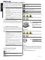 6
6
-
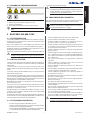 7
7
-
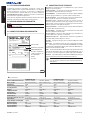 8
8
-
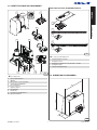 9
9
-
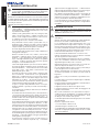 10
10
-
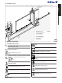 11
11
-
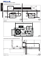 12
12
-
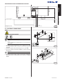 13
13
-
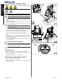 14
14
-
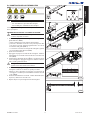 15
15
-
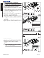 16
16
-
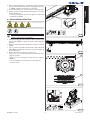 17
17
-
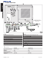 18
18
-
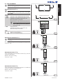 19
19
-
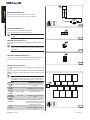 20
20
-
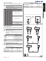 21
21
-
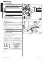 22
22
-
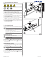 23
23
-
 24
24
-
 25
25
-
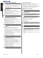 26
26
-
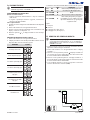 27
27
-
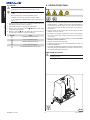 28
28
-
 29
29
-
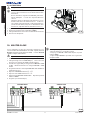 30
30
-
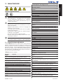 31
31
-
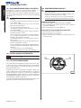 32
32
-
 33
33
-
 34
34
-
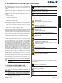 35
35
-
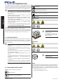 36
36
-
 37
37
-
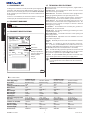 38
38
-
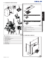 39
39
-
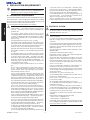 40
40
-
 41
41
-
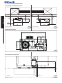 42
42
-
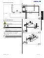 43
43
-
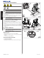 44
44
-
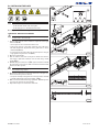 45
45
-
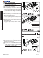 46
46
-
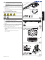 47
47
-
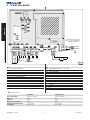 48
48
-
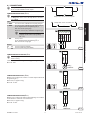 49
49
-
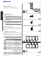 50
50
-
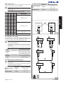 51
51
-
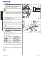 52
52
-
 53
53
-
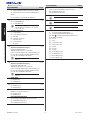 54
54
-
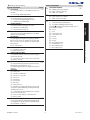 55
55
-
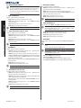 56
56
-
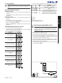 57
57
-
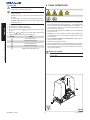 58
58
-
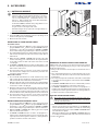 59
59
-
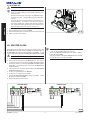 60
60
-
 61
61
-
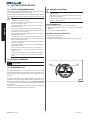 62
62
-
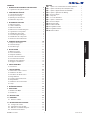 63
63
-
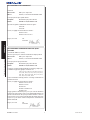 64
64
-
 65
65
-
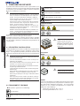 66
66
-
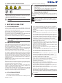 67
67
-
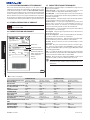 68
68
-
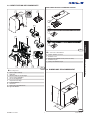 69
69
-
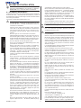 70
70
-
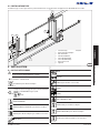 71
71
-
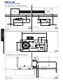 72
72
-
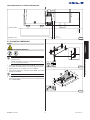 73
73
-
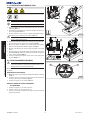 74
74
-
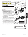 75
75
-
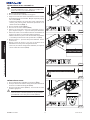 76
76
-
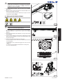 77
77
-
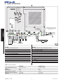 78
78
-
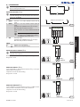 79
79
-
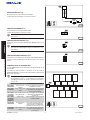 80
80
-
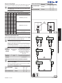 81
81
-
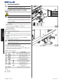 82
82
-
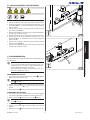 83
83
-
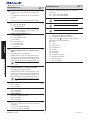 84
84
-
 85
85
-
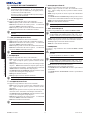 86
86
-
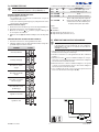 87
87
-
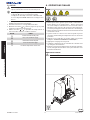 88
88
-
 89
89
-
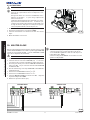 90
90
-
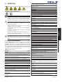 91
91
-
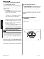 92
92
-
 93
93
-
 94
94
-
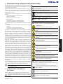 95
95
-
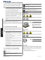 96
96
-
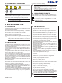 97
97
-
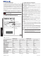 98
98
-
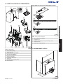 99
99
-
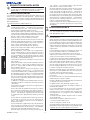 100
100
-
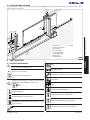 101
101
-
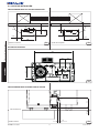 102
102
-
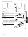 103
103
-
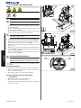 104
104
-
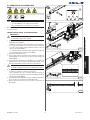 105
105
-
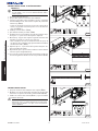 106
106
-
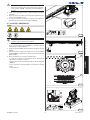 107
107
-
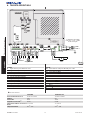 108
108
-
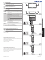 109
109
-
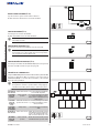 110
110
-
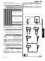 111
111
-
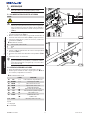 112
112
-
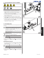 113
113
-
 114
114
-
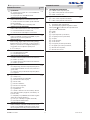 115
115
-
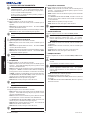 116
116
-
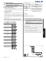 117
117
-
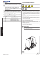 118
118
-
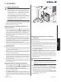 119
119
-
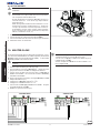 120
120
-
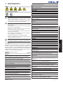 121
121
-
 122
122
-
 123
123
-
 124
124
-
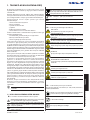 125
125
-
 126
126
-
 127
127
-
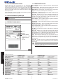 128
128
-
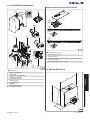 129
129
-
 130
130
-
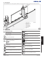 131
131
-
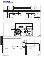 132
132
-
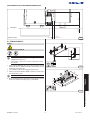 133
133
-
 134
134
-
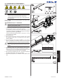 135
135
-
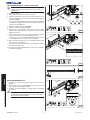 136
136
-
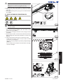 137
137
-
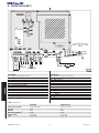 138
138
-
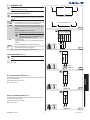 139
139
-
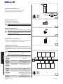 140
140
-
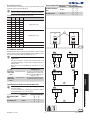 141
141
-
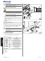 142
142
-
 143
143
-
 144
144
-
 145
145
-
 146
146
-
 147
147
-
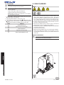 148
148
-
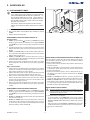 149
149
-
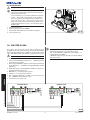 150
150
-
 151
151
-
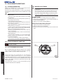 152
152
-
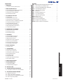 153
153
-
 154
154
-
 155
155
-
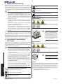 156
156
-
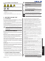 157
157
-
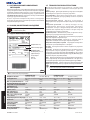 158
158
-
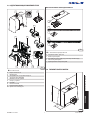 159
159
-
 160
160
-
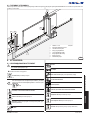 161
161
-
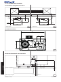 162
162
-
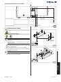 163
163
-
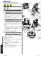 164
164
-
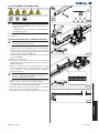 165
165
-
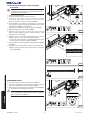 166
166
-
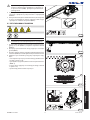 167
167
-
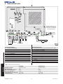 168
168
-
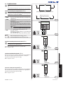 169
169
-
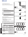 170
170
-
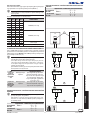 171
171
-
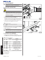 172
172
-
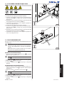 173
173
-
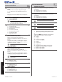 174
174
-
 175
175
-
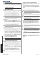 176
176
-
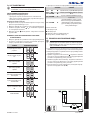 177
177
-
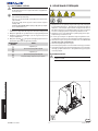 178
178
-
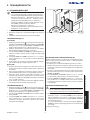 179
179
-
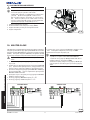 180
180
-
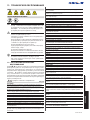 181
181
-
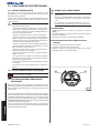 182
182
-
 183
183
-
 184
184


Genius Blizzard 400C 800C Instrucciones de operación
- Tipo
- Instrucciones de operación
en otros idiomas
Artículos relacionados
-
Genius Blizzard 400C 800C Instrucciones de operación
-
-
Genius Blizzard 500C 900C Instrucciones de operación
-
-
-
-
-
-
-


