Kichler Lighting 10170BK Manual de usuario
- Tipo
- Manual de usuario

CAUTION
Take care when handling any aluminum track as track has pre-attached screws and may have sharp edges. Screws and/or sharp
edges can scratch other material or oneself.
BE CAREFUL NOT TO BEND TRACK.
INSTALLATION
1. Remove track from packaging.
2. Determine desired length of track needed. NOTE: if track needs to be cut to meet desired length, use a saw safe for cutting
metal. Make sure to remove any sharp edges after cutting.
3. To mount track with screws (provided):
a. Line up track in desired location.
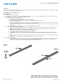
b. (Optional) Place end caps on both ends of track. (figure 1)
c. Screw in the screws closest to the ends first - only half way to hold track in place.
d. Screw in remaining screws.
e. If no other track is being connected, screw in end screws. If more track is to be connected leave the connecting
end unscrewed until the next piece of track is connected to the first.
f. When connecting two pieces of track, first attach end caps then connect the two pieces of track using the end cap
connector.
g. Once all pieces of track have been aligned thoroughly tighten all screws.
4. To mount track using tape (not provided)
a. Only use wood/metal safe double sided tape. NOTE: Some tape may peel paint or laminate off wood substrates.
NOTE: In outdoor applications it may be necessary to use a stronger adhesive tape made for wet locations.
b. (Optional) Place end caps on both ends of track. (figure 1)
c. Place double sided tape on side of track to be adhered to surface.
d. Line up track at desired location and remove tape covering.
e. Stick middle of track to surface first and work your way to the end of the track firmly pressing track to surface.
f. If more track is to be connected leave the connecting end loose until the next piece of track is connected to the
first.
g. When connecting two pieces of track, first attach end caps then connect the two pieces of track using the end cap
connector.
h. Once all pieces of track have been aligned thoroughly press all track to surface.
5. Only for U channel track.
a. To install lens. Install lens after tape light has been installed. Slide diffusing lens into slot in channel (figure 2). Slide
lens until even at the opposite side of the track and trim. NOTE: Diffusing lens should not exceed beyond the
length of the track or it may be damaged when installing end caps on track.
We’re here to help 866-558-5706
Hrs: M-F 9am to 5pm EST
Date Issued: 11/8/13 IS-10170-US
SEE OTHER SIDE FOR SPANISH TRANSLATIONS.
VEA EL OTRO LADO DE TRADUCCIONES AL ESPAÑOL.
Figure 1
Figura 1
Figure 2
Figura 2
TRACK
RIEL
LENS
LENTES
TRACK
RIEL
END CAP
TAPA DEL
EXTREMO

PRECAUCIÓN
Tenga cuidado cuando maneje cualquier riel de aluminio ya que los rieles tienen tornillos sujetados previamente y podrán tener
bordes filosos. Los tornillos y/o los bordes filosos pueden rayar otros materiales o a uno mismo.
SEA CUIDADOSO NO DOBLE EL RIEL.
INSTALACIÓN
1. Remueva el riel del empaque.
2. Determine el largo deseado necesario del riel. NOTA: Si el riel necesita ser cortado para cumplir con el largo deseado, utilice
una sierra segura para cortar metal. Asegúrese de remover cualquier borde filoso después del corte.
3. Para montar el riel con los tornillos (provistos):
a. Alinee el riel en la ubicación deseada.
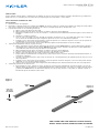
b. (Opcional) Coloque las tapas del extremo en ambos extremos del riel (figura 1).
c. Atornille los tornillos más cerca de los extremos – solamente hasta la mitad de la distancia para sostener al riel en
su lugar.
d. Atornille los tornillos restantes.
e. Si no se está conectando otro riel, atornille los tornillos del extremo. Si se conectarán más rieles deje el extremo
de conexión sin atornillar hasta que la siguiente pieza de riel sea conectada hacia la primera.
f. Cuando conecte dos piezas de riel, primero sujete las tapas de los extremos después conecte las dos piezas de
riel utilizando el conector de la tapa del extremo.
g. Una vez que todas las piezas de riel estén alineadas apriete meticulosamente todos los tornillos.
4. Para montar utilizando cinta (no se proporciona)
a. Utilice únicamente cinta segura de doble lado de madera / metal. NOTA: Algunas cintas podrán pelar la pintura o
el laminado de los substratos de madera. NOTA: En las aplicaciones exteriores podrá ser necesario utilizar una
cinta adhesiva más fuerte hecha para ubicaciones húmedas.
b. (Opcional) Coloque las tapas del extremo en ambos extremos del riel (figura 1).
c. Coloque cinta de doble lado en el lado del riel que será adherido a la superficie.
d. Alinee el riel en la ubicación deseada y remueva la cubierta de la cinta.
e. Pegue primero la mitad del riel a la superficie y siga su paso hacia el extremo del riel presionando firmemente el
riel hacia la superficie.
f. Si serán conectados más rieles deje suelto el extremo de conexión hasta que la siguiente pieza de riel sea conect
ada a la primera.
g. Cuando conecte dos piezas de riel, primero sujete las tapas del extremo después conecte las dos piezas del riel
utilizando el conector de la tapa del extremo.
h. Una vez que todas las piezas del riel hayan sido alineadas presione meticulosamente todo el riel a la superficie.
5. Solamente para rieles de canal en “U”.
a. Para instalar los lentes. Instale los lentes después de que haya sido instalada la cinta de luz. Deslice el lente de
difusión dentro de la ranura en el canal (figura 2). Deslice el lente hasta que esté parejo en el lado opuesto del riel
y guarnición. NOTA: El lente de difusión no deberá exceder el largo del riel o éste podrá ser dañado cuando se
instalen las tapas del extremo sobre el riel.
We’re here to help 866-558-5706
Hrs: M-F 9am to 5pm EST
Figure 1
Figura 1
Figure 2
Figura 2
Date Issued: 11/8/13 IS-10170-US
TRACK
RIEL
LENS
LENTES
TRACK
RIEL
END CAP
TAPA DEL
EXTREMO
SEE OTHER SIDE FOR ENGLISH TRANSLATIONS.
VEA EL OTRO LADO DE TRADUCCIONES AL INGLÉS.
-
 1
1
-
 2
2


Kichler Lighting 10170BK Manual de usuario
- Tipo
- Manual de usuario
En otros idiomas
- English: Kichler Lighting 10170BK User manual
Otros documentos
-
 Hampton Bay EC6827BK Guía de instalación
-
Craftsman 13953973SRT Manual de usuario
-
Craftsman 139.53962SRT1 El manual del propietario
-
-
Lithonia Lighting LTIHSQLED27K90CRIMW Guía de instalación
-
-
-
ODL RTMW01 Guía de instalación
-
Craftsman 139.5399211 El manual del propietario
-
