La página se está cargando...

BOM-34115786
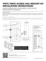
Read all instructions prior to installing product.
Refer to manufacturers safety instructions when operating any tools.
To register your product, please visit:
freedom.barretteoutdoorliving.com
INSTALLATION INSTRUCTIONS
FOR POST, RAIL AND STAIR RAIL
Aluminum Railing
English Instructions
............................................................
1
Español Instructions
.........................................................
17

2
WARNING:
• Improper installation of this product can result in personal injury. Always wear safety goggles when
cutting, drilling and assembling the product.
• Incorrect installation may cause harm to the product or individual.
• Not pool code approved.
NOTICE:
• DO NOT attempt to assemble the kit if parts are missing or damaged.
• DO NOT return the product to the store, for assistance or replacement parts call: 1-800-336-2383.
TOOLS NEEDED:
BEFORE YOU BEGIN:
Post Kit
Components:
Baluster Kits:
(Sold Separately)
*Bracket kits are sold separately
and include 4 brackets (2 top,
2 bottom), support block,
hardware and bracket covers.
*Bracket kits are sold separately
and include 4 brackets (2 top, 2
bottom), hardware and bracket
covers.
Rail Kit
Components:
Stair Rail Kit
Components:
Description
Post, with Mounted Plate
Pyramid Post Top
Base Trim
Secondary Mounting Plate
Template
Description
Square Baluster Kit
Twisted Baluster Kit
Glass Kit
Description
Rail Cap
Top Rail
Bottom Rail
Snap&Stay™ Locking Strips
Rail Bracket Kit*
Angle Bracket Kit*
Description
Rail Cap
Top Rail
Bottom Rail
Snap&Stay™ Locking Strips
Stair Bracket Kit*
Safety Glasses
Pencil
Level
Chalk Line
7
⁄
7
⁄
7
16
⁄16⁄
" &
1
⁄
1
⁄
1
8
⁄8⁄
" Drill Bits
Drill
Hacksaw or Chopsaw*
Tape Measure
Scissors or Utility Knife
Tape
Rubber Mallet
Clamps
Fine-tooth Carbide Blade*
Deck Board
(For Stair Rail Spacing)
2"x8" Wooden Blocks
(For Post Support)
Shims (Steel Washers)
Clear, Weatherproof Silicone
Caulk (For Glass Slats)
FASTENERS NEEDED:
Depending on Installation Method (Sold Separately)
3
⁄
3
⁄
3
8
⁄8⁄
" Diameter Galvanized Bolts with
Nuts
(For Deck/Wood)
3
⁄
3
⁄
3
8
⁄8⁄
" Masonry Anchors (For Concrete)
#10x3
1
⁄
1
⁄
1
2
⁄2⁄
" Deck Screws (For Deck/Wood)
It is the responsibility of the installer to
meet and/or exceed all code and safety
requirements and to obtain all required
building code permits.
The deck and railing installer should
determine and implement appropriate
installation techniques for each installation.
*If using a chopsaw, use a ne-tooth carbide blade.
To obtain and review a copy of the warranty please go to: Freedomproduct.com/warranty. You can also
contact 1.888.418.4400 or write to Freedom Outdoor Living, 7830 Freeway Circle, Middleburg Heights,
Ohio 44130 to obtain a copy of the warranty.

3
Planning:
a. Posts are designed and manufactured to accept
3
⁄
3
⁄
3
8
⁄8⁄
"
fasteners (sold separately). Be sure to use appropriate
fasteners for your installation.
b. Determine the desired rail placement and snap a
chalk line onto the mounting surface to ensure that all
posts are aligned properly (Fig 1).
c. Plumb and level the posts using steel washers as
shims (sold separately) (Fig. 2), secure the posts in
place with appropriate fasteners (sold separately) and
install base trim on each post (Fig. 3).
d. Determine the appropriate method for installing your
posts below.
Concrete Surface Installations:
a. Purchase four
3
⁄
3
⁄
3
8
⁄8⁄
" masonry anchors according to local
building codes.
b. Mark holes through mounting plate onto concrete
surface and follow masonry anchor manufacturer
installation instructions.
c. Install base trim around post (Fig. 3).
Deck/Wood Surface Installations:
a. For decking applications, use the provided secondary
mounting plate when securing posts in place.
b. Beneath all post locations install at least two 2"x8"
blocks using at least three #10x3
1
⁄
1
⁄
1
2
⁄2⁄
" deck screws
penetrating through the joists at least 1
1
⁄
1
⁄
1
2
⁄2⁄
" into the
blocks (sold separately) (Fig. 4 & 5).
c. Mark holes through the bottom plate of steel post
onto deck surface. Remove steel post and drill
7
⁄
7
⁄
7
16
⁄16⁄
"
holes in all four marks through deck board and
blocking.
d. Purchase
3
⁄
3
⁄
3
8
⁄8⁄
" diameter galvanized bolts and nuts
approximately 1" longer than the distance between
steel mounting plates (minimum 5").
e. Push bolts through post plate and attach separate
bottom plate from beneath deck surface (Fig. 6).
Posts can be leveled as needed by using shims.
f. Tighten bolts, secure in place and install base trim
around each post (Fig. 3).
1
POST INSTALLATION
Fig. 1
Fig. 2
Chalk Line
Chalk Line
Deck
Deck
Mounting Plate
Mounting Plate
Mounting Plate
Mounting Plate
Mounting Plate
Mounting Plate
Mounting Plate
Mounting Plate
Mounting Plate
Mounting Plate
Mounting Plate
Mounting Plate
Mounting Plate
Mounting Plate
Mounting Plate
Shim/Washer
Shim/Washer
Shim/Washer
Shim/Washer
Post
Post
Level
Level
Fig. 3
Base trim
Base trim
Fig. 4
Fig. 5
Fig. 6
Mounting Plate

4
a. Cut out bracket template from side of post box, and
align it with the base trim and post. Secure template
in place using a piece of tape. Pre-drill through the
desired marked locations on the template using a
1
⁄
1
⁄
1
8
⁄8⁄
" drill bit.
b. Remove template, align brackets (Fig. 7) with the
holes ensuring the brackets are square, and fasten
brackets in place using the 1
1
⁄
1
⁄
1
2
⁄2⁄
" screws provided.
2
Fig. 7
TopTop
Bracket
Bracket
Bracket
Bottom
Bottom
Bracket
Bracket
Cut Rails to Length (Top & Bottom Rails, Top Rail Cap):
a. Place bottom rail across post opening leaving
equivalent spacing from last baluster to post on each
end. Make sure there is even spacing from baluster
hole to post (Fig. 1)
b. Mark rail ush to post.
c. From marked lines, mark additional parallel line
1
⁄
1
⁄
1
4
⁄4⁄
"
from rst line to allow for bracket clearance (Fig. 2).
d. Align top rail and top rail cap with bottom rail and
mark all before cutting to size. Then cut all to same
length with a ne-tooth carbide blade. (Fig. 3).
Assemble Railing Section:
a. Place top and bottom rail on a smooth, at and clean
surface. Then, align the top and bottom rails so that
the ridges inside the rails are oriented on the same
side (Fig. 4).
NOTE:
There are two (2) ridges on both sides that are
different sizes.
1
2
RAIL INSTALLATION - FOR SQUARE AND/OR SPIRAL BALUSTERS
Fig. 1
Fig. 3
Fig. 2
1
⁄
1
⁄
1
4
⁄4⁄
"
Tape
Measure
Fig. 4
Top Rail Opening Facing Up
2 Small Ridges
2 Small Ridges
2 Large Ridges
2 Large Ridges
Bottom Rail Opening Facing Down
2 Small Ridges

5
Fig. 5
Install Support Block:
Pivot support block in place under the rail (Fig. 9).
NOTE:
Secure support block to the mounting surface using
1
1
⁄
1
⁄
1
2
⁄2⁄
" screw(s) provided and press cover into place
using plastic plug (Fig. 10).
3
b. Insert all balusters through the square holes in rails,
making sure the hole in each baluster goes in the
same direction facing the side with the two (2) small
ridges (Fig. 5).
c. Make sure the balusters in the rails are about 2"
above the rail and in-line with each other (Fig. 5).
d. Snap in bumps from locking strip into holes of the
baluster for both top and bottom rails. Make sure
arrows on locking strip face rails (Fig. 6).
e. If the rails were cut shorter in step 1, then there will
be some extra locking strip at the end of install. Use
scissors or a utility knife to trim off the excess, while
leaving approximately 2" after the last engaged bump.
f. Pull the top and bottom rails towards ends, guiding
the rails over the locking strips until snug.
g. Stand rail section up and fully lock balusters into the
rails. Place one foot on the top of the bottom rail,
between the second and third baluster while at the
same time placing a hand under the bottom of the top
rail between the second and third baluster. Push with
foot and pull with hand until locking is completed.
You should hear a snap as the strip locks into the rail.
Repeat this process for the middle and the end of the
panel (Fig. 7 & 8).
NOTE:
If no snap is heard or felt, use a rubber mallet to
tap underneath of top rail to ensure a full
connection.
Two Large Two Large
Ridges Side
Ridges Side
Ridges Side
Ridges Side
Ridges SideRidges Side
Two Small
Two Small
Two Small
Ridges Side
Ridges Side
Ridges Side
Ridges Side
Ridges Side
Ridges Side
Ridges Side
Ridges Side
Ridges Side
Ridges Side
Ridges Side
Ridges Side
Ridges Side
Ridges Side
2"
2"
2"
2"
Arrows
Arrows
Arrows
Arrows
Pointing Down
Pointing Down
Pointing Down
Pointing Down
Pointing Down
Pointing Down
Pointing Down
Fig. 6
Fig. 8
Fig. 9
Fig. 10
Arrows
Arrows
Locked
Fig. 7
Side Views of Rails
Side Views of Rails
Side Views of Rails
Side Views of Rails
Side Views of Rails
Side Views of Rails
Side Views of Rails
Side Views of Rails
Side Views of Rails
Side Views of Rails
Side Views of Rails
and Locking Stripsand Locking Strips

6
Attaching Bottom Rail Bracket Cover:
Test t the rail panel. Once proper t is ensured, press
bottom bracket covers onto the ends of the bottom rail
(Fig. 11) and set panel in place on brackets.
Connect Rails to Brackets:
a. Press top rail cap and bracket covers onto the top rail
that was cut in step 1 onto the top of the panel. Press
down on the top rail cap to ensure that it ts snug
onto the panel and that the top rail bracket end covers
are being held in place by the line bracket (Fig. 12).
b. Using the holes in the bracket as a guide, pre-drill
two (2)
1
⁄
1
⁄
1
8
⁄8⁄
" holes from under the bottom of the rail
up through the top rail. Drive two (2) 1
5
⁄
5
⁄
5
8
⁄8⁄
" screws up
through the hole locking the bracket, panel and top
rail together, being careful not to drill through the top
of the top rail (Fig. 13).
c. Install pyramid post top onto each post (Fig. 14).
NOTE:
A rubber mallet may be needed for a proper t.
4
5
Fig. 11
Fig. 12
a. Slide metal spacer pieces over the end of top and
bottom rail channels (Fig. 1).
1
2
RAIL INSTALLATION - FOR GLASS SLATS
Fig. 2
Bottom Bracket Cover
Fig. 14
Pyramid Top
Post
Fig. 1
Rail Channel
Metal Spacer
Rail Channel
Cut Rails to Length (Top & Bottom Rails, Top Rail Cap):
a. Place bottom rail across post opening leaving
equivalent spacing from last glass opening to post on
each end. Make sure there is even spacing from glass
hole to post (Fig. 2)
b. Mark rail ush to post.
c. From marked lines, mark additional parallel line
1
⁄
1
⁄
1
4
⁄4⁄
"
from rst line to allow for bracket clearance (Fig. 3).
d. Cut rails to length (Fig. 4).
Fig. 4
Fig. 13
Fig. 3
1
⁄
1
⁄
1
4
⁄4⁄
"
Tape Measure
Tape Measure
Tape Measure
Tape Measure
Tape Measure
Tape Measure
Tape Measure
Tape Measure
Tape Measure

7
Connect Rails to Brackets:
a. Press top rail cap and bracket covers onto the top rail
that was cut in step 1 onto the top of the panel. Press
down on the top rail cap to ensure that it ts snug
onto the panel and that the top rail bracket covers are
being held in place by the line bracket (Fig. 8).
b. Using the holes in the bracket as a guide, pre-drill
two (2)
1
⁄
1
⁄
1
8
⁄8⁄
" holes from under the bottom of the rail
up through the top rail. Drive two (2) 1
5
⁄
5
⁄
5
8
⁄8⁄
" screws up
through the hole locking the bracket, panel and top
rail together, being careful not to drill through the top
of the top rail (Fig. 9).
c. Install pyramid post top onto each post (Fig. 10).
NOTE:
A rubber mallet may be needed for a proper t.
Install The Glass Slats:
a. Snap gaskets into bottom rail slots (Fig. 11).
b. Place approximately
1
⁄
1
⁄
1
16
⁄16⁄
" bead of clear weatherproof
silicone caulk (sold separately) inside each bottom
glass gasket prior to placing glass slat into place (Fig. 12).
c. Slide top gasket over the glass slat (Fig. 13.) and
place glass slat into top rail. Position glass slat to
allow them to "drop into" the bottom rail gasket.
d. Slide top rail gasket up into top rail ensuring a snug t
(Fig. 13).
e. Repeat for all other slats.
5
6
Fig. 10
Pyramid
Top
Post
Attaching Bottom Rail Bracket Cover:
Test t the rail panel. Once proper t is ensured, press
bottom bracket covers onto the ends of the bottom rail
(Fig. 7) and set panel in place onto brackets previously
mounted on posts.
3
Fig. 7
Bottom Bracket Cover
Install Support Block:
Pivot support block in place under the rail (Fig. 5).
NOTE:
If using a section longer than 6', use two (2) support
blocks (included with 8' panels) and distribute evenly
across length of panel. Secure support block(s) to the
mounting surface using 1
1
⁄
1
⁄
1
2
⁄2⁄
" screw(s) provided and
press cover into place using plastic plug(s) (Fig. 6).
4
Fig. 5
Fig. 8
Glass
Glass
Glass
Glass
Gasket
Glass
Glass
Glass
Glass
Fig. 13
Fig. 9
Gasket
Fig. 11
Fig.6
Bottom Rail
Glass Baluster
Bottom Glass
Gasket
1
⁄
1
⁄
1
16
⁄16⁄
" Bead of Silicone
Fig. 12

8
Assemble rail panels as described in "Rail Installation."
NOTE:
• Do not install glass slats on stair railings, only
use square or twisted balusters.
• Taller posts (sold separately) may be needed for
either bottom or top of the stairs, depending on
the angle of the stairway or the location of where
the posts will be installed relative to the nose of
the stair tread. Bottom stair posts may also be
moved out from bottom step (Fig. 1).
See "Post Installation" section for "Deck/Wood Surface
Installations."
Place a deck board on the stair noses spanning from
post to post. Place the stair panel on the board across
the opening and plumb balusters while ensuring equal
spacing on each end. Clamp the panel in place at this
location (Fig. 2).
NOTE:
Use the proper deck board thickness to result in the
desired nished rail height.
Temporarily assemble top and bottom stair mounting
brackets. Brackets slide into bracket bases, bracket
cover is aligned, and the bracket is fastened together
using the hinge bolt provided (Fig. 3 & 4).
a. Hold each respective bracket (angled) against the
post face, align bracket with stair panel and mark all
four (4) ends of the rail panel (Fig. 5).
b. Repeat this on the opposite side of the panel and be
sure to label the top rail to simplify placement after
cutting.
1
2
3
4
STAIR RAIL INSTALLATION
Fig. 1
Fig. 2
Clamps
Deck
Board
Stair Panel
Stair Panel
Stair Panel
Stair Panel
Stair Panel
Stair Panel
Stair Panel
Stair Panel
Stair Panel
Stair Panel
Stair Panel
Stair Panel
Stair Panel
Stair Panel
Stair Panel
Stair Panel
Stair Panel
Stair Panel
Stair Panel
Stair Panel
Stair Panel
Stair Panel
Stair Bracket Base
Top Bracket
Bracket Cover
Bottom Bracket
Hinge Bolts
Fig. 3
Fig. 4
Fig. 5

9
a. For the bottom rail only, add
3
⁄
3
⁄
3
4
⁄4⁄
" (toward the rail end or
post) to the marks made on the panel in step 3 (Fig. 6)
and cut the panel at these marks.
b. For the top rail, cut the panel directly on the marks
made in step 3. Insert the bottom brackets onto
bottom rail, align top brackets (temporarily secure
brackets in place with tape), and test the panel for
proper t.
c. Once proper t is ensured, mark the bracket positions
at all four (4) locations (Fig. 7) and remove brackets
from the rail panel.
a. Measure the length of the rail panel and cut the top
rail (sold separately) to match. Press down on the top
rail to ensure that it ts snugly onto the panel (Fig. 9).
b. Align top stair bracket with the rail end only at the top
of the stairs (Fig. 9). Using the pre-drilled holes as a
guide, drill through the railing using a
1
⁄
1
⁄
1
8
⁄8⁄
" drill bit being
careful not to drill through the top of top rail. Do this
for the top of the stairs only (Fig. 10).
a. Press top rail cap and end covers onto both ends
of the top rail. Slide top brackets in place on the rail
ends, ensuring that the top rail cap and covers nest
into the grooves of the brackets (Fig. 11).
b. Align the bracket, panel and top rail. Drive two (2) 1
1
⁄
1
⁄
1
2
⁄2⁄
"
painted pan head screws through the pre-drilled holes
locking the assembly together at the top of the stair
rail only.
a. Loosely assemble the stair bracket base and cover
and use it as a template to mark locations for pre-drilling.
NOTE:
If base is centered without bracket cover,
rail will NOT be centered.
b. Place the stair bracket base on the post aligned
with the marks made in step 5 (Fig. 7) ensuring that
brackets are properly oriented.
c. Mark the two hole locations shown (Fig. 8) for each
bracket and pre-drill using a
1
⁄
1
⁄
1
8
⁄8⁄
" bit.
d. Secure brackets to post using the non-painted at
head 1
1
⁄
1
⁄
1
2
⁄2⁄
" screws provided
5
7
8
6
3/4"
Fig. 6
Fig. 7
Fig. 8
Fig. 9
Fig. 10
Fig. 11
Pre-Drill
Top Rail
Pre-drill
End Cover
Stair Bracket
Base

10
a. Press bottom brackets onto the bottom rails. Slide
all four (4) brackets into bracket bases which are
connected to the posts.
b. Slide bracket covers onto the bases and loosely
secure in place with provided hinge bolts (Fig. 12).
a. Pre-drill the top rail at the bottom stair post using the
bracket holes as a guide (Fig. 13).
b. Drive two (2) 1
5
⁄
5
⁄
5
8
⁄8⁄
" painted pan head screws up
through the holes locking the bracket, panel and top
rail together. Once the top rail is secured, tighten all
four (4) of the hinge bolts to lock stair panels in place.
Install pyramid post top onto each post (Fig. 14).
NOTE:
A rubber mallet may be needed for a proper t.
NOTE:
Angle rail installation uses a combination of
features used in both the rail and stair
applications. This installation will use the same
bracket base of the stair brackets and similar
components, while using the preset layout of the
installation template for quick and easy installation.
Angle rail brackets must be purchased separately.
Angle rail mounting varies greatly on each
installation.
9
10
11
1
Bottom Rail
Pre-drill
Pre-drill
Pre-drill
Pre-drill
Fig. 12
Fig. 13
Fig. 14
Pyramid Top
Post
ANGLE RAIL INSTALLATION

11
a. Cut out bracket template from side of post box.
Refer to angle bracket components (Fig. 1).
b. Align bottom of template with top of the base trim and
secure in place with a piece of tape.
c. Follow instructions on template for pre-drilling using a
1
⁄
1
⁄
1
8
⁄8⁄
" drill bit, then remove the template.
d. Align top and bottom bracket bases with covers
attached (Fig. 2) with the holes ensuring that they are
square. Fasten bracket bases in place using the non-
painted at head 1
1
⁄
1
⁄
1
2
⁄2⁄
" screws provided.
a. Temporarily assemble top and bottom level angle
brackets. Mounting brackets slide into bracket base,
bracket cover is aligned, and the bracket is fastened
together using the hinge bolt provided (Fig. 3).
b. Align panel on desired angle and mark the top rails
(Fig. 4) and bottom rails (Fig. 5).
c. Repeat this on the other side of the panel. Label the
top of the rail panel to simplify installation.
2
3
Bottom Bracket
Stair Bracket Base
Bracket
Cover
Hinge Bolts
Top Bracket
Fig. 1
Fig. 2
Pre-Drill
Stair Bracket
Base
Hinge Bolt
Top Bracket
Fig. 3
Fig. 4
Fig. 5

12
a. For the bottom rail only, add
3
⁄
3
⁄
3
4
⁄4⁄
" (toward the rail end or
post (Fig. 6) to the marks made on the panel in step 3
(Fig. 5) and cut the panel at these marks.
b. For the top rail, cut the panel directly on the marks
made in Step 3 (Fig. 4).
c. Cut the top rail to the same length.
4
3/4"
Fig. 6
Assemble Railing Section:
a. Place top and bottom rail on a smooth, at and clean
surface. Then, align the top and bottom rails so that
the ridges inside the rails are oriented on the same
side (Fig. 7).
NOTE:
There are two (2) ridges on both sides that are
different sizes.
b. Insert all balusters through the square holes in rails,
making sure the hole in each baluster goes in the
same direction facing the side with the two (2) small
ridges (Fig. 8).
c. Make sure the balusters in the rails are about 2"
above the rail and in-line with each other (Fig. 8).
d. Snap in bumps from locking strip into holes of the
baluster for both top and bottom rails. Make sure
arrows on locking strip face rails (Fig. 9).
e. If the rails were cut shorter in step 3, then there will
be some extra locking strip at the end of install. Use
scissors or a utility knife to trim off the excess, while
leaving approximately 2" after the last engaged bump.
f. Pull the top and bottom rails towards ends, guiding
the rails over the locking strips until snug.
5
Fig. 7
Top Rail Opening Facing Up
2 Small Ridges
2 Small Ridges
2 Large Ridges
2 Large Ridges
Bottom Rail Opening Facing Down
2 Small Ridges
Fig. 8
Two Large Two Large
Ridges Side
Ridges Side
Ridges Side
Two Small
Two Small
Two Small
Two Small
Ridges Side
Ridges Side
Ridges Side
Ridges Side
Ridges Side
Ridges Side
Ridges Side
Ridges Side
2"
2"
2"
2"
Arrows
Arrows
Arrows
Arrows
Pointing Down
Pointing Down
Pointing Down
Pointing Down
Pointing Down
Pointing Down
Pointing Down
Fig. 9
Arrows
Arrows

13
g. Stand rail section up and fully lock balusters into the
rails. Place one foot on the top of the bottom rail,
between the second and third baluster while at the
same time placing a hand under the bottom of the top
rail between the second and third baluster. Push with
foot and pull with hand until locking is completed.
You should hear a snap as the strip locks into the rail.
Repeat this process for the middle and the end of the
panel (Fig. 10).
NOTE:
If no snap is heard or felt, use a rubber mallet to
tap underneath of top rail to ensure a full
connection
Install Support Block:
Pivot support block in place under the rail (Fig. 12).
NOTE:
Secure support block to the mounting surface using
1
1
⁄
1
⁄
1
2
⁄2⁄
" screw(s) provided and press cover into place
using plastic plug (Fig. 13).
a. Remove the hinge bolts from the bottom brackets.
Remove the bottom brackets from the bracket bases,
and insert the bottom brackets into each end of the
bottom rail (Fig. 14).
b. Slide the bottom bracket (and rail) into the bottom
mounting base while setting the top rail on top of the
top rail bracket.
c. Reinsert the hinge bolt through the bottom brackets
to lock assembly into place.
6
7
Fig. 11
Fig. 12
Fig. 13
Hinge Bolt
Top Bracket
Fig. 14
Locked
Fig. 10
Side Views of Rails
Side Views of Rails
Side Views of Rails
Side Views of Rails
Side Views of Rails
Side Views of Rails
Side Views of Rails
Side Views of Rails
Side Views of Rails
Side Views of Rails
Side Views of Rails
and Locking Stripsand Locking Strips

14
8
Fig. 15
Connect Rails to Brackets:
a. Press top rail bracket end covers onto each end of
the top rail cap that was previously cut. Press down
on the top rail cap to ensure that it ts snug onto the
panel and that the top rail end bracket covers are
being held in place by the line bracket (Fig. 15).
b. Using the holes in the bracket as a guide, pre-drill
two (2)
1
⁄
1
⁄
1
8
⁄8⁄
" holes from under the bottom of the rail
up through the top rail. Drive two (2) 1
5
⁄
5
⁄
5
8
⁄8⁄
" screws up
through the hole locking the bracket, panel and top
rail together, being careful not to drill through the top
of the top rail (Fig. 16).
c. Install pyramid post top onto each post (Fig.17).
NOTE:
A rubber mallet may be needed for a proper t.
Fig. 16
Fig. 17
Pyramid Top
Post

15

16

BOM-34115786
Read all instructions prior to installing product.
Refer to manufacturers safety instructions when operating any tools.
To register your product, please visit:
freedom.barretteoutdoorliving.com
INSTRUCCIONES DE INSTALACIÓN DE POSTE,
TRAVESAÑO Y BARANDAL DE ESCALERA
INSTRUCCIONES DE INSTALACIÓN DE POSTE,
TRAVESAÑO Y BARANDAL DE ESCALERA
INSTRUCCIONES DE INSTALACIÓN DE POSTE,
Barandal de aluminio
English Instructions
............................................................
1
Español Instructions
.........................................................
17

18
3
⁄
3
⁄
3
8
⁄8⁄
" Diámetro Cerrojos Galvanizados
con Loco (Para Cubierta/Madera)
3
⁄
3
⁄
3
8
⁄8⁄
" anclas de albañilería
(para concreto)
#10x3
1
⁄
1
⁄
1
2
⁄2⁄
" Tornillos de Cubierta
(Para Cubierta/Madera)
*If using a chopsaw, use a ne-tooth carbide blade.
ADVERTENCIA:
• La instalación incorrecta de este producto puede resultar en lesiones corporales. Utilice siempre gafas
de seguridad al cortar, taladrar y ensamblar el producto.
• La instalación incorrecta puede causar daños al producto o a personas.
• No aprobado por el código de piscinas
AVISO:
• NO intente ensamblar el kit si faltan piezas o las piezas están dañadas.
• NO devuelva el producto a la tienda; para solicitar ayuda o piezas de repuesto, llame al: 1-800-336-2383
ANTES DE COMENZAR:
SUJETADORES NECESARIOS:
Según el método de instalación
Es responsabilidad del instalador cumplir
y/o exceder los códigos y requisitos de
seguridad, y obtener los permisos de los
códigos de construcción requeridos.
El instalador de la plataforma y de los
barandales debe determinar e implementar
las técnicas de instalación adecuadas para
cada instalación.
HERRAMIENTAS QUE SE
REQUIEREN:
Gafas de protección
Lápiz
Nivel
Línea de gis
Brocas de
7
⁄
7
⁄
7
16
⁄
16
⁄
" y
1
⁄
1
⁄
1
8
⁄
8
⁄
"
Taladro
Sierra o tronzadora
Cinta métrica
Tijeras o navaja
Cinta
Martillo de goma
Abrazaderas
Hoja de carburo de dientes nos
Tablón (por espaciado de
barandal de escalera )
Bloques de madera de 2"x8"
(para soporte de poste)
Cuñas (arandelas de acero)
Masilla de silicona transparente
resistente a la intemperie (para
los paneles de cristal)
Componentes
del kit de poste:
Kits de barrotes:
(Se venden por separado)
Componentes
del kit de travesaños:
Componentes del kit de
barandal de escalera:
Descripción
Postes con placa de montaje
Cubierta para poste estilo
Pirámide
Moldura base
Placa de montaje secundaria
Plantilla
Template
Descripción
Kit de barrote cuadrado
Kit de barrote trenzado
Kit de vidrio
Descripción
Tapa de travesaño
Travesaño superior
Travesaño inferior
Tiras de bloqueo Snap&Stay™
Kit de soporte de travesaño*
Kit de soporte angular*
Descripción
Tapa de travesaño
Travesaño superior
Travesaño inferior
Tiras de bloqueo Snap&Stay™
Kit de soporte para escaleras*
*Los kits de soportes se venden
por separado e incluyen 4
soportes (2 superiores y 2
inferiores), un bloque de soporte,
componentes y cubiertas de
soporte.
*Los kits de soportes se venden
por separado e incluyen 4
soportes (2 superiores y 2
inferiores), componentes y
cubiertas de soporte.
Para obtener y revisar una copia de la garantía, vaya a: Freedomproduct.com/warranty. También puede
llamar al 1.888.418.4400 o escribir a Freedom Outdoor Living, 7830 Freeway Circle, Middleburg Heights,
OH 44130 para obtener una copia de la garantía.

19
1
INSTALACIÓN DEL POSTE
Planifi cación:
a. Los postes están diseñados y fabricados para
aceptar sujetadores de
3
⁄
3
⁄
3
8
⁄8⁄
" (se venden por separado).
Asegúrese de utilizar sujetadores adecuados para su
instalación.
b. Determine la ubicación deseada del barandal y
marque una línea sobre la terraza para asegurarse
de que todos los postes queden alineados
correctamente (Fig. 1).
c. Aplome y nivel los postes mediante arandelas de acero
a manera de cuña (se venden por separado) (Fig. 2); je
los postes en su lugar con los sujetadores adecuados
(se venden por separado) e instale la moldura base en
cada poste (Fig. 3).
d. Determine a continuación el método adecuado para la
instalación de los postes.
Instalaciones en superfi cies de concreto:
a. Compre cuatro anclajes de mampostería de
3
⁄
3
⁄
3
8
⁄8⁄
" de
acuerdo con los códigos locales de construcción.
b. Marque los ori cios a través de las placas de montaje
en la super cie de concreto y siga las instrucciones
de instalación para el anclaje de mampostería.
c. Instale la moldura base alrededor del poste (Fig. 3).
Instalaciones en superfi cies de madera:
a. En las plataformas, utilice la placa de montaje
secundaria provista al jar los postes en su lugar.
b. Debajo de los lugares donde se instalarán los postes,
instale al menos dos bloques de 2"x8" utilizando al
menos tres tornillos de plataforma #10 de 3
1
⁄
1
⁄
1
2
⁄2⁄
" que
penetran por las viguetas a una profundidad mínima
de 1
1
⁄
1
⁄
1
2
⁄2⁄
" en los bloques (se venden por separado) (Fig.
4 y 5)
c. Marcar los agujeros a través de la placa inferior del
poste de acero en la super cie de la plataforma.
Retire el poste de acero y perfore agujeros de
7
⁄
7
⁄
7
16
⁄16⁄
"
en las cuatro marcas a través del tablón y el bloque.
d. Compre tornillos y tuercas galvanizados de
3
⁄
3
⁄
3
8
⁄8⁄
" de
diámetro aproximadamente 2.54 cm o 1" más largos
que la distancia entre las placas de montaje de acero
(al menos de 12.70 cm o 5")
e. Empuje los tornillos a través de la placa de poste y je
una placa inferior adicional por debajo de la super cie
de la plataforma (Fig. 6). Los postes se pueden nivelar
según sea necesario mediante el uso de cuñas.
f. Apriete los tornillos jos en su lugar e instale la
moldura base alrededor de cada poste (Fig. 3).
Fig. 1
Fig. 2
Línea de gisLínea de gis
Plataforma
Plataforma
Placa de
Placa de
montajemontaje
Cuña/
Cuña/
Cuña/
Arandela
Arandela
Arandela
Arandela
Arandela
Arandela
Poste
Poste
Nivel
Nivel
Fig. 3
Moldura
Moldura
base
base
Fig. 4
Fig. 5
Fig. 6
montaje
montaje

20
2
1
2
a. Recorte la plantilla para los soportes del interior
de la caja de los postes, y alineela con la moldura
base y el poste. Fije la plantilla en su lugar con un
trozo de cinta adhesiva. Perfore a través de los
lugares deseados que se han marcado en la plantilla
utilizando una broca de
1
⁄
1
⁄
1
8
⁄8⁄
".
b. Retire la plantilla, alinee los soportes (Fig. 7) con los
ori cios asegurándose de que los soportes queden
en ángulo recto, y je los soportes en su lugar con los
tornillos de 1
1
⁄
1
⁄
1
2
⁄2⁄
" proporcionados.
Fig. 7
Soporte Soporte
superior
superior
superior
Soporte Soporte
inferior
inferior
inferior
Corte los travesaños a la longitud (travesaño superior,
travesaño inferior, tapa de travesaño superior).
a. Coloque el travesaño inferior perpendicular a la
abertura del poste, dejando un espacio igual entre
el último balaustre y el poste en cada extremo.
Compruebe que los espacios entre el ori cio del
balaustre y el poste sean uniformes (Fig. 1).
b. Marque el travesaño al ras del poste.
c. De la línea marcada, marca una línea adicional
paralela de
1
⁄
1
⁄
1
4
⁄4⁄
" desde la primera línea, para dejar un
espacio libre para el soporte (Fig. 2).
d. Alinee el travesaño superior y la tapa del travesaño
superior con el travesaño inferior y marque lo anterior
antes de cortar. A continuación, corte todo a la misma
longitud con una hoja de carburo de dientes nos.
(Fig. 3).
Ensamblar la sección del barandal:
a. Coloque los travesaños superior e inferior sobre una
super cie lisa, plana y limpia. Oriente los travesaños
superior e inferior de modo que las aristas dentro de
los travesaños queden orientadas en el mismo lado
(Fig. 4)
NOTA:
Hay dos (2) aristas en ambos lados, pero de
diferentes tamaños.
INSTALACIÓN DE LOS TRAVESAÑOS, PARA BARROTES CUADRADOS O TRENZADOS
Fig. 1
Fig. 3
Fig. 2
1
⁄
1
⁄
1
4
⁄4⁄
"
Cinta
métrica
Fig. 4
Apertura de travesaño superior
Apertura de travesaño superior
Apertura de travesaño superior
Apertura de travesaño superior
Apertura de travesaño superior
Apertura de travesaño superior
Apertura de travesaño superior
Apertura de travesaño superior
Apertura de travesaño superior
Apertura de travesaño superior
Apertura de travesaño superior
Apertura de travesaño superior
Apertura de travesaño superior
Apertura de travesaño superior
Apertura de travesaño superior
orientada hacia arriba
orientada hacia arriba
orientada hacia arriba
orientada hacia arriba
orientada hacia arriba
orientada hacia arriba
orientada hacia arriba
orientada hacia arriba
orientada hacia arriba
orientada hacia arriba
orientada hacia arriba
orientada hacia arriba
orientada hacia arriba
orientada hacia arriba
orientada hacia arriba
orientada hacia arriba
orientada hacia arriba
orientada hacia arriba
orientada hacia arriba
2 Aristas pequeñas
2 Aristas pequeñas
2 Aristas grandes
2 Aristas grandes
Abertura de travesaño inferior
Abertura de travesaño inferior
Abertura de travesaño inferior
Abertura de travesaño inferior
Abertura de travesaño inferior
Abertura de travesaño inferior
Abertura de travesaño inferior
Abertura de travesaño inferior
Abertura de travesaño inferior
Abertura de travesaño inferior
Abertura de travesaño inferior
Abertura de travesaño inferior
Abertura de travesaño inferior
Abertura de travesaño inferior
Abertura de travesaño inferior
Abertura de travesaño inferior
orientada hacia abajo
orientada hacia abajo
orientada hacia abajo
orientada hacia abajo
orientada hacia abajo
orientada hacia abajo
orientada hacia abajo
orientada hacia abajo
orientada hacia abajo
orientada hacia abajo
orientada hacia abajo
orientada hacia abajo
2 Aristas pequeñas

21
3
Fig. 5
Instalar el bloque de soporte:
Coloque el bloque de soporte en su lugar debajo del
barandal (Fig. 9).
NOTA:
Fije el bloque de soporte a la super cie de montaje
usando los tornillos de 1
1
⁄
1
⁄
1
2
⁄2⁄
" provistos y presione la
cubierta en su lugar con los tapon de plástico (Fig. 10).
b. Inserte los barrotes en los ori cios en los travesaños
teniendo cuidado de que los ori cios en los barrotes
apunten en la misma dirección hacia el lado con las
dos (dos) aristas pequeñas (Fig. 5)
c. Compruebe que los barrotes en los travesaños estén
aproximadamente 5cm o 2" por encima del travesaño
y en línea el uno con el otro (Fig. 5).
d. Encaje las protuberancias de la tira sujetadora en los
ori cios de los barrotes en los travesaños superior
e inferior. Compruebe que las echas en la tira
sujetadora estén orientadas hacia los travesaños (Fig, 6).
e. Si los travesaños se acortan en el paso 3, entonces
sobrará algo de tira sujetadora al nal de la
instalación. Utilice tijeras o un cuchillo para cortar
el sobrante, dejando aproximadamente 5 cm (2")
después de la última protuberancia encajada.
f. Tire de los travesaños superior e inferior hacia los
extremos, guiando los travesaños sobre las tiras
sujetadoras hasta que queden bien apretados.
g. Enderece la sección de baranda y je los barrotes
completamente a los travesaños. Coloque un pie
en la parte superior del travesaño inferior, entre el
segundo y el tercer barrote, mientras coloca al mismo
tiempo una mano por debajo del travesaño superior,
entre el segundo y el tercer barrote. Empuje con el pie
y tire con la mano hasta que encaje completamente.
Debe escuchar un chasquido cuando la tira encaja
en el travesaño. Repita este proceso en la parte
intermedia y nal del panel (Fig. 7 & 8).
NOTA:
Si no escucha ni siente un chasquido, utilice un mazo
de goma para golpetear por debajo del travesaño
superior para asegurar una conexión completa.
Lado con
Lado con
Lado con
Lado con
Lado con
dos aristas
dos aristas
dos aristas
dos aristas
dos aristas
dos aristas
pequeñas
pequeñas
pequeñas
2"
2"
2"
2"
Flechas apuntando
Flechas apuntando
Flechas apuntando
Flechas apuntando
Flechas apuntando
Flechas apuntando
Flechas apuntando
Flechas apuntando
Flechas apuntando
Flechas apuntando
Flechas apuntando
Flechas apuntando
Flechas apuntando
hacia abajo
hacia abajo
hacia abajo
hacia abajo
hacia abajo
hacia abajo
hacia abajo
hacia abajo
hacia abajo
hacia abajo
Fig. 6
Fig. 8
Fig. 9
Fig. 10
Flechas apuntando
Flechas apuntando
Lado con
Lado con
dos aristas dos aristas
grandesgrandes
Bloqueado
Fig. 7
Vistas laterales Vistas laterales
de travesaño y
de travesaño y
de travesaño y
de travesaño y
de travesaño y
de travesaño y
de travesaño y
de travesaño y
de travesaño y
de travesaño y
de travesaño y
de travesaño y
de travesaño y
tira sujetadora
tira sujetadora
tira sujetadoratira sujetadora

22
1
2
Fijar la cubierta de soporte de travesaño inferior:
Compruebe la colocación del panel de barandal. Una
vez que se garantice el ajuste, presione las cubiertas de
soporte inferior en los extremos del travesaño inferior
(Fig. 11), y coloque el panel en los soportes.
Conectar los travesaños con los soportes:
a. Presione las cubiertas de extremo de travesaño
superior que se cortó en el paso 1 en la parte
superior del panel. Presione hacia abajo en el
travesaño superior para asegurarse de que encaje
perfectamente en el panel y compruebe que las
cubiertas de extremo del travesaño superior se
mantengan en su lugar con el soporte de montaje
(Fig. 12).
b. Usando los ori cios en el soporte a modo de guía,
perfore dos (2) agujeros de
1
⁄
1
⁄
1
8
⁄8⁄
" desde la parte inferior
del travesaño hacia arriba a través del travesaño
superior. Coloque dos (2) tornillos de 1
5
⁄
5
⁄
5
8
⁄8⁄
" hacia arriba
a través del ori cio para jar el soporte, el panel y el
travesaño superior, teniendo cuidado de no perforar
a través de la parte superior del travesaño superior
(Fig. 13).
c. Instale la cubierta de poste estilo pirámide en cada
poste (Fig. 14).
NOTA:
Puede ser necesario utilizar un mazo de goma para
obtener el ajuste adecuado.
Fig. 11
Fig. 12
a. Deslice el separador metálico sobre el extremo de la
parte superior y un canal de travesaño inferior (Fig. 1)
INSTALACIÓN DE BARANDAL - PARA TABLILLAS DE VIDRIO
Fig. 2
Cubierta de soporte inferior
Cubierta de soporte inferior
Fig. 14
Cubierta estilo Cubierta estilo
Pirámide
Pirámide
Poste
Fig. 1
Canal de travesaño
Separador metálico
Canal de travesaño
Corte los travesaños a la longitud (travesaño superior,
travesaño inferior, tapa de travesaño superior):
a. Coloque el travesaño inferior perpendicular a la
abertura del poste, dejando un espacio igual entre la
última abertura de vidrio y el poste en cada extremo.
Compruebe que los espacios entre el ori cio para
vidrio y el poste sean uniformes (Fig. 2).
b. Marque el travesaño al ras del poste.
c. De la línea marcada, marca una línea adicional
paralela de
1
⁄
1
⁄
1
4
⁄4⁄
" desde la primera línea, para dejar un
espacio libre para el soporte (Fig. 3).
d. Corte los travesaños a la longitud (Fig. 4).
Fig. 4
Fig. 13
Fig. 3
1
⁄
1
⁄
1
4
⁄4⁄
"
Cinta métrica
Cinta métrica
Cinta métrica
Cinta métrica
Cinta métrica
Cinta métrica
Cinta métrica
Cinta métrica
4
5

23
Fig. 10
Cubierta
estilo
Pirámide
Poste
Fig. 7
Cubierta de soporte inferior
Cubierta de soporte inferior
Fig. 5
Fig. 8
Vidrio
Vidrio
Vidrio
Vidrio
Vidrio
Vidrio
Vidrio
Vidrio
Vidrio
Vidrio
Vidrio
Vidrio
Vidrio
Vidrio
Vidrio
Vidrio
Vidrio
Vidrio
Vidrio
Empaque
Vidrio
Vidrio
VidrioVidrio
Fig. 13
Fig. 9
Empaque
Fig. 11
Fig.6
Travesaño inferior
Panel de cristal
Empaque
inferior del
cristal
Empaque inferior
del cristal
Fig. 12
Conectar los travesaños con los soportes:
a. Presione las cubiertas de extremo de travesaño
superior que se cortaron en el paso 1 en la parte
superior del panel. Presione hacia abajo en el
travesaño superior para asegurarse de que encaje
perfectamente en el panel y compruebe que las
cubiertas de extremo del travesaño superior se
mantengan en su lugar con el soporte de montaje
(Fig. 8).
b. Usando los ori cios en el soporte a modo de guía,
perfore dos (2) agujeros de
1
⁄
1
⁄
1
8
⁄8⁄
" desde la parte inferior
del travesaño hacia arriba a través del travesaño
superior. Coloque dos (2) tornillos de 1
5
⁄
5
⁄
5
8
⁄8⁄
" hacia arriba
a través del ori cio para jar el soporte, el panel y el
travesaño superior, teniendo cuidado de no perforar a
través de la parte superior del travesaño superior (Fig. 9).
c. Instale la cubierta de poste estilo pirámide en cada
poste (Fig. 10).
NOTA:
Puede ser necesario utilizar un mazo de goma para
obtener el ajuste adecuado.
Instalar las tablillas de vidrio:
a. Encaje los empaques en las ranuras del travesaño
inferior (Fig. 11).
b. Coloque un cordón de masilla de silicona
transparente resistente a la intemperie de
aproximadamente
1
⁄
1
⁄
1
16
⁄16⁄
" (se vende por separado) dentro
de cada uno de los empaques inferiores del cristal
antes de colocar los paneles de cristal en su lugar
(Fig. 12).
b. Deslice el empaque superior sobre la tablilla de vidrio
(Fig. 12.) y coloque la tablilla de vidrio en el travesaño
superior. Posiciones la tablilla de vidrio de tal modo
que "caigan" en el empaque del travesaño inferior.
c. Deslice el empaque de travesaño superior en el
travesaño superior y asegúrese de que encaje
perfectamente (Fig. 12).
d. Repita la operación para todas las tablillas de vidrio.
5
6
Fijar la cubierta de soporte de travesaño inferior:
Compruebe la colocación del panel de barandal. Una
vez que se garantice el ajuste, presione las cubiertas de
soporte inferior en los extremos del travesaño inferior
(Fig. 7), y coloque el panel en su lugar en los soportes
montados previamente en los postes.
3
Instalar el bloque de soporte:
Coloque el bloque de soporte en su lugar debajo del
barandal (Fig. 5).
NOTA:
Si utiliza una sección de más de 1.80 m (6 pies),
utilice dos (2) bloques de soporte (que se incluyen
con los paneles de 2.44cm u 8 pies) y distribúyalos de
manera uniforme a lo largo del panel). Fije los bloques
de soporte a la super cie de montaje usando los
tornillos de 1 ½" provistos y presione la cubierta en su
lugar con los tapones de plástico (Fig. 6).
4

24
Ensamble los paneles de barandal como se describe en
la sección "Instalación de travesaño".
NOTA:
• No instale tablillas de vidrio en el barandal de escalera;
sólo use barrotes cuadrados o trenzados.
• Es posible que necesite postes más largos (se venden
por separado) para la parte superior o inferior de la
escalera, dependiendo de la inclinación de la escalera
o la ubicación de los postes donde se instalará el
barandal con respecto a la saliente de los peldaños de
las escaleras. El poste inferior de la escalera también se
puede alejar del peldaño inferior (Fig. 1).
Consulte la sección "Después de la instalación" en
"Instalaciones en plataforma o super cies de madera".
Coloque un tablón sobre la saliente del peldaño que
se extienda desde un poste hasta el otro. Coloque el
panel de barandal sobre el tablón a todo lo largo de la
abertura, aplome los barrotes y asegure que el espacio
sea el mismo en cada extremo. Fije el panel en su lugar
con una pinza (Fig. 2).
NOTA:
Utilice un tablón del espesor adecuado para que el
barandal quede a la altura deseada.
Ensamble temporalmente los soportes de montaje
superior e inferior de las escaleras. Los soportes se
colocan en las bases de soporte, la cubierta del soporte
se alinea y el soporte se sujeta mediante el tornillo de
bisagra provisto (Fig. 3 y 4).
a. Sujete cada uno de los respectivos soportes
(inclinados) contra la cara del poste, alinee el soporte
con el panel de barandal y marque los cuatro
extremos del panel (Fig. 5).
b. Repita la misma operación en el lado opuesto del
panel y no se olvide de etiquetar el barandal superior
para simpli car la colocación después del corte.
1
2
3
4
INSTALACIÓN DEL BARANDAL DE ESCALERA
Fig. 1
Fig. 2
Pinzas
Tablón
Panel
Panel
Panel
Panel
Panel
Panel
Panel
Panel
Panel
Panel
Base de soporte
para escaleras
para escaleras
Soporte superior
Soporte superior
Cubierta de
soporte
Soporte inferior
Tornillos de bisagra
Fig. 3
Fig. 4
Fig. 5

25
a. Únicamente en el travesaño inferior, agregue
3
⁄
3
⁄
3
4
⁄4⁄
"
(hacia el extremo del travesaño o poste) a las marcas
hechas en el panel en el paso 3 (Fig. 6) y corte el
panel en estas marcas.
b. En el travesaño superior, corte el panel directamente
en las marcas realizadas en el paso 3. Inserte los
soportes inferiores en el travesaño inferior, alinee los
soportes superiores ( je los soportes temporalmente
en su lugar con cinta adhesiva), y el pruebe el panel
para ver si se ajusta de forma adecuada.
c. Una vez que ha comprobado que el ajuste es
adecuado, marque la posición del soporte en las
cuatro (4) posiciones (Fig. 7), y quite los soportes del
panel.
a. Mida la longitud del panel de barandal y corte el
travesaño superior (que se vende por separado)
según corresponda. Presione sobre el travesaño
superior para comprobar que encaje perfectamente
en el panel (Fig. 9).
b. Alinee el soporte superior de la escalera con el
extremo del travesaño sólo en la parte superior de
las escaleras (Fig. 9). Usando los ori cios perforados
previamente como guía, perfore a través del barandal
con un broca de
1
⁄
1
⁄
1
8
⁄8⁄
", teniendo cuidado de no perforar
a través de la parte superior del travesaño superior.
Haga esto únicamente en la parte superior de las
escaleras (Fig. 10).
a. Presione las cubiertas nales sobre los dos extremos
del travesaño superior. Coloque los soportes
superiores en su lugar en los extremos de los
travesaños, comprobando que las cubiertas y el
travesaño superior encajen en las ranuras de los
soportes (Fig. 11).
b. Alinee el soporte, el panel y el travesaño superior.
Coloque dos (2) tornillos de cabeza plana pintados
de 1
1
⁄
1
⁄
1
2
⁄2⁄
" a través de los ori cios perforados jando el
conjunto sólo en la parte superior del barandal de
escalera.
a. Ensamble la base de soporte para escaleras y la
cubierta sin apretar, y utilice esto como plantilla para
marcar los puntos de perforación.
NOTA:
Si centra la base sin la cubierta del soporte, el
travesaño no estará centrado. b. Coloque la base
de soporte en el poste alineado con las marcas
realizadas en el paso 5 (Fig. 7) y compruebe que
los soportes están orientados correctamente.
c. Marque los dos lugares para los ori cios que se
muestran (Fig. 8) para cada soporte y perfore con una
broca de
1
⁄
1
⁄
1
8
⁄8⁄
".
d. Fije los soportes en el poste con los tornillos de
cabeza plana de 1
1
⁄
1
⁄
1
2
⁄2⁄
" sin pintar provistos.
5
7
8
6
3/4"
Fig. 6
Fig. 7
Fig. 8
Fig. 9
Fig. 10
Fig. 11
Perforar
Travesaño superior
Perforar
Cubierta nal
Base de
soporte para
escaleras

26
a. Presione los soportes inferiores sobre los travesaños
inferiores. Deslice los cuatro (4) soportes en las bases
para soporte, que están conectadas a los postes.
b. Deslice las cubiertas de soporte en las bases y fíjelas
en su lugar sin apretar con los tornillos de bisagra
(Fig. 12).
a. Perfore el travesaño superior en el poste inferior de
la escalera utilizando los ori cios de los soportes a
modo de guía (Fig. 13).
b. Coloque dos (2) tornillos de cabeza plana pintados
de 1
5
⁄
5
⁄
5
8
⁄8⁄
" a través de los ori cios perforados jando
el soporte, el panel y el travesaño superior. Una vez
que el travesaño superior está asegurado, apriete los
cuatro (4) tornillos de bisagra para jar los paneles en
su lugar.
Instale la cubierta de poste estilo pirámide en cada
poste (Fig. 14).
NOTA:
Puede ser necesario utilizar un mazo de goma para
obtener el ajuste adecuado.
NOTA:
La instalación del barandal en ángulo utiliza una
combinación de características que se usan en las
aplicaciones planas y de escalera. Esta instalación
utiliza la misma base de soporte de los soportes
de escalera y componentes similares, mientras que
utiliza el diseño preestablecido en la plantilla de
instalación para una instalación rápida y fácil.
Los soportes de barandal en ángulo se compran por
separado. El montaje en ángulo varía considerablemente
en cada instalación.
9
10
11
1
Travesaño
inferiores
Perforar
Perforar
Fig. 12
Fig. 13
Fig. 14
Cubierta estilo Cubierta estilo
Pirámide
Pirámide
Poste
INSTALACION DE TRAVESAÑO EN ÁNGULO

27
a. Recorte la plantilla del soporte del costado de la caja
de los postes. Consulte los componentes del soporte
en ángulo (Fig. 1).
b. Alinee la parte inferior de la plantilla con la parte
superior de la moldura base y je la plantilla en su
lugar con un trozo de cinta.
c. Siga las instrucciones de la plantilla para perforar con
una broca de
1
⁄
1
⁄
1
8
⁄8⁄
" y, a continuación, retire la plantilla.
c. Alinee las bases de soporte superior e inferior con
las cubiertas instaladas (Fig. 2) con los agujeros para
comprobar que estén son cuadradas. Fije las bases
de soporte en su lugar con los tornillos de cabeza
plana de 1
1
⁄
1
⁄
1
2
⁄2⁄
" sin pintar provistos.
a. Ensamble temporalmente los soportes de montaje
superior e inferior en ángulo plano Los soportes
de montaje se colocan en las bases de soporte, la
cubierta del soporte se alinea y el soporte se sujeta
mediante el tornillo de bisagra provisto (Fig. 3).
b. Alinee el panel en el ángulo deseado y marque
los travesaños superiores (Fig. 4) y los travesaños
inferiores (Fig. 6).
c. Repita este procedimiento en el otro lado del
panel. Etiquete la parte superior del travesaño para
simpli car la instalación.
2
3
Soporte inferior
Base de soporte para
escaleras
Cubierta de
soporte
Tornillos de
bisagra
Soporte
superior
Fig. 1
Fig. 2
Perforar
Base de
soporte para
escaleras
Tornillo de
bisagra
Soporte
superior
Fig. 3
Fig. 4
Fig. 5

28
a. Únicamente en el travesaño inferior, agregue
3
⁄
3
⁄
3
4
⁄4⁄
"
(hacia el extremo del travesaño o poste (Fig. 6) a las
marcas hechas en el panel en el paso 3 (Fig. 5) y
corte el panel en estas marcas.
b. En el travesaño superior, corte el panel directamente
en las marcas realizadas en el paso 3 (Fig. 4).
c. Corte el travesaño superior a la misma longitud
4
3/4"
Fig. 6
Ensamblar la sección del barandal:
a. Coloque los travesaños superior e inferior sobre una
super cie lisa, plana y limpia. Oriente los travesaños
superior e inferior de modo que las aristas dentro de
los travesaños queden orientadas hacia el mismo
lado (Fig. 7)
NOTA:
Hay dos (2) aristas en ambos lados, pero de
diferentes tamaños.
b. Inserte los barrotes en los ori cios en los travesaños
teniendo cuidado de que los ori cios en los barrotes
apunten en la misma dirección hacia el lado con las
dos (2) aristas pequeñas (Fig. 8)
c. Compruebe que los barrotes en los travesaños
estén aproximadamente a 5 cm o 2" por encima del
travesaño y en línea el uno con el otro (Fig. 8).
d. Encaje las protuberancias de la tira sujetadora en los
ori cios de los barrotes en los travesaños superior
e inferior. Compruebe que las echas en la tira
sujetadora estén orientadas hacia los travesaños (Fig, 9).
e. Si los travesaños se acortan en el paso 3, entonces
sobrarán tiras sujetadoras al nal de la instalación.
Utilice tijeras o un cuchillo para cortar el sobrante,
dejando aproximadamente 5 cm (2") después de la
última protuberancia encajada.
f. Tire de los travesaños superior e inferior hacia los
extremos, guiando los travesaños sobre las tiras
sujetadoras hasta que queden bien apretados.
5
Fig. 7
Apertura de travesaño superior
Apertura de travesaño superior
Apertura de travesaño superior
Apertura de travesaño superior
Apertura de travesaño superior
Apertura de travesaño superior
Apertura de travesaño superior
Apertura de travesaño superior
Apertura de travesaño superior
Apertura de travesaño superior
Apertura de travesaño superior
Apertura de travesaño superior
Apertura de travesaño superior
Apertura de travesaño superior
Apertura de travesaño superior
Apertura de travesaño superior
orientada hacia arriba
orientada hacia arriba
orientada hacia arriba
orientada hacia arriba
2 Aristas pequeñas
2 Aristas pequeñas
2 Aristas grandes
2 Aristas grandes
Abertura de travesaño inferior
Abertura de travesaño inferior
Abertura de travesaño inferior
Abertura de travesaño inferior
Abertura de travesaño inferior
Abertura de travesaño inferior
Abertura de travesaño inferior
Abertura de travesaño inferior
Abertura de travesaño inferior
Abertura de travesaño inferior
Abertura de travesaño inferior
Abertura de travesaño inferior
Abertura de travesaño inferior
Abertura de travesaño inferior
Abertura de travesaño inferior
Abertura de travesaño inferior
orientada hacia abajo
orientada hacia abajo
orientada hacia abajo
orientada hacia abajo
orientada hacia abajo
orientada hacia abajo
orientada hacia abajo
orientada hacia abajo
orientada hacia abajo
orientada hacia abajo
orientada hacia abajo
orientada hacia abajo
2 Aristas pequeñas
Fig. 8
Lado con
Lado con
dos aristas dos aristas
grandesgrandes
Lado con
Lado con
Lado con
Lado con
Lado con
Lado con
dos aristas
dos aristas
dos aristas
dos aristas
dos aristas
dos aristas
pequeñas
pequeñas
pequeñas
pequeñas
pequeñas
pequeñas
2"
2"
2"
2"
Flechas apuntando
Flechas apuntando
Flechas apuntando
Flechas apuntando
Flechas apuntando
Flechas apuntando
Flechas apuntando
Flechas apuntando
Flechas apuntando
Flechas apuntando
Flechas apuntando
Flechas apuntando
Flechas apuntando
hacia abajo
hacia abajo
hacia abajo
hacia abajo
hacia abajo
hacia abajo
hacia abajo
hacia abajo
hacia abajo
hacia abajo
Fig. 9
Flechas apuntando
Flechas apuntando

29
g. Enderece la sección de barandal y je los barrotes
completamente a los travesaños. Coloque un pie
en la parte superior del travesaño inferior, entre el
segundo y el tercer barrote, mientras coloca al mismo
tiempo una mano por debajo del travesaño superior,
entre el segundo y el tercer barrote. Empuje con el pie
y tire con la mano hasta que encaje completamente.
Debe escuchar un chasquido cuando la tira encaja
en el travesaño. Repita este proceso en la parte
intermedia y nal del panel (Fig. 10 & 11).
NOTA:
Si no escucha ni siente un chasquido, utilice un mazo
de goma para golpetear por debajo del travesaño
superior para asegurar una conexión completa.
Instalar el bloque de soporte:
Coloque el bloque de soporte en su lugar debajo del
barandal (Fig. 12).
NOTA:
Fije el bloque de soporte a la super cie de montaje
usando los tornillos de 1
1
⁄
1
⁄
1
2
⁄2⁄
" provistos y presione la
cubierta en su lugar con la tapon de plástico (Fig. 13).
a. Retire los tornillos de bisagra de los soportes
inferiores. Retire los soportes inferiores de las bases
de soporte, e inserte los soportes inferiores en cada
extremo del travesaño inferior (Fig. 14).
b. Deslice el soporte inferior (y el travesaño) en la base
de montaje inferior y coloque el travesaño superior en
la parte superior del soporte de travesaño superior.
c. Vuelva a colocar el tornillo de bisagra a través de los
soportes inferiores para jar el conjunto en su lugar.
6
7
Fig. 11
Fig. 12
Fig. 13
Fig. 14
Tornillo de
bisagra
Soporte
superior
Bloqueado
Fig. 7
Vistas laterales Vistas laterales
de travesaño y
de travesaño y
de travesaño y
de travesaño y
de travesaño y
de travesaño y
de travesaño y
de travesaño y
de travesaño y
de travesaño y
de travesaño y
de travesaño y
de travesaño y
tira sujetadora
tira sujetadora
tira sujetadoratira sujetadora

30
Fig. 15
Conecte los travesaños con los soportes (Fig. 14):
a. Presione las cubiertas nales para el soporte de
travesaño superior en cada extremo del travesaño
superior que fue cortado previamente. Presione sobre
la tapa hacia abajo en el travesaño superior para
asegurarse de que encaje perfectamente en el panel y
compruebe que las cubiertas de extremo del soporte
de travesaño superior se mantengan en su lugar con
el soporte de montaje (Fig. 15).
b. Usando los ori cios en el soporte a modo de guía,
perfore dos (2) agujeros de
1
⁄
1
⁄
1
8
⁄8⁄
" desde la parte inferior
del travesaño hacia arriba a través del travesaño
superior. Coloque dos (2) tornillos de 1
5
⁄
5
⁄
5
8
⁄8⁄
" hacia arriba
a través del ori cio para jar el soporte, el panel y el
travesaño superior, teniendo cuidado de no perforar
a través de la parte superior del travesaño superior
(Fig. 16).
c. Instale la cubierta de poste estilo pirámide en cada
poste (Fig. 17).
NOTA:
Puede ser necesario utilizar un mazo de goma para
obtener el ajuste adecuado.
Fig. 16
Fig. 17
Cubierta estilo Cubierta estilo
Pirámide
Pirámide
Poste

31

BARRETTE OUTDOOR LIVING
7830 FREEWAY CIRCLE
MIDDLEBURG HEIGHTS, OHIO 44130
TEL: (888) 418-4400
WWW.FREEDOM.BARRETTEOUTDOORLIVING.COM
/