


TKF-13 – INSTRUKCJA OBSŁUGI
2
SPIS TREŚCI
1 Bezpieczeństwo ........................................................................................................................... 2
2 Test kierunku wirowania faz ....................................................................................................... 3
3 Test kierunku wirowania wału silnika (przewodowy) ................................................................ 3
4 Test kierunku wirowania wału silnika (bezprzewodowy) .......................................................... 4
5 Wyłączenie zasilania ................................................................................................................... 5
6 Sygnalizacja stanu baterii ........................................................................................................... 5
7 Wymiana baterii ........................................................................................................................... 5
8 Czyszczenie i konserwacja ......................................................................................................... 5
9 Magazynowanie ........................................................................................................................... 5
10 Rozbiórka i utylizacja .................................................................................................................. 5
11 Dane techniczne .......................................................................................................................... 6
12 Producent..................................................................................................................................... 6
Dziękujemy za zakup naszego testera kolejności faz i kierunku obrotów silnika. Tester TKF-13 jest nowocze-
snym, wysokiej jakości przyrządem, łatwym i bezpiecznym w obsłudze. Jednak przeczytanie niniejszej instrukcji
pozwoli uniknąć błędów podczas testów i zapobiegnie ewentualnym problemom przy obsłudze przyrządu.
Producent zastrzega sobie prawo wprowadzania zmian w wyglądzie, wyposażeniu i danych
technicznych przyrządu.
1 Bezpieczeństwo
Przyrząd TKF-13 odpowiada wymaganiom bezpieczeństwa wg normy PN-EN 61010-1.
Dla bezpieczeństwa własnego i przyrządu należy przestrzegać zasad opisanych w tej instrukcji.
Ostrzeżenia:
Nie sprawdzaj obiektów w środowisku zawilgoconym, za-
wierającym gazy (materiały) wybuchowe lub łatwopalne, pa-
rę wodną lub kurz.
Po przeniesieniu przyrządu ze środowiska zimnego do cie-
płego odczekaj przed użyciem 0,5 h w celu aklimatyzacji, w
razie potrzeby wytrzyj skroploną parę wodną.
Podczas pomiarów nie dotykaj części metalowych gniazd-
ka, końcówek przewodów, elementów mocujących, obwo-
dów itp.
Zapewnij sobie dobrą izolację od testowanego obiektu.
Nie wykonuj pomiarów przyrządem niesprawnym, z uszko-
dzoną obudową lub przewodami (nadłamania, pęknięcia, deformacje, zanieczyszczenie itp.).
Przyrząd TKF-13 może być używany jedynie przez wykwalifikowane osoby posiadające odpowiednie
uprawnienia do prac przy instalacjach elektrycznych. Posługiwanie się przyrządem przez osoby nieu-
prawnione może spowodować uszkodzenie przyrządu i być źródłem poważnego niebezpieczeństwa dla
użytkownika.
Tester można podłączyć do sieci energetycznej tylko za pomocą dedykowanych przewodów dostarczo-
nych przez producenta. Tylko takie przewody gwarantują zgodność z przepisami bezpieczeństwa.
Podłączenie do testera napięcia większego niż 760 V może spowodować jego uszkodzenie i zagroże-
nie dla użytkownika.
Każde inne zastosowanie przyrządu niż podane w tej instrukcji może spowodować jego uszkodzenie
i być źródłem poważnego niebezpieczeństwa dla użytkownika.

TKF-13 – INSTRUKCJA OBSŁUGI
3
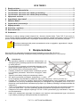
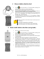
2 Test kierunku wirowania faz
Naciskając uruchomić tester. Powinna zapalić się zielona
dioda ON sygnalizująca gotowość przyrządu do pracy.
Podłączyć sondy pomiarowe do testera TKF-13.
Podłączyć sondy pomiarowe do punktów, gdzie występuje spo-
dziewane napięcie trójfazowe (obok przykładowy rysunek).
Jeśli fazy w danych punktach pomiarowych są zgodne z opisem
L1, L2, L3 na testerze zaświeca się dioda R, w przeciwnym wy-
padku dioda L.
Świecenie danej neonówki (L1, L2, L3) sygnalizuje istnienie napię-
cia większego niż 100 V między odpowiadającą jej sondą, a którąś
z pozostałych sond.
Błędne wskazania mogą być powodowane przez:
podłączenie dwóch sond do jednej fazy,
podłączenie jednej z sond do przewodu neutralnego,
brak podłączenia którejś z sond do sieci energetycznej.
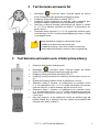
3 Test kierunku wirowania wału silnika (przewodowy)
Odłączyć silnik od sieci energetycznej.
Naciskając uruchomić tester. Powinna zapalić się zielona
dioda ON sygnalizująca gotowość przyrządu do pracy.
Podłączyć sondy pomiarowe do testera TKF-13.
Podłączyć sondy pomiarowe do badanego silnika (patrz rysunek ob-
ok).
Energicznie zakręcić wałem silnika w pożądanym kierunku.
Świecenie diody R oznacza, że podłączenie do zacisków silnika
U, V, W odpowiednio faz L1, L2, L3, będzie skutkowało wirowaniem
silnika w kierunku, w jakim obracany był wał w czasie testu.
Świecenie diody L oznacza, że podłączenie do zacisków silnika
U, V, W odpowiednio faz L1, L2, L3, będzie skutkowało wirowaniem
wału silnika w przeciwnym kierunku, do tego w jakim obracany był w
czasie testu.
Aby mieć pewność, że po podłączeniu silnika do zasilania jego wał
będzie obracał się w żądanym kierunku, należy przeprowadzić test
kolejności faz (patrz rozdział 1).

TKF-13 – INSTRUKCJA OBSŁUGI
4
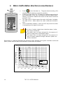
4 Test kierunku wirowania wału silnika (bezprzewodowy)
Naciskając uruchomić tester. Powinna zapalić się zielona
dioda ON sygnalizująca gotowość przyrządu do pracy.
Przyłożyć tylną część testera TKF-13 do pracującego silnika wzdłuż
jego osi (położenie osi zgodnie z rysunkiem obok). Odległość od te-
stera do silnika nie powinna być większa niż 2-3 cm.
Świecenie diody R oznacza, że wał silnika obraca się zgodnie z kie-
runkiem ruchu wskazówek zegara. Świecenie diody L oznacza, że
wał wiruje przeciwne.
Brak wskazań (diody L i R wygaszone) może oznaczać nie pracujący
silnik lub zbyt słaby sygnał.
W przypadku niektórych silników indukcyjnych jednofazo-
wych, wskazania mogą być utrudnione.
Przyrząd nie jest przeznaczony do badania silników jedno-
fazowych komutatorowych.
Przyrząd nie jest przeznaczony do badania silników zasila-
nych przez przekształtniki energoelektroniczne (falowniki).
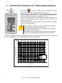
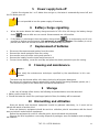
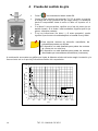
Poniżej przedstawiono wykres ilustrujący minimalną średnicę silnika dla danych obrotów i częstotliwo-
ści sieci energetycznej, przy której wskazania testera są wiarygodne.
0
10
20
30
40
50
60
70
80
90
0500 1000 1500 2000 2500 3000 3500 4000
obroty/min
minimalna średnica silnika [cm]
16.66 Hz
50Hz
60Hz

TKF-13 – INSTRUKCJA OBSŁUGI
5
5 Wyłączenie zasilania
Jeśli w ciągu pięciu minut nie zaświeci się dioda L lub R, następuje automatyczne wyłączenie te-
stera, dioda ON gaśnie.
Nie ma możliwości ręcznego wyłączenia zasilania.
6 Sygnalizacja stanu baterii
Jeśli tester wykryje, że w baterii pozostało około 10% energii, dioda stanu baterii zaczyna
pulsować co 1 s. Pomiary są nadal możliwe.
Jeśli bateria jest wyczerpana, dioda stanu baterii świeci światłem ciągłym i niemożliwe
jest wykonywanie pomiarów. W tym momencie należy wymienić baterie. Jeśli bateria nie zo-
stanie wymieniona, po pięciu minutach nastąpi automatyczne wyłączenie testera.
7 Wymiana baterii
Odłączyć sondy pomiarowe od sieci energetycznej.
Ściągnąć z obudowy elastyczną osłonę.
Odkręcić tylną dolną część obudowy, a następnie wyciągnąć ją.
Wyjąć baterię z testera, a następnie odłączyć ją.
Podłączyć nową baterię, przykręcić tylną klapkę i naciągnąć elastyczną osłonę na obudowę.
8 Czyszczenie i konserwacja
UWAGA!
Należy stosować jedynie metody konserwacji podane przez producenta w niniejszej in-
strukcji.
Tester można czyścić miękką, wilgotną flanelą używając ogólnie dostępnych detergentów.
Nie należy używać żadnych rozpuszczalników, ani środków czyszczących, które mogłyby poryso-
wać obudowę (proszki, pasty itp.).
Układ elektroniczny testera nie wymaga konserwacji.
9 Magazynowanie
Przy przechowywaniu testera należy przestrzegać poniższych zaleceń:
upewnić się, że tester jest suchy,
przy dłuższym okresie przechowywania, należy wyjąć baterię z testera.
10 Rozbiórka i utylizacja
Zużyty sprzęt elektryczny i elektroniczny należy gromadzić selektywnie, tj. nie umieszczać z od-
padami innego rodzaju.
Zużyty sprzęt elektroniczny należy przekazać do punktu zbiórki zgodnie z ustawą o zużytym
sprzęcie elektrycznym i elektronicznym.
Przed przekazaniem sprzętu do punktu zbiórki nie należy samodzielnie demontować żadnych
części z tego sprzętu.
Należy przestrzegać lokalnych przepisów dotyczących wyrzucania opakowań, zużytych baterii
i akumulatorów.

TKF-13 – INSTRUKCJA OBSŁUGI
6
11 Dane techniczne
a) rodzaj izolacji zgodnie z PN-EN 61010-1 .......................................................................... podwójna
b) kategoria pomiarowa wg PN-EN 61010-1 ........................................................................... III 600 V
c) stopień ochrony obudowy wg PN-EN 60529 ............................................................................ IP42
d) zakres częstotliwości ........................................................................................................ 2 ÷ 70 Hz
e) zakres międzyfazowych napięć roboczych.............................................................. 120 ÷ 760 V AC
f) zakres międzyfazowych napięć nominalnych ........................................................... 127÷ 690 V AC
g) zakres napięć SEM silników ....................................................................................... 1 ÷ 760 V AC
h) prąd pomiarowy (na każdą fazę) ......................................................................................... <3,5 mA
i) temperatura pracy .......................................................................................................... -10 ÷ 45ºC
j) temperatura przechowywania ......................................................................................... -20 ÷ 60ºC
k) okres migania diody stanu baterii ........................................................................................... ok. 1 s
l) czas do automatycznego wyłączenia ................................................................................. ok. 5 min
m) zasilanie testera................................................................................ bateria alkaliczna 6LR61 (9 V)
n) wymiary ............................................................................................................... 130 x 72 x 31 mm
o) masa ................................................................................................................................. ok. 150 g
Urządzenie nie posiada charakteru wzorca i dlatego nie podlega wzorcowaniu. Wła-
ściwą formą kontroli dla tego typu przyrządów jest sprawdzenie.
12 Producent
Producentem przyrządu prowadzącym serwis gwarancyjny i pogwarancyjny jest:
SONEL S.A.
ul. Wokulskiego 11
58-100 Świdnica
tel. +48 74 884 10 53 (Biuro Obsługi Klienta)
e-mail: bok@sonel.pl
internet: www.sonel.pl
UWAGA!
Do prowadzenia napraw serwisowych upoważniony jest jedynie producent.


TKF-13 – USER MANUAL
8
CONTENTS
1 Safety ........................................................................................................................................... 8
2 Phase rotation direction test....................................................................................................... 9
3 Motor shaft rotation direction (using leads) .............................................................................. 9
4 Motor shaft rotation direction (connectionless) ...................................................................... 10
5 Power supply turn-off ................................................................................................................ 11
6 Battery charge signalling .......................................................................................................... 11
7 Replacement of batteries .......................................................................................................... 11
8 Cleaning and maintenance ....................................................................................................... 11
9 Storage ....................................................................................................................................... 11
10 Dismantling and utilization ....................................................................................................... 11
11 Technical data............................................................................................................................ 12
12 Manufacturer .............................................................................................................................. 12
We appreciate your having purchased our phase sequence and motor rotation direction tester. The TKF-13
tester is a modern high-quality, simple and safe device. However it is recommended to get acquainted with
the present manual in order to avoid measuring errors and prevent possible problems related to operation of
the meter.
The manufacturer reserves the right to modify the appearance, equipment and technical da-
ta of the device.
1 Safety
The TKF-13 tester complies with the safety requirements specified in the norm EN 61010-1.
In order to protect yourself and the device do observe the rules described in the present manual.
Warning:
Do not perform tests in a humid environment, which contains
explosive or inflammable gases (materials), water vapour or
dust.
Having carried the device from a cold environment to a warm
one, wait 0.5 hour before you proceed to perform measure-
ments for the purpose of acclimatisation, if necessary wipe
out the condensed water vapour.
During measurements do not touch the metal parts of the
socket, lead terminals, fastening elements, circuits, etc.
Make sure you are properly insulated from the tested object.
Do not perform measurements using an out-of-order device, whose casing or leads are damaged (bro-
ken, cracked, deformed, contaminated, etc.).
The TKF-13 tester may be operated exclusively by qualified personnel who are properly authorised to
perform work on electric installations. Should the device be operated by unauthorised personnel, the
device may be damaged and there may be a serious danger for the operator.
The tester may be connected to the mains solely by means of dedicated leads provided by the manu-
facturer. Solely such leads guarantee compliance with safety regulations.
If phase-to-phase voltage exceeding 760 V AC will be connected to the device, the tester may be dam-
aged and there may be a risk for the operator.
If the device will be used for any other purpose than those specified in the present operating manual,
the tester may be damaged and there may be a serious risk for the operator.

TKF-13 – USER MANUAL
9
2 Phase rotation direction test
Press to turn the tester on. The green diode should go ON
signalling that the device is ready for operation.
Connect measurement probes to the TKF-13 tester.
Connect measurement probes to the points where there is the ex-
pected three-phase voltage (see the illustration below).
If the phases at the given measurement points are compliant with
the L1, L2, L3 description, the R diode of the tester will go on;
otherwise the L diode will go on.
The light of the given neon lamp (L1, L2, L3) signalises a voltage
exceeding 100 V between the corresponding probe and one of the
remaining probes.
Incorrect indications of the tester may be caused by one of
the following:
connection of two probes to one phase,
connection of one of the probes to the neutral lead,
lack of connection of one of the probes to the mains.
3 Motor shaft rotation direction (using leads)
Disconnect the motor from the mains.
Press to turn the tester on. The green diode should go ON
signalling that the device is ready for operation.
Connect measurement probes to the TKF-13 tester.
Connect measurement probes to the tested motor (see the adja-
cent illustration).
Rotate the motor shaft energetically in the desired direction.
The light of the R diode means the connection to the U, V and W
motor terminals of phases L1, L2 and L3, respectively, will cause
rotation of the motor in the direction the shaft spun during the test.
The light of the L diode means the connection to the U, V and W
motor terminals of phases L1, L2 and L3, respectively, will cause
rotation of the motor in the opposite direction to the direction the
shaft spun during the test.
Make sure the shaft rotates in the desired direction once the mo-
tor has been connected to the power supply source performing a
phase sequence test (see Chapter 2).

TKF-13 – USER MANUAL
10
4 Motor shaft rotation direction (connectionless)
Press to turn the tester on. The green diode should go ON
signalling that the device is ready for operation.
Put the rear part of the TKF-13 tester to a working motor along its
axis (the position of the axis in accordance with the adjacent illus-
tration). The distance between the tester and the motor should not
exceed 2-3 cm.
The light of the R diode means the motor shaft spins clockwise.
The light of the L diode means the motor shaft spins anticlock-
wise.
Lack of indications (diodes L and R are off) may mean the motor
is not working or the signal is too weak.
In case of certain single-phase inductive motors, indica-
tions may be hindered.
The device has not been designed for the purpose of
tests of single-phase commutator motors.
The device has not been designed for the purpose of
tests of motors powered through electronic power con-
verters (inverters).
Below there is a diagram illustrating the minimum motor diameter for the given revolution and the fre-
quency of the mains at which the indications of the tester are reliable.
0
10
20
30
40
50
60
70
80
90
0
500
1000
1500
2000
2500
3000
3500
4000
rpm
minimum motor diameter [cm]
16.66 Hz
50 Hz
60 Hz

TKF-13 – USER MANUAL
11
5 Power supply turn-off
If within five minutes the L or R diode does not go on, the tester is automatically turned off, and
the ON diode goes off.
It is not possible to turn the power supply off manually.
6 Battery charge signalling
When the tester detects the battery charge amounts to 10% of its full charge, the battery charge
diode starts to blink once a second. Measurements are still possible.
If the battery is discharged, then the battery charge diode is it continuously and it is im-
possible to perform measurements. It is necessary to replace batteries. If the battery is not re-
placed, then after five minutes the tester will be automatically turned off.
7 Replacement of batteries
Disconnect the measurement probes from the mains.
Remove the elastic protection from the casing.
Unscrew the rear part of the casing and remove it.
Remove the battery from the tester and disconnect it.
Connect a new battery, screw the rear flap and place the elastic protection upon the casing.
8 Cleaning and maintenance
NOTE!
Use solely the maintenance techniques specified by the manufacturer in this user
manual.
The tester may be cleaned with a soft, damp cloth using all-purpose detergents.
Do not use any solvents or cleaning agents which might scratch the casing (powders, pastes, etc.).
The electronic system of the meter does not require maintenance..
9 Storage
In the case of storage of the device, the following recommendations must be observed:
Make sure the tester is dry.
Should the tester be stored for a prolonged period of time, the battery will be removed.
10 Dismantling and utilization
Worn-out electric and electronic equipment should be gathered selectively, i.e. it must not be
placed with waste of another kind.
Worn-out electronic equipment should be sent to a collection point in accordance with the law of
worn-out electric and electronic equipment.
Before the equipment is sent to a collection point, do not dismantle any elements.
Observe the local regulations concerning disposal of packages, worn-out batteries and rechargea-
ble batteries.

TKF-13 – USER MANUAL
12
11 Technical data
a) Type of insulation in accordance with EN 61010-1 ................................................................. double
b) Measurement category in accordance with EN 61010-1 ..................................................... III 600 V
c) Ingress protection in accordance with EN 60529 .................................................................... IP42
d) Frequency range .............................................................................................................. 2 ÷ 70 Hz
e) Nominal phase-to-phase voltage range .................................................................. 127 ÷ 690 V AC
f) Phase-to-phase working voltage range ................................................................... 120 ÷ 760 V AC
g) Motor voltage range .................................................................................................... 1 ÷ 760 V AC
h) Measurement current (per each phase) .............................................................................. <3.5 mA
i) Working temperature ...................................................................................................... -10 ÷ 45ºC
j) Storage temperature ....................................................................................................... -20 ÷ 60ºC
k) Battery charge diode blinking rate ......................................................................... approximately 1 s
l) Time before automatic turn-off .......................................................................... approximately 5 min
m) Tester power supply ............................................................................. alkaline battery 6LR61 (9 V)
n) Dimensions .......................................................................................................... 130 x 72 x 31 mm
o) Mass of the tester (with battery, without leads) .................................................................. ca. 150 g
The device does not have the character of a standard and therefore is not subject to
calibration. The proper form of control for this type of instrument is checking.
12 Manufacturer
The manufacturer of the device and provider of guarantee and post-guarantee service:
SONEL S.A.
Wokulskiego 11
58-100 Świdnica
Poland
tel. +48 74 884 10 53 (Customer Service)
e-mail: customer[email protected]
web page: www.sonel.com
NOTE!
Service repairs must be performed only by the manufacturer.


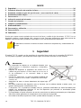
TKF-13 – MANUAL DE USO
14
ÍNDICE
1 Seguridad ................................................................................................................................... 14
2 Prueba de dirección de rotación de fases ............................................................................... 15
3 Prueba de sentido de giro del eje del motor (con conexión de cable) .................................. 15
4 Prueba del sentido de giro ........................................................................................................ 16
5 Desconexión .............................................................................................................................. 17
6 Indicación estado de la batería ................................................................................................. 17
7 Cambio de la batería .................................................................................................................. 17
8 Limpieza y mantenimiento ........................................................................................................ 17
9 Almacenamiento ........................................................................................................................ 17
10 Desmontaje y utilización ........................................................................................................... 17
11 Datos técnicos ........................................................................................................................... 18
12 Fabricante .................................................................................................................................. 18
Gracias por comprar nuestro probador de secuencia de fases y sentido de giro de motores. El TKF-13 es un
dispositivo moderno, de alta calidad, fácil y seguro de usar. Lea estas instrucciones para evitar errores de
medición y prevenir posibles problemas relacionados con el funcionamiento del dispositivo.
El fabricante se reserve el derecho de hacer cambios en la apariencia y características del
equipo.
1 Seguridad
El equipo TKF-13 cumple con los requisitos de seguridad de acuerdo con la normativa EN 61010-1.
Por su propia seguridad y del dispositivo debe seguir las normas descritas en este manual.
Advertencias:
No compruebe los objetos en un ambiente húmedo, que
contenga gases, (o materiales), explosivos o inflamables,
vapor o polvo.
Después de desplazar el dispositivo del entorno frío al
caliente hay que esperar 0,5 horas antes de su uso con el
fin de aclimatarse, si es necesario limpie el agua
condensada.
Durante las mediciones, no toque las partes metálicas del
enchufe, extremos de los cables, componentes de montaje ,
circuitos, etc.
Asegúrese de tener un buen aislamiento del objeto bajo
prueba.
No realice mediciones del dispositivo que no funciona, con la cubierta dañada o cables (rotos, con
grietas, deformaciones, contaminación, etc).
El dispositivo TKF-13 puede ser utilizado sólo por personas cualificadas que estén facultadas para
trabajar con instalaciones eléctricas. El uso del dispositivo por personas no autorizadas puede
peligroso para las personas y bienes.
El comprobador se puede conectar a la red sólo a través de los cables suministrados por el fabricante.
Sólo estos cables garantizan el cumplimiento con las normas de seguridad.
No conetar a tensiónes superiores a 760 V; pueden dañar al equipo y al usuario.

TKF-13 – MANUAL DE USO
15
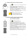
2 Prueba de dirección de rotación de fases
Pulsar para encender el TKF-13, se encenderá el diodo verde
ON.
Conectar los cables de medición al comprobador TKF-13.
Conectar los cables de medición a los puntos donde se encuentra
la tensión trifásica (ver dibujo).
Si las fases de los puntos de medición coinciden con la
descripción L1, L2, L3 en el comprobador se enciende el diodo R,
en caso contrario se enciende el diodo L.
La iluminación de las lámparas de neón (L1, L2, L3) indica la
existencia de una tensión superior a 100 V entre la fase
correspondiente, y cualquiera de las otras fases.
Una indicación incorrecta puede ser causada por:
conexión de dos cables a una fase.
conexión de uno de los cables al neutro,
no conexión de los cables a la red eléctrica.
3 Prueba de sentido de giro del eje del motor
(con conexión de cable)
Desconectar el motor de la red eléctrica.
Pulsar se encenderá el diodo verde ON.
Conectar los cables de medición al TKF-13.
Conectar los cables de medición al motor a probar (ver dibujo).
Girar enérgicamente el eje del motor en la dirección deseada.
Si el diodo R se ilumina, significa que la conexión a los terminales
del motor U, V, W, respectivamente a las fases L1, L2, L3, dará
como resultado que el motor gire en la dirección en la que el eje
fue rotado durante la prueba.
Si el diodo L se ilumina, significa que la conexión a los terminales
del motor U, V, W, respectivamente a las fases L1, L2, L3, dará
como resultado que el motor gire en la dirección contraria en la
que el eje fue rotado durante la prueba.
Para estar seguro de que cuando se conecte el motor a la
alimentación el eje gire en la dirección deseada, debe realizarse
tambien prueba de la secuencia de fases (ver el capítulo 1).

TKF-13 – MANUAL DE USO
16
4 Prueba del sentido de giro
Pulsar , se encenderá el diodo verde ON.
Ponga la parte posterior del probador TKF-13 al motor en marcha
a lo largo de su eje (posición del eje según dibujo). La distancia
desde el comprobador hasta el motor no debe ser superior a 2 ó
3 cm.
Si el diodo R esta encendido, significa que el eje del motor gira en
sentido horario. Si el diodo L está encendido, significa que el eje
gira en dirección contraria.
Si no hay indicaciones (los iodos L y R estan apagados), puede
significar que el motor no está trabajando o la señal es muy débil.
Para algunos motores de inducción monofásica, las
indicaciones pueden ser difíciles.
El dispositivo no está diseñado para probar los motores
de colector de una sola fase.
El dispositivo no está diseñado para probar los motores
alimentados por convertidores electrónicos (inversores).
A continuación se muestra un gráfico que ilustra el diámetro mínimo del motor según la rotación y la
frecuencia de red en la que hay indicaciones fiables del comprobador.
0
10
20
30
40
50
60
70
80
90
0
500
1000
1500
2000
2500
3000
3500
4000
rpm
diámetro mínimo del motor [cm]
16,66 Hz
50 Hz
60 Hz

TKF-13 – MANUAL DE USO
17
5 Desconexión
Si transcurridos cinco minutos, los diodos L o R no se encienden, el comprobador se apaga
automáticamente, el diodo ON se apaga.
No es posible apagar manualmente el equipo.
6 Indicación estado de la batería
Cuando el comprobador detecta que de las baterías estan aproximadamente al 10% de la carga,
el diodo de estado de la batería comienza a parpadear cada 1s. Las medidas aún son
posibles.
Si la batería está agotada, el diodo de estado de la batería se ilumina de forma continua,
y es imposible realizar las mediciones. En este momento hay que cambiar las baterías.
Si la batería no es reemplazada, después de cinco minutos se apagará automáticamente
el comprobador.
7 Cambio de la batería
Desconectar los cables de medición de la red eléctrica.
Quitar el protector de la carcasa.
Quitar la parte trasera e inferior de la carcasa, y luego sacarla.
Retirar la batería del comprobador, y desconectarla.
Conectar la batería nueva, atornillar la tapa trasera y poner el protector de la carcasa.
8 Limpieza y mantenimiento
NOTA!
Use únicamente el método de conservación indicado por el fabricante en este manual.
El comprobador puede ser limpiado con una trapo suave, humedecido con detergentes
habituales.
No utilice disolventes o productos de limpieza que puedan rayar la carcasa (polvos, pastas, etc.).
El sistema electrónico del probador no requiere mantenimiento.
9 Almacenamiento
Durante el almacenamiento del comprobador hay que observar las siguientes instrucciones:
asegurarse de que el comprobador está seco,
para un almacenamiento prolongado debe quitarse la batería.
10 Desmontaje y utilización
Los residuos de aparatos eléctricos y electrónicos deben ser recogidos por separado; no deben
depositarte con otro tipo de residuos.
El dispositivo electrónico debe ser llevado a un punto de recogida de este tipo de equipos,
conforme a la Ley de residuos de este tipo.
Antes de llevarlo al punto de recogida no debe de desarmarse ninguna parte del equipo.
Observe la normativa vigente en cuanto a la eliminación de los envases, baterías usadas, etc.

TKF-13 – MANUAL DE USO
18
11 Datos técnicos
a) tipo de aislamiento según la norma EN 61010-1 ......................................................................doble
b) categoría de seguridad según EN 61010-1 ......................................................................... III 600 V
c) grado de protección de la carcasa según EN 60529 ................................................................ IP42
d) rango de frecuencia .......................................................................................................... 2 ÷ 70 Hz
e) rango de tension nominales entre fases ................................................................ 127 ÷ 690 V AC
f) rango de tensión, entre fases, de trabajo .............................................................. 120 ÷ 760 V AC
g) rango de tensiones SEM de motores .......................................................................... 1 ÷ 760 V AC
h) corriente de medición (por fase) ......................................................................................... <3,5 mA
i) temperatura de trabajo ................................................................................................... -10 ÷ 45ºC
j) temperatura de almacenamiento .................................................................................... -20 ÷ 60ºC
k) tiempo de parpadeo del diodo de batería ............................................................................... ca. 1 s
l) apagado automático .............................................................................................. aprox. 5 minutos
m) alimentación ........................................................................................ batería alcalina 6LR61 (9 V)
n) dimensiones ....................................................................................................... 130 x 72 x 31 mm
o) peso ............................................................................................................................. aprox. 150 g
El dispositivo no tiene el carácter de un patrón, por lo tanto, no está sujeto a
calibración. La forma adecuada de control para este tipo de instrumento es la
verificación.
12 Fabricante
El fabricante del dispositivo que presta el servicio de garantía y postgarantía es:
SONEL S.A.
Wokulskiego 11
58-100 Świdnica
Polonia
tel. +48 74 884 10 53 (Servicio al cliente)
e-mail: customer[email protected]m
internet: www.sonel.com
¡ATENCIÓN!
Para el servicio de reparaciones sólo está autorizado el fabricante.


TKF-13 – BEDIENUNGSANLEITUNG
20
INHALTSVERZEICHNIS
1 Sicherheit ................................................................................................................................... 20
2 Test der Drehrichtung der Phasen ........................................................................................... 21
3 Richtungstest der Drehung der Motorwelle (mit Leitung) ....................................................... 21
4 Richtungstest der Drehung der Motorwelle (leitungslos) ....................................................... 22
5 Abschalten der Stromversorgung ............................................................................................ 23
6 Signalisierung des Batteriezustandes ..................................................................................... 23
7 Batteriewechsel ......................................................................................................................... 23
8 Reinigung und Wartung ............................................................................................................ 23
9 Lagerung .................................................................................................................................... 23
10 Demontage und Entsorgung ..................................................................................................... 23
11 Technische Daten ...................................................................................................................... 24
12 Hersteller .................................................................................................................................... 24
Wir danken für den Kauf unseres Phasenprüfers und Prüfgerätes für die Drehrichtung des Motors. Der Prüfer
TKF-13 ist ein modernes, hochqualitatives Messgerät, das leicht und sicher zu bedienen ist. Das Durchlesen der vor-
liegenden Anleitung ermöglicht jedoch Prüffehler zu vermeiden und eventuellen Problemen bei der Bedienung des
Gerätes vorzubeugen..
Der Hersteller behält sich das Recht vor, Änderungen bzgl. des Aussehens, der Ausrüstung und
der technischen Daten des Gerätes einzuführen.
1 Sicherheit
Das Gerät TKF-13 entspricht den Sicherheitsanforderungen der Norm EN 61010-1.
Für die eigene und die Sicherheit des Gerätes sind die in dieser Anleitung beschriebenen Vorschriften einzuhalten.
Warnhinweise:
Die Objekte sind nicht bei feuchter Umwelt, die explosi-
ve oder leicht brennbare Gase (Stoffe), Wasserdampf
oder Staub enthält, zu prüfen.
Nach der Verlagerung des Gerätes von einem kalten in
ein warmes Umfeld muss man zwecks Akklimatisierung
vor dem Gebrauch 0,5 h abwarten und bei Bedarf die
Wasserdampftropfen abwischen.
Während der Messungen dürfen die Metallteile der
Steckdose, Leitungsenden, Befestigungselemente,
Stromkreise usw. nicht berührt werden. Eine gute Iso-
lierung vom zu prüfenden Objekt ist abzusichern.
Wenn das Gerät nicht funktionsfähig ist sowie sein Ge-
häuse oder die Leitungen beschädigt sind (angebro-
chen, gerissen, deformiert, verunreinigt usw.), dürfen
keine Messungen ausgeführt werden.
Das Gerät TKF-13 ist ausschließlich von entsprechend qualifizierten Personen, die auch die erforderlichen Be-
rechtigungen für die Durchführung von Messungen in Elektroanlagen haben, zu bedienen. Die Handhabung
des Gerätes durch unbefugte Personen kann zu einer Beschädigung des Gerätes führen und eine ernsthafte
Gefahrenquelle für den Nutzer sein.
Das Prüfgerät darf man nur mit den dafür vorgesehenen und vom Hersteller bereitgestellten Leitungen an das
Stromversorgungsnetz anschließen. Nur solche Leitungen entsprechen den Sicherheitsvorschriften.
Der Anschluss an das Prüfgerät einer Spannung von mehr als 760 V kann zu seiner Beschädigung und Ge-
fährdung für den Nutzer führen.
Jede andere als in dieser Anleitung vorgegebene Anwendung des Gerätes kann es beschädigen und eine
ernsthafte Gefahrenquelle für den Nutzer sein.

TKF-13 – BEDIENUNGSANLEITUNG
21
2 Test der Drehrichtung der Phasen
Durch Drücken von wird das Prüfgerät in Betrieb genom-
men. Es müsste die grüne Diode ON aufleuchten, welche die Be-
triebsbereitschaft des Gerätes signalisiert.
Die Prüfspitzen an das Prüfgerät TKF-13 anschließen.
Die Prüfspitzen an die Punkte anschließen, wo die zu erwartende
Dreiphasenspannung auftritt (Siehe daneben das Abbildungsbei-
spiel).
Wenn die Phasen in den gegebenen Messpunkten mit der Be-
schreibung L1, L2, L3 auf dem Prüfgerät übereinstimmen, dann
leuchtet die Diode R, im umgekehrten Fall die Diode L.
Das Leuchten einer gegebenen Neonlampe (L1, L2, L3) signali-
siert das Vorhandensein einer Spannung zwischen den Phasen,
die größer als 100 V zwischen der ihr entsprechenden Prüfspitze
und irgendeiner der übrigen Prüfspitzen ist.
Eine fehlerhafte Anzeige kann hervorgerufen werden durch:
den Anschluss von zwei Prüfspitzen an eine Phase,
den Anschluss einer der Prüfspitzen an den Nullleiter,
den fehlenden Anschluss einer der Prüfspitzen an das
Stromversorgungsnetz.
3 Richtungstest der Drehung der Motorwelle (mit Leitung)
Den Motor vom Stromversorgungsnetz trennen.
Durch Drücken von wird das Prüfgerät in Betrieb genom-
men. Es müsste die grüne Diode ON aufleuchten, welche die Be-
triebsbereitschaft des Gerätes signalisiert.
Die Prüfspitzen an das Prüfgerät TKF-13 anschließen.
Die Prüfspitzen an den zu prüfenden Motor anschließen (Siehe oben
das Abbildungsbeispiel).
Die Motorwelle energisch in die gewünschte Richtung drehen
Das Aufleuchten der Diode R bedeutet, dass ein Anschließen an die
Klemmen, U, V, W des Motors entsprechend den Phasen L1, L2, L3
eine Drehung des Motors in die Richtung bewirken wird, in der die
Welle während des Tests gedreht wurde.
Das Aufleuchten der Diode L bedeutet, dass ein Anschließen an die
Klemmen, U, V, W des Motors entsprechend den Phasen L1, L2, L3
eine Drehung der Motorwelle in die Gegenrichtung bewirken wird, in
der die Welle während des Tests gedreht wurde.
Um ganz sicher zu sein, dass nach dem Anschließen des Motors an
die Stromversorgung seine Welle sich in der gewünschten Richtung
drehen wird, ist die Reihenfolge der Phasen zu prüfen (Siehe Kapi-
tel 1).

TKF-13 – BEDIENUNGSANLEITUNG
22
4 Richtungstest der Drehung der Motorwelle (leitungslos)
Durch Drücken von wird das Prüfgerät in Betrieb genom-
men. Es müsste die grüne Diode ON aufleuchten, welche die Be-
triebsbereitschaft des Gerätes signalisiert.
Den hinteren Teil des Prüfgerätes TKF-13 an den sich im Betrieb
befindenden Motor längs seiner Achse anlegen (Lage der Achse
gemäß der nebenstehenden Abbildung). Der Abstand des Prüfge-
rätes zum Motor sollte nicht größer als 2-3 cm sein.
Das Aufleuchten der Diode R bedeutet, dass die Motorwelle sich in
Uhrzeigerrichtung dreht. Beim Aufleuchten der Diode L dagegen
dreht sich die Welle entgegengesetzt.
Fehlende Anzeigen (Dioden L und R sind erloschen) können be-
deuten, dass entweder der Motor nicht arbeitet oder das Signal zu
schwach ist.
Bei einigen Einphasen-Induktions-motoren können die
Anzeigen erschwert sein.
Das Gerät ist nicht für die Prüfung von Einphasen-
Kommutatormotoren bestimmt.
Ebenso ist das Gerät nicht für die Prüfung von solchen
Motoren geeignet, deren Stromversorgung durch ener-
goelektronische Wandler (Wechselrichter) erfolgt..
Das nachstehend dargestellte Diagramm veranschaulicht den minimalen Durchmesser des Motors für
gegebene Umdrehungen und Frequenzen des Elektroenergienetzes, bei denen die Anzeigen des
Prüfgerätes glaubwürdig sind.
0
1
0
2
0
3
0
4
0
5
0
6
0
7
0
8
0
9
0
0
50
0
100
0
150
0
200
0
250
0
300
0
350
0
400
0
Umdrehungen/Min
Minimaler Durchmesser des Motors [cm]
16,66 Hz
50 Hz
60 Hz

TKF-13 – BEDIENUNGSANLEITUNG
23
5 Abschalten der Stromversorgung
Wenn innerhalb von fünf Minuten die Dioden L oder R nicht aufleuchten, dann erfolgt automatisch das Ab-
schalten des Prüfgerätes; die Diode ON erlischt.
Es gibt keine Möglichkeit einer manuellen Abschaltung der Stromversorgung.
6 Signalisierung des Batteriezustandes
Wenn das Prüfgerät feststellt, dass in der Batterie nur noch 10% der Energie verblieben sind, dann be-
ginnt die Diode für den Batteriezustand jeweils nach 1 s zu pulsieren. Messungen sind weiter-
hin möglich.
Wenn die Batterie leer ist, dann leuchtet die Diode für den Batteriezustand mit einem Dauerlicht
und die Ausführung von Messungen ist nicht mehr möglich. In dem Moment ist die Batterie zu wech-
seln. Wenn die Batterie nicht ausgetauscht wird, dann wird das Prüfgerät nach fünf Minuten automa-
tisch abgeschaltet..
7 Batteriewechsel
Die Prüfspitzen vom Energienetz trennen.
Aus dem Gehäuse mit der elastischen Abdeckung ziehen.
Den hinteren unteren Teil des Gehäuses abdrehen und sie danach herausziehen.
Die Batterie aus dem Prüfgerät nehmen und sie dann abtrennen.
Die neue Batterie anschließen, die hintere Klappe anschrauben und die elastische Abdeckung auf das
Gehäuse ziehen.
8 Reinigung und Wartung
ACHTUNG!
Es sind ausschließlich nur die Wartungsarbeiten durchzuführen, die durch den Hersteller in
der vorliegenden Anleitung angegeben werden.
Das Prüfgerät kann man mit einem weichen, feuchten Flanell und unter Verwendung allgemein erhältli-
cher Mittel reinigen.
Es sind dabei weder Lösungsmittel noch solche Reinigungsmittel zu verwenden, die das Gehäuse zer-
kratzen könnten (Pulver, Pasten usw.).
Das elektronische System des Prüfgerätes erfordert keine Wartung.
9 Lagerung
Bei der Lagerung des Spannungsprüfers sind nachfolgende Hinweise zu beachten:
man muss sich überzeugen, ob der Prüfer trocken ist,
bei längerer Aufbewahrung sind die Batterien aus dem Prüfgerät zu nehmen.
10 Demontage und Entsorgung
Die verschlissene elektrische und elektronische Ausrüstung ist getrennt zu sammeln, d.h. sie ist nicht mit
Abfällen anderer Art zu vermischen
Die verschlissene elektronische Ausrüstung ist entsprechend dem Gesetz über verbrauchte elektrische
und elektronische Ausrüstung einer Sammelstelle zu übergeben.
Vor der Übergabe der Ausrüstung an die Sammelstelle sind keine Teile der Ausrüstung selbstständig zu
demontieren.
Außerdem sind die örtlichen Vorschriften bzgl. der Verwertung von Verpackungen, verbrauchter Batte-
rien und Akkus zu beachten..

TKF-13 – BEDIENUNGSANLEITUNG
24
11 Technische Daten
a) Isolationsart gemäß EN 61010-1 ........................................................................................ doppelte
b) Messkategorie gem. EN 61010-1 ........................................................................................ III 600 V
c) Schutzgrad des Gehäuses gem. EN 60529 .............................................................................. IP42
d) Frequenzbereich ............................................................................................................... 2 ÷ 70 Hz
e) Bereich der Nennspannungen zwischen den Phasen ............................................. 127 ÷ 690 V AC
f) Bereich der Betriebsspannung zwischen den Phasen ............................................. 120 ÷ 760 V AC
g) Bereich der SEM - Spannungen der Motoren ............................................................. 1 ÷ 760 V AC
h) Messstrom (für jede Phase) ................................................................................................ <3,5 mA
i) Betriebstemperatur ......................................................................................................... -10 ÷ 45ºC
j) Lagertemperatur ............................................................................................................. -20 ÷ 60ºC
k) Blinkdauer der Diode für den Batteriezustand ........................................................................ ca. 1 s
l) Zeit zum automatischen Abschalten ................................................................................. ca.. 5 Min
m) Stromversorgung des Prüfgerätes: ............................................ alkalische Batterie 6LR61 (9V)
n) Abmessungen:ca. ............................................................................................... 130 x 72 x 31 mm
o) Gewicht des Messgerätes mit Batterien: ......................................................................... ca. 0,15 kg
Das Gerät hat keinen Standardcharakter und ist daher nicht eichpflichtig. Die richtige
Form der Kontrolle für diese Art von Instrument ist die Kontrolle.
12 Hersteller
Gerätehersteller für Garantieansprüche und Service:
SONEL S.A.
Wokulskiego 11
58-100 Świdnica
Polen
Tel. +48 74 884 10 53 (Kundenbetreuung)
E-Mail: custo[email protected]om
Webseite: www.sonel.com
ACHTUNG!
Servicereparaturen dürfen nur vom Hersteller durchgeführt werden.


TKF-13 – MANUALE D’USO
26
INDICE
1 Sicurezza .................................................................................................................................... 26
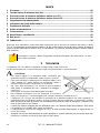
2 Test del senso di rotazione delle fasi ....................................................................................... 27
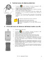
3 Prova del senso di rotazione dell'albero motore (con fil) ....................................................... 27
4 Prova del senso di rotazione dell'albero motore (senza fii) .................................................... 28
5 Spegnimento dell'alimentazione ............................................................................................... 29
6 Indicazione del livello della batteria ......................................................................................... 29
7 Sostituzione delle pile ............................................................................................................... 29
8 Pulizia e manutenzione ............................................................................................................. 29
9 Conservazione ........................................................................................................................... 29
10 Demolizione e smaltimento ....................................................................................................... 29
11 Dati tecnici ................................................................................................................................. 30
12 Fabbricante ................................................................................................................................ 30
Grazie per aver acquistato il nostro tester della sequenza di fasi e del senso di rotazione del motore. Il tester
TKF-13 è un dispositivo di misurazione moderno e di alta qualità, facile e sicuro da usare. Tuttavia, la lettura di
questo manuale permetterà di evitare errori di misurazione e a prevenire eventuali problemi durante l'utilizzo
dello strumento.
Il produttore si riserva il diritto di apportare modifiche all'aspetto, alle attrezzature e ai dati
tecnici dello strumento.
1 Sicurezza
Lo strumento TKF-13 soddisfa i requisiti di sicurezza della norma EN 61010-1.
Per la tua sicurezza e la sicurezza del tester, segui le regole descritte in questo manuale.
Avvertenze:
Non testare oggetti in un ambiente umido contenente gas
(materiali) esplosivi o infiammabili, vapore acqueo o polvere.
Dopo aver trasferito lo strumento da un ambiente freddo a uno
caldo, aspetta 0,5 h prima dell'uso per acclimatare il tester e
asciuga il vapore acqueo condensato, se necessario.
Nel corso delle misurazioni, non toccare le parti metalliche
della presa, le estremità dei cavi, i dispositivi di fissaggio, i
circuiti, ecc.
Assicurati di essere ben isolati dall'oggetto da testare.
Non effettuare misurazioni con uno strumento che funziona
male, con l'involucro o i cavi danneggiati (rotti, incrinati, deformati, contaminati, ecc.).
L'indicatore TKF-13 Dopo aver trasferito lo strumento da un ambiente freddo a uno caldo, aspetta 0,5 h
prima dell'uso per acclimatare il tester e asciuga il vapore acqueo condensato, se necessario. L'utilizzo
dello strumento da parte di persone non autorizzate può provocare danni al dispositivo e costituire una
fonte di grave pericolo per l'utente.
Il tester può essere collegato alla rete utilizzando solo i cavi dedicati forniti dal produttore. Solo questi
cavi garantiscono il rispetto delle norme di sicurezza.
Il collegamento di una tensione maggiore di 760 V al tester potrebbe danneggiarlo e rappresentare un
rischio per l'utente.
Qualsiasi uso diverso dell'indicatore da quelli specificati in questo manuale può provocare danni allo
strumento e costituire una fonte di grave pericolo per l'utente.

TKF-13 – MANUALE D’USO
27
2 Test del senso di rotazione delle fasi
Premendo avvia il rilevatore. Dovrebbe accendersi il LED
verde ON che indica che lo strumento è operativo.
Collega le sonde di prova al tester TKF-13.
Collega i puntali del tester ai punti su cui si verifica la tensione
trifase attesa (esempio di figura a fianco).
Se le fasi nei punti di misurazione dati sono conformi alla
descrizione L1, L2, L3, sul tester si accende il led R, altrimenti si
accende il led L.
La spia (L1, L2, L3) accesa indica la presenza di una tensione
superiore a 100 V tra la sonda corrispondente e una delle altre
sonde.
Le indicazioni errate possono essere causate da:
collegamento di due sonde ad una fase,
collegamento di una delle sonde al cavo neutro,
assenza di collegamento di una delle sonde alla rete
elettrica.
3 Prova del senso di rotazione dell'albero motore (con fil)
Scollega il motore dalla rete.
Premendo avvia il rilevatore. Dovrebbe accendersi il LED
verde ON che indica che lo strumento è operativo.
Collegare le sonde di prova al tester TKF-13.
Collega i puntali di prova al motore testato (vedi disegno a lato).
Ruota energicamente l'albero motore nella direzione desiderata.
Il diodo R acceso indica che il collegamento delle fasi L1, L2, L3 ai
morsetti rispettivamente U, V, W del motore, comporterà la rotazione
del motore nello stesso senso di rotazione in cui stava ruotando
durante la prova.
Il diodo R acceso indica che il collegamento delle fasi L1, L2, L3 ai
morsetti rispettivamente U, V, W del motore, comporterà la rotazione
dell'albero motore nella direzione opposta a quella in cui stava
ruotando durante la prova.
Per assicurarti che l'albero ruoti nella direzione desiderata quando il
motore è collegato all'alimentazione, esegui un test della sequenza
delle fasi (vedi capitolo 1).

TKF-13 – MANUALE D’USO
28
4 Prova del senso di rotazione dell'albero motore (senza fii)
Premendo avvia il rilevatore. Dovrebbe accendersi il LED
verde ON che indica che lo strumento è operativo.
Posizionare la parte posteriore del tester TKF-13 contro il motore in
funzione lungo il suo asse (posizione dell'asse come mostrato nella
figura a fianco). La distanza del tester dal motore non dovrebbe
essere più di 2-3 cm.
Il diodo R acceso indica che l'albero del motore gira in senso orario.
Il diodo L acceso indica che l'albero del motore gira in senso
antiorario.
Nessuna indicazione (LED L e R spenti) potrebbe significare che il
motore non sta girando o che il segnale è troppo debole.
Per alcuni motori a induzione monofase, le indicazioni
possono essere difficili.
Lo strumento non è destinato alle prove di motori a
collettore monofase.
Lo strumento non è destinato alle prove di motori alimentati
da convertitori elettronici di potenza (inverter).
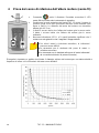
Di seguito è riportato un grafico che illustra il diametro minimo del motore per una data velocità e
frequenza di rete a cui le indicazioni del tester sono affidabili.

TKF-13 – MANUALE D’USO
29
5 Spegnimento dell'alimentazione
Se il diodo L o R non si accende entro cinque minuti, il tester si spegne automaticamente, il led
ON si spegne.
Non è possibile spegnere manualmente l'alimentazione.
6 Indicazione del livello della batteria
Se il tester rileva che la batteria ha circa il 10% di energia rimanente, il LED di stato della batteria
inizia a lampeggiare ogni 1 s. Tuttavia, le misure sono ancora possibili.
Se la batteria è scarica, la luce del LED di stato della batteria è fissa e non è possibile
effettuare misurazioni. A questo punto, le batterie devono essere sostituite. Se la batteria
non verrà sostituita, il tester si spegnerà automaticamente dopo cinque minuti.
7 Sostituzione delle pile
Scollega i puntali di prova dalla rete.
Rimuovi la protezione elastica dall'involucro.
Svita la parte posteriore inferiore dell'alloggiamento e poi estrailo.
Rimuovi la batteria dal tester e quindi scollegala.
Collega una nuova batteria, avvita il coperchio posteriore e rimetti la protezione elastica
sull'alloggiamento.
8 Pulizia e manutenzione
ATTENZIONE!
Utilizzare solo i metodi di manutenzione specificati dal produttore in questo manuale.
Il tester può essere pulito con un panno di flanella morbido e umido usando detergenti
generalmente disponibili.
Non usare solventi o detergenti che potrebbero graffiare l'alloggiamento (polveri, paste, ecc.).
Il circuito elettronico del tester non richiede manutenzione.
9 Conservazione
Alla conservazione del tester devono essere osservate le seguenti raccomandazioni:
assicurati che lo strumento sia asciutto,
in caso di stoccaggio prolungato, rimuovere la pila dal tester.
10 Demolizione e smaltimento
I rifiuti di apparecchiature elettriche ed elettroniche devono essere raccolti separatamente, cioè
non devono essere messi insieme ad altri tipi di rifiuti.
Conformemente alla legge sui rifiuti di apparecchiature elettriche ed elettroniche, i rifiuti di
apparecchiature elettroniche devono essere consegnati a un centro di raccolta.
Non smontare nessuna parte dello strumento in modo autonomo prima di consegnarlo in un
centro di raccolta.
Rispettare le norme locali per lo smaltimento dell'imballaggio, delle pile e delle batterie usate.

TKF-13 – MANUALE D’USO
30
11 Dati tecnici
a) tipo di isolamento secondo EN 61010-1 ................................................................................. doppio
b) categoria di misura secondo EN 61010-1 ........................................................................... III 600 V
c) grado di protezione dell'involucro secondo EN 60529 .............................................................. IP42
d) campo di frequenza .......................................................................................................... 2 ÷ 70 Hz
e) campo delle tensioni di esercizio concatenate ........................................................ 120 ÷ 760 V AC
f) campo delle tensioni nominali concatenate .............................................................. 127÷ 690 V AC
g) campo di tensioni SEM dei motori ............................................................................... 1 ÷ 760 V AC
h) corrente di prova (per ogni fase) ......................................................................................... <3,5 mA
i) temperatura di esercizio ................................................................................................. -10 ÷ 45ºC
j) temperatura di conservazione ......................................................................................... -20 ÷ 60ºC
k) tempo di lampeggiamento del LED di stato della batteria .................................................... circa 1 s
l) tempo per lo spegnimento automatico ............................................................................... ca. 5 min
m) alimentazione del tester ............................................................................. pila alcalina 6LR61 (9 V)
n) dimensioni ........................................................................................................... 130 x 72 x 31 mm
o) peso .................................................................................................................................. ca. 150 g
Lo strumento non ha il carattere di un campione e quindi non è soggetto a taratura. La
forma di controllo appropriata per questo tipo di strumento è la verifica.
12 Fabbricante
Il fabbricante dello strumento e fornitore dei servizi di garanzia e post-garanzia:
SONEL S.A.
Wokulskiego 11
58-100 Świdnica
Polonia
tel. +48 74 884 10 53 (Servizio clienti)
e-mail: customer[email protected]m
sito web: www.sonel.com
ATTENZIONE!
Gli interventi di riparazione devono essere effettuati solo dal produttore.


TKF-13 – РУКОВОДСТВО ПО ЭКСПЛУАТАЦИИ
32
СОДЕРЖАНИЕ
1 Безопасность .......................................................................................................................... 32
2 Определение чередования фаз ............................................................................................. 33
3 Определение направления враще-ния вала электродвигателей (проводная) ........... 33
4 Определение направ-ления вращения электродвигателя (бесконтактное) ............. 34
5 Автоматическое выключение ............................................................................................. 35
6 Состояние элементов питания .......................................................................................... 35
7 Замена элементов питания ................................................................................................. 35
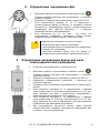
8 Обслуживание указателя ...................................................................................................... 35
9 Хранение ................................................................................................................................... 35
10 Разборка и утилизация .......................................................................................................... 35
11 Технические данные ............................................................................................................... 36
12 Производитель ....................................................................................................................... 36
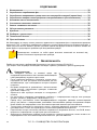
Мы благодарим за покупку нашего указатель правильности чередования фаз и направления вращения
двигателей. TKF-13 является современным прибором, который характе-ризуется высоким качеством, а
также простотой исполь-зования. Однако прочтение данной инструкции позволит избежать ошибок во
время работы и предотвратит проблемы при обслуживании прибора.
Производитель оставляет за собой право внесения изменений во внешний вид,
а также технические характеристики прибора.
1 Безопасность
Прибор соответствует требованиям безопасности согласно стандарту EN 61010-1.
Для защиты себя и прибора необходимо соблюдать правила, указанные в данном руководстве.
Предупреждения:
Не тестируйте объекты во влажной среде, при
содержании взрывоопасных или легковоспламеняющихся
газов (материалов), водяного пара и пыли.
После переноски прибора из холодной в теплую среду,
подождите 0,5 часа до начала использования для его
акклиматизации, при необходимости вытрите водяной
конденсат.
Во время измерения не прикасайтесь к металлическим
частям розетки, наконечникам проводов, элементам
крепления, схемы и т.д.
Обеспечьте себе хорошую изоляцию от тестируемого
объекта.
Не выполняйте измерения неисправным прибором, с повреждениями корпуса или проводов
(изломы, трещины, деформация, загрязнение и т.п.).
Прибор могут пользоваться только квалифицированные сотрудники, имеющие соответствующий
доступ для работы с электрическими установками. Использование прибора посторонними лицами
может вызвать его повреждение и стать источником серьезной опасности для пользователя.
Тестер можно подключать к электросети только с помощью фирменных проводов, поставляемых
производителем. Только они гарантируют соответствие правилам безопасности.
Подключение тестера к источнику линейного переменного напряжения больше, чем 760 В, может
вызвать его повреждение и создать риск для пользователя.
Любое другое применение прибора, кроме указанного в данном руководстве, может вызвать его
повреждение и стать источником серьезной опасности для пользователя.

TKF-13 – РУКОВОДСТВО ПО ЭКСПЛУАТАЦИИ
33
2 Определение чередования фаз
Включение прибора осуществляется нажатием кнопки .
Горящий зеленый светодиод ON сигнализирует о готовности
указателя к работе.
Подключите измерительные проводники к указателю TKF-13
Если измерительные провода L1, L2, L3 подключены к
соответствующим фазам на объекте, то загорается зеленый
светодиод R, индицирующий прямую последо-вательность
чередования фаз. Красный светодиод L – обратную
последовательность чередования фаз.
Если светодиоды (L1, L2, L3) горят – это значит, что
существующее межфазное напряжение между соответ-
ствующим зондом и любым другим, превышает 100 В.
Неправильные показания могут быть вызваны:
подключением двух зондов к одной фазе
подключением одного из измерительных проводников
нейтрали (PE-проводнику)
отсутствие контакта между хотя бы одним из
измерительных проводников и электрической сетью.
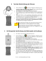
3 Определение направления враще-ния вала
электродвигателей (проводная)
Отключите электродвигатель от питающей сети.
Включение прибора осуществляется нажатием кнопки .
Горящий зеленый светодиод ON сигнализирует о готовности
указателя к работе.
Подключите измерительные проводники к указателю TKF-13.
Подключите измерительные проводники к двигателю как
показано на рисунке.
Проверните вал тестируемого электродвигателя в любом напра-
влении.
Если загорается светодиод R, то подключенные к зажимам
элект-родвигателя U V W соответ-ствующие фазы L1 L2 L3, при-
ведут вращение его вала в напра-влении, совпадающим с
напра-влением при проведении тести-рования.
Если загорается светодиод L, то подключенные к зажимам
элект-родвигателя U V W соответ-ствующие фазы L1 L2 L3, при-
ведут вращение его вала в направлении, противоположенном
направлению при проведении тестирования.
Для подтверждения полученных данных, перед запуском
электро-двигателя, проведите определе-ние чередования фаз,
согласно п.1 данного руководства

TKF-13 – РУКОВОДСТВО ПО ЭКСПЛУАТАЦИИ
34
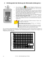
4 Определение направ-ления вращения
электродвигателя (бесконтактное)
Включение прибора осуществляется нажатием кнопки .
Горящий зеленый светодиод ON сигнализирует о готовности
указателя к работе.
Приложите задней панелью указатель TKF-13 к работающему
электродвига-телю, вдоль оси вращения вала как показано на
рисунке. Расстояние от задней панели указателя до корпуса
электродвигателя не должно превышать 2-3 см.
Если горит светодиод R, то вращение вала электродвига-теля
происходит по часовой стрелке. Если горит светодиод L – то
в противоположенном направлении.
Если обо светодиода не горят (R и L), то необходимо убедиться
в работоспосо-бности электродвигателя, либо очень слабый
сигнал для проведения индикации.
При определении направления вращения вала
однофазных электродвигателей, данные могут быть
недостоверны.
Прибор не предназначен для испытания однофазных
двигателей с коммутатором.
При определении направления вращения вала
электродвигателей, питание которых осуществляется
через преобразователи электрической энергии, данные
могут быть недостоверны.
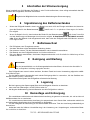
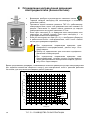
Далее представлена диаграмма, показывающая значения диаметров ротора электродвигателя
при заданном количестве оборотов в минуту для электрических сетей с разными рабочими
частотами, для получения достоверных данных указателя.
0
10
20
30
40
50
60
70
80
90
0500 1000 1500 2000 2500 3000 3500 4000
obroty/min
minimalna średnica silnika [cm]
16.66 Hz
50Hz
60Hz

TKF-13 – РУКОВОДСТВО ПО ЭКСПЛУАТАЦИИ
35
5 Автоматическое выключение
Если на протяжении 5 минут не происходит процесса тестирования (светодиоды R и L не
загораются), происходит автоматическое выключение указателя. Светодиод ON гаснет.
Указатель не имеет возможности ручного отключения питания.
6 Состояние элементов питания
Если уровень заряда элементов питания указателя составляет 10%, светодиод состояния
заряда начинает моргать с периодичностью раз в 1 секунду. Дальнейшие
измерения невозможны.
Если уровень заряда элементов питания ниже 10%, светодиод горит постоянно.
Необходимо произвести замену элементов питания, в противном случае через 5 минут
произойдет автоматическое отключение указателя.
7 Замена элементов питания
Podłączyć nową baterię, przykręcić tylną klapkę i naciągnąć elastyczną osłonę na obudowę.
Отсоединить прорезиненную часть.
Открутите заднюю нижнюю часть корпуса указателя.
Замените элементы питания
Закрутите заднюю крышку корпуса и наденьте прорези-ненную часть указателя.
8 Обслуживание указателя
ВНИМАНИЕ!
Следует использовать только указанные производителем в данном руководстве
методы технического обслуживания.
Корпус измерителя можно чистить мягкой влажной фланелью.
Нельзя использовать растворители, абразивные чистящие средства (порошки, пасты и так далее).
Электронная схема измерителя не нуждается в чистке.
9 Хранение
При хранении прибора следуйте приведенным ниже рекомендациям:
убедитесь, что тестер сухой,
при длительном хранении извлеките батарею из тестера.
10 Разборка и утилизация
Утилизируемое электрическое и электронное оборудование необходимо собирать
отдельно, т.е. не хранить его с отходами другого вида.
Утилизируемое электронное оборудование необходимо отправить в пункт приема в
соответствии с действующим Положением об обращении с отходами электрического и
электронного оборудования.
Нельзя самостоятельно разбирать оборудование на части до его передачи в пункт сбора.
Необходимо соблюдать местные законы и правила по утилизации упаковки,
использованных батареек и аккумуляторов.

TKF-13 – РУКОВОДСТВО ПО ЭКСПЛУАТАЦИИ
36
11 Технические данные
a) тип изоляции, согласно EN 61010-1 ................................................................................ двойная
b) измерительная категория по EN 61010-1 ........................................................................ III 600 В
c) степень защиты корпуса по EN 60529 .................................................................................. IP42
d) диапазон частоты ........................................................................................................... 2 ÷ 70 Гц
e) максимальное межфазное напряжение работы.......................... 120 ÷ 760 В переменного тока
f) диапазон междуфазных напряжений ............................................ 127÷ 690 В переменного тока
g) диапазон напряжения двигателя ЭДС ............................................. 1 ÷ 760 В переменного тока
h) потребляемый ток (по каждой фазе) ............................................................................... <3,5 мА
i) рабочая температура ................................................................................................... -10 ÷ 45ºC
j) температура хранения .................................................................................................. -20 ÷ 60ºC
k) период мигания светодиодного индикатора состояния батареи .................................. около 1 c
l) время бездействия до автовыключения ................................................................ около 5 минут
m) питание указателя ........................................................ элемент питания щелочной 6LR61 (9 B)
n) размеры............................................................................................................... 130 x 72 x 31 мм
o) вес ................................................................................................................................ около 150 г
Устройство не является эталоном и поэтому не подлежит поверке. Правильная
форма контроля для приборов этого типа – это проверка.
12 Производитель
Производитель прибора, осуществляющий гарантийное и послегарантийное обслуживание:
SONEL S.A.
Wokulskiego 11
58-100 Świdnica
Польша
Тел. +48 74 884 10 53 (Обслуживание клиентов)
E-mail: custo[email protected]om
Сайт: www.sonel.com
ВНИМАНИЕ!
Только производитель имеет право на ремонт и сервисное обслуживаниея.


-
 1
1
-
 2
2
-
 3
3
-
 4
4
-
 5
5
-
 6
6
-
 7
7
-
 8
8
-
 9
9
-
 10
10
-
 11
11
-
 12
12
-
 13
13
-
 14
14
-
 15
15
-
 16
16
-
 17
17
-
 18
18
-
 19
19
-
 20
20
-
 21
21
-
 22
22
-
 23
23
-
 24
24
-
 25
25
-
 26
26
-
 27
27
-
 28
28
-
 29
29
-
 30
30
-
 31
31
-
 32
32
-
 33
33
-
 34
34
-
 35
35
-
 36
36
-
 37
37
-
 38
38
-
 39
39
-
 40
40


en otros idiomas
- italiano: Sonel TKF-13 Manuale utente
- Deutsch: Sonel TKF-13 Benutzerhandbuch
- polski: Sonel TKF-13 Instrukcja obsługi