
Owner´s Manual
Manual de instrucciones
Pre-Amplifier
Español
English

2
Thank you and congratulations on your purchase of this Yamaha product.
¡
You can enjoy the high-quality stereo sound of this preamplier at home.
¡
This Owner’s Manual describes the unit’s features, connection procedures, and operations.
¡
To use the product properly and safely, we suggest that you read this manual and Safety Brochure
(separate booklet) thoroughly.
Keep the manual in a safe, accessible place for future reference.
You can download a PDF version of this manual from the following Yamaha website.
https://download.yamaha.com/
Features
¡
Left-right symmetrical design creates a bookmatched structure
¡
Class A operation of full-stage, full-oating balanced signal transmission from input to output
¡
Full-oating and balanced phono EQ amplier with balanced inputs
¡
High-accuracy controls that employ a proprietary bearing structure and high-rigidity lever switches
¡
Twin transformer designed specically for audio, which is completely separate from the control power
supply
¡
Stable mechanical grounding construction dramatically lessens the impact of external vibration.
¡
Tone control circuit that features a proprietary parallel volume system
¡
Newly-designed brass spiked feet
¡
Gain control function that enables ultra ne volume adjustment
About this manual
¡
The illustrations as shown in this manual are for instructional purposes only.
¡
The company names and product names in this manual are the trademarks or registered trademarks of
their respective companies.
¡
“
WARNING
” describes precautions to be followed to avoid the possibility of serious injury or
even death.
¡
“
CAUTION
” describes precautions to be followed to avoid the possibility of injury.
¡
“
NOTICE
” describes precautions to be followed to avoid the possibility of malfunction/damage to the
product, or damage to data.
¡
“
Note
” describes supplemental information about the product.
¡
Before starting to use the product, please be sure to read the separate “Safety Brochure”.
English

3
English
Table of contents
Features . . . . . . . . . . . . . . . . . . . . . . . . 2
About this manual . . . . . . . . . . . . . . . . .2
Supplied accessories . . . . . . . . . . . . . . . . 4
Maintenance . . . . . . . . . . . . . . . . . . . . . 4
Mirror-nish side panels . . . . . . . . . . . . .4
Surfaces other than the mirror-nish
side panels . . . . . . . . . . . . . . . . . . . . . 4
Part Names and Functions
Front panel . . . . . . . . . . . . . . . . . . . . . . 6
Rear panel. . . . . . . . . . . . . . . . . . . . . .10
Balanced and unbalanced connections . . 14
Remote control . . . . . . . . . . . . . . . . . . 16
Installing batteries in the remote control
. . 18
Operating the remote control . . . . . . . . 18
Connections
Connecting an external component . . . . . 20
Connecting a turntable . . . . . . . . . . . . 22
Connecting a recording component . . . . 22
Connecting another preamplier . . . . . . 23
Connecting a power amplier and
an active subwoofer . . . . . . . . . . . . . . 23
Trigger connections . . . . . . . . . . . . . . . 24
Controlling the power on-and-o operation
of a connected component, such as
a power amplier, in sync with this unit . . 24
Controlling the unit’s power on-and-
o operation in sync with a connected
component, such as an AV receiver. . . . .24
Remote connections . . . . . . . . . . . . . . . 25
Operating the unit from another room . . 25
Remote connection between Yamaha
components . . . . . . . . . . . . . . . . . . . 25
Connecting the power cord. . . . . . . . . . .26
Operations
Turning the power on . . . . . . . . . . . . . . 28
Selecting the input and output . . . . . . . . 28
Selecting the input from the EXT.IN jacks
. . 29
Adjusting the turntable input setting . . . . 29
PHONO selector . . . . . . . . . . . . . . . . . 29
Subsonic lter . . . . . . . . . . . . . . . . . . 30
Adjusting the volume level . . . . . . . . . . . 30
Lowering the volume level momentarily
. . 31
Adjusting the tone . . . . . . . . . . . . . . . . 31
Connecting headphones . . . . . . . . . . . . 32
Reference Materials
General specications . . . . . . . . . . . . . . 34
Block diagram . . . . . . . . . . . . . . . . . . . 36
Audio characteristics . . . . . . . . . . . . . . .37
Frequency response (tone control) . . . . . 37
Total harmonic distortion (PHONO). . . . .37
Frequency response (subsonic lter) . . . .38
Volume curve. . . . . . . . . . . . . . . . . . .38
Troubleshooting. . . . . . . . . . . . . . . . . .39
Index . . . . . . . . . . . . . . . . . . . . . . . . . 41

4
Supplied accessories
Please make sure that the following accessories are included in the package.
• Remote control
• Batteries (AAA, R03, UM-4) (x2)
• Power cord
• Owner’s Manual (this book)
• Safety Brochure (separate booklet)
WARNING
Do not use the supplied power cord for other devices.
Maintenance
To use this product for an extended period of time, we recommend that you maintain it regularly.
WARNING
• Check the power cord regularly to see if it is dusty. If so, wipe o the dust completely. Otherwise, re or electric shock might be
caused.
• Do not use aerosol or ammable gas spray for cleaning or lubrication. Otherwise, ammable gas will build up inside the unit,
causing possible explosion or re.
NOTICE
• Use a dry soft cloth to clean the unit. Using cleaning agents, such as benzene or thinner, detergent, or chemically-treated cloth
might cause color changes or deterioration of the surface. If the surface gets very dirty, damp a cloth with detergent (diluted
with water), wring the cloth tightly, and wipe o the dirt.
• If you wipe the surface area in the vicinity of the Yamaha logo with force, the logo might peel o or ber from the cloth might
stick to the surface.
Mirror-nish side panels
We recommend that you use a cleaning cloth such as those made for pianos. If the surface is very dirty, use a soft cloth
that is damp with water and wrung tightly.
Surfaces other than the mirror-nish side panels
Wipe other surfaces using a soft dry cloth. If the surface gets
very dirty, dampen a cloth with detergent diluted in water,
wring the cloth tightly, and then wipe the dirt from the surface.
Mirror-nish
side panels

5
English
Part Names and Functions
This section lists the names and describes the function of
various parts on the front and rear panels, and the remote control.

6
Front panel
A.
STANDBY/ON/OFF (Power)
switch/ indicator
Turns the power to the unit on (standby) or off.
STANDBY/ON
: Switches between standby and on using
the
A
AMP key on the remote control.
OFF
: Turns the power to the unit off.
Power status Indicator
On mode Lit brightly
Standby mode Lit dimly
O mode Off
The unit will enter standby mode not only when you
press the AMP key on the remote control, but also in one
of the following events:
• If the unit is powered on but not operated for eight
hours while the auto power standby function is turned
on, or
• If you turn off the power to the device that is connected
to this unit’s TRIGGER IN jack.
For more information, refer to “
Q
AUTO POWER
STANDBY switch” in the “Rear panel” section (page
13) and to “Trigger connections” (page 24).
Note
After you turn on the unit, it will take a few seconds before
the unit can reproduce sound.
NOTICE
If you plan not to use the unit for an extended period of
time, be sure to unplug the power cord from the AC outlet.
Even when the STANDBY/ON/OFF (Power) switch is turned
o (the power indicator is dark), a minimal amount of
electric current is still owing to the unit.
B.
Remote control sensor
Receives signals from the remote control. For more
information, refer to “Operating the remote control”
(page 18).
C.
PHONES jack
Connect your headphones here to listen to music
privately. For more information, refer to “Connecting
headphones” (page 32).

7
English
D.
TRIM selector
Switches the headphone amp gain. The unit will adjust
the volume level when headphones are plugged in to
avoid sudden changes in volume by modifying the level
balance between the audio output from the PHONES jack
and from the speakers.
Choices
: −6 dB, 0 dB, +6 dB, +12 dB
E.
GAIN selector
Switches the preamp gain. The unit will smoothly adapt to
the power amp gain and speaker sensitivity, enabling you
to make ne volume adjustments. For more information,
refer to “Adjusting the volume level” (page 30).
Choices
: −12 dB, −6 dB, 0 dB
F.
OUTPUT selector
Species which OUTPUT jacks will output signals, as
follows:
Use this selector if multiple power ampliers are
connected.
OUTPUT selector
OFF ALL BAL LINE1 LINE2
BAL
jacks
—
Output Output
— —
LINE 1
jacks
—
Output
—
Output
—
LINE 2
jacks
—
Output
— —
Output
G.
PHONO selector
Indicates the type of cartridge installed on the turntable
that is connected to the PHONO jacks on the rear panel
(
MM, MC 300, MC 100, MC 30, MC 10
). For
more information, refer to “Adjusting the turntable input
setting” (page 29).
NOTICE
Before you replace the cartridge, be sure to turn o the
power to this unit.

8
H.
BASS control
Adjusts the low-frequency response in the range from
−10 dB to +10 dB (in 0.5 dB steps). The center position
produces a at response.
I.
TREBLE control
Adjusts the high-frequency response in the range from
−10 dB to +10 dB (in 0.5 dB steps). The center position
produces a at response.
J.
BALANCE control
Adjusts the audio output balance between the left and
right speakers in the range from L (the right channel is
muted) to R (the left channel is muted) to compensate
for sound imbalances caused by speaker locations or
listening room conditions.
K.
EXT. DIRECT switch/indicator
If you press the EXT. DIRECT switch once, the EXT.
DIRECT indicator will light up, and the audio source
input at the EXT. IN jacks will be output at the connected
output jacks. For more information, refer to “Connecting
another preamplier” (page 23) and “Selecting the
input and output” (page 28).
If you press the EXT. DIRECT switch again or rotate
the INPUT selector, the signal specied by the INPUT
selector will become the input source, and the EXT.
DIRECT indicator will turn off.
Note
If EXT. DIRECT is selected, no signal will be output at the
LINE 2 OUT (recording) jacks nor at the PHONES jack.
Front panel

9
English
L.
INPUT selector/indicator
Enables you to select the input source to play back.
Options are:
PHONO, PHONO BAL, TUNER, CD, BAL 1,
BAL 2, LINE 1, and LINE 2
. The indicator for the selected
input source lights up.
Note
If LINE 2 is selected here, audio signals will not be output at
the LINE 2 OUT (recording) jacks.
M.
SUBSONIC FILTER switch
Toggles between
ON
(enabled) and
THROUGH
(disabled)
for the subsonic lter. For more information, refer to
“Adjusting the turntable input setting” (page 29).
Note
If the INPUT selector is set to any option other than PHONO
or PHONO BAL, the lter will be disabled.
N.
AUDIO MUTE switch/indicator
Press this switch to reduce the current volume level by
approximately 20 dB. The indicator will light up. Press
again to restore the audio output to the previous volume
level. The indicator will turn off.
O.
VOLUME control
Adjusts the volume level. This setting will not affect the
output level at the LINE 2 OUT (recording) jacks.
Note
The VOLUME control will not aect the volume level if EXT.
DIRECT is selected as the input source. To adjust the volume
level, use the volume control on the external preamplier
or another component connected to the EXT. IN jacks.
P.
Feet
If the unit is unstable, adjust the height of the feet as
needed by rotating them.

10
Note
For information regarding the connection procedure, refer
to “Connections” (page19).
A.
PHONO jacks
RCA and XLR-type jacks. If the INPUT selector is set
to PHONO, the signals at the RCA-type PHONO jacks
will be the input source. If the INPUT selector is set to
PHONO BAL, the signals at the XLR-type PHONO jacks
will be the input source.
Your preamplier comes with a shorting plug installed on
each RCA-type PHONO input jack. If you are planning
to connect an external component to these jacks, remove
the shorting plugs. For more information, refer to
“Connecting a turntable” (page 22).
PHONO
CAUTION
Handle the shorting plugs carefully. Do not allow children
to play with the shorting plug; otherwise they might
swallow it.
NOTICE
• Shorting plugs are intended for unused INPUTS ONLY;
using them on OUTPUTS can cause serious damage to
your components.
• If you are planning not to use the RCA-type PHONO input
jacks, insert the shorting plugs into the jacks to prevent
random static or noise from degrading the audio signal.
B.
SIGNAL GND (ground) terminal
If you connect your turntable to the RCA-type PHONO
input jacks, also connect the turntable to this terminal.
Doing so may reduce noise.
Rear panel

11
English
C.
BAL 1/BAL 2 jacks
These are two sets of XLR-type balanced input jacks. If
the INPUT selector is set to BAL 1 or BAL 2, signals at
the corresponding XLR jacks will be the input source.
Note
Set the ATTENUATOR selector and PHASE selector
appropriately for the playback components that are
connected to the unit.
D.
ATTENUATOR selector
Enables you to set the allowable input level for the XLR-
type balanced input jacks (BAL 1 and BAL 2 jacks). For
more information, refer to “Adjusting the volume level”
(page 30).
BYPASS
: The allowable input level will not change.
Usually select this option.
ATT. (−6 dB)
: The input gain will be lowered by 6 dB
to raise the allowable input level. Select this option if
the audio output from the connected component sounds
distorted.
E.
PHASE selector
Species the HOT pin position for the XLR-type
balanced input jacks (BAL 1 and BAL 2 jacks).
NORMAL
: Pin #2 is specied as HOT.
INV.
: Pin #3 is specied as HOT.
For more information, refer to “Balanced and unbalanced
connections” (page 14).
F.
TUNER jacks
These are RCA input jacks. If the INPUT selector is set
to TUNER, signals at these jacks will be the input source.
Connect your tuner here.

12
G.
CD jacks
These are RCA input jacks. If the INPUT selector is set
to CD, signals at these jacks will be the input source.
Connect your CD player here.
H.
LINE 1 jacks
These are RCA input jacks. If the INPUT selector is set
to LINE 1, signals at these jacks will be the input source.
I.
LINE 2 IN jacks
These are RCA input jacks. If the INPUT selector is set
to LINE 2, these jacks will be the input source.
J.
LINE 2 OUT (recording) jacks
These are RCA input jacks for recording. These jacks
normally output the input source signals selected via the
front panel or remote control. For information on the
connection procedure, refer to “Connecting a recording
component” (page 22).
Note
• Connect the LINE 2 IN jacks and LINE 2 OUT (recording)
jacks to the same component.
• The LINE 2 OUT (recording) jacks will not output any
signals if the INPUT selector is set to LINE 2 or the EXT.
DIRECT switch is pressed.
K.
EXT.IN jacks
These jacks feature XLR-type input jacks and RCA
input jacks. If the EXT. DIRECT switch is pressed,
signals at these jacks will be the input source. Connect
your preamplier here. For more information, refer to
“Connecting another preamplier” (page 23).
CAUTION
You cannot adjust the volume level of the signals input at
the EXT. IN jacks. Therefore, be sure to connect to the EXT.
IN jacks a component that features a volume control.
Rear panel

13
English
Note
The volume level is xed. Operating the VOLUME control or
GAIN selector on this unit will not change the volume level
of the signal from the EXT. IN jacks. Adjust the volume level
using the volume control on the component connected to
the EXT. IN jacks.
L.
BAL jacks
These are XLR-type output jacks. Connect these jacks to
the balanced input jacks on the power amplier.
M.
LINE 1/LINE 2 jacks
These are RCA output jacks. Connect these jacks to the
RCA input jacks on the power amplier.
N.
TRIGGER IN/TRIGGER OUT jacks
These are monaural mini jacks. Connect external
components that support the trigger function here.
For more information, refer to “Trigger connections”
(page 24).
O.
REMOTE IN/REMOTE OUT jacks
These are monaural mini jacks. Connect external
components that support the remote function here.
For more information, refer to “Remote connections”
(page 25).
P.
SERVICE jack
This jack is used to service the product. It is rarely used.
Q.
AUTO POWER STANDBY switch
Species whether the unit automatically enters standby
mode.
ON
: The unit enters standby mode automatically if it is
powered on but not operated for eight hours.
OFF
: The unit does not enter standby mode automatically.
R.
AC IN jack
Connect the supplied power cord here. For more
information, refer to “Connecting the power cord”
(page 26).

14
Balanced and unbalanced
connections
This unit features XLR-type balanced jacks and RCA-
type unbalanced input jacks.
Note
Do not use balanced and unbalanced connections between
two components simultaneously. Doing so would create a
ground loop that could generate static and noise.
Balanced connection
A balanced connection is designed to cancel and prevent
unwanted noise. Since longer cables tend to pick up
more noise, a balanced connection is useful if you need
to use long cables. Generally, if your components feature
balanced outputs, you should use balanced connections.
Jacks for balanced connections
XLR-type jacks on this unit are used for balanced
connections. The input and output jacks utilize different
designs. Input jacks are female, and output jacks are
male. For balanced connections, balanced cables with
XLR connectors are used. Connect a male connector
on the cable to a female jack on the unit, and connect a
female connector to a male jack on the unit.
3
2
2
1
1
3
Lever
XLR connector (male)XLR jack (female)
When connecting a cable to an input jack, be sure to
align the pins on the connector with the holes in the jack,
and then insert the connector into the jack until you hear
a click. To remove the cable, while pressing and holding
down the lever on the input jack on the unit, pull out the
male XLR connector from the jack.
3
1
1
2
2
3
XLR connector (female)XLR jack (male)
Lever
When connecting a cable to an output jack, be sure to
align the holes on the connector with the pins on the jack,
and then insert the connector into the jack until you hear
a click. To remove the cable, while pressing and holding
down the lever on the female XLR connector, pull it out
from the jack.
Balanced connection polarity
When making a balanced connection, you must set the
polarity correctly. Generally, pin #2 is Hot, but sometimes
pin #3 can be Hot. Refer to the owner’s manual for the
connected component to learn which pin at the output
jack is Hot.
To set the polarity for the BAL 1 and BAL 2 input jack
pins, use the PHASE selector on the rear panel.
Note
• The PHONO and EXT. IN jacks do not feature a PHASE
switch. The pin polarity of these jacks is standard and
xed.
• Pin #2 is Hot on Yamaha players.

15
English
If the PHASE selector is set to NORMAL, pin #2
becomes Hot.
XLR-type input jack
1: Ground
(earth)
3: Cold (−)
2: Hot (+)
Lever
If the PHASE selector is set to INVERTED, pin #3
becomes Hot.
XLR-type input jack
1: Ground
(earth)
3: Hot (+)
2: Cold (−)
Lever
XLR-type output jack
1: Ground
(earth)
3: Cold (−)
2: Hot (+)
Unbalanced connection
If you are connecting an audio component that features
only standard RCA jacks, use the RCA jacks on this unit
for unbalanced connections. For unbalanced connections,
unbalanced cables with RCA connectors should be used.
These jacks and connectors do not feature a male or
female design nor polarity differences.
Pin
Ring

16
Remote control
A.
Infrared signal transmitter
Outputs infrared control signals toward the unit.
B.
A
AMP key
Turns on the power to the unit or switches it to standby
mode. For more information regarding standby mode,
refer to “Front panel” (page 6).
C.
Input select keys
Enable you to select the input source to be played back.
BAL
: Selects the component connected to the XLR-type
BAL 1 or BAL 2 jacks as the input source.
PHONO
: Selects the turntable connected to the PHONO
jacks (XLR-type or RCA) as the input source. Press the
BAL key to select the source at the XLR-type jacks, or
the UNBAL key to select the source at the RCA jacks.
LINE
: Selects the component connected to the RCA-type
LINE 1 or LINE 2 jacks as the input source.
EXT. DIRECT
: Selects the component connected to the
EXT. IN jacks as the input source. If EXT. DIRECT is
selected as the input source, audio signals will not be
output at the LINE 2 OUT or PHONES jacks.
CD
: Selects the component (usually, a CD player)
connected to the RCA-type CD jacks as the input source.
TUNER
: Selects the component (usually, a tuner)
connected to the RCA-type TUNER jacks as the input
source.
Note
Audio signals of the selected input source will be output at
the LINE 2 OUT (recording) jacks. If LINE 2 is selected as the
input source, audio signals will not be output at the LINE 2
OUT (recording) jacks.
D.
Tuner control keys
Enable you to control the functions of the connected
Yamaha tuner. Use the BAND key to switch the reception
band, and the PRESET
er
keys to select a preset
station. For more information, refer to the owner’s
manual for your tuner.
Note
Some Yamaha tuner models might not support these key
functions.
AMP CD
BAL
PHONO
LINE
CD
TUNER BAND
PRESET
SOURCE LAYER
EXT.DIRECT
BALUNBAL
21
21
OPEN/CLOSE
VOLUME
MUTE

17
English
E.
A
CD key
Turns on the power to a connected Yamaha CD player, or
switches it to standby mode.
F.
OPEN/CLOSE key
Opens or closes the disc tray of a connected Yamaha CD
player. For more information, refer to the owner’s manual
for your CD player.
Note
Some Yamaha CD player models might not support the
A
CD key and/or
OPEN/CLOSE key functions.
G.
CD player control keys
Enable you to control the functions of a connected
Yamaha CD player. For more information, refer to the
owner’s manual for your CD player.
(Play)
Starts playback.
(Pause)
Pauses playback. Press or to resume playback.
(Stop)
Stops playback.
/ (Skip)
Skips to the next track, or returns to the beginning of
the current track.
SOURCE key
Selects the source to be played on the Yamaha CD
player. The playback source changes each time this key
is pressed.
LAYER key
Toggles the playback layer of a hybrid super audio CD
between “Super audio CD” and “CD.”
Note
Some Yamaha CD player models might not support these
key functions.
H.
VOLUME +/− keys
Adjust the volume level.
Note
The VOLUME +/− keys on the remote control will not aect
the volume level if EXT. DIRECT is selected as the input
source. To adjust the volume level, use the volume control
on the external amplier connected to the EXT. IN jacks.
I.
MUTE key
Reduces the current volume level by approximately
20 dB. Press the key again to restore the audio output to
the previous volume level. Pressing the VOLUME + or
− key on the remote control will also cancel muting.

18
Installing batteries in the remote
control
1
Remove the battery compartment cover.
2
Insert two batteries (AAA, R03, UM-4)
according to the polarity markings
(+ and −) on the inside of the battery
compartment.
1
2
3
Reinstall the battery compartment cover.
3
WARNING
• Do not toss the batteries into an open re, or expose
them to high temperatures, such as direct sunlight or
open ame. Otherwise, the battery might explode,
causing re or injury.
• Do not try to recharge non-rechargeable batteries.
Otherwise, batteries might explode or leak, causing
blindness, chemical burns or injury.
• If a battery is leaking, do not touch the liquid. Otherwise,
blindness or chemical burns might be caused. If your
eyes, mouth, or skin comes in contact with the liquid,
immediately wash the site thoroughly with water and
seek medical attention.
CAUTION
• Do not use a new and old batteries at the same time.
Otherwise, re, burns, or irritation due to leaking battery
liquid might be caused.
• Do not use two dierent types of batteries at the same
time. For example, if you use an alkaline battery and
a manganese battery together, or two batteries from
two dierent manufacturers or with dierent product
numbers at the same time, re, burns, or skin irritation
due to leaking battery liquid might be caused.
• Keep the batteries out of the reach of children.
Otherwise, a child might swallow the battery by accident.
Also, leaking battery liquid might cause skin irritation.
• Insert the two batteries according to the polarity
markings (+ and −). Otherwise, re, burns, or skin
irritation due to leaking battery liquid might be caused.
• If you plan not to use the remote control for an
extended period of time, or if the batteries are
exhausted completely, remove them from the remote
control. Otherwise, all batteries will eventually become
exhausted and might leak, causing skin irritation or
damage to the remote control.
Operating the remote control
To operate the remote control, aim it directly at the
remote control sensor on the front panel of the unit.
Remote control
sensor
30 30
Within 6 m (20 ft)

19
English
Connections
CAUTION
Turn o the power to all components before making any connections.
NOTICE
• Do not use balanced and unbalanced connections between two components simultaneously. Doing so would create a ground
loop that could generate static and noise.
• If you are planning to connect external components, read and follow the instruction manuals for those components.
Otherwise, this unit or external components might malfunction.
This section explains how to connect the unit to an audio source,
such as a tuner or CD player, and a power amplier.

20
Connecting an external component
Turntable
Network audio player
CD player
Hard disk recorder,
etc.
Tuner
CD playerTurntable BD player

21
English
NOTICE
Do not use balanced and unbalanced connections between two components simultaneously. Doing so would create a ground
loop that could generate static and noise.
Power amplier
Other preamplier
AV amplier, etc.
Active subwoofer
Power amplier

22
Connecting a turntable
Connect your turntable to the PHONO jacks on this unit.
The unit provides XLR-type balanced jacks and RCA-
type unbalanced input jacks.
Balanced connection
L
R
OUTPUT
BALANCE
Turntable
Unbalanced connection
L
R
OUTPUT
Turntable
Note
If you connect the turntable to the RCA jacks on this unit,
listen to and compare the sound with the SIGNAL GND
(ground) terminal connected and unconnected, and then
select whichever less noisy.
NOTICE
Do not use balanced and unbalanced connections between
this unit and the turntable simultaneously. Doing so would
create a ground loop that could generate static and noise.
Connecting a recording
component
You can connect a recording device, such as a hard disk
recorder to the unit, and record audio input from the unit.
Connect the recording component to both LINE 2 IN
jacks and LINE 2 OUT (recording) jacks.
Note
• Make sure that you connect the LINE 2 IN jacks and LINE
2 OUT (recording) jacks to the same component.
• The signal from the LINE 2 OUT (recording) jacks is
essentially identical to the signal from the output jacks
specied by the OUTPUT selector. If the INPUT selector is
set to LINE 2, no signal will be output at the LINE 2 OUT
(recording) jacks.
L
R
L
R
OUTPUT
INPUT
Hard disk recorder,
etc.

23
English
Connecting another
preamplier
If you connect the output of another preamplier to the
EXT. IN jacks on this unit and press the EXT. DIRECT
switch, the source signal will pass through the unit and
will be output to the connected power amplier. The
source signal input at the balanced EXT. IN jacks will
be output at the balanced BAL jacks. The source signal
input at the unbalanced EXT. IN jacks will be output at
the LINE 1 and LINE 2 jacks.
Note
If the EXT. DIRECT switch is turned on, you will not hear any
sound from the headphones connected to the PHONES
jack.
L
R
OUTPUT
BALANCE
Other preamplier
L
R
PREOUT
AV amplier, etc.
Connecting a power amplier
and an active subwoofer
You can connect a power amplier and an active
subwoofer to the BAL, LINE 1, or LINE 2 output jacks
on this unit.
Balanced connection
L
R
INPUT
BALANCE
Power amplier
Unbalanced connection
L
R
INPUT
UNBALANCE
L
R
INPUT
UNBALANCE
Power amplier
Active subwoofer
NOTICE
Do not use balanced and unbalanced connections between
two components simultaneously. Doing so would create a
ground loop that could generate static and noise.

24
Trigger connections
Controlling the power on-and-
o operation of a connected
component, such as a power
amplier, in sync with this unit
You can control the power on-and-off operation of a
connected component, such as a Yamaha CD player or
power amplier, in sync with this unit.
Use a system cable to connect the unit’s TRIGGER OUT
jack to the connected component’s TRIGGER IN jack.
CD player
Power amplier
TRIGGER IN jack
TRIGGER
IN jack
Controlling the unit’s power on-
and-o operation in sync with a
connected component, such as
an AV receiver
You can control the unit’s power on-and-off operation
in sync with a connected component, such as a Yamaha
AV receiver. Use an optional system cable to connect the
unit’s TRIGGER IN jack to the connected component’s
TRIGGER OUT jack. While the unit is in standby mode,
turning on the power to the connected component will
also turn on the unit, and the signal at the EXT. IN jacks
will be selected as the input source. When the power to
the connected component is turned off, the unit will enter
standby mode.
AV receiver
TRIGGER
OUT jack
Note
• If the power switch of this unit is turned OFF, power
to the unit will not be triggered from a connected
component.
• Unless the input source is selected via the EXT. DIRECT
switch, turning o the connected component will not
turn o power to the unit.

25
English
Remote connections
Operating the unit from another
room
If you connect an infrared receiver and transmitter to
the unit’s REMOTE IN/OUT jacks, you will be able to
operate the unit and/or external component from another
room, using the supplied remote control.
External component
(CD player, etc.)
Remote control
Infrared
transmitter
Infrared
receiver
Remote connection between
Yamaha components
If you have another Yamaha component that supports
remote connections, as this unit does, an infrared
transmitter is not necessary. You can transmit remote
signals by connecting an infrared receiver to the unit’s
REMOTE IN jack, and the REMOTE IN jack of the
other component to the unit’s REMOTE OUT jack,
using monaural mini-plug cables. Up to three Yamaha
components (including this unit) can be set up for remote
connection.
REMOTE
IN OUT
Yamaha component
(up to 3 components,
including this unit)
Remote control
Monaural mini-plug
cable
Infrared
receiver

26
Connecting the power cord
After all connections are complete, make sure that the
STANDBY/ON/OFF (Power) switch is turned off, then
plug the power cord into the AC IN connector of the unit,
and then plug the power cord into the AC outlet.
To AC outlet
C-5000
Rear panel
Supplied
power cord
WARNING
• If you notice any of the following abnormal conditions,
turn o the power to the unit immediately, and
disconnect the power plug from the AC outlet.
- The power cord or plug is damaged.
- The unit is emitting odor, strange noise, or smoke.
- Liquid has been spilled or objects have fallen into the
unit.
- The sound is suddenly muted during operation.
- The unit is cracked or damaged.
Otherwise, continued use of the unit might lead to
electric shock, re, or malfunction. Contact your nearest
Yamaha dealer or service center for check-up or repair.
• Do not touch the power cord or plug during lightning
storms. Otherwise, an electric shock might be caused.
• Be sure to use a power outlet with the power voltage
labeled on the unit. If the unit is plugged into an outlet
of an inappropriate voltage, re, electric shock, or
malfunction might be caused.
• Use only the supplied power cord. Do not use the
supplied power cord for other devices. Otherwise, re,
burning, or malfunction might be caused.
• Plug the unit into an AC outlet that is clearly visible and
easily reached, so that you can unplug the unit easily and
quickly from the AC outlet in case of emergency. Even
when the power switch is turned o, a minimal amount
of electric current is still owing to the unit, unless you
unplug the unit from the AC outlet.
• If a lightning storm is approaching, turn o the power
to the unit immediately, and disconnect the power plug
from the AC outlet. Otherwise, re or malfunction might
be caused.
• If you plan not to use the unit for an extended period
of time, be sure to unplug the power cord from the AC
outlet. Otherwise, re or malfunction might be caused.
CAUTION
• Do not use an AC outlet that is so loose that the plug
does not stay rmly in place. Otherwise, re, electric
shock, or burning might be caused.
• When disconnecting the power cord from the AC outlet,
grasp the plug; do not pull the cord. Otherwise, the
power cord might be damaged, causing an electric shock
or re.
• Insert the power plug into the AC outlet all the way
rmly. If the plug is not inserted completely, use of the
unit might cause an electric shock. Or, dust might build
up on the plug, causing re or burning.
NOTICE
If you plan not to use the unit for an extended period of
time, be sure to unplug the power cord from the AC outlet.
Even when the STANDBY/ON/OFF switch is turned o
(the power indicator is dark), a minimal amount of electric
current is still owing to the unit.

27
English
Operations
This section explains basic operating procedures.
You can follow these procedures to take advantage of the unit’s functions.
These procedures are intended only as examples.

28
Turning the power on
CAUTION
Be sure to lower the volume level to minimum before
turning the power on.
Turn the power on by setting the STANDBY/ON/OFF
(Power) switch on the front panel to STANDBY/ON.
If the unit is in standby mode, you can also turn the
power on using the remote control.
AMPCD
BAL
PHONO
LINE
CD
TUNERBAND
PRESET
SOURCE LAYER
EXT.DIRECT
BAL UNBAL
21
21
OPEN/CLOSE
VOLUME
MUTE
AMP
NOTICE
Turn on the power to all components in the following
sequence: power amplier, preamplier (this unit), other
components (such as a CD player and tuner).
Reverse this sequence when you turn the power o.
Selecting the input
and output
Select a pair of output jacks using the OUTPUT selector.
All jacks
Only BAL jacks
Only LINE 1 jacks
Only LINE 2 jacks
O
Select the audio source using the INPUT selector.
PHONO jacks
(balanced)
PHONO jacks
(unbalanced)
The corresponding indicators will light up.

29
English
Selecting the input from the
EXT.IN jacks
Press the EXT. DIRECT switch. The EXT. DIRECT
indicator will light up. The INPUT selector setting will
be disabled, and the audio source input from the EXT.
IN jacks will be output at a pair of the output jacks. The
source signal input at the balanced input jacks will be
output at the balanced BAL output jacks. The source
signal input at the LINE input jacks will be output at the
LINE 1 and LINE 2 output jacks.
If you press the EXT. DIRECT switch again or rotate
the INPUT selector, the signal specied by the INPUT
selector will become the input source. The EXT. DIRECT
indicator will turn off.
Note
If EXT. DIRECT is selected, no signal will be output at the
LINE 2 OUT (recording) jacks nor at the PHONES jack.
Adjusting the
turntable input
setting
PHONO selector
Set the PHONO selector according to the turntable
cartridge.
Options for turntable cartridge
MM-type cartridge
MC-type cartridge (about 300)
MC-type cartridge (about 100)
MC-type cartridge (about 30)
MC-type cartridge (about 10)
CAUTION
If an MM-type cartridge is used on the turntable, be sure to
set the PHONO selector to MM.
Note
Impedance labels on the PHONO selector indicate
approximate values. Listen to and check the sound with
dierent impedance settings to select the most appropriate
option.
NOTICE
Before you replace the cartridge, be sure to turn o the
power to this unit.

30
Subsonic lter
Turn on the SUBSONIC FILTER switch to apply the
subsonic lter, as needed.
A resonating turntable tone arm or a warped vinyl record
could cause a very low frequency rumble (subsonic noise)
that might apply load and damage to the speakers. A
subsonic lter will cut such noise to protect the speakers.
Note
The subsonic lter is disabled whenever any audio source
other than the turntable (connected to the PHONO jacks) is
selected as the input source, even if the SUBSONIC FILTER
switch is turned on.
Adjusting the
volume level
Set the gain using the GAIN selector so that you can
make ne volume adjustments.
Gain
Adjust the volume level using the VOLUME control.
Note
If you still hear distortion even if the VOLUME control is
turned down, the signal might exceed the allowable input
level. If the audio source is being input at the balanced
input jacks (BAL 1 or BAL 2), set the ATTENUATOR selector
to ATT. (−6 dB).

31
English
Lowering the volume level
momentarily
Press the AUDIO MUTE switch to reduce the current
volume level by approximately 20 dB. Press the switch
again to restore the previous volume level.
Adjusting the tone
Adjust the volume level balance between the left and
right speakers using the BALANCE control.
Adjust the volume level of the high and low ranges using
the BASS and TREBLE control.
Note
• If both BASS and TREBLE controls are set to the center,
the audio signal will bypass the tone control circuit.
• The BASS, TREBLE, and BALANCE control settings will not
aect the input signals at the EXT. IN jacks nor the output
signals at the LINE 2 OUT (recording) jacks.

32
Connecting
headphones
If headphones are connected to the PHONES jack, no
signal will be output at the output jacks (BAL, LINE 1,
and LINE 2 output jacks) on the rear panel.
Use the TRIM selector to switch the headphone amp gain
so you can adjust the level balance between the audio
output from the PHONES jack and the speakers to avoid
sudden changes in volume.
Note
If EXT. DIRECT is selected, no signal will be output from the
PHONES jack.

33
English
Reference Materials

34
General specications
Total harmonic distortion plus noise
(JEITA, input 0.5V, 20 Hz to 20 kHz)
BAL 1/BAL 2/TUNER/CD/LINE 1/LINE 2 IN →
BAL/LINE 1/LINE 2 .................0.0100%
PHONO (MC) → LINE 2 OUT (recording)
.................................0.0200%
PHONO (MM) → LINE 2 OUT (recording)
.................................0.0200%
Channel separation
(Input 1.0 k terminated, 1 kHz/10 kHz, JEITA)
BAL 1/BAL 2/TUNER/CD/LINE 1/LINE 2 IN
...........................110 dB or higher
PHONO (MC) ..................80 dB or higher
PHONO (MM) .................98 dB or higher
Function separation
(IHF-A network, input 1.0 k terminated, JEITA)
BAL 1/BAL 2/TUNER/CD/LINE 1/LINE 2 IN
...........................110 dB or higher
PHONO (MC) ..................75 dB or higher
PHONO (MM) .................95 dB or higher
Signal to noise ratio
(IHF-A network, input 1.0 k terminated, JEITA)
BAL 1/BAL 2/TUNER/CD/LINE 1/LINE 2 IN
...........................110 dB or higher
PHONO (MC 300Ω) .............80 dB or higher
PHONO (MM) .................98 dB or higher
Residual noise (IHF-A network)
BAL/LINE 1/LINE 2 .................... 3 μV
Tone control characteristics
Bass
Boost/cut ...................... 30 Hz/±9 dB
Turnover frequency ...................350 Hz
Treble
Boost/cut ..................... 20 kHz/±9 dB
Turnover frequency ..................3.5 kHz
Rated output voltage/output impedance
(Input 200 mV, 20 Hz to 20 kHz, THD 0.01%)
BAL (BYPASS) .................. 2 Vrms/150Ω
BAL (ATT. −6dB) ................ 1 Vrms/150Ω
LINE 1/LINE 2 .................. 1 Vrms/150Ω
LINE 2 OUT (recording) .......200 mVrms/1.2 kΩ
Maximum output voltage (1 kHz, THD 0.05%)
BAL ................................ 6 Vrms
LINE 1/LINE 2 ....................... 3 Vrms
LINE 2 OUT (recording) ................ 3 Vrms
Input sensitivity/input impedance
BAL/LINE 1/LINE 2, 1 V
BAL 1/BAL 2 .............. 200 mVrms/52 kΩ
TUNER/CD/LINE 1/LINE 2 IN
....................... 200 mVrms/47 kΩ
EXT.IN .......................1 Vrms/20 kΩ
LINE 2 OUT (recording) (150 mV, 1 kHz)
PHONO (MC 300Ω) ......... 100 μVrms/300Ω
PHONO (MC 100Ω) ......... 100 μVrms/100Ω
PHONO (MC 30Ω) ........... 100 μVrms/30Ω
PHONO (MC 10Ω) ........... 100 μVrms/10Ω
PHONO (MM, XLR-type) .....2.5 mVrms/52 kΩ
PHONO (MM, RCA-type) ....2.5 mVrms/47 kΩ
Maximum input signal voltage
LINE 2 OUT (recording) (1 kHz, THD 0.05%)
BAL (BYPASS) ......................2.8 Vrms
BAL (ATT. −6dB) ....................5.6 Vrms
TUNER/CD/LINE 1/LINE 2 IN .........2.8 Vrms
PHONO (MC) .......................2 mVrms
PHONO (MM) .....................50 mVrms
EXT.IN ............................5.6 Vrms
Frequency response (JEITA, load 22 k)
10 Hz to 100 kHz ....................+0/−3 dB
20 Hz to 20 kHz ...................+0/−0.3 dB

35
English
Headphone jack rated output power
(1 kHz, 32, 0.2% THD)
.......................... 35 mW + 35 mW
RIAA equalization deviation
MC/MM ............................±0.5 dB
Subsonic lter characteristics
MC/MM ........................15 Hz/−3 dB
Power supply
[Models for U.S.A. and Canada] ...AC 120 V, 60 Hz
[Model for China] ..............AC 220 V, 50 Hz
[Model for Korea] ..............AC 220 V, 60 Hz
[Model for Australia] ............AC 240 V, 50 Hz
[Models for U.K. and Europe] ....AC 230 V, 50 Hz
[Model for Asia] .....AC 220–240 V, 50 Hz/60 Hz
[Models for Central and South America,
and Taiwan] ...................AC 110 V, 60 Hz
Power consumption
....................................60 W
Standby power consumption
Off mode ............................. 0.1 W
Standby mode ......................... 0.2 W
Dimensions (W x H x D)
....................... 435 × 142 × 451 mm
Weight
.................................. 19.1 kg
* The contents of this manual apply to the latest
specications as of the publishing date. To obtain
the latest manual, access the Yamaha website then
download the manual le.

36
Block diagram
BAL 2
LINE 2 OUT
(recording)
PHONO
INPUT
INPUT
L channel
R channel
OUTPUT
SELECTOR
BAL
LINE 1
LINE 2
EXT. IN
VOLUME
BUFFER AMP
UNBALANCE
BALANCE
CONVERTER
INDEPENDENT REGULATED POWER SUPPLY (for AUDIO)
SUB TRANSFORMER
TONE CONTROL ON / THROUGH
Relay
BAL 1
LOW IMPEDANCE DRIVE
HEADPHONE AMP.
TONE CONTROL
BAL Normal / UNBAL: 18.6dB
BAL ATT: 12.5dB
TONE CONTROL
POWER RELAY
Relay
Relay
Phase change
(normal/inv.)
Phase change
(normal/inv.)
AMP GAIN: 1.58dB
AMP GAIN: 0.0dB
TUNER /CD
LINE 1/ LINE
2
PHONO
BAL→UNBAL
TREBLE
BASS
MIDDLE
SUBSONIC FILTER
SUBSONIC ON / THROUGH
UNBALANCE BALANCE
CONVERTER
UNBALANCE BALANCE
CONVERTER
BUFFER
AMP PRE
BALANCE UNBALANCE
CONVERTER
CONTROL SPLY
TRANSFORMER
CPU/LOGIC
STANDBY POWER
MOTOR VOL/
RELAY
INDEPENDENT CONSTANT CURRENT POWER SUPPLY
±32V ±81V +99V +12V
PHONES
BALANCE
UNBALANCE
FLOATING BLANCE AMPLIFIER
MM EQ
TOROIDAL
TRANSFORMER
MC BAL

37
English
Audio characteristics
Frequency response (tone control)
Response (dB)
Frequency (Hz)
14
12
10
8
6
4
2
0
–2
–4
–6
–8
–10
–12
–14
10 20 30 50 100 200 300 500 1k 2k 3k 5k 10k 20k 30k 50k 100k
+10dB
+8dB
+6dB
+4dB
+2dB
±0dB
–2dB
–4dB
–6dB
–8dB
–10dB
Total harmonic distortion (PHONO)
10
5
2
1
0.5
0.2
0.1
0.05
0.02
0.01
0.005
0.002
0.001
0.0005
0.0002
0.0001
100µ 200µ 500µ10µ 20µ 50µ 1m 2m 5m 10m 20m
50m
100m 200m 500m
12
20 Hz 1 kHz 20 kHz
THD + N Ratio (%)
Generator Level (Vrms)

38
Frequency response (subsonic lter)
Response (dB)
Frequency (Hz)
10
5
0
–5
–10
–15
–20
–25
105203050 100 200 300 500 1k 2k 3k 5k 10k 20k 30k 50k 100
k
THROUGH
ON
Volume curve
Volume Level (dB)
Volume control (degree)
0
–20
–40
–60
–80
–100
–110
10
0.00 50.00 100.00 150.00 200.00 250.00
300.00
GAIN selector: –12 dB
GAIN selector: –6 dB
GAIN selector: 0 dB

39
English
Troubleshooting
Refer to the table below if this unit does not function properly. If the instructions below do not help, or if the problem
you are experiencing is not listed below, turn off the unit, disconnect the power cord, and contact the nearest authorized
Yamaha dealer or service center.
Problem Cause Remedy
See
page
Power does not turn on.
The power cord is not connected
to the AC IN connector on the
rear panel or is not plugged into
an AC outlet.
Connect the power cord firmly. 26
The unit has been exposed to
a strong external electric shock
(such as lightning or strong
static electricity).
Turn off the unit, disconnect the
power cord from the AC outlet, wait
for about 30 seconds, and then plug
the unit in again.
26
There is a problem with the
internal circuitries of this unit.
Disconnect the power cord from the
AC outlet and contact the nearest
authorized Yamaha dealer or service
center.
26
No sound is heard.
Incorrect input or output cable
connections.
Connect the cables properly. If the
problem persists, the cables might be
defective.
20
No appropriate input source has
been selected.
Select an appropriate input source
using the INPUT selector on the front
panel (or one of the input selector
keys on the remote control).
28
The OUTPUT selector setting
does not match the output jacks
that are being used.
Select an appropriate output using
the OUTPUT selector.
28
The volume level cannot
be adjusted.
EXT. DIRECT is selected as the
input source.
Adjust the volume level on the
connected component. Alternatively,
connect the external component to
a pair of the input jacks other than
the EXT. IN jacks, and then select the
corresponding input source.
20
28
Only one channel
speaker can be heard.
The playback component is not
connected properly.
Make sure that the connections are
made properly. If the problem persists,
the cables might be defective.
20

40
Problem Cause Remedy
See
page
A “humming” noise is
heard.
Incorrect input or output cable
connections.
Connect the cables properly. If the
problem persists, the cables might be
defective.
20
The turntable is not grounded to
the GND terminal.
Connect the turntable to the GND
terminal of this unit.
22
Both balanced and line cables
are being used simultaneously
between two components.
Do not use both balanced and line
cables simultaneously between two
components. Doing so would create
a ground loop that could generate
static and noise.
21
Playback audio from the
component connected
to the BAL 1 or BAL 2
balanced input jacks
sounds distorted.
The level of the signal at
the balanced input jacks is
exceeding the allowable input
level.
If the level of the signal at the XLR-
type balanced output jacks on the
connected playback component
is doubled compared to the RCA
unbalanced jacks, set the ATTENUATOR
selector located below the input jacks
to ATT. (−6 dB).
30
Bass lacks depth when
BAL 1 or BAL 2 (balanced
input) is selected.
The polarity is incorrect.
Select the correct polarity using the
PHASE selector.
14
The volume level of the
vinyl record is too low.
The PHONO switch on the front
panel is set incorrectly.
Set the PHONO switch to the MM or
MC position according to the type of
magnetic cartridge of the turntable.
29
The remote control does
not work or function
properly.
The remote control has been
used out of the operating range.
The remote control must be used
within a maximum distance of 6 m
and no more than 30 degrees off-axis
from the remote control sensor on the
front panel.
18
Direct sunlight or lighting (from
an inverter type of fluorescent
lamp, strobe light, etc.) is hitting
the remote control sensor on
the front panel.
Change the orientation of the lighting
or reposition the unit.
18
The batteries are weak. Replace all batteries. 18

41
English
Index
A
AC IN jack ............................... 26
Adjusting the turntable input ................. 29
ATTENUATOR selector .................... 30
AUDIO MUTE switch ..................... 31
AUTO POWER STANDBY switch ........... 13
B
BAL 1 jack ............................... 11
BAL 2 jack ............................... 11
BALANCE control ........................ 31
Balanced connection ....................... 14
BAL jack ................................ 13
BASS control ............................. 31
C
Connecting a power amplier ................ 23
Connecting a recording component ............ 22
Connecting a subwoofer .................... 23
Connecting a turntable ...................... 22
Connecting headphones ..................... 32
E
EXT. DIRECT switch ...................... 29
External In jack ........................... 23
EXT. IN jack ............................. 23
G
GAIN selector ............................ 30
Ground terminal ........................... 22
I
INPUT selector ........................... 28
L
LINE 1 jack .............................. 13
LINE 2 jack .............................. 13
LINE 2 IN jack ........................... 12
LINE 2 OUT (recording) jack ................ 12
O
OUTPUT selector ......................... 28
P
PHASE selector ........................... 14
PHONES jack ............................ 32
Phono jack ............................... 22
PHONO jack ............................. 22
PHONO selector .......................... 29
Power indicator ............................ 6
Power switch .............................. 6
R
Remote connection ........................ 25
Remote control sensor ...................... 18
REMOTE jack ............................ 25
S
SERVICE jack ............................ 13
SIGNAL GND terminal ..................... 22
Signal ground terminal ..................... 22
STANDBY/ON/OFF indicator ................ 6
STANDBY/ON/OFF switch .................. 6
SUBSONIC FILTER ....................... 30
SUBSONIC FILTER switch ................. 30
T
TREBLE control .......................... 31
Trigger connection ......................... 24
TRIGGER jack ........................... 24
TRIM selector ............................ 32
Turning the power on ........................ 6
U
Unbalanced connection ..................... 15
V
VOLUME control ......................... 30

42
Gracias y enhorabuena por la compra de este producto Yamaha.
¡
Puede disfrutar del sonido estéreo de calidad alta de este preamplicador en casa.
¡
En este Manual del propietario se describen las funciones, los procedimientos de conexión y las
operaciones de la unidad.
¡
Para utilizar el producto de forma adecuada y segura, le sugerimos que lea detenidamente este manual
y el Folleto de seguridad (folleto independiente).
Conserve el manual en un lugar seguro y de fácil acceso como referencia futura.
Puede descargar una versión en PDF de este manual desde el siguiente sitio web de Yamaha.
https://download.yamaha.com/
Funciones
¡
El diseño simétrico de izquierda-derecha crea una estructura equilibrada
¡
Funcionamiento clase A de transmisión de señal balanceada completamente otante de etapa completa
de entrada a salida
¡
Amplicador de ecualizador phono completamente otante y balanceado con entradas balanceadas
¡
Controles de precisión alta que emplean una estructura de soporte patentada e interruptores de palanca
con alto grado de rigidez
¡
Transformador doble diseñado especícamente para audio, completamente independiente de la
alimentación de control
¡
La estructura mecánica estable con conexión a tierra reduce drásticamente el impacto de la vibración externa.
¡
Circuito de control de tono que incluye un sistema de volumen paralelo patentado
¡
Patas con puntas de latón de nuevo diseño
¡
Función de control de ganancia que permite un ajuste del volumen muy preciso
Acerca de este manual
¡
Las ilustraciones que se muestran en este manual son únicamente orientativas.
¡
Los nombres de empresas y de productos que aparecen en este manual son marcas comerciales o
marcas comerciales registradas de sus respectivos propietarios.
¡
“
ADVERTENCIA
” describe las precauciones que se deben seguir para evitar la posibilidad
de lesiones graves o la muerte.
¡
“
ATENCIÓN
” describe las precauciones que se deben seguir para evitar la posibilidad de
lesiones.
¡
“
AVISO
” describe las precauciones que se deben seguir para evitar la posibilidad de averías/daños al
producto o daños a los datos.
¡
“
Nota
” describe información complementaria acerca del producto.
¡
Antes de comenzar a utilizar el producto, asegúrese de leer el documento “Folleto de seguridad”
independiente.
Español

43
Español
Contenido
Funciones . . . . . . . . . . . . . . . . . . . . . . 42
Acerca de este manual . . . . . . . . . . . . . .42
Accesorios suministrados . . . . . . . . . . . . 44
Mantenimiento . . . . . . . . . . . . . . . . . . 44
Paneles laterales con acabado de espejo
. . 44
Supercies distintas de los paneles
laterales con acabado de espejo. . . . . . .44
Nombres y funciones de las piezas
Panel delantero . . . . . . . . . . . . . . . . . . 46
Panel trasero . . . . . . . . . . . . . . . . . . . . 50
Conexiones balanceadas y no
balanceadas . . . . . . . . . . . . . . . . . . . 54
Mando a distancia. . . . . . . . . . . . . . . . .56
Instalación de las pilas en el mando a
distancia. . . . . . . . . . . . . . . . . . . . . .58
Control del mando a distancia . . . . . . . . 58
Conexiones
Conexión de un componente externo . . . . 60
Conexión de un giradiscos . . . . . . . . . . 62
Conexión de un componente de
grabación . . . . . . . . . . . . . . . . . . . . . 62
Conexión de otro preamplicador . . . . . 63
Conexión de un amplicador de potencia
y un altavoz de subgraves activo . . . . . . 63
Conexiones de activación . . . . . . . . . . . .64
Control de la operación de encendido y
apagado de un componente conectado,
como un amplicador de potencia, de
manera sincronizada con esta unidad . . . 64
Control de la operación de encendido y
apagado de la unidad de manera
sincronizada con un componente
conectado, como un receptor AV . . . . . . 64
Conexiones remotas . . . . . . . . . . . . . . . 65
Control de la unidad desde otra
habitación. . . . . . . . . . . . . . . . . . . . .65
Conexión remota entre componentes
Yamaha . . . . . . . . . . . . . . . . . . . . . . 65
Conexión del cable de alimentación . . . . . 66
Operaciones
Encendido de la unidad . . . . . . . . . . . . . 68
Selección de la entrada y la salida. . . . . . .68
Selección de la entrada desde los
jacks EXT.IN . . . . . . . . . . . . . . . . . . . . 69
Selección del ajuste de entrada del
giradiscos . . . . . . . . . . . . . . . . . . . . . . 69
Selector PHONO . . . . . . . . . . . . . . . . .69
Filtro subsónico . . . . . . . . . . . . . . . . . 70
Ajuste del nivel de volumen . . . . . . . . . . 70
Bajada momentánea del nivel de
volumen . . . . . . . . . . . . . . . . . . . . . .71
Ajuste del tono. . . . . . . . . . . . . . . . . . .71
Conexión de auriculares. . . . . . . . . . . . .72
Materiales de referencia
Especicaciones generales . . . . . . . . . . . 74
Diagrama en bloques . . . . . . . . . . . . . . 76
Características de audio . . . . . . . . . . . . . 77
Respuesta de frecuencia
(control de tono) . . . . . . . . . . . . . . . . 77
Distorsión armónica total (PHONO). . . . .77
Filtro subsónico . . . . . . . . . . . . . . . . . 78
Curva de volumen. . . . . . . . . . . . . . . .78
Resolución de problemas . . . . . . . . . . . . 79
Índice. . . . . . . . . . . . . . . . . . . . . . . . .81

44
Accesorios suministrados
Asegúrese de que el embalaje incluye los accesorios siguientes.
• Mando a distancia
• Pilas (AAA, R03, UM-4) (x2)
• Cable de alimentación
• Manual de instrucciones (este libro)
• Folleto de seguridad (folleto independiente)
ADVERTENCIA
No utilice el cable de alimentación suministrado para otros dispositivos.
Mantenimiento
Para utilizar este producto durante un periodo prolongado, se recomienda realizar un mantenimiento periódico.
ADVERTENCIA
• Compruebe el cable de alimentación periódicamente para ver si acumula polvo. Si es así, limpie todo el polvo. De lo contrario,
se puede provocar un incendio o una descarga eléctrica.
• No utilice aerosoles o pulverizadores de gas inamable con nes de limpieza o lubricación. De lo contrario, el gas inamable se
acumulará en el interior de la unidad, lo que puede provocar una explosión o un incendio.
AVISO
• Utilice un paño suave y seco para limpiar la unidad. El uso de agentes de limpieza, como benceno o diluyente, detergente o un
paño tratado químicamente puede provocar cambios de color o el deterioro de la supercie. Si la supercie se ensucia mucho,
humedezca un paño con detergente (diluido en agua), escúrralo bien y limpie la suciedad.
• Si limpia la zona de la supercie cercana al logotipo de Yamaha con fuerza, es posible que el logotipo se despegue o que se
adhieran bras del paño a la supercie.
Paneles laterales con acabado de espejo
Se recomienda utilizar un paño de limpieza como los destinados a pianos. Si la supercie está muy sucia, utilice un paño
suave humedecido en agua y bien escurrido.
Supercies distintas de los paneles laterales con acabado de espejo
Limpie las demás supercies con un paño suave y seco.
Si la supercie se ensucia mucho, humedezca un paño
con detergente diluido en agua, escúrralo bien y limpie la
suciedad de la supercie.
Paneles laterales con
acabado de espejo

45
Español
Nombres y funciones
de las piezas
En esta sección se enumeran los nombres y se describen las
funciones de las distintas piezas de los paneles delantero y
trasero, así como del mando a distancia.

46
Panel delantero
A.
Interruptor/indicador STANDBY/ON/
OFF (alimentación)
Activa (espera) o desactiva la alimentación de la unidad.
STANDBY/ON
: cambia entre el modo de espera y el
activado usando la tecla
A
AMP del mando a distancia.
OFF
: desactiva la alimentación de la unidad.
Estado de alimentación Indicador
Modo activado Iluminación intensa
Modo de espera Iluminación tenue
Modo desactivado Apagado
La unidad pasará al modo de espera no solo al pulsar la
tecla AMP en el mando a distancia, sino también si se
produce uno de los eventos siguientes:
• Si la unidad está encendida pero no se utiliza durante
ocho horas con la función de espera automática
activada.
• Si apaga la alimentación del dispositivo que esta
conectado al TRIGGER IN de esta unidad.
Para obtener más información, consulte “
Q
Interruptor
AUTO POWER STANDBY” de la sección “Panel trasero”
(página 53) y “Conexiones de activación” (página 64).
Nota
Tras encender la unidad, tendrá que esperar unos segundos
antes de que pueda reproducir sonido.
AVISO
Si no va a utilizar la unidad durante un periodo prolongado,
asegúrese de desenchufar el enchufe de alimentación
de la toma de CA. Aunque el interruptor STANDBY/
ON/OFF (alimentación) esté desactivado (el indicador
de alimentación está oscuro), una cantidad mínima de
corriente eléctrica sigue uyendo hacia la unidad.
B.
Sensor del mando a distancia
Recibe señales del mando a distancia. Para obtener más
información, consulte “Control del mando a distancia”
(página 58).
C.
Jack PHONES
Conecte los auriculares aquí para escuchar música
en privado. Para obtener más información, consulte
“Conexión de auriculares” (página 72).

47
Español
D.
Selector TRIM
Cambia la ganancia del amplicador de auriculares.
La unidad ajustará el nivel de volumen cuando los
auriculares estén conectados para evitar cambios
repentinos de volumen modicando el balance de nivel
entre la salida de audio procedente del jack PHONES y
de los altavoces.
Opciones
: −6 dB, 0 dB, +6 dB, +12 dB
E.
Selector GAIN
Cambia la ganancia del preamplicador. La unidad se
adaptará sin problemas a la ganancia del amplicador
de potencia y a la sensibilidad de los altavoces, lo que
le permitirá hacer ajustes precisos del volumen. Para
obtener más información, consulte “Ajuste del nivel de
volumen” (página 70).
Opciones
: −12 dB, −6 dB, 0 dB
F.
Selector OUTPUT
Especica los jacks OUTPUT que emitirán señales, de la
siguiente forma:
Utilice este selector si se conectan varios amplicadores
de potencia.
Selector OUTPUT
OFF ALL BAL LINE1 LINE2
Jacks
BAL
—
Salida Salida
— —
Jacks
LINE 1
—
Salida
—
Salida
—
Jacks
LINE 2
—
Salida
— —
Salida
G.
Selector PHONO
Indica el tipo de cartucho instalado en el giradiscos que
está conectado a los jacks PHONO en el panel trasero
(
MM, MC 300, MC 100, MC 30, MC 10
). Para
obtener más información, consulte “Selección del ajuste
de entrada del giradiscos” (página 69).
AVISO
Antes de sustituir el cartucho, asegúrese de apagar la
alimentación de esta unidad.

48
H.
Control BASS
Ajusta la respuesta de frecuencia baja en la gama de
−10 dB a +10 dB (en pasos de 0,5 dB). La posición
central produce una respuesta plana.
I.
Control TREBLE
Ajusta la respuesta de frecuencia alta en la gama de
−10 dB a +10 dB (en pasos de 0,5 dB). La posición
central produce una respuesta plana.
J.
Control BALANCE
Ajusta el balance de salida de audio de los altavoces
izquierdo y derecho en la gama de L (el canal derecho
está silenciado) a R (el canal izquierdo está silenciado)
para compensar los desequilibrios del sonido debidos a
las ubicaciones de los altavoces o a las condiciones de la
sala de escucha.
K.
Interruptor/indicador EXT. DIRECT
Si pulsa el interruptor EXT. DIRECT una vez, el
indicador EXT. DIRECT se iluminará, y la entrada de
fuente de audio en los jacks EXT. IN se emitirá por los
jacks de salida conectados. Para obtener más información,
consulte “Conexión de otro preamplicador”
(página 63) y “Selección de la entrada y la salida”
(página 68).
Si pulsa el interruptor EXT. DIRECT de nuevo o gira
el selector INPUT, la señal especicada por el selector
INPUT se convertirá en la fuente de entrada, y el
indicador EXT. DIRECT se apagará.
Nota
Si se selecciona EXT. DIRECT, no se emitirá ninguna señal
por los jacks LINE 2 OUT (grabación) ni por el jack PHONES.
Panel delantero

49
Español
L.
Selector/indicador INPUT
Permite seleccionar la fuente de entrada que se va a
reproducir. Las opciones son:
PHONO, PHONO BAL,
TUNER, CD, BAL 1, BAL 2, LINE 1 y LINE 2
. El indicador
para la fuente de entrada seleccionada se ilumina.
Nota
Si aquí se selecciona LINE 2, no se emitirán señales de audio
por los jacks LINE 2 OUT (grabación).
M.
Interruptor SUBSONIC FILTER
Alterna entre
ON
(activado) y
THROUGH
(desactivado)
para el ltro subsónico. Para obtener más información,
consulte “Selección del ajuste de entrada del giradiscos”
(página 69).
Nota
Si el selector INPUT está establecido en cualquier opción
distinta de PHONO o PHONO BAL, el ltro se desactivará.
N.
Interruptor/indicador AUDIO MUTE
Pulse este interruptor para reducir el nivel de volumen
actual 20 dB aproximadamente. El indicador se iluminará.
Púlselo de nuevo para reponer la salida de audio al nivel
de volumen anterior. El indicador se apagará.
O.
Control VOLUME
Ajusta el nivel del volumen. Este ajuste no afectará al
nivel de salida en los jacks LINE 2 OUT (grabación).
Nota
El control VOLUME no afectará al nivel de volumen si EXT.
DIRECT está seleccionado como la fuente de entrada. Para
ajustar el nivel de volumen, utilice el control de volumen
del preamplicador externo o de otro componente
conectado a los jacks EXT. IN.
P.
Patas
Si la unidad no está estable, ajuste la altura de las patas
según sea necesario girándolas.

50
Nota
Para obtener información acerca del procedimiento de
conexión, consulte “Conexiones” (página59).
A.
Jacks PHONO
Jacks de tipo RCA y XLR. Si el selector INPUT se ha
establecido en PHONO, las señales en los jacks PHONO
de tipo RCA serán la fuente de entrada. Si el selector
INPUT se ha establecido en PHONO BAL, las señales en
los jacks PHONO de tipo XLR serán la fuente de entrada.
El preamplicador incluye una clavija de cortocircuito
instalada en cada jack de entrada PHONO de tipo RCA.
Si tiene previsto conectar un componente externo a estos
jacks, retire las clavijas de cortocircuito. Para obtener
más información, consulte “Conexión de un giradiscos”
(página 62).
PHONO
ATENCIÓN
Manipule las clavijas de cortocircuito con cuidado.
No permita que los niños jueguen con la clavija de
cortocircuito; de lo contrario, podrían ingerirla.
AVISO
• Las clavijas de cortocircuito están pensadas SOLO PARA
ENTRADAS sin usar; si se utilizan en SALIDAS se pueden
producir daños graves en los componentes.
• Si no tiene previsto utilizar los jacks de entrada PHONO
de tipo RCA, inserte las clavijas de cortocircuito en los
jacks para evitar la estática o el ruido aleatorios debido a
la degradación de la señal de audio.
B.
Terminal SIGNAL GND (tierra)
Si conecta el giradiscos a los jacks de entrada PHONO de
tipo RCA, conecte también el giradiscos a este terminal.
Este operación puede reducir el ruido.
Panel trasero

51
Español
C.
Jacks BAL 1/BAL 2
Se trata de dos juegos de jacks de entrada balanceada
de tipo XLR. Si el selector INPUT se ha establecido
en BAL 1 o BAL 2, las señales en los jacks XLR
correspondientes serán la fuente de entrada.
Nota
Establezca el selector ATTENUATOR y el selector
PHASE según correspondan para los componentes de
reproducción que están conectados a la unidad.
D.
Selector ATTENUATOR
Le permite establecer el nivel de entrada permitido para
los jacks de entrada balanceada de tipo XLR (jacks BAL
1 y BAL 2). Para obtener más información, consulte
“Ajuste del nivel de volumen” (página 70).
BYPASS
: el nivel de entrada permitido no cambiará. Por
lo general se debe seleccionar esta opción.
ATT. (−6 dB)
: la ganancia de entrada se reducirá en 6 dB
para elevar el nivel de entrada permitido. Seleccione
esta opción si la salida de audio desde el componente
conectado suena distorsionada.
E.
Selector PHASE
Especica la posición del contacto con corriente para los
jacks de entrada balanceada de tipo XLR (jacks BAL 1 y
BAL 2).
NORMAL
: se especica que el contacto n.º 2 tiene
corriente.
INV.
: se especica que el contacto n.º 3 tiene corriente.
Para obtener más información, consulte “Conexiones
balanceadas y no balanceadas” (página 54).
F.
Jacks TUNER
Se trata de jacks de entrada RCA. Si el selector INPUT
se ha establecido en TUNER, las señales en estos jacks
serán la fuente de entrada. Conecte el sintonizador aquí.

52
G.
Jacks CD
Se trata de jacks de entrada RCA. Si el selector INPUT se
ha establecido en CD, las señales en estos jacks serán la
fuente de entrada. Conecte el reproductor de CD aquí.
H.
Jacks LINE 1
Se trata de jacks de entrada RCA. Si el selector INPUT se
ha establecido en LINE 1, las señales en estos jacks serán
la fuente de entrada.
I.
Jacks LINE 2 IN
Se trata de jacks de entrada RCA. Si el selector INPUT se
ha establecido en LINE 2, estos jacks serán la fuente de
entrada.
J.
Jacks LINE 2 OUT (grabación)
Se trata de jacks de entrada RCA para grabación. Estos
jacks suelen emitir las señales de fuente de entrada
seleccionadas mediante el panel delantero o el mando
a distancia. Para obtener información acerca del
procedimiento de conexión, consulte “Conexión de un
componente de grabación” (página 62).
Nota
• Conecte los jacks LINE 2 IN y los jacks LINE 2 OUT
(grabación) al mismo componente.
• Los jacks LINE 2 OUT (grabación) no emitirán señales
si el selector INPUT se ha establecido en LINE 2 o el
interruptor EXT. DIRECT está pulsado.
K.
Jacks EXT.IN
Estos jacks presentan jacks de entrada de tipo XLR y
jacks de entrada RCA. Si el interruptor EXT. DIRECT
está pulsado, las señales en estos jacks serán la fuente
de entrada. Conecte el preamplicador aquí. Para
obtener más información, consulte “Conexión de otro
preamplicador” (página 63).
ATENCIÓN
No puede ajustar el nivel de volumen de la entrada de
señales en los jacks EXT. IN. Por lo tanto, asegúrese de
conectar a los jacks EXT. IN un componente que disponga
de control de volumen.
Panel trasero

53
Español
Nota
El nivel de volumen es jo. Al manipular el control VOLUME
o el selector GAIN en esta unidad no cambiará el nivel
de volumen de la señal procedente de los jacks EXT. IN.
Ajuste el nivel de volumen con el control de volumen del
componente conectado a los jacks EXT. IN.
L.
Jacks BAL
Se trata de jacks de salida de tipo XLR. Conecte estos
jacks a los jacks de entrada balanceada en el amplicador
de potencia.
M.
Jacks LINE 1/LINE 2
Se trata de jacks de salida RCA. Conecte estos jacks a los
jacks de entrada RCA en el amplicador de potencia.
N.
Jacks TRIGGER IN/TRIGGER OUT
Se trata de mini jacks monaurales. Conecte componentes
externos compatibles con la función de disparo aquí.
Para obtener más información, consulte “Conexiones de
activación” (página 64).
O.
Jacks REMOTE IN/REMOTE OUT
Se trata de mini jacks monaurales. Conecte componentes
externos compatibles con la función remota aquí. Para
obtener más información, consulte “Conexiones remotas”
(página 65).
P.
Jack SERVICE
Este jack se utiliza para realizar reparaciones del
producto. Casi nunca se usa.
Q.
Interruptor AUTO POWER STANDBY
Especica si la unidad pasa automáticamente al modo de
espera.
ON
: la unidad pasa automáticamente al modo de espera si
está encendida pero no se utiliza durante ocho horas.
OFF
: la unidad no pasa automáticamente al modo de
espera.
R.
Jack AC IN
Conecte el cable de alimentación suministrado aquí. Para
obtener más información, consulte “Conexión del cable
de alimentación” (página 66).

54
Conexiones balanceadas y no
balanceadas
Esta unidad presenta jacks balanceados de tipo XLR y
jacks de entrada no balanceada de tipo RCA.
Nota
No utilice conexiones balanceadas y no balanceadas entre
dos componentes simultáneamente. Si lo hace se creará un
bucle a tierra que podría generar estática y ruido.
Conexión balanceada
Una conexión balanceada está diseñada para cancelar
y evitar el ruido no deseado. Debido a que los cables
más largos tienden a captar más ruido, una conexión
balanceada es útil si necesita utilizar cables más largos.
Por lo general, si los componentes presentan salidas
balanceadas, debería utilizar conexiones balanceadas.
Jacks para conexiones balanceadas
Los jacks de tipo XLR en esta unidad se utilizan para
conexiones balanceadas. Los jacks de entrada y salida
utilizan diseños distintos. Los jacks de entrada son
hembra, y los jacks de salida son macho. Para conexiones
balanceadas, se utilizan cables balanceados con
conectores XLR. Conecte un conector macho en el cable
a un jack hembra en la unidad y conecte un conector
hembra a un jack macho en la unidad.
3
2
2
1
1
3
Palanca
Conector XLR (macho)Jack XLR (hembra)
Al conectar un cable a un jack de entrada, asegúrese de
alinear los contactos del conector con los oricios del
jack y, a continuación, inserte el conector en el jack hasta
que oiga un chasquido. Para retirar el cable, mientras
mantiene presionada la palanca del jack de entrada en la
unidad, extraiga el conector XLR macho del jack.
3
1
1
2
2
3
Conector XLR (hembra)Jack XLR (macho)
Palanca
Al conectar un cable a un jack de salida, asegúrese de
alinear los oricios del conector con los contactos del
jack y, a continuación, inserte el conector en el jack hasta
que oiga un chasquido. Para retirar el cable, mientras
mantiene presionada la palanca del conector XLR
hembra, extráigalo del jack.
Polaridad de conexión balanceada
Al realizar una conexión balanceada, debe establecer
correctamente la polaridad. Por lo general, el contacto
n.º 2 tiene corriente, pero a veces el contacto n.º 3 puede
tener corriente. Consulte el manual del propietario del
componente conectado para averiguar qué contacto del
jack de salida tiene corriente.
Para establecer la polaridad de los contactos de los jacks
de entrada BAL 1 y BAL 2, utilice el selector PHASE del
panel trasero.
Nota
• Los jacks PHONO y EXT. IN no presentan un interruptor
PHASE. La polaridad de contacto de estos jacks es
estándar y ja.
• El contacto n.º 2 tiene corriente en los reproductores
Yamaha.

55
Español
Si el selector PHASE se establece en NORMAL, el
contacto n.º 2 recibe corriente.
Jack de entrada de tipo XLR
1: conexión a
tierra
3: sin corriente (−)
2: con corriente
(+)
Palanca
Si el selector PHASE se establece en INVERTED, el
contacto n.º 3 recibe corriente.
Jack de entrada de tipo XLR
1: conexión a
tierra
3: con corriente (+)
2: sin corriente
(−)
Palanca
Jack de salida de tipo XLR
1: conexión
a tierra
3: sin corriente (−)
2: con corriente
(+)
Conexión no balanceada
Si va a conectar un componente de audio que solo incluye
jacks RCA estándar, utilice los jacks RCA de esta unidad
para conexiones no balanceadas. Para conexiones no
balanceadas, se deben utilizar cables no balanceados con
conectores RCA. Estos jacks y conectores no presentan
un diseño de tipo macho o hembra ni diferencias de
polaridad.
Contacto
Arandela

56
Mando a distancia
A.
Transmisor de señales infrarrojas
Emite señales infrarrojas de control hacia la unidad.
B.
Tecla
A
AMP
Enciende la alimentación de la unidad o cambia al modo
de espera. Para obtener más información sobre el modo
de espera, consulte “Panel delantero” (página 46).
C.
Teclas de selección de entrada
Permiten seleccionar la fuente de entrada que se va a
reproducir.
BAL
: selecciona el componente conectado a los jacks
BAL 1 o BAL 2 de tipo XLR como la fuente de entrada.
PHONO
: selecciona el giradiscos conectado a los jacks
PHONO (tipo XLR o RCA) como la fuente de entrada.
Pulse la tecla BAL para seleccionar la fuente en los jacks
de tipo XLR, o bien la tecla UNBAL para seleccionar la
fuente en los jacks RCA.
LINE
: selecciona el componente conectado a los jacks
LINE 1 o LINE 2 de tipo RCA como la fuente de entrada.
EXT.
DIRECT
: selecciona el componente conectado a los
jacks EXT. IN como la fuente de entrada. Si se selecciona
EXT. DIRECT como la fuente de entrada, no se emitirán
señales de audio por los jacks LINE 2 OUT o PHONES.
CD
: selecciona el componente (normalmente un
reproductor de CD) conectado a los jacks CD de tipo
RCA como la fuente de entrada.
TUNER
: selecciona el componente (normalmente un
sintonizador) conectado a los jacks TUNER de tipo RCA
como la fuente de entrada.
Nota
Las señales de audio de la fuente de entrada seleccionada
no se emitirán por los jacks LINE 2 OUT (grabación). Si se
selecciona LINE 2 como la fuente de entrada, no se emitirán
señales de audio por los jacks LINE 2 OUT (grabación).
D.
Teclas de control del sintonizador
Le permiten controlar las funciones del sintonizador
Yamaha conectado. Utilice la tecla BAND para cambiar
la banda de recepción y las teclas PRESET
er
para
seleccionar una emisora presintonizada. Para obtener
más información, consulte el manual del propietario del
sintonizador.
Nota
Es posible que algunos modelos de sintonizador Yamaha
no sean compatibles con estas funciones de teclas.
AMP CD
BAL
PHONO
LINE
CD
TUNER BAND
PRESET
SOURCE LAYER
EXT.DIRECT
BALUNBAL
21
21
OPEN/CLOSE
VOLUME
MUTE

57
Español
E.
Tecla
A
CD
Enciende la alimentación de un reproductor de CD
Yamaha conectado o lo cambia al modo de espera.
F.
Tecla OPEN/CLOSE
Abre o cierra la bandeja del disco de un reproductor de
CD Yamaha conectado. Para obtener más información,
consulte el manual del propietario de su reproductor de
CD.
Nota
Es posible que algunos modelos de reproductor de CD
Yamaha no sean compatibles con las funciones de la tecla
A
CD o de las teclas
OPEN/CLOSE.
G.
Teclas de control del reproductor de
CD
Le permiten controlar las funciones de un reproductor de
CD Yamaha conectado. Para obtener más información,
consulte el manual del propietario de su reproductor de
CD.
(reproducción)
Inicia la reproducción.
(pausa)
Hace una pausa en la reproducción. Pulse o
para reanudar la reproducción.
(parada)
Detiene la reproducción.
/ (saltar)
Salta a la siguiente pista o vuelve al principio de la
pista actual.
Tecla SOURCE
Selecciona la fuente que se va a reproducir en el
reproductor de CD Yamaha. La fuente de reproducción
cambia cada vez que se pulsa esta tecla.
Tecla LAYER
Alterna la capa de reproducción de un Super Audio CD
híbrido entre “Super audio CD” y “CD”.
Nota
Es posible que algunos modelos de reproductor de CD
Yamaha no sean compatibles con estas funciones de teclas.
H.
Teclas VOLUME +/−
Ajuste el nivel del volumen.
Nota
Las teclas VOLUME +/− en el mando a distancia no afectarán
al nivel de volumen si EXT. DIRECT está seleccionado como
la fuente de entrada. Para ajustar el nivel de volumen,
utilice el control de volumen del amplicador externo
conectado a los jacks EXT. IN.
I.
Tecla MUTE
Reduce el nivel de volumen actual en aproximadamente
20 dB. Pulse la tecla de nuevo para reponer la salida de
audio al nivel de volumen anterior. Al pulsar la tecla
VOLUME + o − en el mando a distancia también se
cancelará el silencio.

58
Instalación de las pilas en el
mando a distancia
1
Retire la tapa del compartimento de las
pilas.
2
Introduzca las dos pilas (AAA, R03,
UM-4) teniendo en cuenta las marcas
de polaridad (+ y −) del interior del
compartimento de las pilas.
1
2
3
Vuelva a colocar la tapa del compartimento
de las pilas.
3
ADVERTENCIA
• No tire las pilas al fuego ni las exponga a temperaturas
altas, como la luz solar directa o llamas abiertas. De lo
contrario, la pila podría explorar y provocar un incendio
o lesiones.
• No intente recargar las pilas no recargables. De lo
contrario, las pilas podrían explotar o presentar fugas y
provocar ceguera, quemaduras químicas o lesiones.
• Si una pila presenta fugas, no toque el líquido. De lo
contrario, se puede producir ceguera o quemaduras
químicas. Si sus ojos, boca o piel entran en contacto con
el líquido, lave a fondo y de inmediato la zona con agua
y busque atención médica.
ATENCIÓN
• No utilice nuevas y antiguas al mismo tiempo. De lo
contrario, podrían producirse incendios, quemaduras o
irritaciones debido a la fuga de líquido de las pilas.
• No utilice dos tipos distintos de pilas al mismo
tiempo. Por ejemplo, si utiliza una pila alcalina y una
de manganeso juntas, o dos pilas de dos fabricantes
distintos o con números de producto distintos al mismo
tiempo, pueden producirse incendios, quemaduras o
irritaciones en la piel debido a la fuga de líquido de las
pilas.
• Mantenga las pilas fuera del alcance de los niños. De lo
contrario, un niño podría ingerir la pila por accidente.
Además, las fugas de las pilas pueden provocar
irritaciones en la piel.
• Inserte las dos pilas siguiendo las marcas de polaridad
(+ y −). De lo contrario, podrían producirse incendios,
quemaduras o irritaciones en la piel debido a la fuga de
líquido de las pilas.
• Si no tiene previsto utilizar el mando a distancia durante
un periodo prolongado, o si las pilas se han agotado
por completo, extráigalas del mando a distancia. De lo
contrario, todas las pilas acabarán por agotarse y podrían
tener fugas, lo que provocaría irritación en la piel y daños
en el mando a distancia.
Control del mando a distancia
Para utilizar el mando a distancia, diríjalo directamente
hacia el sensor del mando a distancia situado en el panel
delantero de la unidad.
Sensor del mando
a distancia
30 30
Menos de 6 m

59
Español
Conexiones
ATENCIÓN
Desactive la alimentación de todos los componentes antes de realizar conexiones.
AVISO
• No utilice conexiones balanceadas y no balanceadas entre dos componentes simultáneamente. Si lo hace se creará un bucle a
tierra que podría generar estática y ruido.
• Si tiene previsto conectar componentes externos, lea y siga los manuales de instrucciones de dichos componentes. De lo
contrario, se pueden producir averías en esta unidad o los componentes externos.
En esta sección se describe cómo conectar la unidad a una fuente
de audio, como un sintonizador o un reproductor de CD, y a un
amplicador de potencia.

60
Conexión de un componente externo
Giradiscos
Reproductor de audio de red
Reproductor de CD
Grabador de disco
duro, etc.
Sintonizador
Reproductor de CD
Giradiscos Reproductor de BD

61
Español
AVISO
No utilice conexiones balanceadas y no balanceadas entre dos componentes simultáneamente. Si lo hace se creará un bucle a
tierra que podría generar estática y ruido.
Amplicador de
potencia
Otro preamplicador
Amplicador AV, etc.
Altavoz de subgraves
activo
Amplicador de
potencia

62
Conexión de un giradiscos
Conecte el giradiscos a los jack PHONO de esta unidad.
La unidad proporciona jacks balanceados de tipo XLR y
jacks de entrada no balanceada de tipo RCA.
Conexión balanceada
L
R
OUTPUT
BALANCE
Giradiscos
Conexión no balanceada
L
R
OUTPUT
Giradiscos
Nota
Si conecta el giradiscos a los jacks RCA de esta unidad,
escuche y compare el sonido con el terminal SIGNAL GND
(tierra) conectado y no conectado, y luego seleccione el
menos ruidoso.
AVISO
No utilice conexiones balanceadas y no balanceadas entre
esta unidad y el giradiscos simultáneamente. Si lo hace se
creará un bucle a tierra que podría generar estática y ruido.
Conexión de un componente de
grabación
Puede conectar un dispositivo de grabación, como un
grabador de disco duro, a la unidad y grabar la entrada de
audio procedente de la unidad. Conecte el componente de
grabación a los jacks LINE 2 IN y los jacks LINE 2 OUT
(grabación).
Nota
• Asegúrese de conectar los jacks LINE 2 IN y los jacks LINE
2 OUT (grabación) al mismo componente.
• La señal procedente de los jacks LINE 2 OUT (grabación)
es básicamente idéntica a la señal de los jacks de salida
especicados por el selector OUTPUT. Si el selector INPUT
se ha establecido en LINE 2, no se emitirá ninguna señal
por los jacks LINE 2 OUT (grabación).
L
R
L
R
OUTPUT
INPUT
Grabador de disco
duro, etc.

63
Español
Conexión de otro
preamplicador
Si conecta la salida de otro preamplicador a los jacks
EXT. IN de esa unidad y pulsa el interruptor EXT.
DIRECT, la señal de fuente atravesará la unidad y se
emitirá por el amplicador de potencia conectado.
La entrada de señal de fuente en los jacks EXT. IN
balanceados se emitirá por los jacks BAL balanceados.
La entrada de señal de fuente en los jacks EXT. IN no
balanceados se emitirá por los jacks LINE 1 y LINE 2.
Nota
Si el interruptor EXT. DIRECT está activado, no escuchará
ningún sonido procedente de los auriculares conectados al
jack PHONES.
L
R
OUTPUT
BALANCE
Otro preamplicador
L
R
PREOUT
Amplicador AV, etc.
Conexión de un amplicador
de potencia y un altavoz de
subgraves activo
Puede conectar un amplicador de potencia y un altavoz
de subgraves activo a los jacks de salida BAL, LINE 1 o
LINE 2 de esta unidad.
Conexión balanceada
L
R
INPUT
BALANCE
Amplicador de potencia
Conexión no balanceada
L
R
INPUT
UNBALANCE
L
R
INPUT
UNBALANCE
Amplicador de potencia
Altavoz de
subgraves activo
AVISO
No utilice conexiones balanceadas y no balanceadas entre
dos componentes simultáneamente. Si lo hace se creará un
bucle a tierra que podría generar estática y ruido.

64
Conexiones de activación
Control de la operación de
encendido y apagado de un
componente conectado, como
un amplicador de potencia,
de manera sincronizada con
esta unidad
Puede controlar la operación de encendido y apagado
de un componente conectado, como un reproductor de
CD Yamaha o un amplicador de potencia, de manera
sincronizada con esta unidad.
Utilice un cable del sistema para conectar el jack
TRIGGER OUT de la unidad al jack TRIGGER IN del
componente conectado.
Reproductor de CD
Amplicador de potencia
Jack TRIGGER IN
Jack
TRIGGER
IN
Control de la operación de
encendido y apagado de la
unidad de manera sincronizada
con un componente conectado,
como un receptor AV
Puede controlar la operación de encendido y apagado de
la unidad de manera sincronizada con un componente
conectado, como un receptor AV Yamaha. Utilice un cable
del sistema opcional para conectar el jack TRIGGER IN
de la unidad al jack TRIGGER OUT del componente
conectado. Con la unidad en modo de espera, al activar
la alimentación del componente conectado también se
activará la unidad, y la señal a los jacks EXT. IN se
seleccionará como la fuente de entrada. Al desactivar la
alimentación del componente conectado, la unidad pasará
al modo de espera.
Receptor AV
Jack
TRIGGER
OUT
Nota
• Si el interruptor de alimentación de esta unidad está
en la posición OFF, no se activará la alimentación de la
unidad desde un componente conectado.
• A menos que la fuente de entrada se seleccione con el
interruptor EXT. DIRECT, la desactivación del componente
conectado no desactivará la alimentación de la unidad.

65
Español
Conexiones remotas
Control de la unidad desde otra
habitación
Si conecta un receptor y un transmisor de señales
infrarrojas a los jacks REMOTE IN/OUT de la unidad,
podrá controlar la unidad o un componente externo desde
otra habitación con el mando a distancia suministrado.
Componente externo
(reproductor de CD, etc.)
Mando a distancia
Transmisor de
señales infrarrojas
Receptor de
señales infrarrojas
Conexión remota entre
componentes Yamaha
Si dispone de otro componente Yamaha compatible con
conexiones remotas, como es el caso de esta unidad,
no es necesario un transmisor de infrarrojos. Puede
transmitir señales remotas conectando un receptor de
señales infrarrojas al jack REMOTE IN de la unidad, y el
jack REMOTE IN del otro componente al jack REMOTE
OUT de la unidad con cables con mini clavija monaural.
Se pueden congurar hasta tres componentes Yamaha
(incluida esta unidad) para la conexión remota.
REMOTE
IN OUT
Componente Yamaha
(hasta tres componentes,
incluida esta unidad)
Mando a distancia
Cable con mini clavija
monoaural
Receptor de
señales infrarrojas
Receptor de
señales infrarrojas

66
Conexión del cable de alimentación
Una vez realizadas todas las conexiones, asegúrese de
que el interruptor STANDBY/ON/OFF (alimentación)
está desactivado y, a continuación, enchufe el cable de
alimentación al conector AC IN de la unidad y luego
enchúfelo a la toma de CA.
A la toma de CA
C-5000
Panel trasero
Cable de
alimentación
suministrado
ADVERTENCIA
• Si detecta cualquiera de las siguientes condiciones
anómalas, desactive la alimentación de la unidad
inmediatamente y desconecte el enchufe de
alimentación de la toma de CA.
- El cable o enchufe de alimentación está dañado.
- La unidad emite olores, ruidos extraños o humo.
- Se ha derramado líquido o han caído objetos dentro
de la unidad.
- El sonido se silencia repentinamente durante el uso.
- La unidad está agrietada o dañada.
De lo contrario, el uso continuado de la unidad podría
provocar una descarga eléctrica, un incendio o una
avería. Póngase en contacto con su centro de servicio
o distribuidor Yamaha más cercano para una revisión o
una reparación.
• No toque el cable o enchufe de alimentación durante
tormentas eléctricas. De lo contrario, se puede provocar
una descarga eléctrica.
• Asegúrese de utilizar una toma de corriente con la
tensión indicada en la etiqueta de la unidad. Si la unidad
se enchufa a una toma con una tensión incorrecta, se
puede producir un incendio, una descarga eléctrica o
una avería.
• Utilice únicamente el cable de alimentación
suministrado. No utilice el cable de alimentación
suministrado para otros dispositivos. De lo contrario, se
puede provocar un incendio, fuego o una avería.
• Enchufe la unidad a una toma de CA claramente visible
y que se pueda alcanzar con facilidad, para que pueda
desenchufar la unidad con rapidez y facilidad de la toma
de CA en caso de emergencia. Aunque el interruptor de
alimentación esté desactivado, una cantidad mínima
de corriente eléctrica sigue uyendo hacia la unidad, a
menos que la desenchufe de la toma de CA.
• Si se acerca una tormenta eléctrica, desactive la
alimentación de la unidad inmediatamente y desconecte
el enchufe de alimentación de la toma de CA. De lo
contrario, se puede provocar un incendio o una avería.
• Si no va a utilizar la unidad durante un periodo
prolongado, asegúrese de desenchufar el enchufe de
alimentación de la toma de CA. De lo contrario, se puede
provocar un incendio o una avería.
ATENCIÓN
• No utilice una toma de CA si está tan oja que el enchufe
no se sujeta con rmeza. De lo contrario, se puede
provocar un incendio, una descarga eléctrica o fuego.
• Al desconectar el cable de alimentación de la toma
de CA, sujete el enchufe; no tire del propio cable. De
lo contrario, el cable de alimentación podría resultar
dañado, lo que provocará una descarga eléctrica o un
incendio.
• Inserte el enchufe de alimentación en la toma de CA
rmemente hasta el fondo. Si el enchufe no se inserta
completamente, el uso de la unidad puede provocar una
descarga eléctrica. También se puede acumular polvo en
el enchufe, lo que podría provocar un incendio o fuego.
AVISO
Si no va a utilizar la unidad durante un periodo prolongado,
asegúrese de desenchufar el enchufe de alimentación de la
toma de CA. Aunque el interruptor STANDBY/ON/OFF esté
desactivado (el indicador de alimentación está oscuro),
una cantidad mínima de corriente eléctrica sigue uyendo
hacia la unidad.

67
Español
Operaciones
En esta sección se describen los procedimientos básicos de funcionamiento.
Puede seguir estos procedimientos para aprovechar las funciones de la unidad.
Estos procedimientos se proporcionan simplemente como ejemplos.

68
Encendido de la
unidad
ATENCIÓN
Asegúrese de bajar el nivel de volumen al mínimo antes de
activar la alimentación.
Active la alimentación estableciendo el interruptor
STANDBY/ON/OFF (alimentación) en el panel delantero
en STANDBY/ON.
Si la unidad está en modo de espera, también puede
activar la alimentación con el mando a distancia.
AMPCD
BAL
PHONO
LINE
CD
TUNERBAND
PRESET
SOURCE LAYER
EXT.DIRECT
BAL UNBAL
21
21
OPEN/CLOSE
VOLUME
MUTE
AMP
AVISO
Active la alimentación de todos los componentes
en la secuencia siguiente: amplicador de potencia,
preamplicador (esta unidad), otros componentes (como
un reproductor de CD y un sintonizador).
Invierta esta secuencia al desactivar la alimentación.
Selección de la
entrada y la salida
Seleccione una pareja de jacks de salida con el selector
OUTPUT.
Todos los jacks
Solo los jacks BAL
Solo los jacks LINE 1
Solo los jacks LINE 2
Apagado
Seleccione la fuente de audio con el selector INPUT.
Jacks PHONO
(balanceados)
Jacks PHONO
(no balanceados)
Los indicadores correspondientes se iluminarán.

69
Español
Selección de la entrada desde
los jacks EXT.IN
Pulse el interruptor EXT. DIRECT. El indicador EXT.
DIRECT se iluminará. El ajuste del selector INPUT se
desactivará, y la entrada de fuente de audio desde los
jacks EXT. IN se emitirá por una pareja de los jacks
de salida. La entrada de señal de fuente en los jacks de
entrada balanceada se emitirá por los jacks de salida BAL
balanceada. La entrada de señal de fuente en los jacks de
entrada LINE se emitirá por los jacks de salida LINE 1 y
LINE 2.
Si pulsa el interruptor EXT. DIRECT de nuevo o gira
el selector INPUT, la señal especicada por el selector
INPUT se convertirá en la fuente de entrada. El indicador
EXT. DIRECT se apagará.
Nota
Si se selecciona EXT. DIRECT, no se emitirá ninguna señal
por los jacks LINE 2 OUT (grabación) ni por el jack PHONES.
Selección del ajuste
de entrada del
giradiscos
Selector PHONO
Ajuste el selector PHONO en función del cartucho del
giradiscos.
Opciones para cartucho del giradiscos
Cartucho de tipo MM
Cartucho de tipo MC (unos 300)
Cartucho de tipo MC (unos 100)
Cartucho de tipo MC (unos 30)
Cartucho de tipo MC (unos 10)
ATENCIÓN
Si se utiliza un cartucho de tipo MM en el giradiscos,
asegúrese de establecer el selector PHONO en MM.
Nota
Las etiquetas de impedancia en el selector PHONO indican
valores aproximados. Escuche y compruebe el sonido con
distintos ajustes de impedancia para seleccionar la opción
más adecuada.
AVISO
Antes de sustituir el cartucho, asegúrese de apagar la
alimentación de esta unidad.

70
Filtro subsónico
Active el interruptor SUBSONIC FILTER para aplicar el
ltro subsónico, en caso necesario.
Un brazo fonocaptor de giradiscos resonante o un disco
de vinilo combado pueden provocar una reverberación de
frecuencia muy baja (ruido subsónico) que podría aplicar
carga y daños a los altavoces. Un ltro subsónico cortará
dicho ruido para proteger los altavoces.
Nota
El ltro subsónico estará desactivado siempre que esté
seleccionada una fuente de audio distinta del giradiscos
(conectado a los jacks PHONO) como la fuente de entrada,
aunque el interruptor SUBSONIC FILTER esté activado.
Ajuste del nivel de
volumen
Ajuste la ganancia usando el selector GAIN para poder
realizar ajustes precisos del volumen.
Ganancia
Ajuste el nivel de volumen usando el control VOLUME.
Nota
Si sigue escuchando una distorsión aunque el control
VOLUME se haya bajado, es posible que la señal supere el
nivel de entrada permitido. Si la fuente de audio se emite
por los jacks de entrada balanceada (BAL 1 o BAL 2), ajuste
el selector ATTENUATOR en ATT. (−6 dB).

71
Español
Bajada momentánea del nivel
de volumen
Pulse el interruptor AUDIO MUTE para reducir el nivel
de volumen actual 20 dB aproximadamente. Pulse el
interruptor de nuevo para reponer el nivel de volumen
anterior.
Ajuste del tono
Ajuste el balance de nivel de volumen entre los altavoces
izquierdo y derecho usando el control BALANCE.
Ajuste el nivel de volumen de las gamas altas y bajas
usando los controles BASS y TREBLE.
Nota
• Si los controles BASS y TREBLE se establecen en el centro,
la señal de audio omitirá el circuito de control de tono.
• Los ajustes de los controles BASS, TREBLE y BALANCE no
afectarán a las señales de entrada en los jacks EXT. IN ni a las
señales de salida en los jacks LINE 2 OUT (grabación).

72
Conexión de
auriculares
Si hay auriculares conectados al jack PHONES, no se
emitirá ninguna señal por los jacks de salida (jacks de
salida BAL, LINE 1 y LINE 2) en el panel trasero.
Utilice el selector TRIM para cambiar la ganancia del
amplicador de auriculares de modo que pueda ajustar
el balance de nivel entre la salida de audio del jack
PHONES y los altavoces para evitar cambios repentinos
de volumen.
Nota
Si se selecciona EXT. DIRECT, no se emitirá ninguna señal
por el jack PHONES.

73
Español
Materiales de referencia

74
Especicaciones generales
Distorsión armónica total más ruido
(JEITA, entrada 0,5V, de 20 Hz a 20 kHz)
BAL 1/BAL 2/TUNER/CD/LINE 1/LINE 2 IN →
BAL/LINE 1/LINE 2 .................0,0100%
PHONO (MC) → LINE 2 OUT (grabación)
.................................0,0200%
PHONO (MM) → LINE 2 OUT (grabación)
.................................0,0200%
Separación de canales
(entrada 1,0 k terminada, 1 kHz/10 kHz, JEITA)
BAL 1/BAL 2/TUNER/CD/LINE 1/LINE 2 IN
............................. 110 dB o más
PHONO (MC) .................... 80 dB o más
PHONO (MM) ................... 98 dB o más
Separador de funciones
(red IHF-A, entrada 1.0 k terminada, JEITA)
BAL 1/BAL 2/TUNER/CD/LINE 1/LINE 2 IN
............................. 110 dB o más
PHONO (MC) .................... 75 dB o más
PHONO (MM) ................... 95 dB o más
Relación señal a ruido
(red IHF-A, entrada 1,0 k terminada, JEITA)
BAL 1/BAL 2/TUNER/CD/LINE 1/LINE 2 IN
............................. 110 dB o más
PHONO (MC 300 Ω) .............. 80 dB o más
PHONO (MM) ................... 98 dB o más
Ruido residual (red IHF-A)
BAL/LINE 1/LINE 2 .................... 3 μV
Características de control de tono
Graves
Refuerzo/corte .................. 30 Hz/±9 dB
Frecuencia de transición .............. 350 Hz
Agudos
Refuerzo/corte ................. 20 kHz/±9 dB
Frecuencia de transición ..............3,5 kHz
Tensión de salida nominal/impedancia de salida
(entrada a 200 mV, de 20 Hz a 20 kHz, THD 0,01%)
BAL (BYPASS) .................. 2 Vrms/150 Ω
BAL (ATT. −6dB) ................1 Vrms/150 Ω
LINE 1/LINE 2 ..................1 Vrms/150 Ω
LINE 2 OUT (grabación) ......200 mVrms/1,2 kΩ
Tensión de salida máxima (1 kHz, THD 0,05%)
BAL ................................ 6 Vrms
LINE 1/LINE 2 ....................... 3 Vrms
LINE 2 OUT (grabación) ............... 3 Vrms
Sensibilidad de entrada/impedancia de entrada
BAL/LINE 1/LINE 2, 1 V
BAL 1/BAL 2 .............. 200 mVrms/52 kΩ
TUNER/CD/LINE 1/LINE 2 IN
....................... 200 mVrms/47 kΩ
EXT.IN .......................1 Vrms/20 kΩ
LINE 2 OUT (grabación) (150 mV, 1 kHz)
PHONO (MC 300 Ω) .........100 μVrms/300 Ω
PHONO (MC 100 Ω) .........100 μVrms/100 Ω
PHONO (MC 30 Ω) ...........100 μVrms/30 Ω
PHONO (MC 10 Ω) ...........100 μVrms/10 Ω
PHONO (MM, tipo XLR) .....2,5 mVrms/52 kΩ
PHONO (MM, tipo RCA) .....2,5 mVrms/47 kΩ
Tensión de señal de entrada máxima
LINE 2 OUT (grabación) (1 kHz, THD 0,05%)
BAL (BYPASS) ......................2,8 Vrms
BAL (ATT. −6dB) ....................5,6 Vrms
TUNER/CD/LINE 1/LINE 2 IN .........2,8 Vrms
PHONO (MC) .......................2 mVrms
PHONO (MM) .....................50 mVrms
EXT.IN ............................5,6 Vrms
Respuesta de frecuencia (JEITA, carga 22 k)
De 10 Hz a 100 kHz ..................+0/−3 dB
De 20 Hz a 20 kHz ................. +0/−0,3 dB

75
Español
Potencia de salida nominal de la toma de auriculares
(1 kHz, 32, 0,2% THD)
.......................... 35 mW + 35 mW
Desviación de ecualización RIAA
MC/MM ............................±0,5 dB
Características del ltro subsónico
MC/MM ........................15 Hz/−3 dB
Alimentación
[Modelos para EE. UU. y Canadá]
... 120 V CA, 60 Hz
[Modelo para China] ........... 220 V CA, 50 Hz
[Modelo para Corea] ........... 220 V CA, 60 Hz
[Modelo para Australia] ........ 240 V CA, 50 Hz
[Modelos para Reino Unido y Europa]
.. 230 V CA, 50 Hz
[Modelo para Asia] ...220–240 V CA, 50 Hz/60 Hz
[Modelos para América Central y del Sur
y Taiwán] .................... 110 V CA, 60 Hz
Consumo
....................................60 W
Consumo en espera
Modo desactivado ...................... 0,1 W
Modo de espera ........................ 0,2 W
Dimensiones (An. × Al. × Prof.)
....................... 435 × 142 × 451 mm
Peso
.................................. 19,1 kg
* El contenido de este manual se aplica a las últimas
especicaciones según la fecha de publicación. Para
obtener el último manual, acceda al sitio web de
Yamaha y descargue el archivo del manual.

76
Diagrama en bloques
BAL 2
LINE 2 OUT
(recording)
PHONO
INPUT
INPUT
L channel
R channel
OUTPUT
SELECTOR
BAL
LINE 1
LINE 2
EXT. IN
VOLUME
BUFFER AMP
UNBALANCE
BALANCE
CONVERTER
INDEPENDENT REGULATED POWER SUPPLY (for AUDIO)
SUB TRANSFORMER
TONE CONTROL ON / THROUGH
Relay
BAL 1
LOW IMPEDANCE DRIVE
HEADPHONE AMP.
TONE CONTROL
BAL Normal / UNBAL: 18.6dB
BAL ATT: 12.5dB
TONE CONTROL
POWER RELAY
Relay
Relay
Phase change
(normal/inv.)
Phase change
(normal/inv.)
AMP GAIN: 1.58dB
AMP GAIN: 0.0dB
TUNER /CD
LINE 1/ LINE
2
PHONO
BAL→UNBAL
TREBLE
BASS
MIDDLE
SUBSONIC FILTER
SUBSONIC ON / THROUGH
UNBALANCE BALANCE
CONVERTER
UNBALANCE BALANCE
CONVERTER
BUFFER
AMP PRE
BALANCE UNBALANCE
CONVERTER
CONTROL SPLY
TRANSFORMER
CPU/LOGIC
STANDBY POWER
MOTOR VOL/
RELAY
INDEPENDENT CONSTANT CURRENT POWER SUPPLY
±32V ±81V +99V +12V
PHONES
BALANCE
UNBALANCE
FLOATING BLANCE AMPLIFIER
MM EQ
TOROIDAL
TRANSFORMER
MC BAL

77
Español
Características de audio
Respuesta de frecuencia (control de tono)
Response (dB)
Frequency (Hz)
14
12
10
8
6
4
2
0
–2
–4
–6
–8
–10
–12
–14
10 20 30 50 100 200 300 500 1k 2k 3k 5k 10k 20k 30k 50k 100k
+10dB
+8dB
+6dB
+4dB
+2dB
±0dB
–2dB
–4dB
–6dB
–8dB
–10dB
Distorsión armónica total (PHONO)
·
10
5
2
1
0.5
0.2
0.1
0.05
0.02
0.01
0.005
0.002
0.001
0.0005
0.0002
0.0001
100µ 200µ 500µ10µ 20µ 50µ 1m 2m 5m 10m 20m
50m
100m 200m 500m
12
20 Hz 1 kHz 20 kHz
THD + N Ratio (%)
Generator Level (Vrms)

78
Filtro subsónico
·
Response (dB)
Frequency (Hz)
10
5
0
–5
–10
–15
–20
–25
105203050 100 200 300 500 1k 2k 3k 5k 10k 20k 30k 50k 100
k
THROUGH
ON
Curva de volumen
Volume Level (dB)
Volume control (degree)
0
–20
–40
–60
–80
–100
–110
10
0.00 50.00 100.00 150.00 200.00 250.00
300.00
GAIN selector: –12 dB
GAIN selector: –6 dB
GAIN selector: 0 dB

79
Español
Resolución de problemas
Consulte la tabla siguiente si esta unidad no funciona bien. Si las instrucciones siguientes no ayudan a solucionar el
problema, o si el problema no es uno de los que aparecen en la siguiente lista, apague la unidad, desconecte el cable de
alimentación y póngase en contacto con el centro de servicio o distribuidor Yamaha autorizado más cercano.
Problema Causa Solución
Consulte
la página
La alimentación no se
enciende.
El cable de alimentación no
está conectado al conector AC
IN del panel trasero o no está
enchufado a una toma de CA.
Conecte firmemente el cable de
alimentación.
66
La unidad ha sido expuesta a
una descarga eléctrica externa
intensa (rayo o electricidad
estática intensa).
Apague la unidad, desconecte el
cable de alimentación de la toma de
CA, espere unos 30 segundos y luego
vuelva a enchufar la unidad.
66
Hay un problema con los
circuitos internos de esta unidad.
Desconecte el cable de alimentación
de la toma de CA y póngase en
contacto con el centro de servicio o
distribuidor Yamaha autorizado más
cercano.
66
No se oye sonido.
Conexiones incorrectas de los
cables de entrada o salida.
Conecte los cables correctamente. Si
el problema persiste, es posible que
los cables estén defectuosos.
60
No se ha seleccionado una
fuente de entrada adecuada.
Seleccione la fuente de entrada
adecuada usando el selector INPUT
del panel delantero (o una de las
teclas de selección de entrada del
mando a distancia).
68
El ajuste del selector OUTPUT no
coincide con los jacks de salida
que se están utilizando.
Seleccione una salida adecuada con el
selector OUTPUT.
68
No es posible ajustar el
nivel de volumen.
EXT. DIRECT está seleccionado
como la fuente de entrada.
Ajuste el nivel de volumen en el
componente conectado. Asimismo,
conecte el componente externo a una
pareja de jacks de entrada distinta de
los jacks EXT. IN y luego seleccione la
fuente de entrada correspondiente.
60
68
Solo se puede oír el
altavoz de un canal.
El componente de reproducción
no está conectado
correctamente.
Asegúrese de que las conexiones se
realizan correctamente. Si el problema
persiste, es posible que los cables
estén defectuosos.
60

80
Problema Causa Solución
Consulte
la página
Se oye un ruido de
zumbido.
Conexiones incorrectas de los
cables de entrada o salida.
Conecte los cables correctamente. Si
el problema persiste, es posible que
los cables estén defectuosos.
60
El giradiscos no está conectado
a tierra en el terminal GND.
Conecte el giradiscos al terminal GND
de esta unidad.
62
Se están utilizando
simultáneamente cables
balanceados y de línea entre dos
componentes.
No utilice cables balanceados y de
línea simultáneamente entre dos
componentes. Si lo hace se creará
un bucle a tierra que podría generar
estática y ruido.
61
El audio de
reproducción
procedente del
componente conectado
a los jacks de entrada
balanceada BAL 1 o BAL
2 suena distorsionado.
El nivel de la señal en los jacks
de entrada balanceada supera el
nivel de entrada permitido.
Si el nivel de la señal en los jacks de
salida balanceada de tipo XLR en
el componente de reproducción
conectado está duplicado en
comparación con los jacks no
balanceados RCA, ajuste el selector
ATTENUATOR situado debajo de los
jacks de entrada en ATT. (−6 dB)
70
Los graves no tienen
profundidad cuando se
selecciona BAL 1 o BAL
2 (entrada balanceada).
La polaridad es incorrecta.
Seleccione la polaridad correcta con el
selector PHASE.
54
El nivel de volumen
del disco de vinilo es
demasiado bajo.
El interruptor PHONO del panel
delantero se ha establecido de
manera incorrecta.
Ajuste el interruptor PHONO en la
posición MM o MC según el tipo de
cartucho magnético del giradiscos.
69
El mando a distancia no
funciona bien.
El mando a distancia se ha
utilizado fuera del rango
operativo.
El mando a distancia se debe utilizar
dentro de una distancia máxima de
6 m y sin superar un ángulo de 30
grados a partir del eje central desde
el sensor del mando a distancia en el
panel delantero.
58
El sensor del mando a distancia
en el panel delantero está
sometido a la luz solar directa o
a iluminación intensa (lámpara
fluorescente de tipo inverso, luz
estroboscópica, etc.).
Cambie la orientación de la
iluminación o vuelva a colocar la
unidad.
58
Las pilas están casi agotadas. Sustituya las pilas. 58

81
Español
Índice
A
Activación, conexión ....................... 64
Ajuste de la entrada del giradiscos ............ 69
Altavoz de subgraves, conexión .............. 63
Amplicador de potencia, conexión ........... 63
ATTENUATOR, selector .................... 70
AUDIO MUTE, interruptor .................. 71
Auriculares, conexión ...................... 72
AUTO POWER STANDBY, interruptor ........ 53
B
BAL 1, jack .............................. 51
BAL 2, jack .............................. 51
BALANCE, control ........................ 71
BAL, jack ............................... 53
BASS, control ............................ 71
C
Componente de grabación, conexión .......... 62
Conexión balanceada ....................... 54
Conexión no balanceada .................... 55
Conexión remota .......................... 65
E
Encendido de la unidad ..................... 46
EXT. DIRECT, interruptor .................. 69
EXT. IN, jack ............................. 63
G
GAIN, selector ............................ 70
Giradiscos, conexión ....................... 62
I
Indicador de alimentación ................... 46
Indicador STANDBY/ON/OFF ............... 46
INPUT, selector ........................... 68
Interruptor de alimentación .................. 46
Interruptor STANDBY/ON/OFF .............. 46
J
Jack AC IN .............................. 66
Jack de entrada externa ..................... 63
Jack phono ............................... 62
L
LINE 1, jack ............................. 53
LINE 2 IN, jack ........................... 52
LINE 2, jack ............................. 53
LINE 2 OUT (grabación), jack ............... 52
O
OUTPUT, selector ......................... 68
P
PHASE, selector .......................... 54
PHONES, jack ............................ 72
PHONO, jack ............................. 62
PHONO, selector .......................... 69
R
REMOTE, jack ........................... 65
S
Sensor del mando a distancia ................ 58
SERVICE, jack ........................... 53
SUBSONIC FILTER ....................... 70
SUBSONIC FILTER, interruptor ............. 70
T
Terminal de tierra .......................... 62
Terminal de tierra de señales ................. 62
Terminal SIGNAL GND .................... 62
TREBLE, control .......................... 71
TRIGGER, jack ........................... 64
TRIM, selector ............................ 72
V
VOLUME, control ......................... 70

82

83
Español

VAQ1820
Manual Development Group
© 2018 Yamaha Corporation
Published 10/2018 IPEM-A0
Yamaha Global Site
https://www.yamaha.com/
Yamaha Downloads
https://download.yamaha.com/
10-1 Nakazawa-cho, Naka-ku, Hamamatsu, 430-8650 J
apan
L
-
 1
1
-
 2
2
-
 3
3
-
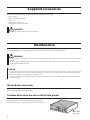 4
4
-
 5
5
-
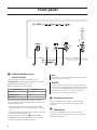 6
6
-
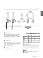 7
7
-
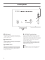 8
8
-
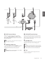 9
9
-
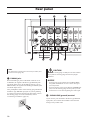 10
10
-
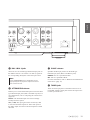 11
11
-
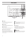 12
12
-
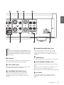 13
13
-
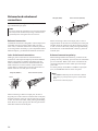 14
14
-
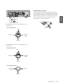 15
15
-
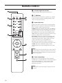 16
16
-
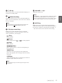 17
17
-
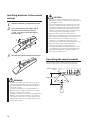 18
18
-
 19
19
-
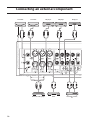 20
20
-
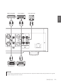 21
21
-
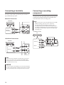 22
22
-
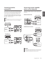 23
23
-
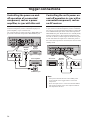 24
24
-
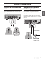 25
25
-
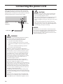 26
26
-
 27
27
-
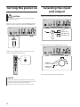 28
28
-
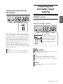 29
29
-
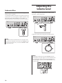 30
30
-
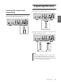 31
31
-
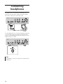 32
32
-
 33
33
-
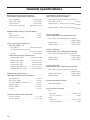 34
34
-
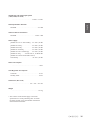 35
35
-
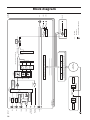 36
36
-
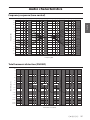 37
37
-
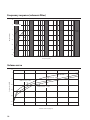 38
38
-
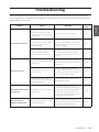 39
39
-
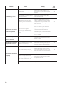 40
40
-
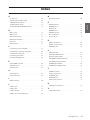 41
41
-
 42
42
-
 43
43
-
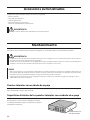 44
44
-
 45
45
-
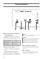 46
46
-
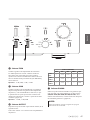 47
47
-
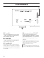 48
48
-
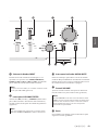 49
49
-
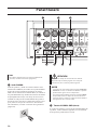 50
50
-
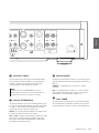 51
51
-
 52
52
-
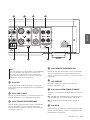 53
53
-
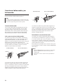 54
54
-
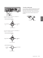 55
55
-
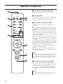 56
56
-
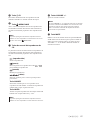 57
57
-
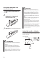 58
58
-
 59
59
-
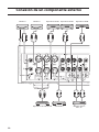 60
60
-
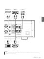 61
61
-
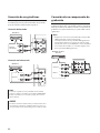 62
62
-
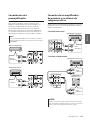 63
63
-
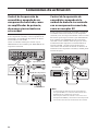 64
64
-
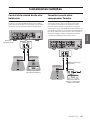 65
65
-
 66
66
-
 67
67
-
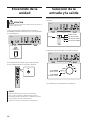 68
68
-
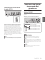 69
69
-
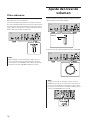 70
70
-
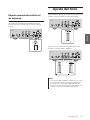 71
71
-
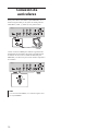 72
72
-
 73
73
-
 74
74
-
 75
75
-
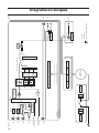 76
76
-
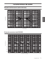 77
77
-
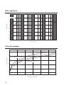 78
78
-
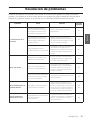 79
79
-
 80
80
-
 81
81
-
 82
82
-
 83
83
-
 84
84


en otros idiomas
- English: Yamaha C-5000 User manual
Artículos relacionados
-
Yamaha A-S3200 El manual del propietario
-
Yamaha A-S1200 El manual del propietario
-
Yamaha C-5000 El manual del propietario
-
Yamaha A-S2100 El manual del propietario
-
Yamaha A-S3000 El manual del propietario
-
-
-
-
-
Yamaha A-S2000 El manual del propietario