
34-8719-2337-0 49-50322 07-16 GEA
GE is a trademark of the General Electric Company. Manufactured under trademark license.
REVERSE OSMOSIS
FILTRATION SYSTEM
ENGLISH/ESPAÑOL
OWNER’S MANUAL
& INSTALLATION
INSTRUCTIONS
PNRQ20RBL
PNRQ21RBN
PNRQ21RRB
PNRQ20RBL, PNRQ21RBN and PNRQ21RRB
are Tested and Certified to NSF/ANSI
Standards 58 and 42 and CSA B483.1. For
the reduction of the claims specified, see the
Performance Data Sheet.
C
US
Write the model and serial
numbers here:
Model # __________________
Serial # ___________________
You can find them on the bracket.
SAFETY INFORMATION .........3
SPECIFICATIONS .................5
Performance Data .....................6
Arsenic Fact Sheet .....................8
USING THE FILTRATION
SYSTEM ..........................9
INSTALLATION INSTRUCTIONS
Tools and Materials Required ...........10
Before Beginning Installation ........... 11
Mounting System Installation ...........12
Feed Water Supply ...................13
Faucet Assembly .....................17
Battery Installation ....................18
Filtration Drain Connection ............19
Storage Tank and Startup ..............21
CARE AND CLEANING
Prefilter, Postfilter and
RO Cartridge Replacement. . . . . . . . . . . . .22
Sanitization ..........................23
Water Test Kit ........................23
TROUBLESHOOTING TIPS ..... 24
WARRANTY ......................28
CONSUMER SUPPORT ......... 30

2 49-50322
THANK YOU FOR MAKING GE APPLIANCES A PART OF YOUR HOME.
Whether you grew up with GE Appliances, or this is your first, we’re happy to have you in the family.
We take pride in the craftsmanship, innovation and design that goes into every GE Appliances
product, and we think you will too. Among other things, registration of your appliance ensures that we
can deliver important product information and warranty details when you need them.
Register your GE appliance now online. Helpful websites and phone numbers are available in the
Consumer Support section of this Owner’s Manual. You may also mail in the pre-printed registration
card included in the packing material.

49-50322 3
READ AND SAVE THESE INSTRUCTIONS
IMPORTANT SAFETY INFORMATION
READ ALL INSTRUCTIONS BEFORE USING THE APPLIANCE
SAFETY INFORMATION
SAFETY PRECAUTIONS
Ŷ%HVXUHWKHZDWHUVXSSO\FRQIRUPVZLWKWKH
Specification Guidelines. If the water supply
conditions are unknown, contact your municipal water
company or your local health department for a list of
contaminants in your area and a list of laboratories
certified by your state to analyze drinking water.
WARNING
To reduce the risk associated with
choking:
ŶDo not allow children under 3 years of age to have
access to small parts during the installation of this
product.
WARNING
To reduce the risk associated with
the ingestion of contaminants:
ŶDo not use with water that is microbiologically unsafe
or of unknown quality without adequate disinfection
before or after the system. Systems certified for cyst
reduction may be used on disinfected water that may
contain filterable cysts.
WARNING
To reduce the risk associated
with hazardous voltage due to an installer drilling
through existing electric wiring or water pipes in
the area of installation:
Ŷ Do not install near electric wiring or piping which may
be in path of a drilling tool when selecting the position
to mount the filter bracket.
WARNING
To reduce the risk of physical
injury:
Ŷ'HSUHVVXUL]HV\VWHPDVVKRZQLQPDQXDOSULRUWR
cartridge removal.
WARNING
To reduce the risk of physical
injury due to hydro-pneumatic tank rupture:
Ŷ
Do not install if water pressure exceeds 120 psi (827
kPa). If your water pressure exceeds 80 psi (552 kPa),
you should install a pressure limiting valve. Contact
a plumbing professional if you are uncertain how to
check your water pressure.
Ŷ
Do not install where water hammer conditions may
occur. If water hammer conditions exist you should
install a water hammer arrester. Contact a plumbing
professional if you are uncertain how to check for this
condition.
Ŷ:KHUHDEDFNIORZSUHYHQWLRQGHYLFHLVLQVWDOOHGRQD
water system, a device for controlling pressure due to
thermal expansion should be installed.
WARNING
To reduce the risk associated
with irritation from Sodium Metabisulphite during
installation:
Ŷ6RGLXP0HWDELVXOSKLWH&$6LVXVHGLQ
a 1% preservative solution within the reverse osmosis
membrane.
Ŷ
To request an MSDS relating to this product call
800-364-3577 or visit the web at http://
solutions.3m.com/wps/portal/3m/en_us/msds
(click MSDS search). For emergencies, call 800-
364-3577 or 651-737-6501 (24 hours).
WARNING
To reduce the risk associated with
ingesting of water contaminated with sanitizer:
Ŷ$IWHULQVWDOODWLRQVDQLWL]HU0867EHIOXVKHGIURP
the system before first use as directed within the
installation instructions.
This system has been tested for the treatment of water
containing pentavalent arsenic (also known as As(V),
As(+5) or arsenate) at concentrations of 0.050 mg/L
or less. This system reduces pentavalent arsenic, but
may not remove other forms of arsenic. This system is
to be used on water supplies containing a detectable
free chlorine residual or on water supplies that have
been demonstrated to contain only pentavalent arsenic.
Treatment with chloramine (combined chlorine) is not
sufficient to ensure complete conversion of trivalent
arsenic to pentavalent arsenic. Please see the Arsenic
Facts section of the Performance Data Sheet for further
information.
This reverse osmosis system contains a replaceable
component critical to efficiency of the system.
Replacement of the reverse osmosis component should
be with one of identical specifications, as defined by
the manufacturer, to assure the same efficiency and
contaminant reduction performance.
Read, understand, and follow all safety information contained in these instructions prior to installation and use of the
GE Appliances Reverse Osmosis systems. Retain these instructions for future reference.
Intended use:
The GE Appliances Reverse Osmosis systems are intended for use in filtering potable water in Residential
applications, and have not been evaluated for other uses. The system is typically installed at the point of use, and
must be installed as specified in the installation instructions. Contact a plumbing professional if you are uncertain
how to install.

4 49-50322
SAFETY PRECAUTIONS (continued)
Ŷ
Extended non-use of the Reverse Osmosis
system.
If the system has not been used for one week or
more, open the RO water faucet and allow the system
to drain. Close the RO water faucet and allow the
system to regenerate the water supply.
Ŷ
Recommended installation is under the sink.
However, the unit can be installed in a remote
location, up to 20 feet away from the sink.
• However, additional materials will be required. See
parts list to obtain additional materials from GE
Appliances.
• Locating the tank on a basement floor, with the
faucet at a first floor sink may result in some
loss of flow rate and capacity (approximately
20%). Installing a second tank will improve this
performance. An RVKIT can be used.
Ŷ
If Reverse Osmosis system is connected to a
refrigerator icemaker, a special icemaker connection
kit is required (RVKIT). Do not use copper tubing for
the connection between the Reverse Osmosis system
and the refrigerator.
Ŷ
Sanitize upon installation of the Reverse Osmosis
system and after servicing inner parts, including
replacement of prefilter, postfilter and Reverse
Osmosis cartridge. It is important to have clean hands
while handling inner parts of the system. See the
Sanitizing the Reverse Osmosis System section.
Ŷ
This Reverse Osmosis system contains a replaceable
treatment component critical for effective reduction
of total dissolved solids. This product water shall
be tested periodically to verify that the system is
performing satisfactorily. See the The Water Test Kit
section.
BE SURE TO FOLLOW ALL APPLICABLE STATE
AND LOCAL CODES.
NOTICE: To reduce the risk associated with
property damage due to water leakage:
Ŷ
Read and follow these instruction before installation
and use of this system.
Ŷ
Installation and use MUST comply with all state and
local plumbing codes.
Ŷ
Protect from freezing, remove filter cartridge when
temperatures are expected to drop below 40° F (4.4° C).
Ŷ
Do not install systems in areas where ambient
temperatures may go above 110° F (43.3° C).
Ŷ
Do not install if water pressure exceeds 120 psi
(827 kPa). If your water pressure exceeds 80 psi
(552 kPa), you should install a pressure limiting valve.
Contact a plumbing professional if you are uncertain
how to check your water pressure.
Ŷ
Do not install where water hammer conditions may
occur. If water hammer conditions exist, you should
install a water hammer arrester. Contact a plumbing
professional if you are uncertain how to check for this
condition.
Ŷ
Where a back flow prevention device is installed on a
water system, a device for controlling pressure due to
thermal expansion should be installed.
NOTICE: To reduce the risk associated with
property damage due to water leakage:
Ŷ
Do not use a torch or other high temperature sources
near filter system, cartridges, plastic fittings or plastic
plumbing.
Ŷ
On plastic fittings, never use pipe sealant or pipe
dope. Use PTFE thread tape only, pipe dope
properties may deteriorate plastic.
Ŷ
Take care when using pliers or pipe wrenches to
tighten plastic fittings, as damage may occur if over
tightening occurs.
Ŷ
Do not install in direct sunlight or outdoors.
Ŷ
Do not install near water pipes which will be in path of
a drilling tool when selecting the position to mount the
bracket.
Ŷ
Mount filter in such a position as to prevent it from
being struck by other items used in the area of
installation.
Ŷ
Ensure that the location and fasteners will support the
weight of the system when installed and full of water.
Ŷ
Ensure all tubing and fittings are secure and free of
leaks.
Ŷ
Do not install unit if any collets (parts 27 and 28 on
SDJHDUHPLVVLQJ&RQWDFWLIFROOHWV
are missing from any fittings to obtain replacements.
Ŷ
Replace the disposable pre and post filter cartridges
HYHU\PRQWKVDWWKHUDWHGFDSDFLW\RUVRRQHULID
noticeable reduction in flow rate occurs.
• Replace the disposable RO cartridge every 24 months
or sooner if a noticeable reduction in filtration efficiency
occurs.
READ AND SAVE THESE INSTRUCTIONS
IMPORTANT SAFETY INFORMATION
READ ALL INSTRUCTIONS BEFORE USING THE APPLIANCE
SAFETY INFORMATION

49-50322 5
Specifications
SPECIFICATIONS
a. If house water pressure is over 80 psi, install a pressure reducing valve in the water supply line. If house water pressure
is under 40 psi, install a Reverse Osmosis booster pump (contact your local plumbing supply company).
b. Removed (maximum of 2.0 ppm) by the Reverse Osmosis prefilter. REGULAR MAINTENANCE IS REQUIRED. Chlorine will
destroy the Reverse Osmosis membrane.
c. Theoretical tank capacity. When tested according to NSF/ANSI Standard 58 at 50 psig inlet pressure, tank capacity is
2.3 gallons.
SPECIFICATION GUIDELINES
The system makes a good supply of drinking water each day.
How much it will make depends primarily on these things…
Feed water pressure limits—pounds per square inch (psi) ...................40–120
a
Feed water temperature limits—minimum/maximum degrees F ...............40–100
Maximum Total Dissolved Solids (TDS)—parts per million (ppm) ..............2000
Maximum water hardness @ 6.9 pH recommended to optimize membrane life
—grains per gallon (gpg) .............................................10
Maximum turbidity (NTU) ...............................................<2
Maximum iron, manganese, hydrogen sulfide (ppm) ........................<0.1
Chlorine in water supply ...............................................2.0 ppm Maximum Allowable
b
Feed water pH limits (pH) ...............................................4–10
Storage tank capacity—gallons ..........................................4
c
Automatic shutoff control ..............................................yes
Prefilter and postfilter .................................................(FQROPF) Carbon Block
Reverse Osmosis membrane ...........................................(FQROMF) Thin Film
Polyamide
Storage Tank Dimension (inches) ........................................height 15” diameter 11”
System Body Dimension (inches) ........................................height 11” width 10.5” depth 4”
WATER SOFTENER RECOMMENDED
INCOMING WATER HARDNESS (GPG)
60
50
40
30
2010
Water Softener
not required
)RUZDWHUZLWKKDUGQHVVJUHDWHUWKDQJUDLQVDWS+WKHXVHRID
softener is recommended. Failure to install a water softener will reduce
the life of the Reverse Osmosis membrane. See chart for additional
information on the possible need for a water softener.

49-50322
Specifications
SPECIFICATIONS: Performance Data
Performance Data
GE Appliances Reverse Osmosis System
Model(s): PNRQ15RBL, and PXRQ15RBL
Use Replacement Cartridge(s): FQROPF (pre and post filter)
and FQROMF (membrane filter)
The concentration of the indicated substances in water entering the
system was reduced to a concentration less than or equal to the
permissible limit for water leaving the system as specified in NSF/
ANSI Standard 42, Standard 58 and CSA B483.1.
System tested and certified by NSF
International against NSF/ANSI to Standard 42,
Standard 58 and CSA B483.1 for the reduction
of substances as listed below.
Capacity 11.15 gpd (gallons per day) 42.2 lpd (liters per day). Contaminant Reduction Determined by NSF testing.
Substance Reduction
Average
Influent
NSF specified
Challenge
Concentration
Avg %
Reduction
Average
Product Water
Concentration
Max Permissible
Product Water
Concentration
NSF Reduction
Requirements
NSF Test
Report
Chlorine Taste and Odor 2.0 mg/L 2.0 mg/L ± 10% 0.05 mg/L N/A -
Nominal Particulate
&ODVV,,,WRP
70,333 pts/
mL
At least 10,000 particles/
mL
23 pts/mL N/A -
Arsenic (pentavlent) 0.032 mg/L 0.050 mg/L ± 10% PJ/ 0.010 mg/L N/A J-00122054
Asbestos
fibers/L
10
7
to 10
8
fibers/L; fibers
JUHDWHUWKDQP
< 1 fiber/L NA -
Barium PJ/ 10 mg/L
± 10%
0.310 mg/L 2.00 mg/L N/A J-00122055
Cadmium 0.028 mg/L 0.03 mg/L ± 10% 0.0003 mg/L 0.005 mg/L N/A -
Chromium (Hex.) 0.28 mg/L 0.3 mg/L ± 10% (added
as hexavalent)
0.008 mg/l 0.1 mg/L N/A J-00122054
Chromium (Tri.) 0.32 mg/L 0.3 mg/L ± 10% (added
as triavalent)
0.01 mg/l 0.1 mg/L N/A J-00122055
Copper PJ/ 3.0 mg/L + 10% 0.027 mg/L 1.3 mg/L N/A -
Cyst 140,000
cysts/L
Minimum 50,000 cysts/L 3 cyst/L N/A -
Lead 0.14 mg/L 0.15 mg/L + 10% 0.001 mg/L 0.010 mg/L N/A -
5DGLXP 25 pCi/L 25 pCi/L ± 10% 80.0% 5 pCi/L 5 pCi/L N/A J-00122055
Selenium 0.1 mg/L 0.10 mg/L ± 10% (added
as ½ selenite and ½
selenate)
0.002 mg/L 0.05 mg/L N/A J-00122057
TDS PJ/ 750 mg/L + 40 mg/L 42 mg/L 187 mg/L N/A -
Turbidity 11 NTU 11 ± 1 NTU 0.1 NTU 0.5 NTU N/A -
Operating Specifications
Inlet Pressure 40-120 psig (2.8-7.0 kg/cm
2
)
Inlet Temperature
40-100 F° (5-38° C)
Maximum TDS Level 2000 mg/L
Maximum Hardness @ 6.9pH 10 grains per gal. (171 mg/L)
Maximum Chlorine 2.0 mg/L
pH Range 4 – 10
Daily Production Rate 8.46 GPD (32.0 L/day)
Efficiency Rating
(3)
9.05%
Recovery Rating
(4)
19.84%
Notes:
(1) Tested by NSF International per NSF/ANSI Standard 58 or NSF/ANSI Standard 42.
(2) NTU is Nephelometric Turbidity Units
(3) Efficiency rating means the percentage of the influent water to the system that is available to the user as reverse osmosis
treated water under operating conditions that approximate
typical daily usage.
(4) Recovery rating means the percentage of influent water to the membrane portion of the system that is available to the user as reverse osmosis treated water when the system is
operated without a storage tank or when the storage tank is bypassed.
C
US

49-50322 7
Specifications
SPECIFICATIONS: Performance Data
Performance Data Sheet
Profile™ Reverse Osmosis System
Models: PXRQ15FBL, PXRQ15RBL, PNRQ15FBL, and PNRQ15RBL
NOTICE: This system has been tested according to NSF/ANSI 58 for reduction of the substances listed below. The
concentration of the indicated substances in water entering the system was reduced to a concentration less than or
equal to the permissible limit for water leaving the system, as specified in NSF/ANSI 58.
Before purchasing a water treatment unit, it is recommended that you have your water supply tested to determine
your actual water treatment needs. The NSF/ANSI 58 testing were performed under standard testing conditions,
actual
WARNING
Do not use with water that is microbiologically unsafe or with water of unknown quality without
adequate disinfection before or after the system. Systems certified for cyst reduction may be used on disinfected
water that may contain filterable cysts. This system is to be used for arsenic reduction only on chlorinated water
supplies containing detectable residual free chlorine at the system inlet. Water systems using an in-line chlorinator
should provide a one-minute chlorine contact time before the RO system. See Arsenic Fact Sheet for additional
details.
This reverse osmosis system contains a carbon pre-filter to help protect the reverse osmosis membrane from
deterioration that is induced by chlorine in the supply water. This reverse osmosis system contains replaceable
treatment components critical to the efficiency of the system. Replacement of the membrane component should be
with one of identical specifications, as defined by the manufacturer, to assure the same efficiency and contaminant
reduction performance. The product water should be tested periodically to verify that the system is performing
satisfactorily. Consult the owner’s manual for further information on installation, operating instructions, component
replacement, and product warranty.
This system has been tested for the treatment of water containing pentavalent arsenic (also known as As (V), As
(+5), or arsenate) at concentrations of 0.050 mg/L or less. This system reduces pentavalent arsenic, but may not
remove other forms of arsenic. This system is to be used on water supplies containing a detectable free chlorine
residual at the system inlet or on water supplies that have been demonstrated to contain only pentavalent arsenic.
Treatment with chloramine (combined chlorine) is not sufficient to ensure complete conversion of trivalent arsenic to
pentavalent arsenic. Please see the Arsenic Facts section of Performance Data Sheet for further information.
Estimated Replacement Costs
FQROPF – Pre- and Post-Filters carbon elements: $45 - $50
FQROMF – Reverse Osmosis Membrane: $75 - $80
)RUUHSODFHPHQWSDUWVFDOOWROOIUHH

8 49-50322
Specifications
SPECIFICATIONS: Arsenic Fact Sheet
Arsenic Fact Sheet
Background
Arsenic (abbreviated As) can occur naturally in well water. There are two forms of arsenic: pentavalent arsenic (also
called As(V), As(+5), and arsenate), and trivalent arsenic (also called As(III), AS(+3), and arsenite). Although both
forms are potentially harmful to human health, trivalent arsenic is considered more harmful than pentavalent arsenic.
In well water, arsenic may be pentavalent, trivalent, or a combination of both. Additional information about arsenic in
water can be found on the Internet at the U.S Environmental Protection Agency (USEPA) website at: www.epa.gov/
safewater/arsenic.html.
Testing Your Water
Arsenic in water has no color, taste or odor. It must be measured by a lab test. Public water utilities must have their
water tested for arsenic. You can get the results from your water utility. If you have your own well, you can have the
water tested. The local health department or the state environmental health agency can provide a list of certified
labs. The cost is typically $15 to $30.
Pentavalent vs. Trivalent Arsenic Reduction
This system is very effective at reducing pentavalent arsenic from drinking water. This model was tested in a lab
and proven to reduce 50 parts per billion (ppb) pentavalent arsenic to below 10 ppb, the USEPA standard for safe
drinking water. RO systems are not as effective at removing trivalent arsenic from water. This model will not convert
trivalent arsenic to pentavalent arsenic. If you have free chlorine residual in your water supply, any trivalent arsenic
will be converted to pentavalent arsenic and reduced by this Reverse Osmosis system. Other water treatment
chemicals, such as ozone and potassium permanganate will also change trivalent arsenic to pentavalent arsenic.
A combined chlorine residual (also called chloramine) may not convert all of the trivalent arsenic to pentavalent
arsenic. Water systems using an in-line chlorinator should provide a one-minute chlorine contact time before the
Reverse Osmosis system. If you get your water from a public water utility, contact the utility to find out if free chlorine
or combined chlorine is used in the water system.
Maintenance
It is strongly recommended that you follow the maintenance instructions in your owner’s manual and have your water
tested periodically to make sure the system is performing properly. See replacement element information above for
recommendations on maintaining your Reverse Osmosis drinking water treatment system.
For IOWA Only
All sales in Iowa require the following signature before consummation of sale. These signatures must be retained by
the seller/renter for two years minimum.
Buyer/Renter ______________________________________ Date _______________________________________
Seller ____________________________________________ Date _______________________________________
Seller’s Address _______________________________________________________________________________
Seller’s Phone number __________________________________________________________________________
Product: GE Appliances Reverse Osmosis Filtration System: PNRQ20FBL, PNRQ20FWW, PNRQ20FBB,
PNRQ20FCC, PNRQ21LBN, PNRQ21LRB, PNRQ20RBL, PNRQ21RBN, and PNRQ21RRB.

49-50322
Using the Reverse Osmosis System
USING THE REVERSE OSMOSIS SYSTEM: How the System Works
How the Reverse Osmosis System Works
Reverse Osmosis reduces Total Dissolved Solids (TDS) and organic matter from water by diffusing it through a special
membrane (see Performance Data Sheet). The membrane separates minerals and impurities from the water and they
are flushed to the drain. For the reduction of the claims specified, see Performance Data Sheet. High quality product
water goes directly to the drinking water faucet or to the storage tank. The system makes a good supply of drinking
water each day. How much it makes depends on the feed water supply pressure, temperature and quality.
The prefilter and postfilter are replaceable cartridges. The carbon prefilter reduces chlorine while also filtering
sediments. The postfilter reduces any other undesirable tastes and odors before you use the water.
These systems include an electronic faucet assembly with a prefilter and postfilter change reminder, Reverse Osmosis
membrane change reminder and a status okay reminder.
7KHSUHILOWHUDQGSRVWILOWHUFKDQJHUHPLQGHUZLOOIODVKDPEHUDIWHUVL[PRQWKVKDYHSDVVHGRUJDOORQVKDYHEHHQ
used. When this occurs, it is time to replace these cartridges and sanitize the system.
The membrane change reminder flashes amber when the TDS monitor in the system has measured the amount of
impurities removed is less than 75%. When this occurs, it is time to replace this Reverse Osmosis membrane cartridge
and sanitize the system.
Finally, a green flashing light will indicate the system is functioning properly.
Description of the Reverse Osmosis System
Prefilter - Water from the cold supply pipe is directed
to the prefilter cartridge. The prefilter is a replaceable
sediment cartridge containing activated carbon. The
prefilter reduces chlorine taste and odor in the feed
water because CHLORINE DESTROYS THE REVERSE
OSMOSIS MEMBRANE. Filtered, clean, chlorine-
reduced water flows from the prefilter to the Reverse
Osmosis cartridge.
Reverse Osmosis Cartridge - The middle
cartridge includes a tightly wound, special membrane.
Water is forced through the cartridge where the
membrane reduces the dissolved solids and organic
matter. For the reduction of the claims specified, see
Performance Data Sheet. High quality product water
exits the Reverse Osmosis cartridge and goes to the
storage tank. Reject water, with the dissolved solids and
organic matter, leaves the cartridge and is discharged to
WKHGUDLQWKURXJK»´WXELQJ
Postfilter - After leaving the storage area, but before
going to the system faucet, product water goes to the
postfilter cartridge. The postfilter is also a replaceable
sediment cartridge that contains activated carbon.
Any remaining tastes, odors or sediments are reduced
from product water by the postfilter. Clean, high quality
drinking water flows through the tubing and to the
system faucet.
Storage Tank - The storage area holds up to 2-1/2
gallons of product water. A diaphragm inside the tank
keeps water pressurized, when the tank is full, for fast
flow to the faucet when drinking water is needed.
Check Valve - The check valve prevents a backward
flow of product water from the storage tank. A backward
flow could cause the Reverse Osmosis membrane to
rupture.
Automatic Shutoff Assembly - To conserve
water, the drinking water system has an automatic
shutoff. When the storage tank has filled to capacity and
the drinking water faucet is closed, pressure closes the
shutoff. Water flow to the Reverse Osmosis housing is
shut off until drinking water is used again, and pressure
drops in the Reverse Osmosis system.
Flow Control - The flow control regulates the flow
of water through the Reverse Osmosis cartridge at the
required rate to produce high quality water. The control
is located in the 1/4” drain line exiting off the manifold.
Faucet and Electronics -
The countertop faucet dispenses filtered drinking water
when opened. It has a hand-operated lever, with variable
flow adjustment. You can keep the faucet open by
removing your hand from the lever once water is flowing.
To comply with plumbing codes, an air gap is built into
the faucet drain water connection.
The electronic
faucet provides a
six month timer to
remind you when
it is time to replace
your prefilter and
postfilter. Replace
these when the
amber filter light
flashes. The faucet
also provides an
amber RO light
indicating when the
Reverse Osmosis
cartridge is no
longer filtering out
at least 75% of the
TDS. Replace this
cartridge when this
amber light flashes.
The green flashing
light will indicate the system is
functioning properly.

10 49-50322
INSTALLATION INSTRUCTIONS
Installation
Reverse Osmosis Filtration System
Instructions
Models PNRQ20RBL, PNRQ21RBN, PNRQ21RRB
TOOLS AND MATERIALS
REQUIRED FOR INSTALLATION
Ŷ Electric drill and 1-1/2” Drill Bit (type as required) if
mounting is needed for faucet
Ŷ Two (2) Adjustable Wrenches
Ŷ´'ULOO%LWRSWLRQDOIRUSLORWKROHV
Ŷ Tape Measure
Ŷ Phillips and Flat Blade Screwdrivers
Ŷ Utility Knife
Ŷ If your main water line is a rigid pipe, you will
require a compression fitting and possibly other
plumbing hardware to complete the installation.
IMPORTANT – To avoid damaging the
sink, consult a qualified plumber or installer for
drilling procedures. Special drill bits may be needed
for stone, porcelain or stainless steel.
BEFORE YOU BEGIN
Read these instructions completely and
carefully.
Ŷ IMPORTANT – Save these instructions
for local inspector’s use.
Ŷ IMPORTANT – Observe all governing
codes and ordinances.
Ŷ Note to Installer – Be sure to leave these
instructions with the Consumer.
Ŷ Note to Consumer – Keep these instructions for
future reference.
Ŷ Proper installation is the responsibility of the
installer.
Ŷ Product failure due to improper installation is not
covered under the Warranty.
Ŷ A shutoff valve must be available or added near
the installation point.
Questions? Call 800.626.2005 or visit our Website at: GEAppliances.com/ge/service-and-
support/contact.htm
CONTENTS INCLUDED WITH
PRODUCT
Ŷ Reverse Osmosis Assembly and Tubing
Ŷ Product Literature (Owner’s Manual and
Installation Instructions)
Ŷ Performance Data Sheet
Ŷ Feed Water Adapter
Ŷ Faucet Assembly with Electronic Base Monitor
and Tubing
Ŷ Storage Tank
Ŷ Drain Line Adapter
Ŷ Sanitation Canisters
WARNING
Read entire manual. Failure to follow all guides and rules could cause
personal injury or property damage.
Ŷ Check with your state and/or local public works department for plumbing codes. You must
follow their guides as you install the Water Filtration system.
NOTE: Failure to comply with these installation instructions will void the product warranty, and
the installer will be responsible for any service, repair or damages caused thereby.

49-50322 11
TUBING/FILTER DETAIL
INSTALLATION INSTRUCTIONS
THINGS TO CHECK BEFORE BEGINNING INSTALLATION
FEED WATER
The water supply to the undercounter Reverse
Osmosis system must have the qualities listed in
the specifications. Municipal water supplies most
often will have these qualities. Well water may need
conditioning—have the water tested by a water
analysis laboratory and get their recommendations
for treatment.
IMPORTANT — For water with a hardness
JUHDWHUWKDQJUDLQVDWS+WKHXVHRI
a softener is recommended. Failure to install a
softener will reduce the life of the Reverse Osmosis
cartridge.
FILTRATION DRAIN CONNECTION
A suitable drain point and air gap (check your state
and/or local codes) are needed for reject water
from the Reverse Osmosis membrane cartridge.
BASEMENT INSTALLATION
If installing in a basement, leave enough tubing in
place during installation to be able to move unit
to floor for ease at servicing and making filter/
membrane changes. Additional tubing and fittings
required.
NOTE: See parts list on page for optional parts
that may be required for a basement installation.
RO FAUCET
The RO product water faucet installs on the sink
or on the countertop next to the sink. Often, it is
installed in an existing sink spray attachment hole or
a hole may be drilled. Space is required underneath
for tubing to and from the faucet, and for securing
the faucet in place. All faucet connections are done
on or above the sink or countertop.
Sink
p-trap
Hot
Cold
Disposer
1/4” drain
tube (black)
3/8” outlet tube (blue banded)
1/4” inlet tube
(yellow banded)
Reverse osmosis system
3/8” storage
tank tube
(red banded)
11” dia. 10-1/2”
15”
11”
7”
3/8” drain tube (black)
RO product water faucet mounted through sink or countertop
Feed water adapter
Prefilter Postfilter
Membrane
1/4” yellow
banded inlet
from supply
valve
1/4” black
tube to
faucet
3/8” red
banded tube to
storage tank
3/8” blue
banded
tube to
faucet
Installation Instructions

12 49-50322
Installation Instructions
INSTALLATION INSTRUCTIONS
MOUNTING SYSTEM INSTALLATION
Choose a location under the sink to mount the
system. Location should be easily accessible, with
adequate clearance between the bottom of the filter
cartridges and the floor or bottom of the cabinet for
removal of filter cartridges. Allow enough space on
either side of the system for the tubing connections.
1. Remove the prefilter and postfilter cartridges.
2. Remove the assembly cover by unlocking the
four tabs on the cover from the system.
3. Use a flat-head screwdriver to work from left to
right from the underside of the system.
4. Use the icons on the bottom of the system for
screwdriver positioning.
5. Hold the Reverse Osmosis assembly up to the
wall surface where you wish to install it. Mark
location for screws. There should be a minimum
of 17” from the marks to the bottom of the
cabinet floor.
IMPORTANT — Do not get dirt or debris
inside the assembly area. Use only to mark
mounting hole locations.
,QVWDOOVFUHZVWRWKHZDOOOHDYLQJD´
clearance between the head of the screw and
wall (drill pilot holes if needed).
7. Hang the Reverse Osmosis assembly on the
screws. Tighten or loosen the screws as desired
until the system is secure on the wall.
8. To install the
cover, line up
the front tabs on
the cover with
the openings in
the system.
6QDSWKHFRYHU
in place; the tabs
will flex, allowing
the cover to snap
in place.
10. Remove the
membrane
cartridge.
Screw locations
Screwdriver positioning
Screwdriver
System opening
Tab
Prefilter Postfilter
To removeTo remove
To remove
Membrane
Screws
Screw
´
Wall
7”
17”
Reverse Osmosis Assembly

49-50322 13
Installation Instructions
INSTALLATION INSTRUCTIONS
B. OPTIONAL INSTALLATION 1
Utilizing existing kitchen sink water supply valve (A)
and removable faucet tubing (B).
1. Refer to illustration below to complete assembly
depending on supply valve size (A).
2. Close the cold water supply valve (A) under the
sink.
3. Unscrew the flexible tubing line (B) from
the supply valve (A) that connects to the
COLD water riser.
NOTE: For rigid pipe, see D. Optional Rigid Pipe
Installation on page 11.
Note Adapter (C) orientation:
3/8-inch installation—Rounded end of adapter (C)
connects to supply valve (A).
1/2-inch installation—Rounded end of adapter (C)
connects to coupling (D), then to existing faucet
tubing (B).
Feed Water Supply
Check and comply with local plumbing codes as you plan, then install a cold feed water supply fitting.
For 3/8” Plumbing
For 1/2” Plumbing
(B) Faucet
tubing line (not
included)
(D)
Coupling
(C)
Adapter
(F) Inlet valve
(A) Cold water
supply valve
(not included)
(B) Faucet
tubing line
(not included)
(A) Cold water
supply valve
(not included)
(D)
Coupling
(C) Adapter
(G) Gasket
(G)
Gasket
(H)
Ferrule
(F) Inlet valve
(I) Nut
(G) Gasket
A. PREFERRED INSTALLATION
Utilizing existing kitchen sink water supply valve and
removable faucet tubing.
A typical connection using the included water supply
fitting is shown in the illustration below.
1. Close the water shut-off valve that is immediately
in front of the supply tube and open the faucets to
drain water from the sink cold water pipe.
2.
Remove the nut that connects the cold water faucet
to the supply tube. Some water may spill out.
NOTES:
• Be sure to turn off the water supply and open a
faucet to drain the pipe.
• Make sure the gasket is installed in the water
supply fitting.
3. Hand-tighten the water supply fitting onto the cold
water faucet. Be sure the gasket, as shown, is
in place before final assembly. Finish tightening
with an adjustable wrench. Be careful not to
overtighten or cross-thread, since damage to
the threads can occur. Make sure the 1/4” quick
connection is not against a wall that causes the
supply tubing connection to bend. A quarter
turn to tighten or loosen the adapter may be
necessary to avoid this.
4. Reconnect faucet tubing line to the fitting.
5. Install tubing. (See Installing the Tubing section.)
Cold
Water
Faucet
Stud
Cold
Water Pipe
Water Supply Fitting
1/4” Tubing to
Water Filter Inlet
Cold Water Shut-Off
Gasket
Fig. 1

14 49-50322
INSTALLATION INSTRUCTIONS
C. OPTIONAL INSTALLATION 2
Where codes permit (Requires additional parts)
*For 1/2” OD or larger metal tubing only.
NOTE: Codes in certain states require installation
by a licensed plumber and do not permit the use of
the saddle valve. For installation, use plumbing code
248-CMR of the Commonwealth of Massachusetts.
Saddle valve is available through GE Appliances
3DUWVDQG6HUYLFHVDWSDUWQXPEHU
WS15X10023. Self-piercing saddle valves are not
recommended.
1. Turn off the cold water supply and attach saddle
valve as required by product selection. (Be sure
to follow manufacturer’s Installation Instructions.)
WARNING
Many homes are electrically
grounded through the plumbing. To protect
yourself from serious injury or fatal shock, use a
battery-powered hand drill only to make the hole.
DO NOT USE AN ELECTRIC DRILL.
2. Close the water supply valve by turning the
handle clockwise.
3. Open the main water supply valve and several
house faucets to purge air from the system.
Close faucets when water runs smoothly.
B. OPTIONAL INSTALLATION 1
(CONT.)
4. Assemble adapter (C) and coupling (D) as shown
in illustration on page 11, per your configuration.
Ensure that the gasket (G) is in place before final
assembly. Start installation by hand, then finish
tightening with adjustable wrench. Be careful not
to overtighten or cross-thread since damage to
threads may occur.
5. Hand-tighten assembled adapter (C) onto supply
valve (A) for the proper size installation. Be sure
gasket (G) is in place before final assembly. Start
installation by hand; then finish tightening with an
adjustable wrench.
Be careful not to overtighten or cross-thread
since damage to threads may occur.
5HFRQQHFWIDXFHWWXELQJOLQH%WRWRSRIDGDSWHU
(C).
7. Cut wire ties on tubing coils, using care not to
damage tubes or parts if using a utility knife.
8. Remove the 1/2” nut (I) and ferrule (H) from end
of inlet valve. Using the yellow banded tubing
provided, place the nut (I) and ferrule (H) onto
the tubing and install onto inlet valve (F) as
shown at left. Tighten with adjustable wrench. Be
careful not to overtighten or cross-thread since
damage to threads may occur.
NOTE: Inspect the ends of the tubing prior to
installation to be sure there are no imperfections and
that the end of the tubing is cut square. It may be
necessary to cut the tubing again.
Snug valve into bracket
(DO NOT OVERTIGHTEN)
Some threads
should be visible
Rubber gasket
Optional water supply connection (using saddle valve)*
Pre-drill
1/4” hole
Seal—make sure the
seal is in place
Clamp X
Nut (2)—not
required if holes
in clamp are
threaded
Valve
Handle
Tubing adapter
Washer
Compression
nut
Clamp Z
Use to connect the tubing
*For 1/2” OD or larger metal tubing only.
Í
Feed Water Supply (Cont.)
Installation Instructions

49-50322 15
INSTALLATION INSTRUCTIONS
E. OPTIONAL REMOTE LOCATION
INSTALLATION
(requires additional part)
1. Turn off the cold water supply.
2. Complying with plumbing codes, install a fitting
on the cold water pipe to adapt 1/4” OD tubing.
A typical connection is shown in illustration
below. Make sure a water supply valve is used.
,IWKH52XQLWLVWREHLQVWDOOHGPRUHWKDQIHHW
from the valve, replace the yellow banded inlet
tubing with a longer length of GE Appliances
1/4” tubing. A 33-foot length of 1/4” tubing
is available through GE Appliances Parts
and Services at , part number
WS07X10018. DO NOT SUBSTITUTE TUBING
OF UNKNOWN QUALITY.
,IWKH52XQLWLVWREHLQVWDOOHGPRUHWKDQIHHW
from the faucet, replace the blue banded outlet
tubing with a longer length of GE Appliances
3/8” tubing. A 33-foot length is available
through GE Appliances Parts and Services at
SDUWQXPEHU:6;6HH
Faucet Mounting Installation on page 17 for
more details. DO NOT SUBSTITUTE TUBING
OF UNKNOWN QUALITY.
If you are using copper tubing, DO NOT connect
it directly onto the RO unit. Purchase a connector
and use a short length of the yellow banded tubing
provided to make final connection to RO. Do not use
copper tubing to attach to icemaker or faucet.
D. OPTIONAL RIGID PIPE
INSTALLATION
For installation with rigid pipe between supply valve
and sink faucet.
Option 1
1. Remove pipe from supply valve and sink faucet.
2. Obtain flexible pipe sized to your plumbing.
3. Install flexible pipe.
4. GO back to B. OPTIONAL INSTALLATION 1
section, step 4.
Option 2
1. Obtain compression fittings to fit rigid pipe.
2. Obtain any other fittings required to connect
compression fittings to adapter.
NOTE: Adapter has 1/2” and 3/8” internal and
external threads.
3. Remove pipe from supply valve.
4. Cut pipe to fit length of assembled fittings and
adapter.
5. Install compression fitting to pipe.
*2EDFNWR%237,21$/,167$//$7,21
section, step 4.
NOTE: Above described materials are not included
with the product.
Cold
water
pipe
Insert (not included)
Ferrule
Water supply valve
To RO
Preferred water supply connection
(using compression fitting)
1/4” (yellow banded)
tubing to inlet
Feed Water Supply (Cont.)
Installation Instructions

49-50322
Installation Instructions
INSTALLATION INSTRUCTIONS
INSTALLING THE TUBING TO TANK
AND FAUCET
1. Measure 3/4” from the end of each remaining
piece of tubing (faucet end and inlet end) and
mark with a pencil. (Check for roundness,
smoothness, cuts, nicks, flat spots and sharp
edges).
2. Push the tubing firmly into each fitting on the
manifold until the line is flush with the fitting
collar. (If the tubing is removed, re-cut the end,
measure, mark and re-insert). Tubing must be
fully inserted to avoid leaks. To remove tubing:
depress and hold red or blue collet; pull tubing
out to remove.
3. Pull out slightly on tubing to ensure a good seal.
3/4”
PP
INCORRECT
3
4
"
Engagement
3/4”
(3/8” tubing)
Red or Blue Collet
(DO NOT REMOVE)
Insertion line
Insert tubing
FLOW RESTRICTOR REPLACEMENT
PROCEDURE (cont.)
1. Remove drain line tubing by pushing up on the
drain line collet with one hand (1) and removing
the drain line with the other hand (2).
2. Once the drain line has been removed from
the system base, grasp the end of the flow
restrictor and pull it straight out from the tube*.
If the restrictor is difficult to remove by hand, a
pair of pliers may be used to grip the end of the
restrictor to aid in removal from the tubing.
*In some instances, the restrictor may slide out
of the drain tubing as it is removed from the
drain line port. If, after removing the drain line as
described in step 1, the restrictor is no longer in
the end of the tubing, check the drain line port.
Remove the restrictor from the port and proceed
to step 3.
3. Take new restrictor and slide it back into the
drain tubing. Insert the restrictor by hand only.
Do not use pliers to insert. Make sure to insert
restrictor all the way into the tubing. Failure to
do so could result in improper operation of the
RO system.
4. Reinsert drain line tubing in system base. Tug
lightly on the tubing to ensure that the collet is
engaged and has a proper grip on the tubing.
FLOW RESTRICTOR REPLACEMENT
PROCEDURE
Each time the Reverse Osmosis cartridge is
changed, you will need to replace the flow restrictor
in the drain line as well.
Be sure to wash your hands before handling inner
parts of the system.
1
2
Feed Water Supply (Cont.)

49-50322 17
Installation Instructions
INSTALLATION INSTRUCTIONS
INSTALL THE FAUCET (CONT.)
5. Tighten the toggle screw until the base is firmly in
place and does not wobble or turn.
3XVKWKH´EOXHWXEHXSWRFRQQHFWLWWRWKH
fitting on the bottom of the faucet body. It should
go in about 3/4”. Pull tube slightly to make sure it
is secure.
7. Push the faucet body down into the faucet base
and turn the faucet 1/8 of a turn counterclockwise
until it stops into place.
NOTE: You can install the faucet so the handle is
on the right or the left side.
If you want the faucet handle on the right, position
the handle on the front-right side of the base
before turning 1/8 of a turn counterclockwise.
If you want the faucet handle on the left, position
the handle on the rear-left side of the base before
turning 1/8 of a turn counterclockwise.
8. Locate the hole at the rear of the
base. Insert the set screw and
begin to tighten by hand. Finish
tightening with the Allen wrench
provided in the packet. DO NOT
OVERTIGHTEN.
INSTALL THE FAUCET
Be sure there is room underneath and above
the sink to make the needed connections. Before
starting, make sure there is sufficient room for the
faucet base and unit. Select one of the following
places to install the faucet:
A. In an existing sink spray attachment or soap
dispenser hole.
B. In a hole to be drilled in the sink top.
C. In a hole to be drilled in the countertop, next to
the sink.
NOTES:
•
Be sure the faucet base will fit flat against the
surface at the selected location so the bottom
gasket between the base and surface area will seal.
• Make sure to leave enough clearance at the back
of the faucet in case you need to remove it.
Installation Steps (refer to illustration below for
clarification)
1. If drilling is needed, make a 1
1
»2” diameter hole.
Be sure to use the proper procedure for drilling
stone, porcelain or stainless steel. Special drill
bits may be needed. Consult a qualified plumber
for the proper procedure.
NOTE: When drilling in stainless steel, the edges
may be sharp and could puncture the tube. Be
careful to not cut yourself or damage the tube.
2. Remove the faucet body and base by turning the
base counterclockwise.
3. Push the 1/4” black tube and the 3/8” black tube
onto the correct barb fittings on the faucet base.
Push the 3/8” blue tube through the base.
4. Align the gasket to cover the hole completely.
Then place the toggle screw on the base into the
hole.
Faucet base
Sink
Gasket
Toggle screw
Faucet base
1/4” Barb fitting
1/4” Black tube
3/8” Barb fitting
3/8” Black tube
3/8” Blue tube
Faucet body
Faucet base
Sink
Gasket
Toggle screw
3/8” Black tube
1/4” Black tube
3/8” Blue tube
Mounting screw
Faucet Faucet
Faucet handle on the RIGHT Faucet handle on the LEFT
Faucet Assembly

18 49-50322
Installation Instructions
INSTALLATION INSTRUCTIONS
Faucet Assembly (Cont.)
OPTIONAL ONE-PERSON FAUCET
TUBING INSTALLATION
1. From under the sink, gather the 1/4” drain line
(black), 3/8” drain line (black) and 3/8” outlet
tube (blue banded) in one hand with the drain
tubes the same length and the outlet tube offset
DSSUR[LPDWHO\LQFKHV
2. Wrap a rubber band around all 3 tubes.
3. Insert a typical No. 2 pencil through the rubber
band location.
4. Rotate the pencil down until it is in line with the
tubing and push up through the mounting hole.
Release the grip on the pencil and the tubes will
remain in position for easier faucet connection.
INSTALL THE BATTERY
1. Remove the lens cover from the faucet base.
Grip it from both sides and pull forward.
2. Install one CR2032 3V battery with the “+” side
UP into the battery tray. Slide the battery tray
completely back into the base.
3. The amber light will illuminate five times. If you
want to reinitiate the start-up sequence, remove
WKHEDWWHU\IRUVHFRQGVVRWKHHOHFWURQLFVFDQ
fully reset; then put the battery back in.
4.1RUPDOO\WKHOLJKWLVRII$IWHUPRQWKVRIXVH
the amber LED light will flash every 30 seconds
indicating it is time to replace the filter canister.
NOTE: The amber LED light may stop blinking
if it is allowed to blink for an extended period of
time. To ensure proper operation, the battery
should be replaced with every filter change.
FOR FILTER CHANGE: Replace the battery
when changing the filter. Remove the used
EDWWHU\DQGZDLWVHFRQGVEHIRUHLQVWDOOLQJWKH
new battery to ensure the proper electronics are
UHVHWIRUWKHQH[WPRQWKV
WARNING
To reduce the risk associated
with choking, immediately dispose of the replaced
battery.
Faucet base
Lens cover
Battery “+”side up
POWER CORD INSTALLATION
Connect power cord from
faucet to union outlet from
the Reverse Osmosis
Assembly.
NOTE: If extension cord
is required for a remote
location, this extension
SKRQHFDEOHPXVWEHFRQGXFWRUZLUHDQG
connectors; typical 4 conductor will not work.

49-50322
Installation Instructions
INSTALLATION INSTRUCTIONS
Filtration Drain Connection
PREFERRED INSTALLATION:
OPTION A—BASEMENT ACCESS
INSTALLATION
Route the drain line DIRECTLY from the
Reverse Osmosis system to a standpipe in
the basement, bypassing the air gap provided
in the faucet. The air gap installation is left to
the discretion of the installer. The drain line
may also be routed to a floor drain or washtub,
provided that the air gap is maintained. Special
air gap fittings are available to connect the drain
line to the top of the standpipe.
Check and comply with local plumbing codes as you plan.
CAUTION
The options detailed below are the ONLY approved installation
configurations. Do not use any drain saddle device.
NOTE: Failure to follow these Installation Instructions will void the warranty, and the installer
will be responsible for any service, repair or damages caused thereby.
Drain line from the Reverse Osmosis system
1”
1” minimum air gap
must be maintained
PREFERRED INSTALLATION:
OPTION B—DRY-VENTED P-TRAP
INSTALLATION
Install a separate dry-vented p-trap under the
sink to be used exclusively for the Reserve
Osmosis drain line. A dry-vented p-trap is a
p-trap that has its own vent/stack. Attach the
drain line adapter to the p-trap and secure it
with the slip joint nut and washer as shown. The
drain line MUST be routed through the air gap
provided in the RO water faucet.
Reverse
Osmosis
drain line
Optional disposer

20 49-50322
Installation Instructions
INSTALLATION INSTRUCTIONS
Filtration Drain Connection (Cont.)
PREFERRED INSTALLATION:
OPTION C—WET-VENTED P-TRAP
INSTALLATION
Install a p-trap under the sink to be used exclusively
for the Reverse Osmosis drain line. A wet-vented
p-trap is a p-trap that shares a common vent/stack.
Attach the drain line adapter to the p-trap and
secure it with the slip joint nut and washer as shown.
The drain line MUST be routed through the air gap
provided in the RO water faucet. Locate the Reverse
Osmosis p-trap as high as possible (minimum of 4”
above horizontal).
Optional disposer
Reverse
Osmosis
drain line
4” minimum
SECONDARY INSTALLATION:
OPTION D—DRAIN LINE ADAPTER
INSTALLATION
NOTICE: Using Option D may result in
clogging under adverse conditions and
requires periodic inspection/cleaning by the
user.
DO NOT INSTALL THE DRAIN LINE
DOWNSTREAM OF A DISPOSER OR IN A
HORIZONTAL PIPE. Install the drain line adapter
under the sink as shown (parts included). The baffle
tee shown must be installed to prevent a clog in the
Reverse Osmosis drain line. Route the drain line
from the air gap to the drain line adapter, ensuring
that there are no dips, loops or low spots in the line.
The drain line adapter should be aligned vertically
so that the hose connection points upward (the hose
connection should never be allowed to drop below
45° from this vertical position). This installation MAY
result in a slight drain noise in the sink drain when
the Reverse Osmosis system is regenerating. If this
happens, simply place the sink drain stoppers in the
strainer to suppress it.
Reverse
Osmosis
drain line
Drain line
adapter
Maximum 45°
Baffle tee
(mandatory)
Optional
disposer
From second
sink or
disposer
From faucet air gap
Drain line
adapter
Drain line connection should be 180°
opposite existing horizontal pipe/baffle-tee
as shown in diagram
45°
Drain line
adapter
Proper drain line adapter orientation.

49-50322 21
Installation Instructions
INSTALLATION INSTRUCTIONS
Storage Tank and Startup
STORAGE TANK INSTALLATION
1. Remove the protective cap from the top of the
tank.
2. Apply 2–3 wraps
of thread tape,
in a clockwise
direction, to the
tank threads.
3. Install the push-to-connect fittings on the
threaded fitting on the tank as shown.
4. Push the 3/8” red banded tubing from the
Reverse Osmosis System into the fitting on the
storage tank.
SYSTEM STARTUP PROCEDURE
IMPORTANT — If installing the unit
in new construction, ensure that house
plumbing is flushed thoroughly before
opening the water supply valve.
1. Check that all tubing connections are
secure.
2. Turn on the Feed Water Supply Valve.
3. Check all connection points for leaks.
4.
Follow the Sanitization procedures on
page 23.
5. After sanitization is complete, reinstall
prefilter, postfilter and Reverse Osmosis
cartridges.
0HPEUDQHFRQWDLQVDIRRGJUDGH
preservative. Allow the system to fill the
tank, then drain it completely four times
before using the water from the system.
7. Recheck all water connection points a few
days later to check for small leaks.
Storage tank
Thread
tape

22 49-50322
Care and Cleaning
CARE AND CLEANING: Cartridge Replacement
Prefilter, Postfilter and Reverse Osmosis Membrane Cartridge Replacement
Procedure
When the blue light in the faucet base flashes, it is time
to replace the prefilter and postfilter. This will occur every
PRQWKV
Be sure to wash your hands before handling inner parts
of the system.
1. Turn OFF the icemaker (if attached to the system).
2. Turn off water supply to the system.
3. Turn ON faucet to drain tank (may take several
minutes). Turn OFF faucet when tank is empty.
4. Remove the prefilter, postfilter and Reverse Osmosis
cartridge by rotating to the left about 1/3 turn.
5. Follow Sanitizing the Reverse Osmosis System
procedure found on page 23.
5HPRYHIRLORQWRSRIQHZUHSODFHPHQWFDUWULGJHV
Install new cartridges into the manifold by turning to
the right about 1/3 turn until the alignment marks line
up and the cartridges stop. DO NOT OVERTIGHTEN.
The cartridges will rise up as they are turned.
NOTE: The prefilter and postfilter are identical. You
may install either filter in the prefilter or postfilter
position. The reverse osmosis cartridge is installed in
the center position.
7. Turn ON water supply to fill the system (may take up
to four hours). Check for leaks.
8. Remove the battery tray and replace the battery,
positive “+” side up, to reset timer and monitor
function in faucet base (see Battery Installation for
proper procedure).
NOTE: $OORZDWOHDVWVHFRQGVWRHODSVHEHIRUH
installing new battery. This will ensure a full electronic
UHVHWDQGSURSHURSHUDWLRQIRUWKHQH[WPRQWKV
,IRQO\WKHSUHILOWHUDQGSRVWILOWHUDUHUHSODFHGWXUQWKH
faucet ON and fill and empty the storage tank two (2)
times. If the membrane cartridge is replaced, fill and
empty the storage tank a total of four (4) times. (This
will remove the food-grade preservatives contained in
new membranes. This preservative will give product
water an unpleasant taste and odor.)
10. Once the storage tank is full, turn on the icemaker.
NOTE: System should be sanitized when replacing the
prefilter and postfilter cartridge or the Reverse Osmosis
cartridge. Follow the Sanitizing the Reverse Osmosis
System procedure on page 23.
ON
OFF
To remove
Reverse
Osmosis
Prefilter Postfilter

49-50322 23
Care and Cleaning
CARE AND CLEANING: Sanitizing\Filters\Water Test Kit
Sanitizing the Reverse Osmosis System
Sanitize upon installation of the Reverse Osmosis
system and after servicing inner parts, including
replacement of prefilter, postfilter and the membrane
cartridge.
Be sure to wash your hands before handling inner parts
of the system.
IMPORTANT — Before sanitizing, be sure to
remove all cartridges. Chlorine will destroy the Reverse
Osmosis membrane cartridge.
1. Follow steps 1 through 4 under Prefilter, Postfilter and
Reverse Osmosis Membrane Cartridge Replacement
Procedure.
2. Fill the empty canister labeled “Sanitization Canister”
with water to within 1 inch of the upper opening. Add
1 oz. (2 Tbsp.) ordinary unscented household bleach.
Install canister into the prefilter canister position by
turning to the right about 1/3 turn until the alignment
marks line up and the canister stops.
3. Install the two additional “sanitiziation canisters” into
the membrane canister and postfilter openings in the
manifold by turning to the right about 1/3 turn until the
alignment marks line up and the canister stops.
4. Turn ON water supply. Turn ON faucet until water
begins to flow from the faucet, then turn faucet OFF.
Allow system to fill for 10 minutes.
5. Turn faucet ON and allow water to flow for 20
minutes, or until bleach odor is gone. Turn OFF water
supply again. Turn ON faucet to drain the system.
2QFHWKHV\VWHPLVGUDLQHGWXUQWKHIDXFHW2))DQG
remove the canisters by turning to the left about 1/3
turn. Keep these in a safe place until needed the next
time.
Sanitation
canisters
To obtain replacement filters, call toll-free GE Appliances Parts and Services at 877.959.8688, or
visit the store where you purchased your reverse osmosis system.
WARNING
To reduce the risk of physical injury:
Depressurize system as shown in manual prior to catridge removal.
Prefilter/Postfilter Cartridge Replacement FQROPF Carbon Block
Reverse Osmosis Cartridge Replacement FQROMF Thin Film Polyamide
The Water Test Kit
7RREWDLQDQLQGHSHQGHQWODERUDWRU\ZDWHUWHVWNLWSOHDVHFDOO/HJHQG7HFKQLFDO6HUYLFHVDWDQG
leave your contact details. They will contact you to find out what water tests you are interested in, and inform you
of the cost of the testing. You will then receive a kit that will include all necessary tests to properly indicate the
performance level of your system. Product water should be tested a minimum of every six months.
NOTE: When the TDS reduction of the system falls below 75%, it is time to replace the reverse osmosis cartridge in
addition to the prefilter and postfilter.
Prefilter
position

24 49-50322
Troubleshooting Tips... Before you call for service
TROUBLESHOOTING TIPS
Save time and money! Review the charts on the following pages first and you may not need to call for service.
If you are still having trouble, please visit www.GEAppliances.com/ge/service-and-support/contact.htm
or call us at 800.626.2005.
Problem Possible Causes What To Do
Water has air bubbles and
is cloudy
Air in system after installation. Will go away after it runs for a while.
Amber “FILTER” light on
the faucet base is flashing
Six months or 900 gallons of product
water usage has occurred. This is
the maximum life of the prefilter and
postfilter.
Replace the prefilter, postfilter and battery in the
faucet base.
Amber “RO” light flashing.
NOTE: Disregard initial or
occasional short periods of
this flashing light
Low usage of Reverse Osmosis
product water.
Open the RO water faucet and allow system to
drain.
Close the RO water faucet and allow the system to
regenerate the water supply.
The Reverse Osmosis cartridge is no
longer reducing the required amount
of Total Dissolved Solids.
Replace the Reverse Osmosis cartridge and flow
control.
Water supply to the Reverse Osmosis
system not within specifications.
Increase water pressure, precondition the
water, etc., as needed to conform before doing
maintenance on the Reverse Osmosis system.
It takes 25 seconds or light flashes
for RO light to switch to OK light with
good filtered water.
Normal operation. See description of operation on
page 14.
Indicator lights on faucet
base not working
Faucet base leadwire not connected to
the electronics board lead wire.
Connect.
Battery installed incorrectly or
expended.
Observe orientation markings on page 14 and
install correctly. Replace battery if old.
Leadwires damaged. Inspect and repair as needed.
Battery is dead. Use new CR2032, 3-volt battery.
Amber “FILTER” light
ON after filter and battery
replacement
Electronics not fully reset when
battery was replaced.
5HPRYHEDWWHU\IRUVHFRQGVWKHQUHLQVWDOO
Chlorine taste and/or odor
in the Reverse Osmosis
product water
The ppm of chlorine in your water
supply exceeds maximum limits and
has destroyed the Reverse Osmosis
membrane.
If the water supply contains more than 2.0 ppm
of chlorine, additional filtering of the water supply
to the Reverse Osmosis is needed. Correct this
condition before doingmaintenance on the Reverse
Osmosis system.
The prefilter is no longer reducing
chlorine from the water supply.
Replace the Reverse Osmosis membrane
cartridge, flow control, screen, prefilter, postfilter
and battery in the faucet base.
Other taste and/or odor High quality product water may have
a different taste than what you’re used
to.
This is normal.
Low water usage. Completely drain system and allow to refill.
Contamination in product water
storage.
Use sanitizing procedures.
Prefilter and postfilter need to be
changed.
Replace the prefilter and postfilter.
Sanitize system.

49-50322 25
Troubleshooting Tips... Before you call for service
TROUBLESHOOTING TIPS
Problem Possible Causes What To Do
Other taste and/
or odorW
High quality product water may have a
different taste than what you’re used to.
This is normal.
Low water usage. Completely drain system and allow to refill.
Contamination in product water storage. Use sanitizing procedures.
Prefil ter and postfilter need to be
changed.
Replace the prefilter and postfilter.
Sanitize system.
Water leaking
from faucet air
gap hole
Drain side of faucet air gap (3/8” tubing)
plugged, restricted or incorrectly
connected to the drain.
Inspect and eliminate restriction or plug. It is important that
there are no dips, loops or low spots in the drain line from
the faucet air gap to the drain pipe. Refer to Installation
Instructions for proper drain connection. If drain line
adapter was used as the drain point, periodic inspection/
cleaning is recommended.
System makes
product water
slowly
This is normal. Water flow rate will be lower than your regular faucet. It
takes 3–4 hours to fill the tank.
Water supply to the Reverse Osmosis
system not within specifications.
Increase water pressure, precondition the water, etc.,
as needed to conform before doing maintenance on the
Reverse Osmosis system.
Prefilter cartridge plugged with
sediments.
Replace the prefilter. If rate does not increase, replace the
postfilter.
Reverse Osmosis membrane plugged
with sediments.
Replace Reverse Osmosis membrane cartridge, flow
control and battery in the faucet base.
No Water Water supply valve not turned on. Turn water supply valve on. See diagram on page 14.
After filter change, tank is empty. It takes 3–4 hours for RO system to provide enough water
to fill the tank.
Leaks at fittings Improperly installed. Reinstall. See Installation Instructions.
Sounds you may
hear
Sink drain, drain water from system. This is normal.
Drain line can be installed to an alternative drain, such as
DEDVHPHQWGUDLQ6HHSDJHVDQGIRUDOWHUQDWLYH
drain configurations.
Faucet air gap—drain water flowing
through the faucet air gap. This may
be associated with high pressure water
supply, generally 80 psi or greater.
Install a pressure regulator in the house water supply
system to reduce the pressure below 80 psi.
An alternative flow restrictor for high pressure installations
is available from GE (see item #31 on the parts list, page
&RQWDFW*(3DUWVDQGDVNIRU)ORZ5HVWULFWRU+LJK
3UHVVXUH3DUW1XPEHU:6;

49-50322
PARTS LIST
Parts List
PXRQ15RBL and PNRQ15RBL
OPTIONAL PARTS FOR
REMOTE INSTALLATION

49-50322 27
PARTS CATALOG
Parts Catalog
REF. NO.
GE
APPLIANCES
PART NO. PART DESCRIPTION
QUANTITY
P
N
R
Q
2
0
R
B
L
P
N
R
Q
2
1
R
B
N
P
N
R
Q
2
1
R
R
B
0001 :6; MANIFOLD ASSEMBLY 1 1 1
0002 :6; HOOD 1 1 1
0003 FQROPF PRE AND POSTFILTER SET 1 1 1
0004 FQROMF RO CARTRIDGE 1 1 1
0005 WS03X10047 25,1*.,7/*60 11 1
WS03X10048 FLOW METER CAP & O-RING 1 1 1
0007 WS15X10040 SHUT-OFF VALVE ASSEMBLY 1 1 1
0008 WS10X10030 SHUT-OFF COVER & CHECK BALL ASSEMBLY 1 1 1
WS02X10034
SCREWS, SET OF 7
11
0010 :6; CIRCUIT BOARD 1 1 1
0011 WS32X10021 WATER STORAGE TANK 1 1 1
0012 :6; 3,13+21(&25'²)7 –– –
0013 :6; PHONE CORD CONNECTOR – – –
0014 WS07X10018 TUBING, 1/4” DIA. X 33”—WHITE 1 1 1
0015 :6; TUBING, 3/8” DIA. X 33”—WHITE 1 1 1
:6; FAUCET SPOUT, CHROME 1 – –
WS15X10074 FAUCET SPOUT, BRUSHED NICKEL – 1 –
WS15X10073 FAUCET SPOUT, OIL-RUBBED BRONZE – – 1
0018 WS10X10044 FAUCET BASE, W/ WIRE—CHROME 1 – –
WS10X10043 FAUCET BASE, W/ WIRE—BRUSHED NICKEL – 1 –
WS10X10042 FAUCET BASE, W/ WIRE—OIL-RUBBED BRONZE – – 1
:6; INLET ADAPTER—NO VALVE 1 1 1
0021 WS35X10041 SANITIZATION KIT 1 1 1
0022 WS15X10041 FLOW RESTRICTOR 1 1 1
0023 WS22X10055 TANK CONNECTOR, 3/8” TUBE 1 1 1
0025 :6; PHONE CORD JUMPER, 12” 1 1 1
:6; FLOW METER IMPELLER 1 1 1
0027 WS22X10052 COLLET, 1/4” (SET OF 2) 1 1 1
0028 WS22X10053 COLLET, 3/8” (SET OF 2) 1 1 1
:6; DRAIN LINE ADAPTER 1 1 1
0031 :6; FLOW RESTRICTOR, HIGH-PRESSURE – – –
0032 WS21X10052 BATTERY TRAY COVER & O-RING 1 1 1
OWNER’S MANUAL & INSTALLATION INSTRUCTIONS 1 1 1

28 49-50322
Staple your receipt here. Proof of the original purchase
date is needed to obtain service under the warranty.
GEAppliances.com
All warranty service provided by our SmartWater™ Authorized Servicer Network. To schedule service, call us toll-free at
800.GE.CARES. Please have serial number and model number available when calling for service.
What GE Appliances will not cover:
Ŷ 6HUYLFHWULSVWR\RXUKRPHWRWHDFK\RXKRZWRXVH
the product.
Ŷ ,PSURSHULQVWDOODWLRQGHOLYHU\RUPDLQWHQDQFH
Ŷ )DLOXUHRIWKHSURGXFWLILWLVDEXVHGPLVXVHG
modified, or used for other than the intended purpose
or used commercially.
Ŷ 8VHRIWKLVSURGXFWZKHUHZDWHULVPLFURELRORJLFDOO\
unsafe or of unknown quality, without adequate
disinfection. Systems certified for cyst reduction
may be used on disinfected water that may contain
filterable cysts.
Ŷ )LOWHUFDUWULGJHVPHPEUDQHFDUWULGJHVDQGEDWWHULHV
after 30 days from date of purchase.
Ŷ 'DPDJHWRWKHSURGXFWFDXVHGE\DFFLGHQWILUH
floods or acts of God.
Ŷ ,QFLGHQWDORUFRQVHTXHQWLDOGDPDJHFDXVHGE\
possible defects with this appliance.
WARRANTY
GE Appliances Reverse Osmosis System Warranty
EXCLUSION OF IMPLIED WARRANTIES
Your sole and exclusive remedy is product repair as provided in this Limited Warranty. Any implied warranties,
including the implied warranties of merchantability or fitness for a particular purpose, are limited to one year or
the shortest period allowed by law.
This warranty is extended to the original purchaser and any succeeding owner for products purchased for home use
within the USA. If the product is located in an area where service by a GE Appliances Authorized Servicer is not available,
you may be responsible for a trip charge or you may be required to bring the product to an Authorized GE Appliances
Service location for service. In Alaska, the warranty excludes the cost of shipping or service calls to your home.
Some states do not allow the exclusion or limitation of incidental or consequential damages. This warranty gives you
specific legal rights, and you may also have other rights which vary from state to state. To know what your legal rights
are, consult your local or state consumer affairs office or your state’s Attorney General.
Warrantor: GE Appliances
For the period of GE Appliances will replace
One year
From the date
of the original
purchase
Any part of the Reverse Osmosis Filtration System which fails due to a defect in materials
or workmanship. During this limited one-year warranty, GE Appliances will provide, free of
charge, all labor and in-home service to replace the defective part.

49-50322
Notes
NOTES

30 49-50322
Printed in the United States
Consumer Support
CONSUMER SUPPORT
GE Appliances Website
Have a question or need assistance with your appliance? Try the GE Appliances Website 24 hours a day, any day
of the year! You can also shop for more great GE Appliances products and take advantage of all our on-line support
services designed for your convenience. In the US: GEAppliances.com
Register Your Appliance
Register your new appliance on-line at your convenience! Timely product registration will allow for enhanced
communication and prompt service under the terms of your warranty, should the need arise. You may also mail in
the pre-printed registration card included in the packing material. In the US: GEAppliances.com/register
Schedule Service
Expert GE Appliances repair service is only one step away from your door. Get on-line and schedule your service at
your convenience any day of the year. In the US: GEAppliances.com/ge/service-and-support/service.htm
or call 800.432.2737 during normal business hours.
Extended Warranties
Purchase a GE Appliances extended warranty and learn about special discounts that are available while your
warranty is still in effect. You can purchase it on-line anytime. GE Appliances Services will still be there after your
warranty expires. In the US: GEAppliances.com/ge/service-and-support/shop-for-extended-service-plans.htm
RUFDOOGXULQJQRUPDOEXVLQHVVKRXUV
Parts and Accessories
Individuals qualified to service their own appliances can have parts or accessories sent directly to their homes
(VISA, MasterCard and Discover cards are accepted). Order on-line today 24 hours every day.
In the US: GEApplianceparts.comRUE\SKRQHDWGXULQJQRUPDOEXVLQHVVKRXUV
Instructions contained in this manual cover procedures to be performed by any user. Other servicing
generally should be referred to qualified service personnel. Caution must be exercised, since improper
servicing may cause unsafe operation.
Contact Us
If you are not satisfied with the service you receive from GE Appliances, contact us on our Website with all the
details including your phone number, or write to:
In the US: General Manager, Customer Relations | GE Appliances, Appliance Park | Louisville, KY 40225
GEAppliances.com/ge/service-and-support/contact.htm

34-8719-2337-0 49-50322 07-16 GEA
GE es una marca registrada de General Electric Company. Fabricado bajo licencia de marca.
REVERSE OSMOSIS
FILTRATION SYSTEM
ENGLISH/ESPAÑOL
MANUAL DEL
PROPIETARIO E
INSTALACIÓN
PNRQ20RBL
PNRQ21RBN
PNRQ21RRB
PNRQ20RBL, PNRQ21RBN y PNRQ21RRB
se encuentran probados y certificados en
cumplimiento con la Norma 58 y 42 de NSF/
ANSI y CSA B483.1. Para la reducción de las
demandas especificadas, vea la Hoja de datos
de funcionamiento.
C
US
Anote aquí los números de
modelo y de serie:
Modelo No ________________
Serie No. __________________
Los podrá encontrar en el soporte del
sumidero.
INFORMACIÓN DE SEGURIDAD
..3
SPECIFICACIONES ...............5
Datos de Rendimiento ..................6
Ficha Técnica del Arsénico ..............8
USO DEL SISTEMA DE ÓSMOSIS
INVERSA ..........................9
INSTRUCCIONES
DE INSTALACIÓN ...........
Herramientas y materiales requeridos . . .10
Antes de Empezar la Instalación ........ 11
Instalación del Sistema
de Montaje .........................12
Suministro de Agua de Alimentación ....13
Ensambladura del Grifo ................17
Instalación de la baterí ................18
Conexión del drenaje de filtración ......19
Tanque de almacenamiento
y arranque .........................21
CUIDADO Y LIMPIEZA
Reemplazo del pre-filtro, post-filtro y
cartucho del sistema
de Ósmosis Inversa ..................22
Desinfección .........................23
Kit de prueba del agua ................23
CONSEJOS PARA LA SOLUCIÓN
DE PROBLEMAS .............. 24
GARANTÍA .......................28
SOPORTE AL CONSUMIDOR .. 30

2 49-50322
GRACIAS POR HACER QUE GE APPLIANCES SEA PARTE DE SU HOGAR.
Ya sea que haya crecido usando GE Appliances, o que ésta es su primera vez, nos complace
tenerlo en la familia.
Sentimos orgullo por el nivel de arte, innovación y diseño de cada uno de los electrodomésticos de
GE Appliances, y creemos que usted también. Entre otras cosas, el registro de su electrodoméstico
asegura que podamos entregarle información importante del producto y detalles de la garantía
cuando los necesite.
Registre su electrodoméstico GE ahora a través de Internet. Sitios Web y números telefónicos útiles
están disponibles en la sección de Soporte para el Consumidor de este Manual del Propietario.
También puede enviar una carta en la tarjeta de inscripción preimpresa que se incluye con
el material embalado.

49-50322 3
LEA Y GUARDE ESTAS INSTRUCCIONES
INFORMACIÓN IMPORTANTE DE SEGURIDAD
LEA TODAS LAS INSTRUCCIONES ANTES DE USAR
INFORMACIÓN DE SEGURIDAD
PRECAUCIONES DE SEGURIDAD
Ŷ$VHJ~UHVHGHTXHHOVXPLQLVWURGHDJXDVHDGDSWHDODV
Pautas sobre las especificaciones. Si las condiciones
del suministro de agua son desconocidas, contacte a su
compañía de suministro de agua o a su departamento
local de salud para obtener una lista de contaminantes en
su área y de laboratorios certificados por el estado para
analizar el agua de consumo.
ADVERTENCIA
A fin de reducir el riesgo asociado
con asfixia:
Ŷ1RSHUPLWDTXHORVQLxRVPHQRUHVGHWUHVDxRVWHQJDQ
acceso a las partes pequeñas durante la instalación de este
producto.
ADVERTENCIA
A fin de reducir el riesgo asociado
con la ingestión de contaminantes:
Ŷ1RORVXVHFRQDJXDTXHQRVHDVHJXUDDQLYHO
microbiológico o que sea de calidad desconocida sin una
desinfección adecuada, antes o después, del sistema.
Los sistemas certificados para la reducción de quistes se
podrían usar en aguas desinfectadas que puedan contener
quistes filtrables.
ADVERTENCIA
Para reducir el riesgo asociado con
voltaje peligroso provocado por un instalador que perfore
el cableado eléctrico o tuberías de agua en el área de
instalación:
Ŷ No instale en cercanía de cableado eléctrico o tuberías
que podrían hallarse en el camino de la herramienta
perforadora cuando seleccione la ubicación para montar el
soporte del filtro.
ADVERTENCIA
Para reducir el riesgo de lesiones
físicas:
Ŷ'HVSUHVXULFHHOVLVWHPDFRPRVHLQGLFDHQHOPDQXDODQWHV
de quitar el cartucho.
ADVERTENCIA
Para reducir el riesgo de lesiones
físicas debido a una rotura del tanque hidroneumático:
Ŷ
No se deberá instalar si la presión del agua supera los 120
psi (827 kPa). Si la presión del agua es superior a los 80 psi
(552 KPa), deberá instalar una válvula limitadora de presión.
Si no está seguro sobre cómo controlar la presión del agua,
comuníquese con un plomero profesional.
Ŷ
No instale donde puedan ocurrir condiciones de golpes
hidráulicos. Si existen condiciones de golpes hidráulicos,
usted debe instalar un supresor de golpes hidráulicos.
Comuníquese con un plomero profesional si no está seguro
de cómo controlar esta condición.
Ŷ&XDQGRVHLQVWDODXQGLVSRVLWLYRFRQWUDUHIOXMRHQXQ
sistema hidráulico, debe instalarse un dispositivo para
controlar la presión debido a la expansión térmica.
ADVERTENCIA
Para reducir el riesgo asociado con
irritaciones provocadas por el metabilsulfito de sodio
durante una instalación:
Ŷ(OPHWDELVXOILWRGHVRGLR&$6VHXWLOL]DHQ
una solución conservante al 1% dentro de la membrana de
ósmosis inversa.
Ŷ
TPara solicitar una MSDS (ficha de datos sobre
seguridad de materiales) relacionada con este producto,
llame al 800-364-3577 o visite la página Web http://
solutions.3m.com/wps/portal/3m/en_us/msds (haga clic
en búsqueda de MSDS). Por emergencias, llame
al 800-364-3577 o 651-737-6501 (las 24 horas).
ADVERTENCIA
Para reducir el riesgo asociado con la
ingesta de agua contaminada con desinfectante:
Ŷ'HVSXpVGHODLQVWDODFLyQHOGHVLQIHFWDQWH'(%(SXUJDUVH
del sistema antes del primer uso como se indica en las
instrucciones de instalación.
Este sistema se ha sometido a prueba para el tratamiento de
agua que contiene arsénico pentavalente (también conocido
como As(V), As(+5) o arsenato) en concentraciones de
0,050 mg/L o inferiores. Este sistema reduce el arsénico
pentavalente, pero es posible que no elimine otras formas
de arsénico. Este sistema es para uso en suministros de
agua que contienen un residuo libre de cloro detectable
o en suministros de agua que han demostrado contener
únicamente arsénico pentavalente. El tratamiento con
cloramina (cloro combinado) no es suficiente para garantizar
una conversión completa de arsénico trivalente a arsénico
pentavalente. Sírvase consultar la sección Información sobre
el arsénico en la hoja de datos del desempeño para mayor
información.
Este sistema de ósmosis inversa contiene un componente
reemplazable que es crucial para la eficiencia del sistema. El
componente de ósmosis inversa se debe reemplazar por uno
de especificaciones idénticas, según lo define el fabricante,
para garantizar la misma eficiencia, y el desempeño de
reducción de contaminantes.
Lea, comprenda y siga toda la información de seguridad incluida en estas instrucciones antes de instalar y utilizar los sistemas
de ósmosis inversa de GE Appliances. Conserve estas instrucciones para referencia futura.
Uso previsto:
Los sistemas de ósmosis inversa de GE Appliances están diseñados para filtrar agua potable en aplicaciones residenciales,
y no han sido evaluados para otros usos. El sistema se coloca típicamente en el lugar de uso, y debe instalarse según las
especificaciones de las instrucciones de instalación. Comuníquese con un plomero profesional si no está seguro de cómo
realizar la instalación. .

4 49-50322
PRECAUCIONES DE SEGURIDAD (continued)
Ŷ
Período prolongado sin uso del sistema de Ósmosis
Inversa. Si el sistema no es usado por una semana o más,
abra el grifo de agua del sistema, permita que el sistema se
drene. Cierre el grifo y permita que el sistema regenere el
suministro de agua.
Ŷ
La instalación recomendada es debajo del lavaplatos. Sin
embargo, la unidad se puede instalar en una ubicación
remota, hasta 20 pies de distancia del lavaplatos.
Ŷ
Sin embargo, serán necesarios materiales adicionales.
Consulte el listado de piezas para obtener materiales
adicionales de GE Appliances.
Ŷ
Localizar el tanque en el piso de un sótano, con el grifo
de un lavaplatos de primer piso podría resultar en cierta
pérdida del flujo y capacidad (aproximadamente 20%).
Instalar un segundo tanque mejorará este desempeño.
Se puede usar un RVKIT.
Ŷ
Si el sistema de Ósmosis Inversa está conectado a la
máquina de hielos de un refrigerador, se requiere de un
kit para la conexión a la máquina de hielos (RV KIT). No
utilice tubos de cobre para la conexión entre el sistema de
Ósmosis Inversa y el refrigerador
Ŷ
'HVLQIHFWHGHVSXpVGHLQVWDODUHOVLVWHPDGHÏVPRVLV
Inversa y después de dar servicio a las partes interiores,
LQFOX\HQGRODUHSRVLFLyQGHOSUHILOWURSRVWILOWUR\FDUWXFKR
del sistema de Ósmosis Inversa. Es importante tener las
manos limpias al manipular las partes internas del sistema.
&RQVXOWHODVHFFLyQ'HVLQIHFFLyQGHOVLVWHPDGHÏVPRVLV
Inversa.
Ŷ
This Reverse Osmosis system contains a replaceable
treatment component critical for effective reduction
of total dissolved solids. This product water shall be
tested periodically to verify that the system is performing
satisfactorily. See the The Water Test Kit section.
BASEGÚRESE QU SEGUIR TODOS DE L OS CÓDIGOS
DEL ESTADO Y LOCAL.
AVISO: Para reducir el riesgo asociado con daños a la
propiedad provocados por pérdidas de agua:
Ŷ/HD\VLJDHVWDVLQVWUXFFLRQHVDQWHVGHLQVWDODU\XWLOL]DU
este sistema.
Ŷ/DLQVWDODFLyQ\HOXVR'(%(1FXPSOLUFRQWRGRVORV
códigos de plomería estatales y locales
Ŷ3URWpMDORGHOFRQJHODPLHQWRTXLWHHOFDUWXFKRGHOILOWUR
cuando se espera que las temperaturas desciendan por
debajo de 40° F (4.4°C).
Ŷ1RLQVWDOHVLVWHPDVHQiUHDVGRQGHODVWHPSHUDWXUDV
ambiente puedan superar los 110° F (43.3° C).
Ŷ1RLQVWDOHHQOtQHDVGHVXPLQLVWURGHDJXDFDOLHQWH/D
temperatura máxima de operación de este sistema de filtro
es de 100ºF (37.8ºC).
Ŷ1RLQVWDOHVLODSUHVLyQGHDJXDVXSHUDODVSVL
kPa). Si su presión de agua supera las 80 psi (552 kPa),
usted debe instalar una válvula limitadora de presión.
Comuníquese con un plomero profesional si no está seguro
de cómo controlar su presión de agua.
Ŷ1RLQVWDOHGRQGHSXHGDQRFXUULUFRQGLFLRQHVGHJROSHV
hidráulicos. Si existen condiciones de golpes hidráulicos,
usted debe instalar un supresor de golpes hidráulicos.
Comuníquese con un plomero profesional si no está seguro
de cómo controlar esta condición.
Ŷ&XDQGRVHLQVWDODXQGLVSRVLWLYRFRQWUDUHIOXMRHQXQ
sistema hidráulico, debe instalarse un dispositivo para
controlar la presión debido a la expansión térmica.
AVISO: Para reducir el riesgo asociado con daños a la
propiedad provocados por pérdidas de agua:
Ŷ
No utilice un soplete u otras fuentes de alta temperatura
cerca del sistema de filtro, cartuchos, accesorios plásticos o
tubería plástica.
Ŷ
En los accesorios plásticos, nunca utilice un sellador de
tuberías o grasa para rosca de tuberías. Sólo utilice cinta
para roscas de PTFE; las propiedades de la grasa para
rosca pueden deteriorar el plástico.
Ŷ
Tenga cuidado al utilizar alicates o llaves de tubos para
ajustar accesorios plásticos, porque pueden provocarse
daños por una ajustamiento excesivo.
Ŷ
No instale al rayo del sol directo o al aire libre.
Ŷ
No instale en cercanía de tuberías de agua que podrían
hallarse en el camino de la herramienta perforadora cuando
seleccione la ubicación para montar el soporte.
Ŷ
Instale el filtro en una posición en la que no pueda ser
golpeado por otros elementos utilizados en el área de la
instalación.
Ŷ
Verifique que la ubicación y las sujeciones puedan sostener
el peso del sistema cuando se halle instalado y lleno de
agua.
Ŷ
Verifique que todas las tuberías y accesorios estén firmes y
libres de pérdidas.
Ŷ
No instale la unidad si faltan las boquillas (piezas 27 y 28
de la página6LIDOWDQODVERTXLOODVGHORVDFFHVRULRV
FRPXQtTXHVHFRQHO((88
&DQDGi,QJOpV&DQDGi)UDQFpVSDUD
solicitar repuestos.
Ŷ
&DPELHORVFDUWXFKRVGHVFDUWDEOHVGHSUH\SRVWILOWURFDGD
PHVHVFRQODFDSDFLGDGQRPLQDORDQWHVVLRFXUUHXQD
reducción notable del caudal de agua.
Ŷ
Cambie el cartucho descartable de ósmosis inversa cada
24 meses o antes si ocurre una reducción notable en la
eficiencia de filtrado.
LEA Y GUARDE ESTAS INSTRUCCIONES
INFORMACIÓN IMPORTANTE DE SEGURIDAD
LEA TODAS LAS INSTRUCCIONES ANTES DE USAR
INFORMACIÓN DE SEGURIDAD

49-50322 5
Especificaciones
ESPECIFICACIONES
a. Si la presión del agua de la casa es superior a 120 psi, instale una válvula reductora de presión en la tubería de suministro del agua. Si
la presión del agua de la casa es inferior a 40 psi, instale una bomba impulsora de Ósmosis Inversa (contáctese con la compañía local de
suministros de plomería).
b. Retirado (máximo de 2,0 ppm) por el prefiltro de Ósmosis Inversa. SE REQUIERE MANTENIMIENTO REGULAR. El cloro destruirá la
membrana de Ósmosis Inversa.
c. Capacidad teórica del tanque. Cuando se prueba de acuerdo con el estándar NSF/ANSI 58 a una presión de entrada
de 50 psig, la capacidad del tanque es 2,3 galones.
PAUTAS SOBRE LAS ESPECIFICACIONES
El sistema produce un suministro adecuado de agua potable cada día.
La cantidad que produzca dependerá principalmente de los siguientes aspectos…
Límites de presión del agua de alimentación—libras por pulgada cuadrada (psi) .....40–120a
Límites de la temperatura del agua de alimentación—mínimo/máximo grados F ......40–100
Máximo de sólidos totales disueltos (TDS)—partes por millón (ppm) ...............2000
Dureza máxima del agua a 6,9 pH recomendado para optimizar
la duración de la membrana—granos por galón (gpg) ............................10
Turbidez máxima (NTU) .....................................................<2
Máximo hierro, manganeso, sulfuro de hidrógeno (ppm) .........................<0,1
Cloro en el suministro de agua ...............................................2,0 ppm máximo, permitidob
Límites del pH del agua de alimentación .......................................4–10
Capacidad del tanque de almacenamiento—galones .............................4
c
Control de apagado automático ..............................................sí
Prefiltro y postfiltro ........................................................(FQROPF) bloque de carbón
Membrana de Ósmosis Inversa ...............................................(FQROMF) poliamida de película
. . . . . . . . . . . . . . . . . . . . . . . . . . . . . . . . . . . . . . . . . . . . . . . . . . . . . . . . . . . . . . . . . . . . . . . . . .delgada
Dimensiones del tanque de almacenamiento (pulgadas) ..........................altura 15” diámetro 11”
Dimensiones del cuerpo del sistema (pulgadas) .................................altura 11” ancho 10,5” profundidad 4””
WATER SOFTENER RECOMMENDED
INCOMING WATER HARDNESS (GPG)
60
50
40
30
2010
Water Softener
not required
3DUDDJXDFRQGXUH]DVXSHULRUDJUDQRVDS+VHUHFRPLHQGD
el uso de un descalcificador. No instalar un descalcificador de agua
reducirá la duración de la membrana de Ósmosis Inversa. Consulte
la gráfica para información adicional sobre la posibilidad de necesitar
un descalcificador de agua.

49-50322
Especificaciones
ESPECIFICACIONES: Ficha de Rendimiento
Ficha de Rendimiento
GE Appliances Sistema de Filtración
de Ósmosis Inversa
Modelo(s): PNRQ15RBL, y PXRQ15RBL
Use el Cartucho(s) de Reemplazo:
FQROPF (pre y pos filtro) y FQROMF
(filtro de la membrana)
Se redujo la concentración de las sustancias indicadas en el agua que ingresan en el sistema a una concentración menor o igual
al limite permitido para el agua que sale del sistema, como se especifica en NSF/ANSI el Estándar 42, el Estándar 58 y CSA B483.1.
&DSDFLGDGJDORQHVSRUGLD/LWURVSRUGLD5HGXFFLyQGHOD&RQWDPLQDFLyQ'HWHPLQDGDSRUODHYDOXDFLyQGHO16)
Reducción de
contaminantes
Promedio
influyente
Concentración Máxima
Especificada por NSF
%
Promedio
de
Reducción
Promedio de
Concentración del
Agua Procesada
Concentración
Máxima Autorizada
Aceptable de Agua
Procesada
Requisitos de
Reducción de
NSF
Informe de
Evaluación de
NSF
Cloro sabor y olor 2,0 mg/L 2,0 mg/L ± 10% 0,05 mg/L N/A -
Partículas Nominales Clase
,,,DPLFUDV
70,333 pts/
mL
Por lo menos10,000
partículas/mL
23 pts/mL N/A -
Arsénico (pentavalente) 0,032 mg/L 0,050 mg/L ± 10% PJ/ 0,010 mg/L N/A -
Amianto 0)/ 10
7
a 10
8
fibras/L; fibras
VXSHULRUHVDȝPGH
longitud
< 1 MFL NA -
Bario PJ/ 10 mg/L
± 10%
0,310 mg/L 2,00 mg/L N/A -
Cadmio 0,028 mg/L 0,03 mg/L ± 10% 0,0003 mg/L 0,005 mg/L N/A -
Chromo (Hex.) 0,28 mg/L 0,3 mg/L ± 10%
(agregado como
hexavalente)
0,008 mg/l 0,1 mg/L N/A -
Chromo (Tri.) 0,32 mg/L 0,3 mg/L ± 10%
(agregado como
trivalente)
0,01 mg/l 0,1 mg/L N/A -
Cobre PJ/ 3,0 mg/L + 10% 0,027 mg/L 1,3 mg/L N/A -
Quistes 140,000
Quistes/L
Min 50,000 Quistes/L 3 Quistes/L N/A -
Plomo 0,14 mg/L 0.15 mg/L + 10% 0,001 mg/L 0,010 mg/L N/A -
5DGLR 25 pCi/L 25 pCi/L ± 10% 80,0% 5 pCi/L 5 pCi/L N/A -
Selenio 0,1 mg/L 0,10 mg/L ± 10%
(agregado como ½
selentio et ½ selenato)
0,002 mg/L ,05 mg/L N/A -
7'6 PJ/ 750 mg/L + 40 mg/L 42 mg/L 187 mg/L N/A -
Turbiedad 11 NTU 11 ± 1 NTU 0,1 NTU 0,5 NTU N/A -
Especificaciones de Funcionamiento
Presión de Entrada 40-120 psig (2.8-7.0 kg/cm
2
)
Temperatura de Entrada
40-100 F° (5-38° C)
Nivel Máximo de TDS 2000 mg/L
Dureza Máxima en 6.9 pH 10 granos por galón (171 mg/L)
Cloro Máximo 2.0 mg/L
Rango del pH 4 – 10
Promedio de Producción Diaria 8,46 gallons/jour (32.0 L/jour)
Promedio de Eficiencia
(3)
9,05%
Promedio de Recuperación
(4)
19,84%
Notas:
(1) Evaluado por NSF International de acuerdo con el Estándar 58 de NSF/ANSI o el Estándar 42 de NSF/ANSI..
(2) NTU significa Unidades de Turbidez Nefelométrica (Nephelometric Turbidity Units).
(3) Promedio de eficiencia se refiere al porcentaje del agua entrante al sistema que está disponible para el usuario como agua tratada por ósmosis inversa, de acuerdo con condiciones
de funcionamiento típicamente adecuada en el uso diario.
(4) Promedio de recuperación se refiere al porcentaje de agua entrante a la parte de la membrana del sistema que está disponible para el usuario como agua tratada por ósmosis
inversa, cuando el sistema es operado sin un tanque de almacenamiento o cuando se aplica al tanque de acumulación una circulación alternativa.
Sistema evaluado y certifacado por NSF
International contra el Estándar 42 de NSF/
ANSI y contra el Estándar 58 y CSA B483.1
para la reducción de las sustancias que figuran
a continuación.
C
US

49-50322 7
Especificaciones
ESPECIFICACIONES: Ficha de Rendimiento
Ficha Técnica de Rendimiento
Sistema de Ósmosis Inversa Profile™
Modelos: PXRQ15FBL, PXRQ15RBL, PNRQ15FBL, and PNRQ15RBL
Aviso: Este sistema fue evaluado de acuerdo con NSF/ANSI 58 para la reducción de las sustancias que figuran a continuación. La
concentración de las sustancias indicadas en agua que ingresa al sistema fue reducida a una concentración inferior o igual al límite
tolerable de agua que puede dejar el sistema, de acuerdo con lo especificado en NSF/ANSI 58.
Antes de adquirir una unidad de tratamiento del agua, es recomendable que solicite una evaluación de su suministro de agua a fin
de determinar sus necesidades reales de tratamiento del agua. La evaluación de NSF/ANSI 58 fue realizada bajo condiciones de
evaluación estándar, el rendimiento real puede variar con las condiciones locales del agua.
ADVERTENCIA
No usar con agua que no sea segura a nivel microbiológico o que sea de calidad desconocida sin una
desinfección adecuada, antes o después, del sistema. Los sistemas certificados para la reducción de quistes se podrían usar en
aguas desinfectadas que puedan contener quistes filtrables. Este sistema se debe usar para la reducción de arsénico únicamente en
suministros de agua con cloro que contengan cloro puro residual detectable en la entrada del sistema. Los sistemas de agua que utilicen
un dispositivo de cloración incluido deberían proveer un tiempo de contacto de un minuto con el cloro antes que el sistema RO (ósmosis
inversa). Para conocer detalles adicionales, consulte la Ficha Técnica del Arsénico.
Este sistema de ósmosis inversa cuenta con un prefiltro de carbón, a fin de ayudar a proteger la membrana de ósmosis inversa
del deterioro que es inducido por el cloro en el suministro de agua. Este sistema de ósmosis inversa cuenta con componentes de
tratamiento reemplazables, que son críticos para la eficiencia del sistema. El reemplazo del componente de la membrana debería ser
realizado por uno de especificaciones idénticas, de acuerdo con lo definido por el fabricante, a fin de asegurar la misma eficiencia y
rendimiento en la reducción de contaminantes. El agua procesada debería ser evaluada en forma periódica a fin de verificar que el
sistema está rindiendo satisfactoriamente. Para más información sobre la instalación, consulte el manual del propietario, instrucciones de
uso, reemplazo de componentes y garantía del producto.
Este sistema fue evaluado para el tratamiento de agua que contenga arsénico pentavalente (también conocido como As (V), As (+5), o
arseniato) en concentraciones de 0.050 mg/L o menos. Este sistema reduce el arsénico pentavalente, pero es posible que no reduzca
otras formas de arsénico. Este sistema debe ser usado en suministros de agua que cuenten con un residuo de cloro puro detectable
en la entrada del sistema o en suministros de agua que, según demostraciones, contengan arsénico pentavalente únicamente. El
tratamiento con cloramina (cloro combinado) no es suficiente para asegurar la conversión completa del arsénico trivalente a arsénico
pentavalente. Para más información, consulte la sección de Información Técnica del Arsénico de la Ficha Técnica de Rendimiento.
Costos de Reemplazo Estimados
)4523)±(OHPHQWRVGHFDUERQRGHO3UH\3RV)LOWUR
)4520)±0HPEUDQDGHÏVPRVLV,QYHUVD
3DUDHOUHHPSOD]RGHSLH]DVFRPXQtTXHVHVLQFRVWRDO

8 49-50322
Especificaciones
ESPECIFICACIONES: Ficha Técnica del Arsénico
Ficha Técnica del Arsénico
Antecedentes
El arsénico (abreviado As) puede producirse de forma natural en el agua de pozo. Existen dos formas de arsénico: arsénico
pentavalente (también llamado As(V), AS (+5), y arsenato), y arsénico trivalente (también llamado As(III), AS(+3), y arsenito).
Aunque ambas formas son potencialmente nocivas para la salud humana, el arsénico trivalente es considerado más nocivo que
el arsénico pentavalente. En el agua de pozo, el arsénico puede ser pentavalente, trivalente, o una combinación de ambos.
Información adicional sobre el arsénico en el agua puede ser encontrada en Internet, en el sitio web de la Agencia de Protección
Ambiental de EE.UU. (U.S. Environmental Protection Agency, USEPA) en: www.epa.gov/safewater/arsenic.html.
Cómo Evaluar su Agua
(ODUVpQLFRQRWLHQHFRORUJXVWRQLRORUHQHODJXD'HEHVHUPHGLGRDWUDYpVGHXQH[DPHQGHODERUDWRULR/RVVHUYLFLRV
públicos de agua deben realizar evaluaciones de arsénico en el agua. Usted puede acceder a los resultados de su servicio de
agua. Si posee un pozo propio, puede solicitar la realización de un examen del agua. El departamento de salud local o la agencia
estatal de salud medioambiental le podrá brindar una lista de laboratorios certificados. El costo típico es de entre $15 y $30.
Reducción del Arsénico Pentavalente vs. Trivalente
Este sistema es muy efectivo para la reducción de arsénico pentavalente en el agua potable. Este modelo fue evaluado en un
laboratorio y se probó que reduce 50 partes por millar de millones (ppb) de arsénico pentavalente a menos 10 ppb, el estándar
de USEPA para un agua potable segura. Los sistemas RO (ósmosis inversa) no son tan efectivos para reducir el arsénico
trivalente del agua. Este modelo no convertirá el arsénico trivalente en arsénico pentavalente. Si posee residuos de cloro puro
en el suministro de agua, cualquier arsénico trivalente será convertido en arsénico pentavalente o reducido por este sistema de
Ósmosis Inversa. Otros químicos de tratamiento del agua, tales como el ozono y permanganato potásico también cambiarán
el arsénico trivalente por arsénico pentavalente. Es posible que un residuo de cloro combinado (también llamado cloramina)
no pueda convertir todo el arsénico trivalente en arsénico pentavalente. Los sistemas de agua que utilicen un dispositivo de
cloración incluido deberían proveer un tiempo de contacto de un minuto con el cloro antes que el sistema RO (ósmosis inversa).
Si recibe el agua de un servicio público de agua, comuníquese con el mismo para averiguar si se utiliza cloro puro o cloro
combinado en el sistema de agua
Mantenimiento
Se recomienda enfáticamente que se sigan las instrucciones de mantenimiento que figuran en el manual del propietario y que
se realice un control periódico del agua para asegurar que el sistema está funcionando de forma correcta. Para acceder a
recomendaciones sobre cómo mantener su sistema de tratamiento del agua potable de Ósmosis Inversa, consulte la información
de elementos de reemplazo.
Para IOWA Únicamente
Todas las ventas en Iowa requieren la siguiente firma antes de la consumación de la venta. Estas firmas deberán ser
conservadas por el vendedor/ arrendatario por un mínimo de dos años.
Comprador/ Arrendatario __________________________________Fecha ____________________________________________
Vendedor ______________________________________________Fecha ____________________________________________
'RPLFLOLRGHO9HQGHGRU _____________________________________________________________________________________
Nº Telefónico del Vendedor _________________________________________________________________________________
Producto: Sistemas de Filtrado de Ósmosis Inversa de General Electric: Modelo PXRQ15FBL, PXRQ15RBL, PNRQ15FBL, y
PNRQ15RBL.

49-50322
Descripción del sistema de Ósmosis Inversa
Pre-filtro-El agua de la tubería de suministro de agua fría
OOHJDDOFDUWXFKRGHOSUHILOWUR(OSUHILOWURHVXQFDUWXFKRGH
sedimentos reemplazable que contiene carbono activado. El
SUHILOWURUHGXFHHOVDERU\RORUDFORURGHODJXDGHVXPLQLVWUR
SRUTXH(/&/252'(6758<(/$0(0%5$1$'(/$
ÓSMOSIS INVERSA . El agua filtrada, limpia, con cloro
UHGXFLGRIOX\HGHVGHHOSUHILOWURKDFLDHOFDUWXFKRGHOVLVWHPD
de Ósmosis Inversa.
Cartucho del sistema Ósmosis Inversa(OFDUWXFKRFHQWUDO
incluye una membrana especial fuertemente envuelta. El
agua penetra a través del cartucho donde la membrana retira
los sólidos disueltos y la materia orgánica. Para la reducción
de los reclamos especificados, consulte la Ficha Técnica de
Rendimiento. El agua producida de alta calidad sale de la caja
del sistema de Ósmosis Inversa y se dirige hacia el tanque de
almacenamiento. El agua rechazada, con los sólidos disueltos
y la materia orgánica, sale de la caja y se descarga en el
drenaje a través de un tubo de 1/4”.
Post-filtro'HVSXpVGHVDOLUGHOiUHDGHDOPDFHQDPLHQWR
pero antes de ir hacia el grifo del sistema, el agua producida
YDKDFLDHOSRVWILOWUR(OSRVWILOWURHVWDPELpQXQFDUWXFKRGH
sedimento que puede ser reemplazado que contiene carbono
activado. Cualquier sabor, olor o sedimentos restantes son
UHWLUDGRVGHODJXDSURGXFLGDSRUHOSRVWILOWUR$JXDOLPSLDGH
alta calidad, lista para tomar fluye a través del tubo hacia el
grifo del sistema.
Tanque de almacenamiento(OiUHDGHDOPDFHQDPLHQWR
tiene capacidad hasta de 2,5 galones de agua producida. Un
diafragma al interior del tanque mantiene el agua presurizada,
cuando el tanque está lleno, para un rápido flujo hacia el grifo
cuando se necesite consumir agua.
Válvula de revisión/DYiOYXODGHUHYLVLyQHYLWDXQ
flujo inverso del agua producida desde el tanque de
almacenamiento. Un flujo inverso podría causar que la
membrana del sistema de Ósmosis Inversa se rompiera.
Válvula de apagado automático3DUDFRQVHUYDUHODJXDHO
sistema de agua de consumo tiene un apagado automático.
Cuando el tanque de almacenamiento ha llenado su capacidad
y el grifo de agua de consumo está cerrado, la presión cierra
el apagado automático. El flujo de agua hacia la caja del
sistema de Ósmosis Inversa se apaga hasta que el agua de
consumo se use nuevamente y la presión caiga en el sistema
de Ósmosis Inversa.
Control del flujo(OFRQWUROGHOIOXMRUHJXODHOIOXMRGHDJXDD
través del cartucho del sistema de Ósmosis Inversa al ritmo
requerido para producir agua de alta calidad. El control está
ubicado en la tubería de drenaje de 1/4” saliendo del múltiple.
Grifos y electrónicos(OJULIRGH
la encimera dispensa agua potable
filtrada cuando se abre. Tiene una
palanca operada con las manos, con
un ajuste de flujo variable. Usted puede
mantener el grifo abierto removiendo
sus manos de la palanca una vez el
agua comience a fluir. Para cumplir con
los códigos de plomería, se construye
una tolerancia o huelgo de aire en la
conexión de agua del drenaje del grifo.
(OJULIRHOHFWUyQLFRLQFOX\HXQWHPSRUL]DGRUGHPHVHVSDUD
recordarle cuando es el momento de reemplazar
HOSUHILOWUR\HOSRVWILOWURReemplace ambos cuando la luz
del filtro ámbar titile. El grifo también brinda una luz ámbar
de RO (Ósmosis Inversa), que indica cuando el cartucho de
Ósmosis Inversa ya no está filtrando por lo menos el 75% de
ORV7'66yOLGRV'LVXHOWRV7RWDOHV5HHPSODFHHVWHFDUWXFKR
cuando esta luz ámbar titile. La luz titilante verde indicará que
el sistema está funcionando de forma adecuada.
Uso del Sistema de Ósmosis Inversa
USO DEL SISTEMA DE ÓSMOSIS INVERSA: Cómo Funciona el Sistema
¿Qué hace el sistema de Ósmosis Inversa?
/DyVPRVLVLQYHUVDUHGXFHORV6yOLGRV'LVXHOWRV7RWDOHV7'6\ODPDWHULDRUJiQLFDGHODJXDPHGLDQWHODGLIXVLyQDWUDYpVGHXQD
PHPEUDQDHVSHFLDOYHU+RMDGH'DWRVGH'HVHPSHxR/DPHPEUDQDVHSDUDORVPLQHUDOHVHLPSXUH]DVGHODJXD\ORVH[SXOVD
hacia el desagüe. Consulte la Hoja de datos de desempeño para la reducción de afirmaciones especificadas. El agua producida
de alta calidad va directamente hacia el grifo de agua para consumo o hacia el tanque de almacenamiento. El sistema produce
un buen suministro de agua para consumo cada día. La cantidad que produzca depende de la presión, temperatura y calidad del
suministro de agua.
(OSUHILOWUR\SRVWILOWURVRQFDUWXFKRVUHHPSOD]DEOHV(OSUHILOWURUHGXFHHOFORURDOPLVPRWLHPSRTXHILOWUDORVVHGLPHQWRV(O
SRVWILOWURUHGXFHFXDOTXLHURWURVDERUXRORUQRGHVHDGRVDQWHVGHXVDUHODJXD
(OVLVWHPDLQFOX\HXQDHQVDPEODGXUDGHJULIRHOHFWUyQLFRFRQXQUHFRUGDWRULRGHFDPELRGHSUHILOWUR\SRVWILOWUR&XDQGRKD\DQ
WUDQVFXUULGRPHVHVXQDOX]D]XOLQWHUPLWHQWHOHUHFRUGDUiFDPELDUORVGRVILOWURV

10 49-50322
INSTRUCCIONES DE INSTALACIÓN
Installation
Sistema de filtración de Ósmosis Inversa
Instructions
Modelos PNRQ20RBL, PNRQ21RBN, PNRQ21RRB
HERRAMIENTAS
Y MATERIALES REQUERIDOS
PARA LA INSTALACIÓN
7DODGUR\EURFDGH´SDUDWDODGURWLSRVHJ~QHO
requerido) si se necesita montar el grifo
'RVOODYHVDELHUWDVDMXVWDEOHV
%URFDGH´
• Cinta de medir
'HVWRUQLOODGRU3KLOOLSV\UHFWR
• Cuchillo
• Si la tubería principal del agua es rígida, necesitará un
accesorio de compresión y posiblemente otros equipos
de plomería para completar la instalación.
IMPORTANTE – Para evitar daños al lavaplatos,
consulte con un plomero o instalador calificado para los
procedimientos de perforación. Podría necesitar brocas
especiales para piedra, porcelana o acero inoxidable.
ANTES DE EMPEZAR LA INSTALACIÓN
Lea estas instrucciones completa y
cuidadosamente.
Ŷ IMPORTANTE – Guarde estas
instrucciones para uso del inspector local.
Ŷ IMPORTANTE – Observe todos los
códigos y ordenanzas vigentes.
• Nota al instalador – Asegúrese de dejar estas
instrucciones al consumidor.
• Nota al consumidor – Conserve estas instrucciones
para consultas posteriores.
• La instalación apropiada es la responsabilidad del
instalador.
• Las averías del producto causadas por una
instalación inadecuada no están cubiertas por la
garantía.
'HEHH[LVWLUXQDYiOYXODGHFLHUUHGLVSRQLEOHRVH
debe agregar una cerca al punto de instalación.
Si tiene preguntas, llame al 800.626.2005 o bien visite nuestra página Web: GEAppliances.com/ge/
service-and-support/contact.htm
ADVERTENCIA
Lea este manual en su totalidad. No seguir todas las pautas y normas podría causar
lesiones personales o daños a la propiedad.
• Consulte con la autoridad de obras públicas estatal/local para los códigos de plomería. Deberá seguir
estas pautas para instalar el sistema de filtración de agua.
NOTA: No cumplir con estas instrucciones de instalación invalidará la garantía del producto, el
instalador será responsable por cualquier servicio, reparación o daños causados.
CONTENIDOS INCLUIDOS
CON EL PRODUCTO
Ŷ Ensamblaje del sistema de Ósmosis Inversa y
tubería
Ŷ Literatura sobre el producto (manual del
propietario e instalación) y hoja de datos
funcionamiento
Ŷ Ficha Técnica de Rendimiento
Ŷ Adaptador de agua de alimentación
Ŷ Ensambladura del grifo con monitor electrónico de
base y tubos
Ŷ Tanque de almacenamiento
Ŷ Adaptador de la tubería de drenaje
Ŷ Contenedores de Saneamiento

49-50322 11
INSTRUCCIONES DE INSTALACIÓN
COSAS A REVISAR ANTES DE EMPEZAR LA INSTALACIÓN
AGUA DE ALIMENTACIÓN
El suministro de agua hacia el sistema de Ósmosis
Inversa debajo del mostrador debe tener las condiciones
enumeradas en las especificaciones. Los suministros de
agua locales con frecuencia tendrán estas condiciones. El
agua de pozos puede necesitar acondicionamiento—haga
que el agua sea analizada por un laboratorio y obtenga
sus recomendaciones para tratamiento.
IMPORTANTE — Para aguas con una dureza mayor
DJUDQRVDS+VHUHFRPLHQGDHOXVRGHXQ
descalcificador. No instalar un descalcificador reducirá la
vida del cartucho del sistema de Ósmosis Inversa.
DETALLE DE LOS TUBOS/FILTRO
Instrucciones de instalación
Trampa P del lavaplatos
Caliente Fría
Triturador
Tubería de drenaje de 1/4”
(negra)
Tubería de salida de 3/8” (con banda azul)
Tubería de entrada de
1/4” (con banda amarilla)
Sistema de
Ósmosis Inversa
Tubería del
tanque de
almacenamiento
de 3/8”
(con banda roja)
11” diá. 10-1/2”
15”
11”
7”
Tubería de drenaje de 3/8” (negra)
Grifo de agua producida por el sistema de Ósmosis Inversa
montado en el lavaplatos o en el mostrador
Adaptador del agua
de alimentación
Pre-filtro
Post-filtroMembrana
Entrada con
banda amarilla de
1/4” proveniente
de la válvula de
suministro
Tubería negra
de 1/4” hacia
el grifo
Tubería con banda
roja de 3/8” hacia
el tanque de
almacenamiento
Tubería con
banda azul de
3/8” hacia el
grifo
CONEXIÓN DEL DRENAJE
DE FILTRACIÓN
Un punto de drenaje adecuado y un vacío de aire
(consulte los códigos locales) serán necesarios para el
agua rechazada del cartucho de la membrana del sistema
de Ósmosis Inversa.
INSTALACIÓN EN SÓTANO
Si se va a instalar en un sótano, deje suficiente tubería
en su lugar durante la instalación para poder mover la
unidad hacia el piso para mayor facilidad en el servicio y
hacer cambios al filtro/membrana. Tubería y accesorios
adicionales se necesitarán.
NOTA: &RQVXOWHHOFDWiORJRGHSDUWHVHQODSiJLQD
que podrían ser necesarias para una instalación en el
sótano.
GRIFO DEL SISTEMA DE OI
El grifo del agua producida por el sistema de Ósmosis
Inversa se instala en el lavaplatos o en la parte superior
del mostrador al lado del lavaplatos. Con frecuencia
se instala en un orificio existente en el lavaplatos. Se
requiere espacio en la parte de abajo para la tubería
hacia y desde el grifo, y para asegurar el grifo en su lugar.
Todos los conexiones del grifo se instalan sobre o por
encima del lavaplatos o mostrador.

12 49-50322
Instrucciones de instalación
INSTRUCCIONES DE INSTALACIÓN
Ensambladura del Sistema de Ósmosis Inversa
INSTALACIÓN DEL SISTEMA
DE MONTAJE
Elija una ubicación debajo del lavaplatos para
instalar el sistema. La ubicación debe ser de
fácil acceso, con el espacio necesario entre el
fondo de los cartuchos de filtro y el piso o el
fondo del gabinete para retirar los cartuchos del
ILOWUR'HMHVXILFLHQWHHVSDFLRHQDPERVODGRV
del sistema para las conexiones de los tubos.
5HWLUHORVFDUWXFKRVGHSUHILOWUR\SRVWILOWUR
2. Retire la tapa de la ensambladura desenganchando
las 4 pestañas en la tapa que la unen al sistema.
3. Use un destornillador de cabeza plana para trabajar
de izquierda a derecha desde la parte inferior lateral
del sistema.
4. Use los símbolos en la parte inferior del sistema para
encontrar la posición del destornillador.
5. Sostenga la ensambladura del sistema
de Ósmosis Inversa en la superficie de la pared
en donde lo quiera a instalar. Marque la ubicación de
ORVWRUQLOORV'HEHKDEHUXQHVSDFLRPtQLPR
de 17” entre las marcas y el fondo del piso
del gabinete.
IMPORTANTE — No permita que la suciedad
entre al área de la ensambladura. Use sólo para
marcar la ubicación de los orificios de montaje.
,QVWDOHORVWRUQLOORVKDFLDODSDUHGGHMDQGRXQ
HVSDFLRGH´HQWUHODFDEH]DGHOWRUQLOOR\OD
pared (perfore orificios pilotos si son necesarios).
7. Cuelgue la ensambladura del sistema de Ósmosis
Inversa en los tornillos. Apriete o afloje los tornillos
según lo desee hasta que el sistema esté firme en la
pared.
8. Para instalar
la tapa, alinee
las pestañas
delanteras de
la tapa con las
aberturas en el
sistema.
(QFDMHODWDSDHQVX
lugar; las pestañas se
flexionarán permitiendo
que la tapa encaje
correctamente.
10. Retire el cartucho de
membrana.
Ubicación de los tornillos
p(p p
17”
7”
Tornillos
Tornillo
´
Pared
Posición del destornillador
'HVWRUQLOODGRU
Abertura
del sistema
Pestaña
3UHILOWUR 3RVWILOWUR
Para retirarPara retirar
Para
retirar
Membrana

49-50322 13
Instrucciones de instalación
INSTRUCCIONES DE INSTALACIÓN
Suministro de Agua de Alimentación
Revise y cumpla con los códigos locales de plomería al planear, luego instale un accesorio de suministro de agua
de alimentación fría.
A. INSTALACIÓN PREFERIDA
Uso de la válvula de suministro de agua del fregadero
de la cocina y de la tubería extraíble del grifo. En la
ilustración que aparece a continuación se muestra una
conexión típica usando el accesorio para el suministro de
agua incluido.
1. Cierre la válvula de agua que se encuentra
inmediatamente en frente del tubo de suministro y abra
los grifos para dejar correr agua de la tubería de agua
fría del lavabo.
2. Retire la tuerca que conecta el grifo de agua fría al
tubo de suministro. Es posible que se derrame un poco
de agua.
NOTAS:
• Asegúrese de cerrar el suministro de agua y abra el
grifo para drenar la tubería.
• Asegúrese que esté instalada la junta en el accesorio
de suministro de agua.
3. Ajuste en forma manual el accesorio de suministro
de agua fría en el grifo de agua fría. Asegúrese que
el perno, como se muestra, esté en su lugar antes
del ensamble final. Termine de colocar con una llave
de ajuste. Asegúrese de no forzar ni presionar por
demás a fin de evitar dañar la rosca. Asegúrese que
la conexión rápida de ¼” no esté contra una pared
que haga que la conexión del tubo de suministro se
tuerza. Es posible que se necesite presionar o aflojar el
adaptador con un cuarto de giro a fin de evitar esto.
4. Vuelva a conectar la tubería del grifo al accesorio.
5. Instale la tubería. (Consulte la sección de Instalación
de la Tubería.)
Perno
del Grifo
de Agua
Fría
Flexible
d’eau froide
Accesorio de
Suministro de Agua
Tubo de 1/4” a
Entrada del Filtro
de Agua
Robinet d’eau froide
Perno
Fig. 1
B. INSTALACIÓN OPCIONAL - 1
Utilizando la válvula existente de suministro de agua del
lavaplatos de la cocina (A) y la tubería desmontable del
grifo (B).
1. Consulte la ilustración a continuación para la
ensambladura completa dependiendo del tamaño de la
válvula de suministro (A).
2. Cierre la válvula de suministro de agua fría (A) debajo
del tanque.
3.'HVWRUQLOOHODWXEHUtDIOH[LEOH%GHODYiOYXODGH
suministro (A) que se conecta con la tubería de subida
del agua FRÍA.
NOTA: Para tubería rígida, consulte
D. INSTALACIÓN OPCIONAL DE TUBERÍA RÍGIDA en la
página 14.
Note la orientación del adaptador (C):
Instalación de 3/8”—El extremo redondeado del adaptador
(C) se conecta con la válvula de suministro (A).
Instalación de 1/2”—El extremo redondeado del adaptador
&VHFRQHFWDDODFRSODPLHQWR'OXHJRDODWXEHUtD
existente del grifo (B).
Para plomería de 3/8”
Para plomería de 1/2”
(B) Tubería del grifo
(no incluida)
'
Acoplamiento
(C)
Adaptador
(F) Válvula de entrada
(A) Válvula de
suministro de
agua fría (no incluida)
(B) Tubería
del grifo
(no incluida)
(A) Válvula de
suministro de
agua fría (no incluida)
'
Acoplamiento
(C)
Adaptador
(G) Empaque
(G)
Empaque
(H) Férula
(F) Válvula
de entrada
(I) Tuerca
(G) Empaque

14 49-50322
INSTRUCCIONES DE INSTALACIÓN
C. OPTIONAL INSTALLATION 2
'RQGHORVFyGLJRVORSHUPLWDQ
(Partes adicionales necesitarán)
3DUDWXEHUtDPHWDOGH´'(RPiVODUJR~QLFDPHQWH
NOTA: Los códigos de ciertos estados requieren que
la instalación sea realizada por un plomero certificado
y no permite el uso de una válvula de asiento. Para la
LQVWDODFLyQXWLOLFHHOFyGLJRGHSORPHUtD&05GHO
estado de Massachusetts.
La válvula de montura está disponible a través de Partes y
6HUYLFLRVGH*($SSOLDQFHVHQHOQ~PHUR
de parte WS15X10023. No se recomiendan las válvulas
de monturas de auto perforación.
1. Apague el suministro de agua fría y anexe la válvula
de montura según sea necesario de acuerdo con
la selección del producto. (Cerciórese de seguir las
instrucciones de instalación del fabricante).
ADVERTENCIA
Muchas casas se conectan
electrónicamente a tierra a través de la plomería. Para
protegerse de lesiones serias o de choques fatales,
use únicamente un taladro manual operado con
baterías para abrir el orificio. NO USE UN TALADRO
ELÉCTRICO.
2. Cierre la válvula de suministro de agua girando la
manija en el sentido del reloj.
3. Abra la válvula principal de suministro del agua y varios
grifos de la casa para purgar aire del sistema. Cierre
los grifos cuando el agua corra suavemente.
Suministro de Agua de Alimentación (Cont.)
Instrucciones de Instalación
B. INSTALACIÓN OPCIONAL - 1 (cont.)
(QVDPEOHHODGDSWDGRU&\HODFRSODPLHQWR'FRPR
se muestra en la ilustración en la página 11, según su
configuración. Verifique que el empaque (G) esté en
su lugar antes de la ensambladura final. Empiece la
instalación a mano, luego termine de apretar con una
llave ajustable. Tenga cuidado de no apretar en exceso o
cruzar las roscas ya que se podrían dañar.
5. Apriete a mano el adaptador ensamblado (C) en la válvula
de suministro (A) para la instalación del tamaño correcto.
Cerciórese de que el empaque (G) esté en su lugar antes
de la ensambladura final. Empiece la instalación a mano,
luego termine de apretar con una llave ajustable. Tenga
cuidado de no apretar en exceso o cruzar las roscas ya
que se podrían dañar.
9XHOYDDFRQHFWDUODWXEHUtDGHOJULIR%HQODSDUWH
superior del adaptador (C).
7. Corte las ataduras en los rollos de tubería con cuidado de
no dañar los tubos o las partes si utiliza un cuchillo.
8. Retire la tuerca de 1/2” (I) y la férula (H) del extremo de la
válvula de entrada. Usando la tubería de banda amarilla
que se suministra, coloque la tuerca (I) y la férula (H)
en la tubería e instale en la válvula de entrada (F) como
se muestra a la izquierda. Apriete con la llave ajustable.
Tenga cuidado de no apretar en exceso o cruzar las
roscas ya que se podrían dañar.
NOTA: Inspeccione los extremos de las tuberías antes de la
instalación para verificar que no haya imperfecciones y que
el extremo de la tubería se corte recto. Podría ser necesario
cortar la tubería nuevamente.
Conexión opcional del suministro de agua
(usando válvula de montura)*
Orificio de 1/4” previamente
abierto
Sello—asegúrese que
el sello está en su lugar
Grapa X
Tuercas (2), no se
requieren si los
orificios en
la grapa tienen
filetes
Válvula de
montura
Manija
Adaptador
de la tubería
Arandela
Tuerca de
compresión
Grapa Z
Use para conectar la tubería
3DUDWXEHUtDPHWDOGH´'(RPiVODUJR~QLFDPHQWH
Acomode la válvula en
el soporte. (NO APRIETE
'(0$6,$'2
'HEHUiQYHUVH
algunos filetes
Empaque de caucho
Í

49-50322 15
INSTRUCCIONES DE INSTALACIÓN
Suministro de Agua de Alimentación (Cont.)
Instrucciones de Instalación
E. INSTALACIÓN EN UNA UBICACIÓN
REMOTA
(requiere partes adicionales)
1. Cierre el suministro de agua fría.
2. En cumplimento con los códigos de plomería, instale
un accesorio en el tubo de agua fría para adaptar una
WXEHUtDGH´'((QODLOXVWUDFLyQDEDMRVHPXHVWUD
una conexión típica. Verifique que se utiliza una
válvula de suministro de agua.
3. Si la unidad de Ósmosis Inversa se va a instalar a
PiVGHSLHVGHODYiOYXODUHHPSODFHODWXEHUtDFRQ
banda amarilla con tubería GE de mayor longitud
de 1/4”. Puede adquirir una longitud de 33 pies de
tubería de 1/4” a través de Partes y Servicios de GE
HQHOQ~PHURGHSDUWH:6;
NO REEMPLACE CON TUBERÍA DE CALIDAD
DESCONOCIDA.
4. Si la unidad de Ósmosis Inversa se va a instalar a
PiVGHSLHVGHOJULIRUHHPSODFHODWXEHUtDFRQ
banda azul con tubería GE de mayor longitud de 3/8”.
Puede adquirir una longitud de 33 pies de tubería
de 3/8” a través de Partes y Servicios de GE en el
Q~PHURGHSDUWH:6;
Consulte la sección Instalación del grifo en la página
17 para mayores detalles. NO REEMPLACE CON
TUBERÍA DE CALIDAD DESCONOCIDA.
Si está utilizando tubería de cobre, NO los conecte
directamente en la unidad de Ósmosis Inversa. Adquiera
un conector y utilice una longitud corta de la tubería con
banda amarilla que se suministra para hacer la conexión
final hacia el sistema de Ósmosis Inversa. No utilice
tubería de cobre para conectar a la máquina de hielos o
al grifo.
D. INSTALACIÓN OPCIONAL
DE TUBERÍA RÍGIDA
Para instalación con tubería rígida entre la válvula de
suministro y el grifo del lavaplatos.
Opción 1
1. Retire el tubo de la válvula de suministro y del grifo de
lavaplatos.
2. Obtenga un tubo flexible de acuerdo con el tamaño de
la tubería.
3. Instale el tubo flexible.
4. Regrese al paso 4, B. Instalación opcional.
Opción 2
1. Obtenga accesorios de compresión que se ajusten a la
tubería rígida.
2. Obtenga cualquier otro accesorio necesario para
conectar los accesorios de compresión al adaptador.
NOTA: El adaptador tiene roscas internas y externas de
1/2” y 3/8”.
3. Retire el tubo de la válvula de suministro.
4. Corte el tubo para que se ajuste a la longitud de los
accesorios ensamblados y al adaptador.
5. Instale el accesorio de compresión en el tubo.
5HJUHVHDOSDVR$,QVWDODFLyQSUHIHULGD
NOTA: Los materiales que se describen anteriormente no
vienen incluidos con el producto.
Tubo de
agua fría
Inserto (no incluido)
Férula
Válvula de suministro de
agua
Hacia el
sistema
OI
Conexión preferida del suministro
de agua (usando accesorios de
compresión)
Tubería de 1/4”
(de banda amarilla) hacia la
entrada

49-50322
Instrucciones de Instalación
INSTRUCCIONES DE INSTALACIÓN
CÓMO INSTALAR LA TUBERÍA
AL TANQUE Y AL GRIFO
1. Mida 3/4” a partir del extremo de cada pedazo de
tubería restante (el extremo del grifo y el extremo
de entrada) y marque con un lápiz. (Inspeccione y
cerciórese de que la superficie está redonda, suave, y
que no hay cortes, pinchaduras, rebabas cortantes y
puntos planos).
2. Empuje la tubería con firmeza hacia cada accesorio
en el colector hasta que la línea esté al ras con el
collarín de ajuste. (Si la tubería se remueve, corte el
extremo otra vez, midiendo, marcando y reinsertando).
La tubería debe estar totalmente insertada para evitar
fugas. Para remover la tubería: depresione y sostenga
depresionado el collar rojo o azul; tire del tubo para
remover.
3. Tire de la tubería hacia afuera ligeramente para
asegurarse de que existe un buen sello.
3/4”
PP
3
4
"
PROCEDIMIENTO DE REEMPLAZO
DEL LIMITADOR DE CAUDAL
Cada vez que se cambie el cartucho de Ósmosis
Inversa, también se deberá reemplazar el limitador
de caudal de la tubería de drenaje.
Asegúrese de lavarse las manos antes de
manipular las piezas internas del sistema.
Suministro de Agua de Alimentación (Cont.)
INCORRECTO
Inserción
de 3/4”
(tubería de 3/8”)
Collar rojo o azul
(NO REMOVER)
Línea de inserción
Inserción de la tubería
PROCEDIMIENTO DE REEMPLAZO
DEL ESTRANGULADOR DE FLUJO
(cont.)
1. Remueva la tubería de drenaje empujando en el
collar de la tubería de drenaje con una mano (1) y
removiendo la tubería de drenaje con la otra mano
(2).
2. Una vez la tubería de drenaje se haya removido de la
base del sistema, agarre el extremo del estrangulador
de flujo y tire de él directamente hacia afuera a
partir de la tubería*. Si el estrangulador es difícil
de remover a mano, es posible que usted necesite
pinzas para agarrar el extremo del estrangulador y
auxiliarse en extraerlo.
* En algunos casos, el estrangulador podría deslizarse
hacia afuera de la tubería de drenaje conforme se
remueve del portal de la tubería de drenaje. Si, después
de remover la tubería de drenaje como se describe en
el Paso 1, el estrangulador ya no está en el extremo de
la tubería, inspeccione el portal de la tubería de drenaje.
Remueva el estrangulador del portal y proceda al Paso 3.
3. Tome el estrangulador nuevo y deslícelo de regreso
en la tubería de drenaje. Inserte el estrangulador
usando sus manos solamente. No use pinzas para
insertarlo. Asegúrese de insertar el estrangulador
hasta el máximo. No hacerlo podría resultar en una
operación inapropiada del sistema OI.
4. Reinstale la tubería de drenaje en la base del
sistema. Tire ligeramente de la tubería para
asegurarse de que el collar está ajustado y que existe
un agarre apropiado en la tubería.
1
2

49-50322 17
Instrucciones de Instalación
INSTRUCCIONES DE INSTALACIÓN
INSTALACIÓN DEL GRIFO (CONT.)
5. Ajuste el tornillo basculante hasta que la base esté bien
fija en su lugar y no se desplace o gire.
3UHVLRQHHOWXERD]XOGH´KDFLDDUULEDSDUD
conectarlo al accesorio en la parte inferior del cuerpo
GHOJULIR'HEHLQJUHVDUDOUHGHGRUGH´7LUHGHOWXER
ligeramente para asegurar que esté bien conectado.
7. Presione el cuerpo del grifo dentro de la base
del grifo y gire el grifo en 1/8 de giro en sentido
contrario a las agujas del reloj hasta que se detenga en
su lugar.
NOTA: El grifo puede instalarse de modo tal que la
manija quede del lado derecho o del izquierdo.
Si desea la manija del grifo sobre la derecha, coloque
la manija en el lado frontal derecho de la base antes de
dar un giro de 1/8 en sentido contrario a las agujas del
reloj.
Si desea la manija del grifo sobre la izquierda, coloque
la manija en el lado trasero izquierdo de la base antes
de dar un giro de 1/8 en sentido contrario a las agujas
del reloj.
8. Ubique el orificio en la parte trasera de
la base. Introduzca el tornillo y comience
a ajustar a mano. Termine de ajustar
utilizando la llave Allen provista con el
SDTXHWH12$-867('(0È6
INSTALACIÓN DEL GRIFO
Cerciórese de que haya suficiente espacio debajo y
encima del lavaplatos para realizar la conexión necesaria.
Antes de empezar, cerciórese de que haya suficiente
espacio para la base del grifo y la unidad. Seleccione uno
de los siguientes lugares para instalar el grifo:
A. En un orificio accesorio rociador existente en el
lavaplatos u orificio de dispensador de jabón.
B. En un orificio a perforar en la parte superior del
lavaplatos.
C. En un orificio a perforar en el mostrador, al lado
del lavaplatos.
NOTAS:
Ŷ &HUFLyUHVHGHTXHODEDVHGHOJULIRTXHGHSODQDFRQWUD
la superficie en la ubicación seleccionada de manera
que el empaque de abajo entre la base y el área de la
superficie quede sellado.
Ŷ $VHJ~UHVHGHGHMDUVXILFLHQWHHVSDFLROLEUHHQODSDUWH
trasera del grifo en caso de que necesite quitarlo.
Pasos para la instalación (ver ilustración de abajo para
mayor clarificación)
6LHVQHFHVDULRSHUIRUDUKDJDXQRULILFLRGH´
de diámetro. Cerciórese de utilizar el procedimiento
correcto para perforar piedra, porcelana o acero
inoxidable. Podría necesitar brocas adicionales.
Consulte a un plomero calificado para el procedimiento
correcto.
NOTA: Cuando realice perforaciones en acero inoxidable,
los bordes pueden ser filosos y podrían perforar el tubo.
Tenga cuidado de no cortarse o dañar el tubo.
2. Quite el cuerpo del grifo y la base girando la base
en sentido contrario de las agujas del reloj.
3. Presione el tubo negro de 1/4” y el tubo negro de 3/8”
sobre de los accesorios dentados correctos de la base
del grifo. Presione el tubo azul de 3/8” y el cable de
energía negro (cable de teléfono) a través de la base.
4. Align the gasket to cover the hole completely. Then
place the toggle screw on the base into the hole.
Faucet base
Sink
Gasket
Toggle screw
Faucet base
1/4” Barb fitting
1/4” Black tube
3/8” Barb fitting
3/8” Black tube
3/8” Blue tube
Ensambladura del Grifo
Cuerpo del grifo
Base de grifo
Lavaplatos
Junta
Tornillo basculante
Tubo negro de 3/8”
Tubo negro de
1/4”
Tubo azul de 3/8”
Tornillo de montaje
Cable de energía negro
Grifo
Grifo
Manija del grifo sobre la DERECHA Manija del grifo sobre la
IZQUIERDA

18 49-50322
INSTALACIÓN DEL CABLE DE
CORRIENTE
Conecte el cable de
corriente desde el grifo
hasta la unión de la salida
desde el Ensamble de
Ósmosis Inversa.
NOTA: Si es necesario
el uso de un prolongador para una ubicación
remota, este prolongador telefónico debe ser
GHFRQGXFWRUHV\FRQHFWRUHVXQRWtSLFRGH
conductores no funcionará.
Instrucciones de Instalación
INSTRUCCIONES DE INSTALACIÓN
Ensambladura del Grifo (Cont.)
INSTALACIÓN OPCIONAL DE
LA TUBERÍ A DEL GRIFO POR
UNA SOLA PERSONA
'HVGHODSDUWHLQIHULRUGHOODYDSODWRVUH~QDODWXEHUtD
de drenaje (negra) de 1/4”, la tubería de drenaje
(negra) de 3/8” y la tubería de salida (con banda azul)
de 3/8” en una mano con las tuberías de drenaje
de la misma longitud y la tubería de salida corrida
DSUR[LPDGDPHQWH´
2. Envuelva un caucho o hule alrededor de los tres
tuberías.
3. Inserte un lápiz No. 2 a través del caucho
o hule.
4. Rote el lápiz hacia abajo hasta que
esté en línea con la tubería y empuje
hacia arriba a través del orificio de
montaje. Libere la presión sobre el
lápiz y los tubos permanecerán en
posición para una más fácil conexión
del grifo.
INSTALACIÓN DE LA BATERÍA
1. Quite la cubierta de lente de la base del grifo. Apriétela
de ambas caras y tire adelante.
2. Instale una batería 3V CR2032 con el lado “+” hacia
DUULEDGHQWURGHODEDQGHMDGHODEDWHUtD'HVOLFHOD
bandeja de la batería por completo dentro de la base.
3. La luz ámbar se iluminará cinco veces. Si desea
reiniciar la secuencia de inicio, retire la batería durante
VHJXQGRVGHPRGRTXHHOVLVWHPDHOHFWUyQLFRVH
pueda reiniciar completamente; luego vuelva a colocar
la batería.
1RUPDOPHQWHODOX]HVWiDSDJDGD/XHJRGHPHVHV
GHXVRODOX]/('iPEDUWLWLODUiFDGDVHJXQGRV
indicando que es hora de reemplazar el cartucho del
filtro.
NOTA:/DOX]/('iPEDUSRGUiGHMDUGHWLWLODUVLVH
la deja que titile por un período de tiempo extendido.
A fin de asegurar un funcionamiento adecuado, la
batería debería ser reemplazada con cada cambio de
filtro.
PARA CAMBIAR EL FILTRO: Reemplace la batería
cuando cambie el filtro. Quite la batería usada y
HVSHUHVHJXQGRVDQWHVGHLQVWDODUODEDWHUtDQXHYD
para garantizar una reconfiguración adecuada de los
HOHPHQWRVHOHFWUyQLFRVSDUDORVPHVHVVLJXLHQWHV
ADVERTENCIA
A fin de reducir el riesgo
asociado con asfixia, inmediatamente descarte la batería
reemplazada.
Base del grifo
Cubierta de lente
Batería con el lado “+”
hacia arriba

49-50322
Instrucciones de Instalación
INSTRUCCIONES DE INSTALACIÓN
Conexión del Drenaje de Filtración
INSTALACIÓN PREFERIDA:
OPCIÓN A—INSTALACIÓN DE
ACCESO AL SÓTANO
Enrute la tubería de drenaje (negro, 1/4”)
',5(&7$0(17(GHVGHHOVLVWHPDGHÏVPRVLV,QYHUVD
hacia una torre depósito en el sótano, pasando el vacío
de aire provisto en el grifo. La instalación del vacío del
aire se deja a discreción del instalador. El tubo de drenaje
puede también ser enrutado en el sótano hacia un drenaje
del piso o tina de lavar, siempre y cuando el vacío de aire
en el sótano se mantenga. Existen accesorios especiales
de vacío del aire para conectar el tubo de drenaje a la
parte superior de la torre depósito.
Revise y cumpla con todos los códigos estatales y locales de plomería.
PRECAUCIÓN
Las opciones detalladas a continuación son las ÚNICAS configuraciones
aprobadas para instalación. No use ningún dispositivo de montura de drenaje.
NOTA: No cumplir con estas instrucciones de instalación invalidará la garantía del producto,
y el instalador será responsable por cualquier servicio, reparación o daños causados.
Tubería de drenaje del sistema de Ósmosis Inversa
1”
Se debe mantener un
espacio de aire mínimo
de 1”
INSTALACIÓN
PREFERIDA: OPCIÓN B—
INSTALACIÓN DE VENTILACIÓN
SECA Y TRAMPA EN P
Instale una trampa en P con ventilación seca debajo del
lavaplatos para usar exclusivamente en la tubería de
drenaje del sistema de Ósmosis Inversa. Una trampa
en P con ventilación seca es una que tiene su propia
ventilación/ conducto vertical. Una el adaptador de la
tubería de drenaje a la trampa en P y asegúrelo con la
tuerca y arandela como se muestra. La tubería de drenaje
VH'(%(GLULJLUDWUDYpVGHOYDFtRGHDLUHGLVSXHVWRHQHO
grifo de agua del sistema de Ósmosis Inversa.
Tubería de
drenaje del
sistema
Ósmosis Inversa
Triturador opcional

20 49-50322
Instrucciones de Instalación
INSTRUCCIONES DE INSTALACIÓN
Conexión del Drenaje de Filtración (Cont.)
INSTALACIÓN PREFERIDA: OPCIÓN
C—INSTALACIÓN DE VENTILACIÓN
HÚMEDA Y TRAMPA EN P
Instale una trampa en P debajo del lavaplatos para usar
exclusivamente en la tubería de drenaje del sistema
de Ósmosis Inversa. Una trampa en P con ventilación
húmeda es una que comparte una ventilación común. Una
el adaptador de la tubería de drenaje a la trampa en P y
asegúrelo con la tuerca y arandela como se muestra. La
WXEHUtDGHGUHQDMHVH'(%(GLULJLUDWUDYpVGHOYDFtRGH
aire dispuesto en el grifo de agua del sistema de Ósmosis
Inversa. Localice la trampa en P del sistema de Ósmosis
Inversa lo más alto posible (mínimo 4” por encima de
forma horizontal).
Triturador opcional
Tubería de
drenaje del
sistema
Ósmosis
Inversa
Mínimo de 4”
INSTALACIÓN SECUNDARIA:
OPCIÓN D—INSTALACIÓN DEL
ADAPTADOR DE LA TUBERÍA DE
DRENAJE
AVISO: El uso de la opción D podría resultar
en una obstrucción bajo condiciones adversas
y requiere inspección/limpieza por parte del
usuario.
NO INSTALE LA TUBERÍA DE DRENAJE EN FORMA
DESCENDENTE A PARTIR DEL TRITURADOR O EN
UNA TUBERÍA HORIZONTAL.
INSTALACIÓN SECUNDARIA:
OPCIÓN D—INSTALACIÓN DEL
ADAPTADOR DE LA TUBERÍA DE
DRENAJE (Cont.)
Instale el adaptador de la tubería de drenaje debajo del
lavaplatos como se muestra (partes incluidas). Se debe
instalar una T de reparto como se exhibe para evitar
una obstrucción en la tubería de drenaje del sistema de
ÏVPRVLV,QYHUVD'LULMDODWXEHUtDGHGUHQDMHGHVGHHO
vacío de aire hacia el adaptador de la tubería de drenaje,
asegurándose de que no haya caídas, vueltas o puntos
bajos en la tubería. El adaptador de la tubería de drenaje
se debe alinear verticalmente de manera que los puntos
de conexión de la manguera estén hacia arriba (la
conexión de la manguera nunca debe caer por debajo de
los 45 grados de esta posición vertical). Esta instalación
32'5Ë$UHVXOWDUHQXQUXLGROLJHURGHOGUHQDMHHQHO
lavaplatos cuando el sistema de Ósmosis inversa esté
regenerando. Si esto ocurre, simplemente coloque la tapa
de drenaje del lavaplatos en el sumidero para eliminarlo.
Tubería
de drenaje
del sistema
OI
Adaptador de la tubería
de drenaje
Máximo 45°
T de reparto
(necesario)
Triturador
opcional
45°
'HVGHHO
segundo
lavaplatos
o triturador
'HVGHHOYDFtRGHDLUH
del grifo
Adaptador
de la tubería
de drenaje
La conexión de la tubería de drenaje debe quedar
180° opuesta a la tubería existente horizontal/T de
reparto como se muestra
Adaptador de la tubería de
drenaje
Orientación correcta del adaptador de la tubería de drenaje

49-50322 21
Instrucciones de Instalación
INSTRUCCIONES DE INSTALACIÓN
TANQUE DE ALMACENAMIENTO Y ARRANQUE
INSTALACIÓN DEL TANQUE DE
ALMACENAMIENTO
1. Retire la tapa protectora del tanque.
2. Aplique 2–3 vueltas de
cinta, en dirección del
reloj, a las roscas del
tanque.
3. Instale los accesorios
de presión para conectar
en el accesorio enroscado
del tanque como se
muestra.
4. Empuje la tubería de
banda roja de 3/8”
desde el sistema de
Ósmosis Inversa hacia el
accesorio en el tanque de
almacenamiento.
PROCEDIMIENTO PARA
EL ARRANQUE DEL SISTEMA
IMPORTANTE —
Si se está instalando la
unidad en una construcción nueva, verifique
que la plomería de la casa
se purgue completamente antes de abrir la
válvula de suministro.
1. Verifique que todas las conexiones de la tubería estén
seguras.
2. Encienda la válvula de suministro del agua de
alimentación.
3. Verifique todos los puntos de conexión en busca de
fugas.
4. Siga los procedimientos de desinfección de la página
23.
'HVSXpVGHFRPSOHWDUODGHVLQIHFFLyQYXHOYDD
LQVWDODUHOSUHILOWURSRVWILOWUR\FDUWXFKRVGHÏVPRVLV
Inversa.
/DPHPEUDQDFRQWLHQHXQSUHVHUYDWLYRGHJUDGRGH
alimentos. Permita que el sistema llene el tanque,
luego drénelo completamente 4 veces antes de usar el
agua del sistema.
7. Vuelva a revisar todos los puntos de conexión de agua
unos días después en busca de fugas pequeñas.
Tanque de
almacenamiento
Cinta
de rosca

22 49-50322
Cuidado y limpieza
CUIDADO Y LIMPIEZA: Reemplazo del Cartucho
Procedimiento de reemplazo del pre-filtro, post-filtro y cartucho de membrana del
sistema de Ósmosis Inversa
Cuando la luz azul en la base del grifo está intermitente, es el
PRPHQWRGHUHHPSOD]DUHOSUHILOWUR\SRVWILOWUR(VWRRFXUULUi
cada seis meses.
Cerciórese de lavarse las manos antes de manipular partes
interiores del sistema.
1. Apague la máquina de hielo (si está unida al sistema).
2. Apague el suministro de agua hacia el sistema.
3. Encienda el grifo hacia el tanque de drenaje (podría
tomarse varios minutos). Cierre el grifo cuando el tanque
esté vacío.
5HWLUHHOSUHILOWURSRVWILOWUR\HOFDUWXFKR
de Ósmosis Inversa rotando hacia la izquierda
aproximadamente un tercio de giro.
5. Siga el procedimiento de Cómo desinfectar el sistema de
Ósmosis Inversa en la página 23.
5HWLUHHODOXPLQLRTXHYLHQHHQFLPDGHORVQXHYRV
cartuchos de reemplazo. Instale los nuevos cartuchos en
el colector girando hacia la derecha aproximadamente
un tercio de giro hasta que las marcas de alineación
queden alineadas y los cartuchos paren. NO APRIETE EN
EXCESO. Los cartuchos se levantarán a medida que giran.
NOTA: El prefiltro y posfiltro son idénticos. Usted puede
instalar cualquier filtro en la posición de filtro o posfiltro.
El cartucho de osmosis inversa se instala en la posición
central.
7. Encienda el suministro de agua para llenar el sistema
(puede tomar hasta 4 horas). Revise en busca de fugas.
8. Retire la bandeja de la batería y reemplace la batería,
con el lado positivo “+” hacia la parte superior, para
UHLQLFLDOL]DUHOWHPSRUL]DGRU\PRQLWRUHDUODIXQFLyQHQOD
base del grifo (consulte la sección Instalación de la batería
para el procedimiento correcto).
NOTA: (VSHUHSRUORPHQRVVHJXQGRVDQWHVGHLQVWDODU
la batería nueva. Esto asegurará un reinicio electrónico
completo y un funcionamiento adecuado durante los
SUy[LPRVPHVHV
6L~QLFDPHQWHHOSUHILOWUR\HOSRVWILOWURVHUHHPSOD]DQ
abra el grifo y llene y vacíe el tanque de almacenamiento
dos (2) veces. Si el cartucho de membrana se reemplaza,
llene y desocupe el tanque de almacenamiento un total
de cuatro (4) veces. (Esto eliminará los preservativos de
grado de alimentos contenidos en las nuevas membranas.
Este preservativo le dará al agua un sabor y olor
desagradables).
10. Una vez que el tanque de almacenamiento esté lleno,
encienda la máquina de hielos.
NOTA: El sistema debe desinfectarse cuando se reemplace
HOFDUWXFKRGHSUHILOWUR\SRVWILOWURRHOFDUWXFKRGHÏVPRVLV
Inversa. Siga el procedimiento Cómo desinfectar el sistema de
Ósmosis Inversa en la página 23.
(1&(1','2
$3$*$'2
To remove
Ósmosis
Inversa
3UH
filtro
3RVW
filtro

49-50322 23
Cuidado y limpieza
CUIDADO Y LIMPIEZA: 'HVLQIHFFLyQ)LOWURV.LWGHOD3UXHEDGH$JXD
Cómo desinfectar el sistema de Ósmosis Inversa
'HVLQIHFWHHOVLVWHPDHQHOPRPHQWRGHLQVWDODFLyQGHO
sistema de Ósmosis Inversa y después de realizar servicio a
ODVSDUWHVLQWHUQDVLQFOX\HQGRHOUHHPSOD]RGHOSUHILOWURSRVW
filtro y el cartucho de membrana.
Cerciórese de lavarse las manos antes de manipular las partes
internas del sistema.
IMPORTANTE — Antes de la desinfección, verifique
que retiró todos los cartuchos. El cloro destruirá el cartucho de
membrana de Ósmosis Inversa.
1. Siga los pasos del 1 al 4 en la sección Procedimiento de
UHHPSOD]RGHOSUHILOWURSRVWILOWUR\FDUWXFKRGHPHPEUDQD
del sistema de Ósmosis Inversa.
2. Llene el cartucho vacío marcado como “cartucho de
desinfección” con agua hasta quedar a una pulgada de
la abertura superior. Agregue 1 oz. (2 cucharadas) de
blanqueador común sin aroma. Instale el cartucho en la
SRVLFLyQGHOFDUWXFKRGHSUHILOWURJLUDQGRKDFLDODGHUHFKD
un tercio de giro aproximadamente, hasta que las marcas de
alineación queden alineadas y el cartucho pare.
3. Instale los 2 cartuchos de desinfección adicionales en las
aberturas en el colector para el cartucho
GHPHPEUDQD\GHSRVWILOWURJLUDQGRKDFLD
la derecha un tercio de giro aproximadamente, hasta que las
marcas de alineación queden alineadas y el cartucho pare.
4. Abra la válvula de agua.
Abra el grifo hasta que el agua empiece a fluir, luego cierre
HOJULIR'HMHTXHHOVLVWHPDVHOOHQHSRUPLQXWRV
5. Abra el grifo y deje que el agua fluya por 20 minutos o hasta
que el olor a blanqueador desaparezca. Cierre el suministro
de agua nuevamente. Abra el grifo para drenar el sistema.
8QDYH]TXHHOVLVWHPDVHGUHQHFLHUUHHOJULIR\UHWLUH
los cartuchos girando hacia la izquierda un tercio de giro
aproximadamente. Guárdelos en lugar seguro hasta que los
necesite nuevamente.
Cartuchos de
desinfección
Para obtener filtros de repuesto, llame sin costo a Repuestos de electrodoméstricos de GE
Appliances al 877.959.8688, o visite la tienda donde adquirió el sistema de Ósmosis Inversa.
ADVERTENCIA
Para reducir el riesgo de lesiones físicas:
'HVSUHVXULFHHOVLVWHPDFRPRVHLQGLFDHQHOPDQXDODQWHVGHTXLWDUHOFDUWXFKR
Repuesto de cartucho pre-filtro/post-filtro FQROPF Bloque de carbono
Repuesto de cartucho del sistema de Ósmosis Inversa FQROMF Poliamida de película delgada
Kit de prueba del agua
3DUDREWHQHUXQNLWGHSUXHEDGHODJXDGHXQODERUDWRULRLQGHSHQGLHQWHOODPHD/HJHQG7HFKQLFDO6HUYLFHVDO
y deje sus datos para contactarlo. Ellos le contactarán para averiguar qué pruebas de agua le interesan, y le informarán sobre
el costo de las pruebas. Luego recibirá un kit que incluye todas las pruebas necesarias para indicar correctamente el nivel de
desempeño de su sistema. El agua del producto se debe someter a prueba como mínimo cada seis meses.
NOTA: &XDQGRODUHGXFFLyQGHORVVyOLGRVWRWDOHVGLVXHOWRV7'6GHOVLVWHPDFDLJDSRUGHEDMRGHOHVHOPRPHQWRGH
UHHPSOD]DUHOFDUWXFKRGHÏVPRVLV,QYHUVDDGHPiVGHOSUHILOWUR\SRVWILOWUR
Posición
GHSUHILOWUR

24 49-50322
Consejos para la Solución de Problemas... Antes de solicitar el servicio técnico
CONSEJOS PARA LA SOLUCIÓN DE PROBLEMAS
¡Ahorre tiempo y dinero! Revise las tablas en las siguientes páginas primero y quizás no necesite llamar a solicitar
un servicio.
Problema Posible causas Qué hacer
El agua tiene burbujas de
aire y está turbia
Aire en el sistema después de la
instalación.
'HVDSDUHFHUiGHVSXpVGHTXHHODJXDFRUUDSRU
un tiempo.
La luz ámbar del filtro Han transcurrido 6 meses o se han
usado 900 galones de agua.Esta es
la vida máxima del pre-filtro y post-
filtro.
5HHPSODFHHOSUHILOWURHOSRVWILOWUR\ODEDWHUtD
en el base del grifo
La luz ámbar del sistema
de Ósmosis Inversa está
intermitente. NOTA: ignore
los períodos cortos,
ocasionales o iniciales de
esta luz intermitente
Bajo uso del agua del sistema de
Ósmosis Inversa.
Abra el grifo de agua del sistema de Ósmosis
Inversa y deje que el sistema drene. Cierre el grifo
de agua del sistema de Ósmosis Inversa y deje
que el sistema regenere el suministro de agua.
El cartucho de osmosis inversa ya
no reduce la cantidad requerida de
sólidos disueltos totales.
Reemplace el cartucho del sistema de Ósmosis
Inversa y el control del flujo.
El suministro de agua hacia el
sistema de Ósmosis Inversa no
cumple con las especificaciones.
Aumente la presión del agua. Preacondicione el
agua, etc. según sea necesario antes de realizar
el mantenimiento en el sistema de Ósmosis
Inversa.
Se toma 25 segundos o la luz se
vuelve intermitente para que la luz
del sistema de Ósmosis Inversa pase
a OK con agua buena filtrada.
Operación normal. Vea la descripción de la
operación en la página 14.
Las luces indicadoras de la
base del grifo no funcionan
El cable conductor de la base del
grifo no está conectado al alambre
del tablero principal del sistema
electrónico.
Conecte.
La batería no está instalada
correctamente o está agotada.
Observe las marcas de orientación en la página
14 e instale correctamente. Reemplace la batería
si está vieja.
El cable conductor está dañado. Inspeccione y repare según sea necesario.
La batería está agotada. Use batería nueva CR2032, de 3 voltios.
Luz ámbar del filtro
encendida después de
cambiar y reemplazar la
batería
La parte electrónica no se reinicializó
por completo cuando se reemplazó la
batería.
5HWLUHODEDWHUtDSRUVHJXQGRVOXHJRYXHOYDD
instalar.
Sabor y/u olor a cloro en
el agua producida por el
sistema de Ósmosis Inversa
El nivel de ppm de cloro en su
suministro de agua supera los límites
máximos y ha destruido la membrana
del sistema de Ósmosis Inversa.
Si el suministro de agua contiene más de 2,0
ppm de cloro, se necesita filtración adicional del
suministro de agua hacia el sistema de Ósmosis
Inversa. Corrija esta condición antes de hacer
mantenimiento al sistema de Ósmosis Inversa.
El pre-filtro ya no reduce el cloro del
suministro de agua.
Reemplace el cartucho de la membrana, control
GHOIOXMRUHMLOODSUHILOWURSRVWILOWUR\EDWHUtDHQHO
base del grifo del sistema de Ósmosis Inversa en
el base del grifo del sistema de Ósmosis Inversa.
Si aún tiene problemas, visite www.GEAppliances.com/ge/service-and-support/contact.htm o llámenos
al 800.626.2005.

49-50322 25
TROUBLESHOOTING TIPS
Consejos para la Solución de Problemas... Antes de solicitar el servicio técnico
Problema Posible causas Qué hacer
Otro sabor y/u olor Agua producida de alta calidad puede
tener un sabor diferente al que está
acostumbrado.
Esto es normal.
Bajo uso de agua. 'UHQHFRPSOHWDPHQWHHOVLVWHPD\SHUPLWDTXHVH
vuelva a llenar.
Contaminación en almacenamiento
del agua producida.
Siga los procedimientos de desinfección.
El pre-filtro, post-filtro y/o el cartucho
deben ser cambiados.
5HSRQJDHOSUHILOWUR\SRVWILOWUR
'HVLQIHFWHHOVLVWHPD
Agua goteando del orificio
del vacío de aire del grifo
El lado de drenaje del vacío de
aire del grifo (tubería de 3/8”)
está obstruido, restringido o
incorrectamente conectado hacia el
punto de drenaje
Inspeccione y elimine obstrucciones o bloqueos.
Es importante que no haya hundimientos, vueltas
o caídas en la tubería de drenaje desde el vacío
de aire del grifo hacia la tubería de drenaje.
Consulte las Instrucciones de instalación para una
conexión apropiada del drenaje. Si el adaptador
de la tubería de drenaje se usó como el punto de
drenaje, se recomienda una inspección/limpieza
periódica.
El sistema produce el agua
muy lentamente
Esto es normal. El ritmo de flujo del agua será inferior que el de su
llave normal.
Para llenar el tanque necesitará 3–4 horas.
El suministro de agua hacia el
sistema Ósmosis Inversa no está
dentro de las especificaciones.
Aumente la presión del agua, preacondicione el
agua, etc., según sea necesario para adaptarse
antes de hacer mantenimiento el sistema de
Ósmosis Inversa.
El cartucho de pre-filtro está
obstruido con sedimentos.
5HHPSODFHHOSUHILOWUR6LHOULWPRQRDXPHQWD
UHHPSODFHHOSRVWILOWUR
El cartucho del sistema de Ósmosis
Inversa está obstruido con
sedimentos.
Reemplace el cartucho del sistema de Ósmosis
Inversa, control del flujo y la batería en la base del
grifo.
No hay agua La válvula de suministro de agua no
está abierta.
Abra la válvula de suministro de agua. Consulte el
diagrama en la página 14.
Después del cambio de filtro, el
tanque está vacío.
Se necesitan entre 3 y 4 horas para que el
sistema de Ósmosis Inversa suministre suficiente
agua para llenar el tanque.
Fugas en los accesorios Instalados incorrectamente. Vuelva a instalar. Consulte las instrucciones de
instalación.
Sonidos que usted podría
escuchar
Drenaje del lavamanos, agua de
drenaje del sistema.
Esto es normal.
La tubería de drenaje se puede instalar en un
drenaje alternativo, como en un drenaje de sótano.
&RQVXOWHODVSiJLQDV\SDUDFRQILJXUDFLRQHV
de drenaje alternativos.
Vacío de aire en el grifo— el agua de
drenaje fluye a través del vacío de
aire en el grifo.
Instale un regulador de presión en su sistema
de suministro de agua de la casa para reducir la
SUHVLyQSRUGHEDMRGHSVL
Este podría estar asociado con la
presión alta del suministro de agua,
generalmente a 90 psi o mayor.
GE tiene un limitador del flujo para presión de
agua alta (Consulte el artículo #31 en la lista de
partes, página 84). Póngase en contacto con
HO'HSDUWDPHQWRGH3DUWHVGH*(\SLGDXQ
Limitador del flujo, de presión alta, Número de
SDUWH:6;

49-50322
LISTA DE PARTES
Lista de partes
PXRQ15RBL y PNRQ15RBL
PARTES OPCIONALES
PARA INSTALACIÓN REMOTA
(675$1*8/$'25
'()/8-223&,21$/
PARA INSTALACIONES
'(35(6,21$/7$

49-50322 27
CATÁLOGO DE PARTES
Catálogo de partes
NO. REF. PARTE NO. DESCRIPCIÓN DE LA PARTE
QTY
P
N
R
Q
2
0
R
B
L
P
N
R
Q
2
1
R
B
N
P
N
R
Q
2
1
R
R
B
0001 :6; (16$0%/$'85$'(/&2/(&725 11 1
0002 :6; TAPA 1 1 1
0003 FQROPF -8(*2'(35(<3267),/752 11 1
0004 FQROMF &$578&+2'(Ï6026,6,19(56$ 11 1
0005 WS03X10047 .,7'($527Ï5,&2*5$1'(63(48(²26 11 1
WS03X10048 7$3$'(/0(','25'(/)/8-2<$527Ï5,&2 11 1
0007 WS15X10040 (16$0%/$'85$'(/$9È/98/$'(&,(55( 11 1
0008 WS10X10030 7$3$'(&,(55(<(16$0%/$'85$
'(/$%2/$'(5(7(1&,Ï1
11 1
WS02X10034 7251,//26-8(*2'( 11 1
0010 :6; 7$%/(52'(&,5&8,726 11 1
011 WS32X10021 7$148('($/0$&(1$0,(172'($*8$ 11 1
0012 :6; &$%/(7(/()Ï1,&2'(3$7$6²3,(6 ––
0013 :6; &21(&725'(/&$%/(7(/()Ï1,&2 ––
0014 WS07X10018 78%(5Ë$´',$;´²%/$1&2 11 1
015 :6; 78%(5Ë$´',$;´²%/$1&2 11
:6; 3,&2'(/*5,)2&5202 1– –
WS15X10074 3,&2'(/*5,)21Ë48(/&(3,//$'2 1
WS15X10073 3,&2'(/*5,)2%521&()527$'2&21$&(,7( 1
0018 WS10X10044 %$6('(/*5,)2&21&$%/(&5202 1– –
WS10X10043 %$6('(/*5,)2&21&$%/(1Ë48(/&(3,//$'2 1
WS10X10042 %$6('(/*5,)2&21&$%/(%521&()527$'2
CON ACEITE
1
:6; .,7$'$37$'25'(/$*8$'($/,0(17$&,Ï1 11 1
0021 WS35X10041 .,7'('(6,1)(&&,Ï1 11 1
0022 WS15X10041 /,0,7$'25'(/)/8-2 11 1
0023 WS22X10055 &21(&725'(/7$148(78%(5Ë$'(´ 11 1
0025 :6; 38(17('(/&$%/(7(/()Ï1,&238/*$'$6 11 1
:6; ,038/625'(/0(','25'(/)/8-2 11 1
0027 WS22X10052 %248,//$´-8(*2'( 11 1
0028 WS22X10053 %248,//$´-8(*2'( 11 1
:6; $'$37$'25'(/78%(5Ë$'('5(1$-( 11 1
0031 :6; /,0,7$'25'(/)/8-2'(35(6,Ï1$/7$ ––
0032 WS21X10052 %$1'(-$'(/$%$7(5Ë$
11 1
0$18$/'(/3523,(7$5,2<,167$/$&,Ï1 11 1

28 49-50322
Abroche su recibo aquí. Para acceder al servicio técnico de acuerdo con
la garantía deberá contar con la prueba de la fecha original de compra.
GEAppliances.com
Todo el servicio de garantía es provisto por nuestros Centros de Servicio de Fabricación, o un técnico autorizado de Customer Care®.
Para programar una visita del servicio técnico a través de Internet, visítenos en www.geappliances.com/service_and_support/, o
llame al 800.GE.CARES (800.432.2737). Cuando llame para solicitar el servicio, tenga los números de serie y modelo disponibles.
Qué no cubrirá GE Appliances:
Ŷ 9LVLWDVGHVHUYLFLRKDVWDVXFDVDSDUDHQVHxDUOHFyPR
usar el producto.
Ŷ ,QVWDODFLyQHQWUHJDRPDQWHQLPLHQWRLQFRUUHFWRV
Ŷ )DOODGHOSURGXFWRVLHVDEXVDGRPDOXWLOL]DGRXVDGR
con un fin diferente al propósito pretendido o usado para
fines comerciales.
Ŷ 8VRGHHVWHSURGXFWRGRQGHHODJXDVHD
microbiológicamente insegura o de calidad desconocida,
sin una desinfección adecuada. Los sistemas certificados
para la reducción de quistes pueden ser usados en agua
desinfectada que puede contener quistes filtrables.
Ŷ &DUWXFKRVGHOILOWURFDUWXFKRVGHODPHPEUDQD\ODV
baterías después de treinta días a partir de la fecha de la
compra.
Ŷ 'DxRDOSURGXFWRFDXVDGRSRUDFFLGHQWHLQFHQGLR
LQXQGDFLyQRDFWRVGH'LRV
Ŷ 'DxRVLQFLGHQWDOHVRFRQVHFXHQWHVFDXVDGRVSRUSRVLEOHV
defectos con este aparato.
GARANTÍA
Garantía del Sistema Ósmosis Inversa
EXCLUSIÓN DE GARANTÍAS IMPLÍCITAS
Su única y exclusiva alternativa es la reparación del producto, como se indica en la Garantía Limitada. Las
garantías implícitas, incluyendo garantías implícitas de comerciabilidad o conveniencia sobre un propósito
particular, se limitan a un año o al período más corto permitido por la ley.
Esta garantía se extiende al comprador original y cualquier comprador posterior de productos comprados para uso
residencial dentro de Estados Unidos. Si el producto está situado en un área que no dispone de servicio por parte
de un proveedor de servicio autorizado de GE, podría tener que hacerse cargo de los costes de envío o bien podría
solicitársele que lleve el producto a una centro de servicio de GE autorizado para realizar la reparación. En Alaska, la
garantía excluye el costo de envío o las visitas de servicio a su casa.
Algunos estados no permiten la exclusión o las limitaciones de daños incidentales o consecuenciales. Esta garantía
da derechos legales específicos, y usted podría tener otros derechos que variarán de estado a estado. Para saber
cuáles son sus derechos legales, consulte a la oficina de asuntos del consumidor local o la oficina del Attorney
General en su localidad.
Garante: GE Appliances
Por el Período de GE Appliances reemplazará
Un Año
'HVGHODIHFKDGHOD
compra original
Cualquier parte del Sistema de Filtración de Ósmosis Inversa cuya falla se deba a un defecto
PDWHULDORGHPDQRGHREUD'XUDQWHHVWDJDUDQWtDOLPLWDGDGHXQDxR*($SSOLDQFHVWDPELpQRIUHFHUi
sin costo, toda la mano de obra y servicio relacionado para reemplazar las partes defectuosas.

49-50322
Notas
NOTAS

30 49-50322
Impreso en los Estados Unidos
Soporte para el Consumidor
SOPORTE PARA EL CONSUMIDOR
Sitio Web de GE Appliances
¢'HVHDUHDOL]DUXQDFRQVXOWDRQHFHVLWDD\XGDFRQVXHOHFWURGRPpVWLFR"£,QWHQWHDWUDYpVGHO6LWLR:HEGH*($SSOLDQFHVODV
24 horas del día, cualquier día del año! Usted también puede comprar más electrodomésticos maravillosos de GE Appliances y
aprovechar todos nuestros servicios de soporte a través de Internet, diseñados para su conveniencia.
En EE.UU.: GEAppliances.com
Registre su Electrodoméstico
¡Registre su electrodoméstico nuevo a través de Internet, según su conveniencia! Un registro puntual de su producto permitirá
una mejor comunicación y un servicio más puntual de acuerdo con los términos de su garantía, en caso de surgir la necesidad.
También puede enviar una carta en la tarjeta de inscripción preimpresa que se incluye con el material embalado.
En EE.UU.: GEAppliances.com/register
Servicio Programado
El servicio de reparación de expertos de GE Appliances está a sólo un paso de su puerta. Conéctese a través de Internet y programe
su servicio a su conveniencia cualquier día del año. En EE.UU.: GEAppliances.com/ge/service-and-support/service.htm
o comuníquese al 800.432.2737 durante el horario de atención comercial.
Garantías Extendidas
Adquiera una garantía extendida de GE Appliances y conozca los descuentos especiales que están disponibles mientras su
garantía aún está vigente. La puede adquirir en cualquier momento a través de Internet. Los servicios de GE Appliances aún
estarán allí cuando su garantía caduque.
En EE.UU.: GEAppliances.com/ge/service-and-support/shop-for-extended-service-plans.htm
RFRPXQtTXHVHDOGXUDQWHHOKRUDULRGHDWHQFLyQFRPHUFLDO
Piezas y Accesorios
Aquellos individuos calificados para realizar el servicio técnico de sus propios electrodomésticos podrán solicitar el envío de
SLH]DVRDFFHVRULRVGLUHFWDPHQWHDVXVKRJDUHVVHDFHSWDQODVWDUMHWDV9,6$0DVWHU&DUG\'LVFRYHU2UGHQHKR\DWUDYpVGH
Internet durante las 24 horas, todos los días. En EE.UU.: GEApplianceparts.comRGHIRUPDWHOHIyQLFDDOGXUDQWH
el horario de atención comercial.
Las instrucciones que figuran en este manual cubren los procedimientos que serán realizados por cualquier usuario.
Otros servicios técnicos generalmente deben ser derivados a personal calificado del servicio. Se deberá tener cuidado,
ya que una reparación indebida podrá hacer que el funcionamiento no sea seguro.
Contáctenos
Si no se encuentra satisfecho con el servicio que recibió de GE Appliances, comuníquese con nosotros a través de nuestro sitio
Web con todos los detalles, incluyendo su número telefónico, o escriba a:
En EE.UU.: General Manager, Customer Relations | GE Appliances, Appliance Park | Louisville, KY 40225
GEAppliances.com/ge/service-and-support/contact.htm
-
 1
1
-
 2
2
-
 3
3
-
 4
4
-
 5
5
-
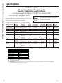 6
6
-
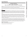 7
7
-
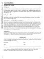 8
8
-
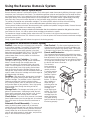 9
9
-
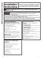 10
10
-
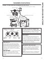 11
11
-
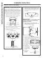 12
12
-
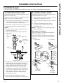 13
13
-
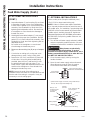 14
14
-
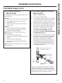 15
15
-
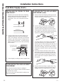 16
16
-
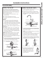 17
17
-
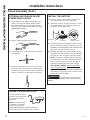 18
18
-
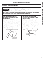 19
19
-
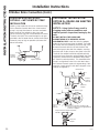 20
20
-
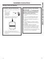 21
21
-
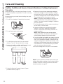 22
22
-
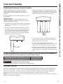 23
23
-
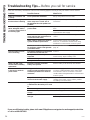 24
24
-
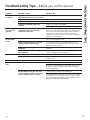 25
25
-
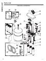 26
26
-
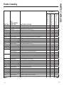 27
27
-
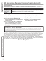 28
28
-
 29
29
-
 30
30
-
 31
31
-
 32
32
-
 33
33
-
 34
34
-
 35
35
-
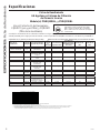 36
36
-
 37
37
-
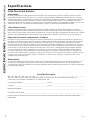 38
38
-
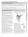 39
39
-
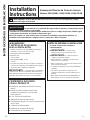 40
40
-
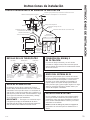 41
41
-
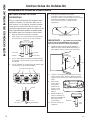 42
42
-
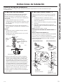 43
43
-
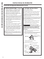 44
44
-
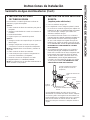 45
45
-
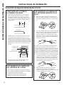 46
46
-
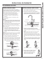 47
47
-
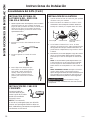 48
48
-
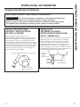 49
49
-
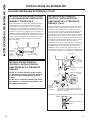 50
50
-
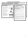 51
51
-
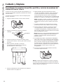 52
52
-
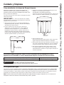 53
53
-
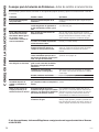 54
54
-
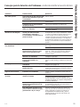 55
55
-
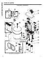 56
56
-
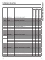 57
57
-
 58
58
-
 59
59
-
 60
60


GE Profile PNRQ21RRB El manual del propietario
- Tipo
- El manual del propietario
En otros idiomas
- English: GE Profile PNRQ21RRB Owner's manual
Documentos relacionados


Otros documentos
-
 GE Appliances GXRM10RBL Manual de usuario
-
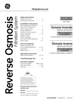 GE Appliances GXRM10RBL Manual de usuario
-
GE GXRM10G Manual de usuario
-
-
 GE Appliances GXRM10RBL Manual de usuario
-
GE PNRQ21RRB Manual de usuario
-
-
-
-


