Hitachi P 20SB Handling Instructions Manual
- Categoría
- Herramientas eléctricas
- Tipo
- Handling Instructions Manual

Planer
Cepillo
Máy báo
P 20SB
Handling instructions
Instrucciones de manejo
Hướng dẫn sử dụng
Read through carefully and understand these instructions before use.
Leer cuidadosamente y comprender estas instrucciones antes del uso.
Đọc kỹ và hiểu rõ các hướng dẫn này trước khi sử dụng.

2
1
2
3
4
5
6
7
9
8
0
!
@
#
$
%
^
7
!
&
123
456
789
10 11 12

3
*
(
!
)
6
7
q
q
w
w
!
e
r
w
q
u
t
y
i
r
o
13 14 15
16 17 18
19 20 21
22 23 24

4
24.5 mm
12 mm
5 mm
21
7
9
0
p
a
s
d
25 26 27
28 29

English Español
1
Knob Botón
2
Scale Escala
3
Mark Marca
4
Beginning of cutting operation Principio de la operación de corte
5
End of cutting operation Fin de la operación de corte
6
Box wrench Llave anular
7
Blade holder Sujetador de cuchilla
8
Loosen Soltar
9
Bolt Perno
0
Cutter blade Cuchilla
!
Machine screw Tornillo de máquina
@
Back metal Metal posterior
#
Edge of back metal Borde
del metal posterior
$
Surface of cutter block Superfi cie de bloque de cortador
%
Correct installation Instalación correcta
^
Erroneous installation Instalación erronea
&
Align the back metal end with on
extruded portion
Alinear el extremo del metal
posterior con una parte extrusionada
*
Lightly push with a thumb Empujar ligeramente con un pulgar
(
Plate Placa
)
Push up the back metal for beneath
Empujar el metal posterior de abajo
a arriba
q
Carbide blade (Double edged blade
type)
Cuchilla de carburo (Tipo de cuchilla
de doble borde)
w
Set plate (B) Placa de ajuste (B)
e
Turned surface Superfi cie girada
r
Set plate (A) Placa de ajuste (A)
t
Set gauge Manómetro de
ajuste
y
Wall surface b Superfi cie de pared b
u
Wall surface a Superfi cie de pared a
i
Flat portion of the cutter block Parte plana del bloque del cortador
o
Groove Ranura
p
Machine screw Tornillo de máquina
a
Grinding allowance 3.5 Desgaste por afi lado 3,5
s
Wear limit Límite de uso
d
No. of carbon brush No de
carbón de contacto
5

Tiếng Việt
1
Núm vặn
2
Thang đo
3
Ký hiệu
4
Bắt đầu thao tác bào
5
Kết thúc thao tác bào
6
Cờ-lê lỗ
7
Giá kẹp lưỡi dao
8
Nới lỏng
9
Bu lông
0
Lưỡi bào
!
Vít máy
@
Tấm lót kim loại
#
Mép tấm lót kim loại
$
Bề mặt khối máy bào
%
Lắp đúng
^
Lắp sai
&
Gióng thẳng tấm lót kim
loại với một phần nhô ra
*
Đẩy nhẹ bằng ngón tay cái
(
Đĩa
)
Đẩy tấm lót kim loại đối với
bên dưới
q
Dao cacbit (kiểu dao hai
cạnh sắc)
()
w
Tấm chặn (B)
(B)
e
Bề mặt quay
r
Tấm chặn (A)
(A)
t
Thiết bị đo cố định
y
Mặt tường b
b
u
Mặt tường a
a
i
Phần phẳng của khối bào
o
Đường bào xoi
p
Vít máy
a
Dung sai mài 3,5
3.5
s
Giới hạn mài mòn
d
Mã số chổi than
6

English
7
GENERAL SAFETY RULES
WARNING!
Read all instructions
Failure to follow all instructions listed below may result in
electric shock, fi re and/or serious injury.
The term “power tool” in all of the warnings listed below
refers to your mains operated (corded) power tool or battery
operated (cordless) power tool.
SAVE THESE INSTRUCTIONS
1) Work area
a) Keep work area clean and well lit.
Cluttered and dark areas invite accidents.
b) Do not operate power tools in explosive
atmospheres, such as in the presence of
fl ammable liquids, gases or dust.
Power tools create sparks which may ignite the dust
of fumes.
c) Keep children and bystanders away while
operating a power tool.
Distractions can cause you to lose control.
2)
Electrical safety
a) Power tool plugs must match the outlet.
Never modify the plug in any way.
Do not use any adapter plugs with earthed
(grounded) power tools.
Unmodifi ed plugs and matching outlets will reduce
risk of electric shock.
b) Avoid body contact with earthed or grounded
surfaces such as pipes, radiators, ranges and
refrigerators.
There is an increased risk of electric shock if your
body is earthed or grounded.
c) Do not expose
power tools to rain or wet
conditions.
Water entering a power tool will increase the risk
of electric shock.
d) Do not abuse the cord. Never use the cord for
carrying, pulling or unplugging the power tool.
Keep cord away from heat, oil, sharp edges or
moving parts.
Damaged or entangled cords increase the risk of
electric shock.
e) When operating a power tool outdoors, use an
extension cord suitable for
outdoor use.
Use of a cord suitable for outdoor use reduces
the risk of electric shock.
3) Personal safety
a) Stay alert, watch what you are doing and use
common sense when operating a power tool.
Do not use a power tool while you are tired
or under the infl uence of drugs, alcohol or
medication.
A moment of inattention while operating power
tools may result in serious personal injury.
b) Use safety equipment. Always wear eye
protection.
Safety equipment such as dust mask, non-skid
safety shoes, hard hat, or hearing protection used for
appropriate conditions will reduce personal injuries.
c) Avoid accidental starting. Ensure the switch is in
the off position before plugging in.
Carrying power tools with your fi nger on the
switch or plugging in power tools that have the switch
on invites accidents.
d) Remove any adjusting key or wrench before
turning the power tool on.
A wrench or a key left attached to a rotating part
of the power tool may result in personal injury.
e) Do not overreach. Keep proper footing and
balance at all times.
This enables better control of the power tool in
unexpected situations.
f) Dress properly. Do not wear loose
clothing or
jewellery. Keep your hair, clothing and gloves
away from moving parts.
Loose clothes, jewellery or long hair can be caught in
moving parts.
g) If devices are provided for the connection of
dust extraction and collection facilities, ensure
these are connected and properly used.
Use of these devices can reduce dust related
hazards.
4) Power tool use and care
a) Do not force the power tool. Use the correct
power tool for your application.
The correct power tool will do the job better and safer
at the rate for which it was designed.
b) Do not use the power tool if the switch does not
turn it on and off .
Any power tool that cannot be controlled with the
switch is dangerous and must be repaired.
c) Disconnect the plug from the power source
before making any adjustments, changing
accessories, or storing power tools.
Such preventive safety measures reduce the risk
of starting the power tool accidentally.
d) Store idle power tools out of
the reach of children
and do not allow persons unfamiliar with the
power tool or these instructions to operate the
power tool.
Power tools are dangerous in the hands of
untrained users.
e) Maintain power tools. Check for misalignment or
binding of moving parts, breakage of parts and
any other condition that may aff ect the power
tools’ operation.
If
damaged, have the power tool repaired before
use.
Many accidents are caused by poorly maintained
power tools.
f) Keep cutting tools sharp and clean.
Properly maintained cutting tools with sharp cutting
edges are less likely to bind and are easier to
control.
g) Use the power tool, accessories and tool bits
etc., in accordance with these instructions and
in the manner intended for the particular type
of power tool, taking into account the working
conditions and
the work to be performed.
Use of the power tool for operations diff erent from
intended could result in a hazardous situation.
5) Service
a) Have your power tool serviced by a qualifi ed
repair person using only identical replacement
parts.
This will ensure that the safety of the power tool
is maintained.
PRECAUTION
Keep children and infi rm persons away.
When not in use, tools should be stored out of reach of
children and infi rm persons.

English
8
PRECAUTIONS ON USING PLANER
○ Do not use the Planer with the blades facing upward
(except when using the F20-BS stand).
SPECIFICATIONS
Voltage (by areas)* (110 V, 115 V, 120 V, 127 V, 220 V, 230 V, 240 V)
Power Input 570 W*
Cutting Width 82 mm
Max. Cutting Depth 1 mm
Weight (without cord) 2.5 kg
No-load Speed
15000/min
* Be sure to check the nameplate on product as it is subject to change by areas.
STANDARD ACCESSORIES
1. Box wrench (for securing cutter blade).........................1
2. Set gauge (for adjusting cutter height) .........................1
3. Guide (with set screw)..................................................1
Standard accessories are subject to change without notice.
OPTIONAL ACCESSORIES (sold separately)
1. Blade sharpening ass’y
Optional accessories are subject to change without notice.
APPLICATIONS
○ Planing various wooden planks and panels.
Planing
Beveling
Max. 12 mm
Max.
12 mm
Rabbeting
Max.
6 mm
PRIOR TO OPERATION
1. Power source
Ensure that the power source to be utilized conforms
to the power requirements specifi ed on the product
nameplate.
2. Power switch
Ensure that the power switch is in the OFF position. If the
plug is connected to a receptacle while the power switch
is in the ON
position, the power tool will start operating
immediately, inviting serious accident.
3. Extension cord
When the work area is removed from the power source,
use an extension cord of suffi cient thickness and rated
capacity. The extension cord should be kept as short as
practicable.
4. Prepare a stable wooden workbench suitable for planing
operation. As a poorly balanced workbench creates a
hazard, ensure it is securely positioned on fi rm, level
ground.
PLANING PROCEDURES
1. Adjusting the cutter depth
(1) Turn the knob in the direction indicated by the arrow in
Fig. 1 (clockwise), until the triangular mark is aligned with
the desired cutting depth on the scale. The scale unit is
graduated in millimeters.
(2) The cutting depth can be adjusted within a range of
0-1 mm.
2. Surface cutting
Rough cutting should be accomplished at large cutting
depths and at a suitable speed so that shavings are
smoothly ejected from the machine. To ensure a smoothly
fi nished surface, fi nish cutting should be accomplished at
small cutting depth and at low feeding speed.
3. Beginning and
ending the cutting operation
As shown in Fig. 2, place the front base of the planer on
the material and support the planer horizontally. Turn ON
the power switch, and slowly operate the planer toward
the leading edge of the material. Firmly depress the front
half of the planer at
the fi rst stage of cutting, as shown in
Fig. 3, depress the rear half of the planer at the end of
the cutting operation. The planer must always be kept fl at
throughout the entire cutting operation.
4. Precaution after fi nishing the planing operation
When the planer is suspended with one
hand after
fi nishing the planing operation, ensure that the cutting
blades (base) of the planer do not contact or come too
near your body. Failure to do so could result in serious
injury.
CUTTER BLADE ASSEMBLY AND
DISASSEMBLY AND ADJUSTMENT OF CUTTER
BLADE HEIGHT (FOR RESHARPENABLE BLADE
TYPE)
1. Cutter blade disassembly
(1) As shown in Fig. 4, use the accessory box wrench to
withdraw the three bolts used to retain the cutter blade,
and remove the cutter blade holder.

English
9
(2) As shown in Fig. 5, slide the rear side of the cutter blade
in the direction indicated by the arrow to disassemble the
cutter blade.
CAUTIONS
○ Be careful not to injure your hands.
○ It is not necessary to disassemble the back metal from
the cutter blade. (See Fig. 6)
○ Disassembling the back metal from the cutter blade is to
be made only at grinding the cutter blade.
2. Cutter blade assembly
CAUTION
○ Prior to assembly, thoroughly wipe off all swarf
accumulated on the cutter blade.
(1) Turn the cutter block fl at surface sideways, and assemble
the adjusted cutter blade as
shown in Fig. 7. Ensuring
that the leaf spring on the cutter block is correctly fi tted
to the hole on the rear plate, push the back of the cutter
blade with a fi ngertip in the direction indicated by the
arrow, until the edge of the back metal is properly fi tted
to
the cutter block surface. Correct installation is illustrated
in Fig. 8.
(2) Place the blade holder on the completed assembly,
as shown in Fig. 10, and fasten it with the three bolts.
Ensure that the bolts are securely tightened.
(3) Turn the cutter block over, and set the other
side in the
same manner.
3. Adjustment of cutter blade height
CAUTION
○ As the set gauge has been accurately factory adjusted,
never attempt to loosen it.
(1) After attaching the back metal to the cutter blade,
temporarily fasten them together with machine screws,
as shown in Fig. 11.
(2) Insert the set
gauge plate spring into the hole on the back
metal and heavily push the plate spring in the direction
indicated by the arrow in Fig. 12 until it snaps into the
correct position.
(3) Holding the set gauge with the blade edge facing
downward as shown in Fig. 13, loosen
the temporarily
fastened machine screws and lightly push the cutter
blade with a thumb until the cutter blade gently touches
plate.
CAUTION
○ Do not push the blade with excessive pressure.
Excessive pressure could cause maladjustment of the
blade height.
(4) Finally, retighten the machine screws to securely fasten
the cutter blade and
the back metal, thereby completing
the blade height adjustment procedure.
(5) Holding the set gauge as shown in Fig. 14, push upward
on the back metal and remove it from the set gauge.
(6) The cutter blade is now ready to be mounted on the planer
as described in the section
on cutter blade assembly.
CARBIDE BLADE ASSEMBLY AND
DISASSEMBLY AND ADJUSTMENT OF CUTTER
BLADE HEIGHT (FOR DOUBLE EDGED BLADE
TYPE)
1. Carbide blade disassembly
(1) As shown in Fig. 15, loosen the blade holder with the
attached box wrench.
(2) As shown in Fig. 16, remove the carbide blade by sliding
it with the attached box wrench.
CAUTION
○ Be careful not to injure your hands.
2. Carbide blade assembly
CAUTION
○ Prior to
assembly, thoroughly wipe off all swarf
accumulated on the carbide blade.
(1) As shown in Fig. 17, lift set plate (B) and insert the new
carbide blade between cutter block and set plate (B).
(2) As shown in Fig. 18, mount the new carbide blade by
sliding it on the set plate (B) so that the blade tip projects
by 1mm
from the end of the cutter block.
(3) As shown in Fig. 19, fi x the bolts at the blade holder after
blade replacement has been completed.
(4) Turn the cutter block over, and set the other side in the
same manner.
3. Adjustment of carbide blade height
CAUTION
○ If the carbide blade’s
heights are inaccurate after
above procedures have been completed, carry out the
procedures described below.
(1) As shown in Fig. 4, use the box wrench to loosen the
three bolts used to retain the carbide blade, and remove
the blade holder.
(2) As shown in Fig. 20, after removing the
carbide blade,
slide set plate (B) in the direction indicated by the arrow
to disassemble set plate (B).
(3) Loosen the 2 screws holding on the carbide blade and
set plate (A), set plate (B).
(4) As shown in Fig. 21, 22, press the turned surface of
set plate (A)
to the wall surface (B) while adjusting the
carbide blade edge to the wall surface a of the set gauge.
Then, tighten them with the 2 screws.
(5) As shown in Fig. 23, 24, insert a turned portion of set
plate (A) attached to set plate (B) into a groove
on the fl at
portion of the cutter block.
(6) As shown in Fig. 25, place the blade holder on the
completed assembly and fasten it with the three bolts.
Ensure that the bolts are securely tightened. Follow the
same procedures for the opposite side carbide blade.
SHARPENING THE RESHARPENABLE CUTTER
BLADES
Use of the optional accessory Blade Sharpening Ass'y is
recommended for convenience.
1. Use of Blade Sharpening Ass’y
As shown in Fig. 26, two blades can be mounted on
the blade sharpening ass’y to ensure that the blade tips
are ground at uniform angles. During grinding, adjust
the position of the
cutter blades so that their edges
simultaneously contact the dressing stone as shown in
Fig. 27.
2. Cutter blade sharpening intervals
Cutter blade sharpening intervals depend on the type
of wood being cut and the cutting depth. However,
sharpening should generally be eff ected after each 500
meters of cutting
operation.
3. Grinding allowance of the cutter blades
As illustrated in Fig. 28, a grinding allowance of 3.5 mm
is provided for on the cutter blade. That is , the cutter
blade can be repeatedly sharpened until its total height
is reduced to 24.5 mm.
4. Dressing stone
When a water
dressing stone is available, use it after
dipping it suffi ciently in water since such a dressing stone
may be worn during grinding works, fl atten the upper
surface of the dressing stone as often as necessary.
MAINTENANCE AND INSPECTION
1. Inspecting the blades
Continued use of dull or damaged cutter blades will result
in reduced cutting effi ciency and may cause overloading
of the motor. Sharpen or replace the cutter blades as
often as necessary.

English
10
2. Handling
CAUTION
○ The front base, rear base, and cutting depth control
knob are precisely machined to obtain specifi cally high
precision. If these parts are roughly handled or subjected
to heavy mechanical impact, it may cause deteriorated
precision and reduced cutting performance. These parts
must be handled with particular care.
3. Inspecting the mounting screws
Regularly inspect all mounting screws and ensure that
they are properly tightened. Should any of the screws be
loose, retighten them immediately. Failure to do so could
result in serious hazard.
4. Inspecting the carbon brushes (Fig. 29)
The motor employs carbon brushes which are
consumable
parts. Since an excessively worn carbon
brush could result in motor trouble, replace the carbon
brushes with new ones which having the same carbon
brush No. shown in the fi gure when they become worn to
or near the “wear limit”. In addition, always keep carbon
brushes clean and ensure that they
slide freely within the
brush holders.
5. Replacing carbon brushes
Disassemble the brush cap with a slotted-head
screwdriver. The carbon brush can then be easily
removed.
6. Maintenance of the motor
The motor unit winding is the very “heart” of the power
tool. Exercise due care to ensure the winding does
not
become damaged and/or wet with oil or water.
7. Service parts list
A: Item No.
B: Code No.
C: No. Used
D: Remarks
CAUTION
Repair, modifi cation and inspection of Hitachi Power
Tools must be carried out by a Hitachi Authorized Service
Center.
This Parts List will be helpful if presented with the
tool to
the Hitachi Authorized Service Center when requesting
repair or other maintenance.
In the operation and maintenance of power tools, the
safety regulations and standards prescribed in each
country must be observed.
MODIFICATIONS
Hitachi Power Tools are constantly being improved
and modifi ed to incorporate the latest technological
advancements.
Accordingly, some
parts (i.e. code numbers and/or
design) may be changed without prior notice.
NOTE
Due to HITACHI’s continuing program of research and
development, the specifi cations herein are subject to change
without prior notice.

Español
11
NORMAS GENERALES DE SEGURIDAD
¡ADVERTENCIA!
Lea todas las instrucciones
Si no se siguen las instrucciones de abajo podría producirse
una descarga eléctrica, un incendio y/o daños graves.
El término “herramienta eléctrica” en todas las advertencias
indicadas a continuación hace referencia a la herramienta
eléctrica que funciona con la red de suministro (con cable) o
a la herramienta eléctrica que funciona con pilas (sin cable).
CONSERVE ESTAS INSTRUCCIONES
1) Área de trabajo
a) Mantenga la zona de trabajo limpia y bien
iluminada.
Las zonas desordenadas y oscuras pueden provocar
accidentes.
b) No utilice las herramientas eléctricas en entornos
explosivos como, por ejemplo, en presencia de
líquidos infl amables, gases o polvo.
Las herramientas eléctricas crean chispas que
pueden hacer que el polvo desprenda humo.
c) Mantenga a los niños y transeúntes alejados
cuando utilice una herramienta eléctrica.
Las distracciones pueden hacer que pierda el
control.
2) Seguridad eléctrica
a) Los enchufes de las herramientas eléctricas
tienen que ser adecuados a la toma de
corriente.
No modifi que el enchufe.
No utilice enchufes adaptadores con
herramientas eléctricas conectadas a tierra.
Si no se modifi can los enchufes y se utilizan tomas
de corriente adecuadas se reducirá el riesgo de
descarga eléctrica.
b) Evite el contacto corporal con superfi cies
conectadas
a tierra como tuberías, radiadores y
frigorífi cos.
Hay mayor riesgo de descarga eléctrica si su cuerpo
está en contacto con el suelo.
c) No exponga las herramientas eléctricas a la
lluvia o a la humedad.
La entrada de agua en una herramienta eléctrica
aumentará el riesgo de descarga eléctrica.
d) No utilice el cable incorrectamente. No utilice el
cable para transportar, tirar de la herramienta
eléctrica o desenchufarla.
Mantenga el cable alejado del calor, del aceite,
de bordes afi lados o piezas móviles.
Los cables dañados o enredados aumentan el riesgo
de descarga eléctrica.
e) Cuando utilice una herramienta eléctrica al aire
libre, utilice un cable prolongador adecuado
para utilizarse al aire libre.
La utilización de un cable adecuado para usarse al
aire libre reduce el riesgo de descarga eléctrica.
3) Seguridad personal
a) Esté atento, preste atención a lo que hace y
utilice el sentido común cuando utilice una
herramienta eléctrica.
No utilice
una herramienta eléctrica cuando esté
cansado o esté bajo la infl uencia de drogas,
alcohol o medicación.
La distracción momentánea cuando utiliza
herramientas eléctricas puede dar lugar a importantes
daños personales.
b) Utilice equipo de seguridad. Utilice siempre una
protección ocular.
El equipo de seguridad como máscara para el
polvo, zapatos de seguridad antideslizantes, casco
o protección para oídos utilizado para condiciones
adecuadas reducirá los daños personales.
c) Evite un inicio accidental. Asegúrese de que el
interruptor está en “off ” antes de enchufarlo.
El transporte de herramientas eléctricas con el
dedo en el interruptor o el enchufe de herramientas
eléctricas con el interruptor encendido puede
provocar accidentes.
d) Retire las llaves
de ajuste antes de encender la
herramienta eléctrica.
Si se deja una llave en una pieza giratoria de la
herramienta eléctrica podrían producirse daños
personales.
e) No se extralimite. Mantenga un equilibrio
adecuado en todo momento.
Esto permite un mayor control de la herramienta
eléctrica en situaciones inesperadas.
f) Vístase adecuadamente. No lleve prendas
sueltas o joyas. Mantenga el pelo, la ropa y los
guantes alejados de las piezas móviles.
La ropa suelta, las joyas y el pelo largo pueden
pillarse en las piezas móviles.
g) Si se proporcionan dispositivos para la conexión
de extracción de polvo e instalaciones de
recogida, asegúrese de que están conectados y
se utilizan adecuadamente.
La utilización de estos dispositivos puede reducir los
riesgos relacionados con el polvo.
4) Utilización y mantenimiento de las herramientas
eléctricas
a) No fuerce la herramienta eléctrica. Utilice
la herramienta eléctrica correcta para su
aplicación.
La herramienta eléctrica correcta trabajará mejor y
de forma más segura si se utiliza a la velocidad para
la que fue diseñada.
b) No utilice la herramienta elétrica si el interruptor
no la
enciende y apaga.
Las herramientas elétricas que no pueden controlarse
con el interruptor son peligrosas y deben repararse.
c) Desconecte el enchufe de la fuente eléctrica
antes de hacer ajustes, cambiar accesorios o
almacenar herramientas eléctricas.
Estas medidas de seguridad preventivas reducen el
riesgo de que la herramienta eléctrica se ponga en
marcha accidentalmente.
d) Guarde las herramientas eléctricas que no se
utilicen para que no las cojan los niños y no
permita que utilicen las herramientas eléctricas
personas no familiarizadas con las
mismas o
con estas instrucciones.
Las herramientas eléctricas son peligrosas si son
utilizadas por usuarios sin formación.
e) Mantenimiento de las herramientas eléctricas.
Compruebe si las piezas móviles están mal
alineadas o unidas, si hay alguna pieza rota u otra
condición que pudiera afectar al funcionamiento
de las herramientas eléctricas.
Si la herramienta eléctrica está dañada, llévela a
reparar antes de utilizarla.
Se producen muchos accidentes por no realizar
un mantenimiento correcto de las herramientas
eléctricas.
f) Mantenga las herramientas de corte afi ladas y
limpias.

Español
12
Las herramientas de corte correctamente mantenidas
con los bordes de corte afi lados son más fáciles de
controlar.
g) Utilice la herramienta eléctrica, los accesorios
y las brocas de la herramienta, etc., de acuerdo
con estas instrucciones y de la manera adecuada
para el tipo de herramienta eléctrica, teniendo
en cuenta las condiciones laborales y el trabajo
que se va a realizar.
La utilización de la herramienta eléctrica para
operaciones diferentes a pretendidas podría dar
lugar a una situación peligrosa.
5) Revisión
a) Lleve su herramienta a que la revise un experto
cualifi cado que utilice sólo piezas de repuesto
idénticas.
Esto garantizará el mantenimiento de la seguridad de
la herramienta eléctrica.
PRECAUCIÓN
Mantenga a los niños y a las personas enfermas
alejadas.
Cuando no se utilicen, las herramientas deben
almacenarse fuera del alcance de los niños y de las
personas enfermas.
PRECAUCIONES AL USAR EL CEPILLO
○ No usar el cepillo con la cuchilla mirando hacia arriba
(except o quando ese utiliza el pie F20-BS).
ESPECIFICACIONES
Voltaje (por áreas)* (110 V, 115 V, 120 V, 127 V, 220 V, 230 V, 240 V)
Acometida 570 W*
Anchura de corte 82 mm
Profundidad máx. de corte 1 mm
Peso (sin cable) 2,5 kg
Velocidad de marcha en vacío
15000/min
*
Verifi car indefectiblemente los datos de la placa de características de la máquina, pues varían de acuerdo al país de destino.
ACCESORIOS ESTÁNDAR
1. Llave anular (para afi rmar la cuchilla del cortador) .......1
2. Manómetro de ajuste (para ajustar la altura del
cortador) ......................................................................1
3. Guía (con tornillo de sujeción) ......................................1
Los accesorios estándar están sujetos a cambio sin previo
aviso.
ACCESORIOS FACULTATIVOS (venta por
separado)
1. Conjunto de afi lacuchillas
Los accesorios facultativos están sujetos a cambio sin previo
aviso.
APLICACIONES
○ Cepillar diferentes tablas y paneles de madera.
Cepillar
Biselar
Max. 12 mm
Max.
12 mm
Ensamblar
Max.
6 mm
ANTES DE LA PUESTA EN MARCHA
1. Alimentación
Asegurarse de que la alimentación de red que ha de
ser utilizada y responda a las exigencias de corriente
especifi cadas en la placa de características del
producto.
2. Interruptor de alimentación
Asegurarse de que el interruptor de alimentación esté
en la posición OFF (desconectado). Si el enchufe está
conectado en el receptáculo mientras el interruptor
de alimentación esté en posición ON (conectado)
las herramientas eléctricas empezarán a funzionar
inesperadamente, provocando un serio accidente.
3. Cable de prolongación
Cuando el área de trabajo esté alejada de la red de
acometida, usar un cable de prolongación sufi ciente
grueso y potente. El cable de prolongación debe ser
mantenido lo más corto posible.
4. Preparar un banco de trabajo de madera estable para la
operación de cepillado. Como un lugar de trabajo poco
equilibrado representa una fuente de peligro, asegurarse
de que esté fi rmemente colocado en un fundamento
fi rme y horizontal.
PROCEDIMIENTOS DE CEPILLADO
1. Ajustar la profundidad del cortador
(1) Girar el botón en la dirección indicada por la fl echa en
la Fig. 1 (en el sentido de las manillas de un reloj) hasta
que la marca triangular esté alineada con la profundidad
de corte deseada en la escala. La unidad de escala está
graduada en milímetros.
(2) La profundidad de corte puede ser ajustada dentro de un
ámbito de 0 mm-1 mm.

Español
13
2. Corte de superfi cie
Se debe realizar un corte tosco con una profundidad larga
de corte y una velocidad adecuada de tal manera que
sean expulsadas suavemente las virutas de la máquina.
Para asegurarse de que el acabado de la superfi cie
sea fi no, el corte de acabado debe
ser realizado a una
profundidad pequeña de corte y velocidad baja.
3. Comienzo y fi nal de la operación de corte
Como se muestra en la Fig. 2, situar la base frontal de
el cepillo en la pieza de trabajo y mantener la garlopa
horizontal. Girar el conmutador ON (conectado) y
llevar
despacio el cepillo en la dirección la borde directriz de la
pieza de trabajo. Apretar fi rmemente hacia abajo la mitad
delantera de el cepillo en la primera parte de la operación
de cortar y, como se muestra en la Fig. 3, apretar hacia
abajo la mitad trasera de el
cepillo al fi nal de la operación
de corte. El cepillo tiene que ser mantenido siempre
plano durante toda la operación de corte
4. Precaución después de haber acabado la operación
de cepillar
Cuando la garlopa esté suspendida con una mano
después de haber acabado la operación de cepillar,
asegurarse de que
las cuchillas (base) de la cepillo no
contacten o vayan demasiado cerca de su cuerpo. El no
tener esto en cuenta ocasionaría heridas serias.
MONTAJE Y DESMONTAJE DE LA CUCHILLA
Y AJUSTAMIENTO DE LA ALTURA DE LA
CUCHILLA
1. Desmontaje de la cuchilla
(1) Como mostrado en Fig. 4, usar llave anular accesoria
para destrnillar los tres pernos usados para sujetar la
cuchilla y quitar el sujetador de cuchilla.
(2) Como mostrado en Fig. 5, correr la parte trasera de
la cuchilla en la dirección indicada por la fl echa
para
desmontar la cuchilla.
PRECAUCIONES
○ Tener cuidado de no herirse las manos.
○ No es necesario desmontar el metal posterior de la
cuchilla (mira Fig. 6).
○ El desmonte del metal posterior de la cuchilla se lleva a
cabo sólo para afi lar la cuchilla.
2. Montaje de la cuchilla
PRECAUCIÓN
○ Antes
del montaje, quitar cuidadosamente todo el polvo
de afi lado acumulado en la cuchilla.
(1) Girar oblicuamente la superfi cie lisa del bloque del
cortador y montar la cuchilla ajustada como mostrado en
Fig. 7. Asegurarse de que el muelle de hoja en el bloque
del cortador esté montada correctamente al
orifi cio en
la placa trasera, oprimir el trasero de la cuchilla con la
punta del dedo el la dirección indicada por la fl echa,
hasta que el borde del metal posterior esté bién montado
en la superfi cie del bloque de cortador. La instalación
correcta está ilustrada en Fig. 8.
(2) Situar el sujetador de cuchilla en el conjunto completo
como mostrado en Fig. 10, y apretarlo con los tres
pernos. Asegurarse de que los pernos estén apretados
fi rmemente.
(3) Dar la vuelta al bloque de cortador y ajustar el otro lado
de la misma manera.
3. Ajustamiento de la altura
de cuchilla
PRECAUCIÓN
○ Como el calibrador de conjunto ha sido ajustado con
precisión en fábrica, no intentar nunca soltarlo.
(1) Después de aplicar el metal posterior a la cuchilla, volver
a apretarlos mutuamente con tornillos de máquina, como
mostrado en Fig. 11.
(2) Insertar el muelle de la placa del calibrador de conjunto
dentro del origicio en el metal posterior y oprimir
fuertemente el muelle de la placa en la dirección indicado
por la fl echa en Fig. 12 hasta que engatille en su posición
correcta.
(3) Manteniendo el calibrador de conjunto con el fi
lo de la
cuchilla mirando hacia abajo como mostrado en Fig. 13,
afl ojar los tornillos de máquina apretados temporalmente
y empujar ligeramente la cuchilla con el pulgar hasta que
la cuchilla toque ligeramente la placa.
PRECAUCIÓN
○ No empujar la cuchilla con excesiva fuerza. Presión
excesiva podría causar desajustamiento de la
altura de
cuchilla.
(4) Finalmente, volver a apretar los tornillos de máquina
para ajustar fi rmemente la cuchilla y el metal posterior,
completando así el procedimiento de ajuste de la altura
de la cuchilla.
(5) Mantener el calibrador de conjunto como mostrado en
Fig. 14, empujar hacia arriba el metal posterior y
quitarlo
del calibrador de conjunto.
(6) La cuchilla está preparada ahorra para ser montada en
el garlopa como descrito en la sección montaje de la
cuchilla.
MONTAJE Y DESMONTAJE DE LA CUCHILLA
DE CARBURO Y AJUSTE DE LA ALTURA DE LA
CUCHILLA (PARA EL TIPO DE CUCHILLA DE
DOBLE BORDE)
1. Desmontaje de la cuchilla de carburo
(1) Como se muestra en la Fig. 15, afl oje el soporte de las
cuchillas de carburo con la llave de cubo suministrada.
(2) Como se muestra en la Fig. 16, extraiga la cuchilla de
carburo deslizándola con la llave de cubo suministrada.
PRECAUCIÓN
○
Tener cuidado de no herirse las manos.
2. Montaje de la cuchilla de carburo
PRECAUCIÓN
○ Antes del montaje, quitar cuidadosamente todo el polvo
de afi lado, acumulado en la cuchilla de carburo.
(1) Como se muestra en la Fig. 17, levante la placa de ajuste
(B) e inserte la nueva cuchilla de
carburo entre el bloque
del cortador y la placa de ajuste (B).
(2) Como se muestra en la Fig. 18. monte la nueva cuchilla
de carburo deslizándola en la placa de ajuste (B) de
forma que la punta de la misma sobresalga 1 mm del
extremo del bloque del cortador.
(3) Como se muestra en la Fig. 19, fi je el perno en el
soporte de la cuchilla de carburo y, de esta forma, habrá
fi nalizado el reemplazo de la misma.
(4) Dar la vuelta al bloque de cortador y ajustar el otro lado
de la misma manera.
3. Ajuste de la
altura de cuchilla de carburo
PRECAUCIÓN
○ Si la altura de la cuchilla de carburo es imprecisa después
de haber realizado los ajustes anteriores, realice los
descritos a continuación.
(1) Como se muestra en la Fig. 4, utilice la llave de cubo
para afl ojar los tres pernos utilizados para retener la
cuchilla de carburo, y extraiga el soporte de la cuchilla de
carburo.
(2) Como se muestra en la Fig. 20, después de haber
extraído la cuchilla de carburo del cortador, deslice la
placa de ajuste (B) en el sentido indicado por la fl echa
para desmontar dicha placa (B).
(3) Afl oje
los 2 tornillos que sujetan la cuchilla de carburo del
cortador y la placa de ajuste (A) y la placa de ajuste (B).

Español
14
(4) Como se muestra en las Figs. 21 y 22, presione la
superfi cie torneada de la placa de ajuste (A) contra la
superfi cie de la pared (B) mientras ajuste el borde de la
cuchilla con la superfi cie de la pared a la del manómetro
de ajuste. Después,
apriételas con los 2 tornillos.
(5) Como se muestra en las Figs. 23 y 24, inserte la parte
torneada de la placa de ajuste (A) fi jada a la placa de
ajuste (B) en la ranura de la parte plana del bloque del
cortador.
(6) Como se muestra en la Fig. 25,
coloque el soporte de la
cuchilla de carburo en el conjunto completado y apriételo
con los tres pernos. Cerciórese de que los pernos hayan
quedado fi rmemente asegurados. Realice los mismos
procedimientos desde la cuchilla de carburo del lado
opuesto.
AFILADO DE LAS CUCHILLAS AFILABLES
Por motivos de comodidad, se aconseja utilizar el conjunto
de afi lado de cuchillas.
1. Utilice el conjunto de afi lado de cuchillas
Como se muestra en la Fig. 26, en el conjunto de afi lado
de cuchillas sierra pueden montarse dos cuchillas para
asegurar que las puntas se afi
len con ángulos uniformes.
Durante el afi lado, ajuste la posición de las cuchillas de
forma que su borde quede simultáneamente en contacto
con la piedra de afi lar, como se muestra en la Fig. 27.
2. Intervalos de afi lado de las cuchillas
Los intervalos de afi lado de
las cuchillas dependerán del
tipo de madera que esté cortándose y de la profundidad
de corte. Sin embargo, el afi lado deberá realizarse
normalmente después de cada 500 metros de operación
de corte.
3. Desgaste de las cuchillas por afi lado
Como ilustrado en Fig. 28 está previsto un desgaste
por
afi lado de 3,5 mm en la cuchilla. Es decir, la cuchilla
puede ser afi lada repetidamente hasta que su altura total
sea reducida a 24,5 mm.
4. Piedra de afi lar
Cuando disponga de una piedra de afi lar para agua,
utilícela después de haberla humedecido sufi cientemente
porque
de lo contrario podría desgastarse durante el
afi lado. Aplane la superfi cie de la piedra de afi lar cuando
sea necesario.
MANTENIMIENTO E INSPECCIÓN
1. Inspeccionar las cuchillas
El uso continuo de cuchillas desgastadas o dañadas
podría ocasionar una reducción de la efi ciencia de corte
y recalentamiento del motor. Afi lar o reemplazar las
cuchillas tantas veces como sea necesario.
2. Manejo
PRECAUCIÓN
○ La base delantera, la base trasera y el botón de control
de
la profundidad de corte están trabajados con
exactitud para obtener una específi ca alta precisión. Si
estas piezas fueran tratadas con rudeza o sometidas
a pesados golpes mecánicos, podría ser causados
deterioros en la presición y reducción del rendimiento
de corte. Estas piezas tienen que ser manejadas con
especial cuidado.
3.
Inspeccionar los tornillos de montaje
Regularmente inspeccionar todos los tornillos de montaje
y asegurarse de que estén apretados fi rmemente. Si
cualquier tornillo estuviese suelto, volver a apretarlo
inmediatamente. El no hacer esto provocaría un riesgo
serio.
4. Inspección de escobillas de carbón (Fig. 29)
El motor emplea carbones de contacto que
son
partes consumibles. Como un carbón de contacto
excesivamente desgastado podría dar problemas al
motor, reemplazar el carbón de contacto por uno nuevo,
y que tenga el mismo número, como muestra en la fi gura,
cuando se haya desgastado o esté cerca del límite de
uso. Adicionalmente, mantener siempre los carbones
de
contacto limpios y asegurarse de que corran libremente
dentro de los sujetadores de carbón.
5. Reemplazamiento de un carbón de contacto
Después de quitar la cubierta de virutas, usar un
destornillador corriente para desarmar la tapa de la
escobilla. Entonces podrá quitarse fácilmente la escobilla
de carbón con el resorte.
6.
Mantenimiento de motor
La unidad de bobinado del motor es el verdadero
“corazón” de las herramientas eléctricas. Prestar el
mayor cuidado y asegurarse de que el bobinado no se
dañe y/o se humedezca con aceite o agua.
7. Lista de repuestos
A: N°. ítem
B: N°. código
C: N°. usado
D: Observaciones
PRECAUCIÓN
La
reparación, modifi cación e inspección de las
herramientas eléctricas Hitachi deben ser realizadas por
un Centro de Servicio Autorizado de Hitachi.
Esta lista de repuestos será de utilidad si es presentada
junto con la herramienta al Centro de Servicio Autorizado
de Hitachi, para solicitar la reparación o cualquier otro
tipo
de mantenimiento.
En el manejo y el mantenimiento de las herramientas
eléctricas, se deberán observar las normas y reglamentos
vigentes en cada país.
MODIFICACIONES
Hitachi Power Tools introduce constantemente mejoras
y modifi caciones para incorporar los últimos avances
tecnológicos.
Por consiguiente, algunas partes (por ejemplo, números
de códigas y/o diseño) pueden ser
modifi cadas sin
previo aviso.
OBSERVACIÓN
Debido al programa continuo de investigación y desarrollo
de HITACHI estas especifi caciones están sujetas a cambio
sin previo aviso.

15

16
○
○

17
○
○
○
○
○
○
○
○

18
○ ○

Tiếng Việt
19
CÁC NGUYÊN TẮC AN TOÀN CHUNG
CẢNH BÁO!
Đọc kỹ tất cả hướng dẫn
Việc không tuân theo mọi hướng dẫn được liệt kê dưới đây
có thể dẫn đến bị điện giật, cháy và/hoặc bị chấn thương
nghiêm trọng.
Thuật ngữ "dụng cụ điện” có trong tất cả các cảnh báo dưới
đây đề cập đến dụng cụ điện (có dây) điều khiển b
ằng tay
hoặc dụng cụ điện (không dây) vận hành bằng pin.
GHI NHỚ CÁC HƯỚNG DẪN NÀY
1) Khu vực làm việc
a) Giữ khu vực làm việc sạch và đủ ánh sáng.
Khu vực làm việc tối tăm và bừa bộn dễ gây tai nạn.
b) Không vận hành dụng dụ điện trong khu vực
dễ cháy nổ, chẳng hạn như nơi có chất lỏng dễ
cháy, khí đốt hoặc bụi khói.
Các dụng dụ
điện tạo tia lửa nên có thể làm bụi khói
bén lửa.
c) Không để trẻ em và những người không phận sự
đứng gần khi vận hành dụng dụ điện.
Sự phân tâm có thể khiến bạn mất kiểm soát.
2) An toàn về điện
a) Phích cắm dụng cụ điện phải phù hợp với ổ cắm.
Không bao giờ được cải biến phích cắm dưới
mọi hình thức. Không
được sử dụng phích tiếp
hợp với dụng cụ điện nối đất (tiếp đất).
Phích cắm nguyên bản và ổ cắm điện đúng loại sẽ
giảm nguy cơ bị điện giật.
b) Tránh để cơ thể tiếp xúc với các bề mặt nối đất
hoặc tiếp đất như đường ống, lò sưởi, bếp ga và
tủ lạ
nh.
Có nhiều nguy cơ bị điện giật nếu cơ thể bạn nối
hoặc tiếp đất.
c) Không để các dụng cụ điện tiếp xúc với nước
mưa hoặc ẩm ướt.
Nước thấm vào dụng cụ điện sẽ làm tăng nguy cơ bị
điện giật.
d) Không được lạm dụng dây dẫn điện. Không bao
giờ nắ
m dây để xách, kéo hoặc rút dụng cụ điện.
Để dây cách xa nơi có nhiệt độ cao, trơn trượt,
vật sắc cạnh hoặc bộ phận chuyển động.
Dây bị hư hỏng hoặc rối sẽ làm tăng nguy cơ bị điện
giật.
e) Khi vận hành dụng cụ điện ở ngoài trời, hãy sử
dụng dây nối thích hợp cho việc sử dụng ngoài
trời.
Sử dụng dây nối ngoài trời thích hợp làm giảm nguy
cơ bị điện giật.
3) An toàn cá nhân
a) Luôn cảnh giác, quan sát những gì bạn đang làm
và phán đoán theo kinh nghiệm khi vận hành
dụng dụ điện.Không được sử dụng dụng cụ điện
khi mệt mỏi hoặc dưới ảnh hưởng của rượu, ma
túy hoặc dược phẩm.
Một thoáng mất tập trung khi vận hành dụng cụ
điện
có thể dẫn đến chấn thương cá nhân nghiêm trọng.
b) Sử dụng thiết bị bảo hộ. Luôn đeo kính bảo vệ
mắt.
Trang thiết bị bảo hộ như khẩu trang, giày an toàn
chống trượt, nón bảo hộ, hoặc dụng cụ bảo vệ tai
được sử dụng trong các điều kiện thích hợp sẽ làm
giảm nguy cơ thương tích cá nhân.
c) Tránh để máy khởi động b
ất ngờ. Đảm bảo công
tắc ở vị trí tắt trước khi cắm điện.
Đặt ngón tay trên công tắc khi xách dụng cụ điện
hoặc cắm điện lúc công tắc ở vị trí bật rất dễ dẫn đến
tai nạn.
d) Tháo mọi khóa điều chỉnh hoặc chìa vặn đai ốc ra
trước khi bật dụng cụ điện.
Chìa vặn đai
ốc hoặc chìa khóa còn cắm trên một bộ
phận quay của dụng dụ điện có thể gây thương tích
cá nhân.
e) Không với tay quá xa. Luôn luôn đứng vững và
cân bằng.
Điều này giúp kiểm soát dụng cụ điện trong tình
huống bất ngờ tốt hơn.
f) Trang phục phù hợp. Không mặc quần áo rộng
lùng thùng hoặc đeo trang sức. Giữ tóc, quần áo
và găng tay tránh xa các bộ phận chuyển động.
Quần áo rộ
ng lùng thùng, đồ trang sức hoặc tóc dài
có thể bị cuốn vào các bộ phận chuyển động.
g) Nếu có các thiết bị đi kèm để nối máy hút bụi và
các phụ tùng chọn lọc khác, hãy đảm bảo các
thiết bị này được nối và sử dụng đúng cách.
Việc sử dụng các thiết bị này có thể làm giảm độc hại
do bụi gây ra.
4) Sử dụng và bảo dưỡng dụng cụ điệ
n
a) Không được ép máy hoạt động quá mức. Sử
dụng đúng loại dụng cụ điện phù hợp với công
việc của bạn.
Dụng cụ điện đúng chủng loại sẽ hoàn thành công
việc tốt và an toàn hơn theo đúng tiêu chí mà máy
được thiết kế.
b) Không sử dụng dụng cụ điện nếu công tắc
không tắt hoặc bật được.
Bất kỳ d
ụng cụ điện nào không thể điều khiển được
bằng công tắc đều rất nguy hiểm và phải được sửa
chữa.
c) Luôn rút phích cắm ra khỏi nguồn điện trước khi
điều chỉnh, thay phụ tùng, hoặc cất dụng cụ điện.
Những biện pháp ngăn ngừa như vậy giúp giảm
nguy cơ dụng cụ điện khởi động b
ất ngờ.
d) Cất giữ dụng cụ điện không sử dụng ngoài tầm
tay trẻ em và không được cho người chưa quen
sử dụng dụng cụ điện hoặc chưa đọc hướng dẫn
sử dụng này vận hành dụng cụ điện.
Dụng cụ điện rất nguy hiểm khi ở trong tay người
chưa được đào tạo cách sử dụng.
e) B
ảo dưỡng dụng cụ điện. Kiểm tra đảm bảo các
bộ phận chuyển động không bị xê dịch hoặc mắc
kẹt, các bộ phận không bị rạn nứt và kiểm tra các
điều kiện khác có thể ảnh hưởng đến quá trình
vận hành máy. Nếu bị hư hỏng, phải sửa chữa
dụng cụ điện trước khi sử dụng.
Nhiều tai nạn x
ảy ra do bảo quản dụng dụ điện kém.
f) Giữ các dụng cụ cắt sắc bén và sạch sẽ.
Dụng cụ cắt có cạnh cắt bén được bảo quản đúng
cách sẽ ít khi bị kẹt và dễ điều khiển hơn.
g) Sử dụng dụng cụ điện, phụ tùng và đầu cài v.v...
đúng theo những chỉ dẫn này và tập trung vào
loại dụng cụ đi
ện cụ thể, lưu ý đến điều kiện làm
việc và công việc phải thực hiện.
Vận hành dụng cụ điện khác với mục đích thiết kế có
thể dẫn đến các tình huống nguy hiểm.
5) Bảo dưỡng
a) Đem dụng cụ điện của bạn đến thợ sửa chữa
chuyên nghiệp để bảo dưỡng, chỉ sử dụ
ng các
phụ tùng đúng chủng loại để thay thế.
Điều này giúp đảm bảo duy trì tính năng an toàn của
dụng cụ điện.
PHÒNG NGỪA
Giữ trẻ em và những người không phận sự tránh xa
dụng cụ.
Khi không sử dụng, các dụng cụ điện phải được cất giữ
tránh xa tầm tay trẻ em và người không phận sự.

Tiếng Việt
20
ĐỀ PHÒNG KHI SỬ DỤNG MÁY BÀO
○ Không dùng máy bào với lưỡi để ngửa lên (trừ khi sử
dụng chân đứng F20-BS).
THÔNG SỐ KỸ THUẬT
Điện áp (theo khu vực)* (110 V, 115 V, 120 V, 127 V, 220 V, 230 V, 240 V)
Công suất 570 W*
Chiều rộng bào 82 mm
Độ sâu bào tối đa 1 mm
Trọng lượng (không tính dây) 2,5 kg
Tốc độ không tải
15.000 /phút
* Lưu ý luôn kiểm tra nhãn mác trên sản phẩm vì thông số này có thể thay đổi theo khu vực.
CÁC PHỤ TÙNG TIÊU CHUẨN
1. Cờ-lê lỗ (để vặn chặt lưỡi lưỡi bào) ............................1
2.
Thiết bị đo cố định (để điều chỉnh chiều cao lưỡi bào)
...1
3. Dẫn hướng (bằng vít hãm) ..........................................1
Phụ tùng tiêu chuẩn có thể thay đổi mà không báo trước.
CÁC PHỤ TÙNG TÙY CHỌN (bán riêng)
1. Bộ mài lưỡi dao
Các phụ tùng tùy chọn có thể thay đổi mà không báo trước.
ỨNG DỤNG
○ Bào các tấm ván gỗ khác nhau.
Bào
Bào vát mép
Tối đa 12 mm
Tối đa
12 mm
Bào xoi
Tối đa
6 mm
TRƯỚC KHI VẬN HÀNH
1. Nguồn điệne
Đảm bảo rằng nguồn điện sử dụng phù hợp với yêu cầu
nguồn điện có trên nhãn mác sản phẩm.
2. Công tắc điện
Đảm bảo rằng công tắc điện nằm ở vị trí OFF. Nếu nối
phích cắm với ổ cắm trong khi công tắc điện ở vị trí ON,
dụng cụ điện sẽ b
ắt đầu hoạt động ngay lập tức và có
thể gây tai nạn nghiêm trọng.
3. Dây nối dài
Khi khu vực làm việc ở cách xa nguồn điện, sử dụng một
dây nối đủ dày và điện dung phù hợp. Kéo dây nối càng
ngắn càng tốt.
4. Chuẩn bị một bàn làm việc bằng gỗ chắc chắn phù hợp
để bào. Bàn có độ cân bằng kém sẽ gây nguy hiểm, phải
chắc chắn rằng bàn được đặt an toàn trên nền cứng và
bằng phẳng.
QUY TRÌNH BÀO
1. Điều chỉnh chiều sâu lưỡi bào
(1) Xoay núm theo hướng mũi tên trong Hình 1 (cùng chiều
kim đồng hồ), đến khi ký hiệu hình tam giác gióng thẳng
với chiều sâu mong muốn của máy bào trên thang đo.
Đơn vị của thang đo được chia bằng milimet.
(2) Chiều sâu bào có thể điều chỉnh trong phạm vi 0-1mm.
2. Bào bề mặt
Phải tiến hành bào thô ở các độ sâu bào lớn và với tốc
độ thích hợp để phoi được đẩy từ máy ra ngoài một cách
trơn tru. Để đảm bảo bề mặt hoàn thiện trơn nhẵn, việc
bào hoàn thiện phải được thực hiện với độ sâu bào nhỏ
và với tốc độ thấp.
3. Bắt đầu và kết thúc công đoạn bào
Như thể hiện trong Hình 2, đặt chân đế phía trước của
máy bào lên vật liệu và đỡ máy bào theo chiều ngang.
Bật công tắc điện ở vị trí ON, và từ từ
điều khiển máy
bào theo hướng cạnh mép trước của vật liệu. Ép chặt
nửa phía trước của máy bào ở pha bào đầu tiên, như
trong Hình 3, ấn nửa sau của máy bào vào pha kết thúc
bào. Phải luôn giữ phẳng máy bào trong suốt thời gian
bào.
4. Phòng tránh sau khi hoàn thành công đoạn bào
Khi treo bào lên bằng một tay sau khi bào xong, phải
chắc chắn rằng các lưỡi bào (đế) của máy bào không
được tiếp xúc hoặc ở quá gần cơ thể bạn. Nếu không
làm nh
ư vậy có thể gây ra chấn thương nghiêm trọng.
THÁO LẮP LƯỠI BÀO VÀ ĐIỀU CHỈNH ĐỘ CAO
LƯỠI BÀO (ĐỐI VỚI KIỂU LƯỠI BÀO MÀI SẮC
LẠI ĐƯỢC)
1. Tháo lưỡi bào
(1) Như trong Hình 4, sử dụng cờ-lê lỗ kèm theo để rút ba
bulông dùng để giữ lưỡi bào, và tháo bỏ kẹp đỡ lưỡi
bào.
(2) Như trong Hình 5, trượt mặt sau của lưỡi bào theo
hướng mũi tên để tháo lưỡi bào.
THẬN TRỌNG
○ Hãy cẩn thận để không bị thương ở tay.
○ Không cần tháo tấm lót kim loại ra khỏi lưỡi bào. (Xem
Hình 6)
○ Việc tháo tấm lót kim loại ra khỏi lưỡi bào ch
ỉ được thực
hiện khi mài lưỡi bào.

Tiếng Việt
21
2. Lắp lưỡi bào
THẬN TRỌNG
○ Trước khi lắp, quét sạch hết các phoi tích tụ trên lưỡi
bào.
(1) Xoay mặt phẳng khối bào sang một bên, và lắp lưỡi bào
đã được điều chỉnh như trong Hình 7. Phải chắc chắn
rằng lò xo lá nằm trên khối bào ăn khớp chính xác vào lỗ
trên tấm sau, dùng một đầu ngón tay đẩy phần sau của
lưỡi bào theo hướng mũi tên, cho đến khi mép của tấm
lót kim loại vừ
a khít với bề mặt khối bào. Minh họa việc
lắp đặt đúng như Hình 8.
(2) Đặt kẹp lưỡi dao lên khối lắp ráp đã xong, như trong
Hình 10, và xiết chặt bằng ba bulông.Phải đảm bảo rằng
bulông được xiết chắc chắn.
(3) Lật xoay khối bào, và cũng làm như vậy đối với mặt kia.
3. Điều chỉnh chiều cao lưỡi bào
THẬN TRỌNG
○ Khi thiết b
ị đo cố định đã được điều chỉnh chính xác tại
nhà máy, đừng bao giờ thử nới lỏng ra.
(1) Sau khi gắn tấm lót kim loại vào lưỡi bào, tạm thời xiết
chặt cùng với vít máy, như trong Hình 11.
(2) Gắn lò xo tấm thiết bị đo cố định vào lỗ trên tấm lót kim
loại và đẩy mạnh lò xo tấm theo hướng mũi tên như
trong Hình 12 cho đến khi nó được đặt đúng vào vị
trí.
(3) Giữ thiết bị đo cố định bằng cạnh lưỡi dao, mặt hướng
xuống như trong Hình 13, nới lỏng tạm thời các vít máy
đã xiết chặt trước đó và nhẹ nhàng dùng ngón tay cái
đẩy lưỡi bào cho đến khi lưỡi bào chạm nhẹ vào tấm kim
loại.
THẬN TRỌNG
○ Không được đẩy lưỡi dao với áp lực quá mạnh.Áp lực
quá mạnh có thể làm cho việc điều chỉ
nh độ cao lưỡi
dao bị sai lệch.
(4) Cuối cùng, xiết chặt lại một lần nữa các vít máy để bảo
đảm gắn chặt lưỡi bào và tấm lót kim loại, qua đó hoàn
thành việc điều khiển độ cao lưỡi dao.
(5) Giữ thiết bị đo cố định như trong Hình 14, đẩy lên trên
tấm lót kim loại và tháo nó ra từ thiết bị đo cố định.
(6) Bây giờ lưỡi bào sẵn sàng được g
ắn trên máy bào như
miêu tả trong phần lắp lưỡi bào.
THÁO LẮP LƯỠI DAO CACBIT VÀ ĐIỀU CHỈNH
ĐỘ CAO LƯỠI DAO CACBIT (ĐỐI VỚI KIỂU
LƯỠI DAO CÓ HAI CẠNH SẮC)
1. Tháo lưỡi dao cacbit
(1) Như trong Hình 15, nới lỏng kẹp đỡ dao bằng cờ-lê lỗ
kèm theo.
(2) Như Hình 16, tháo lưỡi dao cacbit bằng cách đẩy trượt
nó bằng cờ-lê lỗ kèm theo.
THẬN TRỌNG
○ Cẩn thận không làm bị thương tay bạn.
2. Lắp lưỡi dao cacbit
THẬN TRỌNG
○ Trước khi lắp, lau sạch tất cả các phoi tích tụ trên lưỡi
dao cacbit.
(1) Như trong Hình 17, nâng tấm chặn (B) và chèn lưỡi dao
cacbit mới gi
ữa khối bào và tấm chặn (B).
(2) Như trong Hình 18, gắn lưỡi dao cacbit mới bằng cách
đẩy nó lên tấm chặn (B) sao cho đầu lưỡi dao nhô lên
cao 1mm từ phần cuối của khối bào.
(3) Như trong Hình 19, cố định các bulông tại kẹp lưỡi dao
sau khi hoàn thành thay thế lưỡi dao.
(4) Lật xoay khối bào, và cũng làm như vậy đối với mặt kia.
3. Điều chỉnh chiều cao dao cacbit
THẬN TRỌNG
○ Nếu các chiều cao của l
ưỡi dao cacbit không được
chính xác sau khi hoàn thành xong các bước trên đây,
hãy thực hiện các quy trình miêu tả dưới đây.
(1) Như trong Hình 4, dùng cờ lê lỗ nới lỏng ba bu lông
dùng để kẹp giữ lưỡi dao cacbit, và tháo kẹp lưỡi dao ra.
(2) Như trong Hình 20, sau khi tháo bỏ lưỡi cacbit, trượt
tấm chặn (B) theo hướng mũi tên để tháo rời tấm chặn
(B).
(3) Nới lỏng 2 vít giữ trên lưỡi dao cacbit và tấm chặn (A),
tấm chặn (B).
(4) Như trong Hình 21, 22, ấn bề mặt quay của tấm chặn
(A) lên mặt tường (B) trong khi điều chỉnh c
ạnh lưỡi dao
cacbit hướng đến mặt tường của thiết bị đo cố định.
Sau đó, xiết chặt lại bằng 2 vít.
(5) Như trong Hình 23, 24, chèn vào một phần quay của tấm
chặn (A) gắn với tấm chặn (B) vào một đường rãnh trên
phần phẳng của khối bào.
(6) Như trong Hình 25, đặt kẹp dao lên bộ lắp ráp đã hoàn
chỉnh và xiết chặt bằng ba bulông.
Đảm bả
o rằng các bulông đã được xiết chặt một cách an
toàn.Thực hiện các quy trình tương tự đối với phía bên
kia của cacbit.
MÀI LƯỠI BÀO CÓ THỂ MÀI SẮC LẠI ĐƯỢC
Để thuận tiện, hãy dùng Bộ Phụ kiện Mài Tuỳ chọn.
1. Bộ Phụ kiện Mài Tuỳ chọn
Như trong Hình 26, hai lưỡi dao có thể được gắn trên
bộ mài dao để đảm bảo rằng các đầu lưỡi dao được mài
ở các góc độ giống nhau. Trong khi mài, điều chỉnh vị trí
của các lưỡi bào sao cho các cạnh của chúng đồng thời
tiếp xúc được với đá mài như trong Hình 27.
2. Các khoảng thờ
i gian giữa những lần mài sắc lưỡi
bào
Khoảng thời gian mài sắc lưỡi bào phụ thuộc vào loại gỗ
được bào và độ sâu bào. Tuy nhiên, thông thường sau
mỗi 500 m bào thì nên mài lại lưỡi bào.
3. Dung sai mài của lưỡi bào
Như minh họa trong Hình 28, lưỡi bào có dung sai mài
là 3,5 mm. Nghĩa là lưỡi bào có thể được mài nhiều lần
cho đến khi tổng chiều cao giảm đi còn 24,5 mm.
4. Đá mài
Khi có một viên đá mài dùng nước, hãy sử dụng nó sau
khi ngâm hoàn toàn trong nước do đá mài có thể b
ị mòn
trong khi mài, thường xuyên làm phẳng bề mặt đá mài
khi cần thiết.
BẢO TRÌ VÀ KIỂM TRA
1. Kiểm tra lưỡi dao
Tiếp tục sử dụng lưỡi bào bị cùn hoặc hỏng sẽ dẫn đến
hiệu suất bào gọt bị giảm và có thể làm cho động cơ bị
quá tải. Phải thường xuyên mài hoặc thay lưỡi bào khi
cần thiết.
2. Xử lý
THẬN TRỌNG
○ Bệ trước, bệ sau, và núm điều khiển độ sâu bào được
gia công chính xác để đạt được độ chính xác cao. Nếu
các b
ộ phận này được xử lý thô hoặc bị tác động cơ học
nặng nề, nó có thể làm mất đi độ chính xác và hiệu năng
bào gọt bị suy giảm. Các chi tiết này phải được xử lý đặc
biệt.
3. Kiểm tra các đinh ốc đã lắp
Thường xuyên kiểm tra tất cả các đinh ốc đã lắp và đảm
bảo rằng chúng được siết chặt. Nếu có bất kỳ
đinh ốc
nào bị nới lỏng, siết chặt lại ngay lập tức. Nếu không làm
như vậy có thể gây nguy hiểm nghiêm trọng.

Tiếng Việt
22
4. Kiểm tra chổi than (Hình 29)
Động cơ sử dụng các chổi than, đây là những bộ phận
có thể bị mài mòn. Vì một chổi than bị mài mòn quá mức
có thể dẫn đến sự cố động cơ, do đó nên thay chổi than
cũ bằng một cái mới có cùng mã số như trong hình khi
cái cũ đã mòn bằng hoặc gần bằng “giới hạn mài mòn”.
Ngoài ra, luôn giữ chổi than sạch và đảm bảo là chúng
di chuyển t
ự do trong giá đỡ chổi than.
5. Thay mới chổi than
Tháo nắp chổi than bằng một tuốc nơ vít có rãnh. Sau đó
có thể dễ dàng tháo các chổi than.
6. Bảo dưỡng động cơ
Cuộn dây động cơ là "trái tim" của dụng cụ điện. Kiểm
tra và bảo dưỡng để đảm bảo cuộn dây không bị hư
hỏng và/hoặc ẩm ướt do dính dầu nhớt hoặc nước.
7. Danh sách phụ tùng bảo dưỡ
ng
A: Số linh kiện
B: Mã số
C: Số đã sử dụng
D: Ghi chú
CẢNH BÁO
Sửa chữa, biến cải và kiểm tra Dụng cụ điện Hitachi phải
được thực hiện bởi một Trung tâm Dịch vụ Ủy quyền
của Hitachi.
Cung cấp Danh sách phụ tùng kèm theo dụng cụ cho
Trung tâm dịch vụ ủy quyền Hitachi là rất hữu ích khi yêu
cầu sửa chữa hoặc bảo dưỡng.
Trong khi vận hành và bả
o trì dụng cụ điện, phải tuân
theo các nguyên tắc an toàn và tiêu chuẩn quy định của
từng quốc gia.
SỬA ĐỔI
Dụng cụ điện Hitachi không ngừng được cải thiện và
sửa đổi để thích hợp với các tiến bộ kỹ thuật mới nhất.
Theo đó, một số bộ phận có thể được thay đổi mà không
cần thông báo trước.
CHÚ Ý
Do chương trình nghiên cứu và phát triển liên tục của
Hitachi, các thông số kỹ thuật nêu trong tài liệu này có thể
thay đổi mà không thông báo trước.

23
!
/
""
() ( )
1)
a)
b)
c)
2)
a)
b)
c)
d)
e)
3)
a)
b)
c)
d)
e)
f)
g)
4)
a)
b)
c)
d)
e)
f)
g)
5)
a)

24
○
( F20-BS)
()* (110 , 115 , 120 , 127 , 220 , 230 , 240 )
570 *
82 .
1 .
() 2.5 .
15000/
*
1. () ............................................... 1
2. .............................................................................. 1
3. () ..................................................................... 1
()
1.
○
12 .
12 .
6 .
1.
2.
OFF
ON
3.
4.
1.
(1) 1 ()
(2) 0 - 1 .
2.
3.
2
3
4.
()

25
, (
)
1.
(1)
4
(2) 5
○
○ ( 6)
○
2.
○
(1)
7
8
(2)
10
(3)
3.
○
(1)
11
(2)
12
(3)
13
○
(4)
(5) 14
(6)
, (
)
1.
(1)
15
(2)
16
○
2.
○
(1) (B)
(B) 17
(2) (B)
1 .
18
(3)
19
(4)
3.
○
(1)
4
(2) (B)
(B) 20
(3) 2 (A) (B)
(4) (A) (B)
2 21, 22
(5) (A) (B)
23, 24
(6)
25
1.
26
27
2.
500

26
3.
3.5 . 28
24.5 .
4.
1.
2.
○ ,
3.
4. ( 29)
""
5.
6.
/
7.
A:
B:
C:
D:
( /
)

27
ABCD
1 958-731Z 4
2 958-732Z 4
3 990-669 6 M6×18
4 958-734Z 2
5 986-723 4 M4×8
6 958-733Z 2
7 958-728 2
8 958-730Z 1 “1, 2, 9, 21”
9 620-0VV 2 6200VVCMPS2S
10 958-709 1
11 958-708 1
12 958-707 1
13 958-945 1
14A 954-004 1 D4×15
15 958-710 1
16 958-729 1 “15”
17 957-561 1
18 962-642Z 1
19 ––––––– 1
20 931-701 2
21 600-0VV 1 6000VVCMPS2S
22 945-135 1
23A 313-671 1
24 954-017 2 D4×12
25 958-714 1
26 930-446 2 D4×16
27 ––––––– 1
28 938-477 2 M5×8
29 957-571 2
30 999-021 2
31 931-266 2
32 956-636 9 D4×25
33 1 958-697U 1 110V-115V “9, 42”
33 2 958-697E 1 220V-230V
33 3 958-697F 1 240V
34 958-719Z 1
35A 958-718 1
36 958-717 1
37 958-716 1
38 958-704 1
39 960-108 2 D4×60
40 1 958-693P 1 110V-115V “41”
40 2 954-215E 1 220V-230V “41”
40 3 958-693H 1 240V “41”
ABCD
41 930-630 2
42 608-VVM 1 608VVMC2EPS2L
43 949-510 2 D2.5×4.8
44 ––––––– 1
45 984-750 2 D4×16
46 937-631 1
47 1 930-487 1 D8.2
47 2 930-026 1 D10.2
48 ––––––– 1
49 957-747 1
50 959-140 1
51 958-944 1
52 940-633 1
53 954-004 4 D4×16
501 958-736 1
502 940-543 1 10MM
503 958-842z 1
504 940-650 1 M5×15

Hitachi Koki Co., Ltd.
103
Code No. C99034136 F
Printed in China
Transcripción de documentos
Planer Cepillo 電動鉋刀機 Máy báo กบไฟฟา P 20SB Handling instructions Instrucciones de manejo 使用說明書 Hướng dẫn sử dụng คูมือการใชงาน Read through carefully and understand these instructions before use. Leer cuidadosamente y comprender estas instrucciones antes del uso. 使用前務請詳加閱讀 Đọc kỹ và hiểu rõ các hướng dẫn này trước khi sử dụng. โปรดอานโดยละเอียดและทําความเขาใจกอนใชงาน 000Book̲P20SB̲ChVT.indb 1 2011/02/15 8:51:27 1 2 1 3 5 4 2 3 4 5 6 6 7 0 ! 8 @ 9 7 8 9 ^ % # $ 10 11 12 7 ! & 2 000Book̲P20SB̲ChVT.indb 2 2011/02/15 8:51:28 13 14 15 ) * 6 7 ( ! 16 q 17 18 q w 19 20 21 ! w 22 23 r q w u t e 24 i r y o 3 000Book̲P20SB̲ChVT.indb 3 2011/02/15 8:51:28 25 26 27 7 p 0 9 28 29 a s d 21 24.5 mm 12 mm 5 mm 4 000Book̲P20SB̲ChVT.indb 4 2011/02/15 8:51:28 English Español 中國語 Knob Botón 2 Scale Escala 刻度盤 3 Mark Marca 符號 1 捏手 4 Beginning of cutting operation Principio de la operación de corte 切削起點 5 End of cutting operation Fin de la operación de corte 切削終點 6 Box wrench Llave anular 套筒板手 7 Blade holder Sujetador de cuchilla 刀架 8 Loosen Soltar 鬆 9 Bolt Perno 螺栓 0 Cutter blade Cuchilla 刀片 ! Machine screw Tornillo de máquina 機用螺釘 @ Back metal Metal posterior 襯片 # Edge of back metal Borde del metal posterior 襯片邊緣 $ Surface of cutter block Superficie de bloque de cortador 鉋身擋面 % Correct installation Instalación correcta 裝配正確 ^ Erroneous installation Instalación erronea 裝配錯誤 & Align the back metal end with on extruded portion Alinear el extremo del metal 把襯片邊緣連接於突出部 posterior con una parte extrusionada * Lightly push with a thumb Empujar ligeramente con un pulgar 用大拇指輕輕按壓 ( Plate Placa 板 ) Push up the back metal for beneath Empujar el metal posterior de abajo a arriba 從底下推上襯片 q Carbide blade (Double edged blade type) Cuchilla de carburo (Tipo de cuchilla 炭化刃(雙刃型) de doble borde) w Set plate (B) Placa de ajuste (B) e Turned surface Superficie girada 轉動面 r Set plate (A) Placa de ajuste (A) 定位板(A) t Set gauge Manómetro de ajuste 定位規 定位板(B) y Wall surface b Superficie de pared b 牆面 b u Wall surface a Superficie de pared a 牆面 a i Flat portion of the cutter block Parte plana del bloque del cortador 刀刃座的平坦部分 o Groove Ranura 槽 p Machine screw Tornillo de máquina 機用螺釘 a Grinding allowance 3.5 Desgaste por afilado 3,5 磨削加工餘量 3.5 s Wear limit Límite de uso 磨損極限 d No. of carbon brush No de carbón de contacto 碳刷號 5 000Book̲P20SB̲ChVT.indb 5 2011/02/15 8:51:29 Tiếng Việt 1 Núm vặn 2 Thang đo 3 Ký hiệu 4 Bắt đầu thao tác bào 5 Kết thúc thao tác bào 6 Cờ-lê lỗ 7 Giá kẹp lưỡi dao 8 Nới lỏng 9 Bu lông 0 Lưỡi bào ! Vít máy @ Tấm lót kim loại # Mép tấm lót kim loại $ Bề mặt khối máy bào % Lắp đúng ^ Lắp sai & Gióng thẳng tấm lót kim loại với một phần nhô ra * Đẩy nhẹ bằng ngón tay cái ( Đĩa ไทย ปุมปรับ สเกลวัด เครื่องหมาย การเริ่มตนการไส การสิ้นสุดการไส ประแจบ็อกซ ตัวยึดใบเลื่อย คลาย โบลต ใบมีด สกรูยึด เหล็กรองใบมีด ขอบของเหล็กรองใบมีด พื้นผิวของบล็อกยึดใบมีด การติดตั้งที่ถูกตอง การติดตั้งที่ผิด จัดตําแหนงปลายของเหล็กรอง ใบมีดใหตรงกับสวนท ี่โผล ออกมา ใชนิ้วหัวแมมือกดเบาๆ แผนเพลท ) Đẩy tấm lót kim loại đối với bên dưới ดันเหล็กรองหลังขึ้นไปใหอยูดานใต q Dao cacbit (kiểu dao hai cạnh sắc) ใบมีดคาร ไบด (แบบสองคม) w Tấm chặn (B) e Bề mặt quay r Tấm chặn (A) t Thiết bị đo cố định y Mặt tường b u Mặt tường a i Phần phẳng của khối bào o Đường bào xoi p Vít máy a Dung sai mài 3,5 s Giới hạn mài mòn d Mã số chổi than แผนยึด (B) ดานหมุน แผนยึด (A) เกจวัดการยึด พื้นผิวผนัง b พื้นผิวผนัง a สวนเรียบของบล็อกยึดใบมีด รอง สกรูยึด ระยะเผื่อของการเจียร 3.5 ขอบเขตระยะสึกหรอ เบอรแปรงถาน 6 000Book̲P20SB̲ChVT.indb 6 2011/02/15 8:51:29 English GENERAL SAFETY RULES WARNING! Read all instructions Failure to follow all instructions listed below may result in electric shock, fire and/or serious injury. The term “power tool” in all of the warnings listed below refers to your mains operated (corded) power tool or battery operated (cordless) power tool. SAVE THESE INSTRUCTIONS 1) Work area a) Keep work area clean and well lit. Cluttered and dark areas invite accidents. b) Do not operate power tools in explosive atmospheres, such as in the presence of flammable liquids, gases or dust. Power tools create sparks which may ignite the dust of fumes. c) Keep children and bystanders away while operating a power tool. Distractions can cause you to lose control. 2) Electrical safety a) Power tool plugs must match the outlet. Never modify the plug in any way. Do not use any adapter plugs with earthed (grounded) power tools. Unmodified plugs and matching outlets will reduce risk of electric shock. b) Avoid body contact with earthed or grounded surfaces such as pipes, radiators, ranges and refrigerators. There is an increased risk of electric shock if your body is earthed or grounded. c) Do not expose power tools to rain or wet conditions. Water entering a power tool will increase the risk of electric shock. d) Do not abuse the cord. Never use the cord for carrying, pulling or unplugging the power tool. Keep cord away from heat, oil, sharp edges or moving parts. Damaged or entangled cords increase the risk of electric shock. e) When operating a power tool outdoors, use an extension cord suitable for outdoor use. Use of a cord suitable for outdoor use reduces the risk of electric shock. 3) Personal safety a) Stay alert, watch what you are doing and use common sense when operating a power tool. Do not use a power tool while you are tired or under the influence of drugs, alcohol or medication. A moment of inattention while operating power tools may result in serious personal injury. b) Use safety equipment. Always wear eye protection. Safety equipment such as dust mask, non-skid safety shoes, hard hat, or hearing protection used for appropriate conditions will reduce personal injuries. c) Avoid accidental starting. Ensure the switch is in the off position before plugging in. Carrying power tools with your finger on the switch or plugging in power tools that have the switch on invites accidents. d) Remove any adjusting key or wrench before turning the power tool on. A wrench or a key left attached to a rotating part of the power tool may result in personal injury. e) Do not overreach. Keep proper footing and balance at all times. This enables better control of the power tool in unexpected situations. f) Dress properly. Do not wear loose clothing or jewellery. Keep your hair, clothing and gloves away from moving parts. Loose clothes, jewellery or long hair can be caught in moving parts. g) If devices are provided for the connection of dust extraction and collection facilities, ensure these are connected and properly used. Use of these devices can reduce dust related hazards. 4) Power tool use and care a) Do not force the power tool. Use the correct power tool for your application. The correct power tool will do the job better and safer at the rate for which it was designed. b) Do not use the power tool if the switch does not turn it on and off. Any power tool that cannot be controlled with the switch is dangerous and must be repaired. c) Disconnect the plug from the power source before making any adjustments, changing accessories, or storing power tools. Such preventive safety measures reduce the risk of starting the power tool accidentally. d) Store idle power tools out of the reach of children and do not allow persons unfamiliar with the power tool or these instructions to operate the power tool. Power tools are dangerous in the hands of untrained users. e) Maintain power tools. Check for misalignment or binding of moving parts, breakage of parts and any other condition that may affect the power tools’ operation. If damaged, have the power tool repaired before use. Many accidents are caused by poorly maintained power tools. f) Keep cutting tools sharp and clean. Properly maintained cutting tools with sharp cutting edges are less likely to bind and are easier to control. g) Use the power tool, accessories and tool bits etc., in accordance with these instructions and in the manner intended for the particular type of power tool, taking into account the working conditions and the work to be performed. Use of the power tool for operations different from intended could result in a hazardous situation. 5) Service a) Have your power tool serviced by a qualified repair person using only identical replacement parts. This will ensure that the safety of the power tool is maintained. PRECAUTION Keep children and infirm persons away. When not in use, tools should be stored out of reach of children and infirm persons. 7 000Book̲P20SB̲ChVT.indb 7 2011/02/15 8:51:29 English PRECAUTIONS ON USING PLANER ○ Do not use the Planer with the blades facing upward (except when using the F20-BS stand). SPECIFICATIONS Voltage (by areas)* (110 V, 115 V, 120 V, 127 V, 220 V, 230 V, 240 V) Power Input 570 W* Cutting Width 82 mm Max. Cutting Depth 1 mm Weight (without cord) 2.5 kg No-load Speed 15000/min * Be sure to check the nameplate on product as it is subject to change by areas. STANDARD ACCESSORIES 1. Box wrench (for securing cutter blade).........................1 2. Set gauge (for adjusting cutter height) .........................1 3. Guide (with set screw)..................................................1 Standard accessories are subject to change without notice. OPTIONAL ACCESSORIES (sold separately) 1. Blade sharpening ass’y Optional accessories are subject to change without notice. APPLICATIONS ○ Planing various wooden planks and panels. Max. 12 mm Max. 12 mm Beveling Planing Max. 6 mm Rabbeting PRIOR TO OPERATION 1. Power source Ensure that the power source to be utilized conforms to the power requirements specified on the product nameplate. 2. Power switch Ensure that the power switch is in the OFF position. If the plug is connected to a receptacle while the power switch is in the ON position, the power tool will start operating immediately, inviting serious accident. 3. Extension cord When the work area is removed from the power source, use an extension cord of sufficient thickness and rated capacity. The extension cord should be kept as short as practicable. 4. Prepare a stable wooden workbench suitable for planing operation. As a poorly balanced workbench creates a hazard, ensure it is securely positioned on firm, level ground. PLANING PROCEDURES 1. Adjusting the cutter depth (1) Turn the knob in the direction indicated by the arrow in Fig. 1 (clockwise), until the triangular mark is aligned with the desired cutting depth on the scale. The scale unit is graduated in millimeters. (2) The cutting depth can be adjusted within a range of 0-1 mm. 2. Surface cutting Rough cutting should be accomplished at large cutting depths and at a suitable speed so that shavings are smoothly ejected from the machine. To ensure a smoothly finished surface, finish cutting should be accomplished at small cutting depth and at low feeding speed. 3. Beginning and ending the cutting operation As shown in Fig. 2, place the front base of the planer on the material and support the planer horizontally. Turn ON the power switch, and slowly operate the planer toward the leading edge of the material. Firmly depress the front half of the planer at the first stage of cutting, as shown in Fig. 3, depress the rear half of the planer at the end of the cutting operation. The planer must always be kept flat throughout the entire cutting operation. 4. Precaution after finishing the planing operation When the planer is suspended with one hand after finishing the planing operation, ensure that the cutting blades (base) of the planer do not contact or come too near your body. Failure to do so could result in serious injury. CUTTER BLADE ASSEMBLY AND DISASSEMBLY AND ADJUSTMENT OF CUTTER BLADE HEIGHT (FOR RESHARPENABLE BLADE TYPE) 1. Cutter blade disassembly (1) As shown in Fig. 4, use the accessory box wrench to withdraw the three bolts used to retain the cutter blade, and remove the cutter blade holder. 8 000Book̲P20SB̲ChVT.indb 8 2011/02/15 8:51:30 English (2) As shown in Fig. 5, slide the rear side of the cutter blade in the direction indicated by the arrow to disassemble the cutter blade. CAUTIONS ○ Be careful not to injure your hands. ○ It is not necessary to disassemble the back metal from the cutter blade. (See Fig. 6) ○ Disassembling the back metal from the cutter blade is to be made only at grinding the cutter blade. 2. Cutter blade assembly CAUTION ○ Prior to assembly, thoroughly wipe off all swarf accumulated on the cutter blade. (1) Turn the cutter block flat surface sideways, and assemble the adjusted cutter blade as shown in Fig. 7. Ensuring that the leaf spring on the cutter block is correctly fitted to the hole on the rear plate, push the back of the cutter blade with a fingertip in the direction indicated by the arrow, until the edge of the back metal is properly fitted to the cutter block surface. Correct installation is illustrated in Fig. 8. (2) Place the blade holder on the completed assembly, as shown in Fig. 10, and fasten it with the three bolts. Ensure that the bolts are securely tightened. (3) Turn the cutter block over, and set the other side in the same manner. 3. Adjustment of cutter blade height CAUTION ○ As the set gauge has been accurately factory adjusted, never attempt to loosen it. (1) After attaching the back metal to the cutter blade, temporarily fasten them together with machine screws, as shown in Fig. 11. (2) Insert the set gauge plate spring into the hole on the back metal and heavily push the plate spring in the direction indicated by the arrow in Fig. 12 until it snaps into the correct position. (3) Holding the set gauge with the blade edge facing downward as shown in Fig. 13, loosen the temporarily fastened machine screws and lightly push the cutter blade with a thumb until the cutter blade gently touches plate. CAUTION ○ Do not push the blade with excessive pressure. Excessive pressure could cause maladjustment of the blade height. (4) Finally, retighten the machine screws to securely fasten the cutter blade and the back metal, thereby completing the blade height adjustment procedure. (5) Holding the set gauge as shown in Fig. 14, push upward on the back metal and remove it from the set gauge. (6) The cutter blade is now ready to be mounted on the planer as described in the section on cutter blade assembly. CARBIDE BLADE ASSEMBLY AND DISASSEMBLY AND ADJUSTMENT OF CUTTER BLADE HEIGHT (FOR DOUBLE EDGED BLADE TYPE) 1. Carbide blade disassembly (1) As shown in Fig. 15, loosen the blade holder with the attached box wrench. (2) As shown in Fig. 16, remove the carbide blade by sliding it with the attached box wrench. CAUTION ○ Be careful not to injure your hands. 2. Carbide blade assembly CAUTION ○ Prior to assembly, thoroughly wipe off all swarf accumulated on the carbide blade. (1) As shown in Fig. 17, lift set plate (B) and insert the new carbide blade between cutter block and set plate (B). (2) As shown in Fig. 18, mount the new carbide blade by sliding it on the set plate (B) so that the blade tip projects by 1mm from the end of the cutter block. (3) As shown in Fig. 19, fix the bolts at the blade holder after blade replacement has been completed. (4) Turn the cutter block over, and set the other side in the same manner. 3. Adjustment of carbide blade height CAUTION ○ If the carbide blade’s heights are inaccurate after above procedures have been completed, carry out the procedures described below. (1) As shown in Fig. 4, use the box wrench to loosen the three bolts used to retain the carbide blade, and remove the blade holder. (2) As shown in Fig. 20, after removing the carbide blade, slide set plate (B) in the direction indicated by the arrow to disassemble set plate (B). (3) Loosen the 2 screws holding on the carbide blade and set plate (A), set plate (B). (4) As shown in Fig. 21, 22, press the turned surface of set plate (A) to the wall surface (B) while adjusting the carbide blade edge to the wall surface a of the set gauge. Then, tighten them with the 2 screws. (5) As shown in Fig. 23, 24, insert a turned portion of set plate (A) attached to set plate (B) into a groove on the flat portion of the cutter block. (6) As shown in Fig. 25, place the blade holder on the completed assembly and fasten it with the three bolts. Ensure that the bolts are securely tightened. Follow the same procedures for the opposite side carbide blade. SHARPENING THE RESHARPENABLE CUTTER BLADES Use of the optional accessory Blade Sharpening Ass'y is recommended for convenience. 1. Use of Blade Sharpening Ass’y As shown in Fig. 26, two blades can be mounted on the blade sharpening ass’y to ensure that the blade tips are ground at uniform angles. During grinding, adjust the position of the cutter blades so that their edges simultaneously contact the dressing stone as shown in Fig. 27. 2. Cutter blade sharpening intervals Cutter blade sharpening intervals depend on the type of wood being cut and the cutting depth. However, sharpening should generally be effected after each 500 meters of cutting operation. 3. Grinding allowance of the cutter blades As illustrated in Fig. 28, a grinding allowance of 3.5 mm is provided for on the cutter blade. That is , the cutter blade can be repeatedly sharpened until its total height is reduced to 24.5 mm. 4. Dressing stone When a water dressing stone is available, use it after dipping it sufficiently in water since such a dressing stone may be worn during grinding works, flatten the upper surface of the dressing stone as often as necessary. MAINTENANCE AND INSPECTION 1. Inspecting the blades Continued use of dull or damaged cutter blades will result in reduced cutting efficiency and may cause overloading of the motor. Sharpen or replace the cutter blades as often as necessary. 9 000Book̲P20SB̲ChVT.indb 9 2011/02/15 8:51:30 English 2. Handling CAUTION ○ The front base, rear base, and cutting depth control knob are precisely machined to obtain specifically high precision. If these parts are roughly handled or subjected to heavy mechanical impact, it may cause deteriorated precision and reduced cutting performance. These parts must be handled with particular care. 3. Inspecting the mounting screws Regularly inspect all mounting screws and ensure that they are properly tightened. Should any of the screws be loose, retighten them immediately. Failure to do so could result in serious hazard. 4. Inspecting the carbon brushes (Fig. 29) The motor employs carbon brushes which are consumable parts. Since an excessively worn carbon brush could result in motor trouble, replace the carbon brushes with new ones which having the same carbon brush No. shown in the figure when they become worn to or near the “wear limit”. In addition, always keep carbon brushes clean and ensure that they slide freely within the brush holders. 5. Replacing carbon brushes Disassemble the brush cap with a slotted-head screwdriver. The carbon brush can then be easily removed. 6. Maintenance of the motor The motor unit winding is the very “heart” of the power tool. Exercise due care to ensure the winding does not become damaged and/or wet with oil or water. 7. Service parts list A: Item No. B: Code No. C: No. Used D: Remarks CAUTION Repair, modification and inspection of Hitachi Power Tools must be carried out by a Hitachi Authorized Service Center. This Parts List will be helpful if presented with the tool to the Hitachi Authorized Service Center when requesting repair or other maintenance. In the operation and maintenance of power tools, the safety regulations and standards prescribed in each country must be observed. MODIFICATIONS Hitachi Power Tools are constantly being improved and modified to incorporate the latest technological advancements. Accordingly, some parts (i.e. code numbers and/or design) may be changed without prior notice. NOTE Due to HITACHI’s continuing program of research and development, the specifications herein are subject to change without prior notice. 10 000Book̲P20SB̲ChVT.indb 10 2011/02/15 8:51:30 Español NORMAS GENERALES DE SEGURIDAD ¡ADVERTENCIA! Lea todas las instrucciones Si no se siguen las instrucciones de abajo podría producirse una descarga eléctrica, un incendio y/o daños graves. El término “herramienta eléctrica” en todas las advertencias indicadas a continuación hace referencia a la herramienta eléctrica que funciona con la red de suministro (con cable) o a la herramienta eléctrica que funciona con pilas (sin cable). CONSERVE ESTAS INSTRUCCIONES 1) Área de trabajo a) Mantenga la zona de trabajo limpia y bien iluminada. Las zonas desordenadas y oscuras pueden provocar accidentes. b) No utilice las herramientas eléctricas en entornos explosivos como, por ejemplo, en presencia de líquidos inflamables, gases o polvo. Las herramientas eléctricas crean chispas que pueden hacer que el polvo desprenda humo. c) Mantenga a los niños y transeúntes alejados cuando utilice una herramienta eléctrica. Las distracciones pueden hacer que pierda el control. 2) Seguridad eléctrica a) Los enchufes de las herramientas eléctricas tienen que ser adecuados a la toma de corriente. No modifique el enchufe. No utilice enchufes adaptadores con herramientas eléctricas conectadas a tierra. Si no se modifican los enchufes y se utilizan tomas de corriente adecuadas se reducirá el riesgo de descarga eléctrica. b) Evite el contacto corporal con superficies conectadas a tierra como tuberías, radiadores y frigoríficos. Hay mayor riesgo de descarga eléctrica si su cuerpo está en contacto con el suelo. c) No exponga las herramientas eléctricas a la lluvia o a la humedad. La entrada de agua en una herramienta eléctrica aumentará el riesgo de descarga eléctrica. d) No utilice el cable incorrectamente. No utilice el cable para transportar, tirar de la herramienta eléctrica o desenchufarla. Mantenga el cable alejado del calor, del aceite, de bordes afilados o piezas móviles. Los cables dañados o enredados aumentan el riesgo de descarga eléctrica. e) Cuando utilice una herramienta eléctrica al aire libre, utilice un cable prolongador adecuado para utilizarse al aire libre. La utilización de un cable adecuado para usarse al aire libre reduce el riesgo de descarga eléctrica. 3) Seguridad personal a) Esté atento, preste atención a lo que hace y utilice el sentido común cuando utilice una herramienta eléctrica. No utilice una herramienta eléctrica cuando esté cansado o esté bajo la influencia de drogas, alcohol o medicación. La distracción momentánea cuando utiliza herramientas eléctricas puede dar lugar a importantes daños personales. b) Utilice equipo de seguridad. Utilice siempre una protección ocular. El equipo de seguridad como máscara para el polvo, zapatos de seguridad antideslizantes, casco o protección para oídos utilizado para condiciones adecuadas reducirá los daños personales. c) Evite un inicio accidental. Asegúrese de que el interruptor está en “off” antes de enchufarlo. El transporte de herramientas eléctricas con el dedo en el interruptor o el enchufe de herramientas eléctricas con el interruptor encendido puede provocar accidentes. d) Retire las llaves de ajuste antes de encender la herramienta eléctrica. Si se deja una llave en una pieza giratoria de la herramienta eléctrica podrían producirse daños personales. e) No se extralimite. Mantenga un equilibrio adecuado en todo momento. Esto permite un mayor control de la herramienta eléctrica en situaciones inesperadas. f) Vístase adecuadamente. No lleve prendas sueltas o joyas. Mantenga el pelo, la ropa y los guantes alejados de las piezas móviles. La ropa suelta, las joyas y el pelo largo pueden pillarse en las piezas móviles. g) Si se proporcionan dispositivos para la conexión de extracción de polvo e instalaciones de recogida, asegúrese de que están conectados y se utilizan adecuadamente. La utilización de estos dispositivos puede reducir los riesgos relacionados con el polvo. 4) Utilización y mantenimiento de las herramientas eléctricas a) No fuerce la herramienta eléctrica. Utilice la herramienta eléctrica correcta para su aplicación. La herramienta eléctrica correcta trabajará mejor y de forma más segura si se utiliza a la velocidad para la que fue diseñada. b) No utilice la herramienta elétrica si el interruptor no la enciende y apaga. Las herramientas elétricas que no pueden controlarse con el interruptor son peligrosas y deben repararse. c) Desconecte el enchufe de la fuente eléctrica antes de hacer ajustes, cambiar accesorios o almacenar herramientas eléctricas. Estas medidas de seguridad preventivas reducen el riesgo de que la herramienta eléctrica se ponga en marcha accidentalmente. d) Guarde las herramientas eléctricas que no se utilicen para que no las cojan los niños y no permita que utilicen las herramientas eléctricas personas no familiarizadas con las mismas o con estas instrucciones. Las herramientas eléctricas son peligrosas si son utilizadas por usuarios sin formación. e) Mantenimiento de las herramientas eléctricas. Compruebe si las piezas móviles están mal alineadas o unidas, si hay alguna pieza rota u otra condición que pudiera afectar al funcionamiento de las herramientas eléctricas. Si la herramienta eléctrica está dañada, llévela a reparar antes de utilizarla. Se producen muchos accidentes por no realizar un mantenimiento correcto de las herramientas eléctricas. f) Mantenga las herramientas de corte afiladas y limpias. 11 000Book̲P20SB̲ChVT.indb 11 2011/02/15 8:51:30 Español Las herramientas de corte correctamente mantenidas con los bordes de corte afilados son más fáciles de controlar. g) Utilice la herramienta eléctrica, los accesorios y las brocas de la herramienta, etc., de acuerdo con estas instrucciones y de la manera adecuada para el tipo de herramienta eléctrica, teniendo en cuenta las condiciones laborales y el trabajo que se va a realizar. La utilización de la herramienta eléctrica para operaciones diferentes a pretendidas podría dar lugar a una situación peligrosa. 5) Revisión a) Lleve su herramienta a que la revise un experto cualificado que utilice sólo piezas de repuesto idénticas. Esto garantizará el mantenimiento de la seguridad de la herramienta eléctrica. PRECAUCIÓN Mantenga a los niños y a las personas enfermas alejadas. Cuando no se utilicen, las herramientas deben almacenarse fuera del alcance de los niños y de las personas enfermas. PRECAUCIONES AL USAR EL CEPILLO ○ No usar el cepillo con la cuchilla mirando hacia arriba (except o quando ese utiliza el pie F20-BS). ESPECIFICACIONES Voltaje (por áreas)* (110 V, 115 V, 120 V, 127 V, 220 V, 230 V, 240 V) Acometida 570 W* Anchura de corte 82 mm Profundidad máx. de corte 1 mm Peso (sin cable) 2,5 kg Velocidad de marcha en vacío 15000/min * Verificar indefectiblemente los datos de la placa de características de la máquina, pues varían de acuerdo al país de destino. ACCESORIOS ESTÁNDAR ANTES DE LA PUESTA EN MARCHA 1. Llave anular (para afirmar la cuchilla del cortador).......1 2. Manómetro de ajuste (para ajustar la altura del cortador) ......................................................................1 3. Guía (con tornillo de sujeción)......................................1 Los accesorios estándar están sujetos a cambio sin previo aviso. 1. Alimentación Asegurarse de que la alimentación de red que ha de ser utilizada y responda a las exigencias de corriente especificadas en la placa de características del producto. 2. Interruptor de alimentación Asegurarse de que el interruptor de alimentación esté en la posición OFF (desconectado). Si el enchufe está conectado en el receptáculo mientras el interruptor de alimentación esté en posición ON (conectado) las herramientas eléctricas empezarán a funzionar inesperadamente, provocando un serio accidente. 3. Cable de prolongación Cuando el área de trabajo esté alejada de la red de acometida, usar un cable de prolongación suficiente grueso y potente. El cable de prolongación debe ser mantenido lo más corto posible. 4. Preparar un banco de trabajo de madera estable para la operación de cepillado. Como un lugar de trabajo poco equilibrado representa una fuente de peligro, asegurarse de que esté firmemente colocado en un fundamento firme y horizontal. ACCESORIOS FACULTATIVOS (venta por separado) 1. Conjunto de afilacuchillas Los accesorios facultativos están sujetos a cambio sin previo aviso. APLICACIONES ○ Cepillar diferentes tablas y paneles de madera. Max. 12 mm Max. 12 mm Biselar Cepillar Max. 6 mm 12 PROCEDIMIENTOS DE CEPILLADO 1. Ajustar la profundidad del cortador (1) Girar el botón en la dirección indicada por la flecha en la Fig. 1 (en el sentido de las manillas de un reloj) hasta que la marca triangular esté alineada con la profundidad de corte deseada en la escala. La unidad de escala está graduada en milímetros. (2) La profundidad de corte puede ser ajustada dentro de un ámbito de 0 mm-1 mm. Ensamblar 02Spa̲P20SB̲ChVT.indd 12 2011/02/15 10:45:04 Español 2. Corte de superficie Se debe realizar un corte tosco con una profundidad larga de corte y una velocidad adecuada de tal manera que sean expulsadas suavemente las virutas de la máquina. Para asegurarse de que el acabado de la superficie sea fino, el corte de acabado debe ser realizado a una profundidad pequeña de corte y velocidad baja. 3. Comienzo y final de la operación de corte Como se muestra en la Fig. 2, situar la base frontal de el cepillo en la pieza de trabajo y mantener la garlopa horizontal. Girar el conmutador ON (conectado) y llevar despacio el cepillo en la dirección la borde directriz de la pieza de trabajo. Apretar firmemente hacia abajo la mitad delantera de el cepillo en la primera parte de la operación de cortar y, como se muestra en la Fig. 3, apretar hacia abajo la mitad trasera de el cepillo al final de la operación de corte. El cepillo tiene que ser mantenido siempre plano durante toda la operación de corte 4. Precaución después de haber acabado la operación de cepillar Cuando la garlopa esté suspendida con una mano después de haber acabado la operación de cepillar, asegurarse de que las cuchillas (base) de la cepillo no contacten o vayan demasiado cerca de su cuerpo. El no tener esto en cuenta ocasionaría heridas serias. (2) Insertar el muelle de la placa del calibrador de conjunto dentro del origicio en el metal posterior y oprimir fuertemente el muelle de la placa en la dirección indicado por la flecha en Fig. 12 hasta que engatille en su posición correcta. (3) Manteniendo el calibrador de conjunto con el filo de la cuchilla mirando hacia abajo como mostrado en Fig. 13, aflojar los tornillos de máquina apretados temporalmente y empujar ligeramente la cuchilla con el pulgar hasta que la cuchilla toque ligeramente la placa. PRECAUCIÓN ○ No empujar la cuchilla con excesiva fuerza. Presión excesiva podría causar desajustamiento de la altura de cuchilla. (4) Finalmente, volver a apretar los tornillos de máquina para ajustar firmemente la cuchilla y el metal posterior, completando así el procedimiento de ajuste de la altura de la cuchilla. (5) Mantener el calibrador de conjunto como mostrado en Fig. 14, empujar hacia arriba el metal posterior y quitarlo del calibrador de conjunto. (6) La cuchilla está preparada ahorra para ser montada en el garlopa como descrito en la sección montaje de la cuchilla. MONTAJE Y DESMONTAJE DE LA CUCHILLA Y AJUSTAMIENTO DE LA ALTURA DE LA CUCHILLA MONTAJE Y DESMONTAJE DE LA CUCHILLA DE CARBURO Y AJUSTE DE LA ALTURA DE LA CUCHILLA (PARA EL TIPO DE CUCHILLA DE DOBLE BORDE) 1. Desmontaje de la cuchilla (1) Como mostrado en Fig. 4, usar llave anular accesoria para destrnillar los tres pernos usados para sujetar la cuchilla y quitar el sujetador de cuchilla. (2) Como mostrado en Fig. 5, correr la parte trasera de la cuchilla en la dirección indicada por la flecha para desmontar la cuchilla. PRECAUCIONES ○ Tener cuidado de no herirse las manos. ○ No es necesario desmontar el metal posterior de la cuchilla (mira Fig. 6). ○ El desmonte del metal posterior de la cuchilla se lleva a cabo sólo para afilar la cuchilla. 2. Montaje de la cuchilla PRECAUCIÓN ○ Antes del montaje, quitar cuidadosamente todo el polvo de afilado acumulado en la cuchilla. (1) Girar oblicuamente la superficie lisa del bloque del cortador y montar la cuchilla ajustada como mostrado en Fig. 7. Asegurarse de que el muelle de hoja en el bloque del cortador esté montada correctamente al orificio en la placa trasera, oprimir el trasero de la cuchilla con la punta del dedo el la dirección indicada por la flecha, hasta que el borde del metal posterior esté bién montado en la superficie del bloque de cortador. La instalación correcta está ilustrada en Fig. 8. (2) Situar el sujetador de cuchilla en el conjunto completo como mostrado en Fig. 10, y apretarlo con los tres pernos. Asegurarse de que los pernos estén apretados firmemente. (3) Dar la vuelta al bloque de cortador y ajustar el otro lado de la misma manera. 3. Ajustamiento de la altura de cuchilla PRECAUCIÓN ○ Como el calibrador de conjunto ha sido ajustado con precisión en fábrica, no intentar nunca soltarlo. (1) Después de aplicar el metal posterior a la cuchilla, volver a apretarlos mutuamente con tornillos de máquina, como mostrado en Fig. 11. 1. Desmontaje de la cuchilla de carburo (1) Como se muestra en la Fig. 15, afloje el soporte de las cuchillas de carburo con la llave de cubo suministrada. (2) Como se muestra en la Fig. 16, extraiga la cuchilla de carburo deslizándola con la llave de cubo suministrada. PRECAUCIÓN ○ Tener cuidado de no herirse las manos. 2. Montaje de la cuchilla de carburo PRECAUCIÓN ○ Antes del montaje, quitar cuidadosamente todo el polvo de afilado, acumulado en la cuchilla de carburo. (1) Como se muestra en la Fig. 17, levante la placa de ajuste (B) e inserte la nueva cuchilla de carburo entre el bloque del cortador y la placa de ajuste (B). (2) Como se muestra en la Fig. 18. monte la nueva cuchilla de carburo deslizándola en la placa de ajuste (B) de forma que la punta de la misma sobresalga 1 mm del extremo del bloque del cortador. (3) Como se muestra en la Fig. 19, fije el perno en el soporte de la cuchilla de carburo y, de esta forma, habrá finalizado el reemplazo de la misma. (4) Dar la vuelta al bloque de cortador y ajustar el otro lado de la misma manera. 3. Ajuste de la altura de cuchilla de carburo PRECAUCIÓN ○ Si la altura de la cuchilla de carburo es imprecisa después de haber realizado los ajustes anteriores, realice los descritos a continuación. (1) Como se muestra en la Fig. 4, utilice la llave de cubo para aflojar los tres pernos utilizados para retener la cuchilla de carburo, y extraiga el soporte de la cuchilla de carburo. (2) Como se muestra en la Fig. 20, después de haber extraído la cuchilla de carburo del cortador, deslice la placa de ajuste (B) en el sentido indicado por la flecha para desmontar dicha placa (B). (3) Afloje los 2 tornillos que sujetan la cuchilla de carburo del cortador y la placa de ajuste (A) y la placa de ajuste (B). 13 000Book̲P20SB̲ChVT.indb 13 2011/02/15 8:51:31 Español (4) Como se muestra en las Figs. 21 y 22, presione la superficie torneada de la placa de ajuste (A) contra la superficie de la pared (B) mientras ajuste el borde de la cuchilla con la superficie de la pared a la del manómetro de ajuste. Después, apriételas con los 2 tornillos. (5) Como se muestra en las Figs. 23 y 24, inserte la parte torneada de la placa de ajuste (A) fijada a la placa de ajuste (B) en la ranura de la parte plana del bloque del cortador. (6) Como se muestra en la Fig. 25, coloque el soporte de la cuchilla de carburo en el conjunto completado y apriételo con los tres pernos. Cerciórese de que los pernos hayan quedado firmemente asegurados. Realice los mismos procedimientos desde la cuchilla de carburo del lado opuesto. AFILADO DE LAS CUCHILLAS AFILABLES Por motivos de comodidad, se aconseja utilizar el conjunto de afilado de cuchillas. 1. Utilice el conjunto de afilado de cuchillas Como se muestra en la Fig. 26, en el conjunto de afilado de cuchillas sierra pueden montarse dos cuchillas para asegurar que las puntas se afilen con ángulos uniformes. Durante el afilado, ajuste la posición de las cuchillas de forma que su borde quede simultáneamente en contacto con la piedra de afilar, como se muestra en la Fig. 27. 2. Intervalos de afilado de las cuchillas Los intervalos de afilado de las cuchillas dependerán del tipo de madera que esté cortándose y de la profundidad de corte. Sin embargo, el afilado deberá realizarse normalmente después de cada 500 metros de operación de corte. 3. Desgaste de las cuchillas por afilado Como ilustrado en Fig. 28 está previsto un desgaste por afilado de 3,5 mm en la cuchilla. Es decir, la cuchilla puede ser afilada repetidamente hasta que su altura total sea reducida a 24,5 mm. 4. Piedra de afilar Cuando disponga de una piedra de afilar para agua, utilícela después de haberla humedecido suficientemente porque de lo contrario podría desgastarse durante el afilado. Aplane la superficie de la piedra de afilar cuando sea necesario. MANTENIMIENTO E INSPECCIÓN 1. Inspeccionar las cuchillas El uso continuo de cuchillas desgastadas o dañadas podría ocasionar una reducción de la eficiencia de corte y recalentamiento del motor. Afilar o reemplazar las cuchillas tantas veces como sea necesario. 2. Manejo PRECAUCIÓN ○ La base delantera, la base trasera y el botón de control de la profundidad de corte están trabajados con exactitud para obtener una específica alta precisión. Si estas piezas fueran tratadas con rudeza o sometidas a pesados golpes mecánicos, podría ser causados deterioros en la presición y reducción del rendimiento de corte. Estas piezas tienen que ser manejadas con especial cuidado. 3. Inspeccionar los tornillos de montaje Regularmente inspeccionar todos los tornillos de montaje y asegurarse de que estén apretados firmemente. Si cualquier tornillo estuviese suelto, volver a apretarlo inmediatamente. El no hacer esto provocaría un riesgo serio. 4. Inspección de escobillas de carbón (Fig. 29) El motor emplea carbones de contacto que son partes consumibles. Como un carbón de contacto excesivamente desgastado podría dar problemas al motor, reemplazar el carbón de contacto por uno nuevo, y que tenga el mismo número, como muestra en la figura, cuando se haya desgastado o esté cerca del límite de uso. Adicionalmente, mantener siempre los carbones de contacto limpios y asegurarse de que corran libremente dentro de los sujetadores de carbón. 5. Reemplazamiento de un carbón de contacto Después de quitar la cubierta de virutas, usar un destornillador corriente para desarmar la tapa de la escobilla. Entonces podrá quitarse fácilmente la escobilla de carbón con el resorte. 6. Mantenimiento de motor La unidad de bobinado del motor es el verdadero “corazón” de las herramientas eléctricas. Prestar el mayor cuidado y asegurarse de que el bobinado no se dañe y/o se humedezca con aceite o agua. 7. Lista de repuestos A: N°. ítem B: N°. código C: N°. usado D: Observaciones PRECAUCIÓN La reparación, modificación e inspección de las herramientas eléctricas Hitachi deben ser realizadas por un Centro de Servicio Autorizado de Hitachi. Esta lista de repuestos será de utilidad si es presentada junto con la herramienta al Centro de Servicio Autorizado de Hitachi, para solicitar la reparación o cualquier otro tipo de mantenimiento. En el manejo y el mantenimiento de las herramientas eléctricas, se deberán observar las normas y reglamentos vigentes en cada país. MODIFICACIONES Hitachi Power Tools introduce constantemente mejoras y modificaciones para incorporar los últimos avances tecnológicos. Por consiguiente, algunas partes (por ejemplo, números de códigas y/o diseño) pueden ser modificadas sin previo aviso. OBSERVACIÓN Debido al programa continuo de investigación y desarrollo de HITACHI estas especificaciones están sujetas a cambio sin previo aviso. 14 000Book̲P20SB̲ChVT.indb 14 2011/02/15 8:51:31 中國語 一般安全規則 警告! 閱讀所有說明 未遵守下列之說明可能導致電擊、火災及/或嚴重傷 害。 「電動工具」一詞在下列警告中,關係到電源操作 (有線)之電動工具或電池操作(無線)之電動工 具。 記住這些說明 1) 工作場所 a) 保持工作場所清潔及明亮。 雜亂及昏暗區域易發生意外。 b) 勿在易產生爆炸之環境中操作,譬如有易燃液 體、瓦斯或粉塵存在之處。 電動工具產生火花會引燃粉塵或煙氣。 c) 當操作電動工具時,保持兒童及過往人員遠 離。 分神會讓你失去控制。 2) 電氣安全 a) 電動工具插頭必須與插座配合,絕不可以任何 方法修改插頭,且不得使用任何轉接插頭於有 接地之電動工具。 不修改插頭及所結合之插座可減少電擊。 b) 避免身體接觸到接地面諸如管子、散熱器、爐 灶及冰箱。 如果你的身體接地或搭地,會增加電擊的危 險。 c) 勿讓電動工具淋雨或曝露在潮濕的環境下。 電動工具進水會增加電繫的危險。 d) 勿濫用電源線。絕勿使用電源線去纏繞、拖拉 電動工具或拔插頭,保持電源線遠離熱氣、油 氣、尖角或可動零件。 損壞或纏繞的電源線會增加電繫之危險。 e) 電動工具在室外操作時要使用一適合室外用的 延長線。 使用合適之室外用延長線會減少電擊的危險。 3) 人員安全 a) 保持機警,注意你正在做什麼,並運用普通常 識操作電動工具。 當你感到疲勞或受藥品、酒精或醫療影響時, 勿操作電動工具。 操作中瞬間的不注意可能造成人員嚴重的傷 害。 b) 使用安全裝備,常時佩戴安全眼鏡。 安全裝備有防塵口罩、防滑安全鞋、硬帽,或 在適當情況下使用聽覺防護,可減少人員傷 害。 c) 避 免 意 外 地 啟 動 。 在 插 電 前 確 認 開 關 是 在 “off”的位置。 以手指放在開關握持電動工具,或在電動工具 的開關於“on”的狀況下插上插頭,都會導致 意外發生。 d) 在將電動工具啟動前,先卸下任何調整用鑰匙 或扳手。 扳手或鑰匙遺留在電動工具的轉動部位時,可 能導致人員傷害。 e) 身體勿過度伸張,任何時間要保持站穩及平 衡。 以便在不預期的狀態下,能對電動工具有較好 的控制。 f) 衣著要合宜,別穿太鬆的衣服或戴首飾。 保持你的頭髮、衣服及手套遠離轉動部位。 寬鬆的衣服、手飾及長髮會被捲入轉動部位。 g) 如果裝置要用於粉塵抽取及集塵設施,要確保 其連接及正當使用。 使用此類裝置能減少與粉塵有關之危害。 4) 電動工具之使用及注意事項 a) 勿強力使用電動工具,使用正確之電動工具為 你所需。 正確使用電動工具會依其設計條件使工作做得 更好更安全。 b) 如果開關不能轉至開及關的位置,勿使用電動 工具。 任何電動工具不能被開關所控制是危險的,必 須要修理。 c) 在做任何調整、更換配件或收存電動工具時, 要將插頭與電源分開,且/或將電池從電動工 具中取出。 此種預防安全措施可減少意外開啟電動機之危 險。 d) 收存停用之電動工具,遠離兒童,且不容許不 熟悉電動工具或未瞭解操作電動工具說明書的 人操作電動工具。 在未受過訓練的人手裡,電動工具極為危險。 e) 保養電動工具,檢核是否有可動零件錯誤的結 合或卡住、零件破裂及可能影響電動工具操作 的任何其他情形。 電動工具如果損壞,在使用前要修好。許多意 外皆肇因於不良的保養。 f) 保持切割工具銳利清潔。 適當的保養切割工具,保持銳利之切削鋒口, 可減少卡住並容易控制。 g) 按照說明書使用電動工具、配件及刀具等,使 用特殊型式之電動工具時要考量工作條件及所 執行之工作。 使用電動工具未如預期用途之操作時,會導致 危害。 15 000Book̲P20SB̲ChVT.indb 15 2011/02/15 8:51:31 中國語 5) 維修 a) 讓你的電動工具由合格修理人員僅使用相同的 維修零件更換。 如此可確保電動工具的安全得以維持。 注意事項 不可讓孩童和體弱人士靠近工作場所。 應將不使用的工具存放在孩童和體弱人士伸手不及的 地方。 規 使用電動鉋刀機時應注意事項 ○ 請勿在刀片朝上的狀態下使用電動鉋刀機 (並用 F20-BS 時不在此限)。 格 電壓(按地區)* (110 V,115 V,120 V,127 V,220 V,230 V,240 V) 輸入功率 570 W* 切削寬度 82 mm 最大切削深度 1 mm 重量(不含線纜) 2.5 kg 無負荷速度 15000 轉 分 * 當須改變地區時應檢查產品上的銘牌。 標準附件 作業之前 1. 套筒板手(鉋刃鎖定用) .................................. 1 2. 定位規(刃高調整用) ..................................... 1 3. 導板(帶止動螺釘) ......................................... 1 標準附件可能不預先通告而徑予更改。 1. 電源 確認所使用的電源與工具銘牌上標示的規格是否 相符。 2. 電源開關 確認電源開關是否切斷。若電源開關接通,則插 頭插入電源插座時電動工具將出其不意地立刻轉 動,從而招致嚴重事故。 3. 延伸線纜 若作業場所移到離開電源的地點,應使用容量足 夠、鎧裝合適的延伸線纜,並且要盡可能地短 些。 4. 應事前準備妥適於進行鉋工,堅牢穩定的木制工 作台架。工作台架穩定性差,可能導致危險,因 此設置時必需檢查地面是否堅牢穩定,並有足夠 的平坦度。 選購附件(分開銷售) 1. 刃磨組件 選購附件可能不預先通告而徑予更改。 用 途 ○ 鉋平木板與面板 最大 12 mm 最大 12 mm 鉋平 最大 6 mm 16 斜削 鉋平方法 1. 調節刃深 (1) 按圖 1 上箭頭指示方向(順時針方向)轉動旋鈕, 直到三角指標對準於度盤上的希望刃深刻度線。 度盤上刻度線從毫米為單位。 (2) 可在 0-1mm 的範圍內調整刃深。 槽鉋 000Book̲P20SB̲ChVT.indb 16 2011/02/15 8:51:31 中國語 2. 表面平鉋 粗鉋以較大的刃深和合適的速度進行作業,所以 鉋屑能夠順利地從鉋機排出。但為了獲得平滑的 表面,還必需以較小的刃深和更低的速度進行精 鉋。 3. 鉋削的起點和終點 首先如圖 2 所示,把電動鉋刀機的前底部放在工 作上,並使電動鉋刀機保持水平狀態,繼而接通 電源開關,徐徐操作電動鉋刀機,把它推向工作 前端。在鉋削的第 1 階段,必需穩固地按壓電動 鉋刀機的前半部;而在接近終點時,則應如圖 3 所示,按壓電動鉋刀機的後半部。 進行作業時,自始至終,電動鉋刀機部必需一直 保持平直。 4. 鉋完後應注意事項 鉋完後,用一手提吊電動鉋刀機時,切不可讓鉋 刃觸及身體的任一部分,也不可使鉋刃過度靠近 身體。如果忽略了這一點,可能導致嚴重的傷害 事故,應十分注意。 鉋刃的組裝、拆解以及刃高的 調整(適用於可再磨銳鉋刃 型) 1. 鉋刃的拆解 (1) 如圖 4 所示,鉋刃是由 3 根螺栓加以緊固的,拆 解時可使用附屬的套筒扳手拆卸螺栓,取下鉋刃 夾。 (2) 如圖 5 所示,使鉋刃後端朝箭頭指示方向滑動, 把鉋刃拆下。 注意 ○ 拆卸時務需十分小心,以免傷手。 ○ 襯片用不著從鉋刃拆下。(參照圖 6) ○ 祇在磨快鉋刃時,才需要從鉋刃拆下襯片。 2. 鉋刃的組裝 注意 ○ 組裝前,必需先把積留在鉋刃上的鉋屑徹底清 除掉。 (1) 橫向翻轉鉋身平直面,再如圖 7 所示,把已經 調整好的鉋刃裝上去。這時候,應確認鉋身上的 片簧是否準確地套入襯片孔口。繼而用指尖往頭 指示方向推動鉋刃後部,使襯片邊緣緊靠鉋身擋 面。正確的安裝示如圖 8。 (2) 如圖 10 所示,把鉋刃夾放在已裝配了的鉋刃 上,然後用 3 根螺栓加以緊固。螺栓是否充分扭 固,應再度確認。 (3) 把鉋身翻倒過來,以同法安裝另一邊。 3. 刃高的調整 注意 ○ 定位規已在工廠調整好,不可扭鬆。 (1) 襯片貼附於鉋刃後,應如圖 11 所示,使用機用 螺釘把兩者暫予緊固。 (2) 把定位規片簧插入襯片孔口,並如圖 12 所示, 往箭頭指示方向用力推壓片簧,直到卡入正確的 位置為止。 (3) 如圖 13 所示,使刃口朝下把定位規壓住,然後 扭鬆臨時緊固的機用螺釘,並以拇指輕輕推動鉋 刃,直到鉋刃輕觸板為止。 注意 ○ 推動鉋刃時不可用力過度。用力過度將導致刃 高失調。 (4) 最後重新緊固機用螺釘,把鉋刃和襯片連結起 來。到此,刃高調整程序即告終了。 (5) 如圖 14 所示拿住定位規,把襯片推上,使之從 定位規卸下。 (6) 至此,鉋刃就可按照“鉋刃的組裝”一項所述方 法裝上電鉋。 炭化刃之裝卸和刀刃高度之調 整(適用於雙刃型) 1. 炭化刃的拆卸 (1) 如圖 15 所示,用附帶的套筒扳手鬆開刀架。 (2) 如圖 16 所示,用附帶的套筒扳手將炭化刃拆 下。 注意 ○ 注意,拆卸時勿傷著您的手指。 2. 炭化刃的安裝 注意 ○ 在安裝前,請徹底擦除炭化刃上積存著的碎 屑。 (1) 如圖 17 所示,抬起定位板將新的炭化刃插入刀 刃座與定位板(B)之間。 (2) 如圖 18 所示,使新的炭化刃在定位板(B)上 移動並將其裝上,使刀刃端會從刀刃座端伸出 1mm。 (3) 如圖 19 所示,更換刀刃完畢後,請擰緊刀架上 的螺栓。 (4) 將刀刃座向上轉動,用同樣方法設置其他面。 17 000Book̲P20SB̲ChVT.indb 17 2011/02/15 8:51:32 中國語 3. 調整炭化刃之高度 注意 ○ 若上述操作結束之後,炭化刃之高度不夠精 確,則請執行下述操作。 (1) 如圖 4 所示,用套筒扳手鬆開 用於固定刀刃座的 3 根螺栓並將其拆下。 (2) 如圖 20 所示,拆下炭化刃之後,按箭頭所示方 向滑動定位板(B)並將其拆下。 (3) 鬆開固定炭化刃、定位板(A)和定位板(B)的 2 顆螺釘。 (4) 如圖 21、22 所示,請一面將炭化刃緣調至定位 規的牆面,一面將定位板(A)的轉動面按至牆 面。然後擰緊 2 顆螺釘固定之。 (5) 如圖 23、24 所示,將安裝在定位板(B)上的定 位板(A)的轉動部分插入位刀刃座平坦部分的 槽中。 (6) 如圖 25 所示,將刀架置於已完成組件之上,並 用 3 根螺栓固定之。務請擰緊螺栓。對反側的炭 化刃也請按相同方法進行。 研磨可反覆磨峰的刀刃 為方便起見,建議您使用附帶的刃磨組件。 1. 使用刃磨組件 如圖 26 所示,可將兩片刀刃安在刃磨組件上並 確保刀刃以相同的角度研磨。如圖 27 所示,研 磨時,調整刀刃的位置使其邊緣同時與磨石相接 觸。 2. 刀刃磨峰間隔 刀刃磨峰的間隔要根據切割的木材類型和切割深 度而定。但每當切割 500 米木材之後,通常鋒利 度就會受到影響。 3. 磨削加工餘量 如圖 28 所示,鉋刃的磨削加工餘量為 3.5 毫 米。因此,鉋刃可以反復研磨,直到其總高減至 24.5 毫米為止。 4. 磨石 在使用水磨石之前,請先將其在水中充分浸泡。 因為這種磨石可能會在研磨作業中磨損。有必要 時,請隨時將磨石表面磨平。 維護和檢查 1. 刀刃的檢查 繼續使用鈍的或損壞的刀刃將導致切割效率的降 低及馬達的超載。需要經常研磨或更換刀刃。 2. 操作 注意 ○ 前底座、後底座和切削控制捏手經過精密加 工,以確保高精度。如果這些部件受到粗暴的 處理或過度的機械衝擊,可能會影響精度,降 低切削效果。處理這些部件必須特別小心。 3. 檢查安裝螺釘 要經常檢查安裝螺釘是否堅固妥善。若發現螺釘 松了,應立即重新扭緊,否則會導致嚴重的事 故。 4. 檢查碳刷(圖 29) 本工具的馬達上使用了碳刷,碳刷為消耗性零 件。若使用過度磨損的碳刷,便會引起馬達故 障。因此,當碳刷已損壞或接近“磨損極限” 時,請用新碳刷更換之。新碳刷的號碼必須與圖 示號碼相同。另外,請保持碳刷潔淨,並請確認 碳刷在碳刷座內是否能自由滑動。 5. 更換碳刷 用無頭螺絲刀卸下碳刷蓋、然後可以很容易地取 下碳刷。 6. 電動機的維護 電動機繞線是電動工具的心臟部。應仔細檢查有 無損傷,是否被油液或水沾濕。 7. 維修部件目錄 A:項目號碼 B:代碼號碼 C:所使用號碼 D:備註 注意 日立電動工具的修理、維護和檢查必須由日立所認 可的維修中心進行。 當尋求修理或其他維護時,將本部件目錄與工具一 起提交給日立所認可的維修中心會對您有所幫助。 在操作和維護電動工具中,必須遵守各國的安全規 則和標准規定。 改進 日立電動工具隨時都在進行改進以適應最新的技術進 步。 因此,有些部件(如,代碼號碼和 或設計)可能未 預先通知而進行改進。 註 為求改進,本手冊所載規格可能不預先通告而徑予 更改。 18 000Book̲P20SB̲ChVT.indb 18 2011/02/15 8:51:32 Tiếng Việt CÁC NGUYÊN TẮC AN TOÀN CHUNG CẢNH BÁO! Đọc kỹ tất cả hướng dẫn Việc không tuân theo mọi hướng dẫn được liệt kê dưới đây có thể dẫn đến bị điện giật, cháy và/hoặc bị chấn thương nghiêm trọng. Thuật ngữ "dụng cụ điện” có trong tất cả các cảnh báo dưới đây đề cập đến dụng cụ điện (có dây) điều khiển bằng tay hoặc dụng cụ điện (không dây) vận hành bằng pin. GHI NHỚ CÁC HƯỚNG DẪN NÀY 1) Khu vực làm việc a) Giữ khu vực làm việc sạch và đủ ánh sáng. Khu vực làm việc tối tăm và bừa bộn dễ gây tai nạn. b) Không vận hành dụng dụ điện trong khu vực dễ cháy nổ, chẳng hạn như nơi có chất lỏng dễ cháy, khí đốt hoặc bụi khói. Các dụng dụ điện tạo tia lửa nên có thể làm bụi khói bén lửa. c) Không để trẻ em và những người không phận sự đứng gần khi vận hành dụng dụ điện. Sự phân tâm có thể khiến bạn mất kiểm soát. 2) An toàn về điện a) Phích cắm dụng cụ điện phải phù hợp với ổ cắm. Không bao giờ được cải biến phích cắm dưới mọi hình thức. Không được sử dụng phích tiếp hợp với dụng cụ điện nối đất (tiếp đất). Phích cắm nguyên bản và ổ cắm điện đúng loại sẽ giảm nguy cơ bị điện giật. b) Tránh để cơ thể tiếp xúc với các bề mặt nối đất hoặc tiếp đất như đường ống, lò sưởi, bếp ga và tủ lạnh. Có nhiều nguy cơ bị điện giật nếu cơ thể bạn nối hoặc tiếp đất. c) Không để các dụng cụ điện tiếp xúc với nước mưa hoặc ẩm ướt. Nước thấm vào dụng cụ điện sẽ làm tăng nguy cơ bị điện giật. d) Không được lạm dụng dây dẫn điện. Không bao giờ nắm dây để xách, kéo hoặc rút dụng cụ điện. Để dây cách xa nơi có nhiệt độ cao, trơn trượt, vật sắc cạnh hoặc bộ phận chuyển động. Dây bị hư hỏng hoặc rối sẽ làm tăng nguy cơ bị điện giật. e) Khi vận hành dụng cụ điện ở ngoài trời, hãy sử dụng dây nối thích hợp cho việc sử dụng ngoài trời. Sử dụng dây nối ngoài trời thích hợp làm giảm nguy cơ bị điện giật. 3) An toàn cá nhân a) Luôn cảnh giác, quan sát những gì bạn đang làm và phán đoán theo kinh nghiệm khi vận hành dụng dụ điện.Không được sử dụng dụng cụ điện khi mệt mỏi hoặc dưới ảnh hưởng của rượu, ma túy hoặc dược phẩm. Một thoáng mất tập trung khi vận hành dụng cụ điện có thể dẫn đến chấn thương cá nhân nghiêm trọng. b) Sử dụng thiết bị bảo hộ. Luôn đeo kính bảo vệ mắt. Trang thiết bị bảo hộ như khẩu trang, giày an toàn chống trượt, nón bảo hộ, hoặc dụng cụ bảo vệ tai được sử dụng trong các điều kiện thích hợp sẽ làm giảm nguy cơ thương tích cá nhân. c) Tránh để máy khởi động bất ngờ. Đảm bảo công tắc ở vị trí tắt trước khi cắm điện. Đặt ngón tay trên công tắc khi xách dụng cụ điện hoặc cắm điện lúc công tắc ở vị trí bật rất dễ dẫn đến tai nạn. d) Tháo mọi khóa điều chỉnh hoặc chìa vặn đai ốc ra trước khi bật dụng cụ điện. Chìa vặn đai ốc hoặc chìa khóa còn cắm trên một bộ phận quay của dụng dụ điện có thể gây thương tích cá nhân. e) Không với tay quá xa. Luôn luôn đứng vững và cân bằng. Điều này giúp kiểm soát dụng cụ điện trong tình huống bất ngờ tốt hơn. f) Trang phục phù hợp. Không mặc quần áo rộng lùng thùng hoặc đeo trang sức. Giữ tóc, quần áo và găng tay tránh xa các bộ phận chuyển động. Quần áo rộng lùng thùng, đồ trang sức hoặc tóc dài có thể bị cuốn vào các bộ phận chuyển động. g) Nếu có các thiết bị đi kèm để nối máy hút bụi và các phụ tùng chọn lọc khác, hãy đảm bảo các thiết bị này được nối và sử dụng đúng cách. Việc sử dụng các thiết bị này có thể làm giảm độc hại do bụi gây ra. 4) Sử dụng và bảo dưỡng dụng cụ điện a) Không được ép máy hoạt động quá mức. Sử dụng đúng loại dụng cụ điện phù hợp với công việc của bạn. Dụng cụ điện đúng chủng loại sẽ hoàn thành công việc tốt và an toàn hơn theo đúng tiêu chí mà máy được thiết kế. b) Không sử dụng dụng cụ điện nếu công tắc không tắt hoặc bật được. Bất kỳ dụng cụ điện nào không thể điều khiển được bằng công tắc đều rất nguy hiểm và phải được sửa chữa. c) Luôn rút phích cắm ra khỏi nguồn điện trước khi điều chỉnh, thay phụ tùng, hoặc cất dụng cụ điện. Những biện pháp ngăn ngừa như vậy giúp giảm nguy cơ dụng cụ điện khởi động bất ngờ. d) Cất giữ dụng cụ điện không sử dụng ngoài tầm tay trẻ em và không được cho người chưa quen sử dụng dụng cụ điện hoặc chưa đọc hướng dẫn sử dụng này vận hành dụng cụ điện. Dụng cụ điện rất nguy hiểm khi ở trong tay người chưa được đào tạo cách sử dụng. e) Bảo dưỡng dụng cụ điện. Kiểm tra đảm bảo các bộ phận chuyển động không bị xê dịch hoặc mắc kẹt, các bộ phận không bị rạn nứt và kiểm tra các điều kiện khác có thể ảnh hưởng đến quá trình vận hành máy. Nếu bị hư hỏng, phải sửa chữa dụng cụ điện trước khi sử dụng. Nhiều tai nạn xảy ra do bảo quản dụng dụ điện kém. f) Giữ các dụng cụ cắt sắc bén và sạch sẽ. Dụng cụ cắt có cạnh cắt bén được bảo quản đúng cách sẽ ít khi bị kẹt và dễ điều khiển hơn. g) Sử dụng dụng cụ điện, phụ tùng và đầu cài v.v... đúng theo những chỉ dẫn này và tập trung vào loại dụng cụ điện cụ thể, lưu ý đến điều kiện làm việc và công việc phải thực hiện. Vận hành dụng cụ điện khác với mục đích thiết kế có thể dẫn đến các tình huống nguy hiểm. 5) Bảo dưỡng a) Đem dụng cụ điện của bạn đến thợ sửa chữa chuyên nghiệp để bảo dưỡng, chỉ sử dụng các phụ tùng đúng chủng loại để thay thế. Điều này giúp đảm bảo duy trì tính năng an toàn của dụng cụ điện. PHÒNG NGỪA Giữ trẻ em và những người không phận sự tránh xa dụng cụ. Khi không sử dụng, các dụng cụ điện phải được cất giữ tránh xa tầm tay trẻ em và người không phận sự. 19 000Book̲P20SB̲ChVT.indb 19 2011/02/15 8:51:32 Tiếng Việt ĐỀ PHÒNG KHI SỬ DỤNG MÁY BÀO ○ Không dùng máy bào với lưỡi để ngửa lên (trừ khi sử dụng chân đứng F20-BS). THÔNG SỐ KỸ THUẬT Điện áp (theo khu vực)* (110 V, 115 V, 120 V, 127 V, 220 V, 230 V, 240 V) Công suất 570 W* Chiều rộng bào 82 mm Độ sâu bào tối đa 1 mm Trọng lượng (không tính dây) 2,5 kg Tốc độ không tải 15.000 /phút * Lưu ý luôn kiểm tra nhãn mác trên sản phẩm vì thông số này có thể thay đổi theo khu vực. CÁC PHỤ TÙNG TIÊU CHUẨN 1. Cờ-lê lỗ (để vặn chặt lưỡi lưỡi bào) ............................1 2. Thiết bị đo cố định (để điều chỉnh chiều cao lưỡi bào) ...1 3. Dẫn hướng (bằng vít hãm) ..........................................1 Phụ tùng tiêu chuẩn có thể thay đổi mà không báo trước. CÁC PHỤ TÙNG TÙY CHỌN (bán riêng) 1. Bộ mài lưỡi dao Các phụ tùng tùy chọn có thể thay đổi mà không báo trước. ỨNG DỤNG ○ Bào các tấm ván gỗ khác nhau. Tối đa 12 mm Tối đa 12 mm Bào vát mép Bào Tối đa 6 mm Bào xoi TRƯỚC KHI VẬN HÀNH 1. Nguồn điệne Đảm bảo rằng nguồn điện sử dụng phù hợp với yêu cầu nguồn điện có trên nhãn mác sản phẩm. 2. Công tắc điện Đảm bảo rằng công tắc điện nằm ở vị trí OFF. Nếu nối phích cắm với ổ cắm trong khi công tắc điện ở vị trí ON, dụng cụ điện sẽ bắt đầu hoạt động ngay lập tức và có thể gây tai nạn nghiêm trọng. 3. Dây nối dài Khi khu vực làm việc ở cách xa nguồn điện, sử dụng một dây nối đủ dày và điện dung phù hợp. Kéo dây nối càng ngắn càng tốt. 20 000Book̲P20SB̲ChVT.indb 20 4. Chuẩn bị một bàn làm việc bằng gỗ chắc chắn phù hợp để bào. Bàn có độ cân bằng kém sẽ gây nguy hiểm, phải chắc chắn rằng bàn được đặt an toàn trên nền cứng và bằng phẳng. QUY TRÌNH BÀO 1. Điều chỉnh chiều sâu lưỡi bào (1) Xoay núm theo hướng mũi tên trong Hình 1 (cùng chiều kim đồng hồ), đến khi ký hiệu hình tam giác gióng thẳng với chiều sâu mong muốn của máy bào trên thang đo. Đơn vị của thang đo được chia bằng milimet. (2) Chiều sâu bào có thể điều chỉnh trong phạm vi 0-1mm. 2. Bào bề mặt Phải tiến hành bào thô ở các độ sâu bào lớn và với tốc độ thích hợp để phoi được đẩy từ máy ra ngoài một cách trơn tru. Để đảm bảo bề mặt hoàn thiện trơn nhẵn, việc bào hoàn thiện phải được thực hiện với độ sâu bào nhỏ và với tốc độ thấp. 3. Bắt đầu và kết thúc công đoạn bào Như thể hiện trong Hình 2, đặt chân đế phía trước của máy bào lên vật liệu và đỡ máy bào theo chiều ngang. Bật công tắc điện ở vị trí ON, và từ từ điều khiển máy bào theo hướng cạnh mép trước của vật liệu. Ép chặt nửa phía trước của máy bào ở pha bào đầu tiên, như trong Hình 3, ấn nửa sau của máy bào vào pha kết thúc bào. Phải luôn giữ phẳng máy bào trong suốt thời gian bào. 4. Phòng tránh sau khi hoàn thành công đoạn bào Khi treo bào lên bằng một tay sau khi bào xong, phải chắc chắn rằng các lưỡi bào (đế) của máy bào không được tiếp xúc hoặc ở quá gần cơ thể bạn. Nếu không làm như vậy có thể gây ra chấn thương nghiêm trọng. THÁO LẮP LƯỠI BÀO VÀ ĐIỀU CHỈNH ĐỘ CAO LƯỠI BÀO (ĐỐI VỚI KIỂU LƯỠI BÀO MÀI SẮC LẠI ĐƯỢC) 1. Tháo lưỡi bào (1) Như trong Hình 4, sử dụng cờ-lê lỗ kèm theo để rút ba bulông dùng để giữ lưỡi bào, và tháo bỏ kẹp đỡ lưỡi bào. (2) Như trong Hình 5, trượt mặt sau của lưỡi bào theo hướng mũi tên để tháo lưỡi bào. THẬN TRỌNG ○ Hãy cẩn thận để không bị thương ở tay. ○ Không cần tháo tấm lót kim loại ra khỏi lưỡi bào. (Xem Hình 6) ○ Việc tháo tấm lót kim loại ra khỏi lưỡi bào chỉ được thực hiện khi mài lưỡi bào. 2011/02/15 8:51:33 Tiếng Việt 2. Lắp lưỡi bào THẬN TRỌNG ○ Trước khi lắp, quét sạch hết các phoi tích tụ trên lưỡi bào. (1) Xoay mặt phẳng khối bào sang một bên, và lắp lưỡi bào đã được điều chỉnh như trong Hình 7. Phải chắc chắn rằng lò xo lá nằm trên khối bào ăn khớp chính xác vào lỗ trên tấm sau, dùng một đầu ngón tay đẩy phần sau của lưỡi bào theo hướng mũi tên, cho đến khi mép của tấm lót kim loại vừa khít với bề mặt khối bào. Minh họa việc lắp đặt đúng như Hình 8. (2) Đặt kẹp lưỡi dao lên khối lắp ráp đã xong, như trong Hình 10, và xiết chặt bằng ba bulông.Phải đảm bảo rằng bulông được xiết chắc chắn. (3) Lật xoay khối bào, và cũng làm như vậy đối với mặt kia. 3. Điều chỉnh chiều cao lưỡi bào THẬN TRỌNG ○ Khi thiết bị đo cố định đã được điều chỉnh chính xác tại nhà máy, đừng bao giờ thử nới lỏng ra. (1) Sau khi gắn tấm lót kim loại vào lưỡi bào, tạm thời xiết chặt cùng với vít máy, như trong Hình 11. (2) Gắn lò xo tấm thiết bị đo cố định vào lỗ trên tấm lót kim loại và đẩy mạnh lò xo tấm theo hướng mũi tên như trong Hình 12 cho đến khi nó được đặt đúng vào vị trí. (3) Giữ thiết bị đo cố định bằng cạnh lưỡi dao, mặt hướng xuống như trong Hình 13, nới lỏng tạm thời các vít máy đã xiết chặt trước đó và nhẹ nhàng dùng ngón tay cái đẩy lưỡi bào cho đến khi lưỡi bào chạm nhẹ vào tấm kim loại. THẬN TRỌNG ○ Không được đẩy lưỡi dao với áp lực quá mạnh.Áp lực quá mạnh có thể làm cho việc điều chỉnh độ cao lưỡi dao bị sai lệch. (4) Cuối cùng, xiết chặt lại một lần nữa các vít máy để bảo đảm gắn chặt lưỡi bào và tấm lót kim loại, qua đó hoàn thành việc điều khiển độ cao lưỡi dao. (5) Giữ thiết bị đo cố định như trong Hình 14, đẩy lên trên tấm lót kim loại và tháo nó ra từ thiết bị đo cố định. (6) Bây giờ lưỡi bào sẵn sàng được gắn trên máy bào như miêu tả trong phần lắp lưỡi bào. THÁO LẮP LƯỠI DAO CACBIT VÀ ĐIỀU CHỈNH ĐỘ CAO LƯỠI DAO CACBIT (ĐỐI VỚI KIỂU LƯỠI DAO CÓ HAI CẠNH SẮC) 1. Tháo lưỡi dao cacbit (1) Như trong Hình 15, nới lỏng kẹp đỡ dao bằng cờ-lê lỗ kèm theo. (2) Như Hình 16, tháo lưỡi dao cacbit bằng cách đẩy trượt nó bằng cờ-lê lỗ kèm theo. THẬN TRỌNG ○ Cẩn thận không làm bị thương tay bạn. 2. Lắp lưỡi dao cacbit THẬN TRỌNG ○ Trước khi lắp, lau sạch tất cả các phoi tích tụ trên lưỡi dao cacbit. (1) Như trong Hình 17, nâng tấm chặn (B) và chèn lưỡi dao cacbit mới giữa khối bào và tấm chặn (B). (2) Như trong Hình 18, gắn lưỡi dao cacbit mới bằng cách đẩy nó lên tấm chặn (B) sao cho đầu lưỡi dao nhô lên cao 1mm từ phần cuối của khối bào. (3) Như trong Hình 19, cố định các bulông tại kẹp lưỡi dao sau khi hoàn thành thay thế lưỡi dao. (4) Lật xoay khối bào, và cũng làm như vậy đối với mặt kia. 3. Điều chỉnh chiều cao dao cacbit THẬN TRỌNG ○ Nếu các chiều cao của lưỡi dao cacbit không được chính xác sau khi hoàn thành xong các bước trên đây, hãy thực hiện các quy trình miêu tả dưới đây. (1) Như trong Hình 4, dùng cờ lê lỗ nới lỏng ba bu lông dùng để kẹp giữ lưỡi dao cacbit, và tháo kẹp lưỡi dao ra. (2) Như trong Hình 20, sau khi tháo bỏ lưỡi cacbit, trượt tấm chặn (B) theo hướng mũi tên để tháo rời tấm chặn (B). (3) Nới lỏng 2 vít giữ trên lưỡi dao cacbit và tấm chặn (A), tấm chặn (B). (4) Như trong Hình 21, 22, ấn bề mặt quay của tấm chặn (A) lên mặt tường (B) trong khi điều chỉnh cạnh lưỡi dao cacbit hướng đến mặt tường của thiết bị đo cố định. Sau đó, xiết chặt lại bằng 2 vít. (5) Như trong Hình 23, 24, chèn vào một phần quay của tấm chặn (A) gắn với tấm chặn (B) vào một đường rãnh trên phần phẳng của khối bào. (6) Như trong Hình 25, đặt kẹp dao lên bộ lắp ráp đã hoàn chỉnh và xiết chặt bằng ba bulông. Đảm bảo rằng các bulông đã được xiết chặt một cách an toàn.Thực hiện các quy trình tương tự đối với phía bên kia của cacbit. MÀI LƯỠI BÀO CÓ THỂ MÀI SẮC LẠI ĐƯỢC Để thuận tiện, hãy dùng Bộ Phụ kiện Mài Tuỳ chọn. 1. Bộ Phụ kiện Mài Tuỳ chọn Như trong Hình 26, hai lưỡi dao có thể được gắn trên bộ mài dao để đảm bảo rằng các đầu lưỡi dao được mài ở các góc độ giống nhau. Trong khi mài, điều chỉnh vị trí của các lưỡi bào sao cho các cạnh của chúng đồng thời tiếp xúc được với đá mài như trong Hình 27. 2. Các khoảng thời gian giữa những lần mài sắc lưỡi bào Khoảng thời gian mài sắc lưỡi bào phụ thuộc vào loại gỗ được bào và độ sâu bào. Tuy nhiên, thông thường sau mỗi 500 m bào thì nên mài lại lưỡi bào. 3. Dung sai mài của lưỡi bào Như minh họa trong Hình 28, lưỡi bào có dung sai mài là 3,5 mm. Nghĩa là lưỡi bào có thể được mài nhiều lần cho đến khi tổng chiều cao giảm đi còn 24,5 mm. 4. Đá mài Khi có một viên đá mài dùng nước, hãy sử dụng nó sau khi ngâm hoàn toàn trong nước do đá mài có thể bị mòn trong khi mài, thường xuyên làm phẳng bề mặt đá mài khi cần thiết. BẢO TRÌ VÀ KIỂM TRA 1. Kiểm tra lưỡi dao Tiếp tục sử dụng lưỡi bào bị cùn hoặc hỏng sẽ dẫn đến hiệu suất bào gọt bị giảm và có thể làm cho động cơ bị quá tải. Phải thường xuyên mài hoặc thay lưỡi bào khi cần thiết. 2. Xử lý THẬN TRỌNG ○ Bệ trước, bệ sau, và núm điều khiển độ sâu bào được gia công chính xác để đạt được độ chính xác cao. Nếu các bộ phận này được xử lý thô hoặc bị tác động cơ học nặng nề, nó có thể làm mất đi độ chính xác và hiệu năng bào gọt bị suy giảm. Các chi tiết này phải được xử lý đặc biệt. 3. Kiểm tra các đinh ốc đã lắp Thường xuyên kiểm tra tất cả các đinh ốc đã lắp và đảm bảo rằng chúng được siết chặt. Nếu có bất kỳ đinh ốc nào bị nới lỏng, siết chặt lại ngay lập tức. Nếu không làm như vậy có thể gây nguy hiểm nghiêm trọng. 21 000Book̲P20SB̲ChVT.indb 21 2011/02/15 8:51:33 Tiếng Việt 4. Kiểm tra chổi than (Hình 29) Động cơ sử dụng các chổi than, đây là những bộ phận có thể bị mài mòn. Vì một chổi than bị mài mòn quá mức có thể dẫn đến sự cố động cơ, do đó nên thay chổi than cũ bằng một cái mới có cùng mã số như trong hình khi cái cũ đã mòn bằng hoặc gần bằng “giới hạn mài mòn”. Ngoài ra, luôn giữ chổi than sạch và đảm bảo là chúng di chuyển tự do trong giá đỡ chổi than. 5. Thay mới chổi than Tháo nắp chổi than bằng một tuốc nơ vít có rãnh. Sau đó có thể dễ dàng tháo các chổi than. 6. Bảo dưỡng động cơ Cuộn dây động cơ là "trái tim" của dụng cụ điện. Kiểm tra và bảo dưỡng để đảm bảo cuộn dây không bị hư hỏng và/hoặc ẩm ướt do dính dầu nhớt hoặc nước. 7. Danh sách phụ tùng bảo dưỡng A: Số linh kiện B: Mã số C: Số đã sử dụng D: Ghi chú CẢNH BÁO Sửa chữa, biến cải và kiểm tra Dụng cụ điện Hitachi phải được thực hiện bởi một Trung tâm Dịch vụ Ủy quyền của Hitachi. Cung cấp Danh sách phụ tùng kèm theo dụng cụ cho Trung tâm dịch vụ ủy quyền Hitachi là rất hữu ích khi yêu cầu sửa chữa hoặc bảo dưỡng. Trong khi vận hành và bảo trì dụng cụ điện, phải tuân theo các nguyên tắc an toàn và tiêu chuẩn quy định của từng quốc gia. SỬA ĐỔI Dụng cụ điện Hitachi không ngừng được cải thiện và sửa đổi để thích hợp với các tiến bộ kỹ thuật mới nhất. Theo đó, một số bộ phận có thể được thay đổi mà không cần thông báo trước. CHÚ Ý Do chương trình nghiên cứu và phát triển liên tục của Hitachi, các thông số kỹ thuật nêu trong tài liệu này có thể thay đổi mà không thông báo trước. 22 000Book̲P20SB̲ChVT.indb 22 2011/02/15 8:51:33 ไทย กฎความปลอดภัยโดยทั่วไป คําเตือน! โปรดอานคําแนะนําทั้งหมด ถาไมปฏิบัติตามคําแนะนําทั้งหมด อาจถูกไฟฟาดูด เกิดไฟไหม และ/หรือ บาดเจ็บสาหัสก็ ได คําวา "เครื่องมือไฟฟา" ในคําเตือนตอไปนี้ทั้งหมดหมายถึงเครื่องมือที่ คุณใชงานกับปลั๊กไฟฟา (มีสายไฟ) หรือใชงานกับแบตเตอรี่ (ไรสาย) โปรดปฏิบัติตามคําแนะนําตอไปนี้ 1) พื้นที่ทํางาน a) รักษาพื้นที่ทํางานใหสะอาดและมีแสงสวางเพียงพอ สิ่งที่เกะกะและความมืดทําใหเกิดอุบัติเหตุได b) อยาใชเครื่องมือไฟฟาในบรรยากาศที่อาจระเบิด เชน มีของเหลว ไวไฟ แกสหรือฝุน เครื่องมือไฟฟาอาจเกิดประกายไฟที่อาจทําใหฝุนและไอติดไฟ ได c) ใชงานเครื่องมือไฟฟาให ไกลจากเด็กและคนเฝาชม คนที่วอกแวกทําใหคุณขาดสมาธิในการทํางานได 2) ความปลอดภัยทางไฟฟา a) ปลั๊กของเครื่องมือไฟฟาตองเหมาะกับเตาเสียบ อยาดัดแปลงปลั๊ก อยาใชปลั๊กของตัวปรับแรงดันไฟฟากับเครื่องมือไฟฟาชนิดที่ตอ ลงดิน ปลั๊กกับเตาเสียบที่ไมพอดีกันอาจทําใหคุณถูกไฟฟาดูด b) อยาใหตัวคุณสัมผัสกับพื้นผิวที่ตอลงดิน เชนทอโลหะ เครื่องทําความรอน เตาอบ ตูเย็น เปนตน อาจถูกไฟฟาดูดถารางกายของคุณตอวงจรลงดิน c) อยาใหเครื่องมือไฟฟาถูกกับน้ําฝนหรือความเปยกชื้น น้ําที่เขาไปในเครื่องมือไฟฟาจะเพิ่มความเสี่ยงที่จะถูกไฟฟาดูด d) อยาใชสายไฟฟาในงานอื่น อยาใชสายเพื่อหิ้ว ดึงหรือ เสียบ เครื่องมือไฟฟา ใหสายไฟอยูหางจากความรอน น้ํามัน ขอบ แหลมคมหรือชิ้นสวนที่เคลื่อนไหว สายที่ชํารุดหรือตึงอาจทําใหคุณถูกไฟฟาดูดไดงาย e) เมื่อใชงานเครื่องมือไฟฟานอกอาคาร ใชสายพวงชนิดที่ ใชกับนอกอาคารเมื่อใชสายที่เหมาะสมจะลด ความเสี่ยงที่จะถูกไฟฟาดูด 3) ความปลอดภัยสวนบุคคล a) ระวังตัว ดูสิ่งที่คุณกําลังทํา ใชสามัญสํานึกเมื่อใชเครื่องมือ ไฟฟา อยาใชเครื่องมือไฟฟาเมื่อคุณออนเพลียหรือกินยา สุรา หรือยาเสพติด การขาดสติชั่วขณะเมื่อใชเครื่องมือไฟฟาอาจทําใหคุณบาดเจ็บ สาหัส b) ใชอุปกรณนิรภัย สวมแวนตาปองกันเสมอ อุปกรณปองกันเชนหนากากกันฝุน รองเทากันลื่น หมวกนิรภัย หรือจุกอุดหูที่เหมาะสมจะเลี่ยงการบาดเจ็บของรางกายได c) ระวังเครื่องทํางานโดยไมตั้งใจ ใหสวิทซอยู ในตําแหนงปด กอนเสียบปลั๊ก เมื่อจับเครื่องมือไฟฟาเมื่อนิ้วอยูที่ตัวสวิทซ หรือเมื่อเสียบปลั๊ก ขณะเปดสวิทซ ไวอาจทําใหเกิดอุบัติเหตุ d) เอาสลักปรับแตงหรือประแจออกกอนเปดสวิทซไฟฟา สลักหรือประแจที่ติดกับสวนหมุนของเครื่องมือไฟฟาอาจทําให คุณบาดเจ็บได e) อยาเอื้อมตัว ยืนใหมั่นและสมดุลตลอดเวลา ทําใหควบคุมเครื่องมือไฟฟาไดดีขึ้นเมื่อมีเหตุที่ไมคาดฝน f) แตงตัวใหรัดกุม อยาสวมเสื้อผาหลวมหรือใชเครื่องประดับ ใหผม เสื้อผาและถุงมืออยูหางจากชิ้นสวนที่เคลื่อนที่ เสื้อผาหลวม เครื่องประดับหรือผมยาวอาจถูกชิ้นสวนหมุนรั้ง เขาไป g) ถาออกแบบเครื่องมือไฟฟาไว ใหตอกับชุดดูดฝุนหรือเศษวัสดุ ใหเชื่อมตอและใชงานอยางถูกตอง เมื่อใชกับชุดอุปกรณเหลานี้ จะลดอันตรายจากฝุน 4) การใชและบํารุงรักษาเครื่องมือไฟฟา a) อยาใชเครื่องมือไฟฟาโดยฝนกําลัง ใชเครื่องมือที่ถูกตองกับ งานของคุณ เครื่องมือไฟฟาที่ถูกตองจะทํางานไดดีกวาและปลอดภัยกวา ใน อัตราตามที่ออกแบบไวแลว b) อยาใชเครื่องมือไฟฟาถาสวิทซปดเปดไมได เครื่องมือไฟฟาที่ควบคุมดวยสวิทซไมไดจะมีอันตรายและตอง ซอม c) ถอดปลั๊กจากแหลงไฟฟากอนปรับแตง เปลี่ยนอะไหล หรือเก็บ รักษา มาตรการป อ งกั น เช น นี้ จ ะลดความเสี่ ย งของอุ บั ติ เ หตุ ที่ เครื่องมือไฟฟาจะเริ่มทํางานโดยไมไดตั้งใจ และอยายอมใหผูที่ไม d) เก็บเครื่องมือไฟฟาใหหางจากเด็ก เคยชิ น กั บ เครื่ อ งมื อ ไฟฟ า หรื อ คํ า แนะนํ า เหล า นี้ ใ ห ใช เ ครื่ อ งมื อ ไฟฟา เครื่องมือไฟฟาเปนสิ่งที่มีอันตรายมากเมื่ออยููในมือของคนที่ีไม ชํานาญ e) บํารุงรักษาเครื่องมือไฟฟา ตรวจดูศูนยเคลื่อน สวนบิด งอ ชํารุดหรือสภาพอื่นๆ ที่มีผลตอการทํางานของเครื่องมือ ไฟฟา หากชํารุด ใหซอมแซมกอนใชงาน อุ บั ติ เ หตุ จํ า นวนมากเกิ ด จากเครื่ อ งมื อ ไฟฟ า ที่ บํ า รุ ง รั ก ษา ไมดีพอ f) ใหเครื่องมือตัดมีความคมและสะอาด เครื่องมือตัดที่บํารุงรักษาอยางถูกตองและมีขอบคมจะไมคอย บิดงอ และควบคุมไดงายกวา g) ใชเครื่องมือไฟฟา สวนประกอบและปลายเครื่องมือตัดตาม คําแนะนําเหลานี้ และตามที่ออกแบบไว โดยพิจารณาสภาพงาน และสิ่งที่จะใชงาน ถาใชเครื่องมือไฟฟากับงานที่ไมไดออกแบบไวอาจเกิดความ เสียหายได 5) การซอมบํารุง a) ใหชางซอมที่ชํานาญเปนผูซอม และเปลี่ยนอะไหลที่เปน ของแท ทําใหเครื่องมือไฟฟามีความปลอดภัย คําเตือน เก็บใหพนมือเด็กและผููไมชํานาญ หากไมได ใช ควรเก็บใหพนมือเด็กและผูไมชํานาญ 23 000Book̲P20SB̲ChVT.indb 23 2011/02/15 8:51:34 ไทย ขอควรระวังในการใชกบไฟฟา ○ หามใชกบไฟฟาที่ีใบมีดหันขึ้นดานบน (ยกเวนเมื่อใชแทนไสไมรุน F20-BS) รายละเอียดจําเพาะ แรงดันไฟฟา (ตามทองที่ีใชงาน)* (110 โวลท, 115 โวลท, 120 โวลท, 127 โวลท, 220 โวลท, 230 โวลท, 240 โวลท) กําลังไฟฟา 570 วัตต* หนากวางในการไสไม 82 มม. ความลึกในการไสสูงสุด 1 มม. น้ําหนัก (ไมรวมสายไฟฟา) 2.5 กก. ความเร็วอิสระ 15000/นาที * โปรดตรวจดูปายที่ตัวเลื่อยไฟฟา เพราะแตกตางไปตามทองที่ ใชงาน 2. สวิทซไฟฟา ตรวจดูใหสวิทซไฟฟาอยูในตําแหนง OFF ถาเสียบปลั๊กเขากับ อุปกรณมาตรฐาน เตาเสียบเมื่อสวิทซอยูในตําแหนง ON เครื่องใซไฟฟาจะทํางานทันที 1. ประแจบ็อกซ (สําหรับติดตั้งใบมีด) ...............................................1 และทําใหเกิดอุบัติเหตุที่รายแรงได 2. เกจวัดการยึด ..............................................................................1 3. สายไฟฟาพวง 3. ราง (พรอมสกรูยึด) .....................................................................1 เมื่อพื้นที่ทํางานอยูหางจากแหลงจายไฟ ใหใชสายพวงที่ีโตและ อาจเปลี่ยนแปลงอุปกรณมาตรฐานไดโดยไมตองแจงลวงหนา มีความจุไฟฟามากพอ ควรพยายามใหสายพวงสั้นที่สุดเทาที่จะทําได 4. เตรียมโตะงานไมที่มั่นคงเหมาะสําหรับงานไส ไม เนื่องจากหากใช อุปกรณประกอบ (แยกจําหนาย) โตะงานที่ีไมสมดุลจะทําใหเกิดอันตรายได ตองแนใจวาโตะตั้งอยู บนพื้นที่มั่นคงและราบเรียบ 1. ชุดลับใบมีด อาจเปลี่ยนแปลงอุปกรณประกอบไดโดยไมตองแจงลวงหนา ขั้นตอนการไสไม การใชงาน 1. การปรับความลึกในการตัด (1) หมุนปุมปรับตามทิศทางลูกศรในรูปที่ 1 (ตามเข็มนาิกา) ○ ไสแผนไมแปรรูปและแผนไม จนกระทั ่ ง เครื ่ อ งหมายสามเหลี ่ ย มตรงกั บ สเกลระดั บ ความลึ ก ใน สูงสุด 12 มม. การไสไมที่ตองการ หนวยสเกลจะกําหนดเปนมิลลิเมตร (2) สามารถปรับความลึกในการไสไม ไดภายในชวง 0 - 1 มม. สูงสุด 2. การไสพื้นผิว 12 มม. ควรไสหยาบใหเสร็จสิ้นโดยใชความลึกในการไสที่มากและใชความ เร็วที่เหมาะสมเพื่อใหกบไฟฟาสามารถระบายเศษไมออกไดอยาง ราบรื่น เพื่อใหพื้นผิวที่ีไสราบเรียบ ควรไสเรียบโดยใชความลึกใน การลบมุม การไสไม การไสที่นอยและใชความเร็วในการปอนตํา 3. การเริ่มตนและการสิ้นสุดรอบการไสไม วางฐานสวนหนาของกบไฟฟาบนวัสดุและถือกบไฟฟาตามแนวนอน สูงสุด ตามที่แสดงในรูปที่ 2 เปดสวิทซเครื่อง แลวคอยๆ เลื่อนกบไฟฟา 6 มม. ไปทางขอบบนของวัสดุ กดสวนครึ่งหนาของกบไฟฟาใหแนบสนิท ในชวงแรกของการไสตามที่แสดงในรูปที่ 3 และกดสวนครึ่งหลัง ของกบไฟฟาในชวงจบรอบการไส ตองกดกบไฟฟาใหแนบกับวัสดุ ตลอดรอบการไส การบาก 4. ขอควรระวังหลังการไสไมเสร็จสิ้น เมือ่ ใชมอื หนึง่ ขางถือกบไฟฟาหลังเสร็จสิน้ การไสไม ตองแนใจวาใบ คําแนะนํากอนการใชงาน มีด (ฐาน) ของกบไฟฟาไมสัมผัสหรืออยููใกลรางกายของคุณ มิฉะนั้น อาจทําให ไดรับบาดเจ็บสาหัส 1. แหลงไฟฟา ตรวจดูใหแหลงไฟฟาที่จะใชตรงกับรายละเอียดจําเพาะบนแผนปาย ของเลื่อยไฟฟา 24 000Book̲P20SB̲ChVT.indb 24 2011/02/15 8:51:34 ไทย การติดตั้ง, การถอด และการปรับความสูงของใบมีด (สําหรับใบมีด แบบลับคมได) 1. การถอดใบมีด (1) ใชประแจในกลองอุปกรณเสริมถอดโบลตยึดใบมีดทั้งสามตัวออก แลวถอดใบมีดออกจากตัวยึดใบมีดตามที่แสดงในรูปที่ 4 (2) เลื่อนสวนดานหลังของใบมีดตามทิศทางลูกศรในรูปที่ 5 เพื่อถอด ใบมีดออก ขอควรระวัง ○ ระวังอยาให ใบมีดบาดมือ ○ ไมจําเปนตองถอดเหล็กรองใบมีดออกจากใบมีด (ดูรูปที่ 6) ○ ถอดเหล็กรองใบมีดออกเฉพาะเมื่อตองการลับใบมีดเทานั้น 2. การติดตั้งใบมีด ขอควรระวัง ○ กอนการติดตั้ง ใหเช็ดเศษไมจากการตัดออกจากใบมีดใหหมด (1) หันดานเรียบของบล็อกยึดใบมีดไปทางดานขาง แลวติดตั้งใบมีดที่ ปรับแลวตามที่แสดงในรูปที่ 7 ตรวจใหแนใจวาแหนบที่บล็อกยึด ใบมีดยึดเขากับชองบนแผนเพลทสวนหลัง ใชนิ้วมือกดดานหลังของ ใบมีดตามทิศทางลูกศร จนกระทั่งขอบของเหล็กรองใบมีดสวมเขา กับพื้นผิวของบล็อกยึดใบมีดอยางแนนหนา การติดตั้งที่ถูกตอง แสดงอยูในรูปที่ 8 (2) ใสตัวยึดใบมีดเขากับใบมีดที่ติดตั้งเสร็จเรียบรอยแลวตามที่แสดง ในรูปที่ 10 จากนั้นขันโบลตสามตัวยึดไว ตรวจสอบใหแนใจวาขัน โบลตแนนหนาดีแลว (3) พลิกบล็อกยึดใบมีดกลับดาน แลวปรับตั้งอีกดานดวยวิธีเดียวกัน 3. การปรับความสูงของใบมีด ขอควรระวัง ○ เนื่องจากเกจวัดการยึดไดรับการปรับตั้งอยางถูกตองมาจากโรงงาน แลว หามคลายออกเด็ดขาด (1) หลังจากประกอบเหล็กรองใบมีดเขากับใบมีดแลว ใหยึดไวดวยสกรู ยึดชั่วคราวตามที่แสดงในรูปที่ 11 (2) สอดสปริงของเกจวัดการยึดเขาไปในชองของเหล็กรองใบมีดแลว กดแหนบสปริงตามทิศทางลูกศรที่แสดงในรูปที่ 12 แรงๆ จน กระทั่งแหนบสปริงอยูในตําแหนงที่ถูกตอง (3) ถื อ เกจวั ด การยึ ด โดยให ค มมี ด หั น ลงด า นล า งตามที่ แ สดงใน รูปที่ 13 คลายสกรูที่ยึดออกชั่วคราวแลวใชหัวแมมือดันใบมีดเบาๆ จนกระทั่งใบมีดสัมผัสกับแผนเพลท ขอควรระวัง ○ หามดันใบมีดแรงเกินไป เพราะแรงดันที่มากเกินไปจะทําใหการ ปรับความสูงของใบมีดผิดพลาด (4) ในขั้นตอนสุดทาย ขันสกรูอีกครั้งเพื่อยึดใบมีดและแผนรองใบมีด ใหแนนหนา และเพื่อสิ้นสุดขั้นตอนการปรับความสูงของใบมีด (5) ถือเกจวัดการยึดตามลักษณะที่แสดงในรูปที่ 14 แลวดันแผนรอง ใบมีดขึ้นเพื่อถอดออกจากเกจวัดการยึด (6) ในตอนนี้ใบมีดจะพรอมสําหรับการติดตั้งบนกบไฟฟาตามที่อธิบาย ไว ในหัวขอการติดตั้งใบมีด 000Book̲P20SB̲ChVT.indb 25 การติดตั้ง, การถอด และการปรับความสูงของใบมีดคารไบด (สําหรับ ใบมีดแบบสองคม) 1. การถอดใบมีดคารไบด (1) ใช ป ระแจบ็ อ กซ ที่ มี ม าให ค ลายตั ว ยึ ด ใบมี ด ออกตามที่ แ สดงใน รูปที่ 15 (2) ถอดใบมีดคารไบดออกโดยใชประแจบ็อกซที่มีมาใหจับใบมีดเลื่อน ออกตามที่แสดงในรูปที่ 16 ขอควรระวัง ○ ระวังอยาให ใบมีดบาดมือ 2. การติดตั้งใบมีดคารไบด ขอควรระวัง ○ กอนการติดตั้ง ใหเช็ดเศษไมจากการตัดออกจากใบมีดใหหมด (1) ยกแผนยึด (B) ขึ้นแลวสอดใบมีดคารไบดแผนใหมเขาไประหวาง บล็อกยึดใบมีดและแผนยึด (B) ตามที่แสดงในรูปที่ 17 (2) ติดตั้งใบมีดคารไบดแผนใหมโดยเลื่อนใบมีดบนแผนยึด (B) จน ปลายมีดยืน่ ออกจากขอบบล็อกยึดใบมีด 1 มม. ตามทีแ่ สดงใน รูปที่ 18 (3) ใส โ บลต ที่ ตั ว ยึ ด ใบมี ด หลั ง จากเปลี่ ย นใบมี ด แล ว ตามที่ แ สดงใน รูปที่ 19 (4) พลิกบล็อกยึดใบมีดกลับดาน แลวปรับตั้งอีกดานดวยวิธีเดียวกัน 3. การปรับความสูงของใบมีดคารไบด ขอควรระวัง ○ ถ า ความสู ง ของใบมี ด คาร ไ บด ไ ม ถู ก ต อ งหลั ง ขั้ น ตอนข า งต น เสร็จสิ้น ใหปฏิบัติตามขั้นตอนดานลางนี้ (1) ใชประแจบ็อกซคลายโบลตสามตัวที่ยึดใบมีดคารไบดออก แลว ถอดตัวยึดใบมีดออกตามที่แสดงในรูปที่ 4 (2) หลังจากถอดใบมีดคารไบดออก ใหเลื่อนแผนยึด (B) ตามทิศทาง ลูกศรเพื่อถอดแผนยึด (B) ออกตามที่แสดงในรูปที่ 20 (3) คลายสกรู 2 ตัวที่ยึดใบมีดคารไบดกับแผนยึด (A) และแผนยึด (B) ออก (4) ดันดานหมุนของแผนยึด (A) ไปที่พื้นผิวผนัง (B) พรอมกับ ปรับคมใบมีดคารไบดไปที่พื้นผิวผนังของเกจวัดการยึด จากนั้น ขันแนนดวยสกรู 2 ตัว ตามที่แสดงในรูปที่ 21, 22 (5) สอดสวนที่หมุนของแผนยึด (A) ซึ่งติดอยูกับแผนยึด (B) เขาไป ใน รองบนสวนเรียบของบล็อกยึดใบมีดตามที่แสดงในรูปที่ 23, 24 (6) ใสตัวยึดใบมีดเขากับใบมีดที่ติดตั้งเสร็จเรียบรอยแลวตามที่แสดง ในรูปที่ 25 จากนั้นขันโบลตสามตัวยึดไว ตรวจสอบใหแนใจวาขัน โบลตแนนหนาดีแลว ปฏิบัติตามขั้นตอนเดียวกันนี้กับใบมีด คาร ไบดอีกดาน การลับใบมีดคารไบดแบบลับคมได เพื่อความสะดวก เราแนะนําให ใชชุดลับใบมีดซึ่งเปนอุปกรณเสริม 1. การใชงานชุดลับใบมีด สามารถติ ด ตั้ ง ใบมี ด สองใบเข า กั บ ชุ ด ลั บ ใบมี ด ได ต ามที่ แ สดงใน รูปที่ 26 เพื่อชวยปรับตําแหนงของใบมีดใหสัมผัสกับหินลับได พรอมๆ กันตามที่แสดงในรูปที่ 27 2. กําหนดเวลาสําหรับการลับใบมีด กําหนดเวลาสําหรับการลับใบมีดจะขึ้นอยูกับประเภทของไมที่ ไส และความลึกในการไส อยางไรก็ตาม โดยทั่วไปแลวควรลับใบมีด หลังจากทําการไสไม ไปไดทุกๆ 500 เมตร 25 2011/02/15 8:51:34 ไทย 3. ระยะเผื่อของการเจียรใบมีด ระยะเผื่อของการเจียรใบมีดอยูที่ 3.5 มม. ตามที่แสดงในรูปที่ 28 โดยสามารถลับใบมีดซําๆ ไดจนกระทั่งความสูงโดยรวมของใบมีด ลดเหลือ 24.5 มม. 4. หินลับมีด เมื่อใชหินลับมีดแบบใชนํา ใหนําหินลับมีดแชในนํากอนใชงาน เนื่องจากหินลับมีดชนิดนี้จะสึกหรอลงในระหวางการใชงาน และให ปรับพื้นผิวสวนบนของหินลับมีดใหราบเรียบเปนประจํา การบํารุงรักษาและการตรวจสอบ การแก ไข มีการปรับปรุงและแกไขเครื่องมือไฟฟาของฮิตาชิเสมอ เพื่อให สอดคลองกับความกาวหนาลาสุดทางเทคโนโลยี ดังนั้น จึงอาจเปลี่ยนแปลงชิ้นสวนบางอยาง (คือ หมายเลขรหัสและ/ หรือรุน) ไดโดยไมตองแจงลวงหนา หมายเหต เนื่องจากฮิตาชิมีแผนงานวิจัยและพัฒนาอยางตอเนื่อง จําเพาะนี้จึงอาจเปลี่ยนแปลงไดโดยไมตองแจงลวงหนา รายละเอียด 1. การตรวจสอบใบมีด การฝนใชงานใบมีดที่ทื่อหรือเสียหายจะสงผลใหประสิทธิภาพในการ ตัดลดลง และอาจเปนสาเหตุใหมอเตอร โอเวอร โหลด ใหลับหรือ เปลี่ยนใบมีดบอยๆ เทาที่ทําได 2. การใชงาน ขอควรระวัง ○ ฐานสวนหนา, ฐานสวนหลัง และปุมปรับความลึกในการไสไม ไดรับ การปรับตั้งมาอยางละเอียดเพื่อใหมีความแมนยําในการทํางานสูง ถาใชงานชิ้นสวนดังกลาวอยางไมระมัดระวังหรือถูกกระแทกอยาง รุนแรงอาจสงผลใหประสิทธิภาพและความแมนยําในการตัดลดลง ดัง นั้นจึงตองใชงานชิ้นสวนเหลานี้ดวยความระมัดระวัง 3. การตรวจสอบสกรูยึด ใหตรวจสอบสกรูยึดเสมอ และใหขันไวอยางถูกตอง ถาสกรูหลวม ให ขันเสียใหมโดยทันที มิฉะนั้นอาจเกิดอันตรายมาก 4. การตรวจสอบแปรงถาน (รูปที่ 29) มอเตอรมแี ปรงถาน ซึง่ เปนชิน้ สวนทีส่ น้ิ เปลือง เนือ่ งจากแปรงถาน ทีส่ กึ หรอมากจะทําใหมอเตอรขดั ของได โปรดเปลีย่ นแปรงถาน เสียใหมดว ยชนิดทีม่ หี มายเลขเดียวกับตามรูป เมือ่ แปรงถานสึกหรอ จนถึง หรือใกลระดับ "ขอบเขตระยะสึกหรอ" นอกจากนี้ รักษา แปรงถานใหสะอาดเสมอ และตรวจดูใหเลือ่ นไดโดยอิสระใน ปลอกแปรง 5. การเปลี่ยนแปรงถาน ถอดฝาแปรงถานดวยไขควงปากแบน ตอมาจะถอดแปรงถาน ออก ไดโดยงายดาย 6. การบํารุงรักษามอเตอร การขดลวดของมอเตอรเปนหัวใจสําคัญของเครื่องมือไฟฟา ใหใช ความระมั ด ระวั ง เพื่ อ ไม ใ ห ข ดลวดของมอเตอร ชํ า รุ ด และ/หรื อ เปยกน้ําหรือน้ํามัน 7. รายการอะไหลซอม A: หมายเลขอะไหล B: หมายเลขรหัส C: จํานวนที่ีใช D: หมายเหตุ ขอควรระวัง ศูนยบริการที่ ไดรับอนุญาตของฮิตาชิเทานั้นเปนผูซอม ดัดแปลง และตรวจสอบเครื่องมือไฟฟาของฮิตาชิ รายการอะไหลซอมนี้จะเปนประโยชนเมื่อสงใหศูนยบริการที่ ไดรับ อนุญาตของฮิตาชิเทานั้นเพื่อแจงซอมหรือบํารุงรักษา ต อ งปฏิ บั ติ ต ามระเบี ย บและมาตรฐานความปลอดภั ย ของแต ล ะ ประเทศในการใชงานและบํารุงรักษาเครื่องมือไฟฟา 26 000Book̲P20SB̲ChVT.indb 26 2011/02/15 8:51:34 27 000Book̲P20SB̲ChVT.indb 27 2011/02/15 8:51:34 A 1 2 3 4 5 6 7 8 9 10 11 12 13 14A 15 16 17 18 19 20 21 22 23A 24 25 26 27 28 29 30 31 32 33 1 33 2 33 3 34 35A 36 37 38 39 40 1 40 2 40 3 B 958-731Z 958-732Z 990-669 958-734Z 986-723 958-733Z 958-728 958-730Z 620-0VV 958-709 958-708 958-707 958-945 954-004 958-710 958-729 957-561 962-642Z ––––––– 931-701 600-0VV 945-135 313-671 954-017 958-714 930-446 ––––––– 938-477 957-571 999-021 931-266 956-636 958-697U 958-697E 958-697F 958-719Z 958-718 958-717 958-716 958-704 960-108 958-693P 954-215E 958-693H C 4 4 6 2 4 2 2 1 2 1 1 1 1 1 1 1 1 1 1 2 1 1 1 2 1 2 1 2 2 2 2 9 1 1 1 1 1 1 1 1 2 1 1 1 D4×60 110V-115V “41” 220V-230V “41” 240V “41” D4×25 110V-115V “9, 42” 220V-230V 240V M5×8 D4×16 D4×12 6000VVCMPS2S “15” D4×15 “1, 2, 9, 21” 6200VVCMPS2S M4×8 M6×18 D A 41 42 43 44 45 46 47 1 47 2 48 49 50 51 52 53 501 502 503 504 B 930-630 608-VVM 949-510 ––––––– 984-750 937-631 930-487 930-026 ––––––– 957-747 959-140 958-944 940-633 954-004 958-736 940-543 958-842z 940-650 C 2 1 2 1 2 1 1 1 1 1 1 1 1 4 1 1 1 1 M5×15 10MM D4×16 D8.2 D10.2 D4×16 608VVMC2EPS2L D2.5×4.8 D Hitachi Koki Co., Ltd. 103 Code No. C99034136 F Printed in China 000Book̲P20SB̲ChVT.indb 28 2011/02/15 8:51:35-
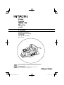 1
1
-
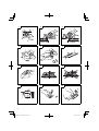 2
2
-
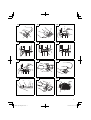 3
3
-
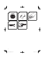 4
4
-
 5
5
-
 6
6
-
 7
7
-
 8
8
-
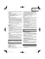 9
9
-
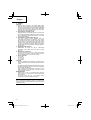 10
10
-
 11
11
-
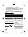 12
12
-
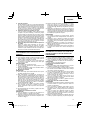 13
13
-
 14
14
-
 15
15
-
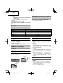 16
16
-
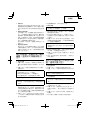 17
17
-
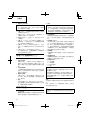 18
18
-
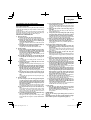 19
19
-
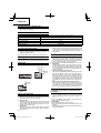 20
20
-
 21
21
-
 22
22
-
 23
23
-
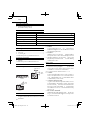 24
24
-
 25
25
-
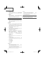 26
26
-
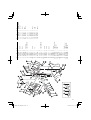 27
27
-
 28
28


Hitachi P 20SB Handling Instructions Manual
- Categoría
- Herramientas eléctricas
- Tipo
- Handling Instructions Manual
En otros idiomas
- English: Hitachi P 20SB
Documentos relacionados
-
Hitachi P 20SB Handling Instructions Manual
-
-
-
Hikoki P 20DA El manual del propietario
-
Hikoki P14DSL Manual de usuario
-
-
Hitachi P20ST Instruction Manual And Safety Instructions
-
Hitachi Koki F-30A Manual de usuario
-
Hitachi CC 14SF Handling Instructions Manual