Hobart HL600, HL662, HL800, HL1400 Legacy+ Mixers Manual de usuario
- Categoría
- Mezcladores
- Tipo
- Manual de usuario

701 S. RIDGE AVENUE
TROY, OHIO 45374-0001
937 332-3000
www.hobartcorp.com
INSTRUCTIONS
MANUAL
MODELS
HL600
HL600C
HL662
HL800
HL800C
HL1400
HL1400C
Page 1 - English
Page 25 - Spanish
Page 49 - French F48154 (May 2021)

– 2 –
ITW Food Equipment Group © HOBART 2021
TABLE OF CONTENTS
GENERAL .................................................................................................................................................................3
Safety Guidelines ................................................................................................................................................4
Operation Guidelines ..........................................................................................................................................4
Dust Hazard ........................................................................................................................................................5
Warning Symbol ..................................................................................................................................................5
Warranty Disclaimer ............................................................................................................................................5
General Information ............................................................................................................................................5
INSTALLATION ........................................................................................................................................................6
Unpacking ...........................................................................................................................................................6
Location ..............................................................................................................................................................6
Electrical Connections ........................................................................................................................................7
OPERATION ............................................................................................................................................................8
Initial Checks .......................................................................................................................................................8
Mixer Components ..............................................................................................................................................9
Controls .............................................................................................................................................................12
Bowl Placement ................................................................................................................................................13
Agitator ..............................................................................................................................................................14
Power Bowl Lift .................................................................................................................................................14
Prepare For Mixing ...........................................................................................................................................15
Timer Operation (SmartTimer™).......................................................................................................................15
Operating Notes ................................................................................................................................................16
Unloading ..........................................................................................................................................................17
Wire Cage (Fig. 13) ...........................................................................................................................................17
CLEANING .............................................................................................................................................................19
MAINTENANCE .....................................................................................................................................................20
Interlock Safety System ...................................................................................................................................20
Lubrication ........................................................................................................................................................20
Transmission Belt ..............................................................................................................................................21
Adjustments ......................................................................................................................................................21
TROUBLESHOOTING ..........................................................................................................................................23
Troubleshooting Guide ......................................................................................................................................23
Service ..............................................................................................................................................................23
AGITATORS AND ATTACHMENTS ......................................................................................................................24
Available Agitators and Attachments .................................................................................................................24

– 3 –
INSTALLATION, OPERATION AND CARE OF
LEGACY+® MIXERS
60-QUART through 140-QUART
SAVE THESE INSTRUCTIONS
GENERAL
This Operation Manual is for the Hobart Legacy+® 60-Qt through 140-Qt Floor Mixers which are available
LQWKUHHGLႇHUHQWERZOVL]HV9LVLWWKHZHEVLWHZZZKREDUWFRUSFRPWRVHHDGGLWLRQDOPL[HUVL]HVDYDLODEOH
from Hobart.
Device Bowl Size (Qt) Motor Horsepower Hub Mixing Speeds
HL600 60-Qt 2.7 HP Motor #12 STIR, plus four mixing speeds
HL600C 60-Qt 2.7 HP Motor #12 Correctional Mixer, STIR, plus
four mixing speeds
HL662 60-Qt 2.7 HP Motor #12 Pizza Mixer, two mixing
speeds
HL800 80-Qt 3.0 HP Motor N/A STIR, plus four mixing speeds
HL800C 80-Qt 3.0 HP Motor N/A Correctional Mixer, STIR, plus
four mixing speeds
HL1400 140-Qt 5.0 HP Motor N/A STIR, plus four mixing speeds
HL1400C 140-Qt 5.0 HP Motor N/A Correctional Mixer, STIR, plus
four mixing speeds
All sizes of Hobart Maximum Heavy Duty Floor Mixers feature a digital SmartTimer™ with Shift-on-the-Fly™
Controls and a power bowl lift as standard equipment.
A variety of agitators and accessories are available. These are described in a separate Use and Applications
Handbook available on our website at www.hobartcorp.com.
Step down bowl sizes and agitators are available for the 60-Qt through 140-Qt mixers (e.g. 40-Qt bowl for
60-Qt mixer). Please see the website or contact you authorized Hobart Distributor for more information.

– 4 –
SAFETY GUIDELINES
• All operators must be properly trained in the safe operation of the mixer and attachments.
• To avoid risk of serious injury follow all precautions and instructions in this manual when installing,
operating, and servicing the mixer.
• To avoid risk of serious injury, keep hands, feet, clothing, and utensils away from the bowl, bowl
support, slideways, and agitator when the mixer is in operation or any of the components are
moving.
• Do not operate the mixer if it is not in proper operating condition.
• Disconnect power to the mixer and follow lockout-tagout procedures before moving or servicing
the mixer.
• Do not operate the mixer if parts are disassembled.
• Do not override safety switches on the mixer.
• When moving the mixer make sure it is stable to avoid tipping and keep hands and feet clear of
the bottom of the mixer to avoid pinching.
• Use the STOP button to stop the mixer. Never open the wire cage or use the power bowl lift to
stop the mixer.
• Do not wear loose clothing around the mixer.
'RQRWLQKDOHGXVWSDUWLFOHVIURPPL[LQJLQJUHGLHQWV([SRVXUHWRGXVWLQFOXGLQJÀRXUPD\EH
harmful to health. When mixing ingredients that develop dust use the STIR speed until the dust is
eliminated and follow the instructions in the DUST HAZARD section below.
• Do not install or leave an agitator on the mixer without a bowl in place.
'RQRWXVHH[FHVVLYHIRUFHZKHQRSHUDWLQJZKLFKFRXOGDႇHFWWKHVWDELOLW\RIWKHPL[HU
OPERATION GUIDELINES
• Use the correct sized bowl only with agitators for that sized bowl. Double check the sizes
when using a reduced sized bowl, by consulting the mixer accessories chart available
at www.hobartcorp.com.
(QVXUHWKHERZODJLWDWRUDQGZLUHFDJHDUHFRUUHFWO\¿WWHGWRWKHPL[HU
• Stop the mixer before adding more ingredients unless using a food chute.
• Have your mixer regularly serviced; at least twice a year for typical usage. Mixers may require
more or less service depending on frequency of use.
• Use the mixer in a well-lit area.
• Ensure this manual is kept in an easily accessible place near the mixer for future reference.
• Do not clean the mixer with scouring powder or a scouring pad.
• Do not clean aluminum agitators in dishwashers.
• Do not hose or pressure clean the mixer. It is important to adhere to the cleaning instructions
detailed in the CLEANING section of the manual.

– 5 –
DUST HAZARD
In order to minimize any dust hazard, follow the instructions detailed below.
:KHQPL[LQJLQJUHGLHQWVFDUHPXVWEHWDNHQWRDYRLGWKHLQKDODWLRQRIGXVWSDUWLFOHVHJÀRXU5HIHUHQFH
should be made to the product supplier’s data sheets to ensure adequate precautions and protections
are taken.
,QJUHGLHQWVVXFKDVÀRXUPXVWEHDGGHGFDUHIXOO\WRPLQLPL]HDLUERUQHGXVWSDUWLFOHV
Carefully slit the bag while holding it in the lower part of the bowl. When mixing dry ingredients use the
lowest speed and a splash cover to minimize dust emission. Mix the ingredients in the bowl using the
lowest speed until the risk of producing any dust is eliminated. Fit suitable dust extraction equipment.
WARNING SYMBOL
To identify the safety messages in this manual, the following symbol has been used.
The WARNING symbol is located in the manual before information corresponding
to the safe use of the mixer.
WARRANTY DISCLAIMER
,QVWDOODWLRQVDQGUHSDLUVFDUULHGRXWE\QRQDXWKRUL]HGVHUYLFHWHFKQLFLDQVPD\DႇHFWWKHPL[HUZDUUDQW\
8VLQJRWKHUWKDQRULJLQDOUHSODFHPHQWSDUWVPD\DႇHFWWKHPL[HUZDUUDQW\7HFKQLFDODOWHUDWLRQVWRWKH
PL[HUPD\DႇHFWWKHPL[HUZDUUDQW\
For warranty information, please contact Hobart Customer Care.
GENERAL INFORMATION
Hobart reserves the right to alter the design of its products without prior notice. If you have questions
UHJDUGLQJPL[HUGHWDLOVQRWLQFOXGHGLQWKLVPDQXDOFRQWDFW\RXUORFDO+REDUW6HUYLFH2ႈFH

– 6 –
INSTALLATION
UNPACKING
The mixer was inspected before leaving the factory. The carrier assumes full responsibility for the safe
delivery of the mixer upon acceptance of the mixer for shipping. The customer must check for possible
shipping damage immediately upon receipt before moving, installing, or modifying the mixer.
If damage is found, keep all original packaging materials for inspection purposes. The customer must
complete the following steps to report the damage.
&DUULHU¶VORFDOWHUPLQDOPXVWEHQRWL¿HGZLWKLQEXVLQHVVGD\VRIVKLSPHQWUHFHLSWQRWHWLPH
GDWHDQGZKRZDVVSRNHQWRDQGIROORZXSDQGFRQ¿UPZLWKZULWWHQRUHOHFWURQLFFRPPXQLFD-
tion.
2. Notify Hobart customer care at (800) 333-7447 within 5 business days of shipment receipt.
LOCATION
3ULRUWRLQVWDOODWLRQWHVWWKHHOHFWULFDOVHUYLFHWRHQVXUHWKDWLWPDWFKHVWKHVSHFL¿FDWLRQVRQWKHPL[HU
data plate.
Place the mixer in its operating location. There should be adequate space around the mixer for the user
to operate the controls and to install and remove bowls. The area above and to the right side of the mixer
should allow the top and side covers to be removed for routine maintenance and servicing.
6HOHFWDVXLWDEOHÀDWDQGOHYHOVXUIDFHWKDWFDQVXSSRUWWKHZHLJKWRIWKHPL[HUDQGFRQWHQWVRIDIXOOERZO
Once in position, the mixer must be leveled:
• Remove the two top cover screws and the top
cover.
• Place a level on the top rim of the large pulley
(Fig. 1). Slide shims under the base contact
surface of the mixer as required to level it front-
to-back and side-to-side.
• Do not replace the top cover until installation is
completed.
4WDQG4WPL[HUVPD\EHEROWHGWRWKHÀRRUXVLQJVWXGV)ORRUDQFKRULQJKDUGZDUHLVLQFOXGHG
with some models.
1. Place the mixer in its operating location.
0DUNWKHÀRRUXVLQJWKHIRXUKROHVLQWKHEDVHDVDWHPSODWH
0RYHWKHPL[HUIRUDFFHVVWRWKHÀRRU
8VLQJDGLDPHWHUELWGULOOIRXUKROHVLQÀRRUWRDGHSWKRI
'ULYHÀRRUDQFKRUVÀXVKZLWKWKHVXUIDFHRIWKHFRQFUHWH
6. Expand the anchor with the setting tool provided. Anchor is properly expanded when shoulder of
VHWWLQJWRROLVÀXVKZLWKWKHWRSRIWKHDQFKRU
7. Place the mixer in its operating location over the drilled holes.
,QVWDOOVWXGVWKURXJKWKHEDVHDQGLQWRWKHÀRRUDQFKRUV
,QVWDOOÀDWZDVKHUVORFNZDVKHUVDQGQXWVRQWRWKHVWXGVDQGWLJKWHQ
6DZRႇDOOWKUHDGVÀXVKZLWKWKHWRSRIWKHQXWDQGUHPRYHDQ\VKDUSHGJHV
Fig. 1

– 7 –
ELECTRICAL CONNECTIONS
Electrical and grounding connections must comply with the applicable portion
of the National Electrical Code and/or other local electrical codes.
Disconnect the electrical power to the mixer and follow lockout / tagout
procedures.
A hole for 3/4"-trade-size conduit is located at the top of the pedestal. Make electrical connections per the
wiring diagram located on the inside of the top cover.
Single-Phase Mixer:
&RQQHFW¿HOGVXSSO\OHDGZLUHVWR/DQG/
• Connect ground wire to ground lug on the mixer.
&XWRႇVWULSSHGSRUWLRQRI/RQ/HJDF\® Mixer and wrap securely with electrical tape to insulate
the exposed conductor.
Three-Phase Mixer:
&RQQHFW¿HOGVXSSO\OHDGZLUHVWR//DQG/
• Connect ground wire to ground lug on the mixer.

– 8 –
OPERATION
INITIAL CHECKS
To avoid risk of serious injury, keep hands, feet, clothing, and utensils away from
the bowl, bowl support, slideways, and agitator when the mixer is in operation or when any of
the components are moving.
This food mixer is only for professional use by properly trained persons.
Ensure operators have read and understood this manual and have received
proper training.
Do not use the mixer without the interlocked wire cage in place.
The Legacy+® mixer is equipped with SmartTimer™ controls and a power bowl lift. Other operating parts
(Fig. 3, Fig. 4, and Fig. 5) and their functions are described throughout the Operation section.
The wire cage must be in position or the mixer will not operate.
The bowl must stay in the locked position on the bowl support or the mixer will not operate.
If the bowl support is not all the way up (mix position), the mixer will not operate unless the START button
is pressed and held.
If the bowl support is not in the mix position and the START button is pressed and held, the mixer will
operate only in STIR speed.
Check Lubrication Before Use
This mixer is shipped with oil in the transmission.
Check oil level before starting mixer (Fig. 2). Refer
to the Lubrication section for applicable lubrication
procedures.
Wiring Check
1. Turn the SPEED dial pointer to STIR.
2. Apply power to the mixer. With the bowl
locked into place, the bowl support all the
way up and wire cage closed, momentarily
run the machine by pushing the START and
then STOP buttons.
9HULI\WKDWWKHERZOOLIWUDLVHVDQGORZHUVSHUWKHVZLWFKGLUHFWLRQDUURZV,IQRWSURFHHGWRVWHS
3a below.
a. Refer to the Electrical Connections section and follow all warnings and instructions to correct
the lead wires.
Fig. 2
Transmission Fill Plug / Oil Dipstick

– 9 –
MIXER COMPONENTS
60-Quart Mixer
Fig. 3
Controls
Apron
Bowl Support
Bowl Lock Lever
Attachment Hub
Wire Cage
Agitator
Drip Cup-
Splash Guard
Assembly

– 10 –
80-Quart Mixer
Fig. 4
Controls
Wire Cage
Agitator
Drip Cup-
Splash Guard
Assembly
Apron
Bowl Support
Bowl Lock Lever

– 11 –
140-Quart Mixer
Fig. 5
Controls
Wire Cage
Agitator
Drip Cup-
Splash Guard
Assembly
Apron
Bowl Support
Bowl Lock Lever

– 12 –
CONTROLS
Models HL600 and HL600C
HL600 and HL600C Mixer Speeds
STIR (Slow) For incorporating ingredients
SPEED 1 (Low) For heavy mixtures such as pizza dough, heavy batters, and potatoes
SPEED 2 (Medium-Low) For mixing cake batters, mashing potatoes, and developing bread dough
SPEED 3 (Medium-High) )RULQFRUSRUDWLQJDLULQWREDWFKHVDVZHOODV¿QLVKLQJZKLSSHGLWHPV
SPEED 4 (High) For maximum, accelerated air incorporation into light batches
Model HL662
HL662 Mixer Speeds
SPEED 1 (Slow) For heavy mixtures such as pizza dough, heavy batters, and potatoes
SPEED 2 (Low) For developing pizza dough
MEAT GRIND For grinding meat
CHEESE SHRED For shredding cheese
9(*(7$%/(6/,&( For slicing vegetables
Time Selector
Starts
Mixer
Stops
Mixer
Raises
and Lowers
Mixing Bowl
Speed Selector
Displays Selected Mix Speed Displays Mixing Time
Fig. 6
Time Selector
Starts
Mixer
Stops
Mixer
Raises
and Lowers
Mixing Bowl
Speed Selector
Displays Selected Mix Speed Displays Mixing Time
Fig. 7

– 13 –
Models HL800, HL800C, HL1400, and HL1400C
HL800, HL800C, HL1400, and HL1400C Mixer Speeds
STIR (Slow) For incorporating ingredients
SPEED 1 (Low) For heavy mixtures such as pizza dough, heavy batters, and potatoes
SPEED 2 (Medium-Low) For mixing cake batters, mashing potatoes, and developing bread dough
SPEED 3 (Medium-High) )RULQFRUSRUDWLQJDLULQWREDWFKHVDVZHOODV¿QLVKLQJZKLSSHGLWHPV
SPEED 4 (High) For maximum, accelerated air incorporation into light batches
BOWL PLACEMENT
The bowl must be installed onto the bowl support before the agitator is installed. The bowl is
heavy and must be correctly handled and lifted to avoid personal injury.
To Install
1. Fully lower the bowl support by pressing
and holding the down arrow on the bowl
switch (Fig. 6, Fig. 7, and Fig. 8).
2. Position the bowl so the alignment pins
on the left side of the bowl support
)LJ¿WLQWKHKROHVLQWKHERZO
3. Swing the bowl into the locked position on
bowl support (Fig. 9).
To Remove
Before lowering the bowl onto a bowl
truck, always unlock the bowl and swing the bowl
out slightly.
1. Lower the bowl by pressing and holding the down arrow on the bowl switch (Fig. 6, Fig. 7, and
Fig. 8).
2. Unlock bowl and swing out slightly from the locked position.
3. Open the wire cage and remove the agitator.
Time Selector
Starts
Mixer
Stops
Mixer
Raises
and Lowers
Mixing Bowl
Speed Selector
Displays Selected Mix Speed Displays Mixing Time
Fig. 8
Fig. 9

– 14 –
AGITATOR
To install an agitator, the bowl must be on the bowl support and fully lowered.
To Install
1. Open the wire cage. Refer to the Wire Cage sec-
tion as needed.
2. Place the agitator inside the bowl and align the
horizontal slot on the agitator with the agitator
shaft pins.
3. Hold the agitator and pull the plunger pin of the
agitator out (Fig. 10).
4. Slide the agitator up the agitator shaft until it
stops and latches.
To Remove
1. Open the wire cage. Refer to the Wire Cage sec-
tion as needed.
2. Lower the bowl by pressing and holding the down
arrow on the bowl switch (Fig. 6, Fig. 7, and Fig. 8)
+ROGWKHDJLWDWRUDQGSXOOWKHSOXQJHURIWKHDJLWDWRURXW)LJ6OLGHWKHDJLWDWRUGRZQRႇWKH
agitator shaft.
POWER BOWL LIFT
Before lowering the bowl onto a bowl truck,
always unlock bowl and swing bowl out slightly (Fig. 11).
To raise the bowl, the bowl must be in the locked position.
Push and hold the up arrow on the bowl switch.
To lower the bowl, push and hold the down arrow on the
bowl switch.
To Raise the Bowl While Mixing
To raise the bowl while the agitator is mixing the product
(when required by recipe or when using the bowl scraper
attachment):
1. Close the wire cage, then select a mixing speed
on the SPEED dial.
2. Select a count-down time or HOLD for continu-
ous count-up mixing. Refer to the Timer Operation
section as needed.
3. While pressing and holding the up arrow on the bowl switch, press and hold the START button.
The mixer runs only in stir speed while the bowl is rising.
4. When the bowl reaches the mix position, release the START button. The mixer automatically
changes to the selected mixing speed.
Mixing speed and time can be adjusted any time during the mixing operation without
stopping the mixer.
Fig. 10
Fig. 11

– 15 –
PREPARE FOR MIXING
1. Open the wire cage. Refer to the Wire Cage section as
needed.
2. Place the mixing bowl on the bowl support.
3. Pour ingredients into the bowl.
4. Swing the bowl to the locked position.
5. Place the agitator inside the bowl, then attach it to the
agitator shaft (Fig. 12).
6. Return the wire cage to the front-center position
(Fig. 13).
7. Push and hold the up arrow on the bowl switch until the
bowl reaches the mix position and stops.
8. The mixer is now ready for mixing. Refer to the Timer
Operation section.
TIMER OPERATION (SmartTimer™)
Using the Count-Up Mode (Continuous Mixing)
1. Turn the SPEED dial to select a mix speed (the SPEED setting can be changed at any time dur-
ing mixing).
Only use STIR for incorporating ingredients. Do not use to develop dough products.
2. Set the timer on hold by turning the TIME selector counterclockwise until "Hold" appears in the
TIME window.
3. Press the START button to begin mixing. The timer starts to count up from 00:00.
If the wire cage is opened at any time, mixing stops. To resume mixing, close the wire cage
and press the START button.
4. Press the STOP button to stop the mixer; the mixing time is displayed in the TIME window.
5. Press the START button to resume mixing if needed.
When the timer reaches 20:00 minutes, it rolls over to 00:01 and continues counting until the
STOP button is pressed.
Fig. 12

– 16 –
Using the Count-Down Mode (Timed Mixing)
1. Turn the SPEED dial to select a mix speed.
a. If the count-up mode was used for the previous batch, the desired time needs to be entered.
b. If the count-down mode was used for the previous batch, the previous time is displayed. If a
GLႇHUHQWWLPHLVQHHGHGWXUQWKH7,0(VHOHFWRUWRWKHGHVLUHGWLPH
2. Press the START button to begin mixing; the timer starts counting down from the set time.
a. To stop the mixer at any time, press the STOP button. To resume mixing, press the START
button. For example: The mixer is started at SPEED 1 for 30 seconds and is stopped after
10 seconds. Pressing the START button will resume mixing.
b. If the mixer is stopped and a new time setting is entered, pressing the START button saves
the new time setting on the current speed selection. For example: The mixer is started at
SPEED 1 for 30 seconds and is stopped after 10 seconds. A new time is entered by turn-
ing the TIME selector. The new time replaces the initial 30 seconds for SPEED 1 after the
START button is pressed.
c. If the time is changed while mixing, the mixer operates until the new time expires. The ad-
justment to the time is not stored.
d. If the speed is changed while mixing, the time reverts to the previously set time for the se-
lected speed and counts down.
The agitator does not stop immediately. To avoid risk of serious injury, keep
hands, clothing, and utensils out of the mixing bowl and away from the agitator as the agitator
winds down.
If the wire cage is opened at any time, the mixing stops. To resume the mixing, close the wire
cage and press the START button.
3. When the timer reaches 00:00, the mixer stops; a beeper sounds for 3 seconds. The count-down
timer displays the last-entered time.
OPERATING NOTES
• Only use STIR for incorporating ingredients. Do not use it to develop dough products.
• If the mixer is stopped during mixing, the timer also stops. The timer starts again (with the time
remaining) when the START button is pressed.
• The SPEED window displays the current SPEED selection.
• Turn the TIME selector clockwise to take the mixer out of the hold mode.

– 17 –
UNLOADING
1. After the mixer has stopped, and the agitator comes to rest, unlock the bowl and swing-out
slightly. Press and hold the down arrow on the bowl switch to lower the bowl.
2. Open the wire cage assembly.
3. Remove the agitator from the agitator shaft.
4. Remove the bowl from the bowl support.
WIRE CAGE (Fig. 13)
The wire cage can be rotated out of the way to add ingredients or to access the bowl and agitator.
Note how the grooves on the retainer shoes allow the wire cage to ride around the circular ridge of the
planetary drip cup.
• To open the wire cage: rotate it to your left.
• To close the wire cage: rotate it to your right until it stops in the front-center, closed position.
The wire cage must be returned to the closed position for the mixer to operate.
Fig. 13

– 18 –
Remove and Clean Wire Cage (Fig. 14)
1. Lower the bowl. Remove the agitator and bowl.
2. While holding the wire cage securely with both hands, rotate it to your left until the front-center
retainer shoe reaches the gap in the circular ridge of the planetary drip cup.
3. Lower the front of the wire cage and move the wire cage slightly to the rear so the rear retainer
shoes clear the ridge of the drip cup. The wire cage can now be removed.
Fig. 14
4. Wash the wire cage in a sink, rinse with clear water, and dry with a clean cloth.
7KHVWDLQOHVVVWHHOVSODVKJXDUGFDQEHZLSHGRႇDQGRUZDVKHGZLWKDFORWKRUVSRQJHXVLQJ
warm, soapy water. Rinse with clear water and dry with a clean cloth.
Reinstall Wire Cage
1. Position the ring of the wire cage so the front-center retainer shoe is positioned below the gap in
the circular ridge of the planetary drip cup.
2. Position the grooves so the rear retainer shoes straddle the circular ridge on the planetary drip
cup.
3. Lift the front of the wire cage so the front-center retainer shoe passes up through the gap in the
circular ridge on the planetary drip cup.
4. Rotate the wire cage to your right until all three retainer shoes straddle the ridge on the drip cup.

– 19 –
CLEANING
Disconnect the electrical power to the mixer and follow lockout / tagout
procedures.
New mixer bowls and accessories (beaters, whips, and dough arms) should be thoroughly washed with
hot water and a mild soap solution, rinsed with either a mild soda or vinegar solution and thoroughly
rinsed with clear water before being used. This cleaning procedure should also be followed for bowls and
agitators before whipping egg whites or whole eggs.
The mixer should be thoroughly cleaned daily. DO NOT use a hose to clean the mixer; it should be washed
with a clean, damp cloth. The base allows ample room for cleaning under the mixer. The apron (Fig. 3,
Fig. 4, and Fig. 5) may be removed for cleaning by loosening the thumb screws. DO NOT wipe down
slideways (Fig. 15) when cleaning.
The drip cup-splash guard assembly (Fig. 3, Fig. 4, and Fig. 5) should be removed periodically and wiped
clean.
For cleaning the wire cage refer to the Wire Cage section.

– 20 –
MAINTENANCE
Disconnect the electrical power to the mixer and follow lockout / tagout
procedures.
'RQRWUHPRYHDQ\FRYHUVRUORRVHQDQ\¿WWLQJVZKLOHWKHPL[HULVRSHUDWLQJ
Ensure the electrical supply has been isolated before attempting to service or move the mixer.
7KHHOHFWURQLFGULYHFRQWUROLV¿WWHGZLWKKLJKYROWDJHFDSDFLWRUV,VRODWHWKH
mixer from the mains and allow the capacitors to discharge for 5 minutes before removing any
covers.
2QO\+REDUWWUDLQHGVHUYLFHSHUVRQQHORURWKHUSURSHUO\WUDLQHGDQGTXDOL¿HG
personnel should carry out service.
INTERLOCK SAFETY SYSTEM
Regular inspection of the mixer's safety system is necessary to check the operation of the wire cage and
bowl support interlock switches. Inspections must be performed no less than once a year.
A spare parts manual is available from Hobart Resource Center. For continued safe and reliable operation
of this mixer, it is recommended that servicing is only carried out by Hobart trained service personnel.
LUBRICATION
Fig. 15
Slideways
The slideways (Fig. 15) should be lubricated approximately twice a year. To reach these areas, fully lower
the bowl support and remove the apron (Fig. 3, Fig. 4, and Fig. 5), which is secured by thumb screws.
Wipe a thin coat of Lubriplate 630AA on the bowl pad area of the bowl supports and on each slideway.
Install the apron.
Planetary Seal
Occasionally, the planetary seal (Fig. 15) may become dry and begin to squeak. To correct this, work a
little lubrication (mineral oil) under the lip of the seal.
Agitator Shaft
The agitator shaft (Fig. 15) should be lubricated twice a year with a thin coat of mineral oil.
AGITATOR
SHAFT

– 21 –
Transmission
To check the oil level, remove the top cover, which is secured by two screws. Remove the Transmission
Fill Plug (Fig. 16) and check the oil level. If the oil level is below the line on the oil dipstick, add a small
DPRXQW RI WKH UHFRPPHQGHG WUDQVPLVVLRQ RLO XQWLO LW UHWXUQV WR WKH SURSHU OHYHO 'R QRW RYHU¿OO WKH
WUDQVPLVVLRQ DV OHDNDJH PD\ UHVXOW &RQWDFW \RXU ORFDO +REDUW 6HUYLFH 2ႈFH IRU WKH UHFRPPHQGHG
transmission oil.
Fig. 16
TRANSMISSION BELT
The transmission belt should be inspected yearly for wear and replace by a Hobart Service Technician if
worn.
ADJUSTMENTS
Agitator Clearance
The agitator clearance should be checked periodically. The agitator must not touch the bowl, and the
maximum clearance between the bottom of the bowl and an agitator is:
Agitator Models Max Clearance
B Flat Beater HL600, HL600C, HL800, HL800C, HL1400, HL1400C 1/8" (3 mm)
ED Dough Arm HL600, HL600C, HL800, HL800C 5/16" (8 mm)
HL1400, HL1400C 11/16" (17 mm)
Install a bowl and agitator (e.g., beater). If the bowl and beater come into contact before the bowl support
reaches its stop, adjust the stop screw. Refer to the Adjust the Bowl/Agitator Clearance section.

– 22 –
Measure Clearance
3RXUHQRXJKÀRXULQWKHERZOWRFRYHUWKHERWWRPRIWKHERZOZKHUHWKHEHDWHUWUDYHOV:LWKWKHERZOIXOO\
UDLVHGEHDWHUVKRXOGQRWWRXFKWKHERWWRPRIWKHERZOEULHÀ\UXQWKHPL[HUDWWKHORZHVWVSHHG
7XUQRႇWKHPL[HUGLVFRQQHFWWKHHOHFWULFDOSRZHUVXSSO\DQGPHDVXUHWKHGHSWKRIÀRXUZKHUHWKHEHDWHU
has traced a path. This measurement should be taken at several points around the bowl to assure accuracy.
Adjust the Bowl/Agitator Clearance
• Remove the apron (Fig. 3, Fig. 4, and Fig. 5)
(which is secured by thumbscrews).
• Adjust the stop screw on the left side (80-Qt
and 140-Qt) and the right side (60-Qt).
- Loosen the bottom locking nut, (Fig. 17)
and turn the stop screw counterclock-
wise to increase the clearance or clock-
wise to decrease the clearance.
- Tighten the locking nut while holding the
stop screw.
• After the adjustments are made, replace the
apron and secure it with the thumbscrews.
• Reconnect the electrical power supply.
• Carefully operate the bowl lift several times to
check the adjustment.
Bowl Lock Lever (Fig. 18)
• Occasionally debris may collect and cause
the lever to move slowly.
3RXUYHU\ZDUPZDWHUDURXQGORFNSLQWRÀXVK
out food particles that may have collected
WKHUH7KHZDWHUVKRXOGÀRZWKURXJKDURXQG
the pin. Be sure to have a cloth or dish under
to bowl support to catch the water and food
particles.
• Lubricate the pin with a thin coat of Lubriplate
630AA.
STOP SCREW AND
STOP NUT Fig. 17
Fig. 18
BOWL
LOCK
LEVER

– 23 –
TROUBLESHOOTING
TROUBLESHOOTING GUIDE
Symptoms Possible Causes
Mixer will not start. • Circuit protector is in open position - check fuse or disconnect
switch.
• Mixer is overloaded.
• Wire cage is not in the closed, front-center position.
• Bowl is not in closed (locked) position.
Agitator touches bowl. • Bowl is not in closed (locked) position.
• Improper agitator clearance - refer to the Maintenance section for
adjustment procedure.
• Agitator is not installed properly.
Planetary seal squeaks. • Seal requires occasional lubrication - refer to the Maintenance
section.
Timer displays error code
(ErXX).
,IWKHHUURUFRGHLVÀDVKLQJGLVFRQQHFWHOHFWULFDOSRZHUIURP
mixer for 1 minute, then reconnect. If symptoms still exist, contact
\RXUORFDO+REDUW6HUYLFHRႈFH
SERVICE
,IVHUYLFHLVQHHGHGRQWKLVHTXLSPHQWFRQWDFW\RXUORFDO+REDUW6HUYLFHRႈFH#+2%$57

– 24 –
F48154 (May 2021) PRINTED IN U.S.A.
AGITATORS AND ATTACHMENTS
Attachments for attachment hub and agitators are covered in a separate Use and Application Handbook
available on our website at www.hobartcorp.com Follow the instructions accordingly.
AVAILABLE AGITATORS AND ATTACHMENTS
“B” Flat Beater
Multi-purpose agitator
typically used for mashed
SRWDWRHVFDNHVZDႉHV
sugar cookies, pies,
shortening, icings, and more.
“C” Wing Whip
Heavy whipping such
as potatoes, butter,
mayonnaise, and light icing.
“D” Wire Whip
Maximum blending of air
into light products such
as egg whites, meringue,
whipped cream, and more.
“ED” Dough Arm
Mixing, folding and
stretching dough such as
bread, pasta, pizza, donut,
and more.
“I” Wire Whip
Heavy whipping such as
sponge cages, and light
marshmallow.
“P” Pastry Knife
Cutting action for combining
ingredients such as pastry
and pie dough.
Ingredient Chute
Add ingredients to mixing
bowls during operation
without interruption.
Splash Cover
Controls the splash of light
ingredients during mixing.
Bowl Truck
Minimize strain from moving
large, heavy mixing bowls.
Stainless Bowl
Reliably holds ingredients. Available in stepdown sizes
e.g. 40-Qt bowl on 140-Qt mixer.
Bowl Scraper
Continuously scrapes the
sides of the bowl.

701 S. RIDGE AVENUE
TROY, OHIO 45374-0001
937 332-3000
www.hobartcorp.com
MANUAL DE
INSTRUCCIONES
MODELOS
HL600
HL600C
HL662
HL800
HL800C
HL1400
HL1400C
Page 1 - Inglés
Page 25 - Español
Page 49 - Francés F48154 (Mayo de 2021)

– 26 –
ITW Food Equipment Group © HOBART 2021
TABLA DE CONTENIDO
GENERAL ...............................................................................................................................................................26
Pautas de seguridad .........................................................................................................................................27
Pautas de operación .........................................................................................................................................27
Peligro por polvo ...............................................................................................................................................28
Símbolo de advertencia ....................................................................................................................................28
Descargo de responsabilidad ...........................................................................................................................28
Información general ..........................................................................................................................................28
INSTALACIÓN .......................................................................................................................................................29
Desembalaje .....................................................................................................................................................29
Ubicación ..........................................................................................................................................................29
Conexiones eléctricas .......................................................................................................................................30
FUNCIONAMIENTO ..............................................................................................................................................31
Comprobaciones iniciales .................................................................................................................................31
Componentes de la batidora .............................................................................................................................32
Controles ...........................................................................................................................................................35
Colocación del tazón .........................................................................................................................................36
Agitador .............................................................................................................................................................37
Levantamiento eléctrico del tazón ....................................................................................................................37
Preparación para mezclar .................................................................................................................................38
Funcionamiento del temporizador (SmartTimer™) ...........................................................................................38
Notas de funcionamiento ..................................................................................................................................39
Descarga ...........................................................................................................................................................40
Rejilla del tazón (Fig. 13) ..................................................................................................................................40
LIMPIEZA ...............................................................................................................................................................42
MA NT EN IM IE NTO .................................................................................................................................................43
Sistema de seguridad de interbloqueo ............................................................................................................43
Lubricación ........................................................................................................................................................43
Correa de transmisión .......................................................................................................................................44
Ajustes ..............................................................................................................................................................44
RESOLUCIÓN DE PROBLEMAS .........................................................................................................................46
Guía de resolución de problemas .....................................................................................................................46
Servicio .............................................................................................................................................................46
AGITADORES Y ADITAMENTOS .........................................................................................................................47
Agitadores y aditamentos disponibles ..............................................................................................................47

– 27 –
INSTALACIÓN, FUNCIONAMIENTO Y CUIDADO DE
LAS BATIDORAS LEGACY+®
60 CUARTOS a 140 CUARTOS
CONSERVE ESTAS INSTRUCCIONES
GENERAL
Este manual de funcionamiento abarca las batidoras Legacy+® de 60 a 140 cuartos, que están disponibles con tres
tamaños de tazón distintos. Visite el sitio web www.hobartcorp.com para ver otros tamaños de batidoras disponibles
de Hobart.
Dispositivo Tamaño de tazón
(cuartos) Potencia del motor Núcleo Velocidades de mezcla
HL600 60 cuartos Motor 2,7 CV N.º 12 STIR (Batir), más cuatro
velocidades de mezcla
HL600C 60 cuartos Motor 2,7 CV N.º 12
Batidora correctiva, STIR (Batir),
más cuatro velocidades de
mezcla
HL662 60 cuartos Motor 2,7 CV N.º 12 Batidora para pizza, dos
velocidades de mezcla
HL800 80 cuartos Motor 3,0 CV N/D STIR (Batir), más cuatro
velocidades de mezcla
HL800C 80 cuartos Motor 3,0 CV N/D
Batidora correctiva, STIR (Batir),
más cuatro velocidades de
mezcla
HL1400 140 cuartos Motor 5,0 CV N/D STIR (Batir), más cuatro
velocidades de mezcla
HL1400C 140 cuartos Motor 5,0 CV N/D
Batidora correctiva, STIR (Batir),
más cuatro velocidades de
mezcla
Todos los tamaños de batidoras Heavy Duty tipo Piso de Hobart cuentan con un SmartTimer™ digital con mandos
Shift-on-the-Fly™ y un levantamiento eléctrico del tazón como equipo estándar.
Están disponibles una variedad de aditamentos y agitadores. Estos se describen en un Manual de uso y aplicaciones
que está disponible en nuestro sitio web en www.hobartcorp.com.
Hay disponibles agitadores y tazones de tamaño reducido para las batidoras de 60 a 140 cuartos (por ej., tazón
de 40 cuartos para una batidora de 60 cuartos). Consulte la página web o póngase en contacto con su distribuidor
autorizado de Hobart para obtener más información.

– 28 –
PAUTAS DE SEGURIDAD
• Todos los operadores deben estar capacitados adecuadamente en la operación segura de la batidora y los
accesorios.
• Para evitar riesgos de lesiones graves, siga todas las instrucciones y las precauciones en este manual al
instalar, operar o realizar tareas de servicio en la batidora.
• Para evitar riesgos de lesiones graves, mantenga alejados los utensilios, las prendas, las manos y los pies
del tazón, del soporte del tazón, de las guías y del agitador cuando la batidora está en funcionamiento o
cualquiera de sus componentes está en movimiento.
• No opere la batidora si su condición operativa no es adecuada.
• Desconecte la alimentación de la batidora y siga los procedimientos de bloqueo/etiquetado antes de mover
la batidora o realizar tareas de servicio en ella.
• No opere la batidora si hay piezas desmontadas.
• No anule los interruptores de seguridad en la batidora.
• Al mover la batidora, asegúrese de que esté estable para evitar vuelcos, y mantenga alejados las manos y
los pies de la parte inferior de la batidora para evitar atrapamientos.
• Use el botón STOP (Detener) para detener la batidora. Nunca abra la rejilla ni utilice el levantamiento eléc-
trico del tazón para detener la batidora.
• No utilice prendas sueltas cerca de la batidora.
• No inhale partículas de polvo de los ingredientes de la mezcla. La exposición a polvo (incluida la harina)
puede ser perjudicial para la salud. Al mezclar ingredientes que generan polvo, use la velocidad STIR
(Batir) hasta eliminar el polvo, y siga las instrucciones incluidas en la sección PELIGRO POR POLVO a
continuación.
• No instale ni deje un agitador en la batidora sin un tazón colocado.
• No aplique demasiada fuerza durante la operación, ya que esto podría afectar la estabilidad de la batidora.
PAUTAS DE OPERACIÓN
• Use el tazón de tamaño correcto únicamente con agitadores para ese tamaño de tazón. Si utiliza un reci-
piente de tamaño reducido, compruebe los tamaños consultando la tabla de aditamentos de la batidora,
disponible en www.hobartcorp.com.
• Asegúrese de que el tazón, el agitador y la rejilla estén colocados correctamente en la batidora.
• Detenga la batidora antes de agregar más ingredientes a menos que se utilice un conducto para alimentos.
• Realice tareas de servicio regulares en la batidora, al menos dos veces al año para un uso típico. Las bati-
doras requieren más o menos servicio según la frecuencia de uso.
• Use la batidora en zonas con buena iluminación.
• Asegúrese de que este manual se conserve en un lugar de fácil acceso y cercano a la batidora para refe-
rencia futura.
• No limpie la batidora con polvo limpiador o un estropajo.
• No limpie batidoras de aluminio en friegaplatos.
• No limpie la batidora con una manguera ni aplicando presión. Es importante respetar las instrucciones de
limpieza detalladas en la sección LIMPIEZA del manual.

– 29 –
PELIGRO POR POLVO
Para minimizar cualquier tipo de peligro por polvo, siga las instrucciones que se detallan a continuación.
Al mezclar ingredientes, se debe tener la precaución de evitar la inhalación de partículas de polvo (por ejemplo, de
harina). Deben consultarse las hojas de datos del proveedor del producto para asegurarse de tomar las medidas
y las precauciones adecuadas.
Los ingredientes como la harina deben agregarse con cuidado para minimizar las partículas de polvo suspendido.
Abra la bolsa con cuidado mientras la sostiene en la parte inferior del tazón. Al mezclar ingredientes secos, use la
velocidad más baja y una cubierta contra salpicaduras para minimizar la emisión de polvo. Mezcle los ingredientes
en el tazón con la velocidad más baja hasta eliminar el riesgo de producción de polvo. Use equipos de extracción
de polvo adecuados.
SÍMBOLO DE ADVERTENCIA
3DUDLGHQWL¿FDUORVPHQVDMHVGHDGYHUWHQFLDHQHVWHPDQXDOVHKDXWLOL]DGRHOVLJXLHQWHVtPEROR
ADVERTENCIA
El símbolo de ADVERTENCIA está ubicado en el manual antes de la información
correspondiente para garantizar un uso seguro de la batidora.
DESCARGO DE RESPONSABILIDAD
Las instalaciones y las reparaciones llevadas a cabo por técnicos de servicio no autorizados pueden afectar la garantía
de la batidora. El uso de piezas que no sean originales puede afectar la garantía de la batidora. Las alteraciones
técnicas a la batidora pueden afectar su garantía.
Para obtener información sobre la garantía, comuníquese con Atención al Cliente de Hobart.
INFORMACIÓN GENERAL
Hobart se reserva el derecho de alterar el diseño de sus productos sin previo aviso. Si tiene alguna pregunta sobre
GHWDOOHVGHODEDWLGRUDQRLQFOXLGRVHQHVWHPDQXDOFRPXQtTXHVHFRQVXR¿FLQDGHVHUYLFLRORFDOGH+REDUW

– 30 –
INSTALACIÓN
DESEMBALAJE
La batidora fue inspeccionada antes de salir de fábrica. El transportista asume toda la responsabilidad por la entrega
VHJXUDGHODEDWLGRUDOXHJRGHVXDFHSWDFLyQSDUDHQYtR(OFOLHQWHGHEHYHUL¿FDUSRVLEOHVGDxRVSURGXFLGRVGXUDQWH
HOHQYtRDOUHFLELUHOSURGXFWR\DQWHVGHPRYHULQVWDODURPRGL¿FDUODEDWLGRUD
6L VH GHWHFWDQ GDxRV GHEHQ FRQVHUYDUVH WRGRV ORV PDWHULDOHV GH HPEDODMH RULJLQDOHV D ¿QHV GH UHDOL]DU XQD
inspección. El cliente debe seguir estos pasos para informar los daños:
/DWHUPLQDOORFDOGHOWUDQVSRUWLVWDGHEHVHUQRWL¿FDGDHQORVGtDVODERUDEOHVSRVWHULRUHVDUHFLELUHO
HQYtRDQRWDUODIHFKDODKRUD\HOLQWHUORFXWRU\DGHPiVGHEHHIHFWXDUVHXQVHJXLPLHQWR\XQDFRQ¿U-
mación por un medio escrito o electrónico.
'HEHQRWL¿FDUVHDDWHQFLyQDOFOLHQWHGH+REDUWDOHQORVGtDVODERUDEOHVSRVWHULRUHVD
la recepción del envío.
UBICACIÓN
$QWHVGHODLQVWDODFLyQGHEHSUREDUVHHOVHUYLFLRHOpFWULFRSDUDYHUL¿FDUTXHFXPSODODVHVSHFL¿FDFLRQHVGHODSODFD
de datos del equipo.
Coloque la batidora en su ubicación de funcionamiento. Debe haber espacio adecuado alrededor de la batidora para
que el usuario opere los controles e instale y retire los tazones. Los espacios arriba y a la derecha de la batidora
deben permitir que se puedan quitar la cubierta superior y lateral para el servicio y mantenimiento de rutina.
6HOHFFLRQHXQDVXSHU¿FLHSODQD\QLYHODGDDGHFXDGDTXHSXHGDVRSRUWDUHOSHVRGHODEDWLGRUD\HOFRQWHQLGRGH
un tazón lleno.
Una vez en su posición, la batidora se debe nivelar:
• Quite los dos tornillos de la cubierta superior y la
cubierta.
• Coloque un nivel en el borde superior de la polea
grande (Fig. 1). Deslice las cuñas debajo de la su-
SHU¿FLHGHFRQWDFWRGHODEDVHGHODEDWLGRUDFRPR
se requiere para nivelarla de adelante hacia atrás y
de lado a lado.
• No vuelva a colocar la cubierta superior hasta que
se haya completado la instalación.
/DVEDWLGRUDVGH\FXDUWRVSXHGHQ¿MDUVHDOSLVRFRQSDVDGRUHV6HLQFOX\HQSLH]DVSDUDDQFODMHHQHOSLVR
con algunos modelos.
1. Coloque la batidora en su ubicación de funcionamiento.
0DUTXHHOSLVRXVDQGRORVFXDWURRUL¿FLRVHQODEDVHFRPRJXtD
3. Mueva la batidora para acceder al piso.
&RQXQDEURFDGHGHGLiPHWURSHUIRUHFXDWURRUL¿FLRVGHGHSURIXQGLGDGHQHOSLVR
5. Coloque los anclajes en el piso; deben quedar al ras respecto del concreto.
([SDQGDHODQFODMHFRQODKHUUDPLHQWDGH¿MDFLyQSURSRUFLRQDGD(ODQFODMHHVWiFRUUHFWDPHQWHH[SDQGL-
GRFXDQGRHOKRPEURGHODKHUUDPLHQWDGH¿MDFLyQHVWiDOUDVUHVSHFWRGHODSDUWHVXSHULRUGHODQFODMH
9XHOYDDFRORFDUODEDWLGRUDHQVXXELFDFLyQGHIXQFLRQDPLHQWRHQFLPDGHORVRUL¿FLRVSHUIRUDGRV
8. Instale los pasadores a través de la base y por los anclajes del piso.
9. Instale arandelas planas, arandelas de bloqueo y tuercas en los pasadores y, por último, apriete.
10. Serruche todas las roscas para que queden al ras respecto de la parte superior de la tuerca y elimine
WRGRVORVERUGHV¿ORVRV
BORDE
SUPERIOR
Fig. 1

– 31 –
CONEXIONES ELÉCTRICAS
ADVERTENCIA
Las conexiones eléctricas y a tierra deben cumplir con la parte aplicable del Código
Eléctrico Nacional o de otros códigos eléctricos locales.
ADVERTENCIA
Desconecte el suministro eléctrico que va hacia la batidora y siga los procedimientos de
bloqueo y etiquetado.
(ORUL¿FLRSDUDHOFRQGXFWRGHGHWDPDxRFRPHUFLDOVHHQFXHQWUDHQODSDUWHVXSHULRUGHOSHGHVWDO5HDOLFHODV
conexiones eléctricas según el diagrama de cableado que está ubicado en el interior de la cubierta superior.
Batidora monofásica:
• Conecte los cables conductores de suministro de campo a L1 y L2.
• Conecte el cable de conexión a tierra a la lengüeta de conexión a tierra de la batidora.
• Corte la parte pelada de L3 en la batidora Legacy+® y envuelva con cinta aislante para aislar el conductor
expuesto.
Batidora trifásica:
• Conecte los cables conductores de suministro de campo a L1, L2 y L3.
• Conecte el cable de conexión a tierra a la lengüeta de conexión a tierra de la batidora.

– 32 –
FUNCIONAMIENTO
COMPROBACIONES INICIALES
ADVERTENCIA
Para evitar riesgos de lesiones graves, mantenga alejados los utensilios, las prendas, las
manos y los pies del tazón, del soporte del tazón, de las guías y del agitador cuando la batidora está en
funcionamiento o cualquiera de sus componentes está en movimiento.
ADVERTENCIA
Esta batidora de alimentos está pensada solo para uso profesional a cargo de personas
con la capacitación adecuada.
ADVERTENCIA
Asegúrese de que los operadores hayan leído y comprendido este manual, y de que
hayan recibido la capacitación adecuada.
ADVERTENCIA
No use la batidora sin la rejilla del tazón interbloqueada en su lugar.
La batidora Legacy+® cuenta con mandos SmartTimer™ y levantamiento eléctrico del tazón. Otras piezas operativas
(Fig. 3, Fig. 4 y Fig. 5) y sus funciones se describen en la sección Funcionamiento.
La rejilla debe estar en su posición para que la batidora funcione.
El tazón debe permanecer en la posición de bloqueo sobre el soporte del tazón para que la batidora funcione.
Si el soporte del tazón no está completamente elevado (posición de mezclado), la batidora no funcionará a menos
que se mantenga presionado el botón START (Iniciar).
Si el soporte del tazón no está en la posición de mezclado y se mantiene presionado el botón START (Iniciar), la
batidora funcionará solo en la velocidad STIR (Batir).
Compruebe la lubricación antes del uso
Esta batidora se envía con aceite en la transmisión.
Compruebe el nivel de aceite antes de poner en marcha
la batidora (Fig. 2). Consulte la sección Lubricación para
conocer los procedimientos de lubricación aplicables.
Comprobación del cableado
1. Gire la perilla SPEED (Velocidad) a la posición
STIR (Batir).
2. Conecte la batidora a la energía eléctrica. Con
el tazón bloqueado en su lugar, el soporte del ta-
zón completamente levantado y la rejilla cerrada,
haga funcionar momentáneamente la máquina
pulsando los botones START (Iniciar) y luego
STOP (Detener).
&RPSUXHEHTXHHOOHYDQWDPLHQWRGHOWD]yQVXEH\EDMDVHJ~QODVÀHFKDVGHGLUHFFLyQGHOLQWHUUXSWRU6L
no es así, continúe en el paso 3a siguiente.
a. Consulte la sección Conexiones eléctricas y siga todas las advertencias e instrucciones para corregir
los cables conductores.
Fig. 2
Tapón de llenado /
varilla de aceite de transmisión

– 33 –
COMPONENTES DE LA BATIDORA
Batidora de 60 cuartos
Fig. 3
Controles
Cubierta
Soporte del tazón
Palanca de
bloqueo del tazón
Entrada de
aditamentos
Rejilla del
tazón
Agitador
Protector contra
salpicaduras/
Colector de
goteo

– 34 –
Batidora de 80 cuartos
Fig. 4
Controles
Rejilla del
tazón
Agitador
Protector contra
salpicaduras/
Colector de
goteo
Cubierta
Soporte del tazón
Palanca de
bloqueo del tazón

– 35 –
Batidora de 140 cuartos
Fig. 5
Controles
Rejilla del
tazón
Agitador
Protector contra
salpicaduras/
Colector de
goteo
Cubierta
Soporte del tazón
Palanca de
bloqueo del tazón

– 36 –
CONTROLES
Modelos HL600 y HL600C
Velocidades de batidoras HL600 y HL600C
STIR (lenta) Para incorporar los ingredientes
VELOCIDAD 1 (baja) Para mezclas pesadas como masa para pizza, masas pesadas y papas.
VELOCIDAD 2 (intermedia-baja) Para mezclar masas para pasteles, hacer puré de papas y desarrollar masa con
levadura para pan.
VELOCIDAD 3 (intermedia-alta) Para incorporar aire en los lotes ligeros y también para terminar productos batidos.
VELOCIDAD 4 (alta) Para una incorporación de aire máxima y acelerada en lotes ligeros
Modelo HL662
Velocidades de la batidora HL662
VELOCIDAD 1 (lenta) Para mezclas pesadas como masa para pizza, masas pesadas y papas.
VELOCIDAD 2 (baja) Para elaborar la masa de pizza
MEAT GRIND Para moler carne
CHEESE SHRED Para queso rallado
VEGETABLE SLICE Para cortar verduras en rodajas
Selector de tiempo
Puesta en
marcha de
la batidora
Parada de
la batidora
Sube y baja
el tazón de
mezclado
Selector de velocidad
Muestra la velocidad de mezclado seleccionada Muestra el tiempo de mezclado
Fig. 6
Selector de tiempo
Puesta en
marcha de
la batidora
Parada de
la batidora
Sube y baja
el tazón de
mezclado
Selector de velocidad
Muestra la velocidad de mezclado seleccionada Muestra el tiempo de mezclado
Fig. 7

– 37 –
Modelos HL800, HL800C, HL1400 y HL1400C
Velocidades de batidoras HL800, HL800C, HL1400 y HL1400C
STIR (lenta) Para incorporar los ingredientes
VELOCIDAD 1 (baja) Para mezclas pesadas como masa para pizza, masas pesadas y papas.
VELOCIDAD 2 (intermedia-baja) Para mezclar masas para pasteles, hacer puré de papas y desarrollar masa con
levadura para pan.
VELOCIDAD 3 (intermedia-alta) Para incorporar aire en los lotes ligeros y también para terminar productos batidos.
VELOCIDAD 4 (alta) Para una incorporación de aire máxima y acelerada en lotes ligeros
COLOCACIÓN DEL TAZÓN
AVISO El tazón debe colocarse sobre el soporte del tazón antes de colocar el agitador. El tazón es pesado y
debe manejarse y elevarse correctamente para evitar lesiones.
Para instalarlo
1. Baje completamente el soporte del tazón
PDQWHQLHQGRSUHVLRQDGDODÀHFKDKDFLDDEDMR
en el interruptor del tazón (Fig. 6, Fig. 7 y
Fig. 8).
2. Ubique el tazón de manera que los pernos de
alineamiento en el lado izquierdo del soporte
)LJHQWUHQHQORVRUL¿FLRVGHOWD]yQ
3. Gire el tazón a la posición de bloqueo en el
soporte del tazón (Fig. 9).
Para quitarlo
AVISO Antes de bajar el tazón y colocarlo en
un carrito, siempre desbloquee el tazón y gírelo
ligeramente para sacarlo.
%DMHHOWD]yQPDQWHQLHQGRSUHVLRQDGDODÀHFKDKDFLDDEDMRHQHOLQWHUUXSWRUGHOWD]yQ)LJ)LJ\
Fig. 8).
2. Desbloquee el tazón y gírelo ligeramente para sacarlo de la posición de bloqueo.
3. Abra la rejilla y retire el agitador.
Selector de tiempo
Puesta en
marcha de la
batidora
Parada de la
batidora
Sube y baja
el tazón de
mezclado
Selector de velocidad
Muestra la velocidad de mezclado seleccionada Muestra el tiempo de mezclado
Fig. 8
REJILLA
ABIERTA
PERNO DE
ALINEAMIENTO
AGITADOR EN
POSICIÓN ASEGURADA
POSICIÓN BLOQUEADA
TAZÓN HACIA ABAJO
Fig. 9

– 38 –
AGITADOR
Para instalar un agitador, el tazón deben estar en el soporte y completamente hasta abajo.
Para instalarlo
1. Abra la rejilla. Consulte la sección Rejilla del tazón si
es necesario.
2. Coloque el agitador dentro del tazón y alinee la ranu-
ra horizontal en el agitador con los pernos del eje del
agitador.
3. Sostenga el agitador y tire del perno del agitador has-
ta retirarlo (Fig. 10).
4. Deslice el agitador en el eje hasta que se detenga y
se asegure.
Para quitarlo
1. Abra la rejilla. Consulte la sección Rejilla del tazón si
es necesario.
%DMHHOWD]yQPDQWHQLHQGRSUHVLRQDGDODÀHFKDKDFLD
abajo en el interruptor del tazón (Fig. 6, Fig. 7 y Fig. 8).
3. Sostenga el agitador y tire del perno del agitador hasta
retirarlo (Fig. 10). Deslice el agitador hacia abajo de su
eje.
LEVANTAMIENTO ELÉCTRICO DEL TAZÓN
AVISO Antes de bajar el tazón y colocarlo en un carrito,
siempre desbloquee el tazón y gírelo ligeramente para sacarlo
(Fig. 11).
Para levantar el tazón, este debe estar en la posición de bloqueo.
0DQWHQJDSUHVLRQDGDODÀHFKDKDFLDDUULEDHQHOLQWHUUXSWRUGHO
tazón.
3DUDEDMDUHOWD]yQPDQWHQJDSUHVLRQDGDODÀHFKDKDFLDDEDMR
en el interruptor del tazón.
Para levantar el tazón durante la mezcla
Para levantar el tazón mientras el agitador está mezclando el
producto (si la receta lo requiere o al usar el accesorio de espátula
del tazón):
1. Cierre la rejilla y escoja una velocidad de mezcla en el
selector SPEED (Velocidad).
2. Seleccione un tiempo para la cuenta regresiva o HOLD
(Mantener) para una mezcla con conteo continuo. Consulte la sección Funcionamiento del temporizador
si es necesario.
0LHQWUDVPDQWLHQHSUHVLRQDGDODÀHFKDKDFLDDUULEDHQHOLQWHUUXSWRUGHOWD]yQPDQWHQJDSUHVLRQDGRHO
botón START (Iniciar). La batidora funciona solo en velocidad STIR (Batir) cuando el tazón se está ele-
vando.
4. Cuando el tazón llega a la posición de mezclado, suelte el botón START (Iniciar). La batidora cambiará
automáticamente a la velocidad de mezclado seleccionada.
AVISO La velocidad y el tiempo de mezclado pueden ajustarse en cualquier momento durante la operación
de mezclado sin necesidad de detener la batidora.
Fig. 10
BLOQUEO
DEL TAZÓN
Fig. 11

– 39 –
PREPARACIÓN PARA MEZCLAR
1. Abra la rejilla. Consulte la sección Rejilla del tazón si es
necesario.
2. Coloque el tazón para mezclar en el soporte del tazón.
3. Vierta los ingredientes en el tazón.
4. Gire el tazón a la posición de bloqueo.
5. Coloque el agitador dentro del tazón y asegúrelo al eje
(Fig. 12).
6. Ponga la rejilla en la posición delantera central (Fig. 13).
0DQWHQJDSUHVLRQDGDODÀHFKDKDFLDDUULEDHQHOLQWHUUXSWRU
del tazón hasta que el tazón alcance la posición de mezcla y
se detenga.
8. El agitador ahora está listo para mezclar. Consulte la sección
Funcionamiento del temporizador.
FUNCIONAMIENTO DEL TEMPORIZADOR (SmartTimer™)
Uso del modo de cuenta ascendente (mezclado continuo)
1. Gire la perilla SPEED (Velocidad) para seleccionar la velocidad de mezclado (la velocidad se puede cam-
biar en cualquier momento durante el mezclado).
AVISO Solo utilice STIR (Batir) para incorporar los ingredientes. No use esta función para desarrollar los
productos con masa.
2. Ponga el temporizador en modo HOLD (Espera). Para ello, gire el selector TIME (Tiempo) en sentido
contrario a las agujas del reloj hasta que aparezca la palabra "Hold" en la ventana de TIME (Tiempo).
3. Presione el botón START (Iniciar) para comenzar a mezclar. El temporizador inicia el conteo ascendente
a partir de 00:00.
AVISO Si la rejilla se abre en cualquier momento, el mezclado se detiene. Para reiniciarlo, cierre la rejilla y
presione el botón START (Iniciar).
4. Presione el botón STOP (Detener) para detener la batidora; el tiempo de mezclado aparece en la ventana
TIME (Tiempo).
5. Presione el botón START (Iniciar) para reanudar el mezclado, si es necesario.
AVISO Cuando el temporizador llegue a los 20:00 minutos, comenzará nuevamente en 00:01 y seguirá
contando hasta que se presione el botón STOP (Detener).
Fig. 12
REJILLA DEL
TAZÓN
ACCESORIO DE
GANCHO PARAMASA

– 40 –
Uso del modo de cuenta regresiva (mezclado con tiempo)
1. Gire la perilla SPEED (Velocidad) para seleccionar la velocidad de mezclado.
a. Si se utilizó el modo de cuenta ascendente para el lote anterior, deberá ingresar el tiempo deseado.
b. Si se utilizó el modo de cuenta regresiva para el lote anterior, se muestra el tiempo anterior. Si nece-
sita un tiempo diferente, gire el selector TIME (Tiempo) al tiempo deseado.
2. Presione el botón START (Iniciar) para comenzar el mezclado; el temporizador inicia la cuenta regresiva
del tiempo programado.
a. Para detener la batidora en cualquier momento, presione el botón STOP (Detener). Para reanudar el
mezclado, presione el botón START (Iniciar). Por ejemplo, la batidora se inicia en SPEED 1 (Veloci-
dad 1) durante 30 segundos y se detiene después de 10 segundos. Presione el botón START (Iniciar)
para continuar con el mezclado.
b. Si se detiene la batidora y se introduce un nuevo valor de tiempo, presione el botón START (Iniciar)
para guardar el nuevo valor en la selección de velocidad actual. Por ejemplo, la batidora se inicia en
SPEED 1 (Velocidad 1) durante 30 segundos y se detiene después de 10 segundos. Se ingresa un
nuevo valor de tiempo al girar el selector TIME. El nuevo valor de tiempo reemplaza los 30 segundos
iniciales para SPEED 1 (Velocidad 1) después de presionar el botón START (Iniciar).
c. Si el tiempo se cambia mientras se está mezclando, la batidora funcionará hasta que se acabe el
nuevo tiempo establecido. El ajuste de tiempo no se almacenará.
d. Si se cambia la velocidad mientras se está mezclando, el tiempo regresará al tiempo programado
anteriormente para la velocidad y cuenta regresiva seleccionadas.
ADVERTENCIA
El agitador no se detiene inmediatamente. Para evitar riesgos de lesiones graves,
mantenga alejados los utensilios, las prendas y las manos del tazón de mezclado y del agitador cuando el
agitador reduce su velocidad.
AVISO Si la rejilla se abre en cualquier momento, el mezclado se detiene. Para reanudar el mezclado, cierre
la rejilla y presione el botón START (Iniciar).
3. Cuando el temporizador llega a 00:00, la batidora se detiene y suena una alarma por 3 segundos. El tem-
porizador en cuenta regresiva muestra el último tiempo que se introdujo.
NOTAS DE FUNCIONAMIENTO
• Solo utilice STIR (Batir) para incorporar los ingredientes. No use esta función para desarrollar los produc-
tos con masa.
• Si la batidora se detiene durante el mezclado, el temporizador también se detiene. El temporizador co-
mienza nuevamente (con el tiempo restante) cuando se presiona el botón START (Iniciar).
• La ventana SPEED (Velocidad) mostrará la selección de velocidad actual.
• Gire el selector TIME (Tiempo) en el sentido de las agujas del reloj para sacar la batidora del modo HOLD
(Espera).

– 41 –
DESCARGA
1. Cuando se haya detenido la batidora y el agitador esté inactivo, desbloquee el tazón y gírelo lentamente
KDFLDDIXHUD0DQWHQJDSUHVLRQDGDODÀHFKDKDFLDDEDMRHQHOLQWHUUXSWRUGHOWD]yQSDUDEDMDUHOWD]yQ
2. Abra el ensamblaje de la rejilla.
3. Retire el agitador de su eje.
4. Saque el tazón del soporte del tazón.
REJILLA DEL TAZÓN (Fig. 13)
La rejilla del tazón puede girarse de forma que no estorbe para agregar los ingredientes o llegar al tazón y el agitador.
Tenga en cuenta que las ranuras del dispositivo de retención permiten que la rejilla se traslade alrededor del reborde
circular del colector de goteo del planetario.
• Para abrir la rejilla del tazón, gírela hacia la izquierda.
• Para cerrar la rejilla, gírela hacia la derecha hasta que se detenga en la posición delantera central (cerra-
da).
AVISO La rejilla debe volver a la posición cerrada para que la batidora pueda funcionar.
Fig. 13
ZAPATA DE RETENCIÓN
FRONTAL CENTRAL
ZAPATA DE RETENCIÓN TRASERA
REBORDE CIRCULAR EN
EL COLECTOR DE GOTEO
DEL PLANETARIO
POSICIÓN CENTRAL FRONTAL DE LA REJILLA
REJILLA GIRADA HACIA LA IZQUIERDA
CONJUNTO DE PROTECCIÓN CONTRA
SALPICADURAS/COLECTOR DE GOTEO

– 42 –
Cómo retirar y limpiar la rejilla (Fig. 14)
1. Baje el tazón. Quite el agitador y el tazón.
2. Mientras sostiene de forma segura la rejilla con las dos manos, gírela hacia la izquierda hasta que la
zapata de retención frontal central llegue al espacio en el reborde circular del colector de goteo del
planetario.
3. Baje la parte central de la rejilla y muévala ligeramente hacia la parte posterior de manera que las
zapatas de retención traseras superen el reborde del colector de goteo. Ahora puede quitarse la rejilla.
Fig. 14
4. Lave la rejilla en el fregadero, enjuáguela con agua limpia y séquela con un trapo limpio.
5. La guarda contra salpicaduras de acero inoxidable puede lavarse con un trapo o esponja, agua tibia y
jabón. Enjuáguela con agua limpia y séquela con un trapo limpio.
Reinstalación de la rejilla
1. Posicione el anillo de la rejilla de forma tal que la zapata de retención frontal central esté posicionada
debajo del espacio en el reborde circular del colector de goteo del planetario.
2. Posicione las ranuras de forma tal que las zapatas de retención traseras atraviesen el reborde circular en
el colector de goteo del planetario.
3. Eleve la parte frontal de la rejilla de forma tal que la zapata de retención frontal central pase por el espa-
cio en el reborde circular del colector de goteo del planetario.
4. Gire la rejilla hacia la derecha hasta que las tres zapatas de retención atraviesen el reborde en el colector
de goteo.
ESPACIO EN REBORDE CIRCULAR
ZAPATA DE RETENCIÓN FRONTAL CENTRAL

– 43 –
LIMPIEZA
ADVERTENCIA
Desconecte el suministro eléctrico que va hacia la batidora y siga los procedimientos de
bloqueo y etiquetado.
Los tazones y accesorios nuevos de la batidora (batidores, agitadores y brazos para masa) se deben lavar
minuciosamente con agua caliente y una solución de jabón suave, luego enjuagar lo anterior con una solución de
YLQDJUHRELFDUERQDWRGHVRGLRVXDYH\¿QDOPHQWHHQMXDJDUFXLGDGRVDPHQWHFRQDJXDOLPSLDDQWHVGHXVDUORV
Este procedimiento de limpieza también se debe seguir para los tazones y agitadores antes de batir claras de huevo
o huevos enteros.
La batidora debe limpiarse cuidadosamente a diario. NO utilice una manguera para limpiarla; hágalo con un trapo
limpio y húmedo. La base tiene un espacio amplio para la limpieza debajo de la batidora. La cubierta (Fig. 3, Fig. 4 y
)LJSXHGHUHWLUDUVHSDUDODOLPSLH]DDÀRMDQGRORVWRUQLOORVPDQXDOHV12LQFOX\DODVJXtDV)LJHQODOLPSLH]D
El conjunto de protección contra salpicaduras/colector de goteo (Fig. 3, Fig. 4 y Fig. 5) debe quitarse periódicamente
para su limpieza.
Para la limpieza de la rejilla del tazón, consulte la sección Rejilla del tazón.

– 44 –
MANTENIMIENTO
ADVERTENCIA
Desconecte el suministro eléctrico que va hacia la batidora y siga los procedimientos de
bloqueo y etiquetado.
ADVERTENCIA
1RTXLWHQLQJXQDFXELHUWDQLDÀRMHQLQJ~QDGDSWDGRUPLHQWUDVODEDWLGRUDHVWiHQ
funcionamiento. Asegúrese de haber aislado el suministro eléctrico antes de realizar tareas de servicio o
mover la batidora.
ADVERTENCIA
El control de transmisión electrónica incluye capacitores de alto voltaje. Aísle la batidora
de la red de suministro y permita que los capacitores se descarguen durante 5 minutos antes de quitar
las cubiertas.
ADVERTENCIA
Solo el personal de servicio capacitado de Hobart y otro personal con la capacitación
adecuada deben encargarse de estas tareas de servicio.
SISTEMA DE SEGURIDAD DE INTERBLOQUEO
La inspección regular del sistema de seguridad de la batidora es necesaria para comprobar el funcionamiento de
los interruptores de interbloqueo de la rejilla y el soporte del tazón. Las inspecciones deben realizarse al menos
una vez al año.
Hay un manual de piezas de repuesto disponible en Hobart Resource Center. Para un funcionamiento continuo y
seguro de esta batidora, se recomienda que las tareas de servicio estén a cargo solo de personal capacitado de
Hobart.
LUBRICACIÓN
Fig. 15
Guías
Las guías (Fig. 15) deben lubricarse aproximadamente dos veces al año. Para llegar a estas zonas, baje completamente
el soporte del tazón y retire la cubierta (Fig. 3, Fig. 4 y Fig. 5), que está asegurada con tornillos manuales. Aplique una
película delgada de Lubriplate 630AA sobre el área de los soportes del tazón y sobre cada guía. Coloque la cubierta.
Sello planetario
En ocasiones, el sello planetario (Fig. 15) puede secarse y comenzar a rechinar. Para corregir esto, aplique un poco
de lubricante (aceite mineral) debajo del labio del sello.
Eje del agitador
El eje del agitador (Fig. 15) debe lubricarse dos veces al año con una película delgada de aceite mineral.
SELLO
PLANE-
TARIO
GUÍAS
AGITADOR
EJE

– 45 –
Transmisión
Para comprobar el nivel de aceite, quite la cubierta superior asegurada con dos tornillos. Quite el tapón de llenado
de la transmisión (Fig. 16) y compruebe el nivel de aceite. Si el nivel de aceite está por debajo de la línea en la
varilla, agregue una pequeña cantidad del aceite recomendado para la transmisión hasta que regrese al nivel
DGHFXDGR1ROOHQHHQH[FHVRODWUDQVPLVLyQ\DTXHHVWRSXHGHSURGXFLUGHUUDPHV&RPXQtTXHVHFRQODR¿FLQD
de servicio local de Hobart para obtener información sobre el aceite recomendado para la transmisión.
Fig. 16
CORREA DE TRANSMISIÓN
La correa de transmisión debe inspeccionarse una vez al año para observar que no haya desgaste; si lo hay, un
técnico de servicio de Hobart debe reemplazarla.
AJUSTES
Espacio libre del agitador
El espacio libre del agitador debe revisarse en forma periódica. El agitador no debe tocar el tazón, y la distancia
máxima entre el fondo del tazón y un agitador es:
Agitador Modelos Espacio máx.
Agitador plano tipo B HL600, HL600C, HL800, HL800C, HL1400, HL1400C 1/8" (3 mm)
Brazo para masa
tipo ED
HL600, HL600C, HL800, HL800C 5/16" (8 mm)
HL1400, HL1400C 11/16" (17 mm)
Coloque un tazón y un agitador (por ejemplo, un batidor). Si el tazón y el agitador entran en contacto antes de que
el soporte del tazón llegue a su tope, ajuste el tornillo de tope. Consulte la sección Ajuste del espacio libre del tazón
y el agitador, a continuación
TAPÓN DE LLENADO / VARILLA DE
ACEITE DE TRANSMISIÓN

– 46 –
Medida del espacio libre
9LHUWDXQDFDQWLGDGVX¿FLHQWHGHKDULQDHQHOWD]yQSDUDFXEULUHOIRQGRGHOWD]yQGRQGHJLUDHODJLWDGRU&RQHO
tazón totalmente levantado (el agitador no debe tocar el fondo del tazón), haga funcionar brevemente la batidora
a la velocidad más baja.
Apague la batidora, desconéctela y mida la profundidad de la harina donde el agitador haya dejado un camino. Esta
medida debe tomarse en varios puntos alrededor del tazón para asegurar la precisión.
Ajuste del espacio libre del tazón y el agitador
• Quite la cubierta (Fig. 3, Fig. 4 y Fig. 5) (asegura-
da con tornillos manuales).
• Ajuste el tornillo de tope en el lado izquierdo (80 y
140 cuartos) y en el lado derecho (60 cuartos).
$ÀRMHODFRQWUDWXHUFDLQIHULRU)LJ\JLUH
el tornillo de tope en sentido antihorario para
aumentar el espacio, o en sentido horario
para reducirlo.
- Ajuste la contratuerca mientras sostiene el
tornillo de tope.
• Después de realizar los ajustes, vuelva a colocar
la cubierta y asegúrela con los tornillos manuales.
• Vuelva a conectar el suministro eléctrico.
• Levante con cuidado el tazón varias veces para
revisar el ajuste.
Palanca de bloqueo del tazón (Fig. 18)
• Ocasionalmente, pueden acumularse desechos
que harán mover lentamente la palanca.
• Vierta agua muy tibia alrededor del pasador de
bloqueo para purgar las partículas de comida que
SXHGDQKDEHUVHDFXPXODGRDOOt(ODJXDGHEHÀXLU
a través y alrededor del pasador. Asegúrese de
contar con un paño o un trapo debajo del soporte
del tazón para contener el agua y las partículas
de comida.
• Lubrique el pasador con una película delgada de
Lubriplate 630AA.
TORNILLO Y TUERCA DE TOPE
Fig. 17
Fig. 18
PALAN-
CA DE
BLO-
QUEO
DEL
TAZÓN

– 47 –
RESOLUCIÓN DE PROBLEMAS
GUÍA DE RESOLUCIÓN DE PROBLEMAS
Problemas Causas posibles
La batidora no arranca. • El protector de circuito está abierto. Revise el fusible o el interruptor de
desconexión.
• La batidora está sobrecargada.
• La rejilla no está cerrada en su posición delantera central.
• El tazón no está en posición cerrada (bloqueado).
El agitador toca el tazón. • El tazón no está en posición cerrada (bloqueado).
• El espacio del agitador no es el adecuado. Consulte la sección Manteni-
miento para conocer el procedimiento de ajuste.
• El agitador no está instalado correctamente.
El sello planetario rechina. • El sello debe lubricarse de vez en cuando. Consulte la sección Manteni-
miento.
El temporizador muestra un
código de error (ErXX).
• Si el código de error parpadea, desconecte el suministro eléctrico de la
batidora durante 1 minuto y luego vuelva a conectarlo. Si los síntomas
FRQWLQ~DQFRPXQtTXHVHFRQVXR¿FLQDGHVHUYLFLRORFDOGH+REDUW
SERVICIO
6LVXHTXLSRQHFHVLWDVHUYLFLROODPHDODR¿FLQDGHVHUYLFLRORFDOGH+REDUWDO+2%$57

– 48 –
F48154 (Mayo de 2021) IMPRESO EN EE.UU.
AGITADORES Y ADITAMENTOS
Los aditamentos para el núcleo de aditamentos y los agitadores se describen en un Manual de uso y aplicación que
está disponible en www.hobartcorp.com. Siga las instrucciones correspondientes.
AGITADORES Y ADITAMENTOS DISPONIBLES
Batidor plano tipo B
Agitador multiuso que se utiliza
normalmente para hacer puré
de papas, pasteles, gofres,
galletas dulces, tartas, manteca,
glaseados, etc.
Revolvedor con aletas tipo C
Batidos pesados como
papas, manteca, mayonesa y
glaseado ligero.
Revolvedor de alambre tipo D
Máxima mezcla de aire en
productos ligeros como claras
de huevo, merengue, nata
montada, etc.
Brazo para masa tipo ED
Mezclar, doblar y estirar masas
como la del pan, la pasta, la
pizza, los donut, etc.
Revolvedor de alambre tipo I
Batido pesado como tortas
esponjosas y malvavisco ligero.
Cuchilla para masa tipo P
Acción de corte para combinar
ingredientes, como la masa
de pastelería y la pasta de
hojaldre.
Conducto de ingredientes
Añada los ingredientes
a los tazones durante
el funcionamiento sin
interrupción.
Cubierta contra
salpicaduras
Controla las salpicaduras de
los ingredientes ligeros durante
la mezcla.
Carrito
Minimiza el esfuerzo que
supone mover los grandes y
pesados tazones para mezclar.
Tazón inoxidable
&RQVHUYDORVLQJUHGLHQWHVGHPDQHUD¿DEOH'LVSRQLEOHHQ
tamaños reducidos, por ejemplo, tazón de 40 cuartos en batidora
de 140 cuartos.
Espátula del tazón
Raspa continuamente los lados
del tazón.

701 S. RIDGE AVENUE
TROY, OHIO 45374-0001
937 332-3000
www.hobartcorp.com
MODE
D'EMPLOI
MODÈLES
HL600
HL600C
HL662
HL800
HL800C
HL1400
HL1400C
Page 1 - Anglais
Page 25 - Espanol
Page 49 - Français F48154 (mai 2021)

– 50 –
ITW Food Equipment Group © HOBART 2021
TABLE DES MATIÈRES
RENSEIGNEMENTS GÉNÉRAUX .......................................................................................................................49
Consignes de sécurité ......................................................................................................................................50
Conseils d’utilisation .........................................................................................................................................50
Risque de poussière .........................................................................................................................................51
Symbole d’avertissement ..................................................................................................................................51
Déclaration de garantie .....................................................................................................................................51
Informations générales .....................................................................................................................................51
INSTALLATION ......................................................................................................................................................52
Déballage ..........................................................................................................................................................52
Emplacement ....................................................................................................................................................52
Connexions électriques .....................................................................................................................................53
UTILISATION .........................................................................................................................................................54
Contrôles initiales ..............................................................................................................................................54
Composants du batteur-mélangeur ..................................................................................................................55
Commandes ......................................................................................................................................................58
Mise en place de la cuve ..................................................................................................................................59
Agitateur ............................................................................................................................................................60
Monte-cuve motorisé ........................................................................................................................................60
Préparation pour le mélange .............................................................................................................................61
Utilisation de la minuterie (SmartTimer™) ........................................................................................................61
Notes sur l’opération .........................................................................................................................................62
Déchargement ..................................................................................................................................................63
*ULOOHGHSURWHFWLRQ¿J ...............................................................................................................................63
NETTOYAGE..........................................................................................................................................................65
ENTRETIEN ...........................................................................................................................................................66
Système de sécurité ........................................................................................................................................66
/XEUL¿FDWLRQ .......................................................................................................................................................66
Courroie de transmission ..................................................................................................................................67
Réglages ...........................................................................................................................................................67
DÉPANNAGE .........................................................................................................................................................69
Guide de dépannage ........................................................................................................................................69
Réparations .......................................................................................................................................................69
AGITATEURS ET ACCESSOIRES .......................................................................................................................70
Agitateurs et accessoires disponibles ...............................................................................................................70

– 51 –
INSTALLATION, UTILISATION ET ENTRETIEN DES
BATTEURS-MÉLANGEURS LEGACY+®
60 PINTES à 140 PINTES
CONSERVEZ CES INSTRUCTIONS
RENSEIGNEMENTS GÉNÉRAUX
Ce manuel d’utilisation est destiné aux batteurs-mélangeurs Hobart Legacy+® de 60 pintes jusqu’à 140 pintes à
SRVHUDXVROTXLVRQWGLVSRQLEOHVHQWURLVGLႇpUHQWHVWDLOOHVGHFXYHV9LVLWH]OHVLWH:HEZZZKREDUWFRUSFRPSRXU
YRLUOHVDXWUHVWDLOOHVGHEDWWHXUVPpODQJHXUVGLVSRQLEOHVFKH]+REDUW
Appareil Taille de la cuve
(pte)
Puissance du
moteur Adaptateur Vitesses de mélange
HL600 60 ptes Moteur de 2,7 HP no 12 STIR (remuer) plus quatre
vitesses de mélange
HL600C 60 ptes Moteur de 2,7 HP no 12
Mélange de correction, STIR
(remuer) plus quatre vitesses de
mélange
HL662 60 ptes Moteur de 2,7 HP no 12 0pODQJHSL]]DGHX[YLWHVVHVGH
mélange
HL800 80 ptes Moteur de 3,0 HP N/D STIR (remuer) plus quatre
vitesses de mélange
HL800C 80 ptes Moteur de 3,0 HP N/D
Mélange de correction, STIR
(remuer) plus quatre vitesses de
mélange
HL1400 140 ptes Moteur de 5,0 HP N/D STIR (remuer) plus quatre
vitesses de mélange
HL1400C 140 ptes Moteur de 5,0 HP N/D
Mélange de correction, STIR
(remuer) plus quatre vitesses de
mélange
Toutes les tailles de batteurs-mélangeurs de pose au sol à usage intensif Hobart sont équipés d’un SmartTimer™
numérique avec commandes Shift-on-the-Fly™ et d’un monte-cuve électrique en équipement standard.
Divers agitateurs et accessoires sont disponibles. Ceux-ci sont décrits dans un manuel d’utilisation et d’applications
GLVWLQFWGLVSRQLEOHVXUQRWUHVLWH:HEjO¶DGUHVVHZZZKREDUWFRUSFRP
Des cuves de taille inférieure et des agitateurs sont disponibles pour les batteurs-mélangeurs de 60 ptes jusqu’à
SWHVSDUH[HPSOHXQHFXYHGHSWHVSRXUXQEDWWHXUPpODQJHXUGHSWHV9HXLOOH]FRQVXOWHUOHVLWH:HE
ou contacter votre distributeur Hobart agréé pour plus d’informations.

– 52 –
CONSIGNES DE SÉCURITÉ
• Tous les utilisateurs doivent être correctement formés à l’utilisation sécuritaire du batteur-mélangeur et des
accessoires.
3RXUpYLWHUWRXWULVTXHGHEOHVVXUHJUDYHVXLYH]WRXWHVOHVSUpFDXWLRQVHWLQVWUXFWLRQVGHFHPDQXHOORUVGH
l’installation, de l’utilisation et de l’entretien du batteur-mélangeur.
3RXUpYLWHUWRXWULVTXHGHEOHVVXUHJUDYHpORLJQH]OHVPDLQVOHVSLHGVOHVYrWHPHQWVHWOHVXVWHQVLOHVGH
la cuve, du porte-cuve, des glissières et de l’agitateur lorsque le batteur-mélangeur est en marche ou que
l’un des composants est en mouvement.
1¶XWLOLVH]SDVOHEDWWHXUPpODQJHXUV¶LOQ¶HVWSDVHQERQpWDWGHIRQFWLRQQHPHQW
&RXSH]O¶DOLPHQWDWLRQGXEDWWHXUPpODQJHXUHWVXLYH]OHVSURFpGXUHVGHYHUURXLOODJHpWLTXHWDJHDYDQWGH
déplacer ou d’entretenir le batteur-mélangeur.
1¶XWLOLVH]SDVOHEDWWHXUPpODQJHXUVLOHVSLqFHVVRQWGpPRQWpHV
1HPRGL¿H]SDVOHVLQWHUUXSWHXUVGHVpFXULWpGXEDWWHXUPpODQJHXU
/RUVTXHYRXVGpSODFH]OHEDWWHXUPpODQJHXUDVVXUH]YRXVTX¶LOHVWVWDEOHSRXUpYLWHUGHOHIDLUHEDVFXOHU
HWJDUGH]OHVPDLQVHWOHVSLHGVpORLJQpVGXEDVGXEDWWHXUPpODQJHXUSRXUpYLWHUWRXWSLQFHPHQW
8WLOLVH]OHERXWRQ2))DUUrWSRXUDUUrWHUOHEDWWHXUPpODQJHXU1¶RXYUH]MDPDLVODJULOOHGHSURWHFWLRQHW
Q¶XWLOLVH]SDVOHPRQWHFXYHPRWRULVpSRXUDUUrWHUOHEDWWHXUPpODQJHXU
1HSRUWH]SDVGHYrWHPHQWVDPSOHVDXWRXUGXEDWWHXUPpODQJHXU
1¶LQKDOH]SDVOHVSDUWLFXOHVGHSRXVVLqUHGXPpODQJHGHVLQJUpGLHQWV/¶H[SRVLWLRQjODSRXVVLqUH\
FRPSULVODIDULQHSHXWrWUHQRFLYHSRXUODVDQWp/RUVTXHYRXVPpODQJH]GHVLQJUpGLHQWVTXLSURGXLVHQW
GHODSRXVVLqUHXWLOLVH]ODYLWHVVH67,5PpODQJHUMXVTX¶jFHTXHODSRXVVLqUHVRLWpOLPLQpHHWVXLYH]OHV
instructions de la section DANGER DE POUSSIÈRE ci-dessous.
1¶LQVWDOOH]SDVQLQHODLVVH]G¶DJLWDWHXUVXUOHEDWWHXUPpODQJHXUVDQVXQHFXYHHQSODFH
1¶XWLOLVH]SDVXQHIRUFHH[FHVVLYHORUVGXIRQFWLRQQHPHQWFHTXLSRXUUDLWDႇHFWHUODVWDELOLWpGXPpODQJHXU
CONSEILS D’UTILISATION
8WLOLVH]ODFXYHGHWDLOOHFRUUHFWHXQLTXHPHQWDYHFGHVDJLWDWHXUVSRXUFHWWHWDLOOHGHFXYH9pUL¿H]OHV
dimensions lors de l’utilisation d’une cuve de taille de réduite, en consultant le tableau des accessoires du
EDWWHXUPpODQJHXUGLVSRQLEOHVXUZZZKREDUWFRUSFRP
$VVXUH]YRXVTXHODFXYHO¶DJLWDWHXUHWODJULOOHGHSURWHFWLRQVRQWFRUUHFWHPHQWLQVWDOOpVVXUOHEDWWHXUPp-
langeur.
$UUrWH]OHEDWWHXUPpODQJHXUDYDQWG¶DMRXWHUSOXVG¶LQJUpGLHQWVjPRLQVG¶XWLOLVHUXQHWUpPLH
• Faites entretenir régulièrement votre batteur-mélangeur; au moins deux fois par an pour une utilisation
typique. Les batteurs-mélangeurs peuvent nécessiter plus ou moins d’entretien selon la fréquence d’utilisa-
tion.
8WLOLVH]OHEDWWHXUPpODQJHXUGDQVXQHQGURLWELHQpFODLUp
$VVXUH]YRXVTXHFHPDQXHOHVWFRQVHUYpGDQVXQHQGURLWIDFLOHPHQWDFFHVVLEOHSUqVGXEDWWHXUPpODQ-
geur à titre de référence.
1HQHWWR\H]SDVOHEDWWHXUPpODQJHXUDYHFGHODSRXGUHjUpFXUHURXXQWDPSRQjUpFXUHU
1HQHWWR\H]SDVOHVDJLWDWHXUVHQDOXPLQLXPGDQVOHVODYHYDLVVHOOH
1HQHWWR\H]SDVOHEDWWHXUPpODQJHXUDYHFXQER\DXRXXQHODYHXVHjSUHVVLRQ,OHVWLPSRUWDQWGHUHV-
pecter les instructions de nettoyage détaillées dans la section NETTOYAGE du manuel.

– 53 –
RISQUE DE POUSSIÈRE
$¿QGHPLQLPLVHUWRXWULVTXHGHSRXVVLqUHVXLYH]OHVLQVWUXFWLRQVGpWDLOOpHVFLGHVVRXV
Lors du mélange des ingrédients, des précautions doivent être prises pour éviter l’inhalation de particules de poussière,
SDUH[HPSOHGHODIDULQH,OFRQYLHQWGHYRXVUpIpUHUDX[¿FKHVWHFKQLTXHVGXIRXUQLVVHXUGXSURGXLWSRXUTXHOHV
précautions et protections adéquates sont prises.
Des ingrédients tels que la farine doivent être ajoutés avec soin pour minimiser les particules de poussière en
suspension dans l’air.
)HQGH]VRLJQHXVHPHQWOHVDFWRXWHQOHWHQDQWGDQVODSDUWLHLQIpULHXUHGHODFXYH/RUVGXPpODQJHGHVLQJUpGLHQWV
VHFVXWLOLVH]ODYLWHVVHODSOXVEDVVHHWXQFRXYHUFOHDQWLpFODERXVVXUHVSRXUPLQLPLVHUOHVpPLVVLRQVGHSRXVVLqUH
0pODQJH]OHVLQJUpGLHQWVGDQVODFXYHjODYLWHVVHODSOXVEDVVHMXVTX¶jFHTXHOHULVTXHGHSURGXFWLRQGHSRXVVLqUH
VRLWpOLPLQp,QVWDOOH]XQpTXLSHPHQWG¶DVSLUDWLRQGHSRXVVLqUHDSSURSULp
SYMBOLE D’AVERTISSEMENT
3RXULGHQWL¿HUOHVPHVVDJHVGHVpFXULWpGDQVFHPDQXHOOHV\PEROHVXLYDQWDpWpXWLOLVp
AVERTISSEMENT
Le symbole AVERTISSEMENT se trouve dans le manuel avant les informations
correspondantes pour garantir une utilisation sûre du batteur-mélangeur.
DÉCLARATION DE GARANTIE
/HVLQVWDOODWLRQVHWUpSDUDWLRQVHႇHFWXpHVSDUGHVWHFKQLFLHQVGHVHUYLFHQRQDJUppVSHXYHQWDႇHFWHUODJDUDQWLH
GXEDWWHXUPpODQJHXU/¶XWLOLVDWLRQGHSLqFHVGHUHFKDQJHDXWUHVTXHG¶RULJLQHSHXWDႇHFWHUODJDUDQWLHGXEDWWHXU
PpODQJHXU'HVPRGL¿FDWLRQVWHFKQLTXHVGXEDWWHXUPpODQJHXUSHXYHQWDႇHFWHUODJDUDQWLHGXEDWWHXUPpODQJHXU
3RXUGHVLQIRUPDWLRQVVXUODJDUDQWLHYHXLOOH]FRQWDFWHUOHVHUYLFHjFOLHQWqOHGH+REDUW
INFORMATIONS GÉNÉRALES
+REDUWVHUpVHUYHOHGURLWGHPRGL¿HUODFRQFHSWLRQGHVHVSURGXLWVVDQVSUpDYLV6LYRXVDYH]GHVTXHVWLRQV
FRQFHUQDQWOHVGpWDLOVGXPpODQJHXUQRQLQFOXVGDQVFHPDQXHOFRQWDFWH]YRWUHEXUHDXGHVHUYLFH+REDUWORFDO

– 54 –
INSTALLATION
DÉBALLAGE
Ce batteur-mélangeur a été inspecté avant de quitter l’usine. La société de transport assume l’entière responsabilité
de la livraison du batteur-mélangeur en bon état du fait de l’acceptation du batteur-mélangeur pour l’expédition. Le
FOLHQWGRLWYpUL¿HUOHVpYHQWXHOVGRPPDJHVGXVDXWUDQVSRUWGqVVDUpFHSWLRQDYDQWGHGpSODFHUG¶LQVWDOOHURXGH
PRGL¿HUOHEDWWHXUPpODQJHXU
6LGHVGRPPDJHVVRQWFRQVWDWpVFRQVHUYH]WRXVOHVPDWpULDX[G¶HPEDOODJHG¶RULJLQHjGHV¿QVG¶LQVSHFWLRQ/H
FOLHQWGRLWHႇHFWXHUOHVpWDSHVVXLYDQWHVSRXUVLJQDOHUOHVGRPPDJHV
/DVRFLpWpGHWUDQVSRUWGRLWrWUHLQIRUPpHGDQVOHVMRXUVRXYUDEOHVVXLYDQWODUpFHSWLRQGHO¶HQYRLQRWH]
O¶KHXUHODGDWHHWODSHUVRQQHjTXLYRXVDYH]SDUOpHWHႇHFWXH]XQVXLYLHWFRQ¿UPH]SDUFRPPXQLFD-
tion écrite ou électronique.
,QIRUPH]OHVHUYLFHjODFOLHQWqOH+REDUWDXGDQVOHVMRXUVRXYUDEOHVVXLYDQWODUpFHSWLRQ
de l’envoi.
EMPLACEMENT
$YDQW G¶LQVWDOOHU OH EDWWHXUPpODQJHXU YpUL¿H] OH VHUYLFH pOHFWULTXH SRXU YRXV DVVXUHU TX¶LO HVW FRQIRUPH DX[
VSpFL¿FDWLRQVGHODSODTXHVLJQDOpWLTXHGXEDWWHXUPpODQJHXU
,QVWDOOH]OHEDWWHXUPpODQJHXUjVRQHPSODFHPHQWG¶XWLOLVDWLRQ,OGHYUDLW\DYRLUVXႈVDPPHQWG¶HVSDFHDXWRXUGX
EDWWHXUPpODQJHXUSRXUTXHO¶XWLOLVDWHXUSXLVVHDFWLRQQHUOHVFRPPDQGHVHWLQVWDOOHUHWUHWLUHUOHVEROV/D]RQH
au-dessus et sur le côté droit du batteur-mélangeur doit permettre de retirer les capots supérieur et latéral pour
l’entretien et la maintenance de routine.
6pOHFWLRQQH]XQHVXUIDFHSODQHHWGHQLYHDXDSSURSULpHSRXYDQWVXSSRUWHUOHSRLGVGXEDWWHXUPpODQJHXUHWOH
contenu d’une cuve pleine.
Une fois en position, le batteur-mélangeur doit être mis à niveau :
5HWLUH]OHVGHX[YLVGXFDSRWVXSpULHXUHWOHFDSRW
supérieur.
3ODFH]XQQLYHDXVXUOHERUGVXSpULHXUGHODJUDQGH
SRXOLH¿J*OLVVH]OHVFDOHVVRXVODVXUIDFHGH
contact de la base du batteur-mélangeur comme
requis pour le niveler d’avant en arrière et d’un côté
à l’autre.
1HUHPHWWH]SDVOHFDSRWVXSpULHXUHQSODFHWDQW
que l’installation n’est pas terminée.
Les batteurs-mélangeurs de 80 ptes et de 140 ptes peuvent être boulonné au plancher au moyen de goujons. Le
matériel d’ancrage au sol est inclus avec certains modèles.
,QVWDOOH]OHEDWWHXUPpODQJHXUjVRQHPSODFHPHQWG¶XWLOLVDWLRQ
2. Faites des marques sur le plancher en vous servant des quatre trous percés dans le socle.
'pSODFH]OHEDWWHXUPpODQJHXUSRXUDFFpGHUDXSODQFKHU
$XPR\HQG¶XQIRUHWG¶XQGLDPqWUHGHSRPPSHUFH]TXDWUHWURXVGDQVOHSODQFKHUjXQHSURIRQ-
deur de 2 po (50 mm).
,QVpUH]OHVGLVSRVLWLIVG¶DQFUDJHGHSODQFKHUHQDႉHXUHPHQWDYHFODVXUIDFHGHEpWRQ
'pSOR\H]OHGLVSRVLWLIG¶DQFUDJHjO¶DLGHGHO¶RXWLOGHUpJODJHIRXUQL/HGLVSRVLWLIG¶DQFUDJHHVWFRUUHFWH-
PHQWGpSOR\pORUVTXHO¶pSDXOHPHQWGHO¶RXWLOGHUpJODJHDႉHXUHOHKDXWGXGLVSRVLWLIG¶DQFUDJH
3ODFH]OHEDWWHXUPpODQJHXUjVRQHPSODFHPHQWG¶XWLOLVDWLRQSDUGHVVXVOHVWURXVSHUFpV
e
ea
u
:
REBORD
SUPÉRIEUR
Fig. 1

– 55 –
,QVWDOOH]OHVJRXMRQVjWUDYHUVODEDVHHWGDQVOHVGLVSRVLWLIVG¶DQFUDJHGHVRO
,QVWDOOH]GHVURQGHOOHVSODWHVGHVURQGHOOHVIUHLQHWGHVpFURXVVXUOHVJRXMRQVHWVHUUH]OHWRXW
6FLH]WRXVOHV¿OHWDJHVDXUDVGXVRPPHWGHO¶pFURXHWUHWLUH]OHVERUGVWUDQFKDQWV
CONNEXIONS ÉLECTRIQUES
AVERTISSEMENT
Les raccordements électriques et de mise à la terre doivent être conformes aux parties
applicables du National Electrical Code et/ou d’autres codes électriques locaux.
AVERTISSEMENT
Coupez l’alimentation électrique du batteur-mélangeur et suivez les procédures de
verrouillage et d’étiquetage.
/HGHVVXVGXVRFOHFRPSRUWHXQHRXYHUWXUHGHVWLQpHDX[FRQGXLWVVWDQGDUGVGHSRPP(ႇHFWXH]OHV
connexions électriques suivant le schéma de câblage situé à l’intérieur du capot supérieur.
Batteur-mélangeur (monophasé) :
&RQQHFWH]OHV¿OVVXUVLWHGHO¶DOLPHQWDWLRQj/HW/
&RQQHFWH]OH¿OGHPLVHjODWHUUHjODERUQHGHPDVVHGXEDWWHXUPpODQJHXU
&RXSH]ODSDUWLHGpQXGpHGH/VXUOHEDWWHXUPpODQJHXU/HJDF\HWHQYHORSSH]ODVROLGHPHQWDYHFGX
ruban isolant pour isoler le conducteur exposé.
Batteur-mélangeur (triphasé) :
&RQQHFWH]OHV¿OVGHVRUWLHGHO¶DOLPHQWDWLRQj//HW/
&RQQHFWH]OH¿OGHPLVHjODWHUUHjODERUQHGHPDVVHGXEDWWHXUPpODQJHXU

– 56 –
UTILISATION
CONTRÔLES INITIALES
AVERTISSEMENT
Pour éviter tout risque de blessure grave, éloignez les mains, les pieds, les vêtements et
les ustensiles de la cuve, du porte-cuve, des glissières et de l’agitateur lorsque le batteur-mélangeur est
en marche ou que l’un des composants est en mouvement.
AVERTISSEMENT
Ce batteur-mélangeur est uniquement destiné à un usage professionnel par des
personnes adéquatement formées.
AVERTISSEMENT
Assurez-vous que les utilisateurs ont lu et compris ce manuel et ont reçu une formation
appropriée.
AVERTISSEMENT
N’utilisez pas le batteur-mélangeur sans la grille de protection verrouillée en place.
Le batteur-mélangeur Legacy® est équipé des commandes SmartTimerMD et d’un monte-cuve motorisé. D’autres
GLVSRVLWLIV¿J¿JHW¿JHWOHXUIRQFWLRQQHPHQWVRQWGpFULWVWRXWDXORQJGHODVHFWLRQ8WLOLVDWLRQ
La grille de protection doit être en position fermée pour que le batteur-mélangeur puisse fonctionner.
La cuve doit rester en position verrouillée sur le porte-cuve pour que le batteur-mélangeur fonctionne.
Si le porte-cuve n’est pas complètement relevé (position de travail), le batteur-mélangeur ne fonctionnera pas à
moins que le bouton de START (mise en marche) ne soit enfoncé et maintenu dans cette position.
Si le porte-cuve n’est pas en position pour mélanger et que le bouton de START (mise en marche) est maintenu
enfoncé, le batteur-mélangeur fonctionnera uniquement en vitesse STIR (remuer).
9pUL¿HUODOXEUL¿FDWLRQDYDQWWRXWHXWLOLVDWLRQ
Ce batteur-mélangeur est livré avec de l’huile dans la
WUDQVPLVVLRQ9pUL¿H]OHQLYHDXG¶KXLOHDYDQWGHGpPDUUHU
OHEDWWHXUPpODQJHXU¿J5HSRUWH]YRXVjODVHFWLRQ
/XEUL¿FDWLRQSRXUOHVSURFpGXUHVGHOXEUL¿FDWLRQSHUWLQHQWHV
9pUL¿FDWLRQGXFkEODJH
7RXUQH]VpOHFWHXU63(('YLWHVVHYHUVODSRVL-
tion STIR (remuer).
0HWWH]OHEDWWHXUPpODQJHXUVRXVWHQVLRQ8QH
fois la cuve verrouillée à sa position, le porte-
cuve complètement relevé et la grille de pro-
tection fermée, faites brièvement fonctionner la
machine en appuyant sur le bouton START (mise
en marche), puis sur le bouton STOP (arrêt).
$VVXUH]YRXVTXHOHPRQWHFXYHpOqYHHWDEDLVVHODFXYHGDQVODPrPHGLUHFWLRQTXHOHVÀqFKHV6LQRQ
SDVVH]jO¶pWDSHDFLGHVVRXV
D 5HSRUWH]YRXVjODVHFWLRQ&RQQH[LRQVpOHFWULTXHVHWVXLYH]WRXVOHVDYHUWLVVHPHQWVHWLQVWUXFWLRQV
SRXUFRUULJHUOHV¿OVFRQGXFWHXUV
Fig. 2
Bouchon de remplissage de transmission/
jauge de niveau d’huile

– 57 –
COMPOSANTS DU BATTEUR-MÉLANGEUR
Batteur-mélangeur de 60 ptes
Fig. 3
Commandes
Tablier
Porte-cuve
Levier de
verrouillage de la
cuve
Adaptateur à
accessoires
Grille de
protection
Agitateur
Ensemble godet
à huile et pare-
éclaboussures

– 58 –
Batteur-mélangeur de 80 ptes
Fig. 4
Commandes
Grille de
protection
Agitateur
Ensemble godet
à huile et pare-
éclaboussures
Tablier
Porte-cuve
Levier de
verrouillage de la
cuve

– 59 –
Batteur-mélangeur de 140 ptes
Fig. 5
Commandes
Grille de
protection
Agitateur
Ensemble godet
à huile et pare-
éclaboussures
Tablier
Porte-cuve
Levier de
verrouillage de la
cuve

– 60 –
COMMANDES
Modèles HL600 et HL600C
Vitesses des batteurs-mélangeurs HL600 et HL600C
STIR (remuer lentement) Pour incorporer des ingrédients
SPEED 1 (vitesse basse) &HWWHYLWHVVHHVWGHVWLQpHDX[PpODQJHVORXUGVWHOVTXHODSkWHjSL]]DOHVSkWHVjIULUH
lourdes et les pommes de terre.
SPEED 2 (vitesse
moyenne-basse)
Cette vitesse est destinée aux mélanges de pâte à gâteau, aux pommes de terre en purée et
à la pâte à pain.
SPEED 3 (vitesse
moyenne-haute)
Cette vitesse permet d’incorporer de l’air dans des lots de pâte et de terminer les aliments
fouettés.
SPEED 4 (vitesse haute) Pour une incorporation maximale et accélérée de l’air dans des lots légers
Modèle HL662
Vitesses du batteur-mélangeur HL662
SPEED 1 (vitesse basse) &HWWHYLWHVVHHVWGHVWLQpHDX[PpODQJHVORXUGVWHOVTXHODSkWHjSL]]DOHVSkWHVjIULUH
lourdes et les pommes de terre.
SPEED 2 (vitesse basse) 3RXUGpYHORSSHUODSkWHjSL]]D
MEAT GRIND Pour hacher la viande
CHEESE SHRED Pour râper du fromage
9(*(7$%/(6/,&( Pour trancher les légumes
Sélecteur de temps
Démarre
le batteur-
mélangeur
Arrête le
batteur-
mélangeur
Élève et
abaisse la
cuve
Sélecteur de vitesse
$ႈFKHODYLWHVVHVpOHFWLRQQpH $ႈFKHOHWHPSVGXPpODQJH
Fig. 6
Sélecteur de temps
Démarre
le batteur-
mélangeur
Arrête le
batteur-
mélangeur
Élève et
abaisse la
cuve
Sélecteur de vitesse
$ႈFKHODYLWHVVHVpOHFWLRQQpH $ႈFKHOHWHPSVGXPpODQJH
Fig. 7

– 61 –
Modèles HL800, HL800C, HL1400 et HL1400C
Vitesses des batteurs-mélangeurs HL800, HL800C, HL1400 et HL1400C
STIR (remuer lentement) Pour incorporer des ingrédients
SPEED 1 (vitesse basse) &HWWHYLWHVVHHVWGHVWLQpHDX[PpODQJHVORXUGVWHOVTXHODSkWHjSL]]DOHVSkWHVjIULUH
lourdes et les pommes de terre.
SPEED 2 (vitesse
moyenne-basse)
Cette vitesse est destinée aux mélanges de pâte à gâteau, aux pommes de terre en purée et
à la pâte à pain.
SPEED 3 (vitesse
moyenne-haute)
Cette vitesse permet d’incorporer de l’air dans des lots de pâte et de terminer les aliments
fouettés.
SPEED 4 (vitesse haute) Pour une incorporation maximale et accélérée de l’air dans des lots légers
MISE EN PLACE DE LA CUVE
AVIS La cuve doit être installée sur le porte-cuve avant d’installer l’agitateur. La cuve est lourde et doit être
correctement manipulée et soulevée pour éviter les blessures.
Installation
$EDLVVH]OHSRUWHFXYHHQDSSX\DQWVXUOD
ÀqFKHYHUVOHEDVGXFRPPXWDWHXUGXPRQWH
FXYH¿J¿JHW¿J
3RVLWLRQQH]ODFXYHD¿QTXHOHVJRXSLOOHV
d’alignement du côté gauche du porte-cuve
¿JVHORJHQWGDQVOHVWURXVGHODFXYH
3. Faites pivoter la cuve en position verrouillée
VXUOHSRUWHFXYH¿J
Retrait
AVIS Avant de descendre la cuve sur le chariot
SRUWHFXYHGpYHUURXLOOH]WRXMRXUVODFXYHHWIDLWHVOH
pivoter légèrement vers l’extérieur.
$EDLVVH]ODFXYHHQDSSX\DQWVXUODÀqFKHSRLQ-
WDQWYHUVOHEDVGXFRPPXWDWHXUGXPRQWHFXYHWRXWHQODPDLQWHQDQWHQIRQFpH¿J¿JHW¿J
'pYHUURXLOOH]ODFXYHHWIDLWHVODSLYRWHUKRUVGHODSRVLWLRQYHUURXLOOpH
2XYUH]ODJULOOHGHSURWHFWLRQHWUHWLUH]O¶DJLWDWHXU
Sélecteur de temps
Démarre
le batteur-
mélangeur
Arrête le
batteur-
mélangeur
Élève et
abaisse la
cuve
Sélecteur de vitesse
$ႈFKHODYLWHVVHVpOHFWLRQQpH $ႈFKHOHWHPSVGXPpODQJH
Fig. 8
GOUPILLE
D’ALIGNEMENT
AGITATEUR EN
POSITION ENCLENCHÉE
POSITION VERROUILLÉE
CUVE ABAISSÉE
GRILLE DE
PROTECTION
OUVERTE
Fig. 9

– 62 –
AGITATEUR
Pour installer un agitateur, la cuve doit se trouver sur le porte-cuve et être entièrement abaissée.
Installation
2XYUH]ODJULOOHGHSURWHFWLRQ$XEHVRLQUHSRU-
WH]YRXVjODVHFWLRQ*ULOOHGHSURWHFWLRQ
3ODFH]O¶DJLWDWHXUjO¶LQWpULHXUGHODFXYHHWDOLJQH]OD
IHQWHKRUL]RQWDOHGHO¶DJLWDWHXUDYHFOHVJRXSLOOHVGHOD
tige pour agitateur.
7HQH]O¶DJLWDWHXUHWUHWLUH]ODWLJHGXSLVWRQGHO¶DJLWD-
WHXU¿J
4. Faites glisser l’agitateur sur l’arbre de l’agitateur
jusqu’à ce qu’il s’arrête et se bloque.
Retrait
2XYUH]ODJULOOHGHSURWHFWLRQ$XEHVRLQUHSRU-
WH]YRXVjODVHFWLRQ*ULOOHGHSURWHFWLRQ
$EDLVVH]ODFXYHHQDSSX\DQWVXUODÀqFKHSRLQWDQW
vers le bas du commutateur du monte-cuve tout en la
PDLQWHQDQWHQIRQFpH¿J¿JHW¿J
7HQH]O¶DJLWDWHXUHWUHWLUH]OHSLVWRQGHO¶DJLWDWHXU
¿J)DLWHVJOLVVHUO¶DJLWDWHXUYHUVOHEDVVXUO¶DUEUHGHO¶DJLWDWHXU
MONTE-CUVE MOTORISÉ
AVIS Avant d’abaisser la cuve sur le chariot porte-cuve,
GpYHUURXLOOH]WRXMRXUVODFXYHHWIDLWHVODSLYRWHUOpJqUHPHQW
YHUVO¶H[WpULHXU¿J
Pour faire remonter la cuve, elle doit être en position verrouillée.
$SSX\H]VXUODÀqFKHYHUVOHKDXWGXFRPPXWDWHXUGXPRQWH
cuve tout en la maintenant enfoncée.
3RXUDEDLVVHUODFXYHDSSX\H]VXUODÀqFKHGXFRPPXWDWHXU
SRLQWDQWYHUVOHEDVHWPDLQWHQH]ODHQIRQFpH
Pour relever la cuve tout en mélangeant
Pour relever la cuve pendant que l’agitateur mélange le produit
(lorsque cela est requis par la recette ou lors de l’utilisation du
racloir de cuve) :
)HUPH]ODJULOOHGHSURWHFWLRQSXLVVpOHFWLRQQH]XQH
vitesse de mélange sur le sélecteur SPEED (vitesse).
6pOHFWLRQQH]XQWHPSVGHFRPSWDJHjUHERXUVRXWRXU-
QH]OHVpOHFWHXUYHUV+2/'PDLQWLHQSRXUHႇHFWXHUXQPpODQJHHQFRQWLQX$XEHVRLQUHSRUWH]YRXVj
la section Utilisation de la minuterie.
7RXWHQDSSX\DQWVXUOHFRPPXWDWHXUSRUWDQWXQHÀqFKHYHUVOHKDXWDSSX\H]VXUOHERXWRQGH67$57
PLVHHQPDUFKHHWPDLQWHQH]OHHQIRQFp/RUVTXHODFXYHHVWHQFRXUVGHUHPRQWpHOHEDWWHXUPpODQ-
geur fonctionne uniquement en vitesse d’incorporation.
/RUVTXHODFXYHDDWWHLQWODSRVLWLRQGHPpODQJHUHOkFKH]OHERXWRQ67$57PLVHHQPDUFKH/HEDW-
teur-mélangeur passe automatiquement à la vitesse de mélange sélectionnée.
AVIS /DYLWHVVHHWOHWHPSVSRXUPpODQJHUSHXYHQWrWUHPRGL¿pVjWRXWPRPHQWVDQVDUUrWHUO¶DSSDUHLO
pendant le travail.
Fig. 10
VERROUILLAGE
DE LA CUVE
Fig. 11

– 63 –
PRÉPARATION POUR LE MÉLANGE
2XYUH]ODJULOOHGHSURWHFWLRQ$XEHVRLQUHSRUWH]YRXVjOD
section Grille de protection.
3ODFH]ODFXYHGHPpODQJHVXUOHSRUWHFXYH
9HUVH]OHVLQJUpGLHQWVGDQVODFXYH
4. Faites pivoter la cuve en position verrouillée.
3ODFH]O¶DJLWDWHXUjO¶LQWpULHXUGXEROSXLV¿[H]OHjODWLJH
SRXUDJLWDWHXU¿J
5HPHWWH]ODJULOOHGHSURWHFWLRQHQSRVLWLRQDYDQWFHQWUDOH
¿J
$SSX\H]VXUODÀqFKHYHUVOHKDXWGXFRPPXWDWHXUHWPDLQ-
WHQH]ODHQIRQFpHMXVTX¶jFHTXHODFXYHDWWHLJQHODSRVLWLRQ
de mélange et s’arrête.
8. Le batteur-mélangeur est maintenant prêt à l’emploi. Repor-
WH]YRXVjODVHFWLRQ8WLOLVDWLRQGHODPLQXWHULH
UTILISATION DE LA MINUTERIE (SmartTimer™)
Utilisation du mode Comptage progressif (mélange en continu)
3RXUVpOHFWLRQQHUXQHYLWHVVHGHWUDYDLOOHUpJODJHGH9,7(66(SHXWrWUHPRGL¿pjWRXWPRPHQWSHQGDQW
O¶RSpUDWLRQGHPpODQJHWRXUQH]OHVpOHFWHXU63(('YLWHVVH
AVIS 1¶XWLOLVH]67,5UHPXHUTXHSRXULQFRUSRUHUGHVLQJUpGLHQWV1HO¶XWLOLVH]SDVSRXUGpYHORSSHUGHV
pâtes.
3ODFH]ODPLQXWHULHHQSRVLWLRQG¶DWWHQWHHQWRXUQDQWOHVpOHFWHXU7,0(WHPSVGDQVOHVHQVDQWLKRUDLUH
MXVTX¶jFHTXH+2/'PDLQWHLQV¶DႈFKHGDQVODIHQrWUHGH7,0(WHPSV
$SSX\H]VXUOHERXWRQ67$57PLVHHQPDUFKHSRXUFRPPHQFHUjPpODQJHU/HGpFRPSWHFRPPHQFHj
00:00.
AVIS L’opération de mélange est interrompue si la grille de protection est ouverte à tout moment pendant le
IRQFWLRQQHPHQW3RXUUHFRPPHQFHUjPpODQJHUUHIHUPH]ODJULOOHGHSURWHFWLRQHWDSSX\H]VXUOHERXWRQ67$57
(mise en marche).
$SSX\H]VXUOHERXWRQ6723DUUrWSRXUDUUrWHUO¶RSpUDWLRQGHPpODQJHOHWHPSVGHPpODQJHV¶DႈFKH
dans la fenêtre de TIME (temps).
$XEHVRLQDSSX\H]VXUOHERXWRQ67$57PLVHHQPDUFKHSRXUUHFRPPHQFHUjPpODQJHU
AVIS Lorsque la minuterie atteint 20:00 minutes, elle revient à 00:01 et continue de compter jusqu’à ce que
le bouton STOP (arrêt) soit enfoncé.
Fig. 12
GRILLE DE
PROTECTION
CROCHET
PÉTRISSEUR

– 64 –
Utilisation du mode de compte à rebours (travailler avec la minuterie)
7RXUQH]OHVpOHFWHXU63(('9LWHVVHSRXUVpOHFWLRQQHUODYLWHVVHGXEDWWHXUPpODQJHXU
D 6LOHPRGHGHPpODQJHHQFRQWLQXDpWpXWLOLVpORUVGXORWSUpFpGHQWYRXVGHYH]HQWUHUOHWHPSV
E6LOHPRGHGHPpODQJHDYHFPLQXWHULHDpWpXWLOLVpORUVGXORWSUpFpGHQWOHWHPSVSUpFpGHQWVHUDDႈ-
FKp6LYRXVYRXOH]XWLOLVHUXQWHPSVGLႇpUHQWWRXUQH]OHVpOHFWHXU7,0(WHPSVDXWHPSVVRXKDLWp
$SSX\H]VXUOHERXWRQGH67$57PLVHHQPDUFKHSRXUFRPPHQFHUjPpODQJHUODPLQXWHULHGpPDUUHOH
FRPSWHjUHERXUVjSDUWLUGXWHPSVGp¿QL
D 3RXUDUUrWHUOHEDWWHXUPpODQJHXUjWRXWPRPHQWDSSX\H]VXUOHERXWRQ6723DUUrW3RXUUH-
SUHQGUHOHWUDYDLODSSX\H]VXUOHERXWRQ67$57PLVHHQPDUFKH3DUH[HPSOH/HEDWWHXUPpODQ-
geur démarre au réglage SPEED 1 (vitesse 1) pendant 30 secondes et s’arrête après 10 secondes.
En appuyant sur le bouton START (mise en marche), I'appareil reprend le processus de mélange.
E 6LYRXVDUUrWH]OHEDWWHXUPpODQJHXUHWHQWUH]XQQRXYHDXUpJODJHGHWHPSVOHIDLWG¶DSSX\HUVXUOH
bouton START (mise en marche) enregistre le nouveau réglage de temps à la vitesse en cours. Par
exemple : Le batteur-mélangeur démarre au réglage SPEED 1 (vitesse 1) pendant 30 secondes et
V¶DUUrWHDSUqVVHFRQGHV9RXVSRXYH]HQWUHUXQQRXYHDXWHPSVHQWRXUQDQWOHVpOHFWHXU7,0(
(temps). Le nouveau temps remplace les 30 premières secondes du réglage SPEED 1 (vitesse 1)
après avoir appuyé sur le bouton START (mise en marche).
F 6LYRXVPRGL¿H]OHWHPSVDORUVTXHOHEDWWHXUPpODQJHXUHVWHQIRQFWLRQFHOXLFLIRQFWLRQQHMXVTX¶j
ce que le nouveau temps soit expiré. Le réglage de ce temps n’est pas enregistré.
G 6LYRXVPRGL¿H]ODYLWHVVHDORUVTX¶XQWUDYDLOHVWHQFRXUVOHWHPSVSDVVHDXWHPSVSUpFpGHQWSRXU
la vitesse et le compte à rebours sélectionnés.
AVERTISSEMENT
L’agitateur ne s’arrête pas immédiatement. Pour éviter tout risque de blessure grave,
gardez les mains, les vêtements et les ustensiles hors de la cuve de mélange et loin de l’agitateur
pendant que l’agitateur ralentit.
AVIS L’opération de mélange est interrompue si la grille de protection est ouverte à tout moment pendant le
IRQFWLRQQHPHQW3RXUUHFRPPHQFHUjPpODQJHUUHIHUPH]ODJULOOHGHSURWHFWLRQHWDSSX\H]VXUOHERXWRQ67$57
(mise en marche).
3. Lorsque la minuterie atteint 00:00, le batteur-mélangeur s’arrête et un signal sonore retentit pendant 3
VHFRQGHV/DPLQXWHULHDႈFKHHQVXLWHOHGHUQLHUWHPSVHQUHJLVWUp
NOTES SUR L’OPÉRATION
1¶XWLOLVH]67,5UHPXHUTXHSRXULQFRUSRUHUGHVLQJUpGLHQWV1HO¶XWLOLVH]SDVSRXUGpYHORSSHUGHVSkWHV
• Si le batteur-mélangeur est arrêté pendant une opération de mélange, la minuterie s’arrête également. La
minuterie redémarre (avec la durée restante) lorsque le bouton START (mise en marche) est appuyé.
/DIHQrWUH63(('YLWHVVHDႈFKHODYLWHVVHDFWXHOOHFKRLVLH
7RXUQH]OHVpOHFWHXUGH7,0(WHPSVGDQVOHVHQVKRUDLUHSRXUTXHOHEDWWHXUPpODQJHXUTXLWWHOHPRGH
de HOLD (maintien).

– 65 –
DÉCHARGEMENT
8QHIRLVTXHOHEDWWHXUPpODQJHXUV¶HVWDUUrWpHWTXHO¶DJLWDWHXUV¶HVWLPPRELOLVpGpYHUURXLOOH]ODFXYHHW
IDLWHVODSLYRWHUOpJqUHPHQWYHUVO¶H[WpULHXU$SSX\H]VXUODÀqFKHYHUVOHEDVGXFRPPXWDWHXUHWPDLQWH-
QH]ODHQIRQFpHSRXUDEDLVVHUODFXYH
2XYUH]ODJULOOHGHSURWHFWLRQ
5HWLUH]O¶DJLWDWHXUGHODWLJHSRXUDJLWDWHXU
5HWLUH]ODFXYHGXSRUWHFXYH
GRILLE DE PROTECTION (¿J)
9RXVSRXYH]IDLUHSLYRWHUODJULOOHGHSURWHFWLRQSRXUDMRXWHUGHVLQJUpGLHQWVRXSRXUDFFpGHUjODFXYHHWjO¶DJLWDWHXU
1RWH]ODIDoRQGRQWOHVUDLQXUHVGHVSDWLQVGHUHWHQXHSHUPHWWHQWjODJULOOHGHSURWHFWLRQGHFLUFXOHUDXWRXUGHO¶DUrWH
du godet à huile alentour du planétaire.
3RXURXYULUODJULOOHGHSURWHFWLRQWRXUQH]ODYHUVYRWUHJDXFKH
3RXUUHIHUPHUODJULOOHGHSURWHFWLRQWRXUQH]ODYHUVYRWUHGURLWHMXVTX¶jFHTX¶HOOHV¶DUUrWHHQSRVLWLRQIHU-
mée.
AVIS La grille de protection doit être refermée pour que le batteur-mélangeur fonctionne.
Fig. 13
PATIN DE RETENUE CENTRAL AVANT
PATIN DE RETENUE ARRIÈRE
CRÊTE CIRCULAIRE DU
GODET À HUILE DU PLANÉTAIRE
POSITION CENTRALE AVANT DE LA
GRILLE DE PROTECTION
GRILLE DE PROTECTION
TOURNÉE VERS LA GAUCHE
ENSEMBLE GODET À HUILE
ET PARE-ÉCLABOUSSURES

– 66 –
5HWLUHUHWQHWWR\HUODJULOOHGHSURWHFWLRQ¿J
$EDLVVH]ODFXYH5HWLUH]O¶DJLWDWHXUHWOHERO
2. Tout en maintenant fermement la grille de protection des deux mains, faites-la pivoter vers la gauche
jusqu’à ce que le patin de retenue avant central atteigne le vide situé dans l’arrête circulaire du godet à
huile du planétaire.
$EDLVVH]O¶DYDQWGHODJULOOHGHSURWHFWLRQHWGpSODFH]ODOpJqUHPHQWYHUVO¶DUULqUHSRXUTXHOHVSDWLQVGH
UHWHQXHDUULqUHVHGpWDFKHQWGHO¶DUrWHGXJRGHWjKXLOH9RXVSRXYH]jSUpVHQWUHWLUHUODJULOOHGH
protection.
Fig. 14
/DYH]ODJULOOHGHSURWHFWLRQGDQVXQpYLHUULQFH]ODjO¶HDXIUDvFKHHWHVVX\H]ODDYHFXQFKLႇRQSURSUH
9RXVSRXYH]HVVX\HUHWRXODYHUOHSDUHpFODERXVVXUHVHQDFLHULQR[\GDEOHDXPR\HQG¶XQFKLႇRQRX
G¶XQHpSRQJHHQXWLOLVDQWGHO¶HDXFKDXGHHWVDYRQQHXVH5LQFH]jO¶HDXFODLUHHWVpFKH]DYHFXQFKLႇRQ
propre.
Réinstaller la grille de protection
3RVLWLRQQH]ODEDJXHGHODJULOOHGHSURWHFWLRQSRXUTXHOHSDWLQGHUHWHQXHFHQWUDODYDQWVRLWSRVLWLRQQp
sous l’arête circulaire du godet à huile du planétaire.
3RVLWLRQQH]OHVUDLQXUHVGHVRUWHTXHOHVSDWLQVGHUHWHQXHDUULqUHFKHYDXFKHQWO¶DUrWHFLUFXODLUH
5HOHYH]O¶DYDQWGHODJULOOHGHSURWHFWLRQGHVRUWHTXHOHSDWLQGHUHWHQXHFHQWUDODYDQWUHPRQWHHQSDV-
sant par le vide dans l’arête circulaire du godet à huile du planétaire.
7RXUQH]ODJULOOHGHSURWHFWLRQYHUVYRWUHGURLWHMXVTX¶jFHTXHOHVWURLVSDWLQVGHUHWHQXHFKHYDXFKHQW
l’arête du godet à huile.
É
CART DANS LA CR
Ê
TE CIRCULAIRE
PATIN DE RETENUE CENTRAL AVANT

– 67 –
NETTOYAGE
AVERTISSEMENT
Coupez l’alimentation électrique du batteur-mélangeur et suivez les procédures de
verrouillage et d’étiquetage.
Les cuves et les outils du nouveau batteur-mélangeur (les batteurs, les fouets, et les crochets pétrisseurs) doivent
être lavés soigneusement avec de l’eau chaude et une solution savonneuse douce, rincés avec une solution de soude
GRXFHRXGHYLQDLJUHSXLVULQFpVVRLJQHXVHPHQWjO¶HDXFODLUHDYDQWGHOHVXWLOLVHU9RXVGHYH]pJDOHPHQWVXLYUH
cette procédure de nettoyage des cuves et des agitateurs avant de fouetter des blancs d’œufs ou des œufs entiers.
/HEDWWHXUPpODQJHXUGRLWrWUHQHWWR\pj IRQG WRXV OHV MRXUV 1¶XWLOLVH] 3$6 GH WX\DX SRXU QHWWR\HU OH EDWWHXU
PpODQJHXULOGRLWrWUHODYpDYHFXQFKLႇRQSURSUHHWKXPLGH/DEDVHSHUPHWDPSOHPHQWG¶HVSDFHSRXUOHQHWWR\DJH
VRXVOHEDWWHXUPpODQJHXU9RXVSRXYH]UHWLUHUOHWDEOLHU¿J¿JHW¿JSRXUOHQHWWR\HUHQGHVVHUUDQWOHVYLV
jVHUUDJHjPDLQ1¶(668<(=3$6OHVJOLVVLqUHV¿JGHF{Wp
9RXVGHYH]UHWLUHUHWQHWWR\HUSpULRGLTXHPHQWO¶HQVHPEOHJRGHWjKXLOHHWSDUHpFODERXVVXUHV¿J¿JHW¿J
3RXUQHWWR\HUODJULOOHGHSURWHFWLRQUHSRUWH]YRXVjODVHFWLRQ*ULOOHGHSURWHFWLRQ

– 68 –
ENTRETIEN
AVERTISSEMENT
Coupez l’alimentation électrique du batteur-mélangeur et suivez les procédures de
verrouillage et d’étiquetage.
AVERTISSEMENT
Ne retirez aucun capot et ne desserrez aucun raccord pendant que le batteur-mélangeur
fonctionne. Assurez-vous que l’alimentation électrique a été isolée avant de tenter de réparer ou de
déplacer le batteur-mélangeur.
AVERTISSEMENT
La commande électronique de l’entraînement est équipée de condensateurs haute
tension. Isolez le batteur-mélangeur du secteur et laissez les condensateurs se décharger pendant 5
minutes avant de retirer tout capot.
AVERTISSEMENT
Seul le personnel de service formé par Hobart ou tout autre personnel correctement
IRUPpHWTXDOL¿pGRLWHႇHFWXHUO¶HQWUHWLHQ
SYSTÈME DE SÉCURITÉ
8QHLQVSHFWLRQUpJXOLqUHGXV\VWqPHGHVpFXULWpGXEDWWHXUPpODQJHXUHVWQpFHVVDLUHSRXUYpUL¿HUOHIRQFWLRQQHPHQW
GHVLQWHUUXSWHXUVGHVpFXULWpGHODFDJHPpWDOOLTXHHWGXSRUWHFXYH/HVLQVSHFWLRQVGRLYHQWrWUHHႇHFWXpHVDX
moins une fois par an.
Un manuel des pièces de rechange est disponible auprès du Hobart Resource Centre. Pour un fonctionnement sûr
HW¿DEOHGHFHEDWWHXUPpODQJHXULOHVWUHFRPPDQGpTXHO¶HQWUHWLHQQHVRLWHႇHFWXpTXHSDUGXSHUVRQQHOG¶HQWUHWLHQ
formé par Hobart.
LUBRIFICATION
Fig. 15
Glissières
/HVJOLVVLqUHV¿JGRLYHQWrWUHOXEUL¿pHVHQYLURQGHX[IRLVSDUDQ3RXUDWWHLQGUHFHV]RQHVDEDLVVH]FRPSOqWHPHQW
OHSRUWHFXYHHWUHWLUH]OHWDEOLHU¿J¿JHW¿JTXLHVW¿[pSDUGHVYLV$SSOLTXH]XQH¿QHFRXFKHGHJUDLVVH
Lubriplate 630AAVXUOD]RQHGHVDSSXLVGXSRUWHFXYHHWVXUFKDTXHJOLVVLqUH,QVWDOOH]OHWDEOLHU
Joint planétaire
/HMRLQWSODQpWDLUH ¿J SHXW GHYHQLU VHF HW FRPPHQFHU j JULQFHU 3RXU FRUULJHU FHOD DSSOLTXH] XQ SHX GH
OXEUL¿FDWLRQKXLOHPLQpUDOHVRXVODOqYUHGXMRLQW
Arbre de l’agitateur
/¶DUEUHGHO¶DJLWDWHXU¿JGRLWrWUHOXEUL¿pGHX[IRLVSDUDQDYHFXQH¿QHFRXFKHG¶KXLOHPLQpUDOH
JOINT
PLANÉ-
TAIRE
GLIS-
SIÈRES
ARBRE
AGITATEUR

– 69 –
Transmission
3RXUYpUL¿HUOHQLYHDXG¶KXLOHUHWLUH]OHFDSRWVXSpULHXUTXLHVWUHWHQXSDUGHX[YLV5HWLUH]OHERXFKRQGHUHPSOLVVDJH
GHODWUDQVPLVVLRQ¿JHWYpUL¿H]OHQLYHDXG¶KXLOH6LOHQLYHDXG¶KXLOHVHWURXYHVRXVODOLJQHVLWXpHVXUODMDXJH
GHQLYHDXG¶KXLOHDMRXWH]XQHSHWLWHTXDQWLWpGHO¶KXLOHGHWUDQVPLVVLRQUHFRPPDQGpHMXVTX¶jFHTXHOHERQQLYHDX
G¶KXLOHVRLWDWWHLQW1HUHPSOLVVH]SDVWURSODWUDQVPLVVLRQVLQRQGHVIXLWHVSRXUUDLHQWVHSURGXLUH&RPPXQLTXH]
avec le bureau local du service de l’entretien de Hobart pour obtenir l’huile de transmission recommandée.
Fig. 16
COURROIE DE TRANSMISSION
L’usure de la courroie de transmission doit être inspectée chaque année et remplacée par un technicien de service
Hobart si elle est usée.
RÉGLAGES
Distance de dégagement de l’agitateur
9pUL¿H]UpJXOLqUHPHQWODGLVWDQFHGHGpJDJHPHQWGHO¶DJLWDWHXU/¶DJLWDWHXUQHGRLWSDVWRXFKHUODFXYHHWODGLVWDQFH
de dégagement maximal entre le fond de la cuve et un agitateur est :
Agitateur Modèles Dégagement
maximum
Batteur plat B HL600, HL600C, HL800, HL800C, HL1400, HL1400C 1/8 po (3 mm)
Crochet pétrisseur ED HL600, HL600C, HL800, HL800C 5/16 po (8 mm)
HL1400, HL1400C 11/16 po (17 mm)
,QVWDOOH]XQHFXYHHWXQDJLWDWHXUSDUH[EDWWHXU6LODFXYHHWOHEDWWHXUHQWUHQWHQFRQWDFWDYDQWTXHOHSRUWH
FXYHQ¶DWWHLJQHVRQDUUrWUpJOH]ODYLVG¶DUUrW5HSRUWH]YRXVjODVHFWLRQ5pJODJHGHODGLVWDQFHGHGpJDJHPHQW
cuve/agitateur.
BOUCHON DE REMPLISSAGE DE
TRANSMISSION/JAUGE DE NIVEAU D’HUILE

– 70 –
Mesurer la distance de dégagement
9HUVH]VXႈVDPPHQWGHIDULQHGDQVODFXYHSRXUFRXYULUOHIRQGROHEDWWHXUVHGpSODFH$YHFODFXYHFRPSOqWHPHQW
relevée (le batteur ne doit pas toucher le fond de la cuve); faites tourner brièvement le batteur à la vitesse la plus
basse.
eWHLJQH]OHEDWWHXUPpODQJHXUGpEUDQFKH]OHFRUGRQG¶DOLPHQWDWLRQHWPHVXUH]ODSURIRQGHXUGHODIDULQHROH
batteur a tracé un chemin. Cette mesure devrait être prise à plusieurs points autour du bol pour assurer la précision.
Réglage du dégagement cuve/agitateur
5HWLUH]OHWDEOLHU¿J¿JHW¿J¿[pSDU
des vis à serrage à main).
$MXVWH]ODYLVG¶DUUrWVXUOHF{WpJDXFKHSWHV
et 140 ptes) et le côté droit (60 ptes).
± 'HVVHUUH]O¶pFURXGHEORFDJHVLWXpDXEDV
¿JHWWRXUQH]ODYLVG¶DUUrWGDQVOHVHQV
antihoraire pour augmenter l’écartement ou
dans le sens horaire pour le réduire.
± 6HUUH]O¶pFURXGHEORFDJHWRXWHQUHWHQDQWOD
vis d’arrêt.
$SUqVDYRLUHႇHFWXpOHVUpJODJHVUHSODFH]OH
WDEOLHUHW¿[H]OHDXPR\HQGHVYLVjVHUUDJHj
main.
5HEUDQFKH]O¶DOLPHQWDWLRQpOHFWULTXH
)DLWHVOHYHUOHEROSOXVLHXUVIRLVD¿QGHYpUL¿HUOH
réglage.
/HYLHUGHYHUURXLOODJHGHODFXYH¿J
• Des débris peuvent parfois s’accumuler dans le
OHYLHUHWOHUHQGUHGLႈFLOHjGpSODFHU
9HUVH]GHO¶HDXWUqVFKDXGHDXWRXUGHODJRXSLOOH
de verrouillage pour expulser les particules de
nourriture qui peuvent s’y être accumulées. L’eau
GRLWV¶LQ¿OWUHUGDQVHWDXWRXUGHODJRXSLOOH$VVX-
UH]YRXVGHSODFHUXQFKLႇRQRXXQXVWHQVLOHVRXV
le porte-cuve pour récupérer l’eau et les particules
de nourriture.
/XEUL¿H]ODJRXSLOOHDXPR\HQG¶XQH¿QHFRXFKH
de graisse Lubriplate 630AA.
VIS D’ARRÊT ET ÉCROU
D’ARRÊT Fig. 17
Fig. 18
LEVIER
DE VER-
ROUIL-
LAGE DE
LA CUVE

– 71 –
DÉPANNAGE
GUIDE DE DÉPANNAGE
Symptômes Causes possibles
Le batteur-mélangeur ne
démarre pas.
/HSURWHFWHXUGXFLUFXLWHVWHQSRVLWLRQRXYHUWH±YpUL¿H]OHIXVLEOHRX
GpEUDQFKH]OHVHFWLRQQHXU
• Le batteur-mélangeur est surchargé.
• La grille de protection n’est pas en position fermée (avant centrale).
• La cuve n’est pas en position fermée (verrouillée).
L’agitateur touche la cuve. • La cuve n’est pas en position fermée (verrouillée).
'LVWDQFHGHGpJDJHPHQWLQFRUUHFWGHO¶DJLWDWHXU±FRQVXOWH]ODVHFWLRQ
Entretien pour la procédure de réglage.
• L’agitateur n’est pas installé correctement.
Le joint du planétaire grince. /HMRLQWQpFHVVLWHGHOXEUL¿FDWLRQRFFDVLRQQHOOH±FRQVXOWH]ODVHFWLRQ
Entretien.
/D PLQXWHULH DႈFKH XQ FRGH
d’erreur (ErXX).
6LOHFRGHG¶HUUHXUFOLJQRWHFRXSH]O¶DOLPHQWDWLRQpOHFWULTXHGXEDW-
WHXUPpODQJHXUSHQGDQWXQHPLQXWHSXLVUpWDEOLVVH]OHFRXUDQW6LOHV
V\PSW{PHVSHUVLVWHQWFRQWDFWH]OHEXUHDXORFDOGXVHUYLFHGHO¶HQWUHWLHQ
de Hobart.
RÉPARATIONS
6LXQHUpSDUDWLRQHVWQpFHVVDLUHVXUFHWpTXLSHPHQWFRQWDFWH]YRWUHEXUHDXGHVHUYLFH+REDUWORFDODX+2%$57

– 72 –
F48154 (mai 2021) IMPRIMÉ AUX ÉTATS-UNIS
AGITATEURS ET ACCESSOIRES
Les accessoires pour l’adaptateur à accessoires et les agitateurs sont abordés dans un manuel d’utilisation et
d’applicationGLVWLQFWGLVSRQLEOHVXUQRWUH VLWH :HEjO¶DGUHVVH ZZZKREDUWFRUSFRP 6XLYH] OHV LQVWUXFWLRQVHQ
conséquence.
AGITATEURS ET ACCESSOIRES DISPONIBLES
Batteur plat « B »
Agitateur polyvalent généralement
utilisé pour la purée de pommes
de terre, les gâteaux, les gaufres,
les biscuits au sucre, les tartes, le
shortening, les glaçages, etc.
Batteur à ailettes « C »
Pour fouettage intensif des
produits comme les pommes de
terre, le beurre, la mayonnaise et
le glaçage léger.
Fouet standard « D »
3RXUHႇHFWXHUXQPpODQJH
maximal de l’air dans des
produits légers tels que les
blancs d’œufs, la meringue, la
crème fouettée, etc.
Crochet pétrisseur « ED »
Pour mélanger, plier et étirer la
pâte comme le pain, les pâtes, la
SL]]DOHEHLJQHWHWF
Fouet renforcé « I »
Pour fouettage intensif des
produits comme les gâteaux
éponges et les guimauves
légères.
&RXWHDXjSkWLVVHULH©3ª
Action de coupe pour combiner
des ingrédients tels que la
pâtisserie et la pâte à tarte.
Goulotte à ingrédients
Pour ajouter les ingrédients aux
cuves de mélange pendant le
fonctionnement sans interruption.
Couvercle pare-
éclaboussures
Contrôle les éclaboussures
d’ingrédients légers pendant le
mélange.
Chariot porte-cuve
Facilite le déplacement de
grandes cuves à mélanger
lourdes.
Cuve en acier inoxydable
&RQWLHQWOHVLQJUpGLHQWVGHPDQLqUH¿DEOH'LVSRQLEOHHQWDLOOHV
inférieures, par exemple une cuve de 40 ptes sur batteur-mélangeur
de 140 ptes.
Racloir de cuve
Gratte continuellement les parois
de la cuve.
-
 1
1
-
 2
2
-
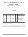 3
3
-
 4
4
-
 5
5
-
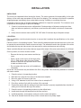 6
6
-
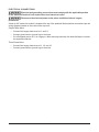 7
7
-
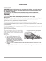 8
8
-
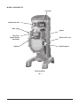 9
9
-
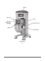 10
10
-
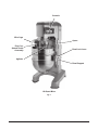 11
11
-
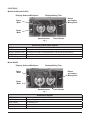 12
12
-
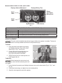 13
13
-
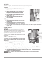 14
14
-
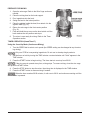 15
15
-
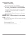 16
16
-
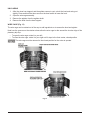 17
17
-
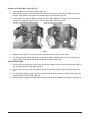 18
18
-
 19
19
-
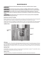 20
20
-
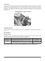 21
21
-
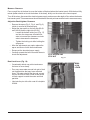 22
22
-
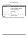 23
23
-
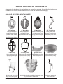 24
24
-
 25
25
-
 26
26
-
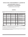 27
27
-
 28
28
-
 29
29
-
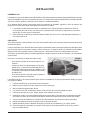 30
30
-
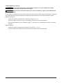 31
31
-
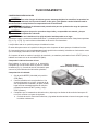 32
32
-
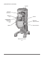 33
33
-
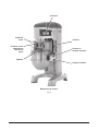 34
34
-
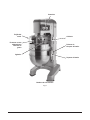 35
35
-
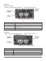 36
36
-
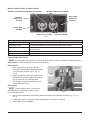 37
37
-
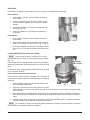 38
38
-
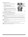 39
39
-
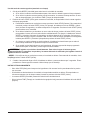 40
40
-
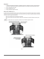 41
41
-
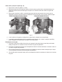 42
42
-
 43
43
-
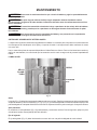 44
44
-
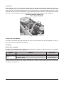 45
45
-
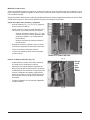 46
46
-
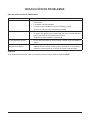 47
47
-
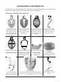 48
48
-
 49
49
-
 50
50
-
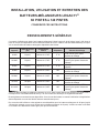 51
51
-
 52
52
-
 53
53
-
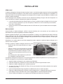 54
54
-
 55
55
-
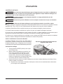 56
56
-
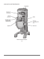 57
57
-
 58
58
-
 59
59
-
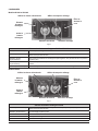 60
60
-
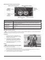 61
61
-
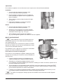 62
62
-
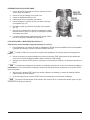 63
63
-
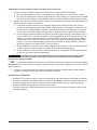 64
64
-
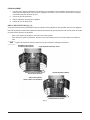 65
65
-
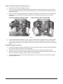 66
66
-
 67
67
-
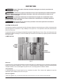 68
68
-
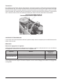 69
69
-
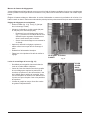 70
70
-
 71
71
-
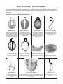 72
72


Hobart HL600, HL662, HL800, HL1400 Legacy+ Mixers Manual de usuario
- Categoría
- Mezcladores
- Tipo
- Manual de usuario
