Walther PILOT BOND 2K Operating Instructions Manual
- Categoría
- Potentes sistemas de pulverización fina
- Tipo
- Operating Instructions Manual


76
Inhaltsverzeichnis
Explosionszeichnung 2
Konformitätserklärung 7
Ersatzteilliste 8
1 Allgemeines 10
1.1 Kennzeichnung des Modells 10
1.2 Bestimmungsgemäße Verwendung 10
1.3 Sachwidrige Verwendung 10
2 Technische Beschreibung 11
3 Sicherheitshinweise 11
3.1 Kennzeichnung der Sicherheitshinweise 11
3.2 allgemeine Sicherheitshinweise 11
4 Versorgungsleitungen anschließen und
Inbetriebnahme 12
4.1 Spritzbildprobe erzeugen 13
4.2 Spritzbild verändern 13
5 Spritzpistole umrüsten / Instandsetzung 13
5.1 Materialdüse und Luftkopf austauschen 14
5.2 Materialnadel austauschen (A-Komponente) 14
5.3 Ventil B-Komponente austauschen 15
5.4 Undichte Nadelpackung austauschen (A-Komponente) 15
5.5 Mängel eines Spritzbildes beheben 16
6 Reinigung 16
7 Fehlersuche und -beseitigung 18
8 Entsorgung 18
9 Technische Daten 19
EG-Konformitätserklärung
Wir, der Gerätehersteller, erklären in alleiniger Verantwortung, dass das Produkt in der
untenstehenden Beschreibung den einschlägigen grundlegenden Sicherheits- und
Gesundheitsanforderungen entspricht. Bei einer nicht mit uns abgestimmten Änderung
an dem Gerät oder bei einer unsachgemäßen Verwendung verliert diese Erklärung ihre
Gültigkeit.
Hersteller WALTHER Spritz- und Lackiersysteme GmbH
Kärntner Str. 18 - 30
D - 42327 Wuppertal
Tel.: +49(0)202 / 787 - 0
Fax: +49(0)202 / 787 - 2217
www.walther-pilot.de • e-mail: [email protected]
Typenbezeichnung Zweikomponenten-Handspritzpistole
PILOT BOND 2K
Breitstrahl V 11 815
Rundstrahl V 11 816
Verwendungszweck Verarbeitung spritzbarer Materialien
Angewandte Normen und Richtlinien
EG-Maschinenrichtlinien 2006 / 42 / EG
DIN EN ISO 12100 Teil 1
DIN EN ISO 12100 Teil 2
DIN EN 1127-1
Spezifikation im Sinne der Richtlinie 94 / 9 / EG
Bevollmächtigt mit der Zusammenstellung der technischen Unterlagen:
Nico Kowalski, WALTHER Spritz- und Lackiersysteme GmbH, Kärntner Str. 18 - 30
D- 42327 Wuppertal
Besondere Hinweise :
Das Produkt ist zum Einbau in ein anderes Gerät bestimmt. Die Inbetriebnahme ist
so lange untersagt, bis die Konformität des Endproduktes mit der Richtlinie
2006 / 42 / EG festgestellt ist.
Wuppertal, den 01. Oktober 2015
Name: Torsten Bröker
Stellung im Betrieb: Leiter der Konstruktion und Entwicklung
Diese Erklärung ist keine Zusicherung von Eigenschaften im Sinne der Produkthaftung. Die
Sicherheitshinweise der Produktdokumentation sind zu beachten.
ppa.

98
Ersatzteilliste
PILOT BOND 2K
Breitstrahl
PILOT BOND 2K
Rundstrahl
V 11 815 xx xx3 V 11 816 xx xx3
Pos. Bezeichnung Stck Artikelnummer Stck Artikelnummer
1Luftkopfmutter kompl. 1 2337082 1 2337082
2Luftkopf Breitstrahl 1V 11 815 0x 000*
Luftkopf Rundstrahl 1V 11 816 0x 000*
33.1 Materialdüse 1 V 11 815 00 xx3* 1 V 11 815 00 xx3*
3.2 Materialnadel kompl.
4Pistolenkörper kompl. 1V 11 815 01 000 1V 11 815 01 000
5 Verschlussschraube 1 V 11 815 64 000 1V 11 815 64 000
6
6.1 Ventilschaftdichtung
1V 17 118 02 000 1V 17 118 02 000
6.2 Ventilschaft kompl.
6.3 Ventilfeder
6.4 Unterlegscheibe
6.5 O-Ring
7 Federbuchse 1 2337086 1 2337086
8 Nadelfeder 1 2337093 1 2337093
9 Einstellschraube 1 2337087 1 2337087
10 Nadeldichtung kompl. 1 V 11 815 06 000 1 V 11 815 06 000
11 Packungsschraube 1 2337091 1 2337091
12 Ventil B-Komponente
kompl. 1V 11 815 50 103 1V 11 815 50 103
13 Abzug kompl. 1V 11 815 67 000 1V 11 815 67 000
14 Schaftschraube 1 V 11 815 63 000 1V 11 815 63 000
15 Hebelschraube 1 V 10 301 09 000 1V 10 301 09 000
16 Steckverschraubung 1 V 66 100 01 148 1V 66 100 01 148
17 Verschraubung 1 V 66 100 06 257 1V 66 100 06 257
18 Schlauch 9 cm 1V 11 815 05 090 1V 11 815 05 090
*Bei Ersatzteil-Bestellung bitte entsprechende Größe angeben:
B-Komponente 0,3/ 0,4/ 0,5 mm. Der Luftkopf ist für A-Komponente gleich, nur die
B-Komponente unterscheidet sich.
Düsenausstattung nach Wahl:
۔ 0,8 ۔ 1,0 ۔ 1,2 ۔ 1,4 mm ø
◄ Luftköpfe wahlweise:
Düsengröße Größe Artikelnummer
Bohrung für B-Komponente (Aktivator)
Breitstrahlluftkopf
0,8 - 1,4 mm ø
0,3 mm ø V 11 815 03 000
0,4 mm ø V 11 815 04 000
0,5 mm ø V 11 815 05 000
Rundstrahlluftkopf
0,8 - 1,4 mm ø
0,3 mm ø V 11 816 03 000
0,4 mm ø V 11 816 04 000
0,5 mm ø V 11 816 05 000
Luftventil - Set
WALTHER hält für die Handspritzpistole PILOT BOND 2K ein Luftventil-Set
bereit, das folgende Artikel beinhaltet:
Ventilschaftdichtung (Pos. 6.1), Ventilschaft kompl. (Pos. 6.2), Ventilfeder
(Pos. 6.3), Unterlegscheibe (Pos. 6.4) und O-Ring (Pos. 6.5).
Artikel-Nr.
PILOT BOND 2K V 17 118 02 000
Düsen- / Nadelset
Materialdüse (Pos. 3.1) und Materialnadel kompl. (Pos. 3.2)
Artikel-Nr.
PILOT BOND 2K V 15 815 00 xx3*
Reparaturset (ohne Luftkopf)
WALTHER hält für die Handspritzpistole PILOT BOND 2K ein Reparaturset bereit,
das sämtliche Verschleißteile enthält. Die Verschleißteile sind auch in der
Ersatzteilliste aufgeführt (durch Fettdruck gekennzeichnet).
Artikel-Nr.
Rep.-Set V 16 815 00 xx3*
Zubehör
Artikelnummer
WALTHER PILOT Pistolenfett (Kissen 8 - 10 g) V 00 000 00 001
Schlauchpaket 5m (Luft, A+B-Komponente) V 87 005 55 060
Schlauchpaket B-Komponente (5er Set PU-Schlauch) V 87 005 55 061

1110
1 Allgemeines
1.1 Kennzeichnung des Modells
Modell: Zweikomponenten Spritzpstole
Typ: PILOT BOND 2K Breitstrahl V 11 815
PILOT BOND 2K Rundstrahl V 11 816
Hersteller: WALTHER Spritz- und Lackiersysteme GmbH
Kärntner Str. 18-30
D-42327 Wuppertal
Tel.: +202 / 787-0
Fax: +202 / 787-2217
www.walther-pilot.de • Email: [email protected]
1.2 Bestimmungsgemäße Verwendung
Die Handspritzpistole PILOT BOND 2K dient ausschließlich der Verarbeitung spritz-
barer wasserlöslicher nicht brennbarer Zweikomponenten-Medien. Da sämtliche
materialführende Teile aus Edelstahl-rostfrei gefertigt sind, eignet sich das Modell
PILOT BOND 2K zum Auftrag wasserlöslicher Zweikomponenten-Klebstoffe in der
Polstermöbel- und Schaumstoffindustrie.
Sollen andere Materialien verspritzt werden, wenden Sie sich bitte an WALTHER
Spritz- und Lackiersysteme GmbH, Wuppertal.
Die spritzbaren Materialien dürfen lediglich auf Werkstücke bzw. Gegenstände
aufgetragen werden.
Die Temperatur des Spritzmaterials darf 43°C grundsätzlich nicht überschreiten.
Die bestimmungsgemäße Verwendung schließt auch ein, dass alle Hinweise und
Angaben der vorliegenden Betriebsanleitung gelesen, verstanden und beachtet
werden.
Die Angaben auf den Geräteschildern bzw. die Angaben in dem Kapitel technische
Daten sind unbedingt einzuhalten und dürfen nicht überschritten werden. Eine
Überlastung des Gerätes muss ausgeschlossen sein.
Falls im Betrieb Auffälligkeiten erkannt werden, muss das Gerät sofort stillgesetzt
werden und es ist mit WALTHER Spritz- und Lackiersysteme Rücksprache zu halten.
1.3 Sachwidrige Verwendung
Die Spritzpistole darf nicht anders verwendet werden, als es im Abschnitt bestim-
mungsgemäße Verwendung geschrieben steht. Jede andere Verwendung ist
sachwidrig. Zur sachwidrigen Verwendung gehören z.B.:
• das Verspritzen von Materialien auf Personen und Tiere.
• das Verspritzen von flüssigem Stickstoff.
• das Verspritzen von brennbaren Materialien
2 Technische Beschreibung
Bei der Bond 2 K handelt es sich um ein Spritzpistolenmodell für den Auftrag von
Zweikomponenten - Dispersionsklebstoffen.
Die Materialförderung zur Pistole erfolgt bauseits über eine für den Klebstoff geeig-
nete Zuführeinrichtung.
Das Mischungsverhältnis wird dabei sowohl von den gewählten Düsengrößen, wie
auch durch die Zuführdrücke bestimmt.
3 Sicherheitshinweise
3.1 Kennzeichnung der Sicherheitshinweise
Warnung
Das Piktogramm und die Dringlichkeitsstufe “Warnung“ kennzeichnen eine mögliche
Gefahr für Personen. Mögliche Folgen: schwere oder leichte Verletzungen.
Achtung
Das Piktogramm und die Dringlichkeitsstufe “Achtung“ kennzeichnen eine mögliche
Gefahr für Sachwerte. Mögliche Folgen: Beschädigung von Sachen.
Hinweis
Das Piktogramm und die Dringlichkeitsstufe “Hinweis“ kennzeichnen zusätzliche
Informationen für das sichere und effiziente Arbeiten mit der Spritzpistole.
3.2 Allgemeine Sicherheitshinweise
► Die einschlägigen Unfallverhütungsvorschriften sowie die sonstigen anerkann-
ten sicherheitstechnischen und arbeitsmedizinischen Regeln sind einzuhalten.
► Die Anwender müssen im gefahrlosen Umgang mit der Spritzpistole entspre-
chend unterwiesen werden.
► Benutzen Sie die Spritzpistole nur in gut belüfteten Räumen. Beim Verspritzen
von Materialien besteht erhöhte Gesundheitsgefahr.
► Schalten Sie vor jeder Wartung und Instandsetzung die Luft- und Materialzufuhr
zur Spritzpistole drucklos - Verletzungsgefahr.
► Halten Sie beim Verspritzen von Materialien keine Hände oder andere
Körperteile vor die unter Druck stehende Düse der Spritzpistole.
- Verletzungsgefahr.
Hierbei tritt die Komponente A aus der Düse (1) aus.
Die Komponente B wird durch die im Luftkopf
integrierte Düse (2) ausgetragen.
Dabei werden beide Komponenten außerhalb
der Pistole im Spritzstrahl vermischt und auf das
Werkstück aufgetragen.
1
2

1312
► Richten Sie die Spritzpistole nicht auf Personen und Tiere - Verletzungsgefahr.
► Beachten Sie die Verarbeitungs- und Sicherheitshinweise der Hersteller von
Spritzmaterial und Reinigungsmitteln. Insbesondere aggressive und ätzende
Materialien können gesundheitliche Schäden verursachen.
► Die partikelführende Abluft ist vom Arbeitsbereich und Betriebspersonal fernzu-
halten. Tragen Sie dennoch vorschriftsgemäßen Atemschutz und vorschriftsge-
mäße Arbeitskleidung, wenn Sie mit der Spritzpistole Materialien verarbeiten.
Umherschwebende Partikel gefährden Ihre Gesundheit.
► Tragen Sie beim Lackieren und Reinigen einen Augenschutz.
► Tragen Sie im Arbeitsbereich der Spritzpistole einen Gehörschutz. Der erzeugte
Schallpegel der Spritzpistole beträgt ca. 83 dB (A).
► Achten Sie stets darauf, dass bei Inbetriebnahme, insbesondere nach Montage-
und Wartungsarbeiten alle Muttern und Schrauben fest angezogen sind.
► Verwenden Sie nur Original-Ersatzteile, da WALTHER nur für diese eine sichere
und einwandfreie Funktion garantieren kann.
► Die Spritzpistole muss nach Arbeitsende drucklos geschaltet werden.
► DiemaximalenDrückeausdentechnischenDatensindeinzuhalten.
Bei Nachfragen zur gefahrlosen Benutzung der Spritzpistole sowie der darin verwen-
deten Materialien, wenden Sie sich bitte an WALTHER Spritz- und Lackiersysteme
GmbH, D-42327 Wuppertal.
4 Versorgungsleitungen anschließen und Inbetriebnahme
Hinweis
Zur Durchführung der aufgeführten Arbeitsschritte benutzen Sie bitte die
Explosionszeichnung (Seite 2) dieser Betriebsanleitung.
Hinweis
Vor dem ersten Inbetriebsetzen muss die Pistole mit einem geeigneten Lösemittel
gespült werden, um das Spritzmaterial nicht zu verunreinigen.
4.1 Spritzbildprobe
Eine Spritzbildprobe sollte immer dann erzeugt werden, wenn:
• die Spritzpistole zum erstenmal in Betrieb gesetzt wird.
• das Spritzmaterial ausgetauscht wird.
• die Pistole zur Wartung oder Instandsetzung zerlegt wurde.
Die Spritzbildprobe kann auf ein Probewerkstück, Blech, Pappe oder Papier abge-
geben werden.
1. Setzen Sie die Spritzpistole in Betrieb, um eine Spritzbildprobe zu erzeugen
(siehe 4 Versorgungsleitungen anschließen und Inbetriebnahme).
2. Kontrollieren Sie die Spritzbildprobe und verändern Sie ggf. die Einstellungen an
der Spritzpistole (siehe 4.2 Spritzbild verändern).
4.2 Spritzbild verändern
Sie können an der PILOT BOND 2 K durch die folgenden Einstellungen das
Spritzbild verändern:
5 Spritzpistole umrüsten / Instandsetzung
Die zum Spritzmaterial passende Kombination bestehend aus Luftkopf und Düsen- /
Nadelset bildet eine aufeinander abgestimmte Einheit - die Düseneinlage. Tauschen
Sie immer die komplette Düseneinlage aus, damit die gewünschte Spritzbildqualität
erhalten bleibt.
Hinweis
Alle beweglichen und gleitenden Bauteile müssen vor dem Einbau in den Pistolenkörper
mit WALTHER PILOT Pistolenfett (Art.-Nr.: V 00 000 00 001) eingefettet werden.
Materialanschluss
Komponente A
Materialanschluss
Komponente B
Luftanschluss
Die Pistole ist nun betriebsbereit.
4. Um die im Materialschlauch
befindliche Luft entweichen zu las-
sen, betätigen Sie den Abzugshebel
solange, bis ein gleichmäßiger
Materialstrahl (Komponente A) und
Aktivator (Komponente B) aus der
Düse tritt.
3. Stellen Sie die gewünschten Material-
und Luftdrücke an Ihrer Versorgung
ein.
2. Befestigen Sie die Material-
zuführungsschläuche an den
Materialanschlüssen (Komponente A/
Komponente B) der Spritzpistole.
1. Befestigen Sie den Druckluft-
schlauch an dem Luftanschluss der
Spritzpistole.
Materialdurchflussmenge einstellen
Die Materialmenge läßt sich durch Ein- bzw. Ausschrauben der
Stellschraube (Pos. 9) regeln. Die Materialmenge wird durch
Linksdrehen (Ausschrauben) erhöht, durch Rechtsdrehen
(Einschrauben) verringert.
Materialdruck regulieren
Den Materialdruck können Sie nur an der Pumpe oder am
Druckbehälter regulieren. Beachten Sie dabei die Anweisungen
und Sicherheitshinweise des Herstellers.

1514
5.1 Materialdüse und Luftkopf austauschen
5.2 Materialnadel austauschen (A-Komponente)
Hinweis
Das Einstellmaß der Materialnadel beträgt 117 mm von der Nadelspitze bis zur
Nadelmutter gerechnet.
1
2
3
1
3
2
WALTHER PILOT Pistolenfett
Art.-Nr.: V 00 000 00 001
5.3 Ventil B-Komponente austauschen
5.4 Undichte Nadelpackung austauschen (A-Komponente)
3
2
1
A
B
1
3
B
2
32
1

1716
Hinweis
Nach Demontage der Dichtungen dürfen diese nicht wiederverwendet werden und
müssen durch neue Dichtungen ersetzt werden.
Reparaturset:
WALTHER PILOT hält für die Handspritzpistole PILOT BOND 2K ein Reparaturset
bereit, das sämtliche Verschleißteile enthält. Die Verschleißteile sind auch in der
Ersatzteilliste aufgeführt (durch Fettdruck gekennzeichnet).
Rep.-Set luftseitig und materialseitig: Art.-Nr.: V 16 815 00 . . 3
5.5 Mängel eines Spritzbildes beheben
Die folgende Tabelle zeigt Ihnen, mit welchen Einstellungen Sie das Spritzbild beein-
flussen können.
Spritzbildprobe Abweichung erforderliche Einstellung
Spritzbild ist in der Mitte
zu dick
• breitere Spritzstrahlform
einstellen
Spritzbild ist an den
Enden zu dick
• rundere Spritzstrahlform
einstellen
Spritzbild ist ziemlich
grobtropfig • Zerstäuberluftdruck erhöhen
Materialauftrag ist in der
Spritzbildmitte sehr dünn • Zerstäuberluftdruck verringern
Spritzbild ist in der Mitte
gespalten
• Düsendurchmesser erhöhen
• Zerstäuberluftdruck verringern
• Materialdruck erhöhen
Spritzbild ist sehr ballig • Materialdruck verringern
• Zerstäuberluftdruck erhöhen
6 Reinigung
Damit die Lebensdauer und die Funktion der Spritzpistole lange erhalten bleibt,
muss die Spritzpistole regelmäßig gereinigt und geschmiert werden.
Achtung
Legen Sie die Spritzpistole nie in Lösemittel oder ein anderes Reinigungsmittel. Die
einwandfreie Funktion der Spritzpistole kann sonst nicht garantiert werden.
angestrebtes Spritzergebnis
Achtung
Verwenden Sie zur Reinigung keine harten oder spitzen Gegenstände. Präzisions-
teile der Spritzpistole könnten sonst beschädigt werden und das Spritzergebnis
verschlechtern.
Verwenden Sie zur Reinigung der Spritzpistole nur Reinigungsmittel, die vom
Hersteller des Spritzmaterials angegeben werden und die folgenden Bestandteile
nicht enthalten:
• halogenierte Kohlenwasserstoffe (z. B. 1,1,1, Trichlorethan, Methylen-Chlorid
usw.)
• Säuren und säurehaltige Reinigungsmittel
• regenerierte Lösemittel (sog. Reinigungsverdünnungen)
• Entlackungsmittel.
Die o.g. Bestandteile verursachen an galvanisierten Bauteilen chemische Reaktio-
nen und führen zu Korrosionsschäden.
Für Schäden, die aus einer derartigen Behandlung herrühren, übernimmt WALTHER
Spritz- und Lackiersysteme keine Gewährleistung.
Reinigen Sie die Spritzpistole
• vor jedem Materialwechsel
• mindestens einmal wöchentlich
• materialabhängig und je nach Verschmutzungsgrad mehrfach wöchentlich.
Sie erhalten so die sichere Funktion der Spritzpistole.
1. Zerlegen Sie die Pistole gemäß 5.1 / 5.2 Materialdüse und -nadel wechseln.
2. Reinigen Sie den Luftkopf und die Materialdüse mit einem Pinsel und dem
Reinigungsmittel.
3. Reinigen Sie alle übrigen Bauteile und den Pistolenkörper mit einem Tuch und
dem Reinigungsmittel.
4. Bestreichen Sie folgende Teile mit einem dünnen Fettfilm:
• Materialnadel
• Nadelfeder
• alle gleitenden Teile und Lagerstellen
• Die beweglichen Innenteile sind wenigstens einmal wöchentlich zu fetten.
• Die Federn sollten ständig mit einem leichten Fettüberzug versehen sein.
Verwenden Sie dazu WALTHER PILOT Pistolenfett und einen Pinsel. Anschließend
wird die Spritzpistole in umgekehrter Reihenfolge zusammengesetzt.

1918
7 Fehlersuche und -beseitigung
Fehler Ursache Abhilfe
Pistole tropft
A-Komponente
Materialnadel oder -düse
verschmutzt
Materialnadel oder -düse
beschädigt
Nadelfeder (Pos. 8) nicht in
Ordnung, evtl. gebrochen
Materialnadel stimmt nicht mit
Düsengröße überein
Einstellschraube (Pos. 9) zu
weit nach hinten gedreht
reinigen
erneuern,
gemäß 5 Spritzpistole
umrüsten/ Instandsetzung
Materialnadel ausbauen und
Feder austauschen
auf gleiche Durchmesser
achten
Stellschraube etwas
Einschrauben
(Rechtsdrehen)
Pistole tropft
B-Komponente
B-Komponente beschädigt
B-Komponente undicht
austauschen
austauschen
Stoßweiser oder
flatternder
Spritzstrahl
zu wenig Material im Material-
behälter
die Materialdüse ist lose oder
beschädigt
Material auffüllen
(s. Betriebsanleitung des
Anlagenherstellers)
festziehen oder austauschen
Pistole bläst in
Ruhestellung
Ventilfeder (Pos. 6.3) oder
Ventilschaft (Pos. 6.2)
beschädigt
austauschen
8 Entsorgung
Die Spritzmedien sowie die bei der Reinigung und Wartung anfallenden Materialien
sind den Gesetzen und Vorschriften entsprechend sach- und fachgerecht zu entsor-
gen.
9 Technische Daten
Gewicht: 470 g
Anschlüsse
Zerstäuberluft: Schlauchanschluss 8x6 mm ø
Materialzufuhr Komp. A: Schlauchanschluss 8x6 mm ø
Materialzufuhr Komp. B: Schlauchanschluss 4x2,5 mm ø
Düsenbohrung Komp. A: 0,8 / 1,0 / 1,2 mm ø
Düsenbohrung Komp. B: 0,3 / 0,4 / 0,5 mm ø
Luftköpfe: Rundstrahl
Breitstrahl
Druckbereiche
Eingangsluftdruck: max. 5 bar
Materialdruck: max. 3 bar
empfohlener Zerstäuberluftdruck ca. 1 - 2 bar
max. Betriebstemperatur: 43°C
Schallpegel
(gemessen in ca. 1m
Abstand zur Spritzpistole) 83 db (A)
Luftverbrauch:
Zerstäuberluftdruck Rundstrahl in l/min. Breitstrahl in l/min.
1 bar 93 130
2 bar 155 210
3 bar 205 290
4 bar 260 360
5 bar 310 440
Technische Änderungen vorbehalten.

2120
Table of contents
Explosion drawing 2
Declaration of conformity 21
Listing of Replacement Parts 22
1 General 24
1.1 Model identification 24
1.2 Intended use 24
1.3 Unintended use 24
2 Technical description 25
3 Safety instructions 25
3.1 Identification of safety instructions 25
3.2 General safety instructions 25
4 Connecting supply lines and Operation 26
4.1 Generating a spray pattern test 27
4.2 Changing the spray pattern 27
5 Converting / repairing the spray gun 27
5.1 Changing the material nozzle and air cap 28
5.2 Replacing the material needle (component A) 28
5.3 Replacing the Valve component B 29
5.4 Replacing a leaking needle packing (component A) 29
5.5 Correcting flaws of spray pattern 30
6 Cleaning 30
7 Troubleshooting and fault correction 32
8 Disposal 32
9 Technical data 33
EC Declaration of conformity
We, the device manufacturer, declare at our sole responsibility that the product with the
description below corresponds to the relevant based safety and health requirements. In
the event of changes to the device not agreed on with us or if used improperly this
declaration becomes invalid.
Manufacturer Walther Spritz- und Lackiersysteme GmbH
Kärntner Str. 1830
D - 42327 Wuppertal
Phone: +49(0)202 / 787 - 0
Fax: +49(0)202 / 787 - 2217
www.walther-pilot.de • email: [email protected]
Type designation Two-component hand spray gun
PILOT BOND 2K
Wide jet V 11 815
Round jet V 11 816
Purpose of use Processing of sprayable materials
Applied standards and directives
EC Machinery Directive 2006 / 42 / EC
EN ISO 12100 Part 1
EN ISO 12100 Part 2
DIN EN 1127-1
Specifications according to Directive 94 / 9 / EC
Authorized to compile the technical documentation:
Nico Kowalski, WALTHER Spritz- und Lackiersysteme GmbH, Kärntner Str. 18 - 30
D- 42327 Wuppertal
Special notes:
The product is intended to be installed in another device. Commissioning is prohibited
until conformity of the end product with Directive 2006 / 42 / EC has been verified.
Wuppertal, 11 February 2016
Name: Torsten Bröker
Position in the company: Head of Design and Development
This declaration does not represent a promise of properties according to product liability. The safety instructions
of the product documentation must be observed.
ppa.

2322
Listing of Replacement Parts
PILOT BOND 2K
Wide Jet
PILOT BOND 2K
Round Jet
V 11 815 xx xx3 V 11 816 xx xx3
Item Description Qty. Article-No. Qty. Article-No.
1Sleeve nut compl. 1 2337082 1 2337082
2Air Cap Wide Jet 1V 11 815 0x 000*
Air Cap Round Jet 1V 11 816 0x 000*
33.1 Material nozzle 1 V 11 815 00 xx3* 1 V 11 815 00 xx3*
3.2 Material Needle compl.
4Gun Body compl. 1V 11 815 01 000 1V 11 815 01 000
5Plug screw 1V 11 815 64 000 1V 11 815 64 000
6
6.1 Valve shaft seal
1V 17 118 02 000 1V 17 118 02 000
6.2 Valve shaft compl.
6.3 Valve spring
6.4 Washer
6.5 O-Ring
7Spring bushing 1 2337086 1 2337086
8 Needle spring 1 2337093 1 2337093
9Adjusting screw 1 2337087 1 2337087
10 Needle seal compl. 1 V 11 815 06 000 1 V 11 815 06 000
11 Packing screw 1 2337091 1 2337091
12 Valve Component B compl. 1V 11 815 50 103 1V 11 815 50 103
13 Trigger compl. 1V 11 815 67 000 1V 11 815 67 000
14 Shank screw 1V 11 815 63 000 1V 11 815 63 000
15 Lever screw 1V 10 301 09 000 1V 10 301 09 000
16 Push-in-fitting 1 V 66 100 01 148 1V 66 100 01 148
17 Threaded joint 1V 66 100 06 257 1V 66 100 06 257
18 Hose 9 cm 1V 11 815 05 090 1V 11 815 05 090
*When ordering replacements please quote the respective sizes:
Component B 0,3/ 0,4/ 0,5 mm. The air cap is the same for the A-component, only the
B-component is different.
Nozzle equipment as selected:
۔ 0,8 ۔ 1,0 ۔ 1,2 ۔ 1,4 mm ø
◄ Air caps optional:
Nozzle Size Size Article-No.
Bore for Component B (Activator)
Wide jet air cap
0,8 - 1,4 mm ø
0,3 mm ø V 11 815 03 000
0,4 mm ø V 11 815 04 000
0,5 mm ø V 11 815 05 000
Round jet air cap
0,8 - 1,4 mm ø
0,3 mm ø V 11 816 03 000
0,4 mm ø V 11 816 04 000
0,5 mm ø V 11 816 05 000
Air valve set
WALTHER offers an air valve set for the PILOT BOND 2K hand spray gun which
contains the following items:
Valve shaft seal (Pos. 6.1), Valve shaft compl. (Pos. 6.2), Valve spring (Pos. 6.3),
Washer (Pos. 6.4) and O-Ring (Pos. 6.5).
Article-No.
PILOT BOND 2K V 17 118 02 000
Nozzle / needle set
Material nozzle (Pos. 3.1) and Material Needle compl. (Pos. 3.2)
Article-No.
PILOT BOND 2K V 15 815 00 xx3*
Repair set (without air cap)
WALTHER has a repair kit available for the manual spray gun PILOT BOND 2K
that includes all wearing parts. The wearing parts are also listed in the spare parts
list (highlighted in bold).
Article-No.
Rep.-set V 16 815 00 xx3*
Accessories
Article-No.
WALTHER PILOT gun grease (Pads 8-10 g) V 00 000 00 001
Hose package (5 meters) V 87 005 55 060
Hose package Component B V 87 005 55 061

2524
1 General
1.1 Model identification
Model: Two-component hand spray gun
Type: PILOT BOND 2K Wide jet V 11 815
PILOT BOND 2K Round jet V 11 816
Manufacturer: WALTHER Spritz- und Lackiersysteme GmbH
Kärntner Str. 18-30
D-42327 Wuppertal
Tel.: +202 / 787-0
Fax: +202 / 787-2217
www.walther-pilot.de • Email: [email protected]
1.2 Intended use
The manual spray gun PILOT BOND 2K is used exclusively to process sprayable
water-soluble non-flammable two-component media. Because all material-carrying
parts are manufactured from stainless steel the model PILOT BOND 2K is suited for
the application of water-soluble two-component adhesives in the upholstery and
foamed plastic industry.
Please contact WALTHER Spritz- und Lackiersysteme GmbH, Wuppertal if other
materials shall be sprayed.
The sprayable materials may only be applied to work pieces or objects.
The temperature of the sprayed material must generally not exceed 43 °C.
Intended use also includes the reading and understanding of, as well as compliance
with all information and data in the operating instructions.
The information on the device signs or the details in the chapter on technical data
must be absolutely complied with and may not be exceeded. Overloading the device
must be ruled out.
If any particularities are noted during operation, the device must be shut down imme-
diately and WALTHER Spritz- und Lackiersysteme shall be contacted.
1.3 Unintended use
The spray gun must not be used for purposes other than those set forth in section
Intended use.
Any other use is considered inappropriate.
Inappropriate use includes, for example:
• spraying materials on persons and animals
• spraying liquid nitrogen.
• spraying of flammable materials
2 Technical description
The Bond 2K is a spray gun model for the application of two-component dispersion
adhesives.
On site, the material is fed to the gun via a feed unit suitable for the adhesive.
The mixing ratio is determined by the selected nozzle sizes and by the supply pres-
sure.
3 Safety instructions
3.1 Identification of safety instructions
Warning
The pictogram and the urgency level “Warning“ identify a possible danger to
persons.
Possible consequences: Slight to severe injuries.
Attention
The pictogram and the urgency level “Attention“ identify a possible danger to
material assets.
Possible consequences: Damage to material assets.
Note
The pictogram and the urgency level “Note“ identify additional information for the
safe and efficient operation of the spray gun.
3.2 General safety instructions
► Compliance with applicable accident prevention instructions and other acknow-
ledged health and safety regulations is mandatory.
► The users must be instructed in the safe handling of the spray gun.
► Use the spray gun only in well ventilated rooms. When spraying materials,
health hazards will increase.
► Always depressurize the air and material supply to the spray gun before
beginning with any maintenance and repair work - risk of injury.
► When spraying material do not hold hands or other parts of the body in front of
the pressurized nozzle of the spray gun. - Risk of injury.
Component A is ejected from the nozzle (1).
Component B is ejected through the nozzle integrated
into the air cap (2).
Both components are mixed in the spray jet outside
the gun and applied to the workpiece.
1
2

2726
► Never point the spray gun at persons or animals - risk of injury.
► Follow the processing and safety notes of the spraying material and cleaning
agent manufacturers. In particular, aggressive and caustic materials can cause
damage to health.
► Particle-carrying discharged air must be kept away from the working area and
operating personnel. However, respiratory protection and work clothing should
always be worn in accordance with regulations when processing materials with
the spray gun. Airborne particles can damage your health.
► Wear eye protection during painting and cleaning.
► Wear hearing protection in the working area of the spray gun. The noise level
generated by the spray gun is approx. 83 dB (A).
► Always make sure that all nuts and bolts have been tightened when starting the
unit, especially after assembly and maintenance work.
► Use only original spare parts, since only then WALTHER can guarantee the safe
and fault-free functioning of these parts.
► Always depressurize the spray gun after work is completed.
► The maximum pressure values from the technical data must be observed.
Please contact WALTHER Spritz- und Lackiersysteme GmbH, D-42327 Wuppertal
for further information regarding the safe use of the spray gun and the materials used
in them.
4 Connecting supply lines and Operation
Note
Please refer to the explosion drawing (page 2) in these operating instructions to
perform the work steps listed.
Note
The gun must be flushed with a suitable solvent before initial commissioning to pre-
vent contamination of the spraying material.
4.1 Spray Pattern Test
A spray pattern test should always be generated when:
• the spray gun is used for the first time
• the spray material has been replaced
• the gun has been disassembled for maintenance or repair
The spray pattern can be applied to a sample work piece, sheet metal, cardboard or
paper.
1. Start operation of the spray gun to generate a spray pattern test (see 4
Connecting supply lines and Operation.
2. Check the spraying pattern trial and change the settings on the spray gun, as
necessary (see 4.2 Changing the spray pattern).
4.2 Changing the spray pattern
You can change the spray pattern on the PILOT BOND 2 K by making the following
settings:
5 Converting / repairing the spray gun
The air cap / material nozzle / needle combination matching the spraying material
represents an interactively tuned unit - the nozzle set. Always replace the entire
nozzle insert to maintain the desired spray pattern quality.
Note
All movable and sliding parts must be greased with WALTHER PILOT gun grease
before installation in the gun body (Art. No.: V 00 000 00 001).
Material connection
Component A
Material connection
Component B
Air connection
The gun is now ready to be operated.
4. To allow the air in the material
hose to escape, operate the trigger
until a uniform material jet (compo-
nent A) and activator (component
B) exit from the nozzle.
3. Set the desired material pressure
and air pressure on your supply
unit.
2. Connect the material supply hoses
to the material connections (com-
ponent A/ component B) of the
spray gun.
1. Connect the compressed air hose
to the air connection of the spray
gun.
Adjusting the material flow volume
The material volume can be regulated by turning the adjusting
screw (item 9) in or out. The material volume is increased by
turning it to the left (unscrewing) and reduced by turning it to the
right (screwing down).
Regulating the material pressure
You can adjust the material pressure only on the pump or the
pressure tank. Please follow the directions and safety instructions
of the manufacturer.

2928
5.1 Changing the material nozzle and air cap
5.2 Replacing the material needle component A
Note
The setting dimension of the material needle is 117 mm from the tip of the needle to
the needle chuck.
1
2
3
1
3
2
WALTHER PILOT gun grease
Art.-Nr.: V 00 000 00 001
5.3 Replacing the valve component B
5.4 Replacing a leaking needle packing (component A)
3
2
1
A
B
1
3
B
2
32
1

3130
Note
The seals must not be reused after removal and have to be replaced with new seals.
Repair set:
WALTHER has a repair kit available for the hand spray gun PILOT BOND 2K which
includes all wearing parts. The wearing parts are also listed in the spare parts list
(highlighted in bold).
Rep. kit: Art. No.: V 16 815 00 . . 3
5.5 Correcting spray pattern flaws
The following table shows the settings you can use to change the spray pattern.
Spray pattern
test
Fault Required adjustment
Spray pattern is split in
the centre • setting a wider spray pattern
Spray pattern is too thick
at the ends • Setting a more rounded spray
pattern
The spray pattern shows
rather large droplets • Increase the nozzle air pres-
sure
Material application in the
centre of the spray pattern
is very thin
• Decrease the nozzle air pres-
sure
Spray pattern is split in
the centre
• Increase the nozzle diameter
• Reduce nozzle air pressure
• Increase material pressure
Spray pattern is very
spherical • Reduce material pressure
• Increase nozzle air pressure
6 Cleaning
The spray gun must be regularly cleaned and lubricated in order to enhance its
service life and ensure the functionality of the spray gun.
Attention
Never place the spray gun in solvent or another cleaning agent. The perfect function
of the spray gun can otherwise not be guaranteed.
desired spray result
Attention
Do not use any hard or pointed objects for cleaning. Otherwise, precision parts of the
spray gun can be damaged and spraying results degraded.
Use only those cleaning materials for cleaning the spray gun which have been
prescribed by the manufacturer of the spraying material and which do not contain the
following components:
• halogenated hydrocarbons (e.g. 1,1,1, trichloroethane, methylene chloride, etc.)
• Acids or acidic cleaning agents
• Solvents or cleaning thinners
• Varnish removers.
The constituents named above cause chemical reactions on galvanised components
and lead to corrosion damage.
WALTHER Spritz- und Lackiersysteme GmbH will not honour warranty claims for
damages resulting from such treatment.
Clean the spray gun
• before each material change
• at least once a week
• several times a week, depending on the material and the degree of contamination.
In this manner, the safe functioning of the spray gun is maintained.
1. Dismantle the gun as described in 5.1/ 5.2 Replacing the material nozzle and
needle.
2. Clean the air head and the material nozzle with a brush and the cleaning agent.
3. Clean all other components and the gun body with a cloth and the cleaning
agent.
4. Apply a thin layer of grease to the following parts:
• Material needle
• Needle spring
• All sliding parts and bearing points
• Grease the movable inside parts at least once a week.
• The springs should always be coated with a thin grease film.
Use WALTHER PILOT gun grease and a brush for this purpose. The spray gun must
subsequently be reassembled in reverse order.

3332
7 Troubleshooting and fault correction
Fault Cause Remedy
Gun drips
Component A
Material needle or nozzle dirty
Material needle or nozzle
damaged
Needle spring (item 13) not in
order, possibly broken
Material needle does not
agree with nozzle size
Adjusting screw (item 9) tur-
ned too far back
Clean
Replace, according to
5 Converting / repairing the
spray gun
Remove material needle
and replace spring
Make sure diameters are
the same
Slightly turn in the adju-
sting screw (clockwise)
Gun is dripping
(Component B)
Component B is damaged
Component B is leaky
Replace
Replace
Pulsating or
unsteady spray jet
Level in material tank too low
Material nozzle is loose or
damaged
Refill material (see
operating instructions of
system manufacturer)
Tighten
Gun keeps blo-
wing in off-position
Valve spring (Item 6.3) or
Valve shaft (Item 6.2) dama-
ged
Replace
8 Disposal
Waste spraying media and waste material from cleaning and servicing must be
disposed of in accordance with all applicable local and national regulations.
9 Technical data
Net weight: 470 g
Connections
Atomizer air: Hose connection 8x6 mm ø
Material connection comp. A: Hose connection 8x6 mm ø
Material connection comp. B: Hose connection 4x2,5 mm ø
Nozzle orifice comp. A: 0,8 / 1,0 / 1,2 mm ø
Nozzle orifice comp. B: 0,3 / 0,4 / 0,5 mm ø
Air Cap: Round spray jet
Wide spray jet
Pressure ranges
intake air pressure: max. 5 bar
material pressure: max. 3 bar
recommended atomizer air pressure ca. 1 - 2 bar
max. operating temperature: 43°C
Sound level
(measured at approx. 1 m
distance to the spray gun) 83 db (A)
Air consumption:
Atomizer air pressure Round spray jet
in l/min.
Wide spray jet
in l/min.
1 bar 93 130
2 bar 155 210
3 bar 205 290
4 bar 260 360
5 bar 310 440
Right to effect technical changes reserved.

3534
Table des matières
Vue éclatée 2
Déclaration de conformité 35
Liste des pièces de rechange 36
1 Généralités 38
1.1 Caractérisation du modèle 38
1.2 Utilisation courante 38
1.3 Utilisation inappropriée 38
2 Caractéristiques techniques 39
3 Consignes de sécurité 39
3.1 Signalisation de sécurité 39
3.2 Consignes générales de sécurité 39
4 Raccordement des conduits d’alimentation et
mise en service 40
4.1 Essai de pulvérisation 41
4.2 Modification du schéma de pulvérisation 41
5 Conversion et maintenance du pistolet pulvérisateur 41
5.1 Remplacement de la buse de produit et de la tête à air 42
5.2 Remplacement de l’aiguille de produit (composant A) 42
5.3 Remplacement de la vanne du composant B 43
5.4 Remplacement de la garniture d’aiguille non
étanche (composant A) 43
5.5 Correction d’un jet imparfait 44
6 Nettoyage 44
7 Recherche et résolution des erreurs 46
8 Élimination 46
9 Données techniques 47
Déclaration de conformité CE
Nous, fabricant de l’appareil, déclarons sous notre entière responsabilité que le produit
décrit ci-dessous est conforme aux exigences de sécurité et d’hygiène fondamentales
s’y rapportant. En cas de modification de l’appareil réalisée sans notre accord ou en
cas d’utilisation non conforme, la présente déclaration perd sa validité.
Fabricant WALTHER Spritz- und Lackiersysteme GmbH
Kärntner Str. 18 - 30
D-42327 Wuppertal
Tél. : +49 202 787-0
Fax : +49 202 787-2217
www.walther-pilot.de • e-mail: [email protected]
Code de désignation Pistolet pulvérisateur manuel à deux composants
PILOT BOND 2K
Jet large V 11 815
Jet rond V 11 816
Champ d’application Traitement des produits pulvérisables
Normes et directives applicables
Directives CE relatives aux machines 2006/42/CE
DIN EN ISO 12100 partie 1
DIN EN ISO 12100 partie 2
DIN EN 1127-1
Spécification au sens de la directive 94 / 9 / CE
Personne chargée de la compilation des documents techniques :
Nico Kowalski, WALTHER Spritz- und Lackiersysteme GmbH, Kärntner Str. 18 - 30
D-42327 Wuppertal
Indications particulières :
Le produit est conçu pour être monté dans un autre appareil. Sa mise en service est
interdite tant que la conformité du produit fini avec la directive 2006/42/CE n’a pas
été constatée.
Wuppertal, le 1er octobre 2015
Nom : Torsten Bröker
Poste au sein de l’entreprise : Directeur de la fabrication et du développement
Cette déclaration ne représente aucune garantie quant aux propriétés de la machine au sens de
la responsabilité légale du fabricant. Les consignes de sécurité de la documentation du produit
doivent être respectées.
p.p.

3736
Liste des pièces de rechange
PILOT BOND 2K
Jet plat
PILOT BOND 2K
Jet rond
V 11 815 xx xx3 V 11 816 xx xx3
Pos. Désignation Pce Numéro d’article Pce Numéro d’article
1Écrou de tête à air compl. 1 2337082 1 2337082
2Tête à air – Jet large 1V 11 815 0x 000*
Tête à air – Jet rond 1V 11 816 0x 000*
3
3.1 Buse de produit
1 V 11 815 00 xx3* 1 V 11 815 00 xx3*
3.2 Aiguille de produit
compl.
4Corps du pistolet compl. 1V 11 815 01 000 1V 11 815 01 000
5Vis de blocage 1V 11 815 64 000 1V 11 815 64 000
6
6.1 Joint Tige de valve
1V 17 118 02 000 1V 17 118 02 000
6.2 Tige de valve compl.
6.3 Ressort de valve
6.4 Rondelle
6.5 Joint torique
7Bague à ressort 1 2337086 1 2337086
8 Ressort d’aiguille 1 2337093 1 2337093
9Vis de réglage 1 2337087 1 2337087
10 Joint d’aiguille complet 1 V 11 815 06 000 1 V 11 815 06 000
11 Vis de garniture 1 2337091 1 2337091
12 Vanne compl. pour
composant B 1V 11 815 50 103 1V 11 815 50 103
13 Évent compl. 1V 11 815 67 000 1V 11 815 67 000
14 Vis sans tête
partiellement filetée
1V 11 815 63 000 1V 11 815 63 000
15 Contre-vis de la gâchette 1V 10 301 09 000 1V 10 301 09 000
16 Raccord enfichable 1V 66 100 01 148 1V 66 100 01 148
17 Raccord vissé 1V 66 100 06 257 1V 66 100 06 257
18 Tuyau de 9 cm 1V 11 815 05 090 1V 11 815 05 090
* Veuillez indiquer la taille correspondante à la commande de pièces de rechange.
Composant B 0,3 / 0,4 / 0,5 mm. La tête à air est identique pour le composant A ;
seule celle du composant B change.
Présentation des buses au choix :
۔ 0,8 ۔ 1,0 ۔ 1,2 ۔ 1,4 mm ø
◄ Têtes à air, au choix :
Taille des
buses
Taille Numéro d’article
Trou pour composant B (activateur)
Tête à air à jet large
0,8 - 1,4 mm ø
0,3 mm ø V 11 815 03 000
0,4 mm ø V 11 815 04 000
0,5 mm ø V 11 815 05 000
Tête à air à jet rond
0,8 - 1,4 mm ø
0,3 mm ø V 11 816 03 000
0,4 mm ø V 11 816 04 000
0,5 mm ø V 11 816 05 000
Kit « Vanne d’air »
WALTHER propose un kit « Vanne d’air » pour son pistolet pulvérisateur manuel
PILOT BOND 2K ; celui-ci contient les pièces suivantes :
joint Tige de valve (pos. 6.1), tige de valve compl. (pos. 6.2), ressort de valve
(pos. 6.3), rondelle (pos. 6.4), joint torique (pos. 6.5).
Référence
PILOT BOND 2K V 17 118 02 000
Kit « Buse / Aiguille »
Buse de produit (pos. 3.1) et aiguille de produit compl. (pos. 3.2)
Référence
PILOT BOND 2K V 15 815 00 xx3*
Kit de réparation (sans tête à air)
WALTHER met à disposition pour le pistolet pulvérisateur manuel PILOT BOND 2K
un kit de réparation comprenant toutes les pièces d’usure. Les pièces d’usure
apparaissent également dans la liste des pièces de rechange (en caractère gras).
Référence
Kit rép. V 16 815 00 xx3*
Accessoires
Numéro d’article
Graisse pour pistolet WALTHER PILOT (coussinets 8 – 10 g) V 00 000 00 001
Jeudeexibles5 m (air, composants A+B) V 87 005 55 060
JeudeexiblesComposantB(jeude5exiblesenPU) V 87 005 55 061

3938
1 Généralités
1.1 Caractérisation du modèle
Modèle : Pistolet pulvérisateur à deux composants
Type : PILOT BOND 2K – Jet large V 11 815
PILOT BOND 2K – Jet rond V 11 816
Fabricant : WALTHER Spritz- und Lackiersysteme GmbH
Kärntner Str. 18-30
D-42327 Wuppertal
Tél. : +202 787-0
Fax : +202 787-2217
www.walther-pilot.de • E-mail : [email protected]
1.2 Utilisation courante
Le pistolet pulvérisateur manuel PILOT BOND 2K sert exclusivement au traitement
de fluides à deux composants non inflammables solubles dans l’eau pulvérisables.
Comme l’ensemble des pièces conductrices de produit sont en acier inoxydable, le
modèle PILOT BOND 2K convient parfaitement à l’application de produits adhésifs à
deux composants solubles dans l’eau dans l’industrie des meubles capitonnés et de
la mousse synthétique.
Si d’autres produits doivent être pulvérisés, adressez-vous à WALTHER Spritz- und
Lackiersysteme GmbH, Wuppertal.
Les produits pulvérisables ne peuvent être appliqués que sur des pièces à usiner et
des objets.
En principe, la température du produit à pulvériser ne doit jamais dépasser 43 °C.
L’utilisation conforme implique également que toutes les consignes et indications du
présent manuel d’utilisation ont été lues, comprises et respectées.
Les indications reprises sur les plaques de l’appareil ou dans le chapitre Données
techniques doivent impérativement être respectées et ne doivent pas être dépassées.
Une surcharge de l’appareil doit être exclue.
Si des particularités sont constatées pendant le fonctionnement, mettre l’appareil
immédiatement à l’arrêt et prendre contact avec WALTHER Spritz- und Lackiersysteme.
1.3 Utilisation inappropriée
Le pistolet pulvérisateur ne doit pas être utilisé à des fins autres que celles décrites
à la section Utilisation conforme. Toute autre utilisation est inappropriée. Sont consi-
dérées comme des utilisations inappropriées, par ex. :
• la pulvérisation de produits sur des personnes ou des animaux.
• la pulvérisation d’azote liquide.
• la pulvérisation de produits inflammables.
2 Caractéristiques techniques
Le Bond 2K est un modèle de pistolet pulvérisateur pour l’application de colles
à dispersion à deux composants.
Le transport du produit vers le pistolet se fait, sur site, via un dispositif d’alimentation
adapté à la colle utilisé.
Le rapport de mélange est ici adapté à la fois à la taille de la buse choisie, ainsi
qu’aux pressions d’alimentation.
3 Consignes de sécurité
3.1 Signalisation de sécurité
Avertissement
Le pictogramme et le niveau de dangerosité « Avertissement » signalent un danger
éventuel pour les personnes. Éventuelles conséquences : blessures sévères ou
légères.
Attention
Le pictogramme et le niveau de dangerosité « Attention » signalent un danger éven-
tuel pour les biens matériels. Éventuelles conséquences : endommagement de biens
matériels.
Remarque
Le pictogramme et le niveau de dangerosité « Remarque » signalent des informati-
ons supplémentaires pour utiliser le pistolet pulvérisateur en toute sécurité et avec
efficacité.
3.2 Consignes générales de sécurité
► Les prescriptions en vigueur relatives à la prévention des accidents ainsi que les
autres règles reconnues de la technique de sécurité et de la médecine du travail
doivent être respectées.
► Les utilisateurs doivent avoir été formés à utiliser le pistolet pulvérisateur sans
danger.
► Utiliser uniquement le pistolet pulvérisateur dans des pièces bien aérées. Il
existe d’importants risques sanitaires lors de la pulvérisation de produits.
► Avant tout entretien ou toute réparation, dépressurisez l’alimentation en air et en
produit du pistolet pulvérisateur – danger de blessure.
► Lors de la pulvérisation de produit, ne passez pas la main ou d’autres parties du
corps devant la buse sous pression du pistolet pulvérisateur. - Risques de
blessure.
► Ne dirigez pas le pistolet pulvérisateur sur les personnes et les animaux
Le composant A s’échappe ici par la buse (1).
Le composant B est appliqué par la buse intégrée
dans la tête à air (2).
Les deux composants sont ici mélangés en dehors
du pistolet, dans le jet de pulvérisation, puis appliqué
sur l’objet.
1
2

4140
– danger de blessure.
► Respectez les consignes d’utilisation et de sécurité du fabricant du produit à
pulvériser et des produits nettoyants. Les produits corrosifs et agressifs peuvent
tout particulièrement causer des problèmes sanitaires.
► L’évacuation d’air chargé en particules doit être maintenue éloignée de la zone
de travail et du personnel d’exploitation. Portez cependant de manière préven-
tive une protection des voies respiratoires et des vêtements de travail réglemen-
taires lorsque vous traitez des produits avec le pistolet pulvérisateur. Les parti-
cules en suspension sont nocives pour la santé.
► Portez une protection oculaire lors du vernissage ou du nettoyage.
► Portez des protège-oreilles dans la zone de travail du pistolet pulvérisateur. Le
niveau sonore produit par le pistolet pulvérisateur est d’env. 83 dB(A).
► Veillez toujours à ce que tous les écrous et vis soit correctement serrés lors de
la mise en service, et en particulier lors des travaux de montage et de mainte-
nance.
► Utilisez uniquement des pièces de rechange d’origine ; WALTHER ne peut
garantir un fonctionnement sûr et parfait que pour ces pièces.
► Le pistolet pulvérisateur doit toujours être dépressurisé à la fin du travail.
► Nedépassezpaslespressionsmaximalesindiquéesdanslescaractéristiques
techniques.
En cas de questions relatives à l’utilisation sûre du pistolet pulvérisateur, veuillez
vous adresser à : WALTHER Spritz- und Lackiersysteme GmbH, D-42327 Wuppertal.
4 Raccordement des conduits d’alimentation et mise en service
Remarque
Veuillez utiliser la vue éclatée de ces instructions de service (page 2) pour la réali-
sation des étapes de travail énumérées.
Remarque
Avant la première mise en service, le pistolet doit être rincé au moyen d’un solvant
adapté afin de ne pas souiller la matière à pulvériser.
4.1 Essai de pulvérisation
Un essai de pulvérisation doit toujours être effectué quand :
• le pistolet est mis en service pour la première fois.
• le produit à pulvériser est remplacé.
• le pistolet a été démonté pour l’entretien ou la réparation.
L’essai de pulvérisation peut être réalisé sur une pièce échantillon, une tôle, du car-
ton ou du papier.
1. Mettez le pistolet pulvérisateur en service afin de faire un essai de pulvérisation
(voir 4 Raccordement des conduits d’alimentation et mise en service).
2. Contrôlez l’essai de pulvérisation et modifiez le cas échéant les réglages sur le
pistolet pulvérisateur (voir 4.2 Régulation du jet).
4.2 Modification du schéma de pulvérisation
Vous pouvez modifier le schéma de pulvérisation du PILOT BOND 2K avec les régla-
ges suivants :
5 Conversion et maintenance du pistolet pulvérisateur
La combinaison de la tête à air et du kit buse/aiguille forme une unité comp-
lète : l’unité de buse. Remplacez toujours cette unité de buse complète afin de con-
server la qualité souhaitée pour le dessin de pulvérisation.
Remarque
Tous les composants mobiles et coulissants doivent être lubrifiés avec de la graisse
pour pistolet WALTHER PILOT avec le montage dans le corps du pistolet
(art. n° : V 00 000 00 001).
Raccord de
produit –
Composant A
Raccord de
produit –
Composant B
Raccord d’air
Le pistolet est maintenant prêt à l’emploi.
4. Afin de laisser échapper l’air se
trouvant dans le flexible de produit,
actionner la gâchette jusqu’à ce qu’un
jet de produit régulier (composant A)
et d’activateur (composant B) sorte
de la buse.
3. Réglez la pression de produit et d’air
souhaitée sur votre alimentation.
2. Fixez les flexibles d’alimentation du
produit aux raccords de produit
(composant A / composant B) du
pistolet pulvérisateur.
1. Fixez le tuyau d’air comprimé sur le
raccord d’air du pistolet de
pulvérisation.
Régulation du débit de matière
La quantité de produit peut être réglée en vissant ou dévissant la
vis de réglage (pos. 9). La quantité de produit est diminuée en
tournant à gauche (dévissage) et augmentée en tournant à droite
(vissage).
Réglage de la pression de matière
La pression de produit ne peut être réglée que sur la pompe ou
le réservoir sous pression. Respecter les instructions et les con-
signes de sécurité du fabricant.

4342
3
2
1
B
1
2
3
5.1 Remplacement de la buse de produit et de la tête à air
5.2 Remplacement de l’aiguille de produit (composant A)
Remarque
La dimension réglée de l’aiguille de produit est de 117 mm de la pointe de l’aiguille
à l’écrou à aiguilles.
1
3
2
Graisse pour pistolets Walther Pilot
Réf. : V 00 000 00 001
5.3 Remplacement de la vanne du composant B
5.4 Remplacement de la garniture d’aiguille non étanche
(composant A)
A
1
3
B
2
32
1

4544
Remarque
Après le démontage des joints, ceux-ci ne peuvent pas être réutilisés et doivent être
remplacés par des joints neufs.
Kit de réparation :
WALTHER PILOT met à disposition pour le pistolet pulvérisateur manuel PILOT BOND
2K un kit de réparation comprenant toutes les pièces d’usure. Les pièces d’usure
apparaissent également dans la liste des pièces de rechange (en caractère gras).
Kit rép. pour le côté air et le côté produit : Réf. : V 16 815 00 . . 3
5.5 Correction d’un jet imparfait
Le tableau suivant vous indique quels réglages peuvent influencer le dessin de pul-
vérisation.
Essai de
pulvérisation
Écart Réglage requis
Le dessin de pulvérisati-
on est trop épais au
milieu
• Régler une forme du jet plus
large
Le dessin de pulvérisati-
on est trop épais aux
extrémités
• Régler une forme du jet plus
ronde
Le dessin de pulvérisati-
on contient d’assez gros-
ses gouttes
• Augmenter la pression de l’air
de pulvérisation
La couche de produit est
très fine au centre de la
pulvérisation du jet
• Réduire la pression de l’air de
pulvérisation
Le dessin de pulvérisati-
on est lézardé au centre
• Augmenter le diamètre de la
buse
• Réduire la pression de l’air de
pulvérisation
• Augmenter la pression du
produit
Le dessin de pulvérisati-
on est très bombé
• Réduire la pression du produit
• Augmenter la pression de l’air
de pulvérisation
6 Nettoyage
De manière à garantir la durée de vie et le bon fonctionnement du pistolet de pulvé-
risation sur le long terme, celui-ci doit régulièrement être nettoyé et graissé.
Résultats de pulvérisation
souhaités
Attention
Ne jamais placer le pistolet pulvérisateur dans des solvants ou tout autre produit de
nettoyage. Dans le cas contraire, le bon fonctionnement du pistolet pulvérisateur ne
peut pas être garanti.
Attention
Ne jamais utiliser d’objets pointus ou durs pour le nettoyage. Les pièces de précision
du pistolet pulvérisateur pourraient être endommagées et empêcher d’obtenir un bon
résultat de pulvérisation.
Pour le nettoyage du pistolet pulvérisateur, n’utilisez que des produits de nettoyage
indiqués par le fabricant du produit à pulvériser ne contenant pas les composants
suivants :
• hydrocarbures halogénés (par ex. 1.1.1 trichloréthane, chlorure de méthylène,
etc.)
• Acides et produits de nettoyage à base d’acide
• Solvants régénérés (appelés diluants de nettoyage)
• Produits décapants.
Les composants susmentionnés causent des réactions chimiques sur les compo-
sants galvanisés et entraînent des dégâts dus à la corrosion.
Les dommages résultant d’une manipulation inappropriée ne sont pas couverts par
WALTHER Spritz- und Lackiersysteme.
Nettoyage du pistolet pulvérisateur
• avant chaque changement de produit
• au moins une fois par semaine
• plusieurs fois par semaine selon le produit et le degré d’encrassement.
Ainsi, le pistolet pulvérisateur peut fonctionner en toute sécurité.
1. Démontez le pistolet conformément au point 5.1 / 5.2 Remplacement de la buse
et de l’aiguille de produit.
2. Nettoyez la tête à air et la buse de produit avec un pinceau et du produit de
nettoyage.
3. Nettoyez tous les composants habituels et le corps de pistolet avec un chiffon
et le produit de nettoyage.
4. Appliquez une fine couche de graisse sur les pièces suivantes :
• Aiguille de produit
• Ressort d’aiguille
• Tous les pièces et paliers coulissants
• Les pièces internes mobiles doivent être graissées au moins une fois par
semaine.
• Les ressorts doivent en permanence être revêtues d’une légère couche de
graisse.
Utilisez pour ce faire la graisse pour pistolets WALTHER PILOT et un pinceau.
Le pistolet pulvérisateur est ensuite remonté dans l’ordre inverse.

4746
7 Recherche et résolution des erreurs
Défaillance Cause Solution
Écoulement de
composant A
hors du pistolet
Aiguille ou buse de produit
encrassées
Aiguille ou buse de produit
endommagées
Ressort d’aiguille (pos. 8)
défectueuse ou év. cassée
L’aiguille de produit ne corre-
spond pas à la dimension de
la buse
Vis de réglage (pos. 9) trop
serrée vers l’arrière
Nettoyer
Remplacer
selon 5 Conversion et
maintenance du pistolet
pulvérisateur
Démonter l’aiguille de
produit et remplacer les
ressorts
Veillez à ce que le diamètre
soit identique
Desserrer légèrement la vis
de réglage (vers la droite)
Écoulement de
composant B
hors du pistolet
Composant B endommagé
Fuite sur le composant B
Remplacer
Remplacer
Jet de pulvérisa-
tion par salves
ou tremblotant
Trop de peu de matière dans
le réservoir de matière
La buse de produit est desser-
rée ou endommagée
Rajouter du produit (voir
manuel d’utilisation du fabri-
cant de l’installation)
Serrer ou remplacer
Le pistolet souff-
le lorsqu’il est au
repos
Ressort de valve (pos. 6.3) ou
tige de valve (pos. 6.2)
endommagé
Remplacer
8 Élimination
Les produits à pulvériser ainsi que les matières qui se forment durant le nettoyage
et l’entretien doivent être éliminés de manière correcte et appropriée, dans le respect
des lois et prescriptions.
9 Données techniques
Poids : 470 g
Raccords
Air de pulvérisation : Raccordement de tuyau 8x6 mm ø
Alimentation en produit – Comp. A : Raccordement de tuyau 8x6 mm ø
Alimentation en produit – Comp. B : Raccordement de tuyau 4x2,5 mm ø
Alésage de buse compl. A : 0,8 / 1,0 / 1,2 mm ø
Alésage de buse compl. B : 0,3 / 0,4 / 0,5 mm ø
Têtes à air : Jet rond
Jet plat
Plages de pression
Pression d’entrée d’air : max. 5 bars
Pression de produit : max. 3 bars
Pression d’air de pulvérisation
recommandée : env. 1 - 2 bars
Température de service max. : 43 °C
Niveau sonore
(mesuré à env. 1 m
de distance du pistolet pulvérisateur) 83 dB (A)
Consommation d’air :
Pression de l’air
de pulvérisation
Jet rond en l/min. Jet large en l/min.
1 bar 93 130
2 bars 155 210
3 bars 205 290
4 bars 260 360
5 bars 310 440
Sous réserve de modifications techniques.

4948
Índice de contenido
Esquema de despiece 2
Declaración de conformidad 49
Lista de piezas de recambio 50
1 Aspectos generales 52
1.1 Identificación del modelo 52
1.2 Uso previsto 52
1.3 Uso ilícito 52
2 Descripción técnica 53
3 Indicaciones de seguridad 53
3.1 Identificación de las indicaciones de seguridad 53
3.2 Indicaciones generales de seguridad 53
4 Conectar líneas de alimentación y
puesta en funcionamiento 54
4.1 Crear prueba gráfica de la pulverización 55
4.2 Modificar el diagrama de pulverización 55
5 Reequipar/reparar la pistola de pulverización 55
5.1 Cambiar la tobera de material y el cabezal de aire 56
5.2 Cambiar la aguja de material (componente A) 56
5.3 Cambiar componente B de válvula 57
5.4 Cambiar la guarnición de aguja inestanca (componente A) 57
5.5 Eliminar fallos en un diagrama de pulverización 58
6 Limpieza 58
7 Localización y eliminación de errores 60
8 Eliminación de desechos 60
9 Datos técnicos 61
Declaración de conformidad CE
Nosotros, el fabricante del aparato, declaramos bajo exclusiva responsabilidad que el
producto descrito a continuación cumple los requisitos básicos pertinentes sobre segu-
ridad y salud. Esta declaración pierde su validez si se realiza cualquier modificación en
el aparato que no haya sido acordada con nosotros o en caso de un uso inadecuado.
Fabricante WALTHER Spritz- und Lackiersysteme GmbH
Kärntner Str. 18 - 30
D-42327 Wuppertal, Alemania
Tel.: +49 202 787-0
Fax: +49 202 787-2217
www.walther-pilot.de • e-mail: [email protected]
Designación de tipo Pistola de pulverizado manual de dos componentes
PILOT BOND 2K
Chorro ancho V 11 815
Chorro redondo V 11 816
Uso previsto Procesamiento de materiales de pulverización
Normas y directivas aplicadas
Directiva de máquinas 2006/42/CE
DIN EN ISO 12100 Parte 1
DIN EN ISO 12100 Parte 2
DIN EN 1127-1
Especificación a los efectos de la Directiva 94/9/CE
Persona autorizada para la compilación de la documentación técnica:
Nico Kowalski, WALTHER Spritz- und Lackiersysteme GmbH, Kärntner Str. 18-30
D-42327 Wuppertal, Alemania
Indicaciones especiales:
El producto está previsto para el montaje en otro aparato. La puesta en marcha
queda prohibida hasta que se haya determinado la conformidad del producto final
con la Directiva 2006/42/CE.
Wuppertal, a 1 de octubre de 2015
Nombre: Torsten Bröker
Puesto en la empresa: Director de construcción y desarrollo
Esta declaración no es garantía de características a los efectos de responsabilidades sobre el
producto. Deben tenerse en cuenta las indicaciones de seguridad de la documentación del pro-
ducto.
ppa.

5150
Lista de piezas de recambio
PILOT BOND 2K
Chorro ancho
PILOT BOND 2K
Chorro redondo
V 11 815 xx xx3 V 11 816 xx xx3
Pos. Denominación Uds. Número de
artículo Uds. Número de
artículo
1Tuerca del cabezal de aire
compl. 12337082 12337082
2
Cabezal de aire para chorro
ancho 1V 11 815 0x 000*
Cabezal de aire para chorro
redondo 1V 11 816 0x 000*
33.1 Tobera de material 1 V 11 815 00 xx3* 1 V 11 815 00 xx3*
3.2 Aguja de material compl.
4Cuerpo de la pistola compl. 1V 11 815 01 000 1V 11 815 01 000
5Tornillo tapón 1V 11 815 64 000 1V 11 815 64 000
6
6.1 Junta de vástago de válvula
1V 17 118 02 000 1V 17 118 02 000
6.2 Vástago de válvula compl.
6.3 Resorte de válvula
6.4 Arandela
6.5 Anillo toroidal
7Casquillo de resorte 1 2337086 1 2337086
8 Resorte de la aguja 1 2337093 1 2337093
9Tornillo de ajuste 1 2337087 1 2337087
10 Junta de aguja compl. 1 V 11 815 06 000 1 V 11 815 06 000
11 Tornillo de guarnición 1 2337091 1 2337091
12 Componente B de válvula
compl. 1V 11 815 50 103 1V 11 815 50 103
13 Gatillo 1 V 11 815 67 000 1V 11 815 67 000
14 Tornillo de vástago 1V 11 815 63 000 1V 11 815 63 000
15 Tornillo del gatillo 1V 10 301 09 000 1V 10 301 09 000
16 Racor de empalme 1V 66 100 01 148 1V 66 100 01 148
17 Racor 1 V 66 100 06 257 1V 66 100 06 257
18 Tubo flexible de 9 cm 1V 11 815 05 090 1V 11 815 05 090
*Al realizar el pedido de piezas de recambio indicar el tamaño correspondiente:
Componente B 0,3/ 0,4/0,5 mm. El cabezal de aire es igual para el componente A,
solo el componente B es diferente.
Equipamiento de tobera a elegir:
۔ 0,8 ۔ 1,0 ۔ 1,2 ۔ 1,4 mm ø
◄ Cabezales de aire opcionales:
Tamaño de
tobera
Tamaño Número de artículo
Oricio para componente B (activador)
Cabezal de chorro
ancho 0,8 - 1,4 mm ø
0,3 mm ø V 11 815 03 000
0,4 mm ø V 11 815 04 000
0,5 mm ø V 11 815 05 000
Cabezal de chorro
redondo 0,8 - 1,4 mm ø
0,3 mm ø V 11 816 03 000
0,4 mm ø V 11 816 04 000
0,5 mm ø V 11 816 05 000
Set de válvulas de aire
WALTHER dispone de un set de válvulas de aire para la pistola de pulverizado
manual PILOT BOND 2K que contiene los siguientes artículos:
Junta de vástago de válvula (pos. 6.1), vástago de válvula compl. (pos. 6.2), resor-
te de válvula (pos. 6.3), arandela (pos. 6.4) y anillo toroidal (pos. 6.5).
N.° art.
PILOT BOND 2K V 17 118 02 000
Set de toberas y agujas
Tobera de material (pos. 3.1) y aguja de material compl. (pos. 3.2)
N.° art.
PILOT BOND 2K V 15 815 00 xx3*
Sets de reparación (sin cabezal de aire)
WALTHER dispone de un set de reparación para la pistola de pulverización manual
PILOT BOND 2K que contiene todas las piezas de desgaste. Las piezas de
desgaste también están en la lista de piezas de recambio (marcadas en negrita).
N.° art.
Juego de reparación V 16 815 00 xx3*
Accesorios
Número de artículo
Grasa para pistolas WALTHER PILOT
(almohadillas 8 - 10 g)
V 00 000 00 001
Rack de mangueras 5 m (aire, componentes A y B) V 87 005 55 060
Rack de mangueras del componente B (juego de 5
piezas de tubos de poliuretano)
V 87 005 55 061

5352
1 Aspectos generales
1.1 Identificación del modelo
Modelo: Pistola de pulverización de dos componentes
Tipo: PILOT BOND 2K de chorro ancho V 11 815
PILOT BOND 2K de chorro redondo V 11 816
Fabricante: WALTHER Spritz- und Lackiersysteme GmbH
Kärntner Str. 18-30
D-42327 Wuppertal, Alemania
Tel.: +202 787-0
Fax: +202 787-2217
www.walther-pilot.de • e-mail: [email protected]
1.2 Uso previsto
La pistola de pulverización manual PILOT BOND 2K sirve exclusivamente para el
procesamiento de materiales de pulverizado de dos componentes, solubles en agua
y no combustibles. Dado que todas las piezas conductoras de materiales están
fabricadas en acero inoxidable, el modelo PILOT BOND 2K resulta especialmente
apto para la aplicación de adhesivos de dos componentes solubles en agua de uso
habitual en la industria de muebles tapizados y de materiales de espuma.
Si desea pulverizar otros materiales, póngase en contacto con WALTHER Spritz- und
Lackiersysteme GmbH, Wuppertal (Alemania).
Los productos de pulverizado únicamente deben aplicarse sobre piezas u objetos.
Por norma general, la temperatura del producto de pulverizado no debe superar los
43 °C.
El uso previsto incluye también la lectura, comprensión y cumplimiento de todas las
indicaciones y datos del presente Manual de servicio.
Es imprescindible cumplir los datos de las placas del aparato o los datos en el capítu-
lo Datos técnicos y no saltarlos. Debe evitarse una sobrecarga del aparato.
En caso de que se produzca cualquier incidente durante el funcionamiento, deberá
detenerse el aparato de inmediato y contactar a WALTHER Spritz- und Lackiersysteme.
1.3 Uso ilícito
No está permitido utilizar la pistola de pulverización para usos diferentes a los descri-
tos en el apartado Uso previsto. Cualquier otro uso se considera un uso impropio e
ilícito. Entre los usos no apropiados se encuentran por ejemplo:
• La pulverización de materiales sobre personas y animales.
• La pulverización de nitrógeno líquido.
• La pulverización de materiales inflamables.
2 Descripción técnica
El Bond 2 K es un modelo de pistolas de pulverización para la aplicación de adhesi-
vos en dispersión de dos componentes.
El bombeo de material hasta la pistola se realiza en las instalaciones del cliente a
través de un dispositivo de alimentación adecuado para el adhesivo.
La relación de la mezcla se determina según los tamaños de tobera seleccionados y
las presiones de alimentación.
3 Indicaciones de seguridad
3.1 Identificación de las indicaciones de seguridad
Advertencia
El pictograma y el grado de prioridad “Advertencia” marcan un peligro potencial
para personas. Posibles consecuencias: lesiones graves o leves.
Atención
El pictograma y el grado de prioridad “Atención” marcan un peligro potencial para
bienes materiales. Posibles consecuencias: daños materiales.
Aviso
El pictograma y el grado de prioridad “Aviso” señalan informaciones adicionales
para el trabajo seguro y eficaz con la pistola de pulverización.
3.2 Indicaciones generales de seguridad
► Deben cumplirse las normativas de prevención de accidentes pertinentes, así
como otras regulaciones oficiales sobre seguridad técnica y salud en el trabajo.
► Los usuarios deben ser instruidos correspondientemente sobre el uso no peli-
groso de la pistola de pulverización.
► Utilice la pistola de pulverización únicamente en espacios bien ventilados. Al
pulverizar productos existe un riesgo mayor para la salud.
► Antes de cada mantenimiento y reparación, despresurice la entrada de aire y de
material a la pistola de pulverización. Peligro de lesiones.
► Al pulverizar materiales no ponga las manos ni otras partes del cuerpo delante
de la tobera de la pistola de pulverización sometida a presión. - Peligro de lesio-
nes.
► No dirija la pistola de pulverización a personas ni animales. Peligro de lesiones.
El componente A sale aquí de la tobera (1).
El componente B se aplica con la tobera (2) integrada
en el cabezal de aire.
Al hacerlo, ambos componentes se mezclan fuera de
la pistola en el chorro pulverizado y se aplican sobre
la pieza de trabajo.
1
2

5554
► Tenga en cuenta las indicaciones de procesamiento y seguridad del fabricante
del material de pulverizado y de los agentes de limpieza. Especialmente los
productos agresivos y cáusticos pueden provocar daños en la salud.
► El aire de salida con partículas debe mantenerse alejado del área de trabajo y
del personal de servicio. A pesar de ello, utilice una protección reglamentaria
para las vías respiratorias y ropa de trabajo reglamentaria cuando procese
materiales con la pistola de pulverización. Las partículas en suspensión son
nocivas para su salud.
► Al realizar trabajos de pintura y limpieza, lleve una protección para los ojos.
► Lleve protección para los oídos en el área de trabajo de la pistola de pulveriza-
ción. El nivel de ruido generado por la pistola de pulverización es de aprox.
83 dB(A).
► Asegúrese en todo momento de que durante la puesta en funcionamiento, espe-
cialmente durante los trabajos de montaje y mantenimiento, todas las tuercas y
tornillos están apretados correctamente.
► Utilice solo piezas de recambio originales, ya que WALTHER únicamente puede
garantizar un funcionamiento seguro y sin problemas de las piezas originales.
► La pistola de pulverización debe despresurizarse al concluir el trabajo.
► DebenrespetarselaspresionesmáximasindicadasenlosDatostécnicos.
Para consultas sobre el uso seguro de la pistola de pulverización, así como sobre
los productos que deban utilizarse, póngase en contacto con WALTHER Spritz- und
Lackiersysteme GmbH, D-42327 Wuppertal, Alemania.
4 Conectar líneas de alimentación y puesta en funcionamiento
Aviso
Para efectuar los pasos indicados, consulte el esquema de despiece (página 2) al
inicio de este Manual de servicio.
Aviso
Antes de la primera puesta en funcionamiento debe aclararse la pistola con un disol-
vente adecuado para no contaminar el producto de pulverizado.
4.1 Prueba gráfica de la pulverización
Debe generarse siempre una prueba gráfica de la pulverización cuando:
• Se pone en funcionamiento por primera vez la pistola de pulverización.
• Se cambia el producto de pulverizado.
• Se haya desarmado la pistola para su mantenimiento o reparación.
La prueba gráfica de la pulverización se puede efectuar sobre una pieza de prueba,
una chapa, cartón o papel.
1. Ponga a funcionar la pistola de pulverización para crear una prueba gráfica de
la pulverización (véase 4 Conectar líneas de alimentación y puesta en funcion-
amiento).
2. Controle la prueba gráfica de la pulverización y, en caso necesario, modifique
la configuración de la pistola de pulverización (véase 4.2 Modificar el diagrama
de pulverización).
4.2 Modificar el diagrama de pulverización
En la PILOT BOND 2 K se puede modificar el diagrama de pulverización efectuando
los siguientes ajustes.
5 Reequipar/reparar la pistola de pulverización
La combinación del cabezal de aire, el set de toberas y de agujas para el producto
de pulverizado forma una unidad que se complementa: la pieza de la tobera.
Reemplace siempre la pieza de tobera completa para mantener la calidad deseada
del diagrama de pulverización.
Aviso
Todos los componentes móviles y deslizantes deben engrasarse antes del montaje en
el cuerpo de la pistola con grasa para pistolas WALTHER PILOT
(n.° art.: V 00 000 00 001).
Conexión de
material del
componente A
Conexión de
material del
componente B
Toma de aire
La pistola está ahora lista para usar.
4. Para purgar el aire encerrado en la
manguera de material, accione el
gatillo hasta que salga un chorro de
material homogéneo (componente A)
y el activador (componente B) por la
tobera.
3. Ajuste las presiones de material y de
aire comprimido deseadas en la ali-
mentación.
2. Fije las mangueras de alimentación
de material a las conexiones de
material (componente A/componente
B) de la pistola de pulverización.
1. Fije la manguera de aire comprimido
en la toma de aire de la pistola de
pulverización.
Ajustar el caudal de material
La cantidad de material puede regularse enroscando y desen-
roscando el tornillo de ajuste (pos. 9). La cantidad de material se
aumenta girando hacia la izquierda (desenroscando) y se reduce
girando hacia la derecha (enroscando).
Regular la presión del material
La presión de material únicamente puede regularse en la bomba
o en el depósito a presión. Tenga en cuenta las instrucciones e
indicaciones de seguridad del fabricante.

5756
3
2
1
B
5.1 Cambiar la tobera de material y el cabezal de aire
5.2 Cambiar la aguja de material (componente A)
Aviso
El tamaño de ajuste de la aguja de material es de 117 mm desde la punta de la
aguja hasta el casquillo de arrastre.
1
2
3
1
3
2
Grasa de pistola WALTHER PILOT
N.° art.: V 00 000 00 001
5.3 Cambiar componente B de válvula
5.4 Cambiar la guarnición de aguja inestanca (componente A)
A
1
3
B
2
32
1

5958
Aviso
Después de desmontar las juntas estas no se pueden volver a usar y tienen que ser
reemplazadas por juntas nuevas.
Set de reparación:
WALTHER PILOT dispone de un set de reparación para la pistola de pulverización
manual PILOT BOND 2K que contiene todas las piezas de desgaste. Las piezas de
desgaste también están en la lista de piezas de recambio (marcadas en negrita).
Set de reparación para el aire y el material: N.° art.: V 16 815 00 . . 3
5.5 Eliminar fallos en un diagrama de pulverización
La siguiente tabla le muestra los ajustes que pueden influir en el diagrama de pul-
verización.
Prueba gráfica de
la pulverización
Desviación Ajuste necesario
Diagrama de pulverización
demasiado grueso en el
centro
• Ajustar una forma de
chorro de pulverizado
más ancha
Diagrama de pulverización
demasiado grueso en los
extremos
• Ajustar una forma de
chorro de pulverizado
más redondeada
Diagrama de pulverización
con gotas bastante gruesas
• Aumentar la presión del
aire de pulverización
Capa de material demasia-
do fina en el centro del dia-
grama de pulverización
• Reducir la presión del
aire de pulverización
Diagrama de pulverización
fraccionado en el centro
• Aumentar el diámetro de
la tobera
• Reducir la presión del
aire de pulverización
• Aumentar la presión del
material
Diagrama de pulverización
muy abombado
• Reducir la presión del
material
• Aumentar la presión del
aire de pulverización
6 Limpieza
Para que la vida útil y el funcionamiento de la pistola de pulverización duren mucho,
la pistola de pulverización debe limpiarse y engrasarse regularmente.
Resultado de
pulverizado buscado
Atención
No sumerja nunca la pistola de pulverización en disolventes ni en otros agentes de
limpieza. De lo contrario, no se puede garantizar el funcionamiento correcto de la
pistola de pulverización.
Atención
Para la limpieza no utilice objetos duros ni puntiagudos. De lo contrario podrían
dañarse las piezas de precisión de la pistola de pulverización y empeorar el result-
ado de pulverizado.
Para limpiar la pistola de pulverización utilice únicamente los agentes de limpieza
indicados por el fabricante del material de pulverizado y que no contengan los sigui-
entes componentes:
• Hidrocarburos halogenados (p. ej., 1,1,1, tricloroetano, diclorometano, etc.)
• Ácidos y agentes de limpieza ácidos
• Disolventes regenerados (los denominados disolventes de limpieza)
• Agentes de deslacado
Los componentes indicados anteriormente provocan reacciones químicas en com-
ponentes galvanizados que producen daños por corrosión.
WALTHER Spritz- und Lackiersysteme no se hace responsable de los daños provo-
cados por tratamientos de este tipo.
Limpie la pistola de pulverización
• Antes de cada cambio de material
• Al menos una vez a la semana
• Dependiendo del material y según el grado de suciedad, varias veces por
semana
De esta forma obtendrá un funcionamiento seguro de la pistola de pulverización.
1. Desmonte la pistola según lo dispuesto en 5.1 / 5.2 Cambiar la tobera y la aguja
de material.
2. Limpie el cabezal de aire y la tobera de material con un pincel y el agente de
limpieza.
3. Limpie todos los componentes restantes y el cuerpo de la pistola con un paño
y el agente de limpieza.
4. Aplique una capa fina de grasa en las siguientes piezas:
• Aguja de material
• Resorte de la aguja
• Todas las piezas deslizantes y puntos de rodamiento
• Las piezas interiores móviles deben engrasarse al menos una vez por
semana.
• Los resortes deberán tener en todo momento un revestimiento fino de
grasa.
Utilice para ello la grasa para pistolas WALTHER PILOT y un pincel. A continuación
se monta la pistola de pulverización en sentido inverso.

6160
7 Localización y eliminación de errores
Error Causa Remedio
La pistola gotea
Componente A
Aguja o tobera de material
sucia
Aguja o tobera de material
dañada
Resorte de la aguja (pos. 8)
deteriorado, posiblemente roto
La aguja de material no coinci-
de con el tamaño de la tobera
Tornillo de ajuste (pos. 9) gira-
do demasiado hacia atrás
limpiar
cambiar,
conforme a 5 Reequipar/
reparar la pistola de pulveri-
zación
Desmontar la aguja de
material y cambiar el resorte
Mantener el mismo diámetro
Ajustar algo el tornillo de
ajuste (hacia la derecha)
La pistola gotea
Componente B
Componente B dañado
Componente B inestanco
reemplazar
reemplazar
Chorro de pulve-
rizado a sacudi-
das u ondeante
Material insuficiente en el
depósito de material
Tobera de material suelta o
dañada
Añadir material (véase el
Manual de servicio del fabri-
cante del equipo)
apretar o reemplazar
La pistola burbu-
jea en posición
de reposo
Resorte de válvula (pos. 6.3) o
vástago de válvula (pos. 6.2)
dañado
reemplazar
8 Eliminación de desechos
Los productos de pulverizado, así como los materiales empleados durante la limpie-
za y el mantenimiento, deben eliminarse correctamente conforme a las normativas
y disposiciones correspondientes.
9 Datos técnicos
Peso: 470 g
Conexiones
Aire de pulverizado: Empalme de manguera 8x6 mm ø
Introducción de material compl. A: Empalme de manguera 8x6 mm ø
Introducción de material compl. B: Empalme de manguera 4x2,5 mm ø
Orificio de la tobera compl. A: 0,8 / 1,0 / 1,2 mm ø
Orificio de la tobera compl. B: 0,3 / 0,4 / 0,5 mm ø
Cabezales de aire: Chorro redondo
Chorro ancho
Rangos de presión
Presión de aire de entrada: máx. 5 bar
Presión de material: máx. 3 bar
Presión del aire de
pulverización recomendada aprox. 1 - 2 bar
Temperatura de servicio máx.: 43 °C
Nivel acústico
(medido a aprox. 1 m
de distancia a la pistola de pulverización) 83 db(A)
Consumo de aire:
Presión del aire de
pulverización
Chorro redondo en l/
min.
Chorro ancho en l/
min.
1 bar 93 130
2 bar 155 210
3 bar 205 290
4 bar 260 360
5 bar 310 440
Reservado el derecho a realizar modificaciones técnicas sin previo aviso.

6362
Spis treści
Schemat złożeniowy 2
Deklaracja zgodności 63
Wykaz części zamiennych 64
1 Informacje ogólne 66
1.1 Oznaczenie modelu 66
1.2 Zastosowanie zgodne z przeznaczeniem 66
1.3 Zastosowanie niezgodne z przeznaczeniem 66
2 Opis techniczny 67
3 Zasady bezpieczeństwa 67
3.1 Znaczenie symboli umieszczonych obok zasad
bezpieczeństwa 67
3.2 Ogólnezasadybezpieczeństwa 67
4 Podłączenie przewodów zasilających i
uruchomienie 68
4.1 Próba natrysku 69
4.2 Zmiana obrazu natrysku 69
5 Przezbrajanie pistoletu natryskowego / Naprawy 69
5.1 Wymianadyszymateriałowejigłowicypowietrza 70
5.2 Wymianaiglicymateriałowej(składnikA) 70
5.3 WymianazaworuskładnikaB 71
5.4 Wymianawadliwegouszczelnieniaiglicy(składnikA) 71
5.5 Korygowanie obrazu natrysku 72
6 Czyszczenie 72
7 Lokalizowanie i usuwanie usterek 74
8 Usuwanie zużytych materiałów 74
9 Dane techniczne 75
Deklaracja zgodności WE
Jakoproducenturządzeniaoświadczamyzpełnąodpowiedzialnością,żewymieniony
poniżejproduktspełniaodpowiedniepodstawowewymogiwzakresiebezpieczeństwa
iochronyzdrowia. Wprzypadkudokonaniazmianw urządzeniubezporozumieniaz
producentemlubużytkowaniaurządzenianiezgodniezjegoprzeznaczeniem,niniejsza
deklaracjatraciważność.
Producent WALTHER Spritz- und Lackiersysteme GmbH
Kärntner Str. 18 - 30
D-42327 Wuppertal
Tel.: +49 202 787-0
Faks: +49 202 787-2217
www.walther-pilot.de • e-mail: [email protected]
Oznaczenie typu Ręcznypistoletnatryskowydwuskładnikowy
PILOT BOND 2K
Strumieńszeroki V11815
Strumieńokrągły V11816
Przeznaczenie Nanoszeniemateriałówmetodąnatryskową
Zastosowane normy i dyrektywy
Dyrektywa maszynowa WE 2006 / 42 / WE
DINENISO12100część1
DINENISO12100część2
DIN EN 1127-1
Specyfikacja w rozumieniu dyrektywy 94 / 9 / WE
Osoba upoważniona do zestawienia dokumentacji technicznej:
Nico Kowalski, WALTHER Spritz- und Lackiersysteme GmbH, Kärntner Str. 18 - 30
D-42327 Wuppertal
Informacje szczególne :
Produkt jest przeznaczony do montażu w innym urządzeniu. Uruchomienie może
nastąpić dopiero po potwierdzeniu zgodności produktu końcowego z dyrektywą
2006 / 42 / WE.
Wuppertal,czwartek,1października2015
Nazwisko: Torsten Bröker
Zajmowane stanowisko: Kierownik do spraw konstrukcji i rozwoju
Niniejsza deklaracja nie stanowi potwierdzenia właściwości produktu. Należy stosować się do
zasadbezpieczeństwazamieszczonychwdokumentacjiproduktu.
per procura.

6564
Wykaz części zamiennych
PILOT BOND 2K
Strumień szeroki
PILOT BOND 2K
Strumień okrągły
V 11 815 xx xx3 V 11 816 xx xx3
Poz. Nazwa Szt. Numer katalo-
gowy Szt. Numer katalo-
gowy
1Nakrętkagłowicypowietrza
kompl. 12337082 12337082
2
Głowicapowietrzastrumień
szeroki 1V 11 815 0x 000*
Głowicapowietrzastrumień
okrągły 1V 11 816 0x 000*
33.1 Dysza materiałowa 1 V 11 815 00 xx3* 1 V 11 815 00 xx3*
3.2 Iglica materiałowa kompl.
4Korpus pistoletu kompl. 1V 11 815 01 000 1V 11 815 01 000
5Śrubazamykająca 1V 11 815 64 000 1V 11 815 64 000
6
6.1 Uszczelka trzonka zaworu
1V 17 118 02 000 1V 17 118 02 000
6.2 Trzonek zaworu kompl.
6.3 Sprężynazaworu
6.4 Podkładka
6.5 O-ring
7Tulejasprężyny 1 2337086 1 2337086
8 Sprężyna iglicy 1 2337093 1 2337093
9Śrubanastawcza 1 2337087 1 2337087
10 Uszczelka iglicy kompl. 1 V 11 815 06 000 1 V 11 815 06 000
11 Śruba uszczelniająca 1 2337091 1 2337091
12 ZawórskładnikaBkompl. 1V 11 815 50 103 1V 11 815 50 103
13 Spust kompl. 1V 11 815 67 000 1V 11 815 67 000
14 Śrubabezłba 1V 11 815 63 000 1V 11 815 63 000
15 Śrubaspustu 1V 10 301 09 000 1V 10 301 09 000
16 Złączkawtykowagwintowana 1V 66 100 01 148 1V 66 100 01 148
17 Złącześrubowe 1V 66 100 06 257 1V 66 100 06 257
18 Wąż9cm 1V 11 815 05 090 1V 11 815 05 090
*Wzamówieniunaczęścizamiennenależypodaćodpowiednirozmiar:
SkładnikB0,3/0,4/0,5mm.GłowicapowietrzadoskładnikaAjestrówna,różnisię
tylkodoskładnikaB.
Dostępne rozmiary dyszy:
۔ 0,8 ۔ 1,0 ۔ 1,2 ۔ 1,4 mm ø
◄ Głowice powietrza do wyboru:
Rozmiar dyszy Rozmiar Numer katalogowy
Otwór na składnik B (aktywator)
Głowica powietrza
strumienia
szerokiego 0,8 - 1,4 mm ø
0,3 mm ø V 11 815 03 000
0,4 mm ø V 11 815 04 000
0,5 mm ø V 11 815 05 000
Głowica powietrza
strumienia
okrągłego 0,8 - 1,4 mm ø
0,3 mm ø V 11 816 03 000
0,4 mm ø V 11 816 04 000
0,5 mm ø V 11 816 05 000
Zestaw zaworu powietrza
FirmaWALTHERposiadawoferciezestawdoręcznychpistoletównatryskowych
PILOTBOND2Kzawierającynastępująceczęści:
Uszczelkatrzonkazaworu(poz.6.1),trzonekzaworukompl.(poz.6.2),sprężyna
zaworu(poz.6.3),podkładka(poz.6.4)io-ring(poz.6.5).
Nr kat.
PILOT BOND 2K V 17 118 02 000
Zestaw dyszy / iglicy
Dyszamateriałowa(poz.3.1)iiglicamateriałowakompl.(poz.3.2)
Nr kat.
PILOT BOND 2K V 15 815 00 xx3*
Zestaw naprawczy (bez głowicy powietrza)
Firma WALTHER posiada w ofercie zestaw naprawczy do ręcznych pistoletów
natryskowychPILOTBOND2Kzawierającywszystkieczęścizużywalne. Części
zużywalnezostaływyróżnionenawykazieczęścizamiennychtłustymdrukiem.
Nr kat.
Zestaw napraw. V 16 815 00 xx3*
Akcesoria
Numer katalogowy
Smar do pistoletów WALTHER PILOT
(saszetka 8 - 10 g)
V 00 000 00 001
Przewód zespolony 5m(powietrza,składnikaA+B) V 87 005 55 060
PrzewódzespolonyskładnikaB
(zestaw 5 przewodów PU)
V 87 005 55 061

6766
1 Informacje ogólne
1.1 Oznaczenie modelu
Model: Pistoletdonatryskudwóchskładników
Typ: PILOT BOND 2K o strumieniu szerokim V 11 815
PILOTBOND2Kostrumieniuokrągłym V11816
Producent: WALTHER Spritz- und Lackiersysteme GmbH
Kärntner Str. 18-30
D-42327 Wuppertal
Tel.: +202 787-0
Faks: +202 787-2217
www.walther-pilot.de • E-mail: [email protected]
1.2 Zastosowanie zgodnie z przeznaczeniem
RęcznypistoletnatryskowyPILOTBOND2Kjestprzeznaczonywyłączniedonano-
szeniametodąnatryskową,rozpuszczalnychwwodzie,niepalnychdwuskładnikowych
mediów.Ponieważwszystkieelementymającestycznośćznatryskiwanymmateriałem
wykonanesązestalinierdzewnej,modelPILOTBOND2Kdoskonalenadajesiędo
natrysku rozpuszczalnych w wodzie klejów dwuskładnikowych stosowanych w
przemyślemeblitapicerowanychorazpiankowym.
Wprzypadkunatryskuinnychmateriałów,prosimyokontaktzWALTHERSpritz-und
Lackiersysteme GmbH, Wuppertal.
Rozpylanemateriaływolnonanosićwyłącznienaobrabianenarzędzialubprzedmio-
ty.
Temperaturamateriałunatryskowegoniemożeprzekraczać43°C.
Prawidłowysposóbużytkowaniazakładarównieżzapoznaniesięizrozumienietreści
niniejszejinstrukcjiobsługi oraz przestrzeganie zawartychwniejinformacjii wska-
zówek.
Należyprzestrzegaćinformacjiiparametrówpodanychnatabliczkachznamionowych
orazwrozdzialedotyczącymdanychtechnicznychipodżadnympozoremniewolno
ichprzekraczać.Należywykluczyćmożliwośćprzeciążeniaurządzenia.
Wraziezauważenianieprawidłowościwdziałaniuurządzenianależynatychmiastje
wyłączyćiskonsultowaćsięzfirmąWALTHERSpritz-undLackiersysteme.
1.3 Nieprawidłowe użytkowanie urządzenia
Pistoletunatryskowegoniewolnoużytkowaćwsposóbodbiegającyodpodanegow
rozdziale Zastosowanie zgodne z przeznaczeniem.Każdyinnysposóbużytkowania
uważasięzanieprawidłowy.Zanieprawidłowysposóbużytkowaniauważasięnp.:
• kierowaniestrumieniamateriałuwstronęosóblubzwierząt.
• rozpryskiwanieciekłegoazotu.
• rozpryskiwaniepalnychmateriałów
2 Opis techniczny
ModelBond2Kpistoletnatryskowyprzeznaczonydonatryskudwuskładnikowych
klejów dyspersyjnych.
Tłoczenie materiału do pistoletu odbywa się przy użyciu urządzenia użytkownika
przystosowanegodotłoczeniakleju.
Stosunekmieszanki zależyzarównoodwybranego rozmiarudyszy,jak iciśnienia
tłoczenia.
3 Zasady bezpieczeństwa
3.1 Znaczenie symboli umieszczonych obok zasad bezpieczeństwa
Ostrzeżenie
Piktogram oraz napis “Ostrzeżenie“ wskazują na zagrożenie dla zdrowia osób.
Możliweskutki:ciężkielublekkieobrażenia.
Uwaga
Piktogram oraz napis “Uwaga“wskazująnaniebezpieczeństwouszkodzeniaprzed-
miotów.Możliweskutki:uszkodzenieprzedmiotów.
Wskazówka
Piktogram oraz napis “Wskazówka“ pojawia się przy dodatkowych informacjach
dotyczącychbezpiecznegoiefektywnegoużytkowaniapistoletunatryskowego.
3.2 Ogólne zasady bezpieczeństwa
► NależybezwzględniestosowaćsiędoprzepisówBHPwzakresiezapobiegania
wypadkomorazinnychobowiązującychprzepisówwzakresiebezpieczeństwa
technicznego oraz medycyny pracy.
► Wszyscy użytkownicy pistoletu natryskowego muszą zostać przeszkoleni w
zakresie jego bezpiecznej eksploatacji.
► Pistoletu natryskowego należy używać wyłącznie w dobrze wentylowanych
pomieszczeniach. Podczas rozpryskiwania materiałów występuje zwiększone
zagrożeniedlazdrowia.
► Przedrozpoczęciemprackonserwacyjnychinaprawodłączyćdopływpowietrza
imateriałupodciśnieniem-niebezpieczeństwoobrażeń.
► Podczasrozpryskiwaniamateriału,przedznajdującymsiępodciśnieniempisto-
letem natryskowym nie należy trzymać rąk ani innych części ciała. -
niebezpieczeństwoobrażeń.
► Nie wolno kierować pistoletu natryskowego w stronę osób i zwierząt -
niebezpieczeństwoobrażeń.
SkładnikAwylatujezdyszy(1).
SkładnikBjestwyrzucanyprzezdyszę(2)zintegro-
wanązgłowicąpowietrza.
Obaskładnikimieszająsięzesobąpozapistoletemw
strumieniunatryskowymizostająnaniesionenaobra-
biany przedmiot.
1
2

6968
► Należyprzestrzegaćzasadbezpieczeństwaorazużytkowaniapodanychprzez
producentówmateriałównatryskowychiśrodkówczyszczących.Zagrożeniedla
zdrowiastanowiąwszczególnościsubstancjeagresywneiżrące.
► Zanieczyszczone powietrze odlotowe należy odprowadzać z dala od strefy
roboczej i osób. Podczas pracy z pistoletem natryskowym należy stosować
przepisowąochronędrógoddechowychorazodzieżroboczą.Zanieczyszczenia
unoszącesięwpowietrzustanowiązagrożeniedlazdrowia.
► Podczaslakierowaniaiczyszczenianależystosowaćokularyochronne.
► W strefie roboczej pistoletu należy stosować środki ochrony słuchu. Poziom
hałasuemitowanyprzezpistoletnatryskowywynosiok.83dB(A).
► Przedużyciem pistoletu, w szczególnościpo zakończeniuprac montażowych
ikonserwacyjnych,należysprawdzićdokręceniewszystkichśrubinakrętek.
► Należystosowaćwyłącznieoryginalneczęścizamienne,ponieważtylkowtakim
przypadku firma WALTHER może zagwarantować bezpieczne i prawidłowe
funkcjonowanie pistoletu natryskowego.
► Pozakończeniupracypistoletnależyprzełączyćwtrybbezciśnieniowy.
► Należyprzestrzegaćmaksymalnychciśnieńpodanychwdanychtechnicznych.
W razie pytań dotyczących bezpieczeństwa użytkowania pistoletu natryskowego,
oraz użytych materiałów należy zwrócić się do firmy WALTHER Spritz- und
Lackiersysteme GmbH, D-42327 Wuppertal.
4 Podłączenie przewodów zasilających i uruchomienie
Wskazówka
Opisane poniżej czynności należy przeprowadzić posługując się rysunkiem
złożeniowym(strona2)zniniejszejinstrukcjiużytkowania.
Wskazówka
Przedpierwszymuruchomieniempistoletnależyprzepłukaćodpowiednimrozpusz-
czalnikiem,abyuniknąćzanieczyszczeniamateriałunatryskowego.
4.1 Próba natrysku
Próbęnatryskunależyprzeprowadzićwprzypadku,gdy:
• pistoletnatryskowymazostaćuruchomionyporazpierwszy.
• dokonanozmianymateriałunatryskowego.
• pistoletzostałrozłożonynaczęściwcelukonserwacjilubnaprawy.
Natryskpróbnymożnaprzeprowadzićnaprzedmiociepróbnym,blasze,tekturzelub
papierze.
1. Uruchomić pistolet natryskowy i wykonać próbę natrysku (patrz punkt 4
Podłączenie przewodów zasilających i uruchomienie).
2. Sprawdzić obraz natrysku i w razie potrzeby dokonać zmiany ustawień na
pistolecie natryskowym (patrz punkt 4.2 Zmiana obrazu natrysku).
4.2 Zmiana obrazu natrysku
ObraznatryskupistoletuPILOTBOND2Kmożnaregulowaćwnastępującysposób:
5 Przezbrajanie pistoletu natryskowego / Naprawy
Przeznaczonadodanegotypumateriaługłowicapowietrzaorazzestawdyszy/iglicy
tworzą razem dopasowany do siebie zestaw w postaci wkładu dyszy. Chcąc
zachowaćjakośćnatryskunależyzawszewymieniaćcaływkładdyszy.
Wskazówka
Wszystkieczęściprowadniczeorazmiejscałożyskowanianależyprzedmontażemw
korpusiepistoletunasmarowaćsmaremdopistoletówWALTHERPILOT
(nr kat.: V 00 000 00 001).
Przyłącze
materiału
składnikA
Przyłącze
materiału
składnikB
Przyłączepowietrza
Pistoletjestterazgotowydoużycia.
4. Aby odprowadzić powietrze z prze-
wodu doprowadzającego materiał,
należy wciskać dźwignię spustu tak
długo, dopóki z dyszy nie będzie
wydobywaćsięrównomiernystrumień
materiału(składnikA)orazaktywator
(składnikB).
3. Ustawić żądane ciśnienie materiału
i powietrza na zasilaniu.
2. Przymocować przewody
doprowadzające materiał do
przyłączy materiału (składnik A/
składnikB)napistolecie.
1. Przymocować wąż sprężonego
powietrza do przyłącza powietrza
w pistolecie natryskowym.
Ustawienie natężenia przepływu materiału
Ilość materiału można wyregulować dokręcając lub odkręcając
śrubę nastawczą (poz. 9). Obrót śruby w lewo (odkręcanie)
zmniejsza,natomiastobrótwprawo(dokręcanie)zwiększailość
doprowadzanegomateriału.
Regulacja ciśnienia materiału
Ustawienia ciśnienia materiału można dokonać wyłącznie na
pompie lub zbiorniku ciśnieniowym. Należy stosować się do
instrukcjiizasadbezpieczeństwapodanychprzezproducenta.

7170
5.1 Wymiana dyszy materiałowej i głowicy powietrza
5.2 Wymiana iglicy materiałowej (składnik A)
Wskazówka
Wymiarnastawczyiglicymateriałowejwynosi117 mmmierzącodczubkaiglicydo
nakrętkiiglicy.
1
2
3
1
3
2
Smar do pistoletów WALTHER PILOT
Nr kat.: V 00 000 00 001
5.3 Wymiana zaworu składnika B
5.4 Wymiana wadliwego uszczelnienia iglicy (składnik A)
3
2
1
A
B
1
3
B
2
32
1

7372
Wskazówka
Po zdemontowaniu uszczelek nie wolno ich używać ponownie i muszą zostać
zastąpionenowymi.
Zestaw naprawczy:
Firma WALTHER PILOT posiada w ofercie zestaw naprawczy do ręcznych pisto-
letów natryskowych PILOT BOND 2K zawierający wszystkie części zużywalne.
Częścizużywalnezostały wyróżnione nawykazieczęścizamiennychtłustym dru-
kiem.
Zestaw napraw. strony powietrza i materiałowej: Nr kat.: V 16 815 00 . . 3
5.5 Korygowanie obrazu natrysku
Poniższatabelaobjaśniasposobykorygowaniaobrazunatrysku.
Próba natrysku Nieprawidłowość Zmiana ustawień
Natrysk pogrubiony w
środkowejczęści • Ustawićszerszystrumień
Natrysk pogrubiony na
końcach • Ustawićokrąglejszystrumień
Natrysk gruboziarnisty • Zwiększyćciśnieniepowietrza
rozpylającego
Zbyt cienka warstwa
materiałuwśrodkowej
częścinatrysku
• Zmniejszyćciśnieniepowietr-
zarozpylającego
Obraz natrysku rozszc-
zepionypośrodku
• Zwiększyćśrednicędyszy
• Zmniejszyćciśnieniepowietr-
zarozpylającego
• Zwiększyćciśnieniemateriału
Natrysk zbyt owalny
• Zmniejszyćciśnienie
materiału
• Zwiększyćciśnieniepowietrza
rozpylającego
6 Czyszczenie
W celu przedłużenia żywotności pistoletu natryskowego oraz zapewnienia jego
poprawnościdziałania,pistoletnależyregularnieczyścićismarować.
Uwaga
Pistoletunatryskowegoniewolno zanurzaćwrozpuszczalnikachanijakichkolwiek
innychśrodkachczyszczących.Wprzeciwnymrazieniemożnazagwarantowaćjego
prawidłowegofunkcjonowania.
Prawidłowy obraz natrysku
Uwaga
Do czyszczenia nie należy używać twardych ani ostrych przedmiotów. Mogłoby to
spowodowaćuszkodzenieprecyzyjnychelementówpistoletunatryskowegoipogorszyć
jakośćnatrysku.
Doczyszczeniapistoletunatryskowegostosowaćwyłącznieśrodkiczyszczącezale-
cane przez producenta materiału natryskowego i niezawierające następujących
składników:
• węglowodoryhalogenowane(np.1,1,1,trójchloroetan,chlorekmetylenuitp.)
• kwasyiśrodkiczyszczącenabaziekwasów
• rozpuszczalnikiregenerowane(tzw.rozcieńczalniki)
• zmywacze do lakierów.
Wymienione wyżej składniki wchodzą w reakcje z powłokami galwanicznymi i
powodująkorozję.
FirmaWALTHERSpritz-undLackiersystemenieponosiodpowiedzialnościzaszko-
dypowstałewwynikustosowaniategotypuśrodków.
Pistolet natryskowy należy czyścić
• przedkażdązmianąmateriału
• co najmniej raz w tygodniu
• kilkarazywtygodniuwzależnościodużytegomateriałuistopniazabrudzenia.
Regularneczyszczeniepozwalanazachowaniesprawnościpistoletu.
1. Pistoletnależyrozłożyćnaczęścizgodniezopisemzpunktu5.1 / 5.2 Wymiana
dyszy oraz iglicy materiałowej.
2. Głowicę powietrza oraz dyszę materiałową wyczyścić za pomocą pędzelka
iśrodkaczyszczącego.
3. Wszystkie pozostałe elementy oraz korpus pistoletu wyczyścić szmatką i
środkiemczyszczącym.
4. Wymienioneniżejczęścinależypokryćcienkąwarstwąsmaru:
• Iglicamateriałowa
• Sprężynaiglicy
• wszystkieczęściprowadniczeimiejscałożyskowania
• Ruchomeczęściwewnętrznenależysmarowaćconajmniejrazwtygodniu.
• Sprężynypowinnybyćprzezcałyczaspokrytecienkąwarstwąsmaru.
Do ich smarowania należy używać smaru pistoletowego WALTHER PILOT oraz
pędzla.Pistoletnależyzłożyćwykonującczynnościwodwrotnejkolejności.

7574
7 Lokalizowanie i usuwanie usterek
Usterka Przyczyna Naprawa
Z pistoletu kapie
składnikA
Zanieczyszczona iglica lub
dyszamateriałowa
Uszkodzona iglica lub dysza
materiałowa
Sprężynaiglicy(poz.8)nie
wporządku,ewent.złamana
Iglicamateriałowaniezgadza
sięzrozmiaremdyszy.
Śrubanastawcza(poz.9)
obróconazbytmocnodotyłu
Wyczyścić
Wymienić
zgodnie z 5 Przezbrajanie
pistoletu natryskowego /
Naprawy
Wymontowaćiglicę
materiałowąiwymienić
sprężynę
Zwrócićuwagęnataką
samąśrednicę
Dokręcićniecośrubę
nastawczą(wprawo)
Z pistoletu kapie
składnikB
UszkodzonyskładnikB
NieszczelnyskładnikB
Wymienić
Wymienić
Strumieńuderze-
niowy lub przery-
wany
Zbytmałailośćmateriałuw
zbiorniku
Dyszamateriałowapoluzowa-
na lub uszkodzona
Uzupełnićmateriał
(p.instrukcjaużytkowania
producenta instalacji)
Dokręcićlubwymienić
Pistolet nie
zamyka w trybie
spoczynku
Uszkodzonasprężynazaworu
(poz. 6.3) lub trzonek zaworu
(poz. 6.2)
Wymienić
8 Usuwanie zużytych materiałów
Materiały natryskowe, jak również materiały użyte do czyszczenia i konserwacji,
należy usuwać w prawidłowy sposób, zgodnie z obowiązującymi w tym zakresie
przepisami.
9 Dane techniczne
Ciężar: 470 g
Przyłącza
Powietrzerozpylające: Przyłączewężowe8x6mmø
Zasilaniemateriałemkomp.A: Przyłączewężowe8x6mmø
Zasilaniemateriałemkomp.B: Przyłączewężowe4x2,5mmø
Otwór dyszy komp. A: 0,8 / 1,0 / 1,2 mm ø
Otwór dyszy komp. B: 0,3 / 0,4 / 0,5 mm ø
Głowice powietrza: Strumieńokrągły
Strumieńszeroki
Zakresy ciśnień
Ciśnieniepowietrzawlotowego: maks.5bar
Ciśnieniemateriału: maks.3bar
Zalecaneciśnieniepowietrzarozpylającego ok.1-2bar
maks. temperatura robocza: 43 °C
Poziom hałasu
(pomiarwodległościok.1m
od pistoletu natryskowego) 83 db (A)
Zużycie powietrza:
Ciśnienie powietrza
rozpylającego
Strumień okrągły
w l/min
Strumień szeroki
w l/min
1 bar 93 130
2 bar 155 210
3 bar 205 290
4 bar 260 360
5 bar 310 440
Producent zastrzega sobie prawo do wprowadzenia zmian technicznych
w urządzeniu.

Technische Änderungen und Irrtümer vorbehalten. © WALTHER PILOT 05/2016
Das WALTHER PILOT - Programm
• Hand-Spritzpistolen
• Automatik-Spritzpistolen
• Niederdruck-Spritzpistolen (System HVLP)
• Zweikomponenten-Spritzpistolen
• Materialdruckbehälter
• Drucklose Behälter
• Rührwerk-Systeme
• Airless-Geräte und Flüssigkeitspumpen
• Materialumlaufsysteme
• Kombinierte Spritz- und Trockenboxen
• Absaugsysteme mit Trockenabscheidung
• Absaugsysteme mit Nassabscheidung
• Trockner
• Zuluft-Systeme
• Atemschutzsysteme und Zubehör
Walther Spritz- und Lackiersysteme GmbH
Kärntner Straße 18 -30 . D-42327 Wuppertal
T +49 202 787-0 . F +49 202 787-2217
info@walther-pilot.de . www.walther-pilot.de
-
 1
1
-
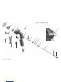 2
2
-
 3
3
-
 4
4
-
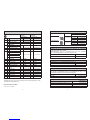 5
5
-
 6
6
-
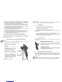 7
7
-
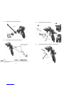 8
8
-
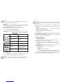 9
9
-
 10
10
-
 11
11
-
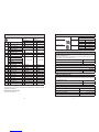 12
12
-
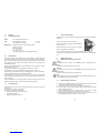 13
13
-
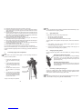 14
14
-
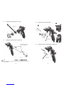 15
15
-
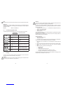 16
16
-
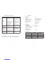 17
17
-
 18
18
-
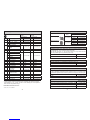 19
19
-
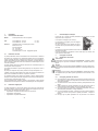 20
20
-
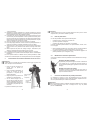 21
21
-
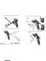 22
22
-
 23
23
-
 24
24
-
 25
25
-
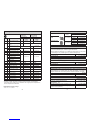 26
26
-
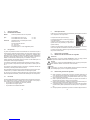 27
27
-
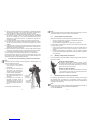 28
28
-
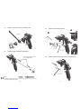 29
29
-
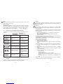 30
30
-
 31
31
-
 32
32
-
 33
33
-
 34
34
-
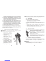 35
35
-
 36
36
-
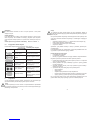 37
37
-
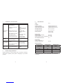 38
38
-
 39
39


Walther PILOT BOND 2K Operating Instructions Manual
- Categoría
- Potentes sistemas de pulverización fina
- Tipo
- Operating Instructions Manual
en otros idiomas
- français: Walther PILOT BOND 2K
- Deutsch: Walther PILOT BOND 2K
- polski: Walther PILOT BOND 2K
Otros documentos
-
WALTHER PILOT TWIN Instrucciones de operación
-
-
-
-
-
-
-
-
-