
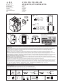
A1 A2
1
L2 3L2 5L3
2T1 4T2 6T3
14X
NO
NC
NC
NO
13X
21X
22X
A1 A2
1
L2 3L2 5L3
2T1 4T2 6T3
14X
NO
NC
NC
NO
13X
21X
22X
44X
NO
NC
NC
NO
43X
31X
32X
Operating instructions
Betriebsanleitung
Notice d’instructions
Instruktion
Istruzioni tecniche
IInstrucciones de empleo
Ohje
Contactors
Schtze
Contacteurs
Kontaktorer
Contattori
Contactores
Kontaktori
A1
A2
M 3,5
1 N.m
5
Pozidriv N 2
2 x 1 ................... 2,5 mm
2 x 0,75 ............. 2,5 mm
2
2
/ > 3,5 mm, L < 8 mm
L
/
Pos. 5
Pos. 4
Pos. 3
Pos. 2
Pos. 1
Max. 32mm
Max. 30mm
Max. 10mm
M10
28 N.m - 240 lb.in
M8
18 N.m - 160 lb.in
A 145, A 185
AF 145, AF 185
A 145, A 185
AF 145, AF 185
A 210, A 260, A 300
AF 210, AF 260, AF 300
A 210, A 260, A 300
AF 210, AF 260, AF 300
Max. 24mm
Max. 22mm
Max. 8mm
1
2
1 2+
A ... -30-22
AF ... -30-22
A ... -30-11
AF ... -30-11
1
1L1 3L2 5L3
2T1 4T2 6T3A2
A1
31X
NC
43X
44X32X
NO
NCNO
13X
NC
21X
22X14X
NO
NCNO
1L1 3L2 5L3
2T1 4T2 6T3A2
A1
13X
NC
21X
22X14X
NO
NCNO
1SFC 380003-89, 1(4), ed.E, April 2010
AF 145, AF 185, AF 210, AF 260, AF 300
A 145, A 185, A 210, A 260, A 300
Warning! The operation, installation and servicing of this product must be carried out by a qualified electrician, following installation standards and safety regulations.
Before operating the contactor, make sure that the control voltage supply corresponds with the coil marking. Wrong control voltage can damage the coil. Do not touch
live parts. Danger!
Warnung! Die inbetriebnahme und die installation des vorhandenen Gerätes sowie jegliche Wartungsarbeiten müssen durch einen Fachelektriker, der die anerkannten
technischen Regeln, die Montagenormen und die Sicherheitsvorschriften beachtet, durchgefürt werden. Vor Inbetriebnahme der Schüttze prüfen ob Steuerspannung
am Verwendungsort mit den aufgedruckten Spulendaten übereinstimmt. Der Anschluss einer anderen Steuerspannung kan zur Zerstörung der Spule führen.
Spannung führende Teile nicht berühren. Lebensgefahr!
Attention! La mise en ceuvre et I'installation de cet appareil et toute intervention doivent être affectuées par un électricien professionnel appliquant les normes
d'installation et les réglements de sécurité. Avant la mise en marche des contacteurs, vérifier que la tension du circuit de contrôle correspond bien aux indications de la
bobine. Le raccordement d'une tension différente peut mener à une destruction de la bobine. Ne pas toucher les pièces sous tension. Danger de mort!
Varning! Igångsättning och installation av apparaten samt alla ingrepp bör utföras av en kompetent elektriker enligt alla gällande installationsnormer och säkerhetsregler.
Kontrollera före installation av kontaktorn att aktuell manöverspänning överensstämmer med spolens märkdata. Felaktig manöverspänning kan skada spolen.
Beröring av spänningsförande delar är förenat med livsfara.
Attenzione! La messa in opera, I'installazione di questo apparecchio ed ogni tipo di intervento devona essere effettuati da un elettricista professionista il quale applichi
le regole del mestiere, le norme di installazioneed i regolamenti di sicuezza. Prima della messa in servizio del contattore, verificare che la tensione del circuito di comando
corrisponda esattamente a quella indicata sulla bobina.
L'alimentazione con una tensione diversa, puo provocare la distruzione della bobina. Non toccare le parti attive. Pericole de vita!
Atención! La puesta en aplicación, la instalación de este aparato y cualquier intervención deben realizarse por un electricista profesional que aplique las reglas del oficio
las normas de instalaciones y la reglamentación de seguridad. Antes de la puesta en servicio del contactor, comprobar si coinciden la tensión de mando con los datos
impresos en la bobina. La conexión de otra tensión de mando puede producir la destruccion de la bobina. Las partes bajo tensión no deben tocarse. Peligro de muerte!
30°
30°
Pos 1 ± 30°
A(F) 145, 185: Enclosure with min. dimension 24 by 20 by 10 inches should be used.
According to UL 508:
A(F) 210, 260, 300: Enclosure with min. dimension 36 by 30 by 12 inches should be used.
Use wire Cu 75 C only.
注意!所有对此产品的操作、安装及维护,均需由合格的电气工程师,在遵循安装标准及安全准则的条件下进行。在运行之前,
确认控制电压与与线圈上标识一致,否则会损坏线圈。不要接触带电部分。危险!
AF: 12 VA
A/AD: XX VA
A(AF)145(D),A(AF)185(D), A205D = A/AD: 51 VA
A(AF)210,A(AF)260,A(AF)300,A260D,A300D
A370D = A/AD: 89VA

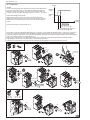
General
Control with voltage on A1 and A2
AF-Contactors
The AF-Contactors have the same dimensions and nearly the same apperance as
the A-Contactors of equal rating. The only difference is that AF-Contactors are
fitted with an electronic coil interface. For a given coil, this interface allows the
contactor to accept a very wide voltage range a well in d.c. as in a.c. , 50 or 60 Hz.
Operatin of AF-Contactors can be done as with conventional contactors by
applaying and removing voltage on A1 and A2. The function limits are very exact
compared with a conventional contactor and there is a built in hysterises in the
function.
Note: Minimum length of the starting pulse=70 ms
AF-Contactors comply with international standards IEC 947-1, IEC 947-4-1 and European standards EN 60 947-1, EN 60 497-4-1. Moreover in
environment 2, they meet the electromagnetic compability rules (EMC): additional clauses A11 and A11 to above mentioned EN standards.
Using these materials in environment 1 may lead to radio-interferences requiringthe use of aditional mitigation methods. Here are the definitions
given in the additional clause A11 to standard EN 60 497-1.
Environment 1: "Mainly relates to low-voltage public networks such as residential, commercial and light industrial locations/installations.
Highly distributing sources such as arc welders are not covered by this environment".
Environment 2: "Mainly relates to low-voltage industrial networks/locations/installations including highly distrurbing sources".
Position
Contactor
closed
Contactor
open
100V 250V
Control
voltage
Normal range
Accepted range
77% of lower voltage range level
55% of lower voltage range level
5
6
x3
x3
1/4
x4
2x3
11
12
9
2x3
10
KZ 185,300
KZ 185,300
2x3
8
7
1
1/4
x4
2x3
2
3
4
13
1/2
5
x4
4
6
1
2
1/4
3
x4
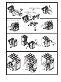
(A 145...300)
ZA 185, 300
ZAF 185, 300
(AF 145...300)
1SFC 380003-89, 2(4)
8 Nm - 71 lb.in

13
9
10
7
7
8
Click
11
1/2
14
x4
15
16
x4
2
Lift
Lift
3
3
5
2
4
1
4
6
Lift
1SFC 380003-89, 3(4)
7
8
12
11
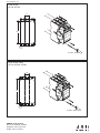
A 145, A 185
AF 145, AF 185
A 210, A 260, A 300
AF 210, AF 260, AF 300
AF 145, 185
ZAF 185
AF 210, 260, 300
ZAF 300
A 145, 185
ZA 185
A 210, 260, 300
ZA 300
1/4

ABB AB, Cewe-Control
SE-721 61 Västerås, Sweden
Telephone +46 21 32 07 00
Telefax +46 21 12 60 01
2,9 Nm - 26 lb.in
2,9 Nm - 26 lb.in
165
M5
35
187
M5
43,8
A145, A185
AF145, AF185
A210, A260, A300
AF210, AF260, AF300
1SFC 380003-89, 4(4)
-
 1
1
-
 2
2
-
 3
3
-
 4
4


en otros idiomas
- English: ABB A 210 Operating instructions
Artículos relacionados
Otros documentos
-
 Automation Direct Soft-starter SSW07 Manual de usuario
-
WEG SSW08 Manual de usuario
-
 Automation Direct SSW-05 Manual de usuario
-
Socomec 14715111 Instruction Sheet
-
WEG SSW06 Guía del usuario
-
-
Wacker Neuson CT30EDT Manual de usuario
-
Eurotherm ATS22 El manual del propietario
-
-
Schneider Electric TPRS-065 TeSys Active Starters and Power Interface Modules Manual de usuario

