Extraflame Automatic loading pellet stocking tank El manual del propietario
- Tipo
- El manual del propietario

SERBATOIO STOCCAGGIO PELLET CARICO AUTOMATICO
AUTOMATIC LOADING PELLET STORAGE TANK
RÉSERVOIR DE STOCKAGE DU PELLET CHARGEMENT AUTOMATIQUE
PELLETLAGERTANK FÜR DIE AUTOMATISCHE BEFÜLLUNG
DEPÓSITO ALMACENAMIENTO PELLET CARGA AUTOMÁTICA
COMPATIBILE CON COMPATIBLE WITH COMPATIBLE AVEC KOMPATIBEL MIT COMPATIBLE CON : HP152230
SERBATOIO STOCCAGGIO PELLET CARICO AUTOMATICO
AUTOMATIC LOADING PELLET STORAGE TANK
RÉSERVOIR DE STOCKAGE DU PELLET CHARGEMENT AUTOMATIQUE
PELLETLAGERTANK FÜR DIE AUTOMATISCHE BEFÜLLUNG
DEPÓSITO ALMACENAMIENTO PELLET CARGA AUTOMÁTICA

22

33
| ITALIANO
AVVERTENZE
Il presente manuale di istruzione costituisce parte integrante del prodotto: assicurarsi che sia sempre a corredo dell’apparecchio,
anche in caso di cessione ad un altro proprietario o utente, oppure di trasferimento su un altro luogo. In caso di suo
danneggiamento o smarrimento richiedere un altro esemplare al servizio tecnico di zona. Questo prodotto deve essere
destinato all’uso per il quale è stato espressamente realizzato. E’ esclusa qualsiasi responsabilità contrattuale ed extracontrattuale
del costruttore per danni causati a persone, animali o cose, da errori d’installazione, di regolazione di manutenzione e da usi
impropri.
L’installazione deve essere eseguita da personale qualicato e abilitato, il quale si assumerà l’intera responsabilità
dell’installazione denitiva e del conseguente buon funzionamento del prodotto installato. E’ necessario tenere in
considerazione anche tutte le leggi e le normative nazionali, regionali, provinciali e comunali presente nel paese in cui è
stato installato l’apparecchio.
Non vi sarà responsabilità da parte di Extraame S. p. A. in caso di mancato rispetto di tali precauzioni.
Dopo aver tolto l’imballo, assicurarsi dell’integrità e della completezza del contenuto. In caso di non rispondenza, rivolgersi al
rivenditore da cui è stato acquistato l’apparecchio.
Tutti i componenti elettrici che costituiscono il prodotto garantendone il corretto funzionamento, dovranno essere sostituiti
con pezzi originali esclusivamente da un centro di assistenza tecnica autorizzato.
SICUREZZA
E’ vietato l’uso del prodotto da parte di persone (inclusi bambini) con capacità siche, sensoriali e mentali ridotte, o
inesperte, a meno che non vengano super visionate ed istruite nell’uso dell’apparecchio da una persona responsabile per la
loro sicurezza.
I bambini devono essere controllati per assicurarsi che non giochino con l’apparecchio.
Non toccare il prodotto se si è a piedi nudi e con parti del corpo bagnate o umide.
E’ vietato modicare i dispositivi di sicurezza o di regolazione senza l’autorizzazione o le indicazioni del costruttore.
Non tirare, staccare, torcere i cavi elettrici fuoriuscenti dalla stufa anche se questa è scollegata dalla rete di alimentazione
elettrica.
Si raccomanda di posizionare il cavo di alimentazione in modo che non venga in contatto con parti calde dell’apparecchio.
La spina di alimentazione deve risultare accessibile dopo l’installazione.
Se si verica una anomalia di funzionamento contattare il servizio di assistenza tecnica e, in ogni caso, non disabilitare i
sistemi di sicurezza.

MAX
MIN
1
2
3
4
CARATTERISTICHE TECNICHE
INTERFACCIA UTENTE
LED 5 VERDE: INDICA LA PRESENZA DI TENSIONE:
ACCESA : TENSIONE PRESENTE
SPENTA : TENSIONE ASSENTE
LAMPEGGIANTE : È ATTIVO IL TEST DI CARICO
LED 4 GIALLO: INDICA LO STATO DEL SENSORE DI MAX DEL SERBATOIO STUFA
ACCESA : PELLET PRESENTE
SPENTA : PELLET NON PRESENTE
LED 3 GIALLO: INDICA LO STATO DEL SENSORE DI MIN DEL SERBATOIO STUFA
ACCESA : PELLET PRESENTE
SPENTA : PELLET NON PRESENTE
LED 2 ROSSO: INDICA LA PRESENZA DI UN ALLARME
SPENTA : INDICA L’ASSENZA DI ALLARMI
ACCESA : INDICA LA PRESENZA DELL’ALLARME PELLET ESAURITO
LAMPEGGIANTE : INDICA LA PRESENZA DELL’ALLARME SENSORI GUASTI
LED 1 GIALLO: INDICA LO STATO DI FUNZIONAMENTO
SPENTA : IL CARICATORE È IN OFF
ACCESA : IL CARICATORE È IN ATTESA DEL CARICO
LAMPEGGIANTE : IL CARICATORE STA CARICANDO PELLET MOTORE ATTIVO
4
| ITALIANO
DIMENSIONI L 1190 x H 2050 x P 653
PESO NETTO 97 kg
CAPIENZA TOTALE SERBATOIO 300kg
PORTATA 55 kg/h
TENSIONE NOMINALE 230V
FREQUENZA NOMINALE 50Hz
POTENZA ELETTRICA NOMINALE 100 W
LED 5 VERDE: INDICA LA PRESENZA DI TENSIONE:
ACCESA : TENSIONE PRESENTE
SPENTA : TENSIONE ASSENTE
LAMPEGGIANTE : È ATTIVO IL TEST DI CARICO
LED 4 GIALLO: INDICA LO STATO DEL SENSORE DI MAX DEL SERBATOIO STUFA
ACCESA : PELLET PRESENTE
SPENTA : PELLET NON PRESENTE
LED 3 GIALLO: INDICA LO STATO DEL SENSORE DI MIN DEL SERBATOIO STUFA
ACCESA : PELLET PRESENTE
SPENTA : PELLET NON PRESENTE
LED 2 ROSSO: INDICA LA PRESENZA DI UN ALLARME
SPENTA : INDICA L’ASSENZA DI ALLARMI
ACCESA : INDICA LA PRESENZA DELL’ALLARME PELLET ESAURITO
LAMPEGGIANTE : INDICA LA PRESENZA DELL’ALLARME SENSORI GUASTI
LED 1 GIALLO: INDICA LO STATO DI FUNZIONAMENTO
SPENTA : IL CARICATORE È IN OFF
ACCESA : IL CARICATORE È IN ATTESA DEL CARICO
LAMPEGGIANTE : IL CARICATORE STA CARICANDO PELLET MOTORE ATTIVO
DIMENSIONI L 1190 x H 2050 x P 653
PESO NETTO 97 kg
CAPIENZA TOTALE SERBATOIO 300kg
PORTATA 55 kg/h
TENSIONE NOMINALE 230V
FREQUENZA NOMINALE 50Hz
POTENZA ELETTRICA NOMINALE 100 W
CARATTERISTICHE TECNICHE

5
Per attivare il test:
Premere il tasto 1 no all’inizio del lampeggiamento del LED VERDE 1
Il sistema inizierà a caricare il serbatoio
della caldaia
.
Quando la sonda max (superiore) avrà rilevato la presenza di pellet, la funzione
TEST CARICO verrà automaticamente disattivata.
Terminato il test, il serbatoio è attivo e operativo.
Il sistema inizierà nuovamente a caricare (LED 1 LAMPEGGIANTE) quando il sensore di livello minimo (SONDA MIN - LED 3) sarà
scoperto/libero dal pellet no al raggiungimento del sensore di livello massimo (SONDA MAX LED 4) o terminato il conteggio
del TIMER.
Se non vi è richiesta, rimane in “ATTESA CARICO - LED 1 ACCESO”
FUNZIONAMENTO DEL SISTEMA
Se non è stato eseguito con “TEST CARICO”.
Premere il tasto 3 per circa 3 secondi, per attivare il sistema (LED 1 ACCESO)
Il sistema inizierà a caricare (LED 1 LAMPEGGIANTE) quando il sensore di livello minimo (SONDA MIN - LED 3) sarà
scoperto/ libero dal pellet no al raggiungimento del sensore di livello massimo (SONDA MAX LED 4), altrimenti se non vi è
richiesta, rimane in “ATTESA CARICO - LED 1 ACCESO”.
Nel caso di un Black out (mancanza di tensione di rete) il sistema si comporta come descritto di seguito:
Se il sistema era in OFF ritorna in OFF.
Se il sistema era in ATTESA CARICO ritorna in ATTESA CARICO.
Se il sistema era in fase di CARICO PELLET si porta in ATTESA CARICO.
Se il sistema era in ALLARME ritorna in ALLARME.
CARICO MANUALE
E’ possibile attivare il carico manualmente, anche se il sensore di livello minimo SONDA MIN LED 3 non è scoperto/ richiede.
Premendo il tasto 1 per 3 secondi è possibile eseguire un carico del serbatoio manuale senza controllare il livello inferiore
(SONDA MIN LED 3) caricando no al raggiungimento del sensore di livello massimo (SONDA MAX LED 4).
Dopo aver eseguito un carico manuale, il sistema resterà attivo, in attesa che il sensore di livello minimo richieda nuovamente
un carico.
SPEGNIMENTO DEL SISTEMA
Agendo per 3 secondi sul tasto 3 si attiva e disattiva il caricamento.
Se il sistema è disattivato, il LED 1 sarà spento.
Con il sistema attivo il LED 1 Sarà accesso sso.
FUNZIONAMENTO E LOGICA
Dopo aver installato il serbatoio stoccaggio pellet seguire le istruzioni:
Collegare il cavo di alimentazione alla rete elettrica.
Alimentare il serbatoio portando l’interruttore su “I”.
Il LED VERDE 5 si accenderà indicando la presenza di alimentazione.
TEST CARICO FACOLTATIVO
L’azienda consiglia di eseguire la funzione “TEST CARICO” prima dell’avvio. La funzione “TEST CARICO” deve essere eseguita con
il serbatoio della caldaia vuoto e in OFF ( LED 1 spento).
Questa funzione calcola automaticamente il tempo necessario per riempire il serbatoio della caldaia no al sensore di livello
massimo (SONDA MAX LED 4).
In questo modo, qualora la sonda superiore dovesse avere un’anomalia, il timer fermerà comunque il caricamento automatico
evitando fuoriuscite.
5
| ITALIANO

0.5CM
6
TARATURA
6
| ITALIANO
TARATURA SONDA
E’ possibile tarare le due sonde (minimo e massimo). Qualora sia necessario, o vengano sostituite, procedere con la taratura
come segue:
Collegare le sonde alla scheda elettronica.
Alimentare il sistema( Interruttore su “I”).
Posizionare davanti alla Sonda una tavoletta di legno (vedi gura 1)ad una distanza di circa 0,5cm.
Nel retro della Sonda (vedi gura 2) è presente una fessura per la taratura agibile tramite un cacciavite piccolo piatto.
Ruotare no a quando il led sul lato della sonda si accende.
Vericare la corretta lettura, allontanando e avvicinando la tavoletta, e vericando che nella distanza stabilita il led si illumini e
si spegna correttamente.
LED GIALLO
POSIZIONAMENTO SONDA
Prima di procedere alla foratura e montaggio delle sonde nel serbatoio e della angia sulla copertura del serbatoio della
caldaia è necessario assicurarsi che il loro posizionamento sia in linea!
Il tubo essibile deve essere posizionato in modo tale che durante il riempimento del serbatoio della caldaia crei una cresta
(vedi gura 3)vicino alla sonda superiore.
Questo è necessario per garantire una corretta lettura da parte del sensore di livello massimo (SONDA MAX LED 4) che
arresterà il carico di pellet.
Figura 2
Figura 1
Figura 3
TARATURA
Figura 2
Figura 1
LED GIALLO
TARATURA SONDA
E’ possibile tarare le due sonde (minimo e massimo). Qualora sia necessario, o vengano sostituite, procedere con la taratura
come segue:
Collegare le sonde alla scheda elettronica.
Alimentare il sistema( Interruttore su “I”).
Posizionare davanti alla Sonda una tavoletta di legno (vedi gura 1)ad una distanza di circa 0,5cm.
Nel retro della Sonda (vedi gura 2) è presente una fessura per la taratura agibile tramite un cacciavite piccolo piatto.
Ruotare no a quando il led sul lato della sonda si accende.
Vericare la corretta lettura, allontanando e avvicinando la tavoletta, e vericando che nella distanza stabilita il led si illumini e
si spegna correttamente.
CALDAIA
Figura 3

7
ALLARMI
In caso di anomalia il sistema disattiva automaticamente il carico del pellet, segnalando l’allarme tramite un cicalino acustico ad
intermittenza e visualizzando lo stato d’allarme:
7
| ITALIANO
SEGNALAZIONE E MOTIVAZIONE AZIONE/ CAUSA
LED 2 ACCESO
FISSO
Pellet esaurito nel silos.
Caricare il pellet.
Resettare l’allarme premendo per 3 secondi il tasto 2.
Riavviare il sistema premendo il tasto 3.
LED 2 ACCESO
LAMPEGGIANTE
Indica una anomalia ai sensori.
I sensori non sono montati/collegati correttamente. Vericare il corretto
collegamento sulla scheda e sul serbatoio
(sensore di minima in basso, sensore di massima sopra)
Si è creato un vuoto davanti alla sonda di minima - scuotere
il contenuto del pellet del silos.
Sonda guasta.
LA VERIFICA ED EVENTUALI INTERVENTI SU PARTI MECCANICHE O ELETTRICHE DEVONO ESSERE ESEGUITE DA PERSONALE QUALIFICATO!
SCHEDA ELETTRONICA
Br Bu W
MARRONE BLU BIANCO

1
2
88
| ITALIANO

1
9
| ITALIANO

2
b
a
ROTATION MAX 30 °
b
6
A
A
B
B
C
10
INSERIRE LA COCLEA “a” E FISSARE CON LA FASCIETTA STRINGI TUBO “b”.
MONTARE I DUE COPERCHI “A ”, FISSANDO PRIMA LE VITI “B” E DOPO LE RESTANTI VITI. STRINGERE LA FASCETTA
“C” FINO CHE LA COLEA RESTI BLOCCATA.
| ITALIANO

3
a
b
4
180°
1.
2.
3.
4.
11
POSIZIONAMENTO “A” STANDARD o “B”?
SOLO IN CASO POSIZIONAMENTO “B”
| ITALIANO

5
30mm
max
min
H
H
1.
2.
3.
6
MAX
MIN
D
D
12
SENSORE
LIVELLO
MAX
SENSORE
LIVELLO
MIN
Marrone
Bianco
Blu
Marrone
Bianco
Blu
| ITALIANO

7
A
F
G
I
A
13
| ITALIANO

9
8
b
14
ROTATION MAX 30 °
14
| ITALIANO
14
ALLENTARE IL DADO E ORIENTARE GRUPPO MOTORE E TUBO FLESSIBILE IN DOTAZIONE IN ASSE AI SENSORI
SERBATOIO CALDAIA

11
10
1515
CALDAIA
| ITALIANO

16
ENGLISH
WARNINGS
This instruction manual is an integral part of the product: make sure it is always supplied with the appliance, even i transferred
to another owner or user, or when transferred to another place. If it is damaged or lost, request a copy from the your area after-
sales service. This product is intended for the use for which it has been expressly realised. The manufacturer is excluded from
any contractual or extracontractual liability owing to injury/damage caused to persons, animals or objects, installation errors,
maintenance adjustment and improper use.
The installation must be performed by qualied and enabled sta, which assumes full responsibility for the denitive
installation and the consequent good working order of the product installed. All of the national, regional, provincial and
municipal Laws and Standards, present in the country in which the appliance is installed, must be taken into consideration.
Extraame S. p. A. is not liable if these precautions are not respected.
After having removed the packaging, check the integrity and completeness of the content. If this is not the case, contact the
dealer where the appliance was purchased.
All electric components that constitute the product guaranteeing its correct operation, must be replaced with original parts
exclusively from an authorised technical after-sales centre.
SAFETY
This appliance is not intended for use by persons (including children) with reduced physical and sensory conditions or lack
of experience and knowledge, unless they have been given supervision or instruction concerning use of the appliance by a
person responsible for their safety.
Children should be supervised to ensure they do not play with the appliance.
Do not touch the product if you are barefoot or with wet or damp parts of the body.
It is prohibited to modify the safety or regulation devices without the manufacturer's authorisation or instructions.
Do not pull, detach, twist the electric cables leaving the stove, even if they are disconnected from the electric mains supply.
It is recommended to position the power supply cable in a way that it does not come into contact with hot parts of the
appliance.
The power supply plug must be accessible after installation.
If operating anomalies occur, contact the technical after-sales service and, in no case should the safety systems be disabled.

MAX
MIN
1
2
3
TECHNICAL FEATURES
USER INTERFACE
GREEN LED 5: INDICATES THE PRESENCE OF VOLTAGE:
ON: VOLTAGE PRESENT
OFF: NO VOLTAGE
FLASHING: THE LOAD TEST IS ACTIVE
YELLOW LED 4: INDICATES THE MAX SENSOR STATUS OF THE STOVE TANK
ON: PELLETS PRESENT
OFF: PELLETS NOT PRESENT
YELLOW LED 3: INDICATES THE MIN SENSOR STATUS OF THE STOVE TANK
ON: PELLETS PRESENT
OFF: PELLETS NOT PRESENT
RED LED 2: INDICATES THE PRESENCE OF AN ALARM
OFF: INDICATES THE ABSENCE OF ALARMS
ON: INDICATES THE PRESENCE OF THE PELLET FINISHED ALARM
FLASHING: INDICATES THE PRESENCE OF THE SENSOR FAULT ALARM
YELLOW LED 1: INDICATES THE OPERATING STATUS
OFF: THE LOADING DEVICE IS IN OFF MODE
ON: THE LOADING DEVICE IS IN LOAD STANDBY MODE
FLASHING: THE LOADING DEVICE IS LOADING THE PELLETS, MOTOR ACTIVE
17
ENGLISH
DIMENSIONS L 1190 x H 2050 x D 653
NET WEIGHT 97 kg
TOTAL TANK CAPACITY 300 kg
FLOW RATE 55 kg/h
RATED VOLTAGE 230V
RATED FREQUENCY 50Hz
RATED ELECTRICAL POWER 100 W

To activate the test:
Press key 1 until GREEN LED 1 STARTS TO FLASH
The system will start to load the
boiler
tank.
When the max probe (upper) has detected the presence of pellets, the
LOADING TEST function will be automatically deactivated.
On completion of the test, the tank is active and operational.
The system will start to load again (LED 1 FLASHING) when the minimum level sensor (MIN PROBE - LED 3) is uncovered/free
from the pellets until the max level sensor is reached (MAX PROBE LED 4) or the TIMER count has ended.
If there is no request, it remains in “LOAD STAND-BY - LED 1 ON”
SYSTEM OPERATION
If it has not been performed with “LOAD TEST”.
Press key 3 for about 3 seconds, to activate the system (LED 1 ON)
The system will start to load (LED 1 FLASHING) when the minimum level sensor (MIN PROBE - LED 3) is
uncovered/free from pellets until the max level sensor is reached (MAX PROBE LED 4), otherwise if there is no request, it
remains in “LOAD STAND-BY - LED 1 ON”.
In the event of a Black out (no mains voltage), the system behaves as described below:
If the system was in OFF mode, it returns to OFF.
If the system was in LOAD STAND-BY, it returns to LOAD STAND-BY.
If the system was in PELLET LOAD phase, it goes to PELLET LOAD.
If the system was in ALARM mode, it returns to ALARM.
MANUAL LOADING
Manual loading can be activated, even if the minimum level sensor MIN PROBE LED 3 is not uncovered/requests.
By pressing key 1 for 3 seconds, the tank can be loaded manually without controlling the lower level (MIN PROBE LED 3)
loading until the maximum level sensor is reached (MAX PROBE LED 4).
After having performed a manual load, the system will remain active while waiting for the minimum sensor level to request a
load again.
SWITCHING THE SYSTEM OFF
By operating for 3 seconds on key 3, loading will be activated and deactivated.
If the system is deactivated, the LED 1 will be o.
With the system active, LED 1 will be on with xed light.
OPERATION AND LOGIC
After having installed the pellet storage tank, follow the instructions:
Connect the power supply cable to the mains electricity.
Power the tank by taking the switch to "I".
The GREEN LED 5 will switch on indicating the presence of the power supply.
LOAD TEST FACULTATIVE
The company recommends performing the “LOAD TEST” before start-up. The “LOAD TEST” function must be carried out with the
boiler tank empty and in OFF mode (LED 1 o).
This function automatically calculates the time necessary to ll the boiler tank up to the maximum level sensor (MAX PROBE
LED 4).
In this way, whenever the upper probe should have an anomaly, the timer will stop automatic loading anyway, thus preventing
escapes.
18
ENGLISH

0.5CM
CALIBRATION
19
ENGLISH
BOILER
PROBE CALIBRATION
The two probes can be calibrated (minimum and maximum). Whenever necessary, or when replaced, calibrate as follows:
Connect the probes to the circuit board.
Power the system (Switch at “I”).
Position a wooden board in front of the probe (see gure 1) at a distance of approx. 0.5cm.
There is a slot in the rear (see gure 2) for practical calibration using a at tip screwdriver.
Turn until the LED on the side of the probe switches on.
Check the correct reading, moving the block closer and away and checking that the LED illuminates and switches o correctly
in the distance established.
YELLOW LED
PROBE POSITIONING
Before drilling and assembly of the probes in the thermoproduct/boiler tank and of the ange on the tank lid, make sure
that they are positioned in line!.
The exible hose must be position in a way that, during boiler tank lling, it creates a peak (see gure 3) near to the upper
probe.
This is necessary to guarantee a correct reading of the maximum level by the sensor (MAX PROBE LED 4), which will stop
pellet loading.
Figure 2
Figure 1
Figure 3

ALARMS
In the event of an anomaly, the system automatically deactivates pellet loading, indicating the alarm via an intermittent acoustic
buzzer and displaying the alarm state:
20
ENGLISH
SIGNAL AND REASON ACTION/CAUSE
LED 2 ON
FIXED LIGHT
No pellets in silo.
Load the pellets.
Reset the alarm by pressing key 2 for 3 seconds.
Re-start the system by pressing key 3.
LED 2 ON WITH
FLASHING LIGHT
Indicates a sensor anomaly.
The sensors are not assembled/connected correctly. Check correct connection
on the board and on the tank.
(minimum level sensor low, maximum level sensor above)
An empty space has been formed in front of the minimum level probe - shake
the pellet content in the silos.
Probe fault.
THE CHECKS AND ANY INTERVENTIONS ON MECHANICAL OR ELECTRICAL PARTS MUST BE PERFORMED BY QUALIFIED STAFF!
CIRCUIT BOARD
Br Bu W
BROWN BLUE WHITE

1
2
ENGLISH
21

1
ENGLISH
22

2
b
a
ROTATION MAX 30 °
b
6
A
A
B
B
C
ENGLISH
INSERT “A” AUGER AND KEEP IN POSITION USING THE “B” PIPE BAND, NOT TIGHTEN
MOUNT THE TWO “A”COVERS, FIXING FIRST THE “B” SCREWSAND AFTER THE REMAINING SCREWS. TIGHTEN THE “C”
CLAMP UNTIL THE AUGER REMAINS BLOCKED.
23

3
a
b
4
180°
1.
2.
3.
4.
ENGLISH
ONLY IN THE EVENT OF POSITIONING "B"
POSITIONING “A” STANDARD or “B”?
24

5
30mm
max
min
H
H
1.
2.
3.
6
MAX
MIN
D
D
ENGLISH
Brown
White
Blue
Brown
White
Blue
SENSOR
LEVEL
MAX
SENSOR
LEVEL
MIN
25

7
A
F
G
I
A
ENGLISH
26

9
8
b
27
ROTATION MAX 30 °
27
ENGLISH
LOOSEN THE NUTS AND POSITION MOTOR UNIT AND FLEXIBLE HOSE SUPPLIED IN AXIS WITH THE SENSORS
TANK
BOILER

11
10
28
ENGLISH
BOILER

29
| FRANÇAIS
MISES EN GARDE
Le présent manuel d'instruction fait partie intégrante du produit: s'assurer qu'il accompagne toujours l'appareil, même en cas
de cession à un autre propriétaire ou utilisateur ou bien de transfert dans un autre endroit. En cas d'endommagement ou
de perte il faut en demander un autre exemplaire au Service Après-Vente (SAV) le plus proche. Ce produit doit être destiné à
l'utilisation pour laquelle il a été espressément réalisé. Toute responsabilité contractuelle et extracontractuelle du fabricant est
exclue pour les dommages causés aux personnes, animaux ou choses, par des erreurs d'installation, de réglage d'entretien et
d'utilisations impropres.
L'installation doit être eectuée par un personnel qualié et autorisé, qui s'assumera toute la responsabilité de l'installation
dénitive et par conséquent du bon fonctionnement de l'appareil installé. Il faut également tenir en considération toutes
les lois et les réglementations nationales, régionales, départementales et communales présentes dans le pays d'installation
de l'appareil.
Extraame S.p.A. décline toute responsabilité en cas de non respect de ces consignes.
Après avoir enlevé l'emballage, s'assurer que le contenu soit intègre et complet. Le cas échéant, s'adresser au revendeur qui a
vendu l'appareil.
Tous les composants électriques qui constituent le produit et en garantissent le bon fonctionnement, devront être remplacés
avec des pièces originales exclusivement par un SAV autorisé.
SÉCURITÉ
L'utilisation du produit est interdite aux personnes (y compris les enfants) ayant des capacités physiques, sensorielles et
mentales réduites ou sans expérience, à moins qu'elles ne soient surveillées et instruites pour l'utilisation de l'appareil par une
personne responsable de leur sécurité.
Les enfants doivent être contrôlés pour éviter qu'ils ne jouent pas avec l'appareil.
Ne pas toucher le produit pieds nus et/ou avec des parties du corps mouillées ou humides.
Il est interdit de modier les dispositifs de sécurité ou de réglage sans l'autorisation ou les indications du fabricant.
Ne pas tirer, détacher, tordre les câbles électriques qui sortent du poêle même ci ce dernier est débranché du réseau
d'alimentation électrique.
Nous recommandons de positionner le câble d'alimentation de façon à ce qu'il ne touche pas les parties chaudes de
l'appareil.
La che d'alimentation doit être accessible après l'installation.
Si une anomalie de fonctionnement devrait se manifester contacter le SAV et, dans tous les cas, ne pas désactiver les
systèmes de sécurité.

MAX
MIN
1
2
3
CARACTÉRISTIQUES TECHNIQUES
INTERFACE UTILISATEUR
LED 5 VERTE: INDIQUE LA PRÉSENCE DE TENSION:
ALLUMÉE: TENSION PRÉSENTE
ÉTEINTE: TENSION ABSENTE
CLIGNOTANTE: LE TEST DE CHARGEMENT EST ACTIF
LED 4 JAUNE: INDIQUE L'ÉTAT DU CAPTEUR DE NIVEAU MAXI DU RÉSERVOIR DU
POÊLE
ALLUMÉE: PELLET PRÉSENT
ÉTEINTE: PAS DE PELLET
LED 3 JAUNE: INDIQUE L'ÉTAT DU CAPTEUR DE NIVEAU MIN DU RÉSERVOIR DU POÊLE
ALLUMÉE: PELLET PRÉSENT
ÉTEINTE: PAS DE PELLET
LED 2 ROUGE: INDIQUE LA PRÉSENCE D'UNE ALARME
ÉTEINTE: INDIQUE L'ABSENCE DES ALARMES
ALLUMÉE: INDIQUE LA PRÉSENCE DE L'ALARME DE PELLET TERMINÉ
CLIGNOTANTE: INDIQUE LA PRÉSENCE DE L'ALARME DE CAPTEURS EN PANNE
LED 1 JAUNE: INDIQUE L'ÉTAT DE FONCTIONNEMENT
ÉTEINTE: LE CHARGEUR EST EN MODE OFF
ALLUMÉE: LE CHARGEUR ATTEND LE CHARGEMENT
CLIGNOTANTE: LE CHARGEUR EST EN TRAIN DE CHARGER LE PELLET MOTEUR ACTIF
30
| FRANÇAIS
DIMENSIONS L 1190 x H 2050 x P 653
POIDS NET 97 kg
CAPACITÉ TOTALE DU RÉSERVOIR 300kg
CAPACITÉ DE CHARGE 55 kg/h
TENSION NOMINALE 230V
FRÉQUENCE NOMINALE 50Hz
PUISSANCE ÉLECTRIQUE NOMINALE 100 W

Pour activer le test:
Appuyer sur la touche 1 jusqu'à ce que la LED VERTE 1 COMMENCE À CLIGNOTER
Le système commencera à charger le réservoir
du chaudière
.
Quand la sonde maxi (supérieure) aura relevé la présence de pellet, la fonction
TEST CHARGEMENT sera automatiquement désactivée.
Terminé le test, le réservoir est actif et opérationnel.
Le système commencera à nouveau à charger (LED 1 CLIGNOTANTE) quand le capteur de niveau minimal (SONDE MIN - LED
3) sera découvert/libre du pellet jusqu'à l'atteinte du capteur de niveau maximal (SONDE MAXI LED 4) ou le comptage du
MINUTEUR terminé.
Si il n'y a pas de demande, il reste en "ATTENTE DE CHARGEMENT - LED 1 ALLUMÉE"
FONCTIONNEMENT DU SYSTÈME
S'il n'a pas été eectué avec “TEST CHARGEMENT”.
Appuyer sur la touche 3 pendant environ 3 secondes, pour activer le système (LED 1 ALLUMÉE)
Le système commencera à charger (LED 1 CLIGNOTANTE) quand le capteur de niveau minimal (SONDE MIN - LED 3) sera
découvert/libre du pellet jusqu'à atteinte du capteur de niveau maximal (SONDE MAXI LED 4), autrement s'il n'y a pas de
demande, il reste en “ATTENTE CHARGEMENT - LED 1 ALLUMÉE”.
Dans le cas d'un blackout (panne d'électricité générale) le système se comporte de la façon suivante:
Si le système était en mode OFF il revient en mode OFF.
Si le système était en mode ATTENTE CHARGEMENT il revient en mode ATTENTE CHARGEMENT.
Si le système était en phase de CHARGEMENT PELLET il se met en mode ATTENTE CHARGEMENT.
Si le système était en état d'ALARME il revient en état d'ALARME.
CHARGEMENT MANUEL
On peut activer le chargement manuel, même si le capteur de niveau minimal SONDE MIN LED 3 n'est pas découvert/requiert.
En appuyant sur la touche 1 pendant 3 secondes on peut eectuer un chargement manuel du réservoir sans contrôler le niveau
inférieur (SONDE MIN LED 3) en chargeant jusqu'à l'atteindre le capteur de niveau maximal (SONDE MAXI LED 4).
Après avoir eectué un chargement manuel, le système restera actif, en attendant que le capteur de niveau minimal demande
à nouveau un chargement.
ARRÊT DU SYSTÈME
En agissant pendant 3 secondes sur la touche 3 on active et désactive le chargement.
Si le système est désactivé, la LED 1 sera éteinte.
Avec le système actif la LED 1 sera allumée en mode xe.
FONCTIONNEMENT ET LOGIQUE
Après avoir installé le réservoir de stockage du pellet suivre les instructions:
Brancher le câble d'alimentation au réseau électrique.
Alimenter le réservoir en positionnant l'interrupteur sur “I”.
La LED VERTE 5 s'allumera en indiquant la présence d'alimentation.
TEST CHARGEMENT FACULTATIF
L’entreprise conseille d'eectuer la fonction “TEST CHARGEMENT” avant la mise en marche. La fonction “TEST CHARGEMENT”doit
être eectuée avec le réservoir du produit chaudière vide et en mode OFF (LED 1 éteinte).
Cette fonction calcule automatiquement le temps nécessaire pour remplir le réservoir du chaudière jusqu'au capteur de niveau
maximal (SONDE MAXI LED 4).
De cette façon, en cas d'anomalie de la sonde supérieure, le minuteur arrêtera tout de même le chargement automatique en
évitant des débordements.
31
| FRANÇAIS

0.5CM
TARAGE
32
| FRANÇAIS
CHAUDIÈRE
RÉGLAGE DE LA SONDE
On peut régler les deux sondes (minimum et maximum). Si cela est nécessaire ou si celles-ci on été remplacées, procéder avec
le réglage de la façon suivante:
Brancher les sondes à la carte électronique.
Alimenter le système (Interrupteur sur "I").
Positionner devant la sonde une planche en bois (voir gure 1) à une distance d'environ 0,5 cm.
Une ssure pour le réglage, à laquelle on peut accéder à l'aide petit tournevis à tête plate, se trouve derrière la sonde (voir
gure 2).
Tourner jusqu'à ce que la led sur le côté de la sonde s'allume.
Vérier la lecture correcte, en éloignant et en approchant la planche et en vériant que dans la distance établie la led s'éclaire
et s'éteint correctement.
LED JAUNE
POSITIONNEMENT DE LA SONDE
Avant de procéder au perçage et montage des sondes dans le réservoir et de la bride sur la couverture du réservoir du
chaudière il faut s'assurer que leur positionnement soit en ligne!
Le tuyau exible doit être positionné de façon à créer, durant le remplissage du réservoir du produit chaudière, une pointe
(voir gure 3) près de la sonde supérieure.
Cela est nécessaire pour garantir une lecture correcte de la part du capteur de niveau maximal (SONDE MAXI LED 4) qui
arrêtera le chargement de pellet.
Figure 2
Figure 1
Figure 3

ALARMES
En cas d'anomalie le système désactive automatiquement le chargement du pellet, en signalant l'alarme grâce à un signal
sonore à intermittence et en visualisant l'état d'alarme:
33
| FRANÇAIS
SIGNALISATION ET MOTIVATION ACTION/CAUSE
LED 2 ALLUMÉE
FIXE
Il n'y a aplus de pellet dans le silo.
Charger le pellet.
Réarmer l'alarme en appuyant pendant 3 secondes sur la touche 2.
Réactiver le système en appuyant sur la touche 3.
LED 2
CLIGNOTANTE
Indique une anomalie aux
capteurs.
Les capteurs ne sont pas montés/branchés correctement. Vérier le
branchement correct sur la carte et sur le réservoir
(capteur de minimum bas, capteur de maximum haut)
Si un vide s'est créé devant la sonde de minimum - secouer
le contenu du pellet du silo.
Sonde en panne.
LE CONTRÔLE ET LES ÉVENTUELLES INTERVENTIONS MÉCANIQUES OU ÉLECTRIQUES DOIVENT ÊTRE EFFECTUÉES PAR UN PERSONNEL
QUALIFIÉ!
CARTE ÉLECTRONIQUE
Br Bu W
MARRON BLEU BLANC

1
2
| FRANÇAIS
34

1
| FRANÇAIS
35

2
b
a
ROTATION MAX 30 °
b
6
A
A
B
B
C
| FRANÇAIS
INSEREZ LA VIS SANS FIN “A” ET FIXEZLA AVEC LE COLLIER SERRETUBE “B”.
INSTALLEZ LES DEUX COUVERCLES “A” EN FIXANT AVANT LES VIS “B” ET APRÈS LES VIS RESTANTES. SERRER LE
COLLIER C DE MANIÈRE QUE LA VIS SANS FIN SOIT EN PLACE.
36

3
a
b
4
180°
1.
2.
3.
4.
| FRANÇAIS
POSITIONNEMENT “A” STANDARD ou “B”?
UNIQUEMENT EN CAS DE POSITIONNEMENT "B"
37

5
30mm
max
min
H
H
1.
2.
3.
6
MAX
MIN
D
D
| FRANÇAIS
Marron
Blanc
Bleu
Marron
Blanc
Bleu
CAPTEUR
NIVEAU
MAXI
CAPTEUR
NIVEAU
MIN.
38

7
A
F
G
I
A
| FRANÇAIS
39

9
8
b
40
ROTATION MAX 30 °
40
| FRANÇAIS
RÉSERVOIR
CHAUDIÈRE
DESSERRER LES ÉCROUS ET ORIENTER LE GROUPE MOTEUR ET LE TUYAU FLEXIBLE EN DOTATION EN LIGNE AVEC LES CAPTEURS

11
10
41
| FRANÇAIS
CHAUDIÈRE

42
DEUTSCH
ACHTUNG
Die vorliegende Bedienungsanleitung ist wesentlicher Bestandteil des Produkts: Stellen Sie sicher, dass sie sich immer beim
Gerät bendet, auch wenn das Gerät den Besitzer wechselt oder an einen anderen Ort gebracht wird. Im Falle von Schäden oder
bei Verlust der Anleitung, fordern Sie beim lokalen Kundendienst ein neues Exemplar an. Dieses Produkt muss entsprechend
seinem Verwendungszweck verwendet werden, für den es entwickelt wurde. Der Hersteller lehnt jegliche vertragliche und
außervertragliche Haftung für Schäden an Personen, Tieren oder Gegenständen ab, die auf Fehler bei der Installation, Wartung
und unsachgemäße Verwendung zurückzuführen sind.
Die Installation muss von qualizierten und hierfür ausgebildeten Fachtechnikern durchgeführt werden, die die gesamte
Verantwortung für die endgültige Installation und die ordnungsgemäße Funktion des installierten Produkts übernehmen.
Außerdem müssen alle nationalen, regionalen und kommunalen Gesetze und Vorschriften, die am Installationsstandort
des Geräts gelten, beachtet werden.
Extraame S. p. A. ist nicht haftbar in Fällen, in denen diese Vorsichtsmaßnahmen nicht beachtet werden.
Stellen Sie nach der Entfernung der Verpackung sicher, dass das Gerät unversehrt ist, und prüfen Sie, ob der Inhalt vollständig
ist. Im Fall von Unregelmäßigkeiten nehmen Sie Kontakt mit dem Händler auf, bei dem Sie das Gerät gekauft haben.
Alle elektrischen Komponenten des Produkts, die den ordnungsgemäßen Betrieb garantieren, dürfen nur in einem autorisierten
Werkstattbetrieb ausschließlich durch originale Ersatzteile ersetzt werden.
SICHERHEIT
Dieses Gerät darf nicht von Personen (einschließlich Kindern) mit verminderten physischen, sensorischen oder geistigen
Fähigkeiten oder ohne Erfahrung und Kenntnis benutzt werden, es sei denn, sie werden beim Gebrauch von einer für die
Sicherheit verantwortlichen Person überwacht und angelernt.
Es muss sichergestellt werden, dass Kinder mit diesem Gerät nicht spielen.
Das Produkt nicht mit feuchten oder nassen Körperteilen oder barfuß berühren.
Es ist verboten, die Sicherheitsvorrichtungen oder -einstellungen ohne Genehmigungen oder Anweisungen durch den
Hersteller zu ändern.
Die elektrischen Kabel der Heizung nicht herausziehen oder verdrehen, auch wenn sie nicht mit dem Stromnetz verbunden
sind.
Wir empfehlen, das Stromkabel so zu verlegen, dass es mit heißen Geräteteilen nicht in Berührung kommt.
Der Netzstecker muss nach der Installation zugänglich sein.
Wenn eine Funktionsstörung auftritt, kontaktieren Sie bitte den technischen Kundendienst und deaktivieren Sie auf
keinen Fall die Sicherheitsvorrichtungen.

MAX
MIN
1
2
3
TECHNISCHE EIGENSCHAFTEN
BEDIENOBERFLÄCHE
GRÜNE LED 5: ANZEIGE DER STROMSPANNUNG:
LEUCHTET: SPANNUNG VORHANDEN
AUS: KEIN SPANNUNG VORHANDEN
BLINKT: DER BEFÜLLUNGSTEST IST AKTIV
GELBE LED 4: ZEIGT DEN STATUS DES SENSORS MAX DES HEIZKESSELS AN
LEUCHTET: PELLET VORHANDEN
AUS: PELLET NICHT VORHANDEN
GELBE LED 3: ZEIGT DEN STATUS DES SENSORS MIN DES HEIZKESSELS AN
LEUCHTET: PELLET VORHANDEN
AUS: PELLET NICHT VORHANDEN
ROTE LED 2: ZEIGT AN, DASS EIN ALARM VORHANDEN IST
AUS: KEINE ALARMZUSTÄNDE VORHANDEN
LEUCHTET: ZEIGT DEN ALARM „PELLETVORRAT ERSCHÖPFT“ AN
BLINKT: ZEIGT DEN ALARM „SENSOREN DEFEKT“ AN
GELBE LED 1: ZEIGT DEN BETRIEBSZUSTAND AN
AUS: DER LADER BEFINDET SICH IM ZUSTAND OFF
LEUCHTET: DER LADER WARTET AUF DIE BEFÜLLUNG
BLINKEND: DER LADER WIRD MIT PELLETS BELADEN, MOTOR IN BETRIEB
43
DEUTSCH
ABMESSUNGEN B 1190 x H 2050 x T 653
NETTOGEWICHT 97 kg
GESAMTKAPAZITÄT DES TANKS 300kg
DURCHSATZ 55 kg/h
NENNSPANNUNG 230 V
NENNFREQUENZ 50 Hz
ELEKTRISCHE NENNLEISTUNG 100 W

Um den Test zu starten:
Drücken Sie die Taste 1, bis die grüne LED 1 ANFÄNGT ZU BLINKEN
Das System beginnt mit der Befüllung des Tanks
des Heizkessels
.
Sobald die (obere) Sonde Max festgestellt hat, dass Pellets vorhanden sind, wird die
Funktion
BEFÜLLUNGSTEST automatisch deaktiviert.
Wenn der Test beendet ist, ist der Tank aktiv und in Betrieb.
Das System beginnt erneut mit der Befüllung (LED 1 BLINKT), sobald der Sensor des Minimalenfüllstands (SONDE MIN - LED 3)
nicht mehr durch Pellets verdeckt ist. Die Befüllung dauert an, bis der Sensor des Maximalfüllstands (SONDE MAX LED 4) oder
das Ende der TIMER-Zeit erreicht ist.
Wenn keine andere Anforderung vorliegt, verbleibt das System im Status „WARTE AUF BEFÜLLUNG - LED 1 LEUCHTET“
FUNKTIONSWEISE DES SYSTEMS
Wenn dies noch nicht im Rahmen des „BEFÜLLUNGSTESTS“ DURCHGEFÜHRT WURDE.
Drücken Sie die Taste 3 für ca. 3 Sekunden, um das System zu starten (LED 1 LEUCHTET)
Das System beginnt mit der Befüllung (LED 1 BLINKT), sobald der Sensor des Minimalfüllstands (SONDE MIN - LED 3) nicht mehr
durch Pallets bedeckt ist. Die Befüllung dauert an, bis der Sensor des Maximalfüllstands (SONDE MAX LED 4) erreicht ist. Wenn
keine andere Anforderung vorliegt, verbleibt das System im Status „WARTE AUF BEFÜLLUNG - LED 1 LEUCHTET“.
Im Falle eines Stromausfalls (Netzspannung fehlt), verhält sich das System wie folgt:
Wenn das System im Modus OFF war, kehrt es zu OFF zurück.
Wenn das System im Modus WARTEN AUF BEFÜLLUNG war, kehrt es zu WARTEN AUF BEFÜLLUNG zurück.
Wenn sich das System in der Phase PELLETBEFÜLLUNG befand, geht es in den Status WARTEN AUF BEFÜLLUNG über.
Wenn das System im Modus ALARM war, kehrt es zu ALARM zurück.
MANUELLE BEFÜLLUNG
Es ist möglich, die Befüllung manuell durchzuführen, auch wenn der Sensor des Minimalfüllstands SONDE MIN LED 3 nicht frei liegt.
Durch Drücken von Taste 1 für 3 Sekunden kann eine manuelle Befüllung des Tanks erfolgen, ohne dass der untere Füllstand
(SONDE MIN LED 3) kontrolliert werden muss. Die Befüllung dauert an, bis der Sensor des maximalen Füllstands (SONDA MAX
LED 4) erreicht ist.
Nach Durchführung einer manuellen Befüllung, bleibt das System aktiv und wartet auf eine neue Befüllungsanforderung durch
den minimalen Füllstandssensor.
ABSCHALTUNG DES SYSTEMS
Wenn Sie für 3 Sekunden auf die Taste 3 drücken, wird die Befüllung aktiviert oder deaktiviert.
Wenn das System deaktiviert ist, schaltet sich die LED 1 ab.
Wenn das System aktiv ist, leuchtet die LED 1 auf.
FUNKTIONSWEISE UND LOGIK
Nach Installation des Pelletlagertanks gehen Sie wie folgt vor:
Schließen Sie das Netzkabel an das Stromnetz an.
Setzen Sie den Tank unter Spannung, indem Sie den Schalter auf „I“ setzen.
Die ROTE LED 5 leuchtet auf und zeigt die Spannungsversorgung an.
BEFÜLLUNGSTEST FAKULTATIV
Der Hersteller empehlt vor dem Start die Durchführung der Funktion „Befüllungstest“. Die Funktion „BEFÜLLUNGSTEST“ muss
durchgeführt werden, wenn der Tank des Heizkessels leer ist und sich im Zustand OFF bendet (LED 1 aus).
Diese Funktion berechnet automatisch die Zeit, die für die Befüllung des Tanks des Heizkessels bis zum maximalen
Füllstandssensor (SONDE MAX LED 4) notwendig ist.
Auf diese Weise ist es möglich, dass bei einer Störung des oberen Sensors der Timer die automatische Befüllung stoppt und so
eine Überfüllung verhindert.
44
DEUTSCH

0.5CM
KALIBRIERUNG
45
DEUTSCH
HEIZKESSEL
KALIBRIERUNG DER SONDE
Die beiden Sonden (Minimum und Maximum) können kalibriert werden. Falls notwendig, oder nach einem Austausch, führen
Sie die Kalibrierung wie folgt durch:
Verbinden Sie die Sonden mit der Leiterplatte.
Setzen Sie das System unter Spannung (Schalter auf „I“).
Bringen Sie vor der Sonde in einem Abstand von ca. 0,5 cm ein Holzstück (siehe Abbildung 1) an.
Auf der Rückseite der Sonde (siehe Abbildung 2) ist eine Spalte vorhanden, durch die die Kalibrierung mithilfe eines
kleinen achen Schraubendrehers möglich ist.
Drehen Sie den Schraubendreher, bis die LED auf der Seite der Sonde aueuchtet.
Prüfen Sie die korrekte Funktionsweise, indem Sie das Holzstück entfernen und wieder annähern, und überprüfen Sie, ob die
LED korrekt an und aus geht.
GELBE LED
POSITIONIERUNG DER SONDE
Bevor Sie mit der Bohrung und Montage der Sonde an den Tank und des Flansches auf dem Tankdeckel beginnen, stellen
Sie sicher, dass beide Teile sich auf einer Linie benden.
Der Schlauch muss so verlegt werden, dass während der Befüllung des Tanks des Heizkessels in der Nähe der oberen Sonde
eine Kante (siehe Abbildung 3) entsteht.
Die Kante ist notwendig, um dem Sensor des maximalen Füllstands (SONDE MAX LED 4) ein korrektes Ablesen und somit
den Stopp der Pelletbefüllung zu ermöglichen.
Abbildung 2
Abbildung 1
Abbildung 3

ALARMZUSTÄNDE
Im Fall einer Störung wird die Pelletbefüllung durch das System automatisch deaktiviert und der Alarm über einen akustischen
und visuellen Alarmhinweis angezeigt:
46
DEUTSCH
MELDUNG UND GRUND AKTION/URSACHE
LED 2 LEUCHTET Der Pelletvorrat im Silo geht zu
Ende.
Füllen Sie Pellets nach.
Setzen Sie den Alarm zurück, indem Sie die Taste 2 für 3 Sekunden drücken.
Starten Sie das System neu, indem Sie die Taste 3 drücken.
LED 2 BLINKT
Zeigt eine Störung an den
Sensoren an.
Die Sensoren sind nicht korrekt montiert oder verbunden. Prüfen Sie die
korrekte Verbindung mit der Platine und dem Tank
(Minimalfüllstandssensor unten, Maximalfüllstandssensor oben)
Wenn vor dem Minimalfüllstandssensor ein Leerraum besteht, schütteln
Sie die Pellets im Silo.
Sonde defekt.
DIE ÜBERPRÜFUNG UND EVENTUELLE EINGRIFFE AN DEN MECHANISCHEN ODER ELEKTRISCHEN TEILEN DÜRFEN NUR VON
FACHTECHNIKERN DURCHGEFÜHRT WERDEN!
LEITERPLATTE
Br Bu W
BRAUN BLAU WEISS

1
2
DEUTSCH
47

1
DEUTSCH
48

2
b
a
ROTATION MAX 30 °
b
6
A
A
B
B
C
DEUTSCH
GEBEN SIE DIE NEUE SCHNECKE “A” IN DEN TANK UND HALTEN SIE DIE SCHNECKE MIT DER SCHELLE “B” IN POSI
TION, SCHLIESSEN SIE NICHT VOLLSTÄNDIG DIE SCHELLE.
MONTIEREN SIE DIE ZWEI ABDEKBLECHE “A” , BEFESTIGEN SIE DIESE ERST MIT DEN SCHRAUBEN”B”UND DANACH
MIT DEN RESTLICHEN SCHRAUBEN. ZIEHEN SIE DANN DIE SCHELLE “C” AN BIS DIE SCHNECKE BEFESTIGT IST.
49

3
a
b
4
180°
1.
2.
3.
4.
DEUTSCH
NUR WENN IN POSITION „B“
POSITION „A“ STANDARD oder „B“?
50

5
30mm
max
min
H
H
1.
2.
3.
6
MAX
MIN
D
D
DEUTSCH
Braun
Weiß
Blau
Braun
Weiß
Blau
SENSOR
FÜLLSTAND
MAX
SENSOR
FÜLLSTAND
MIN
51

7
A
F
G
I
A
DEUTSCH
52

9
8
b
53
ROTATION MAX 30 °
53
DEUTSCH
TANK
HEIZKESSEL
LÖSEN SIE DIE MUTTERN UND RICHTEN SIE DEN MOTOR UND DIE SCHLÄUCHE IM LIEFERUMFANG ENTHALTEN AN DEN SENSOREN AUS

11
10
54
DEUTSCH
HEIZKESSEL

55
| ESPAÑOL
ADVERTENCIAS
El presente manual de instrucción es parte integrante del producto: asegúrese de que acompañe siempre el aparato, incluso en
caso de cesión a otro propietario o usuario, o de traslado a otro lugar. En caso de que se dañe o se pierda pida otro ejemplar al
servicio técnico de la zona. Este producto se debe destinar al uso para el que ha sido expresamente fabricado. Se excluye toda
responsabilidad contractual y extracontractual del fabricante por los daños causados a personas, animales o cosas, por errores
de instalación, de regulación, y de mantenimiento o por los usos impropios.
La instalación debe ser realizada por personal cualicado y habilitado que asumirá toda la responsabilidad de la instalación
denitiva y del consiguiente buen funcionamiento del producto instalado. Es necesario tener también en consideración
todas las leyes y normativas nacionales, regionales, provinciales y municipales del país en que se ha instalado el aparato.
En caso de falta de respeto de dichas precauciones Extraame S.p.A no será responsable.
Una vez retirado el embalaje, asegúrese de que el contenido está íntegro y completo. In caso de que no corresponda diríjase al
vendedor al que se ha comprado el aparato.
Todos los componentes eléctricos que integran el producto garantizando su correcto funcionamiento deberán ser sustituidos
exclusivamente con piezas originales por un centro de asistencia técnica autorizado.
SEGURIDAD
Se prohíbe el uso del producto por parte de personas (incluidos niños) con las capacidades físicas, sensoriales y mentales
reducidas, o inexpertas, a menos que no sean supervisadas e instruidas en el uso del aparato por una persona responsable
de su seguridad.
Los niños deben ser vigilados para asegurarse de que no jueguen con el aparato.
No toque el producto con los pies descalzos y con partes del cuerpo mojadas o húmedas.
Se prohíbe modicar los dispositivos de seguridad o de regulación sin la autorización o las indicaciones del fabricante.
No tire, arranque o tuerza los cables eléctricos uorescentes de la estufa incluso si está desconectada de la red de
alimentación eléctrica.
Se recomienda colocar el cable de alimentación de forma que no entre en contacto con partes calientes del aparato.
La clavija de alimentación debe ser accesible después de la instalación.
Si se verica una anomalía de funcionamiento contacte el servicio de asistencia técnica y, en cualquier caso, no deshabilite
los sistemas de seguridad.

MAX
MIN
1
2
3
CARACTERíSTICAS TÉCNICAS
INTERFAZ USUARIO
LED 5 VERDE: INDICA LA PRESENCIA DE TENSIÓN:
ENCENDIDA: TENSIÓN PRESENTE
APAGADA: TENSIÓN AUSENTE
INTERMITENTE: EL TEST DE CARGA ESTÁ ACTIVO
LED 4 AMARILLO: INDICA EL ESTADO DEL SENSOR DE MAX DEL DEPÓSITO ESTUFA
ENCENDIDA: PELLET PRESENTE
APAGADA: PELLET NO PRESENTE
LED 3 AMARILLO: INDICA EL ESTADO DEL SENSOR DE MIN DEL DEPÓSITO ESTUFA
ENCENDIDA: PELLET PRESENTE
APAGADA: PELLET NO PRESENTE
LED 2 ROJO: INDICA LA PRESENCIA DE UNA ALARMA
APAGADA: INDICA LA AUSENCIA DE ALARMAS
ENCENDIDA: INDICA LA PRESENCIA DE ALARMA PELLET AGOTADA
INTERMITENTE: INDICA LA PRESENCIA DE ALARMA SENSORES AVERIADOS
LED 1 AMARILLO: INDICA EL ESTADO DE FUNCIONAMIENTO
APAGADA: EL CARGADOR ESTÁ EN OFF
ENCENDIDA: EL CARGADOR ESTÁ EN ESPERA DE LA CARGA
INTERMITENTE: EL CARGADOR ESTÁ CARGANDO PELLET MOTOR ACTIVO
56
| ESPAÑOL
DIMENSIONES L 1190 x H 2050 x P 653
PESO NETO 97 kg
CABIDA TOTAL DEPÓSITO 300 kg
CAPACIDAD 55 kg/h
TENSIÓN NOMINAL 230V
FRECUENCIA NOMINAL 50Hz
POTENCIA ELÉCTRICA NOMINAL 100 W

Para activar el test:
Pulse la tecla 1 hasta que empiece a parpadear el LED VERDE 1
El sistema empezará a cargar el depósito
della caldera
.
Cuando la sonda max (superior) haya detectado la presencia de pellet, la función
TEST CARGA será automáticamente desactivada.
Una vez nalizado el test, el depósito es activo y operativo.
El sistema iniciará a cargar nuevamente (LED 1 INTERMITENTE) cuando el sensor de nivel mínimo (SONDA MIN - LED 3)
quede descubierto/libre del pellet hasta alcanzar el sensor de nivel máximo (SONDA MAX LED 4) o nalice el recuento del
TEMPORIZADOR.
Si no se solicita permanece en "ESPERA CARGA - LED 1 ENCENDIDO"
FUNCIONAMIENTO DEL SISTEMA
Si no se ha efectuado con “TEST CARGA”.
Pulse la tecla 3 durante unos 3 segundos para activar el sistema (LED 1 ENCENDIDO)
El sistema empezará a cargar (LED 1 INTERMITENTE) cuando el sensor de nivel mínimo (SONDA MIN - LED 3 ) esté
descubierto/ libre del pellet hasta alcanzar el sensor de nivel máximo SONDA MAX LED 4), de no ser así, si no se solicita,
permanece en "ESPERA CARGA - LED 1 ENCENDIDO".
En caso de black out (falta de tensión de la red) el sistema se comporta tal y como se describe a continuación:
Si el sistema estaba en OFF vuelve a OFF.
Si el sistema estaba en ESPERA DE CARGA vuelve a ESPERA DE CARGA.
Si el sistema estaba en fase de CARGA PELLET se lleva a ESPERA CARGA.
Si el sistema estaba en ALARMA vuelve a ALARMA.
CARGA MANUAL
Es posible activar la carga manualmente, aunque el sensor de nivel mínimo SONDA MIN LED 3 no está descubierto/solicita.
Pulsando la tecla 1 durante 3 segundos es posible realizar una carga del depósito manual sin controlar el nivel inferiorSONDA
MIN LED 3) cargando hasta alcanzar el sensor de nivel máximo (SONDA MAX LED 4).
Una vez realizada la carga manual el sistema permanecerá activo, a la espera de que el sensor de nivel mínimo pide nuevamente
una carga.
APAGADO DEL SISTEMA
Accionando durante 3 segundos la tecla 3 se activa y desactiva la carga.
Si el sistema está desactivado el LED 1 estará apagado.
Con el sistema activo el LED 1 estará encendido jo.
FUNCIONAMIENTO Y LÓGICA
Después de instalar el depósito almacenamiento pellet seguir las instrucciones:
Conectar el cable de alimentación a la red eléctrica.
Alimentar el depósito llevando el interruptor a "I".
El LED VERDE 5 se encenderá indicando la presencia de alimentación.
TEST CARGA FACULTATIVO
La empresa aconseja realizar la función “TEST CARGA” antes del encendido. La función “TEST CARGA” debe realizarse con el
depósito della caldera vacío y en OFF (LED 1 apagado).
Esta función calcula automáticamente el tiempo necesario para llenar el depósito del caldera hasta el sensor de nivel máximo
(SONDA MAX LED 4).
De esta forma, si la sonda superior tiene una anomalía el temporizador detendrá en todo caso la carga automática evitando
fugas.
57
| ESPAÑOL

0.5CM
CALIBRADO
58
| ESPAÑOL
CALDERA
CALIBRADO SONDA
Es posible calibrar las dos sondas (mínimo y máximo). En caso de que sea necesario o se sustituyan realice el calibrado tal y como
se explica a continuación:
Conecte las sondas a la cha electrónica.
Alimente el sistema (Interruptor en "I").
Coloque delante de la sonda una tabla de madera (ver gura 1)a una distancia de unos 0,5cm.
En la parte posterior de la sonda (ver gura 2) hay una ranura para el calibrado posible mediante un tornillo pequeño y
plano.
Gire hasta que el led que hay al lado de la sonda se encienda.
Verique que la lectura es correcta alejando y acercando la tabla, y comprobando que en la distancia establecida el led se
ilumina y se apaga correctamente.
LED AMARILLO
COLOCACIÓN SONDA
¡Antes de proceder a perforar y montar las sondas en el depósito y de la arandela en la tapa del depósito della caldera es
necesario asegurarse de que están colocados en línea!
El tubo exible debe estar colocado de forma que durante el llenado del depósito della caldera se cree una cresta (ver gura
3) cerca de la sonda superior.
Esto es necesario para garantizar que el sensor de nivel máximo(SONDA MAX LED 4) efectúa una lectura correcta que
detendrá la carga de pellet.
Figura 2
Figura 1
Figura 3

ALARMAS
En caso de anomalía el sistema desactiva automáticamente la carga del pellet señalando la alarma a través de un timbre eléctrico
acústico intermitente y visualizando el estado de alarma:
59
| ESPAÑOL
SEÑALACIÓN Y MOTIVACIÓN ACCIÓN/CAUSA
LED 2 ENCENDIDO
FIJO
Pellet agotado en el silo.
Cargue el pellet.
Reajuste la alarma pulsando la tecla 2 durante 3 segundos.
Encienda de nuevo el sistema pulsando la tecla 3.
LED 2 ENCENDIDO
INTERMITENTE
Indica una anomalía en los
sensores.
Los sensores no están montados/conectados correctamente. Verique la
correcta conexión en la cha y en el depósito
(sensor de mínima abajo, sensor de máxima arriba)
Se ha creado un vacío delante de la sonda de mínima - sacudir
el contenido del pellet del silo.
Sonda averiada.
LA VERIFICACIÓN Y LAS EVENTUALES INTERVENCIONES EN PARTES MECÁNICAS O ELÉCTRICAS DEBEN SER REALIZADAS POR PERSONAL
CUALIFICADO!
FICHA ELECTRÓNICA
Br Bu W
MARRÓN AZUL BLANCO

1
2
| ESPAÑOL
60

1
| ESPAÑOL
61

2
b
a
ROTATION MAX 30 °
b
6
A
A
B
B
C
| ESPAÑOL
INSERTAR EL TORNILLO “A” Y MANTENERLO EN POSICIÓN UTILIZANDO LA ABRAZADERA DE TUBOS “B”, SIN FIJARLO
COMPLETAMENTE .
INSTALAR LAS COBERTURAS “A”, FIJANDO PRIMERO LOS TORNILLOS “B” Y DESPUES LOS TORNILLOS QUE QUE
DAN. APRETAR LA ABRAZADERA “C” HASTA QUE EL TORNILLO SIN FIN PERMANEZCA BLOQUEADO.
62

3
a
b
4
180°
1.
2.
3.
4.
| ESPAÑOL
SOLO EN CASO DE POSICIÓN "B"
COLOCACIÓN "A” ESTÁNDAR o “B”?
63

5
30mm
max
min
H
H
1.
2.
3.
6
MAX
MIN
D
D
| ESPAÑOL
Marrón
Blanco
Azul
Marrón
Blanco
Azul
SENSOR
NIVEL
MAX
SENSOR
NIVEL
MIN
64

7
A
F
G
I
A
| ESPAÑOL
65

9
8
b
66
ROTATION MAX 30 °
66
| ESPAÑOL
DEPÓSITO
CALDERA
AFLOJAR LAS TUERCAS Y ORIENTAR EL GRUPO MOTOR Y EL TUBO FLEXIBLE SUMINISTRADOS EN EJE CON LOS SENSORES

11
10
67
| ESPAÑOL
CALDERA

EXTRAFLAME S.p.A. Via Dell’Artigianato, 12 36030 - MONTECCHIO PRECALCINO (VI) - ITALY
+39.0445.865911 - +39.0445.865912 - info@extraame.it - www.lanordica-extraame.com
Extraame S.p.A. si riserva di variare le caratteristiche e i dati riportate nel presente fascicolo in qualunque
momento e senza preavviso, al ne di migliorare i propri prodotti.
Questo manuale, pertanto, non può essere considerato come un contratto nei confronti di terzi.
Questo documento è a vostra disposizione all’indirizzo www.extraame.it/support
Extraame S.p.A. reserves the right to vary the features and data shown in this booklet at any
time and without prior notice, in order to improve its products.
This manual cannot be considered as a contract for third parties.
This document is available at www.extraame.it/support
Extraame S.p.A. se réserve le droit de modier les caractéristiques et les données reportées dans ce manuel à tout
moment et sans préavis, dans le but d’améliorer ses produits.
Par conséquent, ce manuel ne peut pas être considéré comme un contrat vis-à-vis de tiers.
Ce document est à votre disposition à l’adresse www.extraame.it/support
Extraame S.p.A. behält sich vor, die im vorliegenden Heft wiedergegebenen Eigenschaften und Daten zu
jedem beliebigen Zeitpunkt und ohne Vorankündigung zu ändern, um seine Produkte zu verbessern.
Diese Anleitung kann daher nicht als Vertrag Dritten gegenüber angesehen werden.
Dieses Dokument steht Ihnen unter folgender Adresse zur Verfügung: www.extraame.it/support
Extraame S.p.A. se reserva el derecho a modicar las características y los datos contenidos en el presente manual en cualquier
momento y sin previo aviso, con el objetivo de mejorar sus productos.
Por lo tanto este manual no se puede considerar como un contrato respecto a terceros.
Este documento está a su disposición en la dirección www.extraame.it/support
004205269 - MANUALE ISTR SERBATOIO STOCCAGGIO PELLET 001
07/10/2015
Transcripción de documentos
compatibile con - Compatible with - compatible avec - kompatibel mit - compatible con : hp15-22-30 Serbatoio stoccaggio pellet carico automatico Automatic loading pellet storage tank Réservoir de stockage du pellet chargement automatique Pelletlagertank für die automatische Befüllung Depósito almacenamiento pellet carga automática 2 | ITALIANO Avvertenze Il presente manuale di istruzione costituisce parte integrante del prodotto: assicurarsi che sia sempre a corredo dell’apparecchio, anche in caso di cessione ad un altro proprietario o utente, oppure di trasferimento su un altro luogo. In caso di suo danneggiamento o smarrimento richiedere un altro esemplare al servizio tecnico di zona. Questo prodotto deve essere destinato all’uso per il quale è stato espressamente realizzato. E’ esclusa qualsiasi responsabilità contrattuale ed extracontrattuale del costruttore per danni causati a persone, animali o cose, da errori d’installazione, di regolazione di manutenzione e da usi impropri. L’installazione deve essere eseguita da personale qualificato e abilitato, il quale si assumerà l’intera responsabilità dell’installazione definitiva e del conseguente buon funzionamento del prodotto installato. E’ necessario tenere in considerazione anche tutte le leggi e le normative nazionali, regionali, provinciali e comunali presente nel paese in cui è stato installato l’apparecchio. Non vi sarà responsabilità da parte di Extraflame S. p. A. in caso di mancato rispetto di tali precauzioni. Dopo aver tolto l’imballo, assicurarsi dell’integrità e della completezza del contenuto. In caso di non rispondenza, rivolgersi al rivenditore da cui è stato acquistato l’apparecchio. Tutti i componenti elettrici che costituiscono il prodotto garantendone il corretto funzionamento, dovranno essere sostituiti con pezzi originali esclusivamente da un centro di assistenza tecnica autorizzato. Sicurezza E’ vietato l’uso del prodotto da parte di persone (inclusi bambini) con capacità fisiche, sensoriali e mentali ridotte, o inesperte, a meno che non vengano super visionate ed istruite nell’uso dell’apparecchio da una persona responsabile per la loro sicurezza. I bambini devono essere controllati per assicurarsi che non giochino con l’apparecchio. Non toccare il prodotto se si è a piedi nudi e con parti del corpo bagnate o umide. E’ vietato modificare i dispositivi di sicurezza o di regolazione senza l’autorizzazione o le indicazioni del costruttore. Non tirare, staccare, torcere i cavi elettrici fuoriuscenti dalla stufa anche se questa è scollegata dalla rete di alimentazione elettrica. Si raccomanda di posizionare il cavo di alimentazione in modo che non venga in contatto con parti calde dell’apparecchio. La spina di alimentazione deve risultare accessibile dopo l’installazione. Se si verifica una anomalia di funzionamento contattare il servizio di assistenza tecnica e, in ogni caso, non disabilitare i sistemi di sicurezza. 3 | ITALIANO CARATTERISTICHE TECNICHE DIMENSIONI L 1190 x H 2050 x P 653 Peso netto 97 kg Capienza totale serbatoio 300kg Portata 55 kg/h Tensione nominale 230V Frequenza nominale 50Hz Potenza elettrica nominale 100 W Interfaccia utente led 5 Verde: Indica la presenza di tensione: 3 Accesa : tensione presente Spenta : tensione assente Lampeggiante : è attivo il test di carico led 4 Giallo: Indica lo stato del sensore di MAX del serbatoio stufa MAX Accesa : pellet presente Spenta : pellet non presente led 3 Giallo: Indica lo stato del sensore di MIN del serbatoio stufa Accesa : pellet presente Spenta : pellet non presente MIN led 2 Rosso: Indica la presenza di un allarme 2 Spenta : indica l’assenza di allarmi Accesa : indica la presenza dell’allarme pellet esaurito Lampeggiante : indica la presenza dell’allarme sensori guasti led 1 Giallo: Indica lo stato di funzionamento 1 4 Spenta : Il caricatore è in OFF Accesa : Il caricatore è in attesa del carico Lampeggiante : Il caricatore sta caricando pellet motore attivo | ITALIANO FUNZIONAMENTO E LOGICA Dopo aver installato il serbatoio stoccaggio pellet seguire le istruzioni: Collegare il cavo di alimentazione alla rete elettrica. Alimentare il serbatoio portando l’interruttore su “I”. Il led verde 5 si accenderà indicando la presenza di alimentazione. Test carico (facoltativo) L’azienda consiglia di eseguire la funzione “test carico” prima dell’avvio. La funzione “test carico” deve essere eseguita con il serbatoio della caldaia vuoto e in OFF ( LED 1 spento). Questa funzione calcola automaticamente il tempo necessario per riempire il serbatoio della caldaia fino al sensore di livello massimo (sonda max - LED - 4). In questo modo, qualora la sonda superiore dovesse avere un’anomalia, il timer fermerà comunque il caricamento automatico evitando fuoriuscite. Per attivare il test: Premere il tasto 1 fino all’inizio del lampeggiamento del LED verde 1 Il sistema inizierà a caricare il serbatoio della caldaia. Quando la sonda max (superiore) avrà rilevato la presenza di pellet, la funzione test carico verrà automaticamente disattivata. Terminato il test, il serbatoio è attivo e operativo. Il sistema inizierà nuovamente a caricare (LED 1 LAMPEGGIANTE) quando il sensore di livello minimo (SONDA MIN - LED 3) sarà scoperto/libero dal pellet fino al raggiungimento del sensore di livello massimo (sonda max - LED 4) o terminato il conteggio del TIMER. Se non vi è richiesta, rimane in “ATTESA CARICO - LED 1 ACCESO” Funzionamento del sistema Se non è stato eseguito con “test carico”. Premere il tasto 3 per circa 3 secondi, per attivare il sistema (LED 1 ACCESO) Il sistema inizierà a caricare (LED 1 LAMPEGGIANTE) quando il sensore di livello minimo (SONDA MIN - LED 3) sarà scoperto/ libero dal pellet fino al raggiungimento del sensore di livello massimo (sonda max - LED 4), altrimenti se non vi è richiesta, rimane in “ATTESA CARICO - LED 1 ACCESO”. Nel caso di un Black out (mancanza di tensione di rete) il sistema si comporta come descritto di seguito: Se il sistema era in OFF ritorna in OFF. Se il sistema era in ATTESA CARICO ritorna in ATTESA CARICO. Se il sistema era in fase di CARICO PELLET si porta in ATTESA CARICO. Se il sistema era in ALLARME ritorna in ALLARME. Carico manuale E’ possibile attivare il carico manualmente, anche se il sensore di livello minimo (sonda min - LED 3) non è scoperto/ richiede. Premendo il tasto 1 per 3 secondi è possibile eseguire un carico del serbatoio manuale senza controllare il livello inferiore (sonda min - LED 3) caricando fino al raggiungimento del sensore di livello massimo (sonda max - LED 4). Dopo aver eseguito un carico manuale, il sistema resterà attivo, in attesa che il sensore di livello minimo richieda nuovamente un carico. Spegnimento del sistema Agendo per 3 secondi sul tasto 3 si attiva e disattiva il caricamento. Se il sistema è disattivato, il LED 1 sarà spento. Con il sistema attivo il LED 1 Sarà accesso fisso. 5 | ITALIANO Taratura Sonda E’ possibile tarare le due sonde (minimo e massimo). Qualora sia necessario, o vengano sostituite, procedere con la taratura come segue: Collegare le sonde alla scheda elettronica. Alimentare il sistema( Interruttore su “I”). Posizionare davanti alla Sonda una tavoletta di legno (vedi figura 1)ad una distanza di circa 0,5cm. Nel retro della Sonda (vedi figura 2) è presente una fessura per la taratura agibile tramite un cacciavite piccolo piatto. Ruotare fino a quando il led sul lato della sonda si accende. Verificare la corretta lettura, allontanando e avvicinando la tavoletta, e verificando che nella distanza stabilita il led si illumini e si spegna correttamente. 0.5cm LED GIALLO TARATURA Figura 2 Figura 1 Posizionamento Sonda Prima di procedere alla foratura e montaggio delle sonde nel serbatoio e della flangia sulla copertura del serbatoio della caldaia è necessario assicurarsi che il loro posizionamento sia in linea! Il tubo flessibile deve essere posizionato in modo tale che durante il riempimento del serbatoio della caldaia crei una cresta (vedi figura 3)vicino alla sonda superiore. Questo è necessario per garantire una corretta lettura da parte del sensore di livello massimo (sonda max - LED 4) che arresterà il carico di pellet. caldaia 6 Figura 3 | ITALIANO Allarmi In caso di anomalia il sistema disattiva automaticamente il carico del pellet, segnalando l’allarme tramite un cicalino acustico ad intermittenza e visualizzando lo stato d’allarme: Segnalazione e motivazione Pellet esaurito nel silos. Caricare il pellet. Resettare l’allarme premendo per 3 secondi il tasto 2. Riavviare il sistema premendo il tasto 3. Indica una anomalia ai sensori. I sensori non sono montati/collegati correttamente. Verificare il corretto collegamento sulla scheda e sul serbatoio (sensore di minima in basso, sensore di massima sopra) Si è creato un vuoto davanti alla sonda di minima - scuotere il contenuto del pellet del silos. Sonda guasta. Led 2 acceso fisso Led 2 acceso lampeggiante Azione/ causa La verifica ed eventuali interventi su parti meccaniche o elettriche devono essere eseguite da personale qualificato! Scheda elettronica Br Bu w Marrone BLU bianco 7 | ITALIANO 1 2 8 | ITALIANO 1 9 | ITALIANO 2 INSERIRE LA COCLEA “a” E FISSARE CON LA FASCIETTA STRINGI TUBO “b”. ROTATION MAX 30 ° a b 6 b MONTARE i due COPERCHI “A”, fissando prima le viti “B” e dopo le restanti viti. stringere la fascetta “C” fino che la colea resti bloccata. b a b a c 10 | ITALIANO 3 Posizionamento “a” (standard) o “B”? a 4 b solo in caso posizionamento “B” 1. 2. 3. 4. 180° 11 | ITALIANO 5 30mm 1. H max 2. H min 3. Sensore Livello Max Sensore Livello Min Marrone Bianco Blu Marrone Bianco Blu 6 D MAX D 12 MIN | ITALIANO 7 A G I F A 13 | ITALIANO 8 9 Allentare il dado e orientare gruppo motore e tubo flessibile (in dotazione) in asse ai sensori b ROTATION MAX 30 ° Serbatoio 14 caldaia | ITALIANO 10 caldaia 11 15 ENGLISH Warnings This instruction manual is an integral part of the product: make sure it is always supplied with the appliance, even i transferred to another owner or user, or when transferred to another place. If it is damaged or lost, request a copy from the your area aftersales service. This product is intended for the use for which it has been expressly realised. The manufacturer is excluded from any contractual or extracontractual liability owing to injury/damage caused to persons, animals or objects, installation errors, maintenance adjustment and improper use. The installation must be performed by qualified and enabled staff, which assumes full responsibility for the definitive installation and the consequent good working order of the product installed. All of the national, regional, provincial and municipal Laws and Standards, present in the country in which the appliance is installed, must be taken into consideration. Extraflame S. p. A. is not liable if these precautions are not respected. After having removed the packaging, check the integrity and completeness of the content. If this is not the case, contact the dealer where the appliance was purchased. All electric components that constitute the product guaranteeing its correct operation, must be replaced with original parts exclusively from an authorised technical after-sales centre. Safety This appliance is not intended for use by persons (including children) with reduced physical and sensory conditions or lack of experience and knowledge, unless they have been given supervision or instruction concerning use of the appliance by a person responsible for their safety. Children should be supervised to ensure they do not play with the appliance. Do not touch the product if you are barefoot or with wet or damp parts of the body. It is prohibited to modify the safety or regulation devices without the manufacturer's authorisation or instructions. Do not pull, detach, twist the electric cables leaving the stove, even if they are disconnected from the electric mains supply. It is recommended to position the power supply cable in a way that it does not come into contact with hot parts of the appliance. The power supply plug must be accessible after installation. If operating anomalies occur, contact the technical after-sales service and, in no case should the safety systems be disabled. 16 ENGLISH TECHNICAL FEATURES DIMENSIONS L 1190 x H 2050 x D 653 Net weight 97 kg Total tank capacity 300 kg Flow rate 55 kg/h Rated voltage 230V Rated frequency 50Hz Rated electrical power 100 W User interface Green LED 5: Indicates the presence of voltage: 3 On: voltage present Off: no voltage Flashing: the load test is active Yellow LED 4: indicates the MAX sensor status of the stove tank MAX On: pellets present Off: pellets not present Yellow LED 3: indicates the MIN sensor status of the stove tank On: pellets present Off: pellets not present MIN Red LED 2: Indicates the presence of an alarm 2 Off: indicates the absence of alarms On: indicates the presence of the pellet finished alarm Flashing: indicates the presence of the sensor fault alarm Yellow LED 1: Indicates the operating status 1 17 Off: The loading device is in OFF mode On: The loading device is in load stand-by mode Flashing: The loading device is loading the pellets, motor active ENGLISH OPERATION AND LOGIC After having installed the pellet storage tank, follow the instructions: Connect the power supply cable to the mains electricity. Power the tank by taking the switch to "I". The green LED 5 will switch on indicating the presence of the power supply. Load test (facultative) The company recommends performing the “load test” before start-up. The “load test” function must be carried out with the boiler tank empty and in OFF mode (LED 1 off ). This function automatically calculates the time necessary to fill the boiler tank up to the maximum level sensor (max probe LED - 4). In this way, whenever the upper probe should have an anomaly, the timer will stop automatic loading anyway, thus preventing escapes. To activate the test: Press key 1 until green LED 1 starts to flash The system will start to load the boiler tank. When the max probe (upper) has detected the presence of pellets, the loading test function will be automatically deactivated. On completion of the test, the tank is active and operational. The system will start to load again (LED 1 FLASHING) when the minimum level sensor (MIN PROBE - LED 3) is uncovered/free from the pellets until the max level sensor is reached (max probe - LED 4) or the TIMER count has ended. If there is no request, it remains in “LOAD STAND-BY - LED 1 ON” System operation If it has not been performed with “load test”. Press key 3 for about 3 seconds, to activate the system (LED 1 ON) The system will start to load (LED 1 FLASHING) when the minimum level sensor (MIN PROBE - LED 3) is uncovered/free from pellets until the max level sensor is reached (max probe - LED 4), otherwise if there is no request, it remains in “LOAD STAND-BY - LED 1 ON”. In the event of a Black out (no mains voltage), the system behaves as described below: If the system was in OFF mode, it returns to OFF. If the system was in LOAD STAND-BY, it returns to LOAD STAND-BY. If the system was in PELLET LOAD phase, it goes to PELLET LOAD. If the system was in ALARM mode, it returns to ALARM. Manual loading Manual loading can be activated, even if the minimum level sensor (min probe - LED 3) is not uncovered/requests. By pressing key 1 for 3 seconds, the tank can be loaded manually without controlling the lower level (min probe - LED 3) loading until the maximum level sensor is reached (max probe - LED 4). After having performed a manual load, the system will remain active while waiting for the minimum sensor level to request a load again. Switching the system off By operating for 3 seconds on key 3, loading will be activated and deactivated. If the system is deactivated, the LED 1 will be off. With the system active, LED 1 will be on with fixed light. 18 ENGLISH Probe Calibration The two probes can be calibrated (minimum and maximum). Whenever necessary, or when replaced, calibrate as follows: Connect the probes to the circuit board. Power the system (Switch at “I”). Position a wooden board in front of the probe (see figure 1) at a distance of approx. 0.5cm. There is a slot in the rear (see figure 2) for practical calibration using a flat tip screwdriver. Turn until the LED on the side of the probe switches on. Check the correct reading, moving the block closer and away and checking that the LED illuminates and switches off correctly in the distance established. 0.5cm YELLOW LED calibration Figure 2 Figure 1 Probe Positioning Before drilling and assembly of the probes in the thermoproduct/boiler tank and of the flange on the tank lid, make sure that they are positioned in line!. The flexible hose must be position in a way that, during boiler tank filling, it creates a peak (see figure 3) near to the upper probe. This is necessary to guarantee a correct reading of the maximum level by the sensor (max probe - LED 4), which will stop pellet loading. boiler 19 Figure 3 ENGLISH Alarms In the event of an anomaly, the system automatically deactivates pellet loading, indicating the alarm via an intermittent acoustic buzzer and displaying the alarm state: Signal and reason No pellets in silo. Load the pellets. Reset the alarm by pressing key 2 for 3 seconds. Re-start the system by pressing key 3. Indicates a sensor anomaly. The sensors are not assembled/connected correctly. Check correct connection on the board and on the tank. (minimum level sensor low, maximum level sensor above) An empty space has been formed in front of the minimum level probe - shake the pellet content in the silos. Probe fault. LED 2 on fixed light LED 2 on with flashing light Action/cause The checks and any interventions on mechanical or electrical parts must be performed by qualified staff! Circuit board Br Bu w Brown BLUE white 20 ENGLISH 1 2 21 ENGLISH 1 22 ENGLISH 2 INSERT “A” AUGER AND KEEP IN POSITION USING THE “B” PIPE BAND, NOT TIGHTEN ROTATION MAX 30 ° a b 6 b MOUNT THE TWO “A”COVERS, FIXING FIRST THE “B” SCREWSAND AFTER THE REMAINING SCREWS. TIGHTEN THE “C” CLAMP UNTIL THE AUGER REMAINS BLOCKED. b a b a c 23 ENGLISH 3 Positioning “a” (standard) or “B”? a b 4 only in the event of positioning "B" 1. 2. 3. 4. 180° 24 ENGLISH 5 30mm 1. H max 2. H min 3. Sensor Level Max Sensor Level Min Brown White Blue Brown White Blue 6 D MAX D 25 MIN ENGLISH 7 A G I F A 26 ENGLISH 8 9 Loosen the nuts and position motor unit and flexible hose (supplied) in axis with the sensors b ROTATION MAX 30 ° Tank 27 boiler ENGLISH 10 boiler 11 28 | FRANÇAIS Mises en garde Le présent manuel d'instruction fait partie intégrante du produit: s'assurer qu'il accompagne toujours l'appareil, même en cas de cession à un autre propriétaire ou utilisateur ou bien de transfert dans un autre endroit. En cas d'endommagement ou de perte il faut en demander un autre exemplaire au Service Après-Vente (SAV) le plus proche. Ce produit doit être destiné à l'utilisation pour laquelle il a été espressément réalisé. Toute responsabilité contractuelle et extracontractuelle du fabricant est exclue pour les dommages causés aux personnes, animaux ou choses, par des erreurs d'installation, de réglage d'entretien et d'utilisations impropres. L'installation doit être effectuée par un personnel qualifié et autorisé, qui s'assumera toute la responsabilité de l'installation définitive et par conséquent du bon fonctionnement de l'appareil installé. Il faut également tenir en considération toutes les lois et les réglementations nationales, régionales, départementales et communales présentes dans le pays d'installation de l'appareil. Extraflame S.p.A. décline toute responsabilité en cas de non respect de ces consignes. Après avoir enlevé l'emballage, s'assurer que le contenu soit intègre et complet. Le cas échéant, s'adresser au revendeur qui a vendu l'appareil. Tous les composants électriques qui constituent le produit et en garantissent le bon fonctionnement, devront être remplacés avec des pièces originales exclusivement par un SAV autorisé. Sécurité L'utilisation du produit est interdite aux personnes (y compris les enfants) ayant des capacités physiques, sensorielles et mentales réduites ou sans expérience, à moins qu'elles ne soient surveillées et instruites pour l'utilisation de l'appareil par une personne responsable de leur sécurité. Les enfants doivent être contrôlés pour éviter qu'ils ne jouent pas avec l'appareil. Ne pas toucher le produit pieds nus et/ou avec des parties du corps mouillées ou humides. Il est interdit de modifier les dispositifs de sécurité ou de réglage sans l'autorisation ou les indications du fabricant. Ne pas tirer, détacher, tordre les câbles électriques qui sortent du poêle même ci ce dernier est débranché du réseau d'alimentation électrique. Nous recommandons de positionner le câble d'alimentation de façon à ce qu'il ne touche pas les parties chaudes de l'appareil. La fiche d'alimentation doit être accessible après l'installation. Si une anomalie de fonctionnement devrait se manifester contacter le SAV et, dans tous les cas, ne pas désactiver les systèmes de sécurité. 29 | FRANÇAIS CARACTÉRISTIQUES TECHNIQUES DIMENSIONS L 1190 x H 2050 x P 653 Poids net 97 kg Capacité totale du réservoir 300kg Capacité de charge 55 kg/h Tension nominale 230V Fréquence nominale 50Hz Puissance électrique nominale 100 W Interface utilisateur led 5 verte: Indique la présence de tension: 3 Allumée: tension présente Éteinte: tension absente Clignotante: le test de chargement est actif led 4 jaune: Indique l'état du capteur de niveau MAXI du réservoir du poêle MAX Allumée: pellet présent Éteinte: pas de pellet led 3 jaune: Indique l'état du capteur de niveau MIN du réservoir du poêle Allumée: pellet présent Éteinte: pas de pellet MIN led 2 rouge: Indique la présence d'une alarme 2 Éteinte: indique l'absence des alarmes Allumée: indique la présence de l'alarme de pellet terminé Clignotante: indique la présence de l'alarme de capteurs en panne led 1 jaune: Indique l'état de fonctionnement 1 30 Éteinte: Le chargeur est en mode OFF Allumée: Le chargeur attend le chargement Clignotante: Le chargeur est en train de charger le pellet moteur actif | FRANÇAIS FONCTIONNEMENT ET LOGIQUE Après avoir installé le réservoir de stockage du pellet suivre les instructions: Brancher le câble d'alimentation au réseau électrique. Alimenter le réservoir en positionnant l'interrupteur sur “I”. La led verte 5 s'allumera en indiquant la présence d'alimentation. Test chargement (facultatif) L’entreprise conseille d'effectuer la fonction “test chargement” avant la mise en marche. La fonction “test chargement”doit être effectuée avec le réservoir du produit chaudière vide et en mode OFF (LED 1 éteinte). Cette fonction calcule automatiquement le temps nécessaire pour remplir le réservoir du chaudière jusqu'au capteur de niveau maximal (sonde maxi - LED - 4). De cette façon, en cas d'anomalie de la sonde supérieure, le minuteur arrêtera tout de même le chargement automatique en évitant des débordements. Pour activer le test: Appuyer sur la touche 1 jusqu'à ce que la LED verte 1 commence à clignoter Le système commencera à charger le réservoir du chaudière. Quand la sonde maxi (supérieure) aura relevé la présence de pellet, la fonction test chargement sera automatiquement désactivée. Terminé le test, le réservoir est actif et opérationnel. Le système commencera à nouveau à charger (LED 1 CLIGNOTANTE) quand le capteur de niveau minimal (SONDE MIN - LED 3) sera découvert/libre du pellet jusqu'à l'atteinte du capteur de niveau maximal (sonde maxi - LED 4) ou le comptage du MINUTEUR terminé. Si il n'y a pas de demande, il reste en "ATTENTE DE CHARGEMENT - LED 1 ALLUMÉE" Fonctionnement du système S'il n'a pas été effectué avec “test chargement”. Appuyer sur la touche 3 pendant environ 3 secondes, pour activer le système (LED 1 ALLUMÉE) Le système commencera à charger (LED 1 CLIGNOTANTE) quand le capteur de niveau minimal (SONDE MIN - LED 3) sera découvert/libre du pellet jusqu'à atteinte du capteur de niveau maximal (sonde maxi - LED 4), autrement s'il n'y a pas de demande, il reste en “ATTENTE CHARGEMENT - LED 1 ALLUMÉE”. Dans le cas d'un blackout (panne d'électricité générale) le système se comporte de la façon suivante: Si le système était en mode OFF il revient en mode OFF. Si le système était en mode ATTENTE CHARGEMENT il revient en mode ATTENTE CHARGEMENT. Si le système était en phase de CHARGEMENT PELLET il se met en mode ATTENTE CHARGEMENT. Si le système était en état d'ALARME il revient en état d'ALARME. Chargement manuel On peut activer le chargement manuel, même si le capteur de niveau minimal (sonde min - LED 3) n'est pas découvert/requiert. En appuyant sur la touche 1 pendant 3 secondes on peut effectuer un chargement manuel du réservoir sans contrôler le niveau inférieur (sonde min - LED 3) en chargeant jusqu'à l'atteindre le capteur de niveau maximal (sonde maxi - LED 4). Après avoir effectué un chargement manuel, le système restera actif, en attendant que le capteur de niveau minimal demande à nouveau un chargement. Arrêt du système En agissant pendant 3 secondes sur la touche 3 on active et désactive le chargement. Si le système est désactivé, la LED 1 sera éteinte. Avec le système actif la LED 1 sera allumée en mode fixe. 31 | FRANÇAIS Réglage de la sonde On peut régler les deux sondes (minimum et maximum). Si cela est nécessaire ou si celles-ci on été remplacées, procéder avec le réglage de la façon suivante: Brancher les sondes à la carte électronique. Alimenter le système (Interrupteur sur "I"). Positionner devant la sonde une planche en bois (voir figure 1) à une distance d'environ 0,5 cm. Une fissure pour le réglage, à laquelle on peut accéder à l'aide petit tournevis à tête plate, se trouve derrière la sonde (voir figure 2). Tourner jusqu'à ce que la led sur le côté de la sonde s'allume. Vérifier la lecture correcte, en éloignant et en approchant la planche et en vérifiant que dans la distance établie la led s'éclaire et s'éteint correctement. 0.5cm LED JAUNE TARAGE Figure 2 Figure 1 Positionnement de la sonde Avant de procéder au perçage et montage des sondes dans le réservoir et de la bride sur la couverture du réservoir du chaudière il faut s'assurer que leur positionnement soit en ligne! Le tuyau flexible doit être positionné de façon à créer, durant le remplissage du réservoir du produit chaudière, une pointe (voir figure 3) près de la sonde supérieure. Cela est nécessaire pour garantir une lecture correcte de la part du capteur de niveau maximal (sonde maxi - LED 4) qui arrêtera le chargement de pellet. chaudière 32 Figure 3 | FRANÇAIS Alarmes En cas d'anomalie le système désactive automatiquement le chargement du pellet, en signalant l'alarme grâce à un signal sonore à intermittence et en visualisant l'état d'alarme: Signalisation et motivation Led 2 allumée fixe Action/cause Il n'y a aplus de pellet dans le silo. Charger le pellet. Réarmer l'alarme en appuyant pendant 3 secondes sur la touche 2. Réactiver le système en appuyant sur la touche 3. Indique une anomalie aux capteurs. Les capteurs ne sont pas montés/branchés correctement. Vérifier le branchement correct sur la carte et sur le réservoir (capteur de minimum bas, capteur de maximum haut) Si un vide s'est créé devant la sonde de minimum - secouer le contenu du pellet du silo. Sonde en panne. Led 2 clignotante Le contrôle et les éventuelles interventions mécaniques ou électriques doivent être effectuées par un personnel qualifié! Carte électronique Br Bu w Marron BLEU blanc 33 | FRANÇAIS 1 2 34 | FRANÇAIS 1 35 | FRANÇAIS 2 Inserez la vis sans fin “A” et fixez-la avec le collier serre-tube “B”. ROTATION MAX 30 ° a b 6 b INSTALLEZ LES DEUX COUVERCLES “A” EN FIXANT AVANT LES VIS “B” ET APRÈS LES VIS RESTANTES. SERRER LE COLLIER «C» DE MANIÈRE QUE LA VIS SANS FIN SOIT EN PLACE. b a b a c 36 | FRANÇAIS 3 Positionnement “a” (standard) ou “B”? a b 4 uniquement en cas de positionnement "B" 1. 2. 3. 4. 180° 37 | FRANÇAIS 5 30mm 1. H max 2. H min 3. Capteur Niveau Maxi Capteur Niveau Min. Marron Blanc Bleu Marron Blanc Bleu 6 D MAX D 38 MIN | FRANÇAIS 7 A G I F A 39 | FRANÇAIS 8 9 Desserrer les écrous et orienter le groupe moteur et le tuyau flexible (en dotation) en ligne avec les capteurs b ROTATION MAX 30 ° Réservoir 40 chaudière | FRANÇAIS 10 chaudière 11 41 DEUTSCH Achtung Die vorliegende Bedienungsanleitung ist wesentlicher Bestandteil des Produkts: Stellen Sie sicher, dass sie sich immer beim Gerät befindet, auch wenn das Gerät den Besitzer wechselt oder an einen anderen Ort gebracht wird. Im Falle von Schäden oder bei Verlust der Anleitung, fordern Sie beim lokalen Kundendienst ein neues Exemplar an. Dieses Produkt muss entsprechend seinem Verwendungszweck verwendet werden, für den es entwickelt wurde. Der Hersteller lehnt jegliche vertragliche und außervertragliche Haftung für Schäden an Personen, Tieren oder Gegenständen ab, die auf Fehler bei der Installation, Wartung und unsachgemäße Verwendung zurückzuführen sind. Die Installation muss von qualifizierten und hierfür ausgebildeten Fachtechnikern durchgeführt werden, die die gesamte Verantwortung für die endgültige Installation und die ordnungsgemäße Funktion des installierten Produkts übernehmen. Außerdem müssen alle nationalen, regionalen und kommunalen Gesetze und Vorschriften, die am Installationsstandort des Geräts gelten, beachtet werden. Extraflame S. p. A. ist nicht haftbar in Fällen, in denen diese Vorsichtsmaßnahmen nicht beachtet werden. Stellen Sie nach der Entfernung der Verpackung sicher, dass das Gerät unversehrt ist, und prüfen Sie, ob der Inhalt vollständig ist. Im Fall von Unregelmäßigkeiten nehmen Sie Kontakt mit dem Händler auf, bei dem Sie das Gerät gekauft haben. Alle elektrischen Komponenten des Produkts, die den ordnungsgemäßen Betrieb garantieren, dürfen nur in einem autorisierten Werkstattbetrieb ausschließlich durch originale Ersatzteile ersetzt werden. Sicherheit Dieses Gerät darf nicht von Personen (einschließlich Kindern) mit verminderten physischen, sensorischen oder geistigen Fähigkeiten oder ohne Erfahrung und Kenntnis benutzt werden, es sei denn, sie werden beim Gebrauch von einer für die Sicherheit verantwortlichen Person überwacht und angelernt. Es muss sichergestellt werden, dass Kinder mit diesem Gerät nicht spielen. Das Produkt nicht mit feuchten oder nassen Körperteilen oder barfuß berühren. Es ist verboten, die Sicherheitsvorrichtungen oder -einstellungen ohne Genehmigungen oder Anweisungen durch den Hersteller zu ändern. Die elektrischen Kabel der Heizung nicht herausziehen oder verdrehen, auch wenn sie nicht mit dem Stromnetz verbunden sind. Wir empfehlen, das Stromkabel so zu verlegen, dass es mit heißen Geräteteilen nicht in Berührung kommt. Der Netzstecker muss nach der Installation zugänglich sein. Wenn eine Funktionsstörung auftritt, kontaktieren Sie bitte den technischen Kundendienst und deaktivieren Sie auf keinen Fall die Sicherheitsvorrichtungen. 42 DEUTSCH TECHNISCHE EIGENSCHAFTEN ABMESSUNGEN B 1190 x H 2050 x T 653 Nettogewicht 97 kg Gesamtkapazität des Tanks 300kg Durchsatz 55 kg/h Nennspannung 230 V Nennfrequenz 50 Hz Elektrische Nennleistung 100 W Bedienoberfläche Grüne LED 5: Anzeige der Stromspannung: 3 Leuchtet: Spannung vorhanden Aus: Kein Spannung vorhanden Blinkt: Der Befüllungstest ist aktiv Gelbe LED 4: Zeigt den Status des Sensors MAX des Heizkessels an MAX Leuchtet: Pellet vorhanden Aus: Pellet nicht vorhanden Gelbe LED 3: Zeigt den Status des Sensors MIN des Heizkessels an Leuchtet: Pellet vorhanden Aus: Pellet nicht vorhanden MIN Rote LED 2: Zeigt an, dass ein Alarm vorhanden ist 2 Aus: Keine Alarmzustände vorhanden Leuchtet: Zeigt den Alarm „Pelletvorrat erschöpft“ an Blinkt: Zeigt den Alarm „Sensoren defekt“ an Gelbe LED 1: Zeigt den Betriebszustand an 1 43 Aus: Der Lader befindet sich im Zustand OFF Leuchtet: Der Lader wartet auf die Befüllung Blinkend: Der Lader wird mit Pellets beladen, Motor in Betrieb DEUTSCH FUNKTIONSWEISE UND LOGIK Nach Installation des Pelletlagertanks gehen Sie wie folgt vor: Schließen Sie das Netzkabel an das Stromnetz an. Setzen Sie den Tank unter Spannung, indem Sie den Schalter auf „I“ setzen. Die rote LED 5 leuchtet auf und zeigt die Spannungsversorgung an. Befüllungstest (fakultativ) Der Hersteller empfiehlt vor dem Start die Durchführung der Funktion „Befüllungstest“. Die Funktion „Befüllungstest“ muss durchgeführt werden, wenn der Tank des Heizkessels leer ist und sich im Zustand OFF befindet (LED 1 aus). Diese Funktion berechnet automatisch die Zeit, die für die Befüllung des Tanks des Heizkessels bis zum maximalen Füllstandssensor (Sonde Max - LED - 4) notwendig ist. Auf diese Weise ist es möglich, dass bei einer Störung des oberen Sensors der Timer die automatische Befüllung stoppt und so eine Überfüllung verhindert. Um den Test zu starten: Drücken Sie die Taste 1, bis die grüne LED 1 anfängt zu blinken Das System beginnt mit der Befüllung des Tanks des Heizkessels. Sobald die (obere) Sonde Max festgestellt hat, dass Pellets vorhanden sind, wird die Funktion Befüllungstest automatisch deaktiviert. Wenn der Test beendet ist, ist der Tank aktiv und in Betrieb. Das System beginnt erneut mit der Befüllung (LED 1 BLINKT), sobald der Sensor des Minimalenfüllstands (SONDE MIN - LED 3) nicht mehr durch Pellets verdeckt ist. Die Befüllung dauert an, bis der Sensor des Maximalfüllstands (Sonde Max - LED 4) oder das Ende der TIMER-Zeit erreicht ist. Wenn keine andere Anforderung vorliegt, verbleibt das System im Status „WARTE AUF BEFÜLLUNG - LED 1 LEUCHTET“ Funktionsweise des Systems Wenn dies noch nicht im Rahmen des „Befüllungstests“ durchgeführt wurde. Drücken Sie die Taste 3 für ca. 3 Sekunden, um das System zu starten (LED 1 LEUCHTET) Das System beginnt mit der Befüllung (LED 1 BLINKT), sobald der Sensor des Minimalfüllstands (SONDE MIN - LED 3) nicht mehr durch Pallets bedeckt ist. Die Befüllung dauert an, bis der Sensor des Maximalfüllstands (Sonde Max - LED 4) erreicht ist. Wenn keine andere Anforderung vorliegt, verbleibt das System im Status „WARTE AUF BEFÜLLUNG - LED 1 LEUCHTET“. Im Falle eines Stromausfalls (Netzspannung fehlt), verhält sich das System wie folgt: Wenn das System im Modus OFF war, kehrt es zu OFF zurück. Wenn das System im Modus WARTEN AUF BEFÜLLUNG war, kehrt es zu WARTEN AUF BEFÜLLUNG zurück. Wenn sich das System in der Phase PELLETBEFÜLLUNG befand, geht es in den Status WARTEN AUF BEFÜLLUNG über. Wenn das System im Modus ALARM war, kehrt es zu ALARM zurück. Manuelle Befüllung Es ist möglich, die Befüllung manuell durchzuführen, auch wenn der Sensor des Minimalfüllstands (Sonde Min - LED 3) nicht frei liegt. Durch Drücken von Taste 1 für 3 Sekunden kann eine manuelle Befüllung des Tanks erfolgen, ohne dass der untere Füllstand (Sonde Min - LED 3) kontrolliert werden muss. Die Befüllung dauert an, bis der Sensor des maximalen Füllstands (Sonda Max - LED 4) erreicht ist. Nach Durchführung einer manuellen Befüllung, bleibt das System aktiv und wartet auf eine neue Befüllungsanforderung durch den minimalen Füllstandssensor. Abschaltung des Systems Wenn Sie für 3 Sekunden auf die Taste 3 drücken, wird die Befüllung aktiviert oder deaktiviert. Wenn das System deaktiviert ist, schaltet sich die LED 1 ab. Wenn das System aktiv ist, leuchtet die LED 1 auf. 44 DEUTSCH Kalibrierung der Sonde Die beiden Sonden (Minimum und Maximum) können kalibriert werden. Falls notwendig, oder nach einem Austausch, führen Sie die Kalibrierung wie folgt durch: Verbinden Sie die Sonden mit der Leiterplatte. Setzen Sie das System unter Spannung (Schalter auf „I“). Bringen Sie vor der Sonde in einem Abstand von ca. 0,5 cm ein Holzstück (siehe Abbildung 1) an. Auf der Rückseite der Sonde (siehe Abbildung 2) ist eine Spalte vorhanden, durch die die Kalibrierung mithilfe eines kleinen flachen Schraubendrehers möglich ist. Drehen Sie den Schraubendreher, bis die LED auf der Seite der Sonde aufleuchtet. Prüfen Sie die korrekte Funktionsweise, indem Sie das Holzstück entfernen und wieder annähern, und überprüfen Sie, ob die LED korrekt an und aus geht. 0.5cm GELBE LED KALIBRIERUNG Abbildung 2 Abbildung 1 Positionierung der Sonde Bevor Sie mit der Bohrung und Montage der Sonde an den Tank und des Flansches auf dem Tankdeckel beginnen, stellen Sie sicher, dass beide Teile sich auf einer Linie befinden. Der Schlauch muss so verlegt werden, dass während der Befüllung des Tanks des Heizkessels in der Nähe der oberen Sonde eine Kante (siehe Abbildung 3) entsteht. Die Kante ist notwendig, um dem Sensor des maximalen Füllstands (Sonde Max - LED 4) ein korrektes Ablesen und somit den Stopp der Pelletbefüllung zu ermöglichen. Heizkessel 45 Abbildung 3 DEUTSCH Alarmzustände Im Fall einer Störung wird die Pelletbefüllung durch das System automatisch deaktiviert und der Alarm über einen akustischen und visuellen Alarmhinweis angezeigt: Meldung und Grund Led 2 leuchtet Aktion/Ursache Der Pelletvorrat im Silo geht zu Ende. Füllen Sie Pellets nach. Setzen Sie den Alarm zurück, indem Sie die Taste 2 für 3 Sekunden drücken. Starten Sie das System neu, indem Sie die Taste 3 drücken. Zeigt eine Störung an den Sensoren an. Die Sensoren sind nicht korrekt montiert oder verbunden. Prüfen Sie die korrekte Verbindung mit der Platine und dem Tank (Minimalfüllstandssensor unten, Maximalfüllstandssensor oben) Wenn vor dem Minimalfüllstandssensor ein Leerraum besteht, schütteln Sie die Pellets im Silo. Sonde defekt. LED 2 blinkt Die Überprüfung und eventuelle Eingriffe an den mechanischen oder elektrischen Teilen dürfen nur von Fachtechnikern durchgeführt werden! Leiterplatte Br Bu w Braun BLAU WeiSS 46 DEUTSCH 1 2 47 DEUTSCH 1 48 DEUTSCH 2 Geben Sie die neue Schnecke “A” in den Tank und halten Sie die Schnecke mit der Schelle “B” in Position, schlieSSen Sie nicht vollständig die Schelle. ROTATION MAX 30 ° a b 6 b Montieren Sie die zwei Abdekbleche “A” , befestigen Sie diese erst mit den Schrauben”B”und danach mit den restlichen Schrauben. Ziehen Sie dann die Schelle “C” an bis die Schnecke befestigt ist. b a b a c 49 DEUTSCH 3 Position „a“ (Standard) oder „B“? a b 4 nur wenn in Position „B“ 1. 2. 3. 4. 180° 50 DEUTSCH 5 30mm 1. H max 2. H min 3. Sensor Füllstand Max Sensor Füllstand Min Braun Weiß Blau Braun Weiß Blau 6 D MAX D 51 MIN DEUTSCH 7 A G I F A 52 DEUTSCH 8 9 Lösen Sie die Muttern und richten Sie den Motor und die Schläuche (im Lieferumfang enthalten) an den Sensoren aus b ROTATION MAX 30 ° Tank 53 Heizkessel DEUTSCH 10 Heizkessel 11 54 | ESPAÑOL Advertencias El presente manual de instrucción es parte integrante del producto: asegúrese de que acompañe siempre el aparato, incluso en caso de cesión a otro propietario o usuario, o de traslado a otro lugar. En caso de que se dañe o se pierda pida otro ejemplar al servicio técnico de la zona. Este producto se debe destinar al uso para el que ha sido expresamente fabricado. Se excluye toda responsabilidad contractual y extracontractual del fabricante por los daños causados a personas, animales o cosas, por errores de instalación, de regulación, y de mantenimiento o por los usos impropios. La instalación debe ser realizada por personal cualificado y habilitado que asumirá toda la responsabilidad de la instalación definitiva y del consiguiente buen funcionamiento del producto instalado. Es necesario tener también en consideración todas las leyes y normativas nacionales, regionales, provinciales y municipales del país en que se ha instalado el aparato. En caso de falta de respeto de dichas precauciones Extraflame S.p.A no será responsable. Una vez retirado el embalaje, asegúrese de que el contenido está íntegro y completo. In caso de que no corresponda diríjase al vendedor al que se ha comprado el aparato. Todos los componentes eléctricos que integran el producto garantizando su correcto funcionamiento deberán ser sustituidos exclusivamente con piezas originales por un centro de asistencia técnica autorizado. Seguridad Se prohíbe el uso del producto por parte de personas (incluidos niños) con las capacidades físicas, sensoriales y mentales reducidas, o inexpertas, a menos que no sean supervisadas e instruidas en el uso del aparato por una persona responsable de su seguridad. Los niños deben ser vigilados para asegurarse de que no jueguen con el aparato. No toque el producto con los pies descalzos y con partes del cuerpo mojadas o húmedas. Se prohíbe modificar los dispositivos de seguridad o de regulación sin la autorización o las indicaciones del fabricante. No tire, arranque o tuerza los cables eléctricos fluorescentes de la estufa incluso si está desconectada de la red de alimentación eléctrica. Se recomienda colocar el cable de alimentación de forma que no entre en contacto con partes calientes del aparato. La clavija de alimentación debe ser accesible después de la instalación. Si se verifica una anomalía de funcionamiento contacte el servicio de asistencia técnica y, en cualquier caso, no deshabilite los sistemas de seguridad. 55 | ESPAÑOL Características técnicas DIMENSIONES L 1190 x H 2050 x P 653 Peso neto 97 kg Cabida total depósito 300 kg Capacidad 55 kg/h Tensión nominal 230V Frecuencia nominal 50Hz Potencia eléctrica nominal 100 W Interfaz usuario led 5 Verde: Indica la presencia de tensión: 3 Encendida: tensión presente Apagada: tensión ausente Intermitente: el test de carga está activo led 4 Amarillo: Indica el estado del sensor de MAX del depósito estufa MAX Encendida: pellet presente Apagada: pellet no presente led 3 Amarillo: Indica el estado del sensor de MIN del depósito estufa Encendida: pellet presente Apagada: pellet no presente MIN led 2 Rojo: Indica la presencia de una alarma 2 Apagada: indica la ausencia de alarmas Encendida: indica la presencia de alarma pellet agotada Intermitente: indica la presencia de alarma sensores averiados led 1 Amarillo: Indica el estado de funcionamiento 1 56 Apagada: El cargador está en OFF Encendida: El cargador está en espera de la carga Intermitente: El cargador está cargando pellet motor activo | ESPAÑOL FUNCIONAMIENTO Y LÓGICA Después de instalar el depósito almacenamiento pellet seguir las instrucciones: Conectar el cable de alimentación a la red eléctrica. Alimentar el depósito llevando el interruptor a "I". El led verde 5 se encenderá indicando la presencia de alimentación. Test carga (facultativo) La empresa aconseja realizar la función “test carga” antes del encendido. La función “test carga” debe realizarse con el depósito della caldera vacío y en OFF (LED 1 apagado). Esta función calcula automáticamente el tiempo necesario para llenar el depósito del caldera hasta el sensor de nivel máximo (sonda max - LED - 4). De esta forma, si la sonda superior tiene una anomalía el temporizador detendrá en todo caso la carga automática evitando fugas. Para activar el test: Pulse la tecla 1 hasta que empiece a parpadear el LED verde 1 El sistema empezará a cargar el depósito della caldera. Cuando la sonda max (superior) haya detectado la presencia de pellet, la función test carga será automáticamente desactivada. Una vez finalizado el test, el depósito es activo y operativo. El sistema iniciará a cargar nuevamente (LED 1 INTERMITENTE) cuando el sensor de nivel mínimo (SONDA MIN - LED 3) quede descubierto/libre del pellet hasta alcanzar el sensor de nivel máximo (sonda max - LED 4) o finalice el recuento del TEMPORIZADOR. Si no se solicita permanece en "ESPERA CARGA - LED 1 ENCENDIDO" Funcionamiento del sistema Si no se ha efectuado con “test carga”. Pulse la tecla 3 durante unos 3 segundos para activar el sistema (LED 1 ENCENDIDO) El sistema empezará a cargar (LED 1 INTERMITENTE) cuando el sensor de nivel mínimo (SONDA MIN - LED 3 ) esté descubierto/ libre del pellet hasta alcanzar el sensor de nivel máximo sonda max - LED 4), de no ser así, si no se solicita, permanece en "ESPERA CARGA - LED 1 ENCENDIDO". En caso de black out (falta de tensión de la red) el sistema se comporta tal y como se describe a continuación: Si el sistema estaba en OFF vuelve a OFF. Si el sistema estaba en ESPERA DE CARGA vuelve a ESPERA DE CARGA. Si el sistema estaba en fase de CARGA PELLET se lleva a ESPERA CARGA. Si el sistema estaba en ALARMA vuelve a ALARMA. Carga manual Es posible activar la carga manualmente, aunque el sensor de nivel mínimo (sonda min - LED 3) no está descubierto/solicita. Pulsando la tecla 1 durante 3 segundos es posible realizar una carga del depósito manual sin controlar el nivel inferiorsonda min - LED 3) cargando hasta alcanzar el sensor de nivel máximo (sonda max - LED 4). Una vez realizada la carga manual el sistema permanecerá activo, a la espera de que el sensor de nivel mínimo pide nuevamente una carga. Apagado del sistema Accionando durante 3 segundos la tecla 3 se activa y desactiva la carga. Si el sistema está desactivado el LED 1 estará apagado. Con el sistema activo el LED 1 estará encendido fijo. 57 | ESPAÑOL Calibrado sonda Es posible calibrar las dos sondas (mínimo y máximo). En caso de que sea necesario o se sustituyan realice el calibrado tal y como se explica a continuación: Conecte las sondas a la ficha electrónica. Alimente el sistema (Interruptor en "I"). Coloque delante de la sonda una tabla de madera (ver figura 1)a una distancia de unos 0,5cm. En la parte posterior de la sonda (ver figura 2) hay una ranura para el calibrado posible mediante un tornillo pequeño y plano. Gire hasta que el led que hay al lado de la sonda se encienda. Verifique que la lectura es correcta alejando y acercando la tabla, y comprobando que en la distancia establecida el led se ilumina y se apaga correctamente. 0.5cm LED AMARILLO CALIBRADO Figura 2 Figura 1 Colocación sonda ¡Antes de proceder a perforar y montar las sondas en el depósito y de la arandela en la tapa del depósito della caldera es necesario asegurarse de que están colocados en línea! El tubo flexible debe estar colocado de forma que durante el llenado del depósito della caldera se cree una cresta (ver figura 3) cerca de la sonda superior. Esto es necesario para garantizar que el sensor de nivel máximo(sonda max - LED 4) efectúa una lectura correcta que detendrá la carga de pellet. caldera 58 Figura 3 | ESPAÑOL Alarmas En caso de anomalía el sistema desactiva automáticamente la carga del pellet señalando la alarma a través de un timbre eléctrico acústico intermitente y visualizando el estado de alarma: Señalación y motivación Led 2 encendido fijo Led 2 encendido intermitente Acción/causa Pellet agotado en el silo. Cargue el pellet. Reajuste la alarma pulsando la tecla 2 durante 3 segundos. Encienda de nuevo el sistema pulsando la tecla 3. Indica una anomalía en los sensores. Los sensores no están montados/conectados correctamente. Verifique la correcta conexión en la ficha y en el depósito (sensor de mínima abajo, sensor de máxima arriba) Se ha creado un vacío delante de la sonda de mínima - sacudir el contenido del pellet del silo. Sonda averiada. ¡La verificación y las eventuales intervenciones en partes mecánicas o eléctricas deben ser realizadas por personal cualificado! Ficha electrónica Br Bu w Marrón AZUL blanco 59 | ESPAÑOL 1 2 60 | ESPAÑOL 1 61 | ESPAÑOL 2 INSERTAR EL TORNILLO “A” Y MANTENERLO EN POSICIÓN UTILIZANDO LA ABRAZADERA DE TUBOS “B”, SIN FIJARLO COMPLETAMENTE . ROTATION MAX 30 ° a b 6 b INSTALAR LAS COBERTURAS “A”, FIJANDO PRIMERO LOS TORNILLOS “B” Y DESPUES LOS TORNILLOS QUE QUEDAN. APRETAR LA ABRAZADERA “C” HASTA QUE EL TORNILLO SIN FIN PERMANEZCA BLOQUEADO. b a b a c 62 | ESPAÑOL 3 ¿Colocación "a” (estándar) o “B”? a b 4 solo en caso de posición "B" 1. 2. 3. 4. 180° 63 | ESPAÑOL 5 30mm 1. H max 2. H min 3. Sensor Nivel Max Sensor Nivel Min Marrón Blanco Azul Marrón Blanco Azul 6 D MAX D 64 MIN | ESPAÑOL 7 A G I F A 65 | ESPAÑOL 8 9 Aflojar las tuercas y orientar el grupo motor y el tubo flexible (suministrados) en eje con los sensores b ROTATION MAX 30 ° Depósito 66 caldera | ESPAÑOL 10 caldera 11 67 EXTRAFLAME S.p.A. Via Dell’Artigianato, 12 36030 - MONTECCHIO PRECALCINO (VI) - ITALY +39.0445.865911 - +39.0445.865912 - [email protected] - www.lanordica-extraflame.com Extraflame S.p.A. si riserva di variare le caratteristiche e i dati riportate nel presente fascicolo in qualunque momento e senza preavviso, al fine di migliorare i propri prodotti. Questo manuale, pertanto, non può essere considerato come un contratto nei confronti di terzi. Questo documento è a vostra disposizione all’indirizzo www.extraflame.it/support Extraflame S.p.A. reserves the right to vary the features and data shown in this booklet at any time and without prior notice, in order to improve its products. This manual cannot be considered as a contract for third parties. This document is available at www.extraflame.it/support Extraflame S.p.A. se réserve le droit de modifier les caractéristiques et les données reportées dans ce manuel à tout moment et sans préavis, dans le but d’améliorer ses produits. Par conséquent, ce manuel ne peut pas être considéré comme un contrat vis-à-vis de tiers. Ce document est à votre disposition à l’adresse www.extraflame.it/support Extraflame S.p.A. behält sich vor, die im vorliegenden Heft wiedergegebenen Eigenschaften und Daten zu jedem beliebigen Zeitpunkt und ohne Vorankündigung zu ändern, um seine Produkte zu verbessern. Diese Anleitung kann daher nicht als Vertrag Dritten gegenüber angesehen werden. Dieses Dokument steht Ihnen unter folgender Adresse zur Verfügung: www.extraflame.it/support Extraflame S.p.A. se reserva el derecho a modificar las características y los datos contenidos en el presente manual en cualquier momento y sin previo aviso, con el objetivo de mejorar sus productos. Por lo tanto este manual no se puede considerar como un contrato respecto a terceros. Este documento está a su disposición en la dirección www.extraflame.it/support 07/10/2015 004205269 - MANUALE ISTR SERBATOIO STOCCAGGIO PELLET 001-
 1
1
-
 2
2
-
 3
3
-
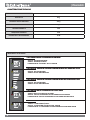 4
4
-
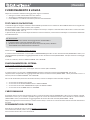 5
5
-
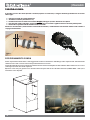 6
6
-
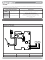 7
7
-
 8
8
-
 9
9
-
 10
10
-
 11
11
-
 12
12
-
 13
13
-
 14
14
-
 15
15
-
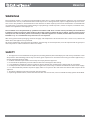 16
16
-
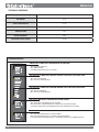 17
17
-
 18
18
-
 19
19
-
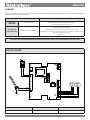 20
20
-
 21
21
-
 22
22
-
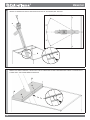 23
23
-
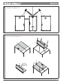 24
24
-
 25
25
-
 26
26
-
 27
27
-
 28
28
-
 29
29
-
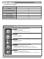 30
30
-
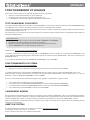 31
31
-
 32
32
-
 33
33
-
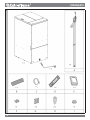 34
34
-
 35
35
-
 36
36
-
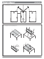 37
37
-
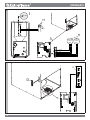 38
38
-
 39
39
-
 40
40
-
 41
41
-
 42
42
-
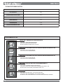 43
43
-
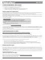 44
44
-
 45
45
-
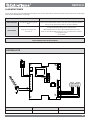 46
46
-
 47
47
-
 48
48
-
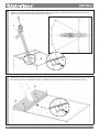 49
49
-
 50
50
-
 51
51
-
 52
52
-
 53
53
-
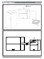 54
54
-
 55
55
-
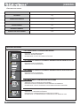 56
56
-
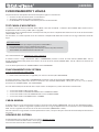 57
57
-
 58
58
-
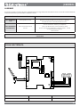 59
59
-
 60
60
-
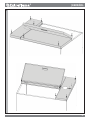 61
61
-
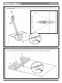 62
62
-
 63
63
-
 64
64
-
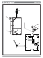 65
65
-
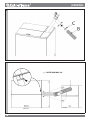 66
66
-
 67
67
-
 68
68


Extraflame Automatic loading pellet stocking tank El manual del propietario
- Tipo
- El manual del propietario
en otros idiomas
- français: Extraflame Automatic loading pellet stocking tank Le manuel du propriétaire
- italiano: Extraflame Automatic loading pellet stocking tank Manuale del proprietario
- English: Extraflame Automatic loading pellet stocking tank Owner's manual
- Deutsch: Extraflame Automatic loading pellet stocking tank Bedienungsanleitung
Artículos relacionados
Otros documentos
-
Palazzetti EcoFire IDRO Installation, User And Maintenance Manual
-
Ravelli HR EVO 14 Hydro El manual del propietario
-
 Bio Bronpi HYDRO Serie Installation, Operating And Service Instructions
-
Castorama 98BASE8-GCA Manual de usuario
-
-
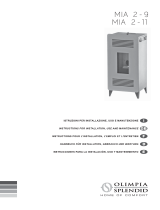 Olimpia Splendid MIA 2-9 Manual de usuario
-
Vemer Elettrosonda DB Manual de usuario
-
Dometic DTM05C Instrucciones de operación

